-
Contents
-
Table of Contents
-
Bookmarks
Quick Links
Related Manuals for Siemens SINAMICS S120
Summary of Contents for Siemens SINAMICS S120
-
Page 3
___________________ Preface ___________________ Fundamental safety instructions ___________________ SINAMICS System overview ___________________ Motor Modules in booksize C/D-type format S120 Power Units in Booksize C/D-Type ___________________ Motor connection, shield Format support and fabrication ___________________ Motor-side power components Manual ___________________ Cabinet design ___________________ Service and support for booksize C/D-type ___________________… -
Page 4
Note the following: WARNING Siemens products may only be used for the applications described in the catalog and in the relevant technical documentation. If products and components from other manufacturers are used, these must be recommended or approved by Siemens. Proper transport, storage, installation, assembly, commissioning, operation and maintenance are required to ensure that the products operate safely and without any problems. -
Page 5: Preface
Preface Preface to the SINAMICS S120 Manual «Booksize C/D-Type Power Units» Based on the booksize design, SINAMICS S120 booksize C/D-type power units have been developed for full compatibility with the booksize series ● The C type power unit includes Single Motor Modules from 18 A to 60 A and the Double Motor Module 2 x 18 A.
-
Page 6
Siemens’ content, and adapt it for your own machine documentation. Training At the following address (http://www.siemens.com/sitrain), you can find information about SITRAIN (Siemens training on products, systems and solutions for automation and drives). FAQs You can find Frequently Asked Questions in the Service&Support pages at Product Support (https://support.industry.siemens.com/cs/de/en/ps/faq). -
Page 7
Preface Usage phase Document/tool Installation/assembly SINAMICS S120 Equipment Manual for Control Units and Additional System Components • SINAMICS S120 Equipment Manual for Booksize Power Units • SINAMICS S120 Equipment Manual for Booksize Power Units C/D Type • SINAMICS S120 Equipment Manual for Chassis Power Units •… -
Page 8
Preface Software Manual Basic Functions SINAMICS S120 Function Manual Drive Functions Commissioning Of a simple SINAMICS S120 drive with Getting Started (up to Firmware V5.1 SP1) STARTER Commissioning With STARTER SINAMICS S120 Commissioning Manual (up to firmware V5.1 SP1) Commissioning Of a simple SINAMICS S120 drive with Getting Started (from Firmware V5.2) -
Page 9
Relevant directives and standards You can obtain an up-to-date list of currently certified components on request from your local Siemens office. If you have any questions relating to certifications that have not yet been completed, please ask your Siemens contact person. -
Page 10
(«Safety Integrated») on the Internet at the following address (https://support.industry.siemens.com/cs/ww/en/ps/13231/cert). The following directives and standards are relevant for SINAMICS S devices: ● European Low Voltage Directive SINAMICS S devices fulfil the requirements stipulated in the Low-Voltage Directive 2014/35/EU, insofar as they are covered by the application area of this directive. -
Page 11
SINAMICS S devices showing the test symbols fulfill the EMC requirements for Australia and New Zealand. ● Quality systems Siemens AG employs a quality management system that meets the requirements of ISO 9001 and ISO 14001. Not relevant standards China Compulsory Certification SINAMICS S devices do not fall in the area of validity of the China Compulsory Certification (CCC). -
Page 12
This document contains recommendations relating to third-party products. Siemens accepts the fundamental suitability of these third-party products. You can use equivalent products from other manufacturers. Siemens does not accept any warranty for the properties of third-party products. Ground symbols Table 1… -
Page 13: Table Of Contents
System overview ……………………… 25 Field of application ……………………25 Platform Concept and Totally Integrated Automation …………. 26 Introduction ……………………..28 SINAMICS S120 components ………………..30 2.4.1 Advantages of Motor Modules in booksize C/D-type format ……….32 2.4.2 Overview of C/D-type Motor Modules ………………33 System data ……………………..
-
Page 14
Electromagnetic fields in the workplace …………….102 6.4.1 Preliminary remarks ………………….102 6.4.2 Measurements/assessments for SINAMICS S120 Booksize Power Units ……103 Arrangement of components and equipment …………… 104 Electrical connection ………………….105 6.6.1 Releasing the DC link protective cover …………….105 6.6.2… -
Page 15
Table of contents 6.6.6 Connecting the 24 V terminal adapter ……………… 113 6.6.7 Shield connection ……………………114 6.6.7.1 Shield connection for X21/X22 on the Motor Module …………114 6.6.7.2 Shield connection for the motor holding brake …………..114 Connection system ………………….. 114 6.7.1 Configuring the cable length ……………….. -
Page 16
Table of contents Power Units in Booksize C/D-Type Format Manual, 12/2018, 6SL3097-5AC20-0BP0… -
Page 17: Fundamental Safety Instructions
Fundamental safety instructions General safety instructions WARNING Electric shock and danger to life due to other energy sources Touching live components can result in death or severe injury. • Only work on electrical devices when you are qualified for this job. •…
-
Page 18
Fundamental safety instructions 1.1 General safety instructions WARNING Risk of electric shock and fire from supply networks with an excessively low impedance Excessively high short-circuit currents can lead to the protective devices not being able to interrupt these short-circuit currents and being destroyed, and thus causing electric shock or a fire. -
Page 19
Fundamental safety instructions 1.1 General safety instructions WARNING Electric shock due to unconnected cable shield Hazardous touch voltages can occur through capacitive cross-coupling due to unconnected cable shields. • As a minimum, connect cable shields and the conductors of power cables that are not used (e.g. -
Page 20
• If you come closer than around 2 m to such components, switch off any radios or mobile phones. • Use the «SIEMENS Industry Online Support app» only on equipment that has already been switched off. Power Units in Booksize C/D-Type Format… -
Page 21
Fundamental safety instructions 1.1 General safety instructions NOTICE Damage to motor insulation due to excessive voltages When operated on systems with grounded line conductor or in the event of a ground fault in the IT system, the motor insulation can be damaged by the higher voltage to ground. If you use motors that have insulation that is not designed for operation with grounded line conductors, you must perform the following measures: •… -
Page 22
Fundamental safety instructions 1.1 General safety instructions WARNING Unexpected movement of machines caused by inactive safety functions Inactive or non-adapted safety functions can trigger unexpected machine movements that may result in serious injury or death. • Observe the information in the appropriate product documentation before commissioning. -
Page 23: Equipment Damage Due To Electric Fields Or Electrostatic Discharge
Fundamental safety instructions 1.2 Equipment damage due to electric fields or electrostatic discharge Equipment damage due to electric fields or electrostatic discharge Electrostatic sensitive devices (ESD) are individual components, integrated circuits, modules or devices that may be damaged by either electric fields or electrostatic discharge. NOTICE Equipment damage due to electric fields or electrostatic discharge Electric fields or electrostatic discharge can cause malfunctions through damaged…
-
Page 24: Industrial Security
Siemens’ products and solutions undergo continuous development to make them more secure. Siemens strongly recommends that product updates are applied as soon as they are available and that the latest product versions are used. Use of product versions that are no longer supported, and failure to apply the latest updates may increase customer’s exposure…
-
Page 25: Residual Risks Of Power Drive Systems
Fundamental safety instructions 1.5 Residual risks of power drive systems WARNING Unsafe operating states resulting from software manipulation Software manipulations (e.g. viruses, trojans, malware or worms) can cause unsafe operating states in your system that may lead to death, serious injury, and property damage.
-
Page 26
Fundamental safety instructions 1.5 Residual risks of power drive systems 2. Unusually high temperatures, including open flames, as well as emissions of light, noise, particles, gases, etc., can occur inside and outside the components under fault conditions caused by, for example: –… -
Page 27: System Overview
System overview Field of application SINAMICS is the family of drives from Siemens designed for machine and plant engineering applications. SINAMICS offers solutions for all drive tasks: ● Simple pump and fan applications in the process industry ● Complex single drives in centrifuges, presses, extruders, elevators, as well as conveyor and transport systems ●…
-
Page 28: Platform Concept And Totally Integrated Automation
Communication via PROFINET This Ethernet-based bus enables control data to be exchanged at high speed via PROFINET IO with IRT or RT and makes SINAMICS S120 a suitable choice for integration in high-performance multi-axis applications. At the same time, PROFINET also uses standard IT mechanisms (TCP/IP) to transport information, e.g.
-
Page 29
● HMI (operator control and monitoring) ● Control ● Drives and I/O Figure 2-2 SINAMICS as part of the Siemens modular automation system Power Units in Booksize C/D-Type Format Manual, 12/2018, 6SL3097-5AC20-0BP0… -
Page 30: Introduction
System overview, SINAMICS S120 with S120M distributed servo drive technology Modular system for sophisticated drive tasks SINAMICS S120 solves complex drive tasks for a wide range of industrial applications and is, therefore, designed as a modular system. Select from many different harmonized components and functions to create the combination that best meets your requirements.
-
Page 31
Electronic rating plates in all components An important digital linkage element of the SINAMICS S120 drive system are the electronic type plates integrated in every component. They allow all drive components to be detected automatically via a DRIVE-CLiQ link. As a result, data does not have to be entered manually during commissioning or component replacement –… -
Page 32: Sinamics S120 Components
System overview 2.4 SINAMICS S120 components SINAMICS S120 components Figure 2-4 SINAMICS S120 components Power Units in Booksize C/D-Type Format Manual, 12/2018, 6SL3097-5AC20-0BP0…
-
Page 33
● Standardized design, side-by-side mounting Note Installation location in the cabinet As a general rule, SINAMICS S120 components must be mounted vertically in the control cabinet. If other mounting positions are permissible, these are specified in the descriptions for the individual components. -
Page 34: Advantages Of Motor Modules In Booksize C/D-Type Format
Only components from the booksize C/D-type series plus the relevant connection components are described in this manual. Additional documentation containing system information and system component descriptions can be found in the SINAMICS S120 Manual «Booksize Power Units». This manual also contains all further information that is required to operate Motor Modules in booksize C/D-type format: ●…
-
Page 35: Overview Of C/D-Type Motor Modules
System overview 2.4 SINAMICS S120 components 2.4.2 Overview of C/D-type Motor Modules The Motor Modules of the SINAMICS S system in booksize C-type and D-type format operate as inverters. They make the energy from the connected motors’ DC link available at an adjusted voltage and with variable frequency.
-
Page 36
System overview 2.4 SINAMICS S120 components Table 2- 2 Overview of Motor Modules in booksize D-type format (with up to 3x overload) 50 mm modules 100 mm modules 6SL3120-1TE13-0AD. (3 A) 6SL3120-1TE23-0AD. (30 A) • • 6SL3120-1TE15-0AD. (5 A) 6SL3120-2TE21-8AD. (2 x 18 A) •… -
Page 37: System Data
System overview 2.5 System data System data Unless explicitly specified otherwise, the following technical data is valid for components of the SINAMICS S120 booksize drive system described in this document. Table 2- 3 Electrical data Line connection voltage 380 … 480 V 3 AC ±10 % (-15 % < 1 min) Line frequency 47 ……
-
Page 38
System overview 2.5 System data Table 2- 5 Degree of protection / protection class Degree of protection IPXXB according to EN 60529, open type according to UL/CSA Protection class Power circuits I (with protective conductor connection) Electronic circuits safety extra-low voltage PELV/SELV Table 2- 6 Environmental conditions Chemically active substances… -
Page 39
System overview 2.5 System data Installation altitude Operation 0 … 1000 m above sea level without derating > 1000 … 4000 m Reduction of the output current by 10 % per 1000 meters, or • Reduction in the ambient temperature by 5 °C per 1000 meters •… -
Page 40
System overview 2.5 System data Power Units in Booksize C/D-Type Format Manual, 12/2018, 6SL3097-5AC20-0BP0… -
Page 41: Motor Modules In Booksize C/D-Type Format
Motor Modules in booksize C/D-type format Description A Motor Module is an inverter that supplies AC voltage to the connected motor(s). The Motor Module is supplied with DC voltage from a Line Module via the DC link. Connect Motor Modules via DRIVE-CLiQ to a Control Unit in which the open-loop and closed-loop control functions for the Motor Module are implemented.
-
Page 42: Safety Instructions For Motor Modules Of C/D-Type
This can result in serious injury or death. • Only use adapters (DC link adapters and DC link rectifier adapters) approved by Siemens for the connection to the DC link. WARNING Electric shock due to incorrectly installed DC link bridges Incorrectly installed DC link bridges at the left-hand end of the drive line-up can cause an electric shock.
-
Page 43
Motor Modules in booksize C/D-type format 3.2 Safety instructions for Motor Modules of C/D-type WARNING Electric shock due to missing DC link side covers There is a danger of an electric shock through contact when the side covers of the DC link are missing. -
Page 44
• Set the DC power supply to 26 V. This ensures that the supply voltage for the brake remains within the permissible range when the following conditions are fulfilled: – Siemens three-phase motors are used – Siemens MOTION-CONNECT power cables are used – Motor cable lengths, max. 100 m Power Units in Booksize C/D-Type Format… -
Page 45
Damage or malfunctions can occur on the devices or system when DRIVE-CLiQ cables are used that are either incorrect or have not been approved for this purpose. • Only use suitable DRIVE-CLiQ cables that have been approved by Siemens for the particular application. -
Page 46: Interface Description
Motor Modules in booksize C/D-type format 3.3 Interface description Interface description 3.3.1 Overview Interfaces of the 50 mm modules and 100 mm modules (30 A and 2 x 18 A) The interface designations for Double Motor Modules are shown in parentheses. Figure 3-1 Overview of interfaces of Motor Modules in booksize C/D-type format (here: 100 mm) Power Units in Booksize C/D-Type Format…
-
Page 47
Motor Modules in booksize C/D-type format 3.3 Interface description Note Shield connection The shield connection plate is fitted to the Motor Module in the delivery state. The associated shield connection clamp can be found in the terminal kit. Note Protective conductor connection On the 100 mm module illustrated above, the protective conductor connection is located on the left next to the shield connection plate. -
Page 48
Motor Modules in booksize C/D-type format 3.3 Interface description Interfaces of the 100 mm modules (45 A / 60 A) Figure 3-2 Overview of interfaces of Motor Modules in booksize C-type format 45 A / 60 A Power Units in Booksize C/D-Type Format Manual, 12/2018, 6SL3097-5AC20-0BP0… -
Page 49: Motor And Brake Connection
Motor Modules in booksize C/D-type format 3.3 Interface description ① Interface X11 to connect the motor holding brake ② Threaded socket M4 for attachment of the shield connection clamp (Page 114) Figure 3-3 Motor Module 45 A / 60 A (view from below) Additional data regarding connecting motor holding brakes is provided in Chapter «Control cabinet installation/electrical connection (Page 114)».
-
Page 50
Motor Modules in booksize C/D-type format 3.3 Interface description Note Motor connector For information about the motor connector, please refer to Chapter «Motor connector» (Page 73). Note Shielding Attach the motor cable shield to the shield connection plate on the Motor Module using the shield connection clamp supplied in the terminal kit. -
Page 51
Motor Modules in booksize C/D-type format 3.3 Interface description The following diagrams show the dependencies of motor cable length, motor holding brake current and cross-section of the motor holding brake cables: Module input voltage 24 V Module input voltage 26 V Note Protective circuit against overvoltages The Motor Modules have an integrated overvoltage protection circuit for the motor holding… -
Page 52: Protective Conductor Connection
Motor Modules in booksize C/D-type format 3.3 Interface description NOTICE Faulty brake function due to inadmissible wear Inadmissible wear means that the braking function can no longer be guaranteed. • Comply with the defined Emergency Stop characteristics. • Avoid repeated brief acceleration of the motor against a holding brake that is still closed. Consider the operating times of the brakes and the relays in the drive control and/or enable circuit.
-
Page 53
Motor Modules in booksize C/D-type format 3.3 Interface description 50 mm modules: Protective 100 mm modules (30 A, 100 mm modules (45 A / 60 A): conductor connection behind 2 x 18 A): Protective conductor Protective conductor connection the shield connection plate connection to the left, adjacent at the motor connection block to the shield connection plate… -
Page 54: X21/X22 Ep Terminals / Temperature Sensor
Motor Modules in booksize C/D-type format 3.3 Interface description 3.3.4 X21/X22 EP terminals / temperature sensor Table 3- 3 X21/X22: EP terminals / temperature sensor Terminal Function Technical data + Temp Temperature sensors: KTY84-130 / Pt1000 / PTC / bimetallic switch with — Temp NC contact EP +24 V (digital input…
-
Page 55: X200-X203 Drive-Cliq Interface
Motor Modules in booksize C/D-type format 3.3 Interface description Temperature sensor connection WARNING Electric shock when the motor temperature sensor insulation fails When connecting temperature sensors, which have no safe protective separation with respect to the motor power circuit, then arcing to the signal electronics can occur. •…
-
Page 56: Connection Examples
Motor Modules in booksize C/D-type format 3.4 Connection examples Connection examples Figure 3-4 Connection example for Motor Modules Book a room size format C/D type, 3 A … 30 A, 2×3 A … 2×18 A Power Units in Booksize C/D-Type Format Manual, 12/2018, 6SL3097-5AC20-0BP0…
-
Page 57
Motor Modules in booksize C/D-type format 3.4 Connection examples Figure 3-5 Connection examples for Motor Modules Booksize format C type, 45 A / 60 A Power Units in Booksize C/D-Type Format Manual, 12/2018, 6SL3097-5AC20-0BP0… -
Page 58: Meaning Of The Leds
Motor Modules in booksize C/D-type format 3.5 Meaning of the LEDs Meaning of the LEDs Table 3- 5 Meaning of the LEDs on the Motor Module Status Description, cause Remedy DC LINK The electronics power supply is missing or outside the –…
-
Page 59: Dimension Drawings
Motor Modules in booksize C/D-type format 3.6 Dimension drawings Dimension drawings Figure 3-6 Dimension drawing of 50 mm Motor Modules in booksize C/D-type format with internal air cooling, all dimensions in mm and (inches) Power Units in Booksize C/D-Type Format Manual, 12/2018, 6SL3097-5AC20-0BP0…
-
Page 60
Motor Modules in booksize C/D-type format 3.6 Dimension drawings Figure 3-7 Dimension drawing of 100 mm Motor Modules 30 A / 2 x 18 A in Booksize format C/D type with internal air cooling, all dimensions in mm and (inches) Power Units in Booksize C/D-Type Format Manual, 12/2018, 6SL3097-5AC20-0BP0… -
Page 61
Motor Modules in booksize C/D-type format 3.6 Dimension drawings Figure 3-8 Dimension drawing of 100 mm Motor Modules 45 A / 60 A in Booksize format C type with internal air cooling, all dimensions in mm and (inches) Power Units in Booksize C/D-Type Format Manual, 12/2018, 6SL3097-5AC20-0BP0… -
Page 62: Installation
Motor Modules in booksize C/D-type format 3.7 Installation Installation Motor Modules are designed for installation in the control cabinet. They are fixed to the control cabinet wall or a mounting panel using M6 screws. Figure 3-9 Installing a Motor Module Power Units in Booksize C/D-Type Format Manual, 12/2018, 6SL3097-5AC20-0BP0…
-
Page 63
Motor Modules in booksize C/D-type format 3.7 Installation Drilling patterns Drilling pattern for 50 mm Motor Modules Drilling pattern for 100 mm Motor Modules Requirements placed on the electrical cabinet ● Housing: Sheet steel ● Panel thickness: 3 mm (0.12 in) ●… -
Page 64: Technical Data
Motor Modules in booksize C/D-type format 3.8 Technical data Technical data 3.8.1 Single Motor Modules Table 3- 6 Technical data of Single Motor Modules in Booksize format C type (18 A to 60 A) C-type 6SL3120- 1TE21- 1TE22- 1TE23- 1TE24- 1TE26- 8AC.
-
Page 65
Motor Modules in booksize C/D-type format 3.8 Technical data C-type 6SL3120- 1TE21- 1TE22- 1TE23- 1TE24- 1TE26- 8AC. 4AC. 0AC. 5AC. 0AC. Ventilation clearances above/below ≥ 80 Weight Higher output frequencies up to a maximum of 3200 Hz are possible with an additional license. Default for 400 V line systems;… -
Page 66: Double Motor Modules
Motor Modules in booksize C/D-type format 3.8 Technical data D-type 6SL3120 1TE13- 1TE15- 1TE21- 1TE21- 1TE22- 1TE23- 0AD. 0AD. 0AD. 8AD. 4AD. 0AD. Ventilation clearances above/below ≥ 80 Weight Higher output frequencies up to a maximum of 3200 Hz are possible with an additional license. Default for 400 V line systems;…
-
Page 67
Motor Modules in booksize C/D-type format 3.8 Technical data C-type 6SL3120- 2TE21-8AC. Current carrying capacity DC link busbars 24 V DC busbars Unit rating Based on I (600 V DC; 4 kHz) 2 x 9.7 Based on I 2 x 8.2 Typical power loss See also Power losses of the components (Page 134) Max. -
Page 68: Motor Overload Protection According To 61800-5-1
The Motor Module has integrated motor overload protection according to 61800-5-1. The protection threshold is 115 % of the full load current of the Motor Module. It can be adapted using parameter p5453 (see SINAMICS S120/S150 List Manual). Power Units in Booksize C/D-Type Format…
-
Page 69: Characteristics
Motor Modules in booksize C/D-type format 3.9 Characteristics Characteristics 3.9.1 Duty cycles Rated duty cycles of Motor Modules in booksize C-type format Figure 3-10 Duty cycle with initial load Figure 3-11 Duty cycle without initial load Figure 3-12 S6 duty cycle with initial load for a duty cycle duration of 600 s Power Units in Booksize C/D-Type Format Manual, 12/2018, 6SL3097-5AC20-0BP0…
-
Page 70
Motor Modules in booksize C/D-type format 3.9 Characteristics Figure 3-13 S6 duty cycle with initial load for a duty cycle duration of 60 s Figure 3-14 Duty cycle with 60 s overload for a duty cycle duration of 300 s Figure 3-15 Duty cycle with 30 s overload for a duty cycle duration of 300 s Rated duty cycles of Motor Modules in booksize D-type format… -
Page 71
Motor Modules in booksize C/D-type format 3.9 Characteristics Figure 3-17 Duty cycle with initial load Figure 3-18 Duty cycle without initial load for a duty cycle duration of 10 s Figure 3-19 Duty cycle without initial load for a duty cycle duration of 30 s Table 3- 10 Times I for the duty cycle… -
Page 72
Motor Modules in booksize C/D-type format 3.9 Characteristics Figure 3-20 S6 duty cycle with initial load for a duty cycle duration of 600 s Figure 3-21 S6 duty cycle with initial load for a duty cycle duration of 60 s Figure 3-22 Duty cycle with 60 s overload for a duty cycle duration of 300 s Figure 3-23… -
Page 73: Derating Characteristics
Motor Modules in booksize C/D-type format 3.9 Characteristics 3.9.2 Derating characteristics Derating characteristics for Motor Modules in booksize C/D-type format Note For information about derating depending on ambient temperature and installation altitude, please refer to Chapter «System data» (Page 35). Figure 3-24 Output current as a function of the pulse frequency Note…
-
Page 74
Motor Modules in booksize C/D-type format 3.9 Characteristics Figure 3-25 Output current during operation at low frequencies Supplementary conditions applicable to operation at low frequencies ● Derating does not apply to acceleration from zero speed if an output frequency of >10 Hz is reached within 100 ms. -
Page 75: Motor Connection, Shield Support And Fabrication
Motor connection, shield support and fabrication Motor plug connector for Motor Modules 3 A … 30 A 4.1.1 Description Motor Modules up to 30 A are connected to motors using a motor plug connector (power connector). The motor plug connector is not included in the scope of supply. The motor connector must be ordered separately for power cables that do not have preassembled connectors.
-
Page 76: Electrical Connection
Motor connection, shield support and fabrication 4.1 Motor plug connector for Motor Modules 3 A … 30 A Note Using identical plug connector variants for Double Motor Modules Two connectors of identical type must be used on Double Motor Modules (both push-in connectors or both connectors with screw terminals).
-
Page 77: Cable Cross-Sections And End Sleeves
Motor connection, shield support and fabrication 4.1 Motor plug connector for Motor Modules 3 A … 30 A ③ BR- (white) ④ Motor protective conductor connection (PE) ⑤ U2, V2, W2 ⑥ Locking lever (for push-in connector only) Spring-loaded terminal Screw terminal (push-in) U2, V2, W2, pro-…
-
Page 78
Motor connection, shield support and fabrication 4.1 Motor plug connector for Motor Modules 3 A … 30 A Table 4- 2 Connector with screw terminals 1.5 mm 2.5 mm 4 mm 6 mm Dimensions of the terminal AWG 16 AWG 14 AWG 12 AWG 10 openings… -
Page 79: Crimping Conductor End Sleeves
Motor connection, shield support and fabrication 4.1 Motor plug connector for Motor Modules 3 A … 30 A 4.1.2.2 Crimping conductor end sleeves The following crimping tool is available from Weidmüller to crimp conductor end sleeves (www.weidmueller.com). ● Type PZ 6/5 Article No. 9011460000 Figure 4-1 Crimp shape PZ 6/5 Note…
-
Page 80
Motor connection, shield support and fabrication 4.1 Motor plug connector for Motor Modules 3 A … 30 A ① Conductors U-V-W ② Protective conductor core ③ Holding brake conductors ④ Protective braided shield ⑤ Shrink tubing Figure 4-2 Conductor and stripped insulation lengths Table 4- 3 Conductor and stripped insulation lengths as a function of the cable cross-section, data in mm and (inch) 1.5 mm… -
Page 81: Connecting The Motor Cable
Motor connection, shield support and fabrication 4.1 Motor plug connector for Motor Modules 3 A … 30 A Note Cables for UL applications For UL applications, only 60/75 °C copper cables may be used. 4.1.4 Connecting the motor cable Connecting conductors to the push-in connector The state of the push-in plug connector when it is Insert the conductors into the open terminals.
-
Page 82
Motor connection, shield support and fabrication 4.1 Motor plug connector for Motor Modules 3 A … 30 A Opening the terminals/releasing the motor cables To release the terminals, press the individual locking levers up using a slot-head screwdriver (0.8 x 4 mm) until the lever snaps back into the motor connector casing. If it is difficult to withdraw the conductors from the open terminal, it may help to press the locking lever up as far as it will go while withdrawing the conductor. -
Page 83: Installation
Motor connection, shield support and fabrication 4.1 Motor plug connector for Motor Modules 3 A … 30 A 4.1.5 Installation 4.1.5.1 Installation Plug the motor connector into socket X1 for Single Motor Modules and into sockets X1 and X2 for Double Motor Modules. The motor connector has a catch, which snaps into the opening provided on the Motor Module.
-
Page 84: Shielding
Motor connection, shield support and fabrication 4.1 Motor plug connector for Motor Modules 3 A … 30 A Figure 4-4 Connecting the power cables to the Motor Module 4.1.5.2 Shielding Shield for 50 mm modules and 100 mm modules (30 A, 2 x 18 A) Shield connection The shield is connected through the shield connecting plate, which is screwed to the Motor Module, and a shield connecting terminal.
-
Page 85
Motor connection, shield support and fabrication 4.1 Motor plug connector for Motor Modules 3 A … 30 A Shield support The power cable shield is attached to the shield connection plate of the Motor Module by means of the supplied shield connection clamp. 1. -
Page 86: Coding
Motor connection, shield support and fabrication 4.1 Motor plug connector for Motor Modules 3 A … 30 A 4.1.5.3 Coding Coding keys can be used to distinguish between different motor connectors, especially those for Double Motor Modules. The terminal kit contains 2 coding stars, each of which has 6 coding keys.
-
Page 87: Pre-Assembled Power Cables
Motor connection, shield support and fabrication 4.1 Motor plug connector for Motor Modules 3 A … 30 A Now insert coding keys into the matching slots on the motor connector terminal. In order to prevent the connector with ② coding key from being inserted into the left-hand connector terminal, a coding key must be inserted into the matching ③…
-
Page 88
Motor connection, shield support and fabrication 4.1 Motor plug connector for Motor Modules 3 A … 30 A Detaching the preassembled power cable from the motor connector If the power cable needs to be routed through a confined space, the motor connector must be detached from the preassembled cable. -
Page 89: Motor Connection Block For 45 A / 60 A Motor Modules
Motor connection, shield support and fabrication 4.2 Motor connection block for 45 A / 60 A Motor Modules Motor connection block for 45 A / 60 A Motor Modules 4.2.1 Description The motor connection block is used for the 45 and 60 A modules to connect phase conductors U2, V2, W2 and the protective conductor connection (PE) of the motor.
-
Page 90
Motor connection, shield support and fabrication 4.2 Motor connection block for 45 A / 60 A Motor Modules Figure 4-5 Dimension drawing of the motor connection block Table 4- 5 Dimensions of the motor connection block in mm (inch) Maximum dimensions 42 (1.65) 24.5 (0.96) 12 (0.47) -
Page 91: Shield Connection Plate For 45 A / 60 A Motor Modules 100 Mm
Motor connection, shield support and fabrication 4.2 Motor connection block for 45 A / 60 A Motor Modules 4.2.2.2 Shield connection plate for 45 A / 60 A Motor Modules 100 mm Attach the shield connecting plate to the lower mounting points of the module. The shield connecting plate has several slots, which provide various options for connecting a shield: ●…
-
Page 92: Prefabricating A Motor Connecting Cable
Motor connection, shield support and fabrication 4.2 Motor connection block for 45 A / 60 A Motor Modules Connection using a shield connection clamp Connection using a hose clamp at the shield connecting plate at the shield connecting plate The shield connecting plate, shield connecting terminals and hose clamps are not included in the scope of supply of the Motor Module.
-
Page 93
Motor connection, shield support and fabrication 4.2 Motor connection block for 45 A / 60 A Motor Modules 5. Shorten the individual conductors as indicated in the drawing and table below. 6. Use suitable ring or tubular cable lugs (see appendix). ①… -
Page 94
Motor connection, shield support and fabrication 4.2 Motor connection block for 45 A / 60 A Motor Modules Power Units in Booksize C/D-Type Format Manual, 12/2018, 6SL3097-5AC20-0BP0… -
Page 95: Motor-Side Power Components
2 x rated current Control types Vector control and U/f control Further information such as safety instructions and dimension drawings can be found in the SINAMICS S120 Manual «Booksize Power Units». Power Units in Booksize C/D-Type Format Manual, 12/2018, 6SL3097-5AC20-0BP0…
-
Page 96: Safety Instructions For Motor Reactors
NOTICE Damaged device due to use of incorrect motor reactors When using motor reactors that have not been approved by Siemens for SINAMICS, the motor reactors can be damaged. • Only use motor reactors that Siemens has approved for operation with SINAMICS.
-
Page 97: Technical Data
Motor-side power components 5.1 Motor reactors 5.1.3 Technical data Table 5- 2 Technical data, motor reactors, part 1 Article No. 6SE7021- 6SL3000- 6SE7022- 0ES87-1FE0 2BE21-0AA0 6ES87-1FE0 Suitable for Motor Modules 6SL3120- 6SL3120- 6SL3120- booksize C/D type 1TE13-0AD. 1TE21-0AD. 1TE21-8AC. 2TE13-0AD. 2TE21-0AD.
-
Page 98
Motor-side power components 5.1 Motor reactors Table 5- 3 Technical data, motor reactors, part 2 Article No. 6SE7024- 6SE7027- 6SL3000- 7ES87-1FE0 2ES87-1FE0 2BE26-0AA0 Suitable for Motor Modules 6SL3120- 6SL3120- 6SL3120- 6SL3120- booksize C/D type 1TE22-4AC. 1TE23-0AC. 1TE24-5AC. 1TE26-0AC. 1TE22-4AD. 1TE23-0AD. Rated current Maximum current Inductance… -
Page 99: Cabinet Design
Cabinet design General information SINAMICS S components are available as chassis units with degree of protection IP20 or IPXXB according to IEC 60529 and as open type devices to UL 50. This therefore ensures that fingers cannot come into contact with any active components. To ensure also protection against mechanical stress and climatic conditions, the components must always be operated in housings, cabinets or enclosed electrical operating areas/rooms that fulfill at least degree of protection IP54 according to European enclosure specifications,…
-
Page 100: Safety Instructions With Respect To Control Cabinet Design
Cabinet design 6.2 Safety instructions with respect to control cabinet design Safety of machinery — electrical equipment of machines All information relating to device selection in this section applies to ● Operation on TN and TT line supply systems with grounded neutral point and grounded protective conductor as well as to IT line supply systems ●…
-
Page 101: Classification Of Emc Behavior
● Operation on TN and TT line supply systems with grounded neutral point ● Observance of information about cable shielding and equipotential bonding ● Use of the recommended power and signal cables from Siemens. ● Only use Siemens cables for the DRIVE-CLiQ connections.
-
Page 102: Drive System Applications
6.3.3 Drive system applications SINAMICS S120 units are designed for use in the second environment. They are to be used on a professional basis in trade, business and industry and are not sold to the general public. In order to satisfy the EMC requirements, the drive system must be installed by appropriately qualified personnel in compliance with EMC regulations and the installation notes provided in the manual.
-
Page 103: Emitted Interference/Interference Immunity
Note Malfunctions when not using original Siemens accessories Malfunctions can occur if accessories are used that are not original. • For DRIVE-CLiQ connections, only use the genuine Siemens DRIVE-CLiQ wiring and DRIVE-CLiQ cabinet bushings. Power Units in Booksize C/D-Type Format…
-
Page 104: Electromagnetic Fields In The Workplace
100 kHz (see system data or relevant technical specifications) 5. The routing of power cables has a significant impact on the electromagnetic fields that occur. You can find more detailed information in the «EMC installation guideline (https://support.industry.siemens.com/cs/ww/de/view/60612658)». Power Units in Booksize C/D-Type Format Manual, 12/2018, 6SL3097-5AC20-0BP0…
-
Page 105: Measurements/Assessments For Sinamics S120 Booksize Power Units
Magnetic flux density For assessment, see the following Limits not exceeded table Table 6- 2 Minimum distances from SINAMICS S120 power units at 0 Hz … 100 kHz in cm (inch) Line Module with Generally Individuals with active implants power rating…
-
Page 106: Arrangement Of Components And Equipment
● EMC Note Further information about the arrangement of components and equipment For detailed information about the arrangement of components and equipment, please refer to the SINAMICS S120 Manual «Booksize Power Units». Power Units in Booksize C/D-Type Format Manual, 12/2018, 6SL3097-5AC20-0BP0…
-
Page 107: Electrical Connection
6.6.1 Releasing the DC link protective cover The protective covers for the DC link on the SINAMICS S120 components have an interlocking mechanism, which must be opened using a flat bladed screwdriver (1 x 5.5 mm). This interlocking mechanism is identical for the power units of all series.
-
Page 108: Connecting The Dc Link Busbars And 24 V Busbars To Components In The Booksize C/D Type Format
Cabinet design 6.6 Electrical connection 6.6.2 Connecting the DC link busbars and 24 V busbars to components in the Booksize C/D type format 6.6.2.1 Description The DC link busbars and 24 V busbars of the components must be connected in a drive line- up before commissioning.
-
Page 109
Motor Modules. It is not permissible that the maximum current carrying capacity of the DC link busbar is exceeded. For detailed information on this topic, see SINAMICS S120 Manual «Booksize Power Units «, Chapter «Current carrying capacity of DC links». -
Page 110: Installation
Cabinet design 6.6 Electrical connection NOTICE Component damage caused by excessively low current load capability of the DC link busbars The DC link busbars of the individual components have different current carrying capacities (current ratings). If the current flowing through a DC link busbar is higher than the current specified for the busbar, the component will heat up and may sustain damage as a result of overheating.
-
Page 111
Cabinet design 6.6 Electrical connection Loosen the DC link screws at the right-hand end Always connect the lower DC link busbars first of the left module, and at the left-hand end of the and then the upper DC link busbars. To do this, adjacent module. -
Page 112
Cabinet design 6.6 Electrical connection Close the DC link protective covers until you hear them snap into place. WARNING Electric shock due to incorrectly installed DC link bridges Incorrectly installed DC link bridges at the left-hand end of the drive line-up can cause an electric shock. -
Page 113: 24 V Connection
Cabinet design 6.6 Electrical connection NOTICE Material damage due to loose power connections Insufficient tightening torques or vibration can result in faulty electrical connections. This can cause fire damage or malfunctions. • Tighten all power connections with the specified tightening torques, e.g. line supply connection, motor connection, DC link connections.
-
Page 114: Connection Of Booksize Components To Booksize C/D-Type Components
Description It is possible to combine components in booksize format with components in booksize C/D- type format with one another in the SINAMICS S120 drive line-up. They are mutually compatible in terms of both hardware design and software support. The following components in booksize format can also be used for components in booksize C/D-type format: ●…
-
Page 115: Connecting The 24 V Terminal Adapter
Cabinet design 6.6 Electrical connection Further information can be found in the SINAMICS S120 Manual «Booksize Power Units». NOTICE DC link rectifier adapters for 45 A and 60 A modules burning No appropriate DC link rectifier adapters are available for 45 A and 60 A Motor Modules, Booksize C type.
-
Page 116: Shield Connection
(Page 47)»). Connection system Note Information about the connection system and cables For detailed information about the connection system and cables, please refer to the SINAMICS S120 Manual «Booksize Power Units» Power Units in Booksize C/D-Type Format Manual, 12/2018, 6SL3097-5AC20-0BP0…
-
Page 117: Configuring The Cable Length
Cabinet design 6.7 Connection system 6.7.1 Configuring the cable length To implement a longer motor cable, you can ● select a higher rating Motor Module or ● reduce the permissible continuous output current I in relation to the rated output continuous current I rated…
-
Page 118: Current-Carrying Capacity And Derating Factors For Power Cables And Signal Cables
Cabinet design 6.7 Connection system 6.7.2 Current-carrying capacity and derating factors for power cables and signal cables The current carrying capacity of PVC/PUR-insulated copper cables is specified for routing types B1, B2 and C under continuous operating conditions in the table below with reference to an ambient air temperature of 40°…
-
Page 119
Cabinet design 6.7 Connection system Table 6- 8 Derating factors for deviating ambient temperatures Ambient air temperature [° C] Derating factor according to EN 60204-1, Table 1.15 1.08 1.00 0.91 0.82 0.71 0.58 WARNING Overheating of the motor cables when the permissible conductor cross-sections are fallen below Excessively thin motor cables can result in overheating. -
Page 120: Connecting Terminals
Cabinet design 6.7 Connection system 6.7.3 Connecting terminals Table 6- 9 Connectable conductor cross-sections and tightening torques for screw terminals Screw terminal type Conductor Flexible 0.08 … 1.5 mm (AWG 28 … AWG cross sections With end sleeve, without plastic sleeve that can be With end sleeve, with plastic sleeve 0.25 ……
-
Page 121: Cable Lugs
Cabinet design 6.7 Connection system 6.7.4 Cable lugs Figure 6-4 Dimension drawing of cable lugs Table 6- 11 Dimensions of cable lugs Cable lug Bolt Cable cross-section [mm] [mm] [mm] [mm] [mm] [mm] [mm] [mm] Ring 1 — 2.5 Ring 2.5 — 6 Ring 6 — 10…
-
Page 122: Possible Functions Of The 24 V Supply
Note Grounding the 24 V electronics power supply In SINAMICS S120 components, the electronics ground is permanently connected to the protective conductor potential. The connection cannot be disconnected. WARNING…
-
Page 123
Set the DC power supply to at least 26 V. This ensures that the supply voltage for the brake remains within the permissible range when the following conditions are fulfilled: • Siemens three-phase motors are used • Siemens MOTION-CONNECT power cables are used • Motor cable lengths, max. 100 m Protective circuit against overvoltages The Motor Modules have an integrated overvoltage protection circuit for the motor holding brake. -
Page 124
External protective circuits are not required. Note More information Further information about conductor protection and the possible functions of the 24 V supply can be found in the SINAMICS S120 Manual «Booksize Power Units». Power Units in Booksize C/D-Type Format Manual, 12/2018, 6SL3097-5AC20-0BP0… -
Page 125: Cable Shielding And Routing
Cabinet design 6.9 Cable shielding and routing Cable shielding and routing In order to comply with the EMC requirements, certain cables must be routed apart from other cables and from certain components. To satisfy EMC requirements, the following cables must be used with shields: ●…
-
Page 126
The cable shields must be connected as close to the conductor terminal connections as possible to ensure a low-impedance connection with cabinet ground. For power cables from Siemens in which the shield is connected to the connector shell (see relevant catalog), this is a sufficiently good shield support. -
Page 127: Protective Connection And Equipotential Bonding
• Carefully comply with the applicable regulations for dimensioning the protective conductor (see below). Protective connection concept, SINAMICS S120 booksize power units Booksize power units should always be connected with a protective conductor to the central PE busbar or the conductive mounting plate in the control cabinet (see the following diagram).
-
Page 128
Additional details are provided in the following document «Dimensioning the protective conduc- tor for SINAMICS S120 Booksize (https://support.industry.siemens.com/cs/ww/en/view/109738572)». ④ Same cross-section as the line conductor of the motor cable. Figure 6-5 Protective connection concept, SINAMICS S120 booksize Power Units in Booksize C/D-Type Format Manual, 12/2018, 6SL3097-5AC20-0BP0… -
Page 129
Cabinet design 6.10 Protective connection and equipotential bonding Protective connection via the mounting plate Alternative to the described methods with protective conductors, it is also possible to establish the protective conductor connection of the electrical cabinet through the mounting plate, assuming that all of the following conditions are satisfied. As a consequence, the requirements placed on a protective conductor for an increased discharge current are satisfied. -
Page 130
Cabinet design 6.10 Protective connection and equipotential bonding Functional equipotential bonding For EMC reasons, the shield of the motor cable should be connected through a large surface area both at the Motor Module as well as at the motor. The drive line-up must be arranged on a single, bare metal mounting plate in order to comply with the EMC limit values. -
Page 131: Notes On Control Cabinet Cooling
Cabinet design 6.11 Notes on control cabinet cooling 6.11 Notes on control cabinet cooling 6.11.1 Control cabinet cooling options The following options are available for cooling the control cabinet: ● Filter fan ● Heat exchanger ● Cooling unit ● Liquid cooling ●…
-
Page 132: General Information On Ventilation
They switch themselves off with a small hysteresis as soon as the heat sink temperature drops below the stored temperature value and there is no pulse enable. The fan run-on time can be parameterized (see SINAMICS S120/S150 List Manual). Air guidance The cooling air must flow through the components vertically from bottom (cooler region) to top (region heated by operation).
-
Page 133
Cabinet design 6.11 Notes on control cabinet cooling ① Cooling unit ② Control cabinet Figure 6-6 Examples of cabinet ventilation NOTICE Component damage caused by condensation Condensation on the components can result in their failure. • Select the air circuit and arrangement of the cooling equipment in such a way that no condensation can form on the components. -
Page 134: Ventilation Clearances
Note Ventilation clearances of the SINAMICS booksize drive line-up The ventilation clearances of other components in the booksize drive line-up can be found in the SINAMICS S120 Manual «Booksize Power Units». Drive line-up with internal air cooling Figure 6-7 Ventilation clearances for a drive line-up with internal air cooling…
-
Page 135: Dimensioning Cooling Equipment
Cabinet design 6.11 Notes on control cabinet cooling 6.11.4 Dimensioning cooling equipment Manufacturers provide calculation programs for selecting cooling equipment. It is always necessary to know the power loss of the components and equipment installed in the cabinet. The physical relationship is shown in the following example. Formula to calculate the power loss: q = Q — k ·…
-
Page 136: Power Losses Of The Components
Cabinet design 6.12 Power losses of the components 6.12 Power losses of the components 6.12.1 Typical power losses for Motor Modules The information on the power losses in the previous chapters are maximum values, which occur in the most unfavorable case. For typical applications, the losses are lower. The following applies as typical application: ●…
-
Page 137: Maximum Power Losses In The Rated Load Range
Cabinet design 6.12 Power losses of the components Overview of typical power losses at the rated operating point Table 6- 16 Typical power losses in the control cabinet for operation at the rated operating point for internally cooled Motor Modules Motor Module internal air cooling Single Motor Module 3 A…
-
Page 138: Maximum Power Losses In The Partial Load Range
Note Additional power loss values The power loss data for other components in the booksize drive line-up can be found in the SINAMICS S120 Manual «Booksize Power Units». 6.12.3 Maximum power losses in the partial load range Losses in the partial load range for Motor Modules…
-
Page 139: Service And Support For Booksize C/D-Type
Service and support for booksize C/D-type Spare parts You can find spare parts in the Internet here (https://www.sow.siemens.com). Replacing the fan 7.2.1 Safety instructions when replacing a fan WARNING Electric shock when live parts are touched Before replacing the fan, you must switch off the power supplies (400 V AC and 24 V DC).
-
Page 140: Replacing The Fan
Service and support for booksize C/D-type 7.2 Replacing the fan 7.2.2 Replacing the fan Note Service life and replacement intervals of the fan module The modules have an operating hours counter (p0251). When the maximum operating duration is reached, a corresponding message is output (A30042). The fan modules of the Motor Modules can be ordered as replacement parts.
-
Page 141
Service and support for booksize C/D-type 7.2 Replacing the fan Detach the protective conductor from Pull the fan module out forwards out of Motor Module with removed fan module the Motor Module. the Motor Module. (12 V or 24 V) Screwdriver: Torx 20 Installing a new fan module 1. -
Page 142
Service and support for booksize C/D-type 7.2 Replacing the fan Replacing the fan for 100 mm modules (45 A / 60 A) The fan assembly is integrated in the motor connection block. Use a slotted screwdriver to release the Open the cover. Remove the conductors of the motor terminal block cover on the left and connecting cable (von left: protective… -
Page 143
Service and support for booksize C/D-type 7.2 Replacing the fan Motor Module without fan Removed fan module Installing a new fan module 1. Insert a new fan assembly into the Motor Module. The power supply for the fan is automatically established. 2. -
Page 144: Recycling And Disposal
Service and support for booksize C/D-type 7.3 Recycling and disposal Recycling and disposal For environmentally friendly recycling and disposal of your old device, please contact a company certified for the disposal of electrical and electronic waste and dispose of the device in accordance with the regulations in your country.
-
Page 145: Appendix
Appendix List of abbreviations Note The following list of abbreviations includes all abbreviations and their meanings used in the entire SINAMICS family of drives. Abbreviation Source of abbreviation Meaning A… Alarm Warning Alternating Current Alternating current Analog Digital Converter Analog digital converter Analog Input Analog input Active Interface Module…
-
Page 146
Appendix A.1 List of abbreviations Abbreviation Source of abbreviation Meaning C… Safety message Controller Area Network Serial bus system Communication Board CAN Communication Board CAN Communication Board Ethernet PROFINET communication module (Ethernet) Compact Disc Compact disc Command Data Set Command data set CF Card CompactFlash Card CompactFlash card… -
Page 147
Appendix A.1 List of abbreviations Abbreviation Source of abbreviation Meaning DRIVE-CLiQ DRIVE-CLiQ DRAM Dynamic Random Access Memory Dynamic Random Access Memory DRIVE-CLiQ Drive Component Link with IQ Drive Component Link with IQ Dynamic Servo Control Dynamic Servo Control Doppelsubmodul Double submodule Digital Time Clock Timer EASC… -
Page 148
Appendix A.1 List of abbreviations Abbreviation Source of abbreviation Meaning FPGA Field Programmable Gate Array Field Programmable Gate Array Firmware Firmware Gigabyte Gigabyte Global Control Global control telegram (broadcast telegram) Ground Reference potential for all signal and operating voltages, usually defined as 0 V (also referred to as M) Gerätestammdatei Generic Station Description: Describes the fea-… -
Page 149
Appendix A.1 List of abbreviations Abbreviation Source of abbreviation Meaning Kreuzweiser Datenvergleich Data cross-check Know-how protection Know-how protection Kinetische Pufferung Kinetic buffering Proportional gain KTY84-130 Temperature sensor Symbol for inductance Light Emitting Diode Light emitting diode Linearmotor Linear motor Lageregler Position controller Least Significant Bit Least significant bit… -
Page 150
Appendix A.1 List of abbreviations Abbreviation Source of abbreviation Meaning Nullmarke Zero mark Normally Open (contact) NO contact Netzstromrichter Line-side converter Network Time Protocol Standard for synchronization of the time of day NVRAM Non-Volatile Random Access Memory Non-volatile read/write memory Open Architecture Software component which provides additional functions for the SINAMICS drive system… -
Page 151
Appendix A.1 List of abbreviations Abbreviation Source of abbreviation Meaning Power Supply Power supply Power Stack Adapter Power Stack Adapter PT1000 Temperature sensor Positive Temperature Coefficient Positive temperature coefficient Point To Point Point-to-point Pulse Width Modulation Pulse width modulation Prozessdaten Process data r…… -
Page 152
Safe stop Safety Integrated Safety Integrated Safety Info Channel Safety Info Channel Safety Integrity Level Safety Integrity Level SITOP Siemens power supply system Safely-Limited Acceleration Safely limited acceleration Smart Line Module Smart Line Module Safely-Limited Position Safely Limited Position Safely-Limited Speed… -
Page 153
Appendix A.1 List of abbreviations Abbreviation Source of abbreviation Meaning Terminal Board Terminal Board Technology Extension Software component which is installed as an addi- tional technology package and which expands the functionality of SINAMICS (previously OA applica- tion) Totally Integrated Automation Totally Integrated Automation Transport Layer Security Encryption protocol for secure data transfer (previ-… -
Page 154
Appendix A.1 List of abbreviations Abbreviation Source of abbreviation Meaning Extensible Markup Language Extensible markup language (standard language for Web publishing and document management) Zwischenkreis DC link Zero Mark Zero mark Zustandswort Status word Power Units in Booksize C/D-Type Format Manual, 12/2018, 6SL3097-5AC20-0BP0… -
Page 155: Documentation Overview
Appendix A.2 Documentation overview Documentation overview Power Units in Booksize C/D-Type Format Manual, 12/2018, 6SL3097-5AC20-0BP0…
-
Page 156
Appendix A.2 Documentation overview Power Units in Booksize C/D-Type Format Manual, 12/2018, 6SL3097-5AC20-0BP0… -
Page 157: Index
Shielding, 123 Field of application, 25 Communication PROFIBUS DP, 27 PROFINET, 26 Components Motor Module, 39 Heat dissipation SINAMICS S120, 30 Control cabinet, 129 Configuring, 115 Control cabinet design, 97 Electrical connection, 105 Heat dissipation, 129 Installation Protective connections, 125…
-
Page 158
Motor Module, 45, 114 Electrical connection, 74 Shield connection plate, 89 Installation, 81 Shielding, 82, 123 Shield connection, 82 SINAMICS S120, 30 Shield support, 83 System architecture, 29 Stripped lengths, 78 System data, 35 Motor holding brake, 48 Motor Module, 39…
|
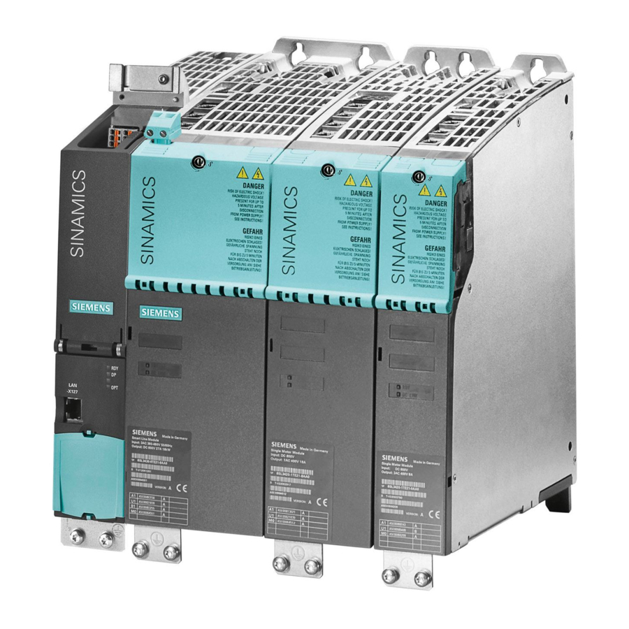
6SL3120-1TE21-8AA4
Аналогичные изображения SINAMICS S120 SINGLE MOTOR MODULE INPUT: DC 600В OUTPUT: 3AC 400V, 18A ИСПОЛНЕНИЕ: BOOKSIZE INTERNAL AIR COOLING OPTIMIZED PULSE SAMPLE AND SUPPORT OF THE EXTENDED SAFETY INTEGRATED FUNCTIONS INCL. DRIVE-CLIQ CABLE Комментарий Продукт не доступен для заказа Замена:Successor 6SL3120-1TE21-8AD0 C/D-types SIOS 109480497, adapt connector and cable Если Вы нуждаетесь в поддержке, пожалуйста, обратитесь к Вашему менеджеру ООО «Сименс» по телефону или в колл-центр по e-mail icc.ru@siemens.com.
|
| |

-
Contents
-
Table of Contents
-
Bookmarks
Quick Links
SINAMICS S120
Chassis Power Units
Manual 01/2013
SINAMICS
s
Related Manuals for Siemens SINAMICS S120
Summary of Contents for Siemens SINAMICS S120
-
Page 1
SINAMICS S120 Chassis Power Units Manual 01/2013 SINAMICS… -
Page 3
___________________ Chassis power units Preface ___________________ System overview ___________________ Line-side power components SINAMICS ___________________ Line Modules S120 ___________________ Chassis power units Motor Modules ___________________ DC link components Manual Motor-side power ___________________ components ___________________ Cabinet design and EMC ___________________ Maintenance and Servicing ___________________ Appendix (GH3), 01/2013… -
Page 4
Note the following: WARNING Siemens products may only be used for the applications described in the catalog and in the relevant technical documentation. If products and components from other manufacturers are used, these must be recommended or approved by Siemens. Proper transport, storage, installation, assembly, commissioning, operation and maintenance are required to ensure that the products operate safely and without any problems. -
Page 5: Preface
Siemens’ content, and adapt it for your own machine documentation: http://www.siemens.com/mdm Training Using the following link, you can find information on SITRAIN — training from Siemens for products, systems and drive technology solutions: http://www.siemens.com/sitrain FAQs You can find Frequently Asked Questions in the Service&Support pages under Product Support: http://support.automation.siemens.com…
-
Page 6
SIZER engineering tool • Configuration manuals, motors • Decision making/ordering SINAMICS S Catalogs Configuring/installation SINAMICS S120 Manual for Control Units and Additional System • Components SINAMICS S120 Manual for Booksize Power Units • SINAMICS S120 Manual for Chassis Power Units •… -
Page 7: Technical Support
EC declarations of conformity The EC Declaration of Conformity for the EMC Directive and for the Low-Voltage Directive can be found/obtained from the relevant regional office of the I DT MC and I DT LD Business Units of Siemens AG. Note Low-voltage directive When operated in dry operating areas, SINAMICS equipment with AC motors conforms to Low-Voltage Directive 2006/95/EC.
-
Page 8
The Safety Integrated functions of SINAMICS components are generally certified by independent institutes. An up-to-date list of certified components is available on request from your local Siemens office. If you have any questions relating to certifications that have not been completed, please ask your Siemens contact. -
Page 9
Preface ESD information CAUTION Electrostatic sensitive devices Electrostatic sensitive devices (ESD) are single components, integrated circuits or devices that can be damaged by electrostatic fields or electrostatic discharges. Regulations for handling ESD components: • During the handling of electronic components, pay attention to the grounding of the person, workplace and packaging! •… -
Page 10
Preface Safety information DANGER Qualified personnel SINAMICS S equipment must only be commissioned by suitably qualified personnel. The personnel must take into account the information provided in the technical customer documentation for the product, and be familiar with and follow the specified danger and warning notices. -
Page 11
Preface Note Installation of a UL-approved system For a UL-approved system use 60/75° C copper conductors only. NOTICE Malfunctions caused by mobile telephones Operating the equipment in the immediate vicinity (< 1.8 m) of mobile telephones with a transmitting power of > 1 W may cause the devices to malfunction. Chassis power units Manual, (GH3), 01/2013, 6SL3097-4AE00-0BP3… -
Page 12
Preface Residual risks of power drive systems The control and drive components of a power drive system (PDS) are approved for industrial and commercial use in industrial line supplies. Their use in public electrical networks requires a different configuration and/or additional measures. These components may only be operated in closed housings or in higher-level control cabinets with protective covers that are closed, and when all of the protective devices are used. -
Page 13
Preface 4. Electrical, magnetic and electromagnetic fields generated in operation that can pose a risk to people with a pacemaker, implants or metal replacement joints, etc. if they are too close. 5. Release of environmental pollutants or emissions as a result of improper operation of the system and/or failure to dispose of components safely and correctly. -
Page 14
Preface Electromagnetic fields WARNING Electromagnetic fields «electro smog» Electromagnetic fields are generated by the operation of electrical power engineering installations such as transformers, converters or motors. Electromagnetic fields can interfere with electronic devices, which could cause them to malfunction. For example, the operation of heart pacemakers can be impaired, potentially leading to damage to a person’s health or even death. -
Page 15: Table Of Contents
Basic structure of a drive system with SINAMICS S120 ………….33 1.6.1 Structure of a drive system with SINAMICS S120 and regulated infeed……..33 1.6.2 Structure of a drive system with SINAMICS S120 and unregulated infeed / regenerative feedback……………………….34 1.6.3 Structure of a drive system with SINAMICS S120 and unregulated infeed………35 Line-side power components ……………………
-
Page 16
Table of contents 2.6.3.3 Line/load connection ……………………70 2.6.3.4 DRIVE-CLiQ interface X500………………….70 2.6.3.5 X530 neutral point grounding …………………. 71 2.6.3.6 X609 terminal strip ……………………72 2.6.3.7 Meaning of the LED on the Voltage Sensing Module (VSM) in the Active Interface Module ..73 2.6.4 Dimension drawing…………………… -
Page 17
Table of contents 3.4.3.6 X42 terminal strip ……………………159 3.4.3.7 DRIVE-CLiQ interfaces X400, X401, X402…………….160 3.4.3.8 Meaning of the LEDs on the Control Interface Module in the Active Line Module ….161 3.4.4 Dimension drawing ……………………162 3.4.5 Electrical connection ……………………166 3.4.6 Technical specifications ………………….168 Motor Modules………………………. -
Page 18
Table of contents 5.1.4.4 Installing the Braking Module in a Smart Line Module / Active Line Module / Motor Module, frame size JX………………….. 234 5.1.4.5 Installing the Braking Module in a Basic Line Module, frame size FB ……..235 5.1.4.6 Installing the Braking Module in a Basic Line Module, frame size GB, GD …… -
Page 19
Table of contents Maintenance and Servicing……………………319 Chapter content …………………….319 Maintenance……………………..319 Maintenance……………………..320 8.3.1 Installation device ……………………322 8.3.2 Using crane lifting lugs to transport power blocks …………..323 Replacing components ………………….326 8.4.1 Safety information ……………………326 8.4.2 Replacing the power block, Active Line Module, and Motor Module, frame size FX….327 8.4.3 Replacing the power block, Smart Line Module, Active Line Module, and Motor Module, frame size GX ……………………..330… -
Page 20
Table of contents Chassis power units Manual, (GH3), 01/2013, 6SL3097-4AE00-0BP3… -
Page 21: System Overview
The SINAMICS range of drives Field of application SINAMICS is the family of drives from Siemens designed for machine and plant engineering applications. SINAMICS offers solutions for all drive tasks: ● Simple pump and fan applications in the process industry ●…
-
Page 22
The different SINAMICS versions can be easily combined with each other. SINAMICS is part of the Siemens «Totally Integrated Automation» concept. Integrated SINAMICS systems covering engineering, data management and communication at the automation level, result in extremely cost-effective solutions based on SIMOTION, SINUMERIK and SIMATIC control systems. -
Page 23
System overview 1.1 The SINAMICS range of drives Figure 1-2 SINAMICS as part of the Siemens modular automation system Quality management according to DIN EN ISO 9001 SINAMICS is able to meet the highest requirements in terms of quality. Comprehensive quality assurance measures in all development and production processes ensure a consistently high level of quality. -
Page 24: Sinamics S120 Drive System
SIZER, a high-performance engineering tool, makes it easier to choose and determine the optimum drive configuration. SINAMICS S120 is enhanced by a wide range of motors. Whether synchronous or induction, all motor types are supported by SINAMICS S120.
-
Page 25
SINAMICS S120 takes a different approach. A central Control Unit controls the drive for all connected axes and also establishes the technological links between the drives and/or axes. -
Page 26
1.2 SINAMICS S120 drive system DRIVE-CLiQ – the digital interface between all components All SINAMICS S120 components, including the motors and encoders, are interconnected by a shared serial interface called DRIVE-CLiQ. The standardized cables and connectors reduce the variety of different parts and cut storage costs. -
Page 27
System overview 1.2 SINAMICS S120 drive system SINAMICS S120 components were developed for installation in cabinets. They have the following features and characteristics: ● Easy to handle, simple installation and wiring ● Practical connection system, cable routing according to EMC requirements ●… -
Page 28: Technical Specifications
System overview 1.3 Technical specifications Technical specifications Technical data Unless specified otherwise, the following technical data is valid for all the following components of the SINAMICS S120 drive system. Table 1- 1 General technical data Electrical data Line supply voltage 3 AC 380 V -10% (-15% <…
-
Page 29
System overview 1.3 Technical specifications Ambient conditions Degree of protection IP00 or IP20 according to EN 60529 Protection class Class I (with protective conductor system) and class III (PELV) according to EN 61800-5-1 Shock protection EN 50274 and BGV A 3 when used as intended Permissible ambient and coolant 0 … -
Page 30
System overview 1.3 Technical specifications Installation altitude > 2000 m above sea level without derating • > 2000 … 4000 m above sea level, see derating characteristics • Certificates Conformity CE (Low Voltage and EMC Directives), Machinery Directive Standards EN 61800-5-1, EN 60204-1, EN 61800-3, EN 60146-1-1 Approvals (only up to 3 AC 600 V) cULus (File Nos.: E192450, E214113 and E253831) In transport packaging… -
Page 31: Derating Factors As A Function Of Installation Altitude And Ambient Temperature
System overview 1.4 Derating factors as a function of installation altitude and ambient temperature Derating factors as a function of installation altitude and ambient temperature Chassis units and the associated system components are rated for an ambient temperature of 40° C and installation altitudes up to 2000 m above sea level. At ambient temperatures >…
-
Page 32: Standards
System overview 1.5 Standards Standards Note Information on the listed standards The standards listed in the table below are non-binding and do not in any way claim to be complete. The standards listed do not represent a guaranteed property of the product. Only the statements made in the Declaration of Conformity shall be deemed binding.
-
Page 33
System overview 1.5 Standards Standards* Title IEC 60287-1 to -3 Cables — Calculation of the current carrying capacity Part 1: Current carrying capacity equations (100 % load factor) and calculating the losses Part 2: Thermal resistance — Part 3: Main sections for operating conditions HD 60364-x-x Erection of power installations with nominal voltages up to 1000 V;… -
Page 34
System overview 1.5 Standards Standards* Title EN 61800-5-x Adjustable-speed electrical power drive systems; IEC 61800-5-x Part 5: Safety requirements; DIN EN 61800-5-x Main section 1: Electrical, thermal and energy requirements VDE 0160-105-x Main section 2: Functional safety requirements EN 62061 Safety of machinery;… -
Page 35: Basic Structure Of A Drive System With Sinamics S120
Basic structure of a drive system with SINAMICS S120 1.6.1 Structure of a drive system with SINAMICS S120 and regulated infeed Figure 1-4 Basic structure of a drive system with SINAMICS S120 and regulated infeed Chassis power units Manual, (GH3), 01/2013, 6SL3097-4AE00-0BP3…
-
Page 36: Structure Of A Drive System With Sinamics S120 And Unregulated Infeed / Regenerative Feedback
1.6 Basic structure of a drive system with SINAMICS S120 1.6.2 Structure of a drive system with SINAMICS S120 and unregulated infeed / regenerative feedback Figure 1-5 Basic structure of a drive system with SINAMICS S120 and unregulated infeed / regenerative feedback Chassis power units Manual, (GH3), 01/2013, 6SL3097-4AE00-0BP3…
-
Page 37: Structure Of A Drive System With Sinamics S120 And Unregulated Infeed
1.6 Basic structure of a drive system with SINAMICS S120 1.6.3 Structure of a drive system with SINAMICS S120 and unregulated infeed Figure 1-6 Basic structure of a drive system with SINAMICS S120 and unregulated infeed Chassis power units Manual, (GH3), 01/2013, 6SL3097-4AE00-0BP3…
-
Page 38
System overview 1.6 Basic structure of a drive system with SINAMICS S120 Chassis power units Manual, (GH3), 01/2013, 6SL3097-4AE00-0BP3… -
Page 39: Line-Side Power Components
Line-side power components General Line-side power components are used to protect the connected components against transient or continuous overvoltages and ensure that prescribed limit values are adhered to. Line filters for Basic Line Modules 2.2.1 Description The line filters limit the conducted interference emitted by the Power Modules to permissible values.
-
Page 40
(Page 102) «Electrical connection». NOTICE Use only approved line filters Using line filters not approved by SIEMENS for SINAMICS can lead to line-side harmonics that can interfere with or damage other loads powered from the network. Chassis power units… -
Page 41: Dimension Drawing
Line-side power components 2.2 Line filters for Basic Line Modules 2.2.3 Dimension drawing Figure 2-1 Dimension drawing of line filters for Basic Line Modules Chassis power units Manual, (GH3), 01/2013, 6SL3097-4AE00-0BP3…
-
Page 42
Line-side power components 2.2 Line filters for Basic Line Modules Table 2- 1 Dimensions of line filters for Basic Line Modules (all data in mm) 6SL3000- 0BE34-4AA0 0BE36-0AA0 0BE41-2AA0 0BE41-6AA0 0BG34-4AA0 0BG36-0AA0 0BG41-2AA0 0BG41-6AA0 – – – 78.2 127.5 127.5 Lengths n1 and n2 correspond to the distance between holes Chassis power units Manual, (GH3), 01/2013, 6SL3097-4AE00-0BP3… -
Page 43: Technical Data
Line-side power components 2.2 Line filters for Basic Line Modules 2.2.4 Technical data Table 2- 2 Technical data of line filters for Basic Line Modules, 3 AC 380 … 480 V, Part 1 Order number 6SL3000- 0BE34-4AA0 0BE36-0AA0 0BE41-2AA0 0BE41-2AA0 Suitable for 6SL3330- 1TE34-2AAx…
-
Page 44
Line-side power components 2.2 Line filters for Basic Line Modules Table 2- 4 Technical data of line filters for Basic Line Modules, 3 AC 500 … 690 V, Part 1 Order number 6SL3000- 0BG34-4AA0 0BG34-4AA0 0BG36-0AA0 0BG41-2AA0 Suitable for 6SL3330- 1TG33-3AAx 1TG34-3AAx 1TG36-8AAx… -
Page 45: Line Filters For Smart Line Modules And Active Line Modules
Line-side power components 2.3 Line filters for Smart Line Modules and Active Line Modules Line filters for Smart Line Modules and Active Line Modules 2.3.1 Description The line filters limit the conducted interference emitted by the Power Modules to permissible values.
-
Page 46
Interface Module. NOTICE Use only approved line filters Using line filters not approved by SIEMENS for SINAMICS can lead to line-side harmonics that can interfere with or damage other loads powered from the network. Chassis power units Manual, (GH3), 01/2013, 6SL3097-4AE00-0BP3… -
Page 47: Dimension Drawing
Line-side power components 2.3 Line filters for Smart Line Modules and Active Line Modules 2.3.3 Dimension drawing Figure 2-2 Dimension drawing for Line filters for Smart Line Modules and Active Line Modules Chassis power units Manual, (GH3), 01/2013, 6SL3097-4AE00-0BP3…
-
Page 48
Line-side power components 2.3 Line filters for Smart Line Modules and Active Line Modules Table 2- 6 Dimensions of the line filters for Smart Line Modules and Active Line Modules, 380 V … 480 V 3 AC (all specifications in mm) 6SL3000- 6SL3000- 6SL3760-… -
Page 49
Line-side power components 2.3 Line filters for Smart Line Modules and Active Line Modules Table 2- 7 Dimensions of the line filters for Smart Line Modules and Active Line Modules, 500 V … 690 V 3 AC (all specifications in mm) 6SL3760- 6SL3760- 6SL3760-… -
Page 50: Technical Data
Line-side power components 2.3 Line filters for Smart Line Modules and Active Line Modules 2.3.4 Technical data Table 2- 8 Technical data of the line filters for the Smart Line Modules and Active Line Modules, 3 AC 380 V … 480 V Order number 6SL3000- 6SL3000-…
-
Page 51: Line Reactors For Basic Line Modules
The connecting cables to the Line Module must be kept as short as possible (max. 5 m). NOTICE Use only approved line reactors When using line reactors that have not been approved by SIEMENS for SINAMICS, the following can occur: • The Basic Line Modules may become damaged/faulty.
-
Page 52: Dimension Drawing
Line-side power components 2.4 Line reactors for Basic Line Modules 2.4.3 Dimension drawing Figure 2-3 Dimension drawing of line reactors for Basic Line Modules Chassis power units Manual, (GH3), 01/2013, 6SL3097-4AE00-0BP3…
-
Page 53
Line-side power components 2.4 Line reactors for Basic Line Modules Table 2- 10 Dimensions of line reactors for Basic Line Modules, 3 AC 380 V … 480 V (all values in mm) 6SL3000- 0CE35-1AA0 0CE37-7AA0 0CE41-0AA0 0CE41-5AA0 0CE41-6AA0 152.5 152.5 212.5 212.5 211.5… -
Page 54: Technical Data
Line-side power components 2.4 Line reactors for Basic Line Modules 2.4.4 Technical data Table 2- 12 Technical data of line reactors for Basic Line Modules, 3 AC 380 … 480 V, Part 1 Order number 6SL3000- 0CE35-1AA0 0CE35-1AA0 0CE37-7AA0 0CE41-0AA0 Suitable for 6SL3330- 1TE34-2AAx…
-
Page 55
Line-side power components 2.4 Line reactors for Basic Line Modules Table 2- 14 Technical data of line reactors for Basic Line Modules, 3 AC 500 … 690 V, Part 1 Order number 6SL3000- 0CH32-7AA0 0CH34-8AA0 0CH36-0AA0 0CH41-2AA0 Suitable for 6SL3330- 1TG33-0AAx 1TG34-3AAx 1TG36-8AAx… -
Page 56: Line Reactors For Smart Line Modules
The connecting cables to the Line Module must be kept as short as possible (max. 5 m). NOTICE Use only approved line reactors When using line reactors that have not been approved by SIEMENS for SINAMICS, the following can occur: • The Smart Line Modules may become damaged/faulty.
-
Page 57: Dimension Drawing
Line-side power components 2.5 Line reactors for Smart Line Modules 2.5.3 Dimension drawing Line reactor 6SL3000-0EE36-2AA0 Figure 2-4 Dimension drawing of line reactor 6SL3000-0EE36-2AA0 Table 2- 16 Dimensions (all dimensions in mm) – – Lengths D and E correspond to the distance between holes Chassis power units Manual, (GH3), 01/2013, 6SL3097-4AE00-0BP3…
-
Page 58
Line-side power components 2.5 Line reactors for Smart Line Modules Line reactor 6SL3000-0EE38-8AA0 Figure 2-5 Dimension drawing of line reactor 6SL3000-0EE38-8AA0, all dimensions in mm Chassis power units Manual, (GH3), 01/2013, 6SL3097-4AE00-0BP3… -
Page 59
Line-side power components 2.5 Line reactors for Smart Line Modules Line reactor 6SL3000-0EE41-4AA0 Figure 2-6 Dimension drawing of line reactor 6SL3000-0EE41-4AA0 Table 2- 17 Dimensions (all dimensions in mm) 80.5 130.5 Lengths D and E correspond to the distance between holes Note Remove the crane lifting eyes The crane lifting eyes can be removed after installation. -
Page 60
Line-side power components 2.5 Line reactors for Smart Line Modules Line reactor 6SL3000-0EH34-7AA0 Figure 2-7 Dimension drawing of line reactor 6SL3000-0EH34-7AA0 Table 2- 18 Dimensions (all dimensions in mm) 16.5 – – Lengths D and E correspond to the distance between holes Chassis power units Manual, (GH3), 01/2013, 6SL3097-4AE00-0BP3… -
Page 61
Line-side power components 2.5 Line reactors for Smart Line Modules Line reactor 6SL3000-0EH37-6AA0 Figure 2-8 Dimension drawing of line reactor 6SL3000-0EE37-6AA0, all dimensions in mm Note Remove the crane lifting eyes The crane lifting eyes can be removed after installation. Chassis power units Manual, (GH3), 01/2013, 6SL3097-4AE00-0BP3… -
Page 62
Line-side power components 2.5 Line reactors for Smart Line Modules Line reactor 6SL3000-0EE41-4AA0 Figure 2-9 Dimension drawing of line reactor 6SL3000-0EH41-4AA0 Table 2- 19 Dimensions (all dimensions in mm) 88.5 79.5 236.5 139.5 149.5 108.5 Lengths D and E correspond to the distance between holes Note Remove the crane lifting eyes The crane lifting eyes can be removed after installation. -
Page 63: Technical Data
Line-side power components 2.5 Line reactors for Smart Line Modules 2.5.4 Technical data Table 2- 20 Technical data, line reactors for Smart Line Modules, 3 AC 380 … 480 V Order number 6SL3000- 0EE36-2AA0 0EE36-2AA0 0EE38-8AA0 0EE41-4AA0 0EE41-4AA0 Suitable for 6SL3330- 6TE35-5AAx 6TE37-3AAx…
-
Page 64: Active Interface Modules
Line-side power components 2.6 Active Interface Modules Active Interface Modules 2.6.1 Description Active Interface Modules are used in conjunction with the Active Line Modules in chassis format. The Active Interface Modules contain a Clean Power Filter with basic RI suppression, the precharging circuit for the Active Line Module, the line voltage sensing circuit and monitoring sensors.
-
Page 65: Safety Information
Line-side power components 2.6 Active Interface Modules 2.6.2 Safety information CAUTION Danger notice in the local language The DC-link discharge time hazard warning must be affixed to the component in the relevant local language. Note Maintain ventilation clearances The ventilation clearances above, below, and in front of the component, which are specified in the dimension drawings, must be observed.
-
Page 66: Interface Description
Line-side power components 2.6 Active Interface Modules 2.6.3 Interface description 2.6.3.1 Overview Figure 2-10 Interface overview in the Active Interface Module, frame size FI Chassis power units Manual, (GH3), 01/2013, 6SL3097-4AE00-0BP3…
-
Page 67
Line-side power components 2.6 Active Interface Modules Figure 2-11 Interface overview in the Active Interface Module, frame size GI Chassis power units Manual, (GH3), 01/2013, 6SL3097-4AE00-0BP3… -
Page 68
Line-side power components 2.6 Active Interface Modules Figure 2-12 Interface overview in the Active Interface Module, frame size HI Chassis power units Manual, (GH3), 01/2013, 6SL3097-4AE00-0BP3… -
Page 69
Line-side power components 2.6 Active Interface Modules Figure 2-13 Interface overview in the Active Interface Module, frame size JI Chassis power units Manual, (GH3), 01/2013, 6SL3097-4AE00-0BP3… -
Page 70: Connection Example
Line-side power components 2.6 Active Interface Modules 2.6.3.2 Connection example Figure 2-14 Connection example Active Interface Module, frame sizes FI / GI CAUTION Same phase sequence in the precharging and main circuits It is absolutely imperative that the precharging and main circuits have the same phase sequence.
-
Page 71
Line-side power components 2.6 Active Interface Modules Figure 2-15 Connection example Active Interface Module, frame sizes HI / JI CAUTION Same phase sequence in the precharging and main circuits It is absolutely imperative that the precharging and main circuits have the same phase sequence. -
Page 72: Line/Load Connection
Line-side power components 2.6 Active Interface Modules 2.6.3.3 Line/load connection Table 2- 23 Connections for the Active Interface Module Terminals Designations X1: L1, L2, L3 Voltage: X2: U2, V2, W2 3 AC 380 V -10 % (-15 % < 1 min) … 3 AC 480 V +10 % •…
-
Page 73: X530 Neutral Point Grounding
Line-side power components 2.6 Active Interface Modules 2.6.3.5 X530 neutral point grounding Table 2- 25 Neutral point grounding X530 Terminal Designation Technical data Neutral point of the voltage Jumper inserted: Grounded sensing measurement Jumper not inserted: isolated Ground potential measurement The Voltage Sensing Module is supplied with inserted jumper.
-
Page 74: X609 Terminal Strip
Line-side power components 2.6 Active Interface Modules 2.6.3.6 X609 terminal strip Table 2- 26 X609 terminal strip Termina Designation Technical specifications Voltage: 24 VDC (20.4 … 28.5 V) Current consumption: Max. 0.25 A Voltage: 230 VAC (195.5 … 264.5 V) Current consumption: Max.
-
Page 75: Meaning Of The Led On The Voltage Sensing Module (Vsm) In The Active Interface Module
Line-side power components 2.6 Active Interface Modules 2.6.3.7 Meaning of the LED on the Voltage Sensing Module (VSM) in the Active Interface Module Table 2- 27 Description of the LED on the Voltage Sensing Module (VSM) in the Active Interface Module Color State Description…
-
Page 76: Dimension Drawing
Line-side power components 2.6 Active Interface Modules 2.6.4 Dimension drawing Dimension drawing, frame size FI The mandatory cooling clearances are indicated by the dotted line. Figure 2-17 Dimension drawing for Active Interface Module, frame size FI Side view, front view Chassis power units Manual, (GH3), 01/2013, 6SL3097-4AE00-0BP3…
-
Page 77
Line-side power components 2.6 Active Interface Modules Dimension drawing, frame size GI The mandatory cooling clearances are indicated by the dotted line. Figure 2-18 Dimension drawing for Active Interface Module, frame size GI Side view, front view Chassis power units Manual, (GH3), 01/2013, 6SL3097-4AE00-0BP3… -
Page 78
Line-side power components 2.6 Active Interface Modules Dimension drawing, frame size HI The mandatory cooling clearances are indicated by the dotted line. Figure 2-19 Dimension drawing for Active Interface Module, frame size HI Side view, rear view Chassis power units Manual, (GH3), 01/2013, 6SL3097-4AE00-0BP3… -
Page 79
Line-side power components 2.6 Active Interface Modules Dimension drawing, frame size JI The mandatory cooling clearances are indicated by the dotted line. Figure 2-20 Dimension drawing for Active Interface Module, frame size JI Side view, rear view Chassis power units Manual, (GH3), 01/2013, 6SL3097-4AE00-0BP3… -
Page 80: Electrical Connection
Line-side power components 2.6 Active Interface Modules 2.6.5 Electrical connection The Active Interface Module is electrically connected in accordance with the connection examples shown in section «Interface description». Operating an Active Interface Module on an ungrounded line supply (IT system) When the device is operated on an ungrounded line supply (IT system), the integrated basic interference suppression modules must be deactivated by screwing out a connection clip.
-
Page 81
Line-side power components 2.6 Active Interface Modules Figure 2-22 Removing the connection clip to the basic interference suppression module in the Active Interface Module for frame size FI Chassis power units Manual, (GH3), 01/2013, 6SL3097-4AE00-0BP3… -
Page 82
Line-side power components 2.6 Active Interface Modules Figure 2-23 Removing the connection clip to the basic interference suppression module in the Active Interface Module for frame size GI Chassis power units Manual, (GH3), 01/2013, 6SL3097-4AE00-0BP3… -
Page 83
Line-side power components 2.6 Active Interface Modules Figure 2-24 Removing the connection clip to the basic interference suppression module in the Active Interface Module for frame size HI Chassis power units Manual, (GH3), 01/2013, 6SL3097-4AE00-0BP3… -
Page 84
Line-side power components 2.6 Active Interface Modules Figure 2-25 Removing the connection clip to the basic interference suppression module in the Active Interface Module for frame size JI Chassis power units Manual, (GH3), 01/2013, 6SL3097-4AE00-0BP3… -
Page 85
Line-side power components 2.6 Active Interface Modules WARNING Removing the connection clip on an ungrounded power network Failure to remove the connection clip to the basic interference suppression module on an ungrounded line supply (IT system) can cause significant damage to the device. Removing the connector jumper on the VSM10 Voltage Sensing Module When operating the Active Interface Module on an ungrounded line supply (IT system), at the Voltage Sensing Module (VSM10), remove the connector jumper in terminal X530 at the… -
Page 86: Technical Data
Line-side power components 2.6 Active Interface Modules 2.6.6 Technical data Table 2- 28 Technical data for Active Interface Modules, 3 AC 380 V … 480 V, Part 1 Order number 6SL3300– 7TE32–6AA0 7TE32–6AA0 7TE33–8AA0 7TE35–0AA0 Suitable for Active Line Module 6SL3330- 7TE32-1AAx 7TE32-6AAx…
-
Page 87
Line-side power components 2.6 Active Interface Modules Table 2- 29 Technical data for Active Interface Modules, 3 AC 380 V … 480 V, Part 2 Order number 6SL3300– 7TE38–4AA0 7TE38–4AA0 7TE41–4AA0 7TE41–4AA0 Suitable for Active Line Module 6SL3330- 7TE36-1AAx 7TE37-5AAx 7TE41-0AAx 7TE41-2AAx 7TE38-4AAx… -
Page 88
Line-side power components 2.6 Active Interface Modules Table 2- 30 Technical data for Active Interface Modules, 3 AC 500 V … 690 V Order number 6SL3300– 7TG35–8AA0 7TG37–4AA0 7TG41–3AA0 7TG41–3AA0 Suitable for Active Line Module 6SL3330- 7TG35-8AAx 7TG37-4AAx 7TG41-0AAx 7TG41-3AAx Rated power of 1100 1400… -
Page 89: Line Modules
Line Modules Line Modules Introduction The drive line-up is connected to the power supply network via the Line Modules. Line Infeeds comprise a Line Module and the associated line connection and generate a DC voltage from the connected line voltage that is used to power the connected Motor Modules. The Line Modules and Interface Modules are suitable for direct operation on TN, IT and TT systems.
-
Page 90: Basic Line Modules
Line Modules 3.2 Basic Line Modules Basic Line Modules 3.2.1 Description Basic Line Modules are used for the power infeed into the DC link. They are suitable for applications in which no regenerative energy is produced, or in which the energy exchange takes place between the motor- and the generator-driven axes in the DC link.
-
Page 91
Line Modules 3.2 Basic Line Modules Components of the Basic Infeed A Basic Infeed comprises a Basic Line Module and an external line connection, which comprises a line filter and a line reactor. Operating principle One or more Motor Modules can be connected to the power supply network via the Basic Line Module. -
Page 92: Safety Information
Line Modules 3.2 Basic Line Modules 3.2.2 Safety information WARNING Dangerous electrical voltage A hazardous voltage will be present in the component for a further 5 minutes after all voltage supplies have been disconnected. Work cannot be carried out until this time has elapsed.
-
Page 93: Interface Description
Line Modules 3.2 Basic Line Modules 3.2.3 Interface description 3.2.3.1 Overview Figure 3-1 Basic Line Module, frame size FB Chassis power units Manual, (GH3), 01/2013, 6SL3097-4AE00-0BP3…
-
Page 94
Line Modules 3.2 Basic Line Modules Figure 3-2 Basic Line Module, frame sizes GB, GD Chassis power units Manual, (GH3), 01/2013, 6SL3097-4AE00-0BP3… -
Page 95: Connection Example
Line Modules 3.2 Basic Line Modules 3.2.3.2 Connection example Basic Line Module Figure 3-3 Connection example for Basic Line Module, frame sizes FB, GB, Chassis power units Manual, (GH3), 01/2013, 6SL3097-4AE00-0BP3…
-
Page 96
Line Modules 3.2 Basic Line Modules Basic Line Module Figure 3-4 Connection example, Basic Line Module, frame size GD CAUTION Same phase sequence in the precharging and main circuits It is absolutely imperative that the precharging and main circuits have the same phase sequence. -
Page 97: Line/Load Connection
Line Modules 3.2 Basic Line Modules 3.2.3.3 Line/load connection Table 3- 2 Line/load connection of the Basic Line Module Terminals Technical specifications U1, V1, W1 Voltage: 3 AC power input 3 AC 380 V -10% (-15% < 1 min) … 3 AC 480 V +10% •…
-
Page 98: X41 Ep Terminal / Temperature Sensor Connection
Line Modules 3.2 Basic Line Modules Table 3- 4 Terminal strip X9 for Basic Line Modules, frame size GD Terminal Signal name Technical specifications P24V Voltage: 24 VDC (20.4 … 28.8 V) Current consumption: Max. 1.1 A Line contactor control 240 VAC: Max.
-
Page 99: X42 Terminal Strip
Line Modules 3.2 Basic Line Modules DANGER Electrical shock hazard Only temperature sensors that meet the safety isolation specifications stipulated in EN 61800-5-1 may be connected to terminals «+Temp» and «-Temp». If safe electrical separation cannot be guaranteed (for linear motors or third-party motors, for example), a Sensor Module External (SME120 or SME125) must be used.
-
Page 100: Drive-Cliq Interfaces X400, X401, X402
Line Modules 3.2 Basic Line Modules 3.2.3.7 DRIVE-CLiQ interfaces X400, X401, X402 Table 3- 7 DRIVE-CLiQ interfaces X400, X401, X402 Signal name Technical specifications Transmit data + Transmit data — Receive data + Reserved, do not use Reserved, do not use Receive data — Reserved, do not use Reserved, do not use…
-
Page 101: Meaning Of The Leds On The Control Interface Module In The Basic Line Module
Flashing There is a fault. If the LED continues to flash after you have performed a light POWER ON, please contact your Siemens service center. WARNING Hazardous DC-link voltage Irrespective of the state of the LED «DC LINK», hazardous DC-link voltages can always be present.
-
Page 102: Dimension Drawing
Line Modules 3.2 Basic Line Modules 3.2.4 Dimension drawing Dimension drawing, frame size FB The mandatory ventilation clearances are indicated by the dotted line. Figure 3-5 Dimension drawing, Basic Line Module, frame sizes FB, side view, front view Chassis power units Manual, (GH3), 01/2013, 6SL3097-4AE00-0BP3…
-
Page 103
Line Modules 3.2 Basic Line Modules Dimension drawing, frame sizes GB, GD The mandatory ventilation clearances are indicated by the dotted line. Figure 3-6 Dimension drawing, Basic Line Module, frame sizes GB, GD. Side view, rear view Chassis power units Manual, (GH3), 01/2013, 6SL3097-4AE00-0BP3… -
Page 104: Electrical Connection
Line Modules 3.2 Basic Line Modules 3.2.5 Electrical connection Operating a Basic Line Module on a non-grounded line supply (IT system) When the Basic Line Module is operated on an ungrounded line supply (IT system), the integrated basic interference suppression modules must be deactivated by screwing out a connection clip.
-
Page 105
Line Modules 3.2 Basic Line Modules Figure 3-8 Removing the connection clip to the basic interference suppression module in the Basic Line Module, frame size FB Chassis power units Manual, (GH3), 01/2013, 6SL3097-4AE00-0BP3… -
Page 106
Line Modules 3.2 Basic Line Modules Figure 3-9 Removing the connection clip to the basic interference suppression module in the Basic Line Module, frame sizes GB, GD WARNING Removing the connection clip on an ungrounded power network Failure to remove the connection clip to the basic interference suppression module on an ungrounded line supply (IT system) can cause significant damage to the device. -
Page 107: Adjusting Fan Voltage
Line Modules 3.2 Basic Line Modules Adjusting the fan voltage (-T10) The power supply for the device fans (1 AC 230 V) in the Basic Line Module (-T10) is taken from the line supply using transformers. The installation position of the transformers is indicated in the interface descriptions.
-
Page 108: Precharging Circuit For The Basic Line Modules, Frame Size Gd
Line Modules 3.2 Basic Line Modules Table 3- 11 Line voltage assignment for the setting at the fan transformer (3 AC 500 … 690 V) Line voltage Tap at the fan transformer (-T10) 500 V ± 10% 500 V 525 V ± 10% 525 V 575 V ±…
-
Page 109
Line Modules 3.2 Basic Line Modules Basic Line Module Figure 3-11 Connection example, Basic Line Module, frame size GD Precharging contactor The precharging contactor must be able to conduct the maximum precharging current for approx. 1 second (see the technical data). To protect against overvoltage when opening, the contactor should be equipped with a varistor, corresponding to the manufacturer’s recommendations. -
Page 110
Line Modules 3.2 Basic Line Modules In a version with two precharging resistors connected in parallel for each phase, a contactor of the Sirius 3RT1044 series is recommended. Precharging resistors The precharging resistors are used to limit the current while precharging. Table 3- 12 Technical data for the precharging resistors Category… -
Page 111: Technical Data
Line Modules 3.2 Basic Line Modules 3.2.7 Technical data Table 3- 13 Technical data for Basic Line Modules, 3 AC 380 V … 480 V, Part 1 Order number 6SL3330– 1TE34–2AA3 1TE35–3AA3 1TE38–2AA3 1TE41–2AA3 Rated output — For I (50 Hz, 400 V) n_DC — For I (50 Hz, 400 V)
-
Page 112
Line Modules 3.2 Basic Line Modules Order number 6SL3330– 1TE34–2AA3 1TE35–3AA3 1TE38–2AA3 1TE41–2AA3 Degree of protection IP00 IP00 IP00 IP00 Dimensions — Width — Height 1164 1164 1164 1653 — Depth Frame size Weight Recommended fuse 3NE1333-2 3NE1334-2 3NE1438-2 3NE1435-2 — Number (connected in parallel) — Rated current — Frame size acc. -
Page 113
Line Modules 3.2 Basic Line Modules Table 3- 14 Technical data for Basic Line Modules, 3 AC 380 V … 480 V, Part 2 Order number 6SL3330– 1TE41–5AA3 1TE41–8AA3 Rated output — For I (50 Hz, 400 V) n_DC — For I (50 Hz, 400 V) H_DC — For I… -
Page 114
Line Modules 3.2 Basic Line Modules Order number 6SL3330– 1TE41–5AA3 1TE41–8AA3 Dimensions — Width — Height 1653 1653 — Depth Frame size Weight Recommended fuse 3NE1437-2 3NE1435-2 — Number (connected in parallel) — Rated current — Frame size acc. to IEC 60269 Minimum short-circuit current 18400 18600… -
Page 115
Line Modules 3.2 Basic Line Modules Table 3- 15 Technical data for Basic Line Modules, 500 V … 690 V 3 AC, Part 1 Order number 6SL3330– 1TG33–0AA3 1TG34–3AA3 1TG36–8AA3 1TG41–1AA3 Rated power — For I (50 Hz, 690 V) n_DC — For I (50 Hz, 690 V) -
Page 116
Line Modules 3.2 Basic Line Modules Order number 6SL3330– 1TG33–0AA3 1TG34–3AA3 1TG36–8AA3 1TG41–1AA3 Dimensions — Width — Height 1164 1164 1164 1653 — Depth Frame size Weight Recommended fuse 3NE1230-2 3NE1333-2 3NE1436-2 3NE1334-2 — Number (connected in parallel) — Rated current — Frame size acc. -
Page 117
Line Modules 3.2 Basic Line Modules Table 3- 16 Technical data for Basic Line Modules, 500 V … 690 V 3 AC, Part 2 Order number 6SL3330– 1TG41–4AA3 1TG41–8AA3 Rated power — For I (50 Hz, 690 V) 1100 1500 n_DC — For I (50 Hz, 690 V) -
Page 118
Line Modules 3.2 Basic Line Modules Order number 6SL3330– 1TG41–4AA3 1TG41–8AA3 Degree of protection IP00 IP00 Dimensions — Width — Height 1653 1653 — Depth Frame size Weight Recommended fuse 3NE1436-2 3NE1435-2 — Number (connected in parallel) — Rated current — Frame size acc. -
Page 119
Line Modules 3.2 Basic Line Modules Overload capability The Basic Line Modules have an overload reserve. The criterion for overload is that the Basic Line Module is operated with its base load current before and after the overload occurs (a load duration of 300 s is used as a basis here). High overload The base load current for a high overload I is based on a duty cycle of 150% for 60 s;… -
Page 120: Smart Line Modules
Line Modules 3.3 Smart Line Modules Smart Line Modules 3.3.1 Description Smart Line Modules are infeed/regenerative feedback units. Like the Basic Line Module, they supply energy to the connected Motor Modules, but unlike the Basic Line Module, they can feed back regenerative energy. The infeed occurs over a diode jumper, while stable, line-commutated regenerative feedback takes place via IGBTs with 100% continuous energy regeneration.
-
Page 121
Line Modules 3.3 Smart Line Modules Components of the Smart Infeed A Smart Infeed comprises a Smart Line Module and an external line connection, which comprises bypass contactor, precharging input circuit, fuse, and line reactor. Figure 3-13 Overview of Smart Infeed Operating principle One or more Motor Modules can be connected to the power supply network via the Smart Line Module. -
Page 122
Line Modules 3.3 Smart Line Modules Parallel connection of Smart Line Modules to increase power rating Up to four Smart Line Modules with the same power rating can be connected in parallel in order to increase power. The following rules must be observed when connecting Smart Line Modules in parallel: ●… -
Page 123: Safety Information
Line Modules 3.3 Smart Line Modules 3.3.2 Safety information WARNING Dangerous electrical voltage A hazardous voltage will be present in the component for a further 5 minutes after all voltage supplies have been disconnected. Work cannot be carried out until this time has elapsed.
-
Page 124
Line Modules 3.3 Smart Line Modules DANGER High leakage current Smart Line Modules discharge a high leakage current to the protective ground conductor. Due to the high leakage current associated with Smart Line Modules, they or the relevant control cabinet must be permanently connected to PE. According to EN 61800-5-1, Section 6.3.6.7, the minimum cross-section of the protective ground conductor must conform to the local safety regulations for protective ground conductors for equipment with a high leakage current. -
Page 125: Interface Description
Line Modules 3.3 Smart Line Modules 3.3.3 Interface description 3.3.3.1 Overview Figure 3-14 Smart Line Module, frame size GX Chassis power units Manual, (GH3), 01/2013, 6SL3097-4AE00-0BP3…
-
Page 126
Line Modules 3.3 Smart Line Modules Figure 3-15 Smart Line Module, frame size HX Chassis power units Manual, (GH3), 01/2013, 6SL3097-4AE00-0BP3… -
Page 127
Line Modules 3.3 Smart Line Modules Figure 3-16 Smart Line Module, frame size JX Chassis power units Manual, (GH3), 01/2013, 6SL3097-4AE00-0BP3… -
Page 128: Connection Example
Line Modules 3.3 Smart Line Modules 3.3.3.2 Connection example Smart Line Module Figure 3-17 Smart Line Module wiring diagram Chassis power units Manual, (GH3), 01/2013, 6SL3097-4AE00-0BP3…
-
Page 129: Line/Load Connection
Line Modules 3.3 Smart Line Modules CAUTION Same phase sequence in the precharging and main circuits It is absolutely imperative that the precharging and main circuits have the same phase sequence. If this is not the case, during the brief overlap period, where both contactors are simultaneously closed, the precharging resistors will be overloaded and could be destroyed.
-
Page 130: X9 Terminal Strip
Line Modules 3.3 Smart Line Modules 3.3.3.4 X9 terminal strip Table 3- 19 Terminal strip X9 Terminal Signal name Technical specifications P24V Voltage: 24 V DC (20.4 … 28.8 V) Current consumption: max. 1.7 A Bypass contactor control 240 V AC: 8 A max. 24 V DC: max.
-
Page 131: X42 Terminal Strip
Line Modules 3.3 Smart Line Modules DANGER Electrical shock hazard Only temperature sensors that meet the safety isolation specifications stipulated in EN 61800-5-1 may be connected to terminals «+Temp» and «-Temp». If safe electrical separation cannot be guaranteed (for linear motors or third-party motors, for example), a Sensor Module External (SME120 or SME125) must be used.
-
Page 132: Drive-Cliq Interfaces X400, X401, X402
Line Modules 3.3 Smart Line Modules 3.3.3.7 DRIVE-CLiQ interfaces X400, X401, X402 Table 3- 22 DRIVE-CLiQ interfaces X400, X401, X402 Signal name Technical specifications Transmit data + Transmit data — Receive data + Reserved, do not use Reserved, do not use Receive data — Reserved, do not use Reserved, do not use…
-
Page 133: Meaning Of The Leds On The Control Interface Module In The Smart Line Module
Flashing There is a fault. If the LED continues to flash after you have performed a light POWER ON, please contact your Siemens service center. WARNING Hazardous DC-link voltage Irrespective of the state of the LED «DC LINK», hazardous DC-link voltages can always be present.
-
Page 134: Dimension Drawing
Line Modules 3.3 Smart Line Modules 3.3.4 Dimension drawing Dimension drawing, frame size GX The mandatory cooling clearances are indicated by the dotted line. Figure 3-18 Dimension drawing Smart Line Module, frame size GX Front view, side view Chassis power units Manual, (GH3), 01/2013, 6SL3097-4AE00-0BP3…
-
Page 135
Line Modules 3.3 Smart Line Modules Dimension drawing, frame size HX The mandatory cooling clearances are indicated by the dotted line. Figure 3-19 Dimension drawing Smart Line Module, frame size HX Side view, rear view Chassis power units Manual, (GH3), 01/2013, 6SL3097-4AE00-0BP3… -
Page 136
Line Modules 3.3 Smart Line Modules Dimension drawing, frame size JX The mandatory cooling clearances are indicated by the dotted line. Figure 3-20 Dimension drawing Smart Line Module, frame size JX Side view, rear view Chassis power units Manual, (GH3), 01/2013, 6SL3097-4AE00-0BP3… -
Page 137: Electrical Connection
Line Modules 3.3 Smart Line Modules 3.3.5 Electrical connection Operating a Smart Line Module on a non-grounded line supply (IT system) When the device is operated on an ungrounded line supply (IT system), the integrated basic interference suppression modules must be deactivated by screwing out a connection clip. Note Warning label on the connection clip A yellow warning label is attached to each connection clip so that it is easier to find.
-
Page 138
Line Modules 3.3 Smart Line Modules Figure 3-22 Removing the connection clip to the basic interference suppression module in the Smart Line Module for frame size GX Chassis power units Manual, (GH3), 01/2013, 6SL3097-4AE00-0BP3… -
Page 139
Line Modules 3.3 Smart Line Modules Figure 3-23 Removing the connection clip to the basic interference suppression module in the Smart Line Module for frame size HX Chassis power units Manual, (GH3), 01/2013, 6SL3097-4AE00-0BP3… -
Page 140
Line Modules 3.3 Smart Line Modules Figure 3-24 Removing the connection clip to the basic interference suppression module in the Smart Line Module for frame size JX WARNING Removing the connection clip on an ungrounded power network Failure to remove the connection clip to the basic interference suppression module on an ungrounded line supply (IT system) can cause significant damage to the device. -
Page 141
Line Modules 3.3 Smart Line Modules Removing the connector jumper on the VSM10 Voltage Sensing Module When operating the Smart Line Module on an ungrounded line supply (IT system), at the Voltage Sensing Module (VSM10), remove the connector jumper in terminal X530 at the lower side of the component. -
Page 142
Line Modules 3.3 Smart Line Modules Figure 3-25 Setting terminals for the fan transformers (3 AC 380 to 480 V / 3 AC 500 to 690 V The supply voltage assignments for making the appropriate setting on the fan transformer are indicated in the following tables (factory presetting: 480 V / 0 V or 690 V / 0 V). -
Page 143: Technical Data
Line Modules 3.3 Smart Line Modules 3.3.6 Technical data Table 3- 27 Technical data for Smart Line Modules, 3 AC 380 V … 480 V, Part 1 Order number 6SL3330– 6TE35–5AA3 6TE37–3AA3 6TE41–1AA3 6TE41–3AA3 Rated output — For I (50 Hz, 400 V) n_DC — For I (50 Hz, 400 V)
-
Page 144
Line Modules 3.3 Smart Line Modules Order number 6SL3330– 6TE35–5AA3 6TE37–3AA3 6TE41–1AA3 6TE41–3AA3 Degree of protection IP00 IP00 IP00 IP00 Dimensions — Width — Height 1420 1420 1475 1480 — Depth Frame size Weight, approx. Recommended fuse 3NE1435-2 3NE1437-2 3NE1334-2 3NE1436-2 — Number (connected in parallel) — Rated current… -
Page 145
Line Modules 3.3 Smart Line Modules Table 3- 28 Technical data for Smart Line Modules, 3 AC 380 V … 480 V, Part 2 Order number 6SL3330– 6TE41–7AA3 Rated output — For I (50 Hz, 400 V) n_DC — For I (50 Hz, 400 V) H_DC — For I… -
Page 146
Line Modules 3.3 Smart Line Modules Order number 6SL3330– 6TE41–7AA3 Dimensions — Width — Height 1480 — Depth Frame size Weight, approx. Recommended fuse 3NE1448-2 — Number (connected in parallel) — Rated current — Frame size acc. to IEC 60269 Minimum short-circuit current 21000 The specified power loss is the maximum value at 100% capacity utilization. -
Page 147
Line Modules 3.3 Smart Line Modules Table 3- 29 Technical data for Smart Line Modules, 3 AC 500 to 690 V Order number 6SL3330– 6TG35–5AA3 6TG38–8AA3 6TG41–2AA3 6TG41–7AA3 Rated power — For I (50 Hz, 690 V) 1000 1400 n_DC — For I (50 Hz, 690 V) 1255… -
Page 148: Overload Capability
Line Modules 3.3 Smart Line Modules Order number 6SL3330– 6TG35–5AA3 6TG38–8AA3 6TG41–2AA3 6TG41–7AA3 Dimensions — Width — Height 1420 1475 1480 1480 — Depth Frame size Weight, approx. Recommended fuse 3NE1435-2 3NE1448-2 3NE1435-2 3NE1448-2 — Number (connected in parallel) — Rated current — Frame size acc.
-
Page 149
Line Modules 3.3 Smart Line Modules High overload The base load current for a high overload I is based on a duty cycle of 150% for 60 s; the H_DC max. current I can flow for 5 s. max_DC Figure 3-26 High overload Chassis power units Manual, (GH3), 01/2013, 6SL3097-4AE00-0BP3… -
Page 150: Active Line Modules
Line Modules 3.4 Active Line Modules Active Line Modules 3.4.1 Description The self-commutating infeed / regenerative feedback units act as step-up converters and generate a stabilized DC-link voltage that is 1.5x greater than the rated line supply voltage. In this way, the connected Motor Modules are isolated from the line voltage. This improves the dynamic response and control quality because line tolerances and fluctuations do not affect the motor voltage.
-
Page 151: Operating Principle
Line Modules 3.4 Active Line Modules Figure 3-27 Overview of Active Infeed (frame sizes FI/FX and GI/GX) In the case of an Active Infeed with an Active Line Module of frame sizes HX or JX, the bypass contactor is not included in the associated Active Interface Module, but must be provided separately.
-
Page 152
Line Modules 3.4 Active Line Modules Parallel connection of Active Line Modules to increase power rating Up to four Active Line Modules with the same power rating can be connected in parallel in order to increase power. The following rules must be observed when connecting Active Line Modules in parallel: ●… -
Page 153: Safety Information
Line Modules 3.4 Active Line Modules 3.4.2 Safety information WARNING Dangerous electrical voltage A hazardous voltage will be present in the component for a further 5 minutes after all voltage supplies have been disconnected. Work cannot be carried out until this time has elapsed.
-
Page 154: Interface Description
Line Modules 3.4 Active Line Modules 3.4.3 Interface description 3.4.3.1 Overview Figure 3-29 Active Line Module, frame size FX Chassis power units Manual, (GH3), 01/2013, 6SL3097-4AE00-0BP3…
-
Page 155
Line Modules 3.4 Active Line Modules Figure 3-30 Active Line Module, frame size GX Chassis power units Manual, (GH3), 01/2013, 6SL3097-4AE00-0BP3… -
Page 156
Line Modules 3.4 Active Line Modules Figure 3-31 Active Line Module, frame size HX Chassis power units Manual, (GH3), 01/2013, 6SL3097-4AE00-0BP3… -
Page 157
Line Modules 3.4 Active Line Modules Figure 3-32 Active Line Module, frame size JX Chassis power units Manual, (GH3), 01/2013, 6SL3097-4AE00-0BP3… -
Page 158: Connection Example
Line Modules 3.4 Active Line Modules 3.4.3.2 Connection example Active Line Module Figure 3-33 Active Line Module wiring diagram Chassis power units Manual, (GH3), 01/2013, 6SL3097-4AE00-0BP3…
-
Page 159: Line/Load Connection
Line Modules 3.4 Active Line Modules 3.4.3.3 Line/load connection Table 3- 31 Line/load connection of the Active Line Module Terminals Technical specifications U1, V1, W1 Voltage: 3 AC power input 3 AC 380 V -10 % (-15 % < 1 min) … 3 AC 480 V +10 % •…
-
Page 160: X9 Terminal Strip
Line Modules 3.4 Active Line Modules 3.4.3.4 X9 terminal strip Table 3- 32 Terminal strip X9 Terminal Signal name Technical specifications P24V Voltage: 24 V DC (20.4 … 28.8 V) Current consumption: max. 1.7 A Bypass contactor control for Active Interface Module, X609:11 for Active Interface Module, X609:12 Pre-charge contactor control for Active Interface Module, X609:9…
-
Page 161: X42 Terminal Strip
Line Modules 3.4 Active Line Modules DANGER Electrical shock hazard Only temperature sensors that meet the safety isolation specifications stipulated in EN 61800-5-1 may be connected to terminals «+Temp» and «-Temp». If safe electrical separation cannot be guaranteed (for linear motors or third-party motors, for example), a Sensor Module External (SME120 or SME125) must be used.
-
Page 162: Drive-Cliq Interfaces X400, X401, X402
Line Modules 3.4 Active Line Modules 3.4.3.7 DRIVE-CLiQ interfaces X400, X401, X402 Table 3- 35 DRIVE-CLiQ interfaces X400, X401, X402 Signal name Technical specifications Transmit data + Transmit data — Receive data + Reserved, do not use Reserved, do not use Receive data — Reserved, do not use Reserved, do not use…
-
Page 163: Meaning Of The Leds On The Control Interface Module In The Active Line Module
Flashing There is a fault. If the LED continues to flash after you have performed a light POWER ON, please contact your Siemens service center. WARNING Hazardous DC-link voltage Irrespective of the state of the LED «DC LINK», hazardous DC-link voltages can always be present.
-
Page 164: Dimension Drawing
Line Modules 3.4 Active Line Modules 3.4.4 Dimension drawing Dimension drawing, frame size FX The mandatory cooling clearances are indicated by the dotted line. Figure 3-34 Dimension drawing Active Line Module, frame size FX Front view, side view Chassis power units Manual, (GH3), 01/2013, 6SL3097-4AE00-0BP3…
-
Page 165
Line Modules 3.4 Active Line Modules Dimension drawing, frame size GX The mandatory cooling clearances are indicated by the dotted line. Figure 3-35 Dimension drawing Active Line Module, frame size GX Front view, side view Chassis power units Manual, (GH3), 01/2013, 6SL3097-4AE00-0BP3… -
Page 166
Line Modules 3.4 Active Line Modules Dimension drawing, frame size HX The mandatory cooling clearances are indicated by the dotted line. Figure 3-36 Dimension drawing Active Line Module, frame size HX Side view, rear view Chassis power units Manual, (GH3), 01/2013, 6SL3097-4AE00-0BP3… -
Page 167
Line Modules 3.4 Active Line Modules Dimension drawing, frame size JX The mandatory cooling clearances are indicated by the dotted line. Figure 3-37 Dimension drawing Active Line Module, frame size JX Side view, rear view Chassis power units Manual, (GH3), 01/2013, 6SL3097-4AE00-0BP3… -
Page 168: Electrical Connection
Line Modules 3.4 Active Line Modules 3.4.5 Electrical connection Adjusting the fan voltage (-T10) The power supply for the device fans (1 AC 230 V) in the Active Line Module (-T10) is taken from the line supply using transformers. The locations of the transformers are indicated in the interface descriptions.
-
Page 169
Line Modules 3.4 Active Line Modules Table 3- 38 Line voltage assignment for the setting at the fan transformer (3 AC 380 … 480 V) Line voltage Tap at the fan transformer (-T10) 380 V ± 10% 380 V 400 V ± 10% 400 V 440 V ±… -
Page 170: Technical Specifications
Line Modules 3.4 Active Line Modules 3.4.6 Technical specifications Table 3- 40 Technical data for Active Line Modules, 3 AC 380 V … 480 V, Part 1 Order number 6SL3330– 7TE32–1AA3 7TE32–6AA3 7TE33–8AA3 7TE35–0AA3 Rated output — For I (50 Hz, 400 V) n_DC — For I (50 Hz, 400 V)
-
Page 171
Line Modules 3.4 Active Line Modules Order number 6SL3330– 7TE32–1AA3 7TE32–6AA3 7TE33–8AA3 7TE35–0AA3 Dimensions — Width — Height 1400 1400 1533 1533 — Depth Frame size Weight Recommended fuse 3NE1230-2 3NE1331-2 3NE1334-2 3NE1436-2 — Number (connected in parallel) — Rated current — Frame size acc. -
Page 172
Line Modules 3.4 Active Line Modules Table 3- 41 Technical data for Active Line Modules, 3 AC 380 V … 480 V, Part 2 Order number 6SL3330– 7TE36–1AA3 7TE37–5AA3 7TE38–4AA3 7TE41–0AA3 Rated output — For I (50 Hz, 400 V) n_DC — For I (50 Hz, 400 V) -
Page 173
Line Modules 3.4 Active Line Modules Order number 6SL3330– 7TE36–1AA3 7TE37–5AA3 7TE38–4AA3 7TE41–0AA3 Dimensions — Width — Height 1475 1475 1475 1480 — Depth Frame size Weight Recommended fuse 3NE1438-2 3NE1333-2 3NE1334-2 3NE1436-2 — Number (connected in parallel) — Rated current — Frame size acc. -
Page 174
Line Modules 3.4 Active Line Modules Table 3- 42 Technical data for Active Line Modules, 3 AC 380 V … 480 V, Part 3 Order number 6SL3330– 7TE41–2AA3 7TE41–4AA3 Rated output — For I (50 Hz, 400 V) n_DC — For I (50 Hz, 400 V) H_DC — For I… -
Page 175
Line Modules 3.4 Active Line Modules Order number 6SL3330– 7TE41–2AA3 7TE41–4AA3 Dimensions — Width — Height 1480 1480 — Depth Frame size Weight Recommended fuse 3NE1448-2 3NE1448-2 — Number (connected in parallel) — Rated current — Frame size acc. to IEC 60269 Minimum short-circuit current 21000 21000… -
Page 176
Line Modules 3.4 Active Line Modules Table 3- 43 Technical data for Active Line Modules, 3 AC 500 V … 690 V Order number 6SL3330– 7TG35–8AA3 7TG37–4AA3 7TG41–0AA3 7TG41–3AA3 Rated power — For I (50 Hz, 690 V) 1100 1400 n_DC — For I (50 Hz, 690 V) -
Page 177
Line Modules 3.4 Active Line Modules Order number 6SL3330– 7TG35–8AA3 7TG37–4AA3 7TG41–0AA3 7TG41–3AA3 Dimensions — Width — Height 1475 1480 1480 1480 — Depth Frame size Weight Recommended fuse 3NE1447-2 3NE1448-2 3NE1436-2 3NE1438-2 — Number (connected in parallel) — Rated current — Frame size acc. -
Page 178
Line Modules 3.4 Active Line Modules Overload capability The Active Line Modules have an overload reserve. The criterion for overload is that the Active Line Module is operated with its base load current before and after the overload occurs (a load duration of 300 s is used as a basis here). High overload The base load current for a high overload I is based on a duty cycle of 150% for 60 s;… -
Page 179: Motor Modules
Motor Modules Description A Motor Module is a power unit (DC-AC inverter) that provides the power supply for the motor connected to it. Power is supplied by means of the DC link of the drive unit. A Motor Module must be connected to a Control Unit via DRIVE-CLiQ. The open-loop and closed-loop control functions are stored in the Control Unit.
-
Page 180
Motor Modules 4.1 Description Operating principle Motor Modules are designed for multi-axis drive systems and are controlled by either a CU320-2 or a SIMOTION D Control Unit. Motor Modules are interconnected by means of a shared DC busbar. One or more Motor Modules are supplied with energy for the motors via the DC link. Both synchronous and induction motors can be operated. -
Page 181: Safety Information
Motor Modules 4.2 Safety information Safety information WARNING Dangerous electrical voltage After disconnecting all the supply voltages, a hazardous voltage will be present in all components for another 5 minutes. Work cannot be carried out until this time has elapsed. Before starting work, you should also measure the voltage after the 5 minutes have elapsed.
-
Page 182: Interface Description
Motor Modules 4.3 Interface description Interface description 4.3.1 Overview Figure 4-1 Motor Module, frame size FX Chassis power units Manual, (GH3), 01/2013, 6SL3097-4AE00-0BP3…
-
Page 183
Motor Modules 4.3 Interface description Figure 4-2 Motor Module, frame size GX Chassis power units Manual, (GH3), 01/2013, 6SL3097-4AE00-0BP3… -
Page 184
Motor Modules 4.3 Interface description Figure 4-3 Motor Module, frame size HX Chassis power units Manual, (GH3), 01/2013, 6SL3097-4AE00-0BP3… -
Page 185
Motor Modules 4.3 Interface description Figure 4-4 Motor Module, frame size JX Chassis power units Manual, (GH3), 01/2013, 6SL3097-4AE00-0BP3… -
Page 186: Connection Example
Motor Modules 4.3 Interface description 4.3.2 Connection example Figure 4-5 Connection example Motor Modules Chassis power units Manual, (GH3), 01/2013, 6SL3097-4AE00-0BP3…
-
Page 187: Dc Link/Motor Connection
Motor Modules 4.3 Interface description 4.3.3 DC link/motor connection Table 4- 2 DC link/motor connection of the Motor Module Terminals Technical specifications DCP, DCN Voltage: DC power input 510 … 750 V DC • 675 … 1080 V DC • Connections: Frame sizes FX / GX: Thread M10 / 25 Nm for cable lugs in accordance with DIN 46234 / •…
-
Page 188: X9 Terminal Strip
Motor Modules 4.3 Interface description 4.3.4 X9 terminal strip Table 4- 3 Terminal strip X9 Terminal Signal name Technical specifications P24V Voltage: 24 V DC (20.4 … 28.8 V) Current consumption: max. 1.4 A 240 V AC: 8 A max. 24 V DC: max.
-
Page 189: X41 Ep Terminal / Temperature Sensor Connection
Motor Modules 4.3 Interface description 4.3.6 X41 EP terminal / temperature sensor connection Table 4- 5 Terminal strip X41 Terminal Function Technical specifications EP M1 (Enable Pulses) Supply voltage: 24 VDC (20.4 … 28.8 V) Current consumption: 10 mA EP +24 V (Enable Pulses) Signal propagation delay times: L →…
-
Page 190: X42 Terminal Strip
Motor Modules 4.3 Interface description Note EP terminals only for Safety Integrated Basic Functions The function of the EP terminals is only available when Safety Integrated Basic Functions are enabled. 4.3.7 X42 terminal strip Table 4- 6 Terminal strip X42 voltage supply for Control Unit, Sensor Module and Terminal Module Terminal Function Technical specifications…
-
Page 191: Drive-Cliq Interfaces X400, X401, X402
Motor Modules 4.3 Interface description 4.3.9 DRIVE-CLiQ interfaces X400, X401, X402 Table 4- 8 DRIVE-CLiQ interfaces X400, X401, X402 Signal name Technical specifications Transmit data + Transmit data — Receive data + Reserved, do not use Reserved, do not use Receive data — Reserved, do not use Reserved, do not use…
-
Page 192: Meaning Of The Leds On The Control Interface Module In The Motor Module
Flashing There is a fault. If the LED continues to flash after you have performed a light POWER ON, please contact your Siemens service center. WARNING Hazardous DC-link voltage Irrespective of the state of the LED «DC LINK», hazardous DC-link voltages can always be present.
-
Page 193: Dimension Drawing
Motor Modules 4.4 Dimension drawing Dimension drawing Dimension drawing, frame size FX The mandatory cooling clearances are indicated by the dotted line. Figure 4-6 Dimension drawing Motor Module, frame size FX Front view, side view Chassis power units Manual, (GH3), 01/2013, 6SL3097-4AE00-0BP3…
-
Page 194
Motor Modules 4.4 Dimension drawing Dimension drawing, frame size GX The mandatory cooling clearances are indicated by the dotted line. Figure 4-7 Dimension drawing Motor Module, frame size GX Front view, side view Chassis power units Manual, (GH3), 01/2013, 6SL3097-4AE00-0BP3… -
Page 195
Motor Modules 4.4 Dimension drawing Dimension drawing, frame size HX The mandatory cooling clearances are indicated by the dotted line. Figure 4-8 Dimension drawing Motor Module, frame size HX Side view, rear view Chassis power units Manual, (GH3), 01/2013, 6SL3097-4AE00-0BP3… -
Page 196
Motor Modules 4.4 Dimension drawing Dimension drawing, frame size JX The mandatory cooling clearances are indicated by the dotted line. Figure 4-9 Dimension drawing Motor Module, frame size JX Side view, rear view Chassis power units Manual, (GH3), 01/2013, 6SL3097-4AE00-0BP3… -
Page 197: Electrical Connection
Motor Modules 4.5 Electrical connection Electrical connection Adjusting the fan voltage (-T10) The power supply for the device fans (1 AC 230 V) in the Motor Module (-T10) is taken from the line supply using transformers. The installation position of the transformers is indicated in the interface descriptions.
-
Page 198
Motor Modules 4.5 Electrical connection Table 4- 11 Line voltage assignment for the setting at the fan transformer (3 AC 380 … 480 V) Line voltage Tap at the fan transformer (-T10) 380 V ± 10% 380 V 400 V ± 10% 400 V 440 V ±… -
Page 199: Technical Specifications
Motor Modules 4.6 Technical specifications Technical specifications 4.6.1 510 V DC – 750 V DC Motor Modules Table 4- 13 Technical data for Motor Modules, 510 … 750 VDC, Part 1 Order number 6SL3320– 1TE32–1AA3 1TE32–6AA3 1TE33–1AA3 1TE33–8AA3 Output current — Rated current I — Base load current I — Base load current I…
-
Page 200
Motor Modules 4.6 Technical specifications Order number 6SL3320– 1TE32–1AA3 1TE32–6AA3 1TE33–1AA3 1TE33–8AA3 Connections — DC-link connection — Motor connection — PE connection PE1 — PE connection PE2 Max. conductor cross-sections — DC-link connection (DCP, DCN) mm² 2 x 185 2 x 185 2 x 240 2 x 240 — Motor connection (U2, V2, W2) -
Page 201
Motor Modules 4.6 Technical specifications Table 4- 14 Technical data for Motor Modules, 510 … 750 VDC, Part 2 Order number 6SL3320– 1TE35–0AA3 1TE36–1AA3 1TE37–5AA3 1TE38–4AA3 Output current — Rated current I — Base load current I — Base load current I — For S6 operation (40%) I — Max. -
Page 202
Motor Modules 4.6 Technical specifications Order number 6SL3320– 1TE35–0AA3 1TE36–1AA3 1TE37–5AA3 1TE38–4AA3 Max. conductor cross-sections — DC-link connection (DCP, DCN) mm² 2 x 240 Busbar Busbar Busbar — Motor connection (U2, V2, W2) mm² 2 x 240 4 x 240 4 x 240 4 x 240 — PE connection PE1… -
Page 203
Motor Modules 4.6 Technical specifications Table 4- 15 Technical data for Motor Modules, 510 … 750 VDC, Part 3 Order number 6SL3320– 1TE41–0AA3 1TE41–2AA3 1TE41–4AA3 Output current — Rated current I 1260 1405 — Base load current I 1230 1370 — Base load current I 1127 1257… -
Page 204
Motor Modules 4.6 Technical specifications Order number 6SL3320– 1TE41–0AA3 1TE41–2AA3 1TE41–4AA3 Max. conductor cross-sections — DC-link connection (DCP, DCN) mm² Busbar Busbar Busbar — Motor connection (U2, V2, W2) mm² 6 x 240 6 x 240 6 x 240 — PE connection PE1 mm²… -
Page 205: Dc — 1080 V Dc Motor Modules
Motor Modules 4.6 Technical specifications 4.6.2 675 V DC – 1080 V DC Motor Modules Table 4- 16 Technical data for Motor Modules, 675 … 1080 VDC, Part 1 Order number 6SL3320– 1TG28–5AA3 1TG31–0AA3 1TG31–2AA3 1TG31–5AA3 Output current — Rated current I — Base load current I — Base load current I — Max.
-
Page 206
Motor Modules 4.6 Technical specifications Order number 6SL3320– 1TG28–5AA3 1TG31–0AA3 1TG31–2AA3 1TG31–5AA3 Connections — DC-link connection — Motor connection — PE connection PE1 — PE connection PE2 Max. conductor cross-sections — DC-link connection (DCP, DCN) mm² 2 x 185 2 x 185 2 x 185 2 x 185 — Motor connection (U2, V2, W2) -
Page 207
Motor Modules 4.6 Technical specifications Table 4- 17 Technical data for Motor Modules, 675 … 1080 VDC, Part 2 Order number 6SL3320– 1TG31–8AA3 1TG32–2AA3 1TG32–6AA3 1TG33–3AA3 Output current — Rated current I — Base load current I — Base load current I — Max. -
Page 208
Motor Modules 4.6 Technical specifications Order number 6SL3320– 1TG31–8AA3 1TG32–2AA3 1TG32–6AA3 1TG33–3AA3 Max. conductor cross-sections — DC-link connection (DCP, DCN) mm² 2 x 240 2 x 240 2 x 240 2 x 240 — Motor connection (U2, V2, W2) mm² 2 x 240 2 x 240 2 x 240… -
Page 209
Motor Modules 4.6 Technical specifications Table 4- 18 Technical data for Motor Modules, 675 … 1080 VDC, Part 3 Order number 6SL3320– 1TG34–1AA3 1TG34–7AA3 1TG35–8AA3 1TG37–4AA3 Output current — Rated current I — Base load current I — Base load current I — Max. -
Page 210
Motor Modules 4.6 Technical specifications Order number 6SL3320– 1TG34–1AA3 1TG34–7AA3 1TG35–8AA3 1TG37–4AA3 Max. conductor cross-sections — DC-link connection (DCP, DCN) mm² Busbar Busbar Busbar Busbar — Motor connection (U2, V2, W2) mm² 4 x 240 4 x 240 4 x 240 6 x 240 — PE connection PE1 mm²… -
Page 211
Motor Modules 4.6 Technical specifications Table 4- 19 Technical data for Motor Modules, 675 … 1080 VDC, Part 4 Order number 6SL3320– 1TG38–1AA3 1TG38–8AA3 1TG41–0AA3 1TG41–3AA3 Output current — Rated current I 1025 1270 — Base load current I 1000 1230 — Base load current I 1136… -
Page 212: Specifications
Motor Modules 4.6 Technical specifications Order number 6SL3320– 1TG38–1AA3 1TG38–8AA3 1TG41–0AA3 1TG41–3AA3 Max. conductor cross-sections — DC-link connection (DCP, DCN) mm² Busbar Busbar Busbar Busbar — Motor connection (U2, V2, W2) mm² 6 x 240 6 x 240 6 x 240 6 x 240 — PE connection PE1 mm²…
-
Page 213: Low Overload
Motor Modules 4.6 Technical specifications Low overload The base load current for low overload (I ) is based on a load duty cycle of 110% for 60 s or 150% for 10 s. Figure 4-11 Low overload High overload The base load current for a high overload I is based on a duty cycle of 150% for 60 s or 160% for 10 s.
-
Page 214: Current De-Rating Depending On The Pulse Frequency
Motor Modules 4.6 Technical specifications 4.6.4 Current de-rating depending on the pulse frequency When the pulse frequency is increased, the derating factor of the output current must be taken into account. This derating factor must be applied to the currents specified in the technical data for Motor Modules.
-
Page 215
Motor Modules 4.6 Technical specifications Note Derating factors for pulse frequencies in the range between two fixed values For pulse frequencies in the range between the specified fixed values, the relevant derating factors can be determined by linear interpolation. Maximum output frequencies achieved by increasing the pulse frequency By multiplying the rated pulse frequency with a multiple integer, the following output frequencies can be achieved taking into account the derating factors: Table 4- 22… -
Page 216: Parallel Connection Of Motor Modules
Motor Modules 4.6 Technical specifications 4.6.5 Parallel connection of Motor Modules The following rules must be observed when connecting Motor Modules in parallel: ● Up to four identical Motor Modules can be connected in parallel. ● A common Control Unit is required whenever the modules are connected in parallel. ●…
-
Page 217
Motor Modules 4.6 Technical specifications Table 4- 24 Motor Modules, 510 to 750 VDC Order number Type rating Output current Minimum cable length [kW] 6SL3320-1TE32-1AAx 6SL3320-1TE32-6AAx 6SL3320-1TE33-1AAx 6SL3320-1TE33-8AAx 6SL3320-1TE35-0AAx 6SL3320-1TE36-1AAx 6SL3320-1TE37-5AAx 6SL3320-1TE38-4AAx 6SL3320-1TE41-0AAx 6SL3320-1TE41-2AAx 1260 6SL3320-1TE41-4AAx 1405 Table 4- 25 Motor Modules, 675 to 1080 VDC Order number Type rating… -
Page 218
Motor Modules 4.6 Technical specifications Chassis power units Manual, (GH3), 01/2013, 6SL3097-4AE00-0BP3… -
Page 219: Dc Link Components
DC link components Braking Module 5.1.1 Description A Braking Module and an external braking resistor are required to bring drives to a controlled standstill in the event of a power failure (e.g. emergency retraction or EMERGENCY STOP category 1) or limit the DC-link voltage if the generator is operated for a short period of time, for example because there is no regenerative feedback capability into the supply network when a Basic Line Module is used.
-
Page 220
DC link components 5.1 Braking Module Layout The Braking Module in chassis format is inserted in a mounting location inside the Basic Line Modules, Smart Line Modules, Active Line Modules, or Motor Modules, the fan of which ensures forced cooling. The supply voltage for the electronics is drawn from the DC link. The Braking Module is connected to the DC link by means of the busbar sets and flexible cables, which are supplied as standard. -
Page 221: Safety Information
• Route the cables in separate cable ducts or pipes. Note Use only released braking resistors If braking resistors are used that have not been released by SIEMENS for SINAMICS, then the braking resistors could be destroyed. Chassis power units…
-
Page 222: Interface Description
DC link components 5.1 Braking Module 5.1.3 Interface description 5.1.3.1 Braking Module for frame sizes FX, FB Figure 5-2 Braking Module for Active Line Module / Motor Module, frame size FX and for Basic Line Module, frame size FB Note Common connection for the R1 and DCPA With this Braking Module, the R1 and DCPA interfaces use the same connection.
-
Page 223: Braking Module For Frame Sizes Gx, Gb, Gd
DC link components 5.1 Braking Module 5.1.3.2 Braking Module for frame sizes GX, GB, GD Figure 5-3 Braking Module for Smart Line Module / Active Line Module / Motor Module, frame size GX and for Basic Line Module, frame size GB, GD Note Common connection for the R1 and DCPA With this Braking Module, the R1 and DCPA interfaces use the same connection.
-
Page 224: Braking Module For Frame Sizes Hx, Jx
DC link components 5.1 Braking Module 5.1.3.3 Braking Module for frame sizes HX, JX Figure 5-4 Braking Module for Smart Line Module / Active Line Module / Motor Module, frame sizes HX / JX Chassis power units Manual, (GH3), 01/2013, 6SL3097-4AE00-0BP3…
-
Page 225: Connection Example
DC link components 5.1 Braking Module 5.1.3.4 Connection example Figure 5-5 Connection example for Braking Module 5.1.3.5 Braking resistor connection Table 5- 1 Braking resistor connection Terminal Designation Braking resistor connection R+ Braking resistor connection R- Recommended conductor cross-sections: for 25/125 kW: 35 mm , for 50/250 kW: 50 mm Chassis power units Manual, (GH3), 01/2013, 6SL3097-4AE00-0BP3…
-
Page 226: X21 Digital Inputs/Outputs
Applying a high signal to terminal X21.3 inhibits the Braking Module. On a falling edge, pending error signals are acknowledged. Note Notes on setting You will find setting instructions for wiring the signals in the SINAMICS S120 Function Manual. Chassis power units Manual, (GH3), 01/2013, 6SL3097-4AE00-0BP3…
-
Page 227: S1 Threshold Switch
DC link components 5.1 Braking Module 5.1.3.7 S1 Threshold switch The response threshold at which the Braking Module is activated and the DC-link voltage generated during braking are specified in the following table. WARNING Actuate threshold switch only when device is turned off The threshold switch must only be used when the Basic Line, Smart Line, Active Line, or Motor Module are switched off and the DC-link capacitors are discharged.
-
Page 228
DC link components 5.1 Braking Module Note Positions of the threshold switches The switch positions of the threshold switches of the Braking Modules are positioned on the panel as follows: • Braking Modules for frame sizes FX, FB, GX, GB, GD: Position «1» is at the top; position «2»… -
Page 229: Installation
DC link components 5.1 Braking Module 5.1.4 Installation 5.1.4.1 Installing the Braking Module in an Active Line Module / Motor Module, frame size FX Figure 5-6 Installing the Braking Module in an Active Line Module / Motor Module, frame size FX – steps 1 — 3 Chassis power units Manual, (GH3), 01/2013, 6SL3097-4AE00-0BP3…
-
Page 230
DC link components 5.1 Braking Module Figure 5-7 Installing the Braking Module in an Active Line Module / Motor Module, frame size FX – steps 4 — 7 Installing the Braking Module The steps for the installation procedure are numbered in accordance with the diagrams in front of them. -
Page 231
DC link components 5.1 Braking Module 4. Unscrew the three screws of the blanking plate. Remove the plate. 5. Insert the Braking Module where the cover used to be and secure it using the three screws (from step 4). 6. Attach the adapter bar to the DCNA using a nut, so that the busbar cannot be twisted. For this purpose, a small bolt is attached to the adapter bar, which must be located on the lower side of the DCNA connection. -
Page 232: Installing The Braking Module In A Smart Line Module / Active Line Module / Motor Module, Frame Size Gx
DC link components 5.1 Braking Module 5.1.4.2 Installing the Braking Module in a Smart Line Module / Active Line Module / Motor Module, frame size GX Figure 5-8 Installing the Braking Module in a Smart Line Module / Active Line Module / Motor Module, frame size GX –…
-
Page 233
DC link components 5.1 Braking Module Figure 5-9 Installing the Braking Module in a Smart Line Module / Active Line Module / Motor Module, frame size GX – steps 4 — 6 Installing the Braking Module The steps for the installation procedure are numbered in accordance with the diagrams in front of them. -
Page 234
DC link components 5.1 Braking Module 4. Unscrew the three screws of the blanking plate. Remove the plate. 5. Insert the Braking Module where the cover used to be and secure it using the three screws (from step 4). 6. Secure the connecting cable to the DC link with two screws (Braking Module connection) and two nuts (DC-link connection). -
Page 235: Installing The Braking Module In A Smart Line Module / Active Line Module / Motor Module, Frame Size Hx
DC link components 5.1 Braking Module 5.1.4.3 Installing the Braking Module in a Smart Line Module / Active Line Module / Motor Module, frame size HX Figure 5-10 Installing the Braking Module in a Smart Line Module / Active Line Module / Motor Module, frame size HX Installing the Braking Module The steps for the installation procedure are numbered in accordance with the diagram.
-
Page 236: Installing The Braking Module In A Smart Line Module / Active Line Module / Motor Module, Frame Size Jx
DC link components 5.1 Braking Module 5.1.4.4 Installing the Braking Module in a Smart Line Module / Active Line Module / Motor Module, frame size JX Figure 5-11 Installing the Braking Module in a Smart Line Module / Active Line Module / Motor Module, frame size JX Installing the Braking Module The steps for the installation procedure are numbered in accordance with the diagram.
-
Page 237: Installing The Braking Module In A Basic Line Module, Frame Size Fb
DC link components 5.1 Braking Module 5.1.4.5 Installing the Braking Module in a Basic Line Module, frame size FB Figure 5-12 Installing the Braking Module in a Basic Line Module, frame size FB Chassis power units Manual, (GH3), 01/2013, 6SL3097-4AE00-0BP3…
-
Page 238
DC link components 5.1 Braking Module Installing the Braking Module The steps for the installation procedure are numbered in accordance with the diagram. 1. Unscrew the three screws of the blanking plate. Remove the plate. 2. Insert the Braking Module where the cover used to be and secure it using the three screws (from step 1). -
Page 239: Installing The Braking Module In A Basic Line Module, Frame Size Gb, Gd
DC link components 5.1 Braking Module 5.1.4.6 Installing the Braking Module in a Basic Line Module, frame size GB, GD Figure 5-13 Installing the Braking Module in a Basic Line Module, frame size GB, GD Chassis power units Manual, (GH3), 01/2013, 6SL3097-4AE00-0BP3…
-
Page 240
DC link components 5.1 Braking Module Installing the Braking Module Note To install a frame size GX Braking Module in a frame size GB or GD Basic Line Module a cable harness set is required, which is available under order number 6SL3366-2NG00-0AA0. The steps for the installation procedure are numbered in accordance with the diagram. -
Page 241: Technical Specifications
DC link components 5.1 Braking Module 5.1.5 Technical specifications Table 5- 4 Technical data, Braking Modules, 3 AC 380 V … 480 V Braking Module 6SL3300- 1AE31-3AA0 1AE32-5AA0 1AE32-5BA0 Suitable for installation in: Smart Line Module / Active Line Module / Motor Module, frame size HX / JX Basic Line Module, frame size…
-
Page 242
DC link components 5.1 Braking Module Table 5- 5 Technical data, Braking Modules, 3 AC 500 V … 600 V Braking Module 6SL3300- 1AF31-3AA0 1AF32-5AA0 1AF32-5BA0 Suitable for installation in: Smart Line Module / Active Line Module / Motor Module, frame size HX / JX Basic Line Module, frame size GB, GD… -
Page 243
DC link components 5.1 Braking Module Table 5- 6 Technical data, Braking Modules, 3 AC 660 V … 690 V Braking Module 6SL3300- 1AH31-3AA0 1AH32-5AA0 1AH32-5BA0 Suitable for installation in: Smart Line Module / Active Line Module / Motor Module, frame size HX / JX Basic Line Module, frame size GB, GD… -
Page 244: Braking Resistors
DC link components 5.2 Braking resistors Braking resistors 5.2.1 Description The excess energy of the DC link is dissipated via the braking resistor. The braking resistor is connected to a Braking Module. The braking resistor is positioned outside the cabinet unit or switchgear room. This enables the resulting heat loss around the Basic Line Modules, Smart Line Modules, Active Line Modules, or Motor Modules to be dissipated.
-
Page 245: Safety Information
DC link components 5.2 Braking resistors 5.2.2 Safety information NOTICE Maintain ventilation clearances A ventilation clearance of 200 m must be maintained on all sides of the component (with ventilation meshes). WARNING Risk of fire and damage to equipment due to short-circuit / ground fault The cables to the braking resistor must be routed so that a ground fault or short-circuit can be ruled out.
-
Page 246: Dimension Drawing
DC link components 5.2 Braking resistors 5.2.3 Dimension drawing Figure 5-14 Dimension drawing braking resistor 25 kW/125 kW Figure 5-15 Dimension drawing braking resistor 50 kW/250 kW Chassis power units Manual, (GH3), 01/2013, 6SL3097-4AE00-0BP3…
-
Page 247: Electrical Connection
DC link components 5.2 Braking resistors 5.2.4 Electrical connection WARNING Connect only when the device is switched off The Braking Module must only be connected when the Line Module or Motor Module has been disconnected from the power supply and the DC-link capacitors have been discharged.
-
Page 248: Technical Data
DC link components 5.2 Braking resistors 5.2.5 Technical data Table 5- 8 Technical data, braking resistors, 380 V … 480 V 3 AC Order number Unit 6SL3000-1BE31-3AA0 6SL3000-1BE32-5AA0 (rated power) (peak power) Max. current Resistance Ω 4.4 (± 7,5 %) 2.2 (±…
-
Page 249
DC link components 5.2 Braking resistors Duty cycle Figure 5-16 Duty cycle for braking resistors Chassis power units Manual, (GH3), 01/2013, 6SL3097-4AE00-0BP3… -
Page 250
DC link components 5.2 Braking resistors Chassis power units Manual, (GH3), 01/2013, 6SL3097-4AE00-0BP3… -
Page 251: Motor-Side Power Components
Motor-side power components Sine-wave filter 6.1.1 Description If a sine-wave filter is connected to the output of the Motor Module, the voltage between the motor terminals is virtually sinusoidal. This reduces the voltage load on the motor windings and prevents motor noise that would be induced by the pulse frequency. Sine-wave filters are available up to a converter type power rating of 250 kW (without consideration for derating).
-
Page 252: Safety Information
• Outgoing cable to the load 1U2, 1V2, 1W2. Non-observance may damage the sine-wave filter. NOTICE Use only approved sine-wave filters If sine-wave filters are used that have not been approved for SINAMICS by SIEMENS, the Motor Modules may be damaged or may malfunction. CAUTION Hot surfaces The surface temperature of the sine-wave filters can exceed 80°…
-
Page 253: Dimension Drawing
Motor-side power components 6.1 Sine-wave filter 6.1.3 Dimension drawing Mounting holes Figure 6-2 Dimension drawing, sine-wave filter Chassis power units Manual, (GH3), 01/2013, 6SL3097-4AE00-0BP3…
-
Page 254: Technical Data
Motor-side power components 6.1 Sine-wave filter Table 6- 1 Dimensions of the sine-wave filter (all values in mm) 6SL3000- 2CE32-3AA0 2CE32-8AA0 2CE33-3AA0 2CE34-1AA0 The lengths n1, n2 and n3 correspond to the drill hole spacing 6.1.4 Technical data Table 6- 2 Technical data of sine-wave filters 380 V …
-
Page 255: Motor Reactors
The connecting cables to the Motor Module must be kept as short as possible (max. 5 m). NOTICE Use only released motor reactors Using motor reactors not approved by SIEMENS for SINAMICS can result in thermal damage to the reactor. CAUTION Hot surfaces The surface temperature of the motor reactors can exceed 80°…
-
Page 256
Motor-side power components 6.2 Motor reactors NOTICE Maximum pulse frequency The maximum permissible pulse frequency when motor reactors are used is 2.5 Hz or 4 kHz. Chassis power units Manual, (GH3), 01/2013, 6SL3097-4AE00-0BP3… -
Page 257: Dimension Drawing
Motor-side power components 6.2 Motor reactors 6.2.3 Dimension drawing Figure 6-3 Dimension drawing, motor reactor Chassis power units Manual, (GH3), 01/2013, 6SL3097-4AE00-0BP3…
-
Page 258
Motor-side power components 6.2 Motor reactors Table 6- 3 Dimensions of motor reactors, 3 AC 380 V … 480 V, Part 1 (all specifications in mm) 6SL3000- 2BE32-1AA0 2BE32-6AA0 2BE33-2AA0 2BE33-8AA0 2BE35-0AA0 Connection type Type 1 Type 1 Type 1 Type 1 Type 2 12.5… -
Page 259
Motor-side power components 6.2 Motor reactors Table 6- 5 Dimensions of motor reactors, 3 AC 500 V … 690 V, Part 1 (all specifications in mm) 6SL3000- 2AH31-0AA0 2AH31-5AA0 2AH31-8AA0 2AH32-4AA0 2AH32-6AA0 Connection type Type 1 Type 1 Type 1 Type 1 Type 1 12.5… -
Page 260
Motor-side power components 6.2 Motor reactors Table 6- 7 Dimensions of motor reactors, 3 AC 500 V … 690 V, Part 3 (all specifications in mm) 6SL3000- 2AH41-0AA0 2AH41-1AA0 2AH41-3AA0 Connection type Type 1 Type 1 Type 1 79.5 94.5 94.5 Lengths n1 and n2 correspond to the distance between holes Chassis power units… -
Page 261: Technical Data
Motor-side power components 6.2 Motor reactors 6.2.4 Technical data Table 6- 8 Technical data of motor reactors, 3 AC 380 V … 480 V, Part 1 Order number 6SL3000- 2BE32-1AA0 2BE32-6AA0 2BE33-2AA0 2BE33-8AA0 Suitable for Motor Module 6SL3320- 1TE32-1AAx 1TE32-6AAx 1TE33-1AAx 1TE33-8AAx Type rating of the Motor Module…
-
Page 262
Motor-side power components 6.2 Motor reactors Table 6- 10 Technical data of motor reactors, 3 AC 380 … 480 V, Part 3 Order number 6SL3000- 2AE41-0AA0 2AE41-4AA0 2AE41-4AA0 Suitable for Motor Module 6SL3320- 1TE41-0AAx 1TE41-2AAx 1TE41-4AAx Type rating of the Motor Module Rated current 1405 1405… -
Page 263
Motor-side power components 6.2 Motor reactors Table 6- 12 Technical data of motor reactors, 3 AC 500 … 690 V, Part 2 Order number 6SL3000- 2AH31-8AA0 2AH32-4AA0 2AH32-6AA0 2AH33-6AA0 Suitable for Motor Module 6SL3320- 1TG31-8AAx 1TG32-2AAx 1TG32-6AAx 1TG33-3AAx Type rating of the Motor Module Rated current Power loss — At 50 Hz… -
Page 264
Motor-side power components 6.2 Motor reactors Table 6- 14 Technical data of motor reactors, 3 AC 500 … 690 V, Part 4 Order number 6SL3000- 2AH38-1AA0 2AH41-0AA0 2AH41-1AA0 2AH41-3AA0 Suitable for Motor Module 6SL3320- 1TG38-1AAx 1TG38-8AAx 1TG41-0AAx 1TG41-3AAx Type rating of the Motor Module 1000 1200 Rated current… -
Page 265: Dv/Dt Filter Plus Voltage Peak Limiter
Motor-side power components 6.3 dv/dt filter plus Voltage Peak Limiter dv/dt filter plus Voltage Peak Limiter 6.3.1 Description The dV/dt filter plus voltage peak limiter comprises two components: The dV/dt reactor and the voltage-limiting network (voltage peak limiter) which cuts of the voltage peaks and returns energy to the DC link.
-
Page 266
Motor-side power components 6.3 dv/dt filter plus Voltage Peak Limiter Table 6- 16 Max. pulse frequency when a dV/dt filter is used in units with a rated pulse frequency of 2 kHz Order no. Power Output current for a Max. pulse frequency when a 6SL3320-… -
Page 267: Safety Information
Failure to connect the terminals correctly could damage the voltage peak limiter. NOTICE Use only approved dV/dt filters When using dV/dt filters that SIEMENS has not approved for SINAMICS, then these dV/dt filters can be thermally damaged. CAUTION Hot surfaces The surface temperature of the dV/dt reactors may exceed 80°…
-
Page 268: Interface Description
Motor-side power components 6.3 dv/dt filter plus Voltage Peak Limiter NOTICE Maximum permissible output frequency The maximum permissible output frequency when using dV/dt filters is 150 Hz. 6.3.3 Interface description Figure 6-4 Interface overview, voltage peak limiter, type 1 Figure 6-5 Interface overview, voltage peak limiter, type 2 Chassis power units Manual, (GH3), 01/2013, 6SL3097-4AE00-0BP3…
-
Page 269
Motor-side power components 6.3 dv/dt filter plus Voltage Peak Limiter Figure 6-6 Interface overview, voltage peak limiter, type 3 Chassis power units Manual, (GH3), 01/2013, 6SL3097-4AE00-0BP3… -
Page 270: Connecting The Dv/Dt Filter Plus Voltage Peak Limiter
Motor-side power components 6.3 dv/dt filter plus Voltage Peak Limiter 6.3.4 Connecting the dv/dt filter plus Voltage Peak Limiter Figure 6-7 Connecting a dV/dt filter plus voltage peak limiter for versions with one dV/dt reactor Figure 6-8 Connecting a dV/dt filter plus voltage peak limiter for versions with two dV/dt reactors Chassis power units Manual, (GH3), 01/2013, 6SL3097-4AE00-0BP3…
-
Page 271
Motor-side power components 6.3 dv/dt filter plus Voltage Peak Limiter Cable cross-sections Table 6- 18 Cable cross-sections for connections between the dV/dt filter plus voltage peak limiter and Motor Module dV/dt filter plus voltage Connection to the DC link Connection between dV/dt reactor and peak limiter (DCPS/DCNS) voltage peak limiter… -
Page 272: Dimension Drawing, Dv/Dt Reactor
Motor-side power components 6.3 dv/dt filter plus Voltage Peak Limiter 6.3.5 Dimension drawing, dv/dt reactor Figure 6-9 Dimension drawing, dV/dt reactor Chassis power units Manual, (GH3), 01/2013, 6SL3097-4AE00-0BP3…
-
Page 273
Motor-side power components 6.3 dv/dt filter plus Voltage Peak Limiter Table 6- 19 Dimensions of dV/dt reactor, 380 V … 480 V 3 AC (all dimensions in mm) 6SL3000- 2DE32-6CA0 2DE35-0CA0 2DE38-4CA0 2DE41-4DA0 10.5 x 14 14 x 18 14 x 18 14 x 18 152.5 152.5… -
Page 274
Motor-side power components 6.3 dv/dt filter plus Voltage Peak Limiter Table 6- 21 Dimensions of dV/dt reactor, 500 V … 690 V 3 AC, part 2 (all dimensions in mm) 6SL3000- 2DH35-8CA0 2DH38-1DA0 2DH41-3DA0 14 x 18 14 x 18 14 x 18 152.5 hmax… -
Page 275: Dimension Drawing Of The Voltage Peak Limiter
Motor-side power components 6.3 dv/dt filter plus Voltage Peak Limiter 6.3.6 Dimension drawing of the Voltage Peak Limiter Figure 6-10 Dimension drawing of the voltage peak limiter, type 1 Figure 6-11 Dimension drawing of the voltage peak limiter, type 2 Chassis power units Manual, (GH3), 01/2013, 6SL3097-4AE00-0BP3…
-
Page 276
Motor-side power components 6.3 dv/dt filter plus Voltage Peak Limiter Figure 6-12 Dimension drawing of the voltage peak limiter, type 3 Chassis power units Manual, (GH3), 01/2013, 6SL3097-4AE00-0BP3… -
Page 277
Motor-side power components 6.3 dv/dt filter plus Voltage Peak Limiter Table 6- 22 Assigning voltage peak limiter to dimension drawings Voltage peak limiter Dimension drawing type 380 … 480 V line voltage 6SL3000-2DE32-6BA0 Type 1 6SL3000-2DE35-0BA0 Type 2 6SL3000-2DE38-4BA0 Type 3 6SL3000-2DE41-4BA0 Type 3 500 … -
Page 278: Technical Data
Motor-side power components 6.3 dv/dt filter plus Voltage Peak Limiter 6.3.7 Technical data Table 6- 23 Technical data of the dV/dt filter plus voltage peak limiter, 3 AC 380 … 480 V, Part 1 Order number 6SL3000- 2DE32-6AA0 2DE32-6AA0 2DE35-0AA0 2DE35-0AA0 Suitable for Motor Module 6SL3320-…
-
Page 279
Motor-side power components 6.3 dv/dt filter plus Voltage Peak Limiter Table 6- 24 Technical data of the dV/dt filter plus voltage peak limiter, 3 AC 380 … 480 V, Part 2 Order number 6SL3000- 2DE35-0AA0 2DE38-4AA0 2DE38-4AA0 2DE38-4AA0 Suitable for Motor Module 6SL3320- 1TE35-0AAx 1TE36-1AAx… -
Page 280
Motor-side power components 6.3 dv/dt filter plus Voltage Peak Limiter Table 6- 25 Technical data of the dV/dt filter plus voltage peak limiter, 3 AC 380 … 480 V, Part 3 Order number 6SL3000- 2DE41-4AA0 2DE41-4AA0 2DE41-4AA0 Suitable for Motor Module 6SL3320- 1TE41-0AAx 1TE41-2AAx… -
Page 281
Motor-side power components 6.3 dv/dt filter plus Voltage Peak Limiter Table 6- 26 Technical data of the dV/dt filter plus voltage peak limiter, 3 AC 500 … 690 V, Part 1 Order number 6SL3000- 2DH31-0AA0 2DH31-0AA0 2DH31-5AA0 2DH31-5AA0 Suitable for Motor Module 6SL3320- 1TG28-5AAx 1TG31-0AAx… -
Page 282
Motor-side power components 6.3 dv/dt filter plus Voltage Peak Limiter Table 6- 27 Technical data of the dV/dt filter plus voltage peak limiter, 3 AC 500 … 690 V, Part 2 Order number 6SL3000- 2DH32-2AA0 2DH32-2AA0 2DH33-3AA0 2DH33-3AA0 Suitable for Motor Module 6SL3320- 1TG31-8AAx 1TG32-2AAx… -
Page 283
Motor-side power components 6.3 dv/dt filter plus Voltage Peak Limiter Table 6- 28 Technical data of the dV/dt filter plus voltage peak limiter, 3 AC 500 … 690 V, Part 3 Order number 6SL3000- 2DH34-1AA0 2DH35-8AA0 2DH35-8AA0 2DH38-1AA0 Suitable for Motor Module 6SL3320- 1TG34-1AAx 1TG34-7AAx… -
Page 284
Motor-side power components 6.3 dv/dt filter plus Voltage Peak Limiter Table 6- 29 Technical data of the dV/dt filter plus voltage peak limiter, 3 AC 500 … 690 V, Part 4 Order number 6SL3000- 2DH38-1AA0 2DH41-3AA0 2DH41-3AA0 2DH41-3AA0 Suitable for Motor Module 6SL3320- 1TG38-1AAx 1TG38-8AAx… -
Page 285: Dv/Dt Filter Compact Plus Voltage Peak Limiter
Motor-side power components 6.4 dv/dt filter compact plus Voltage Peak Limiter dv/dt filter compact plus Voltage Peak Limiter 6.4.1 Description The dV/dt filter compact plus voltage peak limiter comprises two components: The dV/dt reactor and the voltage-limiting network (voltage peak limiter) which cuts off the voltage peaks and feeds back the energy into the DC link.
-
Page 286
Motor-side power components 6.4 dv/dt filter compact plus Voltage Peak Limiter Note Components of the dV/dt filter The dV/dt filters compact plus voltage peak limiter of types 1 to 3 consist of a single component. Type 4 consists of two separate components, the dV/dt reactor and the voltage peak limiter. -
Page 287
Motor-side power components 6.4 dv/dt filter compact plus Voltage Peak Limiter Table 6- 31 Max. pulse frequency when a dV/dt filter compact plus voltage peak limiter is used in units with a rated pulse frequency of 1.25 kHz Order no. of the Type rating Output current for a Max. -
Page 288: Safety Information
Failure to connect the terminals correctly could damage the voltage peak limiter. NOTICE Use only approved dV/dt filters When using dV/dt filters that SIEMENS has not approved for SINAMICS, then these dV/dt filters can be thermally damaged. CAUTION Hot surfaces The surface temperature of the dV/dt filters compact may exceed 80°…
-
Page 289: Interface Description
Motor-side power components 6.4 dv/dt filter compact plus Voltage Peak Limiter NOTICE No operation without connected motor When a dV/dt filter compact plus voltage peak limiter is used, the drive must not be operated without a connected motor, otherwise the filter could be destroyed. NOTICE Maximum permissible output frequency The maximum permissible output frequency when using dV/dt filters compact plus voltage…
-
Page 290
Motor-side power components 6.4 dv/dt filter compact plus Voltage Peak Limiter Figure 6-14 Interface overview for dv/dt filter compact plus Voltage Peak Limiter, Type 2 Figure 6-15 Interface overview for dv/dt filter compact plus Voltage Peak Limiter, Type 3 Chassis power units Manual, (GH3), 01/2013, 6SL3097-4AE00-0BP3… -
Page 291
Motor-side power components 6.4 dv/dt filter compact plus Voltage Peak Limiter Figure 6-16 Interface overview for dv/dt filter compact plus Voltage Peak Limiter, Type 4 dv/dt reactor Chassis power units Manual, (GH3), 01/2013, 6SL3097-4AE00-0BP3… -
Page 292: Connecting The Dv/Dt Filter Compact Plus Voltage Peak Limiter
Motor-side power components 6.4 dv/dt filter compact plus Voltage Peak Limiter Figure 6-17 Interface overview for dv/dt filter compact plus Voltage Peak Limiter, Type 4 Voltage Peak Limiter 6.4.4 Connecting the dv/dt filter compact plus Voltage Peak Limiter Figure 6-18 Connecting the dV/dt filter compact plus voltage peak limiter — integrated unit Chassis power units Manual, (GH3), 01/2013, 6SL3097-4AE00-0BP3…
-
Page 293
Motor-side power components 6.4 dv/dt filter compact plus Voltage Peak Limiter Figure 6-19 Connecting the dV/dt filter compact plus voltage peak limiter — separate components Cable cross-sections In a dV/dt filter with separate voltage peak limiter (type 4), the connections between dV/dt reactor and voltage peak limiter are already installed on the voltage peak limiter. -
Page 294
Motor-side power components 6.4 dv/dt filter compact plus Voltage Peak Limiter WARNING Risk of fire and damage to equipment due to short-circuit / ground fault The cables to the DC link of the Motor Modules must be routed so that a ground fault or short-circuit can be ruled out. -
Page 295: Dimension Drawing For Dv/Dt Filter Compact Plus Voltage Peak Limiter
Motor-side power components 6.4 dv/dt filter compact plus Voltage Peak Limiter 6.4.5 Dimension drawing for dv/dt filter compact plus Voltage Peak Limiter dV/dt filter compact plus voltage peak limiter, type 1 Figure 6-20 Dimension drawing for dV/dt filter compact plus voltage peak limiter, type 1 Chassis power units Manual, (GH3), 01/2013, 6SL3097-4AE00-0BP3…
-
Page 296
Motor-side power components 6.4 dv/dt filter compact plus Voltage Peak Limiter dV/dt filter compact plus voltage peak limiter, type 2 Figure 6-21 Dimension drawing for dV/dt filter compact plus voltage peak limiter, type 2 Chassis power units Manual, (GH3), 01/2013, 6SL3097-4AE00-0BP3… -
Page 297
Motor-side power components 6.4 dv/dt filter compact plus Voltage Peak Limiter dV/dt filter compact plus voltage peak limiter, type 3 Figure 6-22 Dimension drawing for dV/dt filter compact plus voltage peak limiter, type 3 Chassis power units Manual, (GH3), 01/2013, 6SL3097-4AE00-0BP3… -
Page 298
Motor-side power components 6.4 dv/dt filter compact plus Voltage Peak Limiter dV/dt filter compact plus voltage peak limiter, type 4 Figure 6-23 Dimension drawing for dV/dt filter compact plus voltage peak limiter, type 4 dV/dt reactor Chassis power units Manual, (GH3), 01/2013, 6SL3097-4AE00-0BP3… -
Page 299
Motor-side power components 6.4 dv/dt filter compact plus Voltage Peak Limiter Figure 6-24 Dimension drawing for dV/dt filter compact plus voltage peak limiter, type 4 Voltage peak limiter Chassis power units Manual, (GH3), 01/2013, 6SL3097-4AE00-0BP3… -
Page 300: Technical Data
Motor-side power components 6.4 dv/dt filter compact plus Voltage Peak Limiter Table 6- 34 Assignment of dV/dt filters compact plus voltage peak limiter to the dimension drawings dV/dt filter compact plus voltage peak limiter Dimension drawing type Line supply voltage 3-ph. 380…480 V AC 6SL3000-2DE32-6EA0 Type 1 6SL3000-2DE35-0EA0…
-
Page 301
Motor-side power components 6.4 dv/dt filter compact plus Voltage Peak Limiter Table 6- 36 Technical data of the dV/dt filter compact plus voltage peak limiter, 380 V … 480 V 3 AC, Part 2 Order number 6SL3000- 2DE41-4EA0 Suitable for Motor Module 6SL3320- 1TE41-0AAx (560 kW) (unit rating) -
Page 302
Motor-side power components 6.4 dv/dt filter compact plus Voltage Peak Limiter Table 6- 37 Technical data of the dV/dt filter compact plus voltage peak limiter, 500 V … 690 V 3 AC, Part 1 Order number 6SL3000- 2DG31-0EA0 2DG31-5EA0 2DG32-2EA0 Suitable for Motor Module 6SL3320- 1TG28-5AAx (75 kW) -
Page 303
Motor-side power components 6.4 dv/dt filter compact plus Voltage Peak Limiter Table 6- 39 Technical data of the dV/dt filter compact plus voltage peak limiter, 500 V … 690 V 3 AC, Part 3 Order number 6SL3000- 2DG38-1EA0 2DG41-3EA0 Suitable for Motor Module 6SL3320- 1TG37-4AAx (710 kW) 1TG38-8AAx (900 kW) -
Page 304
Motor-side power components 6.4 dv/dt filter compact plus Voltage Peak Limiter Chassis power units Manual, (GH3), 01/2013, 6SL3097-4AE00-0BP3… -
Page 305: Cabinet Design And Emc
7.1.1 General The modular concept of SINAMICS S120 allows a wide range of potential device combinations. For this reason, it is impossible to describe each individual combination. This section instead aims to provide some basic information and general rules on the basis of which special device combinations can be constructed and to ensure electromagnetic compatibility.
-
Page 306
Comply with all safety regulations Safety regulations governing shock protection must be observed. See also EN 60204-1. NOTICE Only use original Siemens accessories To ensure that the entire system functions properly, you are advised to use original Siemens accessories. Only original DRIVE-CLiQ cables may be used for wiring the DRIVE-CLiQ nodes. -
Page 307
Cabinet design and EMC 7.1 Information NOTICE Limiting of overvoltages On systems with a grounded phase conductor and a line voltage >600 VAC, line-side components should be installed to limit overvoltages to overvoltage category II according to IEC 61800-5-1. Maximum cable lengths Table 7- 1 Maximum cable lengths Type… -
Page 308: Insulation Test
Cabinet design and EMC 7.1 Information 7.1.3 Insulation test Insulation test In accordance with EN 60204-1, an insulation test must be performed on the machine/system. The test may be done with one of the following tests: ● Insulation resistance test ●…
-
Page 309: Directives
Cabinet design and EMC 7.2 EMC-compliant design and control cabinet configuration Components and devices that have been voltage tested according to their product standard may be disconnected during testing. The SINAMICS components are voltage tested in accordance with EN 61800-5-1 and are to be disconnected during this test.
-
Page 310: Cabinet Air Conditioning
NOTICE Avoid the reduction of service life If the guidelines for installing SINAMICS S120 Chassis devices are not observed, this can significantly reduce the service life of the components and result in premature component failure.
-
Page 311: Ventilation
7.3.2 Ventilation The SINAMICS S120 Chassis devices are forced-ventilated by means of integrated fans. To ensure an adequate air supply, suitable openings for the inlet air (e.g. ventilation slots in the cabinet door) and discharged air (e.g. by means of a hood) must be provided.
-
Page 312
Cabinet design and EMC 7.3 Cabinet air conditioning Figure 7-1 Air guidance for Active Interface Module, frame sizes FI, GI Chassis power units Manual, (GH3), 01/2013, 6SL3097-4AE00-0BP3… -
Page 313
Cabinet design and EMC 7.3 Cabinet air conditioning Figure 7-2 Air guidance for Active Interface Module, frame sizes HI, JI Chassis power units Manual, (GH3), 01/2013, 6SL3097-4AE00-0BP3… -
Page 314
Cabinet design and EMC 7.3 Cabinet air conditioning Figure 7-3 Air guidance for Smart Line Module, Active Line Module, Motor Module, frame sizes FX, Chassis power units Manual, (GH3), 01/2013, 6SL3097-4AE00-0BP3… -
Page 315
Cabinet design and EMC 7.3 Cabinet air conditioning Figure 7-4 Air guidance for Smart Line Module, Active Line Module, Motor Module, frame sizes HX, Chassis power units Manual, (GH3), 01/2013, 6SL3097-4AE00-0BP3… -
Page 316
Cabinet design and EMC 7.3 Cabinet air conditioning Figure 7-5 Air guidance for Basic Line Module, frame sizes FB, GB, GD Devices must not be operated in an «air short-circuit», since this can damage equipment or cause it to fail. The drawn air of the fan causes negative pressure to build up at the ventilation openings in the cabinet doors. -
Page 317
Cabinet design and EMC 7.3 Cabinet air conditioning Due to the flow of air within the cabinet, the device fan draws in pre-heated air. This heats up the components considerably and the fan does not function effectively. NOTICE To prevent an air short-circuit Devices must not be operated in an air short-circuit, since this can cause it to fail. -
Page 318
Cabinet design and EMC 7.3 Cabinet air conditioning The opening cross-sections specified in the table refer in each case to one device. If more than one device is installed in a cabinet, the opening cross-section increases accordingly. If the required openings cannot be made in the cabinet, the devices must be distributed across several cabinets which are separated from each other by means of partitions. -
Page 319
Cabinet design and EMC 7.3 Cabinet air conditioning Smart Line Modules Order number 6SL3330- 6TE35-5AAx 6TE41-1AAx 6TE41-3AAx 6TE37-3AAx 6TG38-8AAx 6TE41-7AAx 6TG35-5AAx 6TG41-2AAx 6TG41-7AAx Cooling air requirement [m³/s] 0.36 0.78 1.08 Min. opening cross-section in cabinet inlet outlet [m²] 0.19 0.28 0.38 [m²] 0.19… -
Page 320
Cabinet design and EMC 7.3 Cabinet air conditioning Chassis power units Manual, (GH3), 01/2013, 6SL3097-4AE00-0BP3… -
Page 321: Maintenance And Servicing
Maintenance and Servicing Chapter content This chapter provides information on the following: ● Maintenance and servicing procedures that have to be carried out on a regular basis to ensure the availability of the components. ● Exchanging device components when the unit is serviced ●…
-
Page 322: Maintenance
The actual intervals at which maintenance procedures are to be performed depend on the installation conditions (cabinet environment) and the operating conditions. Siemens offers its customers support in the form of a service contract. For further details, contact your regional office or sales office.
-
Page 323
Maintenance and Servicing 8.3 Maintenance Tightening torques for screw connections The following tightening torques apply when tightening connections of operating current- conducting parts (DC-link/motor connections, general busbars), non-operating current- conducting parts (ground connections, ground terminal connections), and general steel threaded connections. Table 8- 1 Tightening torques for screw connections Thread… -
Page 324: Installation Device
Maintenance and Servicing 8.3 Maintenance 8.3.1 Installation device Description The installation device is used for installing and removing the power blocks for the Basic Line Modules, Smart Line Modules, Active Line Modules, and Motor Modules in chassis format. It is used as a mounting aid and is placed in front of and secured to the module. The telescopic rails allow the withdrawable device to be adjusted according to the height at which the power blocks are installed.
-
Page 325: Using Crane Lifting Lugs To Transport Power Blocks
Maintenance and Servicing 8.3 Maintenance 8.3.2 Using crane lifting lugs to transport power blocks Crane lifting lugs The power blocks are fitted with crane lifting lugs for transportation on a lifting harness in the context of replacement. The positions of the crane lifting lugs are illustrated by arrows in the figures below. WARNING Hazards during improper transport A lifting harness with vertical ropes or chains must be used to prevent any risk of damage…
-
Page 326
Maintenance and Servicing 8.3 Maintenance Figure 8-3 Crane lifting lugs on HX, JX power block Note Crane lifting lugs on HX, JX power block On HX and JX power blocks, the front crane lifting lug is located behind the busbar. Chassis power units Manual, (GH3), 01/2013, 6SL3097-4AE00-0BP3… -
Page 327
Maintenance and Servicing 8.3 Maintenance Figure 8-4 Crane lifting lugs on power block frame size GB, GD Chassis power units Manual, (GH3), 01/2013, 6SL3097-4AE00-0BP3… -
Page 328: Replacing Components
Maintenance and Servicing 8.4 Replacing components Replacing components 8.4.1 Safety information WARNING Hazards during transport and replacement of components When transporting the devices and replacing components, note the following: • Some of the devices and components are heavy (e.g. > 30 Kg) and top heavy. •…
-
Page 329: Replacing The Power Block, Active Line Module, And Motor Module, Frame Size Fx
Maintenance and Servicing 8.4 Replacing components 8.4.2 Replacing the power block, Active Line Module, and Motor Module, frame size Replacing the power block Figure 8-5 Replacing the power block, Active Line Module, and Motor Module (type FX) Chassis power units Manual, (GH3), 01/2013, 6SL3097-4AE00-0BP3…
-
Page 330
Maintenance and Servicing 8.4 Replacing components Preparatory steps ● Disconnect the drive line-up from the power supply ● Allow unimpeded access to the power block ● Remove the front cover Removal The removal steps are numbered in accordance with the numbers in the diagram. 1. -
Page 331
Maintenance and Servicing 8.4 Replacing components Installation steps Installing is the same as removing, however in the reverse order. NOTICE Specifications for the installation The tightening torques specified in the table «Tightening torques for screw connections» must be observed. Carefully insert the plug connections and ensure that they are secure. The fiber optic cable plugs must be remounted at their original slot. -
Page 332: Replacing The Power Block, Smart Line Module, Active Line Module, And Motor Module, Frame Size Gx
Maintenance and Servicing 8.4 Replacing components 8.4.3 Replacing the power block, Smart Line Module, Active Line Module, and Motor Module, frame size GX Replacing the power block Figure 8-6 Replacing the power block, Smart Line Module, Active Line Module, and Motor Module, frame size GX Chassis power units Manual, (GH3), 01/2013, 6SL3097-4AE00-0BP3…
-
Page 333
Maintenance and Servicing 8.4 Replacing components Preparatory steps ● Disconnect the drive line-up from the power supply ● Allow unimpeded access to the power block ● Remove the front cover Removal The removal steps are numbered in accordance with the numbers in the diagram. 1. -
Page 334
Maintenance and Servicing 8.4 Replacing components Installation steps Installing is the same as removing, however in the reverse order. NOTICE Caution when removing The tightening torques specified in the table «Tightening torques for screw connections» must be observed. Carefully insert the plug connections and ensure that they are secure. The fiber optic cable plugs must be remounted at their original slot. -
Page 335: Replacing The Power Block, Smart Line Module, Active Line Module, And Motor Module, Frame Size Hx
Maintenance and Servicing 8.4 Replacing components 8.4.4 Replacing the power block, Smart Line Module, Active Line Module, and Motor Module, frame size HX Replacing the left-hand power block Figure 8-7 Replacing the power block, Smart Line Module, Active Line Module, and Motor Module, frame size HX — left power block Chassis power units Manual, (GH3), 01/2013, 6SL3097-4AE00-0BP3…
-
Page 336
Maintenance and Servicing 8.4 Replacing components Preparatory steps ● Disconnect the drive line-up from the power supply ● Allow unimpeded access to the power block ● Remove the protective cover Removal The removal steps are numbered in accordance with the numbers in the diagram. 1. -
Page 337
Maintenance and Servicing 8.4 Replacing components Replacing the right-hand power block Figure 8-8 Replacing the power block, Smart Line Module, Active Line Module, and Motor Module, frame size HX — right power block Chassis power units Manual, (GH3), 01/2013, 6SL3097-4AE00-0BP3… -
Page 338
Maintenance and Servicing 8.4 Replacing components Preparatory steps ● Disconnect the drive line-up from the power supply ● Allow unimpeded access to the power block ● Remove the protective cover Removal The removal steps are numbered in accordance with the numbers in the diagram. 1. -
Page 339
Maintenance and Servicing 8.4 Replacing components Installation steps Installing is the same as removing, however in the reverse order. NOTICE Specifications for the installation The tightening torques specified in the table «Tightening torques for screw connections» must be observed. Carefully insert the plug connections and ensure that they are secure. The fiber optic cable plugs must be remounted at their original slot. -
Page 340: Replacing The Power Block, Smart Line Module, Active Line Module, And Motor Module, Frame Size Jx
Maintenance and Servicing 8.4 Replacing components 8.4.5 Replacing the power block, Smart Line Module, Active Line Module, and Motor Module, frame size JX Replacing the power block Figure 8-9 Replacing the power block, Smart Line Module, Active Line Module, and Motor Module, frame size JX Chassis power units Manual, (GH3), 01/2013, 6SL3097-4AE00-0BP3…
-
Page 341
Maintenance and Servicing 8.4 Replacing components Preparatory steps ● Disconnect the drive line-up from the power supply ● Allow unimpeded access to the power block ● Remove the protective cover Removal The removal steps are numbered in accordance with the numbers in the diagram. 1. -
Page 342: Replacing The Power Block, Basic Line Module, Frame Size Fb
Maintenance and Servicing 8.4 Replacing components 8.4.6 Replacing the power block, Basic Line Module, frame size FB Replacing the power block Figure 8-10 Replacing the power block, Basic Line Module, frame size FB Chassis power units Manual, (GH3), 01/2013, 6SL3097-4AE00-0BP3…
-
Page 343
Maintenance and Servicing 8.4 Replacing components Preparatory steps ● Disconnect the drive line-up from the power supply ● Allow unimpeded access to the power block ● Remove the protective cover Removal The removal steps are numbered in accordance with the numbers in the diagram. 1. -
Page 344
Maintenance and Servicing 8.4 Replacing components Installation steps Installing is the same as removing, however in the reverse order. NOTICE Specifications for the installation The tightening torques specified in the table «Tightening torques for screw connections» must be observed. Carefully insert the plug connections and ensure that they are secure. Note Connection clip for the interference-suppression capacitor The connection clip to the interference suppression capacitor is mounted on the spare power… -
Page 345: Replacing The Power Block, Basic Line Module Gb, Gd
Maintenance and Servicing 8.4 Replacing components 8.4.7 Replacing the power block, Basic Line Module GB, GD Replacing the power block Figure 8-11 Replacing the power block, Basic Line Module, frame sizes GB, GD Chassis power units Manual, (GH3), 01/2013, 6SL3097-4AE00-0BP3…
-
Page 346
Maintenance and Servicing 8.4 Replacing components Preparatory steps ● Disconnect the drive line-up from the power supply ● Allow unimpeded access to the power block ● Remove the protective cover Removal The removal steps are numbered in accordance with the numbers in the diagram. 1. -
Page 347
Maintenance and Servicing 8.4 Replacing components Installation steps Installing is the same as removing, however in the reverse order. NOTICE Specifications for the installation The tightening torques specified in the table «Tightening torques for screw connections» must be observed. Carefully insert the plug connections and ensure that they are secure. Note Connection clip for the interference-suppression capacitor The connection clip to the interference suppression capacitor is mounted on the spare power… -
Page 348: Replacing The Control Interface Module, Active Line Module And Motor Module, Frame Size Fx
Maintenance and Servicing 8.4 Replacing components 8.4.8 Replacing the Control Interface Module, Active Line Module and Motor Module, frame size FX Replacing the Control Interface Module Figure 8-12 Replacing the Control Interface Module, Active Line Module and Motor Module, frame size FX Chassis power units Manual, (GH3), 01/2013, 6SL3097-4AE00-0BP3…
-
Page 349
Maintenance and Servicing 8.4 Replacing components Preparatory steps ● Disconnect the drive line-up from the power supply ● Allow unimpeded access ● Remove the front cover Removal The removal steps are numbered in accordance with the numbers in the diagram. 1. -
Page 350: Replacing The Control Interface Module, Smart Line Module, Active Line Module, And Motor Module, Frame Size Gx
Maintenance and Servicing 8.4 Replacing components 8.4.9 Replacing the Control Interface Module, Smart Line Module, Active Line Module, and Motor Module, frame size GX Replacing the Control Interface Module Figure 8-13 Replacing the Control Interface Module, Smart Line Module, Active Line Module, and Motor Module, frame size GX Chassis power units Manual, (GH3), 01/2013, 6SL3097-4AE00-0BP3…
-
Page 351
Maintenance and Servicing 8.4 Replacing components Preparatory steps ● Disconnect the drive line-up from the power supply ● Allow unimpeded access ● Remove the front cover Removal The removal steps are numbered in accordance with the numbers in the diagram. 1. -
Page 352: Replacing The Control Interface Module, Smart Line Module, Active Line Module, And Motor Module, Frame Size Hx
Maintenance and Servicing 8.4 Replacing components 8.4.10 Replacing the Control Interface Module, Smart Line Module, Active Line Module, and Motor Module, frame size HX Replacing the Control Interface Module Figure 8-14 Replacing the Control Interface Module, Smart Line Module, Active Line Module, and Motor Module, frame size HX Chassis power units Manual, (GH3), 01/2013, 6SL3097-4AE00-0BP3…
-
Page 353
Maintenance and Servicing 8.4 Replacing components Preparatory steps ● Disconnect the drive line-up from the power supply ● Allow unimpeded access ● Remove the protective cover Removal The removal steps are numbered in accordance with the numbers in the diagram. 1. -
Page 354: Replacing The Control Interface Module, Smart Line Module, Active Line Module, And Motor Module, Frame Size Jx
Maintenance and Servicing 8.4 Replacing components 8.4.11 Replacing the Control Interface Module, Smart Line Module, Active Line Module, and Motor Module, frame size JX Replacing the Control Interface Module Figure 8-15 Replacing the Control Interface Module, Smart Line Module, Active Line Module, and Motor Module, frame size JX Chassis power units Manual, (GH3), 01/2013, 6SL3097-4AE00-0BP3…
-
Page 355
Maintenance and Servicing 8.4 Replacing components Preparatory steps ● Disconnect the drive line-up from the power supply ● Allow unimpeded access ● Remove the protective cover Removal The removal steps are numbered in accordance with the numbers in the diagram. 1. -
Page 356: Replacing The Control Interface Module, Basic Line Module, Frame Size Fb
Maintenance and Servicing 8.4 Replacing components 8.4.12 Replacing the Control Interface Module, Basic Line Module, frame size FB Replacing the Control Interface Module Figure 8-16 Replacing the Control Interface Module, Basic Line Module, frame size FB Chassis power units Manual, (GH3), 01/2013, 6SL3097-4AE00-0BP3…
-
Page 357
Maintenance and Servicing 8.4 Replacing components Preparatory steps ● Disconnect the drive line-up from the power supply ● Allow unimpeded access ● Remove the front cover Removal The removal steps are numbered in accordance with the numbers in the diagram. 1. -
Page 358: Replacing The Control Interface Module, Basic Line Module, Frame Size Gb, Gd
Maintenance and Servicing 8.4 Replacing components 8.4.13 Replacing the Control Interface Module, Basic Line Module, frame size GB, GD Replacing the Control Interface Module Figure 8-17 Replacing the Control Interface Module, Basic Line Module, frame sizes GB, GD Chassis power units Manual, (GH3), 01/2013, 6SL3097-4AE00-0BP3…
-
Page 359
Maintenance and Servicing 8.4 Replacing components Preparatory steps ● Disconnect the drive line-up from the power supply ● Allow unimpeded access ● Remove the front cover Removal The removal steps are numbered in accordance with the numbers in the diagram. 1. -
Page 360: Replacing The Fan, Smart Line Module, Active Line Module, And Motor Module, Frame Sizes Fx, Gx
Maintenance and Servicing 8.4 Replacing components 8.4.14 Replacing the fan, Smart Line Module, Active Line Module, and Motor Module, frame sizes FX, GX Replacing the fan Figure 8-18 Replacing the fan, Smart Line Module, Active Line Module, and Motor Module, frame sizes FX, GX Chassis power units Manual, (GH3), 01/2013, 6SL3097-4AE00-0BP3…
-
Page 361
Maintenance and Servicing 8.4 Replacing components Description The average service life of the device fans is 50,000 hours. In practice, however, the service life depends on other variables (e.g. ambient temperature, degree of cabinet protection, etc.) and, therefore, may deviate from this value. The fans must be replaced in good time to ensure that the device is available. -
Page 362: Replacing The Fan, Smart Line Module, Active Line Module, And Motor Module, Frame Size Hx
Maintenance and Servicing 8.4 Replacing components 8.4.15 Replacing the fan, Smart Line Module, Active Line Module, and Motor Module, frame size HX Replacing the fan (left-hand power block) Figure 8-19 Replacing the fan, Smart Line Module, Active Line Module, and Motor Module, frame size HX — left power block Chassis power units Manual, (GH3), 01/2013, 6SL3097-4AE00-0BP3…
-
Page 363
Maintenance and Servicing 8.4 Replacing components Description The average service life of the device fans is 50,000 hours. In practice, however, the service life depends on other variables (e.g. ambient temperature, degree of cabinet protection, etc.) and, therefore, may deviate from this value. The fans must be replaced in good time to ensure that the device is available. -
Page 364
Maintenance and Servicing 8.4 Replacing components Replacing the fan (right-hand power block) Figure 8-20 Replacing the fan, Smart Line Module, Active Line Module, and Motor Module, frame size HX — right power block Chassis power units Manual, (GH3), 01/2013, 6SL3097-4AE00-0BP3… -
Page 365
Maintenance and Servicing 8.4 Replacing components Description The average service life of the device fans is 50,000 hours. In practice, however, the service life depends on other variables (e.g. ambient temperature, degree of cabinet protection, etc.) and, therefore, may deviate from this value. The fans must be replaced in good time to ensure that the device is available. -
Page 366: Replacing The Fan, Smart Line Module, Active Line Module, And Motor Module, Frame Size Jx
Maintenance and Servicing 8.4 Replacing components 8.4.16 Replacing the fan, Smart Line Module, Active Line Module, and Motor Module, frame size JX Replacing the fan Figure 8-21 Replacing the fan, Smart Line Module, Active Line Module, and Motor Module, frame size JX Chassis power units Manual, (GH3), 01/2013, 6SL3097-4AE00-0BP3…
-
Page 367
Maintenance and Servicing 8.4 Replacing components Description The average service life of the device fans is 50,000 hours. In practice, however, the service life depends on other variables (e.g. ambient temperature, degree of cabinet protection, etc.) and, therefore, may deviate from this value. The fans must be replaced in good time to ensure that the device is available. -
Page 368: Replacing The Fan, Active Interface Module, Frame Size Fi
Maintenance and Servicing 8.4 Replacing components 8.4.17 Replacing the fan, Active Interface Module, frame size FI Replacing the fan Figure 8-22 Replacing the fan, Active Interface Module, frame size FI Chassis power units Manual, (GH3), 01/2013, 6SL3097-4AE00-0BP3…
-
Page 369
Maintenance and Servicing 8.4 Replacing components Description The average service life of the device fans is 50,000 hours. In practice, however, the service life depends on other variables (e.g. ambient temperature, degree of cabinet protection, etc.) and, therefore, may deviate from this value. The fans must be replaced in good time to ensure that the device is available. -
Page 370: Replacing The Fan, Active Interface Module, Frame Size Gi
Maintenance and Servicing 8.4 Replacing components 8.4.18 Replacing the fan, Active Interface Module, frame size GI Replacing the fan Figure 8-23 Replacing the fan, Active Interface Module, frame size GI Chassis power units Manual, (GH3), 01/2013, 6SL3097-4AE00-0BP3…
-
Page 371
Maintenance and Servicing 8.4 Replacing components Description The average service life of the device fans is 50,000 hours. In practice, however, the service life depends on other variables (e.g. ambient temperature, degree of cabinet protection, etc.) and, therefore, may deviate from this value. The fans must be replaced in good time to ensure that the device is available. -
Page 372: Replacing The Fan, Active Interface Module, Frame Size Hi
Maintenance and Servicing 8.4 Replacing components 8.4.19 Replacing the fan, Active Interface Module, frame size HI Replacing the fan Figure 8-24 Replacing the fan, Active Interface Module, frame size HI Chassis power units Manual, (GH3), 01/2013, 6SL3097-4AE00-0BP3…
-
Page 373
Maintenance and Servicing 8.4 Replacing components Description The average service life of the device fans is 50,000 hours. In practice, however, the service life depends on other variables (e.g. ambient temperature, degree of cabinet protection, etc.) and, therefore, may deviate from this value. The fans must be replaced in good time to ensure that the device is available. -
Page 374: Replacing The Fan, Active Interface Module, Frame Size Ji
Maintenance and Servicing 8.4 Replacing components 8.4.20 Replacing the fan, Active Interface Module, frame size JI Replacing the fan Figure 8-25 Replacing the fan, Active Interface Module, frame size JI Chassis power units Manual, (GH3), 01/2013, 6SL3097-4AE00-0BP3…
-
Page 375
Maintenance and Servicing 8.4 Replacing components Description The average service life of the device fans is 50,000 hours. In practice, however, the service life depends on other variables (e.g. ambient temperature, degree of cabinet protection, etc.) and, therefore, may deviate from this value. The fans must be replaced in good time to ensure that the device is available. -
Page 376: Replacing The Fan, Basic Line Module, Frame Sizes Fb, Gb, Gd
Maintenance and Servicing 8.4 Replacing components 8.4.21 Replacing the fan, Basic Line Module, frame sizes FB, GB, GD Replacing the fan Figure 8-26 Replacing the fan, Basic Line Module, frame sizes FB, GB and GD Chassis power units Manual, (GH3), 01/2013, 6SL3097-4AE00-0BP3…
-
Page 377
Maintenance and Servicing 8.4 Replacing components Description The average service life of the device fans is 50,000 hours. In practice, however, the service life depends on other variables (e.g. ambient temperature, degree of cabinet protection, etc.) and, therefore, may deviate from this value. The fans must be replaced in good time to ensure that the device is available. -
Page 378: Replacing The Dc Fuses, Smart Line Module, Active Line Module, And Motor Module, Frame Size Hx
Maintenance and Servicing 8.4 Replacing components 8.4.22 Replacing the DC fuses, Smart Line Module, Active Line Module, and Motor Module, frame size HX Replacing the DC fuses Figure 8-27 Replacing the DC fuses, Smart Line Module, Active Line Module, and Motor Module, frame size HX Chassis power units Manual, (GH3), 01/2013, 6SL3097-4AE00-0BP3…
-
Page 379
Maintenance and Servicing 8.4 Replacing components Description The DC fuses are installed in a fuse insert. To replace the fuses, the fuse insert be removed. NOTICE Replace all DC fuses at the same time After a DC fuse trips, always replace all DC fuses at the same time. Only fuses of the same type may be installed. -
Page 380: Replacing The Dc Fuses, Smart Line Module, Active Line Module, And Motor Module, Frame Size Jx
Maintenance and Servicing 8.4 Replacing components 8.4.23 Replacing the DC fuses, Smart Line Module, Active Line Module, and Motor Module, frame size JX Replacing the DC fuses Figure 8-28 Replacing the DC fuses, Smart Line Module, Active Line Module, and Motor Module, frame size JX Chassis power units Manual, (GH3), 01/2013, 6SL3097-4AE00-0BP3…
-
Page 381
Maintenance and Servicing 8.4 Replacing components Description The DC fuses are installed in a fuse insert. To replace the fuses, the fuse insert be removed. NOTICE Replace all DC fuses at the same time After a DC fuse trips, always replace all DC fuses at the same time. Only fuses of the same type may be installed. -
Page 382: Replacing The Fan Fuses (-F10/-F11)
Maintenance and Servicing 8.5 Forming the DC link capacitors 8.4.24 Replacing the fan fuses (-F10/-F11) The order numbers for replacement fan fuses can be found in the spare parts list. WARNING Removing fault causes Make sure that the cause of the fault is found before the fuse is replaced. Forming the DC link capacitors Description If the Basic Line Module, Smart Line Module, Active Line Module, and Motor Module have…
-
Page 383
Maintenance and Servicing 8.5 Forming the DC link capacitors Rating plate Figure 8-29 Rating plate using an Active Line Module as example Date of manufacture The date of manufacture can be determined as follows: Table 8- 2 Production year and month Character Year of manufacture Character… -
Page 384
Maintenance and Servicing 8.5 Forming the DC link capacitors Procedure in the event of repair or replacement A replacement Line Module or Motor Module or the corresponding replacement power block has to be re-formed after being in storage for a period of more than two years. The DC-link capacitors are re-formed by applying the rated voltage without load for at least 30 minutes. -
Page 385
Maintenance and Servicing 8.5 Forming the DC link capacitors Forming circuit for Line Modules Note Forming the Line Modules Voltage must be supplied to Line Modules via a connected Motor Module and the associated DC link. Figure 8-30 Forming circuit for Line Modules Chassis power units Manual, (GH3), 01/2013, 6SL3097-4AE00-0BP3… -
Page 386
Maintenance and Servicing 8.5 Forming the DC link capacitors Forming circuit for Motor Modules Figure 8-31 Forming circuit for Motor Modules Procedure ● The unit being formed must not receive a power-on command (e.g. from the keyboard, BOP20 or terminal block). ●… -
Page 387: Appendix
Appendix Cable lugs Cable lugs The cable connections on the devices are designed for cable lugs according to DIN 46234 or DIN 46235. For connection of alternative cable lugs, the maximum dimensions are listed in the table below. These cable lugs are not to exceed these dimensions, as mechanical fastening and adherence to the voltage distances is not guaranteed otherwise.
-
Page 388: List Of Abbreviations
Appendix A.2 List of abbreviations List of abbreviations Table A- 2 List of abbreviations Abbreviation Meaning, German Meaning, English A… Warnung Alarm Wechselstrom Alternating Current Analog-Digital-Konverter Analog Digital Converter Analogeingang Analog Input Analogausgang Analog Output Advanced Operator Panel Advanced Operator Panel ASCII Amerikanische Code-Norm für den American Standard Code for Information…
-
Page 389
Appendix A.2 List of abbreviations Abbreviation Meaning, German Meaning, English Gleichstrom negativ Direct current negative DCNA Gleichstrom negativ Zusatzanschluss Direct current negative auxiliary Gleichstrom positiv Direct current positive DCPA Gleichstrom negativ Zusatzanschluss Direct current positive auxiliary Antriebsdatensatz Drive Data Set Digitaleingang Digital Input DI / DO… -
Page 390
Appendix A.2 List of abbreviations Abbreviation Meaning, German Meaning, English Hardware Hardware i. V. in Vorbereitung: diese Eigenschaft steht zur in preparation: this feature is currently not Zeit nicht zur Verfügung available Inbetriebnahme Commissioning Eingang/Ausgang Input/Output Identifizierung Identifier Internationale Norm in der Elektrotechnik International Electrotechnical Commission IGBT Bipolartransistor mit isolierter Steuerelektrode… -
Page 391
Appendix A.2 List of abbreviations Abbreviation Meaning, German Meaning, English Leistungsteildatensatz Power Module Data Set Schutzerde Protective Earth PELV Schutzkleinspannung Protective Extra Low Voltage Programmiergerät Programming terminal Proportional Integral Proportional Integral Speicherprogrammierbare Steuerung (SPS) Programmable Logic Controller (PLC) Baustein zur Synchronisierung Phase Locked Loop PROFIBUS Nutzerorganisation PROFIBUS user organization… -
Page 392
Appendix A.2 List of abbreviations Abbreviation Meaning, German Meaning, English Totally Integrated Automation Totally Integrated Automation Terminal Module Terminal Module Drehstromversorgungsnetz geerdet Three-phase supply network, grounded Drehstromversorgungsnetz geerdet Three-phase supply network, grounded Transistor-Transistor-Logik Transistor-transistor logic Underwriters Laboratories Inc. Underwriters Laboratories Inc. Vektorregelung Vector Control Zwischenkreisspannung… -
Page 393: Index
Index Frame size HX, replacement, 350 Frame size JX, replacement, 352 Frame sizes GB, GD, replacement, 356 Active Interface Modules, 62 Dimension drawing, 74 DC fuses Active Line Modules, 148 Frame size HX, replacement, 376 Dimension drawing, 162 Frame size JX, replacement, 378 DC-link components Braking Module, 217 Braking resistors, 242…
-
Page 394
Index Line filters for Basic Line Modules, 37 Dimension drawing, 39 Electromagnetic fields, 12 Line filters for Smart Line Modules, 43 Dimension drawing, 45 General, 303 Line Modules, 87 Active Line Modules, 148 Basic Line Modules, 88 Smart Line Modules, 118 Line reactors for Basic Line Modules, 49 Frame size FI, replacement, 366 Dimension drawing, 50… -
Page 395
Index Low overload, 211 Active Line Modules, 151 Overload reserve for Smart Line Modules, 146 Basic Line Modules, 90 High overload, 147 Braking Module, 219 Braking resistors, 243 dV/dt filter, 265 dV/dt filter compact plus voltage peak limiter, 286 EMC, 303 Parallel connection Line filters for Active Line Modules, 43 Motor Modules, 214… -
Page 396
Index Voltage peak limiter Dimension drawing, 273 Chassis power units Manual, (GH3), 01/2013, 6SL3097-4AE00-0BP3… -
Page 398
Siemens AG Subject to change without prior notice Industry Sector © Siemens AG 2004 — 2013 Drive Technologies Large Drives Postfach 4743 90025 NUREMBERG GERMANY www.siemens.com/automation…
SINAMICS S120 SINGLE MOTOR MODULE INPUT: DC 600В OUTPUT: 3AC 400V, 18A ИСПОЛНЕНИЕ: BOOKSIZE INTERNAL AIR COOLING OPTIMIZED PULSE SAMPLE AND SUPPORT OF THE EXTENDED SAFETY INTEGRATED FUNCTIONS INCL. DRIVE-CLIQ CABLE
Артикул: 6SL3120-1TE21-8AA4
Страна происхождения:
Германия
Характеристики товара
Вид продуктов:
Обзор заказных данных
Размеры (Ш x Д x В):
Не доступный
Размеры упаковки:
нет данных
Количество в упаковке:
1 шт
- Описание
- Дополнительные характеристики
Описание
Преобразователи Sinamics S120, аксессуары 6SL3120-1TE21-8AA4
Модульные преобразователи частот СИМЕНС SINAMICS 6SL3120-1TE21-8AA4, созданы для высокопроизводительных решений в машиностроении и станкостроении.
Спектр мощностей(номинальных) синхронного встраиваемого электродвигателя 6SL3120-1TE21-8AA4 SINAMICS составляет 0,12-4,500 кВт.
Частотные преобразователи SINAMICS 6SL3120-1TE21-8AA4 свободно комбинируют двигатели разных функциональности и мощностей.
Устройство позволяет покупателю выбрать при помощи настройки характеристик любой режим регулирования: серво, или векторный, при этом изменения аппаратной части не происходит.
К преимуществам SINAMICS 6SL3120-1TE21-8AA4 можно отнести:
- Гибкость параметрирования;
- Эргономичность;
- Простую установку и настройку.
Преобразователи SINAMICS 6SL3120-1TE21-8AA4 SIEMENS производятся в комплектациях для индивидуального или многодвигательного привода.
SINAMICS 6SL3120-1TE21-8AA4 SIEMENS – лучшее решение для производительности и гибкости.
Преобразователи частот 6SL3120-1TE21-8AA4 SINAMICS представлены в разных концепциях охлаждения, что позволяет добиться максимально эффективной структуры электрошкафов.
Купить частотные регуляторы СИМЕНС 6SL3120-1TE21-8AA4, цена на которые будет уменьшена, за счет системы персональной скидки, Вы можете в компании ООО «МАРК».
По любым, появившимся у Вас вопросам, таким как: техническое описание, применяемость, монтаж, доставка, паспорт, характеристики, документация, комплектация, отправка в регионы, цена и так далее, уточняйте по телефону.
Купить 6SL3120-1TE21-8AA4 цена которых снижена благодаря системе персональных скидок, Вы можете в компании ООО «MAPK»
Если у Вас есть вопросы, связанные с 6SL3120-1TE21-8AA4, обращайтесь к нашим специалистам по телефону, сотрудники компании ООО «MАРK» детально проконсультируют Вас, чтобы подобрать нужное Вам оборудование по самым выгодным условиям и срокам.
Компания ООО «MARK» занимается продажей оборудования SIEMENS, в том числе и 6SL3120-1TE21-8AA4, постоянно поддерживая в актуальном наличии на собственном складе самые востребованные позиции.
SINAMICS S120 SINGLE MOTOR MODULE INPUT: DC 600В OUTPUT: 3AC 400V, 18A ИСПОЛНЕНИЕ: BOOKSIZE INTERNAL AIR COOLING OPTIMIZED PULSE SAMPLE AND SUPPORT OF THE EXTENDED SAFETY INTEGRATED FUNCTIONS INCL. DRIVE-CLIQ CABLE
Артикул: 6SL3120-1TE21-8AA4
Страна происхождения:
Германия
Характеристики товара
Оборудование департамента DF&PD
Управление Перемещением
Вид продуктов:
Обзор заказных данных
Размеры (Ш x Д x В):
Не доступный
Размеры упаковки:
нет данных
Описание
Дополнительные товары
Продукция SIEMENS Управление Перемещением.
| Характеристики товара | |
|---|---|
| EAN | Нет данных |
| Товарный код | 85044088 |
| Раздел каталога | D21MC |
| Группа продукта | 9617 |
| Дата соответствия RoHS | 21.02.2013 |
| Заказные данные | 6SL3120-1TE21-8AA4, 6SL31201TE218AA4, 6SL312O-1TE21-8AA4, 6SL312O1TE218AA4 |
Управление Перемещением SIEMENS 6SL3120-1TE21-8AA4
Модульные преобразователи частот SIEMENS SINAMICS 6SL3120-1TE21-8AA4, разработаны для высокопроизводительных решений в станкостроении и машиностроении.
К преимуществам SINAMICS 6SL3120-1TE21-8AA4 можно отнести:
- Эргономичность;
- Простую установку и настройку;
- Гибкость параметрирования.
Преобразователи SINAMICS 6SL3120-1TE21-8AA4 СИМЕНС производятся в модификациях для индивидуального или многодвигательного привода.
Преобразователи частот 6SL3120-1TE21-8AA4 SINAMICS представлены в разных концепциях охлаждения, что позволяет добиться максимально оптимизированной структуры электрошкафов.
Спектр мощностей(номинальных) синхронного встраиваемого электронного двигателя 6SL3120-1TE21-8AA4 SINAMICS составляет 0,12-4,500 кВт.
Преобразователи частот SINAMICS 6SL3120-1TE21-8AA4 свободно комбинируют приводы различных мощностей и функциональности.
Устройство позволяет пользователю выбрать благодаря настройки характеристик любой режим управления: серво, или скалярный, при этом изменения аппаратной части не производится.
SINAMICS 6SL3120-1TE21-8AA4 SIEMENS – лучшее решение для гибкости и производительности.
Купить преобразователи СИМЕНС 6SL3120-1TE21-8AA4, цена на которые будет уменьшена, за счет системы персональной скидки, Вы можете в компании ООО «МАРК».
По всем, возникшим у Вас вопросам, как например: документация, техническое описание, комплектация, применяемость, характеристики, цена, монтаж, доставка, паспорт, отправка в регионы и т.д., звоните по номеру телефона +7 (495) 589-56-84.
Купить 6SL3120-1TE21-8AA4 цена которых снижена благодаря системе персональных скидок, Вы можете в компании ООО «МAРK»
Если у Вас есть вопросы, связанные с 6SL3120-1TE21-8AA4, обращайтесь к нашим специалистам по телефону, сотрудники компании ООО «MАРK» детально проконсультируют Вас, чтобы подобрать нужное Вам оборудование по самым выгодным условиям и срокам.
Компания ООО «MАРK» занимается продажей горелочного оборудования, в том числе и 6SL3120-1TE21-8AA4, постоянно поддерживая в актуальном наличии на собственном складе самые востребованные позиции.
Дополнительные товары
Сопутствующие товары
| Наименование | Артикул | Описание | Изображение |
|---|---|---|---|
| 6SL3120-2TE21-8AA3 | 6SL3120-2TE21-8AA3 | SINAMICS S120 ДВУХДВИГАТЕЛЬНЫЙ МОДУЛЬ ВХОД: 600 В ПОСТ. ТОКА ВЫХОД: 3-ФА… |  |
| 6FX8002-2DC10-…. | 6FX8002-2DC10-…. | СИГНАЛЬНЫЙ КАБЕЛЬ С РАЗЪЕМАМИ (SINAMICS DRIVE CLIQ) ШТЕКЕР IP20/IP67, С … |  |
| 6SL3120-1TE23-0AA4 | 6SL3120-1TE23-0AA4 | SINAMICS S120 SINGLE MOTOR MODULE INPUT: DC 600В OUTPUT: 3AC 400V, 30A И… |  |
| 6SE7032-7EB87-2DA1 | 6SE7032-7EB87-2DA1 | SIMOVERT MASTERDRIVES ТОРМОЗНОЙ БЛОК 510-650В ПОСТ. ТОКА, 170 КВТ КЛАСС … |  |
| 6SL3055-0AA00-5CA2 | 6SL3055-0AA00-5CA2 | SINAMICS МОДУЛЬ ДАТЧИКА SMC30 ДЛЯ ИНКРЕМЕНТАЛЬНОГО ДАТЧИКА: TTL/HTL ИЛИ … |  |
| 6SL3040-1MA00-0AA0 | 6SL3040-1MA00-0AA0 | SINAMICS УПРАВЛЯЮЩИЙ МОДУЛЬ CU320-2 DP С ИНТЕРФЕЙСОМ PROFIBUS БЕЗ КОМПАК… |  |
| 6SL3120-1TE28-5AA3 | 6SL3120-1TE28-5AA3 | SINAMICS S120 ОДНОДВИГАТЕЛЬНЫЙ МОДУЛЬ ВХОД: 600 В ПОСТ. ТОКА ВЫХОД: 3-ФА… |  |
| 6FX2001-5QP24 | 6FX2001-5QP24 | АБСОЛЮТНЫЙ ДАТЧИК 27 БИТ С ШИНОЙ PROFIBUS DP С СИНХРОНИЗАЦИЕЙ ТАКТА, РАБ… |  |
| 6FX2001-5FS24 | 6FX2001-5FS24 | АБСОЛЮТНЫЙ ДАТЧИК РАЗРЕШЕНИЕ 25 БИТ С SSI, РАБОЧЕЕ НАПРЯЖЕНИЕ 10-30В СИН… |  |
| 6SL3000-0BE32-5AA0 | 6SL3000-0BE32-5AA0 | SINAMICS/MICROMASTER СЕТЕВОЙ ФИЛЬТР PX ВХОД: 3-ФАЗН. 380-480 В, 50/60 ГЦ 250A |  |
| 6SL3040-1MA01-0AA0 | 6SL3040-1MA01-0AA0 | SINAMICS УПРАВЛЯЮЩИЙ МОДУЛЬ CU320-2 PN БЕЗ КОМПАКТ ФЛЕШ КАРТЫ |  |
| 6SL3040-0JA02-0AA0 | 6SL3040-0JA02-0AA0 | SINAMICS S110 УПРАВЛЯЮЩИЙ МОДУЛЬ CU305 CAN С ИНТЕРФЕЙСОМ CAN-BUS БЕЗ КАР… |  |
| 6SL3120-2TE21-0AA4 | 6SL3120-2TE21-0AA4 | ДВУХДВИГАТЕЛЬНЫЙ МОДУЛЬ SINAMICS S120 ВХ. НАПР.: DC 600В ВЫХ. НАПР.: 3AC… |  |
| 6FX2001-3CC50 | 6FX2001-3CC50 | SIMODRIVE (ПРИНАДЛЕЖНОСТИ) ИНКР. ДАТЧИК С 1-В СИНУСН. 2500 ИМП./ОБ. СИНХ… |  |
| 6SL3130-7TE25-5AA3 | 6SL3130-7TE25-5AA3 | SINAMICS АКТИВНЫЙ БЛОК ПИТАНИЯ ВХОД: 3-ФАЗН. 380-480 В, 50/60 ГЦ ВЫХОД: … |  |
| 6SL3210-1SE27-5AA0 | 6SL3210-1SE27-5AA0 | SINAMICS S120 СИЛОВОЙ МОДУЛЬ PM340 ВХОД: 3-ФАЗН. 380-480 В, 50/60 ГЦ ВЫХ… |  |
| 6FX2003-0SU12 | 6FX2003-0SU12 | СИГНАЛЬНЫЙ ШТЕКЕР 12-ПОЛ., ГНЕЗДО, НАКИДНАЯ ГАЙКА, 1 Х 12-ПОЛ. ИЗОЛ. ЭЛЕ… |  |
| 6SL3055-0AA00-4BA0 | 6SL3055-0AA00-4BA0 | SINAMICS БАЗОВАЯ ПАНЕЛЬ УПРАВЛЕНИЯ BOP20 |  |
| 6SL3120-1TE26-0AA3 | 6SL3120-1TE26-0AA3 | SINAMICS S120 ОДНОДВИГАТЕЛЬНЫЙ МОДУЛЬ ВХОД: 600 В ПОСТ. ТОКА ВЫХОД: 3-ФА… |  |
| 6SL3120-1TE31-3AA3 | 6SL3120-1TE31-3AA3 | SINAMICS S120 ОДНОДВИГАТЕЛЬНЫЙ МОДУЛЬ ВХОД: 600 В ПОСТ. ТОКА ВЫХОД: 3-ФА… |  |
| 6SL3120-1TE21-0AA4 | 6SL3120-1TE21-0AA4 | SINAMICS S120 SINGLE MOTOR MODULE INPUT: DC 600В OUTPUT: 3-PH 400V, 9A И… |  |
| 6SL3162-2MA00-0AC0 | 6SL3162-2MA00-0AC0 | SINAMICS S120 POWER CONNECTOR C-/D-TYPE WITH SCREW TERMINALS FOR MOTOR M… |  |
| 6SL3162-2AA00-0AA0 | 6SL3162-2AA00-0AA0 | SINAMICS 24-В-КЛЕММНЫЙ АДАПТЕР ДЛЯ МОДУЛЕЙ КНИЖНОГО ФОРМАТА |  |
| 6SL3210-1SE31-0UA0 | 6SL3210-1SE31-0UA0 | SINAMICS S120 СИЛОВОЙ МОДУЛЬ PM340 ВХОД: 3-ФАЗН. 380-480 В, 50/60 ГЦ ВЫХ… |  |
| 6FX2001-3EC50 | 6FX2001-3EC50 | SIMODRIVE (ПРИНАДЛЕЖНОСТИ) ИНКР. ДАТЧИК С 1-В СИНУСН. 2500 ИМП./ОБ. СИНХ… |  |
| 6SL3040-1LA01-0AA0 | 6SL3040-1LA01-0AA0 | SINAMICS S120 УПРАВЛЯЮЩИЙ МОДУЛЬ CU310-2 PN С ИНТЕРФЕЙСОМ PROFINET, БЕЗ … |  |
| 6SL3055-0AA00-3BA0 | 6SL3055-0AA00-3BA0 | SINAMICS ТЕРМИНАЛЬНЫЙ МОДУЛЬ CABINET TM54F БЕЗ КАБЕЛЯ DRIVE-CLIQ |  |
| 6SE7032-7ES87-2DC0 | 6SE7032-7ES87-2DC0 | SIMOVERT MASTERDRIVES ТОРМОЗНОЙ РЕЗИСТОР 510-620В ПОСТ. ТОКА 170 КВТ, 2,35 ОМ |  |
| 6SL3120-1TE21-8AA4 | 6SL3120-1TE21-8AA4 | SINAMICS S120 SINGLE MOTOR MODULE INPUT: DC 600В OUTPUT: 3AC 400V, 18A И… |  |
| 6SL3130-6AE21-0AB1 | 6SL3130-6AE21-0AB1 | SINAMICS S120 SMART LINE MODULE INPUT: 3AC 380-480V, 50/60HZ OUTPUT: 600… |  |
| 6SL3120-1TE32-0AA4 | 6SL3120-1TE32-0AA4 | SINAMICS S120 ОДНОДВИГАТЕЛЬНЫЙ МОДУЛЬ ВХОД ВХОД: 600 В ПОСТ. ТОКА ВЫХОД:… |  |
| 6SL3054-4AG00-2AA0 | 6SL3054-4AG00-2AA0 | SINAMICS SD-КАРТА 512 МБ ПУСТАЯ |  |
| 6SL3100-0BE23-6AB0 | 6SL3100-0BE23-6AB0 | SINAMICS S120 АКТИВНЫЕ ИНТЕРФЕЙСНЫЕ МОДУЛИ ДЛЯ АКТИВНЫХ БЛОКОВ ПИТАНИЯ 3… |  |
| 6SL3320-1TE32-6AA3 | 6SL3320-1TE32-6AA3 | SINAMICS S120 ОДНОДВИГАТЕЛЬНЫЙ МОДУЛЬ ВХОД: 600 В ПОСТ. ТОКА ВЫХОД: 3-ФА… |  |
| 6FX2001-5QN13 | 6FX2001-5QN13 | ДАТЧИК АБСОЛЮТНЫХ ЗНАЧЕНИЙ ST 13 БИТ С МОДУЛЕМ PROFINET, РАБОЧЕЕ НАПРЯЖЕ… |  |
| 6FX8008-1BB51-…. | 6FX8008-1BB51-…. | СИЛОВОЙ КАБЕЛЬ, ПРОДАЖА МЕТРАМИ, 4X10,0 С ПОВЫШЕННОЙ ГИБКОСТИ КАБЕЛЬ UL/… |  |
| 6SL3055-0AA00-5BA3 | 6SL3055-0AA00-5BA3 | SINAMICS S120 МОДУЛЬ ДАТЧИКА SMC20 МОДУЛЬ ДЛЯ АНАЛИЗА ДАННЫХ ИНКРЕМЕНТАЛ… |  |
| 6SL3055-0AA00-6AA1 | 6SL3055-0AA00-6AA1 | SINAMICS DRIVE-CLIQ HUB MODULE CABINET DMC20 WITHOUT DRIVE-CLIQ CABLE |  |
| 6SL3130-1TE24-0AA0 | 6SL3130-1TE24-0AA0 | SINAMICS S120 БАЗОВЫЙ БЛОК ПИТАНИЯ ВХОД: 3-ФАЗН. 380-480 В, 50/60 ГЦ ВЫХ… |  |
| 6SL3120-1TE24-5AA3 | 6SL3120-1TE24-5AA3 | SINAMICS S120 ОДНОДВИГАТЕЛЬНЫЙ МОДУЛЬ ВХОД: 600 В ПОСТ. ТОКА ВЫХОД: 3-ФА… |  |
| 6SL3054-0EH00-1BA0 | 6SL3054-0EH00-1BA0 | SINAMICS S120 КОМПАКТНАЯ ФЛЕШ КАРТА, БЕЗ УЛУЧШЕНИЯ РАБОЧИХ ХАРАКТЕРИСТИК… |  |
| 6SL3130-7TE23-6AA3 | 6SL3130-7TE23-6AA3 | SINAMICS АКТИВНЫЙ БЛОК ПИТАНИЯ ВХОД: 3-ФАЗН. 380-480 В, 50/60 ГЦ ВЫХОД: … |  |
| 6SL3330-1TE34-2AA3 | 6SL3330-1TE34-2AA3 | SINAMICS S120 БАЗОВЫЙ МОДУЛЬ ПИТАНИЯ ВХОД: 3-ФАЗН. 380-480 В, 50/60 ГЦ В… |  |
| 6SL3300-1AE32-5AA0 | 6SL3300-1AE32-5AA0 | SINAMICS ТОРМОЗНОЙ МОДУЛЬ ВХОД: 600 В ПОСТ. ТОКА ВЫХОД: 250 КВТ/15С ДЛЯ … |  |
| 6FX2001-2EC50 | 6FX2001-2EC50 | SINUMERIK (ПРИНАДЛЕЖНОСТИ) ИНКР. ДАТЧИК ПЕРЕМЕЩЕНИЯ, С LED ФЛАНЦЕВАЯ РОЗ… |  |
| 6FX5002-2DC10-…. | 6FX5002-2DC10-…. | СИГНАЛЬНЫЙ КАБЕЛЬ С РАЗЪЕМАМИ (SINAMICS DRIVE CLIQ) ШТЕКЕР IP20/IP67, С … |  |
| 6SL3040-0PA01-0AA0 | 6SL3040-0PA01-0AA0 | АДАПТЕР УПРАВЛЯЮЩЕГО МОДУЛЯ CUA32 ДЛЯ МОДУЛЕЙ ПИТАНИЯ PM340 С ИНТЕРФЕЙСО… |  |
| 6SL3000-0CE33-3AA0 | 6SL3000-0CE33-3AA0 | SINAMICS/MICROMASTER СЕТЕВОЙ ДРОССЕЛЬ PX, ВХОД: 3-ФАЗН. 380-480 В, 50/60 ГЦ 331A |  |
| 6SL3100-1BE31-0AA0 | 6SL3100-1BE31-0AA0 | SINAMICS ТОРМОЗНОЙ РЕЗИСТОР ВХОД: 600 В ПОСТ. ТОКА 1,5 КВТ/100 КВТ |  |
| 6SL3162-2BD00-0AA0 | 6SL3162-2BD00-0AA0 | SINAMICS АДАПТЕР ДЛЯ НЕПОСРЕДСТВЕННОГО ПИТАНИЯ ПРОМЕЖУТОЧНОГО КОНТУРА, В… |  |
Срок поставки от 4 недель
Стоимость по запросу
Система приводов SINAMICS S120 представляет собой комплексный набор унифицированных элементов для высокопроизводительных решений в станко- и машиностроении. SINAMICS S120 предлагает индивидуальные и многоосевые приводы для широкого спектра промышленных применений. SINAMICS S120 удовлетворяет самым высоким требованиям к количеству осей и производительности благодаря своей гибкости и масштабируемости. SINAMICS S120 позволяет реализовать гибкие концепции машин.
Векторное управление SINAMICS S120 применяется для приводов при непрерывных технологических процессах, например, для волочильных машин, при производстве пленок и бумаги, а также для подъемно-транспортных устройств, центрифуг и корабельных приводов с равномерным круговым движением.
Сервоуправление в SINAMICS S120 применяется для прерывистых процессов с высокоточным и одновременно динамичным позиционированием с серводвигателями, например, в текстильных, упаковочных, печатных машинах и металлообрабатывающих станках
Доступные к заказу модули управления
Модуль управления CU310 DP (без карточки CompactFlash) номер для заказа 6SL3040-0LA00-0AA0
Модуль управления CU310 PN (без карточки CompactFlash) номер для заказа 6SL3040-0LA01-0AA0
Модуль управления CU320 (без карточки CompactFlash) номер для заказа 6SL3040-0MA00-0AA1
Модуль управления SIMOTION D425 номер для заказа 6AU1425-0AA00-0AA0
Модуль управления SIMOTION D435 номер для заказа 6AU1435-0AA00-0AA1
Модуль управления SIMOTION D445 номер для заказа 6AU1445-0AA00-0AA0
Контроллер расширения SIMOTION CX32 номер для заказа 6SL3040-0NA00-0AA0
Однодвигательные модули книжного формата
| Номинальный выходной ток |
Мощность номинальная |
Внутреннее воздушное охлаждение |
Внутр. воздушное охл. с лакированными платами |
Внешнее воздушное охлаждение |
| A | кВт | код изделия | код изделия | код изделия |
| 3 | 1.6 | 6SL3120-1TE13-0AA0 | 6SL3120-1TE13-0AB0 | 6SL3121-1TE13-0AA0 |
| 5 | 2.7 | 6SL3120-1TE15-0AA0 | 6SL3120-1TE15-0AB0 | 6SL3121-1TE15-0AA0 |
| 9 | 4,8 | 6SL3120-1TE21-0AA1 | 6SL3120-1TE21-0AB0 | 6SL3121-1TE21-0AA0 |
| 18 | 9,7 | 6SL3120-1TE21-8AA1 | 6SL3120-1TE21-8AB0 | 6SL3121-1TE21-8AA0 |
| 30 | 16 | 6SL3120-1TE23-0AA1 | 6SL3120-1TE23-0AB0 | 6SL3121-1TE23-0AA0 |
| 45 | 24 | 6SL3120-1TE24-5AA1 | 6SL3120-1TE24-5AB0 | 6SL3121-1TE24-5AA0 |
| 60 | 32 | 6SL3120-1TE26-0AA1 | 6SL3120-1TE26-0AB0 | 6SL3121-1TE26-0AA0 |
| 85 | 46 | 6SL3120-1TE28-5AA1 | 6SL3120-1TE28-5AB0 | 6SL3121-1TE28-5AA0 |
| 132 | 71 | 6SL3120-1TE31-3AA0 | 6SL3120-1TE31-3AB0 | 6SL3121-1TE31-3AA0 |
| 200 | 107 | 6SL3120-1TE32-0AA0 | 6SL3120-1TE32-0AB0 | 6SL3121-1TE32-0AA0 |
Однодвигательные модули шасси
| Номинальный выходной ток |
Мощность номинальная |
Однодвигательные модули шасси |
| A | кВт | код изделия |
| Напряжение DC-контура DC от 510 В до 720 В | ||
| 210 | 110 | 6SL3320-1TE32-1AA0 |
| 260 | 132 | 6SL3320-1TE32-6AA0 |
| 310 | 160 | 6SL3320-1TE33-1AA0 |
| 380 | 200 | 6SL3320-1TE33-8AA0 |
| 490 | 250 | 6SL3320-1TE35-0AA0 |
| 605 | 315 | 6SL3320-1TE36-1AA0 |
| 745 | 400 | 6SL3320-1TE37-5AA0 |
| 840 | 450 | 6SL3320-1TE38-4AA0 |
| 985 | 560 | 6SL3320-1TE41-0AA0 |
| 1260 | 710 | 6SL3320-1TE41-2AA0 |
| 1405 | 800 | 6SL3320-1TE41-4AA0 |
| Напряжение DC-контура от 890 В до 1035 В | ||
| 85 | 75 | 6SL3320-1TH28-5AA0 |
| 100 | 90 | 6SL3320-1TH31-0AA0 |
| 120 | 110 | 6SL3320-1TH31-2AA0 |
| 150 | 132 | 6SL3320-1TH31-5AA0 |
| 175 | 160 | 6SL3320-1TH31-8AA0 |
| 215 | 200 | 6SL3320-1TH32-2AA0 |
| 260 | 250 | 6SL3320-1TH32-6AA0 |
| 330 | 315 | 6SL3320-1TH33-3AA0 |
| 410 | 400 | 6SL3320-1TH34-1AA0 |
| 465 | 450 | 6SL3320-1TH34-7AA0 |
| 575 | 560 | 6SL3320-1TH35-8AA0 |
| 735 | 710 | 6SL3320-1TH37-4AA0 |
| 810 | 800 | 6SL3320-1TH38-1AA0 |
| 910 | 900 | 6SL3320-1TH38-8AA0 |
| 1025 | 1000 | 6SL3320-1TH41-0AA0 |
| 1270 | 1200 | 6SL3320-1TH41-3AA0 |
Двухдвигательные модули книжного формата
| Номинальный выходной ток |
Мощность номинальная |
Внутреннее воздушное охлаждение |
Внутр. воздушное охл. с лакированными платами |
Внешнее воздушное охлаждение |
| A | кВт | код изделия | код изделия | код изделия |
| Напряжение DC-контура DC от 510 В до 720 В | ||||
| 2 × 3 A | 2 × 1,6 кВт | 6SL3120-2TE13-0AA0 | 6SL3120-2TE13-0AB0 | 6SL3121-2TE13-0AA0 |
| 2 × 5 A | 2 × 2,7 кВт | 6SL3120-2TE15-0AA0 | 6SL3120-2TE15-0AB0 | 6SL3121-2TE15-0AA0 |
| 2 × 9 A | 2 × 4,8 кВт | 6SL3120-2TE21-0AA0 | 6SL3120-2TE21-0AB0 | 6SL3121-2TE21-0AA0 |
| 2 × 18 A | 2 × 9,7 кВт | 6SL3120-2TE21-8AA0 | 6SL3120-2TE21-8AB0 | 6SL3121-2TE21-8AA0 |

6SL3120-1TE13-0AA0
6SL3120-1TE13-0AB0
6SL3121-1TE13-0AA0
6SL3120-1TE15-0AA0
6SL3120-1TE15-0AB0
6SL3121-1TE15-0AA0
6SL3120-1TE21-0AA1
6SL3120-1TE21-0AB0
6SL3121-1TE21-0AA0
6SL3120-1TE21-8AA1
6SL3120-1TE21-8AB0
6SL3121-1TE21-8AA0
6SL3120-1TE23-0AA1
6SL3120-1TE23-0AB0
6SL3121-1TE23-0AA0
6SL3120-1TE24-5AA1
6SL3120-1TE24-5AB0
6SL3121-1TE24-5AA0
6SL3120-1TE26-0AA1
6SL3120-1TE26-0AB0
6SL3121-1TE26-0AA0
6SL3120-1TE28-5AA1
6SL3120-1TE28-5AB0
6SL3121-1TE28-5AA0
6SL3120-1TE31-3AA0
6SL3120-1TE31-3AB0
6SL3121-1TE31-3AA0
6SL3120-1TE32-0AA0
6SL3120-1TE32-0AB0
6SL3121-1TE32-0AA0
6SL3320-1TE32-1AA0
6SL3320-1TE32-6AA0
6SL3320-1TE33-1AA0
6SL3320-1TE33-8AA0
6SL3320-1TE35-0AA0
6SL3320-1TE36-1AA0
6SL3320-1TE37-5AA0
6SL3320-1TE38-4AA0
6SL3320-1TE41-0AA0
6SL3320-1TE41-2AA0
6SL3320-1TE41-4AA0
6SL3320-1TH28-5AA0
6SL3320-1TH31-0AA0
6SL3320-1TH31-2AA0
6SL3320-1TH31-5AA0
6SL3320-1TH31-8AA0
6SL3320-1TH32-2AA0
6SL3320-1TH32-6AA0
6SL3320-1TH33-3AA0
6SL3320-1TH34-1AA0
6SL3320-1TH34-7AA0
6SL3320-1TH35-8AA0
6SL3320-1TH37-4AA0
6SL3320-1TH38-1AA0
6SL3320-1TH38-8AA0
6SL3320-1TH41-0AA0
6SL3320-1TH41-3AA0
6SL3120-2TE13-0AA0
6SL3120-2TE13-0AB0
6SL3121-2TE13-0AA0
6SL3120-2TE15-0AA0
6SL3120-2TE15-0AB0
6SL3120-2TE21-0AA0
6SL3120-2TE21-0AB0
6SL3120-2TE21-8AA0
6SL3120-2TE21-8AB0
6SL3121-2TE21-0AA0
6SL3121-2TE21-8AA0
6SL3121-2TE15-0AA0

Поддержка (сервис) скоро будут прекращены
Доступна прямая замена для заказа: 6SL3120-1TE21-8AD0
Заказной номер:
6SL3120-1TE21-8AA4
Цена по каталогу:
за 1 единицу
Ваша цена:
Вместе с НДС
Минимальная партия:
от 1 шт
Наличие: Под заказ
Под заказ: 12
нед.
Цена и наличие, ВРЕМЕННО могут быть неточными, уточняйте у менеджеров. Счет, договор, коммерческое предложение и другие документы генерируются автоматически при оформлении заказа по текущему курсу ЦБ РФ в рублях. USELOGIC официальный партнер Siemens в России.
Коммерческие данные
Информация о поставке
| Количество в упаковке |
1 |
| Вес, кг |
5.06 |
| Возможность поставки: |
Проверка доступност�
|
Дополнительная информация о продукте
| EAN |
887621204082 |
| ID каталога |
D21MC |
| Группа продукта |
9485 |
| Товарный код |
85044088 |
| Страна происхождения |
Germany |
| Дата соответствия ROHS |
21.02.2013 |
Жизненный цикл
| Начало производства |
06.03.2013 22:00:00 |
| Начало продаж |
06.03.2013 22:00:00 |
| Активный продукт |
18.03.2013 22:00:00 |
Классификация
| Версия | Классификация | |
|---|---|---|
| eClass | 5.1 | 27-02-32-01 |
| eClass | 6 | 27-02-32-01 |
| UNSPSC | 15 | 39-12-20-03 |
Для данного продукта нет Видеообзора