| Название | Русский | English |
|---|---|---|
| A-S201 Owner’s Manual | — |
[3.2MB] |
| A-S201 Инструкция по эксплуатации |
[3.2MB] |
[3.2MB] |
| CD Player flyer for Hi-Fi Amplifier | — |
[109KB] |
| CD Player flyer for Hi-Fi Amplifier |
[109KB] |
— |
Посмотреть инструкция для Yamaha A-S201 бесплатно. Руководство относится к категории Приемники, 7 человек(а) дали ему среднюю оценку 8.3. Руководство доступно на следующих языках: русский, английский. У вас есть вопрос о Yamaha A-S201 или вам нужна помощь? Задайте свой вопрос здесь
Не можете найти ответ на свой вопрос в руководстве? Вы можете найти ответ на свой вопрос ниже, в разделе часто задаваемых вопросов о Yamaha A-S201.
Когда звук считается слишком громким?
Могут ли устройства разных марок подключаться друг к другу при помощи Bluetooth?
Как лучше всего выполнять чистку Приемник?
Какая высота Yamaha A-S201?
Какая ширина Yamaha A-S201?
Какая толщина Yamaha A-S201?
Инструкция Yamaha A-S201 доступно в русский?
Не нашли свой вопрос? Задайте свой вопрос здесь
-
Contents
-
Table of Contents
-
Bookmarks
Quick Links
This manual has been provided for the use of authorized Yamaha Retailers and their service personnel.
It has been assumed that basic service procedures inherent to the industry, and more specifi cally Yamaha Products, are already known
and understood by the users, and have therefore not been restated.
WARNING:
IMPORTANT:
The data provided is believed to be accurate and applicable to the unit(s) indicated on the cover. The research, engineering, and service
departments of Yamaha are continually striving to improve Yamaha products. Modifi cations are, therefore, inevitable and specifi cations
are subject to change without notice or obligation to retrofi t. Should any discrepancy appear to exist, please contact the distributor’s
Service Division.
WARNING:
IMPORTANT:
■ CONTENTS
FRONT PANEL ………………………………………………………3
REAR PANELS …………………………………………………..3-5
SPECIFICATIONS ……………………………………………….6-7
INTERNAL VIEW ……………………………………………………8
1 0 1 2 9 4
INTEGRATED AMPLIFIER
A-S201
SERVICE MANUAL
IMPORTANT NOTICE
Failure to follow appropriate service and safety procedures when servicing this product may result in personal injury,
destruction of expensive components, and failure of the product to perform as specifi ed. For these reasons, we advise
all Yamaha product owners that any service required should be performed by an authorized Yamaha Retailer or the
appointed service representative.
The presentation or sale of this manual to any individual or fi rm does not constitute authorization, certifi cation or
recognition of any applicable technical capabilities, or establish a principle-agent relationship of any form.
Static discharges can destroy expensive components. Discharge any static electricity your body may have
accumulated by grounding yourself to the ground buss in the unit (heavy gauge black wires connect to this buss).
Turn the unit OFF during disassembly and part replacement. Recheck all work before you apply power to the unit.
DISPLAY DATA …………………………………………………….28
IC DATA ………………………………………………………….29-31
BLOCK DIAGRAM ………………………………………………..32
WIRING DIAGRAM ……………………………………………….33
REMOTE CONTROL ……………………………………………..50
ADVANCED SETUP ………………………………………………51
Copyright (c) Yamaha Corporation All rights reserved.
This manual is copyrighted by Yamaha and may not be copied or
redistributed either in print or electronically without permission.
P.O.Box 1, Hamamatsu, Japan
‘13.12
Summary of Contents for Yamaha A-S201
This manual is also suitable for:
R-s201

Integrated Amplifier
Amplificateur Intégré
OWNER’S MANUAL
MODE D’EMPLOI
BEDIENUNGSANLEITUNG
BRUKSANVISNING
MANUALE DI ISTRUZIONI
MANUAL DE INSTRUCCIONES
GEBRUIKSAANWIJZING
G
Integrated Amplifier
Amplificateur Intégré
OWNER’S MANUAL
MODE D’EMPLOI
BEDIENUNGSANLEITUNG
BRUKSANVISNING
MANUALE DI ISTRUZIONI
MANUAL DE INSTRUCCIONES
GEBRUIKSAANWIJZING
ИНСТРУКЦИЯ ПО ЭКСПЛУАТАЦИИ
G
CAUTION: READ THIS BEFORE OPERATING YOUR UNIT.
i En
1 To assure the finest performance, please read this manual
carefully. Keep it in a safe place for future reference.
2 Install this sound system in a well ventilated, cool, dry,
clean place — away from direct sunlight, heat sources,
vibration, dust, moisture, and/or cold. For proper
ventilation, allow the following minimum clearances
around this unit.
Top: 30 cm
Rear: 20 cm
Sides: 20 cm
3 Locate this unit away from other electrical appliances,
motors, or transformers to avoid humming sounds.
4 Do not expose this unit to sudden temperature changes
from cold to hot, and do not locate this unit in an
environment with high humidity (i.e. a room with a
humidifier) to prevent condensation inside this unit,
which may cause an electrical shock, fire, damage to this
unit, and/or personal injury.
5 Avoid installing this unit where foreign object may fall
onto this unit and/or this unit may be exposed to liquid
dripping or splashing. On the top of this unit, do not
place:
– Other components, as they may cause damage and/or
discoloration on the surface of this unit.
– Burning objects (i.e. candles), as they may cause fire,
damage to this unit, and/or personal injury.
– Containers with liquid in them, as they may fall and
liquid may cause electrical shock to the user and/or
damage to this unit.
6 Do not cover this unit with a newspaper, tablecloth,
curtain, etc. in order not to obstruct heat radiation. If the
temperature inside this unit rises, it may cause fire,
damage to this unit, and/or personal injury.
7 Do not plug in this unit to an AC wall outlet until all
connections are complete.
8 Do not operate this unit upside-down. It may overheat,
possibly causing damage.
9 Do not use force on switches, knobs and/or cords.
10 When disconnecting the power cable from the AC wall
outlet, grasp the plug; do not pull the cable.
11 Do not clean this unit with chemical solvents; this might
damage the finish. Use a clean, dry cloth.
12 Only voltage specified on this unit must be used. Using
this unit with a higher voltage than specified is dangerous
and may cause fire, damage to this unit, and/or personal
injury. Yamaha will not be held responsible for any
damage resulting from use of this unit with a voltage
other than specified.
13 To prevent damage by lightning, keep the power cable
and outdoor antennas disconnected from an AC wall
outlet or this unit during a lightning storm.
14 Do not attempt to modify or fix this unit. Contact
qualified Yamaha service personnel when any service is
needed. The cabinet should never be opened for any
reasons.
15 When not planning to use this unit for long periods of
time (i.e. vacation), disconnect the AC power plug from
the AC wall outlet.
16 Be sure to read the “TROUBLESHOOTING” section on
common operating errors before concluding that this unit
is faulty.
17 Before moving this unit, press A (power) to set this unit
to standby mode, and then disconnect the AC power plug
from the AC wall outlet.
18 Condensation will form when the surrounding
temperature changes suddenly. Disconnect the power
cable from the outlet, then leave this unit alone.
19 When using this unit for a long time, this unit may
become warm. Turn the power off, then leave this unit
alone for cooling.
20 Install this unit near the AC wall outlet and where the AC
power plug can be reached easily.
21 The batteries shall not be exposed to excessive heat such
as sunshine, fire or the like.
22 Excessive sound pressure from earphones and
headphones can cause hearing loss.
This label is required to be attached to a product of which
the temperature of the top cover may be hot during
operation.
■ For U.K. customers
If the socket outlets in the home are not suitable for the
plug supplied with this appliance, it should be cut off and
an appropriate 3 pin plug fitted. For details, refer to the
instructions described below.
The plug severed from the mains lead must be destroyed,
as a plug with bared flexible cord is hazardous if engaged
in a live socket outlet.
■ Special Instructions for U.K. Model
CAUTION: READ THIS BEFORE OPERATING YOUR UNIT.
This unit is not disconnected from the AC power source as long as
it is connected to the AC wall outlet, even if this unit itself is turned
off by A. This state is called the standby mode. In this state, this
unit is designed to consume a very small quantity of power.
WARNING
TO REDUCE THE RISK OF FIRE OR ELECTRIC SHOCK, DO
NOT EXPOSE THIS UNIT TO RAIN OR MOISTURE.
Note
IMPORTANT
THE WIRES IN MAINS LEAD ARE COLOURED IN
ACCORDANCE WITH THE FOLLOWING CODE:
Blue: NEUTRAL
Brown: LIVE
As the colours of the wires in the mains lead of this apparatus may
not correspond with the coloured markings identifying the
terminals in your plug, proceed as follows:
The wire which is coloured BLUE must be connected to the
terminal which is marked with the letter N or coloured BLACK.
The wire which is coloured BROWN must be connected to the
terminal which is marked with the letter L or coloured RED.
Make sure that neither core is connected to the earth terminal of the
three pin plug.
1 En
PREPARATIONINTRODUCTION
BASIC
OPERATION
ADDITIONAL
INFORMATION
ADVANCED
OPERATION
English
USEFUL FEATURES ……………….…………..……….. 1
SUPPLIED ACCESSORIES …………………….…….. 1
CONTROLS AND FUNCTIONS …………..……….. 2
Front panel…….………………..……………………………….. 2
Rear panel..………………..…………………………………..… 4
Remote control……….……..………………………………….. 5
Using the remote control …..……………………………….. 7
CONNECTIONS …………..………….………..………….. 8
Connecting speakers and source components.……..… 8
Connecting power cable ……………………………………..9
PLAYBACK .……….…………..……….…………..………10
Playing a source……….………..……………………………. 10
Enjoying pure, high fidelity sound (Pure Direct) .… 11
Using the sleep timer……..……..…………………………. 11
SETTING THE OPTION MENU FOR EACH
INPUT SOURCE………..………….……….………….12
Option menu items…………………..………………………. 12
TROUBLESHOOTING ………………..……….………13
SPECIFICATIONS……………..………..………….……15
■ About this manual
• y indicates a tip for your operation.
• The instructions in this manual describe the operation of this unit with the supplied remote control. You can also use the buttons or
knobs on the front panel if they have the same or similar names as those on the remote control.
This unit allows you to:
◆ Enjoy pure, high fidelity sound by using the Pure
Direct function (see page 11)
◆ Use the remote control of this unit to operate a Yamaha
tuner and/or CD player (see page 6)
◆ Save power by using the AUTO POWER STANDBY
function (see page 12)
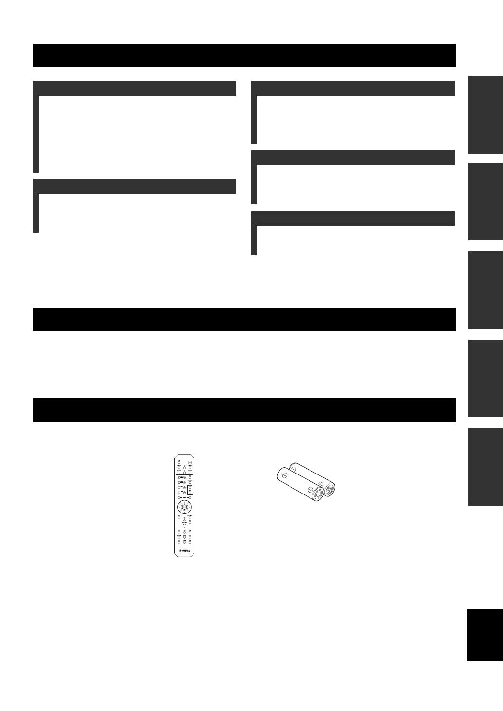
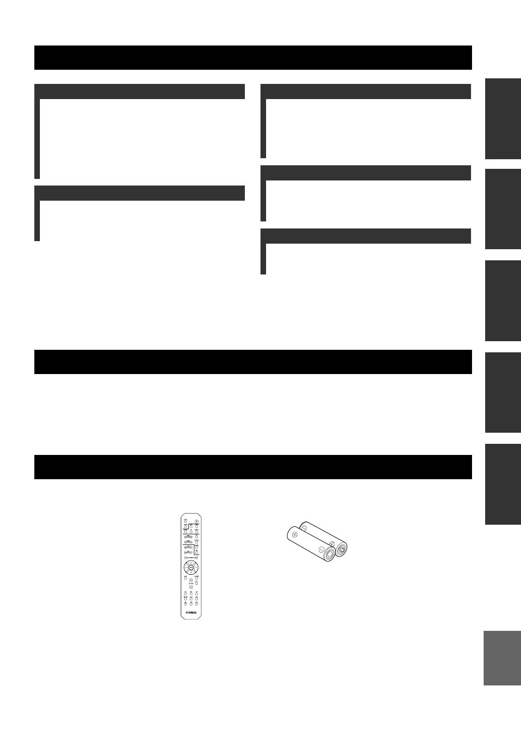
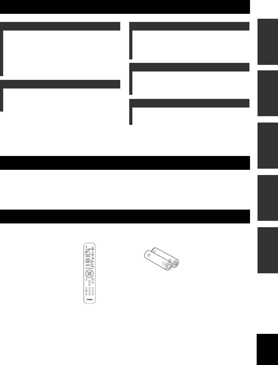
Please check that you received all of the following parts.
CONTENTS
INTRODUCTION
PREPARATION
BASIC OPERATION
ADVANCED OPERATION
ADDITIONAL INFORMATION
USEFUL FEATURES
SUPPLIED ACCESSORIES
Remote control Batteries (x2)
(AA, R6, UM-3)
2 En
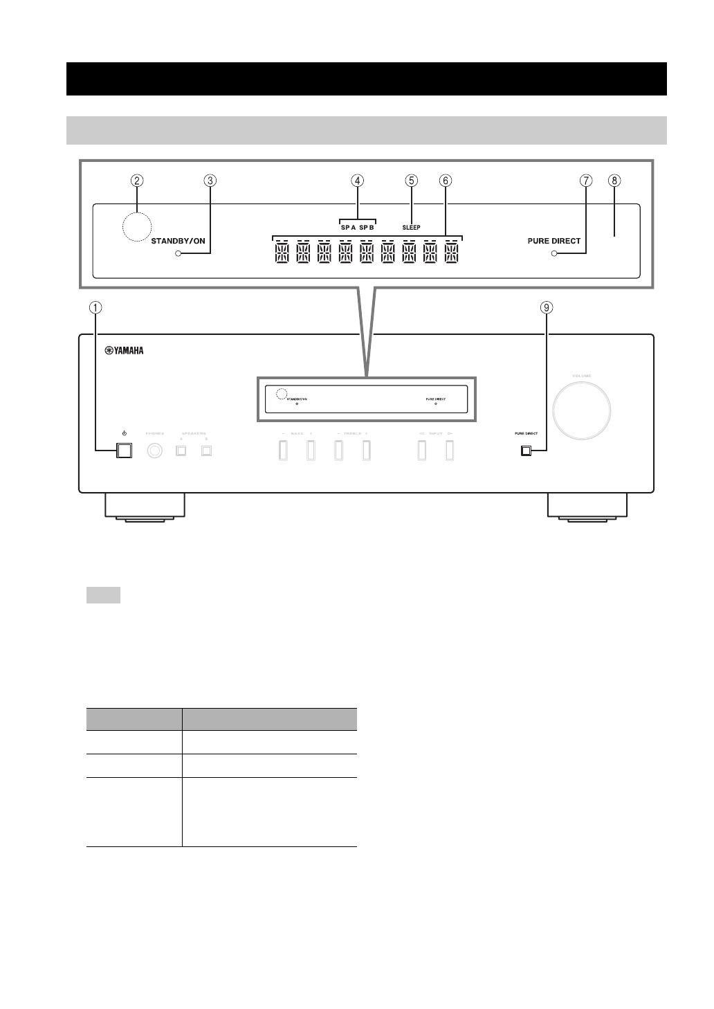
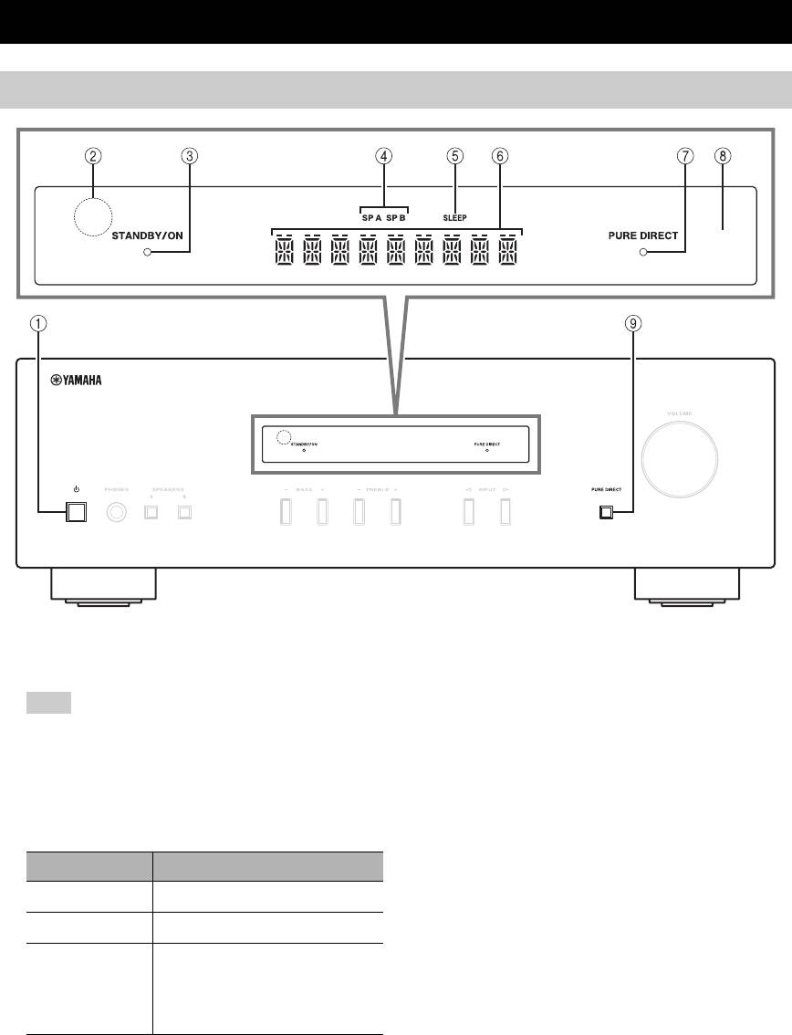
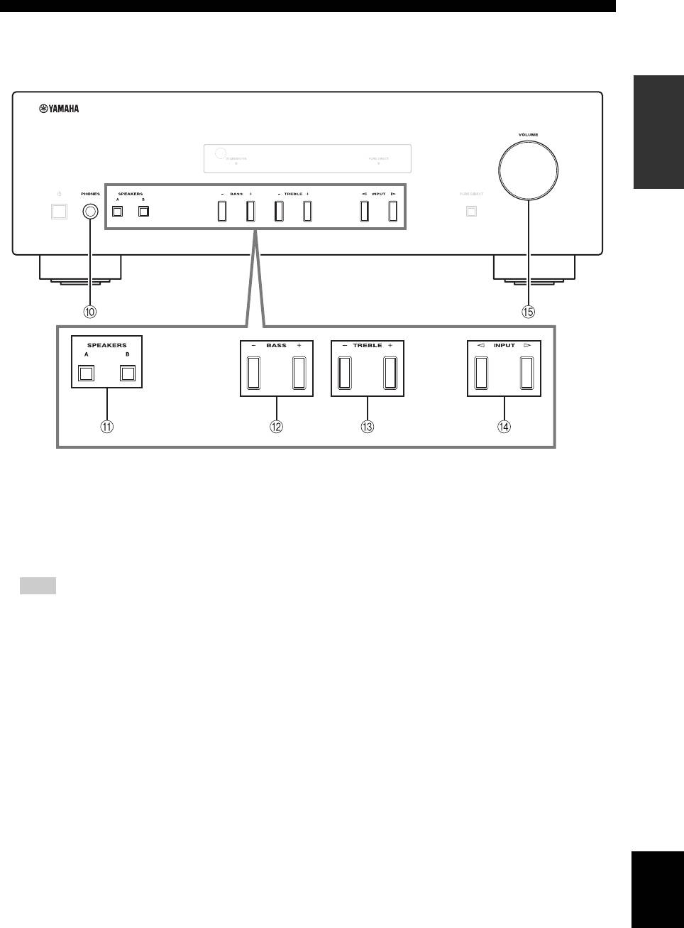
INTRODUCTION
1 A (power)
Turns this unit on, or sets it to standby mode.
This unit consumes a small amount of power even when in
standby mode.
2 Remote control sensor
Receives infrared signals from the remote control.
3 STANDBY/ON indicator
4 SP (SPEAKERS) A/B indicators
Light up according to the set of speakers selected.
Both indicators light up when both sets of speakers are
selected.
5 SLEEP indicator
Lights up when the sleep timer is turned on (see
page 11).
6 Multi-information display
Shows information when adjusting or changing
settings.
7 PURE DIRECT indicator
Lights up when the Pure Direct function is on.
8 Front panel display
Shows information about the operational status of this
unit.
9 PURE DIRECT button
Reproduces any input source in the purest sound
possible. (see page 11).
CONTROLS AND FUNCTIONS
Front panel
Note
Indicator Status
Brightly lit
The power of this unit is “on”.
Dimly lit
This unit is in “standby” mode.
Off
The power of this unit is “off”.
To turn off this unit, disconnect
the power cable from an AC
wall outlet.
CONTROLS AND FUNCTIONS
3 En
INTRODUCTION
English
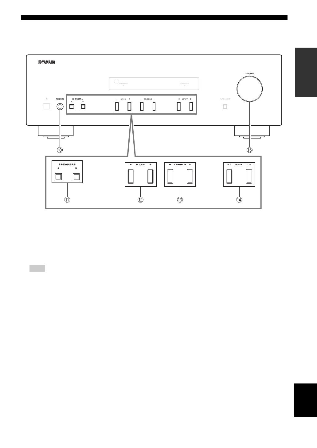
0 PHONES jack
Outputs audio to your headphones for private
listening.
Press SPEAKERS A/B so that the SP A/B indicators (see
page 2) turn off before you connect your headphones to the
PHONES jack.
A SPEAKERS A/B
Turns on or off the speaker set connected to the
SPEAKERS A and/or SPEAKERS B terminals on the
rear panel each time the corresponding button is
pressed (see page
10
).
B BASS –/+
Increases or decreases the low frequency response.
Control range: –10 dB to +10 dB
C TREBLE –/+
Increases or decreases the high frequency response.
Control range: –10 dB to +10 dB
D INPUT l / h
Selects the input source you want to listen to.
E VOLUME control
Increases or decreases the sound output level.
Note

CONTROLS AND FUNCTIONS
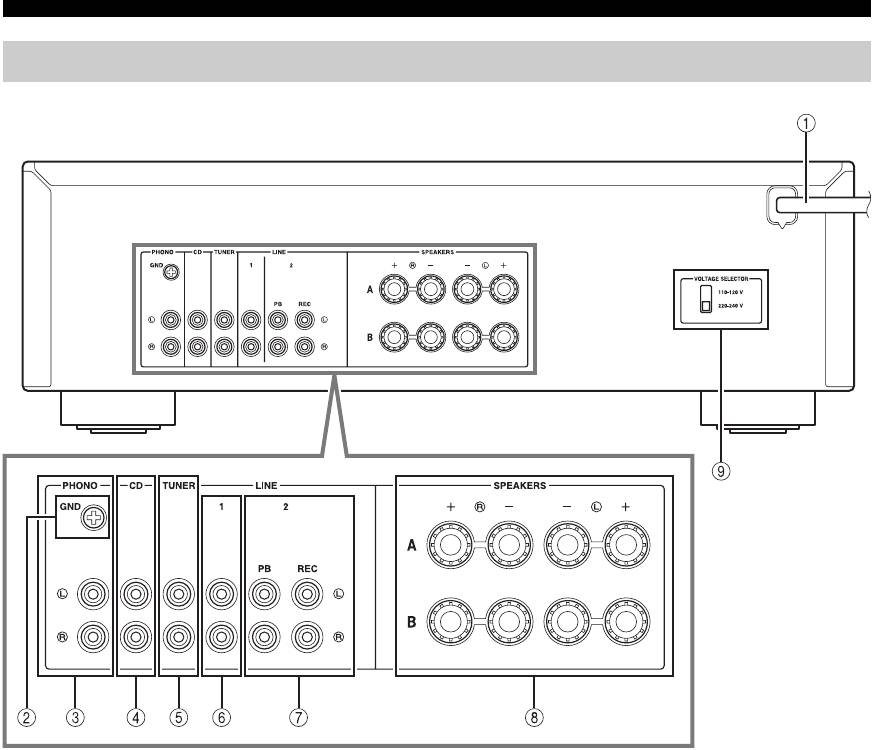
4 En
1 Power cable
For connecting this unit to an AC wall outlet (see
page 9).
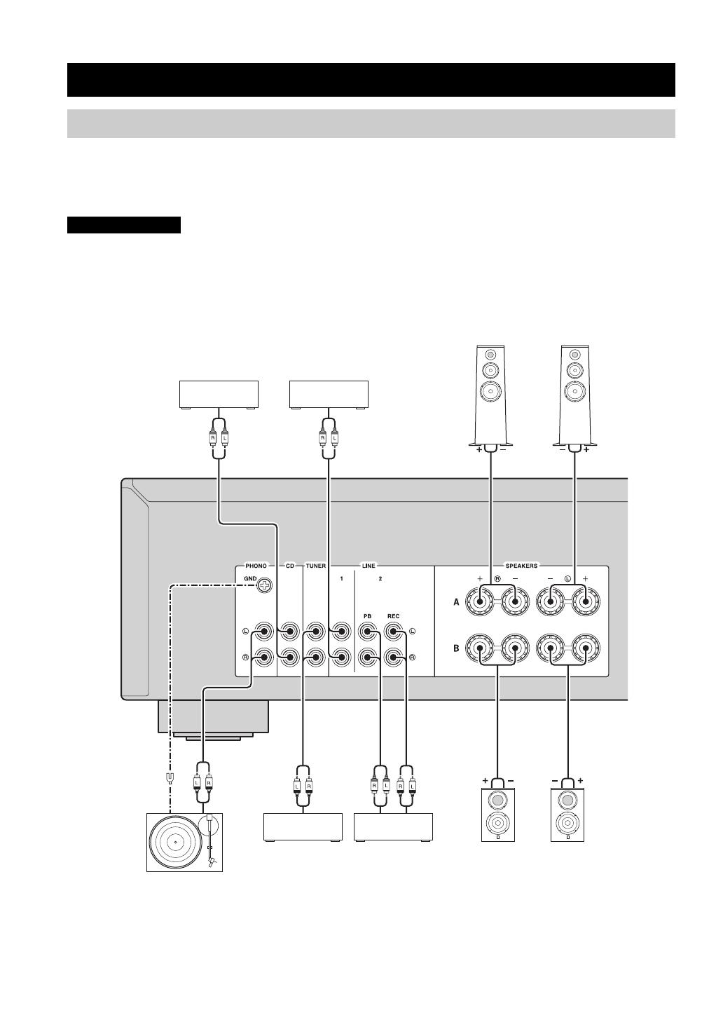
2 GND terminal
Used to connect a turntable (see page 8).
3 PHONO jacks
Used to connect a turntable (see page 8).
4 CD jacks
Used to connect a CD player (see page 8).
5 TUNER jacks
Used to connect a tuner (see page 8).
6 LINE 1 jacks
Used to connect audio components (see page 8).
7 LINE 2 jacks
PB (Playback) jacks
Used to connect to audio output jacks of an audio
component.
REC (Recording) jacks
Used to connect to audio input jacks of an audio
component.
8 SPEAKERS terminals
Used to connect speakers (see page 8).
9 VOLTAGE SELECTOR (Only for General
model)
Rear panel
CONTROLS AND FUNCTIONS
5 En
INTRODUCTION
English
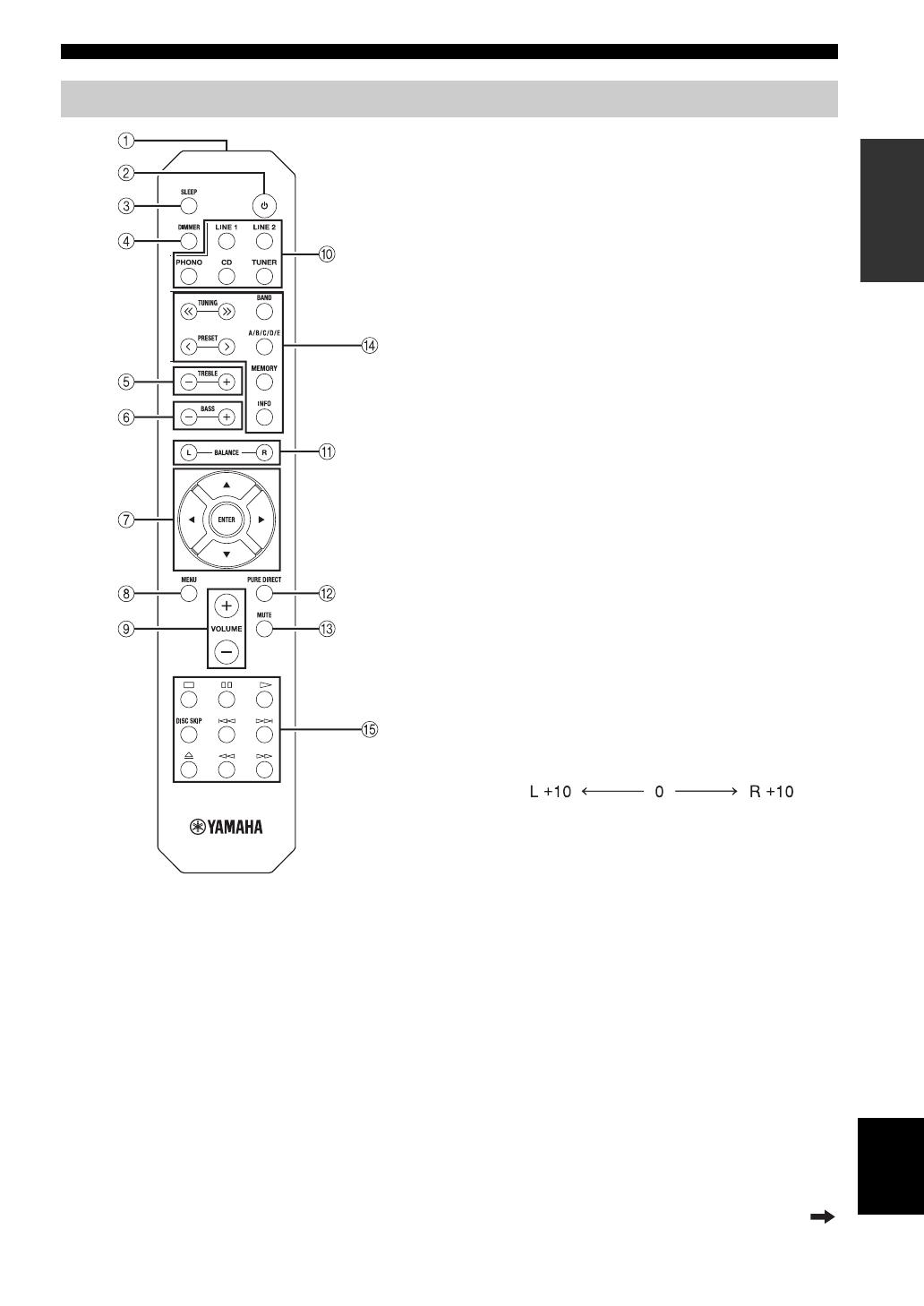
■ Common controls
The following parts and controls can be used no matter
which input source is selected.
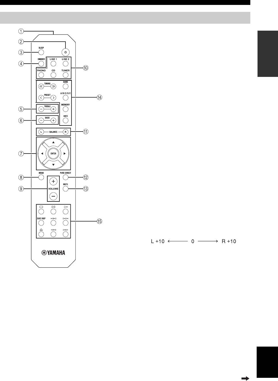
1 Infrared signal transmitter
Sends infrared signals.
2
A (power)
Turns this unit on, or sets it to standby mode.
3 SLEEP
Sets the sleep timer (see page 11).
4 DIMMER
Select the brightness level of the front panel display
from 3 levels by pressing this button repeatedly.
y
• This setting is retained even if you turn off this unit.
• The default setting is the brightest.
5 TREBLE –/+
Increases or decreases the high frequency response.
Control range: –10 dB to +10 dB
6 BASS –/+
Increases or decreases the low frequency response.
Control range: –10 dB to +10 dB
7 B / C / D / E / ENTER
Selects and confirms items in the Option menu (see
page 12).
8 MENU
Turns the Option menu on and off (see page 12).
9 VOLUME +/–
Increases or decreases the sound output level.
0 Input selector buttons
Select the input source you want to listen to.
y
The input source names correspond to the names of the
connection jacks on the rear panel.
A BALANCE L/R
Adjusts the sound output balance of the left and right
speakers to compensate for sound imbalances.
Control range:
B PURE DIRECT button
Reproduces any input source in the purest sound
possible (see page 11).
C MUTE
Mutes the sound output. Press again to restore the
sound output to the previous volume level.
Remote control
(+20 dB) (center) (+20 dB)
The opposite side of
channel is muted.
The opposite side of
channel is muted.
Continued to the next page.

CONTROLS AND FUNCTIONS
6 En
■ Yamaha tuner control buttons
The following buttons can be used to control various
functions of a Yamaha tuner.
D TUNING jj / ii
Selects the tuning frequency.
A/B/C/D/E, PRESET j / i
Selects a preset FM/AM station.
A/B/C/D/E: Selects the preset group from A to E.
PRESET j / i: Selects the preset number.
BAND
Selects the reception band (FM/AM).
MEMORY
Stores the current FM/AM station as a preset.
INFO
Only for Europe model:
Switches information shown on the front panel
display.
Even when using a Yamaha tuner, certain components and
features may not be available. Refer to your component’s owner’s
manual for more information.
■ Yamaha CD player controls
The following buttons can be used to control a Yamaha
CD player.
E Yamaha CD player control buttons
s Stops playback
e Pauses playback
p Starts playback
DISC SKIP Skips to the next disc in a CD changer
b Skips backward
a Skips forward
Ejects the disc
w Rewinds playback
f Fast-forwards playback
Even when using a Yamaha CD player, certain components and
features may not be available. Refer to your component’s owner’s
manual for more information.
Note
Note
CONTROLS AND FUNCTIONS
7 En
INTRODUCTION
English
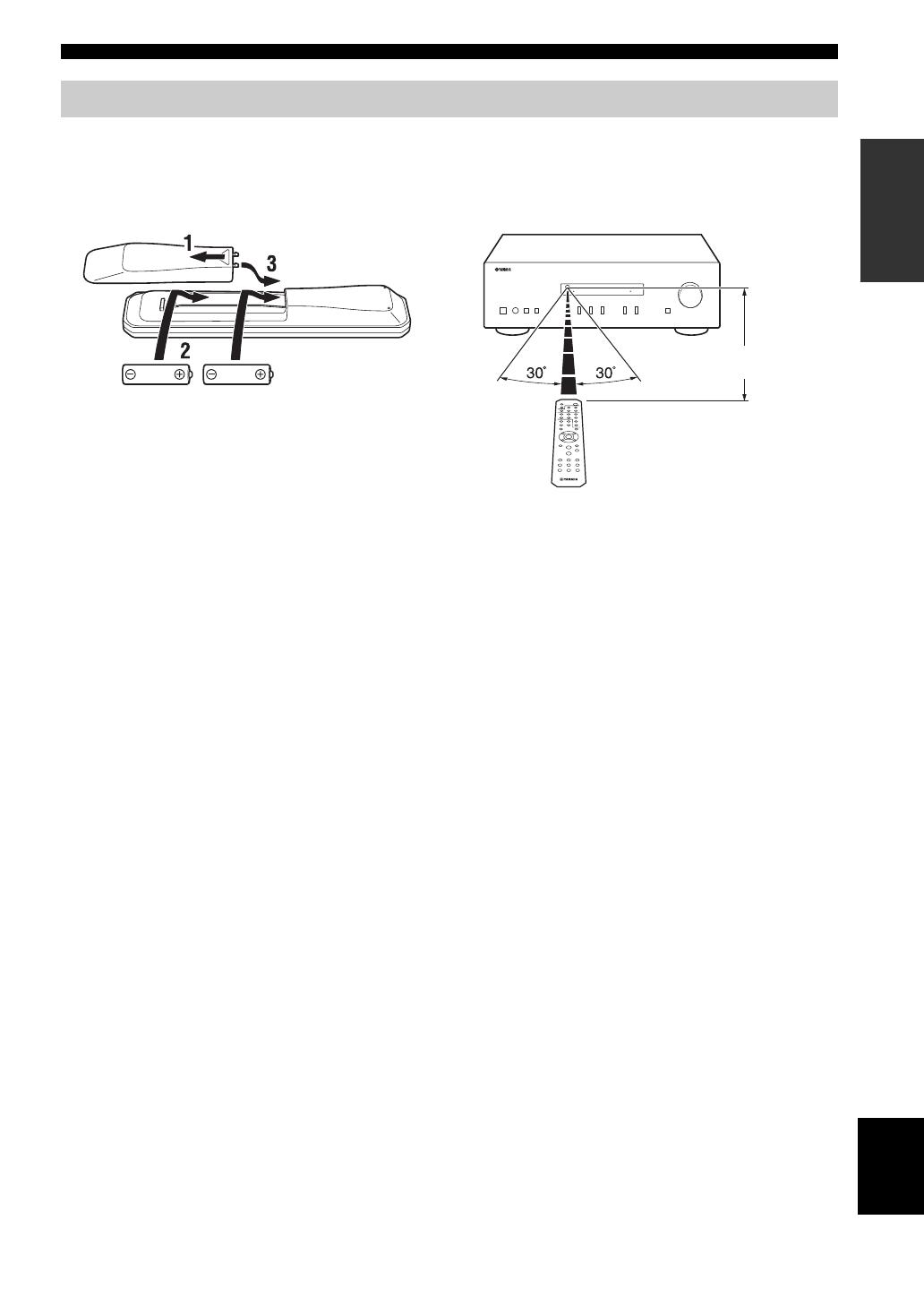
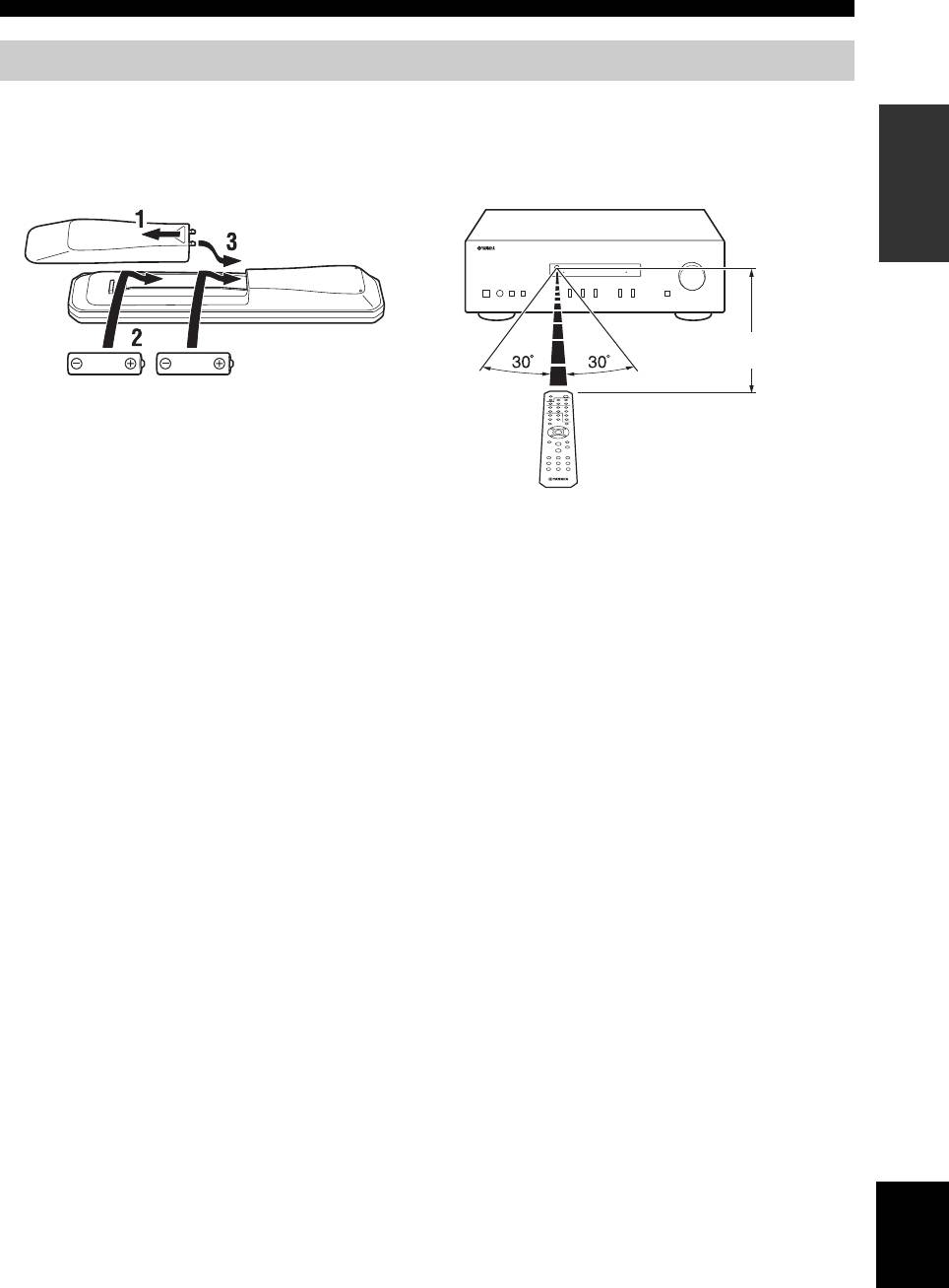
■ Installing batteries ■ Operation range
Point the remote control at the remote control sensor on
this unit and remain within the operating range shown
below.
■ Notes on remote control and batteries
• The area between the remote control and this unit must be clear of large obstacles.
• Be careful not to spill water or other liquids on the remote control.
• Be careful not to drop the remote control.
• Do not leave or store the remote control in the following conditions:
– places of high humidity, such as near a bathroom
– places of high temperatures, such as near a heater or stove
– places of extremely low temperatures
– dusty places
• Change all batteries if you notice the operation range of the remote control narrows.
• If the batteries run out, immediately remove them from the remote control to prevent an explosion or acid leak.
• If you find leaking batteries, discard the batteries immediately, taking care not to touch the leaked material. If the leaked material
comes into contact with your skin or gets into your eyes or mouth, rinse it away immediately and consult a doctor. Clean the battery
compartment thoroughly before installing new batteries.
• Do not use old batteries together with new ones. This may shorten the life of the new batteries or cause old batteries to leak.
• Do not use different types of batteries (such as alkaline and manganese batteries) together. Batteries that look the same may have a
different specification.
• Before inserting new batteries, wipe the battery compartment clean.
• Dispose of batteries according to your regional regulations.
• Keep the batteries in a location out of reach of children.
Batteries can be dangerous if a child were to put in his or her mouth.
• If you plan not to use this unit for a long period of time, remove the batteries from this unit. Otherwise, the batteries will wear out,
possibly resulting in a leakage of battery liquid that may damage this unit.
Using the remote control
AA, R6, UM-3 batteries
Approximately
6 m
Remote control
8 En
PREPARATION
Make sure to connect L (left) to L, R (right) to R, “+” to “+” and “–” to “–”. If the connections are faulty, no sound will
be heard from the speakers, and if the polarity of the speaker connections is incorrect, the sound will be unnatural and
lack bass. Refer to the owner’s manual for each of your components.
Make sure to use RCA cables to connect audio components.
• Do not connect this unit or other components to the main power until all connections between components are
complete.
• Do not let bare speaker wires touch each other or any metal part of this unit. This could damage this unit and/or the
speakers.
y
• The PHONO jacks are designed for connecting a turntable with an MM cartridge.
• Connect your turntable to the GND terminal to reduce noise in the signal. However, for some turntables, you may hear less noise
without the GND connection.
CONNECTIONS
Connecting speakers and source components
CAUTION
CD recorder,
etc.
Tuner
Speakers A
Speakers B
DVD player, etc.CD player
Turntable
Audio
out
Audio
out
Audio
out
Audio
out
Audio
in
Audio
out
GND
LeftRight
LeftRight
9 En
CONNECTIONS
PREPARATION
English
■ REC jacks
• The REC jacks output audio signals of the currently
selected input (except when LINE 2 is selected).
• Volume level, tone control, balance and Pure Direct
settings do not affect the REC jacks.
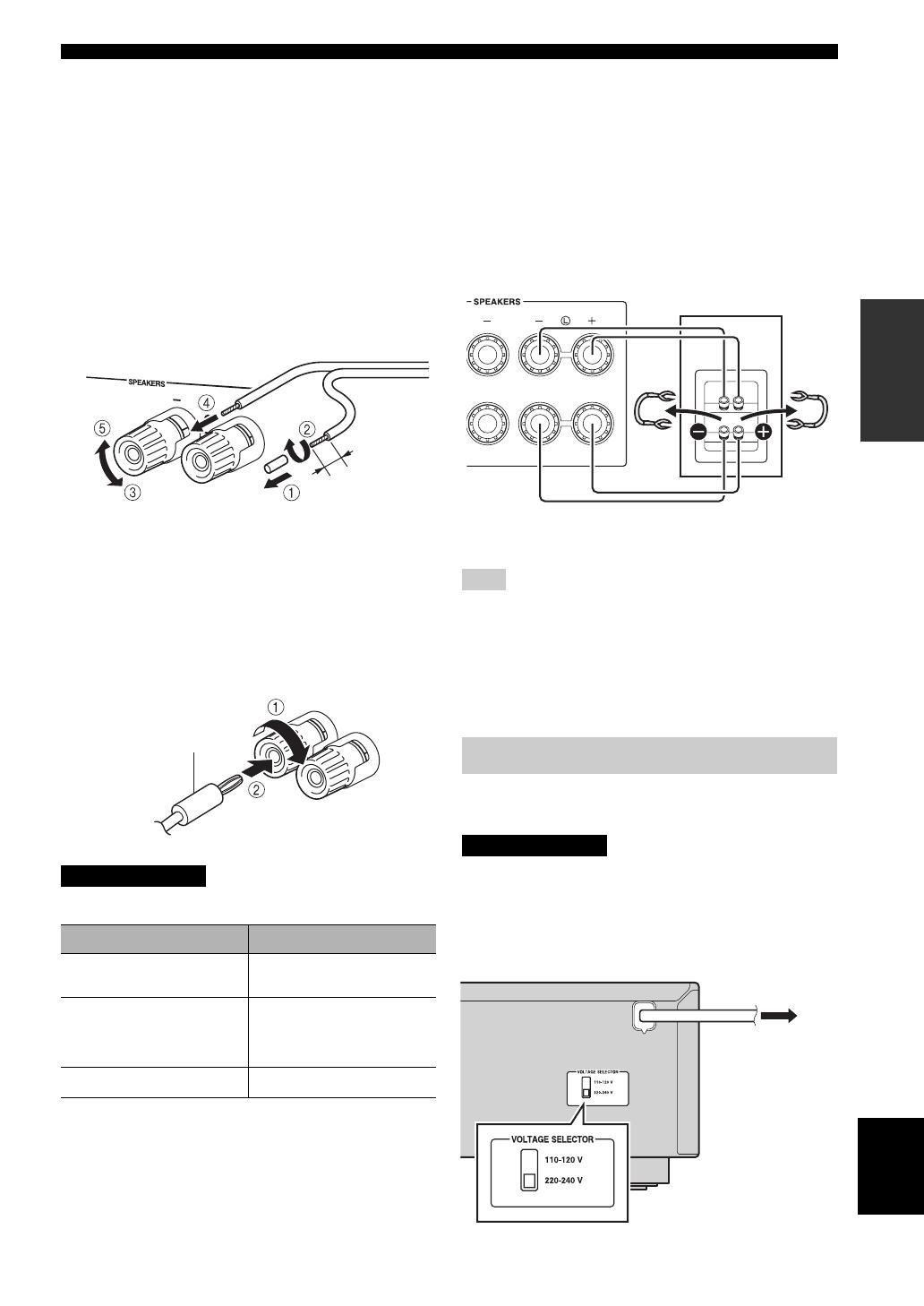
■ Connecting speaker cables
1 Remove approximately 10 mm of insulation from the
end of each speaker cable.
2 Twist the bare wires of the cable firmly together.
3 Unscrew the knob.
4 Insert one bare wire into the hole in the side of each
terminal.
5 Tighten the knob to secure the wire.
■ Connecting via banana plug
(Except for Asia, U.K. and Europe
models)
1 Tighten the knob.
2 Insert the banana plug into the end of the
corresponding terminal.
Speaker impedance must be set as shown below.
■ Bi-wire connection
Bi-wire connection separates the woofer from the
combined midrange and tweeter section.
A bi-wire compatible speaker has four binding post
terminals. These two sets of terminals allow the speaker to
be split into two independent sections. With these
connections, the mid and high frequency drivers are
connected to one set of terminals and the low frequency
driver to another set of terminals.
Connect the other speaker to the other set of terminals in
the same way.
When making bi-wire connections, remove the shorting bridges
or cables on the speaker.
y
To use the bi-wire connections, press SPEAKERS A and
SPEAKERS B on the front panel so that both SP A and B light up
on the front panel display.
Plug the power cable into an AC wall outlet after all other
connections are complete.
Only for General model:
Before connecting the power cable, make sure you set
VOLTAGE SELECTOR of this unit according to your
local voltage. Improper setting of VOLTAGE SELECTOR
may cause fire and damage to this unit.
CAUTION
Speaker connection Speaker impedance
SPEAKERS A or
SPEAKERS B
8 Ω or higher
SPEAKERS A and
SPEAKERS B
16 Ω or higher
(except for North
America model)
Bi-wiring
8 Ω or higher
Red: positive (+)
Black: negative (–)
Banana plug
Note
Connecting power cable
CAUTION
Rear panel
Speaker
To the AC wall
outlet with the
power cable
10 En
BASIC OPERATION
1 Press A (power) to turn on this unit.
2 Press one of the Input selector buttons to
select the desired input source.
3 Press SPEAKERS A and/or SPEAKERS B on
the front panel to select desired speaker(s).
• When one set of speakers is connected using bi-wire
connections, or when using two sets of speakers simultaneously
(A and B), make sure SP A and SP B are displayed on the front
panel display.
• When listening with headphones, turn off the speakers.
4 Play the source.
5 Press VOLUME +/– to adjust the sound
output level.
y
You can adjust the tonal quality by using BASS –/+,
TREBLE –/+, and the left/right sound balance of speakers
by using BALANCE L/R (see page 5).
6 When finished listening, press A (power) to
set this unit to standby mode.
Press A (power) to turn this unit on again.
y
• You can also use the buttons or knobs on the front panel if they
have the same or similar names as those on the remote control.
• For recording, see page 4.
PLAYBACK
Playing a source
A (power)
Input selector
buttons
VOLUME +/–
TREBLE –/+
BASS –/+
BALANCE L/R
SPEAKERS A/B
Notes
11 En
PLAYBACK
BASIC
OPERATION
English
The Pure Direct function bypasses unnecessary circuitry
in this unit to reduce electrical noise when playing the
selected source. This allows you to enjoy high fidelity
sound quality.
The PURE DIRECT indicator lights up and the front panel
display turns off after a few seconds.
The BASS, TREBLE, and BALANCE controls do not function
while the PURE DIRECT feature is turned on.
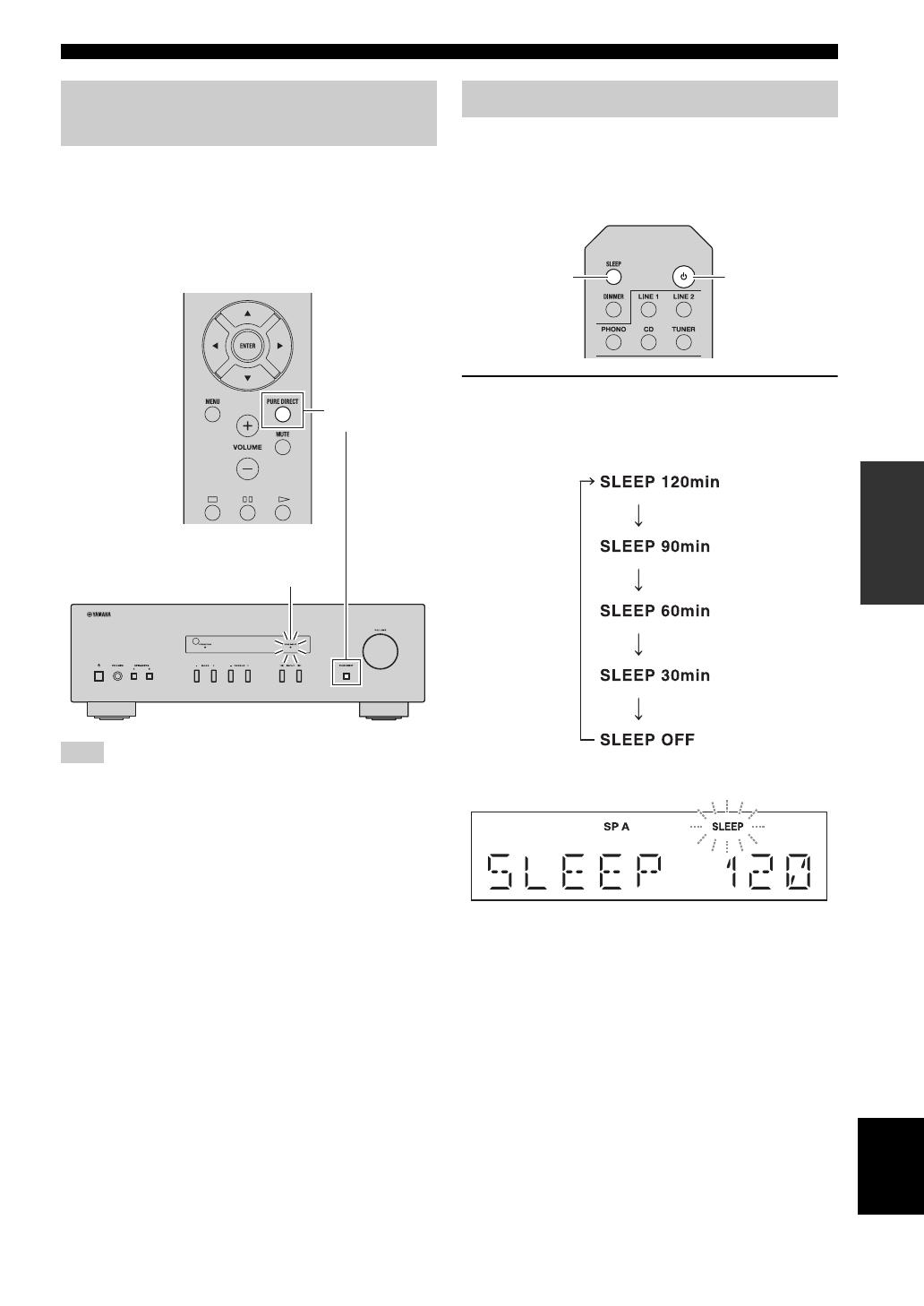
Use this feature to automatically set this unit to standby
mode after a certain amount of time. The sleep timer is
useful when you are going to sleep while this unit is
playing or recording a source.
Press SLEEP repeatedly to set the amount of
time before this unit is set to standby mode.
Each time you press SLEEP, the front panel display
changes cyclically as shown below.
The SLEEP indicator blinks while setting the amount
of time for the sleep timer.
If the sleep timer is set, the SLEEP indicator on the
front panel display lights up.
y
To cancel the sleep timer, do one of the following:
– Select “SLEEP OFF”.
– Set this unit to standby mode.
Enjoying pure, high fidelity sound
(Pure Direct)
Note
PURE DIRECT
button
PURE DIRECT indicator
Using the sleep timer
A (power)
SLEEP
12 En
ADVANCED OPERATION
The Option menu allows you to configure various settings for each input source and recall those settings automatically
when an input source is selected.
1 Press one of the Input selector buttons to
select the desired input source.
2 Press MENU.
3 Press B / C to select the desired menu item,
and then press ENTER.
4 Press B / C to change the settings.
y
• For certain menu items, you must press ENTER to save
the new setting.
• To return to the screen where you can select menu items,
press D.
5 To exit the Option menu, press MENU.
y
The default settings are marked with “*”.
SETTING THE OPTION MENU FOR EACH INPUT SOURCE
Input selector
buttons
MENU
B / C / D
ENTER
Option menu items
Menu item Description
MAX VOL Sets the maximum volume level so that the volume will not be accidentally increased above a
certain level.
Adjustable range: 01 to 99, MAX*
INITIAL VOLUME (INIT VOL) Sets the volume at the time this unit is turned on. When this parameter is set to “OFF”, the
volume level used when this unit was set to standby is applied.
Adjustable range: OFF*, MUTE, 01 to 99, MAX
AUTO POWER STANDBY
(AUTO STBY)
Sets this unit to standby mode automatically if no operation is performed in the specified time.
Choices: OFF/2H/4H/8H*/12H
13 En
ADDITIONAL
INFORMATION
English
ADDITIONAL INFORMATION
Refer to the chart below if this unit does not function properly. If the problem you are experiencing is not listed below or
if the instructions below do not help, set this unit to standby mode, disconnect the power cable, and then contact the
nearest authorized Yamaha dealer or service center.
■ General
TROUBLESHOOTING
Problem Cause Remedy
See
page
This unit fails to turn
on.
The power cable is not connected or the
plug is not completely inserted.
Connect the power cable firmly.
—
The impedance setting of the connected
speaker is too small.
Use speaker(s) with proper speaker impedance.
9
The protection circuitry has been activated
because of a short circuit, etc.
Check that the speaker wires are not touching each
other and then turn the power of this unit back on.
8
This unit has been exposed to a strong
external electric shock (such as lightning
or strong static electricity).
Set this unit to standby mode, disconnect the power
cable, plug it back in after 30 seconds, then use it
normally.
—
No sound Incorrect input or output cable
connections.
Connect the cables properly. If the problem persists,
the cables may be defective.
8
No appropriate input source has been
selected.
Select an appropriate input source by pressing one of
the Input selector buttons on the remote control
(INPUT l / h on the front panel).
10
The SPEAKERS A/B switches are not set
properly.
Turn on the corresponding SPEAKERS A or
SPEAKERS B.
10
Speaker connections are not secure. Secure the connections.
8
Output has been muted. Deactivate the mute function.
5
The MAX VOL or INITIAL VOLUME
setting is set too low.
Set the setting to a higher value.
12
The component corresponding to the
selected input source is turned off or is not
playing.
Turn the component on and make sure it is playing.
—
The sound suddenly
goes off.
The protection circuitry has been activated
because of a short circuit, etc.
Check that the speaker wires are not touching each
other and then turn the power of this unit back on.
8
This unit has become too hot. Make sure the openings on the top panel are not
blocked.
—
The AUTO POWER STANDBY or
SLEEP function has set this unit to
standby mode.
Change the AUTO POWER STANDBY setting to a
longer setting or OFF from the Option menu by
pressing MENU.
12
Only the speaker on
one side can be
heard.
Incorrect cable connections. Connect the cables properly. If the problem persists,
the cables may be defective.
8
Incorrect setting for the BALANCE L/R
setting.
Set the BALANCE L/R setting to the appropriate
position.
5
There is a lack of bass
and no ambience.
The + and – wires are connected in
reverse at the amplifier or the speakers.
Connect the speaker wires to the correct + and –
phase.
8
A “humming” sound
can be heard.
Incorrect cable connections. Connect the audio plugs firmly. If the problem
persists, the cables may be defective.
8
No connection from the turntable to the
GND terminal.
Make the GND connection between the turntable and
this unit.
8

14 En
TROUBLESHOOTING
The volume level
cannot be increased,
or the sound is
distorted.
The component connected to the LINE 2
PB/REC jacks of this unit is turned off.
Turn on the power of the component.
—
The sound is
degraded when
listening with
headphones
connected to a CD
player connected to
this unit.
This unit has been set to standby mode. Turn on the power of this unit.
10
The BASS, TREBLE
and BALANCE
settings do not
applied to the sound.
The PURE DIRECT function is turned on. The PURE DIRECT function must be turned off to
apply these settings to the sound.
11
The remote control
does not work nor
function properly.
Wrong distance or angle. The remote control will function within a maximum
range of 6 m and no more than 30 degrees off-axis
from the front panel.
7
Direct sunlight or lighting (from an
inverter type of fluorescent lamp, etc.) is
striking the remote control sensor of this
unit.
Reposition this unit.
—
The batteries are weak. Replace all batteries.
7
Your tuner and/or CD
player cannot be
operated with the
remote control.
The remote control does not support the
tuner and/or CD player.
Refer to the owner’s manual supplied with the tuner
and/or CD palyer.
—
“OVER HEAT”
appears on the front
panel display.
This unit has become too hot. Make sure the openings on the top panel are not
blocked.
—
“CHECK SP” appears
on the front panel
display.
Speaker cables got shorted out. Twist bare wires of speaker cables firmly, and then
connect to this unit and speakers properly.
—
Problem Cause Remedy
See
page
15 En
ADDITIONAL
INFORMATION
English
AUDIO SECTION
• Minimum RMS output power
(8 Ω, 40 Hz to 20 kHz, 0.2% THD)
[General, Korea, Australia, U.K. and Europe models]
………………….…………………………………………..… 100 W + 100 W
[China and Asia models] ……………..………………… 85 W + 85 W
• Dynamic power per channel (IHF) (8/6/4/2 Ω)
[General, Korea, Australia, U.K. and Europe models]
………………….…………………………… 125 W/150 W/165 W/180 W
• Maximum power per channel
(4 Ω, 1 kHz, 0.7% THD)
[U.K. and Europe models]………………………………………….115 W
• Input sensitivity/Input impedance (1 kHz, 100 W/8 Ω)
PHONO (MM) …………………………..………………… 10.0 mV/47 kΩ
CD, etc. ………..…………………..…………………………. 500 mV/47 kΩ
• Output level/Output impedance
CD, etc. (Input 1 kHz, 500 mV)
REC ………………………………………………………… 500 mV/2.2 kΩ
CD, etc. (Input 1 kHz, 500 mV, 8 Ω)
PHONES ……….……………………….…………………. 470 mV/470 Ω
• Frequency response
CD, etc. (20 Hz to 20 kHz) ….………………………………… 0 ± 0.5 dB
CD, etc. (10 Hz to 100 kHz) ..………………………………… 0 ± 3.0 dB
• RIAA equalization deviation
PHONO (MM) …………………………..…………………………… ± 0.5 dB
• Total harmonic distortion
PHONO (MM) to REC (20 Hz to 20 kHz, 2 V) …. 0.025% or less
CD, etc. to SPEAKERS
(20 Hz to 20 kHz, 50 W, 8 Ω) ….……………………….…. 0.2% or less
• Signal to noise ratio (IHF-A network)
PHONO (MM) (10 mV input shorted) ………………. 75 dB or more
CD, etc. (500 mV input shorted) ….…………………. 100 dB or more
• Residual noise (IHF-A network) …………….………………………. 70 µV
• Tone control characteristics
BASS
Boost/Cut (50 Hz) …………..……………………………………. ± 10 dB
TREBLE
Boost/Cut (20 kHz) ………………………………………………. ± 10 dB
GENERAL
• Power supply
[General model] ……………….... AC 110-120/220-240 V, 50/60 Hz
[China model]………..……………………….……………. AC 220 V, 50Hz
[Korea model] ……………………………………………….AC 220 V, 60Hz
[Australia model] ……………………………………….. AC 240 V, 50 Hz
[U.K. and Europe models] …………………………… AC 230 V, 50 Hz
[Asia model] …….……………………….……. AC 220-240 V, 50/60 Hz
• Power consumption
[General, Korea, Australia, U.K. and Europe models]
………………….…………………………………………..……………… 175 W
[China and Asia models] ..……………………….…………………. 140 W
• Standby power consumption
[China, Korea, Australia, U.K., Europe and Asia models]
………………….…………………………………………..…….. 0.5 W or less
• Dimensions (W × H × D) ….………………………. 435 × 141 × 333 mm
• Weight ………………………..………………………………………………. 6.7 kg
* Specifications are subject to change without notice.
SPECIFICATIONS
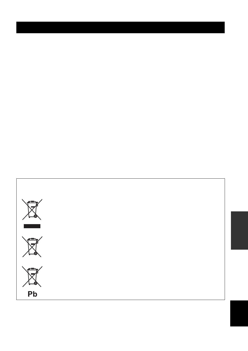
Information for Users on Collection and Disposal of Old Equipment
and Used Batteries
These symbols on the products, packaging, and/or accompanying documents mean that used electrical and
electronic products and batteries should not be mixed with general household waste.
For proper treatment, recovery and recycling of old products and used batteries, please take them to
applicable collection points, in accordance with your national legislation and the Directives 2002/96/EC
and 2006/66/EC.
By disposing of these products and batteries correctly, you will help to save valuable resources and prevent
any potential negative effects on human health and the environment which could otherwise arise from
inappropriate waste handling.
For more information about collection and recycling of old products and batteries, please contact your
local municipality, your waste disposal service or the point of sale where you purchased the items.
[Information on Disposal in other Countries outside the European Union]
These symbols are only valid in the European Union. If you wish to discard these items, please contact
your local authorities or dealer and ask for the correct method of disposal.
Note for the battery symbol (bottom two symbol examples):
This symbol might be used in combination with a chemical symbol. In this case it complies with the
requirement set by the Directive for the chemical involved.
ATTENTION : VEUILLEZ LIRE CE QUI SUIT AVANT D’UTILISER L’APPAREIL.
i Fr
1 Pour utiliser l’appareil au mieux de ses possibilités, lisez
attentivement ce mode d’emploi. Conservez-le
soigneusement pour référence.
2 Installez cet ensemble audio dans un endroit bien aéré,
frais, sec et propre — veillez à ce qu’il soit à l’abri de la
lumière directe du soleil, des sources de chaleur, des
vibrations, des poussières, de l’humidité et/ou du froid.
Pour une ventilation correcte, ménagez l’espace
minimum suivant autour de cet appareil.
Au-dessus : 30 cm
À l’arrière : 20 cm
Sur les côtés : 20 cm
3 Placez l’appareil loin des équipements, moteurs et
transformateurs électriques, pour éviter les ronflements
parasites.
4 N’exposez pas l’appareil à des variations brutales de
température, ne le placez pas dans un environnement très
humide (par exemple dans une pièce contenant un
humidificateur) car cela peut entraîner la condensation
d’humidité à l’intérieur de l’appareil qui elle-même peut
être responsable de décharge électrique, d’incendie, de
dommage à l’appareil ou de blessure corporelle.
5 Evitez d’installer l’appareil dans un endroit où des objets
peuvent tomber, ainsi que là où l’appareil pourrait être
exposé à des éclaboussures ou des gouttes d’eau. Sur le
dessus de l’appareil, ne placez pas :
– d’autres appareils qui peuvent endommager la surface
de l’appareil ou provoquer sa décoloration.
– des objets se consumant (par exemple, une bougie)
qui peuvent être responsables d’incendie, de
dommage à l’appareil ou de blessure corporelle.
– des récipients contenant des liquides qui peuvent être
à l’origine de décharge électrique ou de dommage à
l’appareil.
6 Ne couvrez pas l’appareil d’un journal, d’une nappe, d’un
rideau, etc. car cela empêcherait l’évacuation de la
chaleur. Toute augmentation de la température intérieure
de l’appareil peut être responsable d’incendie, de
dommage à l’appareil ou de blessure corporelle.
7 Ne branchez pas la fiche du câble d’alimentation de
l’appareil sur une prise secteur aussi longtemps que tous
les raccordements n’ont pas été effectués.
8 Ne pas faire fonctionner l’appareil à l’envers. Il risquerait
de chauffer et d’être endommagé.
9 N’exercez aucune force excessive sur les commutateurs,
les boutons et les cordons.
10 Pour débrancher la fiche du câble d’alimentation au
niveau de la prise secteur, saisissez la fiche et ne tirez pas
sur le cordon.
11 Ne nettoyez pas l’appareil au moyen d’un solvant
chimique, ce qui pourrait endommager la finition.
Utilisez un chiffon sec et propre.
12 N’alimentez l’appareil qu’à partir de la tension prescrite.
Alimenter l’appareil sous une tension plus élevée est
dangereux et peut être responsable d’incendie, de
dommage à l’appareil ou de blessure corporelle. Yamaha
ne saurait être tenue responsable des dommages résultant
de l’alimentation de l’appareil sous une tension autre que
celle prescrite.
13 Pour empêcher tout dommage causé par les éclairs,
déconnectez le câble d’alimentation et toute antenne
extérieure de la prise murale pendant un orage.
14 Ne tentez pas de modifier ni de réparer l’appareil.
Consultez le service Yamaha compétent pour toute
réparation qui serait requise. Le coffret de l’appareil ne
doit jamais être ouvert, quelle que soit la raison.
15 Si vous envisagez de ne pas vous servir de l’appareil
pendant une longue période (par exemple, pendant les
vacances), débranchez la fiche du câble d’alimentation au
niveau de la prise secteur.
16 Lisez la section intitulée « GUIDE DE DÉPANNAGE »
où figurent une liste d’erreurs de manipulation
communes avant de conclure que l’appareil présente une
anomalie de fonctionnement.
17 Avant de déplacer l’appareil, appuyez sur
A (alimentation) pour mettre l’appareil en mode veille,
puis débranchez la fiche du cordon d’alimentation au
niveau de la prise secteur.
18 La condensation se forme lorsque la température
ambiante change brusquement. En ce cas, débranchez la
fiche du câble d’alimentation et laissez l’appareil reposer.
19 La température de l’appareil peut augmenter en raison
d’une utilisation prolongée. En ce cas, coupez
l’alimentation de l’appareil et laissez-le au repos pour
qu’il refroidisse.
20 Installez cet appareil à proximité de la prise secteur et à
un emplacement où la fiche du câble d’alimentation est
facilement accessible.
21 Les piles ne doivent pas être exposées à une chaleur
extrême, par exemple au soleil, à une flamme, etc.
22 Une pression excessive du son par les écouteurs et le
casque d’écoute peut entraîner la perte de l’ouïe.
Cette étiquette doit être apposée sur un produit dont le
capot supérieur peut devenir chaud lorsqu’il fonctionne.
ATTENTION : VEUILLEZ LIRE CE QUI SUIT AVANT D’UTILISER
L’APPAREIL.
Cet appareil n’est pas déconnecté du secteur tant qu’il reste
branché à la prise de courant, même si l’appareil en soi est éteint
par la touche A. Il se trouve alors « en veille ». En mode veille,
l’appareil consomme une très faible quantité de courant.
AVERTISSEMENT
POUR RÉDUIRE LES RISQUES D’INCENDIE OU DE
DÉCHARGE ÉLECTRIQUE, N’EXPOSEZ PAS CET
APPAREIL À LA PLUIE OU À L’HUMIDITÉ.
1 Fr
PRÉPARATIONINTRODUCTION
OPÉRATIONS DE
BASE
INFORMATIONS
COMPLÉMENTAIRES
OPÉRATIONS
AVANCÉES
Français
FONCTIONS UTILES…………………….…………..…. 1
ACCESSOIRES FOURNIS…….……….…………..…. 1
COMMANDES ET FONCTIONS…………….…….. 2
Panneau avant ………..………..……………………………….. 2
Panneau arrière …………………..………………………..…… 4
Télécommande….………..………………………………..…… 5
Utilisation de la télécommande ….………………………..7
RACCORDEMENTS…………..………….…………..…. 8
Raccordement des enceintes et des
composants source…..…………………………………..… 8
Raccordement du cordon d’alimentation…..……..…… 9
LECTURE ….…………..……….…………..……….………10
Lecture d’une source………………..………………………. 10
Écoutez un son pur de haute fidélité
(Pure Direct)…..………………..…………………………. 11
Utilisation de la minuterie de veille……………………. 11
PARAMÉTRAGE DU MENU OPTION POUR
CHAQUE SOURCE D’ENTRÉE….……….……12
Éléments du menu Option …..……………………………. 12
GUIDE DE DÉPANNAGE………………….………....13
CARACTÉRISTIQUES TECHNIQUES…………15
■ À propos de ce manuel
• Le symbole y attire votre attention sur un conseil d’utilisation.
• Les instructions de ce mode d’emploi décrivent les opérations de cet appareil à l’aide de la télécommande fournie avec l’appareil.
Vous pouvez également utiliser les touches ou les boutons du panneau avant s’ils portent le même nom ou un nom semblable sur la
télécommande.
Cet appareil permet d’effectuer les opérations suivantes :
◆ Écouter un son pur de haute fidélité à l’aide de la
fonction Pure Direct (voir page 11)
◆ Utiliser la télécommande de cet appareil pour
commander un syntoniseur et/ou un lecteur de CD
Yamaha (voir page 6)
◆ Économiser de l’énergie grâce à la fonction AUTO
POWER STANDBY (voir page 12)
Vérifiez que vous avez reçu tous les articles suivants.
TABLE DES MATIÈRES
INTRODUCTION
PRÉPARATION
OPÉRATIONS DE BASE
OPÉRATIONS AVANCÉES
INFORMATIONS COMPLÉMENTAIRES
FONCTIONS UTILES
ACCESSOIRES FOURNIS
Télécommande Piles (× 2)
(AA, R6, UM-3)
2 Fr
INTRODUCTION
1 A (alimentation)
Met l’appareil sous tension ou en mode veille.
Cet appareil consomme une faible quantité de courant même
lorsqu’il est en mode veille.
2 Capteur de télécommande
Reçoit les signaux infrarouges émis par la
télécommande.
3 Témoin STANDBY/ON
4 Témoins SP (SPEAKERS) A/B
S’allument en fonction du jeu d’enceintes sélectionné.
Les deux témoins s’allument lorsque les deux jeux
d’enceintes sont sélectionnés.
5 Témoin SLEEP
S’allume lorsque la minuterie de veille est activée
(voir page 11).
6 Affichage multi-informations
Affiche des informations lors du réglage ou de la
modification de certains paramètres.
7 Témoin PURE DIRECT
S’allume lorsque la fonction Pure Direct est activée.
8 Afficheur du panneau avant
Indique des informations sur l’état opérationnel de
l’appareil.
9 Touche PURE DIRECT
Pour reproduire toute source d’entrée avec le son le
plus pur possible (voir page 11).
COMMANDES ET FONCTIONS
Panneau avant
Remarque
Témoin État
Fortement
éclairé
L’alimentation de cet appareil
est « sous tension ».
Faiblement
éclairé
Cet appareil est en mode
« veille ».
Éteint
L’alimentation de cet appareil
est « hors tension ».
Pour éteindre l’appareil,
débranchez le cordon
d’alimentation de la prise
secteur.
/
Требуется руководство для вашей Yamaha A-S201 Усилитель? Ниже вы можете просмотреть и загрузить бесплатно руководство в формате PDF. Кроме того, приведены часто задаваемые вопросы, рейтинг изделия и отзывы пользователей, что позволит оптимально использовать ваше изделие. Если это не то руководство, которое вы искали, – свяжитесь с нами.
Ваше устройство неисправно, и в руководстве отсутствует решение? Перейдите в Repair Café для получения бесплатных ремонтных услуг.
Руководство

Рейтинг
Сообщите нам, что вы думаете о Yamaha A-S201 Усилитель, оставив оценку продукта. Хотите поделиться вашими впечатлениями от данного изделия или задать вопрос? Вы можете оставить комментарий в нижней части страницы.
Довольны ли вы данным изделием Yamaha?
Да Нет
2 голоса
Часто задаваемые вопросы
Наша служба поддержки выполняет поиск полезной информации по изделиям и отвечает на часто задаваемые вопросы. Если вы заметили неточность в наших часто задаваемых вопросах, сообщите нам об этом с помощью нашей контактной формы.
В чем разница между усилителем и предварительным усилителем? Проверенный
Усилитель часто представляет собой интегрированный усилитель с предварительным усилителем и усилителем мощности в одном устройстве. Предварительный усилитель регулирует громкость, а иногда и баланс и тон, и позволяет вам выбирать, какой источник используется (компакт-диск, кассета, проигрыватель винила и т. Д.). Предварительный усилитель часто обеспечивает небольшое усиление, достаточное для усилителя мощности. Это активный предварительный усилитель. Иногда предварительный усилитель не усиливает сигнал, что делает его пассивным предварительным усилителем.
Это было полезно (28)

G
G
Integrated Amplifier
Integrated Amplifier
Amplificateur Intégré
Amplificateur Intégré
OWNER’S MANUAL
OWNER’S MANUAL
MODE D’EMPLOI
MODE D’EMPLOI
BEDIENUNGSANLEITUNG
BEDIENUNGSANLEITUNG
BRUKSANVISNING
BRUKSANVISNING
MANUALE DI ISTRUZIONI
MANUALE DI ISTRUZIONI
MANUAL DE INSTRUCCIONES
MANUAL DE INSTRUCCIONES
GEBRUIKSAANWIJZING
GEBRUIKSAANWIJZING
ИНСТРУКЦИЯ ПО ЭКСПЛУАТАЦИИ
© 2013 Yamaha Corporation
Printed in Malaysia ZH10680
CAUTION: READ THIS BEFORE OPERATING YOUR UNIT.
CAUTION: READ THIS BEFORE OPERATING YOUR UNIT.
1 To assure the finest performance, please read this manual
17 Before moving this unit, press A (power) to set this unit
carefully. Keep it in a safe place for future reference.
to standby mode, and then disconnect the AC power plug
2 Install this sound system in a well ventilated, cool, dry,
from the AC wall outlet.
clean place — away from direct sunlight, heat sources,
18 Condensation will form when the surrounding
vibration, dust, moisture, and/or cold. For proper
temperature changes suddenly. Disconnect the power
ventilation, allow the following minimum clearances
cable from the outlet, then leave this unit alone.
around this unit.
19 When using this unit for a long time, this unit may
Top: 30 cm
become warm. Turn the power off, then leave this unit
Rear: 20 cm
alone for cooling.
Sides: 20 cm
20 Install this unit near the AC wall outlet and where the AC
3 Locate this unit away from other electrical appliances,
power plug can be reached easily.
motors, or transformers to avoid humming sounds.
21 The batteries shall not be exposed to excessive heat such
4 Do not expose this unit to sudden temperature changes
as sunshine, fire or the like.
from cold to hot, and do not locate this unit in an
22 Excessive sound pressure from earphones and
environment with high humidity (i.e. a room with a
headphones can cause hearing loss.
humidifier) to prevent condensation inside this unit,
which may cause an electrical shock, fire, damage to this
This unit is not disconnected from the AC power source as long as
unit, and/or personal injury.
it is connected to the AC wall outlet, even if this unit itself is turned
5 Avoid installing this unit where foreign object may fall
off by A. This state is called the standby mode. In this state, this
onto this unit and/or this unit may be exposed to liquid
unit is designed to consume a very small quantity of power.
dripping or splashing. On the top of this unit, do not
place:
WARNING
– Other components, as they may cause damage and/or
TO REDUCE THE RISK OF FIRE OR ELECTRIC SHOCK, DO
discoloration on the surface of this unit.
NOT EXPOSE THIS UNIT TO RAIN OR MOISTURE.
– Burning objects (i.e. candles), as they may cause fire,
damage to this unit, and/or personal injury.
– Containers with liquid in them, as they may fall and
liquid may cause electrical shock to the user and/or
damage to this unit.
6 Do not cover this unit with a newspaper, tablecloth,
curtain, etc. in order not to obstruct heat radiation. If the
This label is required to be attached to a product of which
temperature inside this unit rises, it may cause fire,
the temperature of the top cover may be hot during
damage to this unit, and/or personal injury.
operation.
7 Do not plug in this unit to an AC wall outlet until all
connections are complete.
■ For U.K. customers
8 Do not operate this unit upside-down. It may overheat,
If the socket outlets in the home are not suitable for the
possibly causing damage.
plug supplied with this appliance, it should be cut off and
9 Do not use force on switches, knobs and/or cords.
an appropriate 3 pin plug fitted. For details, refer to the
10 When disconnecting the power cable from the AC wall
instructions described below.
outlet, grasp the plug; do not pull the cable.
11 Do not clean this unit with chemical solvents; this might
Note
damage the finish. Use a clean, dry cloth.
12 Only voltage specified on this unit must be used. Using
The plug severed from the mains lead must be destroyed,
this unit with a higher voltage than specified is dangerous
as a plug with bared flexible cord is hazardous if engaged
and may cause fire, damage to this unit, and/or personal
in a live socket outlet.
injury. Yamaha will not be held responsible for any
damage resulting from use of this unit with a voltage
■ Special Instructions for U.K. Model
other than specified.
13 To prevent damage by lightning, keep the power cable
IMPORTANT
and outdoor antennas disconnected from an AC wall
THE WIRES IN MAINS LEAD ARE COLOURED IN
outlet or this unit during a lightning storm.
ACCORDANCE WITH THE FOLLOWING CODE:
14 Do not attempt to modify or fix this unit. Contact
Blue: NEUTRAL
qualified Yamaha service personnel when any service is
Brown: LIVE
needed. The cabinet should never be opened for any
As the colours of the wires in the mains lead of this apparatus may
reasons.
not correspond with the coloured markings identifying the
15 When not planning to use this unit for long periods of
terminals in your plug, proceed as follows:
time (i.e. vacation), disconnect the AC power plug from
The wire which is coloured BLUE must be connected to the
terminal which is marked with the letter N or coloured BLACK.
the AC wall outlet.
The wire which is coloured BROWN must be connected to the
16 Be sure to read the “TROUBLESHOOTING” section on
terminal which is marked with the letter L or coloured RED.
common operating errors before concluding that this unit
Make sure that neither core is connected to the earth terminal of the
is faulty.
three pin plug.
i En
CONTENTS
INTRODUCTION
BASIC OPERATION
USEFUL FEATURES ……………….…………..……….. 1
PLAYBACK .……….…………..…………..……….………10
SUPPLIED ACCESSORIES …………………….…….. 1
Playing a source…….………..………………………………. 10
CONTROLS AND FUNCTIONS …………..……….. 2
Enjoying pure, high fidelity sound (Pure Direct) …. 11
Front panel…….………………..…………………………..…… 2
Using the sleep timer……..……..…………………………. 11
Rear panel..………………..……………………………………..4
Remote control……….……..………………………………….. 5
Using the remote control …..…………………………..…… 7
ADVANCED OPERATION
PREPARATIONINTRODUCTION
SETTING THE OPTION MENU FOR EACH
PREPARATION
INPUT SOURCE…………..…………..……….………12
Option menu items…………………..………………………. 12
CONNECTIONS ……………..……….…………..……….. 8
Connecting speakers and source components….…….. 8
Connecting power cable ………………………………..…… 9
ADDITIONAL INFORMATION
TROUBLESHOOTING ………………..……….………13
SPECIFICATIONS………..………….…………..………15
■ About this manual
OPERATION
• y indicates a tip for your operation.
BASIC
• The instructions in this manual describe the operation of this unit with the supplied remote control. You can also use the buttons or
knobs on the front panel if they have the same or similar names as those on the remote control.
USEFUL FEATURES
This unit allows you to:
◆ Enjoy pure, high fidelity sound by using the Pure
◆ Save power by using the AUTO POWER STANDBY
OPERATION
ADVANCED
Direct function (see page 11)
function (see page 12)
◆ Use the remote control of this unit to operate a Yamaha
tuner and/or CD player (see page 6)
SUPPLIED ACCESSORIES
Please check that you received all of the following parts.
INFORMATION
ADDITIONAL
Remote control Batteries (x2)
(AA, R6, UM-3)
English
1 En
INTRODUCTION
CONTROLS AND FUNCTIONS
Front panel
1 A (power)
5 SLEEP indicator
Turns this unit on, or sets it to standby mode.
Lights up when the sleep timer is turned on (see
page 11).
Note
6 Multi-information display
This unit consumes a small amount of power even when in
Shows information when adjusting or changing
standby mode.
settings.
2 Remote control sensor
7 PURE DIRECT indicator
Receives infrared signals from the remote control.
Lights up when the Pure Direct function is on.
3 STANDBY/ON indicator
8 Front panel display
Indicator Status
Shows information about the operational status of this
unit.
Brightly lit
The power of this unit is “on”.
9 PURE DIRECT button
Dimly lit
This unit is in “standby” mode.
Reproduces any input source in the purest sound
Off
The power of this unit is “off”.
possible. (see page 11).
To turn off this unit, disconnect
the power cable from an AC
wall outlet.
4 SP (SPEAKERS) A/B indicators
Light up according to the set of speakers selected.
Both indicators light up when both sets of speakers are
selected.
2 En
CONTROLS AND FUNCTIONS
INTRODUCTION
0 PHONES jack
C TREBLE –/+
Outputs audio to your headphones for private
Increases or decreases the high frequency response.
listening.
Control range: –10 dB to +10 dB
Note
D INPUT l / h
Press SPEAKERS A/B so that the SP A/B indicators (see
Selects the input source you want to listen to.
page 2) turn off before you connect your headphones to the
E VOLUME control
PHONES jack.
Increases or decreases the sound output level.
A SPEAKERS A/B
Turns on or off the speaker set connected to the
SPEAKERS A and/or SPEAKERS B terminals on the
rear panel each time the corresponding button is
pressed (see page
10
).
B BASS –/+
Increases or decreases the low frequency response.
Control range: –10 dB to +10 dB
English
3 En
CONTROLS AND FUNCTIONS
Rear panel
1 Power cable
7 LINE 2 jacks
For connecting this unit to an AC wall outlet (see
PB (Playback) jacks
page 9).
Used to connect to audio output jacks of an audio
component.
2 GND terminal
REC (Recording) jacks
Used to connect a turntable (see page  .
.
Used to connect to audio input jacks of an audio
3 PHONO jacks
component.
Used to connect a turntable (see page .
8 SPEAKERS terminals
4 CD jacks
Used to connect speakers (see page 8).
Used to connect a CD player (see page 8).
9 VOLTAGE SELECTOR (Only for General
5 TUNER jacks
model)
Used to connect a tuner (see page 8).
6 LINE 1 jacks
Used to connect audio components (see page 8).
4 En
CONTROLS AND FUNCTIONS
Remote control
4 DIMMER
INTRODUCTION
Select the brightness level of the front panel display
from 3 levels by pressing this button repeatedly.
y
• This setting is retained even if you turn off this unit.
• The default setting is the brightest.
5 TREBLE –/+
Increases or decreases the high frequency response.
Control range: –10 dB to +10 dB
6 BASS –/+
Increases or decreases the low frequency response.
Control range: –10 dB to +10 dB
7 B / C / D / E / ENTER
Selects and confirms items in the Option menu (see
page 12).
8 MENU
Turns the Option menu on and off (see page 12).
9 VOLUME +/–
Increases or decreases the sound output level.
0 Input selector buttons
Select the input source you want to listen to.
y
The input source names correspond to the names of the
connection jacks on the rear panel.
A BALANCE L/R
Adjusts the sound output balance of the left and right
speakers to compensate for sound imbalances.
Control range:
(+20 dB) (center) (+20 dB)
The opposite side of
The opposite side of
channel is muted.
channel is muted.
B PURE DIRECT button
■ Common controls
Reproduces any input source in the purest sound
The following parts and controls can be used no matter
possible (see page 11).
which input source is selected.
C MUTE
1 Infrared signal transmitter
Mutes the sound output. Press again to restore the
Sends infrared signals.
sound output to the previous volume level.
2
A (power)
Turns this unit on, or sets it to standby mode.
3 SLEEP
Sets the sleep timer (see page 11).
English
Continued to the next page.
5 En

CONTROLS AND FUNCTIONS
■ Yamaha tuner control buttons
■ Yamaha CD player controls
The following buttons can be used to control various
The following buttons can be used to control a Yamaha
functions of a Yamaha tuner.
CD player.
D TUNING jj / ii
E Yamaha CD player control buttons
Selects the tuning frequency.
s Stops playback
e Pauses playback
A/B/C/D/E, PRESET j / i
p Starts playback
Selects a preset FM/AM station.
DISC SKIP Skips to the next disc in a CD changer
A/B/C/D/E: Selects the preset group from A to E.
b Skips backward
PRESET j / i: Selects the preset number.
a Skips forward
BAND
Ejects the disc
Selects the reception band (FM/AM).
w Rewinds playback
f Fast-forwards playback
MEMORY
Stores the current FM/AM station as a preset.
Note
INFO
Even when using a Yamaha CD player, certain components and
Only for Europe model:
features may not be available. Refer to your component’s owner’s
manual for more information.
Switches information shown on the front panel
display.
Note
Even when using a Yamaha tuner, certain components and
features may not be available. Refer to your component’s owner’s
manual for more information.
6 En
CONTROLS AND FUNCTIONS
Using the remote control
■ Installing batteries ■ Operation range
INTRODUCTION
Point the remote control at the remote control sensor on
this unit and remain within the operating range shown
below.
Approximately
6 m
AA, R6, UM-3 batteries
Remote control
■ Notes on remote control and batteries
• The area between the remote control and this unit must be clear of large obstacles.
• Be careful not to spill water or other liquids on the remote control.
• Be careful not to drop the remote control.
• Do not leave or store the remote control in the following conditions:
– places of high humidity, such as near a bathroom
– places of high temperatures, such as near a heater or stove
– places of extremely low temperatures
– dusty places
• Change all batteries if you notice the operation range of the remote control narrows.
• If the batteries run out, immediately remove them from the remote control to prevent an explosion or acid leak.
• If you find leaking batteries, discard the batteries immediately, taking care not to touch the leaked material. If the leaked material
comes into contact with your skin or gets into your eyes or mouth, rinse it away immediately and consult a doctor. Clean the battery
compartment thoroughly before installing new batteries.
• Do not use old batteries together with new ones. This may shorten the life of the new batteries or cause old batteries to leak.
• Do not use different types of batteries (such as alkaline and manganese batteries) together. Batteries that look the same may have a
different specification.
• Before inserting new batteries, wipe the battery compartment clean.
• Dispose of batteries according to your regional regulations.
• Keep the batteries in a location out of reach of children.
Batteries can be dangerous if a child were to put in his or her mouth.
• If you plan not to use this unit for a long period of time, remove the batteries from this unit. Otherwise, the batteries will wear out,
possibly resulting in a leakage of battery liquid that may damage this unit.
English
7 En