-
Contents
-
Table of Contents
-
Troubleshooting
-
Bookmarks
Quick Links
DCS 500 Thyristor Power Converters
for DC Drive Systems
25 to 5150 A
Operating Instructions
DCS 500B / DCF 500B
DCP 500B
Related Manuals for ABB 500
Summary of Contents for ABB 500
-
Page 1
DCS 500 Thyristor Power Converters for DC Drive Systems 25 to 5150 A Operating Instructions DCS 500B / DCF 500B DCP 500B… -
Page 2
How the DCS 500 Documentation System works Description of the converter Volume II D DCS 500B Operating Instructions System Description (documentation in hand) including in- DCS 500B 3ADW000066 formation and advise to commission the drive. If three phase DCF 500B field… -
Page 3: Operating Instructions
Thyristor Power Converters Series DCS 500B / DCF 500B DCP 500B 25 to 5150 A OPERATING INSTRUCTIONS Code: 3ADW 000 055 R0401 Rev D DCS_OI_E_D.DOC EFFECTIVE: Oct. 30th, 2002 SUPERSEDES:Rev C Sept. 14th, 2001 2002 ABB Automation Products GmbH. All rights reserved.
-
Page 4
DCS 500B / DCP 500B Operating Instructions 3ADW000055R0401_DCS500B_Operating Instruction_e_d… -
Page 5: Safety Instructions
This chapter contains safety instructions which must be complied with during installation, operation and maintenance of the power converters series DCS 500B / DCF 500B or DCP 500B. If these in- structions are not complied with, this may result in injuries (perhaps even with fatal) or in damage to the power converter, the motor and the driven machine.
-
Page 6
Where appropriate, the text printed next to this symbol describes how a risk of this kind may be avoided. DCS 500B / DCP 500B Operating Instructions 3ADW000055R0401_DCS500B_Operating Instruction_e_d… -
Page 7
Mains connection EMERGENCY STOP buttons Intended use DCS 500B / DCP 500B Operating Instructions 3ADW000055R0401_DCS500B_Operating Instruction_e_d Notes supply information on states requiring particular attention, or indicate that additional information is available on a specific topic. For this purpose, the following symbols are used:… -
Page 8: Table Of Contents
3.9 Uploading and Downloading of Parameters (UPLOAD/DOWNLOAD)…3-10 3.10 Setting of the Display Contrast …3-12 3.11 Full Name of output pins…3-12 3.12 Selecting output pins …3-13 3.13 Drive Mode …3-14 3.14 Running the Drive…3-15 Operational Command Keys…3-15 NSTRUCTIONS DCS 500B / DCP 500B Operating Instructions 3ADW000055R0401_DCS500B_Operating Instruction_e_d…
-
Page 9
4.4 Fault Signals (F) … 4-3 4.5 Alarm Signals (A) … 4-12 4.6 Status Signals … 4-17 Appendix A — Connection diagrams Connection diagram 1 …A-1 Connection diagram 2 …A-2 DCS 500B / DCP 500B Operating Instructions 3ADW000055R0401_DCS500B_Operating Instruction_e_d Contents… -
Page 10
DCS 500B / DCP 500B Operating Instructions 3ADW000055R0401_DCS500B_Operating Instruction_e_d… -
Page 11: Chapter 1 — Introduction
Chapter 4 — Signals and Troubleshooting This chapter describes the available signals and possibilities of dis- play with DCS 500B and DCP 500B. As far as fault signals are con- cerned there will be indicated measures (actions) to be taken for troubleshooting.
-
Page 12: Incoming Inspection
1 — 2 After opening this package, you should check whether it contains the following items: DCS 500B / DCF 500B or DCP 500B thyristor power con- verter in the configuration ordered DCS 500B / DCF 500B or DCP 500B publications…
-
Page 13: Chapter 2 — Start-Up Instructions
DCF 501B / DCF 502B: Maximally possible output voltage U DCF 501B / DCF 502B: DCS 500B / DCP 500B Operating Instructions 3ADW000055R0401_DCS500B_Operating Instruction_e_d Chapter 2 — Start-Up Instructions [Only with the SDCS-CON-2 control board & the CDP 312 panel!] Activates German texts on the display …
-
Page 14
The function which can be set with Parameter 915 (inputs DI7 and DI8 for switching the contactors) will only be operative when the drive has been wired as shown in connection diagram 2. IV A 2 — 2 designation EM STOP designation ON/OFF DCS 500B / DCP 500B Operating Instructions 3ADW000055R0401_DCS500B_Operating Instruction_e_d ), the… -
Page 15
P 917, then certain operating states (regeneration) may, due to laws of physics, result in the unit fuses tripping, and in extreme cases in thyristor defects. DCS 500B / DCP 500B Operating Instructions 3ADW000055R0401_DCS500B_Operating Instruction_e_d X6: 7 ⇒ „1“ signal (K20 in connection example) X6: 7 ⇒… -
Page 16
Symbol for displaying parameter values or connections Display Symbol for measuring physical variables Measure IV A 2 — 4 e.g. 1204 = 10000 DCS 500B / DCP 500B Operating Instructions 3ADW000055R0401_DCS500B_Operating Instruction_e_d Assign the value of 10000 to Parameter 1204… -
Page 17: Preparatory Work
Check whether auxiliaries, such as motor fans or unit fans, function properly; while doing this, also check for correct direction of rota- tion and voltage level as well! DCS 500B / DCP 500B Operating Instructions 3ADW000055R0401_DCS500B_Operating Instruction_e_d Chapter 2 — Start-Up Instructions…
-
Page 18: Scaling Intra-Unit Signals
520 = 4 ⇒ Size C4 has been selected Coding for unit type 521 = 1 : Single bridge (2-Q) converter 4 : Double bridge (4-Q) converter ⇒ on rating plate: DCS 502 xxxx Coding for power section (bridge) type IV A 2 — 6 SDCS-IOB-3: ⇒…
-
Page 19
Set this only for units of the DCP 500 series! 517 = Rated power converter current Enter numerical value from rating plate here 518 = 500 V (fixed!); rated power converter voltage Enter numerical value 500 V here 519 = Temperature monitoring of power section Enter value as indicated in the table „Technical Data“… -
Page 20: Presetting The Field Supply Unit
Check field current and field voltage by measuring them; if necessary, correct field current with 503. IV A 2 — 8 Panel display: DIODE FIELD EXCIT Continue with Chapter 2.4 Panel display: FEX2 OR FEX3 DCS 500B / DCP 500B Operating Instructions 3ADW000055R0401_DCS500B_Operating Instruction_e_d…
-
Page 21
First perform the start-up routine for the DCF 501B or DCF 502B field supply unit (Chapter 2.9) and then: continue with Chapter 2.4 DCS 500B / DCP 500B Operating Instructions 3ADW000055R0401_DCS500B_Operating Instruction_e_d Panel display: FEX2/3 AUTOTUNING Continue with Chapter 2.4… -
Page 22: Adjusting The Current Controller
Switch the electronics section’s power supply on again! IV A 2 — 10 Do not preset an external reference! Panel display: NO FIELD EXCITER DCS 500B / DCP 500B Operating Instructions 3ADW000055R0401_DCS500B_Operating Instruction_e_d FIELD REMOVAL?
-
Page 23
505 = 2 CAUTION! Please don’t forget! 11202 = SAVE MOT1 SET Save the altered values in the non-volatile memory! DCS 500B / DCP 500B Operating Instructions 3ADW000055R0401_DCS500B_Operating Instruction_e_d Do not preset an external reference! Panel display: ARM. AUTOTUNING — signal (2201) ⇒… -
Page 24: Speed Feedback Balancing
Use R9, R48 or R2716 to set the tacho voltage to 10 % of the maximum tacho voltage. IV A 2 — 12 EMF SPEED ACT CONSTANT FIELD or X1: 1… 3 or X1: 4 Panel display: TACHO VOLT. +/-10 Panel display: ANALOG TACHO DCS 500B / DCP 500B Operating Instructions 3ADW000055R0401_DCS500B_Operating Instruction_e_d…
-
Page 25
Switch OFF power, thus stopping the drive; drive coasts. CAUTION! Please don’t forget! 11202 = SAVE MOT1 SET Save the altered values in the non-volatile memory! DCS 500B / DCP 500B Operating Instructions 3ADW000055R0401_DCS500B_Operating Instruction_e_d Panel display: ENCODER A+-, B+-… -
Page 26: Balancing The Field Supply Unit And The E.m.f. Controller
R9, R48 or R2716. 12516 = 0 Switch OFF power, thus stopping the drive! IV A 2 — 14 Continue with Chapter 2.7 DCS 500B / DCP 500B Operating Instructions 3ADW000055R0401_DCS500B_Operating Instruction_e_d ⇒ Section 2.6.1 ⇒ Section 2.6.2 ⇒…
-
Page 27
Switch OFF power, thus stopping the drive! CAUTION! Please don’t forget! 11202 = SAVE MOT1 SET Save the altered values in the non-volatile memory! DCS 500B / DCP 500B Operating Instructions 3ADW000055R0401_DCS500B_Operating Instruction_e_d Chapter 2 — Start-Up Instructions EMF, NO FIELD REV Continue with Chapter 2.7… -
Page 28
D: normal E: slightly overcompensated; when a higher dynamic response is required F: overcompensated; short reset time and a high P-gain IV A 2 — 16 Panel display: FEXC2/3 MAN. TUNIN DCS 500B / DCP 500B Operating Instructions 3ADW000055R0401_DCS500B_Operating Instruction_e_d 11302… -
Page 29
Note: Measure motor voltage with the U ARM AC signal (change between ACT and PAR). Scaling of 12516: 20000 corresponds to 100 % speed. DCS 500B / DCP 500B Operating Instructions 3ADW000055R0401_DCS500B_Operating Instruction_e_d Panel display: NOT ACTIVATED EMF, NO FIELD REV… -
Page 30
This measure serves to provide a greater safety margin for the motor voltage during start-up. IV A 2 — 18 (will later be entered in 1015) (will later be entered in 1014) (will later be entered in 1013) DCS 500B / DCP 500B Operating Instructions 3ADW000055R0401_DCS500B_Operating Instruction_e_d… -
Page 31
Switch OFF power, thus stopping the drive! CAUTION! Please don’t forget! 11202 = SAVE MOT1 SET Save the altered values in the non-volatile memory! DCS 500B / DCP 500B Operating Instructions 3ADW000055R0401_DCS500B_Operating Instruction_e_d Chapter 2 — Start-Up Instructions IV A… -
Page 32: Balancing The Speed Controller, Plus Fine-Balancing The E.m.f. And The Current Contr
1205 (POT2) ca. 10% greater than speed at field weakening point The following parameters at the e.m.f. controller must be adapted: 1007 = desired response (behaviour) of controller 1008 = desired response (behaviour) of controller. IV A 2 — 20 DCS 500B / DCP 500B Operating Instructions 3ADW000055R0401_DCS500B_Operating Instruction_e_d…
-
Page 33: Matching The Thyristor Power Converter Unit To The System Conditions Concerned
2.8 Matching the thyristor power converter unit to the system conditions concerned — Ramp function generator — Binary inputs and outputs — Limit-value messages — Additional functions IV A DCS 500B / DCP 500B Operating Instructions 2 — 21 3ADW000055R0401_DCS500B_Operating Instruction_e_d…
-
Page 34: Presetting The 3-Phase Field Supply Unit Dcf 50Xb
DCF field mode, DCF 506 is monitored, FEX-link in use and DCF 500B is node 1 1216 = 10703 digital input 2 used to monitor the motor fan at a DCS 500B is now used to monitor the DCF 506 overvoltage protection…
-
Page 35
— using the armature converter´s input / outputs Make sure the Emergency Stop Function mentioned at the Make sure, no reference is active (DCS 500B not switched on) 1215 = 2 current controller set to STAND ALONE for high inductive load Switch ON power. -
Page 36
Save the altered values in the non-volatile memory! The DCS converter in DCF-mode (parameter 1215=1 or higher) will not accept a start command, if an alarm or fault is still active (an A or F indication on the 7-segment dis- play). -
Page 37: Chapter 3 — Handling Of Control Panel Cdp 31X
The Control and Display Panel [Control Panel] is used for parame- ter setting, for feedback value measuring and for drive control with series DCS 500B / DCF 500B and DCP 500B thyristor power con- verters. This device is available in different versions depending on the type of unit and software to be used: Units with software S 21.1xx…
-
Page 38: Start Mode
Action: Disconnect the CDP 31x drive. By this means the the Start Mode another time! DCS 500B / DCP 500B Operating Instructions 3ADW000055R0401_DCS500B_Operating Instruction_e_d DCS 500 ID-NUMBER Display with CDP 312 NO COMMUNICATION [x] The CDP is not active for 10 s…
-
Page 39: Panel Functions
3.3 Panel Functions Actual Signal Display Mode DCS 500B / DCP 500B Operating Instructions 3ADW000055R0401_DCS500B_Operating Instruction_e_d Chapter 3 — Handling of Control Panel CDP 31x The CDP 31x has four different keypad modes: Actual Signal Display Mode (ACT) Parameter Mode (PAR)
-
Page 40: Parameter Mode
Parameter DOWNLOAD from CDP 31x to drive CDP 31x display contrast setting Function Display Statusrow UPLOAD Selectable Functions DOWNLOAD Display contrast CONTRAST adjusting DCS 500B / DCP 500B Operating Instructions 3ADW000055R0401_DCS500B_Operating Instruction_e_d 0.0 rpm 00 0.0 rpm 00 <=<= =>=>…
-
Page 41: Drive Mode
DCS500 ID=0 CDI 300 link (communication bus) Factory-adjusted (default) values for CDP 310 / CDP 311 with DCS 500 For input / parameter selection, the following applies: • Ignore the two right-hand digits; the remaining digits are the group and to be selected •…
-
Page 42
To cancel the new setting and keep the original value press any key before pressing ENTER. The selected Keypad Mode is entered. DCS 500B / DCP 500B Operating Instructions 3ADW000055R0401_DCS500B_Operating Instruction_e_d Press key Display after key is pressed 0.0 rpm 00 17 RAMP GENERATOR 01 RAMP.[IN]… -
Page 43: Saving Of The Parameters To Backup Memory
3.5 Saving of the Parameters to backup memory Step DCS 500B / DCP 500B Operating Instructions 3ADW000055R0401_DCS500B_Operating Instruction_e_d Chapter 3 — Handling of Control Panel CDP 31x Function To enter the Parameter Mode Selection Select group 112. While holding the arrow down, only the group name is dis- played.
-
Page 44: Fault Resetting (Reset)
If EMERGENCY STOP is acti- vated, the control panel will show the following ALARM To enter the Fault History Dis- play To RESET the ALARM DCS 500B / DCP 500B Operating Instructions 3ADW000055R0401_DCS500B_Operating Instruction_e_d Press key Display after key is pressed 0.0 rpm 00…
-
Page 45: Fault History Display
3.8 Fault History Display Step DCS 500B / DCP 500B Operating Instructions 3ADW000055R0401_DCS500B_Operating Instruction_e_d Chapter 3 — Handling of Control Panel CDP 31x Up to 100 faults are stored time related and displayed together with the time they appeared after electronics supply switched on.
-
Page 46: Uploading And Downloading Of Parameters (Upload/Download)
. Note: For reasons of safety the DOWNLOAD function will only operate if „LOCAL mode“ of the Control Panel CDP 31x is selected! DCS 500B / DCP 500B Operating Instructions 3ADW000055R0401_DCS500B_Operating Instruction_e_d FPROM = FLASH-PROM DCS 500 RAM = Random Access Memory…
-
Page 47
Step DCS 500B / DCP 500B Operating Instructions 3ADW000055R0401_DCS500B_Operating Instruction_e_d Chapter 3 — Handling of Control Panel CDP 31x Depending on the drive´s condition and the status of the commis- sioning, UPLOAD has to take place before DOWNLOAD, otherwise a warning may be displayed:… -
Page 48: Setting Of The Display Contrast
To display the full name of the three actual signals press key and hold To return to the Actual Signal Display Mode release key. DCS 500B / DCP 500B Operating Instructions 3ADW000055R0401_DCS500B_Operating Instruction_e_d Press key Display after key is pressed 0.0 rpm 00…
-
Page 49: Selecting Output Pins
3.12 Selecting output pins Step DCS 500B / DCP 500B Operating Instructions 3ADW000055R0401_DCS500B_Operating Instruction_e_d Chapter 3 — Handling of Control Panel CDP 31x Note for CDP 310 / CDP 311: Newly selected actual signals will be used for display until the elec- tronics power supply is switched OFF.
-
Page 50: Drive Mode
Stopped, main contactor OFF (open) Ü Running, main contactor ON (closed) Ö Control Panel CDP 31x Alarm or fault signalling effective in the drive DCS 500B / DCP 500B Operating Instructions 3ADW000055R0401_DCS500B_Operating Instruction_e_d Press key Display after key is pressed DCS500…
-
Page 51: Running The Drive
Panel Key Running the DC- Drive from the CDP31x DCS 500B / DCP 500B Operating Instructions 3ADW000055R0401_DCS500B_Operating Instruction_e_d Chapter 3 — Handling of Control Panel CDP 31x Operational commands can be given from the Control Panel CDP31x every time when the status row is displayed. Operational commands include START and STOP of the the drive, controlling the main contactor and adjusting the reference.
-
Page 52: Speed Reference Setting For The Drive
To change the reference: (slow change) (fast change) To exit the Reference Setting Mode. The selected Keypad Mode is entered. DCS 500B / DCP 500B Operating Instructions 3ADW000055R0401_DCS500B_Operating Instruction_e_d Press key Display after key is pressed 0.0 rpm 00 SPEED AC 0.0 rpm…
-
Page 53: Chapter 4 — Signals And Troubleshooting
⇑ ⇓ In addition to this the DCS 500B DCF 500B or DCP 500 combined with the LCD of the control panel CDP 31x will be able to show the fault and alarm signals as well as the status signals (selected by signal numbers ) as clear text.
-
Page 54: General Messages
No TC-link board (not valid for software version S21.1xx) Communic. board SDCS-COM-x faulty No control program in memory ASIC not O.K. Parameter FLASH identity test failed DCS 500B / DCP 500B Operating Instructions 3ADW000055R0401_DCS500B_Operating Instruction_e_d – Remark – – –…
-
Page 55: Fault Signals (F)
CDP 31x display Auxil. undervoltage Overcurrent DCS 500B / DCP 500B Operating Instructions 3ADW000055R0401_DCS500B_Operating Instruction_e_d Chapter 4 — Signals and Troubleshooting The fault signals will be shown on the seven segment display of the control board SDCS-CON-x as codes F . . as well as on the LCD of the control panel CDP 31x as clear text.
-
Page 56
Overload of MOTOR 1 Check: — Motor temperature (let motor cool down and restart); — Motor ratings and parameters of thermal model; — Motor sizing or load cycle. DCS 500B / DCP 500B Operating Instructions 3ADW000055R0401_DCS500B_Operating Instruction_e_d Status Remark signal (FAULT_WORD_1/2) 11103 bit 11 S21.232… -
Page 57
F 14 Speed meas. fault F 17 Type coding fault F 18 Backup read fault DCS 500B / DCP 500B Operating Instructions 3ADW000055R0401_DCS500B_Operating Instruction_e_d Chapter 4 — Signals and Troubleshooting Definition / Action Actual current changed faster than allowed The rate of current change is monitored. -
Page 58
4 — 6 Definition / Action No communication between CDP 31x/CMT and DCS 500B / DCF 500B or DCP 500B in lo- cal control mode (LOCAL) Check: — Connection cable between CDP 31x – DCS 500 / DCP 500 (unplug connection cable from CDP 31x and plug in again);… -
Page 59
Not in synchronism F 31 F 32 Field ex.1 overcurr F 33 Field ex.1 comerror DCS 500B / DCP 500B Operating Instructions 3ADW000055R0401_DCS500B_Operating Instruction_e_d Chapter 4 — Signals and Troubleshooting Definition / Action Armature (DC circuit) overvoltage Check: — Setting of param. [… -
Page 60
— power supply for the field unit not within permissi- ble limits Reasons for (2): — field supply unit is broken — field reversal took too long time — field current lower than threshold because DCS 500B / DCP 500B Operating Instructions 3ADW000055R0401_DCS500B_Operating Instruction_e_d Status signal (FAULT_WORD_1/2) 11102… -
Page 61
No main cont. ack. F 42 Field ex.1 not OK Field ex.2 not OK F 43 DCS 500B / DCP 500B Operating Instructions 3ADW000055R0401_DCS500B_Operating Instruction_e_d Chapter 4 — Signals and Troubleshooting Definition / Action field weakening range too big / threshold… -
Page 62
— Communication between module and thyristor power con- Nxxx-0x verter O.K.? — Correct setting of the time inter- val between two telegrams via parameter [P 921] DCS 500B / DCP 500B Operating Instructions 3ADW000055R0401_DCS500B_Operating Instruction_e_d Status signal (FAULT_WORD_1/2) 11101 bit 7 11101… -
Page 63
CDP 31x display F 65 Reversal Fault F 66 Current Difference DCS 500B / DCP 500B Operating Instructions 3ADW000055R0401_DCS500B_Operating Instruction_e_d Chapter 4 — Signals and Troubleshooting Definition / Action Reversal of direction of current is not O.K. The reversal of the direction of current was not correct. -
Page 64: Alarm Signals (A)
Alarm Current Regulator/Controller blocked Pin 404 (BLOCK) is set to logical «1“. When pin is set to logical «0“, the alarm sig- nal will be reset. DCS 500B / DCP 500B Operating Instructions 3ADW000055R0401_DCS500B_Operating Instruction_e_d — will not A 101…
-
Page 65
A 120 Arm.curr.dev.alarm A 121 Ext.Overvolt.Alarm A 123 Motor 2 temp. alarm A 124 Motor 2 overl alarm A 126 Conv.FAN ack.alarm DCS 500B / DCP 500B Operating Instructions 3ADW000055R0401_DCS500B_Operating Instruction_e_d Chapter 4 — Signals and Troubleshooting Definition / Possible source… -
Page 66
Set 2 (over [ P 913] ) — the content of the [P 11202] RAM been saved over Value 5 (SELECT_MOT2_SET) in Motor Set 2? DCS 500B / DCP 500B Operating Instructions 3ADW000055R0401_DCS500B_Operating Instruction_e_d Signal number (ALARM_WORD_1/2) 11104 bit 15 11105… -
Page 67
A 134 Backup not allowed A 136 Write backup alarm A 137 Arm. current ripple A 138 Init values read A 140 Auto-reclosing DCS 500B / DCP 500B Operating Instructions 3ADW000055R0401_DCS500B_Operating Instruction_e_d Chapter 4 — Signals and Troubleshooting Definition / Possible source… -
Page 68
— Switch ON electronics; — Select BACKUPSTOREMODE [11202]; — Save default parameter set; — Switch OFF electronics; — Reset jumper S2 to its original position; — Switch ON electronics again. DCS 500B / DCP 500B Operating Instructions 3ADW000055R0401_DCS500B_Operating Instruction_e_d Signal Remark number (ALARM_WORD_1/2) -
Page 69: Status Signals
CANNOT AUTOTUNE reserved IF AT START ? DCS 500B / DCP 500B Operating Instructions 3ADW000055R0401_DCS500B_Operating Instruction_e_d Chapter 4 — Signals and Troubleshooting The status of drive functions (autotuning of controllers; saving val- ues) is shown by status signals named 11201 and 11202. The…
-
Page 70
Status of this mode. This is used to give commands to parameter handling function in the drive Save motor set 1 Save motor set 2 Load factory values Load motor set 1 Load motor set 2 DCS 500B / DCP 500B Operating Instructions 3ADW000055R0401_DCS500B_Operating Instruction_e_d Remark… -
Page 71
(FIELD1_REV_ACK (ACK_CSC_ON) (ACK_FEXC_ON (FIELD_REF_ON) (FIELD1_CURR_MIN_L) DCS 500B / DCP 500B Operating Instructions 3ADW000055R0401_DCS500B_Operating Instruction_e_d Chapter 4 — Signals and Troubleshooting Definition / explication of the signal Load application; if additional function blocks are ac- tivated and saved via SAVE MOTx SET and modified… -
Page 72
——— primary (AC) or secondary (48Vdc) power failure synchronization signal missing pulse firing section not in synchronism not released DCS 500B / DCP 500B Operating Instructions 3ADW000055R0401_DCS500B_Operating Instruction_e_d Remark… -
Page 73
Connection diagram 1 DCS 500B / DCP 500B Operating Instructions 3ADW000055R0401_DCS500B_Operating Instruction_e_d Appendix A — Connection diagrams For detailed information see System description DCS 500B / DCF 500B. IV A A — 1… -
Page 74: Connection Diagram 2
Appendix A — Connection diagrams Connection diagram 2 IV A A — 2 For detailed information see System description DCS 500B / DCF 500B. DCS 500B / DCP 500B Operating Instructions 3ADW000055R0401_DCS500B_Operating Instruction_e_d…
-
Page 75
Appendix A — Connection diagrams IV A DCS 500B / DCP 500B Operating Instructions A — 3 3ADW000055R0401_DCS500B_Operating Instruction_e_d… -
Page 76
ABB Automation Products GmbH Postfach 1180 Lampertheim • GERMANY Tel: +49 (0) 62 06-5 03-0 Fax: +49 (0) 62 06-5 03-6 09 *055R0401A2440000* www.abb.com/dc *055R0401A2440000*…

Документация на DCS800
1. Каталог приводов DCS800 (Рус.) 1,9 Мбайт Скачать
2.Привод DCS800. Быстрый ввод в эксплуатацию (Eng.) 14,6 Мбайт Скачать
3. Привод DCS800. Руководство по эксплуатации (Eng.) 4,3 Мбайт Скачать
4. Привод DCS800. Руководство по монтажу и подключению (Eng.) 3,9 Мбайт Скачать
5. Привод DCS800. Сервисное руководство (Eng.) 13,9 Мбайт Скачать
Документация на DCS550
1. Каталог приводов DCS550 (Eng.) 1,19 Мбайт Скачать
2. Привод DCS550. Быстрый ввод в эксплуатацию (Eng.) 9,68 Мбайт Скачать
3. Привод DCS550. Руководство по эксплуатации (Eng.) 8,25 Мбайт Скачать
Документация на DCS400
1. Каталог приводов DCS400 (Рус.) 1,43 Мбайт Скачать
2. Привод DCS400. Техническое руководство (Eng.) 781,81 Кбайт Скачать
3. Привод DCS400. Сервисное руководство (Eng.) 3,42 Мбайт Скачать
4. Привод DCS400. Справочное руководство (Рус.) 11,8 Мбайт Скачать
Опции
1. Коммуникационная плата PROFIBUS DP RPBA-01 (Рус.) 516 Кбайт Скачать
2. Коммуникационная плата DeviceNet RDNA-01 (Eng.) 820 Кбайт Скачать
3. Коммуникационная плата CANopen RCAN-01 (Eng.) 631 Кбайт Скачать
4. Коммуникационная плата Controlnet RCNA-01 (Eng.) 549 Кбайт Скачать
5. Коммуникационная плата Modbus RTU RMBA-01 (Рус.) 354 Кбайт Скачать
6. Коммуникационная плата EtherNet/IP RETA-01 (Eng.) 702 Кбайт Скачать
7. Плата дискретных входов-выходов RDIO-01 (Eng.) 354 Кбайт Скачать
8. Плата аналоговых входов-выходов RAIO-01 (Eng.) 391 Кбайт Скачать
9. Плата энкодеров RTAC-01 (Eng.) 405 Кбайт Скачать
10. Плата энкодеров RTAC-03 (Eng.) 254 Кбайт Скачать
10. Плата резольвера RRIA-01 (Eng.) 403 Кбайт Скачать
- Manuals
- Brands
- ABB Manuals
- Power Supply
- DCS 500B
Manuals and User Guides for ABB DCS 500B. We have 4 ABB DCS 500B manuals available for free PDF download: Description, Service Manual, Operating Instructions Manual
ABB DCS 500B Description (228 pages)
Software for Thyristor Power Converter
Brand: ABB
|
Category: Media Converter
|
Size: 1.46 MB
Table of Contents
-
Table of Contents
3
-
General
9
-
Software Overview
10
-
Parameter Sets
10
-
Saving the Program
10
-
Identification of the Converter Software Version
11
-
Identification of the Field Exciter Software Version
11
-
-
Function Blocks
12
-
Digital and Analog I/O
13
-
Digital Inputs
13
-
Digital Outputs
13
-
Analog Inputs
14
-
Analog Outputs
17
-
-
-
Settings and Commissioning Functions
19
-
SETTINGS Function Block
19
-
MANUAL TUNING Function Block
20
-
Autotuning
21
-
-
-
Drive Logic
24
-
DRIVE LOGIC Function Block
24
-
Closing Control of the Contactors
24
-
Opening Control of the Contactors
25
-
Run Control
25
-
Stop Control
26
-
Reset the Drive Fault
28
-
-
Change between Parameter Set1 and Set2
29
-
Local/Remote
29
-
-
Speed Feedback and Speed Reference Handling
31
-
Speed Scaling to Software
31
-
SPEED_MEASURMENT Function Block
31
-
Selection of the Speed Actual Measurement
32
-
Incremental Encoder
32
-
Analogue Tacho Generator
32
-
Polarity
32
-
Scaling of the Actual Voltage to Control
33
-
Application Example
33
-
Actual Speed Based on EMF
33
-
Calculation of Speed from the EMF
33
-
Filtering of the Actual Speed
33
-
-
CONST_REF Function Block
34
-
SOFTPOT Function Block
34
-
Reference Increment and Decrement
34
-
Limitation
34
-
-
REF_SEL Function Block
34
-
Changing of the Speed Direction of Rotation
35
-
-
RAMP GENERATOR Function Block
35
-
Local / Remote Speed Reference
35
-
Holding of the Reference
35
-
Ramp Function in Emergency Stop
35
-
Selecting of the Ramp Function
36
-
Limitation of the Reference
36
-
Passing of the RAMP Function
36
-
Output Follows the Speed Actual
36
-
Reset the Output
36
-
Acceleration Compensation
36
-
-
-
Speed Control
38
-
REFSUM_2 Function Block
38
-
SPEED_ERROR Function Block
38
-
Speed Step for Testing
38
-
Error Value Filter
38
-
Window Control Principle
39
-
Application Example for Window Control
39
-
Enabling the Window Control
39
-
Determining the Window Size
39
-
Output Connection Points
39
-
-
SPEED_CONTROL Function Block
39
-
Gain and Integral Time Settings
40
-
The P-Gain Reduction
40
-
Output Limitation
40
-
Integral Part Setting During the Control Mode Changing
41
-
Principle of Drooping
41
-
Drooping Adjustment
41
-
Speed Actual Comparators
42
-
Overspeed Limit
42
-
Speed Measurement Fault
42
-
Stall Protection
42
-
-
-
Torque Reference
45
-
Torque Reference Scaling
45
-
Load Sharing in Master / Follower Application
45
-
Output Limitation
45
-
TORQUE/CURRENT_LIMITATION Function Block
45
-
Current Limitations
45
-
-
TORQ_REF_SELECTION Function Block
45
-
Torque Limits
46
-
Speed Dependant Current Limitation
46
-
Gear Backlash Compensation
47
-
-
-
Current Control
50
-
Torque Reference Selection
50
-
TORQ_REF_HANDLING Function Block
50
-
Torque Step
51
-
Output Limitation and Its Indication
51
-
-
CURRENT_CONTROL Function Block
51
-
Torque / Current Reference Selection
51
-
Current Response Test
51
-
Regulation Blocking
51
-
Armature Current Scaling
51
-
Current Reference Rise Time
51
-
Current Reference Limitation
51
-
Current Difference Alarm
51
-
PI- Regulation
52
-
Scaling of the Gain KP
52
-
Scaling of the Time Constant KI
52
-
Discontinuous Current Point
52
-
Tuning of Current Regulator
53
-
Firing Angle Limitation
53
-
Additional Commutation Reserve DXN
53
-
Example
53
-
Network Reactance
54
-
Short Circuit Current
54
-
400 A Load
54
-
Dxn
54
-
Firing Angle Example
55
-
Note
55
-
Status Indication for Bridge
55
-
-
-
Field Excitation
57
-
Selection of the Field Exciter
58
-
Field Exciter Status
58
-
No Field Acknowledge Selected
58
-
Internal Diode Field Exciter SDCS-FEX-1
58
-
Internal Field Exciter SDCS-FEX-2
59
-
Acknowledge
59
-
-
External Field Exciter DCF503-0050
59
-
External Field Exciter DCF504-0050
59
-
AI/DI Connected Field Exciters
59
-
Acknowledge Selection
59
-
Use of the Analog Input Channel
60
-
Calculation Example
60
-
-
Two Field Exciters at the same Time
60
-
Field Current Settings
60
-
Free Wheeling Function
61
-
Trigger Point Setting of the Free Feeling Function
61
-
Filter for Actual Field Current
61
-
-
Field Current Controller
62
-
Field Reversal
62
-
Activating
63
-
Field Direction Change Hysteresis
63
-
Force Field Direction
63
-
Field Monitoring When Changing Direction
63
-
-
Opti-Torque
64
-
Selection of OPTI-TORQUE
65
-
Field Current Reduction Using Torque Reference
65
-
Field Monitoring When OPTI-TORQUE Changes the Field Direction
66
-
Field Current / FLUX Linearisation
66
-
Saturation
67
-
Linearisation Procedure
67
-
Field Reduction When at Stand-Still
67
-
Field Heating When in «OFF»-State
68
-
The Purpose of EMF Controller
68
-
Selection of EMF-Control
69
-
Resistive and Inductive Voltage Drop
69
-
Field Weakening Area
69
-
FLUX Reference Handling
70
-
Flux Reference in Emergency Stop
70
-
EMF Reference Handling
70
-
PI — Controller
70
-
EMF-Error Value Filter
71
-
PI -Gain Value Scaling
71
-
PI — Controller Output Limitation
71
-
-
-
Protections
73
-
Network Voltage Measurement
73
-
400 V Supply
73
-
Network Undervoltage
73
-
Network Overvoltage
73
-
Overcurrent
73
-
CONVERTER_PROTECTION Function Block
73
-
Over -Temperature
74
-
Earth Fault
74
-
-
MOTOR_1_PROTECTION Function Block
75
-
Alarm and Tripping Limits
76
-
Motor Protection by Means of the Switch
77
-
-
Motor Thermal Model
77
-
Preloading
79
-
Thermal Model Selection
79
-
Alarm and Tripping Limits
79
-
Thermal Time Constant
80
-
-
-
Brake Control
84
-
Safety
84
-
Holding Torque
84
-
Brake Release
84
-
Minimum Speed Indication
84
-
Brake Acknowledge
84
-
Start Delay
85
-
Stop Delay
85
-
Function
85
-
Tref out
87
-
Tref Enable
87
-
Decel Cmnd
87
-
Lift Brake
87
-
Brake Run
87
-
-
Extended Inputs / Outputs
89
-
Serial Link Via FIELDBUS
91
-
• 12 Pulse Configuration
93
-
DATA LOGGER Function Block
95
-
-
User Event
98
-
Diagnostics
100
-
FAULT HANDLING Function Block
100
-
Fault and Alarm Signals
100
-
Fault Word Bits
100
-
Alarm Word Bits
100
-
-
Fault Logger
100
-
CONSTANTS Function Block
101
-
Logical Constants
101
-
Numerical Constants
101
-
-
-
-
Dcs 500 Thyristor Power Converters Parameter and Signal List
106
-
General
108
-
Parameters of DCS 500
109
-
Signals of DCS 500
111
-
Group 1: ANALOG INPUTS
112
-
Group 2: ANALOG OUTPUTS
116
-
Group 3: BRAKE CONTROL
118
-
Group 4: CURRENT CONTROL
119
-
Group 5: CONVERTER and MOTOR
122
-
Group 6: DATA LOGGER
127
-
Group 8: DIGITAL OUTPUTS
129
-
Group 9: DRIVE LOGIC
131
-
Group 10: EMF CONTROL
134
-
Group 11: FAULTS, ALARMS
137
-
Group 12: MAINTENANCE
140
-
Group 13: MOTOR 1 FIELD
143
-
Group 14: MOTOR 1 PROTECT
146
-
Group 15: MOTOR 2 FIELD
147
-
Group 16: MOTOR 2 PROTECT
149
-
Group 17: RAMP GENERATOR
150
-
Group 18: REFERENCE CHAIN
152
-
Group 19: REFERENCE SOURCES
153
-
Group 20: SPEED CONTROLLER
156
-
Group 21: SPEED MEASUREMENT
158
-
Group 22: SPEED MONITOR
159
-
Group 23: TORQUE and CURRENT LIMITS
161
-
Group 24: TORQUE REFERENCE CHAIN
164
-
Group 25: FB EXECUTION
165
-
Group 26: FUNCTION BLOCKS 1
166
-
Group 27: FUNCTION BLOCKS 2
166
-
Group 28: FUNCTION BLOCKS 3
166
-
Group 29: FUNCTION BLOCKS 4
166
-
Group 30: FUNCTION BLOCKS 5
166
-
Group 31: FUNCTION BLOCKS 6
166
-
Group 32: FUNCTION BLOCKS 7
166
-
Group 34: FUNCTION BLOCKS 9
166
-
Group 36: 12-PULSE OPERATING
167
-
Group 37: WINDER PARAMETER
170
-
Group 38: FUNCTION BLOCKS WINDER
170
-
Group 39: FUNCTION BLOCKS 10
170
-
Group 40: FIELDBUS
171
-
Group 101: ANALOG INPUTS
178
-
Group 103: BRAKE CONTROL
182
-
Group 104: CURRENT CONTROL
183
-
Group 105: CONVERTER, MOTOR
184
-
Group 106: DATA LOGGER
186
-
Group 107: DIGITAL INPUTS
187
-
Group 109: DRIVE LOGIC
190
-
Group 110: EMF CONTROL
192
-
Group 111: FAULTS, ALARMS
193
-
Group 112: MAINTENANCE
197
-
Group 113: MOTOR 1 FIELD
202
-
Group 114: MOTOR 1 PROTECT
203
-
Group 115: MOTOR 2 FIELD
204
-
Group 116: MOTOR 2 PROTECTION
205
-
-
Group 117: RAMP GENERATOR
206
-
Group 118: REFERENCE CHAIN
207
-
Group 119: REFERENCE SOURCES
208
-
Group 120: SPEED CONTROLLER
209
-
Group 121: SPEED MEASUREMENT
210
-
Group 122: SPEED MONITOR
211
-
Group 123: TORQUE and CURRENT LIMITS
212
-
Group 124: TORQUE REFERENCE CHAIN
213
-
Group 125: TASKS, CONSTANTS
214
-
Group 126: FUNCTION BLOCKS 1
217
-
Group 127: FUNCTION BLOCKS 2
217
-
Group 128: FUNCTION BLOCKS 3
217
-
Group 129: FUNCTION BLOCKS 4
217
-
Group 130: FUNCTION BLOCKS 5
217
-
Group 135: Ddctool
218
-
Group 136: 12-PULSE-OPERATING
219
-
Group 138: FUNCTION WINDER BLOCKS
222
-
Group 139: FUNCTION BLOCKS 10
222
-
Advertisement

ABB DCS 500B Service Manual (126 pages)
DCS Thyristor Power Converters
for DC Drive Systems
25 to 5200 A
Brand: ABB
|
Category: Media Converter
|
Size: 4.64 MB
Table of Contents
-
Safety Instructions
5
-
Table of Contents
9
-
Chapter 1 — Introduction
13
-
How to Use this Manual
13
-
Contents of this Manual
13
-
Target Group
14
-
Associated Publications
14
-
Storage and Transport
14
-
Rating Plate and Type Code
14
-
-
Chapter 2 — Fault Tracing Thyristors
17
-
How to Detect, if a Thyristor Is Faulty
17
-
A Fuse Is Blown
17
-
Ripple Monitor
17
-
-
How to Find a Faulty Thyristor
18
-
Converters Size C1 and C2/C2B (25
18
-
Blown Fuses
18
-
Converters Size A5, A6, A7, C3 and C4 (900
19
-
Blown Fuses
19
-
Ripple Monitor
19
-
-
-
Chapter 3 — Handling the Semiconductors
21
-
General Instruction How to Handle the Semiconductors
21
-
-
Chapter 4 — Exchange of Thyristors for Sizes C1/C2/C2B
23
-
Installation of Thyristor Modules in Converters Size C1/C2/C2B (25
23
-
Required Tools
23
-
Remove Faulty Thyristor Modules
23
-
Install New Thyristor Modules
24
-
Thyristor Module Location
25
-
Module Terminals
30
-
-
-
Chapter 5 — Exchange of Thyristors for Size A5
33
-
Installation of «Disc Type» Thyristor in Converters Size A5 (900
33
-
Required Tools
33
-
Find Faulty Thyristor
34
-
Remove Faulty Thyristor
35
-
Install New Thyristor
36
-
-
-
Chapter 6 — Exchange of Thyristors for Size A6
41
-
Installation of «Disc Type» Thyristor in Converters Size A6 (1900
41
-
Required Tools
41
-
BCT Thyristors
42
-
Find Faulty Thyristor
43
-
Remove Faulty Thyristor
44
-
Install New Thyristor
47
-
-
-
Chapter 7 — Exchange of Thyristors for Size A7
55
-
Installation of «Disc Type» Thyristor in Converters Size A7 (2050
55
-
Required Tools
55
-
Find Faulty Thyristor
56
-
-
-
Chapter 8 — Exchange of Thyristors for Size C3
65
-
Required Tools
65
-
Installation of «Disc Type» Thyristor in Converters Size C3 (900…2000 A)
65
-
Find Faulty Thyristor
66
-
Remove Faulty Thyristor
66
-
Install New Thyristor
67
-
Fasten the Clamp
67
-
Front View
69
-
-
-
Chapter 9 — Exchange of Thyristors for Size C4
71
-
Required Tools
71
-
Find Faulty Thyristor
72
-
Install New Thyristor
73
-
-
Chapter 10 — Service
77
-
Compatibility of SDCS-PIN-2 Boards
77
-
Description of SDCS-PIN-20Xb Boards
77
-
Hardware Coding
77
-
Snubber Circuit
77
-
-
Compatibility of SDCS-PIN-20X Boards
78
-
Compatibility of SDCS-PIN-20X and SDCS-PIN-2X Boards
78
-
Change SDCS-PIN-2X Boards
79
-
-
Compatibility of Thyristor Modules for Dcsxxx-0200 and Dcsxxx-0250
80
-
Types Concerned
80
-
Actual Status
80
-
Hardware
80
-
Subject
80
-
Time Schedule
80
-
Compatibility
80
-
-
DC-Motor Neutral Zone Adjustment
81
-
Types Concerned
81
-
Summary
81
-
General
81
-
-
How to Remove the Converter Fan in a Frame A6
82
-
How to Remove the Converter Fan in a Frame A7
83
-
SDCS-CON-X Firmware Download Instructions for Windows 2000 and NT 4.0
84
-
Hardware Configuration
84
-
Firmware Download Kit
84
-
Bus Cable
84
-
Installation
85
-
-
Software Configuration
85
-
PC Operating Systems
85
-
Drive Software Versions
85
-
Programs / Files
85
-
-
Firmware Download with Windows 2000
86
-
Recommendation
86
-
Preparation
88
-
Hyperterminal Private Edition
91
-
Flash Erase
91
-
Flash Program
92
-
-
Firmware Download with Windows NT 4.0
94
-
Recommendation
94
-
Preparation
94
-
Hyperterminal
95
-
Flash Erase
96
-
Flash Program
96
-
-
-
DCS600 Multidrive — How to Download Firmware on a SDCS-AMC-DC 2 Board under Windows 2000
98
-
Types Concerned
98
-
Summary
98
-
Download DCS600 Multidrive Firmware
98
-
-
DCS600 Multidrive — How to Download Firmware on a SDCS-AMC-DC 2 Board under Windows NT 4.0
99
-
Types Concerned
99
-
Summary
99
-
Installation of Ntnisa Drivers
99
-
Configure PC
100
-
Types Concerned
101
-
Summary
101
-
-
DCS600 Multidrive — How to Download Parameter Files on a SDCS-AMC-DC X Board
101
-
-
Chapter 11 — Preventive Maintainance
103
-
Recommended Regular Maintenance
103
-
Air Filters
103
-
Cooling Air Pressure Switch in Converter Modules Type A6/A7/C4
103
-
Fan
103
-
Heatsink
103
-
Relays and Electrical Connections
104
-
Internal High Current Connections in Converters Type A7/C4
104
-
-
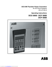
ABB DCS 500B Operating Instructions Manual (76 pages)
DCS 500 Thyristor Power Converters for DC Drive Systems 25 to 5150 A
Brand: ABB
|
Category: Power Supply
|
Size: 1.34 MB
Table of Contents
-
Operating Instructions
3
-
Safety Instructions
5
-
Table of Contents
8
-
-
Chapter 1 — Introduction
11
-
How to Use this Manual
11
-
Contents of this Manual
11
-
Target Group
11
-
Associated Publications
11
-
Incoming Inspection
12
-
Storage and Transport
12
-
Rating Plate
12
-
-
Chapter 2 — Start-Up Instructions
13
-
General Notes
13
-
Preparatory Work
17
-
Scaling Intra-Unit Signals
18
-
Presetting the Field Supply Unit
20
-
Adjusting the Current Controller
22
-
Speed Feedback Balancing
24
-
Balancing the Field Supply Unit and the E.M.f. Controller
26
-
Balancing the Speed Controller, Plus Fine-Balancing the E.M.f. and the Current Contr
32
-
Matching the Thyristor Power Converter Unit to the System Conditions Concerned
33
-
Presetting the 3-Phase Field Supply Unit DCF 50Xb
34
-
-
Chapter 3 — Handling of Control Panel CDP 31X
37
-
Overview
37
-
Panel Link
37
-
Mounting the Panel
37
-
-
Start Mode
38
-
Panel Functions
39
-
Actual Signal Display Mode
39
-
Parameter Mode
40
-
Function Mode
40
-
Drive Mode
41
-
-
Pin/Parameter Selecting and Changing of Value
41
-
Saving of the Parameters to Backup Memory
43
-
Fault Resetting (Reset)
44
-
Emergency Stop Resetting (Reset)
44
-
Fault History Display
45
-
Uploading and Downloading of Parameters (UPLOAD/DOWNLOAD)
46
-
Setting of the Display Contrast
48
-
Full Name of Output Pins
48
-
Selecting Output Pins
49
-
Drive Mode
50
-
Running the Drive
51
-
Operational Command Keys
51
-
-
Running the DC- Drive from the Cdp31X
51
-
Speed Reference Setting for the Drive
52
-
-
Chapter 4 — Signals and Troubleshooting
53
-
Display of Status, Alarm and Fault Signals
53
-
Categories of Signals and Possibilities of Display
53
-
-
General Messages
54
-
Starting Errors (E)
54
-
Fault Signals (F)
55
-
Alarm Signals (A)
64
-
Status Signals
69
-
Connection Diagram 2
74
-
Advertisement
ABB DCS 500B Service Manual (73 pages)
DCS Thyristor Power Converters for DC Drive Systems 25 to 5150 A
Brand: ABB
|
Category: Media Converter
|
Size: 1.57 MB
Table of Contents
-
Safety Instructions
5
-
Table of Contents
9
-
Chapter 1 — Introduction
11
-
How to Use this Manual
11
-
Contents of this Manual
11
-
Target Group
12
-
Associated Publications
12
-
Storage and Transport
12
-
Rating Plate and Type Code
12
-
-
Chapter 2 — Fault Tracing Thyristors
15
-
How to Detect, if a Thyristor Is Faulty
15
-
A Fuse Is Blown
15
-
Ripple Monitor
15
-
How to Find a Faulty Thyristor
16
-
Converters Size C1 and C2/C2B (25
16
-
Blown Fuses
16
-
Converters Size A5, C3 and C4 (900
17
-
Blown Fuses
17
-
Ripple Monitor
17
-
-
Chapter 3 — Handling the Semiconductors
19
-
General Instruction How to Handle the Semiconductors
19
-
-
Chapter 4 — Exchange of Thyristors for Sizes C1/C2/C2B
21
-
Installation of Thyristor Modules in Converters Size C1/C2/C2B (25
21
-
Required Tools
21
-
Remove Faulty Thyristor Modules
21
-
Install New Thyristor Modules
22
-
Install New Thyristor
22
-
Thyristor Module Location
23
-
Module Terminals
28
-
-
Chapter 5 — Exchange of Thyristors for Size A5
31
-
Installation of «Disc Type» Thyristor in Converters Size A5 (900
31
-
Required Tools
31
-
Find Faulty Thyristor
32
-
Remove Faulty Thyristor
33
-
Install New Thyristor
34
-
-
Chapter 6 — Exchange of Thyristors for Size C3
39
-
Installation of «Disc Type» Thyristor in Converters Size C3 (900
39
-
Required Tools
39
-
Remove Faulty Thyristor
40
-
Find Faulty Thyristor
40
-
-
Chapter 8 — Compatibility of SDCS-PIN-2 Boards
51
-
Description of SDCS-PIN-20Xb Boards
51
-
Hardware Coding
51
-
Snubber Circuit
51
-
Compatibility of SDCS-PIN-20X Boards
52
-
Compatibility of SDCS-PIN-20X and SDCS-PIN-2X Boards
52
-
Change SDCS-PIN-2X Boards
53
-
-
Chapter 9 — Preventive Maintainance
55
-
Recommended Regular Maintenance
55
-
Air Filters
55
-
Cooling Air Pressure Switch in Converter Modules Type C4
55
-
Fan
55
-
Heatsink
55
-
Internal High Current Connections in Converters Type C4
56
-
Relays and Electrical Connections
56
-
Advertisement
Related Products
-
ABB DCF 500B
-
ABB DCP 500B
-
ABB DCS550 Series
-
ABB DCS550-S01
-
ABB DCS550-S02
-
ABB DCS 500
-
ABB DCS880 H8
-
ABB DCS880 series
-
ABB DCS800-S01-0090-05
-
ABB DCS800-EP1-0470-05
ABB Categories
Industrial Equipment
Controller
Battery Charger
Measuring Instruments
DC Drives
More ABB Manuals
Как пользоваться?
Наша цель — обеспечить Вам самый быстрый доступ к руководству по эксплуатации устройства DCS 500. Пользуясь просмотром онлайн Вы можете быстро просмотреть содержание и перейти на страницу, на которой найдете решение своей проблемы с DCS 500.
Для Вашего удобства
Если просмотр руководства DCS 500 непосредственно на этой странице для Вас неудобен, Вы можете воспользоваться двумя возможными решениями:
- Полноэкранный просмотр -, Чтобы удобно просматривать инструкцию (без скачивания на компьютер) Вы можете использовать режим полноэкранного просмотра. Чтобы запустить просмотр инструкции DCS 500 на полном экране, используйте кнопку Полный экран.
- Скачивание на компьютер — Вы можете также скачать инструкцию DCS 500 на свой компьютер и сохранить ее в своем архиве. Если ты все же не хотите занимать место на своем устройстве, Вы всегда можете скачать ее из ManualsBase.
Руководство по эксплуатации DCS 500
Печатная версия
Многие предпочитают читать документы не на экране, а в печатной версии. Опция распечатки инструкции также предусмотрена и Вы можете воспользоваться ею нажав на ссылку, находящуюся выше — Печатать инструкцию. Вам не обязательно печатать всю инструкцию DCS 500 а только некоторые страницы. Берегите бумагу.
Резюме
Ниже Вы найдете заявки которые находятся на очередных страницах инструкции для DCS 500. Если Вы хотите быстро просмотреть содержимое страниц, которые находятся на очередных страницах инструкции, Вы воспользоваться ими.
-
DCS 500 — page 1
DCS 500 Thyristor Power Converters for DC Drive Systems 25 to 5150 A Operating Instructions DCS 500B / DCF 500B DCP 500B …
-
DCS 500 — page 2
How the DCS 500 Documentation System works System Description DCS 50 0B 3ADW000 066 Volume I I D Operating Instructions DCS 50 0B 3ADW000 055 Volume I V D Technica l Data 3ADW000 054 Volume III Description of the converter DCS 500B Operating Instructions (documentation in hand) including in- formation and advise to commission the drive. If three ph …
-
DCS 500 — page 3
2002 ABB Automation Products GmbH. All rights reserved. Thyristor Power Converters Series DCS 500B / DCF 500B DCP 500B 25 to 5150 A OPERATING INSTRUCTIONS Code: 3ADW 000 055 R0401 Rev D DCS_OI_E_D.DOC EFFECTIVE: Oct. 30th, 2002 SUPERSEDES:Rev C Sept. 14th, 2001 3ADW000055R0401_DCS500B_Operating Instruction_e_d …
-
DCS 500 — page 4
DCS 500B / DCP 500B Operating Instructions 3ADW000055R0401_DCS500B_Operating Instruction_e_d …
-
DCS 500 — page 5
Safety Instructions DCS 500B / DCP 500B Operating Instructions i Overview This chapter contains safety instructions which must be complied with during installation, operation and maintenance of the power converters series DCS 500B / DCF 500B or DCP 500B . If these in- structions are not complied with, this may result in injuries (perhaps even with …
-
DCS 500 — page 6
Safety Instructions ii DCS 500B / DCP 500B Operating Instructions General warning: this symbol warns you of non- electrical risks and dangers which may result in seri- ous or even fatal injury to persons and/or in damage to equipment. Where appropriate, the text printed ad- jacent to this symbol describes how risks of this kind may be avoided. ● …
-
DCS 500 — page 7
Safety Instructions DCS 500B / DCP 500B Operating Instructions iii Notes Notes supply information on states requiring particular attention, or indicate that additional information is available on a specific topic. For this purpose, the following symbols are used: CAUTION! Cautions are designed to draw your attention to a particular state of affairs …
-
DCS 500 — page 8
Contents iv DCS 500B / DCP 500B Operating Instructions IV A O PERATING I NSTRUCTIONS Safety Instructions Chapter 1 — Introduction How to use this manual …………………………………………………………………………………………… .. 1-1 Contents of this manual …………………………………………………… …
-
DCS 500 — page 9
Contents DCS 500B / DCP 500B Operating Instructions v Running the DC- Drive from the CDP31x ……………………………………………………….. 3-15 3.15 Speed Reference Setting for the Drive ……………………………………………………………….. 3-16 Chapter 4 — Signals and Troubleshooting 4.1 Display of status, a …
-
DCS 500 — page 10
vi DCS 500B / DCP 500B Operating Instructions 3ADW000055R0401_DCS500B_Operating Instruction_e_d …
-
DCS 500 — page 11
Chapter 1 — Introduction DCS 500B / DCP 500B Operating Instructions IV A 1 — 1 How to use this manual The purpose of these operating instructions is to provide detailed in- formation on how to start up a thyristor power converter from the DCS 500B or DCP 500B series. Note: If it is not mentioned explicitly all details given in these Operating Instr …
-
DCS 500 — page 12
Chapter 1 — Introduction IV A 1 — 2 DCS 500B / DCP 500B Operating Instructions Incoming inspection After opening this package, you should check whether it contains the following items: ● DCS 500B / DCF 500B or DCP 500B thyristor power con- verter in the configuration ordered ● DCS 500B / DCF 500B or DCP 500B publications ● Accessories, includ …
-
DCS 500 — page 13
Chapter 2 — Start-Up Instructions DCS 500B / DCP 500B Operating Instructions IV A 2 — 1 General notes CAUTION: it is absolutely essential that the applicable accident prevention regulations be observed by the user (in this context, please also read the chapter entitled «Safety Instructions»)! How this chapter is structured For better unde …
-
DCS 500 — page 14
Chapter 2 — Start-Up Instructions IV A 2 — 2 DCS 500B / DCP 500B Operating Instructions Phase sequence when connecting to the mains / Potential isolation No special phase sequence required for the main connections U1, V1 and W1! Phase coordination between electronics section and power section not necessary! For potential isolation and for avoiding …
-
DCS 500 — page 15
Chapter 2 — Start-Up Instructions DCS 500B / DCP 500B Operating Instructions IV A 2 — 3 Symbols for switching the electronics or the power section ON and OFF — Switch ON electronics — Switch ON power X6: 7 ⇒ „1“ signal (K20 in connection example) (input ON / OFF ) — Switch OFF electronics — Switch OFF power X6: 7 ⇒ „0“ signal (K20 in co …
-
DCS 500 — page 16
Chapter 2 — Start-Up Instructions IV A 2 — 4 DCS 500B / DCP 500B Operating Instructions Symbol for altering parameters or for establishing new connections Enter at keyboard e.g. 1204 = 10000 Assign the value of 10000 to Parameter 1204 Symbol for displaying parameter values or connections Display Symbol for measuring physical variables Measure 3ADW0 …
-
DCS 500 — page 17
Chapter 2 — Start-Up Instructions DCS 500B / DCP 500B Operating Instructions IV A 2 — 5 2.1 Preparatory work Check the unit for damage in transit or other damage. Install and wire unit; connect all inputs and outputs required. Proceed in the same way for the field supply unit as well. Check whether protective measures, earthing, screening, etc. hav …
-
DCS 500 — page 18
Chapter 2 — Start-Up Instructions IV A 2 — 6 DCS 500B / DCP 500B Operating Instructions 2.2 Scaling intra-unit signals Make sure that the existing electronics supply voltage has been set on the SDCS- POW-1 power supply board as well, using the SW1 switch. If an encoder is being used as the speed feedback device, make sure that the correct supply vo …
-
DCS 500 — page 19
Chapter 2 — Start-Up Instructions DCS 500B / DCP 500B Operating Instructions IV A 2 — 7 Set this only for units of the DCP 500 series! 517 = Rated power converter current Enter numerical value from rating plate here 518 = 500 V ( fixed! ); rated power converter voltage Enter numerical value 500 V here 519 = Temperature monitoring of power section E …
-
DCS 500 — page 20
Chapter 2 — Start-Up Instructions IV A 2 — 8 DCS 500B / DCP 500B Operating Instructions 2.3 Presetting the field supply unit Make sure that existing supply voltages for power section, field supply unit (field ex- citer) and field winding, fan, etc. match the rated data of the components used. Switch ON power. DANGER : System components now energize …
-
DCS 500 — page 21
Chapter 2 — Start-Up Instructions DCS 500B / DCP 500B Operating Instructions IV A 2 — 9 Only for armature-circuit power converters with SDCS-CON-2 control board & CDP 312 panel! 1201 = 5 Panel display: FEX2/3 AUTOTUNING Activates the field current controller’s auto-tuning function. Action has been completed when NOT ACTIVATED is shown on t …
-
DCS 500 — page 22
Chapter 2 — Start-Up Instructions IV A 2 — 10 DCS 500B / DCP 500B Operating Instructions 2.4 Adjusting the current controller Make sure that static current limitation Bridge 1 (2307) and Bridge 2 (2308; with 4Q-unit) have been set to the same value; values of all parameters for current reference limitation must be greater than 20 %; conditions have …
-
DCS 500 — page 23
Chapter 2 — Start-Up Instructions DCS 500B / DCP 500B Operating Instructions IV A 2 — 11 Drive must not turn! Do not preset an external reference! 1201 = 3 Panel display: ARM. AUTOTUNING Activate the current controller’s auto-tuning function. Start the next two steps within the next 20 seconds! Switch ON power. DANGER : System components now e …
-
DCS 500 — page 24
Chapter 2 — Start-Up Instructions IV A 2 — 12 DCS 500B / DCP 500B Operating Instructions 2.5 Speed feedback balancing E.M.F. control active? 2102 = 5 Panel display: EMF SPEED ACT Field weakening mode not selected? 1001 = 0 Panel display: CONSTANT FIELD 2103 = Desired speed / or motor rating plate Scale speed control circuit to maximum speed. 1701 = …
-
DCS 500 — page 25
Chapter 2 — Start-Up Instructions DCS 500B / DCP 500B Operating Instructions IV A 2 — 13 Only when an encoder (pulse encoder) is being used! 12104 = Content of pulse counter If the shape of the curve corresponds to the diagram below, this means the wiring is correct and the pulses will be correctly evaluated [see also documentation entitled „ Tec …
-
DCS 500 — page 26
Chapter 2 — Start-Up Instructions IV A 2 — 14 DCS 500B / DCP 500B Operating Instructions 2.6 Balancing the field supply unit and the e.m.f. controller When matching the field supply unit to the system conditions, differences in the proce- dures adopted must be taken into account; these different procedures result from the op- erating mode used. Onl …
-
DCS 500 — page 27
Chapter 2 — Start-Up Instructions DCS 500B / DCP 500B Operating Instructions IV A 2 — 15 2.6.2 Field weakening control with setting range < 1 : 1.5 CAUTION: Not p ermi tte d whe n Ch apt er 2 .5 wa s qu it w ith e .m.f . co ntr ol! 1001 = 1 Panel display: EMF, NO FIELD REV Field weakening function activated 1012 = Speed at field weakening point …
-
DCS 500 — page 28
Chapter 2 — Start-Up Instructions IV A 2 — 16 DCS 500B / DCP 500B Operating Instructions 2.6.3 Field weakening control with setting range > 1 : 1.5 CAUTION: Not per mitt ed w hen Cha pte r 2.5 was quit wit h e.m .f. c ont rol ! Only when unit is fitted with an SDCS-CON-1 control board! If the field time constant is known, e.g. from the motor dat …
-
DCS 500 — page 29
Chapter 2 — Start-Up Instructions DCS 500B / DCP 500B Operating Instructions IV A 2 — 17 Switch OFF power! 1201 = 0 Panel display: NOT ACTIVATED 11202 = SAVE MOT1 SET Save the altered values in the non-volatile memory! When unit is fitted either with an SDCS-CON-1 or SDCS-CON-2 control board! 1001 = 1 Panel display: EMF, NO FIELD REV Field weakenin …
-
DCS 500 — page 30
Chapter 2 — Start-Up Instructions IV A 2 — 18 DCS 500B / DCP 500B Operating Instructions 12522 = decrease so that motor voltage is 90 %. Flux and thus the field current as well are reduced. How to proceed: 1. decrease 12522 (in steps of 100 at a time) 2. press ACT , read off motor voltage 3. press PAR and correct 12522 if necessary (then continue w …
-
DCS 500 — page 31
Chapter 2 — Start-Up Instructions DCS 500B / DCP 500B Operating Instructions IV A 2 — 19 Only if analog tacho is used as speed feedback! Switch ON power; start drive. DANGER : System components now energized! 12516 = increase slowly up to 20000 (=100 % speed). Check motor voltage; if value has been set with 501, motor voltage must remain constant, …
-
DCS 500 — page 32
Chapter 2 — Start-Up Instructions IV A 2 — 20 DCS 500B / DCP 500B Operating Instructions 2.7 Balancing the speed controller, pl us fine-balancing the e.m.f. and the current controllers 1701 = 11206 Change between POT1 and POT2 activated. Extremely reduce the ramp-up time, depending on the system conditions: 1708 = 0,1 s 1709 = 0,1 s Adjusting the p …
-
DCS 500 — page 33
Chapter 2 — Start-Up Instructions DCS 500B / DCP 500B Operating Instructions IV A 2 — 21 1204 = 0 1205 = 0 Switch OFF power, thus stopping the drive! 1701 = 11903 501 = Rated motor voltage set in Chapter 2.2. 1012 = Speed at rated motor voltage CAUTION! Please don’t forget! 11202 = SAVE MOT1 SET Save the altered values in the non-volatile memo …
-
DCS 500 — page 34
Chapter 2 — Start-Up Instructions IV A 2 — 22 DCS 500B / DCP 500B Operating Instructions 2.9 Presetting the 3-phase field supply unit DCF 50xB This is a new functionality available for the first time with software version S21.232. When commissioning a drive consisting of a DCS converter for the armature supply and a DCF converter for the field plea …
-
DCS 500 — page 35
Chapter 2 — Start-Up Instructions DCS 500B / DCP 500B Operating Instructions IV A 2 — 23 alarm or fault indication / reaction, if DCF 506 has triggered 3601 = 15 only at DCF 50 2 B; bridge reversal delayed to app. 50ms 3602 = 15 only at DCF 50 2 B; in worst case bridge change over will take place when time of 3601 has elapsed plus app. 50ms 3603 = …
-
DCS 500 — page 36
Chapter 2 — Start-Up Instructions IV A 2 — 24 DCS 500B / DCP 500B Operating Instructions When the display shows NOT ACTIVATED (action correctly completed): Stop drive Switch OFF power! In case the autotuning failed: 1201 = 4 Panel display: ARM. MAN. TUNING ARM.MAN_TUNING, if the FEX2/3 autotuning failed; activate the reference via pa- rameter 11209 …
-
DCS 500 — page 37
Chapter 3 — Handling of Control Panel CDP 31x DCS 500B / DCP 500B Operating Instructions IV A 3 — 1 3.1 Overview The Control and Display Panel [Control Panel] is used for parame- ter setting, for feedback value measuring and for drive control with series DCS 500B / DCF 500B and DCP 500B thyristor power con- verters. This device is available in diff …
-
DCS 500 — page 38
Chapter 3 — Handling of Control Panel CDP 31x IV A 3 — 2 DCS 500B / DCP 500B Operating Instructions 3.2 Start Mode Note: The CDP 31x can be connected to the drive without dis- connecting the auxiliary power ! When connected and power is applied to the electronics, the dis- play of the CDP 31x shows: — software version of the Control Panel — ID numb …
-
DCS 500 — page 39
Chapter 3 — Handling of Control Panel CDP 31x DCS 500B / DCP 500B Operating Instructions IV A 3 — 3 3.3 Panel Functions The CDP 31x has four different keypad modes: • Actual Signal Display Mode (ACT) • Parameter Mode (PAR) • Function Mode (FUNC) • Drive Mode (DRIVE) for further extensions Actual Signal Display Mode ACT This keypad mode will …
-
DCS 500 — page 40
Chapter 3 — Handling of Control Panel CDP 31x IV A 3 — 4 DCS 500B / DCP 500B Operating Instructions Parameter Mode PA R The Parameter Mode is used for: — change the structure in the firmware — show signals and their actual status — show and change values of parameters, if they are not write-protected. When the Parameter mode is entered parameter 10 …
-
DCS 500 — page 41
Chapter 3 — Handling of Control Panel CDP 31x DCS 500B / DCP 500B Operating Instructions IV A 3 — 5 Drive Mode DR I VE Drive mode is used to check the configuration. The display will show the type and ID-number of the drive to whom the CDP 31x is connected to. DCS5 00 ID-N UMBER 0 TOTA L 1 DRIVE S Device typ e Th e ID -num be r Tot al num ber of dr …
-
DCS 500 — page 42
Chapter 3 — Handling of Control Panel CDP 31x IV A 3 — 6 DCS 500B / DCP 500B Operating Instructions Step Function Press key Display after key is pressed 1. To enter the Parameter Mode Selection PAR 0 L 0.0 rpm 0 0 17 RAMP GENERATOR 01 RAMP . [IN] 119.03 2. To select another group. While holding the key down, only the group number and name is displa …
-
DCS 500 — page 43
Chapter 3 — Handling of Control Panel CDP 31x DCS 500B / DCP 500B Operating Instructions IV A 3 — 7 3.5 Saving of the Parameters to backup memory Step Function Press key Display after key is pressed 1. To enter the Parameter Mode Selection PAR 0 L 0.0 rpm 0 0 2 A NALOG OU TPUTS 05 AO2. [ IN] 105.01 2. Select group 112. While holding the arrow down, …
-
DCS 500 — page 44
Chapter 3 — Handling of Control Panel CDP 31x IV A 3 — 8 DCS 500B / DCP 500B Operating Instructions 3.6 FAULT RESETTING (RESET) FAULT resetting and EMERGENCY STOP resetting (RESET) can only be performed via the CDP 31x if LOCAL is active. If drive is in REMOTE, please check whether LOCAL is a critical condition. If not activate LOCAL, reset the fau …
-
DCS 500 — page 45
Chapter 3 — Handling of Control Panel CDP 31x DCS 500B / DCP 500B Operating Instructions IV A 3 — 9 3.8 Fault History Display Up to 100 faults are stored time related and displayed together with the time they appeared after electronics supply switched on. Step Function Press key Display after key is pressed 1. To enter the Actual Signal Display Mod …
-
DCS 500 — page 46
Chapter 3 — Handling of Control Panel CDP 31x IV A 3 — 10 DCS 500B / DCP 500B Operating Instructions 3.9 Uploading and Downloading of Pa rameters (UPLOAD/DOWNLOAD) CAUTION! The drive must be in standstill condition with given STOP command (controllers blocked, power section disconnected from the network) when UPLOAD/ DOWNLOAD function is selected. …
-
DCS 500 — page 47
Chapter 3 — Handling of Control Panel CDP 31x DCS 500B / DCP 500B Operating Instructions IV A 3 — 11 Depending on the drive´s condition and the status of the commis- sioning, UPLOAD has to take place before DOWNLOAD , otherwise a warning may be displayed: **WA RNIN G* * NOT UPLOADED DOWNLOADING NOT POSSIBLE The drive must be in stopped state durin …
-
DCS 500 — page 48
Chapter 3 — Handling of Control Panel CDP 31x IV A 3 — 12 DCS 500B / DCP 500B Operating Instructions 3.10 Setting of the Display Contrast Step Function Press key Display after key is pressed 1. To enter the Function Mode . FUNC 0 L 0.0 rpm 00 UPLOAD <= <= DOWNLOAD => => CONTRAST 7 2. To select a function. 0 L 0.0 rpm 00 UPLOAD <= < …
-
DCS 500 — page 49
Chapter 3 — Handling of Control Panel CDP 31x DCS 500B / DCP 500B Operating Instructions IV A 3 — 13 3.12 Selecting output pins Note for CDP 310 / CDP 311: Newly selected actual signals will be used for display until the elec- tronics power supply is switched OFF. Note for CDP 312: If there is a need for permanent display of the newly selected pin …
-
DCS 500 — page 50
Chapter 3 — Handling of Control Panel CDP 31x IV A 3 — 14 DCS 500B / DCP 500B Operating Instructions 3.13 Drive Mode Display of the ID-number for the Drive and for the Control Panel CDP 31x as well as display of the status (Status Display) Step Function Press key Display after key is pressed 1. To enter the Drive Mode DRIVE DCS500 ID-NUMBER 0 TOTAL …
-
DCS 500 — page 51
Chapter 3 — Handling of Control Panel CDP 31x DCS 500B / DCP 500B Operating Instructions IV A 3 — 15 3.14 Running the Drive Operational Com- mand Keys Operational commands can be given from the Control Panel CDP31x every time when the status row is displayed. Operational commands include START and STOP of the the drive, controlling the main contact …
-
DCS 500 — page 52
Chapter 3 — Handling of Control Panel CDP 31x IV A 3 — 16 DCS 500B / DCP 500B Operating Instructions 3.15 Speed Reference Setting for the Drive Step Function Press key Display after key is pressed 1. Press one of these keys to get the status row displayed. ACT PAR FUNC 0 L 0.0 rpm 0 0 SPEED A C 0.0 rp m CONV CU R 0 A U ARM A C 0 V _ 2. To enter the …
-
DCS 500 — page 53
Chapter 4 — Signals and Troubleshooting DCS 500B / DCP 500B Operating Instructions IV A 4 — 1 4.1 Display of status, alarm and fault signals Categories of signals and possibilities of display The signals (messages) to be available for thyristor power con- verters series DCS 500B / DCF 500B or DCP 500 are subdivided into five categories: General mes …
-
DCS 500 — page 54
Chapter 4 — Signals and Troubleshooting IV A 4 — 2 DCS 500B / DCP 500B Operating Instructions 4.2 General messages The general messages will only be shown on the seven segment display of the control board SDCS-CON-x. Code seven segm. display Text on LCD of control panel CDP 31x Definition – Remark 8 Not available Program is not running – (1) . …
-
DCS 500 — page 55
Chapter 4 — Signals and Troubleshooting DCS 500B / DCP 500B Operating Instructions IV A 4 — 3 4.4 Fault Signals (F) The fault signals will be shown on the seven segment display of the control board SDCS-CON-x as codes F . . as well as on the LCD of the control panel CDP 31x as clear text. All fault signals — with the exception of F 17 , F 18 and F …
-
DCS 500 — page 56
Chapter 4 — Signals and Troubleshooting IV A 4 — 4 DCS 500B / DCP 500B Operating Instructions Code seven segm. display Text on LCD of control panel CDP 31x Definition / Action Status signal (FAULT_WORD_1/2) Remark F 3 Conv.fan curr.fault Current converter fan not within limits The current of the converter´s cooling fan is measured via the option b …
-
DCS 500 — page 57
Chapter 4 — Signals and Troubleshooting DCS 500B / DCP 500B Operating Instructions IV A 4 — 5 Code seven segm. display Text on LCD of control panel CDP 31x Definition / Action Status signal (FAULT_WORD_1/2) Remark F 8 Current rise fault Actual current changed faster than allowed The rate of current change is monitored. Check: — Setting of current r …
-
DCS 500 — page 58
Chapter 4 — Signals and Troubleshooting IV A 4 — 6 DCS 500B / DCP 500B Operating Instructions Code seven segm. display Text on LCD of control panel CDP 31x Definition / Action Status signal (FAULT_WORD_1/2) Remark F 20 Local & discon- nected No communication between CDP 31x/CMT and DCS 500B / DCF 500B or DCP 500B in lo- cal control mode (LOCAL) …
-
DCS 500 — page 59
Chapter 4 — Signals and Troubleshooting DCS 500B / DCP 500B Operating Instructions IV A 4 — 7 Code seven segm. display Text on LCD of control panel CDP 31x Definition / Action Status signal (FAULT_WORD_1/2) Remark F 28 Armature over- voltage Armature (DC circuit) overvoltage Check: — Setting of param. [ P 511 ] suitable for the system configuration …
-
DCS 500 — page 60
Chapter 4 — Signals and Troubleshooting IV A 4 — 8 DCS 500B / DCP 500B Operating Instructions Code seven segm. display Text on LCD of control panel CDP 31x Definition / Action Status signal (FAULT_WORD_1/2) Remark F 34 Arm. curent ripple Armature current ripple One or several thyristors carry no current. Check: — Current feedback with oscilloscope …
-
DCS 500 — page 61
Chapter 4 — Signals and Troubleshooting DCS 500B / DCP 500B Operating Instructions IV A 4 — 9 Code seven segm. display Text on LCD of control panel CDP 31x Definition / Action Status signal (FAULT_WORD_1/2) Remark field weakening range too big / threshold too high Check: — Do selection parameters match the field exciter (field supply)? — Field exci …
-
DCS 500 — page 62
Chapter 4 — Signals and Troubleshooting IV A 4 — 10 DCS 500B / DCP 500B Operating Instructions Code seven segm. display Text on LCD of control panel CDP 31x Definition / Action Status signal (FAULT_WORD_1/2) Remark F 44 I/O-Board not found Missing input/output (I/O-) boards IOB1/2x/3/IOE1 The existance of the boards had been recog- nized by the sof …
-
DCS 500 — page 63
Chapter 4 — Signals and Troubleshooting DCS 500B / DCP 500B Operating Instructions IV A 4 — 11 Code seven segm. display Text on LCD of control panel CDP 31x Definition / Action Status signal (FAULT_WORD_1/2) Remark F 65 Reversal Fault Reversal of direction of current is not O.K. The reversal of the direction of current was not correct. Check: — Ext …
-
DCS 500 — page 64
Chapter 4 — Signals and Troubleshooting IV A 4 — 12 DCS 500B / DCP 500B Operating Instructions 4.5 Alarm Signals (A) The alarm signals will be shown on the seven segment display of the control board SDCS-CON-x as codes A . . as well as on the LCD of the control panel CDP 31x as plain text. Alarm signals will only be displayed, if there is no fault …
-
DCS 500 — page 65
Chapter 4 — Signals and Troubleshooting DCS 500B / DCP 500B Operating Instructions IV A 4 — 13 Code seven segm. display Text on LCD of control panel CDP 31x Definition / Possible source Signal number (ALARM_WORD _1/2) Remark A 108 RAM-backup failed Alarm No Battery Backup Function for RAM Capacitor for RAM backup has discharged (perhaps unit has be …
-
DCS 500 — page 66
Chapter 4 — Signals and Troubleshooting IV A 4 — 14 DCS 500B / DCP 500B Operating Instructions Code seven segm. display Text on LCD of control panel CDP 31x Definition / Possible source Signal number (ALARM_WORD _1/2) Remark A 127 Ext. FAN ack.alarm Alarm No Acknowledge from External FAN (of Motor) Check: — See Fault Code F 40. 11104 bit 15 A 128 P …
-
DCS 500 — page 67
Chapter 4 — Signals and Troubleshooting DCS 500B / DCP 500B Operating Instructions IV A 4 — 15 Code seven segm. display Text on LCD of control panel CDP 31x Definition / Possible source Signal number (ALARM_WORD _1/2) Remark A 134 Backup not allowed Alarm Change of Parameter Set not allowed Signal will appear when an attempt has been made to change …
-
DCS 500 — page 68
Chapter 4 — Signals and Troubleshooting IV A 4 — 16 DCS 500B / DCP 500B Operating Instructions Code seven segm. display Text on LCD of control panel CDP 31x Definition / Possible source Signal number (ALARM_WORD _1/2) Remark A 143 Macro change failed Alarm Change from Macro x to Macro y has failed At Macro x, macro-specific links or function blocks …
-
DCS 500 — page 69
Chapter 4 — Signals and Troubleshooting DCS 500B / DCP 500B Operating Instructions IV A 4 — 17 4.6 Status Signals The status of drive functions (autotuning of controllers; saving val- ues) is shown by status signals named 11201 and 11202. The status of the first and / or the second field exciter, the torque control sequencing and the current contro …
-
DCS 500 — page 70
Chapter 4 — Signals and Troubleshooting IV A 4 — 18 DCS 500B / DCP 500B Operating Instructions Para- meter Code / bit Text on LCD of con- trol panel CDP 31x Definition / explication of the signal Remark 11201 — —- Gives feedback status information when the DRIVEMODE parameter (1201) was used to start the drive function 3, 5 or 6 (autotuning). 50 …
-
DCS 500 — page 71
Chapter 4 — Signals and Troubleshooting DCS 500B / DCP 500B Operating Instructions IV A 4 — 19 Para- meter Code / bit Text on LCD of con- trol panel CDP 31x Definition / explication of the signal Remark 6 READ APPL BLOCKS Load application; if additional function blocks are ac- tivated and saved via SAVE MOTx SET and modified afterwards without savi …
-
DCS 500 — page 72
Chapter 4 — Signals and Troubleshooting IV A 4 — 20 DCS 500B / DCP 500B Operating Instructions Para- meter Code / bit Text on LCD of con- trol panel CDP 31x Definition / explication of the signal Remark 12 (FIELD2_CURR_MIN_L) 1 = motor 2 field current above min level 11204 — —- TC_STATUS : Status of the torque control sequencing 00 (RDY ON) 1 = …
-
DCS 500 — page 73
Appendix A — Connection diagrams DCS 500B / DCP 500B Operating Instructions IV A A — 1 Connection diagram 1 For detailed information see System description DCS 500B / DCF 500B . IN3 OUT3 IN1 OUT1 V5 V6 V1 V2 X96: DO8 12 X 9 9 : 12 X 2 : 4 5 X 2 : 1 2 3 U1 W1 V1 PE K1 K20 K21 K20 K1 X96:1 X96 :2 L1 L2 L 3 400V 50 Hz F1 F3 M ~ K21 X33 C 1 D 1 AI TAC …
-
DCS 500 — page 74
Appendix A — Connection diagrams IV A A — 2 DCS 500B / DCP 500B Operating Instructions Connection diagram 2 For detailed information see System description DCS 500B / DCF 500B . IN3 OUT3 IN1 OUT1 V5 V6 V1 V2 X96: DO8 12 X 9 9 : 12 X 2 : 4 5 X 2 : 1 2 3 U1 W1 V1 PE K1 F6 K20 K21 K20 K3 K1 X96: 1 X96 :2 L1 L2 L3 F1 F3 K3 13 24 M ~ T3 F2 3 4 1 2 T2 69 …
-
DCS 500 — page 75
Appendix A — Connection diagrams DCS 500B / DCP 500B Operating Instructions IV A A — 3 3ADW000055R0401_DCS500B_Operating Instruction_e_d …
-
DCS 500 — page 76
ABB Automation Products GmbH Postfach 1180 Lampertheim • GERMANY Tel: +49 (0) 62 06-5 03-0 Fax: + 49 (0) 62 06-5 03-6 09 www.abb.com/dc *055R0401A2440000* *055R0401A2440000* Ident. No.: 3ADW 000 055 R0401 Rev D 09_01 …