- Manuals
- Brands
- ABB Manuals
- Other
- Emax X1
Manuals and User Guides for ABB Emax X1. We have 2 ABB Emax X1 manuals available for free PDF download: Operating Instructions Manual, Quick Start Manual

ABB Emax X1 Operating Instructions Manual (66 pages)
T7-T8-X1 low voltage air circuit breakers protection releases
Brand: ABB
|
Category: Other
|
Size: 2.87 MB
Table of Contents
-
Table of Contents
3
-
1 PROTECTION RELEASE — General Notes
5
-
Compatibility between Protection Releases and CB
6
-
Abbreviations and Notes
6
-
Abbrevations
6
-
Safety Notes
6
-
Notes for Dielectric Stiffness Tests
6
-
-
2 Protection Release Pr331/P
7
-
Overview
7
-
Main Specifications
7
-
Protections
7
-
Functions
7
-
Accessories
8
-
Compatibility CB
8
-
Standards
8
-
Environmental Characteristics
8
-
Electrical Characteristics
8
-
User Interface
9
-
Dip Switches
9
-
Led
10
-
Itest Button
10
-
Test Connector
11
-
Protection Functions
11
-
Protection L
11
-
Thermal Memory L
11
-
Protection S
12
-
Thermal Memory S
12
-
Protection I
12
-
MCR Protection
12
-
Protection G
12
-
Neutral Protection
12
-
Protection against Instantaneous Short-Circuit «Iinst
13
-
Summary Table of Protections
13
-
Trip Curves
14
-
Trip Curves for Functions L-I
14
-
Trip Curves for Functions L-S(T =K/I )-I
14
-
Trip Curves for Functions L-S(T=K)-I
15
-
Trip Curves for Function G
15
-
Main Functions
16
-
Measurement
16
-
Self-Monitoring
16
-
Contact S51/P1
16
-
Putting into Service and Recommendations
16
-
Installation
16
-
Connections
17
-
CS and TC Connection Check
17
-
Connection of Current Sensor for External Neutral
17
-
Default Parameters
17
-
Troubleshooting
18
-
In the Case of a Fault
18
-
-
3 Protection Releases Pr332/P and Pr333/P
19
-
Introduction
19
-
Overview
19
-
Specifications
19
-
Protections
20
-
Functions
20
-
Inputs/Outputs
20
-
Accessories
21
-
CB Compatibility
21
-
Standards
21
-
Environmental Characteristics
21
-
Electrical Characteristics
22
-
User Interface
23
-
Leds
23
-
Push-Buttons
24
-
Display
24
-
Graphic Ammeter and Voltmeter
25
-
CB and Protection Release Alarms
25
-
Operating Icons
26
-
User Menus
27
-
Measurements Area
27
-
Information
27
-
Menu Area
27
-
Menu Browsing
27
-
Protection Functions
28
-
Notes about Protection Operation
28
-
Protection L
29
-
Thermal Memory L
29
-
Protection S
29
-
Thermal Memory S
29
-
Start-Up Threshold S
30
-
Zone S Selectivity
30
-
Protection S2
30
-
Directional Protection D
31
-
Start-Up Threshold D
31
-
Directional) Zone Selectivity D
32
-
Protection «I
33
-
Start-Up Threshold «I
33
-
Protection against Closing on Short-Circuit «MCR
33
-
Protection «G
33
-
Start-Up Threshold «G
33
-
Zone Selectivity «G
33
-
Protection «Gext
33
-
Start-Up Threshold «Gext
34
-
Zone Selectivity «Gext
34
-
Residual Current Protection Rc
34
-
Protection «U
34
-
Protection «UV
35
-
Protection «OV
35
-
Protection «RV
35
-
Protection «RP
35
-
Protection «UF» and «OF
35
-
Protection «T
35
-
Load Control Function
36
-
Double Protection Set
36
-
Neutral Protection
36
-
Protection MM
37
-
Protection against Instantaneous Short-Circuit «Iinst
37
-
Summary Table of Protection Functions for PR332 and PR333/P
37
-
Trip Curves
39
-
Trip Curves for Functions L-I
39
-
Trip Curves for Functions L-S(T=K/I 2 )-I
40
-
Trip Curves for Functions L-S(T=K)-I
40
-
Trip Curves for Function L in Accordance with IEC 60255-151 (Type A)
41
-
Trip Curves for Function L in Accordance with IEC 60255-151 (Type B)
41
-
Trip Curves for Function L in Accordance with IEC 60255-151 (Type C)
42
-
Trip Curves for Function G
42
-
Trip Curves for Function D
43
-
Trip Curves for Function U
43
-
Trip Curves for Function UV
44
-
Trip Curves for Function OV
44
-
Trip Curves for Function RV
45
-
Trip Curves for Function RP
45
-
Measuring Functions
46
-
Runtime Measurements: Current, Voltage, Power
46
-
Trip
47
-
Events
47
-
Measurements Log Register
47
-
Power Factor
47
-
Energy
48
-
Peak Factor
48
-
Mains Frequency
48
-
Contact Wear
48
-
Wave Forms
48
-
Main Functions
49
-
Watchdog
49
-
Circuit-Breaker State
49
-
Datalogger
49
-
Settings
49
-
Recording Time Windows
50
-
Access to Saved Data from the System
51
-
Contact S51/P1
52
-
-
Network Frequency
53
-
Internal Modules
54
-
Voltage Transformer
55
-
Dielectric Strength Tests
56
-
Test Menu
57
-
COM Module
58
-
Putting into Service and Recommendations
59
-
Default Parameters
60
-
Troubleshooting
61
-
In the Case of a Fault
62
-
Accessories
63
-
-
Bt030-Usb
64
-
Notes about the HMI030 and Flex Interface Connection
65
-
Advertisement
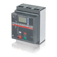
ABB Emax X1 Quick Start Manual (4 pages)
Auxiliary position contacts for fixed part
Brand: ABB
|
Category: Switch
|
Size: 0.35 MB
Advertisement
Related Products
-
ABB SACE Tmax XT2
-
ABB SACE Tmax XT4
-
ABB Cassia X1000
-
ABB Emax X1 UL
-
ABB TOTALFLOW XFCG4
-
ABB X00080669
-
ABB XAC18513
-
ABB XAC24337
-
ABB XAC26457
-
ABB XAC25880
ABB Categories
Industrial Equipment
Controller
Battery Charger
Measuring Instruments
DC Drives
More ABB Manuals
Последнее обновление: 12.04.2023 всего обновлено: 703 товара
SACE Emax X1 ABB отличает исключительная компактность со значительно меньшими габаритными размерами. Кроме того, другой важной характеристикой SACE Emax X1 ABB является возможность установки выключателя как в вертикальном, так и в горизонтальном положении. Таким образом, можно соответственно уменьшить размеры распределительного щита. Например, благодаря небольшой ширине, количество выключателей SACE Emax X1 ABB в стойке распределительного щита может быть увеличено, если их установить в горизонтальном положении.
Выключатели-разъединители или рубильники SACE Emax X1 ABB основаны на соответствующих автоматических выключателях с сохранением их габаритных размеров и возможности установки аксессуаров. Это исполнение отличается от автоматических выключателей только отсутствием расцепителей максимального тока. Имеются рубильники SACE Emax X1 ABB в стационарном и выкатном исполнениях, как с тремя, так и с четырьмя полюсами. Выключатели-разъединители, обозначаемые буквами “MS”, могут использоваться в соответствии с категорией применения АС-23А (коммутация нагрузок электродвигателей или других высокоиндуктивных нагрузок) в соответствии со Стандартом IEC 60947-3.
Более того SACE Emax X1 ABB может быть поставлен в специальном исполнении для номинального рабочего напряжения до 1000 В переменного тока. Выключатели SACE Emax X1 ABB в таком исполнении имеют буквенное обозначение для стандартного диапазона (номинальное рабочее напряжение до 690 В переменного тока) плюс “E”, и получаются на основе соответствующих стандартных Emax X1B. Эти автоматы предлагаются в таких же исполнениях и с такими же аксессуарами, что и вышеуказанные выключатели. SACE Emax X1 ABB могут быть поставлены в стационарном и выкатном исполнениях, как с тремя, так и с четырьмя полюсами. Автоматические выключатели Emax X1/E особенно хорошо подходят для установки в шахтах, на нефтеперерабатывающих и химических предприятиях, а также на транспорте.
Выключатели-разъединители семейства SACE Emax X1 ABB завершают ассортимент аппаратов для применения при напряжении 1000 В переменного тока. Эти выключатели соответствуют Стандартам IEC 60947-3. Автоматы в таком исполнении обозначаются буквами стандартного диапазона с номинальным рабочим напряжением до 690 В переменного тока плюс “/E”, получая обозначение Emax X1B/E MS. Рубильники получаются на базе соответствующих стандартных выключателей-разъединителей X1B/MS. Имеются как с тремя, так и с четырьмя полюсами, в стационарном и выкатном исполнениях, с такими же дополнительными аксессуарами и установками, как у соответствующих стандартных выключателей.
Смотрите также в разделе SACE Emax X1:
Вы можете купить SACE Emax X1 недорого и по выгодной цене в интернет магазине ABB|выключатели ABB|контакторы ABB|узо ABB|рубильники ABB. В магазине представлены SACE Emax X1 с подробными техническими характеристиками. Мы предлагаем SACE Emax X1 купить по низкой оптовой цене.


Note for Owners:
Guidesimo.com webproject is not a service center of ABB trademark and does not carries out works for diagnosis and repair of faulty ABB Emax X1 UL equipment. For quality services, please contact an official service center of ABB company. On our website you can read and download documentation for your ABB Emax X1 UL device for free and familiarize yourself with the technical specifications of device.
-
Eaton NRX Series
Installation and Removal Instructions for Series NRX Front Connect Adapters effective August 2011 Series NRXInstruction Leaet IL01301056E• WARNING(1) ONLY QUALIFIED ELECTRICAL PERSONNEL SHOULD BE PERMITTED TO WORK ON THE EQUIPMENT. (2) ALWAYS DE-ENERGIZE PRIMARY AND SECONDARY CIRCUITS IF A CIRCUIT BREAKER CANNOT BE REMOVED TO A SAFE WORK LOCATION. (3) DRAWOUT CIRCUIT BREAKERS SHOULD BE LEVER …
NRX Series Adapter, 8
-
OEZ LFN-B Series
ENGLISHČESKYOEZ s.r.o., Šedivská 339, 561 51 Letohrad, Czech Republic994283a-Z00RESIDUAL CURRENT CIRKUIT BREAKERPROUDOVÝ CHRÁNIČLFN-…BLFN-…BPINSTRUCTIONS FOR USE, NÁVOD K POUŽITÍInstallation, service and maintenance of the electrical equipment may be carried out by an authorized person only.Montáž, obsluhu a údržbu smí provádět jen osoba s odpovídající elektrotechnickou kval …
LFN-B Series Circuit breakers, 8
-
Allen-Bradley 140G Series
Padlock adapter for 140G-K Frontale per blocchiFrontplatte für VerriegelungenFrontal pour verrouillagesFrontal para bloques前面板WARNING: To prevent electrical shock, disconnect from power source before installing or servicing. Install in suitable enclosure. Keep free from contaminants. (Follow NFPA70E requirements).AVVERTENZA: Per prevenire infortuni, togliere tensione prima dell’i …
140G Series Adapter, 5
-
Eaton DILMS17 Series
1/2Instruction LeafletMontageanweisungNotice dinstallationInstrucciones de montajeIstruzioni per il montaggio安安装说明装说明Инструкция по монтажуMontagehandleidingMontagevejledningΟδηγίες εγκατάστασηςInstruções de montagemMonteringsanvisningAsennusohjeNávod k montáiPaigaldusjuhendSzerelési utasításMontāas instrukcijaMontavimo instrukc …
DILMS17 Series Circuit breakers, 2
-
Eaton Moeller DIL-SWD-32-001
Emergency On Call Service: Local representative (Eaton.eu/aftersales) or +49 (0)180 5223822 (de, en) 1/2Instruction LeafletMontageanweisungNotice d’installationInstrucciones de montajeIstruzioni per il montaggio安安装装说说明明Инструкция по монтажуMontagehandleidingMontagevejledningΟδηγίες εγκατάστασηςInstruções de montagemMonteringsanvisningAsennu …
Moeller DIL-SWD-32-001 Circuit breakers, 2
-
Scame ISOLATORS-EX 20A
ISOLATORS-EX 20-32-40AMP36511 ZP90828-5IT Installazione, uso e manutenzioneEN Installation, use and maintenanceFR Installation, utilisation et entretienES Instalación, uso y mantenimientoPL Instalacja, użytkowanie i konserwacjaRO Instalare, utilizare și întreținereBG Инсталация, употреба и поддръжкаCZ Instalace, použití a údržba SK Inštalácia, použi …
ISOLATORS-EX 20A Circuit breakers, 68
-
Siemens SION 3AE
SION® Vacuum circuit breaker 3AE Instructions for assembling and disassembling ten-pole X01 and X02 connectors OPERATING INSTRUCTIONSGeneral These operating instructions describe how to assemble and disassemble the ten-pole X01 and X02 connectors. In doing so, it is possible to wire the upper parts of the ten-pole X01 and X02 connectors in such a way that the low-voltage interface is connected …
SION 3AE Circuit breakers, 2
-
Noark Ex9M3
Circuit breakerJističIstičWyłącznik kompaktowyIntrerupator automat in carcasa turnataLeistungsschalterDisjoncteurАвтоматический выключательАвтоматичен прекьсвачPrekidačMegszakítókAutomatinis jungiklisАвтоматичний вимикачSwitch disconnectorOdpínačOdpínačRozłącznik kompaktowyComutator de separare LasttennschalterInterrupteu …
Ex9M3 Circuit breakers, 2
-
Eaton PXS24 Series
Eaton Industries (Austria) GmbH, Eugenia 1, A-3943 Schrems MA-PXS24_Standard.docx/04.2018 www.eaton.eu/documentation 1 150501507d/IL019188ZU Technical Manual page 3 PXS24… Standard …
PXS24 Series Power distribution unit, 30
-
ABB F204 125 Series
Montage- und Bedienungsanleitungfür Fehlerstromschutzschalter der Baureihe F204…-125/…AllgemeinUm Personen- und Sachschäden zu vermeiden, ist die Bedienungsanleitung vor Gebrauch des Fehlerstromschutzschalters sorgfältig zu lesen. Zudem ist sie aufzubewahren, um ein späteres Nachschlagen zu ermöglichen. Die Installation darf nur durch eine autorisierte Fachkraft erfolgen, die mit den eins …
F204 125 Series Circuit breakers, 2
Popular Circuit breakers User Guides:
5.1.2
Examples of positioning the connection busbars according to the types of terminals
The connection busbars enable the connection between the terminals of the circuit-breakers and the busbars of the switchgear. Their sizing must
be carefully studied by the switchgear designer. Some examples of possible constructions in relation to the shape and size of the circuit-breaker
terminals are given in this paragraph. The various types of terminals are of constant dimensions for each size of circuit-breaker: it is normally advisable
to exploit the whole contact surface of the terminal, so the width of the connection busbars should be the same as that of the terminal. Different
connection capacities can be obtained by adjusting the thickness and number of busbars in parallel. In some cases, reductions in the width of
the connection in relation to that of the terminal are allowable as shown in the following examples.
Circuit-breaker
Iu [A]
E1B/N 08
800
E1B/N 10
1000
E1B/N 12
1250
E1B/N 16
1600
E2S 08
800
E2N/S 10
1000
E2N/S 12
1250
E2B/N/S 16
1600
E2B/N/S 20
2000
E2L 12
1250
E2L 16
1600
E3H/V 08
800
E3S/H 10
1000
E3S/H/V 12
1250
E3S/H/V 16
1600
E3S/H/V 20
2000
E3N/S/H/V 25
2500
E3N/S/H/V 32
3200
E3L 20
2000
E3L 25
2500
E4H/V 32
3200
E4S/H/V 40
4000
E6V 32
3200
E6H/V 40
4000
E6H/V 50
5000
E6H/V 63
6300
Fig. 16
Positioning the first anchoring baffle of the busbars according to the short-circuit current
Anchoring to the switchgear
HORIZONTAL
P
E1-E2
HORIZONTAL
250
VERTICAL
250
FRONT
–
FLAT
–
Fig. 17
L2234
Model
L2778
Vertical terminals
Continuous current-
carrying capacity
[A]
35 °C
45 °C
55 °C
800
800
800
1000
1000
1000
1250
1250
1250
1600
1600
1500
800
800
800
1000
1000
1000
1250
1250
1250
1600
1600
1600
2000
2000
1800
1250
1250
1250
1600
1600
1500
800
800
800
1000
1000
1000
1250
1250
1250
1600
1600
1600
2000
2000
2000
2500
2500
2500
3200
3100
2800
2000
2000
2000
2500
2390
2250
3200
3200
3200
4000
3980
3500
3200
3200
3200
4000
4000
4000
5000
4850
4600
6000
5700
5250
VERTICAL
E3-E4-E6
E1-E6
150
–
150
–
–
250
–
250
Busbar cross-section
Continuous current-
carrying capacity
[mm
]
2
35 °C
1x(60×10)
800
1x(80×10)
1000
1x(80×10)
1250
2x(60×10)
1550
1x(60×10)
800
1x(60×10)
1000
1x(60×10)
1250
2x(60×10)
1600
3x(60×10)
2000
1x(60×10)
1250
2x(60×10)
1600
1x(60×10)
800
1x(60×10)
1000
1x(60×10)
1250
1x(100×10)
1600
2x(100×10)
2000
2x(100×10)
2500
3x(100×10)
3000
2x(100×10)
2000
2x(100×10)
2375
3x(100×10)
3200
4x(100×10)
3600
3x(100×10)
3200
4x(100×10)
4000
6x(100×10)
4850
7x(100×10)
—
Apparatus
Doc. No.
Horizontal and front terminals
Busbar cross-section
[A]
45 °C
55 °C
800
800
1x(60×10)
1000
1000
2x(60×8)
1250
1200
2x(60×8)
1450
1350
2x(60×10)
800
800
1x(60×10)
1000
1000
1x(60×10)
1250
1250
1x(60×10)
1600
1530
2x(60×10)
2000
1750
3x(60×10)
1250
1250
1x(60×10)
1500
1400
2x(60×10)
800
800
1x(60×10)
1000
1000
1x(60×10)
1250
1250
1x(60×10)
1600
1600
1x(100×10)
2000
2000
2x(100×10)
2450
2400
2x(100×10)
2880
2650
3x(100×10)
2000
1970
2x(100×10)
2270
2100
2x(100×10)
3150
3000
3x(100×10)
3510
3150
6x(60×10)
3200
3200
3x(100×10)
4000
4000
4x(100×10)
4510
4250
6x(100×10)
—
—
FRONT
FLAT
Emax
1SDH000460R0002
[mm
]
2
—
Scale
Page No.
11/158
Предложите, как улучшить StudyLib
(Для жалоб на нарушения авторских прав, используйте
другую форму
)
Ваш е-мэйл
Заполните, если хотите получить ответ
Оцените наш проект
1
2
3
4
5