-
Contents
-
Table of Contents
-
Troubleshooting
-
Bookmarks
Quick Links
Operating manual
E
ASC 200 and ASC 250
© 1 / 2008
CUMMINS TIER III
Related Manuals for Ammann ASC 200 Series
Summary of Contents for Ammann ASC 200 Series
-
Page 1
Operating manual ASC 200 and ASC 250 © 1 / 2008 CUMMINS TIER III… -
Page 2
If you identify any differences between the machine operated by you and the information contained in this publication, contact your local dealer. Reproduction or copying of any kind is prohibited without the written permission of Ammann Czech Republic a.s. -
Page 3
AMMANN experience in the field of road roller engineering. In order to avoid faults due to improper operation and maintenance we request that you read this operating manual with great care and keep it for later reference. -
Page 4
ASC200/ASC250… -
Page 5
! NOTICE ! As used in this operating manual, the terms „right“, „left“, „front“ and „rear“ indicate the sides of the machine moving forward. ASC200/ASC250… -
Page 6: Table Of Contents
Content Content …………………………6 SPECIFICATION MANUAL ……………………11 1.1. Basic Data …………………………. 12 1.2. Dimension Chart ……………………….. 14 1.3. Technical Data ……………………….22 1.3.1. Weights …………………………..22 1.3.2. Travel Parameters ………………………… 25 1.3.3. Vibration …………………………..27 1.3.4. Engine …………………………..28 1.3.5.
-
Page 7
SPECIFICATION MANUAL OPERATING INSTRUCTIONS ……………………. 39 2.1. Safety Regulations ……………………..41 2.1.1. Safety Regulations and Instruction for Operation of the Machine …………..41 2.1.1.1. Beginning of Compaction Works ……………………41 2.1.1.2. Operation in an imperiled area ……………………. 41 2.1.1.3. Work safety precepts on behalf of the operator ………………..42 2.1.2. -
Page 8
Content MAINTENANCE MANUAL ……………………123 3.1. Safety Standards at Lubrication and Maintenance …………….125 3.1.1. Safety during maintenance ……………………..125 3.1.2. Fire safety during changing contents ………………….125 3.1.3. Environmental and health regulations ………………….126 3.1.3.1. Health regulations ……………………….126 3.1.3.2. -
Page 9
SPECIFICATION MANUAL Every 1000 Hours or Once a Year ………………….163 3.6.23. How to check tightening pulley and belt of the engine ……………… 163 3.6.24. Exchanging oil in gearboxes …………………….. 164 3.6.25. Checking the damping system ……………………166 3.6.26. Cleaning the fuel tank ……………………….167 Every 2000 Hours or Every 2 Years ………………….. -
Page 10
ASC200/ASC250… -
Page 11: Specification Manual
1. SPECIFICATION MANUAL ASC 200 and ASC 250 (Cummins tier 3) ASC200/ASC250…
-
Page 12: Basic Data
1.1. Basic Data Introduction Vibratory roller ASC200/250 HD with increased traction force — smooth drum Vibratory roller ASC200/250 HDPD with increased trac- Single drum vibratory rollers of line ASC 200, ASC 250 are tion force – padded drum outstanding by their up-to-date design, adopted techno- logies, as well as modern styling.
-
Page 13
SPECIFICATION MANUAL Location of the Decal at the Machine Please refer to the data in the table below always when approaching the dealer or the manufacturer. Please fill in the following data: (see Pin label, Label of the CUMMINS engine) Type of machine ……………. -
Page 14: Dimension Chart
1.2. Dimension Chart Dimension Chart of the Machine ASC 200 (with cab and protective frame) ) — ( ) — ( ) — ( ASC200/ASC250…
-
Page 15
SPECIFICATION MANUAL Dimension Chart of the Machine ASC 200 (with cab and protective frame) ) — ( ) — ( ) — ( ) — ( ) — ( ASC200/ASC250… -
Page 16
1.2. Dimension Chart Dimension Chart of the Machine ASC 200 (with platform, protective frame and canopy) ) — ( ) — ( ) — ( ASC200/ASC250… -
Page 17
SPECIFICATION MANUAL Dimension Chart of the Machine ASC 200 (with platform, protective frame and canopy) ) — ( ) — ( ) — ( ) — ( ) — ( ASC200/ASC250… -
Page 18
1.2. Dimension Chart Dimension Chart of the Machine ASC 250 (with cab and protective frame) ) — ( ) — ( ) — ( ASC200/ASC250… -
Page 19
SPECIFICATION MANUAL Dimension Chart of the Machine ASC 250 (with cab and protective frame) ) — ( ) — ( ) — ( ) — ( ASC200/ASC250… -
Page 20
1.2. Dimension Chart Dimension Chart of the Machine ASC 250 (with platform, protective frame and canopy) ) — ( ) — ( ) — ( ASC200/ASC250… -
Page 21
SPECIFICATION MANUAL Dimension Chart of the Machine ASC 250 (with platform, protective frame and canopy) ) — ( ) — ( ) — ( ) — ( ASC200/ASC250… -
Page 22: Technical Data
1.3. Technical Data 1.3.1. Weights ASC 200 D ASC 200 PD Operation weight with cab EN500-1 kg (lb) 20405 (44985) 20475 (45139) Operation weight EN500-1 to drum kg (lb) 14080 (31041) 14150 (31195) to axle kg (lb) 6325 (13944) 6325 (13944) Static linear load kg/cm (lb/in) 62,9 (352) Operation weight EN500-1 with cab…
-
Page 23
SPECIFICATION MANUAL ASC 200 HD ASC 200 HDPD ASC 200 HT ASC 200 HTPD Operation weight with cab EN500-1 kg (lb) 21605 (47631) 21675 (47785) Operation weight EN500-1 to drum kg (lb) 14080 (31041) 14150 (31195) to axle kg (lb) 7525 (16590) 7525 (16590) Static linear load… -
Page 24
1.3. Technical Data ASC 250 D ASC 250 PD ASC 250 HD ASC 250 HDPD ASC 250 HT ASC 250 HTPD Operation weight with cab EN500-1 kg (lb) 25030 (55180) 25215 (55588) Operation weight EN500-1 to drum kg (lb) 17510 (38602) 17695 (39010) to axle kg (lb) -
Page 25: Travel Parameters
SPECIFICATION MANUAL 1.3.2. Travel Parameters ASC 200 D ASC 200 PD Travel speed — infinitely adjustable in both directions 1st speed range (work) km/h 0 — 2,5 0 — 2,5 (MPH) (0 — 1,55) (0 — 1,55) 0 — 3,1 0 — 3,1 (0 — 1,92) (0 — 1,92)
-
Page 26
1.3. Technical Data ASC 200 D; HD; HT ASC 200 PD; HDPD; HTPD Approach angle — front (°) — rear (°) Transversal stability with cabin and ROPS frame — straight frame (static) (°) — full turn (static) (°) Max. allowed transversal inclination — without vibration (°) — with vibration… -
Page 27: Vibration
SPECIFICATION MANUAL ASC 250 HT ASC 250 HTPD Travel speed — infinitely adjustable in both directions 1st speed range (work) km/h 0 — 1,8 0 — 1,8 (MPH) (0 — 1,12) (0 — 1,12) 0 — 2,3 0 — 2,3 (0 — 1,43) (0 — 1,43) 0 — 2,8…
-
Page 28: Engine
1.3. Technical Data 1.3.4. Engine Make Cummins Diesel Type QSB6.7-C220 Serial number ….Number of cylinders Total displacement (cu in) 6700 (409) Output according to ISO 3046/1 (DIN 6271) kW (HP) 164 (220) Rated speed (RPM) 2200 Maximal torque Nm (ft lb) 949 (700) /1500 min (RPM) Specific fuel consumption at rated speed…
-
Page 29: Axle
SPECIFICATION MANUAL 1.3.5. Axle The front axle consists of the drum, the rear axle of the axle housing with two drive gearboxes with the wheels. Tire size 23,5×25“ thread NB57(EM-30) (16PR) MITAS Average contact pressure on soil kPa (PSI) 235 (32,9) ASC 200 Tire inflation kPa (PSI) 150 (22) ASC 200…
-
Page 30: Steering
1.3. Technical Data 1.3.7. Steering Hydraulic power steering with two hydraulic cylinders Hydraulic pump of steering Jihostroj Q 43R Power steering unit DANFFOS OSPB 1000 ON Safety pressure MPa (PSI) 14 (2030) Hydraulic cylinders 2x HV 110/55/400 Steering angle max. ±…
-
Page 31: Hydrostatic Drive Of Travel
SPECIFICATION MANUAL 1.3.9. Hydrostatic Drive of Travel ASC 200 Hydraulic pump of travel variable output with skew plate, electrohydraulically controlled Sauer 90 R 100 Delivery per revolution (cu in/rev) 100 (6,08) Safety pressure MPa (PSI) 42 (6090) Kontroller Sauer MCH Drum drive gear-box Trasmital 715C3B 108 H6 (D;…
-
Page 32: Hydraulic Oil Tank
1.3. Technical Data 1.3.11. Hydraulic Oil Tank Suction basket Argo AS 080-1 1.3.12. Lifting and lowering of the Hood and the Cabin Hydraulic set Hytos SMA 03 731-0433 Filter SF 56/48 Block of lifting Hytos 729-0030 Hydraulic cylinders of hood lifting 2x HM 25/18-320 Hydraulic cylinder of cab lifting HM 40/22-320…
-
Page 33: Fluids
SPECIFICATION MANUAL 1.3.14. Fluids Engine oil l (gal US) 19,7 (5,2) Cooling system l (gal US) 30 (7,9) Fuel l (gal US) 405 (107) Hydraulic system l (gal US) 100 (26,4) Drum drive gear-box l (gal US) 7,7 (2,0) Wheel gears l (gal US) 2×4,4 (2×1,2) Vibratory drum…
-
Page 34: Hygienical Data
1.3. Technical Data 1.3.17. Hygienical Data The machine with cab and closed windows: Noise: The acoustic pressure level affecting the driver: (measured according the EN 11 204 and prEN 500-4:2001 on the elastic material, stopped machine with vibration) = 82 dB (A) Guaranteed sound power level — according toCE (measured due to the Directive 2000/14/EC, EN ISO 3744 on the elastic material, stopped machine with vibration)
-
Page 35: Accessories
SPECIFICATION MANUAL 1.3.19. Accessories A) Rolling Over Protective Structure (ROPS) Compliant with international standards EN 500-4:1995; SAE J 1040:APR88; AS 2294:1990; ISO 3471:1994 for maximum machine weight 30 500 kg (67240 lb). Weight of the ROPS frame kg (lb) 300 (661) Fastened to the machine flame with 20 bolts M 24 x 90 ČSN 02 1143.55 (8G) Tightening torque…
-
Page 36
1.3. Technical Data D) FOPS roof cover The cover complies with international standards ISO 3449:1992; SAE J 231:JAN81; AS 2294:1990 and approval level II. It is mounted on the ROPS protective frame. Cover weight kg (lb) 140 (309) Attached to ROPS by 4 bolts M16x30(8G) Tightening torque Nm (in lb) -
Page 37
SPECIFICATION MANUAL ASC200/ASC250… -
Page 38
ASC200/ASC250… -
Page 39: Operating Instructions
2. OPERATING INSTRUCTIONS ASC 110, ASC 130, ASC 150 ASC 200 and ASC 250 (Cummins tier 3) ASC110/ASC130/ASC150/ASC200/ASC250…
-
Page 40
ASC110/ASC130/ASC150/ASC200/ASC250… -
Page 41: Safety Regulations
2.1. Safety Regulations OPERATING INSTRUCTIONS 2.1.1. Safety Regulations and 2.1.1.2.Operation in an imperiled area Instruction for Operation of the Whatever damage to service networks must be reported Machine immediately to the operating company, simultaneously, access by unauthorized persons to the imperiled area The safety regulations stated in the individual chapters of must be limited.
-
Page 42: Work Safety Precepts On Behalf Of The Operator
2.1. Safety Regulations 2.1.1.3. Work safety precepts on behalf When using ROPS frame of the operator • the machine frame in the spot of connection must not The operator be damaged (broken bent, etc.) • must make sure that the machine is operated only •…
-
Page 43: Requirements For The Competence Of The Driver
OPERATING INSTRUCTIONS 2.1.2. Requirements for the 2.1.3. The driver’s duties competence of the driver • Before the start of operations, the driver must become • acquainted with instructions published in the ma- The roller may be operated by a driver, who has been chine documentation, particularly with safety rules, trained to ISO 7130 and other local and national and adhere to them.
-
Page 44
2.1. Safety Regulations • To follow safety messages Following the warning signal the operator may start under all circumstances to the machine first after all personnel have left the avoid risk of serious injury or vicinity of the machine. On a difficult to oversee site the machine may be started after a certain time allowed death. -
Page 45: Forbidden Actions
OPERATING INSTRUCTIONS 2.1.4. Forbidden actions • operate the machine in deteriorated visibility and at night, unless the site and the machine are sufficiently illuminated, It is not permitted to • leave the seat with the machine running • operate the machine under the influence of alcohol or •…
-
Page 46: Safety Signs And Symbols Marked On The Machine
2.1. Safety Regulations 2.1.5. Safety signs and symbols marked on the machine Risk of grasp Dangerous space with risk of grasp. (Symbols lo- cated on the left and right side of the rear crossbar of the front frame) Risk of burn Risk of burn.
-
Page 47
OPERATING INSTRUCTIONS Safety belt Fasten your safety belt before machine start. (Symbol located on the left side of the control board) Machine maximum height Attention to be paid when driving through places with a height limit. (Symbol located on the left side, on the frame under the cab) Battery disconnector Switch the battery disconnector into „O“… -
Page 48
2.1. Safety Regulations 15. Ear protection If there is no cab at the machine or if working with the windows open, be sure to wear an ear protection. (Symbol located on the central post of the control) 16. Noise emission Symbol located on the right side of frame under cabine. -
Page 49
OPERATING INSTRUCTIONS 21. Emergency exit (symbol placed on the right window of the cabin) 22. Sling Points The machine is to be rigged in these points. (Symbols located on the both sides of the frames) ASC110/ASC130/ASC150/ASC200/ASC250… -
Page 50: Hand Signals
2.1. Safety Regulations 2.1.6. Hand Signals Signals given by Machine assistant operator unless driver visually contains the rolling space or working space or working equipment, tool. Signals for general commands Stop One arm erected with open palm in the direction of the driver, second arm akimbo.
-
Page 51
OPERATING INSTRUCTIONS Low-speed cruising forward – towards me Both arms erected abreast bending across, with palms towards the body – short swinging movements of ante- brachium towards the body and backward. Low-speed cruising backward – away from me Both arms erected abreast bending across, with palms away from the body — short swinging movements of ante- brachium away from the body and back. -
Page 52
2.1. Safety Regulations Short motion Both arms lifted forward bending across. Mark the „X“ distance between palms, then the motion signal follows. Engine start Circular motion of right hand’s antebrachium, with the fist closed. Engine cut off Oscillating motion of right hand sideways raised in front of the body to the sides. -
Page 53: Environmental And Hygienical Principle
2.2. Environmental and Hygienical Principle OPERATING INSTRUCTIONS 2.2.2. Ecological rules The user must observe general rules of health and environment protec- • The fills of specific systems and some components tion, and all applicable laws, notices become waste with risk factors to the environment and regulations in the country of use, when discharged.
-
Page 54: Conservation And Storing
2.3. Conservation and Storing 2.3.1. Short-term storage of 1 to 2 2.3.2. Conservation and storage for months more than 2 months Wash and clean the machine thoroughly. Warm up the Same rules for short-term storage apply here as well, engine to operating temperature before starting conser- moreover, vation for storage.
-
Page 55: Conservation And Inspection Of Brand New Machines
OPERATING INSTRUCTIONS 2.3.3. De-conservation and inspection of brand new machines Check the machine against delivery documentation. Check whether any parts were damaged during transport or are missing. Inform the shipper of any discrepancies. Before starting operations again, wash off conservation with high- pressured hot water with ordinary degreasing means added as direct- ed, while observing environmental…
-
Page 56: Liquidation Of The Machine After Termination Of Its Service Life
2.4. Liquidation of the Machine After Termination of Its Service Life In disposing of the machine at the end of its life, the user must observe national regulations and laws on waste disposal and protection of environment. We recommend that you refer always to •…
-
Page 57: Description Of The Machine
2.5. Description of the machine OPERATING INSTRUCTIONS Main Components of the Machine 1 — Drum frame 13 — Engine 2 — Vibratory drum 14 — Hydraulic oil cooler 3 — Scraper 15 — Liquid radiator 4 — Articulated joint 17 — Driver’s workplace 5 — Tractor frame 18 — Pump of travel 6 — Axle…
-
Page 58: Controls And Control Devices
2.6. Controls and control devices Controls and control devices ASC110/ASC130/ASC150/ASC200/ASC250…
-
Page 59
OPERATING INSTRUCTIONS 1 — Travel control 2 — Transport gear selector 3 — Working gear pre-selector 4 — Parking brake switch 5 — Emergency brake push-button 6 — Vibration switch 7 — Steering wheel 8 — Engine speed selector 9 — Switchbox 10 — Hydraulic oil thermometer 11 — Fuel gauge 12 — Revolution counter… -
Page 60
2.6. Controls and control devices Layout of controls and cabin accessories 44 — Windshield washer switch 45 — Fan switch 46 — Rear wiper switch 47 — Front wiper switch 48 — Cabin illumination 49 — Vent jets 50 — Sun shield 51 — Glove box 52 — Rear mirrors ASC110/ASC130/ASC150/ASC200/ASC250… -
Page 61
OPERATING INSTRUCTIONS Cabin 53 — Battery disconnector 64 — Fire extinguisher 54 — Cabin lifting and lowering switch 65 — Washer tank 55 — Bonnet lifting and lowering switch 66 — Bottle holder 56 — Manual hydro-generator for lifting and lower- 67 — Storage compartment ing of driver’s stand and bonnet 68 — Cabin ventilation filter… -
Page 62
2.6. Controls and control devices Travel control 1 Use this control to adjust the travel direction and speed. The travel speed depends on ! NOTE ! degree of the control movement from the neu- The engine can only be started when in tral position. -
Page 63
OPERATING INSTRUCTIONS Transport gear selector 2 Parking brake push-button 4 When the gear selector is on, the transport gear is en- Use the brake of the machine when the engine is running. The brake pilot lamp is shining. Then the operator can gaged (”rabbit”… -
Page 64
2.6. Controls and control devices ASC110/ASC130/ASC150/ASC200/ASC250… -
Page 65
OPERATING INSTRUCTIONS Steering wheel 7 Use the steering wheel to steer the machine. Fuel gauge 11 ! NOTE ! Indicates the level of fuel in fuel tank. When driving without vibration, set optimum speed (e.g. 1800 rpm) to ensure ! NOTE ! safe steering. -
Page 66
2.6. Controls and control devices ASC110/ASC130/ASC150/ASC200/ASC250… -
Page 67
OPERATING INSTRUCTIONS Troubleshooting switch 17 (idle speed op- tion) Engine idling switch 15 The switch is in the middle position. Turn it continuously any direction (+ forward or Use the switch to turn on engine idling with an engine — backward) to find defects according to flash- start. -
Page 68
2.6. Controls and control devices ASC110/ASC130/ASC150/ASC200/ASC250… -
Page 69
OPERATING INSTRUCTIONS Stop engine — signal lamp 18 Battery charging — signal lamp 22 Stop the engine as soon as possible if this red lamp goes Indicates proper function of battery charging. The lamp must go on at turning the ignition key 7 to ”I” position and go off after the engine has been started. -
Page 70
2.6. Controls and control devices ASC110/ASC130/ASC150/ASC200/ASC250… -
Page 71
OPERATING INSTRUCTIONS Clogged air cleaner — signal lamp 25 Vibration on — signal lamp 28 This lamp (on) indicates excessively clogged air filter. This lamp (on) indicates vibration is on. ! NOTE ! Clogging of the pressure filter of hydraulic Replace filters immediately! oil — signal lamp 29 At oil temperature of 50 — 60°C, this lamp (on) indicates… -
Page 72
2.6. Controls and control devices ASC110/ASC130/ASC150/ASC200/ASC250… -
Page 73
OPERATING INSTRUCTIONS Horn push-button 31 Beacon switch 36 Press the button to horn. Use the switch to turn on warning beacon. The lamp in the switch indicates beacon on. ! NOTE ! Rear lights switch 32 The beacon must be connected to con- nector 70. -
Page 74
2.6. Controls and control devices Drum traction slip control switch 38 Heating fan switch 39 Located on the control panel if the machine is not equipped position — off with ATC function. position — high speed of fan motor The lamp in the switch indicates the function on. position — low speed of fan motor Fan ensures air circulation inside the cabin only. -
Page 75
OPERATING INSTRUCTIONS ATC connector 41 Fuse (F9) — 50 A Use this connector to connect a service device (notebook) Secures protection of electric pump used for lifting and in order to communicate with the control module (sus- lowering of bonnet and driver’s stand. mic) and to troubleshoot. -
Page 76
2.6. Controls and control devices Roof light 48 Windshield washer switch 44 Use the switch to turn on front and rear washers at the same time. Roof fan switch 45 Use this switch to turn on the roof fan. NOTE The fan draws outside air, through a filter. -
Page 77
OPERATING INSTRUCTIONS Glove box 51 Use this box to store first aid kit. Battery disconnector 53 Use the disconnector 1 to disconnect battery. O position — electric system of the machine is disconnected I position — electric system of the machine is connected Rear mirrors 52 When working in congested environment or when trans- porting the machine, rear mirrors can be folded 90 de-… -
Page 78
2.6. Controls and control devices Driver’s seat 58 Lifting and lowering driver’s stand switch Adjustable, sprung, equipped with two-point retractor belt Lifting and lowering bonnet switch 55 Press buttons 54 or 55 to turn on lifting or lowering. Driver must fasten the seat- belt during drive! Manual hydro-generator 56 Use this device to manually lift or lower bonnet or driver’s… -
Page 79
OPERATING INSTRUCTIONS SEAT ADJUSTING ELEMENTS: Horizontal seat squab adjustment — raise the lever to move the seat single handedly forward or backward. Backrest inclination adjustment — raise the lever to tilt the backrest infinitely as necessary. Horizontal seat adjustment — raise the handle to move the seat with control panel forward or backward. -
Page 80
2.6. Controls and control devices Vertical seat adjustment — grasp the seat at the bottom Arm rest adjustment — raise and turn the screw to cast and lift it to gradually adjust height of the seat. The seat down a raise the rest. must click into the position. -
Page 81
OPERATING INSTRUCTIONS Box 59 Heating control 61 Fold out the back wall of the seat to use the box to store operation manual. Amount of liquid flowing to the heating radiator can be infinitely controlled from fully closed (valve closed) to fully open valve. -
Page 82
2.6. Controls and control devices Heating vents 62 Front and rear windshields are blown with hot air to avoid dewing. Tilt the vents to adjust amount of fresh air, swivel to adjust direction. ! NOTE ! Ensure proper ventilation while heating! ASC110/ASC130/ASC150/ASC200/ASC250… -
Page 83
OPERATING INSTRUCTIONS Hydro-generator control lever 63 Fire extinguisher 64 Use the lever to control manual hydro-generator of lifting For instructions how to use the fire extinguisher, see the and lowering the cabin and bonnet. label. Get familiar with using the fire extinguisher! Inspect the fire extinguisher regularly! -
Page 84
2.6. Controls and control devices Washer tank 65 Bottle holder 66 The tank is used for supplying solution to two pumps of Fold out the holder to keep standard bottle. windshield washers — for front and rear washer jets. ! NOTE ! Fill the tank with anti-freeze solution before winter! ASC110/ASC130/ASC150/ASC200/ASC250… -
Page 85
OPERATING INSTRUCTIONS Connector 70 Storage compartment 67 Use this connector for warning beacon. Compartment for driver’s personal belongings. ASC110/ASC130/ASC150/ASC200/ASC250… -
Page 86: Controlling And Operation Of The Machine
2.7. Controlling and operation of the machine 2.7.1. Starting the engine WARNING! Do not start longer than 30 seconds. Wait for 2 minutes before next starting. Blow horn before starting the Repeat starting procedure 3 times at engine to check that nobody most;…
-
Page 87
OPERATING INSTRUCTIONS ASC110/ASC130/ASC150/ASC200/ASC250… -
Page 88
2.7. Controlling and operation of the machine • After starting up, disconnect starting cables in reverse ! NOTE ! order. Starting voltage of the external starting • If using a starting power unit without connected batte- source must be 24 V. ries, do not disconnect the power unit before a battery will be connected in the machine. -
Page 89: Travel And Reversing Without Vibrations
OPERATING INSTRUCTIONS • 2.7.2. Travel and reversing without Turn off gear selector 2 to set the working gear mode. vibrations • Select appropriate range of working gear on the work- ing gear pre-selector 3. • Switch off the switch 15 IDLE. Using the selector 8, set Give the acoustic signal before –1 the required engine speed (e.g.
-
Page 90
2.7. Controlling and operation of the machine Selecting driving direction and speed Do not drive across (traverse) • Move the travel control 1 from neutral to the required slopes with high inclination! direction — little movement = low speed and vice versa. Drive directly up the slope! Upon moving the travel control 1, the neutral 24 signal lamp will go off. -
Page 91: Travel With Vibration
OPERATING INSTRUCTIONS 2.7.3. Travel with vibration • • Start moving and use switch 6 to turn on vibration. Turn off gear selector 2 to set the working gear mode. Signal lamp 28 will light up; the drum will start vibrat- •…
-
Page 92: Stopping The Machine And Engine
2.7. Controlling and operation of the machine 2.7.4. Stopping the machine and engine ! NOTE ! • Use switch 6 to deactivate vibration — signal lamp 28 will go off. Do not stop the engine immediately; let it idle for 3 minutes to cool it down and •…
-
Page 93: Emergency Stopping
OPERATING INSTRUCTIONS 2.7.5. Emergency stopping Use this way of stopping in ! NOTE ! Before restarting the engine, turn case of defect, when the the button 5 in the direction of the arrow, machine cannot be stopped move the travel lever 1 in to ”N” position. by moving travel control 1 to Brake the machine with switch 4 and turn neutral position, or is it im-…
-
Page 94: Dead Parking Of The Machine
2.7. Controlling and operation of the machine 2.7.6. Dead parking of the machine • Stop the machine — see chapter 2.7.4. Stop the machine on even • Turn off the battery disconnector. and firm surface. • Clean the machine from dirt (scraper and tyres). Check the place of parking •…
-
Page 95: Troubleshooting According To Flashing Codes
OPERATING INSTRUCTIONS 2.7.7. Troubleshooting according to NOTE: If only one defect is identified, its error code will be signalled repeatedly even if you press switch 17 in either flashing codes direction. • In case of engine fault, either stop engine red signal lamp 18 or engine warning yellow lamp 19 will light up.
-
Page 96: Atc Function
NOTE In case of ATC defect, transport gear cannot be engaged • ATC (Ammann Traction Control) — interaxle differential or, if adhesion limit is exceeded, drum or one of wheels — prevents slipping of wheels and drum in case of will start slipping.
-
Page 97: Blade
OPERATING INSTRUCTIONS 2.7.9. Blade • Unlock the blade on both sides. • • For unlocked blade. For locked (secured) blade. ASC110/ASC130/ASC150/ASC200/ASC250…
-
Page 98
2.7. Controlling and operation of the machine • Start the engine. Switch off the ”Idle” switch 15, set maximum RPM 8 (or those proportional to the subse- quent output). Switch off the gear selector 2 and choose a suitable range of speed of operation on the appropriate preselector 3. -
Page 99
OPERATING INSTRUCTIONS • • Lower the blade down to the earth by shifting the blade Return the controller (pedal) to ”0” position and start controller forwards from ”0” position to ”III” (floating driving. position). • The blade then starts digging after shifting the control- or pedal. -
Page 100
2.7. Controlling and operation of the machine • • Floating position can be used for shovelling the ma- After finishing work with the blade secure it in the terial. The blade slides over removable skids 96. It upper position using both safety pull rods 1 and pins can be also used for the regressive spreading and evening of the material. -
Page 101: Lifting Driver’s Stand And Bonnet
OPERATING INSTRUCTIONS • 2.7.10. Lifting driver’s stand and Move the lever to A position (lifting). bonnet ! NOTE ! Fold the seat and rest before lifting drivers stand. Just the machine with integrated roof in ROPS. • Insert the lever to the pump and lift the driver’s stand. Lifting driver’s stand •…
-
Page 102
2.7. Controlling and operation of the machine Lifting bonnet Lifting and lowering using electric-hydraulic pump (op- tional) • Move the lever to A position — (lifting). • Remove nuts of the driver’s stand. • Insert the lever to the pump and lift the driver’s stand. •… -
Page 103
OPERATING INSTRUCTIONS Manual lifting and lowering Driver’s stand • • In case of el-hydraulic unit or flat battery, use the Remove nuts of the driver’s stand. manual hydro-generator to perform lifting and lower- ing. • Open the cover 1 on the left side under the driver’s stand. -
Page 104
2.7. Controlling and operation of the machine • Bonnet Unlock the safety pin of lifting before starting lowering. • • Push the sliding valve 3 on the switchboard 2 and Push the sliding valve 3 on the other side of the secure it in the position with safety pin 4. -
Page 105: Shifting The Machine (Transport)
2.8. Shifting the machine (transport) OPERATING INSTRUCTIONS 2.8.1. Transporting the machine on its The machine may drive on its own between worksites if not using public roads. ! NOTE ! Safety rules of the site must When transporting the machine on fin- be followed.
-
Page 106: Transporting The Machine On Public Roads
2.8. Shifting the machine (transport) 2.8.2. Transporting the machine on public roads ! NOTE ! The machine must be at- tached to the transporting The standard version of the machine is vehicle by tying ropes (1) on not equipped with facilities to travel on tying spots.
-
Page 107: Loading The Machine
OPERATING INSTRUCTIONS 2.8.3. Loading the machine Joint locking: • Unlock and pull pin 1. • Use drive-up ramps or crane to load the machine to a transporting vehicle. • The roller is equipped with lifting eyes for loading by crane: •…
-
Page 108
2.8. Shifting the machine (transport) • Unlock and pull pins 1 of two blocks 2 on both sides from the joint. (options) Do not step under the hang- ing load! Return the safety arm and blocks to default positions after loading is complete. Observe appropriate regula- tions while loading and unloading the machine. -
Page 109: Dismantling Cabin And Rops Frame
OPERATING INSTRUCTIONS 2.8.4. Dismantling cabin and ROPS frame • If the machine height on the transporting vehicle is higher than allowed for transport, dismantle cabin and ROPS frame. Dismantling ROPS • Hang the frame by lifting eyes. • Disconnect electric system by disconnecting connec- tor between steering column and front windshield.
-
Page 110: Using The Machine Under Special Conditions
2.9. Using the machine under special conditions 2.9.1. Towing Options: • Pin is also used for front towing lug on the crossbar • In case of failure the Machine can be towed to a of the front frame. distance necessarily needed. For this reason the Machine has been fitted with two eyes on the frame of drum.
-
Page 111
OPERATING INSTRUCTIONS • Releasing drum and wheels for ASC 110 — ASC 130 — ASC Connect hose 1 of the manual hydro-generator with 150: hose 3 of pressure filter. • Release all multi-plate brakes to avoid slipping of drum and wheels. •… -
Page 112
2.9. Using the machine under special conditions • Releasing brakes of the drum and the wheels for ASC Unscrew central parts 1 (haxagonal 27 mm (11/16”)) 200÷250 by three turns anti-clockwise on two multi-purpose safety valves of the hydro-generator of travel. •… -
Page 113
OPERATING INSTRUCTIONS • To put the machine into the original condition for ASC Turn the ignition key to I position and check signal 110 — ASC 130 — ASC 150: lamp of brake 23 switched off. • Disconnect hose 1 from hose 3 in the quick coupling •… -
Page 114
2.9. Using the machine under special conditions • To put the machine into the original condition for ASC Screw back multi-purpose valves on the hydro- 200÷250 generator. • Disconnect hoses 4. • Put the manual hydro-generator lever 63 to the holder under the driver’s stand. -
Page 115: Driving With Vibrations On Compacted And Hard Material
OPERATING INSTRUCTIONS 2.9.2. Driving with vibrations on After releasing brakes and compacted and hard material short-circuiting the travel hydraulic circuit, all brakes When driving with vibration on more compacted sub- are out of operation! grade material, so called vibro-strike may occur. Use unimpaired towing ca- The same applies when driving with vibration on hard bles or towing bars of suffi-…
-
Page 116: Using The Machine Under Heavy Weather Conditions
2.9. Using the machine under special conditions 2.9.3. Using the machine under heavy weather conditions 2.9.3.1. Operating the machine under low temperature Compacting in winter depends on content of fine particles and water in compacted soil. The lower temperature ! NOTE ! below zero, the firmer soil and more difficult compacting.
-
Page 117: Operating The Machine At Higher Temperature And Humidity
OPERATING INSTRUCTIONS 2.9.3.2. Operating the machine at higher temperature and humidity Engine power output decreases with increasing temper- ature and air humidity. With regards to the fact that the two ! NOTE ! factors are independent of each other, their influence can When working under extreme condi- be described as follows: tions, when cooling liquid or hydraulic…
-
Page 118: Operating The Machine In Higher Altitude
2.9. Using the machine under special conditions 2.9.3.3. Operating the machine in 2.9.3.4. Operating the machine in higher altitude extremely dusty conditions In higher altitude, engine power output decreases as a result of lower atmospheric pressure and specific densi- ! NOTE ! ty of incoming air.
-
Page 119: Filling Tyres With Water
OPERATING INSTRUCTIONS 2.9.4. Filling tyres with water This is useful to increase weight allocated to axle and to lower gravity center when working in extreme conditions. Fill the inside of tyres with a solution of water, hydrated lime (calcium hydroxide) and anhydrous calcium chloride (CaCl or magnesium chloride (MgCl ).
-
Page 120: Installing Air Conditioner
2.9. Using the machine under special conditions Draining: 2.9.5. Installing air conditioner • Secure the drum by scotch blocks from both sides, lift When retrofitting air condition unit, it is necessary to keep the rear part of the roller and release brake of wheel sufficient distance between the oil cooler and air condi- hydromotors, see chapter 2.9.1.
-
Page 121
OPERATING INSTRUCTIONS ASC110/ASC130/ASC150/ASC200/ASC250… -
Page 122
ASC110/ASC130/ASC150/ASC200/ASC250… -
Page 123: Maintenance Manual
3. MAINTENANCE MANUAL ASC 200 and ASC 250 (Cummins tier 3) ASC200/ASC250…
-
Page 124
ASC200/ASC250… -
Page 125: Safety Standards At Lubrication And Maintenance
3.1. Safety Standards at Lubrication and Maintenance 3.1.1. Safety during maintenance 3.1.2. Fire safety during changing contents Lubrication, maintenance and adjustment process: • • From fire safety point of view, inflammable liquids use qualified personnel. used in the machine are classified into following •…
-
Page 126: Environmental And Health Regulations
3.1. Safety Standards at Lubrication and Maintenance 3.1.3. Environmental and health 3.1.3.2.Environmental principles regulations Contents of specific machine systems During operation and maintenance of the machines the and some of its parts are wastes user must follow general principles of health and environ- dangerous to the environment after ment protection, and laws, notices and regulations relat- when discarded (disassembly, chang-…
-
Page 127: Specification Of Fluids
3.2. Specification of fluids MAINTENANCE MANUAL 3.2.1. Engine oil Engine oil is specified by its performance and viscosity classifications. Performance classification according to API (AMERICAN PETROLEUM INSTITUTE) CCMC (COMMITE of COMMON MARKET AUTOMOBILE CONSTRUCTORS). ACEA (ASSOTIATION DES CONSTRUCTEURS EU- ROPÉENS DE AUTOMOBILE) Viscosity classification To determine SAE (Society of Automotive Engineers) viscosity class, the ambient temperature and type of…
-
Page 128: Fuel
3.2. Fills specification 3.2.2. Fuel 3.2.3. Coolant Diesel is used as fuel: Use coolant consisting of 50% of frost-resistant ethyl glycol agent and water according to Table all year-round • CEN EN 590 or DIN/EN 590 (draft) for the cooling system of the engine. Use the coolant with •…
-
Page 129: Hydraulic Oil
MAINTENANCE MANUAL 3.2.4. Hydraulic oil ! WARNING ! At high ambient temperatures, when the oil temperature reaches continual 90 °C For use in the hydraulic system of the machine, only high- (194 °F), we recommend replacing the oil quality hydraulic oils of output class according to ISO with one of kinetic viscosity 100 mm /s — 6743/HV (equal to DIN 51524 part 3 HVLP;…
-
Page 130: Gearbox Oil
3.2. Fills specification 3.2.5. Gearbox oil 3.2.6. Lubricating grease Use high quality oils complying with API GL-5 or EP or MIL- Plastic grease containing lithium in compliance with L-2105 C for lubricating the drum gearbox and axle (wheels) NLGI-2 regulation (Mobilplex EP-1, Retinax A, Alvania, drive gearboxes.
-
Page 131: Fills
3.3. Fills MAINTENANCE MANUAL s l l . . . l l i f t i t l i o c i t c i l l i o l i o l i o t n i t n i c i t n i l f — i…
-
Page 132: Lubrication And Maintenance Chart
3.4. Lubrication and Maintenance Chart ASC200/ASC250…
-
Page 133
MAINTENANCE MANUAL ASC200/ASC250… -
Page 134: Lubrication Chart
3.5. Lubrication Chart ASC200/ASC250…
-
Page 135: Individual Operations Of Maintenance
3.6. Individual Operations of Maintenance MAINTENANCE MANUAL Ensure regular and repetitive lubrication and maintenance at intervals according to daily reading of the working hours counter. This manual includes only basic information on the engine; the rest is provided in the operation and maintenance manual of the engine, which is a part of documentation supplied with the machine.
-
Page 136: Every 20 Hours Or Daily
3.6. Individual Operations of Maintenance Every 20 Hours or Daily Every 20 Hours or Daily 3.6.1. Checking the amount of oil in • Refill oil after removing the filler plug through the oil filler. Wait approx. 1 min until the level is stable and the engine check again.
-
Page 137: Checking Cooling Liquid Of The Engine
MAINTENANCE MANUAL Every 20 Hours or Daily Every 20 Hours or Daily 3.6.2. Checking cooling liquid of the ! WARNING ! engine The level must not fall below the level • Check visually the level 1. indicator eyesight. • Refill coolant through the filler 2. Refill only cooling liquids containing the frost-resistant agents on the identical basis, according to chapter 3.2.3.
-
Page 138: Checking Oil In The Hydraulic Tank
3.6. Individual Operations of Maintenance Every 20 Hours or Daily Every 20 Hours or Daily • 3.6.3. Checking oil in the hydraulic Refill oil using filling device by means of filling quick coupling according to chapter 3.6.28. tank • Check the oil level. (oil gauge). ! WARNING ! If the oil level falls below the lower edge of the ”MIN”…
-
Page 139: Crankcase Breather Tube
MAINTENANCE MANUAL Every 20 Hours or Daily Every 20 Hours or Daily 3.6.4. Crankcase breather tube • Inspect the breather tube for sluge, debris, or ice the tube. Note: Inspect the tube more frequently in icy conditions. ASC200/ASC250…
-
Page 140: Checking Of The Condition Ventilator And Belt
3.6. Individual Operations of Maintenance Every 20 Hours or Daily Every 20 Hours or Daily • 3.6.5. Checking of the condition Traverse (across the belt width) cracks are accept- able. Longitudinal (direction of belt length) cracks that ventilator and belt intersect with traverse cracks are not acceptable.
-
Page 141: Checking The Vacuum Valve Of The Air Cleaner
MAINTENANCE MANUAL Every 20 Hours or Daily Every 20 Hours or Daily 3.6.6. Checking the vacuum valve of the air cleaner • Clean the exit slit and remove the trapped dust by NOTE pushing. • Collected dust is stored in the dust valve and automa- tically emptied during the machine operation.
-
Page 142: Checking Fuel Level
3.6. Individual Operations of Maintenance Every 20 Hours or Daily Every 20 Hours or Daily • 3.6.7. Checking fuel level Refill the fuel tank up to the lower edge of the tank filler through the strainer. • Check the amount of fuel on fuel gauge; in case of insufficient amount refill fuel.
-
Page 143: Cleaning The Water Separator
MAINTENANCE MANUAL Every 20 Hours or Daily Every 20 Hours or Daily 3.6.8. Cleaning the water separator • Prepare a vessel for draining the settling. • Use your hand to open the drain valve 1. Turn the valve counterclockwise approximately 31/2 turns until the valve drops down 25 mm (1 in) and draining occurs and let fuel drain until clean fuel starts to drain.
-
Page 144: Checking Warning And Control Devices
3.6. Individual Operations of Maintenance Every 20 Hours or Daily Every 20 Hours or Daily 3.6.9. Checking warning and control devices • Turn on switches 31, 32, 33, 34, 35, 36, 37, test the Continuously check devices horn, beacon and lights. and signal lights during opera- tion Repair any indicated defects…
-
Page 145: Every 100 Hours
MAINTENANCE MANUAL Every 100 Hours Every 100 Hours 3.6.10. Checking the tyre pressure ! WARNING ! Rotate tyres so that valves are at top positions. • Check the pressure in cold tyres, by air pressure meter. • Keep the tyre pressure at 150 kPa (22 PSI). ASC200/ASC250…
-
Page 146: Every 250 Hours Or Once In 3 Months
3.6. Individual Operations of Maintenance Every 250 Hours or Once in 3 Months Every 250 Hours or Once in 3 Months • 3.6.11. Checking the engine inlet piping Check again tightness between the bonnet 2 and the air cleaner 3. •…
-
Page 147: Checking Of The Condition Ventilator And Belt
MAINTENANCE MANUAL Every 250 Hours or Once in 3 Months Every 250 Hours or Once in 3 Months • 3.6.12. Checking of the condition Check visually the belt, for intersecting crakcks. Traverse (across the belt width) cracks are accept- ventilator and belt able.
-
Page 148: Checking The Cooling Circuit Of The Engine
3.6. Individual Operations of Maintenance Every 250 Hours or Once in 3 Months Every 250 Hours or Once in 3 Months • 3.6.13. Checking the cooling circuit of Check whether the oil cooler gills and the engine radiator gills are not clogged. In case of clogged gills the engine clean them for instance by blowing the radiators throu- gh with pressure air (steam or warm water) according…
-
Page 149: Checking Batteries
MAINTENANCE MANUAL Every 250 Hours or Once in 3 Months Every 250 Hours or Once in 3 Months 3.6.14. Checking batteries or hydrometer. • Place the roller onto flat, firm surface. • Stop the engine and disconnect the electric system using the isolating master switch.
-
Page 150
3.6. Individual Operations of Maintenance Every 250 Hours or Once in 3 Months Every 250 Hours or Once in 3 Months Do not turn batteries upside down to Always follow the instructions avoid draining of electrolyte from of the manufacturer, when venting of the battery. -
Page 151: Checking The Function Of Vacuum Switch Of The Air Cleaner
MAINTENANCE MANUAL Every 250 Hours or Once in 3 Months Every 250 Hours or Once in 3 Months • 3.6.15. Checking the function of After such covering the signal lamp 25 of the air cleaner clogging must light up. vacuum switch of the air cleaner •…
-
Page 152: Lubrication Of The Machine
3.6. Individual Operations of Maintenance Every 250 Hours or Once in 3 Months Every 250 Hours or Once in 3 Months 3.6.16. Lubrication of the machine bearing 4x • Place the roller onto flat, firm surface. • Stop the engine and disconnect electric system using the isolating master switch.
-
Page 153
MAINTENANCE MANUAL Every 250 Hours or Once in 3 Months Every 250 Hours or Once in 3 Months Hydraulic cylinders of bonnet lifting Hydraulic cylinder of driver’s post lifting upper pins 2x lower pins 2x lower pins 2x Door hinges pins pins 6 x ASC200/ASC250… -
Page 154
3.6. Individual Operations of Maintenance Every 250 Hours or Once in 3 Months Every 250 Hours or Once in 3 Months Bonnet hinges pins Front pins of cabin attachment pins 2 x pins 2 x ! NOTE ! Use only recommended lubricating greases, see chapter 3.2.6. -
Page 155: Checking Oil In The Vibrator
MAINTENANCE MANUAL Every 250 Hours or Once in 3 Months Every 250 Hours or Once in 3 Months 3.6.17. Checking oil in the vibrator • Stop the machine in order that the plugs on the left side of the drum are in the position according to fig. ! NOTE ! NOTE: Refill the identical type of oil.
-
Page 156: Checking Oil In Gearboxes
3.6. Individual Operations of Maintenance Every 250 Hours or Once in 3 Months Every 250 Hours or Once in 3 Months 3.6.18. Checking oil in gearboxes Drum gearbox • Disassembly the cover on the right side of the frame. Wheel gearbox •…
-
Page 157
MAINTENANCE MANUAL Every 250 Hours or Once in 3 Months Every 250 Hours or Once in 3 Months • • Dismantle cover and refill oil through the filling plug 2, Clean the plugs and mount again. if necessary. • Check tightness of the gearboxes. Do not touch the gearbox and adjacent parts if they are hot. -
Page 158: Every 500 Hours Or Once In 6 Month
3.6. Individual Operations of Maintenance Every 500 Hours or Once in 6 Month Every 500 Hours or Once in 6 Month 3.6.19. Engine oil and the filter exchange ! NOTE ! Drain the oil after stopping the operation immediately, when is temperature of cooling liquid 60 °C (140 °F).
-
Page 159
MAINTENANCE MANUAL Every 500 Hours or Once in 6 Month Every 500 Hours or Once in 6 Month • • Tighten 3/4 to 1 turn after gasket makes contact with Refill oil to the upper oil level mark (H). Oil charge is the filter head. -
Page 160: Engine Fuel Filter Exchange
3.6. Individual Operations of Maintenance Every 500 Hours or Once in 6 Month Every 500 Hours or Once in 6 Month • Tighten 3/4 turn after gasket rmakes contact with the 3.6.20. Engine fuel filter exchange filter head. Fuel filter •…
-
Page 161
MAINTENANCE MANUAL Every 500 Hours or Once in 6 Month Every 500 Hours or Once in 6 Month • • Clean the area around the fuel filtr head, remove filtr. Refuel with hand pump in fuel pre-filter. • Lubricate o ring seal with of new filter clean lubricating oil. -
Page 162: Checking Cooling Liquid
3.6. Individual Operations of Maintenance Every 500 Hours or Once in 6 Month Every 500 Hours or Once in 6 Month 3.6.21. Checking cooling liquid 3.6.22. Checking tightening of wheel bolts • Check the concentration of anti-freeze agent in coo- ling liquid using a refractometer.
-
Page 163: Every 1000 Hours Or Once A Year
MAINTENANCE MANUAL Every 1000 Hours or Once a Year Every 1000 Hours or Once a Year • 3.6.23. How to check tightening pulley Lift the belt tightening pulley using a lever with a square end of 10 mm (3/8 in) and remove the belt. and belt of the engine •…
-
Page 164: Exchanging Oil In Gearboxes
3.6. Individual Operations of Maintenance Every 1000 Hours or Once a Year Every 1000 Hours or Once a Year • Check the pulley (arm) does not deflects from the 3.6.24. Exchanging oil in gearboxes vertical axis. Maximal deflection allowed is 3 mm (0.12 in).
-
Page 165
MAINTENANCE MANUAL Every 1000 Hours or Once a Year Every 1000 Hours or Once a Year • Drum gearbox — right side Mount the drain plug 3 after draining is finished. • • Unscrew covers. Refill recommended oil through the filling plug 2. •… -
Page 166: Checking The Damping System
3.6. Individual Operations of Maintenance Every 1000 Hours or Once a Year Every 1000 Hours or Once a Year 3.6.25. Checking the damping system Rear metal-rubber mountings — driver’s post • Check the condition of metal-rubber mountings and bonding of metal with rubber. Drum damping system — left side;…
-
Page 167: Cleaning The Fuel Tank
MAINTENANCE MANUAL Every 1000 Hours or Once a Year Every 1000 Hours or Once a Year 3.6.26. Cleaning the fuel tank NOTE Clean the tank when minimum of fuel is inside. • Unscrew the drain plug 1 and let fuel drain into a Approximately 45 l (12 US gal) of fuel remains in the tank vessel.
-
Page 168: Every 2000 Hours Or Every 2 Years
3.6. Individual Operations of Maintenance Every 2000 Hours or Every 2 Years Every 2000 Hours or Every 2 Years 3.6.27. Oil exchange in the vibrator 3.6.28. Exchanging hydraulic oil and filter • Place the roller onto a flat, firm surface so that the drain plug on the left side of the drum 3 is in the lowest position and the opposite filling plug 1 in the highest ! NOTE !
-
Page 169
MAINTENANCE MANUAL Every 2000 Hours or Every 2 Years Every 2000 Hours or Every 2 Years • • Dismantle suction hose. Dismantle the suction strainer from the suction pipe. Wash the suction strainer and blow the strainer with pressure air from inside. •… -
Page 170
3.6. Individual Operations of Maintenance Every 2000 Hours or Every 2 Years Every 2000 Hours or Every 2 Years • Checking the oil thermometer sensor Mount the quick coupling of the filling device to the quick coupling. • Dismantle the sensor and clean the contact. •… -
Page 171
MAINTENANCE MANUAL Every 2000 Hours or Every 2 Years Every 2000 Hours or Every 2 Years ALTERNATIVE FILLING THROUGH THE TANK FILLER ! NOTE ! After filling the circuit, check whether ! NOTE ! signal lamp doesn‘t shine. The alternative way of filling the hydrau- lic circuit is only emergency solution! When filling through the tank filler, large amount of old dirty oil remains in the… -
Page 172
3.6. Individual Operations of Maintenance Every 2000 Hours or Every 2 Years Every 2000 Hours or Every 2 Years • Exchanging the filter element of pressure filter Take out the filter element. • Carefully clean the filter container. Exchange the filter element always in •… -
Page 173: Cleaning Of The Suction Strainer Of Lifting And Lowering Of The Bonnet And The Driver’s Post
MAINTENANCE MANUAL Every 2000 Hours or Every 2 Years Every 2000 Hours or Every 2 Years • 3.6.29. Cleaning of the suction strainer Remove the suction strainer 4. Wash the suction strainer in petrol and blow through the strainer with of lifting and lowering of the pressure air.
-
Page 174: Exchanging The Engine Cooling Liquid
3.6. Individual Operations of Maintenance Every 2000 Hours or Every 2 Years Every 2000 Hours or Every 2 Years • 3.6.30. Exchanging the engine cooling Open the drain cock in the cooler lower chamber. Let liquid drain into prepared vessels. The quantity drai- liquid ned is approximately 30 l (7.9 gal US).
-
Page 175
MAINTENANCE MANUAL Every 2000 Hours or Every 2 Years Every 2000 Hours or Every 2 Years • After closing the drain cock, fill cooling system with Do not dismantle the pressure new cooling liquid with ratio of 50% of water + 50% of plug before the temperature of anti-freeze agent. -
Page 176: Checking Torsion Vibration Damper Of The Engine
3.6. Individual Operations of Maintenance Every 2000 Hours or Every 2 Years Every 2000 Hours or Every 2 Years • 3.6.31. Checking torsion vibration Check visually whether the torsion vibration damper is not moving forward. Check th vibration damper for damper of the engine evidence of fluids loss, dents and wobble.
-
Page 177: Checking Coolant In The Drum
MAINTENANCE MANUAL Every 2000 Hours or Every 2 Years Every 2000 Hours or Every 2 Years 3.6.32. Checking coolant in the drum Wash off spilled liquid with • clean water. Stop the machine on a firm, flat, and horizontal surface, and lace the plugs as illustrated.
-
Page 178: Maintenance — As Needed
3.6. Individual Operations of Maintenance Maintenance — As Needed Maintenance — As Needed • 3.6.33. Exchanging cleaner elements of Carefully remove the main element. air cleaner NOTE The air cleaner contains the main and safety elements. ! NOTE ! If signal lamp 25 lights up, the both elements must be exchanged.
-
Page 179
MAINTENANCE MANUAL Maintenance — As Needed Maintenance — As Needed • Clean the inside of the cleaner and contact surface in ! NOTE ! order that the engine inlet pipe does not get blocked. Check connections and piping for any untightness Do not clean the inside of the cleaner by and clogging of the engine inlet opening on the bonnet pressure air;… -
Page 180: Cleaning The Engine Radiator And Hydraulic Oil Radiator
3.6. Individual Operations of Maintenance Maintenance — As Needed Maintenance — As Needed 3.6.34. Cleaning the engine radiator ! NOTE ! and hydraulic oil radiator Do not use cleaner with too high pres- • Due to variable working conditions it is not possible sure so as not to damage radiator honey- to determine any fixed interval of cleaning.
-
Page 181: Cleaning The Air Cleaner Of Cabin Ventilation
MAINTENANCE MANUAL Maintenance — As Needed Maintenance — As Needed 3.6.35. Cleaning the air cleaner of cabin 3.6.36. Cleaning the machine ventilation • Clean the machine from major impurities after finis- hing your work. • Dismantle the cover grill 1. •…
-
Page 182: Adjusting Scrapers
3.6. Individual Operations of Maintenance Maintenance — As Needed Maintenance — As Needed 3.6.37. Adjusting scrapers Scrapers for the taper foot drum • Loosen bolts 1 and move individual scrapers 2 to- Scrapers for the smooth drum wards the drum to the distance of 25 mm (1 in). •…
-
Page 183: Checking And Tightening Bolted Joints
MAINTENANCE MANUAL Maintenance — As Needed Maintenance — As Needed 3.6.38. Checking and tightening bolted joints • Check regularly for loosened bolted joints. • Use torque wrenches to tighten them. t f — t f — The values given in the chart are torques used for dry threads (friction factor 0.14).
-
Page 184
3.6. Individual Operations of Maintenance Maintenance — As Needed Table of insert nuts tightening moments of the hoses with sealing “O” ring h t i n i l » r » t f — ASC200/ASC250… -
Page 185
MAINTENANCE MANUAL Maintenance — As Needed Table of tightening moments for necks with tightening Table of tightening moments for plugs with flat packing edge, or with flat packing t f — t f — » 8 » 8 » 4 «… -
Page 186
3.6. Individual Operations of Maintenance ASC200/ASC250… -
Page 187: Defects
3.7. Defects MAINTENANCE MANUAL ! NOTE ! Usually, defects are caused by incorrect operation of the machine. Therefore, in case of any troubles read again properly through the instructions given in the operation and mainte- nance manual for the machine and engine. If you cannot identify the cause, contact a ser- vice department of an authorised dealer or the manufacturer.
-
Page 188: Appendixes
3.8. Appendixes Wiring scheme Wiring scheme — seat switch — with engine QSB according to TIER 3 (Ammann Traction Control) Legend: (the schematic reflects machine version that includes all controlling elements and accessories) A1 — Interrupter of direction lights S5 — Switch of rear headlights…
-
Page 189
MAINTENANCE MANUAL ASC200/ASC250… -
Page 190
3.8. Appendixes ASC200/ASC250… -
Page 191
MAINTENANCE MANUAL MAINTENANCE MANUAL ASC200/ASC250… -
Page 192: Hydraulic Circuit — Asc 200/250 — Inter — Wheel Differential Lock
3.8. Appendixes Hydraulic circuit — ASC 200/250 — Inter — wheel differential lock Diagram: 1 — Travel pump SAUER 2 — Vibration pump SAUER 3 — Drive drum hydromotor SAUER 4 — Vibration hydromotor SAUER 5 — Wheel hydromotors SAUER 8 — Steering pump JIHOSTROJ 9 — Power steering unit…
-
Page 193
MAINTENANCE MANUAL MAINTENANCE MANUAL ASC200/ASC250… -
Page 194: Hydraulic Circuit — Asc 200/250 — Interaxle Differential Lock Atc
3.8. Appendixes Hydraulic circuit — ASC 200/250 — Interaxle differential lock ATC Diagram: 1 — Travel pump SAUER 2 — Vibration pump SAUER 3 — Drive drum hydromotor SAUER 4 — Vibration hydromotor SAUER 5 — Wheel hydromotors SAUER 8 — Steering pump JIHOSTROJ 9 — Power steering unit DANFOS…
-
Page 195
MAINTENANCE MANUAL MAINTENANCE MANUAL ASC200/ASC250… -
Page 196
ASC200/ASC250… -
Page 197
MAINTENANCE MANUAL ASC200/ASC250…
- » Спецтехника
- » AMMANN
- » Грунтовые катки


Фотографии грунтового катка AMMANN ASC 150D


Технические характеристики грунтового катка AMMANN ASC 150D
|
Масса |
14380 кг |
|
Ширина уплотнения |
2200 мм |
|
Двигатель |
Сummins Tier III |
|
Мощность двигателя |
119 кВт |
|
Трансмиссия |
Гидростатическая |
|
Статическая линейная нагрузка |
46,4 кг/см |
|
Нагрузка на валец |
10200 кг |
|
Амплитуда |
2,0 / 1,0 мм |
|
Частота |
29 / 35 Гц |
|
Центробежная сила |
325 / 237 кН |
|
Радиус поворота |
3090 мм |
|
Длина |
5686 мм |
|
Ширина |
2500 мм |
|
Высота |
3030 мм |
Описание грунтового катка AMMANN ASC 150D
Самоходные дорожные катки AMMANN предназначены для выполнения строительных и инженерных работ, обустройства различных типов дорог. Машины серии ASC комплектуются двигателями Cummins мощностью от 74 до 153 кВт. Прогрессивное распределение массы катка на валец и колеса усиливает уплотняющее воздействие.
Грунтовые катки AMMANN обеспечивают максимальную производительность даже в самых сложных условиях работы. Каждый дорожный каток имеет компактный дизайн и соответствует всем требованиям по безопасности. Оптимальный уровень уплотнения, достигаемый минимальным количеством проходов, гарантирует владельцу отличные результаты работы и экономию на эксплуатационных затратах.
Особенности грунтовых катков AMMANN
- Заранее установленные рабочие скорости обеспечивают оптимальное соотношение с частотой вибрации
- Передняя рама и валец машины статически и динамически сбалансированы, что гарантирует равномерный эффект уплотнения на всю рабочую ширину
- Высокие значения центробежной силы и амплитуд
- Шарнирное и колебательное соединение с подшипниками, выдерживающими высокую нагрузку
- Благодаря оригинальной концепции гидростатического привода машины модельного ряда ASC обладают замечательными тяговыми свойствами
- Пониженный центр тяжести обеспечивает отличную стабильность машины на любой местности
- Возможность непрерывной работы, большой по объему топливный бак (275 л у категории 7 т, до 405 л у категории 25 т)
Инструкция по эксплуатации грунтового катка AMMANN ASC 150D
Скачать руководство — техническая документация
Цена грунтового катка AMMANN ASC 150D
Продажа грунтового катка AMMANN ASC 150D осуществляется официальным дилером в России.
Чтобы купить узнайте стоимость по телефону: +7(495)761-75-10 или отправьте заявку на электронную почту info@xcmg.com.ru
Услуги и аренда грунтового катка AMMANN ASC 150D
Стоимость аренды и услуг грунтового катка AMMANN ASC 150D узнать по телефону: +7(495)761-75-10
Рекомендуемая спецтехника


Официальный дилер грунтового катка AMMANN ASC 150D в России
ГК «МДСТ» официальный дистрибьютор XCMG, XGMA, ZOOMLION, SANY, SHANTUI, SHAANXI. Представленные заводы занимаются производством только сертифицированной продукции, которая имеет свидетельства, такие как CE и ISO 9001, что в свою очередь позволяет использовать нашу дорожно-строительную технику по всей России.
<< Вернуться к списку
![]()
-
Home
-
Heavy Equipment Construction & Forest Forum
-
Heavy Equipment Workshop & Service Manuals
-
AMMANN
-
Download this document, you need
250
Gallons
Download Now
Ammann ASC 70, ASC 90, ASC 110, ASC 150, ASC 200, ASC 250, TIER 1, TIER 2 AND TIER 3 CUMMINS ENGINES Service manual.
Contains repair procedures and schematics for all the above models.

Last edited by a moderator: Sep 3, 2020
More the random threads same category:
- Ammann ASC 100 Spare Parts List
- AMMANN AV85-2 AV85-2K AV95-2 AV95-2K Workshop Manual
- Ammann ASC 70 / ASC 90 / ASC 110 / ASC 150 / ASC 200 / ASC 250 Cummins Tier II Workshop Manual
- Ammann AP240 H Cummins Workshop Manual
- AMMANN VH 850 and VH 950 Workshop Manual
- AMMANN ARX 110 Spare Parts Catalog
- AMMANN ARX 90 Workshop manual
- AMMANN VH 250/ VH 350 Workshop Manual
- Ammann ARX 12/16/16K/20 Spare Parts Catalogue
- Rammax 1585 Original Manual
- Single Drum Roller AC70-2 — AC110-2 Workshop Manual_Original
- Ammann ASC110 ACE II, ASC130 ACE II Workshop Manual
- AV1-2 (AV12-2, AV16-2, AV20-2)(AV16-2K)AV2-2 (AV23-2, AV26-2, AV32-2, AV33-2, AV40-2)AV23-2K, AV26-2
- Airmann AX-35 Parts Catalog
- RAMMAX 1515 Spare Parts Catalog
-
Home
-
Heavy Equipment Construction & Forest Forum
-
Heavy Equipment Workshop & Service Manuals
-
AMMANN
 Loading…
![]()
MANUALEQUIPOSPESADOS.COM
Workshop manual
Single drum roller
ASC 70
ASC 90
ASC 100
ASC 110
ASC 130
ASC 150
ASC 200
ASC 250
MANUALEQUIPOSPESADOS.COM
MANUALEQUIPOSPESADOS.COM
ASC 70, ASC 90, ASC 100, ASC 110, ASC 130, ASC 150, ASC 200, ASC 250
Single drum roller
Cummins Tier 1 — 3
Workshop manual
Edition 05/2010 EN
MANUALEQUIPOSPESADOS.COM

MANUALEQUIPOSPESADOS.COM
WORKSHOP MANUAL
Preface
Information, specifications, and recommended instructions for the assembly and disassembly of individual components and parts of the machine contained in this publication are basic and final information at the time of the printing of this publication. Printer’s errors, technical modifications, and modifications of figures are reserved. All dimensions and weights are approximate and, therefore, not binding.
Ammann Czech Republic a.s. reserves the right to perform modifications without obligation to inform the machine user. If you identify any differences between the machine operated by you and the information contained in this publication, contact your local dealer.
Reproduction or copying of any kind is prohibited without the written permission of Ammann Czech Republic a.s.
Ammann Czech Republic a.s. | Náchodská 145 | CZ–549 01 Nové Město nad Metují
%+ 420 491 476 111 | Fax + 420 491 470 215 | info@ammann-group.com | www.ammann-group.com
|
ASC 70 / 90 / 100 / 110 / 130 / 150 / 200 / 250 |
1 |

MANUALEQUIPOSPESADOS.COM
|
2 |
ASC 70 / 90 / 100 / 110 / 130 / 150 / 200 / 250 |

|
MANUALEQUIPOSPESADOS.COM |
||
Contents |
WORKSHOP MANUAL |
|
|
Contents…………………………………………………………………………………………………………………………………….. |
3 |
|
|
1. |
Introduction…………………………………………………………………………………………………………………….. |
5 |
|
2. |
Safety precautions ………………………………………………………………………………………………………….. |
9 |
|
3. |
Repair safety instructions……………………………………………………………………………………………. |
37 |
|
4. |
A summary of applications……………………………………………………………………………………………. |
43 |
|
5. |
Description of the machine…………………………………………………………………………………………… |
47 |
|
6. |
Removing the engine……………………………………………………………………………………………………….. |
61 |
|
7. |
Drum removal………………………………………………………………………………………………………………….. |
81 |
|
8. |
Articulated joint………………………………………………………………………………………………………….. |
115 |
|
9. |
Removal of pumps, cento clutch………………………………………………………………………………… |
129 |
|
10. |
Steering cylinders………………………………………………………………………………………………………… |
139 |
|
11. |
Controls…………………………………………………………………………………………………………………………. |
143 |
|
12. |
The driver‘s station assembly…………………………………………………………………………………….. |
147 |
|
13. |
Disassembly of heater………………………………………………………………………………………………….. |
153 |
|
14. |
Electrical installation……………………………………………………………………………………………….. |
163 |
|
15. |
Removal of ROPS frame………………………………………………………………………………………………… |
183 |
|
16. |
Assembly of segments…………………………………………………………………………………………………… |
187 |
|
17. |
Disassembly of wheel……………………………………………………………………………………………………. |
199 |
|
18. |
Removal of hydraulic motors……………………………………………………………………………………. |
203 |
|
19. |
Replacing pressure filter of hydraulics………………………………………………………………….. |
211 |
|
20. |
Filling hydraulic oil…………………………………………………………………………………………………….. |
215 |
|
21. |
Disassembly of level gauge…………………………………………………………………………………………. |
219 |
|
22. |
Disassembly of the floater………………………………………………………………………………………….. |
223 |
|
23. |
Electrical schemata……………………………………………………………………………………………………… |
227 |
|
24. |
Hydraulic……………………………………………………………………………………………………………………….. |
299 |
|
25. |
Diagnostics of hydraulic system defects………………………………………………………………… |
339 |
|
26. |
Check the tightening of bolted connections………………………………………………………….. |
353 |
|
27. |
Hand Signals………………………………………………………………………………………………………………….. |
357 |
|
ASC 70 / 90 / 100 / 110 / 130 / 150 / 200 / 250 |
3 |

MANUALEQUIPOSPESADOS.COM
|
4 |
ASC 70 / 90 / 100 / 110 / 130 / 150 / 200 / 250 |

MANUALEQUIPOSPESADOS.COM
WORKSHOP MANUAL
1. Introduction
|
ASC 70 / 90 / 100 / 110 / 130 / 150 / 200 / 250 |
5 |

MANUALEQUIPOSPESADOS.COM
1. Introduction
This Service Manual splits into separate chapters, it includes technical data and assembly data, adjusting guidelines, and instructions to use special tools, jigs and aids.
The major purpose of this Workshop Manual is to provide basic information on disassembly, assembly and service repairs of the Machine’s main groups.
Machine group identification in this Manual corresponds to the Spare Parts Catalogue.
Before the assembly, itself, we recommend to always mark the parts disassembled, and this due their reassembly, and to blind all the holes of individual parts of the hydraulic system so to prevent any contamination of the hydraulic circuits.
When you install individual parts into the Machine, please tighten individual bolts or nuts as per the torque tables (Annex) unless otherwise stated in the text.
ALWAYS observe safety instructions and precautions mentioned in Chapter 2.
Manufacturer improves continuously his products based on operation experience and latest knowledge. Consequently, Manufacturer reserves the possibility of changes depending on development, and this against the illustrations, descriptions, procedures or design patterns given in this Manual.
The roller should be used under conditions defined in the Czech Standard (CSN) IEC 721-2-1 (038900): WT, WDr, MWDr, i. e. in mild, dry warm and dry hot weather in the range of temperatures from -15 °C (5 °F) to 45 °C (113 °F).
If the machine is used incorrectly, by untrained operators or for other purpose than stipulated above, there is a danger of an accident or damage to the equipment.
Some expressions are used in the manual for better orientation, i. e. right, left, forward, backward – in the sense of the machine moving forward.
|
6 |
ASC 70 / 90 / 100 / 110 / 130 / 150 / 200 / 250 |
![]()
MANUALEQUIPOSPESADOS.COM
WORKSHOP MANUAL
SYMBOLS OF THE SAFETY NOTICES IN THE MANUAL:
The notice warns of a serious risk of personal injury or other personal hazards.
The notice warns of possible damages to the machine or its parts.
The notice warns of the necessity of environmental protection.
! NOTICE !
As used in this operating manual, the terms„right“,„left“,„front“ and„rear“ indicate the sides of the machine moving forward.
FRONT
|
ASC 70 / 90 / 100 / 110 / 130 / 150 / 200 / 250 |
7 |

MANUALEQUIPOSPESADOS.COM
|
8 |
ASC 70 / 90 / 100 / 110 / 130 / 150 / 200 / 250 |

MANUALEQUIPOSPESADOS.COM
WORKSHOP MANUAL
2. Safety precautions
|
ASC 70 / 90 / 100 / 110 / 130 / 150 / 200 / 250 |
9 |

MANUALEQUIPOSPESADOS.COM
2. Safety precautions
Generalities
Read the Operation and Maintenance Instruction Manual carefully before starting, operating, maintaining, fuelling or servicing the machine.
Carefully read the explanation to each and all safety signs in the special section of this Manual before starting, operating, maintaining, fuelling or servicing the machine.
Machine-mounted safety plates are colour coded yellow with black borders when they refer to points where special ATTENTION must be paid and failure to observe them may cause a serious DANGER to the integrity of machine operators. They are white with red borders and black lettering when they refer to a
FORBIDDEN practice.
It is fundamental that all machine operators know very well the meaning of each safety plate as this considerably decreases operating hazards and accidents.
Do not allow unauthorised personnel to operate or service this machine.
Do not wear rings, wrist watches, jewellery, loose or hanging garments, such as ties, torn clothing, scarves, unbuttoned or unzipped jackets that can get caught in moving parts. Wear certified safety clothes such as: hard hat, no-slip footwear, heavy gloves, ear protection, safety glasses , reflector vests, respirators every time the job requires it. Ask your employer about safety regulations in force and protective equipment. Always keep the operator’s compartment, step plates, grab-rails and handles clean and clear of foreign objects, oil, grease, mud or snow to minimise the danger of slipping or stumbling. Remove mud or grease from your shoes before operating the machine.
Do not jump on or off the machine. Always keep both hands and one foot, or both feet and one hand in contact with steps and/ or grab rails.
Starting
Never start or operate a failed machine. Walk all around the machine before mounting.
Before operating the machine, make sure that any possible dangerous condition has been properly removed. Before starting machine, check that steering and attachment controls are in the neutral position and the safety lever is in the LOCK position. Immediately report any malfunction of parts or systems to the maintenance managers for proper action.
Prior to starting the engine, check, adjust and lock the driver’s seat for maximum riding comfort and control accessibility. Prior to operating the machine and/or its attachments, check that bystanders are outside the machine operating range. Sound the horn.
Obey all hand signals, safety indications and signs. Due to the presence of flammable fluids, never check fuel level, refuel, charge the batteries or use the starting fluid in the presence of smoking materials, open flames or sparks.
Ensure that nobody is within operating area before starting the machine or moving in any direction.
Adjust all rear-view mirrors for maximum visibility of the area behind the machine.
Ensure that engine speed is appropriate to the job to be carried out.
If any hydraulic control or system exhibits erratic performance or responds abnormally, have the machine checked for air in the system.
Air in these circuits may cause incorrect movements with consequent accident hazard. Refer to the Operation and Maintenance Instruction Manual about corrective action to be taken.
Do not use controls or hoses as hand holds. Hoses and controls are movable parts and do not provide solid support. Besides, controls may be inadvertently moved and cause unexpected movement of the machine or its attachments.
Never operate the machine or its attachments from any position other than sitting in the driver’s seat. Keep head, body, limbs, hands and feet inside the operator’s compartment at all times to reduce exposure to external hazards.
Be careful of possible slippery conditions of the steps and hand rails as well as of the ground around the machine. Wear protective boots or shoes with the soles made of highly no-slip rubber.
Do not leave the machine until it has come to a complete stop.
Always check height, width and weight limitations which may be encountered in the working site and ensure the machine does not exceed them.
Assess exact paths of gas ducts, water mains, telephone lines, sewers, overhead and underground electric lines and all other possible obstacles.
Such paths should be opportunely defined by
competent Authorities. If necessary, require that the service is interrupted or said installations are moved prior to starting the work.
You must know the working capacity of the machine. Define the rear upperstructure swing area and provide for opportune barriers to prevent access into it.
Operating
Do not run the engine of this machine in closed buildings without proper ventilation capable to remove harmful exhaust gases which concentrate in the air. Keep the operator’s compartment free of foreign objects, especially if not firmly secured. Never use the machine to transport objects, unless proper securing points are provided.
Do not carry riders on the machine.
Study and familiarise with escape routes alternative to normal exit routes.
For your personal safety, do not climb on or off the machine while it is in motion.
Make sure that bystanders are clear of the machine operating range before starting the engine and operating the attachment. Sound the horn.
Obey all hand signals, safety indications and signs. When backing, always look to where the machine is to be moved. Be alert of the position of bystanders. Should someone enter the work area, stop the machine.
Maintain a safe distance from other machines or obstacles to ensure required visibility conditions. Always give way to loaded machines.
Maintain a clear vision of the surroundings of the travel or work area at all times.
Keep cab windows clean and repaired.
When pulling loads or towing through a cable or chain, do not start suddenly at full throttle. Take-up slack carefully.
|
10 |
ASC 70 / 90 / 100 / 110 / 130 / 150 / 200 / 250 |

MANUALEQUIPOSPESADOS.COM
WORKSHOP MANUAL
Avoid kinking or twisting chains or cables.
Carefully inspect cables or chains for flaws or problems before proceeding.
Do not pull through a kinked chain or cable as the high anomalous stresses existing in this condition may induce failures in the kinked portion.
Always wear heavy gloves when handling chains or cables.
Chains and cables should be securely anchored using suitable hooks. Anchor points should be strong enough to withstand the expected load.
Keep anyone clear of anchor points and cables or chains.
Do not pull or tow unless the operator’s compartments of the machines involved are properly protected against possible backlash in case of cable or chain failure or detachment.
Be alert of soft ground conditions close to newly constructed walls. The fill material and machine weight may cause the wall to collapse under the machine.
In darkness, check area of operation carefully before moving in with the machine. Use all lights provided. Do not move into low visibility areas.
If the engine tends to slow down and stall for whatever reason under load or at idle, immediately report this problem to the maintenance managers for proper action. Do not operate the machine until this condition is corrected.
Regularly check all exhaust system components, as exhaust fumes are toxic for the operator.
Operators must know the performance of the machine they are driving.
When working on slopes or near sudden level drops in the terrain, pay attention not to lose adherence and avoid loose soft ground since overturn or loss of machine control could result.
If noise level is high and exceeds 90 dB(A) over 8 hours at the operator’s ear, wear approved ear protection in compliance with local regulations.
Do not operate the machine if you are extremely tired or feel ill.
Be especially careful towards the end of the working shift. Where removable counterweights are provided, do not operate the machine if they have been removed.
When operating the machine, keep in mind height limits of overhead doors, arches, overhead cables and lines as well as width limits of corridors, roads and narrow passages. Also, get to know load limits of the ground and paving type of the ramps you are to work on. Beware of fog, smoke or dust that obscure visibility. Always inspect the working area to identify potential risks such as: inclines, overhangs, trees, demolition rubble, fires, ravines, steep slopes, rough terrain, ditches, crowns, ridge trenches, diggings in traffic areas, crowded parking lots, crowded service areas, fenced zones. In such conditions, proceed with extreme care.
Whenever possible, avoid crossing over obstacles such as very rough terrain, rocks, logs, steps, ditches, railroad tracks. When obstructions must be crossed, do so with extreme care and at a square angle, if possible. Slow down. Ease up to the break-over point, pass the balance point slowly and ease down the other side also using the attachment, if necessary.
To overcome deep trenches or sinking ground, place the machine perpendicular to the obstacle, drastically reduce ground speed and start crossing using also the attachment if necessary, only after assessing that ground conditions allow the traverse safely and without risks.
The gradient you may attempt to overcome is limited by factors such as ground conditions, load being handled, machine type and speed, and visibility.
There is no substitute for good judgement and experience when working on slopes.
Avoid operating the attachment too close to an overhang or high wall, either above or below the machine. Beware of caving edges, falling objects and landslides. Remember that such hazards are likely to be concealed by bushes, undergrowth and such.
Avoid faggots, bushes, logs and rocks. Never drive over them, nor over any other surface irregularities that discontinue adherence or traction with the ground, especially near slopes or dropoffs.
Be alert to avoid changes in adherence conditions that could cause loss of control.
Work with extreme care on ice or frozen ground and on stepped slopes or near drop-offs.
Never use the machine as a work platform or scaffolding. The machine must not be improperly used for works not consistent with its features (such as pushing railway cars, trucks or other machines). Always pay attention to people within the machine operating range.
Ground speed should be adequate to ground condi¬tions.
— Nobody should be allowed to stand within the machine operating range for any reason whatever. Never exceed specified loading capacity. Incorrect fastening of slings or chains may cause boom/arm failure or failure of the lifting means with consequent bodily injuries and even death.
Always ensure that slings and chains used for lifting are adequate to the load and in good condition.
All features capacities are referred to the machine on a level surface and should be disregarded when working on a slope.
Avoid travelling across slopes. Proceed from uphill downhill and vice-versa.
Working on slopes is dangerous. Grade the working area if possible. Reduce work cycle time if it is not possible to grade the working area.
We recommend to work on slopes after checking machine stability.
Properly judge ground conditions with particular attention to consistency of the area you are going to work on.
Keep the machine sufficiently far from the ditch edge. Do not swing the upperstructure, raise the load or brake abruptly if not required. This may cause accidents.
Prior to beginning the work near gas distribution mains or other public utilities:
—Contact the company owner of the gas mains or its nearest branch before starting the work. Look up the number in the telephone directory.
—Define together which precautions should be taken to guarantee work safety.
—Decrease work speed. Reaction time could be too slow and distance evaluation wrong.
—When working near gas mains or other public utilities installations, appoint a person in charge of signalling duties. This person will have the responsibility of observing the machine, any part of it and/or the load approaching the gas mains from a standpoint more favourable than the Operator’s. This signal
|
ASC 70 / 90 / 100 / 110 / 130 / 150 / 200 / 250 |
11 |

MANUALEQUIPOSPESADOS.COM
2. Safety precautions
man (flagman) must be in direct communication with the Operator and the Operator must pay undivided attention to the signals supplied.
— The gas distributing Company, if previously advised and involved in the work, as well as machine Operator, Owner and/ or any natural person or legal entity having rent or leased the machine or being responsible at the time by contract or by law, are liable for the adoption of the necessary precautions.
Working near electric lines can be very dangerous, therefore some special precautions must be observed. Within this Manual, „work near electric lines“ means when the attachment (in any position) may reach the minimum safety distance established by local or international Safety Regulations.
To work without risks, keep maximum possible distance from electric lines and never trespass minimum safety distance. Ensure that local or national safety regulations concerning work near electric lines are observed.
Prior to beginning the work near electric lines:
— Contact the Company owner of the electric lines or its nearest branch before starting the work.
Look up the in the telephone directory.
—Define together with the Company representative which precautions should be taken to guarantee work safety.
—All electric lines should be considered as operative live lines even though it might be well known that the line in question is out of work and visibly connected to the ground.
—The Electric Power Company, if previously advised and involved in the work, as well as machine Operator, Owner and/or any natural person or legal entity having rent or leased the machine or being responsible at the time by contract or by law, are liable for the adoption of the necessary precautions.
—Decrease work speed. Reaction time could be too slow and distance evaluation wrong.
—Warn all ground personnel to keep clear of the machine at all times.
—Appoint a person in charge of signalling duties.
This person will have the responsibility of observing II the machine approaching the electric lines from a I standpoint more favourable than the Operator’s. This signal man (flag-man) must be in direct communication with the Operator and the Operator must pay undivided attention to the signals supplied.
When working in or near pits, in ditches or very high walls, check that the walls are sufficiently propped up to avoid cave-in hazards.
Pay the utmost attention when working near overhang walls or where landslides may take place. Make sure that the support surface is strong enough to prevent landslides.
Always check ground conditions and conditions of the material to be removed. Support everywhere it is required to prevent possible cave-ins or landslides:
—near previous trenches filled with material, — in bad ground conditions,
—when working trenches subject to vibration from railroads, working machines or highway traffic.
Stopping
When the machine is to be stopped for whatever reason, always check that all controls are in the neutral position and that the safety lever is on the lock position to guarantee risk-free startup.
Never leave the machine unattended with the engine running.
Prior to leaving the driver’s seat, and after making sure that all people are clear of the machine, slowly lower the attachment until resting it safely to the ground. Retract possible auxiliary tools to the closed safety position.
Check that all controls are in the neutral position. Move engine controls to the shut-down position. Switch off the key-start switch. Consult the Operation and Maintenance Instruction Manual. ‚‘ Park the machine in a non-operating and no-traffic area. Park on firm level ground. If this is not possible, position the machine at a right angle to the slope, making sure there is no danger of uncontrolled sliding.
If parking in traffic lanes cannot be avoided, provide appropriate flags, barriers, flares and other signals as required to adequately warn the oncoming drivers. Always switch off the keystart switch before cleaning, repairing or servicing, or parking the machine to prevent accidental unauthorised start-up.
Never lower the attachment or auxiliary tools other than from sitting in the operator’s seat. Sound the horn. Make sure that nobody is within the machine operating range. Lower the attachment slowly.
Securely block and lock the machine every time you leave it unattended. Return keys to the safe place previously agreed upon. Perform all necessary operations for stopping as detailed in the Operation and Maintenance Instruction Manual.
Drive the machine far from pits, trenches, rocky hanging walls, areas with overhead electric lines, and slopes before stopping it at the end of the working day. Move all controls to the position specified for machine stopping. Refer the Operation and Maintenance Instruction Manual.
Never park on an incline without accurately blocking the machine to prevent unexpected movement.
Follow stopping instructions contained in the Operation and Maintenance Instruction Manual.
|
12 |
ASC 70 / 90 / 100 / 110 / 130 / 150 / 200 / 250 |

|
MANUALEQUIPOSPESADOS.COM |
WORKSHOP MANUAL |
|
|
MAINTENANCE |
steps. Always perform all service or maintenance work with the |
|
|
greatest care and attention. |
Generalities
Carefully read the Operation and Maintenance Instruction Manual before starting, operating, maintaining, fuelling or servicing the machine in any manner.
Read all safety plates mounted on the machine and observe instructions they contain before starting, operating, repairing, fuelling or servicing the machine. Do not allow unauthorised personnel to repair or service the machine.
Follow all recommended maintenance and service procedures.
Do not wear rings, wrist watches, jewellery, loose or hanging garments, such as ties, torn clothing, scarves, unbuttoned or unzipped jackets that can get caught in moving parts. Wear certified safety clothes such as: hard hat, no-slip footwear, heavy gloves, ear protection, safety glasses, reflector vests, respirators when required. Ask your employer about safety regulations in force and protective equipment.
Do not use controls or hoses as hand holds. Hoses and controls are movable parts and do not provide solid support. Besides, controls may be inadvertently moved and cause unexpected movement of the machine or its attachments.
Do not jump on or off the machine. Always keep both hands and one foot, or both feet and one hand in contact with steps and/ or grab rails.
Never service the machine with someone sitting in the driver’s seat, unless this person is an authorised operator assisting in the maintenance being carried out.
Keep the operator’s compartment, step plates, grab rails and handles clear of foreign objects, oil, grease, mud or snow to minimise the danger of slipping or stumbling.
Clean mud or grease from your shoes before climbing on the machine or driving it.
Never attempt to operate the machine or its attachments from any position other than sitting in the operator’s seat.
Keep the driver’s seat free from foreign objects, especially if these are not secured.
Should it be necessary to move the attachment for maintenance purposes, do not raise or lower the attachment from any other position than sitting in the operator’s seat. Before starting the machine or moving its attachment, sound the horn and require that nobody remains near the machine.
Raise the attachment slowly.
Always lock all moving components or parts of the machine that must be lifted for maintenance purposes using adequate external means as required by local and national regulations. Do not allow anyone to pass or stay near or below a raised attachment. If you are not absolutely sure about your safety, do not stay or walk under a raised attachment.
Do not place head, body, limbs, hands, feet or fingers near articulated cutting edges deprived of the necessary guards, unless they are suitably and safely locked.
Never lubricate, repair or adjust the machine with the engine running, except when this is specifically required by the Operation and Maintenance Instruction Manual.
Do not wear loose clothing, jewellery near rotating parts.
When service or maintenance require access to areas that cannot be reached from the ground, use a ladder or step platform conforming to local or national regulations to reach the working area. If such means are not available, use machine grab rails and
Shop and/or field service platforms or ladders should be manufactured and maintained in accordance with local or national safety regulations in force.
Disconnect batteries and label all controls to warn that service work is in progress, according to local and national safety regulation requirements.
Block the machine and all attachments to be raised according to local and national safety regulation requirements.
Do not check or fill fuel tanks or install batteries near burning or smoking materials and open flames due to the presence of flammable vapours.
The fuel filler pipe nozzle must be constantly kept in contact with the filler neck and this even before fuel starts flowing in. Keep this contact from the beginning to the end of the fuelling operation to avoid possible generation of sparks due to static electricity.
Use a trailer to haul a failed machine. Should it be necessary to tow it, provide for suitable danger signals as required by the local norms and regulations and observe recommendations given in the Operation and Maintenance Instruction Manual. Load/unload the machine on firm level ground providing safe support. Use strong access ramps, with adequate height and angle. Keep the trailer flatbed free of mud, oil or slippery materials. Tie the machine securely to the trailer.
Never align holes or slots using your fingers; always use appropriate aligning tools.
Remove all sharp edges and burrs from re-worked parts.
Use only approved and effectively grounded auxiliary power sources for heaters, battery chargers, pumps and similar equipment to reduce electrical shock hazard.
Lift and handle heavy components using hoisting devices of appropriate capacity. Ensure the parts are supported by appropriate straps and hooks.
Use lifting eyes provided to this aim.
Pay attention to bystanders near the lifting area.
Never pour gasoline or diesel fuel into open containers. Never use gasoline, solvents or other flammable fluids to clean parts. Use proprietary certified non-flammable, non-toxic solvents only.
When using compressed air to clean parts, wear safety glasses with side shields. Limit pressure to max. 2 bars, in accordance with local and national safety regulations in force.
Do not run the engine of this machine in closed buildings without proper forced ventilation capable to remove toxic exhaust gases concentrating in the air. Do not smoke, nor allow open flames or sparks nearby while refuelling the unit or handling highly flammable materials.
Do not use open flames as light sources to look for leaks or inspect anywhere on the machine.
Make sure that all mechanical tools provided are in good condition at all times. Never use tools with mushroomed or damaged heads. Always wear eye protections with side shields.
Move with extreme care when working under, on or near the machine or its attachments.
In case of attachment tests during which the engine should be kept running, a qualified operator must sit in the driver’s seat at all times while the mechanic is at work.
Keep hands and clothes far OFF moving parts.
|
ASC 70 / 90 / 100 / 110 / 130 / 150 / 200 / 250 |
13 |

MANUALEQUIPOSPESADOS.COM
2. Safety precautions
Stop the engine and move the safety lever to the lock position before starting adjusting or repairing an assembly.
Do not carry out any work on the attachment without prior authorisation. Observe recommended maintenance and repair procedures.
In case of field service, move the machine to level ground and block it. If work on an incline cannot be avoided, securely block the machine and its attachments. Move the machine to level ground as soon as possible. Do not twist chains and cables. Never use a twisted chain or cable for lifting or pulling. Always wear safety gloves to handle chains or cables. Be sure chains and cables are firmly fastened and that
the anchor point is strong enough to withstand the expected load. Keep all bystanders clear of the anchor point, cables or chains. Do not pull or tow unless the operator’s compartments of the machines involved are fitted with proper guards against cable or chain backlash.
Keep the maintenance area clean and dry at all times. Clean immediately all water and oil spillage.
Do not pile up oily or greasy rags as they represent a major fire hazard. Always store them in closed metal containers.
Before starting the machine or its attachment, check, adjust and lock the operator’s seat. Also ensure that nobody is within the machine or attachment operating range before starting or operating the machine and/or its attachments. Sound the horn.
Rust inhibitors are volatile and flammable. Prepare parts in well ventilated areas. Keep open flames away. Do not smoke. Store containers in a cool well ventilated place where they could not be reached by unauthorised people.
Do not carry loose objects in your pockets that might fall unnoticed into open compartments.
Wear appropriate safety clothing such as hard hat, safety shoes and gloves, safety glasses when splinters or other particles may be ejected.
Wear the appropriate welder’s equipment such as dark safety glasses or mask, hard hat, protective clothing, safety gloves and footwear always while welding or arc-cutting. Wear dark safety glasses when you are near a welding in progress.
Do not look the welding arc without proper eye protection.
Become acquainted with all your jacking equipment and their capacity. Ensure that the jacking point on the machine is appropriate for the load applied. Also, be sure the supports under the jack and between the jack and the machine are appropriate and stable.
Any equipment supported by a jack represents a possible hazard. Always support the load onto appropriate blocking means as a safety measure before proceeding with service or maintenance work, in compliance with local or national safety regulations. Metal cables produce steel splinters. Always wear certified protection clothes such as safety gloves and glasses while handling them.
Handle all parts carefully. Keep hands and fingers away from gaps, gears, and similar. Always use and wear certified safety clothes such as safety glasses, gloves and footwear.
The attachment is kept constantly in position by an oil column trapped into the high pressure circuit. Lower the attachment to the ground and relieve pressure from all circuits prior to carrying out any type of maintenance or repair work.
Do not service or repair the machine if it is parked downhill. Consult the Operation and Maintenance Instruction Manual for correct maintenance procedure. Areas near articulated cutting edges where mechanical parts are in motion are where personal
injuries are most likely to occur. Pay attention to prevent possible you are near a welding in progress. Do not look the welding arc without proper eye protection.
Become acquainted with all your jacking equipment and their capacity. Ensure that the jacking point on the machine is appropriate for the load applied. Also, be sure the supports under the jack and between the jack and the machine are appropriate and stable.
Any equipment supported by a jack represents a possible hazard. Always support the load onto appropriate blocking means as a safety measure before proceeding with service or maintenance work, in compliance with local or national safety regulations. Metal cables produce steel splinters. Always wear certified protection clothes such as safety gloves and glasses while handling them.
Handle all parts carefully. Keep hands and fingers away from gaps, gears, and similar. Always use and wear certified safety clothes such as safety glasses, gloves and footwear.
The attachment is kept constantly in position by an oil column trapped into the high pressure circuit. Lower the attachment to the ground and relieve pressure from all circuits prior to carrying out any type of maintenance or repair work.
Do not service or repair the machine if it is parked downhill. Consult the Operation and Maintenance Instruction Manual for correct maintenance procedure. Areas near articulated cutting edges where mechanical parts are in motion are where personal injuries are most likely to occur. Pay attention to prevent possible part movements by means of blocks or by keeping clear of such zones when motion may take place during maintenance or repair.
Move the hydraulic system lock safety lever to the lock position when stopping the machine for whatever reason.
Always install the safety stays for the hood and other hinged covers before performing any maintenance or repair work in the engine compartment.
Transfers and transportation
Before moving or transporting the machine, block it to prevent accidental movement.
Pay particular attention during transfer on inclines, both uphill and downhill.
Do not travel across the slope.
Never transfer the machine in the working site, in a crowded area, or near people without having at least one person charged with hand-signals who could guide the Operator.
Sound the horn to inform that you are about to move off.
It is necessary to know load limits of bridges and dimensional limits of tunnels. Such limits must never be exceeded. You should also know machine height, width, and weight. Have a signal-man help you when clearances are limited.
Check dimensional limits during transfer or
transportation. Rough terrain may cause the machine to sway and roll. Cross obstacles at a right angle at low speed. Pay attention to machine shaking when the centre of gravity overcomes the obstacle.
Drive with the lights on and use appropriate signals and flags.
Get to know and respect local and national regulations. Consider machine dimensions while turning.
Use a ramp to load the machine on a trailer. If a ramp is not avail-
|
14 |
ASC 70 / 90 / 100 / 110 / 130 / 150 / 200 / 250 |

MANUALEQUIPOSPESADOS.COM
WORKSHOP MANUAL
able, fabricate one using blocks. The ramp should be sufficiently strong to support machine weight. Always load and unload on level surface.
Tow the machine following the instructions contained in the Operation and Maintenance Instruction Manual.
Engine
Do not run the engine in closed buildings without proper ventilation capable to remove harmful exhaust fumes. Do not place head, body, limbs, feet, hands or fingers near rotating fans or belts. Be especially careful near blower fans.
Loosen the radiator cap very slowly to relieve system pressure before removing it. Always top-up coolant level with the engine off or idling if hot. See the Operation and Maintenance Instruction Manual.
Keep the exhaust manifold and tube free from combustible matters. Fit the machine with shields and guards when working in the presence of combustible matter free in the air.
Do not refuel with the engine running, especially if hot, as this increases fire hazard in case of fuel spillage. Never attempt to check or adjust fan belt tensions when the engine is running.
Do not adjust the fuel injection pump when the machine is operating.
Do not lubricate the machine with the engine running. Do not run the engine with the air intakes open and not protected. If this cannot be avoided for service reasons, place protection meshes on all intakes before servicing the engine.
Hydraulic system
Pressure fluid escaping from a very small hole can be almost invisible and still have sufficient force to penetrate the skin. Always check any suspected pressure leaks using a piece of cardboard or wood. Do not use hands. If injured by escaping fluid, obtain medical attention immediately or serious infection or reaction may develop.
Stop the engine and ensure pressure is relieved from all systems before removing side panels, housings, guards and covers. See the Operation and Maintenance Instruction Manual.
Always use gauges of adequate capacity for pressure testing. Refer to the Operation and Maintenance Instruction Manual or Repair Manual.
Tools
Always keep head, body, limbs, feet, hands, and fingers away from the bucket and attachments, when in the raised position.
Prior to any maintenance or repair work, install all supports necessary to this aim according to local and national safety regulations.
In case the attachment is to be operated for maintenance or repair purposes, do so exclusively while sitting in the driver’s seat. Sound the horn before starting the machine or moving the attachment. Require that nobody remain near the machine. Raise the attachment slowly.
Do not use the machine to transport loose objects, unless proper securing devices are provided.
Electrical system
Pay attention to connect connecting cables to correct poles (+ to +) and (- to -) at both ends. Do not short-circuit
terminals. Thoroughly follow instructions given in Operation and Maintenance Instruction Manual.
Always move the key-start switch in the lock position before servicing or repairing the machine.
Batteries contain SULPHURIC ACID. Protect the eyes when working near the batteries against possible sprays of the acid solution. Should acid contact skin, eyes, or clothes, RINSE IMMEDIATELY IN WATER FOR AT LEAST 15 MINUTES. Immediately seek medical attention.
Battery released gas is highly flammable. Leave the battery compartment cover open during recharging to improve ventilation. Never check battery charge by placing metal objects across the posts. Keep sparks or open flames away from batteries. Do not smoke near the battery to prevent explosion hazard.
Before any maintenance or repair, make sure that there are no fuel or electrolyte leaks from the batteries. If any, correct prior to proceeding with further work. Do not recharge batteries in confined spaces. Ensure proper ventilation is provided to avoid accidental explosions due to build-up of explosive gas released during charging.
Disconnect batteries before working on the electrical system or carrying out any other type of work.
Tyres and wheels
Make sure that the inflation pressure of the tyres is according to the specifications issued by the Manufacturer and check it periodically.
Should the pressure be changed, stand on the side of the tyre at a safe distance.
Pressure check operations must be performed with unloaded machine and cold tyres.
Never use reconditioned tyre rims, since eventual weldings, heat-treatments or repairs not performed correctly can weaken the wheel, thus causing subsequent damages or dangers.
Do not perform torch cutting or welding operations on rims with tyres installed.
Spare tyres must be inflated only as far it is necessary to keep the rim components assembled; remember that when not installed on the disc, a tyre inflated to maximum pressure can explode.
Before operating on tyres, block all wheels, front and rear. After lifting the machine with the cylinders, block it with stands according to current safety rules and regulations.
Deflate the tyres before removing them.
Before removing objects from the tyre tread, deflate it.
Do not inflate tyres with flammable gas: they may cause explosions and serious personal injuries.
After each shift check for loose screws and/or rim mounting brackets. If necessary, tight them according to the instructions herein contained.
|
ASC 70 / 90 / 100 / 110 / 130 / 150 / 200 / 250 |
15 |

MANUALEQUIPOSPESADOS.COM
2. Safety precautions
RIRECOGNISE SAFETY INFORMATION
This is your SAFETY SYMBOL ALERT
When you see this symbol on your machine or in this Manual, be alert of the potential for personal injury. Follow recommended precautions and safe operating practises.
UNDERSTAND SIGNAL WORDS
These words are always accompanied by the safety alert symbol.
DANGER: indicates an imminent hazardous situation which, if not avoided, will result in death or serious injury.
WARNING: indicated a potential hazardous situation which, if not avoided, could result in death or serious injury.
CAUTION: indicates a potential hazardous situation which, if not avoided, may result in minor or moderate injury.
IMPORTANT: indicates a situation which, if not avoided, may cause damage to the machine.
NOTE: indicates an additional explanation for information purposes.
ENVIRONMENTAL PROTECTION
This Manual also contains this symbol accompanying instructions for correct behaviour as regards environmental protection.
|
16 |
ASC 70 / 90 / 100 / 110 / 130 / 150 / 200 / 250 |
![]()
MANUALEQUIPOSPESADOS.COM
WORKSHOP MANUAL
FOLLOW SAFETY INSTRUCTION
Carefully read and follow all safety signs on the machine and all safety messages in this manual.
Safety signs should be installed maintained and replaced when necessary.
If a safety sign or this manual is damaged or missing, order a replacement from your dealer in the same way you order other replacement parts (be sure to state machine model and serial number when ordering).
Learn how to operate the machine and its controls correctly and safety.
Allow only trained, qualified, authorized personnel to operate the machine.
Keep your machine in proper working condition.
Unauthorized modifications to the machine may impair the function and/or safety and affect machine life.
The safety messages in this SAFETY PRECAUTIONS chapter are intended to illustrate basic safety procedures of hydraulic excavators. However it is impossible for these safety messages to cover every hazardous situation you may encounter.
If you have any questions, you should first consult your supervisor before operating and servicing the machine.
PREPARE FOR EMERGENCIES
Be prepared if a fire starts or an accident occurs.
Keep the first-aid kit and fire extinguisher on hand. Thoroughly read and understand the label attached to the fire extinguisher to use it properly. Establish emergency priority procedures to cope with fires and accidents.
Keep emergency numbers for doctors, ambulance service, hospitals and fire department posted near the telephone.
WEAR PROTECTIVE CLOTHING
Avoid wearing loose clothing, jewelry, or other items that can catch on control levers or other parts of the machine. Operating equipment safety requires the full attention of one operator. Do not wear radio or music headphones while operating machine. Wear close fitting clothing and safety equipment appropriate for the job.
Standard safety equipment includes:
—A hard hat
—Safety shoes
—Safety glasses, goggles, or face shield
—Heavy gloves
—Hearing protection
—Reflective clothing
—Wet weather clothing
—Respirator or filter mask.
Do not take chances. Wear whatever is needed for the job at hand.
|
ASC 70 / 90 / 100 / 110 / 130 / 150 / 200 / 250 |
17 |

MANUALEQUIPOSPESADOS.COM
2. Safety precautions
PROTECT AGAINST NOISE
Prolonged exposure to loud noise can cause impairment or loss of hearing.
Wear a suitable hearing protective device such as earmuffs or earplugs to protect against constant or uncomfortably loud noised.
FASTEN SEAT BELT
Should the machine overturn, the operator may become injured and/or thrown from the cab. Not only, the operator may be crushed by the overturning machine resulting in serious injury or oven death.
Prior to operating the machine, thoroughly examine belt webbing, buckle, and attaching hardware. If any item is damaged or worn, replace the seat belt or component before operating operating the machine. Be sure to remain seated with the seat belt securely fastened at all times when the machine is in operation to minimise injury hazard in case of accident. After a significant accident, replace the seat belts even though they do not look damaged.
INSPECT THE MACHINE
Inspect the machine carefully every day or work-shift by an attentive visual inspection of machine outside prior to starting it to prevent damages and personal injuries.
In the walk-around inspection, be sure to cover all points detailed in the Chapter “MAINTENANCE”, paragraph “EXTERNAL
VISUAL INSPECTION”.
USE HANDHOLDS AND STEPS
Falling is one of the major causes of personal injury. When you get on and off the machine, always maintain a three-point contact with the steps and handrails and face the machine. Do not use any controls as handholds. Never jump on or off the machine. Never mount or dismount a moving machine.
Be careful of slippery conditions on platforms, steps, and handrails when leaving the machine.
|
18 |
ASC 70 / 90 / 100 / 110 / 130 / 150 / 200 / 250 |

MANUALEQUIPOSPESADOS.COM
WORKSHOP MANUAL
ADJUST THE SEAT
Adjust the seat whenever changing operators. Be sure that the operator can fully depress the pedals with his back against the seat back.
If not, move the seat forward and check again.
OPERATE ONLY FROM OPERATOR’S SEAT
Avoid possible injury or machine damage. Do not start the engine by shorting across started terminals. NEVER start the engine while standing on ground. Start the engine only from operator’s seat.
KEEP RIDERS OFF MACHINE
Only allow the operator on the machine. Keep riders off.
Riders on machine are vulnerable to injury such as being struck by foreign objects or being thrown off the machine.
Riders also obstruct the operator’s view, resulting in unsafe operation.
|
ASC 70 / 90 / 100 / 110 / 130 / 150 / 200 / 250 |
19 |

MANUALEQUIPOSPESADOS.COM
2. Safety precautions
Avoid injury from back-over and SWING ACCIDENTS
To avoid back-over and swing accidents:
Always look around before you back up and swing the machine. Be sure that everyone is in the clear. Keep travel alarm in working condition (if equipped).
Always be alert for bystanders moving into the work area. Use horn or other signal to warm bystanders beforemoving machine.
A person could stand behind the machine, in a dead area, not visible from rearview mirrors. Before backing up, make sure nobody is standing in that area.
Use a signal person when backing up if you view is obstructed. Always keep signal person in view.
Use hand signals when work conditions require signal person.
No excavator or backhoe motions shall be made unless signals are clearly understood by both signalman and operator.
Learn the meaning of all flags, signs, and markings used on the job and confirm who has the responsibility for signaling.
When operating in potential dangerous areas, or in areas with low visibility, use a person for machine shifts.
Before starting machine shifting, warm people near the working area by means of the horn.
Keep windows, mirrors, and lights clean and in good condition.
Dust, heavy rain, fog etc., can reduce visibility. As visibility decreases, reduce speed and use proper lighting.
WORK WITH CAUTION
Accidental severing of underground cables or gas lines may cause an explosion and/or fire, possibly resulting in serious injury or death.
Before digging, check the location of cables, gas lines, and water lines.
Keep the minimum distance required by law from cables, gas lines, and water lines. If a fiber optic cable should be accidentally severed, do not look into the end. Doing so may result in serious eye injury. Contact local authorities and/or the utility companies directly (electric power, gas, telephone, water, sewers, telecommunications, etc.) to obtain information about underground utility lines.
MOVE AND OPERATE MACHINE SAFELY
Bystanders are in danger of being run over.
Confirm the location of bystanders before moving, swinging, or operating the machine.
Always keep the travel alarm in good working condition. (if equipped). It warns people when the machine starts to move.
Use a signal person when moving, swinging, or operating the machine in congested areas. Coordinate hand signals before starting the machine.
|
20 |
ASC 70 / 90 / 100 / 110 / 130 / 150 / 200 / 250 |

MANUALEQUIPOSPESADOS.COM
WORKSHOP MANUAL
RULES FOR ROAD TRANSFER
The machine is equipped with safety locks to be used for road transfer.
When transferring the machine:
— Locate cylinders as shown in homologation configuration.
— Lock cylinders (cocks, reference marks). — Lift dozing blade (if equipped).
— Unlock equipment control levers shifting safety device lever to lock position.
On the road follow the rules regulating traffic.
INVESTIGATE JOB SITE BEFORE HAND
Clear all persons from area of operation and machine movement.
Make sure worksite footing has sufficient strength to firmly support the machine.
When working close to an excavation, operate the machine with che chassis frame positioned perpendicular to the cliff face, so that the machine can more easily evacuate if the cliff face collapses.
Confirm that your machine is equipped with a R.O.P.S. (Roll Over Protective Structure) cab before working in areas where there is the possibility of falling stones or landslides.
WORKING ON SLOPES
Never go down on slopes with gearbox in neutral. You might loose control and cause serious injuries or death.
When going down on slopes, use a low gear. In this way the engine is used as brake and holds the machine without overloading brakes.
When working on a slope and the warning light for fuel insufficient level lights up, fill the tank immediately.
Due to machine inclination, the engine can suct air and stop suddenly, causing a serious danger to the operator and the persons behind the machine.
If the engine stops suddenly, apply brakes and lower immediately the blade to the ground.
|
ASC 70 / 90 / 100 / 110 / 130 / 150 / 200 / 250 |
21 |
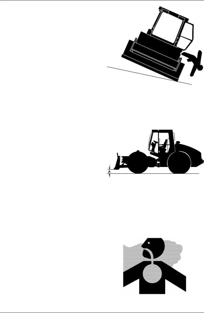
MANUALEQUIPOSPESADOS.COM
2. Safety precautions
AVOID TIPPING
When operating on a slope, keep blade low to ground and close to machine.
To avoid tipping:
— Be extra careful before operating on a grade.
— Prepare machine operating area flat by grading.
— Keep the blade low to the ground and close to the machine.
— Reduce machine operating speed to avoid tipping or slipping.
— Never attempt to travel across a grade steeper than 15 degrees.
Be careful when working on frozen ground.
— Temperature increases will cause the ground to b e — come soft and make ground travel unstable.
DRIVE MACHINE SAFELY
Before starting the machine, read carefully the “use and instructions manual” to get familiar with levers.
Before moving the machine, confirm which way to move pedals/levers for the corresponding direction you wish to go.
When traveling up or down a grade, keep the blade in the direction of travel, approximately 20 to 30 cm (A) above the ground.
BEWARE OF EXHAUST FUMES
Engine exhaust fumes can cause sickness or death.
If you must operate in a building, be sure there is adequate ventilation.
Either use an exhaust pipe extension to remove the exhaust fumes or open doors and windows to bring enough outside air into the area.
|
22 |
ASC 70 / 90 / 100 / 110 / 130 / 150 / 200 / 250 |
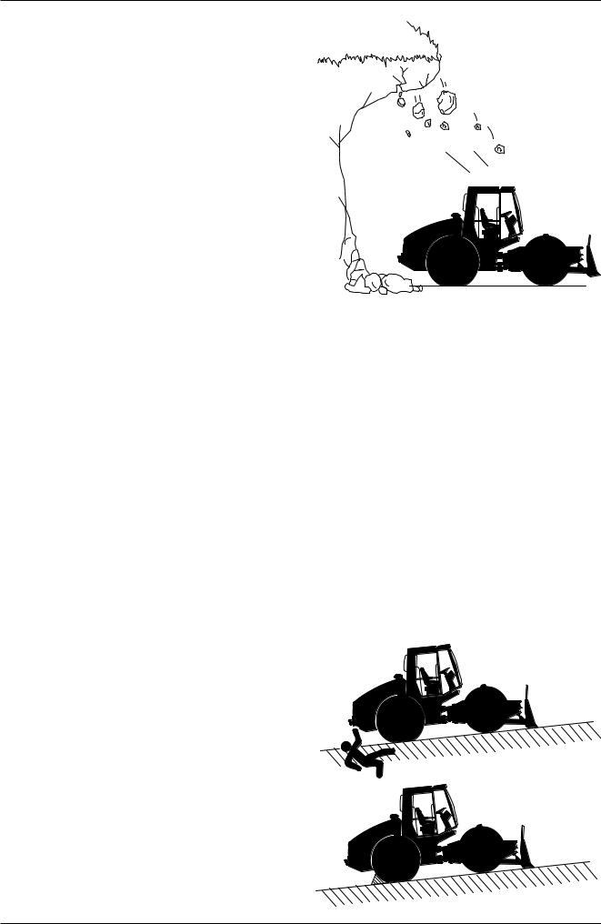
MANUALEQUIPOSPESADOS.COM
WORKSHOP MANUAL
PROTECTION OF CAB
In case of operation under conditions where land slides with falling rocks or any conditions where there is a potential falling of objects of different nature that could endanger the operator, it is necessary to install a FOPS (Falling Object Protective Structure) to protect the cab.
OPERATE WITH CAUTION
If the front attachment or any other part of the machine hits against an overhead obstacle, such as a bridge, both the machine and the overhead obstacle will be damaged, and personal injury may results as well.
AVOID INJURY FROM RUNAWAY ACCIDENTS
Death or serious injury may result if you attempt to stop a moving machine.
To avoid runaways:
Select level ground when possible to park machine. Lower dozing blade (blade) to the ground.
Lock articulation.
Stop the engine and remove the key from the key switch. Pull pilot control shut-off lever to LOCK position.
Block both tyres if you must park on a slope. Park a reasonable distance from other machine.
|
ASC 70 / 90 / 100 / 110 / 130 / 150 / 200 / 250 |
23 |
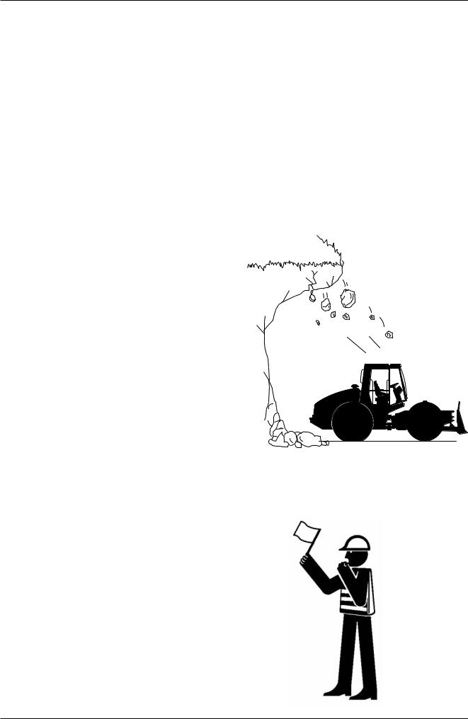
MANUALEQUIPOSPESADOS.COM
2. Safety precautions
PARK MACHINE SAFELY
Before working on the machine:
— Park machine on a level surface. — Lower bucket to the ground.
— Move turret swing lever to lock position.
— Run engine at slow idle speed without load for 3 minutes.
— Turn key switch to OFF to stop engine. Remove key from switch.
— Pull pilot control shut-off lever to LOCK position. — Allow engine to cool.
— Close windows, roof window, and cab door. — Lock all access doors and compartments.
NEVER WORK UNDER PROJECTING BANKS
The edges could collapse o a land slide could occur causing serious injury or death.
PROVIDE SIGNALS FOR JOBS INVOLVING A NUMBER OF MACHINES
For jobs involving several machines, provide signals commonly known by all personnel involved.
Also, appoint a signal person to co-ordinate the job site.
Make sure that all personnel obey the signal person’s directions.
|
24 |
ASC 70 / 90 / 100 / 110 / 130 / 150 / 200 / 250 |

MANUALEQUIPOSPESADOS.COM
WORKSHOP MANUAL
KEEP PERSONNEL CLEAR FROM WORKING AREA
A person may be hit severely by the swinging front attachment or counterweight and/or may be crushed against an other object, resulting in serious injury or death.
Keep all persons clear from the area of operation and machine movement.
Before operating the machine, set up barriers to the sides and rear area of the bucket swing radius to prevent anyone from entering the work area.
SAFETY TRANSPORTING
The danger of tipping is present when loading/unloading the machine onto/from a truck or trailer bed.
— Be sure to observe local regulations when transporting the machine on public roads.
— Provide an appropriate truck or trailer for transporting the machine.
Take the following precautions when loading/unloading the machine:
— Select firm level ground.
— Be sure t use a loading dock or ramp.
— Be sure to have a signal person when loading/unloading the machine.
— Always select the slow speed mode with the travel speed selector.
— Avoid steering while driving up or down the ramp as it is extremely dangerous.
If steering is unavoidable, first move back to the ground or flatbed, modify travelling direction, and begin to drive again.
— Operate the safety lever but do not operate any other control except travel control when driving up or down the ramp.
— The top end of the ramp where it meets the flatbed is a sudden bump. Take care when traveling over it.
— Securely fasten machine frame using chains or cables. Refer to “Transport” chapter in this manual for details.
|
ASC 70 / 90 / 100 / 110 / 130 / 150 / 200 / 250 |
25 |
3.8.
Appendixes
Hydraulic circuit – ASC110/130/150 – INTER — Wheel differential lock
Diagram:
1 — Travel pump
2 — Vibration pump*
3 — Drive drum hydromotor
4 — Vibration hydromotor**
5 — Wheel hydromotors
8 — Steering pump
9 — Power steering unit
1 0 — Brake block
1 1 — Steering hydraulic cylinder
1 2 — Divider lock
1 3 — Switch 60 bar
1 4 — Suction strainer
1 5 — Filter
1 6 — Filler
1 7 — Hydraulic tank float
1 8 — Combined cooler
1 8 — One-way valve
2 0 — Thermoregulator
2 1 — Check point
2 2 — Quick-release coupling — male
2 3 — Quick-release coupling — female
2 4 — Quick-release coupling — male
2 5 — Temperature sensor
2 6 — Lifting electro-hydraulic generator SMA03 HYTOS
2 7 — Lifting hand hydraulic generator RC16
2 8 — Lifting block
2 9 — Hydraulic lock
3 0 — Cabin lifting hydraulic cylinder
3 1 — Bonnet lifting hydraulic cylinder
* Rexroth A10VG 45 for ASC 110
Rexroth A10VG 63 for ASC 130/150
Sauer 90R042 for ASC 110 option
Sauer 90R055 for ASC 130/150 option
** Rexroth A10FM 45 for ASC 110
Rexroth A10FM 63 for ASC 130/150
Sauer 90M042 for ASC 110 option
Sauer 90M055 for ASC 130/150 option
190
SAUER
REXROTH
SAUER
REXROTH
SAUER
REXROTH
REXROTH
HYTOS
AXL SEMILY
HYTOS
HYTOS
HYTOS
DONALDSON
ARGO
EMMEGI
HYTOS
STAUFF
FASTER
FASTER
FASTER
SAUER
HYTOS
HYTOS
AXL SEMILY
AXL SEMILY
ASC110 / ASC130 / ASC150