- Manuals
- Brands
- ASROCK Manuals
- Motherboard
- P67 PRO3 —
- User manual
-
Contents
-
Table of Contents
-
Bookmarks
Quick Links
P67 Pro3
User Manual
Version 1.0
Published September 2010
Copyright©2010 ASRock INC. All rights reserved.
1
Related Manuals for ASROCK P67 PRO3
Summary of Contents for ASROCK P67 PRO3
-
Page 1
P67 Pro3 User Manual Version 1.0 Published September 2010 Copyright©2010 ASRock INC. All rights reserved. -
Page 2: Copyright Notice
(including damages for loss of profi ts, loss of business, loss of data, interruption of business and the like), even if ASRock has been advised of the possibility of such damages arising from any defect or error in the manual or product.
-
Page 3: Table Of Contents
….. 34 2.13 Hot Plug and Hot Swap Functions for SATA / SATAII HDDs …………….35 2.14 Hot Plug and Hot Swap Functions for SATA3 HDDs ..35 2.15 SATA / SATAII / SATA3 HDD Hot Plug Feature and Operation Guide …………
-
Page 4
® 2.18 Installing Windows 7 / 7 64-bit / Vista / Vista 64-bit / XP / XP 64-bit Without RAID Functions ….42 ® 2.18.1 Installing Windows XP / XP 64-bit Without RAID Functions…………42 ® 2.18.2 Installing Windows 7 / 7 64-bit / Vista Vista 64-bit Without RAID Functions …. -
Page 5: Introduction
ASRock’s commitment to quality and endurance. In this manual, chapter 1 and 2 contain introduction of the motherboard and step- by-step guide to the hardware installation. Chapter 3 and 4 contain the confi guration guide to BIOS setup and information of the Support CD.
-
Page 6: Specifi Cations
Specifications Platform — ATX Form Factor: 12.0-in x 9.6-in, 30.5 cm x 24.4 cm — All Solid Capacitor design (100% Japan-made high-quality Conductive Polymer Capacitors) ® — Supports 2nd Generation Intel Core i7 / i5 / i3 in LGA1155 Package — Advanced V8 + 2 Power Phase Design ®…
-
Page 7
— HD Audio Jack: Side Speaker/Rear Speaker/Central/Bass/ Line in/Front Speaker/Microphone (see CAUTION 5) SATA3 — 2 x SATA3 6.0 Gb/s connectors, support RAID (RAID 0, RAID 1, RAID 10, RAID 5 and Intel Rapid Storage), NCQ, AHCI and «Hot Plug» functions (SATA3_1 connector is shared with eSATA3 port) USB3.0… -
Page 8
Overclocking may affect your system stability, or even cause damage to the components and devices of your system. It should be done at your own risk and expense. We are not responsible for possible damage caused by overclocking. -
Page 9
BIOS setup menu to access ASRock Instant Flash. Just launch this tool and save the new BIOS fi le to your USB fl ash drive, fl oppy disk or hard drive, then you can update your BIOS only in a few clicks without prepar- ing an additional fl… -
Page 10
ASRock AIWI is the world’s fi rst utility to turn your iPhone/iPod touch as a game joystick to control your PC games. All you have to do is just to install the ASRock AIWI utility either from ASRock offi cial website or ASRock software support CD to your motherboard, and also download the free AIWI Lite from App store to your iPhone/iPod touch. -
Page 11
EuP ready power supply are required. According to Intel’s suggestion, the EuP ready power supply must meet the standard of 5v standby power effi ciency is higher than 50% under 100 mA current consumption. For EuP ready power supply selection, we recommend you… -
Page 12: Motherboard Layout
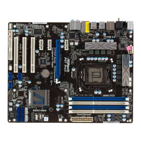
(HDMI_SPDIF1, White) System Panel Header (PANEL1, White) PCI Slots (PCI1-3) Intel P67 Chipset PCI Express 2.0 x1 Slot (PCIE4, White) SATA3 Connector (SATA3_1, White) PCI Express 2.0 x1 Slot (PCIE3, White) SATA3 Connector (SATA3_0, White) PCI Express 2.0 x16 Slot (PCIE2, Blue) SATA2 Connector (SATA2_3, Blue) PCI Express 2.0 x1 Slot (PCIE1, White)
-
Page 13: I/O Panel
Line In (Light Blue) PS/2 Keyboard Port (Purple) ** 9 Front Speaker (Lime) * There are two LED next to the LAN port. Please refer to the table below for the LAN port LED indications. LAN Port LED Indications ACT/LINK…
-
Page 14
To enable Multi-Streaming function, you need to connect a front panel audio cable to the front panel audio header. After restarting your computer, you will fi nd “Mixer” tool on your system. Please select “Mixer ToolBox” , click “Enable playback multi-streaming”, and click “ok”. -
Page 15: Installation
Chapter 2: Installation This is an ATX form factor (12.0″ x 9.6″, 30.5 x 24.4 cm) motherboard. Before you install the motherboard, study the confi guration of your chassis to ensure that the motherboard fi ts into it. Make sure to unplug the power cord before installing or removing the motherboard.
-
Page 16: Cpu Installation
Before you insert the 1155-Pin CPU into the socket, please check if the CPU surface is unclean or if there is any bent pin on the socket. Do not force to insert the CPU into the socket if above situation is found. Other- wise, the CPU will be seriously damaged.
-
Page 17
1155-Pin CPU For proper inserting, please ensure to match the two orientation key notches of the CPU with the two alignment keys of the socket. Step 3-3. Carefully place the CPU into the socket by using a purely vertical mo- tion. -
Page 18: Installation Of Cpu Fan And Heatsink
Installation of CPU Fan and Heatsink This motherboard is equipped with 1155-Pin socket that supports Intel 1155-Pin CPU. Please adopt the type of heatsink and cooling fan compliant with Intel 1155- Pin CPU to dissipate heat. Before you installed the heatsink, you need to spray thermal interface material between the CPU and the heatsink to improve heat dis- sipation.
-
Page 19: Installation Of Memory Modules (Dimm)
fi guration, you always need to install identical (the same brand, speed, size and chip-type) DDR3 DIMM pair in the slots of the same color. In other words, you have to install identical DDR3 DIMM pair in Dual Channel A (DDR3_ A1 and DDR3_B1;…
-
Page 20: Installing A Dimm
DIMMs or the system components. Step 1. Unlock a DIMM slot by pressing the retaining clips outward. Step 2. Align a DIMM on the slot such that the notch on the DIMM matches the break on the slot. notch break…
-
Page 21: Expansion Slots (Pci And Pci Express Slots)
2.6 Expansion Slots (PCI and PCI Express Slots) There are 3 PCI slots and 4 PCI Express slots on this motherboard. PCI slots: PCI slots are used to install expansion cards that have the 32-bit PCI interface. PCIE slots: PCIE1 / PCIE3 / PCIE4 (PCIE x1 slot; White) is used for PCI Express cards with x1 lane width cards, such as Gigabit LAN card, SATA2 card, etc.
-
Page 22: Jumpers Setup
CMOS when you just fi nish updating the BIOS, you must boot up the system fi rst, and then shut it down before you do the clear-CMOS ac- tion. Please be noted that the password, date, time, user default profi le, 1394 GUID and MAC address will be cleared only if the CMOS battery is removed.
-
Page 23: Onboard Headers And Connectors
FDD connector (33-pin FLOPPY1) (see p.12 No. 29) the red-striped side to Pin1 Note: Make sure the red-striped side of the cable is plugged into Pin1 side of the connector. Serial ATAII Connectors These four Serial ATAII (SATAII) SATA2_3…
-
Page 24
USB 2.0 Headers Besides six default USB 2.0 USB_PWR ports on the I/O panel, there (9-pin USB8_9) DUMMY are three USB 2.0 headers on (see p.12 No. 25) this motherboard. Each USB 2.0 header can support USB_PWR two USB 2.0 ports. -
Page 25: Front Panel Audio Header
Connect to the power status indicator on the chassis front panel. The LED is on when the system is operating. The LED keeps blinking when the sys- tem is in S1 sleep state. The LED is off when the system is in S3/S4 sleep state or powered off (S5).
-
Page 26
Though this motherboard provides 4-Pin CPU fan (Quiet Fan) support, the 3-Pin CPU fan still can work successfully even without the fan speed control function. If you plan to connect the 3-Pin CPU fan to the CPU fan connector on this motherboard, please connect it to Pin 1-3. -
Page 27
Though this motherboard provides 8-pin ATX 12V power connector, it can still work if you adopt a traditional 4-pin ATX 12V power supply. To use the 4-pin ATX power supply, please plug your power supply along with Pin 1 and Pin 5. -
Page 28: Smart Switches
2.9 Smart Switches The motherboard has three smart switches: power switch, reset switch and clear CMOS switch, allowing users to quickly turn on/off or reset the sytem clear the CMOS values. Power Switch Power Switch is a smart switch, allowing users to quickly turn (PWRBTN) on/off the system.
-
Page 29: Dr. Debug
2.10 Dr. Debug Dr. Debug is used to provide code information, which makes troubleshooting even easier. Please see the diagrams below for reading the Dr. Debug codes. SEC Phase Status Code Description 0x00 Not used Progress Codes 0x01 Power on. Reset type detection (soft/hard)
-
Page 30
0x5B reset PPI is not available 0x5C-0x5F Reserved for future AMI error codes S3 Resume Progress Codes 0xE0 S3 Resume is stared (S3 Resume PPI is called by the DXE IPL) 0xE1 S3 Boot Script execution 0xE2 Video repost 0xE3… -
Page 31
North Bridge DXE initialization is started 0x6A North Bridge DXE SMM initialization is started 0x6B North Bridge DXE initialization (North Bridge module specifi c) 0x6C North Bridge DXE initialization (North Bridge module specifi c) 0x6D North Bridge DXE initialization (North Bridge module specifi c) 0x6E North Bridge DXE initialization (North Bridge module specifi… -
Page 32
0xA7 SCSI Enable 0xA8 Setup Verifying Password 0xA9 Start of Setup 0xAA Reserved for ASL (see ASL Status Codes section below) 0xAB Setup Input Wait 0xAC Reserved for ASL (see ASL Status Codes section below) 0xAD Ready To Boot event… -
Page 33
System is waking up from the S3 sleep state 0x40 System is waking up from the S4 sleep state 0xAC System has transitioned into ACPI mode. Interrupt controller is in PIC mode 0xAA System has transitioned into ACPI mode. Interrupt controller is in APIC mode… -
Page 34: Serial Ata (Sata) / Serial Ataii (Sataii) Hard Disks Installation
STEP 3: Connect one end of the SATA data cable to the motherboard’s SATAII con- nector. STEP 4: Connect the other end of the SATA data cable to the SATA / SATAII hard disk. 2.12 Serial ATA3 (SATA3) Hard Disks Installation ®…
-
Page 35: Hot Plug And Hot Swap Functions For Sata / Sataii Hdds
SATA / SATAII HDD. What is Hot Swap Function? If SATA / SATAII HDDs are built as RAID 1 or RAID 5 then it is called “Hot Swap” for the action to insert and remove the SATA / SATAII HDDs while the system is still power-on and in working condition.
-
Page 36: Sata / Sataii / Sata3 Hdd Hot Plug Feature And Operation Guide
1. Below operation procedure is designed only for our motherboard, which supports SATA / SATAII / SATA3 HDD Hot Plug. * The SATA / SATAII / SATA3 Hot Plug feature might not be supported by the chipset because of its limitation, the SATA / SATAII / SATA3 Hot Plug support information of our motherboard is indicated in the product spec on our website: www.asrock.com…
-
Page 37
SATA / SATAII / SATA3 HDD damage and data loss. Step 1 Unplug SATA data cable from SATA / SATAII / SATA3 HDD side. Step 2 Unplug SATA 15-pin power cable connector (Black) from SATA / SATAII / SATA3 HDD side. -
Page 38: Driver Installation Guide
Start to format and copy fi les [YN]? Please insert a fl oppy diskette into the fl oppy drive, and press <Y>. E. The system will start to format the fl oppy diskette and copy SATA / SATAII / SATA3 drivers into the fl oppy diskette.
-
Page 39: Setting Up A «Raid Ready» System
Rapid Storage” will be installed to your system as well. 2.17.2 Setting Up a “RAID Ready” System You can also set up a “RAID Ready” system with a single SATA / SATAII / SATA3 hard disk. A “RAID Ready” system can be seamlessly upgraded to RAID 0, RAID 1 or RAID 5 at a later date by using RAID migration feature of Intel Rapid Storage.
-
Page 40: Raid 1 Or Raid 5
Rapid Storage Console which can be used to manage the RAID confi guration. 7. After setting up a “RAID Ready” system as the above steps, you can follow the procedures of the next section to migrate the system to RAID 0, RAID 1 or RAID 2.17.3 Migrating a “RAID Ready”…
-
Page 41: Installing Windows
Support CD, “Guide to SATA Hard Disks Installation and RAID Confi guration”, which is lo- cated in the folder at the following path: .. RAID Installation Guide and the document in the support CD, “Guide to Intel Rapid Storage”, which is located in the folder at the follow- ing path: ..
-
Page 42: Xp / Xp 64-Bit Without Raid Functions
2 on page 38. ® STEP 3: Install Windows XP / XP 64-bit OS on your system. After making a SATA / SATAII / SATA3 driver diskette, you can start to install Win- ® ® dows XP / XP 64-bit on your system. At the beginning of Windows setup, press F6 to install a third-party AHCI driver.
-
Page 43: Vista Tm 64-Bit Without Raid Functions
7 / 7 64-bit / Vista / Vista 64-bit OS on your SATA / SATAII / SATA3 HDDs without RAID functions, please follow below steps. Using SATA / SATAII / SATA3 HDDs with NCQ function STEP 1: Set Up BIOS.
-
Page 44: Uefi Setup Utility
To exit the current screen or the UEFI SETUP UTILITY Use < > key or < > key to choose among the selections on the menu bar, and then press <Enter> to get into the sub screen. You can also use the mouse to click your required item.
-
Page 45: Navigation Keys
To save changes and exit the UEFI SETUP UTILITY <ESC> To jump to the Exit Screen or exit the current screen 3.2 Main Screen When you enter the UEFI SETUP UTILITY, the Main screen will appear and display the system overview.
-
Page 46: Advanced Screen
fi rst like MS-DOS or Windows . Just launch this tool and save the new UEFI fi le to your USB fl ash drive, fl oppy disk or hard drive, then you can update your UEFI only in a few clicks without preparing an additional fl…
-
Page 47: Cpu Confi Guration
Vista / 7 and want to enable this function, please set this item to [Enabled]. This item will be hidden if the current CPU does not support Intel SpeedStep technology. Please note that enabling this function may reduce CPU voltage and lead to system stability or compatibility issue with some power supplies.
-
Page 48
CPU does not support Hyper-Threading technology. Active Processor Cores Use this item to select the number of cores to enable in each processor package. Confi guration options: [All], [1] and [2]. The default value is [All]. -
Page 49: Integrated Clock Chip Confi Guration
3.3.2 Integrated Clock Chip Configuration DIV-1S Integrated Clock Control options. DIV-2S Integrated Clock Control options. DIV3 Integrated Clock Control options. DIV4 Integrated Clock Control options. DIV-1NS Integrated Clock Control options. DIV-2NS Integrated Clock Control options.
-
Page 50: Dram Confi Guration
3.3.3 DRAM Configuration Load XMP Setting Use this to load XMP setting. Confi guration options: [Auto], [Profi le 1] and [Profi le 2]. The default value is [Auto]. DRAM Frequency If [Auto] is selected, the motherboard will detect the memory module(s) inserted and assigns appropriate frequency automatically.
-
Page 51
RAS to RAS Delay (tRRD) Use this item to change RAS to RAS Delay (tRRD) Auto/Manual setting. The default is [Auto]. Write to Read Delay (tWTR) Use this item to change Write to Read Delay (tWTR) Auto/Manual setting. The default is [Auto]. -
Page 52: North Bridge Confi Guration
Virtualization Technology for Directed I/O). The default value of this feature is [Disabled]. Primary Graphics Adapter This allows you to select [PCI] or [PCI Express] as the boot graphic adapter priority. The default value is [PCI]. 3.3.5 South Bridge Configuration…
-
Page 53: South Bridge Confi Guration
Select [Auto] or [Disabled] for the onboard HD Audio Front Panel. ACPI HPET Table Use this item to enable or disable ACPI HPET Table. The default value is [Enabled]. Please set this option to [Enabled] if you plan to use this ®…
-
Page 54: Storage Confi Guration
3.3.6 Storage Configuration SATA Mode Use this to select SATA mode. Confi guration options: [IDE Mode], [AHCI Mode] and [RAID Mode]. The default value is [IDE Mode]. AHCI (Advanced Host Controller Interface) supports NCQ and other new features that will improve SATA disk perfor- mance but IDE mode does not have these advantages.
-
Page 55: Super Io Confi Guration
Use this item to enable or disable the onboard serial port. Serial Port Address Use this item to set the address for the onboard serial port or disable it. Confi guration options: [Disabled], [3F8 / IRQ4], [2F8 / IRQ3], [3E8 / IRQ4], [2E8 / IRQ3].
-
Page 56: Voltage Confi Guration
3.3.8 Voltage Configuration CPU Core Voltage Offset Use this to select CPU Core Voltage Offset. Confi guration options: [Auto], [+0.005V] to [+0.300V]. The default value is [Auto]. DRAM Voltage Use this to select DRAM Voltage. Confi guration options: [Auto], [1.200V] to [2.040V].
-
Page 57: Acpi Confi Guration
Use this item to enable or disable PS/2 keyboard to turn on the system from the power-soft-off mode. PCI Devices Power On Use this item to enable or disable PCI devices to turn on the system from the power-soft-off mode. Ring-In Power On Use this item to enable or disable Ring-In signals to turn on the system from the power-soft-off mode.
-
Page 58: Usb Confi Guration
3.3.10 USB Configuration USB 2.0 Controller Use this item to enable or disable the use of USB 2.0 controller. USB 3.0 Controller Use this item to enable or disable the use of USB 3.0 controller. Legacy USB Support Use this option to select legacy support for USB devices. There are four confi…
-
Page 59: Hardware Health Event Monitoring Screen
3.4 Hardware Health Event Monitoring Screen In this section, it allows you to monitor the status of the hardware on your system, including the parameters of the CPU temperature, motherboard temperature, CPU fan speed, chassis fan speed, and the critical voltage.
-
Page 60: Boot Screen
3.5 Boot Screen In this section, it will display the available devices on your system for you to confi g- ure the boot settings and the boot priority. Bootup Num-Lock If this item is set to [On], it will automatically activate the Numeric Lock function after boot-up.
-
Page 61: Security Screen
3.6 Security Screen In this section, you may set or change the supervisor/user password for the system. For the user password, you may also clear it.
-
Page 62: Exit Screen
When you select this option, it will pop-out the following message, “Discard changes?” Select [OK] to discard all changes. Load UEFI Defaults Load UEFI default values for all the setup questions. F9 key can be used for this operation. User Default In this option, you are allowed to load and save three user defaults according to your own requirements.
-
Page 63: Software Support
CD automatically displays the Main Menu if “AUTORUN” is enabled in your computer. If the Main Menu did not appear automatically, locate and double click on the fi le “ASSETUP.EXE” from the BIN folder in the Support CD to dis- play the menus.
-
Page 64
2. Set AHCI Mode in UEFI Setup Utility > Advanced > Storage Confi guration > SATA Mode. 3. Press F11 to launch boot menu at system POST. 4. Choose the item “UEFI:xxx“ to boot. (“xxx” is the device which contains ® your Windows installation fi…
-
Драйверы
21
-
Инструкции по эксплуатации
5
Языки:

Asrock P67 Pro3 инструкция по эксплуатации
(19 страниц)
- Языки:Английский
-
Тип:
PDF -
Размер:
834.6 KB
Просмотр

Asrock P67 Pro3 инструкция по эксплуатации
(15 страниц)
- Языки:Немецкий
-
Тип:
PDF -
Размер:
1.15 MB
Просмотр

Asrock P67 Pro3 инструкция по эксплуатации
(15 страниц)
- Языки:Французский
-
Тип:
PDF -
Размер:
989.26 KB
Просмотр

Asrock P67 Pro3 инструкция по эксплуатации
(15 страниц)
- Языки:Итальянский
-
Тип:
PDF -
Размер:
948.53 KB
Просмотр

Asrock P67 Pro3 инструкция по эксплуатации
(266 страниц)
-
Тип:
PDF -
Размер:
2.05 MB
Просмотр
На NoDevice можно скачать инструкцию по эксплуатации для Asrock P67 Pro3. Руководство пользователя необходимо для ознакомления с правилами установки и эксплуатации Asrock P67 Pro3. Инструкции по использованию помогут правильно настроить Asrock P67 Pro3, исправить ошибки и выявить неполадки.

135
ASRock P67 Pro3 SE Motherboard
1. Введение
Благодарим вас за покупку материнской платы ASRock P67 Pro3 SE надежной
материнской платы, изготовленной в соответствии с постоянно предъявляемыми ASRock
жесткими требованиями к качеству. Она обеспечивает превосходную производительность
и отличается отличной конструкцией, которые отражают приверженность ASRock качеству
и долговечности.
Данное руководство по быстрой установке включает вводную информацию о материнской
плате и пошаговые инструкции по ее установке. Более подробные сведения о плате
можно найти в руководстве пользователя на компакт-диске поддержки.
Спецификации материнской платы и программное обеспечение
BIOS
иногда изменяются, поэтому содержание этого руководства
может обновляться без уведомления. В случае любых
модификаций руководства его новая версия будет размещена на
веб-сайте ASRock без специального уведомления. Кроме того,
самые свежие списки поддерживаемых модулей памяти и
процессоров можно найти на сайте ASRock.
Адрес веб-сайта ASRock
http://www.asrock.com
При необходимости технической поддержки по вопросам данной
материнской платы посетите наш веб-сайт для получения
информации об используемой модели.
www.asrock.com/support/index.asp
1.1 Комплектность
Материнская плата ASRock P67 Pro3 SE
(форм-фактор ATX: 12,0 x 7,5 дюйма / 30,5 x 19,1 см)
Руководство по быстрой установке ASRock P67 Pro3 SE
Компакт-диск поддержки ASRock P67 Pro3 SE
2 x кабель данных Serial ATA (SATA) (дополнительно)
1 x I/O Щит Группы ввода / вывода
Ру
сский
ASRock напоминает…
Для обеспечения максимальной производительности ОС Windows
®
7 / 7 64-bit / Vista
TM
/ Vista
TM
64-bit рекомендуется в BIOS выбрать для
параметра Storage Configuration (Конфигурация запоминающего
устройства) режим AHCI. Подробные сведения о настройке BIOS см.
в руководстве пользователя на прилагаемом компакт-диске.

Русский
1.Введение
Благодарим вас за покупку материнской платы ASRock P67 Pro3 надежной материнской платы, изготовленной в соответствии с постоянно предъявляемыми ASRock жесткими требованиями к качеству. Она обеспечивает превосходную производительность и отличается отличной конструкцией, которые отражают приверженность ASRock качеству и долговечности.
Данное руководство по быстрой установке включает вводную информацию о материнской плате и пошаговые инструкции по ее установке. Более подробные сведения о плате можно найти в руководстве пользователя на компакт-диске поддержки.
Спецификации материнской платы и программное обеспечение BIOS иногда изменяются, поэтому содержание этого руководства может обновляться без уведомления. В случае любых модификаций руководства его новая версия будет размещена на веб-сайте ASRock без специального уведомления. Кроме того, самые свежие списки поддерживаемых модулей памяти и процессоров можно найти на сайте ASRock.
Адрес веб-сайта ASRock http://www.asrock.com
При необходимости технической поддержки по вопросам данной материнской платы посетите наш веб-сайт для получения информации об используемой модели. www.asrock.com/support/index.asp
1.1Комплектность
Материнская плата ASRock P67 Pro3
(форм-фактор ATX: 12,0 x 9,6 дюйма / 30,5 x 24,4 см) Руководство по быстрой установке ASRock P67 Pro3 Компакт-диск поддержки ASRock P67 Pro3
2 x кабель данных Serial ATA (SATA) (дополнительно)
1 x I/O Щит Группы ввода / вывода
ASRock напоминает…
Для обеспечения максимальной производительности ОС Windows® 7 / 7 64-bit / VistaTM / VistaTM 64-bit рекомендуется в BIOS выбрать для параметра Storage Configuration (Конфигурация запоминающего устройства) режим AHCI. Подробные сведения о настройке BIOS см. в руководстве пользователя на прилагаемом компакт-диске.
130
ASRock P67 Pro3 Motherboard

2
ASRock P67 Pro3 Motherboard
Motherboard Layout
English
1
ATX 12V Power Connector (ATX12V1)
21
Dr. Debug
2
CPU Fan Connector (CPU_FAN2)
22
Reset Switch (RSTBTN)
3
CPU Fan Connector (CPU_FAN1)
23
Power Switch (PWRBTN)
4
1155-Pin CPU Socket
24
USB 2.0 Header (USB12_13, Blue)
5
2 x 240-pin DDR3 DIMM Slots
25
USB 2.0 Header (USB8_9, Blue)
(Dual Channel: DDR3_A1, DDR3_B1, Blue)
26
USB 2.0 Header (USB10_11, Blue)
6
2 x 240-pin DDR3 DIMM Slots
27
Chassis Fan Connector (CHA_FAN1)
(Dual Channel: DDR3_A2, DDR3_B2, White)
28
Infrared Module Header (IR1)
7
ATX Power Connector (ATXPWR1)
29
Floppy Connector (FLOPPY1)
8
Clear CMOS Jumper (CLRCMOS1)
30
COM Port Header (COM1)
9
Chassis Fan Connector (CHA_FAN2)
31
Front Panel Audio Header
10
64Mb SPI Flash
(HD_AUDIO1, White)
11
Power LED Header (PLED1)
32
HDMI_SPDIF Header
12
Chassis Speaker Header (SPEAKER 1, White)
(HDMI_SPDIF1, White)
13
System Panel Header (PANEL1, White)
33
PCI Slots (PCI1-3)
14
Intel P67 Chipset
34
PCI Express 2.0 x1 Slot (PCIE4, White)
15
SATA3 Connector (SATA3_1, White)
35
PCI Express 2.0 x1 Slot (PCIE3, White)
16
SATA3 Connector (SATA3_0, White)
36
PCI Express 2.0 x16 Slot (PCIE2, Blue)
17
SATA2 Connector (SATA2_3, Blue)
37
PCI Express 2.0 x1 Slot (PCIE1, White)
18
SATA2 Connector (SATA2_2, Blue)
38
Chassis Fan Connector (CHA_FAN3)
19
SATA2 Connector (SATA2_4, Blue)
39
Power Fan Connector (PWR_FAN1)
20
SATA2 Connector (SATA2_5, Blue)
Intel
P67
24.4cm (9.6 in)
30.5cm
(12.0
in)
DDR3_A1
(64
bit,
240-pin
module)
DDR3_A2
(64
b
it,
2
40-pin
module)
DDR3_B1
(64
b
it,
2
40-pin
module)
DDR3_B2
(64
b
it,
2
40-pin
module)
A
T
XPWR1
CHA_FAN1
CLRCMOS1
1
ATX12V1
CHA_FAN2
CPU_FAN1
CPU_FAN2
P67 Pro3
64Mb
BIOS
PWRBTN
RSTBTN
Dr.
Debug
Super
I/O
PCIE1
PCIE2
PCI1
CMOS
Battery
SATA2_5
SATA2_4
HDLED RESET
PLED PWRBTN
PANEL1
1
SPEAKER1
1
PLED1
1
USB12_13
1
USB10_11
1
USB8_9
1
1
HD_AUDIO1
FLOPPY1
COM1
1
IR1
1
1
HDMI_SPDIF1
LAN
PHY
AUDIO
CODEC
PS2
Mouse
Coaxial
SPDIF
PS2
Keyboard
Optical
SPDIF
Clr
CMOS
USB 2.0
T: USB4
B: USB5
Top:
RJ-45
USB 2.0
T: USB0
B: USB1
T
op:
SIDE
SPK
Center:
REAR
SPK
T
op:
LINE
IN
Center:
FRONT
Bottom:
CTR
B
ASS
Bottom:
MIC
IN
USB 2.0
T: USB6
B: USB7
eSA
T
A
PWR_F
AN1
Dual
Channel
PCI Express 2.0
ErP/EuP Ready
RoHS
USB 3.0
Designed in Taipei
SA
TA
3
6
Gb/s
1
2
3
4
5
6
7
11
12
13
14
16
8
9
10
15
17
18
24
19
20
21
22
23
25
26
27
28
29
30
31
32
33
34
35
36
37
38
39
PCIE3
PCIE4
PCI2
PCI3
SATA2_3
SATA2_2
SATA3_1
SATA3_0
CHA_F
AN3
DDR3
2133
USB 3.0
T: USB2
B: USB3