6.
ATX power connectors (24-pin EATXPWR, 4-pin ATX12V)
These connectors are for ATX power supply plugs. The power supply plugs are
designed to fit these connectors in only one orientation. Find the proper orientation and
push down firmly until the connectors completely fit.
• For a fully configured system, we recommend that you use a power supply unit (PSU)
that complies with EATX 12 V Specification 2.0 (or later version) and provides a
minimum power of 400 W.
• Do not forget to connect the 4-pin ATX12V power plug. Otherwise, the system will not
boot.
• We recommended that you use a PSU with a higher power output when configuring a
system with more power-consuming devices. The system may become unstable or may
not boot up if the power is inadequate.
7.
Speaker connector (4-pin SPEAKER)
This 4-pin connector is for the chassis-mounted system warning speaker. The speaker
allows you to hear system beeps and warnings.
1-13
ASUS P5KPL-AM IN/ROEM/SI
-
Contents
-
Table of Contents
-
Bookmarks
Quick Links
Related Manuals for Asus P5KPL-AM IN ROEM SI
Summary of Contents for Asus P5KPL-AM IN ROEM SI
-
Page 1
P5KPL-AM IN/ROEM/SI… -
Page 2
Product warranty or service will not be extended if: (1) the product is repaired, modified or altered, unless such repair, modification of alteration is authorized in writing by ASUS; or (2) the serial number of the product is defaced or missing. -
Page 3: Table Of Contents
BIOS information Managing and updating your BIOS ……….2-1 2.1.1 ASUS Update utility …………2-1 2.1.2 ASUS EZ Flash 2 utility ……….. 2-2 2.1.3 ASUS CrashFree BIOS 3 utility ……..2-3 BIOS setup program …………..2-4 Main menu ………………2-4 2.3.1…
-
Page 4
Boot menu ……………… 2-13 2.6.1 Boot Device Priority …………2-13 2.6.2 Boot Settings Configuration ………. 2-13 2.6.3 Security …………….. 2-14 Tools menu …………….. 2-15 2.7.1 ASUS EZ Flash 2 …………2-15 2.7.2 AI NET 2……………. 2-15 Exit menu ………………2-16… -
Page 5: Notices
Notices Federal Communications Commission Statement This device complies with Part 15 of the FCC Rules. Operation is subject to the following two conditions: • This device may not cause harmful interference, and • This device must accept any interference received including interference that may cause undesired operation.
-
Page 6: Safety Information
Safety information Electrical safety • To prevent electric shock hazard, disconnect the power cable from the electric outlet before relocating the system. • When adding or removing devices to or from the system, ensure that the power cables for the devices are unplugged before the signal cables are connected. If possible, disconnect all power cables from the existing system before you add a device.
-
Page 7: Conventions Used In This Guide
Refer to the following sources for additional information and for product and software updates. ASUS websites The ASUS website provides updated information on ASUS hardware and software products. Optional documentation Your product package may include optional documentation, such as warranty flyers, that may have been added by your dealer.
-
Page 8: P5Kpl-Am In/Roem/Si Specifications Summary
Memory Dual channel memory architecture 2 x 240-pin DIMM sockets supports unbuffered non-ECC 4GB 1066(O.C.)/800/667 MHz DDR2 memory modules * Refer to www.asus.com for memory QVL (Qualify Vendor List) Expansion Slots 1 x PCI Express x16 slot 2 x PCI slots…
-
Page 9
8 Mb Flash ROM, AMI BIOS, PnP, DMI2.0, WfM2.0, SM BIOS 2.5 Manageability WOL, PXE,RPL, WOR, PME Wake Up Support CD contents Drivers ASUS PC Probe II ASUS Update utility Accessories 1 x Serial ATA cable 1 x Ultra ATA66 cable I/O shield… -
Page 10: Chapter 1 Product Introduction
Chapter 1 Product introduction Thank you for buying an ASUS P5KPL-AM IN/ROEM/SI motherboard! ® Before you start installing the motherboard, and hardware devices on it, check the items in your motherboard package. Refer to page ix for the list of accessories.
-
Page 11: Motherboard Overview
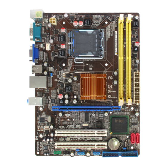
Motherboard overview 1.2.1 Motherboard layout Ensure that you install the motherboard into the chassis in the correct orientation. The edge with external ports goes to the rear part of the chassis. Place this side towards the rear of the chassis. 14 13 Place six screws into the holes indicated by circles to secure the motherboard to the chassis.
-
Page 12: Central Processing Unit (Cpu)
Contact your retailer immediately if the PnP cap is missing, or if you see any damage to the PnP cap/socket contacts/motherboard components. ASUS will shoulder the cost of repair only if the damage is shipment/ transit-related.
-
Page 13
• You may install varying memory sizes in Channel A and Channel B. The system maps the total size of the lower-sized channel for the dual-channel configuration. Any excess memory from the higher-sized channel is then mapped for single-channel operation. •… -
Page 14
Kingston KHX6400D2LL/1G 1024MB Kingston Heat-Sink Package • • Kingston KVR800D2N5/1G 1024MB Kingston D6408TR4CGL25USL3624 • • 06PECXA Kingston KVR800D2N6/1G 1024MB Elpida E5108AJBG-8E-E • • Kingston KHX6400D2K2/2G 2048MB(Kit of 2) Heat-Sink Package • • (continued on the next page) ASUS P5KPL-AM IN/ROEM/SI… -
Page 15
DIMM support Chip Vendor Part No. Size Chip NO. Brand Kingston 461625.010819 PTGC 2048MB Kingston KVR800D2N6/2G • • Kingston KHX6400D2/2G 2048MB Kingston Heat-Sink Package • • Kingston KVR800D2N5/2G 2048MB Elpida E1108ACBG-8E-E • • Kingston KVR800D2N6/4G 4096MB Elpida E2108ABSE-8G-E • • OCZ2G800R22GK 1024MB Heat-Sink Package… -
Page 16: Expansion Slots
Visit the ASUS website at (www.asus.com) for the latest QVL. SS — Single-sided / DS — Double — sided DIMM support: • A*: Supports one module inserted into any slot as Single-channel memory configuration. • B*: Supports one pair of modules inserted into the yellow slots as one pair of Dual-channel memory configuration.
-
Page 17: Clear Rtc Ram
Clear RTC RAM (CLRTC) This jumper allows you to clear the Real Time Clock (RTC) RAM in CMOS. You can clear the CMOS memory of date, time, and system setup parameters by erasing the CMOS RTC RAM data. The onboard button cell battery powers the RAM data in CMOS, which include system setup information such as system passwords.
-
Page 18: Connectors
Local Area Network (LAN) through a network hub. Refer to the table below for the LAN port LED indications. LAN port LED indications ACT/LINK SPEED ACT LED Speed LED Status Description Status Description No link No link Blink Data activity Blink Data activity Green 100M LAN port ASUS P5KPL-AM IN/ROEM/SI…
-
Page 19: Internal Connectors
Line In port (light blue). This port connects to the tape, CD, DVD player, or other audio sources. Line Out port (lime). This port connects to a headphone or a speaker. In 4-channel and 6-channel configuration, the function of this port becomes Front Speaker Out. Microphone port (pink).
-
Page 20
These USB connectors comply with USB 2.0 specification that supports up to 480 Mbps connection speed. Never connect a 1394 cable to the USB connectors. Doing so will damage the motherboard! The USB module cable is purchased separately. 1-11 ASUS P5KPL-AM IN/ROEM/SI… -
Page 21
Do not forget to connect the fan cables to the fan connectors. Insufficient air flow inside the system may damage the motherboard components. These are not jumpers! Do not place jumper caps on the fan connectors! Only the CPU_FAN connector support the ASUS Advanced Q-Fan feature. Chapter 1: Product introduction 1-12… -
Page 22
The system may become unstable or may not boot up if the power is inadequate. Speaker connector (4-pin SPEAKER) This 4-pin connector is for the chassis-mounted system warning speaker. The speaker allows you to hear system beeps and warnings. 1-13 ASUS P5KPL-AM IN/ROEM/SI… -
Page 23
System panel connector (10-1 pin F_PANEL) This connector supports several chassis-mounted functions. System power LED (2-pin PWRLED) • This 2-pin connector is for the system power LED. Connect the chassis power LED cable to this connector. The system power LED lights up when you turn on the system power, and blinks when the system is in sleep mode. -
Page 24: Software Support
Click an item to install If Autorun is NOT enabled in your computer, browse the contents of the Support CD to locate the file ASSETUP.EXE from the BIN folder. Double-click the ASSETUP.EXE to run the CD. 1-15 ASUS P5KPL-AM IN/ROEM/SI…
-
Page 25: Chapter 2 Bios Information
BIOS in the future. Copy the original motherboard BIOS using the ASUS Update utility. 2.1.1 ASUS Update utility The ASUS Update is a utility that allows you to manage, save, and update the motherboard BIOS in Windows environment. ®…
-
Page 26: Asus Ez Flash 2 Utility
2.1.2 ASUS EZ Flash 2 utility ASUS EZ Flash 2 allows you to update the BIOS without having to use a DOS-based utility. Download the latest BIOS file for this motherboard from the ASUS website at www.asus.com. To update the BIOS using EZ Flash 2.
-
Page 27: Asus Crashfree Bios 3 Utility
2.1.3 ASUS CrashFree BIOS 3 utility The ASUS CrashFree BIOS 3 is an auto recovery tool that allows you to restore the BIOS file when it fails or gets corrupted during the updating process. You can update a corrupted BIOS file using the motherboard support CD or a USB flash disk that contains the updated BIOS file.
-
Page 28: Bios Setup Program
• The BIOS setup screens in this section are for reference only. They may not exactly match what you see on your screen. • Visit the ASUS website at www.asus.com to download the latest BIOS file for this motherboard. Main menu When you enter the BIOS Setup program, the Main menu screen appears, giving you an overview of the basic system information.
-
Page 29: Primary Ide/Sata1-2
2.3.3 Primary IDE/SATA1-2 While entering Setup, the BIOS automatically detects the presence of IDE/SATA devices. There is a separate sub-menu for each IDE/SATA device. Select a device item then press <Enter> to display the IDE/SATA device information. The BIOS automatically detects the values opposite the dimmed items (Device, Vendor, Size, LBA Mode, Block Mode, PIO Mode, Async DMA, Ultra DMA, and SMART monitoring).
-
Page 30: System Information
Manual — allows you to individually set overclocking parameters. Auto — loads the optimal settings for the system. Overclock Profile — loads overclocking profiles with optimal parameters for stability when overclocking. Test Mode — loads overclock (overclocking 5%) with spread spectrum. ASUS P5KPL-AM IN/ROEM/SI…
-
Page 31
The following item appears only when you set the AI Overclocking item to [Manual]. CPU Frequency [xxx] Displays the frequency sent by the clock generator to the system bus and PCI bus. The value of this item is auto-detected by the BIOS. Use the <+> and <-> keys to adjust the CPU frequency. -
Page 32: Usb Configuration
Enable this item to boot legacy operating systems that cannot support CPUs with extended CPUID functions. Configuration options: [Disabled] [Enabled] Vanderpool Technology [Enabled] Enable this item when the processor supports Vanderpool technology. Users need to reset the computer to change the configuration of this item. Configuration options: [Disabled] [Enabled] ASUS P5KPL-AM IN/ROEM/SI…
-
Page 33: Chipset
CPU TM function [Enabled] Enables or disables Intel® CPU Thermal Monitor (TM2) function, a CPU overheating protection function. When enabled, the CPU core frequency and voltage is reduced when the CPU is overheats. Configuration options: [Enabled] [Disabled] Execute Disable Bit [Enabled] Allows you to Enable/disable Execute Disable Function.
-
Page 34: Onboard Devices Configuration
Palette Snooping [Disabled] When set to [Enabled], the pallete snooping feature informs the PCI devices that an ISA graphics device is installed in the system so that the latter can function correctly. Configuration options: [Disabled] [Enabled] 2-10 ASUS P5KPL-AM IN/ROEM/SI…
-
Page 35: Power Menu
IRQ-xx assigned to [PCI Device] When set to [PCI Device], the specific IRQ is free for use of PCI/PnP devices. When set to [Reserved], the IRQ is reserved for legacy ISA devices. Configuration options: [PCI Device] [Reserved] Power menu The Power menu items allow you to change the settings for the Advanced Power Management (APM).
-
Page 36: Hardware Monitor
VCORE Voltage, 3.3V Voltage, 5V Voltage, 12V Voltage The onboard hardware monitor automatically detects the voltage output through the onboard voltage regulators. CPU Q-Fan Control [Disabled] Allows you to enable or disable the Q-Fan control. Configuration options: [Disabled] [Enabled] 2-12 ASUS P5KPL-AM IN/ROEM/SI…
-
Page 37: Boot Menu
Chassis Q-Fan Control [Disabled] Allows you to enable or disable the Q-Fan control. Configuration options: [Disabled] [Enabled] Boot menu The Boot menu items allow you to change the system boot options. Select an item then press <Enter> to display the sub-menu. BIOS SETUP UTILITY Main Advanced…
-
Page 38: Security
[View Only] — allows access but does not allow change to any field. [Limited] — allows changes only to selected fields, such as Date and Time. [Full Access] — allows viewing and changing all the fields in the Setup utility. 2-14 ASUS P5KPL-AM IN/ROEM/SI…
-
Page 39: Tools Menu
2.7.1 ASUS EZ Flash 2 Allows you to run ASUS EZ Flash 2. When you press <Enter>, a confirmation message appears. Use the left/right arrow key to select between [Yes] or [No], then press <Enter> to confirm your choice. Please see section 2.1.3 for details.
-
Page 40: Exit Menu
When you select this option or if you press <F5>, a confirmation window appears. Select OK to load default values. Select Exit & Save Changes or make other changes before saving the values to the non-volatile RAM. 2-16 ASUS P5KPL-AM IN/ROEM/SI…
-
Драйверы
29
-
Инструкции по эксплуатации
2

ASUS P5KPL-AM IN/ROEM/SI инструкция по эксплуатации
(40 страниц)
- Языки:Английский
-
Тип:
PDF -
Размер:
1.5 MB -
Описание:
P5KPL-AM IN/ROEM/SI user’s manual(English)
Просмотр

ASUS P5KPL-AM IN/ROEM/SI инструкция по эксплуатации
(38 страниц)
-
Тип:
PDF -
Размер:
1.7 MB -
Описание:
P5KPL-AM IN/ROEM/SI European Quick Start Guide for Multiple Languages
Просмотр
На NoDevice можно скачать инструкцию по эксплуатации для ASUS P5KPL-AM IN/ROEM/SI. Руководство пользователя необходимо для ознакомления с правилами установки и эксплуатации ASUS P5KPL-AM IN/ROEM/SI. Инструкции по использованию помогут правильно настроить ASUS P5KPL-AM IN/ROEM/SI, исправить ошибки и выявить неполадки.
4 ноября 2013 г.
- Производитель
- Asus
- Модель
- P5KPL-AM IN/ROEM/SI
- Операционная система
-
- Windows 8.1
- Windows 8
- Windows 7
- Windows Vista
- Windows Server 2003
- Windows XP
- Windows 2000
- MS-DOS
- Тип файла
-
- Инструкция
- Версия
-
E4555
32-bit
64-bit
Просмотреть содержимое архива
Вы нашли то, что искали?
Дополнительная информация
P5KPL-AM IN/ROEM/SI user’s manual(English)
Полезно
0 %
0
Commentary
Ваше имя
 Loading…
![]()

E4422
First Edition V1
February 2009
Copyright © 2009 ASUSTeK Computer Inc. All Rights Reserved.
No part of this manual, including the products and software described in it, may be reproduced, transmitted, transcribed, stored in a retrieval system, or translated into any language in any form or by any means, except documentation kept by the purchaser for backup purposes, without the express written permission of ASUSTeK Computer Inc. (“ASUS”).
Product warranty or service will not be extended if: (1) the product is repaired, modified or altered, unless such repair, modification of alteration is authorized in writing byASUS; or (2) the serial number of the product is defaced or missing.
ASUS PROVIDES THIS MANUAL “AS IS” WITHOUT WARRANTY OF ANY KIND, EITHER EXPRESS OR IMPLIED, INCLUDING BUT NOT LIMITED TO THE IMPLIED WARRANTIES OR CONDITIONS OF MERCHANTABILITY OR FITNESS FOR A PARTICULAR PURPOSE. IN NO EVENT SHALL ASUS, ITS DIRECTORS, OFFICERS, EMPLOYEES OR AGENTS BE LIABLE FOR ANY INDIRECT, SPECIAL, INCIDENTAL, OR CONSEQUENTIAL DAMAGES (INCLUDING DAMAGES FOR LOSS OF PROFITS, LOSS OF BUSINESS, LOSS OF USE OR DATA, INTERRUPTION OF BUSINESS AND THE LIKE), EVEN IF ASUS HAS BEEN ADVISED OF THE POSSIBILITY OF SUCH DAMAGES ARISING FROM ANY DEFECT OR ERROR IN THIS MANUAL OR PRODUCT.
SPECIFICATIONS AND INFORMATION CONTAINED IN THIS MANUAL ARE FURNISHED FOR INFORMATIONAL USE ONLY, AND ARE SUBJECT TO CHANGE AT ANY TIME WITHOUT NOTICE, AND SHOULD NOT BE CONSTRUED AS A COMMITMENT BY ASUS. ASUS ASSUMES NO RESPONSIBILITY OR LIABILITY FOR ANY ERRORS OR INACCURACIES THAT MAY APPEAR IN THIS MANUAL, INCLUDING THE PRODUCTS AND SOFTWARE DESCRIBED IN IT.
Products and corporate names appearing in this manual may or may not be registered trademarks or copyrights of their respective companies, and are used only for identification or explanation and to the owners’ benefit, without intent to infringe.
ii

Contents
|
Notices……………………………………………………………………………………………. |
v |
|
Safety information…………………………………………………………………………… |
vi |
|
About this guide……………………………………………………………………………… |
vi |
|
P5KPL-AM IN specifications summary…………………………………………… |
viii |
|
Chapter 1 |
Product intruction |
||
|
1.1 |
Before you proceed……………………………………………………………. |
1-1 |
|
|
1.2 |
Motherboard overview……………………………………………………….. |
1-2 |
|
|
1.2.1 |
Motherboard layout …………………………………………………. |
1-2 |
|
|
1.2.2 |
Layout contents . …………………………………………………….. |
1-2 |
|
|
1.3 |
Central Processing Unit (CPU)……………………………………………. |
1-3 |
|
|
1.4 |
System memory…………………………………………………………………. |
1-3 |
|
|
1.4.1 |
Overview ……………………………………………………………….. |
1-3 |
|
|
1.4.2 |
Memory configurations . …………………………………………… |
1-3 |
|
|
1.5 |
Expansion slots…………………………………………………………………. |
1-7 |
|
|
1.5.1 |
PCI slot …………………………………………………………………. |
1-7 |
|
|
1.5.2 |
PCI Express x1 slot . ……………………………………………….. |
1-7 |
|
|
1.6 |
Jumpers |
…………………………………………………………………………….. |
1-7 |
|
1.7 |
Connectors………………………………………………………………………… |
1-9 |
|
|
1.7.1 …………………………………………………….. |
Rear panel ports |
1-9 |
|
|
1.7.2 ……………………………………………….. |
Internal connectors |
1-10 |
|
|
1.8 |
Software ………………………………………………………………support |
1-15 |
|
|
1.8.1 ………………………………… |
Installing an operating system |
1-15 |
|
|
1.8.2 …………………………………………. |
Support CD information |
1-15 |
|
Chapter 2 |
BIOS information |
||
|
2.1 |
Managing and updating your BIOS……………………………………… |
2-1 |
|
|
2.1.1 |
ASUS Update utility………………………………………………… |
2-1 |
|
|
2.1.2 |
ASUS EZ Flash 2 utility.………………………………………….. |
2-2 |
|
|
2.1.3 |
ASUS CrashFree BIOS 3 utility………………………………… |
2-3 |
|
|
2.2 |
BIOS setup program…………………………………………………………… |
2-4 |
|
|
2.3 |
Main menu…………………………………………………………………………. |
2-4 |
|
|
2.3.1 |
System Time………………………………………………………….. |
2-4 |
|
|
2.3.2 |
System Date………………………………………………………….. |
2-4 |
|
|
2.3.3 |
Primary IDE/SATA1-2.…………………………………………….. |
2-5 |
iii

Contents
|
2.3.4 |
Storage Configuration……………………………………………… |
2-5 |
|
|
2.3.5 |
System Information…………………………………………………. |
2-6 |
|
|
2.4 |
Advanced menu…………………………………………………………………. |
2-6 |
|
|
2.4.1 |
JumperFree Configuration……………………………………….. |
2-6 |
|
|
2.4.2 |
USB Configuration………………………………………………….. |
2-8 |
|
|
2.4.3 |
CPU Configuration………………………………………………….. |
2-8 |
|
|
2.4.4 |
Chipset…………………………………………………………………. |
2-9 |
|
|
2.4.5 |
Onboard Devices Configuration……………………………… |
2-10 |
|
|
2.4.6 |
PCI PnP………………………………………………………………. |
2-10 |
|
|
2.5 |
Power menu…………………………………………………………………….. |
2-11 |
|
|
2.5.1 |
Suspend Mode……………………………………………………… |
2-11 |
|
|
2.5.2 |
ACPI 2.0 Support…………………………………………………… |
2-11 |
|
|
2.5.3 |
ACPIAPIC Support……………………………………………….. |
2-11 |
|
|
2.5.4 |
APM Configuration………………………………………………… |
2-11 |
|
|
2.5.5 |
Hardware Monitor…………………………………………………. |
2-12 |
|
|
2.6 |
Boot menu……………………………………………………………………….. |
2-13 |
|
|
2.6.1 |
Boot Device Priority………………………………………………. |
2-13 |
|
|
2.6.2 |
Boot Settings Configuration……………………………………. |
2-13 |
|
|
2.6.3 |
Security……………………………………………………………….. |
2-14 |
|
|
2.7 |
Tools menu………………………………………………………………………. |
2-15 |
|
|
2.7.1 |
ASUS EZ Flash 2…………………………………………………. |
2-15 |
|
|
2.7.2 |
AI NET 2……………………………………………………………… |
2-15 |
|
|
2.8 |
Exit menu…………………………………………………………………………. |
2-16 |
iv
Notices
Federal Communications Commission Statement
This device complies with Part 15 of the FCC Rules. Operation is subject to the following two conditions:
•This device may not cause harmful interference, and
•This device must accept any interference received including interference that may cause undesired operation.
This equipment has been tested and found to comply with the limits for a Class B digital device, pursuant to Part 15 of the FCC Rules. These limits are designed to provide reasonable protection against harmful interference in a residential installation. This equipment generates, uses and can radiate radio frequency energy and, if not installed and used in accordance with manufacturer’s instructions, may cause harmful interference to radio communications. However, there is no guarantee that interference will not occur in a particular installation. If this equipment does cause harmful interference to radio or
television reception, which can be determined by turning the equipment off and on, the user is encouraged to try to correct the interference by one or more of the following measures:
•Reorient or relocate the receiving antenna.
•Increase the separation between the equipment and receiver.
•Connect the equipment to an outlet on a circuit different from that to which the receiver is connected.
•Consult the dealer or an experienced radio/TV technician for help.
The use of shielded cables for connection of the monitor to the graphics card is required to assure compliance with FCC regulations. Changes or modifications to this unit not expressly approved by the party responsible for compliance could void the user’s authority to operate this equipment.
Canadian Department of Communications Statement
This digital apparatus does not exceed the Class B limits for radio noise emissions from digital apparatus set out in the Radio Interference Regulations of the Canadian Department of Communications.
This class B digital apparatus complies with Canadian ICES-003.
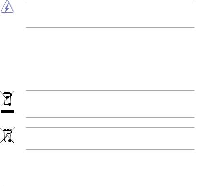
DO NOT throw the motherboard in municipal waste. This product has been designed to enable proper reuse of parts and recycling. This symbol of the crossed out wheeled bin indicates that the product (electrical and electronic equipment) should not be placed in municipal waste. Check local regulations for disposal of electronic products.
DO NOT throw the mercury-containing button cell battery in municipal waste. This symbol of the crossed out wheeled bin indicates that the battery should not be placed in municipal waste.

Safety information
Electrical safety
•To prevent electric shock hazard, disconnect the power cable from the electric outlet before relocating the system.
•When adding or removing devices to or from the system, ensure that the power cables for the devices are unplugged before the signal cables are connected. If possible, disconnect all power cables from the existing system before you add a device.
•Before connecting or removing signal cables from the motherboard, ensure that all power cables are unplugged.
•Seek professional assistance before using an adapter or extension cord. These devices could interrupt the grounding circuit.
•Ensure that your power supply is set to the correct voltage in your area. If you are not sure about the voltage of the electrical outlet you are using, contact your local power company.
•If the power supply is broken, do not try to fix it by yourself. Contact a qualified service technician or your retailer.
Operation safety
•Before installing the motherboard and adding devices on it, carefully read all the manuals that came with the package.
•Before using the product, ensure that all cables are correctly connected and the power cables are not damaged. If you detect any damage, contact your dealer immediately.
•To avoid short circuits, keep paper clips, screws, and staples away from connectors, slots, sockets, and circuitry.
•Avoid dust, humidity, and temperature extremes. Do not place the product in any area where it may become wet.
•Place the product on a flat and stable surface.
•If you encounter technical problems with the product, contact a qualified service technician or your retailer.
About this guide
This user guide contains the information you need when installing and configuring the motherboard.
How this guide is organized
This guide contains the following parts:
•Chapter 1: Product introduction
This chapter describes the features of the motherboard and the new technology it supports.
•Chapter 2: BIOS setup
This chapter tells how to change system settings through the BIOS setup menus. Detailed descriptions of the BIOS parameters are also provided.
vi

Conventions used in this guide
To ensure that you perform certain tasks properly, take note of the following symbols used throughout this manual.
DANGER/WARNING: Information to prevent injury to yourself when trying to complete a task.
CAUTION: Information to prevent damage to the components when trying to complete a task.
IMPORTANT: Instructions that you MUST follow to complete a task.
NOTE: Tips and additional information to help you complete a task.
Where to find more information
Refer to the following sources for additional information and for product and software updates.
1.ASUS websites
The ASUS website provides updated information on ASUS hardware and software products.
2.Optional documentation
Your product package may include optional documentation, such as warranty flyers, that may have been added by your dealer. These documents are not part of the standard package.
Typography
|
Bold text |
Indicates a menu or an item to select. |
|
Italics |
Used to emphasize a word or a phrase. |
|
<Key> |
Keys enclosed in the less-than and greater-than sign means |
|
that you must press the enclosed key. |
|
|
Example: <Enter> means that you must press the Enter or |
|
|
Return key. |
|
|
<Key1>+<Key2>+<Key3> |
If you must press two or more keys simultaneously, the key |
|
names are linked with a plus sign (+). |
|
|
Example: <Ctrl>+<Alt>+<D> |
|
|
Command |
Means that you must type the command exactly as shown, |
|
then supply the required item or value enclosed in brackets. |
|
|
Example: At the DOS prompt, type the command line: |
|
|
afudos /i[filename] |
|
|
afudos /iP5KPLAMI.ROM |
vii

P5KPL-AM IN specifications summary
|
CPU |
LGA775 socket for Intel® Core™2 Quad/ Core™2 |
|
Extreme / Core™2 Duo / Pentium® D / Pentium® 4 / |
|
|
Celeron® E1000 Series and Celeron 400 Series |
|
|
Processors |
|
|
Support Intel® 45nm CPU |
|
|
Intel® Hyper-Threading Technology ready |
|
|
Supports Enhanced Intel SpeedStep® Technology (EIST) |
|
|
(Refer to www.asus.com for Intel CPU support list) |
|
|
Chipset |
Northbridge: Intel® G31 |
|
Southbridge: Intel® ICH7 |
|
|
Front Side Bus |
1600(O.C.) / 1333 / 1066 / 800 / 533MHz |
|
Memory |
Dual channel memory architecture |
|
2×240-pinDIMMsocketssupportsunbufferednon-ECC |
|
|
4GB1066(O.C.)/800/667MHzDDR2 memory modules |
|
|
* Refer to www.asus.com for memory QVL (Qualify Vendor |
|
|
List) |
|
|
Expansion Slots |
1 x PCI Express x1 slot |
|
2 x PCI slots |
|
|
VGA |
Integrated Gfx (Intel GMA3100) in North bridge supports |
|
— Maximum resolution: 2048 x 1536 @ 75Hz |
|
|
Storage |
Southbridge Intel® ICH7 supports: |
|
— 1 x UltraDMA100 / 66 / 33 hard disk drives |
|
|
— 2 x SATA150/300 ports |
|
|
LAN |
Realtek® RTL8131, 10/100 LAN |
|
Audio |
VT1705 6-CH high-DefinitionAudio CODEC |
|
USB |
Max. 8 x USB2.0 ports (4 ports at mid-board, 4 ports at |
|
back panel |
|
|
ASUS Features |
ASUS CrashFree BIOS 3 |
|
ASUS Q-Fan |
|
|
ASUS EZ Flash 2 |
|
|
Rear panel |
1 x PS/2 keyboard port |
|
1 x PS/2 mouse port |
|
|
1 x VGA port |
|
|
1 x LAN (RJ-45) port |
|
|
4 x USB 2.0 ports |
|
|
6-channel audio I/O port |
|
|
(continued on the next page) |
viii

P5KPL-AM IN specifications summary
|
Internal connectors |
1 xHigh Definition frontpanelaudioconnector |
|
2 xUSB2.0connectors supportsadditional 4 USBports |
|
|
2 x SerialATAconnectors |
|
|
1 x CPU fan connector |
|
|
1 x IDE connector |
|
|
1 x 24-pin EATXPWR 12 V power connector |
|
|
1 x 4-pinATX 12 V power connector |
|
|
1 x System Panel connector |
|
|
BIOS features |
8 Mb Flash ROM,AMI BIOS, PnP, DMI2.0, WfM2.0, |
|
SM BIOS 2.5 |
|
|
Manageability |
WOL, PXE,RPL, WOR, PME Wake Up |
|
Support CD contents |
Drivers |
|
ASUS PC Probe II |
|
|
ASUS Update utility |
|
|
Accessories |
1 x Serial ATA cable |
|
1 x Ultra ATA66 cable |
|
|
I/Oshield |
|
|
User manual |
|
|
Form factor |
uATX form factor: 9.6 in x 7.0 in (24.4 cm x 17.8cm) |
*Specifications are subject to change without notice.
ix
Chapter 1
Product introduction
Thank you for buying an ASUS® P5KPL-AM IN motherboard!
Before you start installing the motherboard, and hardware devices on it, check the items in your motherboard package. Refer to page ix for the list of accessories.
If any of the items is damaged or missing, contact your retailer.
1.1Before you proceed
Take note of the following precautions before you install motherboard components or change any motherboard settings.
• Unplug the power cord from the wall socket before touching any component.
•Use a grounded wrist strap or touch a safely grounded object or a metal object, such as the power supply case, before handling components to avoid damaging them due to static electricity
•Hold components by the edges to avoid touching the ICs on them.
•Whenever you uninstall any component, place it on a grounded antistatic pad or in the bag that came with the component.
•Before you install or remove any component, ensure that the ATX power supply is switched off or the power cord is detached from the power supply. Failure to do so may cause severe damage to the motherboard, peripherals, or components.
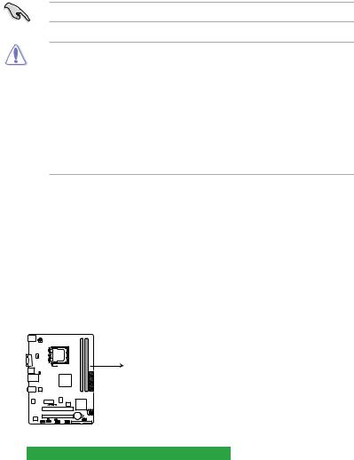
Onboard LED
This motherboard comes with a standby power LED that lights up to indicate that the system is ON, in sleep mode, or in soft-off mode. This is a reminder that you must shut down
the system and unplug the power cable before removing or plugging in any motherboard component. The illustration below shows the location of the onboard LED.
P5KPL-AM IN
SB_PWR
ON OFF
Standy Power Powered Off
P5KPL-AM IN Onboard LED

1.2Motherboard overview
1.2.1Motherboard layout
Ensure that you install the motherboard into the chassis in the correct orientation. The edge with external ports goes to the rear part of the chassis.
Place this side towards the rear of the chassis.
|
1 |
2 |
3 |
4 |
5 |
||||
|
17.8cm(7.0in) |
||||||||
|
KBMS |
||||||||
|
ATX12V |
||||||||
|
VGA |
module) |
module) |
||||||
|
CPU_FAN |
LGA775 |
pin-240 |
pin-240 |
|||||
|
USB34 |
PS2 USBPW1-4 |
DIMMA1 (64bit, |
DIMMB1 (64bit, |
|||||
|
LAN1_USB12 |
Intel® |
DDR2 |
DDR2 |
|||||
|
G31 B0 |
||||||||
|
AUDIO |
ITE |
EATXPWR |
||||||
|
IT8755E |
||||||||
|
8131 |
PCIEX1_1 |
ICS 9LRS954A4GLF |
||||||
|
RTL |
||||||||
|
8Mb |
Intel® |
|||||||
|
BIOS |
ICH7 |
SATA2 |
SATA1 |
|||||
|
PCI1 |
P5KPL-AM IN
|
Lithium Cell |
|||||
|
PCI2 |
CMOS Power |
CLRTC |
|||
|
VIA |
SPEAKER |
||||
|
VT1705 |
SB_PWR |
USBPW5-8 |
USB56 |
PRI_IDE |
|
|
AAFP |
F_PANEL |
USB78 |
|||
Place six screws into the holes indicated by circles to secure the motherboard to the chassis. DO NOT overtighten the screws! Doing so can damage the motherboard.
1.2.2Layout contents
|
Connectors/Jumpers/Slots |
Page |
Connectors/Jumpers/Slots |
Page |
||
|
1. |
ATX power connectors (24-pin EATXPWR, 4-pin |
1-13 |
8. |
Speaker connector (4-1 pin SPEAKER) |
1-14 |
|
ATX12V) |
|||||
|
2. |
CPU fan connector (4-pin CPU_FAN) |
1-12 |
9. |
IDE connector (40-1 pin PRI_EIDE) |
1-11 |
|
3. |
Keyboard/mouse power (3-pin PS2_USBPW1-4) |
1-9 |
10. |
USB connectors (10-1 pin USB56 USB78) |
1-11 |
|
4. |
LGA775 CPU socket |
1-3 |
11. |
USB device wake-up (3-pin USBPW5-8) |
1-7 |
|
5. |
DDR2 DIMM slots |
1-3 |
12. |
System panel connector (10-1 pin PANEL) |
1-14 |
|
6. |
Serial ATA connectors (7-pin SATA1-4) |
1-10 |
13. |
Onboard LED |
1-1 |
|
7. |
Clear RTC RAM (3-pin CLRTC) |
1-8 |
14. |
Front panel audio connector (10-1 pin |
1-12 |
|
AAFP) |
|
Chapter 1: Product introduction |
1-2 |
1.3Central Processing Unit (CPU)
The motherboard comes with a surface mount LGA775 socket designed for the Intel® Core
™2 Quad / Core™2 Extreme / Core™2 Duo / Pentium® D / Pentium® 4 and Celeron® E1000 Series and Celeron 400 Series processors.
• Ensure that all power cables are unplugged before installing the CPU.
• Upon purchase of the motherboard, make sure that the PnP cap is on the socket and the socket contacts are not bent. Contact your retailer immediately if the PnP cap
is missing, or if you see any damage to the PnP cap/socket contacts/motherboard components.ASUS will shoulder the cost of repair only if the damage is shipment/ transit-related.
•Keep the cap after installing the motherboard. ASUS will process Return Merchandise
Authorization (RMA) requests only if the motherboard comes with the cap on the
LGA775 socket.
•The product warranty does not cover damage to the socket contacts resulting from incorrect CPU installation/removal, or misplacement/loss/incorrect removal of the PnP cap.
1.4System memory
1.4.1Overview
The motherboard comes with two Double Data Rate 2 (DDR2) Dual Inline Memory Modules
(DIMM) sockets.
The figure illustrates the location of the DDR2 DIMM sockets:
DIMM_B1
DIMM_A1
P5KPL-AM IN
P5KPL-AM IN 240-pin DDR2 DIMM sockets
|
Channel |
Sockets |
|
Channel A |
DIMM_A1 |
|
Channel B |
DIMM_B1 |
1.4.2Memory configurations
You may install 512MB, 1GB, and 2GB unbuffered ECC/non-ECC DDR2 DIMMs into the
DIMM sockets.