- Manuals
- Brands
- Ski-Doo Manuals
- Snowmobiles
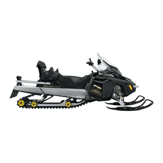
- SKANDIC EXPEDITION 600 H.O. SDI 2005
- Operator’s manual
-
Contents
-
Table of Contents
-
Troubleshooting
-
Bookmarks
Quick Links
Related Manuals for Ski-Doo SKANDIC EXPEDITION 600 H.O. SDI 2005
Summary of Contents for Ski-Doo SKANDIC EXPEDITION 600 H.O. SDI 2005
-
Page 1
520 000 477… -
Page 2
SAFETY WARNING Disregarding any of the safety precautions and instructions contained in this Operator’s Guide, Safety Videocassette or on- product warnings may result in injury, including the possibility of death. This Operator’s Guide and Safety Videocassette should remain with the unit at time of resale. In USA, products are distributed by BRP US Inc. -
Page 3
Dear 2005 Skandic Expedition owner, in addition to the infor- mations in the 2005 Tundra Skandic Series Operator’s Guide (P/N 520 000 477), the following also applies to your model. __________________________… -
Page 4: Table Of Contents
TABLE OF CONTENTS VEHICLE INFORMATION HOW TO IDENTIFY YOUR SNOWMOBILE ….. Engine Serial Number Location ……. . ON-VEHICLE IMPORTANT INSTRUCTIONS.
-
Page 5
SPECIFICATIONS ……….45 WARRANTY BRP LIMITED WARRANTY NORTH AMERICA: 2005 SKI-DOO ®… -
Page 6: Vehicle Information
VEHICLE INFORMATION __________________________…
-
Page 7: How To Identify Your Snowmobile
HOW TO IDENTIFY YOUR SNOWMOBILE Engine Serial Number Location 600 H.O. SDI A32C01B 1. Engine serial number V-1000 A32A1XA 1. Engine serial number __________________________…
-
Page 8: On-Vehicle Important Instructions
ON-VEHICLE IMPORTANT INSTRUCTIONS The following instructions are on your snowmobile. If missing or damaged, the decals can be replaced free of charge. See an autho- rized SKI-DOO dealer. Please read the following instructions carefully before operating this snowmobile. 1,2,3,4 A29H1AB TYPICAL —…
-
Page 9
Instruction 2 A00A8TA Instruction 3 A00A8UA __________________________… -
Page 10
Instruction 4 A00A8VA Instruction 5 A05H1CA __________________________… -
Page 11
Instruction 6 A01A2EA Instruction 7 A01A2FA _________________________… -
Page 12
Instruction 8 A01A2GA TYPICAL Instruction 9 A29A0IA __________________________… -
Page 13
Instruction 10 A32A1GA Instruction 11 A32A1HA TYPICAL _________________________… -
Page 14
Instruction 12 EMISSION CONTROL INFORMATION THIS ENGINE IS CERTIFIED TO OPERATE ON UNLEADED GASOLINE AND CONFORMS TO XXXX U.S. EPA REGULATIONS FOR SNOWMOBILE SI ENGINES. ENGINE FAMILY: ………… XXXXXXXXXXX FEL: …………XXg/kW-hr HC+NO XXXg/kW-hr CO ENGINE DISPLACEMENT:……… XXXX cc EXHAUST EMISSION CONTROL SYSTEM: ….TUNE-UP SPECIFICATIONS IDLE SPEED: ………… -
Page 15: Controls/Instruments/Equipment
CONTROLS/INSTRUMENTS/EQUIPMENT A29A0JA 41-42-43 A29A0KA NOTE: See description of numbered items in Tundra Skandic Series Operator’s Guide (P/N 520 000 477) except for the following. _________________________…
-
Page 16: Fuses
CAUTION: Do not use skis to pull or lift snowmobile. 37) Low Battery Voltage Pilot Lamp This lamp will light up to indicate a low battery voltage condition. See an authorized SKI-DOO dealer as soon as possible. __________________________…
-
Page 17: Oil Pilot Lamp
Restart engine, oil pilot lamp must turn off after few seconds. If oil pilot lamp still glows up, stop engine and have lubrication system inspected by an authorized SKI-DOO dealer. 39) Engine Management System (EMS) Pilot Lamp This lamp will light up to indicate a trouble. Refer to TROU- BLESHOOTING for trouble code meaning and remedy.
-
Page 18: Resetable Hour Meter
43) Resetable Hour Meter Records engine running time in hours and minutes since it has been reset. NOTE: At vehicle speed of 90 km/h (55 MPH) and more the mode LCD screen will show speed only instead of the selected mode. 44) Heating Grip Switch A33E04B TYPICAL…
-
Page 19
Release START button immediately when engine has started. If engine does not start on first try, wait a few seconds then repeat procedure. To stop engine, turn off engine cut-out switch or pull off tether cord cap. _________________________… -
Page 20: Fuel And Oil
FUEL AND OIL Recommended Fuel Use regular unleaded gasoline, available from most service stations or oxygenated fuel containing less than 10% of ethanol or 5% of methanol. The gasoline used must have the following recommend- ed minimum octane number. LOCATION OCTANE NUMBER Inside North America 87 (RON + MON)/2…
-
Page 21: Recommended Oil
Recommended Oil 600 H.O. SDI CAUTION: Use only injection oil that flows at — 40°C (- 40°F). Do not mismatch oil reservoir cap with fuel tank cap. Oil reservoir cap is identified OIL. Oil is contained in the injection oil reservoir. Use only two-stroke engine injection oil sold by an authorized SKI- DOO dealers.
-
Page 22
WARNING Do not overfill. Reinstall cap and fully tighten. Wipe off any oil spills. Oil is highly flammable. V-1000 With V-1000 use XP-S 0W40 synthetic 4-stroke oil (P/N 293 600 054). NOTE: There is no known equivalent for this oil on the market for the moment. -
Page 23: Break-In Period
BREAK-IN PERIOD Engine CAUTION: A break-in period of 10 operating hours or 500 km (300 miles) is required before running the snowmobile at full throttle. During break-in period, maximum throttle should not exceed 3/4. However, brief full acceleration and speed variations contribute to a good break-in.
-
Page 24: Operating Instructions
OPERATING INSTRUCTIONS Starting the Engine • Recheck throttle control lever operation. • Ensure that the engine cut-out switch is in the ON position. • Ensure that the tether cord cap is in position and that the cord is attached to your clothing eyelet. NOTE: On the 600 H.O.
-
Page 25
A07D0UA Attach one end of emergency rope to rewind handle. NOTE: The spark plug socket can be used as an emergency handle. A17B01A TYPICAL Attach the other end of emergency rope to the starter clip supplied in the tool kit. Hook up clip on drive pulley. -
Page 26
A19D13A TYPICAL 1. Clip Pull the rope using a sharp, crisp pull so the rope comes free of the drive pulley. Start engine as per usual manual starting. WARNING When starting the snowmobile in an emergency situation, us- ing drive pulley, do not reinstall the belt guard and return slow- ly to have snowmobile repaired. -
Page 27: Maintenance Information
MAINTENANCE INFORMATION __________________________…
-
Page 28: Periodic Maintenance Chart
(4) ONCE A YEAR OR EVERY 3200 km (2000 m.). (5) ONCE A YEAR OR EVERY 6000 km (3700 m.). (6) STORAGE (to be performed by an authorized SKI-DOO dealer). (7) PRESEASON PREPARATION (to be performed by an authorized SKI-DOO dealer).
-
Page 29
PERIODIC MAINTENANCE CHART (2) (3) (4) (5) (6) (7) FUEL SYSTEM Fuel Stabilizer Fuel Filter Fuel Lines and Connections Throttle Cable Air Filter Fuel Injection System (visual inspection) Throttle Body Bores and Throttle Plates (3) DRIVE Drive Belt Drive and Driven Pulleys Tightening Torque of Drive Pulley Screw Driven Pulley Preload BRAKE… -
Page 30
PERIODIC MAINTENANCE CHART (2) (3) (4) (5) (6) (7) ELECTRICAL EMS Fault Codes (3) Spark Plugs (1) (3) Battery Headlamp Beam Aiming Wiring Harnesses, Cables and Lines Operation of Lighting System (HI/LO beam, brake light, etc.), Test Operation of Engine Cut-Out Switch and Tether Cut-Out Switch BODY/FRAME Rags in Air Intake and Exhaust System… -
Page 31: Fluid Levels
Oil level must be between lower and upper marks. NOTE: It is normal to find metallic particles stuck to dipstick mag- net. If bigger pieces of metal are found, see an authorized SKI-DOO dealer. Remove metal particles from magnet.
-
Page 32: Oil Injection System
A29C31A TYPICAL 1. Dipstick Oil Injection System 600 H.O. SDI Always maintain a sufficient amount of recommended injection oil in the injection oil reservoir. CAUTION: Never allow oil reservoir to be almost empty. Do not mismatch oil reservoir cap with fuel tank cap. Install cap that is identified OIL.
-
Page 33: Engine Oil Level
A29C32A 1. Injection oil reservoir Engine Oil Level V-1000 Make sure engine is at operating temperature. Snowmobile must be on a level surface. Leave engine running at idle for 30 seconds. Stop engine and wipe the dipstick. Dipstick must be completely screwed in before checking oil level. Oil level must be between minimum and maximum marks on dip- stick.
-
Page 34: Cooling System
A29C2YA 1. Maximum 2. Minimum Add XP-S 0W40 synthetic 4-stroke oil (P/N 293 600 054) or an equiv- alent through dipstick hole as required. Reinstall dipstick. Cooling System Check coolant level in expansion reservoir. When the engine is cold, the level must be between minimum and maximum marks. _________________________…
-
Page 35
A29C33A 600 H.O. SDI — EXPANSION RESERVOIR NEAR INJECTION OIL RESERVOIR 1. Maximum A29C2ZA V-1000 — EXPANSION RESERVOIR NEAR MUFFLER 1. Maximum 2. Minimum __________________________… -
Page 36: Battery Electrolyte
Battery Electrolyte The Skandic Expedition is equipped with a maintenance-free battery. Electrolyte level can not be checked. WARNING Battery BLACK negative cable must always be disconnected first and connected last. WARNING Never charge or boost battery while installed. Battery elec- trolyte contains sulfuric acid which is corrosive and poisonous.
-
Page 37: Maintenance For Epa Certified Engines
MAINTENANCE FOR EPA CERTIFIED ENGINES Maintenance, replacement, or repair of the emission control de- vices and systems may be performed by any snowmobile SI (spark ignition) engine repair establishments or individual. Engine Emissions Information Manufacturer’s Responsibility Beginning with 2005 model year engines, snowmobile manufactur- ers of snowmobile engines may determine the exhaust emission levels for each engine horsepower family and certify these engines with the United States of America Environmental Protection Agen-…
-
Page 38
EPA Emission Regulations All new 2005 and more recent certified SKI-DOO snowmobiles man- ufactured by BRP are certified to the EPA as conforming to the re- quirements of the regulations for the control of air pollution from new snowmobile engines. This certification is contingent on certain ad- justments being set to factory standards. -
Page 39: Maintenance
MAINTENANCE WARNING It is recommended that the assistance of an authorized SKI- DOO dealer be periodically obtained on other components/ systems not covered in this guide. Unless otherwise speci- fied, engine must not be running and cold. Remove tether cord cap before performing any maintenance or adjustment, unless otherwise specified.
-
Page 40: Air Filter Cleaning
A29D2RA 1. Collar screw 2. Vent hose 3. Air temperature sensor 4. Latch – Refer to Tundra Skandic Series Operator’s Guide (P/N 520 000 477) and follow Skandic SUV 600 procedure to remove belt guard. At installation do not forget to connect air temperature sensor other- wise a trouble code will appear.
-
Page 41: Drive Pulley Adjustment
A29C30B 1. Air filter Drive Pulley Adjustment WARNING Remove tether cord cap before performing any maintenance or adjustment, unless otherwise specified. Vehicle must be parked in a safe place, away from the trail. General From factory TRA drive pulley adjustment screws are set to differ- ent positions depending vehicle and its engine type.
-
Page 42
This could lead to serious injury including the possibility of death. See your SKI-DOO dealer to maintain or service the drive pulley. Improper servicing or maintenance may affect per- formance and reduce belt life. Always respect maintenance schedules. -
Page 43: Troubleshooting
TROUBLESHOOTING Monitoring Beeper Coded Signals 2 short beeps (when engine is started). DESS/RER pilot lamp also blinks. 1. Confirms that proper tether cord cap is installed. Engine can rev above pulley engagement. – Normal condition. 1 short beep every 1.5 seconds (when engine is started). DESS/RER pilot lamp also blinks.
-
Page 44
3 short beeps per second. Oil pilot lamp also lights up. 1. Low oil pressure on 4-TEC models. – Stop engine immediately and check oil level and top it. Check lubrication system. 3 short beeps per second. 1. Low battery voltage. –… -
Page 45: Specifications
SPECIFICATIONS SKANDIC EXPEDITION MODEL 600 H.O. SDI V-1000 ENGINE 1004-Rotax, Type 593-Rotax, 2-TEC 4-TEC Number of cylinder 594.40 cc 995.90 cc Displacement (60.774 cu. in.) (60.774 cu. in.) Bore 72 mm (2.83 in) 100 mm (3.937 in) 63.40 mm Stroke 73 mm (2.87 in) (2.496 in) Maximum power engine…
-
Page 46
SKANDIC EXPEDITION MODEL 600 H.O. SDI V-1000 TRACK 40 — 50 Tension (in) (1-9/16 — 1-31/32) (1) Alignment DIMENSION Dry mass 310 kg (683 lb) 342 kg (754 lb) Overall length 3.06 m (120.5 in) Overall width 1.22 m (48 in) LIQUIDS and GREASES Engine oil Coolant… -
Page 47
(1) Measure gap between slider shoe and bottom inside of track when exerting a downward pull of 7.3 kg (16 lb) to the track. (2) Equal distance between edges of track guides and slider shoes. (3) 87 (R + M)/2 Inside North America or 91 RON Outside North America. -
Page 48: Warranty
WARRANTY __________________________…
-
Page 49: Brp Limited Warranty North America: 2005 Ski-Doo
All genuine Ski-Doo parts and accessories, installed by an authorized BRP dealer (as hereinafter defined) at the time of delivery of the 2005 Ski-Doo snowmobile, carry the same warranty as that of the snow- mobile. A GPS receiver may be supplied by BRP as standard equipment on certain 2005 Ski-Doo snowmobiles.
-
Page 50
600 HO 4-TEC EMISSION-RELATED COMPONENTS V-1000 Throttle Position Sensor (TPS) Air Temperature Sensor (ATS) Air Pressure Sensor (APS) Fuel Pressure Regulator Fuel Injectors Engine Management System (EMS) Cylinder Head Rubber Rings/O-Ring or Gasket Cylinder/Base Gaskets Throttle Body Shaft Seals RAVE Hose System Exhaust System Sealing Components Knock Sensor Muffler Temperature Sensor… -
Page 51
This warranty coverage is available only on 2005 Ski-Doo snowmo- bile purchased as new and unused by its first owner from a BRP deal- er authorized to distribute Ski-Doo products in the country in which the sale occurred (“BRP dealer”), and then only after the BRP spec- ified pre-delivery inspection process is completed and documented. -
Page 52
6. EXCLUSIONS The following are not warranted under any circumstances: • Normal wear and tear; • Routine maintenance items, tune ups, adjustments; • Damage caused by failure to provide proper maintenance and/or storage, as described in the Operator’s Guide; • Damage resulting from removal of parts, improper repairs, service, maintenance, modifications or use of parts not manufactured or approved by BRP or resulting from repairs done by a person that is not an authorized servicing BRP dealer;… -
Page 53
Neither the distributor, any BRP dealer nor any other person has been authorized to make any affirmation, representation or warranty re- garding the product, other than those contained in this limited war- ranty, and if made, shall not be enforceable against BRP. BRP reserves the right to modify this warranty at any time, being un- derstood that such modification will not alter the warranty conditions applicable to the products sold while this warranty is in effect. -
Page 54
If the issue has not yet been resolved, please submit your com- plaint in writing or call the appropriate number below: In Canada: BOMBARDIER RECREATIONAL PRODUCTS INC. SKI-DOO CONSUMER SERVICES GROUP VALCOURT QC J0E 2L0 Tel: (819) 566-3366 In USA: BRP US INC. -
Page 55: Brp International Limited Warranty: 2005 Ski-Doo
All genuine Ski-Doo parts and accessories, installed by an authorized BRP distributor/dealer (as hereinafter defined) at the time of delivery of the 2005 Ski-Doo snowmobile, carry the same warranty as that of the snowmobile. Use of the product for racing or any other competitive activity, at any point, even by a previous owner, will render this warranty null and void.
-
Page 56
Routine maintenance outlined in the Operator’s Guide must be time- ly performed in order to maintain warranty coverage. BRP reserves the right to make warranty coverage contingent upon proof of proper maintenance. 4. WHAT TO DO TO OBTAIN WARRANTY COVERAGE The customer must notify a servicing BRP distributor/dealer within two (2) days of the appearance of a defect, and provide it with reasonable access to the product and reasonable opportunity to… -
Page 57
• Operation with fuels, oils or lubricants which are not suitable for use with the product (see the Operator’s Guide); • Snow or water ingestion; • Incidental or consequential damages, or damages of any kind in- cluding without limitation towing, storage, telephone, rental, taxi, inconvenience, insurance coverage, loan payments, loss of time, loss of income;… -
Page 58
If the matter still remains unresolved then contact BRP by writing to us at the address listed below. BOMBARDIER RECREATIONAL PRODUCTS INC. SKI-DOO CONSUMER SERVICES GROUP VALCOURT QC J0E 2L0 Canada Tel: (819) 566-3366 ©… -
Page 59: Privacy Obligations/Disclaimer
PRIVACY OBLIGATIONS/DISCLAIMER We wish to inform you that your coordinates will be used for safety and warranty purposes. Sometimes, we also use the coordinates of our clients to inform them about our products and to present them offers. Should you prefer not to receive information on our products, services and offers, please let us know by writing to the address below.
-
Page 60: Change Of Address Or Ownership
BRP. STOLEN UNITS: If your snowmobile is stolen, you should notify BRP or an authorized SKI-DOO distributor/dealer. We will ask you to pro- vide your name, address, phone number, the vehicle identification number and the date it was stolen.
-
Page 61
__________________________… -
Page 62
_________________________… -
Page 63
__________________________… -
Page 64
_________________________…
- Manuals
- Brands
- BOMBARDIER Manuals
- Offroad Vehicle
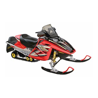
- SKI-DOO MX-Z Renegade 600 HO SDI
- Operator’s manual
-
Contents
-
Table of Contents
-
Troubleshooting
-
Bookmarks
Quick Links
Related Manuals for BOMBARDIER SKI-DOO MX-Z Renegade 600 HO SDI
Summary of Contents for BOMBARDIER SKI-DOO MX-Z Renegade 600 HO SDI
-
Page 2
This Operator’s Guide and Safety Videocassette should remain with the unit at time of resale. In USA, products are distributed by Bombardier Motor Corporation of America. In Canada, products are distributed by Bombardier Inc. The following are trademarks of Bombardier Inc. or its subsidiaries. ®… -
Page 3
2005 SKI-DOO OPERATOR’S GUIDE ® This guide is applicable to MX-Z Renegade 600 HO SDI. -
Page 4
FOREWORD Congratulations on your purchase of a new SKI-DOO snowmobile. Whatever model you have chosen, it is backed by the Bombardier warranty and a network of authorized SKI-DOO snowmobile dealers ready to provide the parts, service or accessories you may require. -
Page 5
The information and components/system descriptions contained in this guide are correct at time of publication. Bombardier Inc., howev- er maintains a policy of continuous improvement of its products with- out imposing upon itself any obligation to install them on products previously manufactured. -
Page 6: Table Of Contents
LAWS AND REGULATIONS ………… SUMMARY OF ACCIDENT PREVENTION PRACTICES ..ENVIRONMENT …………… VEHICLE INFORMATION LIST OF HOT PARTS…………..LIST OF MOVING PARTS …………BOMBARDIER LIMITED WARRANTY NORTH AMERICA: ® 2005 SKI-DOO SNOWMOBILES……….FREQUENTLY ASKED QUESTIONS ……..AUTHORIZED SKI-DOO DEALERS ………
-
Page 7
11) Engine Cut-Out Switch …………12) Headlamp Dimmer Switch ……….. 13) High Beam Pilot Lamp (Blue) ……….14) Oil Pilot Lamp…………… 15) Low Battery Voltage Pilot Lamp ………. 16) Engine Management System (EMS) Pilot Lamp….17) Rewind Starter Handle …………18) Speedometer …………… -
Page 8
OPERATING INSTRUCTIONS ……….102 Principle of Operation…………..102 Starting the Engine…………..103 Emergency Starting…………..103 Shutting Off the Engine…………. 105 VEHICLE WARM-UP …………..106 RIDING THE VEHICLE ………….. 106 HOW TO RIDE …………….107 TERRAIN/RIDING VARIATIONS ……….110 POST-OPERATION CARE …………117 SPECIAL OPERATIONS ………… -
Page 9
Track Condition …………….139 Track Tension and Alignment…………. 140 Steering and Front Suspension……….144 Wear and Condition of Skis and Runners ……..144 Exhaust System …………….. 144 Air Filter Cleaning…………… 145 Headlamp Beam Aiming …………146 Bulb Replacement…………..146 TOWING THE VEHICLE …………148 TRANSPORTING THE VEHICLE ………. -
Page 10: Safety Measures
SAFETY MEASURES Observe the Following Warnings: The performance of some snowmobiles may significantly exceed that of other snowmobiles you have operated. Therefore, use by novice or inexperienced operators is not recommended. Basic training is required for the safe operation of any snowmobile. Study your Operator’s Guide paying particular attention to cautions and warnings.
-
Page 11
Never ride after consuming drugs or alcohol or if you feel tired or ill. Operate your snowmobile prudently. Speeding can be fatal. In many cases, you cannot react or respond quickly enough to the unexpected. Always ride at a speed which is suitable to the trail, weather conditions and your own ability. -
Page 12
Use of Rotax snowmobile engines in other than SKI-DOO snowmobiles is not recommended or autho- rized by Bombardier Inc.or its subsidiaries. Electronic reverse (RER ) models only: The shifting to reverse mode on these snowmobiles is done by the push of the RER button when the engine is running. -
Page 13: Safety Information
SAFETY INFORMATION SAFETY INFORMATION…
-
Page 14: Introduction
INTRODUCTION This safety information section includes safety WARNINGS which if not followed may result in serious personal injury including the pos- sibility of death. After reading, please keep this Operator’s Guide with the snowmo- bile. If the snowmobile is resold, please give the guide to the new owner for his awareness.
-
Page 15: Safety Labeling
SAFETY LABELING Safety standards for snowmobiles have been adopted by the Snowmo- bile Safety and Certification Committee (SSCC) of which Bombardier is a proud participating member. Assurance that your snowmobile meets these standards is easily checked by locating the Certification Label on a right vertical portion of the vehicle.
-
Page 16
HOW TO DRESS Proper snowmobile clothing should be worn. It should be comfort- able and not too tight. Always check the weather forecast before you go on a ride. Dress for the coldest weather expected. Thermal under- wear next to the skin also provides an important layer of insulation. Approved helmets are recommended at all times. -
Page 17: A Word To All Snowmobilers
A WORD TO ALL SNOWMOBILERS Everyone is a beginner the first time he sits behind the controls of a snowmobile regardless of previous experience in driving an automo- bile, a motorcycle or a motorboat. The safe use of your snowmobile is dependent on many conditions such as visibility, speed, weather, environment, traffic, vehicle condition and the condition of the driver.
-
Page 18: Laws And Regulations
TRANSPORTING AND TOWING Follow transporting and towing instructions explained further in this guide. LAWS AND REGULATIONS Federal, state, provincial and local government agencies have enact- ed laws and regulations pertaining to the safe use and operation of snowmobiles. It is your responsibility as a snowmobiler to learn and obey these laws and regulations.
-
Page 19
Be aware of inherent risks associated with riding off trails, such as avalanche and other natural or man made hazards or obstacles. Avoid road traveling. If you must do so and it is permitted, reduce speed. The snowmobile is not designed to operate or turn on pav- ing. -
Page 20
Drinking and driving demonstrates a most irresponsible at- titude not only to others but to yourself. Legislators and the popu- lation in general don’t tolerate it for good reason and BOMBARDIER Recreational Products doesn’t either! Wildlife compliments your snowmobiling day. Snowmobile tracks provide firm ground over which animals can travel from area to area. -
Page 21
Help us lead it down the right path! From all of us at BOMBARDIER Recreational Products, thank you for doing your share. SAFETY INFORMATION… -
Page 22: Environment
Recognizing the importance of this issue and the need for snowmo- bilers to do their share in preserving areas that make it possible to enjoy our sport, BOMBARDIER Recreational Products has developed the “Light Treading Is Smart Sledding” campaign for snowmobilers.
-
Page 23
Respect wildlife and be particularly sensitive of animals that are rear- ing young or suffering from food shortage. Stress can sap scarce energy reserves. Refrain from riding in areas where only animals are intended to tread! Obey gate closures and regulatory signs and remember, light tread- ers don’t litter! Stay out of wilderness areas. -
Page 24: Vehicle Information
VEHICLE INFORMATION…
-
Page 25: List Of Hot Parts
LIST OF HOT PARTS All power train components. LIST OF MOVING PARTS All transmission, suspension and steering parts.
-
Page 26: Bombardier Limited Warranty North America: 2005 Ski-Doo Snowmobiles
All genuine BOMBARDIER parts and accessories, installed by an autho- rized BOMBARDIER dealer (as hereinafter defined) at the time of delivery of the 2005 SKI-DOO snowmobile, carry the same warranty as that of the snowmobile.
-
Page 27
3. CONDITIONS TO HAVE WARRANTY COVERAGE This warranty coverage is available only on 2005 SKI-DOO snowmobile purchased as new and unused by its first owner from a BOMBARDIER dealer authorized to distribute SKI-DOO products in the country in which the sale occurred (hereinafter “BOMBARDIER dealer”), and then only after the BOMBARDIER specified pre-delivery inspection process is com- pleted and documented. -
Page 28
(2) days of the appearance of a defect, and provide it with reasonable access to the product and reasonable opportunity to repair it. The custom- er must also present to the BOMBARDIER dealer, proof of purchase of the product and must sign the repair/work order prior to the start of the repair in order to validate the warranty repair. -
Page 29
BOMBARDIER. BOMBARDIER reserves the right to modify this warranty at any time, being understood that such modification will not alter the warranty conditions ap- plicable to the products sold while this warranty is in effect. -
Page 30: Frequently Asked Questions
SKI-DOO dealer with all the necessary data to complete warranty claim forms. b) be advised by Bombardier should there be a safety recall or particular warranty campaign. c) be contacted much faster by the police, the minute they find your stolen snowmobile (if such a case occurs).
-
Page 31
Q: Are “ Genuine” Bombardier replacement parts used in warranty repairs covered by warranty? A: Yes. When installed by an authorized SKI-DOO dealer, any “Genuine”… -
Page 32: Authorized Ski-Doo Dealers
AUTHORIZED SKI-DOO DEALERS For Canada and USA Only To find the nearest authorized SKI-DOO dealer, dial: 1 800 375-4366 or visit our web site at WWW.SKIDOO.COM.
-
Page 33: How To Identify Your Snowmobile
HOW TO IDENTIFY YOUR SNOWMOBILE Vehicle Description Decal Vehicle description decal is located on right hand side of tunnel. A33H01A TYPICAL 1. Vehicle description decal A00A6MA VEHICLE DESCRIPTION DECAL 1. Manufacturer name 2. Manufacturing date 3. Vehicle identification number (VIN) 4.
-
Page 34: Serial Numbers
These numbers are required by the authorized SKI-DOO dealer to complete warranty claims properly. No warranty will be allowed by Bombardier if the engine serial number or vehicle identification number (VIN) is removed or mutilated in any way.
-
Page 35
Engine Serial Number Location A32C01B 2-STROKE LIQUID COOLED MODELS 1. Engine serial number… -
Page 36: On-Vehicle Important Instructions
ON-VEHICLE IMPORTANT INSTRUCTIONS The following instructions are on your snowmobile. If missing or dam- aged, the decals can be replaced free of charge. See an authorized SKI-DOO dealer. Please read the following instructions carefully before operating this snowmobile. A33A1ZC TYPICAL — LOCATION OF IMPORTANT INSTRUCTIONS…
-
Page 37
Instruction 1 A32A24A… -
Page 38
Instruction 2 A01A2EA Instruction 3 A01A2FA… -
Page 39
Instruction 4 A01A2GA TYPICAL Instruction 5 A32A1GA… -
Page 40
Instruction 6 A32A1HA Instruction 7 A32A1EA… -
Page 41
Instruction 8 DO NOT SIT HERE / NE PAS S’ASSEOIR ICI A33H02A Instruction 9 A33H11A… -
Page 42
Instruction 10 A33A20A Instruction 11 EMISSION CONTROL INFORMATION THIS ENGINE IS CERTIFIED TO OPERATE ON UNLEADED GASOLINE AND CONFORMS TO XXXX U.S. EPA REGULATIONS FOR SNOWMOBILE SI ENGINES. ENGINE FAMILY: ………… XXXXXXXXXXX FEL: …………XXg/kW-hr HC+NO XXXg/kW-hr CO ENGINE DISPLACEMENT:……… XXXX cc EXHAUST EMISSION CONTROL SYSTEM: …. -
Page 43: Controls/Instruments/Equipment
CONTROLS/INSTRUMENTS/EQUIPMENT NOTE: Some controls/instruments/equipment are optional on the MX-Z Renegade. A33A1ZD TYPICAL…
-
Page 44
A33A1FB TYPICAL… -
Page 45: Throttle Lever
6-10 20-21-22 A32A15D TYPICAL 1) Throttle Lever Located on the right hand side of handlebar and designed to be thumb activated. When squeezed, it increases the engine speed and engages the transmission. When released, engine speed returns au- tomatically to idle. WARNING Test the throttle lever operation each time before starting the engine.
-
Page 46: Brake/Parking Brake (Red) Pilot Lamp
WARNING Make sure parking brake is fully disengaged before operating the snowmobile. When you ride the vehicle, brake pads that are caused to drag by a continuous pressure on the lever may cause damage to the brake system and cause loss of braking capacity and/or fire. To engage mechanism, squeeze brake lever and maintain while pull- ing locking lever with a finger.
-
Page 47: Rer Button
5) RER Button General When the engine is running, depressing the RER button will com- mand the engine to reverse crankshaft rotation as driving the snow- mobile in reverse is achieved by changing the direction of rotation of the engine, not by shifting the chaincase in reverse gear. When depressing the RER button, the MPEM (Multi-Purpose Elec- tronic Module) will practically slow down the engine RPM to a stop and advance the ignition timing to cause crankshaft rotation revers-…
-
Page 48: Reverse Pilot Lamp
DESS/RER pilot lamp and warning buzzer will stop. Apply throttle slowly and evenly. Allow drive pulley to engage then accelerate carefully. RER Modification at High Altitude General At high altitude, the RER system needs a different engine timing curve to work properly. Operation The MX-Z Renegade 600 HO SDI is equipped with a Engine Manage- ment System (EMS).
-
Page 49
A33H12A ONE SIDE SHOWN — REARWARD POSITION 1. Bolts retaining windshield assembly Remove steering cover and console cap. A33H05B 1. Steering cover 2. Console cap… -
Page 50
Unscrew 4 bolts retaining console. A33H06A 1. Bolts retaining console… -
Page 51
Slightly lift console to gain access to electrical connector housings. Unplug the 2 large connector housings and the separate 3 wire con- nector. A33H07A TYPICAL 1. Large connector housings Remove console. Remove 2 bolts retaining top of steering column. A33H08A STEERING COLUMN IN REARWARD POSITION 1. -
Page 52
Move steering column to forward position. A33H09B STEERING COLUMN IN FORWARD POSITION 1. Longer bolt Reinstall the 2 bolts. Always install the longer bolt on thicker portion to be bolted. Use new lock nuts. Torque nuts to 24 N• m (18 lbf• ft). Reconnect the electrical connectors and reinstall all removed parts. -
Page 53
Position of console cap will be inverted. Instead of being above it will be beneath steering column. A33H0AA CONSOLE CAP INSTALLED BENEATH STEERING COLUMN Reinstall windshield assembly to handlebar. Refer to WINDSHIELD ADJUSTMENT below. A33H04A ONE SIDE SHOWN — FORWARD POSITION 1. -
Page 54
Readjust throttle lever housing and brake lever housing accordingly to optimal angle so that you will not need to release your grip to operate levers. WARNING Adjust with vehicle at rest in a safe place. Securely retighten all fasteners. Never rotate throttle lever to operate with fingers instead of thumb. -
Page 55
Windshield Adjustment The windshield can be adjusted to properly fit with console. Before adjusting windshield, make sure it is installed on the proper bracket slots according to steering column position. See above photos. Slots in brackets allow different windshield positions. Move wind- shield to fit with console. -
Page 56: Holding Strap
A33H18A PROPER FIT OF WINDSHIELD VERSUS CONSOLE 1. In line A. 8 to 12 mm (3/8 to 1/2 in)
 Holding Strap Holding strap provides a grip for driver when side-hilling. WARNING This strap is not for towing, lifting or other purpose than tem- porary use as a grab bar during side-hilling.
 -
Page 57
Operation Attach to clothing eyelet then snap tether cord cap over post before starting engine. A06H1YA TYPICAL 1. Snap over post 2. Attach to eyelet If emergency engine shut off is required, completely pull tether cord cap from post. A06H1XA TYPICAL… -
Page 58
Tether cut-out switch is part of tether cut-out system. This system serves 3 functions. It shuts off engine preventing snowmobile to runaway if the operator falls off the vehicle accidently. Through the DESS (Digitally Encoded Security System), it acts as a lock by preventing unauthorized use of your snowmobile thus de- terring theft. -
Page 59: Dess Pilot Lamp
DESS Pilot Lamp Codes DESS pilot lamp blinking slowly (one time per 1.5 seconds) means that a bad connection has been detected. Vehicle can not be driven. To check for bad connection, remove tether cord cap. Make sure the tether cord cap is free of dirt or snow. Reinstall cap and restart engine. If a blink per 1.5 seconds still occurs contact an authorized dealer.
-
Page 60: Headlamp Dimmer Switch
A33E03A TYPICAL 1. ON 2. OFF All operators of the snowmobile should familiarize themselves with the function of this device by using it several times on first outing and whenever stopping the engine there-after. This engine cut-out pro- cedure will become a reflex and will prepare operators for emergency situations requiring its use.
-
Page 61: High Beam Pilot Lamp (Blue)
A33E04A TYPICAL 13) High Beam Pilot Lamp (Blue) Lights when headlamp is on HIGH beam. 14) Oil Pilot Lamp This pilot lamp will glow up when injection oil level is low. Stop vehi- cle in a safe place then, replenish injection oil reservoir. 15) Low Battery Voltage Pilot Lamp This lamp will light up to indicate a low battery voltage condition.
-
Page 62: Speedometer
18) Speedometer These models are equipped with an electronic speedometer. It may show speed in km/h or MPH. NOTE: At vehicle speed of 90 km/h (55 MPH) and more the mode LCD screen will show speed only instead of the selected mode. Change from One Unit to the Other NOTE: Speedometer, odometer and trip meter will have their units (kilometer or miles) changed all together.
-
Page 63: Mode Button
A33E06A REV SERIES — KILOMETERS READING — CONNECTORS PLUGGED 19) Mode Button Depress mode button to change display. Each time engine is started, display shows odometer. From that point depressing mode button will change display for the trip meter. Depressing mode button again will change display for the resetable hourmeter.
-
Page 64: Resetable Hourmeter
22) Resetable Hourmeter Records engine running time in hours and minutes since it has been reset. NOTE: At vehicle speed of 90 km/h (55 MPH) and more the mode LCD screen will show speed only instead of the selected mode. Push and hold mode button for 2 seconds to reset the resetable hour- meter.
-
Page 65: Fuel Tank Cap
24) Fuel Tank Cap Unscrew to fill up tank then fully tighten. WARNING Always stop the engine before refueling. Fuel is inflammable and explosive under certain conditions. Always work in a well ventilated area. Do not smoke or allow open flames or sparks in the vicinity.
-
Page 66: Engine Overheat Warning Lamp (Red)
NEEDLE POSITION APPROXIMATE REMAINING OF FUEL LEVEL FUEL QUANTITY GAUGE L (U.S. gallon) 15 (4) 21 (5.5) 30 (8) 36 (9.5) 26) Engine Overheat Warning Lamp (Red) If this lamp glows, reduce snowmobile speed and run snowmobile in loose snow or stop engine immediately. 27) Heating Grip Switch It is a three-position switch.
-
Page 67: Heating Throttle Lever Switch
28) Heating Throttle Lever Switch Three-position switch. Select the desired position to keep your right thumb at a comfortable temperature. See illustrations above. 29) Windshield Windshield provides operator comfort, as well as protection by de- flecting wind and snow away from the operator. 30) Adjustable Mirrors (optional) Each mirror can be adjusted to suit driver’s preference.
-
Page 68: Hood And Side Panel Latches
32) Hood and Side Panel Latches To open hood, slightly widen (pull-out) its both sides top portion in order to unhook its anchors from their grommets. A33H0MA 1. Anchors 2. Grommets To open a side panel, stretch and unhook the latches. A33H13A 1.
-
Page 69
To remove a side panel remove by pulling up both locking devices from hinge. A33H0EA 1. Locking device For left hand side panel removal, also unplug sensor from air silencer. A33E0RA 1. Sensor… -
Page 70: Fuses
Reverse opening procedure to close hood and side panels. Properly hook up latches. 33) Fuses To remove fuse from holder, pull fuse out. Check if filament is melted. A15E0KA 1. Fuse 2. Check if melted CAUTION: Do not use a higher rated fuse as this can cause se- vere damage to electric components and/or fire.
-
Page 71
A33E0EA TYPICAL 1. Charging system fuse Fuse Box To open fuse box push on cover tab and tilt cover. A32I0KA TYPICAL 1. Push tab… -
Page 72
A32I0IA TYPICAL 1. Fuse description decal 2. Fuse remover/installer 3. Spare fuses… -
Page 73
A32I0JA 1. Fuse remover/installer… -
Page 74: Front Grab Handle/Front Bumper
34) Front Grab Handle/Front Bumper To be used whenever front of snowmobile requires manual lifting. WARNING Do not attempt to lift the vehicle by hand alone. Use appropriate lifting device or have assistance to share lifting stress in order to avoid risk of strain injuries.
-
Page 75: Storage Compartment
35) Storage Compartment WARNING All storage compartments must be properly latched and they must not contain any heavy or breakable objects. Pull latch slightly upward then, backward to unlock cover. A33H0LA 1. Latch 36) Rear Rack WARNING All objects in rear rack must be properly latched. Do not carry any breakable objects.
-
Page 76: Spark Plug Holder
A33B0QA 1. Tool kit 38) Spark Plug Holder To keep spare spark plugs dry and prevent shocks that might affect the adjustment or break them, a holder is provided in engine compartment. A33C02A TYPICAL — SPARK PLUG HOLDER ON LEFT HAND SIDE PANEL 1.
-
Page 77: Shields And Guards
NOTE: Spare spark plugs are not supplied with snowmobile. NOTE: Check spare spark plug gap according to SPECIFICATIONS be- fore installation. CAUTION: Do not attempt to adjust gap on spark plug BR9ECS. 39) Shields and Guards WARNING Never operate engine without belt guard securely installed or, with hood or access/side panels open or removed.
-
Page 78: Guidelines To Adjust Suspension
A32F40A TYPICAL 1. Rear springs for comfort and ride height 2. Center spring for steering behavior 3. Stopper strap for snowmobile weight transfer 4. Coupling blocks — Handling 5. Front springs for handling 6. Rear shock motion ratio — Damping strength Guidelines to Adjust Suspension The following is to fine-tune suspension.
-
Page 79
1. Rear Springs — Comfort IMPORTANT: Make sure that all objects to be transported are in place in storage compartment and rear rack. Grab rear bumper and lift until suspension is fully extended. From this point, rear of snowmobile should collapse by 50 to 75 mm (2 to 3 in) when driver and passenger (if so applicable) take place. -
Page 80
A32F0CA TYPICAL — TOO SOFT OF ADJUSTMENT (REAR SUSPENSION IS TOO LOW, IT HAS COLLAPSED MORE THAN 75 mm (3 in) CAUTION: To increase preload, always turn the left side adjust- ment cam in a clockwise direction, and the right side cam in a coun- terclockwise direction. -
Page 81
A32F0DA TYPICAL — TOO HARD OF ADJUSTMENT (REAR SUSPENSION RUNS TOO HIGH, IT HAS COLLAPSED LESS THAN 50 mm (2 in) CAUTION: To decrease preload, always turn the left side adjust- ment cam in a counterclockwise direction, the right side cam in a clockwise direction. -
Page 82
2. Center Spring — Steering Behavior Ride at moderate speed on a trail. If handlebar is felt too easy or too hard to turn, adjust center spring accordingly. WARNING Remove tether cord cap before performing any maintenance or adjustment, unless otherwise specified. Vehicle must be parked in a safe place, away from the trail. -
Page 83
A32F0EA TYPICAL — TOO SOFT OF ADJUSTMENT 1. Handlebar harder to turn — oversteering altitude A32F01B TYPICAL 1. Use adjuster wrench provided in tool kit to increase preload… -
Page 84
A32F0EA TYPICAL — TOO HARD OF ADJUSTMENT — TOO MUCH PRELOAD 1. Handlebar is very easy to turn — understeering attitude A32F01B TYPICAL 1. Use adjuster wrench provided in tool kit to decrease preload… -
Page 85
3. Stopper Strap — Weight Transfer Ride at low speed then fully accelerate. Note steering behavior. Adjust stopper strap length accordingly. WARNING Remove tether cord cap before performing any maintenance or adjustment, unless otherwise specified. Vehicle must be parked in a safe place, away from the trail. CAUTION: Whenever stopper strap length is changed, track ten- sion must be readjusted. -
Page 86
A32F0EC TYPICAL — TOO LONG STRAP 1. Skis lift off the ground A03F0QB TYPICAL 1. Reduce strap length by bolting to a different hole… -
Page 87
A32F0EA TYPICAL — TOO SHORT STRAP 1. Heavy steering A03F0QB TYPICAL 1. Increase strap length by bolting to a different hole… -
Page 88
4. Coupling Blocks — Handling Ride at moderate speed and check for desired handling. When driver and passenger (if applicable) are sitted on vehicle, the coupling blocks should be centered between rubber stoppers. This condition is achieved when a proper rear spring preload is done. See above rear spring adjustment. -
Page 89
A32F0JA COUPLING BLOCK — RIGHT SIDE VIEW (“R” — RIGHT EMBOSSED ON BLOCK) 1. Thicker part of block facing downward (partly coupled suspension) — more track grip and less skis steering 2. Turn block in this direction to adjust to the other position… -
Page 90
5. Front Springs — Handling Ride at moderate speed and check for proper handling. Adjust front springs accordingly. WARNING Remove tether cord cap before performing any maintenance or adjustment, unless otherwise specified. Vehicle must be parked in a safe place, away from the trail. WARNING Always adjust both front springs to same position. -
Page 91
Some Models A32F0EA TYPICAL — TOO SOFT OF ADJUSTMENT 1. Bad handling A32F1CA 1. Increase spring preload 2. Position number… -
Page 92
A32F0EA TYPICAL — TOO HARD OF ADJUSTMENT 1. Steering hard to turn A32F1CB 1. Decrease spring preload 2. Position number… -
Page 93
CAUTION: Make sure that both front springs are still preloaded when front of vehicle is off the ground. Some Models A32F0EA TYPICAL — TOO SOFT OF ADJUSTMENT 1. Bad handling A03F2IA 1. Increase spring preload… -
Page 94
A32F0EA TYPICAL — TOO HARD OF ADJUSTMENT 1. Steering hard to turn A03F2JA 1. Decrease spring preload… -
Page 95
6. Rear Shock Motion Ratio — Damping Strength Rear shock motion ratio can be adjusted according to driver and pas- senger weight and/or trail condition. There are two adjustment positions. A32F30A 1. Soft position 2. Firm position WARNING Remove tether cord cap before performing any maintenance or adjustment, unless otherwise specified. -
Page 96
Suspension Troubleshooting Chart PROBLEM CORRECTIVE MEASURES Front suspension – Check ski alignment and camber angle wandering adjustment. See an authorized SKI-DOO dealer. – Reduce ski ground pressure. • Reduce front suspension spring preload. • Increase center spring preload. • Reduce rear spring preload. Snowmobile seems –… -
Page 97: Fuel And Oil
FUEL AND OIL Recommended Fuel Use premium unleaded gasoline, available from most service stations or oxygenated fuel containing less than 10% of ethanol or 5% of methanol. The gasoline used must have an octane number (R + M)/2 of 91 or higher. NOTE: In most service station pump octane number corresponds to (R + M)/2 octane number.
-
Page 98: Recommended Oil
➀ 2-TEC SDI BOMBARDIER FORMULA XP-S II ➀ CAUTION: The BOMBARDIER Formula XP-S II oil is specially formulated and tested for the severe requirements of these en- gines. Use of any other brand two-stroke oil may void the lim- ited warranty. Use only BOMBARDIER FORMULA XP-S II oil.
-
Page 99: Break-In Period
BREAK-IN PERIOD Engine CAUTION: A break-in period of 10 operating hours — 500 km (300 miles) — is required before running the snowmobile at full throttle. During break-in period, maximum throttle should not exceed 3/4. However, brief full acceleration and speed variations contribute to a good break-in.
-
Page 100: Pre-Operation Check
PRE-OPERATION CHECK WARNING The pre-operation check is very important prior to operating the vehicle. Always check the proper operation of critical controls, safety features and mechanical components before starting. If not done as specified here, severe injury or death might occur. •…
-
Page 101
• Check fuel and injection oil for levels and leaks. Replenish as nec- essary and see an authorized SKI-DOO dealer in case of any leaks. • Verify that air filter(s) is free of snow, if so equipped. • All storage compartments must be properly latched and they must not contain any heavy or breakable objects. -
Page 102: Pre-Operation Check List
PRE-OPERATION CHECK LIST ✔ ITEM OPERATION Body including seat, footrests, lights, Check that there is no snow or ice. controls and instruments Track and idler wheels Check for free movement. Brake lever Check proper action. Parking device Check proper action. Throttle lever Check proper action.
-
Page 103: Operating Instructions
OPERATING INSTRUCTIONS WARNING Proceed with pre-operation check list before riding. Principle of Operation Propulsion Depressing throttle lever increases engine RPM causing the drive pulley to engage. Depending on models engine RPM must be be- tween 2500 and 4200 before drive pulley engagement will occur. Outer sheave of drive pulley moves toward inner sheave, forcing drive belt to move upward on the drive pulley and simultaneously forcing the sheaves apart on the driven pulley.
-
Page 104: Starting The Engine
Stopping Before riding your snowmobile, you should understand how to stop it. This is done by releasing the throttle and gradually depressing the brake lever on the left side of the handlebar. In an emergency, you may stop your vehicle by pressing the engine cut-out switch located near the throttle control and applying the brake.
-
Page 105
A07D0UA Attach one end of emergency rope to rewind handle. NOTE: The spark plug socket can be used as an emergency handle. A17B01A TYPICAL Attach the other end of emergency rope to the starter clip supplied in the tool kit. Hook up clip on drive pulley. -
Page 106: Shutting Off The Engine
Wind the rope tightly around drive pulley. When pulled, pulley must rotate counterclockwise. A19D13A TYPICAL 1. Clip Pull the rope using a sharp, crisp pull so the rope comes free of the drive pulley. Start engine as per usual manual starting. WARNING When starting the snowmobile in an emergency situation, us- ing drive pulley, do not reinstall the belt guard and return slow-…
-
Page 107: Vehicle Warm-Up
VEHICLE WARM-UP Before every ride, vehicle has to be warmed up as follows. Snowmobile must be securely supported by the rear bumper using a wide-base snowmobile mechanical stand. Track must be 100 mm (4 in) off the ground. Attach tether cord to operator’s clothing eyelet. Start engine and allow it to warm up two or three minutes at idle speed.
-
Page 108: How To Ride
HOW TO RIDE Your riding position and balance are the two basic principles of mak- ing your snowmobile go where you want it to. When turning on the side of a hill, you and your passenger must be ready to shift body weight to help it turn in the desired direction.
-
Page 109
Posting A semi-sitting position with the body off the seat and the feet under the body in a sort of squatting posture, thus allowing the legs to absorb the shocks when traveling over uneven terrain. Avoid abrupt stops. A30H03A Kneeling This position is achieved by placing one foot firmly on the running board and the opposite knee on the seat. -
Page 110
Standing Place both feet on the running boards. Knees should be flexed to absorb the shock from surface bumps. This is an effective position to see better and to shift weight as conditions dictate. Avoid abrupt stop. A30H05A… -
Page 111: Terrain/Riding Variations
TERRAIN/RIDING VARIATIONS Groomed Trail On a maintained trail, sitting is the most preferred riding position. Do not race and, above all, keep to the right hand side of the trail. Be prepared for the unexpected. Observe all trail signs. Do not zigzag from one side of the trail to the other.
-
Page 112
Frozen Water Traveling frozen lakes and rivers can be fatal. Avoid waterways. If you are in a unfamiliar area, ask the local authorities or residents about the ice condition, inlets, outlets, springs, fast moving currents or oth- er hazards. Never attempt to operate your snowmobile on ice that may be too weak to support you and the vehicle. -
Page 113
Downhill Downhill driving requires that you have full control of your vehicle at all times. On steeper hills, keep your center of gravity low and both hands on the handlebar. Maintain slight throttle pressure and allow the machine to run downhill with the engine operating. If a higher than safe speed is reached, slow down by braking but apply the brake with frequent light pressure. -
Page 114
Bright Sunshine Bright sunny days can considerably reduce your vision. The glare from sun and snow may blind you to the extent that you cannot easily distinguish ravines, ditches or other obstacles. Goggles with colored lenses should always be worn under these conditions. Unseen Obstruction There may be obstructions hidden beneath the snow. -
Page 115
Turning Depending on terrain conditions, there are two preferred ways to turn or corner a snowmobile. For most snow surfaces, “ body english” is the key to turning. Leaning towards the inside of the turn and position- ing body weight on the inside foot will create a “ banking” condition beneath the track. -
Page 116
Railroad Crossing Never ride on railroad tracks. It is illegal. Railroad tracks and railroad rights-of-way are private property. A snowmobile is no match for a train. When crossing a railroad track, stop, look and listen. Night Rides The amount of natural and artificial light at a given time can effect your ability to see or to be seen. -
Page 117
Carrying a Passenger Each operator has a responsability to ensure the safety of his pas- senger. If your snowmobile is so designed and you are carrying a passenger (if snowmobile is specifically designed or equipped), you should inform him of snowmobiling basics. Make sure that you in- struct your passenger to maintain a firm grab of the passenger strap or grips. -
Page 118: Post-Operation Care
Trail Stops Whenever possible, pull off the trail when you stop. This will reduce the hazard to other snowmobilers using the trail. Trails and Signs Trail signs are used to control, direct or regulate the use of snowmo- biles on trails. Become familiar with all signs used in the area where you are snowmobiling.
-
Page 119: Special Operations
SPECIAL OPERATIONS Riding at High Altitudes If you ride at altitudes above 600 m (2000 ft), your snowmobile should have modifications. Refer to an authorized SKI-DOO dealer. CAUTION: Do not change original factory calibration if snowmo- bile is used below 600 m (2000 ft). Engine Overheating Engine overheating pilot lamp will light up if engine is too hot.
-
Page 120: Maintenance Information
MAINTENANCE INFORMATION…
-
Page 121: Periodic Maintenance Chart
When component conditions seem less than satisfactory, replace with genuine BOMBARDIER parts or approved equivalents. Some items may not apply to your particular model. Refer to MAIN- TENANCE in Shop Manual for more details.
-
Page 122
➀ ➁ ➂ ➃ ➄ ➅ ➆ PERIODIC MAINTENANCE CHART Drive Belt Drive and Driven Pulleys Tightening Torque of Drive Pulley Screw Driven Pulley Preload Brake Fluid Brake Drive Chain Tension Countershaft Lubrication (2) Chaincase Oil Drive Axle End Bearing (2) Steering and Front Suspension A,I,L A,I L… -
Page 123: Fluid Levels
FLUID LEVELS WARNING It is recommended that the assistance of an authorized SKI-DOO dealer be periodically obtained on other components/systems not covered in this guide. Unless otherwise specified, engine must be cold and not running. Remove tether cord cap before performing any maintenance or adjustment, unless otherwise specified.
-
Page 124: Chaincase Oil Level
Chaincase Oil Level With snowmobile on a level surface, check the oil level by removing dipstick. Oil level must be between lower and upper marks. NOTE: It is normal to find metallic particles stuck to dipstick magnet. If bigger pieces of metal are found, see an authorized SKI-DOO dealer. Remove metal particles from magnet.
-
Page 125: Oil Injection System
Oil Injection System Always maintain a sufficient amount of recommended injection oil in the injection oil reservoir. CAUTION: Never allow oil reservoir to be almost empty. Do not mismatch oil reservoir cap with fuel tank cap. Install cap that is identified OIL.
-
Page 126
If additional coolant is necessary or if entire system has to be refilled, refer to an authorized SKI-DOO dealer. A33C03A 1. Coolant tank 2. COLD LEVEL line… -
Page 127: Battery Electrolyte
Battery Electrolyte These vehicles are equipped with a maintenance-free battery. Elec- trolyte level can not be checked. WARNING Battery BLACK negative cable must always be disconnected first and connected last. WARNING Never charge or boost battery while installed. Battery electro- lyte contains sulfuric acid which is corrosive and poisonous.
-
Page 128: Maintenance For Epa Certified Engines
(EPA). An emissions control information label, showing emission lev- els and engine specifications, must be placed on each vehicle at the time of manufacture. Bombardier Recreational Products certified the following engines to applicable EPA snowmobile standards: 600 HO SDI Dealer’s Responsibility…
-
Page 129
EPA Emission Regulations All new 2004 and more recent certified SKI-DOO snowmobiles man- ufactured by Bombardier are certified to the EPA as conforming to the requirements of the regulations for the control of air pollution from new snowmobile engines. This certification is contingent on certain adjustments being set to factory standards. -
Page 130: Maintenance
For vinyl and plastic parts use Vinyl & Plastic Cleaner (P/N 413 711 200 (6 x 1 L)). To remove scratches on windshield or hood use BOMBARDIER Scratch Remover Kit (P/N 861 774 800). CAUTION: Never clean plastic parts or hood with strong detergent, degreasing agent, paint thinner, acetone, products containing chlorine, etc.
-
Page 131: Belt Guard Removal And Installation
Lift rear of vehicle until track is clear of the ground. Install on a wide- base snowmobile mechanical stand. WARNING Do not attempt to lift the vehicle by hand alone. Use appropriate lifting device or have assistance to share lifting stress in order to avoid risk of strain injuries.
-
Page 132: Drive Belt Removal/Installation
When reinstalling belt guard, position its cut-away toward front of snowmobile. Refer to decal in belt guard. Place belt guard slots over tabs first, then snap the other end in re- tainer. A32C06A TYPICAL 1. Slots Drive Belt Removal/Installation WARNING Remove tether cord cap before performing any maintenance or adjustment, unless otherwise specified.
-
Page 133
Open the driven pulley with the drive belt installer/remover provided in tool bag. A03D2PA DRIVE BELT INSTALLER/REMOVER Screw drive belt installer/remover in the free threaded hole and tight- en to open the pulley. Remove belt. A32D13A TYPICAL 1. Tighten to open pulley… -
Page 134
Slip the belt over the top edge of the sliding half of driven pulley, as shown in previous photo. Slip belt under drive pulley then, remove it from vehicle. A32D14A TYPICAL Clean sheaves of both pulleys using pulley flange cleaner (P/N 413 711 809). -
Page 135
A32D15A TYPICAL 1. Arrow pointing front of vehicle CAUTION: Do not force or use tools to pry the belt into place, as this could cut or break the cords in the belt. To install the drive belt, first place belt between drive pulley sheaves. Then, between driven pulley sheaves, finishing with bottom. -
Page 136: Drive Chain Tension
Drive Chain Tension Remove hair pin. Fully tighten tensioner adjustment screw by hand, then back off only far enough for hair pin to engage in locking hole. A33D0BA TYPICAL 1. Hair pin 2. Adjustment screw…
-
Page 137: Drive Pulley Adjustment
Drive Pulley Adjustment WARNING Remove tether cord cap before performing any maintenance or adjustment, unless otherwise specified. Vehicle must be parked in a safe place, away from the trail. General The drive pulley is factory calibrated to transmit maximum engine power at a predefined RPM.
-
Page 138
There are 6 positions numbered 1 to 6. On TRA drive pulley, note that in position 1 the number is substitued by a dot (due to its location on casting). A16D0GA TRA DRIVE PULLEY 1. Position 1 (not numbered) Each position modifies maximum engine RPM by about 200 RPM. Lower position numbers decrease engine RPM in steps of 200 RPM and higher position numbers increase it in steps of 200 RPM. -
Page 139: Drive Belt Condition
A16D0HA TYPICAL 1. Loosen just enough to permit rotating of calibrate screw WARNING Always reinstall belt guard. Do not operate engine with hood open or belt guard removed. Improper servicing, modification or poor adjustment may affect drive pulley performance and belt life.
-
Page 140: Brake Condition
Brake Condition WARNING The brake mechanism on your snowmobile is an essential safety device. Keep this mechanism in proper working condi- tion. Above all, do not operate the snowmobile without an ef- fective brake system. Periodically verify the condition/wear of the brake pads.
-
Page 141: Track Tension And Alignment
WARNING Do not modify track, including by the installation of traction enhancing products. At speed it may cause the track to tear and separate from vehicle posing a risk of severe injury or death. Do not operate or rotate a track if torn, damaged or excessively worn (exposed fibers).
-
Page 142
A32F39A TYPICAL 1. Top tool O-ring positioned at 7.3 kg (16 lb) 2. Push on top portion of tool until it contacts the top O-ring 3. Measured track deflection CAUTION: Too much tension will result in power loss and exces- sive stresses on suspension components. -
Page 143
A30F03A TYPICAL 1. Adjustment screw 2. Retaining screw 3. Wheel cap removal – Retighten retaining screws. – Check track alignment as described below. Alignment WARNING Before checking track alignment, ensure that the track is free of all particles which could be thrown out while track is rotat- ing. -
Page 144
A01F05A 1. Guides 2. Slider shoes 3. Equal distance To Adjust Track Alignment: WARNING Remove tether cord cap before performing any maintenance or adjustment, unless otherwise specified. Vehicle must be parked in a safe place, away from the trail. – Remove the tether cord cap. –… -
Page 145: Steering And Front Suspension
Tighten retaining screws. WARNING Properly tighten wheel retaining screws, otherwise wheel may come off and cause track to “lock”. Restart engine and rotate track slowly to recheck alignment. Reposition snowmobile on ground. Install rear wheel caps. Steering and Front Suspension Visually inspect steering and front suspension for tightness of com- ponents (steering arms, control arms and links, tie rods, ball joints, ski bolts, ski legs, etc.).
-
Page 146: Air Filter Cleaning
Air Filter Cleaning A33H0JA AIR FILTER LOCATION A33H0KA REMOVAL OF FILTER FROM ITS GRILL Check that the air silencer is clean and dry and properly reinstall the filter. CAUTION: Snowmobile engines have been calibrated with the filters installed. Operating the snowmobile without them may cause engine damage.
-
Page 147: Headlamp Beam Aiming
Headlamp Beam Aiming Open left side panel. Turn knob to adjust beam height. A33E08A TYPICAL 1. Knob Bulb Replacement Always check light operation after bulb replacement. Headlamp CAUTION: Never touch glass portion of an halogen bulb with bare fingers, it shortens its operating life. If glass is touched, clean it with isopropyl alcohol which will not leave a film on the bulb.
-
Page 148
Unplug burnt bulb connector. Remove the rubber boot. A33E0CA 1. Bulb connector 2. Rubber boot Turn bulb locking ring counterclockwise to remove it. Detach the bulb and replace. Properly reinstall parts. A33E0DA 1. Locking ring… -
Page 149: Towing The Vehicle
Taillight If taillight bulb is burnt, expose the bulb by removing the red plastic lens. To remove, unscrew the 2 lens screws. TOWING THE VEHICLE First remove drive belt from vehicle to be towed. A rope is not suitable to tow. Use a rigid bar and tow at very low speed.
-
Page 150: Storage And Preseason Preparation
STORAGE AND PRESEASON PREPARATION WARNING Have an authorized SKI-DOO dealer inspect fuel and oil systems integrity as specified in PERIODIC MAINTENANCE CHART. Storage It is during summer, or when a snowmobile is not in use for more than one month that proper storage is a necessity. To prepare your snowmobile, refer to an authorized SKI-DOO dealer.
-
Page 151: Troubleshooting
TROUBLESHOOTING Monitoring Beeper Coded Signals CODED SIGNALS POSSIBLE CAUSE REMEDY 2 short beeps Confirms that Normal condition. (when engine is started). proper tether cord DESS/RER pilot lamp cap is installed. also blinks. Engine can rev above pulley engagement. 1 short beep every Bad DESS system Reinstall tether 1.5 seconds…
-
Page 152
CODED SIGNALS POSSIBLE CAUSE REMEDY 4 short beeps every 2 Low oil level. Check oil level and minutes. Oil pilot lamp replenish as soon also lights up. as possible. Battery pilot lamp lights No charging. Check battery and charging system. 4 short beeps every 2 Too high battery Check battery and… -
Page 153
SYMPTOM: Engine is cranked but fails to start. POSSIBLE CAUSES WHAT TO DO 1. Engine cut-out switch in OFF position Place engine cut-out switch in the ON or tether cord cap away from post. position and install tether cord cap on post. -
Page 154
SYMPTOM: Engine lacks acceleration or power. POSSIBLE CAUSES WHAT TO DO 1. DESS did not read tether cord cap Properly install. code. DESS pilot lamp blinks once every 1.5 seconds. Engine can not exceed 3000 RPM. 2. DESS has read a different code then Install a tether cord cap (key) for which the one programmed. -
Page 155
SYMPTOM: Engine backfires. POSSIBLE CAUSES WHAT TO DO 1. DESS did not read tether cord cap Properly install. code. DESS/RER pilot lamp blinks once every 1.5 seconds. Engine can not exceed 3000 RPM. 2. DESS has read a different code then Install a tether cord cap (key) for which the one programmed. -
Page 156
SYMPTOM: Snowmobile cannot reach full speed. POSSIBLE CAUSES WHAT TO DO 1. DESS did not read tether cord cap Properly install. code. DESS/RER pilot lamp blinks once every 1.5 seconds. Engine can not exceed 3000 RPM. 2. DESS has read a different code then Install a tether cord cap (key) for which the one programmed. -
Page 157: Specifications
– Type ➀ to ➇ and N.A.: See at end of specifications. Because of its ongoing commitment to product quality and innovation, Bombardier reserves the right, at any time, to make changes in design and specifications and/or to make additions to, or improvements in its products without imposing any obliga-…
-
Page 158
BOMBARDIER Formula XP-S II synthetic injection. ➄ Bombardier synthetic chaincase oil (P/N 413 803 300 — 12 x 355 mL). ➅ Bombardier premixed coolant (P/N 413 711 802 — 16 x 1 L). ➆ CAUTION: Do not attempt to adjust gap on spark plug BR 9 ECS. -
Page 159: Privacy Obligations/Disclaimer
Such notification is necessary for your safety or the safety of any subsequent owner, even after expiration of the original warranty, since Bombardier will be in a position to contact you if correction to your snowmobile becomes necessary. NOTICE TO ALL NEW OWNERS: Make sure to mail the Change of Ownership Card as you are entitled to the unexpired portion of the warranty.
 Holding Strap Holding strap provides a grip for driver when side-hilling. WARNING This strap is not for towing, lifting or other purpose than tem- porary use as a grab bar during side-hilling.
 РУКОВОДСТВО ПО ЭКСПЛУАТАЦИИ LYNX® 2010 AdventureTM Grand Tourer 600 SDI AdventureTM Grand Tourer 1200 4-TEC XtrimTM Commander 600 SDI XtrimTM Commander 600 SDI Limited НАПОМИНАНИЕ О БЕЗОПАСНОСТИ Несоблюдение инструкций и рекомендаций по мерам безопасности, которые содержатся в Руководстве по
ПРЕДИСЛОВИЕ Поздравляем, Вы стали владельцем снегохода Lynx. Вне зависимости от выбранной модели снегоход обеспечивается гарантией Bombardier Recreational Products Inc. (BRP) и поддержкой дилеров Lynx, которые всегда готовы обеспечить Вас запасными частями, обслуживанием и аксессуарами. Руководство
ПРЕДИСЛОВИЕ отдаётся тексту на английском языке. Спецификации приведены в метрической системе единиц СИ. Для удобства (и там, где возможно) значения физических величин округлены. Основные узлы и детали снегохода изготовлены по метрическим стандартам. Крепёжные детали также изготовлены в метрической
ОГЛАВЛЕНИЕ ПРЕДИСЛОВИЕ ……………………………………………………………………………………………….. 1 ИНФОРМАЦИЯ ПО БЕЗОПАСНОСТИ ПРАВИЛА ТЕХНИКИ БЕЗОПАСНОСТИ…………………………………………………………….. 8 Подготовка водителя
ОГЛАВЛЕНИЕ 19) Крышка топливного бака ………………………………………………………………………………………48 20) Капот и боковые панели ……………………………………………………………………………………….49 21) Предохранители
ОГЛАВЛЕНИЕ ТЕХНИЧЕСКОЕ ОБСЛУЖИВАНИЕ РЕГЛАМЕНТ ТЕХНИЧЕСКОГО ОБСЛУЖИВАНИЯ ………………………………………….. 80 РЕГЛАМЕНТ ТЕХНИЧЕСКОГО ОБСЛУЖИВАНИЯ СНЕГОХОДОВ ОСНАЩЁННЫХ 2-ТАКТНЫМ ДВИГАТЕЛЕМ (С ВОЗДУШНЫМ И ЖИДКОСТНЫМ
ОГЛАВЛЕНИЕ ГАРАНТИЙНЫЕ ОБЯЗАТЕЛЬСТВА МЕЖДУНАРОДНАЯ ОГРАНИЧЕННАЯ ГАРАНТИЯ КОМПАНИИ BRP FINLAND OY НА СНЕГОХОДЫ LYNX® 2010 ……………………………………………………. 108 ГАРАНТИЯ ПРАВ ЛИЧНОСТИ/ОТКАЗ ОТ УСЛУГ ……………………………………………111 ИЗМЕНЕНИЕ АДРЕСА
ИНФОРМАЦИЯ ПО БЕЗОПАСНОСТИ 7
ПРАВИЛА ТЕХНИКИ БЕЗОПАСНОСТИ Подготовка водителя Настоятельно рекомендуем пройти базовый курс обучения вождению снегохода. Внимательно изучите настоящее Руководство по эксплуатации, обратив особое внимание на содержащиеся в нем предупреждения. Вступите в клуб любителей снегоходов. Деятельность
ПРАВИЛА ТЕХНИКИ БЕЗОПАСНОСТИ происшествия. Обязательно надевайте защитный шлем сертифицированного образца, защитные очки и лицевой щиток. Это относится и к пассажиру. При движении вне трассы помните о связанных с этим опасностях, таких как лавина, природные или искусственно созданные препятствия.
ПРАВИЛА ТЕХНИКИ БЕЗОПАСНОСТИ Запрещается пускать двигатель снегохода при снятом защитном кожухе ремня/шкива вариатора, открытых или снятых боковых панелях и капоте. Не допускайте работу двигателя при снятом ремне вариатора. Пуск двигателя без нагрузки может представлять опасность. Для моделей с
ПРАВИЛА ТЕХНИКИ БЕЗОПАСНОСТИ Основные правила техники безопасности для пассажира Не катайтесь на снегоходе в качестве пассажира, если он не оборудован местом для пассажира. В течение всей поездки пассажир должен находиться на сиденье для пассажира. Обязательно надевайте защитный шлем установленного
ЗАКОНОДАТЕЛЬНЫЕ НОРМЫ Изучите и знайте местное законодательство. Правила эксплуатации и контроля безопасного состояния снегоходов регулируются законами и постановлениями федеральных, региональных и местных органов власти. Владелец снегохода обязан знать и соблюдать эти законы и постановления. Вы
УПРАВЛЕНИЕ СНЕГОХОДОМ Прежде чем выезжать на трассу, потренируйтесь на ровной закрытой площадке, пока полностью не овладеете основами управления и не почувствуете уверенность в том, что сможете безопасно ездить в более разнообразных условиях. Желаем радостных и безопасных путешествий! Принцип
УПРАВЛЕНИЕ СНЕГОХОДОМ Наиболее удобной обувью для езды на снегоходе являются ботинки с кожаным или нейлоновым верхом и на резиновой подошве. Ботинки должны иметь вынимаемые войлочные стельки. Во время поездки на снегоходе старайтесь не промокать. Придя в помещение, снимите и тщательно просушите
УПРАВЛЕНИЕ СНЕГОХОДОМ Движение с пассажиром Снегоходы могут быть одно-, двух- и даже трехместными. Проверьте по табличке на корпусе снегохода, можно ли брать на борт пассажиров и сколько. Перегрузка снегохода, не предназначенного для перевозки пассажиров, очень опасна. Если правила не запрещают
УПРАВЛЕНИЕ СНЕГОХОДОМ взявший на борт пассажира, должен плавно начинать движение и плавно тормозить; скорость движения должна быть снижена до безопасного уровня. Вы, как водитель, должны предупреждать пассажира о крене, уклоне, неровностях, ветках деревьев, нависших над трассой, поворотах и т. д.
УПРАВЛЕНИЕ СНЕГОХОДОМ гусеничной ленты и вращающихся деталей гусеничного движителя. Движение по ледяному покрову Движение на снегоходе по льду замёрзших озёр и рек может представлять опасность для жизни. Остерегайтесь таких трасс. Находясь на незнакомой местности, узнайте у местных жителей или
УПРАВЛЕНИЕ СНЕГОХОДОМ Движение по размокшему снегу Перед переправой по льду через водную преграду разведайте наличие участков с размокшим снегом. Если колея лыж темнеет и на дне выступает вода, немедленно сверните со льда на берег. Старайтесь избегать движения по размокшему снегу. Куски льда и
УПРАВЛЕНИЕ СНЕГОХОДОМ Прохождение поворотов Пересечение железнодорожных путей В зависимости от состояния снежного покрова или трассы может применяться один из двух способов поворота снегохода. В большинстве случаев для уверенного прохождения криволинейных участков трассы необходимо отклонять тело в
УПРАВЛЕНИЕ СНЕГОХОДОМ Постоянно контролируйте положение впереди идущего снегохода. Сигналы Перед остановкой снегохода подайте знак следующим за Вами водителям, подняв вверх над головой правую или левую руку. Поворот влево обозначают вытянутой левой рукой, которая поднята в горизонтальное положение.
ОКРУЖАЮЩАЯ СРЕДА 21
ОБЩИЕ СВЕДЕНИЯ При правильной эксплуатации снегоходы могут приносить определённую пользу природе. Например, по укатанным колеям снегоходов дикие животные могут мигрировать в другие зоны обитания. Не злоупотребляйте техническими возможностями снегохода и не устраивайте погоню или травлю диких
ЧТО ЗНАЧИТ «БЕРЕЖНО ОТНОСИТЬСЯ К ПРИРОДЕ»? Для бережного отношения к природе важно, где и как Вы эксплуатируете Ваш снегоход. Всегда выполняйте следующие рекомендации. Будьте информированы. Запаситесь картами, изучите местное природоохранное законодательство и правила пользования рекреационными
ПОЧЕМУ МЫ ДОЛЖНЫ БЕРЕЖНО ОТНОСИТЬСЯ К ПРИРОДЕ? Всем владельцам и любителям катания на снегоходах хорошо известны те многолетние усилия, которые предпринимаются с самого начала развития этого вида зимнего спорта и направлены на расширение регионов, доступных для безопасной и ответственной
СВЕДЕНИЯ О ТРАНСПОРТНОМ СРЕДСТВЕ 25
ИДЕНТИФИКАЦИОННЫЕ НОМЕРА СНЕГОХОДА Табличка с данными снегохода Расположение идентификационного номера снегохода (V.I.N.) Табличка с данными снегохода находится на правой стороне туннеля. Идентификационный номер снегохода (V.I.N.) указан в табличке (см. выше) и выбит на туннеле рядом с табличкой.
ОРГАНЫ УПРАВЛЕНИЯ, ПРИБОРЫ, ОБОРУДОВАНИЕ ПРИМЕЧАНИЕ: На некоторых моделях могут отсутствовать те или иные органы управления, приборы или оборудование, поэтому на иллюстрациях соответствующие позиции не указываются. Typical1 ТИПОВОЙ ВАРИАНТ Typical2 ТИПОВОЙ ВАРИАНТ 27
ОРГАНЫ УПРАВЛЕНИЯ, ПРИБОРЫ, ОБОРУДОВАНИЕ Typical3 ТИПОВОЙ ВАРИАНТ Co mmande r Seat ТИПОВОЙ ВАРИАНТ 28
ОРГАНЫ УПРАВЛЕНИЯ, ПРИБОРЫ, ОБОРУДОВАНИЕ 15. 16. 17. 18. 19. 20. 21. 22. 23. 24. 25. 26. 27. 28. 29. 30. 31. Выключатель со шнуром безопасности Выключатель двигателя Рукоятка ручного стартера Рычаг переключения передач Крышка топливного бака Капот и боковые панели Предохранители Рукоятка/бампер
ОРГАНЫ УПРАВЛЕНИЯ, ПРИБОРЫ, ОБОРУДОВАНИЕ ПРЕДОСТЕРЕЖЕНИЕ mmo2 008 -003 -014 ЛЕВАЯ ЧАСТЬ ИНФОРМАЦИОННОГО ЦЕНТРА 2) Тахометр Показывает частоту вращения коленчатого вала двигателя в об/мин. Для получения фактического значения частоты вращения, показания тахометра необходимо умножить на 1000.
ОРГАНЫ УПРАВЛЕНИЯ, ПРИБОРЫ, ОБОРУДОВАНИЕ A) Спидометр В дополнение к аналоговому спидометру скорость также может быть показана на многофункциональном дисплее. mmo2 007 -009 -066_u МНОГОФУНКЦИОНАЛЬНЫЙ АНАЛОГОЦИФРОВОЙ ИНФОРМАЦИОННЫЙ ЦЕНТР 1. Многофункциональный дисплей ФУНКЦИИ ДИСПЛЕЯ ФУНКЦИЯ
ОРГАНЫ УПРАВЛЕНИЯ, ПРИБОРЫ, ОБОРУДОВАНИЕ mmo2 007 -009 -066_n 1. Режим спидометра (Km/h/MPH) Для подтверждения выбора режима нажмите кнопку MODE (M) или подождите 5 секунд. mmo2 007 -009 -066_m ПРИМЕЧАНИЕ: Показания на дисплее будут «мигать» примерно 5 секунд, затем дисплей вернётся к показаниям
ОРГАНЫ УПРАВЛЕНИЯ, ПРИБОРЫ, ОБОРУДОВАНИЕ E) Счётчик моточасов Показывает наработку двигателя с момента последнего сброса показаний. Для выбора режима счётчика моточасов (HrTRIP) нажмите кнопку SET (S). mmo2 007 -009 -066_p 1. Режим одометра (км/мили) D) Счётчик пробега за поездку «A» или «B»
ОРГАНЫ УПРАВЛЕНИЯ, ПРИБОРЫ, ОБОРУДОВАНИЕ Нажмите и удерживайте кнопку SET (S) для активации режима настройки часов. mmo2 007 -009 -066_q mmo2 007 -009 -066_k При мигающей надписи HOURS (ЧАСЫ), нажатиями кнопки SET (S) установите нужное значение часов. Для перехода к настройкам минут (MINUTES)
ОРГАНЫ УПРАВЛЕНИЯ, ПРИБОРЫ, ОБОРУДОВАНИЕ При включённом режиме альтиметра на дисплее появится следующий символ. Нажмите кнопку SET (S) для выбора режима альтиметра (M/FT). mmo2 007 -009 -066_s mmo2 008 -003 -023 РЕЖИМ АЛЬТИМЕТРА Для подтверждения выбора режима нажмите кнопку MODE (M) или подождите
ОРГАНЫ УПРАВЛЕНИЯ, ПРИБОРЫ, ОБОРУДОВАНИЕ Для смены режима нажмите кнопку MODE (M). mmo2 007 -009 -066_m mmo2 007 -009 -066_m ПРИМЕЧАНИЕ: Показания на дисплее будут «мигать» примерно 5 секунд, затем дисплей вернётся к показаниям прежде выбранного режима, если не выбрать новый режим. Нажмите кнопку
ОРГАНЫ УПРАВЛЕНИЯ, ПРИБОРЫ, ОБОРУДОВАНИЕ mmo2 007 -009 -066_n 1. Режим средней скорости (AVR_SPD) Для подтверждения выбора режима нажмите кнопку MODE (M) или подождите 5 секунд. mmo2 007 -009 -066_w K) Степень обогрева рукояток руля Степень обогрева показывает столбцовый индикатор. Более подробное
ОРГАНЫ УПРАВЛЕНИЯ, ПРИБОРЫ, ОБОРУДОВАНИЕ mmo2 007 -009 -066_n 1. Режим среднего расхода топлива (L/100 km) mmo2 007 -009 -044_a ОБОГРЕВ РЫЧАГА ДРОССЕЛЬНОЙ ЗАСЛОНКИ 1. Диапазон показаний Для подтверждения выбора режима нажмите кнопку MODE (M) или подождите 5 секунд. M) Средний расход топлива
ОРГАНЫ УПРАВЛЕНИЯ, ПРИБОРЫ, ОБОРУДОВАНИЕ Нажмите кнопку SET (S) для выбора режима суммарного расхода топлива (TC). mmo2 007 -009 -066_p 1. Режим счётчика пробега за поездку (TRIP B) mmo2 007 -009 -066_n 1. Суммарный расход топлива (TC) Для сброса показаний нажмите и удерживайте кнопку SET (S).
ОРГАНЫ УПРАВЛЕНИЯ, ПРИБОРЫ, ОБОРУДОВАНИЕ P) Температура охлаждающей жидкости Столбцовый индикатор непрерывно показывает температуру охлаждающей жидкости двигателя. mmo2 009 -004 -049_L ТЕМПЕРАТУРА ОХЛАЖДАЮЩЕЙ ЖИДКОСТИ 1. Диапазон показаний Q) Режим записи параметров движения (опция) В этом режиме в
ОРГАНЫ УПРАВЛЕНИЯ, ПРИБОРЫ, ОБОРУДОВАНИЕ Чтобы повторить просмотр записанных данных, нажмите кнопку SET (S) для возврата в режим воспроизведения PLAY. Повторите процедуру воспроизведения, описанную выше. Для записи новых сессий нажмите кнопку SET (S) для перехода в режим записи REC. Повторите
ОРГАНЫ УПРАВЛЕНИЯ, ПРИБОРЫ, ОБОРУДОВАНИЕ СИГНАЛЬНАЯ ЛАМПА ВКЛЮЧЕНА ЗВУКОВОЙ СИГНАЛ СООБЩЕНИЕ НА ДИСПЛЕЕ (только комплектации X и Limited) ОПИСАНИЕ Двухтактные двигатели: Низкий уровень инжекционного масла. Остановите снегоход в безопасном месте, пополните запас инжекционного масла. 4 коротких
ОРГАНЫ УПРАВЛЕНИЯ, ПРИБОРЫ, ОБОРУДОВАНИЕ 7) Кнопка настройки дисплея SET (S) Кнопка предназначена для настройки параметров, отображаемых на многофункциональном дисплее, и обнуления показаний. ПРИМЕЧАНИЕ: Можно также пользоваться кнопкой SET (S) на многофункциональном переключателе, которая имеет
ОРГАНЫ УПРАВЛЕНИЯ, ПРИБОРЫ, ОБОРУДОВАНИЕ Выберите наиболее комфортную для Вас степень обогрева. ДЛЯ ВСЕХ МОДЕЛЕЙ XU mmo2 007 -009 -037_b ТИПОВОЙ ВАРИАНТ — ВЫКЛЮЧЕНИЕ СТОЯНОЧНОГО ТОРМОЗА Шаг 1: Нажмите рычаг тормоза 11) Многофункциональный переключатель mmo2 008 -003 -009_c 1. Выключатель обогрева
ОРГАНЫ УПРАВЛЕНИЯ, ПРИБОРЫ, ОБОРУДОВАНИЕ ДЛЯ ВСЕХ МОДЕЛЕЙ XU Кнопка Mode/Set (Режим/Установка) ВСЕ МОДЕЛИ XU Этой кнопкой можно пользоваться вместо двух кнопок сверху на аналоговом/цифровом информационном центре для облегчения его настройки. – При нажатии вверх она имеет те же функции, что и кнопка
ОРГАНЫ УПРАВЛЕНИЯ, ПРИБОРЫ, ОБОРУДОВАНИЕ 13) Регулировка положения руля (только для Grand Tourer) 15) Выключатель со шнуром безопасности МОДЕЛИ GRAND TOURER В модели Grand Tourer есть возможность регулирования положения руля. Вы можете выбрать одно из 4 положений руля. Система с вытяжным шнуром
ОРГАНЫ УПРАВЛЕНИЯ, ПРИБОРЫ, ОБОРУДОВАНИЕ Ключ DESS, входящий в комплект поставки снегохода, содержит электронный чип с уникальным цифровым кодом, постоянно хранящимся в его памяти. Дилер LYNX заносит этот код в память электронного блока ECM (Блок управления двигателем) снегохода. После считывания и
ОРГАНЫ УПРАВЛЕНИЯ, ПРИБОРЫ, ОБОРУДОВАНИЕ 16) Выключатель двигателя Выключатель имеет нажимно-отжимную конструкцию. Для аварийной остановки двигателя нажмите на кнопку выключателя (положение OFF) и одновременно нажмите рычаг тормоза. Для пуска двигателя кнопку следует перевести в верхнее положение
ОРГАНЫ УПРАВЛЕНИЯ, ПРИБОРЫ, ОБОРУДОВАНИЕ ПРЕДОСТЕРЕЖЕНИЕ Во время заправки топливом двигатель должен быть вык лючен. Бензин является горючим и взрывоопасным продуктом. Производите заправку на открытом воздухе или в хорошо проветриваемом помещении. Не курите вблизи топливного бака, не подносите к
ОРГАНЫ УПРАВЛЕНИЯ, ПРИБОРЫ, ОБОРУДОВАНИЕ mmo2 009 -004 -040_a 1. Резиновый замок 2. Приподнимите заднюю часть панели, чтобы высвободить пластиковый выступ. 3. Сдвиньте панель назад. Установка боковой панели 1. Вставьте передние нижние выступы панели в соответствующие пазы консоли. mmo2 009 -004
ОРГАНЫ УПРАВЛЕНИЯ, ПРИБОРЫ, ОБОРУДОВАНИЕ Нижние боковые панели ПРЕДОСТЕРЕЖЕНИЕ Не допускайте работу двигателя снегохода с открытыми или снятыми боковыми панелями. Открытие нижней боковой панели 1. Снимите верхнюю боковую панель как указано выше. 2. Расстегните резиновый замок. mmo2 009 -004 -046_L
ОРГАНЫ УПРАВЛЕНИЯ, ПРИБОРЫ, ОБОРУДОВАНИЕ ПРЕДОСТЕРЕЖЕНИЕ Установите и устраните причину перегорания предохранителя, преж де чем снова пускать двигатель. При необходимости обратитесь за помощью к дилеру LYNX. mmo2 009 -004 -048_l 1. Выступ 2. Паз 4. Застегните резиновый замок. 5. Поверните фиксатор
ОРГАНЫ УПРАВЛЕНИЯ, ПРИБОРЫ, ОБОРУДОВАНИЕ ПРЕДОСТЕРЕЖЕНИЕ Во избежание травм не пытайтесь поднять тяжёлый снегоход в одиночку. Пользуйтесь подъёмными устройствами и приспособлениями или позовите кого-нибудь на помощь. Чтобы открыть крышку, необходимо потянуть и удерживать резиновый фиксатор, затем
ОРГАНЫ УПРАВЛЕНИЯ, ПРИБОРЫ, ОБОРУДОВАНИЕ ПРИМЕЧАНИЕ: Перед установкой свечи зажигания проверьте искровой зазор (см. раздел «ТЕХНИЧЕСКИЕ ХАРАКТЕРИСТИКИ»). ПРИМЕЧАНИЕ: Commander Limited: Свечи зажигания находятся в комплекте Army. Все щитки и кожухи должны всегда стоять на своём месте. Не регулируйте
ОРГАНЫ УПРАВЛЕНИЯ, ПРИБОРЫ, ОБОРУДОВАНИЕ Компания BRP не рекомендует двигаться длительное время с высокой скоростью на снегоходах, оснащённых гусеницами с увеличенными грунтозацепами, по трассе, уплотнённому снегу или льду. В случае необходимости такого движения снизьте скорость и постарайтесь
ОРГАНЫ УПРАВЛЕНИЯ, ПРИБОРЫ, ОБОРУДОВАНИЕ 200 9-004-0 18 HIGH 1. Крючок сиденья 2. Паз ВЕРХНЕЕ 3. Сдвиньте сиденье вперёд по направлению к водительскому сиденью и нажмите на заднюю часть, чтобы защёлкнуть крепление сиденья. ПРИМЕЧАНИЕ: При правильной установке сиденья Вы должны услышать характерный
ОРГАНЫ УПРАВЛЕНИЯ, ПРИБОРЫ, ОБОРУДОВАНИЕ 3. Вращайте рычажок по часовой стрелке, чтобы зафиксировать положение поручня. 4. Опустите рычажок. 31) Выключатель обогрева поручней пассажира Выключатель находится на левом поручне пассажира. Отрегулируйте степень обогрева, как показано на рисунке. 33)
ОРГАНЫ УПРАВЛЕНИЯ, ПРИБОРЫ, ОБОРУДОВАНИЕ Hitc h 1. Проволочный фиксатор 2. Крюк ПРЕДОСТЕРЕЖЕНИЕ Убедитесь, что проволочный фиксатор находится на своём месте. ОТСОЕДИНЕНИЕ ОТ СЦЕПНОГО УСТРОЙСТВА 1. Выньте проволочный фиксатор. 2. Отсоедините буксировочную штангу от крюка. 3. Установите проволочный
ТОПЛИВО И МАСЛО Рекомендуемое топливо Топливный антифриз Пользуйтесь стандартным неэтилированным бензином, который продаётся на автозаправочных станциях, или бензином с кислородными добавками (содержащим не более 10% этилового или метилового спирта). При использовании топлива с кислородными
ТОПЛИВО И МАСЛО РЕКОМЕНДУЕМОЕ ИНЖЕКЦИОННОЕ МАСЛО XP-S synthetic oil (P/N 619 590 106) (2)(3) XP-S synthetic blend (P/N 619590103)(2)(3) XP-S mineral injection oil 600 HO SDI (1) — X(1) X рекомендованное О С Т О Р О Ж Н О (2) М а с л а X P — S synthetic oil и XP-S synthetic blend специально
ОБКАТКА СНЕГОХОДА Только модели с двигателем 600 SDI ОСТОРОЖНО Двигатель снегохода требует обкатки в течение 10 моточасов или на протяжении пробега около 500 км, преж де чем он сможет нормально работать на полную мощность. Во время обкатки не следует открывать дроссельную заслонку более чем на три
УКАЗАНИЯ ПО ЭКСПЛУАТАЦИИ Проверка снегохода перед выездом ПРЕДОСТЕРЕЖЕНИЕ Контрольный осмотр — важная часть процедуры подготовки снегохода к выезду. Проверьте работоспособность основных элементов управления, средств защиты, механических узлов и деталей. Нарушение указанных требований ставит под
УКАЗАНИЯ ПО ЭКСПЛУАТАЦИИ ПЕРЕЧЕНЬ КОНТРОЛЬНЫХ ПРОВЕРОК ПУНКТ Корпус, сиденье, подножки, осветительные и контрольные приборы, органы управления ОПЕРАЦИЯ Очистить от снега и льда. Гусеница и направляющие катки Проверить свободу движения. Рычаг тормоза Проверить работоспособность. Стояночный тормоз
УКАЗАНИЯ ПО ЭКСПЛУАТАЦИИ ОСТОРОЖНО Не вк лючайте электрический стартер более чем на 10 секунд. Перед повторной попыткой пуска двигателя стартер должен остыть. Использование электрического стартера при работающем двигателе может привести к серьёзным поломкам системы пуска двигателя. ПРИМЕЧАНИЕ: Если
УКАЗАНИЯ ПО ЭКСПЛУАТАЦИИ ПРЕДОСТЕРЕЖЕНИЕ Скорость движения задним ходом не ограничена. Соблюдайте осторожность, движение задним ходом с высокой скоростью может стать причиной потери снегоходом устойчивости. Не вставайте во время движения назад. Преж де чем начать движение назад убедитесь, что
ОСОБЫЕ УСЛОВИЯ ЭКСПЛУАТАЦИИ Высокогорье и равнинная местность ОСТОРОЖНО Неправильная высотная настройка снегохода может стать причиной серьёзных поломок двигателя. Обратитесь за помощью к авторизованному дилеру LYNX. Аварийный пуск двигателя 1200 4-TEC Для данного типа двигателя процедура
ОСОБЫЕ УСЛОВИЯ ЭКСПЛУАТАЦИИ снимайте ремень вариатора на буксируемом снегоходе. mmo2 008 -005 -014_a Резко дёрните за пусковой шнур так, чтобы он размотался и в конце соскочил с ведущего шкива. Запустите двигатель так, как это делается при ручном запуске. ПРЕДОСТЕРЕЖЕНИЕ После аварийного пуска не
РЕГУЛИРОВКА ПОДВЕСКИ ПРЕДОСТЕРЕЖЕНИЕ Рег улировка подвески может влиять на управляемость снегохода. Уделите время для ознакомления с поведением снегохода после выполнения рег улировки подвески. Управляемость и плавность хода Вашего снегохода зависят от регулировки подвески. Выбор оптимального
РЕГУЛИРОВКА ПОДВЕСКИ Преднатяг задних пружин (комфорт) ВАЖНАЯ ИНФОРМАЦИЯ: Убедитесь, что все перевозимые предметы и груз, уложены в багажное отделение и на заднюю багажную площадку. – Возьмитесь за задний бампер и поднимайте заднюю часть снегохода, пока ход подвески не будет полностью выбран. –
РЕГУЛИРОВКА ПОДВЕСКИ Если рулевое управление чрезмерно затруднено или чрезмерно облегчено, отрегулируйте центральную пружину. СПРАВОЧНАЯ ТАБЛИЦА ПЕРЕРАСПРЕДЕЛЕНИЕ ВЕСА (ДАВЛЕНИЕ ЛЫЖ) ПРИЧИНА, РЕШЕНИЕ Регулировка не требуется УПРАВЛЯЕМОСТЬ ПРИЧИНА, РЕШЕНИЕ Лёгкая в повороте (нейтральная) Регулировка
РЕГУЛИРОВКА ПОДВЕСКИ Регулировка удлинителя подвески Удлинитель подвески регулируется с учётом нагрузки на снегоход и состояния снежного покрова. Для улучшения движения по глубокому снегу, в том числе и задним ходом: ослабьте контргайку, затем заверните гайку на ¾ оборота после её контакта с
УСТРАНЕНИЕ НЕИСПРАВНОСТЕЙ Звуковые коды Звуковые коды информируют о работе системы DESS и/или используются в качестве дополнения к сигнальным лампам для привлечения внимания водителя к неисправности или некоторым условиям работы. Более подробно значение звуковых кодов системы DESS описаны в главе
УСТРАНЕНИЕ НЕИСПРАВНОСТЕЙ ХЛОПКИ В СИСТЕМЕ ВЫПУСКА 1. Перегрев двигателя – См. п. 2 «ПОТЕРЯ МОЩНОСТИ ДВИГАТЕЛЯ/СНЕГОХОД НЕ РАЗВИВАЕТ МАКСИМАЛЬНУЮ СКОРОСТЬ». 2. Нарушен угол опережения зажигания или неисправна система зажигания. – Обратитесь к дилеру LYNX. ПРОПУСКИ ЗАЖИГАНИЯ 1. Наличие воды в
ТЕХНИЧЕСКИЕ ХАРАКТЕРИСТИКИ ПРИМЕЧАНИЕ: Компания BRP, придерживающаяся политики постоянного обновления и совершенствования своей продукции, оставляет за собой право на изменение технических характеристик, конструкции, дизайна и комплектации выпускаемой ею продукции без обязательства произвести
ТЕХНИЧЕСКИЕ ХАРАКТЕРИСТИКИ МОДЕЛЬ XTRIM COMMANDER 600 SDI XTRIM COMMANDER LIMITED ADVENTURE GRAND TOURER 600 SDI ПОДВЕСКА (продолжение) Задний амортизатор 36 мм HPG Максимальный ход задней подвески, мм 340 ЭЛЕКТРООБОРУДОВАНИЕ Мощность системы электроснабжения, Вт Фара (дальний/ближний свет) Задний
ТЕХНИЧЕСКИЕ ХАРАКТЕРИСТИКИ МОДЕЛЬ XTRIM COMMANDER 600 SDI XTRIM COMMANDER LIMITED ADVENTURE GRAND TOURER 600 SDI ГАБАРИТЫ Общая длинна, мм Общая ширина, мм Общая высота, мм «Сухая» масса, кг Лыжная колея, мм 3230 Commander/ Commander Limited 1135 Adventure 600 SDI 1198 Commander/ Commander Limited
ТЕХНИЧЕСКИЕ ХАРАКТЕРИСТИКИ 1200 4-TEC МОДЕЛЬ ADVENTURE GRAND TOURER 1200 4-TEC ДВИГАТЕЛЬ Rotax 1203, жидкостное охлаждение, четырехтактный, два распределительных вала верхнего расположения, промежуточный вал, сухой картер Тип Число цилиндров 3 Рабочий объем, куб. см 1170,7 Диаметр цилиндра
МОДЕЛЬ ADVENTURE GRAND TOURER 1200 4-TEC ПОДВЕСКА Передняя подвеска A-LFS Передний амортизатор 36 HP GAS Максимальный ход передней подвески, мм Задняя подвеска 225 RCG-A Амортизатор переднего рычага Амортизатор заднего рычага 36 HP GAS 36 HP GAS SPA ЭЛЕКТРООБОРУДОВАНИЕ Мощность системы
ТЕХНИЧЕСКОЕ ОБСЛУЖИВАНИЕ 79
РЕГЛАМЕНТ ТЕХНИЧЕСКОГО ОБСЛУЖИВАНИЯ ПРЕДОСТЕРЕЖЕНИЕ Техническое обслуживание компонентов и систем, не вк лючённых в настоящий раздел, рекомендуем проводить у дилера LYNX. Все операции ТО, если не оговорено особо, проводятся при вык люченном, холодном двигателе. Во время проведения ТО колпачок шнура
РЕГЛАМЕНТ ТЕХНИЧЕСКОГО ОБСЛУЖИВАНИЯ СНЕГОХОДОВ ОСНАЩЁННЫХ 2-ТАКТНЫМ ДВИГАТЕЛЕМ (С ВОЗДУШНЫМ И ЖИДКОСТНЫМ ОХЛАЖДЕНИЕМ) РЕГЛАМЕНТ ТЕХНИЧЕСКОГО ОБСЛУЖИВАНИЯ A: С: I: L: R: T: Первое ТО 10 м.ч. или 500 км(1) Регулировка Чистка Осмотр Смазка Замена При необходимости Еженедельно или каждые 250 км(2)
РЕГЛАМЕНТ ТЕХНИЧЕСКОГО ОБСЛУЖИВАНИЯ РЕГЛАМЕНТ ТЕХНИЧЕСКОГО ОБСЛУЖИВАНИЯ A: С: I: L: R: T: Первое ТО 10 м.ч. или 500 км(1) Регулировка Чистка Осмотр Смазка Замена При необходимости Еженедельно или каждые 250 км(2) Ежемесячно или каждые 1000 км(3) Ежегодно или каждый 3000 км(1) 1 раз в 2 года или
РЕГЛАМЕНТ ТЕХНИЧЕСКОГО ОБСЛУЖИВАНИЯ РЕГЛАМЕНТ ТЕХНИЧЕСКОГО ОБСЛУЖИВАНИЯ A: С: I: L: R: T: Первое ТО 10 м.ч. или 500 км(1) Регулировка Чистка Осмотр Смазка Замена При необходимости Еженедельно или каждые 250 км(2) Ежемесячно или каждые 1000 км(3) Ежегодно или каждый 3000 км(1) 1 раз в 2 года или
РЕГЛАМЕНТ ТЕХНИЧЕСКОГО ОБСЛУЖИВАНИЯ РЕГЛАМЕНТ ТЕХНИЧЕСКОГО ОБСЛУЖИВАНИЯ A: С: I: L: R: T: Первое ТО 10 м.ч. или 500 км(1) Регулировка Чистка Осмотр Смазка Замена При необходимости Еженедельно или каждые 250 км(2) Ежемесячно или каждые 1000 км(3) Ежегодно или каждый 3000 км(1) 1 раз в 2 года или
РЕГЛАМЕНТ ТЕХНИЧЕСКОГО ОБСЛУЖИВАНИЯ СНЕГОХОДОВ ОСНАЩЕННЫХ 4-ТАКТНЫМ ДВИГАТЕЛЕМ (V800 И 1203) РЕГЛАМЕНТ ТЕХНИЧЕСКОГО ОБСЛУЖИВАНИЯ A: С: I: L: R: T: Первое ТО 10 м.ч. или 500 км(1) Регулировка Чистка Осмотр Смазка Замена При необходимости Еженедельно или каждые 250 км(2) Ежемесячно или каждые 1000
РЕГЛАМЕНТ ТЕХНИЧЕСКОГО ОБСЛУЖИВАНИЯ РЕГЛАМЕНТ ТЕХНИЧЕСКОГО ОБСЛУЖИВАНИЯ A: С: I: L: R: T: Первое ТО 10 м.ч. или 500 км(1) Регулировка Чистка Осмотр Смазка Замена При необходимости Еженедельно или каждые 250 км(2) Ежемесячно или каждые 1000 км(3) Ежегодно или каждый 3000 км(1) 1 раз в 2 года или
РЕГЛАМЕНТ ТЕХНИЧЕСКОГО ОБСЛУЖИВАНИЯ РЕГЛАМЕНТ ТЕХНИЧЕСКОГО ОБСЛУЖИВАНИЯ A: С: I: L: R: T: Первое ТО 10 м.ч. или 500 км(1) Регулировка Чистка Осмотр Смазка Замена При необходимости Еженедельно или каждые 250 км(2) Ежемесячно или каждые 1000 км(3) Ежегодно или каждый 3000 км(1) 1 раз в 2 года или
РЕГЛАМЕНТ ТЕХНИЧЕСКОГО ОБСЛУЖИВАНИЯ (1) (2) (3) (4) (5) (6) (7) (8) (9) (10) (11) 88 ВЫПОЛНЯЕТ АВТОРИЗОВАННЫЙ ДИЛЕР LYNX. ВЫПОЛНЯЕТ ВЛАДЕЛЕЦ СНЕГОХОДА. ВЫПОЛНЯЕТ ВЛАДЕЛЕЦ СНЕГОХОДА ИЛИ АВТОРИЗОВАННЫЙ ДИЛЕР LYNX (ПО ЗАПРОСУ). В ДОПОЛНЕНИЕ К ТО ПОСЛЕ ПРОБЕГА 3000 КМ. КОМПОНЕНТЫ СИСТЕМЫ ПОНИЖЕНИЯ
ДВИГАТЕЛЬ Проверка предфильтра глушителя шума впуска воздуха Убедитесь, что предварительный фильтр глушителя шума впуска воздуха правильно установлен и находится в хорошем состоянии, замените его, если он повреждён. Co olant Filter Система охлаждения Уровень охлаждающей жидкости Расширительный
ДВИГАТЕЛЬ Прогрев двигатель до рабочей температуры, установите снегоход на ровной горизонтальной площадке и произведите проверку уровня масла в следующей последовательности: 1. Дайте двигателю поработать на оборотах холостого хода в течение приблизительно 30 секунд. 2. Заглушите двигатель. 3.
СИСТЕМА ПРИВОДА Защитный кожух ремня вариатора Совместите прорези кожуха с выступами. Снятие защитного кожуха ремня вариатора ПРЕДОСТЕРЕЖЕНИЕ Запрещается пуск двигателя: – со снятым кожухом ремня вариатора и щитками; – с открытым или снятым капотом. ЗАПРЕЩАЕТСЯ выполнять регулировки подвижных
СИСТЕМА ПРИВОДА Уровень тормозной жидкости Масло для коробки передач ОСТОРОЖНО При проверке уровней эксплуатационных жидкостей снегоход должен стоять на ровной горизонтальной поверхности. Рекомендуемое масло для коробки передач Проверьте уровень тормозной жидкости DOT 4 в бачке. При необходимости
СИСТЕМА ПРИВОДА 2. Доливайте рекомендованное масло через заливную горловину, пока масло не начнёт вытекать через отверстие контрольной пробки. 3. Установите контрольную пробку на место и затяните её (момент затяжки 10 Н•м). Ремень вариатора Проверка ремня вариатора Проверьте состояние ремня
СИСТЕМА ПРИВОДА Регулировка ремня вариатора по высоте (вариант с регулятором кольцевого типа) После установки нового ремня вариатора необходимо проверить его регулировку по высоте. Регулировка ремня вариатора по высоте осуществляется в следующей последовательности: 1. Снимите ключ DESS с
СИСТЕМА ПРИВОДА 8. Установите левую боковую панель, см. раздел «КАПОТ И БОКОВЫЕ ПАНЕЛИ». ПРИМЕЧАНИЕ: Данные регулировки являются предварительными, но, как правило, подходят для всех моделей и типов ремней. В некоторых случаях, после запуска двигателя, снегоход может «ползти» — это указывает на то,
СИСТЕМА ПРИВОДА Регулировка Ослабьте контргайку настолько, чтобы можно было частично вынуть калибровочный болт и переставить его в нужное положение. Запрещается полностью отворачивать контргайку. Затягивайте контргайку моментом 10 Н•м. ОСТОРОЖНО Запрещается полностью вынимать калибровочный болт во
СИСТЕМА ПРИВОДА ПРЕДОСТЕРЕЖЕНИЕ Во избежание серьёзных травм и увечий: – НЕ стойте позади или рядом с вращающейся гусеницей; – ставьте заднюю часть снегохода на опору с широким основанием и отражательным щитком; – гусеницу, поднятую над опорной поверхностью, проворачивайте только на малой скорости.
СИСТЕМА ПРИВОДА 1 2 1 2 3 A01F05A 3 A05F0EA ТИПОВОЙ ВАРИАНТ 1. Регулировочный болт 2. Контргайка 2. Болты крепления направляющих катков – – Затяните контргайки и болты крепления направляющих катков. Проверьте центровку гусеницы как указано ниже. Центровка гусеничной ленты ПРЕДОСТЕРЕЖЕНИЕ Перед
СИСТЕМА ПРИВОДА ПРЕДОСТЕРЕЖЕНИЕ Убедитесь, что крепёжные болты направляющих катков надёжно затянуты, чтобы избежать самопроизвольного демонтажа направляющего катка и последующего зак линивания г усеницы. 1 2 A05F0EB ТИПОВОЙ ВАРИАНТ 1. Контргайка 2. Болт крепления направляющего катка – – – пустите
ПОДВЕСКА Состояние задней подвески Лыжи Осмотрите все компоненты подвески, включая накладки опорных полозьев, пружины, катки и другие детали. ПРИМЕЧАНИЕ: При движении снегохода по снежному покрову снег играет роль смазки и охладителя поверхности скольжения. Продолжительное движение снегохода по
ПОДВЕСКА Свечи зажигания Упор двигателя Снятие свечи зажигания Регулировка упора двигателя 1. Потянув за наконечник свечного провода, осторожно снимите его со свечи зажигания. Упор двигателя находится возле левой опоры двигателя перед ведущим шкивом. 1. Снимите ключ DESS с выключателя. 2. Снимите
ЭЛЕКТРООБОРУДОВАНИЕ Предохранители Снятие/проверка предохранителей Система электрооборудования защищена предохранителями. Проверяйте состояние предохранителей и меняйте их при необходимости. Чтобы извлечь предохранитель из держателя, потяните за него. Проверьте, не оплавилась ли нить. mmo2 009 -004
КОРПУС/РАМА Чистка и защитная смазка Очистите снегоход от грязи и следов ржавчины. Для чистки снегохода пользуйтесь только фланелевой тканью (или аналогичной). О С ТО Р ОЖ Н О М я г к а я ф л а н е левая ткань не оставляет царапин на обрабатываемых поверхностях. Пользуйтесь фланелью для протирки
КОРПУС/РАМА Осторожно потяните многофункциональный центр и отведите его в сторону. mmo2 007 -009 -062_a Разъедините разъем перегоревшей лампы. Снимите резиновый чехол. Выньте лампу и замените её. Установка осуществляется в последовательности, обратной снятию. mmo2 007 -009 -064_a ВЫНЬТЕ ЛАМПУ И
КОРПУС/РАМА Taillight bulb Светодиоды заднего габаритного фонаря замене не подлежат. Блок заднего габаритного фонаря заменяется в сборе. Закрепите новый задний фонарь с помощью винтов. 105
ХРАНЕНИЕ И ПРЕДСЕЗОННАЯ ПОДГОТОВКА ПРЕДОСТЕРЕЖЕНИЕ Авторизованный дилер LYNX должен проверить систему смазки и топливную систему снегохода в соответствии с указаниями раздела «РЕГЛАМЕНТ ТЕХНИЧЕСКОГО ОБСЛУЖИВАНИЯ». Хранение Снегоход должен быть правильно подготовлен к хранению в летний период.
ГАРАНТИЙНЫЕ ОБЯЗАТЕЛЬСТВА 107
МЕЖДУНАРОДНАЯ ОГРАНИЧЕННАЯ ГАРАНТИЯ КОМПАНИИ BRP FINLAND OY НА СНЕГОХОДЫ 2010 LYNX® 1) ПРЕДМЕТ ГАРАНТИЙНЫХ ОБЯЗАТЕЛЬСТВ Компания BRP Finland Oy (далее BRP) гарантирует отсутствие дефектов материалов и производственных дефектов в снегоходах 2010 LYNX в течение срока, указанного ниже. На подлинные
ГАРАНТИЙНЫЕ ОБЯЗАТЕЛЬСТВА 4) УСЛОВИЯ ПРИЗНАНИЯ ПРАВА НА ГАРАНТИЙНОЕ ОБСЛУЖИВАНИЕ Владелец должен известить дистрибьютора/дилера BRP о дефекте материала или изготовления в течение двух (2) дней с момента обнаружения и предоставить беспрепятственный доступ к изделию с целью ремонта. Владелец также
ГАРАНТИЙНЫЕ ОБЯЗАТЕЛЬСТВА 7) ОГРАНИЧЕНИЯ ГАРАНТИЙНЫХ ОБЯЗАТЕЛЬСТВ ДАННЫЕ ГАРАНТИЙНЫЕ ОБЯЗАТЕЛЬСТВА ЯВЛЯЮТСЯ ИСКЛЮЧИТЕЛЬНЫМИ И НЕ ПРЕДУСМАТРИВАЮТ НИКАКИХ ИНЫХ ГАРАНТИЙНЫХ ОБЯЗАТЕЛЬСТВ, ВЫРАЖЕННЫХ ИЛИ ПОДРАЗУМЕВАЮЩИХСЯ, В ТОМ ЧИСЛЕ ГАРАНТИЙ КОММЕРЧЕСКОЙ ЦЕННОСТИ ИЗДЕЛИЯ ИЛИ ЕГО СООТВЕТСТВИЯ
ГАРАНТИЯ ПРАВ ЛИЧНОСТИ/ОТКАЗ ОТ УСЛУГ Мы хотели бы проинформировать Вас, что Ваши данные будут использоваться исключительно в целях обеспечения безопасности и в гарантийных случаях. Иногда мы также используем данные наших клиентов для ознакомления с нашей продукцией и нашими предложениями. Если Вы
ИЗМЕНЕНИЕ АДРЕСА ВЛАДЕЛЬЦА ИЛИ ПЕРЕПРОДАЖА В случае изменения адреса или перемены владельца снегохода: – заполните бланк (см. след. стр.) и отправьте по указанному адресу; – обратитесь к дилеру или дистрибьютору LYNX. СКАНДИНАВСКИЕ И ЕВРОПЕЙСКИЕ СТРАНЫ: BRP FINLAND OY Service Department Ahjotie 30
113
ИЗМЕНЕНИЕ АДРЕСА ВЛАДЕЛЬЦА ИЛИ ПЕРЕПРОДАЖА 114
СНЕГОХОД МОДЕЛЬ № ТРАНСПОРТНОЕ СРЕДСТВО ИДЕНТИФИКАЦИОННЫЙ НОМЕР (VIN) ДВИГАТЕЛЬ ИДЕНТИФИКАЦИОННЫЙ НОМЕР (EIN) Владелец: СТРАНА Ф.И.О. ПОЧТОВЫЙ ИНДЕКС УЛИЦА Дата продажи: Дата истечения гарантийного срока: ГОРОД № ДОМА № КВАРТИРЫ ГОД МЕСЯЦ ДЕНЬ ГОД МЕСЯЦ ДЕНЬ Заполняется дилером при продаже ШТАМП

Mmo2008-001_Skandic Exp_520000745 ANG_123_CMYK.FH10 Wed Mar 21 14:43:42 2007 Page 1 C M Y CM MY CY CMY K Operators Guide SKANDIC WT/SWT/SUV EXPEDITION TUV TM TM Includes Safety, Vehicle and Maintenance Information 520 000 745 CA OPERATORS GUIDE, SKANDIC/WT/SWT/SUV, EXPEDITION TUV, ENGLISH GUIDE DU CONDUCTEUR, SKANDIC/WT/SWT/SUV, EXPEDITION TUV, ANGLAIS FAIT AU / MADE IN CANADA U/M:P.C. ® AND THE BRP LOGO ARE TRADEMARKS OF BOMBARDIER RECREATIONAL PRODUCTS INC. OR ITS AFFILIATES. ©2007 BOMBARDIER RECREATIONAL PRODUCTS INC. ALL RIGHTS RESERVED. PRINTED IN CANADA. Composite Read this guide thoroughly. It contains important safety information. Minimum recommended operators age: 16 years old. Minimum recommended passengers age (if applicable): 16 years old. Do not remove this Operators Guide from the vehicle. 5 2 0 0 0 0 7 4 5 SAFETY WARNING Disregarding any of the safety precautions and instructions contained in this Operator’s Guide, SAFETY VIDEO or on-product warnings may result in injury, including the possibility of death. This Operator’s Guide and SAFETY VIDEO should remain with the snowmobile at time of resale. In USA, products are distributed by BRP US Inc. In Canada, products are distributed by Bombardier Recreational Products Inc. The following are trademarks of Bombardier Recreational Products Inc. or its subsidiaries. ROTAXTM SKI-DOO® DESSTM SKANDICTM EXPEDITIONTM XP-STM Printed in Canada. (mmo2008-001 DR) ®™ and the BRP logo are trademarks of Bombardier Recreational Products Inc. or its affiliates. ©2007 Bombardier Recreational Products Inc. and BRP US Inc. All rights reserved. FOREWORD Congratulations on your purchase of a new SKI-DOO® snowmobile. Whatever model you have chosen, it is backed by the Bombardier Recreational Products Inc. (BRP) warranty and a network of authorized SKI-DOO snowmobile dealers ready to provide the parts, service or accessories you may require. The Operator's Guide has been prepared to acquaint the owner/operator and passenger with this new snowmobile and its various controls, maintenance and safe riding instructions. This guide is indispensable for the proper use of the product and should be kept with this snowmobile at all times. Make sure you read and understand the content of this Operator's Guide. After reading, please keep this Operator's Guide with the snowmobile. If the snowmobile is resold, please give the guide to the new owner for his awareness. If you want to view and/or print an extra copy of your Operator's Guide, simply visit the following website www.operatorsguide.brp.com. Also note that the guide may be available in several languages. If you have any question regarding any topic whether or not it is covered in this Operator's Guide, please call BRP at the number below and we will be happy to assist you: In USA: 715 848-4957 In Canada: 819 566-3366 For Russia, CIS and the middle east: + 32 9 218 26 00 For Scandinavian and European countries: + 358 16 3208 111 For all other countries, please contact your respective distributor (his coordinates are on www.brp.com) or our North American office: + 1 819 566-3366 This guide uses the following safety alert symbol in conjunction with signal words to indicate a potential personal injury hazard. WARNING Indicates a potentially hazardous situation which, if not avoided, could result in death or serious injury. CAUTION Indicates a potentially hazardous situation which, if not avoided, may result in minor or moderate injury. When used without the safety alert symbol , potential hazard exists for property damage only. NOTE: Indicates supplementary information needed to fully complete an instruction. Although the mere reading of such information does not eliminate the hazard, the understanding and application of the information will promote the correct use of the vehicle. Your dealer is committed to your satisfaction. He has taken training to perform the initial set-up and inspection of your snowmobile as well as completed the final adjustment required to suit your specific weight and riding environment before you took possession. At delivery, your dealer would have explained the snowmobile controls and provided you with a brief explanation of the various suspension adjustments. We trust you have taken full advantage of this! ______________________ 1 At delivery, you were also informed of the warranty coverage and have completed the Warranty Registration process. The information and components/ system descriptions contained in this guide are correct at time of publication. BRP, however maintains a policy of continuous improvement of its products without imposing upon itself any obligation to install them on products previously manufactured. Because of its ongoing commitment to product quality and innovation, BRP reserves the right at any time to discontinue or change specifications, designs, features, models or equipment without incurring obligation. The illustrations in this document show the typical construction of the different assemblies and, in all cases, may not reproduce the full detail or exact shape of the parts shown, however, they represent parts which have the same or a similar function. It is understood that this guide may be translated into another language. In the event of any discrepancy, the English version shall prevail. Specifications are given in the SI metric system with the SAE U.S. equivalent in parentheses. Where precise accuracy is not required, some conversions are rounded off for easier use. Most components of this snowmobile are built with parts dimensioned in the metric system. Most fasteners are metric and must not be replaced by customary fasteners or vice versa. We recommend genuine BRP products for replacement parts and accessories. They've been specially designed for your vehicle and manufactured to meet BRP's demanding standards. A SHOP MANUAL can be obtained for complete service, maintenance and more repair information. 2 For any questions pertaining to the warranty and its application, consult the WARRANTY section in this guide, and/or an authorized SKI-DOO dealer. _______________________ TABLE OF CONTENTS SAFETY INFORMATION INTRODUCTION .. . . .. . . .. . . .. . . .. . . .. . . .. . . .. . . .. . . .. . . .. . . .. . . .. . . .. . . .. . . .. . . .. . . . IMPORTANT BASIC SAFETY MEASURES. . .. . . .. . . .. . . .. . . .. . . .. . . .. . . .. . . .. . . . LAWS AND REGULATIONS. . . .. . . .. . . .. . . .. . . .. . . .. . . .. . . .. . . .. . . .. . . .. . . .. . . .. . . RIDING THE VEHICLE. . .. . . .. . . .. . . .. . . .. . . .. . . .. . . .. . . .. . . .. . . .. . . .. . . .. . . .. . . .. . . Principle of Operation . . .. . . .. . . .. . . .. . . .. . . .. . . .. . . .. . . .. . . .. . . .. . . .. . . .. . . .. . . How to Ride . .. . . .. . . .. . . .. . . .. . . .. . . .. . . .. . . .. . . .. . . .. . . .. . . .. . . .. . . .. . . .. . . .. . . Carrying a Passenger . . . .. . . .. . . .. . . .. . . .. . . .. . . .. . . .. . . .. . . .. . . .. . . .. . . .. . . .. . . Terrain/Riding Variations .. . . .. . . .. . . .. . . .. . . .. . . .. . . .. . . .. . . .. . . .. . . .. . . .. . . .. . . Transporting and Towing . . . .. . . .. . . .. . . .. . . .. . . .. . . .. . . .. . . .. . . .. . . .. . . .. . . .. . . LOCATION OF THE IMPORTANT LABELS. . .. . . .. . . .. . . .. . . .. . . .. . . .. . . .. . . .. . . 8 9 13 14 14 14 16 18 22 23 ENVIRONMENT INFORMATION GENERAL .. . . .. . . .. . . .. . . .. . . .. . . .. . . .. . . .. . . .. . . .. . . .. . . .. . . .. . . .. . . .. . . .. . . .. . . .. . . 28 JUST WHAT IS LIGHT TREADING? . .. . . .. . . .. . . .. . . .. . . .. . . .. . . .. . . .. . . .. . . .. . . 29 WHY IS LIGHT TREADING SMART . . .. . . .. . . .. . . .. . . .. . . .. . . .. . . .. . . .. . . .. . . .. . . 30 VEHICLE INFORMATION HOW TO IDENTIFY YOUR SNOWMOBILE . .. . . .. . . .. . . .. . . .. . . .. . . .. . . .. . . .. . . CONTROLS/INSTRUMENTS/EQUIPMENT .. . . .. . . .. . . .. . . .. . . .. . . .. . . .. . . .. . . 1) Throttle Lever .. . . .. . . .. . . .. . . .. . . .. . . .. . . .. . . .. . . .. . . .. . . .. . . .. . . .. . . .. . . .. . . 2) Brake Lever. . . .. . . .. . . .. . . .. . . .. . . .. . . .. . . .. . . .. . . .. . . .. . . .. . . .. . . .. . . .. . . .. . . 3) Parking Brake Lever . .. . . .. . . .. . . .. . . .. . . .. . . .. . . .. . . .. . . .. . . .. . . .. . . .. . . .. . . 4) Pilot Lamps . . . .. . . .. . . .. . . .. . . .. . . .. . . .. . . .. . . .. . . .. . . .. . . .. . . .. . . .. . . .. . . .. . . 5) Gear Shift Lever. . .. . . .. . . .. . . .. . . .. . . .. . . .. . . .. . . .. . . .. . . .. . . .. . . .. . . .. . . .. . . 6) Handlebar . .. . . .. . . .. . . .. . . .. . . .. . . .. . . .. . . .. . . .. . . .. . . .. . . .. . . .. . . .. . . .. . . .. . . 7) Holding Strap . .. . . .. . . .. . . .. . . .. . . .. . . .. . . .. . . .. . . .. . . .. . . .. . . .. . . .. . . .. . . .. . . 8) Ignition Switch/Start Button .. . . .. . . .. . . .. . . .. . . .. . . .. . . .. . . .. . . .. . . .. . . .. . . 9) Tether Cut-Out Switch. . . .. . . .. . . .. . . .. . . .. . . .. . . .. . . .. . . .. . . .. . . .. . . .. . . .. . . 10) Engine Cut-Out Switch .. . . .. . . .. . . .. . . .. . . .. . . .. . . .. . . .. . . .. . . .. . . .. . . .. . . 11) Headlamp Dimmer Switch .. . . .. . . .. . . .. . . .. . . .. . . .. . . .. . . .. . . .. . . .. . . .. . . 12) Rewind Starter Handle . .. . . .. . . .. . . .. . . .. . . .. . . .. . . .. . . .. . . .. . . .. . . .. . . .. . . 13) Choke Lever .. . . .. . . .. . . .. . . .. . . .. . . .. . . .. . . .. . . .. . . .. . . .. . . .. . . .. . . .. . . .. . . 14) Speedometer . . . .. . . .. . . .. . . .. . . .. . . .. . . .. . . .. . . .. . . .. . . .. . . .. . . .. . . .. . . .. . . 15) Odometer . . . .. . . .. . . .. . . .. . . .. . . .. . . .. . . .. . . .. . . .. . . .. . . .. . . .. . . .. . . .. . . .. . . 16) Trip Meter/Display . . .. . . .. . . .. . . .. . . .. . . .. . . .. . . .. . . .. . . .. . . .. . . .. . . .. . . .. . . 17) Mode Button .. . . .. . . .. . . .. . . .. . . .. . . .. . . .. . . .. . . .. . . .. . . .. . . .. . . .. . . .. . . .. . . 18) Fuel Tank Cap . . . .. . . .. . . .. . . .. . . .. . . .. . . .. . . .. . . .. . . .. . . .. . . .. . . .. . . .. . . .. . . 19) Heated Grip Switch .. . . .. . . .. . . .. . . .. . . .. . . .. . . .. . . .. . . .. . . .. . . .. . . .. . . .. . . 20) Heated Throttle Lever Switch . .. . . .. . . .. . . .. . . .. . . .. . . .. . . .. . . .. . . .. . . .. . . ______________________ 32 34 35 35 35 35 36 37 37 37 38 39 40 40 40 41 41 41 42 42 42 42 3 21) Hood Latches . . . .. . . .. . . .. . . .. . . .. . . .. . . .. . . .. . . .. . . .. . . .. . . .. . . .. . . .. . . .. . . 22) Electric Power Outlet . . .. . . .. . . .. . . .. . . .. . . .. . . .. . . .. . . .. . . .. . . .. . . .. . . .. . . 23) Fuses .. . . .. . . .. . . .. . . .. . . .. . . .. . . .. . . .. . . .. . . .. . . .. . . .. . . .. . . .. . . .. . . .. . . .. . . 24) Front Grab Handles/Front Bumper . . . .. . . .. . . .. . . .. . . .. . . .. . . .. . . .. . . .. . . 25) Storage Compartment . .. . . .. . . .. . . .. . . .. . . .. . . .. . . .. . . .. . . .. . . .. . . .. . . .. . . 26) Rear Rack . . . .. . . .. . . .. . . .. . . .. . . .. . . .. . . .. . . .. . . .. . . .. . . .. . . .. . . .. . . .. . . .. . . 27) Tool Kit. . . .. . . .. . . .. . . .. . . .. . . .. . . .. . . .. . . .. . . .. . . .. . . .. . . .. . . .. . . .. . . .. . . .. . . 28) Hitch . .. . . .. . . .. . . .. . . .. . . .. . . .. . . .. . . .. . . .. . . .. . . .. . . .. . . .. . . .. . . .. . . .. . . .. . . 29) Shields and Guards. .. . . .. . . .. . . .. . . .. . . .. . . .. . . .. . . .. . . .. . . .. . . .. . . .. . . .. . . 30) Windshield . . .. . . .. . . .. . . .. . . .. . . .. . . .. . . .. . . .. . . .. . . .. . . .. . . .. . . .. . . .. . . .. . . 31) Modular Seat.. . . .. . . .. . . .. . . .. . . .. . . .. . . .. . . .. . . .. . . .. . . .. . . .. . . .. . . .. . . .. . . 32) Backrest . .. . . .. . . .. . . .. . . .. . . .. . . .. . . .. . . .. . . .. . . .. . . .. . . .. . . .. . . .. . . .. . . .. . . 33) Rear Grab Handles/Heated Grips Switch .. . . .. . . .. . . .. . . .. . . .. . . .. . . .. . . 34) Tachometer . .. . . .. . . .. . . .. . . .. . . .. . . .. . . .. . . .. . . .. . . .. . . .. . . .. . . .. . . .. . . .. . . 35) Electric Fuel Level Gauge . .. . . .. . . .. . . .. . . .. . . .. . . .. . . .. . . .. . . .. . . .. . . .. . . 36) Temperature Gauge .. . . .. . . .. . . .. . . .. . . .. . . .. . . .. . . .. . . .. . . .. . . .. . . .. . . .. . . 37) Adjustable Mirrors. . .. . . .. . . .. . . .. . . .. . . .. . . .. . . .. . . .. . . .. . . .. . . .. . . .. . . .. . . 38) Mechanical Fuel Level Gauge . .. . . .. . . .. . . .. . . .. . . .. . . .. . . .. . . .. . . .. . . .. . . RECOMMENDED FUEL AND OIL .. . . .. . . .. . . .. . . .. . . .. . . .. . . .. . . .. . . .. . . .. . . .. . . BREAK-IN PERIOD. . .. . . .. . . .. . . .. . . .. . . .. . . .. . . .. . . .. . . .. . . .. . . .. . . .. . . .. . . .. . . .. . . OPERATING INSTRUCTIONS. .. . . .. . . .. . . .. . . .. . . .. . . .. . . .. . . .. . . .. . . .. . . .. . . .. . . Pre-Operation Check . . . .. . . .. . . .. . . .. . . .. . . .. . . .. . . .. . . .. . . .. . . .. . . .. . . .. . . .. . . SDI Engine Starting Procedure .. . . .. . . .. . . .. . . .. . . .. . . .. . . .. . . .. . . .. . . .. . . .. . . Carburetor Engine Starting Procedure .. . . .. . . .. . . .. . . .. . . .. . . .. . . .. . . .. . . .. . . Engine Starting Procedure (4-stroke) . .. . . .. . . .. . . .. . . .. . . .. . . .. . . .. . . .. . . .. . . Vehicle Warm-Up . . . .. . . .. . . .. . . .. . . .. . . .. . . .. . . .. . . .. . . .. . . .. . . .. . . .. . . .. . . .. . . Shutting Off the Engine .. . . .. . . .. . . .. . . .. . . .. . . .. . . .. . . .. . . .. . . .. . . .. . . .. . . .. . . Post-Operation Care .. . . .. . . .. . . .. . . .. . . .. . . .. . . .. . . .. . . .. . . .. . . .. . . .. . . .. . . .. . . SPECIAL OPERATING INSTRUCTIONS . .. . . .. . . .. . . .. . . .. . . .. . . .. . . .. . . .. . . .. . . Riding at High Altitudes .. . . .. . . .. . . .. . . .. . . .. . . .. . . .. . . .. . . .. . . .. . . .. . . .. . . .. . . Riding in Cold Weather . .. . . .. . . .. . . .. . . .. . . .. . . .. . . .. . . .. . . .. . . .. . . .. . . .. . . .. . . Emergency Starting. .. . . .. . . .. . . .. . . .. . . .. . . .. . . .. . . .. . . .. . . .. . . .. . . .. . . .. . . .. . . Towing an Accessory . . . .. . . .. . . .. . . .. . . .. . . .. . . .. . . .. . . .. . . .. . . .. . . .. . . .. . . .. . . Towing Another Snowmobile . . .. . . .. . . .. . . .. . . .. . . .. . . .. . . .. . . .. . . .. . . .. . . .. . . Towing an Heavy Load at Low Speed .. . . .. . . .. . . .. . . .. . . .. . . .. . . .. . . .. . . .. . . Transporting the Vehicle.. . . .. . . .. . . .. . . .. . . .. . . .. . . .. . . .. . . .. . . .. . . .. . . .. . . .. . . SUSPENSION ADJUSTMENTS . . .. . . .. . . .. . . .. . . .. . . .. . . .. . . .. . . .. . . .. . . .. . . .. . . TROUBLESHOOTING . . .. . . .. . . .. . . .. . . .. . . .. . . .. . . .. . . .. . . .. . . .. . . .. . . .. . . .. . . .. . . SPECIFICATIONS . . . .. . . .. . . .. . . .. . . .. . . .. . . .. . . .. . . .. . . .. . . .. . . .. . . .. . . .. . . .. . . .. . . 42 42 43 45 45 46 46 46 46 46 46 47 48 48 48 49 49 49 50 53 54 54 55 56 57 57 58 58 59 59 59 59 60 60 60 61 62 69 73 MAINTENANCE INFORMATION PERIODIC MAINTENANCE CHART . . .. . . .. . . .. . . .. . . .. . . .. . . .. . . .. . . .. . . .. . . .. . . 88 2-Stroke . . .. . . .. . . .. . . .. . . .. . . .. . . .. . . .. . . .. . . .. . . .. . . .. . . .. . . .. . . .. . . .. . . .. . . .. . . 89 4-Stroke . . .. . . .. . . .. . . .. . . .. . . .. . . .. . . .. . . .. . . .. . . .. . . .. . . .. . . .. . . .. . . .. . . .. . . .. . . 92 4 _______________________ ENGINE SYSTEM. . . .. . . .. . . .. . . .. . . .. . . .. . . .. . . .. . . .. . . .. . . .. . . .. . . .. . . .. . . .. . . .. . . 95 Air Filter Cleaning . . . .. . . .. . . .. . . .. . . .. . . .. . . .. . . .. . . .. . . .. . . .. . . .. . . .. . . .. . . .. . . 95 Cooling System . .. . . .. . . .. . . .. . . .. . . .. . . .. . . .. . . .. . . .. . . .. . . .. . . .. . . .. . . .. . . .. . . 95 Exhaust System. .. . . .. . . .. . . .. . . .. . . .. . . .. . . .. . . .. . . .. . . .. . . .. . . .. . . .. . . .. . . .. . . 96 Injection Oil Level (2-stroke engines) . .. . . .. . . .. . . .. . . .. . . .. . . .. . . .. . . .. . . .. . . 96 Engine Oil Level (4-stroke engines) . . . .. . . .. . . .. . . .. . . .. . . .. . . .. . . .. . . .. . . .. . . 97 EPA Certified Engines . . .. . . .. . . .. . . .. . . .. . . .. . . .. . . .. . . .. . . .. . . .. . . .. . . .. . . .. . . 98 DRIVE SYSTEM . .. . . .. . . .. . . .. . . .. . . .. . . .. . . .. . . .. . . .. . . .. . . .. . . .. . . .. . . .. . . .. . . .. 100 Brake Fluid Level.. . . .. . . .. . . .. . . .. . . .. . . .. . . .. . . .. . . .. . . .. . . .. . . .. . . .. . . .. . . .. 100 Brake Condition . .. . . .. . . .. . . .. . . .. . . .. . . .. . . .. . . .. . . .. . . .. . . .. . . .. . . .. . . .. . . .. 100 Brake Adjustment. . . .. . . .. . . .. . . .. . . .. . . .. . . .. . . .. . . .. . . .. . . .. . . .. . . .. . . .. . . .. 100 Gearbox Oil Level . . . .. . . .. . . .. . . .. . . .. . . .. . . .. . . .. . . .. . . .. . . .. . . .. . . .. . . .. . . .. 100 Belt Guard Removal and Installation . . .. . . .. . . .. . . .. . . .. . . .. . . .. . . .. . . .. . . .. 100 Drive Belt Condition .. . . .. . . .. . . .. . . .. . . .. . . .. . . .. . . .. . . .. . . .. . . .. . . .. . . .. . . .. 101 Drive Belt Removal/Installation .. . . .. . . .. . . .. . . .. . . .. . . .. . . .. . . .. . . .. . . .. . . .. 101 Drive Belt Height Adjustment . .. . . .. . . .. . . .. . . .. . . .. . . .. . . .. . . .. . . .. . . .. . . .. 102 Drive Pulley Adjustment . . . .. . . .. . . .. . . .. . . .. . . .. . . .. . . .. . . .. . . .. . . .. . . .. . . .. 103 Track Condition . . .. . . .. . . .. . . .. . . .. . . .. . . .. . . .. . . .. . . .. . . .. . . .. . . .. . . .. . . .. . . .. 104 Track Adjustments . . .. . . .. . . .. . . .. . . .. . . .. . . .. . . .. . . .. . . .. . . .. . . .. . . .. . . .. . . .. 105 ELECTRICAL SYSTEM . .. . . .. . . .. . . .. . . .. . . .. . . .. . . .. . . .. . . .. . . .. . . .. . . .. . . .. . . .. 108 Battery Electrolyte . . .. . . .. . . .. . . .. . . .. . . .. . . .. . . .. . . .. . . .. . . .. . . .. . . .. . . .. . . .. 108 REAR SUSPENSION . . . .. . . .. . . .. . . .. . . .. . . .. . . .. . . .. . . .. . . .. . . .. . . .. . . .. . . .. . . .. 109 STEERING AND FRONT SUSPENSION . .. . . .. . . .. . . .. . . .. . . .. . . .. . . .. . . .. . . .. 110 BODY/FRAME. . . .. . . .. . . .. . . .. . . .. . . .. . . .. . . .. . . .. . . .. . . .. . . .. . . .. . . .. . . .. . . .. . . .. 111 Vehicle Cleaning and Protection. . . .. . . .. . . .. . . .. . . .. . . .. . . .. . . .. . . .. . . .. . . .. 111 Bulb Replacement . . .. . . .. . . .. . . .. . . .. . . .. . . .. . . .. . . .. . . .. . . .. . . .. . . .. . . .. . . .. 111 STORAGE AND PRESEASON PREPARATION . .. . . .. . . .. . . .. . . .. . . .. . . .. . . .. 113 WARRANTY BRP LIMITED WARRANTY NORTH AMERICA: 2008 SKI-DOO® SNOWMOBILES .. . . .. . . .. . . .. . . .. . . .. . . .. . . .. . . .. . . .. . . .. . . .. . . .. . . .. . . .. . . .. . . .. 116 BRP INTERNATIONAL LIMITED WARRANTY: 2008 SKI-DOO® SNOWMOBILES .. . . .. . . .. . . .. . . .. . . .. . . .. . . .. . . .. . . .. . . .. . . .. . . .. . . .. . . .. . . .. . . .. 121 BRP EUROPEAN UNION MEMBER STATES LIMITED WARRANTY: 2008 SKI-DOO® SNOWMOBILES. . . .. . . .. . . .. . . .. . . .. . . .. . . .. . . .. . . .. . . .. . . .. . . .. . . .. 125 PRIVACY OBLIGATIONS/DISCLAIMER . .. . . .. . . .. . . .. . . .. . . .. . . .. . . .. . . .. . . .. 129 CHANGE OF ADDRESS/OWNERSHIP . . .. . . .. . . .. . . .. . . .. . . .. . . .. . . .. . . .. . . .. 130 ______________________ 5 6 _______________________ SAFETY INFORMATION ____________ SAFETY INFORMATION ____________ 7 INTRODUCTION Everyone is a beginner the first time he sits behind the controls of a snowmobile regardless of previous experience in driving an automobile, a motorcycle or a motorboat. The safe use of your snowmobile is dependent on many conditions such as visibility, speed, weather, environment, traffic, vehicle condition and the condition of the driver. Each operator has a responsibility to ensure the safety of his/her passenger, if any, and of other recreationists or bystanders. You are responsible for proper operation of your vehicle as well as training those whom you allow to ride or drive. There may be noticeable handling and performance differences from one snowmobile to the other. A snowmobile is relatively simple to operate but like any other vehicle or mechanical equipment, it can be hazardous if you or a passenger are reckless, thoughtless or inattentive. We encourage you to have an Annual Safety Inspection of your snowmobile. Please contact an authorized SKI-DOO dealer for further details. Finally, we urge you to visit an authorized SKI-DOO dealer periodically for regular and safety maintenance, as well as snowmobile accessories you may require. 8 ____________ SAFETY INFORMATION ___________ IMPORTANT BASIC SAFETY MEASURES Training Age Basic training is required for the safe operation of any snowmobile. Study your Operator's Guide paying particular attention to cautions and warnings. Join your local snowmobile club: its social activities and trail systems are planned for both fun and safety. Obtain basic instructions from your snowmobile dealer, friend, fellow club member or enroll in your state or provincial safety training program. Always show a new operator how to start and stop the vehicle. Indicate the correct riding positions and, above all else, only allow him to operate the snowmobile in a restricted flat area — at least until he is completely familiar with its operation. If there is a local snowmobile operator's training course existing, have him enroll. BRP recommends the operator has at least 16 years old of age. Performance The performance of some snowmobiles may significantly exceed that of other snowmobiles you have operated. Therefore, use by novice or inexperienced operators is not recommended. Snowmobiles are used in many areas and in many snow conditions. Not all models perform the same in similar conditions. Always consult your snowmobile dealer when selecting the snowmobile model for your particular needs and uses. Injury or death may result to the snowmobile operator, passenger or bystander if the snowmobile is used in risky conditions which are beyond the driver's, passenger's or snowmobile's capabilities or intended use. ____________ Speed Speeding can be fatal. In many cases, you cannot react or respond quickly enough to the unexpected. Always ride at a speed which is suitable to the trail, weather conditions and your own ability. Know your local rules. Speed limit may be in effect and meant to be observed. Riding Always keep right hand side of the trail. Always keep a safe distance from other snowmobiles and bystanders. Remember, promotional material may show risky maneuvers performed by professional riders under ideal and/or controlled conditions. You should never attempt any such risky maneuvers if they are beyond your level of riding ability. Never ride after consuming drugs or alcohol or if you feel tired or ill. Operate your snowmobile prudently. Your snowmobile is not designed to be operated on public streets, roads or highways. Snowmobiling at night can be a delightful experience but because of reduced visibility, be extra cautious. Avoid unfamiliar terrain and be sure your lights are working. Always carry a flashlight and spare light bulbs. SAFETY INFORMATION ___________ 9 Nature is wonderful but don't let it distract your attention from driving. If you want to truly appreciate winter's scenery, stop your snowmobile on the side of the trail so that you don't become a hazard to others. Fences represent a very serious threat for both you and your snowmobile. Give a wide berth to telephone poles or posts. Hidden wires unseen from a distance can cause serious accidents. Always wear an approved safety helmet, eye protection and a face shield. This also applies to your passenger. Be aware of inherent risks associated with riding off trails, such as avalanche and other natural or man made hazards or obstacles. Avoid road traveling. If you must do so, and it is permitted, reduce speed. The snowmobile is not designed to operate or turn on paving. When crossing a road, make a full stop, then look carefully in both directions before crossing at a 90° angle. Be wary of parked vehicles. Tailgating another snowmobile should be avoided. If the snowmobile in front of you slows for any reason, its driver and passenger could be harmed through your neglect. Maintain a safe stopping distance between you and the snowmobile in front of you. Depending on the terrain condition, stopping may require a little more space than you think. Play it safe. Be prepared to use evasive driving. 10 ___________ Venturing out alone with your snowmobile could also be hazardous. You could run out of fuel, have an accident, or damage your snowmobile. Remember, your snowmobile is capable of traveling further in half an hour than you may be able to walk in a day. Use the “buddy system”. Always ride with a friend or member of your snowmobile club. Even then, tell someone where you are going and the approximate time you plan to return. Meadows sometimes have low areas where water accumulate and freezes over in winter. This ice is usually glare ice. Attempting to turn or brake on this surface could cause your vehicle to spin out of control. Never brake or attempt speeding or turning on glare ice. If you do happen to travel over such a condition, reduce speed by carefully releasing the throttle. Never “jump” with your snowmobile. This should be left to professional stunt men. Don't show off. Be responsible. While on safari, do not “gun” the throttle. Snow and ice can be thrown back into the path of a following snowmobile. In addition, when “gunning” the throttle, the vehicle digs into and leaves an irregular snow surface for others. Safaris are both fun and enjoyable but don't show off or overtake others in the group. A less experienced operator might try to do the same as you and fail. When riding with others, limit your abilities to the experience of others. SAFETY INFORMATION ___________ Operation Always make a pre-start inspection BEFORE you turn on the ignition. In an emergency, the snowmobile engine can be stopped by pressing down on the engine cut-out switch, pulling the tether cord cap (DESSTM key) or turning off the ignition switch key. Throttle mechanism should be checked for free movement and return to idle position before starting engine. Always engage parking brake when vehicle is not in use. Never run the engine in a nonventilated area and/or if vehicle is left unattended. Never operate the engine without belt guard securely installed or, with hood or access/side panels opened or removed. Never run the engine without drive belt installed. Running an unloaded engine such as without drive belt or with track raised, can be dangerous. Electric start models only: Never charge or boost a battery while installed on snowmobile. Ensure the path behind is clear of obstacles or bystanders before proceeding in reverse. Always remove the ignition key (if applicable) or the tether cord cap (DESS key) when vehicle is not in operation in order to prevent accidental engine starting, to avoid unauthorized use by children or others or theft. Raising the rear of your snowmobile while the engine is running could cause snow, ice or debris to be thrown back at an observer. Never raise the rear of the vehicle while the engine is running. To clear or inspect the track, stop the engine, tilt the vehicle on its side and remove blockage with a piece of wood or branch. Never allow anyone near a rotating snowmobile track. Maintenance Know your snowmobile and treat it with the respect and care due of any power driven machine. Common sense, proper handling and routine maintenance will result in safer and enjoyable use. Only perform procedures as detailed in this guide. Unless otherwise specified, engine should be turned OFF and cold for all lubrication, adjustment and maintenance procedures. Never have the engine running while the hood or access/side panels are opened. Even at idle, a snowmobile engine is turning around 1800 RPM. Always turn off the engine before opening the hood and/or side panels for any reason. Never remove any original equipment from your snowmobile. Each vehicle has many built in safety features. Such features include various guards and consoles, plus reflective materials and warning labels. ____________ SAFETY INFORMATION ___________ 11 A poorly maintained snowmobile itself can be a potential hazard. Excessively worn components could render the vehicle completely inoperative. Keep the snowmobile in good working condition at all times. Follow your pre-operation check, weekly, monthly and annually routine maintenance and lubrication procedures as detailed in this guide. Consult a snowmobile dealer or acquire a shop manual and proper tools and equipment if other repairs or service is required. Do not stud the track unless it has been approved for studs. At speed, a studded track that has not been approved for studs could tear and separate from vehicle posing a risk of severe injury or death. Always wear a DOT approved helmet and follow the same dressing guidelines as those recommended for the operator and described in this guide. Make sure that you are able to achieve a stable stance, both feet resting positively on the footboards of footrests with good grip, and that you are able to hold on firmly to the handholds. Once underway, if you feel uncomfortable or insecure for any reason, don‘t wait, tell the driver to slow down or stop. Fuel Always stop the engine before refueling. Fuel is flammable and explosive under certain conditions. Always work in a well-ventilated area. Do not smoke or allow open flames or sparks in the vicinity. Open cap slowly. If a differential pressure condition is noticed (whistling sound heard when loosening fuel tank cap) have vehicle inspected and/or repaired before further operation. Do not overfill or top off the fuel tank before placing the vehicle in a warm area. As temperature increases, fuel expands and might overflow. Always wipe off any fuel spillage from the vehicle. Periodically verify fuel system. Basics for Passenger Never ride as a passenger unless the snowmobile is equipped with a passenger seat, and sit only on the designated passenger seat. 12 ___________ SAFETY INFORMATION ___________ LAWS AND REGULATIONS Know your local laws. Federal, state, provincial and local government agencies have enacted laws and regulations pertaining to the safe use and operation of snowmobiles. It is your responsibility as a snowmobiler to learn and obey these laws and regulations. Respect and observance will result in safer snowmobiling for all. Be aware of the liability property damages and insurance laws regarding your equipment. ____________ SAFETY INFORMATION ___________ 13 RIDING THE VEHICLE Before venturing on the trails, operate the snowmobile in a restricted flat area until you are completely familiar with its operation and feel comfortable that you can safely tackle a more demanding task. Have an enjoyable and safe ride. Principle of Operation Propulsion Depressing throttle lever increases engine RPM causing the drive pulley to engage. Depending on models engine RPM must be between 2500 and 4200 before drive pulley engagement will occur. Outer sheave of drive pulley moves toward inner sheave, forcing the drive belt to move upward on the drive pulley and simultaneously forcing the sheaves apart on the driven pulley. The driven pulley senses the load on the track and limits the belt movement. The result is an optimized speed ratio between engine RPM and the speed of the vehicle at any time. WARNING Never operate engine without belt guard securely installed or, with hood or access/side panels opened or removed. Power is transferred to the track through the chaincase or gearbox and drive axle. WARNING Always use a wide-base snowmobile mechanical stand to properly support vehicle during any track verification. Slowly accelerate engine in order to rotate track at very low speed when it is not on ground. 14 ___________ Turning Handlebar controls the steering of the vehicle. As the handlebar is rotated to right or left, the skis are turned right or left to steer the snowmobile. Stopping Before riding your snowmobile, you should understand how to stop it. This is done by releasing the throttle and gradually depressing the brake lever on the left side of the handlebar. In an emergency, you may stop your vehicle by pressing the engine cut-out switch located near the throttle control and applying the brake. Remember, a snowmobile cannot “stop on a dime”. Braking characteristics vary with deep snow, packed snow or ice. If the track is locked during hard braking, skidding may result. How to Ride How to Dress Proper snowmobile clothing should be worn. It should be comfortable and not too tight. Always check the weather forecast before going on a ride. Dress for the coldest weather expected. Thermal underwear next to the skin also provides a good insulation. DOT approved helmets are recommended at all times. They provide both warmth and reduce injury. A stocking type cap, balaclava and face mask should always be carried or worn. Goggles or a face shield that attach to the helmet are indispensable. Hands should be protected by a pair of snowmobile gloves or mitts which have sufficient insulation and allow use of thumbs and fingers for operation of controls. SAFETY INFORMATION ___________ Rubber bottom boots with either a nylon or a leather top, with removable felt liners are best suited for snowmobiling. You should keep yourself as dry as possible when snowmobiling. When you come indoors, take your snowmobile suit and boots off and make certain they dry properly. Do not wear long scarfs and loose apparels that could get caught in moving parts. What to Bring Every snowmobiler should carry at least the following basic parts and tools that can help him and others in an emergency: – this Operator's Guide – spare spark plugs and wrench – friction tape – spare drive belt – spare starter rope – spare light bulbs – tool kit (including at least pliers, screwdriver, adjustable wrench) – knife – flashlight. Include other items depending on the length and time of your ride. Generally, the riding position for best balance and control is sitting. However, the posting, kneeling or standing positions are also used under certain conditions. The novice driver should become familiar with the snowmobile through practice on a level area at slow speeds before venturing afield. WARNING Do not attempt any maneuvers if they are beyond your abilities. Sitting Feet on the running boards, body midway back on seat is an ideal position when operating the snowmobile over familiar, smooth terrain. Knees and hips should remain flexible to absorb shocks. mmo2006-003-001 Riding Position Your riding position and balance are the two basic principles of making your snowmobile go where you want it to. When turning on the side of a hill, you and your passenger must be ready to shift body weight to help it turn in the desired direction. Driver and passenger(s) must never attempt this maneuvering by placing feet outside of the vehicle. Experience will teach you how much lean to put into turns at different speeds and how much you will have to lean into a slope to maintain proper balance. ____________ SAFETY INFORMATION ___________ 15 Posting A semi-sitting position with the body off the seat and the feet under the body in a sort of squatting posture, thus allowing the legs to absorb the shocks when traveling over uneven terrain. Avoid abrupt stops. Standing Place both feet on the running boards. Knees should be flexed to absorb the shock from surface bumps. This is an effective position to see better and to shift weight as conditions dictate. Avoid abrupt stop. mmo2006-003-002 mmo2006-003-004 Kneeling This position is achieved by placing one foot firmly on the running board and the opposite knee on the seat. Avoid abrupt stops. mmo2006-003-003 Carrying a Passenger Certain snowmobiles are designed for an operator only, others can allow one passenger only, and others can allow up to two passengers. Refer to the indications on the vehicles to know if any particular snowmobile can accommodate passengers or not, and if so, how many. Always respect those indications. Overloading is dangerous because snowmobiles are not designed for it. Even when passengers are allowed, you must make sure that the persons who would like to become passengers are physically fit for snowmobiling. WARNING Any passenger must be able to firmly lay his feet on the footrests and keep his hands on the grab handles or seat strap at all times when seated. Respecting those physical criteria is important to ensure that the passenger is stable and to reduce the risks of ejection. 16 ___________ SAFETY INFORMATION ___________ On snowmobiles allowing two passengers, if you have an adult and a child for passenger, BRP recommends that the child sits in the center location. This allows an adult sitting in the rear seat to keep a visual contact with the child and hold him if necessary. In addition, the child is best protected against the wind and cold temperature if seated in the center location. Each operator has a responsibility to ensure the safety of his passengers and should inform them of snowmobiling basics. WARNING – Passengers must only sit on designated passenger seats. Never allow anyone to sit between the handlebar and the operator. – Each passenger seat must have a strap or grab handles and meet SSCC standards. – Passengers and operators must always wear DOT approved helmets and warm clothing appropriate for snowmobiling. Make sure that no skin is exposed. – Once underway, if a passenger feels uncomfortable or unsecure for any reason, he must not wait, and tell the driver to slow-down or stop. Riding with passengers on board is different than riding alone. The operator has the benefit of knowing what will be the next maneuver and is able to prepare himself accordingly. The operator also benefits from the support of his grip on the handlebar. In contrast, the passengers have to rely on the operator’s careful and safe operation of the vehicle. In addition, “body english” is limited with passengers, and the operator can sometimes see more of the trail ahead than the passengers. Therefore, smooth starting and stopping are required with passengers, and the operator must slow down. The operator must also warn passengers of side hills, bumps, branches, etc. An unforeseen bump can leave you passenger-less. Remind your passengers to lean into the turn with you, without causing the vehicle to topple. Be extremely careful, go more slowly and check the passengers frequently. WARNING When riding with a passenger: – Braking ability and steering control are reduced. Decrease speed and allow extra space to maneuver. – Adjust suspension according to weight. For complete information on how to adjust the suspension, please refer to the section of this Operator’s Guide entitled SUSPENSION ADJUSTMENTS. Use extra caution and go even more slowly with young passengers. Check frequently to make certain the child has a firm grip and is properly positioned with his feet on the running boards. ____________ SAFETY INFORMATION ___________ 17 Terrain/Riding Variations Groomed Trail On a maintained trail, sitting is the most preferred riding position. Do not race and, above all, keep to the right hand side of the trail. Be prepared for the unexpected. Observe all trail signs. Do not zigzag from one side of the trail to the other. Ungroomed Trail Unless there has been a fresh snowfall you can expect “washboard” and snowdrift conditions. Taken at excessive speeds, such conditions can be physically harmful. Slow down. Hold on the handlebar and assume a posting position. Feet should be under the body assuming a crouched position to absorb any jarring effect. On longer stretches of “washboard” trails, the kneeling position of one knee on the seat can be adopted. This provides a certain amount of comfort, while at the same time keeps the body loose and capable of vehicle control. Beware of hidden rocks or tree stumps partially hidden by a recent snowfall. 18 ___________ Deep Snow In deep “powder” snow, your vehicle could begin to “bog” down. If this occurs, turn in as wide an arc as possible and look for a firmer base. If you do get “bogged”, and it happens to everyone, do not spin your track as this makes the vehicle sink deeper. Instead, turn the engine off, get off and move the back of the vehicle onto new snow. Then tramp a clear path ahead of the vehicle. A few feet will generally suffice. Restart the engine. Assume the standing position and rock the vehicle gently as you steadily and slowly apply the throttle. Depending on whether the front or rear end of the vehicle is sinking, your feet should be placed on the opposing end of the running boards. Never place foreign material beneath the track for support. Do not allow anyone to stand in front of, or to the rear of, the snowmobile with the engine running. Stay away from the track. Personal injury will result if contact is made with the revolving track. SAFETY INFORMATION ___________ Frozen Water Traveling frozen lakes and rivers can be fatal. Avoid waterways. If you are in an unfamiliar area, ask the local authorities or residents about the ice condition, inlets, outlets, springs, fast moving currents or other hazards. Never attempt to operate your snowmobile on ice that may be too weak to support you and the vehicle. Operating a snowmobile on ice or icy surfaces can be very dangerous if you do not observe certain precautions. The very nature of ice is foreign to good control of a snowmobile or any vehicle. Traction for starting, turning or stopping is much less than that on snow. Thus, these distances can be multiplied manyfold. Steering is minimal, and uncontrolled spins are an ever present danger. When operating on ice, drive slowly with caution. Allow yourself plenty of room for stopping and turning. This is especially true at night. Hard Packed Snow Don't underestimate hard packed snow. It can be difficult to negotiate as both skis and track do not have as much traction. Best advice is to slow down and avoid rapid acceleration, turning or braking. Uphill There are two types of hills you can encounter — the open hill on which there are few trees, cliffs or other obstacles, and a hill that can only be climbed directly. On an open hill, the approach is to climb it by side hilling or slaloming. Approach at an angle. Adopt a kneeling position. Keep your weight on the uphill side at all times. Maintain a steady, safe speed. Continue as far as you can in this direction, then switch to an opposite hill angle and riding position. A direct climb could present problems. Choose the standing position, accelerate before you start the climb and then reduce throttle pressure to prevent track slippage. In either case, vehicle speed should be as fast as the incline demands. Always slow down as you reach the crest. If you cannot proceed further, don't spin your track. Turn the engine off, free the skis by pulling them out and downhill, place the rear of the snowmobile uphill restart the engine and ease it out with slow even throttle pressure. Position yourself to avoid tipping over, then descend. Downhill Downhill driving requires that you have full control of your vehicle at all times. On steeper hills, keep your center of gravity low and both hands on the handlebar. Maintain slight throttle pressure and allow the machine to run downhill with the engine operating. If a higher than safe speed is reached, slow down by braking but apply the brake with frequent light pressure. Never jam the brake and lock the track. Side Hill When crossing a side hill or traversing up or downhill, certain procedures must be followed. All riders should lean towards the slope as required for stability. The preferred operating positions are the kneeling position, with the knee of the down hill leg on the seat and the foot of the uphill leg on the running board, or the posting position. Be prepared to shift your weight quickly as needed. Side hills and steep slopes are not recommended for a beginner or a novice snowmobiler. ____________ SAFETY INFORMATION ___________ 19 Slush Slush should be avoided at all times. Always check for slush before starting across any lake or river. If dark spots appear in your tracks, get off the ice immediately. Ice and water can be thrown rearward into the path of a following snowmobile. Getting a vehicle out of a slush area is strenuous and in some cases, impossible. Fog or Whiteouts On land or water, fog or visibilitylimiting snow can form. If you have to proceed into the fog or heavy snow, do so slowly with your lights on and watch intently for hazards. If you are not sure of your way, do not proceed. Keep a safe distance behind other snowmobilers to improve visibility and reaction time. Unfamiliar Territory Whenever you enter an area that is new to you, drive with extreme caution. Go slow enough to recognize potential hazards such as fences or fence posts, brooks crossing your path, rocks, sudden dips, guy wires and countless other obstacles which could result in a termination of your snowmobile ride. Even when following existing tracks, be cautious. Travel at a speed so you can see what is around the next bend or over the top of the hill. Bright Sunshine Bright sunny days can considerably reduce your vision. The glare from sun and snow may blind you to the extent that you cannot easily distinguish ravines, ditches or other obstacles. Goggles with colored lenses should always be worn under these conditions. 20 ___________ Unseen Obstruction There may be obstructions hidden beneath the snow. Driving off established trails and in the woods requires reduced speed and increased vigilance. Driving too fast in an area can make even minor obstacles very hazardous. Even hitting a small rock or stump could throw your snowmobile out of control and cause injury to its riders. Stay on established trails to reduce your exposure to hazards. Be safe, slow down and enjoy the scenery. Hidden Wires Always be on the lookout for hidden wires, especially in areas that may have been farmed at one time or another. Too many accidents have been caused by running into wires in the fields, guy wires next to poles and roads, and into chains and wires used as road closures. Slow speeds are a must. Obstacles and Jumping Unplanned jumps of snowdrifts, snowplow ridges, culverts or indistinguishable objects can be dangerous. You can avoid them by wearing the proper color lenses or face shields and by operating at a lower speed. Jumping a snowmobile is an unsafe and dangerous practice. However, if the trail does suddenly drop away from you, crouch (stand) towards the rear of the vehicle and keep the skis up and straight ahead. Apply partial throttle and brace yourself for the impact. Knees must be flexed to act as shock absorbers. SAFETY INFORMATION ___________ Turning Depending on terrain conditions, there are two preferred ways to turn or corner a snowmobile. For most snow surfaces, “body english” is the key to turning. Leaning towards the inside of the turn and positioning body weight on the inside foot will create a “banking” condition beneath the track. By adopting this position and positioning yourself as far forward as possible, weight will be transferred to the inside ski. On occasion, you will find that the only way to turn the vehicle about in deep snow is to pull the snowmobile around. Do not over-exert yourself. Get assistance. Remember to always lift using your legs as opposed to your back. mmo2006-003-005 Road Crossing In some cases, you will be approaching the road from a ditch or snowbank. Choose a place where you know you can climb without difficulty. Use the standing position and proceed with only as much speed needed to crest the bank. Stop completely at the top of the bank and wait for all traffic to clear. Judge the drop to the roadway. Cross the road at a 90° angle. If you encounter another snowbank on the opposite side, position your feet near the rear of the vehicle. Remember, your snowmobile is not designed to operate on bare pavement and steering on this type of surface is more difficult. Railroad Crossing Never ride on railroad tracks. It is illegal. Railroad tracks and railroad rightsof-way are private property. A snowmobile is no match for a train. When crossing a railroad track, stop, look and listen. Night Rides The amount of natural and artificial light at a given time can effect your ability to see or to be seen. Nighttime snowmobiling is delightful. It can be a unique experience if you acknowledge your reduced visibility. Before you start, make certain your lights are clean and work properly. Drive at speeds that will allow you to stop in time when you see an unknown or dangerous object ahead. Stay on established trails and never operate in unfamiliar territory. Avoid rivers and lakes. Guy wires, barbed wire fences, cabled road entrances and other objects such as tree limbs are difficult to see at night. Never drive alone. Always carry a flashlight. Keep away from residential areas and respect the right of others to sleep. Safari Riding Before starting out, designate a “trail boss” to lead the party and another person to follow-up at the end of the party. Ensure that all members of the party are aware of the proposed route and destination. Make certain that you are carrying all necessary tools and equipment and that you have sufficient fuel to complete the trip. Never overtake the trail boss or, for that matter, any other snowmobile. Use down-the-line hand signals to indicate hazards or intent of direction change. Assist others whenever necessary. ____________ SAFETY INFORMATION ___________ 21 It is always IMPORTANT to keep a safe distance between each snowmobile. Always maintain a safe interval and allow sufficient stopping distance. Don't be a tailgater. Know the position of the machine ahead. Signals If you intend to stop, raise either hand straight above your head. A left turn is indicated by extending your left hand straight out in the proper direction. For right turns, extend the left arm and raise the hand to a vertical position so it forms a right angle at the elbow. Every snowmobiler should relay any signal to the ones behind. Trail Stops Whenever possible, pull off the trail when you stop. This will reduce the hazard to other snowmobilers using the trail. Trails and Signs Trail signs are used to control, direct or regulate the use of snowmobiles on trails. Become familiar with all signs used in the area where you are snowmobiling. Transporting and Towing Follow transporting and towing instructions explained further in this guide. 22 ___________ SAFETY INFORMATION ___________ LOCATION OF THE IMPORTANT LABELS Safety standards for snowmobiles have been adopted by the Snowmobile Safety and Certification Committee (SSCC) of which BRP is a proud participating member. Assurance that your snowmobile meets these standards is easily checked by locating the Certification Label on a right vertical portion of the vehicle. This label shows that an independent testing laboratory has verified compliance with the SSCC safety standards. PARRAINÉ PAR LE COMITÉ DE SÉCURITÉ DE CERTIFICATION DE LA MOTONEIGE, INC. CERTIFIED PRINTED IN U.S.A. CE MODÈLE A ÉTÉ ÉVALUÉ PAR UN LABORATOIRE D'ESSAIS INDÉPENDANT ET SATISFAIT TOUTES LES NORMES DE SÉCURITÉ DU SSCC EN VIGUEUR À LA DATE DE FABRICATION. CERTIFIÉ Instruction 1 A00A8TA Instruction 2 THIS MODEL HAS BEEN EVALUATED BY AN INDEPENDENT TESTING LABORATORY AND IT MEETS ALL SSCC SAFETY STANDARDS IN EFFECT ON THE DATE OF ITS MANUFACTURE. SPONSORED BY THE SNOWMOBILE SAFETY AND CERTIFICATION COMMITTEE, INC. A00A1MA A33A2DA Other important labels on the vehicle are WARNING or CAUTION labels relating to safety, maintenance and/or snowmobile operation. Ensure all such labeling is retained on the vehicle and its content is followed by vehicle operator and passenger. If missing or damaged, the decals can be replaced free of charge. See an authorized SKI-DOO dealer. Please read the following instructions carefully before operating this snowmobile. Instruction 3 A01A2EA Instruction 4 WARNING This guard must ALWAYS be in place when engine is running. Beware of rotating parts _ they could cause injuries or catch your clothing. AVERTISSEMENT Ce garde-courroie doit TOUJOURS être en place lorsque le moteur fonctionne. Attention aux pièces en rotation _ elles peuvent vous blesser ou capter vos vêtements. mmo2008-001-025_a TYPICAL — LOCATION OF IMPORTANT INSTRUCTIONS 516 002 670 A33A2FA ____________ SAFETY INFORMATION ___________ 23 Instruction 5 Instruction 9 NEVER SIT IN CARGO AREA. NE JAMAIS S'ASSEOIR À LA PLACE DU CARGO. Exceeding maximum cargo load may affect steering control and braking ability. MAXIMUM cargo load : XX Kg /XX Lbs. Excéder le poids maximal du cargo peut affecter le contrôle de la direction et la capacité de freinage. Charge MAXIMALE cargo : XX Kg / XX Lbs. mmo2007-002-002 A32A1ZA Instruction 10 V800 MODEL Instruction 6 516002673 Instruction 11 A29A0IA Instruction 7 Beware of HOT parts! A00A8VA Instruction 12 Attention aux pièces CHAUDES! 516002664 A33A2GA Instruction 8 A00A8SA A32A1HA LIQUID-COOLED MODELS 24 ___________ SAFETY INFORMATION ___________ Instruction 13 Instruction 16 704901107 vmo2006-005-009_en HANG TAG — NOT SHOWN A00A8UA Instruction 14 516002853 Instruction 15 xxxx xxxx xxxx xxxx xxxx xxxx mmo2007-009-070 TYPICAL ____________ SAFETY INFORMATION ___________ 25 26 ___________ SAFETY INFORMATION ___________ ENVIRONMENT INFORMATION _____________________ 27 GENERAL Wildlife compliments your snowmobiling day. Snowmobile tracks provide firm ground over which animals can travel from area to area. Do not violate this privilege by chasing or harassing wildlife. Fatigue and exhaustion can lead to animal's death. Avoid areas posted for the protection or feeding of wildlife. If you happen to be fortunate enough to see an animal, stop your snowmobile and observe quietly. The guidelines that we support are not designed to limit your snowmobiling fun, but to preserve the beautiful freedom that you can experience only on a snowmobile! These guidelines will keep snowmobilers healthy, happy and able to introduce others to what they know and enjoy about their favorite winter pastime. So, the next time you hit the trails on a cool, crisp and clear winter day, we ask you to remember that you are paving the way for the future of our sport. Help us lead it down the right path! From all of us at BRP, thank you for doing your share. There is nothing more exhilarating than snowmobiling. Venturing onto snowmobile trails that criss-cross the wild areas of the U.S. and Canada is an exciting and healthy winter sport. However, as the number of people using these recreational parks increases, so does the potential for damage to the environment. Abuse of land, facilities and resources inevitably leads to restrictions and closures of both private and public land. In essence, the greatest threat to our sport, is all around us. Which leaves us with one logical choice. When we snowmobile, we must always ride responsibly. 28 The vast majority respect the law and the environment. Each of us must set an example for those who are new to the sport, young and old alike. It is in every one's best interest to tread lightly into our recreational areas. Because, in the long run, to protect the sport we must preserve the environment. Recognizing the importance of this issue and the need for snowmobilers to do their share in preserving areas that make it possible to enjoy our sport, BRP has developed the “Light Treading is Smart Sledding” campaign for snowmobilers. Light Treading refers to more than the thread of our tracks. It's a statement of concern, respect and willingness to take the lead and take action. It applies to the environment in general, its proper care and maintenance, its natural inhabitants and all enthusiasts and the public at large who enjoy the great outdoors. With this theme, we invite all snowmobilers to remember that respecting the environment is not only critical to the future of our industry but to future generations. Light Treading in no way suggests you should curb your appetite for snowmobiling fun! It simply means tread with respect! ______________________ JUST WHAT IS LIGHT TREADING? The fundamental objective of Light Treading is one of respect for where and how you ride a snowmobile. You're a light treader when you follow the principles below. Become informed. Obtain maps, regulations and other information from the Forest Service or from other public land agencies. Learn the rules and follow them and that goes for speed limits, too! Avoid running over young trees, shrubs, and grasses and don't cut wood. On flatlands or areas where trail riding is popular, it's important to ride only where authorized. Remember, there is a link between protecting your environment and your own safety. Respect wildlife and be particularly sensitive of animals that are rearing young or suffering from food shortage. Stress can sap scarce energy reserves. Refrain from riding in areas where only animals are intended to tread! Obey gate closures and regulatory signs and remember, light treaders don't litter! Stay out of wilderness areas. They're closed to all vehicles. Know where the boundaries are. Obtain permission to travel across private land. Respect the rights of landowners and other people's privacy. Remember, snowmobile technology has lowered the noise factor considerably, but you still shouldn't rev your engines where quiet “is the order of the day”. _____________________ 29 WHY IS LIGHT TREADING SMART Snowmobilers know all too well the efforts that have been made throughout the sport's history to enjoy access to areas where people can snowmobile safely and responsibly. This effort continues today, as strong as ever. Respecting the areas where we ride... wherever they may be... is the only way to ensure their future enjoyment. That's one major reason why we know you'll agree that Light Treading Is Smart Sledding! And there are more. Enjoying the opportunity to see winter and all its natural majestic wonders, is an experience cherished by snowmobilers. Light Treading will preserve this opportunity and will make it possible for us to expose others to the beauty of winter and the unique thrill of our sport! Light Treading will help our sport to grow! Finally, Light Treading is the sign of a smart snowmobiler. You don't have to leave big tracks or careen through a virgin forest to show you can ride. So whether you're driving a high performance SKI-DOO, a sporty MX Z snowmobile or any other make or model, show you know what you're doing. Show you know how to send snow flying and make tracks with a light touch! 30 ______________________ VEHICLE INFORMATION _____________________ 31 HOW TO IDENTIFY YOUR SNOWMOBILE Vehicle Description Decal Vehicle description decal is located on right hand side of tunnel. Vehicle Identification Number (VIN) Location VIN is scribed on vehicle description decal. See above. It is also embossed on tunnel near vehicle description decal. Model Number Location Model number is part of vehicle identification number (VIN). Typical VIN Description mmo2008-001-013_a TYPICAL 1. Vehicle description decal 2BPS BX5A 9 Y 1 000001 Serial number Model number Model year: y = 2000 1 = 2001 2 = 2002 etc. Engine Serial Number Location mmo2008-001-015_a VEHICLE DESCRIPTION DECAL 1. Manufacturer name 2. Manufacturing date 3. Vehicle identification number (VIN) Serial Numbers The main components of your snowmobile (engine and frame) are identified by different serial numbers. It may sometimes become necessary to locate these numbers for warranty purposes or to trace your snowmobile in the event of loss. These numbers are required by the authorized SKI-DOO dealer to complete warranty claims properly. No warranty will be allowed by BRP if the engine serial number or vehicle identification number (VIN) is removed or mutilated in any way. We strongly recommend that you take note of all the serial numbers on your snowmobile and supply them to your insurance company. 32 mmo2007-002-008_a FAN COOLED — 550F ENGINE TYPE 1. Engine serial number mmo2007-002-007_a LIQUID COOLED — 600/600 HO SDI ENGINE TYPE 1. Engine serial number ______________________ mmo2007-001-001_a V800 ENGINE TYPE 1. Engine serial number _____________________ 33 CONTROLS/INSTRUMENTS/EQUIPMENT NOTE: Some controls/instruments/ equipment do not apply or are optional on some models. In these cases their reference numbers are deliberately missing in the illustrations. mmo2008-001-016_a SKANDICTM SWT V800 ONLY — REAR RACK 22. Electric power outlet mmo2008-001-014_a TYPICAL 4. Pilot lamps 14. Speedometer 15. Odometer 16. Display 17. Mode button 22. Electric power outlet 34. Tachometer 35. Electric fuel level gauge 36. Temperature gauge 26 32 31 18 7 30 37 28 24 33 25,27 mmo2008-001-001_a TYPICAL 34 ______________________ 23,29 2 2) Brake Lever 6 3 10 19 20 21 7 8 5 11 12 1 21 Located on the left hand side of handlebar. When squeezed, the brake is applied. When released, it automatically returns to its original position. Braking effect is proportional to the pressure applied on the lever and to the type of terrain and its snow coverage. 3) Parking Brake Lever Located on left hand side of handlebar. Parking brake should be used whenever snowmobile is parked. A29A0KE TYPICAL WARNING Make sure parking brake is fully disengaged before operating the snowmobile. When you ride the vehicle, brake pads that are caused to drag by a continuous pressure on the lever may cause damage to the brake system and cause loss of braking capacity and/or fire. mmo2008-001-024_a TYPICAL 1) Throttle Lever Located on the right hand side of handlebar and designed to be thumb activated. When squeezed, it increases the engine speed and engages the transmission. When released, engine speed returns automatically to idle. WARNING Test the throttle lever operation each time before starting the engine. The lever must return to its original position once released. Otherwise, do not start engine. To Engage Mechanism Squeeze brake lever and maintain while pulling locking lever with a finger. When brake lever is held at half-way the parking brake should be fully applied. To Release Mechanism Squeeze brake lever. Locking lever will automatically return to its original position. Always release parking brake before riding. 4) Pilot Lamps Injection Oil Level/Engine Oil Pressure 2-Stroke Models Lights up when injection oil level is low (with engine running). Check oil level and replenish as soon as possible. _____________________ 35 4-Stroke Models This pilot lamp will glow up when engine oil pressure is too low. Stop vehicle in a safe place then, check oil level and replenish as described in ENGINE OIL LEVEL. Restart engine, oil pilot lamp must turn off after few seconds. If oil pilot lamp still glows up, stop engine and have lubrication system inspected by an authorized SKI-DOO dealer. DESS Status Engine Management System (EMS) 600 HO SDI and V800 Models This lamp will light up to indicate a trouble. Refer to TROUBLESHOOTING for trouble code meaning and remedy. 5) Gear Shift Lever These models are equipped with a mechanical reverse controlled by a 4-position gear shift lever. Liquid Cooled Models This lamp will light up to confirm DESS status. Refer to previous paragraphs for description. High Beam All Models Lights when headlamp is on HIGH beam. A29D2JA TYPICAL Engine Overheat Warning Shifting Procedure WARNING Liquid Cooled Models If this lamp glows, reduce snowmobile speed and run snowmobile in loose snow or stop engine immediately. Low Battery Voltage 600 HO SDI and V800 Models This lamp will light up to indicate a low battery voltage condition. See an authorized SKI-DOO dealer as soon as possible. The reverse speed of these snowmobiles is not limited. Always proceed with caution as fast reverse could result in loss of vehicle stability and control. Come to complete stop before selecting reverse gear. Wait until the reverse alarm sounds before operating throttle to proceed in reverse. Always remain seated and apply the brake before shifting. Ensure the path behind is clear of obstacles or bystanders before proceeding. CAUTION: Upshift only when engine is idling and speed is below 20 km/h (12 MPH). 36 ______________________ With snowmobile completely stopped and engine at idle, move lever to engage in desired gear. Maximum speed in first gear is 60 km/h (37 MPH). Do not force lever. If unable to shift, apply throttle to move snowmobile, stop vehicle, then try again. 8) Ignition Switch/Start Button Ignition Switch Fan Cooled Models 1 1 2 6) Handlebar 3 The handlebar allows the steering of the snowmobile. As the handlebar is rotated to right or left, the skis are turned right or left to steer the snowmobile. WARNING Fast reverse while turning, could result in loss of stability and control. Handlebar height is adjustable. See an authorized SKI-DOO dealer. 7) Holding Strap Holding strap provides a grip for driver when side-hilling. WARNING 2 This strap is not for towing, lifting or other purpose than temporary use as a grab handle during sidehilling. Always keep at least one hand on the handlebar. A23H04A MANUAL START/ELECTRIC START 1. OFF 2. ON 3. START Manual Starting To start the engine, first turn the key to ON position, then pull rewind starter handle. To stop the engine, turn the key to OFF position. See illustration above. Electric Starting To start engine, turn key to START position and hold until engine has started. See illustration above. CAUTION: Do not engage electric starter for more than 10 seconds at a time. A rest period should be observed between the cranking cycles to allow electric starter to cool down. Using electric starter when engine has started could damage electric starter mechanism. Release the key as soon as the engine starts. Key returns to ON position as soon as it is released. If the engine does not start on the first try, turn the key back to OFF and wait a few seconds before restarting. To stop engine, turn the key to OFF. NOTE: Engine may be manually started with rewind starter if necessary. _____________________ 37 If starter does not operate, check starting system fuse condition. Refer to STARTING SYSTEM AND ELECTRIC POWER OUTLET FUSE. Start Button Liquid Cooled Models To start engine, push START button and hold until engine has started. CAUTION: Do not hold START button more than 10 seconds at a time. A rest period should be observed between the cranking cycles to allow starter to cool down. Holding START button when engine has started could damage starter mechanism. Release START button immediately when engine has started. If engine does not start on first try, wait a few seconds then repeat procedure. 9) Tether Cut-Out Switch General When the tether cord cap (DESS key) is removed, it shuts the engine off preventing snowmobile to runaway if the operator falls off the vehicle accidently. WARNING Always remove ignition key or tether cord cap (DESS key) when vehicle is not in operation in order to prevent accidental engine starting, to avoid unauthorized use by children or others or theft. Operation Attach tether cord eyelet to clothing, then snap cap (DESS key) over post before starting engine. V800 Model NOTE: If engine does not start after the second try, wait until all lights are shutdown then repeat procedure. All Models To stop engine, turn off engine cutout switch or pull off tether cord cap (DESS key). If starter does not operate, check starting system fuse condition. Refer to STARTING SYSTEM AND ELECTRIC POWER OUTLET FUSE. A06H1YA 2 1 TYPICAL 1. Snap over post 2. Attach to clothing eyelet If emergency engine shut off is required, pull tether cord cap (DESS key) from post completely. All Models except V800 NOTE: Engine may be manually started with rewind starter if necessary. ® A06H1XA TYPICAL 38 ______________________ DESS (Digitally Encoded Security System) Key/ Cut-Out Switch Liquid Cooled Models On these models, the tether cord cap (DESS key) is digitally encoded to provide you and your snowmobile with the equivalent security of a conventional lock key and it shuts off the engine preventing snowmobile to runaway if the operator falls off the vehicle accidently. The DESS key provided with your snowmobile contains an electronic chip which features a unique permanently memorized digital code. Your authorized SKI-DOO dealer programs this key in the ECM (Engine Control Module) of your snowmobile to allow engine operation above 3000 RPM if and only if this unique code has been read after engine starting. If another DESS key is installed, the engine will start but will not reach drive pulley engagement speed to move vehicle. Make sure the DESS key is free of dirt or snow. 1 We recommend the purchase of additional keys from your authorized SKIDOO dealer. If you have more than one DESS equipped SKI-DOO snowmobile, each can be programmed by your authorized SKI-DOO dealer to accept the other vehicles keys. DESS Pilot Lamp Codes NOTE: If any code still occurs, contact an authorized SKI-DOO dealer. WARNING SIGNALS DESS PILOT LAMP DESCRIPTION BEEPER 2 shorts Blink Good key Blink Make sure the (DESS key) is free Unable to of dirt or snow. read key (bad Reinstall key and connection) restart engine. Vehicle can not be driven. Blink Use the proper key for this vehicle Invalid key or or have the key key not programmed. programmed Vehicle can not be driven. 1 short per 1.5 second/ repetitive 3 shorts per second/ repetitive 10) Engine Cut-Out Switch To stop the engine in an emergency, push the button to the lower position (OFF) and simultaneously apply the brake. To restart, button must be at the upper position (ON). A30H08A DESS KEY 1. Free of dirt or snow Additional DESS Keys The ECM of your snowmobile can be programmed by your authorized SKI-DOO dealer to accept 8 different keys. _____________________ 39 1 2 A33E04A 12) Rewind Starter Handle All Models except V800 Auto-rewind type located on right hand side of snowmobile. To engage mechanism, pull handle slowly until a resistance is felt, then pull vigorously. Slowly release handle. A17G1DA 1. ON 2. OFF All operators of the snowmobile should familiarize themselves with the function of this device by using it several times on first outing and whenever stopping the engine there-after. This engine cut-out procedure will become a reflex and will prepare operators for emergency situations requiring its use. WARNING 13) Choke Lever 550F and 600 Models See proper usage instructions in STARTING THE ENGINE in OPERATING INSTRUCTIONS section. This device features a 3-position lever to facilitate cold start. 1 If the switch has been used in an emergency caused by a suspected malfunction, the source of the malfunction should be determined and corrected before restarting engine. See an authorized SKI-DOO dealer for servicing. 2 A06H1KA 3 11) Headlamp Dimmer Switch 1. OFF 2. Position 2 3. Position 3 Located on left hand side of handlebar, allows selection of headlamp beam. Note that lights are automatically ON whenever the engine is running. Initial Cold Starting NOTE: Do not operate the throttle lever with the choke lever on. Move the choke lever to position 3 and start the engine. As soon as the engine starts, move the lever to position 2. After a few seconds (10 seconds maximum) move the choke lever to OFF. 40 ______________________ NOTE: In severe cold weather, colder than - 20°C (- 4°F) you may need to flip choke lever from position 1 (OFF) to position 2 a couple of times once engine is started. Warm Engine Starting Start the engine without any choke. If the engine will not start after two pulls of the rope or two 5 second attempts with the electric starter move choke lever to position 2. Start the engine without activating the throttle lever. As soon as the engine starts move the choke lever to position 1 (OFF). 14) Speedometer Direct-reading dial indicates the speed of the snowmobile in km/h or MPH. These models are equipped with an electronic speedometer. It may show speed in km/h or MPH. At vehicle speed of 90 km/h (55 MPH) and more, the multifunction display will show speed only instead of the selected mode. Unit Selection (MPH vs km/h) The speedometer is factory preset in miles but it is possible to change it to kilometer reading, refer to the following procedure or contact an authorized SKI-DOO dealer. NOTE: Speedometer, odometer and trip meter will have their units (kilometer or miles) changed all together. Stop engine and open engine compartment. Cut locking ties. Plug connectors together to change units from miles to kilometers. Unplug to return to miles reading. Fasten connector to harness with locking ties. A29E126 CONNECTORS LOCATION 15) Odometer Odometer records the total distance travelled and displays it either in miles or kilometers. NOTE: At vehicle speed of 90 km/h (55 MPH) and more the mode LCD screen will show speed only instead of the selected mode. 16) Trip Meter/Display Trip Meter Records distance travelled since it has been reset. Distance travelled is displayed either in miles or kilometers. Refer to UNIT SELECTION (MPH VS KM/H) for changing units. Display NOTE: At vehicle speed of 90 km/h (55 MPH) and more the mode LCD screen will show speed only instead of the selected mode. Resetable Hour Meter Records engine running time in hours and minutes since it has been reset. Push and hold mode button for 2 seconds to reset the hourmeter. Multifunction Display Code If your speedometer shows SCALE in the multifunction display, it means that the display selector button is stuck in the down position or depressed when the electrical system was activated. _____________________ 41 17) Mode Button Depress mode button to change display. Each time engine is started, display shows odometer. From that point depressing mode button will change display for the trip meter. Depressing mode button again will change display for the resetable hourmeter. Push mode button again to return to odometer. Push and hold mode button for 2 seconds to reset the tripmeter or the resetable hourmeter depending on the one displayed. 20) Heated Throttle Lever Switch Three-position toggle switch. Select the desired position to keep your right thumb at a comfortable temperature. 4 5 18) Fuel Tank Cap 2 A33E04B Unscrew to fill up tank, then fully tighten. WARNING Always stop the engine before refueling. Fuel is flammable and explosive under certain conditions. Always work in a well ventilated area. Do not smoke or allow open flames or sparks in the vicinity. Open cap slowly. If a differential pressure condition is noticed (whistling sound heard when loosening fuel tank cap) have vehicle inspected and/or repaired before further operation. Do not overfill or top off the fuel tank before placing the vehicle in a warm area. As temperature increases, fuel expands and might overflow. Always wipe off any fuel spillage from the vehicle. Periodically verify fuel system. NOTE: Do not sit or lean on seat when fuel tank cap is not properly installed. 19) Heated Grip Switch Three-position toggle switch. Select the desired position to keep your hands at a comfortable temperature. 42 1. 2. 3. 4. 5. 3 1 Heated grip switch Heated throttle lever switch Hot Warm Off 21) Hood Latches Stretch and unhook the latches to unlock the hood from its anchors. Always lift hood gently until stopped by retaining device. Close hood slowly, then hook up latches. 22) Electric Power Outlet A 12-volt electric appliance may be connected to that jack connector. Electric current is supplied when ever engine is running. See FUSES section for electric power outlet fuse location. MODELS SWT V800 All others ______________________ MAXIMUM OUTPUT CURRENT LOCATION 20 amperes Rear rack 5 amperes Dashboard 5 amperes Dashboard 1 2 A15E0KA 1. Fuse 2. Check if melted A29I04A TYPICAL — ELECTRIC POWER OUTLET SWT V800 Model Only With the engine running, use the toggle switch mounted on the multiswitch housing to supply current to the rear rack power outlet. CAUTION: Do not use a higher rated fuse as this can cause severe damage to electrical components and/or be a potential fire hazard. WARNING If fuse has burnt out, source of malfunction should be determined and corrected before restarting. See an authorized SKI-DOO dealer for servicing. Description/Location 550F Model FUSE mmo2008-001-017_a 30 A MULTI-SWITCH HOUSING 1. Rear power outlet switch 2. Upper/Lower ON position 3. Middle OFF position DESCRIPTION LOCATION Ground Engine protection (includes electric compartment power outlet) Ground Protection 23) Fuses Fuse Removal/Inspection Check fuse condition and replace it if necessary. To remove fuse from holder, pull fuse out. Check if filament is melted. CAUTION: This fuse should always be disconnected before doing any maintenance under the hood. This is to prevent any unexpected electrical activation. _____________________ 43 V800 Model FUSE DESCRIPTION LOCATION 30 A Engine F1 1A CAPS F2 5A Instrumentation F3 5A MPEM/fuel pump F4 15 A PTO cylinder F5 ENGINE COMPARTMENT — UNDERNEATH CONSOLE 1. Fuse holder 15 A MAG cylinder F6 30 A Load F7 600 Model 5A F8 mmo2008-001-018_a FUSE DESCRIPTION LOCATION 20 A Load F1 15 A Heaters F2 15 A Instruments/rear light F3 5A F4 Start Fuse box (engine compartment) Relay/start button Rear power outlet/horn 20 A (Skandic SWT) Alternator 5A (Expedition TM TUV) F9 F9 15 A Cooler F10 20 A Lighting (headlamp) F11 20 A Secondary load F12 30 A Engine F5 5A F6 Electric Fuel Level Gauge F7 Expedition TUV Relays 15 A Lighting (headlamp) See an authorized SKI-DOO dealer for fuse replacement. 600 HO SDI Model FUSE DESCRIPTION LOCATION 30 A Load F1 5A CAPS F2 15 A Instruments F3 7.5 A MPEM/fuel pump F4 5A PTO cylinder (injectors) F5 5A MAG cylinder (injectors) F6 30 A Load F7 5A F8 Relay/start button 20 A Lighting (headlamp) F11 20 A Heaters F12 44 Fuse box (engine compartment) Fuse Box To open fuse box push on cover tab and tilt cover. A fuse description decal is inside the cover. Fuse box (engine compartment) ______________________ 24) Front Grab Handles/ Front Bumper 600 Model To be used whenever front of snowmobile requires manual lifting. WARNING Do not attempt to lift the vehicle by hand alone. Use appropriate lifting device or have assistance to share lifting stress in order to avoid risk of strain injuries. mmo2008-001-023_a 1. Fuse box 2. Cover tab 600 HO SDI Model 1 1 A03H0KA TYPICAL 1. Front grab handles CAUTION: Do not use skis to pull or lift snowmobile. A29E10A FUSE BOX 1. Cover tab V800 Model V800 Model CAUTION: Do not lift snowmobile by the front bumper. 25) Storage Compartment WARNING All storage compartments must be properly latched and they must not contain any heavy or breakable objects. A storage compartment is provided under seat. To open storage compartment, lift seat latch, then tip seat over. mmo2007-001-005_a 1. Fuse box 2. Cover tab _____________________ 45 Your snowmobile is provided with a number of shields and guards. Leave these in place on your vehicle as they are designed to keep clothing and hands out of moving parts and away from hot components. Never attempt to make adjustments to any moving part while the engine is running. 30) Windshield mmo2008-001-019_e TYPICAL 1. Lift seat latch 26) Rear Rack WARNING All objects in rear rack must be properly latched. Do not carry any breakable objects. Excessive weight in rack may reduce steering ability. CAUTION: Always readjust suspension according to the load. The capacity of this rack is limited. Ride at very low speed when loaded. Avoid speed over bumps. 27) Tool Kit Windshield provides operator comfort, as well as protection by deflecting wind and snow away from the operator. 31) Modular Seat This snowmobile can be converted into a snowmobile with one (1) seat only instead of two (2). This could be useful if you want to increase the cargo area. If necessary, backrest can also be removed to increase the cargo area. Refer to BACKREST. WARNING Never ride with a passenger without the backrest properly installed. A tool kit containing tools for basic maintenance is supplied with the vehicle under seat. 28) Hitch The hitch can be used to pull most equipment. Use a rigid tow bar. 29) Shields and Guards WARNING Never operate engine without belt guard securely installed or, with hood or access/side panels opened or removed. 46 mmo2008-001-019_a TYPICAL 1. Passenger seat (removable) 2. Driver seat To remove the passenger seat, lift seat latch, then tip driver seat over. ______________________ Installation is the reverse of removal procedure. Pay attention to the following. WARNING Make sure that the passenger seat is locked securely in place before using the snowmobile. mmo2008-001-019_b TYPICAL 1. Seat latch 2. Tip driver seat over Slide the passenger seat forward, then lift to remove. mmo2008-001-019_d TYPICAL 1. Passenger seat hooks 32) Backrest WARNING mmo2008-001-019_c Never ride with a passenger without the backrest properly installed. TYPICAL Step 1: Slide seat forward Step 2: Lift seat to remove 1. Passenger seat CAUTION: Take care to store the passenger seat properly to avoid any damages. Skandic SWT Only To remove backrest, remove retaining hardware on both sides. WARNING NEVER use the space left by removing the passenger seat to sit a passenger. The passenger could hurt his back or suffer other serious injuries due to his seating position. WARNING All objects in rear rack must be properly latched. Do not carry any breakable objects. Excessive weight in rack may reduce steering ability. mmo2008-001-020_a TYPICAL 1. Retaining hardware _____________________ 47 All Other Models To remove backrest, remove wing screw on both sides. Heated Grips Switch Three-position switch. Select the desired position to keep rear passenger's hands at a comfortable temperature. 34) Tachometer Direct-reading dial indicates the number of thousand of revolutions per minute (RPM) of the engine. mmo2008-001-021_a 1. Wing screw All Models CAUTION: Take care to store backrest properly to avoid any damages. A33E0AA 33) Rear Grab Handles/ Heated Grips Switch Expedition TUV TYPICAL — MULTIPLY THE READING BY 1000 35) Electric Fuel Level Gauge Expedition TUV Dash-mounted gauge to facilitate fuel level reading. This gauge functions when engine is running. 1 mmo2007-001-018_a TYPICAL 1. Left side passenger grab handle 2. Heated grips switch Rear Grab Handles Rear grab handles provides a grip for the passenger. 48 2 A32A26A TYPICAL 1. Full 2. Empty ______________________ 36) Temperature Gauge Expedition TUV The gauge indicates engine coolant temperature. The needle moves to the normal range as engine warms. Under all riding conditions, the needle should stay within this range. If needle moves into the overheat range, reduce snowmobile speed and run snowmobile in loose snow or stop engine immediately. A32A25B 1 2 TYPICAL 1. Full 2. Empty 2 1 A32A27A TYPICAL 1. Normal 2. Overheat 37) Adjustable Mirrors Each mirror can be adjusted to suit driver's preference. WARNING Adjust with vehicle at rest in a safe place. WARNING Objects in mirror are closer than they appears. 38) Mechanical Fuel Level Gauge All Models except Expedition TUV Located at rear of fuel tank cap, the gauge facilitates fuel level reading. _____________________ 49 RECOMMENDED FUEL AND OIL WARNING Recommended Fuel Use regular unleaded gasoline, available from most service stations or oxygenated fuel containing a maximum total of 10% of ethanol or methanol or both. The gasoline used must have the following recommended minimum octane number. LOCATION OCTANE NUMBER Inside North America (87 (RON + MON)/2) (1) Outside North America (1) 92 RON (1) This is the minimum octane number required, if not available, (91 (RON + MON)/2) or 95 RON (outside North America) can be used. CAUTION: Never experiment with other fuels or fuel ratios. The use of unrecommended fuel can result in snowmobile performance deterioration and damage to critical parts in the fuel system and engine components. Do not mistake oil reservoir cap for fuel tank cap. Oil reservoir cap is identified OIL. 50 Always stop the engine before refueling. Fuel is flammable and explosive under certain conditions. Always work in a well ventilated area. Do not smoke or allow open flames or sparks in the vicinity. Open cap slowly. If a differential pressure condition is noticed (whistling sound heard when loosening fuel tank cap) have vehicle inspected and/or repaired before further operation. Do not overfill or top off the fuel tank before placing the vehicle in a warm area. As temperature increases, fuel expands and might overflow. Always wipe off any fuel spillage from the vehicle. Periodically verify fuel system. Fuel System Antifreeze When using oxygenated fuel, additional gas line antifreeze or water absorbing additives are not required and should be not used. When using non-oxygenated fuel, we highly recommend the use of isopropyl base gas line antifreeze in a proportion of 150 mL (5 U.S. oz) of gas line antifreeze added to 40 liters (10-1/2 U.S. gal) of gas. This precaution is in order to reduce the risk of frost buildup in carburetors/ throttle bodies which may lead, in certain cases, to high fuel consumption or severe damage to engine. NOTE: Use only methyl hydrate free gas line antifreeze. ______________________ Recommended Oil 550F/600/600 HO SDI Engine Type CAUTION: Use only injection oil that flows at - 40°C (- 40°F). Do not mismatch oil reservoir cap with fuel tank cap. Oil reservoir cap is identified OIL. Oil is contained in the injection oil reservoir. Use only two-stroke engine injection oil sold by authorized SKI-DOO dealers. ENGINE TYPE OIL TYPE 550F and 600 XP-STM mineral injection oil (2) 600 HO SDI XP-S 2-stroke synthetic blend (1) CAUTION: (1) XP-S 2-stroke synthetic blend oil is specially formulated and tested for the severe requirements of this engine. Use of any other brand two-stroke oil may void the limited warranty. Use only XP-S 2-stroke synthetic blend. There is no known equivalent on the market for the moment. If a high quality equivalent were available, it could be used. (2) If XP-S mineral injection oil is not available, API TC high-quality low ash two-stroke injection oil may be used. XP-S mineral injection oil is a special blend of basic oil and additives specially selected to ensure unequalled lubrication, engine cleanliness and minimum spark plug fouling. The XP-S 2-stroke synthetic blend oil provides superior lubrication, reduced engine component wear and oil deposit, thus maintaining maximum-level performance and antifriction properties. These synthetic and synthetic blend injection oil meets the latest ASTM and JASO standards by ensuring high biodegradability and low exhaust smoke. CAUTION: Never use four-stroke petroleum or synthetic motor oil and never mix these with outboard motor oil. Do not use NMMA TC-W, TC-W2 or TC-W3 outboard two-stroke engine oils or ashless two-stroke engine oils. Avoid mixing different brands of API TC oil as resulting chemical reactions may cause severe engine damage. Always maintain a sufficient amount of recommended oil in the injection oil reservoir. CAUTION: Check level and refill every time you refuel. Do not mismatch oil reservoir cap with fuel tank cap. Install cap that is identified OIL. WARNING Do not overfill. Reinstall cap and fully tighten. Wipe off any oil spills. Oil is highly flammable. V800 Engine Type Use SAE 0W 40 synthetic-based oil that meets or exceeds the requirements for API service classification SM, SL or SJ. Always check the API service label certification on the oil container, it must contain at least one of the above standards. NOTE: This is the only recommended viscosity to ensure proper cold start and optimum engine protection at high RPM and temperature. _____________________ 51 ENGINE TYPE OIL TYPE V800 XP-S 0W40 synthetic oil or an equivalent 52 ______________________ BREAK-IN PERIOD Engine 10-Hour Inspection CAUTION: A break-in period of 10 operating hours — 500 km (300 miles) — is required before running the snowmobile at full throttle. During break-in period, maximum throttle should not exceed 3/4 opening. However, brief full acceleration and speed variations contribute to a good break-in. NOTE: The 10-hour inspection is at the expense of the snowmobile owner. As with any precision piece of mechanical equipment, we suggest that after the first 10 hours of operation — 500 km (300 miles) — or 30 days after the purchase, whichever comes first, your snowmobile be checked by an authorized SKI-DOO dealer. This inspection will also give you the opportunity to discuss the unanswered questions you may have encountered during the first hours of operation. CAUTION: Engine overheating, continued wide open throttle runs and prolonged cruising without speed variations should be avoided, this can cause engine damage during the break-in period. 550F and 600 Models To assure additional protection during the initial engine break-in, 500 mL (18 imp. oz) of recommended injection oil should be added to fuel for the first full filling of fuel tank. Have spark plugs cleaned after engine break-in. Belt All Models A new drive belt requires a break-in period of 50 km (30 miles). Avoid strong acceleration/deceleration, pulling a load or high speed cruising. _____________________ 53 OPERATING INSTRUCTIONS WARNING Pre-Operation Check WARNING The pre-operation check is very important prior to operating the vehicle. Always check the proper operation of critical controls, safety features and mechanical components before starting. If not done as specified here, severe injury or death might occur. – Remove snow and ice from body including seat, footrests, controls and instruments. – Lights — The headlamp, the taillight and the brake light are standard equipment. Be sure lights are clear of dirt, slush or snow and are in good working order or condition. – Verify that track and idler wheels are free to turn and not frozen. WARNING Always use a wide base snowmobile mechanical stand to properly support vehicle during any track verification. Slowly accelerate engine in order to rotate track at very low speed when it is not on ground. – Activate the brake control lever and make sure the brake fully applies before the brake control lever touches the handlebar grip. It must fully return when released. – Check the parking device. Apply parking brake and check if it operates properly. – Activate the throttle control lever several times to check that it operates easily and smoothly. 54 Throttle lever must operate easily and smoothly. It must return to idle position when released. – Check operation of tether cord cap (DESS key), engine cut-out switches, ignition switch, headlamp switch (HI-LO), taillight, brake light and pilot lamps. – Check gear shift lever position. – Verify that skis and steering operate freely. Check corresponding action of skis versus handlebar. – Check fuel and injection oil for levels and leaks. Replenish as necessary and see an authorized SKI-DOO dealer in case of any leaks. – Verify that air filter(s) is free of snow, if so equipped. – All storage compartments must be properly latched and they must not contain any heavy or breakable objects. Hood must also be properly latched. WARNING All adjustable features should be positioned at optimal setting. Securely tighten all adjustment locks. – Make certain your snowmobile is pointed away from people or objects before you start it. No one is to be standing in front of or in back of the snowmobile. – Be warmly dressed with clothing designed for snowmobiling. ______________________ PRE-OPERATION CHECK LIST ITEM OPERATION Body including seat, footrests, lights, controls and instruments Check that there is no snow or ice. Track and idler wheels Check for free movement. Brake lever Check proper action. Parking device Check proper action. Throttle lever Check proper action. Switches and lights Check proper action. Tether cord must be attached to driver clothing eyelet. Skis and steering Check for free movement and proper action. Fuel and oil Check for proper level and leaks. Air filter Check that there is no snow or ice. Adjustable features Check for optimal adjustment and securely tightened adjustment locks. Storage compartment Check for proper latching and no heavy or breakable objects. Vehicle vicinity Snowmobile must be pointed away from people or objects. No one is to be standing in front of or in back of the snowmobile. Clothing Be warmly dressed according to weather forecast. SDI Engine Starting Procedure 600 HO SDI Model General IMPORTANT: – If the low battery voltage pilot lamp is on, battery would not have enough power to start the engine. In this case, use the manual rewind starter. – If the battery is dead, engine cannot be started. Have the battery recharged or replaced. ✔ Procedure – Recheck throttle control lever operation. – Ensure that the tether cord cap (DESS key) is in position and that the cord is attached to your clothing eyelet. – Ensure that the engine cut-out switch is in the ON position (up). Manual Starting – Grab rewind starter handle, pull handle slowly until a resistance is felt, then hold handle firmly and pull vigorously to start engine. _____________________ 55 WARNING Do not apply throttle while starting. Electric Starting – Depressing the START button will engage the electric starter and start the engine. – Release button immediately when engine has started. WARNING Choke Application Initial Cold Starting When Temperature is Below - 10°C (+ 15°F) NOTE: Do not operate the throttle lever with the choke lever on. Set the choke lever to position 3. NOTE: After the engine is started, let engine warm up at fast idle until engine speed drops. Then, close off choke to ensure proper air-fuel mixture. 1 Do not apply throttle while starting. CAUTION: Do not engage electric starter for more than 10 seconds at a time. A rest period should be observed between the cranking cycles to allow electric starter to cool down. Using electric starter when engine has started could damage electric starter mechanism. NOTE: If for any reason, the engine cannot be started electrically, start engine manually using the rewind starter. Carburetor Engine Starting Procedure 550F and 600 Models Procedure – Recheck throttle control lever operation. – Ensure that the tether cord cap (DESS key) is in position and that the cord is attached to your clothing eyelet. – Ensure that the engine cut-out switch is in the ON position (up). – On fan-cooled models, turn ignition key to ON position. – Activate the choke according to the temperature as explained below. 56 2 A06H1KA 3 1. OFF 2. Position 2 3. Position 3 Initial Cold Starting When Temperature is Above - 10°C (above + 15°F) Set the choke lever to position 2. NOTE: After the engine is started, close off choke to ensure proper air-fuel mixture. Warm Engine Starting Start the engine without any choke. If the engine will not start after two pulls of the rope or two 5 second attempts with the electric starter move choke lever to position 2. Start the engine without activating the throttle lever. As soon as the engine starts move the choke lever to OFF. Procedure (cont'd) Manual Starting – Grab rewind starter handle, pull handle slowly until a resistance is felt, then hold handle firmly and pull vigorously to start engine. ______________________ – Ensure that the engine cut-out switch is in the ON position (up). Electric Starting WARNING Never depress throttle while starting engine. CAUTION: Do not engage electric starter for more than 10 seconds at a time. A rest period should be observed between the cranking cycles to allow electric starter to cool down. Using electric starter when engine has started could damage electric starter mechanism. 550F Model – Turn key clockwise until starter engages. – Release key immediately when engine has started. NOTE: If for any reason, the engine cannot be started electrically, leave ignition key to ON position and start engine manually using the rewind starter. 600, 600 HO SDI and V800 Models – Depressing the START button will engage the electric starter and start the engine. – Release button immediately when engine has started. NOTE: If for any reason, the engine cannot be cranked electrically, start engine manually using the rewind starter. Engine Starting Procedure (4-stroke) V800 Model Procedure – Recheck throttle control lever operation. – Ensure that the tether cord cap (DESS key) is in position and that the cord is attached to your clothing eyelet. CAUTION: Do not engage electric starter for more than 10 seconds at a time. A rest period should be observed between the cranking cycles to allow electric starter to cool down. Using electric starter when engine has started could damage electric starter mechanism. – Depressing the START button will engage the electric starter and start the engine. – Release button immediately when engine has started. NOTE: If for any reason, the battery is dead, engine cannot be started. Have the battery recharged or replaced. Vehicle Warm-Up Before every ride, vehicle has to be warmed up as follows. Snowmobile must be securely supported by the rear bumper using a wide-base snowmobile mechanical stand. Track must be 100 mm (4 in) off the ground. Engage parking brake. Attach tether cord to operator's clothing eyelet. Start engine and allow it to warm up two or three minutes at idle speed. NOTE: Gearbox may be in neutral position. Disengage parking brake. WARNING Make sure wide-base snowmobile mechanical stand is stable. Stay clear of the front of vehicle and the track. Do not use too much throttle during warm-up or when track is free-hanging. _____________________ 57 Apply throttle until drive pulley engages. Let track rotate at low speed for several turns. The lower the vehicle temperature, the longer the warm-up should be. Shut-off the engine and remove the wide-base snowmobile mechanical stand. Skis may be frozen on the ground. Grab both skis one at a time by their loops and lift their front end slightly off the ground. After restarting engine, the vehicle can be driven at low speed for the first 2 or 3 minutes of riding. After that, it may be driven up to the legal speed limit as per normal safety practices. Shutting Off the Engine Release throttle lever and wait until engine has returned to idle speed. Shut off the engine using either ignition switch, engine cut-out switch or tether cord cap (DESS key) engine cut-out switch. WARNING Always remove tether cord cap (DESS key) and ignition key when vehicle is not in operation in order to prevent accidental engine starting or to avoid unauthorized use by children or others or theft. Post-Operation Care Shut off the engine. Install rear of vehicle on a wide-base snowmobile mechanical stand. Remove snow and ice from rear suspension, track, front suspension, steering mechanism and skis. Always cover your snowmobile when leaving it outside overnight or during extended periods of inactivity. This will protect it from frost and snow as well as help retain its appearance. 58 ______________________ SPECIAL OPERATING INSTRUCTIONS Riding at High Altitudes CAUTION: Failure to re-calibrate may cause serious engine damage. If you ride at altitudes above 600 m (2000 ft), your snowmobile should be modified. Refer to an authorized SKI-DOO dealer. A07D0UA CAUTION: Do not change original factory calibration if snowmobile is used below 600 m (2000 ft). Riding in Cold Weather Attach one end of emergency rope to rewind handle. NOTE: The spark plug socket can be used as an emergency handle. 550F and 600 Models All vehicles have been calibrated for - 20°C (- 4°F). They can be operated at warmer winter temperatures without risk of problems. CAUTION: For colder temperatures than - 20°C (- 4°F), carburetor(s) must be recalibrated to avoid engine damage. Refer to an authorized SKI-DOO dealer. Emergency Starting All Models except V800 The engine can be started with the emergency starter rope supplied with the tool kit. Remove belt guard. A17B01A TYPICAL Attach the other end of emergency rope to the starter clip supplied in the tool kit. Hook up clip on drive pulley. Wind the rope tightly around drive pulley. When pulled, pulley must rotate counterclockwise. WARNING Do not wind starting rope around your hand. Hold rope by the handle only. Do not start the snowmobile by the drive pulley unless it is a true emergency situation. Have the snowmobile repaired as soon as possible. 1 A19D13A TYPICAL 1. Clip _____________________ 59 Ensure engine cut-out switch is in ON position (up), ignition switch turned to ON position (if applicable) and tether cord cap (DESS key) is on its post. Choke as necessary (if applicable). Pull the rope using a sharp, crisp pull so the rope comes free of the drive pulley. Start engine as per usual manual starting. WARNING When starting the snowmobile in an emergency situation, using drive pulley, do not reinstall the belt guard and return slowly to have snowmobile repaired. Towing an Accessory Always use a rigid towbar to tow an accessory. Any towed accessory should have reflectors on both sides and at the rear. Check local laws for brake light(s) requirements. WARNING Never tow an accessory with a rope. Always use a rigid towbar. Using a rope would result in a collision between the object and the snowmobile and possibly in a tip over in case of a rapid deceleration or on a downward slope. Towing Another Snowmobile If a snowmobile is disabled and must be towed use a rigid towbar, remove the drive belt from disabled snowmobile and tow at moderate speed. CAUTION: Always remove the drive belt of the snowmobile that is to be towed to prevent damage to its belt and drive system. 60 In an emergency situation only, if a rigid towbar is not available, a rope can be used provided you proceed with extra caution. (In some areas, it may be illegal to do so. Check with state or local authorities). Remove the drive belt, attach the rope to the ski legs (spindles), have someone sit on the towed snowmobile to activate the brake, and tow at low speed. CAUTION: In order to prevent damage to the steering system, never attach the tow rope to the ski loops (handles). WARNING Never ride at high speed when towing a disabled snowmobile. Proceed slowly with extra caution. Towing an Heavy Load at Low Speed V800 Models Only CAUTION: When towing an heavy load at low speed, engine compartment temperature may become hot due to a lack of air circulation. To reduce engine compartment temperature when stopping the vehicle, it is always a good practice before removing the tether cord cap (DESS key) to do the following: – let engine idle for approximately 30 seconds – stop engine using the engine cutout switch – engine cooling fan should continue to work for approximately 30 to 45 seconds – when engine cooling fan stops, remove tether cord cap (DESS key). NOTE: Removing tether cord cap (DESS key) will stop engine cooling fan automatically. ______________________ Transporting the Vehicle Make sure that oil reservoir and fuel tank caps are properly installed. Tilt bed trailers can easily be equipped with a winch mechanism to afford maximum safety in loading. Simple as it may seem, never drive your snowmobile onto a tilt bed trailer or any other kind of trailer or vehicle. Many serious accidents have resulted from driving up and over a trailer. Anchor your vehicle securely, front and rear, even on short hauls. Be certain all equipment is securely fastened. Cover your snowmobile when trailering to prevent road grime from causing damage. Be certain your trailer meets state or provincial requirements. Ensure the hitch and safety chains are secure and the brake, turn indicators and clearance lights all function. _____________________ 61 SUSPENSION ADJUSTMENTS Snowmobile handling and comfort depends on suspension adjustments. Choice of suspension adjustments vary with carrying load, driver's weight, personal preference, riding speed and field condition. NOTE: Some adjustments may not apply to your snowmobile. Use special keys in tool kit. The following is to fine-tune suspension. The best way to set up a suspension, is to start from factory settings, then customize each adjustment one at a time. Adjustments 2 through 6 are interrelated. It may be necessary to readjust center spring after adjusting front springs for instance. Test run the snowmobile under the same conditions; trail, speed, snow, driver riding position, etc. Change one adjustment and retest. Proceed methodically until you are satisfied. WARNING mmo2008-001-004_a Do not attempt to lift the vehicle by hand alone. Use appropriate lifting device or have assistance to share lifting stress in order to avoid risk of strain injuries. WARNING mmo2008-001-002_a TYPICAL — REAR SUSPENSION 1. Rear spring(s) — comfort and ride height 2. Suspended extension — reverse performance, load and snow conditions 3. Shackle movement — reverse performance, load and snow conditions 4. Center spring — handling 5. Stopper strap — snowmobile weight transfer Always remove tether cord cap (DESS key) before performing any maintenance or adjustment, unless otherwise specified. Vehicle must be parked in a safe place, away from the trail. Always lift the front of vehicle off the ground with a suitable lifting device before adjusting ski suspension. Lift the rear of vehicle off the ground with a suitable lifting device before rear suspension adjustment. CAUTION: Whenever adjusting rear suspension, check track tension and adjust as necessary. Slight suspension bottoming occurring under the worst riding conditions indicates a good choice of spring preload. mmo2008-001-003_a TYPICAL — FRONT SUSPENSION 1. Front shock — handling 62 ______________________ 1. Rear Springs — Comfort REAR SPRINGS ADJUSTMENT IMPORTANT: Make sure that all objects to be transported are in place in rear rack and under the seat. – Grab rear bumper and lift until suspension is fully extended. – From this point, rear of snowmobile should collapse by 50 to 75 mm (2 to 3 in) when driver, passenger (if so applicable) and load take place. – Measure at rear bumper as shown in next illustration. WARNING CAUSE SOLUTION 50 to 75 mm (2 to 3 in) No adjustment required More than 75 mm (3 in) Adjusted too soft Increase preload (see preload adjustment) Less than 50 mm (2 in) Adjusted too hard Decrease preload (see preload adjustment) Increase Spring Preload Do not attempt to lift the vehicle by hand alone. Use appropriate lifting device or have assistance to share lifting stress in order to avoid risk of strain injuries. Rear Springs Adjustment C B ”C” Skandic SWT/WT Only CAUTION: To increase preload, always turn the left side adjustment cam in a clockwise direction, and the right side cam in a counterclockwise direction. Left and right adjustment cams may be at different settings. A mmo2006-003-022_a TYPICAL — PROPER ADJUSTMENT A. Suspension fully extended B. Suspension has collapse with driver, passenger and load added C. Distance between dimension A and B, must not exceed 50 to 75 mm (2 to 3 in), see table mmo2008-001-006_a TYPICAL 1. Adjustment cam 2. Turn to increase spring preload Skandic SUV/Expedition TUV Only From the lowest position, turn adjuster to select highest position, then turn adjuster to the desired position. _____________________ 63 mmo2008-001-005_a mmo2008-001-005_a TYPICAL 1. Pull on handle 2. Turn to increase spring preload TYPICAL 1. Pull on handle 2. Turn to decrease spring preload Decrease Spring Preload 2. Suspended Extension Adjustment Skandic SWT/WT Only CAUTION: To decrease preload, always turn the left side adjustment cam in a counterclockwise direction, the right side cam in a clockwise direction. Left and right adjustment cams may be at different settings. Suspended extension can be adjusted according to the load and snow conditions. For better deep snow performance or to increase reverse performance in deep snow, first loosen lock nut, then tighten nut 3/4 turn after contacting washers. Retighten lock nut. Adjust the same on both sides. For trail riding with a load or for pulling a load, first loosen lock nut. Turn to a maximum preload of 3 turns after nut touching washers. Retighten lock nut. Adjust the same on both sides. mmo2008-001-006_a 1. Pull on handle 2. Turn to decrease spring preload Skandic SUV/Expedition TUV Only From the highest position, turn adjuster to select lowest position, then turn adjuster to the desired position. 64 mmo2008-001-007_a TYPICAL 1. Lock nut 2. Nut 3. Washers ______________________ 3. Shackle Movement Limiter CENTER SPRING ADJUSTMENT For deep snow riding, do not install horse shoe washers. For trail riding with passenger and/or weight, install 1 horse shoe washer under each rubber stoppers. For trail riding with heavy load and/or pulling a load, use 2 horse shoe washers under each rubber stoppers. CAUTION: Always install same amount of washers on both sides. HANDLEBAR (steering attitude) PROBLEM SOLUTION Easy to turn (neutral) No adjustment required Harder to turn (oversteering) Adjusted too soft Increase preload Very easy to turn (understeering) Adjusted too hard Decrease preload Increase Spring Preload 1 mmo2008-001-008_a TYPICAL 1. Rubber stopper 2. Horse shoe washer(s) A29F0DA 4. Center Spring — Steering Behavior 1. Use adjuster wrench provided in tool kit to increase preload Skandic SUV/Expedition TUV Only Decrease Spring Preload – Ride at moderate speed on a trail. – If handlebar seems too easy or too hard to turn, adjust center spring accordingly. 1 WARNING Before proceeding with any suspension adjustment, remember: – Park in a safe place. – Remove tether cord cap (DESS key). – Lift rear of vehicle off the ground with suitable lifting device. – Make sure lifting device is stable and secure. A29F0DB 1. Use adjuster wrench provided in tool kit to decrease preload _____________________ 65 5. Stopper Strap — Weight Transfer Strap Length Adjustment – Ride at low speed, then fully accelerate. – Note steering behavior. – Adjust stopper strap length accordingly. Skandic WT/SWT 1 CAUTION: Whenever stopper strap length is changed, track tension must be readjusted. WARNING Before proceeding with any suspension adjustment, remember: – Park in a safe place. – Remove tether cord cap (DESS key). – Lift rear of vehicle off the ground with suitable lifting device. – Make sure lifting device is stable and secure. A29F06B 1. Screw or unscrew knob to vary strap length Skandic SUV/Expedition TUV 1 STOPPER STRAP WEIGHT TRANSFER ADJUSTMENTS STEERING TRACK (skis) PROBLEM SOLUTION Comfortable Good weight transfer (light pressure) No adjustment required Light Too much weight transfer (lift off the ground) Strap too long Reduce strap length Heavy Not enough weight transfer (heavy pressure) Strap too short Increase strap length 66 A29F0FA 1. Bolt stopper strap to a different hole 6. Front Suspension Springs — Handling – Ride at moderate speed and check for proper handling. – Adjust front springs accordingly. ______________________ WARNING Decrease Spring Preload Before proceeding with any suspension adjustment, remember: – Park in a safe place. – Remove tether cord cap (DESS key). – Lift rear of vehicle off the ground with suitable lifting device. – Make sure lifting device is stable and secure. WARNING 1 A29F0EB Always adjust both front springs to same position. 1. Decrease spring preload FRONT SPRINGS ADJUSTMENT HANDLING (steering) Good (comfortable) PROBLEM SOLUTION No adjustment required Bad (too easy to turn) Adjustment too soft Increase spring preload Bad (hard to turn) Adjustment too hard Decrease spring preload Increase Spring Preaload 1 A29F0EA 1. Increase spring preload _____________________ 67 SUSPENSION TROUBLESHOOTING CHART PROBLEM CORRECTIVE MEASURES Front suspension wandering – Check ski alignment and camber angle adjustment. – See an authorized SKI-DOO dealer. – Reduce ski ground pressure. • Reduce front suspension spring preload. • Increase center spring preload. • Reduce rear spring preload. Snowmobile seems unstable and seems to pivot around its center – Reduce rear suspension front arm pressure. • Reduce center spring preload. • Increase rear spring preload. • Increase front suspension spring preload. Steering feels too heavy – Reduce ski ground pressure. • Reduce front suspension spring preload. • Increase center spring preload. Rear of snowmobile seems too stiff – Reduce rear spring preload. Rear of snowmobile seems too soft – Increase rear spring preload. Rear suspension front shock absorber is frequently bottoming – Lengthen stopper strap. – Increase center spring preload. Track spins too much at start – Lengthen stopper strap. – Change driving position. In Deep Snow When operating the snowmobile in deep snow, it may be necessary to vary extension adjustment, stopper strap and/or riding position, to change the angle at which the track rides on the snow. Operator's familiarity with the various adjustments as well as snow conditions will dictate the most efficient combination. 68 ______________________ TROUBLESHOOTING ENGINE OVERHEATING (fan cooled) 1. Engine is too hot, shut off the engine. – Check for clogged air duct passages. Remove any foreign materials. Check for proper fan belt condition and tension. See an authorized SKI-DOO dealer. ENGINE OVERHEATING (liquid cooled) 1. Engine overheating pilot lamp will light up if engine is too hot. – Reduce snowmobile speed and run snowmobile in loose snow or stop engine immediately. – Check for adequate coolant level. See an authorized SKI-DOO dealer. FUEL FLOODED ENGINE 1. Never depress throttle while starting engine, even if flooded with gas. – Install new spark plugs and restart engine. REAR SUSPENSION SLIDER SHOE STICKING 1. Slider shoes are cooled and lubricated by snow. When riding at moderate or high speed on a thin-snow-covered surface, slider shoes may stick on metallic track guides. – Run snowmobile on a surface covered by snow or drive snowmobile at very slow speed. – Have slider shoes inspected by an authorized SKI-DOO dealer. ENGINE CRANKS BUT FAILS TO START 1. Ignition switch or engine cut-out switch is in OFF position or tether cord cap (DESS key) away from its post. – Place engine cut-out switch in the ON position (up) and install tether cord cap (DESS key) on its post. 2. Mixture not rich enough to start cold engine. – Check fuel tank level and check starting procedure, particularly use of the choke. 3. Flooded engine (spark plug wet when removed). – Do not choke. Remove wet spark plug, turn ignition switch or engine cutout switch to OFF position and crank engine several times. Install clean dry spark plug. Start engine following usual starting procedure. If engine continues to flood, see an authorized SKI-DOO dealer. 4. No fuel to the engine (spark plug dry when removed). – Check fuel tank level; check fuel filter; replace if clogged; check condition of fuel and impulse lines and their connections. A failure of the fuel pump, throttle body or carburetor has occurred. Contact an authorized SKI-DOO dealer. _____________________ 69 ENGINE CRANKS BUT FAILS TO START (cont’d) 5. Spark plug/ignition (no spark). – Remove spark plug(s), then reconnect to spark cap. Check that engine cutout switch is at the ON position (up) and the tether cord cap (DESS key) on its post. Start engine with spark plug(s) grounded to engine away from spark plug hole. If no spark appears, replace spark plug. If trouble persists, contact an authorized SKI-DOO dealer. 6. Engine compression. – As the engine is pulled over with the rewind starter, “cycles” of resistance should be felt as piston goes past top dead center (each piston on multicylinder engines). If no pulsating resistance is felt, it suggests a major loss of compression. Contact an authorized SKI-DOO dealer. ENGINE LACKS ACCELERATION OR POWER 1. DESS did not read tether cord cap (DESS key) code. DESS pilot lamp blinks once every 1.5 seconds. Engine can not exceed 3000 RPM. – Properly install tether cord cap (DESS key). 2. DESS has read a different tether cord cap (DESS key) code than the one programmed. DESS pilot lamp blinks rapidly (3 times per second). Engine can not exceed 3000 RPM. – Install a tether cord cap (DESS key) for which this snowmobile was programmed. 3. Fouled or defective spark plug. – Check item 5 of ENGINE TURNS OVER BUT FAILS TO START. 4. Lack of fuel to engine. – Check item 4 of ENGINE TURNS OVER BUT FAILS TO START. 5. Carburetor adjustments. – Contact an authorized SKI-DOO dealer. 6. Drive belt worn too thin. – If the drive belt has lost more than 3 mm (1/8 in) of its original width, it will affect vehicle performance. Replace drive belt. 7. Drive and driven pulleys require servicing. – Contact an authorized SKI-DOO dealer. 8. Engine is overheating. – On liquid cooled engines, check coolant level, pressure cap, thermostat and for air locks in cooling system. On fan cooled engines, check fan belt and its tension; clean cooling fins of engine; if overheating persists, contact an authorized SKI-DOO dealer. ENGINE BACKFIRES 1. DESS did not read tether cord cap (DESS key) code. DESS pilot lamp blinks once every 1.5 seconds. Engine can not exceed 3000 RPM. – Properly install tether cord cap (DESS key). 70 ______________________ ENGINE BACKFIRES (cont’d) 2. DESS has read a different tether cord cap (DESS key) code than the one programmed. DESS pilot lamp blinks rapidly (3 times per second). Engine can not exceed 3000 RPM. – Install a tether cord cap (DESS key) for which this snowmobile was programmed. 3. Faulty spark plug (carbon accumulation). – See item 5 of ENGINE TURNS OVER BUT FAILS TO START. 4. Engine is running too hot. – See item 6 of ENGINE LACKS ACCELERATION OR POWER. 5. Ignition timing is incorrect or there is an ignition system failure. – Contact an authorized SKI-DOO dealer. ENGINE MISFIRES 1. DESS did not read tether cord cap (DESS key) code. DESS pilot lamp blinks once every 1.5 seconds. Engine can not exceed 3000 RPM. – Properly install tether cord cap (DESS key). 2. DESS has read a different tether cord cap (DESS key) code than the one programmed. DESS pilot lamp blinks rapidly (3 times per second). Engine can not exceed 3000 RPM. – Install a tether cord cap (DESS key) for which this snowmobile was programmed. 3. Fouled/defective/worn spark plugs. – Clean/verify spark plug gap and identification number. Replace as required. 4. Too much oil supplied to engine (2-stroke). – Improper oil pump adjustment, refer to an authorized SKI-DOO dealer. 5. Water in fuel. – Drain fuel system and refill with fresh fuel. SNOWMOBILE CANNOT REACH FULL SPEED 1. DESS did not read tether cord cap (DESS key) code. DESS pilot lamp blinks once every 1.5 seconds. Engine can not exceed 3000 RPM. – Properly install tether cord cap (DESS key). 2. DESS has read a different tether cord cap (DESS key) code than the one programmed. DESS pilot lamp blinks rapidly (3 times per second). Engine can not exceed 3000 RPM. – Install a tether cord cap (DESS key) for which this snowmobile was programmed. 3. Drive belt. – Check item 6 of ENGINE LACKS ACCELERATION OR POWER. 4. Incorrect track adjustment. – See MAINTENANCE and/or an authorized SKI-DOO dealer for proper alignment and tension adjustments. 5. Pulleys misaligned. – Contact an authorized SKI-DOO dealer. _____________________ 71 SNOWMOBILE CANNOT REACH FULL SPEED (cont’d) 6. Engine. – See items 1, 2, 6 and 7 of ENGINE LACKS ACCELERATION OR POWER. Engine Management System (EMS) Faults NOTE: For any fault code not listed below, refer to an authorized SKI-DOO dealer. 600 HO SDI Model 2 SHORT BEEPS PER MINUTE. 1. Low battery voltage. – Check battery and charging system. 2 SHORT BEEPS PER MINUTE AND DESS PILOT LAMP BLINKS. 1. High battery voltage. – Check battery and charging system. DESS PILOT LAMP BLINKS. 1. Engine Management System (EMS) fault code. – See an authorized SKI-DOO dealer. V800 Model ENGINE MANAGEMENT SYSTEM PILOT LAMP BLINKS. 1. Engine Management System (EMS) fault code. – See an authorized SKI-DOO dealer. ENGINE MANAGEMENT SYSTEM PILOT LAMP BLINKS AND 2 SECOND BEEP EVERY 15 MINUTES. 1. Low or high battery voltage. – Check battery and charging system. 72 ______________________ SPECIFICATIONS SKANDIC WT/SUV/SWT MODEL 550F ENGINE 552 Engine type 2 Number of cylinder Bore mm (in) 76 (2.992) Stroke mm (in) 61.00 (2.402) Displacement cm³ (in³) 553.40 (33.771) Maximum horsepower RPM ± 100 RPM 6900 COOLING SYSTEM Type Axial fan belt adjustment Fan Deflection mm (in) 9.5 ± 1.5 (.37 ± .06) Force kgf (lbf) 5.0 (11.0) LUBRICATION SYSTEM Type Injection oil Quantity XP-S mineral injection oil L (U.S. oz) 2.5 (84.5) FUEL SYSTEM Gas type Pump octane number Fuel tank capacity Gas/oil ratio Unleaded Inside North America ((R+M)/2) 87 or higher Outside North America (RON) 92 or higher L (U.S. gal) 42 (11.1) Injection _____________________ 73 SKANDIC WT/SUV/SWT MODEL 550F ELECTRICAL SYSTEM Magneto generator output 340 W @ 6000 RPM Ignition type CDI by Ducati Make and type Spark plug Gap NGK BR9ES mm (in) Battery 0.40 to 0.60 (.016 to .024) 12 V, 18 A•h Headlamp W 60/55 (H4) Taillight and stoplight W 8/27 Fuse Refer to FUSES section DRIVE SYSTEM Type XP-S synthetic chaincase oil Gearbox oil Quantity SWT Gear ratio Others mL (U.S. oz) 1st 1 : 3.80 2nd 1 : 2.29 R 1 : 4.63 1st 1 : 2.93 2nd 1 : 2.04 R 1 : 3.57 Drive pulley type Drive pulley calibration Bombardier Lite Clutch engagement ± 100 RPM Driven pulley type Drive belt adjustment 74 2500 6-K VSA Drive belt Drive belt 500 (16.9) P/N 605 348 425 (3) Width mm (in) 37.3 (1.469) Wear limit mm (in) 35.8 (1.409) Deflection mm (in) 32 ± 5 (1.260 ± .197) Force kgf (lbf) 11.34 (25) ______________________ SKANDIC WT/SUV/SWT MODEL 550F DRIVE SYSTEM (cont'd) Width Track WT mm (in) 500 (20) SWT mm (in) 600 (24) SUV mm (in) 500 (20) Length Track adjustment m (in) 3.968 (156) Profile height mm (in) 31.8 (1.25) Deflection (1) mm (in) 40 to 50 (1.181 to 1.378) Force kgf (lbf) 7.3 (16) (1) (2) Alignment BRAKE SYSTEM Brake lining thickness Brake fluid Service limit mm (in) Type 1 (.039) DOT 4 Quantity mL (U.S. oz) 60 (2.0) SUSPENSION FRONT Suspension type SUV SUV WT/SWT LTS Suspension maximum travel mm (in) Shock absorber type 151 (5.95) Hydraulic REAR WT/SWT Suspension type Easy ride WLS SUV Suspension maximum travel Center Shock absorber type Rear RCG1-W WT/SWT mm (in) 210 (8.23) SUV mm (in) 290 (11.42) WT/SWT — SUV Gas WT/SWT Gas SUV HPG _____________________ 75 SKANDIC WT/SUV/SWT MODEL 550F STEERING SYSTEM Ski type ADJ Toe-out mm (in) Camber 5 (.197) 0° VEHICLE INFORMATIONS WT kg lb 285 (628.3) SWT kg lb 302 (665.8) SUV kg lb 300 (661.4) WT m (in) 3.06 (120) SWT m (in) 3.06 (120) SUV m (in) 3.06 (120) Width m (in) 1.08 (42.5) Height m (in) 1.3 (51) SUV mm (in) 985 (38.8) WT/SWT mm (in) 900 (35.4) Mass (dry) Length Ski stance (carbide to carbide) (1) Measure gap between slider shoe and bottom inside of track when exerting a downward pull to the track. (2) Equal distance between edges of track guides and slider shoes. (3) Drive belt height must be adjusted every time a new drive belt is installed. Confirm drive belt part number application with an authorized SKI-DOO dealer. 76 ______________________ SKANDIC WT MODEL 600 ENGINE Engine type 593 2 Number of cylinder Bore mm (in) 76 (2.992) Stroke mm (in) 65.8 (2.591) Displacement cm³ (in³) 597 (36.43) Maximum horsepower RPM ± 100 RPM 7000 COOLING SYSTEM Coolant Ethyl glycol and distilled water (50%/ 50%). Use premix coolant from BRP (P/N 219 700 362) or coolant specifically formulated for aluminum engines Type Quantity L (U.S. gal.) 4.9 (1.29) LUBRICATION SYSTEM Injection oil Type XP-S mineral injection oil Quantity L (U.S. oz) 3.5 (118) FUEL SYSTEM Gas type Pump octane number Unleaded Inside North America ((R+M)/2) 87 or higher Outside North America (RON) 92 or higher Fuel tank capacity L (U.S. gal) Gas/oil ratio 42 (11.1) Injection ELECTRICAL SYSTEM Magneto generator output W Ignition type Spark plug 360 @ 6000 RPM C.D.I. by Denso Make and type Gap NGK BR9ECS mm (in) Battery 0.40 to 0.50 (.016 to .020) 12 V, 18 A•h (with electric starter) Headlamp W 60/55 (H4) Taillight and stoplight W 8/27 Fuse Refer to FUSES section _____________________ 77 SKANDIC WT MODEL 600 DRIVE SYSTEM Gearbox oil Type Quantity XP-S synthetic chaincase oil mL (U.S. oz) 1st Gear ratio 1 : 2.82 2nd 1 : 1.70 R 1 : 3.44 Drive pulley type Drive pulley calibration TRA III Clutch engagement 2700 ± 100 RPM Driven pulley type 6-K VSA Drive belt Drive belt Drive belt adjustment Track Track adjustment 500 (16.9) P/N 605 348 425 Width mm (in) 37.3 (1.469) Wear limit mm (in) 35.8 (1.409) Deflection mm (in) 40 to 50 (1.575 to 1.969) Force kgf (lbf) 11.30 (24.91) Width mm (in) Length m (in) 3.968 (156) Profile height mm (in) 31.8 (1.25) Deflection (1) mm (in) 40 to 50 (1.575 to 1.969) Force (1) kgf (lbf) 7.3 (16) 500 (20) (2) Alignment BRAKE SYSTEM Brake lining thickness Brake fluid 78 (3) Service limit mm (in) Type Quantity 1 (.039) DOT 4 mL (U.S. oz) ______________________ 60 (2.0) SKANDIC WT MODEL 600 SUSPENSION FRONT Suspension type LTS Suspension maximum travel mm (in) Shock absorber type 151 (6) Hydraulic REAR Suspension type Easy ride WLS Suspension maximum travel Shock absorber type mm (in) 210 (8.3) — Center Rear Sealed 36 STEERING SYSTEM Ski type Toe-out ADJ mm (in) 5 (.197) 0° Camber VEHICLE INFORMATIONS Mass (dry) kg (lb) 304 (670) Length m (in) 3.06 (120) Width m (in) 1.08 (42.5) Height m (in) 1.30 (51) mm (in) 900 (35.4) Ski stance (carbide to carbide) (1) (2) (3) Measure gap between slider shoe and bottom inside of track when exerting a downward pull to the track. Equal distance between edges of track guides and slider shoes. Drive belt height must be adjusted every time a new drive belt is installed. Confirm drive belt part number application with an authorized SKI-DOO dealer. _____________________ 79 EXPEDITION TUV/ SKANDIC SUV MODEL 600 HO SDI ENGINE Engine type 593 HO SDI 2 Number of cylinder Bore mm (in) 72 (2.835) Stroke mm (in) 73 (2.874) Displacement cm³ (in³) 594.40 (36.273) Maximum horsepower RPM ± 100 RPM 8000 COOLING SYSTEM Coolant Ethyl glycol and distilled water (50%/ 50%). Use premix coolant from BRP (P/N 219 700 362) or coolant specifically formulated for aluminum engines Type Quantity L (U.S. gal.) 4.5 (1.2) LUBRICATION SYSTEM Injection oil Type Quantity XP-S 2-stroke synthetic blend L (U.S. oz) 2.5 (84.5) FUEL SYSTEM Gas type Pump octane number Unleaded Inside North America ((R+M)/2) 87 or higher Outside North America (RON) 92 or higher Fuel tank capacity L (U.S. gal) Gas/oil ratio 42 (11.1) Injection ELECTRICAL SYSTEM Magneto generator output W Ignition type Spark plug Inductive by BOSCH Make and type Gap NGK BR8ECS mm (in) Battery W Taillight and stoplight W Fuse 0.85 (.033) 12 V, 18 A•h Headlamp 80 480 @ 6000 RPM 60/55 (H4) 8/27 Refer to FUSES section ______________________ EXPEDITION TUV/ SKANDIC SUV MODEL 600 HO SDI DRIVE SYSTEM Gearbox oil Gear ratio Type Quantity XP-S synthetic chaincase oil mL (U.S. oz) 1 : 2.82 2nd 1 : 1.70 R 1 : 3.44 Drive pulley type Drive pulley calibration TRA III Clutch engagement 3000 ± 100 RPM Driven pulley type 6-K VSA Drive belt Drive belt Drive belt adjustment Track Track adjustment 500 (16.9) 1st P/N 605 348 425 (3) Width mm (in) 37.3 (1.469) Wear limit mm (in) 35.8 (1.409) Deflection mm (in) 32 ± 5 (1.260 ± .197) Force kgf (lbf) 11.30 (24.91) Width mm (in) 500 (20) Length m (in) 3.968 (156) Profile height mm (in) 31.8 (1.25) Deflection (1) mm (in) 40 to 50 (1.575 to 1.969) Force (1) kgf (lbf) 7.3 (16) (2) Alignment BRAKE SYSTEM Brake lining thickness Brake fluid Service limit mm (in) Type Quantity 1 (.039) DOT 4 mL (U.S. oz) 500 (17) _____________________ 81 EXPEDITION TUV/ SKANDIC SUV MODEL 600 HO SDI SUSPENSION FRONT Suspension type SUV Suspension maximum travel mm (in) Shock absorber type 200 (7.9) HPG REAR Suspension type RCG1-W Suspension maximum travel Shock absorber type mm (in) 290 (11.4) Center HPG Rear HPG 4-2 Stroke limiter standard position STEERING SYSTEM Ski type Toe-out ADJ mm (in) 5 (.197) 0° Camber VEHICLE INFORMATIONS Mass (dry) kg (lb) 330 (728) Length m (in) 3.06 (120.5) Width m (in) 1.17 (46) Height m (in) 1.31 (52) mm (in) 985 (38.8) Ski stance (carbide to carbide) (1) Measure gap between slider shoe and bottom inside of track when exerting a downward pull to the track. (2) Equal distance between edges of track guides and slider shoes. (3) Drive belt height must be adjusted every time a new drive belt is installed. Confirm drive belt part number application with an authorized SKI-DOO dealer. 82 ______________________ EXPEDITION TUV/SKANDIC SWT MODEL V800 ENGINE ROTAXTM V810 Engine type 4-stroke, Single Over Head Camshaft (SOHC), liquid cooled 2 Number of cylinders Number of valves 8 valves (mechanical adjustment) Bore mm (in) 91 (3.58) Stroke mm (in) 61.5 (2.42) Displacement cm³ (in³) 800 (48.82) Maximum horsepower RPM ± 100 RPM 7250 COOLING SYSTEM Ethyl glycol and distilled water (50%/ 50%). Use premix coolant from BRP (P/N 219 700 362) or coolant specifically formulated for aluminum engines Type Coolant Quantity L (U.S. gal.) 4.00 (1.06) LUBRICATION SYSTEM Type Wet sump. Replaceable oil filter Oil filter BRP Rotax paper type, replaceable Lubrication Capacity (oil change with filter) Engine oil Recommended 2.3 L (2.4 quarts) XP-S 0W40 synthetic oil or an equivalent _____________________ 83 EXPEDITION TUV/SKANDIC SWT MODEL V800 FUEL SYSTEM Gas type Pump octane number Unleaded Inside North America ((R+M)/2) 87 or higher Outside North America (RON) 92 or higher Fuel tank capacity L (U.S. gal) 41 (10.8) ELECTRICAL SYSTEM Magneto generator output W CDI (Capacity Discharge Ignition) by DENSO Ignition type Spark plug 460 @ 6000 RPM Make and type NGK DCPR8E Gap mm (in) Battery 0.75 (.0303) 12 V, 21 A•h Headlamp W 60/55 (H4) Taillight and stoplight W 8/27 Fuse Refer to FUSES section DRIVE SYSTEM Type Gearbox oil XP-S synthetic chaincase oil Quantity SWT Gear ratio TUV mL (U.S. oz) 1st 1 : 3.80 2nd 1 : 2.29 R 1 : 4.63 1st 1 : 2.82 2nd 1 : 2.04 R 1 : 3.44 Drive pulley type Drive pulley calibration TRA IV Clutch engagement 2500 ± 100 RPM Driven pulley type 6-K VSA Drive belt Drive belt 84 500 (16.9) P/N 605 348 425 Width mm (in) 37.3 (1.469) Wear limit mm (in) 35.8 (1.409) ______________________ (3) EXPEDITION TUV/SKANDIC SWT MODEL V800 DRIVE SYSTEM (cont'd) Drive belt adjustment Deflection mm (in) 32 ± 5 (1.260 ± .197) Force kgf (lbf) 11.30 (24.91) SWT mm (in) 600 (24) TUV mm (in) 500 (20) Width Track Track adjustment Length m (in) 3.968 (156) Profile height mm (in) 31.8 (1.25) Deflection mm (in) 40 to 50 (1.575 to 1.969) Force (1) kgf (lbf) 7.3 (16) Service limit mm (in) 1 (.039) (1) BRAKE SYSTEM Brake lining thickness Brake fluid Type DOT 4 Quantity mL (U.S. oz) 500 (17) SUSPENSION FRONT Suspension type Suspension maximum travel SWT LTS TUV SUV SWT mm (in) 150 (6) TUV mm (in) 200 (8) Shock absorber type Motion control REAR Suspension type Suspension maximum travel Center Shock absorber type Rear SWT Easy ride XWLS TUV RCG1-W SWT mm (in) 210 (8.3) TUV mm (in) 293 (11.5) Motion control HPG _____________________ 85 EXPEDITION TUV/SKANDIC SWT MODEL V800 STEERING SYSTEM Ski type ADJ Toe-out mm (in) Camber 5 (.197) 0° VEHICLE INFORMATIONS Mass (dry) kg (lb) 330 (728) Length m (in) 3.06 (120.5) SWT m (in) 1.08 (42.5) TUV m (in) 1.22 (48) m (in) 1.36 (53.5) SWT mm (in) 900 (35.4) TUV mm (in) 985 (38.8) Width Height Ski stance (carbide to carbide) (1) Measure gap between slider shoe and bottom inside of track when exerting a downward pull to the track. (2) Equal distance between edges of track guides and slider shoes. (3) Drive belt height must be adjusted every time a new drive belt is installed. Confirm drive belt part number application with an authorized SKI-DOO dealer. 86 ______________________ MAINTENANCE INFORMATION _____________________ 87 PERIODIC MAINTENANCE CHART WARNING It is recommended that the assistance of an authorized SKI-DOO dealer be periodically obtained on other components/systems not covered in this guide. Unless otherwise specified, engine must be cold and not running. Remove tether cord cap (DESS key) before performing any maintenance or adjustment, unless otherwise specified. Vehicle must be parked in a safe place, away from the trail. WARNING Observe WARNINGS and CAUTIONS mentioned throughout this guide which are relevant to the item being checked. When component conditions seem less than satisfactory, replace with genuine BRP parts or approved equivalents. Some items may not apply to your particular model. Refer to MAINTENANCE in SHOP MANUAL for more details. 88 ______________________ 2-Stroke 2-STROKE PERIODIC MAINTENANCE CHART * 10-HOUR OR 500 km (300 mi) A: C: I: L: R: T: ADJUST CLEAN INSPECT LUBRICATE REPLACE PROCEED WITH TASK WEEKLY OR EVERY 240 km (150 mi) MONTHLY OR EVERY 800 km (500 mi) EVERY YEAR OR 3200 km (2000 mi) EVERY 2 YEARS OR 6000 km (3700 mi) *: TO BE PERFORMED BY AN AUTHORIZED SKI-DOO DEALER * STORAGE * PRESEASON PART/TASK LEGEND ENGINE I,L, C Rewind starter and rope Engine support I Exhaust system (3) I Exhaust manifold screws I I I I I I Axial fan condition (fan cooled models) I Engine lubrication T Cooling system cap, hoses and clamps (liquid cooled models) I Coolant (liquid cooled models) I Crankshaft PTO seals RAVE valves (3) I I (3) Emission-related. R I (3) (600 engine only) C RAVE valves solenoid (SDI engine) I Injection oil filter Oil injection pump I A R A A Rags installation/removal in air intake and exhaust system T T FUEL SYSTEM Add fuel stabilizer T Fuel filter R Fuel lines and connections I I Fuel rail (SDI engine only) I I (3) Emission-related. Carburetor (except SDI engine) A A A,C Throttle cable I I I Air filter (3) C C _____________________ 89 2-STROKE PERIODIC MAINTENANCE CHART * 10-HOUR OR 500 km (300 mi) A: C: I: L: R: T: ADJUST CLEAN INSPECT LUBRICATE REPLACE PROCEED WITH TASK WEEKLY OR EVERY 240 km (150 mi) MONTHLY OR EVERY 800 km (500 mi) EVERY YEAR OR 3200 km (2000 mi) EVERY 2 YEARS OR 6000 km (3700 mi) *: TO BE PERFORMED BY AN AUTHORIZED SKI-DOO DEALER * STORAGE * PRESEASON PART/TASK LEGEND FUEL SYSTEM (cont'd) Fuel injection system (visual inspection, SDI engine only) I Throttle body (3) (SDI engine only) C (3) Emission-related. Air intake system (3) I,C DRIVE SYSTEM Drive belt condition I Drive belt height adjustment I I EVERY BELT REPLACEMENT Drive and driven pulley I Tightening torque of drive pulley screw I C I I I Driven pulley preload I I Brake fluid I I Brake hose, pads and disk I I Gearbox oil I I R (4) Drive axle end bearing (2) L L L Track I I I Track tension and alignment A AS REQUIRED C I (2) Lubricate whenever the vehicle is used in wet conditions (wet snow, rain, puddles). I (4) Replace gearbox oil once a year atstorage or every I 6000 km (3700 mi). I I R STEERING/SUSPENSION Steering and front suspension mechanism (2) Wear and condition of skis and runners A,I, L I A,I L I A,I, L I (2) Lubricate whenever the vehicle is used in wet conditions (wet snow, rain, puddles). SUSPENSION Suspension adjustments A Front and rear suspensions (2) I Rear suspension stopper strap 90 AS REQUIRED I,L I,L I I ______________________ (2) Lubricate whenever the vehicle is used in wet conditions (wet snow, rain, puddles). 2-STROKE PERIODIC MAINTENANCE CHART * 10-HOUR OR 500 km (300 mi) A: C: I: L: R: T: ADJUST CLEAN INSPECT LUBRICATE REPLACE PROCEED WITH TASK WEEKLY OR EVERY 240 km (150 mi) MONTHLY OR EVERY 800 km (500 mi) EVERY YEAR OR 3200 km (2000 mi) EVERY 2 YEARS OR 6000 km (3700 mi) *: TO BE PERFORMED BY AN AUTHORIZED SKI-DOO DEALER * STORAGE * PRESEASON PART/TASK LEGEND ELECTRICAL SYSTEM EMS fault codes (SDI engine only) Spark plugs (1) (3) I I I I Battery (if so equipped) I I I Wiring harnesses and cables (3) I I I Operation of lighting system (HI/LO beam, brake light, etc.), test operation of engine cut-out switch and tether engine cut-out switch I I I R (1) Before installing new spark plugs at preseason preparation, it is suggested to burn excess storage I oil by starting the engine with the old spark plugs. Only perform this operation in a well ventilated area. (3) Emission-related. VEHICLE Headlamp beam aiming A Engine compartment C C C Vehicle cleaning and protection T T T — _____________________ 91 4-Stroke 4-STROKE PERIODIC MAINTENANCE CHART * 10-HOUR OR 500 km (300 mi) A: C: I: L: R: T: ADJUST CLEAN INSPECT LUBRICATE REPLACE PROCEED WITH TASK WEEKLY OR EVERY 240 km (150 mi) MONTHLY OR EVERY 800 km (500 mi) EVERY YEAR OR 3200 km (2000 mi) EVERY 2 YEARS OR 6000 km (3700 mi) *: TO BE PERFORMED BY AN AUTHORIZED SKI-DOO DEALER * STORAGE * PRESEASON PART/TASK LEGEND ENGINE Engine oil level EVERY RIDE Engine motor mounts I I I Engine seals Exhaust system I (3) I I I Engine lubrication T Cooling system cap, hoses and clamps I Coolant I Engine oil and filter R R Valve adjustment I,T I,T I (3) Emission-related. I R Rags installation/removal in air intake and exhaust system T T FUEL SYSTEM Add fuel stabilizer T Fuel filter R Fuel lines and connections I Throttle cable I Air filter (3) I I C I (3) Emission-related. C Throttle body (3) C Air intake system (3) I,C 92 ______________________ 4-STROKE PERIODIC MAINTENANCE CHART * 10-HOUR OR 500 km (300 mi) A: C: I: L: R: T: ADJUST CLEAN INSPECT LUBRICATE REPLACE PROCEED WITH TASK WEEKLY OR EVERY 240 km (150 mi) MONTHLY OR EVERY 800 km (500 mi) EVERY YEAR OR 3200 km (2000 mi) EVERY 2 YEARS OR 6000 km (3700 mi) *: TO BE PERFORMED BY AN AUTHORIZED SKI-DOO DEALER * STORAGE * PRESEASON PART/TASK LEGEND DRIVE SYSTEM Drive belt condition I Drive belt height adjustment I I EVERY BELT REPLACEMENT Drive and driven pulley I Tightening torque of drive pulley screw I I Driven pulley preload I I Brake fluid I I Brake hose, pads and disk I I Gearbox oil I I R (4) L L L Drive axle end bearing (2) Track I Track tension and alignment A I C I I (2) Lubricate whenever the vehicle is used in wet conditions (wet snow, rain, puddles). I (4) Replace gearbox oil once a year atstorage or every I 6000 km (3700 mi). I R I C I I AS REQUIRED STEERING/FRONT SUSPENSION Steering and front suspension mechanism (2) A,I, L Wear and condition of skis and runners I A,I L A,I, L I I (2) Lubricate whenever the vehicle is used in wet conditions (wet snow, rain, puddles). SUSPENSION Suspension adjustments A Front and rear suspensions (2) I Rear suspension stopper strap AS REQUIRED I,L I,L I I (2) Lubricate whenever the vehicle is used in wet conditions (wet snow, rain, puddles). _____________________ 93 4-STROKE PERIODIC MAINTENANCE CHART * 10-HOUR OR 500 km (300 mi) A: C: I: L: R: T: ADJUST CLEAN INSPECT LUBRICATE REPLACE PROCEED WITH TASK WEEKLY OR EVERY 240 km (150 mi) MONTHLY OR EVERY 800 km (500 mi) EVERY YEAR OR 3200 km (2000 mi) EVERY 2 YEARS OR 6000 km (3700 mi) *: TO BE PERFORMED BY AN AUTHORIZED SKI-DOO DEALER * STORAGE * PRESEASON PART/TASK LEGEND ELECTRICAL SYSTEM EMS fault codes (3) I Spark plugs (1) (3) I I I I I I I I Battery Wiring harnesses and cables (3) Operation of lighting system (HI/LO beam, brake light, etc.), test operation of engine cut-out switch and tether engine cut-out switch I I R I I (1) Before installing new spark plugs at preseason preparation, it is suggested to burn excess storage I oil by starting the engine with the old spark plugs. Only perform this operation in a well ventilated area. (3) Emission-related. VEHICLE Headlamp beam aiming A Engine compartment C C C Vehicle cleaning and protection T T T 94 ______________________ — ENGINE SYSTEM Air Filter Cleaning V800 Model All Models except V800 Remove filter from air inlet duct. Shake the snow out of filter, then, dry it out. mmo2007-001-004_a 1. Air filter 2. Air silencer All Models Check that the air silencer is clean and dry and properly reinstall the filter. mmr2007-166-010_a 1. Air filter installed in air inlet duct Open hood and make sure the filter on air silencer is free of snow. CAUTION: Snowmobile engines have been calibrated with the filter installed. Operating the snowmobile without it may cause engine damage. Cooling System CAUTION: Vehicle must be on a level surface before checking any fluid levels. Liquid Cooled Models Only mmr2007-166-011_a 1. Air filter installed on top of air silencer Check coolant level at room temperature. Liquid should be at COLD LEVEL line (engine cold) of coolant tank. NOTE: When checking level at low temperature it may be slightly lower than the mark. If additional coolant is necessary or if entire system has to be refilled, refer to an authorized SKI-DOO dealer. _____________________ 95 Exhaust System 1 The tail pipe of the muffler should be centered with the exit hole in the bottom pan. It must be free of rust or leaks. Make sure that gear clamps are properly tightened. The exhaust system is designed to reduce noise and to improve the total performance of the engine. Modification may be in violation of local laws. CAUTION: If any exhaust system component is removed, modified or damaged, severe engine damage may result. A29C2KA SKANDIC WT 600/SUV 600 1. COLD LEVEL line Injection Oil Level (2-stroke engines) CAUTION: Vehicle must be on a level surface before checking any fluid levels. Always maintain a sufficient amount of recommended injection oil in the injection oil reservoir. A29C33A 1 EXPEDITION TUV 600 HO SDI — EXPANSION RESERVOIR NEAR INJECTION OIL RESERVOIR 1. Maximum CAUTION: Never allow oil reservoir to be almost empty. Check level and refill every time you refuel. Do not overfill. Wipe off any spillage. Oil is highly flammable when heated. mmo2007-001-002_a EXPEDITION TUV V800/SKANDIC SWT V800 — EXPANSION RESERVOIR NEAR MUFFLER 1. Maximum 2. Minimum 96 WARNING ______________________ Engine Oil Level (4-stroke engines) Skandic WT 550F/SWT 550F 2 V800 Model CAUTION: Check level frequently and refill if necessary. Do not overfill. Operating the engine with an improper level may severely damage engine. Wipe off any spillage. 1 A29C0CA TYPICAL 1. Injection oil reservoir 2. Maximum level: 13 mm (1/2 in) from top Skandic WT 600/SUV 550F 1 mmo2008-001-009_a RH SIDE OF ENGINE COMPARTMENT 1. Dipstick 2 A29C0BA 1. Injection oil reservoir 2. Maximum level: 13 mm (1/2 in) from top Expedition TUV 600 HO SDI/ SUV 600 HO SDI A29C32A Make sure engine is at operating temperature. Snowmobile must be on a level surface. Let engine running at idle for at least 30 seconds. Remove and wipe the dipstick. Reinstall dipstick. Remove and check oil level. Oil level must be between minimum and maximum marks on dipstick. There is a capacity of 500 mL (17 U.S. oz) between the two marks. 1 1. Injection oil reservoir _____________________ 97 mmo2007-001-003_a 1. Maximum 2. Minimum To add oil, remove dipstick. Place a funnel into the dipstick tube to avoid spillage. Add a small amount of recommended oil and recheck oil level. Repeat the above procedures until oil level reaches the dipstick's upper mark. Do not overfill. Properly reinstall dipstick. EPA Certified Engines Maintenance, replacement, or repair of the emission control devices and systems may be performed by any snowmobile SI (spark ignition) engine repair establishments or individual. Engine Emissions Information Manufacturer's Responsibility Snowmobile manufacturers of snowmobile engines need to determine the exhaust emission levels for each engine horsepower family and certify these engines with the United States of America Environmental Protection Agency (EPA). An emissions control information label, showing emission levels and engine specifications, must be placed on each vehicle at the time of manufacture. 98 Dealer's Responsibility When performing service on a certified SKI-DOO snowmobiles that carry an emissions control information label, adjustments must be kept within published factory specifications. Replacement or repair of any emission related component must be executed in a manner that maintains emission levels within the prescribed certification standards. Dealers are not to modify the engine in any manner that would alter the horsepower or allow emission levels to exceed their predetermined factory specifications. Exceptions include manufacturer's prescribed changes, such as altitude adjustments for example. Owner Responsibility The owner/operator is required to have engine maintenance performed to maintain emission levels within prescribed certification standards. The owner/operator is not to, and should not allow anyone to modify the engine in any manner that would alter the horsepower or allow emissions levels to exceed their predetermined factory specifications. EPA Emission Regulations All new SKI-DOO snowmobiles manufactured by BRP are certified to the EPA as conforming to the requirements of the regulations for the control of air pollution from new snowmobile engines. This certification is contingent on certain adjustments being set to factory standards. For this reason, the factory procedure for servicing the product must be strictly followed and, whenever practicable, returned to the original intent of the design. ______________________ The responsibilities listed above are general and in no way a complete listing of the rules and regulations pertaining to the EPA requirements on exhaust emissions for snowmobile products. For more detailed information on this subject, you may contact the following locations: REGULAR U.S. POSTAL MAIL: 1200 Pennsylvania Ave. NW Mail Code 6403J Washington, DC 20460 FOR ALL COURIER SERVICES: U.S. Environmental Protection Agency Office of Transportation and Air Quality 1310 L Street NW Washington, DC 20005 INTERNET: http://www.epa.gov/otaq/ E-MAIL: [email protected] _____________________ 99 DRIVE SYSTEM Brake Fluid Level CAUTION: Vehicle must be on a level surface before checking any fluid levels. Check brake fluid (DOT 4) in reservoir for proper level. Add fluid (DOT 4) as required. CAUTION: Use only DOT 4 brake fluid from a sealed container. Never use any other types of fluid. 1 NOTE: Before initial start-up, the oil level may be higher than the full mark. After first outing, oil level will decrease as the upper oil cavity fills with oil. To fill, remove filler plug from top of gearbox. Refill as required using XP-S synthetic chaincase oil (P/N 413 803 300). CAUTION: Do not use other unrecommended types of oil when servicing. Do not mix this synthetic oil with other types of oil. A03D22A TYPICAL — BRAKE FLUID RESERVOIR 1. Minimum 2 Brake Condition WARNING The brake mechanism on your snowmobile is an essential safety device. Keep this mechanism in proper working condition. Above all, do not operate the snowmobile without an effective brake system. Periodically verify the condition/wear of the brake pads. Brake Adjustment No adjustment is provided for hydraulic brake. See an authorized SKI-DOO dealer if any problems. Gearbox Oil Level To check, pull dipstick. Oil should reach level mark. 100 1 A29D0IA TYPICAL 1. Full level mark 2. Lower level mark Belt Guard Removal and Installation WARNING Never operate engine: – without shields and belt guard securely installed – with hood and/or side panels opened or removed. Never attempt to make adjustments to moving parts while engine is running. _____________________ 2-Stroke Model – Remove tether cord cap (DESS key). – Open hood. Remove both retaining pins, then belt guard. NOTE: Belt guards are purposely made slightly oversize to maintain tension on their pins and retainers preventing undue noise and vibration. It is important that this tension be maintained when reinstalling. Drive Belt Condition A29D0FA Inspect belt for cracks, fraying or abnormal wear (uneven wear, wear on one side, missing cogs, cracked fabric). If abnormal wear is noted, probable cause could be pulley misalignment, excessive RPM with frozen track, fast starts without warm-up period, burred or rusty sheave, oil on belt or distorted spare belt. Contact an authorized SKI-DOO dealer. 1 TYPICAL 1. Retaining pins Drive Belt Removal/ Installation 4-Stroke Model – Remove tether cord cap (DESS key). Open engine compartment. – Loosen collar screw on air silencer grommet. – Disconnect engine vent hose from air silencer. – Unhook latch from air silencer. Remove air silencer. WARNING Remove tether cord cap (DESS key) before performing any maintenance or adjustment, unless otherwise specified. Vehicle must be parked in a safe place, away from the trail. Removal NOTE: Removal and installation of drive belt is easier when driven pulley is held with brake so that it can not rotate. Apply parking brake, for this purpose. Remove tether cord cap (DESS key). Open hood and remove belt guard. Push on drive belt between pulleys to open driven pulley. mmo2007-001-006_a 1. 2. 3. 4. Collar screw Vent hose Latch Air silencer All Models When reinstalling belt guard, make sure to reinstall retaining device(s). _____________________ 101 mmo2008-001-012_a mmo2008-001-010_a TYPICAL Step 1: Push on drive belt Release parking brake. Slip the belt over the top edge of the sliding half while turning driven pulley, as shown. TYPICAL 1. Arrow pointing at the front of vehicle CAUTION: Do not force or use tools to pry the belt into place, as this could cut or break the cords in the belt. Clean sheaves of both pulleys using Pulley flange cleaner (P/N 413 711 809). Drive Belt Height Adjustment mmo2008-001-011_a TYPICAL Step 1: Slip the belt over the top edge of the sliding half Step 2: Turn driven pulley at the same time To obtain maximum vehicle performance and drive belt longevity, drive belt height adjustment must be performed every time a new drive belt is installed. NOTE: If correct adjustment is unattainable, contact an authorized SKI-DOO dealer. The drive belt cord should be flush with driven pulley edge. Adjust as required. Remove drive belt. Installation To install the drive belt, reverse the removal procedure, however pay attention to the following. The maximum drive belt life span is obtained when the belt has the proper rotation direction. Install it so the arrow printed on belt is pointing at front of vehicle. A02D1UA TYPICAL 1. Flush 102 _____________________ 1 Adjust drive belt height using Allen screws. Loosen jam nuts then turns Allen screws. mmr2007-201-006_a – To lower belt in driven pulley: turn Allen screws clockwise. – To raise belt in driven pulley: turn Allen screws counterclockwise. NOTE: Turn Allen screws 1/4 turn at a time, then rotate driven pulley to allow drive belt to settle in pulley. Check height, repeat as required. NOTE: Allen screws must be restrained while tightening jam nut to prevent throwing adjustment out. ENGINE MAXIMUM HORSEPOWER RPM 550F 6900 RPM (± 100) 600 7000 RPM (± 100) 600 HO SDI 8000 RPM (± 100) V800 7250 RPM (± 100) NOTE: Use precision digital tachometer for engine RPM adjustment. NOTE: The adjustment has an effect on high RPM only. To adjust, turn calibration screws. Calibration screw has a notch on top of its head. Drive Pulley Adjustment WARNING Remove tether cord cap (DESS key) before performing any maintenance or adjustment, unless otherwise specified. Vehicle must be parked in a safe place, away from the trail. The drive pulley is factory calibrated to transmit maximum engine power at a predefined RPM. Factors such as ambient temperature, altitude or surface condition may vary this critical engine RPM thus affecting snowmobile efficiency. This adjustable drive pulley allows setting maximum engine RPM to maintain maximum power. Calibration screws should be adjusted so that actual maximum engine RPM matches the maximum horsepower RPM. 1 A33D19A TYPICAL 1. Notch There are 6 positions numbered 1 to 6. On TRA drive pulley, note that in position 1 the number is substituted by a dot (due to its location on casting). 1 A16D0GA TYPICAL — TRA DRIVE PULLEY 1. Position 1 (not numbered) _____________________ 103 Each position modifies maximum engine RPM by about 200 RPM. Lower position numbers decrease engine RPM in steps of 200 RPM and higher position numbers increase it in steps of 200 RPM. Example: Calibration screw is set at position 4 and is changed to position 6. So maximum engine RPM is increased by 400 RPM. Adjustment Just loosen locking nut enough to pull calibration screw partially out and adjust to desired position. Do not completely remove the locking nut. Torque locking nuts to 10 N•m (89 lbf•in). CAUTION: Do not completely remove calibration screw otherwise internal washers will fall off. Always adjust all 3 calibration screws and make sure they are all set to the same position. WARNING NEVER disassemble or modify the drive pulley. Improper assembly or modifications could cause the pulley to explode violently under the stress generated by the high rotational speed. This could lead to serious injury including the possibility of death. See your SKI-DOO dealer for maintenance or service of the drive pulley. Improper servicing or maintenance may affect performance and reduce belt life. Always respect maintenance schedules. WARNING NEVER operate engine: – without shields and belt guard securely installed – with hood and/or side panels opened or removed. NEVER attempt to make adjustments to moving parts while engine is running. Track Condition WARNING 1 A16D0HA TYPICAL 1. Loosen just enough to permit rotating of calibrate screw 104 Remove tether cord cap (DESS key) before performing any maintenance or adjustment, unless otherwise specified. Vehicle must be parked in a safe place, away from the trail. Remove tether cord cap (DESS key). Lift the rear of the snowmobile and support it with a wide-base snowmobile mechanical stand equipped with a protector back panel. With the engine off, rotate the track by hand, and inspect condition. If worn or cut, or if track fibers are exposed, or if missing or defective inserts or guides are noted; contact an authorized SKI-DOO dealer. _____________________ WARNING Do not modify track, including the installation of traction enhancing products. At speed it may cause the track to tear and separate from vehicle posing a risk of severe injury or death. Do not operate or rotate a track if torn, damaged or excessively worn (fibers showing). A00C07C BELT TENSION TESTER 2 Track Adjustments NOTE: Track tension and alignment are inter-related. Do not adjust one without the other. WARNING – Never stand behind or near a rotating track. – Never spin the track at high speed whenever off the ground. Broken track or debris could be projected with great force which could severe legs or cause other serious injuries. Tension NOTE: Ride the snowmobile in snow about 15 to 20 minutes prior to adjusting track tension. Remove the tether cord cap (DESS key). Lift rear of snowmobile and support it with a wide-base snowmobile mechanical stand equipped with a protector back panel. Allow the suspension to extend normally and check gap half-way between front and rear idler wheels. Measure between slider shoe bottom and inside of track. The gap should be as given in SPECIFICATIONS at the end of this guide. If the track tension is too loose, track will have a tendency to thump. NOTE: A belt tension tester (P/N 414 348 200) may be used to measure deflection as well as force applied. A32F39A 1 3 TYPICAL 1. Top tool O-ring positioned at 7.3 kg (16 lb) 2. Push on top portion of tool until it contacts the top O-ring 3. Measured track deflection CAUTION: Too much tension will result in power loss and excessive stresses on suspension components. To Adjust Track Tension: – Remove the tether cord cap (DESS key). – Loosen the rear idler wheel retaining screws. – Loosen the lock nuts (on so equipped models), then turn adjustment screws to adjust. If correct tension is unattainable, contact an authorized SKI-DOO dealer. _____________________ 105 1 2 1 2 3 A01F05A 3 A05F0EA TYPICAL 1. Adjustment screw 2. Loosen lock nut (on so equipped models) 3. Loosen screw – Retighten retaining screws and lock nuts (on so equipped models). – Check track alignment as described below. Alignment WARNING Before checking track alignment, ensure that the track is free of all particles which could be thrown out while track is rotating. Use a wide-based snowmobile mechanical stand equipped with a protector back panel. Keep hands, tools, feet and clothing clear of track. Ensure no one is standing in close proximity to the snowmobile, especially at the rear of the track. Never rotate track at high speed. Start the engine and accelerate slightly so that track barely turns. This must be done in a short period of time (15 to 20 seconds). Check that the track is well centered; equal distance on both sides between edges of track guides and slider shoes. 1. Guides 2. Slider shoes 3. Equal distance To Adjust Track Alignment: WARNING Remove tether cord cap (DESS key) before performing any maintenance or adjustment, unless otherwise specified. Vehicle must be parked in a safe place, away from the trail. – Remove the tether cord cap (DESS key). – Loosen rear idler wheel retaining screws. – Loosen the lock nuts (on so equipped models). – Tighten the adjustment screw on side where the slider shoe is the farthest from the track insert guides. 1 2 1 3 A01F0BA 1. Guides 2. Slider shoes 3. Tighten on this side Tighten lock nuts (some models only) and retaining screws. 106 _____________________ WARNING If lock nuts are not tightened properly, the adjusting screws could loosen causing the track to become extremely loose and, under some operating conditions, allow the idler wheels to climb over the track lugs forcing the track against the tunnel causing the track to “lock”. Properly tighten wheel retaining screws, otherwise wheel may come off and cause track to “lock”. 1 2 A05F0EB TYPICAL 1. Retighten (so equipped models) 2. Retighten to 48 N•m (35 lbf•ft) Restart engine and rotate track slowly to recheck alignment. Reposition snowmobile on ground. _____________________ 107 ELECTRICAL SYSTEM Battery Electrolyte These vehicles are equipped with a maintenance-free battery. Electrolyte level can not be checked. WARNING BLACK negative battery cable must always be disconnected first and connected last. WARNING Never charge or boost battery while installed. Battery electrolyte contains sulfuric acid which is corrosive and poisonous. In case of contact with skin, flush with water and call a physician immediately. WARNING Should the battery casing be damaged, wear a suitable pair of nonabsorbent gloves when removing the battery by hand. CAUTION: Should any electrolyte spillage occur, immediately wash off with a solution of baking soda and water to prevent damage to vehicle components. 108 _____________________ REAR SUSPENSION Suspension Condition Visually inspect all suspension components including slider shoes, springs, wheels, etc. NOTE: During normal driving, snow will act as a lubricant and coolant for the slider shoes. Extensive riding on ice or sanded snow, will create excessive heat build-up and cause premature slider shoe wear. Suspension Stopper Strap Condition Inspect stopper strap for wear and cracks, bolt and nut for tightness. If loose inspect holes for deformation. Replace as required. Torque nut to 9 N•m (80 lbf•in). _____________________ 109 STEERING AND FRONT SUSPENSION Visually inspect steering and front suspension for tightness of components (steering arms, control arms and links, tie rods, ball joints, ski bolts, ski legs, etc.). If necessary, contact an authorized SKI-DOO dealer. Wear and Condition of Skis and Runners Check the condition of the skis, ski runners and ski runner carbides. If worn, contact an authorized SKI-DOO dealer. WARNING Excessively worn skis and/or ski runners will adversely affect snowmobile control. 110 _____________________ BODY/FRAME Vehicle Cleaning and Protection Remove any dirt or rust. To clean the entire vehicle, use only flannel cloths or equivalent. CAUTION: It is necessary to use flannel cloths or equivalent on windshield and hood to avoid damaging further surfaces to clean. To remove grease, oil and grime, use Heavy duty cleaner (P/N 293 110 001) (spray can 400 g) and (P/N 293 110 002) (4 L). CAUTION: Do not use Heavy duty cleaner on decals or vinyl. To remove stubborn dirt from all plastic and vinyl surfaces, use Vinyl & Plastic Cleaner (P/N 413 711 200) (6 x 1 L). To remove scratches on windshield or hood use Scratch Remover Kit (P/N 861 774 800). CAUTION: Never clean plastic parts or hood with strong detergent, degreasing agent, paint thinner, acetone, products containing chlorine, etc. Clean sheaves of both pulleys using Pulley flange cleaner (P/N 413 711 809). Inspect the hood and repair any damage. Touch up all metal spots where paint has been scratched off. Spray all metal parts including shock chromed rods with XP-S Lube (P/N 293 600 016). Wax painted portion of the vehicle for better protection. NOTE: Apply wax on glossy finish only. Protect the vehicle with a cover to prevent dust accumulation during storage. CAUTION: The snowmobile has to be stored in a cool and dry place and covered with an opaque tarpaulin. This will prevent sun rays and grime from affecting plastic components and vehicle finish. Lift rear of vehicle until track is clear of the ground. Install on a wide-base snowmobile mechanical stand. WARNING Do not attempt to lift the vehicle by hand alone. Use appropriate lifting device or have assistance to share lifting stress in order to avoid risk of strain injuries. NOTE: Do not release track tension. Bulb Replacement Always check light operation after bulb replacement. Headlamp CAUTION: Never touch glass portion of an halogen bulb with bare fingers, it shortens its operating life. If glass is touched, clean it with isopropyl alcohol which will not leave a film on the bulb. To replace a burnt headlamp bulb, remove the following: – windshield assembly – air intake dashboard cover. _____________________ 111 A29H1IA Taillight If taillight bulb is burnt, expose the bulb by removing the red plastic lens. To remove, unscrew the 2 lens screws. 112 _____________________ STORAGE AND PRESEASON PREPARATION WARNING Have an authorized SKI-DOO dealer inspect fuel and oil systems integrity as specified in PERIODIC MAINTENANCE CHART. Storage It is during summer, or when a snowmobile is not in use for more than one month that proper storage is a necessity. To prepare your snowmobile, refer to an authorized SKI-DOO dealer. Engine Cooling System Liquid Cooled Models Antifreeze should be replaced for the storage period to prevent antifreeze deterioration. The antifreeze replacement and a density test should be performed by an authorized SKI-DOO dealer. CAUTION: Improper antifreeze mixture might allow freezing of the liquid in the cooling system if vehicle is stored in area where freezing point is reached. This would seriously damage the engine. Failure to replace the antifreeze for storage may cause its degradation which could result in poor cooling when engine will be used. CAUTION: Do not run engine during storage period. Preseason Preparation Refer to an authorized SKI-DOO dealer. CAUTION: Have carburetor(s) cleaned-up before restarting engine on so equipped models. _____________________ 113 114 _____________________ WARRANTY _____________________ 115 BRP LIMITED WARRANTY NORTH AMERICA: 2008 SKI-DOO® SNOWMOBILES 1) SCOPE OF THE LIMITED WARRANTY Bombardier Recreational Products Inc. (“BRP”)* warrants its 2008 Ski-Doo snowmobiles sold by authorized BRP dealers (as hereinafter defined) in the fifty United States and Canada from defects in material or workmanship for the period and under the conditions described below. All genuine Ski-Doo parts and accessories, installed by an authorized BRP dealer at the time of delivery of the 2008 Ski-Doo snowmobile, carry the same warranty as that of the snowmobile. A GPS receiver may be supplied by BRP as standard equipment on certain 2008 Ski-Doo snowmobiles. The GPS receiver is covered by the limited warranty issued by the GPS receiver’s manufacturer and is not covered by this BRP limited warranty. Use of the product for racing or any other competitive activity, at any point, even by a previous owner, will render this warranty null and void. 2) EXCLUSIONS – ARE NOT WARRANTED The following are not warranted under any circumstances: • Normal wear and tear; • Routine maintenance items, tune ups, adjustments; • Damage caused by failure to provide proper maintenance and/or storage, as described in the Operator’s Guide; • Damage resulting from removal of parts, improper repairs, service, maintenance, modifications or use of parts not manufactured or approved by BRP or resulting from repairs done by a person that is not an authorized servicing BRP dealer; • Damage caused by abuse, abnormal use, neglect, use of the product on surfaces other than snow, or operation of the product in a manner inconsistent with the recommended operation described in the Operator’s Guide; • Damage resulting from accident, submersion, fire, theft, vandalism or any act of God; • Operation with fuels, oils or lubricants which are not suitable for use with the product (see the Operator’s Guide); • Snow or water ingestion; • Incidental or consequential damages, or damages of any kind including without limitation towing, storage, telephone, rental, taxi, inconvenience, insurance coverage, loan payments, loss of time, loss of income; and • Damage resulting from studs installed on tracks if the installation does not conform to BRP’s instructions. 116 _____________________ 3) LIMITATIONS OF LIABILITY THIS WARRANTY IS EXPRESSLY GIVEN AND ACCEPTED IN LIEU OF ANY AND ALL OTHER WARRANTIES, EXPRESSED OR IMPLIED, INCLUDING WITHOUT LIMITATION ANY WARRANTY OF MERCHANTABILITY OR FITNESS FOR A PARTICULAR PURPOSE. TO THE EXTENT THAT THEY CANNOT BE DISCLAIMED, THE IMPLIED WARRANTIES ARE LIMITED IN DURATION TO THE LIFE OF THE EXPRESS WARRANTY. INCIDENTAL AND CONSEQUENTIAL DAMAGES ARE EXCLUDED FROM COVERAGE UNDER THIS WARRANTY. SOME STATES/PROVINCES DO NOT ALLOW FOR THE DISCLAIMERS, LIMITATIONS AND EXCLUSIONS IDENTIFIED ABOVE, AS A RESULT, THEY MAY NOT APPLY TO YOU. THIS WARRANTY GIVES YOU SPECIFIC RIGHTS, AND YOU MAY ALSO HAVE OTHER LEGAL RIGHTS WHICH MAY VARY FROM STATE TO STATE, OR PROVINCE TO PROVINCE. Neither the distributor, any BRP dealer nor any other person has been authorized to make any affirmation, representation or warranty regarding the product, other than those contained in this limited warranty, and if made, shall not be enforceable against BRP. BRP reserves the right to modify this warranty at any time, being understood that such modification will not alter the warranty conditions applicable to the products sold while this warranty is in effect. 4) WARRANTY COVERAGE PERIOD This warranty will be in effect from the date of delivery to the first retail consumer or the date the product is first put into use, whichever occurs first and for a period of: TWELVE (12) CONSECUTIVE MONTHS, for private or commercial use owners. However, the warranty coverage period on a snowmobile delivered between June 1st and December 1st of a given year will expire December 1st of the following year. The emission-related components included in the chart below, that are installed on EPA certified snowmobiles (see list below) registered in the USA are covered for thirty (30) consecutive months or 2500 miles (4000 km) of engine use whichever occurs first. If the 2500 miles (4000 km) are reached during the regular warranty coverage period, the emission-related components are still covered by BRP’s standard warranty until the end of regular coverage period. _____________________ 117 The EPA certified snowmobiles are those equipped with: 550 (fan cooled), 600, 600 HO SDI, 4-TEC V800 engines: EMISSION-RELATED COMPONENTS 550 (fan cooled) 600 600 HO SDI 4-TEC V800 Rave Hose System X Throttle Position Sensor (TPS) X X Air Temperature Sensor (ATS) X X Air Pressure Sensor (APS) X X Knock Sensor X Fuel Pressure Regulator X X Fuel Injectors X X Engine Control Module (ECM) X Throttle Body Shaft Seals X Muffler Temperature Sensor Carburetor X X Carburetor Air Intake Adapter X X X Engine Air Intake Adapter/ Gasket Reed Valve X X X X Temp and Manifold Sensor (TMAPS) X X X The repair or replacement of parts or the performance of service under this warranty does not extend the life of this warranty beyond its original expiration date. 5) CONDITIONS TO HAVE WARRANTY COVERAGE This warranty coverage is available only if each of the following conditions has been fulfilled: • The 2008 Ski-Doo snowmobile must be purchased as new and unused by its first owner from a BRP dealer authorized to distribute Ski-Doo snowmobiles in the country in which the sale occurred (“BRP dealer”); • The BRP specified pre-delivery inspection process must be completed and documented; • The product must have undergone proper registration by an authorized BRP dealer; • The 2008 Ski-Doo snowmobile must be purchased in the country in which the purchaser resides; • Routine maintenance outlined in the Operator’s Guide must be timely performed in order to maintain warranty coverage. BRP reserves the right to make warranty coverage contingent upon proof of proper maintenance. 118 _____________________ BRP will not honour this limited warranty to any private use owner or commercial use owner if the preceding conditions have not been met. Such limitations are necessary in order to allow BRP to preserve both the safety of its products, and also that of its consumers and the general public. 6) WHAT TO DO TO OBTAIN WARRANTY COVERAGE The customer must notify a servicing BRP dealer within two (2) days of the appearance of a defect, and provide it with reasonable access to the product and reasonable opportunity to repair it. The customer must also present to the authorized BRP dealer, proof of purchase of the product and must sign the repair/work order prior to starting the repair in order to validate the warranty repair. All parts replaced under this limited warranty become the property of BRP. 7) WHAT BRP WILL DO BRP’s obligations under this warranty are limited to, at its sole discretion, repairing parts found defective under normal use, maintenance and service, or replacing such parts with new genuine Ski-Doo parts without charge for parts and labor, at any authorized BRP dealer during the warranty coverage period. BRP reserves the right to improve or modify products from time to time without assuming any obligation to modify products previously manufactured. 8) TRANSFER If the ownership of a product is transferred during the warranty coverage period, this warranty shall also be transferred and be valid for the remaining coverage period provided that BRP is notified of such transfer of ownership in the following way: a) The former owner contacts BRP (at the phone number provided below) or an authorized BRP dealer and gives the coordinates of the new owner; or b) BRP or an authorized BRP dealer receives a proof that the former owner agreed to the transfer of ownership, in addition to the coordinates of the new owner. _____________________ 119 9) CONSUMER ASSISTANCE a) In the event of a controversy or a dispute in connection with this limited warranty, BRP suggests that you try to resolve the issue at the dealership level. We recommend discussing the issue with the authorized dealer’s service manager or owner. b) If the issue has not yet been resolved, please submit your complaint in writing or call the appropriate number below: In Canada BOMBARDIER RECREATIONAL PRODUCTS INC. Consumer Services Group 75, J.-A. Bombardier Street Sherbrooke, Québec J1L 1W3 Tel.: 819 566-3366 In USA BRP US INC. Consumer Services Group 7575 Bombardier Court Wausau WI 54401 Tel.: 715 848-4957 * In the USA, products are distributed and serviced by BRP US Inc. © 2006 Bombardier Recreational Products Inc. All rights reserved. ® Registered trademark of Bombardier Recreational Products Inc. 120 _____________________ BRP INTERNATIONAL LIMITED WARRANTY: 2008 SKI-DOO® SNOWMOBILES 1) SCOPE OF THE LIMITED WARRANTY Bombardier Recreational Products Inc. (“BRP”) warrants its 2008 Ski-Doo snowmobiles sold by authorized BRP distributor/dealer (as hereinafter defined) outside of the fifty United States, Canada and states members of the European Union from defects in material or workmanship for the period and under the conditions described below. All genuine Ski-Doo parts and accessories, installed by an authorized BRP distributor/dealer at the time of delivery of the 2008 Ski-Doo snowmobile, carry the same warranty as that of the snowmobile. A GPS receiver may be supplied by BRP as standard equipment on certain 2008 Ski-Doo snowmobiles. The GPS receiver is covered by the limited warranty issued by the GPS receiver’s manufacturer and is not covered by this BRP limited warranty. Use of the product for racing or any other competitive activity, at any point, even by a previous owner, will render this warranty null and void. 2) EXCLUSIONS – ARE NOT WARRANTED The following are not warranted under any circumstances: • Normal wear and tear; • Routine maintenance items, tune ups, adjustments; • Damage caused by failure to provide proper maintenance and/or storage, as described in the Operator’s Guide; • Damage resulting from removal of parts, improper repairs, service, maintenance, modifications or use of parts not manufactured or approved by BRP or resulting from repairs done by a person that is not an authorized servicing BRP distributor/dealer; • Damage caused by abuse, abnormal use, neglect, use of the product on surfaces other than snow, or operation of the product in a manner inconsistent with the recommended operation described in the Operator’s Guide; • Damage resulting from accident, submersion, fire, theft, vandalism or any act of God; • Operation with fuels, oils or lubricants which are not suitable for use with the product (see the Operator’s Guide); • Snow or water ingestion; • Incidental or consequential damages, or damages of any kind including without limitation towing, storage, telephone, rental, taxi, inconvenience, insurance coverage, loan payments, loss of time, loss of income; and • Damage resulting from studs installed on tracks if the installation does not conform to BRP’s instructions. _____________________ 121 3) LIMITATIONS OF LIABILITY THIS WARRANTY IS EXPRESSLY GIVEN AND ACCEPTED IN LIEU OF ANY AND ALL OTHER WARRANTIES, EXPRESSED OR IMPLIED, INCLUDING WITHOUT LIMITATION ANY WARRANTY OF MERCHANTABILITY OR FITNESS FOR A PARTICULAR PURPOSE. TO THE EXTENT THAT THEY CANNOT BE DISCLAIMED, THE IMPLIED WARRANTIES ARE LIMITED IN DURATION TO THE LIFE OF THE EXPRESS WARRANTY. INCIDENTAL AND CONSEQUENTIAL DAMAGES ARE EXCLUDED FROM COVERAGE UNDER THIS WARRANTY. SOME STATES/PROVINCES DO NOT ALLOW FOR THE DISCLAIMERS, LIMITATIONS AND EXCLUSIONS IDENTIFIED ABOVE, AS A RESULT, THEY MAY NOT APPLY TO YOU. THIS WARRANTY GIVES YOU SPECIFIC RIGHTS, AND YOU MAY ALSO HAVE OTHER LEGAL RIGHTS WHICH MAY VARY FROM STATE TO STATE, OR PROVINCE TO PROVINCE. Neither the distributor, any BRP distributor/dealer nor any other person has been authorized to make any affirmation, representation or warranty regarding the product, other than those contained in this limited warranty, and if made, shall not be enforceable against BRP. BRP reserves the right to modify this warranty at any time, being understood that such modification will not alter the warranty conditions applicable to the products sold while this warranty is in effect. 4) WARRANTY COVERAGE PERIOD This warranty will be in effect from the date of delivery to the first retail consumer or the date the product is first put into use, whichever occurs first and for a period of: TWELVE (12) CONSECUTIVE MONTHS, for private or commercial use owners. However, the warranty coverage period on a snowmobile delivered between June 1st and December 1st of a given year will expire December 1st of the following year. The repair or replacement of parts or the performance of service under this warranty does not extend the life of this warranty beyond its original expiration date. Note that the duration and any other modalities of the warranty coverage are subject to the applicable national or local legislation in your country. 5) CONDITIONS TO HAVE WARRANTY COVERAGE This warranty coverage is available only if each of the following conditions has been fulfilled: • The 2008 Ski-Doo snowmobile must be purchased as new and unused by its first owner from a BRP distributor/dealer authorized to distribute Ski-Doo snowmobiles in the country in which the sale occurred (“BRP distributor/ dealer”); • The BRP specified pre-delivery inspection process must be completed and documented; • The product must have undergone proper registration by an authorized BRP distributor/dealer; • The 2008 Ski-Doo snowmobile must be purchased in the country or union of countries in which the purchaser resides. 122 _____________________ • Routine maintenance outlined in the Operator’s Guide must be timely performed in order to maintain warranty coverage. BRP reserves the right to make warranty coverage contingent upon proof of proper maintenance. BRP will not honour this limited warranty to any private use owner or commercial use owner if the preceding conditions have not been met. Such limitations are necessary in order to allow BRP to preserve both the safety of its products, and also that of its consumers and the general public. 6) WHAT TO DO TO OBTAIN WARRANTY COVERAGE The customer must notify a servicing BRP distributor/dealer within two (2) days of the appearance of a defect, and provide it with reasonable access to the product and reasonable opportunity to repair it. The customer must also present to the authorized BRP distributor/dealer, proof of purchase of the product and must sign the repair/work order prior to starting the repair in order to validate the warranty repair. All parts replaced under this limited warranty become the property of BRP. Note that the notification period is subject to the applicable national or local legislation in your country. 7) WHAT BRP WILL DO BRP’s obligations under this warranty are limited to, at its sole discretion, repairing parts found defective under normal use, maintenance and service, or replacing such parts with new genuine Ski-Doo parts without charge for parts and labor, at any authorized BRP distributor/dealer during the warranty coverage period. BRP reserves the right to improve or modify products from time to time without assuming any obligation to modify products previously manufactured. 8) TRANSFER If the ownership of a product is transferred during the warranty coverage period, this warranty shall also be transferred and be valid for the remaining coverage period provided BRP or an authorized BRP distributor/dealer receives a proof that the former owner agreed to the transfer of ownership, in addition to the coordinates of the new owner. 9) CONSUMER ASSISTANCE a) In the event of a controversy or a dispute in connection with this limited warranty, BRP suggests that you try to resolve the issue at the dealership level. We recommend discussing the issue with the authorized distributor/dealer’s service manager or owner. b) If further assistance is required, the distributor’s service department should be contacted in order to resolve the matter. You can find your distributor’s coordinates on www.brp.com. c) If the matter still remains unresolved then contact BRP at the address listed below. _____________________ 123 For Russia, CIS and the Middle East, please contact our European office: BRP EUROPE N.V. Consumer Services Group Skaldenstraat 125 9042 Gent Belgique Tel.: + 32 9 218 26 00 For Scandinavia and European countries, please contact our Finland office: BRP FINLAND OY Service Department Ahjotie 30 FIN-96320 Rovaniemi Finland Tel.: + 358 16 3208 111 For all other countries, please contact our North American office: BOMBARDIER RECREATIONAL PRODUCTS INC. Consumer Services Group 75, J.-A. Bombardier Street Sherbrooke, Québec J1L 1W3 Tel.: 819 566-3366 © ® 2006 Bombardier Recreational Products Inc. All rights reserved. Registered trademark of Bombardier Recreational Products Inc. 124 _____________________ BRP EUROPEAN UNION MEMBER STATES LIMITED WARRANTY: 2008 SKI-DOO® SNOWMOBILES 1) SCOPE OF THE LIMITED WARRANTY Bombardier Recreational Products Inc. (“BRP”)* warrants its 2008 Ski-Doo snowmobiles sold by authorized BRP distributor/dealer (as hereinafter defined) in states members of the European Union from defects in material or workmanship for the period and under the conditions described below. All genuine Ski-Doo parts and accessories, installed by an authorized BRP distributor/dealer (at the time of delivery of the 2008 Ski-Doo snowmobile, carry the same warranty as that of the snowmobile. A GPS receiver may be supplied by BRP as standard equipment on certain 2008 Ski-Doo snowmobiles. The GPS receiver is covered by the limited warranty issued by the GPS receiver’s manufacturer and is not covered by this BRP limited warranty. Use of the product for racing or any other competitive activity, at any point, even by a previous owner, will render this warranty null and void. 2) EXCLUSIONS – ARE NOT WARRANTED The following are not warranted under any circumstances: • Normal wear and tear; • Routine maintenance items, tune ups, adjustments; • Damage caused by failure to provide proper maintenance and/or storage, as described in the Operator’s Guide; • Damage resulting from removal of parts, improper repairs, service, maintenance, modifications or use of parts not manufactured or approved by BRP or resulting from repairs done by a person that is not an authorized servicing BRP distributor/dealer; • Damage caused by abuse, abnormal use, neglect, use of the product on surfaces other than snow, or operation of the product in a manner inconsistent with the recommended operation described in the Operator’s Guide; • Damage resulting from accident, submersion, fire, theft, vandalism or any act of God; • Operation with fuels, oils or lubricants which are not suitable for use with the product (see the Operator’s Guide); • Snow or water ingestion; • Incidental or consequential damages, or damages of any kind including without limitation towing, storage, telephone, rental, taxi, inconvenience, insurance coverage, loan payments, loss of time, loss of income; and • Damage resulting from studs installed on tracks if the installation does not conform to BRP’s instructions. _____________________ 125 3) LIMITATIONS OF LIABILITY THIS WARRANTY IS EXPRESSLY GIVEN AND ACCEPTED IN LIEU OF ANY AND ALL OTHER WARRANTIES, EXPRESSED OR IMPLIED, INCLUDING WITHOUT LIMITATION ANY WARRANTY OF MERCHANTABILITY OR FITNESS FOR A PARTICULAR PURPOSE. TO THE EXTENT THAT THEY CANNOT BE DISCLAIMED, THE IMPLIED WARRANTIES ARE LIMITED IN DURATION TO THE LIFE OF THE EXPRESS WARRANTY. INCIDENTAL AND CONSEQUENTIAL DAMAGES ARE EXCLUDED FROM COVERAGE UNDER THIS WARRANTY. SOME JURISDICTIONS DO NOT ALLOW FOR THE DISCLAIMERS, LIMITATIONS AND EXCLUSIONS IDENTIFIED ABOVE, AS A RESULT, THEY MAY NOT APPLY TO YOU. THIS WARRANTY GIVES YOU SPECIFIC RIGHTS, AND YOU MAY ALSO HAVE OTHER LEGAL RIGHTS WHICH MAY VARY FROM COUNTRY TO COUNTRY, OR PROVINCE TO PROVINCE. Neither the distributor, any BRP distributor/dealer nor any other person has been authorized to make any affirmation, representation or warranty regarding the product, other than those contained in this limited warranty, and if made, shall not be enforceable against BRP. BRP reserves the right to modify this warranty at any time, being understood that such modification will not alter the warranty conditions applicable to the products sold while this warranty is in effect. 4) WARRANTY COVERAGE PERIOD This warranty will be in effect from the date of delivery to the first retail consumer or the date the product is first put into use, whichever occurs first and for a period of: TWENTY-FOUR (24) CONSECUTIVE MONTHS for private use owners, and TWELVE (12) CONSECUTIVE MONTHS for commercial use owners. However, the warranty coverage period on a snowmobile delivered between June 1st and December 1st of a given year will expire December 1st of the applicable year. A snowmobile is used commercially when it is used in connection with generating income or any work or employment during any part of the warranty period. A snowmobile is also used commercially when, at any point during the warranty period, it has commercial tags or is licensed for commercial use. The repair or replacement of parts or the performance of service under this warranty does not extend the life of this warranty beyond its original expiration date. Note that the duration and any other modalities of the warranty coverage are subject to the applicable national or local legislation in your country. 5) CONDITIONS TO HAVE WARRANTY COVERAGE This warranty coverage is available only if each of the following conditions has been fulfilled: • The 2008 Ski-Doo snowmobile must be purchased as new and unused by its first owner from a BRP distributor/dealer authorized to distribute Ski-Doo products in the country in which the sale occurred (“BRP distributor/dealer”); • The BRP specified pre-delivery inspection process must be completed and documented; 126 _____________________ • The product must have undergone proper registration by an authorized BRP distributor/dealer; • he 2008 Ski-Doo snowmobile must be purchased in the country or union of countries in which the purchaser resides; • Routine maintenance outlined in the Operator’s Guide must be timely performed in order to maintain warranty coverage. BRP reserves the right to make warranty coverage contingent upon proof of proper maintenance. BRP will not honour this limited warranty to any private use owner or commercial use owner if the preceding conditions have not been met. Such limitations are necessary in order to allow BRP to preserve both the safety of its products, and also that of its consumers and the general public. 6) WHAT TO DO TO OBTAIN WARRANTY COVERAGE The customer must notify a servicing BRP distributor/dealer within two (2) months of the appearance of a defect, and provide it with reasonable access to the product and reasonable opportunity to repair it. The customer must also present to the authorized BRP distributor/dealer, proof of purchase of the product and must sign the repair/work order prior to starting the repair in order to validate the warranty repair. All parts replaced under this limited warranty become the property of BRP. Note that the notification period is subject to the applicable national or local legislation in your country. 7) WHAT BRP WILL DO BRP’s obligations under this warranty are limited to, at its sole discretion, repairing parts found defective under normal use, maintenance and service, or replacing such parts with new genuine Ski-Doo parts without charge for parts and labor, at any authorized BRP distributor/dealer during the warranty coverage period. BRP reserves the right to improve or modify products from time to time without assuming any obligation to modify products previously manufactured. 8) TRANSFER If the ownership of a product is transferred during the warranty coverage period, this warranty shall also be transferred and be valid for the remaining coverage period provided BRP or an authorised BRP distributor/dealer receives a proof that the former owner agreed to the transfer of ownership, in addition to the coordinates of the new owner. _____________________ 127 9) CONSUMER ASSISTANCE a) In the event of a controversy or a dispute in connection with this limited warranty, BRP suggests that you try to resolve the issue at the dealership level. We recommend discussing the issue with the authorized distributor/dealer’s service manager or owner. b) If further assistance is required, the distributor’s service department should be contacted in order to resolve the matter. You can find your distributor’s coordinates on www.brp.com. c) If the matter still remains unresolved then contact BRP at the address listed below. For Russia, CIS and the Middle East, please contact our European office: BRP EUROPE N.V. Consumer Services Group Skaldenstraat 125 9042 Gent Belgique Tel.: + 32 9 218 26 00 For Scandinavia and European countries, please contact our Finland office: BRP FINLAND OY Service Department Ahjotie 30 FIN-96320 Rovaniemi Finland Tel.: + 358 16 3208 111 For all other countries, please contact our North American office: BOMBARDIER RECREATIONAL PRODUCTS INC. Consumer Services Group 75, J.-A. Bombardier Street Sherbrooke, Québec J1L 1W3 Tel.: 819 566-3366 © ® 2006 Bombardier Recreational Products Inc. All rights reserved. Registered trademark of Bombardier Recreational Products Inc. 128 _____________________ PRIVACY OBLIGATIONS/DISCLAIMER We wish to inform you that your coordinates will be used for safety and warranty purposes. Sometimes, we also use the coordinates of our clients to inform them about our products and to present them offers. Should you prefer not to receive information on our products, services and offers, please let us know by writing to the address below. Also note that, from time to time, carefully selected and trustworthy organizations may be permitted to use the coordinates of our clients to promote quality products and services. If you prefer not to have your name and address released, please let us know by writing to the address below: In Canada In USA BOMBARDIER RECREATIONAL PRODUCTS INC. Warranty Department 75, J.-A. Bombardier Street Sherbrooke, Québec J1L 1W3 Fax Number: 819 566-3590 BRP US INC. Warranty Department 7575 Bombardier Court Wausau WI 54401 Tel.: 715 848-4957 For Russia, CIS and the Middle East BRP EUROPEAN DISTRIBUTION After Sales Service Department Chemin de Messidor 5-7 1006 Lausanne Switzerland Fax Number: + 41213187801 For Scandinavian and European countries BRP FINLAND OY Service Department Ahjotie 30 FIN-96320 Rovaniemi Finland Tel.: + 358 16 3208 111 For all other countries, please contact A) or B) A) Your respective distributor (you will find is coordinates on www.brp.com). B) Our North American office: BOMBARDIER RECREATIONAL PRODUCTS INC. Warranty Department 75, J.-A. Bombardier Street Sherbrooke, Québec J1L 1W3 Canada Fax Number: 819 566-3590 _____________________ 129 CHANGE OF ADDRESS/OWNERSHIP If your address has changed or if you are the new owner of the vehicle, be sure to notify BRP by either: – mailing one of the following card below; – North America Only: calling at 715 848-4957 (USA) or 819 566-3366 (Canada); – notifying an authorized SKI-DOO dealer. In North America BOMBARDIER RECREATIONAL PRODUCTS INC. Warranty Department 75, J.-A. Bombardier Street Sherbrooke, Québec J1L 1W3 Fax Number: 819 566-3590 For Russia, CIS and the Middle East BRP EUROPEAN DISTRIBUTION After Sales Service Department Chemin de Messidor 5-7 1006 Lausanne Switzerland Fax Number: + 41213187801 For Scandinavian and European countries BRP FINLAND OY Service Department Ahjotie 30 FIN-96320 Rovaniemi Finland Tel.: + 358 16 3208 111 For all other countries, please contact A) or B) A) Your respective distributor (you will find is coordinates on www.brp.com). B) Our North American office: BOMBARDIER RECREATIONAL PRODUCTS INC. Warranty Department 75, J.-A. Bombardier Street Sherbrooke, Québec J1L 1W3 Canada Fax Number: 819 566-3590 130 _____________________ In case of change of ownership, please join a proof that the former owner agreed to the transfer. Notifying BRP, even after the expiration of the limited warranty, is very important as it enables BRP to reach the vehicle owner if necessary, like when safety recalls are initiated. It is the owner’s responsibility to notify BRP. STOLEN UNITS: If your personal vehicle is stolen, you should notify BRP or an authorized SKI-DOO dealer. We will ask you to provide your name, address, phone number, the vehicle identification number and the date it was stolen. o CHANGE OF OWNERSHIP o # CHANGE OF ADDRESS VEHICLE IDENTIFICATION NUMBER Model Number Vehicle Identification Number (V.I.N.) OLD ADDRESS OR PREVIOUS OWNER: NAME NO. STREET CITY STATE/PROVINCE COUNTRY NEW ADDRESS OR NEW OWNER: V00A2F APT ZIP/POSTAL CODE TELEPHONE NAME NO. STREET CITY STATE/PROVINCE COUNTRY APT ZIP/POSTAL CODE TELEPHONE _____________________ 131 132 _____________________ Mmo2008-001_Skandic Exp_520000745 ANG_123_CMYK.FH10 Wed Mar 21 14:43:42 2007 Page 1 C M Y CM MY CY CMY K Operators Guide SKANDIC WT/SWT/SUV EXPEDITION TUV TM TM Includes Safety, Vehicle and Maintenance Information 520 000 745 CA OPERATORS GUIDE, SKANDIC/WT/SWT/SUV, EXPEDITION TUV, ENGLISH GUIDE DU CONDUCTEUR, SKANDIC/WT/SWT/SUV, EXPEDITION TUV, ANGLAIS FAIT AU / MADE IN CANADA U/M:P.C. ® AND THE BRP LOGO ARE TRADEMARKS OF BOMBARDIER RECREATIONAL PRODUCTS INC. OR ITS AFFILIATES. ©2007 BOMBARDIER RECREATIONAL PRODUCTS INC. ALL RIGHTS RESERVED. PRINTED IN CANADA. Composite Read this guide thoroughly. It contains important safety information. Minimum recommended operators age: 16 years old. Minimum recommended passengers age (if applicable): 16 years old. Do not remove this Operators Guide from the vehicle. 5 2 0 0 0 0 7 4 5