
Выкладываю руководство по эксплуатации Changan CS35 Plus в PDF формате.
В нем описан весь функционал и доступные опции автомобиля как у нас в России, так и в Китае.
Очень полезная книжка на 200 страниц 
Такие дают в печатном виде при покупке автомобиля.
Скачать руководство Changan CS35 Plus
Цена вопроса: 0 ₽
Пробег: 3 600 км
13 сентября 2019
Метки: другое
Машины в продаже
Комментарии
12
Войдите или зарегистрируйтесь, чтобы писать комментарии, задавать вопросы и участвовать в обсуждении.

Я езжу на Changan CS35 Plus
Подскажите пожалуйста, перестала гореть правя противотуманка на Чинган cs35+ в чем причина что смотиеть

Дисплей пассажира есть только в новых чанганах, я так понял с начала лета этого года
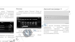

Да, совершенно верно, впринципе можно и на старый поставить.
Да ладно?))) Уверены? Есть информация, ссылка по этой теме?

Добрый день!В сервисной книжке на оф.сайте указан объём бачка стеклоомывателя 1л. Это на самом деле так или опечатка?
Примерно 2.5 литра, но хватает на долго благодаря форсункам веерным


Раздел гарантий сервисной книжки отсканировать не мог бы?
Могу фотки только сделать…

Данная инструкция на русском языке предназначена для автомобиля
Changan CS35 Plus (2018 — нв), описывает принцип работы и основные моменты эксплуатации устройства.
Производитель настойчиво рекомендует перед включением автомобиля
внимательно изучить настоящую инструкцию.
Инструкция для автомобиля
представлена в формате PDF. Все современные браузеры уже поддерживают данный формат и сложностей с открытием файла возникнуть не должно.
Но если открыть инструкцию все же не удается, то необходимо установить на компьютер программу для чтения PDF файлов, например, Acrobat Reader. Если у вас возникли сложности с открытием инструкции на смартфоне под управлением Android, нужно установить, например, Adobe Acrobat Reader.
CHANGAN CS35—PLUS
Комментарии (0)
Комментарии про другие Автомобили
Другие Автомобили Changan
- Manuals
- Brands
- Changan Manuals
- Automobile
- CS35
Manuals and User Guides for Changan CS35. We have 2 Changan CS35 manuals available for free PDF download: Workshop Manual
Changan CS35 Workshop Manual (281 pages)
Electronic Control System — ME7 & Engine Immobilizer System CS35RM2H/2/1
Brand: Changan
|
Category: Automobile
|
Size: 19.08 MB
Table of Contents
-
Power Train
3
-
Engine Immobilizer System
5
-
Specifications Torque Specifications
5
-
Description and Operation
6
-
System Overview
6
-
System Principle
7
-
General Procedures
8
-
General Equipment
8
-
Symptom Diagnosis and Testing
9
-
Inspection and Verification
9
-
Visual Inspection Chart
9
-
Symptom Chart
10
-
ECM Always Detect that Immobilizer Function Activated Diagnosis
11
-
Re-Match the Remote Controller
11
-
Inspect the Power Supply Circuit of the Immobilizer Controller
11
-
Inspect the Lin Network Circuit of the Immobilizer Controller
12
-
Inspect the Immobilizer Controller Ground Circuit
12
-
Test Conditions
12
-
Inspect the K-Line Network Cable between ECM and BCM
13
-
Replace the Password Transponder
13
-
Inspect the ECM Power Supply Circuit
13
-
Inspect the BCM Power Supply Circuit
15
-
Inspect the BCM Ground Circuit
16
-
Replace the BCM
16
-
Description and Operation
18
-
ME7 System Input / Output Signal
20
-
Fuel Injection Control
20
-
Synchronous Injection
20
-
Non — Synchronous Injection
20
-
Air — Fuel Ratio Feedback Compensation
21
-
Fuel Cut — off
21
-
Idle Speed Control
22
-
Fuel Pump Control
23
-
Ignition Timing Control
24
-
Radiator Fan Control
24
-
Ignition Control after Engine Start
24
-
A/C Compressor Control
25
-
DVVT Control
25
-
Fuel Vapor Emission Control
25
-
Component Description
26
-
Engine Control Module (ECM)
26
-
Air Intake Pressure Temperature Sensor
26
-
Water Temperature Sensor ECT
26
-
Electronic Throttle Assembly
26
-
Knock Sensor
27
-
Oil Control Valve
27
-
Camshaft Position Sensor
28
-
Pre — Catalytic Oxygen Sensor
28
-
Crankshaft Position Sensor
28
-
Post — Catalytic Oxygen Sensor
28
-
Refrigerant Pressure Switch
29
-
Vehicle Speed Sensor (AT)
29
-
Fuel Injector
29
-
Ignition Coil
29
-
Accelerator Pedal Position Sensor
30
-
Carbon Canister Sewage Solenoid
30
-
Main Relay
30
-
Fuel Pump Relay and Fuel Pump
30
-
Fan High Speed Relay, Low Speed Relay
31
-
A/C Compressor Relay
31
-
Location View
32
-
DTC Read Program
33
-
Data Stream Read Program
33
-
Actuation Component Test Procedure
33
-
General Procedures
33
-
Symptom Diagnosis and Testing
34
-
Intermittent Malfunction Diagnosis
35
-
Inspection Method of Switch Connector or Wiring Harness
36
-
Inspection Method of Sensor Connector or Wiring Harness
36
-
Test Conditions
36
-
Inspect Method of Actuator or Relay
37
-
Water Sprinkling Method
37
-
Flameout During Coasting
41
-
MIL Indicator Is Always on
41
-
MIL Lamp Is Not on
41
-
Engine Can Not Start at Normal Start Speed Diagnosis
42
-
Difficult Cold Start Diagnosis
45
-
Difficult Warm Start Diagnosis
48
-
Normal Start, but Unstable Idling at All Time Diagnosis
50
-
Normal Start, Unstable Idling or Flameout with Partial Load
54
-
Normal Start, Idling Is too High Diagnosis
56
-
Acceleration Fault Diagnosis
60
-
Engine Unstable Running Diagnosis
64
-
Easy Stall at Start Diagnosis
68
-
Emergency Occurs During Vehicle Driving Diagnosis
74
-
Stall During Coasting Diagnosis
78
-
MIL Indicator Fault Diagnosis
82
-
DTC Diagnosis and Testing
85
-
Control Module Terminal List
85
-
Diagnostic Trouble Code (DTC) Type
88
-
Fault Type
89
-
DTC Code List
90
-
Failure Protection List
96
-
Data Stream List
102
-
Ignition Switch on
103
-
Idle Running
103
-
Active Test List
106
-
Diagnostic Description
108
-
DTC Diagnostic Procedure Index
109
-
Diagnosis Procedures
110
-
Fault Code
111
-
Dtc P000A, P0010, P0012, P2088, P2089
116
-
Possible Sources
116
-
Inspect the Power Supply Line of Intake Control Valve
117
-
Inspect the Ground Circuit of the Intake Control Valve
117
-
Test Conditions
117
-
Inspect the OCV Intake Control Valve
118
-
Inspect the ECM Ground Circuit
118
-
Dtc P000B, P0013, P0015, P2090, P2091
119
-
Inspect the Power Supply Line of Exhaust Control Valve
120
-
Inspect the Ground Circuit of Exhaust Control Valve
120
-
Inspect the OCV Exhaust Control Valve
121
-
Dtc P0016, P0017
122
-
Inspect the Unstable Camshaft Position Sensor Signal
125
-
Inspect the Crankshaft Position Sensor Signal Wheel
125
-
Dtc P0030, P0031, P0032, P0053
127
-
Inspect the Pre — Catalytic Oxygen Sensor Heater Resistance Value
128
-
Inspect the Heater Working Voltage
128
-
Inspect the the Heater Power Supply Circuit
128
-
Dtc P0036, P0037, P0038, P0054
131
-
Inspect the Post — Catalytic Oxygen Sensor Heater Resistance Value
132
-
Inspect the Heater Power Supply Circuit
132
-
Dtc P0105, P0106, P0107, P0108
135
-
Possible Sources
135
-
Inspect the Intake Pressure Sensor Power Supply Voltage
136
-
Dtc P0112, P0113
143
-
DTC P0117 and P0118
149
-
Inspect the Water Temperature Sensor Resistance
150
-
Inspect the Water Temperature Sensor Signal Circuit
150
-
Inspect the Water Temperature Sensor Grounding
151
-
Dtc P0121, P0122, P0123
153
-
DTC P0221, P0222 and P0223
157
-
Dtc P0130, P0131, P0132, P0133, P0134, P2195, P2196
161
-
Dtc P0136, P0137, P0138, P0140, P2270, P2271
168
-
Dtc P0170, P0171, P0172, P2177, P2178, P2187, P2188
174
-
Dtc P0201, P0261, P0262
183
-
Dtc P0300, P0301, P0302, P0303, P0304
187
-
Dtc P0317, P0501, P1523
192
-
Dtc P0321, P0322
194
-
Dtc P0327, P0328
200
-
Dtc P0340, P0341, P0342, P0343
205
-
Dtc P0420
212
-
Dtc P0444, P0458, P0459
214
-
DTC P0480 and P0692
218
-
DTC P0481 and P0694
219
-
Dtc P0506, P0507
220
-
Dtc P0560, P0562, P0563
224
-
Dtc P0564
229
-
Dtc P0571
230
-
Dtc P0219, P0602, P0604, P0605
234
-
Dtc P0627, P0629
236
-
Dtc P0645, P0647
237
-
Dtc P0700
238
-
Dtc P0704
241
-
Dtc P1336, P1545, P1558、 P1568
245
-
Dtc P0606, P1559, P1564, P1565 , P1579, P1604
249
-
Dtc P1610, P1626, P1631
252
-
Dtc P2106
253
-
Dtc P2122, P2123, P2138
255
-
Dtc P2127, P2128, P2138
259
-
Dtc U0001, U0101, U0140
263
-
Engine Control Module
266
-
Remove the Engine Control Module
266
-
Removal and Installation
266
-
Crankshaft Position Sensor
267
-
Electrical Throttle Body
268
-
Engine Coolant Temperature Sensor
270
-
Air Intake Pressure/Temperature Sensor
271
-
Fuel Injector
272
-
Pre-Catalytic Oxygen Sensor
273
-
Special Tool
273
-
Post-Catalytic Oxygen Sensor
274
-
Knock Sensor
275
-
Accelerator Pedal Position Sensor
276
-
Oil Control Valve
277
Advertisement
Changan CS35 Workshop Manual (78 pages)
Supplemental Restraint System
Brand: Changan
|
Category: Automobile
|
Size: 6 MB
Table of Contents
-
4.2 Supplemental Restraint System
3
-
Table of Contents
3
-
4.2 Supplemental Restraint System
5
-
2012 Cs3
5
-
Specification
5
-
Torque Specifications
5
-
-
Description and Operation
6
-
System Overview
6
-
Component Description
7
-
Location View
9
-
-
-
Www.nasicoelec.ir
11
-
Symptom Diagnosis and Testing
10
-
Inspection and Verification
10
-
Symptom Chart
11
-
Abnormal Airbag Indicator Diagnosis
12
-
Airbag Indicator Always on Diagnosis
15
-
-
DTC Diagnosis and Testing
19
-
Airbag Control Module Terminal List
19
-
Diagnostic Trouble Code (DTC) Type
20
-
Diagnostic Trouble Code (DTC) List
20
-
-
-
-
Table of Contents
22
-
Data Stream List
23
-
4.2.1-18
26
-
Code
26
-
Too High Power Supply Voltage
26
-
Too Low Power Supply Voltage
26
-
System Fault Lamp Short Circuit to Ground or Open Circuit
26
-
System Fault Lamp Short Circuit to Power Supply
26
-
-
DTC Diagnosis Procedure Index
26
-
-
Www.nasicoelec.ir
27
-
B0051
27
-
Front Airbag and Front Seat Belt Pretensioner Ignited
27
-
-
B0034
27
-
Side Airbag Ignited
27
-
-
B0052
27
-
B0049
27
-
Impact Output Short Circuit to Power Supply
27
-
-
B0048
27
-
Dtc B0064, B0065, B0066, B0067
28
-
Dtc B0026, B0022, B0024, B0025
32
-
Dtc B1328, B1327
36
-
Dtc B0017, B0016, B0018, B0019
38
-
Dtc B0057, B0058, B0059, B0060
42
-
Dtc B0671, B0673
46
-
Dtc B1000, B1001
49
-
Dtc B0041, B0040, B0045, B0046
51
-
Dtc B0028, B0029, B0030, B0032
55
-
Dtc B0049, B0048
58
-
Dtc B0051, B0034, B0052
63
-
-
Removal and Installation
65
-
Driver Airbag and Steering Wheel
65
-
Clock Spring
68
-
Side Airbag
69
-
Passenger Airbag
70
-
-
-
-
Advertisement
Related Products
-
Changan M201 2014
-
Changan SC1010
-
Changan SC1010X
Changan Categories
Automobile
More Changan Manuals

Руководство по эксплуатации на Changan CS35 Plus 1 поколение с 2018 года с двигателем 1.6 литра JL478QEP передний привод с механической или автоматической трансмиссией
Характеристики Changan CS35 Plus
Тип привода Передний
Тип кузова SUV
Тип трансмиссии АКПП 6
Объем двигателя, куб.см 1598
Время разгона 0-100 км/ч, с 14
Максимальная скорость, км/ч 164
Клиренс (высота дорожного просвета), мм 180
Страна сборки Китай
Габариты кузова (Д x Ш x В), мм 4335 x 1825 x 1660
Колесная база, мм 2600
Ширина передней колеи, мм 1570
Ширина задней колеи, мм 1570
Масса, кг 1465
Объем багажника, л 403 (950)
Расход топлива в смешанном цикле, л/100 км 7,2
Передняя подвеска Независимая, амортизационная стойка типа МакФерсон
Задняя подвеска Полузависимая, торсионная балка
Передние тормоза Дисковые вентилируемые
Задние тормоза Дисковые
Стояночный тормоз Электронный
Заправочные объемы Changan CS35 Plus
Двигатель JL478QEP 1.6 литра 2.8 л SN/GF-5 5W-30
Трансмиссионная жидкость
МКПП 2.0л GL-4 75W/90
Акпп 5,5л AW — 1
Охлаждающая жидкость 6Л
Жидкость омывателя 1Л
Бензин А92 бак 52 Л
Тормозная жидкость 0,8л Дот4
Руководство Changan CS35 Plus
-
Contents
-
Table of Contents
-
Bookmarks
Quick Links
CS35 Workshop Manual
supplemental Restraint System
CS35RM2H/3/1
Related Manuals for Changan CS35
Summary of Contents for Changan CS35
-
Page 1
CS35 Workshop Manual supplemental Restraint System CS35RM2H/3/1… -
Page 3: Table Of Contents
Supplemental Restraint System 4.2 Supplemental Restraint System 2012 CS35 Table of Contents PAGE 4.2.1 supplemental Restraint System Specification……………………….. 4.2.1-1 Torque Specifications…………………… 4.2.1-1 Description and Operation ………………….. 4.2.1-2 System Overview……………………4.2.1-2 Component Description ………………….4.2.1-3 Location View ……………………… 4.2.1-5 Symptom Diagnosis and Testing…………………. 4.2.1-6 Inspection and Verification………………….
-
Page 4
Supplemental Restraint System Passenger Airbag ……………………4.2.1-66 Airbag Control Module ………………….4.2.1-69 Impact Sensor…………………….4.2.1-71 CS35 2013.04… -
Page 5: Specification
4.2.1 supplemental Restraint System 4.2.1-1 Supplemental Restraint System 4.2.1-1 Specification Torque Specifications Description lb-ft lb-in Passenger airbag retaining bolt Airbag control module retaining bolt Airbag wiring harness ground bolt Impact sensor retaining bolt CS35 2013.04…
-
Page 6: Description And Operation
The airbag control module implements a continu- ous personal injury when airbag deploy- ous diagnostic monitoring to the electrical compo- ment. Changan Auto reminds you of nents of the supplemental restraint system. If the wearing seat belts when traveling by car.
-
Page 7: Component Description
Changan Automobile authorized service judge whether the airbag should be ignited. stations for maintenance as soon as pos- Driver Airbag, Passenger Airbag sible;…
-
Page 8
The airbag system wiring harness connects the control unit, inflatable module, deployment loop and data circuit via waterproof connectors. The deployment loop wiring harness supplemental restraint system is yellow. To ser- vice the supplemental restraint system wiring har- CS35 2013.04… -
Page 9: Location View
Item Description Qty. Driver airbag module (DAB) Hexagon flange bolt Airbag wiring harness assembly Airbag controller Passenger airbag module (PAB) Front seat side airbag (right) Hexagon flange bolt Side impact sensor Tapping screw Front seat side airbag (left) CS35 2013.04…
-
Page 10: Symptom Diagnosis And Testing
Digital Multimeter • Shake the connector in the vertical and horizontal directions gently. Changan Auto Special Diagnostic Tool • Shake the wiring harnesses in the vertical Inspection and Verification and horizontal directions gently.
-
Page 11: Symptom Chart
• SDM control module • Fuse and circuit Refer to: Airbag Indicator Always ON Diagnosis (4.2.1 • Instrument The airbag indicator is Supplemental Restraint Sys- always on tem, Symptom Diagnosis and • SDM control module Testing). • Battery CS35 2013.04…
-
Page 12: Abnormal Airbag Indicator Diagnosis
System, Symptom Diagnosis Testing). 3. Clear the historical DTC of the supplemental restraint system A.Connect the Changan Automobile special diagnostic tool. B.Turn the ignition switch to «ON» and read and clear the historical DTC of the supplemental restraint system. C.Start the motor and run it for 5 min. Meanwhile turn the steering wheel all the way to the left and right several times.
-
Page 13
4.2.1-9 Test Conditions Details/Results/Solutions 4. Read the DTC of the supplemental restraint system A.Connect the Changan Automobile special diagnostic tool. B.Turn the ignition switch to «ON» and read the DTC of the supplemental restraint system on the special diagnosis tool. -
Page 14
7. Replace the airbag control module A.Turn the ignition switch to position «LOCK» and disconnect the battery negative cable. B.Replace the airbag control module. Refer to: Airbag Control Module (4.2.1 Supplemental Restraint System, Removal and Installation). Verify the system is normal. CS35 2013.04… -
Page 15: Airbag Indicator Always On Diagnosis
Standard Voltage Value: 11 ~ 16 V Is the battery voltage normal? Go to step 3. Inspect and repair the battery performance. Refer to: Battery Charing Voltage Too Low or Too High (3.1.10 Charging System, Symptom Diagnosis and Testing). CS35 2013.04…
-
Page 16
4.2.1-12 Test Conditions Details/Results/Solutions 3. Read the DTC of the supplemental restraint system A.Connect the Changan Automobile special diagnostic tool. B.Turn the ignition switch to «ON» and read the DTC of the supplemental restraint system on the special diagnosis tool. -
Page 17
6. Replace the Instrument A.Turn the ignition switch to position «LOCK» and disconnect the battery negative cable. B.Replace the Instrument. Refer to: Instrument (4.3.2 Instrument, Removal and Installation). Is the system normal? Confirm the maintenance is finished. Go to step 7. CS35 2013.04… -
Page 18
9. Replace the airbag control module A.Turn the ignition switch to position «LOCK» and disconnect the battery negative cable. B.Replace the airbag control module. Refer to: Airbag Control Module (4.2.1 Supplemental Restraint System, Removal and Installation). Verify the system is normal. CS35 2013.04… -
Page 19: Dtc Diagnosis And Testing
0.5 GN/BU Passenger side airbag power signal P26-15 P26-16 0.5 BK G105 ground line P26-17 0.3 BN Fault alarm indication signal P26-18 0.5 RD Driver side impact sensor power signal P26-19 0.5 RD Driver side impact sensor ground signal CS35 2013.04…
-
Page 20: Diagnostic Trouble Code (Dtc) Type
• Driver side peripheral acceleration sensor performance B0077 fault • Wrong connection or initialization fault of the driver side B0079 peripheral acceleration sensor • Defect or signal reliability fault of the driver side periph- B0080 eral acceleration sensor CS35 2013.04…
-
Page 21
• Passenger airbag resistance too low B0030 • Passenger airbag short circuit to ground or ground B0032 • Passenger airbag short circuit to power B1022 • Driver air curtain open circuit (reserved) B1023 • Driver air curtain resistance too low (reserved) CS35 2013.04… -
Page 22
• Side airbag ignited • Airbag controller reaches the max limit and can’t be used B0052 any more. B0049 • Impact output short circuit to power supply B0048 • Impact output short circuit to ground or open circuit CS35 2013.04… -
Page 23: Data Stream List
Wrong configuration — driver curtain airbag existence Wrong configuration — passenger curtain airbag existence Wrong configuration — driver side peripheral acceleration sensor exis- tence Wrong configuration — passenger side peripheral acceleration sensor existence Wrong configuration — fault lamp Wrong configuration — collision output CS35 2013.04…
-
Page 24
Ignition circuit failure makes the fault lamp on Accident counter Diagnostic tool is used to close the passenger front airbag Manually close the passenger front airbag Bosch development mode Customer development mode Customer production mode Customer after-sales mode Pre-ignited mode Post-ignited mode CS35 2013.04… -
Page 25
Data Flow Item Ignition Switch ON Bosch production date June 28, 2012 EEPROM version 132900 Bosch part number code KJ095 Product serial number 80001113 Customer project code 02D9 Current operating time count 421512 On-off count Bosch software number CS35 2013.04… -
Page 26: Dtc Diagnosis Procedure Index
• System fault lamp short circuit to ground or open Refer to: DTC B0671, B0673 B0671 circuit B0673 • System fault lamp short circuit to power supply B1000 • ECU internal fault Refer to: DTC B1000, B1001 B1001 • Configuration fault CS35 2013.04…
-
Page 27: B0051
B0048 cuit • Front airbag and front seat belt pretensioner Refer to: DTC B0051, B0034, B0051 ignited B0052 B0034 • Side airbag ignited • The airbag controller reaches the max limit and B0052 can’t be used any more CS35 2013.04…
-
Page 28: Dtc B0064, B0065, B0066, B0067
Equippment Conditions (Con- Test Tactics Fault Component Code trol Tactics) B0065 • Wiring harness B0064 • Driver side pretensioner Hardware circuit Carry out the self-test. A hardware B0066 circuit fault is detected. inspection seat belt B0067 • Airbag control module CS35 2013.04…
-
Page 29
4.2.1-25 3. Diagnosis Procedures Test Conditions Details/Results/Solutions 1. Inspect the trouble code A.Connect the Changan special diagnostic tool and diagnose supplemental restraint system. B.Read and clear the historical DTC. C.Frequently turn on the ignition switch to perform the airbag self-test. -
Page 30
P26 and the reliable ground, and the voltage between the terminal 8 of wiring harness connector P26 and the reliable ground. Standard Voltage Value: 0 V Is the circuit normal? Go to step 5. Replace the airbag wiring harness with fault. CS35 2013.04… -
Page 31
E.Connect the diagnostic tool and clear the historical DTCs. F.Read the DTC again. Is the system normal? Confirm the maintenance is finished. Replace the airbag control module. Refer to: Airbag Control Module (4.2.1 supplemental Restraint System, Removal and Installation). Verify the system is normal. CS35 2013.04… -
Page 32: Dtc B0026, B0022, B0024, B0025
3. Diagnosis Procedures Test Conditions Details/Results/Solutions 1. Inspect the trouble code A.Connect the Changan special diagnostic tool and diagnose the supplemental restraint system. B.Read and clear the historical DTC. C.Start the motor and run it for 5 min. Meanwhile turn the steering wheel all the way to the left and right several times.
-
Page 33
A.Turn the ignition switch to the position «LOCK» and disconnect the battery negative cable for at least 60 s. B.Inspect the wiring harness connector of the airbag control module and clean it. Is the system normal? Confirm the maintenance is finished. Go to step 5. CS35 2013.04… -
Page 34
WARNING: Do not measure the resistance value of the airbag inflation module with a multimeter. A special diagnostic tool shall be used for malfunction detection. Standard Voltage Value: 0 V Is the circuit normal? Go to step 6. Replace the wiring harness. CS35 2013.04… -
Page 35
A.Turn the ignition switch to the position «LOCK» and disconnect the battery negative cable for at least 60 s. B.Replace the airbag control module. Refer to: Airbag Control Module (4.2.1 Supplemental Restraint System, Removal and Installation). Confirm the maintenance is finished. CS35 2013.04… -
Page 36: Dtc B1328, B1327
3. Diagnosis Procedures Test Conditions Details/Results/Solutions 1. Inspect the trouble code A.Connect the Changan special diagnostic tool and diagnose the supplemental restraint system. B.Read and clear the historical DTC. C.Start the motor and run it for 5 min. Meanwhile turn the steering wheel all the way to the left and right several times.
-
Page 37
A.Turn the ignition switch to the position «LOCK» and disconnect the battery negative cable for at least 60 s. B.Inspect the airbag control module power supply wiring harness. Replace the airbag wiring harness with fault. Verify the system is normal. CS35 2013.04… -
Page 38: Dtc B0017, B0016, B0018, B0019
3. Diagnosis Procedures Test Conditions Details/Results/Solutions 1. Inspect the trouble code A.Connect the Changan special diagnostic tool and diagnose the supplemental restraint system. B.Read and clear the historical DTC. C.Start the motor and run it for 5 min. Meanwhile turn the steering wheel all the way to the left and right several times.
-
Page 39
A.Turn the ignition switch to the position «LOCK» and disconnect the battery negative cable for at least 60 s. B.Inspect the wiring harness connector of the airbag control module and clean it. Is the system normal? Confirm the maintenance is finished. Go to step 4. CS35 2013.04… -
Page 40
A special diagnostic tool shall be used for malfunction detection. Standard Voltage Value: 0 V Is the circuit normal? Go to step 5. Replace the airbag wiring harness with fault. CS35 2013.04… -
Page 41
A.Turn the ignition switch to the position «LOCK» and disconnect the battery negative cable for at least 60 s. B.Replace the airbag control module. Refer to: Airbag Control Module (4.2.1 Supplemental Restraint System, Removal and Installation). Confirm the maintenance is finished. CS35 2013.04… -
Page 42: Dtc B0057, B0058, B0059, B0060
Test Tactics Fault Component Code Tactics) B0058 • Wiring harness B0057 • Pretensioner seat belt at Hardware circuit Carry out the self-test. A hardware cir- B0059 inspection cuit fault is detected. passenger’s side B0060 • Airbag control module CS35 2013.04…
-
Page 43
3. Diagnosis Procedures Test Conditions Details/Results/Solutions 1. Inspect the trouble code A.Connect the Changan special diagnostic tool and diagnose the supplemental restraint system. B.Read and clear the historical DTC. C.Frequently turn on the ignition switch to perform the airbag self-test. -
Page 44
P26 and the reliable ground, between the terminal 10 of wiring harness connector P26 and the reliable ground. Standard Voltage Value: 0 V Is the circuit normal? Go to step 5. Replace the airbag wiring harness with fault. CS35 2013.04… -
Page 45
E.Connect the diagnostic tool and clear the historical DTCs. F.Read the DTC again. Is the system normal? Confirm the maintenance is finished. Replace the airbag control module. Refer to: Airbag Control Module (4.2.1 supplemental Restraint System, Removal and Installation). Verify the system is normal. CS35 2013.04… -
Page 46: Dtc B0671, B0673
3. Diagnosis Procedures Test Conditions Details/Results/Solutions 1. Inspect the trouble code A.Connect the Changan special diagnostic tool and diagnose the supplemental restraint system. B.Read and clear the historical DTC. C.Start the motor and run it for 5 min. Meanwhile turn the steering wheel all the way to the left and right several times.
-
Page 47
Go to step 4. Inspect and repair the open or short circuit fault between the terminal 5 of the Instrument wiring har- ness connector P11 and the terminal 17 of the air- bag control module wiring harness connector P26. CS35 2013.04… -
Page 48
A.Turn the ignition switch to the position «LOCK» and disconnect the battery negative cable for at least 60 s. B.Replace the airbag control module. Refer to: Airbag Control Module (4.2.1 supplemental Restraint System, Removal and Installation). Verify the system is normal. CS35 2013.04… -
Page 49: Dtc B1000, B1001
3. Diagnosis Procedures Test Conditions Details/Results/Solutions 1. Inspect the trouble code A.Connect the Changan special diagnostic tool and diagnose the supplemental restraint system. B.Read and clear the historical DTC. C.Start the motor and run it for 5 min. Meanwhile turn the steering wheel all the way to the left and right several times.
-
Page 50
A.Turn the ignition switch to the position «LOCK» and disconnect the battery negative cable for at least 60 B.Replace the airbag control module. Refer to: Airbag Control Module (4.2.1 Supplemental Restraint System, Removal and Installation). Verify the system is normal. CS35 2013.04… -
Page 51: Dtc B0041, B0040, B0045, B0046
3. Diagnosis Procedures Test Conditions Details/Results/Solutions 1. Inspect the trouble code A.Connect the Changan special diagnostic tool and diagnose the supplemental restraint system. B.Read and clear the historical DTC. C.Start the motor and run it for 5 min. Meanwhile turn the steering wheel all the way to the left and right several times.
-
Page 52
A.Turn the ignition switch to the position «LOCK» and disconnect the battery negative cable for at least 60 B.Inspect the wiring harness connector of the airbag control module and clean it. Is the system normal? Confirm the maintenance is finished. Go to step 4. CS35 2013.04… -
Page 53
A special diagnostic tool shall be used for malfunction detection. Standard Voltage Value: 0 V Is the circuit normal? Go to step 5. Replace the airbag wiring harness with fault. CS35 2013.04… -
Page 54
A.Turn the ignition switch to the position «LOCK» and disconnect the battery negative cable for at least 60 s. B.Replace the driver side airbag. Refer to: Side Airbag (4.2.1 Supplemental Restraint System, Removal and Installa- tion). Verify the system is normal. CS35 2013.04… -
Page 55: Dtc B0028, B0029, B0030, B0032
3. Diagnosis Procedures Test Conditions Details/Results/Solutions 1. Inspect the trouble code A.Connect the Changan special diagnostic tool and diagnose the supplemental restraint system. B.Read and clear the historical DTC. C.Start the motor and run it for 5 min. Meanwhile turn the steering wheel all the way to the left and right several times.
-
Page 56
A.Turn the ignition switch to the position «LOCK» and disconnect the battery negative cable for at least 60 B.Inspect the wiring harness connector of the airbag control module and clean it. Is the system normal? Confirm the maintenance is finished. Go to step 4. CS35 2013.04… -
Page 57
A special diagnostic tool shall be used for malfunction detection. Standard Voltage Value: 0 V Is the circuit normal? Go to step 5. Replace the airbag wiring harness with fault. CS35 2013.04… -
Page 58: Dtc B0049, B0048
2. Possible Sources Fault Equipment Conditions (Control Test Tactics Fault Component Code Tactics) B0049 • Control module hardware inspec- • Wiring harness tion Hardware circuit fault detected B0048 • SDM • Hardware circuit inspection CS35 2013.04…
-
Page 59
3. Diagnosis Procedures Test Conditions Details/Results/Solutions 1. Inspect the trouble code A.Connect the Changan special diagnostic tool and diagnose the supplemental restraint system. B.Read and clear the historical DTC. C.Start the motor and run it for 5 min. Meanwhile turn the steering wheel all the way to the left and right several times. -
Page 60
A special diagnostic tool shall be used for malfunction detection. Standard Voltage Value: 0 V Is the circuit normal? Go to step 5. Replace the airbag wiring harness with fault. CS35 2013.04… -
Page 61
A special diagnostic tool shall be used for malfunction detection. Standard Voltage Value: 0 V Is the circuit normal? Go to step 6. Replace the airbag wiring harness with fault. CS35 2013.04… -
Page 62
A.Turn the ignition switch to the position «LOCK» and disconnect the battery negative cable for at least 60 B.Replace the engine control module. Refer to: Engine Control Module (3.1.13 Electronic Control System ME7, Removal and Installation). Verify the system is normal. CS35 2013.04… -
Page 63: Dtc B0051, B0034, B0052
3. Diagnosis Procedures Test Conditions Details/Results/Solutions 1. Inspect the trouble code A.Connect the Changan special diagnostic tool and diagnose the supplemental restraint system. B.Read and clear the historical DTC. C.Start the motor and run it for 5 min. Meanwhile turn the steering wheel all the way to the left and right several times.
-
Page 64
A.Turn the ignition switch to the position «LOCK» and disconnect the battery negative cable for at least 60 s. B.Airbag control module. Refer to: Airbag Control Module (4.2.1 Supplemental Restraint System, Removal and Installation). Verify the system is normal. CS35 2013.04… -
Page 65: Removal And Installation
Refer to: Battery Inspection (3.1.10 Charg- ing System, General Procedures). 2. Remove the left side retaining bolt on the steering column upper decorative cover. A4201048 3. Remove the right side retaining bolt on the steering column upper decorative cover. A4201049 CS35 2013.04…
-
Page 66
7. Rotate it for 180° anticlockwise, repeat the operation in the step 6. 8. Continue to rotate for 90° anticlockwise, repeat step 6, and detach the driver airbag from the steering wheel. A4201032 9. Disconnect the wiring harness connector of the driver airbag. A4201019 CS35 2013.04… -
Page 67
10. Remove the steering wheel. 1. Disconnect the wiring harness connector of the horn and the steering wheel audio control switch. 2. Remove the steering wheel retaining nut. Torque: 33 Nm A4201023 Installation 1. To install, reverse the removal procedure. CS35 2013.04… -
Page 68: Clock Spring
Refer to: Driver Airbag and Steering Wheel (4.2.1 Supplemental Restraint System, Removal and Installation). 3. Remove the clock spring retaining screw. A4201039 4. Disconnect the clock spring wiring harness connector and take out the clock spring. A4201040 CS35 2013.04…
-
Page 69: Side Airbag
Refer to: Front Seat (5.1.3 Seat, Removal and Installation). CS35 2013.04…
-
Page 70: Passenger Airbag
1. Disconnect the battery negative cable. Refer to: Battery Inspection (3.1.10 Charg- ing System, General Procedures). 2. Remove the 4 retaining screws on the upper glove box. A5106013 CS35 2013.04…
-
Page 71
A4201027 5. Remove the passenger airbag and the instrument console inner frame retaining bolts. Torque: 9 Nm A4201033 6. Use a proper tool to remove the passenger airbag upper trim strip on the Instrument. A4201035 CS35 2013.04… -
Page 72
4.2.1-68 Supplemental Restraint System 4.2.1-68 7. Remove retaining screw passenger airbag upper protecting panel on the Instrument. A4201036 8. Disconnect the passenger wiring harness connector, and remove the airbag. A4201038 Installation 1. To install, reverse the removal procedure. CS35 2013.04… -
Page 73
Console, Removal and Installation). 3. Remove the retaining bolts of the airbag control module. Torque: 8 Nm A4201029 4. Disconnect the wiring harness connector of the airbag control module. A4201037 Installation 1. To install, reverse the removal procedure. CS35 2013.04… -
Page 74
WARNING: The product bar code on all the airbag system parts is an only permanent identification and is not allowed to tear up or pollute during the removal so that the manufacturers of the parts conduct quality tracking and performance check. CS35 2013.04… -
Page 75
Refer to: B-pillar Trim (5.1.9 Interior Trim and Ornamentation, Removal and Installa- tion). 4. Remove the impact sensor. 1. Disconnect the wiring harness connector of the impact sensor. 2. Remove the impact sensor retaining bolt. A4201030 Installation 1. To install, reverse the removal procedure. CS35 2013.04…