Содержание
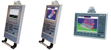
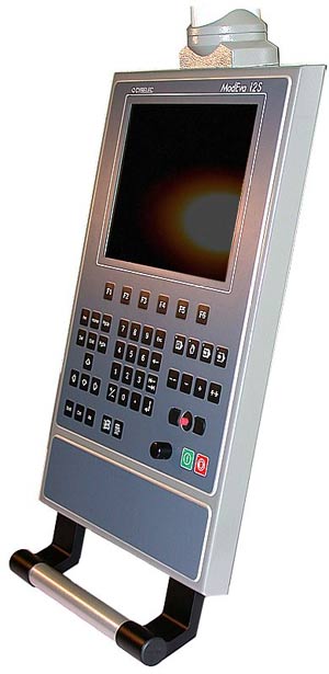
- ModEva 10S ModEva 12S ModEva 15S
- MACHINEMATE. CNC SYSTEM Hardware SPECIFICATION
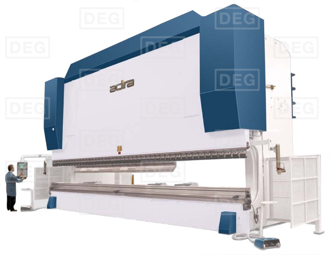
- Гидравлический листогибочный пресс с ЧПУ Adira PH-16060
- Технические характеристики
- Стандартная комплектация:
- Описание станка
- Гибочный пресс AD-S 30320
- Гибочный пресс AD-S 30320
- Основные характеристики
- Параметры подключения
- Габариты
- Дополнительные параметры
- Модельный ряд
- Особенности
- Рекомендации по применению
- Стандартная комплектация:
- Обзор опций
ModEva 10S ModEva 12S ModEva 15S
1 ModEva ModEva is a range of numerical control units intended specifically for sheet metal working. According to the software installed, it will be used on synchronised or unsynchronised press-brakes of the up-stroking or down-stroking type. ModEva numerical control units can control up to 18 axes of which 2 are synchronised hydraulic axes especially intended for press-brakes. The numerical control is composed of 2 main elements: — the programming console — the CNC (Computerised Numerical Control). The programming console is located within the operator’s reach, generally fixed to a swivelling arm; the CNC is placed inside the electric cabinet. The CNC is available in 2 rack formats. — The rack version C This is a small, very compact rack, convenient for many situations. — The rack version M This is a bigger rack permitting a varied combination of configurations. The software enables manufacturers to configure the axes, the inputs/outputs and the auxiliary functions according to their needs. ModEva 10S ModEva 12S ModEva 15S Versions PS PC P PP ModEva CNC /C ModEva CNC /M Version for synchronised press-brakes. Like the PS but for press-brakes with mechanical (or hydraulic) stops and beam control with a linear measuring rule. Like the PC but without beam control with a linear measuring rule. Version for folding presses. ModEva CNC version «C» (Compact): can control up to 4/6 axes or even 18 with CAN axes*. ModEva CNC version «M» (Maxi): controls up to 12/14 axes or even 18 with CAN axes*. * see definitions of the axes and configurations further on in the document. CDS_modeva_en.doc C-PUB-CDSMOD-EN V1.5d 1/
2 ModEva range or or CNC/C CNC/C ModEva 10S ModEva 12S ModEva 15S 10″ screen 12″ screen 15″ screen 2D 3D Windows ModEva is a modular range with a choice of: 3 programming consoles with 3 screen sizes 2 programs and 1 operational system Windows. 2 different rack sizes depending on the number of axes and the desired technology (analogue or CAN). Definitions: Hydraulic axes: Analogical axes: CAN axes: NMX: NSX: NCX: An analogue axis especially intended for controlling the beams (Y1-Y2). These two axes are on the NPU (formerly on the NAX). Axes whose position is given by an incremental sensor and whose instructions are provided by the CNC via an ±10V DC analogue voltage. One also refers to an analogue interface axis. These axes are controlled by cards called NMX / NSX. Each of these cards controls 2 axes. Axes whose positioning information is handled through a CAN bus. These axes require an NCX card on the CNC side and a CAN interface on the servo-amplifier side. An NCX card can control up to 8 axes. The number of CAN axes is controlled as an option. The ModEva CNC can be equipped with a maximum of 2 NCX axis cards. A master card for 2 analogue axes. A master card controls up to 3 NSX slave cards. A slave card for 2 analogue axes. A slave card in all cases requires an NMX card. CAN card for a maximum of 8 CAN axes. This card can handle various protocols according to the type of servo-amplifier utilised. It is possible to combine CAN and analogue axes. Configurations of CNC axes Rack version CNC / C CNC / M No. of axis cards 2 5 Axis position (slot No) The most common configurations NMX — NMX NSX NSX NMX NSX NMX NSX NSX NSX NMX NLR NMX NSX NSX NLR NCX — NMX NSX NSX NLR NMX NCX NLR NCX NLR NMX NSX CDS_modeva_en.doc V1.5d 2/6
3 Configuration of the consoles Console ModEva 10S ModEva 12S ModEva 15S TFT screen 10″ 12″ 15″ Resolution 640x x x768 Track Sensor — Yes Yes Touch Screen — — Option Quick Cursor Yes 3.5″ floppy Yes Ext. keyboard socket Yes PS2 Ext. mouse socket Yes Serial mouse with mini DIN socket Power Through the Panel Link Auxiliary I/O 12/12 Seal IP 54 Link CNC 2 cables RJ 45 twisted pair category 6. Cables 5 m or 10 m. Dist. > 10 m with CYBELEC repeater, ModEva 15S > 5 m with repeater Temperature, pollution level, Min. 5 Celsius, max. 40 Celsius.* Pollution level 2. relative humidity, Relative humidity (10 to 85% non condensing). during work. * If the ambient temperature approaches or exceeds 40 Celsius, it would be advisable to install special ventilation, or even air-conditioning. Weight Approx. 10 kg Approx. 5 kg. Configuration of the CNCs Type ModEva CNC/x-xx-Px-2DW ModEva CNC/x-xx-Px-3DW Software 2D 3D System Windows XP embedded XP pro optional** CPU Kontron 400 MHz 800 MHz optional** RAM 256 MB 512 MB optional** Disk 1 GB flash** Network Yes Ethernet RJ45 USB 1.1 Yes Printer port Yes Keyboard input Yes PS2 Mouse input Yes PS2 Screen output Yes STD VGA Y1, Y2 NPU card RS 232 port Yes 2 of which 1 configurable to RS 422 Serial port for PLC Yes 1 RS232 configurable to RS 422 Analogue axes NMX cards, NSX, according to configuration and rack version CAN axes NCX cards according to configuration and rack version Sensor inputs 5V DC Line Driver, obligatory complementary signals, Digital inputs NIN cards VDC inputs opto-coupled Digital outputs NOT cards 32 outputs 24 VDC «sources», max 2.5 A / output (NOT 204) Max 6 A / card Analogue inputs NIN cards 6 analogue inputs According to configuration 0-10, 0-24 VDC A/D 8 bits Analogue outputs Axes and FA Rack version C or M Number of axes 02 to 18 Type of machine, PS, PC, P, PP NOT cards 4 outputs 0-10 VDC (8 bits) for the auxiliary functions Z out output impedance 4 Auxiliary axes and functions of the standard software The elements listed below are available and can be configured in all numerical controls supplied with standard software (within the number of available axes). Y1 — Y2 Synchronised axes for the beam (servo-valves, proportional valves). X, X1, X2, X5, X6 Main rear backgauge axes (X5, X6 generally for gauges external to the frame). X1 ABS, X2 REL Secondary gauge axes in absolute or relative mode. R, R2, R5, R6 Backgauge height-adjustment axes (R5, R6 generally for gauges external to the frame). Z, Z2, Z5, Z6 Axes for left/right movement of the backgauge. M1, M2 Axes for the adjustment / movement of the die. Conical folds Free 1, 2, 3, 4 Pressure Crowning F1 to F10 Languages Angle measurement Comfortable programming for conical folds (requires X, X2 and adapted stop fingers). Independent axes without any particular control. Voltage output for pressure valve control. Should current control be wanted, the MVP 100 accessory, which is an external amplifier module to be fitted in the electric cabinet, would be necessary (see the MVP 100 data sheet). Voltage output for adjusting the hydraulic crowning. Should current control be wanted, the MVP 100 accessory, which is an external amplifier module to be fitted in the electric cabinet, would be necessary (see the MVP 100 data sheet). or 24 VDC (SP, SN) outputs and potentiometric position transducer for adjusting the mechanical crowning (Wila type). Configurable auxiliary functions (possibly, the number of AFs may be limited according to the type of function and management). 24VDC voltage or logical order outputs, with or without position control by means of a potentiometric transducer. Special controls for gauge fingers, bending aids, die movements. French, German, English, Italian, Spanish, Portuguese, Swedish, Danish, Finnish, Dutch, Hungarian, Polish, Czech, Slovene, Russian, Turkish, Chinese, Taiwanese. Other languages on request. Automatic correction by means of the angle measurement in serial link with digital angle protractor Mitutoyo or other compatible systems. Optional auxiliary axes and functions and other options (at extra cost) M1 M2 mounting Axes for the adjustment / movement of the die in relation with the choice of tool mounting. X3, X4, X7, X8 Front gauge axes (not calculated). Z3, Z4, Z7, Z8 Front gauge axes (not calculated). H, H2 Rear sheet support axes (not calculated). H3, H4 Calculated front sheet support axes. AP1 AP4 CAN axes Angle measurement Thickness measurement Axis thickness measurement Calculated front / rear folding assistance axes. The number of CAN axes is optionally controlled. Option permitting the adaptation of an angle-measuring system during the folding. Option permitting the automatic correction of the depth calculation by using external sheet-metal thickness measuring equipment connected by RS 232. Option permitting the automatic correction of the depth calculation by using external thickness measuring equipment connected to an axis card. The measurement is taken using conventional encoders. Message interpreter Option for the complete remote control of the CNC via network or RS 232. Reading/writing of variables, corrections, part loading, mode changing, etc. Ideal for automation and/or applications with robot. Possibility of connecting the results of an external program. Other There exist numerous options specific to each constructor. Other options can be developed according to needs. CDS_modeva_en.doc V1.5d 4/6
5 Hardware options Touch Screen Touch panel for ModEva 15S. USB CD reader Hand-grips External USB CD reader, self-powered by the USB card (for Windows models). For ModEva 15S console, choice of 2 models. Auxiliary panels Auxiliary panels for Lazer Safe commands, virgin or customised auxiliary panels for ModEva 10 / 12 or 15S Fixing adapter Sserie Earthing kit CAH / CAB MVP 100 MSV Adaptation plate for the ModEva 10S and 12S, allowing the installation of a ModEva 10S or 12S on a pendant arm of ModEva 10 or 12 or DNC Rail and bridles for earthing the sheathing for the ModEva CNC rack. See photo below. Interface card for proportional Hörbiger, Bosch valves. Voltage / current conversion module (0-10V 0,25-0,5 / 0-2 A) for pressure and crowning valves, to be fitted in the electric cabinet. Voltage / current conversion module (0-10V 0-50 ma, ma) for servo-valves interface 5VDC 24VDC interface for remote I/O programming console ports. This interface connects to the ModEva CNC CPU. On demand. EC Directives Directives Our numerical control units comply with Directives 89/336/EEC and 73/23/EEC Overall dimensions CNC / C CNC / M Earthing kit CDS_modeva_en.doc V1.5d 5/6
6 ModEva 10S and ModEva 12S ModEva 15S Auxiliary panel for ModEva 15S Modification rights reserved CDS_modeva_en.doc V1.5d 6/6
MACHINEMATE. CNC SYSTEM Hardware SPECIFICATION
 MACHINEMATE CNC SYSTEM Hardware SPECIFICATION Feb 2005 CONTENTS 1 Introduction / General. 3 1.1 Superior Capability in Technology and Productivity. 3 1.2 General hardware components. 4 1.3 Static
Источник
Гидравлический листогибочный пресс с ЧПУ Adira PH-16060
Технические характеристики
Стандартная комплектация:
- Цифровой контроллер CYBELEC DNC ModEva 10S (Y1, Y2, X, R + 3D программное обеспечение); Стандартный ручной быстросъёмный держатель для зажима пуансонов; Внутренний шестерёнчатый насос, работающий от серводвигателя; Лазерная система безопасности (LazerSafe); Вспомогательный инструмент; Инструкция по эксплуатации станка.
| Технические данные | Ед.изм. | PH-16060 |
|---|---|---|
| Усилие прессования | тонн | 160 |
| Рабочая длина | мм | 6100 |
| Расстояние между стойками станины | мм | 3150 |
| Ход верхней балки | мм | 160 |
| Макс. расстояние от стола до верхней балки без инструмента | мм | 400 |
| Глубина горловины (зев) | мм | 630 |
| Скорость подвода | мм/сек | 120 |
| Рабочая скорость гибки | мм/сек | 10 |
| Скорость отвода | мм/сек | 105 |
| Мощность двигателя | кВт | 15 |
| Габариты | мм | 7160×2340×2985 |
| Вес | кг | 14700 |
| Артикул |
Описание станка
Компания Adira была основана в 1956 году в Португалии и на сегодняшний день является одним из крупнейших европейских производителей металлообрабатывающего оборудования. Продукция компании отвечает всем европейским требованиям по безопасности и энергоэффективности и является высокоточным, высококачественным, долговечным оборудованием.
Все серии станков Adira производятся полностью с использованием комплектующих изделий ведущих европейских производителей. Завод, где собираются листогибочные пресса, гильотины и установки лазерной резки, находится в г.Порту на западе Португалии в наиболее промышленно-развитой ее части. Именно поэтому, листогибочный пресса, гильотины и установки лазерной резки фирмы Adira можно назвать полностью на 100% европейским продуктом.
Задний упор управляется по осям X и R бесщеточными серводвигателями с максимальным уровнем безопасности, который обеспечивается лазерными барьерами, управляемыми программируемыми логическими контроллерами. Самые последние достижения и инновационные решения, примененные при разработке жесткой рамы станка, позволили достигнуть высокой производительности и точности при выполнении гибов.
Параллельность верхней балки, точность остановки и повторяемость глубины изгиба (менее 0,01 мм с возможным измерением толщины обрабатываемого материала) гарантированы эффективным взаимодействием всех электронных и гидравлических компонентов. Считывание точки остановки верхней балки не зависит от гидравлического давления, температуры масла и распределения гибочных усилий между балками гибочного пресса. Быстрое и плавное изменение скорости, сокращение времени рабочего цикла делают работу станка более эффективной и удобной для оператора.
Источник


Станок добавлен в корзину!
В корзине Вы сможете:
- изменить количество товара;
- добавить или удалить опции;
- завершить оформление заказа.
Основные характеристики
| Код номенклатуры | 46062 |
| Производитель | DURMAZLAR |
| Страна-производитель | Турция |
| Тип привода | Гидравлический |
| Рабочая длина | 3050 мм |
| Усилие | 320 т |
| Расстояние между колоннами | 2600 мм |
| Глубина подачи (зёв) | 450 мм |
| Рабочая скорость по оси Y | 160 мм/с |
| Рабочая скорость по оси X | 500 мм/с |
| Рабочая скорость возврата инструмента ось Y | 140 мм/с |
| Рабочая скорость гиба ось Y | 10 мм/c |
| Ход | 265 мм |
| Просвет | 530 мм |
| Ход по оси Х | 650 мм |
| Высота стола | 900 мм |
| Ширина стола | 154 мм |
Параметры подключения
Габариты
| Длина | 4300 мм |
| Ширина | 1820 мм |
| Высота | 3330 мм |
| Вес | 17100 кг |
Дополнительные параметры
| Рабочая скорость ось R | 350 мм/с |
| Рабочий ход ось R | 250 мм |
| Ход по оси X | 1000 (опция) мм |
Модельный ряд
| Модель | Рабочая длина | Усилие |
|---|---|---|
| Гибочный пресс AD-S 25100 | 2550 мм | 100 т |
| Гибочный пресс AD-S 30100 | 3050 мм | 100 т |
| Гибочный пресс AD-S 30135 | 3050 мм | 135 т |
| Гибочный пресс AD-S 1260 | 1250 мм | 60 т |
| Гибочный пресс AD-S 2060 | 2050 мм | 60 т |
| Гибочный пресс AD-S 30175 | 3050 мм | 175 т |
| Гибочный пресс AD-S 30220 | 3050 мм | 220 т |
| Гибочный пресс AD-S 30320 | 3050 мм | 320 т |
| Гибочный пресс AD-S 37175 | 3700 мм | 175 т |
| Гибочный пресс AD-S 37220 | 3700 мм | 220 т |
| Гибочный пресс AD-S 40175 | 4050 мм | 175 т |
| Гибочный пресс AD-S 40220 | 4050 мм | 175 т |
| Гибочный пресс AD-S 40320 | 4050 мм | 320 т |
| Гибочный пресс AD-S 40400 | 4050 мм | 400 т |
| Гибочный пресс AD-S 40600 | 4050 мм | 600 т |
| Гибочный пресс AD-S 60220 | 6050 мм | 220 т |
| Гибочный пресс AD-S 60320 | 6050 мм | 220 т |
| Гибочный пресс AD-S 60400 | 6050 мм | 400 т |
| Гибочный пресс AD-S 60600 | 6050 мм | 600 т |
| Гибочный пресс AD-S 60800 | 6050 мм | 800 т |
| Гибочный пресс AD-S 70800 | 7050 мм | 800 т |
| Гибочный пресс AD-S 701000 | 7050 мм | 1000 т |
| Гибочный пресс AD-S 701250 | 7050 мм | 1250 т |
| Гибочный пресс AD-S 80800 | 8050 мм | 800 т |
| Гибочный пресс AD-S 801000 | 8050 мм | 1000 т |
| Гибочный пресс AD-S 801250 | 8050 мм | 1250 т |
| Гибочный пресс AD-S 801600 | 8100 мм | 1600 т |
| Гибочный пресс AD-S 802000 | 8100 мм | 2000 т |
Особенности
Гибочный пресс AD-S 30320 применяется для гибки листового металла с усилием до 320 тонн;
Продуманная конструкция станины и длинные двойные направляющие обеспечивают высокий подъем верхней балки;
Установлены мощные гидравлические двигатели. Оснащен прочным и быстрым серводвигателем заднего упора;
Система компенсации прогиба позволяет равномерно распределять нагрузку по всей длине заготовки для получения точного гиба без дефектов;
Управление осуществляется при помощи ЧПУ. В стандартную комплектацию включены 4 оси (Y1, Y2, X, R), настройка и корректировка работы осуществляется посредством ЧПУ, также с помощью ЧПУ можно управлять системой компенсации прогиба.
Рекомендации по применению
Гибочные прессы серии AD-S, благодаря возможности изготавливать элементы любой сложности, подходят для работы на предприятиях самого разного профиля.
Стандартная комплектация:
- 4 оси Y1, Y2, Х, R — управление ЧПУ;
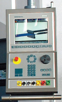
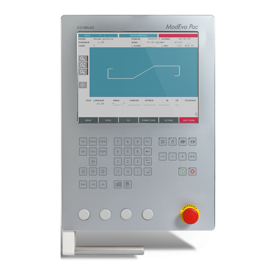
- ЧПУ CNC Cybelec ModEva 10S 2D и PC 1200 3D SW или Delem 66W;
- Электромеханическая компенсация прогиба стола, управляемая ЧПУ;
- Гидравлическая компенсация прогиба стола, управляемая ЧПУ (Стандарт ≥ 800 т);
- «Еврозажим» инструмента (Стандарт ≤ 400 т);
- Зажим инструмента DURMA (Стандарт ≥ 600 т);
- Передняя поддержка на линейных направляющих — опорные штанги с Т-образным профилем и упором;
- Задний упор с серводвигателем, линейной направляющей и системой подшипников (оси X и R);
- Система ограничения случайного травматизма;
- Специально разработанные гидравлические двигатели и система клапанов ведущих мировых производителей (Bosch);
- Электрические узлы и компоненты ведущих мировых производителей (Siemens).
ModEva 10S 3D & Pc 1200 3D S W
ModEva — серия блоков управления, спроектированных под конкретные запросы рынка. Консоли ModEva универсальны, могут легко выполнять роль пульта управления и корректировки рабочих процессов, либо могут стать мощной рабочей станции, позволяющей программировать весь процесс не отходя от станка. Вся серия оборудована высокопроизводительным процессором и максимальными графическими возможностями 3D, что позволяет блокам управления Cybelec® решать самые изощренные задачи.
Все ModEva консоли имеют очень удобную и функциональную систему Quick Cursor, для простого быстрого и удобного программирования — вращение курсора, позволяет перемещаться по страницам, открывать и выбирать меню.
Программное обеспечение PC 1200 3D — специальное приложение для подготовки управляющих программ вне станка на персональном компьютере . PC 1200 помогает пользователю определить последовательность гибки, автоматически рассчитывает положение осей листогибочного пресса, предупреждает о невозможности гибки (пересечение осей листогиба).
Delem DA 66 W
Delem DA 66 W контроллер для гибочных прессов – комбинация дружественного интерфейса, продуктивности и безотказности. Сильная комбинация дающая высокую производительность. Последние достижения в графической визуализации служат для масштабной демонстрации любого проекта. Система позволяет проводить 2-хмерное программирование в реальном времени, просчитывая последовательность гибов и возможные ошибки. В тандеме с объемной «самообучающейся» базой данных готовых расчетов это дает отличный результат. В режиме 3-хмерной развертки доступны как подбор инструмента, так и отображение и управление работой в реальном времени. Эффективная организация работы от проектирования детали до осуществления гибки, вкупе с возможностью интеграции в производственную сеть, делают контроллеры этой серии самими «продвинутыми» на фоне конкурентов.
Обзор опций
Дополнительно вы можете приобрести:
- CYBELEC ModEva 12S 3D + PC 1200 3D SW + CyCad 2D DXF Convertion SW;
- CYBELEC ModEva 15S 3D Touchscreen +PC 1200 3D SW + CyCad 2D DXF Convertion SW;
- DELEM DA-69W 3D;
- DELEM DA-69W 3D Touchscreen;
- Э/м ассиметричная регулировка по осям Z1, Z2 с управлением ЧПУ;
- Э/м ассиметричная регулировка по осям X1,X2 с управлением ЧПУ;
- Э/м ассиметричная регулировка по осям R1,R2 с управлением ЧПУ;
- Delta X, отклонение по каждой оси X до 250мм, оcь управляемая ЧПУ;
- Синхронизированное движение упоров по оси X до 1000 мм со световым барьерным ограничителем доступа сзади;
- AP3-AP4 Пневматическая передняя поддержка листа при гибке со скользящими направляющими с э/м регулировкой высоты подъема (предельная нагрузка 125 кг на каждую);
- Передняя поддержка с пневмоприводом;
- Лазерная подсветка FIESSLER AKAS (ручная);
- DFS1 Фотоэлектрический лазер для нижней балки;
- Быстросъемные зажимы для инструмента;
- Пневматическое позиционирование инструмента нижней балки;
- Система полной автоматизации рабочего процесса;
- ПО — CYBELEC PC 1200 3D SW + CyCad 2D DXF Convertion SW;
- VBend — VMDF и VDraw (утилита раскроя заготовок из листового железа);
- VBend — VMS-D и DXF — импортер (расчет и моделирование процессов);
- Система кондиционирования для электрошкафа;
- Лазерная система измерения угла гиба;
- Лазерная система измерения угла гиба — дополнительная пара сенсоров;
- Лазерная система измерения угла гиба — установка и синхронизация;
- Охладитель масла;
- Централизованная система смазки автоматическая;
- Централизованная система смазки ручная;
- Управление с противоположной стороны;
- Дополнительные пальцевые блоки, каждый;
- Дополнительная фронтальная поддержка на направляющей;
- Лазерная линия гиба.
 |
ModEva 15S
|
 |
Delem DA 69 W
Контроллер DA 69W к преимуществам DA 66W добавил возможность 3-х мерного программирования, а так же возможность вращать деталь в любых плоскостях для более наглядной визуализации результатов. Блок оборудован сенсорным экраном. Развернуть опции Источник Adblock |

-
Contents
-
Table of Contents
-
Bookmarks
Quick Links
April
User Manual
2016
for Synchronized Press Brakes
V2.3
Summary of Contents for CYBELEC ModEva Pac
-
Page 1
April User Manual 2016 for Synchronized Press Brakes V2.3… -
Page 2
© 2016 Cybelec S.A. All Rights Reserved Copying, reproduction, modification, distribution, display or transmission of any of the contents of this manual for any purpose without the prior consent of Cybelec S.A. is strictly prohibited. -
Page 3: Table Of Contents
Signs and Icons appearing in this Manual ……………… 3 General warning ……………………..3 Information………………………. 3 Settings ……………………….3 Navigation ………………………. 3 Getting started with ModEva Pac…………….4 Screen Cleaning ……………………..4 General navigation ……………………5 Menu Button ……………………..5 List of Products …………………………5 Graphical List of Products ……………………..5…
-
Page 4
The Intuitive Programming Tools Position …………………………8 Bend Numerical …………………………9 Touch Bend 2D …………………………9 Image Bend ………………………….9 Bend 2D …………………………..9 Bend 3D …………………………..9 Bend Function …………………………9 Correction Button ………………………10 Tools Bend …………………………10 Corrections …………………………10 Actions Button ……………………..11 Language ………………………..11 Tooling Management ………………… 12 Creating a Tool ……………………… -
Page 5
Access by Password ……………………34 Access to Levels Superior to 3 ………………..34 Change Passwords ……………………35 Forgotten Passwords ……………………36 Cybelec Software ………………..37 Installing the Software ………………….. 37 Leaving the Software ……………………37 Backing the System up ………………. 38 Making a backup of the system ……………….. -
Page 6
The Intuitive Programming… -
Page 7: Safety
ModEva Pac User Manual afety eneral afeTy The users must have , but most of all must ndeRstood espect directives described in this manual. All people coming into contact with the machine on which the numerical control is installed, whatever their function or whatever state the machine is in…
-
Page 8: Modeva With Windows Operating System
The CYBELEC ModEva’s equipped with Windows have been installed at the factory with a configuration especially made for the numerical control. This configuration ensures that a minimum of files are present on the ModEva, offering in this way a maximum speed to execute the programs. This configuration also ensures that the drivers are correct and that the whole guarantees an optimal functioning of the numerical control.
-
Page 9: Signs And Icons Appearing In This Manual
ModEva Pac User Manual iGnS and conS appearinG in ThiS anual While using this manual, you will come across the signs and icons represented here below: they are directly related to the safety and security of persons. Carefully follow this advice and inform others about it.
-
Page 10: Getting Started With Modeva Pac
ModEva Pac User Manual ettinG Started with Depending on software evolutions and the press brake controlled by the ModEva (configuration/capabilities), the present manual may not fully correspond to the ModEva that you currently have. However, differences are only minor. Touchscreens are pressure sensitive.
-
Page 11: General Navigation
ModEva Pac User Manual eneral naviGaTion The main navigation through the many different pages of the ModEva software is done by mean of the buttons at the bottom of the screen. The pages contain fields of different colors: • The blues fields are fixed texts, such as category titles or headings.
-
Page 12: Search Of Product/Criteria
ModEva Pac User Manual Search of Product/Criteria Transfer Allows searching for Allows making data different products transfers from one stored in the memory to another numerical control (USB, network, according to certain etc…). criteria. Programming of Punches Programming of Dies…
-
Page 13: Product Button
ModEva Pac User Manual Machine Parameters Control This page is the first Displays eventual of the pages which messages related to constitute the list of specially configured all the parameters inputs Control 1 to 8. which condition the functioning of the numerical control.
-
Page 14: Bend Button
ModEva Pac User Manual Product 3D Tools Position Allows the operator Allows defining to create a product several work in 3 dimensions. See stations. See also 3D Program- also Tooling ming (optional, only Management, page for off-line version), page Comment…
-
Page 15: Bend Numerical
Is only available if the part was created on a CAD software able to generate a Cybelec compatible program with images. pril 2016 9/40 V2.3…
-
Page 16: Correction Button
ModEva Pac User Manual Tools Bend Allows modifying the position and the width of the tools mounted on the machine. Certain safety factors can also be modified here. Correction button allows you to access the corrections page, where the individual orrection bends of a part can be fine-tuned.
-
Page 17: Actions Button
ModEva Pac User Manual Actions Button button allows you to choose from a list of action available on the page where ctionS you currently are. The content of the list changes contextually. Here below are examples of the pop-up windows being displayed when touching the button.
-
Page 18: Tooling Management
ModEva Pac User Manual oolinG anaGeMent Tooling management involves the creation, configuration and positioning of the tools that will be used on the machine. These tools are then taken into account in bend calculations. reaTinG a → Programming of punches/dies…
-
Page 19: Positioning A Punch
ModEva Pac User Manual oSiTioninG a unch → Tools position Punch placed in the middle of the machine Punch name Punch position Punch length etting nStructionS 1. Touch the beam (it will turn blue) to select the punch. The letter displayed next to the punch name’s…
-
Page 20: Positioning A Die
ModEva Pac User Manual oSiTioninG a → Tools position Proceed in the same manner as for Punch Adjustment. Die name Die placed in the middle Die position of the machine Die length etting nStructionS 1. Touch the table (it will turn blue) to select the die.
-
Page 21: Adding Working Stations
ModEva Pac User Manual ddinG orkinG TaTionS → Tools position Most parts require different sets of tools to be bent. It is therefore possible to define several working stations in the page. ooLS oSition Double horned punch Right horned punch…
-
Page 22: Creating A Part Program
Protection of Access Levels, page These procedures indicate to the operator a programming method recommended by CYBELEC, enabling to assimilate by the example the functioning of the software. For additional information, please consult the 2D Reference Manual and/or the 3D Reference Manual, which each contains a table of contents and a detailed index facilitating the search for information.
-
Page 23: Touchprofile Programming
ModEva Pac User Manual ouch rofile roGraMMinG → TouchProfile Tools selection Product number Material Material thickness Material Sigma Zoom buttons Bending length Delete selected segment Selected bend data In this mode, the operator can very intuitively draw a profile directly on the screen.
-
Page 24: Special Functions For A Bend
ModEva Pac User Manual 6. Touch the Section field, enter the value of and leave the field. This automatically initializes a new page for programming section 2. 7. Draw the profile of section 2 (see Creating a Part Program, page 16) by touching the screen where you want to add a segment.
-
Page 25: L-Alpha Programming
ModEva Pac User Manual lpha roGraMMinG → Product Numerical In this mode, the operator can define each step (length and angle) of a profile in a table. In the bottom section of the page, the operator can see the profile being automatically drawn as a function of the introduced data.
-
Page 26: Programming (Optional, Only For Off-Line Version)
ModEva Pac User Manual 3d p roGraMMinG opTional only for off line verSion → Product 3D In this mode (available only on the ModEva software with 3D option), the operator can conceive a part directly in 3 dimensions. The definitions of the different icons you will encounter through these pages are described in the 3D Reference Manual, in chapter Definition of the Icons.
-
Page 27
ModEva Pac User Manual Function active indicator 7. Touch this button again to add a rectangular face. The red rectangle to the right of the Touching this segment will attach the new face icons lights up and indicates that the here function is active. -
Page 28: Bend 2D Page
ModEva Pac User Manual 2d p → Bend 2D etting nStructionS 1. At this point, a product must have been programmed, using one of the modes previously explained. 2. In the field, choose the option iMuLat itHout rogr endS 3. Touch the button and select in the list.
-
Page 29: Touch Bend 2D Page
ModEva Pac User Manual 2d p ouch → Touch Bend 2D Touch the drawing to toggle between Bend Order page (left) and the Gauging page (right) Whether this page is used to change the order of the bends automatically calculated on…
-
Page 30: Partial Bend Order Calculation
ModEva Pac User Manual Partial bend When the operator needs to impose the first bend – or couple of bends – to be executed on a part, but the rest can be automatically calculated, the following method can be used:…
-
Page 31: Bend Numerical Page (Direct Programming)
ModEva Pac User Manual uMerical irecT roGraMMinG → Bend Numerical This type of programming is often used for simple products or by operators having worked on conventional press brakes without numerical controls. This page is very user-friendly, for the operator has on one single screen all the information and fields necessary for the programming of his product.
-
Page 32: Position Of Axes And Other Functions
ModEva Pac User Manual 8. Proceed in the same manner as for section 1 to define lengths and angles values. There is another way to program on this page, which has however some limitations depending on the product and the chosen bending order. It consists…
-
Page 33: Bending, Tests And Corrections
ModEva Pac User Manual • , defines the downward bending speed and the upward moving speed ending Peed from BDC to Pinch Point point. • , defines the portion (expressed in %) of the upward movement Peed iStance between the TDC and the Pinch Point which will be carried out at low speed; the continuation of the upward movement is made at high speed.
-
Page 34
ModEva Pac User Manual 8. Touch the field, column, and enter the measured angle (93.0 in this case). ngLe The software automatically calculates the necessary correction (-0.436, which can be seen in the y1, fields, in the column). See also the Corrections section in the 2D Reference Manual. -
Page 35: Memorize Or Search A Program
ModEva Pac User Manual eMorize or earch a roGraM eMorize a roGraM The memorizing of a product can be carried out from all pages containing the roduct field at the top of the screen. etting nStructionS 1. Set the ModEva in programming mode 2.
-
Page 36: Search A Product
ModEva Pac User Manual earch a roducT Standard Method If you know the number of the product (provided that it is in the active peripheral), you can search for it from all pages displaying the field on the top left corner of the roduct screen.
-
Page 37: Sorting Products
ModEva Pac User Manual Sorting Products Each column can be listed in an increasing or decreasing order by simply touching its title. The red arrow (▲ ▼) indicates the sorting direction Searching a product Touch the table in the desired column and enter there the product number, the drawing name or the searched date.
-
Page 38: Protection Of Access Levels
ModEva Pac User Manual rotection of cceSS evelS eneral nforMaTion In this manual we will always speak of a (virtual) key position like e.g.: «Key in position 3». Levels There are 4 access levels, 0 to 3. = Programming prohibited, or identical to level 1, according to the configuration in the machine parameters.
-
Page 39
ModEva Pac User Manual SerS A number of different users is predefined. A predefined user is just a role and not a physical person in particular. It can be for example all the operators having the authorization to work on the machine. -
Page 40: Users
Once the authorization granted, the level remains accessible as long as another password is not entered. Cybelec recommends accessing level 0 after your intervention, in order to avoid making undesired changes by inadvertence.
-
Page 41: Change Passwords
ModEva Pac User Manual 3. The ModEva switches to level 3. The operator can «navigate» between levels 1 and 3 without reintroducing his password. 4. If his access level enables him, he can call the procedure to Change Passwords. At the end of the intervention, don’t forget to pass to level 0 in order to leave the current level.
-
Page 42: Forgotten Passwords
ModEva Pac User Manual orGoTTen aSSwordS If a user has lost / forgotten his password, he can, if he is authorized, change it himself (see Change Passwords, page 35). If he is not authorized to change his password himself, he can either: •…
-
Page 43: Cybelec Software
ModEva Pac User Manual ybelec oftware nSTallinG The ofTware The software delivered with the ModEva can be installed on the numerical control itself of course, but also on a PC. When running the software’s installation program, the choice is given in a window as shown below.
-
Page 44: Backing The System Up
NC here 2. Insert a USB key (8 GB or bigger) into the numerical control. Use preferably a new and empty USB key, as the Cybelec Backup Utility will format it and erase all its content. 3. For easy identification, enter the serial number of the numerical control after the new volume’s label.
-
Page 45
:Move Enter:Accept F4:Exit 7. Select Disk, and then your USB key. The NC will boot and display the Hard following menu: *************************************************** CYBELEC S.A. / BACKUP DISK TOOL 18-MAY-2016 Rev: 1.1.4 Product under License, do not copy! *************************************************** **************************************************** LIST ARCHIVE FILE(S) -
Page 46: Restoring A Backup Of The System
The process to restore a backup of the system is very similar to creating the backup itself. Proceed as follows: If the storage media (CF card) has to be replaced, make sure it is with the same model of the same manufacturer. If not possible, contact Cybelec to get an approved replacement. etting nStructionS 1.
Добрый час. В процессе изучения листогиба Durma ADS 25100 с ЧПУ Modeva 10S понадобилось создание новой матрицы, сделал так:.thumb.jpeg.60a0757fa464d7afbdffe52ee001f8ef.jpeg)
В итоге ошибка Безопасность инструмента, вот минимальное расстояние упора до матрицы, хотя в симуляции упоры находятся над матрицей и установлена минимальная полка больше чем Безопасность XS (25мм, толщина 4)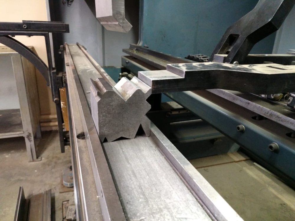
Где ошибка или как поднять упоры выше матрицы? В руководстве не нашел подробного описания программирования матрицы.
Вторая проблема — это приходится к реальной высоте матрицы прибавлять 20мм. Я так понимаю не указана проставка 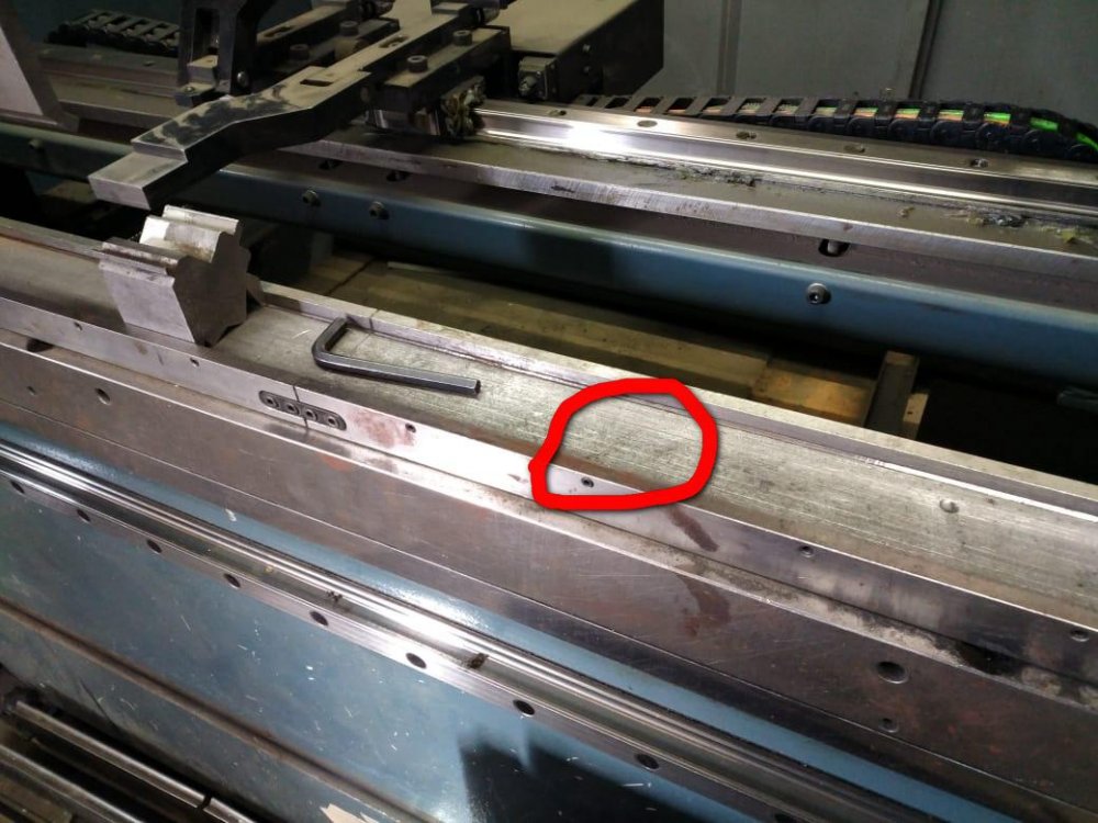 в Размерах машины, простое прибавление +20 по L2, не помогает, упоры также съезжают вниз, если высоту матрицы делаешь реальную.
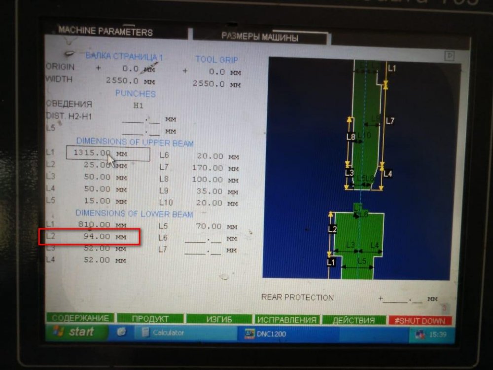
Числовое Программное Управление Cybelec серии MoDeva
Производимое Швейцарской компанией Cybelec, это самое высокотехнологичное решение задачи управления гибочным прессом. MoDeva оснащается тремя типами мониторов 10 дюймов (2D), 12дюймов и 15 дюймов (3D), работает в среде Windows и имеет удобный русскоязычный интерфейс, что значительно сокращает время на ввод данных. Перенос данных с ПК на гибочный пресс может производится как через прямое кабельное соединение так и при помощи 3,5 дюймов дискет. Процесс обработки детали может отображаться в 2D или 3D графике. ЧПУ MoDeva может контролировать до 18 сервомоторов (осей) и 2 гидроцилиндра.
Заказать
Паспорт станка
Все CNC контроллеры CYBELEC сопровождаются программным обеспечением CYBACK, PC 1200 2D или PC 1200 3D, в котором содержится библиотека чертежей прессов и инструмента, с помощью которой можно подготавливать любые программы. С их помощью определяется оптимальная последовательность гибочных операций, процесс гибки моделируется на графическом дисплее. Программное обеспечение CYBELEC это великолепный инструмент для подготовки работы, применение которого не приводит ни к каким производственным потерям и помогает решить все проблемы, связанные с гибочными операциями.
PC-ModEva is a 2D or 3D bending solution software for your PC
It helps the user finding a bending sequence, automatically calculates the axes positions and detects any possible collisions.
PC-ModEva is very helpful in workshop organization; it allows prices to be calculated and the feasibility of parts to be checked before they are produced.
PC-ModEva software is the same HMI software as on ModEva Pac and ModEva 15T, but running on your computer, therefore providing a unified way of programming.
Data is completely compatible and can be transferred between the numerical controls and computer using a USB peripheral or a RS232 serial cable.
Everything you need on a single page:
- The operator has direct access to all data required to create a part on a single page.
- No need for menu or page selections.
Simple programming:
- Simple, logical and visual.
- The operator has direct feedback of the programming.
Information for each part:
- Every time the operator loads the corresponding part program, the attached information, be it textual or graphical, is displayed in a pop-up window. No more doubts or errors are possible.
Parametrical parts:
- If the production is composed of similar and repetitive parts including only small dimension changes, Cybelec “parametric parts” feature is of great help.
- With this feature, only the adjustable dimensions are shown.
- The operator only makes changes within the limits of the data to be modified.
- A single field my change several values at once.
Do you need a calculator?
- All ModEva numerical controls allow you to use a standard or scientific calculator from Windows via a simple key code action.
Have you lost a part?
- The small graphic list of parts will help you to find it easily!
Easy Operating
Better Bending
Powerful
Bundle Software
Customer Benefits