Click the link above to view the complete
manual. The file size for the complete manual is 7.65 MB. Individual chapters
and appendices may be downloaded below.
User Manual: Chapter 1 DirectSOFT 6 User Manual — AutomationDirect
Open the PDF directly: View PDF ![]() .
.
Page Count: 6

In This Chapter
Introduction . . . . . . . . . . . . . . . . . . . . . . . . . . . . . . . . . . . .1-2
Conventions Used …………………………1-5
IntroductIon 1
chapter
1-2
Chapter 1: Introduction
DirectSOFT 6 User Manual, 2nd Edition
1
2
3
D
5
6
7
8
9
1
11
2
13
4
A
B
C
D
1-2
Introduction
The Purpose of this Manual
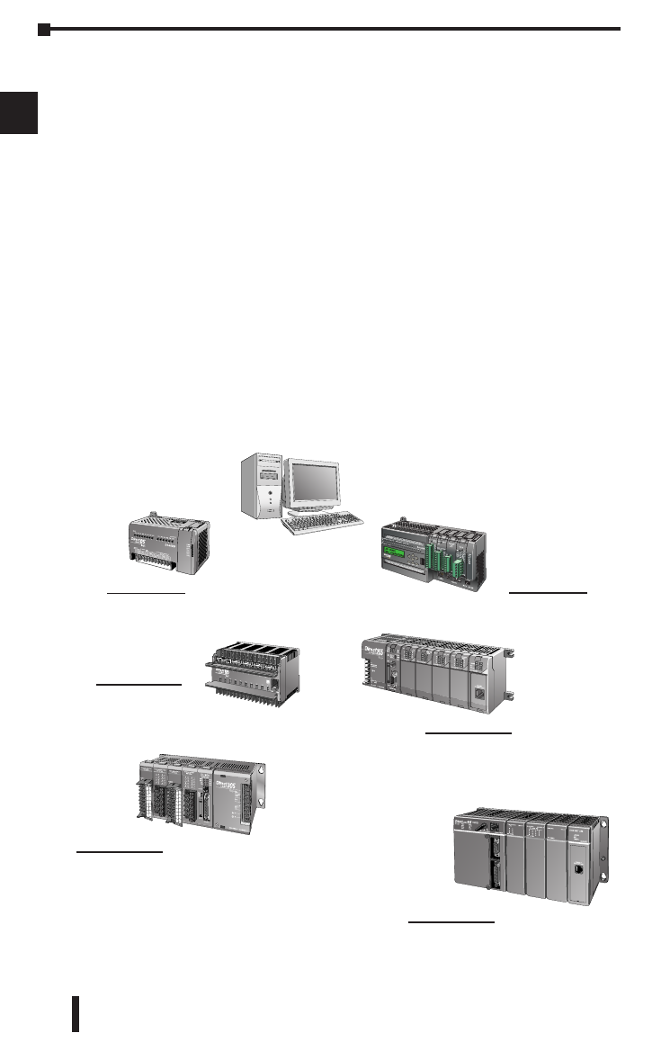
This manual describes how to use the DirectSOFT 6 software
for programming and monitoring any of the DirectLogic and
compatible CPUs. This manual will not teach you how to
develop a relay ladder logic (RLL) program or attempt to
familiarize you with the instruction sets of the CPUs. Please
refer to the applicable PLC user manual for the RLL instructions.
The Quick Start chapter will show the first time user how to get
started using DirectSOFT 6. The balance of the manual will detail
all of the programming tools made available to the user.
Who Can and Should Use DirectSOFT 6
If you have a PLC belonging to the DirectLOGIC CPU family,
you can use DirectSOFT 6 to manage your existing ladder logic
programs and to create new ones. The families of PLCs that
currently exist under this description are shown below.
DirectLOGIC PLC Family
DL05 CPUs
Two built-in ports
Max. baud = 38.4 K
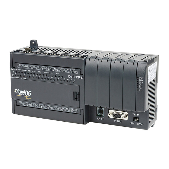
DL06 CPUs
Two built-in ports
Max. baud = 38.4 K
DL205 CPUs
One built-in port D2-230; fixed baud = 9.6 K
Two built-in ports D2-240; max. baud = 19.2 K
Two built-in ports D2-250(-1)/260 max baud =38.4 K
DL405 CPUs
Two built-in ports D4-430/440; max. baud = 19.2 K
Four built-in ports D4-450/D4-454; max. baud = 38.4 K
DL105 CPUs
One built-in port
Fixed baud = 9.6 K
DL305 CPUs
D3-330 requires D3-232-DCU; max. baud = 19.2 K
Two built-in ports D3-340/350; max. baud = 38.4 K
1-3
Chapter 1: Introduction
DirectSOFT 6 User Manual, 2nd Edition
1
2
3
D
5
6
7
8
9
0
1
2
3
4
A
B
C
D
1-3
Besides being easy to use, DirectSOFT 6 includes the following
new features:
• Crisp new graphics-based displays in Ladder View and Stage View
with alpha-blended Block Cursors.
• Color Setup dialog now offers selection of over 16 million colors —
along with the ability to configure Block Cursor and Ladder View Box
colors.
• Now ZOOM IN / ZOOM OUT to eleven (11) levels via new drop-down
Zoom control on the main offline toolbar.
• New Trend View tool which is a new debugging tool for tracking multiple
elements values over time.
• New graphical indicator denotes edge-triggered (vs. level-triggered)
Boxes and IBoxes in Ladder View.
• DirectSOFT now automatically Checks for Updates on startup. Also
added ability to manually “Check for Updates…” under the Help menu.
• Over 40 new IBoxes including: MOVER — Move Real, FILTERD — Filter
Over Time — BCD Double and DECBYBCD — Decrement by BCD
See the chart below for the PLCs and the supporting firmware
revisions required for the new IBox instructions.
Only One DirectSOFT 6 Version
There is only one DirectSOFT 6 version for the DirectLOGIC PLC
family. All licensed versions of DirectSOFT programming software
(v1.0 — v5.0) can be upgraded to version 6. Also, all programs
created with older versions of DirectSOFT are compatible with
DirectSOFT 6.
PLC Firmware
DL05 5.10
DL06 2.10
D2-250-1 4.60
D2-260 2.40
D4-450 3.30
D4-454 1.01

1-4
Chapter 1: Introduction
DirectSOFT 6 User Manual, 2nd Edition
1
2
3
D
5
6
7
8
9
1
11
2
13
4
A
B
C
D
1-4
Supplemental Manuals
Depending on the products you have purchased, there may be
other manuals that are necessary to use for your application.
User Manuals
• DL05 User Manual s D0-USER-M
• DL06 User Manual s D0-06USER-M
• DL105 User Manual s D1-USER-M
• DL205 User Manual s D2-USER-M
• DL305 User Manual s D3-USER-M
• DL350 User Manual s D3-350-M
• DL405 User Manual s D4-USER-M
• DL454 User Manual – D4-454-M
NOTE: AutomationDirect also has many associated product user manuals,
such as analog manuals, which will assist you with your application.
Technical Support
We realize that even though we strive to do our best, we may
have arranged our information in such a way that you cannot find
what you are looking for. First, check these resources for help in
locating the information:
• Table of Contents – chapter and section listing of contents, in the front
of this manual
• Appendices – reference material for key topics, near the end of this
manual
• Index – reference for key items
You can also check our online resources for the latest product
support information:
• Internet – the address of our website is:
http://www.automationdirect.com
If you still need assistance, please call us at 770–844–4200 or visit
our technical support page at:http://support.automationdirect.com.
Our technical support team will be available to work with you to
answer your questions. They are available Monday through Friday
from 9:00 A.M. to 6:00 P.M. Eastern Standard Time.
1-5
Chapter 1: Introduction
DirectSOFT 6 User Manual, 2nd Edition
1
2
3
D
5
6
7
8
9
0
1
2
3
4
A
B
C
D
1-5
Conventions Used
When the “notepad” symbol is shown in the left-hand margin, the
paragraph to its immediate right will be a special note. The word NOTE:
in boldface will mark the beginning of the text.
When the “exclamation mark” symbol is shown in the left-hand
margin, the paragraph to its immediate right will be a warning.
This information could prevent injury, loss of property, or even
death (in extreme cases).
The word WARNING: in boldface will mark the beginning of the
text.
Whenever the “lightbulb” is shown in the left-hand margin, the
paragraph to its immediate right will provide a special tip. The word
TIP: in boldface will mark the beginning of the text.
Menu Selections and Keystrokes
When the software requires you to use a particular keystroke or
menu selection, the written instructions will be in boldface type.
Combination keystrokes will be separated with a plus (+) sign. For
example, Ctrl + C means: Hold down the Ctrl key and press the
C key. Menu selections can also be combinations and separated
by a greater-than sign. For example, File > Write Program > to
Disk is a menu selection combination.
Key Topics for Each Chapter
The beginning of each chapter will list the
key topics that can be found in that chapter.

1-6
Chapter 1: Introduction
DirectSOFT 6 User Manual, 2nd Edition
1
2
3
D
5
6
7
8
9
1
11
2
13
4
A
B
C
D
1-6
Notes:
-
Contents
-
Table of Contents
-
Bookmarks
Quick Links
DL05/06 Option Modules
USER MANUAL
Manual Number: D0-OPTIONS-M
Related Manuals for Automationdirect.com DL06
Summary of Contents for Automationdirect.com DL06
-
Page 1
DL05/06 Option Modules USER MANUAL Manual Number: D0-OPTIONS-M… -
Page 2
Copyright 2018, AutomationDirect.com Incorporated All Rights Reserved No part of this manual shall be copied, reproduced, or transmitted in any way without the prior, written consent of AutomationDirect.com Incorporated. AutomationDirect retains the exclusive rights to all information included in this document. -
Page 3
Esta publicación puede contener referencias a productos producidos y/u ofrecidos por otras compañías. Los nombres de las compañías y productos pueden tener marcas registradas y son propiedad única de sus respectivos dueños. Automationdirect.com, renuncia cualquier interés propietario en las marcas y nombres de otros. -
Page 4
Nulle partie de ce manuel ne doit être copiée, reproduite ou transmise de quelque façon que ce soit sans le consentement préalable écrit de la société Automationdirect.com Incorporated. AutomationDirect conserve les droits exclusifs à l’égard de tous les renseignements contenus dans le présent document. -
Page 5
01/02 Added new chapter and minor changes to chapters 3rd edition 05/02 Added wiring guidelines and new discrete module 4th edition 07/02 Added DL06 micro PLC information 4th edition 02/03 Minor changes and corrections Rev. A 5th edition 05/03 Added new chapter… -
Page 6: Table Of Contents
Conventions Used …………………. 1–2 Key Topics for Each Chapter ………………1–2 Selecting the Proper Module ………………1–3 DL05 ……………………1–3 DL06 ……………………1–3 Module Choices ………………….. 1–3 Module Choices, continued………………1–4 Installing the Option Modules ……………… 1–5 Remove the Slot Cover ………………… 1–5 Insert the Module …………………
-
Page 7
Table of Contents Emergency Power Disconnect ……………… 2–4 Orderly System Shutdown ………………2–4 Class 1, Division 2 Approval (Applies ONLY to modules used with a DL06 PLC.) ..2–4 System Wiring Strategies ………………2–5 PLC Isolation Boundaries ………………2–5 I/O “Common” Terminal Concepts …………….2–8 Connecting DC I/O to Solid State Field Devices ………… -
Page 8
DL05 Data Formatting ………………… 3–7 Structure of V7700 ………………..3–7 Structure of V7701 ………………..3–7 DL06 Data Formatting ………………… 3–8 Setup Data Type and Number of Channels ………….. 3–8 Storage Pointer Setup ………………..3–8 Using the Pointer in Your Control Program …………. 3–9 DL05 Pointer Method ……………….. -
Page 9
DL05 Pointer Method Using the IBox Instruction Available in DirectSOFT5 ….4–9 DL06 Pointer Method Using Conventional Ladder Logic ……..4–10 DL06 Pointer Method Using the IBox Instruction Available in DirectSOFT6 …. 4–11 DL05/06 Option Modules User Manual; 7th Ed. Rev. C… -
Page 10
Resolution Details ………………..4–14 Analog Input Ladder Logic Filter …………….4–15 PID Loops / Filtering ………………..4–15 Smoothing the Input Signal (DL06 only) …………..4–15 Binary Data Format Filter Using Ladder Logic …………4–15 BCD Data Format Filter Using Ladder Logic…………4–16 Example Code to Scale a 4–20 mA Signal to 0–1000 BCD …….. -
Page 11
Resolution Details ………………..5–14 Analog Input Ladder Logic Filter …………….5–15 PID Loops / Filtering: ………………..5–15 Smoothing the Input Signal (DL06 only): …………… 5–15 Using Binary Data Format………………5–15 Using BCD Data Format ………………5–16 Chapter 6 — F0-08ADH-2, 8-Channel Analog Voltage Input Module Specifications ……………….. -
Page 12
DL05 Pointer Method Using the IBox Instruction Available in DirectSOFT5 …. 6–10 DL06 Pointer Method Using Conventional Ladder Logic ……..6–11 DL06 Pointer Method Using the IBox Instruction Available in DirectSOFT5 …. 6–12 Scale Conversions ………………..6–12 Scaling the Input Data ………………. 6–12 The Conversion Program in Standard Ladder Logic ………. -
Page 13
DL05 Pointer Method Using the IBox Instruction Available in DirectSOFT5 ….7–9 DL06 Pointer Method Using Conventional Ladder Logic ……..7–10 DL06 Pointer Method Using the IBox Instruction Available in DirectSOFT5 …. 7–11 Output Scale Conversion ………………7–11 Calculating the Digital Output Value …………..7–11 The Conversion Program in Standard Ladder Logic ………. -
Page 14
DL05 Pointer Method Using the IBox Instruction Available in DirectSOFT6 ….9–9 DL06 Pointer Method Using Conventional Ladder Logic ……..9–10 DL06 Pointer Method Using the IBox Instruction Available in DirectSOFT6 …. 9–11 Output Scale Conversion ………………9–11 Calculating the Digital Output Value …………..9–11 The Conversion Program in Standard Ladder Logic ………. -
Page 15
DL05 Pointer Method Using the IBox Instruction Available in DirectSOFT6 …. 10–9 DL06 Pointer Method Using Conventional Ladder Logic ……..10–10 DL06 Pointer Method Using the IBox Instruction Available in DirectSOFT6 ..10–11 Output Scale Conversion ………………10–11 Calculating the Digital Output Value …………..10–11 The Conversion Program in Standard Ladder Logic ………. -
Page 16
Structure of V7700 ………………..11–8 Structure of V7701 ………………..11–8 Structure of V7702 ………………..11–9 DL06 Data Formatting ………………11–10 Setup Data Type and Number of Channels …………11–10 Input Storage Pointer Setup …………….. 11–10 Output Storage Pointer Setup …………….11–10 Using the Pointer in Your Control Program ………… -
Page 17
Resolution Details ………………..11–18 Analog Input Ladder Logic Filter …………….11–19 PID Loops / Filtering ………………… 11–19 Smoothing the Input Signal (DL06 only) ………….. 11–19 Using Binary Data Format………………11–19 Using BCD Data Format ………………11–20 Chapter 12 — F0-2AD2DA-2, 2-Channel In/2-Ch. Out Analog Voltage Combination Module Specifications ………………… -
Page 18
Analog Data Bits ………………..12–15 Analog Input Ladder Logic Filter …………….12–16 PID Loops / Filtering ………………… 12–16 Smoothing the Input Signal (DL06 only) ………….. 12–16 Using Binary Data Format………………12–16 Using BCD Data Format ………………12–17 Chapter 13 — F0-4AD2DA-2, 4-Channel In/2-Ch. Out Analog Voltage Combination Module Specifications ………………… -
Page 19
Resolution Details ………………..13–15 Analog Input Ladder Logic Filter …………….13–16 PID Loops / Filtering ………………… 13–16 Smoothing the Input Signal (DL06 only) ………….. 13–16 Using Binary Data Format………………13–16 Using BCD Data Format ………………13–17 Chapter 14 — F0-04RTD, 4-Channel RTC Input Module Specifications ………………… -
Page 20
Negative Temperatures 2’s Complement (Binary/Pointer Method) ……. 14–17 Analog Input Ladder Logic Filter …………….14–18 PID Loops / Filtering ………………… 14–18 Smoothing the Input Signal (DL06 only) ………….. 14–18 Using Binary Data Format………………14–18 Using BCD Data Format ………………14–19 RTD Burnout Detection Bits ……………… -
Page 21
Module Resolution 15-Bit Plus Sign (Bipolar Voltage Input) ……..15–18 Analog Input Ladder Logic Filter …………….15–19 PID Loops / Filtering ………………… 15–19 Smoothing the Input Signal (DL06 only) ………….. 15–19 Using Binary Data Format………………15–19 Using BCD Data Format ………………15–20 Thermocouple Burnout Detection Bits ………….. -
Page 22
hapter hapter hapter ettinG tarted In This Chapter… Introduction ………………….. 1–2 Conventions Used …………………. 1–2 Selecting the Proper Module ………………1–3 Installing the Option Modules ……………… 1–5 Module LED Indicator ………………..1–6 Power Budgeting ………………….. 1–6… -
Page 23: Chapter 1: Getting Started
PLC families. It will show you how to select and install an option module for your PLC. Supplemental Manuals You will either need a copy of the DL05 User Manual (D0–USER–M) or the DL06 User Manual (D0–06USER–M) at hand when incorporating any one of the option modules in your PLC.
-
Page 24: Selecting The Proper Module
The DL05 Micro PLC only has one option slot to install an option module. The proper selection of a module is dependent on the control application. DL06 The DL06 Micro PLC has four option slots. The option modules can also be added according to the control application. Module Choices There are over thirty option modules available.
-
Page 25: Module Choices, Continued
Chapter 1: Getting Started Module Choices, continued. Analog Modules Part Number Description F0-04AD-1 4-Channel Analog Input, Current F0-04AD-2 4-Channel Analog Input, Voltage F0-08ADH-1 8-Channel High-Resolution Analog Input, Current F0-08ADH-2 8-Channel High-Resolution Analog Input, Voltage F0-04DAH-1 4-Channel High-Resolution Analog Output, Current F0-04DAH-2 4-Channel High-Resolution Analog Output, Voltage F0-08DAH-1…
-
Page 26: Installing The Option Modules
Chapter 1: Getting Started Installing the Option Modules Before installing the option module in the DL05 option slot or the DL06 option slots set the necessary jumpers and/or dip switches on the module. Refer to the chapter(s) that pertains to the module(s) being installed.
-
Page 27: Module Led Indicator
I/O module is functioning properly. Power Budgeting The DL06 has four option card slots. To determine whether the combination of cards you select will have sufficient power, you will need to perform a power budget calculation. Power supplied Power is supplied from two sources, the internal base unit power supply and, if required, an external supply (customer furnished).
-
Page 28
Chapter 1: Getting Started DL06 Base Unit Power Required DL06 Power Supplied by Base Units Part Number 5 VDC (mA) 24 VDC (mA) Part Number 5 VDC (mA) 24 VDC (mA) D0-06AA 800mA none <1500mA 300mA D0-06xx D0-06AR 900mA none <2000mA… -
Page 29
hapter hapter hapter iscrete uiDelines In This Chapter… Safety Guidelines ………………….. 2–2 System Wiring Strategies ………………2–5 I/O Addressing ………………….2–15 Discrete I/O General Specifications ……………. 2–17 Glossary of Specification Terms …………….2–18 F0-08SIM 8-Point Simulator Input Module …………. 2–19 D0-10ND3 10-Point DC Input Module ………….. -
Page 30: Chapter 2: Discrete I/O Guidelines
The protection provided by the equipment may be impaired if this equipment is used in a manner not specified in this manual. A listing of our international affiliates is available on our Web site: http://www.automationdirect.com WARNING: Providing a safe operating environment for personnel and equipment is your responsibility and should be your primary goal during system planning and installation.
-
Page 31: Three Levels Of Protection
Chapter 2: Discrete I/O Guidelines Three Levels of Protection The publications mentioned provide many ideas and requirements for system safety. At a minimum, you should follow these regulations. Also, you should use the following techniques, which provide three levels of system control. •…
-
Page 32: Emergency Power Disconnect
Retract Class 1, Division 2 Approval (Applies ONLY to modules used with a DL06 PLC.) This equipment is suitable for use in Class 1, Division 2, groups A, B, C and D or non- hazardous locations only.
-
Page 33: System Wiring Strategies
Chapter 2: Discrete I/O Guidelines System Wiring Strategies The DirectLOGIC Micro PLCs are very flexible and will work in many different wiring configurations. By studying this section before actual installation, you can probably find the best wiring strategy for your application . This will help to lower system cost, wiring errors, and avoid safety problems.
-
Page 34
Chapter 2: Discrete I/O Guidelines The following figures show the internal layout of the DL05 and DL06 PLCs, as viewed from the front panels. To Programming Device or Operator Interface DL05 2 Comm. Ports Main Optional Power I/O Circuits Supply… -
Page 35
Chapter 2: Discrete I/O Guidelines Sinking/Sourcing Concepts Before going further in our study of wiring strategies, we must have a solid understanding of “sinking” and “sourcing” concepts. Use of these terms occurs frequently in input or output circuit discussions. It is the goal of this section to make these concepts easy to understand, further ensuring your success in installation. -
Page 36: I/O «Common» Terminal Concepts
Chapter 2: Discrete I/O Guidelines I/O “Common” Terminal Concepts In order for a PLC I/O circuit to operate, current must enter at one terminal and exit at another. Field Main Path Device (I/O point) This means at least two terminals are associated Circuit with every I/O point.
-
Page 37: Connecting Dc I/O To Solid State Field Devices
The six outputs of the DL05 have the same electrical common, even though there are two common terminal screws. Not so with the DL06 which has four isolated commons. Finally, recall that the DC output circuit…
-
Page 38
Chapter 2: Discrete I/O Guidelines In the next example we connect a PLC DC output point to the sinking input of a field device. This is a bit tricky, because both the PLC output and field device input are sinking type. -
Page 39: Relay Output Guidelines
Chapter 2: Discrete I/O Guidelines Relay Output Guidelines Relay outputs are available for the DirectLOGIC PLCs. Relays are best for the following applications: • Loads that require higher currents than the solid-state outputs can deliver • Cost-sensitive applications • Some output channels need isolation from other outputs (such as when some loads require different voltages than other loads) Some applications in which NOT to use relays: •…
-
Page 40: Surge Suppression For Inductive Loads
Chapter 2: Discrete I/O Guidelines Surge Suppression For Inductive Loads Inductive load devices (devices with a coil) generate transient voltages when de-energized with a relay contact. When a relay contact is closed it “bounces”, which energizes and de-energizes the coil until the “bouncing” stops. The transient voltages generated are much larger in amplitude than the supply voltage, especially with a DC supply voltage.
-
Page 41: Prolonging Relay Contact Life
Chapter 2: Discrete I/O Guidelines Use the following table to help select a TVS or MOV suppressor for your application based on the inductive load voltage. Surge Suppressors Vendor / Catalog Type Inductive Load Voltage Part Number AutomationDirect 110/120 VAC ZL-TD8-120 24VDC ZL-TD8-24…
-
Page 42: Dc Input Wiring Methods
DC voltages from one load to another. • The DL06 has isolated commons for each group of four outputs. There are two DL06 models with output switches that are current-sinking only, and one that has sourcing output switches.
-
Page 43: I/O Addressing
The following table shows the number of I/O points per module when used in the DL05 PLC or the first slot of a DL06 PLC that has a discrete module installed. Discrete I/O addressing for a DL06 is automatic from slot 1 to slot 4 by default.
-
Page 44: All Discrete Modules Installed I/O Addressing Example
Chapter 2: Discrete I/O Guidelines All Discrete Modules Installed I/O Addressing Example: Slot 1 Slot 2 Slot 3 Slot 4 16pt Input 4pt Input 10pt Output 8pt Output AC ( L ) AC ( N ) 24V N.C. (discrete) 4pt Output (discrete) (discrete) OUTPUT: 6–240V…
-
Page 45: Discrete I/O General Specifications
The following is a list of general specifications for the discrete I/O option modules that are available for both the DL05 and DL06 PLCs. Also shown is information on the various removable connectors that are used for field wiring on the discrete I/O option modules along with reference to the ZIPLink connection system products that are available for the 16-point I/O modules.
-
Page 46: Glossary Of Specification Terms
Chapter 2: Discrete I/O Guidelines Glossary of Specification Terms Discrete Input One of the input connections to the PLC which converts an electrical signal from a field device to a binary status (OFF or ON), which is read by the internal CPU each PLC scan. Discrete Output One of the output connections from the PLC which converts an internal ladder program result (0 or 1) to turn ON or OFF an output switching device.
-
Page 47: F0-08Sim 8-Point Simulator Input Module
NOTE: The DL05 CPU’s discrete feature for the F0-08SIM module requires DirectSOFT32 Version 3.0c (or later) and firmware version 4.90 (or later). The DL06 requires DirectSOFT32 version V4.0, build 16 (or later) and firmware version 1.80 (or later). See our website for more information: www.
-
Page 48: D0-10Nd3 10-Point Dc Input Module
NOTE: The DL05 CPU’s discrete feature for this module requires DirectSOFT32 Version 3.0c (or later) and firmware version 4.10 (or later). The DL06 requires DirectSOFT32 version V4.0, build 16 (or later) and firmware version 1.00 (or later). See our website for more information: www.
-
Page 49: D0-10Nd3F 10-Point Dc Fast Input Module
NOTE: The DL05 CPU’s discrete feature for this module requires DirectSOFT32 Version 3.0c (or later) and firmware version 4.70 (or later). The DL06 requires DirectSOFT32 version V4.0, build 16 (or later) and firmware version 1.50 (or later). See our website for more information: www.automationdirect.
-
Page 50: D0-16Nd3 16-Point Dc Input Module
53.9(D) requires DirectSOFT32 Version 3.0c (or later) and Weight 20g (0.71 oz.) firmware version 4.10 (or later). The DL06 requires DirectSOFT32 version V4.0, build 16 (or later) and firmware version 1.00 (or later). See our website for Derating chart more information: www.automationdirect.com.
-
Page 51: F0-08Na-1 8-Point Ac Input Module
F0-08NA-1 NOTE: The DL05 CPU’s discrete feature for this module requires DirectSOFT32 Version 3.0c (or later) and firmware version 4.70 (or later). The DL06 requires DirectSOFT32 version V4.0, build 16 (or later) and firmware version 1.50 (or later). See our website for more information: www.automationdirect.com.
-
Page 52: D0-10Td1 10-Point Dc Output Module
NOTE: The DL05 CPU’s discrete feature for this module requires DirectSOFT32 Version 3.0c (or later) and firmware version 4.10 (or later). The DL06 requires DirectSOFT32 version V4.0, build 16 (or later) and firmware version 1.00 (or later). See our website for more information: www.automationdirect.com.
-
Page 53: D0-16Td1 16-Point Dc Output Module
NOTE: The DL05 CPU’s discrete feature for this module requires DirectSOFT32 Version 3.0c (or later) and firmware version 4.10 (or later). The DL06 requires DirectSOFT32 version V4.0, build 16 (or later) and firmware version 1.00 (or later). See our website for more information: www.automationdirect.com.
-
Page 54: D0-10Td2 10-Point Dc Output Module
NOTE: The DL05 CPU’s discrete feature for this module requires DirectSOFT32 Version 3.0c (or later) and firmware version 4.10 (or later). The DL06 requires DirectSOFT32 version V4.0, build 16 (or later) and firmware version 1.00 (or later). See our website for more information: www.automationdirect.com.
-
Page 55: D0-16Td2 16-Point Dc Output Module
NOTE: The DL05 CPU’s discrete feature for this module requires DirectSOFT32 Version 3.0c (or later) and firmware version 4.10 (or later). The DL06 requires DirectSOFT32 version V4.0, build 16 (or later) and firmware version 1.00 (or later). See our website for more information: www.automationdirect.com.
-
Page 56: D0-07Cdr 4-Point Dc Input, 3-Point Relay Output Module
NOTE: The DL05 CPU’s discrete feature for this module requires DirectSOFT32 Version 3.0c (or later) and firmware version 4.10 (or later). The DL06 requires DirectSOFT32 version V4.0, build 16 (or later) and firmware version 1.00 (or later). See our website for more information: www.automationdirect.com.
-
Page 57: D0-08Tr 8-Point Relay Output Module
NOTE: The DL05 CPU’s discrete feature for this module requires DirectSOFT32 Version 3.0c (or later) and firmware version 4.10 (or later). The DL06 requires DirectSOFT32 version V4.0, build 16 (or later) and firmware version 1.00 (or later). See our website for more information: www.automationdirect.com.
-
Page 58: D0-08Cdd1 4-Point Dc Input, 4-Point Dc Output Module
NOTE: The DL05 CPU’s discrete feature for this module requires DirectSOFT32 Version 3.0c (or later) and firmware version 4.10 (or later). The DL06 requires DirectSOFT32 version V4.0, build 16 (or later) and firmware version 1.00 (or later). See our website for more information: www.automationdirect.com.
-
Page 59: F0-04Trs 4-Point Relay Output Module
NOTE: The DL05 CPU’s discrete feature for this module requires DirectSOFT32 Version 3.0c (or later) and firmware version 4.70 (or later). The DL06 requires DirectSOFT32 version V4.0, build 16 (or later) and firmware version 1.50 (or later). See our website for more information: www.automationdirect.com.
-
Page 60
F0-04AD-1, hapter hapter hapter hAnnel nAlog urrent nput In This Chapter… Module Specifications ………………..3–2 Setting the Module Jumper ………………3–4 Connecting and Disconnecting the Field Wiring …………. 3–4 Wiring Diagram ………………….3–5 Module Operation ………………… 3–6 Special V-memory Locations ………………3–7 Using the Pointer in Your Control Program …………. -
Page 61: Chapter 3: F0-04Ad-1, 4-Channel Analog Current Input
NOTE: The DL05 CPU’s analog feature for this module requires DirectSOFT32 Version 3.0c (or later) and firmware version 2.10 (or later). The DL06 requires DirectSOFT32 version V4.0, build 16 (or later) and firmware version 1.00 (or later). See our website for more information: www.automationdirect.com.
-
Page 62
Chapter 3: F0-04AD-1, 4-Channel Analog Current Input The following tables provide the specifications for the F0–04AD–1 Analog Input Module. Review these specifications to make sure the module meets your application requirements. Input Specifications Number of Channels 4, single ended (one common) Input Range 0 to 20mA or 4 to 20mA current (jumper selectable) Resolution… -
Page 63: Setting The Module Jumper
Chapter 3: F0-04AD-1, 4-Channel Analog Current Input Setting the Module Jumper The position of jumper J3 determines the input signal level. You can choose between 4–20 mA and 0–20 mA. The module ships with the jumper not connecting the two pins. In this position, the expected input signal is 4–20 mA.
-
Page 64: Wiring Diagram
Chapter 3: F0-04AD-1, 4-Channel Analog Current Input Wiring Diagram Use the following diagram to connect the field wiring. If necessary, the F0–04AD–1 terminal block can be removed to make removal of the module possible without disturbing field wiring. Typical User Wiring Internal See NOTE 1 Module…
-
Page 65: Module Operation
Module Operation Channel Scanning Sequence The DL05 and DL06 will read all four channels of input data during each scan. Each CPU supports special V-memory locations that are used to manage the data transfer. This is discussed in more detail beginning in the section on “Special V-memory Locations”.
-
Page 66: Special V-Memory Locations
Chapter 3: F0-04AD-1, 4-Channel Analog Current Input Special V-memory Locations Formatting the Module Data The DL05 and DL06 PLCs have special V-memory locations assigned to their respective option slots. These V-memory locations allow you to: • Specify the data format (binary or BCD) •…
-
Page 67: Dl06 Data Formatting
Chapter 3: F0-04AD-1, 4-Channel Analog Current Input DL06 Data Formatting Special V-memory locations are assigned to the four option slots of the DL06 PLC. The table below shows these V-memory locations which can be used to setup the F0–04AD–1. Analog Input Module DL06 Special V-memory Locations Slot No.
-
Page 68: Using The Pointer In Your Control Program
Chapter 3: F0-04AD-1, 4-Channel Analog Current Input Using the Pointer in Your Control Program DL05 Pointer Method The DL05 CPU examines the pointer values (the memory locations identified in V7700 and V7701) on the first scan only. The example program below shows how to setup these locations. This rung can be placed anywhere in the ladder program or in the initial stage if you are using stage programming instructions.
-
Page 69: Dl06 Pointer Method
Use the special V-memory table below as a guide to setup the storage pointer in the following example for the DL06. Slot 1 is the left most option slot. The CPU will examine the pointer values at these locations only after a mode transition.
-
Page 70: Detecting Input Signal Loss
Chapter 3: F0-04AD-1, 4-Channel Analog Current Input Detecting Input Signal Loss Analog Signal Loss The F0–04AD–1 analog module can sense the loss of analog input signals in 4–20 mA loops. The Special Relays described on page 3–14 allow you to use this feature in your ladder program. For example, in the rung below SP610 is used to pull-in coil Y1, which would be used to open or close an external circuit.
-
Page 71: The Conversion Program
Chapter 3: F0-04AD-1, 4-Channel Analog Current Input The Conversion Program The following example shows how you would write the program to perform the engineering unit conversion. This example assumes you have BCD data loaded into the appropriate V-memory locations using instructions that apply for the model of CPU you are using. Note: this example uses SP1, which is always on.
-
Page 72: Special Relays
Chapter 3: F0-04AD-1, 4-Channel Analog Current Input Special Relays The list of other Special Relays associated with the DL05 and DL06 PLCs are contained in the DL05 User Manual and the DL06 User Manual. The following special relays are new and relate to the status of the F0–04AD–1 module or one of its input channels.
-
Page 73
Chapter 3: F0-04AD-1, 4-Channel Analog Current Input DL06 Special Relays (cont’d) SLOT 3 SP340 Chan 1 input type 0 = 0–20 mA 1 = 4–20 mA SP341 Chan 2 input type 0 = 0–20 mA 1 = 4–20 mA SP342 Chan 3 input type 0 = 0–20 mA… -
Page 74: Module Resolution
Chapter 3: F0-04AD-1, 4-Channel Analog Current Input Module Resolution Analog Data Bits The first twelve bits represent the analog data in binary format. Value Value 9 8 7 6 5 4 3 2 1 = data bits 1024 2048 Resolution Details Since the module has 12-bit resolution, the analog signal is converted into 4096 counts ranging from 0 — 4095 (2 ).
-
Page 75: Analog Input Ladder Logic Filter
Analog Input Ladder Logic Filter PID Loops / Filtering: Please refer to the “PID Loop Operation” chapter in the DL06 or DL05 User Manual for information on the built-in PV filter (DL05/06) and the ladder logic filter (DL06 only) shown below.
-
Page 76: Using Bcd Data Format
Chapter 3: F0-04AD-1, 4-Channel Analog Current Input NOTE: Be careful not to do a multiple number conversion on a value. For example, if you are using the pointer method in BCD format to get the analog value, it must be converted to binary (BIN) as shown below.
-
Page 77
F0-08ADH-1, hapter hapter hapter HAnnel nAlog urrent nput In This Chapter… Module Specifications ………………..4–2 Connecting and Disconnecting the Field Wiring …………. 4–4 Wiring Diagram ………………….4–5 Module Operation ………………… 4–6 Special V-memory Locations ………………4–7 Using the Pointer in Your Control Program …………. 4–9 Scale Conversions ……………….. -
Page 78: Chapter 4: F0-08Adh-1, 8-Channel Analog Current Input
NOTE: The DL05 CPU’s analog feature for this module requires DirectSOFT32 Version 3.0c (or later) and firmware version 5.20 (or later). The DL06 requires DirectSOFT32 version V4.0, build 16 (or later) and firmware version 2.30 (or later). See our website for more information: www.automationdirect.com.
-
Page 79
RFI, (145MHz, 440Mhz 5W @ 15cm); Worst case error during noise disturbance is 0.5% of full scale Agency Approvals UL508; UL60079-15 Zone 2 Module Location Any slot in a DL05 or DL06 System Field Wiring Removable Terminal Block Weight 49g (1.7 oz.) 4–3… -
Page 80: Connecting And Disconnecting The Field Wiring
Chapter 4: F0-08ADH-1, 8-Channel Analog Current Input Connecting and Disconnecting the Field Wiring WARNING: Before removing the analog module or the terminal block on the face of the module, disconnect power to the PLC and all field devices. Failure to disconnect power can result in damage to the PLC and/or field devices.
-
Page 81: Wiring Diagram
Chapter 4: F0-08ADH-1, 8-Channel Analog Current Input Wiring Diagram Use the following diagram to connect the field wiring. If necessary, the F0–08ADH–1 terminal block can be removed to make removal of the module possible without disturbing field wiring. Typical User Wiring Internal Module Circuitry CH1 ADC 2-wire 4–20mA…
-
Page 82: Module Operation
Module Operation Channel Scanning Sequence The DL05 and DL06 will read all eight channels of input data during each scan. Each CPU supports special V-memory locations that are used to manage the data transfer. This is discussed in more detail beginning in the section on “Special V-memory Locations”.
-
Page 83: Special V-Memory Locations
Chapter 4: F0-08ADH-1, 8-Channel Analog Current Input Special V-memory Locations Formatting the Analog Module Data The DL05 and DL06 PLCs have special V-memory locations assigned to their respective option slots. These V-memory locations allow you to: • Specify the data format (binary or BCD) •…
-
Page 84: Dl06 Data Formatting
Chapter 4: F0-08ADH-1, 8-Channel Analog Current Input DL06 Data Formatting Special V-memory locations are assigned to the four option slots of the DL06 PLC. The table below shows these V-memory locations which can be used to setup the F0–08ADH–1. Analog Input Module DL06 Special V-memory Locations Slot No.
-
Page 85: Using The Pointer In Your Control Program
Chapter 4: F0-08ADH-1, 8-Channel Analog Current Input Using the Pointer in Your Control Program DL05 Pointer Method Using Conventional Ladder Logic NOTE: The proper use of the DL05 pointer requires that the V-memory address be written to the special memory location on the first scan only. Use the SP0 bit as a permissive contact when using the code shown below.
-
Page 86: Dl06 Pointer Method Using Conventional Ladder Logic
The F0–08ADH–1 can be installed in any available DL06 option slot. The ladder diagram below shows how to set up these locations with the module installed in slot 1 of the DL06. Use the above table to determine the pointer values if locating the module in any of the other slot locations.
-
Page 87: Dl06 Pointer Method Using The Ibox Instruction Available In Directsoft6
Chapter 4: F0-08ADH-1, 8-Channel Analog Current Input DL06 Pointer Method Using the IBox Instruction Available in DirectSOFT6 The following logic accomplishes the same thing as the previous ladder example, but it uses the IBox instruction ANLGIN. Analog Input Module Pointer Setup…
-
Page 88: The Conversion Program In Standard Ladder Logic
Chapter 4: F0-08ADH-1, 8-Channel Analog Current Input The Conversion Program in Standard Ladder Logic The following example shows how you would write the program to perform the engineering unit conversion. This example assumes you have BCD data loaded into the appropriate V-memory locations using instructions that apply for the model of CPU you are using.
-
Page 89: Analog And Digital Value Conversions
Chapter 4: F0-08ADH-1, 8-Channel Analog Current Input Analog and Digital Value Conversions Sometimes it is useful to convert between the signal levels and the digital values. This is especially helpful during machine start-up or troubleshooting. The following table provides formulas to make this conversion easier. Range If you know the digital value If you know the analog signal level…
-
Page 90: Module Resolution
Chapter 4: F0-08ADH-1, 8-Channel Analog Current Input Module Resolution Analog Data Bits Two 16-bit words are reserved for the analog data whether you are using BCD or binary data formatting. The 16 bits in the low word represent the analog data in binary format. BCD Example V2001 V2000…
-
Page 91: Analog Input Ladder Logic Filter
Analog Input Ladder Logic Filter PID Loops / Filtering Please refer to the “PID Loop Operation” chapter in the DL06 or DL05 User Manual for information on the built-in PV filter (DL05/06) and the ladder logic filter (DL06 only) shown below.
-
Page 92: Bcd Data Format Filter Using Ladder Logic
Chapter 4: F0-08ADH-1, 8-Channel Analog Current Input NOTE: Be careful not to do a multiple number conversion on a value. For example, if you are using the pointer method in BCD format to get the analog value, it must be converted to binary (BIN) as shown below. If you are using the pointer method in Binary format, the conversion to binary (BIN) instruction is not needed.
-
Page 93: Example Code To Scale A 4-20 Ma Signal To 0-1000 Bcd
Chapter 4: F0-08ADH-1, 8-Channel Analog Current Input Example Code to Scale a 4–20 mA Signal to 0–1000 BCD (For applications where the field transmitter sends a 4–20 mA signal to the analog input card.) This example will scale the first input, a double word BCD value located at V2000 and V2001, as a 4–20 mA input signal from 0–1000.
-
Page 94: Example Code To Scale A 4-20 Ma Signal To 0-1000 Binary
Chapter 4: F0-08ADH-1, 8-Channel Analog Current Input Example Code to Scale a 4–20 mA Signal to 0–1000 Binary (For applications where the field transmitter sends a 4–20 mA signal to the analog input card.) This example will scale the first input, a binary/decimal value located at V2000 (the CPU reserves two words for each channel so V2000 and V2001 are reserved), as a 4–20 mA input signal from 0–1000.
-
Page 95
F0-04AD-2, hapter hapter hapter hAnnel nAlog oltAge nput In This Chapter… Module Specifications ………………..5–2 Setting the Module Jumpers ………………5–4 Connecting and Disconnecting the Field Wiring …………. 5–5 Wiring Diagram ………………….5–5 Module Operation ………………… 5–6 Special V-memory Locations ………………5–7 Using the Pointer in Your Control Program …………. -
Page 96: Chapter 5 — F0-04Ad-2, 4-Channel Analog Voltage Input
NOTE: The DL05 CPU’s analog feature for this module requires DirectSOFT32 Version 3.0c (or later) and firmware version 2.10 (or later). The DL06 requires DirectSOFT32 version V4.0, build 16 (or later) and firmware version 1.00 (or later). See our website for more information: www.automationdirect.com.
-
Page 97
Chapter 5: F0-04AD-2 4-Ch. Analog Voltage Input The following tables provide the specifications for the F0–04AD–2 Analog Input Module. Review these specifications to make sure the module meets your application requirements. Input Specifications Number of Channels 4, single ended (one common) Input Range 0 to 5VDC or 0 to 10VDC (jumper selectable) Resolution… -
Page 98: Setting The Module Jumpers
Chapter 5: F0-04AD-2 4-Ch. Analog Voltage Input Setting the Module Jumpers The position of the J2 jumpers determines the input signal levels. You can choose between 0–5 VDC or 0–10 VDC. The module ships with the jumpers installed connecting the pins. In this position, the input signal level is 0–5 VDC.
-
Page 99: Connecting And Disconnecting The Field Wiring
Chapter 5: F0-04AD-2 4-Ch. Analog Voltage Input Connecting and Disconnecting the Field Wiring Wiring Guidelines Your company may have guidelines for wiring and cable installation. If so, you should check those before you begin the installation. Here are some general things to consider: •…
-
Page 100: Module Operation
Module Operation Input Channel Update Sequence The DL05 and DL06 read four channels of input data during each scan. The CPU supports special V-memory locations that are used to manage the data transfer. This is discussed in more detail on the next page, “Special V-memory Locations”.
-
Page 101: Special V-Memory Locations
Chapter 5: F0-04AD-2 4-Ch. Analog Voltage Input Special V-memory Locations Formatting the Module Data The DL05 and DL06 PLCs have special V-memory locations assigned to their respective option slots. These V-memory locations allow you to: • Specify the data format (binary or BCD) •…
-
Page 102: Dl06 Data Formatting
Chapter 5: F0-04AD-2 4-Ch. Analog Voltage Input DL06 Data Formatting Special V-memory locations are assigned to the four option module slots of the DL06 PLC. The table below shows these V-memory locations which can be used for the F0–04AD–2. Analog Input Module DL06 Special V-memory Locations Slot No.
-
Page 103: Using The Pointer In Your Control Program
Chapter 5: F0-04AD-2 4-Ch. Analog Voltage Input Using the Pointer in Your Control Program DL05 Pointer Method The DL05 CPU examines the pointer values (the memory locations identified in V7700 and V7701) on the first scan only. The example program below shows how to setup these locations. This rung can be placed anywhere in the ladder program or in the initial stage if you are using stage programming instructions.
-
Page 104: Dl06 Pointer Method
Use the special V-memory table below as a guide to setup the pointer values in the following example for the DL06. Slot 1 is the left most option slot. The CPU will examine the pointer values at these locations only after a mode transition, first scan only.
-
Page 105: Scale Conversions
Chapter 5: F0-04AD-2 4-Ch. Analog Voltage Input Scale Conversions Scaling the Input Data Units = A H – L Many applications call for measurements in 4095 engineering units, which can be more meaningful than raw data. Convert to engineering units using H = High limit of the engineering the formula shown to the right.
-
Page 106: The Conversion Program
Chapter 5: F0-04AD-2 4-Ch. Analog Voltage Input The Conversion Program The following example shows how you would write the program to perform the engineering unit conversion from input data formats 0–4095. This example assumes the raw input data read at V2000 is in BCD format. Note: this example uses SP1, which is always on.
-
Page 107: Analog And Digital Value Conversions
Chapter 5: F0-04AD-2 4-Ch. Analog Voltage Input Analog and Digital Value Conversions Sometimes it is useful to convert between the signal levels and the digital values. This is especially helpful during machine startup or troubleshooting. The following table provides formulas to make this conversion easier. Range If you know the digital value If you know the analog signal level…
-
Page 108: Module Resolution
Chapter 5: F0-04AD-2 4-Ch. Analog Voltage Input Module Resolution Analog Data Bits The first twelve bits represent the analog data in binary format. Value Value 9 8 7 6 5 4 3 2 1 = data bits 1024 2048 Resolution Details Since the module has 12-bit resolution, the analog voltage signal is converted into 4096 counts ranging from 0–4095 (2 ).
-
Page 109: Analog Input Ladder Logic Filter
Analog Input Ladder Logic Filter PID Loops / Filtering: Please refer to the “PID Loop Operation” chapter in the DL06 or DL05 User Manual for information on the built-in PV filter (DL05/06) and the ladder logic filter (DL06 only) shown below.
-
Page 110: Using Bcd Data Format
Chapter 5: F0-04AD-2 4-Ch. Analog Voltage Input NOTE: Be careful not to do a multiple number conversion on a value. For example, if you are using the pointer method in BCD format to get the analog value, it must be converted to binary (BIN) as shown below. If you are using the pointer method in Binary format, the conversion to binary (BIN) instruction is not needed.
-
Page 111
F0-08ADH-2, hapter hapter hapter HAnnel nAlog oltAge nput In This Chapter… Module Specifications ………………..6–2 Setting the Module Jumpers ………………6–4 Connecting and Disconnecting the Field Wiring …………. 6–5 Wiring Diagram ………………….6–6 Module Operation ………………… 6–7 Special V-memory Locations ………………6–8 Using the Pointer in Your Control Program ………… -
Page 112: Chapter 6: F0-08Adh-2, 8-Channel Analog Voltage Input
NOTE: The DL05 CPU’s analog feature for this module requires DirectSOFT32 Version 3.0c (or later) and firmware version 5.20 (or later). The DL06 requires DirectSOFT32 version V4.0, build 16 (or later) and firmware version 2.30 (or later). See our website for more information: www.automationdirect.com.
-
Page 113
RFI, (145MHz, 440MHz 5W @ 15cm); Worst case error during noise disturbance is 0.5% of full scale Agency Approvals UL508; UL60079-15 Zone 2 Module Location Any slot in a DL05 or DL06 System Field Wiring Removable Terminal Block Weight 49g (1.7 oz.) 6–3… -
Page 114: Setting The Module Jumpers
Chapter 6: F0-08ADH-2, 8-Channel Analog Voltage Input Setting the Module Jumpers The position of the jumper determines the input signal voltage levels. You can choose between 0–5 VDC or 0–10 VDC. The 0–5V position is the default position. With the jumper connecting the J5 posts, an input signal level of 0–5 VDC is selected.
-
Page 115: Connecting And Disconnecting The Field Wiring
Chapter 6: F0-08ADH-2, 8-Channel Analog Voltage Input Connecting and Disconnecting the Field Wiring WARNING: Before removing the analog module or the terminal block on the face of the module, disconnect power to the PLC and all field devices. Failure to disconnect power can result in damage to the PLC and/or field devices.
-
Page 116: Wiring Diagram
Chapter 6: F0-08ADH-2, 8-Channel Analog Voltage Input Wiring Diagram Use the following diagram to connect the field wiring. If necessary, the F0–08ADH–2 terminal block can be removed to make removal of the module possible without disturbing field wiring. Typical User Wiring Internal Module Circuitry CH1 ADC 3-wire Voltage…
-
Page 117: Module Operation
Module Operation Channel Scanning Sequence The DL05 and DL06 will read all eight channels of input data during each scan. Each CPU supports special V-memory locations that are used to manage the data transfer. This is discussed in more detail beginning in the section on “Special V-memory Locations”.
-
Page 118: Special V-Memory Locations
Chapter 6: F0-08ADH-2, 8-Channel Analog Voltage Input Special V-memory Locations Formatting the Analog Module Data The DL05 and DL06 PLCs have special V-memory locations assigned to their respective option slots. These V-memory locations allow you to: • Specify the data format (binary or BCD) •…
-
Page 119: Dl06 Data Formatting
Chapter 6: F0-08ADH-2, 8-Channel Analog Voltage Input DL06 Data Formatting Special V-memory locations are assigned to the four option slots of the DL06 PLC. The table below shows these V-memory locations which can be used to setup the F0–08ADH–2. Analog Input Module DL06 Special V-memory Locations Slot No.
-
Page 120: Using The Pointer In Your Control Program
Chapter 6: F0-08ADH-2, 8-Channel Analog Voltage Input Using the Pointer in Your Control Program DL05 Pointer Method Using Conventional Ladder Logic NOTE: The proper use of the DL05 pointer requires that the V-memory address be written to the special memory location on the first scan only. Use the SP0 bit as a permissive contact when using the code shown below.
-
Page 121: Dl06 Pointer Method Using Conventional Ladder Logic
The F0–08ADH–2 can be installed in any available DL06 option slot. The ladder diagram below shows how to set up these locations with the module installed in slot 1 of the DL06. Use the above table to determine the pointer values if locating the module in any of the other slot locations.
-
Page 122: Dl06 Pointer Method Using The Ibox Instruction Available In Directsoft5
Chapter 6: F0-08ADH-2, 8-Channel Analog Voltage Input DL06 Pointer Method Using the IBox Instruction Available in DirectSOFT5 The following logic accomplishes the same thing as the previous ladder example, but it uses the IBox instruction ANLGIN. Analog Input Module Pointer Setup…
-
Page 123: The Conversion Program In Standard Ladder Logic
Chapter 6: F0-08ADH-2, 8-Channel Analog Voltage Input The Conversion Program in Standard Ladder Logic The following example shows how you would write the program to perform the engineering unit conversion. This example assumes you have BCD data loaded into the appropriate V-memory locations using instructions that apply for the model of CPU you are using.
-
Page 124: Analog And Digital Value Conversions
Chapter 6: F0-08ADH-2, 8-Channel Analog Voltage Input Analog and Digital Value Conversions Sometimes it is useful to convert between the signal levels and the digital values. This is especially helpful during machine start-up or troubleshooting. The following table provides formulas to make this conversion easier. Range If you know the digital value If you know the analog signal level…
-
Page 125: Module Resolution
Chapter 6: F0-08ADH-2, 8-Channel Analog Voltage Input Module Resolution Analog Data Bits Two 16-bit words are reserved for the analog data whether you are using BCD or binary data formatting. The 16 bits in the low word represent the analog data in binary format. BCD Example V2001 V2000…
-
Page 126: Analog Input Ladder Logic Filter
Analog Input Ladder Logic Filter PID Loops / Filtering Please refer to the “PID Loop Operation” chapter in the DL06 or DL05 User Manual for information on the built-in PV filter (DL05/06) and the ladder logic filter (DL06 only) shown below.
-
Page 127: Using Bcd Data Format
Chapter 6: F0-08ADH-2, 8-Channel Analog Voltage Input NOTE: Be careful not to do a multiple number conversion on a value. For example, if you are using the pointer method in BCD format to get the analog value, it must be converted to binary (BIN) as shown below. If you are using the pointer method in Binary format, the conversion to binary (BIN) instruction is not needed.
-
Page 128
F0-04DAH-1, hapter hapter HAnnel nAlog urrent utput In This Chapter… Module Specifications ………………..7–2 Connecting and Disconnecting the Field Wiring …………. 7–4 Wiring Diagram ………………….7–5 Module Operation ………………… 7–6 Special V-memory Locations ………………7–7 Using the Pointer in Your Control Program …………. 7–9 Output Scale Conversion ……………… -
Page 129: Chapter 7: F0-04Dah-1, 4-Channel Analog Current Output
NOTE: The DL05 CPU’s analog feature for this module requires DirectSOFT32 Version 3.0c (or later) and firmware version 5.20 (or later). The DL06 requires DirectSOFT32 version V4.0, build 16 (or later) and firmware version 2.30 (or later). See our website for more information: www.automationdirect.com.
-
Page 130
440Mhz 5W @ 15cm); Worst case error during noise disturbance is 0.5% of full scale Agency Approvals UL508; UL60079-15 Zone 2 Module Location Any slot in a DL05 or DL06 System Field Wiring Removable Terminal Block Weight 49g (1.7 oz.) 7–3… -
Page 131: Connecting And Disconnecting The Field Wiring
Chapter 7: F0-04DAH-1, 4-Channel Analog Current Output Connecting and Disconnecting the Field Wiring WARNING: Before removing the analog module or the terminal block on the face of the module, disconnect power to the PLC and all field devices. Failure to disconnect power can result in damage to the PLC and/or field devices.
-
Page 132: Wiring Diagram
Chapter 7: F0-04DAH-1, 4-Channel Analog Current Output Wiring Diagram Use the following diagram to connect the field wiring. If necessary, the F0–04DAH–1 terminal block can be removed to make removal of the module possible without disturbing field wiring. Typical User Wiring Internal Module Circuitry 4-20mA Output Ch.
-
Page 133: Module Operation
Module Operation Channel Scanning Sequence The DL05 and DL06 will write all four channels of output data during each scan. Each CPU supports special V-memory locations that are used to manage the data transfer. This is discussed in more detail beginning in the section on “Special V-memory Locations.”…
-
Page 134: Special V-Memory Locations
Chapter 7: F0-04DAH-1, 4-Channel Analog Current Output Special V-memory Locations Formatting the Analog Module Data The DL05 and DL06 PLCs have special V-memory locations assigned to their respective option slots. These V-memory locations allow you to: • Specify the data format (binary or BCD) •…
-
Page 135: Dl06 Data Formatting
Chapter 7: F0-04DAH-1, 4-Channel Analog Current Output DL06 Data Formatting Special V-memory locations are assigned to the four option slots of the DL06 PLC. The table below shows these V-memory locations which can be used to setup the F0–04DAH–1. Analog Output Module DL06 Special V-memory Locations Slot No.
-
Page 136: Using The Pointer In Your Control Program
Chapter 7: F0-04DAH-1, 4-Channel Analog Current Output Using the Pointer in Your Control Program DL05 Pointer Method Using Conventional Ladder Logic NOTE: The proper use of the DL05 pointer requires that the V-memory address be written to the special memory location on the first scan only. Use the SP0 bit as a permissive contact when using the code shown below.
-
Page 137: Dl06 Pointer Method Using Conventional Ladder Logic
DL06 Pointer Method Using Conventional Ladder Logic NOTE: The proper use of the DL06 pointer requires that the V-memory address be written to the special memory location on the first scan only. Use the SP0 bit as a permissive contact when using the code shown below.
-
Page 138: Dl06 Pointer Method Using The Ibox Instruction Available In Directsoft5
Chapter 7: F0-04DAH-1, 4-Channel Analog Current Output DL06 Pointer Method Using the IBox Instruction Available in DirectSOFT5 The following logic accomplishes the same thing as the previous ladder example, but it uses the IBox instruction ANLGOUT. Analog Output Module Pointer Setup…
-
Page 139: The Conversion Program In Standard Ladder Logic
Chapter 7: F0-04DAH-1, 4-Channel Analog Current Output The Conversion Program in Standard Ladder Logic The following example shows how you would write the program to perform the engineering unit conversion. This example assumes you have BCD data loaded into the appropriate V-memory locations using instructions that apply for the model of CPU you are using.
-
Page 140: Analog And Digital Value Conversions
Chapter 7: F0-04DAH-1, 4-Channel Analog Current Output Analog and Digital Value Conversions Sometimes it is useful to convert between the signal levels and the digital values. This is especially helpful during machine startup or troubleshooting. The following table provides formulas to make this conversion easier. The formulas in the table show the relationship between A, the analog value, and D, the digital value.
-
Page 141: Module Resolution
Chapter 7: F0-04DAH-1, 4-Channel Analog Current Output Module Resolution Analog Data Bits Two 16-bit words are reserved for the analog data whether you are using BCD or binary data formatting. The 16 bits in the low word represent the analog data in binary format. BCD Example V2001 V2000…
-
Page 142
F0-08DAH-1, hapter hapter hapter HAnnel nAlog urrent utput In This Chapter… Module Specifications ………………..8–2 Connecting and Disconnecting the Field Wiring …………. 8–4 Wiring Diagram ………………….8–5 Module Operation ………………… 8–6 Special System V-memory Locations …………….. 8–7 Using the Pointer in Your Control Program …………. 8–9 Output Scale Conversion ……………… -
Page 143: Chapter 8: F0-08Dah-1, 8-Channel Analog Current Output
NOTE: The DL05 CPU’s analog feature for this module requires DirectSOFT32 Version 3.0c (or later) and firmware version 5.20 (or later). The DL06 requires DirectSOFT32 version V4.0, build 16 (or later) and firmware version 2.30 (or later). See our website for more information: www.automationdirect.com.
-
Page 144
RFI, (145MHz, 440Mhz 5W @ 15cm); Worst case error during noise disturbance is 0.5% of full scale Agency Approvals UL508; UL60079-15 Zone 2 Module Location Any slot in a DL05 or DL06 System Field Wiring Removable Terminal Block Weight 49g (1.7 oz.) 8–3… -
Page 145: Connecting And Disconnecting The Field Wiring
Chapter 8: F0-08DAH-1, 8-Channel Analog Current Output Connecting and Disconnecting the Field Wiring WARNING: Before removing the analog module or the terminal block on the face of the module, disconnect power to the PLC and all field devices. Failure to disconnect power can result in damage to the PLC and/or field devices.
-
Page 146: Wiring Diagram
Chapter 8: F0-08DAH-1, 8-Channel Analog Current Output Wiring Diagram Use the following diagram to connect the field wiring. If necessary, the F0–08DAH–1 terminal block can be removed to make removal of the module possible without disturbing field wiring. Typical User Wiring Internal Module Circuitry 4-20mA Output Ch.
-
Page 147: Module Operation
Module Operation Channel Scanning Sequence The DL05 and DL06 will read all eight channels of output data during each scan. Each CPU supports special V-memory locations that are used to manage the data transfer. This is discussed in more detail beginning in the section on “Special V-memory Locations”.
-
Page 148: Special System V-Memory Locations
Chapter 8: F0-08DAH-1, 8-Channel Analog Current Output Special System V-memory Locations Formatting the Analog Module Data The DL05 and DL06 PLCs have system V-memory locations assigned to their respective option slots. These V-memory locations allow you to: • Specify the data format (binary or BCD) •…
-
Page 149: Dl06 Data Formatting
Chapter 8: F0-08DAH-1, 8-Channel Analog Current Output DL06 Data Formatting Special V-memory locations are assigned to the four option slots of the DL06 PLC. The table below shows these V-memory locations which can be used to setup the F0–08DAH–1. Analog Output Module DL06 Special V-memory Locations Slot No.
-
Page 150: Using The Pointer In Your Control Program
Chapter 8: F0-08DAH-1, 8-Channel Analog Current Output Using the Pointer in Your Control Program DL05 Pointer Method Using Conventional Ladder Logic NOTE: The proper use of the DL05 pointer requires that the V-memory address be written to the special memory location on the first scan only. Use the SP0 bit as a permissive contact when using the code shown below.
-
Page 151: Dl06 Pointer Method Using Conventional Ladder Logic
DL06 Pointer Method Using Conventional Ladder Logic NOTE: The proper use of the DL06 pointer requires that the V-memory address be written to the special memory location on the first scan only. Use the SP0 bit as a permissive contact when using the code shown below.
-
Page 152: Dl06 Pointer Method Using The Ibox Instruction Available In Directsoft5
Chapter 8: F0-08DAH-1, 8-Channel Analog Current Output DL06 Pointer Method Using the IBox Instruction Available in DirectSOFT5 The following logic accomplishes the same thing as the previous ladder example, but it uses the IBox instruction ANLGOUT. Analog Output Module Pointer Setup…
-
Page 153: The Conversion Program In Standard Ladder Logic
Chapter 8: F0-08DAH-1, 8-Channel Analog Current Output The Conversion Program in Standard Ladder Logic The following example shows how you would write the program to perform the engineering unit conversion. This example assumes you have BCD data loaded into the appropriate V-memory locations using instructions that apply for the model of CPU you are using.
-
Page 154: Analog And Digital Value Conversions
Chapter 8: F0-08DAH-1, 8-Channel Analog Current Output Analog and Digital Value Conversions Sometimes it is useful to convert between the signal levels and the digital values. This is especially helpful during machine startup or troubleshooting. The following table provides formulas to make this conversion easier. The formulas in the table show the relationship between A, the analog value, and D, the digital value.
-
Page 155: Module Resolution
Chapter 8: F0-08DAH-1, 8-Channel Analog Current Output Module Resolution Analog Data Bits Two 16-bit words are reserved for the analog data whether you are using BCD or binary data formatting. The 16 bits in the low word represent the analog data in binary format. BCD Example V2001 V2000…
-
Page 156
F0-04DAH-2, hapter hapter hapter HAnnel nAlog oltAge utput In This Chapter… Module Specifications ………………..9–2 Connecting and Disconnecting the Field Wiring …………. 9–4 Wiring Diagram ………………….9–5 Module Operation ………………… 9–6 Special V-memory Locations ………………9–7 Using the Pointer in Your Control Program …………. 9–9 Output Scale Conversion ……………… -
Page 157: Chapter 9: F0-04Dah-2, 4-Channel Analog Voltage Output
NOTE: The DL05 CPU’s analog feature for this module requires DirectSOFT32 Version 3.0c (or later) and firmware version 5.20 (or later). The DL06 requires DirectSOFT32 version V4.0, build 16 (or later) and firmware version 2.30 (or later). See our website for more information: www.automationdirect.com.
-
Page 158
RFI, (145MHz, 440Mhz 5W @ 15cm); Worst case error during noise disturbance is 0.5% of full scale Agency Approvals UL508; UL60079-15 Zone 2 Module Location Any slot in a DL05 or DL06 System Field Wiring Removable Terminal Block Weight 49g (1.7 oz.) 9–3… -
Page 159: Connecting And Disconnecting The Field Wiring
Chapter 9: F0-04DAH-2, 4-Channel Analog Voltage Output Connecting and Disconnecting the Field Wiring WARNING: Before removing the analog module or the terminal block on the face of the module, disconnect power to the PLC and all field devices. Failure to disconnect power can result in damage to the PLC and/or field devices.
-
Page 160: Wiring Diagram
Chapter 9: F0-04DAH-2, 4-Channel Analog Voltage Output Wiring Diagram Use the following diagram to connect the field wiring. If necessary, the F0–04DAH–2 terminal block can be removed to make removal of the module possible without disturbing field wiring. Typical User Wiring Internal Module Circuitry Voltage Output Ch.
-
Page 161: Module Operation
Module Operation Channel Scanning Sequence The DL05 and DL06 will read all four channels of output data during each scan. Each CPU supports special V-memory locations that are used to manage the data transfer. This is discussed in more detail beginning in the section on “Special V-memory Locations”.
-
Page 162: Special V-Memory Locations
Chapter 9: F0-04DAH-2, 4-Channel Analog Voltage Output Special V-memory Locations Formatting the Analog Module Data The DL05 and DL06 PLCs have special V-memory locations assigned to their respective option slots. These V-memory locations allow you to: • Specify the data format (binary or BCD) •…
-
Page 163: Dl06 Data Formatting
Chapter 9: F0-04DAH-2, 4-Channel Analog Voltage Output DL06 Data Formatting Special V-memory locations are assigned to the four option slots of the DL06 PLC. The table below shows these V-memory locations which can be used to setup the F0–04DAH–2. Analog Output Module DL06 Special V-memory Locations Slot No.
-
Page 164: Using The Pointer In Your Control Program
Chapter 9: F0-04DAH-2, 4-Channel Analog Voltage Output Using the Pointer in Your Control Program DL05 Pointer Method Using Conventional Ladder Logic NOTE: The proper use of the DL05 pointer requires that the V-memory address be written to the special memory location on the first scan only. Use the SP0 bit as a permissive contact when using the code shown below.
-
Page 165: Dl06 Pointer Method Using Conventional Ladder Logic
DL06 Pointer Method Using Conventional Ladder Logic NOTE: The proper use of the DL06 pointer requires that the V-memory address be written to the special memory location on the first scan only. Use the SP0 bit as a permissive contact when using the code shown below.
-
Page 166: Dl06 Pointer Method Using The Ibox Instruction Available In Directsoft6
Chapter 9: F0-04DAH-2, 4-Channel Analog Voltage Output DL06 Pointer Method Using the IBox Instruction Available in DirectSOFT6 The following logic accomplishes the same thing as the previous ladder example, but it uses the IBox instruction ANLGOUT. Analog Output Module Pointer Setup…
-
Page 167: The Conversion Program In Standard Ladder Logic
Chapter 9: F0-04DAH-2, 4-Channel Analog Voltage Output The Conversion Program in Standard Ladder Logic The following example shows how you would write the program to perform the engineering unit conversion. This example assumes you have BCD data loaded into the appropriate V-memory locations using instructions that apply for the model of CPU you are using.
-
Page 168: Analog And Digital Value Conversions
Chapter 9: F0-04DAH-2, 4-Channel Analog Voltage Output Analog and Digital Value Conversions Sometimes it is useful to convert between the signal levels and the digital values. This is especially helpful during machine startup or troubleshooting. The following table provides formulas to make this conversion easier. The formulas in the table show the relationship between A, the analog value, and D, the digital value.
-
Page 169: Module Resolution
Chapter 9: F0-04DAH-2, 4-Channel Analog Voltage Output Module Resolution Analog Data Bits Two 16-bit words are reserved for the analog data whether you are using BCD or binary data formatting. The 16 bits in the low word represent the analog data in binary format. BCD Example V2001 V2000…
-
Page 170
F0-08DAH-2, hapter hapter hapter HAnnel nAlog oltAge utput In This Chapter… Module Specifications ………………… 10–2 Connecting and Disconnecting the Field Wiring ……….. 10–4 Wiring Diagram ………………….. 10–5 Module Operation ………………..10–6 Special V-memory Locations ………………. 10–7 Using the Pointer in Your Control Program …………10–9 Output Scale Conversion ……………… -
Page 171: Chapter 10: F0-08Dah-2, 8-Channel Analog Voltage Output
NOTE: The DL05 CPU’s analog feature for this module requires DirectSOFT32 Version 3.0c (or later) and firmware version 5.20 (or later). The DL06 requires DirectSOFT32 version V4.0, build 16 (or later) and firmware version 2.30 (or later). See our website for more information: www.automationdirect.com.
-
Page 172
RFI, (145MHz, 440MHz 5W @ 15cm); Worst case error during noise disturbance is 0.5% of full scale Agency Approvals UL508; UL60079-15 Zone 2 Module Location Any slot in a DL05 or DL06 System Field Wiring Removable Terminal Block Weight 49g (1.7 oz.) 10–3… -
Page 173: Connecting And Disconnecting The Field Wiring
Chapter 10: F0-08DAH-2, 8-Channel Analog Voltage Output Connecting and Disconnecting the Field Wiring WARNING: Before removing the analog module or the terminal block on the face of the module, disconnect power to the PLC and all field devices. Failure to disconnect power can result in damage to the PLC and/or field devices.
-
Page 174: Wiring Diagram
Chapter 10: F0-08DAH-2, 8-Channel Analog Voltage Output Wiring Diagram Use the following diagram to connect the field wiring. If necessary, the F0–08DAH–2 terminal block can be removed to make removal of the module possible without disturbing field wiring. Typical User Wiring Internal Module Circuitry Voltage Output Ch.
-
Page 175: Module Operation
Module Operation Channel Scanning Sequence The DL05 and DL06 will read all eight channels of output data during each scan. Each CPU supports special V-memory locations that are used to manage the data transfer. This is discussed in more detail beginning in the section on “Special V-memory Locations”.
-
Page 176: Special V-Memory Locations
Chapter 10: F0-08DAH-2, 8-Channel Analog Voltage Output Special V-memory Locations Formatting the Analog Module Data The DL05 and DL06 PLCs have special V-memory locations assigned to their respective option slots. These V-memory locations allow you to: • Specify the data format (binary or BCD) •…
-
Page 177: Dl06 Data Formatting
Chapter 10: F0-08DAH-2, 8-Channel Analog Voltage Output DL06 Data Formatting Special V-memory locations are assigned to the four option slots of the DL06 PLC. The table below shows these V-memory locations which can be used to setup the F0–08DAH–2. Analog Output Module DL06 Special V-memory Locations Slot No.
-
Page 178: Using The Pointer In Your Control Program
Chapter 10: F0-08DAH-2, 8-Channel Analog Voltage Output Using the Pointer in Your Control Program DL05 Pointer Method Using Conventional Ladder Logic NOTE: The proper use of the DL05 pointer requires that the V-memory address be written to the special memory location on the first scan only. Use the SP0 bit as a permissive contact when using the code shown below.
-
Page 179: Dl06 Pointer Method Using Conventional Ladder Logic
DL06 Pointer Method Using Conventional Ladder Logic NOTE: The proper use of the DL06 pointer requires that the V-memory address be written to the special memory location on the first scan only. Use the SP0 bit as a permissive contact when using the code shown below.
-
Page 180: Dl06 Pointer Method Using The Ibox Instruction Available In Directsoft6
Chapter 10: F0-08DAH-2, 8-Channel Analog Voltage Output DL06 Pointer Method Using the IBox Instruction Available in DirectSOFT6 The following logic accomplishes the same thing as the previous ladder example, but it uses the IBox instruction ANLGOUT. Analog Output Module Pointer Setup…
-
Page 181: The Conversion Program In Standard Ladder Logic
Chapter 10: F0-08DAH-2, 8-Channel Analog Voltage Output The Conversion Program in Standard Ladder Logic The following example shows how you would write the program to perform the engineering unit conversion. This example assumes you have BCD data loaded into the appropriate V-memory locations using instructions that apply for the model of CPU you are using.
-
Page 182: Analog And Digital Value Conversions
Chapter 10: F0-08DAH-2, 8-Channel Analog Voltage Output Analog and Digital Value Conversions Sometimes it is useful to convert between the signal levels and the digital values. This is especially helpful during machine startup or troubleshooting. The following table provides formulas to make this conversion easier. The formulas in the table show the relationship between A, the analog value, and D, the digital value.
-
Page 183: Module Resolution
Chapter 10: F0-08DAH-2, 8-Channel Analog Voltage Output Module Resolution Analog Data Bits Two 16-bit words are reserved for the analog data whether you are using BCD or binary data formatting. The 16 bits in the low word represent the analog data in binary format. BCD Example V2001 V2000…
-
Page 184
F0-4AD2DA-1, /2-C hAnnel hapter hapter hapter nAlOg urrent OmbInAtIOn In This Chapter… Module Specifications ………………… 11–2 Setting the Module Jumper ………………11–4 Connecting and Disconnecting the Field Wiring ……….. 11–5 Wiring Diagram ………………….. 11–6 Module Operation ………………..11–7 Special V-memory Locations ………………. 11–8 Using the Pointer in Your Control Program ………… -
Page 185: Module Specifications
NOTE: The DL05 CPU’s analog feature for this module requires DirectSOFT32 Version 3.0c (or later) and firmware version 3.30 (or later). The DL06 requires DirectSOFT32 version V4.0, build 16 (or later) and firmware version 1.00 (or later). See our website for more information: www.automationdirect.com.
-
Page 186
Chapter 11: F0-4AD2DA-1, 4-Ch. In/2-Ch. Out Analog Current Combination The following tables provide the specifications for the F0–4AD2DA–1 Analog Combination Module. Review these specifications to make sure the module meets your application requirements. Input Specifications Number of Channels 4, single ended (one common) Input Range 0 to 20mA or 4 to 20mA (jumper selectable) Resolution… -
Page 187: Setting The Module Jumper
Chapter 11: F0-4AD2DA-1, 4-Ch. In/2-Ch. Out Analog Current Combination General Specifications PLC Update Rate 4 input channels per scan, 2 output channels per scan 16-bit Data Word 12 binary data bits Operating Temperature 0 to 60°C (32 to 140°F) Storage Temperature -20 to 70°C (-4 to 158°F) Relative Humidity 5 to 95% (non-condensing)
-
Page 188: Connecting And Disconnecting The Field Wiring
Chapter 11: F0-4AD2DA-1, 4-Ch. In/2-Ch. Out Analog Current Combination Connecting and Disconnecting the Field Wiring Wiring Guidelines Your company may have guidelines for wiring and cable installation. If so, you should check those before you begin the installation. Here are some general things to consider: •…
-
Page 189: Wiring Diagram
Chapter 11: F0-4AD2DA-1, 4-Ch. In/2-Ch. Out Analog Current Combination Wiring Diagram Use the following diagram to connect the field wiring. If necessary, the terminal block can be removed to make removal of the module possible without disturbing field wiring. Typical User Wiring Internal See NOTE 1 Module…
-
Page 190: Module Operation
Module Operation Input/Output Channel Update Sequence The DL05 and DL06 will read four channels of input data and two channels of output data during each scan. Each CPU supports special V-memory locations that are used to manage the data transfer. This is discussed in more detail beginning on the next page, “Special V-memory Locations”.
-
Page 191: Special V-Memory Locations
Chapter 11: F0-4AD2DA-1, 4-Ch. In/2-Ch. Out Analog Current Combination Special V-memory Locations Formatting the Module Data The DL05 and DL06 PLCs have three special V-memory locations assigned to their respective option slots. These V-memory locations allow you to: • Specify the data format (binary or BCD) •…
-
Page 192: Structure Of V7702
Chapter 11: F0-4AD2DA-1, 4-Ch. In/2-Ch. Out Analog Current Combination Structure of V7702 V7702 is a system parameter that points to a V-memory location used for storing analog output data. The V-memory location loaded in V7702 is an octal number identifying the first V-memory location for the analog output data.
-
Page 193: Dl06 Data Formatting
Chapter 11: F0-4AD2DA-1, 4-Ch. In/2-Ch. Out Analog Current Combination DL06 Data Formatting Special V-memory locations are assigned to the four option module slots of the DL06 PLC. The table below shows these V-memory locations which can be used by the F0–4AD2DA–1.
-
Page 194: Using The Pointer In Your Control Program
Chapter 11: F0-4AD2DA-1, 4-Ch. In/2-Ch. Out Analog Current Combination Using the Pointer in Your Control Program DL05 Pointer Method The DL05 CPU examines the pointer values (the memory locations identified in V7700, V7701 and V7702) on the first scan only. The example program below shows how to setup these locations for 4 input channels and 2 output channels.
-
Page 195: Dl06 Pointer Method
Use the special V-memory table as a guide to setup the pointer values in the following example for the DL06. Slot 1 is the left most option slot. The CPU will examine the pointer values at these locations only after a mode transition, first scan only.
-
Page 196: Scale Conversions
Chapter 11: F0-4AD2DA-1, 4-Ch. In/2-Ch. Out Analog Current Combination Scale Conversions Scaling the Input Data Many applications call for measurements in Units = A H – L engineering units, which can be more meaningful 4095 than raw data. Convert to engineering units using H = High limit of the engineering the formula shown to the right.
-
Page 197: The Conversion Program
0–1000 in BCD format and stored them in V2300 and V2301 for channels 1 and 2 respectively. Both the DL05 and DL06 offer instructions that allow you to perform math operations using BCD format. It is usually easier to perform any math calculations in BCD and then convert the value to binary before you send the data to the module.
-
Page 198: Analog And Digital Value Conversions
Chapter 11: F0-4AD2DA-1, 4-Ch. In/2-Ch. Out Analog Current Combination Analog and Digital Value Conversions Sometimes it is useful to convert between the signal levels and the digital values. This is especially helpful during machine startup or troubleshooting. The following tables provide formulas to make this conversion easier.
-
Page 199: Special Relays
Chapter 11: F0-4AD2DA-1, 4-Ch. In/2-Ch. Out Analog Current Combination Special Relays The list of other Special Relays associated with the DL05 and DL06 PLCs are contained in the DL05 User Manual and the DL06 User Manual. The following special relays are new and relate to the status of the F0–04AD2DA–1 module or one of its input channels.
-
Page 200
Chapter 11: F0-4AD2DA-1, 4-Ch. In/2-Ch. Out Analog Current Combination DL06 Special Relays (cont’d) SLOT 3 SP340 Chan 1 input type 0 = 0–20 mA 1 = 4–20 mA SP341 Chan 2 input type 0 = 0–20 mA 1 = 4–20 mA… -
Page 201: Module Resolution
Chapter 11: F0-4AD2DA-1, 4-Ch. In/2-Ch. Out Analog Current Combination Module Resolution Analog Data Bits The first twelve bits represent the analog data in binary format. Value Value 9 8 7 6 5 4 3 2 1 = data bits 1024 2048 Resolution Details Since the module has 12-bit resolution, the analog signal is converted from 4096 counts…
-
Page 202: Analog Input Ladder Logic Filter
Analog Input Ladder Logic Filter PID Loops / Filtering Please refer to the “PID Loop Operation” chapter in the DL06 or DL05 User Manual for information on the built-in PV filter (DL05/06) and the ladder logic filter (DL06 only) shown below.
-
Page 203: Using Bcd Data Format
Chapter 11: F0-4AD2DA-1, 4-Ch. In/2-Ch. Out Analog Current Combination NOTE: Be careful not to do a multiple number conversion on a value. For example, if you are using the pointer method in BCD format to get the analog value, it must be converted to binary (BIN) as shown below. If you are using the pointer method in Binary format, the conversion to binary (BIN) instruction is not needed.
-
Page 204
F0-2AD2DA-2 2-C hapter hapter hapter /2-C nAlOg OltAge OmbInAtIOn In This Chapter… Module Specifications ………………… 12–2 Setting the Module Jumpers ………………. 12–4 Connecting and Disconnecting the Field Wiring ……….. 12–5 Wiring Diagram ………………….. 12–5 Module Operation ………………..12–6 Special V-memory Locations ………………. 12–7 Using the Pointer in Your Control Program ………… -
Page 205: Module Specifications
NOTE: The DL05 CPU’s analog feature for this module requires DirectSOFT32 Version 3.0c (or later) and firmware version 3.30 (or later). The DL06 requires DirectSOFT32 version V4.0, build 16 (or later) and firmware version 1.00 (or later). See our website for more information: www.automationdirect.com.
-
Page 206
Chapter 12: F0-2AD2DA-2 2-Ch. In/2-Ch. Out Analog Voltage Combination The following tables provide the specifications for the F0–2AD2DA–2 Analog Voltage Combination Module. Review these specifications to make sure the module meets your application requirements. Input Specifications Number of Channels 2, single ended (one common) Input Range 0 to 5VDC or 0 to 10VDC (jumper selectable) Resolution… -
Page 207: Setting The Module Jumpers
Chapter 12: F0-2AD2DA-2 2-Ch. In/2-Ch. Out Analog Voltage Combination General Specifications 2 input channels per scan PLC Update Rate 2 output channels per scan 16-bit Data Word 12 binary data bits Operating Temperature 0 to 60° C (32 to 140° F) Storage Temperature -20 to 70°…
-
Page 208: Connecting And Disconnecting The Field Wiring
Chapter 12: F0-2AD2DA-2 2-Ch. In/2-Ch. Out Analog Voltage Combination Connecting and Disconnecting the Field Wiring Wiring Guidelines Your company may have guidelines for wiring and cable installation. If so, you should check those before you begin the installation. Here are some general things to consider: •…
-
Page 209: Module Operation
Module Operation Input/Output Channel Scanning Sequence The DL05 and DL06 read two channels of input and two channels of output data during each scan. The CPU supports special V-memory locations that are used to manage the data transfer. This is discussed in more detail on the following page, “Special V-memory Locations”.
-
Page 210: Special V-Memory Locations
Chapter 12: F0-2AD2DA-2 2-Ch. In/2-Ch. Out Analog Voltage Combination Special V-memory Locations Formatting the Module Data The DL05 and DL06 PLCs have three special V-memory locations assigned to their respective option slots These V-memory locations allow you to: • Specify the data format (binary or BCD) •…
-
Page 211: Structure Of V7702
Chapter 12: F0-2AD2DA-2 2-Ch. In/2-Ch. Out Analog Voltage Combination Structure of V7702 V7702 is a system parameter that points to a V-memory location used for storing analog output data. The V-memory location loaded in V7702 is an octal number identifying the first V-memory location for the analog output data.
-
Page 212: Dl06 Data Formatting
Chapter 12: F0-2AD2DA-2 2-Ch. In/2-Ch. Out Analog Voltage Combination DL06 Data Formatting Special V-memory locations are assigned to the four option module slots of the DL06 PLC. The table below shows these V-memory locations which can be used by the F0–2AD2DA–2.
-
Page 213: Using The Pointer In Your Control Program
Chapter 12: F0-2AD2DA-2 2-Ch. In/2-Ch. Out Analog Voltage Combination Using the Pointer in Your Control Program DL05 Pointer Method The DL05 CPU examines the pointer values (the memory locations identified in V7700, V7701 and V7702) on the first scan only. The example program below shows how to setup these locations for 2 input channels and 2 output channels.
-
Page 214: Dl06 Pointer Method
Use the special V-memory table as a guide to setup the pointer values in the following example for the DL06. Slot 1 is the left most option slot. The CPU will examine the pointer values at these locations only after a mode transition, first scan only.
-
Page 215: Scale Conversions
Chapter 12: F0-2AD2DA-2 2-Ch. In/2-Ch. Out Analog Voltage Combination Scale Conversions Scaling the Input Data Many applications call for measurements in engineering units, which can be more meaningful Units = A H – L than raw data. Convert to engineering units using 4095 the formula shown to the right.
-
Page 216: The Conversion Program
0–1000 in BCD format and stored them in V2300 and V2301 for channels 1 and 2 respectively. Both the DL05 and DL06 offer instructions that allow you to perform math operations using BCD format. It is usually easier to perform any math calculations in BCD and then convert the value to binary before you send the data to the module.
-
Page 217: Analog And Digital Value Conversions
Chapter 12: F0-2AD2DA-2 2-Ch. In/2-Ch. Out Analog Voltage Combination Analog and Digital Value Conversions Sometimes it is useful to convert between the signal levels and the digital values. This is especially helpful during machine startup or troubleshooting. The following table provides formulas to make this conversion easier.
-
Page 218: Module Resolution
Chapter 12: F0-2AD2DA-2 2-Ch. In/2-Ch. Out Analog Voltage Combination Module Resolution Analog Data Bits The first twelve bits represent the analog data for both inputs and outputs in binary format. Value Value 9 8 7 6 5 4 3 2 1 = data bits 1024 2048…
-
Page 219: Analog Input Ladder Logic Filter
Analog Input Ladder Logic Filter PID Loops / Filtering Please refer to the “PID Loop Operation” chapter in the DL06 or DL05 User Manual for information on the built-in PV filter (DL05/06) and the ladder logic filter (DL06 only) shown below.
-
Page 220: Using Bcd Data Format
Chapter 12: F0-2AD2DA-2 2-Ch. In/2-Ch. Out Analog Voltage Combination NOTE: Be careful not to do a multiple number conversion on a value. For example, if you are using the pointer method in BCD format to get the analog value, it must be converted to binary (BIN) as shown below. If you are using the pointer method in Binary format, the conversion to binary (BIN) instruction is not needed.
-
Page 221
F0-4AD2DA-2, 4-C hapter hapter hapter /2-C nAlOg OltAge OmbInAtIOn In This Chapter… Module Specifications ………………… 13–2 Setting the Module Jumpers ………………. 13–4 Connecting and Disconnecting the Field Wiring ……….. 13–5 Wiring Diagram ………………….. 13–5 Module Operation ………………..13–6 Special V-memory Locations ………………. 13–7 Using the Pointer in Your Control Program ………… -
Page 222: Module Specifications
NOTE: The DL05 CPU’s analog feature for this module requires DirectSOFT32 Version 3.0c (or later) and firmware version 3.30 (or later). The DL06 requires DirectSOFT32 version V4.0, build 16 (or later) and firmware version 1.00 (or later). See our website for more information: www.automationdirect.com.
-
Page 223
Chapter 13: F0-4AD2DA-2, 4-Ch. In/2 Ch. Out Analog Voltage Combination The following tables provide the specifications for the F0–4AD2DA–2 Analog Combination Module. Review these specifications to make sure the module meets your application requirements. Input Specifications Number of Channels 4, single ended (one common) Input Range 0 to 5VDC or 0 to 10VDC (jumper selectable) Resolution… -
Page 224: Setting The Module Jumpers
Chapter 13: F0-4AD2DA-2, 4-Ch. In/2 Ch. Out Analog Voltage Combination General Specifications 4 input channels per scan PLC Update Rate 2 output channels per scan 16-bit Data Word 12 binary data bits Operating Temperature 0 to 60° C (32 to 140° F) Storage Temperature -20 to 70°…
-
Page 225: Connecting And Disconnecting The Field Wiring
Chapter 13: F0-4AD2DA-2, 4-Ch. In/2 Ch. Out Analog Voltage Combination Connecting and Disconnecting the Field Wiring Wiring Guidelines Your company may have guidelines for wiring and cable installation. If so, you should check those before you begin the installation. Here are some general things to consider: •…
-
Page 226: Module Operation
Module Operation Input/Output Channel Update Sequence The DL05 and DL06 read four channels of input data and two channels of output data during each scan. The CPU supports special V-memory locations that are used to manage the data transfer. This is discussed in more detail on the next page, “Special V-memory Locations”.
-
Page 227: Special V-Memory Locations
Chapter 13: F0-4AD2DA-2, 4-Ch. In/2 Ch. Out Analog Voltage Combination Special V-memory Locations Formatting the Module Data The DL05 and DL06 PLCs have three special V-memory locations assigned to their respective option slots. These V-memory locations allow you to: • Specify the data format (binary or BCD) •…
-
Page 228: Structure Of V7702
Chapter 13: F0-4AD2DA-2, 4-Ch. In/2 Ch. Out Analog Voltage Combination Structure of V7702 V7702 is a system parameter that points to a V-memory location used for storing analog output data. The V-memory location loaded in V7702 is an octal number identifying the first V-memory location for the analog output data.
-
Page 229: Dl06 Data Formatting
Chapter 13: F0-4AD2DA-2, 4-Ch. In/2 Ch. Out Analog Voltage Combination DL06 Data Formatting Special V-memory locations are assigned to the four option module slots of the DL06 PLC. The table below shows these V-memory locations which can be used for the F0–4AD2DA–2.
-
Page 230: Using The Pointer In Your Control Program
Chapter 13: F0-4AD2DA-2, 4-Ch. In/2 Ch. Out Analog Voltage Combination Using the Pointer in Your Control Program DL05 Pointer Method The DL05 CPU examines the pointer values (the memory locations identified in V7700, V7701 and V7702) on the first scan only. The example program below shows how to setup these locations for 4 input channels and 2 output channels.
-
Page 231: Dl06 Pointer Method
Use the special V-memory table as a guide to setup the pointer values in the following example for the DL06. Slot 1 is the left most option slot. The CPU will examine the pointer values at these locations only after a mode transition, first scan only.
-
Page 232: Scale Conversions
Chapter 13: F0-4AD2DA-2, 4-Ch. In/2 Ch. Out Analog Voltage Combination Scale Conversions Scaling the Input Data Many applications call for measurements in engineering Units = A H – L units, which can be more meaningful than raw data. 4095 Convert to engineering units using the formula shown to the right.
-
Page 233: The Conversion Program
0–1000 in BCD format and stored them in V2300 and V2301 for channels 1 and 2 respectively. The DL05 and DL06 offer instructions that allow you to perform math operations using BCD format. It is usually easier to perform any math calculations in BCD and then convert the value to binary before you send the data to the module.
-
Page 234: Analog And Digital Value Conversions
Chapter 13: F0-4AD2DA-2, 4-Ch. In/2 Ch. Out Analog Voltage Combination Analog and Digital Value Conversions Sometimes it is useful to convert between the signal levels and the digital values. This is especially helpful during machine startup or troubleshooting. The following table provides formulas to make this conversion easier.
-
Page 235: Module Resolution
Chapter 13: F0-4AD2DA-2, 4-Ch. In/2 Ch. Out Analog Voltage Combination Module Resolution Analog Data Bits The first twelve bits represent the analog data for both inputs and outputs in binary format. Value Value 9 8 7 6 5 4 3 2 1 = data bits 1024 2048…
-
Page 236: Analog Input Ladder Logic Filter
Analog Input Ladder Logic Filter PID Loops / Filtering Please refer to the “PID Loop Operation” chapter in the DL06 or DL05 User Manual for information on the built-in PV filter (DL05/06) and the ladder logic filter (DL06 only) shown below.
-
Page 237: Using Bcd Data Format
Chapter 13: F0-4AD2DA-2, 4-Ch. In/2 Ch. Out Analog Voltage Combination NOTE: Be careful not to do a multiple number conversion on a value. For example, if you are using the pointer method in BCD format to get the analog value, it must be converted to binary (BIN) as shown below. If you are using the pointer method in Binary format, the conversion to binary (BIN) instruction is not needed.
-
Page 238
hapter hapter hapter F0-04RTD, RTD I hannel npuT In This Chapter… Module Specifications ………………… 14–2 Connecting and Disconnecting the Field Wiring ……….. 14–4 Module Operation ………………..14–6 Special V-memory Locations ………………. 14–7 Configuring the Module in Your Control Program ……….14–11 Negative Temperature Readings with Magnitude Plus Sign ……. -
Page 239: Chapter 14 — F0-04Rtd, 4-Channel Rtc Input
NOTE: The DL05 CPU’s analog feature for this module requires DirectSOFT32 Version 3.0c (or later) and firmware version 4.70 (or later). The DL06 requires DirectSOFT32 version V4.0, build 16 (or later) and firmware version 1.50 (or later). See our website for more information: www.automationdirect.com.
-
Page 240: Module Calibration
Chapter 14: F0-04RTD 4-Channel RTD Input Module Calibration The module automatically re-calibrates every five seconds to remove any offset and gain errors. The F0-04RTD module requires no user calibration. However, if your process requires calibration, it is possible to correct the RTD tolerance using ladder logic. You can subtract or add a constant to the actual reading for that particular RTD.
-
Page 241: Connecting And Disconnecting The Field Wiring
Chapter 14: F0-04RTD 4-Channel RTD Input Connecting and Disconnecting the Field Wiring Wiring Guidelines Your company may have guidelines for wiring and cable installation. If so, you should check those before you begin the installation. Here are some general things to consider: •…
-
Page 242: Ambient Variations In Temperature
Chapter 14: F0-04RTD 4-Channel RTD Input Ambient Variations in Temperature The F0-04RTD module has been designed to operate within the ambient temperature range of 0°C to 60°C. Precision analog measurement with no long term temperature drift is assured by a chopper stabilized programmable gain amplifier, ratiometric referencing, and automatic offset and gain calibration.
-
Page 243: Module Operation
Module Operation Channel Scanning Sequence The DL05 and DL06 read all four input channels data during each scan. The CPUs support special V-memory locations that are used to manage the data transfer. This is discussed in more detail on the following page, “Special V-memory Locations”.
-
Page 244: A: Number Of Channels Enabled/Data Format Register
F: Diagnostic Error V7707 V707 V717 V727 V737 The table below shows the special V-memory locations used by the DL05 and DL06 PLCs for the F0–04RTD module. A: Number of Channels Enabled/Data Format Register Number of Channel Data in Channel Data in…
-
Page 245: B: Input Pointer Register
Registers table on the previous page. For example, if using a Pt1000 RTD with a module installed in slot 2 of a DL06, load a value of 4 into V713. All channels of the module must be the same RTD type.
-
Page 246: D: Units Code Register
Chapter 14: F0-04RTD 4-Channel RTD Input D: Units Code Register All RTD types are converted into a direct temperature reading in either Fahrenheit or Celsius. The data contains one implied decimal place. For example, a value in V-memory of 1002 would be 100.2 °C or °F.
-
Page 247: E: Rtd Burnout Data Value Register
Chapter 14: F0-04RTD 4-Channel RTD Input E: RTD Burnout Data Value Register This register is used to define either up scale or down scale channel values when a channel RTD burnout occurs. Bit 0 = Up scale/down scale value at Burnout 0 = Up scale value at Burnout, 7FFF (BCD/HEX) or 32767 (Binary) written to CH register…
-
Page 248: Configuring The Module In Your Control Program
Chapter 14: F0-04RTD 4-Channel RTD Input Configuring the Module in Your Control Program DL05 Example 1 The example program below shows how to setup the F0–04RTD for 4 input channels enabled, use of a type Pt100 RTD on all 4 input channels, BCD channel data format, the Fahrenheit (°F ) temperature scale, magnitude plus sign bit format, and an up scale burnout value specified.
-
Page 249: Dl05 Example 2
Chapter 14: F0-04RTD 4-Channel RTD Input DL05 Example 2 The example program below shows how to setup the F0–04RTD for 2 input channels enabled, use of a type Cu10 RTD on the first 2 input channels, BCD channel data format, Celsius (ºC) temperature scale, 2’s complement format, and with a down-scale burnout value specified.
-
Page 250: Dl06 Example 1
Chapter 14: F0-04RTD 4-Channel RTD Input DL06 Example 1 The example program below shows how to setup the F0–04RTD in option slot 1 for 4 input channels enabled, use of a type Pt100 RTD on all 4 input channels, BCD channel data format, Fahrenheit (ºF) temperature scale, magnitude plus sign bit format, and an up-scale burnout…
-
Page 251: Dl06 Example 2
Chapter 14: F0-04RTD 4-Channel RTD Input DL06 Example 2 The example program below shows how to setup the F0–04RTD in option slot 2 for 2 input channels enabled, use of a type Cu10 RTD on the first 2 input channels, BCD channel data format, Celsius (ºC ) temperature scale, 2’s complement format, and with a down scale burnout…
-
Page 252: Negative Temperature Readings With Magnitude Plus Sign
Chapter 14: F0-04RTD 4-Channel RTD Input Negative Temperature Readings with Magnitude Plus Sign With bipolar ranges, you need some additional logic to determine whether the value being returned represents a positive temperature or a negative temperature. There is a simple solution: •…
-
Page 253: Magnitude Plus Sign (Bcd)
Chapter 14: F0-04RTD 4-Channel RTD Input Magnitude Plus Sign (BCD) Check Channel 1 Load channel 1 data from V-memory into the accumulator. Remember, the data can be negative. V2000 Contact SP1 is always on. This instruction masks the sign bit of the BCD data, if it ANDD is set.
-
Page 254: Negative Temperatures 2’S Complement (Binary/Pointer Method)
Chapter 14: F0-04RTD 4-Channel RTD Input Negative Temperatures 2’s Complement (Binary/Pointer Method) You can use the 2’s complement mode for negative temperature display purposes, while at the same time using the magnitude plus sign of the temperature in your control program. The DirectSOFT32 element Signed Decimal is used to display negative numbers in 2’s complement form.
-
Page 255: Analog Input Ladder Logic Filter
Analog Input Ladder Logic Filter PID Loops / Filtering Please refer to the “PID Loop Operation” chapter in the DL06 or DL05 User Manual for information on the built-in PV filter (DL05/06) and the ladder logic filter (DL06 only) shown below.
-
Page 256: Using Bcd Data Format
Chapter 14: F0-04RTD 4-Channel RTD Input NOTE: Be careful not to do a multiple number conversion on a value. For example, if you are using the pointer method in BCD format to get the analog value, it must be converted to binary (BIN) as shown below. If you are using the pointer method in Binary format, the conversion to binary (BIN) instruction is not needed.
-
Page 257: Rtd Burnout Detection Bits
Special Relays Corresponding to RTD Burnouts The following Special Relay (SP) bits can be used in your program to monitor for RTD burnout. SP bit : 0 = RTD OK 1 = RTD burnout DL05 and DL06 Option Slot Module Channel DL05 DL06 DL06 DL06…
-
Page 258
hapter hapter hapter F0-04THM 4-C Hannel HerMoCouple npuT In This Chapter… Module Specifications ………………… 15–2 Connecting and Disconnecting the Field Wiring ……….. 15–4 Module Operation ………………..15–7 Special V-memory Locations ………………. 15–8 Configuring the Module in Your Control Program ……….15–12 Negative Temperature Readings with Magnitude Plus Sign ……. -
Page 259: Chapter 15: F0-04Thm 4-Channel Thermocouple Input
NOTE: The DL05 CPU’s analog feature for this module requires DirectSOFT32 Version 3.0c (or later) and firmware version 4.60 (or later). The DL06 requires DirectSOFT32 version V4.0, build 16 (or later) and firmware version 1.40 (or later). See our website for more information: www.automationdirect.com.
-
Page 260
Chapter 15: F0-04THM 4-Channel Thermocouple Input The following tables provide the specifications for the F0-04THM Analog Input Module. Review these specifications to make sure the module meets your application requirements. General Specifications Number of Channels 4, differential inputs, voltage or thermocouple Common Mode Range -1.3 VDC to +3.8 VDC Conversion Time… -
Page 261: Connecting And Disconnecting The Field Wiring
Chapter 15: F0-04THM 4-Channel Thermocouple Input Connecting and Disconnecting the Field Wiring Wiring Guidelines Your company may have guidelines for wiring and cable installation. If so, you should check those before you begin the installation. Here are some general things to consider: •…
-
Page 262: Thermocouples
Chapter 15: F0-04THM 4-Channel Thermocouple Input Thermocouples Use shielded thermocouples whenever possible to minimize the presence of noise on the thermocouple wire. Ground the shield wire at one end only. For both grounded and ungrounded thermocouples, connect the shield to the 0V (common) terminal of the PLC power supply. Grounded Thermocouple Assembly A grounded thermocouple provides better response time than an ungrounded thermocouple because the tip of the thermocouple junction is in direct contact with the protective case.
-
Page 263: Voltage Input Wiring Diagram
Chapter 15: F0-04THM 4-Channel Thermocouple Input Voltage Input Wiring Diagram All of the module’s CH– terminals must be connected together as shown below. This will help eliminate ground potential differences between the input channels that could cause damage to the module. The two unlabeled terminals are internally connected and may be used for convenience to connect the CH–…
-
Page 264: Module Operation
Module Operation Channel Scanning Sequence The DL05 and DL06 read the data from all four input channels during each scan. The CPUs support special V-memory locations that are used to manage the data transfer. This is discussed in more detail on the following page, “Special V-memory Locations”.
-
Page 265: Special V-Memory Locations
• Specify burnout data value at burnout • Read module setup diagnostics Module Configuration Registers The table below shows the special V-memory locations used by the DL05 and DL06 PLCs for the F0–04THM module. DL05 and DL06 Option Slot Module Configuration…
-
Page 266: B: Input Pointer Register
Chapter 15: F0-04THM 4-Channel Thermocouple Input B: Input Pointer Register This is a system parameter that points to a V-memory location used for storing module channel input data. The V-memory location loaded in the input pointer V-memory location is an octal number identifying the first V-memory location for the input data.
-
Page 267: D: Units Code Register
Chapter 15: F0-04THM 4-Channel Thermocouple Input D: Units Code Register All thermocouple types are converted into a direct temperature reading in either Fahrenheit or Celsius. The data contains one implied decimal place. For example, a value in V-memory of 1002 would be 100.2 °C or °F. For thermocouple ranges which include negative temperatures (J,E,K,T,N), the display resolution is from –3276.7 to +3276.7.
-
Page 268: E: Thermocouple Burnout Detection Enable Register
Chapter 15: F0-04THM 4-Channel Thermocouple Input E: Thermocouple Burnout Detection Enable Register This register is used to enable/disable the thermocouple burnout function. Be sure to disable the burnout detection function when checking the module calibration. Bit 0 = Thermocouple Burnout Detection Enable/Disable 0 = Burnout detection is enabled 1 = Burnout detection is disabled Burnout…
-
Page 269: Configuring The Module In Your Control Program
Chapter 15: F0-04THM 4-Channel Thermocouple Input Configuring the Module in Your Control Program DL05 Example 1 The example program below shows how to setup the F0–04THM for 4 input channels enabled, J type thermocouple on all 4 input channels, BCD channel data format, Fahrenheit (ºF) temperature scale, magnitude plus sign bit format, and burnout detection enabled with an up scale burnout specified.
-
Page 270: Dl05 Example 2
Chapter 15: F0-04THM 4-Channel Thermocouple Input DL05 Example 2 The example program below shows how to setup the F0–04THM for 2 input channels enabled, use of a K type thermocouple on the first 2 input channels, BCD channel data format, Celsius (ºC) temperature scale, 2’s complement format, and burnout detection enabled with a down scale burnout specified.
-
Page 271: Dl06 Example 1
Chapter 15: F0-04THM 4-Channel Thermocouple Input DL06 Example 1 The example program below shows how to setup the F0–04THM in option slot 1 for 4 input channels enabled, use of a J type thermocouple on all 4 input channels, BCD channel data format, Fahrenheit (ºF ) temperature scale and magnitude plus sign bit format, and burnout…
-
Page 272: Dl06 Example 2
Chapter 15: F0-04THM 4-Channel Thermocouple Input DL06 Example 2 The example program below shows how to setup the F0–04THM in option slot 2 for 2 input channels enabled, use of a K type thermocouple on the first 2 input channels, BCD channel data format, Celsius (ºC ) temperature scale, 2’s complement format, and burnout detection…
-
Page 273: Negative Temperature Readings With Magnitude Plus Sign
Chapter 15: F0-04THM 4-Channel Thermocouple Input Negative Temperature Readings with Magnitude Plus Sign With bipolar ranges, you need some additional logic to determine whether the value being returned represents a positive temperature/voltage or a negative temperature/voltage. There is a simple solution: •…
-
Page 274: Magnitude Plus Sign (Bcd)
Chapter 15: F0-04THM 4-Channel Thermocouple Input Magnitude Plus Sign (BCD) Check Channel 1 Load channel 1 data from V-memory into the accumulator. Remember, the data can be negative. V2000 Contact SP1 is always on. This instruction masks the sign bit of the BCD data, if it ANDD is set.
-
Page 275: Module Resolution
Chapter 15: F0-04THM 4-Channel Thermocouple Input Module Resolution Module Resolution 16-Bit (Unipolar Voltage Input) Unipolar analog signals are converted 156.25 into 65536 (2 ) counts ranging from mVDC 0 to 65535. For example, with a 0 to 156.25 mVDC signal range, 78 mVDC would be 32767.
-
Page 276: Analog Input Ladder Logic Filter
Analog Input Ladder Logic Filter PID Loops / Filtering Please refer to the “PID Loop Operation” chapter in the DL06 or DL05 User Manual for information on the built-in PV filter (DL05/06) and the ladder logic filter (DL06 only) shown below.
-
Page 277: Using Bcd Data Format
Chapter 15: F0-04THM 4-Channel Thermocouple Input NOTE: Be careful not to do a multiple number conversion on a value. For example, if you are using the pointer method in BCD format to get the analog value, it must be converted to binary (BIN) as shown below. If you are using the pointer method in Binary format, the conversion to binary (BIN) instruction is not needed.
-
Page 278: Special Relays Corresponding To Thermocouple Burnouts
Special Relays Corresponding to Thermocouple Burnouts The following Special Relay (SP) bits can be used in your program to monitor for thermocouple burnout. SP bit : 0 = Thermocouple OK 1 = Thermocouple burnout DL05 and DL06 Option Slot Module Channel DL05 DL06 DL06 DL06…
This manual is also suitable for:
Dl05
- About
- Blog
- Projects
- Help
-
Donate
Donate icon
An illustration of a heart shape - Contact
- Jobs
- Volunteer
- People
Bookreader Item Preview
texts
DL05 DirectSOFT6 IBox Instructions PLC User Manual Supplement
- Topics
- manualzilla, manuals, user manuals, user manual, owners manual, owners manuals, manual, manuals, instruction, instructions, guide, guides,
- Collection
- manuals_contributions; manuals; additional_collections
- Addeddate
- 2021-02-28 00:25:12
- Identifier
- manualzilla-id-5641521
- Identifier-ark
- ark:/13960/t7rp3wn2t
- Ocr
- tesseract 5.0.0-alpha-20201231-10-g1236
- Ocr_autonomous
- true
- Ocr_detected_lang
- en
- Ocr_detected_lang_conf
- 1.0000
- Ocr_detected_script
- Latin
- Ocr_detected_script_conf
- 1.0000
- Ocr_module_version
- 0.0.13
- Ocr_parameters
- -l eng+fra+Latin
- Page_number_confidence
- 87.76
comment
Reviews
There are no reviews yet. Be the first one to
write a review.
13
Views
DOWNLOAD OPTIONS
Uploaded by
chris85
on February 28, 2021
SIMILAR ITEMS (based on metadata)
- Home
- Documents
- Контроллеры DirectLogic. Основы программирования

- Download
Embed Size (px)
DESCRIPTION
Настоящее пособие является сборником минимально необходимых сведений для освоенияпрограммирования контроллеров DirectLogic поставляемых фирмой PLC Direct by Koyo Inc.
TRANSCRIPT
-
, 1998
DirectLogic
…………………………………………………………………………………………………………………………………………….
2
DirectLOGIC……………………………………………………..
2 DirectLOGIC. …………………………………………….
2
DirectSOFT…………………………………………………………………………………………
2………………………………………………………………………………………………………..
5
DL440…………………………………………………………………………………………………………….
5
…………………………………………………………………………………………………………
6
……………………………………………………………………………………………………………………………..
6 /
…………………………………………………………………………………
9
DL440………………………………………………………………………………………10
DL440……………………………………………………………………………………………………14GX —
/………………………………………………………….19X
—
…………………………………………………………………………………………………………
20Y —
………………………………………………………………………………………………………
20 —
…………………………………………………………………………………………………………….
21S —
………………………………………………………………………………………………
22 —
……………………………………………………………………………………………………………………..
23 —
…………………………………………………………………………………………………………………
23RLL
……………………………………………………………………………………………
24
………………………………………………………………………………………………………………….
25
………………………………………………………………………………………………………………………………………..
32
……………………………………………………………………………………………………………………………………….
33
…………………………………………………………………………………………………………………………
34
…………………………………………………………………………………………………………………………………
35………………………………………………………………………………………………………………………………………
39
…………………………………………………………………………………………………….
40RLLPLUS
………………………………………………………………………………………
41
……………………………………………………………………………………………………………………………..
42
RLL…………………………………………………………………………………………………………………………….
43
RLLPLUS……………………………………………………………………………………………………………………….
44
……………………………………………………………………………………………………………………..
45
…………………………………………………………………………………………
50
……………………………………………………………..
51
………………………………………………………………………………….
54
……………………………………………………………………………………………………
55
…………………………………………………………………………………………………………..
56
……………………………………………………………………………………………………………………………….
61
…………………………………………………………………………………………….
65
RLLPLUS…………………………………………………………………………….
67 RLLPLUS
…………………………………………………. 68( ).
……………………………………………………………………..
77
………………………………………………………………………………………………………………..
77
……………………………………………………………………………………..
79 -
19982
DirectLogic PLC Direct by Koyo Inc. DirectLogic : D105, D205,
D305 D405, ( D105) DL..30, DL..40 DL..50, , . RLL RLLPLUS .
DirectSOFT. «» D405 — DL440. DL440 :- -,- «» ,- MODBUS.DirectLOGIC DL450 DL440 DL350 DL340 DL250 DL240 DL130 (),- —
30.8 15.5 15.3
22.5 15.5
7
14.8 76807168
3.9 3.7 192
14.8 76807168
3.8 25601280
2.4 2048384
/,- —
358420481536
11646401024
184184
184184
11521281024
11521281024
1818
/
8/16/32/64 8/16/32/64 8/16 8/16 4/8/12/16 4/8/12/16 .
4/6/8 4/6/8 5/8/10 5/8/10 3/4/6/9 3/4/6/9 ,
0.96 0.33 1.4 0.87 1.4 1.4 3.3
(1 /),
4-5 2-3 1-2 4-5 1-2 3-4 5-6
4 2 2 2 2 2 1 210 170 165 63 165 129 91 .
.. .
.. .
.. .
/
DirectLOGIC. (HHP) Windows DirectSOFT. 486DX (SX), 25 ( ) 8
Windows 3.1 , WIN95, WINDOWS NT 3.51 . . RS232 . ( RS422/485). :
PC-PGMSW, DL205 — PC-PGM-205, DL105 — PC-PGM-105.DirectSOFT DirectSOFT , . . : , , ,
-
1998 3
— — 8,10 16 , , V- ( ) , , ,
, , : 16- 16-
( 618 ) 2069 , : , , , , . V- ( ) : — RLL Plus : — DV-1000 / / (
) : , ,Status (BCD, , +16-
, , .)
-
19984
(, .)
: , /
-
1998 5
DL405 — DL440. DL405. DL405 440 DL440. DL405, , :
1) DL440 / DL405;2) DL440 DL405;3) DL440 ;4) DL440.
1) , : — 32 32
(-); 8- , —
512 / (-). /, 64-. (. F4-PID, F4-CP…) (D4-DCM). , D4-HSC,
.DL440 .DL440 DL440 , /. DL440 . DL440 — , X- , / ( ), ( GX-).
/(D4-REMIO-M D4-SLICE-M). DL440 , , / SP ( ). DL440 , . , Y- , / .
DL440 DL405. ,DL440 . ,, (SP) V-. DL405, DL440 . DL440 .
()
/ V-
— —
SP
?
— Y-
DL405 ?
, () ,
().
DL405 ?
-
19986
DL440 :
1) STOP;2) (
DirectSOFT) , RUN. DL440 . — . : 1 , , V-, , ..
DL405, DL440 :
1) RUN;2) ( ,
DirectSOFT) , STOP. DL440 — , .
, ( ) :
/ (/Y-);
/ (GX-);
/;
V- ..
DL440
, , . , DL440 () .
!!! , , . . , , .
— —
DL440 — , . , 0 1,2 3, . , — X- . — /. DL440 — 320. — — (,
D4-HCS), ( — ). X- , DL440. , /. (., ) — , .! , —
— —
GX-
SP
— Y-
GX-
DL405
-
1998 7
/ GX-
X- DL440 D4-RM/D4-SM, ( 0). GX-, / , . / DL405 / . , — GX-
DL440. . DL440 GX- — , ( DL440) -. / DL440 1024.DL440 , . V-,, GX- — . , — , — DL440, — . V- , Y- — . DL440 .
DL440 , . , DL440 () .!!! , , . . , , .
—
, DL440 ( 0). , DL440 — : — (D4-RM) (D4-SM) /; (D4-DCM, F4-SDS,
F4-SDN, F4-MAS-MB, F4-SLV-MB,F4-SLV-TW); (F4-CP,… F4-16PID); (F4-4LTC, F4-08MPI); D4-HSC,
., 512 , , , . .
! RD/WT RX/WX.
SP
DL405 , (V77668V77748), — DL440: , , , , , (. ). DL440 SP, .
-
19988
DL440 , , , V- :
Y- — ; GX- /; C- — ; S- — ; T- — ; TA- — ; CT- — ; CTA- — ..
DL440, . , , , Y-. — V- (. Y-), , .
— Y-
Y- — , . DL440 , 0 , 1,2 3, . DL440 . Y- — (, D4-HCS), — ( — ).
DL440 — 320./ GX-
— DL440 — / /, . , / DL440. — — (D4-RM/D4-SM) DL440, -. / DL440
1024.DL405
DL440 , , , V- .DL440 DL405. — DL440. AUX 53 (V77758), (V77768)
(V77778) , . V77658 . , , DL440 . 200 , AUX 55. DL440 — — , . , , :
«E003 S/WTIMEOUT». RSTWT , . -
1998 9
/ / — , . DL440 , DL440. , , . / :
DL440, ; ; DL440; .
/ / , — /./
/ , — — — DL440. , -, Y- , -. / :
; — —
— , :1) -;2) — / /,
, ;3) ;4) — ;5) / SP;6) ;7) — Y-
; .
— /.
/
/ , — DL440( — -). — , . / (. ) . / .
/
/ , , , /. , , 6), , . . , , , ., , .
-
199810
DL440
DL405 , DirectSOFT , () . .
. , — , , , , , .
DL405 . , D4-HSC. , D4-INT.
, .
/ , /, .. , /.
DL440.
. , : , .. DL440, . DL440 1 2,5 .
, — — (1) — (2). -:
= 0 + (1 1) + (2 2), DL440:
0 = 14,5 — -;1 = 22,6 — — ;2 = 2,5 — -.
, 16- 32- : = 14,5 + (22,6 5) + (2,5 128) = 447,5
()
/ V-
— —
GX-
SP
?
— Y-
GX-
DL405 ?
, () ,
().
DL405 ?
-
1998 11
(, D4-HSC), :
SX = S0 + (SX1 SX1) + (SX2 SX2), DL440:
SX0 = 20,0 — — ;SX1 = 67,0 — ;SX2 = 54,0 — — ;SX1 — ( -);SX2 — —
., , DL440 D4-HSC:SX = 20,0 + (67,0 1) + (54,0 16) = 951,0
— /
: RX = RX0 + (RX1 RX1) + (RX2 RX2),
DL440:RX0 = 22,0 — — /;RX1 = 100,0 — ;RX2 = 17,0 — ;RX1 — ;RX2 —
., 32- 8- , :
RX = 22,0 + (100,0 3) + (17,0 72) = 1546,0
DL440 , , . , , DL440 . , ( 1, , DB15) DL440 5263 , — 4048 . (
2, , DB25) 6670 4650 . , DL440 . 120 , DL440. 26 , 15 .—
-, 0, . — (. — ). — .
—
— SP( ) DL440 — 3548 , — 6065 .
, DL440 80 7 . . RLL . — .
-
199812
. . , ,
STR X0 0,33 0,33OR C0 0,33 0,33ANDN X1 0,33 0,33OUT Y0 0,33
0,33STRN C100 0,33 0,33LD K10 4,00 110,00STRN C101 0,33 0,33OUT
V2002 4,00 15,40STRN C102 0,33 0,33LD K50 4,00 110,00STRN C103 0,33
0,33OUT V0006 4,00 15,40STR X5 0,33 0,33ANDN X10 0,33 0,33OUT Y3
0,33 0,33END 11,60 11,60: 31,23 266,03
DL440 . FOR/NEXT, . . , , (INT O17) 10 , 10 .
LDK10
OUTV2002
LDK50
OUTV0006
Y0OUT
Y3OUT
END
X0 X1
C0
C100
C101
C102
C103
X5 X10
LDK10
OUTV737
ENI
END
SP0
INT O17
,
10 200
K3FOR
Y100OUTI
Y101OUTI
NEXT
IRT
V737
3 999. ,
-
1998 13
, Y- — (Y1) — (Y2). -:
Y = Y0 + (Y1 Y1) + (Y2 Y2), DL440:
Y0 = 12,6 — -;Y1 = 21,0 — — ;Y2 = 2,5 — -.
, 16- 32- :
Y = 12,6 + (21,0 5) + (2,5 128) = 437,6
(, D4-HSC):
SY = SY0 + (SY1 SY1) + (SY2 SY2), DL440:
SY0 = 20,0 — — ;SY1 = 67,0 — ;SY2 = 54,0 — — ;SY1 — ( -);SY2 — —
., , DL440 D4-HSC:S = 20,0 + (67,0 1) + (54,0 32) = 1815,0
-/
: RY = RY0 + (RY1 RY1) + (RY2 RY2),
DL440:RY0 = 22,0 — — /;RY1 = 100,0 — ;RY2 = 17,0 — ;RY1 — ;RY2 —
., 32- 8- , :
RY = 22,0 + (100,0 3) + (17,0 72) = 1546,0
DL440 540920 .
-
199814
DL440
(PLC) , , ( ), .. -. , — 16- . : , , .. DL440 , , .. :
[][]
DirectLOGIC 405 8 — . , , , / 8.
8
07
32
Y0
Y37
32
1047
64
Y40
Y137
, . /, DL440 0 ( ) 3. — ,DL440 — ,
— . .
-DL440 —
-, V- DL440, , (). , RLL/RLL+ . — , . DL440 RLL/RLL+, — DL440 .
0 — , 1 — .DL405 , (V-) 16- , .. :
V[ ].
V-, 400008, GX,X,Y,C,S,T,CT,SP . V- 16 , , — :
-
1998 15
— X137 X136 X135 X134 X133 X132 X131 X130 X127 X126 X125 X124
X123 X122 X121 X120 V40405 15 14 13 12 11 10 9 8 7 6 5 4 3 2 1
0, 120, 121,137 V- 404058. , , :
1) V40405;2) VX120.
, , , :
V[ ][ , ]
:V1400V7377,V10000V17777
— 16- — V 1400873778, 100008177778. -. , , , — (HEX) — (BCD). 0
65535. , (k=0,1,2,…15), -0 1. , k- , 2k. 1 (k=0) 1, 1 (k=15) —
32768. , , 1995 (1995 = 210+29+28+27+26+23+21+20):15 14 13 12 11 10 9 8 7 6 5 4 3 2 1 0 0 0 0 0 0 1 1 1 1 1 0 0 1
0 1 1BCD- 16- 0000 9999. 4 , :
0 = 0000, 1 = 0001, 2 = 0010, … 7 = 0111, 8 = 1000, 9 = 1001.,
1995 :15 14 13 12 11 10 9 8 7 6 5 4 3 2 1 0 0 0 0 1 1 0 0 1 1 0 0 1 0
1 0 11 9 9 5
/:GX0GX1777
GX- () /.1024 GX- 64 V- :
V40000V40077 = VGX0VGX1760.
:X0X477
X- — .320 — 20 V-:
V40400V40423 = VX0VX460.
:Y0Y477
Y- .320 Y- 20 V-:
V40500V40523 = VY0VY460.
:C0C1777
. 1024 . 64 :
V40600V40677 = VC0VC1760.- .
X5
10
GX13OUT
Y3OUT
5OUT
GX25 C10
-
199816
:S0S1777
RLL+ , -. ( 1024 ), S. , , , , DL440 . , RLL+.S- 64 V-:
V41000V41077 = VS0VS1760.
S1JMP
S2JMPK1
GTS
C5
SGS2
SGS1
ISGS0
SGCNT T0K10
:0T377,TA0TA377
DL440 256 nnn = 0003778. — . DL440 ( ): 10 (TMR) 100 (TMRF). nnn
DL440 :1) Tnnn 0000 9999 BCD- (256 V0V377);2) 0000 9999 BCD-, , V-
;3) nnn, , (
V- 16 V41100V41117 = VT0VT360).DirectSOFT . ( ) 1 100 (TMR) 10
(TMRF). 9999, . , . 5 30,5 3 5, Y1 0,43 , 6.TMR T5K305
TMRF T6K43
X3
Y1SET
Y1RST
T5
Y1
T6
:0T177,0177
DL440 128 . nnn = 0001778 — , , , :1) Tnnn 0000 9999 BCD- (
128 V1000V1177);2) 0000 9999 BCD-, , V-
;3) nnn, , (
V- 8 V41140V41147 = VT0VT360)DirectSOFT . , 10/100, . . , Y1(
SP5 10).CNT CT5
K305
Y1SET
CT5
X3
SP5
-
1998 17
:SP0SP137,SP320SP717
DL440 352 , . , , (SP3 — 1 , SP4 — 1 , SP5 — 100 ,SP6 — 50 ).
SP7 DL440, SP0 — , SP1 . , , , , .. :V41200V41205,V41215V41234 = VSP0VSP120,VSP320VSP700.
DL440 V- : 32- , ..:
V700 V701 ( )V702 V703 1- ( )V704 V705 2- ( )V706 V707 3- (
)V710 V711 4- ( )V712 V713 5- ( )V714 V715 6- ( )V716 V717 7- (
)V720 V721 8- ( )V737 (00030999, BCD-)
V7747 : (00000099, BCD-)V7766 : (00000059, BCD-)V7767 :
(00000059, BCD-)V7770 : (00000023, BCD-)V7771 : (0000 — , 0001 —
..)V7772 : (0001, 0002 .., BCD-)V7773 : (00010012, BCD-)V7774 :
(00000099, BCD-)V7746 : (b) (s) (0b0s)V7750 : V7751 : (DLBL) ASCII V7752 : ,
V7753 : ID , DL405V7754 : (b) (s) , (0b0s)V7755 : , DL440 V7756 :
V7757 : V7760 : (b) (s) (0b0s)V7762 : V7763 : V7764 : V7765 DL440
V7775 DL440V7776 V7777 -
199818
DL440
, . , — : , ( ) — .
DL440 —
/
1024 GX0GX1777 V40000V40077(VGX0VGX1760)
320 X0X477 V40400V40423(VX0VX460)
320 Y0Y477 V40500V40523(VY0VY460)
1024 C0C1777 V40600V40677(VC0VC1760)
1024 S0S1777 V41000V41077(VS0VS1760)
256 0377 V41100V41117(VT0VT360)
256 TA0TA377 V0V377
128 0177 V41140V41147(VCT0VCT160)
128 A0A177 V1000V1177
352SP0SP137
SP320SP717
V41200V41205(VSP0VSP120)V41215V41230
(VSP320VSP7000)
3072 V1400-V7377,V10000-V17777
288 V700-V737V7400-V7777
GX1
X15
GX15
X15
Y15Y15
S0
C1C1
S0 SGS0
T0 TMR T0K10
TA12 K100 LDTA12
CT0 CNT CT0K10
CTA1 K100 LDCTA1
SP5
-
1998 19
GX — /
G- V- :
V-15 14 13 12 11 10 9 8 7 6 5 4 3 2 1 0 . .017 016 015 014 013
012 011 010 007 006 005 004 003 002 001 000 V40000 VGX000037 036
035 034 033 032 031 030 027 026 025 024 023 022 021 020 V40001
VGX020057 056 055 054 053 052 051 050 047 046 045 044 043 042 041
040 V40002 VGX040077 076 075 074 073 072 071 070 067 066 065 064
063 062 061 060 V40003 VGX060117 116 115 114 113 112 111 110 107
106 105 104 103 102 101 100 V40004 VGX100137 136 135 134 133 132
131 130 127 126 125 124 123 122 121 120 V40005 VGX120157 156 155
154 153 152 151 150 147 146 145 144 143 142 141 140 V40006
VGX140177 176 175 174 173 172 171 170 167 166 165 164 163 162 161
160 V40007 VGX160217 216 215 214 213 212 211 210 207 206 205 204
203 202 201 200 V40010 VGX200237 236 235 234 233 232 231 230 227
226 225 224 223 222 221 220 V40011 VGX220257 256 255 254 253 252
251 250 247 246 245 244 243 242 241 240 V40012 VGX240277 276 275
274 273 272 271 270 267 266 265 264 263 262 261 260 V40013
VGX260317 316 315 314 313 312 311 310 307 306 305 304 303 302 301
300 V40014 VGX300337 336 335 334 333 332 331 330 327 326 325 324
323 322 321 320 V40015 VGX320357 356 355 354 353 352 351 350 347
346 345 344 343 342 341 340 V40016 VGX340377 376 375 374 373 372
371 370 367 366 365 364 363 362 361 360 V40017 VGX360417 416 415
414 413 412 411 410 407 406 405 404 403 402 401 400 V40020
VGX400437 436 435 434 433 432 431 430 427 426 425 424 423 422 421
420 V40021 VGX420457 456 455 454 453 452 451 450 447 446 445 444
443 442 441 440 V40022 VGX440477 476 475 474 473 472 471 470 467
466 465 464 463 462 461 460 V40023 VGX460517 516 515 514 513 512
511 510 507 506 505 504 503 502 501 500 V40024 VGX500537 536 535
534 533 532 531 530 527 526 525 524 523 522 521 520 V40025
VGX520557 556 555 554 553 552 551 550 547 546 545 544 543 542 541
540 V40026 VGX540577 576 575 574 573 572 571 570 567 566 565 564
563 562 561 560 V40027 VGX560617 616 615 614 613 612 611 610 607
606 605 604 603 602 601 600 V40030 VGX600637 636 635 634 633 632
631 630 627 626 625 624 623 622 621 620 V40031 VGX620657 656 655
654 653 652 651 650 647 646 645 644 643 642 641 640 V40032
VGX640677 676 675 674 673 672 671 670 667 666 665 664 663 662 661
660 V40033 VGX660717 716 715 714 713 712 711 710 707 706 705 704
703 702 701 700 V40034 VGX700737 736 735 734 733 732 731 730 727
726 725 724 723 722 721 720 V40035 VGX720757 756 755 754 753 752
751 750 747 746 745 744 743 742 741 740 V40036 VGX740777 776 775
774 773 772 771 770 767 766 765 764 763 762 761 760 V40037
VGX7601017 1016 1015 1014 1013 1012 1011 1010 1007 1006 1005 1004
1003 1002 1001 1000 V40040 VGX10001037 1036 1035 1034 1033 1032
1031 1030 1027 1026 1025 1024 1023 1022 1021 1020 V40041
VGX10201057 1056 1055 1054 1053 1052 1051 1050 1047 1046 1045 1044
1043 1042 1041 1040 V40042 VGX10401077 1076 1075 1074 1073 1072
1071 1070 1067 1066 1065 1064 1063 1062 1061 1060 V40043
VGX10601117 1116 1115 1114 1113 1112 1111 1110 1107 1106 1105 1104
1103 1102 1101 1100 V40044 VGX11001137 1136 1135 1134 1133 1132
1131 1130 1127 1126 1125 1124 1123 1122 1121 1120 V40045
VGX11201157 1156 1155 1154 1153 1152 1151 1150 1147 1146 1145 1144
1143 1142 1141 1140 V40046 VGX11401177 1176 1175 1174 1173 1172
1171 1170 1167 1166 1165 1164 1163 1162 1161 1160 V40047
VGX11601217 1216 1215 1214 1213 1212 1211 1210 1207 1206 1205 1204
1203 1202 1201 1200 V40050 VGX12001237 1236 1235 1234 1233 1232
1231 1230 1227 1226 1225 1224 1223 1222 1221 1220 V40051
VGX12201257 1256 1255 1254 1253 1252 1251 1250 1247 1246 1245 1244
1243 1242 1241 1240 V40052 VGX12401277 1276 1275 1274 1273 1272
1271 1270 1267 1266 1265 1264 1263 1262 1261 1260 V40053
VGX12601317 1316 1315 1314 1313 1312 1311 1310 1307 1306 1305 1304
1303 1302 1301 1300 V40054 VGX13001337 1336 1335 1334 1333 1332
1331 1330 1327 1326 1325 1324 1323 1322 1321 1320 V40055
VGX13201357 1356 1355 1354 1353 1352 1351 1350 1347 1346 1345 1344
1343 1342 1341 1340 V40056 VGX13401377 1376 1375 1374 1373 1372
1371 1370 1367 1366 1365 1364 1363 1362 1361 1360 V40057
VGX13601417 1416 1415 1414 1413 1412 1411 1410 1407 1406 1405 1404
1403 1402 1401 1400 V40060 VGX14001437 1436 1435 1434 1433 1432
1431 1430 1427 1426 1425 1424 1423 1422 1421 1420 V40061
VGX14201457 1456 1455 1454 1453 1452 1451 1450 1447 1446 1445 1444
1443 1442 1441 1440 V40062 VGX14401477 1476 1475 1474 1473 1472
1471 1470 1467 1466 1465 1464 1463 1462 1461 1460 V40063
VGX14601517 1516 1515 1514 1513 1512 1511 1510 1507 1506 1505 1504
1503 1502 1501 1500 V40064 VGX15001537 1536 1535 1534 1533 1532
1531 1530 1527 1526 1525 1524 1523 1522 1521 1520 V40065
VGX15201557 1556 1555 1554 1553 1552 1551 1550 1547 1546 1545 1544
1543 1542 1541 1540 V40066 VGX15401577 1576 1575 1574 1573 1572
1571 1570 1567 1566 1565 1564 1563 1562 1561 1560 V40067
VGX15601617 1616 1615 1614 1613 1612 1611 1610 1607 1606 1605 1604
1603 1602 1601 1600 V40070 VGX16001637 1636 1635 1634 1633 1632
1631 1630 1627 1626 1625 1624 1623 1622 1621 1620 V40071
VGX16201657 1656 1655 1654 1653 1652 1651 1650 1647 1646 1645 1644
1643 1642 1641 1640 V40072 VGX16401677 1676 1675 1674 1673 1672
1671 1670 1667 1666 1665 1664 1663 1662 1661 1660 V40073
VGX16601717 1716 1715 1714 1713 1712 1711 1710 1707 1706 1705 1704
1703 1702 1701 1700 V40074 VGX17001737 1736 1735 1734 1733 1732
1731 1730 1727 1726 1725 1724 1723 1722 1721 1720 V40075
VGX17201757 1756 1755 1754 1753 1752 1751 1750 1747 1746 1745 1744
1743 1742 1741 1740 V40076 VGX17401777 1776 1775 1774 1773 1772
1771 1770 1767 1766 1765 1764 1763 1762 1761 1760 V40077
VGX1760 -
199820
X —
— V- :
V-15 14 13 12 11 10 9 8 7 6 5 4 3 2 1 0 . .017 016 015 014 013
012 011 010 007 006 005 004 003 002 001 000 V40400 VX000037 036 035
034 033 032 031 030 027 026 025 024 023 022 021 020 V40401 VX020057
056 055 054 053 052 051 050 047 046 045 044 043 042 041 040 V40402
VX040077 076 075 074 073 072 071 070 067 066 065 064 063 062 061
060 V40403 VX060117 116 115 114 113 112 111 110 107 106 105 104 103
102 101 100 V40404 VX100137 136 135 134 133 132 131 130 127 126 125
124 123 122 121 120 V40405 VX120157 156 155 154 153 152 151 150 147
146 145 144 143 142 141 140 V40406 VX140177 176 175 174 173 172 171
170 167 166 165 164 163 162 161 160 V40407 VX160217 216 215 214 213
212 211 210 207 206 205 204 203 202 201 200 V40410 VX200237 236 235
234 233 232 231 230 227 226 225 224 223 222 221 220 V40411 VX220257
256 255 254 253 252 251 250 247 246 245 244 243 242 241 240 V40412
VX240277 276 275 274 273 272 271 270 267 266 265 264 263 262 261
260 V40413 VX260317 316 315 314 313 312 311 310 307 306 305 304 303
302 301 300 V40414 VX300337 336 335 334 333 332 331 330 327 326 325
324 323 322 321 320 V40415 VX320357 356 355 354 353 352 351 350 347
346 345 344 343 342 341 340 V40416 VX340377 376 375 374 373 372 371
370 367 366 365 364 363 362 361 360 V40417 VX360417 416 415 414 413
412 411 410 407 406 405 404 403 402 401 400 V40420 VX400437 436 435
434 433 432 431 430 427 426 425 424 423 422 421 420 V40421 VX420457
456 455 454 453 452 451 450 447 446 445 444 443 442 441 440 V40422
VX440477 476 475 474 473 472 471 470 467 466 465 464 463 462 461
460 V40423 VX460Y —
Y- V- :
V-15 14 13 12 11 10 9 8 7 6 5 4 3 2 1 0 . .017 016 015 014 013
012 011 010 007 006 005 004 003 002 001 000 V40500 VY000037 036 035
034 033 032 031 030 027 026 025 024 023 022 021 020 V40501 VY020057
056 055 054 053 052 051 050 047 046 045 044 043 042 041 040 V40502
VY040077 076 075 074 073 072 071 070 067 066 065 064 063 062 061
060 V40503 VY060117 116 115 114 113 112 111 110 107 106 105 104 103
102 101 100 V40504 VY100137 136 135 134 133 132 131 130 127 126 125
124 123 122 121 120 V40505 VY120157 156 155 154 153 152 151 150 147
146 145 144 143 142 141 140 V40506 VY140177 176 175 174 173 172 171
170 167 166 165 164 163 162 161 160 V40507 VY160217 216 215 214 213
212 211 210 207 206 205 204 203 202 201 200 V40510 VY200237 236 235
234 233 232 231 230 227 226 225 224 223 222 221 220 V40511 VY220257
256 255 254 253 252 251 250 247 246 245 244 243 242 241 240 V40512
VY240277 276 275 274 273 272 271 270 267 266 265 264 263 262 261
260 V40513 VY260317 316 315 314 313 312 311 310 307 306 305 304 303
302 301 300 V40514 VY300337 336 335 334 333 332 331 330 327 326 325
324 323 322 321 320 V40515 VY320357 356 355 354 353 352 351 350 347
346 345 344 343 342 341 340 V40516 VY340377 376 375 374 373 372 371
370 367 366 365 364 363 362 361 360 V40517 VY360417 416 415 414 413
412 411 410 407 406 405 404 403 402 401 400 V40520 VY400437 436 435
434 433 432 431 430 427 426 425 424 423 422 421 420 V40521 VY420457
456 455 454 453 452 451 450 447 446 445 444 443 442 441 440 V40522
VY440477 476 475 474 473 472 471 470 467 466 465 464 463 462 461
460 V40523 VY460 -
1998 21
—
— V- :
V-15 14 13 12 11 10 9 8 7 6 5 4 3 2 1 0 . .017 016 015 014 013
012 011 010 007 006 005 004 003 002 001 000 V40600 VC000037 036 035
034 033 032 031 030 027 026 025 024 023 022 021 020 V40601 VC020057
056 055 054 053 052 051 050 047 046 045 044 043 042 041 040 V40602
VC040077 076 075 074 073 072 071 070 067 066 065 064 063 062 061
060 V40603 VC060117 116 115 114 113 112 111 110 107 106 105 104 103
102 101 100 V40604 VC100137 136 135 134 133 132 131 130 127 126 125
124 123 122 121 120 V40605 VC120157 156 155 154 153 152 151 150 147
146 145 144 143 142 141 140 V40606 VC140177 176 175 174 173 172 171
170 167 166 165 164 163 162 161 160 V40607 VC160217 216 215 214 213
212 211 210 207 206 205 204 203 202 201 200 V40610 VC200237 236 235
234 233 232 231 230 227 226 225 224 223 222 221 220 V40611 VC220257
256 255 254 253 252 251 250 247 246 245 244 243 242 241 240 V40612
VC240277 276 275 274 273 272 271 270 267 266 265 264 263 262 261
260 V40613 VC260317 316 315 314 313 312 311 310 307 306 305 304 303
302 301 300 V40614 VC300337 336 335 334 333 332 331 330 327 326 325
324 323 322 321 320 V40615 VC320357 356 355 354 353 352 351 350 347
346 345 344 343 342 341 340 V40616 VC340377 376 375 374 373 372 371
370 367 366 365 364 363 362 361 360 V40617 VC360417 416 415 414 413
412 411 410 407 406 405 404 403 402 401 400 V40620 VC400437 436 435
434 433 432 431 430 427 426 425 424 423 422 421 420 V40621 VC420457
456 455 454 453 452 451 450 447 446 445 444 443 442 441 440 V40622
VC440477 476 475 474 473 472 471 470 467 466 465 464 463 462 461
460 V40623 VC460517 516 515 514 513 512 511 510 507 506 505 504 503
502 501 500 V40624 VC500537 536 535 534 533 532 531 530 527 526 525
524 523 522 521 520 V40625 VC520557 556 555 554 553 552 551 550 547
546 545 544 543 542 541 540 V40626 VC540577 576 575 574 573 572 571
570 567 566 565 564 563 562 561 560 V40627 VC560617 616 615 614 613
612 611 610 607 606 605 604 603 602 601 600 V40630 VC600637 636 635
634 633 632 631 630 627 626 625 624 623 622 621 620 V40631 VC620657
656 655 654 653 652 651 650 647 646 645 644 643 642 641 640 V40632
VC640677 676 675 674 673 672 671 670 667 666 665 664 663 662 661
660 V40633 VC660717 716 715 714 713 712 711 710 707 706 705 704 703
702 701 700 V40634 VC700737 736 735 734 733 732 731 730 727 726 725
724 723 722 721 720 V40635 VC720757 756 755 754 753 752 751 750 747
746 745 744 743 742 741 740 V40636 VC740777 776 775 774 773 772 771
770 767 766 765 764 763 762 761 760 V40637 VC7601017 1016 1015 1014
1013 1012 1011 1010 1007 1006 1005 1004 1003 1002 1001 1000 V40640
VC10001037 1036 1035 1034 1033 1032 1031 1030 1027 1026 1025 1024
1023 1022 1021 1020 V40641 VC10201057 1056 1055 1054 1053 1052 1051
1050 1047 1046 1045 1044 1043 1042 1041 1040 V40642 VC10401077 1076
1075 1074 1073 1072 1071 1070 1067 1066 1065 1064 1063 1062 1061
1060 V40643 VC10601117 1116 1115 1114 1113 1112 1111 1110 1107 1106
1105 1104 1103 1102 1101 1100 V40644 VC11001137 1136 1135 1134 1133
1132 1131 1130 1127 1126 1125 1124 1123 1122 1121 1120 V40645
VC11201157 1156 1155 1154 1153 1152 1151 1150 1147 1146 1145 1144
1143 1142 1141 1140 V40646 VC11401177 1176 1175 1174 1173 1172 1171
1170 1167 1166 1165 1164 1163 1162 1161 1160 V40647 VC11601217 1216
1215 1214 1213 1212 1211 1210 1207 1206 1205 1204 1203 1202 1201
1200 V40650 VC12001237 1236 1235 1234 1233 1232 1231 1230 1227 1226
1225 1224 1223 1222 1221 1220 V40651 VC12201257 1256 1255 1254 1253
1252 1251 1250 1247 1246 1245 1244 1243 1242 1241 1240 V40652
VC12401277 1276 1275 1274 1273 1272 1271 1270 1267 1266 1265 1264
1263 1262 1261 1260 V40653 VC12601317 1316 1315 1314 1313 1312 1311
1310 1307 1306 1305 1304 1303 1302 1301 1300 V40654 VC13001337 1336
1335 1334 1333 1332 1331 1330 1327 1326 1325 1324 1323 1322 1321
1320 V40655 VC13201357 1356 1355 1354 1353 1352 1351 1350 1347 1346
1345 1344 1343 1342 1341 1340 V40656 VC13401377 1376 1375 1374 1373
1372 1371 1370 1367 1366 1365 1364 1363 1362 1361 1360 V40657
VC13601417 1416 1415 1414 1413 1412 1411 1410 1407 1406 1405 1404
1403 1402 1401 1400 V40660 VC14001437 1436 1435 1434 1433 1432 1431
1430 1427 1426 1425 1424 1423 1422 1421 1420 V40661 VC14201457 1456
1455 1454 1453 1452 1451 1450 1447 1446 1445 1444 1443 1442 1441
1440 V40662 VC14401477 1476 1475 1474 1473 1472 1471 1470 1467 1466
1465 1464 1463 1462 1461 1460 V40663 VC14601517 1516 1515 1514 1513
1512 1511 1510 1507 1506 1505 1504 1503 1502 1501 1500 V40664
VC15001537 1536 1535 1534 1533 1532 1531 1530 1527 1526 1525 1524
1523 1522 1521 1520 V40665 VC15201557 1556 1555 1554 1553 1552 1551
1550 1547 1546 1545 1544 1543 1542 1541 1540 V40666 VC15401577 1576
1575 1574 1573 1572 1571 1570 1567 1566 1565 1564 1563 1562 1561
1560 V40667 VC15601617 1616 1615 1614 1613 1612 1611 1610 1607 1606
1605 1604 1603 1602 1601 1600 V40670 VC16001637 1636 1635 1634 1633
1632 1631 1630 1627 1626 1625 1624 1623 1622 1621 1620 V40671
VC16201657 1656 1655 1654 1653 1652 1651 1650 1647 1646 1645 1644
1643 1642 1641 1640 V40672 VC16401677 1676 1675 1674 1673 1672 1671
1670 1667 1666 1665 1664 1663 1662 1661 1660 V40673 VC16601717 1716
1715 1714 1713 1712 1711 1710 1707 1706 1705 1704 1703 1702 1701
1700 V40674 VC17001737 1736 1735 1734 1733 1732 1731 1730 1727 1726
1725 1724 1723 1722 1721 1720 V40675 VC17201757 1756 1755 1754 1753
1752 1751 1750 1747 1746 1745 1744 1743 1742 1741 1740 V40676
VC17401777 1776 1775 1774 1773 1772 1771 1770 1767 1766 1765 1764
1763 1762 1761 1760 V40677 VC1760 -
199822
S —
S- V- :
V-15 14 13 12 11 10 9 8 7 6 5 4 3 2 1 0 . .017 016 015 014 013
012 011 010 007 006 005 004 003 002 001 000 V41000 VS000037 036 035
034 033 032 031 030 027 026 025 024 023 022 021 020 V41001 VS020057
056 055 054 053 052 051 050 047 046 045 044 043 042 041 040 V41002
VS040077 076 075 074 073 072 071 070 067 066 065 064 063 062 061
060 V41003 VS060117 116 115 114 113 112 111 110 107 106 105 104 103
102 101 100 V41004 VS100137 136 135 134 133 132 131 130 127 126 125
124 123 122 121 120 V41005 VS120157 156 155 154 153 152 151 150 147
146 145 144 143 142 141 140 V41006 VS140177 176 175 174 173 172 171
170 167 166 165 164 163 162 161 160 V41007 VS160217 216 215 214 213
212 211 210 207 206 205 204 203 202 201 200 V41010 VS200237 236 235
234 233 232 231 230 227 226 225 224 223 222 221 220 V41011 VS220257
256 255 254 253 252 251 250 247 246 245 244 243 242 241 240 V41012
VS240277 276 275 274 273 272 271 270 267 266 265 264 263 262 261
260 V41013 VS260317 316 315 314 313 312 311 310 307 306 305 304 303
302 301 300 V41014 VS300337 336 335 334 333 332 331 330 327 326 325
324 323 322 321 320 V41015 VS320357 356 355 354 353 352 351 350 347
346 345 344 343 342 341 340 V41016 VS340377 376 375 374 373 372 371
370 367 366 365 364 363 362 361 360 V41017 VS360417 416 415 414 413
412 411 410 407 406 405 404 403 402 401 400 V41020 VS400437 436 435
434 433 432 431 430 427 426 425 424 423 422 421 420 V41021 VS420457
456 455 454 453 452 451 450 447 446 445 444 443 442 441 440 V41022
VS440477 476 475 474 473 472 471 470 467 466 465 464 463 462 461
460 V41023 VS460517 516 515 514 513 512 511 510 507 506 505 504 503
502 501 500 V41024 VS500537 536 535 534 533 532 531 530 527 526 525
524 523 522 521 520 V41025 VS520557 556 555 554 553 552 551 550 547
546 545 544 543 542 541 540 V41026 VS540577 576 575 574 573 572 571
570 567 566 565 564 563 562 561 560 V41027 VS560617 616 615 614 613
612 611 610 607 606 605 604 603 602 601 600 V41030 VS600637 636 635
634 633 632 631 630 627 626 625 624 623 622 621 620 V41031 VS620657
656 655 654 653 652 651 650 647 646 645 644 643 642 641 640 V41032
VS640677 676 675 674 673 672 671 670 667 666 665 664 663 662 661
660 V41033 VS660717 716 715 714 713 712 711 710 707 706 705 704 703
702 701 700 V41034 VS700737 736 735 734 733 732 731 730 727 726 725
724 723 722 721 720 V41035 VS720757 756 755 754 753 752 751 750 747
746 745 744 743 742 741 740 V41036 VS740777 776 775 774 773 772 771
770 767 766 765 764 763 762 761 760 V41037 VS7601017 1016 1015 1014
1013 1012 1011 1010 1007 1006 1005 1004 1003 1002 1001 1000 V41040
VS10001037 1036 1035 1034 1033 1032 1031 1030 1027 1026 1025 1024
1023 1022 1021 1020 V41041 VS10201057 1056 1055 1054 1053 1052 1051
1050 1047 1046 1045 1044 1043 1042 1041 1040 V41042 VS10401077 1076
1075 1074 1073 1072 1071 1070 1067 1066 1065 1064 1063 1062 1061
1060 V41043 VS10601117 1116 1115 1114 1113 1112 1111 1110 1107 1106
1105 1104 1103 1102 1101 1100 V41044 VS11001137 1136 1135 1134 1133
1132 1131 1130 1127 1126 1125 1124 1123 1122 1121 1120 V41045
VS11201157 1156 1155 1154 1153 1152 1151 1150 1147 1146 1145 1144
1143 1142 1141 1140 V41046 VS11401177 1176 1175 1174 1173 1172 1171
1170 1167 1166 1165 1164 1163 1162 1161 1160 V41047 VS11601217 1216
1215 1214 1213 1212 1211 1210 1207 1206 1205 1204 1203 1202 1201
1200 V41050 VS12001237 1236 1235 1234 1233 1232 1231 1230 1227 1226
1225 1224 1223 1222 1221 1220 V41051 VS12201257 1256 1255 1254 1253
1252 1251 1250 1247 1246 1245 1244 1243 1242 1241 1240 V41052
VS12401277 1276 1275 1274 1273 1272 1271 1270 1267 1266 1265 1264
1263 1262 1261 1260 V41053 VS12601317 1316 1315 1314 1313 1312 1311
1310 1307 1306 1305 1304 1303 1302 1301 1300 V41054 VS13001337 1336
1335 1334 1333 1332 1331 1330 1327 1326 1325 1324 1323 1322 1321
1320 V41055 VS13201357 1356 1355 1354 1353 1352 1351 1350 1347 1346
1345 1344 1343 1342 1341 1340 V41056 VS13401377 1376 1375 1374 1373
1372 1371 1370 1367 1366 1365 1364 1363 1362 1361 1360 V41057
VS13601417 1416 1415 1414 1413 1412 1411 1410 1407 1406 1405 1404
1403 1402 1401 1400 V41060 VS14001437 1436 1435 1434 1433 1432 1431
1430 1427 1426 1425 1424 1423 1422 1421 1420 V41061 VS14201457 1456
1455 1454 1453 1452 1451 1450 1447 1446 1445 1444 1443 1442 1441
1440 V41062 VS14401477 1476 1475 1474 1473 1472 1471 1470 1467 1466
1465 1464 1463 1462 1461 1460 V41063 VS14601517 1516 1515 1514 1513
1512 1511 1510 1507 1506 1505 1504 1503 1502 1501 1500 V41064
VS15001537 1536 1535 1534 1533 1532 1531 1530 1527 1526 1525 1524
1523 1522 1521 1520 V41065 VS15201557 1556 1555 1554 1553 1552 1551
1550 1547 1546 1545 1544 1543 1542 1541 1540 V41066 VS15401577 1576
1575 1574 1573 1572 1571 1570 1567 1566 1565 1564 1563 1562 1561
1560 V41067 VS15601617 1616 1615 1614 1613 1612 1611 1610 1607 1606
1605 1604 1603 1602 1601 1600 V41070 VS16001637 1636 1635 1634 1633
1632 1631 1630 1627 1626 1625 1624 1623 1622 1621 1620 V41071
VS16201657 1656 1655 1654 1653 1652 1651 1650 1647 1646 1645 1644
1643 1642 1641 1640 V41072 VS16401677 1676 1675 1674 1673 1672 1671
1670 1667 1666 1665 1664 1663 1662 1661 1660 V41073 VS16601717 1716
1715 1714 1713 1712 1711 1710 1707 1706 1705 1704 1703 1702 1701
1700 V41074 VS17001737 1736 1735 1734 1733 1732 1731 1730 1727 1726
1725 1724 1723 1722 1721 1720 V41075 VS17201757 1756 1755 1754 1753
1752 1751 1750 1747 1746 1745 1744 1743 1742 1741 1740 V41076
VS17401777 1776 1775 1774 1773 1772 1771 1770 1767 1766 1765 1764
1763 1762 1761 1760 V41077 VS1760 -
1998 23
—
— V- :
V-15 14 13 12 11 10 9 8 7 6 5 4 3 2 1 0 . .017 016 015 014 013
012 011 010 007 006 005 004 003 002 001 000 V41100 VT000037 036 035
034 033 032 031 030 027 026 025 024 023 022 021 020 V41101 VT020057
056 055 054 053 052 051 050 047 046 045 044 043 042 041 040 V41102
VT040077 076 075 074 073 072 071 070 067 066 065 064 063 062 061
060 V41103 VT060117 116 115 114 113 112 111 110 107 106 105 104 103
102 101 100 V41104 VT100137 136 135 134 133 132 131 130 127 126 125
124 123 122 121 120 V41105 VT120157 156 155 154 153 152 151 150 147
146 145 144 143 142 141 140 V41106 VT140177 176 175 174 173 172 171
170 167 166 165 164 163 162 161 160 V41107 VT160217 216 215 214 213
212 211 210 207 206 205 204 203 202 201 200 V41110 VT200237 236 235
234 233 232 231 230 227 226 225 224 223 222 221 220 V41111 VT220257
256 255 254 253 252 251 250 247 246 245 244 243 242 241 240 V41112
VT240277 276 275 274 273 272 271 270 267 266 265 264 263 262 261
260 V41113 VT260317 316 315 314 313 312 311 310 307 306 305 304 303
302 301 300 V41114 VT300337 336 335 334 333 332 331 330 327 326 325
324 323 322 321 320 V41115 VT320357 356 355 354 353 352 351 350 347
346 345 344 343 342 341 340 V41116 VT340377 376 375 374 373 372 371
370 367 366 365 364 363 362 361 360 V41117 VT360—
— :
V-15 14 13 12 11 10 9 8 7 6 5 4 3 2 1 0 . .017 016 015 014 013
012 011 010 007 006 005 004 003 002 001 000 V41140 VCT000037 036
035 034 033 032 031 030 027 026 025 024 023 022 021 020 V41141
VCT020057 056 055 054 053 052 051 050 047 046 045 044 043 042 041
040 V41142 VCT040077 076 075 074 073 072 071 070 067 066 065 064
063 062 061 060 V41143 VCT060117 116 115 114 113 112 111 110 107
106 105 104 103 102 101 100 V41144 VCT100137 136 135 134 133 132
131 130 127 126 125 124 123 122 121 120 V41145 VCT120157 156 155
154 153 152 151 150 147 146 145 144 143 142 141 140 V41146
VCT140177 176 175 174 173 172 171 170 167 166 165 164 163 162 161
160 V41147 VCT160 -
RLL
199824
RLL RLL, DL440. , . , , . , , . :
1) ;2) ;3) ;4) ;5) .
RLL DL440, : .
(D4-HPP) . DirectSOFT Windows (PC-PGMSW) , . .
, STR X0 0,33OR C0 0,33ANDN X1 0,33OUT Y0 0,33STRNC100
0,33
LD K10 4,00 110,00STRNC101
0,33
OUT V2002 4,00 15,40STRNC102
0,33
LD K50 4,00 110,00STRNC103
0,33
OUT V0006 4,00 15,40STR X5 0,33ANDN X10 0,33OUT Y3 0,33END
11,60L DK 1 0
O U TV 2 0 0 2
L DK 5 0
O U TV 0 0 0 6
Y 0O U T
Y 3O U T
E N D
X 0 X 1
C 0
C 1 0 0
C 1 0 1
C 1 0 2
C 1 0 3
X 5 X 1 0
RLL, , (Relay Ladder Logic — RLL) — , — . RLL , — . , -. ,
DL440. , , . , DL440 , GOTO 1 , . — , . DirectSOFT — , . -
RLL
1998 25
, — , — ..
END DL405 END. , END , , , -. END , :
,
. 0, Y0. STR. 0 Y0 OUT:
,
. Y0, 0, STRN, — OUT:
—
AND ( ) . , Y0 , — X0 X1:
STR X0 AND X1 OUT Y0 END
STRN X0 OUT Y0 END
STR X0 OUT Y0 END
X0 Y0
OUT
END
X0 Y0
OUT
END
X0 Y0
OUT
END
X0 Y0
OUT
END
1
END
-
RLL
199826
c
— . , , AND. Y0 , ; Y1 — 2, Y2 — 3.
OR . Y0 , » » — X0, X1.
—
ORSTR . : 0-1 2-3.
—
, ANDSTR. 0 1 2.
STR X0 AND X1 STR X2 AND X3 ORSTR OUT Y0 END
STR X0 STR X1 OR X2 ANDSTR OUT Y0 END
STR X0 AND X1 OUT Y0 AND X2 OUT Y1 AND X3 OUT Y2 END
STR X0 OR X1 OUT Y0 END
X0 Y0
OUT
END
1
Y1OUT
Y2
OUT
2
3
X0
X1
END
Y0
OUT
X0 Y0
OUT
END
1
X2 X3
X0 Y0
OUT
END
1
X2
-
RLL
1998 27
RLL — , :
DL440 , . , DL440 8- . .
— 8- , , n(n=1,2,3…8) n- . 1 , 8 — . .
! , . , .
4 DL440:
1 2 3 4STR r OR r AND r ORSTR
STRN r ORN r ANDN r ANDSTR
, r, ( N).
STRSTRN
STR/STRN r / r. (1-) «» 2- , — 3-, ..»» 8- («» ) . , STR r STRN
r r.ORORNANDANDN
OR/ORN r AND/ANDN r (OR) (AND) / r. , .
ORSTRANDSTR
ORSTR/ANDSTR . — n- (n=2,3…8) n-1 ( ). / , 2- , .
X0
X1
END
Y0OUT
X2 X5
X3 X4
X6
-
RLL
199828
:
STR X0STR X1STR X2AND X3ORSTRAND X4ORN X5ANDSTROUT Y0
STR X0 1 () X0… —
8 () —
STR X1 1 () X12 X0… —
8 () —
STR X2 1 () X22 X13 X0… —
8 () —
AND X3 1 () X2 AND X32 X13 X0… —
8 () —
ORSTR 1 () ( X2 AND X3 ) OR X12 X0… —
8 () —
AND X4 1 () ( ( X2 AND X3 ) OR X1 ) AND X42 X0… —
8 () —
ORN X5 1 () ( ( ( X2 AND X3 ) OR X1 ) AND X4 ) OR ( NOT X5 )2
X0… —8 () —
ANDSTR 1 () ( ( ( ( X2 AND X3 ) OR X1 ) AND X4 ) OR ( NOT X5 ) )
AND X0… —8 () —
OUT Y0 Y0.
X0 X1 Y0
OUTX3
X4
X5
X2
ANDSTR
ANDORSTR
AND
OR
STR
STR
STR
-
RLL
1998 29
, . , 3- . , , — .
, , , , , , , — , . DL440:
OUT r OROUT r PD r SET r [r] RST r [r] PAUSE y [y]
OUTr
OROUTr
PDr
SETr r
RSTr r
PAUSEy y
OUT OUT r r. -, , OUT r r.
OROUT OROUT r r ,- . r , r.
! OROUT r , r, , .
PD PD r r, DL440 1, 0. DL440 r.
SETRST
SET r [r] RST r [r] r [ r r] 1 0 , 1; .
PAUSE PAUSE y [y] y [ y y] , 1, .. . . PAUSE y, .
NOT
, , (Y0) (Y1) — :
Y0OUT
Y1OUT
-
RLL
199830
DL440 16- . :
A aaa B bbb A aaa B bbb A aaa B bbb A aaa B bbb
STRE Aaaa Bbbb STRNE Aaaa Bbbb STR Aaaa Bbbb STRN Aaaa Bbbb
, DirectSOFT, . ( Bbbb) 16- V-, , . ( ) , () . Bbbb (HEX) ( —
)., :
A aaa B bbb A aaa B bbb A aaa B bbb A aaa B bbb
ORE Aaaa Bbbb ORNE Aaaa Bbbb OR Aaaa Bbbb ORN Aaaa Bbbb
A aaa B bbb A aaa B bbb A aaa B bbb A aaa B bbb
ANDE Aaaa Bbbb ANDNE Aaaa Bbbb AND Aaaa Bbbb ANDN Aaaa Bbbb
, ( ) , 2 .. 8 , .
, , Y3 , 5 , HEX- V1400, 12cf (HEX).
Y3
OUTK12f14005
, , () V1400, , V-, SP71.
STR C5ANDE P1400 K12CFOUT Y3
-
RLL
1998 31
/
/ DL440 . , , — . . -/ , (INT O17, . 9
 , DL440. / , ,
DL440.! , -, DL440. , Y-, DL440 .
OUTI
0 0,
1
Y0 Y0 1
-
RLL
199832
. DL440 — . . 10, — 100:
TMR TMRF TMRA TMRAF
DL440 256 . nnn = 0003778 — , :1) Tnnn 0000 9999 BCD- (
256 V0V377 = 0377);2) 0000 9999 BCD-, , V-
;3) nnn, 1, Tnnn ( V-
16 V41100V41117 = VT0VT360).
DirectSOFT . ( ) 1 100 (TMR) 10 (TMRF). 9999, . , . , . 1 3 1 1,
Y0:Tnnn , 2 — TAnnn TA(nnn+1), 99999999 BCD-. 8- , 2 V-. nnn nnn,
(nnn+1) . ( DirectSOFT ), , , . . , 1 0 ( 0, 1), 2 0: -
RLL
1998 33
, — — . DL440 — (CNT), (UDC) (SGCNT).
DL440 128 . nnn = 0001778 — , , , :1) Tnnn 0000 9999 BCD- (
128V1000V1177 = CTA0CTA177);2) 0000 9999 BCD-, , V-
;3) nnn, , ( V-
V41140V41147 = VT0VT360)
DirectSOFT . 1. , 9999 (BCD). nnn Tnnn:
CNT 1 1. 1 1. 2 1 1.
. 1, — 1, nnn. (UDC) nnn nnn-CTA(nnn+1). (99999999 BCD-) . .
UDC 2, 1 2. () 30000, 2. 3 2-3 2.
-
RLL
199834
SGCNT CNT, . nnn nnn, nnn. RLLPLUS.
SGCNT 2 , 1, .
, , , DL440 — . (
-, , -, .SR C aaa C bbb
2 ( 0 1) SR : C16 17 ( 17 ), 15 16 .. 0 0, 1 0. 1 3 0 0 17.
-
RLL
1998 35
DL440 — 32- , . :
(HEX-); — (BCD-).
! DL440 .
DL440 16- . V- , 16- . DL440 32- , V-, . 16- BCD- 4- , 32- —
8-.! 16- 16 . .
V- ( LD) V- (OUT). , V1400 V1410 (, V1400 ):
, .. 2 V-. DL440 32- (LDD OUTD)., , V1400, V1401 V1410, V1411 ,
: -
RLL
199836
, , , ( ). BCD- 4935, , 4 ( ) ( ), V1410.
32- . , V- ( ) 32- (8- — )., BCD- 67053101 V1410, V1411.
-
RLL
1998 37
, , . , LD ( OUT). OUT ( DL440) . , , 8- , . . 7- ( V716, V717)
8- ( V720, V721), . 6- ( V714, V715) 7- ( V716, V717) .. ,, ( V700,
V701) 1- ( V702, V703). BCD- 3245 , BCD- 5151 BCD- 6363 : -
RLL
199838
POP . , . POP , , , 1 . n=2,38 (n-1), 8 — «» — .
V-
, , , , , V- 9 , , . , V- .
-
RLL
1998 39
DL440 — V-, V-, . V- . , , ( ). DL440 V- . V-, — (-). , DL440
LDA Oooooo (LOAD ADDRESS) . LDA (HEX). LD V1400, 340h ( HEX-),
V1500, — 340h 1500: 34016=15008. V1500 2635 (), V1600, .. LDA, .
-
RLL
199840
DL440 . — V- ( 256), . — V- . , — V-. :
; ; , ; ;
1 ();
1 ();
;
; / .
V- V-. , .
-
RLLPLUS
1998 41
RLLPLUS RLL, DL440. DL405. RLL, , RLLPLUS. , RLL. RLLPLUS .
RLLPLUS -. :. , .
. , , . RLLPLUS , .
, — . , .
RLLPLUS . RLLPLUS, .: DL440 DirectSOFT, , RLLPLUS (. DirectSOFT
), , . -
RLLPLUS
199842
, . . , . .1. .2. DL440 .
, . — .
3. .4. .5.
— .6. ,
() , .
—
— .
, — Y- :
0 Y0 1 Y1 2 Y2 3 4 5 6 7 1
0
-
RLLPLUS
1998 43
RLL
RLL ? . () , — . 30 , . . , — RLL. RLL — . RLL, , . , , — . , —
. RLL, — ,»» , . RLL. RLL , . RLL (RelayLadder Logic — — ). , , , .
, . RLL , ,- -. . , RLL., . . . (,
, .)
. , RLL.
-
RLLPLUS
199844
RLLPLUS
RLLPLUS, -, , . PLUS RLL, :
(ISG), (SG) (JMP).
— (.10-3) RLLPLUS. RLL, :
;
-. . RLL . , RLL DL440 . DL440. . S, . DL440 , S . , DL440 . , ,
, RLL. , . , , . . ..
— , .
— , .
— , .
-
RLLPLUS
1998 45
, DL440 , 8 9. DL440 1024 :
S0S17778. S , . , 1, 1 . Sn n. . , , . , , . , . , 100 . , ,
DL440 Sn, n, , , .: , , — . , . .
» RLLPLUS» .
( )
-
RLLPLUS
199846
DL440 , , , . RLLPLUS (. ) . (DirectSOFT ). SG Sn ( ISG Sn) Sn,
, ., n , Sn , . RLLPLUS S.
(ISG)
, DL440 , — n, SG Sn ISG Sn (. 0 ), Sn, . ISG Sn( ) SG Sn. , S,
ISG, DL440 , , DL440 (DirectSOFT: PLC, Setup, RetentiveRanges,
S:).(JMP)
n m, JMP Sn, Sn. , JMP Sm . , JMP m, , . , JMP, , , .
DL440:
n mDL440 DL440 ( )
ISG Sn SG Sm, Sm
Sn, . SET Sn Sm, . RST Sm JMP Sn Sn
JMP Sn m Sm
-
RLLPLUS
1998 47
ISG JMP
, DL440 . ( 0) , ISG S0. DL440 S0 , , 0 — «» (0). , 0, . «», ,
X0. S0 , 0 0 1 (JMP S1). S1, S0 DL440, 0 . 1 , 1 0. (. ) , — (STR
X1 JMP S2 STRN X1 JMP S5), .. S1 DL440. , X1, 2 — JMP S2. 5 — JMP
S5. , JMP .NJMP
RLLPLUS DL440 — NJMP, JMP. — . JMP , , NJMP — . (. 9-57), : JMP
, «1», NJMP — «0». 1. , NJMP, STRN X1 (. ).! , , NJMP, .
-
RLLPLUS
199848
DL440 , S ., n SET Sn, — RST Sn. , , (. )., — «» (, ). 500, «»
0. ( , .) 500 0 SET S500 «». — 1 JMP S1., SET, «»JMP, ( 0 ) , . SET
. 500, «»:S1
RST Y0 Y2 , . .
RST S0 S6 0 6. , . , , SET. RST , , . .
JMP S0 0. , 0 — , , DL440 . , . DL440 , .
-
RLLPLUS
1998 49
JMP NJMP . , , , ., , , (. ). 2., X2 — 3. — , 2 3, — . 1, JMP S2
JMP S5, 2, 5, .. .!
JMP NJMP. , . JMP NJMP, . , .
-
RLLPLUS
199850
7 .DL440, , ( GOTO). RLLPLUS , . , . , .
SET
2 SET Y0 . SET Y0, OUT Y0 ? . OUT Y0, , Y0, , 3, 2 OUT Y0 Y0.
SET r . , Y0 2. , 2. , Y0, , 3, , Y0. , 4, . RST Y0 4, Y0, , , 5.
SET Y0 RST Y0 OUT Y0. , Y0 , . , SET r RST r, , ( «» ) , , r. OUT r
, r , . OUT . -
RLLPLUS
1998 51
OUT
OUT r r , — r » » , . , «», r . OUT r , , r . OUT r . r , . , r
, OUT r OROUT r.PD
PD r . , «» DL440 ( «») — r «» «», PD r .
( ,), ., , , . DL440 ., , , . , 5, ( ). ( Y2), 0. 0 (.. 10) , 5.
0 ( 50) 5 — , .5 5, 0, — 6.
-
RLLPLUS
199852
. , , . . 3 (, SGCNT 0). 0 0 = V1000 «1» , . ( 5000), 0, ,
5000., 0 = V1000 , . 500, «» 2, ., . , RST , 500. 5000, 0, 500 , 0 0 «». , 500 X6. , . . «» «»
DL440 , «». 4. -
RLLPLUS
1998 53
. , . , 3. , ( , CNT CT0). 500, RST CT0. , X6, 5000- — . , CTA0
= V1000 «1» 4, DL440 3. , 0 500, , — «» ( 0). 0 . -
RLLPLUS
199854
, , , , RLL. ,, , , .. 3 , (, 4- ). 0, , CTA0 = V1000., DL440 —
— BCD-, — 4 . , 9999, .. 4 . , 4- , 44 = 16 ( Y20Y37). 3, 0 , 0 =
V1000( LD V1000) VY- ( 16 Y-, Y20: OUTIF Y20 K16)., . VY-OUT VY20 (
OUT V40501, ). .. , . .
-
RLLPLUS
1998 55
16- ( 4- ) . DL440 . RLL , . , , -. , 1000 , . , SGCNT CT1 1000,
. — , , Y40, Y41 Y42 . — 21, 22 23. , — 20, 1 1 = V1001 c :500 900.
500 900 50% 90% , , , , , , , , 90%, . , , 90%, ., 30. , . 30 1 21,
22 23. , ., 20-23 500 ( ) 20 0 ( ). -
RLLPLUS
199856
, — . DL440 , . ( ), . . . , .
, , «»( 0) , : SET
S20S30. JMP 2 50., -. . , 100, 200 300, . , , , 20, 21 22. — . ,
, , , ., 0 . , 0, 20, 21 22 100, 200 300. . , . DL440 , AND., , -
RLLPLUS
1998 57
— . , , . . , , , . , . , , . -, . , , » «, , — » «. , , , .
, , , . : , .
-
RLLPLUS
199858
S
— , » B», 33, , » » . , , » » -. 33 » » — . — «». , 33 S33, — ,
» » . «» 33 , — S33 , RST. . -
RLLPLUS
1998 59
, » «, S33., . S33, » «, S23, » «, . S23 40, 33, .. S33. 40 — —
RST S33, 33 S33. 40 — . , , » » 23, » » 33. . , — 23 33 , — 40 — ,
, . RLLPLUS DL440 . -
RLLPLUS
199860
.
, 23 33, » «, S23 S33, CV23 CV33 — . , S23 S33 , CV23 CV33 , .
CVJMP, . CVJMP, , CV- .! . 17 CV. CV. CV CVJMP
. CV CVJMP
SBR INT.
-
RLLPLUS
1998 61
— , , . SET RST, , . DL440 , , , . : BLK, BEND BCALL. BLK n — ,
Cn,. BEND — . BLK Cn BEND
(SG), (CV), (ISG). BCALL n — , Cn.
Cn, , BLK Cn. Cn, .
, , . , -.
-
RLLPLUS
199862
:1.
» «.2. , .3. ,
(500).4.
» «. , BCALL Cn Cn, . , , BCALL 0 510. , , , 0. BLK 0, — BEND,
550. 510 » «( 100) BCALL 0 0, 515 — (BLK C0).BCALL 0 ( ). 0. 510 »
«( 101), BCALL 0, 515, 520, 521, 530, 540 550.515 ( ) — 520, 521 550. ? . . , .
-
RLLPLUS
1998 63
( DL440)
: BCALL
BCALL
—
BLK BCALL. S515. 515 .
550 560, , 496, . , 500 . , 4 , .
, , , . , , , BCALL. , BCALL (0), . , 0, , .
-
RLLPLUS
199864
BCALL,BLK BEND
, BCALL, BLK BEND . .
, . BCALL.
, BCALL. BCALL . ,
BCALL, , BCALL . BCALL «» BCALL .
. , — . — . .
, . BCALL
. . ,
BLK BLK BEND. (CR)
— . (ISG) BLK BEND.
-
RLLPLUS
1998 65
, ., , .
, Y1 , . , .
? , , , , . , RLLPLUS.
, , 90 .
OROUT. OROUT, .
. .
, . RLL, , RLLPLUS, . , , .
, , 70 .
-
RLLPLUS
199866
PD
RLL PD . DL405 (PD). X1 PD C0, Y1 ., , X1 10, ? ,, PD , . . . ,
PD .PD , , ., . . , , . DirectSOFT , . , Y1 , X2. , , , . . , .
-
RLLPLUS
1998 67
RLLPLUS
, . , DirectSOFT -. — ( ) . DirectSOFT .
DirectSOFT
DirectSOFT
-
RLLPLUS
199868
RLLPLUS
, . RLLPLUS — . , , -. , RLLPLUS. , -.
1. — .2. — ,
.3. , .4. , .5. ,
.6. ().7. / ( ,
, ..)8. .
DirectSOFT
DirectSOFT RLLPLUS. , -, , .. , DirectSOFT .
1:-
— , , .
1. — , .
2. — . -.
3. -. , .
4. , , , .. . , , .
— , . — .
-
RLLPLUS
1998 69
2:
, , . , -. , — — . , . . — .
-
RLLPLUS
199870
3:
, , , , . , . . — , .
-
RLLPLUS
1998 71
4:
. , , . — , .
-
RLLPLUS
199872
5:
-. , , . — , , .
-
RLLPLUS
1998 73
6:
, , , . . , . , . . — ,
. . . , 0-377().
— ,, . , 400-477 ().
— . , . (RST) . 500-577 .
, . , , .
: DL430, DL440. , DL440 1024 () , . , . , .
, . , . , . .
-
RLLPLUS
199874
-
RLLPLUS
1998 75
7:/
— / , .
-
RLLPLUS
199876
8:
, , .
-
RLLPLUS
1998 77
, , DirectSOFT.
( ). F4-08AD 8- .
F4-08AD 16 , :
. .
V-, , .
-
199878
: 0 11 22 43 84 165 326 647 1288 2569 51210 102411
204812 113 214
1 4
15
( ). CPU. 1214 . 0 , 1 , 7 . . :
H — L = ———
4095H = L =
(H-L)
( )
-10 + 10 20 4.88 — 5 + 5 10 2.44 0 5 5 1.22 0 10 10 2.44 1 5 4
0.98 4 20 16 3.91 -
1998 79
( ) . , SP1 ( RUN). , 1=1.
SP1 SP1=1LDF X20 12 .
K12 X I/O
BCD BCD
LDF X34 3 K3
OUTX 3001 V3001 (30013008)
1 1=1
LD V3001
MUL 1000K1000
DIV 4095K4095
OUT V3101
 , DL440. / , ,