Содержание
- Инструкция по монтажу секционных ворот doorhan isd01
- КОНСТРУКЦИЯ
- ТЕХНИЧЕСКИЕ ХАРАКТЕРИСТИКИ
- ПРАВИЛА БЕЗОПАСНОСТИ И ЭКСПЛУАТАЦИИ
- УСЛОВНЫЕ ОБОЗНАЧЕНИЯ
- DoorHan ISD01
- Инструкции и файлы
- Инструкция по монтажу ворот Doorhan ISD
Инструкция по монтажу секционных ворот doorhan isd01
Настоящее руководство предназначено для ознакомления обслуживающего персонала с устройством, работой и техническим обслуживанием скоростных секционных ворот. Данное руководство является сводом правил по безопасной эксплуатации и техническому обслуживанию скоростных ворот. Изготовитель не осуществляет непосредственного контроля за работой оборудования, его обслуживанием и размещением. Всю ответственность за безопасность эксплуатации и техническое обслуживание оборудования несет оператор. Оператор несет ответственность за изучение и правильное понимание инструкций перед началом работы.
Установку, эксплуатацию и техническое обслуживание должен проводить только квалифицированный персонал. Изготовитель оставляет за собой право вносить изменения в конструкцию без предварительного уведомления.
Монтаж и установка ворот ДорХан +7 (831) 437-80-91 или почта info@doorhan-nn.ru
ВНИМАНИЕ!
Скоростные секционные ворота ISD01-Parking комплектуются блоком управления серии HSSD. При подключении и настройке блока управления используйте инструкцию к данному блоку.
КОНСТРУКЦИЯ
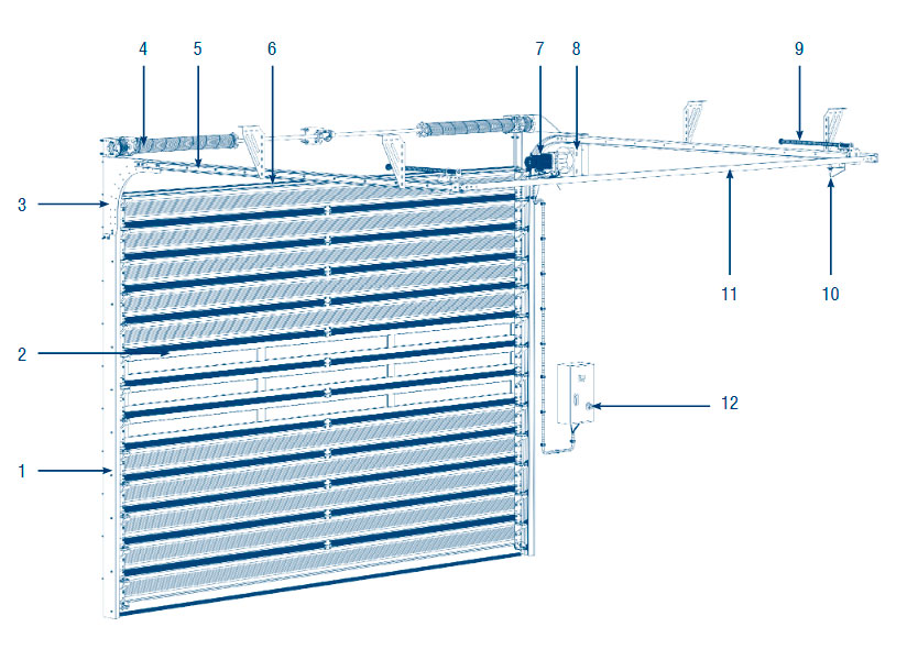
| 1. Угловая стойка 2. Полотно 3. Изгиб 4. Торсионный механизм 5. Горизонтальные направляющие 6. Ригель с уплотнителем |
7. Привод 8. Кронштейн крепления привода 9. Амортизатор 10. Датчик движения полотна ворот 11. С-профиль 12. Блок управления |
ТЕХНИЧЕСКИЕ ХАРАКТЕРИСТИКИ
■ Угловая стойка, С-профиль, изгиб, кронштейн крепления привода и ригель, изготовленные из оцинкованной стали
■ Направляющие из алюминия
■ Роликовые опоры, изготовленные из оцинкованной стали и окрашенные порошковым способом
■ Торсионный механизм
■ Выполнено из сэндвич-панелей толщиной 40 мм и высотой 220 мм
■ Материал панели — алюминий
■ Стандартные цвета: белый (RAL 9003), серый (RAL 9006)
■ Предназначен для работы в сети с напряжением 220 В
■ С частотным преобразователем
■ Выходная мощность привода — max 1,5 кВт
■ Концевые положения отслеживаются энкодером
■ Предназначен для работы в сети с напряжением 220 В
| Параметр | Описание |
| Применение | Универсальное (промышленные, складские и торговые помещения) |
| Максимальные размеры, Ш х В | 5 000 х 3 700 мм |
| Скорость открывания | 1 м/с |
| Скорость закрывания | 0,8 м/с |
| Конструкция ворот | |
| Полотно | |
| Блок управления | |
| Привод |
ПРАВИЛА БЕЗОПАСНОСТИ И ЭКСПЛУАТАЦИИ
ОБЩИЕ ПРАВИЛА
Монтажные работы производятся только в спецодежде, не стесняющей движения, а также в защитной каске и перчатках. При сверлении материалов, дающих отлетающую стружку, при рубке и резке металла следует применять защитные очки; для защиты органов дыхания от строительной пыли — респиратор.
Слесарные молотки и кувалды должны иметь гладкие, слегка выпуклые поверхности бойков, без выбоин, скосов, наклепа, сколов и трещин. Длина рукоятки молотка должна быть не менее 250 мм; молотки должны быть прочно надеты на рукоятки и закреплены клиньями. Все инструменты, имеющие заостренные концы для рукояток, должны иметь рукоятки длиной
ПРАВИЛА БЕЗОПАСНОСТИ ПРИ МОНТАЖЕ
- Монтаж ворот должны осуществлять монтажные бригады, прошедшие обучение и получившие сертификат в центрах обучения МК DoorHan.
- Перед началом монтажа убедитесь, что проем подготовлен согласно требованиям, приведенным в инструкции.
- Запрещается устанавливать на ворота детали, которые не входят в комплект поставки ворот.
не менее 150 мм. Деревянные рукоятки должны быть стянуты бандажными кольцами. Ударные инструменты не должны иметь косых и сбитых затылков, трещин, заусенцев. Гаечные ключи не должны иметь трещин и забоин, должны соответствовать размерам гаек и головок болтов; губки ключей должны быть параллельны, не разработаны и не закатаны.
Для переноски рабочего инструмента к месту работы необходимо применять специальную сумку или ящик. При работе для укладки инструмента следует использовать специальные пояса. Класть инструменты в карманы спецодежды запрещается.
- При монтаже угловые стойки ворот должны быть выставлены по уровню в вертикальных плоскостях.
- Угловые стойки должны прилегать к проему строго по всей высоте, без смещения в горизонтальном положении.
Ворота должны быть надежно закреплены и не представлять потенциальной опасности для жизни и здоровья людей.
Перед установкой устройств контроля доступа убедитесь в том, что они не попадают в зону работы ворот, а также не затруднят перемещение полотна в будущем.
Недопустима установка магнитных петель в зоне работы ворот, в том числе и под горизонтальными направляющими.
ПРАВИЛА БЕЗОПАСНОСТИ ПРИ ЭКСПЛУАТАЦИИ И ОТВЕТСТВЕННОСТЬ ЗА МОНТАЖ
- Производитель (концерн DoorHan) не осуществляет непосредственного контроля за монтажом, обслуживанием и эксплуатацией секционных ворот и не несет ответственность за безопасность их установки и качество монтажа.
- Содержание инструкции не может служить основанием для предъявления любого рода претензий к производителю.
- Ответственность за качество монтажа секционных ворот несет организация, осуществляющая монтаж.
- Производитель оставляет за собой право на внесение изменений в данную конструкцию без уведомления заказчика.
- Недопустимо нахождение людей и животных в зоне работы ворот, в том числе и под горизонтальными направляющими, во время движения полотна.
- Проем ворот всегда должен быть свободным от посторонних предметов.
МЕРЫ БЕЗОПАСНОСТИ ПРИ РАБОТЕ НА ВЫСОТЕ
К работе на высоте относятся работы, выполняемые на высоте 1,3 м и более от поверхности земли со стремянок, подмостей, площадок и другого вспомогательного оборудования. Состояние здоровья лиц, допускаемых к верхолазным работам, должно отвечать медицинским требованиям, установленным для работников, занятых на данных работах. При работах на высоте следует пользоваться предохранительным монтажным поясом. В случае, когда нет возможности закрепления предохранительного пояса за элементы строительной конструкции, следует пользоваться страховочным канатом, предварительно заведенным за элементы строительной конструкции. Выполнение работ в данном случае производится двумя монтажниками. Применение предохранительных поясов со стропами из металлической цепи при работе на конструкциях, под которыми расположены находящиеся под напряжением токоведущие части ЗАПРЕЩЕНО. Приспособления и инструменты должны быть закреплены во избежание их падения при работе на конструкциях, под которыми расположены находящиеся под напряжением токоведущие части.
Подача наверх элементов конструкции, инструмента и монтажных приспособлений должна осуществляться следующим образом: стоящий внизу работник должен удерживать канат для предотвращения раскачивания груза и приближения к токоведущим частям.
ЗАПРЕЩАЕТСЯ:
- стоять под лестницей, с которой производятся работы;
- подбрасывать какие-либо предметы для подачи работающему наверху. Подача должна осуществляться при помощи прочной веревки.
МЕРЫ БЕЗОПАСНОСТИ ПРИ ИСПОЛЬЗОВАНИИ ЛЕСТНИЦ И СТРЕМЯНОК
Приставные лестницы и стремянки должны быть снабжены устройством, предотвращающим возможность сдвига или опрокидывания при работе. Нижние концы приставных лестниц и стремянок должны иметь оковки с острыми наконечниками для установки на грунте, а при использовании лестниц на гладких поверхностях (металле, плитке, бетоне), на них надеваются башмаки из резины или другого нескользящего материала.
ЗАПРЕЩАЕТСЯ:
- работать с приставной лестницы, стоя на ступеньке, находящейся на расстоянии менее 1 м от верхнего ее конца;
- работать с механизированным инструментом с приставных лестниц;
- работать с двух верхних ступенек стремянок, не имеющих перил или упоров;
- находиться на ступеньках приставной лестницы или стремянки более чем одному человеку;
- стоять под лестницей, с которой производятся работы;
- класть инструмент на ступени лестниц и стремянок.
МЕРЫ БЕЗОПАСНОСТИ ПРИ РАБОТЕ С ЭЛЕКТРОИНСТРУМЕНТОМ
К работе с электроинструментом допускается квалифицированный персонал, прошедший специальное обучение, инструктаж на рабочем месте по электробезопасности. При проведении монтажных работ следует пользоваться электроинструментом, работающим при напряжении не выше 380/220 В. Выбор класса электроинструмента производится в зависимости от категории помещения по степени опасности поражения электротоком. Металлический корпус электроинструмента, работающего при напряжении выше 42 В переменного тока и выше 110 В постоянного тока в помещениях с повышенной опасностью, особо опасных и в наружных установках, должен быть заземлен. Вилка подключения должна быть с заземляющим контактом.
Подключение инструмента осуществлять к электросети, имеющей заземление. Используемые удлинители должны иметь вилку и розетку с заземляющими контактами. При работе с таким инструментом следует пользоваться защитными средствами (резиновые перчатки, галоши). Защитные средства должны быть испытаны в установленном законодательством порядке.
Перед началом работы следует:
- проверить комплектность и надежность крепления деталей;
- убедиться в исправности кабеля (шнура), его защитной трубки и штепсельной вилки, целостности изоляционных деталей корпуса, рукоятки и крышек щеткодержателей, наличии защитных кожухов и их исправности;
- убедиться в исправности цепи заземления (между корпусом и заземляющим контактом штепсельной вилки);
- проверить четкость работы выключателя;
- проверить работу электроинструмента на холостом ходу.
При работе применять только исправный инструмент, проверенный и опломбированный. При производстве работ не допускать переломов, перегибов электропровода, а также прокладки его в местах складирования конструкций, материалов, движения транспорта.
При работе в дождливую погоду (при снегопаде) места прокладки кабеля и места производства работ электроинструментом должны быть оборудованы навесами.
ЗАПРЕЩАЕТСЯ:
- держать инструмент за провод;
- удалять стружку или опилки с режущего инструмента, а также производить замену режущего инструмента до его полной остановки. Крепление сменного рабочего инструмента необходимо производить предназначенным для этого инструментом;
- включать электроинструмент в сеть с характеристиками, не соответствующими указанным в техническом паспорте;
- переносить электроинструмент с одного рабочего места на другое при включенном электродвигателе;
- оставлять без надзора подключенный к электросети электроинструмент, а также инструмент с работающим электродвигателем;
- оставлять без присмотра электрифицированный инструмент во избежание пользования им посторонними лицами.
УСЛОВНЫЕ ОБОЗНАЧЕНИЯ
Перечень и расшифровка условных обозначений, принятых в инструкции
Источник
DoorHan ISD01

| Категория: | Оборудование для загородных домов и сада |
| Группа: | Секционные Ворота |
| Устройство: | DoorHan ISD01 |
Инструкции и файлы
| Файл | Страниц | Формат | Размер | Действие |
|
Чтобы ознакомиться с инструкцией выберите файл в списке, который вы хотите скачать, нажмите на кнопку «Скачать» и вы перейдете на страницу, где необходимо будет ввести код с картинки. При правильном ответе на месте картинки появится кнопка для получения файла. Если в поле с файлом есть кнопка «Просмотр», это значит, что можно просмотреть инструкцию онлайн, без необходимости скачивать ее на компьютер. В случае если материал по вашему не полный или нужна дополнительная информация по этому устройству, например драйвер, дополнительные файлы например, прошивка или микропрограмма, то вы можете задать вопрос модераторм и участникам нашего сообщества, которые постараются оперативно отреагировать на ваш вопрос. Также вы можете просмотривать инструкции на своем устройстве Android Источник Инструкция по монтажу ворот Doorhan ISDГлавная » Инструкции » Инструкция по монтажу ворот Doorhan ISD
© 2022 Воротные Системы Урала Время работы: пн-пт.: 9:00-18:00 Работаем в Екатеринбурге и ближайших городах: Ревда, Верхняя Пышма, Среднеуральск, Горный Щит, Коптяки, Таватуй.
На нашем сайте мы используем cookie для сбора информации технического характера. В частности, для персонифицированной работы сайта мы обрабатываем IP-адрес региона вашего местоположения. Политика конфиденциальности Источник Читайте также: Гибкий кабель для сборки щита Adblock |


Инструкция по монтажу и эксплуатации скоростных секционных ворот ISD01-Parking
Настоящее руководство предназначено для ознакомления обслуживающего персонала с устройством, работой и техническим обслуживанием скоростных секционных ворот. Данное руководство является сводом правил по безопасной эксплуатации и техническому обслуживанию скоростных ворот. Изготовитель не осуществляет непосредственного контроля за работой оборудования, его обслуживанием и размещением. Всю ответственность за безопасность эксплуатации и техническое обслуживание оборудования несет оператор. Оператор несет ответственность за изучение и правильное понимание инструкций перед началом работы.
Установку, эксплуатацию и техническое обслуживание должен проводить только квалифицированный персонал. Изготовитель оставляет за собой право вносить изменения в конструкцию без предварительного уведомления.
Монтаж и установка ворот ДорХан +7 (831) 437-80-91 или почта info@doorhan-nn.ru
ВНИМАНИЕ!
Скоростные секционные ворота ISD01-Parking комплектуются блоком управления серии HSSD. При подключении и настройке блока управления используйте инструкцию к данному блоку.
| 1. Угловая стойка 2. Полотно 3. Изгиб 4. Торсионный механизм 5. Горизонтальные направляющие 6. Ригель с уплотнителем |
7. Привод 8. Кронштейн крепления привода 9. Амортизатор 10. Датчик движения полотна ворот 11. С-профиль 12. Блок управления |
ТЕХНИЧЕСКИЕ ХАРАКТЕРИСТИКИ
| Параметр | Описание |
| Применение | Универсальное (промышленные, складские и торговые помещения) |
| Максимальные размеры, Ш х В | 5 000 х 3 700 мм |
| Скорость открывания | 1 м/с |
| Скорость закрывания | 0,8 м/с |
| Конструкция ворот |
■ Угловая стойка, С-профиль, изгиб, кронштейн крепления привода и ригель, изготовленные из оцинкованной стали ■ Направляющие из алюминия ■ Роликовые опоры, изготовленные из оцинкованной стали и окрашенные порошковым способом ■ Торсионный механизм |
| Полотно |
■ Выполнено из сэндвич-панелей толщиной 40 мм и высотой 220 мм ■ Материал панели — алюминий ■ Заполнение — пенополиуретан ■ Структура — «волна» ■ Стандартные цвета: белый (RAL 9003), серый (RAL 9006) |
| Блок управления |
■ Предназначен для работы в сети с напряжением 220 В ■ IP54 ■ С частотным преобразователем |
| Привод |
■ Выходная мощность привода — max 1,5 кВт ■ Концевые положения отслеживаются энкодером ■ Предназначен для работы в сети с напряжением 220 В |
ПРАВИЛА БЕЗОПАСНОСТИ И ЭКСПЛУАТАЦИИ
ОБЩИЕ ПРАВИЛА
Монтажные работы производятся только в спецодежде, не стесняющей движения, а также в защитной каске и перчатках. При сверлении материалов, дающих отлетающую стружку, при рубке и резке металла следует применять защитные очки; для защиты органов дыхания от строительной пыли — респиратор.
Слесарные молотки и кувалды должны иметь гладкие, слегка выпуклые поверхности бойков, без выбоин, скосов, наклепа, сколов и трещин. Длина рукоятки молотка должна быть не менее 250 мм; молотки должны быть прочно надеты на рукоятки и закреплены клиньями. Все инструменты, имеющие заостренные концы для рукояток, должны иметь рукоятки длиной
ПРАВИЛА БЕЗОПАСНОСТИ ПРИ МОНТАЖЕ
- Монтаж ворот должны осуществлять монтажные бригады, прошедшие обучение и получившие сертификат в центрах обучения МК DoorHan.
- Перед началом монтажа убедитесь, что проем подготовлен согласно требованиям, приведенным в инструкции.
- Запрещается устанавливать на ворота детали, которые не входят в комплект поставки ворот.
не менее 150 мм. Деревянные рукоятки должны быть стянуты бандажными кольцами. Ударные инструменты не должны иметь косых и сбитых затылков, трещин, заусенцев. Гаечные ключи не должны иметь трещин и забоин, должны соответствовать размерам гаек и головок болтов; губки ключей должны быть параллельны, не разработаны и не закатаны.
Для переноски рабочего инструмента к месту работы необходимо применять специальную сумку или ящик. При работе для укладки инструмента следует использовать специальные пояса. Класть инструменты в карманы спецодежды запрещается.
- При монтаже угловые стойки ворот должны быть выставлены по уровню в вертикальных плоскостях.
- Угловые стойки должны прилегать к проему строго по всей высоте, без смещения в горизонтальном положении.
Ворота должны быть надежно закреплены и не представлять потенциальной опасности для жизни и здоровья людей.
Перед установкой устройств контроля доступа убедитесь в том, что они не попадают в зону работы ворот, а также не затруднят перемещение полотна в будущем.
Недопустима установка магнитных петель в зоне работы ворот, в том числе и под горизонтальными направляющими.
ПРАВИЛА БЕЗОПАСНОСТИ ПРИ ЭКСПЛУАТАЦИИ И ОТВЕТСТВЕННОСТЬ ЗА МОНТАЖ
- Производитель (концерн DoorHan) не осуществляет непосредственного контроля за монтажом, обслуживанием и эксплуатацией секционных ворот и не несет ответственность за безопасность их установки и качество монтажа.
- Содержание инструкции не может служить основанием для предъявления любого рода претензий к производителю.
- Ответственность за качество монтажа секционных ворот несет организация, осуществляющая монтаж.
- Производитель оставляет за собой право на внесение изменений в данную конструкцию без уведомления заказчика.
- Недопустимо нахождение людей и животных в зоне работы ворот, в том числе и под горизонтальными направляющими, во время движения полотна.
- Проем ворот всегда должен быть свободным от посторонних предметов.
МЕРЫ БЕЗОПАСНОСТИ ПРИ РАБОТЕ НА ВЫСОТЕ
К работе на высоте относятся работы, выполняемые на высоте 1,3 м и более от поверхности земли со стремянок, подмостей, площадок и другого вспомогательного оборудования. Состояние здоровья лиц, допускаемых к верхолазным работам, должно отвечать медицинским требованиям, установленным для работников, занятых на данных работах. При работах на высоте следует пользоваться предохранительным монтажным поясом. В случае, когда нет возможности закрепления предохранительного пояса за элементы строительной конструкции, следует пользоваться страховочным канатом, предварительно заведенным за элементы строительной конструкции. Выполнение работ в данном случае производится двумя монтажниками. Применение предохранительных поясов со стропами из металлической цепи при работе на конструкциях, под которыми расположены находящиеся под напряжением токоведущие части ЗАПРЕЩЕНО. Приспособления и инструменты должны быть закреплены во избежание их падения при работе на конструкциях, под которыми расположены находящиеся под напряжением токоведущие части.
Подача наверх элементов конструкции, инструмента и монтажных приспособлений должна осуществляться следующим образом: стоящий внизу работник должен удерживать канат для предотвращения раскачивания груза и приближения к токоведущим частям.
ЗАПРЕЩАЕТСЯ:
- стоять под лестницей, с которой производятся работы;
- подбрасывать какие-либо предметы для подачи работающему наверху. Подача должна осуществляться при помощи прочной веревки.
МЕРЫ БЕЗОПАСНОСТИ ПРИ ИСПОЛЬЗОВАНИИ ЛЕСТНИЦ И СТРЕМЯНОК
Приставные лестницы и стремянки должны быть снабжены устройством, предотвращающим возможность сдвига или опрокидывания при работе. Нижние концы приставных лестниц и стремянок должны иметь оковки с острыми наконечниками для установки на грунте, а при использовании лестниц на гладких поверхностях (металле, плитке, бетоне), на них надеваются башмаки из резины или другого нескользящего материала.
ЗАПРЕЩАЕТСЯ:
- работать с приставной лестницы, стоя на ступеньке, находящейся на расстоянии менее 1 м от верхнего ее конца;
- работать с механизированным инструментом с приставных лестниц;
- работать с двух верхних ступенек стремянок, не имеющих перил или упоров;
- находиться на ступеньках приставной лестницы или стремянки более чем одному человеку;
- стоять под лестницей, с которой производятся работы;
- класть инструмент на ступени лестниц и стремянок.
МЕРЫ БЕЗОПАСНОСТИ ПРИ РАБОТЕ С ЭЛЕКТРОИНСТРУМЕНТОМ
К работе с электроинструментом допускается квалифицированный персонал, прошедший специальное обучение, инструктаж на рабочем месте по электробезопасности. При проведении монтажных работ следует пользоваться электроинструментом, работающим при напряжении не выше 380/220 В. Выбор класса электроинструмента производится в зависимости от категории помещения по степени опасности поражения электротоком. Металлический корпус электроинструмента, работающего при напряжении выше 42 В переменного тока и выше 110 В постоянного тока в помещениях с повышенной опасностью, особо опасных и в наружных установках, должен быть заземлен. Вилка подключения должна быть с заземляющим контактом.
Подключение инструмента осуществлять к электросети, имеющей заземление. Используемые удлинители должны иметь вилку и розетку с заземляющими контактами. При работе с таким инструментом следует пользоваться защитными средствами (резиновые перчатки, галоши). Защитные средства должны быть испытаны в установленном законодательством порядке.
Перед началом работы следует:
- проверить комплектность и надежность крепления деталей;
- убедиться в исправности кабеля (шнура), его защитной трубки и штепсельной вилки, целостности изоляционных деталей корпуса, рукоятки и крышек щеткодержателей, наличии защитных кожухов и их исправности;
- убедиться в исправности цепи заземления (между корпусом и заземляющим контактом штепсельной вилки);
- проверить четкость работы выключателя;
- проверить работу электроинструмента на холостом ходу.
При работе применять только исправный инструмент, проверенный и опломбированный. При производстве работ не допускать переломов, перегибов электропровода, а также прокладки его в местах складирования конструкций, материалов, движения транспорта.
При работе в дождливую погоду (при снегопаде) места прокладки кабеля и места производства работ электроинструментом должны быть оборудованы навесами.
ЗАПРЕЩАЕТСЯ:
- держать инструмент за провод;
- удалять стружку или опилки с режущего инструмента, а также производить замену режущего инструмента до его полной остановки. Крепление сменного рабочего инструмента необходимо производить предназначенным для этого инструментом;
- включать электроинструмент в сеть с характеристиками, не соответствующими указанным в техническом паспорте;
- переносить электроинструмент с одного рабочего места на другое при включенном электродвигателе;
- оставлять без надзора подключенный к электросети электроинструмент, а также инструмент с работающим электродвигателем;
- оставлять без присмотра электрифицированный инструмент во избежание пользования им посторонними лицами.
Перечень и расшифровка условных обозначений, принятых в инструкции
| Наименование | Количество шт. |
| Скоростные секционные ворота | 1 |
| Привод | 1 |
| Блок управления | 1 |
| Паспорт | 1 |
| Руководство по эксплуатации | 1 |
ВНИМАНИЕ!
При снятии вышеуказанных размеров проема рекомендуется проводить замер каждой величины как минимум
в трех точках (крайних положениях и по центру). При замере Н и В за итоговый размер всегда принимается
наибольшая величина.
|
Упаковка. Торсионный механизм Упаковочных мест 1 |
|||||||
| № | Артикул | Наименование | ЕД. изм. | Кол-во кусков | Длина куска, мм | Ширина куска | Примечание |
| 2 | 25516/М |
Вал полнотелый с пазом под шпонку ОЦ 1″ |
п/м | 1 | 3 295 | ||
| 3 | 35086М-5,1 | Вставка под пружину 152 модернизированная L = 5 100 | шт. | 2 | 1 178 | ||
| 4 | 36085/mL/RAL7004 | Пружина окрашенная 152 – 8,5 левая | п/м | 1 | 1 278 | 12.1 кол. оборотов | |
| 5 | 36085/mR/RAL7004 | Пружина окрашенная 152 – 8,5 правая | п/м | 1 | 1 278 | 12.1 кол. оборотов |
-
Contents
-
Table of Contents
-
Bookmarks
Quick Links
D i r e c t i o n s f o r i n s t a l l a t i o n
o f g a r a g e a n d i n d u s t r i a l
s e c t i o n a l d o o r s
12.12.08
Related Manuals for DoorHan ISD01 Series
Summary of Contents for DoorHan ISD01 Series
-
Page 1
D i r e c t i o n s f o r i n s t a l l a t i o n o f g a r a g e a n d i n d u s t r i a l s e c t i o n a l d o o r s 12.12.08… -
Page 2: Table Of Contents
1. Content . . . . . . . . . . . . . . . . . . . . . . . . . . . . . . . . . . . . . . . . . . . . . . . . . . . . . . . . . . . . . . . . . . . . . . . . . . . . . 2 2.
-
Page 3
cable safety device . . . . . . . . . . . . . . . . . . . . . . . . . . . . . . . . . . . . . . . . . . . . . . . . . . . . . . . . . . . . . . . . . . . . 51 cable break safety device . -
Page 4: Introduction
Before installation of the doors read carefully these directions for mounting, operation and maintenance of doorHan sectional doors . as well as the directions we also recommend to use doorHan sectional doors hardware catalog informa- tions for door mounting .
-
Page 5: Embrasure Requirements
EmbrasurE rEquIrEmEnts Embrasure requirements Required dimensions: H — embrasure height (embrasure bottom-to-top); B – embrasure width ( distance between left and right edges of the embrasure); h – lintel (distance between the top of the embrasure and the ceiling) not less than 150 mm ( without chain electric drive); b1 and b2 –…
-
Page 6
EmbrasurE rEquIrEmEnts If electric drive is installed for installation of the doors with the chain electric drive lintel value (h) must not be less than 200 mm . for installation of the doors with the shaft electric drive one of the side dimensions (b1 or b2) must not be less than 250 mm, and if the shaft is from below it must not be less than 500 mm . -
Page 7: Garage Sectional Doors Rsd02
EmbrasurE rEquIrEmEnts GARAGE SECTIONAL DOORS RSD02 garage sectional doors rsd02 open smoothly and do not need extra space before the garage, they can be compacted inside it . due to variety of door designs and capability to manufacture up to 5 m wide and 3 m high doors an ideal solution can be found practically for any premise .
-
Page 8: Industrial Sectional Doors Series Isd01
EmbrasurE rEquIrEmEnts INDUSTRIAL SECTIONAL DOORS SERIES ISD01 industrial sectional doors are installed mainly in factories and plants, warehouses, workshops and terminals where they are to satisfy more stringent requirements than standard garage doors do . as a rule, the industrial sectional doors are heavy constructions operated daily very strongly, they are resistant to wind load and close hermetically production area doorway .
-
Page 9: Industrial Sectional Doors Series Isd02
INDUSTRIAL SECTIONAL DOORS SERIES ISD02 Panoramic sectional doors doorHan (isd02) are very popular and are installed in modern architecture buildings with window fronts and shop windows, motor shows, exhibition and technical centers, where interior must be seen through clear glasses .
-
Page 10: Tools
tooLs We recommend to use the following tools for door mounting: OPTIMAL ERECTION CREW SIZE 1 . drill 2 . riveting tool 3 . Measuring 4 . cross optimal erection crew size – 2-3 people, tape 5 m screwdriver depending on door size . in average mounting of one door by one erection screw takes 4-6 hours .
-
Page 11: Hardware
HardWarE 20 19 sectional door shield system of guides and torsion gear i n s t a l l a t i o n o f g a r a g e a n d i n d u s t r i a l s e c t i o n a l d o o r s…
-
Page 12
HardWarE in this directions of sectional door mounting the doors with standard lift are taken as an example . in supplement you can find aspects of sectional doors with different lifts and hardware mounting as well as installation of optional equipment . 1 . -
Page 13
HardWarE 7 . corner support in assembly with vertical 8 . installation profile (32x32x2 mm) 9 . Multi-purpose corner bracket for fastening track and side seal 1 pair ** * piece to the ceiling ** * piece 10 . Bolt for assembly of guides 11 . -
Page 14
HardWarE 13 . set of cross-bar sleeves 2 sets 14 . spring bumper ** 1 pair 15 . roller * piece 16 . side support with roller holder * piece 17 . top support with roller holder 2 piece 18 . internal hinge * piece * — quantity depends on door size ** — installation depends on the door hardware… -
Page 15
HardWarE 19 . Bottom corner bracket with wedge- 20 . catch 1 piece 21 . Handle & footstep for industrial operated cable fastening 1** pair sectional doors 1 piece 24 . end support u-shaped bracket 1 pair 25 . internal support bracket * piece 26 . -
Page 16
HardWarE 29 . lock plate * piece 27 . Bolt with semi-rounded head 28 . flanged nut (M8) * piece (M8x25) * piece 30 . tapping screw (8×70 mm) * piece 31 . dowel key PVc * piece 32 . Washer 8×24 * piece * — quantity depends on door size ** — installation depends on the door hardware… -
Page 17
HardWarE 33 . Bushing key * piece 34 . Bushing for cable * piece * — quantity depends on door size ** — installation depends on the door hardware i n s t a l l a t i o n o f g a r a g e a n d i n d u s t r i a l s e c t i o n a l d o o r s… -
Page 18: Safety Provisions
saFEtY ProVIsIons SAFETY PROVISIONS Mounting must be carried out only with safetY ProVisions for them upward, transfer must be performed by working clothes that does not restrain move- WorK at a HeigHt means of a durable rope . ment, protective helmet and gloves on . •…
-
Page 19
saFEtY ProVIsIons safetY ProVisions at WorK • check of parts set completeness and WitH electric tools attachment security; only workers that got special training and • Visual inspection of cable(cord), its protec- instruction at place of work and have proper tive tube, male plug intactness, case isolat- qualification in electrical safety are allowed ing parts, handle and brush-holder caps to operate electrical tools . -
Page 20: Installation Of Doors
MOUNTING OF SECTIONAL DOORS WITH STANDARD LIFT doorHan sandwich-panel packing is made of foamed plastic (foam polystyrene), thats why it is light, durable and effective . Hardware unpacking Bottom panel Middle panel top panel the bottom panel is delivered as a unit of…
-
Page 21: Bottom Panel Assembling
door mountInG Assembling of bottom panel disconnect the roller holders from the side Position the side caps on drilled openings, Place the bottom corner bracket on the bottom panel . Mark and drill ∅4 .2 mm holes supports . using 4 tapping screw 6 .3х38 mm . to fasten it .
-
Page 22: Middle Panels Assembling
door mountInG Assembling of middle panels install the side support on the drilled holes . disconnect the roller holder from the side install the internal hinges on the panel holes supports . made at the manufacturing plant . Holes in the bottom part of the hinge must index the holes in the panel made by the manufacturer .
-
Page 23: Top Panels Assembling
door mountInG Top panel assembling install the top roller supports and fix using tapping screws for panels . Vertical tracks installation the vertical tracks are delivered in assembly Before installation of the vertical tracks check if for c-profile levelling you need plates, with corner supports .
-
Page 24
door mountInG 25-30 Before installation of the tracks the bottom than install the vertical tracks on the panel . the distance from the edge surface of the panel panel must be installed in an embrasure so, must be about 25-30 mm . that its edges overlap the embrasure evenly on two sides . -
Page 25: Horizontal Tracks Installation
door mountInG fix the corner supports to the embrasure wall using two tapping screws with washers, but do not tighten them . level the vertical tracks and only then tighten the tapping screws . Horizontal track installation the horizontal tracks are delivered in assembly fasten the horizontal and vertical tracks using fix the horizontal track c-profile to the corner with a c-profile to increase rigidity of the…
-
Page 26: End U-Shaped Support Brackets Installation
door mountInG U-shaped end support brackets installation install the u-shaped bracket close to the corner support, matching the bracket and corner use of the u-shaped end support brackets support corners . the external bracket wall must match the corner support plane . according to the ensures high manufacturability of assembling, perforation in the bracket mark holes for fastening in the embrasure wall .
-
Page 27: Cross-Bar Sleeves Installation
door mountInG Cross-bar sleeve installation cross-bar sleeves are used to limit door select and install cross-bar sleeves on the leaf run along the embrasure plane . install roller axes of the bottom corner brackets the sleeves on the roller axis of the top according to the bottom corner bracket type .
-
Page 28: Panels Installation
door mountInG Installation of panels insert the rollers in the bottom corner bracket level the bottom panel with a builder’s install other panels in the same way . roller holders and install bottom panel . install level . if required use supports of a required the rollers with the roller holders on side thickness .
-
Page 29: Torsion Gear Installation
door mountInG fix the upper parts of the hinges with tapping install the top panel . Make adjustments of screws for panels . the upper roller position to ensure the panels abutment on the embrasure . Torsion gear installation right left torsion gear is installed in the u-shaped end the twisting direction of the springs must match it winding .
-
Page 30
door mountInG if the shaft consisting of two parts is being connect two parts of the shaft using the coupler installed, use the connection coupler to and having inserted bushing keys in the key enable adjustment of the cable . slots of both parts of the coupler . tighten the bolts connecting the coupler’s parts . -
Page 31
door mountInG relation between installation of end plate with bearing and installed end support u-shaped brackets and the type of the drum is represented in the table . end u-shaped support close oMi8 oMi12 dH11000 dH11011 oMi54-Hl-ld bracket 127/152 mm oMi18 oMi54Hl end u-shaped support close… -
Page 32: Loading Of The Spring With Cylindrical Shaft
door mountInG Loading of the spring with cylindrical shaft right winding spring right winding spring there is a special marking strip on the spring, after the spring is loaded block it by putting that indicates the amount of spring winds . the supports under the mounting drivers, design number of spring turns is indicated in tighten the bolts of plug fastening to the shaft…
-
Page 33: Fastening To The Ceiling
door mountInG Fastening to the ceiling the guides are fastened to the ceiling by using different bracket types depending on the lintel height and the door leaf dimensions . А) Fastening with multi-purpose corner brackets. fasten the bracket to the horizontal track with a lock plate, a bolt and a nut . if required, corner 32х32 mm is used to extend the bracket .
-
Page 34
door mountInG B) Fastening by using mounting corners. the mounting corners are assembled of Place the mounting angle against the guides in the fastening position . Mark and drill openings punched angle bar 32х32 mm taking into in the ceiling . fix the mounting corner with tapping screws, washers and dowels . account the spacing between the horizontal tracks and the ceiling . -
Page 35: Cable Tension Adjustment
door mountInG Cable tension adjustment А) Cable tension adjustment using bottom corner brackets with cable adjustability. lift slightly the door leaf by ~150 mm and unscrew the tapping screw fastening free end using a screwdriver lift a little the narrow end put wooden blocks under the leaf angles .
-
Page 36
door mountInG B) cable tension adjustment using connection coupler with cable adjustability . Before making adjustment you need to ascertain that the floor is even (without distortion) . otherwise supports must be laid under the bottom panel of the door leaf . loose the bolts that connect two parts of the coupler . -
Page 37: C-Profile Installation
door mountInG C-profile installation fasten the c-profile to the horizontal tracks ends with lock plates, bolts and nuts . i n s t a l l a t i o n o f g a r a g e a n d i n d u s t r i a l s e c t i o n a l d o o r s…
-
Page 38
door mountInG Installation of buffers the buffers are used to limit the door leaf run during its opening . Before installation of the buffers unscrew bolts and nuts and fasten fastening cramps to the lock plates on the c-profile using the bolts . install the buffers symmetrically relatively the embrasure axis . -
Page 39: Buffer Installation
door mountInG Handle installation the handle for industrial doors is installed in a ready-made opening in the bottom sandwich-panel . install 2 parts of the handle asymmetrically relatively each other on different sides of the insert 2 tapping screws on the external side of sandwich-panel .
-
Page 40: Handle Installation
door mountInG Installation of protruding handle and light handle. drill 4 holes ∅10-12 mm . Mark the holes for the installation of the handle . after that fasten the handle with tapping screws installation of the light handle is performed in ∅4 .
-
Page 41: Catch Installation
door mountInG Catch installation drill holes ∅4 .2 mm for fastening of the catch and hole ∅15 in the corner support for wicket install the catch at a suitable height for opening . Mark fastening holes . latch . fasten the catch to the panel using four tapping ATTENTION: The catch must be installed after spring loading in order that the catch latch screws .
-
Page 42
suPPLEmEnt Door run check after mounting the door movement must be checked . the door must move smoothly without jerks . the rollers must not jam in the tracks . during installation of the doors in any intermediate height position the door must not move spontaneously up or down . if during the check the horizontal sidesway of the panels is observed, adjust tension of the cables . -
Page 43: Door Operation
door oPEratIon Octagonal shaft, spring cocking the octagonal shaft is used in the torsion there is a special marking strip on the spring, design number of spring winds is indicated in gear of the industrial sectional doors due to that indicates the amount of spring winds . the installation card or on a special label on the its very high strength and reliability .
-
Page 44: End Bracket Support Installation
suPPLEmEnt Installation of end support bracket install the end support bracket in the holes of the corner support . Mark fastening holes in the embrasure wall using perforation in the bracket . drill the marked holes ∅8 .5 mm in the c-profile and the holes ∅12 mm in the wall . Hammer in the dowels in the wall . fasten to the wall the end support bracket using tapping screws .
-
Page 45
suPPLEmEnt run the cable through the ear on the safety in case of lack of the squeezing screw on the run the cable through the special technological coil . the amount of winding turns of the cable drum drill in the side surface of the drums opening . -
Page 46
suPPLEmEnt Cable fastening to the drum cut the cable into two equal parts . run the recoMMended: after cable tension adjustment is done fix the running unsqueezed with the bushing end in case of the adjustable connection coupler cable inserting the squeezing bushing . of the cable through the drilled hole in the or the bottom corner bracket with fine cable drum, extend it along the tracks up to the… -
Page 47: Door Lock Installation
suPPLEmEnt Installation of lock for wicket Mark and drill 4 holes ∅4 mm and 15-20 mm the lock is recommended to be installed on fasten with 4 tapping screws the catch housing deep from the inside of the door to fasten the to the door panel .
-
Page 48
suPPLEmEnt install the outer support and fasten it by using three screws and nuts, from the lock components Put the internal handle on the shank . screw set . them . install the cylinder and fasten it to the lock install the rod, connecting the catch angle and after mounting check for the lock latch run housing using a screw . -
Page 49: Torsion Gear «Spring In Spring
suPPLEmEnt Torsion gear “spring in spring” the torsion gear “spring in spring” is installed install an additional bracket for double springs Mark the points for its fastening to the under ∅152 mm spring . if the embrasure height is half as much again embrasure wall .
-
Page 50: Installation Of Spring Failure Safety Device
suPPLEmEnt Installation of the spring failure safety device this device is used for the shield fall protection fasten the spring failure safety device to the fasten the catch housing to the door panel by the spring failure . Place the bracket against embrasure wall using tapping screws and using 4 tapping screws .
-
Page 51: Cable Safety Device
suPPLEmEnt Cable safety device during installing the corner brackets with the Before installation of the safety device plates install the plates on the holes of the corner cable safety device fasten the plates for safety mark and drill additional holes, using the bracket and fix them simultaneously with the device on the corner supports .
-
Page 52: Cable Break Safety Device
suPPLEmEnt Cable break safety device While using the corner bracket with the cable Before start of work take out cable break break safety device mark and drill 6 holes 4 .2 safety device peg . mm for bracket fastening . fix it with 6 tapping screws 6 .3×38 mm .
-
Page 53: Installation Of Bottom Corner Bracket For Drum Behind
suPPLEmEnt Installation of the bottom corner bracket for drum behind Put the bottom corner bracket for drum behind on the bottom panel, mark and drill holes ∅4 .2 mm for bracket fastening . fix the bracket using tapping screws . Installation of the bottom corner bracket with the cable tension device.
-
Page 54
suPPLEmEnt Installation of connection coupler for octagonal shaft if you are going to install the shaft consisting assemble from the coupler connector plates and Position the connection coupler on two parts of two parts use connection coupler . bolts the coupler . of the shaft and fix it on operational openings using tapping screws for metal 6 .3×25 for octagonal shaft . -
Page 55: Installation Of Nonadjustable Coupler For Cylindrical Shaft
suPPLEmEnt Installation of cylindrical 31.75 mm in diameter shaft in case of installation of 31 .75 mm shaft instead of the regular end support and multi- purpose internal brackets the brackets with adjustable bearing are used . the brackets have additional openings for fastening to the wall and to the corner support .
-
Page 56
suPPLEmEnt Manual chain operator installation the manual chain operator can be installed on the left or on the right sides of the door . 5-10 mm Put the shaft on the closing ring . install on the shaft the manual chain operator, Put on the second closing ring . -
Page 57: Manual Chain Operator Installation
suPPLEmEnt insert a dowel and fix the manual chain install the tension roller with the chain holder insert dowel in the drilled holes and fasten the operator fastening bracket to the wall using at 1 m height and on the same axis with the tension roller using tapping screws .
-
Page 58
suPPLEmEnt If the tension roller is used Place the tension roller on the floor on the same axis with the operator . Mark and drill the holes insert the anchor bolts in the drilled holes and in the floor for the tension roller fastening . tighten them . -
Page 59: Wicket Door Closer Installation
suPPLEmEnt Wicket door closer installation If the door leaf has a wicket, the wicket door closer must be installed. Position the door closer on 4 ready-made holes . remove top wicket modifier profile cap from one of the profile ends . i n s t a l l a t i o n o f g a r a g e a n d i n d u s t r i a l s e c t i o n a l d o o r s…
-
Page 60
suPPLEmEnt install the closer lever in the sliding trunk of the door leaf . Block the closer lever on the closer Place the cap back on the profile end and fix mechanism . it with a tapping screw . i n s t a l l a t i o n o f g a r a g e a n d i n d u s t r i a l s e c t i o n a l d o o r s… -
Page 61: Omega-Profile Installation
suPPLEmEnt Omega-profile installation the omega-profile is installed on the the omega-profile is recommended to be installed at one level with the side supports and to embrasure with a 4500 mm wide shield and be fastened to the panel using rivets or tapping screws (on the inside of the panels) . if there is increased wind load .
-
Page 62: Installation Of Halyard Capronic
suPPLEmEnt Installation of halyard capronic the halyard capronic is used to close the door by hand if there is a high embrasure . one end of the halyard capronic fasten to the fasten the second halyard end to any free hole roller bushing on the bottom corner bracket .
-
Page 63: Aspects Of Vertical And High Lift Installation
suPPLEmEnt Aspects of vertical and high lift installation High lift High lift with remote shaft Vertical lift High lift, two-shaft system High lift, with remote shaft, two-shaft system Vertical lift with remote shaft i n s t a l l a t i o n o f g a r a g e a n d i n d u s t r i a l s e c t i o n a l d o o r s…
-
Page 64: Two-Shaft System On End Support Brackets
suPPLEmEnt Two-shaft system on end support brackets Position the support bracket close to the wall drill the marked holes (in the wall the hole insert the dowels in the holes in the wall . in a is ∅12 mm and in the c-profile the hole is and the corner support, matching the holes similar manner mark the holes for the bracket ∅8 .5 mm) .
-
Page 65
suPPLEmEnt А А install the sprocket on the shaft, having Position the support bracket close to the wall install the second shaft with a spring in the inserted the bushing key in the key slot so, that vertically it is in one line with the top support brackets bearings . -
Page 66
suPPLEmEnt А Place on the second shaft the sprocket so, install the additional support bracket on the bottom shaft, for that position it to the embrasure wall, mark and drill the holes for fastening . that it has been in one line with the bottom sprocket . -
Page 67: Two-Shaft System On U-Shaped End Support Brackets
suPPLEmEnt Two-shaft system on U-shaped end support brackets А Position the sprockets on the top and bottom shafts so, that they are in one line . put on them fix the sprockets using fastening bolts . the chains before . if the center-to-center distance between the shafts (a) is less than 393 mm shorten the chain according to the table .
-
Page 68: Chain Tension Device Installation
suPPLEmEnt Chain tension device installation chain tension device is used to tension the install the device on the top shaft close to the Position the sprocket together with the chain during its stretching and damping of the end support bracket before installation of the chain close to the chain tension device .
-
Page 69
suPPLEmEnt to make easier the industrial sectional door torsion gear mounting we recommend to use the hand hoist and the mounting jig with lifting capacity ~ 500 kg . hand hoist mounting jig i n s t a l l a t i o n o f g a r a g e a n d i n d u s t r i a l s e c t i o n a l d o o r s… -
Page 70: Mounting Of Torsion Gear With Remote Octagonal Shaft
suPPLEmEnt Mounting of torsion gear with remote octagonal shaft lean the low shaft remote bracket to the drill in the wall according to the marking 10 holes ∅12 mm and in the corner support 8 holes embrasure wall close to the corner bracket ∅7 mm .
-
Page 71
suPPLEmEnt Hook the shaft near the drums, hitching them using the manual chain lift the torsion gear up to the remote brackets . with the hand hoist load hook, before it loose six-sided screws 8X16 on the torsion gear end bushing for shaft 1 .25”… -
Page 72
suPPLEmEnt install the torsion gear in the remote brackets Block the spring failure safety device . tighten slots positioning the end bushings . the screws on the end bushings . install the end bushing fixing plate . i n s t a l l a t i o n o f g a r a g e a n d i n d u s t r i a l s e c t i o n a l d o o r s… -
Page 73: Aspects Of Two-Shaft System Of Torsion Gear With Remote Octagonal Shaft Mounting
suPPLEmEnt Aspects of two-shaft system of torsion gear with remote octagonal shaft mounting Place the remote brackets for low shaft to the Place the remote bracket for the second to make mounting easier install first the embrasure wall close to the corner bracket (on shaft tightly to the wall so, that top and additional torsion gear (without drums) in the outside) according to the mounting card .
-
Page 74
suPPLEmEnt Mounting of the torsion gear with cylindrical shaft disassemble the remote shaft bracket with lean the remote bracket for the low shaft to the embrasure wall close to the corner support a cramp (on the outside) according to the mounting card . using perforation in the bracket make marking for its fastening to the wall and the corner bracket . -
Page 75: Cable Support Installation
suPPLEmEnt insert the shaft with a spring in the brackets fasten the pipe to the bracket using cramps install the internal remote brackets for and nuts according to the mounting card . drum fastening on the pipe according to the bearing and install the drums .
-
Page 76: Installation Of End Support Bracket At Vertical Lift
suPPLEmEnt Installation of end support brackets at vertical lift Position the end support bracket along drill the marked holes ∅12 mm . Hammer in the holes on the corner support and using dowels in the wall . fasten the end support perforation in the bracket mark the holes for bracket and the corner support between each fastening to the embrasure wall .
-
Page 77: Installation Of Bumper At Vertical Lift
suPPLEmEnt Installation of bumper at high lift at vertical lift the bumper is installed on the fasten the bumper to the c-profile on the vertical track according to the figure . install the bumper vertical tracks . so, that when the door is open the bumper’s compressed position is not less than 50 % its stroke length .
-
Page 78: Roller’s Top Support Installation
suPPLEmEnt Installation of the top roller support By assembling of the top panel install the Position the support roller on the top top roller supports . level the corner support horizontal track . loose the tapping edges according to the panel, drill four holes screws, adjust the upper supports ∅4 .2 mm and fix it using tapping screws for to enable close abutment of the top…
-
Page 79: Installation Of End Support Bracket At Low Lift
suPPLEmEnt Installation of end support bracket at low lift Mark and drill the holes ∅12 mm for fastening install the support bracket close to the wall fasten the bracket to the wall using dowels and the corner bracket, here the holes in to the embrasure wall using the perforation in and tapping screws and washers and to the the support bracket, the corner support and…
-
Page 80: Fastening Of Horizontal Tracks To The Ceiling
suPPLEmEnt Fastening of horizontal tracks to the ceiling there are two types of brackets applied for tracks fastening to the ceiling depending on the lintel height . A. if the lintel height is up to 400 mm the tracks fasten the corner bracket to В.
-
Page 81: Buffer Installation
suPPLEmEnt Installation of bumpers Mark and drill 2 holes ∅8 mm in the bottom fix the c-profile using bolts with semi-round head М8х25 and flanged nuts . horizontal tracks . fasten the spring bumper using lock plates and bolts and nuts . adjust the bumper’s position and tighten the nuts .
-
Page 82: Low Lift, Drum From Behind, Pulley Installation
suPPLEmEnt Low lift, drum from behind, pulley installation Mark and drill a ∅8 mm hole in the lintel wall . Place the pulley along the holes in the corner bracket and fix it with 4 bolts with semi-rounded head М8X16 . insert dowels and fasten the end bracket to the wall using tapping screws and washers .
-
Page 83: Low Lift, Drum From Behind, Mounting Of Torsion Gear With Octagonal Shaft
suPPLEmEnt Low lift, drum from behind, mounting of torsion gear with octagonal shaft Place on both horizontal tracks the connected fix the multi-purpose brackets on the end fasten the multi-purpose bracket to the construction of the end support bracket for drum support bracket for drum from behind and on ceiling using 2 tapping screws .
-
Page 84
suPPLEmEnt Position the torsion gear in assembly on the fasten the end plate with bearing to the end support bracket for drum from behind using 2 bolts u-shaped brackets . using 2 bolts with semi- with semi-rounded head (M8X16), fix the bolts on the close to the lintel or far from the lintel slots rounded head (M8X16) fasten the end plate (relatively the embrasure) depending on the installed drums . -
Page 85: Low Lift, Drum From Behind, Installation Of End Support Brackets
suPPLEmEnt Low lift, drum from behind, mounting of torsion gear with cylindrical shaft drill the marked holes ∅8 .5 mm . Place the end support bracket against the fasten the end support bracket to the double horizontal tracks on the outside . Mark the horizontal tracks using bolts and nuts .
-
Page 86
suPPLEmEnt install the shaft in the end support brackets fasten the fastening bracket for drum behind to the c-profile using the c-profile fastening bracket, bearing, having installed the drums, the spring the mounting angle for horizontal lath installation, the lock plate and a bolt and a nut . and the fastening bracket for drum behind on it before . -
Page 87: Dismounting
suPPLEmEnt through the lubrication hole in the central Dismounting unplug the electric drive . dismount the part of the hinge curl or in the central part of electric drive according to the directions the roller holder curl . for electric drive . close the door and loose if closing or opening of the doors requires force applying, adjust the rollers .
-
Page 88: Notes
notEs i n s t a l l a t i o n o f g a r a g e a n d i n d u s t r i a l s e c t i o n a l d o o r s…
-
Page 89
notEs i n s t a l l a t i o n o f g a r a g e a n d i n d u s t r i a l s e c t i o n a l d o o r s… -
Page 90
notEs i n s t a l l a t i o n o f g a r a g e a n d i n d u s t r i a l s e c t i o n a l d o o r s… -
Page 91
notEs i n s t a l l a t i o n o f g a r a g e a n d i n d u s t r i a l s e c t i o n a l d o o r s… -
Page 92
ООО «ДорХан» Россия, 121354, г. Москва, Можайское ш., стр. 36 Тел. (+7 495) 933 24 33 Факс (+7 495) 937 95 50 E-mail: info@doorhan.ru www.doorhan.ru…
инструкция по монтажу секционных ворот
Ворота секционные DoorHan инструкции по монтажу
1. Инструкция по монтажу Ворота секционные RSD02, ISD01, ISD02
2. Инструкция по монтажу Ворота секционные RSD01
3. Инструкция по монтажу Ворота секционные RSD02
4. Инструкция по монтажу Ворота секционные RSD01 COMPAST
5. инструкция по монтажу Ворота секционные YETT01
6. Инструкция по монтажу Ворота секционные YETT02
7. Инструкция по монтажу Ворота секционные YETT30
Пояснение условных обозначений
Серия RSD01, RSD02 — гаражные секционные ворота
Серия ISD01, ISD02 — промышленные секционные ворота
Серия YETT01, YETT02 — гаражные секционные ворота
Серия YETT30 — гаражные секционные ворота, толщина секции 30мм