Пульт FWEC2A — усовершенствованный пульт для фанкойлов Daikin.
- Предназначен для регулирования скорости вентилятора фанкойла Daikin с с однофазным многоскоростным асинхронным двигателем вентилятора.
-
Регулировка температуры воздуха посредством включения-выключения (on-off) вентилятора с фиксированной скоростью
-
Управление работой клапанов On/Off для двух- и четырёхтрубных систем
- Управление работой электрического нагревательного устройства для дополнения системы отопления
-
Переключение охлаждение/нагрев: в автономном или удаленном ручном режиме (централизованном), автоматическом (в зависимости от температуры воды (опция) или температуры воздуха
-
Возможность удаленного централизованного переключения режимов охлаждение/нагрев и внешней активации посредством сухих контактов
-
Датчик температуры (аксессуар FWTSKAA)
-
Функция экономии (коррекция уставки на 2,5°C и возможность вентилятора работать на минимальной скорости)
-
Контроль влажности:
— индикация относительной влажности
— удаление влаги (режим охлаждения) Ручная активация
-
Интерфейс последовательной связи (шина RS485)
— возможность настройки главной-второстепенной системы с 247 второстепенными блоками, в которой один из блоков управления является главным и управляет всеми другими второстепенными блоками. ( протокол modbus )
Преимущества покупки запчастей Daikin в нашем магазине:
— Гарантия официального сервисного центра – 6 месяцев;
— 100% гарантия совместимости, при подборе запчасти по модели кондиционера;
— Бесплатная доставка до терминала транспортной компании в вашем городе, а в Москве до двери;
— Техническая поддержка и консультация по установке от собственной сервисной службы;
— Только оригинальные запасные части Daikin;
— Возможность выставления счета с учетом НДС 20%.
 Loading…
![]()
INSTALLATION AND OPERATION MANUAL
Advanced electronic controller
Manuale d’installazione e d’uso
FWEC2 COMANDO LCD PER TERMINALI
Installation and operation manual FWEC2 LCD CONTROLLER FOR INDOOR UNITS
Manuel d’installation et d’utilisation FWEC2 CONTRÔLEUR LCD POUR UNITÉS TERMINALES
Installationsund Bedienungsanleitung
FWEC2 LCD-STEUERUNG FÜR TERMINALS
Manual de instalación y de uso
FWEC2 MANDO LCD PARA TERMINALES
Manual de instalação e de uso
FWEC2 COMANDO LCD PARA TERMINAIS
Handleiding voor gebruik en onderhoud
FWEC2 LCD BEDIENING VOOR TERMINALS
BESZERELÉSI ÉS FELHASZNÁLÓI KÉZIKÖNYV
FWEC2 LCD VEZÉRLŐ TERMINÁLOKHOZ
РУКОВОДСТВО ПО УСТАНОВКЕ И ЭКСПЛУАТАЦИИ FWEC2 LCD (LCD) ПАНЕЛЬ УПРАВЛЕНИЯ ДЛЯ ТЕРМИНАЛОВ
Italiano
English
Français
Deutsch
Español
Portugues
Nederlands
Hungarian
русский
FWEC2 LCD
5


NOTES
|
FWEC2 |
Advanced electronic controller |
Manuale d’installazione e d’uso
CARATTERISTICHE GENERALI
Il comando LCD è progettato per comandare tutti i terminali d’impianto con motore asincrono monofase plurivelocità. Rispetto alla versione standard è presente una gestione avanzata dell’umidità e la comunicazione seriale.
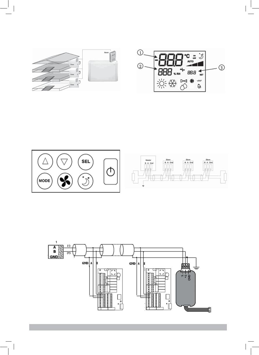
La soluzione (figura 1), realizza un sistema Master-Slave (fino a 247 terminali slave), in cui uno dei comandi svolge la funzione di Master e controlla tutti gli altri elementi slave.
La connessione si realizza mediante il bus RS485, costituito da un semplice cavo schermato a 2 conduttori.
Il master (che è identificato dall’indirizzo 255), invia ai comandi slave le seguenti informazioni:
(1)Modalità di funzionamento (Raffreddamento o riscaldamento)
(2)Set point per la temperatura ambiente.
Ciascun comando Slave mantiene la gestione del selettore delle velocità e la regolazione della temperatura ambiente è consentita con un delta di ± 2°C intorno al valore del set point inviato dal comando master
FUNZIONI PRINCIPALI E DOTAZIONE:
■Regolazione della temperatura dell’aria tramite variazione automatica della velocità del ventilatore.
■Regolazione della temperatura dell’aria tramite on-off del ventilatore ad una velocità fissa.
■Gestione di valvole On/Off per impianti a due o quattro tubi.
■Gestione di resistenza per supporto in riscaldamento.
■Commutazione Raffreddamento/Riscaldamento nelle seguenti modalità:
—manuale a bordo
—manuale a distanza (centralizzato)
—automatica, in funzione della temperatura dell’acqua
—automatica, in funzione della temperatura dell’aria
■Funzione di Deumidifica
■Comunicazione Seriale
INOLTRE È DOTATO DI:
■contatto pulito per consenso esterno (ad esempio; contatto finestra, ON/OFF remoto, sensore di presenza ecc.) che può abilitare o disabilitare il funzionamento dell’unità (logica contatto: vedi parametri configurazione scheda).
■contatto pulito per commutazione Raffreddamento/ Riscaldamento remota centralizzata (logica contatto: vedi parametri configurazione scheda).
■contatto pulito per l’abilitazione della funzione economy da remoto (logica contatto: vedi parametri configurazione scheda).
■sonda remota di temperatura per l’acqua (accessorio).
■sonda di temperatura interna
■sonda di umidità interna
■sonda remota di temperatura per l’aria (accessorio) (tale sonda, se presente, viene utilizzata al posto di quella interna, per la lettura della temperatura ambiente).
■Sonda remota di umidità (accessorio — da utilizzare in abbinamento alla sonda remota di temperatura)
Il pannello di comando è composto da:
■display LCD
■tastiera
DISPLAY LCD (VEDI FIGURA 2)
(1)temperatura ambiente
(2)umidità ambiente
(3)temperatura impostata
|
ON |
stato ventilatori. Se lampeggiante indica ventilatori |
|
|
fermi in attesa di chiamata del termostato. |
||
|
Se simbolo acceso fisso indica ventilatori in |
||
|
funzione |
||
|
OFF |
stato ventilatori. Ventilatori fermi in seguito alla |
|
|
velocità impostata su Off o al comando spento |
||
|
AUTO |
logica ventilazione automatica |
|
|
velocità ventilatore |
||
|
modalità di funzionamento: Raffreddamento.Se |
||
|
lampeggiante indica la mancanza del consenso |
||
|
acqua al funzionamento della ventilazione. |
||
|
modalità di funzionamento: Riscaldamento. Se |
||
|
lampeggiante indica la mancanza del consenso |
||
|
acqua al funzionamento della ventilazione. |
||
|
Deumidifica. Se lampeggiante indica la mancanza |
||
|
di consenso per la deumidificazione; con simbolo |
||
|
acceso fisso indica invece che tale funzione è |
||
|
attiva |
||
|
opzione Economy attiva |
||
|
presenza di allarme |
||
|
controllo Minima Temperatura |
||
|
valvola aperta |
||
|
resistenza elettrica. Con simbolo lampeggiante |
||
|
indica resistenza in funzione; con simbolo acceso |
||
|
fisso indica solamente resistenza selezionata |
||
|
comunicazione seriale attiva. Il simbolo lampeg- |
||
|
giante indica che il comando è il master |
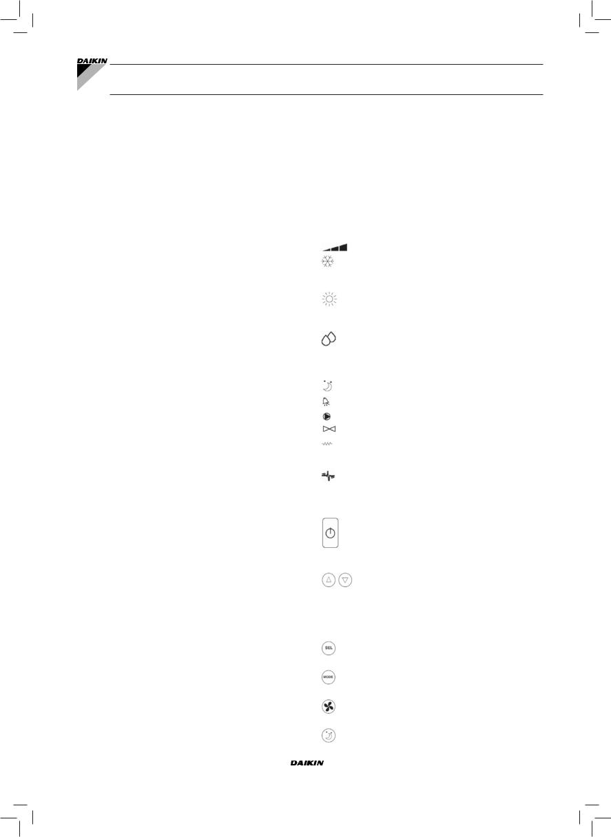
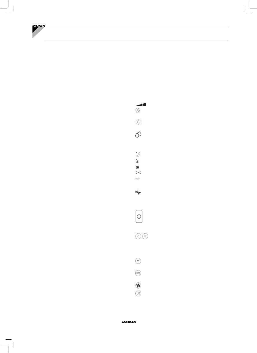
TASTIERA (VEDI FIGURA 3)
tastoOn/Off:accensione/spegnimentotermostato. Durantelaproceduradimodificaparametripermette di tornare al funzionamento normale
tasti Up e Down: modifica della temperatura di regolazione del termostato (Riscaldamento:[5.0- 30.0°C], Raffreddamento: [10.0-35.0°C]). Durante la procedura di modifica parametri vengono utilizzati per selezionare i parametri o modificarne il valore
tasto SEL: in modalità Riscaldamento selezione della resistenza elettrica come funzione ausiliaria
tasto Mode: selezione della modalità di funzionamento Riscaldamento / Raffreddamento
tasto Fan: selezione della velocità di funzionamento
tasto EC: selezione modalità Economy
|
FWEC2 |
Manuale d’installazione e d’uso |
|
Advanced electronic controller |
1 |
|
FC66002764 |
COMBINAZIONI DI TASTI ATTIVE
Con termostato in Off: accesso alla procedura di configurazione parametri
Con termostato in On: visualizza momentanea della temperatura dell’acqua
Selezione della funzione minima temperatura aria
Selezione deumidifica
CONFIGURAZIONE SCHEDA
La scheda è configurabile in base al tipo di terminale/impianto da gestire, attraverso la modifica di alcuni parametri.
LISTA PARAMETRI
■P00 = configurazione comando (vedi «Configurazioni Previste») per selezionare il tipo di terminale da gestire.
■P01 = tipo di installazione del comando —000: bordo terminale
—001: parete
■P02 = indirizzo Modbus (per rendere attiva la modifica di tale parametro (escluso il caso di passaggio interno tra valori) è necessario togliere e ridare alimentazione alla fine della programmazione)
—0: disabilitata la comunicazione seriale —1-247: slave
—255: master
■P03 = zona neutra [20-50°C/10]; parametro utilizzato in caso di configurazioni con commutazione raffreddamento/ riscaldamento automatica in funzione della temperatura dell’aria.
■P04 = sonda acqua: —0: non prevista
—1: prevista
In base al valore impostato verrà gestito opportunamente il relativo allarme sonda e consenso per la resistenza elettrica
■P05 = Logica di configurazione utilizzo ingressi digitali 1
|
e 2: |
||||
|
— |
0: |
DIN1 = — |
DIN2 = — |
|
|
— |
1: |
DIN1 = — |
DIN2 = OnOff |
|
|
— |
2: |
DIN1 = Est/Inv |
DIN2 = — |
|
|
— |
3: |
DIN1 = Eco |
DIN2 = — |
|
|
— |
4: |
DIN1 = Est/Inv |
DIN2 = On/Off |
|
|
— |
5: |
DIN1 = Eco |
DIN2 = On/Off |
|
|
— |
6: |
DIN1 = Est/Inv |
DIN2 = Eco |
|
■P06 = logica di utilizzo ingresso digitale 1:
—0: [aperto/chiuso] = [Raffred./Riscald] = [-/ECO]
—1: [aperto/chiuso] = [Riscald./Raffred] = [ECO/-]
■P07 = logica di utilizzo ingresso digitale 2:
—0: [aperto/chiuso] = [Off/On] = [-/ECO]
—1: [aperto/chiuso] = [On/Off] = [ECO/-]
■P08 = sonda umidità remota:
—0 : non prevista
—1 : prevista
In base al valore impostato verrà eventualmente gestito il relativo allarme sonda.
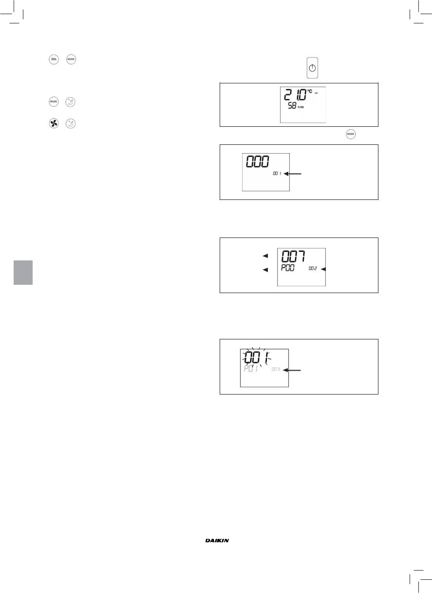
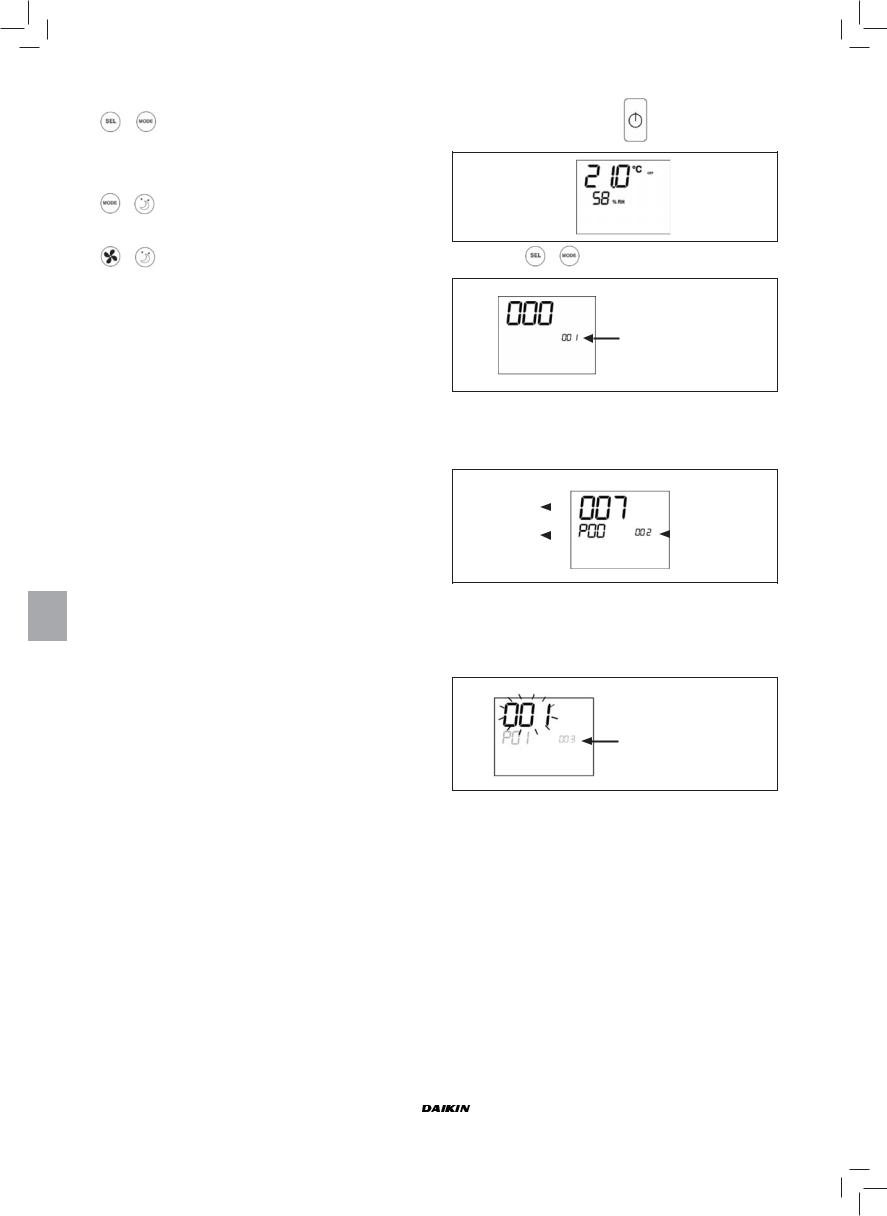
PROCEDURA DI CONFIGURAZIONE
PARAMETRI
■ Mettere in OFF il termostato
■ Premere contemporaneamente i tasti 
Indicazione livello:
001= inserimento password
■Utilizzare i tasti  per modificare il valore del display
fino al valore di password 10, quindi premere  . Se corretta si avrà accesso ai parametri
|
Valore parametro |
||||
|
selezionato |
Indicazione livello: |
|||
|
Parametro |
002= selezione |
|||
|
password |
||||
|
selezionato: P… |
||||
■Utilizzare i tasti  per scorrere i vari parametri (vedi «Lista Parametri» sopra descritta)
■Premere  per attivare la modifica del parametro (il valore comincerà a lampeggiare)
Indicazione livello:
003 = modifica parametro
■Utilizzare i tasti  per modificare il valore
■Premere  per salvare il nuovo valore impostato o
  per annullare la modifica
■Una volta conclusa la modifica di parametri interessati premere il tasto  per uscire dalla procedura
NB: la procedura di parametrizzazione ha una durata limitata. Una volta scaduto tale periodo (2 minuti circa) il termostato verrà riportato allo stato Off mantenendo solo le modifiche salvate.
|
Manuale d’installazione e d’uso |
FWEC2 |
|||||||
|
2 |
Advanced electronic controller |
|||||||
|
FC66002764 |
||||||||

CONFIGURAZIONI PREVISTE (PARAMETRO P00)
Il comando LCD può essere configurato in diversi modi in base al tipo di sistema. Le varie configurazioni si ottengono configurandoopportunamenteilparametroP00 (vediprocedura di configurazione parametri comando).
001
■Tubi impianto: 2
■Valvola: NO
■Resistenza: NO
■Velocità ventilazione: 3
■Logica commutazione estate/inverno: LOCALE MANUALE
002
■Tubi impianto: 2
■Valvola: NO
■Resistenza: NO
■Velocità ventilazione: 3
■Logica commutazione estate/inverno: DISTANZA MANUALE
003
■Tubi impianto: 2
■Valvola: NO
■Resistenza: NO
■Velocità ventilazione: 3
■Logica commutazione estate/inverno: AUTOMATICO
LATO ACQUA
004
■Tubi impianto: 2
■Valvola: NO
■Resistenza: NO
■Velocità ventilazione: 4
■Logica commutazione estate/inverno: LOCALE MANUALE
005
■Tubi impianto: 2
■Valvola: NO
■Resistenza: NO
■Velocità ventilazione: 4
■Logica commutazione estate/inverno: DISTANZA MANUALE
006
■Tubi impianto: 2
■Valvola: NO
■Resistenza: NO
■Velocità ventilazione: 4
■Logica commutazione estate/inverno: AUTOMATICO
LATO ACQUA
007
■Tubi impianto: 2
■Valvola: NO
■Resistenza: SI
■Velocità ventilazione: 3
■Logica commutazione estate/inverno: LOCALE MANUALE
008
■Tubi impianto: 2
■Valvola: NO
■Resistenza: SI
■Velocità ventilazione: 3
■Logica commutazione estate/inverno: DISTANZA MANUALE
009
■Tubi impianto: 2
■Valvola: NO
■Resistenza: SI
■Velocità ventilazione: 3
■Logica commutazione estate/inverno: AUTOMATICO
LATO ARIA
010
■Tubi impianto: 2
■Valvola: NO
■Resistenza: SI
■Velocità ventilazione: 4
■Logica commutazione estate/inverno: LOCALE MANUALE
011
■Tubi impianto: 2
■Valvola: NO
■Resistenza: SI
■Velocità ventilazione: 4
■Logica commutazione estate/inverno: DISTANZA MANUALE
012
■Tubi impianto: 2
■Valvola: NO
■Resistenza: SI
■Velocità ventilazione: 4
■Logica commutazione estate/inverno: AUTOMATICO
LATO ARIA
013
■Tubi impianto: 2
■Valvola: 2/3 VIE
■Resistenza: NO
■Velocità ventilazione: 3
■Logica commutazione estate/inverno: LOCALE MANUALE
014
■Tubi impianto: 2
■Valvola: 2/3 VIE
■Resistenza: NO
■Velocità ventilazione: 3
■Logica commutazione estate/inverno: DISTANZA MANUALE
015
■Tubi impianto: 2
■Valvola: 2/3 VIE
■Resistenza: NO
■Velocità ventilazione: 3
■Logica commutazione estate/inverno: AUTOMATICO
LATO ACQUA
016
■Tubi impianto: 2
■Valvola: 2/3 VIE
■Resistenza: NO
■Velocità ventilazione: 4
■Logica commutazione estate/inverno: LOCALE MANUALE
017
■Tubi impianto: 2
■Valvola: 2/3 VIE
■Resistenza: NO
■Velocità ventilazione: 4
■Logica commutazione estate/inverno: DISTANZA MANUALE
|
FWEC2 |
Manuale d’installazione e d’uso |
|
Advanced electronic controller |
3 |
|
FC66002764 |

CONFIGURAZIONI PREVISTE (PARAMETRO P00)
018
■Tubi impianto: 2
■Valvola: 2/3 VIE
■Resistenza: NO
■Velocità ventilazione: 4
■Logica commutazione estate/inverno: AUTOMATICO
LATO ACQUA
019
■Tubi impianto: 2
■Valvola: 3 VIE
■Resistenza: SI
■Velocità ventilazione: 3
■Logica commutazione estate/inverno: LOCALE MANUALE
020
■Tubi impianto: 2
■Valvola: 3 VIE
■Resistenza: SI
■Velocità ventilazione: 3
■Logica commutazione estate/inverno: DISTANZA MANUALE
021
■Tubi impianto: 2
■Valvola: 3 VIE
■Resistenza: SI
■Velocità ventilazione: 3
■Logica commutazione estate/inverno: AUTOMATICO
LATO ARIA
022
■Tubi impianto: 2
■Valvola: 3 vie
■Resistenza: SI
■Velocità ventilazione: 4
■Logica commutazione estate/inverno: LOCALE MANUALE
023
■Tubi impianto: 2
■Valvola: 3 VIE
■Resistenza: SI
■Velocità ventilazione: 4
■Logica commutazione estate/inverno: DISTANZA MANUALE
024
■Tubi impianto: 2
■Valvola: 3 VIE
■Resistenza: SI
■Velocità ventilazione: 4
■Logica commutazione estate/inverno: AUTOMATICO
LATO ARIA
025
■Tubi impianto: 4
■Valvola: NO
■Resistenza: NO
■Velocità ventilazione: 3
■Logica commutazione estate/inverno: LOCALE MANUALE
026
■Tubi impianto: 4
■Valvola: NO
■Resistenza: NO
■Velocità ventilazione: 3
■Logica commutazione estate/inverno: DISTANZA MANUALE
027
■Tubi impianto: 4
■Valvola: NO
■Resistenza: NO
■Velocità ventilazione: 3
■Logica commutazione estate/inverno: AUTOMATICO
LATO ARIA
028
■Tubi impianto: 4
■Valvola: NO
■Resistenza: NO
■Velocità ventilazione: 4
■Logica commutazione estate/inverno: LOCALE MANUALE
029
■Tubi impianto: 4
■Valvola: NO
■Resistenza: NO
■Velocità ventilazione: 4
■Logica commutazione estate/inverno: DISTANZA MANUALE
030
■Tubi impianto: 4
■Valvola: NO
■Resistenza: NO
■Velocità ventilazione: 4
■Logica commutazione estate/inverno: AUTOMATICO
LATO ARIA
031
■Tubi impianto: 4
■Valvola: 2/3 VIE
■Resistenza: NO
■Velocità ventilazione: 3
■Logica commutazione estate/inverno: LOCALE MANUALE
032
■Tubi impianto: 4
■Valvola: 2/3 VIE
■Resistenza: NO
■Velocità ventilazione: 3
■Logica commutazione estate/inverno: DISTANZA MANUALE
033
■Tubi impianto: 4
■Valvola: 2/3 VIE
■Resistenza: NO
■Velocità ventilazione: 3
■Logica commutazione estate/inverno: AUTOMATICO
LATO ARIA
034
■Tubi impianto: 4
■Valvola: 2/3 VIE
■Resistenza: NO
■Velocità ventilazione: 4
■Logica commutazione estate/inverno: LOCALE MANUALE
|
Manuale d’installazione e d’uso |
FWEC2 |
|
4 |
Advanced electronic controller |
|
FC66002764 |

CONFIGURAZIONI PREVISTE (PARAMETRO P00)
035
■Tubi impianto: 4
■Valvola: 2/3 VIE
■Resistenza: NO
■Velocità ventilazione: 4
■Logica commutazione estate/inverno: DISTANZA MANUALE
036
■Tubi impianto: 4
■Valvola: 2/3 VIE
■Resistenza: NO
■Velocità ventilazione: 4
■Logica commutazione estate/inverno: AUTOMATICO
LATO ARIA
037
■Tubi impianto: 4
■Valvola: NO
■Resistenza: SI
■Velocità ventilazione: 3
■Logica commutazione estate/inverno: LOCALE MANUALE
038
■Tubi impianto: 4
■Valvola: NO
■Resistenza: SI
■Velocità ventilazione: 4
■Logica commutazione estate/inverno: LOCALE MANUALE
COMUNICAZIONE SERIALE
Collegamento alla rete di comunicazione RS485
La rete di comunicazione, tipologia Bus, è costituita da un semplice cavo schermato a 2 conduttori, connesso direttamente alle porte seriali RS485 dei comandi (morsetti A, B e GND).
«Per la realizzazione della rete utilizzare cavo AWG 24 (diam. 0,511 mm)»
La rete di comunicazione deve avere la seguente struttura generale (figura 4).
Nel caso di soluzione «MASTER-SLAVE» dovrà essere installata una resistenza di terminazione su entrambi i comandi agli estremi della rete.
NB: (1) Rispettare la polarità della connessione: indicata con A(-) e B(+)
(2) Evitare anelli di massa (schermatura a terra solo ad una estremità)
____________________________________________________________
ATTENZIONE:
■Utilizzare cavo schermato AWG24
■Colori suggeriti per la rete di comunicazione: A
(-) colore Marrone; B (+) colore Giallo
____________________________________________________________
LOGICHE
COMMUTAZIONE RAFFREDDAMENTO/RISCALDAMENTO
Sono presenti 4 differenti logiche di selezione della modalità di funzionamento del termostato definite in base alla configurazione impostata sul comando:
1.Locale: scelta dall’utente agendo sul tasto 
2.Distanza: in funzione dello stato dell’ingresso digitale DI1 (logica contatto: vedi parametri configurazione scheda)
3.In funzione della temperatura dell’acqua
Estate
Inverno
Temp. acqua
NB: nel caso di allarme sonda acqua il controllo della modalità torna temporaneamente nella modalità Locale.
4. in funzione della temperatura dell’aria:
Estate
Inverno
Temp. aria
Dove:
■Set è la temperatura impostata con le frecce
■ZN è la zona neutra (parametro P03)
La modalità di funzionamento del termostato è indicata sul
display dai simboli  (raffreddamento) e
  (riscaldamento)
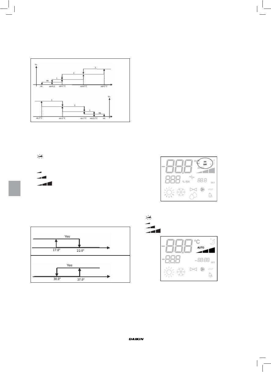
VENTILAZIONE
Il controllo può gestire terminali a 3 o 4 velocità
SELEZIONE VELOCITÀ FUNZIONAMENTO
Utilizzando il tasto Fan  è possibile scegliere fra le seguenti velocità:
■Vel. automatica: in funzione della temperatura impostata e quella dell’aria ambiente
Con configurazioni a 3 velocità  :
:
dove:
1 = velocità minima
2 = velocità media
3 = velocità massima
RAFFREDDAMENTO
RISCALDAMENTO
|
FWEC2 |
Manuale d’installazione e d’uso |
|||||||
|
Advanced electronic controller |
5 |
|||||||
|
FC66002764 |
||||||||
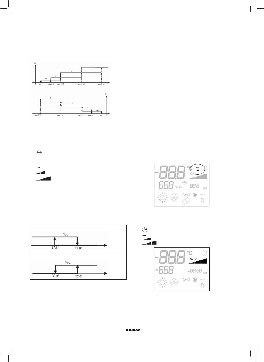
Con configurazioni a 4 velocità  dove:
dove:
sm = velocità superminima 1 = velocità minima
2 = velocità media
3 = velocità massima
RAFFREDDAMENTO
Temp. aria
RISCALDAMENTO
Temp. aria
NB: nelle configurazioni con 4 velocità e valvola, la ventilazione in riscaldamento viene ritardata di 0.5°C per consentire una prima fase di convezione naturale
■Vel. disattivata: selezionabile solo in riscaldamento e con configurazioni a 4 velocità, fa funzionare il terminale in sola convezione naturale
|
■ |
Vel. superminima: selezionabile solo con con- |
|
|
figurazioni a 4 velocità, utilizza come velocità |
||
|
fissa la superminima |
||
|
■ |
Vel. minima |
|
|
■ |
Vel. media |
|
|
■ |
Vel. massima |
NB: nel caso di velocità fissa la logica di attivazione del ventilatore sarà pari a quella della logica automatica
CONSENSO DELL’ACQUA
Il funzionamento della ventilazione è vincolato al controllo della temperatura acqua dell’impianto. In base alla modalità di lavoro avremo differenti soglie di consenso in riscaldamento e raffreddamento
RAFFREDDAMENTO
NO
Temp. acqua
RISCALDAMENTO
NO
Temp. acqua
L’assenza di tale consenso, alla chiamata del termostato, verrà indicata sul display con il lampeggio del simbolo della
modalità attiva ( o
o  )
)
Tale consenso viene ignorato in caso di:
■sonda acqua non prevista (P04 = 0) o in allarme perché scollegata
■in Raffreddamento con configurazioni a 4 tubi
LOGICHE
FORZATURE
La normale logica di ventilazione verrà ignorata nel caso di particolari situazioni di forzatura che possono essere necessarie per il corretto controllo della temperatura o funzionamento del terminale. Si possono avere:
In Raffreddamento:
■con comando a bordo macchina (P01 = 0) e configurazioni con valvola: viene mantenuta la minima velocità disponibile anche a temperatura raggiunta.
■comando a bordo e configurazioni senza valvola: ogni 10minuti di ventilatore fermo viene eseguito un lavaggio di 2 minuti alla velocità media per permettere alla sonda aria una lettura più corretta della temperatura ambiente.
In Riscaldamento
■con resistenza attiva: viene forzata la ventilazione alla velocità media.
■una volta spenta la resistenza: viene mantenuta, per 2 minuti, una post ventilazione alla velocità media. (NB: tale ventilazione verrà completata anche se il termostato dovesse venir spento o si passasse alla modalità raffreddamento)
DISPLAY
Il display visualizza lo stato del ventilatore
■On lampeggiante: ventilatore in standby
■On fisso: ventilatore acceso
■OFF: ventilatore disattivato per lavorare in sola convezione naturale
e la velocità di funzionamento (con eventuale indicazione della logica «automatica») attiva o selezionata (nel caso di ventilatore in stand-by)
|
■ |
Vel. superminima |
|
■ |
Vel. minima |
|
■ |
Vel. media |
■Vel. massima
NB: nel caso la velocità attiva sia diversa da quella selezionata da utente (in caso di forzatura..), una prima pressione del tasto Fan  visualizzerà quest’ultima; una pressione successiva cambierà tale impostazione.
|
Manuale d’installazione e d’uso |
FWEC2 |
|
6 |
Advanced electronic controller |
|
FC66002764 |
![]()
VALVOLA
Il controllo può gestire valvole a 2 o 3 vie di tipo ON OFF con tensione di alimentazione 230V
APERTURA
L’apertura della valvola viene comandata in funzione del set di lavoro e della temperatura dell’aria
RAFFREDDAMENTO
Temp. aria
RISCALDAMENTO
Temp. aria
CONSENSO DELL’ACQUA
Il controllo della temperatura dell’acqua per il consenso all’apertura interessa solo configurazioni con valvole a 3 vie e resistenza elettrica.
In tali configurazioni verrà fatto un controllo della temperatura dell’acqua in caso di:
■Riscaldamento con resistenza: il funzionamento della resistenza comporta una forzatura della ventilazione; è necessario quindi evitare l’eventuale passaggio di acqua troppo fredda nel terminale.
Temp. acqua
■Post ventilazione dovuta allo spegnimento resistenza: mantenuta fino allo scadere del tempo stabilito, anche nel caso di cambio della modalità di funzionamento. Durante tale post ventilazione il consenso dell’acqua coinciderà con quello visto per la ventilazione.
DISPLAY
L’indicazione di valvola attiva sul display sarà data dal simbolo
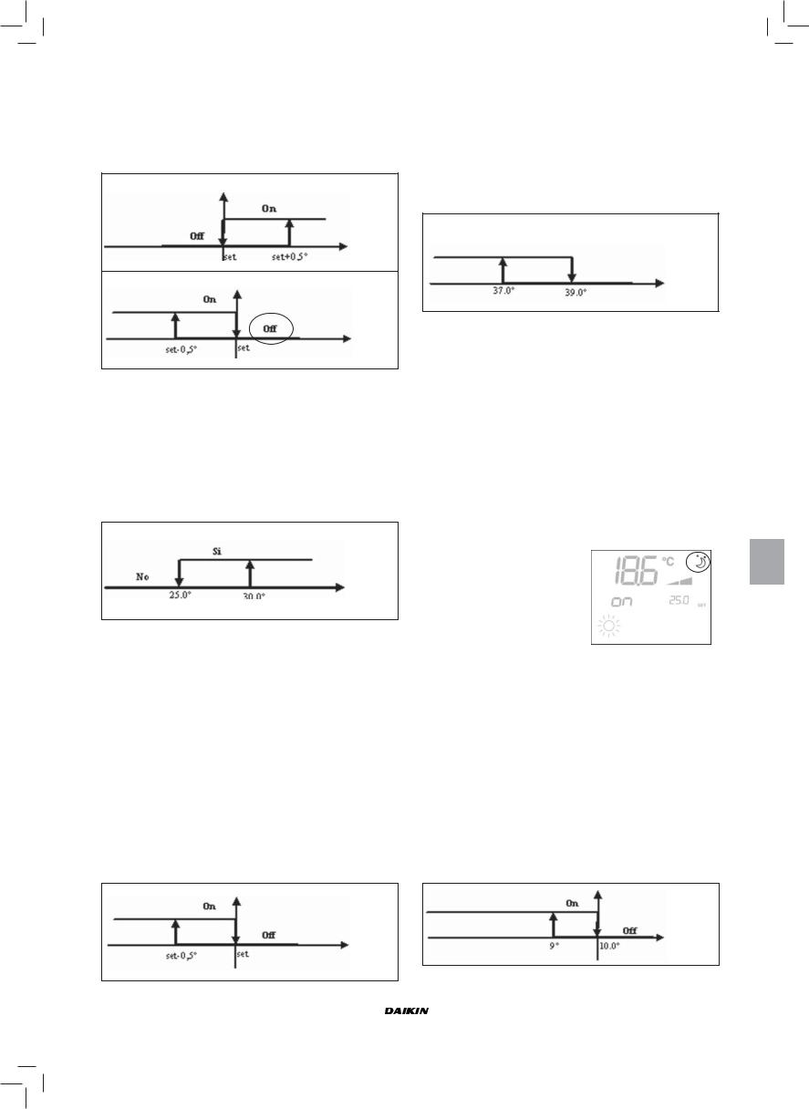
RESISTENZA ELETTRICA
La resistenza elettrica è un dispositivo gestito come eventuale supporto nella fase di riscaldamento.
SELEZIONE
Se prevista dalla configurazione la resistenza può essere selezionata in riscaldamento tramite il tasto Sel 
ATTIVAZIONE
Temp. aria
L’utilizzo della resistenza elettrica, se selezionata da utente, viene utilizzata su chiamata del termostato in base alla temperatura ambiente
NB: l’attivazione comporta una forzatura della ventilazione
CONSENSO DELL’ACQUA
Il consenso per l’attivazione della resistenza è legato al controllo della temperatura dell’acqua. Di seguito la logica di consenso relativa
Tale consenso non verrà dato nel caso di sonda dell’acqua non prevista o scollegata
RISCALDAMENTO
ON
OFF
Temp. acqua
DISPLAY
Il display visualizzerà le seguenti informazioni
■Resistenza selezionata da utente:  simbolo fisso
■Resistenza attiva:  simbolo lampeggiante
ECONOMY
La funzione Economy prevede una correzione del setpoint di 2.5°C e una forzatura alla minima velocità disponibile per ridurre il funzionamento del terminale.
■Raffreddamento: set + 2.5°C
■Riscaldamento: set — 2.5°C
ATTIVAZIONE
La funzione è attivabile con la pressione del tasto 
DISPLAY
Sul display la funzione Economy è indicata da simbolo 
CONTROLLO MINIMA TEMPERATURA
Tale logica permette di controllare, con termostato spento, che la temperatura ambiente non scenda troppo, forzando eventualmente il terminale in modalità riscaldamento per il tempo necessario.
Se presente la resistenza elettrica essa verrà utilizzata solo nel caso in cui fosse stata precedentemente selezionata come risorsa in Riscaldamento.
SELEZIONE
Il controllo Minima Temperatura è selezionabile, a termostato
spento, con la pressione contemporanea dei tasti 
 . La stessa combinazione di tasti disattiva tale funzionamento
ATTIVAZIONE
Se tale controllo è selezionato, il terminale si accenderà nel caso in cui la temperatura ambiente scenda al di sotto dei
9°C.
|
FWEC2 |
Manuale d’installazione e d’uso |
|||||||
|
Advanced electronic controller |
7 |
|||||||
|
FC66002764 |
||||||||
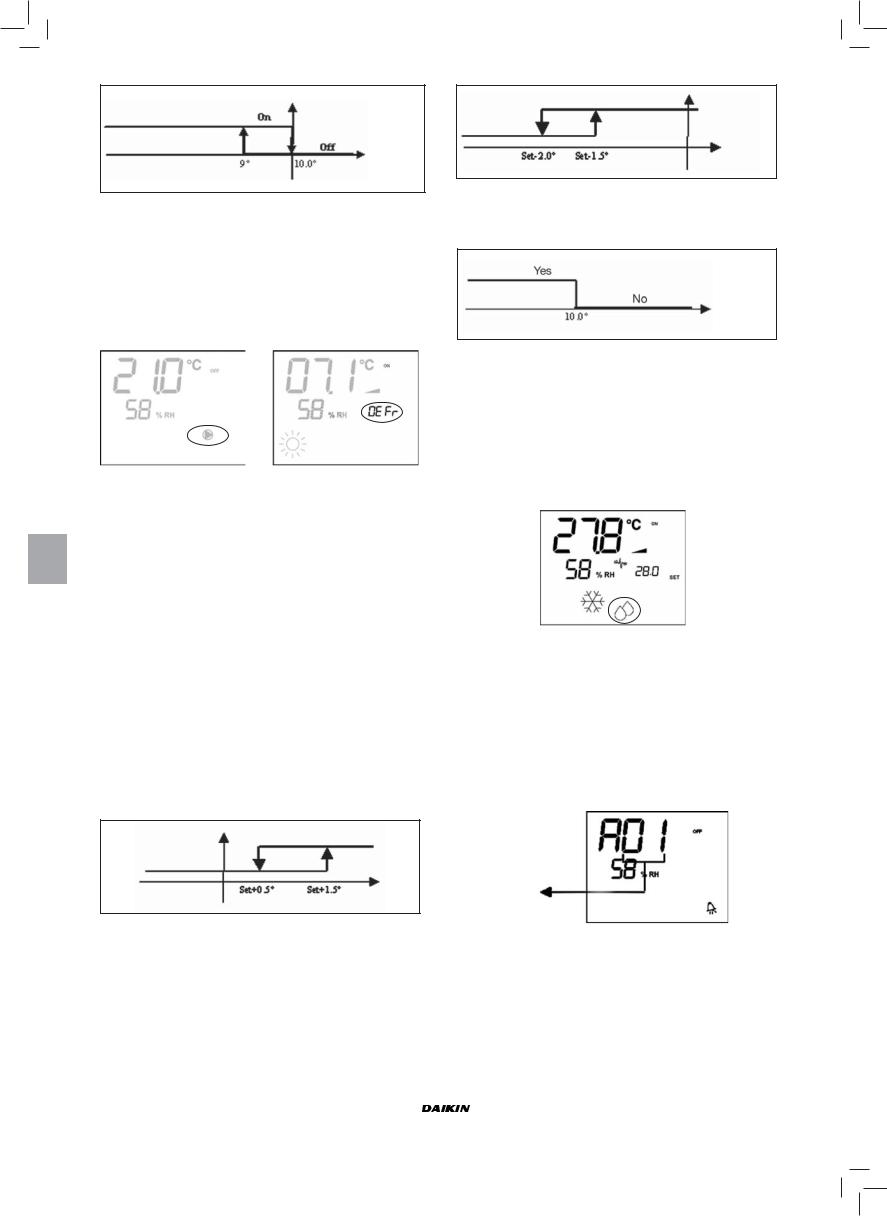
Temp. aria
Una volta riportata la temperatura sopra i 10°C il termostato ritornerà nella situazione di Off.
NB: un eventuale Off da ingresso digitale inibirà tale logica.
DISPLAY
Il display visualizza le seguenti informazioni
■Controllo Minima Temperatura selezionato: simbolo 
■Controllo Minima Temperatura attivo: indicazione DEFR
DEUMIDIFICA
La funzione di deumidifica, utilizzabile nella sola modalità raffreddamento, prevede di far funzionare il terminale con lo scopo di ridurre del 10% l’umidità presente in ambiente al momento della selezione della funzione stessa
SELEZIONE
Il deumidifica è selezionabile/deselezionabile, in Raffreddamento,
con la pressione contemporanea dei tasti 
 . Con sonda acqua non prevista (P04=0) o mancanza di sonda d’umidità remota nel caso di installazioni a bordo (P08=0) tale selezione non sarà consentita. Se selezionata, la zona neutra per la commutazione automatica lato aria è forzata a 5°
LOGICA
Una volta selezionata, la logica di Deumidifica imposta come set di umidità da raggiungere l’umidità presente al momento della selezione meno il 10%. In caso di umidità ambiente inferiore al 40% il set di riferimento verrà impostato al 30%. La velocità di ventilazione verrà forzata alla minima o, nel caso di temperatura molto superiore al set impostato, alla media velocità
Velocità media
Velocità minima
Dovendo portare l’umidità al valore impostato la ventilazione (e la valvola, se presente) verrà attivata anche nel caso in cui la temperatura ambiente abbia già raggiunto il set relativo (visibile sul display dal simbolo 3. Nel caso si scenda troppo al di sotto di tale soglia tale logica verrà momentaneamente inibita.
Inibita
Temp. aria
CONSENSO DELL’ACQUA
Il consenso per l’attivazione della deumidifica è legato al controllo della temperatura dell’acqua. Di seguito la logica di consenso relativa
Temp. acqua
Il mancato consenso prevede l’inibizione momentanea della logica di deumidifica.
Lo stesso verrà fatto nel caso la sonda venga scollegata.
NB: una volta raggiunta l’umidità di riferimento o messo in Off il comando, la deumidifica verrà deselezionata
DISPLAY
Il display visualizza le seguenti informazioni:
■ Deumidifica attiva: simbolo acceso 
■Deumidifica momentaneamente inibita: simbolo lampeggiante 
ALLARMI
Il comando gestisce due tipologie di allarmi:
■Allarmi Gravi: causano lo spegnimento forzato del termostato
■Allarmi Non Gravi: non forzano lo spegnimento del termostato ma inibiscono eventuali funzionalità critiche
ALLARMI GRAVI
Codice allarme
■Cod. A01 = errore sonda esterna di temperatura dell’aria (se termostato installato a Bordo)
■Cod. A02 = errore sonda interna di temperatura dell’aria (se termostato installato a Parete e sonda esterna di temperatura dell’aria sconnessa)
|
Manuale d’installazione e d’uso |
FWEC2 |
|||||||
|
8 |
Advanced electronic controller |
|||||||
|
FC66002764 |
||||||||
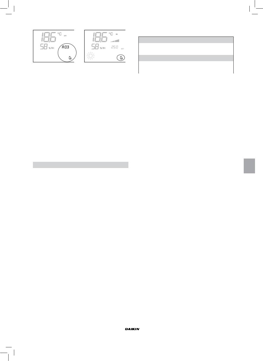
ALLARMI NON GRAVI
|
Termostato OFF |
Termostato ON |
■Cod. A03 = errore sonda di temperatura dell’acqua
■Cod A04= errore sonda umidità esterna (solo se sonda di temperatura remota installata)
■Cod A05 = errore sonda umidità interna
NB: l’indicazione del codice allarme è visualizzato solo con termostato spento
MODBUS
Il protocollo implementato nel comando è il Modbus RTU (9600, N, 8, 2) su RS485
FUNZIONI IMPLEMENTATE
■0x03 : Read Holding Registers
■0x04 : Read Input Registers
■0x10 : Write Multiple registers
ECCEZIONI IMPLEMENTATE
Exception Code 02: Invalidate data address
LISTA PARAMETRI DI SUPERVISIONE
|
INDIRIZZO |
REGISTRO |
TIPO |
U.D.M. |
|
0 |
Stati |
R |
— |
|
1 |
Velocità |
R |
— |
|
2 |
Temperatura aria |
R |
[°C/10] |
|
3 |
Umidità |
R |
% |
|
4 |
Temperatura acqua |
R |
[°C/10] |
|
5 |
P00: Configurazione |
R |
— |
|
6 |
P05: Config. DIN |
R |
— |
|
7 |
T. Setpoint attivo |
R |
[°C/10] |
|
8 |
T. Setpoint utente |
R |
[°C/10] |
|
9 |
Versione LCD |
R |
— |
|
50 |
Digitali 1 |
R/W |
— |
|
51 |
— |
R/W |
— |
|
52 |
Setpoint — Raffreddamento |
R/W |
[°C/10] |
|
53 |
Setpoint — Riscaldamento |
R/W |
[°C/10] |
|
54 |
Minimo Setpoint – Raffr. |
R/W |
[°C/10] |
|
55 |
Massimo Setpoint – Raffr. |
R/W |
[°C/10] |
|
56 |
Minimo Setpoint – Risc. |
R/W |
[°C/10] |
|
57 |
Massimo Setpoint – Risc. |
R/W |
[°C/10] |
|
58 |
Velocità |
R/W |
— |
|
59 |
Correzione Economy |
R/W |
[°C/10] |
DESCRIZIONE REGISTRI DI SOLA LETTURA [R]
■ Registro «STATI»
H
|
Bit 15 |
Bit 14 |
Bit 13 |
Bit 12 |
Bit 11 |
Bit 10 |
Bit 9 |
Bit 8 |
|
— |
— |
P04 |
Deum |
P06 |
P07 |
DI2 |
DI1 |
L
|
Bit 7 |
Bit 6 |
Bit 5 |
Bit 4 |
Bit 3 |
Bit 2 |
Bit 1 |
Bit 0 |
|
Vh |
Vc |
Allarme |
MinT |
Eco |
P01 |
S/W |
On/Off |
—On/Off: stato terminale (0: Off, 1=On)
—S/W: modalità di funzionamento (0: S=raffreddamento,1: W=riscaldamento)
—P01: parametro «installazione bordo/parete»
—Eco: logica Economy attiva
—Min.T: logica Minima Temperatura selezionata
—Allarme: indicazione generale di allarme (si attiva al manifestarsi di uno qualsiasi degli allarmi gestiti)
—Vc: stato uscita digitale Vc
—Vh: stato uscita digitale Vh
—DI1: valore logico ingresso dig.1 (lo stato fisico dell’ingresso dipende dalla logica associata)
—DI2: valore logico ingresso dig.2 (lo stato fisico dell’ingresso dipende dalla logica associata)
—P07: parametro «Logica DIN 2»
—P06: parametro «Logica DIN 1»
—Deum: deumidifica in funzione (0:no, 1:si)
—P04: parametro «sonda acqua prevista»
■REGISTRO «VELOCITÀ» : velocità alla quale sta funzionando il termina
—0: nessuna ventilazione attiva
—1: velocità superminima
—2: velocità minima
—3: velocità media
—4: velocità massima
■REGISTRO «TEMPERATURA ARIA»: temperatura ambiente letta dal comando e visualizzata a display (NB: tale temperatura corrisponde alla lettura da sonda remota se comando a bordo mentre, nel caso di comando a parete e sonda remota scollegata, lettura della sonda interna)
■REGISTRO «UMIDITÀ»: umidità ambiente letta dal comando dalla sonda relativa a quella di temperatura utilizzata
■REGISTRO «TEMPERATURA ACQUA»: temperatura dell’acqua letta dalla sonda relativa (SW)
■Registro «P00» : parametro «Configurazione comando»
■Registro «T. SETPOINT ATTIVO» : setpoint utilizzato per la regolazione
■Registro «T. SETPOINT UTENTE» : setpoint impostato da utente (potrebbe discostare dal setpoint attivo in seguito a correzioni per logiche di economy, …o per utilizzo del setpoint da supervisione)
■Registro «VERSIONE LCD» : definisce il tipo di comando e la versione software installata (0xHHSS: HH: carattere ASCII, SS:versione sw)
|
FWEC2 |
Manuale d’installazione e d’uso |
|||||||
|
Advanced electronic controller |
9 |
|||||||
|
FC66002764 |
||||||||
DESCRIZIONE REGISTRI DI LETTURA/SCRITTURA [R/W]
■ Registro «DIGITALI 1»:
H
|
Bit 15 |
Bit 14 |
Bit 13 |
Bit 12 |
Bit 11 |
Bit 10 |
Bit 9 |
Bit 8 |
|
|
En.Vel |
En.Min/ |
En.Set |
En.MinT |
En.ECO |
En.RE |
En.S/W |
En.On/ |
|
|
Max |
Off |
|||||||
|
L |
||||||||
|
Bit 7 |
Bit 6 |
Bit 5 |
Bit 4 |
Bit 3 |
Bit 2 |
Bit 1 |
Bit 0 |
|
|
— |
— |
Lock |
MinT |
Eco |
RE |
S/W |
On/Off |
|
—On/Off: On/Off da supervisione
—S/W: Modalità da supervisione (0: Raffreddamento, 1: Riscaldamento)
—RE: selezione Resistenza da supervisione
—Eco: attivazione Economy da supervisione
—MinT.: attivazione controllo Minima Temperatura da supervisione
—Lock: blocco tastiera (0: non bloccata, 1: bloccata)
—En.On/Off :abilitazione controllo On/Off da supervisione
—En.S/W: abilitazione controllo modalità da supervisione
—En.RE: abilitazione selezione Resistenza Elettrica da supervisione
—En.ECO: abilitazione attivazione economy da supervisione
—En.MinT: abilitazione selezione logica di Minima Temperatura da supervisione
—En.Set: abilitazione forzatura setpoint da supervisione
—En.Min/Max: abilitazione soglie setpoint da supervisione
—En.Vel: abilitazione selezione velocità ventilatore da supervisione
■Registro «SETPOINT — RAFFREDDAMENTO»: setpoint da supervisione per la modalità Raffreddamento
■Registro «SETPOINT — RISCALDAMENTO»: setpoint da supervisione per la modalità Riscaldamento
■Registro «MINIMO SETPOINT — RAFFR. «: limite inferiore per setpoint in raffreddamento
■Registro «MASSIMO SETPOINT — RAFFR. «: limite superiore per setpoint in raffreddamento
■Registro «MINIMO SETPOINT — RISC. «: limite inferiore per setpoint in riscaldamento
■Registro «MASSIMO SETPOINT — RISC. «: limite superiore per setpoint in riscaldamento
■Registro «VELOCITÀ»: selezione velocità ventilatori da supervisore
■Registro «CORREZIONE ECONOMY»: correzione setpoint nel caso di economy da supervisore (tale correzione viene tolta od aggiunta al setpoint in base alla modalità di funzionamento)
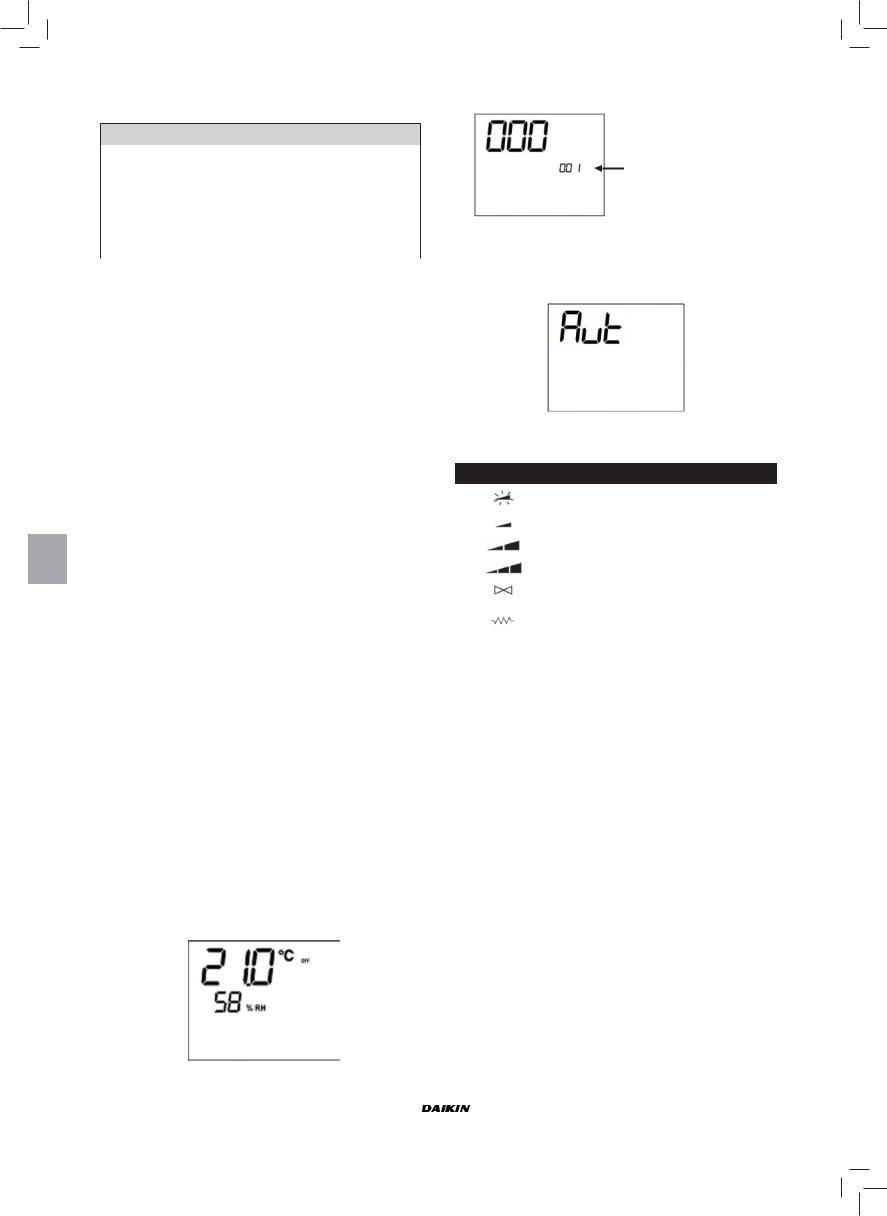
PROCEDURA DI AUTODIAGNOSI
Tale procedura permette di verificare il corretto funzionamento delle singole uscite del comando stesso.
Per eseguire tale procedura seguire le indicazioni sotto riportate:
■ Mettere in Off il termostato
■ Premere contemporaneamente i tasti 

livello 001: Inserimento password
■Utilizzare i tasti  per modificare il valore del display fino al valore di password per la autodiagnosi (030) e premere
  .
.
Verrà visualizzata la seguente schermata:
■Premere il tasto  per accendere in successione le varie uscite del termostato.
|
Simbolo |
Azionamento |
Morsetti |
|
Velocità superminima |
N-V0 |
|
|
Velocità minima |
N-V1 |
|
|
Velocità media |
N-V2 |
|
|
Velocità massima |
N-V3 |
|
|
Valvola |
N-Vc |
|
|
Resistenza |
N-Vh |
|
|
Seconda valvola |
||
|
nessun simbolo |
Nessuna uscita attiva |
|
È possibile verificare, una ad una, le uscite del controllo elettronico osservando il relativo componente (valvola, ventilatore..) o verificando la presenza di una tensione di 230 V ai morsetti corrispondenti.
■premere il tasto  per uscire dalla procedura di autodiagnosi (dopo alcuni minuti il termostato uscirà automaticamente comunque).
|
Manuale d’installazione e d’uso |
FWEC2 |
|||||||
|
10 |
Advanced electronic controller |
|||||||
|
FC66002764 |
||||||||

SCHEDA ELETTRONICA (VEDI FIGURA 6)
Dove
|
Vc |
Valvola |
|
Vh |
Valvola Caldo / Resistenza |
|
V0 |
Vel.superminima |
|
V1 |
Vel. minima |
|
V2 |
Vel. media |
|
V3 |
Vel. massima |
|
N |
Neutro |
|
L |
Fase |
|
PE |
Terra |
|
A-B-GND |
RS 485 |
|
SU |
Sonda umidità remota |
|
SW |
Sonda acqua |
|
SA |
Sonda aria remota |
|
DI1 |
Ingresso dig.1 |
|
CI12 |
Comune DI1-2 |
|
DI2 |
Ingresso dig.2 |
NB:
■Per collegamenti di potenza utilizzare cavo sezione 1 mm2
■Per ingressi digitali utilizzare cavo tipo AWG 24
■Per prolungamenti sonde e RS485 utilizzare cavo schermato tipo AWG 24
SCHEMI ELETTRICI
(Vedi allegato Schemi Elettrici)
Tabella Unità/Schemi
|
UNITA’ |
TIPO |
CONFIGURAZIONE |
SCHEMA |
|
|
FWL-M-V |
— |
1-2-3-13-14-15-25-26-27-31-32-33 |
FC66002554 |
|
|
7-8-9-19-20-21-37 |
FC66002555 |
|||
|
FWB |
— |
4-5-6-16-17-18-28-29-30-34-35-36 |
UT66000887 |
|
|
10-11-12-22-23-24-38 |
UT66000890 |
|||
|
04/12 |
1-2-3-13-14-15-25-26-27-31-32-33 |
UT66000889 |
||
|
7-8-9-19-20-21-37 |
UT66000892 |
|||
|
FWD |
06/12 3PH |
7-8-9-19-20-21-37 |
UT66000894 |
|
|
16/18 |
1-2-3-13-14-15-25-26-27-31-32-33 |
UT66000888 |
||
|
7-8-9-19-20-21-37 |
UT66000891 |
|||
|
16/18 3PH |
7-8-9-19-20-21-37 |
UT66000893 |
||
|
FWL-M-V |
— |
|||
|
EPIMSB6 |
FWB |
— |
FC66002557 |
|
|
FWD |
— |
|||
SCHEMI ELETTRICI
(Vedi allegato Schemi Elettrici)
Tabella Configurazioni/Schemi
|
CONFIG. |
UNITA’ |
SCHEMA |
|||
|
FWL-M-V |
FC66002554 (1) |
||||
|
01-02-03 |
FWD |
UT66000889 (6) |
|||
|
UT66000888 (5) |
|||||
|
04-05-06 |
FWB |
UT66000887 (4) |
|||
|
FWL-M-V |
FC66002555 (2) |
||||
|
UT66000892 (9) |
|||||
|
07-08-09 |
FWD |
UT66000894 (11) |
|||
|
UT66000891 (8) |
|||||
|
UT66000893 (10) |
|||||
|
10-11-12 |
FWB |
UT66000890 (7) |
|||
|
FWL-M-V |
FC66002554 (1) |
||||
|
13-14-15 |
FWD |
UT66000889 (6) |
|||
|
UT66000888 (5) |
|||||
|
16-17-18 |
FWB |
UT66000887 (4) |
|||
|
FWL-M-V |
FC66002555 (2) |
||||
|
UT66000892 (9) |
|||||
|
19-20-21 |
FWD |
UT66000894 (11) |
|||
|
UT66000891 (8) |
|||||
|
UT66000893 (10) |
|||||
|
22-23-24 |
FWB |
UT66000890 (7) |
|||
|
FWL-M-V |
FC66002554 (1) |
||||
|
25-26-27 |
FWD |
UT66000889 (6) |
|||
|
UT66000888 (5) |
|||||
|
28-29-30 |
FWB |
UT66000887 (4) |
|||
|
FWL-M-V |
FC66002554 (1) |
||||
|
31-32-33 |
|||||
|
FWD |
UT66000889 (6) |
||||
|
UT66000888 (5) |
|||||
|
34-35-36 |
FWB |
UT66000887 (4) |
|||
|
FWL-M-V |
FC66002555 (2) |
||||
|
UT66000892 (9) |
|||||
|
37 |
FWD |
UT66000894 (11) |
|||
|
UT66000891 (8) |
|||||
|
UT66000893 (10) |
|||||
|
38 |
FWB |
UT66000890 (7) |
|||
|
FWEC2 |
Manuale d’installazione e d’uso |
|
Advanced electronic controller |
11 |
|
FC66002764 |

SCHEMI ELETTRICI
Legenda dei simboli degli schemi elettrici:
|
Vo |
Velocità Superminima |
|||
|
V1 |
Velocità Minima |
|||
|
V2 |
Velocità Media |
|||
|
V3 |
Velocità Massima |
|||
|
L |
Fase |
|||
|
PE |
Terra |
|||
|
N |
Neutro |
|||
|
RE |
Resistenza Elettrica |
|||
|
SW |
Sonda Acqua |
|||
|
SA |
Sonda Aria |
|||
|
SU |
Sonda Umidità |
|||
|
BK |
Nero (Vel. Massima) |
|||
|
BU |
Blu (Vel. Media) |
|||
|
RD |
Rosso(Vel. Superminima/Minima) |
|||
|
WH |
Bianco (comune) |
|||
|
GY |
Grigio |
|||
|
BN |
Marrone (Vel Minima) |
|||
|
GN |
Verde |
|||
|
YE |
Giallo |
|||
|
MS |
Microinterruttore Flap |
|||
|
DI1 |
Ingresso digitale 1 |
|||
|
DI2 |
Ingresso digitale 2 |
|||
|
CI12 |
Comune ingressi digitali |
|||
|
A/B/GND |
RS 485 |
|||
|
F |
Fusibile (non fornito) |
|||
|
IL |
Interruttore di linea (non fornito) |
|||
|
CN |
Morsettiera Terminale |
|||
|
RHC |
Selettore remoto Riscald./Raffredd. |
|||
|
EXT |
Contatto ON OFF remoto |
|||
|
EPIMSB6 |
Scheda di potenza per gestire 4 terminali |
|||
|
EPIB6 |
Scheda di potenza per unità tipo FWD |
|||
|
M |
Motore Ventilatore |
|||
|
VHC |
Valvola solenoide Raffr./Risc. |
|||
|
VC |
Valvola solenoide Raffreddamento |
|||
|
VH |
Valvola solenoide Riscaldamento |
|||
|
TSA |
Termostato di sicurezza automatico |
|||
|
TSM |
Termofusibile di sicurezza |
|||
|
SC |
Scatola cablaggi |
|||
|
….. |
Collegamenti elettrici a cura dell’installatore |
|||
|
ECONOMY |
Selettore remoto COMFORT / ECONOMY |
|||
INSTALLAZIONE COMANDO A PARETE
NB: per l’installazione del comando a parete è consigliabile l’utilizzo di una scatola elettrica, dietro al comando, per l’alloggiamento dei cavi.
NB: prima dell’installazione rimuovere, con cautela, la pellicola protettiva del display; la rimozione della pellicola può provocare la comparsa di aloni scuri sul display che scompaiono dopo alcuni secondi e non sono indice di difettosità del comando.
ISTRUZIONI PER IL MONTAGGIO A PARETE
1.Togliere la vite di chiusura del comando (FIGURA 8).
2.In caso di utilizzo di una scatola da incasso portafrutti 503, passare i cavi attraverso la feritoia della base del comando ed utilizzare per il fissaggio gli appositi fori.
3.Altrimenti forare la parete dove si vuole installare il comando, in corrispondenza delle asole di fissaggio (5 x 8 mm) poste nella base del comando; passare i cavi attraverso la feritoia della base e fissarla con delle viti alla parete (precedentemente forata) (FIGURA 9).
4.Eseguire i collegamenti elettrici sulla morsettiera del terminale seguendo lo schema elettrico relativo.
5.Richiudere il comando utilizzando la vite tolta nel punto 1.
DATI TECNICI
|
90-250Vac 50/60Hz |
||
|
Alimentazione |
Potenza 8W |
|
|
Fusibile di protezione: 500mA ritardato |
||
|
Temp. Funzionamento |
Range 0-50°C |
|
|
Temp. Stoccaggio |
Range -10-60°C |
|
|
Normal Open 5A @ 240V (Resistivo) |
||
|
Relè |
Isolamento: distanza bobina-contatti 8mm |
|
|
4000V dielettrico bobina-relè |
||
|
Temperatura ambiente max.: 105°C |
||
|
Connettori |
250V 10A |
|
|
Contatto pulito |
||
|
Ingressi digitali |
Corrente di chiusura 2mA |
|
|
Max resistenza di chiusura 50 Ohm |
||
|
Ingressi analogici |
Sonde di Temperatura ed umidità relativa |
|
|
Uscite di potenza |
Relè (vedi sopra) |
|
|
Sonde di Temperatura |
Sonde NTC 10K Ohm @25°C |
|
|
Range -25-100°C |
||
|
Sonde di umidità |
Sonda di tipo resistive |
|
|
Range 20-90%RH |
||
|
Manuale d’installazione e d’uso |
FWEC2 |
|
12 |
Advanced electronic controller |
|
FC66002764 |
|
FWEC2 |
Advanced electronic controller |
Installation and operation manual
GENERAL CHARACTERISTICS
LCD controller has been designed to manage the operation of indoorunitswithsingle-phasemultispeed asynchronousmotor. Compared to the standard model it has the added features of advanced humidity control and serial communication.
This controller allows to set (figure 1) up a Master-Slave system (up to 247 slave terminals), in which one of the Microprocessor controllers plays the role of Master and controls all of the other slave elements.
In this case as well the connection is made via an RS485 bus, consisting of a simple shielded 2-conductor cable.
The master (identified by the address 255) sends the following information to the slave controllers:
(1)Operating mode (Cooling or Heating)
(2)Setpoint for room temperature.
The speed selector of each slave controller remains enabled and the room temperature can be adjusted within a range of
± 2°C around the setpoint value transmitted by the master controller.
MAIN FUNCTIONS AND FEATURES:
■Air temperature adjustment through automatic variation of fan speed;
■Regulation of air temperature via fan on-off control (fan runs at a fixed speed),
■Control of On-Off valves for two or four-pipe systems
■Control of electrical heater for auxiliary heating.
■Cooling/heating switching in the following modes:
—local manual switching
—remote, manual (centralised);
—automatic, depending on water temperature
—automatic, depending on air temperature
■Dehumidify Function
■Serial Communication
ADDITIONAL FEATURES INCLUDE:
■no-voltage contact for external activation (e.g. window contact, remote ON/OFF, occupancy sensor, etc.) which may enable or disable unit operation (contact logic: see circuit board configuration parameters).
■no-voltage contact for centralised remote Cooling/Heating changeover (contact logic: see circuit board configuration parameters).
■no-voltage contact for remote enabling of the economy mode (contact logic: see circuit board configuration parameters).
■remote water temperature probe (accessory FWTSKAA)
■built-in temperature probe
■built-in humidity probe
■remote air temperature probe (accessory FWTSKAA) (this probe, if present, is used in place of the internal one for the measurement of room temperature).
■Remote humidity probe (accessory FWHSKAA — to be used in combination with the remote temperature probe)
The control panel is composed of:
■LCD display
■key board
LCD DISPLAY (SEE FIGURE 2)
(1)room temperature
(2)room humidity
(3)set temperature
|
ON |
fan status. When flashing it indicates that fans are |
||
|
off standing for a call from the thermostat. If the |
|||
|
symbol is steadily lit it means that the fans are |
|||
|
running |
|||
|
OFF |
fan status. Fans are off as speed is set to Off or |
||
|
the control is off. |
|||
|
AUTO |
automatic ventilation logic |
||
|
fan speed |
|||
|
operation mode: Cooling. When flashing it indicates |
|||
|
that water circuit is not enabled to fan ventilation. |
|||
|
operation mode: Heating. When flashing it indicates |
|||
|
that water circuit is not enabled to fan ventilation. |
|||
|
Dehumidification. When flashing it indicates that |
|||
|
the circuit is not enabled to dehumidification. If the |
|||
|
symbol is steadily lit it means that the function is |
|||
|
active. |
|||
|
Economy option enabled |
|||
|
Alarm triggered |
|||
|
Minimum Temperature Control |
|||
|
valve open |
|||
|
electrical heater: If the symbol flashes it means that |
|||
|
the electrical heater is on; if steadily lit it means only |
|||
|
that the electrical heater has been selected |
|||
|
serial communication active. The flashing symbol |
|||
|
indicates that the controller is the master |
|||
KEY BOARD (SEE FIGURE 3)
On/Off key: Thermostat On/Off. During the procedure of parameter modification, it permits to return to normal operating conditions
Up and Down keys: changing of thermostat setting temperature (Heating:[5.0-30.0°C], Cooling: [10.0-35.0°C]). During the procedure of parameter modification, they are used to select the parameters or to change their value
SEL key: in the heating mode, the electrical heater element can be selected as auxiliary function
Mode key: selection of Heating/Cooling operating mode
Fan key: selection of operating speed
EC key: selection of Economy mode
|
FWEC2 |
Installation and operation manual |
|||||||
|
Advanced electronic controller |
1 |
|||||||
|
FC66002764 |
||||||||
|
ACTIVE KEY COMBINATIONS |
PARAMETER CONFIGURATION PROCEDURE |
With OFF thermostat: access to the parameter configuration procedure
With ON thermostat: display of current water temperature
Selection of Minimum air temperature function
Selection of dehumidify option
BOARD CONFIGURATION
The board can be configured according to the type of unit/ system to be governed by changing some parameters.
PARAMETER LIST
■P00 = controller configuration (see “Available configurations”) to select the type of unit to be managed.
■P01 = type of controller installation —000: on the unit
—001: wall mounted
■P02 = Modbus address (in order for the change in this parameter to become active (excepting in the case of internaltransferbetweenvalues,itisnecessarytoswitchthe power off and back on again at the end of programming) —0: serial communication disabled
—1-247: slave —255: master
■P03 = neutralzone[20-50°C/10];parameterusedincaseof configurations with automatic cooling/heating changeover according to air temperature.
■P04 = water sensor —0: not available
—1: available
Based on the set value, the sensor alarm and the electrical heater functions will be controlled
■P05 = Configuration logic for use of digital inputs 1 and 2:
|
— |
0: |
DIN1 = — |
DIN2 |
= — |
|
— |
1: |
DIN1 = — |
DIN2 |
= OnOff |
—2: DIN1 = Sum/Win DIN2 = —
—4: DIN1 = Sum/Win DIN2 = On/Off
|
— 5: DIN1 = Eco |
DIN2 = On/Off |
—6: DIN1 = Sum/Win DIN2 = Eco
■P06 = logic for use of digital input 1:
—0: [open/closed] = [Cooling/Heating] = [-/ECO]
—1: [open/closed] = [Heating/Cooling] = [ECO/-]
■P07 = logic for use of digital input 2:
—0: [open/closed] = [OFF/ON] = [-/ECO]
—1: [open/closed] = [On/Off] = [ECO/-]
■P08 = Remote humidity sensor
—0 : not available
—1 : available
Based on the set value, the associated probe alarm will be triggered accordingly.
■ Switch the thermostat OFF
|
■ Push the |
keys at the same time |
level indication: 001= password entry
■Use keys  to modify the display value up to the password value “10”, and press
  .
.
If it is correct, you will have access to the parameters
|
Value of selected |
|||||
|
parameter |
level indication : |
||||
|
Selected |
002= parameter |
||||
|
selection |
|||||
|
parameter |
|||||
|
P… |
■Use keys  to scroll the various parameters (see “Parameter list” described above)
■Press  to confirm the parameter change (the value will start flashing)
level indication:
003 = edit parameter
■use keys  to change the value
■Press  to save the new value setting or
  to cancel the modification
■After completing the modification of the parameters con-
cerned press key  to exit the procedure
N.B.: the parameter configuration phase is of limited duration. Once a certain time has elapsed (around 2 minutes) the thermostat will switch back into the Off status and only the saved changes will be retained.
|
Installation and operation manual |
FWEC2 |
|||||||
|
2 |
Advanced electronic controller |
|||||||
|
FC66002764 |
||||||||

AVAILABLE CONFIGURATIONS (PARAMETER P00)
The LCD controller can be configured in various ways according to the type of system. Various configurations can be obtained through the P00 parameter (see configuration procedure of controller parameters).
001
■System pipes: 2
■Valve: NO
■Electrical heater: NO
■Fan speed: 3
■Summer/winter switching logic: LOCAL MANUAL
002
■System pipes: 2
■Valve: NO
■Electrical heater: NO
■Fan speed: 3
■Summer/winter switching logic: REMOTE MANUAL
003
■System pipes: 2
■Valve: NO
■Electrical heater: NO
■Fan speed: 3
■Summer/winter switching logic: AUTOMATIC WATER SIDE
004
■System pipes: 2
■Valve: NO
■Electrical heater: NO
■Fan speed: 4
■Summer/winter switching logic: LOCAL MANUAL
005
■System pipes: 2
■Valve: NO
■Electrical heater: NO
■Fan speed: 4
■Summer/winter switching logic: REMOTE MANUAL
006
■System pipes: 2
■Valve: NO
■Electrical heater: NO
■Fan speed: 4
■Summer/winter switching logic: AUTOMATIC WATER SIDE
007
■System pipes: 2
■Valve: NO
■Electrical heater: YES
■Fan speed: 3
■Summer/winter switching logic: LOCAL MANUAL
008
■System pipes: 2
■Valve: NO
■Electrical heater: YES
■Fan speed: 3
■Summer/winter switching logic: REMOTE MANUAL
009
■System pipes: 2
■Valve: NO
■Electrical heater: YES
■Fan speed: 3
■Summer/winter switching logic: AUTOMATIC AIR SIDE
010
■System pipes: 2
■Valve: NO
■Electrical heater: YES
■Fan speed: 4
■Summer/winter switching logic: LOCAL MANUAL
011
■System pipes: 2
■Valve: NO
■Electrical heater: YES
■Fan speed: 4
■Summer/winter switching logic: REMOTE MANUAL
012
■System pipes: 2
■Valve: NO
■Electrical heater: YES
■Fan speed: 4
■Summer/winter switching logic: AUTOMATIC AIR SIDE
013
■System pipes: 2
■Valve: 2-3 WAYS
■Electrical heater: NO
■Fan speed: 3
■Summer/winter switching logic: LOCAL MANUAL
014
■System pipes: 2
■Valve: 2-3 WAYS
■Electrical heater: NO
■Fan speed: 3
■Summer/winter switching logic: REMOTE MANUAL
015
■System pipes: 2
■Valve: 2-3 WAYS
■Electrical heater: NO
■Fan speed: 3
■Summer/winter switching logic: AUTOMATIC WATER SIDE
016
■System pipes: 2
■Valve: 2-3 WAYS
■Electrical heater: NO
■Fan speed: 4
■Summer/winter switching logic: LOCAL MANUAL
017
■System pipes: 2
■Valve: 2-3 WAYS
■Electrical heater: NO
■Fan speed: 4
■Summer/winter switching logic: REMOTE MANUAL
|
FWEC2 |
Installation and operation manual |
|||||||
|
Advanced electronic controller |
3 |
|||||||
|
FC66002764 |
||||||||

AVAILABLE CONFIGURATIONS (PARAMETER P00)
018
■System pipes: 2
■Valve: 2-3 WAYS
■Electrical heater: NO
■Fan speed: 4
■Summer/winter switching logic: AUTOMATIC WATER SIDE
019
■System pipes: 2
■Valve: 3 WAYS
■Electrical heater: YES
■Fan speed: 3
■Summer/winter switching logic: LOCAL MANUAL
020
■System pipes: 2
■Valve: 3 WAYS
■Electrical heater: YES
■Fan speed: 3
■Summer/winter switching logic: REMOTE MANUAL
021
■System pipes: 2
■Valve: 3 WAYS
■Electrical heater: YES
■Fan speed: 3
■Summer/winter switching logic: AUTOMATIC AIR SIDE
022
■System pipes: 2
■Valve: 3 ways
■Electrical heater: YES
■Fan speed: 4
■Summer/winter switching logic: LOCAL MANUAL
023
■System pipes: 2
■Valve: 3 WAYS
■Electrical heater: YES
■Fan speed: 4
■Summer/winter switching logic: REMOTE MANUAL
024
■System pipes: 2
■Valve: 3 WAYS
■Electrical heater: YES
■Fan speed: 4
■Summer/winter switching logic: AUTOMATIC AIR SIDE
025
■System pipes: 4
■Valve: NO
■Electrical heater: NO
■Fan speed: 3
■Summer/winter switching logic: LOCAL MANUAL
026
■System pipes: 4
■Valve: NO
■Electrical heater: NO
■Fan speed: 3
■Summer/winter switching logic: REMOTE MANUAL
027
■System pipes: 4
■Valve: NO
■Electrical heater: NO
■Fan speed: 3
■Summer/winter switching logic: AUTOMATIC AIR SIDE
028
■System pipes: 4
■Valve: NO
■Electrical heater: NO
■Fan speed: 4
■Summer/winter switching logic: LOCAL MANUAL
029
■System pipes: 4
■Valve: NO
■Electrical heater: NO
■Fan speed: 4
■Summer/winter switching logic: REMOTE MANUAL
030
■System pipes: 4
■Valve: NO
■Electrical heater: NO
■Fan speed: 4
■Summer/winter switching logic: AUTOMATIC AIR SIDE
031
■System pipes: 4
■Valve: 2-3 WAYS
■Electrical heater: NO
■Fan speed: 3
■Summer/winter switching logic: LOCAL MANUAL
032
■System pipes: 4
■Valve: 2-3 WAYS
■Electrical heater: NO
■Fan speed: 3
■Summer/winter switching logic: REMOTE MANUAL
033
■System pipes: 4
■Valve: 2-3 WAYS
■Electrical heater: NO
■Fan speed: 3
■Summer/winter switching logic: AUTOMATIC AIR SIDE
034
■System pipes: 4
■Valve: 2-3 WAYS
■Electrical heater: NO
■Fan speed: 4
■Summer/winter switching logic: LOCAL MANUAL
035
■System pipes: 4
■Valve: 2-3 WAYS
■Electrical heater: NO
■Fan speed: 4
■Summer/winter switching logic: REMOTE MANUAL
|
Installation and operation manual |
FWEC2 |
|
4 |
Advanced electronic controller |
|
FC66002764 |
![]()
AVAILABLE CONFIGURATIONS (PARAMETER P00)
036
■System pipes: 4
■Valve: 2-3 WAYS
■Electrical heater: NO
■Fan speed: 4
■Summer/winter switching logic: AUTOMATIC AIR SIDE
037
■System pipes: 4
■Valve: NO
■Electrical heater: YES
■Fan speed: 3
■Summer/winter switching logic: LOCAL MANUAL
038
■System pipes: 4
■Valve: NO
■Electrical heater: YES
■Fan speed: 4
■Summer/winter switching logic: LOCAL MANUAL
SERIAL COMMUNICATION
Connection to the RS485 communication network
The communication network (bus type) relies on a simple shielded 2-conductor cable, directly connected to the RS485 serial ports of the controllers (terminals A, B and GND).
“For the network use a cable AWG 24 (diam. 0.511 mm)”
The communication network must have the following general structure (figure 4).
In the case of the “MASTER-SLAVE” solution a termination resistor will have to be installed on both controllers at the furthest ends of the network.
N.B.: (1) Comply with the polarity of the connection: indicated with A(-) and B(+)
(2) Ground shield at one end only
____________________________________________________________
WARNING:
■Use a shielded cable AWG24
■Colours suggested for the communication
network: A (-) Brown ; B (+) Yellow
____________________________________________________________
LOGICS
COOLING/HEATING SWITCHING
Four logics are present to select the thermostat operating modes according to the controller configuration setting:
1.Local: user choice made through the key 
2.Distance:dependingontheDigitalInputDI1status(contact logic: see configuration parameters of board)
3.Depending on water temperature
Summer
Winter
Water temp.
N.B.: in case of water sensor alarm, the controller returns to the Local mode temporarily.
4. depending on air temperature
Summer
Winter
Air temp.
Where:
■Set is the temperature setting made by the arrows
■ZN is the neutral zone (parameter P03)
The thermostat operating mode is indicated on the display by the symbols  (cooling) and
  (heating)
FAN SPEED CONTROL
The controller can govern 3 or 4-speed indoor units
OPERATING SPEED SELECTION
Using Fan key  it is possible to select the following speeds:
■Automatic ventilation: depending on the set temperature and the room air temperature
With 3-speed configurations  : where:
1 = low speed
2 = medium speed
3 = maximum speed
COOLING
HEATING
|
FWEC2 |
Installation and operation manual |
|||||||
|
Advanced electronic controller |
5 |
|||||||
|
FC66002764 |
||||||||
With 4-speed configurations  : where:
sm = extra-low speed 1 = low speed
2 = medium speed
3 = maximum speed
COOLING
Air temp.
HEATING
Air temp.
N.B.: in case of 4-speed configuration and valve, ventilation in heating mode is shifted by 0.5°C to permit a natural convection phase
■Speed disabled: Can be selected only in heating mode and with 4-speed configuration only. The indoor unit operates by natural convection only.
|
■ |
Extra low speed: can be selected only with |
|
|
4-speed configuration. It works at extra low |
||
|
speed only. |
||
|
■ |
Low speed |
|
|
■ |
Medium speed |
|
|
■ |
High speed |
N.B.: In the case of fixed speed, the fan on/off logic will be equivalent to the automatic logic.
WATER CONTROL
The ventilation operation depends on the system water temperature control. Based on the operation mode, different heating or cooling thresholds will be enabled.
COOLING
NO
Water temp.
HEATING
NO
Water temp.
Upon a call of the thermostat, the absence of the enabling signal will be indicated on the display by the flashing of the
symbol representing the active mode ( or
or  ) The enabling signal is ignored:
■if the water sensor is not included (P04 = 0) or in alarm status because disconnected
■in the cooling mode with 4-pipe configurations
LOGICS
FORCED OVERRIDES
The normal fan operating logic will be ignored in particular override situations that may be necessary to ensure correct control of the temperature or the unit’s operation. This may occur:
in the cooling mode:
■on-board controller (P01 = 0) and configurations with valve: the minimum speed available will be maintained even once the temperature has been reached.
■on-board controller and valveless configurations: every 10 minutes in which the fan remains idle a 2 minute fan rotation is carried out at medium speed to enable the air sensor to read the room temperature more accurately.
In the heating mode
■while the electrical heater is on: the fan is forced to run at medium speed
■once the electrical heater has gone off: a 2 minute postventilation cycle will be run at medium speed. (N.B.: this cycle will be completed even if the thermostat is switched off or in the event of a changeover to the cooling mode)
DISPLAY
The display shows the fan status
■On flashing: fan in standby mode
■On steadily lit: fan on
■OFF: fan disabled to operate by natural convection only
and fan speed (with indication of “automatic” logic if proper) enabled or selected (in case of stand-by fan)
|
■ |
Extra low speed |
|
■ |
Low speed |
|
■ |
Medium speed |
■High speed
N.B.: if the active speed is different from the one selected by the user (in the case of a forced override), pressing the
button  Fan the selected speed will be displayed; pressing again will change this setting.
|
Installation and operation manual |
FWEC2 |
|||||||
|
6 |
Advanced electronic controller |
|||||||
|
FC66002764 |
||||||||
VALVE
The controller can manage 2 or 3-way On/OFF type valves, with 230V voltage.
OPENING
The valve opening is controlled according to the operating setpoint and air temperature setpoint
COOLING
Air temp.
HEATING
Air temp.
WATER CONTROL
The checking of water temperature to enable valve opening is a function that concerns only configurations with 3-way valves and electrical heater.
In such configurations the water temperature will be checked in the following cases:
■Heating with electrical heater: operation of the electrical heater will force the fan to switch on; it is therefore necessary to prevent excessively cold water from passing through the unit.
Water temp.
■Post-ventilation due to switching off of the electrical heater: this function will be maintained until the set time has elapsed, even if the operating mode is changed. During post-ventilation the water temperature enabling signal will coincide with the one seen for fan operation.
DISPLAY
The active valve indication on the display will be shown by the symbol 
ELECTRICAL HEATER
The electrical heater is a device used where necessary in the heating mode.
SELECTION
If provided for in the configuration, the electrical heater can be selected in the heating mode by pressing the Sel  key
key
ACTIVATION
Air temp.
If the electrical heater is selected by the user, it will be activated on a call from the thermostat based on the room temperature
N.B.: switching it on will force the fan on as well
WATER CONTROL
Enabling of the electrical heater is tied to the water temperature. The related enabling logic is described below
The enabling signal will not be given if the water sensor is either not present or disconnected
HEATING
ON
OFF
Water temp.
DISPLAY
The display will show the following information
■electrical heater selected by the user:  steadily symbol
■active electrical heater:  flashing symbol
ECONOMY
The Economy function corrects the setpoint by 2.5°C and forces the fan to run at the minimum available speed to reduce unit operation.
■Cooling: setpoint + 2.5°C
■Heating: setpoint -2.5°C
ACTIVATION
This function can be activated by pressing the key 
DISPLAY
The Economy function is shown on the display by the symbol 
MINIMUM TEMPERATURE CONTROL
This logic makes it possible to keep the room temperature from falling too far when the thermostat is off by forcing the unit into the heating mode if necessary and for the time required.
If the electrical heater is present, it will be used only if it was previously selected as a resource in the heating mode.
SELECTION
When the thermostat is off, you can select the minimum temperature control by pressing at the same time the keys

 .
.
The same key combination disables this function.
ACTIVATION
If this control is selected, the unit will switch on when the room temperature falls below 9°C.
Air temp.
|
FWEC2 |
Installation and operation manual |
|||||||
|
Advanced electronic controller |
7 |
|||||||
|
FC66002764 |
||||||||

When temperature exceeds 10°C the thermostat will resume the Off status.
N.B.: Any Off command from digital input will disable this logic
DISPLAY
The display shows the following information
■Minimum temperature control selected: symbol 
■Minimum temperature control enabled: DEFR
DEHUMIDIFICATION
The dehumidification function, enabled only in the cooling mode, activates operation of the indoor unit in order to achieve a 10% reduction in the level of humidity present in the room at the time the function itself was selected.
SELECTION
Dehumidification can be selected/unselected in the Cooling
mode by simultaneously pressing the 
 buttons. If the water probe (P04=0) or the remote humidity probe is not available, in cases where the controller is installed directly on the unit (P08=0), selection will not be enabled. If selected, the dead band for automatic switching on the air side will be brought to 5°
LOGIC
Once selected, the dehumidification logic sets the target humidity level as the humidity present at the time the function was selected minus 10%. Where the room humidity is less than 40% the target level will be set at 30%.
The fan will be forced to run at low speed or, if the temperature is much higher than the setpoint, at medium speed.
Med. speed
Min. speed
In order to bring the humidity to the set value, the fan (and valve, if present) will be activated even if the room temperature has already reached the programmed setpoint (indicated on the display by the symbol 3). Should the room temperature fall too far below this threshold, the logic will be temporarily inhibited.
Inhibited
Air temp.
WATER CONTROL
Enabling of the dehumidification function is tied to the water temperature. The related enabling logic is described below
Water temp.
If enabling conditions do not exist, the dehumidification function will be temporarily inhibited.
The same will occur in the event that the probe is disconnected.
N.B.: once the target level of humidity is reached or the controller is switched off, the dehumidify option will be unselected
DISPLAY
The display shows the following information:
■ Dehumidification ON: symbol lit 
■ Dehumidification temporarily inhibited: flashing symbol
ALARMS
This control manages two types of alarms:
■Serious Alarms: cause the forced switching off of the thermostat
■Non-serious Alarms: do not cause the forced switching off of the thermostat, but disable possible critical functions
SERIOUS ALARMS
Alarm code
■Code A01= error of external air temperature sensor (in case of on-board thermostat)
■CodeA02= error of internal air temperature sensor (in case of wall mounted thermostat and disconnected external air temperature sensor)
|
Installation and operation manual |
FWEC2 |
|||||||
|
8 |
Advanced electronic controller |
|||||||
|
FC66002764 |
||||||||
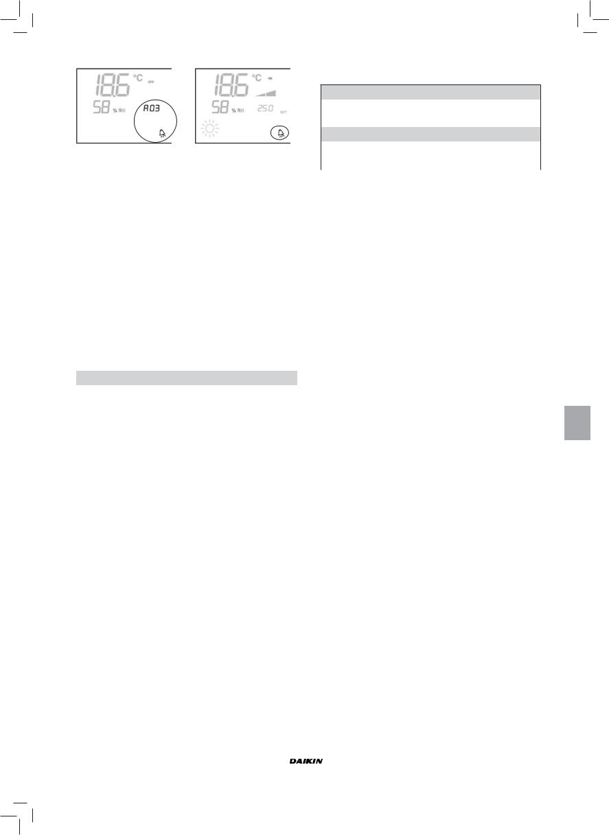
NON-SERIOUS ALARMS
|
Thermostat OFF |
Thermostat ON |
■Code A03 = water sensor error
■Code A04 = remote humidity probe error (only if a remote temperature probe is installed)
■Code A05 = internal humidity probe error
N.B.: the alarm code is displayed only when the thermostat is switched off
MODBUS
The protocol implemented in the controller is Modbus RTU (9600, N, 8, 2) on RS485
FUNCTIONS IMPLEMENTED
■0x03 : Read Holding Registers
■0x04 : Read Input Registers
■0x10 : Write Multiple registers
EXCEPTIONS IMPLEMENTED
Exception Code 02: Invalidate data address
LIST OF SUPERVISION PARAMETERS
|
ADDRESS |
REGISTER |
TYPE |
U.M. |
|
0 |
Status |
R |
— |
|
1 |
Speeds |
R |
— |
|
2 |
Air temperature |
R |
[°C/10] |
|
3 |
Humidity |
R |
% |
|
4 |
Water temperature |
R |
[°C/10] |
|
5 |
P00:Configuration |
R |
— |
|
6 |
P05:Config. DIN |
R |
— |
|
7 |
T. Active setpoint |
R |
[°C/10] |
|
8 |
T. User setpoint |
R |
[°C/10] |
|
9 |
LCD version |
R |
— |
|
50 |
Digital 1 |
R/W |
— |
|
51 |
— |
R/W |
— |
|
52 |
Setpoint — Cooling |
R/W |
[°C/10] |
|
53 |
Setpoint — Heating |
R/W |
[°C/10] |
|
54 |
Minimum Setpoint – Cool. |
R/W |
[°C/10] |
|
55 |
Maximum Setpoint – Cool. |
R/W |
[°C/10] |
|
56 |
Minimum Setpoint – Heat. |
R/W |
[°C/10] |
|
57 |
Maximum Setpoint – Heat. |
R/W |
[°C/10] |
|
58 |
Speeds |
R/W |
— |
|
59 |
Economy Correction |
R/W |
[°C/10] |
DESCRIPTION OF READ-ONLY REGISTERS [R]
■ “Staus” “REGISTER”
H
|
Bit 15 |
Bit 14 |
Bit 13 |
Bit 12 |
Bit 11 |
Bit 10 |
Bit 9 |
Bit 8 |
|
— |
— |
P04 |
Deum |
P06 |
P07 |
DI2 |
DI1 |
L
|
Bit 7 |
Bit 6 |
Bit 5 |
Bit 4 |
Bit 3 |
Bit 2 |
Bit 1 |
Bit 0 |
|
Vh |
Vc |
Alarm |
MinT |
Eco |
P01 |
S/W |
On/Off |
—On/Off: unit status (0: Off, 1=On)
—S/W: operation mode (0: S=cooling,1:W=heating)
—P01: “on unit/wall-mounted” parameter
—Eco: Economy logic active
—Min.T: Minimum Temperature logic selected
—Alarm: general alarm indication (activated when any of the managed alarms is triggered)
—Vc: status of digital output Vc
—Vh: status of digital output Vh
—DI1: logical value of dig. input 1 (the physical status of the input depends on the associated logic)
—DI2: logical value of dig. input 2 (the physical status of the input depends on the associated logic)
—P07: “DIN 2 Logic” parameter
—P06: “DIN 1 Logic” parameter
—Dehum: dehumidification ON (0:no, 1:yes)
—P04: “water probe present” parameter
■“SPEED” REGISTER: current operating speed of the indoor unit
—0: fan OFF
—1: extra-low speed
—2: low speed
—3: medium speed
—4: high speed
■“AIR TEMPERATURE” REGISTER: room temperature read by the controller and shown on the display (N.B.: this temperature corresponds to the reading of the remote probe if the controller is located on the unit, or the reading of the internal probe in the case of a wall-mounted controller and remote probe disconnected)
■“HUMIDITY” REGISTER: room humidity read by the controller via the probe associated with the temperature probe used
■“WATER TEMPERATURE” REGISTER: value read by the water probe (SW)
■“P00” Register: “Controller configuration” parameter
■“T. ACTIVE SETPOINT” Register: setpoint used for temperature control
■“T. USER SETPOINT” Register: setpoint programmed by the user (it may differ from the active setpoint due to corrections based on economy logics,…or use of the setpoint imposed by the supervision software)
■“LCD VERSION” Register : defines the controller type and software version installed (0xHHSS: HH: ASCII character, SS:sw version)
|
FWEC2 |
Installation and operation manual |
|||||||
|
Advanced electronic controller |
9 |
|||||||
|
FC66002764 |
||||||||
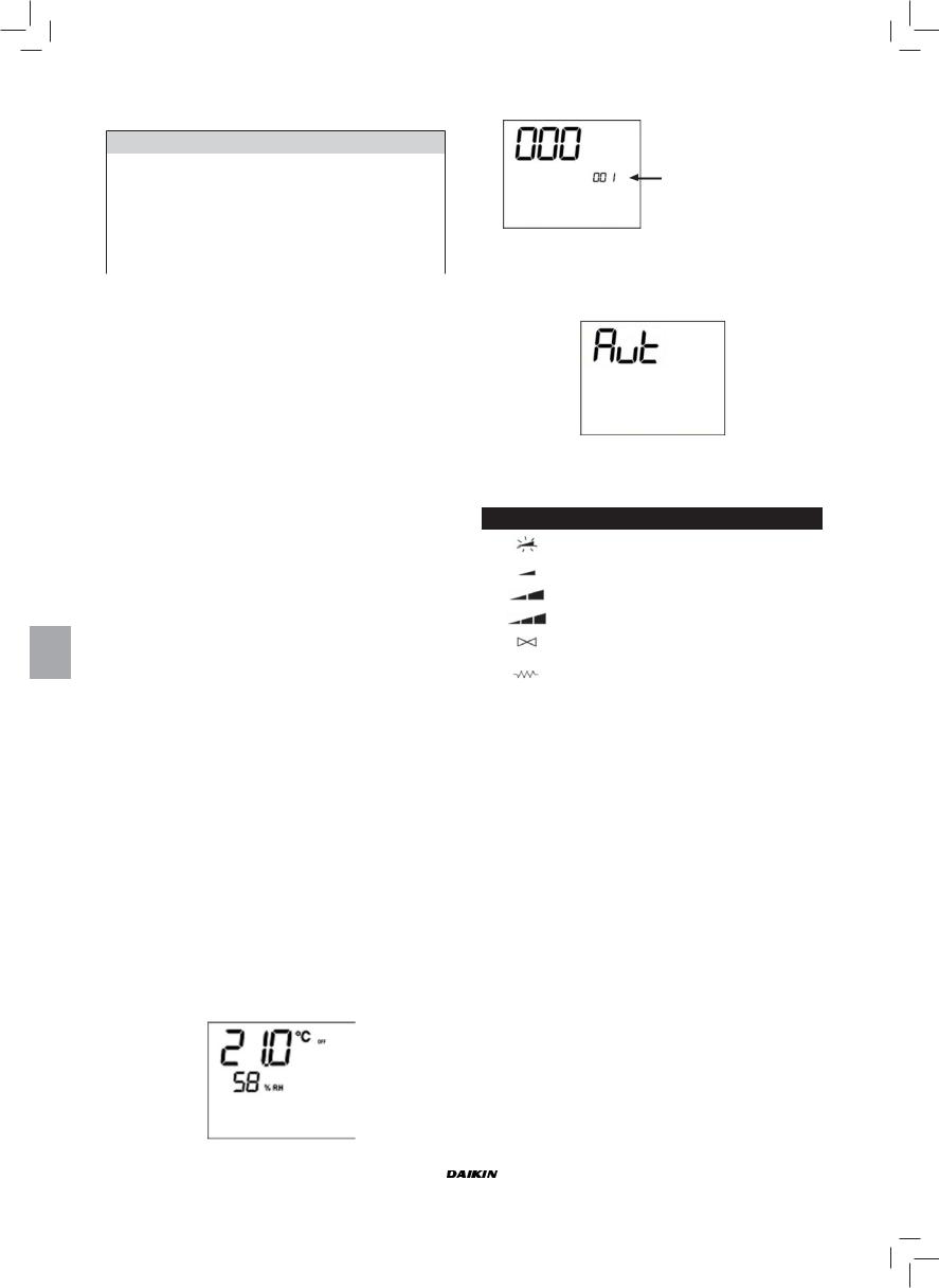
DESCRIPTION OF READ/WRITE REGISTERS [R/W]
■ “Digital 1” REGISTER:
H
|
Bit 15 |
Bit 14 |
Bit 13 |
Bit 12 |
Bit 11 |
Bit 10 |
Bit 9 |
Bit 8 |
|
|
En.Vel |
En.Min/ |
En.Set |
En.MinT |
En.ECO |
En.RE |
En.S/W |
En.On/ |
|
|
Max |
Off |
|||||||
|
L |
||||||||
|
Bit 7 |
Bit 6 |
Bit 5 |
Bit 4 |
Bit 3 |
Bit 2 |
Bit 1 |
Bit 0 |
|
|
— |
— |
Lock |
MinT |
Eco |
RE |
S/W |
On/Off |
|
—On/Off: On/Off via supervision system
—S/W: Mode set via supervision system (0: Cooling, 1: Heating)
—RE: selection of electrical heater via supervision system
—Eco: Economy mode ON via supervision system
—MinT.: Minimum Temperature control ON via supervision system
—Lock: keypad lock (0: unlocked, 1: locked)
—En.On/Off :enabling of On/Off control via supervision system
—En.S/W: enabling of mode control via supervision system
—En.RE: enabling of selection of electrical heater function via supervision system
—En.ECO: enabling of economy mode activation via supervision system
—En.MinT: enabling of selection of Minimum Temperature logic via supervision system
—En.Set: enabling of forced override of setpoint via supervision system
—En.Min/Max: enabling of setpoint thresholds via supervision system
—En.Vel: enabling of selection of fan speed via supervision system
■“SETPOINT — COOLING” Register: setpoint imposed by supervision system for the Cooling mode
■“SETPOINT — HEATING” Register: setpoint imposed by supervision system for the Heating mode
■“MINIMUM SETPOINT — COOL.” Register : lower limit for setpoint in cooling mode
■“MAXIMUM SETPOINT — COOL.” Register “: upper limit for setpoint in cooling mode
■“MINIMUM SETPOINT — HEAT.” Register “: lower limit for setpoint in heating mode
■“MAXIMUM SETPOINT — HEAT.” Register “: upper limit for setpoint in heating mode
■“SPEED” Register: selection of fan speed via supervision system
■“ECONOMY CORRECTION” Register: correction of setpoint in the case of economy mode imposed by supervisor (this correction is an amount subtracted from or added to the setpoint, based on the operating mode)
SELF-DIAGNOSIS PROCEDURE
This procedure allows you to check whether the individual outputs of the controller function correctly.
To run the procedure, follow the directions below: ■ Switch the thermostat off
■ Push the keys at the same time 

001 level: password entry
■Use the  keys to change the value on the display until arriving at the password for self-diagnosis (030) and press
  .
.
The following screen will be displayed:
■Press the  button to switch on the various thermostat outputs in sequence.
|
Symbol |
Actuation |
Terminals |
||||
|
Extra low speed |
N-V0 |
|||||
|
Min. speed |
N-V1 |
|||||
|
Med. speed |
N-V2 |
|||||
|
Max. speed |
N-V3 |
|||||
|
Valve |
N-Vc |
|||||
|
Electrical heater |
N-Vh |
|||||
|
Second valve |
||||||
|
no symbol |
no active outlet |
|||||
The electronic controller outputs can be checked one by one either by observing the respective component (valve, fan..) or verifying whether a voltage of 230 V is present at the corresponding terminals.
■To exit the self-diagnosis procedure press  (after a few minutes the thermostat will automatically exit in any case).
|
Installation and operation manual |
FWEC2 |
|||||||
|
10 |
Advanced electronic controller |
|||||||
|
FC66002764 |
||||||||

ELECTRONIC BOARD (FIGURE 6)
Where
|
Vc |
Valve |
|
Vh |
Heat valve/heater |
|
V0 |
Extra low speed |
|
V1 |
Low speed. |
|
V2 |
Medium speed |
|
V3 |
High speed |
|
N |
Neutral |
|
L |
Phase |
|
PE |
Ground |
|
A-B-GND |
RS 485 |
|
SU |
Remote humidity sensor |
|
SW |
Water sensor |
|
SA |
Remote air probe |
|
DI1 |
Dig.1 input |
|
CI12 |
DI1-2 Common |
|
DI2 |
Dig. 2 input |
N.B.:
■For power connections use cable w/ cross section size of 2 mm2
■For digital inputs used AWG 24 cable
■For sensor extensions and RS485 use AWG 24 shielded cable
WIRING DIAGRAMS
(See Wiring Diagrams enclosed)
UNIT TABLE/DIAGRAMS
|
UNIT |
TYPE |
CONFIGURATION |
DIAGRAM |
|
|
FWL-M-V |
— |
1-2-3-13-14-15-25-26-27-31-32-33 |
FC66002554 |
|
|
7-8-9-19-20-21-37 |
FC66002555 |
|||
|
FWB |
— |
4-5-6-16-17-18-28-29-30-34-35-36 |
UT66000887 |
|
|
10-11-12-22-23-24-38 |
UT66000890 |
|||
|
04/12 |
1-2-3-13-14-15-25-26-27-31-32-33 |
UT66000889 |
||
|
7-8-9-19-20-21-37 |
UT66000892 |
|||
|
FWD |
06/12 3PH |
7-8-9-19-20-21-37 |
UT66000894 |
|
|
16/18 |
1-2-3-13-14-15-25-26-27-31-32-33 |
UT66000888 |
||
|
7-8-9-19-20-21-37 |
UT66000891 |
|||
|
16/18 3PH |
7-8-9-19-20-21-37 |
UT66000893 |
||
|
FWL-M-V |
— |
|||
|
EPIMSB6 |
FWB |
— |
FC66002557 |
|
|
FWD |
— |
|||
WIRING DIAGRAMS
(See Wiring Diagrams enclosed)
CONFIGURATION TABLE/DIAGRAMS
|
CONFIG. |
UNIT |
DIAGRAM |
|||
|
FWL-M-V |
FC66002554 (1) |
||||
|
01-02-03 |
FWD |
UT66000889 (6) |
|||
|
UT66000888 (5) |
|||||
|
04-05-06 |
FWB |
UT66000887 (4) |
|||
|
FWL-M-V |
FC66002555 (2) |
||||
|
UT66000892 (9) |
|||||
|
07-08-09 |
FWD |
UT66000894 (11) |
|||
|
UT66000891 (8) |
|||||
|
UT66000893 (10) |
|||||
|
10-11-12 |
FWB |
UT66000890 (7) |
|||
|
FWL-M-V |
FC66002554 (1) |
||||
|
13-14-15 |
FWD |
UT66000889 (6) |
|||
|
UT66000888 (5) |
|||||
|
16-17-18 |
FWB |
UT66000887 (4) |
|||
|
FWL-M-V |
FC66002555 (2) |
||||
|
UT66000892 (9) |
|||||
|
19-20-21 |
FWD |
UT66000894 (11) |
|||
|
UT66000891 (8) |
|||||
|
UT66000893 (10) |
|||||
|
22-23-24 |
FWB |
UT66000890 (7) |
|||
|
FWL-M-V |
FC66002554 (1) |
||||
|
25-26-27 |
FWD |
UT66000889 (6) |
|||
|
UT66000888 (5) |
|||||
|
28-29-30 |
FWB |
UT66000887 (4) |
|||
|
FWL-M-V |
FC66002554 (1) |
||||
|
31-32-33 |
FWD |
UT66000889 (6) |
|||
|
UT66000888 (5) |
|||||
|
34-35-36 |
FWB |
UT66000887 (4) |
|||
|
FWL-M-V |
FC66002555 (2) |
||||
|
UT66000892 (9) |
|||||
|
37 |
FWD |
UT66000894 (11) |
|||
|
UT66000891 (8) |
|||||
|
UT66000893 (10) |
|||||
|
38 |
FWB |
UT66000890 (7) |
|||
|
FWEC2 |
Installation and operation manual |
|
Advanced electronic controller |
11 |
|
FC66002764 |

WIRING DIAGRAMS
Key to symbols used in wiring diagrams:
|
Vo |
Extra low speed |
|||
|
V1 |
Min. speed |
|||
|
V2 |
Med. speed |
|||
|
V3 |
Max. speed |
|||
|
L |
Phase |
|||
|
PE |
Ground |
|||
|
N |
Neutral |
|||
|
RE |
Electrical heater |
|||
|
SW |
Water sensor |
|||
|
SA |
Air sensor |
|||
|
SU |
Humidity sensor |
|||
|
BK |
Black (Max. speed) |
|||
|
BU |
Blue (Med. speed) |
|||
|
RD |
Red (Extra low speed) |
|||
|
WH |
White (common) |
|||
|
GY |
Grey |
|||
|
BN |
Brown (Min. speed) |
|||
|
GN |
Green |
|||
|
YE |
Yellow |
|||
|
MS |
Flap microswitch |
|||
|
DI1 |
Digital 1 input |
|||
|
DI2 |
Digital 2 input |
|||
|
CI2 |
Digital input common |
|||
|
A/B/GND |
RS 485 |
|||
|
F |
Fuse (not supplied) |
|||
|
IL |
Circuit breaker (not supplied) |
|||
|
CN |
Terminal board |
|||
|
RHC |
Heating/Cooling remote selecting switch |
|||
|
EXT |
Remote ON/OFF contact |
|||
|
EPIMB6 |
Circuit board to control 4 indoor units |
|||
|
EPIB6 |
Circuit board for FWD units |
|||
|
M |
Fan motor |
|||
|
VHC |
Solenoid valve –Cool/Heat. |
|||
|
VC |
Solenoid valve — Cooling |
|||
|
VH |
Solenoid valve — Heating |
|||
|
TSA |
Automatic safety thermostat |
|||
|
TSM |
Safety fuse |
|||
|
SC |
Wiring box |
|||
|
….. |
Electrical connections to be made by |
|||
|
installer |
||||
|
ECONOMY |
COMFORT / ECONOMY remote selecting |
|||
|
switch |
||||
INSTALLATION OF WALL-MOUNTED CONTROLLER
NB: for wall mounting of the controller it is advisable to use an electric box behind the controller to accommodate the cables.
NB: Prior to installation, carefully remove the protective film from the display; removal of the film may cause some dark streaks to appear on the display but these will disappear after a few seconds and are not signs of a controller defect.
INSTRUCTIONS FOR WALL MOUNTING
1.Remove the fastening screw of the controller (FIGURE 8).
2.If a 503 electrical enclosure is used, pass the cables through the slot at the bottom of the controller and use the holes provided for fastening.
3.Otherwise, in the wall where you wish to mount the controller, drill holes to match up with the fastening slots (5x8mm) on the base of the controller; pass the cables through the slot on the base and screw it to the wall (previously drilled) (FIGURE 9).
4.Make the electrical connections to the indoor unit terminal block as per the wiring diagram.
5.Close the controller box and fix with the screw removed as described at point 1.
TECHNICAL DATA
|
90-250Vac 50/60Hz |
||
|
Power supply |
Electrical input 8W |
|
|
Protection fuse 500mA delayed |
||
|
Operating temp. |
Range 0-50°C |
|
|
Storage temp. |
Range -10-60°C |
|
|
NO 5A @ 240V (Resistive) |
||
|
Relay |
insulation: coil-contact distance 8 mm |
|
|
4000V coil-relay dielectric |
||
|
Max ambient temperature 105°C |
||
|
Connectors |
250V 10A |
|
|
Clean contact |
||
|
Digital inputs |
Closing current 2mA |
|
|
Max. closing resistance 50 Ohm |
||
|
Analog inputs |
Temperature and relative humidity probes |
|
|
Power outputs |
Relay (see above) |
|
|
Temperature sensors |
NTC sensors 10K Ohm @25°C |
|
|
Range -25-100°C |
||
|
Humidity probe |
Resistive-type probe |
|
|
Range 20-90%RH |
||
|
Installation and operation manual |
FWEC2 |
|
12 |
Advanced electronic controller |
|
FC66002764 |

|
FWEC2 |
Advanced electronic controller |
Manuel d’installation et d’utilisation
CARACTÉRISTIQUES GÉNÉRALES
Le contrôleur LCD a été conçu pour commander toutes les unités terminales à moteur asynchrone monophasé à plusieurs vitesses. Par rapport à la version standard sont prévues une gestion avancée de l’humidité et la communication sérielle. La version (figure 1), pourvoit à un système Maître-Secondaire (jusqu’à 247 unités internes Secondaire). Dans le cas de cette solution une des commandes exerce la fonction Maître et de ce fait contrôle tous les autres éléments Secondaire.
Dans ce cas également, la connexion se produit par l’intermédiaire du bus RS485, comprenant un simple câble blindé à 2 conducteurs.
La commande Master (identifiée par l’adresse 255) transmet aux commandes Slave les informations suivantes:
(1)Modalité de fonctionnement (rafraîchissement ou chauffage)
(2)Valeur programmée de température ambiante.
Chaque commande Slave maintient le contrôle du sélecteur de vitesse et, pour le réglage de la température ambiante, est admis un écart de ± 2°C autour de la valeur programmée transmise par la commande Master.
PRINCIPALES FONCTIONS:
■Réglage de la température de l’air par variation automatique de la vitesse du ventilateur.
■Réglage de la température de l’air par commande On-Off du ventilateur à une vitesse fixe
■Contrôle de vannes On-Off pour systèmes à deux ou à quatre tubes.
■Gestion de la résistance d’appoint pour le chauffage.
■Commutation Rafraîchissement/Chauffage dans les modalités suivantes:
—manuelle sur l’appareil,
—manuelle à distance (centralisée)
—automatique, en fonction de la température de l’eau
—automatique, en fonction de la température de l’air
■Fonction de Déshumidification
■Communication sérielle
IL EST DOTÉ DE:
■contactlibrepourcommandeexterne(parex.:contactfenêtre, ON/OFF à distance, détecteur de présence, etc.) qui peut activer ou désactiver le fonctionnement de l’unité (logique contact : voir les paramètres de configuration de la carte).
■contact libre pour commutation Rafraîchissement / Chauffage à distance centralisée (logique contact: voir les paramètres de configuration de la carte).
■contact libre pour l’activation de la fonction economy à distance (logique contact) : voir les paramètres de configuration de la carte).
■sonde de température éloignée pour l’eau (accessoire).
■sonde de température interne
■sonde d’humidité interne
■sond de température éloignée pour l’air (accessoire). Si présente, cette sonde est utilisée à la place de la sonde interne pour lalecture de la température ambiante.
■Sonde d’humidité éloignée (accessoire – à utiliser en combinaison avec la sonde de température éloignée)
Le panneau de commande se compose des éléments suivants:
■moniteur LCD
■clavier
MONITEUR LCD (VOIR FIGURE 2)
(1)Température ambiante
(2)Humidité ambiante
(3)température programmée
|
ON |
état ventilateurs. Le voyant clignotant indique |
||
|
l’arrêt des ventilateurs dans l’attente d’un appel du |
|||
|
thermostat. Le symbole allumé fixe indique que les |
|||
|
ventilateurs sont en fonction |
|||
|
OFF |
état ventilateurs. Ventilateurs à l’arrêt car la vites- |
||
|
se sélectionnée est sur Off ou la commande est |
|||
|
désactivée |
|||
|
AUTO |
logique de ventilation automatique |
||
|
vitesse ventilateur |
|||
|
modalités de fonctionnement Rafraîchissement Le |
|||
|
voyant clignotant indique l’absence de signal eau |
|||
|
de fonctionnement de la ventilation. |
|||
|
modalités de fonctionnement Chauffage Le voyant |
|||
|
clignotant indique l’absence de signal eau de |
|||
|
fonctionnement de la ventilation. |
|||
|
Déshumidification. Le symbole clignotant indique |
|||
|
l’absence de signal de déshumidification. Le |
|||
|
symbole allumé fixe indique par contre que cette |
|||
|
fonction est activée. |
|||
|
option Economy activée |
|||
|
présence d’alarme |
|||
|
contrôloe Température minimum |
|||
|
ouverture vanne |
|||
|
résistance électrique Le symbole clignotant indique |
|||
|
que la résistance est en fonction. Le symbole allumé |
|||
|
fixe indique uniquement la résistance sélectionnée. |
|||
|
communicationsérielleactive.Lesymboleclignotant |
|||
|
indique que la commande est maître |
CLAVIER (VOIR FIGURE 3)
Touche On/Off: allumage /extinction thermostat Durantlaprocéduredemodificationdesmaramètres permet de revenir au fonctionnement normal
TouchesUpetDown:modificationdelatempérature de réglage du thermostat (Chauffage:[5.0-30.0°C], rafraîchissement: [10.0-35.0°C]). Durant la procédure de modification des paramètres ces touches sont utilisées pour sélectionner les paramètres ou modifier leur valeur
ToucheSEL:danslamodalitéChauffage,sélectionne la résistance électrique comme fonction auxiliaire
ToucheMode:sélectiondesmodalitésdefonctionnement
Chauffage / Rafraîchissement
Touche Fan: sélection de la vitesse de fonctionnement
Touche EC: sélection de la modalité Economy
|
FWEC2 |
Manuel d’installation et d’utilisation |
|
Advanced electronic controller |
1 |
|
FC66002764 |
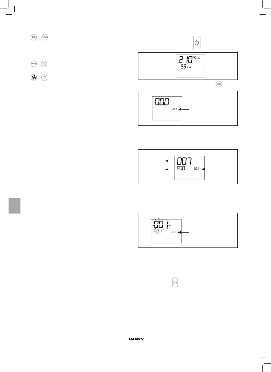
COMBINAISONS DE TOUCHES ACTIVES
Thermostat sur Off: allumé sur la procédure de configuration des paramètres
Thermostat sur On: affichage momentané de la température de l’eau
Sélection de la fonction de Température minimum air
Sélection Déshumidification
CONFIGURATION DE LA CARTE
La carte est configurable en fonction du type d’unité terminale/installation à contrôler, en modifiant des paramètres donnés.
LISTE DES PARAMÈTRES
■P00 = configuration commande (voir “Configurations Prévues”) pour sélectionner le type d’unité terminale à contrôler.
■P01 = type d’installation de la commande —000: sur l’appareil
—001: murale
■P02 = adresse Modbus [pour valider la modifica-
|
tion |
de ce |
paramètre (sauf le |
cas de |
passa- |
|
ge |
inter ne |
entre valeurs] il |
faut |
couper |
l’alimentation et remettre sous tension à la fin de la programmation)
—0: communication sérielle désactivée —1-247: Secondaire
—255: Master
■P03=zoneneutre[20-50°C/10];paramètreutiliséencasdecon- figurationa avec sélection automatique Rafraîchissement/ Chauffage en fonction de la température de l’air.
■P04 = sonde eau —0: non prévue —1: prévue
Selon la valeur programmée, seront contrôlées l’alarme sonde et l’activation de la résistance électrique
■P05 = Logique de configuration – utilisation entrées nu-
|
mériques 1 et 2: |
||||
|
— |
0: |
DIN1 = — |
DIN2 = — |
|
|
— |
1: |
DIN1 = — |
DIN2 = OnOff |
|
|
— |
2: |
DIN1 = Été/Hiv |
DIN2 = — |
|
|
— |
3: |
DIN1 = Eco |
DIN2 = — |
|
|
— |
4: |
DIN1 = Été/Hiv |
DIN2 = On/Off |
|
|
— |
5: |
DIN1 = Eco |
DIN2 = On/Off |
|
|
— |
6: |
DIN1 = Été/Hiv |
DIN2 = Eco |
■P06 = logique d’utilisation – entrée numérique 1:
—0: [ouvert/fermé] = [Rafraîch./Chauff.] = [-/ECO]
—1: [ouvert/fermé] = [Chauff./Rafraîch.] = [ECO/-]
■P07 = logique d’utilisation – entrée numérique 2:
—0: [ouvert/fermé] = [Off/On] = [-/ECO]
—1: [ouvert/fermé] = [On/Off] = [ECO/-]
■P08 = sonde humidité éloignée:
—0 : non prévue
—1 : prévue
Selon la valeur programmée, sera contrôlée l’alarme sonde correspondante.
PROCEDURE DE CONFIGURATION DES
PARAMÈTRES
■ Porter le thermostat sur OFF
■ Enfoncer simultanément les touches 
Indication niveau: 001= saisie MdP
■Utiliser les touches  pour modifier la valeur du moniteur jusqu’à la valeur du MdP 10, puis enforcer
  S’il est correct, on aura accès aux paramètres
|
Valeur paramètre |
||||
|
sélectionné |
Indication niveau: |
|||
|
Paramètre sélec- |
002= sélection |
|||
|
paramètre |
||||
|
tionné: P… |
||||
■Utiliser les touches  pour faire défiler les différents paramètres (voir “List des paramètres, ci-dessus)
■Appuyer sur  pour activer la modification du paramètre (la valeur affichée commence à clignoter)
Indication niveau:
003 = modification paramètre
■Utiliser les touches  pour modifier la valeur
■Appuyer sur  pour sauvegarder la nouvelle valeur ou sur
  pour annuler la modification
■Une fois la modification des paramètres terminée, appuyer
|
sur la touche |
pour quitter la procédure |
NB: la procédure de la procedura de paramétrisation a une durée limitée. À l’échéance de la période prévue (2 min. env.) le thermostat revient à l’état de OFF et ne conserve que les modifications sauvegardées.
|
Manuel d’installation et d’utilisation |
FWEC2 |
|||||||
|
2 |
Advanced electronic controller |
|||||||
|
FC66002764 |
||||||||
![]()
CONFIGURATIONS PRÉVUES (PARAMÈTRE P00)
La commande LCD peut être configurée de façons différentes selon le type de système. Les différentes configurations s’obtiennent au moyen du paramètre P00 (voir procédure de configuration des paramètres de commande).
001
■Tuyaux installation: 2
■Vanne: NON
■Résistance: NON
■Vitesse ventilation: 3
■Logique sélection été / hiver: LOCALE MANUELLE
002
■Tuyaux installation: 2
■Vanne: NON
■Résistance: NON
■Vitesse ventilation: 3
■Logique sélection été / hiver: À DISTANCE MANUELLE
003
■Tuyaux installation: 2
■Vanne: NON
■Résistance: NON
■Vitesse ventilation: 3
■Logique sélection été / hiver: AUTOMATIQUE CÔTÉ EAU
004
■Tuyaux installation: 2
■Vanne: NON
■Résistance: NON
■Vitesse ventilation: 4
■Logique sélection été / hiver: LOCALE MANUELLE
005
■Tuyaux installation: 2
■Vanne: NON
■Résistance: NON
■Vitesse ventilation: 4
■Logique sélection été / hiver: À DISTANCE MANUELLE
006
■Tuyaux installation: 2
■Vanne: NON
■Résistance: NON
■Vitesse ventilation: 4
■Logique sélection été / hiver: AUTOMATIQUE CÔTÉ EAU
007
■Tuyaux installation: 2
■Vanne: NON
■Résistance: OUI
■Vitesse ventilation: 3
■Logique sélection été / hiver: LOCALE MANUELLE
008
■Tuyaux installation: 2
■Vanne: NON
■Résistance: OUI
■Vitesse ventilation: 3
■Logique sélection été / hiver: À DISTANCE MANUELLE
009
■Tuyaux installation: 2
■Vanne: NON
■Résistance: OUI
■Vitesse ventilation: 3
■Logique sélection été / hiver: AUTOMATIQUE CÔTÉ AIR
010
■Tuyaux installation: 2
■Vanne: NON
■Résistance: OUI
■Vitesse ventilation: 4
■Logique sélection été / hiver: LOCALE MANUELLE
011
■Tuyaux installation: 2
■Vanne: NON
■Résistance: OUI
■Vitesse ventilation: 4
■Logique sélection été / hiver: À DISTANCE MANUELLE
012
■Tuyaux installation: 2
■Vanne : NON
■Résistance: OUI
■Vitesse ventilation: 4
■Logique sélection été / hiver: AUTOMATIQUE CÔTÉ AIR
013
■Tuyaux installation: 2
■Vanne: 2-3 VOIES
■Résistance: NON
■Vitesse ventilation: 3
■Logique sélection été / hiver: LOCALE MANUELLE
014
■Tuyaux installation: 2
■Vanne: 2-3 VOIES
■Résistance: NON
■Vitesse ventilation: 3
■Logique sélection été / hiver: À DISTANCE MANUELLE
015
■Tuyaux installation: 2
■Vanne: 2-3 VOIES
■Résistance: NON
■Vitesse ventilation: 3
■Logique sélection été / hiver: AUTOMATIQUE CÔTÉ EAU
016
■Tuyaux installation: 2
■Vanne: 2-3 VOIES
■Résistance: NON
■Vitesse ventilation: 4
■Logique sélection été / hiver: LOCALE MANUELLE
017
■Tuyaux installation: 2
■Vanne: 2-3 VOIES
■Résistance: NON
■Vitesse ventilation: 4
■Logique sélection été / hiver: À DISTANCE MANUELLE
|
FWEC2 |
Manuel d’installation et d’utilisation |
|||||||
|
Advanced electronic controller |
3 |
|||||||
|
FC66002764 |
||||||||

CONFIGURATIONS PRÉVUES (PARAMÈTRE P00)
018
■Tuyaux installation: 2
■Vanne: 2-3 VOIES
■Résistance: NON
■Vitesse ventilation: 4
■Logique sélection été / hiver: AUTOMATIQUE CÔTÉ EAU
019
■Tuyaux installation: 2
■Vanne: 3 VOIES
■Résistance: OUI
■Vitesse ventilation: 3
■Logique sélection été / hiver: LOCALE MANUELLE
020
■Tuyaux installation: 2
■Vanne: 3 VOIES
■Résistance: OUI
■Vitesse ventilation: 3
■Logique sélection été / hiver: À DISTANCE MANUELLE
021
■Tuyaux installation: 2
■Vanne: 3 VOIES
■Résistance: OUI
■Vitesse ventilation: 3
■Logique sélection été / hiver: AUTOMATIQUE CÔTÉ AIR
022
■Tuyaux installation: 2
■Vanne: 3 voies
■Résistance: OUI
■Vitesse ventilation: 4
■Logique sélection été / hiver: LOCALE MANUELLE
023
■Tuyaux installation: 2
■Vanne: 3 VOIES
■Résistance: OUI
■Vitesse ventilation: 4
■Logique sélection été / hiver: À DISTANCE MANUELLE
024
■Tuyaux installation: 2
■Vanne: 3 VOIES
■Résistance: OUI
■Vitesse ventilation: 4
■Logique sélection été / hiver: AUTOMATIQUE CÔTÉ AIR
025
■Tuyaux installation: 4
■Vanne: NON
■Résistance: NON
■Vitesse ventilation: 3
■Logique sélection été / hiver: LOCALE MANUELLE
026
■Tuyaux installation: 4
■Vanne: NON
■Résistance: NON
■Vitesse ventilation: 3
■Logique sélection été / hiver: À DISTANCE MANUELLE
027
■Tuyaux installation: 4
■Vanne: NON
■Résistance: NON
■Vitesse ventilation: 3
■Logique sélection été / hiver: AUTOMATIQUE CÔTÉ AIR
028
■Tuyaux installation: 4
■Vanne: NON
■Vitesse ventilation: 4
■Logique sélection été / hiver: LOCALE MANUELLE
029
■Tuyaux installation: 4
■Vanne: NON
■Résistance: NON
■Vitesse ventilation: 4
■Logique sélection été / hiver: À DISTANCE MANUELLE
030
■Tuyaux installation: 4
■Vanne: NON
■Résistance: NON
■Vitesse ventilation: 4
■Logique sélection été / hiver: AUTOMATIQUE CÔTÉ AIR
031
■Tuyaux installation: 4
■Vanne: 2-3 VOIES
■Résistance: NON
■Vitesse ventilation: 3
■Logique sélection été / hiver: LOCALE MANUELLE
032
■Tuyaux installation: 4
■Vanne: 2-3 VOIES
■Résistance: NON
■Vitesse ventilation: 3
■Logique sélection été / hiver: À DISTANCE MANUELLE
033
■Tuyaux installation: 4
■Vanne: 2-3 VOIES
■Résistance: NON
■Vitesse ventilation: 3
■Logique sélection été / hiver: AUTOMATIQUE CÔTÉ AIR
034
■Tuyaux installation: 4
■Vanne: 2-3 VOIES
■Résistance: NON
■Vitesse ventilation: 4
■Logique sélection été / hiver: LOCALE MANUELLE
035
■Tuyaux installation: 4
■Vanne: 2-3 VOIES
■Vitesse ventilation: 4
■Logique sélection été / hiver: À DISTANCE MANUELLE
|
Manuel d’installation et d’utilisation |
FWEC2 |
|
4 |
Advanced electronic controller |
|
FC66002764 |

CONFIGURATIONS PRÉVUES (PARAMÈTRE P00)
036
■Tuyaux installation: 4
■Vanne: 2-3 VOIES
■Résistance: NON
■Vitesse ventilation: 4
■Logique sélection été / hiver: AUTOMATIQUE CÔTÉ AIR
037
■Tuyaux installation: 4
■Vanne: NON
■Résistance: OUI
■Vitesse ventilation: 3
■Logique sélection été / hiver: LOCALE MANUELLE
038
■Tuyaux installation: 4
■Vanne: NON
■Résistance: OUI
■Vitesse ventilation: 4
■Logique sélection été / hiver: LOCALE MANUELLE
COMMUNICATION SÉRIELLE
Branchement au réseau de communication RS485
Le réseau de communication, de type Bus, est formé par un câble blindé à 2 conducteurs, branché directement aux ports série RS485 des commandes (bornes A, B et GND).
“Pour la réalisation du système utiliser un câble AWG 24 (diam. 0,511 mm).
Le réseau de communication doit avoir la structure générale suivante (figure 4).
Concernant la version “MASTER-SLAVE” une résistance de terminaison devra être installée sur les deux commandes aux extrémités du réseau.
NB: (1) Respecter la polarité de la connexion: indiquée par A(-) et B(+)
(2) Éviter des anneaux de mise à la terre (blindage à la terre sur une extrémité seulement)
____________________________________________________________
ATTENTION:
■Utiliser un câble blindé AWG24
■Couleurs recommandées pour le réseau de
communication: A (-) Marron; B (+) Jaune
____________________________________________________________
LOGIQUES
SÉLECTION RAFRAÎCHISSEMENT/CHAUFFAGE
Sont présentes 4 logiques différentes de sélection du mode de fonctionnement du thermostat, lesquelles sont définies sur la base de la configuration programmée sur la commande:
1.Locale: choix de l’utilisateur en utilisat la touche 
2.À distance: en fonction de l’état de l’entrée digitale DI1 (logique contact: voir les paramètres de configuration de la carte).
3.en fonction de la température de l’eau
Été
Hiver
Temp. eau
NB: dans le cas d’une alarme relativea aux sondes le contrôle de la modalité revient momentanément à la modalité locale
4. en fonction de la température de l’air
Été
Hiver
Temp. air
où
■Set est la température programmée au moyen des flèches
■ZN est la zone neutre (paramètre P03)
Le mode de fonctionnement du thermostat est identifiée sur
le moniteur par les symboles  (Rafraîchissement) et (chauffage)
VENTILATION
Le contrôleur est capable de gérer les unités à 3 ou 4 vitesses
SÉLECTION DE LA VITESSE DE FONCTIONNEMENT
À l’aide de la touche Fan  on peut choisir les vitesses suivantes:
■Vit. automatique: en fonction de la température programmée et de celle de l’air ambiant
Pour configurations à 3 vitesses  :
:
où:
1 = vitesse minimum
2 = vitesse moyenne
3 = vitesse maximum
RAFRAÎCHISSEMENT
CHAUFFAGE
|
FWEC2 |
Manuel d’installation et d’utilisation |
|||||||
|
Advanced electronic controller |
5 |
|||||||
|
FC66002764 |
||||||||

Pour configurations à 4 vitesses  où:
où:
sm = vitesse extra-minimum 1 = vitesse minimum
2 = vitesse moyenne
3 = vitesse maximum
RAFRAÎCHISSEMENT
Temp. air
CHAUFFAGE
Temp. air
NB: pour les configurations à 4 vitesses et vanne, la ventilation dans le mode chauffage est remontée de 0,5°C pour permettre la convection naturelle dans la première phase.
■Vit. désactivée: sélectionnable uniquement dans le mode chauffate et avec configurations à 4 vitesses, l’unité terminale fonctionne par convection naturelle seulement
|
■ |
Vit. extra-minimum: sélectionnable unique- |
|
|
ment avec configurations à 4 vitesses, la |
||
|
vitesse utilisée étant extra-minimum |
||
|
■ |
Vit minimum |
|
|
■ |
Vit moyenne |
■ Vit maximum
NB: dans le cas de vitesse fixe, la logique d’activation du ventilateur correspondra à celle de la logique automatique
ACTIVATION EAU
Le fonctionnement de la ventilation est lié au contrôle de la température de l’eau de l’installation. Compte tenu du mode de fonctionnement on aura différents seuils d’activation en mode chauffage et rafraîchissement
COOLING
NO
Water temp.
HEATING
NO
Water temp.
L’absence de cette commande à l’appel du thermostat sera indiquée sur le moniteur par le clignotement du symbole du
mode actif ( ou
ou  )
)
Cette commande est ignorée dans les cas suivants:
■sonde eau non prévue (P04 = 0) ou sous alarme étant débranchée
■mode Rafraîchissement avec configurations à 4 tuyaux
LOGIQUES
FORÇAGES
La logique normale de ventilation est ignorée dans le cas de situations particulières de forçage pouvant être nécessaires pour le contrôle correct de la température ou le fonctionnement de l’unité. Fonctions disponibles:
mode Rafraîchissement:
■commande installée sur l’unité (P01 = 0) et configuration avec vanne: la vitesse minimum disponible est maintenue après avoir atteint la température fixée.
■commande installée sur l’unité et configuration sans vanne: toutes les 10 minutes d’arrêt du ventilateur est effectué un nettoyage de 2 minutes à la vitesse moyenne pour permettre une lecture plus précise de la température ambiante par la sonde air.
mode Chauffage
■résistance active: la ventilation est forcée à la moyenne vitesse.
■résistasnce éteinte: pendant 2 minutes est maintenue une post-ventilation à la moyenne vitesse. (NB: la ventilation est complétée même si le thermostat est éteint ou en cas de commutation sur la modalité rafraîchissement)
MONITEUR
Le moniteur affiche l’état du ventilateur
■On clignotant: ventilateur en standby
■On fixe: ventilateur allumé
■OFF: ventilateur désactivé pour fonctionner dans la modalité convection naturelle seulement
et la vitesse de fonctionnement (avec indication éventuelle de la logique “automatique”) active ou sélectionnée (dans le cas de ventilateur en stand-by)
|
■ |
Vit. extra-minimum |
|
■ |
Vit. minimum |
|
■ |
Vit. moyenne |
■Vit. maximum
NB: si la vitesse activée ne correspond pas à la vitesse sélectionnée par l’utilisateur (cas de forçage), à la
première pression de la toucheo Fan  est affichée cette dernière; la pression suivante modifie la sélection.
|
Manuel d’installation et d’utilisation |
FWEC2 |
|
6 |
Advanced electronic controller |
|
FC66002764 |

VANNE
Le contrôleur est capable de gérer les vannes à 2 ou 3 voies de type ON/OFF, alimentation 230 V.
OUVERTURE
L’oouverture de la vanne est commandée en fonction du setpoint de service et de la température de l’air
RAFRAÎCHISSEMENT
Temp. air
CHAUFFAGE
Temp. air
ACTIVATION EAU
Le contrôle de la température de l’eau pour activer l’ouverture est prévu uniquement dans les configurations avec vannes à 3 voies et résistance électrique.
Avec ces configurations. Le contrôle de la température est effectué dans les cas suivants:
■Chauffage avec résistance: le fonctionnement de la résistance comporte un forçage de la ventilation. Il est donc nécessaire d’éviter le passe d’eau trop froide dans l’unité.
Temp. eau
■Post ventilation due à l’extinction de la résistance: maintenue jusqu’à l’échéance du temps étabgli même si la modalité de fonctionnement est modifiée. Durant la post-ventilation la fonction eau coïncide avec la fonction ventilation.
MONITEUR
L’indication de vanne activée sur le moniteur est donnée par le symbole 
RÉSISTANCE ÉLECTRIQUE
La résistance électrique est un dispositif ayant la fonction d’appoint dans la phase de chauffage.
SÉLECTION
Si prévue par la configuration, la résistance peut être sélectionnée en mode chauffage à l’aide de la touche Sel 
ACTIVATION
Temp. air
La résistance électrique sélectionnée par l’utilisateur est activée par le thermostat en fonction de la température ambiante
NB: l’activation comporte une ventilation forcée
ACTIVATION EAU
La commande d’activation de la résistance est liée au contrôle de la température de l’eau. Ci-dessous, la logique d’activation.
Cette commande ne sera pas fournie si la sonde n’est pas prévue ou est désactivée
CHAUFFAGE
ON
OFF
Temp. eau
MONITEUR
Le moniteur affiche les informations suivantes
■Résistance sélectionnée par l’utilisateur: symbole fixe
■Résistance active:  symbole clignotant
ECONOMY
La fonction Economy prévoit une correction du setpoint de 2,5 C° et un forçage à la vitesse minimum pour réduire le fonctionnement de l’unité.
■Rafraîchissement: set +2,5°C
■Chauffage: set -2,5°C
ACTIVATION
Pour déclencher la fonction, appuyer sur la touche 
MONITEUR
Sur le moniteur la fonction Economy est déclenché par le symbole 
CONTRÔLE TEMPÉRATURE MINIMUM
Le thermostat étant éteint, cette logique empêche que la température ambiante ne déscende trop tr4op et pour cela l’unité est forcée dans le mode chauffage pour le temps nécessaire.
Si présente, la résistance électrique n’est utilisée que dans le cas où elle serait précédemment sélectionnée comme chauffage d’appoint.
SÉLECTION
Pour sélectionner le contrôle de la Température Minimum,
appuyer simultanément sur les touches 
 le thermostat étant éteint.
Pour désactiver le fonctionnement, utiliser la même combinaison des touches
ACTIVATION
Si cette fonction est sélectionnée, l’unité s’allume lorsque la température ambiante descend au-dessous de 9°C.
|
FWEC2 |
Manuel d’installation et d’utilisation |
|||||||
|
Advanced electronic controller |
7 |
|||||||
|
FC66002764 |
||||||||

Temp. air
Lorsque la valeur de la température remonte à plus de 10°C le thermostat revient à la situation de Off.
NB: un Off éventuel depui une entrée numérique a pour effet d’empêcher l’activation de cette logique.
MONITEUR
Le moniteur affiche les informations suivantes
■Contrôle Température Minimum sélectionné: symbole 
■Contrôle Température Minimum déclenché: indication DEFR
DÉSHUMIDIFICATION
La fonction de déshumidification n’est utilisable que dans le mode rafraîchissement. Dans cette condition l’unité réduit de 10% l’humidité présente dans la pièce à partir du moment de la sélection de cette fonction.
SÉLECTION
Pour activer/désactiver la fonction déshumidification, uniquement dans le mode rafraîchissement, appuyer simultanément
sur les touches 
 . Cette sélection n’est pas permise quand la sonde à eau n’est pas prévue (P04=0) ou que la sonde d’humidité éloignée n’est pas montée sur l’appareil (P08=0). Si elle est sélectionnée, la zone neutre de commutation automatique côté air est forcée à 5°.
LOGIQUE
Une fois sélectionnée, la logique de Déshumidification programme comme valeur d’humidité à atteindre l’humidité présente lors de la sélection moins 10%. Dans le cas d’humidité ambiante inférieure à 40% la valeur de référence sera programmée à 30%.
La ventilation sera forcée sur la vitesse minimum ou, dans le cas de température largement supérieure à la valeur programmée, sur la moyenne vitesse.
Vitesse moyenne
Vitesse minimum
Pour ramener l’humidité à la valeur programmée, la ventilation (et la vanne, si présente) sera activée dans le cas où la température ambiante aurait atteint la valeur de réglage (indiquée sur le moniteur par le symbole 3 ou pas. Si l’on descend trop en dessous de ce seuil, la logique est momentanément
désactivée.
désactivée
Temp. air
ACTIVATION EAU
La commande d’activation de la fonction Déshumidification est liée au contrôle de la température de l’eau. Ci-dessous, la logique d’activation.
Temp. eau
L’absence de commande comporte la désactivation momentanée de la logique de Déshumidification.
La même situation se produira dans le cas de débranchement de la sonde.
NB: une fois atteinte l’humidité de référence ou avoir porté la commande sur Off, la déshumidification sera déselectionnée.
MONITEUR
Le moniteur affiche les informations suivantes:
■ Déshumidification active: symbole allumé 
■Déshumidification momentanément désactivée: symbole clignotant 
ALARMES
La commande contrôle deux types d’alarame:
■Alarmes graves: causent l’extinction forcée du thermostat
■Alarmes non graves: ne forcent pas l’extinction du thermostat mais empêchent les fonctions critiques éventuelles
ALARMES GRAVES
Code alarme
■Code A01 = erreur sonde extérieure de température de l’air (thermostat installé sur l’appareil)
■Code A02 = erreur sonde interne de température de l’air (thermostat à installation murale et sonde extérieur de température de l’air désactivée)
|
Manuel d’installation et d’utilisation |
FWEC2 |
|
8 |
Advanced electronic controller |
|
FC66002764 |

ALARMES NON GRAVES
|
Thermostat OFF |
Thermostat ON |
■Code A03 = erreur sonde de température de l’eau
■Code A04 = erreur sonde humidité externe (si la sonde température éloignée est installée)
■Code A05 = erreur sonde humidité interne
NB: l’indication du code d’alarme est affichée si le thermostat est éteint uniquement
MODBUS
Le protocole prévu dans la commande est Modbus RTU (9600, N, 8, 2) sur RS485
FUNCTIONS APPLIQUÉES
■0x03 : Read Holding Registers
■0x04 : Read Input Registers
■0x10 : Write Multiple registers
EXCEPTIONS APPLIQUÉES
Exception Code 02: Invalidate data address
LISTE PARAMÈTRES DE SUPERVISION
|
ADRESSE |
REGISTRE |
TYPE |
U.M. |
|
0 |
États |
R |
— |
|
1 |
Vitesse |
R |
— |
|
2 |
Température air: |
R |
[°C/10] |
|
3 |
Humidité |
R |
% |
|
4 |
Température eau: |
R |
[°C/10] |
|
5 |
P00:Configuration |
R |
— |
|
6 |
P05: Config. DIN |
R |
— |
|
7 |
T. Setpoint actif |
R |
[°C/10] |
|
8 |
T. Setpoint utilisateur |
R |
[°C/10] |
|
9 |
Version LCD |
R |
— |
|
50 |
Numériques 1 |
R/W |
— |
|
51 |
— |
R/W |
— |
|
52 |
Setpoint — Rafraîchissement |
R/W |
[°C/10] |
|
53 |
Setpoint — Chauffage |
R/W |
[°C/10] |
|
54 |
Setpoint min. – rafraîch. |
R/W |
[°C/10] |
|
55 |
Setpoint max. – rafraîch. |
R/W |
[°C/10] |
|
56 |
Setpoint min. – chauff. |
R/W |
[°C/10] |
|
57 |
Setpoint max. – chauff. |
R/W |
[°C/10] |
|
58 |
Vitesse |
R/W |
— |
|
59 |
Correction Economy |
R/W |
[°C/10] |
DESCRIPTION REGISTRES DE LECTURE SEULEMENT [R]
■ Registre “ÉTATS”
H
|
Bit 15 |
Bit 14 |
Bit 13 |
Bit 12 |
Bit 11 |
Bit 10 |
Bit 9 |
Bit 8 |
|
— |
— |
P04 |
Déshum |
P06 |
P07 |
DI2 |
DI1 |
L
|
Bit 7 |
Bit 6 |
Bit 5 |
Bit 4 |
Bit 3 |
Bit 2 |
Bit 1 |
Bit 0 |
|
|
Vh |
Vc |
Alarme |
MinT |
Eco |
P01 |
S/W |
ON/ |
|
|
OFF |
||||||||
—On/Off: état unité (0:Off, 1=On)
—S/W: modalités de fonctionnement (0 : S=rafraîchisseme nt,1:W=chauffage)
—P01: paramètre “installation sur appareil/murale”
—Eco: logique Economy activée
—Min.T: logique Température minimum sélectionnée
—Alarme: indication générale d’alarme (activée en cas de déclenchement d’une des alarmes gérées)
—Vc: état sortie numérique Vc
—Vh: état sortie numérique Vh
—DI1: valeur logique entrée num.1 (l’état physique de l’entrée dépend de la logique associée)
—DI2: valeur logique entrée num. 2 (l’état physique de l’entrée dépend de la logique associée)
—P07: paramètre “Logique DIN 2”
—P06: paramètre “Logique DIN 1”
—Deum: déshumidification en fonction (0:non, 1:oui)
—P04: paramètre “sonde eau prévue”
■REGISTRE “VITESSE”: vitesse actuelle de fonctionnement de l’unité
—0: aucune ventilation activée
—1: vitesse extra-minimum
—2: vitesse minimum
—3: vitesse moyenne
—4: vitesse maximum
■REGISTRE “TEMPÉRATURE AIR”: température ambiante lue par la commande et affichée par le moniteur (NB: cette température correspond à la lecture effectuée par la sonde éloignée si le contrôleur est monté sur l’appareil, et à la lecture de la sonde interne si le contrôleur est mural et la sonde éloignée est débranchée)
■REGISTRE “HUMIDITÉ”: humidité ambiante lue par la sonde correspondant à la température utilisée
■REGISTRE “TEMPÉRATURE EAU”: température de l’eau lue par la sonde correspondante (SW)
■Registre “P00”: paramètre “Configuration commande”
■Registre “T. SETPOINT ACTIF”: setpoint utilisé pour le réglage
■Registre “T. SETPOINT UTILISATEUR”: valeur de setpoint programmé par l’utilisateur (pourrait s’écarter du setpoint actif suite à des corrections de logiques economy, ou à l’utilisation du setpoint depuis supervision)
■Registre “VERSION LCD”: établit le type de commande et la version de logiciel installée (0xHHSS: HH: caractère ASCII, SS:version sw)
|
FWEC2 |
Manuel d’installation et d’utilisation |
|||||||
|
Advanced electronic controller |
9 |
|||||||
|
FC66002764 |
||||||||

DESCRIPTION REGISTRES DE LECTURE/ÉCRITURE [R/W]
■ Registre “E/S NUMÉRIQUES 1”:
H
|
Bit 15 |
Bit 14 |
Bit 13 |
Bit 12 |
Bit 11 |
Bit 10 |
Bit 9 |
Bit 8 |
|
|
En.Vel |
En.Min/ |
En.Set |
En.MinT |
En.ECO |
En.RE |
En.S/W |
En.On/ |
|
|
Max |
Off |
|||||||
|
L |
||||||||
|
Bit 7 |
Bit 6 |
Bit 5 |
Bit 4 |
Bit 3 |
Bit 2 |
Bit 1 |
Bit 0 |
|
|
— |
— |
Lock |
MinT |
Eco |
RE |
S/W |
ON/ |
|
|
OFF |
||||||||
—On/Off: On/Off depuis superviseur
—S/W: Modalité de supervision (0: Rafraîchissement, 1: Chauffage)
—RE: sélection Résistance depuis supervision
—Eco: activation Economy depuis supervision
—MinT.: activation contrôle température Minimum depuis supervision
—Lock: blocage clavier (0: non bloqué, 1: bloqué)
—En.On/Off :autorisation contrôle On/Off depuis supervision
—En.S/W: autorisation contrôle modalité depuis supervision
—En.RE: autorisation sélection Résistance Électrique depuis supervision
—En.ECO: autorisation activation Economy depuis supervision
—En.MinT: autorisation sélection logique de Température Minimum depuis supervision
—En.Set: autorisation forçage setpoint depuis supervision
—En.Min/Max: autorisation seuils setpoint depuis supervision
—En.Vel: autorisation sélection vitesse ventilateur depuis supervision
■Registre “SETPOINT — RAFRAÎCHISSEMENT”: setpoint depuis supervision pour la modalité Rafraîchissement
■Registre “SETPOINT — CHAUFFAGE”: setpoint depuis supervision pour la modalité Chauffage
■Registre “SETPOINT MIN. – RAFRAÎCH. “: limite inférieure pour setpoint rafraîchissement
■Registre “SETPOINT MAX. – RAFRAÎCH.. “: limite supérieure pour setpoint rafraîchissement
■Registre “SETPOINT MIN. – CHAUFF. “: limite inférieure pour setpoint chauffage
■Registre “SETPOINT MAX. – CHAUFF. “: limite supérieure pour setpoint chauffage
■Registre “VITESSE”: sélection vitesse ventilateurs depuis superviseur
■Registre “CORRECTION ECONOMY”: correction setpoint dans le cas de economy depuis superviseur (cette correction est supprimée ou ajoutée au setpoint selon la modalité de fonctionnement)
PROCÉDURE D’AUTODIAGNOSTIC
Cette procédure permet de vérifier le fonctionnement correct des sorties du contrôleur.
Pour l’exécution de cette procédure, se reporter aux indications suivantes:
■ Porter le thermostat sur Off
■ Enfoncer simultanément les touches 

niveau 001: saisie MdP
■Utiliser les touches  pour modifier la valeur du moniteur jusqu’à la valeur du d’autodiagnostic (030), puis appuyer sur
  .
.
Apparaîtra l’image-écran suivante:
■Appuyer sur la touche  pour allumer successivement les différentes sorties du thermostat.
|
Symbole |
Actionnement |
Bornes |
|
Vitesse extra-minimum |
N-V0 |
|
|
Vitesse minimum |
N-V1 |
|
|
Vitesse moyenne |
N-V2 |
|
|
Vitesse maximum |
N-V3 |
|
|
Vanne |
N-Vc |
|
|
Résistance |
N-Vh |
|
|
Deuxième vanne |
||
|
aucun symbole |
Aucune sortie active |
|
Il est possible de vérifier, une par une, les sorties du contrôleur électronique en observant le composant correspondant (vanne, ventilateur) ou bien en contrôlant la présence de tension (230V) sur les bornes correspondantes.
■ Appuyer sur la touche  pour quitter la procédure d’autodiagnostic (après quelques minutes le thermostat quittera automatiquement la modalité)
|
Manuel d’installation et d’utilisation |
FWEC2 |
|||||||
|
10 |
Advanced electronic controller |
|||||||
|
FC66002764 |
||||||||

CARTE ÉLECTRONIQUE (VOIR FIGURE 6)
où
|
Vc |
Vanne |
|
Vh |
Vanne Chaud / Résistance |
|
V0 |
Vit.extra-minimum |
|
V1 |
Vit. minimum |
|
V2 |
Vit. moyenne |
|
V3 |
Vit. maximum |
|
N |
Neutre |
|
L |
Phase |
|
PE |
Terre |
|
A-B-GND |
RS 485 |
|
SU |
Sonde humidité éloignée |
|
SW |
Sonde eau |
|
SA |
Sonde air éloignée |
|
DI1 |
Entrée num.1 |
|
CI12 |
Commun DI1-2 |
|
DI2 |
Entrée num. 2 |
NB:
■Pour les connexions de puissance utiliser un câble d’1 mm2 de section
■Pour les entrées digitales utiliser un câble de type AWG 24
■Pour les prolongations des sondes et RS485 utiliser un câble blindé de type AWG 24
SCHÉMAS ÉLECTRIQUES
(Voir annexe Schémas Électriques)
Table Unité/Schémas
|
UNITÉ |
TYPE |
CONFIGURATION |
SCHÉMA |
|
|
FWL-M-V |
— |
1-2-3-13-14-15-25-26-27-31-32-33 |
FC66002554 |
|
|
7-8-9-19-20-21-37 |
FC66002555 |
|||
|
FWB |
— |
4-5-6-16-17-18-28-29-30-34-35-36 |
UT66000887 |
|
|
10-11-12-22-23-24-38 |
UT66000890 |
|||
|
04/12 |
1-2-3-13-14-15-25-26-27-31-32-33 |
UT66000889 |
||
|
7-8-9-19-20-21-37 |
UT66000892 |
|||
|
FWD |
06/12 3PH |
7-8-9-19-20-21-37 |
UT66000894 |
|
|
16/18 |
1-2-3-13-14-15-25-26-27-31-32-33 |
UT66000888 |
||
|
7-8-9-19-20-21-37 |
UT66000891 |
|||
|
16/18 3PH |
7-8-9-19-20-21-37 |
UT66000893 |
||
|
FWL-M-V |
— |
|||
|
EPIMSB6 |
FWB |
— |
FC66002557 |
|
|
FWD |
— |
|||
SCHÉMAS ÉLECTRIQUES
(Voir annexe Schémas Électriques)
Table Configurations/Schémas
|
CONFIG. |
UNITÉ |
SCHÉMA |
|||
|
FWL-M-V |
FC66002554 (1) |
||||
|
01-02-03 |
FWD |
UT66000889 (6) |
|||
|
UT66000888 (5) |
|||||
|
04-05-06 |
FWB |
UT66000887 (4) |
|||
|
FWL-M-V |
FC66002555 (2) |
||||
|
UT66000892 (9) |
|||||
|
07-08-09 |
FWD |
UT66000894 (11) |
|||
|
UT66000891 (8) |
|||||
|
UT66000893 (10) |
|||||
|
10-11-12 |
FWB |
UT66000890 (7) |
|||
|
FWL-M-V |
FC66002554 (1) |
||||
|
13-14-15 |
FWD |
UT66000889 (6) |
|||
|
UT66000888 (5) |
|||||
|
16-17-18 |
FWB |
UT66000887 (4) |
|||
|
FWL-M-V |
FC66002555 (2) |
||||
|
UT66000892 (9) |
|||||
|
19-20-21 |
FWD |
UT66000894 (11) |
|||
|
UT66000891 (8) |
|||||
|
UT66000893 (10) |
|||||
|
22-23-24 |
FWB |
UT66000890 (7) |
|||
|
FWL-M-V |
FC66002554 (1) |
||||
|
25-26-27 |
FWD |
UT66000889 (6) |
|||
|
UT66000888 (5) |
|||||
|
28-29-30 |
FWB |
UT66000887 (4) |
|||
|
FWL-M-V |
FC66002554 (1) |
||||
|
31-32-33 |
FWD |
UT66000889 (6) |
|||
|
UT66000888 (5) |
|||||
|
34-35-36 |
FWB |
UT66000887 (4) |
|||
|
FWL-M-V |
FC66002555 (2) |
||||
|
UT66000892 (9) |
|||||
|
37 |
FWD |
UT66000894 (11) |
|||
|
UT66000891 (8) |
|||||
|
UT66000893 (10) |
|||||
|
38 |
FWB |
UT66000890 (7) |
|||
|
FWEC2 |
Manuel d’installation et d’utilisation |
|
Advanced electronic controller |
11 |
|
FC66002764 |

SCHÉMAS ÉLECTRIQUES
Légendes des symboles des schémas électriques:
|
Vo |
Vitesse extra-minimum |
|||
|
V1 |
Vitesse minimum |
|||
|
V2 |
Vitesse Moyenne |
|||
|
V3 |
Vitesse Maximum |
|||
|
L |
Phase |
|||
|
PE |
Terre |
|||
|
N |
Neutre |
|||
|
RE |
Résistance électrique |
|||
|
SW |
Sonde Eau |
|||
|
SA |
Sonde Air |
|||
|
SU |
Sonde humidité |
|||
|
BK |
Noir (Vit. Maximum) |
|||
|
BU |
Bleu (Vit. Moyenne) |
|||
|
RD |
Rouge (Vit. extra-minimum/minimum) |
|||
|
WH |
Blanc (commun) |
|||
|
GY |
Gris |
|||
|
BN |
Marron (Vit. Minimum) |
|||
|
GN |
Vert |
|||
|
YE |
Jaune |
|||
|
MS |
Microinterrupteur Défl. |
|||
|
DI1 |
Entrée num.1 |
|||
|
DI2 |
Entrée num.2 |
|||
|
CI12 |
Commun entrées digitales |
|||
|
A/B/GND |
RS 485 |
|||
|
F |
Fusible (non fourni) |
|||
|
IL |
Interrupteur de ligne (non fourni) |
|||
|
CN |
Bornier terminal |
|||
|
RHC |
Sélecteur Chauff./Rafraich. à distance |
|||
|
EXT |
Contact ON/OFF éloigné |
|||
|
EPIMB6 |
Carte de puissance pour gérer 4 unités |
|||
|
EPIB6 |
Carte de puissance pour unités de type FWD |
|||
|
M |
Moteur ventilateur |
|||
|
VHC |
Électrovanne Rafr./Chauff. |
|||
|
VC |
Électrovanne Refroidissement |
|||
|
VH |
Électrovanne Chauffage |
|||
|
TSA |
Thermostat de sécurité automatique |
|||
|
TSM |
Thermofusible de sécurité |
|||
|
SC |
Boîtier connexions |
|||
|
….. |
Branchements électriques incombant à |
|||
|
l’installateur |
||||
|
ECONOMY |
Sélecteur éloigné COMFORT / ECONOMY |
|||
INSTALLATION MURALE DU CONTRÔLEUR
NB: pour l’installation murale il est recommandé dìutiliser un boîtier électrique derrière le contrôleur, dans lequel seront logés les câbles.
NB: avant l’installation éliminer soigneusement la pellicule de protection du moniteur. Des auréoles sombres pourraient apparaître sur le moniteur, qui disparaîtront au bout de quelques secondes. Elles n’indiquent pas la présence de défauts.
INSTRUCTIONS DE MONTAGE MURAL
1.Retirer la vis de fermeture du contrôleur (FIGURE 8).
2.Si l’on utilise un boîtier 503 à encastrer, faire passer les câbles par l’ouverture prévue sur la base du contrôleur et utiliser les trous prévus pour la fixation.
3.En alternative, réaliser sur le mur les trous à l’endroit auquel le contrôleur doit être installé, à hauteur des des orifices de fixation (5 x 8 mm) présents à la base du contrôleur; faire passer les câbles par l’ouverture prévue sur la base et la fixer au mur (précédemment percé) à l’aide des vis) (FIGURE 9).
4.Procéder aux branchements électriques sur le bornier de l’unité terminale en suivant les indications du schéma électrique correspondant.
5.Refermer le contrôleur en utilisant la vis retirée comme indiqué au point 1.
DONNÉES TECHNIQUES
|
90-250Vac 50/60Hz |
||
|
Alimentation |
Puissance 8W |
|
|
Fusible de protection 500mA retardé |
||
|
Temp. de fonctionnement |
Plage 0-50°C |
|
|
Temp. de stockage |
Plage -10-60°C |
|
|
Norm.Ouvert 5A @ 240V (Résistif) |
||
|
Relais |
Isolation distance bobine-contact 8mm |
|
|
4000V diélectrique bobine -relais |
||
|
Température ambiante max.: 105°C |
||
|
Connecteurs |
250V 10A |
|
|
Contact libre |
||
|
Entrées numériques |
Courant de fermeture 2mA |
|
|
Max résistance de fermeture 50 Ohm |
||
|
Entrées analogiques |
Sondes de température et humidité relative |
|
|
Sorties de puissance |
Relais (voir ci-dessus) |
|
|
Sondes de Température |
Sonde NTC 10K Ohm @25°C |
|
|
Plage -25-100°C |
||
|
Sonde d’humidité |
Sonde de type résistif |
|
|
Plage 20-90%RH |
||
|
Manuel d’installation et d’utilisation |
FWEC2 |
|
12 |
Advanced electronic controller |
|
FC66002764 |
-
Contents
-
Table of Contents
-
Bookmarks
Quick Links
INSTALLATION AND OPERATION MANUAL
Advanced electronic controller
FWEC2 COMANDO LCD PER TERMINALI
FWEC2 LCD CONTROLLER FOR INDOOR UNITS
FWEC2 CONTRÔLEUR LCD POUR UNITÉS TERMINALES
Installations- und Bedienungsanleitung
FWEC2 LCD-STEUERUNG FÜR TERMINALS
FWEC2 MANDO LCD PARA TERMINALES
FWEC2 COMANDO LCD PARA TERMINAIS
Handleiding voor gebruik en onderhoud
FWEC2 LCD BEDIENING VOOR TERMINALS
BESZERELÉSI ÉS FELHASZNÁLÓI KÉZIKÖNYV
FWEC2 LCD VEZÉRLŐ TERMINÁLOKHOZ
РУКОВОДСТВО ПО УСТАНОВКЕ И ЭКСПЛУАТАЦИИ
FWEC2 LCD (LCD) ПАНЕЛЬ УПРАВЛЕНИЯ ДЛЯ ТЕРМИНАЛОВ
FWEC2
Manuale d’installazione e d’uso
Installation and operation manual
Manuel d’installation et d’utilisation
Manual de instalación y de uso
Manual de instalação e de uso
LCD
Italiano
English
Français
Deutsch
Español
Portugues
Nederlands
Hungarian
русский
Greek
Summary of Contents for Daikin FWEC2
Проводной пульт для управления фанкойлами
Daikin FWEC2A — электронный проводной пульт дистанционного управления версии Advanced, совместимый с фанкойлами напольного типа модельного ряда FWV-DAT/DAF, универсальным типом с корпусом (FWL-DAT/DAF) и без корпуса (FWM-DAT/DAF), низконапорным канальным типом (FWE-CT/CF), средненапорным канальным типом (FWB-BT) и высоконапорным канальным типом (FWD-AT/AF).
Отличительные особенности Дайкин FWEC2A:
- индикация относительной влажности
- удаление влаги (режим охлаждения). Ручная активация
- интерфейс последовательной связи (шина RS485): возможность настройки главной-подчиненной системы с 247 подчиненными блоками, в которой один из блоков управления является главным и управляет всеми другими подчиненными блоками (протокол Modbus)
Следует учитывать, что данный пульт не подходит для управления блоками с 24В 2- и 3-ходовыми клапанами.