- Manuals
- Brands
- GMI Manuals
- Gas Detectors
- Gasurveyor 3-500
- User handbook manual
-
Bookmarks
Quick Links
Gasurveyor 3-500
User Handbook
Related Manuals for GMI Gasurveyor 3-500
Summary of Contents for GMI Gasurveyor 3-500
-
Page 1
Gasurveyor 3-500 User Handbook… -
Page 2
Issue 4 20/07/04 Part Number: 42129 GMI welcomes comments on all our publications. Your comments can be of great value in helping us to improve our customer publications. Please send any comments that you have to our Sales Department at GMI. Contact details are provided inside the back cover of this handbook. -
Page 3
Instruments Ltd is prohibited. Reverse engineering is not permitted. LIABILITY Every care has been taken in the preparation of this document, but GMI Ltd do not accept any responsibility for errors or omissions and their consequences. Information in this document is subject to change without notice. This document does not constitute a specification or basis for a contract. -
Page 4
The combustion chamber is a flameproof assembly and must not be opened in the presence of a flammable atmosphere. • Gasurveyor 3-500 instruments are certified as EEx iad IIC T4 (-20 o C < Tamb < 50 o C). BAS01ATEX2292 II 2 G. -
Page 5
REVISION RECORD Date Pages Description Of Change Issue 1 New Handbook 21.09.00 Issue 2 Handbook revised to 25.05.01 reflect updated instrument options and features Issue 3 Handbook revised to 17.07.03 include effect of CR 2291 Issue 4 To include Appendix C 20/07/04 (translations) -
Page 6
GASURVEYOR 3-500 USER HANDBOOK… -
Page 7
CONTENTS COPYRIGHT …………..i LIABILITY …………..i MODIFICATION NOTICES ……….. i SOFTWARE …………..i DISPOSAL ADVICE …………i SAFETY ……………. ii AREAS OF USE …………ii STORAGE, HANDLING AND TRANSIT …… ii REVISION RECORD ……..iii INTRODUCTION ……….. 1 GENERAL INFORMATION ……3 Ranges of Operation ………… -
Page 8
GASURVEYOR 3-500 USER HANDBOOK Batteries ……………. 7 Disposable Alkaline (LR20) Dry Cell Batteries ..7 Rechargeable (NiCd) Battery Pack ……8 Filters …………….8 Liquid Crystal Display (LCD) ……..9 Before Use Checks …………9 OPERATING INSTRUCTIONS ….11 Modes of Operation ………… 11 Switching On ………… -
Page 9
CONTENTS Replacing Alkaline (LR20) Dry Cell Batteries …. 22 Filter Replacement …………. 24 CALIBRATION ……….27 Calibration Validity …………28 ACCESSORIES……….. 29 ADDITIONAL INFORMATION ….. 33 Training …………… 33 World Wide Web …………33 TYPICAL OPERATING PARAMETERS ..A-1 Size ……………. A-2 Weight ………….. -
Page 10
GASURVEYOR 3-500 USER HANDBOOK FIELD CALIBRATION …….. B-1 Selectable Ranges in FCM ……..B-3 Entering FCM …………B-3 Zeroing the Instrument ……….B-4 Field Calibration Procedure ……..B-5 Quitting FCM …………. B-9 Quit And Save Changes ……..B-9 Quit Without Saving Changes …….. B-9 OPERATING INSTRUCTIONS …. -
Page 11
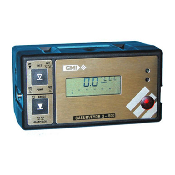
INTRODUCTION The Gasurveyor 3-500 is a two button flammable gas leak location and purge instrument, designed to measure Lower Explosive Level (LEL) and Volume flammable gas. The instrument is designed to the latest standards and is certified for use in Hazardous Areas. -
Page 12
GASURVEYOR 3-500 USER HANDBOOK generally be configured, with the possible options detailed in italic text. GMI recommend that you take the time to study your instrument and, where practical and with advice from your company’s Purchasing / Management departments, highlight your particular instrument configuration. -
Page 13
GENERAL INFORMATION Ranges of Operation LEL, 0 to 100% The LEL range indicates the explosibility of the flammable gas in the sample. This is displayed as a percentage of the lower explosive limit (LEL) of the gas. For methane 100% LEL corresponds to 5% Volume methane in Air. -
Page 14
When using PURGE mode to measure flammable gas in air or Nitrogen, or a combination of both background gases, the Gasurveyor 3-500 will use the thermal conductivity Volume gas range only. The digital display will resolve the signal to 1% Gas, with the analogue bar graph following in steps of 4%. -
Page 15
The instrument, where selected, can have alarm levels for the Flammable LEL pre-set. The Gasurveyor 3-500 has the facility to have two (2) instantaneous alarm levels for the flammable LEL range in the instrument. These are described as LOW and HIGH, although generally only the high alarm would be active. -
Page 16
/ industry in which the unit is being used. Alarm Functions The Gasurveyor 3-500, by default, has the alarm function on the flammable range disabled. Where the alarm function is enabled, the instrument has the facility to have either latching or non-latching alarms. -
Page 17
GENERAL INFORMATION Non-Latching means that the alarms clear automatically when the gas level falls below the alarm limit. For both latching and non-latching alarms, it is possible for both audible and visual indicators to be either On or OFF independent of each other. Construction The instrument is housed in a tough, impact resistant, moulded case made of carbon loaded polypropylene. -
Page 18
Rechargeable Battery Pack OPERATOR MAINTENANCE Filters A number of different filter types are available from GMI. The minimum requirement is a cotton particulate filter and a hydrophobic filter which are incorporated in the probe handle assembly, supplied with the instrument. -
Page 19
GENERAL INFORMATION is drawn into the instrument any filter which has been contaminated must be cleaned or replaced. See Filter in Section 4 Replacement OPERATOR MAINTENANCE Liquid Crystal Display (LCD) The LCD shows the current gas readings in both analogue and digital form together with operational and status information. -
Page 20
GASURVEYOR 3-500 USER HANDBOOK… -
Page 21
ON with either Button One or Button Two . See Figure 3.1 below. INST. PUMP PURGE GASURVEYOR 3-500 ALARM ACK. Figure 3.1 Instrument Front Plate Mode 1. Switching ON with Button One provides two gas ranges: a) LEL autoranging to Volume Gas. -
Page 22
GASURVEYOR 3-500 USER HANDBOOK Audible/visual alarms can operate in this mode. Mode 2. Switching ON with Button Two provides access to only 0-100% Vol Gas range for purge applications. No audible/visual alarms are available in this mode. Switching On Press and hold Button One to turn the instrument on. -
Page 23
OPERATION Calibration Date Features At the end of warm-up and before the Gasurveyor 3-500 instrument is ready for measuring, the instrument will indicate on the display when the next calibration is due. This will be displayed as month and year, as shown in Figure 3.3:… -
Page 24
Switching On in Purge Mode To switch on in Purge mode, press and hold Button Two . The Gasurveyor 3-500 will initiate the warm-up sequence as explained previously. This mode uses the thermal conductivity Volume gas range only since inert Nitrogen atmospheres are likely to be present. -
Page 25
OPERATION Summary of Button Operation Measure Double Press and Single Press Mode Press Hold Button 1 c t i c t i Toggles Pump On / Off (during operation) Button 2 c t i Acknowledge Instrument Alarm in Purge mode Operator Messages / Fault Flags Various messages can appear on the LCD screen to indicate instrument status. -
Page 26
GASURVEYOR 3-500 USER HANDBOOK ‘SAMPLE FAULT’ This indicates a problem with the instrument’s flow due to the sample path being blocked, water ingress, a blocked filter or pump failure. In Measure and Purge mode, the pump stops automatically. The sample line, filters etc. should be checked for water ingress or blockage and Button One should then be pressed to restart the pump. -
Page 27
OPERATION ‘OFF’ and the instrument automatically switches off. The batteries should be replaced immediately. ‘BAT FAULT’ This indicates that the batteries require replacing. ‘1’ This message which can also appear after power on, indicates that a calibration data error has been detected. The instrument should be returned for servicing. -
Page 28
GASURVEYOR 3-500 USER HANDBOOK… -
Page 29
OPERATOR MAINTENANCE Rechargeable Battery Pack Three battery chargers are available from GMI, a Standard Charger, a Flatbed Charger and a Smart Charger. Standard Charger The GMI Standard Charger takes approximately 14 hours to charge a flat battery. Note: The 4-button instrument is for illustration purposes… -
Page 30
GASURVEYOR 3-500 USER HANDBOOK Flatbed Charger The GMI Flatbed Charger allows the Gasurveyor’s battery pack to be charged in NORMAL mode, which takes approximately 14 hours to charge a flat battery. The Mode Select Switch can then be set to STAND-BY, where a trickle charge will maintain the battery in a fully charged state of readiness. -
Page 31
OPERATOR MAINTENANCE The GMI Smart Charger provides both fast and standard charging facilities and can charge an instrument and spare battery pack simultaneously. Using the standard charging option, a battery pack can be recharged in 12 hours from a fully discharged state. Using the fast charge option a battery pack can be 90% recharged in approximately 60 minutes and fully recharged in 120 minutes. -
Page 32
Replacing Alkaline (LR20) Dry Cell Batteries All four batteries should be replaced at any one time and in a safe area. GMI only recommend the use of Energiser or Duracell cells. 1) Loosen the two instrument base screws (4mm hex) -
Page 33
OPERATOR MAINTENANCE 2) Remove battery cover. 3) Remove the old batteries. 4) Check battery compartment for damage to spring contacts or corrosion on springs. Caution: Under no circumstances should rechargeable batteries be fitted in place of Alkaline batteries. 5) Insert four new batteries observing correct polarity indication in battery compartment base. -
Page 34
GASURVEYOR 3-500 USER HANDBOOK Filter Replacement Hydrophobic and cotton particulate filters in the probe handle minimise the danger of water and dust ingress. Caution: The instrument should never be switched on without suitable filters installed. If a blockage occurs the ‘SAMPLE FAULT’ indicator is displayed. -
Page 35
OPERATOR MAINTENANCE 2) Remove the cotton particulate filter and discard. 3) Remove the hydrophobic filter. 4) Clean the probe handle to make sure that it is free from dirt and water. 5) Fit a new cotton particulate filter. 6) Fit the hydrophobic filter. The yellow label on the filter fits against the yellow label on the probe handle. -
Page 36
GASURVEYOR 3-500 USER HANDBOOK… -
Page 37
CALIBRATION The instrument has been calibrated for a particular flammable gas mixture. Where any doubt exists the instrument should be returned to GMI or an authorised distributor for calibration. Four methods of calibration are possible: • Field Calibration. See APPENDIX B, FIELD CALIBRATION for further details. -
Page 38
12 month period can be expected. This is no guarantee, however, as the precise application of the product is unknown to GMI. Individual codes of practice may dictate shorter periods. Regular checking establishes a pattern of reliability and enables the calibration check period to be modified in line with operational experience. -
Page 39
ACCESSORIES Accessories Supplied with Gasurveyor 3-500 Instrument Part Number 42503 / 42503R Part Number Description 42119 Carrying Case 12370/2 Shoulder Harness 12451 4mm Hex. Driver 12712 Clear Sample Line x 1.5 metres. (4ft.10ins.) approx. 12480 Plastic Probe — Solid End 35cm. -
Page 40
GASURVEYOR 3-500 USER HANDBOOK 12888 Standard Charger / 220V Power Supply (Australian Plug) 13179 Standard Charger w/o Power Supply 42121 Flatbed Charger / 240V Power Supply (UK PLug) 42122 Flatbed Charger / 220V Power Supply (Euro Plug) 42123 Flatbed Charger / 110V Power Supply… -
Page 41
Carrying Case (Large) ; Probe Handle Assembly ; Probe Handle Adaptor ; Bellows Probe. Note: Large carrying case has space for special probes, e.g. Swan Neck Note: For other sampling probes and accessories, and for calibration gases, contact GMI Ltd. -
Page 42
GASURVEYOR 3-500 USER HANDBOOK… -
Page 43
GASURVEYOR 3-500 USER HANDBOOK… -
Page 44
TYPICAL OPERATING PARAMETERS Typical operating parameters are as follows: Range Resolution Zero Accuracy Range Stability 0 to 10% 0.1% +/- 0.5% 10 to 100% 2% +/- 1% LEL Volume 0 to 100% +/- 2% 1% +/- 1% Gas Notes: All the values above are at normal temperature and pressure. Humidity is between 0% and 95% RH (non-condensing). -
Page 45
GASURVEYOR 3-500 USER HANDBOOK Size 180mm (7.08”) x 95mm (3.74”) x 105mm (4.13”) Weight 1.7kg (3.75lbs.) with alkaline batteries Operating Temperature C to 50 C (-4 F to 122 Humidity 0 – 95% RH Construction Moulded polypropylene case protected to IP54… -
Page 46
TYPICAL OPERATING PARAMETERS Power Source 4 ‘D’ size alkaline cells giving approximately 15 hours runtime at 20 C (68 F).. Rechargeble (NiCd) battery pack giving approximately 9 hours runtime at 20 C (68… -
Page 47
GASURVEYOR 3-500 USER HANDBOOK… -
Page 48
Field calibration allows simple calibration to be carried out in the field without the use of additional test equipment. Other calibration procedures require the use of the GMI Manual Calibration software or the Workshop System. There are fundementals, in terms of instrument calibration, that should be noted: •… -
Page 49
GASURVEYOR 3-500 USER HANDBOOK INST. PUMP Figure B-1 Button Functions To simplify button operation when calibrating the instrument, an overlay card, shown in Figure B-2, is available and can be placed over the top face of the instrument to identify calibration button functions. -
Page 50
FIELD CALIBRATION Selectable Ranges in FCM When in FCM the following ranges are manually selectable by pressing Button Two : LEL, Volume GAS. Entering FCM 1) Switch the instrument on and allow it to complete its warm-up checks. 2) Double press Button One to initiate instrument switch off. -
Page 51
GASURVEYOR 3-500 USER HANDBOOK In CAL mode, the instrument buttons have the functions shown in Figure B-4. Press and Single Press Double Press Hold Button 1 Button 2 Figure B-4 CAL Mode Button Functions Zeroing the Instrument 1) Enter FCM. See the previous section ENTERING FCM. -
Page 52
FIELD CALIBRATION Field Calibration Procedure 1) Zero gas ranges before attempting calibration. See previous section ZEROING THE INSTRUMENT for details. 2) Make sure that the instrument pump is running and the gas range selected is compatible with the calibration gas. Note: A single press of Button One toggles the pump Off / On. -
Page 53
GASURVEYOR 3-500 USER HANDBOOK 4) Turn the regulator valve counter clockwise to open the valve slightly. Make sure that the gas is flowing before connecting the sample tubing to the instrument, otherwise an instrument sample fault may occur. 5) Connect tubing from regulator to instrument inlet… -
Page 54
FIELD CALIBRATION In SPAN mode, the instrument buttons have the functions shown in Figure B-7. Figure B-7 SPAN Mode Button Functions 8a) In SPAN mode, a single press of Button One will produce small incremental changes to increase display reading, or a single press of Button Two will produce small decremental changes to decrease display reading, until the displayed gas value corresponds to the concentration of the… -
Page 55
GASURVEYOR 3-500 USER HANDBOOK 9) The calibrated instrument display will now return to CAL mode display as shown in Figure B-8. Figure B-8 50% LEL Display 10) Make sure that correct reading is displayed before disconnecting the calibration gas then disconnect… -
Page 56
FIELD CALIBRATION Quitting FCM Quit And Save Changes 1) Press and hold Button Two to save CAL data. 2) Double press Button One to exit FCM. Quit Without Saving Changes 1) Double press Button One to exit FCM. Note: When you exit the FCM without saving the new CAL data, the old calibration data remains in the instrument memory. -
Page 57
GASURVEYOR 3-500 USER HANDBOOK B-10… -
Page 58
OPERATING INSTRUCTIONS The following multi-language instructions provide the user with a quick guide to the operation of the . . Gasurveyor 3-500 instrument. Each language and pages reference is as follows: • English — pages C-2 to C-5 • Français (French) — pages C-6 to C-9 •… -
Page 59
1.2.7 of Annex II of the ATEX Directive 94/9/EC Any right of claim relating to product liability or consequential damage to any third party against GMI is removed if the warnings are not observed. AREAS OF USE Exposure to certain chemicals can result in a loss of sensitivity of the flammable sensor. -
Page 60
Gasurveyor 3-500 — Operating Instructions The enclosure material is polypropylene and must not be exposed to environments which are liable to result in mechanical or thermal degradation or to damage caused by contact with aggressive substances. Additional protection may be required in environments where the instrument enclosure is liable to damage. -
Page 61
GAS MEASUREMENT INSTRUMENTS LTD. OPERATION INST. BUTTON 1 PUMP PURGE BUTTON 2 GASURVEYOR 3-500 ALARM ACK. Switch ON (Mode 1) LEL autoranging to Volume Gas Press and Hold Button One to switch instrument and pump On. This initiates the instrument’s warm-up cycle:… -
Page 62
A further press of Button One turns the pump back on. Clearing Alarms The Gasurveyor 3-500, by default, has the alarm function on the flammable range disabled. If the alarm function is enabled, the instrument has the facility to have either latching or non-latching alarms. -
Page 63
être échangées (*ou rechargés) dans une zone saine et installés correctement. Ne jamais utiliser de batteries endommagées ou les exposer à une chaleur extrême. • Seules les pièces d’origine GMI doivent être utilisées. • Si l’appareil détecte du gaz, suivez les procédures propres à votre entreprise. -
Page 64
Gasurveyor 3-500 — Notice d’utilisation contenant plus de 21% d’oxygène. Le boîtier de l’appareil est en polypropylène et ne doit pas être exposé à des environnements qui soient susceptibles d’apporter des dégradations mécaniques ou thermiques ou des dommages causés par des substances agressives. Une protection additionnelle peut être nécessaire dans les environnements ou le boîtier… -
Page 65
GAS MEASUREMENT INSTRUMENTS LTD. FONCTIONNEMENT INST. PUMP PURGE GASURVEYOR 3-500 ALARM ACK. Mise en marche (Mode 1) avec saut d’échelle automatique entre LIE et GAZ Pressez et maintenir le bouton 1 pour mettre en marche l’appareil et la pompe. Ce-ci démarre le cycle d’initialisation. -
Page 66
Une autre pression sur le bouton 1 remet la pompe en marche. Acquitter les alarmes Par défaut, le Gasurveyor 3-500 n’a pas d’alarme active sur l’échelle inflammable. Si la fonction alarme est activée, l’appareil a la possibilité d’avoir des alarmes maintenues ou non-maintenues. -
Page 67
Die Messkammer ist flammensicher ausgefüehrt und darf nicht in Ex Zonen geoeffnet werd • Gasurveyor 3-500 Instrumente sind zertfiziert nach: EEx iad IIC T4 (-20°C < bis < 50°C) BAS01ATEX2292 II 2 G. UL Klasse 1 Gruppe A,B,C und D. -
Page 68
Gasurveyor 3-500 — Bedienungshinweise Verwendungsgebiete Das auftreten von verschiedenen Chemikalien kann die Empfindlichkeit des Sensors fuer brennbare Gase beeinflussen. Beim vorhandensein dieser Stoffe ist ein kuerzeres Serviceintervall erforderlich. Folgende Komponenten fuehren zur verringerung der Sensorempfindlichkeit: Silicone, Halogene und Schwefel. Das Instrument darf nicht in Athmosphaeren mit mehr als 21% Sauerstoff verwendet werden. -
Page 69
GAS MEASUREMENT INSTRUMENTS LTD. Bedienung INST. PUMP PURGE GASURVEYOR 3-500 ALARM ACK. Einschalten (Modus 1) LEL automatische Umschaltung auf Volume Gas Taste 1 Druecken und Halten, Geraet und Pumpe ein und die Selbsttestphase beginnt: Einschalten (Modus 2) 0 bis 100% Volume Gas ; Für Spülungs (Purge) Anwendungen. -
Page 70
Stop der laufenden Pumpe und der Probenahme. Erneutes Drücken startet die Pumpe wieder Alarmquittung Der Gasurveyor 3-500, hat eine einschaltbare Alarmabgabe bei der Mesung von brennbaren Gasen. Bei aktiviertem Alarm ist eine Selbsthaltung aus-oder einschaltbar. Nicht selbsthaltende Alarme werden automatisch geloescht, wenn die Gasanzeige unter den eingestellten Wert abfaellt. -
Page 71
Denna utrustning är konstruerad och tillverkad för att skydda mot andra risker än definitionen I paragraf 1.2.7 i Annex II i ATEX Direktivet 94/9/EC All rätt till skadestånd med hänvisning till produktansvar eller skada hos tredje man gentemot GMI upphör om denna varning ej beaktas. C-14… -
Page 72
Gasurveyor 3-500 — Handhavande ANVÄNDNINGSOMRÅDE Exponering för vissa kemikalier kan resultera I att sensorn för brännbara gaser skadas. I sådan atmosfär rekommenderas att ofta kontrollera instrumentets känslighet. De kemiska substanser som kan orsaka försämrad reaktion är bl.a. Silikoner, Bly, Halogener and Sulfider. Använd inte instrumentet där oxygenhalten kan överskrida 21vol%. -
Page 73
BRUKSANVISNING INST. KNAPP 1 PUMP PURGE KNAPP 2 GASURVEYOR 3-500 ALARM ACK. Slå på (Alternativ 1) %LEL växlar automatiskt till vol%Gas Tryck och håll nere knapp “1” för att sätta på instrumentet och pumpen. Detta startar en automatisk kontroll och uppvärmning av instrumentet: Slå… -
Page 74
Ett tryck på knapp “1” då pumpen går stoppar pumpen. Med ytterligare ett tryck startar pumpen igen. Kvittering av larm Gasurveyor 3-500, har som standard larmfunktionen aktiverad vid mätning I LEL-området. Om larmfunktionen är aktiverad så kan den vara antingen automatisk återgående eller ej. -
Page 75
Forbrændings kammer er brandsikker tilbehør, og må ikke åbnes i almindelig atmosfære. • Ethvert krav i forbindelse med produkt ansvar eller følge skade på tredje part imod GMI, er fjernet hvis de ovenstående forskrivelser ikke håndhæves. • Gasurveyor 3-500 instrument er certificeret ifølge: C <… -
Page 76
Gasurveyor 3-500 — Bruger manual Bruger beskeder og fejl Forskellige beskeder/tegn forekomme på displayet under brug. ‘SAMPLE’ fortæller at pumpen kører, og at instrumentet optager prøver. ‘OFF’ Indikerer at instrumentet er ved at slukke. Denne kommando kan afbrydes ved et tryk på en anden knap. -
Page 77
GAS MEASUREMENT INSTRUMENTS LTD. Tænd Gasurveyor INST. KNAP 1 PUMP PURGE KNAP 2 GASURVEYOR 3-500 ALARM ACK. Mode 1 (LEL/Volume Gas) Tryk og hold nede den knap 1 , så startes opvarmnings processen og pumpen. Mode 2 (0-100 Volume Gas til purge) Tryk og hold nede den knap 2 , så… -
Page 78
Et tryk mere på knap 1 starter pumpen og målingen igen. Alarms afbrydelse Gasurveyor 3-500 har både hørlig og visuel alarm ved fejl under brug. Når alarm er sat i stand, gar instrumentet muligheden for at enten have latching eller non-latching alarm. -
Page 79
II van de ATEX 94/9/EC Elke recht op een claim met betrekking tot de betrouwbaarheid of de daardoor veroorzaakte schade van welke derde partij dan ook aan GMI zal verworpen worden indien de waarschuwingen genegeerd zijn. PLAATSEN VAN GEBRUIK Blootstelling aan bepaalde chemicaliën kan resulteren in een verlies… -
Page 80
Gasurveyor 3-500 — Gebruiksaanwijzing zuurstof. Het omhullende materiaal is polypropyleen en dit mag niet blootgesteld worden aan omgevingen die waarschijnlijk resulteren in mechanische of thermische degradatie of schade veroorzaakt door contact met aggressieve substanties. Bijkomende bescherming kan nodig zijn in omgevingen waar het omhulsel van het instrument onderhavig kan zijn aan schade. -
Page 81
GAS MEASUREMENT INSTRUMENTS LTD. GEBRUIK INST. KNOP 1 PUMP PURGE KNOP 2 GASURVEYOR 3-500 ALARM ACK. Schakel AAN (Mode 1) LEL autobereik naar volume gas. Druk op knop 1 en houdt ingedrukt om instrument en pomp aan te schakelen. Dit zorgt voor opwarming:… -
Page 82
Een volgende druk op knop 1 schakelt de pomp weer aan. Alarmen verwijderen De Gasurveyor 3-500 heeft standaard de alarmfunctie op het ontvlambare bereik uitgeschakeld. Indien de alarmfunctie aangeschakeld is, kunt u op het instrument kiezen tussen een alarm met of zonder automatische uitschakeling. -
Page 83
GAS MEASUREMENT INSTRUMENTS LTD. C-26… -
Page 84
Index Charger, Flatbed 20 Symbols Charger, Smart 20 Charger, Standard 19 1 17 CHECK ZERO 16 Construction 7, A-2 COPYRIGHT i ACCESSORIES 29 ACCURACY A-1 Alarm Functions 6 Dansk (Danish) C-1 Alarms 5 Deutsch (German) C-1 alkaline A-3 Display A-2 Alkaline (LR20) Dry Cell DISPOSAL ADVICE i Batteries 7, 22… -
Page 85
GASURVEYOR 3-500 USER HANDBOOK GENERAL INFORMA- OFF 15 TION 3 OPERATING INSTRUC- TIONS 11 OPERATING PARAMETERS HANDLING ii Operating Temperature A-2 Humidity A-2 OPERATOR MAINTENANCE Operator Messages 15 IMS 27 INTRODUCTION 1 PARAMETERS A-1 Power Source A-3 Pump 13 LCD 9, 15, A-2… -
Page 86
Replacing the Battery Pack 21 Weight A-2 RESOLUTION A-1 World Wide Web 33 REVISION RECORD iii ZERO FAULT 16 SAMPLE 15 ZERO STABILITY A-1 SAMPLE FAULT 16, 24 Zeroing the Instrument B-4 Sampling System A-2 Save Changes B-9 Selectable Ranges in FCM B-2, B-3 Size A-2 Smart Charger 20… -
Page 87
GASURVEYOR 3-500 USER HANDBOOK… -
Page 89
Thank you for reading this data sheet. For pricing or for further information, please contact us at our UK Office, using the details below. UK Office Keison Products, P.O. Box 2124, Chelmsford, Essex, CM1 3UP, England. Tel: +44 (0)1245 600560 Fax: +44 (0)1245 808399 Email: sales@keison.co.uk…
This manual is also suitable for:
42129
измерительные приборы, аналитическая аппаратура, лабораторное оборудование, расходные материалы

Внесены в Государственный реестр средств измерений РФ под № 33963-07
Области применения
- Диагностика газопроводов высокого и низкого давления, ПХГ, крановых узлов
- Диагностика газохранилищ, резервуаров и газораспределительных станций
- Поиск и контроль концентрации горючих и токсичных газов в местах возможных утечек
- Экологический мониторинг на территории заводов, газоперекачивающих и газозаправочных станций и других объектов.
Возможности
- Измерение концентрации горючих и токсичных газов и паров
- Измеряемые диапазоны воспламеняемости
- РРМ (в долях на миллион)
- в процентах
- LEL (нижний предел взрывоопасности) по объему
- Измерение уровня кислорода и токсичных газов (H2S и CO).
Особенности
- Наличие моделей с двумя или четырьмя кнопками
- Встроенный пробоотборный насос
- Большой ЖК дисплей с автоматической подсветкой
- Звуковая и визуальная сигнализация с сигналом отказа
- Возможности регистрации данных
- Широкий выбор датчиков
- Удобство эксплуатации
- Чрезвычайно прочный антистатичный корпус
В модернизированную серию приборов Gasurveyor входит наиболее широкий выбор индикаторов утечки газа.
Двухкнопочные детекторы Gasurveyor 500 очень просты в употреблении. Они позволяют решать стандартные задачи с наименьшими затратами.
Приборы с четырьмя кнопками отличает возможность регистрации измеренных данных и расширенный набор сигнальных функций.
Модели детекторов Gasurvevor
| Датчики | Двухкнопочные | Четырехкнопочные | |||||||||||||||||
| РРМ-500 | 3-500 | 6-500 | 11-500 | 511 | 512 | 521 | 522 | 523 | 524 | 525 | 526 | 531 | 532 | 533 | 534 | 541 | 542 | для служб ЧП | |
| 0…100 % LEL | x | x | x | x | x | x | x | x | x | x | x | x | x | x | x | x | x | x | x |
| 0…100 % Газ | x | x | x | x | x | x | x | x | x | x | x | x | x | x | x | x | x | x | x |
| 1…1000 РРМ СН4 | x | x | x | x | x | x | x | x | x | ||||||||||
| Розыск по РРМ | x | ||||||||||||||||||
| 0…25 % О2 | x | x | x | x | x | x | x | x | x | ||||||||||
| 0…200 РРМ H2S | x | x | x | x | x | x | |||||||||||||
| 0…1000 РРМ СО | x | x | x | x | x | x | x | x | |||||||||||
| Сигнализация | x | x | x | x | x | x | x | x | x | x | x | x | x | x | x | ||||
| Регистр. данных 0…10000 РРМ | x | x | x | x | x | x | x | x | x | x | x | x | x | x | x |
Технические характеристики
| Диапазоны | Газ | Разрешающая способность |
| 0…1000 PPM | горючий | 5 РРМ |
| 0…100 % LEL | горючий | 0.1 % (0…9,9 %) |
| 1 % (10…100 %) | ||
| 0…100 % объем | горючий | 1 % |
| 0…25 % | кислород | 0.1 % |
| 0…1000 РРМ | угарный газ | 1 РРМ |
| 0…200 РРМ | H2S | ±2 % всей шкалы |
| Дисплей | ЖКИ с аналоговым дисплеем в диапазонах: 0…10; 0…100; 0…1000 и 0…10000 | |
| Четырехзначный цифровой дисплей | ||
| Трехсимвольный индикатор диапазона | ||
| Указатель эксплуатационного режима | ||
| Диапазон рабочей температуры, °С | -20…+50 | |
| Влажность, % RH | 95, неконденсирующаяся | |
| Конструкция | корпус из литого полипропелена | |
| Класс защиты | защищен до IP54 | |
| Пробоотборная система | встроенный насос с датчиком отказа | |
| пробовод защищен гидрофобным фильтром и автоматическим выключателем насоса | ||
| Источник питания | щелочные батареи типа «D» 4 шт | |
| комплект аккумуляторных батарей (опция) | ||
| Время действия батареи, ч | 15 (с щелочной) | |
| 8 (с аккумуляторной) | ||
| Сигнализация | яркие мигающие светодиоды | |
| Динамик | выше 80 дБ(А), обычно 85 дБ(А) на расстоянии 1 м | |
| Заводские параметры настройки | LEL | 20 % |
| СО | 35 PPM | |
| Кислород | 19 % нижний уровень, 23 % верхний уровень | |
| Время реакции (типичное) | LEL горючее | 3 сек (t50); 5 сек (t50) |
| Кислород | 7 сек (t50) | |
| Токсичные газы | 15 сек (t50) | |
| Аттестация | ЕЕх iad IIС Т4 | |
| UL класс 1, группы А, В, С и D | ||
| Стандарты | EN50014/EN50018/EN50020/UL913 | |
| Габаритные размеры, мм | 180×95×105 | |
| Масса (с щелочными батареями), кг | 1,7 |
t50: время, необходимое для достижения 50 % полного значения
Комплектующие
- Стандартное недорогое зарядное устройство
- Зарядное устройство «Smart Charger» с программой регистрации данных
- Датчики
- Датчик анализа дымоходов (15″)
- Гофрированный обзорный датчик
- Лексановый датчик (36″)
- Датчики трубопроводных траншей (27.5″ и 15″)
- Гибкий полупроводниковый датчик
- Гибкий датчик
php|sql engine by ivan
design by p.s.
html|php coding by fish
Почтовый адрес: 190013, Санкт-Петербург, а/я 120
Офис: Клинский проспект, д. 25
Телефон: +7 (812) 336-90-86 (многоканальный)
Транспортный отдел: +7 (931) 535-80-69
Факс: +7 (812) 336-90-86
E-mail: marketing@granat-e.ru
Для непрерывного и селективного измерения содержания кислорода, метана в дымовых газах, образующихся при сжигании различных видов топлива, а также для определения энергетических параметров отходящих газов малых топливных установок в химической, нефтехимической, бумажной, автомобильной, металлургической промышленности, теплоэлектростанциях, установках для сжигания мусора, крупных котельных установках.
Скачать
| 33963-07: Описание типа СИ | Скачать | 146.9 КБ |
Информация о поверке
| Методика поверки / информация о поверке | МП ВНИИМС |
| Межповерочный интервал / Периодичность поверки | 1 год |
| Зарегистрировано поверок | 308 |
| Найдено поверителей | 12 |
| Успешных поверок (СИ пригодно) | 297 (96%) |
| Неуспешных поверок (СИ непригодно) | 11 (4%) |
Информация по Госреестру
| Основные данные | |
|---|---|
| Номер по Госреестру | 33963-07 |
| Наименование | Газоанализаторы |
| Модель | Gasurveyor 500 мод. PPM-500,3-500, 6-500, 11-500, 511, 512, 521, 522 |
| Модификации | «PPM-500″,»3-500», «6-500», «11-500», «511», «512», «521», «522» |
| Технические условия на выпуск | тех.документация фирмы |
| Класс СИ | 31.01 |
| Год регистрации | 2007 |
| Страна-производитель | США |
| Центр сертификации СИ | |
| Наименование центра | ГЦИ СИ ВНИИМС |
| Адрес центра | 119361, г.Москва, Озерная ул., 46 |
| Руководитель центра | Кононогов Сергей Алексеевич |
| Телефон | (8*095) 437-55-77 |
| Факс | 437-56-66 |
| Информация о сертификате | |
| Срок действия сертификата | 01.03.2012 |
| Номер сертификата | 26859 |
| Тип сертификата (C — серия/E — партия) | С |
| Дата протокола | 02 от 15.02.07 п.108 |
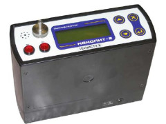
Фирма «Gas Measurement Instruments Ltd. (GMI)», США
США
9030 Monroe RoadHouston, Texas 77061, USA
Для: измерения содержания кислорода (О2), оксида углерода (СО), диоксида углерода (СО2), оксида азота (N0), диоксида азота (NO2), сернистого ангидрида (SO2), сероводорода (H2S), аммиака (NH3), хлора (Cl2), хлористого водорода (HCI), фтористого водоро…
Specifications:
|
Accompanying Data:
GMI Gasurveyor 3-500 Gas Detectors PDF User Handbook Manual (Updated: Sunday 2nd of April 2023 06:35:40 AM)
Rating: 4.2 (rated by 84 users)
Compatible devices: Gasurveyor 11-500, Gasurveyor 700, PS500, PPM Gasurveyor 500, PhoCheck TIGER, Gasurveyor 500 Series, 69005/10, PS1100.
Recommended Documentation:
GMI Gasurveyor 3-500: Text of User Handbook Manual
(Ocr-Read Version Summary of Contents, UPD: 02 April 2023)
-
41, 31 13427 Plastic Probe — Open End 35cm. (1ft.2ins.) approx. 13413 Stainless Steel Probe — Open End 35cm. (1ft.2ins.) approx. 12895 Barbed Probe — Solid End 69cm. (2ft.3ins.) approx. 12894 Barbed Probe — Open End 69cm. (2ft.3ins.) approx. 13561 Probe Handle 13562 Probe Handle Adaptor (use with 13563 or 13565) 13563 Bellows Cup Probe 13565 Swan Neck Probe 13655 Probe Shroud c/w Skids (use …
-
85, GASURVEYOR 3-500 USER HANDBOOK II G GENERAL INFORMA- TION 3 H HANDLING ii Humidity A-2 I IMS 27 INTRODUCTION 1 L LCD 9, 15, A-2 LEL 3 LEL Displayed as % Volume Equivalent 5 LIABILITY i Liquid Crystal Display 9 M Messages, Operator 15 Modes of Operation 11 MODIFICATION NOTICES i N Nederlands (Dutch) C-1 NiCd A-3 O OFF 15 OPERATING INSTRUC- TIONS 11 OPERA…
-
3, i COPYRIGHT This User Handbook is copyright of Gas Measurement Instruments Ltd (GMI) and the information contained within, is for use only with the Gasurveyor 3-500 instrument. Reproduction, in whole or in part, including utilisation in machines capable of reproduction or retrieval without written permission of Gas Measurement Instruments Ltd is prohibited. Reverse engineering is…
-
27, 17 ‘OFF’ and the instrument automatically switches off. The batteries should be replaced immediately. ‘BAT FAULT’ This indicates that the batteries require replacing. ‘1’ This message which can also appear after power on, indicates that a calibration data error has been detected. The instrument should be returned for servicing. OPERATION
… -
25, 15 Summary of Button Operation ffOsehctiwS tnemurtsnI Measure Mode Single Press Double Press Press and Hold Button 1 Button 2 Acknowledge Alarm Toggles Pump On / Off (during operation) OnsehctiwS tnemurtsnI OnsehctiwS Instrument in Purge mode _ Operator Messages / Fault Flags Various messages can appear on the LCD screen to indicate instrument status. ‘SAMPLE’ This indicates tha…
-
17, 7 Non-Latching means that the alarms clear automatically when the gas level falls below the alarm limit. For both latching and non-latching alarms, it is possible for both audible and visual indicators to be either On or OFF independent of each other. Construction The instrument is housed in a tough, impact resistant, moulded case made of carbon loaded polyp…
-
71, C-14 GAS MEASUREMENT INSTRUMENTS LTD. CHECKLISTA 1. Kontrollera att instrumentet ej har några synliga fel. 2. Kontrollera samtliga tillbehör. 3. Läs och förstå instruktionsboken innan Du använder instrumentet 4. Slå på instrumentet (se nedanstående) 5. Kontrollera batteriets kapacitet. 6. Kontrollera “Nollan” I frisk luft. SÄKERHET • Instrumentet skall regelbundet k…
-
14, GASURVEYOR 3-500 USER HANDBOOK 4 Volume Gas, 0 to 100 % This range displays the total volume of a specific flammable gas with respect to air. The calibration gas is shown on the service label and for the purpose of this handbook is assumed to be methane. Instruments calibrated for methane in air should only be used for measuring such mixtures. To change the calibration gas, e.g. fr…
-
45, GASURVEYOR 3-500 USER HANDBOOK A-2 Size 180mm (7.08”) x 95mm (3.74”) x 105mm (4.13”) Weight 1.7kg (3.75lbs.) with alkaline batteries Operating Temperature -20 o C to 50 o C (-4 o F to 122 o F) Humidity 0 – 95% RH Construction Moulded polypropylene case protected to IP54 Display LCD containing: Analogue display scaled 0-10, 0-100, 0-1000 or 0-10000 4…
-
19, 9 is drawn into the instrument any filter which has been contaminated must be cleaned or replaced. See Filter Replacement in Section 4 OPERATOR MAINTENANCE. Liquid Crystal Display (LCD) The LCD shows the current gas readings in both analogue and digital form together with operational and status information. The display is protected by a toughened glass cover. Backlighting is provided t…
-
69, C-12 GAS MEASUREMENT INSTRUMENTS LTD. Bedienung Einschalten (Modus 1) LEL automatische Umschaltung auf Volume Gas Taste 1 Druecken und Halten, Geraet und Pumpe ein und die Selbsttestphase beginnt: kurz dargestellt, die Instrument Type, Softwareversion und der Batteriezustand, Einschalten (Modus 2) 0 bis 100% Volume Gas ; Für Spülungs (Purge) Anwendungen. Ta…
-
65, C-8 GAS MEASUREMENT INSTRUMENTS LTD. la pompe. Ce-ci démarre le cycle d’initialisation. Mise en marche (Mode 2) 0 à 100% Volume Gaz pour les applications « Balayage d’Azote » Pressez et maintenir le bouton 2 pour mettre en marche l’appareil et la pompe. Ce-ci démarre le cycle d’initialisation. GASURVEYOR 3-500 ON OFF PUMP ON OFF INST. ALARM ACK. PURGE Mise en marche (Mode 1) ave…
GMI Gasurveyor 3-500: Recommended Instructions
Wireless Bluetooth Keyboard, HT-CT350, 357, StorTrends 1108-P, Dynaflow


-
1 Intended useThe Dräger tube has been designed to determine whether ethylene glycol is in the air at the time of measurement. The Dräger tube is intended only as a spot measurement.2 Reaction principleOH-C2H4-OH → HCHOHCHO + C6H4(CH3 )2 + H2SO4 → quinoid reaction products3 Measurement and evaluation1. Ensure the measuring site has good lighting.2. Break off both Dräger tube ends wi …
Ethylene glycol 10 2
-
Merlin 1500S User Guide Rev: 07 05-19 1 Gas Safety Products Merlin 1500S Gas & Ventilation interlock system User Guide Please read this guide carefully and retain for future use. …
Merlin 1500S 12
-
Copyright © 2014 CO2 Meter. All Rights Reserved. User Manual iSenseRemoteOxygenSafetyAlarmCM‐0180–25%OxygenCM‐0181–95%OxygeniSense Oxygen Transmitter – Manual CO2Meter.com Rev. 27 October 2014 Pg. 2 of 21 Table of Contents TABLEOFCONTENTS………………………………………………….. …
iSense CM-0180 11
-
GSH900 Belonging toTo protect your familyGSH900 — V. 1Household gas detectorImportant: Assembly / maintenance of the appliance must be carried out by qualified personnel and inaccordance with applicable laws and regulations.The manufacturer assumes no responsibility for the use of products that have to comply with particularenvironmental and / or installation standards.Impo …
GSH900 8
-
PT0E-1451 Request for the Customers • Read and understand this operating manual before using the management program. • Use the management program in accordance with the operating manual. Formaldehyde Gas Detector FP-31Series Data Logger Management Program SW-FP-31 Operating Manual …
FP-31 39
-
MAN154 Rev Date 4/30/2020 E-16D/-5D/-2D Enterprise Environment Monitoring System Installation and Operation Manual ENVIROMUX® Series Front View of E-5D Front View of E-2D Front and Rear View of E-16D …
ENVIROMUX Series 150
-
® DG-1 DIGITAL GAS DETECTORS dg1_en 05/09 The DG-1 microprocessor-based digital gas detectors are characterized by reliability and low current consumption. Due to a digital temperature compensation feature they can operate within a wide temperature range. Gas concentration above the threshold level triggers visual and audible alarm signals. T …
DG-1 Series 4
-
MP-D, MP-DS, MP-DK, MP-DR SE Instruktioner GB Instructions D Anleitungen ES Instrucciones FR Instructions MP-D IS MP-series 1210.doc.doc 1 MP-DS MP-DK MP-DR SE — Detektorer: MP-serien GB — Gasdetector type: MP-series D — Gasdetektor Typ: MP-Serie ES — Detector de gas tipo: Serie MP FR — Type de détecteur de gaz: série MP …
MP Series 8
-
Quick Start Card ALTAIR 4, ALTAIR 4X Please review the back of this card for a detailed illustration of the following components: T Button S Button Button •Turn the instrument ON with the button. Instrument willwarm up and show info & setpoints.•FAS: to accept press , to cancel press S.•Page through screens with T button from the NormalOperat …
altair 4 40
-
Installation & Operation Manual Merlin Gas Detector TFT AGSDETTFT-IOM Iss: 5 06-20 1 Merlin Gas Detector TFT Installation & Operation Manual Please read this manual carefully and retain for future use. At American Gas Safety, we supply a full range of remote gas detectors in …
Merlin TFT 16
Additional Information:
Popular Right Now:
Operating Impressions, Questions and Answers:
Газоанализаторы Gasurveyor 500 мод. PPM-500,3-500, 6-500, 11-500, 511, 512, 521, 522, мод. «PPM-500″,»3-500», «6-500», «11-500», «511», «512», «521», «522»
Изделие зарегистрировано в Госреестре под номером 33963-07
НАЗНАЧЕНИЕ И ОБЛАСТЬ ПРИМЕНЕНИЯ
Газоанализаторы «Gasurveyor 500» модели «РРМ-500», «3-500», «6-500», «11-500», «511», «512», «521», «522» предназначены для непрерывного и селективного измерения содержания кислорода, метана в дымовых газах, образующихся при сжигании различных видов топлива, а также для определения энергетических параметров отходящих газов малых топливных установок.
Газоанализаторы могут применяться в химической, нефтехимической, бумажной, автомобильной, металлургической промышленности, теплоэлектростанциях, установках для сжигания мусора, крупных котельных установках.
ОПИСАНИЕ
Принцип действия газоанализаторов основан на непрерывном и селективном измерении электрохимическим сенсором, сенсором по теплопроводности, каталитическим сенсором анализируемых компонентов в потоке проходящего газа.
Пробы газа для анализа отбирают при помощи зонда и встроенного в анализаторы насоса. Зонд оснащен гидрофобным фильтром и устройством автоматического отключением насоса.
Газоанализаторы полностью автоматизированы. Встроенный микропроцессор управляет ходом анализа, проводит перед каждым анализом самодиагностику, промывку сенсоров воздухом и установку нулевых показаний, обрабатывает результаты измерений. Полученные результаты выводятся на жидкокристаллический дисплей.
Питание приборов осуществляется от щелочных батарей, обеспечивающих до 15ч беспрерывной работы при температуре окружающей среды 20 »С.
Приборы вьщают световую и звуковую (85 дБ на расстоянии 1м) сигнализацию при превышении уровней концентраций, установленных для приборов.
ОСНОВНЫЕ ТЕХНИЧЕСКИЕ ХАРАКТЕРИСТИКИ
ОСНОВНЫЕ ТЕХНИЧЕСКИЕ ХАРАКТЕРИСТИКИ
|
Модели |
||||||||
|
«РРМ-500» |
«3-500» |
«6-500» |
«11-500» |
«511» |
«512» |
«521» |
«522» |
|
|
Диапазон измерений: |
||||||||
|
об. доля, % |
— |
— |
— |
0…25 |
— |
— |
0…25 |
0…25 |
|
СН4, % НКПР |
0…50 |
0…50 |
0…50 |
0…50 |
0…50 |
0…50 |
0…50 |
0…50 |
|
СН4, об.доля, % |
0…2,2 |
0…2,2 |
0…2,2 |
0…2,2 |
0…2,2 |
0…2,2 |
0…2,2 |
0…2,2 |
|
об доля, млн’* |
0…1000 |
— |
— |
— |
— |
0…1000 |
— |
0…1000 |
|
Диапазон показаний: |
||||||||
|
СН4, % НКПР |
50…100 |
50…100 |
50…100 |
50…100 |
50…100 |
50… 100 |
50…100 |
50…100 |
|
СН4, об.доля, % |
2,2… 100 |
2,2…100 |
2,2… 100 |
2,2…100 |
2,2…100 |
2,2… 100 |
2,2…100 |
2,2… 100 |
|
Пределы допускаемой |
абсолютной погрешности измерений: |
|||||||
|
об. доля, % |
±0,2 |
|||||||
|
СН4, об.доля, % |
±0,2 в диапазоне (0.. .2,2) об. доля % |
|||||||
|
СН4, % НКПР |
±4 в диапазоне (0.. .50) % НКПР |
|||||||
|
Пределы допускаемой |
приведенной погрешности измерений, %: |
|||||||
|
об доля, млн»‘ |
±5 |
|||||||
|
Время отклика, с, не более: |
||||||||
|
О2 (при достижении 50% сигнала, Т50) |
15 |
|||||||
|
СН4 (при достижении 50% сигнала, Т50) |
7 |
|||||||
|
СН4 (НКПР) (при достижении 50% сигнала, Х50) |
5 |
|||||||
|
Габаритные размеры, мм, не более |
180x95x105 |
|||||||
|
Масса (со щелочными батареями), кг, не более |
1,7 |
|||||||
|
Температура окружающей среды. |
-20…50 |
ЗНАК УТВЕРЖДЕНИЯ ТИПА
Знак утверждения типа наносят на лицевую панель прибора методом штемпелевания и титульный лист руководства по эксплуатации типографским способом.
КОМПЛЕКТНОСТЬ
Газоанализатор «Gasurveyor 500» модели «РРМ-500», «3-500», «6-500», «11-500», «511», «512», «521», «522» — по заказу.
Зонд для отбора пробы — 1 шт.
Руководство по эксплуатации — 1 экз.
Методика поверки — 1 экз.
ПОВЕРКА
Газоанализаторы «Gasurveyor 500» модели «РРМ-500», «3-500», «6-500», «11-500», «511», «512», «521», «522» поверяют в соответствии с документом «Инструкция. Газоанализаторы «Gasurveyor 500» модели «РРМ-500», «3-500», «6-500», «11-500», «511», «512», «521», «522» Методика поверки», разработанным и утвержденным ВНИИМС в 2007 г. и входящим в комплект поставки
Для поверки применяют государственные стандартные образцы состава поверочных газовых смесей ГСО-ПГС №№ 3726-87, 3885-87, 3895-97, 3904-87, 3905-87, 3908-87 по ТУ 6-16-2956-01.
Межповерочный интервал — 1 год.
НОРМАТИВНЫЕ ДОКУМЕНТЫ
ГОСТ 13320 «Газоанализаторы промышленные автоматические. Общие технические условия».
ЗАКЛЮЧЕНИЕ
Тип газоанализаторов «Gasurveyor 500» модели «РРМ-500», «3-500», «6-500», «11-500», «511», «512», «521», «522» утвержден с техническими и метрологическими характеристиками, приведенными в настоящем описании типа, метрологически обеспечен при выпуске из производства и в эксплуатации согласно государственной поверочной схеме.
Вьщан сертификат соответствия ГОСТ Р № РОСС US.AE25.A43503.