-
Драйверы
10
-
Инструкции по эксплуатации
22
Языки:

Gigabyte GA-G41M-Combo инструкция по эксплуатации
(72 страницы)
- Языки:Венгерский, Греческий, Испанский, Итальянский, Немецкий, Польский, Португальский, Русский, Турецкий, Французский, Чешский
-
Тип:
PDF -
Размер:
18.6 MB -
Описание:
Installation Guidebook


На NoDevice можно скачать инструкцию по эксплуатации для Gigabyte GA-G41M-Combo. Руководство пользователя необходимо для ознакомления с правилами установки и эксплуатации Gigabyte GA-G41M-Combo. Инструкции по использованию помогут правильно настроить Gigabyte GA-G41M-Combo, исправить ошибки и выявить неполадки.
-
Contents
-
Table of Contents
-
Bookmarks
Quick Links
GA-G41M-Combo
LGA775 socket motherboard for Intel
Intel
Pentium
®
®
User’s Manual
Rev. 1302
12ME-G41MC-1302R
processor family/Intel
Core
processor family/
®
™
Celeron
processor family
®
®
Related Manuals for Gigabyte GA-G41M-Combo
Summary of Contents for Gigabyte GA-G41M-Combo
-
Page 1
GA-G41M-Combo LGA775 socket motherboard for Intel Core processor family/ ® ™ Intel Pentium processor family/Intel Celeron processor family ® ® ® ® User’s Manual Rev. 1302 12ME-G41MC-1302R… -
Page 3: Identifying Your Motherboard Revision
GIGABYTE’s prior written permission. Documentation Classifications In order to assist in the use of this product, GIGABYTE provides the following types of documentations: For detailed product information, carefully read the User’s Manual.
-
Page 4: Table Of Contents
Table of Contents GA-G41M-Combo Motherboard Layout …………….5 Chapter 1 Hardware Installation ………………6 Installation Precautions ………………6 Product Specifications ………………7 Installing the CPU and CPU Cooler …………..9 1-3-1 Installing the CPU …………………9 Installing the Memory ………………10 1-4-1 Dual Channel Memory Configuration …………..10 Installing an Expansion Card ……………..
-
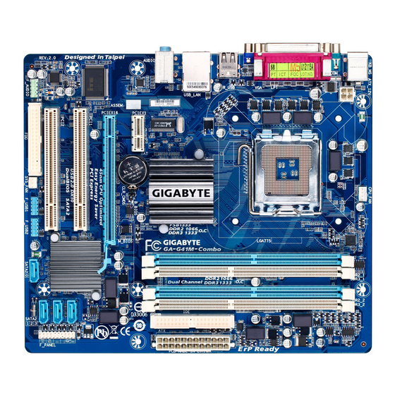
Page 5: Ga-G41M-Combo Motherboard Layout
GA-G41M-Combo Motherboard Layout CPU_FAN KB_MS ATX_12V COMA LGA775 R_USB USB_LAN AUDIO Intel ® F_AUDIO PCIEX1 Atheros AR8151 B_BIOS M_BIOS PCIEX16 IT8718F PCI1 SATA2_3 CODEC PCI2 Intel ICH7 ® SYS_FAN SATA2_2 F_USB2 SATA2_1 SATA2_0 F_USB1 Box Contents GA-G41M-Combo motherboard One IDE cable Motherboard driver disk Two SATA cables User’s Manual…
-
Page 6: Chapter 1 Hardware Installation
Chapter 1 Hardware Installation Installation Precautions The motherboard contains numerous delicate electronic circuits and components which can become damaged as a result of electrostatic discharge (ESD). Prior to installation, carefully read the user’s manual and follow these procedures: • Prior to installation, do not remove or break motherboard S/N (Serial Number) sticker or warranty sticker provided by your dealer.
-
Page 7: Product Specifications
Dual channel memory architecture Support for DDR2 1066(O.C.)/800/667 MHz memory modules (Note: Mixed mode, populating DDR2 and DDR3 memory modules simulta- neously is not supported. Go to GIGABYTE’s website for the latest supported memory speeds and memory modules.) Onboard Graphics w…
-
Page 8
Internal 1 x CPU fan header Connectors 1 x system fan header 1 x front panel header 1 x front panel audio header 1 x CD In connector 1 x S/PDIF Out header 2 x USB 2.0/1.1 headers 1 x serial port header 1 x clearing CMOS jumper Back Panel 1 x PS/2 keyboard port… -
Page 9: Installing The Cpu And Cpu Cooler
Read the following guidelines before you begin to install the CPU: • Make sure that the motherboard supports the CPU. (Go to GIGABYTE’s website for the latest CPU support list.) • Always turn off the computer and unplug the power cord from the power outlet before installing the CPU to prevent hardware damage.
-
Page 10: Installing The Memory
If you are unable to insert the memory, switch the direction. • Populating DDR2 and DDR3 memory modules simultaneously is not supported. To ensure memory compatibility, be sure to use the memory modules on the memory support list at GIGABYTE’s website. 1-4-1 Dual Channel Memory Configuration This motherboard provides two DDR2 and two DDR3 memory sockets and supports Dual Channel Technology.
-
Page 11: Back Panel Connectors
Back Panel Connectors PS/2 Keyboard and PS/2 Mouse Port Use the upper port (green) to connect a PS/2 mouse and the lower port (purple) to connect a PS/2 keyboard. Parallel Port Use the parallel port to connect devices such as a printer, scanner and etc. The parallel port is also called a printer port.
-
Page 12: Internal Connectors
Internal Connectors ATX_12V F_AUDIO CD_IN CPU_FAN SPDIF_O SYS_FAN F_USB1/F_USB2 COMB CLR_CMOS SATA2_0/1/2/3 F_PANEL Read the following guidelines before connecting external devices: • First make sure your devices are compliant with the connectors you wish to connect. • Before installing the devices, be sure to turn off the devices and your computer. Unplug the power cord from the power outlet to prevent damage to the devices.
-
Page 13
1/2) ATX_12V/ATX (2×2 12V Power Connector and 2×12 Main Power Connector) With the use of the power connector, the power supply can supply enough stable power to all the com- ponents on the motherboard. Before connecting the power connector, first make sure the power supply is turned off and all devices are properly installed. -
Page 14
3/4) CPU_FAN/SYS_FAN (Fan Headers) The motherboard has a 4-pin CPU fan header (CPU_FAN) and a 3-pin (SYS_FAN) system fan header. Most fan headers possess a foolproof insertion design. When connecting a fan cable, be sure to connect it in the correct orientation (the black connector wire is the ground wire). The motherboard supports CPU fan speed control, which requires the use of a CPU fan with fan speed control design. -
Page 15
6) IDE (IDE Connector) The IDE connector supports up to two IDE devices such as hard drives and optical drives. Before attach- ing the IDE cable, locate the foolproof groove on the connector. If you wish to connect two IDE devices, remember to set the jumpers and the cabling according to the role of the IDE devices (for example, master or slave). -
Page 16: Front Panel Header
 F_PANEL (Front Panel Header) Connect the power switch, reset switch, speaker and system status indicator on the chassis front panel to this header according to the pin assignments below. Note the positive and negative pins before con- necting the cables. PWR- SPEAK- Power LED…
 -
Page 17
9) F_AUDIO (Front Panel Audio Header) The front panel audio header supports Intel High Definition audio (HD) and AC’97 audio. You may connect your chassis front panel audio module to this header. Make sure the wire assignments of the module con- nector match the pin assignments of the motherboard header. -
Page 18
11) SPDIF_O (S/PDIF Out Header) This header supports digital S/PDIF Out and connects a S/PDIF digital audio cable (provided by expan- sion cards) for digital audio output from your motherboard to certain expansion cards like graphics cards and sound cards. For example, some graphics cards may require you to use a S/PDIF digital audio cable for digital audio output from your motherboard to your graphics card if you wish to connect an HDMI display to the graphics card and have digital audio output from the HDMI display at the same time. -
Page 19
13) COMB (Serial Port Header) The COM header can provide one serial port via an optional COM port cable. For purchasing the op- tional COM port cable, please contact the local dealer. Pin No. Definition NDCD- NSIN NSOUT NDTR- NDSR- NRTS- NCTS- NRI-… -
Page 20: Battery
15) BAT(Battery) The battery provides power to keep the values (such as BIOS configurations, date, and time information) in the CMOS when the computer is turned off. Replace the battery when the battery voltage drops to a low level, or the CMOS values may not be accurate or may be lost. You may clear the CMOS values by removing the battery: 1.
-
Page 21: Chapter 2 Bios Setup
To see more advanced BIOS Setup menu options, you can press <Ctrl> + <F1> in the main menu of the BIOS Setup program. To upgrade the BIOS, use either the GIGABYTE Q-Flash or @BIOS utility. Q-Flash allows the user to quickly and easily upgrade or back up BIOS without entering the operating •…
-
Page 22: Mb Intelligent Tweaker(M.i.t.)
• If you do not find the settings you want in the Main Menu or a submenu, press <Ctrl>+<F1> to access more advanced options. • When the system is not stable as usual, select the Load Optimized Defaults item to set your system to its defaults.
-
Page 23: Cpu Frequency
CMOS Setup Utility-Copyright (C) 1984-2010 Award Software MB Intelligent Tweaker(M.I.T.) Item Help x CAS Latency Time Auto Menu Level x tRCD Auto x tRP Auto x tRAS Auto >>>>> Advanced Timing Control Advanced Timing Control [Press Enter] ******** Mother Board Voltage Control ******** Voltage Types Normal Current…
-
Page 24
CPU Host Frequency (Mhz) Allows you to manually set the CPU host frequency. The adjustable range is from 100 MHz to 1200 MHz. This item is configurable only if the CPU Host Clock Control option is enabled. Important: It is highly recommended that the CPU frequency be set in accordance with the CPU specifications. -
Page 25
CMOS Setup Utility-Copyright (C) 1984-2010 Award Software Advanced Timing Control Item Help x tRRD Auto Menu Level x tWTR Auto x tWR Auto x tRFC Auto x tRTP Auto x Command Rate (CMD) Auto >>>>> Channel A Channel A Timing Settings [Press Enter] … -
Page 26
Static tRead Value Options are: Auto (default), 1~15. tRD Phase0 Adjustment Options are: Auto (default), 0-Normal, 1-Advanced. tRD Phase1 Adjustment Options are: Auto (default), 0-Normal, 1-Advanced. tRD Phase2 Adjustment Options are: Auto (default), 0-Normal, 1-Advanced. tRD Phase3 Adjustment Options are: Auto (default), 0-Normal, 1-Advanced. Trd2rd(Different Rank) Options are: Auto (default), 1~15. -
Page 27
CMOS Setup Utility-Copyright (C) 1984-2010 Award Software Channel A/B Driving Settings Item Help x Driving Strength Profile Auto Menu Level x Data Driving Pull-Up Level Auto x Cmd Driving Pull-Up Level Auto x Ctrl Driving Pull-Up Level Auto x Clk Driving Pull-Up Level Auto x Data Driving Pull-Down Level Auto… -
Page 28: Standard Cmos Features
Standard CMOS Features CMOS Setup Utility-Copyright (C) 1984-2010 Award Software Standard CMOS Features Item Help Date (mm:dd:yy) Mon, May 10 2010 Menu Level Time (hh:mm:ss) 22:31:24 IDE Channel 0 Master [None] IDE Channel 0 Slave [None] IDE Channel 2 Master [None] …
-
Page 29: Advanced Bios Features
Floppy 3 Mode Support Allows you to specify whether the installed floppy disk drive is 3-mode floppy disk drive, a Japanese standard floppy disk drive. Options are: Disabled (default), Drive A. Halt On Allows you to determine whether the system will stop for an error during the POST. Options are: «All Errors,»…
-
Page 30
HDD S.M.A.R.T. Capability Enables or disables the S.M.A.R.T. (Self Monitoring and Reporting Technology) capability of your hard drive. This feature allows your system to report read/write errors of the hard drive and to issue warnings when a third party hardware monitor utility is installed. (Default: Enabled) CPU Multi-Threading (Note) Allows you to determine whether to enable all CPU cores and multi-threading function when using an… -
Page 31: Advanced Chipset Features
Delay For HDD (Secs) Allows you to set a delay time for the BIOS to initialize the hard drive as the system boots up. The adjustable range is from 0 to 15 seconds. (Default: 0) Backup BIOS Image to HDD Allows the system to copy the BIOS image file to the hard drive.
-
Page 32: Integrated Peripherals
Paranoid PAVP Mode This item is configurable only if the PAVP Mode option is set to Paranoid PAVP. Options are: (32+96)128MB (default), (48+96) Round to 160MB, (64+96)160MB, (128+96)224MB and (256+96)352MB. The table below shows the supported features of the PAVP Lite and Paranoid modes. Feature PAVP Lite PAVP Paranoid…
-
Page 33
PATA IDE Set to This item is configurable only if the On-Chip SATA Mode is set to Combined. Ch.0 Master/Slave Sets the IDE channels to Ch. 0 Master/Slave. (Default) Ch.1 Master/Slave Sets the IDE channels to Ch. 1 Master/Slave. SATA Port 0/2 Set to This value is dependent on the On-Chip SATA Mode and PATA IDE Set to settings. -
Page 34: Power Management Setup
Onboard Parallel Port Enables or disables the onboard parallel port (LPT) and specifies its base I/O address and correspond- ing interrupt. Options are: 378/IRQ7 (default), 278/IRQ5, 3BC/IRQ7, Disabled. Parallel Port Mode Selects an operating mode for the onboard parallel (LPT) port. Options are: SPP (Standard Parallel Port) (default), EPP (Enhanced Parallel Port), ECP (Extended Capabilities Port), ECP+EPP.
-
Page 35
Soft-Off by PWR-BTTN Configures the way to turn off the computer in MS-DOS mode using the power button. Instant-Off Press the power button and then the system will be turned off instantly. (Default) Delay 4 Sec. Press and hold the power button for 4 seconds to turn off the system. If the power button is pressed for less than 4 seconds, the system will enter suspend mode. -
Page 36: Pnp/Pci Configurations
AC Back Function Determines the state of the system after the return of power from an AC power loss. Soft-Off The system stays off upon the return of the AC power. (Default) Full-On The system is turned on upon the return of the AC power. Memory The system returns to its last known awake state upon the return of the AC power.
-
Page 37: Load Fail-Safe Defaults
Current Voltage(V) Vcore/DDR/+3.3V/+12V Displays the current system voltages. Current CPU Temperature Displays current CPU temperature. Current CPU/SYSTEM FAN Speed (RPM) Displays current CPU/system fan speed. CPU Warning Temperature Sets the warning threshold for CPU temperature. When CPU temperature exceeds the threshold, BIOS will emit warning sound.
-
Page 38: Load Optimized Defaults
2-12 Load Optimized Defaults CMOS Setup Utility-Copyright (C) 1984-2010 Award Software MB Intelligent Tweaker(M.I.T.) PC Health Status Standard CMOS Features Load Fail-Safe Defaults Advanced BIOS Features Load Optimized Defaults Advanced Chipset Features Set Supervisor Password Integrated Peripherals Set User Password …
-
Page 39: Save & Exit Setup
2-14 Save & Exit Setup CMOS Setup Utility-Copyright (C) 1984-2010 Award Software MB Intelligent Tweaker(M.I.T.) PC Health Status Standard CMOS Features Load Fail-Safe Defaults Advanced BIOS Features Load Optimized Defaults Save to CMOS and EXIT (Y/N)? Y Advanced Chipset Features Set Supervisor Password …
-
Page 40: Chapter 3 Drivers Installation
Chapter 3 Drivers Installation • Before installing the drivers, first install the operating system. • After installing the operating system, insert the motherboard driver disk into your optical drive. The driver Autorun screen is automatically displayed which looks like that shown in the screen shot below.
-
Page 41: Regulatory Statements
Contravention will be prosecuted. We believe that the information contained herein was accurate in all respects at the time of printing. GIGABYTE cannot, however, assume any responsibility for errors or omissions in this text. Also note that the informa- tion in this document is subject to change without notice and should not be construed as a commitment by GIGABYTE.
-
Page 42
Finally, we suggest that you practice other environmentally friendly actions by understanding and using the energy-saving features of this product (where applicable), recycling the inner and outer packaging (including shipping containers) this product was delivered in, and by disposing of or recycling used batteries properly. With your help, we can reduce the amount of natural resources needed to produce electrical and electronic equipment, minimize the use of landfills for the disposal of «end of life»… -
Page 43
WEB address (English): http://www.gigabyte.com WEB address (Chinese): http://www.gigabyte.tw You may go to the GIGABYTE website, select your language in the language list on the top right corner of the website. • GIGABYTE Global Service System To submit a technical or non-technical (Sales/Market- ing) question, please link to: http://ggts.gigabyte.com.tw… -
Page 44
Appendix — 44 -…
 F_PANEL (Front Panel Header) Connect the power switch, reset switch, speaker and system status indicator on the chassis front panel to this header according to the pin assignments below. Note the positive and negative pins before con- necting the cables. PWR- SPEAK- Power LED…
 Посмотреть инструкция для Gigabyte GA-G41M-COMBO бесплатно. Руководство относится к категории Материнские платы, 6 человек(а) дали ему среднюю оценку 7.9. Руководство доступно на следующих языках: английский. У вас есть вопрос о Gigabyte GA-G41M-COMBO или вам нужна помощь? Задайте свой вопрос здесь
Не можете найти ответ на свой вопрос в руководстве? Вы можете найти ответ на свой вопрос ниже, в разделе часто задаваемых вопросов о Gigabyte GA-G41M-COMBO.
Какая ширина Gigabyte GA-G41M-COMBO?
Какая толщина Gigabyte GA-G41M-COMBO?
Инструкция Gigabyte GA-G41M-COMBO доступно в русский?
Не нашли свой вопрос? Задайте свой вопрос здесь
В представленном списке руководства для конкретной модели Материнской платы — GIGABYTE GA-G41M-Combo (rev. 1.4). Вы можете скачать инструкции к себе на компьютер или просмотреть онлайн на страницах сайта бесплатно или распечатать.
- Инструкции и файлы
- Характеристики
- Основные поломки
- Сервисы по ремонту
В случае если инструкция на русском не полная или нужна дополнительная информация по этому устройству, если вам нужны
дополнительные файлы: драйвера, дополнительное руководство пользователя (производители зачастую для каждого
продукта делают несколько различных документов технической помощи и руководств), свежая версия прошивки, то
вы можете задать вопрос администраторам или всем пользователям сайта, все постараются оперативно отреагировать
на ваш запрос и как можно быстрее помочь. Ваше устройство имеет характеристики:Socket: LGA775, Поддерживаемые процессоры: Intel Core 2 Extreme/Core 2 Quad/Core 2 Duo/Pentium/Celeron, Системная шина: 800 МГц — 1333 МГц, Поддержка многоядерных процессоров: есть, Чипсет: Intel G41, Поддержка SLI/CrossFire: нет, полные характеристики смотрите в следующей вкладке.
Для многих товаров, для работы с GIGABYTE GA-G41M-Combo (rev. 1.4) могут понадобиться различные дополнительные файлы: драйвера, патчи, обновления, программы установки. Вы можете скачать онлайн эти файлы для конкретнй модели GIGABYTE GA-G41M-Combo (rev. 1.4) или добавить свои для бесплатного скачивания другим посетителями.
Если вы не нашли файлов и документов для этой модели то можете посмотреть интсрукции для похожих товаров и моделей, так как они зачастую отличаются небольшим изменениями и взаимодополняемы.
Обязательно напишите несколько слов о преобретенном вами товаре, чтобы каждый мог ознакомиться с вашим отзывом или вопросом. Проявляйте активность что как можно бльше людей смогли узнать мнение настоящих людей которые уже пользовались GIGABYTE GA-G41M-Combo (rev. 1.4).
Хотелось бы знать, возможно ли использовать с Win10 и как это сделать. На сайте производителя драйверов нет
Основные и самые важные характеристики модели собраны из надежных источников и по характеристикам можно найти похожие модели.
| Процессор | |
| Socket | LGA775 |
| Поддерживаемые процессоры | Intel Core 2 Extreme/Core 2 Quad/Core 2 Duo/Pentium/Celeron |
| Системная шина | 800 МГц — 1333 МГц |
| Поддержка многоядерных процессоров | есть |
| Чипсет | |
| Чипсет | Intel G41 |
| Поддержка SLI/CrossFire | нет |
| Память | |
| Память | DDR2/DDR3 DIMM, 667 — 1333 МГц |
| Количество слотов памяти | 4 |
| Поддержка двухканального режима | есть |
| Максимальный объем памяти | 8 Гб |
| Дисковые контроллеры | |
| IDE | количество слотов: 1, UltraDMA 100 |
| SATA | количество разъемов SATA 3Gb/s: 4, RAID: нет |
| Слоты расширения | |
| Слоты расширения | 1xPCI-E x16, 1xPCI-E x1, 2xPCI |
| Аудио/видео | |
| Звук | 5.1CH, HDA, на основе VIA VT1708S |
| Встроенный видеоадаптер | есть, на основе Intel GMA X4500 |
| Сеть | |
| Ethernet | 1000 Мбит/с, на основе Atheros AR8151 |
| Подключение | |
| Наличие интерфейсов | 8 USB, выход S/PDIF, 2xCOM, D-Sub, Ethernet, PS/2 (клавиатура), PS/2 (мышь), LPT |
| Разъемы на задней панели | 4 USB, 1xCOM, D-Sub, Ethernet, PS/2 (клавиатура), PS/2 (мышь) |
| Основной разъем питания | 24-pin |
| Разъем питания процессора | 4-pin |
| Дополнительные параметры | |
| Форм-фактор | microATX |
| Дополнительная информация | поддержка памяти: 2 x 1.5V DDR3 DIMM 1333(O.C.)/1066/800 MHz до 8Гб или 2 x 1.8V DDR2 DIMM 1066(O.C.)/800/667 MHz до 8 Гб |
Здесь представлен список самых частых и распространенных поломок и неисправностей у Материнских плат. Если у вас такая поломка то вам повезло, это типовая неисправность для GIGABYTE GA-G41M-Combo (rev. 1.4) и вы можете задать вопрос о том как ее устранить и вам быстро ответят или же прочитайте в вопросах и ответах ниже.
| Название поломки | Описание поломки | Действие |
|---|---|---|
| Разрыв Печатных Проводников | ||
| Обрыв Конденсаторов Или Резисторов | ||
| Короткое Замыкание В Электрических Цепях | ||
| Разрушение Разъемов И Слотов | ||
| Поломка Процессорного Разъема | ||
| Выгорание Портов | ||
| Микротрещины В Плате | ||
| Выход Из Строя Сетевого Адаптера | ||
| Перегрев Компонентов | ||
| Не Запускается При Включении | При Включении Не Загружается. В Биос Не Входит. Пост Код — А3 | |
| Какой Компонент | Подскажите Марку Траyзистора Q46? | |
| Не Работает Ps/2 | Сначала Отвалилась Клавиатура, А Через Некоторое Время 6 Коротких Гудков И Не Запускается | |
| Подключить Переднюю Панель | Не Могу Подключить Переднюю Панель | |
| Судя По Всему Отвал Биоса | Материнка Стартует Секунд На 5,Кулер Процессора Берет Обороты И Останавливается.и Так-Циклически,Без Остановок.запуск Невозможен.вечером Либо Завтра Буду Пытаться Его Восстановить,Потом Может Дополню | |
| Пропал Звук На Материнке | Пропал Звук На Материнке, Отображается Только Nvidia Hdmi. Переустановка Драйверов С Офсайта Не Помогла. | |
| Биос | При Старте Звук Через Промежетки Времени Примерно В 1-3 Мин Три Сигнала Потом Стартует Винда , Недавно Вообще Написал Cmos Setting Wrong И C7, Жму Del Меняется На B2 Чтоб Воити В Биос Три Сигнала По Одному Через Промеежутки Времени 1-3 Мин И Черный Экра | |
| Asus M2A-Vm Hdmi | Не Запускается Процессор Phenom Ii X4 945 Rev. C3, На Socket-Ам 3, Нет Даже Сигнала, Черный Экран | |
| Не Включается | После Замены Конденсаторов С34 И С35 Не Включается | |
| Черный Экран | Все Уже Перепробовал И Озу Менял И Переставлял И Ластиком Чистил, И Батарейку Вынимал И Измерял, И Видеокарту С Бп На Заведомо Годную Ставил Исход Один, Черный Экран И Speaker Издает 1 Длинный 2 Коротких, Если Я Не Путаю. | |
| Неправильно Отображается Память | При Установленной Памяти 4 Гигабайта В Биосе Отображается 8. Установил Одну Планку 2 Гига — Отображается 4 | |
В нашей базе сейчас зарегестрированно 18 353 сервиса в 513 города России, Беларусии, Казахстана и Украины.

АБИТ-ЦЕНТР
⭐
⭐
⭐
⭐
⭐
Адресс:
ул. Верхние Поля, д.36, корп.1
Телефон:
74957419058
Сайт:
n/a
Время работы
Время работы не указано
РЕСПЕКТ
⭐
⭐
⭐
⭐
⭐
Адресс:
Волгоградский проспект, д. 111
Телефон:
74952761210
Сайт:
n/a
Время работы
Время работы не указано
ASUS
⭐
⭐
⭐
⭐
⭐
Адресс:
Зеленый проспект, д.81
Телефон:
74999630187
Сайт:
n/a
Время работы
Время работы не указано
ASUS
⭐
⭐
⭐
⭐
⭐
Адресс:
Старокачаловская , д.3 к.2
Телефон:
74999630187
Сайт:
n/a
Время работы
Время работы не указано
REMOBI
⭐
⭐
⭐
⭐
⭐
Адресс:
Ветошный пер., 9, ТЦ Никольский Пассаж
Телефон:
74993222524
Сайт:
n/a
Время работы
Ежедневно: с 1000 до 2100
Видеообзор материнской платы Gigabyte Socket 775 Intel G41 GA-G41M-COMBO
1:52
Очень доволен
хочу
авпваы
Хочу купить
ирлдоьвап ькеьпрлджыкеь дзьакерджь щзрбкежбрь апкыезрбкыеджрбеджр щзапбкерл
Только приобрела,а инструкции нет
Только приобрела,а инструкции нет
Отвалился распрыскиватель
Смотреть руководство для Gigabyte GA-G41M-COMBO ниже. Все руководства на ManualsCat.com могут просматриваться абсолютно бесплатно. Нажав кнопку «Выбор языка» вы можете изменить язык руководства, которое хотите просмотреть.

MANUALSCAT | RU
Вопросы и ответы
У вас есть вопрос о Gigabyte GA-G41M-COMBO, но вы не можете найти ответ в пользовательском руководстве? Возможно, пользователи ManualsCat.com смогут помочь вам и ответят на ваш вопрос. Заполните форму ниже — и ваш вопрос будет отображаться под руководством для Gigabyte GA-G41M-COMBO. Пожалуйста, убедитесь, что вы опишите свои трудности с Gigabyte GA-G41M-COMBO как можно более детально. Чем более детальным является ваш вопрос, тем более высоки шансы, что другой пользователь быстро ответит на него. Вам будет автоматически отправлено электронное письмо, чтобы проинформировать вас, когда кто-то из пользователей ответит на ваш вопрос.
Задать вопрос о Gigabyte GA-G41M-COMBO
- Бренд:
- Gigabyte
- Продукт:
- Материнские платы
- Модель/название:
- GA-G41M-COMBO
- Тип файла:
- Доступные языки:
- английский
Сопутствующие товары Gigabyte GA-G41M-COMBO
-
Gigabyte GA-G41M-COMBO — page 1
GA-G41M-Combo LGA775 socket motherboard for Intel ® Core ™ processor family/ Intel ® Pentium ® processor family/Intel ® Celeron ® processor family User’s Manual Rev . 1301 12ME-G41MC-1301R …
-
Gigabyte GA-G41M-COMBO — page 2
Motherboard GA-G41M-Combo May 24, 2010 May 24, 2010 Motherboard GA-G41M-Combo …
-
Gigabyte GA-G41M-COMBO — page 3
Copyright © 2010 GIGA-BYTE TECHNOLOGY CO., L TD. All rights reserved. The trademarks mentioned in this manual are legally registered to their respective owners. Disclaimer Information in this manual is protected by copyright laws and is the property of GIGABYTE. Changes to the specications and features in this manual may be made by GIGABYTE wit …
-
Gigabyte GA-G41M-COMBO — page 4
— 4 — T able of Contents Box Contents ……………………………………………………………………………………………………. 6 Optional Items ………………………………………………………………………………………………….. 6 GA-G41M-Combo Motherboard Layout ………………………… …
-
Gigabyte GA-G41M-COMBO — page 5
— 5 — Chapter 3 Drivers Installation ……………………………………………………………………………. 55 3-1 Installing Chipset Drivers ……………………………………………………………………. 55 3-2 Application Software ………………………………………………………………………. …
-
Gigabyte GA-G41M-COMBO — page 6
— 6 — Box Contents GA-G41M-Combo motherboard Motherboard driver disk User’s Manual One IDE cable T wo SA T A cables I/O Shield Optional Items Floppy disk drive cable (Part No. 12CF1-1FD001-7*R) 2-port USB 2.0 bracket (Part No. 12CR1-1UB030-5*R) 2-port SA T A power cable (Part No. 12CF1-2SERPW-0*R) S/PDIF In and Out cable (Part No. 12CR1-1SPINO …
-
Gigabyte GA-G41M-COMBO — page 7
— 7 — GA-G41M-Combo Motherboard Layout KB_MS COMA CPU_F AN LGA775 GA-G41M-Combo CD_IN F_AUDIO AUDIO B_BIOS M_BIOS IDE SPDIF_O DDR3_1 DDR3_2 BA T A TX_12V Intel ® G41 Intel ® ICH7 FDD PCIEX16 VGA USB_LAN CLR_CMOS CODEC SYS_F AN COMB F_USB1 F_USB2 F_P ANEL SA TA2_0 SA TA2_1 SA TA2_2 SA TA2_3 Atheros AR8151 R_USB PCI2 PCI1 PCIEX1 LPT iTE IT8718F A T …
-
Gigabyte GA-G41M-COMBO — page 8
— 8 — GA-G41M-Combo Motherboard Block Diagram PS/2 KB/Mouse 8 USB Ports LGA775 CPU Host Interface Intel ® G41 GMCH CLK (333/266/200 MHz) DDR3 1333(O.C.)/1066/800 MHz Intel ® ICH7 PCI Bus Dual Channel Memory PCI CLK (33 MHz) PCIe CLK (100 MHz) PCI Express x16 Floppy CPU CLK+/- (333/266/200 MHz) 4 SA T A 3Gb/s A T A-100/66/33 IDE Channel 1 PCI Expr …
-
Gigabyte GA-G41M-COMBO — page 9
— 9 — Hardware Installation 1- 1 Installation Precautions Th e m ot her bo ar d c on ta in s n um er ou s d el ic at e e le ct ro ni c c ir cu it s a nd comp one nt s w hi ch can become damaged as a result of electrostatic discharge (ESD). Prior to installation, carefully read the user’s manual and follow these procedures: • Prio r to ins …
-
Gigabyte GA-G41M-COMBO — page 10
Hardware Installation — 10 — 1- 2 Product Specications CPU w Support for an Intel ® Core ™ 2 Extreme processor/ Intel ® Core ™ 2 Quad processor/Intel ® Core ™ 2 Duo processor/ Intel ® Pentium ® processor/Intel ® Celeron ® processor in the LGA775 package (Go to GIGABYTE’s website for the latest CPU support list.) w L2 cache vari …
-
Gigabyte GA-G41M-COMBO — page 11
— 1 1 — Hardware Installation Internal w 1 x 24-pin A TX main power connector Connectors w 1 x 4-pin A TX 12V power connector w 1 x oppy disk drive connector w 1 x IDE connector w 4 x SA T A 3Gb/s connectors w 1 x CPU fan header w 1 x system fan header w 1 x front panel header w 1 x front panel audio header w 1 x CD In connector w 1 x S/PDIF Out …
-
Gigabyte GA-G41M-COMBO — page 12
Hardware Installation — 12 — (Note 1) Due to Windows 32-bit operating system limitation, when more than 4 GB of physical memory is installed, the actual memory size displayed will be less than 4 GB. (Note 2) Whether the CPU fan speed control function is supported will depend on the CPU cooler you install. (Note 3) Available functions in EasyTune ma …
-
Gigabyte GA-G41M-COMBO — page 13
— 13 — Hardware Installation 1-3 Installing the CPU and C PU C ooler Read the following guidelines before you begin to install the CPU: • Make sure that the motherboard supports the CPU. (Go to GIGABYTE’s website for the latest CPU support list.) • Always turn off the computer and unplug the power cord from the power outlet before in …
-
Gigabyte GA-G41M-COMBO — page 14
Hardware Installation — 14 — B. Follow the steps below to correctly install the CPU into the motherboard CPU socket. Step 1: Completely raise the CPU socket lever . Step 3: Re m o ve t h e p r ot e c t iv e s o ck e t c o ve r f r o m th e load pla te. (T o protec t the CPU s ocket, always re p l a ce t h e p r o te c t i ve s o c k et co v e r w h …
-
Gigabyte GA-G41M-COMBO — page 15
— 15 — Hardware Installation 1-3 -2 I nst all ing t he CPU Cool er Follow the steps below to correctly install the CPU cooler on the motherboard. (The following procedure uses Intel ® boxed cooler as the example cooler .) Step 1: Apply an even and thin layer of thermal grease on the surface of the installed CPU. Male Pus h Pin Female Push Pin The …
-
Gigabyte GA-G41M-COMBO — page 16
Hardware Installation — 16 — DDR3_1 DDR3_2 DDR3/DDR2 Dual Channel Memory Conguration: Due to chipset limitations, read the following guidelines before installing the memory in Dual Channel mode. 1. Dual Channel mode cannot be enabled if only one DDR3/DDR2 memory module is installed. 2. When enabling Dual Channel mode with two memory modules, it …
-
Gigabyte GA-G41M-COMBO — page 17
— 17 — Hardware Installation Notch 1- 4 -2 Inst all ing a M emo r y Before installing a memory module, make sure to turn off the computer and unplug the power cord from the power outlet to prevent damage to the memory module. DDR3 and DDR2 DIMMs are not compatible to each other or DDR DIMMs. Do not install DDR DIMMs on this motherboard. Populating …
-
Gigabyte GA-G41M-COMBO — page 18
Hardware Installation — 18 — 1-5 Installing an Expansion Card Read the following guidelines before you begin to install an expansion card: • Make sure the motherboard supports the expansion card. Carefully read the manual that came with your expansion card. • Always turn off the computer and unplug the power cord from the power outlet before in …
-
Gigabyte GA-G41M-COMBO — page 19
— 19 — Hardware Installation 1-6 Back Panel Connectors • When removing the cable connected to a back panel connector, rst remove the cable from your device and then remove it from the motherboard. • When removing the cable, pull it straight out from the connector . Do not rock it side to side to prevent an electrical short inside the c …
-
Gigabyte GA-G41M-COMBO — page 20
Hardware Installation — 20 — 1- 7 Internal Connec tors Read the following guidelines before connecting external devices: • First make sure your devices are compliant with the connectors you wish to connect. • Befor e ins tall ing th e dev ices, be sur e to tu rn off th e devi ces a nd you r com puter. Unplu g the power cord from the power …
-
Gigabyte GA-G41M-COMBO — page 21
— 21 — Hardware Installation Pin No. Denition 1 GND 2 GND 3 +12V 4 +12V A TX_12V: DEBUG PO RT G.QBOFM 13 1 24 12 A TX A TX: Pin No. Denition 13 3.3V 14 -12V 15 GND 16 PS_ON (soft On/Off) 17 GND 18 GND 19 GND 20 -5V 21 +5V 22 +5V 23 +5V (O nly for 2×12-pi n A TX) 24 GN D ( Only for 2 x12-p in A TX) Pin No. Denition 1 3.3V 2 3.3V 3 GND 4 +5V …
-
Gigabyte GA-G41M-COMBO — page 22
Hardware Installation — 22 — 3/4) CPU_F AN/SYS_F AN (Fan Headers) The motherboard has a 4-pin CPU fan header (CPU_F AN) and a 3-pin (SYS_F AN) system fan header. Most fan headers possess a foolproof insertion design. When connecting a fan cable, be sure to connect it in the correct orientation (the black connector wire is the ground wire). The moth …
-
Gigabyte GA-G41M-COMBO — page 23
— 23 — Hardware Installation 6) IDE (IDE Connector) The IDE connector supports up to two IDE devices such as hard drives and optical drives. Before attach- ing the IDE cable, locate the foolproof groove on the connector . If you wish to connect two IDE devices, remember to set the jumpers and th e cabling accordi ng to the role o f the IDE devices …
-
Gigabyte GA-G41M-COMBO — page 24
Hardware Installation — 24 —
F_P ANEL (Front Panel Header) Connect the power switch, reset switch, speaker and system status indicator on the chassis front panel to this header according to the pin assignments below . Note the positive and negative pins before con- necting the cables. The fr ont pan el des ign ma y differ by chas sis. A f ront p … -
Gigabyte GA-G41M-COMBO — page 25
— 25 — Hardware Installation 9) F_AUDIO (Front Panel Audio Header) The front panel audio header supports Intel High Denition audio (HD) an d AC’97 audi o. Y ou may connect your chassis front panel audio module to this header. Make sure the wire assignments of the module con — nector match the pin assignments of the motherboard header. Incor …
-
Gigabyte GA-G41M-COMBO — page 26
Hardware Installation — 26 — 12) F_USB1/F_USB2 (USB Headers) The headers conform to USB 2.0/1.1 specication. Each USB header can provide two USB ports via an optional USB bracket. For purchasing the optional USB bracket, please contact the local dealer . Pin No. Denition 1 Power (5V) 2 Power (5V) 3 USB DX- 4 USB DY — 5 USB DX+ 6 USB DY+ 7 GND …
-
Gigabyte GA-G41M-COMBO — page 27
— 27 — Hardware Installation 13) COMB (Serial Port Header) The COM header can provide one serial port via an optional COM port cable. For purchasing the op- tional COM port cable, please contact the local dealer . Pin No. Denition 1 NDCD- 2 NSIN 3 NSOUT 4 NDTR- 5 GND 6 NDSR- 7 NRTS- 8 NCTS- 9 NRI- 10 No Pin 14) CLR_CMOS (Clearing CMOS Jumper) Us …
-
Gigabyte GA-G41M-COMBO — page 28
Hardware Installation — 28 — 15) BA T(Battery) The battery provides power to keep the values (such as BIOS congurations, date, and time information) in the CMOS when the computer is turned off. Replace the battery when the battery voltage drops to a low level, or the CMOS values may not be accurate or may be lost. Y ou may clear the CMOS values …
-
Gigabyte GA-G41M-COMBO — page 29
— 29 — BIOS Setup BIOS (Ba sic Inpu t and Out put Syst em) reco rds hard ware par ameters of the sy stem in t he CMOS o n the motherboard. Its major functions include conducting the Power-On Self-T est (POST) during system startup, saving sy stem param eters and l oading op erating sy stem, etc . BIOS incl udes a BIO S Setup pro gram that allows th …
-
Gigabyte GA-G41M-COMBO — page 30
BIOS Setup — 30 — 2-1 Startup Screen The following screens may appear when the computer boots. Function Keys: <DEL>: BIOS SETUP Press the <Delete> key to enter BIOS Setup or to access the Q-Flash utility in BIOS Setup. <F9>: XPRESS RECOVERY2 If you have ever entered Xpress Recovery2 to back up hard drive data using the driver disk …
-
Gigabyte GA-G41M-COMBO — page 31
— 31 — BIOS Setup 2-2 The Main Menu Once you enter the BIOS Setup program, the Main Menu (as shown below) appears on the screen. Use ar- row keys to move among the items and press <Enter> to accept or enter a sub-menu. (Sample BIOS V ersion: E20c) Main Menu Help The on-screen description of a highlighted setup option is displayed on the botto …
-
Gigabyte GA-G41M-COMBO — page 32
BIOS Setup — 32 — The Functions of the <F1 1> and <F12> keys (For the Main Menu Only) F1 1: Save CMOS to BIOS This function allows you to save the current BIOS settings to a prole. Y ou can create up to 8 proles (Prole 1-8) and name each prole. First enter the prole name (to erase the default prole name, use …
-
Gigabyte GA-G41M-COMBO — page 33
— 33 — BIOS Setup 2-3 MB Intelligent T weaker(M.I.T .) (Note) This item appears only if you install a CPU that supports this feature. Whether the system will work stably with the overclock/overvoltage settings you made is dependent on your overall system congurations. Incorrectly doing overclock/overvoltage may result in dam — age to CPU, chipse …
-
Gigabyte GA-G41M-COMBO — page 34
BIOS Setup — 34 — Robust Graphics Booster Robust Graphics Booster (R.G.B.) helps to enhance the performance of the graphics chip and memory. Auto allows the BIOS to automatically set the R.G.B. mode based on system congurations. Options are: Auto (default), Fast, Turbo. CPU Clock Ratio (Note) Allows you to alter the clock ratio for the installed …
-
Gigabyte GA-G41M-COMBO — page 35
— 35 — BIOS Setup System Memory Multiplier (SPD) Allows you to set the system memory multiplier. Options are dependent on CPU FSB and the (G)MCH Frequency Latch settings. Auto sets memory multiplier according to memory SPD data. (Default: Auto) Memory Frequency (Mhz) The rst memory f requenc y value i s the nor mal ope rating f requenc y of the …
-
Gigabyte GA-G41M-COMBO — page 36
BIOS Setup — 36 — tWR Options are: Auto (default), 1~31. tRFC Options are: Auto (default), 1~255. tRTP Options are: Auto (default), 1~15. Command Rate(CMD) Options are: Auto (default), 1~3. >>>>> Channel A/B Channel A/B T iming Settings CMOS Setup Utility-Copyright (C) 1984-2010 A ward Software Channel A/B Timing Settings higf : Move …
-
Gigabyte GA-G41M-COMBO — page 37
— 37 — BIOS Setup T wr2rd(Different Rank) Options are: Auto (default), 1~15. T rd2wr(Same/Diff Rank) Options are: Auto (default), 1~15. DIMM1 Clock Skew Control Options are: Auto (default), +800ps~-700ps. DIMM2 Clock Skew Control Options are: Auto (default), +800ps~-700ps. DDR Write Leveling Allows you to determine whether to ne-tune memory para …
-
Gigabyte GA-G41M-COMBO — page 38
BIOS Setup — 38 — Ctrl Driving Pull-Up Level Options are: Auto (default), +8~-7. Clk Driving Pull-Up Level Options are: Auto (default), +8~-7. Data Driving Pull-Down Level Options are: Auto (default), +8~-7. Cmd Driving Pull-Down Level Options are: Auto (default), +8~-7. Ctrl Driving Pull-Down Level Options are: Auto (default), +8~-7. Clk Driving P …
-
Gigabyte GA-G41M-COMBO — page 39
— 39 — BIOS Setup Date (mm:dd:yy) Sets the system date. The date format is week (read-only), month, date and year . Select the desired eld and use the up arrow or down arrow key to set the date. Time (hh:mm:ss) Sets the system time. For example, 1 p.m. is 13:0:0. Select the desired eld and use the up arrow or down arrow key to set the time. I …
-
Gigabyte GA-G41M-COMBO — page 40
BIOS Setup — 40 — The following elds display your hard drive specications. If you wish to enter the parameters manually , refer to the information on the hard drive. Capacity Approximate capacity of the currently installed hard drive. Cylinder Number of cylinders. Head Number of heads. Precomp Write precompensation cylinder. Landing Zone Land …
-
Gigabyte GA-G41M-COMBO — page 41
— 41 — BIOS Setup (Note) This item is present only if you install a CPU that supports this feature. For more information about Intel CPUs’ unique features, please visit Intel’s website. 2-5 Advanced BIOS Features Hard Disk Boot Priority Species the sequence of loading the operating system from the installed hard drives. Use the up or d …
-
Gigabyte GA-G41M-COMBO — page 42
BIOS Setup — 42 — CPU Multi-Threading (Note) Allows you to determine whether to enable all CPU cores and multi-threading function when using an Intel CPU that supports multi-core technology . This feature only works for operating systems that support multi-processor mode. Enabled Enables all CPU cores and multi-threading capability . (Default) Disa …
-
Gigabyte GA-G41M-COMBO — page 43
— 43 — BIOS Setup 2-6 Advanced Chipset Features CMOS Setup Utility-Copyright (C) 1984-2010 A ward Software Advanced Chipset Features ** VGA Setting ** Onboard VGA [Enable If No Ext PEG] Init Display First [PCI] P A VP Mode [P A VP Lite Mode] P A VP Lite Mode [32MB] x Paranoid P A VP Mode (32+96)128MB higf : Move Enter: Select +/-/PU/PD: V alue F10: …
-
Gigabyte GA-G41M-COMBO — page 44
BIOS Setup — 44 — P A VP Lite Mode This item is congurable only if the P A VP Mode option is set to P A VP Lite Mode . Options are: 32MB (default), 48MB, 64MB, 128MB and 256MB. Paranoid P A VP Mode This item is congurable only if the P A VP Mode option is set to Paranoid P A VP . Options are: (32+96)128MB (default), (48+96) Round to 160MB, (6 …
-
Gigabyte GA-G41M-COMBO — page 45
— 45 — BIOS Setup 2-7 Integrated Peripherals On-Chip Primary PCI IDE Enables or disables the rst integrated IDE controller . (Default: Enabled) On-Chip SA T A Mode Congures the integrated SA T A controller . Disabled Disables the integrated SA T A controller. Auto Lets the BIOS set SA T A devices to Combined or Enhanced mode . If your onboard …
-
Gigabyte GA-G41M-COMBO — page 46
BIOS Setup — 46 — Azalia Codec Enables or disables the onboard audio function. (Default: Auto) If you wish to install a 3rd party add-in audio card instead of using the onboard audio, set this item to Disabled . Onboard H/W LAN Enables or disables the onboard LAN function. (Default: Enabled) If you wish to install a 3rd party add-in network card in …
-
Gigabyte GA-G41M-COMBO — page 47
— 47 — BIOS Setup When a Cable Problem Occurs… If a cable problem occurs on a specied pair of wires, the Status eld will show Short and thenlength shown will be the approximate distance to the fault or short. Example: Part1-2 Status = Short / Length = 2m Explanation: A fault or short might occur at about 2m on Pair 1-2. Onboard LAN Boot ROM …
-
Gigabyte GA-G41M-COMBO — page 48
BIOS Setup — 48 — ACPI Suspend T ype Species the ACPI sleep state when the system enters suspend. S1(POS) Enables the system to enter the ACPI S1 (Power on Suspend) sleep state. In S1 sleep state, the system appears suspended and stays in a low power mode. The system can be resumed at any time. S3(STR) Enables the system to enter the ACPI S3 (Su …
-
Gigabyte GA-G41M-COMBO — page 49
— 49 — BIOS Setup (Note) Supported on Windows 7/Vista operating system only . Resume by Alarm Determines whether to power on the system at a desired time. (Default: Disabled) If enabled, set the date and time as following: Date (of Month) Alarm: Turn on the system at a specic time on each day or on a specic day in a month. Time (hh: mm: ss) A …
-
Gigabyte GA-G41M-COMBO — page 50
BIOS Setup — 50 — PCI1 IRQ Assignment Auto BIOS auto-assigns IRQ to the rst PCI slot. (Default) 3,4,5,7,9,10,1 1,12,14,15 Assigns IRQ 3,4,5,7,9,10,1 1,12,14,15 to the rst PCI slot. PCI2 IRQ Assignment Auto BIOS auto-assigns IRQ to the second PCI slot. (Default) 3,4,5,7,9,10,1 1,12,14,15 Assigns IRQ 3,4,5,7,9,10,1 1,12,14,15 to the second PCI …
-
Gigabyte GA-G41M-COMBO — page 51
— 51 — BIOS Setup Reset Case Open Status Keeps or clears the record of previous chassis intrusion status. Enabled clears the record of previous chassis intrusion status and the Case Opened eld will show «No» at next boot. (Default: Disabled) Case Opened Displays the detection status of the chassis intrusion detection device attached to …
-
Gigabyte GA-G41M-COMBO — page 52
BIOS Setup — 52 — Press <Enter> on this item and then press the <Y> key to load the safest BIOS default settings. In case system instability occurs, you may try to load Fail-Safe defaults, which are the safest and most stable BIOS settings for the motherboard. 2-1 1 Load Fail-Safe Defaults CMOS Setup Utility-Copyright (C) 1984-2010 A wa …
-
Gigabyte GA-G41M-COMBO — page 53
— 53 — BIOS Setup Press <Enter> on this item and type the password with up to 8 characters and then press <Enter>. Y ou will be requested to conrm the password. T ype the password again and press <Enter>. The BIOS Setup program allows you to specify two separate passwords: Supervisor Password When a system password is set and t …
-
Gigabyte GA-G41M-COMBO — page 54
BIOS Setup — 54 — Press <Enter> on this item and press the <Y> key . This saves the changes to the CMOS and exits the BIOS Setup program. Press <N> or <Esc> to return to the BIOS Setup Main Menu. 2-14 Save & Exit Setup Press <Enter> on this item and press the <Y> key. This exits the BIOS Setup without saving …
-
Gigabyte GA-G41M-COMBO — page 55
— 55 — Drivers Installation 3-1 Installing Chipset Drivers Chapter 3 Drivers Installation • Before installing the drivers, rst install the operating system. • After installing the operating system, insert the motherboard driver disk into your optical drive. The driver Autorun screen is automatically displayed which looks like that show …
-
Gigabyte GA-G41M-COMBO — page 56
Drivers Installation — 56 — 3-2 Application Software This page displays all the utilities and applications that GIGABYTE develops and some free software. Y ou can click the Install button on the right of an item to install it. 3-3 T echnical Manuals This page provides GIGABYTE’s application guides, content descriptions for this driver disk, an …
-
Gigabyte GA-G41M-COMBO — page 57
— 57 — Drivers Installation 3-4 Contact For the detailed contact information of the GIGABYTE T aiwan headquarter or worldwide branch ofces, click the URL on this page to link to the GIGABYTE website. 3-5 System This page provides the basic system information. …
-
Gigabyte GA-G41M-COMBO — page 58
Drivers Installation — 58 — 3-6 Download Center T o update the BIO S, drivers, or applications, click the Download Ce nter button to link to t he GIGABYTE website. The latest version of the BIOS, drivers, or applications will be displayed. 3-7 New Utilities This page provides a quick link to GIGABYTE’s lately developed utilities for users to i …
-
Gigabyte GA-G41M-COMBO — page 59
— 59 — Unique Features 4 — 1 Xpress Recovery 2 Chapter 4 Unique F eatures Xp r es s R e co v er y 2 i s a u ti l it y t h at a l l ow s y ou to q u ic k l y co m p re s s an d back up your system data and perform restoration of it. Supporting NTFS, F A T32, and F A T16 le systems, Xpress Recovery2 can back up data on P A T A and SA T A hard driv …
-
Gigabyte GA-G41M-COMBO — page 60
Unique Features — 60 — Step 3: Wh e n pa r ti t io n in g y o ur h a rd d r i ve , m ak e s ur e t o leave unallocated space (10 GB or more is recom- mended; actual size requirements vary , depending on the amount of data) and begin the installation of the operating system. Step 1: Select BACKUP to start backing up your hard drive data. Step 4: Aft …
-
Gigabyte GA-G41M-COMBO — page 61
— 61 — Unique Features D. Using the Restore Function in Xpress Recovery2 E. Removing the Backup F . Exiting Xpress Recovery2 Sel ec t RESTORE to re st or e th e ba ck up t o yo ur h ar d dr ive in case the system breaks down. The RESTORE option will not be present if no backup is created before. Select REBOOT to exit Xpress Recovery2. Step 2: After …
-
Gigabyte GA-G41M-COMBO — page 62
Unique Features — 62 — 4 -2-1 U pda tin g th e BI OS wi th t he Q — Fl ash Ut ili t y A. Before Y ou Begin 1. From GIGABYTE’s website, download the latest compressed BIOS update le that matches your moth — erboard model. 2. Extract the le and save the new BIOS le (e.g. g41mc.f1) to your oppy disk, USB ash drive, or hard drive. N …
-
Gigabyte GA-G41M-COMBO — page 63
— 63 — Unique Features B. Updating the BIOS When updatin g the BIOS, ch oose the loc ation where t he BIOS le is saved. The followi ng procedure as — sumes that you save the BIOS le to a oppy disk. Step 1: 1. Insert the oppy disk containing the BIOS le into the oppy disk driv e. In the main menu of Q-Flash, use the up or down arro …
-
Gigabyte GA-G41M-COMBO — page 64
Unique Features — 64 — Step 4: Press <Esc> and then <Enter> to exit Q-Flash and reboot the system. As the system boots, you should see the new BIOS version is present on the POST screen. Step 5: During the POST , press <Delete> to enter BIOS Setup. Select Load Optimized Defaults and press <Enter> to load BIOS defaults. Syste …
-
Gigabyte GA-G41M-COMBO — page 65
— 65 — Unique Features 4 -2-2 U pda tin g th e BI OS wi th t he @ BI OS Ut ili t y A. Before Y ou Begin 1. In Windows, close all applications and TSR (T erminate and Stay Resident) programs. This helps prevent unexpected failures when performing a BIOS update. 2. D uring t he BIOS u pdate pr ocess, e nsure th e Inter net conn ection i s stable and …
-
Gigabyte GA-G41M-COMBO — page 66
Unique Features — 66 — 4 -3 Easy T une 6 GIGABYTE’s EasyTune 6 is a simple and easy-to-use interface that allows users to ne-tune their system settings or do overclock/overvoltage in Windows environment. The user-friendly EasyTune 6 interface also includes tabbed pages for CPU and memory information, letting users read their system-related …
-
Gigabyte GA-G41M-COMBO — page 67
— 67 — Unique Features 4 — 4 Easy Energy Sav er GIGABYTE Easy Energy Saver (Note 1) is a revolutionary technology that delivers unparalleled power savings with a click of the button. Featuring an advanced proprietary software design, GIGABYTE Easy Energy Saver is able to provide exceptional power savings and enhanced power efciency without sacri …
-
Gigabyte GA-G41M-COMBO — page 68
Unique Features — 68 — B. T otal Mode In T otal Mode, users are able to see how much total power savings they have accumulated in a set period of time since activating Easy Energy Saver for the rst time (Note 4) . C. Stealth Mode In Stealth Mode, the system continues t o work with the user-dened power saving settings, even after the system is …
-
Gigabyte GA-G41M-COMBO — page 69
— 69 — Unique Features 4 — 5 Q — Share Q-Share is an easy and convenient data sharing too l. After conguring your LAN connection settings and Q-Share, you are able to share your data with computers on the same network, making full use of Internet resources. Directions for using Q-Share After installing Q-Share from the motherboard driver disk, g …
-
Gigabyte GA-G41M-COMBO — page 70
Unique Features — 70 — 4 — 6 SMART Recovery With SMART Recovery , users can quickly create backups of changed data les (Note 1) or copy les from a spe — cic backup on P A T A and SA T A hard drives (partitioned on NTFS le system) in Windows Vista. Instructions for copying les/folders from a backup: T o b r ow se t hr ou g h yo ur b a …
-
Gigabyte GA-G41M-COMBO — page 71
— 71 — Unique Features 4 -7 Auto Green Auto Green is an easy-to-use tool that provides users with simple options to enable system power savings via a Bluetooth cell phone. When the phone is out of the range of the computer’s Bluetooth receiver , the sys- tem will enter the specied power saving mode. Sele cting a sy stem e nerg y savi ng m o …
-
Gigabyte GA-G41M-COMBO — page 72
Unique Features — 72 — …
-
Gigabyte GA-G41M-COMBO — page 73
— 73 — Appendix 5-1-1 Conguring 2/4/5.1-Channel Audio The motherboard provides three audio jacks on the back panel which support 2/4/5.1 (Note) -channel audio. The picture to the right shows the default audio jack assignments. 5-1 Conguring Audio Input and Output High Denition Audio (HD Audio) HD Audio include s multip le high q uality d i …
-
Gigabyte GA-G41M-COMBO — page 74
Appendix — 74 — Th e pi c tu re s t o th e r ig ht sh ow t h e 2/4/5.1 -c h an ne l speaker congurations. 2-Channel Speakers: Center/Subwoofer Speaker Out Front Speaker Out Rear Speaker Out 4-Channel Speakers: 5.1-Channel Speakers: Front Speaker Out Rear Speaker Out Speakers or Headphones Step 2: Aft er co nn ect ing the s pea ke r(s ), in E xpe …
-
Gigabyte GA-G41M-COMBO — page 75
— 75 — Appendix Step 3: Then, click the Speaker Setting and T est tab. Select the 2 Channels , 4 Channels , or 6 Channels icon according to the type o f spea ker c ong urat ion yo u wis h to se t up. Then the speaker setup is completed. B. Environmental Modeling Y ou may congure an audio environment on the Environmental Modeling tab. If y o u …
-
Gigabyte GA-G41M-COMBO — page 76
Appendix — 76 — 5-1-2 Conguring Microphone Recording Step 1: After installing the audio driver , the VIA HD Audio Deck icon will appear in the notication area. Double-click the icon to access the VIA HD Audio Deck . Step 2: Connect your microphone to the Mic in jack (pink) on th e ba c k pa ne l o r th e M ic i n j ac k ( pi nk ) o n th e f r …
-
Gigabyte GA-G41M-COMBO — page 77
— 77 — Appendix Step 4: T o raise the recording and playback volume for the mi- crophone, click the Automatic recording gain control icon . Set the voice level. Step 5: After co mpletin g the set tings a bove, cl ick Start , p oint to All Programs , point to Accessories , and then click Sound Recorder to begin the sound recording. * Conguring S/ …
-
Gigabyte GA-G41M-COMBO — page 78
Appendix — 78 — 5-1-3 Using the Sound Recorder A. Recording Sound 1. Make sure you have connected the sound input device (e.g. microphone) to the computer. 2. T o record the audio, click the Start Recording button . 3. T o stop recording audio, click the Stop Recording button . Be sure to save the recorded audio le upon completion. B. Playing th …
-
Gigabyte GA-G41M-COMBO — page 79
— 79 — Appendix 5-2 T roubleshooting 5-2-1 Frequently Asked Questions T o read more FAQs for your motherboard, please go to the Support&DownloadsMotherboardF AQ page on GIGABYTE’s website. Q: In the BIOS Setup program, why are some BIOS options missing? A: Some advanced options are hidden in the BIOS Setup program. Press <Delete> t …
-
Gigabyte GA-G41M-COMBO — page 80
Appendix — 80 — 5-2-2 T roubleshooting Procedure If you encounter any troubles during system startup, follow the troubleshooting procedure below to solve the problem. ST ART A Turn off the power . Remove all peripherals, connecting cables, and power cord etc. Isolate the short circuit. Secure the CPU cooler on the CPU. Connect the CPU cooler power …
-
Gigabyte GA-G41M-COMBO — page 81
— 81 — Appendix If the proce dure above is una ble to solv e your p robl em, c onta ct the place of pur chas e or lo cal dealer for help. Or go to the Support&DownloadsT echnical Service Zone page to submit your question. Our customer service staff will reply you as soon as possible. The power supply , CPU or CPU socket might fail. The keyboar …
-
Gigabyte GA-G41M-COMBO — page 82
Appendix — 82 — 5-3 Regulatory Statements Regulatory Notices This document must not be copied without our written permission, and the conten ts there of must not be imparted to a third party nor be used for any unauthorized purpose. Contravention will be prosecuted. We believe that the information contained herein was accurate in all respects at th …
-
Gigabyte GA-G41M-COMBO — page 83
— 83 — Appendix Finally , we suggest that you practice other environmentally friendly actions by understanding and using the energy-saving features of this product (where applicable), recycling the inner and outer packaging (including shipping containers) this product was delivered in, and by disposing of or recycling used batteries properly . With …
-
Gigabyte GA-G41M-COMBO — page 84
Appendix — 84 — …
-
Gigabyte GA-G41M-COMBO — page 85
— 85 — Appendix …
-
Gigabyte GA-G41M-COMBO — page 86
Appendix — 86 — …
-
Gigabyte GA-G41M-COMBO — page 87
— 87 — Appendix Contact Us • GIGA-BYTE TECHNOLOGY CO., L TD. Address: No.6, Bau Chiang Road, Hsin-Tien, T aipei 231, T aiwan TEL: +886-2-8912-4000 F AX: +886-2-8912-4003 T ech. and Non-T ech. Support (Sales/Marketing) : http://ggts.gigabyte.com.tw WEB address (English): http://www .gigabyte.com.tw WEB address (Chinese): http://www .gigabyte.tw ? …
-
Gigabyte GA-G41M-COMBO — page 88
Appendix — 88 — • G.B.T . TECHNOLOGY TRADING GMBH — Germany WEB address : http://www .gigabyte.de • G.B.T . TECH. CO., L TD. — U.K. WEB address : http://www .giga-byte.co.uk • Giga-Byte T echnology B.V . — The Netherlands WEB address : http://www .giga-byte.nl • GIGABYTE TECHNOLOGY FRANCE — France WEB address : http://www .gigabyte.fr • S …