инструкцияGigabyte X570 Gaming X

To reduce the impacts on global warming, the packaging materials of this product
are recyclable and reusable. GIGABYTE works with you to protect the environment.
For more product details, please visit GIGABYTE’s website.
X570 GAMING X
User’s Manual
Rev. 1001
12ME-X57GMX-1001R
Посмотреть инструкция для Gigabyte X570 Gaming X бесплатно. Руководство относится к категории Материнские платы, 3 человек(а) дали ему среднюю оценку 9.3. Руководство доступно на следующих языках: английский. У вас есть вопрос о Gigabyte X570 Gaming X или вам нужна помощь? Задайте свой вопрос здесь
- X570 GAMING X Motherboard Layout
- Chapter 1 Hardware Installation
- Chapter 2 BIOS Setup
- Chapter 3 Appendix
Главная
| Gigabyte | |
| X570 Gaming X | X570 GAMING X | |
| Материнская плата | |
| 4719331806422 | |
| английский | |
| Руководство пользователя (PDF), Инструкция по установке (PDF) |
Процессор
| Производитель процессора | AMD |
| Сокет процессора | Разъем AM4 |
| Совместимые серии процессоров | AMD Ryzen 3 2nd Gen, AMD Ryzen 3 3rd Gen, AMD Ryzen 5 2nd Gen, AMD Ryzen 5 3rd Gen, AMD Ryzen 7 2nd Gen, AMD Ryzen 7 3rd Gen, AMD Ryzen 9 3rd Gen |
Свойства
| Семейство чипсета материнской платы | AMD |
| Чипсет материнской платы | AMD X570 |
| Комплектующие для | ПК |
| Формат материнской платы | ATX |
| Аудио чип | Realtek ALC887 |
| Выходные звуковые каналы | 5.1 канала |
| Мониторинг состояния ПК | FAN, Temperature, Voltage |
| Поддерживаемые операционные системы Windows | Да |
Память
| Поддерживаемые типы памяти | DDR4-SDRAM |
| Количество слотов памяти | 4 |
| Тип слотов памяти | DIMM |
| Каналы памяти | Dual-channel |
| Error-correcting code (ECC) | Да |
| без функции коррекции ошибок | Да |
| Поддерживаемые частоты памяти | 2133,2400,2667,2933,3200,3300,3333,3400,3466,3600,3733,3800,3866,4000 MHz |
| Максимальная внутренняя память | 128 GB |
| Небуферизованная память | Да |
Контроллеры хранения данных
| Поддерживаемые интерфейсы носителя | M.2, SATA III |
| Уровни RAID | 0, 1,10 |
Графический адаптер
| Поддержка технологии параллельной обработки | 2-Way CrossFireX, Quad-GPU CrossFireX |
| Максимальное разрешение | 4096 x 2160 пикселей |
| HDCP | Да |
Внутренние порты
| Разъемы USB 2.0 | 2 |
| Разъемы USB 3.2 Gen 1 (3.1 Gen 1) | 2 |
| Разъемы USB 3.2 Gen 2 (3.1 Gen 2) | 0 |
| Количество разъемов SATA III | 6 |
| Количество разъемов SATA II | 0 |
| Количество параллельных разъемов ATA (PATA) | 0 |
| Аудиоразъем передней панели | Да |
| Разъем передней панели | Да |
| Разъем питания ATX (24-конт.) | Да |
| Разъем вентилятора центрального процессора | Да |
| Количество разъемов вентилятора корпуса | 2 |
| TPM коннектор | Да |
| 12В разъем питания | Да |
| RGB LED контактный разъем | Да |
Слоты расширения
| Количество M.2 (M) слотов | 2 |
| PCI Express x16 слоты | 2 |
| PCI Express x1 слоты | 3 |
Порты на задней панели
| Количество портов USB 3.2 Gen 1 (3.1 Gen 1) Type-A | 4 |
| Количество портов USB 3.2 Gen 1 (3.1 Gen 1) Type-С | 0 |
| Количество портов USB 2.0 | 2 |
| Количество портов USB 3.2 Gen 2 (3.1 Gen 2) Type-A | 0 |
| Количество портов USB 3.2 Gen 2 (3.1 Gen 2) Type-С | 0 |
| Количество портов Ethernet LAN ( RJ-45) | 1 |
| Количество портов eSATA | 0 |
| Количество портов PS/2 | 2 |
| Порты FireWire | 0 |
| Количество портов VGA (D-Sub) | 0 |
| Количество HDMI портов | 1 |
| Количество портов DVI-D | 0 |
| Линейные выходы наушников | 1 |
| Линейный вход микрофона | Да |
| Версия HDMI | 2.0 |
Сеть
| Подключение Ethernet | Да |
| Тип Ethernet интерфейса | Fast Ethernet, Gigabit Ethernet |
| Wi-Fi | — |
BIOS
| Тип BIOS | UEFI AMI |
| Перемычка Clear CMOS | Да |
| Размер памяти BIOS | 128 Mbit |
| Версия ACPI | 5.0 |
| Desktop Management Interface (DMI) версия | 2.7 |
| Версия BIOS (SMBIOS) | 2.7 |
Вес и размеры
| Ширина | 305 mm |
| Глубина | 244 mm |
Содержимое упаковки
| Поставляемое ПО | Norton® Internet Security (OEM version)nRealtek® 8118 Gaming LAN Bandwidth Control Utility |
Логистические данные
| Код гармонизированной системы описания (HS) | 84733020 |
показать больше
Не можете найти ответ на свой вопрос в руководстве? Вы можете найти ответ на свой вопрос ниже, в разделе часто задаваемых вопросов о Gigabyte X570 Gaming X.
Какая ширина Gigabyte X570 Gaming X?
Какая толщина Gigabyte X570 Gaming X?
Инструкция Gigabyte X570 Gaming X доступно в русский?
Не нашли свой вопрос? Задайте свой вопрос здесь
- Manuals
- Brands
- Gigabyte Manuals
- Motherboard
- X570 UD
- User manual
-
Contents
-
Table of Contents
-
Bookmarks
Quick Links
X570 UD
User’s Manual
Rev. 1001
12ME-X57UD-1001R
For more product details, please visit GIGABYTE’s website.
To reduce the impacts on global warming, the packaging materials of this product
are recyclable and reusable. GIGABYTE works with you to protect the environment.
Related Manuals for Gigabyte X570 UD
Summary of Contents for Gigabyte X570 UD
-
Page 1
X570 UD User’s Manual Rev. 1001 12ME-X57UD-1001R For more product details, please visit GIGABYTE’s website. To reduce the impacts on global warming, the packaging materials of this product are recyclable and reusable. GIGABYTE works with you to protect the environment. -
Page 2
Information in this manual is protected by copyright laws and is the property of GIGABYTE. Changes to the specifications and features in this manual may be made by GIGABYTE without prior notice. No part of this manual may be reproduced, copied, translated, transmitted, or published in any form or by any means without GIGABYTE’s prior written permission. -
Page 3: Table Of Contents
Table of Contents X570 UD Motherboard Layout ………………4 Chapter 1 Hardware Installation ………………5 Installation Precautions ………………5 1-2 Product Specifications ………………6 Installing the CPU ……………….. 9 Installing the Memory ………………9 Installing an Expansion Card …………….. 10 Back Panel Connectors ……………… 10 Internal Connectors ………………
-
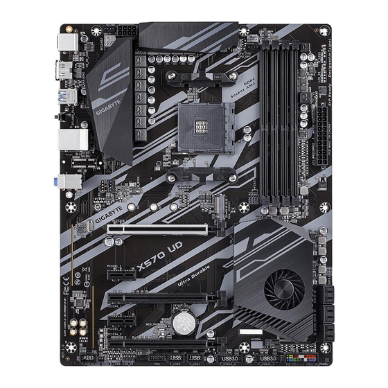
Page 4: X570 Ud Motherboard Layout
X570 UD Motherboard Layout SYS_FAN1 CPU_FAN ATX_12V KB_MS_USB CPU_OPT HDMI Socket AM4 R_USB30 QFLED QFLASH_PLUS USB30_LAN AUDIO M_BIOS Realtek ® PCIEX16 GbE LAN X570 UD PCIEX1_1 AMD X570 PCIEX4_1 CODEC PCIEX1_2 Super ® PCIEX4_2 F_AUDIO CLR_CMOS LED_C1 F_USB2 F_USB1 F_USB30_2…
-
Page 5: Chapter 1 Hardware Installation
Chapter 1 Hardware Installation Installation Precautions The motherboard contains numerous delicate electronic circuits and components which can become damaged as a result of electrostatic discharge (ESD). Prior to installation, carefully read the user’s manual and follow these procedures: • Prior to installation, make sure the chassis is suitable for the motherboard. •…
-
Page 6: 1-2 Product Specifications
Dual channel memory architecture Š Support for ECC Un-buffered DIMM 1Rx8/2Rx8 memory modules Š Support for non-ECC Un-buffered DIMM 1Rx8/2Rx8/1Rx16 memory modules Š Support for Extreme Memory Profile (XMP) memory modules Š (Go to GIGABYTE’s website for the latest supported memory speeds and memory modules.) Onboard Integrated Graphics Processor: Š Graphics 1 x HDMI port, supporting a maximum resolution of 4096×2160@60 Hz (Note 1) * Support for HDMI 2.0 version, HDCP 2.2, and HDR.
-
Page 7
Multi-Graphics Support for AMD Quad-GPU CrossFire and 2-Way AMD CrossFire technologies ™ ™ Š Technology (Note 3) Storage Interface Integrated in the CPU: 3rd Generation AMD Ryzen processors: ™ Š 1 x M.2 connector (Socket 3, M key, type 2242/2260/2280/22110 SATA and PCIe 4.0 x4/x2 SSD support) 2 nd Generation AMD Ryzen processors/2nd Generation AMD Ryzen with Radeon… -
Page 8
* G IGABYTE reserves the right to make any changes to the product specifications and product-related information without prior notice. Please visit GIGABYTE’s website Please visit the SupportUtility List for support lists of CPU, memory page on GIGABYTE’s website to modules, SSDs, and M.2 devices. download the latest version of apps. — 8 -… -
Page 9: Installing The Cpu
• Make sure that the motherboard supports the memory. It is recommended that memory of the same capacity, brand, speed, and chips be used. (Go to GIGABYTE’s website for the latest supported memory speeds and memory modules.) • Always turn off the computer and unplug the power cord from the power outlet before installing the memory to prevent hardware damage.
-
Page 10: Installing An Expansion Card
The four memory sockets are divided into two channels and each channel has two memory sockets as following: Channel A: DDR4_A1, DDR4_A2 Channel B: DDR4_B1, DDR4_B2 Dual Channel Memory Configurations Table DDR4_A1 DDR4_A2 DDR4_B1 DDR4_B2 2 Modules DS/SS DS/SS DS/SS DS/SS 4 Modules DS/SS DS/SS DS/SS DS/SS (SS=Single-Sided, DS=Double-Sided, «- -«=No Memory) Due to CPU limitations, read the following guidelines before installing the memory in Dual Channel mode.
-
Page 11
• When removing the cable, pull it straight out from the connector. Do not rock it side to side to prevent an electrical short inside the cable connector. (Note 2) To enable the Q-Flash Plus function please visit the «Unique Features» webpage of GIGABYTE’s website. -
Page 12: Internal Connectors
Internal Connectors ATX_12V F_PANEL F_AUDIO CPU_FAN F_USB30_1/F_USB30_2 SYS_FAN1/2 F_USB1/F_USB2 CPU_OPT LED_C1 CLR_CMOS SATA3 0/1/2/3/4/5 M2A_SOCKET Read the following guidelines before connecting external devices: • First make sure your devices are compliant with the connectors you wish to connect. • Before installing the devices, be sure to turn off the devices and your computer. Unplug the power cord from the power outlet to prevent damage to the devices.
-
Page 13
1/2) ATX_12V/ATX (2×4 12V Power Connector and 2×12 Main Power Connector) With the use of the power connector, the power supply can supply enough stable power to all the components on the motherboard. Before connecting the power connector, first make sure the power supply is turned off and The power connector possesses a foolproof design. Connect the power all devices are properly installed. -
Page 14
LED strip. For how to turn on/off the lights of the LED strip please visit the «Unique Features» webpage of GIGABYTE’s website. Before installing the devices, be sure to turn off the devices and your computer. Unplug the power cord from the power outlet to prevent damage to the devices. -
Page 15
S B_ 7) SATA3 0/1/2/3/4/5 (SATA 6Gb/s Connectors) The SATA connectors conform to SATA 6Gb/s standard and are compatible with SATA 3Gb/s and SATA 1.5Gb/s standard. Each SATA connector supports a single SATA device. The SATA connectors support RAID 0, RAID 1, and RAID 10. Refer to Chapter 3, «Configuring a RAID Set,» for instructions on configuring a RAID array. Pin No. -
Page 16
9) F_PANEL (Front Panel Header) Connect the power switch, reset switch, speaker, chassis intrusion switch/sensor and system status indicator on the chassis to this header according to the pin assignments below. Note the positive and negative pins before connecting the cables. •… -
Page 17
11) F_USB30_1/F_USB30_2 (USB 3.2 Gen 1 Headers) The headers conform to USB 3.2 Gen 1 and USB 2.0 specification and each header can provide two USB ports. For purchasing the optional 3.5″ front panel that provides two USB 3.2 Gen 1 ports, please contact the local dealer. Pin No. Definition Pin No. Definition Pin No. Definition VBUS SSTX2- SSRX1- SSRX1+ SSRX2+… -
Page 18
14) CLR_CMOS (Clear CMOS Jumper) Use this jumper to clear the BIOS configuration and reset the CMOS values to factory defaults. To clear the CMOS values, use a metal object like a screwdriver to touch the two pins for a few seconds. Open: Normal Short: Clear CMOS Values • Always turn off your computer and unplug the power cord from the power outlet before clearing the CMOS values. -
Page 19: Chapter 2 Bios Setup
To access the BIOS Setup program, press the <Delete> key during the POST when the power is turned on. To upgrade the BIOS, use either the GIGABYTE Q-Flash or @BIOS utility. Q-Flash allows the user to quickly and easily upgrade or back up BIOS without entering the operating system.
-
Page 20: The Main Menu
The Main Menu System Time Setup Menus Hardware Information Configuration Items Current Settings Quick Access Bar allows you to enter Easy Mode, select BIOS default language, configure fan settings, or enter Q-Flash. Classic Setup Function Keys <f><g> Move the selection bar to select a setup menu <h><i> Move the selection bar to select an configuration item on a menu <Enter>/Double Click Execute command or enter a menu <…
-
Page 21
M.I.T. Whether the system will work stably with the overclock/overvoltage settings you made is dependent on your overall system configurations. Incorrectly doing overclock/overvoltage may result in damage to CPU, chipset, or memory and reduce the useful life of these components. This page is for advanced users only and we recommend you not to alter the default settings to prevent system instability or other unexpected results. -
Page 22
` Advanced CPU Core Settings & CPU Clock Ratio, CPU Frequency The settings above are synchronous to those under the same items on the Advanced Frequency Settings menu. & Core Performance Boost (Note 1) Allows you to determine whether to enable the Core Performance Boost (CPB) technology, a CPU performance-boost technology. -
Page 23
` Advanced Memory Settings & Extreme Memory Profile (X.M.P.) , System Memory Multiplier, Memory Frequency(MHz) (Note) The settings above are synchronous to those under the same items on the Advanced Frequency Settings menu. & XMP High Frequency Support (Note) Allows you to select the compatibility level for high-frequency memory. This item is configurable only when Extreme Memory Profile (X.M.P.) is set to Profile1 or Profile2. -
Page 24
` Smart Fan 5 & Monitor Allows you to select a target to monitor and to make further adjustment. (Default: CPU FAN) & Fan Speed Control Allows you to determine whether to enable the fan speed control function and adjust the fan speed. Allows the fan to run at different speeds according to the temperature. -
Page 25: System
System This section provides information on your motherboard model and BIOS version. You can also select the default language used by the BIOS and manually set the system time. & System Language Selects the default language used by the BIOS. &…
-
Page 26: Bios
System (Default) & Full Screen LOGO Show Allows you to determine whether to display the GIGABYTE Logo at system startup. Disabled skips the GIGABYTE Logo when the system starts up. (Default: Enabled) & Fast Boot Enables or disables Fast Boot to shorten the OS boot process. Ultra Fast provides the fastest bootup speed.
-
Page 27
& SATA Support Last Boot SATA Devices Only Except for the previous boot drive, all SATA devices are disabled before the OS boot process completes. (Default) All SATA Devices All SATA devices are functional in the operating system and during the POST. This item is configurable only when Fast Boot is set to Enabled or Ultra Fast. -
Page 28
& Other PCI Device ROM Priority Allows you to select whether to enable the UEFI or Legacy option ROM for the PCI device controller other than the LAN, storage device, and graphics controllers. Disabled Disables option ROM. UEFI Only Enables UEFI option ROM only. (Default) Enables legacy option ROM only. Legacy Only This item is configurable only when CSM Support is set to Enabled. & Administrator Password Allows you to configure an administrator password. Press <Enter> on this item, type the password, and then press <Enter>. You will be requested to confirm the password. Type the password again and press <Enter>. You must enter the administrator password (or user password) at system startup and when entering BIOS Setup. -
Page 29: Peripherals
Peripherals & AMD CPU fTPM Enables or disables the TPM 2.0 function integrated in the AMD CPU. (Default: Disabled) & Initial Display Output Specifies the first initiation of the monitor display from the installed PCI Express graphics card or the onboard graphics. IGD Video Sets the onboard graphics as the first display. (Note) Sets the graphics card on the PCIEX16 slot as the first display. (Default) PCIe 1 Slot Sets the graphics card on the PCIEX4_1 slot as the first display. PCIe 2 Slot Sets the graphics card on the PCIEX4_2 slot as the first display. PCIe 3 Slot & LEDs in System Power On State Allows you to enable or disable motherboard LED lighting when the system is on.
-
Page 30
` Trusted Computing Enables or disables Trusted Platform Module (TPM). ` USB Configuration & Legacy USB Support Allows USB keyboard/mouse to be used in MS-DOS. (Default: Enabled) & XHCI Hand-off Determines whether to enable XHCI Hand-off feature for an operating system without XHCI Hand-off support. -
Page 31
` AMD CBS This sub-menu provides AMD CBS-related configuration options. ` Realtek PCIe GBE Family Controller This sub-menu provides information on LAN configuration and related configuration options. — 31 -… -
Page 32: Chipset
Chipset & IOMMU Enables or disables AMD IOMMU support. (Default: Auto) & PCIEX16 Bifurcation Allows you to determine how the bandwidth of the PCIEX16 slot is divided. Options: Auto, PCIE 2×8, PCIE 1×8/2×4, PCIE 4×4. (Default: Auto) & SATA Mode Enables or disables RAID for the integrated SATA controllers or configures the SATA controllers to AHCI mode.
-
Page 33: Power
Power & AC BACK Determines the state of the system after the return of power from an AC power loss. The system returns to its last known awake state upon the return of the AC power. Memory Always On The system is turned on upon the return of the AC power. Always Off The system stays off upon the return of the AC power.
-
Page 34
& ErP Determines whether to let the system consume least power in S5 (shutdown) state. Note: When this item is set to Enabled, the following functions will become unavailable: Resume by Alarm, power on by mouse, and power on by keyboard. & Soft-Off by PWR-BTTN Configures the way to turn off the computer in MS-DOS mode using the power button. Press the power button and then the system will be turned off instantly. (Default) Instant-Off Delay 4 Sec. -
Page 35: Save & Exit
Save & Exit & Save & Exit Setup Press <Enter> on this item and select Yes. This saves the changes to the CMOS and exits the BIOS Setup program. Select No or press <Esc> to return to the BIOS Setup Main Menu. &…
-
Page 36: Chapter 3 Appendix
Chapter 3 Appendix 3-1 Configuring a RAID Set RAID Levels RAID 0 RAID 1 RAID 10 Minimum Number of ≥2 Hard Drives Array Capacity Number of hard drives * Size of the smallest drive (Number of hard drives/2) * Size of the smallest drive Size of the smallest drive Fault Tolerance Before you begin, please prepare the following items:…
-
Page 37
3. Insert the USB thumb drive and then browse to the location of the driver. The location of the drivers is as follows: Hw10RAIDx64 4. Select AMD-RAID Bottom Device first and click Next to load the driver. Then select AMD-RAID Controller and click Next to load the driver. Finally, continue the OS installation. Please visit GIGABYTE’s website for details on configuring a RAID array. — 37 -… -
Page 38: Drivers Installation
You can click the Xpress Install button and «Xpress Install» will install all of the selected drivers. Or click the arrow icon to individually install the drivers you need. Please visit GIGABYTE’s website for Please visit GIGABYTE’s website for more troubleshooting information.
-
Page 39: Regulatory Statements
Contravention will be prosecuted. We believe that the information contained herein was accurate in all respects at the time of printing. GIGABYTE cannot, however, assume any responsibility for errors or omissions in this text. Also note that the information in this document is subject to change without notice and should not be construed as a commitment by GIGABYTE.
-
Page 40
FCC Notice (U.S.A. Only) This equipment has been tested and found to comply with the limits for a Class B digital device, pursuant to Part 15 of the FCC Rules. These limits are designed to provide reasonable protection against harmful interference in a residential installation. This equipment generates, uses, and can radiate radio frequency energy and, if not installed and used in accordance with the instructions, may cause harmful interference to radio communications. -
Page 41
— 41 -… -
Page 42
— 42 -… -
Page 43
— 43 -… -
Page 44: Contact Us
Contact Us GIGA-BYTE TECHNOLOGY CO., LTD. Address: No.6, Baoqiang Rd., Xindian Dist., New Taipei City 231, Taiwan TEL: +886-2-8912-4000, FAX: +886-2-8912-4005 Tech. and Non-Tech. Support (Sales/Marketing) : https://esupport.gigabyte.com WEB address (English): https://www.gigabyte.com WEB address (Chinese): https://www.gigabyte.com/tw GIGABYTE eSupport • To submit a technical or non-technical (Sales/Marketing) question, please link to: https://esupport.gigabyte.com…
перейти к содержанию
Руководство пользователя материнской платы MSI MPG x570 Gaming Plus

Контекст
- Система была собрана в апреле 2020 года с установленным только диском Samsung Evo 970 M.2 (в слоте M2_2).
- Система полностью функциональна, работает под управлением Windows 10 Pro в течение 10 месяцев.
- Сегодня (12 февраля 2021 г.) я приобрел и установил новый WD Black SN750 M.2 в слот M2_1.
- BIOS не определяет WD M.2 в слоте M2_1
- Тестирование показало, что ни один M.2 не определяется BIOS в слоте M2_1.
- ОС Windows 10 после загрузки не видит диск WD, установленный в слот M2_1
Решение Проблем
Samsung 970 Evo M.2 в M2_1
WD Black SN750 M.2 в M2_2

BIOS видит WD в M2_2, но не видит Samsung в M2_1

Samsung 970 Evo M.2 в M2_2
WD Black SN750 M.2 в M2_1
BIOS видит Samsung в M2_2
но не видит WD в M2_1

Обратите внимание, что WD M.2 не отображается в диспетчере устройств.

Заключение
- Система видит диски Samsung и WD M.2 в M2_2
- Система не видит ни один диск M.2 в M2_1
- Либо слот M2_1 неисправен, либо необходимо изменить параметр конфигурации
- MSI – Пожалуйста, сообщите о следующих шагах по устранению неполадок