- Manuals
- Brands
- Hitachi Manuals
- Inverter
- WJ200 Series Software
- Instruction manual
-
Contents
-
Table of Contents
-
Bookmarks
Quick Links
HITACHI WJ BASIC INSTRUCTION MANUAL
DH PROGRAM #27
Detroit Hoist & Crane LLC, Co.
6650 Sterling Drive North, Sterling Height Michigan 48312
+1 586-268-2600
Page 1
Related Manuals for Hitachi WJ200
Summary of Contents for Hitachi WJ200
-
Page 1
HITACHI WJ BASIC INSTRUCTION MANUAL DH PROGRAM #27 Detroit Hoist & Crane LLC, Co. 6650 Sterling Drive North, Sterling Height Michigan 48312 +1 586-268-2600 Page 1… -
Page 2
Stop Read First! Important! – This manual is for program number #27 from Detroit Hoist. Please verify the program number before using this manual by navigating to VFD parameter d024. To navigate to d024 and check your VFD’s program number follow the steps chart below. Step Instruction Power up the VFD. -
Page 3: Table Of Contents
Contents BASIC SPECIFICATIONS …………………………….4 POWER CIRCUIT WIRING …………………………….5 CONTROL CIRCUIT WIRING …………………………….6 CONFIGURING SPEED CONTROL METHOD ……………………….7 CONFIGURING SPEEDS / FREQUENCIES …………………………8 ACCELERATION / DECELERATION TIMES …………………………. 9 ALTERNATE ACCELERATION / DECELERATION TIMES ……………………..9 MICRO-SPEED FUNCTION …………………………….
-
Page 4: Basic Specifications
BASIC SPECIFICATIONS For specifications that are not listed please contact Detroit Hoist for further information. Input power 3-phase 50/60hz (recommended). • Single phase applica�ons must derate VFD to 70% and may require a larger VFD to supply the required motor current. •…
-
Page 5: Power Circuit Wiring
POWER CIRCUIT WIRING Risk of electric shock! Risk of electric shock! • Before inspecting the inverter, be sure to turn off • Before inspecting the inverter, be sure to turn off the power supply and wait for more than 10 or 15 the power supply and wait for more than 10 or 15 minutes depending on the invertor model minutes depending on the invertor model…
-
Page 6: Control Circuit Wiring
CONTROL CIRCUIT WIRING Below is a basic example of the control circuit for the Hitachi WJ with the DH firmware and may differ from the actual configuration please reference the provided electrical drawing. Please consult Detroit Hoist if you plan to make changes to the control circuit for specific functions to ensure compatibility with the DH firmware.
-
Page 7: Configuring Speed Control Method
CONFIGURING SPEED CONTROL METHOD Detroit Hoist VFD controls come factory pre-configured for 2-Step speed control unless otherwise specified during the ordering process. Use the chart below to configure the speed control method that is required. Speed Control Method Parameters Values 2-Step P108 2-Step Infinitely Variable…
-
Page 8: Configuring Speeds / Frequencies
CONFIGURING SPEEDS / FREQUENCIES Speed / frequency values are stored as whole numbers (example is 15.25 Hz = 1525). Use the chart below to configure the speeds / frequencies for the configured speed control method. If operating at frequencies below or at 5hz for an extended amount of time an external motor cooling device may be required to prevent motor overheating.
-
Page 9: Acceleration / Deceleration Times
ACCELERATION / DECELERATION TIMES Changing the acceleration time to a shorter time can cause a E01, E02, or E03 over-current and or E05 over-load fault /trip, if this occurs due to a short acceleration time increase the acceleration time and test again. Changing the deceleration time to a shorter time can cause a E07 over-voltage fault/trip, if this occurs due to a short deceleration time increase the deceleration time and test again.
-
Page 10: Micro-Speed Function
MICRO-SPEED FUNCTION Micro-speed is designed to temporarily restrict the speed of the hoist to a lower speed and to prevent high speed operations until the function is released. The micro-speed function can be configured two ways. 2-STEP MAINTAINED MODE – This mode will switch to a 2-Step maintained speed set. This is helpful where the micro-speeds need to be specific.
-
Page 11: Auto-Speed 90Hz Function
AUTO-SPEED 90HZ FUNCTION The auto-speed function will allow the VFD to increase the high speed to up to 90Hz when there is an empty hook or a light load. You can set this function for automatic or for input activation. The auto-speed function is not available when using 0-10V/4-20mA speed control methods, when micro-speed is active, and or when in tandem mode.
-
Page 12: 125% Field Load Testing / Over-Weight Bypass
125% FIELD LOAD TESTING / OVER-WEIGHT BYPASS Each hoist is factory load tested prior to shipment. If a field load test is required, you will need to bypass the over-weight signal. To bypass the over-weight signal, locate the bypass terminal knife disconnect it should be labeled “BPS” (use images below as reference) and pull the yellow/orange tab to open.
-
Page 13: Hoist Over-Weight Function
HOIST OVER-WEIGHT FUNCTION The VFD is setup to use the output current to the motor as the over-weight function. The VFD uses (2) over-weight current parameters. Over-weight (1) is when operating less than or equal to the low-speed frequency and over-weight (2) is when operating above low-speed frequency.
-
Page 14: Setting Hoist Over-Weight
SETTING HOIST OVER-WEIGHT Each hoist’s over-weight settings will be set at the factory prior to shipment. In some cases, field adjustments may be required. Use the step chart below to set the hoist’s over-weight settings. Step Instruction Locate the terminal knife disconnect labeled “BPS” and pull the top of the yellow/orange tab outwards, this will bypass the over-weight circuit.
-
Page 15: Carrier Frequency
CARRIER FREQUENCY The carrier frequency is adjustable from 2.0kHz to 15kHz. The audible sound decreases at the higher frequencies, but RFI noise and leakage current may be increased. It is recommended that the carrier frequency is 2.3kHz or greater when operating in sensorless vector A044 = 03.
-
Page 16: Reset Fault Using Input
RESET FAULT USING INPUT Resetting a fault remotely using an input to the VFD can be done by configuring one of the available digital inputs for reset. Use the chart below. Function Parameters Value Fault reset C006 – C007 18 = RS OUTPUT SIGNAL WHEN FAULT OCCURS You can configure a 24v digital output to turn on when a fault occurs.
-
Page 17: Motor Brake Parameters
MOTOR BRAKE PARAMETERS The motor brake parameters ca be adjusted based on the application needs. Brake wait time for release – After the Brake Release Frequency Setting is reached, the inverter waits for the braking wait time (b121) Brake wait time for acceleration – The inverter waits for the Brake Wait Time for Acceleration (b122), and then starts accelerating the motor up to the set acceleration frequency.
-
Page 18: Constant Torque Control Mode / Manual Torque Boost
CONSTANT TORQUE CONTROL MODE / MANUAL TORQUE BOOST Manual Torque Boost – The Constant and Variable Torque algorithms feature an adjustable torque boost curve. When the motor load has a lot of inertia or starting friction, you may need to increase the low frequency starting torque characteristics by boosting the voltage above the normal V/f ratio (shown below).
-
Page 19: Constant Torque Control Mode / Automatic Torque Boost
CONSTANT TORQUE CONTROL MODE / AUTOMATIC TORQUE BOOST In constant torque using automatic torque boost the starting torque boost value and frequency break point are used as starting points for automatic torque boost. Voltage compensation gain and slip compensation gain are used for fine tuning adjustments. Using parameters A046 and A047, you can obtain better performance under automatic torque boost mode (A041=01).
-
Page 20: Sensorless Vector Control Mode
SENSORLESS VECTOR CONTROL MODE Sensorless vector control can achieve high torque performance (200% torque at 0.5Hz of output frequency) without motor speed feedback (encoder feedback). Sensorless vector control enables the inverter to accurately operate the motor with a high starting torque, even at low speed.
-
Page 21: Fine Tuning Sensorless Vector
FINE TUNING SENSORLESS VECTOR In most cases fine tuning is not required with the standard motor constants that are supplied when selecting the correct motor constant profile in parameter H003. Before making adjustments, try selecting a motor constant profile (1) smaller or larger than the combined connected motors in kW’s in parameter H003.
-
Page 22: Auto-Tuning
AUTO-TUNING In some cases, performing an auto-tune to get the proper motor constant will help in providing optimal performance when operating in sensorless vector control mode A044 = 03. Before auto-tuning make sure that parameter H003 is set to a value of the combined connected motors in kW’s, in some cases this value might be (1) size larger or smaller.
-
Page 23: Reduced Load Swing
REDUCED LOAD SWING In traverse applications it is possible to reduce the chance of load swing by configuring the VFD for sensorless vector control and using the torque limits to help reduce starting load swing. Also, you will use the alternate acceleration and deceleration functions to reduce load swing when accelerating and decelerating to and from high speeds.
-
Page 24: Tandem Hoist / Trolley Ezcom (Speed / Command Syncing)
TANDEM HOIST / TROLLEY EZCOM (SPEED / COMMAND SYNCING) Tandem hoist / trolley EZCOM can be used when 2 hoists / trolleys are used in tandem operation and require the frequency, command status, and run status to sync between each hoist. The VFD’s will need to be configured to communicate between each other and the internal logic activated.
-
Page 25: Ezcom Setup Guide
EZCOM SETUP GUIDE Step Instruction Configure the VFD’s parameters using the EZCOM parameter chart. Most of the parameters should already be configured and only the ones highlighted in yellow should need to be changed. Power down both VFD’s and connect the 2-wire shielded cable to the corresponding SN & SP terminals as shown in the EZCOM circuit wiring example on the next page.
-
Page 26: Ezcom Circuit Wiring
EZCOM CIRCUIT WIRING EZCOM wiring example circuit. Make sure the BVFD has the RS485 termination resistor dip switch toggled to the right. MDSW1 Dip switch for termination RS-485 (Modbus) Page 26…
-
Page 27: View Fault History
VIEW FAULT HISTORY To view the fault history, use the step chart below. Step Instruction Power on the VFD. Press ESC button and use the arrow buttons to navigate to d081 – d086. Press the SET button to view the fault. NOTE d081 will always be the most recent fault.
-
Page 28: Clearing Fault History
CLEARING FAULT HISTORY To clear the fault history, use the step chart below. Step Instruction Power on the VFD. Press the ESC button 4 times or until the screen displays b001. Use the arrow buttons to navigate to parameter b084. Press the SET button to enter the parameter, use the UP arrow to set the value to 01 and press the SET button to save the change.
-
Page 29: Fault / Error Codes Description
FAULT / ERROR CODES DESCRIPTION Fault / Error Code Description Over-current event while at constant speed Over-current event during deceleration Over-current event during acceleration Over-current event during other conditions Electronic thermal overload protection (motor current > b012) Dynamic braking resistor over used error. Check incoming voltage for spikes. DC-Bus over-voltage error.
-
Page 30
REVISIONS Version Date Changes / Updates 1/7/2022 Initial release Page 30…
 Loading…
![]()
WJ200 Series Inverter
Quick Reference Guide
|
• |
Single-phase Input |
200V class |
|
• |
Three-phase Input |
200V class |
|
• |
Three-phase Input |
400V class |
|
Manual Number: NT3251AX |
Refer to the user manual for detail |
March 2012
Hitachi Industrial Equipment Systems Co., Ltd.


UL® Cautions, Warnings and Instructions
Warnings and Cautions for Troubleshooting and Maintenance
(Standard to comply with : UL508C,CSA C22.2 No.14-05) Warning Markings
GENERAL:
These devices are open type Power Conversion Equipment. They are intended to be used in an enclosure. Insulated gate bipolar transistor (IGBT) incorporating microprocessor technology. They are operated from a single or three-phase source of supply, and intended to control three-phase induction motors by means of a variable frequency output. The units are intended for general-purpose industrial applications.
MARKING REQUIREMENTS:
Ratings — Industrial control equipment shall be plainly marked with the Listee’s name, trademark, File number, or other descriptive marking by which the organization responsible for the product may be identified;
a)“Maximum surrounding air temperature rating of 50 ºC.”
b)“Solid State motor overload protection reacts with max. 150 % of FLA”.
c)“Install device in pollution degree 2 environment.”
d)“Suitable for use on a circuit capable of delivering not more than 100,000 rms Symmetrical Amperes, 240 or 480 Volts Maximum.”
e)“When Protected by CC, G, J or R Class Fuses.” or “When Protected By A Circuit Breaker Having An Interrupting Rating Not Less Than 100,000 rms Symmetrical Amperes, 240 or 480 Volts Maximum.”
f)“Integral solid state short circuit protection does not provide branch circuit protection. Branch circuit protection must be provided in accordance with the National Electrical Code and any additional local codes.”
1

Terminal symbols and Screw size
|
Inverter Model |
Screw Size |
Required |
Wire range |
||||||
|
Torque (N-m) |
|||||||||
|
WJ200-001S |
M3.5 |
1.0 |
AWG16 (1.3mm2) |
||||||
|
WJ200-002S |
|||||||||
|
WJ200-004S |
|||||||||
|
WJ200-007S |
M4 |
1.4 |
AWG12 (3.3mm2) |
||||||
|
WJ200-015S |
M4 |
1.4 |
AWG10 (5.3mm2) |
||||||
|
WJ200-022S |
|||||||||
|
WJ200-001L |
|||||||||
|
WJ200-002L |
M3.5 |
1.0 |
AWG16 (1.3mm2) |
||||||
|
WJ200-004L |
|||||||||
|
WJ200-007L |
|||||||||
|
WJ200-015L |
M4 |
1.4 |
AWG14 (2.1mm2) |
||||||
|
WJ200-022L |
M4 |
1.4 |
AWG12 (3.3mm2) |
||||||
|
WJ200-037L |
M4 |
1.4 |
AWG10 (5.3mm2) |
||||||
|
WJ200-055L |
M5 |
3.0 |
AWG6 (13mm2) |
||||||
|
WJ200-075L |
|||||||||
|
WJ200-110L |
M6 |
3.9 to 5.1 |
AWG4 (21mm2) |
||||||
|
WJ200-150L |
M8 |
5.9 to 8.8 |
AWG2 (34mm2) |
||||||
|
WJ200-004H |
AWG16 (1.3mm2) |
||||||||
|
WJ200-007H |
M4 |
1.4 |
|||||||
|
WJ200-015H |
|||||||||
|
WJ200-022H |
M4 |
1.4 |
AWG14 (2.1mm2) |
||||||
|
WJ200-030H |
|||||||||
|
WJ200-040H |
M4 |
1.4 |
AWG12 (3.3mm2) |
||||||
|
WJ200-055H |
M5 |
3.0 |
AWG10 (5.3mm2) |
||||||
|
WJ200-075H |
|||||||||
|
WJ200-110H |
M6 |
3.9 to 5.1 |
AWG6 (13mm2) |
||||||
|
WJ200-150H |
2

Fuse Sizes
Distribution fuse size marking is included in the manual to indicate that the unit shall be connected with a Listed Cartridge Nonrenewable fuse, rated 600 Vac with the current ratings as shown in the table below or Type E Combination Motor Controller marking is included in the manual to indicate that the unit shall be connected with,LS Industrial System Co.,Ltd,Type E Combination Motor Controller MMS Series with the ratings as shown in the table below:
|
Inverter Model |
Type |
Fuse Rating |
Type E CMC |
||||||||
|
WJ200-001S |
|||||||||||
|
WJ200-002S |
10A, AIC 200kA |
||||||||||
|
WJ200-004S |
MMS-32H,240V,40A |
||||||||||
|
WJ200-007S |
20A, AIC 200kA |
||||||||||
|
WJ200-015S |
30A, AIC 200kA |
||||||||||
|
WJ200-022S |
|||||||||||
|
WJ200-001L |
|||||||||||
|
WJ200-002L |
10A, AIC 200kA |
||||||||||
|
WJ200-004L |
|||||||||||
|
WJ200-007L |
15A, AIC 200kA |
MMS-32H,240V,40A |
|||||||||
|
WJ200-015L |
|||||||||||
|
WJ200-022L |
20A, AIC 200kA |
||||||||||
|
WJ200-037L |
Class J |
30A, AIC 200kA |
|||||||||
|
WJ200-055L |
60A, AIC 200kA |
||||||||||
|
WJ200-075L |
|||||||||||
|
MMS-100H,240V,80A |
|||||||||||
|
WJ200-110L |
80A, AIC 200kA |
||||||||||
|
WJ200-150L |
|||||||||||
|
WJ200-004H |
|||||||||||
|
WJ200-007H |
10A, AIC 200kA |
||||||||||
|
WJ200-015H |
|||||||||||
|
WJ200-022H |
MMS-32H,480V,40A |
||||||||||
|
WJ200-030H |
15A, AIC 200kA |
||||||||||
|
or |
|||||||||||
|
WJ200-040H |
|||||||||||
|
MMS-63H,480V,52A |
|||||||||||
|
WJ200-055H |
30A, AIC 200kA |
||||||||||
|
WJ200-075H |
|||||||||||
|
WJ200-110H |
50A, AIC 200kA |
||||||||||
|
WJ200-150H |
|||||||||||
3
Inverter Specification Label
The Hitachi WJ200 inverters have product labels located on the right side of the housing, as pictured below. Be sure to verify that the specifications on the labels match your power source, and application safety requirements.
|
Model name |
-001SF |
Ver:2.0 |
|
|
Input ratings |
|||
|
200-240 |
2.0/1.3 |
||
|
Output ratings |
200-240 |
1.2/1.0 |
|
|
MFG number |
05A_T12345_A_-001 |
1005 |
|
Inverter Specification Label
The model number for a specific inverter contains useful information about its operating characteristics. Refer to the model number legend below:
|
WJ200 |
001 |
S |
F |
Configuration type |
||||||||||||
|
Series name |
||||||||||||||||
|
F=with keypad |
||||||||||||||||
|
Input voltage: |
||||||||||||||||
|
S=Single-phase 200V class |
||||||||||||||||
|
L=Three-phase 200V class |
||||||||||||||||
|
H=Three-phase 400V class |
||||||||||||||||
|
Applicable motor capacity in kW |
||||||||||||||||
|
001=0.1kW |
037=3.7kW |
|||||||||||||||
|
002=0.2kW |
040=4.0kW |
|||||||||||||||
|
004=0.4kW |
055=5.5kW |
|||||||||||||||
|
007=0.75kW |
075=7.5kW |
|||||||||||||||
|
015=1.5kW |
110=11kW |
|||||||||||||||
|
022=2.2kW |
150=15kW |
|||||||||||||||
|
030=3.0kW |
4

WJ200 Inverter Specifications
Model-specific tables for 200V and 400V class inverters
The following tables are specific to WJ200 inverters for the 200V and 400V class model groups. Note that “General Specifications” on page in this chapter apply to both voltage class groups. Footnotes for all specification tables follow the table below.
|
Item |
Single-phase 200V class Specifications |
||||||||||
|
WJ200 inverters, 200V models |
001SF |
002SF |
004SF |
007SF |
015SF |
022SF |
|||||
|
Applicable motor size |
kW |
VT |
0.2 |
0.4 |
0.55 |
1.1 |
2.2 |
3.0 |
|||
|
CT |
0.1 |
0.2 |
0.4 |
0.75 |
1.5 |
2.2 |
|||||
|
HP |
VT |
1/4 |
1/2 |
3/4 |
1.5 |
3 |
4 |
||||
|
CT |
1/8 |
1/4 |
1/2 |
1 |
2 |
3 |
|||||
|
Rated capacity (kVA) |
200V |
VT |
0.4 |
0.6 |
1.2 |
2.0 |
3.3 |
4.1 |
|||
|
CT |
0.2 |
0.5 |
1.0 |
1.7 |
2.7 |
3.8 |
|||||
|
240V |
VT |
0.4 |
0.7 |
1.4 |
2.4 |
3.9 |
4.9 |
||||
|
CT |
0.3 |
0.6 |
1.2 |
2.0 |
3.3 |
4.5 |
|||||
|
Rated input voltage |
Single-phase: 200V-15% to 240V +10%, 50/60Hz ±5% |
||||||||||
|
Rated output voltage |
Three-phase: 200 to 240V (proportional to input voltage) |
||||||||||
|
Rated output current (A) |
VT |
1.2 |
1.9 |
3.5 |
6.0 |
9.6 |
12.0 |
||||
|
CT |
1.0 |
1.6 |
3.0 |
5.0 |
8.0 |
11.0 |
|||||
|
Starting torque |
200% |
at 0.5Hz |
|||||||||
|
Braking |
Without resistor |
100%: ≤50Hz |
70%: ≤ 50Hz |
20%: ≤ 50Hz |
|||||||
|
50%: ≤60Hz |
50%: ≤ 60Hz |
20%: ≤ 60Hz |
|||||||||
|
With resistor |
150% |
100% |
|||||||||
|
DC braking |
Variable operating frequency, time, and braking |
force |
|||||||||
|
Weight |
kg |
1.0 |
1.0 |
1.1 |
1.6 |
1.8 |
1.8 |
||||
|
lb |
2.2 |
2.2 |
2.4 |
3.5 |
4.0 |
4.0 |
5

WJ200 Inverter Specifications, continued…
|
Item |
Three-phase 200V class Specifications |
||||||||||||
|
WJ200 inverters, 200V models |
001LF |
002LF |
004LF |
007LF |
015LF |
022LF |
|||||||
|
Applicable motor size |
kW |
VT |
0.2 |
0.4 |
0.75 |
1.1 |
2.2 |
3.0 |
|||||
|
CT |
0.1 |
0.2 |
0.4 |
0.75 |
1.5 |
2.2 |
|||||||
|
HP |
VT |
1/4 |
1/2 |
1 |
1.5 |
3 |
4 |
||||||
|
CT |
1/8 |
1/4 |
1/2 |
1 |
2 |
3 |
|||||||
|
Rated capacity (kVA) |
200V |
VT |
0.4 |
0.6 |
1.2 |
2.0 |
3.3 |
4.1 |
|||||
|
CT |
0.2 |
0.5 |
1.0 |
1.7 |
2.7 |
3.8 |
|||||||
|
240V |
VT |
0.4 |
0.7 |
1.4 |
2.4 |
3.9 |
4.9 |
||||||
|
CT |
0.3 |
0.6 |
1.2 |
2.0 |
3.3 |
4.5 |
|||||||
|
Rated input voltage |
Three-phase: 200V-15% to 240V +10%, 50/60Hz ±5% |
||||||||||||
|
Rated output voltage |
Three-phase: 200 to 240V (proportional to input voltage) |
||||||||||||
|
Rated output current (A) |
VT |
1.2 |
1.9 |
3.5 |
6.0 |
9.6 |
12.0 |
||||||
|
CT |
1.0 |
1.6 |
3.0 |
5.0 |
8.0 |
11.0 |
|||||||
|
Starting torque |
200% at 0.5Hz |
||||||||||||
|
Braking |
Without resistor |
100%: ≤50Hz |
70%: ≤ 50Hz |
20%: ≤ 50Hz |
|||||||||
|
50%: ≤60Hz |
50%: ≤ 60Hz |
20%: ≤ 60Hz |
|||||||||||
|
With resistor |
150% |
100% |
|||||||||||
|
DC braking |
Variable operating frequency, time, and braking |
force |
|||||||||||
|
Weight |
kg |
1.0 |
1.0 |
1.1 |
1.2 |
1.6 |
1.8 |
||||||
|
lb |
2.2 |
2.2 |
2.4 |
2.6 |
3.5 |
4.0 |
|||||||
|
Item |
Three-phase 200V class Specifications |
||||||||||||
|
WJ200 inverters, 200V models |
037LF |
055LF |
075LF |
110LF |
150LF |
||||||||
|
Applicable motor size |
kW |
VT |
5.5 |
7.5 |
11 |
15 |
18.5 |
||||||
|
CT |
3.7 |
5.5 |
7.5 |
11 |
15 |
||||||||
|
HP |
VT |
7.5 |
10 |
15 |
20 |
25 |
|||||||
|
CT |
5 |
7.5 |
10 |
15 |
20 |
||||||||
|
Rated capacity (kVA) |
200V |
VT |
6.7 |
10.3 |
13.8 |
19.3 |
20.7 |
||||||
|
CT |
6.0 |
8.6 |
11.4 |
16.2 |
20.7 |
||||||||
|
240V |
VT |
8.1 |
12.4 |
16.6 |
23.2 |
24.9 |
|||||||
|
CT |
7.2 |
10.3 |
13.7 |
19.5 |
24.9 |
||||||||
|
Rated input voltage |
Three-phase: 200V-15% to 240V +10%, 50/60Hz ±5% |
||||||||||||
|
Rated output voltage |
Three-phase: 200 to 240V (proportional to input voltage) |
||||||||||||
|
Rated output current (A) |
VT |
19.6 |
30.0 |
40.0 |
56.0 |
69.0 |
|||||||
|
CT |
17.5 |
25.0 |
33.0 |
47.0 |
60.0 |
||||||||
|
Starting torque |
200% at 0.5Hz |
||||||||||||
|
Braking |
Without resistor |
20%: ≤50Hz |
|||||||||||
|
20%: ≤60Hz |
|||||||||||||
|
With resistor |
100% |
80% |
|||||||||||
|
DC braking |
Variable operating frequency, time, and braking |
force |
|||||||||||
|
Weight |
Kg |
2.0 |
3.3 |
3.4 |
5.1 |
7.4 |
|||||||
|
lb |
4.4 |
7.3 |
7.5 |
11.2 |
16.3 |
6

WJ200 Inverter Specifications, continued…
|
Item |
Three-phase 400V class Specifications |
||||||||||||
|
WJ200 inverters, 400V models |
004HF |
007HF |
015HF |
022HF |
030HF |
040HF |
|||||||
|
Applicable motor size |
kW |
VT |
0.75 |
1.5 |
2.2 |
3.0 |
4.0 |
5.5 |
|||||
|
CT |
0.4 |
0.75 |
1.5 |
2.2 |
3.0 |
4.0 |
|||||||
|
HP |
VT |
1 |
2 |
3 |
4 |
5 |
7.5 |
||||||
|
CT |
1/2 |
1 |
2 |
3 |
4 |
5 |
|||||||
|
Rated capacity (kVA) |
380V |
VT |
1.3 |
2.6 |
3.5 |
4.5 |
5.7 |
7.3 |
|||||
|
CT |
1.1 |
2.2 |
3.1 |
3.6 |
4.7 |
6.0 |
|||||||
|
480V |
VT |
1.7 |
3.4 |
4.4 |
5.7 |
7.3 |
9.2 |
||||||
|
CT |
1.4 |
2.8 |
3.9 |
4.5 |
5.9 |
7.6 |
|||||||
|
Rated input voltage |
Three-phase: 400V-15% to 480V +10%, 50/60Hz ±5% |
||||||||||||
|
Rated output voltage |
Three-phase: 400 to 480V (proportional to input voltage) |
||||||||||||
|
Rated output current (A) |
VT |
2.1 |
4.1 |
5.4 |
6.9 |
8.8 |
11.1 |
||||||
|
CT |
1.8 |
3.4 |
4.8 |
5.5 |
7.2 |
9.2 |
|||||||
|
Starting torque |
200% at 0.5Hz |
||||||||||||
|
Braking |
Without resistor |
100%: ≤50Hz |
70%: ≤ 50Hz |
20%: ≤ 50Hz |
|||||||||
|
50%: ≤60Hz |
50%: ≤ 60Hz |
20%: ≤ 60Hz |
|||||||||||
|
With resistor |
150% |
||||||||||||
|
DC braking |
Variable operating frequency, time, and braking |
force |
|||||||||||
|
Weight |
kg |
1.5 |
1.6 |
1.8 |
1.9 |
1.9 |
2.1 |
||||||
|
lb |
3.3 |
3.5 |
4.0 |
4.2 |
4.2 |
4.6 |
|||||||
|
Item |
Three-phase 400V class Specifications |
||||||||||||
|
WJ200 inverters, 400V models |
055HF |
075HF |
110HF |
150HF |
|||||||||
|
Applicable motor size |
kW |
VT |
7.5 |
11 |
15 |
18.5 |
|||||||
|
CT |
5.5 |
7.5 |
11 |
15 |
|||||||||
|
HP |
VT |
10 |
15 |
20 |
25 |
||||||||
|
CT |
7.5 |
10 |
15 |
20 |
|||||||||
|
Rated capacity (kVA) |
380V |
VT |
11.5 |
15.1 |
20.4 |
25.0 |
|||||||
|
CT |
9.7 |
11.8 |
15.7 |
20.4 |
|||||||||
|
480V |
VT |
14.5 |
19.1 |
25.7 |
31.5 |
||||||||
|
CT |
12.3 |
14.9 |
19.9 |
25.7 |
|||||||||
|
Rated input voltage |
Three-phase: 400V-15% to 480V +10%, 50/60Hz ±5% |
||||||||||||
|
Rated output voltage |
Three -phase: 400 to 480V (proportional to input voltage) |
||||||||||||
|
Rated output current (A) |
VT |
17.5 |
23.0 |
31.0 |
38.0 |
||||||||
|
CT |
14.8 |
18.0 |
24.0 |
31.0 |
|||||||||
|
Starting torque |
200% at 0.5Hz |
||||||||||||
|
Braking |
Without resistor |
20%: ≤50Hz |
|||||||||||
|
20%: ≤60Hz |
|||||||||||||
|
With resistor |
150% |
||||||||||||
|
DC braking |
Variable operating frequency, time, and braking force |
||||||||||||
|
Weight |
kg |
3.5 |
3.5 |
4.7 |
5.2 |
||||||||
|
lb |
7.7 |
7.7 |
10.4 |
11.5 |
7

The following table shows which models need derating.
|
1-ph 200V class |
Need |
3-ph 200V class |
Need |
3-ph 400V class |
Need |
|
derating |
derating |
WJ200-004H |
derating |
||
|
WJ200-001S |
WJ200-001L |
||||
|
WJ200-002S |
WJ200-002L |
WJ200-007H |
|||
|
WJ200-004S |
WJ200-004L |
WJ200-015H |
|||
|
WJ200-007S |
WJ200-007L |
WJ200-022H |
|||
|
WJ200-015S |
WJ200-015L |
WJ200-030H |
|||
|
WJ200-022S |
WJ200-022L |
WJ200-040H |
|||
|
WJ200-037L |
WJ200-055H |
||||
|
WJ200-055L |
WJ200-075H |
||||
|
WJ200-075L |
WJ200-110H |
||||
|
WJ200-110L |
WJ200-150H |
||||
|
WJ200-150L |
|||||
|
need derating |
need no derating
Use the following derating curves to help determine the optimal carrier frequency setting for your inverter and find the output current derating. Be sure to use the proper curve for your particular WJ200 inverter model number.
8
![]()
Basic System Description
A motor control system will obviously include a motor and inverter, as well as a circuit breaker or fuses for safety. If you are connecting a motor to the inverter on a test bench just to get started, that’s all you may need for now. But a system can also have a variety of additional components. Some can be for noise suppression, while others may enhance the inverter’s braking performance. The figure and table below show a system with all the optional components you might need in your finished application.
Breaker,
MCCB or
GFI
L1 L2 L3
+1 
Inverter +
GND T1 T2 T3
From power supply
|
Name |
Function |
|
Breaker / |
A molded-case circuit breaker (MCCB), ground fault |
|
disconnect |
interrupter (GFI), or a fused disconnect device. NOTE: The |
|
installer must refer to the NEC and local codes to ensure |
|
|
safety and compliance. |
|
|
Input-side |
This is useful in suppressing harmonics induced on the |
|
AC Reactor |
power supply lines and for improving the power factor. |
|
WARNING: Some applications must use an input-side AC |
|
|
Reactor to prevent inverter damage. See Warning on next |
|
|
page. |
|
|
Radio noise filter |
Electrical noise interference may occur on nearby |
|
equipment such as a radio receiver. This magnetic choke |
|
|
filter helps reduce radiated noise (can also be used on |
|
|
output). |
|
|
EMC filter (for |
Reduces the conducted noise on the power supply wiring |
|
CE applications, |
between the inverter and the power distribution system. |
|
see Appendix D) |
Connect to the inverter primary (input) side. |
|
Radio noise filter |
This capacitive filter reduces radiated noise from the main |
|
(use in non-CE |
power wires in the inverter input side. |
|
applications) |
|
|
DC link choke |
Suppress harmonics generated by the inverter. However, it |
|
will not protect the input diode bridge rectifier. |
|
|
Radio noise filter |
Electrical noise interference may occur on nearby |
|
equipment such as a radio receiver. This magnetic choke |
|
|
filter helps reduce radiated noise (can also be used on |
|
|
input). |
|
|
Output-side |
This reactor reduces the vibration in the motor caused by |
|
AC Reactor |
the inverter’s switching waveforms, by smoothing the |
|
waveform to approximate commercial power quality. It is |
|
|
also useful to reduce harmonics when wiring from the |
|
|
inverter to the motor is more than 10m in length. |
|
|
LCR filter |
Sine wave shaping filter for output side. |

Determining Wire and Fuse Sizes
The maximum motor currents in your application determines the recommended wore size. The following table gives the wire size in AWG. The “Power Lines” column applies to the inverter input power, output wires to the motor, the earth ground connection, and any other components shown in the “Basic System Description” on page 9. The “Signal Lines” column applies to any wire connecting to the two green connectors just inside the front cover panel.
|
Motor Output |
Wiring |
Applicable |
|||||||||||||||||||
|
equipment |
|||||||||||||||||||||
|
kW |
HP |
Inverter Model |
Fuse (UL-rated, |
||||||||||||||||||
|
Power Lines |
Signal Lines |
class J, 600V , |
|||||||||||||||||||
|
VT |
CT |
VT |
CT |
Maximum |
|||||||||||||||||
|
allowable current) |
|
0.2 |
0.1 |
¼ |
1/8 |
WJ200-001SF |
AWG16 / 1.3mm2 |
|
|
0.4 |
0.2 |
½ |
¼ |
WJ200-002SF |
||
|
(75°C only) |
||||||
|
0.55 |
0.4 |
¾ |
½ |
WJ200-004SF |
||
|
1.1 |
0.75 |
1.5 |
1 |
WJ200-007SF |
AWG12 / 3.3mm2 |
|
|
(75°C only) |
||||||
|
2.2 |
1.5 |
3 |
2 |
WJ200-015SF |
AWG10 / 5.3mm2 |
|
|
3.0 |
2.2 |
4 |
3 |
WJ200-022SF |
||
|
0.2 |
0.1 |
¼ |
1/8 |
WJ200-001LF |
||
|
0.4 |
0.2 |
½ |
¼ |
WJ200-002LF |
AWG16 / 1.3mm2 |
|
|
0.75 |
0.4 |
1 |
½ |
WJ200-004LF |
||
|
1.1 |
0.75 |
1.5 |
1 |
WJ200-007LF |
||
|
2.2 |
1.5 |
3 |
2 |
WJ200-015LF |
AWG14 / 2.1mm2 |
|
|
(75°C only) |
||||||
|
3.0 |
2.2 |
4 |
3 |
WJ200-022LF |
AWG12 / 3.3mm2 |
|
|
(75°C only) |
||||||
|
5.5 |
3.7 |
7.5 |
5 |
WJ200-037LF |
AWG10 / 5.3mm2 |
|
|
(75°C only) |
||||||
|
7.5 |
5.5 |
10 |
7.5 |
WJ200-055LF |
AWG6 / 13mm2 |
|
|
11 |
7.5 |
15 |
10 |
WJ200-075LF |
(75°C only) |
|
|
15 |
11 |
20 |
15 |
WJ200-110LF |
AWG4 / 21mm2 |
|
|
(75°C only) |
||||||
|
18.5 |
15 |
25 |
20 |
WJ200-150LF |
AWG2 / 34mm2 |
|
|
(75°C only) |
||||||
|
0.75 |
0.4 |
1 |
½ |
WJ200-004HF |
AWG16 / 1.3mm2 |
|
|
1.5 |
0.75 |
2 |
1 |
WJ200-007HF |
||
|
2.2 |
1.5 |
3 |
2 |
WJ200-015HF |
||
|
3.0 |
2.2 |
4 |
3 |
WJ200-022HF |
AWG14 / 2.1mm2 |
|
|
4.0 |
3.0 |
5 |
4 |
WJ200-030HF |
||
|
5.5 |
4.0 |
7.5 |
5 |
WJ200-040HF |
AWG12 / 3.3mm2 |
|
|
(75°C only) |
||||||
|
7.5 |
5.5 |
10 |
7.5 |
WJ200-055HF |
AWG10/ 5.3mm2 |
|
|
11 |
7.5 |
15 |
10 |
WJ200-075HF |
(75°C only) |
|
|
15 |
11 |
20 |
15 |
WJ200-110HF |
AWG6 / 13mm2 |
|
|
(75°C only) |
||||||
|
18.5 |
15 |
25 |
20 |
WJ200-150HF |
AWG6 / 13mm2 |
|
|
(75°C only) |
||||||
18 to 28 AWG / 0.14 to 0.75 mm2 shielded wire (see Note 4)
10A
20A
30A
10A
15A
20A
30A
60A
80A
80A
10A
15A
30A
50A
50A
Note 1: Field wiring must be made by a UL-Listed and CSA-certified closed-loop terminal connector sized for the wire gauge involved. Connector must be fixed by using the crimping tool specified by the connector manufacturer.
Note 2: Be sure to consider the capacity of the circuit breaker to be used.
Note 3: Be sure to use a larger wire gauge if power line length exceeds 66ft. (20m). Note 4: Use 18 AWG / 0.75mm2 wire for the alarm signal wire ([AL0], [AL1], [AL2]
terminals).
10
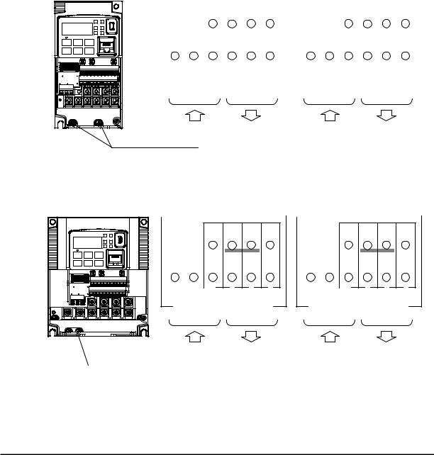
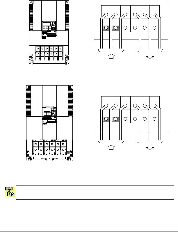
Wire the Inverter Input to a Supply
In this step, you will connect wiring to the input of the inverter. First, you must determine whether the inverter model you have required three-phase power only, or single-phase power only. All models have the same power connection terminals [R/L1], [S/L2], and
[T/L3]. So you must refer to the specifications label (on the side of the inverter) for the acceptable power source types! For inverters that can accept single-phase power and are connected that way, terminal [S/L2] will remain unconnected.
Note the use of ring lug connectors for a secure connection.
|
Single-phase 200V 0.1 to 0.4kW |
||||||||||||||||||||||||||||||||||||||||
|
Three-phase 200V |
0.1 to 0.75kW |
|||||||||||||||||||||||||||||||||||||||
|
Single-phase |
Three-phase |
|||||||||||||||||||||||||||||||||||||||
|
RB |
+1 |
+ |
— |
RB |
PD/+1 |
P/+ |
N/— |
|||||||||||||||||||||||||||||||||
|
L1 |
N |
U/T1 |
V/T2 |
W/T3 |
R/L1 |
S/L2 |
T/L3 |
U/T1 |
V/T2 |
W/T3 |
||||||||||||||||||||||||||||||
|
Power input Output to Motor |
Power input Output to Motor |
|
Chassis Ground (M4) |
|
Single-phase 200V |
0.75 to 2.2kW |
|
Three-phase 200V |
1.5, 2.2kW |
|
Three-phase 400V |
0.4 to 3.0kW |
RB +1 + —
RB PD/+1 P/+ N/—
|
L1 |
N U/T1 V/T2 W/T3 |
R/L1 |
S/L2 |
T/L3 U/T1 V/T2 W/T3 |
||||||||||||||||||||||||
|
Power input Output to Motor |
Power input Output to Motor |
|
Chassis Ground (M4) |
11
Three-phase 200V 3.7kW
Three-phase 400V 4.0kW
|
R/L1 |
S/L2 |
T/L3 |
U/T1 |
V/T2 |
W/T3 |
|
Chassis Ground (M4) |
Output to Motor |
|
Power input |
|
Three-phase 200V |
5.5, 7.5kW |
|
Three-phase 400V |
5.5, 7.5kW |
|
R/L1 |
S/L2 |
T/L3 |
U/T1 |
V/T2 |
W/T3 |
|
PD/+1 |
P/+ |
N/— |
RB |
G |
G |
|
Power input |
Output to Motor |
12
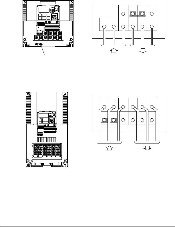
Three-phase 200V 11kW
Three-phase 400V 11, 15kW
|
R/L1 |
S/L2 |
T/L3 |
U/T1 |
V/T2 |
W/T3 |
|
PD/+1 |
P/+ |
N/— |
RB |
G |
G |
|
Power input |
Output to Motor |
Three-phase 200V 15kW
|
R/L1 |
S/L2 |
T/L3 |
U/T1 |
V/T2 |
W/T3 |
|
PD/+1 |
P/+ |
N/— |
RB |
G |
G |
|
Power input |
Output to Motor |
NOTE: An inverter powered by a portable power generator may receive a distorted power waveform, overheating the generator. In general, the generator capacity should be five times that of the inverter (kVA).
13
Using the Front Panel Keypad
Please take a moment to familiarize yourself with the keypad layout shown in the figure below. The display is used in programming the inverter’s parameters, as well as monitoring specific parameter values during operation.
|
(4) RUN LED |
(1) POWER LED |
|||||||||||
|
(5) Monitor LED [Hz] |
(2) ALARM LED |
|||||||||||
|
(6) Monitor LED [A] |
(3) Program LED |
|||||||||||
|
(8) 7-seg LED |
||||||||||||
|
RUN |
PWR |
(15) USB connector |
||||||||||
|
(7) Run command LED |
8888 |
|||||||||||
|
A |
PRG |
|||||||||||
|
Hz |
ALM |
|||||||||||
|
(9) RUN key |
(10) STOP/RESET key |
|||||||||||
|
RUN |
1 |
STOP |
(16) RJ45 connector |
|||||||||
|
RESET |
||||||||||||
|
(11) ESC key |
||||||||||||
|
ESC |
2 |
SET |
||||||||||
(12) Up key (13) Down key (14) SET key
Key and Indicator Legend
|
Items |
Contents |
||||
|
(1) |
POWER LED |
Turns ON (Green) while the inverter is powered up. |
|||
|
(2) ALARM LED |
Turns ON (Red) when the inverter trips. |
||||
|
(3) |
Program LED |
Turns ON (Green) when the display shows changeable parameter. |
|||
|
Blinks when there is a mismatch in setting. |
|||||
|
(4) |
RUN LED |
Turns ON (Green) when the inverter is driving the motor. |
|||
|
(5) |
Monitor LED [Hz] |
Turns ON (Green) when the displayed data is frequency related. |
|||
|
(6) |
Monitor LED [A] |
Turns ON (Green) when the displayed data is current related. |
|||
|
(7) |
Run command LED |
Turns ON (Green) when a Run command is set to the operator. (Run key is effective.) |
|||
|
(8) |
7-seg LED |
Shows each parameter, monitors etc. |
|||
|
(9) |
RUN key |
Makes inverter run. |
|||
|
(10) STOP/RESET key |
Makes inverter decelerates to a stop. |
||||
|
Reset the inverter when it is in trip situation |
|||||
|
Go to the top of next function group, when a function mode is shown |
|||||
|
(11) ESC key |
Cancel the setting and return to the function code, when a data is shown |
||||
|
Moves the cursor to a digit left, when it is in digit-to-digit setting mode |
|||||
|
Pressing for 1 second leads to display data of d001, regardless of current display. |
|||||
|
(12) Up key |
Increase or decrease the data. |
||||
|
(13) Down key |
Pressing the both keys at the same time gives you the digit-to-digit edit. |
||||
|
Go to the data display mode when a function code is shown |
|||||
|
(14) SET key |
Stores the data and go back to show the function code, when data is shown. |
||||
|
Moves the cursor to a digit right, when it is in digit-to-digit display mode |
|||||
|
(15) USB connector |
Connect USB connector (mini-B) for using PC communication |
||||
|
(16) RJ45 connector |
Connect RJ45 jack for remote operator |
14

Keys, Modes, and Parameters
The purpose of the keypad is to provide a way to change modes and parameters. The term function applies to both monitoring modes and parameters. These are all accessible through function codes that are primary 4-character codes. The various functions are separated into related groups identifiable by the left-most character, as the table shows.
RUN 
 PWR
PWR
8888
 Hz
Hz 
 ALM A PGM
|
RUN |
1 |
STOP |
|
|
RESET |
|||
ESC 
 2
2 
 SET
SET
|
Function |
Type (Category) of Function |
Mode to Access |
PRG LED |
||||||||
|
Group |
Indicator |
||||||||||
|
“d” |
Monitoring functions |
Monitor |
|||||||||
|
“F” |
Main profile parameters |
Program |
|||||||||
|
“A” |
Standard functions |
Program |
|||||||||
|
“b” |
Fine tuning functions |
Program |
|||||||||
|
“C” |
Intelligent terminal functions |
Program |
|||||||||
|
“H” |
Motor constant related functions |
Program |
|||||||||
|
“P” |
Pulse train input, torque, EzSQ, and |
Program |
|||||||||
|
communication related functions |
|||||||||||
|
“U” |
User selected parameters |
Program |
|||||||||
|
“E” |
Error codes |
− |
− |
You can see from the following page how to monitor and/or program the parameters.
Keypad Navigation Map
The WJ200 Series inverter drives have many programmable functions and parameters. Chapter 3 will cover these in detail, but you need to access just a few items to perform the powerup test. The menu structure makes use of function codes and parameter codes to allow programming and monitoring with only a 4-digit display and keys and LEDs. So, it is important to become familiar with the basic navigation map of parameters and functions in the diagram below. You may later use this map as a reference.
15
|
Func. code display |
|||
|
SET |
: Moves to data display |
||
|
Group «d» |
|||
|
Func. code display |
SET |
||||
|
d001 |
0.00 |
||||
|
V |
U |
ESC |
|||
|
d002 |
Func. code display |
||||
|
ESC : Jumps to the next group |
|||||
|
d104 |
|||||
|
Group «F» |
ESC |
||||
|
Func. code display |
SET |
Save |
|||
|
F001 |
50.00 |
||||
|
V |
U |
SET |
ESC |
||
|
F002 |
50.01 |
||||
|
SET |
ESC |
||||
|
F004 |
Data display |
(F001 to F003) |
|||
|
Data does not blink because of real time synchronizing |
|||||
|
ESC |
SET : Saves the data in EEPROM |
||||
|
and returns to func. code display. |
|||||
|
Group «A» |
|||||
|
ESC |
: Returns to func. code display without saving data. |
||||
|
Func. code display |
|||||
|
SET |
|||||
|
A001 |
00 |
||||
|
V |
U |
SET |
ESC |
||
|
A002 |
|||||
|
01 |
|||||
|
SET |
ESC |
||||
|
A165 |
ESC Data display
When data is changed, the display starts blinking, which means that new data has not been activated yet.
|
SET |
: Saves the data in EEPROM and |
|
returns to func. code display. |
|
|
: Cancels the data change and |
|
|
ESC |
|
|
returns to func. code display. |
Press the both up and down key at the same time in func. code or data display, then single-digit edit mode will be enabled.
Refer to 2-34 for further information.

 NOTE: Pressing the [ESC] key will make the display go to the top of next function group,
  regardless the display contents. (e.g. A021 [ESC] b001)
16
[Setting example]
After power ON, changing from 0.00 display to change the A002 (Run command source) data.
Press [ESC] key to show
the function code
ESC
d001 

SET
ESC
Data of d001 will be shown on the display after the first power ON
0.00
Press [ESC] key to move on to the function group F001
F001
ESC
Press [ESC] key Once to move on to the function group A001.
A001
U V 

Press Up key to change increase
|
function code (A001 |
A002) |
Press SET key to display the data of A002
SET
Display is solid lighting.
A002
ESC
Press up key to increase the data (02 01)
SET
Press SET key to set and save the data
When data is changed, the display starts blinking, which means that new data has not been activated yet.
SET :Fix and stores the data and moves back to the function code
ESC :Cancels the change and moves back to the function code
Function code dxxx are for monitor and not possible to change.
Function codes Fxxx other than F004 are reflected on the performance just after changing the data
(before pressing SET key), and there will be no blinking.
17

|
When a function code is shown… |
When a data is shown… |
||||||||||
|
Cancels the change and moves back to the |
|||||||||||
|
ESC |
key |
Move on to the next function group |
|||||||||
|
function code |
|||||||||||
|
Fix and stores the data and moves back to |
|||||||||||
|
SET |
key |
Move on to the data display |
|||||||||
|
the function code |
|||||||||||
|
key |
Increase function code |
Increase data value |
|||||||||
|
U |
|||||||||||
|
key |
Decrease function code |
Decrease data value |
|||||||||
|
V |
|||||||||||
Note
Keep pressing for more than 1 second leads to d001 display, regardless the display situation. But note that the display will circulates while keep pressing the [ESC] key because of the original function of the key.
(e.g. F001 A001 b001 C001 … displays 50.00 after 1 second)
18
![]()
Connecting to PLCs and Other Devices
Hitachi inverters (drives) are useful in many types of applications. During installation, the inverter keypad (or other programming device) will facilitate the initial configuration. After installation, the inverter will generally receive its control commands through the control logic connector or serial interface from another controlling device. In a simple application such as single-conveyor speed control, a Run/Stop switch and potentiometer will give the operator all the required control. In a sophisticated application, you may have a programmable logic controller (PLC) as the system controller, with several connections to the inverter.
It is not possible to cover all the possible types of application in this manual. It will be necessary for you to know the electrical characteristics of the devices you want to connect to the inverter. Then, this section and the following sections on I/O terminal functions can help you quickly and safely connect those devices to the inverter.
CAUTION: It is possible to damage the inverter or other devices if your application exceeds the maximum current or voltage characteristics of a connection point.
The connections between the inverter and other devices rely on the electrical input/output characteristics at both ends of each connection, shown in the diagram to the right. The inverter’s configurable inputs accept either a sourcing or sinking output from an external device (such as PLC). This chapter shows the inverter’s internal electrical component(s) at each I/O terminal. In some cases, you will need to insert a power source in the interface wiring.
In order to avoid equipment damage and get your application running smoothly, we recommend drawing a schematic of each connection between the inverter and the other device. Include the internal components of each device in the schematic, so that it makes a complete circuit loop.
After making the schematic, then:
1.Verify that the current and voltage for each connection is within the operating limits of each device.
|
Other device |
signal |
WJ200 inverter |
|
|
Input |
Output |
||
|
return |
|||
|
circuit |
circuit |
||
|
Output |
signal |
Input |
|
|
return |
|||
|
circuit |
circuit |
||
|
Other device |
WJ200 inverter |
||
|
P24 |
+ — 24V |
||
|
1 |
|||
|
2 |
Input |
||
|
… |
3 |
circuits |
|
|
… |
|||
|
7 |
|||
|
GND |
L |
2.Make sure that the logic sense (active high or active low) of any ON/OFF connection is correct.
3.Check the zero and span (curve end points) for analog connections, and be sure the scale factor from input to output is correct.
4.Understand what will happen at the system level if any particular device suddenly loses power, or powers up after other devices.
19
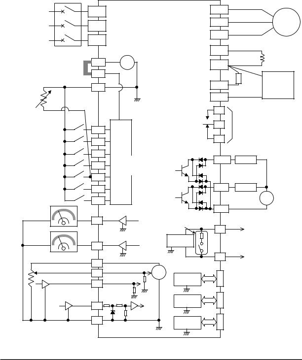
Example Wiring Diagram
The schematic diagram below provides a general example of logic connector wiring, in addition to basic power and motor wiring converted in Chapter 2. The goal of this chapter is to help you determine the proper connections for the various terminals shown below for your application needs.
|
Breaker, MCCB |
|||||||||
|
or GFI |
|||||||||
|
R |
WJ200 |
(T1) |
|||||||
|
Power source, |
U |
||||||||
|
(L1) |
|||||||||
|
3-phase or |
S |
V(T2) |
Motor |
||||||
|
1-phase, per |
|||||||||
|
inverter model |
(L2) |
W(T3) |
|||||||
|
T |
|||||||||
|
N(L3) |
PD/+1 |
||||||||
|
24V |
DC reactor |
||||||||
|
P24 |
+ — |
P/+ |
(optional) |
||||||
|
Jumper wire |
|||||||||
|
(Sink logic) |
PLC |
Braking |
|||||||
|
Brake |
|||||||||
|
unit (optional) |
|||||||||
|
L |
RB |
resistor |
|||||||
|
(optional) |
|||||||||
|
Thermistor |
Forward |
L |
N/- |
||||||
|
GND for logic inputs |
AL1 |
Relay contacts, |
|||||||
|
Intelligent inputs, |
AL0 |
type 1 Form C |
|||||||
|
7 terminals |
1 |
||||||||
|
NOTE: For the wiring |
|||||||||
|
AL2 |
|||||||||
|
of intelligent I/O and |
2 |
||||||||
|
analog inputs, be sure |
Input |
Open collector output |
|||||||
|
to use twisted pair / |
3/GS1 |
circuits |
Output circuit |
Freq. arrival signal |
|||||
|
shielded cable. Attach |
[5] configurable as |
11/EDM |
|||||||
|
the shielded wire for |
4/GS2 |
Load |
|||||||
|
each signal to its |
discrete input or |
||||||||
|
respective common |
5/PTC |
thermistor input |
|||||||
|
terminal at the inverter |
|||||||||
|
end only. |
12 |
Load |
|||||||
|
Input impedance of |
6 |
||||||||
|
each intelligent input is |
+ |
||||||||
|
4.7kΩ |
7/EB |
||||||||
|
Meter |
CM2 |
— |
|||||||
|
EO |
Termination resistor (200Ω) |
GND for logic outputs |
|||||||
|
(Change by slide switch) |
SP |
||||||||
|
Meter |
L |
Serial communication port |
|||||||
|
RS485 |
|||||||||
|
AM |
transceiver |
(RS485/Modbus) |
|||||||
|
L |
L |
SN |
NOTE: Common for |
||||||
|
Analog reference |
10Vdc |
||||||||
|
H |
RS485 is “L”. |
||||||||
|
0~10VDC |
|||||||||
|
O |
+ |
RS485 |
RJ45 port |
||||||
|
Apprx.10kΩ |
— |
||||||||
|
4~20mA |
(Optional operator port) |
||||||||
|
OI |
transceiver |
||||||||
|
Apprx.100Ω |
|||||||||
|
Pulse train input |
L |
USB (mini-B) port |
|||||||
|
L |
|||||||||
|
USB |
|||||||||
|
24Vdc 32kHz max. |
(PC communication port) |
||||||||
|
EA |
transceiver |
USB power: Self power |
|||||||
|
L |
|||||||||
|
L |
Option port |
Option port connector |
|||||||
|
GND for analog signals |
controller |
||||||||
|
L |
|||||||||
|
L |
|||||||||
20

Control Logic Signal Specifications
The control logic connectors are located just behind the front housing cover. The relay contacts are just to the left of the logic connectors. Connector labeling is shown below.
|
Relay |
SN 7 |
6 |
5 4 |
3 |
2 |
1 |
L |
PLC P24 |
|||
|
contacts |
Jumper wire |
||||||||||
|
SP |
EO |
EA |
H |
O |
OI |
L |
AM CM2 |
12 11 |
|||
|
AL2 AL1 AL0 |
|||||||||||
|
RS485 |
Pulse |
Pulse |
Analog |
Analog |
Logic |
||||||
|
comm. |
Train |
Train |
input |
output |
output |
||||||
|
output |
input |
||||||||||
|
Terminal Name |
Description |
Ratings |
|||||||||
|
P24 |
+24V for logic inputs |
24VDC, 100mA. (do not short to terminal L) |
|||||||||
|
PLC |
Intelligent input common |
To change to sink type, remove the jumper |
|||||||||
|
wire between [PLC] and [L], and connect it |
|||||||||||
|
between [P24] and [PLC]. In this case, |
|||||||||||
|
connecting [L] to [1]~[7] makes each input |
|||||||||||
|
ON. Please remove the jumper wire when |
|||||||||||
|
using external power supply. |
|||||||||||
|
1 |
Discrete logic inputs |
27VDC max. (use PLC or an external supply |
|||||||||
|
2 |
(Terminal [3],[4],[5] and [7] |
referenced to terminal L) |
|||||||||
|
3/GS1 |
have dual function. See |
||||||||||
|
4/GS2 |
following description and |
||||||||||
|
5/PTC |
related pages for the details.) |
||||||||||
|
6 |
|||||||||||
|
7/EB |
Functionality is based on ISO13849-1 |
||||||||||
|
GS1(3) |
Safe stop input GS1 |
||||||||||
|
GS2(4) |
Safe stop input GS2 |
See appendix for the details. |
|||||||||
|
PTC(5) |
Motor thermistor input |
Connect motor thermistor between PTC and |
|||||||||
|
L terminal to detect the motor temperature. |
|||||||||||
|
Set 19 in C005. |
|||||||||||
|
EB(7) |
Pulse train input B |
2kHz max. |
|||||||||
|
Common is [PLC] |
|||||||||||
|
EA |
Pulse train input A |
32kHz max. |
|||||||||
|
Common is [L] |
|||||||||||
|
L (in upper row) *1 |
GND for logic inputs |
Sum of input [1]~[7] currents (return) |
|||||||||
|
11/EDM |
Discrete logic outputs [11] |
50mA max. ON state current, |
|||||||||
|
(Terminal [11] has dual |
27 VDC max. OFF state voltage |
||||||||||
|
function. See following |
Common is CM2 |
||||||||||
|
description and related pages |
In case the EDM is selected, the functionality |
||||||||||
|
for the details.) |
is based on ISO13849-1 |
||||||||||
|
4VDC max. ON state voltage depression |
|||||||||||
|
12 |
Discrete logic outputs [12] |
50mA max. ON state current, |
|||||||||
|
27 VDC max. OFF state voltage |
|||||||||||
|
Common is CM2 |
|||||||||||
|
CM2 |
GND for logic output |
100 mA: [11], [12] current return |
|||||||||
|
AM |
Analog voltage output |
0~10VDC 2mA maximum |
|||||||||
|
EO |
Pulse train output |
10VDC 2mA maximum, 32kHz maximum |
|||||||||
|
L (in bottom row) *2 GND for analog signals |
Sum of [OI], [O], and [H] currents (return) |
||||||||||
|
OI |
Analog current input |
4 to 19.6 mA range, 20 mA nominal, |
|||||||||
|
input impedance 100 Ω |
|||||||||||
|
21 |
|
Terminal Name |
Description |
Ratings |
||||
|
O |
Analog voltage input |
0 to 9.8 VDC range, 10 VDC nominal, |
||||
|
input impedance 10 kΩ |
||||||
|
H |
+10V analog reference |
10VDC nominal, 10mA max. |
||||
|
SP, SN |
Serial communication terminal |
For RS485 Modbus communication. |
||||
|
AL0, AL1, AL2 *3 |
Relay common contact |
250VAC, |
2.5A |
(R load) max. |
||
|
250VAC, |
0.2A |
(I load, P.F.=0.4) max. |
||||
|
100VAC, |
10mA |
min. |
||||
|
30VDC, |
3.0A |
(R load) max. |
||||
|
30VDC, |
0.7A |
(I load, P.F.=0.4) max. |
||||
|
5VDC, 100mA |
min. |
|||||
|
Note 1: |
The two terminals [L] are electrically connected together inside the inverter. |
|||||
|
Note 2: We recommend using [L] logic GND (to the right) for logic input circuits and [L] |
||||||
|
analog GND (to the left) for analog I/O circuits. |
||||||
|
Note 3: |
Refer to page 39 for details of trip signals. |
Wiring sample of control logic terminal (sink logic)
|
Jumper wire |
||||||||||||||||||||||||||||||||
|
(sink logic) |
||||||||||||||||||||||||||||||||
|
SN |
7/EB |
6 |
5/PTC |
4/GS2 |
3/GS1 |
2 |
1 |
L |
PLC |
P24 |
||||||||||||||||||||||
|
SP |
EO |
EA |
H |
O |
OI |
L |
AM |
CM2 |
12 |
11/EDM |
||||||||||||||||||||||

 RY
RY  RY
RY
Variable resistor for freq. setting (1kΩ-2kΩ)
Freq. meter
Note: If relay is connected to intelligent output, install a diode across the relay coil (reverse-biased) in order to suppress the turn-off spike.
Caution for intelligent terminals setting
In turning on power when the input to the intelligent terminals become the following operations, the set data might be initialized.
Please ensure not becoming the following operations, in changing the function allocation of the intelligent input terminal.
1)Turning on power while [Intelligent input terminal 1/2/3 are ON] and [Intelligent input terminal 4/5/6/7 are OFF].
2)After 1)’s condition, turning off power.
3)After 2)’s condition, turning on power while [Intelligent input terminal 2/3/4 are ON] and [Intelligent input terminal 1/5/6/7 are OFF].
22
Sink/source logic of intelligent input terminals
|
Sink or source logic is switched by a jumper wire as below. |
||||||||||||||||||||||||||
|
Sink logic |
Source logic |
|||||||||||||||||||||||||
|
2 |
1 |
L |
PLC |
P24 |
2 |
1 |
L |
PLC |
P24 |
|||||||||||||||||
|
Jumper wire |
Jumper wire |
|||||||||||||||||||||||||
Wire size for control and relay terminals
Use wires within the specifications listed below. For safe wiring and reliability, it is recommended to use ferrules, but if solid or stranded wire is used, stripping length should be 8mm.
Control logic terminal
Relay output terminal
 8mm
8mm
|
Solid |
Stranded |
Ferrule |
|||||||||||||
|
mm2 (AWG) |
mm2 (AWG) |
mm2 (AWG) |
|||||||||||||
|
Control logic |
0.2 to 1.5 |
0.2 to 1.0 |
0.25 to 0.75 |
||||||||||||
|
terminal |
(AWG 24 to 16) |
(AWG 24 to 17) |
(AWG 24 to 18) |
||||||||||||
|
Relay terminal |
0.2 to 1.5 |
0.2 to 1.0 |
0.25 to 0.75 |
||||||||||||
|
(AWG 24 to 16) |
(AWG 24 to 17) |
(AWG 24 to 18) |
|||||||||||||
23

Recommended ferrule
For safe wiring and reliability, it is recommended to use following ferrules.
|
Wire size |
Model name of |
L [mm] |
Φd [mm] |
ΦD [mm] |
|
mm2 (AWG) |
ferrule * |
|||
|
0.25 (24) |
AI 0.25-8YE |
12.5 |
0.8 |
2.0 |
|
0.34 (22) |
AI 0.34-8TQ |
12.5 |
0.8 |
2.0 |
|
0.5 (20) |
AI 0.5-8WH |
14 |
1.1 |
2.5 |
|
0.75 (18) |
AI 0.75-8GY |
14 |
1.3 |
2.8 |
* Supplier: Phoenix contact
Crimping pliers: CRIPMFOX UD 6-4 or CRIMPFOX ZA 3
How to connect?
(1)Push down an orange actuating lever by a slotted screwdriver (width 2.5mm max.).
(2)Plug in the conductor.
(3)Pull out the screwdriver then the conductor is fixed.
2.5mm
|
Push down an |
Plug in the |
Pull out the |
|
orange actuating |
conductor. |
screwdriver to fix |
|
lever. |
the conductor. |
24

Intelligent Terminal Listing
Intelligent Inputs
Use the following table to locate pages for intelligent input material in this chapter.
Input Function Summary Table
|
Symbol |
Code |
Function Name |
Page |
||
|
FW |
00 |
Forward Run/Stop |
|||
|
RV |
01 |
Reverse Run/Stop |
|||
|
CF1 |
02 |
Multi-speed Select, Bit 0 (LSB) |
|||
|
CF2 |
03 |
Multi-speed Select, Bit 1 |
|||
|
CF3 |
04 |
Multi-speed Select, Bit 2 |
|||
|
CF4 |
05 |
Multi-speed Select, Bit 3 (MSB) |
|||
|
JG |
06 |
Jogging |
|||
|
DB |
07 |
External DC braking |
|||
|
SET |
08 |
Set (select) 2nd Motor Data |
|||
|
2CH |
09 |
2-stage Acceleration and Deceleration |
|||
|
FRS |
11 |
Free-run Stop |
|||
|
EXT |
12 |
External Trip |
|||
|
USP |
13 |
Unattended Start Protection |
|||
|
CS |
14 |
Commercial power source switchover |
|||
|
SFT |
15 |
Software Lock |
|||
|
AT |
16 |
Analog Input Voltage/Current Select |
|||
|
RS |
18 |
Reset Inverter |
|||
|
PTC |
19 |
PTC thermistor Thermal Protection |
|||
|
STA |
20 |
Start (3-wire interface) |
|||
|
STP |
21 |
Stop (3-wire interface) |
|||
|
F/R |
22 |
FWD, REV (3-wire interface) |
|||
|
PID |
23 |
PID Disable |
|||
|
PIDC |
24 |
PID Reset |
|||
|
UP |
27 |
Remote Control UP Function |
|||
|
DWN |
28 |
Remote Control Down Function |
|||
|
UDC |
29 |
Remote Control Data Clearing |
|||
|
OPE |
31 |
Operator Control |
|||
|
SF1~SF7 |
32~38 |
Multi-speed Select,Bit operation Bit 1~7 |
|||
|
OLR |
39 |
Overload Restriction Source Changeover |
|||
|
TL |
40 |
Torque Limit Selection |
|||
|
TRQ1 |
41 |
Torque limit switch 1 |
|||
|
TRQ2 |
42 |
Torque limit switch 2 |
|||
|
BOK |
44 |
Brake confirmation |
|||
|
LAC |
46 |
LAD cancellation |
|||
|
PCLR |
47 |
Pulse counter clear |
|||
|
ADD |
50 |
ADD frequency enable |
|||
|
F-TM |
51 |
Force Terminal Mode |
|||
|
ATR |
52 |
Permission for torque command input |
|||
|
KHC |
53 |
Clear watt-hour data |
|||
|
MI1~MI7 |
56~62 |
General purpose input (1)~(7) |
|||
|
AHD |
65 |
Analog command hold |
|||
|
CP1~CP3 |
66~68 |
Multistage-position switch (1)~(3) |
|||
|
ORL |
69 |
Limit signal of zero-return |
|||
|
ORG |
70 |
Trigger signal of zero-return |
|||
|
SPD |
73 |
Speed/position changeover |
|||
|
GS1 |
77 |
STO1 input (Safety related signal) |
|||
|
GS2 |
78 |
STO2 input (Safety related signal) |
|||
|
485 |
81 |
Starting communication signal |
|||
|
PRG |
82 |
Executing EzSQ program |
|||
|
HLD |
83 |
Retain output frequency |
|||
|
ROK |
84 |
Permission of Run command |
|||
|
EB |
85 |
Rotation direction detection (phase B) |
25

Use the following table to locate pages for intelligent input material in this chapter.
Input Function Summary Table
|
Symbol |
Code |
Function Name |
Page |
||
|
DISP |
86 |
Display limitation |
|||
|
NO |
255 |
No assign |
Intelligent Outputs
Use the following table to locate pages for intelligent output material in this chapter.
Input Function Summary Table
|
Symbol |
Code |
Function Name |
Page |
||
|
RUN |
00 |
Run Signal |
|||
|
FA1 |
01 |
Frequency Arrival Type 1–Constant Speed |
|||
|
FA2 |
02 |
Frequency Arrival Type 2–Over frequency |
|||
|
OL |
03 |
Overload Advance Notice Signal |
|||
|
OD |
04 |
PID Deviation error signal |
|||
|
AL |
05 |
Alarm Signal |
|||
|
FA3 |
06 |
Frequency Arrival Type 3–Set frequency |
|||
|
OTQ |
07 |
Over/under Torque Threshold |
|||
|
UV |
09 |
Undervoltage |
|||
|
TRQ |
10 |
Torque Limited Signal |
|||
|
RNT |
11 |
Run Time Expired |
|||
|
ONT |
12 |
Power ON time Expired |
|||
|
THM |
13 |
Thermal Warning |
|||
|
BRK |
19 |
Brake Release Signal |
|||
|
BER |
20 |
Brake Error Signal |
|||
|
ZS |
21 |
Zero Hz Speed Detection Signal |
|||
|
DSE |
22 |
Speed Deviation Excessive |
|||
|
POK |
23 |
Positioning Completion |
|||
|
FA4 |
24 |
Frequency Arrival Type 4–Over frequency |
|||
|
FA5 |
25 |
Frequency Arrival Type 5–Set frequency |
|||
|
OL2 |
26 |
Overload Advance Notice Signal 2 |
|||
|
ODc |
27 |
Analog Voltage Input Disconnect Detection |
|||
|
OIDc |
28 |
Analog Voltage Output Disconnect Detection |
|||
|
FBV |
31 |
PID Second Stage Output |
|||
|
NDc |
32 |
Network Disconnect Detection |
|||
|
LOG1~3 |
33~35 |
Logic Output Function 1~3 |
|||
|
WAC |
39 |
Capacitor Life Warning Signal |
|||
|
WAF |
40 |
Cooling Fan Warning Signal |
|||
|
FR |
41 |
Starting Contact Signal |
|||
|
OHF |
42 |
Heat Sink Overheat Warning |
|||
|
LOC |
43 |
Low load detection |
|||
|
MO1~3 |
44~46 |
General Output 1~3 |
|||
|
IRDY |
50 |
Inverter Ready Signal |
|||
|
FWR |
51 |
Forward Operation |
|||
|
RVR |
52 |
Reverse Operation |
|||
|
MJA |
53 |
Major Failure Signal |
|||
|
WCO |
54 |
Window Comparator for Analog Voltage Input |
|||
|
WCOI |
55 |
Window Comparator for Analog Current Input |
|||
|
FREF |
58 |
Frequency Command Source |
|||
|
REF |
59 |
Run Command Source |
|||
|
SETM |
60 |
2nd Motor in operation |
|||
|
EDM |
62 |
STO (Safe Torque Off) Performance Monitor |
|||
|
(Output terminal 11 only) |
|||||
|
OP |
63 |
Option control signal |
|||
|
no |
255 |
Not used |
26
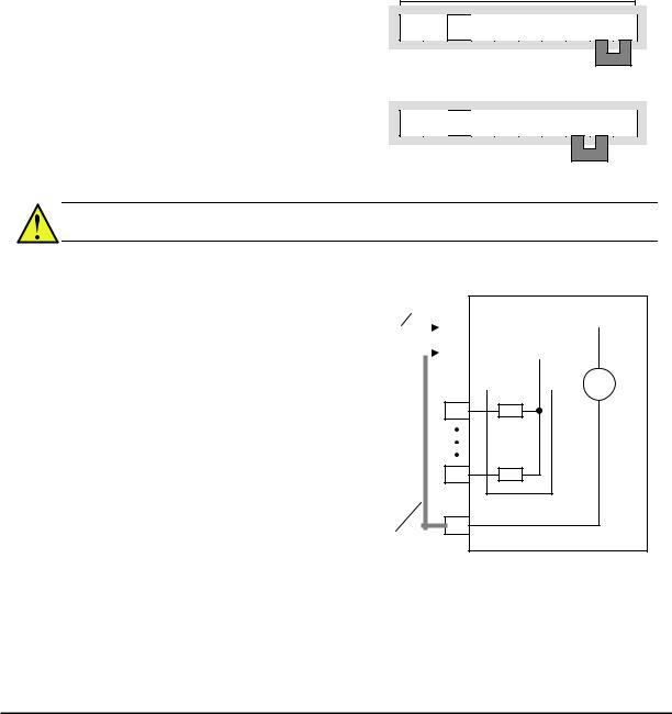
Using Intelligent Input Terminals
Terminals [1], [2], [3], [4], [5], [6] and [7] are identical, programmable inputs for general use. The input circuits can use the inverter’s internal (isolated) +24V field supply or an external power supply. This section describes input circuits operation and how to connect them properly to switches or transistor outputs on field devices.
The WJ200 inverter features selectable sinking or sourcing inputs. These terms refer to the connection to the external switching device–it either sinks current (from the input to GND) or sources current (from a power source) into the input. Note that the sink/source naming convention may be different in your particular country or industry. In any case, just follow the wiring diagrams in this section for your application.
The inverter has a jumper wire for configuring the choice of sinking or sourcing inputs. To access it, you must remove the front cover of the inverter housing. In the figure to the top right, the jumper wire is shown as attached to the logic terminal block (connector). If you need to change to the source type connection, remove the jumper wire and connect it as shown in the figure at the bottom right.
Logic inputs
7 6 5 4 3 2 1 L PLC P24
Jumper wire 
Sink logic connection
7 6  5 4 3 2 1 L PLC P24
Jumper wire 
Source logic connection
CAUTION: Be sure to turn OFF power to the inverter before changing the jumper wire position. Otherwise, damage to the inverter circuitry may occur.
[PLC] Terminal Wiring – The [PLC] terminal (Programmable Logic Control terminal) is named to include various devices that can connect to the inverter’s logic inputs. In the figure to the right, note the [PLC] terminal and the jumper wire. Locating the jumper wire between [PLC] and [L] sets the input logic source type, which is the default setting for EU and US versions. In this case, you connect input terminal to [P24] to make it active. If instead you locate the jumper wire between [PLC] and [P24], the input logic will be sink type. In this case, you connect the input terminal to [L] to make it active.
Jumper wire
|
for sink logic |
WJ200 inverter |
|||||||||||
|
P24 |
||||||||||||
|
Input common |
24V |
|||||||||||
|
PLC |
||||||||||||
|
+ |
||||||||||||
|
— |
||||||||||||
1
Input circuits
7
Logic GND
L
Jumper wire for source logic
The wiring diagram on the following pages show the four combinations of using sourcing or sinking inputs, and using the internal or an external DC supply.
27
The two diagrams below input wiring circuits using the inverter’s internal +24V supply. Each diagram shows the connection for simple switches, or for a field device with transistor outputs. Note that in the lower diagram, it is necessary to connect terminal [L] only when using the field device with transistors. Be sure to use the correct connection of the jumper wire shown for each wiring diagram.
Sinking Inputs, Internal Supply
Jumper wire = [PLC] – [P24] position
Open collector outputs,
NPN transistors
|
Jumper wire |
WJ200 |
||
|
P24 |
24V |
||
|
Input common |
|||
|
PLC |
+ |
||
|
Logic GND |
— |
||
|
L |
|||
|
1 |
|||
|
Input |
|||
|
circuits |
|||
|
7 |
|||
|
Input switches |
Sourcing Inputs, Internal Supply
|
Jumper wire = [PLC] – [L] position |
||
|
Field device |
Common to |
|
|
[P24] |
||
|
1 |
||
|
7 |
||
|
to PNP bias |
GND |
|
|
circuits |
||
PNP transistor sousing outputs
|
Jumper wire |
WJ200 |
|
|
P24 |
24V |
|
|
Input common |
||
|
PLC |
+ |
|
|
— |
||
|
L |
||
|
Logic GND |
||
|
1 |
||
|
Input |
||
|
circuits |
||
|
7 |
||
|
Input switches |
28
- Manuals
- Brands
- Hitachi Manuals
- Inverter
- WJ200-001L
Manuals and User Guides for Hitachi WJ200-001L. We have 5 Hitachi WJ200-001L manuals available for free PDF download: Instruction Manual, Quick Reference Manual
Hitachi WJ200-001L Instruction Manual (421 pages)
WJ200 Series Single-phase Input 200V class Three-phase Input 200V class Three-phase Input 400V class
Brand: Hitachi
|
Category: Inverter
|
Size: 4.69 MB
Table of Contents
-
Caution When Using Safe Stop Function
2
-
Definitions and Symbols
2
-
Hazardous High Voltage
2
-
Safety Messages
2
-
General Precautions — Read These First
3
-
Index to Warnings and Cautions in this Manual
5
-
Wiring – Cautions for Electrical Practice
7
-
Powerup Test Caution Messages
8
-
Cautions for Configuring Drive Parameters
9
-
Warnings for Configuring Drive Parameters
9
-
Cautions for Operations and Monitoring
10
-
-
General Warnings and Cautions
11
-
Warnings and Cautions for Troubleshooting and Maintenance
11
-
Terminal Symbols and Screw Size
15
-
Fuse Sizes
16
-
Table of Contents
17
-
-
Revisions
19
-
Contact Information
20
-
Getting Started
21
-
-
Chapter 1 : Getting Started
22
-
Introduction
22
-
Main Features
22
-
Inverter Specification Label
23
-
Model-Specific Tables for 200V and 400V Class Inverters
24
-
-
WJ200 Inverter Specifications
24
-
General Specifications
28
-
Derating Curves
31
-
-
Introduction to Variable-Frequency Drives
38
-
The Purpose of Motor Speed Control for Industry
38
-
What Is an Inverter
38
-
Inverter Input and Three-Phase Power
39
-
Torque and Constant Volts/Hertz Operation
39
-
Inverter Output to the Motor
40
-
Braking
41
-
Intelligent Functions and Parameters
41
-
Velocity Profiles
42
-
-
Frequently Asked Questions
43
-
Inverter Mounting and Installation
46
-
-
Chapter 2 : Inverter Mounting and Installation
47
-
Main Physical Features
47
-
Orientation to Inverter Features
47
-
Unpacking and Inspection
47
-
Power Wiring Access
48
-
-
Basic System Description
49
-
Step-By-Step Basic Installation
51
-
Choosing a Mounting Location
52
-
Ensure Adequate Ventilation
53
-
Keep Debris out of Inverter Vents
53
-
Check Inverter Dimensions
54
-
Prepare for Wiring
60
-
Determining Wire and Fuse Sizes
61
-
Terminal Dimensions and Torque Specs
62
-
Wire the Inverter Input to a Supply
63
-
Logic Control Wiring
67
-
Wire the Inverter Output to Motor
67
-
Goals for the Powerup Test
68
-
-
Powerup Test
68
-
Uncover the Inverter Vents
68
-
Powering the Inverter
69
-
Pre-Test and Operational Precautions
69
-
Key and Indicator Legend
70
-
-
Using the Front Panel Keypad
70
-
Keypad Navigation Map
71
-
Keys, Modes, and Parameters
71
-
Selecting Functions and Editing Parameters
74
-
Set the Motor Base Frequency and AVR Voltage of the Motor
76
-
Set the Motor Current
77
-
Set the Number of Motor Poles
78
-
Monitoring Parameters with the Display
79
-
Running the Motor
79
-
Single-Digit Edit Mode
80
-
Powerup Test Observations and Summary
81
-
Configuring Drive Parameters
82
-
-
-
Choosing a Programming Device
83
-
Introduction of Inverter Programming
83
-
-
Chapter 3 : Configuring Drive Parameters
84
-
Using the Keypad Devices
84
-
Control Algorithms
85
-
Operational Modes
85
-
Run Mode Edit
85
-
Dual Rating Selection
86
-
“D” Group: Monitoring Functions
88
-
Trip Event and History Monitoring
90
-
Local Monitoring with Keypad Connected
91
-
“F” Group: Main Profile Parameters
92
-
“A” Group: Standard Functions
93
-
Run Command Source Setting
94
-
Basic Parameter Settings
96
-
Analog Input Settings
97
-
Ezsq Related Settings
99
-
Multi-Speed and Jog Frequency Setting
100
-
Jog Frequency
102
-
Torque Control Algorithms
103
-
Manual Torque Boost
105
-
Voltage Compensation Gain and Slip Compensation Gain
105
-
Voltage Gain
105
-
DC Braking (DB) Settings
107
-
Frequency-Related Functions
109
-
Jump Frequencies
110
-
Acceleration Stop/Deceleration Stop
111
-
PID Control
112
-
PID Loop Configuration
114
-
PID Sleep Function
115
-
Automatic Voltage Regulation (AVR) Function
116
-
Energy Savings Mode / Optional Accel/Decel
117
-
Second Acceleration and Deceleration Functions
118
-
Accel/Decel
119
-
A131 Curve Constant (Swelling)
120
-
A150~A153 Curvature of EL-S-Curve
120
-
Acceleration / Deceleration Pattern Summary
120
-
Additional Analog Input Settings
121
-
Analog Input Calculate Function
122
-
Add Frequency
123
-
Input Range Settings
124
-
Automatic Restart Mode
125
-
B» Group: Fine Tuning Functions
125
-
Active Frequency Matching Restart
128
-
Electronic Thermal Overload Alarm Setting
129
-
Electronic Thermal Characteristic
130
-
Electronic Thermal Characteristic Curve
130
-
Electronic Thermal Warning Output
131
-
Current Limitation Related Functions
132
-
Over-Current Trip Suppression
132
-
Overload Restriction
132
-
Software Lock Mode
134
-
Motor Cable Length Parameter
135
-
Rotation Restriction Related Parameters
136
-
Run/Power on Warning Time
136
-
Reduced Voltage Start
137
-
Display Related Parameters
138
-
Basic Display Mode
139
-
Data Comparison Display Mode
139
-
User Setting Display Mode
139
-
Automatic User Parameter Registration
142
-
User Parameter Registration
142
-
Analog Voltage Input Mode
143
-
Quadrant-Specific Setting Mode
143
-
Terminal-Switching Mode
143
-
Torque Limit Function
143
-
Controlled Stop Operation at Power Loss
145
-
Window Comparator, Analog Disconnection
148
-
Ambient Temperature Setting
149
-
Watt-Hour Related
149
-
Carrier Frequency (PWM) Related
150
-
Miscellaneous Settings
151
-
Stop Mode / Restart Mode Configuration
153
-
Brake Control Function Related
156
-
DC Bus AVR (Automatic Voltage Regulation) for Deceleration Settings
159
-
Inverter Mode Setting
160
-
STO (Safe Torque Off) Setting
160
-
Password Function
162
-
How to Authenticate Password
163
-
How to Change Password
163
-
How to Delete Password
163
-
-
C» Group: Intelligent Terminal Functions
164
-
Intelligent Input Terminal Overview
165
-
Input Function Summary Table
166
-
Output Terminal Configuration
170
-
Output Function Summary Table
172
-
Low Load Detection Parameters
175
-
Frequency Arrival Output
176
-
Output Function Adjustment Parameters
176
-
Overload Warning Output
176
-
PID FBV Output
176
-
Network Communications Settings
179
-
Analog Input Signal Calibration Settings
180
-
Miscellaneous Functions
181
-
Analog Output Calibration Related Functions
182
-
Output Logic and Timing
183
-
Other Functions
184
-
“H” Group: Motor Constants Functions
185
-
Motor Constants Selection
187
-
-
Sensorless Vector Control
188
-
Auto-Tuning Function
189
-
Off-Line Auto-Tuning Procedure (with Motor Rotation)
191
-
Option Card Error
192
-
“P” Group: Other Parameters
192
-
Encoder (Pulse Train Input) Related Settings
193
-
Torque Command Related Settings
194
-
-
Simple Positioning
195
-
2-Phase Pulse Input
195
-
Single Phase Pulse Input
196
-
Simple Positioning Setting
197
-
Multistage Position Switching Function (CP1/CP2/CP3)
200
-
Speed/Positioning Switching Function (SPD)
201
-
Homing Function
202
-
Ezsq User Parameter Related Settings
203
-
Operations and Monitoring
204
-
Caution Messages for Operating Procedures
205
-
-
-
Chapter 4 : Operations and Monitoring
205
-
Introduction
205
-
Warning Messages for Operating Procedures
206
-
-
Connecting to Plcs and Other Devices
207
-
Example Wiring Diagram
208
-
-
Control Logic Signal Specifications
209
-
Wiring Sample of Control Logic Terminal (Source Logic)
210
-
Sink/Source Logic of Intelligent Input Terminals
211
-
Wire Size for Control and Relay Terminals
211
-
How to Connect?
212
-
Recommended Ferrule
212
-
Intelligent Inputs
213
-
-
Intelligent Terminal Listing
213
-
Intelligent Outputs
214
-
-
Using Intelligent Input Terminals
215
-
Forward Run/Stop and Reverse Run/Stop Commands
219
-
Multi-Speed Select ~Binary Operation
220
-
Programming Using the CF Switches
221
-
Standard Keypad Programming
221
-
Jogging Command
222
-
External Signal for DC Braking
223
-
Set Second Motor, Special Set
224
-
Two Stage Acceleration and Deceleration
225
-
Free-Run Stop
226
-
External Trip
227
-
Unattended Start Protection
228
-
Commercial Power Source Switchover
229
-
Software Lock
230
-
Analog Input Current/Voltage Select
231
-
Reset Inverter
232
-
Thermistor Thermal Protection
233
-
Three-Wire Interface Operation
234
-
PID ON/OFF and PID Clear
235
-
Remote Control up and down Functions
236
-
Force Operation from Digital Operator
238
-
Overload Restriction Source Changeover
240
-
Brake Confirmation
241
-
Torque Limit Switch
241
-
LAD Cancellation
242
-
Pulse Counter Clear
243
-
Add Frequency Enable
244
-
Force Terminal Mode
245
-
Permission for Torque Command Input
245
-
Clearance of Cumulative Power Data
246
-
General Purpose Input
247
-
Analog Command Hold
248
-
Multistage-Position Switch
249
-
Limit Signal of Homing, Trigger Signal of Zero-Return
250
-
Speed/Position Changeover
251
-
Executing Ezsq Program
252
-
Retain Output Frequency
252
-
Safe Stop Related Signals
252
-
Display Limitation
253
-
Permission of Run Command
253
-
Rotation Direction Detection
253
-
Sinking Outputs, Open Collector
254
-
-
Using Intelligent Output Terminals
254
-
Internal Relay Output
255
-
Output Signal ON/OFF Delay Function
256
-
Run Signal
257
-
Frequency Arrival Signals
258
-
Overload Advance Notice Signal
260
-
Output Deviation for PID Control
261
-
Alarm Signal
262
-
Over Torque Signal
264
-
Undervoltage Signal
265
-
Torque Limited Signal
266
-
Running Time and Power on Time over Signal
267
-
Electronic Thermal Warning Signal Output
268
-
External Brake Related Output Signals
269
-
Zero Hz Speed Detection Signal
270
-
Speed Deviation Excessive Signal
271
-
Positioning Completion Signal
272
-
Analog Input Disconnect Detect
273
-
PID Second Stage Output
274
-
Communication Signal Disconnect Detect
277
-
Logic Output Function
278
-
Lifetime Warning Output Function
279
-
Starting Contact Signal
280
-
Heat Sink Overheat Warning
281
-
General Input
282
-
Low Load Detection Signal
282
-
Inverter Ready Signal
283
-
Forward Rotation, Reverse Rotation Signals
284
-
Major Failure Signal
285
-
Window Comparator for Analog Inputs
286
-
Frequency Command Source, Run Command Source
287
-
2Nd Motor Selection
288
-
STO (Safe Torque Off) Performance Monitor
289
-
Analog Input Operation
290
-
Pulse Train Input Operation
292
-
Analog Output Operation
293
-
-
Safe Stop Function
295
-
Chapter 5: Inverter System Accessories
296
-
Component Description
296
-
Introduction
296
-
AC Reactors, Input Side
298
-
AC Reactors, Output Side
298
-
Component Descriptions
298
-
Zero-Phase Reactor (RF Noise Filter)
299
-
-
-
Chapter 6 Troubleshooting and Maintenance
300
-
General Precautions and Notes
301
-
Inspection Items
301
-
-
Troubleshooting
301
-
Inverter Does Not Power up
302
-
Motor Does Not Start
302
-
Troubleshooting Tips
302
-
A Part of Function Codes Is Not Displayed
303
-
Inverter Doesn’t Respond to Changes in Frequency Setting from Operator
303
-
Motor Does Not Accelerate to Command Speed
303
-
Operator (Keypad) Does Not Respond
303
-
Motor Rotates Reverse Direction with Forward Command
304
-
Motor Rotates Reverse Direction with RUN Key of Keypad
304
-
Overcurrent Trip
304
-
Parameter Data Does Not Change
304
-
Over Voltage Trip (E07)
305
-
Overload Trip (E05)
305
-
Sound Noise of Motor or Machine
305
-
Thermistor Error Trip (E35)
305
-
DC Braking Doesn’t Work
306
-
If Cable to Operator Is Disconnected, Inveter will Trip or Stop
306
-
No Response over Modbus Communication
306
-
Under-Voltage Error
306
-
Error Codes
307
-
Fault Detection and Clearing
307
-
-
Monitoring Trip Events, History, & Conditions
307
-
Warning Codes
310
-
Trip History and Inverter Status
312
-
-
Restoring Factory Default Settings
313
-
Daily and Yearly Inspection Chart
314
-
-
Maintenance and Inspection
314
-
Megger Test
315
-
IGBT Test Method
316
-
General Inverter Electrical Measurements
317
-
Inverter Output Voltage Measurement Techniques
319
-
Capacitor Life Curves
320
-
-
Warranty
321
-
Appendix A: Glossary and Bibliography
322
-
Glossary and Bibliography
322
-
Connecting the Inverter to Modbus
330
-
Modbus Network Communications
330
-
Network Protocol Reference
330
-
-
Appendix B: Modbus Network Communications
331
-
Introduction
331
-
Connecting the Inverter to Modbus
332
-
Inverter Parameter Setup
333
-
-
Network Protocol Reference
334
-
Transmission Procedure
334
-
Message Configuration: Query
335
-
Error Check
336
-
Header and Trailer (Silent Interval)
336
-
Message Configuration: Response
337
-
Normal Response
337
-
Transmission Time Required
337
-
No Response Occurs
338
-
Explanation of Function Codes
339
-
Read Holding Register [03H]
340
-
Write in Coil [05H]
341
-
Write in Holding Register [06H]
342
-
Loopback Test [08H]
343
-
Write in Coils [0Fh]
344
-
Write in Holding Registers [10H]
345
-
Write in Holding Registers [17H]
346
-
Exception Response
347
-
Store New Register Data (ENTER Command)
348
-
Ezcom (Peer-To-Peer Communication)
349
-
Modbus Coil List
353
-
-
Modbus Data Listing
353
-
Modbus Holding Registers
355
-
List of Inverter Trip Factors
358
-
List of Registers (Monitoring)
359
-
-
Appendix C: Drive Parameter Setting Tables
382
-
Introduction
382
-
Main Profile Parameters
383
-
Parameter Settings for Keypad Entry
383
-
Standard Functions
384
-
Fine Tuning Functions
392
-
Motor Constants Functions
406
-
CE-EMC Installation Guidelines
412
-
Installation for WJ200 Series (Example of SFE Models)
416
-
Hitachi EMC Recommendations
417
-
Safety
418
-
How It Works
419
-
Components to be Combined
420
-
Periodical Check
420
-
Precautions
420
-
-
Advertisement
Hitachi WJ200-001L Instruction Manual (680 pages)
WJ200 Series Single/Three-phase Inputs 200V/400V class
Brand: Hitachi
|
Category: DC Drives
|
Size: 14.4 MB
Table of Contents
-
Hazardous High Voltage
4
-
General Precautions — Read These First
5
-
Index to Warnings and Cautions in this Manual
7
-
General Warnings and Cautions
13
-
Table of Contents
19
-
Revisions
22
-
Contact Information
23
-
Chapter 1 : Getting Started
25
-
Introduction
25
-
WJ200 Inverter Specifications
27
-
WJ200 Inverter Specifications
29
-
-
Introduction to Variable-Frequency Drives
41
-
Frequently Asked Questions
46
-
-
Chapter 2 : Inverter Mounting and Installation
51
-
Orientation to Inverter Features
51
-
Basic System Description
53
-
Step-By-Step Basic Installation
55
-
Powerup Test
72
-
Using the Front Panel Keypad
74
-
-
Choosing a Programming Device
87
-
Chapter 3 : Configuring Drive Parameters
88
-
Using the Keypad Devices
88
-
D» Group: Monitoring Functions
92
-
F» Group: Main Profile Parameters
96
-
A» Group: Standard Functions
97
-
B» Group: Fine Tuning Functions
129
-
C» Group: Intelligent Terminal Functions
168
-
H» Group: Motor Constants Functions
189
-
Sensorless Vector Control
192
-
Auto-Tuning Function
193
-
P» Group: Other Parameters
196
-
-
Simple Positioning
199
-
-
Chapter 4 : Operations and Monitoring
209
-
Introduction
209
-
Connecting to Plcs and Other Devices
211
-
Control Logic Signal Specifications
213
-
Intelligent Terminal Listing
217
-
Using Intelligent Input Terminals
219
-
Using Intelligent Output Terminals
258
-
Analog Input Operation
294
-
Pulse Train Input Operation
296
-
Analog Output Operation
297
-
Chapter 5: Inverter System Accessories
300
-
Introduction
300
-
Component Description
300
-
-
Chapter 6 : Troubleshooting and Maintenance
306
-
Troubleshooting
306
-
-
Troubleshooting
307
-
Monitoring Trip Events, History, & Conditions
313
-
Restoring Factory Default Settings
319
-
Maintenance and Inspection
320
-
Warranty
327
-
Appendix A: Glossary and Bibliography
328
-
Glossary
329
-
Bibliography
335
-
-
Appendix B: Modbus Network Communications
337
-
Introduction
337
-
Connecting the Inverter to Modbus
338
-
Network Protocol Reference
340
-
Modbus Data Listing
359
-
Appendix C: Drive Parameter Setting Tables
388
-
Introduction
388
-
Parameter Settings for Keypad Entry
389
-
-
Appendix D: EMC Installation Guidance
420
-
CE-EMC Installation Guidelines
420
-
Hitachi EMC Recommendations
425
-
-
Appendix E: Safety (ISO13849-1)
426
-
Introduction
426
-
How It Works
427
-
Installation
428
-
Components to be Combined
428
-
Periodical Check
429
-
Precautions
429
-
Additional Function for Version
430
-
PM Motor Drive
431
-
Dynamic Braking Related Functions
444
-
Inverter Mode
445
-
Thermal Detection System Error
446
-
Modbus Data Listing
447
-
Drive Parameter Setting Tables
477
-
Additional Function for Version
510
-
Inverter Mode Selection
511
-
Operation Condition of Speed Detection
512
-
Position Feedback Monitor (D030)» Enabling at «Simple Positioning»-Off
512
-
Frequency Source Monitor
512
-
Run Source Monitor
512
-
LAD Cancel by Setting ACC/DEC
513
-
Analog Input O/OI Monitor(Always Enable)
513
-
Pulse Train Input Monitor (Always Enable)
513
-
PID Deviation Monitor
514
-
PID Output Monitor
514
-
Over-Current Trip Suppression: B027
515
-
Output Frequency Range from 0.01Hz to 400Hz
516
-
Support of Multiple Pole 3 Phase Induction Motors(up to 48 Pole Motor)
516
-
Creep Pulse Ratio(Simple Positioning)
517
-
Frequency Reference by Pulse Train Input
519
-
Restarting Simple Positioning
520
-
Simple Positioning & Brake Control Co-Operation
523
-
Simple Positioning(Current Position Store at Shut Down)
525
-
Simple Positioning(Preset Function by PSET Terminal)
525
-
Electronic Thermal Improve
526
-
IRDY Old/New Spec. Selection
530
-
Initial Value Change of the PM Motor Control Relations Parameter
531
-
Modbus Mapping Function
532
-
Holding Register Big Endian L Ittle Endian Select
573
-
Electronic Thermal Detection System Error
594
-
Modbus Data Listing
595
-
Drive Parameter Setting Tables
629
-
Additional Function for Version
666
-
Improvement of the Reaction Time of Overload Output Signal
667
-
Improvement of Speed Detection with Single-Phase Encoder
668
-
Hitachi WJ200-001L Quick Reference Manual (104 pages)
WJ200 Series
Brand: Hitachi
|
Category: Inverter
|
Size: 3.02 MB
Table of Contents
-
Safety Precautions
3
-
Fuse Sizes
8
-
Inverter Specification Label
9
-
Wj200 Inverter Specifications
10
-
Basic System Description
14
-
Using the Front Panel Keypad
19
-
Connecting to Plcs and Other Devices
24
-
Control Logic Signal Specifications
26
-
Intelligent Terminal Listing
30
-
Using Intelligent Input Terminals
32
-
Unattended Start Protection
39
-
Reset Inverter
40
-
Run Signal
41
-
Using Intelligent Output Terminals
41
-
Alarm Signal
44
-
Analog Input Operation
46
-
Pulse Train Input Operation
48
-
Analog Output Operation
49
-
Error Codes
90
-
Restoring Factory Default Settings
92
-
CE-EMC Installation
93
-
Hitachi Emc Recommendations
97
-
How It Works
98
-
Wiring Example
100
-
Ec Declaration of Conformity
104
Advertisement

Hitachi WJ200-001L Quick Reference Manual (94 pages)
WJ200 Series Inverter Single-phase Input 200V class Three-phase Input 200V class Three-phase Input 400V class
Brand: Hitachi
|
Category: Inverter
|
Size: 1.02 MB
Table of Contents
-
Wj200 Inverter Specifications
6
-
Basic System Description
10
-
Using the Front Panel Keypad
15
-
Connecting to Plcs and Other Devices
20
-
Control Logic Signal Specifications
22
-
Intelligent Terminal Listing
26
-
Using Intelligent Input Terminals
28
-
Unattended Start Protection
35
-
Reset Inverter
36
-
Run Signal
37
-
Alarm Signal
40
-
Analog Input Operation
42
-
Pulse Train Input Operation
44
-
Analog Output Operation
45
-
Monitoring Functions
47

Hitachi WJ200-001L Quick Reference Manual (95 pages)
WJ200 Series Inverter Single-phase Input 200V class Three-phase Input 200V class Three-phase Input 400V class
Brand: Hitachi
|
Category: Inverter
|
Size: 2.74 MB
Table of Contents
-
Wj200 Inverter Specifications
7
-
Basic System Description
11
-
Using the Front Panel Keypad
16
-
Connecting to Plcs and Other Devices
21
-
Control Logic Signal Specifications
23
-
Intelligent Terminal Listing
27
-
Using Intelligent Input Terminals
29
-
Reset Inverter
37
-
Alarm Signal
41
-
Analog Input Operation
43
-
Pulse Train Input Operation
45
-
Analog Output Operation
46
-
Wiring Example
93
Advertisement
Related Products
-
Hitachi WJ200-001S
-
Hitachi WJ200-001SF
-
Hitachi WJ200-0015SF
-
Hitachi WJ200-001LF
-
Hitachi WJ200-004S
-
Hitachi WJ200-007S
-
Hitachi WJ200-002L
-
Hitachi WJ200-004H
-
Hitachi WJ200-007SF
-
Hitachi WJ200-002LF
Hitachi Categories
![]()
Projector
![]()
Air Conditioner
Drill
Power Tool
LCD TV
More Hitachi Manuals