Honda Integra JDM
Мануал для тигры, может кому понадобиться

Gusmanjdm
Был 1 день назад
Ильгиз Айдарович
Я езжу на Honda Integra JDM (до этого — LADA 2109)
Нефтекамск, Россия
Братья хондаводы может кому понадобиться мануал для наших тигр Мануал Integra
9 января 2015
Метки: своими руками
7
Ранее #Губа, или наконец купил
Далее Неприятность или понедельник
Разместить рекламу
Реклама
Машины в продаже
Комментарии
7
Войдите или зарегистрируйтесь, чтобы писать комментарии, задавать вопросы и участвовать в обсуждении.
Войти
Зарегистрироваться

rednakleika
Я езжу на Honda Integra (DC1/DC2)
Скачала но файл пустой 🫠🥲
5 месяцев

Gusmanjdm
Автор
Я езжу на Honda Integra (DC1/DC2)
Странно, найду на компе скину 😄
5 месяцев

somebody
Несуществующий пользователь
Без машины
полезная книженция, давно ещё скачивал её)
8 лет
Gusmanjdm
Автор
Я езжу на Honda Integra (DC1/DC2)
Да хорошая книжка) помогает
8 лет
somebody
Несуществующий пользователь
Без машины
я не помню что там искал, но вроде что то да нашел)
8 лет

Flap
Я езжу на Ford Fusion
у меня такой в бумажном виде)) ещё от цивика остался)
8 лет
Gusmanjdm
Автор
Я езжу на Honda Integra (DC1/DC2)
Жалко у меня нет такого)
8 лет

Инструкции по ремонту |
||||||
|---|---|---|---|---|---|---|
| Описание | Кузов | Двигатель | Файл | Размер | Формат | Язык |
| Инструкция по ремонту Acura Integra | DC2, DC4, DB7, DB8 | B18B1 (140 сил), B18C1 (170 сил), B18C5 (195 сил) | Acura Integra (98-01) Service Manual.pdf | 54 MB | PDF* | Английский |
| Инструкция по ремонту Acura RSX (Honda Integra) | DC5 | K20A2 (200 сил), K20A3 (160 сил) | Acura RSX (02-03) Service Manual.pdf | 40 MB | Английский | |
| Honda Integra Acura RSX (01-07) Rus.pdf | 32 MB | Русский | ||||
| Инструкция по ремонту Acura TSX (Honda Accord) | CL9 | K24A2 (200 сил) | Acura TSX.zip | 252 MB | Английский | |
| Инструкция по ремонту Honda Civic | EG/EH | D15B7 (100 сил), D15B8 (70 сил), D15Z1 (90 сил), D16Z6 (125 сил) | Honda Civic 92-95 Service Manual.pdf | 88 MB | Английский | |
| Инструкция по ремонту Honda Civic | EK/EJ | D16Y5 (114 сил), D16Y7 (105 сил), D16Y8 (125 сил), B16A2 (160 сил) | Honda Civic EJ6, EJ7, EJ8 (96-00) Service Manual.pdf | 69 MB | Английский | |
| Инструкция по ремонту Honda Civic, Acura Integra | EK/EJ, DC2, DC4, DB7, DB8 | KD16Y5 (114 сил), D16Y7 (105 сил), D16Y8 (125 сил), B18B1 (140 сил), B18C1 (170 сил), B18C5 (195 сил) | Honda_Civic_Acura_Integra_1994.zip | 220 MB | EXE | Русский |
| Инструкция по ремонту Honda Civic | EP3 | K20A3(160 сил) | Honda Civic EP3 (02-03) Service Manual.pdf | 28 MB | Английский | |
| Инструкция по ремонту Honda Civic | ES/EM/EU/EP | D14Z(4-5), D15Y(2-6), D16W(7-8), D16Y(1-3), D17A(1-9), D17Z1, K20A2 | Civic01-05.zip | 165 MB | EXE | Английский |
| Инструкция по ремонту Honda S2000 | AP1 | F20C1 (240 сил) | Honda S2000 (00-03) Service Manual.pdf | 28 MB | Английский | |
| Инструкция по ремонту Honda CRX | ED9 | D16A6 (110 сил), D16A7 (110 сил), D16A8 (122 силы), D16A9 (130 сил) | Honda CRX 90 Service Manual.pdf | 16 MB | Английский | |
| Инструкция по ремонту Honda CRX | EE8 | B16A1 (150 сил), Special for MSSFM  |
Honda CRX 90 Service Manual B16A1 Engine.pdf | 7 MB | Английский | |
Инструкции по эксплуатации |
||||||
| Описание | Кузов | Двигатель | Файл | Размер | Формат | Язык |
| Инструкция по эксплуатации Honda Civic | EK/EJ | D14, D15, D16, B16 | Honda Civic Gen6 (96-00) Rus.zip | 12 MB | GIF | Русский |
| Инструкция по эксплуатации Honda Accord | CL/CM | K20A6 (155 сил), K24A3 (190 сил) |
Accord_guide.pdf Accord_MFD_ru.pdf |
7 MB | Русский | |
| Инструкция по эксплуатации Honda Civic | FN2 | K20Z3 (201 сила) | Civic_Type_R_guide.pdf | 17 MB | Русский |
*Для просмотра документов в формате PDF необходим Adobe Reader.
Отзывы и предложения можно оставлять здесь.
Вернуться на форум
Welcome to ManualMachine
You have been successfully registered
We have sent a verification link to to complete your registration.
If you can’t find the email, check your Junk/Spam folder.


- Buy Points
- How it Works
- FAQ
- Contact Us
- Questions and Suggestions
- Users
 Loading…
You can only view or download manuals with
Sign Up and get 5 for free
Upload your files to the site. You get 1 for each file you add
Get 1 for every time someone downloads your manual
Buy as many as you need
View and download manuals available only for
Register and get 5 for free
Upload manuals that we do not have and get 1 for each file
Get 1 for every download of your manual
Buy as much as you need
Get your hands on the complete Honda factory workshop software
Locations
ABS Main Relay: Locations
Right Front Of Engine Compartment
Page 178
Circuit Identification for In-Line and Fuse Box Connectors Part 4
Use the charts to help diagnose multiple symptoms in separate circuits which could be caused by a
single problem in a connector shared by those circuits. Here’s how that chart could help you find
such a problem:
1. Pick one of the multiple symptoms and look up the schematic for that circuit. 2. Make a list of all
in-line and fuse box connectors in that schematic (include page numbers). 3. Then, in the chart,
look up each connector on your list to see if circuits related to the other symptoms run through one
of them. If they do, inspect
that connector for the problem.
Example: The horn, A/C, and the right headlight don’t work. List all in-line and fuse box connectors
in the horn circuit and then check the chart (See Sample). You find that C211 is common to the A/C
circuit and the headlight circuit, so you inspect C211 and find the problem: bent terminals.
Light Flasher Relay
101. Below Left Side of Dash (with Security)
Page 181
Body Control Module: Diagram Information and Instructions Component Locations
To see where a component or connector is located on the car, look up its photo number in the
Component Location. The photo will also tell you the color of the connector, and how many cavities
it has.
If there is no photo number below or beside a connector, ground, or terminal number, look up that
connector, ground, or terminal number in the appropriate Connector Identification Chart. The chart
will tell you the color of a connector, how many cavities it has, where it’s located, and what
component or harness it connects to. On the page opposite that chart you’ll find an illustration of
the related harness.
Page 163
Fuse-To-Components Index Image 6-2
Page 15
Circuit Identification for In-Line and Fuse Box Connectors Part 4
Use the charts to help diagnose multiple symptoms in separate circuits which could be caused by a
single problem in a connector shared by those circuits. Here’s how that chart could help you find
such a problem:
1. Pick one of the multiple symptoms and look up the schematic for that circuit. 2. Make a list of all
in-line and fuse box connectors in that schematic (include page numbers). 3. Then, in the chart,
look up each connector on your list to see if circuits related to the other symptoms run through one
of them. If they do, inspect
that connector for the problem.
Example: The horn, A/C, and the right headlight don’t work. List all in-line and fuse box connectors
in the horn circuit and then check the chart (See Sample). You find that C211 is common to the A/C
circuit and the headlight circuit, so you inspect C211 and find the problem: bent terminals.
Locations
Power Door Lock Relay: Locations
Front Of Driver’s Door
Front Of Driver’s Door
Page 104
Blower Motor Relay: Testing and Inspection
RELAY TEST
Normally-Open Type 1. Remove the power relay from its socket.
2. Check continuity between relay terminals.
— There should be continuity between the A and C terminals when power and ground are connected
to the B and D terminals.
— There should be no continuity when power is disconnected.
Page 162
Fuse-To-Components Index Image 6-1
Page 32
Splices
Locations
Ignition Shut Down Relay (For Antitheft): Locations
Below Left Side Of Dash
Page 27
Terminals — T
Page 48
General Module: Description and Operation
INTEGRATED CONTROL UNIT
An integrated control unit, located in the left kick panel, integrates the functions of the key-in/seat
belt reminder, side marker light flasher, wiper/washer, lights-on reminder, rear window defogger
timer, brake system light bulb check, and engine oil pressure indicator flasher circuits.
NOTE: Different wires with the same color have been given a number suffix to distinguish them (for
example, GRN/RED1 and GRN/RED2 are not the same).
Page 19
General Module: Diagram Information and Instructions Ground Distribution Schematics
This sample Ground Distribution schematic shows all of the components that share two ground
points.
Page 156
58. Behind Dashboard Lower Cover
Page 21
From Fuses to Relays and Components
The second half of Power Distribution shows the wiring «From Fuses to Relays and Components.»
This can speed your troubleshooting by showing which circuits share fuses. If Power Distribution
shows that an inoperative circuit and another circuit share a fuse, check a component in the other
circuit. If it works, you know the fuse is good and power is available to the inoperative circuit.
Page 20
General Module: Diagram Information and Instructions Power Distribution Schematics
Power Distribution schematics show how power is supplied from the positive battery terminal to
various circuits in the car. Refer to the Power Distribution to get a more detailed picture of how
power is supplied to the circuit you’re working on.
From Battery to Ignition Switch, Fuses, and Relays
Individual circuit schematics begin with a fuse. The first half of Power Distribution, however, shows
the wiring «upstream» between the battery and the fuses.
Page 99
3. Inspect the connector and socket terminals to be sure they are all making good contact.
If the terminals are bent, loose or corroded, repair them as necessary, and recheck the system. If
the terminals look OK, make the following input tests at the connector. If any test indicates a problem, find and correct the cause, then recheck the system.
— If all the input tests prove OK, the control unit must be faulty; replace it.
Page 116
Blower Motor Speed (2 Of 2)
Page 134
60. Behind Dashboard Lower Cover
Testing For a Short to Ground With A Test Light or DVOM
General Module: Diagnostic Aids Testing For a Short to Ground With A Test Light or DVOM
1. Remove the blown fuse and disconnect the load.
2. Connect a test light or digital volt/ohmmeter (DVOM), switched to the appropriate DC volts
range, across the fuse terminals to make sure voltage
is present. You might have to turn the ignition switch to ON; check the schematic to see.
3. Beginning near the fuse box, wiggle the harness. Continue this at convenient points about six
inches apart while watching the test light or DVOM. 4. Where the test light goes off, or the DVOM
voltage drops to zero, there is a short to ground in the wiring near that point.
NOTE: Always use a DVOM on high impedance circuits. A test light may not glow (even with
battery voltage present).
Page 79
Brake Fluid Pump Relay: Testing and Inspection
RELAY TEST / ABS PUMP MOTOR RELAY
Normally-Open Type 1. Remove the power relay from its socket.
2. Check continuity between relay terminals.
— There should be continuity between the A and C terminals when power and ground are connected
to the B and D terminals.
— There should be no continuity when power is disconnected.
Page 25
Components
Page 159
Under-Hood Fuse/Relay Box (2 Of 2)
21. Right Rear Corner of Engine Compartment
Page 121
Maintenance Reminder Control Module: Testing and Inspection
MAINTENANCE REMINDER UNIT / INPUT TEST
1. With the ignition switch OFF, disconnect the 5-P connector from the reminder unit.
2. Inspect the connector and socket terminals to be sure they are all making good contact.
If the terminals are bent, loose or corroded, repair them as necessary, and recheck the system. If
the terminals look OK, make the following in-put tests at the connector. —
If a test indicates a problem, find and correct the cause, then recheck the system.
— If all the input tests prove OK, the reminder unit must be faulty; replace it.
Page 164
Fuse-To-Components Index Image 6-5
Locations
55. Above Left Kick Panel
Page 165
Relay Box: Application and ID Under-Hood Fuse/Relay Box
Fuse-To-Components View Image 6-3
Page 31
Shielding
Wire Color Abbreviations
Wire Color Abbreviations
Page 70
Trunk / Liftgate Relay: Testing and Inspection
RELAY TEST
Normally-Open Type 1. Remove the power relay from its socket.
2. Check continuity between relay terminals.
— There should be continuity between the A and C terminals when power and ground are connected
to the B and D terminals.
— There should be no continuity when power is disconnected.
Page 175
Body Control Module: Diagram Information and Instructions Circuit Identification For In-Line and
Fuse Box Connectors
Circuit Identification for In-Line and Fuse Box Connectors Part 1
Locations
Body Control Module: Locations
Rear Of Under-dash Fuse/Relay box
Page 42
General Module: Diagnostic Aids Testing For A Short to Ground W/Self-Powered Test Light or
DVOM
1. Remove the blown fuse and disconnect the battery and load.
2. Connect one lead of a self-powered test light or digital volt/ohmmeter (DVOM) (switched to the
lowest «OHMS» range) to the fuse terminal on the
load side.
3. Connect the other lead to a known good ground. 4. Beginning near the fuse box, wiggle the
harness. Continue this at convenient points about six inches apart while watching the test light or
DVOM. 5. If the self-powered test light goes on or the DVOM displays a low reading or no reading
(zero), there is a short to ground in the wiring near that
point.
Locations
54. Above Left Kick Panel
Testing and Inspection
Control Module HVAC: Testing and Inspection
Blower Motor Speed (1 Of 2)
Page 35
General Module: Diagram Information and Instructions Wire Color Codes
The following abbreviations are used to identify wire colors in the circuit schematics:
WHT = White YEL = Yellow BLK = Black BLU = Blue GRN = Green RED = Red ORN = Orange
PNK = Pink BRN = Brown GRY = Gray PUR = Purple LT BLU = Light Blue LT GRN = Light Green
Wire Color Codes
The wire insulation has one color or one color with another color stripe. The second color is the
stripe.
NOTE: Different wires with the same color in the same system have been given number suffixes to
distinguish them (for example, YEL1 and YEL2 are not the same).
Locations
13. Right Front Corner of Engine Compartment
Page 45
General Module: Diagnostic Aids Testing For Voltage Drop
Wires, connectors, and switches are designed to conduct current with a minimum loss of voltage. A
voltage drop of more than one volt indicates a problem.
1. Place the digital volt/ohmmeter (DVOM) in the appropriate DC volts range. Connect the positive
lead to the end of the wire (or to the connector or
switch) closest to the battery.
2. Connect the negative lead to the other end of the wire (or the other side of the connector or
switch). 3. Turn on the components in the circuit. 4. The DVOM will show the difference in voltage
between the two points. A difference, or drop, of more than one volt indicates a problem. Check
the circuit for loose, dirty, or bent terminals.
Page 75
ABS Main Relay: Testing and Inspection
RELAY TEST
Normally-Open Type 1. Remove the power relay from its socket.
ABS Pump Motor Relay
ABS Fail-Safe Relay
2. Check continuity between relay terminals.
— There should be continuity between the A and C terminals when power and ground are connected
to the B and D terminals.
— There should be no continuity when power is disconnected.
Locations
60. Behind Dashboard Lower Cover
Power Relay Test
Radiator Cooling Fan Motor Relay: Testing and Inspection Power Relay Test
Relay Test (Normally-Open Type)
Check for continuity between the terminals.
There should be continuity between the A and B terminals when power and ground are connected
to the C and D terminals.
There should be no continuity between the A and S terminals when power is disconnected.
Type 1
— Condenser Fan Relay
— Radiator Fan Relay
— A/C Compressor Clutch Relay
Type 2
Page 180
connector’s location on the car. Connector cavities are also numbered. The numbering sequence
begins at the top left corner of the connector as seen from either of the viewpoints. Disregard any
numbers molded into the connector housing.
Wires are identified by the abbreviated names of their colors; the second color is the color of the
stripe. Wires are also identified by their location in a connector. The number «2» next to the male
and female wire terminals at C416, for example, means those terminals join in cavity 2 of connector
C416.
A complete description of schematic symbols is as given in «Symbols».
Page 140
Horn Relay: Testing and Inspection
RELAY TEST
Normally-Open Type 1. Remove the power relay from its socket.
2. Check continuity between relay terminals.
— There should be continuity between the A and C terminals when power and ground are connected
to the B and D terminals.
— There should be no continuity when power is disconnected.
Electrical Load Detector Unit
Right Rear Corner Of Engine Compartment
Page 29
Fuses
Testing and Inspection
Power Distribution Relay: Testing and Inspection
RELAY TEST
Normally-Open Type 1. Remove the power relay from its socket.
2. Check continuity between relay terminals.
— There should be continuity between the A and B terminals when power and ground are connected
to the C and D terminals.
— There should be no continuity when power is disconnected.
Type 1
Type 1
Type 2
Type 2
— Power Window Relay
— Radiator Fan Relay
— Blower Motor Relay
— A/C Compressor Clutch Relay
Page 17
connector’s location on the car. Connector cavities are also numbered. The numbering sequence
begins at the top left corner of the connector as seen from either of the viewpoints. Disregard any
numbers molded into the connector housing.
Wires are identified by the abbreviated names of their colors; the second color is the color of the
stripe. Wires are also identified by their location in a connector. The number «2» next to the male
and female wire terminals at C416, for example, means those terminals join in cavity 2 of connector
C416.
A complete description of schematic symbols is as given in «Symbols».
Page 179
Body Control Module: Diagram Information and Instructions Circuit Schematics
Each schematic represents one circuit. A circuit’s wires and components are arranged to show
current flow, from power at the top of the page, to ground, at the bottom.
Other circuits may share power or ground terminals or wiring with the circuit shown. A wire that
connects one circuit to another, for example, is cut short and has an arrowhead at the end of it
pointing in the direction of current flow. Next to the arrowhead is the name of the circuit or
component which shares that wiring. To quickly check shared wiring, check the operation of a
component it serves. If that component works, you know the shared wiring is OK.
All connectors are numbered (C709, C416, etc.). Below each connector number (except those for
components) is the number of a photo showing the
Page 26
Connectors — C
Page 136
— If a test indicates a problem, find and correct the cause, then recheck the system.
— If all the input tests prove OK, the turn signal/hazard relay must be faulty; replace it.
Page 166
Fuse-To-Components Index Image 6-4
Testing and Inspection
Daytime Running Lamp Control Unit: Testing and Inspection
DAYTIME RUNNING LIGHTS CONTROL UNIT / INPUT TEST
CAUTION:
All SRS wire harnesses are covered with yellow insulation. Before you disconnect any part of an
SRS wire harness, disconnect the airbag connectors.
Whenever the ignition switch is ON, or has been turned OFF for less than three minutes, be careful
not to bump the SRS unit; the airbags could accidentally deploy and cause damage or injuries.
For additional precautions, refer to SRS See: Restraint Systems/Air Bag Systems/Service
Precautions.
1. Remove the dashboard lower cover and knee bolster. 2. Disconnect the connectors from the
daytime running lights control unit.
Page 38
General Module: Diagnostic Aids Troubleshooting Precautions
Before Troubleshooting
1. Check the main fuse and the fuse box. 2. Check the battery for damage, state of charge, and
clean and tight connections.
CAUTION: Do not quick-charge a battery unless the battery ground cable has been disconnected, or you will
damage the alternator diodes.
— Do not attempt to crank the engine with the ground cable disconnected or you will severely
damage the wiring.
While You’re Working
1. Make sure connectors are clean, and have no loose terminals or receptacles.
2. Make sure multiple terminal connectors are packed with dielectric (silicone) grease.
Part Number: 08798-9001
3. When connecting a connector, push it until it clicks into place.
CAUTION: Do not pull on the wires when disconnecting a connector. Pull only on the connector housings.
— Most circuits include solid-state devices. Test the voltages in these circuits only with a
10-megaohm or higher impedance digital multimeter. Never use a test light or analog meter on
circuits that contain solid-state devices. Damage to the devices may result.
Page 176
Circuit Identification for In-Line and Fuse Box Connectors Part 2
Locations
82. Front of Driver’s Door
Page 126
3. Inspect the connector and socket terminals to be sure they are all making good contact.
If the terminals are bent, loose or corroded, repair them as necessary, and recheck the system. If
the terminals look OK, make the following input tests at the connector. If any test indicates a problem, find and correct the cause, then recheck the system.
— If all the input tests prove OK, the control unit must be faulty; replace it.
Page 34
Wires
Page 43
General Module: Diagnostic Aids Testing For Continuity
When testing for continuity at a connector without wire seals, you do not have to separate the two
halves of the connector. Instead, probe the connector from the back. Always check both sides of
the connector because dirty, corroded, and bent terminals can cause problems (no electrical
contact = an open).
1. Disconnect the negative cable from the car battery. If you’re using a DVOM, place it in the lowest
«OHMS» range.
2. Connect one lead of a self-powered test light or DVOM to one end of the part of the circuit you
want to test. 3. Connect the other lead to the other end. 4. If the self-powered test light glows, there
is continuity. If you’re using a DVOM, a low reading or no reading (zero), means good continuity.
Page 150
Normally-Open Type 1. Remove the power relay from its socket.
2. Check continuity between relay terminals.
— There should be continuity between the A and C terminals when power and ground are connected
to the B and D terminals.
— There should be no continuity when power is disconnected.
Type 1
Type 1
— Blower Motor Relay
— Rear Window Defogger Relay
Type 2
— Horn Relay
Page 145
— If a test indicates a problem, find and correct the cause, then recheck the system.
— If all the input tests prove OK, the turn signal/hazard relay must be faulty; replace it.
Page 135
Hazard Flasher Relay: Testing and Inspection
TURN SIGNAL & HAZARD RELAY INPUT TEST
CAUTION:
All SRS wire harnesses are covered with yellow insulation. Before you disconnect any part of an
SRS wire harness, disconnect the airbag connectors.
Whenever the ignition switch is ON, or has been turned OFF for less than three minutes, be careful
not to bump the SRS unit; the airbags could accidentally deploy and cause damage or injuries.
For additional precautions, refer to SRS See: Restraint Systems/Air Bag Systems/Service
Precautions.
1. Remove the turn signal/hazard relay from the under-dash fuse/relay box. 2. Inspect the relay and
socket terminals to be sure they are all making good contact.
If the terminals are bent, loose or corroded, repair them as necessary, and recheck the system. If
the terminals look OK, make the following in-put tests at the socket.
Page 108
Compressor Clutch Relay: Testing and Inspection
Relay Test (Normally-Open Type)
Check for continuity between the terminals.
There should be continuity between the A and B terminals when power and ground are connected
to the C and D terminals.
There should be no continuity between the A and S terminals when power is disconnected.
Type 1
— Condenser Fan Relay
— Radiator Fan Relay
— A/C Compressor Clutch Relay
Type 2
Page 51
Engine Oil Pressure Indicator Flasher System
Engine Oil Pressure Indicator Flasher System
Key-in/Seat Belt Reminder System
Key-in/Seat Belt Reminder System
Bulb Check System (brake system light)
Bulb Check System (brake system light)
Locations
64. Behind Dashboard Lower Cover
Page 112
Condenser Fan Motor Relay: Testing and Inspection
RELAY TEST / CONDENSER FAN Normally-Open Type
Type 1
Type 2
Check for continuity between the terminals.
There should be continuity between the A and B terminals when power and ground are connected
to the C and D terminals.
There should be no continuity between the A and S terminals when power is disconnected.
Cavity Numbering System
General Module: Diagram Information and Instructions Cavity Numbering System
Cavity Numbering System
Cavity Numbering System
Page 83
Electronic Brake Control Module: Service and Repair
1. Remove the right quarter trim panel. 2. Disconnect the ABS control unit connectors.
3. Remove the ABS control unit. 4. Install the ABS control unit in the reverse order of removal. 5.
Start the engine, and check that the ABS indicator goes off. 6. Test-drive the vehicle, and check
that the ABS indicator does not come on.
Locations
105. Left Side of Cargo Area (Hatchback)
Page 47
Integrated Control Unit (2 Of 2)
Page 14
Circuit Identification for In-Line and Fuse Box Connectors Part 3
Page 177
Circuit Identification for In-Line and Fuse Box Connectors Part 3
Page 28
Diodes
Page 158
Relay Box: Locations Under-Hood Fuse/Relay Box
Under-Hood Fuse/Relay Box (1 Of 2)
Page 12
General Module: Diagram Information and Instructions Circuit Identification For In-Line and Fuse
Box Connectors
Circuit Identification for In-Line and Fuse Box Connectors Part 1
Five-Step Troubleshooting
General Module: Diagnostic Aids Five-Step Troubleshooting
1. Verify The Complaint
Turn on all the components in the problem circuit to check the accuracy of the customer complaint.
Note the symptoms. Do not begin disassembly or testing until you have narrowed down the
problem area.
2. Analyze The Schematic
Look up the schematic for the problem circuit. Determine how the circuit is supposed to work by
tracing the current paths from the power source through the circuit components to ground. Also,
trace circuits that share wiring with the problem circuit. The names of circuits that share the same
fuse, ground, or switch, and so on, are referred to in each circuit schematic. Try to operate any
shared circuits you didn’t check in step 1. If the shared circuits work, the shared wiring is OK, and
the cause must be in the wiring used only by the problem circuit. If several circuits fail at the same
time, the fuse or ground is a likely cause.
Based on the symptoms and your understanding of the circuit’s operation, identify one or more
possible causes.
3. Isolate The Problem By Testing The Circuit
Make circuit tests to check the diagnosis you made in step 2. Keep in mind that a logical, simple
procedure is the key to efficient troubleshooting. Test for the most likely cause of failure first. Try to
make tests at points that are easily accessible.
4. Fix The Problem
Once the specific problem is identified, make the repair. Be sure to use proper tools and safe
procedures.
5. Make Sure The Circuit Works
Turn on all components in the repaired circuit in all modes to make sure you’ve fixed the entire
problem. If the problem was a blown fuse, be sure to test all of the circuits on that fuse. Make sure
no new problems turn up and the original problem does not recur.
Cavity Numbering System
Body Control Module: Diagram Information and Instructions Cavity Numbering System
Cavity Numbering System
Cavity Numbering System
Page 50
NOTE:
— Different wires with the same color have been given a number suffix to distinguish them (for
example, GRN/BLU1 and GRN/BLU2 are not the same).
— Do not disconnect any connectors on the under-dash fuse/relay box except the integrated control
unit.
All Systems
All Systems
Rear window Defogger Timer System
Rear window Defogger Timer System
Intermittent Wiper Relay System
Intermittent Wiper Relay System
Locations
23. Right Rear Corner of Engine Compartment
Under-Dash Fuse/Relay Box
Relay Box: Application and ID Under-Dash Fuse/Relay Box
Fuse-To-Components View Image 6
Page 98
Cruise Control Module: Testing and Inspection
CRUISE CONTROL UNIT / INPUT TEST
CAUTION:
All SRS wire harnesses are covered with yellow insulation. Before you disconnect any part of an
SRS wire harness, disconnect the airbag connectors.
Whenever the ignition switch is ON, or has been turned OFF for less than three minutes, be careful
not to bump the SRS unit; the airbags could accidentally deploy and cause damage or injuries.
For additional precautions, refer to SRS See: Restraint Systems/Air Bag Systems/Service
Precautions.
1. Remove the dashboard lower cover and knee bolster. 2. Disconnect the 14-P connector from the
control unit.
Locations
22. Right Rear Corner of Engine Compartment
Locations
52. Rear of Dashboard Lower Cover
Page 144
Turn Signal Relay: Testing and Inspection
TURN SIGNAL & HAZARD RELAY INPUT TEST
CAUTION:
All SRS wire harnesses are covered with yellow insulation. Before you disconnect any part of an
SRS wire harness, disconnect the airbag connectors.
Whenever the ignition switch is ON, or has been turned OFF for less than three minutes, be careful
not to bump the SRS unit; the airbags could accidentally deploy and cause damage or injuries.
For additional precautions, refer to SRS See: Restraint Systems/Air Bag Systems/Service
Precautions.
1. Remove the turn signal/hazard relay from the under-dash fuse/relay box. 2. Inspect the relay and
socket terminals to be sure they are all making good contact.
If the terminals are bent, loose or corroded, repair them as necessary, and recheck the system. If
the terminals look OK, make the following in-put tests at the socket.
Page 22
Schematic Symbols
Locations
60. Behind Dashboard Lower Cover
Page 46
General Module: Electrical Diagrams
Integrated Control Unit (1 Of 2)
Locations
22. Right Rear Corner of Engine Compartment
Locations
23. Right Rear Corner of Engine Compartment
Page 13
Circuit Identification for In-Line and Fuse Box Connectors Part 2
Page 30
Ground — G
Page 18
General Module: Diagram Information and Instructions Component Locations
To see where a component or connector is located on the car, look up its photo number in the
Component Location. The photo will also tell you the color of the connector, and how many cavities
it has.
If there is no photo number below or beside a connector, ground, or terminal number, look up that
connector, ground, or terminal number in the appropriate Connector Identification Chart. The chart
will tell you the color of a connector, how many cavities it has, where it’s located, and what
component or harness it connects to. On the page opposite that chart you’ll find an illustration of
the related harness.
Page 41
General Module: Diagnostic Aids Testing For a Short With a Short Circuit Locator (Short Finder)
1. Remove the blown fuse. Leave the battery connected.
2. Connect the short finder across the battery terminals and the load (component) side of the fuse
terminal. 3. Close all switches in the circuit you’re testing. 4. Turn on the short finder. This creates a
pulsing magnetic field around the wiring between the fuse box and the short. 5. Beginning at the
fuse box, slowly move the short finder along the circuit wiring. The meter will show current pulses
through sheet metal and body
trim. As long as the meter is between the fuse and the short, the needle will move with each current
pulse. Once you move the meter past the point of the short, the needle will stop moving. Check the
wiring and connectors in this area to locate the cause of the short.
Page 16
General Module: Diagram Information and Instructions Circuit Schematics
Each schematic represents one circuit. A circuit’s wires and components are arranged to show
current flow, from power at the top of the page, to ground, at the bottom.
Other circuits may share power or ground terminals or wiring with the circuit shown. A wire that
connects one circuit to another, for example, is cut short and has an arrowhead at the end of it
pointing in the direction of current flow. Next to the arrowhead is the name of the circuit or
component which shares that wiring. To quickly check shared wiring, check the operation of a
component it serves. If that component works, you know the shared wiring is OK.
All connectors are numbered (C709, C416, etc.). Below each connector number (except those for
components) is the number of a photo showing the
Page 93
Radiator Cooling Fan Motor Relay: Testing and Inspection Radiator Fan Relay Test
Relays / Test
There should be continuity between the No.1 and No.2 terminals when power and ground are
connected to the No.3 and No.4 terminals, and there should be no continuity when power is
disconnected.
— Condenser Fan Relay
— Radiator Fan Relay
— A/C Compressor Clutch Relay
Page 49
General Module: Testing and Inspection
INTEGRATED CONTROL UNIT / INPUT TEST
CAUTION:
All SRS wire harnesses are covered with yellow insulation. Before you disconnect any part of an
SRS wire harness, disconnect the airbag connectors.
Whenever the ignition switch is ON, or has been turned OFF for less than three minutes, be careful
not to bump the SRS unit; the airbags could accidentally deploy and cause damage or injuries.
For additional precautions, refer to SRS See: Restraint Systems/Air Bag Systems/Service
Precautions.
Remove the dashboard lower cover and knee bolster, then disconnect the 15-P connector from the
integrated control unit.
Remove the integrated control unit from the under-dash fuse/relay box.
Inspect the connector and socket terminals to be sure they are all making good contact.
If the terminals are bent, loose or corroded, repair them as necessary, and recheck the system. If
the terminals look OK, make the following input tests at the connector and under-dash fuse/relay
box. If any test indicates a problem, find and correct the cause, then recheck the system.
— If all the input tests prove OK, the control unit must be faulty; replace it.
Page 60
Reconnect the 14-P connector form the power door lock control unit.
CAUTION: To prevent damage to the motor, apply battery voltage only momentarily
Page 151
— Hatch Release Relay
— Starter Cut Relay
— ABS Pump Motor Relay
— ABS Rear Fail-Safe Relay
Page 59
Power Door Lock Control Module: Testing and Inspection
POWER DOOR LOCKS CONTROL UNIT / INPUT TEST
1. Remove the driver’s door panel. 2. Disconnect the 14-P connector from the control unit.
3 Inspect the connector and socket terminals to be sure they are all making good contact.
If the terminals are bent, loose or corroded, repair them as necessary, and recheck the system. If
the terminals look OK, make the following in-put tests at the connector. If any test indicates a problem, find and correct the cause, then recheck the system.
— If all the input tests prove OK, the control unit must be faulty; replace it.
Disconnect the 14-P connector form the power door lock control unit.
Locations
122. Above Left Kick Panel (Optional)
Locations
7. Right Front of Engine Compartment
Page 33
Switches
Page 157
12. Right Side of Engine Compartment
Locations
100. Behind Right Quarter Panel Trim (Hatchback)
Page 44
General Module: Diagnostic Aids Testing For Voltage
When testing for voltage at a connector without wire seals, you do not have to separate the two
halves of the connector. Instead, probe the connector from the back. Always check both sides of
the connector because dirty, corroded, and bent terminals can cause problems (no electrical
contact an open).
1. Connect one lead of the test light to a known good ground, or, if you’re using a digital volt
ohmmeter (DVOM), place it in the appropriate DC
volts range, and connect its negative lead to ground.
2. Connect the other lead of the test light or DVOM to the point you want to check. 3. If the test light
glows, there is voltage present. If you’re using a DVOM, note the voltage reading. It should be
within one volt of measured battery
voltage. A loss of more than one volt indicates a problem.
NOTE: Always use a DVOM on high impedance circuits. A test light may not glow (even with
battery voltage present).

Honda Integra. Хонда Интегра. DC1. Технические регламенты и рекомендуемые интервалы технического обслуживания.
Моторное масло: Honda 5W30, Honda 10W30. Допускается использование моторного масла с вязкостью 5W40, 10W40. Для замены потребуется 3,4 литра. Упаковка – 4 литра (4 банки). Интервал замены, — 5000-7500 км. Наши рекомендованные интервалы отличаются от интервалов, указанных в мануалах Honda Russia в два раза. Удвоить частоту замены масла мы предлагаем руководствуясь рекомендациями Honda Japan.
Масляный фильтр: вместе с заменой масла.
Топливный фильтр: каждые 30 000 — 40 000 км.
Воздушный фильтр: 15 000 км, или по внешнему состоянию.
Жидкость в КПП:
МКПП – MTF– 2 литра. Интервал замены — 40 000 км.
АКПП — ATF DW-1– от 2,5 до 3,2 литра (в зависимости от положения автомобиля и открытии/закрытии клапанов в момент остановки двигателя). Потребуется покупать до 4-х литров. Интервал замены 40 000 км.
АКПП — ATF Z1– от 2,5 до 3,2 литра (в зависимости от положения автомобиля и открытии/закрытии клапанов в момент остановки двигателя). Потребуется покупать до 4-х литров. Интервал замены 40 000 км.
Жидкость в ГУР: PSF. Для замены потребуется около 1 литра. Ресурс — 50 000 км.
Тормозная жидкость: DOT 3, DOT 4. Замена по интервалу, — 1 раз в 2 года. Для полной замены требуется около 1 литра жидкости.
Охлаждающая жидкость (антифриз): Оригинальная охлаждающая жидкость- 10 лет с момента выпуска автомобиля. Рекомендуемый интервал замены, — 1 раз в 2-3 года. Рекомендуется охлаждающая жидкость не ниже класса G12. Для полной замены потребуется чуть больше 4-х литров жидкости. Для частичной замены, — меньше 4-х.
Свечи зажигания: Ресурс обычной свечи зажигания — 20 000 км. Подбор свечи осуществляется по VIN (Frame)- номеру + комплектация.
Замена ремня (узла) ГРМ:
Подбор осуществляется только по vin- или frame- номеру автомобиля. Комплект для замены ремня ГРМ подразумевает следующие позиции:
Двигатели ZC, оригинальная продукция Honda.
Ремень ГРМ (ресурс 100 000 км)
Ролик-натяжитель ремня ГРМ (ресурс 100 000 км)
Сальник лобовины коленвала (ресурс 100 000 км)
Сальник распредвала (ресурс 100 000 км)
Прокладка клапанной крышки (ресурс определяется мастером)
Кольца свечных колодцев (ресурс определяется мастером)
Отдельно рассматривается вопрос о замене помпы (насоса охлаждающей жидкости), ресурс которой составляет 200 000 км.
- Совет!
При замене ремня ГРМ на двигателях ZC вместе с помпой, допустимо использовать вместе с оригинальным комплектом ремня ГРМ дубликатную помпу, чей реальный ресурс составляет 100 000 км. В данном случае общий ресурс узла станет одинаковым. Старайтесь всегда использовать оригинальные сальники, это существенно повысит ресурс узла в целом.
- Совет!
Старайтесь избегать использования неоригинальной продукции в узле ГРМ. В случае, если Вы понимаете риск использования неоригинальной продукции и готовы установить его в свой автомобиль, ориентируйтесь на вдвое меньший ресурс узла, даже если использован только один элемент комплекта ремня ГРМ.
Замена тормозных колодок:
Передние тормозные колодки: в зависимости от производителя и стиля езды, замена передних тормозных колодок осуществляется каждые 25 000 – 60 000 км.
Задние тормозные колодки: ресурс барабанных колодок может достигать 200 000 км. Дисковые колодки рекомендуются к замене каждые 40 000 км. Номер по Nisshinbo — 8266
Регулировка клапанов. Регламент регулировки клапанов, — 40 000 км пробега. Для проведения операции потребуются прокладки клапанной крышки и кольца свечных колодцев.
Если вы нашли ошибку, пожалуйста, выделите фрагмент текста и нажмите Ctrl+Enter.
Еще интересные статьи
Руководство на английском языке по ремонту и техническому обслуживанию Acura Integra 1986-1989 г.
- Автор: —
- Издательство: Honda Motor Co., Ltd.
- Год издания: 1986
- Страниц: 682
- Формат: PDF
- Размер: 156,8 Мб
Руководство на английском языке по ремонту и техническому обслуживанию Acura Integra 1990-1993 г.
- Автор: —
- Издательство: Honda Motor Co., Ltd.
- Год издания: —
- Страниц: 1163
- Формат: PDF
- Размер: 55,5 Мб
Руководство на английском языке по ремонту и техническому обслуживанию Acura Integra 1994-1997 г.
- Автор: —
- Издательство: Honda Motor Co., Ltd.
- Год издания: 1993
- Страниц: 1413
- Формат: PDF
- Размер: 33,5 Мб
Руководство на английском языке по ремонту и техническому обслуживанию Acura Integra 1998-2001 г.
- Автор: —
- Издательство: Honda Motor Co., Ltd.
- Год издания: 1997
- Страниц: 1681
- Формат: PDF
- Размер: 49,1 Мб

Мультимедийное руководство по обслуживанию и ремонту Acura Integra и Honda Civic с 1994 года выпуска.
- Автор: —
- Издательство: —
- Год издания: —
- Страниц: —
- Формат: multimedia
- Размер: 218,8 Мб

Service Manual Acura Integra Mark III (DB7/DB8/DC2/DC4 — North American market) с бензиновыми двигателями: B18B1 1.8 л (1834 см³) 141 л.с./104 кВт и B18C1 1.8 л (1797 см³) 170 л.с./125 кВт. Профессиональное руководство по ремонту и техническому обслуживанию для СТО легковой автомобиль малого среднего класса (компактный) Акура Интегра с цельнометаллическими несущими кузовами трехдверный хэтчбек и четырёхдверный седан переднеприводные модели для Северной Америки третьего поколения выпуска с 1993 по 2001 год
ЕСЛИ ВЫ ВИДИТЕ ОШИБКУ 406 Not Acceptable и не видите документ, то скорей всего у Вас IP РФ и его надо сменить, на любой другой страны, с помощью VPN ( Scribd и SlideShare блокируют посетителей с Российским IP).
Видео Акура Интегра замена распределителя зажигания и генератора (Acura Integra 94)
Акура Интегра 1993-2001 общая информация (Acura Integra DB7/DB8/DC2/DC4)
В оригинальном руководстве по ремонту «Honda Motor Co., LTD», на английском языке, дается подробное описание технологических процедур по демонтажу, сборки, диагностики, ремонту отдельных узлов и техническому обслуживанию автомобилей Acura Integra и его модификаций 1994 год выпуска.
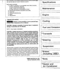
Состоит из следующих глав:
- Раздел Основная информация
- Раздел Специальный инструмент
- Раздел Спецификация
- Раздел Настройки и обслуживание
- Раздел Двигатель
- Раздел Система охлаждения
- Раздел Системы впуска и выпуска
- Раздел Трансмиссия
- Раздел Рулевое управление
- Раздел Подвеска
- Раздел Тормозная система (Включая систему «ABS»)
- Раздел Кузов и салон
- Раздел Системы отопления и кондиционирования
- Раздел Электрические схемы и электрооборудование (Включая систему «SRS»)
Конструкция системы тормозов
Диагонально распределенный, двойной контур системы тормозов позволяет в случае отказа одного контура тормозов нормально выполнять функции торможения другому контуру. Для того, чтобы остановить автомобиль в случае, если из одной половины тормозной системы полностью вытечет тормозная жидкость, потребуется дополнительное давление на педаль тормоза (ход педали увеличится по сравнению с нормальным положением).
Кроме того, использование половины тормозной мощности приведет к увеличению тормозного пути. Если неожиданно отказали тормоза, необходимо перейти на пониженную передачу и как можно скорее съехать на обочину.
• Опасно ездить на автомобиле, если в электрической или гидравлической системе тормозов имеются неполадки. В таком случае необходимо немедленно обратиться к дилеру «Хонда».
• Не ставьте ногу на педаль тормоза, если вы не собираетесь тормозить. Это приводит к преждевременному износу тормозов, может повредить их или отрицательно сказаться на эффективности торможения. Кроме того, включение стоп-сигналов на вашем автомобиле введет в заблуждение водителей, едущих за вами.
• Езда по глубокой воде может отразиться на работе тормозов. Мягко нажмите на педаль, чтобы проверить эффективность действия тормозов. Если автомобиль не снижает скорости, как обычно, продолжайте мягко наступать на педаль, двигаясь на безопасной скорости, пока тормоза не высохнут и не вернутся в нормальное рабочее состояние. Износ тормозов Передние и задние тормоза должны регулярно проверяться в соответствии с графиком проведения техобслуживания. Когда детали тормозной системы нуждаются в замене, пользуйтесь только фирменными запасными деталями «Хонда» или их аналогами.
| № | Спецификация / Specs | Данные |
| Габариты (мм/mm) и масса (кг/kg) / Dimensions and Weight | ||
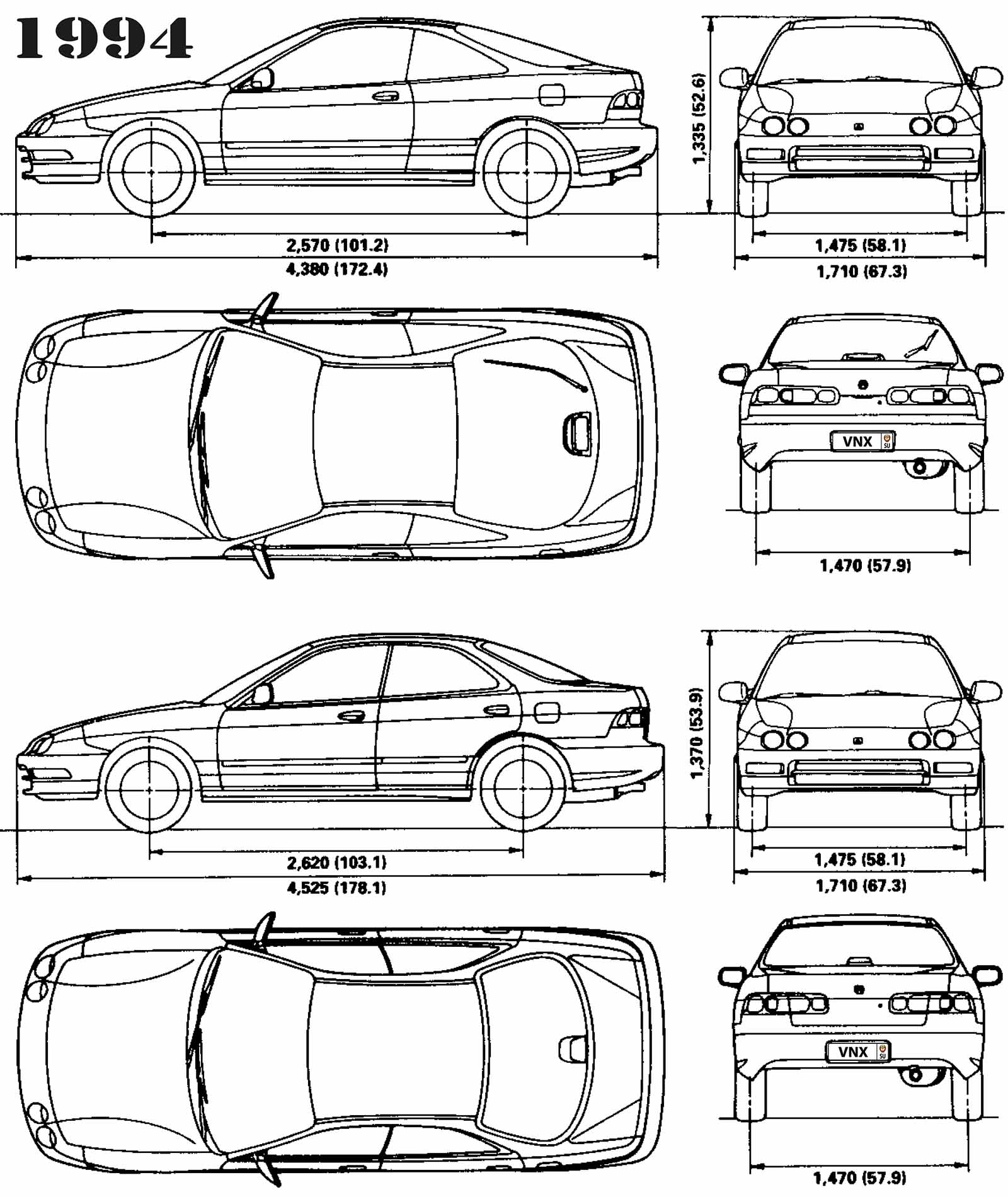
| 1 | Длина / Length | 4380 |
| 2 | Ширина (без/с зеркалами) / Width | 1710 |
| 3 | Высота (загружен/пустой) / Height | 1335 |
| 4 | Колёсная база / Wheelbase | 2570 |
| 5 | Дорожный просвет (клиренс) / Ground clearance | 150 |
| 6 | Снаряжённая масса / Total (curb) weight | 1197 |
| Полная масса / Gross (max.) weight | 1670 | |
|
Двигатель / Engine |
||
| 7 | Тип / Engine Type, Code | Бензиновый, жидкостного охлаждения, четырехтактный, B18B1 |
| 8 | Количество цилиндров / Cylinder arrangement: Total number of cylinders, of valves | 4-цилиндровый, рядный, 16V, DOHC с верхним расположением двух распредвалов |
| 9 | Диаметр цилиндра / Bore | 81.0 мм |
| 10 | Ход поршня / Stroke | 89.0 мм |
| 11 | Объём / Engine displacement | 1834 см³ |
| 12 | Система питания / Fuel supply, Aspiration | Распределенный впрыск топлива PGM-FI |
| Атмосферный | ||
| 13 | Степень сжатия / Compression ratio | 9.2:1 |
| 14 | Максимальная мощность / Max. output power kW (HP) at rpm | 104 кВт (144 л.с.) при 6300 об/мин |
| 15 | Максимальный крутящий момент / Max. torque N·m at rpm | 169 Нм при 5200 об/мин |
|
Трансмиссия / Transmission |
||
| 16 | Сцепление / Clutch type | Однодисковое, сухое, с диафрагменной нажимной пружиной и гасителем крутильных колебаний, постоянно замкнутого типа |
| 17 | КПП / Transmission type | Y80 МКПП 5 пятиступенчатая механическая, двухвальная, с синхронизаторами на всех передачах переднего хода |
О Книге
- Название: Acura Integra 1994 Service Manual
- Бензиновые двигатели: B18B1 1.8 л (1834 см³) 141 л.с./104 кВт и B18C1 1.8 л (1797 см³) 170 л.с./125 кВт
- Выпуск с 1994 года
- Серия: «Workshop Manual»
- Год издания: июль 1993
- Автор: Коллектив авторов
- Издательство: «Honda Motor Co., Ltd»
- Формат: PDF
- Страниц в книге: 1413
- Размер: 32.86 МБ
- Язык: Английский — Graecum est, non legitur
- Количество электросхем: более 50