- Manuals
- Brands
- Sony Manuals
- Home Theater System
- STR-K670P (HT-DDW670)
Manuals and User Guides for Sony STR-K670P (HT-DDW670). We have 5 Sony STR-K670P (HT-DDW670) manuals available for free PDF download: Service Manual, Operating Instructions Manual, Limited Warranty

Sony STR-K670P (HT-DDW670) Service Manual (65 pages)
FM STEREO FM-AM RECEIVER
Brand: Sony
|
Category: Stereo Receiver
|
Size: 9.46 MB
Table of Contents
-
Specifications
1
-
Safety Check-Out
3
-
Leakage Test
3
-
Unleaded Solder
3
-
Lead Free Mark
3
-
Model Identification
4
-
Servicing Note
4
-
Back Panel
4
-
Abbreviation
4
-
Test Mode
4
-
General
5
-
Main Unit
5
-
Before You Use Your Remote
6
-
Remote Button Description
6
-
Inserting Batteries into the Remote
6
-
Changing the Factory Setting of an Input Button
9
-
Test Mode
10
-
Factory Preset Mode
10
-
Fluorescent Indicator Tube Test Mode
10
-
Sound Field Clear Mode
10
-
Diagrams
11
-
Circuit Boards Location
11
-
Waveforms
11
-
DIGITAL Board
11
-
Block Diagram
12
-
Printed Wiring Board
14
-
Schematic Diagram
21
-
IC Block Diagrams
27
-
Digital Board
27
-
Ic1401 Pcm1800E/2K
28
-
Main Board
29
-
Display Board
30
-
Exploded Views
34
-
Front Panel Section
34
-
Chassis Section
35
-
Electrical Parts List
37
-
Digital Display
41
-
Supplement-1
49
-
IC Pin Function Description
57
Advertisement
Sony STR-K670P (HT-DDW670) Operating Instructions Manual (44 pages)
Sony HOME THEATER SYSTEM Model HTDDW670 User Guide
Brand: Sony
|
Category: Home Theater System
|
Size: 2.27 MB
Table of Contents
-
Operating Instructions
1
-
About this Manual
3
-
Table of Contents
4
-
1 : Check How to Hookup Your Components
5
-
Required Cords
6
-
1A: Connecting Components with Digital Audio Output Jacks
7
-
1B: Connecting Components with Only Analog Audio Jacks
9
-
-
2 : Connecting the Antennas
10
-
3 : Connecting Speakers
11
-
Installing the Speakers on the Wall
13
-
-
4 : Connecting the AC Power Cord
14
-
5 : Setting up the Speakers
15
-
6 : Adjusting the Speaker Levels and Balance
17
-
Test Tone
17
-
-
Amplifier Operation
18
-
Selecting the Component
18
-
Listening to FM/AM Radio
19
-
Storing FM Stations Automatically
20
-
Autobetical
20
-
-
Presetting Radio Stations
20
-
Using the Radio Data System (RDS)
21
-
Models of Area Code CEL, CEK
21
-
Changing the Display
23
-
Adjusting the Brightness of the Display
23
-
About the Indications in the Display
24
-
-
Enjoying Surround Sound
25
-
Using Only the Front Speakers and Sub Woofer
25
-
2Ch Stereo
25
-
-
Enjoying Higher Fidelity Sound
25
-
Auto Format Direct
25
-
-
Selecting a Sound Field
26
-
Selecting a Sound Field for Music
27
-
-
Advanced Adjustments and Settings
28
-
Switching the Audio Input Mode for Digital Components
28
-
Input Mode
28
-
Customizing Sound Fields
28
-
Resetting Sound Fields to the Initial Settings
29
-
Adjusting the Tone
30
-
Advanced Settings
30
-
-
Other Operations
32
-
Naming Preset Stations and Inputs
32
-
Using the Sleep Timer
32
-
-
Operations Using the Remote RM-AAU002
33
-
Before You Use Your Remote
33
-
Remote Button Description
33
-
Changing the Factory Setting of an Input Button
36
-
-
Additional Information
37
-
Precautions
37
-
Troubleshooting
38
-
Remote Control
39
-
Error Messages
39
-
-
Specifications
40
-
List of Button Locations and Reference Pages
43
-
Index
44
-
Sony STR-K670P (HT-DDW670) Operating Instructions Manual (44 pages)
Home Theater System
Brand: Sony
|
Category: Home Theater System
|
Size: 1.44 MB
Table of Contents
-
Operating Instructions
1
-
About this Manual
3
-
Table of Contents
4
-
1 : Check How to Hookup Your Components
5
-
Required Cords
6
-
1A: Connecting Components with Digital Audio Output Jacks
7
-
1B: Connecting Components with Only Analog Audio Jacks
9
-
-
2 : Connecting the Antennas
10
-
3 : Connecting Speakers
11
-
Installing the Speakers on the Wall
14
-
-
4 : Connecting the AC Power Cord
15
-
5 : Setting up the Speakers
16
-
6 : Adjusting the Speaker Levels and Balance
18
-
Test Tone
18
-
-
Amplifier Operation
19
-
Selecting the Component
19
-
Listening to FM/AM Radio
20
-
Presetting Radio Stations
21
-
Changing the Display
22
-
About the Indications in the Display
23
-
-
Enjoying Surround Sound
24
-
Using Only the Front Speakers and Sub Woofer
24
-
2Ch Stereo
24
-
-
Enjoying Higher Fidelity Sound
24
-
Auto Format Direct
24
-
-
Selecting a Sound Field
25
-
-
Advanced Adjustments and Settings
27
-
Switching the Audio Input Mode for Digital Components
27
-
Input Mode
27
-
Customizing Sound Fields
27
-
Resetting Sound Fields to the Initial Settings
28
-
Adjusting the Tone
29
-
Advanced Settings
29
-
-
Other Operations
31
-
Naming Preset Stations and Inputs
31
-
Using the Sleep Timer
31
-
-
Operations Using the Remote RM-AAU002
32
-
Before You Use Your Remote
32
-
Remote Button Description
32
-
Changing the Factory Setting of an Input Button
35
-
-
Additional Information
36
-
Precautions
36
-
Troubleshooting
37
-
Error Messages
38
-
Troubleshooting Guide
38
-
Remote Control
38
-
-
Specifications
39
-
List of Button Locations and Reference Pages
41
-
Index
42
-
Advertisement
Sony STR-K670P (HT-DDW670) Service Manual (64 pages)
Brand: Sony
|
Category: Stereo Receiver
|
Size: 12.5 MB
Table of Contents
-
General
2
-
Changing the Factory Setting of an Input Button
9
-
Test Mode
10
-
Block Diagram — MAIN Section
12
-
Block Diagram — DISPLAY/POWER Section
13
-
Schematic Diagram — DIGITAL Board (1/4)
16
-
Schematic Diagram — DIGITAL Board (2/4)
17
-
Schematic Diagram — DIGITAL Board (3/4)
18
-
Schematic Diagram — DIGITAL Board (4/4)
19
-
Printed Wiring Board — MAIN Section
20
-
Schematic Diagram — MAIN Section (1/3)
21
-
Schematic Diagram — MAIN Section (2/3)
22
-
Schematic Diagram — MAIN Section (3/3)
23
-
Printed Wiring Board — STANDBY Section
24
-
Printed Wiring Board — DISPLAY Section
25
-
Schematic Diagram — DISPLAY Section
26
-
-
Front Panel Section
34
-
Electrical Parts List
37
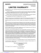
Sony STR-K670P (HT-DDW670) Limited Warranty (1 page)
General Stereo/Hifi Components/Tape Decks CD Players/Mini Disc Players/Audio Systems
Brand: Sony
|
Category: Receiver
|
Size: 0.1 MB
Advertisement
Related Products
-
Sony STR-K675P — Fm Stereo Fm-am Receiver
-
Sony STR-K6800P — A/v Receiver
-
Sony STR-K675P (For HT-DDW675)
-
Sony STR-K660P — Fm Stereo/fm-am Receiver
-
Sony STR-K665P — Receiver For Home Theater System
-
Sony STR-K5800P — A/v Receiver
-
Sony STR-K700 — Fm Stereo/fm-am Receiver
-
Sony STR-K5900P — A/v Receiver
-
Sony STR-K995
-
Sony STR-KSL50
Sony Categories
![]()
Laptop
![]()
Camcorder
![]()
TV
![]()
CD Player
![]()
Digital Camera
More Sony Manuals
-
Руководства по ремонту
1
-
Инструкции по эксплуатации
1

SONY STR-K670P инструкция по эксплуатации
(44 страницы)
- Языки:Английский
-
Тип:
PDF -
Размер:
1.26 MB
Просмотр
На NoDevice можно скачать инструкцию по эксплуатации для SONY STR-K670P. Руководство пользователя необходимо для ознакомления с правилами установки и эксплуатации SONY STR-K670P. Инструкции по использованию помогут правильно настроить SONY STR-K670P, исправить ошибки и выявить неполадки.
masterpage:Right
lename[E:SEM_JanetRevision
DataJ9050000_2342216141DDW670_GB2342216141GB02REG_HT-DDW670-U.fm]
model name1[HT-DDW670]
[2-342-216-14(1)]
3
GB
About This Manual
• The instructions in this manual are for model
HT-DDW670. Check your receiver’s model number
by looking at the lower right corner of the front
panel.
• The instructions in this manual describe the controls
on the receiver. You can also use the controls on the
supplied remote if they have the same or similar
names as those on the receiver. For details on the use
of your remote, see pages 33–36.
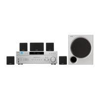
The HT-DDW670 consists of:
Models of area code CEL, CEK only
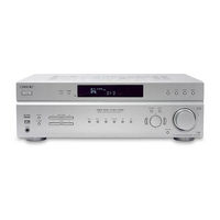
• Receiver
STR-K670P
• Speaker system
– Front speaker (left)
SS-MSP67LE
– Front speaker (right)
SS-MSP67RE
– Center speaker
SS-CNP87
– Surround speaker (left)
SS-MSP67SLE
– Surround speaker (right)
SS-MSP67SRE
– Sub woofer
SS-WMSP67E
Models of others area code
• Receiver
STR-K670P
• Speaker system
– Front speaker (left)
SS-MSP67L
– Front speaker (right)
SS-MSP67R
– Center speaker
SS-CNP67
– Surround speaker (left)
SS-MSP67SL
– Surround speaker (right)
SS-MSP67SR
– Sub woofer
SS-WMSP67
This receiver incorporates Dolby* Digital and Pro
Logic Surround and the DTS** Digital Surround
System.
* Manufactured under license from Dolby
Laboratories.
“Dolby”, “Pro Logic” and the double-D symbol are
trademarks of Dolby Laboratories.
** “DTS” and “DTS Digital Surround” are registered
trademarks of Digital Theater Systems, Inc.
About area codes
The area code of the receiver you purchased is
shown on the lower portion of the rear panel (see
the illustration below).
Any differences in operation, according to the area
code, are clearly indicated in the text, for example,
“Models of area code AA only”.
2-XXX-XXX-XX AA
S
+
CENTER
FRONT
L
R
L
R
+
+
Area code
GB01COV_HT-DDW670-U.book Page 3 Wednesday, July 13, 2005 1:45 PM
STR-K670P
Ver. 1.3
3 7 63 1515 0
1) Measured under the following conditions:
Area code
US, CND
AEP, UK, RU, SP, SP6, AR 230 V AC, 50 Hz
AUS, E51
MX
2) Depending on the sound field settings and the
source, there may be no sound output.
Inputs (Analog)
SA-CD/CD, DVD
VIDEO 1, 2
Inputs (Digital)
DVD (Coaxial)
SA-CD/CD (Optical)
Output (Analog)
SUB WOOFER
Reproduction frequency range:
Tone
Gain levels
FM tuner section
TE
L 13942296513
Tuning range
Antenna
Antenna terminals
Intermediate frequency
AM tuner section
Tuning range
Models of area code US, CND
With 10-kHz tuning scale: 530 — 1,710 kHz
With 9-kHz tuning scale: 531 — 1,710 kHz
Models of area code AEP, UK, RU, AUS, SP, SP6
With 9-kHz tuning scale: 531 – 1,602 kHz
Models of area code E51
With 10-kHz tuning scale: 530 — 1,610 kHz
With 9-kHz tuning scale: 531 — 1,602 kHz
Models of area code MX, AR
With 10-kHz tuning scale: 530 — 1,610 kHz
Antenna
Intermediate frequency
3) You can change the AM tuning scale to 9 kHz or
10 kHz. After tuning in any AM station, turn off the
receiver. While holding down PRESET TUNING +
or TUNING +, press ?/1. All preset stations will be
erased when you change the tuning scale. To reset
the scale to 10 kHz (or 9 kHz), repeat the procedure.
www
.
2
http://www.xiaoyu163.com
Power requirements
120 V AC, 60 Hz
240 V AC, 50 Hz
127 V AC, 60 Hz
Sensitivity: 800 mV
Impedance: 50 k ohms
Sensitivity: –
Impedance: 75 ohms
Sensitivity: –
Impedance: –
Voltage: 2 V
Impedance: 1 k ohm
28 – 20,000 Hz
±6 dB, 1 dB step
87.5 — 108.0 MHz
FM wire antenna
75 ohms, unbalanced
10.7 MHz
3)
3)
3)
3)
Loop antenna
450 kHz
x
ao
u163
y
i
http://www.xiaoyu163.com
2 9
8
Power requirements
Area code
Power requirements
US, CND
120 V AC, 60 Hz
AEP, UK, RU
2
30 V AC, 50/60 Hz
AUS
240 V AC, 50 Hz
E15
120/220/240 V AC,
50/60 Hz
SP, SP6, AR
220 – 230 V AC, 50/60 Hz
MX
127 V AC, 60 Hz
Power consumption
Area code
Power consumption
US, AEP, UK, E51, AR,
160 W
SP, SP6, MX, AUS, RU
CND
220 VA
Power consumption (during standby mode)
0.2 W
Dimensions (w/h/d) (Approx.)
430 × 145 × 301.5 mm
(17 × 5 6/8 × 11 7/8 inches)
including projecting parts
and controls
Mass (Approx.)
6.5 kg (14 lb 6 oz)
•
Abbreviation
AR
: Argentina model
AUS
: Australian model
CND
: Canadian model
Q Q
E51
: Chilean and Peruvian models
3
6 7
1 3
1 5
MX
: Mexican model
RU
: Russian model
SP
: Singapore model
SP6
: Singapore and Malaysia models
Design and specifications are subject to change
without notice
co
.
9 4
2 8
0 5
8
2 9
9 4
2 8
m
9 9
9 9
SERVICE MANUAL
Sony Corporation
Audio Business Group
Published by Sony Techno Create Corporation
US Model
Canadian Model
AEP Model
UK Model
E Model
Australian Model
FM STEREO FM-AM RECEIVER
9-879-447-06
2008B16-1
© 2008.02
Ver. 1.5 2008.02
SPECIFICATIONS
STR-K670P
• STR-K670P is the tuner and the amplifier
section in HT-DDW670 and HTP-32DW/
82DWK.
– Continued on next page –
Manufactured under license from Dolby Laboratories.
“Dolby”, “Pro Logic” and the double-D symbol are trademarks of Dolby Laboratories.
“DTS” and “DTS Digital Surround” are registered trademarks of Digital Theater
Systems, Inc.
Models of area code AUS
(6 ohms 120 Hz – 20 kHz, THD 0.09%)
FRONT
2)
: 40
W/ch
CENTER
2)
: 40
W
SURR
2)
: 40
W/ch
(6 ohms 100 Hz, THD 0.09%)
(6 ohms 1 kHz, THD 0.7%)
(6 ohms 100 Hz, THD 0.7%)
(6 ohms 1 kHz, THD 10%)
FRONT
2)
: 50
W/ch
CENTER
2)
: 50
W
SURR
2)
: 50
W/ch
FRONT
2)
: 85
W/ch
CENTER
2)
: 85
W
SURR
2)
:
85 W/ch
AUDIO POWER SPECIFICATIONS
POWER OUTPUT AND TOTAL HARMONIC
DISTORTION:
(Models of area code US only)
With 6 ohm loads, both channels driven, from
120 – 20,000 Hz; rated 60 watts per channel
minimum RMS power, with no more than 0.7%
total harmonic distortion from 250 milliwatts to
rated output.
Amplifier section
Power Output
1)
Models of area code US
Models of area code CND
(6 ohms 1 kHz, THD 10%)
(6 ohms 100 Hz, THD 10%)
FRONT
2)
: 100 W/ch
CENTER
2)
:
100 W
SURR
2)
: 100
W/ch
SUB WOOFER
2)
: 100
W
(6 ohms 1 kHz, THD 0.7%)
FRONT
2)
: 60
W/ch
CENTER
2)
:
60 W
SURR
2)
:
60 W/ch
FRONT
2)
: 100
W/ch
CENTER
2)
:
100 W
SURR
2)
:
100 W/ch
(6 ohms 100 Hz, THD 0.7%)
(6 ohms 1 kHz, THD 10%)
SUB WOOFER
2)
: 100
W
(6 ohms 100 Hz, THD 10%)
SUB WOOFER
2)
: 85
W
SUB WOOFER
2)
: 40
W
(6 ohms 100 Hz, THD 10%)
SUB WOOFER
2)
: 85
W
SUB WOOFER
2)
: 50
W/ch
(6 ohms 100 Hz, THD 10%)
SUB WOOFER
2)
: 50
W
(6 ohms 100 Hz, THD 0.7%)
SUB WOOFER
2)
: 60
W
Models of area code AEP, UK, RU, MX, SP, SP6, E51, AR
(6 ohms 1 kHz, THD 0.7%)
FRONT
2)
: 50 W/ch
CENTER
2)
:
50 W
SURR
2)
: 50
W/ch
(6 ohms 1 kHz, THD 10%)
FRONT
2)
: 85
W/ch
CENTER
2)
:
85 W
SURR
2)
:
85 W/ch
2
STR-K670P
FM tuner section
Tuning range
87.5 — 108.0 MHz
Antenna
FM wire antenna
Antenna terminals
75 ohms, unbalanced
Intermediate frequency
10.7 MHz
AM tuner section
Tuning range
Models of area code US, CND
With 10-kHz tuning scale: 530 — 1,710 kHz
3)
With 9-kHz tuning scale: 531 — 1,710 kHz
3)
Models of area code AEP, UK, RU, AUS, SP, SP6
With 9-kHz tuning scale: 531 – 1,602 kHz
Models of area code E51
With 10-kHz tuning scale: 530 — 1,610 kHz
3)
With 9-kHz tuning scale: 531 — 1,602 kHz
3)
Models of area code MX, AR
With 10-kHz tuning scale: 530 — 1,610 kHz
Antenna
Loop antenna
Intermediate frequency
450 kHz
3) You can change the AM tuning scale to 9 kHz or
10 kHz. After tuning in any AM station, turn off the
receiver. While holding down PRESET TUNING +
or TUNING +, press ?/1. All preset stations will be
erased when you change the tuning scale. To reset
the scale to 10 kHz (or 9 kHz), repeat the procedure.
1) Measured under the following conditions:
2) Depending on the sound field settings and the
source, there may be no sound output.
Inputs (Analog)
Inputs (Digital)
Output (Analog)
Reproduction frequency range:
28 – 20,000 Hz
Tone
Area code
Power requirements
US, CND
120 V AC, 60 Hz
AEP, UK, RU, SP, SP6, AR 230 V AC, 50 Hz
AUS, E51
240 V AC, 50 Hz
MX
127 V AC, 60 Hz
SA-CD/CD, DVD
VIDEO 1, 2
Sensitivity: 800 mV
Impedance: 50 k ohms
DVD (Coaxial)
Sensitivity: –
Impedance: 75 ohms
SA-CD/CD (Optical)
Sensitivity: –
Impedance: –
SUB WOOFER
Voltage: 2 V
Impedance: 1 k ohm
Gain levels
±
6 dB, 1 dB step
General
Power requirements
Area code
Power requirements
US, CND
120 V AC, 60 Hz
2
AEP, UK, RU
30 V AC, 50/60 Hz
AUS
240 V AC, 50 Hz
SP, SP6, AR
220 – 230 V AC, 50/60 Hz
E15
120/220/240 V AC,
50/60 Hz
Power consumption
Power consumption (during standby mode)
0.2 W
Dimensions (w/h/d) (Approx.)
430
×
145
× 301.5
mm
(17
×
5 6/8
×
11 7/8 inches)
including projecting parts
and controls
Mass (Approx.)
6.5 kg (14 lb 6 oz)
Area code
Power consumption
US, AEP, UK, E51, AR,
SP, SP6, MX, AUS, RU
160 W
CND
220 VA
Design and specifications are subject to change
without notice
MX
127 V AC, 60 Hz
•
Abbreviation
AR
: Argentina model
AUS
: Australian model
CND
: Canadian model
E51
: Chilean and Peruvian models
MX
: Mexican model
RU
: Russian model
SP
: Singapore model
SP6
: Singapore and Malaysia models
Ver. 1.3
3
STR-K670P
SAFETY CHECK-OUT
After correcting the original service problem, perform the following
safety check before releasing the set to the customer:
Check the antenna terminals, metal trim, “metallized” knobs, screws,
and all other exposed metal parts for AC leakage.
Check leakage as described below.
LEAKAGE TEST
The AC leakage from any exposed metal part to earth ground and
from all exposed metal parts to any exposed metal part having a
return to chassis, must not exceed 0.5 mA (500 microamperes.).
Leakage current can be measured by any one of three methods.
1. A commercial leakage tester, such as the Simpson 229 or RCA
WT-540A. Follow the manufacturers’ instructions to use these
instruments.
2. A battery-operated AC milliammeter. The Data Precision 245
digital multimeter is suitable for this job.
3. Measuring the voltage drop across a resistor by means of a
VOM or battery-operated AC voltmeter. The “limit” indication
is 0.75 V, so analog meters must have an accurate low-voltage
scale. The Simpson 250 and Sanwa SH-63Trd are examples
of a passive VOM that is suitable. Nearly all battery operated
digital multimeters that have a 2 V AC range are suitable. (See
Fig. A)
Fig. A.
Using an AC voltmeter to check AC leakage.
1.5 k
Ω
0.15
µ
F
AC
voltmeter
(0.75 V)
To Exposed Metal
Parts on Set
Earth Ground
Notes on chip component replacement
• Never reuse a disconnected chip component.
• Notice that the minus side of a tantalum capacitor may be
damaged by heat.
UNLEADED SOLDER
Boards requiring use of unleaded solder are printed with the lead-
free mark (LF) indicating the solder contains no lead.
(Caution: Some printed circuit boards may not come printed with
the lead free mark due to their particular size)
: LEAD FREE MARK
Unleaded solder has the following characteristics.
• Unleaded solder melts at a temperature about 40 °C higher
than ordinary solder.
Ordinary soldering irons can be used but the iron tip has to be
applied to the solder joint for a slightly longer time.
Soldering irons using a temperature regulator should be set to
about 350
°C.
Caution: The printed pattern (copper foil) may peel away if
the heated tip is applied for too long, so be careful!
• Strong viscosity
Unleaded solder is more viscou-s (sticky, less prone to flow)
than ordinary solder so use caution not to let solder bridges
occur such as on IC pins, etc.
• Usable with ordinary solder
It is best to use only unleaded solder but unleaded solder may
also be added to ordinary solder.
SAFETY-RELATED COMPONENT WARNING!!
COMPONENTS IDENTIFIED BY MARK
0
OR DOTTED LINE
WITH MARK
0
ON THE SCHEMATIC DIAGRAMS AND IN
THE PARTS LIST ARE CRITICAL TO SAFE OPERATION.
REPLACE THESE COMPONENTS WITH SONY PARTS WHOSE
PART NUMBERS APPEAR AS SHOWN IN THIS MANUAL OR
IN SUPPLEMENTS PUBLISHED BY SONY.
ATTENTION AU COMPOSANT AYANT RAPPORT
À LA SÉCURITÉ!
LES COMPOSANTS IDENTIFIÉS PAR UNE MARQUE
0
SUR
LES DIAGRAMMES SCHÉMATIQUES ET LA LISTE DES
PIÈCES SONT CRITIQUES POUR LA SÉCURITÉ DE
FONCTIONNEMENT. NE REMPLACER CES COM- POSANTS
QUE PAR DES PIÈCES SONY DONT LES NUMÉROS SONT
DONNÉS DANS CE MANUEL OU DANS LES SUPPLÉMENTS
PUBLIÉS PAR SONY.
4
STR-K670P
SERVICING NOTE
1.
GENERAL
………………………………………………………….
5
2.
TEST MODE
……………………………………………………… 10
3.
DIAGRAMS
3-1.
Block Diagram — MAIN Section — ………………………… 12
3-2.
Block Diagram — DISPLAY/POWER Section — …….. 13
3-3.
Printed Wiring Board
— DIGITAL Board (Side A) — ……………………………….. 14
3-4.
Printed Wiring Board
— DIGITAL Board (Side B) — ……………………………….. 15
3-5.
Schematic Diagram — DIGITAL Board (1/4) — ………. 16
3-6.
Schematic Diagram — DIGITAL Board (2/4) — ………. 17
3-7.
Schematic Diagram — DIGITAL Board (3/4) — ………. 18
3-8.
Schematic Diagram — DIGITAL Board (4/4) — ………. 19
3-9.
Printed Wiring Board — MAIN Section — ………………. 20
3-10. Schematic Diagram — MAIN Section (1/3) — …………. 21
3-11. Schematic Diagram — MAIN Section (2/3) — …………. 22
3-12. Schematic Diagram — MAIN Section (3/3) — …………. 23
3-13. Printed Wiring Board — STANDBY Section — ……….. 24
3-14. Printed Wiring Board — DISPLAY Section — …………. 25
3-15. Schematic Diagram — DISPLAY Section — ……………. 26
4.
EXPLODED VIEWS
4-1.
Front Panel Section ………………………………………………… 34
4-2.
Chassis Section-1 …………………………………………………… 35
4-3.
Chassis Section-2 …………………………………………………… 36
5.
ELECTRICAL PARTS LIST
……………………………. 37
Parts No.
MODEL IDENTIFICATION
– BACK PANEL –
• Abbreviation
AR
: Argentina mdell
AUS
: Australian model
CND
: Canadian model
E51
: Chilean and Peruvian models
MX
: Mexican model
RU
: Russian model
SP
: Singapore model
SP6
: Singapore and Malaysia models
Model
Part No.
US model
2-342-334-0
[]
CND model
2-342-334-1
[]
AUS model
2-342-334-2
[]
SP, SP6 models
2-342-334-3
[]
MX model
2-342-334-4
[]
E51 model
2-342-334-5
[]
AEP, UK and RU models
2-342-334-8
[]
AR model
2-348-134-1
[]
Note on replacement POWER AMPLIFIER IC
There are two kinds of sets by POWER AMPLIFIER IC (IC501,
IC601, IC701: on MAIN board) used with this model.
Type1 : 6-700-943-01
IC uPC2581V-S
Type2 : 6-600-450-01
IC STK350-530-E
Ref. No.
Type1 : uPC2581V-S
Type2 : STK350-530-E
Wiring Board
Location
C503
1-128-813-11
CERAMIC 220PF 5% 50V
1-128-809-11
CERAMIC 100PF 5% 50V
C-4
C553
1-128-813-11
CERAMIC 220PF 5% 50V
1-128-809-11
CERAMIC 100PF 5% 50V
C-4
C603
1-128-813-11
CERAMIC 220PF 5% 50V
1-128-809-11
CERAMIC 100PF 5% 50V
C-5
C653
1-128-813-11
CERAMIC 220PF 5% 50V
1-128-809-11
CERAMIC 100PF 5% 50V
C-5
C703
1-128-813-11
CERAMIC 220PF 5% 50V
1-128-809-11
CERAMIC 100PF 5% 50V
D-3
C753
1-128-813-11
CERAMIC 220PF 5% 50V
1-128-809-11
CERAMIC 100PF 5% 50V
D-3
IC501
6-700-943-01
IC UPC2581V-S
6-600-450-01
IC STK350-530-E
C-4
IC601
6-700-943-01
IC UPC2581V-S
6-600-450-01
IC STK350-530-E
C-5
IC701
6-700-943-01
IC UPC2581V-S
6-600-450-01
IC STK350-530-E
D-2
R500
1-247-863-91
CARBON 22K 5% 1/4W
1-247-871-91
CARBON 47K 5% 1/4W
C-5
R600
1-247-863-91
CARBON 22K 5% 1/4W
1-247-871-91
CARBON 47K 5% 1/4W
C-6
R700
1-247-863-91
CARBON 22K 5% 1/4W
1-247-871-91
CARBON 47K 5% 1/4W
D-3
JUMPER (EXCEP E51, MX)
1-216-453-00
METAL OXIDE 270 5% 2W (EXCEP E51, MX)
R858
1-216-452-11
RES, METAL OXIDE FILM 180 (E51)
1-215-889-00
METAL OXIDE 330 5% 2W (E51)
D-7
JUMPER (MX)
1-215-888-00
METAL OXIDE 220 5% 2W (MX)
1-215-889-00
METAL OXIDE 330 5% 2W (EXCEP E51, MX)
R859
1-215-888-00
METAL OXIDE 220 5% 2W (E51)
1-215-888-00
METAL OXIDE 220 5% 2W
D-6
1-216-453-00
METAL OXIDE 270 5% 2W (MX)
As for the set of type1 and type2, the parts on the Main board in the
table below are different.
When repairing, please confirm the type name printed on IC at the
beggining and use the parts corresponded to the table below.
Ver. 1.3