[featured_image]
Скачать
Download is available until [expire_date]
-
Версия
-
Скачать
55 -
Размер файла
4.27 MB -
Количество файлов
1 -
Дата создания
28.02.2023 -
Последнее обновление
28.02.2023
Руководство по работе с программой Kinco Builder на русском языке
Builder

Назначение интегрированной среды разработки (ИСР) Kinco Builder является создание логических программ, обеспечивающих решение задач управления технологическим процессом на базе ПЛК Kinco Automation.
Kinco Builder. Урок 1. Среда разработки алгоритмов управления для ПЛК.
Kinco Builder. Урок 2. Первые шаги при создании проекта.
Kinco Builder. Урок 3. Библиотеки среды разработки часть 1.
Kinco Builder. Урок 4. Библиотеки Kinco Builder. Урок 3. Библиотеки среды разработки часть 2.
Kinco Builder. Урок №5. Библиотеки высокоскоростных счетчиков.

Kinco Automation
Kinco Automation (Shanghai) Ltd (далее Kinco) и ее дочерняя компания Kinco Electric (Shenzhen) Ltd., является корпораций, работающей в сфере высоких технологий. Компании специализируются на исследовании, развитии и производстве устройств промышленной автоматики. В состав Kinco входят компании eView HMItek Ltd (Шеньжень), JA KINKO Electric Shenzhen Ltd, Beijing KDN Automatio Co., Ltd и Kinavo Servo Motor Ltd (Changzhou), а также корпорация владеет двумя хорошо известными брендами: «Kinco» и «eView». Компания создала и запатентовала линии производства промышленных сервосистем переменного тока, шаговых систем, программируемых логических контроллеров (ПЛК) и ряда промышленных шин.
На сегодня Kinco является одной из ведущих компаний Китая в отрасли автоматического управления. Kinco постоянно предлагает современные технологии и собственные разработки для развития базы автоматизированных технических средств, в том числе систем управления, приводов, коммуникаций и разработки в сфере электромеханической интеграции.
Соблюдая международные стандарты и следуя тенденциям в развитии устройств автоматического управления компания Kinco совместно с немецкой компанией-партнером, развивает направления программируемых логических контроллеров (PLC) соответствующих стандарту IEC61131-3, интеллектуальные системы AC Сервоприводов (AC servo drives). Кроме того Kinco является лидером в производстве HMI панелей оператора. В свои продукты Kinco интегрирует промышленные шины (ProfiBus, CANopen, Ethernet, ModBus), что позволяет создавать высоконадежные системы управления технологическим процессом.
Компания Kinco Automation организовала центры по исследованию и разработке средств автоматизации в Шеньжене, Шанхае, Пекине, Kinco работает по системе создания комплексного управления технологическим процессом, в линейку продукции компании Kinco Autoamtion входят: источники питания, частотные преобразователи, системы позиционирования, программируемые логические контроллеры (PLC), панели оператора (HMI).
Компания «ЭЛЕКТРОТЕХНОЛОГИИ» является официальным дилером продукции Kinco Automation в Росcии.
Панели оператора/HMI
Линейка Green:
Среда разработки Kinco Dtools (скачать)
Руководство разработчика по среде Kinco Dtools (EN) 14,61 Mb
Руководство по подключению (EN) 15,92 Mb
Серии MT4000/MT5000/F/SZ:
Среда разработки Kinco HMIware (скачать)
Руководство разработчика по среде Kinco HMIware (EN) 11,7 Mb
Руководство по подключению (EN) 13,56 Mb
Серия MD (текстовые панели оператора):
Среда разработки TP 200 5,28 Mb
Контроллеры с программируемой логикой/ПЛК (PLC)
ПЛК серий KS/KW/K2/K5:
Среда разработки алгоритмов KincoBuilder (скачать)
Руководство разработчика по среде Kinco Builder (RU) 2,63 Mb
Руководство аппаратных средств для ПЛК серии K2 1,62 Mb
Руководство аппаратных средств для ПЛК серии KS 588,26 Kb
ПЛК серии F1:
Частотные преобразователи Kinco Automation:
Kinco Invert 14,35 Mb
Программное обеспечение не требует установки
Сервосистемы Kinco Automation:
Kinco Servo 2,42 Mb
Программное обеспечение не требует установки
Шаговые системы Kinco Automation:
В качестве тестового проекта мы решили осуществить на платформе контроллера Kinco управление драйвером шагового двигателя по технологии STEP/DIR.
Скачать программу KincoBuilder для программирования контроллера
Скачать тестовый проект
Задача:
Необходимо обеспечить бесконечное вращение двигателя по технологии Step/Dir с определенной скоростью. Предусмотреть возможность реверсирования двигателя, работу на двух заданных скоростях, с возможностью дистанционного переключения, а также отображение состояний.
Комплект оборудования:
- Двигатель.
- Драйвер двигателя, например DM556.
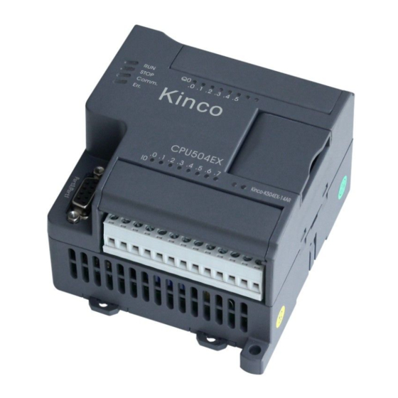
- Контроллер, например, K50624AT
- Кнопки управления.
- Токоограничивающие резисторы номиналом 2 кОм.
Описание оборудования:
- Двигатель – двигатель в поставленной задаче может быть любым – шаговый двигатель GD, Orienatalmotor, серводвигателем Kinco и т.д. В данном примере использовался шаговый двигатель GD57STH56-2804A.
- Драйвер двигателя – драйвер двигателя тоже может быть любым, но с одним условием, он должен поддерживать технологию управления Step/Dir – драйвер шаговых двигателей Leadshine или Orientalmotor, сервопреобразователь Kinco и т.д. В данном примере использовался драйвер шагового двигателя Leadshine DM556.
- Контроллер должен иметь высокочастотные выходы. Такими контроллерами являются линейка Kinco – K504Ex, K506, K508. В данном примере использовался контроллер Kinco K506-24AT.
Необходимые инструкции и справки:
- Паспорт шагового двигателя.
- Инструкция на драйвер шагового двигателя.
- Инструкция по «железу» контроллера.
- Инструкция по программированию контроллера.
Необходимое программное обеспечение: KincoBuilderV1.5.3.0
Распределение входов/выходов:
I0.0 – сигнал «запуск в работу».
I0.1 – реверс.
I0.2 – выбор скорости.
Q0.0 – сигнал Step.
Q0.2 – сигнал Dir.
Q0.4 – сигнал перемещение завершено.
Q0.5 – сигнал ошибки перемещения.
Схема подключения: 
Последовательность действий:
- Подключить контроллер к компьютеру при помощи кабеля RS232, предварительно подав на него напряжение.
- Запустить программу Kinco Builder

- Загрузить демонстрационный проект
- Выбрать соответствующий проект
- Проверить тип используемого контроллера – двойное нажатие на Hardware:
- При необходимости можно поменять тип контроллера
- Проверить связь компьютера с контроллером
- Запустить автоматический поиск контроллера. В случае успеха можно переходить к следующему шагу.
- Закачать программу в контроллер
- При необходимости можно воспользоваться режимом отладки


Структура программы и основные положения:
Программа состоит из трех основных разделов:
Main– главная исполняющая программа
(SBR00) Input– опрос входных сигналов
(SBR01)Output– установка выходных сигналов

Изменение скорости вращения осуществляется в Network2 программы Main. Задание осуществляется в Герцах, т.е. в количестве импульсов на выходе за секунду.

Пример реализации программы:
скачать тестовый проект
- Manuals
- Brands
- Kinco Manuals
- Microcontrollers
- K5 Series
- Hardware manual
Plc
-
Contents
-
Table of Contents
-
Bookmarks
Quick Links
Kinco
K5
PLC
HARDWARE MANUAL
Summary of Contents for Kinco K5 Series
-
Page 1
Kinco HARDWARE MANUAL… -
Page 2: Table Of Contents
1.4 P -K5 …………………….. 13 RODUCT LIST OF INCO PART II HARDWARE MANUAL ……………………15 CHAPTER I APPLICATION OF KINCO-K5 SERIES MICRO PLC …………..16 1.1 A KINCO-K5 ……………………16 RCHITECTURE OF 1.1.1 Overview …………………………16 1.1.2 Allowable System Scales ……………………16 1.1.3 Communicating over a Network………………….
-
Page 3
Kinco-K5 User’s Manual 2.1.2CPU Types ………………………… 22 2.2F …………………………24 UNCTIONS 2.2.1OperationMode ……………………….24 2.2.2Communication Port ……………………..25 2.2.3Data Keep-in and Back Up ……………………25 2.2.4Real-time Clock (RTC) ……………………..26 2.2.5High-speed counter and High-speed pulse output ……………… 26 2.2.6 Trigger interrupt ………………………. 26 2.3 W… -
Page 4
Kinco-K5 User’s Manual 4.2.2 Technical Data ……………………….46 4.3 DO 16*DC24V ……………………….. 47 4.3.1 Wiring Diagram ……………………….. 47 4.3.2 Technical Data ……………………….48 4.4 DO 16*R …………………………. 49 ELAY 4.4.1 Wiring Diagram ……………………….. 49 4.4.2Technical Data ……………………….50 CHAPTER V DI/O MODULES …………………….. 51 5.1 DI/O, DI4*DC24V DO4*DC24V ……………………. -
Page 5
Kinco-K5 User’s Manual 6.3 AI 4*TC, ……………………64 THERMOCOUPLE NPUT 6.3.1Wiring Diagram ……………………….64 6.3.2Measurement Ranges and The measured value Representation ………….. 65 6.3.3 Technical Data ……………………….65 CHAPTER VII AO (ANALOG OUTPUT) MODULES ………………66 7.1 AO 2*IV, M ……………………. -
Page 6
10.2 I …………………….. 80 NSTALLATION UIDELINES 10.2.1 Module Connection ……………………..80 10.2.2 Installing the KINCO-K5 modules ………………….. 81 10.3 …………….83 INSTALLATION AND REMOVING THE WIRING TERMINAL ROW 10.3.1 Remove wiring terminal row …………………… 83 10.3.2 Install the terminal row ……………………83 10.4 P… -
Page 7: Part I General Introduction
Kinco-K5 User’s Manual Part I General Introduction…
-
Page 8: Chapter I System Overview
This chapter will briefly introduce the Kinco-K5 series micro PLC (Programmable Logic Controller) and focuses on the explanation of the terms related to Kinco-K5 with a purpose of facilitating you to understand the contents in the following part of this manual. The main content of this chapter covers: application scope of the product, explanations on relevant terms, rules for nomenclature, etc.
-
Page 9
▪ KincoBuilder The programming software for Kinco-K5 series PLC, accords with IEC61131-3 standard. KincoBuilder presently provides LD and IL languages for convenience and efficiency in developing the control programs for your applications. KincoBuilder provides a user-friendly environment to develop and debug the programs . -
Page 10: Name Rules For The Product
1.3.1 Description of the Product Name The “product name” of Kinco-K5 PLC is used to indicate the main functions and applications of the product. The “product name” is not for any individual product but the general name for a type of products. The “product name”…
-
Page 11
Kinco-K5 User’s Manual expansion function module power supply module Software Accessory ▪ 5 means Kinco-K5 series micro PLC ▪ Subtype: use a number (0~9) to indicate the subtype of the module. CPU modules Reserved Digital Input/output module Analog Input/output module… -
Page 12
Kinco-K5 User’s Manual 3 DI / DO mixed module; Other serial numbers are reserved. ▪ Analog Input/Output module 1 AI (analog input) module; 2 AO (analog output) module; 3 AI/AO mixed module; Other serial numbers are reserved. ▪ Communication Module 0 RS485 communication module;… -
Page 13: Description Of Order Number
NT: NTC thermistor Diagram 1-2 Description of the Order Number According to the above principle,KINCO-K506-24DT stands for the CPU module with 24 I/O channels (the output channel is of transistor type) and DC24V power supply; KINCO-K521-08DXstands for the DI expansion…
-
Page 14: Product List Of Kinco-K5
Kinco-K5 User’s Manual 1.4 Product list of Kinco-K5 Type Name Order no. Description AC85~265V power supply, with 14 I/O, DI 8*DC24V, DO Kinco-K504-14AT 6*DC24V,1*RS232, non-reconnected extension module AC85~265V power supply, with 14 I/O, DI 8*DC24V, DO Kinco-K504-14AR 6*Relay, 1*RS232, non-reconnected extension module CPU504 DC21.6~28.8V power supply, with 14 I/O, DI 8*DC24V, DO 6*…
-
Page 15
Kinco-K5 User’s Manual DC21.6~28.8V power supply, with 40 I/O, DI 24*DC24V, DO Kinco-K508-40DT 16*24V, 1*RS232, 2*RS485 DC21.6~28.8V power supply, with 40 I/O, DI 24*DC24V, DO Kinco-K508-40DR 16*Relay, 1*RS232, 2*RS485 Kinco-K521-08DX DI 8*DC24V PM521 Kinco-K521-16DX DI 16*DC24V Kinco-K522-08DT DO 8*DC24V Kinco-K522-16DT… -
Page 16: Part Ii Hardware Manual
Kinco-K5 User’s Manual Part II Hardware Manual…
-
Page 17: Chapter I Application Of Kinco-K5 Series Micro Plc
Kinco-K5 a perfect solution for a wide variety of applications. CPU module is the core of Kinco-K5, and it can monitor input channels and change output channels as controlled by the user program, which can include Boolean logic, counting, timing, complex math operations, and communications with other devices.
-
Page 18: Communicating Over A Network
(RS232 and RS485) and CAN bus to conveniently communicate with other equipments and systems. Kinco-K5 can not only meet the requirement of monitoring single equipment but also build up a complex network to satisfy all kinds of demands.
-
Page 19: Power Supply Design
CAN communication instructions for your application. 1.2 Power supply design The Kinco-K5 CPU has an internal integrated power supply that provides power for the CPU itself, for all connected expansion modules and for other DC24V (VO+, VO-) power requirements.
-
Page 20: 2Expansion Power Supply Calculation
Kinco-K5 User’s Manual KDN-K306-24DR Diagram 1-1 Wiring of the DC24V Sensor Supply 1.2.2Expansion power supply calculation The expansion supply provides both DC5V power and DC24V power for the connected expansion modules through expansion bus. In a PLC system, the power requirements for all the expansion modules must not exceed the capacity of the CPU‟s expansion power supply, otherwise you have to add a PS580 module to provide extra…
-
Page 21: 3Input Power Of The Cpu
11.2 Table 1-5 Input power values of the CPU 1.3 Operation Environmental Condition Kinco-K5 accords with GB/T 15969.3-2007(idt IEC61131-2:2007)standard and test specifications. The following table lists the conditions and requirements for Kinco-K5 to work properly. Please do not use the…
-
Page 22
Kinco-K5 User’s Manual PLC in the bad condition which exceeds the following conditions. Transport and storage temperature -40 — +70 °C Ambient 10%~95%, no condensation relative humidity conditions Altitude Up to 3000 m Mechanical With manufacturer’s original package, 5 times falling from 1m height to… -
Page 23: Chapter Ii Cpu Principle And Application
Diagram 2-1 Main components 2.1.2CPU Types Kinco-K5 provides different CPU models with a diversity of features and capabilities that help you create effective solutions for your varied applications. According to the voltage of main power supply, there are two kinds of CPU: one requires DC24V power supply and another requires AC85V~265V.
-
Page 24
Kinco-K5 User’s Manual channels and the higher the performance is. The following table describes main technical data of each CPU model. CPU504 CPU504EX CPU506 CPU506EA CPU508 Built-in I/O and Communication Digital channel 8*DI/6*DO 8*DI/6*DO 14*DI/10*DO 14*DI/10*DO 24*DI/16*DO Analog channel 4*AI / 2*AO Max. -
Page 25: Functions
Change CPU Operation Mode Kinco-K5 provides two ways to changing the operation mode manually: Using the operation switch (RUN/STOP); Executing [Debug] -> [RUN] or [STOP] menu command in Kincobuilder. The following table lists the combined results of these two ways.
-
Page 26: 2Communication Port
Kinco-K5 User’s Manual 2.2.2Communication Port Kinco-K5provides 1-3 communication ports, which are named as PORT0, PORT1 and PORT2. PORT0 is RS232, PORT1 and PORT2 are RS485. RS485 ports are fully isolated in hardware (including their power supply and communication port) to enhance anti-interference ability.
-
Page 27: 4Real-Time Clock (Rtc)
Kinco-K5 User’s Manual 2.2.4Real-time Clock (RTC) The real-time clock built in the all CPU modules (except CPU504) can provide real-time clock/calendar indication. The real-time clock/calendar adopts BCD-format coding through second to year, when the CPU looses power,the RTC can also work by the power supply from back battery, in normal temperature , this battery can last about five years for RTC, and can store data for about 3 years with power off.
-
Page 28: Wiring Diagram
Kinco-K5 User’s Manual 2.3 Wiring Diagram PORT0 Description PORT0 DC24V Sensor Supply Real line means source input; Broken line means sink input. Diagram 2-2 Wiring Diagram of K504-14AR PORT0 Description PORT0 DC24V Sensor Supply Real line means source input; Broken line means sink input.
-
Page 29
Kinco-K5 User’s Manual PORT0 Description PORT0 DC24V Sensor Supply Real line means source input; Broken line means sink input. Diagram 2-4 Wiring Diagram of K504-14DR PORT0 Description PORT0 DC24V Sensor Supply Real line means source input; Broken line means sink input. -
Page 30
Kinco-K5 User’s Manual PORT0/PORT1 Description PORT0 RS485 — PORT1 RS485 + DC24V Sensor Supply Real line means source input; Broken line means sink input. Diagram 2-6 Wiring Diagram of K504EX-14AR PORT0/PORT1 Description PORT0 RS485 — PORT1 RS485 + DC24V Sensor Supply Real line means source input;… -
Page 31
Kinco-K5 User’s Manual PORT0/PORT1 Description PORT0 RS485 — PORT1 RS485 + DC24V Sensor Supply Real line means source input; Broken line means sink input. Diagram 2-8 Wiring Diagram of K504EX-14DR PORT0/PORT1 Description PORT0 RS485 — PORT1 RS485 + DC24V Sensor Supply Real line means source input;… -
Page 32
Kinco-K5 User’s Manual PORT2 PORT0/PORT1 Description PORT0 RS485 — PORT1 RS485 + DC24V Sensor Supply Real line means source input; Broken line means sink input. Diagram 2-10 Wiring Diagram of K506-24AR PORT2 PORT0/PORT1 Description PORT0 RS485 — PORT1 RS485 +… -
Page 33
Kinco-K5 User’s Manual PORT2 PORT0/PORT1 Description PORT0 RS485 — PORT1 RS485 + DC24V Sensor Supply Real line means source input; Broken line means sink input. Diagram 2-13 Wiring Diagram of K506-24DT AQW0 AQW2 Voltage Output Current Output 2L- 2L+ VO- VO+… -
Page 34
Kinco-K5 User’s Manual AQW0 AQW2 Voltage Output Current Output 2L- 2L+ VO- VO+ DC24V AIW0 AIW4 Sensor Supply Current Input DC24V Voltage Input AIW2 Real line means source input; Broken line means sink input. (4-wire transducer) Current Input (2-wire transducer) -
Page 35
Kinco-K5 User’s Manual DC24V Sensor Supply DC24V Real line means source input; Broken line means sink input. Description Description RS485 — PORT1 RS485 + PORT0 RS485 — PORT2 RS485 + Diagram 2-17 Wiring Diagram of K508-40AT DC24V Sensor Supply DC24V Real line means source input;… -
Page 36: Specifications
Kinco-K5 User’s Manual DC24V Sensor Supply DC24V Real line means source input; Broken line means sink input. Description Description RS485 — PORT1 RS485 + PORT0 RS485 — PORT2 RS485 + Diagram 2-19 Wiring Diagram of K508-40DT 2.4Specifications 2.4.1CPU Specifications CPU504…
-
Page 37: Cpu Di Specifications
Kinco-K5 User’s Manual I/O Interrupts 4 rising/falling edge interrupts memory area 4K instructions Max. User program instructions User Data M area: 1K bytes; V area: 4K bytes DI mapping area 1 byte 10 bytes 32 bytes DO mapping area 1 byte…
-
Page 38: Cpu Do Specifications(Transistor)
Kinco-K5 User’s Manual 2.4.3 CPU DO Specifications(Transistor) Output type Source Rated power supply voltage DC 24V, allowable range:DC20.4~DC28.8V · Reverse polarity protection Rated output voltage DC 24V Output current per channel Max 500mA at 24VDC Max 0.5цA Output leakage current Max 0.2Ω…
-
Page 39: Ai Channel Parameters On Cpu
Kinco-K5 User’s Manual AI channel parameters on CPU 2.4.5 Signal type 4~20mA、1~5V、0~20mA、0-10V Resolution 12 bits precision 0.3% F.S. Convert Speed(each channel) About 30 per second Current Mode:<=500Ω Input Resistor Voltage Mode:>4MΩ (signal voltage+com-mode voltage)≤12V. If the voltage Anti Com-mode voltage exceeds 12V, the channel will be in protection status.
-
Page 40: Chapter Iii Di (Digital Input) Modules
It provides opto-electrical isolation between the input signal and the internal circuit. DI modules are called PM521. 3.1 DI 8*DC24V Order No.: Kinco-K521-08DX. The module has 8 channels, and each channel has a LED to indicate the input status. 3.1.1 Wiring Diagram ,…
-
Page 41: Technical Data
Kinco-K5 User’s Manual 3.1.2 Technical Data Electrical Data Number of channels 8 (4 channels/group) Input type Source/leakage Rated input voltage DC 24V Rated input current 3.5mA at 24VDC Max input voltage of logic 0 5V at 0.7mA Minimum input voltage of logic 1 11V at 2.0mA…
-
Page 42: Di 16*Dc24V
Kinco-K5 User’s Manual 3.2 DI 16*DC24V Order No.: Kinco-K521-16DX The module has 16 channels, and each channel has a LED to indicate the input status. 3.2.1 Wiring Diagram DC24V Power Suplly: Real line means source input; Broken line means sink input.
-
Page 43: Technical Data
Kinco-K5 User’s Manual 3.2.2 Technical Data Electrical data Number of channels 16 (8 channels/group) Input type Source/leakage Rated input voltage DC 24V Rated input current 3.5mA at 24VDC Max input voltage of “0” 5V at 0.7mA Minimum input voltage of “1”…
-
Page 44: Chapter Iv Do (Digital Output) Modules
All types of DO module are called PM522. 4.1 DO 8*DC24V Order No: Kinco-K522-08DT The module has 8 channels, and each channel is has a LED to indicate the output status. It receives control data from CPU and converts it to DC 24V signal.
-
Page 45: Technical Data
Kinco-K5 User’s Manual 4.1.2 Technical Data Electrical data Number of output channels 8 (4 channels/group) Output type Source Rated power supply voltage DC 24V · Reverse polarity protection Rated output voltage DC 24V Output current per channel Max 500mA at 24VDC Max 0.5цA…
-
Page 46: Do 8*Relay
User’s Manual 4.2 DO 8*relay Order No.: KINCO-K522-08XR The module has 8 relay-output channels, and each channel is has a LED to indicate the output status. It receives control data from CPU and converts it to electrical signals to control relay outputs.
-
Page 47
Kinco-K5 User’s Manual 4.2.2 Technical Data Electrical data Number of relay outputs 8 (4 channels/group) Load voltage Max DC 30V/AC250V Output current per channel Max 2A(DC 30V/AC250V) Output current per group Max 10A Output off-to-on delay Max 10ms Output on-to-off delay Max 5ms <180mA… -
Page 48: Do 16*Dc24V
User’s Manual 4.3 DO 16*DC24V Order No.: KINCO-K522-16DT The module has 16 channels, and each channel is has a LED to indicate the output status. It receives control data from the expansion bus and converts it to DC24 output signal. The module requires a power supply of DC24V via the appropriate terminals.
-
Page 49: Technical Data
Kinco-K5 User’s Manual 4.3.2 Technical Data Electrical data Number of output channels 16 (4 channels/group) Output type Source Rated power supply voltage DC 24V · Reverse polarity protection Rated output voltage DC 24V Output current per channel Max 500mA at 24VDC Max 0.5цA…
-
Page 50: Do 16*Relay
User’s Manual 4.4 DO 16*Relay Order No.: KINCO-K522-16XR The module has 16 relay-output channels, and each channel is has a LED to indicate the output status. It receives control data from the expansion bus and converts it to electrical signal to control relay outputs. The module derives operation power supply and relay coil power supply are from the expansion bus.
-
Page 51: 2Technical Data
Kinco-K5 User’s Manual 4.4.2Technical Data Electrical data Number of relay outputs 16 (4 channels/group) Load voltage Max DC 30V/AC250V Output current per channel Max 2A(DC 30V/AC250V) Output current per group Max 10A Output off-to-on delay Max 10ms Output on-to-off delay Max 5ms <210mA…
-
Page 52: Chapter V Di/O Modules
All types of DI/O module are called PM523. 5.1 DI/O, DI4*DC24V DO4*DC24V Order No.: KINCO-K523-08DT This module has 8 channels. 4 channels are inputs and 4 as outputs. Each channel is has a LED to indicate its status.
-
Page 53: 2Technical Data
Kinco-K5 User’s Manual 5.1.2Technical Data Electrical data Number of inputs 4 (4 channels/group) Input type Source/Leakage Rated input voltage DC 24V Rated input current 3.5mA at 24VDC Max input voltage of logic 0 5V at 0.7mA Minimum input voltage of logic 1 11V at 2.0mA…
-
Page 54
Kinco-K5 User’s Manual Dimension and weight Dimension (L×W×H) 114×50×70mm Net weight 125g… -
Page 55: Di/O,Di 4*Dc24Vdo 4*Relay
Kinco-K5 User’s Manual 5.2 DI/O,DI 4*DC24VDO 4*Relay Order No.: KINCO-K523-08DR This module has 8 channels. 4 channels DI(DC 24V) input and another 4 are relay outputs. Each channel is has a LED to indicate its status. 5.2.1Wiring Diagram DC24V Power Suplly: Real line means source input;…
-
Page 56
Kinco-K5 User’s Manual · Voltage Number of relay outputs 4 (4 channels/group) Load voltage Max DC 30V/AC250V Output current per channel Max 2A(DC 30V/AC250V) Output current per group Max 10A Output off-to-on delay Max 10ms Output on-to-off delay Max 5ms Max. -
Page 57: Di/O, Di 8*Dc24Vdo 8*Dc24V
Kinco-K5 User’s Manual 5.3 DI/O, DI 8*DC24VDO 8*DC24V Order No.: KINCO-K523-16DT This module has 16 channels. 8 channels are DC 24V inputs and another 8 are outputs (transistor). Each channel is has a LED to indicate its status. 5.3.1Wiring Diagram DC24V Power Suplly: Real line means source input;…
-
Page 58
Kinco-K5 User’s Manual Minimum input voltage of logic 1 11V at 2.0mA Input filter time delay Isolation between input and internal circuit · Mode Opto-electrical isolation · Voltage 500VAC/1 min Number of output channels 8 (4 channels/group) Output type Source… -
Page 59: Di/O, Di 8*Dc24V Do 8*Relay
Kinco-K5 User’s Manual 5.4 DI/O, DI 8*DC24V DO 8*Relay Order No.: KINCO-K523-16DR This module has 16 channels. 8 channels are inputs and another 8 are relay outputs. Each channel is has a LED to indicate its status. 5.4.1Wiring Diagram DC24V Power Suplly: Real line means source input;…
-
Page 60
Kinco-K5 User’s Manual Minimum input voltage of logic 1 11V at 2.0mA Input filter time delay Isolation between input and internal circuit · Mode Opto-electrical isolation · Voltage 500VAC/1 min Number of relay outputs 8 (4 channels/group) Load voltage Max DC 30V/AC250V… -
Page 61: Chapter Vi Ai (Analoginput) Modules
All types of AI module are called PM531. 6.1 AI 4*IV, Multi-signal Input Order No.: Kinco-K531-04IV This module has 4 channels for current and voltage measurement, and the measurement type (4-20mA, 1-5V, 0-20mA, 0-10V) is optional for each channel in KincoBuilder Each channel is has a LED, when the signal is exceeds the range of current and voltage , the LED will be red.
-
Page 62: 2Measurement Ranges And The Measured Value Representation
Kinco-K5 User’s Manual 6.1.2Measurement Ranges and The measured value Representation In the following table, I represents input current value, unit mA; V represents input voltage value, unit V. Measurement Measurement Measured Remark Type Range value 4~20mA 3.92~20.4mA I×1000 If input signal exceeds the upper limit of measuring 1~5V 0.96~5.1V…
-
Page 63: Ai 4*Rd, Rtd Input
User’s Manual 6.2 AI 4*RD, RTD Input Order No.: Kinco-K531-04RD This module has 4 channels for temperature measurement using RTD, and the measurement type (Pt100, Cu50, Pt1000 and Resistance) is optional for each channel. 24-bit high-performance A/D converter is adopted in the module.
-
Page 64: 3Technical Data
Kinco-K5 User’s Manual Measurement Type Measurement Range Measured value Pt100 -200~850°C T×10 Cu50 -50~150°C T×10 Pt1000 -50~300°C T×10 0~2000Ω Resistance R×10 Table 6-2 Measurement Range and The relationship between measured value and actual value 6.2.3Technical Data Electrical data Number of channels…
-
Page 65: Ai 4*Tc, Thermocouple Input
User’s Manual 6.3 AI 4*TC, thermocouple Input Order No.: Kinco-K531-04TC This module has 4 channels for temperature measurement by using thermocouples, and the measurement type (Type J, Type K, Type E and Type S) is optional for each channel, additionally cold junction internal compensation or external compensation is optional.24-bit high-performance A/D converter is adopted in the…
-
Page 66: 2Measurement Ranges And The Measured Value Representation
Kinco-K5 User’s Manual 6.3.2Measurement Ranges and The measured value Representation In the following table, T represents measured temperature, unit: °C. Measurement Method Measurement Range Measured value Type J -210~1200°C Type K -270~1300° T×10 Type E -270~1000°C Type S -50~1600°C Table 6-4 Measurement Range and The relationship between measured value and actual value 6.3.3 Technical Data…
-
Page 67: Chapter Vii Ao (Analog Output) Modules
All types of AO module are called PM532. 7.1 AO 2*IV, Multi-signal Output Order No.: KINCO-K532-02IV This module has 2 channels, suitable for connecting with actuators requiring standard voltage or current signals (4-20mA, 1-5V, 0-20mA and 0-10V). The module has corresponding output ranges for different outputs, and if the output value specified in the user program exceeds the upper/lower limit of the output range, the actual output value will be kept at the upper/lower limit to prevent the connected equipment from damage.
-
Page 68: 3Technical Data
Kinco-K5 User’s Manual Output Value Output Signal Output Range Remark Representation 4~20mA 3.92~20.4mA I×1000 If the output value specified in the user 1~5V 0.96~5.1V V×1000 program exceeds the upper/lower limit of the output range, the actual output value 0~20mA 0~20.4mA I×1000…
-
Page 69: Chapter Viii Ai/O (Analog Input/Output) Modules
All types of AO module are called PM533. 8.1 AI/O, AI 2×IVAO 2×IV, Multi-signal Output Order No.: KINCO-K533-04IV This module has 2 channels for current and voltage measurement, and the measurement type (4-20mA, 1-5V, 0-20mA or 0-10V) is optional for each channel. 24-bit high-performance A/D converter is adopted in the module.
-
Page 70: 1Wiring Diagram
Kinco-K5 User’s Manual 8.1.1Wiring Diagram Current output Voltage output DC24V 2-wire 4-wire transducer transducer 4-wire current input 2-wire current input Diagram 8-2 Wiring Diagram of K533-04IV 8.1.2Measurement Ranges and The measured value Representation In the following table, I represents actual input current value, unit mA; V represents input voltage value, unit V.
-
Page 71: 4Technical Data
Kinco-K5 User’s Manual Output Value Output Signal Output Range Remark Representation 4~20mA 3.92-20.4mA I×1000 If the output value specified in the user 1~5V 0.96-5.1V V×1000 program exceeds the upper/lower limit of the output range, the actual output value 0~20mA 0-20.4mA I×1000…
-
Page 72: Chapter Ix Expansion Function Modules
(including its power supply and communication port) to enhance anti-interference ability. When using in a Kinco-K5 plc system, K541 must be arranged at the end of all modules, and it does not need to be configured in Kincobuilder software.
-
Page 73: 2Terminals And Status Leds
Kinco-K5 User’s Manual 9.1.2Terminals and Status LEDs PW1 RUN FM541 Kinco-K541 V- V+ Diagram 9-1Kinco-K541 Front View Status LED PW1:CAN1 power indication: Green LED. LED on means power on, and off means power off. LED on means CAN1 port is powered on, and off means is powered off.
-
Page 74: 3Wiring And Arranging
V+、V-: External DC24V power supply for K541.„ 9.1.3Wiring and Arranging When using K541 in a Kinco-K5 plc system, K541 must be arranged at the end of all modules, and it does not need to be configured in Kincobuilder. Ω…
-
Page 75: 4Technical Data
Kinco-K5 User’s Manual 9.1.4Technical data Electrical data Rated power supply DC24V,≥100mA,tolerance ±5%。 CAN standard CAN2.0A, CAN2.0B Baud rate Standard 10K-1Mbps < 170mA Current consumption via expansion bus Isolation · power supply 2500VAC/1 minute · CAN bus Opto-electrical isolation, 500VAC/1 minute…
-
Page 76: Expansion Power Module
In the same control system, PS580 and CPU module need the same AC85~265V. 9.2.1 Main Specifications. • PS580 does not need to be configured in Kinco builder. • PS580 does not have I/O mapping address in CPU • PS580 is not counted in the total expansion module number •…
-
Page 77: Ps580 Used In The Actual Application
14DI and 10 DO; CPU506EA has 4AI and 2AO, but there are no relay output model,. Consider the above situation, it is better to choose CPU506, the model is Kinco-K506-24AR 2) Expansion module selection: only 8 DI is required, the DI on CPU itself is enough, so we do not need expansion DI.
-
Page 78
Kinco-K5 User’s Manual Expansion +24V consumption: consumed by relay coil in expansion module, circuit. Each expansion module has these two specifications; user can get this data in the technical data sheet of each module. Each CPU can provide this +5V and +24V power supply, it is also in the technical data sheet of each CPU. -
Page 79: Technical Data
Kinco-K5 User’s Manual 9.2.4 Technical Data Electrical data Supply voltage AC85~265V ≤1000mA Capability for expansion bus ≤250mA +24V Green LED(PW) Status indication Dimension and weight Dimension (L×W×H) 114×75×70mm Net weight 195g…
-
Page 80: Chapter X Installation&Wiring Guidelines
10.1 Plastic Case Dimension There are 5 different types of plastic cases for KINCO-K5 modules with the same length and height; the widths (expansion direction) are 200, 125, 97, 75 and 50mm respectively. The plastic cases of 200mm, 125mm and 97mm width are used for the CPU modules;…
-
Page 81: Installation Guidelines
Kinco-K5 User’s Manual 10.2 Installation Guidelines 10.2.1 Module Connection In actual connection, the CPU is arranged at left side, expansion port is at the right side of CPU, then the expansion modules at connected to each other from left to right. The steps are as follows: connect the first expansion module‟s cable to CPU expansion port, connect the second expansion module‟s cable to the first…
-
Page 82: Installing The Kinco-K5 Modules
10.2.2 Installing the KINCO-K5 modules You can install the KINCO-K5 modules either on a panel or on a DIN rail; also, you can arrange the modules either horizontally or vertically. For horizontal mounting, the CPU module shall be located at the lef side;…
-
Page 83
Kinco-K5 User’s Manual module, make some adjustments to make the expansion bus slide into the slot on the right side of the module with a purpose to achieve a better appearance. To prevent the loosing by vibration, please add spring washer and spacer. -
Page 84: Installation And Removing The Wiring Terminal Row
Kinco-K5 User’s Manual 10.3 installation and removing the wiring terminal row The wiring terminals row of K5 is removable, it is convenient for customer to change this part. 10.3.1 Remove wiring terminal row 1. Open the terminal raw cover 2. Use the screw driver to insert the small slot at the middle of terminal row.
-
Page 85: Protection Circuit And Ground Connection
Kinco-K5 User’s Manual 10.4 Protection circuit and ground connection 10.4.1 Protection function of transistor digital Output In transistor DO channel of K5, there is short circuit protection function, if the output current is larger than 3A, the protection function will be triggered, the output group which the short circuit channel is in will be protected, there will be no output for all the channels of this group.
-
Page 86: Grounding
Kinco-K5 User’s Manual In most of the applications, just add A is enough, if the relay will be on/off faster, a additional B is recommended. Make sure the Zener diode satisfy for the current and voltage requirements of output circuit.
-
Page 87
Kinco-K5 User’s Manual Operation grounding, this kind of grounding is used to make sure the system/equipment works properly and reliably, this grounding also can guarantee the precision of the system. Good grounding is one of the most effective methods to improve PLC electromagnetic compatibility (EMC), check the following grounding principles: In the whole factory, the PLC system should have separated operation grounding.