- Manuals
- Brands
- L-Acoustics Manuals
- Recording Equipment
- LA8
- User manual
-
Contents
-
Table of Contents
-
Bookmarks
Quick Links
Related Manuals for L-Acoustics LA 8
Summary of Contents for L-Acoustics LA 8
-
Page 1
user manual (EN) -
Page 2
Document reference: LA8 user manual (EN) version 13.1 Distribution date: September 1, 2016 © 2016 L-Acoustics. All rights reserved. No part of this publication may be reproduced or transmitted in any form or by any means without the express written consent of the… -
Page 3: Table Of Contents
Contents Safety…………………………..5 Safety instructions……………………….. 5 Symbols…………………………8 System components……………………….10 Technical description……………………….12 Main features……………………….12 Internal components……………………12 Front and rear panels……………………13 Signal processing and amplication………………….14 Signal inputs……………………..14 DSP architecture……………………..15 Power supply and amplier section………………..16 Speaker outputs……………………..16 Monitoring and control……………………..16 User interface……………………..
-
Page 4
L-NET……………………….35 Meters……………………….36 OUT………………………..36 Main screen description…………………….. 37 Using quick access functions……………………38 Locking/Unlocking the front panel………………..38 Muting/Unmuting an output channel………………..38 Modifying gain……………………..39 Identifying an amplied controller………………..40 Displaying input level, input selection, input mode and group information……….. 40 Using the main menu…………………….. -
Page 5: Safety
Safety instructions Read this manual Follow all SAFETY INSTRUCTIONS as well as DANGER and OBLIGATION warnings Never incorporate equipment or accessories not approved by L-Acoustics Read all the related PRODUCT INFORMATION documents before exploiting the system The product information document is included in the shipping carton of the related system component.
-
Page 6: Operating Temperature
Safety 12. Grounding To plug the controller to mains only use an outlet tted with a pin tied to ground. Do not defeat the ground pin of the outlet as it connects the controller to earth. If the local outlet is obsolete, consult an electrician.
-
Page 7: Mounting Instructions
The use of unauthorized replacement parts may result in injury and/or damage through re, electric shock, or other electricity-related hazards. All service and repair work must be carried out by an L-Acoustics authorized dealer. 26. Shipping Use the original packaging for shipping the product, unless it is mounted in a rack with the front and rear panels xed to the rack, as described in this manual.
-
Page 8: Symbols
Safety Symbols The following symbols are used in this document: This symbol indicates a potential risk of harm to an individual or damage to the product. It can also notify the user about instructions that must be strictly followed to ensure safe installation or operation of the product.
-
Page 9
DSP, network control, and comprehensive system protection in a single ergonomic package. Based on similar platforms, the exceptional and ground-breaking performance level delivered by the LA8 units allow full optimization of the resources of all L-Acoustics systems and deliver outstanding audio quality combined with the best possible transducer protection. -
Page 10: System Components
System components A complete L-Acoustics system includes loudspeaker enclosures, amplied controllers, cables, rigging system, and software applications. The main components of an L-Acoustics system that includes the LA8 are the following: Loudspeaker enclosures Refer to the user manuals of the loudspeaker systems for detailed instructions about the enclosures and their connection to the amplied controllers.
-
Page 11
System components Illustrations LA-RAK LA Network Manager L-Case LA8 user manual (EN) version 13.1… -
Page 12: Technical Description
Technical description Technical description Main features Internal components The core of the LA8 is a DSP engine driving four channels of amplication from two inputs. The LA8 also features a ash memory for preset storage and management, high performance A/D-D/A converters and AES/EBU inputs for audio signals, an auto-sensing SMPS (Switched Mode Power Supply), a front panel user interface, and a fast Ethernet device for networked remote control.
-
Page 13: Front And Rear Panels
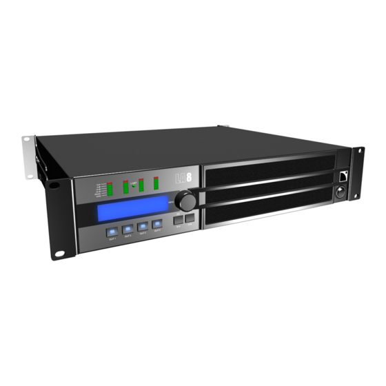
Technical description Front and rear panels 011:K1 011:K1 LF_A LF_A MF_A HF_A LF_A LF_A MF_A HF_A 1 LED meters: A/C power cord — CLIP level 10 outward ventilation grills 11 speakON output connectors — audio levels (-5 dB, -10 dB and -25 dB) —…
-
Page 14: Signal Processing And AmpliCation
Technical description Signal processing and amplication Signal inputs Analog inputs The LA8 can be fed with two balanced analog audio signals using the appropriate XLR input ports — see illustration in section Front and rear panels (p.13). Each analog input port is ESD protected and equipped with one XLR female connector.
-
Page 15: Dsp Architecture
— With a complete factory preset library and the possibility to create additional user presets, the ash memory provides a quick access to all the usual L-Acoustics speaker system congurations (refer to the Preset Guide) Audio path parameters…
-
Page 16: Power Supply And AmpliEr Section
The 4 channels can deliver up to 4 x 1800 watt into 4 or 2.7 ohm yielding perfect power matching to each individual L-Acoustics loudspeaker system. The auto-sensing SMPS (Switched Mode Power Supply) offers better stability by associating two symmetrical power supplies.
-
Page 17: Installation
Installation Installation Mounting The LA8 is two rack units high (2U) and can be mounted in an EIA-standard 19” rack using the four points on the front panel. Use the xing material provided by the rack manufacturer to mount the controller to the rack front rails. LA8 dimensions 483 mm / 19 in 406 mm / 16 in…
-
Page 18
Installation LA-RAK touring rack The L-Acoustics LA-RAK is available for three LA8 with all power and signal connection facilities. Refer to the LA-RAK user manual. LA8 user manual (EN) version 13.1… -
Page 19: Ventilation
Installation Ventilation To maintain moderate operating temperatures, the LA8 is equipped with fans providing front to rear airow. Ventilation instructions Ensure the front foam lter is clean and dirt free. Do not block the front and rear ventilation grills. Ventilation when rack-mounted Do not block the ventilation grills with front or back panels or doors.
-
Page 20: Planning The Power Of The Electrical Generator
Installation Planning the power of the electrical generator Electrical generator You must power on the generator before powering on the product. Verify that the product is turned off before powering on the generator. LA8 draws 16 A from 230 V. A typical generator has a power factor of 0.8 and should operate at 70% load for good efciency.
-
Page 21: Heat Power Calculation
Installation Heat power calculation If a 4 Ω load is connected to each output channel of the LA8, each channel delivers up to 1800 W. With a standard use at 1/8 of full power (9 dB headroom), the power delivered per channel is: 1800 / 8 = 225 W, so a total power of 4 x 225 = 900 W.
-
Page 22
Installation Output audio paths OUT 2 OUT 1 OUT 3 OUT 4 1+ 1- 2+ 2- 1+ 1- 2+ 2- LA8 user manual (EN) version 13.1… -
Page 23
Installation Signal panels The six XLR connectors on the rear panel are for analog or digital signal cabling. Two IN and two LINK connectors are for analog signals, and one IN and one LINK connectors are for AES/EBU signals. LA8 signal panel LINK A IN A LINK B… -
Page 24
Installation AES/EBU input mode Digital audio source specications Standard: AES/EBU (AES3) or electrical S/PDIF (IEC 60958 Type II) Sampling frequency: 44.1, 48, 64, 88.2, 96, 128, 176.4 or 192 kHz Word length: 16, 18, 20 or 24 bits The AES/EBU inputs are transformer balanced and their XLR connectors are wired according to IEC 60268-12. Digital input panel wiring LINK AES/EBU Rx… -
Page 25: Analog Audio
Installation Analog audio Balanced cables Symmetrical (balanced) shielded cables are highly recommended as balanced signals are less sensitive to AC hum and radio interference. Unbalanced lines may add noise especially over long cable runs. In a daisy-chain layout, the male XLR link connectors LINK A and LINK B feed the input signals to the next amplied controller in the signal chain.
-
Page 26: Digital Audio
Installation Digital audio Cables for AES/EBU digital audio AES3 species that the nominal characteristic impedance of cables used for AES/EBU digital audio transmission shall be 110 Ω ± 20%, and closer tolerances allow for increased transmission reliability over long lengths or higher sampling rates.
-
Page 27: L-Net
There is a risk of damaging the speakers The DO2W, DOFILL and DOSUB PA-COM cables are not compatible with the LA8. All other L-Acoustics PA-COM cables can be used. Refer to the LA8 PACOM CABLES technical bulletin for more details.
-
Page 28
Installation 2-way active enclosure on CA-COM output — DO + DOFILL-LA8 SP1 (OUT1/OUT2) CA-COM SP2 (OUT3/OUT4) Connecting a 2-way active enclosure with subwoofers 2-way active enclosure and subwoofers on CA-COM output — DO + DO3WFILL SUB1 (OUT1) CA-COM SUB2 (OUT2) 2WAY (OUT3/4) SUB1 (OUT1) CA-COM… -
Page 29
Installation Connecting 2-way passive enclosures 2-way passive enclosure on speakON output — SP + SP-Y1 CH1 (OUT1) SP-Y1 CC4FP CH2 (OUT2) OUT3/OUT4 OUT1/OUT2 same as OUT1/OUT2 2-way passive enclosure on CA-COM output — DO + DOSUB-LA8 SP1 (OUT1) CA-COM SP2 (OUT2) SP3 (OUT3) SP4 (OUT4) Connecting 3-way active enclosures… -
Page 30
Installation Subwoofer on speakON output — SP + SP-Y1 CH1 (OUT1) SP-Y1 CC4FP OUT3/OUT4 OUT1/OUT2 CH2 (OUT2) same as OUT1/OUT2 CH1 (OUT1) SP-Y1 CC4FP OUT1/OUT2 OUT3/OUT4 CH2 (OUT2) same as OUT1/OUT2 LA8 user manual (EN) version 13.1… -
Page 31
Installation Subwoofer on CA-COM output — DO + DOSUB-LA8 SP1 (OUT1) CA-COM SP2 (OUT2) SP3 (OUT3) SP4 (OUT4) SP1 (OUT1) CA-COM SP2 (OUT2) SP3 (OUT3) SP4 (OUT4) LA8 user manual (EN) version 13.1… -
Page 32
Installation Enclosure drive capacity per LA8 Maximum number of coaxial enclosures per LA8 Loudspeaker enclosure Maximum number of Maximum number of connections per output* enclosures per controller X15 HiQ Active 12XT Passive 12XT 112XT 115XT 115XT HiQ MTD108a MTD112b Active MTD115b Passive MTD115b Maximum number of constant curvature WST enclosures per LA8 Loudspeaker enclosure… -
Page 33
Installation Maximum number of subwoofer enclosures per LA8 Loudspeaker enclosure Maximum number of Maximum number of connections per output* enclosures per controller SB15m SB18 SB28 SB118 SB218 dV-SUB For passive loudspeakers, the value corresponds to the number of enclosures in parallel on the output. For active loudspeakers, the value corresponds to the number of sections in parallel on the output. -
Page 34: Operation
Operation Operation Powering on Press the power switch up. The amplied controller goes through a 9 seconds start-up sequence displaying Initializing Controller. All LEDs lit for test. CLIP -5dB L-NET -10dB -25dB SIGNAL LOAD Initializing MENU Controller IN B IN A OUT 1 OUT 2 OUT 3…
-
Page 35: Setting To Standby Mode
Operation Setting to standby mode To reduce the electrical consumption, the amplied controller can be put in standby mode. Use LA Network Manager to set the amplied controller to standby or back to operating mode. Refer to the LA Network Manager video tutorial. An amplied controller in standby mode displays Standby mode.
-
Page 36: Meters
Operation Meters The four LED meters (six LEDs each) display the state of the corresponding output channel. CLIP -5dB L-NET -10dB -25dB SIGNAL LOAD CLIP red: the output voltage reaches the maximum level (signal clip) -5dB -10dB green: the output voltage reaches 5, 10 or 25 dB below the maximum level -25dB SIGNAL green: a signal is detected and the output voltage reaches 0.1 V…
-
Page 37: Main Screen Description
Operation Main screen description The amplied controller displays the main screen at the end of the startup sequence. 001:X15HiQ_MO 110* PA_A PA_A PA_B PA_B 1. low latency symbol: indicates loaded preset is a low latency preset (refer to the LA Network Manager video tutorial) 2.
-
Page 38: Using Quick Access Functions
Operation Using quick access functions Quick access functions are available directly from the main screen. Quick access functions include: — Locking/Unlocking the front panel (p.38) — Muting/Unmuting an output channel (p.38) — Modifying gain (p.39) — Identifying an amplied controller (p.40) —…
-
Page 39: Modifying Gain
Operation Modifying gain About this task Gain can be modied for sets of output channels having input channels in common in their input selections. Examples of output channels having input channels in common: ‽INPUT SELECTION ‼※ — The OUT1 key displays gain for OUT1, OUT3 and OUT4 (containing IN A) —…
-
Page 40: Identifying An AmpliEd Controller
Operation Identifying an amplied controller If the amplied controller is connected to the L-NET network, it can be identied among other amplied controllers on the Workspace of LA Network Manager (refer to the LA Network Manager video tutorial). To identify an amplied controller, press and hold the encoder wheel. On the Workspace of LA Network Manager, the amplied controller blinks in yellow.
-
Page 41
Operation — The IN A/IN B pair receives an AES/EBU signal of 44.1 kHz (3) — Channels OUT1 and OUT2 are assigned to the same set of groups, OUT3 is not assigned to any group, and OUT4 is assigned to group All (4) LA8 user manual (EN) version 13.1… -
Page 42: Using The Main Menu
Operation Using the main menu The main menu gives access to functions and submenus. ‾LOAD PST USER ‼※ LOAD PST FACTORY ‽STORE PRESET ‼※ DELETE PRESET ‽PRESET PARAMETERS ‼※ CLEAR GRP PARAMS ‽INPUT SETTINGS ‼※ MONITORING & INFO ‼※ ‿OPTIONS Vertical arrows on the left indicate the current position in the menu: indicates the page is the rst in the menu.
-
Page 43: Load Pst
1 to 10 (read and write) User presets stored by user — refer to STORE PRESET (p.45) LOAD PST FACTORY 11 to 199 (read only) Factory preset library created by L-Acoustics and automatically installed during rmware update (refer to the LA Network Manager video tutorial) LA8 user manual (EN) version 13.1…
-
Page 44
Operation Example with a factory preset ‽LOAD PST FACTORY ‼※ STORE PRESET LOAD PRESET K1 068:SB18_60 011:K1 SB_A SB_A SB_B SB_B GROUP CONFLICT! LOAD PRESET SB18 CLEAR GROUP PARAM? 068:SB18_60 068:SB18_60 SB_A SB_A SB_B SB_B group parameters cleared LOAD PRESET CLEAR GROUP PARAM? ARE YOU SURE? OUTPUTS MUTED! -
Page 45: Store Preset
Operation Possible group conicts: The output channels are assigned to groups and the assignation structure is not compatible with the channel sets of the preset to be loaded. Group parameters include enabled FIR lters (Zoom Factor, FIR1, FIR2, FIR3 or Air Absorption Compensation) and the preset to be loaded is a low latency preset.
-
Page 46: Delete Preset
Operation DELETE PRESET A user preset stored in a user memory (in memory range 1 to 10) can be deleted. ‽DELETE PRESET ‼※ PRESET PARAMETERS DELETE USER PRESET DELETE USER PRESET 011:K1 002:MY K1 ARE YOU SURE? LF_A LF_A MF_A HF_A Procedure 1.
-
Page 47
Operation The parameters of the currently loaded preset can be set individually for each output channel or channel set. Channel set In certain presets, some channels are interdependent and form a channel set. Within a channel set the preset parameters are common to all channels. On the amplied controller’s screen, channel sets are indicated by brackets above the corresponding output channel keys. -
Page 48: Clear Grp Params
LA Network Manager (in standalone mode), and when the amplied controller is shut down or restarted. Group parameters are not preset-dependent and remain active when a different preset is loaded. Therefore, L-Acoustics recommends to clear group parameters when an amplied controller is used in standalone mode after being used within a network.
-
Page 49: Input Settings
Operation INPUT SETTINGS The INPUT SETTINGS menu gives access to settings of the input mode, the fallback mode and the AES/EBU gain. ‽INPUT SETTINGS ‼※ ‾INPUT MODE ‼※ MONITORING & INFO ANALOG ‽FALLBACK MODE ‼※ ‿AES/EBU GAIN ‼※ +0.0dB INPUT MODE The XLR connectors of the signal panel can receive analog or digital signals.
-
Page 50
Operation AES/EBU signal statuses When AES/EBU is enabled, the status of the signals is displayed: LOCK and the indicates a digital audio source is connected to the AES/EBU input, the signal delivered by the sampling frequency source has a format supported by the controller’s digital audio board, and no loss or fault is being detected during data transfer. -
Page 51
Operation FALLBACK MODE Sound cuts in case of digital signal failure on the AES/EBU input can be avoided with the fallback option. When automatic fallback is enabled (ON), the amplied controller automatically switches the analog input in case of digital signal failure . Switchover conditions No clock, loss of lock, CRC error, bipolar encoding error or data slip triggers the automatic fallback. -
Page 52
Operation AES/EBU GAIN AES/EBU GAIN must be used when the fallback mode is enabled to align the digital audio source level to the analog level for a seamless fallback switch — refer to section FALLBACK MODE (p.51). AES/EBU gain can be set from -12 dB to +12 dB by steps of 0.1 dB. -
Page 53: Monitoring & Info
Operation MONITORING & INFO The MONITORING & INFO menu provides real-time measurements and information on the amplied controller: — For each output channel: — real-time RMS output voltage (in percentage of the maximum value supported by the connected transducer section) —…
-
Page 54: Options
Operation Network Always ensure that all LA8 amplied controllers used in a given network run the same rmware version. PRESET LIBRARY PRESET LIBRARY displays the version number of the amplied controller onboard preset library. Press the encoder wheel to display the third digit. ‽PRESET LIBRARY ‼…
-
Page 55
Turn the encoder wheel to select a value. c) Press the OK key to validate. d) In LA Network Manager: 1. Click the L-Acoustics logo and select Options. 2. Enter the corresponding values in IP Range to scan for L-NET. LA8 user manual (EN) version 13.1… -
Page 56
Operation DELAY UNIT Delay values can be displayed in ms (milliseconds), meters, feet or samples. The values in meters and feet are given for a temperature of 20° C / 68° F. ‽DELAY UNIT ‼※ DELAY UNIT ‽DELAY UNIT ‼※ >ms<… -
Page 57
Operation RESET TO FACTORY DEFAULT SETTINGS? The amplied controller settings can be reset to the factory default. ‿RESET TO FACTORY ‼※ RESET AMP TO FACTORY Initializing DEFAULT SETTINGS? ARE YOU SURE? Controller 011:K1 LF_A LF_A MF_A HF_A Procedure Amplied controllers default settings include loading the preset from memory 011. The amplied controller retains its IP address. -
Page 58: Settings Protection
Operation Settings protection Some settings can be protected from modications. Settings protection can only be enabled and disabled from LA Network Manager. Refer to the LA Network Manager video tutorial and the SETTINGS PROTECTION technical bulletin. When settings protection is enabled, some settings are completely locked, and the protection on the others can be temporarily bypassed by a 4-digit PIN code.
-
Page 59
Operation Procedure 1. Press and hold the OUT1 key. 2. Turn the encoder wheel to select the rst digit of the PIN code. 3. Release the OUT2 key. 4. Repeat step 1 to 3 with the OUT2, OUT3 and OUT4 key. 5. -
Page 60: Maintenance
The channel is muted. The channel is automatically unmuted when the issue is solved. If the error persists after disconnecting all cables and rebooting, the controller must be sent to an L-Acoustics representative for maintenance. Output channel internal error messages The output channels are continuously monitored for internal errors.
-
Page 61: Other Messages
L-NET cable is in working order and is correctly plugged on both ends and relaunch the update process. If the issue persists, contact L-Acoustics. Displayed if temperature at an output channel is above 85° C. The signal delivered…
-
Page 62: Glossary
Maintenance Glossary Europe check procedure China disassembly/reassembly procedure INSP inspection procedure Japan repair kit CE version of the LA8 amplied controller (when used along with «LA8CN», «LA8JP» or «LA8US») LA8CN CN version of the LA8 amplied controller LA8JP JP version of the LA8 amplied controller LA8US US version of the LA8 amplied controller newton meter, international torque unit, 1 N.m = 9 in lbf…
-
Page 63: SpeciCations
Specications Specications All values given in this section are typical values. General ouput power EIA 4 x 1100 W RMS, 4 x 1300 W peak (at 8 Ω) (1% THD, 1 kHz, all channels driven) 4 x 1800 W RMS, 4 x 1800 W peak (at 4 or 2.7 Ω) maximum output voltage 150 V (Peak voltage, no load) amplication class…
-
Page 64: Input Signal Distribution
Specications protection circuits protection heat sinks and transformers temperature monitoring inrush-current limitation main supply failure and over-voltage detection output DC protection output over-current protection transducers protection L-DRIVE excursion temperature over-voltage fans 2 fans, temperature-controlled speed fans noise (free eld, 1 m) at minimum speed: 24 dBA at maximum speed: 42 dBA interface and connections…
-
Page 65: Digital Input
Specications Digital Input supported operating mode standard AES/EBU (AES3) or electrical S/PDIF (IEC 60958 Type II) sampling frequency (Fs) 44.1, 48, 64, 88.2, 96, 128, 176.4 or 192 kHz word length 16, 18, 20 or 24 bits Sample Rate Converter (SRC) sampling frequency 96 kHz (SRC referenced to the amplied controller internal clock)
-
Page 66: Physical Data
Specications Physical data height weight 12.2 kg / 26.9 lb nish black and anthracite gray 483 mm / 19 in 406 mm / 16 in 465 mm / 18.3 in 420 mm / 16.5 in 433 mm / 17 in 7.6 mm / 0.3 in LA8 user manual (EN) version 13.1…
-
Page 67: Approvals
Approvals Approvals LA8 user manual (EN) version 13.1…
Table Of Contents
📚 L-Acoustics LA8 User Manual
-
TABLE OF CONTENTS
- Safety instructions
- INTEG RATED SYSTEM APPRO ACH
- System components
- LA8 AMPLIFIED CON TROLLER
- Simplified block diagram
- Signal processing and a mplification
- DSP architecture
- Amplifier section a nd power supply
- INSTALLATION
- Cooling
- Electrical generator
- Audio a nd network cabling
- AES/EBU digital audio cabling
- Loudspeaker cabling
- L-NET cabling
- OPERATION
- Display
- LED meters
- User interface
- Main menu
- LOAD PRESET
- STORE PRESET
- DELETE PRESET
- PRESET PARAMETERS
- CLEAR GROUP PARAMETERS
- OPTIONS
- NETWORK ADD RESS
- INPUT M ODE
- FALLBACK MODE
- AES/EBU IN GAIN
- SPK HANDLING
- APPENDIX A: PRO TECTION SYSTEMS
- APPENDIX B: APPROVALS
- APPENDIX C: SPECIFICATIONS
Specifications:
|
Accompanying Data:
L-Acoustics LA8 Amplifier, Controller PDF Operation & User’s Manual (Updated: Sunday 18th of December 2022 04:37:12 AM)
Rating: 4.8 (rated by 93 users)
Compatible devices: V-DOSC, A15 Series, KARA, LA2Xi, L-ISA PROCESSOR, SB18, M-BUMPi, KS21i.
Recommended Documentation:
L-Acoustics LA8: Text of Operation & User’s Manual
(Ocr-Read Version Summary of Contents, UPD: 18 December 2022)
-
32, LA8 AMPLIFIED CONTROLLER USER MANUAL VERSION 5.0 LA8_U M_E N_5 .0 w w w . l — a c ou s t i c s . c o m 32 4.7 PRESET PARAMETERS The preset parameters (gain, delay, polarity, and routing) of the current preset can be set individually for each output channel or channel set (see the following INFORMATION note). Channel set In certain presets, some channels are inte…
-
48, w w w .l -ac ou s ti cs .com Document reference: LA8_UM_EN_5.0 Distribution date: March 4 th , 2013 © 2013 L-ACOUSTICS ® . All rights reserved. No part of this publication may be reproduced or transmitted in any form or by any means without the express written consent of the publisher.
… -
38, LA8 AMPLIFIED CONTROLLER USER MANUAL VERSION 5.0 LA8_U M_E N_5 .0 w w w . l — a c ou s t i c s . c o m 38 4.9.3 FALLBACK MODE An automatic fallback option can be enabled or disabled. When enabled, and when the AES/EBU input mode is selected, this option prevents sound cut in case of digital signal failure (no clock, loss of lock, invalid audi…
-
33, LA8_U M_E N_5 .0 w w w . l — a c ou s t i c s . c o m 33 Value ranges Gain values are adjustable between -60 dB and +15 dB. Delay values are adjustable from 0 to 680 ms (65280 samples / 233.5 m / 765.9 ft at 20 °C). Refer to section 4.9.5 for delay unit setting. Value setting resolution Turn the encoder wheel to obtain fine resolution (last digit). …
-
44, LA8 AMPLIFIED CONTROLLER USER MANUAL VERSION 5.0 LA8_U M_E N_5 .0 w w w . l — a c ou s t i c s . c o m 44 APPENDIX C: SPECIFICATIONS GENERAL Output power EIA (1% THD, 1 kHz, all channels driven) 8 Ω 4 or 2.7 Ω 4 x 1100 W RMS 4 x 1800 W RMS 4 x 1300 W peak 4 x 2500 W peak Max output voltage 150 V (Peak voltage, no load) Circuitry Class D D…
-
11, LA8_U M_E N_5 .0 w w w . l — a c ou s t i c s . c o m 11 2.2 Signal processing and amplification 2.2.1 Analog input The LA8 can be fed with two balanced analog audio signals using the appropriate XLR input ports (see Figure 2). Each of the analog input ports is ESD protected and equipped with one XLR3 female connector. The analog input pane…
-
28, LA8 AMPLIFIED CONTROLLER USER MANUAL VERSION 5.0 LA8_U M_E N_5 .0 w w w . l — a c ou s t i c s . c o m 28 4.3.2 Main menu The main menu gives access to the pages described in the following table. Please refer to the appropriate sections for detailed instructions. LA NETWORK MANAGER software All parameters in each amplified contr…
-
19, LA8_U M_E N_5 .0 w w w . l — a c ou s t i c s . c o m 19 Figure 10: Daisy-chaining digital audio Figure 11: Digital input panel wiring
… -
7, LA8_U M_E N_5 .0 w w w . l — a c ou s t i c s . c o m 7 1 INTEGRATED SYSTEM APPROACH 1.1 Presentation At the heart of the L-ACOUSTICS ® integrated system approach, the LA4 and LA8 amplified controllers offer cutting edge loudspeaker amplification, DSP, network control, and comprehensive system protection in a single ergonomic package…
-
3, LA8_U M_E N_5 .0 w w w . l — a c ou s t i c s . c o m 3 15. Interconnections When connecting the product to other equipment, mute all output channels. Carefully read the user manual of the other equipment and follow the instructions when making the connections. Do not connect a speaker output in parallel or series with any other amplifier output…
-
35, LA8_U M_E N_5 .0 w w w . l — a c ou s t i c s . c o m 35 4.9.1 NETWORK ADDRESS Remote control of LA4 and LA8 requires setting up a private local area Ethernet network to interconnect up to 253 units with a single control computer (and possible additional devices such as Ethernet switches). It is called L -NET and uses a proprietary …
-
5, LA8_U M_E N_5 .0 w w w . l — a c ou s t i c s . c o m 5 WELCOME TO L-ACOUSTICS ® Thank you for choosing the L-ACOUSTICS ® LA8 amplified controller. This document contains essential information on using the product properly. Carefully read this document in order to become familiar with these procedures. As part of a continuous evolution o…
-
45, LA8_U M_E N_5 .0 w w w . l — a c ou s t i c s . c o m 45 ANALOG INPUT Connectors Input Link 2 Neutrik ® female XLR3, IEC 268, ESD protected 2 Neutrik ® male XLR3, IEC 268, ESD protected Input impedance 22 kΩ (balanced) Max input level 22 dBu (balanced, THD 1 %) Latency 3.9 ms Digital conversion two cascaded 24 bit A/D converters (130 dB …
-
17, LA8_U M_E N_5 .0 w w w . l — a c ou s t i c s . c o m 17 3.4 Audio and network cabling 3.4.1 Connection panels The LA8 rear side features four connection panels (Figure 7): ANALOG for analog audio distribution, AES/EBU for digital audio distribution, SPEAKER output, and L-NET for remote control with LA NETWORK MANAGER software. Figure 7: LA8 rear connecti…
L-Acoustics LA8: Recommended Instructions
ROG G20AJ, VT500, Cookmaster CK100F232, 3.4


-
FLYBAR EARTH PRO 115/118MANUALE D’USO — SEZIONE 1USER MANUAL — SECTION 1BEDIENUNGSANLEITUNG — ABSCHNITT 1NOTICE D’EMPLOI — SECTION 1MANUAL DE USO — SECCIÓN 11Le avvertenze del presente manuale devono essere osservate congiuntamente al “Manuale d’uso — sezione 2”The warnings in this manual must be observed together …
DOLLY EARTH PRO 115/118 15
-
Congratulations on your purchase of N22H and thank you for selectingCranborne Audio to be a part of your music creation process.Cranborne Audio, for us, means so much more than metal boxes withcomponents in them. These are our labours of love that embody anddemonstrate our demand for excellence. By distilling what matters an …
N22H 10
-
vPipes — Uilleann Quick Start Guide v1.0 1/3 09/06/2010 QUICK START GUIDE The vPipes© Project SC Welcome to the vPipes world. Please take a few moments to read these guidance notes Safeguards Although the vPipes family of musical instruments is robust please treat with care and observe the following guidelines to avoid damage: a) Handle this precision instr …
Uilleann 3
-
Service Manual Retro Stereo 50 Tutorial How to dis-assemble and re-assemble a Retro Stereo 50. Tools: 1.5mm hex screwdriver T10 screwdriver 2.5mm hex screwdriver T20 screwdriver 10mm spanner (to remove the nut holding the volume potentiometer) Mid-size Philips screwdriver Step 1 — Lay a towel out on a flat table — Flip the Stereo 50 …
Stereo 50 9
-
LFE-4Miller & Kreisel Sound, Inc.9351 Deering AvenueChatsworth, CA 91311-5858 USA(818) 701-7010 fax (818) 701-0369www.mkprofessional.com©2003 Miller & Kreisel Sound, Inc.bass managementoperation manual …
LFE-4 16
-
— WARRANTY INFORMATION — Please register online at http://www.ehx.com/product-registration or complete and return the enclosed warranty card within 10 days of purchase. Electro-Harmonix will repair or replace, at its discretion, a product that fails to operate due to defects in materials or workmanship for a period of one year from date of purchase. This applies only to original purchasers w …
B9 2
-
www.soundskulptor.comDocument revision 1.1 – Last modification : 20/10/14Sound Skulptor MC624 User manual1. OverviewThe MC624 lets you select one out of six stereo line level audio sources, adjust the level and route it to one out of four stereo amplified monitor pairs. The level can be set in very accurate1dB increments.It gives you the possibility to listen to normal stereo, right …
MC624 6
-
AD22SAUDIO DELAYCONTENTS (in order of appearance)Important Safety InstructionsAD22S ManualAD22S Data SheetSound System InterconnectionRane Professional Live Sound ProductsWarrantyDeclaration of Conformity222651: 88.8 FRAMES 23.976 fps MEM: A*2: 88.8 FRAMES 24 fps MEM: AAD22SAUDIO DELAYDISTANCEALIGNMENTCURSOROLSIGVIDEOBYPASSSTOREMEMORYRECALLFINECOARSE121212CHANNELCHANNEL 1CHANNEL 2LINK …
AD22S 24
-
Page 1SERVICE MANUALBPM-1PROFESSIONAL AUTOMATIC BEAT COUNTERCONTENT’S:Connections & Operations:……………………………………………….Page 2-3Specifications:……………………………………………………………………Page 3Parts Lists:………………………………………………………………………Page 3-4PCBs:…………………….. …
BPM-1 11
Additional Information:
Popular Right Now:
Operating Impressions, Questions and Answers:
L
L
L
LA8
A8
A8
A8
a
a
a
amplified controller
mplified controller
mplified controller
mplified controller
USER MANUAL
USER MANUAL
USER MANUAL
USER MANUAL
VERSION
VERSION
VERSION
VERSION 4
4
4
4….0
0
0
0
w w w . l — a c o u s t i c s . c o m

LA8 AMPLIFIED CONTROLLER
user manual
VERSION 7.0
w w w . l — a c o u s t i c s . c o m
SAFETY INSTRUCTIONS
1. Read this manual
2. Follow all SAFETY INSTRUCTIONS as well as DANGER and OBLIGATION warnings
3. Never incorporate equipment or accessories not approved by L-ACOUSTICS®
4. Read all the related PRODUCT INFORMATION documents before exploiting the system
The product information document is included in the shipping carton of the related system component.
5. Environments
Use the product only in E1, E2, E3, or E4 environments according to EN55103-2 standard.
6. Radio interference
A sample of this product has been tested and complies with the limits for the EMC (Electro Magnetic
Compatibility) directive. These limits are designed to provide reasonable protection against harmful interference
from electrical equipment. However, there is no guarantee that interference will not occur in a particular
installation.
7. Power cord caution
Do not use the product if the power cord is broken or frayed.
Protect the power cord from being walked upon or pinched — particularly at the plugs and the point where the
power cord exits from the apparatus.
8. Mains supply
Only connect the LA8 (CE type) or LA8US (US type) to an AC power outlet rated 230 V, 16 A, 50 — 60 Hz or
120 V, 30 A, 50-60 Hz.
Only connect the LA8JP (Japan model) to an AC power outlet rated 100 V, 30 A, 50 — 60 Hz or 200 V, 15 A,
50-60 Hz.
9. Three-phase circuit
Verify that each phase works, in particular the neutral one.
Balance the loads between the three phases.
Never try to reproduce a 230 V circuit connecting an LA8 or an LA8US to two live wires of a 120 V three-phase
circuit.
Never try to reproduce a 200 V circuit connecting an LA8JP to two live wires of a 100 V three-phase circuit.
10. Electrical generator
You must power on the generator before powering on the amplified controllers.
Verify that the amplified controllers are turned off before powering on the generator.
11. Thermal circuit breaker
Always interconnect a thermal circuit breaker between the product and the mains.
The circuit breaker current rating depends on the mains voltage rating as follows:
16 A for 230 V or 30 A for 120 V (LA8 or LA8US), 15 A for 200 V or 30 A for 100 V (LA8JP).
12. Grounding
To plug the controller to mains only use an outlet fitted with a pin tied to ground.
Do not defeat the ground pin of the outlet as it connects the controller to earth. If the local outlet is obsolete,
consult an electrician.
The product is fitted with a grounding-type plug. Do not defeat the ground wire connecting the plug’s female
contact to the product’s chassis.
13. Plug replacement
If the AC plug on the power supply cord of this product does not match the local outlet, it must be replaced by an
appropriate one. This operation should only be performed by qualified service personnel.
Verify that the cut-off plug is withdrawn from use, as it can cause severe electrical shock if connected to an AC
outlet.