Group Tab Locator
1
Description and Operation
2
Table of Contents
2
Vehicle Identification Number
2
Vehicle Safety Certification Label
2
Body Code Plate
3
Location and Decoding
3
Vin Check Digit
3
Vin Code Breakdown
3
Body Code Plate Location
4
If Two Body Code Plates Are Required
5
International Symbols
5
Fastener Identification
6
Fastener Usage
6
Grade/Class Identification
6
Bolt Markings and Torque — Metric
7
Fastener Strength
8
How to Determine Bolt Strength
8
Threaded Hole Repair
9
Metric System
9
Common Metric Equivalents
9
Conversion Formulas and Equivalent Values
9
Metric Conversion Chart
10
Torque Specifications
11
E-Mark Label
12
Vin Decoding Information
13
Engine Coolant
16
Lubricants
16
Lubrication and Maintenance
16
Parts and Lubricant Recommendations
16
Lubrication Point Locations
17
Fluid Capacities
17
Lubricants and Greases
17
Emission Control System Maintenance
18
Fluid Fill Points and Lubrication Locations
18
Maintenance Schedules
18
Unschedule Inspection
18
Jump Starting Procedure
24
Jump Starting, Towing, and Hoisting
24
To Jump Start a Disabled Vehicle
24
Towing Recommendations
25
Recommended Towing Equipment
25
Ground Clearance
25
Front Towing Procedures
26
Hoisting Recommendations
26
Rear Towing Procedures
26
Tie down Locations for Flat Bed Towing
26
Camber
28
Suspension
28
Wheel Alignment
28
Suspension and Steering Diagnosis
29
Vehicle Lead Diagnosis and Correction
31
Pre-Wheel Alignment Inspection
31
Curb Height Measurement
31
Curb Height Specifications
33
Rear Wheel Toe Adjustment
33
Camber and Caster
34
Front Camber Adjustment Procedure
34
Lateral Link Maximum Length Dimensions
34
Strut to Steering Knuckle Attaching Bolts
34
Front Wheel Toe Adjustment
35
Front Wheel Toe Adjustment Location
35
Tie Rod Thread Engagement Requirements
35
Wheel Alignment Specifications
36
Front Suspension
37
Strut Assembly (Front)
37
Steering Knuckle
38
Ball Joint
39
Hub and Bearing (Front)
39
Lower Control Arm
39
Strut Assembly Components
39
Stabilizer Bar (Front)
40
Tension Strut
40
Strut Tower to Coil Spring Minimum Clearance Area (Typical)
42
Stabilizer Bar and Isolator Bushings
42
Caliper Guide Pin Bolts
43
Removing Outer Tie Rod from Steering Arm
43
Speed Sensor Cable Routing Bracket
43
Stabilizer Bar Link at Strut
43
Removal and Storage of Front Caliper
44
Strut Assembly Mounting
44
Strut Assembly to Steering Knuckle Attaching Bolts
44
Brake Rotor
45
Disc Brake Caliper Mounting
45
Speed Sensor Head Removal
46
Hub and Bearing Retaining Bolts
46
Hub and Bearing Retaining Nut
46
Hub and Bearing Assembly Seal
46
Control Arm to Steering Knuckle Attachment
47
Hub and Bearing Assembly Removal and Installation
47
Prying Hub and Bearing Assembly from Steering Knuckle
47
Separating Ball Joint from Steering Knuckle
47
Hub and Bearing Assembly Mounting Surfaces
48
Removing Rotor
49
Torquing Hub and Bearing Retaining Nut
49
Hub and Bearing Removal and Installation
50
Hub and Bearing Assembly Retaining Bolts
50
Hub and Bearing Mounting Surfaces
51
Installing Wheel Stud into Hub and Bearing
60
Removing Wheel Stud from Hub and Bearing
60
Shaft Nut Removal/Installation
61
Strut Assembly in Compressor
61
Lower Spring Isolator
62
Left Front Strut Upper Mount
63
Lower Control Arm Pivot Bushing
63
Right Front Strut Upper Mount
63
Lower Control Arm Tension Strut Bushing
64
Lower Control Arm Pivot Bushing Removal
64
Installing Lower Control Arm Pivot Bushing
64
Removing Lower Control Arm Tension Strut Bushing
65
Tension Strut Installed in Lower Control Arm
65
Installing Tension Strut Bushing into Lower Control Arm
66
Lower Control Arm Pivot Bolt
67
Tension Strut Cradle Bushing
67
Tension Strut to Cradle Mounting
67
Proper Nut Torquing Procedure
68
Tension Strut Bushing Installed in Cradle
68
Lower Control Arm Pivot Bushing Bolt
69
Front Suspension Fastener Torques
69
Rear Suspension
71
Strut Assembly (Rear)
71
Hub and Bearing (Rear)
72
Spindle
72
Lateral Links
73
Strut Assembly
73
Trailing Arm
73
Strut Assembly Inspection
74
Stabilizer Bar Attaching Links
75
Stabilizer Bar (Rear)
75
Service Warnings and Cautions
75
Link Attachment to Stabilizer Bar
76
Storing Rear Caliper Assembly
76
Wheel Speed Sensor at Adapter
76
Lateral Links to Spindle Attachment
76
Center Punch Installed in Spindle
77
Removing Spindle from Strut Assembly
77
Spindle to Strut Assembly Pinch Bolt
77
Strut Assembly Attaching Nuts
77
Spindle Attachment to Strut
78
Storing Caliper
79
Disc Brake Adapter Mounting
79
Hub and Bearing Retaining Nut and Washer
79
Center Punch Inserted in Spindle
80
Lateral Links to Spindle Attaching Bolt
80
Spindle Pinch Bolt
80
Trailing Arm to Bracket Bolt
80
Removing Spindle from Strut
81
Lateral Link Attachment to Spindle
82
Left Forward Lateral Link
82
Left Rear and both Right Lateral Links
83
Lateral Link Attachment to Crossmember
83
Differential and Driveline
92
Driveshaft Assemblies
92
Front Driveshaft Assemblies
93
Driveshaft Component Identification
94
Clunking Noise During Acceleration
95
Driveshaft Diagnosis
95
Noise And/Or Vibration in Turns
95
Shudder or Vibration During Acceleration
95
Removing Braking Disc
96
Puller Installed on Hub/Bearing Assembly
96
Hub and Bearing to Stub Axle Retaining Nut
96
Inner Tripod Joint Removal from Stub Shaft
97
Removing Stub Axle from Hub/Bearing
97
Grease Applied to Inner Tripod Joint Housing Spline
98
Tripod Joint Retaining Circlip and O-Ring Seal
98
Inner Tripod Joint Installation on Stub Shaft
99
Outer C/V Joint Installation into Hub and Bearing
99
Installing Braking Disc
100
Tighten Hub and Bearing Retaining Nut
101
Tightening Wheel Nuts
101
Spider Assembly Joint Removal from Housing
102
Inner Tripod Joint Sealing Boot Clamps
102
Inner Tripod Joint Sealing Boot
102
Seal Boot Correctly Positioned on Interconnecting Shaft
103
Spider Assembly Retaining Snap Ring Installation
103
Spider Assembly Retaining Snap Ring Removal
103
Boot and Clamp Positioning
104
Crimping Tool Installed on Sealing Boot Clamp
104
Sealing Boot Retaining Clamp Installed
104
Spider Assembly Installed in Housing
104
Outer C/V Joint Sealing Boot
105
Outer C/V Joint Seal Boot Clamps
105
Outer C/V Joint Removal from Interconnecting Shaft
105
Outer C/V Joint Installed on Interconnecting Shaft
106
Base Brake System
108
Brake Pedal
109
Master Cylinder
109
Power Brake Booster
110
Brake Tubes and Hoses
111
Junction Block
111
Proportioning Valve
111
Disc Brakes (Front)
112
Brake Tube Nut Thread Sizes and Tube Routing
112
Front Disc Brake Caliper Assembly
113
Performance Front Disc Brake Caliper Assembly (BR5)
114
Brake Fluid Level Switch
115
Brake Lamp Switch
115
Disc Brakes (Rear)
115
Drum in hat Braking Disc
116
Rear Disc Brake Assembly
116
Brake Fluid Level Switch (Sensor)
117
Red Brake Warning Lamp
117
Base Brake System Diagnosis Charts
118
Other Brake Conditions
119
Basic Test
120
Vacuum Leak Test
121
Pressure Gauges Installed
122
Proportioning Valve with Fittings
122
Braking Surface Inspection
123
Proportioning Valve Applications and Pressure Specifications
123
Rotor Minimum Thickness
123
Rotor Thickness Variation
123
Marking Rotor and Wheel Stud
124
Checking Rotor Runout
124
Checking Rotor for Thickness
124
Brake Rotor Limits
125
Checking Hub Runout
125
Index Rotor and Wheel Stud
125
Brake Fluid Contamination
125
Brake Fluid Level Check
126
Master Cylinder Fluid Level
126
Switch Test — Depressed Position
126
Switch Test — Released Position
126
Trapped Air in Brake Line
127
Base Brake Bleeding
127
Proper Method for Purging Air from Brake System
127
Pressure Bleeding
127
Bleeding Without a Pressure Bleeder
128
Brake Tube Repair
128
Master Cylinder Bleeding
128
Cutting and Flaring of Brake Line Tubing
129
Iso Style Tube Flaring Procedure
129
Tube End Properly Prepared for Flaring
129
Refacing Brake Rotor
130
ISO Tubing Flare Tool
130
Brake Rotor Machining
130
Brake Rotor Refinishing Limits
131
Front Rotor Thickness Markings
131
Rear Rotor Thickness Markings
131
Specifications and Limits
131
Brake Pedal Mounting
132
Brake Pedal Retaining Clip
133
Master Cylinder Mounting
133
Wiper Module and Cowl Cover
134
Wiper Arm Attachment to Pivot
134
Correctly Isolated Remote Ground Cable
134
Master Cylinder Positioning
135
Reinforcement Attachment to Vehicle
135
Wiper Crank Lever Positioning
135
Brake Pedal Holding Tool Installed
136
Disc Brake Caliper (Front)
137
Removing Caliper Assembly
138
Caliper Inspection
139
Disc Brake Shoes (Front)
139
Removing or Installing Braking Disc
139
Removing Outboard Brake Shoe
139
Installing Outboard Brake Shoe Assembly
140
Front Brake Shoe Assembly Identification
140
Disc Brake Caliper (Rear)
140
Front Disc Brake Caliper with Retractor Clips
141
Removing / Installing Caliper Assembly
141
Removing Caliper Guide Pin Bolts
141
Disc Brake Shoes (Rear)
142
Removing / Installing Rear Rotor
142
Removing / Installing Caliper
143
Removing / Installing Outboard Brake Shoe
144
Removing / Installing Inboard Brake Shoe
144
Fuse Panel Cover
145
Lower Instrument Panel Cover Mounting Screws
145
Parking Brake Lever (Pedal) and Front Cable Assembly
145
Fuse Junction Block
146
Park Brake Release Cable
146
Reinforcement Panel
146
Trunk Release Wiring
146
Front Park Brake Cable at Rear Floor Pan
147
Front Park Brake Cable Attachment at Front Floor Pan
147
Parking Brake Cable (Rear)
148
Parking Brake Cable (Intermediate)
148
Cable at Torque Box
148
Left Rear Parking Brake Retainer Clip
149
Parking Brake Tensioner
149
Tensioner
149
Adjustment Mark on Cable Tensioner Rod
150
Parking Brake Shoes (with Rear Disc Brakes)
150
Brake Lamp Switch Location
151
Master Cylinder Brake Fluid Reservoir
151
Reservoir Retaining Pins
151
Removing Caliper Guide Pin Bushings
152
Disc Brake Caliper (Front and Rear)
152
Installing Caliper Guide Pin Bushings
152
Caliper Guide Pin Bushing Service
152
Folded Caliper Guide Pin Bushing
153
Installing Caliper Guide Pin Bushing
153
Removing Bushing from Caliper
153
Removing Inner Sleeve from Bushing
153
Bushing Correctly Installed in Caliper
154
Caliper Disassembly
154
Correctly Installed Caliper Sleeve and Bushing
154
Installing Sleeve in Bushing
154
Removing Piston Seal from Caliper
155
Removing Caliper/Piston Dust Boot
155
Honing Brake Caliper Piston Bore
155
Caliper Assembly
156
Installing New Piston Seal in Caliper
156
Installing Piston into Caliper Bore
156
Brake Shoe (Pad) Lining Wear
157
Parking Brake
158
Brake Actuation System
159
Brake Fluid
159
Brake Fastener Torque Specifications
160
Normal Braking
162
Antilock Brake System
162
Noise and Brake Pedal Feel
162
Abs Braking
162
Antilock Brake System Components
163
Integrated Control Unit (Icu)
163
Start-Up Cycle
163
Tire Noise and Marks
163
Controller Antilock Brake (Cab)
164
Hydraulic Control Unit (Hcu)
165
Valves and Solenoids
165
Controller Antilock Brake Outputs
165
Controller Antilock Brake Inputs
165
Abs Fuses
166
Abs Relays (Solid State)
166
Amber Abs Warning Lamp
166
Wheel Speed Sensor (Wss) and Tone Wheel
166
Hydraulic Circuits and Valve Operation
167
Hydraulic Shuttle Valves
167
Traction Control Function Lamps
167
Traction Control System
167
Abs Hydraulic Circuit and Solenoid Valve Function
168
Normal Braking Hydraulic Circuit and Solenoid Valve Function
168
ABS Without Traction Control — ABS Mode Hydraulic Circuit
169
ABS with Traction Control — Normal Braking Hydraulic Circuit
170
Abs General Diagnostics Information
171
Abs Vehicle Test Drive
171
Abs Wiring Diagram Information
171
ABS with Traction Control — ABS Mode Hydraulic Circuit
171
Traction Control Hydraulic Circuit
172
Abs Electronic Diagnosis
173
Abs Self-Diagnosis
173
Drive-Off Cycle
173
Ongoing Tests
173
Tone Wheel
174
Brake Fluid Level Checking
175
Antilock Brake System Bleeding
175
25-Way CAB Connector Lock
177
Brake Tube Fittings
177
Transmission Controller Mounting
177
Wheel Speed Sensor (Front)
178
Speed Sensor Head Attachment to Steering Knuckle
179
Wheel Speed Sensor (Rear)
179
Remove/Install CAB
180
Pump/Motor to CAB Wiring Harness
180
CAB Attaching Bolts
180
Tone Wheel Runout
181
Wheel Speed Sensor Resistance
181
Wheel Speed Sensor-To-Tone Wheel Clearance
181
Cooling System
190
Cooling System Flow
191
Coolant
192
Coolant Performance
192
Engine Thermostat
192
Water Pump
193
Thermostat and Housing—3.2/3.5L Engines
193
Radiator
193
Thermostat and Housing—2.7L Engine
193
Cooling System Fan
194
Hose Clamps
194
Radiator—Typical
194
Water Pump—3.2/3.5L Engine
194
Coolant Bottle
195
Hose Clamp Tool
195
Hose Clamp Usage Chart
195
Spring Clamp Size Location
195
Engine Block Heater
196
Accessory Drive Belts
196
Coolant Pressure/Recovery Bottle Location
196
Coolant Pressure Bottle Cap
196
Automatic Transmission Oil Cooler
197
Engine Oil Cooler—2.7L
197
Transmission Oil Cooler
197
Engine Oil Cooler Lines—2.7L Engine (EES Only)
198
Engine Oil Cooler—2.7L Engine (EES Only)
198
Engine Oil Cooler—3.2/3.5L7
199
Cooling System Diagnosis
200
Water Pump Diagnosis
204
Radiator Fan Control
204
Coolant Concentration Testing
205
Radiator Coolant Flow
205
Deaeration
206
Low Coolant Level
206
Pressure Testing Cooling System
206
Testing System for Leaks
206
Coolant—Adding Additional
207
Coolant Level Check
207
Coolant Bottle Cold Fill Level
207
Accessory Drive Belt Diagnosis
207
Coolant Recovery Pressure Bottle and Cap Location
208
Cooling System—Draining
208
Cooling System—Filling
208
Radiator Draincock Location
208
Cooling System Bleeding
209
Special Tool 8195
210
Water Pump—2.7L
210
Water Pump—2.7L Engine
211
Water Pump Body—3.2/3.5L Engine
212
Water Outlet Connector—Removal and Installation
212
Water Outlet Connector—2.7L
212
Heater Supply Tube—2.7L
213
Heater Supply Tube—3.2/3.5L
213
Thermostat—2.7L
214
A/C Condenser to Radiator—Removal and Installation
216
Fan Module—Removal and Installation
216
Draincock
217
Fan Module
217
Transmission Oil Cooler—External
217
Transmission Oil Cooler Lines
218
Engine Oil Cooler
218
Pressure Control Valve
218
Cooler Lines
218
Battery
228
Low Maintenance Battery
228
Maintenance Free Battery
228
Battery Charger Capacity
229
Battery Ignition off Draw (Iod)
229
Battery State of Charge
230
Battery Temperature
230
Battery Test Indicator
230
Charging Time Required
230
Size of Battery
231
Battery Construction and Test Indicator
231
Battery Built-In Test Indicator
231
Abnormal Battery Discharging
232
Battery Load Test
233
Remove Surface Charge from Battery
233
Volt-Ammeter Load Tester Connection
233
Battery Charging
234
Battery Open Circuit Voltage
234
Battery Open Circuit Voltage Test
234
Load Test Temperature
234
Voltmeter Accurate to 1/10 Volt
235
Visual Inspection
235
Charging Completely Discharged Battery
235
Battery Charging Rate
235
Cleaning Battery
236
Cleaning Battery Cable Terminal
236
Cleaning Battery Post
236
Battery Specifications
237
Cranking Rating
237
Negative Battery Cable Remote Terminal
237
Reserve Capacity Rating
238
Starting Systems
240
Supply Circuit and Control Circuit
241
Control Circuit Test
241
Starting System Schematic
241
Starter Solenoid
241
Feed Circuit Resistance Test
242
Ignition Switch
242
Relay Circuit Test
242
Relay Test
242
Feed Circuit Test
243
Starting System Test
243
Volt Ampere Tester
243
Starting System Diagnosis
244
Safety Switches
245
Starter
245
Charging System
248
Charging System Operation
248
Generator
248
Battery Temperature Sensor—Pcm Input
249
Coil on Plug
252
Ignition System
252
Spark Plugs-Platinum
252
Platinum Pads
253
3.2/3.5L Coil
253
Crankshaft Position Sensor
253
2.7L Coil
253
Camshaft Position Sensor
254
Coil Capacitor
254
Crankshaft Position Sensor Location
254
Timing Slots
254
Camshaft Position Sensor Location
255
Ignition Interlock
256
Knock Sensor
256
Lock Key Cylinder
256
Spark Plug
256
Ignition Coil
257
Camshaft Position Sensor—2.7L
257
Automatic Shutdown Relay
257
Camshaft Position Sensor—3.2/3.5L
257
Analog Clock
264
Instrument Panel Systems
264
Cluster Diagnostic Procedure
265
Cluster – Intrepid/Concorde
265
Electro–Mechanical Instrument Cluster
265
Headlamp Switch
265
Headlamp Switch Resistance
266
Cigar Lighter/Power Outlet Customer Preference
266
Cigar Lighter/Power Outlet Customer Preference Fuse Location
266
Atc Sun Sensor
267
Atc In-Car Temperature Sensor
267
Instrument Panel Components – Intrepid
268
Instrument Panel Components – Concorde
270
Instrument Panel Components – LHS/300M
272
Body Control Module (Bcm)
273
Brake Lamp/Speed Control Cutout Switch
273
Cigar Lighter / Power Outlet Base Removal
273
Cigar Lighter/Power Outlet Assembly
273
Cluster Lamps
274
Clock
274
Cluster and Bezel
274
Cluster Mask/Lens
275
Indicators – Bulbs
275
Combination Flasher
276
Cubby Bin/Storage Compartment
276
Decklid Release Switch
276
Glove Box Door/Handle
276
Heater — A/C Controls
277
Instrument Panel and Pad Assembly
278
Instrument Panel Center Trim Bezel
279
Instrument Panel End Covers — Left and Right
279
Instrument Panel Floor bin
279
Instrument Panel Silencer / Duct
279
Remote Keyless Entry (Rke) Module
280
Traction Control Switch
280
Trip Reset Knob
280
Upper Right Trim Bezel (Lhs / 300M)
280
Rear Fog Lamp Switch
282
Instrument Panel and Systems
282
Headlamp Leveling System
282
Headlamp Leveling Switch
282
Instrument Cluster
283
Rear Fog Lamp (Headlamp) Switch
284
Audio Systems
286
4 Disc In-Dash CD Changer
287
Interference Elimination
287
Rear Defogger/Antenna Module
287
Rear Window Antenna
287
Remote Amplifier
288
MIDLINE and INFINITY L SYSTEM
288
Infinity Ll Remote Amplifier Location
288
Audio Diagnostic Test Procedures
288
Base 4 Speaker System
289
Base 4 Speaker System Continued
290
CD Changer Diagnosis
299
CD Changer Fault Codes
299
Electrical Noise Distortion One Speaker
300
Mechanical Noise Distortion
300
Noise Distortion in All Speakers
300
One Speaker Non-Operative
300
Rear Window Grid Lines and Module
301
Rear Window Antenna Module
301
Fixed Mast Antenna (Intrepid Only)
302
Front Door Speakers
302
Instrument Panel Speaker (Infinity)
303
Radio/Tape/CD Player
303
REAR DOOR SPEAKERS (INFINITY Ll)
303
Rear Shelf Speaker
303
Horn
306
Horn Connector Pin Call-Out
306
Horn Systems
306
Horn Switch Test Locations
307
Horn Switch
307
Horn Relay
307
Horn System Test
308
Horn Relay Location
309
Speed Control Switches
310
Speed Control System
310
Vehicle Speed Control System
310
Climbing a Grade
311
Interactive Speed Control
311
Speed Control Servo-Pcm Output
311
Grade Hunting
312
Downshift Delay
312
Automatic Speed Control Overspeed Reduction
312
Powertrain Control Module
313
Servo Cable
313
Vacuum Reservoir
313
Vehicle Speed and Distance
313
Checking for Diagnostic Codes
314
Servo
314
Speed Control Servo Cable—2.7L
314
Hazard Warning System
318
Turn Signal and Hazard Warning Systems
318
Multi-Function Switch
319
Multi-Function Switch Tests
319
Combination Flasher Diagnosis
320
Beam Select Switch Continuity
321
Turn Signal and Hazard Switch Continuity
321
Windshield Wiper System
324
Wiper and Washer Systems
324
Intermittent Wiper Function
325
Multi-Function/Wiper Switch
325
Windshield Washer System
325
Wiper Blades
325
Windshield Washers
326
Body Control Module Location
326
Multi-Function/Wiper Switch Pin Call-Out
326
Windshield Washer Test
327
Motor will Not Run in any Switch Position
329
Windshield Wiper System Conditions
329
Motor Runs Slowly at All Speeds
330
Wipers Run at Low Speed with Switch in High Speed Position
330
Motor will Keep Running with Switch in off Position
331
Wipers Do Not Run When Washer Motor Is Engaged
331
Wiper Motor Test
332
Washer Fluid Level Sensor
336
Washer Hose
336
Washer Fluid Level Sensor (Intrepid)
336
Washer Reservoir
337
Windshield Washer Nozzles
337
Washer Reservoir Filler Tube
338
Washer Reservoir Pump
338
Remove Blade from Arm
339
Wiper Arm and Blade
339
Wiper Blade Element
339
Wiper Frame Assembly
340
Tower to Tower Support Removal
340
Wiper Blade and Element
340
Transfer Parts
340
Wiper Link Arms
341
Wiper Motor
341
Wiper Motor Retaining Bolts
341
Washer Nozzle
342
Wiper Arm Adjustment
342
Headlamp Washers
344
Windshield/Headlamp Washers
344
Windshield/Headlamp Washer Test
345
Headlamp Washer System Priming Procedure
346
Windshield/Headlamp Washer Reservoir Filler Tube
347
Windshield/Headlamp Washer Reservoir
347
Headlamp Washer Hoses
348
Washer Reservoir Filler Tube Mounting Bolt
348
Washer Reservoir Filler Tube Removal
348
Headlamp Washer Nozzle
349
Left Side Headlamp Washer Hose
349
Right Side Headlamp Washer Hoses
349
Headlamp Washer Pump
350
Lamps
352
Automatic Headlamp System
352
Lamp Diagnosis
352
Courtesy Lamps
353
Daytime Running Lamps
353
Headlamp System
353
Headlamps on with Windshield Wipers
353
Electronic Daytime Running Light
354
Floor Console Transmission Range Indicator Lamp
354
Headlamp and Fog Lamp Diagnosis
354
Illuminated Entry
354
Headlamp Diagnosis
355
Headlamp Alignment
359
Using Alignment Screen
359
Headlamp Alignment Preparation
359
Headlamp and Fog Lamp Adjustment
359
Headlamp Adjustment
360
Headlamp Alignment Screen
360
Headlamp Alignment Screws – Concorde/Lhs/300M
360
Fog Lamp Adjuster Screw – Intrepid
361
Fog Lamp Alignment
361
Fog Lamp Alignment Screen
361
Headlamp Alignment Screws – Intrepid
361
Lamp Bulb Service
363
Headlamp Bulbs – Intrepid
363
Fog Lamp Bulb – Intrepid/300M
364
Fog Lamp Bulb – Lhs
364
Front Parking and Turn Signal Lamp Bulb — Lhs
365
Front Parking, Side Marker, and Turn Signal Lamp Bulb – Concorde
365
Front Parking, Side Marker, and Turn Signal Lamp Bulb – Intrepid
365
CHMSL – Rear Shelf
366
Front Side Marker Lamp Bulb – Lhs
366
Parking, Side Marker, and Turn Signal Bulb
366
Trunk Lamp Bulb
367
Chmsl – 300M
367
CHMSL – Intrepid
367
Tail, Stop, Back Up, and Turn Signal Lamp Bulb
367
License Plate Lamp Bulb
368
License Plate Lamp Bulb – Rear Bumper Fascia
368
Headlamp Housing – Concorde/Lhs/300M
369
Lamp Service
369
Headlamp Jackscrews
370
Remove Push in Fasteners
370
Fastener Locations
370
Access Rubber Grommet
370
Fog Lamp Housing
371
Headlamp Housing – Intrepid
371
Remove Headlamp Housing
371
Roll Fascia Forward
371
Front Parking, and Turn Signal Lamp Housing
372
Front Side Marker Housing – Lhs
372
Chmsl and Applique Housing – Intrepid
373
Chmsl Housing – 300M
373
Chmsl Housing – Concorde/Lhs
373
CHMSL – Decklid
374
CHMSL Housing – Intrepid
374
License Plate Lamp – Rear Bumper Fascia
375
Bulb Application
376
Exterior Lamp Bulbs
376
Dimmer Controlled Interior Lamps
376
Exterior Lamp Bulb Chart
376
Non Dimmer Controlled Interior Lamps
377
Indicator Lamps
377
Lamp Systems
378
Fog Lamp Diagnosis
380
Headlamp Leveling Motor Diagnosis
381
Alignment Screen Preparation
382
Headlamp and Fog Lamp Adjustment Using Alignment Screen
382
Headlamp Assembly Removal
385
Headlamp Bulb
385
City Lamp Housing
386
City Lamp Bulb
387
Front Fog Lamp
387
Front Fog Lamp Bulb
387
Front Fog Lamp Electrical Connector
387
Side Repeater Lamp Retaining Tabs
388
Side Repeater Lamp Bulb
388
Side Repeater Lamp
388
Front Fog Lamp Assembly Rear Cover
388
Side Repeater Lamp Socket
389
Tail Lamp Assembly
389
Tail Lamp Assembly Fasteners
389
Rear License Plate Lamp Bulb
390
Tail Lamp Bulb Socket
390
Tail Lamp Bulbs
390
Chmsl Lamp Bulb
391
Headlamp Dimmer Switch
392
Headlamp Assembly
392
Headlamp Cleaning
397
Interior Lamp Bulbs
397
Clockspring
398
Driver Airbag Module
398
Occupant Restraint Controller (Orc)
398
Passive Restraint Systems
398
Airbag System Test
399
Impact Sensor
399
Passenger Airbag Module
399
Service of Deployed Airbag Module
400
Service Procedures
400
Deployed Module
400
Cleanup Procedure
400
Maintenance Inspection
401
Undeployed
401
Five Passenger Vehicle
403
Six Passenger Vehicle
403
Non Deployed Module
404
Reinforcement to Passenger Airbag
405
Steering Wheel
406
Clockspring Centering Procedure
406
Adjustments
406
Lh Front Seat Backs Equipped with Airbags
409
SIACM Position & Orientation
410
Side Impact Airbag Control Module
410
Side Impact Airbag Restraint System
411
Seat Airbag Modules
412
Lh Airbag Front Seat Backs
413
Clockspring Location
414
Front Seat Airbag Wire Harness
414
Seat Airbag Wire Harness
414
Passenger Airbag Location
415
Front Impact Sensor
415
Driver Airbag Location
415
Handling Airbag Module
416
Front Seat Back Panel
421
Left Seat Airbag Module
421
Seat Airbag Electrical Connector
421
Installing Seat Airbag
422
Seat Airbag Position & Orientation
422
Left Seat Airbag Wire Harness
424
Seat Airbag Module Position & Orientation
424
Wire Harness Position & Orientation
425
Airbag Seat Wire Harness
425
Right Seat Airbag Wire Harness
426
Airbag Related Components
427
Electrically Heated Systems
430
Rear Window Defogger
430
A/C-Heater and Atc Control Head
431
ATC Control Head
431
Grid Test
431
System Test
431
Fuse and Electrical Short Test
432
Rear Window Defogger Relay
432
System Electrical Circuit
432
Rear Window Defogger Relay Test
433
Repair Grid Lines, Terminals and Pigtails
433
Grid Line Repair
434
Heated Seat Switch
435
Heated Seats
435
Memory and Heated Seat Switch Location
435
Heated Seat Element and Sensor
436
Memory and Heated Seat Switches
436
Memory Heated Seat/Mirror Module
436
Seat Cushion
437
Heated Seat Sensor
437
Heated Seat Element
437
Seat Back
437
Power Distribution Center (Pdc)
440
Power Distribution Center Location
440
Power Distribution Systems
440
Junction Block (Jb)
441
Junction Block Location
441
Negative Battery Remote Cable
442
Power Door Locks
444
Power Lock Systems
444
Remote Keyless Entry (Rke) System
445
Central Locking System
445
Door Lock Inhibit
445
Child Protection Lock
445
Deck Lid Release Motor
446
Door Lock Switch
446
Door Lock System
446
Voltage
446
Horn Chirp Toggle
447
Remote Keyless Entry Transmitter
447
Remote Keyless Entry Module/Bcm
448
Remote Keyless Entry Diagnosis
448
Deck Lid Release Toggle
448
Programming by Customer
449
Programming Remote Keyless Entry Transmitter(S)
449
Remote Keyless Entry Module
449
Transmitter Battery
450
Transmitter Range
450
Sentry Key Immobilizer System (Skis)
452
Vehicle Theft/Security System (Vtss)
452
Vehicle Theft/Security Systems
452
Sentry Key Immobilizer Module Location
453
Sentry Key Immobilizer Module
453
Sentry Key Immobilizer Transponder
454
Triggering the Vtss
455
Customer Learn
456
Body Control Module
457
Deck Lid Security Switch
457
Lock Cylinder Switch
457
Door Key Cylinder Switch
458
Sentry Key Immobilizer Module (Skim)
458
Power Seat Systems
460
Power Seat Switch
460
Position Sensing Power Seat Potentiometers
460
Circuit Breaker
461
Diagnostic Procedure
461
Power Seat Switch Diagnostic Test
461
Activation
461
Seat Motor Test
462
Seat Switch Continuity Test
462
Switch Test
462
Seat Adjuster
463
Seat Switch
463
Memory Selector Switch
464
Glide Feature
464
Memory Seats
464
Memory Selector Switch Location
465
Motor Tests
471
Seat / Side Airbag Connector Location
472
Seat Switch Pin Call-Out
472
Seat Adjuster Removal
473
Memory Heated Seat/Mirror Module Location
476
Seat Cushion Side Shield
476
Power Window Systems
478
Window Motor
478
Master Window Switch
479
Window Switch
479
Master Switch
480
Passenger Switch
480
Passenger Window Switch
480
Rear Door Switches
480
Power Mirror Switch
482
Power Mirror Systems
482
Power Side View Mirror Position Sensing
482
Mirror Switch
483
Mirror Motor
483
Heated Mirror
483
Automatic Day/Night Inside Mirror
483
Mirror Switch Connector Pin Call-Out
484
Chime/Buzzer Warning Systems
486
Chime Conditions
487
Chime/Buzzer Warning System Schematic
487
Body Control Module Removal
488
Exterior Lamps Left on
488
Fasten Seat Belts
488
Key Left in Ignition
488
Overhead Travel Information System
490
Overhead Console Systems
490
Map Reading Lamps
490
C/T (Compass/Temperature) Button
491
Reset Button
491
Step Button
491
Us/M (English/Metric Measurement) Button
491
Average Fuel Economy
492
Distance to Empty
492
Instantaneous Fuel Economy
492
Trip Odometer
492
Variance Setting Procedure
493
Compass Calibration
493
Universal Transmitter Channel Status
493
Demagnetizing Procedure
493
Ambient Temperature Sensor
494
Base Unit
494
Map Lamp
494
Variance Zone Map
494
Mini Console Base Removal
495
OTIS Removal
495
Overhead Console Base Plate
495
Wiring Diagrams
496
8W-01 General Information
498
Circuit Functions
501
Circuit Identification Code Chart
501
Circuit Information
501
Wire Color Code Chart
501
Section Identification
502
Symbols
502
Wiring Diagram Symbols
503
Terminology
504
Splice Locations
504
Locations
504
Connector Information
504
Electrostatic Discharge (Esd) Sensitive Devices
505
Probing Tool
505
Take Outs
505
Troubleshooting Tools
505
Intermittent and Poor Connections
506
Testing for Continuity
506
Testing for Voltage Potential
506
Troubleshooting Tests
506
Wiring Repair
507
Wire Repair
507
Troubleshooting Wiring Problems
507
Testing for a Voltage Drop
507
Connector and Terminal Replacement
508
Connector Replacement
508
Molex Connector Repair
508
Terminal/Connector Repair-Molex Connectors
508
Stagger Cutting Wires
509
Terminal Removal
509
Terminal Replacement
509
Terminal/Connector Repair- Augat Connectors
509
Using Special Tool 6932
510
Augat Connector Repair
510
Connector Locking Wedge Tab (Typical)
510
Diode Identification
511
Diode Replacement
511
Terminal Removal Using Special Tool
511
8W-02 Component Index
514
Power Distribution Center
517
Fuses
518
8W-12 Junction Block
544
8W-15 Ground Distribution
576
8W-20 Charging System
594
8W-21 Starting System
596
8W-30 Fuel/Ignition System
598
8W-31 Transmission Control System
618
8W-33 Vehicle Speed Control
626
8W-35 Anti-Lock Brakes
630
8W-39 Vehicle Theft Security System
634
8W-40 Instrument Cluster
640
8W-41 Horn/Cigar Lighter
650
8W-42 Air Conditioning-Heater
652
8W-43 Occupant Restraint System
660
8W-45 Body Control Module
670
8W-47 Audio Systems
686
8W-48 Rear Window Defogger
694
8W-49 Overhead Console
698
8W-50 Front Lighting
700
8W-51 Rear Lighting
716
8W-52 Turn Signals
726
8W-53 Wipers
730
8W-60 Power Windows
736
8W-61 Power Door Locks
740
8W-62 Power Mirrors
746
8W-63 Power Seats
754
8W-64 Power Sunroof
762
8W-65 Speed Proportional Steering
764
8W-70 Splice Information
766
8W-80 Connector Pin-Outs
774
8W-90 Connector/Ground Locations
848
Front of Engine
856
Right Front Engine Compartment
856
Left Front Engine Compartment
857
Left Rear Engine Compartment
858
8W-95 Splice Locations
870
Left Front Lamps
873
Right Front Lamps
873
Right Front Door
878
Left Side Body
879
Cylinder Block
884
Engine Identification
884
Cylinder Block and Crankshaft
885
Piston and Connecting Rod
886
Cylinder Head, Valves, and Springs
887
Timing Drive System
887
Valve Springs
887
Rocker Arms
889
Valvetrain Components
889
Engine Lubrication
890
Exhaust Manifold
890
Intake Manifold
890
Cylinder Block Oil Lubrication System
891
Cylinder Head Oil Lubrication System—Left Side
892
Cylinder Head Oil Lubrication System—Right Side
893
Engine Diagnosis—Introduction
894
Engine Diagnosis—Performance
894
Intake Manifold Leakage Diagnosis
897
Checking Engine Oil Pressure
897
Cylinder Combustion Pressure Leakage Test
898
Cylinder Compression Pressure Test
898
Cylinder Head Gasket Failure Diagnosis
898
Cylinder-To-Cylinder Leakage Test
898
Cooling System Tester Method
899
Cylinder-To-Water Jacket Leakage Test
899
Lash Adjuster (Tappet) Noise Diagnosis
899
Visual Test Method
899
Inspection for Rear Seal Area Leaks
900
Engine Oil Leak Inspection
900
Api Service Grade Certified
901
Engine Oil Level—Checking
901
Engine Oil Service
901
Sae Viscosity
901
Container Identification
902
Engine Oil Change
902
Engine Oil Filter Change
902
Filter Specification
902
Repair of Damaged or Worn Threads
903
Mopar Gasket Sealant
903
Form-In-Place Gasket and Sealer Application
903
Engine Gasket Surface Preparation
903
Cylinder Bore Cross-Hatch Pattern
904
Cylinder Bore—Honing
904
Fitting Pistons
904
Hydrostatic Locked Engine
904
Check Gap on Piston Rings
905
Piston Pins
905
Piston Rings—Installation
905
Piston Ring—Fitting
905
Upper and Intermediate Rings—Installation
906
Piston Ring End Gap Position
906
Side Rail—Installation
906
Connecting Rod Bearing—Installation
906
Check for Stretched Bolts
907
Checking Connecting Rod Bearing Clearance—Typical
907
Connecting Rod Side Clearance Measuring
907
Crankshaft Main Bearing—Fitting
907
Crankshaft End Play—Checking
908
Main Bearing Selection Chart—2.7L
908
Valve and Valve Seat—Refacing
908
Valve Seats
909
Checking Crankshaft End Play
909
Valve Installation
909
Testing Valve Springs
909
Checking Valve Tip Height and Valve Spring Installed Height
910
Engine Timing—Verification
910
Testing Valve Spring with Tool C-647
910
Valve Seal and Spring
910
Engine Timing
911
Intake Manifold Vacuum Port Repair
911
Manifold Port (Nipple) Repair
911
Engine Hydro-Mount Isolators
912
Engine Mounts—Left and Right
912
Engine Mount—Rear
912
Structural Collar
913
Air Cleaner and Inlet Hose
914
Cowl Covers
914
Cowl Support
914
Crankshaft Damper
916
Engine Lifting Fixture
916
Crankshaft Damper Center Bolt—Removal and Installation
917
Crankshaft Damper—Installation
917
Crankshaft Damper—Removal
917
Intake Manifold—Upper
917
Upper Intake Manifold Tightening Sequence
918
Lower Intake Manifold Tightening Sequence
918
Intake Manifold—Lower
918
Cylinder Head Covers
920
Camshaft Bearing Cap Tightening Sequence
921
Camshaft Chain Timing
922
Camshaft End Play Measuring
922
Rocker Arm—Removal/Installation
922
Hydraulic Lash Adjuster
923
Valve Stem Seals or Valve Springs
923
Valve Stem Seal—Removal
923
Water Outlet Connector
924
Checking Cylinder Head Bolts for Stretching
924
Cylinder Head Tightening Sequence
925
Valve and Valve Springs
925
Timing Chain Cover
926
Timing Chain Cover Sealing
926
Valve, Spring, and Valve Stem Seal
926
Primary Timing Drive System
927
Timing Chain and Sprockets
927
Timing Mark Alignment
928
Primary Timing Chain Marks
929
Timing Chain Tensioner—Oil Purging
930
Timing Chain Tensioner—Resetting
931
Crankshaft Sprocket—Installatio
932
Crankshaft Sprocket—Removal
932
Primary Timing Chain Tensioner
932
Crankshaft Sprocket
932
Crankshaft Oil Seal—Front
933
Crankshaft Oil Seal—Rear
933
Oil Seal Retainer
934
Rear Crankshaft Oil Seal Removal
934
Crankshaft Rear Seal—Installation
934
Crankshaft Oil Seal Retainer—Rear
934
Rear Crankshaft Seal Retainer Alignment
935
Oil Pan
936
Main Bearing Cap Identification
937
Thrust Washer—Installation
937
Oil Filter
938
Oil Pump
938
Windage Tray
938
Oil Pump and Pick-Up Tube
939
Specifications
948
3.2/3.5L Engine
955
Catalytic Converters
1034
Exhaust System
1034
Excessive Exhaust Noise
1036
Heat Shields
1036
Exhaust System Components
1037
Exhaust Module Supports
1038
Muffler and Front Resonator
1038
Rubber Isolator Hanger to Body Support Bracket
1038
Air Cleaner with Inlet Hose
1039
Right Catalytic Converter
1039
Tailpipe/Rear Resonator
1039
Exhaust System Alignment
1040
Left Catalytic Converter
1040
Frames and Bumpers
1042
Rear Suspension Crossmember
1042
Rear Suspension Crossmember Bushings
1043
Front Bumper Fascia
1044
Front Bumper Fascia – Intrepid
1044
Air Dam
1045
Front Bumper Reinforcement
1045
Rear Bumper Fascia
1046
Engine Cradle Crossmember
1048
Rear Parking Brake and Retainer Clip (Left)
1049
Rear Brake Proportioning Valve
1050
Frame and Bumpers
1058
Front Tow Hook Bracket
1058
Front License Plate Bracket
1058
Rear Tow Hook Bracket
1059
Fuel Delivery System
1060
Fuel System
1060
Gasoline/Oxygenate Blends
1060
Delivery
1061
Fuel Pump Module
1061
Fuel Tank
1062
Fuel Injectors
1062
Fuel Pump Module—Typical
1062
Fuel Level Sensor
1062
Fuel Filter/Fuel Pressure Regulator
1063
Pressure-Vacuum Filler Cap
1063
Side View—Filter/Regulator
1063
Onboard Refueling Vapor Recovery
1064
ORVR System Schematic
1064
Rollover Valves
1065
Flow Management Valve
1065
Fuel Tubes/Lines/Hoses and Clamps
1065
Draining Fuel Tank
1065
Fuel Tank Drain Plug
1066
Plastic Quick-Connect Fitting/Fuel Tube Connection
1066
Quick-Connect Fittings
1066
Plastic Retainer Ring Type Fitting
1067
Two-Tab Type Fitting
1067
Fuel Pump Relay
1068
Fuel Tank Locknut
1069
Fuel Tank Locator Notch
1069
Fuel Pressure/Regulator
1070
Fuel Pump Inlet Strainer
1070
Inlet Strainer Removal
1070
Fuel Pressure Regulator Locking Tab
1070
Fuel Pump/Level Sensor Connector
1071
Level Sensor Signal and Ground Wires
1071
Wire Terminal Identification
1071
Wire Terminal Retaining Clip
1071
Level Sensor Installation
1072
Standpipe Inside Module
1072
Fuel Rail—2.7L Engine
1072
Fuel Level Sensor Removal
1072
Injector Electrical Connectors
1073
Electrical Connector
1074
Battery Cable
1075
Fuel Tank Drain
1075
Stabilizer Bar and EVAP Canister
1075
Accelerator Pedal
1076
Fuel Filler Neck
1076
Fuel Filler Vent Hose
1076
Throttle Cable
1077
Carpet and Insulation Placement
1077
Accelerator Pedal Removal/Installation
1077
Accelerator Pedal and Throttle Cable
1077
Fuel Requirements
1078
Fuel System Pressure
1078
Fuel Tank Capacity
1078
Mmt in Gasoline
1078
Fuel System Cautions
1079
Materials Added to Fuel
1079
Sulfur in Gasoline
1079
Fuel Injection System
1080
Pcm Replacement
1081
Engine Start-Up Mode
1081
Modes of Operation
1081
Ignition Switch on (Zero Rpm) Mode
1081
Cruise or Idle Mode
1082
Engine Warm-Up Mode
1082
Acceleration Mode
1083
Deceleration Mode
1083
Ignition Switch off Mode
1083
Wide-Open-Throttle Mode
1083
Short Term
1084
Pcm Ground
1084
Long Term
1084
FUEL CORRECTION or ADAPTIVE MEMORIES
1084
Typical Adaptive Memory Fuel Cells
1085
Battery Voltage—Pcm Input
1087
Engine Coolant Temperature Sensor
1087
Engine Coolant Temperature Sensor—Pcm Input
1087
Downstream Heated Oxygen Sensor
1088
Heated Oxygen Sensor (O2 Sensor)
1088
Upstream Heated Oxygen Sensor
1088
MAP Sensor
1089
Ignition Sense—Pcm Input
1089
Manifold Absolute Pressure Sensor
1089
Sci Receive—Pcm Input
1090
Sensor Return—Pcm Input
1090
Automatic Shut down (Asd) and Fuel Pump Relays—Pcm Output
1091
Park/Neutral Switch
1091
Throttle Position Sensor—Pcm Input
1091
Vehicle Speed and Distance—Pcm Input
1091
Exhaust Gas Recirculation (Lsegr)
1092
Manifold Tuning Valve (Mtv)—Pcm Output
1092
Proportional Purge Solenoid—Pcm Output
1092
Short Runner Valve (Srv)
1093
Manifold Tuning Valve
1093
Idle Air Control Motor—Pcm Output
1093
Idle Air Control Motor
1093
Data Link Connector—Pcm Output
1094
Malfunction Indicator (Check Engine) Lamp
1094
Radiator Fan Relays—Pcm Output
1094
Tachometer—Pcm Output
1094
5 Volt Supply—Pcm Output
1095
8-Volt Supply—Pcm Output
1095
Throttle Body—2.7L Engine
1095
Torque Management
1095
Intake Air Temperature Sensor
1097
Manifold Absolute Pressure (Map)
1097
Fuel Cap Tether
1106
Fuel System Components
1106
Locking Fuel Filler Neck Cap
1106
Removing Retaining Ring
1107
Lock Cylinder Removed
1108
Power Steering
1110
Steering Diagnosis Charts
1111
Power Steering Fluid Hoses
1111
Power Steering Fluid Cooler
1111
Power Steering Noise
1112
Power Steering Analyzer with Hoses Installed
1117
Power Steering Fluid
1117
Power Steering System Flow and Pressure Test
1117
Power Steering Analyzer Adapters 6893
1118
Pressure Hose Connection to Power Steering Pump (2.7L Engine)
1118
Pressure Hose Connection to Power Steering Pump (3.2L/3.5L Engine)
1118
Power Steering Fluid Level Check
1120
Power Steering Pump
1128
Power Steering Pump Initial Operation
1129
Power Steering Fluid Reservoir
1129
Power Steering Gear
1138
Checking Tie Rod Socket End Play
1139
Outer Tie Rod Socket End Play Measurement
1139
Speed Proportional Power Steering Gear
1151
Variable-Assist Speed-Proportional Power Steering Gear
1151
42Le Transaxle Hydraulic Schematics
1315
Schematics and Diagrams
1315
Tire Identification
1336
Tires and Wheels
1336
Tire Chains
1337
Replacement Tires
1337
Radial-Ply Tires
1337
Spare Tire–Temporary
1337
Tire Noise or Vibration
1338
Tire Wear Patterns
1338
Tread Wear Indicators
1338
Safety Rim
1343
Wheel Cover (Bolt-On)
1343
Wheels
1343
Wheel Inspection
1344
Bolt-On Wheel Cover
1344
Tire and Wheel Runout
1344
Bolt-On Wheel Cover Retention to Wheel
1344
Chalk Marking on Wheel, Tire and Stud
1345
Checking Lateral Run out of Wheel
1345
Checking Radial Run out of Wheel
1345
Run out Gauge
1345
Static Unbalance & Balance
1346
Styled Wheel Weight
1346
Tire and Wheel Balance
1346
Wheel Cover Retaining Tabs
1347
Dynamic Unbalance & Balance
1347
Wheel Cover Locking Nuts
1347
Aluminum Wheel
1348
Steel Wheel
1348
Tire and Wheel Assembly
1348
Wheel Nuts
1348
Wheel Cover Retaining Nuts
1349
Wheel Installation
1349
Wheel Nut Tightening Sequence
1350
Wheel Specifications
1350
Wheel Cover Installation Position
1350
Aluminum Wheel Care
1350
Body
1352
Vehicle Identification
1352
Body Components
1353
Exterior Components
1353
Paint
1353
Stationary Glass
1353
Sunroof Operation
1354
Paint Code
1355
Painted Surface Touch-Up
1355
Finesse Sanding, Buffing, and Polishing
1355
Base Coat/Clear Coat Finish
1355
After Market Paint Repair Products
1356
Exterior Colors
1356
Lower Body Applique Colors
1357
Windshield
1358
Windshield Safety Precautions
1358
Cut Urethane Around Windshield
1359
Windshield Moldings
1359
Rear Window Glass
1360
Seats
1362
Front Seat Removal
1362
Front Seat Cushion Side Shield
1362
Front Seat
1362
Front Seat Cushion
1363
Front Seat Cushion Wire Harness
1363
Side View of Side Shield
1363
Front Seat Arm Rest
1364
Front Seat Cushion J- Strap
1364
Seat Cushion Alignment Indentations
1364
Seat Cushion Cover
1364
Recliner Attaching Bolt
1365
Arm Rest Bracket
1365
Front Seat Back Cover
1365
Arm Rest Access Hole
1365
Front Seat Head Restraint
1366
Front Seat Lumbar Support
1366
Front Seat Track and Recliner
1366
Front Seat Track – Typical
1367
Rear Seat Back
1367
Rear Seat Back Cover Fixed Seat Back
1367
Rear Seat Cushion
1367
Rear Seat Back – 40 Section
1368
Rear Seat Arm Rest with Ski Pass
1368
Rear Seat Arm Rest – 60/40
1368
Arm Rest Removal
1369
Arm Rest with Ski Pass
1369
Rear Seat Back – 60 Section
1369
Rear Seat Silencer
1369
40 Section Pivot Pin
1370
Collar Assembly
1370
Rear Seat Back 60 Section
1370
Remove 40 Section Seat Back
1370
Rear Seat Cushion Cover J-Straps
1371
Rear Seat Cushion Cover
1371
Rear Seat Cushion Cover Hog Rings
1371
Rear Seat Back Collar
1371
Sunroof
1372
Sunroof Diagnosis Chart
1373
Sunroof Assembly
1374
Sunroof Drive Motor
1375
Sunroof Express Module
1375
Sunroof Glass Panel
1375
Wind Deflector
1376
Sunroof Wind Deflector
1376
Sunroof Housing Assembly
1376
Sunroof Drive Motor and Express Module
1376
Sunroof Housing Assembly Removal
1377
Sunroof Sunshade
1377
Rear Housing Hose
1378
Sunroof Housing Drain Hose
1378
Front Right Housing Drain Hose
1379
Rear Drain Hose – Concorde
1379
Sunroof Glass Panel Timing
1380
Sunroof Glass Panel Adjustment
1380
Sunroof Drive Cable Timing
1380
Dash and Cowl
1441
Roof Panel and Roof Bows
1446
Body Side Aperture
1450
инструкцияChrysler Concorde (2004)

TABLE OF CONTENTS
SECTION PAGE
1
INTRODUCTION
…………………………………………………….3
2
THINGS TO KNOW BEFORE STARTING YOUR VEHICLE
………………………7
3
UNDERSTANDING THE FEATURES OF YOUR VEHICLE
……………………….51
4
UNDERSTANDING YOUR INSTRUMENT PANEL
……………………………101
5
STARTING AND OPERATING
…………………………………………149
6
WHAT TO DO IN EMERGENCIES
………………………………………175
7
MAINTAINING YOUR VEHICLE
……………………………………….187
8
MAINTENANCE SCHEDULES
…………………………………………235
9
IF YOU NEED CONSUMER ASSISTANCE
…………………………………251
10
INDEX
………………………………………………………….261
1
2
3
4
5
6
7
8
9
10
Подборка руководств на английском языке по техническому обслуживанию и ремонту Chrysler 300M/Concorde/Intrepid/LHS и Dodge Intrepid 2000-2004 годов выпуска.
- Автор: —
- Издательство: DaimlerChrysler Corporation
- Год издания: 2000/2001/2002/2003/2004
- Страниц: —
- Формат: PDF
- Размер: 344,5 Mb
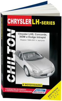
Руководство по техническому обслуживанию и ремонту автомобилей Chrysler 300M/Concorde/LHS и Dodge Intrepid 1998-2001 годов выпуска.
- Автор: —
- Издательство: Легион-Автодата
- Год издания: —
- Страниц: 380
- Формат: —
- Размер: —
-
Contents
-
Table of Contents
-
Bookmarks
Quick Links
SECTION
1
INTRODUCTION
2
THINGS TO KNOW BEFORE STARTING YOUR VEHICLE
3
UNDERSTANDING THE FEATURES OF YOUR VEHICLE
4
UNDERSTANDING YOUR INSTRUMENT PANEL
5
STARTING AND OPERATING
6
WHAT TO DO IN EMERGENCIES
7
MAINTAINING YOUR VEHICLE
8
MAINTENANCE SCHEDULES
9
IF YOU NEED CONSUMER ASSISTANCE
10
. . . . . . . . . . . . . . . . . . . . . . . . . . . . . . . . . . . . . . . . . . . . . . . . . . . . . . . . . . . . . . . . . . . 261
INDEX
TABLE OF CONTENTS
. . . . . . . . . . . . . . . . . . . . . . . . . . . . . . . . . . . . . . . . . . . . . . . . . . . . . . . . . . . . . 3
. . . . . . . . . . . . . . . . . . . . . . . . . . . . . . . . . . . . . . . . . . . . . . . . 149
. . . . . . . . . . . . . . . . . . . . . . . . . . . . . . . . . . . . . . . . . . . . . 175
. . . . . . . . . . . . . . . . . . . . . . . . . . . . . . . . . . . . . . . . . . . . . . 187
. . . . . . . . . . . . . . . . . . . . . . . . . . . . . . . . . . . . . . . . . . . . . . . . 235
I n f o r m a t i o n P r o v i d e d b y :
. . . . . . . . . . . . . . . . . . . . . . . . . . . 7
. . . . . . . . . . . . . . . . . . . . . . . . . . . . 51
. . . . . . . . . . . . . . . . . . . . . . . . . . . . . . . . . 101
. . . . . . . . . . . . . . . . . . . . . . . . . . . . . . . . . . . . . . . 251
PAGE
1
2
3
4
5
6
7
8
9
10
Chapters
Summary of Contents for Chrysler 2004 Concorde
Техническая документация по ремонту автомобилей Chrysler Concorde ( все годы выпуска) Бесплатно, без регистрации и СМС


Руководство по ремонту, эксплуатации и техническому обслуживанию Chrysler Concorde
— полные технические характеристик
-особенности эксплуатации
— устранение неисправностей Chrysler Concorde
— цветные электросхемы Chrysler Concorde
СКАЧАТЬ / СКАЧАТЬ С ЗЕРКАЛА
Руководство по эксплуатации Chrysler Concorde
— полные технические характеристики Chrysler Concorde
— особенности эксплуатации
— устранение неисправностей
— цветные электросхемы
СКАЧАТЬ / СКАЧАТЬ С ЗЕРКАЛА
Руководство по ремонту Chrysler Concorde в фотографиях
— полные технические характеристики
— особенности эксплуатации Chrysler Concorde
— устранение неисправностей
в фотографиях своими руками
— более 1980 фотографий процесса ремонта
СКАЧАТЬ / СКАЧАТЬ С ЗЕРКАЛА
Каталог деталей и сборочных единиц Chrysler Concorde
— таблица взаимозаменяемости деталей автомобилей
— предназначен для работников СТО и владельцев автомобилей Chrysler Concorde
— каталог деталей Chrysler Concorde
СКАЧАТЬ / СКАЧАТЬ С ЗЕРКАЛА
Подробная электросхема Chrysler Concorde
— полное описание электрооборудования Chrysler Concorde , подробная интерактивная электрическая схема Chrysler Concorde
— подробно описан алгоритм поиска неисправностей электрооборудования (стартер, генератор, система зажигания, впрыск, инжектор)
— подробная схема электрооборудования ( электро схема ) Chrysler Concorde
— распиновка разъемов электрических, распиновка электро проводки Chrysler Concorde
СКАЧАТЬ / СКАЧАТЬ С ЗЕРКАЛА
Руководство по ремонту двигателя Chrysler Concorde
— полные технические характеристики двигателя Chrysler Concorde
— особенности конструкции и ремонта двигателя Chrysler Concorde
— подробное описание процессов разборки, дефектовки и сборки двигателя с фотографиями, ГРМ
СКАЧАТЬ / СКАЧАТЬ С ЗЕРКАЛА
Руководство по ремонту коробок передач Chrysler Concorde
— полные технические характеристики КПП
— особенности конструкции и ремонта КПП Chrysler Concorde
— устранение неисправностей КПП трансмиссия, валы, шестерни, ШРУС
— подробное описание процессов разборки, дефектовки и сборки КПП с фотографиями
СКАЧАТЬ / СКАЧАТЬ С ЗЕРКАЛА
а вот здесь можно заработать на новую машину, и тогда старую не придется ремонтировать!!!
Chrysler Concorde


