Перед использованием интерфейса BIOS мы рекомендуем скачать руководство пользователя по материнской плате и ознакомиться с введением в интерфейс BIOS.
Как найти Руководство пользователя
Введение в интерфейс BIOS
Как найти Руководство пользователя
Введите название устройства в строке поиска на официальном сайте MSI.
Например, введите «MPG Z390M GAMING EDGE AC» и нажмите клавишу Enter.

Щелкните по ссылке Manual («Руководство пользователя») под строкой с названием устройства.

Выберите файл на нужном языке и скачайте его, щелкнув по пиктограмме со стрелкой.

Щелкните правой кнопкой мыши по загруженному файлу и выберите пункт меню Extract All («Извлечь все»).

Щелкните по кнопке Extract («Извлечь»).

Откройте извлеченный из архива PDF-файл.

Найдите в файле раздел BIOS Setup («Настройки BIOS»).

Введение в интерфейс BIOS
EZ MODE — Упрощенный режим
Advanced MODE — Расширенный режим
SETTINGS — Настройки
OC — Разгон
M-FLASH — M-FLASH (утилита для обновления BIOS)
HARDWARE MONITOR — Аппаратный мониторинг
BOARD EXPLORER — Обзор материнской платы
EZ MODE — Упрощенный режим

Advanced MODE — Расширенный режим
В расширенном режиме интерфейс BIOS разделен на шесть частей: Настройки, Разгон, M-FLASH, Разгонные профили, Аппаратный мониторинг и Обзор платы.

SETTINGS — Настройки
System Status: обзор состояния компьютерной системы
Advanced: расширенные настройки
Boot: настройки, связанные с загрузкой компьютера
Security: параметры безопасности
Save and Exit: сохранение настроек и выход из интерфейса BIOS

System Status — Статус системы
Настройка системных даты и времени, идентификация накопителей, сведения об интерфейсе DMI.

Advanced — Расширенные настройки
PCI sub-system Settings: Настройки шины PCI/PCIe
ACPI Settings:Настройки электропитания ACPI
Integrated peripherals: Встроенные периферийные контроллеры (сеть, звук, накопители и т.д.)
Integrated graphics configuration: Настройки встроенного графического ядра
USB Settings: Настройки шины USB
Super IO settings: Настройки контроллера ввода/вывода
Power management Settings: Управление питанием (ErP)
Windows operating system configuration: Настройки операционной системы Windows
Wake up event settings: Выход из спящего режима
Secure Erase+: Функция Secure Erase+

PCI Subsystem Settings («Настройки подсистемы PCI»)
Настройки протокола PCIe, латентности, многопроцессорной графической конфигурации.

ACPI Settings («Настройки интерфейса ACPI»)
Настройка индикатора питания и извещений о высокой температуре процессора.

Integrated Peripherals («Встроенные компоненты»)
Настройки встроенных контроллеров (сеть, SATA, звук).

Integrated Graphics Configuration («Конфигурация встроенной графики»)
Настройки, связанные со встроенным графическим ядром.

USB Configuration («Конфигурация шины USB»)
Настройки встроенного контроллера USB.

Super IO Configuration («Настройки контроллера ввода/вывода»)
Настройка параметров COM-порта.

Power Management («Управление энергопотреблением»)
Настройки энергосбережения (ErP).
Реакция компьютера на временное отключение питания от сети.
Защита от перепадов напряжения.
Настройки питания USB в состояниях S4/S5.

Windows OS Configuration («Конфигурация Windows»)
Настройки аутентификации Windows 10 (CSM/UEFI).
Функция ускоренной загрузки MSI.
Сведения о протоколе GOP.
Безопасная загрузка (Secure Boot).

Wake Up Event Setup («Настройки выхода из спящего режима»)
Выход компьютера из спящего режима по сигналу от сети или периферийных устройств.

Secure Erase+
Функция Secure Erase применяется только для твердотельных накопителей, работающих в режиме AHCI.
Boot («Загрузка»)
Настройка параметров загрузки компьютера. Указание порядка опроса загрузочных устройств:
Enable boot configuration settings
Enable boot mode settings
Boot order priorities
Hard drive priorities

Security («Безопасность»)
Пароль для интерфейса BIOS, настройки TPM-модуля, извещение об открытии корпуса компьютера:
BIOS password settings
TPM module settings
Set chassis intrusion warning

Save And Exit («Сохранить и выйти»)
Сохранение или отказ от внесенных в настройки BIOS изменений. Выход из интерфейса BIOS:
Save and cancel BIOS changes
Exit BIOS settings

Overclocking («Разгон»)
Разгон автоматически и вручную, Настройки напряжения питания, Расширенные параметры процессора:
Automatic overclocking
Manual overclocking
Voltage settings
CPU advanced parameter settings


CPU features («Параметры процессора»)
Число активных ядер, технология Hyper-Threading, виртуализация, мониторинг температуры, параметры энергосбережения и т.д.:
Number of Active processor cores
hyper-threading
Intel Virtualization technology
Temperature monitor
C-State
power mode and other Settings

M-FLASH
Данная утилита служит для обновления кода BIOS.
HARDWARE MONITOR
Информация о состоянии процессора и других системных компонентов.
BOARD EXPLORER
Обзор установленных периферийных устройств и компонентов.

Материнская плата MSI Руководство пользователя
Информация по технике безопасности
- Компоненты, входящие в этот комплект, подвержены повреждению электростатическим разрядом (ESD). Пожалуйста, придерживайтесь следующих инструкций, чтобы обеспечить успешную сборку компьютера.
- Убедитесь, что все компоненты надежно подключены. Плохое соединение может привести к тому, что компьютер не распознает компонент или не запустится.
- Держите материнскую плату за края, чтобы не прикасаться к чувствительным компонентам.
- При обращении с материнской платой рекомендуется носить браслет с защитой от электростатического разряда (ESD), чтобы предотвратить электростатическое повреждение. Если браслет для защиты от электростатического разряда недоступен, снимите с себя статическое электричество, прикоснувшись к другому металлическому предмету, прежде чем брать в руки материнскую плату.
- Храните материнскую плату в контейнере для защиты от статического электричества или на антистатической прокладке, если материнская плата не установлена.
- Перед включением компьютера убедитесь, что на материнской плате или где-либо в корпусе компьютера нет незакрепленных винтов или металлических компонентов.
- Не загружайте компьютер до завершения установки. Это может привести к необратимому повреждению компонентов, а также к травмам пользователя.
- Если вам потребуется помощь на любом этапе установки, обратитесь к сертифицированному специалисту по компьютерам.
- Всегда выключайте источник питания и отсоединяйте шнур питания от розетки перед установкой или извлечением каких-либо компонентов компьютера.
- Сохраните это руководство для использования в будущем.
- Берегите материнскую плату от влаги.
- Убедитесь, что ваша электрическая розетка обеспечивает такую же мощность.tage, как указано на блоке питания, перед подключением блока питания к электрической розетке.
- Разместите шнур питания таким образом, чтобы на него нельзя было наступить. Не кладите ничего на шнур питания.
- Следует отметить все предостережения и предупреждения на материнской плате.
- Если возникает какая-либо из следующих ситуаций, обратитесь в сервисную службу для проверки материнской платы.
персонал:- В компьютер попала жидкость.
- Материнская плата подверглась воздействию влаги.
- Материнская плата работает неправильно или вы не можете заставить ее работать в соответствии с руководством пользователя.
- Материнская плата упала и была повреждена.
- Материнская плата имеет явные признаки поломки.
- Не оставляйте материнскую плату при температуре выше 60 ° C (140 ° F), это может повредить материнскую плату.
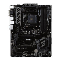
Характеристики
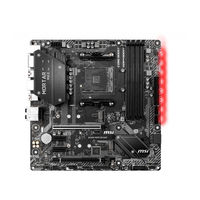
| ЦП | Поддерживает AMD Ryzen ™ / Ryzen ™ 1-го, 2-го и 3-го поколения с графикой Radeon ™ Vega и AMD Ryzen ™ 2-го поколения с графикой Radeon ™ / Athlon ™ с графическим процессором Radeon ™ Vega для настольных ПК для Socket AM4 |
| Набор микросхем | Чипсет AMD® B450 |
| Память |
* Пожалуйста, обратитесь www.msi.com для получения дополнительной информации о совместимой памяти. |
| Слоты расширения |
|
| Onboard Графика |
* Поддержка только при использовании AMD® Ryzen ™ с графикой Radeon ™ Vega и AMD Ryzen ™ 2-го поколения с графикой Radeon ™ / Athlon ™ с графическими процессорами Radeon ™ Vega * Максимальный объем разделяемой памяти 2048 МБ |
| Хранилище | Набор микросхем AMD® B450
|
|
Аудио |
|
| ЛВС | 1x контроллер Realtek® 8111H Gigabit LAN |
| USB | Набор микросхем AMD® B450
AMD® процессор
|
| Разъемы задней панели |
|
| Внутренние разъемы |
|
| Контроллер ввода / вывода | Микросхема контроллера NUVOTON 5567 |
| Монитор оборудования |
|
|
Форм-фактор |
|
| Возможности BIOS |
|
| Software |
|
| Особые возможности |
|
Содержимое пакета
Пожалуйста, проверьте содержимое упаковки материнской платы. Он должен содержать:
- Материнская плата
- DVD с драйверами
- Руководство по быстрой установке
- Экранирование ввода / вывода
- Кабель SATA 6G x2
- Значок случая
- Карточка регистрации продукта
- Винт M.2 x1
![]() Важнo
Важнo
Если что-либо из вышеперечисленного повреждено или отсутствует, обратитесь к продавцу.
Задняя панель ввода-вывода

Таблица состояния индикатора порта LAN

| Светодиод связи / активности | |
| Статус | Описание |
| от | Нет связи |
| Жёлтая | Связанный |
| моргание | Активность данных |
| Скорость LED | |
| от | Соединение 10 Мбит / с |
| Зелёная | Соединение 100 Мбит / с |
| Апельсин | Соединение 1 Гбит / с |
Аудио 7.1-канальная конфигурация
Для настройки 7.1-канального звука необходимо подключить передний аудиомодуль ввода / вывода к разъему JAUD1 и выполнить следующие шаги.
- Нажмите Realtek Audio Console> Advanced Settings, чтобы открыть диалоговое окно ниже.

- Выберите «Отключить звук на заднем устройстве вывода», когда к нему подключены передние наушники.
- Подключите динамики к аудиоразъемам на задней и передней панели ввода / вывода. Когда вы подключаете устройство к аудиоразъему, появляется диалоговое окно с вопросом, какое устройство подключено в данный момент.

Болееview компонентов

- Расстояние от центра процессора до ближайшего слота DIMM
Процессорное гнездо
Пожалуйста, установите ЦП в гнездо ЦП, как показано ниже.


![]() Важнo
Важнo
- При смене процессора конфигурацию системы можно очистить и сбросить BIOS до значений по умолчанию из-за архитектуры процессора AM4.
- Всегда отключайте шнур питания от розетки перед установкой или снятием ЦП.
- При установке ЦП всегда не забывайте устанавливать радиатор ЦП. Радиатор процессора необходим для предотвращения перегрева и поддержания стабильности системы.
- Перед загрузкой системы убедитесь, что радиатор ЦП плотно прилегает к ЦП.
- Перегрев может серьезно повредить процессор и материнскую плату. Всегда проверяйте, правильно ли работают охлаждающие вентиляторы, чтобы защитить ЦП от перегрева. Обязательно нанесите ровный слой термопасты (или термоленты) между процессором и радиатором, чтобы улучшить отвод тепла.
- Если вы приобрели отдельный ЦП и радиатор / кулер, пожалуйста, обратитесь к документации в комплекте радиатора / кулера для получения более подробной информации об установке.
Слоты DIMM
Установите модуль памяти в слот DIMM, как показано ниже.

![]() Важнo
Важнo
- Из-за использования ресурсов чипсета доступный объем памяти будет немного меньше установленного.
- В зависимости от спецификации процессора объем памяти DIMMtagДля защиты процессора рекомендуется напряжение ниже 1.35 В.
- Из-за ограничения официальной спецификации процессора / памяти AM4, частота модулей памяти может работать ниже отмеченного значения в состоянии по умолчанию. Пожалуйста, посетите www.msi.com для получения дополнительной информации о совместимой памяти.
PCI_E1 ~ 3: Слоты расширения PCIe
| Процессоры
Игровые Автоматы |
RYZEN серии |
Ryzen ™ с графикой Radeon ™ Vega и AMD Ryzen ™ 2-го поколения с графикой Radeon ™ |
Athlon ™ с графикой Radeon ™ Vega |
| PCI_E1 | PCIe 3.0 x16 | PCIe 3.0 x8 | PCIe 3.0 x4 |
| PCI_E2 | PCIe 2.0 x1 | PCIe 2.0 x1 | PCIe 2.0 x1 |
| PCI_E3 | PCIe 2.0 x1 | PCIe 2.0 x1 | PCIe 2.0 x1 |
![]() Важнo
Важнo
- При добавлении или удалении карт расширения всегда выключайте источник питания и отсоединяйте кабель питания от розетки. Прочтите документацию карты расширения, чтобы проверить наличие необходимых дополнительных изменений оборудования или программного обеспечения.
- Если вы устанавливаете большую и тяжелую видеокарту, вам необходимо использовать такой инструмент, как крепление графической карты MSI Gaming Series, чтобы выдержать ее вес и предотвратить деформацию слота.
JFP1, JFP2: разъемы передней панели
Эти разъемы подключаются к переключателям и светодиодам на передней панели.
| 1 | Светодиод жесткого диска + | 2 | Светодиод питания + |
| 3 | Светодиод жесткого диска — | 4 | Светодиод питания — |
| 5 | Сбросить переключатель | 6 | Выключатель |
| 7 | Сбросить переключатель | 8 | Выключатель |
| 9 | Зарезервированный | 10 | Нет PIN-кода |

| Оратор- |
| Зуммер + |
| Зуммер — |
| Спикер + |

SATA1 ~ 4: Разъемы SATA 6 Гбит / с
Эти разъемы представляют собой интерфейсные порты SATA 6 Гбит / с. Каждый разъем может подключаться к одному устройству SATA.


![]() Важнo
Важнo
- Не складывайте кабель SATA под углом 90 градусов. В противном случае во время передачи может произойти потеря данных.
- Кабели SATA имеют одинаковые разъемы с обеих сторон кабеля. Однако рекомендуется подключать плоский разъем к материнской плате в целях экономии места.
ATX_PWR1, CPU_PWR1: разъемы питания
Эти разъемы позволяют подключать блок питания ATX.
 |
1 | + 3.3V | 13 | + 3.3V |
| 2 | + 3.3V | 14 | -12V | |
| 3 | земля | 15 | земля | |
| 4 | + 5V | 16 | PS-ON # | |
| 5 | земля | 17 | земля | |
| 6 | + 5V | 18 | земля | |
| 7 | земля | 19 | земля | |
| 8 | PWR ОК | 20 | Res | |
| 9 | 5VSB | 21 | + 5V | |
| 10 | + 12V | 22 | + 5V | |
| 11 | + 12V | 23 | + 5V | |
| 12 | + 3.3V | 24 | земля |
 |
1 | земля | 5 | + 12V |
| 2 | земля | 6 | + 12V | |
| 3 | земля | 7 | + 12V | |
| 4 | земля | 8 | + 12V |
![]() Важнo
Важнo
Убедитесь, что все кабели питания надежно подключены к соответствующему блоку питания ATX, чтобы обеспечить стабильную работу материнской платы.
M2_1: слот M.2 (клавиша M)
Установите твердотельный накопитель (SSD) M.2 в слот M.2, как показано ниже.


JUSB1 ~ 2: Разъемы USB 2.0
Эти разъемы позволяют подключать порты USB 2.0 на передней панели.
 |
1 | VCC | 2 | VCC |
| 3 | USB0- | 4 | USB1- | |
| 5 | USB0 + | 6 | USB1 + | |
| 7 | земля | 8 | земля | |
| 9 | Нет PIN-кода | 10 | NC |
![]() Важнo
Важнo
- Обратите внимание, что контакты VCC и заземления должны быть подключены правильно, чтобы избежать возможных повреждений.
- Чтобы зарядить iPad, iPhone и iPod через порты USB, установите утилиту MSI® SUPER CHARGER.
JUSB3: Разъем USB 3.2 Gen1
Этот разъем позволяет подключать порты USB 3.2 Gen1 на передней панели.
|
|
1 | Питания | 11 | USB2.0 + |
| 2 | USB3_RX_DN | 12 | USB2.0- | |
| 3 | USB3_RX_DP | 13 | земля | |
| 4 | земля | 14 | USB3_TX_C_DP | |
| 5 | USB3_TX_C_DN | 15 | USB3_TX_C_DN | |
| 6 | USB3_TX_C_DP | 16 | земля | |
| 7 | земля | 17 | USB3_RX_DP | |
| 8 | USB2.0- | 18 | USB3_RX_DN | |
| 9 | USB2.0 + | 19 | Питания | |
| 10 | NC | 20 | Нет PIN-кода |

![]() Важнo
Важнo
Обратите внимание, что контакты питания и заземления должны быть подключены правильно, чтобы избежать возможных повреждений.
CPU_FAN1, SYS_FAN1: разъемы вентилятора
Разъемы вентилятора можно разделить на режим ШИМ (широтно-импульсной модуляции) или режим постоянного тока. Разъемы вентилятора в режиме ШИМ обеспечивают постоянное выходное напряжение 12 В и регулируют скорость вентилятора с помощью сигнала управления скоростью. Разъемы вентилятора в режиме постоянного тока управляют скоростью вращения вентилятора путем изменения громкости.tagе. Когда вы подключаете 3-контактный вентилятор (без ШИМ) к разъему вентилятора в режиме ШИМ, скорость вентилятора всегда будет поддерживаться на уровне 100%, что может создавать много шума. Вы можете следовать приведенным ниже инструкциям, чтобы настроить разъем вентилятора в режим ШИМ или постоянного тока.
Разъем вентилятора режима PWM по умолчанию
Разъем вентилятора режима постоянного тока по умолчанию
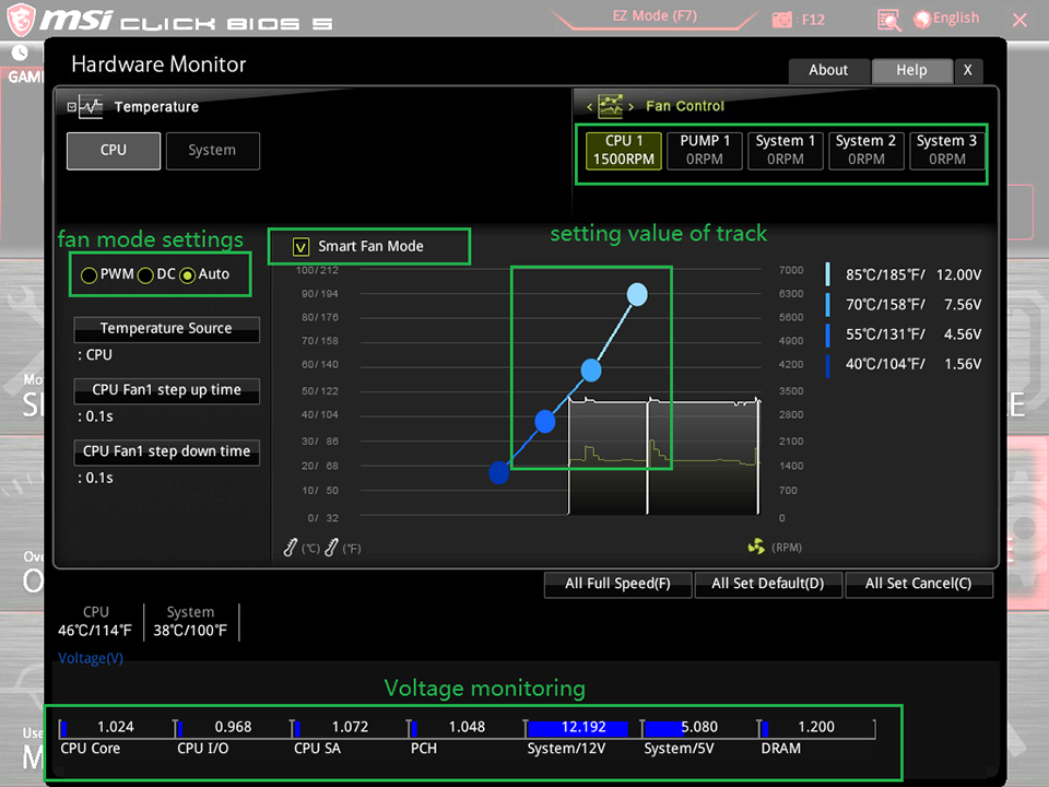
Переключение режима вентилятора и регулировка скорости вентилятора
Вы можете переключаться между режимом ШИМ и режимом постоянного тока и регулировать скорость вращения вентилятора в BIOS> АППАРАТНЫЙ МОНИТОР.
Выберите ШИМ режим или DC Режим
Есть точки градиента скорости вращения вентилятора, которые позволяют регулировать скорость вращения вентилятора в зависимости от температуры процессора.
![]() Важнo
Важнo
Убедитесь, что вентиляторы работают правильно после переключения режима PWM / DC.
Определение контактов разъемов вентилятора
| Определение контакта режима ШИМ | |||
| 1 | земля | 2 | + 12V |
| 3 | Смысл | 4 | Сигнал управления скоростью |
| Определение контакта режима постоянного тока | |||
| 1 | земля | 2 | Voltage Контроль |
| 3 | Смысл | 4 | NC |
JTPM1: Разъем модуля TPM
Этот разъем предназначен для TPM (доверенного платформенного модуля). Дополнительные сведения и способы использования см. В руководстве по платформе безопасности TPM.
|
|
1 | Часы LPC | 2 | 3 В в режиме ожидания |
| 3 | Сброс LPC | 4 | Мощность 3.3V | |
| 5 | Адрес и данные LPC pin0 | 6 | Последовательный IRQ | |
| 7 | Адрес и данные LPC pin1 | 8 | Мощность 5V | |
| 9 | Адрес и данные LPC pin2 | 10 | Нет PIN-кода | |
| 11 | Адрес и данные LPC pin3 | 12 | земля | |
| 13 | Рама LPC | 14 | земля |

JCI1: Разъем обнаружения вторжения в корпус
Этот разъем позволяет подключать кабель переключателя вскрытия корпуса.

Нормальный (по умолчанию)

Запуск события вторжения шасси
Использование детектора вскрытия корпуса
- Подключите разъем JCI1 к переключателю / датчику вскрытия корпуса на корпусе.
- Закройте крышку корпуса.
- Перейдите в BIOS> НАСТРОЙКИ> Безопасность> Конфигурация вскрытия корпуса.
- Установите для параметра Chassis Intrusion значение Enabled.
- Нажмите F10, чтобы сохранить и выйти, а затем нажмите клавишу Enter, чтобы выбрать Да.
- После того, как крышка корпуса снова откроется, при включении компьютера на экране отобразится предупреждающее сообщение.
Сброс предупреждения о вторжении в корпус
- Перейдите в BIOS> НАСТРОЙКИ> Безопасность> Конфигурация вскрытия корпуса.
- Установите для параметра Chassis Intrusion значение Reset.
- Нажмите F10, чтобы сохранить и выйти, а затем нажмите клавишу Enter, чтобы выбрать Да.
JAUD1: Передний аудиоразъем
Этот разъем позволяет подключать аудиоразъемы на передней панели.
 |
1 | МИК Л | 2 | земля |
| 3 | микрофон р | 4 | NC | |
| 5 | Головной телефон R | 6 | Обнаружение микрофона | |
| 7 | SENSE_SEND | 8 | Нет PIN-кода | |
| 9 | Головной телефон L | 10 | Обнаружение головного телефона |
JCOM1: Разъем последовательного порта
Эти разъемы позволяют подключать дополнительный последовательный порт с помощью кронштейна.
 |
1 | DCD | 2 | SIN |
| 3 | ЮГ | 4 | DTR | |
| 5 | земля | 6 | DSR | |
| 7 | РТС | 8 | CTS | |
| 9 | RI | 10 | Нет PIN-кода |
JLED1: разъем для светодиодной ленты
Этот разъем позволяет подключать одноцветную светодиодную ленту.
 |
|||
| 1 | + 12V | 2 | NC |
| 3 | сигнал | 4 | NC |

![]() Важнo
Важнo
- Этот разъем поддерживает 5050 одноцветных светодиодных лент с максимальной номинальной мощностью 3 А (12 В). Пожалуйста, держите светодиодную ленту короче 2 метров, чтобы предотвратить затемнение.
- Перед установкой или снятием светодиодной ленты всегда выключайте источник питания и отсоединяйте шнур питания от розетки.
- Пожалуйста, используйте МИСТИЧЕСКИЙ СВЕТ для управления удлиненной светодиодной лентой.
JBAT1: перемычка очистки CMOS (сброса BIOS)
На плате имеется память CMOS, которая питается от батареи, расположенной на материнской плате, для сохранения данных конфигурации системы. Если вы хотите очистить конфигурацию системы, установите перемычку для очистки памяти CMOS.

Сохранить данные (по умолчанию)

Очистить CMOS / сбросить BIOS
Сброс BIOS до значений по умолчанию
- Выключите компьютер и отсоедините шнур питания.
- Используйте перемычку, чтобы замкнуть JBAT1 примерно на 5-10 секунд.
- Снимите перемычку с JBAT1.
- Подключите шнур питания и включите компьютер.
EZ Debug LED: Светодиодные индикаторы отладки
Эти светодиоды показывают состояние материнской платы.
- ЦП — указывает на то, что ЦП не обнаружен или неисправен.
- Динамическое ОЗУ — указывает, что DRAM не обнаружен или неисправен
- VGA — указывает на то, что графический процессор не обнаружен или неисправен
- BOAT — указывает, что загрузочное устройство не обнаружено или не работает.
Настройка биоса
Настройки по умолчанию обеспечивают оптимальную производительность для стабильности системы в нормальных условиях. Вам следует всегда сохраняйте настройки по умолчанию чтобы избежать возможной системы
повреждение или сбой при загрузке, если вы не знакомы с BIOS.
![]() Важнo
Важнo
- Элементы BIOS постоянно обновляются для повышения производительности системы. Поэтому описание может немного отличаться от последней версии BIOS, и его следует использовать только для справки. Вы также можете обратиться к информационной панели HELP для описания элемента BIOS.
- Изображения в этой главе приведены только для справки и могут отличаться от приобретенного вами продукта.
- Элементы BIOS зависят от процессора.
Вход в программу настройки BIOS
Нажмите клавишу Delete, когда Нажмите клавишу DEL, чтобы войти в меню настройки, F11, чтобы войти в загрузку. Меню сообщение появляется на экране во время процесса загрузки.
Функциональная клавиша
F1: Общая помощь
F2: Добавить / удалить любимый элемент
F3: Войдите в меню избранного
F4: Войдите в меню характеристик процессора
F5: Войдите в меню Memory-Z
F6: Загрузите оптимальные настройки по умолчанию
F7: Переключение между расширенным режимом и режимом EZ
F8: Загрузить Overclocking Profile
F9: Сохранить Overclocking Profile
F10: Сохранить изменения и сбросить *
F12: Сделайте снимок экрана и сохраните его на USB-накопитель (только в формате FAT / FAT32).
- Когда вы нажимаете F10, появляется окно подтверждения с информацией об изменении. Выберите «Да» или «Нет», чтобы подтвердить свой выбор.
Сброс BIOS
Для решения определенных проблем может потребоваться восстановить настройки BIOS по умолчанию. Сбросить BIOS можно несколькими способами:
- Перейдите в BIOS и нажмите F6, чтобы загрузить оптимизированные настройки по умолчанию.
- Замкните перемычку Clear CMOS на материнской плате.
![]() Важнo
Важнo
Пожалуйста, обратитесь к разделу перемычки Clear CMOS для сброса BIOS.
Обновление BIOS
Обновление BIOS с помощью M-FLASH
Перед обновлением: загрузите последнюю версию BIOS file соответствует модели вашей материнской платы от MSI webсайт. А затем сохраните BIOS file на флешку. Обновление BIOS:
- Нажмите клавишу Del, чтобы войти в программу настройки BIOS во время процедуры POST.
- Вставьте USB-накопитель с обновлением. file в компьютер.
- Выберите вкладку M-FLASH и нажмите Да, чтобы перезагрузить систему и войти в режим прошивки.
- Выберите BIOS file для выполнения процесса обновления BIOS.
- После того, как процесс прошивки будет на 100% завершен, система автоматически перезагрузится.
Обновление BIOS с помощью Live Update 6
Перед обновлением: убедитесь, что драйвер LAN уже установлен и подключение к Интернету установлено правильно.
Обновление BIOS:
- Установите и запустите MSI LIVE UPDATE 6.
- Выберите Обновление BIOS.
- Нажмите кнопку «Сканировать».
- Щелкните значок «Загрузить», чтобы загрузить и установить последнюю версию BIOS. file.
- Нажмите «Далее» и выберите «В режиме Windows». Затем нажмите «Далее» и «Пуск», чтобы начать обновление BIOS.
- После того, как процесс прошивки будет завершен на 100%, система автоматически перезагрузится.
Описание программного обеспечения
Загрузите и обновите последние версии утилит и драйверов по адресу www.msi.com
Установка Windows® 10
- Включите компьютер.
- Вставьте установочный диск Windows® 10 / USB в свой компьютер.
- Нажмите кнопку перезагрузки на корпусе компьютера.
- Нажмите клавишу F11 во время POST (самотестирования при включении) компьютера, чтобы войти в меню загрузки.
- Выберите установочный диск Windows® 10 / USB в меню загрузки.
- Нажмите любую клавишу, когда на экране отображается сообщение «Нажмите любую клавишу для загрузки с компакт-диска или DVD…».
- Следуйте инструкциям на экране, чтобы установить Windows® 10.
Установка драйверов
- Загрузите компьютер в Windows® 10.
- Вставьте диск с драйверами MSI® в оптический привод.
- Нажмите «Выбрать», чтобы выбрать, что будет происходить с всплывающим уведомлением об этом диске, затем выберите «Запустить DVDSetup.exe», чтобы открыть программу установки. Если вы отключите функцию автозапуска на панели управления Windows, вы все равно можете вручную запустить DVDSetup.exe из корневого пути диска с драйверами MSI.
- Установщик найдет и перечислит все необходимые драйверы на вкладке «Драйверы / Программное обеспечение».
- Нажмите кнопку «Установить» в правом нижнем углу окна.
- После этого установка драйверов будет продолжена, после ее завершения вам будет предложено перезагрузить компьютер.
- Нажмите кнопку ОК, чтобы закончить.
- Перезагрузите компьютер.
Установка утилит
Перед установкой утилит необходимо завершить установку драйверов.
- Откройте установщик, как описано выше.
- Щелкните вкладку Утилиты.
- Выберите утилиты, которые хотите установить.
- Нажмите кнопку «Установить» в правом нижнем углу окна.
- После этого установка утилит будет продолжена, после ее завершения вам будет предложено перезагрузить компьютер.
- Нажмите кнопку ОК, чтобы закончить.
- Перезагрузите компьютер.
Документы / Ресурсы
Рекомендации
- Manuals
- Brands
- MSI Manuals
- Motherboard
ManualsLib has more than 1812 MSI Motherboard manuals
Click on an alphabet below to see the full list of models starting with that letter:
3
4
5
6
7
8
9
A
B
C
D
E
F
G
H
I
J
K
L
M
N
P
Q
R
S
T
V
W
X
Z
Popular manuals
187 pages
H510M PRO User Manual
190 pages
MPG B550 Quick Start Manual
23 pages
H81M-P33 Series User Manual

148 pages
H110M PRO-VD User Manual
249 pages
PRO Z690-A WIFI DDR4 Manual
175 pages
MAG B550 TOMAHAWK Quick Start Manual
253 pages
PRO B660M-A WIFI DDR4 User Manual
72 pages
MPG X570-A PRO Quick Start Manual

249 pages
PRO Z690-A WIFI Manual
206 pages
B550M PRO-VDH WIFI Quick Start Manual
164 pages
B450M-A PRO MAX User Manual

144 pages
B560M PRO-VDH WIFI Quick Start Manual
164 pages
A320M gaming pro User Manual
165 pages
H310M PRO-VH User Manual

68 pages
MPG B550 GAMING PLUS Quick Start Manual
320 pages
MAG B660M MORTAR WIFI DDR4 User Manual
158 pages
B450M MORTAR MAX Quick Start Manual
204 pages
PRO H610M-G DDR4 User Manual
78 pages
Z390-A PRO Quick Start Manual
96 pages
B450-A PRO Quick Start Manual
Models
Document Type
3
3200 Master Series

User Manual • User Manual
4
4719072611415
Manual
4719072653811
Quick Start Manual
4719072886554
User Manual
4719072886561
User Manual
5
510TI-S01
Manual
6
610BF
Manual
611BF
User Manual
612BF
User Manual • Manual
645 Combo
User Manual
645 Ultra
Manual
645 Ultra MS-6547
Manual • Manual
645 Ultra-C
Manual
645E Max-U
Manual
645E Max2 series
User Manual • User Manual
645E Max2 Series MS-6567
User Manual
648 Max
User Manual
648FM3-V Series
Instruction Manual
648M-IL
User Manual
648M3-V Series
Instruction Manual
649 Neo-V
Instruction Manual
650GLMD
User Manual
650GLMS
User Manual
650GM-L Series
User Manual
650GXM Combo Series
User Manual
651M
User Manual
651M-L
User Manual
651M-V
User Manual • Instruction Manual
655 Max
User Manual
661FM Series
User Manual
661FM-L
User Manual
661FM2 Series
User Manual
661FM2-V ILSR
User Manual
661FM2-V LSR
User Manual
661FM3-L
User Manual
661FM3-V Series
User Manual • Instruction Manual
661GM3-V Series
Instruction Manual
671FXM-V series
Instruction Manual
671M-V series
Instruction Manual
694 MASTER
User Manual
694D PRO
Manual
694D Pro2
Manual
694T Pro
User Manual
7
740GM-P21 Series
Manual
740GM-P25 Series
Manual
745 Ultra
User Manual • Manual
745 Ultra-E
User Manual • Manual
760G-P43 FX series
Manual • Manual
760G-P43 series
Manual
760GA-P43 FX
Manual • Manual
760GM
User Manual
760GM-E51 series
User Manual • Manual
760GM-P21 FX Series
Manual • Manual
760GM-P21FX
Manual
760GM-P22 series
User Manual • Manual
760GM-P22FX series
User Manual
760GM-P23
Manual
760GM-P23FX
Manual
760GM-P24 series
User Manual • Manual
760GM-P24FX series
User Manual
760GM-P25
Manual
760GM-P25FX
Manual
760GM-P31 Series
User Manual
760GM-P33 Series
Manual
760GM-P34 series
User Manual
760GM-P34FX
User Manual
760GM-P35 Series
User Manual
760GM-P43 Series
Manual
760GMA-P34 FX series
Manual
770 C45 — AM3 AMD 770 HDMI Motherboard
User Manual
770-G45 Series
Manual
780GT-E63 Series
Manual
785G-E53 Series
Manual
785G-E65 Series
Manual
785GM
User Manual
785GM-E51 — AMD 785G+SB710 4DDR-16GB Micro ATX Motherboard 7596-030
User Manual
785GM-E51 series
User Manual • Manual
785GM-E65 series
User Manual • User Manual
785GM-P35 Series
User Manual
785GM-P45 Series
User Manual
785GMA-E45 series
User Manual • User Manual
785GMU-E35 series
User Manual • User Manual
785GT-E63 Series
Manual
785GTM-E45 — Motherboard — Micro ATX
User Manual
785GTM-E45 Series
User Manual
790FX
User Manual
790FX-GD70 Series
User Manual
790GX
Manual
790GX-G65 — SocketAM3/140W CPU/AMD 790GX
User Manual
790GX-G65 Series
User Manual • User Manual • Manual
790XT
User Manual
790XT-G35 series
User Manual • Manual
790XT-G45 series
User Manual • Manual
7A94-002R
Quick Start Manual
7B06-001R
Quick Start Manual
7B28-002R
User Manual
7B84-017R
User Manual
7B89-016R
Quick Start Manual
7B94-001R
Quick Start Manual
7C04-001R
Quick Start Manual
7C36-002R
Quick Start Manual
7C57-002R
User Manual
7C60-001R
Quick Start Manual
7C60-005R
Quick Start Manual
7C70-005R
Quick Start Manual
7C75-003R
Quick Start Manual
7C75-007R
Quick Start Manual
7C79-005R
Quick Start Manual
7C80-004R
Quick Start Manual
7C83-003R
Quick Start Manual
7D28-002R
User Manual
8
815 PRO
Manual
815EPT Pro
Manual
815EPT Pro-R
Manual
845 Pro
Manual
845 Pro2
User Manual
845 Pro2 LE
Manual
845 Pro2-A
User Manual
845 Pro2-C
Manual
845 Pro2-R
User Manual
845 PRO4
Manual • User Manual
845 Ultra
Technical Manual • Manual
845 Ultra-AR
Technical Manual • Manual
845 Ultra-ARU
Technical Manual • Manual
845E Max
User Manual
845E Max2 Series
User Manual
845E Neo-V
User Manual
845G Max
Manual
845G Max-L
Manual
845GE Max
User Manual
845GEM Series
Instruction Manual • User Manual
845GEM-V Series
Instruction Manual
845GVM Series
User Manual
845GVM-V Series
Instruction Manual
845GVM2-V Series
Instruction Manual
845GVM2-V2
Instruction Manual
845PE Neo
User Manual • Manual • Manual
845PE Neo MS-6580
Manual
845PE-V2 Series
Instruction Manual
848P Neo
User Manual
848P Neo-S
User Manual
848P NEO-V — Motherboard — ATX
User Manual • User Manual • Instruction Manual
848P Neo2-V Series
Instruction Manual
848P-V2 Series
Instruction Manual
848PM
User Manual
850 Pro2
User Manual • Manual
850 Pro5
User Manual
865GM2
User Manual
865GM2-LS — Motherboard — Micro ATX
User Manual
865GM3 Series
User Manual • User Manual
865GM3-FIS
User Manual
865GM3-LS
User Manual
865GM3-V
User Manual
865GVM
Manual
865GVM2
User Manual
865GVM2-LS
User Manual
865GVM3-V — Motherboard — Micro ATX
Instruction Manual • Instruction Manual
865P Neo
Manual
865PE Neo
Instruction Manual
865PE NEO2
User Manual
865PE NEO2-LS — Motherboard — ATX
User Manual
865PE Neo2-P Platinum Edition
User Manual
865PE Neo2-PFISR
User Manual
865PE NEO2-PFS — Motherboard — ATX
User Manual • User Manual
865PE Neo2-PLS
User Manual
865PE Neo2-V Series
User Manual • Instruction Manual
865PE Neo3-F
User Manual
865PE Neo3-FS
User Manual
865PE Neo3-V Series
Instruction Manual • User Manual
865PE-V2 Series
Instruction Manual
865PE/G Neo2-P MS-6728
Manual
865PE/G Neo3
User Manual
865PEM2 Series
User Manual • User Manual
865PEM3
User Manual
865PEM3-ILS
User Manual
870-C45 FX V2 Series
User Manual
870-C45 FX V2series
User Manual
870-C45 Series
Manual
870-C45 V2 Series
User Manual
870-G45 series
User Manual
870-SG45 FX V2 series
User Manual
870-SG45 V2 series
User Manual
870A Fuzion Power Edition series
User Manual • User Manual
870A-G46 series
Instruction Manual
870A-G54 FX Series
User Manual
870A-G54 series
User Manual • User Manual
870A-G55 Series
Manual
870S-C45 Series
Manual
870S-G46 series
Instruction Manual
870S-G54 Series
User Manual
870S-SG45 Series
Manual
870U-G54 FX Series
User Manual
870U-G54 series
User Manual • User Manual
870U-G55 Series
Manual
875P Neo P Series
User Manual
875P Neo-FIS2R
User Manual
875P Neo-FISR
User Manual
875P Neo-LSR
User Manual
880G-E45 Series
Manual
880GM-E41 series
User Manual
880GM-E43 Series
User Manual
880GM-P51 Series
User Manual
880GMA-E41 FX
Manual
880GMA-E45 series
User Manual • User Manual
880GMA-E53 Series
Manual
880GMA-E55 Series
Manual
880GMS-E41 FX
Manual
880GMU-E35 series
User Manual • User Manual
88GMA-E35 FX
Manual
88GMS-E35 FX
Manual
890FXA-GD65 series
User Manual
890FXA-GD70 series
User Manual
890GXM
User Manual
890GXM-G65 MS-7642
User Manual • User Manual
9
910GLM
User Manual • User Manual
910GLM-V
Instruction Manual
910GLM2-V
User Manual
915G Combo 2
User Manual • User Manual • User Manual
915G COMBO-FR — Motherboard — ATX
User Manual • User Manual
915G Neo2
User Manual • User Manual
915G Neo2-FR
User Manual
915G Neo3
User Manual
915G Neo3-FIR
User Manual
915G Neo3-FR
User Manual
915GLM-V
Instruction Manual • User Manual
915GLM2-V
User Manual • User Manual
915GLM4
User Manual
915GLM4-F
User Manual • User Manual
915GLM4-L
User Manual • User Manual
915GM Speedster MS-9625
User Manual
915GM-FR — Motherboard — Micro ATX
User Manual
915GM4
User Manual
915GM4-F
User Manual
915GM4-FI
User Manual
915GM4-L
User Manual
915GM6 Series
User Manual
915GM6-F
User Manual
915GMB
User Manual
915GMB-F
User Manual
915GMB-FI
User Manual
915GVM
User Manual • User Manual
915GVM-V
Instruction Manual
915GVM3-V
User Manual
915GVM4
User Manual
915GVM6 Series
User Manual
915GVM6-F
User Manual
915GVM6-L
User Manual
915P Combo
User Manual • User Manual
915P Neo
Instruction Manual
915P Neo2
User Manual • User Manual
915P Neo3
User Manual
915P Neo3-F2R
User Manual
915P Neo3-FR
User Manual
915PL Neo
Instruction Manual
915PLM
User Manual
915PLM4
User Manual
915PM
User Manual • User Manual
915PM-ILR
User Manual
915PM4
User Manual
915PM6 Series
User Manual
925X Neo Platinum
User Manual
925XE Neo Platinum
User Manual
925XE Neo-Platinum
User Manual
945 Neo5 Series
User Manual
945G Neo
User Manual • User Manual
945G Neo2 Series
User Manual • User Manual • User Manual
945G Platinum
User Manual • User Manual
945G Series
User Manual • User Manual • Manual
945G Series MS-7324
Manual
945GCM478 Series
Manual
945GCM5 Series
User Manual • Instruction Manual • User Manual
945GCM5 V2 series
Instruction Manual
945GM2 — Fuzzy Motherboard — Mini ITX
User Manual • User Manual • User Manual
945GM2 Series
User Manual
945GM2-F
User Manual • User Manual • User Manual
945GM2-FI
User Manual • User Manual • User Manual
945GM2-FR
User Manual • User Manual • User Manual
945GM3 Series
User Manual
945GM3-F — Motherboard — Micro ATX
User Manual
945GM4-FI
User Manual
945GM5 Series
User Manual
945GZM2-F
User Manual
945GZM3 Series
User Manual
945GZM5 Series
User Manual
945GZM6 series
Instruction Manual
945P Neo
User Manual • User Manual
945P Neo2 Series
User Manual
945P Neo2-F
User Manual • User Manual
945P Neo3 Series
Product Manual • User Manual • User Manual
945P Neo5 Series
User Manual • User Manual
945P Platinum
User Manual
945P Series
Instruction Manual
945P Series MS-7204
Instruction Manual
945PL Neo Series
User Manual • User Manual • Manual
945PL Neo2 Series
User Manual • User Manual
945PL Neo3
User Manual • User Manual
945PL Neo5 Series
User Manual • User Manual
945PLM2 Series
User Manual
946GZ Neo Series
User Manual
946GZM
Instruction Manual
946PLM
Instruction Manual
955X Platinum
User Manual
9672
User Manual
970
User Manual
970A GAMING PRO CARBON
Manual • Quick Start Manual
970A-G43 PLUS
Manual
970A-G43 Series
Instructions Manual
970A-G45 series
User Manual
970A-G46 Series
Manual
970S-G46 Series
Manual
975X Platinum Series
User Manual • User Manual
990FXA
User Manual • User Manual
990FXA-GD65 Series
Manual
990FXA-GD80 G52-76401XB
User Manual
990FXA-GD80 series
User Manual • Manual
990XA-GD55 series
User Manual • Installation Manual
A
A320I PRO AC
Manual
A320M
BAZOOKA
Quick Start Manual
A320M gaming pro
User Manual • Manual
A320M PRO-E
Manual
A320M PRO-M2
Manual
A320M PRO-M2 V2
Manual
A320M PRO-VD/S
User Manual
A320M PRO-VH PLUS
User Manual
A320M PRO-VHL
User Manual
A320M-A PRO
Manual • User Manual
A320MPRO-VDH
User Manual
A520M PRO-C DASH
User Manual
A520M PRO-VH
Manual
A520M-A PRO
Manual
A55-G35 Series
Manual
A55-G41 PC Mate
User Manual • Product Manual
A55M-E35
Manual
A55M-E45 V2
Manual
A55M-P35 series
Manual • Manual
A58-G41 PC Mate
Product Manual
A68HI AC Series
Manual
A68HI ACSeries
Manual
A68HI Series
Manual • Manual
A68HM
User Manual
A68HM-E33 V2 Series
Manual
A68HM-P33 Series
Manual
A75A-G35 Series
Manual
A75A-G45 series
User Manual • Manual
A75A-G55 series
User Manual • Manual
A75MA-G55 Series
Manual
A75MA-P35 series
Manual • Manual
A78-G41 PC Mate
User Manual • Product Manual
A78I
Manual
A78I AC V2
Manual • User Manual
A78M-E35
Manual
A78M-E35 V2 Series
Manual
A78M-E45 V2
Manual
A88X-G41 PC Mate
User Manual • Product Manual
A88X-G43 Series
User Manual
A88X-G45 GAMING
User Manual • Manual • User Manual
A88XI
Manual
A88XI AC
Manual • User Manual
A88XI V2
User Manual
A88XM GAMING
Manual
A88XM-E35
Manual
A88XM-E35 V2 Series
Manual
A88XM-E45 V2
Manual
A88XM-P33 V2 Series
Manual
AL14
Manual
AM-690E
User Manual
AM1I Series
User Manual
AM1M Series
User Manual
AmethystM
Manual
ATX BX1
User Manual
ATX BX13
User Manual
ATX BX2
User Manual
ATX BX7
User Manual
B
Bg Bang-XPower II
User Manual
B150 GAMING M3
Quick Start Manual
B150 PC MATE
Quick Start Manual • Manual • Quick Start Manual
B150 TOMAHAWK AC
User Manual
B150-ICAFE/ H110 PC MATE
Manual
B150A GAMING PRO
Quick Start Manual • Quick Start Manual • User Manual
B150A TOMAHAWK
User Manual
B150M ECO
User Manual
B150M GRENADE
User Manual
B150M MORTAR
User Manual • Assembly Instruction Manual • User Manual
B150M NIGHT ELF
Quick Start Manual
B150M PRO-DH
User Manual
B150M PRO-VDH
User Manual • Quick Start Manual
B150M PRO-VHL
User Manual
B250 GAMING M3
Quick Start Quide • Manual • Manual
B250I GAMING PRO AC
User Manual
B250M BAZOOKA
User Manual
B250M BAZOOKA OPT BOOST
User Manual
B250M BAZOOKA PLUS
User Manual
B250M GAMING PRO
Manual
B250M MORTAR
Manual
B250M PRO-VDH
User Manual
B250M PRO-VH
User Manual
B250MPRO-VD
User Manual
B320M gaming pro
User Manual
B350 PC MATE
Quick Start Manual
B350 TOMAHAWK
User Manual
B350I
PRO AC
Manual
B350I-S01
Manual
B350M BAZOOKA
Quick Start Manual
B350M GAMING PRO
Manual
B350M PRO-VDH
User Manual
B350M PRO-VH PLUS
User Manual
B360
Quick Start Manual
B360 GAMING PLUS
User Manual
B360-A PRO
Manual
B360-F PRO
Manual • Installation Manual
B360I GAMING PRO AC
Manual
B360M BAZOOKA
User Manual
B360M MORTAR
User Manual
B360M PRO-VDH
User Manual
B365M PRO-VD
Manual
B365M PRO-VDH
User Manual
B365M PRO-VH
Manual
B365M WIND
Manual
B450 GAMING PLUS MAX
User Manual
B450 GAMING PRO CARBON MAX WIFI
Quick Start Manual
B450 TOMAHAWK MAX
Quick Start Manual • Quick Start Manual • Manual
B450-A PRO
Quick Start Manual
B450I GAMING PLUS AC
Quick Start Manual • Quick Start Manual
B450M BAZOOKA MAX WIFI
Quick Start Manual
B450M BAZOOKA PLUS
Quick Start Manual
B450M GAMING PLUS
User Manual
B450M MORTAR MAX
Quick Start Manual
B450M MORTAR TITANIUM
Quick Start Manual
B450M PRO-M2
User Manual
B450M PRO-M2 MAX
User Manual • User Manual
B450M PRO-VDH PLUS
User Manual
B450M-A PRO MAX
User Manual
B460M PRO
User Manual
B460M PRO-VDH WIFI
Quick Start Manual • Quick Start Manual
B460M-A
PRO
User Manual
B550-A PRO
Quick Start Manual
B550M PRO-VDH WIFI
Quick Start Manual • Quick Start Manual
B550M-A PRO
Manual
B560-A PRO
Quick Start Manual
B560M BOMBER
User Manual
B560M PLUS
User Manual
B560M PRO
User Manual • User Manual
B560M PRO-E
User Manual
B560M PRO-VDH WIFI
Quick Start Manual
B560M-A PRO
User Manual
B560M-X
User Manual
B660-A PRO DDR4
User Manual • User Manual
B660M BOMBER DDR4
User Manual
B75A-G41 Series
Manual • Manual • Manual
B75A-G43 GAMING
User Manual
B75A-G43 GAMINGseries
Manual
B75A-G43 seres
User Manual
B75A-G43 series
User Manual • User Manual
B75MA-E2
User Manual
B75MA-E21 series
User Manual
B75MA-E23 series
User Manual
B75MA-E31 series
User Manual
B75MA-E33 series
User Manual
B75MA-G43 Series
Manual
B75MA-P33 series
User Manual
B75MA-P45 seres
User Manual
B75MA-P45 series
User Manual • Manual
B85 GAMING 3
Manual
B85-G41 PC Mate
User Manual • Preface
B85-G43 GAMING
User Manual • User Manual • User Manual • Instruction Manual
B85-G43 Series
User Manual • User Manual
B85-IE35 Series
Manual
B85-P33 Series
Manual
B85I
User Manual • Manual • Manual
B85M ECO
Preface
B85M GAMING
Manual
B85M-E33 Series
User Manual • Manual
B85M-E33 V2
Specification
B85M-E43 DASH
Manual
B85M-E45
Preface
B85M-G43 Series
User Manual • User Manual
B85M-P32 series
User Manual
B85M-P33 V3 Series
Manual
B85MP33 Series
User Manual • Manual
Baby AT SI19
Owner’s Manual
BIG BANG MARSHAL (B3)
User Manual
BIG BANG MARSHAL B3 series
User Manual
BIG BANG MARSHAL series
User Manual
Big Bang-Fuzion MS-7582
User Manual
Big Bang-Fuzion Series
User Manual
Big Bang-XPower II series
User Manual
C
C236A WORKSTATION
User Manual
C236M WORKSTATION
Manual
C807MS-E33 Series
Manual
C847MS-E33 Series
Manual
CICZ3-73315346
Quick Start Manual
CIIT6-73315346
Quick Start Manual
Creator TRX40
Quick Start Manual
Creator X299
Quick Start Manual • Quick Start Manual
CSM-B150M PRO-VHL
User Manual
CSM-B150M PROVDH
User Manual
CSM-H110M PRO-VHL
User Manual
CSM-H170M-A PRO
Manual
D
DKA790GX Series
User Manual
E
e GF65M-P4
User Manual
E240M-E33 series
Manual • Manual
E350DM-E33 series
Manual • Manual
E350M-E33 series
Manual • Manual
E7501 Master Series
User Manual
E7505 Master-LS2
Manual
Eclipse PLUS — Motherboard — ATX
Software User’s Manual
Eclipse Plus Series
Manual
EFINITY Series
Manual
F
FM2-A55-G43 series
Manual
FM2-A55M-E23 series
User Manual • User Manual
FM2-A55M-E33 series
User Manual • User Manual
FM2-A55M-E35 series
User Manual • Manual
FM2-A55M-P33 series
User Manual
FM2-A75M-E35 series
User Manual
FM2-A75MA-E35 series
User Manual • Manual
FM2-A75MA-P33 series
User Manual
FM2-A85XA-G43 series
Manual
FM2-A85XA-G65 series
Manual • User Manual
FM2-A85XMA-E35 Series
Manual
FM2-A85XMA-P33 series
User Manual
Fuzzy 945GM1 Series
Hardware User Manual
Fuzzy 945GME1 Series
Hardware User Manual
Fuzzy 945GME2
User Manual
Fuzzy 945GME3
User Manual
Fuzzy CN700G G52-71991X2
User Manual
Fuzzy CN700G Series
User Manual
FUZZY CX700
User Manual • User Manual • User Manual
FUZZY CX700D
User Manual • User Manual
Fuzzy GM965
User Manual
Fuzzy GME965
User Manual
Fuzzy LX800 series
User Manual
Fuzzy LX800D Series
User Manual
Fuzzy RS690E
User Manual
Fuzzy RS690T MS-9804
User Manual
G
G31 Neo2 Series
User Manual
G31-T — Quartz — 0 MB RAM
User Manual
G31M Series
User Manual • User Manual
G31M-F — Motherboard — Micro ATX
Hardware User Manual
G31M2 Series
User Manual • User Manual
G31M2 V1
User Manual
G31M2 V2
User Manual
G31M3 Series
Hardware User Manual • User Manual
G31M3 V2 Series
User Manual
G31M3-F — Motherboard — Micro ATX
User Manual
G31M3-L V2 — Motherboard — Micro ATX
User Manual
G31P Neo2 Series
User Manual
G31TM-P21 — Motherboard — Micro ATX
User Manual
G31TM-P21 series
User Manual
G31TM-P25 series
User Manual
G31TM-P31 series
User Manual
G31TM-P35 series
User Manual
G33 Neo Combo Series
User Manual • User Manual • User Manual
G33 Neo Combo Series MS-7365
User Manual
G33M Series
User Manual • Manual
G33MDH
User Manual
G4M-e43
User Manual
G4m-P23
User Manual
G4m-P25
User Manual
G4M-P33
User Manual
G4m-S02
User Manual
G41M series
User Manual
G41M-E43 series
User Manual
G41M-P23
User Manual
G41M-P25
User Manual • User Manual
G41M-P26
User Manual
G41M-P28
User Manual
G41M-P33 series
User Manual • User Manual
G41M-P34
User Manual
G41M-P43 Combo
User Manual
G41M-S02
User Manual • User Manual
G41M4 series
User Manual
G41M4-F — Motherboard — Micro ATX
User Manual
G41M4-L
User Manual
G41TM-S01 Series
Manual
G43M2 Series
User Manual
G43TM-E41 Series
Owner’s Manual
G43TM-E51 Series
Owner’s Manual
G43TM-E53 Series
Owner’s Manual
G45
Hardware User Manual
G45 Neo Series
Hardware User Manual • User Manual
G45 Neo3
User Manual • User Manual
G45M Digital Series
Manual
G45M2 Series
User Manual
G45TM-E41 Series
Owner’s Manual
G45TM-E51 Series
Owner’s Manual
G45TM-E53 Series
Owner’s Manual
G52-72381X1
User Giude
G52-72801X2
User Manual
G52-73501X1
User Manual
G52-74111X2
Manual
G52-75211X4
Manual
G52-75221X5
Manual
G52-M6540G3
User Manual
G52-M6570XA-G22
Hardware User Manual
G52-M6734XD
Owner’s Manual
G52-M7031X1
User Manual
G52-M7033X1
User Manual
G52-M7047X1
User Manual
G52-M7125X4
User Manual
G52-M7145X2
Manual
G52-M7236X1
Manual
G52-MA00353
User Manual
G52-MA00362
Manual
G52-MA00502
User Manual
G52-MA00563
User Manual
G52-S9617X1
User Manual
G965 Neo2 Series
User Manual
G965M
User Manual
G965MDH Series
User Manual
GAMING PLUS MPG Z590
Quick Start Manual
GAMING PRO CARBON AC
Quick Start Manual
GAMING PRO MAX X470
Quick Start Manual
GAMING Series
Manual
GF65M-P V2
User Manual
GF615M
User Manual
GF615M-P31 series
User Manual
GF615M-P31 V2 Series
User Manual
GF615M-P33 — Motherboard — Micro ATX
User Manual
GF615M-P33 Series
User Manual
GF615M-P33 V2 Series
User Manual
GF615M-P43 Series
User Manual
H
H110I PRO
User Manual
H110M ECO
User Manual
H110M GRENADE
User Manual
H110M PRO-D
User Manual
H110M PRO-VD
User Manual
H110M PRO-VD PLUS
User Manual
H110M PRO-VH
User Manual
H110M PRO-VH PLUS
User Manual
H110M PRO-VHL
User Manual
H110M-A PRO M2
User Manual
H170 GAMING M3
Quick Start Manual
H170A GAMING PRO
Quick Start Manual • Quick Start Manual • User Manual
H170A PC MATE
Quick Start Manual • Manual • Quick Start Manual
H170A-G43 PLUS
Instructions For Unpacking & Installing
H170I PRO
Manual
H170M ECO
User Manual
H170M PRO-DH
User Manual
H170M PRO-VDH
User Manual • Quick Start Manual
H170M-A PRO
Manual
H270 GAMING M3
Manual • Quick Start Quide • Manual
H270 TOMAHAWK ARCTIC
User Manual
H270-A
Manual
H270I GAMING PRO AC
User Manual
H270M BAZOOKA
User Manual
H270M PRO-VDH
User Manual
H310-A PRO
Manual • Quick Start Manual
H310-F PRO
Manual • Installation Manual
H310M
PRO-VD
User Manual
H310M NANO
User Manual
H310M PRO-C
Manual
H310M PRO-D
User Manual
H310M PRO-M2
User Manual • User Manual
H310M PRO-M2 PLUS
Manual • Quick Start Manual
H310M PRO-VDH PLUS
User Manual
H310M PRO-VH
User Manual
H310M WIND
User Manual
H370
Quick Start Manual
H370 GAMING PLUS
User Manual
H370M BAZOOKA
User Manual
H410M PRO
User Manual
H410M PRO-VH
User Manual
H410M-A PRO
User Manual
H510I PRO WIFI
Manual
H510M BOMBER
User Manual
H510M PRO
User Manual
H510M PRO-E
Manual
H510M-A PRO
User Manual
H510TI-S01
Manual
H510TI-S03
Manual
H510TI-S05
Manual
H510TI-S09
Manual
H55-G33 Series
Manual
H55-G43 Series
Manual
H55-GD65 Series
Manual
H55M-E21
User Manual • Manual
H55M-E23
User Manual • Manual
H55M-E32
User Manual • Manual
H55M-E33 series
User Manual
H55M-ED55 Series
Manual
H55M-P31 series
User Manual
H55M-P33 seres
User Manual
H55M-P33 series
User Manual
H57M-ED65 Series
Manual
H6M-E22 (G3)
User Manual
H6M-E33 (G3)
User Manual
H6M-P2 (B3)
User Manual
H6M-P20 (G3)
User Manual
H6M-P22 (B3)
User Manual
H6M-P23 (B3)
User Manual
H6M-P25 (B3)
User Manual
H6M-P3 (B3)
User Manual
H6M-P3 (G3)
User Manual
H6M-P30 (B3)
User Manual
H6M-P32/W8 series
User Manual
H6Ma-P35 (B3)
User Manual
H610M BOMBER DDR4
User Manual
H610TI-S01
User Manual
H610TI-S03
User Manual
H61I-E35 (B3)
User Manual
H61I-E35 B3 series
User Manual
H61I-E35 series
User Manual
H61M-E21
(B3) Series
Manual
H61M-E21 (B3)
User Manual
H61M-E21 B3 series
User Manual
H61M-E21 series
User Manual
H61M-E22 G3 series
User Manual
H61M-E22 series
User Manual
H61M-E23 (G3) Series
Manual
H61M-E23 series
User Manual • User Manual
H61M-E33 G3 Series
User Manual
H61M-E33 series
User Manual • User Manual • User Manual
H61M-P20 G3 series
User Manual
H61M-P20 series
User Manual
H61M-P21 B3 series
User Manual
H61M-P21 series
User Manual
H61M-P22 B3 series
User Manual
H61M-P22 series
User Manual
H61M-P23 B3 series
User Manual
H61M-P23 series
User Manual
H61M-P25 B3 series
User Manual
H61M-P25 series
User Manual
H61M-P30 B3 series
User Manual
H61M-P30 series
User Manual
H61M-P31 B3 series
User Manual
H61M-P31 G3 series
User Manual
H61M-P31 series
User Manual • User Manual
H61M-P32/W8 series
User Manual
H61M-P33 series
User Manual • User Manual
H61MA-E35 (B3)
User Manual • Manual
H61MA-E35 B3 series
User Manual
H61MA-E35 series
User Manual
H61MA-P35 B3 series
User Manual
H61MA-P35 series
User Manual
H61MU-E35 series
User Manual • User Manual
H67A-G43 (B3)
User Manual
H67A-G43 B3 series
User Manual
H67A-G43 series
User Manual
H67MA-E35 B3 series
User Manual • User Manual
H67MA-E35 series
User Manual • User Manual
H67MA-E45 series
User Manual
H67MA-ED55 series
User Manual
H67MA-S01 series
User Manual
H67MS-E23 B3 series
User Manual • User Manual
H67MS-E23 series
User Manual • User Manual
H67MS-E33 series
User Manual
H67MS-E43 series
User Manual
H77MA-G43 Series
Manual
H8M-P32
User Manual
H81-IE35 Series
Manual
H81-P33 Series
Manual
H81I
Specification • Manual
H81I-S01
Manual
H81M-E33 Series
User Manual • User Manual • Manual
H81M-E34 Series
Manual
H81M-E35
Specification
H81M-P32 series
User Manual
H81M-P32L
Manual
H81M-P33 Series
User Manual • User Manual • Manual
H85M-E33 Series
User Manual
H85M-P33 Series
User Manual • User Manual
H87-G41 PC Mate
User Manual • Preface
H87-G43 GAMING
User Manual • User Manual • User Manual • Instruction Manual
H87-G43 Series
User Manual • User Manual
H87I
User Manual • Manual • Manual
H87I AC
Manual
H87M-E33 Series
User Manual • User Manual • Manual
H87M-G43 Series
User Manual • User Manual
H87M-P32 series
User Manual
H87M-P33 Series
User Manual • User Manual • Manual
H97 GAMING 3
Manual
H97 PC Mate
Preface
H97M ECO
Preface
H97M-E35 Series
Manual
H97M-G43
User Manual • Manual
Hetis 865G
User Manual • Instruction Manual • User Manual
I
IA-945GC
User Manual
IA-Q45
User Manual
IB3
User Manual
IM-945GC
User Manual
IM-945GC-D
User Manual
IM-945GSE SERIES MS-9830
User Manual
IM-945GSE-A
User Manual
IM-GM45-D
Manual
IM-GME965
User Manual
IM-HM65
User Manual
IM-HM76
User Manual
IM-Q35 Series
User Manual
IM-QM67
User Manual
IM-QM77
User Manual
IMGS45-M
User Manual
Intel 500 Series
User Manual
Intel RAID
User Manual
J
J-TX98 R2
Manual
J1750I Series
Manual
J1800I Series
Manual
K
K7 Master MS-6341
Manual • Manual
K7D Master-L
User Manual
K7N2 Delta Series
Hardware User Manual

(German) Hardware User Manual
K7N2 Delta-ILSR
Hardware User Manual
K7N2 Delta-L
Hardware User Manual
(German) Hardware User Manual
K7N2 Delta-LS
Hardware User Manual
(German) Hardware User Manual
K7N2 Delta-LSR
(German) Hardware User Manual
K7N2 Delta2 — Motherboard — ATX
Hardware User Manual • User Manual
K7N2 Delta2 Series
User Manual
K7N2 Delta2-FSR
Hardware User Manual
K7N2 Delta2-LSR
Hardware User Manual
K7N2GM
Manual
K7N2GM-V
Instruction Manual
K7N2GM2 Series
User Manual
K7N2GM2-ILSR
User Manual
K7N2GM2-LSR
User Manual
K7N2M
Manual
K7N2M2 Series
User Manual
K7N415 Pro
Instruction Manual
K7N420 Pro
User Manual
K7N420 Pro G52-MA00470
User Manual
K7T Pro 2
Supplementary Manual
K7T Turbo2
User Manual
K7T TURBO2 — K7T Turbo 2 Motherboard
User Manual
K7T266 Pro
User Manual • User Manual • Manual
K7T266 Pro-R
User Manual
K7T266 Pro-RU
User Manual
K7T266 Pro2 Series
User Manual
K7T266 Pro2-A
User Manual
K7T266 Pro2-U
User Manual
K7T266 Pro2-UL
User Manual
K7T266Pro2-A
Manual
K8M Neo-V
Instruction Manual
K8M890M2-V Series
Instruction Manual
K8MM
User Manual
K8MM-ILSR
User Manual
K8MM-V
User Manual
K8MM3 Series
User Manual
K8N Diamond
User Manual
K8N Diamond Plus
User Manual
K8N Neo Platinum
User Manual • User Manual
K8N Neo Series
User Manual • User Manual • User Manual
K8N Neo V2.0 Series
Instruction Manual
K8N Neo-FSR
User Manual • User Manual
K8N Neo-LSR
User Manual • User Manual
K8N Neo-V
User Manual • User Manual
K8N Neo-V2
User Manual • Instruction Manual • User Manual
K8N Neo2 Platinum
User Manual • User Manual
K8N Neo2 Series
User Manual
K8N Neo2-F
User Manual • User Manual
K8N Neo3
User Manual
K8N Neo3 MS-7135
User Manual
K8N NEO4-F — Motherboard — ATX
User Manual • User Manual • User Manual
K8N Neo4-FI
User Manual • User Manual
K8N Neo4-FX
User Manual • User Manual • User Manual
K8N SLI Series
User Manual
K8N SLI-F
User Manual
K8N SLI-FI
User Manual
K8NGM-V Series
Instruction Manual • User Manual
K8NGM2 Series
User Manual
K8NGM2-FID
User Manual
K8NGM2-IL
User Manual
K8NGM2-L
User Manual
K8NGM2-NBP
User Manual
K8NM Series
User Manual
K8NM-FISR
User Manual
K8NM-ILSR
User Manual
K8NNeo2-FX Series
User Manual • User Manual • User Manual
K8NNeo4 Platinum Series
User Manual • User Manual • User Manual • User Manual
K8T Master2-FAR Series
User Manual
K8T Master2-FAR7
User Manual
K8T Neo
User Manual
K8T Neo-FIS2R
User Manual
K8T Neo-FSR
User Manual
K8T Neo-V
Instruction Manual • User Manual
K8T Neo2 Series
User Manual
K8T Neo2-F
User Manual
K8T Neo2-FIR
User Manual
K8T800 — K8T Neo-FSR Motherboard
User Manual
K8T890M2-V Series
Instruction Manual
K8TM
User Manual
K8TM-ILSR
User Manual
K9A PLATINUM — Motherboard — ATX
User Manual • User Manual • User Manual
K9A2 CF
User Manual • Instruction Manual
K9A2 Platinum series
User Manual • User Manual
K9A2 PlatinumV2 Series
User Manual
K9A2GM
User Manual • User Manual
K9A2GM V2 Series
Manual
K9A2GM V3 Series
Manual
K9A2VM
User Manual • User Manual
K9A2VM V2 Series
Manual
K9AG Neo2-Digital
User Manual
K9AGM Series
Hardware User Manual • User Manual
K9AGM2 Series
User Manual • User Manual
K9AGM2-F
User Manual
K9AGM2-FIH — Motherboard — Micro ATX
User Manual • User Manual
K9AGM2-L
User Manual
K9AGM3 Series
User Manual
K9AGM4
Instruction Manual
K9MM-V
Instruction Manual
K9N Diamond Series
Manual
K9N Neo Series MS-7260
User Manual
K9N Neo V3 Series
User Manual • User Manual
K9N2 Diamond Series
Manual
K9N2 SLI PLATINUM — Motherboard — ATX
User Manual
K9N2GM Series
User Manual
K9N2GM-FD — Motherboard — Micro ATX
User Manual
K9N2VM Series
User Manual
K9N4 — Ultra-F Motherboard — ATX
User Manual
K9N4 SLI Series
User Manual
K9N4 Ultra series
User Manual
K9N6GM series
User Manual • User Manual
K9N6PGM-F — Motherboard — Micro ATX
User Manual
K9N6PGM2 series
User Manual
K9N6PGM2-V — Motherboard — Micro ATX
User Manual
K9N6PGM2-V2 — Motherboard — Micro ATX
User Manual
K9N6PGM2-V2 series
User Manual
K9N6SGM-V — Motherboard — Micro ATX
User Manual
K9NG Neo-V
Instruction Manual
K9NGM Series
User Manual
K9NGM2 Series
User Manual
K9NGM3 Series
Manual
K9NGM4 Series
User Manual
K9VGM-V Series
Instruction Manual
KA780G Series
User Manual • User Manual
KA780GM Series
Manual
KA780V Series
User Manual • User Manual
KA790GX Series
User Manual • User Manual
KM2M Combo
User Manual
KM3M-V Series
Instruction Manual
KM4AM Series
Owner’s Manual
KM4AM-L
Owner’s Manual
KM4AM-V Series
Owner’s Manual • Instruction Manual
KM4M Series
Owner’s Manual • Manual
KM4M-L
Owner’s Manual
KM4M-V Series
Owner’s Manual • Instruction Manual
KT3 Ultra
User Manual
KT3 Ultra2 Series
User Manual
KT3 Ultra2-C MS-6593
User Manual
KT4 Ultra
User Manual
KT4 Ultra G52-M6590X6
User Manual
KT4A-V
Instruction Manual • User Manual
KT4V
User Manual
KT6 Delta
User Manual
KT6 Delta-FIS2R
User Manual
KT6 Delta-FISR
User Manual
KT6 Delta-LSR
User Manual
KT6 Delta-SR
User Manual
KT6-V
User Manual • Manual
KT6V-SR
Manual
KT880 Delta
User Manual
L
LPX SI15
Manual
LPX ZX4
User Manual
M
MAG A520M VECTOR WIFI
Manual
MAG B365M MORTAR
Quick Start Manual
MAG B460 TOMAHAWK
Quick Start Manual • Quick Start Manual • Quick Start Manual
MAG B460M BAZOOKA
Quick Start Manual • Quick Start Manual
MAG B460M MORTAR
Quick Start Manual
MAG B460M MORTAR WIFI
Quick Start Manual
MAG B550 TOMAHAWK
Quick Start Manual • User Manual
MAG B550M MORTAR WIFI
Quick Start Manual • Manual • User Manual
MAG B560 TOMAHAWK WIFI
Quick Start Manual • User Manual • Quick Start Manual
MAG B560 TORPEDO
Quick Start Manual • User Manual • Quick Start Manual
MAG B560M BAZOOKA
Manual
MAG B560M MORTAR WIFI
Quick Start Manual
MAG B650M MORTAR WIFI
User Manual
MAG B660 TOMAHAWK WIFI
User Manual • User Manual
MAG B660 TOMAHAWK WIFI DDR4
Quick Start Manual • User Manual • User Manual • User Manual
MAG B660M MORTAR WIFI DDR4
User Manual • User Manual • User Manual • User Manual
MAG B760M MORTAR MAX WIFI
User Manual
MAG X570 TOMAHAWK WIFI
Quick Start Manual
MAG X570S TOMAHAWK MAX WIFI
User Manual • Manual
MAG X570S TORPEDO MAX
User Manual • Manual
MAG Z390 TOMAHAWK
Quick Start Manual • Quick Start Manual
MAG Z490 TOMAHAWK
Quick Start Manual • Quick Start Manual
MAG Z590 TOMAHAWK WIFI
Quick Start Manual
MAG Z590 TORPEDO
Quick Start Manual
MAG Z690 TOMAHAWK
Quick Start Manual • User Manual • User Manual
MAG Z690 TORPEDO
User Manual • User Manual
MAG Z690M MORTAR WIFI
User Manual
MD 5000
User Manual
MD-3000
User Manual
Media Live DIVA
Manual
Media Live DIVA MS-7411 (V1.X)
Manual
MEG B550 UNIFY
User Manual
MEG Unify-X Z690
User Manual
MEG X399 CREATION
Quick Start Manual
MEG X570 ACE
Quick Start Manual
MEG X570 GODLIKE
Quick Start Manual • Quick Start Manual • Quick Start Manual
MEG X570 UNIFY
Quick Start Manual
MEG X570S ACE MAX
Quick Start Manual • Quick Start Manual
MEG X570S UNIFY-X MAX
Quick Start Manual
MEG X670E ACE
User Manual
MEG X670E GODLIKE
User Manual
MEG Z390 ACE
Quick Start Manual • Quick Start Manual
MEG Z390 GODLIKE
Manual • Quick Start Manual
MEG Z490 ACE
Quick Start Manual
MEG Z490 GODLIKE
Quick Start Manual • Quick Start Manual
MEG Z490 UNIFY
Quick Start Manual
MEG Z490I UNIFY
Quick Start Manual
MEG Z590 ACE
Quick Start Manual • User Manual
MEG Z590 GODLIKE
User Manual
Pages:
- 0-999
-
1000-1999
Инструкции по эксплуатации
Укажите здесь торговую марку и тип
В настоящее время вы находитесь на странице с руководствами . Выберите один из продуктов, чтобы сразу перейти к руководству по этому продукту. Не можете найти ? Тогда попробуйте вбить в поле поиска и модель, чтобы найти нужное руководство . На ManualsPDF.ru в настоящее время имеется 162 руководств . Самые популярные :
- MSI B450 Tomahawk Max
- MSI MPG B550 GAMING PLUS
- MSI B550-A Pro
Последнее добавленное руководство было добавлено 2023-03-14, и это MSI B550M PRO-VDH WIFI.
-
Contents
-
Table of Contents
-
Bookmarks
Quick Links
K9N Neo Series
MS-7260 (V1.X) Mainboard
G52-72601X1
i
Related Manuals for MSI MS-7260
Summary of Contents for MSI MS-7260
-
Page 1
K9N Neo Series MS-7260 (V1.X) Mainboard G52-72601X1… -
Page 2: Copyright Notice
If a problem arises with your system and no solution can be obtained from the user’s manual, please contact your place of purchase or local distributor. Alternatively, please try the following help resources for further guidance. Visit the MSI website for FAQ, technical guide, BIOS updates, driver updates, and other information: http://www.msi.com.tw/program/service/faq/ faq/esc_faq_list.php…
-
Page 3: Safety Instructions
Safety Instructions Always read the safety instructions carefully. Keep this User’s Manual for future reference. Keep this equipment away from humidity. Lay this equipment on a reliable flat surface before setting it up. The openings on the enclosure are for air convection hence protects the equip- ment from overheating.
-
Page 4: Fcc-B Radio Frequency Interference Statement
VOIR LA NOTICE D’INSTALLATION AVANT DE RACCORDER AU RESEAU. Micro-Star International MS-7260 This device complies with Part 15 of the FCC Rules. Operation is subject to the following two conditions: (1) this device may not cause harmful interference, and (2) this device must accept any interference received, including interference that may cause undesired operation.
-
Page 5: Weee (Waste Electrical And Electronic Equipment) Statement
WEEE (Waste Electrical and Electronic Equipment) Statement…
-
Page 8: Table Of Contents
CONTENTS Copyright Notice ………………….ii Trademarks ……………………ii Revision History ………………….ii Technical Support ………………….ii Safety Instructions ………………….iii FCC-B Radio Frequency Interference Statement …………iv W EEE (Waste Electrical and Electronic Equipment) Statement ……..v Chapter 1 Getting Started ………………1-1 Mainboard Specifications ……………….
-
Page 9
Slots ……………………2-19 PCI (Peripheral Component Interconnect) Express Slots ……. 2-19 PCI Interrupt Request Routing …………..2-20 Chapter 3 BIOS Setup ……………….. 3-1 Entering Setup ………………… 3-2 Control Keys ………………..3-3 Getting Help ………………..3-3 General Help <F1> ………………3-3 The Main Menu ………………… -
Page 10
NVIDIA IDE Drive/ RAID Utility Installation …………B-9 Installing the NVIDIA RAID Software Under W indows ……B-9 (for Non-bootable RAID Array) …………..B-9 Initializing and Using the Disk Array …………B-10 NVRAID Management Utility …………….B-12 Viewing RAID Array Configurations …………B-12 Setting Up a Spare RAID Disk ………….. -
Page 11: Chapter 1 Getting Started
Getting Started Chapter 1 Getting Started Thank you for choosing the K9N Neo Series (MS-7260 v1.X) ATX mainboard. The K9N Neo Series mainboards ® are based on nVIDIA nForce 550 chipsets for optimal ® system efficiency. Designed to fit the advanced AMD Athlon 64/ X2 &…
-
Page 12: Mainboard Specifications
M S-7260 M ainboard Mainboard Specifications Processor Support ® — AMD Athlon 64/ X2 & Sempron in the socket AM2 package. (For the latest information about CPU, please visit http://www.msi. com.tw/program/products/mainboard/mbd/pro_mbd_cpu_support. php) Supported FSB — HyperTransport supporting speed up to 1GHz (2000MT/s) Chipset ®…
-
Page 13
— 2 PCI Express x 1 slots — 3 PCI slots, support 3.3V/ 5V PCI bus Interface, includes one orange slot which supports 2 master for MSI special PCI function card (ex. wireless LAN and bluetooth combo card.). Form Factor — ATX (20.0 cm X 30.5 cm) -
Page 14: Mainboard Layout
PCI _E X2 W inbond nvidia I/ O BATT nForce 550 PCI _EX3 BIOS PCI 1 PCI 2 NBFAN1 ALC883 PCI 3 JF P2 JFP 1 JCD1 JAUD1 JUS B3 JUS B2 JUSB1 F DD1 K9N Neo Series (MS-7260 v1.X) ATX Mainboard…
-
Page 15: Packing Checklist
Getting Started Packing Checklist Power Cable MSI Driver/Utility CD MSI motherboard Standard Cable for Standard Cable for SATA Cable IDE Devices Floppy Disk Back IO Shield User’s Guide * The pictures are for reference only and may vary from the packing contents of the…
-
Page 16: Msi Special Feature
M S-7260 M ainboard MSI Special Feature Core Center The Core Center is a new utility you can find in the CD-ROM disk. The utility is just like your PC doctor that can detect, view and adjust the PC hardware and system status during real time operation.
-
Page 17
Getting Started Left-side: Current system status In the left sub-menu, you can configure the settings of FSB, Vcore, Memory Voltage and AGP Voltage by clicking the radio button in front of each item and make it available (the radio button will be lighted as yellow when selected), use the “+” and “-” buttons to adjust, then click “OK”… -
Page 18: Chapter 2 Hardware Setup
Hardware Setup Chapter 2 Hardware Setup This chapter provides you with the information about hardware setup procedures. While doing the installation, be careful in holding the components and follow the installation procedures. For some components, if you install in the wrong orientation, the components will not work properly.
-
Page 19: Quick Components Guide
M S-7260 M ainboard Quick Components Guide CPUFAN1, p.2-14 SYSFAN1, p.2-14 CPU, p.2-3 ATX2, DDRII DIMMs, p.2-6 JPW1, p.2-8 p.2-8 Back Panel I/O, p.2-10 IDE1, p.2-12 JCI1, p.2-14 JIR1, p.2-15 JBAT1, p.2-16 SATA1~4, p.2-13 PCIE Slots, p.2-19 PCI Slots, p.2-20 JFP2, p.2-17 JFP1, p.2-17 NBFAN1, p.2-14…
-
Page 20: Cpu (Central Processing Unit)
If you do not have the heat sink and cooling fan, contact your dealer to purchase and install them before turning on the computer. For the latest information about CPU, please visit http://www.msi.com.tw/program/ products/mainboard/mbd/pro_mbd_cpu_support.php Important 1.
-
Page 21: Cpu Installation Procedures For Socket Am2
M S-7260 M ainboard CPU Installation Procedures for Socket AM2 1. Please turn off the power and unplug the power cord before Open Lever installing the CPU. Sliding 2. Pull the lever s ideways away 90 degree Plate from the socket. Make sure to raise the lever up to a 90-de- gree angle.
-
Page 22: Installing Amd Socket Am2 Cpu Cooler Set
Hardware Setup Installing AMD Socket AM2 CPU Cooler Set W hen you are installing the CPU, make sure the CPU has a heat sink and a cooling fan attached on the top to prevent overheating. If you do not have the heat sink and cooling fan, contact your dealer to purchase and install them before turning on the computer.
-
Page 23: Memory
M S-7260 M ainboard Memory The mainboard provides four 240-pin non-ECC DDRII DIMMs and supports up to 4GB system memory. For more information on compatible components, please visit http://www.msi.com.tw/ program/products/mainboard/mbd/pro_mbd_trp_list.php DDRII 240-pin, 1.8V 56×2=112 pin 64×2=128 pin Dual-Channel Memory Population Rules…
-
Page 24: Installing Ddrii Modules
Hardware Setup Installing DDRII Modules 1. The memory module has only one notch on the center and will only fit in the right orientation. 2. Insert the DIMM memory module vertically into the DIMM slot. Then push it in until the golden finger on the memory module is deeply inserted in the socket.
-
Page 25: Power Supply
M S-7260 M ainboard Power Supply ATX 24-Pin Power Connector: ATX2 This connector allows you to connect an ATX 24-pin power supply. pin 13 To connect the ATX 24-pin power supply, make sure the plug of the power supply is inserted in the proper orientation and the pins are aligned.
-
Page 26: Important Notification About Power Issue
Hardware Setup Important Notification about Power Issue NForce chipset is very sensitive to ESD (Electrostatic Discharge), therefore this issue mostly happens while the users intensively swap memory modules under S5 (power-off) states, and the power code is plugged while installing modules. Due to several pins are very sensitive to ESD, so this kind of memory-replacement actions might cause system chipset unable to boot.
-
Page 27: Back Panel
M S-7260 M ainboard Back Panel L-In RS-Out Parallel Port M ou se L-Out CS-Out USB Ports Keyboard Serial Port SS-Out M ouse/Keyboard Connector ® ® The standard PS/2 mouse/keyboard DIN connector is for a PS/2 mouse/keyboard. Parallel Port Connector A parallel port is a standard printer port that supports Enhanced Parallel Port (EPP) and Extended Capabilities Parallel Port (ECP) mode.
-
Page 28
Hardware Setup USB Connectors The OHCI (Open Host Controller Interface) Universal Serial Bus root is for attaching USB devices such as keyboard, mouse, or other USB-compatible devices. Audio Port Connectors These audio connectors are used for audio devices. You can differentiate the color of the audio jacks for different audio sound effects. -
Page 29: Connectors
M S-7260 M ainboard Connectors Floppy Disk Drive Connector: FDD1 This standard FDD connector supports 360K, 720K, 1.2M, 1.44M and 2.88M floppy disk types. FDD1 ATA133 Hard Disk Connectors: IDE1 The mainboard has a 32-bit Enhanced PCI IDE and Ultra DMA 66/100/133 controller that provides PIO mode 0~4, Bus Master, and Ultra DMA 66/ 100/133 function.
-
Page 30: Serial Ata Ii Connectors: Sata1~Sata4
Hardware Setup Serial ATA II Connectors: SATA1~SATA4 SATA1~SATA4 are high-speed SATAII interface ports. Each supports data rates of 300 MB/s and is fully compliant with Serial ATA specifications. Each Serial ATA con- nector can connect to 1 hard disk device. SATA4 Pin Definition SIGNAL…
-
Page 31: Fan Power Connectors: Cpufan1, Sysfan1 & Nbfan1
M S-7260 M ainboard Fan Power Connectors: CPUFAN1, SYSFAN1 & NBFAN1 The fan power connectors support system cooling fan with +12V. W hen connecting the wire to the connectors, always take note that the red wire is the positive and should be connected to the +12V, the black wire is Ground and should be connected to GND.
-
Page 32: Front Panel Audio Connector: Jaud1
Hardware Setup Front Panel Audio Connector: JAUD1 The JAUD1 front panel audio connector allows you to connect the front panel audio ® and is compliant with Intel Front Panel I/O Connectivity Design Guide. JAUD1 JAUD1 Pin Definition SIGNAL DESCRIPTION PORT 1L Analog Port 1 — Left channel Ground PORT 1R…
-
Page 33: Front Usb Connectors: Jusb1, Jusb2 & Jusb3
M S-7260 M ainboard Front USB Connectors: JUSB1, JUSB2 & JUSB3 The mainboard provides USB 2.0 pinheaders (optional USB 2.0 bracket available) that ® are compliant with Intel I/O Connectivity Design Guide. USB 2.0 technology increases data transfer rate up to a maximum throughput of 480Mbps, which is 40 times faster than USB 1.1, and is ideal for connecting high-speed USB interface peripherals such as USB HDD, digital cameras, M P3 players, printers, modems and the like.
-
Page 34: Front Panel Connectors: Jfp1/Jfp2
Hardware Setup Front Panel Connectors: JFP1/JFP2 The mainboard provides two front panel connectors for electrical connection to the ® front panel switches and LEDs. The JFP1 is compliant with Intel Front Panel I/O Connectivity Design Guide. JFP1 Power Reset Switch Switch Power JFP1 Pin Definition…
-
Page 35: Jumper
M S-7260 M ainboard Jumper The motherboard provides the following jumper for you to set the computer’s function. This section will explain how to change your motherboard’s function through the use of jumper. Clear CMOS Jumper: JBAT1 There is a CMOS RAM onboard that has a power supply from external battery to keep the data of system configuration.
-
Page 36: Slots
Hardware Setup Slots PCI (Peripheral Component Interconnect) Express Slots PCI Express architecture provides a high performance I/O infrastructure for Desktop Platforms with transfer rates starting at 2.5 Giga transfers per second over a PCI Express x1 lane for Gigabit Ethernet, TV Tuners, 1394 controllers, and general pur- pose I/O.
-
Page 37: Pci Interrupt Request Routing
M S-7260 M ainboard PCI (Peripheral Component Interconnect) Slots The PCI slots support LAN cards, SCSI cards, USB cards, and other add-on cards that comply with PCI specifications. At 32 bits and 33 MHz, it yields a throughput rate of 133 MBps. 32-bit PCI Slot PCI Interrupt Request Routing The IRQ, acronym of interrupt request line and pronounced I-R-Q, are hardware lines…
-
Page 38: Chapter 3 Bios Setup
BIOS Setup Chapter 3 BIOS Setup This chapter provides information on the BIOS Setup program and allows you to configure the system for optimum use. You may need to run the Setup program when: ² An error message appears on the screen during the system booting up, and requests you to run SETUP.
-
Page 39: Entering Setup
M S-7260 M ainboard Entering Setup Power on the computer and the system will start POST (Power On Self Test) process. W hen the message below appears on the screen, press <DEL> key to enter Setup. Press DEL to enter SETUP If the message disappears before you respond and you still wish to enter Setup, restart the system by turning it OFF and On or pressing the RESET button.
-
Page 40: Control Keys
BIOS Setup Control Keys < > Move to the previous item < > Move to the next item < > Move to the item in the left hand < > Move to the item in the right hand <Enter> Select the item Jumps to the Exit menu or returns to the main menu from a <Esc>…
-
Page 41: The Main Menu
M S-7260 M ainboard The Main Menu Standard CM OS Features Use this menu for basic system configurations, such as time, date etc. Advanced BIOS Features ® Use this menu to setup the items of AMI special enhanced features. Advanced Chipset Features Use this menu to change the values in the chipset registers and optimize your system’s performance.
-
Page 42
BIOS Setup Load Optimized Defaults Use this menu to load the default values set by the mainboard manufacturer specifi- cally for optimal performance of the mainboard. BIOS Setting Password Use this menu to set the password for BIOS. Save & Exit Setup Save changes to CMOS and exit setup. -
Page 43: Standard Cmos Features
M S-7260 M ainboard Standard CMOS Features The items in Standard CMOS Features Menu includes some basic setup items. Use the arrow keys to highlight the item and then use the <PgUp> or <PgDn> keys to select the value you want in each item. Date (MM:DD:YY) This allows you to set the system to the date that you want (usually the current date).
-
Page 44
BIOS Setup Device/ Vender/ Size/ LBA Mode/ Block M ode/ PIO Mode/ Async DM A/ Ultra DMA/ S.M.A.R.T. It will showing the device information that you connected to the IDE/SATA connector. LBA/Large M ode This allows you to enable or disable the LBA Mode. Setting to Auto enables LBA mode if the device supports it and the devices is not already formatted with LBA mode disabled. -
Page 45
M S-7260 M ainboard Halt On The setting determines whether the system will stop if an error is detected at boot. Available options are: [No Errors] The system doesn’t stop for any detected error. [All, But Keyboard] The system doesn’t stop for a keyboard error. System Information Press <Enter>… -
Page 46: Advanced Bios Features
BIOS Setup Advanced BIOS Features Quick Booting Setting the item to [Enabled] allows the system to boot within 5 seconds since it will skip some check items. Full Screen LOGO Display This item enables you to show the company logo on the bootup screen. Settings are: [Enabled] Shows a still image (logo) on the full screen at boot.
-
Page 47
M S-7260 M ainboard MPS Table Version This field allows you to select which MPS (Multi-Processor Specification) version to be used for the operating system. You need to select the MPS version supported by your operating system. To find out which version to use, consult the vendor of your operating system. -
Page 48: Advanced Chipset Features
BIOS Setup Advanced Chipset Features M emory Configuration Press <Enter> to enter the sub-menu and the following screen appears: M emclock M ode Select the DRAM frequency programming method. If set to “Auto”, the DRAM speed will be based on SPDs. If set to “Limit”, the DRAM speed will not exceed the specified value.
-
Page 49
M S-7260 M ainboard M emory Hole In order to improve performance, certain space in memory can be reserved for ISA peripherals. This memory must be mapped into the memory space below 16MB. W hen this area is reserved, it cannot be cached. Settings: Disabled, 15MB-16MB. -
Page 50: Integrated Peripherals
BIOS Setup Integrated Peripherals USB / 2.0 Controller This setting allows you to enable/disable the onboard USB 1.1/ 2.0 controller. USB Device Legacy Support Select [Enabled] if you need to use a USB-interfaced device in the operating system. Onboard LAN Controller These items are used to enable/disable the onboard LAN controller.
-
Page 51
M S-7260 M ainboard On-Chip IDE Controller This item allows you to enable/ disable IDE Controller. Serial-ATA Devices These items allow users to enable or disable the SATA controller. I/O Devices Press <Enter> to enter the sub-menu and the following screen appears: Onboard Floppy Controller Select [Enabled] if your system has a floppy disk controller (FDD) installed on the system board and you wish to use it. -
Page 52
BIOS Setup To operate the onboard parallel port as Standard Parallel Port only, choose [SPP]. To operate the onboard parallel port in the EPP mode simultaneously, choose [EPP]. By choosing [ECP], the onboard parallel port will operate in ECP mode only. Choosing [ECP + EPP] will allow the onboard parallel port to support both the ECP and EPP modes simultaneously. -
Page 53: Power Management Setup
M S-7260 M ainboard Power Management Setup Important S3-related functions described in this section are available only when your BIOS supports S3 sleep mode. ACPI Function This item is to activate the ACPI (Advanced Configuration and Power Management Interface) Function. If your operating system is ACPI-aware, such as Windows 98SE/ 2000/ME, select [Enabled].
-
Page 54
BIOS Setup Power Button Function This feature sets the function of the power button. Settings are: [On/ Off] The power button functions as normal power off button. [Suspend] W hen you press the power button, the computer enters the suspend/sleep mode, but if the button is pressed for more than four seconds, the computer is turned off. -
Page 55
M S-7260 M ainboard Resume by RTC Alarm The field is used to enable or disable the feature of booting up the system on a scheduled time/date. 3-18… -
Page 56: Pnp/Pci Configurations
BIOS Setup PNP/PCI Configurations This section describes configuring the PCI bus system and PnP (Plug & Play) feature. PCI, or Peripheral Component Interconnect, is a system which allows I/O devices to operate at speeds nearing the speed the CPU itself uses when communicating with its special components.
-
Page 57
M S-7260 M ainboard IRQ Resource Setup Press <Enter> to enter the sub-menu and the following screen appears. IRQ 3/4/5/7/9/10/11/14/15 These items specify the bus where the specified IRQ line is used. The settings determine if AMIBIOS should remove an IRQ from the pool of avail- able IRQs passed to devices that are configurable by the system BIOS. -
Page 58: H/W Monitor
BIOS Setup H/W Monitor CPU Spread Spectrum This setting is used to enable or disable the CPU Spread Spectrum feature. W hen overclocking the CPU, always set it to [Disabled]. PCIE Spread Spectrum This setting is used to enable or disable the PCIE Spread Spectrum feature. SATA Spread Spectrum This setting is used to enable or disable the SATA Spread Spectrum feature.
-
Page 59
M S-7260 M ainboard Chassis Intrusion The field enables or disables the feature of recording the chassis intrusion status and issuing a warning message if the chassis is once opened. To clear the warning message, set the field to [Reset]. The setting of the field will automatically return to [Enabled] later. -
Page 60
BIOS Setup PC Health Status Press <Enter> to enter the sub-menu and the following screen appears. System/ CPU Temperature, CPUFAN/System FAN Speed, CPU Vcore, +12.0V, +3.3V, +5.0V, 3VSB These items display the current status of all of the monitored hardware devices/ components such as CPU voltage, temperatures and all fans’… -
Page 61: Cell Menu
CPU Dynamic OverClocking Dynamic Overclocking Technology is the automatic overclocking function, included in ’s newly developed CoreCell the MSI Technology. It is designed to detect the load balance of CPU while running programs, and to adjust the best CPU frequency automatically.
-
Page 62
BIOS Setup [Disabled] Disable Dynamic Overclocking. [Private] 1st level of overclocking, increasing the frequency by 1%. [Sergeant] 2nd level of overclocking, increasing the frequency by 3%. [Captain] 3rd level of overclocking, increasing the frequency by 5%. [Colonel] 4th level of overclocking, increasing the frequency by 7%. [General] 5th level of overclocking, increasing the frequency by 10%. -
Page 63: Load Optimized Defaults
M S-7260 M ainboard Load Optimized Defaults The option on the main menu allows users to restore all of the BIOS settings to the default Optimized values. The Optimized Defaults are the default values set by the mainboard manufacturer specifically for optimal performance of the mainboard. W hen you select Load Optimized Defaults, a message as below appears: Pressing Y loads the default factory settings for optimal system performance.
-
Page 64: Bios Setting Password
BIOS Setup BIOS Setting Password W hen you select this function, a message as below will appear on the screen: Type the password, up to six characters in length, and press <Enter>. The password typed now will replace any previously set password from CMOS memory. You will be prompted to confirm the password.
-
Page 65: Appendix A Realtek Alc883 Audio
Realtek ALC883 Audio Appendix A Realtek ALC883 Audio The Realtek ALC883 provides 10-channel DAC that si- multaneously supports 7.1 sound playback and 2 chan- nels of independent s tereo s ound output (multiple streaming) through the Front-Out-Left and Front-Out- Right channels.
-
Page 66: Installing The Realtek Hd Audio Driver
M S-7260 M ainboard Installing the Realtek HD Audio Driver You need to install the driver for Realtek ALC883 codec to function properly before you can get access to 2-, 4-, 6-, 8- channel or 7.1+2 channel audio operations. Follow the procedures described below to install the drivers for different operating systems.
-
Page 67
Realtek ALC883 Audio 3. Click Next to install the Realtek High Definition Audio Driver. Click here 4. Click Finish to restart the system. S el ec t t hi s option Click here… -
Page 68: Software Configuration
M S-7260 M ainboard Software Configuration After installing the audio driver, you are able to use the 2-, 4-, 6- or 8- channel audio feature now. Click the audio icon from the system tray at the lower-right corner of the screen to activate the HD Audio Configuration. It is also available to enable the audio driver by clicking the Azalia HD Sound Effect M anager from the Control Panel.
-
Page 69: Sound Effect
Realtek ALC883 Audio Sound Effect Here you can select a sound effect you like from the Environment list. Environment Simulation You will be able to enjoy different sound experience by pulling down the arrow, totally 23 kinds of sound effect will be shown for selection. Realtek HD Audio Sound Manager also provides five popular settings “Stone Corridor”, “Bathroom”, “Sewer pipe”, “Arena”…
-
Page 70
M S-7260 M ainboard Equalizer Selection Equalizer frees users from default settings; users may create their owned preferred settings by utilizing this tool. 10 bands of equalizer, ranging from 100Hz to 16KHz. Save Reset The settings are saved 10 bands of equalizer permanently for future would go back to the de- fault setting… -
Page 71
Realtek ALC883 Audio Frequently Used Equalizer Setting Realtek recognizes the needs that you might have. By leveraging our long experience at audio field, Realtek HD Audio Sound Manager provides you certain optimized equal- izer settings that are frequently used for your quick enjoyment. [How to Use It] Other than the buttons “Pop”… -
Page 72: Mixer
M S-7260 M ainboard Mixer In the Mixer part, you may adjust the volumes of the rear and front panels individually. 1. Adjust Volume You can adjust the volume of the speakers that you pluged in front or rear panel by select the Realtek HD Audio rear output or Realtek HD Audio front output items.
-
Page 73
Realtek ALC883 Audio W hen you are playing the first audio source (for example: use W indows Media Player to play DVD/VCD), the output will be played from the rear panel, which is the default setting. Then you must to select the Realtek HD Audio front output from the scroll list first, and use a different program to play the second audio source (for example: use Winamp to play MP3 files). -
Page 74
M S-7260 M ainboard 3. Playback control Playback device Tool Mute This function is to let you freely decide which ports to output the sound. And this is essential when multi- streaming playback enabled. — Realtek HD Audio Output — Realtek HD Audio 2nd Output M u te You may choose to mute single or multiple volume controls or to completely mute sound output. -
Page 75
Realtek ALC883 Audio 4. Recording control Recording device Tool Mute -Back Line in/Mic, Front Lin in -Realtek HD Audio Input M u te You may choose to mute single or multiple volume controls or to completely mute sound input. Tool — Show the following volume controls This is to let you freely decide which volume control items to be displayed. -
Page 76: Audio I/O
M S-7260 M ainboard Audio I/O In this tab, you can easily configure your multi-channel audio function and speakers. You can choose a desired multi-channel operation here. a. Headphone for the common headphone b. 2CH Speaker for Stereo-Speaker Output c. 4CH Speaker for 4-Speaker Output d.
-
Page 77
Realtek ALC883 Audio Connector Settings Click to access connector settings. Disable front panel jack detection (option) Find no function on front panel jacks? Please check if front jacks on your system are so-called AC’97 jacks. If so, please check this item to disable front panel jack detection. M ute rear panel output when front headphone plugged in. -
Page 78
M S-7260 M ainboard Test Speakers You can select the speaker by clicking it to test its functionality. The one you select will light up and make testing sound. If any speaker fails to make sound, then check whether the cable is inserted firmly to the connector or replace the bad speakers with good ones. -
Page 79: Microphone
Realtek ALC883 Audio Microphone In this tab you may set the function of the microphone. Select the Noise Suppres- sion to remove the possible noise during recording, or select Acoustic Echo Cancelltion to cancel the acoustic echo druing recording. Acoustic Echo Cancelltion prevents playback sound from being recorded by mi- crophone together with your sound.
-
Page 80: 3D Audio Demo
M S-7260 M ainboard 3D Audio Demo In this tab you may adjust your 3D positional audio before playing 3D audio applica- tions like gaming. You may also select different environment to choose the most suitable environment you like. A-16…
-
Page 81: Information
Realtek ALC883 Audio Information In this tab it provides some information about this HD Audio Configuration utility, including Audio Driver Version, DirectX Version, Audio Controller & Audio Codec. You may also select the language of this utility by choosing from the Language list. Also there is a selection Show icon in system tray.
-
Page 82: Hardware Setup
M S-7260 M ainboard Hardware Setup Connecting the Speakers W hen you have set the Multi-Channel Audio Function mode properly in the software utility, connect your speakers to the correct phone jacks in accordance with the setting in software utility. n 2-Channel M ode for Stereo-Speaker Output Refer to the following diagram and caption for the function of each phone jack on the back panel when 2-Channel Mode is selected.
-
Page 83
Realtek ALC883 Audio n 4-Channel M ode for 4-Speaker Output Back Panel Description: Connect two speakers to back panel’s front-channel Line Out connector and two speakers to t he r eal- c h an n el L in e O u t connector. -
Page 84
M S-7260 M ainboard n 6-Channel M ode for 6-Speaker Output Back Panel Description: Connect two speakers to back panel’s Line Out connector, two speakers to the rear-channel Line out connec tor and two s p e a k e r s t o t h e c e n t e r / subwoofer-channel Line Out 6-Channel Analog Audio Output connector. -
Page 85
Realtek ALC883 Audio n 8-Channel M ode for 8-Speaker Output Description: Connect two speakers to back panel’s Line Out connector, two speakers to the rear-channel Line out connector, two speak- ers to the center/subwoofer- channel Line Out connector and 8-Channel Analog Audio Output two speakers to the side-chan- nel Line Out connector. -
Page 86: Appendix B Nvidia Raid
nVidia RAID Appendix B nVidia RAID NVIDIA brings Redundant Array of Independent Disks (RAID) technology—which is used by the world’s lead- ing businesses—to the common PC desktop. This tech- nology uses multiple drives to either increase total disk space or to offer data protection. For all levels, RAID techniques optimize storage solutions by using multiple disks grouped together and treating them as a single storage resource.
-
Page 87: Introduct Ion
M S-7260 M ainboard Introduct ion System Requirement Operating System Support NVRAID supports the following operating systems: W indows XP RAID Arrays NVRAID supports the following types of RAID arrays described in this section: RAID 0: RAID 0 defines a disk striping scheme that improves the disk read and write times for many applications.
-
Page 88: Raid Configuration
nVidia RAID RAID Configuration Basic Configuration Instructions The following are the basic steps for configuring NVRAID: Non-Bootable RAID Array 1. Choose the hard disks that are to be RAID enabled in the system BIOS. (To enable the SATA 0/ 1 Primary/ Secondary Channel in nVidia RAID Setup of Inte- grated Peripherals in BIOS.) 2.
-
Page 89
M S-7260 M ainboard Understanding the “Define a New Array” Window Use the Define a New Array window to • Select the RAID Mode • Set up the Striping Block • Specify which disks to use for the RAID Array Depending on the platform used, the system can have one or more channels. -
Page 90
nVidia RAID Using the Define a New Array Window If necessary, press the tab key to move from field to field until the appropriate field is highlighted. • Selecting the RAID Mode By default, this is set to [Mirroring]. To change to a different RAID mode, press the down arrow key until the mode that you want appears in the RAID Mode box—either [Mirroring], [Striping], [Spanning], or [Stripe Mirroring]. -
Page 91
M S-7260 M ainboard Completing the RAID BIOS Setup 1. After assigning your RAID array disks, press F7. The Clear disk data prompt appears. 2. Press Y if you want to wipe out all the data from the RAID array, otherwise press N. -
Page 92: Installing The Raid Driver (For Bootable Raid Array
Please follow the instruction below to make an nVIDIA Serial ATA RAID driver for yourself. 1. Insert the MSI CD into the CD-ROM drive. 2. Click the “Browse CD” on the Setup screen. 3. Copy all the contents in the :\nVidia System M CP55 IDE Win XPsataraid to a formatted floppy disk.
-
Page 93
M S-7260 M ainboard 4. Press Enter to continue with W indows XP Installation. Be sure to leave the floppy disk inserted in the floppy drive until the blue screen portion of W indows XP installation is completed, then take out the floppy. 5. -
Page 94: Nvidia Ide Drive/ Raid Utility Installation
nVidia RAID NVIDIA IDE Drive/ RAID Utility Installation Installing the NVIDIA RAID Software Under Windows (for Non-bootable RAID Array) The existing W indows IDE Parallel ATA driver (as well as the Serial ATA driver if SATA is enabled) must be upgraded to use the NVIDIA IDE Parallel ATA driver (as well as the NV Serial ATA driver if SATA is enabled).
-
Page 95: Initializing And Using The Disk Array
M S-7260 M ainboard Initializing and Using the Disk Array The RAID array is now ready to be initialized under W indows. 1. Launch Computer Management by clicking “Start” —> “Settings” —> “Control Panel” then open the “Administrative Tools” folder and double click on “Computer Management”.
-
Page 96
nVidia RAID 5. Check the disk in the list if you want to make the array a dynamic disk, then click Next. The Completing the Initialize and Convert Disk W izard window appears. 6. Click Finish. The “Computer Management” window appears. The actual disks listed will depend on your system, and the unallocated partition is the total combined storage of two hard disks. -
Page 97: Nvraid Management Utility
M S-7260 M ainboard NVRAID Management Utility There is an application called NVRAIDMAN which helps you perform the following tasks of nVDIA RAID. • Viewing RAID Array Configurations View an array configuration (mirrored, striped, mirror-striped, JBOD, or any sup- ported combination) •…
-
Page 98: Setting Up A Spare Raid Disk
nVidia RAID Setting Up a Spare RAID Disk You can designate a hard drive to be used as a spare drive for a RAID 1 or RAID 0+1 array. The spare drive can take over for a failed disk. NVRAID supports two types of spare drives: •…
-
Page 99
M S-7260 M ainboard Assigning a Dedicated Disk To mark a disk as dedicated, or reserve it for use by a specific array, Step 1: Mark the Disk as a Free Disk 1. Enter the system BIOS setup and make sure that the drive that you want to mark as free is RAID enabled. -
Page 100
nVidia RAID 3. Click Next. The RAID Array Selection page appears. 4. From the Free Disk Selection page, select one of the two free disks available. This would be the disk that will be designated to the mirror array. 5. Click Next. The Completing the NVIDIA Spare Disk Allocation page appears. -
Page 101
M S-7260 M ainboard Removing a Dedicated Disk Once a dedicated disk has been assigned to a particular array, it can be removed at any time. To remove the disk, right click on the dedicated disk and select “Remove Disk…” to remove it. In the previous example, simply right click on the ST380011A drive and select “Remove Disk…”. -
Page 102: Morphing From One Raid Array To Another
nVidia RAID Morphing From One RAID Array to Another In a traditional RAID environment, when a user wants to change the current state of a disk or a current array to a new RAID configuration, the process of reconfiguring the new array involves multiple steps. The user must back up the data, delete the array, re-boot the PC, and then reconfigure the new array.
-
Page 103: Hot Plug Array
M S-7260 M ainboard Hot Plug Array W ith respect to RAID, hot plugging is the ability to add a disk to a system safely and without causing problems for the RAID software. For example, when a drive in a mirrored array fails, the user can launch the Hot Plug Array W izard which instructs the user as to when a drive can be safely added to the system.
-
Page 104: Initializing A Raid Array
nVidia RAID 3 Connect the RAID disk that you want to use with any given RAID array. 4 Click Next and the following screen shot will appear: 5 Click Finish. Initializing a RAID Array Initializing a RAID array erases all the data that is stored on that array, and writes all zeros to the disks.
-
Page 105
M S-7260 M ainboard 2 The Create Array W izard opens. Follow the W izard to create a Mirror array. 3 At the Create Array W izard Welcome screen, click Next. 4 At the RAID Array Selection page, make sure that RAID Mode is set to “Mirroring” and Stripe Size is set to its default value of 64K, then click Next. -
Page 106
nVidia RAID 9 Click Next, then click Finish at the Completing the NVIDIA Create Array W izard screen. The NVRAIDMAN windows shows the created RAID array as shown below. The Initialization Process As you can see from the screen shot above, the initialization process has started and it will be completed in a short period of time. -
Page 107: Rebuilding A Raid Array
M S-7260 M ainboard Rebuilding a RAID Array Rebuilding is the process of restoring data to a hard drive from other drives in the array. This applies only to fault tolerant arrays such as RAID 1 and RAID 0+1. For example, assuming you have a two disk RAID 1 array, and one of the drives fail, then you need the lost data on the newly added drive.
-
Page 108
nVidia RAID 4. Click Next. The Disk Selection page appears. 5. Select the drive that you want to rebuild by clicking it from the list, then click Next. The Completing the NVIDIA Rebuild Array page appears. 6. Click Finish. The array rebuilding starts after a few seconds, and a small pop-up message appears towards the bottom right corner of the screen as shown in the figure below. -
Page 109
M S-7260 M ainboard During the rebuilding process, the NVRAID Management utility screen shows the status under the System Tasks and Details sections. M ore About Rebuilding Arrays • Rebuilding Occurs in the Background The rebuilding process is very slow (it can take up to a day) and occurs in the background so as not to affect the performance of the system. -
Page 110: Synchronizing A Raid Array
nVidia RAID Synchronizing a RAID Array Synchronizing an array will force a rebuild of redundancy or parity. The operation is applicable to any fault tolerant array such as RAID 1 and RAUD 0+1. • For RAID1 and RAID 0+1, “sync” results in copying the data to the redundancy disk, To sync an array, do the following (This example assumes you have already created a fault tolerant array such as RAID 1): 1.
-
Page 111: Appendix C Nvidia System Driver
Installation of nVidia System Driver Appendix C nVidia System Driver MSI provides a setup CD along with your mainboard, which contains the required drivers for your system, and many other useful and powerful utility to bring you the best experience for your office professional work-…
-
Page 112: Nvidia System Driver Installation
M S-7260 M ainboard nVidia System Driver Installation Click on the Driver tab and the screen below will display. NVIDIA System Driver This driver is only available for W indows 2000 and W indows XP operating system. Please follow the following step to install the driver correctly. 1.
-
Page 113
Installation of nVidia System Driver 2. Then the following screen displays the available components to install. All the components shown here will be selected to be installed by default. Then click Next. 3. The system will start installing the selected driver components automatically. 4. -
Page 114
M S-7260 M ainboard 5. Then the following screen displays the installation of NVIDIA IDE SW Driver. Click Yes to continue. 6. The following screen indicates that the installation is complete. Click Yes to restart your computer or click No to restart it later. -
Page 115: Nvidia Utility Installation
Installation of nVidia System Driver nVidia Utility Installation 1. Click on the Utility tab and the screen below will display. 2. Then click on the NVIDIA Utility tab and the screen below will display. 3. Click the nTune Utility icon to install it. NVIDIA nTune Utility — provides a safe and easy way to optimize PC performance.