Комментарии
8
Войдите или зарегистрируйтесь, чтобы писать комментарии, задавать вопросы и участвовать в обсуждении.

Я езжу на Toyota Prius (20)
На…я мануал на английском? Хоть написал бы! Только время потратил

Самая Первая картинка, надо помолиться на какой то баллончик, наверное с демексидом. Или лиш бы нечего не пиз…нуло 🤣🤣🤣🤣


ХладагентуHFC134AмаслукомпрессорномуND-OIL11 — ПО-МО-ЛИ-МСЯ!

Что в них ценнейшего? Давно выкладывал никому не нужны

Ценнее дилерских мануалов нет ничего !))
С учетом что большинство россиян не знают английский, то русский перевод. Хотя и его тоже никто не читает. А те кому надо давно имеют такие мануалы.
У нас с детства с журнала мурзилка осталась привычка по картинкам что то делать, а так мы читать не умеем)

kostya-sha
Что в них ценнейшего? Давно выкладывал никому не нужны
Может скинешь мне мануал на русском?)
Toyota Prius (XW20/NHW20, Mark II, MC Platform) с гибридной установкой: бензиновыми двигателями 1NZ-FXE 1.5 л (1496/1497 см³) 76-77 л.с./56-57 кВт и электрическими мотор-генераторами MG1 25 л.с./18 кВт, 3CM MG2 68 л.с./50 кВт; Руководство по эксплуатации, техническому обслуживанию и ремонту, технические характеристики, электросхемы, устройство, диагностика, особенности конструкции. Иллюстрированное практическое пособие гибридный легковой автомобиль компактного «Ц» класса Тойота Приус с цельнометаллическими несущими кузовами пятидверный хэтчбек (лифтбек) переднеприводные модели второго поколения выпуска с августа 2003 по 2009 год
ЕСЛИ ВЫ ВИДИТЕ ОШИБКУ 406 Not Acceptable и не видите документ, то скорей всего у Вас IP РФ и его надо сменить, на любой другой страны, с помощью VPN ( Scribd и SlideShare блокируют посетителей с Российским IP).
Видео Toyota Prius XW20 замена подшипника передней ступицы и высоковольтной батареи (Тойота Приус 03-09)
Toyota Prius Mark II общая информация (Тойота Приус 2003-2009)
Высоковольтная батарея
Проверка
Проверка ответной части сервисной перемычки
1. Снимите ответную часть сервисной перемычки и убедитесь в отсутствии проводимости между выводами.
2. Подсоедините к ответной части сервисную перемычку и убедитесь в наличии проводимости между выводами.
Проверка датчика тока высоковольтной батареи
1. Используя диагностический тестер, измерьте сопротивление между выводами «1» и «2».
Номинальное сопротивление:
Щуп «+» тестера к выводу «1» …………. 3,5-4,5 кОм
Щуп тестера к выводу «2» …………. 5,0-7,0 кОм
2. Используя диагностический тестер, измерьте сопротивление между выводами «1» и «3»
Номинальное сопротивление:
Щуп «+» тестера к выводу «1» …………. 3,5-4,5 кОм
Щуп «+» тестера к выводу «3» …………. 5,0-7,0 кОм
3. Измерьте сопротивление между выводами «2» и «3».
Номинальное сопротивление …………. менее 0,2 кОм
Снятие и установка
Примечание: установка производится в порядке, обратном снятию.
Моменты затяжки указаны в тексте.
1. Ознакомьтесь с мерами предосторожности перед проведением работ.
2. Снимите крышку пола №2 багажного отделения.
3. Снимите поддон для хранения инструментов.
4. Снимите боковую крышку пола багажного отделения.
5. Отсоедините провод от отрицательной клеммы аккумуляторной батареи.
Момент затяжки …………. 6,0 Нм
6. Снимите сервисную перемычку.
7. Отсоедините четыре пистона и снимите отделку порога багажного отделения.
8. Снимите шторку багажного отделения.
9. Снимите подушку заднего сиденья.
10. Снимите крышку пола №1 багажного отделения.
11. Снимите боковую отделку заднего сиденья с левой и правой стороны.
12. Снимите боковую крышку пола багажного отделения.
13. Снимите боковой поддон для хранения инструментов.
14. Снимите боковые отделки багажного отделения.
15. Отверните семь болтов и снимите кронштейн высоковольтной батареи.
Момент затяжки …………. 28 Нм
16. Снимите воздуховод №2.
а) Отсоедините фиксатор и реле №1 вентилятора батареи.
б) Отсоедините два держателя.
в) Снимите воздуховод №2.
17. Отверните семь болтов и снимите боковой кронштейн.
Момент затяжки …………. 28 Нм
18. Снимите воздуховод №3.
а) Отсоедините разъем.
б) Снимите фиксатор и отсоедините жгут проводов.
в) Отверните болт, отсоедините пистон и снимите воздуховод №3.
Момент затяжки …………. 4,0 Нм
19. Отверните три болта, две гайки и снимите крышку высоковольтной батареи.
Момент затяжки …………. 7,5 Нм
22. Снимите соединитель.
21. Отсоедините высоковольтные провода от батареи.
Момент затяжки …………. 5,6 Нм
22. Снимите высоковольтную батарею.
Примечание: используйте изоляционные перчатки.
а) Отверните четыре болта и отсоедините провод массы от высоковольтной батареи.
Момент затяжки …………. 19 Нм
б) Отсоедините разъем главного реле.
в) Отсоедините разъем выключателя блокировки.
г) Отсоедините фиксатор и разъем блока управления вентилятором батареи.
д) Отсоедините шланг высоковольтной батареи от панели пола.
е) Снимите высоковольтную батарею.
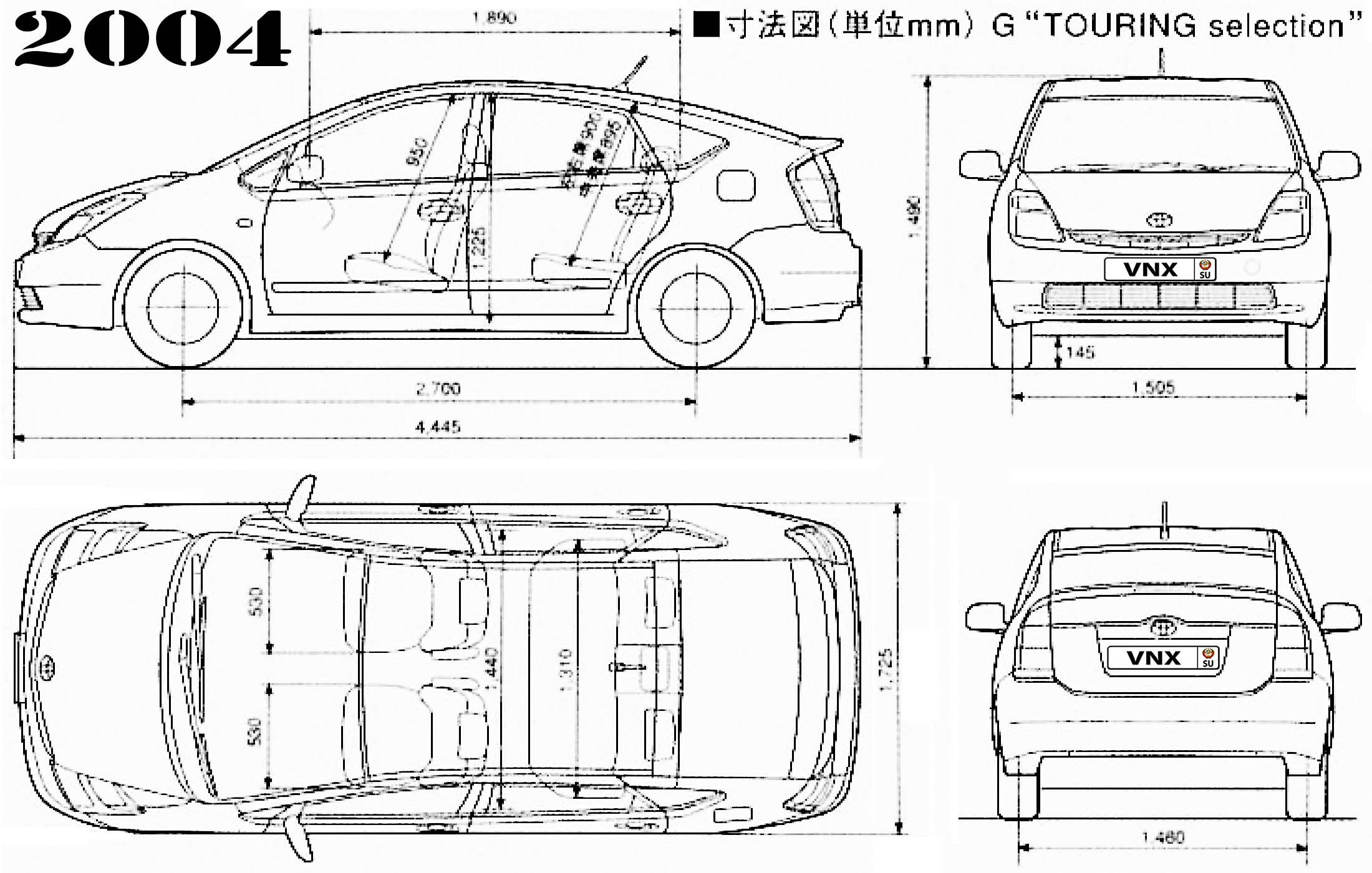
| № | Спецификация / Specs | Данные |
| Габариты (мм/mm) и масса (кг/kg) / Dimensions and Weight | ||
| 1 | Длина / Length | 4445 |
| 2 | Ширина (без/с зеркалами) / Width | 1725 |
| 3 | Высота (загружен/пустой) / Height | 1490 |
| 4 | Колёсная база / Wheelbase | 2700 |
| 5 | Дорожный просвет (клиренс) / Ground clearance | 145 |
| 6 | Снаряжённая масса / Total (curb) weight | 1270 |
| Полная масса / Gross (max.) weight | 1545 | |
|
Двигатель / Engine |
||
| 7 | Тип / Engine Type, Code | Гибридный, бензиновый, жидкостного охлаждения, четырехтактный, 1NZ-FXE и электрический 3CM MG2 |
| 8 | Количество цилиндров / Cylinder arrangement: Total number of cylinders, of valves | 4-цилиндровый, рядный, 16V, DOHC с верхним расположением двух распределительных валов |
| 9 | Диаметр цилиндра / Bore | 75.0 мм |
| 10 | Ход поршня / Stroke | 84.7 мм |
| 11 | Объём / Engine displacement | 1496 см³ |
| 12 | Система питания / Fuel supply, Aspiration | Распределенный впрыск топлива EFI |
| Атмосферный | ||
| 13 | Степень сжатия / Compression ratio | 13.0:1 |
| 14 | Максимальная мощность / Max. output power kW (HP) at rpm | 57 кВт (77 л.с.) при 5000 об/мин, электрический 68 л.с./50 кВт при 1200-1540 об/мин, Синергетический режим: 111.5 л.с./82 кВт |
| 15 | Максимальный крутящий момент / Max. torque N·m at rpm | 115 Нм при 4200 об/мин, электрический 400 Нм при 0-1200 об/мин |
|
Трансмиссия / Transmission |
||
| 16 | Сцепление / Clutch type | Устройство распределения мощности PSD (Power Split Device) |
| 17 | КПП / Transmission type | P112 Планетарная передача (Continuously Variable Transmission CVT — Бесступенчатый Вариатор) |
О Книге
- Название: Toyota Prius Устройство, техническое обслуживание и ремонт
- Бензиновые двигатели: 1NZ-FXE 1.5 л (1496/1497 см³) 76-77 л.с./56-57 кВт и электрическими мотор-генераторами MG1 25 л.с./18 кВт, 3CM MG2 68 л.с./50 кВт
- Выпуск с 2003 года
- Серия: «Ремонт Автомобилей»
- Год издания: 2009
- Автор: Коллектив авторов
- Издательство: «Ассоциация независимых издателей»
- Формат: PDF
- Страниц в книге: 572
- Размер: 423.66 МБ
- Язык: Русский
- Количество электросхем: более 50

-
Contents
-
Table of Contents
-
Bookmarks
Quick Links
To assist you in your service activities, this manual explains the main characteristics of the 2006 PRIUS, in
particular providing a technical explanation of the construction and operation of new mechanisms and new
technology used.
This manual is divided into 3 sections.
1. Introduction — Changed features and model line-up are explained.
2. New Features — Technical explanation of the construction and operation of each new system and
component.
3. Appendix — Major technical specifications of the vehicle.
CAUTION, NOTICE, REFERENCE and NOTE are used in the following ways:
CAUTION
NOTICE
REFERENCE
NOTE
For detailed service specifications and repair procedures, refer to the following Repair Manuals:
» 2006 PRIUS Repair Manual
» 2006 PRIUS Electrical Wiring Diagram
All information contained herein is the most up-to-date at the time of publication. We reserve the right to make
changes without prior notice.
2005
TOYOTA MOTOR CORPORATION
All rights reserved. This book may not be repro-
duced or copied., in whole or in part, without the
written permission of Toyota Motor Corporation.
First Printing: Nov. 7, 2005 01-051107-00
FOREWORD
Applicable models: NHW20 series
A potentially hazardous situation which could result in injury if instructions are
ignored.
Damage to the vehicle or components may occur if instructions are ignored.
Explains the theory behind mechanisms and techniques.
Notes or comments not included under the above 3 titles.
Manual Name
Pub. No.
RM01R0U
EM01R0U
Summary of Contents for Toyota 2006 PRIUS
18
Руководство по эксплуатации
ВНИМАНИЕ: при проведении работ в салоне автомобиля, оборудованного системой подушек безопасности и
преднатяжителей ремней (система «SRS»), следует быть особенно внимательными, чтобы не повредить блок
управления системы «SRS». Во избежание случайного срабатывания подушек безопасности или преднатяжи-
телей ремней, перед началом работ установите колеса в положение прямолинейного движения и замок зажи-
гания в положение «LOCK», отсоедините провод от отрицательной клеммы вспомогательной аккумуляторной
батареи и подождите не менее 90 секунд (время разряда резервного питания). Не пытайтесь разбирать узел
подушки безопасности или узел преднатяжителя ремня, т.к. в данных узлах нет деталей, требующих обслужи-
вания. Если подушки безопасности и/или преднатяжители ремней срабатывали (разворачивались), то их
нельзя отремонтировать или использовать повторно.
Общие сведения
и советы по эксплуатации
гибридного автомобиля
Ваш автомобиль является гибридным
и при движении использует энергию,
получаемую как от двигателя внут-
реннего сгорания (ДВС), так и от элек-
тродвигателя, работающего на высо-
ковольтной батарее (ВВБ), обеспечи-
вая оптимальный расход топлива и
экологичность автомобиля.
Зарядка высоковольтной батареи
осуществляется во время движения
автомобиля или при работе двигателя
на холостом ходу.
Внимание: максимальный заряд высо-
ковольтной батареи является по-
стоянным значением. Зарядка ВВБ
свыше этого значения невозможна.
Примечание:
— Поскольку высоковольтная бата-
рея заряжается по мере необходи-
мости во время движения или при
работающем двигателе, ее не
требуется заряжать от внешней
сети.
— Если не запускать двигатель ав-
томобиля более двух недель, это
может привести к разрядке высо-
ковольтной батареи и уменьшению
ее емкости. Поэтому, каждые две
недели рекомендуется хотя бы раз
запускать двигатель и оставлять
его запущенным при выключенных
потребителях электроэнергии
(осветительные приборы, магни-
тола, кондиционер и т.д.) не менее
чем на 30 минут.
Используемая энергия в
зависимости от условий движения
Примечание: в зависимости от усло-
вий движения автомобиля на много-
функциональном дисплее в режиме
«Energy Monitor» отображается схема
распределения энергии от ДВС и
электродвигателя.
1. При запуске двигателя и движении
задним ходом автомобиль работает на
электродвигателе и использует энер-
гию от высоковольтной батареи.
2. При равномерном ускорении или
движении с постоянной скоростью ав-
томобиль работает на ДВС, однако в
зависимости от условий движения к
работе ДВС может подключаться и
электродвигатель, использующий в
данный момент энергию от генератора
автомобиля. Система управления гиб-
ридной установкой обеспечивает оп-
тимальное соотношение используе-
мой энергии от ДВС и электродвига-
теля для снижения расхода топлива и
токсичности автомобиля, не влияя при
этом на динамические характеристики
автомобиля.
3. При движении на максимальных обо-
ротах коленчатого вала автомобиль ра-
ботает одновременно как на ДВС, так и
на электродвигателе, работающем на
высоковольтной батарее, обеспечивая
максимальную динамику автомобиля.
4. При нажатии на педаль тормоза или
замедлении автомобиля, электродви-
гатель работает как генератор и про-
исходит зарядка высоковольтной ба-
тареи (эффект «рекуперативных» тор-
мозов).
«, £
5. При остановке автомобиля ДВС ав-
томатически выключается и автомо-
биль работает на энергии от электро-
двигателя, работающего на высоко-
вольтной батарее.
Советы по повышению
эффективности использования
гибридного автомобиля
1. Плавно нажимайте на педаль аксе-
лератора, а также плавно отпускайте
педаль.
Примечание:
— Избегайте резкого увеличения или
уменьшения скорости автомобиля.
— Помните, что при спокойной ма-
нере движения (при плавном уско-
рении или снижении скорости) ав-
томобиль может работать без
использования ДВС только на
электродвигателе.
Руководство по эксплуатации
19
2. Во время движения убедитесь, что
селектор трансмиссии установлен в
положение «D». При парковке автомо-
биля всегда нажимайте на выключа-
тель режима «Р» трансмиссии.
Примечание: если селектор транс-
миссии установлен в положение «N»,
зарядка ВВБ не осуществляется.
Более того, продолжительная рабо-
та двигателя при положении «N» се-
лектора трансмиссии может при-
вести к разрядке высоковольтной
батареи.
Режим «EV» движения автомобиля
Внимание: при полном уровне заряда
высоковольтной батареи и обычных
условиях движения, в режиме «EV» ав-
томобиль может проехать около двух
километров. Движение на большее
расстояние при работе автомобиля в
режиме «EV» приведет к критическому
разряду ВВБ, что, в свою очередь,
приведет к безвозвратному уменьше-
нию емкости батареи и невозможно-
сти ее дальнейшей эксплуатации.
Движение автомобиля в режиме «EV»
осуществляется только за счет элек-
троэнергии от высоковольтной бата-
реи, при этом ДВС отключен. Поэтому
данный режим рекомендуется исполь-
зовать при постановке автомобиля в
гараж или движения в недостаточно
вентилируемых помещениях, где не
желательно присутствие выхлопных
газов. Также, в данном режиме значи-
тельно уменьшается шум от автомо-
биля, что актуально при движении по
парковой или дворовой территории.
Внимание: во время движения в дан-
ном режиме ДВС отключен полно-
стью и не участвует ни в движении
автомобиля, ни в подзарядке высоко-
вольтной батареи.
Для включения режима нажмите на
выключатель, расположение которого
показано на рисунке. При этом на
комбинации приборов загорится соот-
ветствующий индикатор.
Выключатель “EV”
I___’)
Примечание:
— В следующих случаях включение
режима «EV» будет невозможно:
— При высокой температуре ком-
понентов гибридной установки.
— При низкой температуре компо-
нентов гибридной установки.
— При температуре охлаждающей
жидкости, близкой к перегреву.
— При уровне заряда высоковольт-
ной батареи, равном трем пунк-
там или меньше.
— При скорости автомобиля более
55 км/ч.
— При сильном нажатии на педаль
акселератора.
— При использовании обогревате-
ля стекла задней двери и т.д.
— Поскольку включение режима «EV»
возможно только на прогретом
автомобиле, включение режима в
холодную погоду осуществляется
либо после того, как перестанет
мигать индикатор «READY”
(свидетельствует о готовности
автомобиля к движению), либо до
запуска двигателя. При этом вы-
ключите все ненужные электро-
приборы и убедитесь, что ВВБ за-
ряжена полностью.
При повторном нажатии на выключа-
тель, режим «EV» отключается и авто-
мобиль продолжает движение, работая
как на ДВС так и на электродвигателе.
Переход автомобиля в режим обычного
движения сопровождается отображе-
нием информационного сообщения на
многофункциональном дисплее и зву-
чанием «зуммера».
Если во время движения автомобиля
в данном режиме звучит звуковой сиг-
нал и индикатор режима «EV» мигает
три раза, а затем гаснет, это свиде-
тельствует о том, что система управ-
ления гибридной установкой автома-
тически отключала режим «EV» для
избежания полной разрядки высоко-
вольтной батареи. Автоматическое
отключение режима происходит в
следующих случаях:
— Если уровень заряда высоковольт-
ной батареи снизился до двух пунк-
тов.
— Если скорость автомобиля более
55 км/ч.
— При сильном нажатии на педаль
акселератора.
Обратите особое внимание
1. Во время движения ДВС включает-
ся и выключается автоматически в за-
висимости от условий движения. В
следующих случаях ДВС может не вы-
ключиться автоматически:
— При перегреве двигателя.
— Во время зарядки высоковольтной
батареи.
— При высокой или низкой темпера-
туре высоковольтной батареи.
2. Поскольку Ваш автомобиль осна-
щен как ДВС, так и электродвигателем
с высоковольтной батареей, некото-
рые узлы автомобиля представляют
собой особую опасность и при недос-
таточном внимании и неправильном
обслуживании могут причинить серь-
езные травмы, ожоги и даже стать
причиной смерти.
Внимание: узлы и агрегаты, а также
соединительные кабели гибридной
установки, приведенные на рисунке
«Компоненты автомобиля, находя-
щиеся под высоким напряжением»,
представляют собой наибольшую
опасность для жизни человека.
— Не прикасайтесь и не пытайтесь
произвести какие-либо подключения
к кабелям высокого напряжения или
клеммам высоковольтной батареи.
Клеммы ВВБ и кабели высокого на-
пряжения (более 200 В), окрашен-
ные в оранжевый цвет, представля-
ют собой наибольшую опасность
для жизни.
— На электродвигателе автомобиля,
электровентиляторе радиатора и на
некоторых других компонентах авто-
мобиля имеются информационные
таблички и этикетки, предупреждаю-
щие о возможной опасности при об-
служивании или проверке данного
компонента, поскольку во время дви-
жения автомобиля они нагреваются
до очень высоких температур.
— Не разбирайте, не демонтируйте,
не усовершенствуйте высоковольт-
ную батарею, кабели высокого на-
пряжения и другие компоненты, на-
ходящиеся под напряжением.
— Не прикасайтесь к аварийному вы-
ключателю ВВБ, расположенному в
левой боковой отделке багажного
отделения. Данный выключатель
предназначен для отключения по-
дачи напряжения от высоковольтной
батареи при ремонте и обслужива-
нии автомобиля.
3. Помните, что когда автомобиль ра-
ботает на электродвигателе, он почти
не производит шума работы двигателя,
тем более характерного для автомоби-
лей с ДВС. Ошибочное суждение лю-
дей, находящихся в непосредственной
близости от Вашего автомобиля, о том,
что автомобиль не работает, может
стать причиной аварии или причинения
вреда окружающим людям.
4. Всегда покидайте автомобиль толь-
ко после того, как убедитесь, что на-
жат выключатель режима «Р» транс-
миссии или селектор установлен в по-
ложение «N».
5. С правой стороны заднего сиденья
установлены воздуховоды, через ко-
торые осуществляется забор воздуха
для охлаждения высоковольтной ба-
тареи. Перед началом движения убе-
дитесь, что дефлекторы воздуховодов
не заслонены багажом или иным гру-
зом, пассажиры заднего сиденья не
ограничивают доступ воздуха к возду-
ховодам, ремни безопасности заднего
сиденья убраны в предназначенные
для них крепления. Ограничение за-
бора воздуха может привести к пере-
греву высоковольтной батареи и стать
причиной серьезных неисправностей.
6. В случае, если Вы попали в аварию,
для уменьшения риска удара током от
компонентов автомобиля, выполните
следующие действия:
а) Нажмите на педаль стояночного
тормоза.
Get your hands on the complete Toyota factory workshop software
IN-26
INTRODUCTION
ABBREVIATIONS USED IN THIS MANUAL
For convenience, the following abbreviations are used in this
manual.
ABS
Antilock Brake System
A/C
Air Conditioner
assy
assembly
ECT
Electronic Controlled Transmission
ECU
Electronic Control Unit
e.g.
Exempli Gratia (for Example)
Ex.
Except
FWD
Front Wheel Drive Vehicles
2WD
Two Wheel Drive Vehicles
4WD
Four Wheel Drive Vehicles
in.
inch
LH
Left-hand
LHD
Left-hand Drive
MIG
Metal Inert Gas
M/Y
Model Year
PPS
Progressive Power Steering
RH
Right-hand
RHD
Right-hand Drive
SRS
Supplemental Restraint System
SSM
Special Service Materials
w/
with
w/o
without
INTRODUCTION
IN-18
FOR ALL OF VEHICLES
PRECAUTION
1.
Service Plug
F13391
WRONG
PRECAUTIONS FOR HIGH-VOLTAGE CIRCUIT INSPECTION
AND SERVICE
(a) Engineer must undergo special training for high-voltage
system inspection and servicing.
(b) All high-voltage wire harness connectors are colored
orange. The HV battery and other high-voltage components have ”High Voltage” caution labels. Do not carelessly
touch these wires and components.
(c) Before inspecting or servicing the high-voltage system, be
sure to follow safety measures, such as wearing insulated
gloves and removing the service plug to prevent electrocution. Carry the removed service plug in your pocket to prevent other technicians from reinstalling it while you are
servicing vehicle.
(d) After removing the service plug, wait 5 minutes before
touching any of the high-voltage connectors and terminals.
HINT:
5 minutes are required to discharge the high-voltage condenser inside the inverter.
(e) Be sure install the service plug before starting the hybrid
system. Starting the hybrid system with the service plug removed may damage the vehicle.
(f) Before wearing insulated gloves, make sure that they are
not cracked, ruptured, torn, or damaged in any way. Do not
wear wet insulated gloves.
(g) When servicing the vehicle, do not carry metal objects like
mechanical pencils or scales that can be dropped accidentally and cause a short circuit.
(h) Before touching a bare high-voltage terminal, wear insulated gloves and use an electrical tester to ensure that the
terminal is not charged with electricity (approximately 0 V).
F13392
(i)
(j)
(k)
(l)
F13393
After disconnecting or exposing a high-voltage connector
or terminal, insulate it immediately using insulation tape.
The screw of a high-voltage terminal should be tightened
firmly to the specified torque. Both insufficient and excessive torque can cause failure.
Use the ”CAUTION: HIGH VOLTAGE. DO NOT TOUCH
DURING OPERATION” sign to notify other engineers that a
high-voltage system is being inspected and/or repaired.
Do not place the battery upside down while removing and
installing it.
INTRODUCTION
IN-19
(m) After servicing the high-voltage system and before reinstalling the service plug, check again that you have not left a
part or tool inside, that the high-voltage terminal screws are
firmly tightened, and that the connectors are correctly connected.
IN-20
INTRODUCTION
CAUTION:
HIGH VOLTAGE. DO
NOT TOUCH DURING
OPERATION.
Person in charge:
Copy this page and put it after folding on the roof of the vehicle in service.
F13394
INTRODUCTION
2.
IN-21
ACTIONS TO BE TAKEN FOR VEHICLE DAMAGED BY
IMPACT
(a) Items to be prepared or operation at the site of the accident
Protective clothing (insulated gloves, rubber gloves,
goggles, and safety shoes)
Saturated boric acid solution 20 L (obtain 800 g of boric acid powder, put it into a container, and dissolve it in
water)
Red litmus paper
ABC fire extinguisher (effective against both oil flames
and electrical flames)
Shop rags (for wiping off the electrolyte)
Vinyl tape (for insulating cable)
Electrical tester
(b) Actions to be taken at the place of accident
(1) Wear insulated or rubber gloves, goggles and safety
shoes.
(2) Do not touch a bare cable that could be a high voltage
cable. If the cable must be touched or if accidentalcaontact is unavoidable, follow these instructions: 1)
wear insulated or rubber gloves and goggles, 2) measure the voltage between the cable and the body
ground using an electrical tester, and 3) insulate the
cable using vinyl tape.
(3) If the vehicle catches fire, use an ABC fire extinguisher
to extinguish the fire. Trying to extinguish a fire using
only a small amount of water can be more dangerous
than effective. Use a substantial amount of water or
wait for firefighters.
(4) Check the HV battery and immediate area for any
electrolyte leakage. Do not touch any leaked liquid because it could be highly alkaline electrolyte. Wear rubber gloves and goggles, and then apply red litmus paper to the leak. If the paper turns blue, the liquid must
be neutralized before wiping. Neutralize the liquid using the following procedures:
1) apply saturated boric acid solution to the liquid, and
2) reapply red litmus paper and make sure it does not
turn blue. Repeat steps 1 and 2 above until the paper
does not turn blue. Then wipe the neutralized liquid
with a shop rag.
(5) If a damage to any of the high-voltage components
and cables is suspended, cut the high-voltage circuit
using the procedure on the following pages.
INTRODUCTION
IN-22
High–voltage part and Wiring
HV Battery
Inverter and Converter
Power Cable
A/C Compressor
Hybrid Transaxle
B76085
Service Plug
F13396
Push the shift switch to the P position and engage the parking brake.
Remove the key from the key slot. Then disconnect the power cable from the negative (–) terminal of the auxiliary battery.
Remove the service plug while wearing insulated
gloves. If the service plug cannot be removed
due to damage to the rear portion of the vehicle,
remove the HV fuse instead.
Do not turn the power switch on whicle removing
the service plug.
INTRODUCTION
IN-23
If the service plug cannot be removed due to damage to the rear
portion of the vehicle, remove the HV fuse instead.
(c) Moving the damaged vehicle
HINT:
If any of the following applies, tow the vehicle away using a
tow truck.
One or more of the high-voltage components and
cables are damaged.
The driving, traction, or fuel system is damaged.
Engine Room J/B
Power Integration
HV Fuse
F13397
F13398
The READY lamp is not illuminated when you turn.
NOTICE:
Before towing the vehicle away using a tow truck,
disconnect the cable from the negative (–) terminal of the auxiliary battery and remove the service
plug.
Only if none of the above applies and there are no
problems that might affect driving, drive the vehicle away from the place of accident to a safe,
nearby place.
Perform the procedure below if the READY lamp
turns off, or there are abnormal noises, unusual
smells, or strong vibrations while driving:
(1) Park the vehicle in a safe place.
(2) Push the selector lever to the P position and engage the parking brake.
(3) Disconnect the power cable from the negative (–)
terminal of the auxiliary battery.
(4) Remove the service plug while wearing insulated
gloves.
(d) Actions required after moving the damaged vehicle
If you see any liquid on the road surface, it could be highly
alkaline electrolyte leakage.
Wear rubber gloves and goggles, and apply red litmus paper to the leak. If the paper turns blue, the liquid must be
neutralized befor wiping. Neutralize the liquid using the following procedures: 1) apply saturated boric acid solution to
the liquid, and 2) reapply red litmus paper and make sure it
does not turn blue. Repeat steps 1 and 2 above until the paper does not turn blue. Then wipe the neutralized liquid with
a shop rag.
IN-24
INTRODUCTION
(e) Items to be prepared (when repairing damaged vehicles)
Protective clothing (Insulated gloves, rubber gloves,
goggles, and safety shoes)
Saturated boric acid solution 20 L (obtain 800 g of boric acid powder, put it into a container, and dissolve it in
water)
Red litmus paper
Shop rags (for wiping off the electrolyte)
Vinyl tape (for insulating cable)
Electrical tester
(f) Precautions to be observed when servicing the damaged
vehicle:
(1) Wear insulated or rubber gloves, goggles, and safety
shoes.
(2) Do not touch a bare cable that could be a high voltage
cable. If the cable must be touched or if accidental
contact is unavailable, follow these instructions: 1)
wear insulated or rubber gloves and goggles, 2) measure the voltage between the cable and the body
ground using an electrical tester, and 3) insulate the
cable using vinyl tape.
(3) Check the HV battery and immediate area for any
electrolyte leakage. Do not touch any leaked liquid because it could be highly alkaline electrolyte. Wear rubber gloves and goggles, and then apply red litmus paper to the leak. If the paper turns blue, the liquid must
be neutralized before wiping. Neutralize the liquid using the following procedures:
1) apply saturated boric acid solution to the liquid, and
2) reapply red litmus paper and make sure it does not
turn blue. Repeat steps 1 and 2 above until the paper
does not turn blue, Then wipe the neutralized liquid
with a shop rag.
(4) If the electrolyte adheres to your skin, wash the skin
immediately using saturated boric acid solution or a
large amount of water. If the electrolyte adheres to an
article of clothing, take it off immediately.
(5) If the electrolyte comes in contact with your eyes, call
out loudly for help. Do not rub your eyes. Wash them
with the large amount of water and seek medical care.
(6) If damage to any of the high-voltage components and
cables is suspected, cut the high-voltage circuit using
the procedure below.
Push the selector lever to the P position and engage the parking brake.
Remove the key from the key slot. Then disconnect the power cable from the negative (–) terminal of the auxiliary battery.
INTRODUCTION
IN-25
Wear insulated gloves, and then remove the service plug.
If you connot remove the service plug due to
damage to the rear portion of the vehicle, remove
the HV fuse or IGCT relay instead.
(g) Precautions to be taken when disposing of the vehicle
When scrapping the vehicle, remove the HV battery from
the vehicle and return it to the location specified by the
manufacturer. The same applies to any damaged HV battery.
(h) After removing the battery, keep it away from water. Water
may heat the battery, which results in fire.
(i) Precautions to be observed when towing
Tow the damaged vehicle with its front wheels or its front
and rear wheels lifted off the ground.
NOTICE:
Towing the damaged vehicle with its front wheels on the
ground may cause the motor to generate electricity. This
electricity could, depending on the nature of the damage,
leak and cause a fire.
(j) Towing with 4 wheels on the ground
NOTICE:
If the damaged vehicle needs to be towed using a rope,
do not exceed 30 km/h and tow only for very short distances. For example, towing from the accident site to a
nearby tow truck is permissible.
Set the power switch on and selector lever to the N
position.
If any abnormalityis present in the damaged vehicle
during the towing, stop towing immediately.
(k) Towing eyelet
(1) Install the hook.
(2) Hook a rope on to the illustrated area for towing.
F13399
BP-26
BODY PANEL REPLACEMENT
COWL TOP INNER SIDE PANEL (ASSY)
REPLACEMENT
F16146-A
REMOVAL
F16146
POINT
1
Remove the [A] the same time.
PART NAME
[A] Front Apron To Cowl Sidemember Plate
BODY PANEL REPLACEMENT
BP-27
INSTALLATION
Temporarily install the new parts and measure each part of the new parts in accordance with the body dimension
diagram. (See the body dimension diagram)
Inspect the fitting of the related parts around the new parts before welding. This affects the appearance of the
finish.
After welding, apply the polyurethane foam to the corresponding parts.
After welding, apply body sealer and under-coating to the corresponding parts.
After applying the top coat layer, apply anti-rust agent to the inside of the necked section structural weld spots.
F16147
POINT
1
Inspect the fitting of the front fender and hood, etc., before welding, since this affects the appearance of the finish.
PART NAME
[A] Front Apron To Cowl Sidemember Plate
15mm (0.59in.)
[B]
Hood Damper Mounting Bracket
BP-24
BODY PANEL REPLACEMENT
COWL TOP SIDE PANEL (ASSY)
REPLACEMENT
F16144-A
REMOVAL
F16144
BODY PANEL REPLACEMENT
BP-25
F16145
15mm (0.59in.)
30mm (1.18in.)
FOREWORD
This repair manual has been prepared to provide essential information on body panel repair methods (including cutting and
welding operations, but excluding painting) for the TOYOTA
PRIUS.
Applicable models: NHW 20 series
This manual consists of body repair methods, exploded diagrams and illustrations of the body components and other information relating to body panel replacement such as handling
precautions, etc. However, it should be noted that the front fenders of the TOYOTA model is bolted on and require no welding.
When repairing, don’t cut and join areas that are not shown in
this manual. Only work on the specified contents to maintain
body strength.
Body construction will sometimes differ depending on specifications and country of destination. Therefore, please keep in mind
that the information contained herein is based on vehicles for
general destinations.
For the repair procedures and specifications other than collisiondamaged body components of the TOYOTA PRIUS refer to the
repair manuals.
If you require the above manuals, please contact your TOYOTA
Dealer.
All information contained in this manual is the most up-to-date at
the time of publication. However, specifications and procedures
are subject to change without prior notice.
NOTE: The Vehicle Lift and Support Locations sections
and For Vehicles Equipped With SRS Airbag and Seat
Belt Pretensioner sections refer to the TOYOTA PRIUS
Repair Manual.
BODY PANEL REPLACEMENT
BP-17
FRONT FENDER APPON (ASSY)
REPLACEMENT
With the radiator upper support and cowl top side panel removed.
F16137-A
REMOVAL
F16137
BP-18
BODY PANEL REPLACEMENT
INSTALLATION
Temporarily install the new parts and measure each part of the new parts in accordance with the body dimension
diagram. (See the body dimension diagram)
Inspect the fitting of the related parts around the new parts before welding. This affects the appearance of the
finish.
After welding, apply the polyurethane foam to the corresponding parts.
After welding, apply body sealer and under-coating to the corresponding parts.
After applying the top coat layer, apply anti-rust agent to the inside of the necked section structural weld spots.
F16138
POINT
1
Make sure each measurement is correct, as this parts affects the front wheel alignment.
2
Inspect the fitting of the front fender and hood, etc., before welding, since this affects the appearance of the
finish.
13mm (0.51in.)
15mm (0.59in.)
BP-14
BODY PANEL REPLACEMENT
FRONT FENDER APRON FRONT WITH
SUPPORT (ASSY)
REPLACEMENT
With the radiator upper support removed.
F16134-A
REMOVAL
F16134
BODY PANEL REPLACEMENT
BP-15
INSTALLATION
Temporarily install the new parts and measure each part of the new parts in accordance with the body dimension
diagram. (See the body dimension diagram)
Inspect the fitting of the related parts around the new parts before welding. This affects the appearance of the
finish.
After welding, apply the polyurethane foam to the corresponding parts.
After welding, apply body sealer and under-coating to the corresponding parts.
After applying the top coat layer, apply anti-rust agent to the inside of the necked section structural weld spots.
F16135
POINT
1
Inspect the fitting of the front fender and hood, etc., before welding, since this affects the appearance of the
finish.
BP-16
BODY PANEL REPLACEMENT
F16136
POINT
1
These values are reference values.
145mm (5.71in.)
157mm (6.18in.)
330mm (12.99in.)
372mm (14.65in.)
BODY DIMENSIONS
Three-dimensional
distance
Center-to-center
straight-line
distance
DI-1
GENERAL INFORMATION
1.
BASIC DIMENSIONS
(a) There are two types of dimensions in the diagram.
(1) (Three-dimensional distance)
Straight-line distance between the centers of two
measuring points.
Two-dimensional
distance
Vertical distance
in center
Center-to-center
Horizontal distance
in forward / rearward
Vertical distance
in lower surface
Imaginary Standard Line
Under Surface of
The Rocker Panel
(2) (Two-dimensional distance)
Horizontal distance in forward/rearward between the
centers of two measuring points.
The height from an imaginary standard line.
(b) In cases in which only one dimension is given, left and right
are symmetrical.
(c) The dimensions in the following drawing indicate actual distance. Therefore, please use the dimensions as a reference.
(d) The line that connects the places listed below is the imaginary standard line when measuring the height. (The dimensions are printed in the text.)
SYMBOL
Name
1
The place that was lowered A mm from the under surface of
the rocker panel centered on the front jack up point.
2
The place that was lowered B mm from the under surface of
the rocker panel centered between 1 and 3.
3
The place that was lowered C mm from the under surface of
the rocker panel centered on the rear jack up point.
Imaginary Standard Line
BODY DIMENSIONS
DI-2
Plate Looseness
Body Looseness
Pointer Looseness
2.
MEASURING
(a) Basically, all measurements are to be done with a tracking
gauge. For portions where it is not possible to use a tracking gauge, a tape measure should be used.
(b) Use only a tracking gauge that has no looseness in the
body, measuring plate, or pointers.
Pointer
Master Gauge
Wrong
Correct
Pointer
HINT:
1) The height of the left and right pointers must be equal.
2) Always calibrate the tracking gauge before measuring
or after adjusting the pointer height.
3) Take care not to drop the tracking gauge or otherwise
shock it.
4) Confirm that the pointers are securely in the holes.
(c) When using a tape measure, avoid twists and bends in the
tape.
INTRODUCTION
IN-1
GENERAL REPAIR INSTRUCTIONS
1.
WORK PRECAUTIONS
(a) VEHICLE PROTECTION
(1) When welding, protect the painted surfaces, windows,
seats and carpet with heat resistant, fire-proof covers.
Glass Cover
Seat Cover
F10001A
(b) SAFETY
(1) Never stand in direct line with the chain when using a
puller on the body or frame, and be sure to attach a
safety cable.
WRONG
F10002A
(2) Before performing repair work, check for fuel leaks.
If a leak is found, be sure to close the opening totally.
(3) If it is necessary to use a flame in the area of the fuel
tank, first remove the tank and plug the fuel line.
WRONG
F10003A
(c)
F10004
SAFETY WORK CLOTHES
(1) In addition to the usual mechanic’s wear, cap and
safety shoes, the appropriate gloves, head protector,
glasses, ear plugs, face protector, dust-prevention
mask, etc. should be worn as the situation demands.
Code
Name
A
Dust-Prevention Mask
B
Face Protector
C
Eye Protector
D
Safety Shoes
E
Welder’s Glasses
F
Ear Plugs
G
Head Protector
H
Welder’s Gloves
INTRODUCTION
IN-2
2.
HANDLING PRECAUTIONS OF PLASTIC BODY PARTS
(1) The repair procedure for plastic body parts must conform with the type of plastic material.
(2) Plastic body parts are identified by the codes in the following table.
(3) When repairing metal body parts adjoining plastic body parts (by brazing, frame cutting, welding, painting etc.), consideration must be given to the property of the plastic.
Code
Material
name
Heat*
resistant
temperature
limit C (F)
Resistance to
alcohol or gasoline
Notes
AAS
Acrylonitrile
Acrylic Styrene
80
(176)
Alcohol is harmless if applied only for
short time in small amounts (e.g., quick
wiping to remove grease).
Avoid gasoline and organic
or aromatic solvents.
ABS
Acrylonitrile
Butadiene Styrene
80
(176)
Alcohol is harmless if applied only for
short time in small amounts (e.g., quick
wiping to remove grease).
Avoid gasoline and organic
or aromatic solvents.
AES
Acrylonitrile
Ethylene Styrene
80
(176)
Alcohol is harmless if applied only for
short time in small amounts (e.g., quick
wiping to remove grease).
Avoid gasoline and organic
or aromatic solvents.
ASA
Acrylonitrile
Styrene
Acrylate
80
(176)
Alcohol is harmless if applied only for
short time in small amounts (e.g., quick
wiping to remove grease).
Avoid gasoline and organic
or aromatic solvents.
CAB
Cellulose
Acetate
80
(176)
Alcohol is harmless if applied only for
short time in small amounts (e.g., quick
wiping to remove grease).
Avoid gasoline and organic
or aromatic solvents.
EPDM
Ethylene
Propylene
100
(212)
Alcohol is harmless.
Gasoline is harmless if applied only for
short time in small amounts.
Most solvents are harmless
but avoid dipping in gasoline,
solvents, etc.
FRP
Fiber
Reinforced
Plastics
180
(356)
Alcohol and gasoline are harmless.
Avoid alkali.
EVA
Ethylene
Acetate
70
(158)
Alcohol is harmless if applid only for short
time in small amounts (e.g., quick wiping
to remove grease).
Avoid gasoline and organic
or aromatic solvents.
Polyamide
(Nylon)
80
(176)
Alcohol and gasoline are harmless.
Avoid battery acid.
PBT
Polybutylene
Terephthalate
160
(320)
Alcohol and gasoline are harmless.
Most solvents are harmless.
PC
Polycarbonate
120
(248)
Alcohol is harmless.
Avoid gasoline brake fluid,
wax, wax removers and
organic solvents. Avoid alkali.
PA
*Temperatures higher than those listed here may result in material deformation during repair.
INTRODUCTION
Code
Material
name
Heat*
resistant
temperature
limit C (F)
Resistance to
alcohol or gasoline
IN-3
Notes
PE
Polyethylene
80
(176)
Alcohol and gasoline are harmless.
Most solvents are harmless.
PET
Polyethylene
Terephthalate
75
(167)
Alcohol and gasoline are harmless.
Avoid dipping in water.
PMMA
Polymethyl
Methacrylate
80
(176)
Alcohol is harmless if applied only for
short time in small amounts.
Avoid dipping or immersing
in alcohol, gasoline,
solvents, etc.
Polyoxymethylene
(Polyacetal)
100
(212)
Alcohol and gasoline are harmless.
Most solvents are harmless.
PP
Polypropylene
80
(176)
Alcohol and gasoline are harmless.
Most solvents are harmless.
PPO
Modified
Polyphenylene
Oxide
100
(212)
Alcohol is harmless.
Gasoline is harmless if
applied only for quick wiping
to remove grease.
Polystyrene
60
(140)
Alcohol and gasoline are harmless if
applied only for short time in small
amounts.
Avoid dipping or immersing
in alcohol, gasoline,
solvents, etc.
PUR
Polyurethane
80
(176)
Alcohol is harmless if applied only for very
short time in small amounts (e.g., quick
wiping to remove grease).
Avoid dipping or immersing
in alcohol, gasoline,
solvents, etc.
PVC
Polyvinylchloride
(Vinyl)
80
(176)
Alcohol and gasoline are harmless if
applied only for short time in small
amounts (e.g., quick wiping to remove
grease).
Avoid dipping or immersing
in alcohol, gasoline,
solvents, etc.
SAN
Styrene
Acrylonitrile
80
(176)
Alcohol is harmless if applied only for
short time in small amounts (e.g., quick
wiping to remove grease).
Avoid dipping or immersing
in alcohol, gasoline, solvents
etc.
TPO
Thermoplastic
Olefine
80
(176)
Alcohol is harmless.
Gasoline is harmless if applied only for
short time in small amounts.
Most solvents are harmless
but avoid dipping in gasoline,
solvents, etc.
TPU
Thermoplastic
Polyurethane
80
(176)
Alcohol is harmless if applied only for
short time in small amounts (e.g., quick
wiping to remove grease).
Avoid dipping or immersing
in alcohol, gasoline,
solvents, etc.
TOYOTA
Super
Olefine Polymer
80
(176)
Alcohol and gasoline are harmless.
Most solvents are harmless.
Unsaturated
Polyester
110
(233)
Alcohol and gasoline are harmless.
Avoid alkali.
POM
PS
TSOP
UP
*Temperatures higher than those listed here may result in material deformation during repair.
INTRODUCTION
IN-4
3.
LOCATION OF PLASTIC BODY PARTS
Parts Name
Code
Radiator Grille
TSOP
Front Bumper Cover
TSOP
Headlight
PP/PC
Front Foglight
PC
Side Turn Signal Light
ABS/PMMA
Outer Rear View Mirror
ABS
Door Outside Handle
PC/PBT
Window Frame Moulding
ASA
Rear Door Rear Guide Seal
AES
Side Mudguard
TSOP
Rear Spoiler
ABS
High Mount Stop Light
ABS/PMMA
Back Door Outside Garnish
ABS
Rear Combination Light
ASA/PMMA
Rear Bumper Cover
TSOP
Rear No.1 Spoiler
PP/EPDM
Rear Side Spoiler
PP/EPDM
License Plate Light
PC
Resin material differs with model.
/ Made up of 2 or more kinds of materials.
INTRODUCTION
IN-15
HANDLING PRECAUTIONS ON RELATED COMPONENTS
1.
BRAKE SYSTEM
The brake system is one of the most important safety components. Always follow the directions and
notes given in brake (32) of the repair manual for the relevant model when handling brake system parts.
NOTICE: When repairing the brake master cylinder or TRAC system, bleed the air out of the TRAC system.
2.
DRIVE TRAIN AND CHASSIS
The drive train and chassis are components that can have great effects on the running performance and
vibration resistance of the vehicle. After installing components in the sections listed in the table below,
perform alignments to ensure correct mounting angles and dimensions. Particularly accurate repair of
the body must also be done to ensure correct alignment.
HINT: Correct procedures and special tools are required for alignment. Always follow the directions given in the repair manual for the relevant model during alignment and section DI of this section.
3.
Component to be aligned
Section of repair manual
for relevant model
Front Wheels
Front Suspension (26) section
Rear Wheels
Rear Suspension (27) section
COMPONENTS ADJACENT TO THE BODY PANELS
Various types of component parts are mounted directly on or adjacently to the body panels. Strictly observe the following precautions to prevent damaging these components and the body panels during handling.
Before repairing the body panels, remove their components or apply protective covers over the components.
Before prying components off using a screwdriver or a scraper, etc., attach protective tape to the tool
tip or blade to prevent damaging the components and the body paint.
Before removing components from the outer surface of the body, attach protective tape to the body to
ensure no damage to painted areas.
HINT: Apply touch-up paint to any damaged paint surfaces.
Before drilling or cutting sections, make sure that there are no wires, etc. on the reverse side.
4.
ECU (ELECTRONIC CONTROL UNIT)
Many ECUs are mounted in this vehicle.
Take the following precautions during body repair to prevent damage to the ECUs.
Before starting electric welding operations, disconnect the negative (–) terminal cable from the battery.
When the negative (–) terminal cable is disconnected from the battery, memory of the clock and audio
systems will be cancelled. So before starting work, make a record of the contents memorized by each
memory system. Then when work is finished, reset the clock and audio systems as before.
When the vehicle has tilt and telescopic steering, power seat and outside rear view mirror, which are
all equipped with memory function, it is not possible to make a record of the memory contents.
So when the operation is finished, it will be necessary to explain this fact to the customer, and request
the customer to adjust the features and reset the memory.
Do not expose the ECUs to ambient temperatures above 80C (176F).
NOTICE: If it is possible the ambient temperature may reach 80C (176F) or more, remove the ECUs
from the vehicle before starting work.
Be careful not to drop the ECUs and not to apply physical shocks to them.
IN-16
INTRODUCTION
PRECAUTIONS FOR REPAIRING BODY
STRUCTURE PANELS
1.
HEAT REPAIR FOR BODY STRUCTURE
PANELS
Toyota prohibits the use of the heat repair method on body
structure panels when repairing a vehicle damaged in a collision.
Panels that have high strength and rigidity, as well as a long
life span for the automobile body are being sought after.
At Toyota, in order to fulfill these requirement, we use high
tensile strength steel sheets and rust preventive steel
sheets on the body.
High tensile steel sheets are made with alloy additives and
a special heat treatment in order to improve the strength.
To prevent the occurrence of rust for a long period of time,
the surface of the steel is coated with a zinc alloy.
If a body structure parts are heat repaired with an acetylene
torch or other heating source, the crystalline organization of
the steel sheet will change and the strength of the steel
sheet will be reduced.
The ability of the body to resist rust is significantly lowered
as well since the rust resistant zinc coating is destroyed by
heat and the steel sheet surface is oxidized.
2.
STRUCTURE PANEL KINKS
A sharp deformation angle on the panel that cannot be returned to its original shape by pulling or hammering is
called a kink.
Since structure parts were designed to exhibit a 100% performance when they were in their original shape, if they are
deformed in an accident, or if the deformed parts are repaired and reused, they become unable to exhibit the same
performance as intended in the design.
It is necessary to replace the part where the kink has occurred.
INTRODUCTION
3.
IN-17
IMPACT BEAM REPAIR
The impact beam and bracket are necessary and important
parts in maintaining a survival space for passengers in a
side collision.
For impact beam, we use special high tensile strength
steel.
The high tensile strength steel maintains its special crystalline organization by heat treatment or alloy additives.
Since these parts were designed to exhibit a 100% performance when they were in their original shape, if they are
deformed in an accident, or if the deformed parts are repaired and reused, they become unable to exhibit the same
performance as intended in the design.
It is necessary to replace the door assembly when impact
beam or bracket is damaged.
INTRODUCTION
IN-10
PROPER AND EFFICIENT WORK
PROCEDURES
1.
REMOVAL
(a) PRE-REMOVAL MEASURING
(1) Before removal or cutting operations, take measurements in accordance with the dimension diagram. Always use a puller to straighten a damaged body or
frame.
F10007
(b) CUTTING AREA
(1) Always cut in a straight line and avoid reinforced area.
Cutting Okay
Reinforcement
Corners
F10008A
(c)
WRONG
PRECAUTIONS FOR DRILLING OR CUTTING
(1) Check behind any area to be drilled or cut to insure
that there are no hoses, wires, etc., that may be damaged.
HINT: See “Handling Precautions on Related Components” on page IN-15.
F10009A
(d) REMOVAL OF ADJACENT COMPONENTS
(1) When removing adjacent components, apply protective tape to the surrounding body and your tools to prevent damage.
HINT: See “Handling Precautions on Related Components” on page IN-15.
F10010
INTRODUCTION
2.
IN-11
PREPARATION FOR INSTALLATION
(a) SPOT WELD POINTS
(1) When welding panels with a combined thickness of
over 3mm (0.12in.), use a MIG (Metal Inert Gas) welder for plug welding.
HINT: Spot welding will not provide sufficient durability
for panels over 3mm (0.12in.) thick.
Less than
3mm
F10011A
(b) APPLICATION OF WELD-THROUGH PRIMER
(SPOT SEALER)
(1) Remove the paint from the portion of the new parts
and body to be welded, and apply weld-through primer.
F10012
(c)
MAKING HOLES FOR PLUG WELDING
(1) For areas where a spot welder cannot be used, use a
puncher or drill to make holes for plug welding.
REFERENCE:
mm (in.)
Thickness of welded portion
Puncher
Size of plug hole
1.0 (0.04) under
5 (0.20) ø over
1.0 (0.04) – 1.5 (0.06)
6.4 (0.26) ø over
1.5 (0.06) over
8 (0.31) ø over
F10013A
(d) SAFETY PRECAUTIONS FOR ELECTRICAL COMPONENTS
(1) When welding, there is a danger that electrical components will be damaged by the electrical current flowing
through the body.
(2) Before starting work, disconnect the negative terminal
of the battery and ground the welder near the welding
location of the body.
F10014
20 30mm
Air Saw
Overlap
F10015A
(e) ROUGH CUTTING OF JOINTS
(1) For joint areas, rough cut the new parts, leaving 20 –
30mm (0.79 – 1.18in.) overlap.
INTRODUCTION
IN-12
3.
INSTALLATION
(a) PRE-WELDING MEASUREMENTS
(1) Always take measurements before installing underbody or engine components to insure correct assembly. After installation, confirm proper fit.
Body
Measurement
Diagrams
F10016A
(b) WELDING PRECAUTIONS
(1) The number of welding spots should be as follows.
Spot weld: 1.3 X No. of manufacturer’s spots.
Plug weld: More than No. of manufacturer’s plugs.
(2) Plug welding should be done with a MIG (Metal Inert
Gas) welder. Do not gas weld or braze panels at areas
other than specified.
WRONG
F10017A
(c)
CORRECT
POST-WELDING REFINISHING
(1) Always check the welded spots to insure they are secure.
(2) When smoothing out the weld spots with a disc grinder, be careful not to grind off too much as this would
weaken the weld.
WRONG
F10018A
(d) SPOT WELD LOCATIONS
(1) Try to avoid welding over previous spots.
Tip Cutter
F10019A
Old
Spot
Locations
New Spot
Locations
F10020A
(e) SPOT WELDING PRECAUTIONS
(1) The shape of the welding tip point has an effect on the
strength of the weld.
(2) Always insure that the seams and welding tip are free
of paint.
INTRODUCTION
4.
Sealer Gun
IN-13
ANTI-RUST TREATMENT
(a) BODY SEALER APPLICATION
(1) For water-proofing and anti-corrosion measures, always apply the body sealer to the body panel seams
and hems of the doors, hoods, etc.
F10021A
(b) UNDERCOAT APPLICATION
(1) To prevent corrosion and protect the body from damage by flying stones, always apply sufficient undercoat to the bottom surface of the under body and inside of the wheel housings.
F10022
5.
ANTI-RUST TREATMENT AFTER PAINTING
PROCESS
(a) ANTI-RUST AGENT (WAX) APPLICATION
(1) To preserve impossible to paint areas from corrosion,
always apply sufficient anti-rust agent (wax) to the inside of the hemming areas of the doors and hoods,
and around the hinges, or the welded surfaces inside
the boxed cross-section structure of the side member,
body pillar, etc.
F10023
INTRODUCTION
IN-14
6.
ANTI-RUST TREATMENT BY PAINTING
REFERENCE:
Painting prevents corrosion and protect the sheet
metal from damage. In this section, anti-chipping paint
only for anti-corrosion purpose is described.
(a) ANTI-CHIPPING PAINT
(1) To prevent corrosion and protect the body from damage by flying stones, etc., apply anti-chipping paint to
the rocker panel, wheel arch areas, balance panel,
etc.
HINT:
Depending on the model or the application area, there
are cases where the application of anti-chipping paint
is necessary before the second coat or after the top
coat.
Apply the anti-chipping paint after
the top coat.
Apply the anti-chipping paint before
the second coat.
Anti-Chipping Paint
Top Coat
Second Coat
Top Coat
Second Coat
Anti-Chipping Paint
Under Coat (ED Primer)
Under Coat (ED Primer)
Steel Metal
Steel Metal
F10024A
VIEWS OF THIS TEXT
Scope of the repair work explanation
This text explains the welding panel replacement instructions from the vehicle’s white body condition. We have abbreviated the explanations of the removal and reinstallation of the equipment parts
up to the white body condition and of the installation, inspection, adjustment and final inspection of
equipment parts after replacing the weld panel.
Section categories
Each section has been divided as shown below.
Section Title
Contents
Examples
INTRODUCTION
Explanation of general body repair.
Views of weld panel replacement instructions.
Cautionary items.
Views of weld panel replacement instructions.
BODY PANEL REPLACEMENT
Instructions for replacing the weld panels
from the white body condition, from which
bolted parts have been removed, with
individual supply parts.
Front side member replacement.
Quarter panel replacement.
BODY DIMENSIONS
Body aligning measurements.
Dimension diagrams.
PAINT COATING
Scope and type of anti-rust treatment, etc.
together with weld panel replacement.
Under coat.
Body sealer.
Abbreviation of contents in this text.
The following essential procedures have been abbreviated. When actually working, conduct this
work properly.
(1) Jack and lift operations.
(2) Clean and wash removed parts, if necessary.
(3) Visual inspection.
NOTE: The Vehicle Lift and Support Locations sections
and For Vehicles Equipped With SRS Airbag and Seat
Belt Pretensioner sections refer to the TOYOTA PRIUS
Repair Manual.
BP-4
BODY PANEL REPLACEMENT
RADIATOR SIDE SUPPORT (ASSY)
REPLACEMENT
With the radiator upper support removed.
F16121-A
REMOVAL
F16123
BODY PANEL REPLACEMENT
BP-5
INSTALLATION
Temporarily install the new parts and measure each part of the new parts in accordance with the body dimension
diagram. (See the body dimension diagram)
Inspect the fitting of the related parts around the new parts before welding. This affects the appearance of the
finish.
After welding, apply the polyurethane foam to the corresponding parts.
After welding, apply body sealer and under-coating to the corresponding parts.
After applying the top coat layer, apply anti-rust agent to the inside of the necked section structural weld spots.
F16124
BODY PANEL REPLACEMENT
BP-77
FIT STANDARDS
4.3mm
3.7mm
3.3mm
1.4mm
0.8mm
0.3mm
7.0mm
4.9mm
4.9 mm
0.8mm
4.9mm
0.3mm
5.8mm
F16115
0.3mm (0.01in.)
0.8mm (0.03in.)
1.4mm (0.06in.)
3.3mm (0.13in.)
3.7mm (0.15in.)
4.3mm (0.17in.)
4.9mm (0.19in.)
5.8mm (0.23in.)
7.0mm (0.28in.)
BP-78
BODY PANEL REPLACEMENT
5.1mm
5.2mm
6.2mm
3.7mm
4.0mm
5.7mm
4.0mm
4.0mm
5.7mm
F16116
3.7mm (0.15in.)
4.0mm (0.16in.)
5.2mm (0.20in.)
5.7mm (0.22in.)
5.1mm (0.20in.)
—
INTRODUCTION
IN-5
HOW TO USE THIS MANUAL
1.
BODY PANEL REPLACEMENT THIS MANUAL
BP-34
BODY PANEL REPLACEMENT
QUARTER PANEL (CUT)
REPLACEMENT
REMOVAL
POINT
1
Remove the [A] at the same time.
PART NAME
[A] Fuel Filler Opening Lid
A : REPLACEMENT PART AND METHOD
QUARTER PANEL (CUT)
Replacement method
(ASSY) … Assembly replacement
(CUT) … Major cutting (less than 1 / 2 of part used)
(CUT-H) … Half cutting (about 1 / 2 of part used)
(CUT-P) … Partial cutting (most of part used)
Replacement part
B : REMOVAL CONDTIONS
C : PART LOCATION
D : REMOVAL DIAGRAM
Describes in detail removal of the damaged part involving repair by cutting.
E : REMOVAL GUIDE
Provides additional information to more efficiently help you perform the removal.
F13890A
INTRODUCTION
IN-6
BODY PANEL REPLACEMENT
BP-35
INSTALLATION
Temporaily install the new parts and measure each part of the new parts in accordance with the body dimension
diagram. (See the body dimension diagram)
Inspect the fiting of the related parts around the new parts before welding. This affects the appearance of the
finish.
After welding, apply the polyurethane foam to the corresponding parts.
After welding, apply body sealer and under-coating to the corresponding parts.
After applying the top coat layer, apply anti-rust agent to the inside of the necked section structural weld spots.
F
I
J
G
I
5mm
POINT
1
Before temporarily installing the new parts, apply body sealer to the wheel arch.
HINT:
1) Apply body sealer about 5mm (0.20in.) front the flange, avoiding any oozing.
2) Apply sealer evenly, about 3 – 4mm (0.12 – 0.16in.) in diameter.
3) For other sealing points, refer to section PC.
H
PART NAME
[A] Fuel Filler Opening Lid
[B] Waterproof Rivet
F : INSTALLATION CONDITIONS
G : INSTALLATION DIAGRAM
Describes in detail installation to the new part involving repair by welding and / or
cutting, but excluding painting.
H : INSTALLATIOLN GUIDE
Provides additional information to more efficiently help you perform the installation.
I : SYMBOLS
(See page IN-7)
J : ILLUSTRATION OF WELD POINTS
Weld method and panel position symbols (See page IN-9)
K : PART NAME
F13891A
INTRODUCTION
2.
IN-7
SYMBOLS
The following symbols are used in the welding diagrams in section BP of this manual to indicate cutting areas
and the types of weld required.
SYMBOLS
MEANING
ILLUSTRATION
CUT AND JOIN LOCATION
(SAW CUT)
CUT AND JOIN LOCATION
(Cut Location for
Supply Parts)
CUT LOCATION
CUT WITH DISC
SANDER, ETC.
BRAZE
(Removal)
BRAZE
(Installation)
—
WELD POINTS
—
SPOT WELD OR
MIG PLUG WELD
(See Page IN-9)
CONTINUOUS
MIG WELD
(BUTT WELD)
CONTINUOUS
MIG WELD
(TACK WELD)
BODY SEALER
F13893A
INTRODUCTION
IN-8
SYMBOLS
MEANING
ILLUSTRATION
Assembly Mark
—
—
BODY SEALER
(Flat Finishing)
—
BODY SEALER
(No flat Finishing)
F13894A
INTRODUCTION
IN-9
3. ILLUSTRATION OF WELD POINT SYMBOLS
EXAMPLE:
REMOVAL
INSTALLATION
Weld points
Weld points
Remove weld point and panel position
SYMBOLS
MEANING
ILLUSTRATION
Remove
Weld
Points
Weld method and panel position
SYMBOLS
MEANING
ILLUSTRATION
Spot Weld
(Outside)
MIG Plug
Weld
(Middle)
(Inside)
Spot MIG
Weld
HINT: Panel position symbols are as seen from
the working posture.
F13892A
BP-40
BODY PANEL REPLACEMENT
ROCKER OUTER PANEL (CUT-H)
REPLACEMENT
F16156A
REMOVAL
F16156
30mm (1.18in.)
BODY PANEL REPLACEMENT
BP-41
INSTALLATION
Temporarily install the new parts and measure each part of the new parts in accordance with the body dimension
diagram. (See the body dimension diagram)
Inspect the fitting of the related parts around the new parts before welding. This affects the appearance of the
finish.
After welding, apply the polyurethane foam to the corresponding parts.
After welding, apply body sealer and under-coating to the corresponding parts.
After applying the top coat layer, apply anti-rust agent to the inside of the necked section structural weld spots.
F16157
POINT
1
Inspect the fitting of the front door, etc., before welding, since this affects the appearance of the finish.
BODY PANEL REPLACEMENT
BP-1
RADIATOR UPPER SUPPORT (ASSY)
REPLACEMENT
F16119-A
REMOVAL
F16119
BP-2
BODY PANEL REPLACEMENT
INSTALLATION
Temporarily install the new parts and measure each part of the new parts in accordance with the body dimension
diagram. (See the body dimension diagram)
Inspect the fitting of the related parts around the new parts before welding. This affects the appearance of the
finish.
After welding, apply the polyurethane foam to the corresponding parts.
After welding, apply body sealer and under-coating to the corresponding parts.
After applying the top coat layer, apply anti-rust agent to the inside of the necked section structural weld spots.
F16120
BODY PANEL REPLACEMENT
BP-3
F16133
POINT
1
Measure the dimensions before installing headlights.
2
These values are reference values.
190mm (7.48in.)
582mm (22.91in.)
710mm (27.95in.)
817mm (32.17in.)
BODY PANEL REPLACEMENT
BP-21
FRONT SIDE MEMBER (ASSY)
REPLACEMENT
With the radiator side support, front crossmember and front fender apron
removed.
F16141-A
REMOVAL
F16141
BP-22
BODY PANEL REPLACEMENT
INSTALLATION
Temporarily install the new parts and measure each part of the new parts in accordance with the body dimension
diagram. (See the body dimension diagram)
Inspect the fitting of the related parts around the new parts before welding. This affects the appearance of the
finish.
After welding, apply the polyurethane foam to the corresponding parts.
After welding, apply body sealer and under-coating to the corresponding parts.
After applying the top coat layer, apply anti-rust agent to the inside of the necked section structural weld spots.
F16142
20mm (0.79in.)
30mm (1.18in.)
BODY PANEL REPLACEMENT
BP-23
F16143
POINT
1
Make sure each measurement is correct, as this parts affects the front wheel alignment.
PART NAME
[A] Front Sidemember Extension
90mm (3.54in.)
PAINT COATING
PC-1
BODY PANEL SEALING AREAS
HINT:
1) Prior to applying body sealer, clean the area with a rag soaked in grease,wax and silicone remover.
2) If weld-through primer was used, first wipe off any excess and coat with anti-corrosion primer before applying
body sealer.
3) Wipe off excess body sealer with a rag soaked in a grease, wax and silicone remover.
4) If body sealer is damaged by peeling, cracks, etc., be sure to repair as necessary.
Flat Finishing
1.
No Flat Finishing
ENGINE COMPARTMENT
F16101
PAINT COATING
PC-2
2.
INSIDE
F16102
PAINT COATING
3.
PC-3
REAR LUGGAGE COMPARTMENT
F16103
PAINT COATING
PC-4
4.
DOOR PARTS
F16104
PAINT COATING
PC-5
F16105
BP-36
BODY PANEL REPLACEMENT
FRONT DOOR OUTER PANEL (ASSY)
REPLACEMENT
F16162A
REMOVAL
Positioning Tape
Installation
Position
Hemming Location
Disk Sander
F16162
POINT
1
Before removing the outer panel, make the installation position with a tape.
2
After grinding off the hemming location, remove the outer panel.
BODY PANEL REPLACEMENT
BP-37
INSTALLATION
Temporarily install the new parts and measure each part of the new parts in accordance with the body dimension
diagram. (See the body dimension diagram)
Inspect the fitting of the related parts around the new parts before welding. This affects the appearance of the
finish.
After welding, apply the polyurethane foam to the corresponding parts.
After welding, apply body sealer and under-coating to the corresponding parts.
After applying the top coat layer, apply anti-rust agent to the inside of the necked section structural weld spots.
Positioning Tape
Do not close the
drain hole,
Cloth Tape
Hemming Tool
F16163
POINT
1
Before temporarily installing the new parts, apply body sealer to the reinforcement, side impact protection
beam and back side of the new parts.
HINT:
1) Apply sealer evenly about 10mm (0.39in.) from the flange and 3mm (0.12in.) in diameter to the outer
panel and apply just enough sealer for the reinforcement and side impact protection beam to make contact.
2
Bend the flange hem about 30 with a hammer and dolly, then fasten tightly with a hemming tool.
HINT:
1) Perform hemming in three steps, being careful not to warp the panel.
2) If a hemming tool cannot be used, hem with a hammer and dolly.
BODY PANEL REPLACEMENT
BP-19
FRONT SIDE MEMBER (CUT-P)
REPLACEMENT
With the radiator side support and front crossmember removed.
F16139-A
REMOVAL
F16139
POINT
1
Rmove the [A] at the same time.
PART NAME
[A] Front Sidememeber Extension
20mm (0.79in.)
BP-20
BODY PANEL REPLACEMENT
INSTALLATION
Temporarily install the new parts and measure each part of the new parts in accordance with the body dimension
diagram. (See the body dimension diagram)
Inspect the fitting of the related parts around the new parts before welding. This affects the appearance of the
finish.
After welding, apply the polyurethane foam to the corresponding parts.
After welding, apply body sealer and under-coating to the corresponding parts.
After applying the top coat layer, apply anti-rust agent to the inside of the necked section structural weld spots.
F16140
PART NAME
[A] Front Sidememeber Extension
BODY DIMENSIONS
DI-6
BODY OPENING AREAS (Rear View)
(Three-Dimensional Distance)
1,095
(43.11)
1,110
(43.70)
1,216
(47.87)
1,255
(49.41)
488
(19.21)
1,117
(43.98)
1,201
(47.28)
1,418
(55.83)
1,252
(49.29)
1,095
(43.11)
1,062
(41.81)
1,067
(42.01)
Vehicle Dimensions
E-G
e-g
F-G
F-g
775
(30.51)
776
(30.55)
873
(34.37)
929
(36.57)
f-G
f-g
G-g
G-h
or
g-H
926
(36.46)
882
(34.72)
898
(35.35)
1,626
(64.02)
HINT: For symbols, capital letters indicate right side of vehicle,
small letters indicate left side of vehicle (Seen from rear).
Symbol
Name
mm (in.)
Hole dia.
Symbol
Name
Hole dia.
A, a
Back door hinge installation hole-outer
15 (0.59)
F, f
Body lower back panel reinforcement working hole
8 (0.31)
B, b
Back door damper stay installation nut
6 (0.24) nut
G, g
Back door lock striker installation nut
C, c
Back door cushion installation nut
6 (0.24) nut
H, h
Rear absorber mounting bracket standard hole
D, d
Quarter panel standard hole
13 (0.51)
I, i
E, e
Deck trim side board installation hole
8.5 (0.335)
—
Center body pillar assembly mark
—
6 (0.24) nut
13 (0.51)
—
—
BODY DIMENSIONS
DI-5
BODY OPENING AREAS (Side View: Rear)
(Three-Dimensional Distance)
1,052
(41.42)
809
(31.85)
910 1,031
(35.83) (40.59)
1,026
(40.39)
710
(27.95)
Vehicle Dimensions Left Right
N-n
O-o
P-p
Q-q
R-r
S-s
1,337
(52.64)
1,426
(56.14)
1,434
(56.46)
1,147
(45.16)
1,295
(50.98)
1,427
(56.18)
G-p
or
g-P
I-q
or
i-Q
N-r
or
n-R
N-s
or
n-S
O-s
or
o-S
P-q
or
p-Q
R-s
or
r-S
1,756
(69.13)
1,390
(54.72)
1,544
(60.79)
1,654
(65.12)
1,593
(62.72)
1,659
(65.31)
1,492
(58.74)
HINT: For symbols, capital letters indicate right side of vehicle,
small letters indicate left side of vehicle (Seen from rear).
Symbol
Name
Hole dia.
mm (in.)
Symbol
Name
Hole dia.
G, g
Rocker panel assembly mark
—
P, p
Rocker panel assembly mark
—
I, i
Roof side rail assembly mark
—
Q, q
Roof side rail assembly mark
—
N, n
Center body pillar assembly mark
—
R, r
Quarter panel assembly mark
—
O, o
Center body pillar assembly mark
—
S, s
Quarter panel assembly mark
—
BODY DIMENSIONS
DI-3
BODY DIMENSION DRAWINGS
ENGINE COMPARTMENT
(Three-Dimensional Distance)
1,407
(55.39)
418
(16.46)
1,444
(56.85)
1,378
(54.25)
1,220
(48.03)
221
(8.70)
602
(23.70)
752
(29.61)
1,038
(40.87)
1,357
(53.43)
784
(30.87)
564
(22.20)
1,010
(39.76)
726
(28.58)
754
(29.69)
253
(9.96)
836
514
(20.24) (32.91)
563
(22.17)
769
(30.28)
818
(32.20)
848
(33.39)
830
(32.68)
525
(20.67)
997
(39.25)
263
(10.35)
440
(17.32)
559
(22.01)
Height from Imaginary Standard Line
A, a
C, c
M, m
692
(27.24)
825
(32.48)
623
(24.53)
Vehicle Dimensions
B-b
B-D
or
b-D
C-m
or
c-M
D-E
D-e
K-k
N-n
N-O
or
n-o
N-o
or
n-O
1,023
(40.28)
513
(20.20)
1,294
(50.94)
826
(32.52)
810
(31.89)
1,437
(56.57)
1,409
(55.47)
232
(9.13)
1,413
(55.63)
HINT: For symbols, capital letters indicate right side of vehicle,
small letters indicate left side of vehicle (Seen from rear).
Symbol
Name
mm (in.)
Hole dia.
Symbol
A, a
Radiator upper support standard hole
10 (0.39)
H, h
B, b
Front spring support hole-inner
11 (0.43)
I
C, c
Hood hinge installation nut
8 (0.31) nut
Cowl top outer panel installation nut
6 (0.24) nut
D
E, e
F
f
G, g
Name
Radiator support standard hole
Hole dia.
15 (0.59)
Hood lock support installation nut
6 (0.24) nut
J, j
Front bumper reinforcement installation bolt
8 (0.31) bolt
K, k
Front fender extension standard hole
7 (0.28)
Front side member standard hole
18 (0.71)
L, l
Radiator upper center support installation nut
6 (0.24) nut
Front side member standard hole
12 (0.47)
M, m
Radiator upper center support installation nut
6 (0.24) nut
Engine mounting installation nut
10 (0.39) nut
N, n
Front fender installation nut
6 (0.24) nut
Radiator support standard hole
10 (0.39)
O, o
Front fender installation nut
6 (0.24) nut
BODY DIMENSIONS
DI-7
UNDER BODY
(Three-Dimensional Distance)
840
(33.07)
531
(20.91)
997
(39.25)
RH
317
(12.48)
985
(38.78)
400
(15.75)
890
(35.04)
1,080
(42.52) 1,093
1,263
(49.72)
(43.03)
912
683
(35.91)
(26.89)
530
(20.87)
1,228
(48.35)
870
(34.25)
966
(38.03)
1,170
(46.06)
1,223
(48.15)
1,135
(44.69)
1,031
(40.59)
522
(20.55)
849
(33.43)
1,023
(40.28) 1,008
(39.69)
956
(37.64)
968
(38.11)
879
(34.61)
641
(25.24)
1,126
(44.33)
952
874
(37.48)
(34.41)
498
(19.61)
248
(9.76)
Vehicle Dimensions
Front
227
86 59
(8.94) (3.39) (2.32)
260
(10.24)
657
(25.87)
1,492
(58.74)
839
(33.03)
396
385
188 316
(15.59) (15.16) (7.40) (12.44)
754
(29.69)
548
(21.57)
860
(33.86)
1,100
(43.31) 870
(34.25)
1,252
(49.29)
912
(35.91)
LH
E
1
2
3
I-l
or
i-L
103
(4.06)
100
(3.94)
105
(4.13)
1,282
(50.47)
53
(2.09)
37
(1.46)
141 119
(5.55) (4.69)
302
293
(11.89) (11.54)
293
(11.54)
Imaginary
Standard
Line
mm (in.)
Symbol
Name
A, a
Front bumper reinforcement installation bolt
Hole dia.
Symbol
Name
Hole dia.
8 (0.31) bolt
H, h
Center member floor No.5 reinforcement standard hole
10 (0.39)
B, b
Radiator lower support standard hole
10 (0.39)
I, i
Rear floor side member standard hole
25 (0.98)
C, c
Front side member standard hole
18 (0.71)
J, j
Trailing arm installation hole inner
13 (0.51)
D, d
Front suspension crossmember installation nut
14 (0.55) nut
K, k
Rear floor No.2 crossmember standard hole
10 (0.39)
E, e
Front suspension crossmember installation nut
14 (0.55) nut
L, l
Rear floor side member standard hole
16 (0.63)
F, f
Torque box front standard hole
25 (0.98)
M, m
Rear floor side member standard hole
18 (0.71)
G, g
Front side member standard hole
18 (0.71)
—
—
—
BODY DIMENSIONS
DI-8
UNDER BODY
(Three-Dimensional Distance)
2,064
(81.26)
2,332 2,174
(91.81) (85.59)
498
(19.61)
500
(19.69)
RH
1,020
(40.16)
1,539
(60.59)
1,120
(44.09)
626
(24.65)
550
(21.65)
0
435
(17.13)
200
(7.87)
LH
499
(19.65)
2,331
(91.77)
485
(19.09)
2,064
(81.26)
507
(19.96)
944
(37.17)
614
(24.17)
537
(21.14)
445
(17.52)
435
(17.13)
435
(17.13)
512
(20.16)
1,542
(60.71)
1,258
(49.53)
860
(33.86)
0
699
(27.52)
Wheel base
2,700 (106.3)
A
a
B, b C, c
E, e D, d
F, f G, g
396
385
188
316
731 227
86
59
(15.59) (15.16) (7.40) (12.44) (28.78) (8.94) (3.39) (2.32)
1
2
3
103
(4.06)
100
(3.94)
105
(4.13)
H, h
53
(2.09)
484
(19.06)
238
(9.37)
456
(17.95)
Front
1,480
(58.27)
I, i
37
(1.46)
265
(10.43)
437
(17.20)
484
(19.06)
1,020 1,225
(40.16) (48.23)
1,468
(57.80)
J, j
K, k
L, l M, m
N, n
141
119
399
302
293
(5.55) (4.69) (15.71) (11.89) (11.54)
O, o
293
(11.54)
Imaginary
Standard
Line
mm (in.)
Symbol
Name
A, a
Front bumper reinforcement installation bolt
B, b
Radiator lower support standard hole
C, c
Front side member standard hole
D, d
Front suspension crossmember installation nut
E, e
Front spring support hole-outer
F, f
Front suspension crossmember installation nut
G, g
H, h
Hole dia.
Symbol
Name
Hole dia.
8 (0.31) bolt
I, i
Center member floor No.5 reinforcement standard hole
10 (0.39)
10 (0.39)
J, j
Rear floor side member standard hole
25 (0.98)
18 (0.71)
K, k
Trailing arm installation hole inner
13 (0.51)
14 (0.55)nut
L, l
Rear spring bracket installation hole-front
12 (0.47)
11 (0.43)
M, m
Rear floor No.2 crossmember standard hole
10 (0.39)
14 (0.55)nut
N, n
Rear floor side member standard hole
16 (0.63)
Torque box front standard hole
25 (0.98)
O, o
Rear floor side member standard hole
18 (0.71)
Front side member standard hole
18 (0.71)
—
—
—
BODY DIMENSIONS
DI-9
REFERENCE VALUE
ENGINE COMPARTMENT
(Three-Dimensional Distance)
1,407
(55.39)
1,403
(55.24)
1,197
(47.13)
526
(20.71)
616
(24.25)
708
(27.87)
1,218
754 (47.95)
(29.69)
736
(28.98)
1,173
(46.18)
1,157
(45.55)
Vehicle Dimensions
A-B
or
a-b
A-E
or
a-e
C-c
96
(3.78)
698
(27.48)
1,449
(57.05)
HINT: These values are actual measurements made on this model.
Use these reference values.
Symbol
Name
mm (in.)
Hole dia.
Symbol
A, a
Front bumper installation screw
—
D, d
Headlight installation screw
Name
—
B, b
Radiator upper support installation bolt
—
E, e
Front fender installation bolt
—
C, c
Front end of front fender
—
—
—
Hole dia.
—
BODY DIMENSIONS
DI-4
BODY OPENING AREAS (Side View: Front)
(Three-Dimensional Distance)
1,148
(45.20)
971
(38.23)
1,599
(62.95)
662
(26.06)
1,151
(45.31)
830
(32.68)
929
(36.57)
1,407
(55.39)
1,073
(42.24)
1,041
(40.98)
830
(32.68)
1,026
(40.39)
Vehicle Dimensions Left Right
E-e
F-f
G-g
H-h
I-i
J-j
K-k
1,282
(50.47)
1,430
(56.30)
1,434
(56.46)
1,435
(56.50)
1,171
(46.10)
1,331
(52.40)
1,431
(56.34)
E-f
or
e-F
E-h
or
e-H
E-j
or
e-J
F-j
or
f-J
F-k
or
f-K
H-i
or
h-I
J-k
or
j-K
1,544
(60.79)
1,644
(64.72)
1,464
(57.64)
1,797
(70.75)
1,654
(65.12)
1,663
(65.47)
1,509
(59.41)
HINT: For symbols, capital letters indicate right side of vehicle,
small letters indicate left side of vehicle (Seen from rear).
Symbol
Name
A, a
Roof panel corner
mm (in.)
Hole dia.
Symbol
—
H, h
Rocker panel assembly mark
Name
Hole dia.
—
B, b
Hood hinge installation nut-rear
8 (0.31) nut
I, i
Roof side rail assembly mark
—
C, c
Front door hinge installation nut
8 (0.31) nut
J, j
Center body pillar assembly mark
—
D, d
Front door hinge installation nut
8 (0.31) nut
K, k
Center body pillar assembly mark
E, e
Front body pillar assembly mark
—
L, l
Rear door hinge installation nut
8 (0.31) nut
F, f
Front body pillar assembly mark
—
M, m
Rear door hinge installation nut
8 (0.31) nut
G, g
Rocker panel assembly mark
—
—
—
—
—
BODY DIMENSIONS
DI-10
UNDER BODY
(Two-Dimensional Distance)
Front bumper reinforcement
56.8
16.8
8.2
Front spring support
65.9 33.1
Rear spring support
71.2
2.3
11.8
10.9
5.7
57.1
33.3
2.3
63.8
57.1
2.3
32.8
0.4
3.4
0.6
1.8
2.3 0.6
1.6
2.8
85.2
mm
BODY PANEL REPLACEMENT
BP-28
FRONT BODY PILLAR (CUT)
REPLACEMENT
With the cowl top side panel and cowl top inner side panel removed.
F16148A
REMOVAL
F16148
POINT
1
*1 : This part of the outer panel is reused, because the rocker panel section is cut off at the rear position behind
the supplied parts cut position of the outer panel.
2
Replace the [A] at the same time.
PART NAME
[A] Cowl Top Side Reinforcement
70mm (2.76in.)
160mm (6.30in.)
BODY PANEL REPLACEMENT
BP-29
F16149
POINT
1
Remove the remaining foamed from the vehicles side.
BP-30
BODY PANEL REPLACEMENT
INSTALLATION
Temporarily install the new parts and measure each part of the new parts in accordance with the body dimension
diagram. (See the body dimension diagram)
Inspect the fitting of the related parts around the new parts before welding. This affects the appearance of the
finish.
After welding, apply the polyurethane foam to the corresponding parts.
After welding, apply body sealer and under-coating to the corresponding parts.
After applying the top coat layer, apply anti-rust agent to the inside of the necked section structural weld spots.
F16150
POINT
1
Before temporarily installing the new parts, weld the [A], [B], [C], [D], [E], and [F] with standard points.
PART NAME
[B] Front Body Pillar Lower Reinforcement
[A] Rocker Outer Reinforcement
[C] Front Fender Rear No, 2 Bracket
[D] Cowl Top Side Reinforcement
[E]
[F] Front Body Upper Inner Pillar
460mm (18.11in.)
15mm (0.59in.)
Outer Pillar
BODY PANEL REPLACEMENT
BP-31
F16151
POINT
1
Inspect the fitting of the front door, front fender and windshield glass, etc., before welding, since this affects the
appearance of the finish.
BODY PANEL REPLACEMENT
BP-32
POINT
1
*1: Area where [D] is to be installed. *2: Reference value
2
Place the front fender. For installation of [D], measure the distance between the front fender and *1. Select a
thickness of [D] from 7mm, 7.5mm and 8mm.
3
Fit the front fender, pushing down the attached [D], and checking that it does not rattle.
HINT:
1) If having wobbles, change the [D] to the thicker one. Also, check the alignment of the front fender again.
PART NAME
[C] Front Fender Rear No.2 Bracket
7mm (0.28in.)
7.5mm (0.30in.)
[D]
Front Fender Spacer
8mm (0.31in.)
45mm (1.77in.)
85mm (3.35in.)
190mm (7.48in.)
BP-6
BODY PANEL REPLACEMENT
FRONT CROSSMEMBER (ASSY)
REPLACEMENT
F16125-A
REMOVAL
F16125
BODY PANEL REPLACEMENT
BP-7
F16126
POINT
1
Remove the [A] at the same time.
PART NAME
[A] Front Sidemember Support
BP-8
BODY PANEL REPLACEMENT
INSTALLATION
Temporarily install the new parts and measure each part of the new parts in accordance with the body dimension
diagram. (See the body dimension diagram)
Inspect the fitting of the related parts around the new parts before welding. This affects the appearance of the
finish.
After welding, apply the polyurethane foam to the corresponding parts.
After welding, apply body sealer and under-coating to the corresponding parts.
After applying the top coat layer, apply anti-rust agent to the inside of the necked section structural weld spots.
F16127
BODY PANEL REPLACEMENT
BP-9
F16128
PART NAME
[A] Front Sidemember Support
BP-10
BODY PANEL REPLACEMENT
RADIATOR SUPPORT (ASSY)
REPLACEMENT
F16129–A
REMOVAL
F16129
BODY PANEL REPLACEMENT
BP-11
F16130
POINT
1
Remove the [A] at the same time.
PART NAME
[A] Front Sidemember Support
BP-12
BODY PANEL REPLACEMENT
INSTALLATION
Temporarily install the new parts and measure each part of the new parts in accordance with the body dimension
diagram. (See the body dimension diagram)
Inspect the fitting of the related parts around the new parts before welding. This affects the appearance of the
finish.
After welding, apply the polyurethane foam to the corresponding parts.
After welding, apply body sealer and under-coating to the corresponding parts.
After applying the top coat layer, apply anti-rust agent to the inside of the necked section structural weld spots.
F16131
BODY PANEL REPLACEMENT
BP-13
F16132
PART NAME
[A] Front Sidemember Support
COLLISION REPAIR INFORMATION
FOR THE TOYOTA DEALER
TITLE:
CHIP RESISTANT COATINGS
SECTION:
EXTERIOR
MODELS:
ALL TOYOTA & LEXUS
DATE:
OCTOBER 2004
BULLETIN # 141
BACKGROUND
During collision repair and refinishing operations it may be necessary to restore
corrosion protection and chip resistant coatings to repaired and/or replacement
panels. PVC chip guard and chip resistant primer is typically applied to lower body
panel and wheel opening exposures, and chip resistant primer is typically applied
to wheel opening areas and the leading exposures of hoods and fenders. Follow
model specific recommendations supplied in Repair Manuals For Collision
Damage for restoring chip resistant coatings. An example is provided. It is also
recommended to apply a suitable epoxy primer to bare metal before body filler
application to ensure corrosion protection and improve adhesion. Paint vendors
listed on this bulletin have supplied product information to help collision repair
professionals identify available products. Consult paint manufacturer for product
technical data and for specific mixing and application information.
Example: Sienna
Anti-Chipping Primer
PVC
Anti-Chipping Tape
PLEASE ROUTE THIS BULLETIN TO YOUR COLLISION REPAIR CENTER MANAGER
AND COLLISION REPAIR TECHNICIANS
00408-03000-141
Chip Resistant Coatings, and Roll-on Primer Recommendations by Paint System
Roll-On Primer
PVC Chip Guard
Chip Resistant
Primer
Glasurit
285-60 & 285-81
1109-1240/4
285-60***
RM
R-M DP21 & DP200 *
R-M DP 21***
DuPont
**
220S
2340S
Nexa Autocolor
P565-510
*
P565-779
PPG
SX1060
DX54
DP or SX1056
Sherwin Williams
**
SpectraprimeSpectraseal
SpectraprimeSpectraseal
Sikkens
Autosurfacer EP
OTO Bodycoat
Colorbuild w/Elasto-O-Actif
Spies-Hecker
**
Permahyd Stone
Chip Protector 7100
Permacron Vario Surfacer 859
w/Elastic Additive 9050
Standox
**
Standohyd Stone
Chip Primer
2K Nonstop Primer
Filler W/2K Plasticizer
Note: All refinish systems strongly recommend following product-specific technical
instructions for product use.
*
Recommends compatible chip guard product from local vendors.
**
Product recommendation not available at time of printing.
***
Has special product application recommendation.
If you should have any further questions about the listed chip resistant coatings
consult paint system technical hotline or local representative.
PLEASE ROUTE THIS BULLETIN TO YOUR COLLISION REPAIR CENTER MANAGER
AND COLLISION REPAIR TECHNICIANS
00408-03000-141
BODY PANEL REPLACEMENT
BP-33
CENTER BODY PILLAR (CUT)
REPLACEMENT
F16153A
REMOVAL
F16153
5mm (0.20in.)
30mm (1.18in.)
50mm (1.97in.)
140mm (5.51in.)
300mm (11.81in.)
BP-34
BODY PANEL REPLACEMENT
INSTALLATION
Temporarily install the new parts and measure each part of the new parts in accordance with the body dimension
diagram. (See the body dimension diagram)
Inspect the fitting of the related parts around the new parts before welding. This affects the appearance of the
finish.
After welding, apply the polyurethane foam to the corresponding parts.
After welding, apply body sealer and under-coating to the corresponding parts.
After applying the top coat layer, apply anti-rust agent to the inside of the necked section structural weld spots.
F16154
POINT
1
Before temporarily installing the new parts, weld the [A], [B], and [C] with standard points.
PART NAME
[B]
[A] Rocker Outer Reinforcement
15mm (0.59in.)
160mm (6.30in.)
Center Body Pillar Reinforcement
[C] Center Body Inner Pillar
400mm (15.75in.)
460mm (18.11in.)
BODY PANEL REPLACEMENT
BP-35
F16155
POINT
1
Inspect the fitting of the front door and rear door, etc., before welding, since this affects the appearace of the finish.
2
Weld the [D] from inside of the butted portion.
Hint:
1) Make the [D] from the remainder of new parts.
3
After welding the reinforcement to the vehicle, install the outer pillar.
PART NAME
[B]
[A] Rocker Outer Reinforcement
[D] Stiffener
20mm (0.79in.)
25mm (0.98in.)
Center Body Pillar Reinforcement
60mm (2.36in.)
[C]
Center Body Inner Pillar
F–1
TABLE OF REPAIR WIRE, TERMINAL PACKING, HOLE PLUG AND PRESS SLEEVE
Repair Wire (Waterproof Type)
Type
1.0II
Male
Female
Sleeve : Medium (Blue)
P/N
82998–24060
Type
1.0III
Male
Sleeve : Medium (Blue)
Female
Sleeve : Medium (Blue)
F
P/N
82998–12710
Type
82998–12720
82998–12730*
1.3
Male
Sleeve : Medium (Blue)
P/N
Female
Sleeve : Medium (Blue)
82998–12630
82998–12650
Wire Harness Repair Manual (RM1022E)
379
F–2
TABLE OF REPAIR WIRE, TERMINAL PACKING, HOLE PLUG AND PRESS SLEEVE
Repair Wire (Waterproof Type)
Type
1.8
Male
Female
Sleeve : Medium (Blue)
P/N
82998–12620
Type
2.3
Male
Female
Sleeve : Medium (Blue)
Sleeve : Medium (Blue)
F
P/N
82998–12260
82998–24070*
Type
82998–12270 (160mm) 82998–12600(500mm)
82998–24080*
2.3II (6mm Pitch Type)
Male
Female
Sleeve : Medium (Blue) or Large (Yellow)
P/N
82998–12430
82998–12450*
Sleeve : Medium (Blue) or Large (Yellow)
82998–12440 (160mm) 82998–12590(500mm)
82998–12460*
Wire Harness Repair Manual (RM1022E)
380
F–3
TABLE OF REPAIR WIRE, TERMINAL PACKING, HOLE PLUG AND PRESS SLEEVE
Repair Wire (Waterproof Type)
Type
2.3II (5mm Pitch Type)
Male
Female
Sleeve : Medium (Blue) or Large (Yellow)
P/N
82998–12790
82998–12780*
Type
4.8
Male
Sleeve : Large (Yellow)
Female
Sleeve : Large (Yellow)
F
P/N
82998–12470
Type
82998–12480
6.3
Male
Female
Sleeve : Large (Yellow)
P/N
82998–12540
Wire Harness Repair Manual (RM1022E)
381
F–4
TABLE OF REPAIR WIRE, TERMINAL PACKING, HOLE PLUG AND PRESS SLEEVE
Repair Wire (Waterproof Type)
Type
6.3II
Male
Female
Sleeve : Medium (Blue)
P/N
82998–24160
Type
8.0
Male
Sleeve : Large (Yellow)
Female
Sleeve : Large (Yellow)
F
P/N
82998–12490
Type
82998–12500
HEAD LAMP
Male
Female
Sleeve : Medium (Blue) or Large (Yellow)
P/N
82998–24150 (160mm) 82998–24190(500mm)
Wire Harness Repair Manual (RM1022E)
382
F–5
TABLE OF REPAIR WIRE, TERMINAL PACKING, HOLE PLUG AND PRESS SLEEVE
Repair Wire (Waterproof Type)
Type
HB3, HB4
Male
Female
Sleeve : Medium (Blue) or Large (Yellow)
P/N
82998–12550 (160mm) 82998–12610(500mm)
Type
TLC
Male
Sleeve : Small (Red)
Female
Sleeve : Small (Red)
F
P/N
82998–12280
82998–12290
Wire Harness Repair Manual (RM1022E)
383
F–6
TABLE OF REPAIR WIRE, TERMINAL PACKING, HOLE PLUG AND PRESS SLEEVE
Repair Wire (Non–waterproof Type)
Type
0.64
Male
Female
Sleeve : Medium (Blue)
P/N
82998–12750
82998–12760*
Type
0.64 IDC
Male
Female
Sleeve : Medium (Blue)
F
P/N
82998–12770
Type
1.0
Male
Female
Sleeve : Medium (Blue)
P/N
82998–12310
82998–12320*
Wire Harness Repair Manual (RM1022E)
384
F–7
TABLE OF REPAIR WIRE, TERMINAL PACKING, HOLE PLUG AND PRESS SLEEVE
Repair Wire (Non–waterproof Type)
Type
1.0II
Male
Sleeve : Medium (Blue)
P/N
Female
Sleeve : Medium (Blue)
Size : S
82998–24010
Type
82998–24020
82998–24110*
1.0II
Male
Female
Sleeve : Medium (Blue)
Size : M
F
P/N
82998–24120*
Type
1.0III
Male
Sleeve : Medium (Blue)
P/N
Female
Sleeve : Medium (Blue)
82998–12670
82998–12680*
82998–12690
82998–12700*
Wire Harness Repair Manual (RM1022E)
385
F–8
TABLE OF REPAIR WIRE, TERMINAL PACKING, HOLE PLUG AND PRESS SLEEVE
Repair Wire (Non–waterproof Type)
Type
1.0III IDC
Male
Sleeve : Medium (Blue)
P/N
Female
Sleeve : Medium (Blue)
82998–12660
Type
82998–12640
1.0IV
Male
Female
Sleeve : Medium (Blue)
F
P/N
82998–12740
Type
1.3
Male
Sleeve : Medium (Blue)
P/N
Female
Sleeve : Medium (Blue)
82998–12410
82998–12420
Wire Harness Repair Manual (RM1022E)
386
F–9
TABLE OF REPAIR WIRE, TERMINAL PACKING, HOLE PLUG AND PRESS SLEEVE
Repair Wire (Non–waterproof Type)
Type
1.8
Male
Female
Sleeve : Medium (Blue)
P/N
Sleeve : Medium (Blue)
82998–12180
82998–12190
82998–12300*
Type
1.8II
Male
Female
Sleeve : Medium (Blue) or Large (Yellow)
Size : S, M
Sleeve : Medium (Blue) or Large (Yellow)
Size : S, M
F
P/N
82998–24090
82998–24130*
82998–24100
Type
1.8II
Male
P/N
Female
Sleeve : Medium (Blue) or Large (Yellow)
Size : L
Sleeve : Medium (Blue) or Large (Yellow)
Size : L
82998–24030
82998–24040
Wire Harness Repair Manual (RM1022E)
387
F–10
TABLE OF REPAIR WIRE, TERMINAL PACKING, HOLE PLUG AND PRESS SLEEVE
Repair Wire (Non–waterproof Type)
Type
2.3
Male
Female
Sleeve : Medium (Blue)
P/N
Sleeve : Medium (Blue)
82998–12160
82998–24050*
82998–12170
Type
2.3II
Male
Female
Sleeve : Medium (Blue) or Large (Yellow)
Sleeve : Medium (Blue) or Large (Yellow)
F
P/N
82998–12330
82998–12350*
Type
82998–12340
82998–12360*
2.3II IDC
Male
Female
Sleeve : Medium (Blue)
P/N
82998–24220
Wire Harness Repair Manual (RM1022E)
388
F–11
TABLE OF REPAIR WIRE, TERMINAL PACKING, HOLE PLUG AND PRESS SLEEVE
Repair Wire (Non–waterproof Type)
Type
4.8
Male
Sleeve : Large (Yellow)
P/N
Female
Sleeve : Large (Yellow)
82998–12370
Type
82998–12380
6.3
Male
Sleeve : Large (Yellow)
P/N
82998–12050
Type
Female
Sleeve : Large (Yellow)
82998–12060 (160mm) 82998–12580(500mm)
6.3
Male
Female
Sleeve : Large (Yellow)
P/N
82998–12070
Wire Harness Repair Manual (RM1022E)
389
F–12
TABLE OF REPAIR WIRE, TERMINAL PACKING, HOLE PLUG AND PRESS SLEEVE
Repair Wire (Non–waterproof Type)
Type
6.3II
Male
Female
Sleeve : Large (Yellow)
P/N
82998–24170
Type
7.7 Terminal Lance
Male
Sleeve : Large (Yellow)
P/N
Female
Sleeve : Large (Yellow)
82998–12010
Type
82998–12020
7.7 Housing Lance
Male
Sleeve : Large (Yellow)
P/N
Female
Sleeve : Large (Yellow)
82998–12030
82998–12040
Wire Harness Repair Manual (RM1022E)
390
F–13
TABLE OF REPAIR WIRE, TERMINAL PACKING, HOLE PLUG AND PRESS SLEEVE
Repair Wire (Non–waterproof Type)
Type
8.0
Male
Sleeve : Large (Yellow)
P/N
Female
Sleeve : Large (Yellow)
82998–12390
Type
82998–12400
BLADE FUSE
Male
Female
Sleeve : Large (Yellow)
P/N
82998–12140
Type
C–Type
Male
Sleeve : Medium (Blue)
P/N
Female
Sleeve : Medium (Blue)
82998–12560
82998–12570
Wire Harness Repair Manual (RM1022E)
391
F–14
TABLE OF REPAIR WIRE, TERMINAL PACKING, HOLE PLUG AND PRESS SLEEVE
Repair Wire (Non–waterproof Type)
Type
FOG–LP
Male
Female
Sleeve : Medium (Blue) or
Large (Yellow)
P/N
82998–24210
Type
FTC
Male
Female
Sleeve : Medium (Blue) or
Large (Yellow)
P/N
82998–12510
Type
HEAD LAMP
Male
Female
Sleeve : Medium (Blue) or Large (Yellow)
P/N
82998–24140 (160mm) 82998–24200(500mm)
Wire Harness Repair Manual (RM1022E)
392
F–15
TABLE OF REPAIR WIRE, TERMINAL PACKING, HOLE PLUG AND PRESS SLEEVE
Repair Wire (Non–waterproof Type)
Type
LAC
Male
P/N
Female
Sleeve : Medium (Blue) or Large (Yellow)
Sleeve : Medium (Blue) or Large (Yellow)
82998–12100
82998–12110
Type
MFPC
Male
Female
Sleeve : Medium (Blue)
P/N
82998–12150
Type
MIC
Male
Female
Sleeve : Medium (Blue) or
Large (Yellow)
P/N
82998–12120
Wire Harness Repair Manual (RM1022E)
393
F–16
TABLE OF REPAIR WIRE, TERMINAL PACKING, HOLE PLUG AND PRESS SLEEVE
Repair Wire (Non–waterproof Type)
Type
PULSE LOCK
Female (Power)
P/N
Female (Signal)
82998–12200
Type
82998–12210
SFPC
Male
Female
Sleeve : Medium (Blue)
P/N
82998–24180
Type
SL
Male
Female
Sleeve : Medium (Blue) or Large (Yellow)
P/N
82998–12130
Wire Harness Repair Manual (RM1022E)
394
F–17
TABLE OF REPAIR WIRE, TERMINAL PACKING, HOLE PLUG AND PRESS SLEEVE
Repair Wire (Non–waterproof Type)
Type
SP
Female (Power)
P/N
Female (Signal)
Sleeve : Medium (Blue) or Large (Yellow)
Sleeve : Medium (Blue) or Large (Yellow)
82998–12520
82998–12530
Type
TLC
Male
Sleeve : Medium (Blue)
P/N
Female
Sleeve : Medium (Blue)
82998–12220
Type
82998–12230
TNS
Male
Sleeve : Medium (Blue)
P/N
Female
Sleeve : Medium (Blue)
82998–12240
82998–12250
Wire Harness Repair Manual (RM1022E)
395
F–18
TABLE OF REPAIR WIRE, TERMINAL PACKING, HOLE PLUG AND PRESS SLEEVE
Repair Wire (Non–waterproof Type)
Type
TODC
Male
Sleeve : Medium (Blue) or
Large (Yellow)
P/N
Female
Sleeve : Medium (Blue) or Large (Yellow)
82998–12080
82998–12090
Wire Harness Repair Manual (RM1022E)
396
D–1
TABLE OF HOUSING SHAPE
1P Waterproof Type
D
1
1
1
1
90980–10090
90980–10115
90980–10197
90980–10201
1
1
1
1
90980–10241
90980–10247
90980–10705
90980–10439
90980–10837
1
1
1
1
90980–10893
90980–10983
90980–11007
90980–11166
1
1
1
1
90980–11184
90980–11243
90980–11252
90980–11271
1
1
1
90980–11282
90980–11363
90980–11400
Wire Harness Repair Manual (RM1022E)
76
1
90980–11428
D–2
TABLE OF HOUSING SHAPE
1P Waterproof Type
1
1
1
1
90980–11941
90980–11942
90980–11943
90980–11944
1
1
90980–12125
90980–12129
90980–12136
1
90980–11963
D
Wire Harness Repair Manual (RM1022E)
77
D–3
TABLE OF HOUSING SHAPE
2P Waterproof Type
1
90980–10092
1 2
D
1
1
2
2
1
2
90980–10123
90980–10157
90980–10184
2
1
2
90980–10193
90980–10243
1 2
1 2
90980–10498
90980–10706
90980–10532
1
90980–10567
1
12
2
2
90980–10581
2
90980–10583
2
90980–10474
1
2
90980–10534
1
90980–10572
1
1
2
90980–10576
1 2
90980–10593
Wire Harness Repair Manual (RM1022E)
78
1 2
90980–10496
1 2
90980–10556
1 2
90980–10578
1
2
90980–10595
D–4
TABLE OF HOUSING SHAPE
2P Waterproof Type
1 2
1
2
90980–10598
90980–10609
1 2
1 2
1 2
1 2
90980–10617
90980–10622
1
2
1 2
90980–10623
90980–10626
90980–10702
90980–10720
1 2
1 2
1 2
1 2
90980–10734
90980–10735
90980–10736
90980–10737
1 2
1 2
90980–10839
90980–10843
90980–10847
1 2
1 2
1 2
90980–10887
90980–10899
90980–10901
12
1
90980–10748
90980–10846
1
2
90980–10853
2
D
Wire Harness Repair Manual (RM1022E)
79
D–5
TABLE OF HOUSING SHAPE
2P Waterproof Type
1
2
90980–10923
90980–10974
1
2
90980–11019
1
2
90980–11038
1
2
90980–11068
2
90980–10928
1
1 2
D
1
2
90980–11003
1
2
90980–11025
90980–11401
1
2
90980–11051
1 2
90980–11070
1 2
1 2
90980–10947
90980–10949
1 2
1 2
90980–11005
90980–11009
1 2
2
90980–11030
90980–11032
1 2
1 2
90980–11061
90980–11062
1
2
90980–11075
Wire Harness Repair Manual (RM1022E)
80
1
1
2
90980–11095
D–6
TABLE OF HOUSING SHAPE
2P Waterproof Type
1
2
1
2
90980–11096
90980–11140
12
12
90980–11153
90980–11154
90980–11284
1
1 2
90980–11235
1
2
90980–11250
2
1
90980–11142
1
2
90980–11149
1 2
90980–11156
90980–11162
1
1 2
90980–11176
1
2
D
2
1 2
90980–11163
1
2
90980–11189
1
2
2
90980–11207
1
2
90980–11237
90980–11246
90980–11248
1 2
1 2
12
90980–11255
90980–11273
90980–11285
Wire Harness Repair Manual (RM1022E)
81
D–7
TABLE OF HOUSING SHAPE
2P Waterproof Type
1
2
90980–11286
1
2
1 2
90980–11410
1
1
90980–11659
1
2
90980–11856
1
2
90980–11898
1
2
90980–12117
90980–11467
1 2
90980–11900
1 2
90980–12188
1 2
90980–11773
2
90980–11859
2
90980–11790
1 2
1 2
90980–11864
1
2
90980–12028
1
2
90980–12195
Wire Harness Repair Manual (RM1022E)
82
2
2
90980–11660
1
1
90980–11448
1
D
2
90980–11875
1
2
90980–12068
D–8
TABLE OF HOUSING SHAPE
3P Waterproof Type
1
2
1
3
90980–10088
2
3
90980–10239
1 2
3
3
3
90980–10110
90980–10191
90980–10199
1
1
1
1
2
1
2
2
3
90980–10245
2
3
90980–10249
2
3
90980–10341
90980–11491
D
1
2
3
1 2 3
1
2
1 2 3
3
90980–10353
1 2
3
90980–10554
1 2
90980–10395
90980–10494
90980–10501
1 2 3
1 2 3
1 2 3
90980–10574
90980–10579
90980–10629
1
2
3
3
90980–10683
90980–10690
90980–11157
1 2 3
1
2
3
90980–10695
90980–10834
Wire Harness Repair Manual (RM1022E)
83
D–9
TABLE OF HOUSING SHAPE
3P Waterproof Type
1
2
3
90980–10841
1 2 3
90980–10845
1
3
90980–10902
90980–10919
1 2 3
3
1 2 3
1 2
3
90980–10981
90980–11016
90980–11020
90980–11045
1 2 3
1 2
3
1 2 3
1 2 3
90980–11108
90980–11132
90980–11143
90980–11145
2
3
2
2
1 2 3
1 2 3
3
90980–11161
1
2
1
1
3
90980–11294
90980–11170
1
2
3
90980–11349
90980–11245
1 2
3
90980–11451
Wire Harness Repair Manual (RM1022E)
84
2
3
1
D
1 2
90980–11261
1
2
3
90980–11860
D–10
TABLE OF HOUSING SHAPE
3P Waterproof Type
1
1 2 3
1
90980–11907
1
2
2
3
90980–12058
2
3
90980–12095
1 2 3
90980–12168
3
90980–12228
D
Wire Harness Repair Manual (RM1022E)
85
D–11
TABLE OF HOUSING SHAPE
4P Waterproof Type
1
2
3
4
1 2
3
90980–10095
3
4
4
90980–10140
90980–10220
1
1
2
2
3
4
90980–10373
1 2
3 4
90980–10476
1
3
90980–10203
1
3
2
4
90980–10549
2
1
2
4
3
4
90980–10649
90980–10663
90980–10664
1234
1 2 3 4
90980–10701
90980–10711
90980–10831
1 2
3 4
1 2 3 4
90980–10869
90980–10929
90980–10591
1
3
2
2
4
90980–10218
1
3
2
4
90980–10551
1
3
2
4
90980–10685
1 2
4
1
2
3
4
90980–10940
Wire Harness Repair Manual (RM1022E)
86
1
3
1 2
3 4
3
4
90980–10844
1 2
3 4
90980–10942
D–12
TABLE OF HOUSING SHAPE
4P Waterproof Type
1
2
1
3
4
90980–10943
1
2
3
4
90980–11037
3
1
3
1
3
2
4
90980–11065
90980–11066
1
2
3
4
1
2
3
4
1
2
3
4
2
4
90980–11036
1 2
3 4
1 2 3 4
90980–11139
90980–11150
90980–11269
1
2
3
90980–11292
1
3
90980–11028
1 2
3 4
90980–11178
2
4
90980–11288
4
90980–10990
1 2
3 4
90980–11152
2
4
90980–11304
1
3
2
4
90980–11283
1 2
3 4
90980–11329
90980–11330
3
1
2
3
4
1
2
1 2
3 4
1 2 3 4
90980–11857
90980–11885
5
90980–11569
90980–11640
Wire Harness Repair Manual (RM1022E)
87
D–13
TABLE OF HOUSING SHAPE
4P Waterproof Type
1
3
2
4
90980–11930
1
2
1 2
3
4
3 4
90980–11964
90980–12005
Wire Harness Repair Manual (RM1022E)
88
1 2 3 4
90980–12057
D–14
TABLE OF HOUSING SHAPE
5P Waterproof Type
1 2
4
1
3
5
2
3 4 5
90980–10162
90980–10393
12345
1 2 3
4
90980–10624
1 2 3
4
5
90980–10550
90980–10558
1
1 2 3 4 5
5
90980–10710
90980–10712
1 2 3 4 5
1 2 3 4 5
90980–10946
1
2
4
5
90980–11022
90980–11024
90980–11049
1 2 3 4 5
1 2 3 4 5
1 2 3 4 5
90980–11182
90980–11232
1 2 3
1 2 3 4 5
90980–11317
3
5
90980–11077
1
3
2
4
5
90980–11413
1 2 3
4 5
4 5
90980–11599
2
3 4 5
1 2 3
4
12345
90980–11904
90980–11960
Wire Harness Repair Manual (RM1022E)
89
D–15
TABLE OF HOUSING SHAPE
6P Waterproof Type
1
4
2
5
3
6
90980–10097
1 2 3
4 5 6
90980–10195
1
1 2 3
4 5 6
4
2
5
1 2 3
4 5 6
1 2 3
4 5 6
90980–10988
90980–11034
4
5
3
5
6
90980–10478
1 2 3
4 5 6
6
90980–10651
2
2
4
3
90980–10643
1
1
90980–10854
1
4
2
5
90980–11144
3
1
2
3
1
2
3
6
4
5
6
4
5
6
90980–11197
90980–11290
2
3
4
5
6
90980–10597
1
2
3
4
5
6
90980–10939
1
2
3
4
5
6
90980–11194
1 2 3 4 5 6
90980–11663
Wire Harness Repair Manual (RM1022E)
90
3
6
1
90980–11858
D–16
TABLE OF HOUSING SHAPE
7P, 8P Waterproof Type
1
1
2
2
1 2 3
3
4
6
7 8
5
1 2 3 4 5 6 7
3 4 5
6 7
4 5 6 7
90980–10628
90980–10931
90980–11172
90980–10205
1 2 3 4
1 2 3 4
5 6 7 8
5 6 7 8
90980–10897
90980–11190
1
4
1 2 3 4
5 6 7 8
1
5
2
6
3
7
6
7
90980–10891
1 2 3 4
5 6 7 8
90980–12080
8
90980–10895
1
4
7
4
8
90980–11242
2
5
3
2
5
8
3
6
1
90980–11461
1
2
3
4
5
6
7
8
2
3
4
5 6 7 8
90980–11592
1 2 3 4
5
6
7
8
90980–11593
90980–12164
Wire Harness Repair Manual (RM1022E)
91
D–17
TABLE OF HOUSING SHAPE
9P Waterproof Type
1 2 3
4 5 6
7 8 9
90980–10380
90980–10381
1 2 3
4 5 6
7 8 9
6
2
3
7
4
8
1 2 3 4
5 678 9
90980–10678
90980–10686
1 2 3 4 5 6 7 8 9
90980–11192
5
9
90980–11784
Wire Harness Repair Manual (RM1022E)
92
1
5
90980–10776
1
12 34 56 78 9
2
6
3
7
8
4
9
90980–11643
D–18
TABLE OF HOUSING SHAPE
10P Waterproof Type
1 2
1
7
3 4
5 6 7
8 9 10
90980–11231
1
2
3
4
5
6
7
5
2
8
6
3 4
9 10
90980–11332
8
9
10
90980–11653
1
2
3
4
6
7
8
9 10
5
90980–11658
Wire Harness Repair Manual (RM1022E)
93
D–19
TABLE OF HOUSING SHAPE
11P Waterproof Type
1
4
7
9
1 2 3 4 5 6 7 8 9 1011
90980–11174
90980–11240
1
4
7
9
1 2 3 4 5
6 7 8 9 1011
90980–11257
3
6
5
8
10 11
2
90980–11612
Wire Harness Repair Manual (RM1022E)
94
3
5
6
8
10 11
2
D–20
TABLE OF HOUSING SHAPE
12P Waterproof Type
1 2
3 4 5 6
7 8 9 10
11 12
1 2 3 4
5 6 7 8
9 10 11 12
90980–10548
90980–10569
1 2 3 4
1
7
5 6 7 8
9 10 11 12
90980–11087
1
7
2
8
3
9
4
5
2 3 4 5 6
8 9 10 11 12
90980–11151
6
1 2
3 4
10 11 12
7 8
9 10 11 12
90980–11664
5 6
90980–11698
Wire Harness Repair Manual (RM1022E)
95
D–21
TABLE OF HOUSING SHAPE
13P, 15P Waterproof Type
1 2 3 4 5
6 7
8 9
10 11
12 13
1 2 3
7 8 9 10 11 12 13 14 15
90980–10654
90980–11089
1 2 3 4 5 6 7 8
9 10 11 12 13 14 15
90980–11677
Wire Harness Repair Manual (RM1022E)
96
4 5 6
D–22
TABLE OF HOUSING SHAPE
16P, 17P, 23P Waterproof Type
1 2 3 4
5 6 7 8
1 2
4 5 6
9 10 11
14 15
9 10 11 12
13 14 15 16
90980–10101
90980–10288
5 6 7
1
2
8 9 10 11 12 13 14 15 16
8
9
1 2 3 4
3
7 8
12 13
16
12 13
90980–11463
3
4
6
5
7
10 11
14
15
16 17
90980–11601
1 2 3
4
5 6
18
19
1 2 3
4
5 6
7 8 9
18
19
7 8 9
12 13 14
10 11 20
15
12 13 14
10 11 20
15
16 17 21 22 23
16 17 21 22 23
90980–11195
90980–11323
Wire Harness Repair Manual (RM1022E)
97
D–23
TABLE OF HOUSING SHAPE
24P, 25P Waterproof Type
1
1 2 3
10 11 12
4 5 6 7
2 3
4 5
6 7
8
9
10 11 12 13 14 15
23
24
16 17 18 19 20 21 22
13 14 15
8
9
23 24
16 17 18 19 20 21 22
90980–11851
1
2
16
17
90980–11882
3 4 5 6 7 8 9
10 11 12 13 14 15
1
2
3 4 5 6 7 8 9
18 19 20 21 22 23 24
16
17
10 11 12 13 14 15
18 19 20 21 22 23 24
90980–11893
1
2
17
18
90980–12116
3 4 5 6 7 8 9
10 11 12 13 14 15 16
19 20 21 22 23 24 25
90980–11861
Wire Harness Repair Manual (RM1022E)
98
D–24
TABLE OF HOUSING SHAPE
34P, 40P Waterproof Type
1
3
2
4 5 6
7 8 9 10 11 12
13 14 15 16 17 18 19 20 21 22
23
24
25 26 27 28 29 30 31 32 33 34
3
1
2
23
24
4 5 6
7 8 9 10 11 12
13 14 15 16 17 18 19 20 21 22
25 26 27 28 29 30 31 32 33 34
90980–12021
90980–12022
90980–12020
1 2 3 4 5 6 7 8 9 10
1 2 3 4 5 6 7 8 9 10
11 12 13 14 15 16 17 18 19 20
11 12 13 14 15 16 17 18 19 20
21 22 23 24 25 26 27 28 29 30
21 22 23 24 25 26 27 28 29 30
31 32 33 34 35 36 37 38 39 40
31 32 33 34 35 36 37 38 39 40
90980–11215
90980–11566
Wire Harness Repair Manual (RM1022E)
99
D–25
TABLE OF HOUSING SHAPE
80P Waterproof Type
1 2 3 4 5 6 7 8 9 10
21 22 23 24 25 26 27 28 29 30
41 42 43 44 45 46 47 48 49 50
61 62 63 64 65 66 67 68 69 70
11 12 13 14 15 16 17 18 19 20
31 32 33 34 35 36 37 38 39 40
51 52 53 54 55 56 57 58 59 60
71 72 73 74 75 76 77 78 79 80
90980–11214
Wire Harness Repair Manual (RM1022E)
100
D–26
TABLE OF HOUSING SHAPE
1P Non–waterproof Type
1
1
1
1
90980–10165
90980–10179
90980–10183
90980–10229
1
1
1
1
90980–10254
90980–10332
90980–10250
90980–10252
1
1
90980–10343
90980–10359
1
1
1
90980–10363
1
90980–10435
90980–10619
90980–10652
1
1
1
90980–10703
90980–10782
90980–10786
1
90980–10398
1
90980–10688
1
90980–10792
Wire Harness Repair Manual (RM1022E)
101
D–27
TABLE OF HOUSING SHAPE
1P Non–waterproof Type
1
90980–10871
1
90980–10911
1
1
90980–10912
1
1
90980–10913
1
90980–10914
90980–10995
90980–11147
90980–11259
1
1
1
1
90980–11315
90980–11703
90980–11738
90980–11775
1
1
90980–11853
90980–11881
Wire Harness Repair Manual (RM1022E)
102
1
D–28
TABLE OF HOUSING SHAPE
2P Non–waterproof Type
1 2
1 2
90980–10012
90980–10039
1 2
1
2
90980–10109
90980–10121
1
2
90980–10069
1 2
90980–10108
1
1
2
2
90980–10124
90980–10141
1
1
1
2
1 2
90980–10185
90980–10214
90980–10256
12
12
1 2
90980–10320
90980–10333
90980–10345
12
1 2
90980–10355
90980–10357
2
2
1
90980–10298
1
2
90980–10348
2
1
90980–10362
2
90980–10385
Wire Harness Repair Manual (RM1022E)
103
D–29
TABLE OF HOUSING SHAPE
2P Non–waterproof Type
12
90980–10423
1
1 2
1 2
90980–10425
90980–10426
90980–10465
1 2
12
90980–10482
90980–10491
1
2
90980–10481
1 2
90980–10512
2
1
2
90980–10559
1
1
90980–10621
1
2
90980–10679
2
2
90980–10760
A
90980–10511
1 2
2
1
1
2
90980–10637
A
B
1 2
90980–10783
90980–10823
B
1 2
1
2
1 2
1 2
90980–10825
90980–10835
90980–10850
Wire Harness Repair Manual (RM1022E)
104
90980–10855
D–30
TABLE OF HOUSING SHAPE
2P Non–waterproof Type
1 2
1
2
90980–10860
90980–10903
1
1 2
1 2
90980–10906
1
90980–10916
1
1 2
2
2
90980–10935
1
2
2
90980–11094
1 2
90980–10960
1
2
90980–11098
1 2
90980–10962
1
90980–11080
12
2
90980–11148
12
90980–11227
90980–11278
90980–11306
1
2
1 2
1 2
90980–11386
90980–11388
90980–11212
1 2
90980–11369
1
90980–11396
2
90980–11429
Wire Harness Repair Manual (RM1022E)
105
D–31
TABLE OF HOUSING SHAPE
2P Non–waterproof Type
1 2
1
90980–11436
2
1 2
90980–11579
90980–11608
1 2
1 2
90980–11736
90980–11769
1
2
90980–11684
1
2
90980–11687
1
2
90980–11824
1 2
1
2
90980–11839
1 2
2
90980–11996
1 2
2
90980–11840
1 2
90980–11886
1
1
90980–11862
12
1 2
90980–11890
90980–11918
90980–11919
1 2
1 2
1 2
90980–12014
90980–12039
90980–12063
Wire Harness Repair Manual (RM1022E)
106
90980–11884
D–32
TABLE OF HOUSING SHAPE
2P Non–waterproof Type
1
1 2
90980–12088
1
1 2
90980–12089
90980–12109
1
1
2
2
90980–12110
2
1 2
1
2
90980–12111
90980–12120
1 2
1 2
90980–12138
90980–12224
90980–12243
90980–12191
1
1
90980–12219
90980–12242
2
2
2
90980–12241
90980–12253
Wire Harness Repair Manual (RM1022E)
107
D–33
TABLE OF HOUSING SHAPE
3P Non–waterproof Type
1
1 2
1 2 3
90980–10056
90980–10070
1
1
2
3
3
2 3
1 2 3
90980–10072
90980–10111
1
1
2
2 3
3
2 3
90980–10143
90980–10189
90980–10216
1
1
1
2
3
90980–10228
90980–10222
1
2 3
2
90980–10232
3
90980–10234
90980–10258
1
1 2 3
1 2 3
90980–10365
123
90980–10483
90980–10420
12
3
2
1
2
3
3
90980–10428
12
3
90980–10464
1
2
3
90980–10489
90980–10490
Wire Harness Repair Manual (RM1022E)
108
3
2
90980–10618
D–34
TABLE OF HOUSING SHAPE
3P Non–waterproof Type
1
1 2 3
90980–10638
90980–10660
2
2
1
1
3
3
90980–10704
90980–10747
90980–10784
1
1 2 3
90980–10908
1 2 3
90980–11071
1
2
3
90980–10956
1
2
90980–11079
123
3
90980–10980
90980–11053
1 2 3
3
1
1 2 3
90980–11251
90980–11296
1
2
3
90980–11314
1
2
2
2
3
3
90980–11485
1 23
90980–11336
1
2
3
90980–11490
2
90980–11387
1
1 2 3
3
2
3
90980–11667
90980–11471
1
2
3
90980–11685
Wire Harness Repair Manual (RM1022E)
109
D–35
TABLE OF HOUSING SHAPE
3P Non–waterproof Type
1
2
3
90980–11731
1 2 3
1 2 3
90980–11764
90980–11777
1
2
3
90980–11938
1 2 3
90980–11987
1
2
90980–12197
Wire Harness Repair Manual (RM1022E)
110
3
1
2
3
90980–11880
D–36
TABLE OF HOUSING SHAPE
4P Non–waterproof Type
90980–10002
1
1
1 2
3 4
1 2
3 4
90980–10127
2
3
1
3
4
90980–10196
1 2 3 4
2
1
3
3 4
2
4
1
2
3
90980–10221
1 2
90980–10142
3 4
4
2
4
90980–10171
1
3
2
4
90980–10260
90980–10307
1 2
3 4
1 2 3 4
90980–10378
90980–10400
90980–10467
90980–10484
12
34
1
2 3 4
1 2
3 4
1 234
90980–10504
90980–10514
90980–10515
90980–10601
1234
1 2 3 4
90980–10716
90980–10717
1234
90980–10645
1 2 3 4
90980–10692
Wire Harness Repair Manual (RM1022E)
111
D–37
TABLE OF HOUSING SHAPE
4P Non–waterproof Type
1
2
3
1 2
3 4
4
1
2
3
4
90980–10759
90980–10795
90980–10867
1 2 3 4
1 2 3 4
1 2 3 4
90980–11013
1
2
3
4
90980–11136
B
1
2
1 2 3 4
90980–10904
1
90980–11090
90980–11107
1
2
3
4
1 2 3 4
90980–11187
90980–11313
1 2 3 4
1 2 3 4
90980–11494
90980–11495
A
2
3
4
90980–11118
1 2 3 4
90980–11398
1 2
3
3 4
4
90980–11427
90980–11606
1
2
3
4
90980–11662
1
2
3
4
90980–11676
1
3
2
4
90980–11742
Wire Harness Repair Manual (RM1022E)
112
1 2
3 4
90980–11766
D–38
TABLE OF HOUSING SHAPE
4P Non–waterproof Type
1
2
3
1 2 3 4
4
1
3
2
4
1 2 3 4
90980–11771
90980–11792
90980–11799
90980–11841
1 2 3 4
1 2
1 2 3 4
1 2 3 4
90980–11892
90980–11950
90980–11988
1 2
3 4
1 2 3 4
1 2 3 4
90980–12017
90980–12018
90980–12019
90980–12160
1 2
1 2 3 4
3 4
90980–11842
1 2
3 4
3 4
90980–12211
90980–12225
Wire Harness Repair Manual (RM1022E)
113
D–39
TABLE OF HOUSING SHAPE
5P Non–waterproof Type
1
3
4
2
5
90980–10041
1
3
4
2
5
90980–10340
1
4
1 2 3 4 5
90980–10644
1 2 3 4 5
90980–10789
5
90980–10262
1 2
3 4 5
90980–10376
1
2
3 4 5
90980–10509
1
3
3
2
1
2 3
4
5
1 2
90980–10274
12
345
90980–10487
1
3
90980–10520
2
5
4
1
2
90980–10659
1
3
4
2
5
90980–10888
90980–10713
1
3
4
2
5
345
90980–10488
12345
90980–10631
2
3
5
90980–10718
2
1
5
2 3 4 5
90980–10986
Wire Harness Repair Manual (RM1022E)
114
12
1
4
345
4
90980–10339
2
5
4
90980–10610
3 4 5
1
3
90980–11319
D–40
TABLE OF HOUSING SHAPE
5P Non–waterproof Type
1
3
2
4
5
90980–11603
1 2 3 4 5
1 2 3 4 5
1 2 3 4 5
90980–11772
90980–11908
90980–11909
3 1 2
1 2 3 4 5
4 5
90980–11921
90980–12190
Wire Harness Repair Manual (RM1022E)
115
D–41
TABLE OF HOUSING SHAPE
6P Non–waterproof Type
1 2
3 4
5 6
1
3
4
2
6
5
90980–10004
90980–10029
1 2 3
4 5 6
1 2
3 4
5 6
90980–10313
90980–10334
1
4
2
5
3
6
1 2 3
1
4
2
5
90980–10173
1
4
2
5
1
2
3 4 5 6
90980–10414
1 2 3
4 5 6
1
2
3 4 5 6
1
2
3 4 5 6
90980–10604
90980–10605
90980–10672
3
5
1 2 3 4 5 6
1
90980–10367
1
90980–10402
2
3
6
123
456
3
90980–10382
1
4
2
5
90980–10224
3
6
90980–10335
4 5 6
1
4
3
6
2
4
5
6
90980–10447
1
4
3
6
2
5
90980–10673
2
1
3 4 5 6
3
2
4
5
6
6
90980–10766
90980–10785
90980–10797
Wire Harness Repair Manual (RM1022E)
116
90980–10889
D–42
TABLE OF HOUSING SHAPE
6P Non–waterproof Type
1
2
3 4
5 6
90980–10910
1
3
4
5
2
3
4
5
6
1 2 3 4 5 6
1 2 3 4 5 6
90980–10933
90980–10957
90980–10964
2
1
6
3 4 5 6
90980–10976
1
1 2 3 4 5 6
90980–10996
3 4
4 5 6
5 6
90980–11001
90980–11011
1
2
3 4 5 6
3
4
5
6
90980–11280
1 2 3
4 5 6
1 2 3
90980–11488
90980–11493
4 5 6
4 5 6
90980–11617
1
2
34 5 6
90980–11297
1
1 2 3
90980–11616
1 2 3
2
1
90980–11091
1 2 3 4 5 6
1 2
2
3
2
4 5
6
90980–11552
1
3 4
2
5 6
90980–11697
90980–11326
1
3
2
4
5
6
90980–11583
1
4
2
5
3
6
90980–11778
Wire Harness Repair Manual (RM1022E)
117
D–43
TABLE OF HOUSING SHAPE
6P Non–waterproof Type
1
1
2
3 4 5 6
1 2 3 4 5 6
90980–11780
90980–11820
1 2 3
4 5 6
90980–12012
2
4
6
1
3
5
90980–12056
3
2
4
5
90980–11879
1 2 3 4 5 6
90980–11986
1
2
3
4
5
6
1 2 3 4 5 6
90980–12067
1 2 3
4 5 6
90980–12209
Wire Harness Repair Manual (RM1022E)
118
6
90980–12199
D–44
TABLE OF HOUSING SHAPE
7P Non–waterproof Type
1 2
4 5
6
3
7
90980–10043
12
3
45 6 7
1
1 2 3 4 5 6 7
4
90980–10071
1 2 3
4 5 6 7
2
5
6
3
12
45
3
7
7
90980–10264
1
6
90980–10311
2
3 4 5 6 7
1 2 3 4 5 6 7
90980–10452
90980–10460
90980–10729
90980–10772
1 2 3 4 5 6 7
1
2
3 4 5 6 7
1
2
3 4 5 6 7
1 2 3 4 5 6 7
90980–11340
90980–11529
90980–11740
90980–11794
90980–11165
1 2
4 5
6 7 3
90980–12060
Wire Harness Repair Manual (RM1022E)
119
D–45
TABLE OF HOUSING SHAPE
8P Non–waterproof Type
1 2 3 4
5 6 7 8
1
90980–10019
4 5
2 3
6
7 8
90980–10112
1 2
1
5
3 4 5
6 7 8
2
6
3
7
4
8
1
2 3
4 5
6 7 8
90980–10113
90980–10175
1 2 3 4 5 6 7 8
12
3
456 78
90980–10301
90980–10321
90980–10336
1
23
4 5678
1
2 3
4 5 6 7 8
90980–10419
90980–10431
6
7
2
4
8
90980–10404
1 2
6
3 4 5
7
8
1
3 4
5
2
6 7
2 3 4
90980–10209
1
3
5
7
2
4
6
8
1
2 3
4 5 6 7 8
5
6 7 8
90980–10119
1
5
1
2
3 4 5 6 7 8
90980–10148
1
3
5
1
2 3 4
6 7 8
90980–10280
1
5
2
6
3
7
4
8
90980–10358
1
3
5
7
2
4
6
8
90980–10449
12
3
456 7 8
8
90980–10463
90980–10517
90980–10523
Wire Harness Repair Manual (RM1022E)
120
90980–10799
D–46
TABLE OF HOUSING SHAPE
8P Non–waterproof Type
1
2 3
4
5
1
2 3
4 5 6 7 8
6 7 8
90980–10877
90980–11439
1 2
3 4 5 6
7 8
90980–11397
1
A
B
2
5
90980–10926
3
6
7
8
3 4 5 6 7 8
90980–11321
90980–11354
1 2
2
3
4 5 6
90980–11459
1 2 3 4 5 6 7 8
4
5
6
7
4 5
7 8
90980–11130
3
90980–11533
2
3
1
1
2
3 456 78
7 8
2
6
90980–11092
1
2
1
4
1
2
3 4 5 6
7 8
1
1
2
3 4 5 6 7 8
90980–11279
1
3
8
2
4 5 6 7
8
90980–11362
1
2
3
4
5
6
7
8
90980–11615
1
2
3 4 5 6 7 8
3 4 5 6 7 8
90980–11630
90980–11633
90980–11686
90980–11701
1 2 3 4
1 2 3 4 5 6 7 8
1 2 3 4 5 6 7 8
5 6 7 8
1 2 3 4 5 6 7 8
90980–11989
90980–12091
90980–12113
90980–12217
Wire Harness Repair Manual (RM1022E)
121
D–47
TABLE OF HOUSING SHAPE
8P Non–waterproof Type
1 2 3 4
5 6 7 8
90980–12221
Wire Harness Repair Manual (RM1022E)
122
D–48
TABLE OF HOUSING SHAPE
9P Non–waterproof Type
1 2
5 6
3 4
8 9
7
1 2
5 6
7
3 4
8 9
1 2
5 6
7
3 4
8 9
1
4
8
90980–10045
12
56
34
89
7
90980–10318
1
2
3
4
5
6
7
8
9
1
4
7
2
5
8
3
6
9
90980–10386
1 2
5 6
90980–11302
1 2
90980–10133
7
3 4
8 9
90980–11479
90980–10152
1 2
5 6
7
3 4
8 9
90980–10536
1 2
3
3
2
5
6
7
9
90980–10266
12
34
67 5 89
90980–11277
4 5 6 7 8 9
1 2
3
4 5 6 7 8 9
90980–11535
90980–11710
3
4 5 6 7 8 9
90980–12026
Wire Harness Repair Manual (RM1022E)
123
D–49
TABLE OF HOUSING SHAPE
10P Non–waterproof Type
1
2 3
4 5
6 7 8 9 10
90980–10158
1
2
3 4 5 6 7
8
9
10
90980–10282
1
2 3 4 5
7 8 9 10
90980–10304
1 2
5 6 7
3 4
8 9 10
90980–10469
7 8
2
7
3
8
4 5
9 10
90980–10177
1 2 3 4 5
6 7 8 9 10
1 2 3 4 5 6 7 8 9 10
90980–10294
90980–10302
5 6 7
3 4
8 9 10
90980–10322
1
2
3
4
6
7
8
9 10
90980–10377
5 6 7 8 9 10
1 2
3 4
5 6 7 8 9 10
90980–10528
90980–10669
1 2
3 4
Wire Harness Repair Manual (RM1022E)
124
1
6
9 10
90980–10159
1 2
1 2 3 4 5 6
6
5
D–50
TABLE OF HOUSING SHAPE
10P Non–waterproof Type
1
2
5
6
3
7
8
1 2
4
9
10
90980–10721
1
2
5
6
7
8
3
4
9
10
3 4
5 6 7 8 9 10
90980–10997
1 2
5 6
3 4
7
8
1 2
1
5
2
6
3
7
8
7
A
B
9 10
8
90980–10822
4
9
3 4
5 6
90980–10801
90980–10862
1 2
3 4
5 6 7 8 9 10
1
10
90980–10965
1 2 3 4 5 6 7 8 9 10
2 3 4
6
5
7 8 9 10
90980–10993
1
3
7
4
8
2
5 6
9 10
90980–11116
90980–11276
1 2
5 6 7
1 2
3 4
8 9 10
5 6
3 4
7
8
9 10
9 10
90980–11366
90980–11450
90980–11527
Wire Harness Repair Manual (RM1022E)
125
D–51
TABLE OF HOUSING SHAPE
10P Non–waterproof Type
1 2 3 4 5
6 7 8 9 10
1 2 3 4 5
1 2 3 4
6 7 8 9 10
6 7 8 9 10
90980–11537
90980–11581
90980–11614
1
3
5
2
A
B
1 2
4
3 4
1 2 3 4 5 6 7 8 9 10
5 6 7 8 9 10
90980–11642
90980–11657
90980–11781
1 2 3 4 5
1 2 3 4 5
1 2 3 4 5
6 7 8 9 10
6 7 8 9 10
90980–11817
90980–11923
5 6 7 8 9 10
1 2 3 4 5
1 2 3 4 5 6 7 8 9 10
90980–12008
Wire Harness Repair Manual (RM1022E)
126
90980–11924
1 2 3 4 5
6 7 8 9 10
6 7 8 9 10
90980–11948
6 7 8 9 10
90980–12135
D–52
TABLE OF HOUSING SHAPE
10P Non–waterproof Type
1
1 2 3 4 5 6 7 8 9 10
90980–12162
2
3
4
5 6 7 8 9 10
90980–12226
1 2 3 4 5 6
7 8
9 10
90980–12272
Wire Harness Repair Manual (RM1022E)
127
D–53
TABLE OF HOUSING SHAPE
11P Non–waterproof Type
1 2
6 7
8
1
2
3 4 5
6 7 8
9 10 11
3 4 5
9 1011
90980–10319
1
3
6
9
4
7
10
90980–10337
2
5
8
11
1 2 3
6 7 8
90980–10450
1 2 3 4 5 6
7 8 9
2
5
6 7 8 9 10 11
3
4
90980–10873
4 5
10 11
9
10
11
1
2
3
6
7
8
4
9
1
2
6
3
7
8
9
5
1 2
8
9
5
10
3 4
5 6 7 8 9 10 11
1 2
11
90980–10966
Wire Harness Repair Manual (RM1022E)
128
7
4
90980–10830
5
10
3
90980–10723
10 11
4
2
6
90980–10781
1
2
5
8
11
90980–10338
90980–10537
90980–10727
1
1
3 4
6 7
9 10
3 4
5 6 7 8 9 1011
90980–11041
11
D–54
TABLE OF HOUSING SHAPE
11P Non–waterproof Type
1 2
3 4
1 2
3 4
5 6 7 8 9 10 11
5 6 7 8 9 1011
90980–11083
90980–11539
1
2
3 4 5 6 7
8 9 1011
90980–12003
Wire Harness Repair Manual (RM1022E)
129
D–55
TABLE OF HOUSING SHAPE
12P Non–waterproof Type
1 2 3 4 5 6
7 8 9 101112
3
7
90980–10006
1 2 3 4 5 6
90980–10150
7 8 9 10 11 12
90980–10303
1 2 3
4 5 6 7 8 9
90980–10397
1 2 3
9
7 8
4 5 6
10 11 12
90980–10421
1 2
4 5 6
8 9 10
11 12
1 2 3 4 5 6
7 8 9 10 11 12
90980–10351
10 11 12
1 2 3
4 5 6
7 8 9 10 11 12
4 5 6 7 8 9
1 2 3 4 5
6 7 8 9 10 11 12
90980–10372
1 2
3 4 5
6 7 8 9 10 11 12
90980–10408
1 2 3
1 2
4 5
10 11 12
90980–10153
90980–10406
3 4 5
6 7 8 9 10 11 12
6 7 8 9 10 11 12
90980–10432
90980–10524
Wire Harness Repair Manual (RM1022E)
130
1 2 3
D–56
TABLE OF HOUSING SHAPE
12P Non–waterproof Type
1 2 3 4 5 6 7 8 9 10 11 12
1 2 3
4 5 6 7 8 9
90980–10565
1 2 3 4
8
90980–10632
5 6 7
9
10
11
12
1
2
7
90980–10714
1 2
6 7
5 6 7
3 4
9 10 11 12
90980–10932
4
9 10
5
6
1
11
12
7
2
7
3
8
4
9 10
4
9
10
5
6
11
12
90980–10725
1
2
3 4
7 8
90980–10803
2
3
8
1 2 3
4 5
6 7 8 9 101112
1
4 5
9 10 11 12
90980–10658
90980–10724
90980–10743
8
3
8
3 4 5
8 9 10 11 12
1 2
1 2 3
6 7 8
10 11 12
9
5 6
10 1112
90980–10879
5
6
1
11
12
7
90980–10967
2
8
3
4
9 10
5
6
11
12
90980–10968
Wire Harness Repair Manual (RM1022E)
131
D–57
TABLE OF HOUSING SHAPE
12P Non–waterproof Type
1 2 3 4 5 6
1 2 3 4 5 6
1 2 3
7 8 9 10 11 12
90980–10973
1 2 3
4 5 6 7 8 9
10 11 12
90980–11311
1 2 3
4 56 7 89
10 1112
7 8 9 10 1112
90980–11121
90980–11129
1 2 3 4 5 6
1 2 3 4 5 6
7 8 9 10 11 12
7 8 9 10 11 12
90980–11408
90980–11424
5 6 7 8 9 10 11 12
1
2
3 4 5 6 7
8 9 10 11 12
90980–11475
90980–11531
1 2
10 1112
90980–11453
1
4 5 6 7 8 9
3 4
2
3 4 5 6 7
1 2 3
4 5 6 7 8 9
101112
1 2 3
4 5 6 7 8 9
8 9 10 11 12
90980–11626
90980–11649
Wire Harness Repair Manual (RM1022E)
132
90980–11656
101112
D–58
TABLE OF HOUSING SHAPE
12P Non–waterproof Type
7 8 9 10 11 12
1
2
3 4 5 6 7
8 9 10 11 12
90980–11661
90980–11693
1 2 3 4 5 6
1 2 3
90980–11720
A
1 2 3
4 5
1 2 3 4 5 6
6 7 8 9 10 11 12
7 8 9 10 11 12
4 5
6 7 8 9 10 11 12
B
1 2 3 4 5 6
7 8 9 101112
90980–11782
A
B
90980–11847
A
B
90980–11867
A
B
1 2 3 4 5 6
1 2 3 4 5 6
1 2 3 4 5 6
7 8 9 101112
7 8 9 101112
7 8 9 101112
90980–11869
90980–11871
90980–11873
1 2 3 4 5 6
1 2 3 4 5 6
7 8 9 10 11 12
7 8 9 101112
7 8 9 10 11 12
90980–11947
90980–12032
90980–12090
1 2 3 4 5 6
Wire Harness Repair Manual (RM1022E)
133
D–59
TABLE OF HOUSING SHAPE
12P Non–waterproof Type
1 2 3 4 5 6
7 8 9 10 11 12
1 2 3 4 5 6
7 8 9 10 11 12
90980–12183
90980–12222
Wire Harness Repair Manual (RM1022E)
134
1
2
7
8 9 10 11 12
3 4 5
6
90980–12273
D–60
TABLE OF HOUSING SHAPE
13P Non–waterproof Type
1 2 3
7 8 9
4 5 6
10 11 12 13
90980–10033
1 2 3
7 8 9
90980–10062
90980–10132
4 5 6
10 11 12 13
1 2
1 2
3
4 5 6 7 8
9 10 11 12 13
1 2 3
7 8 9
90980–10324
1 2 3 4 5 6
1 2 3
4 5 6
7 8 9 10 11 12 13
7 8 9 10 11 12 13
10
4 5 6 7 8
11 12 13
9 10 11 12 13
90980–10480
1 2 3 4 5 6
3
4 5 6
90980–10805
7 8 9 10 11 12 13
1 2 3 4 5 6 7 8 9 10 11 12 13
90980–11114
1 2 3
7 8
4 5 6
9 10 11
12 13
90980–11350
90980–11115
1 2
3 4 5
90980–11199
1 2 3
7 8 9
10
4 5 6
11 12 13
6 7 8 9 10111213
90980–11394
90980–11478
Wire Harness Repair Manual (RM1022E)
135
D–61
TABLE OF HOUSING SHAPE
13P Non–waterproof Type
1 2 3
4 5
6 7 8 9 10111213
1 2
3 4 5
6 7 8 9 10 11 12 13
1 2 3
4 5
6 7 8 9 10111213
90980–11542
90980–11604
90980–11695
1 2 3
4 5
6 7 8 9 10111213
1 2
3 4 5
6 7 8 9 10 11 12 13
1 2
3 4 5
6 7 8 9 10 11 12 13
90980–11714
90980–11827
90980–11848
1 2 3 4 5
1 2
6 7
8 9
5 6 7 8 9 10 11 12 13
1011
1213
90980–11952
3 4
90980–12007
Wire Harness Repair Manual (RM1022E)
136
1 2
3 4 5
6 7 8 9 10 11 12 13
90980–12027
D–62
TABLE OF HOUSING SHAPE
14P Non–waterproof Type
1 2
3 4
5 6 7 8 9
10 11 12 13 14
1 2 3 4 5 6 7
90980–10330
1 2 3 4 5 6 7
8 9 10 11 12 13 14
90980–10368
8 9 10 11 12 13 14
1 2 3 4 5 6 7
8 9 10 11 12 13 14
90980–10369
1 2 3
90980–10371
4 5 6
1 2 3
4 5 6
7 8 9 10 11 12 13 14
7 8 9 10 11 12 13 14
90980–10471
90980–10507
Wire Harness Repair Manual (RM1022E)
137
D–63
TABLE OF HOUSING SHAPE
14P Non–waterproof Type
1
7
2 3
4 5
6
8 9
10 11 12 13
14
1 2 3
7 8 9
10 11
12 13 14
90980–10538
90980–10608
1 2 3
7 8 9 10 11 12 13 14
1 2 3
4 5 6
7 8 9 10 11 12 13 14
90980–10633
90980–10634
4 5 6
1 2
1 2 3
4 5 6
7 8 9 1011121314
90980–10807
90980–11437
3 4
5 6
7
8 9
10 11
12
13 14
90980–10813
Wire Harness Repair Manual (RM1022E)
138
4 5 6
D–64
TABLE OF HOUSING SHAPE
14P Non–waterproof Type
1 2 3
1
2
8
9 10 11 12 13 14
4 5 6
7 8 9 10
A
B
11 12 13 14
90980–10852
3 4 5
6
90980–11225
1 2 3
1
2
5 6 7
A B
3
4
7 8 9
10 11
12 13 14
90980–11433
1
2
4 5 6
8 9 10 11 12 13 14
90980–11383
1
7
A B
3
2
3 4 5 6 7 8
4
9 1011121314
5 6 7
8 9 10 11 12 13 14
90980–11465
90980–11511
Wire Harness Repair Manual (RM1022E)
139
D–65
TABLE OF HOUSING SHAPE
14P Non–waterproof Type
1 2 3
4 5
6 7 8 9 10 11 12 13 14
90980–11556
1 2 3
2 3
4 5
6
7 8 9 10 11 12 13 14
90980–11591
4 5 6
1 2 3
4 5 6
7 8 9 10 11 12 13 14
7 8 9 10 11 12 13 14
90980–11791
90980–11805
1 2 3 4 5 6 7
1 2 3 4 5 6 7
8 9 10 11 12 13 14
8 9 1011121314
90980–11911
90980–11925
Wire Harness Repair Manual (RM1022E)
140
1
D–66
TABLE OF HOUSING SHAPE
14P Non–waterproof Type
7 6 5 4 3 2 1
14 13 12 11 10 9 8
90980–12082
Wire Harness Repair Manual (RM1022E)
141
D–67
TABLE OF HOUSING SHAPE
15P Non–waterproof Type
1 2 3 4
1 2 3 4
5 6 7
8 9 10 11 12 13 14 15
8 9 10 11
90980–10066
1
3
5 6
7
8 9
10
11 12
13 14 15
12
13 14 15
90980–10331
2
4
1 2
3
7 8
9 10
90980–10443
1
3 4
5 6
12 13
14 15
90980–10563
1 2
2
5
11
4
3
6 7
4 5 6 7 8 9
8 9 10 11 12
10 11 12 13 14 15
13
14
15
90980–10815
90980–10828
Wire Harness Repair Manual (RM1022E)
142
5 6 7
D–68
TABLE OF HOUSING SHAPE
15P Non–waterproof Type
1
2 3
7
8 9 1011121314 15
4 5
6
1 2 3
90980–11042
1 2 3
90980–11056
1 2 3 4
4 5 6
8 9
7 8 9 101112131415
90980–11179
1 2 3 4
8 9
4 5 6
7 8 9 1011121314 15
10 11 12 13
5 6 7
14 15
90980–11264
5 6 7
10 11 12 13 14
15
90980–11372
Wire Harness Repair Manual (RM1022E)
143
D–69
TABLE OF HOUSING SHAPE
16P Non–waterproof Type
1 2 3 4 5 6 7 8
9 10 11 12 13 14 15 16
1 2 3
9 10 11
90980–10008
1 2 3
7 8
13
10
16
1 2
3 4
5 6 7 8 9 10
11 12
11 12 13 14
15 16
14
90980–10454
1
5
2
6
7
5 6 7 8
13 14 15 16
90980–10028
4 5 6
9
15
4
12
90980–10486
3
4
8
9
1 2 3
4 5 6 7
8 9 10 11 12 13 14 15 16
10 11 12 13 14 15 16
90980–10522
90980–10525
Wire Harness Repair Manual (RM1022E)
144
D–70
TABLE OF HOUSING SHAPE
16P Non–waterproof Type
1 2
3 4
5 6
7
8 9
10 11 12 13 14 15
16
1 2
3 4
5 6 7 8 9 10
11 12 13 14 15 16
90980–10539
1 2
90980–10543
3 4
1234
5 6 7 8 9 10
9 10 11 12 13 14 15 16
11 12 13 14 15 16
90980–10561
1 2 3 4
567 8
90980–10611
5 6 7
1 2 3 4
5 6 7
8 9 10 11 12 13 14 15 16
8 9 10 11 12 13 14 15 16
90980–10613
90980–10614
Wire Harness Repair Manual (RM1022E)
145
D–71
TABLE OF HOUSING SHAPE
16P Non–waterproof Type
1 2 3
4 5 6 7
8 9 10 11 12 13 14 15 16
1 2 3 4
5 6 7
8 9 10 11 12 13 14 15 16
90980–10635
90980–10636
1 2 3 4 5 6 7 8
1 2 3 4 5 6 7 8
9 10 11 12 13 14 15 16
9 10 11 12 13 14 15 16
90980–10740
90980–10764
1 2
3 4
5 6 7 8 9 10
11 12 13 14 15 16
90980–10809
90980–11445
3 4
5 6
7
8 9
10 11 12 13 14 15
16
90980–10848
Wire Harness Repair Manual (RM1022E)
146
1 2
D–72
TABLE OF HOUSING SHAPE
16P Non–waterproof Type
1 2
5 6
3 4
7
11 12 13
8
1 2 3 4 5 6 7 8
9 10
9 10 11 12 13 14 15 16
14 15 16
90980–10885
90980–11082
1 2 3 4
1 2 3 4 5 6 7 8
9 10 11 12 13 14 15 16
5 6
7
8 9 10 11
12 13 14 15 16
90980–11113
90980–11219
1 2 3 4 5 6 7 8
1 2 3 4 5 6
9 10 11 12 13 14 15 16
7 8 9 10 11 12
13 14 15 16
90980–11391
90980–11416
Wire Harness Repair Manual (RM1022E)
147
D–73
TABLE OF HOUSING SHAPE
16P Non–waterproof Type
1 2 3 4 5 6 7 8
1 2 3
4
5
6 7
9 10 11 12 13 14 15 16
8 9 10
11 12 13 14
15 16
90980–11425
1 2 3 4
9 10 11 12
90980–11435
5 6 7 8
13 14 15 16
90980–11547
1
2 3
7
8 9 10 11 12 13 14 15 16
90980–11562
1
2 3
1 2 3 4 5 6 7 8
4 5 6 7 8 9 10
9 10 11 12 13 14 15 16
11 12 13
90980–11565
14 15 16
90980–11574
Wire Harness Repair Manual (RM1022E)
148
4
5
6
D–74
TABLE OF HOUSING SHAPE
16P Non–waterproof Type
1 2 3
1 2 3 4 5 6 7 8
90980–11648
90980–11652
16 15 14 13 12 11 10 9
1 2
3 4
9 10
1112
A
8 7 6 5 4 3 2 1
90980–11665
90980–11978
3 4
A
9 10
1112
6
7 8 9 10 11 12 13 14 15 16
9 10 11 12 13 14 15 16
1 2
4 5
5 6
7 8
1314
1516
B
90980–11681
5 6
7 8
1314
1516
B
90980–11683
1 2 3 4 5 6 7 8
9 10111213141516
90980–11787
Wire Harness Repair Manual (RM1022E)
149
D–75
TABLE OF HOUSING SHAPE
16P Non–waterproof Type
8 7 6 5 4 3 2 1
1 2 3 4 5 6 7 8
16 15 14 13 12 11 10 9
9 10 11 12 13 14 15 16
90980–12093
90980–12094
1 2 3 4 5 6
9 10 11 12 13 14
7 8
15 16
90980–12101
7 8
9 10 11 12 13 14
15 16
90980–12104
8 7
6 5 4 3 2 1
1 2 3 4 5 6 7 8
16 15
14 13 12 11 10 9
9 10 11 12 13 14 15 16
90980–12105
90980–12155
Wire Harness Repair Manual (RM1022E)
150
1 2 3 4 5 6
D–76
TABLE OF HOUSING SHAPE
16P Non–waterproof Type
1 2 3 4 5 6 7 8
9 10 11 12 13 14 15 16
90980–12156
Wire Harness Repair Manual (RM1022E)
151
D–77
TABLE OF HOUSING SHAPE
17P Non–waterproof Type
1 2 3 4
9 10 11 12
1 2 3 4
5 6 7 8
9 10 11 12 13 14 15 16 17
90980–10031
17 16
5 6 7 8
14 15 16 17
90980–10037
15 14
1 2 3 4
13 12 11 10 9 8 7
5 6 7
6 5 4 3 2 1
8 9 1011121314151617
90980–10731
90980–11417
90980–11420
90980–11203
1 2 3 4
1 2 3
5 6 7
4 5 6 7
8 9 10111213141516 17
8 9 10 11 12 13 14 15 16 17
90980–11310
90980–11335
Wire Harness Repair Manual (RM1022E)
152
13
D–78
TABLE OF HOUSING SHAPE
17P Non–waterproof Type
1
2 3
1 2
3
4
4 5 6 7 8 9 10
5 6 7 8 9 10 11 12
11 12 13 14 15 16 17
13 14 15
90980–11506
16 17
90980–11560
1 2 3 4 5 6
1
7 8 9 10 11 12
13 14 15
2
3
4 5 6 7
6
7
8
9 10 1112131415 16 17
16 17
90980–11586
1
2 3 4 5
90980–11671
1
2
6
7
3
4
5
8
9
8
9 10 1112131415 16 17
1011121314151617
90980–11672
90980–11954
Wire Harness Repair Manual (RM1022E)
153
D–79
TABLE OF HOUSING SHAPE
18P Non–waterproof Type
1 2
9 10
1
2
3 4 5 6 7 8
9
14
10 11 12 13
15 16 17 18
1 2 3 4 5 6 7 8 9
10 11 12 13 14 15 16 17 18
90980–10285
90980–10295
3 4
11 12
13 14
5 6
7 8
15 16
17 18
90980–10326
1 2 3
4
5 6 7
8 9 10
1 2 3 4 5 6 7 8 9
10 11 12 13 14 15 16 17 18
90980–10350
12 13
14 15
11
1 2 3 4
5 6 7 8
9 10 11 12 13 14 15 16 17 18
16 17
18
90980–10530
90980–10656
Wire Harness Repair Manual (RM1022E)
154
D–80
TABLE OF HOUSING SHAPE
18P Non–waterproof Type
1 2 3
4
5 6 7
8 9 10
12 13
14 15
11
16 17
1 2
3 4
5 6
7 8
9 10
11 12 13 14 15 16
17 18
18
90980–10778
1
2 3 4 5 6 7
8
90980–10819
9
1
2
3 4 5 6 7 8
9
10 11 12 13 14 15 16 17 18
10 11 12 13 14 15 16 17 18
90980–11224
90980–11226
1 2 3 4
5 6 7
1 2 3 4 5 6 7 8 9
8 9 101112131415161718
10 11 12 131415 16 17 18
90980–11497
90980–11594
Wire Harness Repair Manual (RM1022E)
155
D–81
TABLE OF HOUSING SHAPE
18P Non–waterproof Type
1 2 3 4 5 6 7 8 9
1 2 3 4 5 6 7 8 9
10 11 1213141516 17 18
10 11 12 13 14 15 16 17 18
90980–11595
90980–11913
1 2 3 4 5 6 7 8 9
1 2 3 4 5 6 7 8 9
10 11 12 13 14 15 16 17 18
101112131415161718
90980–11914
1 2 3
4 5 6
90980–11973
1 2 3 4 5 6 7 8 9
7 8 9
1011121314151617 18
10 11 12 13 14 15 16 17 18
90980–12122
90980–12174
Wire Harness Repair Manual (RM1022E)
156
D–82
TABLE OF HOUSING SHAPE
19P Non–waterproof Type
1 2 3
4 5 6
7 8 9
10 11 12 13 14
15 16
17
1 2
3 4
5 6
8 9
7
10 11
12 13
14 15 16 17 18 19
18 19
90980–10675
1
3 4
7 8 9
90980–10857
2
5 6
1 2 3 4
10 11 12
13 14 15 16 17 18 19
90980–10883
1 2 3 4
5 6 7 8
9 101112131415161718 19
90980–11205
1 2 3 4
5 6 7 8
5 6 7 8
9 101112131415161718 19
9 10 11 12131415 16 1718 19
90980–11308
90980–11377
Wire Harness Repair Manual (RM1022E)
157
D–83
TABLE OF HOUSING SHAPE
19P Non–waterproof Type
1 2
3 4
1 2 3 4 5 6 7
5 6 7 8 9 10 11 12
8 9 10
13 14 15 16
13141516171819
17 18 19
90980–11571
90980–11955
Wire Harness Repair Manual (RM1022E)
158
1112
D–84
TABLE OF HOUSING SHAPE
20P Non–waterproof Type
1 2 3
4 5
6 7
8 9
1 2 3 4
10 11 12
13 14 15 16 17 18
19 20
10 11 12 13 14
90980–10327
1 2 3 4 5
10 11 12
90980–10589
6 7 8 9
13 14 15 16 17
18 19 20
1 2 3 4 5
5 6 7
11 12
6 7 8 9 10
11 12 13 14 15 16 17 18 19 20
90980–10607
1 2
5 6 7 8 9
15 16 17 18 19 20
90980–10612
3 4
1 2
8 9 10
5 6 7
13 14
11 12
15 16 17 18 19 20
3 4
8 9 10
13 14
15 16 17 18 19 20
90980–10811
90980–11441
90980–10640
Wire Harness Repair Manual (RM1022E)
159
D–85
TABLE OF HOUSING SHAPE
20P Non–waterproof Type
1 2 3
4 5 6
7 8 9
10
11 12 13
14 15 16
17
18 19 20
1 2 3
4 5
6 7
8 9
10 11 12
13 14 15 16 17 18
19 20
90980–10817
A
2
1
4
3
7 10
6 9
5 8
10 7
9 6
8 5
90980–10821
4
3
B
2
1
1 2 3
4 5
6 7
8 9
10 11 12
13 14 15 16 17 18
19 20
90980–10952
1 2 3 4 5
10 11 12
90980–11260
6 7 8 9
13 14 15 16 17
18 19 20
1 2 3 4
9 10 11 12 13 14 15 16 17 18 19 20
90980–11432
90980–11469
Wire Harness Repair Manual (RM1022E)
160
5 6 7 8
D–86
TABLE OF HOUSING SHAPE
20P Non–waterproof Type
1 2
3 4
1 2 3 4
5 6 7 8 9 10 11 12
5 6 7 8
9 10 11 12 13 14 15 16 17 18 19 20
13 14 15 16 17 18 19 20
90980–11499
90980–11558
A B
1 2
3 4
1 2 3 4 5 6 7 8 9 10
11 1213141516171819 20
5 6 7 8 9 101112
13 1415 16 171819 20
90980–11868
90980–11971
1 2 3 4 5 6 7 8 9 10
1
11 12 13 14 15 16 17 18 19 20
90980–11974
3 4 5 6 7 8 9 10 11
2 12 13 14 15 16 17 18 19 20
90980–12034
Wire Harness Repair Manual (RM1022E)
161
D–87
TABLE OF HOUSING SHAPE
20P Non–waterproof Type
1
2 3 4 5 6 7 8 9
10
11 12 13 14 15 16 17 18 19 20
90980–12038
1
7 8 9 10
17 18 19 20
90980–12106
2 3 4 5 6 7 8 9 10
1 2 3 4 5 6 7 8 9 10
11 12 13 14 15 16 17 18 19 20
11 12 13 14 15 16 17 18 19 20
90980–12166
90980–12259
Wire Harness Repair Manual (RM1022E)
162
1 2 3 4 5 6
11 12 13 14 15 16
D–88
TABLE OF HOUSING SHAPE
21P Non–waterproof Type
1 2 3 4 5
11 12 13 14 15
6 7 8 9 10
17 18 19 20 21
16
90980–10064
1
6
2
7
13 14 15
3
8
9
10
16 17 18
1 2 3 4 5
6 7 8 9 10
11 12 13 14 15 16 17 18 19 20 21
90980–10207
4
5
11
12
1 2 3 4 5
6 7 8 9
101112131415161718192021
19 20 21
90980–10473
90980–11125
1 2 3 4 5 6 7 8
1 2 3 4 5
6 7 8 9
9 10
10 11 12 13 14 15 16 17 18 19 20 21
111213
141516171819 2021
90980–11379
90980–11956
Wire Harness Repair Manual (RM1022E)
163
D–89
TABLE OF HOUSING SHAPE
21P Non–waterproof Type
1
2
6 7 8 9
3
4
5
101112
13141516171819 2021
90980–11957
Wire Harness Repair Manual (RM1022E)
164
D–90
TABLE OF HOUSING SHAPE
22P Non–waterproof Type
1 2 3 4 5 6 7 8 9 10 11
12 13 14 1516 17 18 19 20 21 22
1 2 3
4 5
6 7
8 9 10
11 12 13
14 15 16 17 18 19
20 21 22
90980–10010
90980–10328
1 2
1 2 3 4 5
11 12 13 14 15 16
6 7 8 9 10
17 18 19 20 21 22
5 6
3 4
7
10 11 12
15 16 17
8 9
13 14
18 19
20 21 22
90980–10456
1 2 3 4 5
11 12 13 14 15 16
90980–10458
6 7 8 9 10
1 2 3 4 5 6 7 8 9 10 11
17 18 19 20 21 22
12 13 14 15 16 17 18 19 20 21 22
90980–10526
90980–10741
Wire Harness Repair Manual (RM1022E)
165
D–91
TABLE OF HOUSING SHAPE
22P Non–waterproof Type
1 2 3 4 5 6 7 8 9 10 11
1 2 3
4 5
6 7
8 9 10
12 13 14 15 16 17 18 19 20 21 22
11 12 13
14 15 16 17 18 19
20 21 22
90980–10765
90980–10875
B
2
1
A
5 8 11
4 7 10
3 6 9
11 8 5
10 7 4
9 6 3
2
1
1 2 3 4 5 6
7 8
18 19
90980–10953
20 21 22
90980–11220
1 2 3
4 5
6 7
8 9 10
1 2 3 4 5 6 7 8 9 10 11
11 12 13
14 15 16 17 18 19
20 21 22
12 13 14 15 16 17 18 19 20 21 22
90980–11238
90980–11392
Wire Harness Repair Manual (RM1022E)
166
9 10 11
121314151617
D–92
TABLE OF HOUSING SHAPE
22P Non–waterproof Type
1 2 3 4 5
6 7 8 9
1 2 3 4 5
6 7 8 9
10111213141516171819202122
10 11 12 13 14 15 16 17 18 19 20 21 22
90980–11502
90980–11628
1 2 3 4 5
6 7
1 2 3 4 5 6 7 8 9 10 11
8 9 10 11 12 13 14 15
12 13 1415161718192021 22
16 17
18 19 20 21 22
90980–11638
90980–11788
1 2 3 4 5 6 7 8 9 10 11
1 2 3 4 5 6 7 8 9 1011
12 13 14 15 16 17 18 19 20 21 22
1213141516171819 202122
90980–11915
90980–11927
Wire Harness Repair Manual (RM1022E)
167
D–93
TABLE OF HOUSING SHAPE
23P Non–waterproof Type
1 2 3 4 5
6 7 8 9 10
11 12 13 14 15 16 1718 19 20 21 22 23
1 2 3
90980–10921
4
5 6
5 6
18
19
7 8 9
12 13 14
1 2 3
4
10 11 20
15
16 17 21 22 23
90980–11195
18
19
7 8 9
12 13 14
10 11 20
15
16 17 21 22 23
1 2 3 4 5
1112 13 14 15161718 19 20 21 22 23
90980–11323
90980–11381
Wire Harness Repair Manual (RM1022E)
168
6 7 8 9 10
D–94
TABLE OF HOUSING SHAPE
24P Non–waterproof Type
1 2 3 4 5 6 7 8 9 10 11 12
13 14 15 16 17 18 19 20 21 22 23 24
90980–10296
1 2 3 4 5
6 7 8 9 10 11
12 13 14 15 16 17
18 19 20 21 22 23 24
90980–10585
1 2
3 4
5 6 7
11 12 13
19 20
8 9 10
14
15
21
22
16 17 18
23 24
90980–10881
12
11
10
9
8
7
6
5
4
3
2 1
A
7 12
6
11
5
4 10
3 9
1 2 8
B
90980–10955
Wire Harness Repair Manual (RM1022E)
169
D–95
TABLE OF HOUSING SHAPE
24P Non–waterproof Type
1 2
3 4 5 6 7
8 9 10 11 12 13 14 15 16
17 18 19 20 21
22 23 24
90980–11476
1 2 3 4
5 6 7 8
9 10111213 14 15 16 17
1819
2021 22
23 24
90980–11509
1 2 3 4 5 6
7 8
9 10 11 12
13 14 15 16 17 18
19 20
21 22 23 24
90980–12070
1
2
3
4
5 6 7 8
9
10 11 12
13 14 15 16 17 18 19 20 21 22 23 24
90980–12079
Wire Harness Repair Manual (RM1022E)
170
D–96
TABLE OF HOUSING SHAPE
24P Non–waterproof Type
1
2
5
6
3 4
7 8 9 10 11 12 13 14 15 16
17 18 19 20
21 22 23 24
90980–12149
1 2 3 4 5 6 7 8 9 10 11 12
13 14 15 16 17 18 19 20 21 22 23 24
90980–12200
Wire Harness Repair Manual (RM1022E)
171
D–97
TABLE OF HOUSING SHAPE
25P Non–waterproof Type
1 2 3 4 5 6
7 8 9 1011
1213141516171819 202122232425
90980–11043
1 2 3 4 5 6
7 8 9 1011
1213141516171819 202122232425
90980–11055
1 2 3 4 5 6
7 8 9 10 11
12 13 14 15 16 17 18 19 20 21 22 23 24 25
90980–11058
1 2 3
4 5
6 7 8
9 1011
121314
151617
1819 20 21 22 232425
90980–11375
Wire Harness Repair Manual (RM1022E)
172
D–98
TABLE OF HOUSING SHAPE
25P Non–waterproof Type
1 2 3 4 5 6
7 8 9 10 11
12 13 14 15 16 17 18 19 20 21 22 23 24 25
90980–11404
1 2 3 4 5 6 7 8 9 101112 13
14 15 16171819
2021222324 25
90980–11877
1
2
3
4
5
6
7 8 9 10 11 12
13 14 15 16 17 18
19 20 21 22 23 24
25
90980–12278
Wire Harness Repair Manual (RM1022E)
173
D–99
TABLE OF HOUSING SHAPE
26P Non–waterproof Type
1 2 3 4 5 6
13 14 15 16 17 18 19
7 8 9 10 11 12
20 21 22 23 24 25 26
90980–10587
1 2 3 4 5 6 7 8 9 10 11 12 13
14 15 16 17 18 19 20 21 22 23 24 25 26
90980–10739
1 2 3 4 5 6 7 8 9 10 11 12 13
14 15 16 17 18 19 20 21 22 23 24 25 26
90980–10763
1 2 3 4 5 6 7 8 9 10 11 12 13
14 15 16 17 18 19 20 21 22 23 24 25 26
90980–10918
Wire Harness Repair Manual (RM1022E)
174
D–100
TABLE OF HOUSING SHAPE
26P Non–waterproof Type
1 2 3 4 5 6 7 8 9 10 11 12 13
14 15 16 17 18 19 20 21 22 23 24 25 26
90980–10925
1
2 3 4
14 15 16 17
5 6 7 8
9 10 11 12 13
18 19 20 21 22
23 24 25 26
90980–11234
1 2 3 4 5 6 7 8 9 10 11 12 13
14 15 16 17 18 19 20 21 22 23 24 25 26
90980–11390
1 2 3 4
5 6 7 8
14 15 16 17
18 19 20 21 22
9 10 11 12 13
23 24 25 26
90980–11406
Wire Harness Repair Manual (RM1022E)
175
D–101
TABLE OF HOUSING SHAPE
26P Non–waterproof Type
1 2 3 4 5 6 7 8 9 10 11 12 13
14 15 16 17 18 19 20 21 22 23 24 25 26
90980–11422
1 2 3 4 5 6 7 8 9 10 11 12 13
14 15 16 17 18 19 20 21 22 23 24 25 26
90980–11423
1 2
3 4
5 6 7
8
9
13 14 15 16
10 11 12
17 18 19 20
21 22 23
24 25 26
90980–11611
1
5
13
2
3
6 7 8
9 10 11
14 15 16 17 18 19 20
22
23 24 25
26
4
12
21
90980–11632
Wire Harness Repair Manual (RM1022E)
176
D–102
TABLE OF HOUSING SHAPE
26P Non–waterproof Type
1 2 3 4 5 6 7 8 9 10 11 12 13
14 15 1617181920212223 24 25 26
90980–11786
1
2
3
4
5
6
7 8 9 10 11 12 13 14 15 16 17
18 19 20 21
22 23 24 25 26
90980–12150
1
2
3
10
11
12
4 5 6 7 8 9
13 14 15 16 17 18 19
20 21 22 23 24 25 26
90980–12203
Wire Harness Repair Manual (RM1022E)
177
D–103
TABLE OF HOUSING SHAPE
27P Non–waterproof Type
1
2 3 4 5 6 7 8 9 10
11
12
13
15
16
17
18 19 20 21 22 23 24 25 26
27
14
90980–11670
Wire Harness Repair Manual (RM1022E)
178
D–104
TABLE OF HOUSING SHAPE
28P Non–waterproof Type
1 2 3 4 5 6 7 8
9 10
11
12 13
141516171819 2021
22 23 24
25 26 27 28
90980–11218
1 2 3 4 5 6
7 8 9
10 11 12 13 14 15 16 17 18 19
20 21 22
23 24 25 26 27 28
90980–11637
A B
1 2 3
4 5 6
7 8 9 1011121314151617
1819 2021 22 23 2425 26 27 28
90980–11872
1 2 3 4 5 6
7 8 9 10
11 12 13 14
15 16 17 18 19 20
21 22 23 24
25 26 27 28
90980–12102
Wire Harness Repair Manual (RM1022E)
179
D–105
TABLE OF HOUSING SHAPE
30P Non–waterproof Type
1
10
2 3 4 5 6 7 8 9
11 12 13 14 15 16 17 18 19 20 21 22
23 24 25 26
27 28 29 30
90980–12151
1
2
3
4
5 6 7
16 17 18 19 20 21 22
8 9 10 11 12 13 14 15
23 24 25 26 27 28 29 30
90980–12277
Wire Harness Repair Manual (RM1022E)
180
D–106
TABLE OF HOUSING SHAPE
31P Non–waterproof Type
1 2
3 4 5 6 7 8 9
10 11 12 13 14 15 16 17 18 19 20 21
22 23 24 25 26
27 28
29 30 31
90980–11421
1 2
3 4 5 6 7 8 9
10 11 12 13 14 15 16 17 18 19 20 21
22 23 24 25 26
27 28
29 30 31
90980–11935
1
2
3
4
5
6
7
8 9 10 11 12 13 14 15 16 17
18 19 20 21 22 23
24 25
26 27
30 31
28 29
90980–12142
Wire Harness Repair Manual (RM1022E)
181
D–107
TABLE OF HOUSING SHAPE
32P Non–waterproof Type
1 2 3 4 5 6
7 8 9 10
11 12 13 14 15 16
17 18 19 20 21 22
23 24 25 26
27 28 29 30 31 32
90980–12071
1 2 3 4 5 6
7 8 9 10
11 12 13141516
17 18 19 20 21 22
23 24 25 26
272829303132
90980–12096
1
2
3
4
5
6
7
8 9 10 11 12 13 14 15 16 17
18 19 20 21 22 23 24 25 26 27
28 29
30
31 32
90980–12143
1 2 3 4 5 6 7 8 9 10 11 12 13 14 15 16
17 18 19 20 21 22 23 24 25 26 27 28 29 30 31 32
90980–12153
Wire Harness Repair Manual (RM1022E)
182
D–108
TABLE OF HOUSING SHAPE
32P Non–waterproof Type
1
2
3
4
5
6
17 18 19 20 21 22
7 8 9 10 11 12 13 14 15 16
23 24 25 26 27 28 29 30 31 32
90980–12275
Wire Harness Repair Manual (RM1022E)
183
D–109
TABLE OF HOUSING SHAPE
34P Non–waterproof Type
1 2 3 4 5 6 7 8 9 10
11 12
13 14
15 16
17 18 19 20 21 22 23 24 25 26
272829 30
31323334
90980–11221
1
2
3
4
5
6
18 19 20 21 22 23
7
8
9 10
11 12 13 14 15 16 17
24 25 26 27
28 29 30 31 32 33 34
90980–12114
1
2
3
4
5
6
7
8 9 10 11 12 13 14 15 16 17
18 19 20 21 22 23 24 25 26 27
28 29 30 31 32
33 34
90980–12144
Wire Harness Repair Manual (RM1022E)
184
D–110
TABLE OF HOUSING SHAPE
35P, 36P Non–waterproof Type
1
2
3
4
5
6
7
8 9 10 11 12 13 14 15 16 17 18 19
20 21 22 23
24 25
26 27
28 29 30 31
32 33
34 35
90980–12145
1
2
3
4
5
6
7 8 9 10 11 12 13 14 15 16
17 18 19 20 21 22 23 24 25 26 27
28 29 30
31 32 33 34 35
90980–12146
1
2
3 4 5 6 7 8
9 10 11 12 13 14 15 16 17 18
19 20 21 22 23 24 25 26
27 28 29 30 31 32 33 34 35 36
90980–12274
Wire Harness Repair Manual (RM1022E)
185
D–111
TABLE OF HOUSING SHAPE
38P Non–waterproof Type
1 2
3
7 8
9
10 11 12 13
14 15 16
17 18 19
20 21 22 23
24 25 26
4
5 6
27 28 29 30 31 32 33 34 35 36 37 38
90980–11555
1
2 3 4 5 6
7
20 21 22 23 24 25
8 9 10 11
12 13 14 15 16 17 18 19
26 27 28 29 30
31 32 33 34 35 36 37 38
90980–12276
Wire Harness Repair Manual (RM1022E)
186
D–112
TABLE OF HOUSING SHAPE
40P Non–waterproof Type
1 2 3 4 5 6 7 8 9 1011121314
15 1617 181920 21 22232425262728
29 3031 32
33 34 3536
37383940
90980–11508
1 2 3 4 5 6 7 8 9
10 11 12 13 14 15 16 17 18
19 20 21 22 23 24 25 26 27 28 29 30 31 32 33 34 35 36 37 38 39 40
90980–11618
1 2 3 4 5 6 7 8 9 10 11 12 13 14 15 16 17 18 19 20
21 22 23 24 25 26 27 28 29 30 31 32 33 34 35 36 37 38 39 40
90980–12169
Wire Harness Repair Manual (RM1022E)
187
D–113
TABLE OF HOUSING SHAPE
40P Non–waterproof Type
1 2 3 4 5 6 7 8 9 10 11 12 13 14 15 16 17 18 19 20
21 22 23 24 25 26 27 28 29 30 31 32 33 34 35 36 37 38 39 40
90980–12170
Wire Harness Repair Manual (RM1022E)
188
D–114
TABLE OF HOUSING SHAPE
42P, 43P, 46P Non–waterproof Type
1
2
3
4
5
6
7 8 9 10 11 12
13 14 15 16 17 18 19 20 21
22 23 24 25 26 27
28 29 30 31 32 33
34 35 36 37 38 39 40 41 42
90980–12184
A
1 2 3 4 5 6 7 8
9 10
1112
1314
1516
1718
1920
2021
1617
9 10
1 2 3
2223
1819
1112131415
4 5 6 7 8
B
90980–11360
1
2 3 4 5 6 7 8
9 10 11 12 13 14
15 16 17 18 19 20 21 22 23
24 25 26 27 28 29 30 31
32 33 34 35 36 37
38 39 40 41 42 43 44 45 46
90980–12179
Wire Harness Repair Manual (RM1022E)
189
D–115
TABLE OF HOUSING SHAPE
49P, 55P, 83P Non–waterproof Type
A
9 10
13 14
17 18
21
1
2
5
6
26
24
2021
1415 16
7 8 9
1
10
2 3
3 4
7 8
1112
1516
19 20
22
27
25
2223
17 1819
11 1213
4 5 6
B
90980–11431
D
F
1 2 3 4
5 6 7 8
9 1011 12
2 3 4 5
7 8 9 10
6
11 12 13 14
1
131415
9 1011 12
5 6 7 8
1 2 3 4
11 12 13 14
7 8 9 10
1 2 3 4 5
6
C
E
90980–11359
90980–11906
Wire Harness Repair Manual (RM1022E)
190
D–116
TABLE OF HOUSING SHAPE
88P Non–waterproof Type
B
F
E
1
3 2
6 5 4
9 8 7
9 8 7
6 5 4
3 2
1
1 2 3 4 5
6 7 8 9 10 11 12
13 14 15 16 17 18 19
20 21 22 23 24 25 26
20 21 22 23 24 25 26
13 14 15 16 17 18 19
6 7 8 9 10 11 12
1 2 3 4 5
1
2 3
4 5 6
7 8 9
7 8 9
4 5 6
2 3
1
D
C
A
90980–10950
Wire Harness Repair Manual (RM1022E)
191
D–117
TABLE OF HOUSING SHAPE
10P Non–waterproof Type
1
2 3
4 5
6 7 8 9 10
90980–10158
1
2
3 4 5 6 7
8
9
10
90980–10282
1
2 3 4 5
7 8 9 10
90980–10304
1 2
5 6 7
3 4
8 9 10
90980–10469
7 8
2
7
3
8
4 5
9 10
90980–10177
1 2 3 4 5
6 7 8 9 10
1 2 3 4 5 6 7 8 9 10
90980–10294
90980–10302
5 6 7
3 4
8 9 10
90980–10322
1
2
3
4
6
7
8
9 10
90980–10377
5 6 7 8 9 10
1 2
3 4
5 6 7 8 9 10
90980–10528
90980–10669
1 2
3 4
Wire Harness Repair Manual (RM1022E)
192
1
6
9 10
90980–10159
1 2
1 2 3 4 5 6
6
5
D–118
TABLE OF HOUSING SHAPE
10P Non–waterproof Type
1
2
5
6
3
7
8
1 2
4
9
10
90980–10721
1
2
5
6
7
8
3
4
9
10
3 4
5 6 7 8 9 10
90980–10997
1 2
5 6
3 4
7
8
1 2
1
5
2
6
3
7
8
7
A
B
9 10
8
90980–10822
4
9
3 4
5 6
90980–10801
90980–10862
1 2
3 4
5 6 7 8 9 10
1
10
90980–10965
1 2 3 4 5 6 7 8 9 10
2 3 4
6
5
7 8 9 10
90980–10993
1
3
7
4
8
2
5 6
9 10
90980–11116
90980–11276
1 2
5 6 7
1 2
3 4
8 9 10
5 6
3 4
7
8
9 10
9 10
90980–11366
90980–11450
90980–11527
Wire Harness Repair Manual (RM1022E)
193
D–119
TABLE OF HOUSING SHAPE
10P Non–waterproof Type
1 2 3 4 5
6 7 8 9 10
1 2 3 4 5
1 2 3 4
6 7 8 9 10
6 7 8 9 10
90980–11537
90980–11581
90980–11614
1
3
5
2
A
B
1 2
4
3 4
1 2 3 4 5 6 7 8 9 10
5 6 7 8 9 10
90980–11642
90980–11657
90980–11781
1 2 3 4 5
1 2 3 4 5
1 2 3 4 5
6 7 8 9 10
6 7 8 9 10
90980–11817
90980–11923
5 6 7 8 9 10
1 2 3 4 5
1 2 3 4 5 6 7 8 9 10
90980–12008
Wire Harness Repair Manual (RM1022E)
194
90980–11924
1 2 3 4 5
6 7 8 9 10
6 7 8 9 10
90980–11948
6 7 8 9 10
90980–12135
D–120
TABLE OF HOUSING SHAPE
10P Non–waterproof Type
1
1 2 3 4 5 6 7 8 9 10
90980–12162
2
3
4
5 6 7 8 9 10
90980–12226
1 2 3 4 5 6
7 8
9 10
90980–12272
Wire Harness Repair Manual (RM1022E)
195
D–121
TABLE OF HOUSING SHAPE
11P Non–waterproof Type
1 2
6 7
8
1
2
3 4 5
6 7 8
9 10 11
3 4 5
9 1011
90980–10319
1
3
6
9
4
7
10
90980–10337
2
5
8
11
1 2 3
6 7 8
90980–10450
1 2 3 4 5 6
7 8 9
2
5
6 7 8 9 10 11
3
4
90980–10873
4 5
10 11
9
10
11
1
2
3
6
7
8
4
9
1
2
6
3
7
8
9
5
1 2
8
9
5
10
3 4
5 6 7 8 9 10 11
1 2
11
90980–10966
Wire Harness Repair Manual (RM1022E)
196
7
4
90980–10830
5
10
3
90980–10723
10 11
4
2
6
90980–10781
1
2
5
8
11
90980–10338
90980–10537
90980–10727
1
1
3 4
6 7
9 10
3 4
5 6 7 8 9 1011
90980–11041
11
D–122
TABLE OF HOUSING SHAPE
11P Non–waterproof Type
1 2
3 4
1 2
3 4
5 6 7 8 9 10 11
5 6 7 8 9 1011
90980–11083
90980–11539
1
2
3 4 5 6 7
8 9 1011
90980–12003
Wire Harness Repair Manual (RM1022E)
197
D–123
TABLE OF HOUSING SHAPE
12P Non–waterproof Type
1 2 3 4 5 6
7 8 9 101112
3
7
90980–10006
1 2 3 4 5 6
90980–10150
7 8 9 10 11 12
90980–10303
1 2 3
4 5 6 7 8 9
90980–10397
1 2 3
9
7 8
4 5 6
10 11 12
90980–10421
1 2
4 5 6
8 9 10
11 12
1 2 3 4 5 6
7 8 9 10 11 12
90980–10351
10 11 12
1 2 3
4 5 6
7 8 9 10 11 12
4 5 6 7 8 9
1 2 3 4 5
6 7 8 9 10 11 12
90980–10372
1 2
3 4 5
6 7 8 9 10 11 12
90980–10408
1 2 3
1 2
4 5
10 11 12
90980–10153
90980–10406
3 4 5
6 7 8 9 10 11 12
6 7 8 9 10 11 12
90980–10432
90980–10524
Wire Harness Repair Manual (RM1022E)
198
1 2 3
D–124
TABLE OF HOUSING SHAPE
12P Non–waterproof Type
1 2 3 4 5 6 7 8 9 10 11 12
1 2 3
4 5 6 7 8 9
90980–10565
1 2 3 4
8
90980–10632
5 6 7
9
10
11
12
1
2
7
90980–10714
1 2
6 7
5 6 7
3 4
9 10 11 12
90980–10932
4
9 10
5
6
1
11
12
7
2
7
3
8
4
9 10
4
9
10
5
6
11
12
90980–10725
1
2
3 4
7 8
90980–10803
2
3
8
1 2 3
4 5
6 7 8 9 101112
1
4 5
9 10 11 12
90980–10658
90980–10724
90980–10743
8
3
8
3 4 5
8 9 10 11 12
1 2
1 2 3
6 7 8
10 11 12
9
5 6
10 1112
90980–10879
5
6
1
11
12
7
90980–10967
2
8
3
4
9 10
5
6
11
12
90980–10968
Wire Harness Repair Manual (RM1022E)
199
D–125
TABLE OF HOUSING SHAPE
12P Non–waterproof Type
1 2 3 4 5 6
1 2 3 4 5 6
1 2 3
7 8 9 10 11 12
90980–10973
1 2 3
4 5 6 7 8 9
10 11 12
90980–11311
1 2 3
4 56 7 89
10 1112
7 8 9 10 1112
90980–11121
90980–11129
1 2 3 4 5 6
1 2 3 4 5 6
7 8 9 10 11 12
7 8 9 10 11 12
90980–11408
90980–11424
5 6 7 8 9 10 11 12
1
2
3 4 5 6 7
8 9 10 11 12
90980–11475
90980–11531
1 2
10 1112
90980–11453
1
4 5 6 7 8 9
3 4
2
3 4 5 6 7
1 2 3
4 5 6 7 8 9
101112
1 2 3
4 5 6 7 8 9
8 9 10 11 12
90980–11626
90980–11649
Wire Harness Repair Manual (RM1022E)
200
90980–11656
101112
D–126
TABLE OF HOUSING SHAPE
12P Non–waterproof Type
7 8 9 10 11 12
1
2
3 4 5 6 7
8 9 10 11 12
90980–11661
90980–11693
1 2 3 4 5 6
1 2 3
90980–11720
A
1 2 3
4 5
1 2 3 4 5 6
6 7 8 9 10 11 12
7 8 9 10 11 12
4 5
6 7 8 9 10 11 12
B
1 2 3 4 5 6
7 8 9 101112
90980–11782
A
B
90980–11847
A
B
90980–11867
A
B
1 2 3 4 5 6
1 2 3 4 5 6
1 2 3 4 5 6
7 8 9 101112
7 8 9 101112
7 8 9 101112
90980–11869
90980–11871
90980–11873
1 2 3 4 5 6
1 2 3 4 5 6
7 8 9 10 11 12
7 8 9 101112
7 8 9 10 11 12
90980–11947
90980–12032
90980–12090
1 2 3 4 5 6
Wire Harness Repair Manual (RM1022E)
201
D–127
TABLE OF HOUSING SHAPE
12P Non–waterproof Type
1 2 3 4 5 6
7 8 9 10 11 12
1 2 3 4 5 6
7 8 9 10 11 12
90980–12183
90980–12222
Wire Harness Repair Manual (RM1022E)
202
1
2
7
8 9 10 11 12
3 4 5
6
90980–12273
D–128
TABLE OF HOUSING SHAPE
13P Non–waterproof Type
1 2 3
7 8 9
4 5 6
10 11 12 13
90980–10033
1 2 3
7 8 9
90980–10062
90980–10132
4 5 6
10 11 12 13
1 2
1 2
3
4 5 6 7 8
9 10 11 12 13
1 2 3
7 8 9
90980–10324
1 2 3 4 5 6
1 2 3
4 5 6
7 8 9 10 11 12 13
7 8 9 10 11 12 13
10
4 5 6 7 8
11 12 13
9 10 11 12 13
90980–10480
1 2 3 4 5 6
3
4 5 6
90980–10805
7 8 9 10 11 12 13
1 2 3 4 5 6 7 8 9 10 11 12 13
90980–11114
1 2 3
7 8
4 5 6
9 10 11
12 13
90980–11350
90980–11115
1 2
3 4 5
90980–11199
1 2 3
7 8 9
10
4 5 6
11 12 13
6 7 8 9 10111213
90980–11394
90980–11478
Wire Harness Repair Manual (RM1022E)
203
D–129
TABLE OF HOUSING SHAPE
13P Non–waterproof Type
1 2 3
4 5
6 7 8 9 10111213
1 2
3 4 5
6 7 8 9 10 11 12 13
1 2 3
4 5
6 7 8 9 10111213
90980–11542
90980–11604
90980–11695
1 2 3
4 5
6 7 8 9 10111213
1 2
3 4 5
6 7 8 9 10 11 12 13
1 2
3 4 5
6 7 8 9 10 11 12 13
90980–11714
90980–11827
90980–11848
1 2 3 4 5
1 2
6 7
8 9
5 6 7 8 9 10 11 12 13
1011
1213
90980–11952
3 4
90980–12007
Wire Harness Repair Manual (RM1022E)
204
1 2
3 4 5
6 7 8 9 10 11 12 13
90980–12027
D–130
TABLE OF HOUSING SHAPE
14P Non–waterproof Type
1 2
3 4
5 6 7 8 9
10 11 12 13 14
1 2 3 4 5 6 7
90980–10330
1 2 3 4 5 6 7
8 9 10 11 12 13 14
90980–10368
8 9 10 11 12 13 14
1 2 3 4 5 6 7
8 9 10 11 12 13 14
90980–10369
1 2 3
90980–10371
4 5 6
1 2 3
4 5 6
7 8 9 10 11 12 13 14
7 8 9 10 11 12 13 14
90980–10471
90980–10507
Wire Harness Repair Manual (RM1022E)
205
D–131
TABLE OF HOUSING SHAPE
14P Non–waterproof Type
1
7
2 3
4 5
6
8 9
10 11 12 13
14
1 2 3
7 8 9
10 11
12 13 14
90980–10538
90980–10608
1 2 3
7 8 9 10 11 12 13 14
1 2 3
4 5 6
7 8 9 10 11 12 13 14
90980–10633
90980–10634
4 5 6
1 2
1 2 3
4 5 6
7 8 9 1011121314
90980–10807
90980–11437
3 4
5 6
7
8 9
10 11
12
13 14
90980–10813
Wire Harness Repair Manual (RM1022E)
206
4 5 6
D–132
TABLE OF HOUSING SHAPE
14P Non–waterproof Type
1 2 3
1
2
8
9 10 11 12 13 14
4 5 6
7 8 9 10
A
B
11 12 13 14
90980–10852
3 4 5
6
90980–11225
1 2 3
1
2
5 6 7
A B
3
4
7 8 9
10 11
12 13 14
90980–11433
1
2
4 5 6
8 9 10 11 12 13 14
90980–11383
1
7
A B
3
2
3 4 5 6 7 8
4
9 1011121314
5 6 7
8 9 10 11 12 13 14
90980–11465
90980–11511
Wire Harness Repair Manual (RM1022E)
207
D–133
TABLE OF HOUSING SHAPE
14P Non–waterproof Type
1 2 3
4 5
6 7 8 9 10 11 12 13 14
90980–11556
1 2 3
2 3
4 5
6
7 8 9 10 11 12 13 14
90980–11591
4 5 6
1 2 3
4 5 6
7 8 9 10 11 12 13 14
7 8 9 10 11 12 13 14
90980–11791
90980–11805
1 2 3 4 5 6 7
1 2 3 4 5 6 7
8 9 10 11 12 13 14
8 9 1011121314
90980–11911
90980–11925
Wire Harness Repair Manual (RM1022E)
208
1
D–134
TABLE OF HOUSING SHAPE
14P Non–waterproof Type
7 6 5 4 3 2 1
14 13 12 11 10 9 8
90980–12082
Wire Harness Repair Manual (RM1022E)
209
D–135
TABLE OF HOUSING SHAPE
15P Non–waterproof Type
1 2 3 4
1 2 3 4
5 6 7
8 9 10 11 12 13 14 15
8 9 10 11
90980–10066
1
3
5 6
7
8 9
10
11 12
13 14 15
12
13 14 15
90980–10331
2
4
1 2
3
7 8
9 10
90980–10443
1
3 4
5 6
12 13
14 15
90980–10563
1 2
2
5
11
4
3
6 7
4 5 6 7 8 9
8 9 10 11 12
10 11 12 13 14 15
13
14
15
90980–10815
90980–10828
Wire Harness Repair Manual (RM1022E)
210
5 6 7
D–136
TABLE OF HOUSING SHAPE
15P Non–waterproof Type
1
2 3
7
8 9 1011121314 15
4 5
6
1 2 3
90980–11042
1 2 3
90980–11056
1 2 3 4
4 5 6
8 9
7 8 9 101112131415
90980–11179
1 2 3 4
8 9
4 5 6
7 8 9 1011121314 15
10 11 12 13
5 6 7
14 15
90980–11264
5 6 7
10 11 12 13 14
15
90980–11372
Wire Harness Repair Manual (RM1022E)
211
D–137
TABLE OF HOUSING SHAPE
16P Non–waterproof Type
1 2 3 4 5 6 7 8
9 10 11 12 13 14 15 16
1 2 3
9 10 11
90980–10008
1 2 3
7 8
13
10
16
1 2
3 4
5 6 7 8 9 10
11 12
11 12 13 14
15 16
14
90980–10454
1
5
2
6
7
5 6 7 8
13 14 15 16
90980–10028
4 5 6
9
15
4
12
90980–10486
3
4
8
9
1 2 3
4 5 6 7
8 9 10 11 12 13 14 15 16
10 11 12 13 14 15 16
90980–10522
90980–10525
Wire Harness Repair Manual (RM1022E)
212
D–138
TABLE OF HOUSING SHAPE
16P Non–waterproof Type
1 2
3 4
5 6
7
8 9
10 11 12 13 14 15
16
1 2
3 4
5 6 7 8 9 10
11 12 13 14 15 16
90980–10539
1 2
90980–10543
3 4
1234
5 6 7 8 9 10
9 10 11 12 13 14 15 16
11 12 13 14 15 16
90980–10561
1 2 3 4
567 8
90980–10611
5 6 7
1 2 3 4
5 6 7
8 9 10 11 12 13 14 15 16
8 9 10 11 12 13 14 15 16
90980–10613
90980–10614
Wire Harness Repair Manual (RM1022E)
213
D–139
TABLE OF HOUSING SHAPE
16P Non–waterproof Type
1 2 3
4 5 6 7
8 9 10 11 12 13 14 15 16
1 2 3 4
5 6 7
8 9 10 11 12 13 14 15 16
90980–10635
90980–10636
1 2 3 4 5 6 7 8
1 2 3 4 5 6 7 8
9 10 11 12 13 14 15 16
9 10 11 12 13 14 15 16
90980–10740
90980–10764
1 2
3 4
5 6 7 8 9 10
11 12 13 14 15 16
90980–10809
90980–11445
3 4
5 6
7
8 9
10 11 12 13 14 15
16
90980–10848
Wire Harness Repair Manual (RM1022E)
214
1 2
D–140
TABLE OF HOUSING SHAPE
16P Non–waterproof Type
1 2
5 6
3 4
7
11 12 13
8
1 2 3 4 5 6 7 8
9 10
9 10 11 12 13 14 15 16
14 15 16
90980–10885
90980–11082
1 2 3 4
1 2 3 4 5 6 7 8
9 10 11 12 13 14 15 16
5 6
7
8 9 10 11
12 13 14 15 16
90980–11113
90980–11219
1 2 3 4 5 6 7 8
1 2 3 4 5 6
9 10 11 12 13 14 15 16
7 8 9 10 11 12
13 14 15 16
90980–11391
90980–11416
Wire Harness Repair Manual (RM1022E)
215
D–141
TABLE OF HOUSING SHAPE
16P Non–waterproof Type
1 2 3 4 5 6 7 8
1 2 3
4
5
6 7
9 10 11 12 13 14 15 16
8 9 10
11 12 13 14
15 16
90980–11425
1 2 3 4
9 10 11 12
90980–11435
5 6 7 8
13 14 15 16
90980–11547
1
2 3
7
8 9 10 11 12 13 14 15 16
90980–11562
1
2 3
1 2 3 4 5 6 7 8
4 5 6 7 8 9 10
9 10 11 12 13 14 15 16
11 12 13
90980–11565
14 15 16
90980–11574
Wire Harness Repair Manual (RM1022E)
216
4
5
6
D–142
TABLE OF HOUSING SHAPE
16P Non–waterproof Type
1 2 3
1 2 3 4 5 6 7 8
90980–11648
90980–11652
16 15 14 13 12 11 10 9
1 2
3 4
9 10
1112
A
8 7 6 5 4 3 2 1
90980–11665
90980–11978
3 4
A
9 10
1112
6
7 8 9 10 11 12 13 14 15 16
9 10 11 12 13 14 15 16
1 2
4 5
5 6
7 8
1314
1516
B
90980–11681
5 6
7 8
1314
1516
B
90980–11683
1 2 3 4 5 6 7 8
9 10111213141516
90980–11787
Wire Harness Repair Manual (RM1022E)
217
D–143
TABLE OF HOUSING SHAPE
16P Non–waterproof Type
8 7 6 5 4 3 2 1
1 2 3 4 5 6 7 8
16 15 14 13 12 11 10 9
9 10 11 12 13 14 15 16
90980–12093
90980–12094
1 2 3 4 5 6
9 10 11 12 13 14
7 8
15 16
90980–12101
7 8
9 10 11 12 13 14
15 16
90980–12104
8 7
6 5 4 3 2 1
1 2 3 4 5 6 7 8
16 15
14 13 12 11 10 9
9 10 11 12 13 14 15 16
90980–12105
90980–12155
Wire Harness Repair Manual (RM1022E)
218
1 2 3 4 5 6
D–144
TABLE OF HOUSING SHAPE
16P Non–waterproof Type
1 2 3 4 5 6 7 8
9 10 11 12 13 14 15 16
90980–12156
Wire Harness Repair Manual (RM1022E)
219
D–145
TABLE OF HOUSING SHAPE
17P Non–waterproof Type
1 2 3 4
9 10 11 12
1 2 3 4
5 6 7 8
9 10 11 12 13 14 15 16 17
90980–10031
17 16
5 6 7 8
14 15 16 17
90980–10037
15 14
1 2 3 4
13 12 11 10 9 8 7
5 6 7
6 5 4 3 2 1
8 9 1011121314151617
90980–10731
90980–11417
90980–11420
90980–11203
1 2 3 4
1 2 3
5 6 7
4 5 6 7
8 9 10111213141516 17
8 9 10 11 12 13 14 15 16 17
90980–11310
90980–11335
Wire Harness Repair Manual (RM1022E)
220
13
D–146
TABLE OF HOUSING SHAPE
17P Non–waterproof Type
1
2 3
1 2
3
4
4 5 6 7 8 9 10
5 6 7 8 9 10 11 12
11 12 13 14 15 16 17
13 14 15
90980–11506
16 17
90980–11560
1 2 3 4 5 6
1
7 8 9 10 11 12
13 14 15
2
3
4 5 6 7
6
7
8
9 10 1112131415 16 17
16 17
90980–11586
1
2 3 4 5
90980–11671
1
2
6
7
3
4
5
8
9
8
9 10 1112131415 16 17
1011121314151617
90980–11672
90980–11954
Wire Harness Repair Manual (RM1022E)
221
D–147
TABLE OF HOUSING SHAPE
18P Non–waterproof Type
1 2
9 10
1
2
3 4 5 6 7 8
9
14
10 11 12 13
15 16 17 18
1 2 3 4 5 6 7 8 9
10 11 12 13 14 15 16 17 18
90980–10285
90980–10295
3 4
11 12
13 14
5 6
7 8
15 16
17 18
90980–10326
1 2 3
4
5 6 7
8 9 10
1 2 3 4 5 6 7 8 9
10 11 12 13 14 15 16 17 18
90980–10350
12 13
14 15
11
1 2 3 4
5 6 7 8
9 10 11 12 13 14 15 16 17 18
16 17
18
90980–10530
90980–10656
Wire Harness Repair Manual (RM1022E)
222
D–148
TABLE OF HOUSING SHAPE
18P Non–waterproof Type
1 2 3
4
5 6 7
8 9 10
12 13
14 15
11
16 17
1 2
3 4
5 6
7 8
9 10
11 12 13 14 15 16
17 18
18
90980–10778
1
2 3 4 5 6 7
8
90980–10819
9
1
2
3 4 5 6 7 8
9
10 11 12 13 14 15 16 17 18
10 11 12 13 14 15 16 17 18
90980–11224
90980–11226
1 2 3 4
5 6 7
1 2 3 4 5 6 7 8 9
8 9 101112131415161718
10 11 12 131415 16 17 18
90980–11497
90980–11594
Wire Harness Repair Manual (RM1022E)
223
D–149
TABLE OF HOUSING SHAPE
18P Non–waterproof Type
1 2 3 4 5 6 7 8 9
1 2 3 4 5 6 7 8 9
10 11 1213141516 17 18
10 11 12 13 14 15 16 17 18
90980–11595
90980–11913
1 2 3 4 5 6 7 8 9
1 2 3 4 5 6 7 8 9
10 11 12 13 14 15 16 17 18
101112131415161718
90980–11914
1 2 3
4 5 6
90980–11973
1 2 3 4 5 6 7 8 9
7 8 9
1011121314151617 18
10 11 12 13 14 15 16 17 18
90980–12122
90980–12174
Wire Harness Repair Manual (RM1022E)
224
D–150
TABLE OF HOUSING SHAPE
19P Non–waterproof Type
1 2 3
4 5 6
7 8 9
10 11 12 13 14
15 16
17
1 2
3 4
5 6
8 9
7
10 11
12 13
14 15 16 17 18 19
18 19
90980–10675
1
3 4
7 8 9
90980–10857
2
5 6
1 2 3 4
10 11 12
13 14 15 16 17 18 19
90980–10883
1 2 3 4
5 6 7 8
9 101112131415161718 19
90980–11205
1 2 3 4
5 6 7 8
5 6 7 8
9 101112131415161718 19
9 10 11 12131415 16 1718 19
90980–11308
90980–11377
Wire Harness Repair Manual (RM1022E)
225
D–151
TABLE OF HOUSING SHAPE
19P Non–waterproof Type
1 2
3 4
1 2 3 4 5 6 7
5 6 7 8 9 10 11 12
8 9 10
13 14 15 16
13141516171819
17 18 19
90980–11571
90980–11955
Wire Harness Repair Manual (RM1022E)
226
1112
D–152
TABLE OF HOUSING SHAPE
20P Non–waterproof Type
1 2 3
4 5
6 7
8 9
1 2 3 4
10 11 12
13 14 15 16 17 18
19 20
10 11 12 13 14
90980–10327
1 2 3 4 5
10 11 12
90980–10589
6 7 8 9
13 14 15 16 17
18 19 20
1 2 3 4 5
5 6 7
11 12
6 7 8 9 10
11 12 13 14 15 16 17 18 19 20
90980–10607
1 2
5 6 7 8 9
15 16 17 18 19 20
90980–10612
3 4
1 2
8 9 10
5 6 7
13 14
11 12
15 16 17 18 19 20
3 4
8 9 10
13 14
15 16 17 18 19 20
90980–10811
90980–11441
90980–10640
Wire Harness Repair Manual (RM1022E)
227
D–153
TABLE OF HOUSING SHAPE
20P Non–waterproof Type
1 2 3
4 5 6
7 8 9
10
11 12 13
14 15 16
17
18 19 20
1 2 3
4 5
6 7
8 9
10 11 12
13 14 15 16 17 18
19 20
90980–10817
A
2
1
4
3
7 10
6 9
5 8
10 7
9 6
8 5
90980–10821
4
3
B
2
1
1 2 3
4 5
6 7
8 9
10 11 12
13 14 15 16 17 18
19 20
90980–10952
1 2 3 4 5
10 11 12
90980–11260
6 7 8 9
13 14 15 16 17
18 19 20
1 2 3 4
9 10 11 12 13 14 15 16 17 18 19 20
90980–11432
90980–11469
Wire Harness Repair Manual (RM1022E)
228
5 6 7 8
D–154
TABLE OF HOUSING SHAPE
20P Non–waterproof Type
1 2
3 4
1 2 3 4
5 6 7 8 9 10 11 12
5 6 7 8
9 10 11 12 13 14 15 16 17 18 19 20
13 14 15 16 17 18 19 20
90980–11499
90980–11558
A B
1 2
3 4
1 2 3 4 5 6 7 8 9 10
11 1213141516171819 20
5 6 7 8 9 101112
13 1415 16 171819 20
90980–11868
90980–11971
1 2 3 4 5 6 7 8 9 10
1
11 12 13 14 15 16 17 18 19 20
90980–11974
3 4 5 6 7 8 9 10 11
2 12 13 14 15 16 17 18 19 20
90980–12034
Wire Harness Repair Manual (RM1022E)
229
D–155
TABLE OF HOUSING SHAPE
20P Non–waterproof Type
1
2 3 4 5 6 7 8 9
10
11 12 13 14 15 16 17 18 19 20
90980–12038
1
7 8 9 10
17 18 19 20
90980–12106
2 3 4 5 6 7 8 9 10
1 2 3 4 5 6 7 8 9 10
11 12 13 14 15 16 17 18 19 20
11 12 13 14 15 16 17 18 19 20
90980–12166
90980–12259
Wire Harness Repair Manual (RM1022E)
230
1 2 3 4 5 6
11 12 13 14 15 16
D–156
TABLE OF HOUSING SHAPE
21P Non–waterproof Type
1 2 3 4 5
11 12 13 14 15
6 7 8 9 10
17 18 19 20 21
16
90980–10064
1
6
2
7
13 14 15
3
8
9
10
16 17 18
1 2 3 4 5
6 7 8 9 10
11 12 13 14 15 16 17 18 19 20 21
90980–10207
4
5
11
12
1 2 3 4 5
6 7 8 9
101112131415161718192021
19 20 21
90980–10473
90980–11125
1 2 3 4 5 6 7 8
1 2 3 4 5
6 7 8 9
9 10
10 11 12 13 14 15 16 17 18 19 20 21
111213
141516171819 2021
90980–11379
90980–11956
Wire Harness Repair Manual (RM1022E)
231
D–157
TABLE OF HOUSING SHAPE
21P Non–waterproof Type
1
2
6 7 8 9
3
4
5
101112
13141516171819 2021
90980–11957
Wire Harness Repair Manual (RM1022E)
232
D–158
TABLE OF HOUSING SHAPE
22P Non–waterproof Type
1 2 3 4 5 6 7 8 9 10 11
12 13 14 1516 17 18 19 20 21 22
1 2 3
4 5
6 7
8 9 10
11 12 13
14 15 16 17 18 19
20 21 22
90980–10010
90980–10328
1 2
1 2 3 4 5
11 12 13 14 15 16
6 7 8 9 10
17 18 19 20 21 22
5 6
3 4
7
10 11 12
15 16 17
8 9
13 14
18 19
20 21 22
90980–10456
1 2 3 4 5
11 12 13 14 15 16
90980–10458
6 7 8 9 10
1 2 3 4 5 6 7 8 9 10 11
17 18 19 20 21 22
12 13 14 15 16 17 18 19 20 21 22
90980–10526
90980–10741
Wire Harness Repair Manual (RM1022E)
233
D–159
TABLE OF HOUSING SHAPE
22P Non–waterproof Type
1 2 3 4 5 6 7 8 9 10 11
1 2 3
4 5
6 7
8 9 10
12 13 14 15 16 17 18 19 20 21 22
11 12 13
14 15 16 17 18 19
20 21 22
90980–10765
90980–10875
B
2
1
A
5 8 11
4 7 10
3 6 9
11 8 5
10 7 4
9 6 3
2
1
1 2 3 4 5 6
7 8
18 19
90980–10953
20 21 22
90980–11220
1 2 3
4 5
6 7
8 9 10
1 2 3 4 5 6 7 8 9 10 11
11 12 13
14 15 16 17 18 19
20 21 22
12 13 14 15 16 17 18 19 20 21 22
90980–11238
90980–11392
Wire Harness Repair Manual (RM1022E)
234
9 10 11
121314151617
D–160
TABLE OF HOUSING SHAPE
22P Non–waterproof Type
1 2 3 4 5
6 7 8 9
1 2 3 4 5
6 7 8 9
10111213141516171819202122
10 11 12 13 14 15 16 17 18 19 20 21 22
90980–11502
90980–11628
1 2 3 4 5
6 7
1 2 3 4 5 6 7 8 9 10 11
8 9 10 11 12 13 14 15
12 13 1415161718192021 22
16 17
18 19 20 21 22
90980–11638
90980–11788
1 2 3 4 5 6 7 8 9 10 11
1 2 3 4 5 6 7 8 9 1011
12 13 14 15 16 17 18 19 20 21 22
1213141516171819 202122
90980–11915
90980–11927
Wire Harness Repair Manual (RM1022E)
235
D–161
TABLE OF HOUSING SHAPE
23P Non–waterproof Type
1 2 3 4 5
6 7 8 9 10
11 12 13 14 15 16 1718 19 20 21 22 23
1 2 3
90980–10921
4
5 6
5 6
18
19
7 8 9
12 13 14
1 2 3
4
10 11 20
15
16 17 21 22 23
90980–11195
18
19
7 8 9
12 13 14
10 11 20
15
16 17 21 22 23
1 2 3 4 5
1112 13 14 15161718 19 20 21 22 23
90980–11323
90980–11381
Wire Harness Repair Manual (RM1022E)
236
6 7 8 9 10
D–162
TABLE OF HOUSING SHAPE
24P Non–waterproof Type
1 2 3 4 5 6 7 8 9 10 11 12
13 14 15 16 17 18 19 20 21 22 23 24
90980–10296
1 2 3 4 5
6 7 8 9 10 11
12 13 14 15 16 17
18 19 20 21 22 23 24
90980–10585
1 2
3 4
5 6 7
11 12 13
19 20
8 9 10
14
15
21
22
16 17 18
23 24
90980–10881
12
11
10
9
8
7
6
5
4
3
2 1
A
7 12
6
11
5
4 10
3 9
1 2 8
B
90980–10955
Wire Harness Repair Manual (RM1022E)
237
D–163
TABLE OF HOUSING SHAPE
24P Non–waterproof Type
1 2
3 4 5 6 7
8 9 10 11 12 13 14 15 16
17 18 19 20 21
22 23 24
90980–11476
1 2 3 4
5 6 7 8
9 10111213 14 15 16 17
1819
2021 22
23 24
90980–11509
1 2 3 4 5 6
7 8
9 10 11 12
13 14 15 16 17 18
19 20
21 22 23 24
90980–12070
1
2
3
4
5 6 7 8
9
10 11 12
13 14 15 16 17 18 19 20 21 22 23 24
90980–12079
Wire Harness Repair Manual (RM1022E)
238
D–164
TABLE OF HOUSING SHAPE
24P Non–waterproof Type
1
2
5
6
3 4
7 8 9 10 11 12 13 14 15 16
17 18 19 20
21 22 23 24
90980–12149
1 2 3 4 5 6 7 8 9 10 11 12
13 14 15 16 17 18 19 20 21 22 23 24
90980–12200
Wire Harness Repair Manual (RM1022E)
239
D–165
TABLE OF HOUSING SHAPE
25P Non–waterproof Type
1 2 3 4 5 6
7 8 9 1011
1213141516171819 202122232425
90980–11043
1 2 3 4 5 6
7 8 9 1011
1213141516171819 202122232425
90980–11055
1 2 3 4 5 6
7 8 9 10 11
12 13 14 15 16 17 18 19 20 21 22 23 24 25
90980–11058
1 2 3
4 5
6 7 8
9 1011
121314
151617
1819 20 21 22 232425
90980–11375
Wire Harness Repair Manual (RM1022E)
240
D–166
TABLE OF HOUSING SHAPE
25P Non–waterproof Type
1 2 3 4 5 6
7 8 9 10 11
12 13 14 15 16 17 18 19 20 21 22 23 24 25
90980–11404
1 2 3 4 5 6 7 8 9 101112 13
14 15 16171819
2021222324 25
90980–11877
1
2
3
4
5
6
7 8 9 10 11 12
13 14 15 16 17 18
19 20 21 22 23 24
25
90980–12278
Wire Harness Repair Manual (RM1022E)
241
D–167
TABLE OF HOUSING SHAPE
26P Non–waterproof Type
1 2 3 4 5 6
13 14 15 16 17 18 19
7 8 9 10 11 12
20 21 22 23 24 25 26
90980–10587
1 2 3 4 5 6 7 8 9 10 11 12 13
14 15 16 17 18 19 20 21 22 23 24 25 26
90980–10739
1 2 3 4 5 6 7 8 9 10 11 12 13
14 15 16 17 18 19 20 21 22 23 24 25 26
90980–10763
1 2 3 4 5 6 7 8 9 10 11 12 13
14 15 16 17 18 19 20 21 22 23 24 25 26
90980–10918
Wire Harness Repair Manual (RM1022E)
242
D–168
TABLE OF HOUSING SHAPE
26P Non–waterproof Type
1 2 3 4 5 6 7 8 9 10 11 12 13
14 15 16 17 18 19 20 21 22 23 24 25 26
90980–10925
1
2 3 4
14 15 16 17
5 6 7 8
9 10 11 12 13
18 19 20 21 22
23 24 25 26
90980–11234
1 2 3 4 5 6 7 8 9 10 11 12 13
14 15 16 17 18 19 20 21 22 23 24 25 26
90980–11390
1 2 3 4
5 6 7 8
14 15 16 17
18 19 20 21 22
9 10 11 12 13
23 24 25 26
90980–11406
Wire Harness Repair Manual (RM1022E)
243
D–169
TABLE OF HOUSING SHAPE
26P Non–waterproof Type
1 2 3 4 5 6 7 8 9 10 11 12 13
14 15 16 17 18 19 20 21 22 23 24 25 26
90980–11422
1 2 3 4 5 6 7 8 9 10 11 12 13
14 15 16 17 18 19 20 21 22 23 24 25 26
90980–11423
1 2
3 4
5 6 7
8
9
13 14 15 16
10 11 12
17 18 19 20
21 22 23
24 25 26
90980–11611
1
5
13
2
3
6 7 8
9 10 11
14 15 16 17 18 19 20
22
23 24 25
26
4
12
21
90980–11632
Wire Harness Repair Manual (RM1022E)
244
D–170
TABLE OF HOUSING SHAPE
26P Non–waterproof Type
1 2 3 4 5 6 7 8 9 10 11 12 13
14 15 1617181920212223 24 25 26
90980–11786
1
2
3
4
5
6
7 8 9 10 11 12 13 14 15 16 17
18 19 20 21
22 23 24 25 26
90980–12150
1
2
3
10
11
12
4 5 6 7 8 9
13 14 15 16 17 18 19
20 21 22 23 24 25 26
90980–12203
Wire Harness Repair Manual (RM1022E)
245
D–171
TABLE OF HOUSING SHAPE
27P Non–waterproof Type
1
2 3 4 5 6 7 8 9 10
11
12
13
15
16
17
18 19 20 21 22 23 24 25 26
27
14
90980–11670
Wire Harness Repair Manual (RM1022E)
246
D–172
TABLE OF HOUSING SHAPE
28P Non–waterproof Type
1 2 3 4 5 6 7 8
9 10
11
12 13
141516171819 2021
22 23 24
25 26 27 28
90980–11218
1 2 3 4 5 6
7 8 9
10 11 12 13 14 15 16 17 18 19
20 21 22
23 24 25 26 27 28
90980–11637
A B
1 2 3
4 5 6
7 8 9 1011121314151617
1819 2021 22 23 2425 26 27 28
90980–11872
1 2 3 4 5 6
7 8 9 10
11 12 13 14
15 16 17 18 19 20
21 22 23 24
25 26 27 28
90980–12102
Wire Harness Repair Manual (RM1022E)
247
D–173
TABLE OF HOUSING SHAPE
30P Non–waterproof Type
1
10
2 3 4 5 6 7 8 9
11 12 13 14 15 16 17 18 19 20 21 22
23 24 25 26
27 28 29 30
90980–12151
1
2
3
4
5 6 7
16 17 18 19 20 21 22
8 9 10 11 12 13 14 15
23 24 25 26 27 28 29 30
90980–12277
Wire Harness Repair Manual (RM1022E)
248
D–174
TABLE OF HOUSING SHAPE
31P Non–waterproof Type
1 2
3 4 5 6 7 8 9
10 11 12 13 14 15 16 17 18 19 20 21
22 23 24 25 26
27 28
29 30 31
90980–11421
1 2
3 4 5 6 7 8 9
10 11 12 13 14 15 16 17 18 19 20 21
22 23 24 25 26
27 28
29 30 31
90980–11935
1
2
3
4
5
6
7
8 9 10 11 12 13 14 15 16 17
18 19 20 21 22 23
24 25
26 27
30 31
28 29
90980–12142
Wire Harness Repair Manual (RM1022E)
249
D–175
TABLE OF HOUSING SHAPE
32P Non–waterproof Type
1 2 3 4 5 6
7 8 9 10
11 12 13 14 15 16
17 18 19 20 21 22
23 24 25 26
27 28 29 30 31 32
90980–12071
1 2 3 4 5 6
7 8 9 10
11 12 13141516
17 18 19 20 21 22
23 24 25 26
272829303132
90980–12096
1
2
3
4
5
6
7
8 9 10 11 12 13 14 15 16 17
18 19 20 21 22 23 24 25 26 27
28 29
30
31 32
90980–12143
1 2 3 4 5 6 7 8 9 10 11 12 13 14 15 16
17 18 19 20 21 22 23 24 25 26 27 28 29 30 31 32
90980–12153
Wire Harness Repair Manual (RM1022E)
250
D–176
TABLE OF HOUSING SHAPE
32P Non–waterproof Type
1
2
3
4
5
6
17 18 19 20 21 22
7 8 9 10 11 12 13 14 15 16
23 24 25 26 27 28 29 30 31 32
90980–12275
Wire Harness Repair Manual (RM1022E)
251
D–177
TABLE OF HOUSING SHAPE
34P Non–waterproof Type
1 2 3 4 5 6 7 8 9 10
11 12
13 14
15 16
17 18 19 20 21 22 23 24 25 26
272829 30
31323334
90980–11221
1
2
3
4
5
6
18 19 20 21 22 23
7
8
9 10
11 12 13 14 15 16 17
24 25 26 27
28 29 30 31 32 33 34
90980–12114
1
2
3
4
5
6
7
8 9 10 11 12 13 14 15 16 17
18 19 20 21 22 23 24 25 26 27
28 29 30 31 32
33 34
90980–12144
Wire Harness Repair Manual (RM1022E)
252
D–178
TABLE OF HOUSING SHAPE
35P, 36P Non–waterproof Type
1
2
3
4
5
6
7
8 9 10 11 12 13 14 15 16 17 18 19
20 21 22 23
24 25
26 27
28 29 30 31
32 33
34 35
90980–12145
1
2
3
4
5
6
7 8 9 10 11 12 13 14 15 16
17 18 19 20 21 22 23 24 25 26 27
28 29 30
31 32 33 34 35
90980–12146
1
2
3 4 5 6 7 8
9 10 11 12 13 14 15 16 17 18
19 20 21 22 23 24 25 26
27 28 29 30 31 32 33 34 35 36
90980–12274
Wire Harness Repair Manual (RM1022E)
253
D–179
TABLE OF HOUSING SHAPE
38P Non–waterproof Type
1 2
3
7 8
9
10 11 12 13
14 15 16
17 18 19
20 21 22 23
24 25 26
4
5 6
27 28 29 30 31 32 33 34 35 36 37 38
90980–11555
1
2 3 4 5 6
7
20 21 22 23 24 25
8 9 10 11
12 13 14 15 16 17 18 19
26 27 28 29 30
31 32 33 34 35 36 37 38
90980–12276
Wire Harness Repair Manual (RM1022E)
254
D–180
TABLE OF HOUSING SHAPE
40P Non–waterproof Type
1 2 3 4 5 6 7 8 9 1011121314
15 1617 181920 21 22232425262728
29 3031 32
33 34 3536
37383940
90980–11508
1 2 3 4 5 6 7 8 9
10 11 12 13 14 15 16 17 18
19 20 21 22 23 24 25 26 27 28 29 30 31 32 33 34 35 36 37 38 39 40
90980–11618
1 2 3 4 5 6 7 8 9 10 11 12 13 14 15 16 17 18 19 20
21 22 23 24 25 26 27 28 29 30 31 32 33 34 35 36 37 38 39 40
90980–12169
Wire Harness Repair Manual (RM1022E)
255
D–181
TABLE OF HOUSING SHAPE
40P Non–waterproof Type
1 2 3 4 5 6 7 8 9 10 11 12 13 14 15 16 17 18 19 20
21 22 23 24 25 26 27 28 29 30 31 32 33 34 35 36 37 38 39 40
90980–12170
Wire Harness Repair Manual (RM1022E)
256
D–182
TABLE OF HOUSING SHAPE
42P, 43P, 46P Non–waterproof Type
1
2
3
4
5
6
7 8 9 10 11 12
13 14 15 16 17 18 19 20 21
22 23 24 25 26 27
28 29 30 31 32 33
34 35 36 37 38 39 40 41 42
90980–12184
A
1 2 3 4 5 6 7 8
9 10
1112
1314
1516
1718
1920
2021
1617
9 10
1 2 3
2223
1819
1112131415
4 5 6 7 8
B
90980–11360
1
2 3 4 5 6 7 8
9 10 11 12 13 14
15 16 17 18 19 20 21 22 23
24 25 26 27 28 29 30 31
32 33 34 35 36 37
38 39 40 41 42 43 44 45 46
90980–12179
Wire Harness Repair Manual (RM1022E)
257
D–183
TABLE OF HOUSING SHAPE
49P, 55P, 83P Non–waterproof Type
A
9 10
13 14
17 18
21
1
2
5
6
26
24
2021
1415 16
7 8 9
1
10
2 3
3 4
7 8
1112
1516
19 20
22
27
25
2223
17 1819
11 1213
4 5 6
B
90980–11431
D
F
1 2 3 4
5 6 7 8
9 1011 12
2 3 4 5
7 8 9 10
6
11 12 13 14
1
131415
9 1011 12
5 6 7 8
1 2 3 4
11 12 13 14
7 8 9 10
1 2 3 4 5
6
C
E
90980–11359
90980–11906
Wire Harness Repair Manual (RM1022E)
258
D–184
TABLE OF HOUSING SHAPE
88P Non–waterproof Type
B
F
E
1
3 2
6 5 4
9 8 7
9 8 7
6 5 4
3 2
1
1 2 3 4 5
6 7 8 9 10 11 12
13 14 15 16 17 18 19
20 21 22 23 24 25 26
20 21 22 23 24 25 26
13 14 15 16 17 18 19
6 7 8 9 10 11 12
1 2 3 4 5
1
2 3
4 5 6
7 8 9
7 8 9
4 5 6
2 3
1
D
C
A
90980–10950
Wire Harness Repair Manual (RM1022E)
259
D–185
TABLE OF HOUSING SHAPE
1P Waterproof Type
1
1
1
1
90980–10114
90980–10125
90980–10200
90980–10240
1
1
1
90980–10246
90980–10438
90980–10836
90980–10892
1
1
1
1
90980–10982
90980–11006
90980–11183
90980–11270
1
90980–11962
Wire Harness Repair Manual (RM1022E)
260
1
D–186
TABLE OF HOUSING SHAPE
2P Waterproof Type
2
90980–10091
2
1
1
2
2
90980–10122
90980–10156
90980–10412
90980–10192
2 1
2 1
1
1
2
1
2 1
90980–10242
90980–10374
90980–10495
90980–10497
2 1
2 1
2 1
2 1
90980–10533
90980–10555
90980–10707
90980–10566
90980–10571
2
1
90980–10575
2
1
90980–10594
2
1
90980–10580
2 1
90980–10625
90980–10788
2
90980–10582
2
2 1
1
1
90980–10665
90980–10592
2
1
90980–10838
Wire Harness Repair Manual (RM1022E)
261
D–187
TABLE OF HOUSING SHAPE
2P Waterproof Type
2 1
2 1
2 1
2 1
90980–10842
90980–10886
90980–10898
90980–10900
2 1
2 1
90980–10948
90980–10959
90980–10970
2 1
2 1
2 1
90980–11004
90980–11008
90980–11029
1
2
1
90980–10927
2
1
90980–11002
2
1
90980–11031
2
1
90980–11050
2
2
2 1
90980–11069
2
90980–11137
1
90980–11141
Wire Harness Repair Manual (RM1022E)
262
2
1
90980–11072
1
1
90980–11073
90980–11074
2
2 1
90980–11155
D–188
TABLE OF HOUSING SHAPE
2P Waterproof Type
2 1
90980–11168
2
1
90980–11247
2
90980–11175
2
1
1
90980–11303
2
1
90980–11249
2
2
2
2 1
1
90980–11322
1
90980–11188
90980–11236
2 1
2 1
90980–11254
90980–11272
2 1
2
1
90980–11409
90980–11447
2 1
2 1
90980–11789
90980–11854
1
2
90980–11466
2 1
90980–11863
1
90980–11486
1
2
1
90980–11865
2
1
1
90980–11901
90980–11945
Wire Harness Repair Manual (RM1022E)
263
D–189
TABLE OF HOUSING SHAPE
2P Waterproof Type
2
1
90980–12194
Wire Harness Repair Manual (RM1022E)
264
D–190
TABLE OF HOUSING SHAPE
3P Waterproof Type
1
3
1
3
2
90980–10093
2
90980–10190
2 1
1
3
3 2
90980–10235
90980–10244
2
1
3
3 2 1
90980–10394
90980–10444
90980–10492
90980–10493
90980–10774
90980–10787
90980–10500
2 1
1
3
2
2
3
90980–10553
90980–10577
90980–10777
3
3
2
90980–10248
90980–10347
2
1
3 2 1
1
2
1
90980–10840
90980–10944
2 1
3
1
90980–11131
90980–10689
2
1
3
3
1
3
2
3
90980–10682
3
1
90980–11015
90980–10698
2 1
3
90980–11044
2
2
90980–11160
321
90980–11169
1
3
90980–11244
90980–11295
90980–11407
Wire Harness Repair Manual (RM1022E)
265
D–191
TABLE OF HOUSING SHAPE
3P Waterproof Type
3
2
1
90980–11293
3
2
2 1
3
90980–11341
3
2
90980–11348
1
90980–11622
90980–12131
Wire Harness Repair Manual (RM1022E)
266
1
3
2
1
90980–11607
D–192
TABLE OF HOUSING SHAPE
4P Waterproof Type
2
1
4
3
90980–10094
2 1
4
90980–10139
2
2
1
4
3
90980–10475
2 1
4 3
90980–10662
2 1
4 3
90980–10941
2
4
1
3
90980–11063
90980–11064
3
2 1
4 3
90980–10202
1
3
90980–10217
1
2 1
4 3
1 2
90980–10510
90980–11076
2 1
4
2
4
3
90980–10749
2
1
4
3
90980–10989
2
1
4
3
90980–11122
2
1
4
3
90980–10590
90980–10648
2 1
4 3
2 1
90980–10751
90980–10768
2
4
1
3
90980–11027
2 1
4 3
90980–11138
4 3
90980–10868
2
1
4
3
90980–11035
2
4
1
3
90980–11177
Wire Harness Repair Manual (RM1022E)
267
D–193
TABLE OF HOUSING SHAPE
4P Waterproof Type
2 1
4 3
2 1
4 3
90980–11262
90980–11328
90980–11268
2
4
1
3
90980–11929
2
4
90980–11287
4 3
90980–12177
Wire Harness Repair Manual (RM1022E)
268
1
3
2 1
4 3
90980–11291
D–194
TABLE OF HOUSING SHAPE
5P Waterproof Type
3
2
5
1
4
2
5
1
4
3
90980–10161
90980–10392
3 2 1
2 1
5
4
5 4 3
54321
90980–10557
90980–10570
3 2 1
5
4
90980–10709
90980–10945
90980–11021
2
1
5 4 3
3 2 1
5 4 3 2 1
90980–11181
90980–11412
90980–11598
5 4
54 321
90980–10642
3
2
5
1
4
90980–11078
1
3
5
2
4
90980–11689
Wire Harness Repair Manual (RM1022E)
269
D–195
TABLE OF HOUSING SHAPE
6P, 7P Waterproof Type
6 5 4
3 2 1
6 5 4
90980–10194
90980–10477
3 2 1
6 5 4
3 2 1
6 5 4
90980–10987
90980–11033
3 2 1
3
2
1
3
6
5
4
6
90980–11267
2
5
3
2
1
6
5
4
90980–10596
3
6
2
5
90980–11289
1
6
5
4
90980–10650
90980–10984
3
2
1
6
5
4
90980–11196
7 6 5 4 3 2 1
2 1
5 4 3
7 6
90980–10627
90980–10930
1
4
2
90980–11193
3 2 1
7 6 5 4
90980–11171
Wire Harness Repair Manual (RM1022E)
270
1
4
3
D–196
TABLE OF HOUSING SHAPE
8P, 9P Waterproof Type
2
5
8
1
4 3
7 6
90980–10204
4
3
2
1
8
7
6
5
4
3
2
1
8
7
6
5
90980–10890
4
8
3
7
2
6
1
5
2
5
8
6
1
4
7
90980–10894
2
5
8
90980–10896
3
3
6
1
4
7
90980–11241
90980–11460
987654321
3 2 1
6 5 4
9 8 7
90980–10379
90980–10677
90980–10775
987654321
9 8 7 6 5 4 3 2 1
90980–10826
90980–11191
3
2 1
6
5 4
9
8 7
Wire Harness Repair Manual (RM1022E)
271
D–197
TABLE OF HOUSING SHAPE
11P, 12P, 13P, 15P Waterproof Type
11 10 9 8 7 6 5 4 3 2 1
90980–11173
3
6
8
11
2
5
10
1
4
7
9
90980–11609
3 2
5
6
8
11 10
1
4
7
9
90980–11239
90980–11256
2 1
6 5 4 3
10 9 8 7
12 11
4 3 2 1
8 7 6 5
12 11 10 9
90980–10568
90980–11086
5 4 3 2 1
9 8
13 12
7 6
11 10
90980–10653
6 5 4
3 2 1
151413121110 9 8 7
90980–11088
Wire Harness Repair Manual (RM1022E)
272
5 4 3 2 1
1110 9 8 7 6
D–198
TABLE OF HOUSING SHAPE
16P, 17P Waterproof Type
3 2 1
8 7 6 5 4
4 3 2 1
8 7 6 5
12 11 10 9
13 12 11 10 9
16 15 14
90980–10287
7 6 5
3
90980–10547
7
4 3 2 1
16 15 14 13 12 11 10 9 8
1
2
4
6
5 4 3
11 10
17 16
90980–11462
15
14
2
1
9
8
13 12
90980–11600
Wire Harness Repair Manual (RM1022E)
273
D–199
TABLE OF HOUSING SHAPE
120P Waterproof Type
20 19 18 17 16 15 14 13 12 11
40 39 38 37 36 35 34 33 32 31
60 59 58 57 56 55 54 53 52 51
80 79 78 77 76 75 74 73 72 71
10 9 8 7 6 5 4 3 2 1
30 29 28 27 26 25 24 23 22 21
50 49 48 47 46 45 44 43 42 41
70 69 68 67 66 65 64 63 62 61
90980–11213
Wire Harness Repair Manual (RM1022E)
274
10 9 8 7 6 5 4 3 2 1
20 19 18 17 16 15 14 13 12 11
30 29 28 27 26 25 24 23 22 21
40 39 38 37 36 35 34 33 32 31
D–200
TABLE OF HOUSING SHAPE
1P Non–waterproof Type
1
1
1
1
90980–10160
90980–10178
90980–10182
90980–10251
1
1
90980–10253
90980–10342
90980–10396
90980–10433
90980–10434
1
1
1
90980–10994
90980–11146
90980–11258
1
90980–10870
90980–11026
90980–11097
1
1
90980–11737
90980–11774
1
1
1
90980–12041
Wire Harness Repair Manual (RM1022E)
275
D–201
TABLE OF HOUSING SHAPE
2P Non–waterproof Type
1
2
1
90980–10011
2
1
90980–10286
2 1
2
2
90980–10038
90980–10213
90980–10305
90980–10255
2 1
2 1
90980–10344
90980–10346
90980–10354
90980–10437
2 1
2 1
90980–10620
90980–10687
2
1
90980–10297
2
1
90980–10356
90980–10424
2 1
2 1
2 1
2
90980–10824
2 1
90980–10905
90980–10833
90980–11299
2
1
1
90980–10849
1
90980–10859
2
1
2
90980–10915
90980–10934
Wire Harness Repair Manual (RM1022E)
276
1
2 1
90980–10958
D–202
TABLE OF HOUSING SHAPE
2P Non–waterproof Type
1
2 1
2
90980–11014
21
2
90980–11060
2
1
90980–11093
90980–11159
21
2 1
90980–11305
90980–11367
2 1
90980–11211
90980–11300
2 1
2 1
1
21
2 1
90980–11368
2
90980–11395
2 1
1
90980–11655
2 1
90980–11889
90980–11724
90980–11545
2 1
2 1
90980–11735
2 1
90980–11917
90980–11589
2 1
90980–11933
90980–11883
2 1
90980–11967
Wire Harness Repair Manual (RM1022E)
277
D–203
TABLE OF HOUSING SHAPE
2P Non–waterproof Type
2
1
90980–11992
2 1
90980–12062
Wire Harness Repair Manual (RM1022E)
278
D–204
TABLE OF HOUSING SHAPE
3P Non–waterproof Type
2
3 2
3 2 1
3
90980–10055
90980–10163
3
1
1
1
1
3
2
90980–10188
90980–10215
90980–10283
90980–10299
3 2 1
3 2 1
90980–10231
3 2 1
2
90980–10257
90980–10300
90980–10410
1
3
90980–10364
90980–10573
321
2
90980–10979
90980–11052
3 2 1
321
90980–11385
90980–11470
90980–10544
90980–10907
3 2 1
3 2 1
90980–11229
90980–11298
1
321
90980–11620
3
3 2 1
90980–11763
1
2
3
2
90980–11484
3 2 1
90980–11874
90980–11489
3
2
1
90980–11936
Wire Harness Repair Manual (RM1022E)
279
D–205
TABLE OF HOUSING SHAPE
3P Non–waterproof Type
3
90980–11937
2
1
90980–11994
3
2
90980–12196
Wire Harness Repair Manual (RM1022E)
280
1
D–206
TABLE OF HOUSING SHAPE
4P Non–waterproof Type
2
1
4
3
90980–10001
2
1
4
3
90980–10399
4 321
90980–10600
4
3
2
4 3
90980–10126
90980–10144
1
4
2 1
1
1
4 3
2
90980–10219
4 3
2
2 1
3
90980–10237
2
1
4
3
90980–10259
2
1
4
3
90980–10170
2
1
4
3
90980–10306
2
1
4
3
2 1
4 3
2 1
4 3
90980–10466
90980–10502
90980–10503
4 3 2 1
2 1
4 3
2 1
4 3
90980–10691
90980–10794
90980–10858
4 3 2 1
4 3 2 1
4 3 2 1
90980–10866
90980–11012
90980–11023
90980–11100
Wire Harness Repair Manual (RM1022E)
281
D–207
TABLE OF HOUSING SHAPE
4P Non–waterproof Type
2
4321
1
4
90980–11106
3
90980–11126
2
1
4
3
1
2
3
4
90980–11135
BA
2 1
4 3
4
90980–11186
2 1
3 2
1
4 3
2 1
2 1
90980–11301
2 1
4 3
90980–11765
90980–11399
90980–11426
90980–11605
2 1
4 3 2 1
2 1
4 3
90980–11779
4 3
90980–11809
90980–11812
2 1
2 1
4 3
4 3 2 1
90980–11891
90980–11965
4 3 2 1
4 3
90980–11878
4 3
2 1
4 3 2 1
4
3 2
1
90980–11985
2 1
4 3
90980–12016
90980–12123
90980–12159
Wire Harness Repair Manual (RM1022E)
282
90980–12212
D–208
TABLE OF HOUSING SHAPE
5P Non–waterproof Type
2
1
5
4 3
90980–10040
4
3 2
5 1
90980–10519
3
1
2
4
5
2
5
1
4
4
3
90980–10261
90980–10308
5 4 3 2 1
5 4 3 2 1
90980–10762
90980–10790
90980–10518
2
5
4
2
5 4 3 2 1
5 4 3 2
90980–11085
90980–11318
90980–11327
5 4 3 2 1
5 4 3 2 1
5 4 3 2 1
5 4 3 2 1
1
3
90980–10985
1
90980–11843
3 2
5 1
5
1
4
3
90980–11602
5 4 3 2 1
90980–11920
90980–11968
90980–12036
2 1 3
2 1
5 4
5
4 3
90980–12050
90980–12189
Wire Harness Repair Manual (RM1022E)
283
D–209
TABLE OF HOUSING SHAPE
6P Non–waterproof Type
2
1
4
3
6
5
2
6
90980–10003
5
1
3
4
90980–10027
3
6
3 2 1
90980–10401
6
4
2
4
6
3
90980–10446
90980–10671
2
1
65
43
90980–10909
4
4
1
2
2
6
5
4
90980–10975
90980–10384
90980–10416
90980–10641
1
4
90980–10603
1
6 5 4 3
1
3
1
3 2
6 5
6 5 4 3
90980–10694
90980–10223
6 5 4 3
90980–10602
90980–10793
2
1
6 5 43
90980–10796
2 1
3 2 1
6 5 4
90980–10998
Wire Harness Repair Manual (RM1022E)
284
1
5
1
3
5
2
2
2
1
6 5 4 3
2
6
90980–10366
90980–10505
1
5
3
32 1
65 4
90980–10312
2
6 5 4
5
1
90980–10172
3 2 1
6 5 4
90980–10289
2
4 3
6 5
90980–11010
D–210
TABLE OF HOUSING SHAPE
6P Non–waterproof Type
2
1
2
1
6 5 4 3
6 5 4 3
6 5 4 3 2 1
2
1
6 5 4 3
90980–11067
90980–11099
90980–11101
90980–11110
3 2 1
6 5 4
3 2 1
2 1
6 5 4
4 3
2 1
4 3
6 5
6 5
90980–11452
2
6
90980–11487
1
5
4
2 1
4 3
3
90980–11696
3 2 1
6 5 4
90980–12064
90980–11492
6 5 4 3 2 1
90980–12004
3
2
1
3 2 1
6
5
4
6 5 4
90980–12198
3 2 1
6 5 4
6 5
90980–11814
90980–11587
90980–12013
90980–12204
Wire Harness Repair Manual (RM1022E)
285
D–211
TABLE OF HOUSING SHAPE
7P Non–waterproof Type
3
2 1
7
6 5 4
3
7
90980–10042
7 6 5 4
2
5
6
1
3
7
4
90980–10263
3 2 1
90980–10459
2 1
6 5 4
3
2 1
7 6 5 4
90980–10310
90980–10451
7 6 5 4 3
7 6 5 4 3 2 1
7 6 5 4 3 2 1
90980–10728
90980–10771
90980–11164
90980–11339
2
1
2 1
2
7 6 5 4 3 2 1
90980–11402
1
2 3 4 5 6
1
2
7 6 5 4 3
7 6 5 4 3
90980–11528
90980–11739
7
90980–12092
Wire Harness Repair Manual (RM1022E)
286
1
3 7 6
5 4
90980–12059
D–212
TABLE OF HOUSING SHAPE
8P Non–waterproof Type
2 1
4 3 2 1
8 7 6 5
5 4 3
8 7 6
90980–10018
2
1
8 7 6 5 4 3
90980–10208
90980–10210
90980–10383
90980–10411
3
2 1
8 7 6 5 4
90980–10360
3 2
1
8 7 6 5 4
90980–10430
90980–10546
90980–10147
4
8
3
7
2
6
1
5
90980–10225
2
4
8
7
1
3
5
6
90980–10403
5 4 3
8
2 1
7
6
90980–10462
4
3
2
1
8
7
6
5
90980–10174
4
3
2
1
8
7
6
5
90980–10279
1
3 2
8 765 4
90980–10418
3
2 1
8 7 6 5 4
90980–10769
Wire Harness Repair Manual (RM1022E)
287
D–213
TABLE OF HOUSING SHAPE
8P Non–waterproof Type
3
21
8 76 54
90980–10798
3
3 2
1
8 7 6
5
4
90980–10876
90980–11438
2 1
8 7 6 5 4
90980–11123
90980–11134
90980–11353
2
1
876543
90980–11532
2
1
8 7 6 5 4 3
1
90980–11320
2
1
8 7 6 5 4 3
8 7 6 5 4 3
90980–11361
90980–11389
4
3
2
1
8
7
6
5
90980–11551
Wire Harness Repair Manual (RM1022E)
288
90980–10963
2
3
2 1
8 7 6 5 4
2
1
6 5 4 3
8 7
3 2
1
8 7 6 5 4
2
1
8 7 6 5 4 3
90980–11582
D–214
TABLE OF HOUSING SHAPE
8P Non–waterproof Type
2
1
8 7 6 5 4 3
2
1
2
B
A
1
8 7 6 5 4 3
8 7 6 5 4 3
90980–11588
2
90980–11623
90980–11629
1
4 3 2 1
8 7 6 5 4 3
90980–11636
8 7 6 5 4 3 2 1
8 7 6 5
90980–12061
90980–12112
4 3 2 1
8 7 6 5
90980–12220
Wire Harness Repair Manual (RM1022E)
289
D–215
TABLE OF HOUSING SHAPE
9P Non–waterproof Type
4 3
9 8
7
3
2 1
6 5
7
9
90980–10044
3
2 1
9 8 7 6 5 4
90980–11534
1
2
5
6
4
2 1
9 8 7 6 5 4
90980–11543
Wire Harness Repair Manual (RM1022E)
290
7
2 1
6 5
8
90980–10265
3
4 3
9 8
90980–10317
3
2 1
9 8 7 6 5 4
90980–11709
D–216
TABLE OF HOUSING SHAPE
10P Non–waterproof Type
5
10
4
9
3
8
2
7
1
6
90980–10176
4
3
10 9
8
7
2
1
6
5
90980–10468
4 3
2
7 6
10
5
9
1
4 3
8
90980–10281
90980–10527
90980–10719
90980–10666
2 1
4 3
2 1
10 9 8 7 6 5
90980–10693
90980–10800
4 3
2 1
10 9 8 7 6 5
90980–10865
90980–11419
90980–10375
90980–10417
90980–10427
90980–10516
4 3
2 1
10 9 8 7 6 5
4 3
2 1
2 1
2 1
10 9 8 7 6 5
10 9 8 7 6 5
4 3
4 3
10 9 8 7 6 5
4
3
10
9
8
7
2
1
6
5
90980–10861
5
4 3 2
1
10 9 8 7 6 5
10 9 8 7
90980–10961
90980–10992
6
Wire Harness Repair Manual (RM1022E)
291
D–217
TABLE OF HOUSING SHAPE
10P Non–waterproof Type
4 3
4 3
2 1
10 9 8 7 6 5
90980–11102
4 3
10 9 8
2 1
7 6 5
90980–11449
4 3
10 9 8
2 1
4 3
10 9 8 7 6 5
10 9
90980–11325
90980–11331
90980–11365
4 3
10 9
90980–11544
7
4 3 2 1
10 9 8 7 6
90980–11613
6 5
5 4 3 2 1
2 1
8
7
6 5
90980–11596
1
B
A
4 3
3
2 1
10 9 8 7 6 5
10 9 8 7 6 5
90980–11641
Wire Harness Repair Manual (RM1022E)
292
90980–11536
10 9
90980–11580
4
6 5
5 4 3 2 1
10 9 8 7 6
4 3
10 9 8 7 6
2
5
7
2 1
8
90980–11526
2 1
7 6 5
2 1
8
90980–11752
D–218
TABLE OF HOUSING SHAPE
10P Non–waterproof Type
5 4 3 2 1
5 4 3 2 1
4 3
2 1
10 9 8 7 6 5
10 9 8 7 6
90980–11757
90980–11823
5 4 3 2 1
5 4 3 2 1
10 9 8 7 6
10 9 8 7 6
90980–11993
90980–12009
10 9 8 7 6
90980–11922
5 4 3 2 1
10 9 8 7 6
90980–12023
5 4 3 2 1
10 9 8 7 6
90980–12249
Wire Harness Repair Manual (RM1022E)
293
D–219
TABLE OF HOUSING SHAPE
11P Non–waterproof Type
3 2 1
4
7 6 5
11
4 3
2 1
11 10 9 8 7 6 5
10 9 8
90980–10531
90980–10829
4 3
2
11 10 9 8 7 6
90980–10872
2
4 3
2 1
11 10 9 8 7 6 5
90980–11200
6 5 4
3 2 1
11 10
9 8 7
1
11 10 9 8 7 6 5
7 6 5 4 3
1110 9 8
90980–11538
90908–12002
4 3
2 1
90980–12250
Wire Harness Repair Manual (RM1022E)
294
1
5
D–220
TABLE OF HOUSING SHAPE
12P Non–waterproof Type
2
6 5
10 9
12
1
4 3
8 7
11
6 5 4
90980–10149
6 5 4
12 11 10
9
3 2 1
8 7
90980–10415
3 2 1
5 4 3
12 11 10 9 8 7
12 11 10 9 8 7 6
90980–10405
90980–10407
90980–10529
5 4
3 2 1
5 4
12 11 10 9 8 7 6
90980–10436
90980–10440
90980–10513
12 11 10 9 8 7 6 5 4 3 2 1
5 4
3 2 1
121110 9 8 7 6
90980–10564
90980–10802
6 5
12 11 10
9
3 2 1
12 11 10 9 8 7 6
5 4
2
2 1
1
5 4
3 2 1
4 3
12 11 10 9 8 7 6
3 2 1
12 11 10 9 8 7 6
90980–10864
4 3
2 1
12 11 10 9 8 7 6 5
8 7
90980–10878
90980–10938
90980–11105
90980–11474
Wire Harness Repair Manual (RM1022E)
295
D–221
TABLE OF HOUSING SHAPE
12P Non–waterproof Type
4 3
2 1
12 11 10 9 8 7 6 5
90980–11500
2
1
7 6 5 4 3
3 2 1
12 11 10 9 8 7 6
12 11 10 9 8
90980–11530
Wire Harness Repair Manual (RM1022E)
296
5 4
90980–11747
D–222
TABLE OF HOUSING SHAPE
13P Non–waterproof Type
6
6 5 4
3 2 1
13 12 11 10 9 8 7
6 5 4
3 2 1
13 12 11 10 9 8 7
90980–10032
90980–10061
5
4
3
2
10
9
8
1
7
90980–10479
8 7 6 5 4
3
90980–10323
2 1
6 5 4
13 12 11 10 9 8 7 6 5 4 3 2 1
13 12 11 10 9
90980–10804
90980–11198
3
5 4 3
2 1
13121110 9 8 7 6
90980–11393
5 4
13 12 11 10 9 8 7 6
2 1
5 4
3 2 1
13 12 11 10 9 8 7 6
13 12 11 10 9
90980–11541
90980–11568
3 2 1
90980–11635
2 1
13 12 11 10 9
8 7
13 12 11
3
5 4
3 2 1
13 12 11 10 9 8 7 6
90980–11694
8 7 6 5 4
5 4 3 2 1
9 8
7 6
13 12
11 10
90980–11951
Wire Harness Repair Manual (RM1022E)
297
D–223
TABLE OF HOUSING SHAPE
14P Non–waterproof Type
4 3
2 1
9 8
7
6 5
14 13
12
11 10
4 3
2 1
7
9 8
6 5
14 13 12 11 10
90980–10329
6 5 4
90980–10422
6 5 4
3 2 1
14 13 12 11 10 9 8 7
14 13 12 11 10 9 8 7
90980–10470
90980–10506
90980–10715
4 3
2 1
9 8
7
6 5
14 13
12
11 10
B A
2 1
90980–10545
4 3
10 9 8
B A
2 1
7 6 5
90980–10767
Wire Harness Repair Manual (RM1022E)
298
3 2 1
B A
2 1
D–224
TABLE OF HOUSING SHAPE
14P Non–waterproof Type
4 3
6 5 4
3 2 1
1413 12 11 10 9 8 7
9 8
14 13
90980–10806
14 13 12 11
3 2 1
B A
3
B
3 2 1
14 13 12 11 10 9 8 7
10 9 8 7
90980–10971
90980–11265
90980–10851
4
6 5
12 11 10
90980–10812
6 5 4
6 5 4
2 1
7
A
14 13 12 11 10 9 8
2
1
7 6
5
90980–11312
6 5 4
3 2 1
14 13 12 11 10 9 8 7
90980–11337
Wire Harness Repair Manual (RM1022E)
299
D–225
TABLE OF HOUSING SHAPE
14P Non–waterproof Type
4
3
B
2
A
2
1
8 7 6 5 4 3
14 13 12 11 10 9 8
7 6
5
90980–11464
1413121110 9
90980–11510
5 4
5 4
3 2
1
14 13 12 11 10 9 8 7
6
3 2 1
14 13 12 11 10 9 8 7 6
90980–11644
90980–11743
90980–11744
90980–11590
5 4
1
3 2 1
5 4
14 13121110 9 8 7 6
3 2 1
1413121110 9 8 7 6
90980–11651
90980–11654
Wire Harness Repair Manual (RM1022E)
300
D–226
TABLE OF HOUSING SHAPE
14P Non–waterproof Type
3 2 1
7 6 5 4 3 2 1
14 13 12 11 10 9 8 7
6 5 4
14 13 12 11 10 9 8
90980–11753
90980–11910
7 6 5 4 3 2 1
1413121110 9 8
90980–11969
90980–12015
Wire Harness Repair Manual (RM1022E)
301
D–227
TABLE OF HOUSING SHAPE
15P Non–waterproof Type
7 6 5
4 3 2 1
15 14 13 12 11 10 9 8
3 2
1
6 5
4
9 8
7
12 11
10
15 14 13
90980–10065
90980–10442
4 3 2 1
6 5
4
15 14 13 12 11 10 9 8
15 14
13 12
7 6 5
90980–10461
2
7 6
3
4 3
14
8 7
2 1
15 14 13 12 11 10
13
90980–10814
90980–10827
Wire Harness Repair Manual (RM1022E)
302
10 9
9 8 7 6 5 4
12 11 10 9 8
15
2 1
90980–10562
1
5
11
3
D–228
TABLE OF HOUSING SHAPE
15P Non–waterproof Type
7 5 4
6 5 4
3 2 1
15 14 13121110 9 8 7
15 14 13121110 9 8 7
90980–11180
7 6 5
15 14
90980–11201
7 6 5
4 3 2 1
15 1413121110 9 8
4 3 2 1
13 12 11 10
3 2 1
9 8
90980–11263
90980–11370
7 6 5
4 3 2 1
15 1413121110 9 8
90980–11371
Wire Harness Repair Manual (RM1022E)
303
D–229
TABLE OF HOUSING SHAPE
16P Non–waterproof Type
8 7 6 5
16 15 14 13
4
12
6 5 4
3 2 1
11 10 9
12 11
14
90980–10026
4 3
10
16
9
15
8 7
13
90980–10453
2 1
4 3
10 9 8 7 6 5
9 8
14 13 12 11
2 1
7
6 5
16 15
16 15 14 13 12 11 10
90980–10485
90980–10521
4 3
2
1
7 6
5
10 9 8 7 6 5
16 15 14 13 12 11
16 15 14 13 12 11
90980–10542
90980–10560
10 9 8
4 3
Wire Harness Repair Manual (RM1022E)
304
3 2 1
2 1
D–230
TABLE OF HOUSING SHAPE
16P Non–waterproof Type
7
6 5
4 3
2 1
16
15 14 13 12 11 10
9 8
4 3
2 1
10 9 8 7 6 5
90980–10744
4 3
2
1
6 5 4 3
90980–10753
2 1
7
6 5
4 3
2 1
16
15 14 13 12 11 10
9 8
10 9 8 7 6 5
16 15 14 13 12 11
90980–10808
90980–11444
4 3
8
10 9
16 15 14
90980–10874
2 1
7
6 5
4 3
2 1
16
15 14 13 12 11 10
9 8
7
6 5
13 12 11
90980–10884
90980–11167
Wire Harness Repair Manual (RM1022E)
305
D–231
TABLE OF HOUSING SHAPE
16P Non–waterproof Type
4 3
2 1
2
10 9 8 7 6 5
7
6 5
4 3
2 1
16
15 14 13 12 11 10
9 8
1
6 5 4 3
90980–11324
90980–11351
6 5 4 3 2 1
12 11 10 9 8 7
16 15 14 13
7 6
5
4
3 2 1
16 15
14 13 12 11
10 9 8
90980–11415
90980–11434
6
8
7
6
5
16 15 14 13
4
3
2
1
4
3 2
1
16 15 14 13 12 11 10 9 8
7
12 11 10 9
90980–11546
90980–11561
Wire Harness Repair Manual (RM1022E)
306
5
D–232
TABLE OF HOUSING SHAPE
16P Non–waterproof Type
3 2
1
6
5
4
3
2
1
16 15 14 13 12 11 10 9
8
7
10 9 8 7 6 5 4
16 15 14
13 12 11
90980–11573
8 7
6 5
1615
1413
B
A
90980–11624
4 3
2 1
8 7
6 5
12 11
10 9
1615
1413
90980–11680
B
A
4 3
2 1
12 11
10 9
90980–11682
8 7 6 5 4 3 2 1
16 15 14 13 12 11 10 9
90980–12192
Wire Harness Repair Manual (RM1022E)
307
D–233
TABLE OF HOUSING SHAPE
17P Non–waterproof Type
6 5 4 3 2 1
8 7 6 5
4 3 2 1
17 16 15 14 13 12 11 10 9
13 12 11 10 9 8 7
17 16
90980–10030
6 5
11 10
4
15 14
90980–10730
3 2 1
7 6 5
9 8 7
4 3 2 1
17 16 1514131211 10 9 8
17 16 15 14 13 12
90980–11046
7 6 5
90980–11202
4 3 2 1
7 6 5 4
17 16 1514131211 10 9 8
3 2 1
17 16 15 14 13 12 11 10 9 8
90980–11309
90980–11334
Wire Harness Repair Manual (RM1022E)
308
D–234
TABLE OF HOUSING SHAPE
17P Non–waterproof Type
3 2
4
1
3
2 1
10 9 8 7 6 5 4
12 11 10 9 8 7 6 5
17 16 15 14 13 12 11
17 16
90980–11505
5
4
9
8
3
2
1
7
6
15 14 13
90980–11559
1716151413121110
90980–12161
Wire Harness Repair Manual (RM1022E)
309
D–235
TABLE OF HOUSING SHAPE
18P Non–waterproof Type
2
1
8 7 6 5 4 3
10
14 13 12 11
9
8 7
6 5
4 3
2 1
18 17
16 15 14 13 12 11
10 9
18 17 16 15
90980–10284
8 7 6 5
90980–10325
4 3 2 1
8 7 6 5
18 17 16 15 14 13 12 11 10 9
90980–10441
90980–10655
90980–11017
8 7
6 5
4 3
2 1
18 17
16 15 14 13 12 11
10 9
8 7
6 5
4 3
2 1
18 17
16 15 14 13 12 11
10 9
90980–10818
90980–10863
Wire Harness Repair Manual (RM1022E)
310
4 3 2 1
18 17 16 15 14 13 12 11 10 9
D–236
TABLE OF HOUSING SHAPE
18P Non–waterproof Type
8 7
6 5
4 3
2 1
18 17
16 15 14 13 12 11
10 9
9
18
90980–10937
90980–11127
B A
2
1
4
3
BA
2
8 7 6 5 4 3
17 16 15 14 13 12
2
1
11 10
90980–11223
1
1413121110 9 8 7 6 5
B A
2
7 6 5
4 3 2 1
1
181716151413121110 9 8
90980–11382
90980–11496
4 3 2 1
8 7
6 5
4 3
2 1
181716151413121110 9 8
18 17
16 15 14 13 12 11
10 9
7 6 5
90980–11745
90980–11748
Wire Harness Repair Manual (RM1022E)
311
D–237
TABLE OF HOUSING SHAPE
18P Non–waterproof Type
8 7
6 5
4 3
2 1
9 8 7 6 5 4 3 2 1
18 17
16 15 14 13 12 11
10 9
18 17 16 15 14 13 12 11 10
90980–11751
90980–11912
9
9 8 7 6 5 4 3 2 1
1
18 17 16 15 14 13 12 11 10
18 17 16 15 14 13 12 11 10
90980–11949
90980–12010
8 7
6 5
4 3
2 1
18 17
16 15 14 13 12 11
10 9
90980–12108
Wire Harness Repair Manual (RM1022E)
312
8 7 6 5 4 3 2
D–238
TABLE OF HOUSING SHAPE
19P Non–waterproof Type
6 5 4
3 2 1
4 3
2 1
7
9 8
6 5
13 12
1110
19 18 17 16 1514
14 13 12 11 10 9 8 7
19 18
17
16 15
90980–10674
2
6 5
90980–10856
1
8 7 6 5
4 3
19 18 17 1615141312 11 10 9
4 3 2 1
12 11 10
9 8 7
19 18 17 16 15 14 13
90980–10882
8 7 6 5
90980–11204
4 3 2 1
8 7 6 5
19 18 17 1615141312 11 10 9
4 3 2 1
19 18 17 16 15 14 13 12 11 10 9
90980–11307
90980–11376
Wire Harness Repair Manual (RM1022E)
313
D–239
TABLE OF HOUSING SHAPE
19P Non–waterproof Type
4 3
2 1
12 11 10 9 8 7 6 5
19 18 17
16 15 14 13
90980–11570
Wire Harness Repair Manual (RM1022E)
314
G
(Cont. next page)
1
2
3
4
5
M:11063
F:11065
M:11064
F:11066
M:11181
F:11182
6
7
8
9
10
G–6
402
Waterproof Type [1]
11
10
1.0
M:11863
1 0 III
1.0
F:11856
M:11188
F:11189
13
1.3
F:10737
18
1.8
Wire Harness Repair Manual (RM1022E)
F:11166
F:11243
F:11363
F:11428
F:11252
M : Male
M:10580
M:10475
F:10476
M:10590
F:10609
F:10474
M:10575
M:10892
F:10893
M:11006
F:11007
M:11270
F:11271
M:10842
F:10843
M:10886
F:10887
M:10898
F:10899
M:10900
F:10901
M:11072
F:10923
M:10959
F:10947
M:10948
F:10949
M:11002
F:11003
M:11004
F:11005
M:11008
F:11009
F : Female
M:11191
F:11192
M:11173
F:11174
F:10711
M:10592
23
2.3
M:11171
F:11172
M:10650
F:10532
M:10648
F:10598
M:11486
F:11019
M:11029
F:11030
M:11137
F:11038
M:11050
F:11051
M:11069
F:11070
M:11073
F:11075
M:11074
F:11075
M:11141
F:11142
M:11155
F:11156
M:11168
F:11162
F:10572
M:11247
F:11248
M:11272
F:11273
F:11207
F:10974
F:11246
F:11025
F:11250
M:11015
F:11016
M:11131
F:11132
M:11244
F:11245
M:11295
F:11245
F:11068
F:11255
F:10834
F:11140
F:11285
F:10845
M:10868
F:10869
M:10941
F:10942
M:11027
F:11028
M:11122
F:11037
M:11177
F:11178
M:11291
F:11292
F:11149
F:12028
F:10902
F:10943
F:11144
F:11153
F:10919
F:11150
F:11858
F:11154
F:10981
F:11152
F:11163
F:11020
F:11235
F:11143
F:11145
F:11261
F:11294
F:11349
M:11348
M:11078
F:11077
F:11317
M:10987
F:10988
M:11033
F:11034
M:11193
F:11194
M:11196
F:11197
M:11289
F:11290
F:11599
F:10854
F:11024
F:11049
F:11232
M:10930
F:10931
M:10890
F:10891
M:10890
F:11190
M:10896
F:10897
F:11231
APPENDIX–PART NUMBER LIST
F:11062
M:10495
F:10496
2 3 II
2.3
M:11169
F:11170
Waterproof Type [1] (Cont’d)
12
15
10
1.0
40
80
F:11215
F:11214
1 0 III
1.0
13
1.3
F:11698
M:11088
F:11089
18
1.8
APPENDIX–PART NUMBER LIST
Wire Harness Repair Manual (RM1022E)
23
2.3
M:11086
F:11087
F:11151
2 3 II
2.3
M : Male
F : Female
G–7
403
G
G
404
48
4.8
63
6.3
77
7.7
80
8.0
1
M:10982
F:10983
F:11400
M:10246
F:10247
M:10114
F:10115
M:10836
F:10837
M:11183
F:11184
Wire Harness Repair Manual (RM1022E)
HB4
PIN
F:11237
M:10156
F:10157
4
M:10989
F:10990
M:11035
F:11036
5
6
8
9
10
11
23
F:11095
F:11659
F:11096
M:11945
F:11660
M:10577
M:10240
F:10241
F:10554
M:10244
F:10353
1 0 III+4
1.0
III+4.8
8
F:12020
2 3+6 3
2.3+6.3
F:10686
M:11160
F:11161
2 3 II+4.8
2.3
II+4 8
M:10749
F:10844
F:10940
M:10945
F:10946
M:11021
F:11022
M:11412
F:11413
F:10939
M:10894
F:10895
M:11239
F:11643
F:11332
F:11784
F:11195
2 3 II+6.3
2.3
II+6 3 II
F:11323
M:11241
F:11242
2 3 II+8.0
2.3
II+8 0
M:11044
F:11045
4 8+8 0
4.8+8.0
M : Male
34
M:10838
F:10839
M:11031
F:11032
TLC
TODC
3
M:10840
F:10841
M:10944
F:10841
M:10347
F:10249
F : Female
M:11138
F:11139
F:12021
APPENDIX–PART NUMBER LIST
HB3
2
M:10927
F:10928
G–8
Waterproof Type [2]
Non–waterproof Type [1]
1
(Cont. next page)
2
3
4
5
F:11988
F:11921
6
7
8
9
10
11
10
1.0
1 0 II
1.0
M:11967
F:11919
1 0 III
1.0
F:11924
F:11909
13
1.3
M:11052
F:11053
M:11186
F:11187
F:11471
F:11107
Wire Harness Repair Manual (RM1022E)
F:11436
F:11319
F:11948
F:11616
F:11165
M:11532
F:11533
M:11623
F:10630
F:11494
F:11450
F:11041
F:11642
F:11083
F:11657
18
1.8
1 8 II
1.8
M:10437
F:10355
23
2.3
2 3 II
2.3
M:10824
F:10825
M:10833
F:10825
M:11299
F:10825
M:11300
F:10825
M:10849
F:10850
M:10859
F:10860
M:11060
F:10860
M:10905
F:10906
M:10934
F:10935
M:11159
F:11148
F:11080
M:10907
F:10908
F:11098
F:11071
F:11227
F:11079
F:10823
F:11278
F:10835
F:11608
F:10855
F:10962
F:10504
M:10384
F:10414
F:10601
M:10794
F:10795
M:10858
F:10795
M:11399
F:10795
M:11012
F:11013
M:11023
F:10904
M:11100
F:11090
M:11085
F:10789
M:10796
F:10797
M:11110
F:10797
M:11099
F:10933
M:11101
F:10996
M:10998
F:11001
M:11010
F:11011
M:11587
F:11011
F : Female
F:10672
F:10957
F:10964
F:11280
F:10322
M:11528
F:11529
M:10798
F:10799
M:11534
F:11535
F:10669
M:10800
F:10801
M:11102
F:10997
M:11536
F:11537
M:10829
F:10830
M:11538
F:11539
F:10966
F:10822
F:10965
G–9
405
M : Male
M:10870
F:10871
M:11026
F:10871
M:11097
F:10871
M:11146
F:11147
M:10573
F:10365
APPENDIX–PART NUMBER LIST
M:11211
F:11212
M:11368
F:11369
G
G
406
12
10
1.0
1 0 II
1.0
13
14
15
16
F:11129
F:10764
F:11408
F:11219
17
18
19
20
21
22
25
F:11220
28
34
F:11218
F:11221
G–10
Non–waterproof Type [1] (Cont’d)
F:11391
F:11925
1 0 III
1.0
F:11911
M:11654
F:11556
F:11913
F:11179
M:11573
F:11574
M:11570
F:11571
F:11125
F:11264
M:11962
F:11927
M:11926
F:11915
M:11503
F:11502
M:11133
F:11055
F:11628
F:11043
Wire Harness Repair Manual (RM1022E)
M:10722
18
1.8
F:10658
F:10973
F:10697
F:10656
F:10696
F:10743
1 8 II
1.8
23
2.3
2 3 II
2.3
F:11424
M:10513
F:10432
M:10325
F:10326
M:10802
F:10803
M:11530
F:11531
M:10804
F:10805
M:11541
F:11542
F:10967
F:11604
F:10968
F:11121
F:11661
M : Male
F:11433
F : Female
M:10806
F:10807
F:10852
M:10827
F:10828
M:10808
F:10809
M:11167
F:10848
F:11417
M:10818
F:10819
M:10810
F:10811
M:10820
F:10821
M:10977
F:10875
F:11552
APPENDIX–PART NUMBER LIST
13
1.3
F:11914
Non–waterproof Type [2]
1
M:11258
F:11259
48
4.8
F:10911
2
M:10915
F:10916
M:11093
F:11094
3
F:10980
4
M:11135
F:11136
M:11878
F:11742
5
F:10912
M:10178
F:10179
63
6.3
M:10213
F:10214
6
M:10975
F:10976
M:10283
F:10216
F:11778
8
M:10963
F:10926
F:11091
F:11092
F:11583
F:11615
M:10172
F:10173
F:11686
M:10174
F:10175
9
10
M:10861
F:10862
12
13
14
17
22
M:10176
F:10177
F:10619
APPENDIX–PART NUMBER LIST
F:10786
Wire Harness Repair Manual (RM1022E)
F:10792
77
7.7
M:10994
F:10995
80
8.0
M:10356
F:10357
M:10958
F:10903
M:11655
F:11579
F:11684
FOG LP
FOG–LP
F:10956
M:10866
F:10867
F:11314
F:11685
F:10481
FTC
HEAD LANP
HEAD–LANP
F:10489
F:10487
F:10490
F:10488
F:10428
M:10131
LAC
F:10133
M:10289
LC
F:10645
MFPC
F : Female
F:10301
F:10302
F:10303
F:10304
F:10372
F:10369
G–11
407
M : Male
F:10132
1
2
(Cont. next page)
3
MIC
4
5
6
7
8
F:10378
9
10
12
F:10152
13
14
15
G–12
408
Non–waterproof Type [3]
16
F:10062
OBD II
F:11665
PULSE
LOCK
F:10294
F:11116
SFPC
F:10351
F:10371
F:11114
F:11113
F:11115
F:10070
Wire Harness Repair Manual (RM1022E)
SP
F:10071
F:10362
F:10376
M:10401
F:10402
TLC
M:10466
F:10467
TNS
TODC
M:10719
F:10528
M:10182
F:10183
F:10635
M:10470
F:10471
M:10040
F:10274
M:10044
F:10045
1 0+1 8
1.0+1.8
1 0 II+1.8
1.0
II+1 8 II
F:11225
F:11565
1 0 III+2.3
1.0
III+2 3 II
M:11613
F:11042
1 3+2 3 II
1.3+2.3
F:11056
2 3+6 3
2.3+6.3
M : Male
F:10463
F : Female
APPENDIX–PART NUMBER LIST
SL
Non–waterproof Type [3] (Cont’d)
17
MIC
18
20
22
23
24
25
26
32
F:10037
OBD II
PULSE
LOCK
F:10295
F:10296
F:10350
SFPC
Wire Harness Repair Manual (RM1022E)
APPENDIX–PART NUMBER LIST
SL
SP
TLC
TNS
M:10552
F:10526
M:10599
F:10587
F:10765
F:10925
TODC
1 0+1 8
1.0+1.8
F:10918
F:10763
M:11223
F:11226
1 0 II+1.8
1.0
II+1 8 II
M:11223
F:11224
M:11222
F:11392
F:11390
1 0 III+2.3
1.0
III+2 3 II
1 3+2 3 II
1.3+2.3
F:11671
F:11594
F:11595
F:11469
M:11504
F:11469
M:10920
F:10921
M:11208
F:10921
F:11423
F:11877
M:11158
F:11058
2 3+6 3
2.3+6.3
M : Male
F : Female
G–13
409
410
4
M:11126
F:11118
5
M:10985
F:10986
6
2 3 II+4.8
2.3
II+4 8
8
M:10876
F:10877
10
M:11596
F:11527
F:11130
F:10993
11
M:10872
F:10873
12
M:10878
F:10879
14
M:10812
F:10813
15
M:10814
F:10815
16
M:10884
F:10885
19
M:10882
F:10883
20
M:10816
F:10817
24
M:10880
F:10881
G–14
Non–waterproof Type [4]
26
M:11631
F:10932
F:11279
F:11701
M:10909
F:10910
2 3 II+8.0
2.3
II+8 0
4 8+8 0
4.8+8.0
F:10888
Wire Harness Repair Manual (RM1022E)
M : Male
F:10889
F:10447
F : Female
APPENDIX–PART NUMBER LIST
6 3+7 7
6.3+7.7
M:10856
F:10857
E–1
HOUSING PART NUMBER LIST
List of equivalent for the gold and tin–plated repair wire
Repair Wire Part No.
Tin–plated (Sn)
Gold–plated (Au)
82998–12160 (2.3.M.U)
82998–24050
–12190
(1.8.F.U)
–12300
–12260
(2.3.M.S)
–24070
–12270
(2.3.F.S)
–24080
–12310
(1.0.F.U)
–12320
–12330
(2.3II.M.U)
–12350
–12340
(2.3II.F.U)
–12360
–12430
(2.3II.M.S)
–12450
–12440
(2.3II.F.S)
–12460
–12790
(2.3II.F.S)
–12780
–12670
(1.0III.M.U)
–12680
–12690
(1.0III.F.U)
–12700
–12720
(1.0III.F.S)
–12730
–24020
(1.0II.F.U)
–24110
–24090
(1.8II.M.U)
–24130
E
Wire Harness Repair Manual (RM1022E)
315
E–2
HOUSING PART NUMBER LIST
* Example : 82998–24050 indicates the gold–plated 82998–12160.
Part No. of
Connector
Body
Supply
Part No. of Repair Wire
Male
Sealing
Terminal
Cav. No.
500 mm
Female
Ability 160 mm
Type
Type
90980–
E
82998–
Sleeve
Color
82998–
10001
X
BHC
M
4
U
–
–
–
10002
X
BHC
F
4
U
–
–
–
10003
X
BHC
M
6
U
–
–
–
10004
X
BHC
F
6
U
–
–
–
10006
X
BHC
F
12
U
–
–
–
10008
X
BHC
F
16
U
–
–
–
10010
X
BHC
F
22
U
–
–
–
10011
X
BHC
M
2
U
–
–
–
10012
X
BHC
F
2
U
–
–
–
10018
X
BHC
M
8
U
–
–
–
10019
X
BHC
F
8
U
–
–
–
10026
X
TODC
M
16
U
12080
–
L,Y
10027
X
–
–
–
12010
–
Y
10028
X
12090
–
L,Y
10029
X
–
–
–
12020
–
Y
10030
X
TODC
M
17
U
12080
–
L,Y
10031
X
TODC
F
17
U
12090
–
L,Y
10032
X
TODC
M
13
U
12080
–
L,Y
10033
X
TODC
F
13
U
12090
–
L,Y
10037
O
MIC
F
17
U
12120
–
L,Y
10038
X
TODC
M
2
U
12080
–
L,Y
10039
X
TODC
F
2
U
12090
–
L,Y
10040
O
TODC
M
5
U
12080
–
L,Y
10041
X
TODC
F
5
U
12090
–
L,Y
10042
X
TODC
M
7
U
12080
–
L,Y
10043
X
TODC
F
7
U
12090
–
L,Y
10044
O
TODC
M
9
U
12080
–
L,Y
10045
O
TODC
F
9
U
12090
–
L,Y
10055
X
TODC
M
3
U
12080
–
L,Y
10056
X
TODC
F
3
U
12090
–
L,Y
10057
X
–
–
–
–
–
–
–
10061
X
MIC
M
13
U
–
–
–
10062
O
MIC
F
13
U
12120
–
L,Y
10063
X
MIC
M
21
U
–
–
–
10064
X
MIC
F
21
U
12120
–
L,Y
6.3
7.7
TODC
6.3
7.7
M
F
F
6
6
16
6
6
U
U
U
Wire Harness Repair Manual (RM1022E)
316
Memo
PCB
PCB
E–3
HOUSING PART NUMBER LIST
Part No. of
Connector
Body
Supply
Terminal
Part No. of Repair Wire
Male
Sealing
Cav. No.
500 mm
Female
Ability 160 mm
Type
Type
90980–
82998–
Sleeve
Color
Memo
82998–
10065
X
TODC
M
15
U
12080
–
L,Y
10066
X
TODC
F
15
U
12090
–
L,Y
10068
X
TODC
M
9
U
–
–
–
10069
X
SL
F
2
U
12130
–
L,Y
10070
O
SL
F
3
U
12130
–
L,Y
10071
O
SL
F
7
U
12130
–
L,Y
10072
X
6.3
F
3
U
12060
12580
Y
10087
X
TODC
M
9
U
12080
–
L,Y
10088
X
6.3
F
3
S
–
–
–
10090
X
6.3
F
1
S
–
–
–
10091
X
6.3
M
2
S
–
–
–
10092
X
6.3
F
2
S
–
–
–
10093
X
6.3
M
3
S
–
–
–
10094
X
6.3
M
4
S
–
–
–
10095
X
6.3
F
4
S
–
–
–
10096
X
TODC
M
6
S
–
–
–
10097
X
TODC
F
6
S
–
–
–
10100
X
TODC
M
16
S
–
–
–
10101
X
TODC
F
16
S
–
–
–
10106
X
TODC
M
9
U
–
–
–
10108
X
SL
F
2
U
12130
–
L,Y
10109
X
SL
F
2
U
12130
–
L,Y
10110
X
6.3
F
3
S
–
–
–
10111
X
FPC
F
3
U
–
–
–
10112
X
FPC
F
8
U
–
–
–
10113
X
FPC
F
8
U
–
–
–
10114
O
7.7
M
1
S
–
–
–
10115
O
7.7
F
1
S
–
–
–
10116
X
6.3
F
2
S
–
–
–
10117
X
TODC
M
5
U
12080
–
L,Y
10119
X
FPC
F
8
U
–
–
–
10121
X
TODC
F
2
U
12090
–
L,Y
10122
X
7.7
M
2
S
–
–
–
10123
X
7.7
F
2
S
–
–
–
10124
X
6.3
F
2
U
–
–
–
10125
X
TODC
M
1
S
–
–
–
10126
X
TODC
M
4
U
12080
–
L,Y
10127
X
TODC
F
4
U
12090
–
L,Y
10130
X
TODC
M
5
U
–
–
–
PCB
E
PCB
PCB
Wire Harness Repair Manual (RM1022E)
317
E–4
HOUSING PART NUMBER LIST
Part No. of
Connector
Body
Supply
Terminal
Part No. of Repair Wire
Male
Sealing
Cav. No.
500 mm
Female
Ability 160 mm
Type
Type
90980–
E
82998–
Sleeve
Color
82998–
10131
X
LAC
M
22
U
12100
–
L,Y
10132
O
LAC
F
13
U
12110
–
L,Y
10133
X
LAC
F
9
U
12110
–
L,Y
10138
X
MIC
M
13
U
–
–
–
10139
X
6.3
M
4
S
–
–
–
10140
X
6.3
F
4
S
–
–
–
10141
X
SL
F
2
U
12130
–
L,Y
10142
X
6.3
F
4
U
–
–
–
10143
X
FPC
F
3
U
–
–
–
10144
X
6.3
M
4
U
–
–
–
10145
X
–
–
–
12010
–
Y
10146
X
–
–
–
12040
–
Y
10147
X
TODC
M
8
U
12080
–
L,Y
10148
X
TODC
F
8
U
12090
–
L,Y
10149
X
TODC
M
12
U
12080
–
L,Y
10150
X
TODC
F
12
U
12090
–
L,Y
10151
X
MIC
M
22
U
–
–
–
10152
O
MIC
F
9
U
12120
–
L,Y
10153
X
2.3
F
12
U
12170
–
L
10154
X
–
–
–
–
–
–
10156
O
6.3
M
2
S
–
–
–
10157
O
6.3
F
2
S
–
–
–
10158
X
FPC
F
10
U
–
–
–
10159
X
FPC
F
10
U
–
–
–
10160
X
7.7
M
1
U
12010
–
Y
10161
X
6.3
M
5
S
–
–
–
10162
O
6.3
F
5
S
–
–
–
10163
X
TODC
M
3
U
12080
–
L,Y
10164
X
TODC
F
3
U
12090
–
L,Y
10165
X
7.7
F
1
U
12020
–
Y
10170
X
6.3
M
4
U
12050
–
Y
10171
O
6.3
F
4
U
12060
12580
Y
10172
O
6.3
M
6
U
12050
–
Y
10173
O
6.3
F
6
U
12060
12580
Y
10174
O
6.3
M
8
U
12050
–
Y
10175
O
6.3
F
8
U
12060
12580
Y
6.3
7.7
6.3
7.7
6.3
7.7
M
F
M
3
3
2
1
3
3
U
U
U
Wire Harness Repair Manual (RM1022E)
318
Memo
PCB
PCB
w/o Clamp
w/o Clamp
w/o Clamp
E–5
HOUSING PART NUMBER LIST
Part No. of
Connector
Body
Supply
Terminal
Part No. of Repair Wire
Male
Sealing
Cav. No.
500 mm
Female
Ability 160 mm
Type
Type
90980–
82998–
Sleeve
Color
82998–
10176
O
6.3
M
10
U
12050
–
Y
10177
O
6.3
F
10
U
12060
12580
Y
10178
O
6.3
M
1
U
12050
–
Y
10179
O
6.3
F
1
U
12060
12580
Y
10182
O
TODC
M
1
U
12080
–
L,Y
10183
O
TODC
F
1
U
12090
–
L,Y
10184
X
TODC
F
2
S
–
–
–
10185
X
7.7
F
2
U
12040
–
Y
10186
X
12050
–
Y
12030
–
Y
10187
X
12050
–
Y
12030
–
Y
10188
X
12050
–
Y
12030
–
Y
10189
X
12060
12580
Y
12040
–
Y
10190
X
EJ
M
3
S
–
–
–
10191
X
EJ
F
3
S
–
–
–
10192
X
EJ
M
2
S
–
–
–
10193
X
EJ
F
2
S
–
–
–
10194
X
TODC
M
6
S
–
–
–
10195
X
TODC
F
6
S
–
–
–
10196
X
6.3
F
4
U
12060
12580
Y
10197
X
TODC
F
1
S
–
–
–
10198
X
–
–
–
–
–
–
10199
X
–
–
–
–
–
–
10200
X
EJ
M
1
S
–
–
–
10201
X
EJ
F
1
S
–
–
–
10202
X
EJ
M
4
S
–
–
–
10203
X
EJ
F
4
S
–
–
–
10204
X
EJ
M
8
S
–
–
–
10205
X
EJ
F
8
S
–
–
–
10206
X
TODC
M
13
U
–
–
–
10207
X
TODC
F
21
U
12090
–
L,Y
10208
X
–
–
–
12080
–
L,Y
6.3
7.7
6.3
7.7
6.3
7.7
6.3
7.7
6.3
7.7
6.3
7.7
6.3
TODC
M
M
M
F
M
F
M
2
1
2
1
2
1
2
1
2
1
2
1
8
8
U
U
U
U
S
S
U
Memo
E
PCB
w/ Flange
Wire Harness Repair Manual (RM1022E)
319
E–6
HOUSING PART NUMBER LIST
Part No. of
Connector
Body
Supply
Terminal
Part No. of Repair Wire
Male
Sealing
Cav. No.
500 mm
Female
Ability 160 mm
Type
Type
90980–
E
82998–
6.3
12580
Y
12090
–
L,Y
12050
–
Y
12080
–
L,Y
U
12080
–
L,Y
13
U
12080
–
L,Y
M
2
U
12050
–
Y
6.3
F
2
U
12060
12580
Y
X
6.3
M
3
U
12050
–
Y
10216
O
6.3
F
3
U
12060
12580
Y
10217
X
TODC
M
4
S
–
–
–
10218
X
TODC
F
4
S
–
–
–
10219
X
6.3
M
4
U
12050
–
Y
10220
X
6.3
F
4
S
–
–
–
10221
X
6.3
F
4
U
12060
12580
Y
10222
X
6.3
F
3
U
12060
12580
Y
10223
X
6.3
M
6
U
12050
–
Y
10224
X
6.3
F
6
U
12060
12580
Y
10225
X
6.3
M
8
U
12050
–
Y
10228
X
HEADLAMP
F
3
U
24140
24200
L,Y
10229
X
6.3
F
1
U
12060
12580
Y
10231
X
6.3
M
3
U
12050
–
Y
10232
X
6.3
F
3
U
12060
12580
Y
10233
X
12050
–
Y
12080
–
L,Y
10234
X
–
–
–
10235
X
–
–
–
–
–
–
10236
X
–
–
–
–
–
–
10237
X
6.3
M
4
U
12050
–
Y
10238
X
7.7
F
2
U
12020
–
Y
10239
X
6.3
F
3
S
–
–
–
10240
O
TODC
M
1
S
–
–
–
10241
O
TODC
F
1
S
–
–
–
10242
X
TODC
M
2
S
–
–
–
10243
X
TODC
F
2
S
–
–
–
10244
O
TODC
M
3
S
–
–
–
10209
X
10210
X
10211
X
TODC
M
7
10212
X
TODC
M
10213
O
6.3
10214
O
10215
TODC
6.3
TODC
6.3
TODC
6.3
6.3
7.7
6.3
7.7
M
M
F
M
F
6
2
6
25
25
3
2
1
2
1
U
U
U
U
S
S
Wire Harness Repair Manual (RM1022E)
320
Memo
82998–
12060
F
2
Sleeve
Color
w/o Clamp
w/o Clamp
w/o Clamp
E–7
HOUSING PART NUMBER LIST
Part No. of
Connector
Body
Supply
Terminal
Part No. of Repair Wire
Male
Sealing
Cav. No.
500 mm
Female
Ability 160 mm
Type
Type
90980–
82998–
Sleeve
Color
82998–
10245
X
TODC
F
3
S
–
–
–
10246
O
6.3
M
1
S
–
–
–
10247
O
6.3
F
1
S
–
–
–
10248
X
6.3
M
3
S
–
–
–
10249
O
6.3
F
3
S
–
–
–
10250
X
6.3
F
1
U
12060
12580
Y
10251
X
6.3
M
1
U
12050
–
Y
10252
X
6.3
F
1
U
12060
12580
Y
10253
X
6.3
M
1
U
12050
–
Y
10254
X
6.3
F
1
U
12060
12580
Y
10255
X
6.3
M
2
U
12050
–
Y
10256
X
6.3
F
2
U
12060
12580
Y
10257
X
6.3
M
3
U
12050
–
Y
10258
X
6.3
F
3
U
12060
12580
Y
10259
X
6.3
M
4
U
12050
–
Y
10260
X
6.3
F
4
U
12060
12580
Y
10261
X
6.3
M
5
U
12050
–
Y
10262
X
6.3
F
5
U
12060
12580
Y
10263
X
6.3
M
7
U
12050
–
Y
10264
X
6.3
F
7
U
12060
12580
Y
10265
X
6.3
M
9
U
12050
–
Y
10266
X
6.3
F
9
U
12060
12580
Y
10267
X
MIC
M
9
U
–
–
–
10272
X
LC
M
8
U
–
–
–
10273
X
LC
F
8
U
–
–
–
10274
O
TODC
F
5
U
12090
–
L,Y
10275
X
TODC
M
7
U
12080
–
L,Y
10276
X
6.3
M
5
U
12050
–
Y
10277
X
6.3
M
7
U
12050
–
Y
10278
X
6.3
M
9
U
12050
–
Y
10279
X
TODC
M
8
U
12080
–
L,Y
10280
X
TODC
F
8
U
12090
–
L,Y
10281
X
12050
–
Y
12080
–
L,Y
10282
X
12060
12580
Y
12090
–
L,Y
10283
O
6.3
M
3
U
12050
–
Y
10284
X
TODC
M
18
U
12080
–
L,Y
10285
X
TODC
F
18
U
12090
–
L,Y
6.3
TODC
6.3
TODC
M
F
3
7
3
7
U
U
Memo
w/o Clamp
w/o Clamp
w/o Clamp
E
PCB
w/ Clamp
Wire Harness Repair Manual (RM1022E)
321
E–8
HOUSING PART NUMBER LIST
Part No. of
Connector
Body
Supply
Terminal
Part No. of Repair Wire
Male
Sealing
Cav. No.
500 mm
Female
Ability 160 mm
Type
Type
90980–
E
82998–
Sleeve
Color
82998–
10286
X
TODC
M
2
U
12080
–
L,Y
10287
X
TODC
M
16
S
–
–
–
10288
X
TODC
F
16
S
–
–
–
10289
X
LC
M
6
U
–
–
–
10290
X
LC
F
6
U
–
–
–
10291
X
LC
M
14
U
–
–
–
10292
X
LC
F
14
U
–
–
–
10293
X
PULSE
LOCK
M
52
U
–
–
–
10294
O
PULSE
LOCK
F
10
U
12200
–
L,Y
10295
O
PULSE
LOCK
F
18
U
12210
–
L
10296
O
PULSE
LOCK
F
24
U
12210
–
L
10297
X
TODC
M
2
U
12080
–
L,Y
10298
X
TODC
F
2
U
12090
–
L,Y
10299
X
6.3
M
3
U
12050
–
Y
10300
X
6.3
M
3
U
12050
–
Y
10301
X
MFPC
F
8
U
12150
–
L
10302
O
MFPC
F
10
U
12150
–
L
10303
O
MFPC
F
12
U
12150
–
L
10304
X
MFPC
F
10
U
12150
–
L
10305
X
6.3
M
2
U
12050
–
Y
10306
X
12050
–
Y
12080
–
L,Y
10307
X
12060
12580
Y
12090
–
L,Y
10308
X
MIC
M
5
U
–
–
–
10309
X
MIC
F
5
U
12120
–
L,Y
10310
X
MIC
M
7
U
–
–
–
10311
X
MIC
F
7
U
12120
–
L,Y
10312
X
TODC
M
6
U
12080
–
L,Y
10313
X
TODC
F
6
U
12090
–
L,Y
10314
X
TODC
M
5
U
12080
–
L,Y
10315
X
MODU
M
26
U
–
–
–
10316
X
MODU
F
26
U
–
–
–
10317
X
12050
–
Y
12080
–
L,Y
6.3
TODC
6.3
TODC
6.3
TODC
M
F
M
2
2
2
2
1
8
U
U
U
Wire Harness Repair Manual (RM1022E)
322
Memo
PCB
w/ Flange
w/ Clamp
PCB
PCB
E–9
HOUSING PART NUMBER LIST
Part No. of
Connector
Body
Supply
Terminal
Part No. of Repair Wire
Male
Sealing
Cav. No.
500 mm
Female
Ability 160 mm
Type
Type
90980–
82998–
6.3
Memo
82998–
12060
12580
Y
12090
–
L,Y
12060
12580
Y
12090
–
L,Y
U
12170
–
L
8
U
12170
–
L
F
10
U
12170
–
L
2.3
M
13
U
12160*
–
L
X
2.3
F
13
U
12170
–
L
10325
O
2.3
M
18
U
12160*
–
L
10326
O
2.3
F
18
U
12170
–
L
10327
X
2.3
F
20
U
12170
–
L
10328
X
2.3
F
22
U
12170
–
L
10329
X
12160*
–
L
12050
–
Y
10330
X
12170
–
L
12060
12580
Y
10331
X
12170
–
L
12060
12580
Y
10332
X
7.7
F
1
U
12040
–
Y
10333
X
6.3
F
2
U
12060
12580
Y
10334
X
6.3
F
6
U
12060
12580
Y
10335
X
6.3
F
6
U
12060
12580
Y
10336
X
6.3
F
8
U
12060
12580
Y
10337
X
6.3
F
11
U
12060
12580
Y
10338
X
6.3
F
11
U
12060
12580
Y
10339
X
12060
12580
Y
12040
–
Y
10340
X
12060
12580
Y
12040
–
Y
10341
X
6.3
F
3
S
12540
–
Y
10342
X
7.7
M
1
U
12030
–
Y
10343
X
7.7
F
1
U
12040
–
Y
10344
X
6.3
M
2
U
12050
–
Y
10345
X
6.3
F
2
U
12060
12580
Y
10346
X
6.3
M
2
U
12050
–
Y
w/ Clamp
10347
O
6.3
M
3
S
12050
–
Y
w/ Clamp
10348
X
6.3
F
2
U
12060
12580
Y
10318
X
10319
X
10320
X
2.3
F
2
10321
X
2.3
F
10322
O
2.3
10323
X
10324
TODC
6.3
TODC
2.3
6.3
2.3
6.3
2.3
6.3
6.3
7.7
6.3
7.7
F
1
Sleeve
Color
F
M
F
F
F
F
8
1
10
12
2
12
2
14
1
4
1
2
3
U
U
U
U
U
U
U
E
w/o Clamp
Wire Harness Repair Manual (RM1022E)
323
E–10
HOUSING PART NUMBER LIST
Part No. of
Connector
Body
Supply
Terminal
Part No. of Repair Wire
Male
Sealing
Cav. No.
500 mm
Female
Ability 160 mm
Type
Type
90980–
E
82998–
Sleeve
Color
Memo
82998–
10349
X
PULSE
LOCK
M
30
U
–
–
–
10350
X
PULSE
LOCK
F
18
U
12200
–
L,Y
10351
O
PULSE
LOCK
F
12
U
12200
–
L,Y
10352
X
TODC
F
2
S
–
–
–
10353
O
TODC
F
3
S
–
–
–
10354
X
2.3
M
2
U
12160*
–
L
10355
O
2.3
F
2
U
12170
–
L
10356
O
7.7
M
2
U
12030
–
Y
10357
O
7.7
F
2
U
12040
–
Y
10358
X
6.3
F
8
U
12060
12580
Y
10359
O
6.3
F
1
U
12060
12580
Y
10360
X
2.3
M
8
U
12160*
–
L
10361
X
2.3
M
20
U
12160*
–
L
10362
O
SP
F
2
U
12530
–
L,Y
10363
X
5.2
F
1
U
–
–
–
10364
X
2.3
M
3
U
12160*
–
L
10365
O
2.3
F
3
U
12170
–
L
10366
O
2.3
M
6
U
12160*
–
L
10367
O
2.3
F
6
U
12170
–
L
10368
X
MFPC
F
14
U
12150
–
L
10369
O
MFPC
F
14
U
12150
–
L
10370
X
PULSE
LOCK
M
42
U
–
–
–
10371
O
PULSE
LOCK
F
14
U
12210
–
L
10372
X
MFPC
F
12
U
12150
–
L
10373
X
–
–
–
–
–
–
10374
X
7.7
M
2
S
–
–
–
10375
X
2.3
M
10
U
12160*
–
L
10376
X
12520
–
L,Y
12530
–
L,Y
10377
X
SP
F
10
U
12530
–
L,Y
10378
O
MIC
F
4
U
12120
–
L,Y
10379
X
TODC
M
9
S
–
–
–
10380
X
TODC
F
9
S
–
–
–
w/o Clamp
10381
X
TODC
F
9
S
–
–
–
w/ Clamp
7.7
TODC
SP
SP
F
F
2
2
5
5
S
U
Wire Harness Repair Manual (RM1022E)
324
PCB
w/o Clamp
w/o Clamp
w/o Clamp
PCB
w/o Flange
E–11
HOUSING PART NUMBER LIST
Part No. of
Connector
Body
Supply
Terminal
Part No. of Repair Wire
Male
Sealing
Cav. No.
500 mm
Female
Ability 160 mm
Type
Type
90980–
82998–
6.3
12580
Y
12040
–
Y
–
–
–
12080
–
L,Y
U
12160*
–
L
2
U
12040
–
Y
9
U
12060
12580
Y
12280
–
R
–
–
–
12290
–
R
–
–
–
S
12280
–
R
3
S
12290
–
R
M
1
U
12220
–
L
2.3
F
12
U
12170
–
L
X
TLC
F
1
U
12230
–
L
10399
O
TLC
M
4
U
12220
–
L
10400
X
TLC
F
4
U
12230
–
L
10401
O
TLC
M
6
U
12220
–
L
10402
O
TLC
F
6
U
12230
–
L
10403
X
12220
–
L
12080
–
L,Y
10404
X
12230
–
L
12090
–
L,Y
10405
X
12160*
–
L
12220
–
L
10406
X
12170
–
L
12230
–
L
10407
X
TLC
M
12
U
12220
–
L
10408
X
TLC
F
12
U
12230
–
L
10410
X
6.3
M
3
U
12050
–
Y
10411
X
12050
–
Y
12080
–
L,Y
10412
X
6.3
M
2
S
–
–
–
10413
X
2.3
M
18
U
12160*
–
L
10414
O
2.3
F
6
U
12170
–
L
10415
X
12160*
–
L
12050
–
Y
10416
X
–
–
–
10382
X
10383
X
10384
O
2.3
M
6
10385
X
7.7
F
10386
X
6.3
F
10392
X
10393
X
10394
X
TLC
M
3
10395
X
TLC
F
10396
X
TLC
10397
X
10398
7.7
6.3
TODC
TLC
TODC
TLC
TODC
TLC
TODC
TLC
TODC
2.3
TLC
2.3
TLC
6.3
TODC
2.3
6.3
2.3
M
M
F
M
F
M
F
M
M
M
2
2
6
3
2
3
2
6
2
6
2
6
6
6
6
2
6
10
2
6
U
U
S
S
U
U
U
U
U
U
U
Memo
82998–
12060
F
4
Sleeve
Color
w/ Flange
w/o Flange
w/ Clamp
w/ Clamp
w/ Clamp
w/ Clamp
PCB
Wire Harness Repair Manual (RM1022E)
325
E–12
HOUSING PART NUMBER LIST
Part No. of
Connector
Body
Supply
Terminal
Part No. of Repair Wire
Male
Sealing
Cav. No.
500 mm
Female
Ability 160 mm
Type
Type
90980–
82998–
10417
X
2.3
10418
X
–
12160*
–
L
12080
–
L,Y
10419
X
12170
–
L
12090
–
L,Y
10420
X
12170
–
L
10421
X
12170
–
L
12060
12580
Y
10422
X
12160*
–
L
12050
–
Y
10423
X
MIC
F
2
U
12120
–
L,Y
10424
X
6.3
M
2
U
12050
–
Y
10425
X
6.3
F
2
U
12060
12580
Y
10426
X
MIC
F
2
U
12120
–
L,Y
10427
X
2.3
M
10
U
12160*
–
L
10428
O
HEADLAMP
F
3
U
24140
24200
L,Y
10429
X
PULSE
LOCK
M
24
U
–
–
–
10430
X
TLC
M
8
U
12220
–
L
10431
X
TLC
F
8
U
12230
–
L
10432
O
2.3
F
12
U
12170
–
L
10433
X
2.3
M
1
U
12160*
–
L
w/o Clamp
10434
X
2.3
M
1
U
12160*
–
L
w/ Clamp
10435
X
2.3
F
1
U
12170
–
L
10436
X
2.3
M
12
U
–
–
–
PCB
10437
O
2.3
M
2
U
12160*
–
L
w/ Clamp
10438
X
2.3
M
1
S
12260*
–
L
10439
X
2.3
F
1
S
12270*
12600
L
10440
X
2.3
M
12
U
–
–
–
PCB
10441
X
2.3
M
18
U
–
–
–
PCB
10442
X
12180
–
L
12050
–
Y
10443
X
12190*
–
L
12060
12580
Y
10444
X
TLC
M
3
S
12280
–
R
w/o Clamp
10445
X
TODC
M
13
U
–
–
–
PCB
10446
X
12050
–
Y
12030
–
Y
TODC
2.3
TODC
2.3
2.3
6.3
2.3
6.3
1.8
6.3
1.8
6.3
6.3
7.7
F
F
F
M
M
F
M
6
2
6
2
3
10
2
12
2
12
3
12
3
4
2
U
82998–
–
M
10
Memo
–
2.3
M
Sleeve
Color
U
U
U
U
U
U
U
U
Wire Harness Repair Manual (RM1022E)
326
PCB
w/ Flange
PCB
E–13
HOUSING PART NUMBER LIST
Part No. of
Connector
Body
Supply
Terminal
Part No. of Repair Wire
Male
Sealing
Cav. No.
500 mm
Female
Ability 160 mm
Type
Type
90980–
82998–
6.3
12580
Y
12040
–
Y
U
–
–
–
8
U
24170
–
Y
F
11
U
24170
–
Y
6.3
M
7
U
12050
–
Y
6.3
F
7
U
12060
12580
Y
12160*
–
L
12050
–
Y
12170
–
L
12060
12580
Y
U
12220
–
L
U
12230
–
L
12160*
–
L
12050
–
Y
12170
–
L
12060
12580
Y
U
–
–
–
7
U
12230
–
L
15
U
12080
–
L,Y
12160*
–
L
12050
–
Y
12170
–
L
12060
12580
Y
U
12090
–
L,Y
2
U
12170
–
L
M
4
U
12240
–
L
TNS
F
4
U
12250
–
L
X
TNS
M
10
U
12240
–
L
10469
X
TNS
F
10
U
12250
–
L
10470
O
TNS
M
14
U
12240
–
L
10471
O
TNS
F
14
U
12250
–
L
10472
X
12160*
–
L
12240
–
L
10473
X
12170
–
L
12250
–
L
10474
O
2.3
F
2
S
12270*
12600
L
10475
O
2.3
M
4
S
12260*
–
L
10476
O
2.3
F
4
S
12270*
12600
L
10447
O
10448
X
6.3 II
M
4
10449
X
6.3 II
F
10450
X
6.3 II
10451
X
10452
X
10453
X
10454
X
10455
X
TLC
M
22
10456
X
TLC
F
22
10457
X
10458
X
10459
X
TLC
M
7
10460
X
TLC
F
10461
X
TODC
M
10462
X
10463
O
10464
X
TODC
F
3
10465
X
2.3
F
10466
X
TNS
10467
O
10468
7.7
2.3
6.3
2.3
6.3
2.3
6.3
2.3
6.3
2.3
6.3
2.3
6.3
2.3
TNS
2.3
TNS
M
F
M
F
M
F
M
F
2
12
4
12
4
19
3
19
3
5
3
5
3
12
9
12
9
U
U
U
U
U
U
U
U
U
Memo
82998–
12060
F
4
Sleeve
Color
PCB
Wire Harness Repair Manual (RM1022E)
327
E–14
HOUSING PART NUMBER LIST
Part No. of
Connector
Body
Supply
Terminal
Part No. of Repair Wire
Male
Sealing
Cav. No.
500 mm
Female
Ability 160 mm
Type
Type
90980–
82998–
Sleeve
Color
Memo
82998–
10477
X
2.3
M
6
S
12260*
–
L
10478
X
2.3
F
6
S
12270*
12600
L
10479
X
12160*
–
L
12050
–
Y
10480
X
12170
–
L
12060
12580
Y
10481
O
6.3
F
2
U
12060
12580
Y
10482
X
2.3
F
2
U
12170
–
L
10483
X
2.3
F
3
U
12170
–
L
10484
X
2.3
F
4
U
12170
–
L
10485
X
12160*
–
L
12080
–
L,Y
10486
X
12170
–
L
12090
–
L,Y
10487
O
FTC
F
5
U
12510
–
L,Y
10488
O
FTC
F
5
U
12510
–
L,Y
10489
O
FTC
F
3
U
12510
–
L,Y
10490
O
FTC
F
3
U
12510
–
L,Y
10491
X
MIC
F
2
U
12120
–
L,Y
10492
X
2.3
M
3
S
12260*
–
L
w/o Clamp
10493
X
2.3
M
3
S
12260*
–
L
w/ Clamp
10494
X
2.3
F
3
S
12270*
12600
L
10495
O
2.3
M
2
S
12260*
–
L
10496
O
2.3
F
2
S
12270*
12600
L
10497
X
2.3
M
2
S
12260*
–
L
10498
O
2.3
F
2
S
12270*
12600
L
10499
X
6.3
M
1
U
12050
–
Y
10500
X
2.3
M
3
S
12260*
–
L
10501
X
2.3
F
3
S
12270*
12600
L
10502
X
2.3
M
4
U
12160*
–
L
10503
X
2.3
M
4
U
12160*
–
L
10504
O
2.3
F
4
U
12170
–
L
10505
X
2.3
M
6
U
12160*
–
L
w/ Clamp
10506
X
2.3
M
14
U
–
–
–
PCB
10507
X
2.3
F
14
U
12170
–
L
10508
X
2.3
M
20
U
–
–
–
10509
X
TODC
F
5
U
12090
–
L,Y
10510
X
TNS
M
4
S
–
–
–
10511
X
TNS
F
2
U
12250
–
L
2.3
6.3
2.3
6.3
2.3
TODC
2.3
TODC
M
F
M
F
12
1
12
1
10
6
10
6
U
U
U
U
Wire Harness Repair Manual (RM1022E)
328
w/ Clamp
PCB
w/o Clamp
E–15
HOUSING PART NUMBER LIST
Part No. of
Connector
Body
Supply
Terminal
Part No. of Repair Wire
Male
Sealing
Cav. No.
500 mm
Female
Ability 160 mm
Type
Type
90980–
82998–
Sleeve
Color
82998–
10512
X
TNS
F
2
U
12250
–
L
10513
O
2.3
M
12
U
12160*
–
L
10514
X
12170
–
L
12060
12580
Y
10515
X
2.3
F
4
U
12170
–
L
10516
X
2.3
M
10
U
–
–
–
12170
–
L
12060
12580
Y
12040
–
Y
12160*
–
L
12050
–
Y
12160*
–
L
12050
–
Y
12170
–
L
12060
12580
Y
12160*
–
L
12030
–
Y
12170
–
L
12040
–
Y
2.3
6.3
F
2.3
10517
X
6.3
2
U
4
F
7.7
2.3
2
2
U
2
4
10518
X
10519
X
10520
X
10521
X
10522
X
10523
X
TNS
F
8
U
12250
–
L
10524
X
TNS
F
12
U
12250
–
L
10525
X
TNS
F
16
U
12250
–
L
10526
O
TNS
F
22
U
12250
–
L
10527
X
TLC
M
10
U
–
–
–
10528
O
TLC
F
10
U
12230
–
L
10529
X
TLC
M
12
U
–
–
–
10530
X
12170
–
L
12060
12580
Y
10531
X
2.3
M
11
U
12160*
–
L
10532
O
2.3
F
2
S
12270*
12600
L
10533
X
2.3
M
2
S
12260*
–
L
10534
X
2.3
F
2
S
12270*
12600
L
10535
X
2.3
M
3
U
–
–
–
10536
X
12170
–
L
12060
12580
Y
10537
X
12170
–
L
12060
12580
Y
10538
X
2.3
F
14
U
12170
–
L
10539
X
2.3
F
16
U
12170
–
L
6.3
2.3
6.3
2.3
6.3
2.3
7.7
2.3
7.7
2.3
6.3
2.3
6.3
2.3
6.3
M
M
F
M
F
F
F
F
1
4
1
4
1
15
1
15
1
17
1
8
1
10
1
U
U
U
U
U
U
U
U
Memo
PCB
PCB
PCB
PCB
Wire Harness Repair Manual (RM1022E)
329
E–16
HOUSING PART NUMBER LIST
Part No. of
Connector
Body
Supply
Terminal
Part No. of Repair Wire
Male
Sealing
Cav. No.
500 mm
Female
Ability 160 mm
Type
Type
90980–
82998–
Sleeve
Color
82998–
10542
X
2.3
M
16
U
12160*
–
L
10543
X
2.3
F
16
U
12170
–
L
10544
X
2.3
M
3
U
12160*
–
L
10545
X
12160*
–
L
12050
–
Y
10546
X
12220
–
L
12260*
–
L
–
–
–
–
–
–
12270*
12600
L
–
–
–
–
–
–
12270*
12600
L
–
–
–
2.3
6.3
TLC
M
M
2.3
10547
X
6.3
2
8
U
U
12
M
7.7
2.3
12
2
S
2
10548
X
10549
X
10550
X
10551
X
6.3
F
4
S
–
–
–
10552
O
TNS
M
22
U
12240
–
L
10553
X
TLC
M
3
S
12280
–
R
10554
O
TLC
F
3
S
12290
–
R
10555
X
2.3
M
2
S
12260*
–
L
10556
X
2.3
F
2
S
12270*
12600
L
10557
X
TLC
M
5
S
12280
–
R
10558
X
TLC
F
5
S
12290
–
R
10559
X
7.7
F
2
U
12040
–
Y
10560
X
2.3
M
16
U
12160*
–
L
10561
X
2.3
F
16
U
12170
–
L
12160*
–
L
12050
–
Y
6.3
7.7
2.3
6.3
F
F
F
2.3
10562
10563
X
X
6.3
12
2
2
3
2
S
S
S
12
M
2
U
7.7
1
12030
–
Y
2.3
12
12170
–
L
12060
12580
Y
12040
–
Y
6.3
F
7.7
2
U
1
10564
X
1.8
M
12
U
12180
–
L
10565
X
1.8
F
12
U
12190*
–
L
10566
X
6.3
M
2
S
–
–
–
10567
X
6.3
F
2
S
12540
–
Y
10568
X
TODC
M
12
S
–
–
–
10569
X
TODC
F
12
S
–
–
–
10570
X
TLC
M
5
S
12280
–
R
10571
X
2.3
M
2
S
12260*
–
L
Wire Harness Repair Manual (RM1022E)
330
Memo
w/ Clamp
w/ Clamp
w/o Clamp
E–17
HOUSING PART NUMBER LIST
Part No. of
Connector
Body
Supply
Terminal
Part No. of Repair Wire
Male
Sealing
Cav. No.
500 mm
Female
Ability 160 mm
Type
Type
90980–
82998–
Sleeve
Color
Memo
82998–
10572
O
2.3
F
2
S
12270*
12600
L
10573
O
2.3
M
3
U
12160*
–
L
10574
X
HEADLAMP
F
3
S
24150
24190
L,Y
10575
O
2.3
M
2
S
12260*
–
L
10576
X
2.3
F
2
S
12270*
12600
L
10577
O
TLC
M
3
S
12280
–
R
10578
X
2.3
F
2
S
12270*
12600
L
10579
X
HEADLAMP
F
3
S
24150
24190
L,Y
10580
O
2.3
M
2
S
12260*
–
L
10581
X
2.3
F
2
S
12270*
12600
L
10582
X
2.3
M
2
S
12260*
–
L
10583
X
2.3
F
2
S
12270*
12600
L
10584
X
TNS
M
38
U
–
–
–
10585
X
TNS
F
24
U
12250
–
L
10586
X
TNS
M
26
U
–
–
–
10587
O
TNS
F
26
U
12250
–
L
10588
X
TNS
M
20
U
–
–
–
10589
X
TNS
F
20
U
12250
–
L
10590
O
2.3
M
4
S
12260*
–
L
10591
X
2.3
F
4
S
12270*
12600
L
10592
O
2.3
M
2
S
12260*
–
L
10593
X
2.3
F
2
S
12270*
12600
L
10594
X
2.3
M
2
S
12260*
–
L
10595
X
2.3
F
2
S
12270*
12600
L
10596
X
2.3
M
6
S
12260*
–
L
10597
X
2.3
F
6
S
12270*
12600
L
10598
O
2.3
F
2
S
12270*
12600
L
10599
O
TNS
M
26
U
12240
–
L
10600
X
2.3
M
4
U
12160*
–
L
10601
O
2.3
F
4
U
12170
–
L
10602
X
2.3
M
6
U
12160*
–
L
10603
X
2.3
M
6
U
12160*
–
L
10604
X
2.3
F
6
U
12170
–
L
10605
X
2.3
F
6
U
12170
–
L
10606
X
1.8
M
34
U
12180
–
L
10607
X
1.8
F
20
U
12190*
–
L
10608
X
1.8
F
14
U
12190*
–
L
10609
O
2.3
F
2
S
12270*
12600
L
w/ Clamp
w/ Clamp
PCB
PCB
PCB
Wire Harness Repair Manual (RM1022E)
331
E–18
HOUSING PART NUMBER LIST
Part No. of
Connector
Body
Supply
Terminal
Part No. of Repair Wire
Male
Sealing
Cav. No.
500 mm
Female
Ability 160 mm
Type
Type
90980–
82998–
2.3
Memo
82998–
12170
–
L
12250
–
L
12170
–
L
12250
–
L
12170
–
L
12250
–
L
U
12250
–
L
16
U
12250
–
L
M
7
U
–
–
–
6.3
F
4
S
12540
–
Y
2.3
F
2
S
12270*
12600
L
12060
12580
Y
12040
–
Y
U
12060
12580
Y
2
U
12220
–
L
F
2
U
12230
–
L
2.3
F
2
S
12270*
12600
L
X
2.3
F
2
S
12270*
12600
L
10624
X
2.3
F
5
S
12270*
12600
L
10625
X
2.3
M
2
S
12260*
–
L
10626
X
2.3
F
2
S
12270*
12600
L
10627
X
TLC
M
7
S
12280
–
R
10628
X
TLC
F
7
S
12290
–
R
10629
X
2.3
F
3
S
12270*
12600
L
10630
X
2.3
M
18
U
–
–
–
10631
X
2.3
F
5
U
12170
–
L
10632
X
2.3
F
12
U
12170
–
L
10633
X
TLC
F
14
U
12230
–
L
10634
X
TLC
F
14
U
12230
–
L
10635
X
TLC
F
16
U
12230
–
L
10636
X
TLC
F
16
U
12230
–
L
10637
X
2.3
F
2
U
12170
–
L
10638
X
2.3
F
3
U
12170
–
L
10639
X
2.3
M
20
U
12160*
–
L
10640
X
2.3
F
20
U
12170
–
L
10641
X
2.3
M
6
U
12160*
–
L
w/ Flange
10642
X
2.3
M
5
S
–
–
–
PCB
10643
X
2.3
F
6
S
12270*
12600
L
10644
X
2.3
F
5
U
12170
–
L
10610
X
10611
X
10612
X
10613
X
TNS
F
16
10614
X
TNS
F
10615
X
TODC
10616
X
10617
X
10618
X
10619
O
6.3
F
1
10620
X
TLC
M
10621
X
TLC
10622
X
10623
TNS
2.3
TNS
2.3
TNS
6.3
7.7
F
1
Sleeve
Color
F
F
F
4
8
8
10
10
2
1
U
U
U
U
Wire Harness Repair Manual (RM1022E)
332
PCB
w/ Clamp
PCB
E–19
HOUSING PART NUMBER LIST
Part No. of
Connector
Body
Supply
Terminal
Part No. of Repair Wire
Male
Sealing
Cav. No.
500 mm
Female
Ability 160 mm
Type
Type
90980–
82998–
Sleeve
Color
Memo
82998–
10645
O
MFPC
F
4
U
12150
–
L
10646
X
6.3
M
4
S
–
–
–
10647
X
6.3
M
5
S
–
–
–
10648
O
2.3
M
4
S
12260*
–
L
10649
X
2.3
F
4
S
12270*
12600
L
10650
O
2.3
M
6
S
12260*
–
L
10651
X
2.3
F
6
S
12270*
12600
L
10652
X
7.7
F
1
U
12040
–
Y
10653
X
1.8
M
13
S
–
–
–
10654
X
1.8
F
13
S
12620
–
L
10655
X
1.8
M
18
U
–
–
–
10656
X
1.8
F
18
U
12190*
–
L
10657
X
1.8
M
30
U
–
–
–
10658
O
1.8
F
12
U
12190*
–
L
10659
X
FTC
F
5
U
12510
–
L,Y
10660
X
2.3
F
3
U
12170
–
L
10661
X
TNS
M
14
U
–
–
–
10662
X
TNS
M
4
S
–
–
–
10663
X
TNS
F
4
S
–
–
–
Outer
10664
X
TNS
F
4
S
–
–
–
Inner
10665
X
2.3
M
2
S
12260*
–
L
10666
X
2.3
M
10
U
–
–
–
PCB
10667
X
2.3
M
10
U
–
–
–
PCB
10668
X
2.3
M
10
U
–
–
–
PCB
10669
O
2.3
F
10
U
12170
–
L
10670
X
2.3
M
6
U
–
–
–
PCB
10671
X
2.3
M
6
U
–
–
–
PCB
10672
O
2.3
F
6
U
12170
–
L
10673
X
12060
12580
Y
12040
–
Y
10674
X
12160*
–
L
12050
–
Y
10675
X
12170
–
L
12060
12580
Y
10676
X
TLC
M
7
S
12280
–
R
10677
X
TLC
M
9
S
12280
–
R
10678
X
TLC
F
9
S
12290
–
R
10679
O
2.3
F
2
U
12170
–
L
10680
X
TLC
M
10
U
–
–
–
6.3
7.7
2.3
6.3
2.3
6.3
F
M
F
4
2
18
1
18
1
U
U
U
w/ Clamp
w/ Clamp
PCB
PCB
PCB
PCB
Wire Harness Repair Manual (RM1022E)
333
E–20
HOUSING PART NUMBER LIST
Part No. of
Connector
Body
Supply
Terminal
Part No. of Repair Wire
Male
Sealing
Cav. No.
500 mm
Female
Ability 160 mm
Type
Type
90980–
82998–
Sleeve
Color
82998–
10681
X
TNS
M
20
U
–
–
–
10682
X
TNS
M
3
S
–
–
–
10683
X
TNS
F
3
S
–
–
–
10684
X
TNS
F
3
S
–
–
–
10685
X
12270*
12600
L
12540
–
Y
10686
O
12270*
12600
L
12540
–
Y
10687
X
2.3
M
2
U
12160*
–
L
10688
X
5.2
F
1
U
–
–
–
10689
X
2.3
M
3
S
12260*
–
L
10690
X
2.3
F
3
S
12270*
12600
L
10691
X
TNS
M
4
U
–
–
–
10692
X
TNS
F
4
U
12250
–
L
10693
X
2.3
M
10
U
12160*
–
L
10694
X
2.3
M
6
U
12160*
–
L
10695
X
2.3
F
3
S
12270*
12600
L
10696
O
1.8
F
20
U
12190*
–
L
10697
O
1.8
F
14
U
12190*
–
L
10698
X
TLC
M
3
S
12280
–
R
10699
X
TLC
M
10
U
–
–
–
10700
X
6.3
M
2
U
12050
–
Y
10701
X
6.3
F
4
S
12540
–
Y
10702
O
2.3
F
2
S
12270*
12600
L
10703
X
6.3
F
1
U
12060
12580
Y
10704
X
6.3
F
3
U
12060
12580
Y
10705
X
6.3
F
1
S
–
–
–
10706
O
2.3
F
2
S
12270*
12600
L
10707
X
2.3
M
2
S
12260*
–
L
10708
X
6.3
F
3
S
–
–
–
10709
X
12260*
–
L
12280
–
R
10710
X
12270*
12600
L
12290
–
R
10711
O
1.8
F
4
S
12620
–
L
10712
X
2.3
F
5
S
12270*
12600
L
10713
X
12060
12580
Y
12040
–
Y
2.3
6.3
2.3
6.3
2.3
TLC
2.3
TLC
6.3
7.7
F
F
M
F
F
2
2
7
2
2
3
2
3
3
2
S
S
S
S
U
Wire Harness Repair Manual (RM1022E)
334
Memo
PCB
PCB
PCB
E–21
HOUSING PART NUMBER LIST
Part No. of
Connector
Body
Supply
Terminal
Part No. of Repair Wire
Male
Sealing
Cav. No.
500 mm
Female
Ability 160 mm
Type
Type
90980–
82998–
2.3
Memo
82998–
12170
–
L
12060
12580
Y
U
12160*
–
L
4
U
12170
–
L
F
4
U
12170
–
L
6.3
F
5
U
12060
12580
Y
O
TLC
M
10
U
12220
–
L
10720
O
2.3
F
2
S
12270*
12600
L
10721
X
2.3
F
10
U
12170
–
L
10722
X
1.8
M
34
U
12180
–
L
10723
X
2.3
F
11
U
12170
–
L
10724
X
2.3
F
12
U
12170
–
L
10725
X
2.3
F
12
U
12170
–
L
10726
X
PULSE
LOCK
M
30
U
–
–
–
10727
X
12170
–
L
12060
12580
Y
10728
X
–
–
–
–
–
–
10729
X
12170
–
L
12060
12580
Y
10730
X
2.3
M
17
U
12160*
–
L
10731
X
2.3
F
17
U
12170
–
L
10732
X
TNS
M
14
U
–
–
–
PCB
10733
X
TNS
M
20
U
–
–
–
PCB
10734
X
1.8
F
2
S
12620
–
L
10735
X
1.8
F
2
S
12620
–
L
10736
X
1.8
F
2
S
12620
–
L
10737
O
1.8
F
2
S
12620
–
L
10738
X
–
–
–
–
–
–
10739
X
12190*
–
L
12310*
–
L
10740
X
12310*
–
L
10741
X
12190*
–
L
12310*
–
L
10742
X
1.8
M
42
U
–
–
–
10743
O
1.8
F
12
U
12190*
–
L
10744
X
2.3
M
16
U
–
–
–
10714
X
10715
X
2.3
M
14
10716
X
2.3
F
10717
X
2.3
10718
X
10719
6.3
2.3
6.3
2.3
6.3
2.3
6.3
1.8
1.0
1.8
1.0
1.0
1.8
1.0
F
9
Sleeve
Color
F
M
F
M
F
F
F
3
9
2
5
2
5
2
16
48
10
16
16
6
16
U
U
U
U
U
U
U
U
PCB
PCB
PCB
PCB
PCB
Wire Harness Repair Manual (RM1022E)
335
E–22
HOUSING PART NUMBER LIST
Part No. of
Connector
Body
Supply
Terminal
Part No. of Repair Wire
Male
Sealing
Cav. No.
500 mm
Female
Ability 160 mm
Type
Type
90980–
82998–
Sleeve
Color
Memo
82998–
10745
X
2.3
M
6
U
–
–
–
10747
X
8.0
F
3
U
12400
–
Y
10748
X
2.3
F
2
S
12270*
12600
L
10749
O
12470
–
Y
12430*
–
L,Y
10750
X
TNS
M
26
U
12240
–
L
10751
X
2.3
M
4
S
12260*
–
L
w/ Clamp
10752
X
1.8
M
30
U
–
–
–
PCB
10753
X
2.3
M
16
U
–
–
–
PCB
10758
X
6.3
M
4
U
12050
–
Y
w/ Clamp
10759
X
12060
12580
Y
12040
–
Y
10760
X
–
–
–
12060
12580
Y
10761
X
–
–
–
–
–
–
10762
X
12160*
–
L
10763
O
12190*
–
L
12310*
–
L
10764
O
12310*
–
L
10765
O
12190*
–
L
12310*
–
L
10766
X
12060
12580
Y
12040
–
Y
10767
X
2.3 II
M
14
U
–
–
–
PCB
10768
X
2.3
M
4
S
12260*
–
L
w/o Clamp
10769
X
2.3
M
8
U
–
–
–
PCB
10770
X
PULSE
LOCK
M
24
U
–
–
–
PCB
10771
X
–
–
–
–
–
–
10772
X
12170
–
L
12060
12580
Y
10773
X
–
–
–
–
–
–
10774
X
2.3
M
3
S
12260*
–
L
10775
X
TODC
M
9
S
–
–
–
10776
X
TODC
F
9
S
–
–
–
10777
X
TLC
M
3
S
12280
–
R
4.8
2.3 II
6.3
7.7
5.2
6.3
1.8
1.0
2.3
1.8
1.0
1.0
1.8
1.0
6.3
7.7
2.3
6.3
2.3
6.3
1.8
1.0
M
F
F
M
M
F
F
F
F
M
F
M
2
2
2
2
1
1
16
48
5
10
16
16
6
16
4
2
5
2
5
2
16
48
S
U
U
U
U
U
U
U
U
U
U
U
Wire Harness Repair Manual (RM1022E)
336
PCB
PCB
PCB
PCB
w/ Clamp
w/ Clamp
E–23
HOUSING PART NUMBER LIST
Part No. of
Connector
Body
Supply
Terminal
Part No. of Repair Wire
Male
Sealing
Cav. No.
500 mm
Female
Ability 160 mm
Type
Type
90980–
82998–
2.3
10778
X
2.3
2
F
6.3
TNS
15
1
12270*
12600
L
12170
–
L
12060
12580
Y
12240
–
L
–
–
–
–
–
–
10780
X
10781
X
MIC
F
11
U
12120
–
L,Y
10782
X
7.7
F
1
U
12040
–
Y
10783
X
7.7
F
2
U
12040
–
Y
10784
X
12060
12580
Y
12040
–
Y
10785
X
2.3
F
6
U
12170
–
L
10786
O
6.3
F
1
U
12070
–
Y
10787
X
2.3
M
3
S
12260*
–
L
w/ Clamp
10788
X
2.3
M
2
S
12260*
–
L
w/ Clamp
10789
O
2.3 II
F
5
U
12340*
–
L,Y
10790
X
2.3 II
M
5
U
–
–
–
10791
X
12160*
–
L
12050
–
Y
10792
O
6.3
F
1
U
12060
12580
Y
10793
X
2.3 II
M
6
U
–
–
–
10794
O
2.3 II
M
4
U
12330*
–
L,Y
10795
O
2.3 II
F
4
U
12340*
–
L,Y
10796
O
2.3 II
M
6
U
12330*
–
L,Y
10797
O
2.3 II
F
6
U
12340*
–
L,Y
10798
O
2.3 II
M
8
U
12330*
–
L,Y
10799
O
2.3 II
F
8
U
12340*
–
L,Y
10800
O
2.3 II
M
10
U
12330*
–
L,Y
10801
O
2.3 II
F
10
U
12340*
–
L,Y
10802
O
2.3 II
M
12
U
12330*
–
L,Y
10803
O
2.3 II
F
12
U
12340*
–
L,Y
10804
O
2.3 II
M
13
U
12330*
–
L,Y
10805
O
2.3 II
F
13
U
12340*
–
L,Y
10806
O
2.3 II
M
14
U
12330*
–
L,Y
10807
O
2.3 II
F
14
U
12340*
–
L,Y
10808
O
2.3 II
M
16
U
12330*
–
L,Y
10809
O
2.3 II
F
16
U
12340*
–
L,Y
10810
O
2.3 II
M
20
U
12330*
–
L,Y
10811
O
2.3 II
F
20
U
12340*
–
L,Y
1.0
6.3
7.7
2.3
6.3
F
M
16
48
2
1
2
2
U
82998–
X
M
24
U
Memo
10779
1.8
M
S
Sleeve
Color
U
U
U
PCB
PCB
PCB
Wire Harness Repair Manual (RM1022E)
337
E–24
HOUSING PART NUMBER LIST
Part No. of
Connector
Body
Supply
Terminal
Part No. of Repair Wire
Male
Sealing
Cav. No.
500 mm
Female
Ability 160 mm
Type
Type
90980–
82998–
4.8
–
Y
12330*
–
L,Y
12380
–
Y
12340*
–
L,Y
12370
–
Y
12330*
–
L,Y
12380
–
Y
12340*
–
L,Y
12370
–
Y
12330*
–
L,Y
12380
–
Y
12340*
–
L,Y
U
12330*
–
L,Y
18
U
12340*
–
L,Y
M
20
U
12330*
–
L,Y
2.3 II
F
20
U
12340*
–
L,Y
O
2.3 II
F
10
U
12340*
–
L,Y
10823
O
2.3 II
F
2
U
12340*
–
L,Y
10824
O
2.3 II
M
2
U
12330*
–
L,Y
10825
O
2.3 II
F
2
U
12340*
–
L,Y
10826
X
TLC
M
9
S
12280
–
R
10827
O
2.3 II
M
15
U
12330*
–
L,Y
10828
O
2.3 II
F
15
U
12340*
–
L,Y
10829
O
2.3 II
M
11
U
12330*
–
L,Y
10830
O
2.3 II
F
11
U
12340*
–
L,Y
10831
X
2.3
F
4
S
12270*
12600
L
10833
O
2.3 II
M
2
U
12330*
–
L,Y
10834
O
2.3 II
F
3
S
12440*
12590
L,Y
10835
O
2.3 II
F
2
U
12340*
–
L,Y
10836
O
8.0
M
1
S
12490
–
Y
10837
O
8.0
F
1
S
12500
–
Y
10838
O
8.0
M
2
S
12490
–
Y
10839
O
8.0
F
2
S
12500
–
Y
10840
O
4.8
M
3
S
12470
–
Y
10841
O
4.8
F
3
S
12480
–
Y
10842
O
2.3 II
M
2
S
12430*
–
L,Y
10843
O
2.3 II
F
2
S
12440*
12590
L,Y
10844
O
12480
–
Y
12440*
12590
L,Y
10812
O
10813
O
10814
O
10815
O
10816
O
10817
O
10818
O
2.3 II
M
18
10819
O
2.3 II
F
10820
O
2.3 II
10821
O
10822
2.3 II
4.8
2.3 II
4.8
2.3 II
4.8
2.3 II
4.8
2.3 II
4.8
2.3 II
4.8
2.3 II
F
M
F
M
F
F
12
2
12
3
12
3
12
2
18
2
18
2
2
U
U
U
U
U
U
S
Wire Harness Repair Manual (RM1022E)
338
Memo
82998–
12370
M
2
Sleeve
Color
w/ Clamp
E–25
HOUSING PART NUMBER LIST
Part No. of
Connector
Body
Supply
Terminal
Part No. of Repair Wire
Male
Sealing
Cav. No.
500 mm
Female
Ability 160 mm
Type
Type
90980–
82998–
Sleeve
Color
Memo
82998–
10845
O
2.3 II
F
3
S
12440*
12590
L,Y
10846
X
2.3
F
2
S
12270*
12600
L
10847
X
2.3
F
2
S
12270*
12600
L
10848
O
2.3 II
F
16
U
12340*
–
L,Y
10849
X
2.3 II
M
2
U
12330*
–
L,Y
10850
O
2.3 II
F
2
U
12340*
–
L,Y
10851
X
2.3 II
M
14
U
–
–
–
10852
O
2.3 II
F
14
U
12340*
–
L,Y
10853
X
2.3 II
F
2
S
12440*
12590
L,Y
10854
O
2.3 II
F
6
S
12440*
12590
L,Y
10855
O
2.3 II
F
2
U
12340*
–
L,Y
10856
O
12330*
–
L,Y
12390
–
Y
10857
O
12340*
–
L,Y
12400
–
Y
10858
O
2.3 II
M
4
U
12330*
–
L,Y
10859
O
2.3 II
M
2
U
12330*
–
L,Y
10860
O
2.3 II
F
2
U
12340*
–
L,Y
10861
O
4.8
M
10
U
12370
–
Y
10862
O
4.8
F
10
U
12380
–
Y
10863
X
2.3 II
M
18
U
–
–
–
PCB
10864
O
2.3 II
M
12
U
–
–
–
PCB
10865
X
2.3 II
M
10
U
–
–
–
PCB
10866
O
8.0
M
4
U
12390
–
Y
10867
O
8.0
F
4
U
12400
–
Y
10868
O
2.3 II
M
4
S
12430*
–
L,Y
10869
O
2.3 II
F
4
S
12440*
12590
L,Y
10870
O
2.3 II
M
1
U
12330*
–
L,Y
10871
O
2.3 II
F
1
U
12340*
–
L,Y
10872
O
12370
–
Y
12330*
–
L,Y
10873
O
12380
–
Y
12340*
–
L,Y
10874
O
2.3 II
M
16
U
–
–
–
10875
O
2.3 II
F
22
U
12340*
–
L,Y
10876
O
12370
–
Y
12330*
–
L,Y
10877
O
12380
–
Y
12340*
–
L,Y
2.3 II
8.0
2.3 II
8.0
4.8
2.3 II
4.8
2.3 II
4.8
2.3 II
4.8
2.3 II
M
F
M
F
M
F
18
1
18
1
7
4
7
4
3
5
3
5
U
U
U
U
U
U
PCB
w/o Clamp
PCB
Wire Harness Repair Manual (RM1022E)
339
E–26
HOUSING PART NUMBER LIST
Part No. of
Connector
Body
Supply
Terminal
Part No. of Repair Wire
Male
Sealing
Cav. No.
500 mm
Female
Ability 160 mm
Type
Type
90980–
82998–
4.8
82998–
12370
–
Y
12330*
–
L,Y
12380
–
Y
12340*
–
L,Y
12370
–
Y
12330*
–
L,Y
12380
–
Y
12340*
–
L,Y
12370
–
Y
12330*
–
L,Y
12380
–
Y
12340*
–
L,Y
12370
–
Y
12330*
–
L,Y
12380
–
Y
12340*
–
L,Y
S
12430*
–
L,Y
S
12440*
12590
L,Y
12380
–
Y
12400
–
Y
12380
–
Y
12400
–
Y
S
12430*
–
L,Y
8
S
12440*
12590
L,Y
M
1
S
12430*
–
L,Y
F
1
S
12440*
12590
L,Y
12470
–
Y
12430*
–
L,Y
12480
–
Y
12440*
12590
L,Y
S
12430*
–
L,Y
8
S
12440*
12590
L,Y
M
2
S
12430*
–
L,Y
2.3 II
F
2
S
12440*
12590
L,Y
O
2.3 II
M
2
S
12430*
–
L,Y
10901
O
2.3 II
F
2
S
12440*
12590
L,Y
10902
O
2.3 II
F
3
S
12440*
12590
L,Y
10903
O
8.0
F
2
U
12400
–
Y
10904
O
2.3 II
F
4
U
12340*
–
L,Y
10878
O
10879
O
10880
O
10881
O
10882
O
10883
O
10884
O
10885
O
10886
O
2.3 II
M
2
10887
O
2.3 II
F
2
10888
O
10889
O
10890
O
2.3 II
M
8
10891
O
2.3 II
F
10892
O
2.3 II
10893
O
2.3 II
10894
O
10895
O
10896
O
2.3 II
M
8
10897
O
2.3 II
F
10898
O
2.3 II
10899
O
10900
2.3 II
4.8
2.3 II
4.8
2.3 II
4.8
2.3 II
4.8
2.3 II
4.8
2.3 II
4.8
2.3 II
4.8
2.3 II
4.8
8.0
4.8
8.0
4.8
2.3 II
4.8
2.3 II
M
2
Sleeve
Color
F
M
F
M
F
M
F
F
F
M
F
10
2
10
4
20
4
20
1
18
1
18
4
12
4
12
2
3
4
2
2
6
2
6
U
U
U
U
U
U
U
U
U
U
S
S
Wire Harness Repair Manual (RM1022E)
340
Memo
E–27
HOUSING PART NUMBER LIST
Part No. of
Connector
Body
Supply
Terminal
Part No. of Repair Wire
Male
Sealing
Cav. No.
500 mm
Female
Ability 160 mm
Type
Type
90980–
82998–
Sleeve
Color
82998–
10905
O
2.3 II
M
2
U
12330*
–
L,Y
10906
O
2.3 II
F
2
U
12340*
–
L,Y
10907
O
2.3 II
M
3
U
12330*
–
L,Y
10908
O
2.3 II
F
3
U
12340*
–
L,Y
10909
O
12330*
–
L,Y
12390
–
Y
10910
O
12340*
–
L,Y
12400
–
Y
10911
O
4.8
F
1
U
12380
–
Y
10912
O
4.8
F
1
U
12380
–
Y
10913
X
6.3
F
1
U
12060
12580
Y
10914
X
6.3
F
1
U
12060
12580
Y
10915
O
4.8
M
2
U
12370
–
Y
10916
O
4.8
F
2
U
12380
–
Y
10917
X
–
–
–
–
–
–
10918
X
12190*
–
L
12310*
–
L
10919
O
12440*
12590
L,Y
10920
O
12410
–
L
12330*
–
L,Y
10921
O
12420
–
L
12340*
–
L,Y
10923
O
12440*
12590
L,Y
10924
X
–
–
–
–
–
–
10925
O
12190*
–
L
12310*
–
L
10926
O
4.8
F
8
U
12380
–
Y
10927
O
4.8
M
2
S
12470
–
Y
10928
O
4.8
F
2
S
12480
–
Y
10929
X
1.8
F
4
S
12620
–
L
10930
O
2.3 II
M
7
S
12430*
–
L,Y
10931
O
2.3 II
F
7
S
12440*
12590
L,Y
10932
O
12380
–
Y
12340*
–
L,Y
10933
O
2.3 II
F
6
U
12340*
–
L,Y
10934
O
2.3 II
M
2
U
12330*
–
L,Y
10935
O
2.3 II
F
2
U
12340*
–
L,Y
2.3 II
8.0
2.3 II
8.0
1.8
1.0
1.8
1.0
2.3 II
1.3
2.3 II
1.3
2.3 II
2.3 II
1.8
1.0
1.8
1.0
4.8
2.3 II
M
F
M
F
F
M
F
F
M
F
F
4
2
4
2
8
18
8
18
3
19
4
19
4
2
16
10
10
16
2
10
U
U
U
U
S
U
U
S
U
U
U
Memo
PCB
PCB
Wire Harness Repair Manual (RM1022E)
341
E–28
HOUSING PART NUMBER LIST
Part No. of
Connector
Body
Supply
Terminal
Part No. of Repair Wire
Male
Sealing
Cav. No.
500 mm
Female
Ability 160 mm
Type
Type
90980–
82998–
Sleeve
Color
Memo
82998–
10936
X
2.3 II
M
20
U
–
–
–
PCB
10937
X
2.3 II
M
18
U
–
–
–
PCB
10938
X
2.3 II
M
12
U
–
–
–
PCB
10939
O
12480
–
Y
12440*
12590
L,Y
10940
O
12480
–
Y
12440*
12590
L,Y
10941
O
2.3 II
M
4
S
12430*
–
L,Y
10942
O
2.3 II
F
4
S
12440*
12590
L,Y
10943
O
2.3 II
F
4
S
12440*
12590
L,Y
10944
O
4.8
M
3
S
12470
–
Y
10945
O
12470
–
Y
12430*
–
L,Y
10946
O
12480
–
Y
12440*
12590
L,Y
10947
O
2.3 II
F
2
S
12440*
12590
L,Y
10948
O
2.3 II
M
2
S
12430*
–
L,Y
10949
O
2.3 II
F
2
S
12440*
12590
L,Y
10950
X
2.3 II
F
88
U
12340*
–
L,Y
10951
X
2.3 II
M
52
U
12330*
–
L,Y
10952
X
12380
–
Y
12400
–
Y
10953
X
12380
–
Y
12400
–
Y
10954
X
12370
–
Y
12390
–
Y
10955
X
12380
–
Y
12400
–
Y
10956
O
8.0
F
3
U
12400
–
Y
10957
O
2.3 II
F
6
U
12340*
–
L,Y
10958
O
8.0
M
2
U
12390
–
Y
10959
O
2.3 II
M
2
S
12430*
–
L,Y
10960
X
MIRROR
F
2
U
–
–
–
10961
X
2.3 II
M
10
U
–
–
–
10962
O
2.3 II
F
2
U
12340*
–
L,Y
10963
O
4.8
M
8
U
12370
–
Y
10964
O
2.3 II
F
6
U
12340*
–
L,Y
10965
O
2.3 II
F
10
U
12340*
–
L,Y
4.8
2.3 II
4.8
2.3 II
4.8
2.3 II
4.8
2.3 II
4.8
8.0
4.8
8.0
4.8
8.0
4.8
8.0
F
F
M
F
F
F
M
F
2
4
2
2
2
3
2
3
12
8
18
4
18
6
18
6
S
S
S
S
U
U
U
U
Wire Harness Repair Manual (RM1022E)
342
PCB
E–29
HOUSING PART NUMBER LIST
Part No. of
Connector
Body
Supply
Terminal
Part No. of Repair Wire
Male
Sealing
Cav. No.
500 mm
Female
Ability 160 mm
Type
Type
90980–
82998–
Sleeve
Color
82998–
10966
O
2.3 II
F
11
U
12340*
–
L,Y
10967
O
2.3 II
F
12
U
12340*
–
L,Y
10968
O
2.3 II
F
12
U
12340*
–
L,Y
10969
X
–
–
–
–
–
–
10970
X
7.7
M
2
S
–
–
–
10971
X
2.3 II
M
14
U
–
–
–
10972
X
–
–
–
–
–
–
10973
O
1.8
F
12
U
12190*
–
L
10974
O
2.3 II
F
2
S
12440*
12590
L,Y
10975
O
4.8
M
6
U
12370
–
Y
10976
O
4.8
F
6
U
12380
–
Y
10977
O
2.3 II
M
22
U
12330*
–
L,Y
10978
O
–
–
–
–
–
–
10979
X
4.8
M
3
U
12370
–
Y
10980
O
4.8
F
3
U
12380
–
Y
10981
O
2.3 II
F
3
S
12440*
12590
L,Y
10982
O
4.8
M
1
S
12470
–
Y
10983
O
4.8
F
1
S
12480
–
Y
10984
X
2.3
M
6
S
12260*
–
L
10985
O
12370
–
Y
12330*
–
L,Y
10986
O
12380
–
Y
12340*
–
L,Y
10987
O
2.3 II
M
6
S
12430*
–
L,Y
10988
O
2.3 II
F
6
S
12440*
12590
L,Y
10989
O
4.8
M
4
S
12470
–
Y
10990
O
4.8
F
4
S
12480
–
Y
10991
X
–
–
–
–
–
–
10992
X
–
–
–
–
–
–
10993
O
12380
–
Y
12340*
–
L,Y
10994
O
8.0
M
1
U
12390
–
Y
10995
O
8.0
F
1
U
12400
–
Y
10996
O
2.3 II
F
6
U
12340*
–
L,Y
1.8
1.0
1.8
1.0
1.8
1.0
4.8
2.3 II
4.8
2.3 II
1.8
1.0
4.8
2.3 II
4.8
2.3 II
M
M
M
M
F
M
M
F
10
32
22
32
16
10
1
4
1
4
18
16
4
6
4
6
U
U
U
U
U
U
U
U
Memo
PCB
PCB
PCB
PCB
w/o Clamp
PCB
PCB
Wire Harness Repair Manual (RM1022E)
343
E–30
HOUSING PART NUMBER LIST
Part No. of
Connector
Body
Supply
Terminal
Part No. of Repair Wire
Male
Sealing
Cav. No.
500 mm
Female
Ability 160 mm
Type
Type
90980–
82998–
Sleeve
Color
Memo
82998–
10997
O
2.3 II
F
10
U
12340*
–
L,Y
10998
O
2.3 II
M
6
U
12330*
–
L,Y
11001
O
2.3 II
F
6
U
12340*
–
L,Y
11002
O
2.3 II
M
2
S
12430*
–
L,Y
11003
O
2.3 II
F
2
S
12440*
12590
L,Y
11004
O
2.3 II
M
2
S
12430*
–
L,Y
11005
O
2.3 II
F
2
S
12440*
12590
L,Y
11006
O
2.3 II
M
1
S
12430*
–
L,Y
11007
O
2.3 II
F
1
S
12440*
12590
L,Y
11008
O
2.3 II
M
2
S
12430*
–
L,Y
11009
O
2.3 II
F
2
S
12440*
12590
L,Y
11010
O
2.3 II
M
6
U
12330*
–
L,Y
11011
O
2.3 II
F
6
U
12340*
–
L,Y
11012
O
2.3 II
M
4
U
12330*
–
L,Y
11013
O
2.3 II
F
4
U
12340*
–
L,Y
11014
X
6.3
M
2
U
12050
–
Y
11015
O
2.3 II
M
3
S
12430*
–
L,Y
11016
O
2.3 II
F
3
S
12440*
12590
L,Y
11017
X
1.8
M
18
U
–
–
–
PCB
11018
X
1.8
M
42
U
–
–
–
PCB
11019
O
2.3 II
F
2
S
12440*
12590
L,Y
11020
O
2.3 II
F
3
S
12440*
12590
L,Y
11021
O
12470
–
Y
12430*
–
L,Y
11022
O
12480
–
Y
12440*
12590
L,Y
11023
O
2.3 II
M
4
U
12330*
–
L,Y
11024
O
2.3 II
F
5
S
12440*
12590
L,Y
11025
O
2.3 II
F
2
S
12440*
12590
L,Y
11026
O
2.3 II
M
1
U
12330*
–
L,Y
11027
O
2.3 II
M
4
S
12430*
–
L,Y
11028
O
2.3 II
F
4
S
12440*
12590
L,Y
11029
O
2.3 II
M
2
S
12430*
–
L,Y
11030
O
2.3 II
F
2
S
12440*
12590
L,Y
11031
O
8.0
M
2
S
12490
–
Y
11032
O
8.0
F
2
S
12500
–
Y
11033
O
2.3 II
M
6
S
12430*
–
L,Y
11034
O
2.3 II
F
6
S
12440*
12590
L,Y
11035
O
4.8
M
4
S
12470
–
Y
4.8
2.3 II
4.8
2.3 II
M
F
2
3
2
3
S
S
Wire Harness Repair Manual (RM1022E)
344
w/ Clamp
E–31
HOUSING PART NUMBER LIST
Part No. of
Connector
Body
Supply
Terminal
Part No. of Repair Wire
Male
Sealing
Cav. No.
500 mm
Female
Ability 160 mm
Type
Type
90980–
82998–
Sleeve
Color
Memo
82998–
11036
O
4.8
F
4
S
12480
–
Y
11037
O
2.3 II
F
4
S
12440*
12590
L,Y
11038
O
2.3 II
F
2
S
12440*
12590
L,Y
11039
X
–
–
–
–
–
–
11040
X
–
–
–
–
–
–
11041
O
12420
–
L
11042
O
12420
–
L
12340*
–
L,Y
11043
O
12420
–
L
11044
O
12470
–
Y
12490
–
Y
11045
O
12480
–
Y
12500
–
Y
11046
X
2.3 II
M
17
U
12330*
–
L,Y
11049
O
2.3 II
F
5
S
12440*
12590
L,Y
11050
O
2.3 II
M
2
S
12430*
–
L,Y
11051
O
2.3 II
F
2
S
12440*
12590
L,Y
11052
O
1.3
M
3
U
12410
–
L
11053
O
1.3
F
3
U
12420
–
L
11054
X
–
–
–
–
–
–
11055
O
12420
–
L
11056
O
12420
–
L
12340*
–
L,Y
11057
X
–
–
–
–
–
–
11058
O
12420
–
L
12340*
–
L,Y
11059
X
–
–
–
–
–
–
11060
O
2.3 II
M
2
U
12330*
–
L,Y
11061
X
1.8
F
2
S
12620
–
L
11062
O
1.8
F
2
S
12620
–
L
11063
O
1.3
M
4
S
12630
–
L
Outer
11064
O
1.3
M
4
S
12630
–
L
Inner
11065
O
1.3
F
4
S
12650
–
L
Outer
11066
O
1.3
F
4
S
12650
–
L
Inner
1.8
1.0
1.3
2.3 II
1.3
1.3
2.3 II
1.3
4.8
8.0
4.8
8.0
1.3
2.3 II
1.3
1.3
2.3 II
1.3
2.3 II
1.3
2.3 II
1.8
1.0
M
M
F
F
F
M
F
M
F
F
M
F
M
16
18
47
4
11
11
4
25
2
1
2
1
55
8
25
11
4
21
4
21
4
18
16
U
U
U
U
U
S
S
U
U
U
U
U
U
PCB
PCB
PCB
PCB
PCB
Wire Harness Repair Manual (RM1022E)
345
E–32
HOUSING PART NUMBER LIST
Part No. of
Connector
Body
Supply
Terminal
Part No. of Repair Wire
Male
Sealing
Cav. No.
500 mm
Female
Ability 160 mm
Type
Type
90980–
82998–
Sleeve
Color
Memo
82998–
11067
X
2.3 II
M
6
U
–
–
–
11068
O
2.3 II
F
2
S
12440*
12590
L,Y
11069
O
2.3 II
M
2
S
12430*
–
L,Y
11070
O
2.3 II
F
2
S
12440*
12590
L,Y
11071
O
2.3 II
F
3
U
12340*
–
L,Y
11072
O
2.3 II
M
2
S
12430*
–
L,Y
11073
O
2.3 II
M
2
S
12430*
–
L,Y
w/o Clamp
11074
O
2.3 II
M
2
S
12430*
–
L,Y
w/ Clamp
11075
O
2.3 II
F
2
S
12440*
12590
L,Y
11076
X
TNS
M
4
S
–
–
–
11077
O
2.3 II
F
5
S
12440*
12590
L,Y
11078
O
2.3 II
M
5
S
12430*
–
L,Y
11079
O
2.3 II
F
3
U
12340*
–
L,Y
11080
O
2.3 II
F
2
U
12340*
–
L,Y
11081
X
–
–
–
–
–
–
11082
X
1.0
F
16
U
12310*
–
L
11083
O
1.3
F
11
U
12420
–
L
11084
X
–
–
–
–
–
–
11085
O
2.3 II
M
5
U
12330*
–
L,Y
11086
O
2.3 II
M
12
S
12430*
–
L,Y
11087
O
2.3 II
F
12
S
12440*
12590
L,Y
11088
O
1.3
M
15
S
12630
–
L
11089
O
1.3
F
15
S
12650
–
L
11090
O
2.3 II
F
4
U
12340*
–
L,Y
11091
O
4.8
F
6
U
12380
–
Y
11092
O
4.8
F
8
U
12380
–
Y
11093
O
4.8
M
2
U
12370
–
Y
11094
O
4.8
F
2
U
12380
–
Y
11095
O
HEADLAMP
F
2
S
24150
24190
L,Y
11096
O
HEADLAMP
F
2
S
24150
24190
L,Y
11097
O
2.3 II
M
1
U
12330*
–
L,Y
11098
O
2.3 II
F
2
U
12340*
–
L,Y
11099
O
2.3 II
M
6
U
12330*
–
L,Y
11100
O
2.3 II
M
4
U
12330*
–
L,Y
11101
O
2.3 II
M
6
U
12330*
–
L,Y
11102
O
2.3 II
M
10
U
12330*
–
L,Y
1.8
1.0
1.3
2.3 II
M
M
10
32
30
4
U
U
Wire Harness Repair Manual (RM1022E)
346
PCB
w/ Clamp
PCB
PCB
w/ Clamp
E–33
HOUSING PART NUMBER LIST
Part No. of
Connector
Body
Supply
Terminal
Part No. of Repair Wire
Male
Sealing
Cav. No.
500 mm
Female
Ability 160 mm
Type
Type
90980–
82998–
1.8
Memo
82998–
–
–
–
–
–
–
U
–
–
–
PCB
12
U
–
–
–
PCB
M
4
U
–
–
–
PCB
1.3
F
4
U
12420
–
L
X
HEADLAMP
F
3
S
24150
24190
L,Y
11110
O
2.3 II
M
6
U
12330*
–
L,Y
11111
O
–
–
–
–
–
–
–
11113
O
SFPC
F
16
U
24180
–
L
11114
O
SFPC
F
13
U
24180
–
L
11115
O
SFPC
F
13
U
24180
–
L
11116
O
SFPC
F
10
U
24180
–
L
11117
X
2.3 II
M
20
U
–
–
–
11118
O
12380
–
Y
12340*
–
L,Y
11119
X
–
–
–
11120
X
–
–
–
–
–
–
11121
O
2.3 II
F
12
U
12340*
–
L,Y
11122
O
2.3 II
M
4
S
12430*
–
L,Y
11123
X
2.3 II
M
8
U
–
–
–
PCB
11124
X
1.8
M
30
U
–
–
–
PCB
11125
O
1.3
F
21
U
12420
–
L
11126
O
12370
–
Y
12330*
–
L,Y
11127
O
–
–
–
11128
X
–
–
–
–
–
–
11129
O
12310*
–
L
11130
O
12380
–
Y
12340*
–
L,Y
11131
O
2.3 II
M
3
S
12430*
–
L,Y
11132
O
2.3 II
F
3
S
12440*
12590
L,Y
11133
O
1.3
M
25
U
12410
–
L
11134
O
2.3 II
M
8
U
–
–
–
11135
O
4.8
M
4
U
12370
–
Y
11136
O
4.8
F
4
U
12380
–
Y
11103
X
11104
X
2.3 II
M
20
11105
X
2.3 II
M
11106
X
1.3
11107
O
11108
1.0
4.8
2.3 II
1.3
1.3
2.3 II
4.8
2.3 II
2.3 II
1.8
1.0
1.0
4.8
2.3 II
M
8
Sleeve
Color
F
M
M
M
M
M
F
F
18
2
2
21
19
4
2
2
18
16
60
12
2
6
U
U
U
U
U
U
U
U
U
PCB
PCB
PCB
PCB
PCB
PCB
PCB
Wire Harness Repair Manual (RM1022E)
347
E–34
HOUSING PART NUMBER LIST
Part No. of
Connector
Body
Supply
Terminal
Part No. of Repair Wire
Male
Sealing
Cav. No.
500 mm
Female
Ability 160 mm
Type
Type
90980–
82998–
11137
O
2.3 II
–
L,Y
11138
O
12470
–
Y
12490
–
Y
11139
O
12480
–
Y
12500
–
Y
11140
O
2.3 II
F
2
S
12440*
12590
L,Y
11141
O
2.3 II
M
2
S
12430*
–
L,Y
11142
O
2.3 II
F
2
S
12440*
12590
L,Y
11143
O
2.3 II
F
3
S
12440*
12590
L,Y
11144
O
2.3 II
F
6
S
12440*
12590
L,Y
11145
O
2.3 II
F
3
S
12440*
12590
L,Y
11146
O
2.3 II
M
1
U
12330*
–
L,Y
11147
O
2.3 II
F
1
U
12340*
–
L,Y
11148
O
2.3 II
F
2
U
12340*
–
L,Y
11149
O
2.3 II
F
2
S
12440*
12590
L,Y
11150
O
2.3 II
F
4
S
12440*
12590
L,Y
11151
O
2.3 II
F
12
S
12440*
12590
L,Y
11152
O
2.3 II
F
4
S
12440*
12590
L,Y
11153
O
2.3 II
F
2
S
–
12790*
L,Y
11154
O
2.3 II
F
2
S
–
12790*
L,Y
11155
O
2.3 II
M
2
S
12430*
–
L,Y
11156
O
2.3 II
F
2
S
12440*
12590
L,Y
11157
X
2.3 II
F
3
S
12440*
12590
L,Y
11158
O
12410
–
L
12330*
–
L,Y
11159
O
12330*
–
L,Y
11160
O
12470
–
Y
12430*
–
L,Y
11161
O
12480
–
Y
12440*
12590
L,Y
11162
O
2.3 II
F
2
S
12440*
12590
L,Y
11163
O
2.3 II
F
2
S
12440*
12590
L,Y
11164
X
1.3
M
7
U
–
–
–
11165
O
1.3
F
7
U
12420
–
L
11166
O
2.3 II
F
1
S
12440*
12590
L,Y
11167
O
2.3 II
M
16
U
12330*
–
L,Y
11168
O
2.3 II
M
2
S
12430*
–
L,Y
11169
O
1.3
M
3
S
12630
–
L
11170
O
1.3
F
3
S
12650
–
L
8.0
4.8
8.0
1.3
2.3 II
2.3 II
4.8
2.3 II
4.8
2.3 II
M
F
M
M
M
F
2
2
2
2
2
21
4
2
1
2
1
2
S
S
S
U
U
S
S
Wire Harness Repair Manual (RM1022E)
348
Memo
82998–
12430*
4.8
M
Sleeve
Color
PCB
E–35
HOUSING PART NUMBER LIST
Part No. of
Connector
Body
Supply
Terminal
Part No. of Repair Wire
Male
Sealing
Cav. No.
500 mm
Female
Ability 160 mm
Type
Type
90980–
82998–
Sleeve
Color
82998–
11171
O
1.3
M
7
S
12630
–
L
11172
O
1.3
F
7
S
12650
–
L
11173
O
1.3
M
11
S
12630
–
L
11174
O
1.3
F
11
S
12650
–
L
11175
O
2.3 II
M
2
S
12430*
–
L,Y
11176
O
2.3 II
F
2
S
12440*
12590
L,Y
11177
O
2.3 II
M
4
S
12430*
–
L,Y
11178
O
2.3 II
F
4
S
12440*
12590
L,Y
11179
O
1.3
F
15
U
12420
–
L
11180
X
1.3
M
15
U
–
–
–
11181
O
1.3
M
5
S
12630
–
L
11182
O
1.3
F
5
S
12650
–
L
11183
O
8.0
M
1
S
12490
–
Y
11184
O
8.0
F
1
S
12500
–
Y
11186
O
1.3
M
4
U
12410
–
L
11187
O
1.3
F
4
U
12420
–
L
11188
O
1.3
M
2
S
12630
–
L
11189
O
1.3
F
2
S
12650
–
L
11190
O
2.3 II
F
8
S
12440*
12590
L,Y
11191
O
1.3
M
9
S
12630
–
L
11192
O
1.3
F
9
S
12650
–
L
11193
O
2.3 II
M
6
S
12430*
–
L,Y
11194
O
2.3 II
F
6
S
12440*
12590
L,Y
22
S
12440*
12590
L,Y
22
U
12340*
–
L,Y
1
S
24160
–
L
2.3 II
11195
O
2.3 II
F
6.3 II
11196
O
2.3 II
M
6
S
12430*
–
L,Y
11197
O
2.3 II
F
6
S
12440*
12590
L,Y
11198
X
1.3
M
13
U
–
–
–
11199
X
1.3
F
13
U
12420
–
L
11200
X
1.3
M
11
U
12410
–
L
11201
X
1.3
M
15
U
12410
–
L
11202
X
1.3
M
17
U
12410
–
L
11203
X
1.3
F
17
U
12420
–
L
11204
X
12410
–
L
12330*
–
L,Y
11205
X
12420
–
L
12340*
–
L,Y
11206
X
12410
–
L
1.3
2.3 II
1.3
2.3 II
1.3
M
F
M
15
4
15
4
21
U
U
U
Memo
PCB
PCB
Wire Harness Repair Manual (RM1022E)
349
E–36
HOUSING PART NUMBER LIST
Part No. of
Connector
Body
Supply
Terminal
Part No. of Repair Wire
Male
Sealing
Cav. No.
500 mm
Female
Ability 160 mm
Type
Type
90980–
82998–
11207
O
2.3 II
12590
L,Y
11208
O
12410
–
L
12330*
–
L,Y
11211
O
1.3
M
2
U
12410
–
L
11212
O
1.3
F
2
U
12420
–
L
11213
X
1.0
M
120
S
–
–
–
11214
O
1.0
F
80
S
–
–
–
11215
O
1.0
F
40
S
–
–
–
11216
O
–
–
–
–
–
–
–
11217
X
1.0 II
M
100
U
–
–
–
11218
O
1.0 II
F
28
U
24020*
–
L
11219
O
1.0 II
F
16
U
24020*
–
L
11220
O
1.0 II
F
22
U
24020*
–
L
11221
O
1.0 II
F
34
U
24020*
–
L
24010
–
L
24030
–
L,Y
2.3 II
M
1.0 II
11222
11223
11224
11225
11226
O
O
O
O
O
1.8 II
2
19
4
S
U
18
M
14
U
1.8 II
14
24090
–
L,Y
1.0 II
12
24010
–
L
24030
–
L,Y
1.8 II
M
6
U
1.8 II
6
24090
–
L,Y
1.0 II
12
24020*
–
L
24040
–
L,Y
1.8 II
F
6
U
1.8 II
6
24100*
–
L,Y
1.0 II
6
24020*
–
L
24040
–
L,Y
1.8 II
F
8
U
1.8 II
8
24100*
–
L,Y
1.0 II
12
24020*
–
L
24040
–
L,Y
24100*
–
L,Y
12340*
–
L,Y
–
–
–
–
–
–
1.8 II
F
1.8 II
2.3 II
6
U
6
11228
O
11229
X
2.3 II
M
3
U
–
–
–
PCB
11230
X
2.3 II
M
5
U
–
–
–
PCB
11231
O
2.3 II
F
10
S
12440*
12590
L,Y
11232
O
2.3 II
F
5
S
12440*
12590
L,Y
11233
X
–
–
–
–
–
–
1.0
1.8
1.0
M
18
16
4
22
U
PCB
O
M
2
PCB
11227
1.8
F
Memo
82998–
12440*
1.3
F
Sleeve
Color
U
U
Wire Harness Repair Manual (RM1022E)
350
PCB
PCB
E–37
HOUSING PART NUMBER LIST
Part No. of
Connector
Body
Supply
Terminal
Part No. of Repair Wire
Male
Sealing
Cav. No.
500 mm
Female
Ability 160 mm
Type
Type
90980–
82998–
1.8
Memo
82998–
12190*
–
L
12310*
–
L
S
12440*
12590
L,Y
2
S
12470
–
Y
F
2
S
12480
–
Y
F
22
U
12340*
–
L,Y
12470
–
Y
12430*
–
L,Y
12480
–
Y
12440*
12590
L,Y
12430*
–
L,Y
12490
–
Y
12440*
12590
L,Y
12500
–
Y
S
12440*
12590
L,Y
3
S
12430*
–
L,Y
F
3
S
12440*
12590
L,Y
2.3 II
F
2
S
12440*
12590
L,Y
O
2.3 II
M
2
S
12430*
–
L,Y
11248
O
2.3 II
F
2
S
12440*
12590
L,Y
11249
X
2.3 II
M
2
S
12430*
–
L,Y
11250
O
2.3 II
F
2
S
12440*
12590
L,Y
11251
X
2.3 II
F
3
U
12340*
–
L,Y
11252
O
2.3 II
F
1
S
12440*
12590
L,Y
11253
X
–
–
–
–
–
–
11254
X
2.3 II
M
2
S
12430*
–
L,Y
11255
O
2.3 II
F
2
S
12440*
12590
L,Y
11256
X
1.3
M
11
S
12630
–
L
11257
X
1.3
F
11
S
12650
–
L
11258
O
4.8
M
1
U
12370
–
Y
11259
O
4.8
F
1
U
12380
–
Y
11260
X
2.3 II
F
20
U
12340*
–
L,Y
11261
O
2.3 II
F
3
S
12440*
12590
L,Y
11262
X
1.3
M
4
S
12630
–
L
Outer
11263
X
1.3
M
15
U
–
–
–
PCB
11264
O
1.3
F
15
U
12420
–
L
11265
X
2.3 II
M
14
U
–
–
–
11234
X
11235
O
2.3 II
F
2
11236
X
4.8
M
11237
O
4.8
11238
X
2.3 II
11239
O
11240
O
11241
O
11242
O
11243
O
2.3 II
F
1
11244
O
2.3 II
M
11245
O
2.3 II
11246
O
11247
1.0
4.8
2.3 II
4.8
2.3 II
2.3 II
8.0
2.3 II
8.0
1.0 III
1.0 III
F
4
Sleeve
Color
M
F
M
F
M
22
3
8
3
8
6
2
6
2
5
52
U
S
S
S
S
U
w/ Clamp
PCB
PCB
Wire Harness Repair Manual (RM1022E)
351
E–38
HOUSING PART NUMBER LIST
Part No. of
Connector
Body
Supply
Terminal
Part No. of Repair Wire
Male
Sealing
Cav. No.
500 mm
Female
Ability 160 mm
Type
Type
90980–
82998–
1.8
–
–
–
–
–
12470
–
Y
12430*
–
L,Y
S
12430*
–
L,Y
4
S
12440*
12590
L,Y
M
1
S
12430*
–
L,Y
2.3 II
F
1
S
12440*
12590
L,Y
O
2.3 II
M
2
S
12430*
–
L,Y
11273
O
2.3 II
F
2
S
12440*
12590
L,Y
11274
O
–
–
–
–
–
–
–
11276
X
4.8
F
10
U
12380
–
Y
11277
X
12380
–
Y
12340*
–
L,Y
11278
O
12340*
–
L,Y
11279
O
12380
–
Y
12340*
–
L,Y
11280
O
12340*
–
L,Y
11281
X
–
–
–
–
–
–
11282
X
12440*
12590
L,Y
11283
X
12480
–
Y
12440*
12590
L,Y
11284
O
2.3 II
F
2
S
–
12790*
L,Y
11285
O
2.3 II
F
2
S
–
12790*
L,Y
11286
X
2.3 II
F
2
S
12440*
12590
L,Y
11287
X
12430*
–
L,Y
12490
–
Y
11288
X
12440*
12590
L,Y
12500
–
Y
11289
O
2.3 II
M
6
S
12430*
–
L,Y
11290
O
2.3 II
F
6
S
12440*
12590
L,Y
11291
O
2.3 II
M
4
S
12430*
–
L,Y
11292
O
2.3 II
F
4
S
12440*
12590
L,Y
11293
X
2.3 II
M
3
S
12430*
–
L,Y
11294
O
2.3 II
F
3
S
12440*
12590
L,Y
11295
O
2.3 II
M
3
S
12430*
–
L,Y
11296
X
2.3 II
F
3
U
12340*
–
L,Y
11297
X
4.8
F
6
U
12380
–
Y
11266
X
11267
X
11268
X
2.3 II
M
4
11269
X
2.3 II
F
11270
O
2.3 II
11271
O
11272
1.0
4.8
2.3 II
4.8
2.3 II
2.3 II
4.8
2.3 II
2.3 II
1.0 III
1.0 IV
2.3 II
4.8
2.3 II
2.3 II
8.0
2.3 II
8.0
M
F
F
F
32
2
4
1
8
2
2
6
U
S
U
U
U
F
6
U
M
98
24
U
F
1
S
F
M
F
2
2
2
2
2
2
S
S
S
Wire Harness Repair Manual (RM1022E)
352
Memo
82998–
–
M
10
Sleeve
Color
PCB
PCB
w/ Clamp
E–39
HOUSING PART NUMBER LIST
Part No. of
Connector
Body
Supply
Terminal
Part No. of Repair Wire
Male
Sealing
Cav. No.
500 mm
Female
Ability 160 mm
Type
Type
90980–
82998–
Sleeve
Color
82998–
11298
X
2.3 II
M
3
U
12330*
–
L,Y
11299
O
2.3 II
M
2
U
12330*
–
L,Y
11300
O
2.3 II
M
2
U
12330*
–
L,Y
11301
X
2.3 II
M
4
U
12330*
–
L,Y
11302
X
4.8
F
9
U
12380
–
Y
11303
X
2.3 II
M
2
S
12430*
–
L,Y
11304
O
12480
–
Y
12440*
12590
L,Y
11305
X
1.3
M
2
U
12410
–
L
11306
X
1.3
F
2
U
12420
–
L
11307
X
12410
–
L
12330*
–
L,Y
11308
X
12420
–
L
12340*
–
L,Y
11309
X
12410
–
L
12330*
–
L,Y
11310
X
12420
–
L
12340*
–
L,Y
11311
O
2.3 II
F
12
U
12340*
–
L,Y
11312
X
2.3 II
M
14
U
–
–
–
11313
X
2.3 II
F
4
U
12340*
–
L,Y
11314
O
HEADLAMP
F
3
U
24140
24200
L,Y
11315
X
2.3 II
F
1
U
12340*
–
L,Y
11316
X
12330*
–
L,Y
–
–
–
11317
O
2.3 II
F
5
S
12440*
12590
L,Y
11318
X
1.3
M
5
U
–
–
–
11319
O
1.3
F
5
U
12420
–
L
11320
X
1.3
M
8
U
–
–
–
11321
X
1.3
F
8
U
12420
–
L
11322
X
2.3 II
M
2
S
12430*
–
L,Y
22
S
12440*
12590
L,Y
22
U
12340*
–
L,Y
1
S
24160
–
L
4.8
2.3 II
1.3
2.3 II
1.3
2.3 II
1.3
2.3 II
1.3
2.3 II
2.3 II
6.3 II
F
M
F
M
F
M
2.3 II
11323
O
2.3 II
F
6.3 II
2
2
15
4
15
4
13
4
13
4
20
1
S
U
U
U
U
U
Memo
w/ Clamp
PCB
PCB
PCB
11324
X
2.3 II
M
16
U
–
–
–
PCB
11325
X
2.3 II
M
10
U
–
–
–
PCB
11326
X
2.3 II
F
6
U
12340*
–
L,Y
11327
X
2.3 II
M
5
U
12330*
–
L,Y
Wire Harness Repair Manual (RM1022E)
353
E–40
HOUSING PART NUMBER LIST
Part No. of
Connector
Body
Supply
Terminal
Part No. of Repair Wire
Male
Sealing
Cav. No.
500 mm
Female
Ability 160 mm
Type
Type
90980–
82998–
Sleeve
Color
Memo
82998–
11328
X
1.3
M
4
S
12630
–
L
Inner
11329
X
1.3
F
4
S
12650
–
L
Outer
11330
X
1.3
F
4
S
12650
–
L
Inner
11331
X
2.3 II
M
10
U
–
–
–
PCB
11332
O
12480
–
Y
12440*
12590
L,Y
11333
X
12180
–
L
–
–
–
11334
X
1.3
M
17
U
12410
–
L
11335
X
1.3
F
17
U
12420
–
L
11336
X
1.3
F
3
U
12420
–
L
11337
X
2.3 II
M
14
U
–
–
–
11338
X
1.0
M
80
S
–
–
–
11339
X
1.3
M
7
U
–
–
–
11340
X
1.3
F
7
U
12420
–
L
11341
X
2.3 II
M
3
S
12430*
–
L,Y
11342
X
1.0
M
40
U
–
–
–
11343
X
1.0
M
28
U
–
–
–
11344
X
1.0
M
16
U
–
–
–
11345
X
1.0
M
22
U
–
–
–
11346
X
1.0
M
34
U
–
–
–
11347
X
LA
F
40
U
–
–
–
11348
O
2.3 II
M
3
S
12430*
–
L,Y
11349
O
2.3 II
F
3
S
12440*
12590
L,Y
11350
X
1.3
F
13
U
12420
–
L
11351
X
2.3 II
M
16
U
–
–
–
11352
X
–
–
–
–
–
–
11353
X
2.3 II
M
8
U
12330*
–
L,Y
11354
X
2.3 II
F
8
U
12340*
–
L,Y
12370
–
Y
12330*
–
L,Y
12390
–
Y
12370
–
Y
12330*
–
L,Y
12330*
–
L,Y
12380
–
Y
12340*
–
L,Y
4.8
2.3 II
1.8
1.0
1.0 II
1.8 II
F
M
M
4.8
11355
X
2.3 II
X
11357
X
11359
X
4.8
2.3 II
2.3 II
4.8
2.3 II
8
4
22
60
16
S
U
U
4
M
8.0
11356
2
38
U
1
M
M
F
4
24
27
4
51
U
U
U
Wire Harness Repair Manual (RM1022E)
354
PCB
PCB
PCB
PCB
PCB
E–41
HOUSING PART NUMBER LIST
Part No. of
Connector
Body
Supply
Terminal
Part No. of Repair Wire
Male
Sealing
Cav. No.
500 mm
Female
Ability 160 mm
Type
Type
90980–
82998–
4.8
11360
X
2.3 II
4
F
8.0
4.8
38
U
1
4
12380
–
Y
12340*
–
L,Y
12400
–
Y
–
–
–
–
–
–
12380
–
Y
12340*
–
L,Y
12440*
12590
L,Y
–
–
–
–
–
–
–
–
–
–
–
–
12380
–
Y
12340*
–
L,Y
X
11362
X
11363
O
11364
O
11365
X
11366
X
11367
X
1.3
M
2
U
12410
–
L
11368
O
1.3
M
2
U
12410
–
L
11369
O
1.3
F
2
U
12420
–
L
11370
X
2.3 II
M
15
U
12330*
–
L,Y
11371
X
2.3 II
M
15
U
12330*
–
L,Y
11372
X
2.3 II
F
15
U
12340*
–
L,Y
11373
X
2.3 II
M
25
U
12330*
–
L,Y
11374
X
2.3 II
M
25
U
12330*
–
L,Y
11375
X
2.3 II
F
25
U
12340*
–
L,Y
11376
X
1.3
M
19
U
12410
–
L
11377
X
1.3
F
19
U
12420
–
L
11378
X
1.3
M
21
U
12410
–
L
11379
X
1.3
F
21
U
12420
–
L
11380
X
1.3
M
23
U
12410
–
L
11381
X
1.3
F
23
U
12420
–
L
11382
X
2.3 II
M
14
U
–
–
–
11383
X
2.3 II
F
14
U
12340*
–
L,Y
11384
X
1.3
M
13
U
–
–
–
11385
X
8.0
M
3
U
12390
–
Y
11386
X
8.0
F
2
U
12400
–
Y
11387
X
12380
–
Y
12400
–
Y
11388
X
2.3 II
F
2
U
12340*
–
L,Y
11389
X
1.3
M
8
U
–
–
–
4.8
2.3 II
2.3 II
1.0 III
1.0 IV
4.8
2.3 II
4.8
2.3 II
4.8
8.0
F
F
M
M
F
F
4
4
4
1
81
24
2
8
2
8
1
2
U
U
S
U
U
U
U
Memo
82998–
11361
2.3 II
M
Sleeve
Color
PCB
PCB
PCB
PCB
PCB
PCB
Wire Harness Repair Manual (RM1022E)
355
E–42
HOUSING PART NUMBER LIST
Part No. of
Connector
Body
Supply
Terminal
Part No. of Repair Wire
Male
Sealing
Cav. No.
500 mm
Female
Ability 160 mm
Type
Type
90980–
82998–
1.0 II
–
L
24100*
–
L,Y
24020*
–
L
24020*
–
L
24100*
–
L,Y
U
12410
–
L
13
U
12420
–
L
M
2
U
12330*
–
L,Y
2.3 II
F
2
U
12340*
–
L,Y
X
2.3 II
F
8
U
12340*
–
L,Y
11398
X
2.3 II
F
4
U
12340*
–
L,Y
11399
O
2.3 II
M
4
U
12330*
–
L,Y
11400
O
4.8
F
1
S
12480
–
Y
11401
X
2.3 II
F
2
S
12440*
12590
L,Y
11402
X
1.3
M
7
U
–
–
–
11403
X
1.3
M
25
U
12410
–
L
11404
X
1.3
F
25
U
12420
–
L
–
–
–
–
–
–
–
–
–
24020*
–
L
24100*
–
L,Y
11390
O
11391
O
11392
O
11393
X
1.3
M
13
11394
X
1.3
F
11395
X
2.3 II
11396
X
11397
1.8 II
1.0 II
1.0 II
1.8 II
F
F
1.8
11405
X
1.0 II
16
16
6
U
U
12
M
1.8 II
1.0 II
10
U
32
U
10
22
11406
X
11407
X
2.3 II
M
3
S
12430*
–
L,Y
11408
O
1.0 II
F
12
U
24020*
–
L
11409
X
4.8
M
2
S
12470
–
Y
11410
O
4.8
F
2
S
12480
–
Y
11411
X
–
–
–
–
–
–
11412
O
12470
–
Y
12430*
–
L,Y
11413
O
12480
–
Y
12440*
12590
L,Y
11414
X
SL
F
3
S
–
–
–
11415
X
2.3 II
M
16
U
12330*
–
L,Y
11416
X
2.3 II
F
16
U
12340*
–
L,Y
11417
O
2.3 II
F
17
U
12340*
–
L,Y
–
–
–
–
–
–
–
–
–
1.8 II
1.3
2.3 II
4.8
2.3 II
4.8
2.3 II
F
M
M
F
1.8
11418
X
1.0 II
1.8 II
4
21
4
3
2
3
2
U
U
S
S
12
M
16
10
U
Wire Harness Repair Manual (RM1022E)
356
Memo
82998–
24020*
F
16
Sleeve
Color
PCB
PCB
w/o Clamp
PCB
PCB
E–43
HOUSING PART NUMBER LIST
Part No. of
Connector
Body
Supply
Terminal
Part No. of Repair Wire
Male
Sealing
Cav. No.
500 mm
Female
Ability 160 mm
Type
Type
90980–
82998–
Sleeve
Color
82998–
11419
X
2.3 II
M
10
U
–
–
–
11420
X
2.3
F
17
U
12170
–
L
11421
O
12690*
–
L
12740
–
L
11422
X
24020*
–
L
24100*
–
L,Y
11423
O
24020*
–
L
24100*
–
L,Y
11424
O
1.8 II
F
12
U
24100*
–
L,Y
11425
X
1.0 II
F
16
U
24020*
–
L
11426
X
2.3 II
M
4
U
–
–
–
11427
X
2.3 II
F
4
U
12340*
–
L,Y
11428
O
2.3 II
F
1
S
12440*
12590
L,Y
11429
X
2.3 II
F
2
U
12340*
–
L,Y
12370
–
Y
12330*
–
L,Y
1.0 III
1.0 IV
1.0 II
1.8 II
1.0 II
1.8 II
F
F
F
4.8
11430
11431
X
X
2.3 II
20
11
18
8
16
10
U
U
U
4
M
40
U
8.0
5
12390
–
Y
4.8
4
12380
–
Y
12340*
–
L,Y
12400
–
Y
24100*
–
L,Y
24040
–
L,Y
24100*
–
L,Y
2.3 II
F
8.0
1.8 II
40
U
5
11432
X
11433
O
11434
X
C–TYPE
M
16
U
12560
–
L
11435
X
C–TYPE
F
16
U
12570
–
L
11436
O
1.3
F
2
U
12420
–
L
11437
X
2.3 II
F
14
U
12340*
–
L,Y
11438
X
12370
–
Y
12330*
–
L,Y
11439
X
12380
–
Y
12340*
–
L,Y
11440
X
2.3 II
M
20
U
12330*
–
L,Y
11441
X
2.3 II
F
20
U
12340*
–
L,Y
11442
X
2.3 II
M
20
U
12330*
–
L,Y
11443
X
2.3 II
F
20
U
12340*
–
L,Y
11444
O
2.3 II
M
16
U
12330*
–
L,Y
11445
X
2.3 II
F
16
U
12340*
–
L,Y
11447
X
2.3 II
M
2
S
12430*
–
L,Y
11448
X
2.3 II
F
2
S
12440*
12590
L,Y
1.8 II
1.8 II
4.8
2.3 II
4.8
2.3 II
F
F
M
F
20
14
14
3
5
3
5
U
U
U
U
Memo
PCB
PCB
Wire Harness Repair Manual (RM1022E)
357
E–44
HOUSING PART NUMBER LIST
Part No. of
Connector
Body
Supply
Terminal
Part No. of Repair Wire
Male
Sealing
Cav. No.
500 mm
Female
Ability 160 mm
Type
Type
90980–
82998–
Sleeve
Color
82998–
11449
X
1.3
M
10
U
–
–
–
11450
O
1.3
F
10
U
12420
–
L
11451
O
2.3 II
F
3
S
–
12790*
L,Y
11452
X
2.3 II
M
6
U
12330*
–
L,Y
11453
X
2.3 II
F
12
U
12340*
–
L,Y
11459
X
2.3 II
F
8
U
12340*
–
L,Y
11460
X
12470
–
Y
12430*
–
L,Y
11461
X
12480
–
Y
12440*
12590
L,Y
11462
X
1.3
M
16
S
12630
–
L
11463
X
1.3
F
16
S
12650
–
L
11464
X
2.3 II
M
14
U
–
–
–
11465
X
2.3 II
F
14
U
12340*
–
L,Y
11466
X
2.3 II
M
2
S
12430*
–
L,Y
11467
O
2.3 II
F
2
S
12440*
12590
L,Y
11468
X
1.3
M
22
U
–
–
–
11469
O
12420
–
L
12340*
–
L,Y
11470
X
1.3
M
3
U
12410
–
L
11471
O
1.3
F
3
U
12420
–
L
11472
X
–
–
–
–
–
–
11473
X
–
–
–
–
–
–
11474
X
1.3
M
12
U
–
–
–
11475
O
1.3
F
12
U
12420
–
L
11476
O
12690*
–
L
12740
–
L
11477
X
LAC
M
22
U
12100
–
L,Y
11478
X
LAC
F
13
U
12110
–
L,Y
11479
X
LAC
F
9
U
12110
–
L,Y
11483
X
–
–
–
–
–
–
11484
X
12330*
–
L,Y
12390
–
Y
11485
X
12340*
–
L,Y
12400
–
Y
11486
O
12430*
–
L,Y
4.8
2.3 II
4.8
2.3 II
1.3
2.3 II
1.3
2.3 II
1.3
2.3 II
1.0 III
1.0 IV
1.3
2.3 II
2.3 II
8.0
2.3 II
8.0
2.3 II
M
F
F
M
M
F
M
M
F
M
2
6
2
6
16
4
30
4
21
4
17
7
21
4
1
2
1
2
2
S
S
U
U
U
U
U
U
U
S
Wire Harness Repair Manual (RM1022E)
358
Memo
PCB
PCB
PCB
PCB
PCB
PCB
PCB
E–45
HOUSING PART NUMBER LIST
Part No. of
Connector
Body
Supply
Terminal
Part No. of Repair Wire
Male
Sealing
Cav. No.
500 mm
Female
Ability 160 mm
Type
Type
90980–
82998–
Sleeve
Color
82998–
11487
X
1.3
M
6
U
12410
–
L
11488
X
1.3
F
6
U
12420
–
L
11489
X
1.3
M
3
U
12410
–
L
11490
O
1.3
F
3
U
12420
–
L
11491
X
6.3
F
3
S
12540
–
Y
11492
X
12410
–
L
12330*
–
L,Y
11493
X
12420
–
L
12340*
–
L,Y
11494
O
1.3
F
4
U
12420
–
L
11495
X
1.3
F
4
U
12420
–
L
11496
X
1.3
M
18
U
–
–
–
11497
X
1.3
F
18
U
12420
–
L
11498
X
1.3
M
20
U
12410
–
L
11499
X
1.3
F
20
U
12420
–
L
11500
X
1.3
M
12
U
12410
–
L
11501
O
–
–
–
–
–
–
11502
O
1.3
F
22
U
12420
–
L
11503
O
1.3
M
22
U
12410
–
L
11504
O
12410
–
L
12330*
–
L,Y
11505
X
1.3
M
17
U
12410
–
L
11506
X
1.3
F
17
U
12420
–
L
11507
X
1.3
M
64
U
–
–
–
11508
X
1.3
F
40
U
12420
–
L
11509
X
1.3
F
24
U
12420
–
L
11510
X
1.3
M
14
U
–
–
–
11511
X
1.3
F
14
U
12420
–
L
11512
X
ABS
F
2
U
–
–
–
11514
X
ABS
F
32
U
–
–
–
11517
X
ABS
F
6
S
–
–
–
11519
X
ABS
F
2
S
–
–
–
11520
X
ABS
F
2
S
–
–
–
11522
X
ABS
F
4
S
–
–
–
11524
X
ABS
F
12
U
–
–
–
11526
X
–
–
–
–
–
–
1.3
2.3 II
1.3
2.3 II
1.3
2.3 II
1.3
2.3 II
4.8
2.3 II
M
F
M
M
M
4
2
4
2
16
4
16
4
2
8
U
U
U
U
U
Memo
PCB
PCB
PCB
PCB
PCB
Wire Harness Repair Manual (RM1022E)
359
E–46
HOUSING PART NUMBER LIST
Part No. of
Connector
Body
Supply
Terminal
Part No. of Repair Wire
Male
Sealing
Cav. No.
500 mm
Female
Ability 160 mm
Type
Type
90980–
82998–
4.8
Memo
82998–
12380
–
Y
12340*
–
L,Y
U
12330*
–
L,Y
7
U
12340*
–
L,Y
M
12
U
12330*
–
L,Y
2.3 II
F
12
U
12340*
–
L,Y
O
1.3
M
8
U
12410
–
L
11533
O
1.3
F
8
U
12420
–
L
11534
O
2.3 II
M
9
U
12330*
–
L,Y
11535
O
2.3 II
F
9
U
12340*
–
L,Y
11536
O
2.3 II
M
10
U
12330*
–
L,Y
11537
O
2.3 II
F
10
U
12340*
–
L,Y
11538
O
2.3 II
M
11
U
12330*
–
L,Y
11539
O
2.3 II
F
11
U
12340*
–
L,Y
11540
X
2.3 II
F
2
S
12440*
12590
L,Y
11541
O
2.3 II
M
13
U
12330*
–
L,Y
11542
O
2.3 II
F
13
U
12340*
–
L,Y
11543
X
2.3 II
M
9
U
–
–
–
PCB
11544
O
1.3
M
10
U
–
–
–
PCB
11545
X
2.3 II
M
2
U
12330*
–
L,Y
11546
X
12370
–
Y
12330*
–
L,Y
11547
X
12380
–
Y
12340*
–
L,Y
11548
X
–
–
–
–
–
–
11549
X
24030
–
L,Y
24090
–
L,Y
11550
X
1.8
M
12
U
–
–
–
11551
X
4.8
M
8
U
12370
–
Y
11552
O
12420
–
L
12340*
–
L,Y
11553
X
–
–
–
11554
X
12410
–
L
12330*
–
L,Y
11555
X
12420
–
L
12340*
–
L,Y
11556
O
1.3
F
14
U
12420
–
L
11557
X
1.3
M
60
U
–
–
–
11527
O
11528
O
2.3 II
M
7
11529
O
2.3 II
F
11530
O
2.3 II
11531
O
11532
2.3 II
4.8
2.3 II
4.8
2.3 II
1.8
1.0
1.8 II
1.8 II
1.3
2.3 II
1.3
1.3
2.3 II
1.3
2.3 II
F
2
Sleeve
Color
M
F
M
M
F
M
M
F
8
4
12
4
12
8
18
34
34
16
22
5
16
22
16
22
U
U
U
U
U
U
U
U
U
Wire Harness Repair Manual (RM1022E)
360
PCB
PCB
PCB
PCB
E–47
HOUSING PART NUMBER LIST
Part No. of
Connector
Body
Supply
Terminal
Part No. of Repair Wire
Male
Sealing
Cav. No.
500 mm
Female
Ability 160 mm
Type
Type
90980–
82998–
11558
X
1.3
11559
X
L
12410
–
L
12330*
–
L,Y
11560
X
12420
–
L
12340*
–
L,Y
11561
X
12410
–
L
12330*
–
L,Y
11562
X
12420
–
L
12340*
–
L,Y
11563
O
–
–
–
–
–
–
11564
O
–
–
–
–
–
–
11565
O
24020*
–
L
24100*
–
L,Y
11566
X
1.0 II
F
40
S
24060
–
L
11567
X
1.0 II
M
40
S
–
–
–
11568
X
2.3 II
M
13
U
12330*
–
L,Y
11569
X
12440*
12590
L,Y
12500
–
Y
11570
O
1.3
M
19
U
12410
–
L
11571
O
1.3
F
19
U
12420
–
L
11572
O
1.3
M
52
U
–
–
–
11573
O
1.3
M
16
U
12410
–
L
11574
O
1.3
F
16
U
12420
–
L
11575
O
–
–
–
–
–
–
11576
O
–
–
–
–
–
–
11577
O
–
–
–
–
–
–
11578
O
1.0
M
100
U
–
–
–
11579
O
8.0
F
2
U
12400
–
Y
11580
X
1.3
M
10
U
12410
–
L
11581
X
1.3
F
10
U
12420
–
L
11582
X
1.3
M
8
U
12410
–
L
11583
O
4.8
F
6
U
12380
–
Y
11585
X
2.3 II
M
16
U
–
–
–
PCB
11586
X
1.0 III
F
17
U
12640
–
L
IDC
2.3 II
1.3
2.3 II
1.3
2.3 II
1.3
2.3 II
1.8
1.0
1.0 II
1.8 II
1.0 II
1.8 II
2.3 II
8.0
1.8
1.0
1.8
1.0
1.8
1.0
F
M
F
M
M
F
F
M
M
M
8
9
8
9
6
10
6
10
10
32
26
16
10
6
2
2
22
32
16
48
16
60
U
82998–
–
M
20
Memo
12420
1.3
F
Sleeve
Color
U
U
U
U
U
U
U
S
U
U
U
PCB
PCB
PCB
PCB
PCB
PCB
PCB
PCB
Wire Harness Repair Manual (RM1022E)
361
E–48
HOUSING PART NUMBER LIST
Part No. of
Connector
Body
Supply
Terminal
Part No. of Repair Wire
Male
Sealing
Cav. No.
500 mm
Female
Ability 160 mm
Type
Type
90980–
82998–
Sleeve
Color
82998–
11587
O
2.3 II
M
6
U
12330*
–
L,Y
11588
X
1.3
M
8
U
12410
–
L
11589
X
1.3
M
2
U
–
–
–
11590
X
12410
–
L
12330*
–
L,Y
11591
X
12420
–
L
12340*
–
L,Y
11592
O
2.3 II
F
8
S
12440*
12590
L,Y
11593
X
2.3 II
F
8
S
12440*
12590
L,Y
11594
O
12420
–
L
12340*
–
L,Y
11595
O
12420
–
L
12340*
–
L,Y
11596
O
12370
–
Y
12330*
–
L,Y
11597
X
–
–
–
–
–
–
11598
O
2.3 II
M
5
S
12430*
–
L,Y
11599
O
2.3 II
F
5
S
12440*
12590
L,Y
12470
–
Y
12430*
–
L,Y
1.3
2.3 II
1.3
2.3 II
1.3
2.3 II
1.3
2.3 II
4.8
2.3 II
1.8
1.0
M
F
F
F
M
M
4.8
11600
11601
O
X
2.3 II
8
6
8
6
10
8
10
8
2
8
10
32
U
U
U
U
U
U
3
M
12
S
8.0
2
12490
–
Y
4.8
3
12480
–
Y
12440*
12590
L,Y
12500
–
Y
12370
–
Y
12330*
–
L,Y
12380
–
Y
12340*
–
L,Y
12340*
–
L,Y
12410
–
L
12330*
–
L,Y
12420
–
L
12340*
–
L,Y
2.3 II
F
8.0
4.8
12
S
2
2
11602
X
11603
X
11604
O
11605
X
11606
X
11607
X
2.3 II
M
3
S
12430*
–
L,Y
11608
O
2.3 II
F
2
U
12340*
–
L,Y
11609
X
12470
–
Y
12430*
–
L,Y
2.3 II
4.8
2.3 II
2.3 II
1.3
2.3 II
1.3
2.3 II
4.8
2.3 II
M
F
F
M
F
M
3
2
3
13
2
2
2
2
3
8
U
U
U
U
U
S
Wire Harness Repair Manual (RM1022E)
362
Memo
PCB
PCB
E–49
HOUSING PART NUMBER LIST
Part No. of
Connector
Body
Supply
Terminal
Part No. of Repair Wire
Male
Sealing
Cav. No.
500 mm
Female
Ability 160 mm
Type
Type
90980–
82998–
4.8
Y
12330*
–
L,Y
12380
–
Y
12340*
–
L,Y
12480
–
Y
12440*
12590
L,Y
12410
–
L
12330*
–
L,Y
12420
–
L
12340*
–
L,Y
U
12380
–
Y
6
U
12420
–
L
F
6
U
12340*
–
L,Y
F
40
U
12420
–
L
–
–
–
–
–
–
U
–
–
–
PCB
22
U
–
–
–
PCB
M
3
S
12430*
–
L,Y
M
8
U
12410
–
L
–
–
–
–
–
–
–
–
–
–
–
–
–
–
–
X
11611
X
11612
X
11613
O
11614
X
11615
O
4.8
F
8
11616
O
1.3
F
11617
X
2.3 II
11618
X
1.3
11619
X
11620
X
1.3
M
3
11621
X
1.3
M
11622
O
2.3 II
11623
O
1.3
11624
X
4.8
2.3 II
4.8
2.3 II
1.3
2.3 II
1.3
2.3 II
1.0 II
1.8 II
1.3
2.3 II
F
F
M
F
M
M
1.3
11625
X
4.8
82998–
–
11610
2.3 II
Memo
12370
M
4
Sleeve
Color
22
4
22
3
8
8
2
8
2
16
18
6
10
U
U
S
U
U
U
U
5
M
2.3 II
2
U
17
PCB
PCB
PCB
11626
X
2.3 II
F
12
U
12340*
–
L,Y
11627
X
1.3
M
20
U
12410
–
L
11628
O
1.3
F
22
U
12420
–
L
11629
O
1.3
M
8
U
–
–
–
11630
O
1.3
F
8
U
12420
–
L
11631
O
12370
–
Y
12330*
–
L,Y
11632
X
12380
–
Y
12340*
–
L,Y
11633
X
1.3
F
8
U
12420
–
L
11634
X
1.3
M
12
U
–
–
–
PCB
11635
X
1.3
M
13
U
–
–
–
PCB
11636
X
1.3
M
8
U
–
–
–
PCB
11637
O
1.0 III
F
28
U
12690*
–
L
4.8
2.3 II
4.8
2.3 II
M
F
6
20
6
20
U
U
PCB
Wire Harness Repair Manual (RM1022E)
363
E–50
HOUSING PART NUMBER LIST
Part No. of
Connector
Body
Supply
Terminal
Part No. of Repair Wire
Male
Sealing
Cav. No.
500 mm
Female
Ability 160 mm
Type
Type
90980–
82998–
1.0 III
–
L
12740
–
L
–
–
–
–
4
S
24160
–
L
M
10
U
–
–
–
F
10
U
12420
–
L
12480
–
Y
12440*
12590
L,Y
–
–
–
–
–
–
–
–
–
–
–
–
–
–
–
–
–
–
–
–
–
U
12420
–
L
U
12340*
–
L,Y
–
–
–
–
–
–
–
–
–
–
–
–
12420
–
L
12340*
–
L,Y
S
12440*
12590
L,Y
14
U
12410
–
L
M
2
U
12390
–
Y
2.3 II
F
12
U
12340*
–
L,Y
O
1.3
F
10
U
12420
–
L
11658
O
2.3 II
F
10
S
12440*
12590
L,Y
11659
O
HEADLAMP
F
2
S
24150
24190
L,Y
11660
O
HEADLAMP
F
2
S
24150
24190
L,Y
11661
O
2.3 II
F
12
U
12340*
–
L,Y
11662
X
8.0
F
4
U
12400
–
Y
11663
X
2.3 II
F
6
S
12440*
12590
L,Y
11664
X
2.3 II
F
12
S
12440*
12590
L,Y
11665
O
OBD II
F
16
U
–
–
–
11666
X
–
–
–
–
–
–
–
11638
O
11639
X
–
–
–
11640
X
6.3 II
F
11641
O
1.3
11642
O
1.3
11643
O
11644
X
11645
X
11646
X
11647
X
11648
X
1.3
F
16
11649
O
2.3 II
F
12
11650
X
11651
X
11652
X
11653
O
2.3 II
F
10
11654
O
1.3
M
11655
O
8.0
11656
O
11657
1.0 IV
4.8
2.3 II
1.3
1.3
2.3 II
1.3
2.3 II
1.3
2.3 II
1.8
1.0
1.3
2.3 II
1.3
2.3 II
F
M
M
M
M
M
M
F
6
2
7
14
60
10
36
16
20
16
22
32
8
6
10
6
U
S
U
U
U
U
U
U
U
Wire Harness Repair Manual (RM1022E)
364
Memo
82998–
12690*
F
16
Sleeve
Color
PCB
PCB
PCB
PCB
PCB
PCB
PCB
E–51
HOUSING PART NUMBER LIST
Part No. of
Connector
Body
Supply
Terminal
Part No. of Repair Wire
Male
Sealing
Cav. No.
500 mm
Female
Ability 160 mm
Type
Type
90980–
82998–
4.8
Memo
82998–
12380
–
Y
12400
–
Y
U
12330*
–
L,Y
U
12340*
–
L,Y
12420
–
L
12340*
–
L,Y
12420
–
L
12340*
–
L,Y
U
12400
–
Y
15
S
12440*
12590
L,Y
M
16
U
12410
–
L
1.3
F
16
U
12420
–
L
X
1.3
M
16
U
12410
–
L
11683
X
1.3
F
16
U
12420
–
L
11684
O
8.0
F
2
U
12400
–
Y
11685
O
8.0
F
3
U
12400
–
Y
11686
O
4.8
F
8
U
12380
–
Y
11687
X
6.3
F
2
U
12060
12580
Y
11688
X
1.3
M
5
S
12630
–
L
11689
X
1.3
M
5
S
12630
–
L
11690
X
1.3
F
5
S
12650
–
L
Outer
11691
X
1.3
F
5
S
12650
–
L
Inner
11693
X
2.3 II
F
12
U
12340*
–
L,Y
11694
X
2.3 II
M
13
U
12330*
–
L,Y
11695
X
2.3 II
F
13
U
12340*
–
L,Y
11696
X
1.5
M
6
U
–
–
–
11697
X
1.5
F
6
U
–
–
–
11698
O
1.3
F
12
S
12650
–
L
11700
X
–
–
–
–
–
–
11701
O
12380
–
Y
12340*
–
L,Y
11703
X
2.3 II
F
1
U
12340*
–
L,Y
11709
X
2.3 II
M
9
U
12330*
–
L,Y
11710
X
2.3 II
F
9
U
12340*
–
L,Y
11714
X
2.3 II
F
13
U
12340*
–
L,Y
11716
X
12420
–
L
12340*
–
L,Y
11720
X
12340*
–
L,Y
11667
X
11669
X
2.3 II
M
27
11670
X
2.3 II
F
27
11671
O
11672
X
11676
X
8.0
F
4
11677
X
2.3 II
F
11680
X
1.3
11681
X
11682
8.0
1.3
2.3 II
1.3
2.3 II
1.0 II
1.8 II
4.8
2.3 II
1.3
2.3 II
2.3 II
F
1
Sleeve
Color
F
F
M
F
F
F
2
8
9
8
9
32
10
4
4
10
8
12
U
U
U
U
U
U
U
PCB
PCB
Wire Harness Repair Manual (RM1022E)
365
E–52
HOUSING PART NUMBER LIST
Part No. of
Connector
Body
Supply
Terminal
Part No. of Repair Wire
Male
Sealing
Cav. No.
500 mm
Female
Ability 160 mm
Type
Type
90980–
82998–
Sleeve
Color
82998–
11724
X
2.3 II
M
2
U
12350*
–
L,Y
11731
X
HEADLAMP
F
3
U
24140
24200
L,Y
–
–
–
–
–
–
–
–
–
–
–
–
1.8
11733
O
1.0
1.0 II
22
M
1.8 II
16
16
U
22
Memo
PCB
11735
X
2.3 II
M
2
U
12330*
–
L,Y
11736
O
2.3 II
F
2
U
12340*
–
L,Y
11737
X
2.3 II
M
1
U
12330*
–
L,Y
11738
X
2.3 II
F
1
U
12340*
–
L,Y
11739
X
2.3 II
M
7
U
12330*
–
L,Y
11740
X
2.3 II
F
7
U
12340*
–
L,Y
11742
O
4.8
F
4
U
12380
–
Y
11743
X
1.3
M
14
U
–
–
–
PCB
11744
X
1.3
M
14
U
–
–
–
PCB
11745
X
1.3
M
18
U
–
–
–
PCB
11746
X
1.3
M
22
U
–
–
–
PCB
11747
X
2.3 II
M
12
U
–
–
–
PCB
11748
X
2.3 II
M
18
U
–
–
–
PCB
11749
X
2.3 II
M
20
U
–
–
–
PCB
11750
X
2.3 II
M
20
U
–
–
–
PCB
11751
X
2.3 II
M
18
U
–
–
–
PCB
11752
X
2.3 II
M
10
U
–
–
–
PCB
11753
X
2.3 II
M
14
U
–
–
–
PCB
11757
X
2.3 II
M
10
U
12330*
–
L,Y
11763
X
2.3 II
M
3
U
12330*
–
L,Y
11764
O
2.3 II
F
3
U
12340*
–
L,Y
11765
X
2.3 II
M
4
U
12330*
–
L,Y
11766
X
2.3 II
F
4
U
12340*
–
L,Y
11767
X
2.3 II
M
1
U
12330*
–
L,Y
11769
X
2.3 II
F
2
U
12340*
–
L,Y
11771
X
12380
–
Y
12340*
–
L,Y
11772
X
2.3 II
F
5
U
12340*
–
L,Y
11773
X
2.3 II
F
2
S
12440*
12590
L,Y
11774
X
9.5
M
1
U
–
–
–
11775
X
9.5
F
1
U
–
–
–
11777
X
1.3
F
3
U
12420
–
L
4.8
2.3 II
F
2
2
U
Wire Harness Repair Manual (RM1022E)
366
E–53
HOUSING PART NUMBER LIST
Part No. of
Connector
Body
Supply
Terminal
Part No. of Repair Wire
Male
Sealing
Cav. No.
500 mm
Female
Ability 160 mm
Type
Type
90980–
82998–
Sleeve
Color
82998–
11778
O
4.8
F
6
U
12380
–
Y
11779
O
2.3 II
M
4
U
12330*
–
L,Y
11780
O
2.3 II
F
6
U
12340*
–
L,Y
11781
X
2.3 II
F
10
U
12340*
–
L,Y
11782
X
2.3 II
F
12
U
12340*
–
L,Y
11784
O
12480
–
Y
12440*
12590
L,Y
11785
X
–
–
–
–
–
–
11786
X
–
–
–
–
–
–
11787
X
–
–
–
11788
X
–
–
–
–
–
–
11789
X
1.0 III
M
2
S
12710
–
L
11790
X
1.0 III
F
2
S
12720*
–
L
11791
X
2.3 II
F
14
U
12340*
–
L,Y
11792
X
2.3 II
F
4
U
12340*
–
L,Y
11794
X
VH
F
7
U
–
–
–
11797
X
2.3 II
F
5
U
12340*
–
L,Y
11799
X
4.8
F
4
U
12380
–
Y
11800
X
2.3 II
F
10
U
12340*
–
L,Y
11805
X
2.3 II
F
14
U
12340*
–
L,Y
11809
X
4.8
M
4
U
12370
–
Y
11812
X
2.3 II
M
4
U
12330*
–
L,Y
11814
X
2.3 II
M
6
U
12330*
–
L,Y
11817
X
2.3 II
F
10
U
12340*
–
L,Y
11820
X
2.3 II
F
6
U
12340*
–
L,Y
11823
X
2.3 II
M
10
U
12330*
–
L,Y
11824
X
8.0
F
2
U
12400
–
Y
11827
X
2.3 II
F
13
U
12340*
–
L,Y
11839
X
2.3 II
F
2
U
12340*
–
L,Y
11840
X
2.3 II
F
2
U
12340*
–
L,Y
11841
X
2.3 II
F
4
U
12340*
–
L,Y
11842
X
2.3 II
F
4
U
12340*
–
L,Y
11843
X
2.3 II
M
5
U
12330*
–
L,Y
11847
X
2.3 II
F
12
U
12340*
–
L,Y
11848
X
2.3 II
F
13
U
12340*
–
L,Y
4.8
2.3 II
1.0 J
1.8 J
1.0 J
1.8 J
1.0 J
1.0 J
1.8 J
F
M
F
F
F
2
7
48
16
16
10
16
16
6
S
U
U
U
U
Memo
PCB
Wire Harness Repair Manual (RM1022E)
367
E–54
HOUSING PART NUMBER LIST
Part No. of
Connector
Body
Supply
Terminal
Part No. of Repair Wire
Male
Sealing
Cav. No.
500 mm
Female
Ability 160 mm
Type
Type
90980–
82998–
4.8
–
Y
–
12790*
L,Y
U
12060
12580
Y
2
S
12710
–
L
F
2
S
12720*
–
L
1.0 III
F
4
S
12720*
–
L
O
2.3 II
F
6
S
12440*
12590
L,Y
11859
X
2.3 II
F
2
S
12440*
12590
L,Y
11860
X
2.3 II
F
3
S
12440*
12590
L,Y
11861
X
12480
–
Y
–
–
–
11862
O
PAI 1
F
2
U
–
–
–
11863
X
1.0 III
M
2
S
12710
–
L
11864
X
1.0 III
F
2
S
12720*
–
L
11865
X
1.0 III
M
2
S
12710
–
L
11866
X
1.0 III
M
44
U
–
–
–
11867
X
1.0 III
F
12
U
12690*
–
L
11868
X
1.0 III
F
20
U
12690*
–
L
11869
X
1.0 III
F
12
U
12690*
–
L
11870
X
1.0 III
M
52
U
–
–
–
11871
X
1.0 III
F
12
U
12690*
–
L
11872
X
1.0 III
F
28
U
12690*
–
L
11873
X
1.0 III
F
12
U
12690*
–
L
11874
X
2.3 II
M
3
U
–
–
–
11875
O
2.3 II
F
2
S
–
12790*
L,Y
11876
X
–
–
–
–
–
–
11877
O
12690*
–
L
12340*
–
L,Y
11878
O
4.8
M
4
U
12370
–
Y
11879
X
4.8
F
6
U
12380
–
Y
11880
X
8.0
F
3
U
12400
–
Y
11881
X
9.5
F
1
U
–
–
–
11882
X
12480
–
Y
–
12790*
L,Y
11883
X
1.0 III
M
2
U
12670*
–
L
11884
X
1.0 III
F
2
U
12690*
–
L
11885
O
2.3 II
F
4
S
–
12790*
L,Y
11886
O
1.0 III
F
2
U
12690*
–
L
11851
X
11853
X
6.3
F
1
11854
X
1.0 III
M
11856
O
1.0 III
11857
X
11858
2.3 II
4.8
1.5
1.0 III
2.3 II
1.0 III
2.3 II
4.8
2.3 II
F
M
F
F
20
25
25
19
6
19
6
4
20
S
S
U
U
S
Wire Harness Repair Manual (RM1022E)
368
Memo
82998–
12480
F
4
Sleeve
Color
PCB
PCB
PCB
PCB
E–55
HOUSING PART NUMBER LIST
Part No. of
Connector
Body
Supply
Terminal
Part No. of Repair Wire
Male
Sealing
Cav. No.
500 mm
Female
Ability 160 mm
Type
Type
90980–
82998–
Sleeve
Color
Memo
82998–
11889
X
1.0 III
M
2
U
12670*
–
L
11890
X
1.0 III
F
2
U
12690*
–
L
11891
X
1.0 III
M
4
U
12670*
–
L
11892
X
1.0 III
F
4
U
12690*
–
L
11893
X
12480
–
Y
–
12790*
L,Y
11898
X
12720*
–
L
11899
X
–
–
–
–
–
–
11900
X
2.3 II
F
2
S
–
12790*
L,Y
11901
X
2.3 II
M
2
S
12430*
–
L,Y
11902
O
–
–
–
–
–
–
11903
X
–
–
–
–
–
–
11904
X
12710
–
L
11905
X
–
–
–
–
–
–
11906
X
SL
F
83
U
12130
–
L,Y
11907
X
SL
F
3
S
–
–
–
11908
X
SL
F
5
U
12130
–
L,Y
11909
O
1.0 III
F
5
U
12690*
–
L
11910
X
1.0 III
M
14
U
12670*
–
L
11911
O
1.0 III
F
14
U
12690*
–
L
11912
X
1.0 III
M
18
U
12670*
–
L
11913
O
1.0 III
F
18
U
12690*
–
L
11914
O
1.0 III
F
18
U
12640
–
L
11915
O
1.0 III
F
22
U
12690*
–
L
11916
X
1.0 III
M
40
U
–
–
–
11917
X
1.0 III
M
2
U
12670*
–
L
11918
O
1.0 III
F
2
U
12690*
–
L
11919
O
1.0 III
F
2
U
12640
–
L
11920
O
1.0 III
M
5
U
12670*
–
L
11921
O
1.0 III
F
5
U
12640
–
L
11922
X
1.0 III
M
10
U
12670*
–
L
11923
O
1.0 III
F
10
U
12690*
–
L
11924
O
1.0 III
F
10
U
12640
–
L
IDC
11925
O
1.0 III
F
14
U
12640
–
L
IDC
11926
O
1.0 III
M
22
U
12670*
–
L
4.8
2.3 II
1.0 III
1.8
1.0
1.8
1.0
1.0 III
1.0 III
1.0 III
1.3
2.3 II
F
F
M
M
M
M
M
4
20
2
8
18
6
32
5
44
5
16
4
S
S
U
U
U
S
U
PCB
PCB
PCB
PCB
IDC
PCB
IDC
IDC
Wire Harness Repair Manual (RM1022E)
369
E–56
HOUSING PART NUMBER LIST
Part No. of
Connector
Body
Supply
Terminal
Part No. of Repair Wire
Male
Sealing
Cav. No.
500 mm
Female
Ability 160 mm
Type
Type
90980–
82998–
Sleeve
Color
Memo
82998–
11927
O
1.0 III
F
22
U
12640
–
L
IDC
11928
X
1.0 III
M
54
U
–
–
–
PCB
11929
X
2.3 II
M
4
S
12430*
–
L,Y
11930
X
2.3 II
F
4
S
12440*
12590
L,Y
11933
X
1.0 III
M
2
U
12670*
–
L
11934
X
–
–
–
–
–
–
11935
X
12690*
–
L
12740
–
L
11936
X
8.0
M
3
U
12390
–
Y
11937
X
INVERTER
M
3
U
–
–
–
11938
X
INVERTER
F
3
U
–
–
–
11939
O
–
–
–
–
–
–
–
11940
X
PIN
M
2
S
–
–
–
11941
X
LA
F
1
S
–
–
–
11942
O
LA
F
1
S
–
–
–
11943
X
SOCKET
F
1
S
–
–
–
11944
O
SOCKET
F
1
S
–
–
–
11945
O
PIN
M
2
S
–
–
–
11946
X
1.0 III
M
5
U
–
–
–
11947
X
12690*
–
L
12340*
–
L,Y
11948
O
1.0 III
F
10
U
12640
–
L
IDC
11949
X
1.0 III
M
18
U
–
–
–
PCB
11950
X
1.0 III
F
4
U
12690*
–
L
11951
X
1.0 III
M
13
U
–
–
–
11952
X
1.0 III
F
13
U
12690*
–
L
11953
X
–
–
–
–
–
–
11954
X
12690*
–
L
12340*
–
L,Y
11955
X
1.0 III
F
19
U
12690*
–
L
11956
X
1.0 III
F
21
U
12690*
–
L
11957
X
12690*
–
L
12340*
–
L,Y
11960
X
12440*
12590
L,Y
1.0 III
1.0 IV
1.0 III
1.0 IV
1.0 III
2.3 II
1.0 III
2.3 II
1.0 III
2.3 II
1.0 III
2.3 II
2.3 II
M
F
F
M
F
F
F
81
24
20
11
8
4
64
14
8
9
16
5
5
U
U
U
U
U
U
S
Wire Harness Repair Manual (RM1022E)
370
PCB
PCB
PCB
PCB
E–57
HOUSING PART NUMBER LIST
Part No. of
Connector
Body
Supply
Terminal
Part No. of Repair Wire
Male
Sealing
Cav. No.
500 mm
Female
Ability 160 mm
Type
Type
90980–
82998–
1.0 III
Memo
82998–
–
–
–
–
–
–
S
–
–
–
1
S
–
–
–
F
4
S
12440*
12590
L,Y
8.0
M
4
U
–
–
–
PCB
X
1.0 II
M
22
U
–
–
–
PCB
11967
O
1.0 III
M
2
U
12670*
–
L
11968
X
1.0 III
M
5
U
–
–
–
PCB
11969
X
1.0 III
M
14
U
–
–
–
PCB
11970
X
–
–
–
–
–
–
11971
X
12690*
–
L
12340*
–
L,Y
11972
X
–
–
–
–
–
–
11973
O
12690*
–
L
12340*
–
L,Y
11974
X
1.0 III
F
20
U
12690*
–
L
11976
O
–
–
–
–
–
–
–
11978
X
OBD II
F
16
U
–
–
–
11985
X
1.0 III
M
4
U
–
–
–
11986
O
1.0 III
F
6
U
12690*
–
L
11987
X
1.0 III
F
3
U
12690*
–
L
11988
O
1.0 III
F
4
U
12640
–
L
11989
X
1.0 III
F
8
U
12690*
–
L
11990
X
–
–
–
–
–
–
11992
X
1.0 III
M
2
U
12670*
–
L
11993
X
1.0 III
M
10
U
–
–
–
PCB
11994
X
2.3 II
M
3
U
–
–
–
PCB
11995
O
–
–
–
–
–
–
–
11996
X
9.5
F
2
U
–
–
–
12002
X
12670*
–
L
12330*
–
L,Y
12003
X
12690*
–
L
12340*
–
L,Y
12004
X
1.0
M
6
U
–
–
–
12005
X
2.3 II
F
4
S
–
12790*
L,Y
11961
X
11962
X
9.5
M
1
11963
X
9.5
F
11964
O
2.3 II
11965
X
11966
1.0 III
1.0 III
2.3 II
1.0 III
2.3 II
1.0 III
2.3 II
1.0 III
2.3 II
1.0 III
2.3 II
1.0 III
2.3 II
1.0 III
2.3 II
M
5
Sleeve
Color
M
F
M
F
M
M
F
28
16
4
16
4
49
14
10
8
37
18
6
5
6
5
U
U
U
U
U
U
U
U
PCB
PCB
PCB
PCB
IDC
PCB
IDC
Wire Harness Repair Manual (RM1022E)
371
E–58
HOUSING PART NUMBER LIST
Part No. of
Connector
Body
Supply
Terminal
Part No. of Repair Wire
Male
Sealing
Cav. No.
500 mm
Female
Ability 160 mm
Type
Type
90980–
82998–
12006
O
–
12007
X
–
12690*
–
L
12340*
–
L,Y
12008
O
12690*
–
L
12340*
–
L,Y
12009
X
–
–
–
12010
X
–
–
–
–
–
–
12011
X
1.0 III
M
18
U
–
–
–
12012
X
1.0 III
F
6
U
12690*
–
L
12013
X
1.0 III
M
6
U
–
–
–
12014
X
2.3 II
F
2
U
12340*
–
L,Y
12015
X
1.0 III
M
14
U
–
–
–
12016
X
1.0 III
M
4
U
12670*
–
L
12017
X
1.0 III
F
4
U
12690*
–
L
12018
X
2.3 II
F
4
U
12340*
–
L,Y
12019
X
1.0 III
F
4
U
12640
–
L
12020
O
12480
–
Y
12720*
–
L
12021
O
12480
–
Y
12720*
–
L
12022
X
12480
–
Y
12720*
–
L
12023
X
1.0 III
M
10
U
12660
–
L
12024
X
1.0 III
M
22
U
12670*
–
L
12025
X
12670*
–
L
12330*
–
L,Y
12026
X
2.3 II
F
9
U
24220
–
L
IDC
12027
X
2.3 II
F
13
U
24220
–
L
IDC
12028
O
2.3 II
F
2
S
12440*
12590
L,Y
12029
X
1.0
M
2
U
–
–
–
12030
X
1.0 III
M
22
U
–
–
–
12031
X
–
–
–
–
–
–
12032
X
–
–
–
12033
X
–
–
–
–
–
–
12034
X
12380
–
Y
12690*
–
L
2.3 II
1.0 III
2.3 II
1.0 III
1.0 III
2.3 II
4.8
1.0 III
4.8
1.0 III
4.8
1.0 III
1.0 III
2.3 II
1.0 J
1.8 J
1.0 J
4.8
1.0 III
4.8
1.0 III
F
M
M
F
F
F
M
M
F
M
F
4
9
2
8
10
10
8
4
30
4
23
4
16
16
4
60
16
12
2
18
2
18
–
82998–
–
F
–
Memo
–
1.0 III
–
Sleeve
Color
U
U
U
U
S
S
S
U
U
U
U
U
Wire Harness Repair Manual (RM1022E)
372
PCB
PCB
PCB
PCB
PCB
IDC
IDC
PCB
PCB
PCB
E–59
HOUSING PART NUMBER LIST
Part No. of
Connector
Body
Supply
Terminal
Part No. of Repair Wire
Male
Sealing
Cav. No.
500 mm
Female
Ability 160 mm
Type
Type
90980–
82998–
1.0 III
–
–
–
–
–
–
–
–
–
–
–
–
–
–
12690*
–
L
12340*
–
L,Y
U
–
–
–
1
U
–
–
–
5
U
–
–
–
–
–
–
–
–
–
U
–
–
–
S
12440*
12590
L,Y
12480
–
Y
12500
–
Y
U
12670*
–
L
7
U
12690*
–
L
M
8
U
–
–
–
1.0 III
M
2
U
12670*
–
L
X
1.0 III
F
2
U
12690*
–
L
12064
X
1.0 III
M
6
U
–
–
–
12067
X
1.0 III
F
6
U
12690*
–
L
12068
X
8.0
F
2
S
12500
–
Y
12070
X
2.3 II
F
24
U
12340*
–
L,Y
12071
X
2.3 II
F
32
U
12340*
–
L,Y
12079
X
B TO J
F
24
U
–
–
–
12080
X
1.0 III
F
8
S
12720*
–
L
12081
X
1.0 III
M
29
U
12670*
–
L
12082
X
1.0 III
F
14
U
12690*
–
L
12087
X
1.0 III
M
20
U
–
–
–
12088
O
2.3 II
F
2
U
12340*
–
L,Y
12089
X
2.3 II
F
2
U
12340*
–
L,Y
12090
X
2.3 II
F
12
U
12340*
–
L,Y
12091
X
1.0 III
F
8
U
12690*
–
L
12092
O
–
–
–
12740
–
L
12093
X
1.0 III
M
16
U
–
–
–
12094
X
1.0 III
F
16
U
12690*
–
L
12035
X
12036
X
12037
X
12038
O
12039
X
VH
F
2
12041
X
HFC
M
12050
X
1.0 III
M
12055
X
12056
X
0.64
F
6
12057
X
2.3 II
F
4
12058
X
12059
X
1.0 III
M
7
12060
X
1.0 III
F
12061
X
1.0 III
12062
X
12063
2.3 II
1.0 III
1.0 III
2.3 II
1.0 III
2.3 II
1.0 III
1.0 IV
4.8
8.0
0.64
1.0 IV
M
M
F
M
F
F
6
5
16
4
16
4
100
22
1
2
5
2
U
U
U
U
U
S
U
Memo
82998–
–
M
41
Sleeve
Color
PCB
PCB
PCB
PCB
PCB
PCB
PCB
PCB
PCB
Wire Harness Repair Manual (RM1022E)
373
E–60
HOUSING PART NUMBER LIST
Part No. of
Connector
Body
Supply
Terminal
Part No. of Repair Wire
Male
Sealing
Cav. No.
500 mm
Female
Ability 160 mm
Type
Type
90980–
82998–
12095
X
M6 NUT
12096
X
–
12690*
–
L
12340*
–
L,Y
12101
X
2.3 II
F
16
U
12340*
–
L,Y
12102
X
2.3 II
F
28
U
12340*
–
L,Y
12104
X
2.3 II
F
16
U
12340*
–
L,Y
12105
X
2.3 II
M
16
U
12330*
–
L,Y
12106
X
2.3 II
F
20
U
12340*
–
L,Y
12108
X
2.3 II
M
18
U
–
–
–
12109
X
PAI 1
F
2
U
–
–
–
12110
X
VALVE
F
2
U
–
–
–
12111
X
VALVE
F
2
U
–
–
–
12112
X
1.0 III
M
8
U
–
–
–
12113
X
1.0 III
F
8
U
12690*
–
L
12114
X
12690*
–
L
12340*
–
L,Y
12116
O
12480
–
Y
12720*
–
L
12117
X
2.3 II
F
2
S
–
12790*
L,Y
12118
X
8.0
M
2
U
–
–
–
PCB
12119
X
8.0
M
2
U
–
–
–
PCB
12120
X
8.0
F
2
U
12400
–
Y
12122
X
12690*
–
L
12340*
–
L,Y
12123
X
1.0 III
M
4
U
12670*
–
L
12125
X
LA
F
1
S
–
–
–
12129
X
LA
F
1
S
–
–
–
12131
X
BUS–
BAR
M
3
S
–
–
–
12134
X
1.0 III
M
10
U
–
–
–
12135
X
1.0 III
F
10
U
12690*
–
L
12136
X
LA
F
1
S
–
–
–
12137
X
–
–
–
–
–
–
12138
O
–
–
–
12140
X
–
–
–
–
–
–
12141
X
–
–
–
–
–
–
2.3 II
1.0 III
2.3 II
4.8
1.0 III
1.0 III
2.3 II
1.0 III
2.3 II
PAI 1
1.0 II
1.8 II
0.64
1.0 IV
F
F
F
M
F
M
M
12
20
6
28
4
20
6
12
14
6
2
48
16
133
34
S
82998–
–
F
3
Memo
–
1.0 III
F
Sleeve
Color
U
U
S
U
U
U
U
U
Wire Harness Repair Manual (RM1022E)
374
PCB
PCB
PCB
PCB
PCB
PCB
E–61
HOUSING PART NUMBER LIST
Part No. of
Connector
Body
Supply
Terminal
Part No. of Repair Wire
Male
Sealing
Cav. No.
500 mm
Female
Ability 160 mm
Type
Type
90980–
82998–
0.64
Memo
82998–
12750*
–
L
12740
–
L
12750*
–
L
12740
–
L
12750*
–
L
12740
–
L
12750*
–
L
12740
–
L
12750*
–
L
12740
–
L
–
–
–
–
–
–
–
–
–
–
–
–
12750*
–
L
12340*
–
L,Y
12750*
–
L
12340*
–
L,Y
12750*
–
L
12340*
–
L,Y
U
–
–
–
32
U
12750*
–
L
F
16
U
12750*
–
L
0.64
F
16
U
12770
–
L
IDC
X
0.64
M
16
U
–
–
–
PCB
12159
X
1.0 III
M
4
U
12670*
–
L
12160
X
1.0 III
F
4
U
12690*
–
L
12161
X
12670*
–
L
12330*
–
L,Y
12162
X
1.0 III
F
10
U
12690*
–
L
12163
X
2.3 II
M
8
S
12430*
–
L,Y
12164
X
2.3 II
F
8
S
12440*
12590
L,Y
12165
O
–
–
–
–
–
–
–
12166
X
12690*
–
L
12340*
–
L,Y
12167
X
1.0 III
M
8
U
–
–
–
12168
X
1.0 III
F
3
S
12720*
–
L
12169
X
0.64
F
40
U
12750*
–
L
12170
X
0.64
F
40
U
12770
–
L
12142
X
12143
X
12144
X
12145
X
12146
X
12147
X
12148
X
12149
X
12150
X
12151
X
12152
X
0.64
M
32
12153
X
0.64
F
12155
X
0.64
12156
X
12157
1.0 IV
0.64
1.0 IV
0.64
1.0 IV
0.64
1.0 IV
0.64
1.0 IV
0.64
2.3 II
0.64
2.3 II
0.64
2.3 II
0.64
2.3 II
0.64
2.3 II
1.0 III
2.3 II
1.0 III
2.3 II
F
24
Sleeve
Color
F
F
F
F
M
M
F
F
F
M
F
7
25
7
27
7
28
7
29
6
68
12
40
10
20
4
20
6
28
2
8
9
14
6
U
U
U
U
U
U
U
U
U
U
U
U
PCB
PCB
PCB
PCB
IDC
Wire Harness Repair Manual (RM1022E)
375
E–62
HOUSING PART NUMBER LIST
Part No. of
Connector
Body
Supply
Terminal
Part No. of Repair Wire
Male
Sealing
Cav. No.
500 mm
Female
Ability 160 mm
Type
Type
90980–
82998–
Sleeve
Color
Memo
82998–
12171
X
0.64
M
40
U
–
–
–
PCB
12174
X
1.0 II
F
18
U
24020*
–
L
IDC
12176
O
2.3 II
F
4
S
–
12790*
L,Y
12177
X
2.3 II
M
4
S
–
–
L,Y
12179
X
12690*
–
L
12340*
–
L,Y
12182
X
0.64
M
12
U
–
–
–
12183
X
0.64
F
12
U
12750*
–
L
12184
X
12690*
–
L
12340*
–
L,Y
12188
X
2.3 II
F
2
S
12440*
12590
L,Y
12189
X
1.0 III
M
5
U
12670*
–
L
12190
X
1.0 III
F
5
U
12690*
–
L
12191
X
PAI 1
F
2
U
–
–
–
12192
X
0.64
M
16
U
–
–
–
12193
X
0.64
M
24
U
–
–
–
12194
X
1.0 III
M
2
S
12710
–
L
12195
X
1.0 III
F
2
S
12720*
–
L
12196
X
D–3
M
3
U
–
–
–
12197
X
D–3
F
3
U
–
–
–
12198
X
D–3
M
6
U
–
–
–
12199
X
D–3
F
6
U
–
–
–
12200
X
0.64
F
24
U
12750*
–
L
12202
X
–
–
–
–
–
–
12203
X
12750*
–
L
12340*
–
L,Y
12204
X
1.0 III
M
6
U
12670*
–
L
12205
X
2.3 II
M
12
U
–
–
–
PCB
12206
X
2.3 II
M
16
U
–
–
–
PCB
12207
X
–
–
–
–
–
–
12208
X
1.0 III
M
6
U
–
–
–
12209
O
1.0 III
F
6
U
12690*
–
L
12210
X
1.0 III
M
4
U
–
–
–
12211
O
1.0 III
F
4
U
12690*
–
L
12212
X
1.0 III
M
4
U
12670*
–
L
12213
X
0.64
M
40
U
–
–
–
PCB
12214
X
0.64
M
24
U
–
–
–
PCB
1.0 III
2.3 II
1.0 III
2.3 II
0.64
2.3 II
0.64
2.3 II
1.0 III
2.3 II
F
F
M
F
M
42
4
30
12
20
6
20
6
26
8
U
U
U
U
U
Wire Harness Repair Manual (RM1022E)
376
PCB
PCB
PCB
PCB
PCB
E–63
HOUSING PART NUMBER LIST
Part No. of
Connector
Body
Supply
Terminal
Part No. of Repair Wire
Male
Sealing
Cav. No.
500 mm
Female
Ability 160 mm
Type
Type
90980–
82998–
Sleeve
Color
Memo
82998–
12215
X
0.64
M
24
U
–
–
–
PCB
12216
X
0.64
M
8
U
–
–
–
PCB
12217
X
0.64
F
8
U
12750*
–
L
12218
X
PAI 1
M
2
U
–
–
–
12219
X
PAI 1
F
2
U
–
–
–
12220
X
0.64
M
8
U
–
–
–
12221
X
0.64
F
8
U
12750*
–
L
12222
X
0.64
F
12
U
12750*
–
L
12223
X
PAI 1
M
2
U
–
–
–
12224
X
PAI 1
F
2
U
–
–
–
12225
X
0.64
F
4
U
12750*
–
L
12226
X
12690*
–
L
12340*
–
L,Y
12227
X
9.5
M
3
S
–
–
–
12228
X
9.5
F
3
S
–
–
–
12230
X
LA
F
1
S
–
–
–
12231
X
LA
F
1
S
–
–
–
12232
X
–
–
–
–
–
–
12233
X
–
–
–
–
–
–
12234
X
4.8
M
3
S
12470
–
Y
12237
X
4.8
F
3
S
12480
–
Y
12241
X
0.64
F
2
U
12750*
–
L
12242
X
PAI 1
F
2
U
–
–
–
12243
X
PAI 1
F
2
U
–
–
–
12249
X
2.3 II
M
10
U
12330*
–
L,Y
12250
X
0.64
M
11
U
–
–
–
12251
X
0.64
F
11
U
12750*
–
L
12252
X
0.64
M
16
U
–
–
–
12253
O
PAI 1
F
2
U
–
–
–
12258
X
0.64
M
20
U
–
–
–
12259
X
0.64
F
20
U
12750*
–
L
12260
X
0.64
M
24
U
–
–
–
PCB
12269
X
0.64
M
12
U
–
–
–
PCB
12270
X
0.64
M
24
U
–
–
–
PCB
12271
X
12690*
–
L
12340*
–
L,Y
12272
X
12690*
–
L
1.0 III
2.3 II
0.64
1.0 IV
0.64
2.3 II
1.0 III
2.3 II
1.0 III
F
M
M
F
F
6
4
108
27
20
6
20
6
10
U
U
U
U
U
PCB
Splash Proof
PCB
PCB
Splash Proof
PCB
Wire Harness Repair Manual (RM1022E)
377
E–64
HOUSING PART NUMBER LIST
Part No. of
Connector
Body
Supply
Terminal
Part No. of Repair Wire
Male
Sealing
Cav. No.
500 mm
Female
Ability 160 mm
Type
Type
90980–
82998–
12273
X
12274
X
12275
X
12276
X
12277
X
1.0 III
2.3 II
1.0 III
2.3 II
1.0 III
2.3 II
1.0 III
2.3 II
1.0 III
2.3 II
F
F
F
F
F
4.8
12278
X
1.0 III
6
6
18
18
8
24
24
14
10
20
U
U
U
U
U
1
F
2.3 II
6
U
18
Sleeve
Color
82998–
12690*
–
L
12340*
–
L,Y
12690*
–
L
12340*
–
L,Y
12690*
–
L
12340*
–
L,Y
12690*
–
L
12340*
–
L,Y
12690*
–
L
12340*
–
L,Y
12380
–
Y
12690*
–
L
12340*
–
L,Y
12291
X
1.0 III
M
39
U
–
–
–
12296
X
0.64
F
3
U
12750*
–
L
Wire Harness Repair Manual (RM1022E)
378
Memo
PCB
F–15
TABLE OF REPAIR WIRE, TERMINAL PACKING, HOLE PLUG AND PRESS SLEEVE
Terminal Packing
Type
Cav.
No.
P/N
6.3
1
90980–09210
Type
Cav.
No.
P/N
P/N
90980–09211
7.7
1
90980–09380
Type
Cav.
No.
3
TODC
1
3
90980–09378
90980–09379
Wire Harness Repair Manual (RM1022E)
411
F–16
TABLE OF REPAIR WIRE, TERMINAL PACKING, HOLE PLUG AND PRESS SLEEVE
Terminal Packing
Type
Cav.
No.
P/N
2.3
1
90980–09148, 09151, 09149
Type
Cav.
No.
P/N
2.3II
1
90980–09451
Type
Cav.
No.
P/N
HB3, HB4
1
90980–09396
Wire Harness Repair Manual (RM1022E)
412
F–18
TABLE OF REPAIR WIRE, TERMINAL PACKING, HOLE PLUG AND PRESS SLEEVE
Press Sleeve
Color
P/N
Color
P/N
YELLOW
82999–12030
82999–12020
RED
82999–12010
Wire Harness Repair Manual (RM1022E)
414
BLUE
03-37
SERVICE SPECIFICATIONS
—
BRAKE
BRAKE
030FQ-05
SERVICE DATA
Brake pedal height (from asphalt sheet)
138 to 148 mm (5.433 to 5.827 in.)
Brake pedal stroke sensor
Standard value:
0.8 to 1.2 V
Brake pedal freeplay
Pedal free play:
0.5 to 4 mm (0.02 to 0.16 in.)
Stop lamp switch clearance
0.5 to 2.4 mm (0.02 to 0.095 in.)
Pedal reserve distance from asphalt sheet at 196 N (20 kgf, 44.1 lbf)
More than 104 mm (4.1 in.)
Front brake pad thickness
Standard thickness:
Minimum thickness:
11.0 mm (0.433 in.)
1.0 mm (0.039 in.)
Front brake disc thickness
Standard thickness:
Minimum thickness:
22.0 mm (0.866 in.)
20.0 mm (0.787 in.)
Front brake disc runout
Rear brake drum inside diameter
Rear drum brake shoe lining thickness
Brake drum to brake shoe clearance
Maximum disc runout:
0.05 mm (0.0020 in.)
Standard inside diameter:
Minimum inside diameter:
200.0 mm (7.874 in.)
201.0 mm (7.913 in.)
Standard thickness:
Minimum thickness:
4.0 mm (0.157 in.)
1.0 mm (0.039 in.)
Clearance: 0.6 mm (0.024 in.)
2004 PRIUS REPAIR MANUAL (RM1075U)
Author:
Date:
147
03-38
SERVICE SPECIFICATIONS
—
BRAKE
030FR-06
TORQUE SPECIFICATION
Part Tightened
N⋅m
kgf⋅cm
ft⋅lbf
Brake line union nut
15
155
11
Bleeder plug
8.4
86
74 in.⋅lbf
Brake booster clevis lock nut
26
265
19
Stop lamp lock nut
26
265
19
Brake stroke sensor assy set bolt
9.3
95
82 in.⋅lbf
Brake pedal sub-assy set bolt
37
375
27
Brake pedal support assy x Body
13
130
9
Brake pedal support assy x Reinforcement
24
241
18
Brake master cylinder union No.1 set screw
1.8
18
16 in.⋅lbf
Brake master cylinder x Bracket
13
127
9
Brake actuator bracket x Tube bracket
5.0
51
44 in.⋅lbf
Cowl top panel sub-assy outer front
6.4
65
57 in.⋅lbf
Engine room R/B No.2 x Body
8.4
86
74 in.⋅lbf
Brake stroke simulator stud bolt
5.0
51
44 in.⋅lbf
Brake stroke simulator x Bracket
6.0
61
53 in.⋅lbf
Brake stroke simulator Bracket x Body
8.5
87
75 in.⋅lbf
Brake stroke simulator x Brake actuator tube assy
8.5
87
75 in.⋅lbf
Wheel nut
103
1,050
76
Front brake cylinder mounting x Steering knuckle
109
1,114
81
Front brake cylinder x Front brake cylinder mounting
34
347
25
Front brake cylinder x Flexible hose
33
337
24
Rear drum brake wheel cylinder x Backing plate
9.8
100
87 in.⋅lbf
Brake actuator assy x Brake actuator bracket No.2
18
184
13
Brake actuator assy x Gusset assy
7.5
76
66 in.⋅lbf
Brake actuator assy x Bracket
18
184
13
Brake actuator assy x Brake actuator damper
18
184
13
Brake actuator w/ gusset assy x Body
20
200
15
Brake actuator assy x Brake tube clamp bracket
5.0
51
44
Brake actuator x Brake actuator tube assy
8.5
87
75 in.⋅lbf
Brake actuator bracket x Front brake tube No.5 bracket
5.0
51
44 in.⋅lbf
Front speed sensor x Steering knuckle
8.0
82
71 in.⋅lbf
71 in.⋅lbf
Front speed sensor wire harness clamp x Body
Bolt A:
8.0
82
Front speed sensor wire harness clamp x Shock absorber
Bolt B:
19
192
14
Skid control ECU assy x Body
5.0
51
44 in.⋅lbf
Brake control power supply assy x Body
19
194
14
Yawrate sensor x Body
19
194
14
2004 PRIUS REPAIR MANUAL (RM1075U)
Author:
Date:
148
03-17
SERVICE SPECIFICATIONS
—
COOLING
COOLING
031LQ-02
SERVICE DATA
Thermostat
Valve opening temperature
Valve lift
at 95C (205F)
80 to 84C (176 to 183F)
8.5 mm (0.335 in.) or more
Radiator cap sub-assy
Standard opening pressure
Minimum opening pressure
74 to 103 kPa (0.75 to 1.05 kgf/cm2, 10.7 to 14.9 psi)
59 kPa (0.6 kgf/cm2, 8.5 psi)
Cooling fan
Standard amperage
9.2 to 11.0 A
Cooling fan relay
Specified condition
Cooling fan relay No.2
Specified condition
Integration relay
Specified condition
Between terminals 3 and 5
Between terminals 3 and 5
10 kΩ or higher
Below 1 Ω (Apply battery voltage to terminals 1 and 2)
Between terminals 3 and 4
Between terminals 3 and 5
Between terminals 3 and 5
Below 1 Ω
10 kΩ or higher
Below 1 Ω (Apply battery voltage to terminals 1 and 2)
Between terminals B1 and B4
Between terminals B1 and B4
10 kΩ or higher
Below 1 Ω (Apply battery voltage to terminals 1 and 2)
2004 PRIUS REPAIR MANUAL (RM1075U)
Author:
Date:
127
03-35
SERVICE SPECIFICATIONS
—
DRIVE SHAFT / PROPELLER SHAFT / AXLE
DRIVE SHAFT / PROPELLER SHAFT / AXLE
031UL-01
SERVICE DATA
Front axle hub bearing: Backlash
Maximum: 0.05 mm (0.0020 in.)
Front axle hub sub-assy: Deviation
Maximum: 0.05 mm (0.0020 in.)
Rear axle hub & bearing assy: Backlash
Maximum: 0.05 mm (0.0020 in.)
Rear axle hub & bearing assy: Deviation
Maximum: 0.07 mm (0.0028 in.)
2004 PRIUS REPAIR MANUAL (RM1075U)
Author:
Date:
145
03-36
SERVICE SPECIFICATIONS
—
DRIVE SHAFT / PROPELLER SHAFT / AXLE
031UM-01
TORQUE SPECIFICATION
Part Tightened
N⋅m
kgf⋅cm
ft⋅lbf
Front wheel set nut
103
1,050
76
Rear wheel set nut
103
1,050
76
transaxle x drain plug
39
398
29
Tie rod end sub-assy x Steering knuckle
49
500
36
Suspension arm sub-assy lower No.1 x Steering knuckle
89
908
66
Flexible hose and speed sensor front x Shock absorber assy front
29
300
22
Speed sensor front x Steering knuckle
8.0
82
71 in.⋅lbf
Front axle hub nut
216
2,200
159
Front axle assy x Shock absorber assy front
153
1,560
113
Front disc brake caliper assy x Steering knuckle
109
1,114
81
Rear axle hub & bearing assy x Rear axle beam
61
622
45
Steering knuckle x Lower ball joint assy
71
724
52
Steering knuckle x Front axle hub
56
571
41
2004 PRIUS REPAIR MANUAL (RM1075U)
Author:
Date:
146
05-1210
DIAGNOSTICS
—
ELECTRIC POWER STEERING SYSTEM
05IP9-02
CALIBRATION
1.
INITIALIZATION OF TORQUE SENSOR ZERO POINT CALIBRATION SIGNAL
NOTICE:
Under the following conditions, perform torque sensor zero point calibration after initializing the
torque sensor zero point calibration signal in the ECU:
The steering column assy (containing the torque sensor) has been replaced.
The power steering ECU assy has been replaced.
The steering wheel has been replaced.
The steering gear assy has been replaced.
There is a difference in steering effort between right and left.
(a) Center the steering wheel and align the front wheels straight ahead.
(b) Connect the hand-held tester to the DLC3.
(c) Turn the power switch on (IG) and then initialize the torque sensor zero point calibration signal by following the tester screen.
NOTICE:
Do not turn the steering wheel while initializing the zero point calibration signal.
(d) Perform steering zero point calibration after turning the power switch off.
NOTICE:
Zero point calibration cannot be carried out with the power switch on (IG) after initialization of the
zero point calibration signal is completed.
2004 PRIUS REPAIR MANUAL (RM1075U)
Author:
Date:
1384
05-121 1
DIAGNOSTICS
”5”
—
ELECTRIC POWER STEERING SYSTEM
”1”
”ENTER”
”Yes”
A
F47677
2004 PRIUS REPAIR MANUAL (RM1075U)
Author:
Date:
1385
05-1212
DIAGNOSTICS
—
ELECTRIC POWER STEERING SYSTEM
A
”ENTER”
”ENTER”
F47678
2004 PRIUS REPAIR MANUAL (RM1075U)
Author:
Date:
1386
05-1213
DIAGNOSTICS
—
ELECTRIC POWER STEERING SYSTEM
2.
TORQUE SENSOR ZERO POINT CALIBRATION
(a) Center the steering wheel and align the front wheels straight ahead.
(b) Connect the hand-held tester to the DLC3.
(c) Turn the power switch on (IG) and then perform the zero point calibration by following the tester screen.
NOTICE:
The vehicle is stopped.
Do not start the engine. (Do not turn the power switch on (READY).)
Do not turn the steering wheel.
The vehicle is on level ground.
(d) Confirm that no DTCs are output after completing the operation.
(1) When DTC C1515 is output, see page 05-1230 .
(2) When DTC C1516 is output, see page 05-1231 .
(3) When DTC C1534 is output, see page 05-1234 .
2004 PRIUS REPAIR MANUAL (RM1075U)
Author:
Date:
1387
05-1214
DIAGNOSTICS
”5”
—
ELECTRIC POWER STEERING SYSTEM
”ENTER”
”2”
”ENTER”
B
F47679
2004 PRIUS REPAIR MANUAL (RM1075U)
Author:
Date:
1388
05-1215
DIAGNOSTICS
—
ELECTRIC POWER STEERING SYSTEM
B
”ENTER”
”Yes”
”ENTER”
F47680
2004 PRIUS REPAIR MANUAL (RM1075U)
Author:
Date:
1389
05-1209
DIAGNOSTICS
—
ELECTRIC POWER STEERING SYSTEM
05IP8-02
CUSTOMER PROBLEM ANALYSIS CHECK
Inspector’s :
Name
EPS Check Sheet
VIN
Customer’s Name
Production Date
/
/
Licence Plate No.
Vehicle Model
Date Vehicle
Brought In
/
Date Problem First Occurred
Frequency Problem Occurs
km
miles
Odometer Reading
/
/
/
Continuous
( Engine
Cold
Intermittent (
Warmed up )
times a day)
Steering is heavy.
Steering effort differs between right and left or is uneven.
While driving, steering effort does not change in accordance with vehicle
speed.
Symptoms
The steering wheel does not return properly.
The steering wheel vibrates or abnormal noise comes from the steering
column.
When a problem occurs:
While turning the wheel around the center
When turning the wheel with the vehicle stopped
Always
Others
Master Warning Light Status
ON
OFF
Indication on Multi-display
PS warning is indicated
PS warning is not indicated
1st Time
Normal System Code
Trouble Code (Code
)
2nd Time
Normal System Code
Trouble Code (Code
)
DTC Check
Freeze Frame Data
When any DTCs are output during the 1st time, record the freeze frame data as well as the DTCs.
2004 PRIUS REPAIR MANUAL (RM1075U)
Author:
Date:
1383
05-1223
DIAGNOSTICS
—
ELECTRIC POWER STEERING SYSTEM
05IPG-02
DATA LIST/ACTIVE TEST
1.
(a)
(b)
(c)
DATA LIST
Connect the hand-held tester to the DLC3.
Turn the power switch on (IG).
Operate the hand-held tester according to the steps on the display and select ”DATA LIST”.
Item
TRQ1
TRQ2
TRQ3
SPD
MOTOR ACTUAL
COMMAND VALUE
THERMISTOR TEMP
PIG SUPPLY
IG SUPPLY
Item Description
Torque sensor 1 output value/
Min.: 0 V, Max.: 5 V
Torque sensor 2 output value/
Min.: 0 V, Max.: 5 V
Torque value for assist control/
Min.: 0 V, Max.: 5 V
Vehicle speed from meter/
Min.: 0 km/h, Max.: 255 km/h
Inspection Condition
Reference Value
1. Steering wheel is not turned
(without load)
2. Turning steering wheel to right
with vehicle stopped
3. Turning steering wheel to left
with vehicle stopped
1. 2.3 to 2.7 V
1. Steering wheel is not turned
(without load)
2. Turning steering wheel to right
with vehicle stopped
3. Turning steering wheel to left
with vehicle stopped
1. 2.3 to 2.7 V
1. Steering wheel is not turned
(without load)
2. Turning steering wheel to right
with vehicle stopped
3. Turning steering wheel to left
with vehicle stopped
1. 2.3 to 2.7 V
1. Vehicle is stopped
2. Vehicle is driven at a constant
speed
1. 0 km/h
2. No significant fluctuation
2. 2.5 to 4.7 V
3. 0.3 to 2.5 V
2. 2.5 to 4.7 V
3. 0.3 to 2.5 V
2. 2.5 to 4.7 V
3. 0.3 to 2.5 V
Amount of current to motor/
Min.: -128 A, Max.: 127 A
—
—
Demanded amount of current to
motor/
Min.: -128 A, Max.: 127 A
—
—
ECU substrate temperature/
Min.: -50 C, Max.: 205 C
Power switch is on (IG)
Power source voltage to activate
motor/
Min.: 0 V, Max.: 25.5 V
Power steering is in operation
ECU power source voltage/
Min.: 0 V, Max.: 25.5 V
—
—
10 to 16 V
10 to 16 V
TRQ1 ZERO VAL
Zero point value of torque sensor
1/
Min.: 0 V, Max.: 5 V
Steering wheel is not turned
(without load)
2.3 to 2.7 V
TRQ2 ZERO VAL
Zero point value of torque sensor
2/
Min.: 0 V, Max.: 5 V
Steering wheel is not turned
(without load)
2.3 to 2.7 V
TRQ3 ZERO VAL
Zero point value of torque sensor
for assist control/
Min.: 0 V, Max.: 5 V
Steering wheel is not turned
(without load)
2.3 to 2.7 V
MTR TERMINAL (+)
Motor terminal M1 voltage/
Min.: 0 V, Max.: 25.5 V
1. Turning steering wheel to right
2. Turning steering wheel to left
1. 10 to 16 V
2. Below 1 V
MTR TERMINAL (-)
Motor terminal M2 voltage/
Min.: 0 V, Max.: 25.5 V
1. Turning steering wheel to right
2. Turning steering wheel to left
1. Below 1 V
2. 10 to 16 V
MTR OVERHEAT
Continuous overheat prevention
control record/
REC/UNREC
—
—
2004 PRIUS REPAIR MANUAL (RM1075U)
Author:
Date:
1397
05-1224
DIAGNOSTICS
—
ELECTRIC POWER STEERING SYSTEM
Item
Item Description
Inspection Condition
Reference Value
MTR LOW POWER
PIG power source voltage drop record/
REC/UNREC
—
—
CONTROL MODE
Codes indicating DTC detection
timing during ECU control are displayed in hexadecimal
—
—
IG ON/OFF TIMES
Number of times power switch is
turned on (IG) after DTC detection/
Min.: 0 time, Max.: 255 times
—
—
Number of detected DTCs when
freeze frame data is stored/
Min.: 0 time, Max.: 255 times
—
—
Selected assist map
—
—
ECU identification information
—
—
Selected mode/
NORMAL MODE/TEST MODE
—
—
# CODES
ASSIST MAP
ECU I.D.
TEST MODE STAT
READY STATUS
HV system ”READY”/
OFF/ON
HV system ”READY” ⇔ Not
”READY”
ON ⇔ OFF
2004 PRIUS REPAIR MANUAL (RM1075U)
Author:
Date:
1398
05-1218
DIAGNOSTICS
—
ELECTRIC POWER STEERING SYSTEM
05IPC-02
DIAGNOSIS SYSTEM
1.
(a)
CHECK THE DLC3
Check the DLC3:
The power steering ECU assy uses CAN and ISO 9141-2
for communication protocol. The terminal arrangement of
the DLC3 complies with SAE J1962 and matches the ISO
9141-2 format.
C52361
Symbols (Terminal No.)
Terminal Description
Condition
Specified Condition
SIL (7) — SG (5)
Bus ”+” line
During transmission
Pulse generation
CG (4) — Body ground
Chassis ground
Always
Below 1 Ω
SG (5) — Body ground
Signal ground
Always
Below 1 Ω
BAT (16) — Body ground
Battery positive
Always
11 to 14 V
CANH (6) — CANL (14)
HIGH-level CAN bus line
Power switch off
54 to 67 Ω
CANH (6) — Battery positive
HIGH-level CAN bus line
Power switch off
1 MΩ or higher
CANH (6) — CG (4)
HIGH-level CAN bus line
Power switch off
3 ΚΩ or higher
CANL (14) — Battery positive
LOW-level CAN bus line
Power switch off
1 MΩ or higher
CANL (14) — CG (4)
LOW-level CAN bus line
Power switch off
3 ΚΩ or higher
HINT:
If the display shows ”UNABLE TO CONNECT TO VEHICLE” after connecting the hand-held tester cable
to the DLC3 and turning the ignition switch to the ON position, there is a problem either with the vehicle or
the tester.
If communication is normal when connecting the tester to another vehicle, inspect the DLC3 on the
original vehicle.
If communication is still not possible when connecting the tester to another vehicle, the problem is
probably in the tester itself. Consult the Service Department listed in the tester’s operator’s manual.
2.
WARNING LIGHT
(a) When a problem occurs in the electric power steering system, the PS warning is indicated on the multidisplay and the master warning light on the combination meter comes on to inform the driver of the
problem.
2004 PRIUS REPAIR MANUAL (RM1075U)
Author:
Date:
1392
05-1225
DIAGNOSTICS
—
ELECTRIC POWER STEERING SYSTEM
05IPH-02
DIAGNOSTIC TROUBLE CODE CHART
HINT:
If a trouble code is displayed during the DTC check, inspect the circuit listed for that code. For details of each
code, refer to the ”See page” under respective ”DTC No.” in the DTC chart.
DTC No.
(See page)
Detection Item
Trouble Area
C1511
(05-1226 )
Torque sensor abnormal
Steering column assy (Torque sensor)
Power steering ECU assy
C1512
(05-1226 )
Torque sensor abnormal
Steering column assy (Torque sensor)
Power steering ECU assy
C1513
(05-1226 )
Torque sensor abnormal
Steering column assy (Torque sensor)
Power steering ECU assy
C1514
(05-1226 )
Torque sensor power supply abnormal
Steering column assy (Torque sensor)
Power steering ECU assy
C1515
(05-1230 )
Torque sensor zero point adjustment undone
—
C1516
(05-1231 )
Torque sensor zero point adjustment incomplete
—
C1517
(05-1226 )
Torque hold abnormal
Steering column assy (Torque sensor)
Power steering ECU assy
C1524
(05-1232 )
Motor abnormal
Power steering motor
Power steering ECU assy
C1531
(05-1234 )
ECU abnormal
Power steering ECU assy
C1532
(05-1234 )
ECU abnormal
Power steering ECU assy
C1533
(05-1234 )
ECU abnormal
Power steering ECU assy
C1534
(05-1234 )
ECU abnormal
Power steering ECU assy
C1551
(05-1235 )
IG power source voltage abnormal
ECU-IG fuse
IG power source circuit
Power steering ECU assy
C1552
(05-1237 )
PIG power supply voltage abnormal
EPS fuse
PIG power source circuit
Power steering ECU assy
C1554
(05-1237 )
Power supply relay failure
EPS fuse
PIG power source circuit
Power steering ECU assy
C1555
(05-1237 )
Motor relay welding failure
EPS fuse
PIG power source circuit
Power steering ECU assy
C1581
(05-1239 )
Assist map number un-writing
Power steering ECU assy
U0073
(05-1240 )
Control module communication bus off
—
U0121
(05-1240 )
Lost communication with anti-lock brake system (ABS)
control module
—
2004 PRIUS REPAIR MANUAL (RM1075U)
Author:
Date:
1399
05-1219
DIAGNOSTICS
—
ELECTRIC POWER STEERING SYSTEM
05IPD-02
DTC CHECK/CLEAR
Hand-held Tester
A82795
1.
(a)
CHECK FOR DTCs
Check for DTCs.
(1) Connect the hand-held tester to the DLC3.
(2) Turn the power switch on (IG).
(3) Read the DTCs by following the display on the
hand-held tester.
HINT:
Refer to the hand-held tester operator’s manual for further details.
2.
CLEAR THE DTCs
(a) Clear the DTCs from the memory.
(1) Connect the hand-held tester to the DLC3.
(2) Turn the power switch on (IG).
(3) Clear the DTCs by following the display on the
hand-held tester.
HINT:
Refer to the hand-held tester operator’s manual for further details.
2004 PRIUS REPAIR MANUAL (RM1075U)
Author:
Date:
1393
05-1222
DIAGNOSTICS
—
ELECTRIC POWER STEERING SYSTEM
05IPF-02
FAIL-SAFE CHART
When a problem occurs in the electronic motor power steering system, the PS warning is indicated on the
multi-display , the master warning light on the combination meter comes on, and steering power assist is
stopped, fixed at a particular point, or decreased simultaneously to protect the system.
DTC No.
Malfunction
Fail-safe
C1511
C1512
C1513
C1514
C1517
Torque sensor malfunction
Power assist stops.
C1524
Motor malfunction
Power assist stops.
C1531
C1532
Power steering ECU malfunction
Power assist stops.
C1533
Temperature sensor malfunction in power steering ECU
Amount of power assist is limited.
C1551
IG power source voltage error
Power assist stops.
C1552
PIG power source voltage error
Power assist stops.
C1554
Power source relay malfunction
Power assist stops.
C1555
Motor relay malfunction
Power assist stops.
U0073
CAN bus malfunction
Amount of power assist is fixed for a speed of 43 mph
(70 km/h).
U0121
ABS (ECB) ECU communication error
Amount of power assist is fixed for a speed of 43 mph
(70 km/h).
—
Extremely high temperature in ECU
Amount of power assist is limited until ECU temperature goes
down.
—
Power source voltage drop
Power assist is interrupted, but normal power assist is resumed when voltage returns.
HINT:
Amount of power assist may be decreased to prevent the motor and ECUs from overheating if the steering
wheel is continuously turned when the vehicle is either stopped or driven at a low speed, or if the steering
wheel is kept at either full lock position for a long time. In that case, amount of power assist returns to normal
if the steering wheel is not turned for approximately 10 minutes with the engine idling.
2004 PRIUS REPAIR MANUAL (RM1075U)
Author:
Date:
1396
05-1220
DIAGNOSTICS
—
ELECTRIC POWER STEERING SYSTEM
05IPE-02
FREEZE FRAME DATA
NOTICE:
It is difficult to show the specified values (judgement values) clearly because freeze frame data
values significantly change due to differences in measurement conditions, surroundings or vehicle conditions. Because of this reason, there may be a problem even when the values are
within specifications.
Turn the power switch on (IG) and park the vehicle on level ground to check the freeze frame
data by using the hand-held tester.
(b) Connect the hand-held tester to the DLC3.
(c) Turn the power switch on (IG) and check the freeze frame data by following the prompts on the display
on the hand-held tester.
Item
TRQ1
TRQ2
TRQ3
SPD
MOTOR ACTUAL
COMMAND VALUE
THERMISTOR TEMP
PIG SUPPLY
IG SUPPLY
Item Description
Torque sensor 1 output value/
Min.: 0 V, Max.: 5 V
Torque sensor 2 output value/
Min.: 0 V, Max.: 5 V
Torque value for assist control/
Min.: 0 V, Max.: 5 V
Vehicle speed from meter/
Min.: 0 km/h, Max.: 255 km/h
Inspection Condition
Reference Value
1. Steering wheel is not turned
(without load)
2. Turning steering wheel to right
with vehicle stopped
3. Turning steering wheel to left
with vehicle stopped
1. 2.3 to 2.7 V
1. Steering wheel is not turned
(without load)
2. Turning steering wheel to right
with vehicle stopped
3. Turning steering wheel to left
with vehicle stopped
1. 2.3 to 2.7 V
1. Steering wheel is not turned
(without load)
2. Turning steering wheel to right
with vehicle stopped
3. Turning steering wheel to left
with vehicle stopped
1. 2.3 to 2.7 V
1. Vehicle is stopped
2. Vehicle is driven at a constant
speed
1. 0 km/h
2. No significant fluctuation
2. 2.5 to 4.7 V
3. 0.3 to 2.5 V
2. 2.5 to 4.7 V
3. 0.3 to 2.5 V
2. 2.5 to 4.7 V
3. 0.3 to 2.5 V
Amount of current to motor/
Min.: -128 A, Max.: 127 A
—
—
Demanded amount of current to
motor/
Min.: -128 A, Max.: 127 A
—
—
ECU substrate temperature/
Min.: -50 C, Max.: 205 C
Power switch is on (IG)
Power source voltage to activate
motor/
Min.: 0 V, Max.: 25.5 V
Power steering is in operation
ECU power source voltage/
Min.: 0 V, Max.: 25.5 V
—
—
10 to 16 V
10 to 16 V
TRQ1 ZERO VAL
Zero point value of torque sensor
1/
Min.: 0 V, Max.: 5 V
Steering wheel is not turned
(without load)
2.3 to 2.7 V
TRQ2 ZERO VAL
Zero point value of torque sensor
2/
Min.: 0 V, Max.: 5 V
Steering wheel is not turned
(without load)
2.3 to 2.7 V
TRQ3 ZERO VAL
Zero point value of torque sensor
for assist control/
Min.: 0 V, Max.: 5 V
Steering wheel is not turned
(without load)
2.3 to 2.7 V
2004 PRIUS REPAIR MANUAL (RM1075U)
Author:
Date:
1394
05-1221
DIAGNOSTICS
Item
Item Description
—
ELECTRIC POWER STEERING SYSTEM
Inspection Condition
Reference Value
MTR TERMINAL (+)
Motor terminal M1 voltage/
Min.: 0 V, Max.: 25.5 V
1. Turning steering wheel to right
2. Turning steering wheel to left
1. 10 to 16 V
2. Below 1 V
MTR TERMINAL (-)
Motor terminal M2 voltage/
Min.: 0 V, Max.: 25.5 V
1. Turning steering wheel to right
2. Turning steering wheel to left
1. Below 1 V
2. 10 to 16 V
# CODES
READY STATUS
Number of detected DTCs when
freeze frame data is stored/
Min.: 0 time, Max.: 255 times
HV system ”READY”/
OFF/ON
HV system ”READY” ⇔ Not
”READY”
—
ON ⇔ OFF
2004 PRIUS REPAIR MANUAL (RM1075U)
Author:
Date:
1395
05-1207
DIAGNOSTICS
—
ELECTRIC POWER STEERING SYSTEM
05IP7-02
HOW TO PROCEED WITH TROUBLESHOOTING
Perform troubleshooting according to the following flowchart.
HINT:
For further details, see the page given.
The hand-held tester can be used at steps 3, 4, 7, 10 and 13.
1
VEHICLE BROUGHT TO WORKSHOP
2
CUSTOMER PROBLEM ANALYSIS (SEE PAGE 05-1209 )
3
CHECK DTC AND FREEZE FRAME DATA (SEE PAGE 05-1219 )
(a)
Record DTCs and freeze frame data.
4
CLEAR DTC AND FREEZE FRAME DATA (SEE PAGE 05-1219 )
5
PROBLEM SYMPTOM CONFIRMATION
SYMPTOM DOES NOT OCCUR (GO TO STEP 6)
SYMPTOM OCCURS (GO TO STEP 7)
6
SYMPTOM SIMULATION (SEE PAGE 01-37 )
7
CHECK DTC (SEE PAGE 05-1219 )
(a) Recheck for DTCs.
HINT:
Refer to the diagnostic trouble code chart when any DTCs are output.
When any CAN communication system DTCs are output, perform troubleshooting on the CAN communication system first (see page 05-2620 ).
When communication to the power steering ECU assy is not established through the hand-held tester,
inspect terminals SIL of the DLC3 and power steering ECU assy and inspect the IG circuit of the power
steering ECU assy.
NORMAL SYSTEM CODE IS OUTPUT: GO TO
STEP 8
TROUBLE CODE IS OUTPUT: GO TO STEP 9
2004 PRIUS REPAIR MANUAL (RM1075U)
Author:
Date:
1381
05-1208
DIAGNOSTICS
—
ELECTRIC POWER STEERING SYSTEM
8
PROBLEM SYMPTOMS TABLE (SEE PAGE 05-1216 )
9
DTC CHART (SEE PAGE 05-1225 )
10
CIRCUIT INSPECTION (SEE PAGE 05-1226 TO 05-1240 )
11
IDENTIFICATION OF PROBLEM
12
REPAIR OR REPLACE
13
CONFIRMATION TEST
END
2004 PRIUS REPAIR MANUAL (RM1075U)
Author:
Date:
1382
05-1204
DIAGNOSTICS
—
ELECTRIC POWER STEERING SYSTEM
05IP4-02
LOCATION
Power Steering Motor Assy
Steering Column Assy
(Containing torque sensor)
Engine Room J/B
EPS Fuse
Multi-display
Power Steering ECU Assy
(Containing power source relay and motor relay)
Driver Side J/B
ECU-IG Fuse
DLC3
F46425
2004 PRIUS REPAIR MANUAL (RM1075U)
Author:
Date:
1378
05-1202
DIAGNOSTICS
—
ELECTRIC POWER STEERING SYSTEM
ELECTRIC POWER STEERING SYSTEM
05IP3-02
PRECAUTION
1.
PRECAUTION
NOTICE FOR INITIALIZATION:
When the negative (-) battery terminal is disconnected, initialize the following system after the terminal is reconnected.
System Name
See page
Power Window Control System
01-28
NOTICES FOR HYBRID SYSTEM ACTIVATION:
When the warning lamp is illuminated or the battery has been disconnected and reconnected,
pressing the power switch may not start the system on the first try. If so, press the power switch
again.
With the power switch’s power mode changed to ON (IG), disconnect the battery. If the key is
not in the key slot during reconnection, DTC B2799 may be output.
2.
HANDLING PRECAUTIONS
(a) When handling the electronic parts:
(1) Avoid any impact to electronic parts such as ECUs and relays. Replace with new ones if dropped
or subjected to a severe blow.
(2) Do not expose any electronic parts to high temperature and humidity.
(3) Do not touch the connector terminals in order to prevent deformation or malfunctions due to static
electricity.
(4) When the power steering ECU assy has been replaced with a new one, perform steering zero
point calibration (see page 05-1210 ).
(b) When handling the steering column assy:
(1) Avoid any impact to the steering column assy, especially to the motor or torque sensor. Replace
with new parts if dropped or subjected to a severe blow.
(2) Do not pull on the wire harness when moving the steering column assy.
(3) When the steering column assy has been replaced, perform steering zero point calibration after
initializing the steering zero point calibration signal (see page 05-1210 ).
(c) When disconnecting and reconnecting the connectors:
(1) When disconnecting the connector related to the electric power steering system, turn the power
switch on (IG), center the steering wheel, turn the power switch off, and then disconnect the connector.
(2) When reconnecting the connector related to the electric power steering system, ensure that the
power switch is off. Center the steering wheel and then turn the power switch on (IG).
NOTICE:
Do not turn the power switch on (IG) when the steering wheel is not centered.
(3) If the above operations are not carried out properly, the steering center point (zero point) will deviate, which may lead to a difference in steering effort between right and left. If there is a difference
in steering effort between right and left, perform steering zero point calibration (see page
05-1210 ).
2004 PRIUS REPAIR MANUAL (RM1075U)
Author:
Date:
1376
05-1203
DIAGNOSTICS
3.
(a)
(b)
(c)
—
ELECTRIC POWER STEERING SYSTEM
PRECAUTIONS FOR CAN COMMUNICATION
CAN communication is used to receive information from the skid control ECU (ECB ECU) and to transmit warnings to the meter and the multi-display. When there are any problems in the CAN communication lines, DTCs indicating the communication line malfunctions are output.
Perform troubleshooting for the communication line problems when the CAN communication DTCs are
output. Be sure to start troubleshooting on the electronic motor power steering system when data communication is normal.
Temporary fix or repair with bypass wiring, etc. is impossible because the length and path of each CAN
communication line is specified.
2004 PRIUS REPAIR MANUAL (RM1075U)
Author:
Date:
1377
05-1216
DIAGNOSTICS
—
ELECTRIC POWER STEERING SYSTEM
05IPA-02
PROBLEM SYMPTOMS TABLE
If the problem still occurs even after the normal system code was displayed during the DTC check, check
the components for each problem symptom in the order given in the following table and proceed to the relevant troubleshooting page.
Symptom
Suspected Area
See page
Steering is heavy
1. Front tires (Improperly inflated, unevenly worn)
2. Front wheel alignment (Incorrect)
3. Front suspension (Lower ball joint)
4. Steering gear assy
5. Torque sensor (built into steering column)
6. Steering column assy
7. Power steering motor
8. Battery and power source system
9. Power source voltage of power steering ECU assy
10.Power steering ECU assy
05-1210
Steering effort differs between right and left or is uneven
1. Steering center point (zero point) is not recorded completely
2. Front tires (Improperly inflated, unevenly worn)
3. Front wheel alignment (Incorrect)
4. Front suspension (Lower ball joint)
5. Steering gear assy
6. Torque sensor (built into steering column)
7. Steering column assy
8. Power steering motor
9. Power steering ECU assy
While driving, steering effort does not change in accordance with
vehicle speed or steering wheel does not return properly
1.
2.
3.
4.
5.
6.
7.
8.
9.
32-62
32-68
10-24
50-8
50-8
01-37
05-2594
Clunking sound occurs when turning steering wheel back and
forth while power steering is in operation
1. Front suspension
2. Steering intermediate shaft
3. Steering gear assy
51-6
Friction sound occurs when turning steering wheel during low
speed driving
1. Power steering motor
2. Steering column assy
50-8
50-8
High-pitched sound (squeaking) occurs when turning steering
wheel slowly with vehicle stopped
Power steering motor
50-8
Steering wheel vibrates and noise occurs when turning steering
wheel with the vehicle stopped
1. Power steering motor
2. Steering column assy
50-8
50-8
PS warning is always indicated on multi-display
Refer to flowchart
Front suspension
Speed sensor
Skid control ECU
Engine speed detection circuit
ECM
Torque sensor (built into steering column)
Power steering motor
Power steering ECU assy
Controlling CAN communication system
28-1
26-6
26-22
51-6
50-8
50-8
50-8
01-37
01-37
28-1
26-6
26-22
51-6
50-8
50-8
50-8
01-37
05-1242
2004 PRIUS REPAIR MANUAL (RM1075U)
Author:
Date:
1390
05-1242
DIAGNOSTICS
—
ELECTRIC POWER STEERING SYSTEM
05IPR-02
PS WARNING IS ALWAYS SHOWN ON MULTI-DISPLA Y
CIRCUIT DESCRIPTION
Troubleshooting procedure for a situation when no DTCs are output but PS warning is always indicated is
specified here. The PS warning remains on when there is an open in the IG circuit inputting power source
voltage to the power steering ECU assy.
2004 PRIUS REPAIR MANUAL (RM1075U)
Author:
Date:
1416
05-1243
DIAGNOSTICS
—
ELECTRIC POWER STEERING SYSTEM
WIRING DIAGRAM
W
A
A
B
G1
B
B
B
Center Connector No.2
GTXGTX+
G1
6
G1
W
7
5E
W
B
6
5C
6
5E
B
15
5H
9
5C
7
1L
1
W
1B
3
1J
B
M13 TX14
M13 TX1+
6
P8 IG
B
W-B
IG1 Relay
3
5
17
1E
2
P7 PGND
W-B
1
Power Source Control ECU
Center Connector No.1
7
34
P6 IG1D
B
4J
Engine Room J/B
DC/DC
1
3M
2
1
1
3D
F15
FL Block
MAIN
5
Driver Side J/B
ECU-IG
2
7
4G
Multi-Display
7
5C
O
1
P8 CANH
B
B
B
21
Power Steering ECU Assy
7
W
P8 CANL
W
A
A
17
CA1H
J15
J/C
J18
J/C
Gateway ECU
18
CA1L G1
1
B
Battery
1
BE1
B
IH
IG
F47683
2004 PRIUS REPAIR MANUAL (RM1075U)
Author:
Date:
1417
05-1244
DIAGNOSTICS
—
ELECTRIC POWER STEERING SYSTEM
INSPECTION PROCEDURE
1
(a)
CHECK HARNESS AND CONNECTOR
Check the indication condition of the PS warning while by wiggling the power steering ECU assy connector and wire harness up and down, and right and left.
OK:
PS warning indication does not change.
NG
REPAIR OR
CONNECTOR
REPLACE
HARNESS
AND
OK
2
(a)
INSPECT CAN COMMUNICATION SYSTEM
Using the hand-held tester, check for DTCs and confirm that there are no problems in the CAN communication system.
OK:
DTCs are not output.
NG
GO TO CAN COMMUNICATION SYSTEM
(SEE PAGE 05-2620 )
OK
3
(a)
INSPECT MULTIPLEX COMMUNICATION SYSTEM(BEAN)
Using the hand-held tester, check for DTCs and confirm that there are no problems in the multiplex
communication system (BEAN).
OK:
DTCs are not output.
NG
GO TO MULTIPLEX COMMUNICATION SYSTEM
(SEE PAGE 05-2541 )
OK
2004 PRIUS REPAIR MANUAL (RM1075U)
Author:
Date:
1418
05-1245
DIAGNOSTICS
4
—
ELECTRIC POWER STEERING SYSTEM
INSPECT POWER STEERING ECU ASSY
(a)
(b)
(c)
P7
IG
P8
PGND
F46436
Disconnect the ”P7” and ”P8” connectors from the power
steering ECU assy.
Turn the power switch on (IG).
Measure the voltage according to the value(s) in the table
below.
Standard:
Tester Connection
Condition
Specified Condition
P8-6 (IG) P7-2 (PGND)
Power switch is on (IG)
10 to 16 V
NG
REPAIR OR
CONNECTOR
REPLACE
HARNESS
AND
OK
(a)
5
REPLACE POWER STEERING ECU ASSY (SEE PAGE 50-16 )
6
CHECK PS WARNING ON MULTI DISPLAY
Check for the PS warning indication on the multi-display.
OK:
The PS warning is not indicated.
OK
END
NG
REPLACE MULTI DISPLAY (SEE PAGE 67-7 )
2004 PRIUS REPAIR MANUAL (RM1075U)
Author:
Date:
1419
05-1206
DIAGNOSTICS
—
ELECTRIC POWER STEERING SYSTEM
05IP6-02
SYSTEM DESCRIPTION
1.
(a)
DESCRIPTION
The EPS system generates torque through the operation of the motor and the reduction gear installed
on the column shaft in order to assist steering effort.
Directions and amount of assisting power are determined by signals from the torque sensor built into
the steering column assy and by the power steering ECU assy, and controlled in accordance with vehicle speed. As a result, steering effort is controlled to be light during low speed driving and moderately
high during high speed driving.
(1) Power steering ECU assy:
The power steering ECU assy calculates assisting power based on a steering torque signal from
the torque sensor and a vehicle speed signal from the skid control ECU. It generates specified
assisting torque by controlling current to the motor.
(2) Torque sensor:
The torque sensor detects steering effort generated when the steering wheel is turned and converts it to an electrical signal.
(3) EPS motor:
The EPS motor is activated by the current from the power steering ECU assy and generates
torque to assist steering effort.
2004 PRIUS REPAIR MANUAL (RM1075U)
Author:
Date:
1380
05-1205
DIAGNOSTICS
—
ELECTRIC POWER STEERING SYSTEM
05IP5-02
SYSTEM DIAGRAM
: CAN
12 V
Power Switch
: BEAN
: Input signal to power
steering ECU assy
: Output signal from
power steering ECU assy
Torque Sensor
EPS Motor
Power Steering
ECU Assy
DLC3
Gateway ECU
HV ECU
ABS ECU
: Shift information signal
: ECB system trouble
signal (WL ON)
: Ready condition signal
: STP switch signal
: Power use permissible
signal
: Vehicle speed signal
: Designation signal
Body ECU
: Vehicle model
signal
: Grade package
information signal
: EPS mass current
controlling signal
Combination
Meter
: Steering angle
information signal
: EPS light ON
signal
F47685
2004 PRIUS REPAIR MANUAL (RM1075U)
Author:
Date:
1379
05-1217
DIAGNOSTICS
—
ELECTRIC POWER STEERING SYSTEM
05IPB-02
TERMINALS OF ECU
P7
P9
P8
P10
F44303
Symbols (Terminals No.)
PIG (P7-1) — PGND (P7-2)
PGND (P7-2) — Body ground
M1 (P9-1) — PGND (P7-2)
M2 (P9-2) — PGND (P7-2)
CANH (P8-1) — CANL (P8-7)
Wiring Color
W — W-B
W-B Body ground
R — W-B
B — W-B
B-W
Terminal Description
Condition
Specified Condition
EPS fuse
Always
10 to 16 V
Body ground
Always
Below 1 Ω
Below 1 V
Power steering motor
With power switch on (IG), turn the
steering wheel to left
With power switch on (IG), turn the
steering wheel to right
10 to 16 V
Power steering motor
With power switch on (IG), turn the
steering wheel to left
With power switch on (IG), turn the
steering wheel to right
CAN BUS
Power switch is off
10 to 16 V
Below 1 V
108 to 132 Ω
SIL (P8-2) — PGND (P7-2)
W — W-B
DLC3
Communication is established by
connecting the intelligent tester II to
the DLC3
IG (P8-6) — PGND (P7-2)
B — W-B
ECU-IG fuse
Power switch is on (IG)
10 to 16 V
TRQ1 (P10-5) — PGND (P7-2)
B — W-B
Torque sensor
With power switch on (IG), turn the
steering wheel to left and right
0.3 to 4.7 V
TRQV (P10-6) — PGND (P7-2)
Y — W-B
Torque sensor
Power switch is on (IG)
7.5 to 8.5 V
TRQ2 (P10-7) — PGND (P7-2)
R — W-B
Torque sensor
With power switch on (IG), turn the
steering wheel to left and right
0.3 to 4.7 V
TRQG (P10-8) — PGND (P7-2)
W — W-B
Torque sensor
Always
Below 1 Ω
Pulse generation
(See waveform 1)
Waveform 1
Reference:
A19594
Terminal
SIL — Body ground
Tool setting
5 V/DIV, 1 ms/DIV
Condition
Communication is established by connecting the intelligent
tester II to the DLC3
C81996
2004 PRIUS REPAIR MANUAL (RM1075U)
Author:
Date:
1391
05-1 112
DIAGNOSTICS
—
ELECTRONICALLY CONTROLLED BRAKE SYSTEM
05J01-01
ABS WARNING LIGHT CIRCUIT (DOES NOT LIGHT UP)
INSPECTION PROCEDURE
1
(a)
INSPECT CAN COMMUNICATION SYSTEM (SEE PAGE 05-2597 )
Is the DTC output for CAN communication system?
Result:
DTC is not output
A
DTC is output
B
B
REPAIR CAN COMMUNICATION SYSTEM
(SEE PAGE 05-261 1)
A
2
(a)
INSPECT MULTIPLEX COMMUNICATION SYSTEM (SEE PAGE 05-2541 )
Is the DTC output for Multiplex communication system?
Result:
DTC is not output
A
DTC is output
B
B
REPAIR
MULTIPLEX
COMMUNICATION
SYSTEM (SEE PAGE 05-2550 )
A
REPAIR OR REPLACE COMBINATION METER ASSY (SEE PAGE 05-1985 )
2004 PRIUS REPAIR MANUAL (RM1075U)
Author:
Date:
1286
05-1 108
DIAGNOSTICS
—
ELECTRONICALLY CONTROLLED BRAKE SYSTEM
05J00-01
ABS WARNING LIGHT CIRCUIT (REMAINS ON)
CIRCUIT DESCRIPTION
Inform the driver that there is trouble with ABS by illuminating the ABS warning light.
When DTC output is normal and the ABS warning lamp remains on, perform troubleshooting as indicated
below.
2004 PRIUS REPAIR MANUAL (RM1075U)
Author:
Date:
1282
05-1 109
DIAGNOSTICS
—
ELECTRONICALLY CONTROLLED BRAKE SYSTEM
WIRING DIAGRAM
Gateway ECU
18
CA1L G1
17
CA1H G1
J16
J/C
J15
J/C
W
W
A
A
B
B
GR
W
B
11
IA1
B
B
B
Center Connector NO.2
12
MPD2 G1
12
IA1
A
A
B
B
W
A/C Control Assembly
4
5C
13
5J
B
8
5K
8
5J
GR
3
11
MPX+
A8
A8
MPX2+
Driver Side J/B
9
1G
GR
17
GR
Center Connector NO.1
7
7
GR
4I
4L
2
2
16
W
IG1
4C
4L
B MPX+
GR
24
MPX- 25
3
MPD1 G1
GR
MPX2
11
4D
2
4D
Transmission Control ECU
19
18
MPX1
T4
T4
MPX2
C10
Combination Meter
GR(*1)
W(*2)
11
4F
14
4I
P
B
9
II1
B
B
Smart Key ECU
31
32
MPX1
S11
S11
MPX2
B(*1)
Power Source
Control ECU
Center Connector NO.2
3
IG2
15
B5
Center Connector NO.1
B
GR
8
II1
Body ECU
MPX1
Transponder Key Computer
16
17
MPX2
T5
T5
MPX1
Skid Control ECU
18
S8 CAN-L
19
S8 CAN-H
13
5D
13
5G
GR
7
P6 MPX1
8
5C
8
5G
B
24
P6 MPX2
Brake Control
Power Supply
Brake Control
Power Supply
P
B
7
S10 BS2
3
S7 BS1
F47521
2004 PRIUS REPAIR MANUAL (RM1075U)
Author:
Date:
1283
05-1 110
DIAGNOSTICS
—
ELECTRONICALLY CONTROLLED BRAKE SYSTEM
Center Connector NO.1
V
9
IG1
BR
BR
4
IG1
G
19
4C
4
4C
15
4I
15
4H
V
22
S8 SP1
V
IA3
BR
C10 Combination Meter
Power
Supply
Circuit
9
V
11
IG2
Y
Y
9
IG2
L
22
14
21
SLIP
ABS
BEANIC
Multiplex
Communication
System
24
Brake Control warnong
25
J6
J/C
R
Driver Side J/B
13
8
1A
1L
R
B
B
Center Connector NO.2
15
11
5H
5D
VSC
P
V
W
Power Source
Control ECU
34
IG1D P6
33
AM1 P6
Center Connector NO.1
B
R
7
4J
7
4G
8
4J
8
4G
1
1M
1
1B
B
Engine Room R/B and J/B
1
3D
3
DC/DC
2
1
DOME
2
1
3M
B
R
8
1J
1
1J
16
5L
7
5D
Driver Side J/B
GAUGE
IG1 Relay
5
3
2
1
17
1E
AM1
W-B
1
1 BE1
F15 FL Block
B
Auxiliary
Battery
MAIN
1
IH
II
F47320
2004 PRIUS REPAIR MANUAL (RM1075U)
Author:
Date:
1284
05-1 111
DIAGNOSTICS
—
ELECTRONICALLY CONTROLLED BRAKE SYSTEM
INSPECTION PROCEDURE
1
INSPECT SKID CONTROL ECU TERMINAL VOLTAGE (BS1, BS2)
(a)
Skid Control ECU
BS2
BS1
Measure the voltage according to the value(s) in the table
below.
HINT:
Measure the voltage from behind the connector with the connector connected to the skid control ECU.
Standard:
S7
Tester Connection
Specified Condition
S7-3 (BS1) — Body ground
10 to 14 V
S10-7 (BS2) — Body ground
10 to 14 V
S10
F47485
NG
REPAIR OR
CONNECTOR
REPLACE
HARNESS
OR
OK
2
(a)
(b)
(c)
PERFORM ACTIVE TEST BY HAND-HELD TESTER(ABS WARNING LIGHT)
Connect the hand-held tester to the DLC3.
Turn the power switch ON (READY).
Select the item ”ABS WARN LIGHT” in the ACTIVE TEST and operate the ABS warning light on the
hand-held tester.
Item
ABS WARN LIGHT
(d)
Vehicle Condition / Test Details
Turns ABS warning light ON / OFF
Diagnostic Note
Observe combination meter
Check that ”ON” and ”OFF” of the ABS warning light can be shown on the combination meter by the
hand-held tester.
OK:
The ABS warning light turns on or off in accordance with the hand-held tester.
NG
REPAIR OR REPLACE COMBINATION METER
ASSY (SEE PAGE 05-1985 )
OK
REPLACE SKID CONTROL ECU ASSY (SEE PAGE 32-68 )
NOTICE:
When replacing the skid control ECU assy, perform initialization of linear solenoid valve and calibration (see page 05-956 ).
2004 PRIUS REPAIR MANUAL (RM1075U)
Author:
Date:
1285
05-1 107
DIAGNOSTICS
—
ELECTRONICALLY CONTROLLED BRAKE SYSTEM
05IZZ-01
BRAKE CONTROL WARNING LIGHT CIRCUIT (DOES NOT LIGHT
UP)
INSPECTION PROCEDURE
1
(a)
INSPECT CAN COMMUNICATION SYSTEM (SEE PAGE 05-2597 )
Is the DTC output for CAN communication system?
Result:
DTC is not output
A
DTC is output
B
B
REPAIR CAN COMMUNICATION SYSTEM
(SEE PAGE 05-261 1)
A
2
(a)
INSPECT MULTIPLEX COMMUNICATION SYSTEM (SEE PAGE 05-2541 )
Is the DTC output for Multiplex communication system?
Result:
DTC is not output
A
DTC is output
B
B
REPAIR
MULTIPLEX
COMMUNICATION
SYSTEM (SEE PAGE 05-2550 )
A
REPAIR OR REPLACE COMBINATION METER ASSY (SEE PAGE 05-1985 )
2004 PRIUS REPAIR MANUAL (RM1075U)
Author:
Date:
1281
05-1 103
DIAGNOSTICS
—
ELECTRONICALLY CONTROLLED BRAKE SYSTEM
05IZY-01
BRAKE CONTROL WARNING LIGHT CIRCUIT (REMAINS ON)
CIRCUIT DESCRIPTION
The skid control ECU is connected to the combination meter via CAN and Multiplex communications.
Informs the driver when there is trouble with ECB or a problem with the brake system that has no influence
on driving, by turning on.
2004 PRIUS REPAIR MANUAL (RM1075U)
Author:
Date:
1277
05-1 104
DIAGNOSTICS
—
ELECTRONICALLY CONTROLLED BRAKE SYSTEM
WIRING DIAGRAM
Gateway ECU
18
CA1L G1
17
CA1H G1
J16
J/C
J15
J/C
W
W
A
A
B
B
GR
W
B
11
IA1
B
B
B
Center Connector NO.2
12
MPD2 G1
12
IA1
A
A
B
B
W
A/C Control Assembly
4
5C
13
5J
B
8
5K
8
5J
GR
3
11
MPX+
A8
A8
MPX2+
Driver Side J/B
9
1G
GR
17
GR
Center Connector NO.1
7
7
GR
4I
4L
2
2
16
W
IG1
4C
4L
B MPX+
GR
24
MPX- 25
3
MPD1 G1
GR
MPX2
11
4D
2
4D
Transmission Control ECU
19
18
MPX1
T4
T4
MPX2
C10
Combination Meter
GR(*1)
W(*2)
11
4F
14
4I
P
B
9
II1
B
B
Smart Key ECU
31
32
MPX1
S11
S11
MPX2
B(*1)
Power Source
Control ECU
Center Connector NO.2
3
IG2
15
B5
Center Connector NO.1
B
GR
8
II1
Body ECU
MPX1
Transponder Key Computer
16
17
MPX2
T5
T5
MPX1
Skid Control ECU
18
S8 CAN-L
19
S8 CAN-H
13
5D
13
5G
GR
7
P6 MPX1
8
5C
8
5G
B
24
P6 MPX2
Brake Control
Power Supply
P
Brake Control
Power Supply
B
7
S10 BS2
3
S7 BS1
F47521
2004 PRIUS REPAIR MANUAL (RM1075U)
Author:
Date:
1278
05-1 105
DIAGNOSTICS
—
ELECTRONICALLY CONTROLLED BRAKE SYSTEM
Center Connector NO.1
V
9
IG1
BR
BR
4
IG1
G
19
4C
4
4C
15
4I
15
4H
V
V
IA3
22
S8 SP1
BR
C10 Combination Meter
Power
Supply
Circuit
9
V
11
IG2
Y
Y
9
IG2
L
22
14
21
SLIP
ABS
BEANIC
Multiplex
Communication
System
24
Brake control warning
25
J6
J/C
R
Driver Side J/B
13
8
1A
1L
R
B
B
Center Connector NO.2
15
11
5H
5D
VSC
P
V
W
Power Source
Control ECU
34
IG1D P6
33
AM1 P6
Center Connector NO.1
B
R
7
4J
7
4G
8
4J
8
4G
1
1M
1
1B
B
Engine Room R/B and J/B
1
3D
3
DC/DC
2
1
DOME
2
1
3M
B
R
8
1J
1
1J
16
5L
7
5D
Driver Side J/B
GAUGE
IG1 Relay
5
3
2
1
17
1E
AM1
W-B
1
1 BE1
F15 FL Block
Auxiliary
Battery
B
MAIN
1
IH
II
F47320
2004 PRIUS REPAIR MANUAL (RM1075U)
Author:
Date:
1279
05-1 106
DIAGNOSTICS
—
ELECTRONICALLY CONTROLLED BRAKE SYSTEM
INSPECTION PROCEDURE
1
INSPECT SKID CONTROL ECU TERMINAL VOLTAGE (BS1, BS2)
(a)
Skid Control ECU
BS2
BS1
Measure the voltage according to the value(s) in the table
below.
HINT:
Measure the voltage from behind the connector with the connector connected to the skid control ECU.
Standard:
S7
Tester Connection
Specified Condition
S7-3 (BS1) — Body ground
10 to 14 V
S10-7 (BS2) — Body ground
10 to 14 V
S10
F47485
NG
REPAIR OR
CONNECTOR
REPLACE
HARNESS
OR
OK
2
(a)
(b)
(c)
PERFORM ACTIVE TEST BY HAND-HELD TESTER (BRAKE CONTROL WARNING
LIGHT)
Connect the hand-held tester to the DLC3.
Turn the power switch ON (READY).
Select the item ”ECB INDI LIGHT” in the ACTIVE TEST and operate the Brake Control warning light
on the hand-held tester.
Item
ECB INDI LIGHT
(d)
Vehicle Condition / Test Details
Diagnostic Note
Turns Brake Control warning light ON /
Observe combination meter
OFF
Check that ”ON” and ”OFF” of the Brake Control warning light are indicated on the combination meter
when using the hand-held tester.
OK:
The Brake Control warning light turns on or off in accordance with the hand-held tester.
NG
REPAIR OR REPLACE COMBINATION METER
ASSY (SEE PAGE 05-1985 )
OK
REPLACE SKID CONTROL ECU ASSY (SEE PAGE 32-68 )
NOTICE:
When replacing the skid control ECU assy, perform initialization of linear solenoid valve and calibration (see page 05-956 ).
2004 PRIUS REPAIR MANUAL (RM1075U)
Author:
Date:
1280
05-1 118
DIAGNOSTICS
—
ELECTRONICALLY CONTROLLED BRAKE SYSTEM
05J04-01
BRAKE WARNING LIGHT CIRCUIT
CIRCUIT DESCRIPTION
The BRAKE warning light comes on when the brake fluid is insufficient or the parking brake is applied.
The skid control ECU is connected to the combination meter via CAN and Multiplex communications.
When DTC is normal and BRAKE warning light remains on, perform troubleshooting as indicated below.
2004 PRIUS REPAIR MANUAL (RM1075U)
Author:
Date:
1292
05-1 119
DIAGNOSTICS
—
ELECTRONICALLY CONTROLLED BRAKE SYSTEM
WIRING DIAGRAM
Gateway ECU
18
CA1L G1
17
CA1H G1
J16
J/C
J15
J/C
W
W
A
A
B
B
GR
W
B
11
IA1
B
B
B
Center Connector NO.2
12
MPD2 G1
12
IA1
A
A
B
B
W
A/C Control Assembly
4
5C
13
5J
B
8
5K
8
5J
GR
3
11
MPX+
A8
A8
MPX2+
Driver Side J/B
9
1G
GR
17
GR
Center Connector NO.1
7
7
GR
4I
4L
2
2
16
W
IG1
4C
4L
B MPX+
GR
24
MPX- 25
3
MPD1 G1
GR
MPX2
11
4D
2
4D
Transmission Control ECU
19
18
MPX1
T4
T4
MPX2
C10
Combination Meter
GR(*1)
W(*2)
11
4F
14
4I
P
B
9
II1
B
B
Smart Key ECU
31
32
MPX1
S11
S11
MPX2
B(*1)
Power Source
Control ECU
Center Connector NO.2
3
IG2
15
B5
Center Connector NO.1
B
GR
8
II1
Body ECU
MPX1
Transponder Key Computer
16
17
MPX2
T5
T5
MPX1
Skid Control ECU
18
S8 CAN-L
19
S8 CAN-H
13
5D
13
5G
GR
7
P6 MPX1
8
5C
8
5G
B
24
P6 MPX2
F47323
2004 PRIUS REPAIR MANUAL (RM1075U)
Author:
Date:
1293
05-1 120
DIAGNOSTICS
9
IG1
4
IG1
V
BR
—
ELECTRONICALLY CONTROLLED BRAKE SYSTEM
Center Connector No.1
9
15
4C
4I
4
15
4C
4H
BR
G
7
IA3
V
V
11
IG2
Y
Y
9
IG2
V
22
S8 SP1
C10
Combination Meter
Power
Supply
Circuit
9
22
14
Multiplex
Communication
System
24
21
25
Brake Warning
BEANIC
J6
J/C
Driver Side J/B
R
13
1A
R
B
B
Center Connector No.2
8
1L
Center Connector No.1
7
7
B
4G
4J
Driver Side J/B
8
4G
8
4J
R
B
R
3
1
2
F15 FL Block
B
1
1
BE1
11
5D
7
5D
16
5L
V
Engine Room R/B and J/B
DC / DC
1
1
3D
3M
2 DOME 1
MAIN
15
5H
P
W
Power Source
Control ECU
34
IG1D P6
33
AM1 P6
L
1
1M
GAUGE
1
1B
3
1J
IG1 Relay
5
3
2
1
17
1E
AM1
1
1J
W-B
BR
B
B1 Brake Fluid Level Warning SW
W-B
P
1
B
IH
II
6
S10 LBL
R
14
S9 PKB
2
R
Auxiliary
Battery
P
B
J9 J/C
EA
P2
Parking Brake SW
*1: w/ Smart Entry System
*2: w/o Smart Entry System
F47324
2004 PRIUS REPAIR MANUAL (RM1075U)
Author:
Date:
1294
05-1 121
DIAGNOSTICS
—
ELECTRONICALLY CONTROLLED BRAKE SYSTEM
INSPECTION PROCEDURE
1
CHECK BRAKE FLUID LEVEL IN RESERVOIR
(a) Check that the brake fluid level is sufficient.
HINT:
If the fluid level drops, check for a fluid leak, and repair if found.
If no leaks exist, add and adjust fluid and then check that the trouble code is not output again.
OK:
Brake fluid level is proper.
NG
ADD BRAKE FLUID
OK
2
CHECK DTC FOR ABS
Are the DTCs recorded? (see page 05-973 )
NO
Go to step 3
YES
REPAIR CIRCUIT INDICATED BY OUTPUT CODE
3
INSPECT PARKING BRAKE SWITCH ASSY
Parking Brake Switch
Release
Push
P2
(a)
(b)
Remove the parking brake switch connector.
Measure the resistance according to the value(s) in the
table below.
Standard:
Tester Connection
Switch Condition
Specified Condition
P2-1 — Ground part
Released
Below 1 Ω
P2-1 — Ground part
Pushed in
10 kΩ or higher
NG
REPLACE PARKING BRAKE SWITCH ASSY
G26238
OK
2004 PRIUS REPAIR MANUAL (RM1075U)
Author:
Date:
1295
05-1 122
DIAGNOSTICS
4
—
ELECTRONICALLY CONTROLLED BRAKE SYSTEM
CHECK HARNESS AND CONNECTOR(SKID CONTROL ECU — PARKING BRAKE
SWITCH)
(a)
Skid Control ECU
(b)
S9
PKB
(c)
Parking Brake Switch
(harness side connector)
Disconnect the skid control ECU connector and the parking brake switch connector.
Measure the resistance according to the value(s) in the
table below.
Standard:
Tester Connection
Specified Condition
S9-14 (PKB) — P3-1 (PKB)
Below 1 Ω
Measure the resistance according to the value(s) in the
table below.
Standard:
Tester Connection
Specified Condition
S9-14 (PKB) — Body ground
10 kΩ or higher
PKB
F47504
NG
REPAIR OR
CONNECTOR
REPLACE
HARNESS
OR
OK
5
INSPECT BRAKE FLUID LEVEL WARNING SWITCH
(a)
(b)
Brake Fluid Level Warning Switch
(c)
Remove the reservoir tank cap and strainer.
Disconnect the brake fluid level warning switch connector.
Measure the resistance according to the value(s) in the
table below.
Standard:
Tester Connection
G26237
Fluid Level
Specified Condition
(B1-1) — (B1-2)
Proper
1.8 to 2.16 kΩ
(B1-1) — (B1-2)
Below min.: level
Below 1 Ω
NG
REPLACE BRAKE FLUID LEVEL WARNING
SWITCH
OK
6
(a)
INSPECT SKID CONTROL ECU CONNECTOR
Check the skid control ECU connector’s connecting condition.
OK:
The connector should be securely connected.
NG
CONNECT CONNECTOR TO ECU CORRECTLY
OK
2004 PRIUS REPAIR MANUAL (RM1075U)
Author:
Date:
1296
05-1 123
DIAGNOSTICS
7
(a)
(b)
(c)
—
ELECTRONICALLY CONTROLLED BRAKE SYSTEM
PERFORM ACTIVE TEST BY HAND-HELD TESTER
Connect the hand-held tester to the DLC3.
Turn the power switch ON (READY).
Select the item ”ABS WARN LIGHT” in the ACTIVE TEST and operate the ABS Warning light on the
hand-held tester.
Item
BRAKE WARN LIGHT
(d)
Measurement Item /
Range (Display)
Turns BRAKE warning light ON / OFF
Normal Condition
Observe combination meter
Check that ”ON” and ”OFF” of the VSC warning light are indicated on the combination meter when using the hand-held tester.
OK:
The ABS warning light turns on or off in accordance with the hand-held tester.
NG
REPAIR OR REPLACE COMBINATION METER
ASSY
A
REPLACE SKID CONTROL ECU (SEE PAGE 32-68 )
NOTICE:
When replacing the skid control ECU assy, perform initialization of linear solenoid valve and calibration (see page 05-956 ).
2004 PRIUS REPAIR MANUAL (RM1075U)
Author:
Date:
1297
05-989
DIAGNOSTICS
—
ELECTRONICALLY CONTROLLED BRAKE SYSTEM
DTC
C0200/31 RIGHT FRONT SPEED SENSOR CIRCUIT
DTC
C0205/32 LEFT FRONT SPEED SENSOR CIRCUIT
05IZB-01
CIRCUIT DESCRIPTION
Rotor
The speed sensor detects wheel speed and sends the appropriate signals to the ECU. These signals are used to control
the ABS control system. The front and rear rotors have 48
serrations, respectively.
When the rotors rotate, the magnetic field emitted by the permanent magnet in the speed sensor generates an AC voltage.
Since the frequency of this AC voltage changes in direct proportion to the speed of the rotor, the frequency is used by the ECU
to detect the speed of each wheel.
Speed Sensor
S Magnet
N
Coil
To ECU
Low Speed
High Speed
+V
BR3583
BR3582
-V
F00010
DTC No.
DTC Detecting Condition
C0200/31
C0205/32
Speed of a malfunctioning wheel is 0 mph (0 km/h) for at
least 15 sec. when vehicle speed is 6 mph (10 km/h) or
more.
Speed of the slowest wheel is less than 1/7th of the 2nd
slowest wheel for at least 15 sec. when vehicle speed is 6
mph (10 km/h) or more.
Abnormal high wheel speed pulse is input for at least 15
sec.
Abnormal high wheel speed pulse is input at least 7 times
when ECU is on.
Speed sensor pulse signal is instantly cut 7 times or more.
Speed sensor signal line is open for at least 0.5 sec.
Trouble Area
Right front and left front speed sensor
Each speed sensor circuit
Sensor rotor
Sensor installation
HINT:
DTC C0200/31 is for the right front speed sensor.
DTC C0205/32 is for the left front speed sensor.
The BRAKE warning light comes on when speed sensor malfunctions are detected in two or more
wheels.
2004 PRIUS REPAIR MANUAL (RM1075U)
Author:
Date:
1163
05-990
DIAGNOSTICS
—
ELECTRONICALLY CONTROLLED BRAKE SYSTEM
WIRING DIAGRAM
A4
ABS Speed Sensor Front RH
2
(Shielded)
L
1
P
Skid Control ECU
22
S7 FR32
S7 FR+
BR
A
J9
J/C
A3
ABS Speed Sensor Front LH
2
13
S10 FSS
BR
A
A
BR
(Shielded)
22
G
S10 FL28
S10 FL+
1
R
F47287
2004 PRIUS REPAIR MANUAL (RM1075U)
Author:
Date:
1164
05-991
DIAGNOSTICS
—
ELECTRONICALLY CONTROLLED BRAKE SYSTEM
INSPECTION PROCEDURE
1
(a)
CHECK HARNESS AND CONNECTOR(MOMENTARY INTERRUPTION)
Using the hand-held tester, check for any momentary interruption in the wire harness and connector
corresponding to a DTC (see page 05-954 ).
Item
SPD SEN FR
SPD SEN FL
Measurement Item /
Range (Display)
FR speed sensor open detection /
OPEN or NORMAL
FL speed sensor open detection /
OPEN or NORMAL
Normal Condition
NORMAL : Normal
condition
NORMAL : Normal
condition
OK:
There are no momentary interruptions.
HINT:
Perform the above inspection before removing the sensor and connector.
NG
Go to step 5
OK
2
(a)
(b)
(c)
READ VALUE OF HAND-HELD TESTER(FRONT SPEED SENSOR)
Connect the hand-held tester to the DLC3.
Turn the power switch ON (READY).
Select the DATA LIST mode on the hand-held tester.
Item
WHEEL SPD FR
WHEEL SPD FL
(d)
Measurement Item /
Range (Display)
Wheel speed sensor (FR) reading /
min.: 0 km/h (0 MPH, max.: 326 km/h
(202 MPH)
Wheel speed sensor (FL) reading /
min.: 0 km/h (0 MPH, max.: 326 km/h
(202 MPH)
Normal Condition
Actual wheel speed
Actual wheel speed
Check that there is no difference between the speed value output from the speed sensor displayed
on the hand-held tester and the speed value displayed on the speedometer when driving the vehicle.
OK:
There is almost no difference from the displayed speed value.
HINT:
There is tolerance of ± 10 % in the speedometer indication.
NG
Go to step 4
OK
2004 PRIUS REPAIR MANUAL (RM1075U)
Author:
Date:
1165
05-992
DIAGNOSTICS
3
—
ELECTRONICALLY CONTROLLED BRAKE SYSTEM
INSPECT SPEED SENSOR AND SENSOR ROTOR SERRATIONS
Normal Signal Waveform
GND
2 m/s / Division
1 V / Division
W04200
INSPECTION USING OSCILLOSCOPE
(a) Connect the oscilloscope to terminal FR+ — FR- or FL+
— FL- of the skid control ECU.
(b) Drive the vehicle at approximately 19 mph (30 km/h), and
check the signal waveform.
OK:
A waveform as shown in a figure should be output.
HINT:
As the vehicle speed (wheel revolution speed) increases,
a cycle of the waveform narrows and the fluctuation in the
output voltage becomes greater.
When noise is identified in the waveform on the oscilloscope, error signals are generated due to the speed sensor rotor’s scratches, looseness or foreign matter attached to it.
NG
Go to step 6
OK
REPLACE SKID CONTROL ECU ASSY (SEE PAGE 32-68 )
NOTICE:
When replacing the skid control ECU assy, perform initialization of linear solenoid valve and calibration (see page 05-956 ).
2004 PRIUS REPAIR MANUAL (RM1075U)
Author:
Date:
1166
05-993
DIAGNOSTICS
4
—
ELECTRONICALLY CONTROLLED BRAKE SYSTEM
INSPECT FRONT SPEED SENSOR
(a)
2
1
(b)
(c)
A4
A3
RH LH
Front Speed Sensor
Make sure that there is no looseness at the connector’s
locking part and connecting part of the connector A3 or
A4.
Disconnect the speed sensor connector.
Measure the resistance according to the value(s) in the
table below.
Standard:
LH:
C93876
Tester Connection
Specified Condition
A3-2 (FL+) — A3-1 (FL-)
1.4 to 1.8 kΩ
RH:
(d)
Tester Connection
Specified Condition
A4-2 (FR+) — A4-1 (FR-)
1.4 to 1.8 kΩ
Measure the resistance according to the value(s) in the
table below.
Standard:
LH:
Tester Connection
Specified Condition
A3-1 (FL-) — Body ground
10 kΩ or higher
A3-2 (FL+) — Body ground
10 kΩ or higher
RH:
Tester Connection
Specified Condition
A4-1 (FL-) — Body ground
10 kΩ or higher
A4-2 (FL+) — Body ground
10 kΩ or higher
NOTICE:
Check the speed sensor signal after replacement
(see page 05-959 ).
NG
REPLACE FRONT SPEED SENSOR
(SEE PAGE 32-62 )
OK
2004 PRIUS REPAIR MANUAL (RM1075U)
Author:
Date:
1167
05-994
DIAGNOSTICS
5
—
ELECTRONICALLY CONTROLLED BRAKE SYSTEM
CHECK HARNESS AND CONNECTOR(FRONT SPEED SENSOR — SKID CONTORL
ECU)
(a)
Skid Control ECU
S7
S10
FR+
FLFR(harness side connector)
A3
(b)
FL+
FL-
FR+
Tester Connection
Specified Condition
A3-1 (FL-) — S10-22 (FL-)
Below 1 Ω
A3-2 (FL+) — S10-28 (FL+)
Below 1 Ω
RH:
A4
FL+
Disconnect the skid control ECU connector and the front
speed sensor connector.
Measure the resistance according to the value(s) in the
table below.
Standard:
LH:
FRF47285
(c)
Tester Connection
Specified Condition
A4-1 (FR-) — S7-22 (FR-)
Below 1 Ω
A4-2 (FR+) — S7-32 (FR+)
Below 1 Ω
Measure the resistance according to the value(s) in the
table below.
Standard:
LH:
Tester Connection
Specified Condition
A3-2 (FL+) — Body ground
10 kΩ or higher
A3-1 (FL-) — Body ground
10 kΩ or higher
RH:
Tester Connection
Specified Condition
A4-2 (FR+) — Body ground
10 kΩ or higher
A4-1 (FR-) — Body ground
10 kΩ or higher
NG
REPAIR OR
CONNECTOR
REPLACE
HARNESS
OR
OK
2004 PRIUS REPAIR MANUAL (RM1075U)
Author:
Date:
1168
05-995
DIAGNOSTICS
6
—
ELECTRONICALLY CONTROLLED BRAKE SYSTEM
INSPECT SPEED SENSOR AND SENSOR ROTOR SERRATIONS
Normal Signal Waveform
GND
2 m/s / Division
1 V / Division
W04200
INSPECTION USING OSCILLOSCOPE
(a) Connect the oscilloscope to terminals FR+ — FR- or FL+
— FL- of the skid control ECU.
(b) Drive the vehicle at approximatery 19mph (30 km/h), and
check the signal waveform.
OK:
A waveform as shown in a figure should be output.
HINT:
As the vehicle speed (wheel revolution speed) increases,
a cycle of the waveform narrows and the fluctuation in the
output voltage becomes greater.
When noise is identified in the waveform on the oscilloscope, error signals are generated due to the speed sensor rotor’s scratches, looseness or foreign matter attached to it.
NG
Go to step 7
OK
REPAIR OR REPLACE SKID CONTROL ECU ASSY (SEE PAGE 32-68 )
NOTICE:
When replacing the skid control ECU assy, perform initialization of linear solenoid valve and calibration (see page 05-956 ).
7
INSPECT FRONT SPEED SENSOR INSTALLATION
(a)
8.0 N⋅m
(82 kgf⋅cm, 71 in.⋅lbf)
No Clearance
BR3795
Check the speed sensor installation.
OK:
There is no clearance between the sensor and front
steering knuckle.
The installation bolt is tightened properly.
Torque: 8.0 N⋅m (82 kgf⋅cm, 71 in.⋅lbf)
NOTICE:
Check the speed sensor signal after the replacement
(see page 05-959 ).
NG
REPLACE FRONT SPEED SENSOR
OK
REPLACE SKID CONTROL ECU ASSY (SEE PAGE 32-68 )
NOTICE:
When replacing the skid control ECU assy, perform initialization of linear solenoid valve and calibration (see page 05-956 ).
2004 PRIUS REPAIR MANUAL (RM1075U)
Author:
Date:
1169
05-996
DIAGNOSTICS
—
ELECTRONICALLY CONTROLLED BRAKE SYSTEM
DTC
C0210/33 RIGHT REAR SPEED SENSOR CIRCUIT
DTC
C0215/34 LEFT REAR SPEED SENSOR CIRCUIT
05IZC-01
CIRCUIT DESCRIPTION
Refer to DTC C0200/31, C0205/32 on page 05-989 .
DTC No.
DTC Detecting Condition
Trouble Area
C0210/33
C0215/34
Speed of a malfunctioning wheel is 0 mph (0 km/h) for at
least 15 sec. when vehicle speed is 6 mph (10 km/h) or
more.
Speed of the slowest wheel is less than 1/7th of the 2nd
slowest wheel for at least 15 sec. when vehicle speed is 6
mph (10 km/h) or more.
Abnormal high wheel speed pulse is input for at least 15
sec.
Abnormal high wheel speed pulse is input at least 7 times
when ECU is on.
Speed sensor pulse signal is instantly cut 7 times or more.
Speed sensor signal line is open for at least 0.5 sec.
Right rear and left rear speed sensor
Each speed sensor circuit
Sensor rotor
Sensor installation
Skid control ECU
HINT:
DTC C0210/33 is for the right rear speed sensor.
DTC C0215/34 is for the left rear speed sensor.
The BRAKE warning light comes on when speed sensor malfunctions are detected in two or more
wheels.
WIRING DIAGRAM
A26
ABS Speed Sensor Rear RH
L
1
2
(Shielded)
(Shielded)
W
2
BL1
1
BL1
B
9
IN1
B
W
8
IN1
W
Skid Control ECU
23
S9 RR31
S9 RR+
10
IN1
BR
D
J9
J/C
BR
D
D
A25
ABS Speed Sensor Rear LH
L
1
2
W
10
S8 RSS
BR
(Shielded)
4
IF1
(Shielded)
2
BD1
B
3
IF1
B
27
S8 RL-
1
BD1
W
2
IF1
W
35
S8 RL+
F48424
2004 PRIUS REPAIR MANUAL (RM1075U)
Author:
Date:
1170
05-997
DIAGNOSTICS
—
ELECTRONICALLY CONTROLLED BRAKE SYSTEM
INSPECTION PROCEDURE
1
(a)
CHECK HARNESS AND CONNECTOR(MOMENTARY INTERRUPTION)
Using the hand-held tester, check for any momentary interruption in the wire harness and connector
corresponding to a DTC (see page 05-954 ).
Item
SPD SEN RR
SPD SEN RL
Measurement Item /
Range (Display)
RR speed sensor open detection /
OPEN or NORMAL
RL speed sensor open detection /
OPEN or NORMAL
Normal Condition
NORMAL : Normal
condition
NORMAL : Normal
condition
OK:
There are no momentary interruption.
HINT:
Perform the above inspection before removing the sensor and connector.
NG
Go to step 5
OK
2
(a)
(b)
(c)
READ VALUE OF HAND-HELD TESTER(REAR SPEED SENSOR)
Connect the hand-held tester to the DLC3.
Start the engine.
Select the DATA LIST mode on the hand-held tester.
Item
WHEEL SPD RL
WHEEL SPD RR
(d)
Measurement Item /
Range (Display)
Wheel speed sensor (RL) reading /
min.: 0 km/h (0 MPH, max.: 326 km/h
(202 MPH)
Wheel speed sensor (RR) reading /
min.: 0 km/h (0 MPH, max.: 326 km/h
(202 MPH)
Normal Condition
Actual wheel speed
Actual wheel speed
Check that there is no difference between the speed value output from the speed sensor displayed
by the hand-held tester and the speed value displayed on the speedometer when driving the vehicle.
OK:
There is almost no difference in the displayed speed value.
HINT:
There is tolerance of ± 10 % in the speedometer indication.
NG
Go to step 4
OK
2004 PRIUS REPAIR MANUAL (RM1075U)
Author:
Date:
1171
05-998
DIAGNOSTICS
3
—
ELECTRONICALLY CONTROLLED BRAKE SYSTEM
INSPECT SPEED SENSOR AND SENSOR ROTOR SERRATIONS
Normal Signal Waveform
GND
2 m/s / Division
1 V / Division
W04200
INSPECTION USING OSCILLOSCOPE
(a) Connect the oscilloscope to terminals RR+ — RR- or RL+
— RL- of the skid control ECU.
(b) Drive the vehicle at approximately 19 mph (30 km/h), and
check the signal waveform.
OK:
A waveform as shown in a figure should be output.
HINT:
As the vehicle speed (wheel revolution speed) increases,
a cycle of the waveform narrows and the fluctuation in the
output voltage becomes greater.
When noise is identified in the waveform on the oscilloscope, error signals are generated due to the speed sensor rotor’s scratches, looseness or foreign matter attached to it.
NG
Go to step 7
OK
REPLACE SKID CONTROL ECU ASSY (SEE PAGE 32-68 )
NOTICE:
When replacing the skid control ECU assy, perform initialization of linear solenoid valve and calibration (see page 05-956 ).
2004 PRIUS REPAIR MANUAL (RM1075U)
Author:
Date:
1172
05-999
DIAGNOSTICS
4
—
ELECTRONICALLY CONTROLLED BRAKE SYSTEM
INSPECT REAR SPEED SENSOR
(a)
(b)
A25
A26
LH
RH
(c)
F41836
Disconnect the rear speed sensor connector.
Measure the resistance according to the value(s) in the
table below.
Standard:
Tester Connection
Specified Condition
1-2
1.04 to 1.30 kΩ
Measure the resistance according to the value(s) in the
table below.
Standard:
Tester Connection
Specified Condition
1 — Body ground
10 kΩ or higher
2 — Body ground
10 kΩ or higher
NG
REPLACE REAR SPEED SENSOR
OK
5
CHECK HARNESS AND CONNECTOR(REAR SPEED SENSOR — SKID CONTORL
ECU)
(a)
Skid Control ECU
S8
(b)
S9
RL-
RRRR+
RL+
Rear Speed Sensor Connector
Front View
A25
RL+
RR+
Tester Connection
Specified Condition
A25-1 (RL+) — S8-35 (RL+)
Below 1 Ω
A25-2 (RL-) — S8-27 (RL-)
Below 1 Ω
RH:
A26
RL-
Disconnect the skid control ECU connector and rear
speed sensor connector.
Measure the resistance according to the value(s) in the
table below.
Standard:
LH:
RRF47286
(c)
Tester Connection
Specified Condition
A26-1 (RR+) — S10-31 (RR+)
Below 1 Ω
A26-2 (RR-) — S10-23 (RR-)
Below 1 Ω
Measure the resistance according to the value(s) in the
table below.
Standard:
LH:
Tester Connection
Specified Condition
A25-1 (RL+) — Body ground
10 kΩ or higher
A25-2 (RL-) — Body ground
10 kΩ or higher
RH:
Tester Connection
Specified Condition
A26-1 (RR+) — Body ground
10 kΩ or higher
A26-2 (RR-) — Body ground
10 kΩ or higher
NG
REPAIR OR
CONNECTOR
REPLACE
HARNESS
OR
OK
2004 PRIUS REPAIR MANUAL (RM1075U)
Author:
Date:
1173
05-1000
DIAGNOSTICS
6
—
ELECTRONICALLY CONTROLLED BRAKE SYSTEM
INSPECT SPEED SENSOR AND SENSOR ROTOR SERRATIONS
Normal Signal Waveform
GND
2 m/s / Division
1 V / Division
W04200
INSPECTION USING OSCILLOSCOPE
(a) Connect the oscilloscope to terminals RR+ — RR- or RL+
— RL- of the skid control ECU.
(b) Drive the vehicle at approximateiy 19 mph (30 km/h), and
check the signal waveform.
OK:
A waveform as shown in a figure should be output.
HINT:
As vehicle speed (wheel revolution speed) increases, a
cycle of the waveform narrows and the fluctuation in the
output voltage becomes greater.
When noise is identified in the waveform on the oscilloscope, error signals are generated due to the speed sensor rotor’s scratches, looseness or foreign matter attached to it.
NG
Go to step 7
OK
REPLACE SKID CONTROL ECU ASSY (SEE PAGE 32-68 )
NOTICE:
When replacing the skid control ECU assy, perform initialization of linear solenoid valve and calibration (see page 05-956 ).
7
INSPECT REAR SPEED SENSOR INSTALLATION
(a)
Check the sensor installation.
OK:
There is no clearance between the sensor and rear
axle carrier.
NOTICE:
Check the speed sensor signal after the replacement
(see page 05-959 ).
No Clearance
OK
NG
NG
REPLACE REAR SPEED SENSOR
F10178
OK
REPLACE SKID CONTROL ECU ASSY (SEE PAGE 32-68 )
NOTICE:
When replacing the skid control ECU assy, perform initialization of linear solenoid valve and calibration (see page 05-956 ).
2004 PRIUS REPAIR MANUAL (RM1075U)
Author:
Date:
1174
05-1001
DIAGNOSTICS
DTC
—
ELECTRONICALLY CONTROLLED BRAKE SYSTEM
05IZD-01
C1202/68 BRAKE FLUID LEVEL LOW
CIRCUIT DESCRIPTION
When a fluid level drop in the master cylinder reservoir is detected, the signal is input to the skid control ECU.
When the DTC for the fluid level drop is memorized, the warning is canceled if the fluid level returns to normal
and the other DTCs are not input.
DTC No.
Detailed Code
DTC Detecting Condition
C1202/68
511
Pump motor operates for specified period when reservoir level
drops
Brake operation signal is input
when the reservoir level is abnormal and the power switch is on.
Trouble Area
Brake fluid level
Brake fluid level warning switch
Harness or connector
Skid control ECU
C1202/68
512
SW signal circuit is open for 2 sec.
or more.
Brake fluid level switch
Harness or connector
Skid control ECU
Skid Control ECU
6
S10 LBL
P
2
B1
Brake Fluid Level
Warning Switch
1
P
EA
F47731
2004 PRIUS REPAIR MANUAL (RM1075U)
Author:
Date:
1175
05-1002
DIAGNOSTICS
—
ELECTRONICALLY CONTROLLED BRAKE SYSTEM
INSPECTION PROCEDURE
HINT:
When releasing the parking brake, set the chocks to hold the vehicle for safety.
1
CHECK BRAKE FLUID LEVEL IN RESERVOIR
(a) Check that the brake fluid level is sufficient.
HINT:
If the fluid level drops, check for a fluid leak, and repair if found.
If no leaks exist, add and adjust fluid and then check that the trouble code is not output again.
OK:
Brake fluid level is proper.
NG
ADD BRAKE FLUID
OK
2
INSPECT BRAKE FLUID LEVEL WARNING SWITCH
(a)
(b)
Brake Fluid Level Warning Switch
B1
(c)
G26237
Remove the reservoir tank cap and strainer.
Disconnect the brake fluid level warning switch connector.
Measure the resistance according to the value(s) in the
table below.
Standard:
Tester Connection
Fluid Level
Specified Condition
(B1-1) — (B1-2)
Proper
1.8 to 2.16 kΩ
(B1-1) — (B1-2)
Below min.: level
Below 1 Ω
NG
REPLACE
BRAKE
MASTER
RESERVOIR SUB-ASSY
CYLINDER
OK
2004 PRIUS REPAIR MANUAL (RM1075U)
Author:
Date:
1176
05-1003
DIAGNOSTICS
3
—
ELECTRONICALLY CONTROLLED BRAKE SYSTEM
CHECK HARNESS AND CONNECTOR
(a)
Disconnect the skid control ECU connector and the brake
fluid level warning switch connector.
Measure the resistance according to the value(s) in the
table below.
Standard:
Skid Control ECU
(b)
S10
LBL
(c)
Tester Connection
Specified Condition
S10-6 (LBL) — (B1-2)
Below 1 Ω
Measure the resistance according to the value(s) in the
table below.
Standard:
Brake Fluid Level Warning Switch
(harness side connector)
Tester Connection
Specified Condition
S10-6 (LBL) — Body ground
10 kΩ or higher
B1
F47515
NG
REPAIR OR
CONNECTOR
REPLACE
HARNESS
OR
OK
4
(a)
(b)
(c)
RECONFIRM DTC
Clear the DTCs (see page 05-973 ).
Turn the power switch ON (READY).
Check the same DTCs are recorded (see page 05-973 ).
Result:
DTC is output
A
DTC is not output
B
B
END
HINT:
This DTC may be memorized due to a malfunction in the connector terminal connection, etc.
A
REPLACE SKID CONTROL ECU ASSY (SEE PAGE 32-68 )
NOTICE:
When replacing the skid control ECU assy, perform initialization of linear solenoid valve and calibration (see page 05-956 ).
2004 PRIUS REPAIR MANUAL (RM1075U)
Author:
Date:
1177
05-1004
DIAGNOSTICS
DTC
—
ELECTRONICALLY CONTROLLED BRAKE SYSTEM
05KMZ-01
C1203/95 ENGINE CONTROL SYSTEM
COMMUNICATION CIRCUIT MALFUNCTION
CIRCUIT DESCRIPTION
DTC No.
C1203/95
DTC Detecting Condition
Trouble Area
No stored information for destination.
No stored information whether VSC is in operation or not.
Destination information from HV-ECU does not match
with stored value.
Skid control ECU
INSPECTION PROCEDURE
1
(a)
CHECK DTC (HYBRID CONTROL SYSTEM(SEE PAGE 05-420 ))
Is DTC output for HYBRID CONTROL SYSTEM ?
Result:
DTC is not output
A
DTC is output
B
B
REPAIR HYBRID CONTROL SYSTEM
(SEE PAGE 05-440 )
A
2
(a)
CHECK DTC (ELECTRONICALLY CONTROLED BRAKE SYSTEM)
Check if C1300/- is output.
Result:
C1300/- is not output
A
C1300/- is output
B
B
GO TO DTC C1300/- (SEE PAGE 05-1056 )
A
REPLACE SKID CONTROL ECU (SEE PAGE 32-68 )
NOTICE:
When replacing the skid control ECU assy, perform initialization of the linear solenoid valve and calibration (see page 05-956 ).
2004 PRIUS REPAIR MANUAL (RM1075U)
Author:
Date:
1178
05-1010
DIAGNOSTICS
DTC
—
ELECTRONICALLY CONTROLLED BRAKE SYSTEM
05IZF-01
C1231/31 MALFUNCTION IN STEERING ANGLE
SENSOR CIRCUIT
CIRCUIT DESCRIPTION
The skid control ECU inputs the steering sensor signal through the CAN communication. When a malfunction occurs in the communication line with the steering sensor, DTC U0126/63 (malfunction in communication with steering angle sensor) is output.
DTC No.
DTC Detecting Condition
C1231/31
Steering angle sensor malfunction signal is received when
data transmission is valid (internal malfunction is detected
at sensor self-check).
A signal of +B open in steering angle sensor is received
when communication with sensor is valid.
Trouble Area
Steering angle sensor
Skid control ECU
2004 PRIUS REPAIR MANUAL (RM1075U)
Author:
Date:
1184
05-101 1
DIAGNOSTICS
—
ELECTRONICALLY CONTROLLED BRAKE SYSTEM
WIRING DIAGRAM
S13
Steering Angle Sensor
J15
J/C
W
CAN-L
A
9
B
10
W
B
11
IA1
B
A
B
CAN-H
W
12
IA1
B
Skid Control ECU
18
S8 CAN-L
19
S8 CAN-H
W-B
ESS
2
J23
J/C
R
BAT
R
A
3
J6
J/C
Driver Side J/B
A
7
1F
13
1A
R
B
B
Center Connector No.2
5
5I
B
IG
1
7
5L
8
5L
15
5H
W
7
1L
1
1B
O
3
1J
R
W
DC / DC
2
DOME
3
2
1
3M
B
1
1J
1
BE1
Power Source Control ECU
34
IG1D P6
3
5
17
1E
1
AM1
B
1
1
IG1 Relay
2
Engine Room R/B and J/B
1
3D
Driver Side J/B
ECU-IG
Center Connector No.1
F15
FL Block
MAIN
R
B
1
8
4G
8
4J
7
4J
7
4G
B
R
33
AM1 P6
W-B
W-B
Auxiliary
Battery
A
IH
IH
A
J24
J/C
F47516
2004 PRIUS REPAIR MANUAL (RM1075U)
Author:
Date:
1185
05-1012
DIAGNOSTICS
—
ELECTRONICALLY CONTROLLED BRAKE SYSTEM
INSPECTION PROCEDURE
HINT:
When U0126 is output together with C1231/31, inspect and repair the trouble areas indicated by
U0126/63 first.
When the speed sensor or the yaw rate (deceleration) sensor has trouble, DTCs for the steering angle
sensor may be output even when the steering angle sensor is normal. When DTCs for the speed sensor or yaw rate sensor are output together with other DTCs for the steering angle sensor, inspect and
repair the speed sensor and yaw rate (deceleration) sensor first, and then inspect and repair the steering angle sensor.
1
(a)
CHECK HARNESS AND CONNECTOR(MOMENTARY INTERRUPTION)
Using the hand-held tester, check for any momentary interruption in the wire harness and connectors
between the skid control ECU and steering angle sensor (see page 05-954 ).
Measurement Item /
Range (Display)
Item
STEERING SEN
Normal Condition
NORMAL : Normal
condition
Steering sensor open detection
OK:
There are no momentary interruptions.
NG
REPAIR OR
CONNECTOR
REPLACE
HARNESS
OR
OK
2
(a)
(b)
(c)
READ VALUE OF HAND-HELD TESTER
Connect the hand-held tester to the DLC3.
Turn the power switch ON (READY).
Select the DATA LIST mode on the hand-held tester.
Item
STEERING ANG
(d)
Measurement Item /
Range (Display)
Steering sensor/
Min.: -1152 deg, Max.: 1150.875 deg
Normal Condition
Left turn: Increase
Right turn: Decrease
Check that the steering angle sensor value of the steering angle sensor observed in the hand-held
tester changes when the steering wheel is moved.
OK:
Steering angle value should change.
NG
Go to step 3
OK
REPLACE SKID CONTROL ECU ASSY (SEE PAGE 32-68 )
NOTICE:
When replacing the skid control ECU assy, perform initialization of linear solenoid valve and calibration (see page 05-956 ).
2004 PRIUS REPAIR MANUAL (RM1075U)
Author:
Date:
1186
05-1013
DIAGNOSTICS
3
—
ELECTRONICALLY CONTROLLED BRAKE SYSTEM
CHECK TERMINAL VOLTAGE(STEERING ANGLE SENSOR CONNECTOR)
(a)
(b)
(c)
(d)
Steering Angle Sensor
(harness side connector)
(-)
(+)
BAT
S13
Remove the steering wheel and the column lower cover.
Disconnect the steering angle sensor connector.
Turn the power switch ON (READY).
Measure the voltage according to the value(s) in the table
below.
Standard:
IG
(+)
(-)
ESS
G26292
(e)
Tester Connection
Specified Condition
S13-1 (IG) — S13-2 (ESS)
10 to 14 V
Measure the voltage according to the value(s) in the table
below.
Standard:
Tester Connection
Specified Condition
S13-3 (BAT) — S13-2 (ESS)
10 to 14 V
NG
REPAIR OR
CONNECTOR
REPLACE
HARNESS
OR
OK
REPLACE STEERING ANGLE SENSOR (SEE PAGE 32-71 )
2004 PRIUS REPAIR MANUAL (RM1075U)
Author:
Date:
1187
05-1014
DIAGNOSTICS
—
ELECTRONICALLY CONTROLLED BRAKE SYSTEM
05IZG-01
DTC
C1235/35 FOREIGN MATTER IS ATTACHED ON TIP OF
RIGHT FRONT SENSOR
DTC
C1236/36 FOREIGN MATTER IS ATTACHED ON TIP OF
LEFT FRONT SENSOR
DTC
C1238/38 FOREIGN MATTER IS ATTACHED ON TIP OF
RIGHT REAR SENSOR
DTC
C1239/39 FOREIGN MATTER IS ATTACHED ON TIP OF
LEFT REAR SENSOR
CIRCUIT DESCRIPTION
Rotor
Speed Sensor
S Magnet
N
Coil
To ECU
Low Speed
High Speed
+V
BR3583
BR3582
-V
F00010
The speed sensor detects wheel speed and sends the appropriate signals to the ECU. These signals are used to control
the ABS control system. The front and rear rotors have 48
serrations respectively.
When the rotors rotate, the magnetic field emitted by the permanent magnet in the speed sensor generates an AC voltage.
Since the frequency of this AC voltage changes in direct proportion to the speed of the rotor, the frequency is used by the ECU
to detect the speed of each wheel.
When foreign matter adheres to the speed sensor tip or sensor
rotor, or the rotor teeth are chipped, these DTCs are output. An
abnormal waveform input from the sensor determines these
conditions.
These DTCs may be detected when a malfunction occurs in the
connector terminals or wire harness of the speed sensor circuit.
2004 PRIUS REPAIR MANUAL (RM1075U)
Author:
Date:
1188
05-1015
DIAGNOSTICS
DTC No.
—
ELECTRONICALLY CONTROLLED BRAKE SYSTEM
Detailed Code
C1238/38
C1239/39
Trouble Area
—
Pulse waveform of speed sensor
signal is abnormal for at least 5
sec. when vehicle speed is 12
mph (20 km/h) or more.
Right front speed sensor
Each speed sensor circuit
Sensor installation
Skid control ECU
303
Pulse waveform of speed sensor
signal is abnormal for at least 5
sec. when vehicle speed is 12
mph (20 km/h) or more.
Left front speed sensor
Each speed sensor circuit
Sensor installation
Skid control ECU
304
Pulse waveform of speed sensor
signal is abnormal for at least 5
sec. when vehicle speed is 12
mph (20 km/h) or more.
Right rear speed sensor
Each speed sensor circuit
Skid control ECU
305
Pulse waveform of speed sensor
signal is abnormal for at least 5
sec. when vehicle speed is 12
mph (20 km/h) or more.
Left rear speed sensor
Each speed sensor circuit
Skid control ECU
C1235/35
C1236/36
DTC Detecting Condition
HINT:
DTC
DTC
DTC
DTC
C1235/35
C1236/36
C1238/38
C1239/39
is
is
is
is
for
for
for
for
the
the
the
the
right front speed sensor.
left front speed sensor.
right rear speed sensor.
left rear speed sensor.
WIRING DIAGRAM
A4
ABS Speed Sensor Front RH
2
Skid Control ECU
L
22
S7 FR-
P
32
S7 FR+
G
22
S10 FL-
R
28
S10 FL+
1
A3
ABS Speed Sensor Front LH
2
1
A26
ABS Speed Sensor Rear RH
1
L
2
BL1
B
9
IN1
B
23
S9 RR-
W
1
BL1
W
8
IN1
W
31
S9 RR+
L
2
BD1
B
3
IF1
B
27
S8 RL-
W
1
BD1
W
2
IF1
W
35
S8 RL+
2
A25
ABS Speed Sensor Rear LH
1
2
F47294
2004 PRIUS REPAIR MANUAL (RM1075U)
Author:
Date:
1189
05-1016
DIAGNOSTICS
—
ELECTRONICALLY CONTROLLED BRAKE SYSTEM
INSPECTION PROCEDURE
1
INSPECT SPEED SENSOR AND SENSOR ROTOR SERRATIONS
Normal Signal Waveform
GND
2 m/s / Division
1 V / Division
W04200
INSPECTION USING OSCILLOSCOPE
(a) Connect the oscilloscope to terminal FR+ — FR- or FL+
— FL- of the skid control ECU.
(b) Drive the vehicle at approximately 19 mph (30 km/h), and
check the signal waveform.
OK:
A waveform as shown in a figure should be output.
As the vehicle speed (wheel revolution speed) increases,
a cycle of the waveform narrows and the fluctuation in the
output voltage becomes greater.
When noise is identified in the waveform on the oscilloscope, error signals are generated due to the speed sensor rotor’s scratches, looseness or foreign matter attached to it.
NG
Go to step 4
OK
2
INSPECT SPEED SENSOR AND SENSOR ROTOR SERRATIONS
GND
Change
F47503
INSPECTION USING OSCILLOSCOPE
(a) Connect the oscilloscope to terminal FR+ — FR- or FL+
— FL- of the skid control ECU.
(b) Check if the oscilloscope has any change when the wire
harness connector is subject to vibration while the vehicle
is stopped and the ignition switch is on.
(If the connector is poorly connected, vibration of the wire
harness connector may cause a temporary stop in current
flow.)
OK:
There is no change in a waveform.
Result:
B
OK
No Change
A
NG
Change
B
REPAIR OR
CONNECTOR
REPLACE
HARNESS
OR
A
2004 PRIUS REPAIR MANUAL (RM1075U)
Author:
Date:
1190
05-1017
DIAGNOSTICS
3
(a)
(b)
(c)
—
ELECTRONICALLY CONTROLLED BRAKE SYSTEM
RECONFIRM DTC
Clear the DTCs (see page 05-973 ).
Turn the power switch ON (READY).
Check the same DTCs are recorded (see page 05-973 ).
Result:
DTC is not output
A
DTC is output
B
B
REPLACE SKID CONTROL ECU ASSY
A
PROCEED TO NEXT CIRCUIT INSPECTION SHOWN IN PROBLEM SYMPTOMS TABLE
(SEE PAGE 05-964 )
4
(a)
(b)
INSPECT SPEED SENSOR TIP
Remove the front axle hub and front speed sensor.
Check the sensor tip.
OK:
No scratches or foreign matter on the sensor tip.
NOTICE:
Check the speed sensor signal after the replacement
(see page 05-959 ).
NG
CLEAN OR REPLACE SPEED SENSOR
OK
5
(a)
(b)
INSPECT SPEED SENSOR ROTOR
Remove the front axle hub and front speed sensor rotor.
Check the sensor rotor serrations.
OK:
No scratches, missing teeth or foreign matter on the rotors.
HINT:
If there is foreign matter in the rotor, remove it and check the output waveform after reassembly.
NOTICE:
Check the speed sensor signal after the replacement (see page 05-959 ).
NG
CLEAN OR REPLACE SPEED SENSOR ROTOR
OK
REPLACE SPEED SENSOR
2004 PRIUS REPAIR MANUAL (RM1075U)
Author:
Date:
1191
05-1018
DIAGNOSTICS
—
ELECTRONICALLY CONTROLLED BRAKE SYSTEM
DTC
C1241/41 LOW BATTERY POSITIVE VOLTAGE OR
ABNORMALLY HIGH BATTERY POSITIVE
VOLTAGE
DTC
C1242/42 IG2 POWER SOURCE CIRCUIT
05IZH-01
CIRCUIT DESCRIPTION
These codes are memorized when the power source voltage for the skid control ECU drops or the voltage
for the ABS No.1, ABS No.2 relay operation drops.
Codes may be memorized when the voltage of the auxiliary battery temporarily drops.
When the power source voltage is too high, the skid control ECU stops functioning and outputs no DTCs,
and the ABS and BRAKE warning light remain on.
HINT:
DTC C1256/56 (accumulator low voltage malfunction) may be memorized if the power source voltage drops.
DTC No.
Detailed Code
DTC Condition
Trouble Area
81
System 1 is under the following
conditions when READY is on:
Linear solenoid cannot receive
enough current (brake is applied).
BS voltage is less than 8.9 V for
at least 3 sec. (brake is not applied).
12 V-power source voltage inside ECU is less than 8.5 V when
main relay is opened or VCM
voltage is less than 4.7 V or 5 V
or more for at least 0.05 sec.
ABS No.1 relay
Harness and connector
Skid control power supply circuit
Brake control power supply assy
Hybrid control system
82
System 2 is under the following
conditions when READY is on:
Linear solenoid cannot receive
enough current (brake is applied).
BS voltage is less than 8.9 V for
at least 3 sec. (brake is not applied).
12 V-power source voltage inside ECU is less than 8.5 V when
main relay is opened or VCM
voltage is less than 4.7 V or 5.3
V or more for at least 0.05 sec.
ABS No.2 relay
Harness and connector
Skid control power supply circuit
Brake control power supply assy
Hybrid control system
C1241/41
83
Capacitor mode signal is received
from brake control power supply
for 3 sec. or more when READY is
on.
Brake control power supply assy
Brake control power supply
Hybrid control system
C1241/41
84
ABS is requested to operate when
the power source voltage of the
main relay system is dropping.
ABS No.1 relay
ABS No.2 relay
Harness and connector
C1241/41
C1241/41
2004 PRIUS REPAIR MANUAL (RM1075U)
Author:
Date:
1192
05-1019
DIAGNOSTICS
DTC No.
C1242/42
C1242/42
—
ELECTRONICALLY CONTROLLED BRAKE SYSTEM
Detailed Code
DTC Condition
Trouble Area
87
Voltage is applied to IG2 terminal,
but not applied to IG1 terminal for
at least 4 sec.
ABS No.1 relay
Harness and connector
Skid control power supply circuit
Brake control power supply assy
Hybrid control system
88
Voltage is applied to IG 1 terminal,
but not applied to IG 2 terminal for
at least 4 sec.
ABS No.2 relay
Harness and connector
Skid control power supply circuit
Brake control power supply assy
Hybrid control system
2004 PRIUS REPAIR MANUAL (RM1075U)
Author:
Date:
1193
05-1020
DIAGNOSTICS
—
ELECTRONICALLY CONTROLLED BRAKE SYSTEM
WIRING DIAGRAM
Skid Control ECU
4
S7 SMC1
3
S10 SMC2
7
S10 BS2
17
S10 R2+
A2 Brake Actuator
SMC1
SMC2
Y
20
LG
6
J/C
D
J8
F
J7
P
Y
P
BS1
19
Engine Room R/B
ABS No.2 Relay
B
B
B
B
3
B B
3
3
5
ABS No.1 Relay
P
3
3
3
5
3
B17 Brake Master
Stroke Simulator
Cylinder Assembly
P
1
L
3
1
2
W
3
3
BR
2
P
B
BDSS
BR
12
S7 SR1
2
S7 R1+
3
S7 BS1
13
S7 SCSS
BSR
3
S8 +BI1
5
S9 +BI2
B
R
B18
Brake Control Power Supply
L
W
BC
OUT2
7
8
B
15
S10 SR2
2
1
Short Connector
1
1
S2
S3
2
2
S2
S3
V
Y
IG
5
OUT 1
V
2
W
7
IN1
Y
J6
J/C
W
C
J/C C C
J7
A
J8
8
IK1
5
S7 +BCTY
7
S8 IG1
J4 J/C
B
B
4
S9 +BO2
5
S8 +BO1
V
B
12345
C
C
J7
W-B
BCTY
14
BCTY
6
IN1
B
6
F47296
2004 PRIUS REPAIR MANUAL (RM1075U)
Author:
Date:
1194
05-1021
DIAGNOSTICS
—
12345
ELECTRONICALLY CONTROLLED BRAKE SYSTEM
6
2
IM1
V
6
1F
24
1A
V
Center Connector No.2
B
7
IM1
B
8
5I
15
5H
Driver Side J/B
O
21
1D
7
1L
ECU-IG
1
1B
IG1 Relay
5
Center Connector No.1
7
4J
7
4G
8
4J
1
4J
8
4G
1
4I
5
4J
3
4I
3
1J
B
34
L
IA3
W
V
L
IG2 Relay
1
3I
1
3K
1
3A
3
3
B
AM1
2
3I
1
3D
R
W-B
Engine Room R/B and J/B
1
IG1D
5
IN1
1
17
1E
V
P6 Power Source
Control ECU
4 IA1
W
W
AM2
12
V
IG2D
35
W
R
AM1
33
B
2
1
1J
R
3
3
3I
4
3I
W
AM2
1
P/I
2
1
2
DC/DC
1
2
ABS MAIN 3
1
2
ABS MAIN 2
1
2
ABS MAIN 1
3
2
1
1
3M
B
W-B
W-B
W-B
1234
5
F47297
2004 PRIUS REPAIR MANUAL (RM1075U)
Author:
Date:
1195
05-1022
DIAGNOSTICS
1234
—
ELECTRONICALLY CONTROLLED BRAKE SYSTEM
6
4G
6
4I
B
B
1
IA1
W
B
W
A
A
Driver Side J/B
4
IGN
9
1J
1A
V
W-B
W-B
1
BE1
5
J2
J/C
Center Connector No.1
W
W-B
W
B
W
F15
FL Block
W-B
W-B
MAIN
GND1
GND2
5
S10 IG2
O
1
S7
2
S8
1
S8
2
S9
GND1
GND2
GND3
GND4
W-B
1
S9 GND5
W-B
4
S10 GND6
1
W-B
31
W-B
32
Auxiliary
Battery
1
EF
IH
D7
Door
Courtesy
SW
Front LH
EF
EE
F47298
2004 PRIUS REPAIR MANUAL (RM1075U)
Author:
Date:
1196
05-1023
DIAGNOSTICS
—
ELECTRONICALLY CONTROLLED BRAKE SYSTEM
INSPECTION PROCEDURE
1
(a)
CHECK DTC(HYBRID CONTROL SYSTEM)
Is DTC output for HYBRID CONTROL SYSTEM?
Result:
DTC is not output
A
DTC is output
B
B
REPAIR HYBRID CONTROL SYSTEM
(SEE PAGE 05-440 )
A
2
(a)
CHECK AUXILIARY BATTERY VOLTAGE
Check the auxiliary battery voltage.
Standard:
10 to 14 V
NG
CHARGE OR REPLACE AUXILIARY BATTERY
OK
3
CHECK BRAKE CONTROL POWER SUPPLY
(a)
Brake Control Power Supply
IG
Measure the voltage according to the value(s) in the table
below.
HINT:
Measure the voltage behind the connector with the connector
connected.
Standard:
B18
Tester Connection
Specified Condition
B18-5 (IG) — Body ground
10 to 14 V
F47500
NG
CHARGE OR REPLACE BRAKE CONTROL
POWER SUPPLY
OK
2004 PRIUS REPAIR MANUAL (RM1075U)
Author:
Date:
1197
05-1024
DIAGNOSTICS
4
—
ELECTRONICALLY CONTROLLED BRAKE SYSTEM
CHECK HARNESS AND CONNECTOR
GND4
GND2
GND3
GND5 GND6
GND1 IG1
+BI1
+BI2
IG2
S7
S8
S9
(a)
Measure the voltage according to the value(s) in the table
below.
HINT:
Measure the voltage from behind the connector with the connector connected to the skid control ECU.
Standard:
S10
Skid Control ECU
F47485
(b)
Tester Connection
Specified Condition
S8-7 (IG1) — Body ground
10 to 14 V
S10-5 (IG2) — Body ground
10 to 14 V
S8-3 (+BI1) — Body ground
10 to 14 V
S9-5 (+BI2) — Body ground
10 to 14 V
Measure the resistance according to the value(s) in the
table below.
Standard:
Tester Connection
Specified Condition
S7-1 (GND1) — Body ground
Below 1 Ω
S8-2 (GND2) — Body ground
Below 1 Ω
S8-1 (GND3) — Body ground
Below 1 Ω
S9-2 (GND4) — Body ground
Below 1 Ω
S9-1 (GND5) — Body ground
Below 1 Ω
S10-4 (GND6) — Body ground
Below 1 Ω
NG
REPAIR OR
CONNECTOR
REPLACE
HARNESS
OR
OK
2004 PRIUS REPAIR MANUAL (RM1075U)
Author:
Date:
1198
05-1025
DIAGNOSTICS
5
—
ELECTRONICALLY CONTROLLED BRAKE SYSTEM
INSPECT SKID CONTROL ECU TERMINAL VOLTAGE
(a)
Skid Control ECU
BS1
R1+
BS2
SR2
R2+
S10
SR1
S7
Measure the voltage according to the value(s) in the table
below.
HINT:
Measure the voltage from behind the connector with the connector connected to the skid control ECU.
Standard:
Tester Connection
Condition
Specified Condition
S7-2 (R1+) Body ground
Power switch
ON (READY)
8 to 13 V
S10-17 (R2+) Body ground
Power switch
ON (READY)
8 to 13 V
S7-12 (SR1) Body ground
Power switch
ON (READY)
Below 1.5 V
S10-15 (SR2) Body ground
Power switch
ON (READY)
Below 1.5 V
S7-3 (BS1) Body ground
Power switch
ON (READY)
10 to 14 V
S10-7 (BS2) Body ground
Power switch
ON (READY)
10 to 14 V
F47485
Result:
All OK
A
NG (R1+, R2+)
B
NG (SR1, SR2, BS1, BS2)
C
B
REPLACE SKID CONTROL ECU ASSY
C
REPAIR OR
CONNECTOR
REPLACE
HARNESS
OR
A
6
(a)
(b)
(c)
RECONFIRM DTC
Clear the DTCs.
Turn the power switch ON (READY).
Check the same DTCs are recorded (see page 05-973 ).
Result:
DTC is not output
A
DTC is output
B
B
REPLACE SKID CONTROL ECU ASSY
(SEE PAGE 32-68 )
A
END (DTC MAY BE STORED DUE TO TEMPORARY POWER SOURCE VOLTAGE DROP)
2004 PRIUS REPAIR MANUAL (RM1075U)
Author:
Date:
1199
05-1026
DIAGNOSTICS
—
ELECTRONICALLY CONTROLLED BRAKE SYSTEM
05IZI-01
DTC
C1246/46 MALFUNCTION IN MASTER CYLINDER
PRESSURE SENSOR
DTC
C1364/61 MALFUNCTION IN W/C PRESSURE SENSOR
CIRCUIT DESCRIPTION
The master cylinder pressure sensor and the wheel cylinder pressure sensor are built into the brake actuator,
and measure the master cylinder pressure and the wheel cylinder pressure send to the skid control ECU.
DTC No.
Detailed Code
DTC Detecting Condition
C1246/46
191
Sensor power source 1 (VMC1)
voltage is less than 4.7 V or 5.3 V
or more for at least 0.05 sec.
Brake actuator assy
Skid control ECU
Harness and connector
C1246/46
192
Ratio of master pressure sensor
output voltage 1 (PMC1) to sensor
power source (VMC1) is less than
5% or 90.5% or more for at least
0.05 sec.
Brake actuator assy
Skid control ECU
Harness and connector
C1246/46
194
Sensor power source 2 (VMC2)
voltage is less than 4.7 V or 5.3 V
or more for at least 0.05 sec.
Brake actuator assy
Skid control ECU
Harness and connector
C1246/46
195
Ratio of master pressure sensor
output voltage 2 (PMC2) to sensor power source (VMC2) is less
than 5% or 90.5% or more for at
least 0.05 sec.
Brake actuator assy
Skid control ECU
Harness and connector
C1246/46
197
Master pressure sensor output
voltage 1 (PMC1) is abnormal.
Brake actuator assy
Skid control ECU
C1246/46
198
Master pressure sensor output
voltage 2 (PMC2) is abnormal.
Brake actuator assy
Skid control ECU
199
Brake actuator assy
Master pressure sensor output 1
Skid control ECU
(PMC1) is not approx. 0 Mpa when
Harness and connector
not braking.
Stop input signal
C1246/46
200
Brake actuator assy
Master pressure sensor output 2
Skid control ECU
(PMC2) is not approx. 0 Mpa when
Harness and connector
not braking.
Stop input signal
C1246/46
201
PMC1 and PMC2 voltages are different when braking.
Brake actuator assy
Skid control ECU
Harness and connector
C1246/46
202
Master pressure sensor 1 data
(PMC1) is invalid.
Brake actuator assy
Skid control ECU
Harness and connector
C1246/46
205
Master pressure sensor 2 data
(PMC2) is invalid.
Brake actuator assy
Skid control ECU
Harness and connector
C1364/61
221
Sensor power source 1 (VMC1)
voltage is less than 4.7 V or 5.3 V
or more for at least 0.05 sec.
Harness and connector
Skid control ECU
222
Raio of FR right sensor output
voltage (PFR) to sensor power
source (VCM1) is less than 5% or
90.5% or more for at least 0.05
sec.
Brake actuator assy
Skid control ECU
Harness and connector
C1246/46
C1364/61
Trouble Area
2004 PRIUS REPAIR MANUAL (RM1075U)
Author:
Date:
1200
05-1027
DIAGNOSTICS
DTC No.
—
ELECTRONICALLY CONTROLLED BRAKE SYSTEM
Detailed Code
DTC Detecting Condition
224
FR right sensor output (PFR) is
not approx. 0 Mpa when not
braking.
FR right sensor (PFR) zero point
malfunction.
Open or short in FR right sensor
(PFR) circuit.
Brake actuator assy
Skid control ECU
Harness and connector
C1364/61
225
Ratio of FR right sensor output
voltage (PFR) to sensor power
source (VCM1) is less than 90.5%
for at least 0.1 sec. when selfdiagnosis signal is output.
Brake actuator assy
Skid control ECU
Harness and connector
C1364/61
227
Sensor power source 2 (VMC2)
voltage is less than 4.7 V or 5.3 V
or more for at least 0.05 sec.
Brake actuator assy
Skid control ECU
Harness and connector
228
Ratio of FR lefr sensor output voltage (PFL) to sensor power source
(VCM2) is less than 5% or 90.5%
or more for at least 0.05 sec.
Brake actuator assy
Skid control ECU
Harness and connector
230
FR left sensor (PFL) is not
approx. 0 Mpa when not braking.
FR left sensor (PFL) zero point
malfunction
Open or short in FR right sensor
(PFL) circuit.
Brake actuator assy
Skid control ECU
Harness and connector
C1364/61
231
Ratio of FR left sensor output voltage (PFL) to sensor power source
(VCM2) is less than 90.5% for at
least 0.1 sec. when self-diagnosis
signal is output.
Brake actuator assy
Skid control ECU
Harness and connector
C1364/61
233
Sensor power source 2 (VCM2)
voltage is less than 4.7 V or 5.3 V
or more for at least 0.05 sec.
Brake actuator assy
Skid control ECU
Harness and connector
234
Ratio of RR right sensor output
voltage (PRR) to sensor power
source (VCM2) is less than 5% or
90.5% or more for at least 0.05
sec.
Brake actuator assy
Skid control ECU
Harness and connector
236
RR right sensor output voltage
(PRR) is not approx. 0 Mpa when
not braking.
RR right sensor (PRR) zero point
malfunction.
Open or short in RR sensor
(PRR) circuit.
Brake actuator assy
Skid control ECU
Harness and connector
C1364/61
237
Ratio of RR right sensor output
voltage (PRR) to sensor power
source (VCM2) is less than 90.5%
for at least 0.1 sec. when selfdiagnosis signal is output.
Brake actuator assy
Skid control ECU
Harness and connector
C1364/61
239
Sensor power source (VMC1) volt- Brake actuator assy
age is less than 4.7 V or 5.3 V or
Skid control ECU
more for at least 0.05 sec.
Harness and connector
240
Ratio of RR left sensor output voltage (PRL) to sensor power source
(VCM1) is less than 5% or 90.5%
or more for at least 0.05 sec.
C1364/61
C1364/61
C1364/61
C1364/61
C1364/61
C1364/61
Trouble Area
Brake actuator assy
Skid control ECU
Harness and connector
2004 PRIUS REPAIR MANUAL (RM1075U)
Author:
Date:
1201
05-1028
DIAGNOSTICS
DTC No.
C1364/61
C1364/61
C1364/61
C1364/61
C1364/61
C1364/61
—
ELECTRONICALLY CONTROLLED BRAKE SYSTEM
Detailed Code
DTC Detecting Condition
Trouble Area
226
Voltage difference before and after
changing the pull-up resistance in
the sensor signal input circuit is
0.3 V or more (poor connection).
Brake actuator assy
Skid control ECU
Harness and connector
232
Voltage difference before and after
changing the pull-up resistance in
the sensor signal input circuit is
0.3 V or more (poor connection).
Brake actuator assy
Skid control ECU
Harness and connector
238
Voltage difference before and after
changing the pull-up resistance in
the sensor signal input circuit is
0.3 V or more (poor connection).
Brake actuator assy
Skid control ECU
Harness and connector
242
RR left sensor output (PRL) is
not approx. 0 Mpa when not
braking.
RR left sensor (PRL) zero point
malfunction.
Open or short in RR left sensor
(PRL) circuit.
Brake actuator assy
Skid control ECU
Harness and connector
243
Ratio of RR left sensor output
voltage (PRL) to sensor power
source (VCM1) is less than
90.5% for at least 0.1 sec. when
sel-diagnosis signal is output.
Brake actuator assy
Skid control ECU
Harness and connector
244
Voltage difference before and after
changing the pull-up resistance in
the sensor signal input circuit is 03
V or more (poor connection).
Brake actuator assy
Skid control ECU
Harness and connector
2004 PRIUS REPAIR MANUAL (RM1075U)
Author:
Date:
1202
05-1029
DIAGNOSTICS
—
ELECTRONICALLY CONTROLLED BRAKE SYSTEM
WIRING DIAGRAM
A2 Brake Actuator
PRL
PFR
PMC1
PACC
PCK1
E1
VCM1
E2
PRR
PFL
PMC2
VCM2
PCK2
Skid Control ECU
18
S7
23
S7
30
S7
21
S7
G
36
Y
34
R
38
W
46
31
S7
8
S7
9
S7
29
S10
31
S10
23
S10
27
S10
14
S10
21
S10
B
37
L
45
P
35
G
44
Y
41
R
39
W
43
B
40
L
42
PRL
PFR
PMC1
PACC
PCK1
E
VCM1
E2
PRR
PFL
PMC2
VCM2
PCK2
F47299
2004 PRIUS REPAIR MANUAL (RM1075U)
Author:
Date:
1203
05-1030
DIAGNOSTICS
—
ELECTRONICALLY CONTROLLED BRAKE SYSTEM
INSPECTION PROCEDURE
1
CHECK HARNESS AND CONNECTOR
(a)
Skid Control ECU
S7
(b)
S10
VCM1
VCM2
Tester Connection
E
PRL
PMC1
PFR
PCK1
PACC
Disconnect the skid control ECU connector and brake actuator connector.
Measure the resistance according to the value(s) in the
table below.
Standard:
PRR
PMC2
PFL
E2
Brake Actuator Assy
(harness side connector)
PCK2
A2
F47487
Specified Condition
S7-8 (E) — A2-45 (E1)
Below 1 Ω
S7-9 (VCM1) — A2-35 (VCM1)
Below 1 Ω
S7-18 (PRL) — A2-36 (PRL)
Below 1 Ω
S7-21 (PACC) — A2-46 (PACC)
Below 1 Ω
S7-23 (PFR) — A2-34 (PFR)
Below 1 Ω
S7-30 (PMC1) — A2-38 (PMC1)
Below 1 Ω
S7-31 (PCK1) — A2-37 (PCK1)
Below 1 Ω
S10-14 (VCM2) — A2-40 (VCM2)
Below 1 Ω
S10-21 (PCK2) — A2-42 (PCK2)
Below 1 Ω
S10-23 (PFL) — A2-39 (PFL)
Below 1 Ω
S10-27 (PMC2) — A2-43 (PMC2)
Below 1 Ω
S10-29 (E2) — A2-44 (E2)
Below 1 Ω
S10-31 (PRR) — A2-41 (PRR)
Below 1 Ω
(c)
Measure the resistance according to the value(s) in the
table below.
Standard:
Tester Connection
Specified Condition
S7-8 (E) — Body ground
10 kΩ or higher
S7-9 (VCM1) — Body ground
10 kΩ or higher
S7-18 (PRL) — Body ground
10 kΩ or higher
S7-21 (PACC) — Body ground
10 kΩ or higher
S7-23 (PFR) — Body ground
10 kΩ or higher
S7-30 (PCM1) — Body ground
10 kΩ or higher
S7-31 (PCK1) — Body ground
10 kΩ or higher
S10-14 (VCM2) — Body ground
10 kΩ or higher
S10-21 (PCK2) — Body ground
10 kΩ or higher
S10-27 (PMC2) — Body ground
10 kΩ or higher
S10-29 (E2) — Body ground
10 kΩ or higher
S10-31 (PRR) — Body ground
10 kΩ or higher
NG
REPAIR OR
CONNECTOR
REPLACE
HARNESS
OR
OK
2004 PRIUS REPAIR MANUAL (RM1075U)
Author:
Date:
1204
05-1031
DIAGNOSTICS
2
—
ELECTRONICALLY CONTROLLED BRAKE SYSTEM
INSPECT SKID CONTROL ECU TERMINAL VOLTAGE
VCM1
(a)
Skid Control ECU
VCM2
E
Measure the voltage according to the value(s) in the table
below.
HINT:
Measure the voltage from behind the connector with the connector connected to the skid control ECU.
Standard:
Tester Connection
E2
F47485
Condition
Specified Condition
S7-9 (VCM1) Body ground
Power switch ON
(READY)
4.75 to 5.25 V
S10-14 (VCM2) Body ground
Power switch ON
(READY)
4.75 to 5.25 V
(b)
Measure the resistance according to the value(s) in the
table below.
Standard:
Tester Connection
Specified Condition
S7-8 (E) — Body ground
Below 1 Ω
S10-29 (E2) — Body ground
Below 1 Ω
NG
REPLACE SKID CONTROL ECU ASSY
(SEE PAGE 32-68 )
OK
3
(a)
(b)
READ VALUE OF HAND-HELD TESTER
Connect the hand-held tester to the DLC3.
Select the DATA LIST mode on the hand-held tester.
Item
MAS CYL PRS 1
MAS CYL PRS 2
(c)
Measurement Item /
Range (Display)
Master cylinder pressure sensor 1
reading / min.: 0 V, max.: 5 V
Master cylinder pressure sensor 2
reading / min.: o V, max.: 5 V
Normal Condition
When brake pedal is released:
0.3 to 0.9 V
When brake pedal is released:
0.3 to 0.9 V
Check the output value of the master cylinder pressure sensor on the hand-held tester display.
OK:
When the pedal is depressed, displayed voltage on the hand-held tester increase.
NG
REPLACE BRAKE ACTUATOR ASSY
(SEE PAGE 32-54 )
OK
2004 PRIUS REPAIR MANUAL (RM1075U)
Author:
Date:
1205
05-1032
DIAGNOSTICS
4
(a)
(b)
(c)
(d)
ELECTRONICALLY CONTROLLED BRAKE SYSTEM
READ VALUE OF HAND-HELD TESTER
Connect the pedal effort gauge.
Install the LSPV gauge (SST) and bleed air (see page 32-4 ).
SST 09709-29018
Connect the hand-held tester to the DLC3.
Select the DATA LIST mode on the hand-held tester.
Item
FR PRESS SENS
FL PRESS SENS
RR PRESS SENS
RL PRESS SENS
(e)
—
Measurement Item /
Range (Display)
Front Right pressure sensor /
min.: 0 V, max.: 5 V
Front Left pressure sensor /
min. 0 V, max.: 5 V
Rear Right pressure sensor /
min.: 0 V, max.: 5 V
Rear Left pressure sensor /
min. 0 V, max.: 5 V
Normal Condition
When brake pedal is released:
0.3 to 0.9 V
When brake pedal is released:
0.3 to 0.9 V
When brake pedal is released:
0.3 to 0.9 V
When brake pedal is released:
0.3 to 0.9 V
Check the output value of the wheel cylinder pressure sensor at each fluid pressure during the ECB
control.
Standard:
Fluid Pressure
MPa (kgf/cm2, psi)
FR PRESS SENS
(DATA-LIST)
FL PRESS SENS
(DATA-LIST)
RR PRESS SENS
(DATA-LIST)
RL PRESS SENS
(DATA-LIST)
1 (10.2, 145.0)
0.65 to 0.75 V
0.65 to 0.75 V
0.65 to 0.75 V
0.65 to 0.75 V
3 (30.6, 435.2)
1.05 to 1.2 V
1.05 to 1.2 V
1.05 to 1.2 V
1.05 to 1.2 V
7 (71.4, 1015.5)
1.8 to 2.05 V
1.8 to 2.05 V
—
—
10 (102.0, 1450.7)
2.4 to 2.7 V
2.4 to 2.7 V
—
—
NG
REPLACE BRAKE ACTUATOR ASSY
(SEE PAGE 32-54 )
OK
REPLACE SKID CONTROL ECU ASSY (SEE PAGE 32-68 )
NOTICE:
When replacing the skid control ECU assy, perform initialization of linear solenoid valve and calibration (see page 05-956 ).
2004 PRIUS REPAIR MANUAL (RM1075U)
Author:
Date:
1206
05-1033
DIAGNOSTICS
—
ELECTRONICALLY CONTROLLED BRAKE SYSTEM
DTC
C1247/47 MALFUNCTION IN STROKE SENSOR
DTC
C1392/48 UN-CORRECTION OF A ZERO POINT OF
THE STROKE SENSOR
05IZJ-01
CIRCUIT DESCRIPTION
The stroke sensor inputs the pedal stroke into the skid control ECU.
DTC No.
C1247/47
C1247/47
C1247/47
C1247/47
C1247/47
C1247/47
C1247/47
C1247/47
C1247/47
C1392/48
Detailed Code
DTC Detecting Condition
Trouble Area
171
Sensor power source voltage
(VCSK) is 3.6 V or less or 4.95 V
or more for at least 1.2 sec.
Brake pedal stroke sensor
Skid control ECU
Harness and connector
172
Ratio of sensor output voltage 1
(SKS1) to sensor power source
voltage (VCSK) is less than 3% or
97% or more for at least 1.2 sec.
Brake pedal stroke sensor
Skid control ECU
Harness and connector
173
Ratio of sensor output voltage 2
(SKS2) to sensor power source
voltage (VCSK) is less than 3% or
97% or more for at least 1.2 sec.
Brake pedal stroke sensor
Skid control ECU
Harness and connector
174
Sensor output 1 (SKS1) calculation value becomes 20 mm or
more for at least 1.2 sec. at an interval of 0.006 sec. (changes due
to interference).
Brake pedal stroke sensor
Skid control ECU
Harness and connector
175
Sensor output 2 (SKS2) calculation value becomes 20 mm or
more for at least 1.2 sec. at an interval of 0.006 sec. (changes due
to interference).
Brake pedal stroke sensor
Skid control ECU
Harness and connector
176
Zero point stored value (ratio to
power source voltage) of sensor
output 1 (SKS1) is 0.46 or more or
0.03 or less.
Brake pedal stroke sensor
Skid control ECU
Harness and connector
177
Zero point stored value (ratio to
power source voltage) of sensor
output 2 (SKS2) is 0.97 or more or
0.48 or less.
Brake pedal stroke sensor
Skid control ECU
Harness and connector
179
Sum of SKS1/VSCK and
SKS2/VSCK is 1.155 or more or
0.845 or less for at least 1 sec.
Brake pedal stroke sensor
Difference between sensor out Skid control ECU
put 1 (SKS1) and sensor output 2 Harness and connector
(SKS2) is excessively large for at
least 0.2 sec.
180
Difference between zero point
output value and stored value is
0.5 or more for at least 0.05 sec.
Short between SKS1 and SKS2
output line.
Brake pedal stroke sensor
Skid control ECU
Harness and connector
Zero point calibration of stroke
sensor is unfinished.
Brake pedal stroke sensor zero
point calibration undone (initialization of linear solenoid valve
and calibration undone)
Skid control ECU
178
2004 PRIUS REPAIR MANUAL (RM1075U)
Author:
Date:
1207
05-1034
DIAGNOSTICS
—
ELECTRONICALLY CONTROLLED BRAKE SYSTEM
WIRING DIAGRAM
B8
Brake Pedal Stroke Sensor
Skid Control ECU
7
S9 SSK
(Shielded)
SKS2
SKS1
SKG
VCSK
G
22
S9 SKS2
R
21
S9 SKS1
W
8
S9 SKG
B
6
S9 VCSK
2
4
1
3
F47301
2004 PRIUS REPAIR MANUAL (RM1075U)
Author:
Date:
1208
05-1035
DIAGNOSTICS
—
ELECTRONICALLY CONTROLLED BRAKE SYSTEM
INSPECTION PROCEDURE
1
(a)
CHECK BRAKE PEDAL
Check that the brake pedal and the brake pedal stroke sensor are properly installed and that the pedal
can be operated normally.
Check the brake pedal height.
OK:
The brake pedal is securely installed.
The pedal height is within the specified range (see page 32-16 ).
(b)
NG
ADJUST BRAKE PEDAL (SEE PAGE 32-16 )
OK
2
(a)
(b)
(c)
READ VALUE OF HAND-HELD TESTER
Connect the hand-held tester to the DLC3.
Turn the power switch ON (READY).
Select the DATA LIST mode on the hand-held tester.
Item
PEDAL STROKE
PEDAL STROKE 2
(d)
Measurement Item /
Range (Display)
Stroke sensor /
min.:0 V, max.: 5 V
Stroke sensor 2 /
min.: 0 V, max.: 5 V
Normal condition
When brake pedal is released:
0.7 to 1.3 V
When brake pedal is released:
3.7 to 4.3 V
Read the pedal stroke sensor voltage value on the hand-held tester screen.
OK:
The Normal condition value displayed on the hand-held tester.
NG
ADJUST BRAKE PEDAL STROKE SENSOR
ASSY
OK
3
PERFORM INITIALIZATION OF LINEAR SOLENIOID VALVE AND CALIBRATION
(SEE PAGE 05-956 )
NEXT
2004 PRIUS REPAIR MANUAL (RM1075U)
Author:
Date:
1209
05-1036
DIAGNOSTICS
4
(a)
(b)
(c)
—
ELECTRONICALLY CONTROLLED BRAKE SYSTEM
RECONFIRM DTC
Clear the DTCs (see page 05-973 ).
Turn the power switch ON (READY).
Check the same DTCs are recorded.
Result:
DTC is output
A
DTC is not output
B
B
END
HINT:
This DTC may be memorized due to a malfunction in the connector terminal connection, etc.
A
5
CHECK HARNESS AND CONNECTOR(SKID CONTROL ECU — BRAKE PEDAL
STROKE SENSOR)
(a)
Skid Control ECU
(b)
S9
Disconnect the skid control ECU connector and brake
pedal stroke sensor connector.
Measure the resistance according to the value(s) in the
table below.
Standard:
Tester Connection
VCSK
SKG
SKS1
SKS2
S9-6 (VCSK) — B8-3 (VCSK)
Below 1 Ω
S9-8 (SKG) — B8-1 (SKG)
Below 1 Ω
S9-21 (SKS1) — B8-4 (SKS1)
Below 1 Ω
S9-22 (SKS2) — B8-2 (SKS2)
Below 1 Ω
(c)
Brake Pedal Stroke Sensor
B8
Measure the resistance according to the value(s) in the
table below.
Standard:
Tester Connection
SKG
SKS1
SKS2
VCSK
F47488
Specified Condition
Specified Condition
S9-6 (VCSK) — Body ground
10 kΩ or higher
S9-8 (SKG) — Body ground
10 kΩ or higher
S9-21 (SKS1) — Body ground
10 kΩ or higher
S9-22 (SKS2) — Body ground
10 kΩ or higher
NG
REPAIR OR
CONNECTOR
REPLACE
HARNESS
OR
OK
2004 PRIUS REPAIR MANUAL (RM1075U)
Author:
Date:
1210
05-1037
DIAGNOSTICS
6
—
ELECTRONICALLY CONTROLLED BRAKE SYSTEM
INSPECT SKID CONTROL ECU TERMINAL VOLTAGE(VCSK, SKG TERMINAL)
(a)
Skid Control ECU
SKG
VCSK
Measure the voltage according to the value(s) in the table
below.
HINT:
Measure the voltage from behind the connector with the connector connected to the skid control ECU.
Standard:
Tester Connection
S9-6 (VCSK) — S9-8 (SKG)
S9
Specified Condition
3.6 to 4.95 V
F47485
NG
REPLACE SKID CONTROL ECU ASSY
(SEE PAGE 32-68 )
OK
7
INSPECT SKID CONTROL ECU TERMINAL VOLTAGE(SKS1, SKS2 TERMINAL)
(a)
Skid Control ECU
Measure the voltage according to the value(s) in the table
below.
GND1
S9
S7
HINT:
SKS2
SKS1
F47485
Measure the voltage from behind the connector with the
connector connected to the skid control ECU.
Slowly depress the brake pedal and check if the voltage
between the skid control ECU terminal changes in accordance with the pedal operation.
Standard:
Tester Connection
Specified Condition
S9-21 (SKS1) — S7-1 (GND1)
1.8 to 3.1 V
S9-22 (SKS2) — S7-1 (GND1)
1.8 to 3.1 V
NG
REPLACE BRAKE PEDAL STROKE SENSOR
ASSY
OK
REPLACE SKID CONTROL ECU ASSY(SEE PAGE 32-68 )
NOTICE:
When replacing the skid control ECU assy, perform initialization of linear solenoid valve and calibration (see page 05-956 ).
2004 PRIUS REPAIR MANUAL (RM1075U)
Author:
Date:
1211
05-1038
DIAGNOSTICS
DTC
—
ELECTRONICALLY CONTROLLED BRAKE SYSTEM
05IZK-01
C1249/49 OPEN CIRCUIT IN STOP LIGHT SWITCH
CIRCUIT
CIRCUIT DESCRIPTION
The skid control ECU inputs the stop lamp switch signal and detects braking condition.
The skid control ECU has a circuit for open detection inside. The skid control ECU outputs the DTC if it detects an open in the stop lamp signal input line when the stop lamp switch is off or an open in the stop lamp
circuit (GND side).
DTC No.
C1249/49
Detailed Code
520
DTC Detected Condition
Trouble Area
Stop lamp switch circuit is open for
Stop lamp switch
at least 10 sec. when IG1 terminal
Stop lamp switch circuit
voltage is between 9.5 V and
Stop lamp bulb
17.02 V.
2004 PRIUS REPAIR MANUAL (RM1075U)
Author:
Date:
1212
05-1039
DIAGNOSTICS
—
ELECTRONICALLY CONTROLLED BRAKE SYSTEM
WIRING DIAGRAM
J9
J/C
S16
Stop Lamp SW
L
B
5
IF1
L
J31
J/C
1
2
Skid Control ECU
14
S8 STP
R
C
L
C
C
R9 Rear Combination Light LH
C
L
R10
Rear Combination Light RH
C
Stop
W-B
2
5
Stop
L
C
C
W-B
2
5
N5
Noise Filter
(High Mounted Stop Light)
L
L
2
1
H19
High Mounted Stop Light
3
BH1
L
10
BK2
R9
Rear Combination Light LH
A
A
R
4
5
Back- Up
Engine Room J/B
BK/UP LP Relay
V
6
3H
8
3H
7
3H
1
2
W-B
A
A
W-B
4
5
Back-Up
R
A
W-B
L
R10
Rear Combination Light RH
R
J31
J/C
J34
J/C
6
IF1
W-B
J10
J/C
R
A
A
R
P
14
IA3
P
1 2
3 4 5 6 7 8
F47695
2004 PRIUS REPAIR MANUAL (RM1075U)
Author:
Date:
1213
05-1040
DIAGNOSTICS
1 2
—
ELECTRONICALLY CONTROLLED BRAKE SYSTEM
3 4 5 6 7 8
Center Connector No.1
13
IG1
P
15
4I
15
4C
G
P
To
Combination Meter
J10
J/C
Y
Y
19
1A
B
18
1A
W
1
1B
E
E
Driver Side J/B
GAUGE
STOP
IG
Relay
7
4J
7
4G
B
3
5
Center Connector No.1
3
1J
17
1E
1
2
8
4J
8
4G
R
1
1J
AM1
Power Source
Control ECU
33
P6 AM1
34
P6 IG1D
R
B
Engine Room J/B
DC/DC
1
3D
2
1
3M
1
BE1
B
1
F15
FL Block
W-B
W-B
W-B
B
MAIN
W-B
1
W-B
W-B
Auxiliary
Battery
IH
BN
BO
BN
F47303
2004 PRIUS REPAIR MANUAL (RM1075U)
Author:
Date:
1214
05-1041
DIAGNOSTICS
—
ELECTRONICALLY CONTROLLED BRAKE SYSTEM
INSPECTION PROCEDURE
1
(a)
CHECK STOP LAMP SWITCH OPERATION
Check that the stop light comes on when the brake pedal is depressed and turns off when the brake
pedal is released.
OK:
Pedal Condition
Illumination Condition
Brake pedal depressed
ON
Brake pedal released
OFF
NG
Go to step 4
HINT:
Check the stop lamp bulb as it may have burnt out.
OK
2
INSPECT SKID CONTROL ECU TERMINAL VOLTAGE
(a)
Skid Control ECU
S8
Measure the voltage according to the value(s) in the table
below.
HINT:
Measure the voltage from behind the connector with the connector connected to the skid control ECU.
Standard:
STP
F47485
Tester Connection
Switch Condition
Specified Condition
S8-14 (STP) Body ground
Brake pedal depressed
8 to 14 V
S8-14 (STP) Body ground
Brake pedal released
Below 1 V
NG
Go to step 4
OK
2004 PRIUS REPAIR MANUAL (RM1075U)
Author:
Date:
1215
05-1042
DIAGNOSTICS
3
(a)
(b)
(c)
—
ELECTRONICALLY CONTROLLED BRAKE SYSTEM
RECONFIRM DTC
Clear the DTCs (see page 05-973 ).
Turn the power switch ON (READY).
Check the same DTCs are recorded (see page 05-973 ).
Result:
DTC is not output
A
DTC is output
B
B
PROCEED TO NEXT CIRCUIT INSPECTION
SHOWN IN PROBLEM SYMPTOMS TABLE
(SEE PAGE 05-964 )
A
REPLACE SKID CONTROL ECU ASSY (SEE PAGE 32-68 )
NOTICE:
When replacing the skid control ECU assy, perform initialization of linear solenoid valve and calibration (see page 05-956 ).
4
INSPECT STOP LAMP SWITCH ASSY
Stop Lamp Switch Assy
2
1
⇔
Free
(a)
(b)
Disconnect the stop lamp switch assy connector.
Measure the resistance according to the value(s) in the
table below.
Standard:
Switch Condition
Tester Connection
Specified Condition
Switch pin free
1-2
Below 1 Ω
Switch pin pushed in
1-2
10 kΩ or higher
Pushed In
NG
REPLACE STOP LAMP SWITCH ASSY
E65594
OK
2004 PRIUS REPAIR MANUAL (RM1075U)
Author:
Date:
1216
05-1043
DIAGNOSTICS
5
—
ELECTRONICALLY CONTROLLED BRAKE SYSTEM
CHECK HARNESS AND CONNECTOR(STOP LAMP SWITCH — SKID CONTROL
ECU)
(a)
Skid Control ECU
(b)
S8
Disconnect the stop lamp switch connector and skid control ECU connector.
Measure the resistance according to the value(s) in the
table below.
Standard:
Tester Connection
Specified Condition
S8-14 (STP) — S16-1
Below 1 Ω
STP
Stop Lamp Switch Connector
(harness side connector)
S16
F47489
NG
REPAIR OR
CONNECTOR
REPLACE
HARNESS
OR
OK
REPLACE SKID CONTROL ECU ASSY (SEE PAGE 32-68 )
NOTICE:
When replacing the skid control ECU assy, perform initialization of linear solenoid valve and calibration (see page 05-956 ).
2004 PRIUS REPAIR MANUAL (RM1075U)
Author:
Date:
1217
05-1044
DIAGNOSTICS
—
ELECTRONICALLY CONTROLLED BRAKE SYSTEM
05IZL-01
DTC
C1252/52 BRAKE BOOSTER PUMP MOTOR ON TIME
ABNORMALLY LONG
DTC
C1253/53 BRAKE BOOSTER PUMP MOTOR CIRCUIT
CIRCUIT DESCRIPTION
The skid control ECU detects decreases in the accumulator pressure according to the data from the accumulator pressure sensor, and then starts and stops the pump motor by operating the motor relay.
The skid control ECU usually drives the motor relay 1 for ECB control, and the motor relay 2 for ABS control.
If either is malfunctioning, the other substitutes.
DTC No.
Detailed Code
C1252/52
130
Motor relay is ON for at least 5
min.
Brake actuator assy
132
Motor relay 1 coil (monitor) is energized for at least 1 sec. when
main relay 1 monitor (BS1) is 9.5
V or more and motor relay 1 is off.
ABS MTR relay
ABS MTR2 relay
Harness and connector
Brake actuator assy
133
Motor relay 1 coil (monitor) is not
energized for at least 1 sec. when
main relay 1 monitor (BS1) is 9.5
V or more and motor relay 1 is on.
ABS MTR relay
ABS MTR2 relay
Harness and connector
Brake actuator assy
134
MTT input is 3.5 V or less for at
least 0.2 sec. when main relay 1
monitor (BS1) is 9.5 V or more and
motor relay 1 is on.
ABS MTR relay
ABS MTR2 relay
Harness and connector
Brake actuator assy
136
Motor relay 2 coil (monitor) is energized for at least 1 sec. when
main relay 2 monitor (BS2) is 9.5
V or more and motor relay 2 is off.
ABS MTR relay
ABS MTR2 relay
Harness and connector
Brake actuator assy
137
Motor relay 2 coil (monitor) is not
energized for at least 1 sec. (0.2
sec. during initial check) when
main rely 2 monitor (BS2) is 9.5 V
or more and motor relay 2 is on.
ABS MTR relay
ABS MTR2 relay
Harness and connector
Brake actuator assy
138
MTT input is 3.5 V or less for at
least 1 sec. (0.2 sec. during initial
check) when main relay 1 monitor
(BS1) is 9.5 V or more and motor
relay 2 is on.
ABS MTR relay
ABS MTR2 relay
Harness and connector
Brake actuator assy
140
MTT input is 3.5 V or more for at
least 2 sec. when motor relay 1
and 2 are off.
ABS MTR relay
ABS MTR2 relay
Harness and connector
Brake actuator assy
C1253/53
C1253/53
C1253/53
C1253/53
C1253/53
C1253/53
C1253/53
DTC Detecting Condition
Trouble Area
2004 PRIUS REPAIR MANUAL (RM1075U)
Author:
Date:
1218
05-1045
DIAGNOSTICS
—
ELECTRONICALLY CONTROLLED BRAKE SYSTEM
WIRING DIAGRAM
A2 Brake Actuator
MTT 33
Skid Control ECU
29
S7 MTT
11
S7 MR1+
R
GR
Engine Room R/B
ABS MTR Relay
3
BM1
2
P
1
IP1
30A ABS
W
2
IP1
B
3
2
G
3
1
3
3
5
ABS MTR2 Relay
3
BM2 1
R
1
3M
ABS-2
1
ABS-1
1
B
1
BE1
GND1 31
W-B
GND 2 32
W-B
1
3
5
25
S10 MR2+
R
L
3
3C
B
2
1
S7
2
S8
1
S8
2
S9
1
S9
4
S10
W
B
W-B
W
W
F15
FL Block
W-B
W-B
MAIN
30
S10 MR2
3
4
3C
2
G
3
2
3
Engine Room J/B
25
S7 MR1
L
W-B
1
W-B
Auxiliary
Battery
EF
GND
GND2
GND3
GND4
GND5
GND6
EE
F48425
2004 PRIUS REPAIR MANUAL (RM1075U)
Author:
Date:
1219
05-1046
DIAGNOSTICS
—
ELECTRONICALLY CONTROLLED BRAKE SYSTEM
INSPECTION PROCEDURE
1
(a)
(b)
(c)
(d)
PERFORM ACTIVE TEST BY HAND-HELD TESTER(ABS MOTOR RELAY
OPERATION)
Connect the hand-held tester to the DLC3.
Turn the power switch ON (READY).
Select the ACTIVE TEST mode on the hand-held tester.
Check the operation sound of the ABS motor individually when operating it with the hand-held tester.
Measurement Item /
Range (Display)
Item
Normal Condition
MOTOR RELAY 1
Turns MOTOR RELAY 1 ON / OFF
MOTOR RELAY 2
Turns MOTOR RELAY 2 ON / OFF
Operation of solenoid
(clicking sound) can be heard
Operation of solenoid
(clicking sound) can be heard
OK:
The operation sound of the ABS motor should be heard.
NG
Go to step 6
OK
2
INSPECT FUSE(ABS-1, ABS-2 FUSE)
(a)
Engine Room
R/B
(b)
Remove the ABS-1 and ABS-2 fuse from the engine
room R/B
Measure the resistance according to the value(s) in the
table below.
Standard:
ABS-1
Fuse
ABS-1
Below 1 Ω (Continuity)
ABS-2
Below 1 Ω (Continuity)
ABS-2
Fuse
F47765
NG
CHECK FOR SHORT IN ALL HARNESS AND
CONNECTOR CONNECTED TO FUSE AND
REPLACE FUSE
OK
2004 PRIUS REPAIR MANUAL (RM1075U)
Author:
Date:
1220
05-1047
DIAGNOSTICS
3
—
ELECTRONICALLY CONTROLLED BRAKE SYSTEM
INSPECT BRAKE ACTUATOR ASSY
Brake Actuator Assy
BM1
BM2
(a)
(b)
Disconnect the brake actuator assy connector.
Measure the resistance according to the value(s) in the
table below.
Standard:
MTT
GND1
GND2
F47491
NG
Tester Connection
Specified Condition
1 (BM2) — 31 (GND1)
Below 10 Ω
2 (BM1) — 31 (GND1)
Below 10 Ω
1 (BM2) — 2 (BM1)
Below 1 Ω
31 (GND1) — 32 (GND2)
Below 1 Ω
1 (BM2) — 33 (MTT)
About 33 Ω
2 (BM1) — 33 (MTT)
About 33 Ω
REPLACE BRAKE ACTUATOR ASSY
OK
4
CHECK HARNESS AND CONNECTOR(SKID CONTROL ECU — BRAKE ACTUATOR
ASSY)
(a)
Skid Control ECU
(b)
S7
Disconnect the skid control ECU connector and brake actuator assy connector.
Measure the resistance according to the value(s) in the
table below.
Standard:
Tester Connection
Specified Condition
S7-29 (MTT) — A2-33 (MTT)
Below 1 Ω
A2-31 (GND1) — Body ground
Below 1 Ω
A2-32 (GND2) — Body ground
Below 1 Ω
MTT
A2
Brake Actuator Assy
(harness side connector)
GND1
MTT
NG
GND2
F47492
REPAIR OR
CONNECTOR
REPLACE
HARNESS
OR
OK
2004 PRIUS REPAIR MANUAL (RM1075U)
Author:
Date:
1221
05-1048
DIAGNOSTICS
5
(a)
(b)
(c)
—
ELECTRONICALLY CONTROLLED BRAKE SYSTEM
READ VALUE OF HAND-HELD TESTER
Connect the hand-held tester to the DLC3.
Turn the power switch ON (READY).
Select the DTA LIST mode on the hand-held tester.
Item
ACC PRESS SENS 1
(d)
Measurement Item /
Range (Display)
Accumulator pressure sensor 1 / min.:
0 V, max.: 5 V
Normal Condition
Specified value: 3.2 to 4.0 V
Depress the brake pedal 4 or 5 times to operate the pump motor, and check the output value on the
hand-held tester with the motor stopped (not braking).
OK:
Accumulator (ACC) pressure sensor voltage does not drop.
NG
REPLACE BRAKE ACTUATOR ASSY
(SEE PAGE 32-54 )
OK
REPLACE SKID CONTROL ECU ASSY (SEE PAGE 32-68 )
NOTICE:
When replacing the skid control ECU assy, perform initialization of linear solenoid valve and calibration (see page 05-956 ).
6
INSPECT ABS MOTOR RELAY
(a)
(b)
Remove the ABS motor relay and ABS motor relay 2.
Measure the resistance according to the value(s) in the
table below.
Standard:
Tester Connection
3-5
3-5
Connection
Specified Resistance
Always
10 kΩ or higher (No continuity)
Apply B+ between terminal 1 and 2
Below 1 Ω
B57491
NG
REPLACE ABS MOTOR RELAY
OK
2004 PRIUS REPAIR MANUAL (RM1075U)
Author:
Date:
1222
05-1049
DIAGNOSTICS
7
—
ELECTRONICALLY CONTROLLED BRAKE SYSTEM
CHECK HARNESS AND CONNECTOR
(a)
(b)
Engine Room R/B
ABS MTR Relay
(5)
ABS MTR
Relay 2
(5)
F47688
Remove the ABS motor relay and ABS motor relay 2.
Measure the voltage according to the value(s) in the table
below.
Standard:
Tester Connection
Specified Condition
ABS Motor Relay (5) — Body ground
10 to 14 V
ABS Motor Relay 2 (5) — Body ground
10 to 14 V
NG
REPAIR OR
CONNECTOR
REPLACE
HARNESS
OR
OK
2004 PRIUS REPAIR MANUAL (RM1075U)
Author:
Date:
1223
05-1050
DIAGNOSTICS
8
—
ELECTRONICALLY CONTROLLED BRAKE SYSTEM
CHECK HARNESS AND CONNECTOR(ENGINE ROOM R/B — BRAKE ACTUATOR)
(a)
(b)
(c)
Brake Actuator Assy
(harness side connector)
A2
BM1
BM2
ABS
MTR
Relay (3)
ABS MTR Relay 2 (3)
Tester Connection
Specified Condition
A2-1 (BM2) — ABS MTR Relay 2 (3)
Below 1 Ω
A2-2 (BM1) — ABS MTR Relay (3)
Below 1 Ω
(d)
Engine Room R/B
F47493
Disconnect the brake actuator assy connector.
Remove the ABS MTR Relay and ABS MTR Relay 2.
Measure the resistance according to the value(s) in the
table below.
Standard:
Measure the resistance according to the value(s) in the
table below.
Standard:
Tester Connection
Specified Condition
A2-1 (BM2) — Body ground
10 kΩ or higher
A2-2 (BM1) — Body ground
10 kΩ or higher
NG
REPAIR OR
CONNECTOR
REPLACE
HARNESS
OR
OK
2004 PRIUS REPAIR MANUAL (RM1075U)
Author:
Date:
1224
05-1051
DIAGNOSTICS
9
—
ELECTRONICALLY CONTROLLED BRAKE SYSTEM
CHECK HARNESS AND CONNECTOR(ENGINE ROOM R/B — SKID CONTROL
ECU)
(a)
(b)
(c)
Skid Control ECU
S7
S10
Disconnect the skid control ECU connector.
Remove the ABS MTR Relay and ABS MTR Relay 2.
Measure the resistance according to the value(s) in the
table below.
Standard:
MR2+
MR1+
MR2
MR1
Engine Room R/B
Tester Connection
Specified Condition
S7-1 1 (MR1+) — ABS MTR Relay (2)
Below 1 Ω
S7-25 (MR1) — ABS MTR Relay (1)
Below 1 Ω
S10-25 (MR2+) — ABS MTR 2 Relay (2)
Below 1 Ω
S10-30 (MR2) — ABS MTR 2 Relay (1)
Below 1 Ω
(d)
MR1
Measure the resistance according to the value(s) in the
table below.
Standard:
MR1+
Tester Connection
Specified Condition
S7-1 1 (MR1+) — Body ground
10 kΩ or higher
S7-25 (MR1) — Body ground
10 kΩ or higher
S10-25 (MR2+) — Body ground
10 kΩ or higher
S10-30 (MR2) — Body ground
10 kΩ or higher
MR2+
MR2
F47494
NG
REPAIR OR
CONNECTOR
REPLACE
HARNESS
OR
OK
REPLACE SKID CONTROL ECU ASSY (SEE PAGE 32-68 )
NOTICE:
When replacing the skid control ECU assy, perform initialization of linear solenoid valve and calibration (see page 05-956 ).
2004 PRIUS REPAIR MANUAL (RM1075U)
Author:
Date:
1225
05-1052
DIAGNOSTICS
DTC
—
ELECTRONICALLY CONTROLLED BRAKE SYSTEM
05IZM-01
C1256/57 ACCUMULATOR LOW PRESSURE
CIRCUIT DESCRIPTION
The accumulator pressure sensor is built into the actuator and detects the accumulator pressure.
The skid control ECU turns on the Brake Control warning lamp and sounds the skid control buzzer if it senses
a decrease in the accumulator pressure.
DTC No.
C1256/57
C1256/57
Detailed Code
DTC Detecting Condition
Trouble Area
141
Braking operation is input when
accumulator pressure is less
than 12.45 MPa and vehicle
speed is input (detected value
changes if accumulator pressure
Brake actuator assy (accumulais low after system start).
tor pressure, accumulator pres Accumulator pressure is less
sure sensor, pump motor)
than 14.62 MPa for 120 sec.
(changes according to power
source voltage) after system start
(stores the DTC after the conditions are met, and drives buzzer).
143
Any of the wheel cylinder pressure sensor value is lower than
the target value for at least 0.5
sec. when accumulator pressure
is less than 14.62 MPa and vehicle speed is input.
Accumulator pressure changes
little when accumulator pressure
is less than 14.62 MPa for at
least 1 sec. without braking
(pump motor is operating).
Accumulator pressure is less
than 14.62 MPa for at least 0.5
sec. when motor relay is malfunctioning.
Brake actuator assy (accumulator pressure, accumulator pressure sensor, pump motor)
2004 PRIUS REPAIR MANUAL (RM1075U)
Author:
Date:
1226
05-1053
DIAGNOSTICS
—
ELECTRONICALLY CONTROLLED BRAKE SYSTEM
INSPECTION PROCEDURE
HINT:
DTCs may be output if the accumulator pressure drops due to frequent braking (this is not a malfunction).
1
INSPECT BRAKE ACTUATOR ASSY
Brake Actuator Assy
BM1
MTT
BM2
GND2
(a)
(b)
Disconnect the brake actuator assy connector.
Measure the resistance according to the value(s) in the
table below.
Standard:
GND1
F47491
NG
Tester Connection
Specified Condition
1 (BM2) — 31 (GND1)
Below 10 Ω
2 (BM1) — 31 (GND1)
Below 10 Ω
1 (BM2) — 2 (BM1)
Below 1 Ω
31 (GND1) — 32 (GND2)
Below 1 Ω
1 (BM2) — 33 (MTT)
About 10 Ω
2 (BM1) — 33 (MTT)
About 10 Ω
REPLACE BRAKE ACTUATOR ASSY
OK
2
(a)
(b)
(c)
READ VALUE OF HAND-HELD TESTER
Connect the hand-held tester to the DLC3.
Turn the power switch ON (READY).
Select the DATA LIST mode on the hand-held tester.
Item
ACC PRESS SENS 1
(d)
Measurement Item /
Range (Display)
Accumulator pressure sensor 1 / min.:
0 V, max.: 5 V
Normal condition
Specified value: 3.2 to 4.0 V
Depress the brake pedal 4 or 5 times to operate the pump motor, and check the output value on the
hand-held tester with the motor stopped (not braking).
OK:
ACC pressure sensor’s output voltage does not drop.
NG
REPLACE BRAKE ACTUATOR ASSY
(SEE PAGE 32-54 )
OK
REPLACE SKID CONTROL ECU ASSY (SEE PAGE 32-68 )
NOTICE:
When replacing the skid control ECU assy, perform initialization of linear solenoid valve and calibration (see page 05-956 ).
2004 PRIUS REPAIR MANUAL (RM1075U)
Author:
Date:
1227
05-1054
DIAGNOSTICS
—
ELECTRONICALLY CONTROLLED BRAKE SYSTEM
DTC
C1259/58 HV SYSTEM REGENERATIVE
MALFUNCTION
DTC
C1310/51 MALFUNCTION IN HV SYSTEM
05IZN-02
CIRCUIT DESCRIPTION
The skid control ECU communicates with the hybrid control ECU and controls braking force according to the
motor’s regenerative force.
The skid control ECU sends Enhanced VSC signal to the hybrid control ECU and inputs operating signal
from the hybrid control ECU.
The skid control ECU uses CAN communication for communication with the hybrid control ECU. If a communication malfunction is memorized, the skid control ECU prohibits Enhanced VSC operation and a part of
ECB control by fail safe function.
C1259/59 is stored if the power switch ON (READY) with the HV battery service plug disconnected.
DTC No.
C1259/58
C1310/51
Detailed Code
DTC Detecting Condition
150
The regeneration malfunction signal is input for at least 0.02 sec.
when IG2 terminal voltage is 9.5 V
or more for at least 2 sec. and
communication with hybrid control
computer is valid.
Hybrid control system
156
The traction control prohibition signal is received for at least 0.07
sec. when IG2 terminal voltage is
10.5 V or more for at least 1.5 sec.
and communication with hybrid
control computer is valid.
Hybrid control system
(Enhanced VSC)
Author:
Trouble Area
Date:
1228
05-1055
DIAGNOSTICS
—
ELECTRONICALLY CONTROLLED BRAKE SYSTEM
WIRING DIAGRAM
J18
J/C
Gateway ECU
18
CA1L G1
17
CA1H G1
Skid Control ECU
W
A
B
B
J15
J/C
Hybrid Control ECU
9
CANL H14
8
H14
CANH
W
W
A
A
A
B
B
B
12
IA1
W
B
11
IA1
B
A
B
B
W
B
18
S8 CAN-L
19
S8 CAN-H
F47308
HINT:
This DTC is output from the skid control ECU when the hybrid control ECU sends a malfunction signal to
the skid control ECU.
INSPECTION PROCEDURE
CHECK HYBRID CONTROL SYSTEM (SEE PAGE 05-440).
Author:
Date:
1229
05-1056
DIAGNOSTICS
DTC
C1300/-
—
ELECTRONICALLY CONTROLLED BRAKE SYSTEM
05IZO-01
MALFUNCTION IN ECU
CIRCUIT DESCRIPTION
The skid control ECU outputs this DTC if malfunctions are found in the circuit inside the computer by selfdiagnosis.
DTC No.
Detailed Code
C1300/-
—
DTC Detecting Condition
Malfunction in skid control ECU
Trouble Area
Skid control ECU
INSPECTION PROCEDURE
1
(a)
(b)
(c)
CHECK DTC
Clear the DTCs (see page 05-973 ).
Turn the power switch ON (READY).
Check the same DTCs are recorded.
Result:
DTC is output
A
DTC is not output
B
B
PROCEED TO NEXT CIRCUIT INSPECTION
SHOWN IN PROBLEM SYMPTOMS TABLE
(SEE PAGE 05-964 )
A
REPLACE SKID CONTROL ECU ASSY (SEE PAGE 32-68 )
NOTICE:
When replacing the skid control ECU assy, perform initialization of linear solenoid valve and calibration (see page 05-956 ).
2004 PRIUS REPAIR MANUAL (RM1075U)
Author:
Date:
1230
05-1057
DIAGNOSTICS
—
ELECTRONICALLY CONTROLLED BRAKE SYSTEM
DTC
C1311/11 OPEN CIRCUIT IN MAIN RELAY 1
DTC
C1312/12 SHORT CIRCUIT IN MAIN RELAY 1
DTC
C1313/13 OPEN CIRCUIT IN MAIN RELAY 2
DTC
C1314/14 SHORT CIRCUIT IN MAIN RELAY 2
05IZP-01
CIRCUIT DESCRIPTION
ABS main relay 1 (ABS No.1 relay) supplies power to the changeover solenoid and the linear solenoid.
ABS main relay 2 (ABS No.2 relay) goes on for approximately 5 seconds after the power switch is turned
off and the braking effort signal input is terminated. ABS main relay 2 (ABS No.2 relay) supplies electricity
and maintains operating condition for the brake system when the power switch is off.
DTC No.
C1311/11
C1312/12
C1313/13
C1314/14
Detailed Code
DTC Detecting Condition
Trouble Area
1
Relay contact is off (BS 1 terminal is less than 3.5 V) for at least
0.2 sec. when R1+ terminal voltage is 9.5 V or more and main
relay 1 is on.
R1+ terminal voltage is less than
9.5 V and main relay 1 cannot be
on for at least 0.2 sec. when
main relay 1 is turned on (BS 1
terminal is 3.5 V or more).
ABS main relay 1
(ABS No.1 relay)
Skid control ECU
Harness and connector
3
Relay contact is on for at least 4
sec. when main relay 1 is off.
ABS main relay 1
(ABS No.1 relay)
Skic control ECU
Harness and connector
4
Relay contact is off (BS2 terminal
is less than 3.5 V) for at least 0.2
sec. when R2+ terminal voltage
is 9.5 V or more and main relay 2
is on.
R2+ terminal voltage is less than
9.5 V and main relay 2 cannot be
on for at least 2 sec. when main
relay 2 is turned on (BS 1 terminal is 3.5 V or more).
ABS main relay 2
(ABS No.2 relay)
Skid control ECU
Harness and connector
6
Relay contact is on for at least 4
sec. when main relay 2 is off.
ABS main relay 2
(ABS No.2 relay)
Skid control ECU
Harness and connector
2004 PRIUS REPAIR MANUAL (RM1075U)
Author:
Date:
1231
05-1058
DIAGNOSTICS
—
ELECTRONICALLY CONTROLLED BRAKE SYSTEM
WIRING DIAGRAM
Skid Control ECU
4
S7 SMC1
3
S10 SMC2
7
S10 BS2
17
S10 R2+
A2 Brake Actuator
SMC1
SMC2
Y
20
LG
6
D
J8
J/C
F
J7
P
Y
Engine Room R/B
ABS NO.2 Relay
3
3
15
S10 SR2
L
12
S7 SR1
P
2
S7 R1+
B
3
S7 BS1
2
1
P
V
3
W
3
5
3
ABS NO.1 Relay
B
3
3
5
3
3
3
2
1
J1 J/C
B
B
B
3
S8 +BI1
R
5
S9 +BI2
B18
Brake Control Power Supply
L
BC
IG
OUT1 1
5
W-B
14
6
IN1
Y
7
IN1
OUT2 7
8
B
W
J6
J/C C
W
A
J8
Y
W
J/C
GND
C
J7
C
J7
C
C
Y
Y
5
S8 +BO1
B
7
S8 IG1
J4
J/C
B
B
1 234 5
4
S9 +BO2
B
6
F47310
2004 PRIUS REPAIR MANUAL (RM1075U)
Author:
Date:
1232
05-1059
DIAGNOSTICS
—
ELECTRONICALLY CONTROLLED BRAKE SYSTEM
1 234 5
6
W-B
Driver Side J/B
24
1A
Center Connector NO.2
B
7
IM1
B
8
5I
15
5H
O
W
7
1L
ECU-IG
1
1B
IG1 Relay
5
Center Connector NO.1
7
4J
7
4G
8
4J
1
4J
8
4G
1
4I
5
4J
3
4I
35
R
33
B
34
AM1
IG1D
W
R
L
V
2
3I
W
1
3I
AM1
IG2 Relay
AM2
1
3A
P/I
1
3D
3
3
3I
4
3I
1
3K
3
B
W-B
Engine Room R/B and J/B
1
W IA3
W
L
17
1E
V
IG2D
5
IN1
1
2
1
1J
R
P6 Power Source
Control ECU
4 IA1
W
AM2
12
V
3
1J
B
3
2
W
1
DC/DC
2
1
ABS MAIN3
2
1
ABS MAIN2
1
2
ABS MAIN1
3
2
1
1
3M
B
W-B
W-B
W-B
1 234
5
F47311
2004 PRIUS REPAIR MANUAL (RM1075U)
Author:
Date:
1233
05-1060
DIAGNOSTICS
1 234
—
ELECTRONICALLY CONTROLLED BRAKE SYSTEM
Center Connector NO.1
6
4G
6
4I
1
IA1
B
4
1J
B
W
A
Driver Side J/B
IGN
W-B
W-B
W-B
B
1
BE1
5
J2
J/C
A
9
1A
O
W
W
W-B
B
W
F15
FL Block
W-B
W-B
W-B
MAIN
GND1
GND2
W-B
5
S10 IG2
1
S7 GND
2
S8 GND2
1
S8 GND3
2
S9 GND4
1
S9 GND5
4
S10 GND6
W-B
31
W-B
32
Auxiliary
Battery
EF
IH
BQ
EF
EE
F47312
2004 PRIUS REPAIR MANUAL (RM1075U)
Author:
Date:
1234
05-1061
DIAGNOSTICS
—
ELECTRONICALLY CONTROLLED BRAKE SYSTEM
INSPECTION PROCEDURE
1
(a)
(b)
(c)
(d)
PERFORM ACTIVE TEST BY HAND-HELD TESTER(ABS NO.1 RELAY, ABS NO.2
RELAY OPERATION)
Connect the hand-held tester to the DLC3.
Turn the power switch ON (READY).
Select the ACTIVE TEST mode on the hand-held tester.
Check the operation sound of the ABS No.1, ABS No.2 relay.
Item
Vehicle Condition / Test Details
MAIN RELAY 2
Turns MAIN RELAY 1 ON / OFF
MAIN RELAY 1
Turns MAIN RELAY 2 ON / OFF
Diagnostic Note
Operation of solenoid
(clicking sound) can be
heard
Operation of solenoid
(clicking sound) can be
heard
OK:
Operation sound of ABS No.1 relay and ABS No.2 relay should be heard.
NG
Go to step 3
OK
2
INSPECT SKID CONTROL ECU TERMINAL VOLTAGE(BS1, BS2 TERMINAL)
(a)
Skid Control ECU
S7
BS1
BS2
S10
F47485
Measure the voltage according to the value(s) in the table
below.
HINT:
Measure the voltage from behind the connector with the connector connected to the skid control ECU.
Standard:
Tester Connection
Specified Condition
S7-3 (BS1) — Body ground
10 to 14 V
S10-7 (BS2) — Body ground
10 to 14 V
NG
REPAIR OR
CONNECTOR
REPLACE
HARNESS
OR
OK
REPLACE SKID CONTROL ECU ASSY (SEE PAGE 32-68 )
NOTICE:
When replacing the skid control ECU assy, perform initialization of linear solenoid valve and calibration (see page 05-956 ).
2004 PRIUS REPAIR MANUAL (RM1075U)
Author:
Date:
1235
05-1062
DIAGNOSTICS
3
—
ELECTRONICALLY CONTROLLED BRAKE SYSTEM
INSPECT FUSE (ABS MAIN 1, ABS MAIN 2 FUSE)
(a)
(b)
Engine Room R/B and J/B
Remove the ABS MAIN 1 and ABS MAIN 2 fuse.
Measure the resistance according to the value(s) in the
table below.
Standard:
ABS MAIN 1 Fuse
Below 1 Ω (Continuity)
ABS MAIN 2 Fuse
Below 1 Ω (Continuity)
ABS MAIN2 Fuse
ABS MAIN1 Fuse
NG
F47495
CHECK FOR SHORT IN ALL HARNESS AND
CONNECTOR CONNECTED TO FUSE AND
REPLACE FUSE
OK
4
INSPECT ABS RELAY(ABS MAIN RELAY 1, ABS MAIN RELAY 2)
(a)
3
5
1
2
(b)
Remove the ABS main relay 1 (ABS No.1 relay) and ABS
main relay 2 (ABS No.2 relay).
Measure the resistance according to the value(s) in the
table below.
Standard:
5
Continuity
2
(c)
(d)
1
2
Tester Connection
Specified Condition
Terminal 1 — Terminal 2
100 Ω
Terminal 3 — Terminal 5
10 kΩ or higher (No Continuity)
Apply battery voltage between terminals 1 and 2.
Measure the resistance according to the value(s) in the
table below.
Standard:
Tester Connection
Specified Condition
Terminal 3 — Terminal 5
Below 1 Ω (Continuity)
5
1
Continuity
3
F47762
NG
REPLACE ABS RELAY
OK
2004 PRIUS REPAIR MANUAL (RM1075U)
Author:
Date:
1236
05-1063
DIAGNOSTICS
5
—
ELECTRONICALLY CONTROLLED BRAKE SYSTEM
INSPECT SKID CONTROL ECU TERMINAL VOLTAGE(+BI1, +BI2 TERMINAL)
(a)
Skid Control ECU
+BI1
S8
+BI2
Measure the voltage according to the value(s) in the table
below.
HINT:
Measure the voltage from behind the connector with the connector connected to the skid control ECU.
Standard:
Tester Connection
Specified Condition
S8-3 (+BI1) — Body ground
10 to 14 V
S9-5 (+BI2) — Body ground
10 to 14 V
S9
F47485
NG
REPAIR OR
CONNECTOR
REPLACE
HARNESS
OR
OK
6
INSPECT SKID CONTROL ECU TERMINAL VOLTAGE(+BO1, +BO2, R1+, R2+
TERMINAL)
(a)
Skid Control ECU
S7
S8
R1+
+BO1
S9
+BO2
S10
Measure the voltage according to the value(s) in the table
below.
HINT:
Measure the voltage from behind the connector with the connector connected to the skid control ECU.
Standard:
R2+
F47485
Tester Connection
Specified Condition
S7-2 (R1+) — Body ground
10 to 14 V
S8-5 (+BO1) — Body ground
10 to 14 V
S9-4 (+BO2) — Body ground
10 to 14 V
S10-17 (R2+) — Body ground
10 to 14 V
NG
REPAIR OR
CONNECTOR
REPLACE
HARNESS
OR
OK
2004 PRIUS REPAIR MANUAL (RM1075U)
Author:
Date:
1237
05-1064
DIAGNOSTICS
7
—
ELECTRONICALLY CONTROLLED BRAKE SYSTEM
INSPECT SKID CONTROL ECU TERMINAL VOLTAGE(BS1, BS2 TERMINAL)
(a)
Skid Control ECU
BS1
S7
BS2
Measure the voltage according to the value(s) in the table
below.
HINT:
Measure the voltage from behind the connector with the connector connected to the skid control ECU.
Standard:
Tester Connection
Specified Condition
S7-3 (BS1) — Body ground
10 to 14 V
S10-7 (BS2) — Body ground
10 to 14 V
S10
F47485
NG
REPAIR OR
CONNECTOR
REPLACE
HARNESS
OR
OK
REPLACE SKID CONTROL ECU ASSY (SEE PAGE 32-68 )
NOTICE:
When replacing the skid control ECU assy, perform initialization of linear solenoid valve and calibration (see page 05-956 ).
2004 PRIUS REPAIR MANUAL (RM1075U)
Author:
Date:
1238
05-1065
DIAGNOSTICS
—
ELECTRONICALLY CONTROLLED BRAKE SYSTEM
05IZQ-01
DTC
C1315/31 CHANGEOVER SOLENOID MALFUNCTION
(SMC1)
DTC
C1316/32 CHANGEOVER SOLENOID MALFUNCTION
(SMC2)
DTC
C1352/21 INCREASING PRESSURE SOLENOID
MALFUNCTION (FR)
DTC
C1353/23 INCREASING PRESSURE SOLENOID
MALFUNCTION (FL)
DTC
C1354/25 INCREASING PRESSURE SOLENOID
MALFUNCTION (RR)
DTC
C1355/27 INCREASING PRESSURE SOLENOID
MALFUNCTION (RL)
DTC
C1356/22 DECREASING PRESSURE SOLENOID
MALFUNCTION (FR)
DTC
C1357/24 DECREASING PRESSURE SOLENOID
MALFUNCTION (FL)
DTC
C1358/26 DECREASING PRESSURE SOLENOID
MALFUNCTION (RR)
DTC
C1359/28 DECREASING PRESSURE SOLENOID
MALFUNCTION (RR)
2004 PRIUS REPAIR MANUAL (RM1075U)
Author:
Date:
1239
05-1066
DIAGNOSTICS
—
ELECTRONICALLY CONTROLLED BRAKE SYSTEM
CIRCUIT DESCRIPTION
Each solenoid adjusts pressure which affects each wheel cylinder according to signals from the skid control
ECU and controls the vehicle.
The master cut solenoid (SMC 1/2) is closed and blocks the master cylinder pressure from the ECB control
pressure when the system is normal. The master cut solenoid is open and sends the master cylinder fluid
pressure to the non-assisted brake wheel cylinders during the fail safe due to system malfunction.
DTC No.
Detailed Code
DTC Detecting Condition
Trouble Area
C1315/31
61
SMC1 drive circuit is malfunction- Brake actuator assy (SMC1)
ing for 0.05 sec. or more.
Skid control ECU
Short to +B.
Harness and connector
C1315/31
62
Open circuit in SMC1 continues
for 0.05 sec. or more when SMC1
is off
Brake actuator assy (SMC1)
Skid control ECU
Harness and connector
C1315/31
63
Open circuit in SMC1 continues
for 0.05 sec. or more when SMC1
is off.
Brake actuator assy (SMC1)
Skid control ECU
Harness and connector
C1315/31
64
Over current in SMC1 continues
for 0.05 sec. or more.
Brake actuator assy (SMC1)
Skid control ECU
Harness and connector
C1316/32
66
SMC1 driver circuit is malfunctioning for 0.05 sec. or more.
Short to +B.
Brake acutator assy (SMC2)
Skid control ECU
Harness and connector
C1316/32
67
Open circuit in SMC2 continues
for 0.05 sec. or more when SMC2
is off.
Brake acutator assy (SMC2)
Skid control ECU
Harness and connector
C1316/32
68
Open circuit in SMC2 continues
for 0.05 sec. or more.
Brake acutator assy (SMC2)
Skid control ECU
Harness and connector
C1316/32
69
Over current in SMC2 continues
for 0.05 sec. or more.
Brake acutator assy (SMC2)
Skid control ECU
Harness and connector
C1352/21
11
Open circuit in SLAFR continues
Brake actuator assy
for 0.05 sec. or more when SLAFR Skid control ECU
is off.
Harness and connector
C1352/21
12
Open circuit in SLAFR continues
Brake actuator assy
for 0.05 sec. or more when SLAFR Skid control ECU
is on.
Harness and connector
C1352/21
13
Short to +B or voltage leak in
SLAFR continues for 0.05 sec. or
more.
Brake actuator assy
Skid control ECU
Harness and connector
C1352/21
14
Over current in SLAFR continues
for 0.05 sec. or more
Brake actuator assy
Skid control ECU
Harness and connector
C1353/23
21
Open circuit in SLAFL continues
for 0.05 sec. or more when SLAFL
is off.
Brake acutator assy
Skid control ECU
Harness and connector
C1353/23
22
Open circuit in SLAFL continues
for 0.05 sec. or more when SLAFL
is on.
Brake acutator assy
Skid control ECU
Harness and connector
C1353/23
23
Short to +B or voltage leak in
SLAFL continues for 0.05 sec. or
more.
Brake acutator assy
Skid control ECU
Harness and connector
C1353/23
24
Over current in SLAFL continues
for 0.05 sec. or more.
Brake acutator assy
Skid control ECU
Harness and connector
C1354/25
31
Open circuit in SLARR continues
for 0.05 sec. or more when
SLARR is off
Brake actuator assy
Skid control ECU
Harness and connecotor
2004 PRIUS REPAIR MANUAL (RM1075U)
Author:
Date:
1240
05-1067
DIAGNOSTICS
—
ELECTRONICALLY CONTROLLED BRAKE SYSTEM
DTC No.
Detailed Code
DTC Detecting Condition
Trouble Area
C1354/25
32
Open circuit in SLARR continues
for 0.05 sec. or more when
SLARR is on.
Brake actuator assy
Skid control ECU
Harness and connecotor
C1354/25
33
Short to +B or voltage leak in
SLARR continues for 0.05 sec. or
more.
Brake actuator assy
Skid control ECU
Harness and connecotor
C1354/25
34
Over current in SLARR continues
for 0.05 sec. or more.
Brake actuator assy
Skid control ECU
Harness and connecotor
C1355/27
41
Open circuit in SLARL continues
for 0.05 sec. or more when SLARL
is off.
Brake acutator assy
Skid control ECU
Harness and connector
C1355/27
42
Open circuit in SLARL continues
for 0.05 sec. or more when SLARL
is on.
Brake acutator assy
Skid control ECU
Harness and connector
C1355/27
43
Short to +B or voltage leak in
SLARL continues for 0.05 sec. or
more.
Brake acutator assy
Skid control ECU
Harness and connector
C1355/27
44
Over current in SLARL continues
for 0.05 sec. or more.
Brake acutator assy
Skid control ECU
Harness and connector
C1356/22
16
Open circuit in SLRFR continues
for 0.05 sec. or more when
SLRFR is off.
Brake actuator assy
Skid control ECU
Harness and connector
C1356/22
17
Open circuit in SLRFR continues
for 0.05 sec. or more when
SKRFR is on.
Brake actuator assy
Skid control ECU
Harness and connector
C1356/22
18
Short to +B or voltage leak in
SLRFR continues for 0.05 sec. or
more.
Brake actuator assy
Skid control ECU
Harness and connector
C1356/22
19
Over current in SLRFR continues
for 0.05 sec. or more.
Brake actuator assy
Skid control ECU
Harness and connector
C1357/24
26
Open circuit in SLRFL continues
or 0.05 sec. or more when SLRFL
is off.
Brake actuator assy
Skid control ECU
Harness and connector
C1357/24
27
Open circuit in SLRFL continues
for 0.05 sec. or more when SLRFL
is on.
Brake actuator assy
Skid control ECU
Harness and connector
C1357/24
28
Short to +B or voltage leak in
SLRFL continues for 0.05 sec. or
more.
Brake actuator assy
Skid control ECU
Harness and connector
C1357/24
29
Over current in SLRFL continues
for 0.05 sec. or more.
Brake actuator assy
Skid control ECU
Harness and connector
C1358/26
36
Open circuit in SLRRR continues
for 0.05 sec. or more when
SLRRR is off.
Brake actuator assy
Skid control ECU
Harness and connector
C1358/26
37
Open circuit in SLRRR continues
for 0.05 sec. or more when
SLRRR is on.
Brake actuator assy
Skid control ECU
Harness and connector
C1358/26
38
Short to +B or voltage leak in
SLRRR continues for 0.05 sec. or
more.
Brake actuator assy
Skid control ECU
Harness and connector
C1358/26
39
Over current in SLRRR continues
for 0.05 sec. or more.
Brake actuator assy
Skid control ECU
Harness and connector
2004 PRIUS REPAIR MANUAL (RM1075U)
Author:
Date:
1241
05-1068
DIAGNOSTICS
—
ELECTRONICALLY CONTROLLED BRAKE SYSTEM
DTC No.
Detailed Code
DTC Detecting Condition
Trouble Area
C1359/28
46
Open circuit in SLRRL continues
Brake actuator assy
for 0.05 sec. or more when SLRRL Skid control ECU
is off.
Harness and connector
C1359/28
47
Open circuit in SLRRL continues
Brake actuator assy
for 0.05 sec. or more when SLRRL Skid control ECU
is on.
Harness and connector
C1359/28
48
Short to +B or voltage leak in
SLRRL continues for 0.05 sec. or
more.
Brake actuator assy
Skid control ECU
Harness and connector
C1359/28
49
Over current in SLRRL continues
for 0.05 sec. or more.
Brake actuator assy
Skid control ECU
Harness and connector
2004 PRIUS REPAIR MANUAL (RM1075U)
Author:
Date:
1242
05-1069
DIAGNOSTICS
—
ELECTRONICALLY CONTROLLED BRAKE SYSTEM
WIRING DIAGRAM
A2
Brake Actuator Assy
FR-
5
FR+
8
Skid Control ECU
W
R
RL- 23
P
RL+ 24
W
9
LG
RL-
RL+ 10
RR-
6
S7 SLAFR7
S7 SLAFR+
26
S7 SLRRL16
S7 SLRRL+
27
S7 SLARL15
S7 SLARL+
18
S10 SLRRR-
L
25
BR
RR+ 26
R
RR- 11
P
RR+ 12
V
FL-
28
L
FL+
27
Y
FL-
14
O
FL+ 13
P
FR-
21
B
FR+ 22
Y
SMC2
6
LG
SMC1
20
Y
20
S10 SLRRR+
9
S10 SLARR19
S10 SLARR+
26
S10 SLRFL8
S10 SLRFL+
2
S10 SLAFL1
S10 SLAFL+
34
S7 SLRFR17
S7 SLRFR+
3
S10 SMC2
4
S7 SMC1
F47769
2004 PRIUS REPAIR MANUAL (RM1075U)
Author:
Date:
1243
05-1070
DIAGNOSTICS
BS2
7
P
J/C
F
J7
D
J8
P
3
BS1 19
B
3
B
B
ELECTRONICALLY CONTROLLED BRAKE SYSTEM
B
1
3
2
3
5
ABS NO.1 Relay
3
3
7
IM1
B
IG
5
Y
OUT 1
Center Connector NO.2
15
8
5I
5H
7
IN1
34
IG1D P6
33
AM1 P6
8
4G
8
4J
15
S10 SR2
Y
12
S7 SR1
L
3
2
S7 R1+
13
S7 SCSS
P
J6
J/C C
W
C
C
A
J8
Y
O
Center Connector NO.1
7
7
B
4J
4G
R
V
J/C
7
1L
B
R
4
S9 +BO2
C
J7
C
J7
W
Power Source
Control ECU
17
S10 R2+
W
3
3
5
P
B17
Brake Master Stroke
3
Simulator Cylinder
1
2
Short Connector
Assembly
1
1
P
S3
S2
BSR
1
2
2
BR
BR
BCSS
S2
S3
2
B18
Brake Control Power Supply
5
6
L
L
W
W
BC
IN1
IN1
OUT2 7
8
B
Y
Engine Room R/B
ABS NO.2 Relay
J1
J/C
B
—
Y
5
S8 +BO1
Driver Side J/B
ECU-IG
1
1B
3
1J
IG1 Relay
1
1J
AM1
5
3
2
1
17
1E
W-B
Engine Room R/B and J/B
Auxiliary
Battery
1
3D
F15
FL Block
B
MAIN
3
1
DC/DC
2
1
ABS MAIN
2
1
3M
1
IH
1 BE1
B
F47770
2004 PRIUS REPAIR MANUAL (RM1075U)
Author:
Date:
1244
05-1071
DIAGNOSTICS
—
ELECTRONICALLY CONTROLLED BRAKE SYSTEM
INSPECTION PROCEDURE
1
INSPECT BRAKE ACTUATOR ASSY
(a)
(b)
Brake Actuator Assy
Disconnect the brake actuator connector.
Measure the resistance according to the value(s) in the
table below.
HINT:
Check the brake actuator assy when it is cooled down.
Standard:
F47491
Tester Connection
Specified Condition
20 (SMC1) — 7 (BS2)
14.6 to 24.6 Ω
6 (SMC2) — 19 (BS1)
14.6 to 24.6 Ω
8 (FR+) — 5 (FR-)
3.5 to 4.3 Ω
22 (FR+) — 21 (FR-)
3.5 to 4.3 Ω
13 (FL+) — 14 (FL-)
3.5 to 4.3 Ω
27 (FL+) — 28 (FL-)
3.5 to 4.3 Ω
12 (RR+) — 11 (RR-)
3.5 to 4.3 Ω
10 (RL+) — 9 (RL-)
3.5 to 4.3 Ω
NG
REPLACE BRAKE ACTUATOR ASSY
OK
2
INSPECT SKID CONTROL ECU TERMINAL VOLTAGE
Skid Control ECU
S7
S8
S9
S10
F47497
(a)
Measure the voltage according to the value(s) in the table below.
Standard:
Tester Connection
Condition
Specified Condition
S7-4 (SMC1) — Body ground
Power switch ON (READY)
Brake pedal release
Below 10 to 14 V
S10-3 (SMC2) — Body ground
Power switch ON (READY)
Brake pedal release
Below 10 to 14 V
S7-7 (SLAFR+) — Body ground
Power switch ON (READY)
Brake pedal release
Pulse generation (see waveform 5)
(see page 05-966 )
S7-6 (SLAFR-) — Body ground
Power switch ON (READY)
Brake pedal release
Pulse generation (see waveform 5)
(see page 05-966 )
S10-1 (SLAFL+) — Body ground
Power switch ON (READY)
Brake pedal release
Pulse generation (see waveform 5)
(see page 05-966 )
S10-2 (SLAFL-) — Body ground
Power switch ON (READY)
Brake pedal release
Pulse generation (see waveform 5)
(see page 05-966 )
S10-19 (SLARR+) — Body ground
Power switch ON (READY)
Brake pedal release
Pulse generation (see waveform 5)
(see page 05-966 )
2004 PRIUS REPAIR MANUAL (RM1075U)
Author:
Date:
1245
05-1072
DIAGNOSTICS
—
ELECTRONICALLY CONTROLLED BRAKE SYSTEM
Tester Connection
Condition
Specified Condition
S10-9 (SLARR-) — Body ground
Power switch ON (READY)
Brake pedal release
Pulse generation (see waveform 5)
(see page 05-966 )
S7-15 (SLARL+) — Body ground
Power switch ON (READY)
Brake pedal release
Pulse generation (see waveform 5)
(see page 05-966 )
S7-27 (SLARL-) — Body ground
Power switch ON (READY)
Brake pedal release
Pulse generation (see waveform 5)
(see page 05-966 )
S7-17 (SLRFR+) — Body ground
Power switch ON (READY)
Brake pedal release
Below 1.5 V
S10-8 (SLRFL+) — Body ground
Power switch ON (READY)
Brake pedal release
Below 1.5 V
S10-20 (SLRRR+) — Body ground
Power switch ON (READY)
Brake pedal release
Below 1.5 V
S7-16 (SLRRL+) — Body ground
Power switch ON (READY)
Brake pedal release
Below 1.5 V
S7-34 (SLRFR-) — Body ground
Power switch ON (READY)
Below 1.5 V
S10-26 (SLRFL-) — Body ground
Power switch ON (READY)
Brake pedal release
Below 1.5 V
S10-18 (SLRRR-) — Body ground
Power switch ON (READY)
Brake pedal release
Below 1.5 V
S7-26 (SLRRL-) — Body ground
Power switch ON (READY)
Brake pedal release
Below 1.5 V
NG
REPAIR OR
CONNECTOR
REPLACE
HARNESS
OR
OK
REPLACE SKID CONTROL ECU ASSY (SEE PAGE 32-68 )
NOTICE:
When replacing the skid control ECU assy, perform initialization of linear solenoid valve and calibration (see page 05-956 ).
2004 PRIUS REPAIR MANUAL (RM1075U)
Author:
Date:
1246
05-1073
DIAGNOSTICS
DTC
—
ELECTRONICALLY CONTROLLED BRAKE SYSTEM
05IZR-01
C1319/35 CHANGEOVER SOLENOID MALFUNCTION
CIRCUIT DESCRIPTION
The stroke simulator solenoid (SCSS) generates pedal reactive effort during ECB control. If one of the 4
wheels loses brake booster function, the stroke simulator operation is prohibited.
DTC No.
Detailed Code
DTC Detecting Condition
Trouble Area
C1319/35
71
SCSS drive circuit is malfunction- Stroke simulator
ing for 0.05 sec. or more.
Skid control ECU
Short to +B in SCSS.
Harness and connector
C1319/35
72
Current leaks for 0.05 sec. or
more when SCSS is off.
C1319/35
73
Stroke simulator
Open circuit in SCSS continues for
Skid control ECU
0.05 sec. or more.
Harness and connector
C1319/35
74
Over current in SCSS continues
for 0.05 sec. or more.
Stroke simulator
Skid control ECU
Harness and connector
Stroke simulator
Skid control ECU
Harness and connector
2004 PRIUS REPAIR MANUAL (RM1075U)
Author:
Date:
1247
05-1074
DIAGNOSTICS
—
ELECTRONICALLY CONTROLLED BRAKE SYSTEM
WIRING DIAGRAM
B17
A2
Brake Master Stroke
Brake Actuator Simulator Cylinder Assembly
BCSS
BR
2
1
S2
P
BSR 1
BS1
Short Connector
2
2
S2
S3
BR
J1 J/C
1
S3
P
B
B
B
B
B
19
Engine Room R/B
J/C
A
J8
ABS NO.1 Relay
C
J7
Y
3
5
3
5
7
IM1
8
5I
B
2
15
5H
33
AM1 P6
3
1
P
2
S7 R1+
L
12
S7 SR1
Driver Side J/B
ECU-IG
7
1L
O
1
1B
Power Source
Control ECU
34
IG1D P6
3
3
Center Connector NO.2
B
3
S7 BS1
B
B
B18
Brake Control Power Supply
7
Y
Y
IN1
OUT
1
IG
Skid Control ECU
13
S7 SCSS
IG1 Relay
5
3
Center Connector NO.1
B
R
7
4J
7
4G
B
8
4J
8
4G
R
3
1J
2
17
W-B
1E
1
AM1
1
1J
Engine Room R/B and J/B
W
BC
L
8
5
IN1
1
3D
L
3
DC/DC
1
2
ABS MAIN 3
2
1
3M
B
1
BE1
B
F15
FL Block
1
Auxiliary Battery
MAIN
IH
1
F47496
2004 PRIUS REPAIR MANUAL (RM1075U)
Author:
Date:
1248
05-1075
DIAGNOSTICS
—
ELECTRONICALLY CONTROLLED BRAKE SYSTEM
INSPECTION PROCEDURE
1
INSPECT BRAKE MASTER STROKE SIMULATOR CYLINDER ASSY
(a)
Brake Master Stroke Simulator
Cylinder Assy
(b)
BCSS
Disconnect brake master stroke simulator cylinder assy
connector.
Measure the resistance according to the value(s) in the
table below.
Standard:
Tester Connection
Specified Condition
1 (BSR) — 2 (BCSS)
22.3 to 38 Ω
BSR
NG
F47498
REPLACE
BRAKE
MASTER
SIMULATOR CYLINDER ASSY
STROKE
OK
2
INSPECT BRAKE MASTER STROKE SIMULATOR CYLINDER ASSY(BSR
TERMINAL VOLTAGE)
(a)
Brake Master Stroke Simulator
Cylinder Assy
(b)
B18
Connect the brake master stroke simulator cylinder assy
connector.
Measure the voltage according to the value(s) in the table
below.
HINT:
Measure the voltage from the behind the connector with the
connector connected.
Standard:
BSR
F47498
Tester Connection
Condition
Specified Condition
B17-1 (BSR) — Body
ground
Power switch ON
(READY)
10 to 14 V
NG
REPAIR OR
CONNECTOR
REPLACE
HARNESS
OR
OK
2004 PRIUS REPAIR MANUAL (RM1075U)
Author:
Date:
1249
05-1076
DIAGNOSTICS
3
(a)
(b)
ELECTRONICALLY CONTROLLED BRAKE SYSTEM
INSPECT SKID CONTROL ECU TERMINAL VOLTAGE(SCSS TERMINAL)
Connect the hand-held tester to the DLC3.
Select the ACTIVE TEST mode on the hand-held tester.
Item
ACC PATTERN
(c)
—
Vehicle Condition / Test Details
Stroke simulator cut valve pattern activation ON / OFF
Diagnostic Note
Operation of solenoid
(clicking sound) can be
heard
Using hand-held tester, turn the stroke simulator cylinder assy ON/OFF.
(d) Measure the voltage according to the value(s) in the table
Skid Control ECU
below.
SCSS
Standard:
S7
Tester Connection
Condition
Specified Condition
S7-13 (SCSS) Body ground
Brake Master Stroke
Simulator Cylinder assy
ON
Below 1.5 V
S7-13 (SCSS) Body ground
Brake Master Stroke
Simulator Cylinder assy
OFF
10 to 14 V
F47485
NG
REPAIR OR
CONNECTOR
REPLACE
HARNESS
OR
OK
REPLACE SKID CONTROL ECU ASSY (SEE PAGE 32-68 )
NOTICE:
When replacing the skid control ECU assy, perform initialization of linear solenoid valve and calibration (see page 05-956 ).
2004 PRIUS REPAIR MANUAL (RM1075U)
Author:
Date:
1250
05-1077
DIAGNOSTICS
—
ELECTRONICALLY CONTROLLED BRAKE SYSTEM
DTC
C1341/62 MALFUNCTION IN HYDRAULIC SYSTEM
(FR)
DTC
C1342/63 MALFUNCTION IN HYDRAULIC SYSTEM
(FL)
DTC
C1343/64 MALFUNCTION IN HYDRAULIC SYSTEM
(RR)
DTC
C1344/65 MALFUNCTION IN HYDRAULIC SYSTEM
(RL)
05IZS-01
CIRCUIT DESCRIPTION
The skid control ECU controls braking force according to the hybrid system regenerative braking force and
inputs the fluid pressure necessary for operating each wheel cylinder according to the wheel cylinder pressure sensor.
DTCs may be stored if brake fluid leaks, wheel cylinder vibrates due to uneven wear of the brake disc rotor,
or foreign matter enters the solenoid valve.
DTCs may be stored if the line pressure drops during air bleeding.
DTC No.
Detailed Code
DTC Detecting Condition
Trouble Area
Fluid leakage
Brake actuator assy
C1341/62
551
Hydraulic pressure control on FR
wheel has deteriorated.
C1341/62
552
Hydraulic pressure control on FR
wheel has deteriorated.
Fluid leakage
Brake actuator assy
C1341/62
553
There is a malfunction, such as
leakage in the pressure increase
control valve of FR wheel.
Fluid leakage
Brake actuator assy
Disc rotor
C1341/62
554
There is a malfunction, such as
leakage in the pressure decrease
control valve of FR wheel.
Fluid leakage
Brake actuator assy
Disc rotor
C1341/62
555
There is a malfunction, such as
leakage in the pressure decrease
control valve of FR wheel.
Fluid leakage
Brake actuator assy
Disc rotor
C1342/63
561
Hydraulic pressure control on FL
wheel has deteriorated.
Fluid leakage
Brake actuator
C1342/63
562
Hydraulic pressure control on FL
wheel has deteriorated.
Fluid leakage
Brake actuator
C1342/63
563
There is a malfunction, such as
leakage in pressure increase control valve of FL wheel.
Fluid leakage
Brake actuator assy
Disc rotor
C1342/63
564
There is a malfunction, such as
leakage in pressure decrease control valve of FL wheel.
Fluid leakage
Brake actuator assy
Disc rotor
C1342/63
565
There is a malfunction, such as
leakage in pressure decrease control valve of FL wheel.
Fluid leakage
Brake actuator assy
Disc rotor
C1343/64
571
Hydraulic pressure control on RR
wheel has deteriorated.
Fluid leakage
Brake actuator
C1343/64
572
Hydraulic pressure control on RR
wheel has deteriorated.
Fluid leakage
Brake actuator
2004 PRIUS REPAIR MANUAL (RM1075U)
Author:
Date:
1251
05-1078
DIAGNOSTICS
—
ELECTRONICALLY CONTROLLED BRAKE SYSTEM
DTC No.
Detailed Code
DTC Detecting Condition
Trouble Area
C1343/64
573
There is a malfunction, such as
leakage in pressure increase control valve of RR wheel.
Fluid leakage
Brake actuator assy
Disc rotor
C1343/64
574
There is a malfunction, such as
leakage in pressure decrease control valve of RR wheel.
Fluid leakage
Brake actuator assy
Disc rotor
C1343/64
575
There is a malfunction, such as
leakage in pressure decrease control valve of RR wheel.
Fluid leakage
Brake actuator assy
Disc rotor
C1344/65
581
Hydraulic pressure control on RL
wheel has deteriorated.
Fluid leakage
Brake actuator
C1344/65
582
Hydraulic pressure control on RL
wheel has deteriorated.
Fluid leakage
Brake actuator
C1344/65
583
There is a malfunction, such as
leakage in pressure increase control valve of RR wheel.
Fluid leakage
Brake actuator assy
Disc rotor
C1344/65
584
There is a malfunction, such as
leakage in pressure decrease control valve of RR wheel.
Fluid leakage
Brake actuator assy
Disc rotor
C1344/65
585
There is a malfunction, such as
leakage in pressure decrease control valve of RL wheel.
Fluid leakage
Brake actuator assy
Disc rotor
2004 PRIUS REPAIR MANUAL (RM1075U)
Author:
Date:
1252
05-1079
DIAGNOSTICS
—
ELECTRONICALLY CONTROLLED BRAKE SYSTEM
WIRING DIAGRAM
A2
Brake Actuator Assy
FR-
5
FR+
8
Skid Control ECU
R
RL- 23
P
RL+ 24
W
9
LG
RL-
RL+ 10
RR-
6
S7 SLAFR7
S7 SLAFR+
26
S7 SLRRL-
W
16
S7 SLRRL+
27
S7 SLARL15
S7 SLARL+
18
S10 SLRRR-
L
25
BR
RR+ 26
R
RR- 11
P
RR+ 12
V
FL-
28
L
FL+
27
Y
FL-
14
O
FL+ 13
P
FR-
21
B
FR+ 22
Y
SMC2
6
LG
SMC1
20
Y
20
S10 SLRRR+
9
S10 SLARR19
S10 SLARR+
26
S10 SLRFL8
S10 SLRFL+
2
S10 SLAFL1
S10 SLAFL+
34
S7 SLRFR17
S7 SLRFR+
3
S10 SMC2
4
S7 SMC1
F47769
2004 PRIUS REPAIR MANUAL (RM1075U)
Author:
Date:
1253
05-1080
DIAGNOSTICS
BS2
7
P
J/C
F
J7
D
J8
P
3
BS1 19
B
3
B
B
ELECTRONICALLY CONTROLLED BRAKE SYSTEM
B
1
3
2
3
5
ABS NO.1 Relay
3
3
7
IM1
B
IG
5
Y
OUT 1
Center Connector NO.2
15
8
5I
5H
7
IN1
34
IG1D P6
33
AM1 P6
8
4G
8
4J
15
S10 SR2
Y
12
S7 SR1
L
3
2
S7 R1+
13
S7 SCSS
P
J6
J/C C
W
C
C
A
J8
Y
O
Center Connector NO.1
7
7
B
4J
4G
R
V
J/C
7
1L
B
R
4
S9 +BO2
C
J7
C
J7
W
Power Source
Control ECU
17
S10 R2+
W
3
3
5
P
B17
Brake Master Stroke
3
Simulator Cylinder
1
2
Short Connector
Assembly
1
1
P
S3
S2
BSR
1
2
2
BR
BR
BCSS
S2
S3
2
B18
Brake Control Power Supply
5
6
L
L
W
W
BC
IN1
IN1
OUT2 7
8
B
Y
Engine Room R/B
ABS NO.2 Relay
J1
J/C
B
—
Y
5
S8 +BO1
Driver Side J/B
ECU-IG
1
1B
3
1J
IG1 Relay
1
1J
AM1
5
3
2
1
17
1E
W-B
Engine Room R/B and J/B
Auxiliary
Battery
1
3D
F15
FL Block
B
MAIN
3
1
DC/DC
2
1
ABS MAIN
2
1
3M
1
IH
1 BE1
B
F47770
2004 PRIUS REPAIR MANUAL (RM1075U)
Author:
Date:
1254
05-1081
DIAGNOSTICS
—
ELECTRONICALLY CONTROLLED BRAKE SYSTEM
INSPECTION PROCEDURE
HINT:
When C1364/61 is output together with C1341/62, C1342/63, C1343/64 and C1344/65, inspect and repair
the trouble areas indicated by C1364/61 first.
1
(a)
CHECK BRAKE FLUID LEAKAGE
Check that there is no fluid leakage in the brake line between the brake actuator and the wheel cylinder
which is the cause of DTCs.
Check that the brake is not dragging.
OK:
There is no fluid leakage or dragging.
(b)
NG
REPAIR OR REPLACE APPLICABLE PART
OK
2
(a)
PERFORM AIR BLEED (SEE PAGE 32-4 )
Bleed the air out of the front and rear systems (see page 32-4 ).
3
(a)
(b)
(c)
RECONFIRM DTC
Clear the DTCs.
Turn the power switch ON (READY).
Check the same DTCs are recorded (see page 05-973 ).
Result:
DTC is output
A
DTC is not output
B
B
END
HINT:
DTC may be stored if foreign matter or air enters the solenoid
valve.
A
2004 PRIUS REPAIR MANUAL (RM1075U)
Author:
Date:
1255
05-1082
DIAGNOSTICS
4
—
ELECTRONICALLY CONTROLLED BRAKE SYSTEM
CHECK HARNESS AND CONNECTOR(SKID CONTROL ECU — BRAKE ACTUATOR
ASSY)
Skid Control ECU
S7
S8
A2
S9
S10
Brake Actuator Assy
(harness side connector)
F47499
(a)
(b)
Disconnect the skid control ECU connectors and brake actuator connector.
Measure the resistance according to the value(s) in the table below.
Standard:
Tester Connection
Specified Condition
S7-6 (SLAFR-) — A2-5 (FR-)
Below 1 Ω
S7-7 (SLAFR+) — A2-8 (FR+)
Below 1 Ω
S7-15 (SLARL+) — A2-10 (RL+)
Below 1 Ω
S7-16 (SLRRL+) — A2-24 (RL+)
Below 1 Ω
S7-17 (SLRFR+) — A2-22 (FR+)
Below 1 Ω
S7-26 (SLRRL-) — A2-23 (RL-)
Below 1 Ω
S7-27 (SLARL-) — A2-9 (RL-)
Below 1 Ω
S7-34 (SLRFR-) — A2-21 (FR-)
Below 1 Ω
S10-1 (SLAFL+) — A2-13 (FL+)
Below 1 Ω
S10-2 (SLAFL-) — A2-14 (FL-)
Below 1 Ω
S10-8 (SLRFL+) — A2-27 (FL+)
Below 1 Ω
S10-9 (SLARR-) — A2-11 (RR-)
Below 1 Ω
S10-18 (SLRRR-) — A2-25 (RR-)
Below 1 Ω
S10-19 (SLARR+) — A2-12 (RR+)
Below 1 Ω
S10-20 (SLRRR+) — A2-26 (RR+)
Below 1 Ω
S10-26 (SLRFL-) — A2-28 (FL-)
Below 1 Ω
2004 PRIUS REPAIR MANUAL (RM1075U)
Author:
Date:
1256
05-1083
DIAGNOSTICS
(c)
—
ELECTRONICALLY CONTROLLED BRAKE SYSTEM
Measure the resistance according to the value(s) in the table below.
Tester Connection
Specified Condition
S7-6 (SLAFR-) — Body ground
10 kΩ or higher
S7-7 (SLAFR+) — Body ground
10 kΩ or higher
S7-15 (SLARL+) — Body ground
10 kΩ or higher
S7-16 (SLRRL+) — Body ground
10 kΩ or higher
S7-17 (SLRFR+) — Body ground
10 kΩ or higher
S7-26 (SLRRL-) — Body ground
10 kΩ or higher
S7-27 (SLARL-) — Body ground
10 kΩ or higher
S7-34 (SLRFR-) — Body ground
10 kΩ or higher
S10-1 (SLAFL+) — Body ground
10 kΩ or higher
S10-2 (SLAFL-) — Body ground
10 kΩ or higher
S10-8 (SLRFL+) — Body ground
10 kΩ or higher
S10-9 (SLARR-) — Body ground
10 kΩ or higher
S10-18 (SLRRR-) — Body ground
10 kΩ or higher
S10-19 (SLARR+) — Body ground
10 kΩ or higher
S10-20 (SLRRR+) — Body ground
10 kΩ or higher
S10-26 (SLRFL-) — Body ground
10 kΩ or higher
NG
REPAIR OR
CONNECTOR
REPLACE
HARNESS
OR
OK
2004 PRIUS REPAIR MANUAL (RM1075U)
Author:
Date:
1257
05-1084
DIAGNOSTICS
5
(a)
(b)
—
ELECTRONICALLY CONTROLLED BRAKE SYSTEM
READ VALUE OF HAND-HELD TESTER
Connect the pedal effort gauge.
Install the LSPV gauge (SST) and bleed air (see page 32-4 ).
SST 09709-29018
Connect the hand-held tester to the DLC3.
Select the DATA LIST mode on the hand-held tester.
(c)
(d)
Item
FR PRESS SENS
FL PRESS SENS
RR PRESS SENS
RL PRESS SENS
(e)
Measurement Item /
Range (Display)
Front Right pressure sensor /
min.: 0 V, max.: 5 V
Front Left pressure sensor /
min.: 0 V, max.: 5 V
Rear Right pressure sensor /
min.: 0 V, max.: 5 V
Rear Left pressure sensor /
min.: 0 V, max.: 5 V
Normal Condition
When brake pedal is released:
0.3 to 0.9 V
When brake pedal is released:
0.3 to 0.9 V
When brake pedal is released:
0.3 to 0.9 V
When brake pedal is released:
0.3 to 0.9 V
Check the output value of the wheel cylinder pressure at each fluid pressure during the ECB control.
Standard:
Fluid Pressure
MPa (kgf/cm, psi)
FR PRESS SENS
(DATA-LIST)
FL PRESS SENS
(DATA-LIST)
RR PRESS SENS
(DATA-LIST)
RL PRESS SENS
(DATA-LIST)
1 (10.2, 145.0)
0.65 to 0.75 V
0.65 to 0.75 V
0.65 to 0.75 V
0.65 to 0.75 V
3 (30.6, 435.2)
1.05 to 1.2 V
1.05 to 1.2 V
1.05 to 1.2 V
1.05 to 1.2 V
7 (71.4, 1015.5)
1.8 to 2.05 V
1.8 to 2.05 V
—
—
10 (102.0, 1450.7)
2.4 to 2.7 V
2.4 to 2.7 V
—
—
NG
REPLACE BRAKE ACTUATOR ASSY
(SEE PAGE 32-54 )
OK
6
(a)
(b)
CHECK BRAKE DISC
Disconnect the brake pedal stroke sensor connector.
Carry out the running and braking test according to freeze frame data or customer problem analysis.
Check the brake line pressure vibration caused due to uneven wear of the disc according to brake pedal vibration.
OK:
Brake pedal is not vibrates during braking.
2004 PRIUS REPAIR MANUAL (RM1075U)
Author:
Date:
1258
05-1085
DIAGNOSTICS
—
ELECTRONICALLY CONTROLLED BRAKE SYSTEM
HINT:
The brake pedal does not kick back due to wheel cylinder piston vibration during ECB control.
If the brake pedal stroke sensor connector is disconnected, the fail-safe function prohibits ECB control.
The active test does not prohibit ECB control when the vehicle is running, so disconnect the stroke
sensor connector and carry out inspection.
Disc wear can be checked by measuring the disc thickness.
NG
REPLACE BRAKE DISC
OK
REPLACE BRAKE ACTUATOR ASSY (SEE PAGE 32-54 )
NOTICE:
When replacing the skid control ECU assy, perform initialization of linear solenoid valve and calibration (see page 05-956 ).
2004 PRIUS REPAIR MANUAL (RM1075U)
Author:
Date:
1259
05-1086
DIAGNOSTICS
—
ELECTRONICALLY CONTROLLED BRAKE SYSTEM
DTC
C1345/66 NOT LEARNING LINEAR VALVE OFF SET
ABNORMALITY
DTC
C1368/67 LINER VALVE OFFSET MALFUNCTION
05IZT-01
CIRCUIT DESCRIPTION
The skid control ECU stores and corrects the difference in each individual part such as the stroke sensor,
actuator solenoids, and stroke simulator solenoid. Perform initialization of linear solenoid valve and calibration if these parts are replaced.
The skid control ECU inputs the shift position P signal.
DTC No.
Detailed Code
DTC Detecting Condition
C1345/66
501
Value of initialization of linear solenoid valve and calibration for the
FR wheel is not stored.
Initialization of linear solenoid
valve and calibration undone
C1345/66
502
Value of initialization of linear solenoid valve and calibration for the
FL wheel is not stored.
Initialization of linear solenoid
valve and calibration undone
C1345/66
503
Value of initialization of linear solenoid valve and calibration for the
RR wheel is not stored.
Initialization of linear solenoid
valve and calibration undone
C1345/66
504
Value of initialization of linear solenoid valve and calibration for the
RL wheel is not stored.
Initialization of linear solenoid
valve and calibration undone
505
Value of initialization of linear solenoid valve and calibration is not
within the brake actuator’s standard value.
Initialization of linear solenoid
valve and calibration undone
Skid control ECU
C1368/67
Trouble Area
INSPECTION PROCEDURE
1
PERFORM INITIALIZATION OF LINEAR SOLENOID VALVE AND CALIBRATION
(SEE PAGE 05-956 )
2
RECONFIRM DTC
(a)
(b)
(c)
Clear the DTCs.
Turn the power switch ON (READY).
Check the same DTCs are recorded (see page 05-973 ).
Result:
DTC is not output
A
DTC is output
B
B
REPLACE BRAKE ACTUATOR ASSY
(SEE PAGE 32-54 )
A
END
2004 PRIUS REPAIR MANUAL (RM1075U)
Author:
Date:
1260
05-1087
DIAGNOSTICS
DTC
—
ELECTRONICALLY CONTROLLED BRAKE SYSTEM
05IZU-01
C1365/54 MALFUNCTION IN ACC PRESSURE
SENSOR
CIRCUIT DESCRIPTION
The accumulator (ACC) pressure sensor is built into the brake actuator.
The skid control ECU detects the accumulator pressure from the data sent from the accumulator pressure
sensor, and then runs and stops the pump motor by operating the motor relay.
DTCs may be output if the accumulator pressure drops due to frequent braking (this is not a malfunction).
DTC No.
Detailed Code
DTC Detecting Condition
C1365/54
211
Sensor power 1 (VCM1) voltage is
4.7 V or less or 5.3 V or more for
at least 0.05 sec.
Brake actuator assy (accumulator pressure sensor)
Skid control ECU
212
Ratio of accumulator pressure
sensor output voltage (PACC) to
sensor power 1 (VCM1) voltage is
5% or less or 90.5% or more for at
least 0.05 sec.
Brake actuator assy (accumulator pressure sensor)
Skid control ECU
214
Total wheel cylinder pressure sensor exceeds 12 MPa after depressing brake pedal, but accumulator pressure sensor output voltage (PACC) changes less than 0.5
MPa for at least 0.5 sec.
Brake actuator assy (accumulator pressure sensor)
Skid control ECU
215
Ratio of accumulator pressure
sensor output voltage (PACC) to
sensor power 1 (VCM1) voltage is
90.5% or less for at least 0.1 sec.
during self-diagnosis.
Brake actuator assy (accumulator pressure sensor)
Skid control ECU
216
Voltage difference is 0.3 V or more
before and after changing the pull
up resistance in sensor signal input circuit (loose contact).
Brake actuator assy (accumulator pressure sensor)
Skid control ECU
C1365/54
C1365/54
C1365/54
C1365/54
Trouble Area
2004 PRIUS REPAIR MANUAL (RM1075U)
Author:
Date:
1261
05-1088
DIAGNOSTICS
—
ELECTRONICALLY CONTROLLED BRAKE SYSTEM
WIRING DIAGRAM
A2 Brake Actuator
PRL
PFR
PMC1
PACC
PCK1
E1
VCM1
E2
PRR
PFL
PMC2
VCM2
PCK2
Skid Control ECU
18
S7
23
S7
30
S7
21
S7
G
36
Y
34
R
38
W
46
31
S7
8
S7
9
S7
29
S10
31
S10
23
S10
27
S10
14
S10
21
S10
B
37
L
45
P
35
G
44
Y
41
R
39
W
43
B
40
L
42
PRL
PFR
PMC1
PACC
PCK1
E
VCM1
E2
PRR
PFL
PMC2
VCM2
PCK2
F47299
2004 PRIUS REPAIR MANUAL (RM1075U)
Author:
Date:
1262
05-1089
DIAGNOSTICS
—
ELECTRONICALLY CONTROLLED BRAKE SYSTEM
INSPECTION PROCEDURE
1
CHECK HARNESS AND CONNECTOR
(a)
Skid Control ECU
(b)
S7
Disconnect the skid control ECU connector and brake actuator connector.
Measure the resistance according to the value(s) in the
table below.
Standard:
Tester Connection
Specified Condition
S7-8 (E) — A2-45 (E1)
Below 1 Ω
S7-9 (VCM1) — A2-35 (VCM1)
Below 1 Ω
S7-21 (PACC) — A2-46 (PACC)
Below 1 Ω
S7-31 (PCK1) — A2-37 (PCK1)
Below 1 Ω
VCM1
E
PACC
PCK1
Brake Actuator Assy
(harness side connector)
PCK1
A2
(c)
E1
VCM1
PACC
F47492
Measure the resistance according to the value(s) in the
table below.
Standard:
Tester Connection
Specified Condition
S7-8 (E) — Body ground
10 kΩ or higher
S7-9 (VCM1) — Body ground
10 kΩ or higher
S7-21 (PACC) — Body ground
10 kΩ or higher
S7-31 (PCK1) — Body ground
10 kΩ or higher
NG
REPAIR OR
CONNECTOR
REPLACE
HARNESS
OR
OK
2
INSPECT SKID CONTROL ECU TERMINAL VOLTAGE(VCM1 — GND)
(a)
Skid Control ECU
VCM1
GND
Measure the voltage according to the value(s) in the table
below.
HINT:
Measure the voltage from behind the connector with the connector connected to the skid control ECU.
Standard:
S7
F47485
Tester Connection
Condition
Specified Condition
S7-9 (VCM1) S7-1 (GND)
Power switch
ON (READY)
4.75 to 5.25 V
NG
REPLACE SKID CONTROL ECU ASSY
(SEE PAGE 32-54 )
OK
2004 PRIUS REPAIR MANUAL (RM1075U)
Author:
Date:
1263
05-1090
DIAGNOSTICS
3
—
ELECTRONICALLY CONTROLLED BRAKE SYSTEM
INSPECT SKID CONTROL ECU TERMINAL VOLTAGE(PACC — GND)
(a)
Skid Control ECU
S7
GND
(b)
(c)
PACC
F47485
Check the auxiliary battery voltage.
Standard: 10 to 14 V
Depress the brake pedal to operate the pump motor, and
then check that the pump motor stops.
Measure the voltage according to the value(s) in the table
below.
Standard:
Tester Connection
Specified Condition
S7-21 (PACC) — S7-1 (GND)
3.3 to 4.7 V
NOTICE:
Do not depress the brake until after the pump motor
stops and the voltage check is finished in order to
keep the accumulator pressure.
Check from behind the connector with the connector
connected to the skid control ECU.
Do not use a DATA LIST, as the sensor itself must be
checked.
NG
REPLACE BRAKE ACTUATOR ASSY
(SEE PAGE 32-54 )
OK
4
(a)
(b)
(c)
READ VALUE OF HAND-HELD TESTER
Connect the hand-held tester to the DLC3.
Turn the power switch ON (READY).
Select the DATA LIST mode on the hand-held tester.
Item
ACC PRESS SENS 1
(d)
Measurement Item /
Range (Display)
Accumulator pressure sensor 1 / min.:
0 V, max.: 5 V
Normal Condition
Specified value: 3.2 to 4.0 V
Depress the brake pedal 4 or 5 times to operate the pump motor, and check the output value on the
hand-held tester with the motor stopped (no braking).
OK:
Accumulator (ACC) pressure sensor voltage does not drop.
NG
REPLACE BRAKE ACTUATOR ASSY
(SEE PAGE 32-54 )
OK
REPLACE SKID CONTROL ECU ASSY (SEE PAGE 32-68 )
NOTICE:
When replacing the skid control ECU assy, perform initialization of linear solenoid valve and calibration (see page 05-956 ).
2004 PRIUS REPAIR MANUAL (RM1075U)
Author:
Date:
1264
05-1091
DIAGNOSTICS
DTC
—
ELECTRONICALLY CONTROLLED BRAKE SYSTEM
05IZV-01
C1377/43 CAPACITOR MALFUNCTION
CIRCUIT DESCRIPTION
The brake control power supply assy (capacitor) provides auxiliary power for brake control when an auxiliary
battery (12 V) voltage drops.
DTC No.
Detailed Code
DTC Detecting Condition
C1377/43
101
Brake control power supply assy
is deteriorated (indicates a need to
replace).
Brake control power supply
C1377/43
102
Self-discharge (current leak) is
excessive (internal malfunction).
Brake control power supply
C1377/43
103
Input voltage from the auxiliary
battery (12 V) to the brake control
power supply is 16.4 V or more for
at least 10 sec.
Brake control power supply
C1377/43
105
Circuit inside the power back up
unit (charge) is malfunctioning.
Brake control power supply
C1377/43
106
Circuit inside the power back up
unit (back up output circuit) is malfunctioning.
Brake control power supply
C1377/43
108
Circuit inside the power back up
unit (voltage monitor circuit) is
malfunctioning.
Brake control power supply
109
Open circuit between auxiliary battery (12 V) and brake control power supply power input (+BC terminal).
Harness and connector
ABS No.3 fuse
110
Open or short circuit between
auxiliary battery (12 V) and brake
control power supply output 1
(OUT 1).
Open or short circuit between
auxiliary battery (12 V) and brake
control power supply output 2
(OUT 2)
Harness and connector
ABS No.1 fuse
ABS No.2 fuse
C1377/43
C1377/43
Trouble Area
2004 PRIUS REPAIR MANUAL (RM1075U)
Author:
Date:
1265
05-1092
DIAGNOSTICS
—
ELECTRONICALLY CONTROLLED BRAKE SYSTEM
WIRING DIAGRAM
Skid Control ECU
4
S7 SMC1
3
S10 SMC2
7
S10 BS2
17
S10 R2+
A2 Brake Actuator
SMC1
SMC2
Y
20
LG
6
D
J8
J/C
F
J7
P
Y
Engine Room R/B
ABS NO.2 Relay
3
3
15
S10 SR2
L
12
S7 SR1
P
2
S7 R1+
B
3
S7 BS1
2
1
P
V
3
W
3
5
3
ABS NO.1 Relay
B
3
3
5
3
3
3
2
1
J1 J/C
B
B
B
3
S8 +BI1
R
5
S9 +BI2
B18
Brake Control Power Supply (capacitor)
L
BC
6
IN1
Y
7
IN1
OUT2 7
8
B
W
IG
5
OUT1 1
J6
J/C C
W
A
J8
Y
W
J/C
W-B
GND
14
C
J7
C
J7
C
C
Y
Y
5
S8 +BO1
B
7
S8 IG1
J4
J/C
B
B
1 234 5
4
S9 +BO2
B
6
F47310
2004 PRIUS REPAIR MANUAL (RM1075U)
Author:
Date:
1266
05-1093
DIAGNOSTICS
—
ELECTRONICALLY CONTROLLED BRAKE SYSTEM
1 234 5
6
W-B
Driver Side J/B
24
1A
Center Connector NO.2
B
7
IM1
B
8
5I
15
5H
O
W
7
1L
ECU-IG
1
1B
IG1 Relay
5
Center Connector NO.1
7
4J
7
4G
8
4J
1
4J
8
4G
1
4I
5
4J
3
4I
35
R
33
B
34
AM1
IG1D
W
R
L
V
2
3I
W
1
3I
AM1
IG2 Relay
AM2
1
3A
P/I
1
3D
3
3
3I
4
3I
1
3K
3
B
W-B
Engine Room R/B and J/B
1
W IA3
W
L
17
1E
V
IG2D
5
IN1
1
2
1
1J
R
P6 Power Source
Control ECU
4 IA1
W
AM2
12
V
3
1J
B
3
2
W
1
DC/DC
2
1
ABS MAIN3
2
1
ABS MAIN2
1
2
ABS MAIN1
3
2
1
1
3M
B
W-B
W-B
W-B
1 234
5
F47311
2004 PRIUS REPAIR MANUAL (RM1075U)
Author:
Date:
1267
05-1094
DIAGNOSTICS
1 234
—
ELECTRONICALLY CONTROLLED BRAKE SYSTEM
Center Connector NO.1
6
4G
6
4I
1
IA1
B
4
1J
B
W
A
Driver Side J/B
IGN
W-B
W-B
W-B
B
1
BE1
5
J2
J/C
A
9
1A
O
W
W
W-B
B
W
F15
FL Block
W-B
W-B
W-B
MAIN
GND1
GND2
W-B
5
S10 IG2
1
S7 GND
2
S8 GND2
1
S8 GND3
2
S9 GND4
1
S9 GND5
4
S10 GND6
W-B
31
W-B
32
Auxiliary
Battery
EF
IH
BQ
EF
EE
F47312
2004 PRIUS REPAIR MANUAL (RM1075U)
Author:
Date:
1268
05-1095
DIAGNOSTICS
—
ELECTRONICALLY CONTROLLED BRAKE SYSTEM
INSPECTION PROCEDURE
1
INSPECT FUSE(ABS MAIN3 FUSE)
(a)
(b)
Remove the ABS MAIN3 fuse from the engine room J/B
and R/B.
Measure the resistance according to the value(s) in the
table below.
Standard:
ABS MAIN3 fuse
Below 1 Ω (Continuity)
ABS MAIN 3 fuse
Engine Room J/B and R/B
NG
F47764
CHECK FOR SHORT IN ALL HARNESS AND
CONNECTOR CONNECTED TO FUSE AND
REPLACE FUSE
OK
2
INSPECT BRAKE CONTROL POWER SUPPLY(BC TERMINAL VOLTAGE)
(a)
Brake Control Power Supply
Measure the voltage according to the value(s) in the table
below.
HINT:
Measure the voltage from behind the connector with the connector connected.
Standard:
BC
B18
Tester Connection
Specified Condition
B18-8 (BC) — Body ground
10 to 14 V
F47500
NG
REPAIR OR
CONNECTOR
REPLACE
HARNESS
OR
OK
2004 PRIUS REPAIR MANUAL (RM1075U)
Author:
Date:
1269
05-1096
DIAGNOSTICS
3
—
ELECTRONICALLY CONTROLLED BRAKE SYSTEM
INSPECT SKID CONTROL ECU TERMINAL VOLTAGE
(a)
Skid Control ECU
+BI1
S8
+BI2
Measure the voltage according to the value(s) in the table
below.
HINT:
Measure the voltage from behind the connector with the connector connected to the skid control ECU.
Standard:
Tester Connection
Specified Condition
S8-3 (+BI1) — Body ground
10 to 14 V
S9-5 (+BI2) — Body ground
10 to 14 V
S9
F47485
NG
REPAIR OR
CONNECTOR
REPLACE
HARNESS
OR
OK
4
INSPECT SKID CONTROL ECU TERMINAL VOLTAGE
(a)
Skid Control ECU
+BO1
+BO2
S8
S9
Measure the voltage according to the value(s) in the table
below.
HINT:
Measure the voltage from behind the connector with the connector connected to the skid control ECU.
Standard:
F47485
Tester Connection
Specified Condition
S8-5 (+BO1) — Body ground
10 to 14 V
S9-4 (+BO2) — Body ground
10 to 14 V
NG
REPAIR OR
CONNECTOR
REPLACE
HARNESS
OR
OK
2004 PRIUS REPAIR MANUAL (RM1075U)
Author:
Date:
1270
05-1097
DIAGNOSTICS
5
—
ELECTRONICALLY CONTROLLED BRAKE SYSTEM
INSPECT BRAKE CONTROL POWER SUPPLY
Brake Control Power Supply
+BCTY
OUT2
OUT1
(a)
(b)
Turn the power switch ON (READY).
Measure the voltage according to the value(s) in the table
below.
HINT:
Measure the voltage from behind the connector with the connector connected.
Standard:
B18
F47500
Tester Connection
Condition
Specified Condition
B18-1 (OUT1) Body ground
Power switch ON
(READY)
9 to 13 V
B18-2 (+BCTY) Body ground
Power switch ON
(READY)
9 to 13 V
B18-7 (OUT2) Body ground
Power switch ON
(READY)
9 to 13 V
NG
REPLACE BRAKE CONTROL POWER SUPPLY
OK
REPAIR OR REPLACE HARNESS OR CONNECTOR
2004 PRIUS REPAIR MANUAL (RM1075U)
Author:
Date:
1271
05-1098
DIAGNOSTICS
DTC
—
ELECTRONICALLY CONTROLLED BRAKE SYSTEM
05IZW-01
C1378/44 CAPACITOR COMMUNICATION CIRCUIT
MALFUNCTION
CIRCUIT DESCRIPTION
The brake control power supply assy (capacitor) provides auxiliary power for brake control when an auxiliary
battery (12 V) voltage drops.
The FAIL and ENA line are placed between the skid control ECU and the brake control power supply assy.
Signals indicating that the brake control power supply is in auxiliary mode are sent to the skid control ECU
through the FAIL line.
Charge permit prohibition signals are sent to the brake control power supply through the ENA line.
DTC No.
C1378/44
C1378/44
Detailed Code
DTC Detecting Condition
Trouble Area
112
Open or short in FAIL line.
Malfunction inside the power
back up unit.
Harness and connector
Skid control ECU
113
Open or short in ENA line
Malfunction inside the skid control ECU (circuit for communication with the capacitor)
Harness and connector
Skid control ECU
2004 PRIUS REPAIR MANUAL (RM1075U)
Author:
Date:
1272
05-1099
DIAGNOSTICS
—
ELECTRONICALLY CONTROLLED BRAKE SYSTEM
WIRING DIAGRAM
B18
Brake Control Power Supply
BCTY
ENA
FAIL
OUT2
OUT
Skid Control ECU
8
IK1
9
IK1
V
2
B
12
B
10
IK1
6
IN1
P
13
W
7
P
J6 J/C
W
7
IN1
Y
1
W
C
A J/C C
J8
J7
Y
IG
B
5
8
5I
B
15
5H
7
1L
O
Power Source
Control ECU
34
IG1D P6
B
8
Auxiliary
Battery
5
7
4J
7
4G
B
3
3
1J
1
2
R
W
5
IN1
IG1 Relay
Center Connector No.1
33
AM1 P6
L
Driver Side J/B
ECU-IG
1
1B
W
BC
C
Y
Center Connector No.2
7
IM1
5
S7 +BCTY
30
S8 ENA
20
S8 FAIL
4
S9 +BO2
5
S8 +BO1
V
L
8
4J
8
4G
R
AM1
1
1J
Engine Room R/B and J/B
DC / DC
1
1
3D
3M
2
1
ABS MAIN 3
3
1
2
17
W-B
1E
B
1
BE1
F15 FL Block
IH
B
MAIN
1
F47319
2004 PRIUS REPAIR MANUAL (RM1075U)
Author:
Date:
1273
05-1 100
DIAGNOSTICS
—
ELECTRONICALLY CONTROLLED BRAKE SYSTEM
INSPECTION PROCEDURE
1
INSPECT BRAKE CONTROL POWER SUPPLY TERMINAL VOLTAGE (IG TERMINAL)
(a)
Brake Control Power Supply
IG
Measure the voltage according to the value(s) in the table
below.
HINT:
Measure the voltage from behind the connector with the connector connected to the skid control ECU.
Standard:
Tester Connection
Condition
Specified Condition
B18-5 (IG) — Body ground
Power switch ON
(READY)
10 to 14 V
B18
F47500
NG
REPLACE HARNESS OR CONNECTOR
OK
2
INSPECT SKID CONTROL ECU TERMINAL VOLTAGE(FAIL, ENA TERMINAL)
(a)
(b)
Skid Control ECU
S8
(c)
Turn the power switch OFF.
Disconnect the skid control ECU connector and brake
control power supply connector.
Measure the resistance according to the value(s) in the
table below.
Standard:
FAIL
ENA
(d)
Brake Control Power Supply
B18
FAIL
ENA
F47501
Tester Connection
Specified Condition
S8-30 (ENA) — B18-12 (ENA)
Below 1 Ω
S8-20 (FAIL) — B18-13 (FAIL)
Below 1 Ω
Measure the resistance according to the value(s) in the
table below.
Tester Connection
Specified Condition
S8-30 (ENA) — Body ground
10 kΩ or higher
S8-20 (FAIL) — Body ground
10 kΩ or higher
NG
REPLACE BRAKE CONTROL POWER SUPPLY
OK
2004 PRIUS REPAIR MANUAL (RM1075U)
Author:
Date:
1274
05-1 101
DIAGNOSTICS
3
—
ELECTRONICALLY CONTROLLED BRAKE SYSTEM
INSPECT SKID CONTROL ECU ASSY
(a)
Skid Control ECU
Check the waveform between terminal S8-20 (FAIL) and
the ground of the skid control ECU using an oscilloscope.
Check the waveform between terminal S8-30 (ENA) and
the ground of the skid control ECU using an oscilloscope.
OK:
Waveform is output as shown in the illustration.
(b)
S8
ENA
FAIL
F47485
(1)
Oscilloscope waveform (FAIL)
HINT:
Terminals FAIL ⇔ GND
Instrument 5 V / DIV, 200 ms / DIV
Condition READY is displayed on the meter
F47502
(2)
Oscilloscope waveform (ENA)
HINT:
Terminals ENA ⇔ GND
Instrument 5 V / DIV, 100 ms / DIV
Condition READY is displayed on the meter
F47502
Result:
A
Both waveforms are normal
B
Waveform (ENA) is abnormal
C
Waveform (FAIL) is abnormal
B
REPLACE BRAKE CONTROL POWER SUPPLY
C
REPLACE SKID CONTROL ECU ASSY
(SEE PAGE 32-68 )
A
REPLACE SKID CONTROL ECU ASSY (SEE PAGE 32-68 )
NOTICE:
When replacing the skid control ECU assy, perform initialization of linear solenoid valve and calibration (see page 05-956 ).
2004 PRIUS REPAIR MANUAL (RM1075U)
Author:
Date:
1275
05-1 102
DIAGNOSTICS
DTC
—
ELECTRONICALLY CONTROLLED BRAKE SYSTEM
05IZX-01
C1391/69 ABNORMAL LEAK OF ACC PRESS
CIRCUIT DESCRIPTION
The DTC is stored if a brake fluid, internal or other leak is detected due to improper sealing in the actuator.
Internal leakage is suspected if the pump motor operates frequently without braking.
DTC No.
Detailed Code
C1391/69
DTC Detecting Condition
Trouble Area
Accumulation performance is deteriorated (improper sealing inside
Fluid leakage
the actuator, gas pressure drop in Brake actuator assy
side the accumulator, leak in each
pressure boosting valve).
591
INSPECTION PROCEDURE
1
(a)
CHECK BRAKE FLUID LEAKAGE
Check that there is no fluid leakage in the brake line between the brake actuator and the wheel cylinder
which is the cause of DTCs.
Check that the brake is not dragging.
OK:
There is no fluid leakage or dragging.
(b)
NG
REPAIR OR REPLACE APPLICABLE PART
OK
2
(a)
(b)
(c)
READ VALUE OF HAND-HELD TESTER
Connect the hand-held tester to the DLC3.
Turn the power switch ON (READY).
Select the DATA LIST mode on the hand-held tester.
Item
ACC PRESS SENS 1
(d)
Measurement Item /
Range (Display)
Accumulator pressure sensor 1 / min.:
0 V, max.: 5 V
Normal Condition
Specified value: 3.2 to 4.0 V
Depress the brake pedal 4 or 5 times to operate the pump motor, and check the output value on the
hand-held tester with the motor and check the output value on the hand-held tester with the motor
stopped (no braking).
OK:
Accumulator (ACC) pressure sensor voltage does not drop.
NG
REPLACE BRAKE ACTUATOR ASSY
OK
REPLACE SKID CONTROL ECU (SEE PAGE 32-68 )
NOTICE:
When replacing the skid control ECU assy, perform initialization of linear solenoid valve and calibration (see page 05-956 ).
2004 PRIUS REPAIR MANUAL (RM1075U)
Author:
Date:
1276
05-958
DIAGNOSTICS
—
ELECTRONICALLY CONTROLLED BRAKE SYSTEM
05IZ0-01
CALIBRATION
1.
(a)
(b)
(c)
Replacing Parts
DESCRIPTION
Zero point calibration is not performed until the data is
cleared when the zero point is once stored. Zero point calibration should be performed after the zero point is
cleared if the yaw rate (deceleration) sensor is replaced.
Steering sensor zero point calibration is automatically
performed with the vehicle driving straight.
Follow the chart to perform calibration.
Necessary Operation
Skid Control ECU
Yaw rate (deceleration) sensor zero point calibration.
Yaw Rate (deceleration) sensor
2. Clearing zero point calibration data.
3. Yaw rate sensor and deceleration sensor zero point calibration.
Hand-held Tester
DLC3
A82795
2.
(a)
CLEAR ZERO POINT CALIBRATION
Clearing the DTCs.
(1) Connect the hand-held tester to the DLC3.
(2) Turn the power switch ON (READY).
(3) Operate the hand-held tester to erase the codes.
HINT:
Refer to the hand-held tester Operator’s Manual for further details.
3.
PERFORM ZERO POINT CALIBRATION OF YAW RATE
SENSOR AND DECELERATION SENSOR
NOTICE:
While obtaining the zero point, do not vibrate the vehicle by tilting, moving or shaking it and keep it in a
stationary condition. (Do not start the engine.)
Be sure to do this on a level surface (with an inclination less than 1 degree).
(a) Check that the steering wheel is in the straight-ahead
position and move the shift lever to the P position.
(b) Connect the hand-held tester to the DLC3.
(c) Turn the power switch ON (READY).
(d) Operate the hand-held tester to test mode.
(e) Obtain the zero point of the yaw rate sensor and deceleration sensor.
(1) Keep the vehicle in the stationary condition on a level surface for 2 seconds or more.
(2) Check that the VSC warning light blinks.
HINT:
If the VSC warning light does not blink, perform the zero
point calibration again.
The zero point calibration is performed only once after the
system enters the test mode.
Calibration cannot be performed again until the stored
data is cleared once.
(f)
Turn the power switch OFF.
2004 PRIUS REPAIR MANUAL (RM1075U)
Author:
Date:
1132
05-954
DIAGNOSTICS
—
ELECTRONICALLY CONTROLLED BRAKE SYSTEM
05IZ2-01
CHECK FOR INTERMITTENT PROBLEMS
1.
CHECK FOR INTERMITTENT PROBLEMS
HINT:
A momentary interruption (open circuit) in the connectors and/
or wire harness between the sensors and ECUs can be detected in the ECU data monitor function of the hand-held tester.
Hand-held tester
(a)
(b)
DLC3
A82795
Item
SPD SEN FR
SPD SEN FL
SPD SEN RR
SPD SEN RL
TAWRATE SEN
DECELE SEN
STEERING SEN
M/C SEN 1
M/C SEN 2
Turn the power switch off and connect the hand-held tester to the DLC3.
Turn the ignition switch on. Follow the on-screen directions on the hand-held tester to display the DATA LIST
and select areas where momentary interruption should
be monitored.
HINT:
A momentary interruption (open circuit) cannot be detected for
3 seconds after the ignition switch is turned on (initial check).
Measurement Item /
Range (Display)
FR speed sensor open
detection / OPEN or NORMAL
FL speed sensor open
detection / OPEN or NORMAL
RR speed sensor open
detection / OPEN or NORMAL
RL speed sensor open
detection / OPEN or NORMAL
Yaw rate sensor open
detection
G sensor open detection
Steering sensor open
detection
Master Cylinder pressure
sensor 1 open detection
Master Cylinder pressure
sensor 1 open detection
STROKE SEN 1
Pedal stroke 1 open
FR W/C SEN
FR Wheel cylinder open
FL W/C SEN
FR Wheel cylinder open
RR W/C SEN
FR Wheel cylinder open
RL W/C SEN
FR Wheel cylinder open
Normal Condition
Diagnostic Note
NORMAL : Normal
condition
—
NORMAL : Normal
condition
—
NORMAL : Normal
condition
—
NORMAL : Normal
condition
—
NORMAL : Normal
condition
NORMAL : Normal
condition
NORMAL : Normal
condition
NORMAL : Normal
condition
NORMAL : Normal
condition
NORMAL : Normal
condition
NORMAL : Normal
condition
NORMAL : Normal
condition
NORMAL : Normal
condition
NORMAL : Normal
condition
—
2004 PRIUS REPAIR MANUAL (RM1075U)
Author:
Date:
1128
05-955
DIAGNOSTICS
Item
HV COM
ACC SEN
—
ELECTRONICALLY CONTROLLED BRAKE SYSTEM
Measurement Item /
Normal Condition
Range (Display)
HV communication open
NORMAL : Normal
detection
condition
Accumulator pressure sen- NORMAL : Normal
sor open detection
condition
Diagnostic Note
—
HINT:
Harness Signal
OK
Momentary Interruption
1 sec. 1 sec. 1 sec.
OPEN
Hand-held
Tester
If the status remains on, check the continuity between the
ECU and the sensors, or between ECUs.
The OPEN display on the hand-held tester remains on for
1 second after the harness signal changes from momentary interruption (open circuit) to normal condition.
NORMAL
F47125
(c)
While observing the screen, gently jiggle the connector or
wire harness between the ECU and sensors, or between
ECUs.
Result: Open-screen display does not change.
HINT:
The connector and/or wire harness will be in momentary
interruption (open circuit) if the chart fluctuates. Repair or
replace connector and/or wire harness as one of them is
faulty.
F47126
2004 PRIUS REPAIR MANUAL (RM1075U)
Author:
Date:
1129
05-952
DIAGNOSTICS
—
ELECTRONICALLY CONTROLLED BRAKE SYSTEM
05IYY-01
CUSTOMER PROBLEM ANALYSIS CHECK
ABS & EBD Check Sheet
Inspector’s
:
Name
VIN
Production Date
Customer’s Name
/
/
Licence Plate No.
Date Vehicle
Brought In
/
Date Problem First Occurred
Frequency Problem Occurs
km
miles
Odometer Reading
/
/
Continuously
/
Intermittently (
times a day)
ABS does not operate.
ABS does not operate efficiently.
BA does not operate.
Symptoms
Brake Control Warning Light Abnormal
Remains ON
Does not Come On
ABS Warning Light
Abnormal
Brake Warning
Light Abnormal
(PKB released)
Remains ON
Does not Come On
Remains ON
Does not Come On
1st Time
Normal Code
Malfunction Code (Code
)
2nd Time
Normal Code
Malfunction Code (Code
)
DTC Check
STOP LIGHT SW
ON
OFF
NO SYS
Freeze Frame Data
ABS
SYSTEM
BA
FAIL SF
#IG ON
km/h
MPH
VEHICLE SPD
2004 PRIUS REPAIR MANUAL (RM1075U)
Author:
Date:
1126
05-953
DIAGNOSTICS
—
ELECTRONICALLY CONTROLLED BRAKE SYSTEM
Enhanced VSC Check Sheet
Inspector’s
:
Name
VIN
/
Production Date
Customer’s Name
/
Licence Plate No.
Date Vehicle
Brought In
/
/
Date Problem First Occurred
Frequency Problem Occurs
km
miles
Odometer Reading
/
Continuous
/
Intermittent (
times a day)
TRAC does not operate. (Wheels spin when starting rapidly.)
Enhanced VSC does not operate. (Wheels sideslip at the time of sharp turning.)
Symptoms
Check Item
DTC Check
Freeze Frame Data
Brake Control Warning Light Abnormal
Remains ON
Does not Come On
VSC Warning
Indicator Abnormal
Displays
Does not Display
SLIP Indicator
Light Abnormal
Remains ON
Does not Come On
Skid Control
Buzzer Abnormal
Sounds
Does not Sound
ABS Warning Light
Normal
Malfunction Code (Code
)
Malfunction
Indicator Light
Normal
Malfunction Code (Code
)
1st Time
Normal Code
Malfunction Code (Code
)
2nd Time
Normal Code
Malfunction Code (Code
)
VSC/TRAC OFF SW
ON
SYSTEM
VSC/TRC
SHIFT POSITION
OFF
P,N
2
R
3
D
4
L
FAIL
STEERING ANGLE
deg
YAW RATE
deg/s
MAS CYL PRESS
V
THROTTLE
deg
MPa/s
MAS PRESS GRADE
G (RIGHT & LEFT)
G
G (BACK & FORTH)
G
2004 PRIUS REPAIR MANUAL (RM1075U)
Author:
Date:
1127
05-979
DIAGNOSTICS
—
ELECTRONICALLY CONTROLLED BRAKE SYSTEM
05IZ9-01
DATA LIST/ACTIVE TEST
1.
DATA LIST
HINT:
With the hand-held tester connected to the DLC3 and the power switch in the ON position, the ECB, ABS,
and Enhanced VSC data list can be displayed. Follow the prompts on the tester screen to access the DATA
LIST.
Item
YAW RATE
YAW ZERO VALUE
STEERING ANG
1 SYS BRAKE
REGEN CO OPRT
AIR BLD SUPPORT
Measurement Item /
Range (Display)
Yaw rate sensor /
Min.: -128 deg/s, Max.:
128 deg/s
Memorized zero value /
Min.: -128 deg/s, Max.:
128 deg/s
Steering sensor /
Min.: -1152 deg, Max.:
1150.875 deg
1 system brake /
OPERATE or BEFORE
Regenerate co operation /
OPERATE or BEFORE
Air bleed availability /
SUPPORT or NOT SUP
PKB SW
Parking brake switch /
ON or OFF
STOP LIGHT SW
Stop lamp switch /
ON or OFF
TEST MODE
Test mode /
NORMAL or TEST
RESERVOIR SW
Reservoir level warning
switch / ON or OFF
WHEEL SPD FR
WHEEL SPD FL
WHEEL SPD RR
WHEEL SPD RL
VEHICLE SPD
IG VOLTAGE
Wheel speed sensor (FR)
reading /
min.: 0 km/h (0 MPH),
max.: 326 km/h (202 MPH)
Wheel speed sensor (FL)
reading /
min.: 0 km/h (0 MPH),
max.: 326 km/h (202 MPH)
Wheel speed sensor (RR)
reading /
min.: 0 km/h (0 MPH),
max.: 326 km/h (202 MPH)
Wheel speed sensor (RL)
reading /
min.: 0 km/h (0 MPH),
max.: 326 km/h (202 MPH)
Maximum wheel speed
sensor reading /
min.: 0 km/h (0 MPH),
max.: 326 km/h (202 MPH)
ECU power supply voltage
TOO HIGH / TOO LOW /
NORMAL
Normal Condition
Diagnostic Note
Min.: -128 deg/s
Max.: 128 deg/s
—
Min.: -128 degs
Max.: 128 deg/s
—
Left turn: Increase
Right turn: Decrease
—
OPERATE: During operation
OPERATE: During operation
—
SUPPORT: During support
—
ON: Parking brake applied
OFF: Parking brake released
ON: Brake pedal depressed
OFF: Brake pedal released
NORMAL: Normal mode
TEST: During test mode
ON: Reservoir level Normal
NG: Reservoir level Low
—
—
Actual wheel speed
Similar speed as indicated
on speedometer
Actual wheel speed
Similar speed as indicated
on speedometer
Actual wheel speed
Similar speed as indicated
on speedometer
Actual wheel speed
Similar speed as indicated
on speedometer
Actual vehicle speed
Speed indicated on
speedometer
TOO HIGH: 9.5 V or over
NORMAL: 9.5 V
TOO LOW: Below 9.5 V
—
2004 PRIUS REPAIR MANUAL (RM1075U)
Author:
Date:
1153
05-980
DIAGNOSTICS
Item
DECELERAT SENS
DECELERAT SENS2
MAS CYL PRS 1
MAS CYL PRS 2
SLAFR CUR
SLAFL CUR
SLARR CUR
SLARL CUR
SLRFR CUR
SLRFL CUR
SLRRR CUR
SLRRL CUR
PEDAL STROKE
PEDAL STROKE 2
MC 2
MC 1
SSC
PATTERN
MAIN RELAY 2
MAIN RELAY 1
ACC PRESS SENS 1
FR PRESS SENS
FL PRESS SENS
RR PRESS SENS
RL PRESS SENS
MOTOR RELAY 2
MOTOR RELAY 1
VSC
Measurement Item /
Range (Display)
Deceleration sensor 1
reading / min.: -1.869 G,
max.: 1.869 G
Deceleration sensor 2
reading / min.: -1.869 G,
max.: 1.869 G
Master cylinder pressure
sensor 1 reading /
min.: 0 V, max.: 5 V
Master cylinder pressure
sensor 2 reading /
min.: 0 V, max.: 5 V
Current of SLAFR solenoid
/ min.: 0 A, max.: 3 A
Current of SLAFL solenoid
/ min.: 0 A, max.: 3 A
Current of SLARR solenoid
/ min.: 0 A, max.: 3 A
Current of SLARL solenoid
/ min.: 0 A, max.: 3 A
Current of SLAFR solenoid
/ min.: 0 A, max.: 3 A
Current of SLAFL solenoid
/ min.: 0 A, max.: 3 A
Current of SLARR solenoid
/ min.: 0 A, max.: 3 A
Current of SLARL solenoid
/ min.: 0 A, max.: 3 A
Stroke sensor /
min.: 0 V, max.: 5 V
Stroke sensor 2 /
min.: 0 V, max.: 5 V
MC2 / ON or OFF
MC1 / ON or OFF
SSC / ON or OFF
A pattern drive is under enforcement / ON or OFF
Main relay 2 for ECB /
ON or OFF
Main relay 1 for ECB /
ON or OFF
Accumulator pressure sensor 1 / min.: 0 V, max.: 5 V
Front Right pressure sensor / min.: 0 V, max.: 5 V
Front Left pressure sensor
/ min. 0 V, max.: 5 V
Rear Right pressure sensor / min.: 0 V, max.: 5 V
Rear Left pressure sensor
/ min. 0 V, max.: 5 V
Motor relay 2 / ON or OFF
Motor relay 1 / ON or OFF
Existance of VSC /
WITH or WITHOUT
—
ELECTRONICALLY CONTROLLED BRAKE SYSTEM
Normal Condition
Diagnostic Note
Approximately 0 0.13 G
at still condition
Reading changes when vehicle is bounced
Approximately 0 0.13 G
at still condition
Reading changes when vehicle is bounced
When brake pedal is released: 0.3 to 0.9 V
Reading increases when
brake pedal is depressed
When brake pedal is released: 0.3 to 0.9 V
Reading increases when
brake pedal is depressed
When brake pedal is released: 0 A
When brake pedal is released: 0 A
When brake pedal is released: 0 A
When brake pedal is released: 0 A
When brake pedal is released: 0 A
When brake pedal is released: 0 A
When brake pedal is released: 0 A
When brake pedal is released: 0 A
When brake pedal is released: 0.7 to 1.3 V
When brake pedal is released: 3.7 to 4.3 V
ON: Operate
ON: Operate
ON: Operate
—
ON: Operate
—
ON: Operate
—
ON: Operate
—
Specified value: 3.2 to 4.0
V
When brake pedal is released: 0.3 to 0.9 V
When brake pedal is released: 0.3 to 0.9 V
When brake pedal is released: 0.3 to 0.9 V
When brake pedal is released: 0.3 to 0.9 V
ON: Motor relay ON
ON: Motor relay ON
WITH: WITH Enhanced
VSC System
—
2004 PRIUS REPAIR MANUAL (RM1075U)
Author:
Date:
1154
05-981
DIAGNOSTICS
Item
2 FRAMES
REGEN TORQ FR
REGEN TORQ FL
REGEN TORQ RR
REGEN TORQ RL
SPD SEN FR
SPD SEN FL
SPD SEN RR
SPD SEN RL
YAW RATE SEN
DECELE SEN
STEERING SEN
M/C SEN 1
M/C SEN 2
STROKE SEN 1
FR W/C SEN
FL W/C SEN
RR W/C SEN
RL W/C SEN
Measurement Item /
Range (Display)
There is two or more frame
for freeze frame data /
YES or NO
Regenerative request
torque (FR) / min.: 0 N⋅m,
max.: 4080 N⋅m
Regenerative request
torque (FL) / min.: 0 N⋅m,
max.: 4080 N⋅m
Regenerative request
torque (RR) / min.: 0 N⋅m,
max.: 4080 N⋅m
Regenerative request
torque (RL) / min.: 0 N⋅m,
max.: 4080 N⋅m
FR speed sensor open
detection /
OPN-DET or NORMAL
FL speed sensor open
detection /
OPN-DET or NORMAL
RR speed sensor open
detection /
OPN-DET or NORMAL
RL speed sensor open
detection /
OPN-DET or NORMAL
Yaw rate sensor open
detection /
OPN-DET or NORMAL
Deceleration sensor open
detection /
OPN-DET or NORMAL
Steering sensor open
detection /
OPN-DET or NORMAL
Master cylinder pressure
sensor 1 open detection /
OPN-DET or NORMAL
Master cylinder pressure
sensor 2 open detection /
OPN-DET or NORMAL
Stroke sensor open detection /
OPN-DET or NORMAL
FR wheel cylinder pressure sensor open detection
/ OPN-DET or NORMAL
FL wheel cylinder pressure
sensor open detection /
OPN-DET or NORMAL
RR wheel cylinder pressure sensor open detection
/ OPN-DET or NORMAL
FR wheel cylinder pressure sensor open detection
/ OPN-DET or NORMAL
—
ELECTRONICALLY CONTROLLED BRAKE SYSTEM
Normal Condition
Diagnostic Note
YES: There are two or
more freeze frame data
—
ECB is not operate: 0 N⋅m
—
ECB is not operate: 0 N⋅m
—
—
—
—
—
NORMAL: Normal condition
—
NORMAL: Normal condition
—
NORMAL: Normal condition
—
NORMAL: Normal condition
—
NORMAL: Normal condition
—
NORMAL: Normal condition
—
NORMAL: Normal condition
—
NORMAL: Normal condition
—
NORMAL: Normal condition
—
NORMAL: Normal condition
—
NORMAL: Normal condition
—
NORMAL: Normal condition
—
NORMAL: Normal condition
—
NORMAL: Normal condition
—
2004 PRIUS REPAIR MANUAL (RM1075U)
Author:
Date:
1155
05-982
DIAGNOSTICS
Item
HV COM
ACC SEN
BUZZER
RESERVOIR SW
SHIFT POSITION
VSC/TRC OFF SW
STOP LIGHT SW
SYSTEM
# IG ON
STEERING ANG
YAW RATE
MAS CYL PRESS
PEDAL STROKE
THROTTLE
MAS PRESS GRADE
G (RIGHT & LEFT)
G (BACK & FORTH)
SPD GRADE
# CODES
Measurement Item /
Range (Display)
HV communication open
detection /
OPN-DET or NORMAL
Accumulator pressure sensor open detection
Buzzer / ON or OFF
Reservoir level warning
switch / ON or OFF
Shift position / FAIL / L / 2 /
3 / 4 / D (M) / R / P.N
TRAC control switch /
ON or OFF
Stop light switch /
ON or OFF
SYSTEM / ABS / VSC
(TRAC) / BA / HAB /
FAIL SAFE / PB / NOSYS
# IG ON / 0 — 31
Steering sensor /
Min.: -1152 deg,
Max.: 1150.875 deg
Yaw rate sensor/
Min.: -128 deg/s,
Max.: 128 deg/s
Master cylinder pressure /
min.: 0 V, max.: 5 V
—
ELECTRONICALLY CONTROLLED BRAKE SYSTEM
Normal Condition
Diagnostic Note
NORMAL: Normal condition
—
NORMAL: Normal condition
ON: Operate
—
ON: Operate
—
ON: TRAC control switch
ON
—
ON: Operate
—
—
—
0
—
Left turn: Increase
Right turn: Decrease
—
Min.: -128 deg/s
Max.: 128 deg/s
—
When brake pedal is reReading increases when
leased : 0.3 to 0.9 V
brake pedal is depressed
When brake pedal is released (SKS1): 0.7 to 1.5
Stroke sensor /
V
min.: 0 V, max.: 5 V
When brake pedal is released (SKS2): 3.7 to 4.3
V
Release accelerator pedal:
Throttle position sensor /
Approx. 0 deg.
min.: 0 deg, max.: 125 deg Depress accelerator pedal:
Approx. 90 deg.
Master pressure sensor
When brake pedal is released:
grade / min.: -30Mpa/s,
0 MPa
max.: 225 Mpa/s
Right and left G / min.:
Approximately 0 0.13 G
-1.869 G, max.: 1.869 G
at still condition
Back and forth G / min.:
Approximately 0 0.13 G
-1.869 G, max.: 1.869 G
at still condition
Vehicle speed grade /min.: Approximately 0 0.13 G
-1.869 G, max.: 1.869 G
at still condition
Number of DTC recorded /
Min.: 0, max.: 39
min.: 0, max.: 255
2004 PRIUS REPAIR MANUAL (RM1075U)
Author:
Date:
1156
05-983
DIAGNOSTICS
—
ELECTRONICALLY CONTROLLED BRAKE SYSTEM
2.
ACTIVE TEST
HINT:
Performing the ACTIVE TEST using the hand-held tester allows the relay and actuator, etc. to operate without removing any parts. Performing the ACTIVE TEST as the first step of troubleshooting is one of the methods to shorten labor time.
It is possible to display the DATA LIST during the ACTIVE TEST.
(a) Connect the hand-heldt tester to the DLC3.
(b) Turn the power switch ON (READY).
(c) According to the display on the tester, perform the ”ACTIVE TEST”.
HINT:
Ignition switch must be turned to the ON position to proceed to the Active Test using the hand-held tester.
Item
ABS WARN LIGHT
VSC WARN LIGHT
SLIP INDI LIGHT
BRAKE WARN LIGHT
VSC/BR WARN BUZ
ECB INDI LIGHT
MAIN RELAY 1
MAIN RELAY 2
MC 1
MC 2
MOTOR RELAY 1
MOTOR RELAY 2
ECB INVALID
ACC PATTERN
SCC PATTERN
POWER SUPPLY 1
POWER SUPPLY 2
Vehicle Condition / Test Details
Diagnostic Note
Observe combination meTurns ABS warning light ON / OFF
ter
Observe combination meTurns VSC warning light ON / OFF
ter
Observe combination meTurns SLIP indicator light ON / OFF
ter
Observe combination meTurns BRAKE warning light ON / OFF
ter
Turns VSC / BRAKE warning buzzer ON / OFF
Buzzer can be heard
Observe combination meTurns Brake Control warning light ON / OFF
ter
Operation of solenoid
Turns MAIN RELAY 1 ON / OFF
(clicking sound) can be
heard
Operation of solenoid
Turns MAIN RELAY 2 ON / OFF
(clicking sound) can be
heard
Operation of solenoid
Turns Master cut valve 1 activation ON / OFF
(clicking sound) can be
heard
Operation of solenoid
Turns Master cut valve 2 activation ON / OFF
(clicking sound) can be
heard
Operation of solenoid
Turns MOTOR RELAY 1 ON / OFF
(clicking sound) can be
heard
Operation of solenoid
Turns MOTOR RELAY 2 ON / OFF
(clicking sound) can be
heard
Operation of solenoid
Turns ECB invalid ON / OFF
(clicking sound) can be
heard
Operation of solenoid
Actuator air bleeding pattern activation ON / OFF
(clicking sound) can be
heard
Operation of solenoid
Stroke simulator cut valve pattern activation ON / OFF
(clicking sound) can be
heard
Operation of solenoid
Power supply air bleeding pattern activation 1 ON / OFF (clicking sound) can be
heard
Operation of solenoid
Power supply air bleeding pattern activation 2 ON / OFF (clicking sound) can be
heard
2004 PRIUS REPAIR MANUAL (RM1075U)
Author:
Date:
1157
05-984
DIAGNOSTICS
Item
—
ELECTRONICALLY CONTROLLED BRAKE SYSTEM
Vehicle Condition / Test Details
RL AIR BLEEDING
RL wheel air bleeding pattern activation ON / OFF
RR AIR BLEEDING
RR wheel air bleeding pattern activation ON / OFF
ZERO DOWN
Accumulator zero down activation ON / OFF
PUMP PATTERN
Pump check pattern activation ON / OFF
DRAIN PATTERN
Drain system air bleeding pattern activation ON / OFF
Diagnostic Note
Operation of solenoid
(clicking sound) can be
heard
Operation of solenoid
(clicking sound) can be
heard
Operation of solenoid
(clicking sound) can be
heard
Operation of solenoid
(clicking sound) can be
heard
Operation of solenoid
(clicking sound) can be
heard
2004 PRIUS REPAIR MANUAL (RM1075U)
Author:
Date:
1158
05-972
DIAGNOSTICS
—
ELECTRONICALLY CONTROLLED BRAKE SYSTEM
05IZ5-01
DIAGNOSIS SYSTEM
1.
DIAGNOSIS FUNCTION
On the combination meter, the BRAKE warning light (Red), BRAKE warning light ((Yellow) Brake Control
warning light), ABS warning light or VSC warning light come on to inform the driver if trouble occurs in the
skid control ECU input signal or actuator system.
If there is trouble in the oil pressure source (pump motor, accumulator) or the vehicle power supply is insufficient, the skid control buzzer sounds to warn the driver.
ABS Warning Light
BRAKE Warning
Light
USA:
USA:
Canada:
Canada:
(Red)
SLIP Indicator Light
VSC Warning Light
Brake Control Warning Light
(Yellow)
F47506
ABS Warning Light
Comes on when a failure in ABS, EBD or Enhanced VSC occurs
VSC Warning Light
Comes on when a failure in Enhanced VSC occurs
SLIP Indicator Light
Comes on while operating ABS or Enhanced VSC
BRAKE Warning Light
((Yellow) Brake Control warning light)
BRAKE Warning Light
(Red)
Comes on when a minor failure that does not affect normal driving occurs in the
brake control system
Comes on when a failure in the brake control system
Comes on when the parking brake is applied or the brake fluid level is low.
2.
DIAGNOSIS DISPLAY FUNCTION
DTCs detected by the ECU can be read by connecting the hand-held tester and performing the read command. The DTC has a detailed code that can be checked on the freeze frame data screen.
3.
BRAKE SYSTEM DISPLAY INITIAL CHECK
Turn the power switch ON (READY) and check that the ABS warning light, VSC warning light, Brake Control
warning light, BRAKE warning light and SLIP indicator light come on, and then go off after approximately
3 seconds.
If any of the lights do not come on, check the bulb and the multiplex communication diagnosis.
2004 PRIUS REPAIR MANUAL (RM1075U)
Author:
Date:
1146
05-985
DIAGNOSTICS
—
ELECTRONICALLY CONTROLLED BRAKE SYSTEM
05IZA-01
DIAGNOSTIC TROUBLE CODE CHART
HINT:
If a malfunction code is displayed during the DTC check, check the circuit indicated by the DTC. For details
of each code, turn to the page for the respective ”DTC No.” in the DTC chart.
DTC chart of ABS:
DTC No.
(See page)
Detection Item
Trouble Area
Right front wheel speed sensor signal malfunction
Right front speed sensor
Speed sensor circuit
Sensor rotor
Sensor installation
Left front wheel speed sensor signal malfunction
Left front speed sensor
Speed sensor circuit
Sensor rotor
Sensor installation
Right rear wheel speed sensor signal malfunction
Right rear speed sensor
Speed sensor circuit
Sensor rotor
Sensor installation
C0215/34
(05-996 )
Left rear wheel speed sensor signal malfunction
Left rear speed sensor
Speed sensor circuit
Sensor rotor
Sensor installation
C1235/35
(05-1014 )
Metal stick to speed sensor (FR)
Right front speed sensor
Speed sensor circuit
Sensor installation
C1236/36
(05-1014 )
Metal stick to speed sensor (FL)
Left front speed sensor
Speed sensor circuit
Sensor installation
C1238/38
(05-1014 )
Metal stick to speed sensor (RR)
Right rear speed sensor
Speed sensor circuit
Sensor installation
C1239/39
(05-1014 )
Metal stick to speed sensor (RL)
Left rear speed sensor
Speed sensor circuit
Sensor installation
C1243/43
(05-1005 )
Malfunction in deceleration sensor (constant output)
Yaw rate (deceleration) sensor
Skid control ECU
C1244/44
(05-1005 )
Open or short circuit in deceleration sensor circuit
Yaw rate (deceleration) sensor
Yaw rate (deceleration) sensor installation
Zero point calibration not done
Skid control ECU
C1245/45
(05-1005 )
Malfunction in deceleration sensor
Yaw rate (deceleration) sensor
Zero point calibration not done
Skid control ECU
C1381/97
(05-1005 )
Malfunction in power supply voltage of yaw/deceleration
sensor
Yaw rate (deceleration) sensor circuit
Harness and connector
Skid control ECU
C0200/31
(05-989 )
C0205/32
(05-989 )
C0210/33
(05-996 )
2004 PRIUS REPAIR MANUAL (RM1075U)
Author:
Date:
1159
05-986
DIAGNOSTICS
(1)
(2)
(3)
—
ELECTRONICALLY CONTROLLED BRAKE SYSTEM
Drive the vehicle at the vehicle speed of 31 mph (50 km/h) and keep depressing the brake pedal
strongly for approximately 3 seconds.
Repeat the above operation 3 times or more and check that the ABS warning light goes off.
Clear the DTC (see page 05-973 ).
HINT:
In some cases, the hand-held tester cannot be used when ABS warning light remains on.
DTC chart of Enhanced VSC:
DTC No.
(See page)
Detection Item
Trouble Area
C1210/36
(05-1005 )
Zero point calibration of yaw rate sensor undone
Zero point calibration undone (Perform zero point calibration
and check DTC. If DTC is not output again, the sensor is
normal.)
C1231/31
(05-1010 )
Malfunction in steering angle sensor
Steering angle sensor
Skid control ECU
C1232/32
(05-1005 )
Malfunction in deceleration sensor
Yaw rate (deceleration) sensor
Skid control ECU
C1234/34
(05-1005 )
Malfunction in yaw rate sensor
Yaw rate (deceleration) sensor
C1310/51
(05-1054 )
Malfunction in HV system
Hybrid control system (Enhanced VSC, TRAC system)
C1336/39
(05-1005 )
Zero point calibration of deceleration sensor undone
Zero point calibration undone (Perform zero point calibration
and check DTC. If DTC is not output again, the sensor is
normal.)
DTC chart of ECB:
DTC No.
(See page)
Detection Item
Trouble Area
C1202/68
(05-1001 )
Brake fluid level low / Open circuit in brake fluid level warning
switch circuit
Brake fluid level
Brake fluid level warning switch
Harness and connector
Skid control ECU
C1203/95
(05-1004 )
Engine control system communication circuit malfunction
Skid control ECU
Low battery positive voltage or abnormally high battery positive
voltage
ABS No.1 relay
ABS No.2 relay
Harness and connector
Skid control power supply circuit
Brake control power supply assy
Hybrid control system
C1242/42
(05-1018 )
Open circuit in IG2 circuit
ABS No.1 relay
ABS No.2 relay
Harness and connector
Skid control power supply circuit
Brake control power supply assy
Hybrid control system
C1246/46
(05-1026 )
Malfunction in master cylinder pressure sensor
Brake actuator assy
Skid control ECU
Harness and connector
C1247/47
(05-1033 )
Malfunction in stroke sensor
Brake pedal stroke sensor
Skid control ECU
Harness and connector
C1241/41
(05-1018 )
2004 PRIUS REPAIR MANUAL (RM1075U)
Author:
Date:
1160
05-987
DIAGNOSTICS
—
ELECTRONICALLY CONTROLLED BRAKE SYSTEM
C1249/49
(05-1038 )
Open circuit in stop light switch circuit
Stop lamp switch
Stop lamp switch circuit
Stop lamp bulb
C1252/52
(05-1044 )
Hydro-booster pump motor malfunction
Brake actuator assy
C1253/53
(05-1044 )
Hydro-booster pump motor relay malfunction
ABS MTR relay
ABS MTR2 relay
Harness and connector
Brake actuator assy
C1256/57
(05-1052 )
Accumulator low pressure malfunction
Brake actuator assy (accumulator pressure, accumulator
pressure sensor, pump motor)
C1259/58
(05-1054 )
HV system regenerative malfunction
Hybrid control system
C1300/(05-1056 )
Malfunction in ECU
Skid control ECU
C1311/11
(05-1057 )
Open circuit in main relay 1
ABS No.1 relay
Skid control ECU
Harness and connector
C1312/12
(05-1057 )
Short circuit in main relay 1
ABS No.1 relay
Skid control ECU
Harness and connector
C1313/13
(05-1057 )
Open circuit in main relay 2
ABS No.2 relay
Skid control ECU
Harness and connector
C1314/14
(05-1057 )
Short circuit in main relay 2
ABS No.2 relay
Skid control ECU
Harness and connector
C1315/31
(05-1065 )
Changeover solenoid malfunction(SMC1)
Brake actuator assy (SMC1)
Skid control ECU
Harness and connector
C1316/32
(05-1065 )
Changeover solenoid malfunction(SMC2)
Brake actuator assy (SMC2)
Skid control ECU
Harness and connector
C1319/35
(05-1073 )
Changeover solenoid malfunction(SCSS)
Stroke simulator
Skid control ECU
Harness and connector
C1341/62
(05-1077 )
Malfunction in hydraulic system(FR)
Fluid leakage
Brake actuator assy
Disc rotor
C1342/63
(05-1077 )
Malfunction in hydraulic system(FL)
Fluid leakage
Brake actuator assy
Disc rotor
C1343/64
(05-1077 )
Malfunction in hydraulic system(RR)
Fluid leakage
Brake actuator assy
Disc rotor
C1344/65
(05-1077 )
Malfunction in hydraulic system(RL)
Fluid leakage
Brake actuator assy
Disc rotor
C1345/66
(05-1086 )
Not learning linear valve offset abnormality
Initialization of linear solenoid valve and calibration undone
C1352/21
(05-1065 )
Increasing pressure solenoid malfunction(FR)
Brake actuator assy
Skid control ECU
Harness and connector
2004 PRIUS REPAIR MANUAL (RM1075U)
Author:
Date:
1161
05-988
DIAGNOSTICS
—
ELECTRONICALLY CONTROLLED BRAKE SYSTEM
C1353/23
(05-1065 )
Increasing pressure solenoid malfunction(FL)
Brake actuator assy
Skid control ECU
Harness and connector
C1354/25
(05-1065 )
Increasing pressure solenoid malfunction(RR)
Brake actuator assy
Skid control ECU
Harness and connector
C1355/27
(05-1065 )
Increasing pressure solenoid malfunction(RL)
Brake actuator assy
Skid control ECU
Harness and connector
C1356/22
(05-1065 )
Decreasing pressure solenoid malfunction(FR)
Brake actuator assy
Skid control ECU
Harness and connector
C1357/24
(05-1065 )
Decreasing pressure solenoid malfunction(FL)
Brake actuator assy
Skid control ECU
Harness and connector
C1358/26
(05-1065 )
Decreasing pressure solenoid malfunction(RR)
Brake actuator assy
Skid control ECU
Harness and connector
C1359/28
(05-1065 )
Decreasing pressure solenoid malfunction(RL)
Brake actuator assy
Skid control ECU
Harness and connector
C1364/61
(05-1026 )
Malfunction in W/C pressure sensor
Brake actuator assy
Skid control ECU
Harness and connector
C1365/54
(05-1087 )
Malfunction in ACC pressure sensor
Brake actuator assy (accumulator pressure sensor)
Skid control ECU
C1368/67
(05-1087 )
Linear valve offset malfunction
Initialization of linear solenoid valve and calibration undone
Skid control ECU
C1377/43
(05-1091 )
Capacitor malfunction
Brake control power supply
Harness and connector
ABS No.1 fuse
ABS No.2 fuse
ABS No.3 fuse
Apply high voltage
C1378/44
(05-1098 )
Capacitor communication circuit malfunction
Harness and connector
Skid control ECU
C1391/69
(05-1102)
Abnormal leak of ACC PRESS
Fluid leakage
Brake actuator assy
C1392/48
(05-1033 )
Un-correction of a zero point of the stroke sensor
Brake pedal stroke sensor zero point calibration undone (initialization of linear solenoid valve and calibration undone)
Skid control ECU
2004 PRIUS REPAIR MANUAL (RM1075U)
Author:
Date:
1162
05-973
DIAGNOSTICS
—
ELECTRONICALLY CONTROLLED BRAKE SYSTEM
05IZ6-01
DTC CHECK/CLEAR
Hand-held tester
DLC3
A82795
DLC3
1.
(a)
HINT:
Refer to the hand-held tester operator’s manual for further details.
2.
(a)
TC
CG
DTC CHECK (USING HAND-HELD TESTER)
Checking DTCs.
(1) Connect the hand-held tester to the DLC3.
(2) Turn the power switch ON (READY).
(3) Read the DTCs following the prompts on the tester
screen.
DTC CHECK (USING SST CHECK WIRE)
Check DTCs.
(1) Using SST, connect terminals TC and CG of the
DLC3.
SST 09843-18040
(2) Turn the power switch ON (READY).
C52361
(3)
Brake Control Warning Light
(Yellow)
ABS Warning Light
Read the DTC from the Brake Control warning light,
ABS warning light and VSC warning light on the
combination meter.
Brake Control warning light
DTC of ECB system
ABS warning light
DTC of ABS system
VSC warning light
DTC of Enhanced VSC system
HINT:
USA:
If no code appears, inspect the diagnostic circuit or ABS
warning light circuit.
Trouble Area
Canada:
See page
TC and CG terminal circuit
05-1131
Brake Control warning light circuit
05-1103
ABS warning light circuit
05-1108
VSC warning light circuit
05-1113
VSC Warning Light
F47737
2004 PRIUS REPAIR MANUAL (RM1075U)
Author:
Date:
1147
05-974
DIAGNOSTICS
—
ELECTRONICALLY CONTROLLED BRAKE SYSTEM
As an example, the blinking patterns for a normal system
code and trouble codes 11 and 21 are shown on the left.
(4) Codes are explained in the code table on page
05-985 .
(5) After completing the check, disconnect terminals
TC and CG of the DLC3, and turn off the display.
If 2 or more DTCs are detected at the same time, the DTCs will
be displayed in ascending order.
Normal System Code
2 sec.
0.25 sec.
0.25 sec.
ON
OFF
Code 11 and 21
0.5 sec.
1.5 sec.
4 sec.
0.5 sec.
2.5 sec.
ON
OFF
Code 11
Code 21
R01346
Hand-held tester
3.
(a)
CLEAR DTC (USING HAND-HELD TESTER)
Clearing the DTCs.
(1) Connect the hand-held tester to the DLC3.
(2) Turn the power switch ON (READY).
(3) Operate the hand-held tester to clear the codes.
HINT:
Refer to the hand-held tester operator’s manual for further details.
DLC3
A82795
DLC3
4.
(a)
TC
D1
CG
CLEAR DTC (USING SST CHECK WIRE)
Clear the DTCs using the SST check wire.
(1) Using SST, connect terminals TC and CG of the
DLC3.
SST 09843-18040
(2) Turn the power switch ON (READY).
C52361
(3)
(4)
(5)
Clear the DTCs stored in the ECU by depressing the
brake pedal 8 times or more within 5 seconds.
Check that the warning light indicates a normal system code.
Remove the SST.
HINT:
Clearing the DTCs cannot be performed by removing the battery cable or the ECU-IG fuse.
BR3890
2004 PRIUS REPAIR MANUAL (RM1075U)
Author:
Date:
1148
05-975
DIAGNOSTICS
5.
(a)
(b)
—
ELECTRONICALLY CONTROLLED BRAKE SYSTEM
END OF CHECK/CLEAR
Turn the power switch ON (READY).
Check that the Brake Control warning light, ABS warning
light and VSC warning light go off within approximately 3
seconds.
2004 PRIUS REPAIR MANUAL (RM1075U)
Author:
Date:
1149
05-978
DIAGNOSTICS
—
ELECTRONICALLY CONTROLLED BRAKE SYSTEM
05IZ8-01
FAIL-SAFE CHART
Master Cylinder
Brake Control Power
Supply Assy
Battery
Skid Control ECU
Brake Actuator
Accumulator
Each Solenoid Valve
Each Wheel
Cylinders
Hydraulic Pressure
F47484
1.
(a)
(b)
(c)
(d)
FAIL-SAFE FUNCTION
If a malfunction occurs in the skid control ECU, sensor signal, or actuator, rest normally operating parts
will maintain brake control.
If the brake control is stopped under such conditions as when trouble occurs with a hydraulic pressure
source, the pressure generated in the master cylinder by the driver is applied to the wheel cylinder to
ensure braking force.
A power back-up unit is built in as an additional power source to supply stable power to the system.
If the regenerative brake alone does not operate under such conditions as a communication error with
the HV ECU, control is switched so that all braking force is generated with the hydraulic pressure brake.
Trouble area
Generated braking force
Skid control ECU
Normally operating parts will control brake and generate braking force
Hydraulic pressure controlling parts
Normally operating parts will control brake and generate braking force
Hydraulic pressure source
Braking force generated by the driver
2004 PRIUS REPAIR MANUAL (RM1075U)
Author:
Date:
1152
05-976
DIAGNOSTICS
—
ELECTRONICALLY CONTROLLED BRAKE SYSTEM
05IZ7-01
FREEZE FRAME DATA OF ABS
1.
FREEZE FRAME DATA
HINT:
Whenever a DTC is detected or the ABS operates, the skid control ECU stores the current vehicle (sensor) state as freeze frame data.
The skid control ECU stores the number of times (maximum: 31) the power switch has been turned
from off to the On position since the last time ABS was activated. However, if the vehicle was stopped
or at low speed (4.3 mph (7 km/h) or less), or if a DTC is detected, the skid control ECU will not count
the number since then.
Freeze frame data at the time the ABS operates:
The skid control ECU stores and updates data whenever the ABS system operates.
When the ECU stores data at the time a DTC is detected, the data stored when the ABS operated is
erased.
Freeze frame data at the time a DTC is detected:
When the skid control ECU stores data at the time a DTC is detected, no updates will be performed
until the data is cleared.
(a) Connect the hand-held tester to the DLC3.
(b) Turn the power switch ON (READY).
(c) From the display on the tester, select the ”FREEZE FRAME DATA”.
Hand-held tester display
Measurement Item
BUZZER
Buzzer
RESERVOIR SW
Reservoir level warning switch
PKB SW
PKB sw
Reference Value
Buzzer ON: ON, OFF: OFF
Reservoir level warning switch
ON: ON, OFF: OFF
PKB switch ON: ON, OFF: OFF
SHIFT POSITION
Shift SFT Position
Fail
P, N
R
D (M)
4
3
2
L
VSC/TRC OFF SW
VSC OFF switch
VSC OFF switch ON: ON, OFF: OFF
STOP LIGHT SW
Stop light switch
Stop light switch ON: ON, OFF: OFF
SYSTEM
SYSTEM
ABS
VSC (TRC)
BA
HAB
FAIL SAFE
PBA
PB
NO SYS
# IG ON
# IG ON
0 — 31
VEHICLE SPD
Vehicle speed
Speed indicated on speedometer
STEERING ANG
Steering sensor
Left turn: Increase
Right turn: Drop (Deceleration)
YAW RATE
Yaw rate sensor
-128 to 127
MAS CYL PRESS
Master cylinder pressure
PEDAL STROKE
Stroke sensor
THROTTLE
Throttle position sensor
MAS PRESS GRADE
Master pressure sensor grade
0 to 5 V
0 to 5.1 V
Release accelerator pedal:
Approx. 0 deg.
Depress accelerator pedal:
Approx. 125 deg.
30 tp 225 Mpa/s
2004 PRIUS REPAIR MANUAL (RM1075U)
Author:
Date:
1150
05-977
DIAGNOSTICS
Hand-held tester display
—
ELECTRONICALLY CONTROLLED BRAKE SYSTEM
Measurement Item
Reference Value
G (RIGHT & LEFT)
Right and left G
-1869 to 1869
G (BACK & FORTH)
Back and forth G
-1869 to 1869
-1869 to 1869
SPD GRADE
Vehicle speed grade
FR W/C SENS
FR wheel cylinder pressure sensor
0 to 5 V
FL W/C SENS
FL wheel cylinder pressure sensor
0 to 5 V
RR W/C SENS
RR wheel cylinder pressure sensor
0 to 5 V
RL W/C SENS
RL wheel cylinder pressure sensor
0 to 5 V
ACCUM PRESS
Accumulator Pressure Sensor
0 to 5 V
MAS CYL PRESS 2
Master cylinder pressure sensor 2
0 to 5 V
PEDAL STROKE 2
Stroke sensor 2
0 to 5 V
MTT
MTT
0 to 5 V
IG1 VOLTAGE
Voltage value of IG1
0 to 20 V
IG2 VOLTAGE
Voltage value of IG2
0 to 20 V
BS1
BS1
0 to 20 V
BS2
BS2
0 to 20 V
VM1
VM1
0 to 20 V
VM2
VM2
0 to 20 V
+B1
+B1
0 to 5 V
+B2
+B2
0 to 5 V
FR TARGET OIL
Target oil pressure (FR)
0 to 20 V
FL TARGET OIL
Target oil pressure (FL)
0 to 20 V
RR TARGET OIL
Target oil pressure (RR)
0 to 20 V
RL TARGET OIL
Target oil pressure (RL)
0 to 20 V
SLAFR CUR
Current of SLAFR solenoid
0 to 1.5 A
SLAFL CUR
Current of SLAFL solenoid
0 to 1.5 A
SLARR CUR
Current of SLARR solenoid
0 to 1.5 A
SLARL CUR
Current of SLARL solenoid
0 to 1.5 A
SLRFR CUR
Current of SLRFR solenoid
0 to 1.5 A
SLRFL CUR
Current of SLRFL solenoid
0 to 1.5 A
SLRRR CUR
Current of SLRRR solenoid
0 to 1.5 A
SLRRL CUR
Current of SLRRL solenoid
0 to 1.5 A
WHEEL SPD FR
Front Right Wheel speed
0 to 255 km/h
WHEEL SPD FL
Front Left Wheel speed
0 to 255 km/h
WHEEL SPD RR
Rear Right Wheel speed
0 to 255 km/h
WHEEL SPD RL
Rear Left Wheel speed
0 to 255 km/h
CAPA MODE
Capacitor mode
ON: ON, OFF: OFF
SCSS
SCSS
ON: ON, OFF: OFF
SMC2
SMC2
ON: ON, OFF: OFF
SMC1
SMC1
ON: ON, OFF: OFF
MOTOR RELAY 2
Motor relay 2
ON: ON, OFF: OFF
MOTOR RELAY 1
Motor relay 1
ON: ON, OFF: OFF
MAIN RELAY 2
Main relay 2 for ECB
ON: ON, OFF: OFF
MAIN RELAY 1
Main relay 1 for ECB
ON: ON, OFF: OFF
DETAILED CODE
Detailed code for freeze DTC
0 to 65535
2004 PRIUS REPAIR MANUAL (RM1075U)
Author:
Date:
1151
05-950
DIAGNOSTICS
—
ELECTRONICALLY CONTROLLED BRAKE SYSTEM
05IYX-01
HOW TO PROCEED WITH TROUBLESHOOTING
The hand-held tester can be used at step 3, 6, 9, 12.
1
Vehicle Brought to Workshop
2
Customer Problem Analysis (SEE PAGE 05-952 )
3
Check and Clear DTCs and Freeze Frame Data (SEE PAGE 05-973 )
4
Problem Symptom Confirmation
Symptom does not occur: Go to step 5
Symptom occur: Go to step 6
5
Symptom Simulation (SEE PAGE 01-47 )
6
DTC Check (SEE PAGE 05-973 )
There is no output: Go to step 7
There is output: Go to step 8
7
Problem Symptoms Table (SEE PAGE 05-964 )
Check for fluid leakage and Go to step 10
8
DTC Chart (SEE PAGE 05-985 )
9
Circuit Inspection (SEE PAGE 05-989 to 05-1 135)
10
Identification of Problem
2004 PRIUS REPAIR MANUAL (RM1075U)
Author:
Date:
1124
05-951
DIAGNOSTICS
11
Repair
12
Confirmation Test
—
ELECTRONICALLY CONTROLLED BRAKE SYSTEM
End
2004 PRIUS REPAIR MANUAL (RM1075U)
Author:
Date:
1125
05-956
DIAGNOSTICS
—
ELECTRONICALLY CONTROLLED BRAKE SYSTEM
05IYZ-01
INITIALIZATION
1.
INITIALIZATION OF LINEAR SOLENOID VALVE AND CALIBRATION
HINT:
Perform initialization of linear solenoid valve and calibration when the skid control ECU, brake actuator
or brake pedal stroke sensor is replaced.
First perform the pedal stroke sensor zero point calibration and then initialization of linear solenoid
valve and calibration when the brake stroke sensor is removed/installed or the brake pedal height is
adjusted(see page 32-16 ).
First bleed air and then perform initialization of linear solenoid valve and calibration when the brake
actuator is replaced.
Initialization of linear solenoid valve and calibration cannot be performed again once it is stored unless
the data is cleared or damaged. Perform initialization of linear solenoid valve and calibration after the
stored value is initialized, except when replacing the skid control ECU.
DTC C1259/59 is stored and ECB control is partly prohibited when the power switch is turned ON
(READY) while the service plug grip of the HV battery is removed, preventing initialization of linear solenoid valve and calibration from being normally performed. In this case, connect the service plug grip
with the power switch OFF and turn the power switch ON (READY) again to cancel the warning (ECB
control prohibition).
If there is a problem with auxiliary battery (12V) voltage, initialization of linear solenoid valve and calibration cannot be completed normally. Make sure to check battery voltage before performing initialization of linear solenoid valve and calibration.
If the actuator’s temperature is high, initialization of linear solenoid valve and calibration may not be
completed normally. In that case, wait until the temperature decreases and then perform initialization
of linear solenoid valve and calibration.
Do not depress the brake pedal during the initialization of linear solenoid valve and calibration procedure.
Hand-held Tester
(a)
DLC3
A82795
(b)
Clear stored value of ”initialization of linear solenoid valve
and calibration”.
(1) Connect the hand-held tester to the DLC3 with the
power switch off.
(2) Turn the power switch ON (READY) with the brake
pedal released.
(3) Check that the ”P” position switch indicator (P) is on.
(4) Turn the hand-held tester power switch on and
clear the stored value of initialization of linear solenoid valve and calibration following the screen.
Perform ”initialization of linear solenoid valve and calibration”.
(1) Connect the hand-held tester to the DLC3 with the
power switch off.
(2) Turn the power switch ON (READY) with the brake
pedal released.
(3) Check that the main switch (parking switch) indicator (P) is on.
2004 PRIUS REPAIR MANUAL (RM1075U)
Author:
Date:
1130
05-957
DIAGNOSTICS
—
(4)
(5)
(6)
0.25 sec.
ON
ELECTRONICALLY CONTROLLED BRAKE SYSTEM
Turn the power switch ON (READY) with the brake
pedal depressed to display the ”READY ON” indicator on the meter.
Select the SIGNAL CHECK following the handheld tester screen.
Leave the vehicle stationary without depressing the
brake pedal for 1 to 2 minutes. Check that the interval between blinks of the Brake Control warning
light (BRAKE warning (Yellow)) changes from 1 second to 0.25 second.
NOTICE:
Leave the meter’s ”READY” indicator on during the
initialization of linear solenoid valve and calibration.
OFF
Do not drive the vehicle or depress the brake pedal.
BR3904
A DTC that indicates trouble with initialization of linear solenoid valve and calibration is stored if entering
the TEST MODE with the shift lever in any position
other than P.
HINT:
The time needed to complete initialization of linear solenoid valve and calibration varies depending on battery
voltage.
The Brake Control warning light (BRAKE warning (Yellow)) blinks at 1 second intervals during the initialization
of linear solenoid valve and calibration and changes to
the TEST MODE display when it is completed.
The Brake Control warning light (BRAKE warning (Yellow)) blinks at 0.25 second intervals if the TEST MODE is
normal.
(7) Check that DTC C1346/66 that indicates trouble
with stroke sensor zero point learning is not output
when the Brake Control warning light changes to
the TEST MODE display upon initialization of linear
solenoid valve and calibration completion.
(8) Enter the NORMAL MODE from the SIGNAL
CHECK following the hand-held tester screen.
2.
YAW RATE SENSOR/DECELERATION SENSOR INITIALIZATION
HINT:
The zero point data of the yaw rate/deceleration sensor stored in the skid control ECU must be cleared when
the yaw rate/deceleration sensor is replaced (see page 05-958 ).
2004 PRIUS REPAIR MANUAL (RM1075U)
Author:
Date:
1131
05-943
DIAGNOSTICS
—
ELECTRONICALLY CONTROLLED BRAKE SYSTEM
05IYV-01
LOCATION
Brake Stroke Simulator
Cylinder sub-assy
Rear Speed Sensor RH
Brake Actuator
Assy
Brake Fluid
Reservoir
Brake Control
Power Supply
Speed Sensor
Front RH
Sensor Rotor
RH
Rear Speed
Sensor LH
Front Speed
Sensor LH
Combination Meter
Brake Control Warning Lamp
Brake Warning Lamp
VSC Warning Lamp
Slip Indicator Lamp
Engine Room R/B
ABS No.1 Relay
ABS No.2 Relay
ABS MTR Relay
ABS MTR2 Relay
ABS Main Fuse
ABS Main 2 Fuse
ABS Main 3 Fuse
ABS 1 Fuse
ABS 2 Fuse
Driver Side J/B
ECU-IG Fuse
GAUGE Fuse
Sensor Rotor
LH
Gate Way ECU
Skid Control
ECU
Hybrid ECU
ECM
Brake Pedal
Stroke Sensor
Skid Control
Buzzer
DLC3
Stop Lamp
Switch
Steering
Angle Sensor
Yaw Rate (Deceleration) Sensor
F47097
2004 PRIUS REPAIR MANUAL (RM1075U)
Author:
Date:
1117
05-941
DIAGNOSTICS
—
ELECTRONICALLY CONTROLLED BRAKE SYSTEM
ELECTRONICALLY CONTOROLLED BRAKE SYSTEM
05IYU-01
PRECAUTION
1.
(a)
(b)
(c)
2.
(a)
(b)
(c)
(d)
(e)
TROUBLESHOOTING PRECAUTIONS
When there is a malfunction with terminal contact points or part installation problems, removal and
installation of the suspected problem parts may return the system to the normal condition either completely or temporarily.
In order to determine the malfunctioning area, be sure to check the conditions at the time the malfunction occurred, such as DTC output and the freeze frame data, and record it before disconnecting each
connector or removing and installing parts.
Since the system may be influenced by malfunctions in systems other than the brake control system,
be sure to check for DTCs in other systems.
HANDLING PRECAUTIONS
Do not remove or install the Enhanced VSC or Electronically Controlled Brake (ECB) parts such as
the steering sensor, yaw rate sensor or brake pedal stroke sensor except when required, as they cannot be adjusted correctly after removal or installation.
Be sure to perform preparation before work and confirmation after work is completed by following the
direction in the repair manual when working on the Enhanced VSC or ECB system.
Be sure to remove and install the ECU, actuator, each sensor, etc. with the power switch off unless
it is not specified in the inspection procedure.
Be sure to remove the 2 main relays before removal and installation, or replacement of the Enhanced
VSC or ECB parts.
The removal or installation of the actuator, master cylinder or stroke simulator as well as some other
procedures can cause the fluid level to drop below the fluid reservoir port. If this happens when performing such work, be sure to remove the 2 motor relays until the bleeding of the air in the pipeline is
completed.
HINT:
(f)
When the pump motor is operated with the air in the brake actuator hose, bleeding the air becomes
difficult due to air in the actuator.
The skid control ECU may operate the stroke simulator and drive the pump motor even when the power
switch is off.
The ECB system has its own auxiliary power source. This system can be operated after disconnecting
the negative terminal from the auxiliary battery (12V) until the discharge is completed.
With the power switch off, the skid control ECU can be operated for 2 minutes after the brake operation
is finished.
Removal of the main relay and motor relay
(1) Wait for 2 minutes after turning the power switch off, stopping the brake pedal operation and closing the driver door before removing the 2 relays.
HINT:
When the pump motor operates to prepare for the next operation just before the brake control system turns
off.
(g) When removing and installing the ECU, actuator and each sensor, be sure to check that the normal
display is output in test mode inspection and in DTC output inspection after installing all the parts.
3.
DTC PRECAUTION
(a) Warnings for some DTCs cannot be cleared only by repairing the malfunctioning parts. If the warning
is displayed after repair work, the DTC should be cleared after turning the power switch off.
NOTICE:
The DTC for a malfunctioning part that repeats after clearing the code is stored again.
2004 PRIUS REPAIR MANUAL (RM1075U)
Author:
Date:
1115
05-942
DIAGNOSTICS
4.
(a)
(b)
—
ELECTRONICALLY CONTROLLED BRAKE SYSTEM
FAIL SAFE FUNCTION
When a trouble occurs in the brake control systems, the skid control ECU lights up the warning lights
(ECB, ABS, Enhanced VSC and BRAKE) corresponding to the malfunctioning systems and prohibits
ABS, Enhanced VSC and brake assist operation.
The control of the ECB can be continued by the normal parts except the malfunctioning parts according
to the malfunction.
HINT:
If control of the ECB for any of the 4 wheels is prohibited, that wheel loses brake booster function or
braking ability.
If one of the 4 wheels loses brake booster function, the feel when depressing brake pedal changes
as the stroke simulator (pedal reactive force generating solenoid) operation is prohibited.
If control of the ECB for all wheels is prohibited, the 2 front wheels lose brake booster function.
5.
DRUM TESTER PRECAUTION
(a) When using the drum tester, be sure to follow the procedures below to prohibit the Enhanced VSC
operation.
NOTICE:
Make sure that the Enhanced VSC warning light is blinking (move to TEST MODE)
Secure the vehicle with the lock chain for safety
6.
CAN COMMUNICATION SYSTEM PRECAUTION
(a) The CAN communication system is used for the data communication between the skid control ECU,
the steering sensor, the yaw rate sensor (deceleration sensor included) and other ECUs. If there is
trouble with the CAN communication line, corresponding DTCs in the communication line are output.
(b) If the DTC in the CAN communication line is output, repair the malfunction in the communication line
and troubleshoot the Enhanced VSC system while data communication is normal.
(c) Since the CAN communication line has its own length and route, it cannot be repaired temporarily with
the bypass wire, etc.
NOTICE:
When disconnecting the negative (-) battery terminal, initialize the following system after the terminal is reconnected.
System Name
See Page
Power Window Control System
01-28
NOTICES FOR HYBRID SYSTEM ACTIVATION:
When the warning lamp is illuminated or the battery has been disconnected and reconnected,
pressing the power switch may not start the system on the first try. If so, press the power switch
again.
With the power switch’s power mode changed to ON (IG), disconnect the battery. If the key is
not in the key slot during reconnection, DTC B2799 may be output.
2004 PRIUS REPAIR MANUAL (RM1075U)
Author:
Date:
1116
05-964
DIAGNOSTICS
—
ELECTRONICALLY CONTROLLED BRAKE SYSTEM
05IZ3-01
PROBLEM SYMPTOMS TABLE
If there are no DTCs output but the problem still occurs, check the circuits for each problem symptom in the
order given in the table below and proceed to the relevant troubleshooting page.
Symptoms
Suspect Areas
See page
1. Check the DTC again and make sure that the normal
code is output.
2. IG power source circuit and ground circuit.
3. Speed sensor circuit
ABS does not operate
BA does not operate
EBD does not operate
4. Check the brake actuator with a hand-held tester.
(Check brake actuator operation using the active test
function.)
If abnormal, check the hydraulic circuit for leakage.
5. If the symptoms still occur even after the above circuits
in suspect areas are inspected and proved to be nor-
05-973
05-1018
05-989
05-996
32-50
mal, replace the skid control ECU.
1. Check the DTC again and make sure that the normal
code is output.
2. Speed sensor circuit
ABS does not operate efficiently
BA does not operate efficiently
EBD does not operate efficiently
3. Stop lamp switch circuit
4. Check the brake actuator with a hand-held tester.
If abnormal, check the hydraulic circuit for leakage.
5. If the symptoms still occur even after the above circuits
in suspect areas are inspected and proved to be normal, replace the skid control ECU.
1. ABS warning light circuit
05-973
05-989
05-996
05-1038
32-50
05-1108 or
05-1112
—
ABS warning light abnormal
2. Skid control ECU
DTC of ABS check cannot be done
1. Check the DTC again and make sure that the normal
code is output.
2. TC terminal circuit
3. If the symptoms still occur even after the above circuits
in suspect areas are inspected and proved to be normal, replace the skid control ECU.
Sensor signal check cannot be done
1. TS terminal circuit
2. Skid control ECU
05-1135
—
1. Check the DTC again and make sure that the normal
code is output.
2. IG power source circuit and ground circuit.
3. Check the hydraulic circuit for leakage.
4. Speed sensor circuit
05-973
VSC does not operate
5. Yaw rate/Deceleration sensor circuit
05-973
05-1131
05-1018
05-989
05-996
05-1005
05-1010
6. Steering sensor circuit
7. If the symptoms still occur even after the above circuits
in suspect areas are inspected and proved to be normal, replace the skid control ECU.
SLIP indicator light abnormal
1. SLIP indicator light circuit
2. Skid control ECU
05-1127
—
2004 PRIUS REPAIR MANUAL (RM1075U)
Author:
Date:
1138
05-965
DIAGNOSTICS
Symptoms
DTC of VSC check cannot be done
—
ELECTRONICALLY CONTROLLED BRAKE SYSTEM
Suspect Areas
See page
1. Check the DTC again and make sure that the normal
code is output.
2. TC terminal circuit
3. If the symptoms still occur even after the above circuits
in suspect areas are inspected and proved to be normal, replace the skid control ECU.
05-973
1. Check the DTC again and make sure that the normal
code is output.
2. VSC warning circuit
VSC warning light abnormal
05-1131
05-973
05-1113 or
05-1117
3. If the symptoms still occur even after the above circuits
in suspect areas are inspected and proved to be normal, replace the skid control ECU.
1. Check the DTC again and make sure that the normal
code is output.
2. Brake Control warning circuit
Brake Control warning light abnormal
05-973
05-1103 or
05-1107
3. If the symptoms still occur even after the above circuits
in suspect areas are inspected and proved to be normal, replace the skid control ECU.
2004 PRIUS REPAIR MANUAL (RM1075U)
Author:
Date:
1139
05-1 124
DIAGNOSTICS
—
ELECTRONICALLY CONTROLLED BRAKE SYSTEM
05J05-01
SKID CONTROL BUZZER CIRCUIT
CIRCUIT DESCRIPTION
The skid control buzzer sounds and VSC warning lamp comes ON during Enhanced VSC operation.
WIRING DIAGRAM
S6
Skid Control Buzzer
VBZ
BZ
B
2
BR
1
W
W-B
W
W
W-B
W-B
W-B
W-B
EF
EE
Skid Control ECU
33
S8 VBZ
12
S8 BZ
1
S7 GND
2
S8
1
S8
2
S9
1
S9
4
S10
GND2
GND3
GND4
GND5
GND6
F47328
2004 PRIUS REPAIR MANUAL (RM1075U)
Author:
Date:
1298
05-1 125
DIAGNOSTICS
—
ELECTRONICALLY CONTROLLED BRAKE SYSTEM
INSPECTION PROCEDURE
1
(a)
(b)
(c)
PERFORM ACTIVE TEST BY HAND-HELD TESTER(SKID CONTROL BUZZER)
Connect the hand-held tester to the DLC3.
Turn power switch ON (READY).
Select the item ”VSC/BR WARN BUZ” in the ACTIVE TEST and operate the skid control buzzer on
the hand-held tester.
Item
VSC / BR WARN BUZ
(d)
Vehicle Condition / Test Details
Turns VSC / BRAKE warning buzzer ON / OFF
Diagnostic Note
Buzzer can be heard
Check that skid control buzzer sounds by operating with the hand-held tester.
OK:
The skid control buzzer sounds in accordance with operation of the hand-held tester.
NG
Go to step 2
OK
REPLACE SKID CONTROL ECU (SEE PAGE 32-68 )
NOTICE:
When replacing the skid control ECU assy, perform initialization of linear solenoid valve and calibration (see page 05-956 ).
2
INSPECT SKID CONTROL BUZZER ASSY
2
1
(+)
(-)
Skid Control Buzzer
F02192
(a)
(b)
Disconnect the skid control buzzer connector.
Apply a battery positive voltage to terminals 1 and 2 of the
skid control buzzer connector, and check that the buzzer
sounds.
OK:
The skid control buzzer sound should be heard.
NG
REPLACE SKID CONTROL BUZZER ASSY
OK
2004 PRIUS REPAIR MANUAL (RM1075U)
Author:
Date:
1299
05-1 126
DIAGNOSTICS
3
—
ELECTRONICALLY CONTROLLED BRAKE SYSTEM
CHECK HARNESS AND CONNECTOR(SKID CONTROL BUZZER — SKID
CONTROL ECU)
(a)
Skid Control ECU
(b)
S8
Disconnect the skid control buzzer connector and the skid
control ECU connector.
Measure the resistance according to the value(s) in the
table below.
Standard:
BZ
VBZ
(c)
Skid Control Buzzer(harness side
connector)
S6
VBZ
BZ
F47505
Tester Connection
Specified Condition
S8-33 (VBZ) — S6-2 (VBZ)
Below 1 Ω
S8-12 (BZ) — S6-1 (BZ)
Below 1 Ω
Measure the resistance according to the value(s) in the
table below.
Standard:
Tester Connection
Specified Condition
S8-33 (VBZ) — Body ground
10 kΩ or higher
S8-12 (BZ) — Body ground
10 kΩ or higher
NG
REPAIR OR
CONNECTOR
REPLACE
HARNESS
OR
OK
4
CHECK HARNESS AND CONNECTOR(GND — BODY GROUND)
GND4
GND2
GND3 GND5 GND6
GND1
S7
S8
S9
S10
Skid Control ECU
F47485
(a)
Measure the resistance according to the value(s) in the
table below.
Standard:
Tester Connection
Specified Condition
S7-1 (GND1) — Body ground
Below 1 Ω
S8-2 (GND2) — Body ground
Below 1 Ω
S8-1 (GND3) — Body ground
Below 1 Ω
S9-2 (GND4) — Body ground
Below 1 Ω
S9-1 (GND5) — Body ground
Below 1 Ω
S10-4 (GND6) — Body ground
Below 1 Ω
NG
REPAIR OR
CONNECTOR
REPLACE
HARNESS
OR
OK
REPLACE SKID CONTROL ECU (SEE PAGE 32-68 )
NOTICE:
When replacing the skid control ECU assy, perform initialization of linear solenoid valve and calibration (see page 05-956 ).
2004 PRIUS REPAIR MANUAL (RM1075U)
Author:
Date:
1300
05-1 127
DIAGNOSTICS
—
ELECTRONICALLY CONTROLLED BRAKE SYSTEM
05J06-01
SLIP INDICATOR LIGHT CIRCUIT
CIRCUIT DESCRIPTION
The SLIP indicator blinks during Enhanced VSC operation.
The skid control ECU is connected to the combination meter via CAN and Multiplex communications.
2004 PRIUS REPAIR MANUAL (RM1075U)
Author:
Date:
1301
05-1 128
DIAGNOSTICS
—
ELECTRONICALLY CONTROLLED BRAKE SYSTEM
WIRING DIAGRAM
Gateway ECU
18
CA1L G1
17
CA1H G1
J16
J/C
J15
J/C
W
W
A
A
B
B
GR
W
B
11
IA1
B
B
B
Center Connector NO.2
12
MPD2 G1
12
IA1
A
A
B
B
W
A/C Control Assembly
4
5C
13
5J
B
8
5K
8
5J
GR
3
11
MPX+
A8
A8
MPX2+
Driver Side J/B
9
1G
GR
17
GR
Center Connector NO.1
7
7
GR
4I
4L
2
2
16
W
IG1
4C
4L
B MPX+
GR
24
MPX- 25
3
MPD1 G1
GR
MPX2
11
4D
2
4D
Transmission Control ECU
19
18
MPX1
T4
T4
MPX2
C10
Combination Meter
GR(*1)
W(*2)
11
4F
14
4I
P
B
9
II1
B
B
Smart Key ECU
31
32
MPX1
S11
S11
MPX2
B(*1)
Power Source
Control ECU
Center Connector NO.2
3
IG2
15
B5
Center Connector NO.1
B
GR
8
II1
Body ECU
MPX1
Transponder Key Computer
16
17
MPX2
T5
T5
MPX1
Skid Control ECU
18
S8 CAN-L
19
S8 CAN-H
13
5D
13
5G
GR
7
P6 MPX1
8
5C
8
5G
B
24
P6 MPX2
F47323
2004 PRIUS REPAIR MANUAL (RM1075U)
Author:
Date:
1302
05-1 129
DIAGNOSTICS
—
ELECTRONICALLY CONTROLLED BRAKE SYSTEM
Center Connector NO.1
V
9
IG1
BR
BR
4
IG1
G
19
4C
4
4C
15
4I
15
4H
V
V
IA3
22
S8 SP1
BR
C10 Combination Meter
Power
Supply
Circuit
9
V
11
IG2
Y
Y
9
IG2
L
22
14
21
SLIP
ABS
BEANIC
Multiplex
Communication
System
24
Brake control warning
25
J6
J/C
R
Driver Side J/B
13
8
1A
1L
R
B
B
Center Connector NO.2
15
11
5H
5D
VSC
P
V
W
Power Source
Control ECU
34
IG1D P6
33
AM1 P6
Center Connector NO.1
B
R
7
4J
7
4G
8
4J
8
4G
1
1M
1
1B
B
Engine Room R/B and J/B
1
3D
3
DC/DC
2
1
DOME
2
1
3M
B
R
8
1J
1
1J
16
5L
7
5D
Driver Side J/B
GAUGE
IG1 Relay
5
3
2
1
17
1E
AM1
W-B
1
1 BE1
F15 FL Block
B
Auxiliary
Battery
MAIN
1
IH
II
F47320
2004 PRIUS REPAIR MANUAL (RM1075U)
Author:
Date:
1303
05-1 130
DIAGNOSTICS
—
ELECTRONICALLY CONTROLLED BRAKE SYSTEM
INSPECTION PROCEDURE
1
(a)
(b)
(c)
PERFORM ACTIVE TEST BY HAND-HELD TESTER (SLIP INDICATOR LIGHT)
Connect the hand-held tester to the DLC3.
Turn power switch ON (READY).
Select the item ”SLIP INDI LIGHT” in the ACTIVE TEST and operate the SLIP indicator light on the
hand-held tester.
Item
SLIP INDI LIGHT
(d)
Vehicle Condition / Test Details
Turns SLIP indicator light ON / OFF
Diagnostic Note
Observe combination meter
Check that ”ON” and ”OFF” of the SLIP indicator light are indicated on the combination meter when
using the hand-held tester.
OK:
Turn the SLIP indicator light on or off in accordance with the hand-held tester.
NG
Go to step 2
OK
REPLACE SKID CONTROL ECU ASSY (SEE PAGE 32-68 )
NOTICE:
When replacing the skid control ECU assy, perform initialization of linear solenoid valve and calibration (see page 05-956 ).
2
(a)
INSPECT CAN COMMUNICATION SYSTEM (SEE PAGE 05-2597 )
Is the DTC output for CAN communication system?
Result:
DTC is not output
A
DTC is output
B
B
REPAIR CAN COMMUNICATION SYSTEM
(SEE PAGE 05-261 1)
A
3
(a)
INSPECT MULTIPLEX COMMUNCATION SYSTEM (SEE PAGE 05-2541 )
Is the DTC output for Multiplex communication system?
Result:
DTC is not output
A
DTC is output
B
B
REPAIR
MULTIPLEX
COMMUNCATION
SYSTEM (SEE PAGE 05-2550 )
A
REPAIR OR REPLACE COMBINATION METER ASSY (SEE PAGE 05-1985 )
2004 PRIUS REPAIR MANUAL (RM1075U)
Author:
Date:
1304
05-947
DIAGNOSTICS
—
ELECTRONICALLY CONTROLLED BRAKE SYSTEM
05J09-01
SYSTEM DESCRIPTION
1.
COMPONENTS AND FUNCTION
Skid Control ECU (*)
Calculates brake control in accordance with sensor/ECU signals or communication
with the hybrid ECU.
Brake Control Power Supply Assy (*)
Charges the capacitor inside the unit and supplies power source to the system by
discharging when the voltage of the vehicle’s power source drops.
Speed sensor
Detects speed of each wheel and inputs the data into the skid control ECU.
Pedal stroke sensor (*)
Detects brake pedal stroke and inputs the data into the skid control ECU.
Yaw rate/deceleration sensor (*)
Detects forward/rearward and lateral acceleration, and then inputs the data into the
skid control ECU
Steering sensor
Detects steering wheel angle and steering wheel direction, and then inputs the data
into the skid control ECU.
Accumulator
Accumulates fluid pressure generated by the pump.
Accumulator pressure sensor (PACC)
Detects accumulator pressure and inputs the data into the skid control ECU.
Master cylinder
Generates pressure according to pedal effort.
Brake fluid reservoir
Stores master cylinder system/power supply system brake fluid. The brake fluid
level warning switch built into the reservoir detects decrease of brake fluid.
Stroke simulator
Generates smooth pedal stroke in accordance with pedal effort during system control.
Stroke simulator cut valve (SCSS)
Changes intake/cutoff of brake fluid from master cylinder to stroke simulator. Sends
oil pressure generated in master cylinder to stroke simulator during system control.
Cuts brake fluid flow from master cylinder to stroke simulator when system is not
controlling.
Master cylinder pressure sensor 1, 2 (PMC1, PMC2)
Detects fluid pressure inside the master cylinder and inputs the data into the skid
control ECU.
Relief valve
Releases brake fluid into the reservoir and prevents excessively high power supply
system pressure when the pump operates continuously due to malfunctions in
parts such as accumulator oil pressure sensor.
Wheel cylinder pressure sensor
Detects the pressure in each wheel cylinder and inputs the data into the skid control ECU.
ABS No.1 relay
ABS No.2 relay
Supplies power to each solenoid according to the skid control ECU signals. Supplies power to the skid control ECU. Stores power source after turning the power
source off.
ABS MTR1 relay
ABS MTR2 relay
Supplies power to each motor according to the skid control ECU signals. Drives
relay1 under normal condition and drives relay 2 under the ABS operation. Substitutes relay operation when one relay malfunctions.
Changeover solenoid valve (SMC1, SMC2)
The changeover solenoid valve switches the brake hydraulic pressure passage
depending on whether the system is in operation or not operation.
Linear solenoid valve (SLA##, SLR##)
Controls wheel cylinder hydraulic pressure according to regenerative braking force
in order to generate braking force required by the driver under normal brake operation. Controls the hydraulic pressure of each wheel cylinder under ABS, VSC brake
operation. SLA## adjusts the pressure increase level. SLR## adjusts the pressure
decrease level.
Stop lamp switch
Illuminates the brake light when the brake pedal is depressed. (Sends brake ON
signal to skid control ECU)
BRAKE warning light (Red)
Informs the driver that there is trouble with the ECB (normal brake) by turning on.
Informs the driver when the parking brake is applied and brake fluid level drops by
turning on.
BRAKE warning light ((Yellow) Brake Control warning light)
Informs the driver when there is trouble with ECB or a problem with the brake system that has no influence on driving, by turning on.
ABS warning light
Informs the driver that there is trouble with ABS by illuminating the light.
VSC warning light
Informs the driver that there is trouble with Enhanced VSC by illuminating the light.
SLIP indicator
Informs the driver that Enhanced VSC and ABS are operating by blinking the light.
Skid control buzzer
Informs the driver when there is trouble with the hydraulic pressure source or power source by continuous buzzer sound.
Informs that Enhanced VSC is operating by an intermittent buzzer sound.
2004 PRIUS REPAIR MANUAL (RM1075U)
Author:
Date:
1121
05-948
DIAGNOSTICS
—
ELECTRONICALLY CONTROLLED BRAKE SYSTEM
*: The initialization of linear solenoid valve and calibration must be initialized when the skid control ECU,
actuator, stroke sensor, yaw rate (deceleration) sensor, brake control power supply assy, and steering sensor are replaced (see page 05-956 ).
It is necessary to perform zero point calibration of yaw rate (deceleration) sensor (see page 05-958 ).
2.
OPERATION DESCRIPTION
ECB (Electronically Controlled Brake ):
The skid control ECU receives signals from the pedal stroke sensor, master cylinder sensor and wheel cylinder pressure sensor. Based on these signals, the skid control ECU calculates necessary braking force for
each wheel. The necessary hydraulic pressure braking force signal is sent to the Hybrid Control ECU via
CAN communication. The skid control ECU receives a braking force (regenerative braking force) signal from
the Hybrid Control motor via CAN communication. The ECU calculates the necessary hydraulic pressure
braking force based on the necessary braking force and regenerative braking force.
Necessary hydraulic pressure is supplied to each wheel by adjusting the brake accumulator (hydraulic pressure source) pressure with each solenoid valve.
If there is a problem with braking function, rest normally operating parts will maintain brake control as a failsafe.
Brake Actuator
Master Cylinder
Pressure Sensor
Brake Pedal
Stroke Sensor
Skid
Control
ECU
Wheel Cylinder
Pressure Sensor
Each Wheel
Cylinders
Each Solenoid
CAN Communication
System
CAN Communication
Hybrid Control ECU
F47110
2004 PRIUS REPAIR MANUAL (RM1075U)
Author:
Date:
1122
05-949
DIAGNOSTICS
—
ELECTRONICALLY CONTROLLED BRAKE SYSTEM
ABS with EBD & Enhanced VSC:
The skid control ECU receives a vehicle speed signal from each speed sensor and detects wheel’s slip condition and then sends a control signal to the solenoid.
The solenoid valve controls each wheel cylinder’s hydraulic pressure and optimizes hydraulic pressure allocation to each wheel cylinder.
Brake Actuator
Each Speed
Sensor
Skid
Control
ECU
Each
Wheel
Cylinders
Solenoid
Valve
F47740
F47111
BA (Brake Assist):
The skid control ECU receives the brake pedal stroke sensor signal and hydraulic pressure signal from the
master cylinder pressure sensor and determines whether brake assist operation is necessary or not. If it is
determined that brake assist operation is necessary, the ECU changes target hydraulic pressure applied to
each wheel.
Brake Actuator
Brake Pedal
Stroke Sensor
Skid
Control
ECU
Each
Wheel
Cylinders
Each
Solenoid
Master
Cylinder
F47112
2004 PRIUS REPAIR MANUAL (RM1075U)
Author:
Date:
1123
05-944
DIAGNOSTICS
—
ELECTRONICALLY CONTROLLED BRAKE SYSTEM
05IYW-01
SYSTEM DIAGRAM
Auxiliary Battery
Door Courtesy
SW Front LH
Brake Control
Power Supply
ABS No.1
Relay
ABS No.2
Relay
ABS MTR
2 Relay
ABS MTR
Relay
Pump Motor
Stop Lamp Switch
Accumulator
Pressure Sensor
Each Speed Sensor
Master Cylinder
Pressure Sensor
Brake Pedal Stroke
Sensor
Wheel Cylinder
Pressure Sensor
Parking Brake Switch
Each Solenoid
Valves
Linear Solenoid
Valve
Skid Control
ECU
EPS ECU
Brake Actuator
Yaw Rate (Deceleration) Sensor
Steering Angle
Sensor
Master Cylinder
Hybrid ECU
Stroke Simulator
Stroke Simulator
Cut Valve
Gate Way
ECU
Brake Fluid Reservoir
BRAKE Warning Lamp (Red)
Brake Fluid Level
Warning Switch
Brake Control Warning Lamp (Yellow)
ABS Warning Lamp
SLIP Indicator Lamp
VSC Warning Lamp
Skid Control
Buzzer
Speed Meter
Combination Meter
BEAN
Signal
CAN Communication
System
F47746
2004 PRIUS REPAIR MANUAL (RM1075U)
Author:
Date:
1118
05-945
DIAGNOSTICS
Brake Fluid Reservoir
—
ELECTRONICALLY CONTROLLED BRAKE SYSTEM
Brake Fluid Level
Warning Switch
Master Cylinder
Brake Pedal
Stroke Sensor
Stroke
Simulator
Stroke Simulator
Cut Valve (SCSS)
Brake Actuator
Brake
Pedal
Accumulator
Master Cylinder
Pressure Sensor 2
(PMC 2)
Pump Motor
Relief
Valve
Master Cylinder
Pressure Sensor 1
(PMC 1)
SMC 1
SMC 2
SCSS
: Changeover
Solenoid
Valve
Accumulator
Pressure Sensor
(PACC)
SMC 1
SMC 2
SLAFL
SLARR
SLRFL
Wheel Cylinder
Pressure Sensor
(PFL)
SLRRR
Wheel Cylinder
Pressure
Sensor
(PRR)
Wheel Cylinder
Front LH
Wheel Cylinder
Rear RH
SLARL
SLAFR
SLRFR
SLAFR
SLARR
SLAFL
SLARL
SLRFR
SLRRR
SLRFL
SLRRL
: Linear
Solenoid
Valve
SLRRL
Wheel Cylinder
Pressure
Sensor
(PFR)
Wheel Cylinder
Pressure
Sensor
(PRL)
Wheel Cylinder
Front RH
Wheel Cylinder
Rear LH
F47747
2004 PRIUS REPAIR MANUAL (RM1075U)
Author:
Date:
1119
05-946
DIAGNOSTICS
Transmitting ECU
Receiving ECU
—
ELECTRONICALLY CONTROLLED BRAKE SYSTEM
Signal name
Communication line
Skid control ECU
Gateway ECU
Warning signal
CAN communication
Skid control ECU
Hybrid Control ECU
Vehicle wheel lock signal
CAN communication
Skid control ECU
Hybrid Control ECU
Vehicle wheel speed sensor signal
CAN communication
Skid control ECU
Hybrid Control ECU
Enhanced VSC, torque control signal
CAN communication
Skid control ECU
Hybrid Control ECU
ABS operation signal
CAN communication
Skid control ECU
Hybrid Control ECU
Cruise control cancel demand signal
CAN communication
Skid control ECU
Hybrid Control ECU
Communication error signal (from
HV to ECB)
CAN communication
Skid control ECU
Hybrid Control ECU
Demand drive torque signal
CAN communication
Skid control ECU
Hybrid Control ECU
Braking torque signal
CAN communication
Skid control ECU
Hybrid Control ECU
Regeneration performing demand
signal
CAN communication
Skid control ECU
Hybrid Control ECU
STP SW signal
CAN communication
Skid control ECU
Hybrid Control ECU
STP SW open signal
CAN communication
Skid control ECU
Hybrid Control ECU
Parking brake signal
CAN communication
Skid control ECU
Yaw rate (deceleration) sensor
Yaw rate (deceleration) signal
CAN communication
Skid control ECU
Steering signal
CAN communication
Hybrid Control ECU
Skid control ECU
EPS ECU
Regeneration prohibit signal
CAN communication
Hybrid Control ECU
Skid control ECU
Regeneration deterioration notice
signal
CAN communication
Hybrid Control ECU
Skid control ECU
Regeneration error signal
CAN communication
Hybrid Control ECU
Skid control ECU
Performing torque recognition signal
CAN communication
Hybrid Control ECU
Skid control ECU
Performing torque recognition signal
CAN communication
Hybrid Control ECU
Skid control ECU
Destination signal
CAN communication
Hybrid Control ECU
Skid control ECU
Throttle opening angle signal
CAN communication
Hybrid Control ECU
Skid control ECU
Accelerator information signal (Idle
SW)
CAN communication
Hybrid Control ECU
Skid control ECU
Communication error signal (from
ECB to HV)
CAN communication
Hybrid Control ECU
Skid control ECU
Wheel lock braking start signal
CAN communication
Hybrid Control ECU
Skid control ECU
Shift information signal
CAN communication
Hybrid Control ECU
Skid control ECU
Ready condition signal
CAN communication
Hybrid Control ECU
Skid control ECU
Braking torque demand signal
CAN communication
Hybrid Control ECU
Skid control ECU
SLIP indicator ON demand signal
CAN communication
2004 PRIUS REPAIR MANUAL (RM1075U)
Author:
Date:
1120
05-1 131
DIAGNOSTICS
—
ELECTRONICALLY CONTROLLED BRAKE SYSTEM
05J07-01
TC AND CG TERMINAL CIRCUIT
CIRCUIT DESCRIPTION
Connecting terminals TC and CG of the DLC3 causes the ECU to display the DTC by flashing the ABS warning light.
WIRING DIAGRAM
Gateway ECU
30
CA1L G1
31
CA1H G1
J18
J/C
Skid Control ECU
W
A
B
B
J 15
J/C
ECM
CANL
30
E6
W
CANH
31
E6
B
W
A
A
A
B
B
12
IA1
W
18
S8 CAN-L
B
11
IA1
B
19
S8 CAN-H
A
B
B
W
B
D1
DLC3
Center Connector No.2
14
TC E6
P
W-B
11
5F
7
5M
P
2
5L
3
5M
W-B
13
4
A
TC
CG
J24
J/C
A
W-B
IH
F47483
2004 PRIUS REPAIR MANUAL (RM1075U)
Author:
Date:
1305
05-1 132
DIAGNOSTICS
—
ELECTRONICALLY CONTROLLED BRAKE SYSTEM
INSPECTION PROCEDURE
1
INSPECT DLC3 TERMINAL VOLTAGE(TC TERMINAL)
D1
(a)
(b)
TC
Turn the ignition switch to the ON position.
Measure the voltage according to the value(s) in the table
below.
Standard:
DLC3
(c)
CG
Tester Connection
Specified Condition
D1-13 (TC) — D1-4 (CG)
10 to 14 V
Measure the resistance according to the value(s) in the
table below.
Standard:
C52361
Tester Connection
Specified Condition
D1-4 (CG) — Body ground)
Below 1 Ω
NG
Go to step 3
OK
2
(a)
INSPECT CAN COMMUNICATION SYSTEM (SEE PAGE 05-2597 )
Is the DTC output for CAN communication system?
Result:
DTC is not output
A
DTC is output
B
B
REPAIR CIRCUIT INDICATED BY OUTPUT
CODE (SEE PAGE 05-261 1)
A
REPLACE SKID CONTROL ECU ASSY (SEE PAGE 32-68 )
NOTICE:
When replacing the skid control ECU assy, perform initialization of linear solenoid valve and calibration (see page 05-956 ).
2004 PRIUS REPAIR MANUAL (RM1075U)
Author:
Date:
1306
05-1 133
DIAGNOSTICS
3
—
ELECTRONICALLY CONTROLLED BRAKE SYSTEM
INSPECT HARNESS AND CONNECTOR (SKID CONTROL ECU — ECM)
D1
(a)
(b)
TC
Disconnect the slid control ECU connector.
Measure the resistance according to the value(s) in the
table below.
Standard:
DLC3
(c)
Tester Connection
Specified Condition
D1-13 (TC) — E6-14 (TC)
Below 1 Ω
Measure the resistance according to the value(s) in the
table below.
Standard:
ECM
Tester Connection
Specified Condition
D1-13 (TC) — Body ground
10 kΩ or higher
E6
TC
C52361
I37490
F47735
B
REPAIR OR
CONNECTOR
REPLACE
HARNESS
OR
OK
4
INSPECT HARNESS AND CONNECTOR (DLC3 — BODY GROUND)
(a)
Measure the resistance according to the value(s) in the
table below.
Standard:
D1
DLC3
CG
C52361
B
Tester Connection
Specified Condition
D1-4 (CG) — Body ground)
Below 1 Ω
REPAIR OR
CONNECTOR
REPLACE
HARNESS
OR
OK
2004 PRIUS REPAIR MANUAL (RM1075U)
Author:
Date:
1307
05-1 134
DIAGNOSTICS
5
(a)
—
ELECTRONICALLY CONTROLLED BRAKE SYSTEM
INSPECT CAN COMMUNICATION SYSTEM (SEE PAGE 05-2597 )
Is the DTC output for CAN communication system?
Result:
DTC is not output
A
DTC is output
B
B
REPAIR CIRCUIT INDICATED BY OUTPUT
CODE (SEE PAGE 05-261 1)
A
REPLACE SKID CONTROL ECU (SEE PAGE 32-68 )
NOTICE:
When replacing the skid control ECU assy, perform initialization of linear solenoid valve and calibration (see page 05-956 ).
2004 PRIUS REPAIR MANUAL (RM1075U)
Author:
Date:
1308
05-966
DIAGNOSTICS
—
ELECTRONICALLY CONTROLLED BRAKE SYSTEM
05IZ4-01
TERMINALS OF ECU
1.
(a)
CHECK BATTERY VOLTAGE
Measure the battery voltage.
Standard: 10 to 14 V
2.
SKID CONTROL ECU ASSY INSPECTION
(a) Measure the voltage between each terminal or between each terminal and the body ground.
(b) Connect the hand-held tester to the DLC3, and check the communication condition with the skid control ECU.
(c) Using an oscilloscope, check that the pulse generates between each terminal or between each terminal and the body ground.
NOTICE:
Inspection should be performed from the back of the connector with the connector connected
to the skid control ECU.
The voltage between terminals of the brake actuator assy may become 0 V due to the fail safe
function when the ECB warning light comes on (malfunctioning).
SKID CONTROL ECU
Skid Control ECU
S7
S8
S9
S10
F47672
HINT: Inspect the ECU from the wire harness side while the connector is connected.
Symbols (Terminals No.)
Wiring Color
Terminal Description
Condition
Specified Condition
R1+ (S7-2) — GND (S7-1)
P-W
Main relay power 1
Push start switch ON (READY)
9.1 to 13.6 V
BS1 (S7-3) — GND (S7-1)
B-W
Battery source 1
Push start switch ON (READY)
Approx. 1.5 sec. after pushing start
switch ON (READY)
8.8 to 14 V
SMC1 (S7-4) — GND (S7-1)
Y-W
Master cut solenoid 1
output
Push start switch ON (READY)
Brake pedal depressed approx. 1.5
sec. after pushing start switch ON
(READY)
Below 1.5 V
+BCTY (S7-5) — GND (S7-1)
V-W
Courtesy power input
Driver door open → close
SLAFR- (S7-6) — GND (S7-1)
W-W
FR solenoid (-) output
Push start switch ON (READY)
Approx. 1.5 sec. after pushing start
switch ON (READY)
Below 1.5 V
Pulse generation
(see waveform 1)
Approx. 5 sec. 8 to 16
V
→ Below 1 V
SLAFR+ (S7-7) — GND (S7-1)
R-W
FR solenoid (+) output
Push start switch ON (READY)
Brake pedal depressed approx. 1.5
sec. after pushing start switch ON
(READY)
E (S7-8) — GND (S7-1)
L-W
Pressure sensor ground
Push start switch OFF
VCM1 (S7-9) — GND (S7-1)
P-W
Pressure sensor power
Push start switch ON (READY)
Below 1 Ω
4.75 to 5.25 V
2004 PRIUS REPAIR MANUAL (RM1075U)
Author:
Date:
1140
05-967
DIAGNOSTICS
MR1+ (S7-11) — GND (S7-1)
SR1 (S7-12) — GND (S7-1)
SCSS (S7-13) — GND (S7-1)
SLARL+ (S7-15) GND (S7-1)
—
ELECTRONICALLY CONTROLLED BRAKE SYSTEM
GR — W
Motor relay power 1
Push start switch ON (READY)
Approx. 1.5 sec. after pushing start
switch ON (READY)
8.8 to 14 V
L-W
Main relay output 1
Push start switch ON (READY)
Approx. 1.5 sec. or more after pushing start switch ON (READY)
Below 1 V
BR — W
Stroke simulator cut
solenoid output
Push start switch ON (READY)
Brake pedal depressed
RL solenoid (+) output
Push start switch ON (READY)
Brake pedal depressed approx. 1.5
sec. after pushing start switch ON
(READY)
Pulse generation
(see waveform 1)
Pulse generation
(see waveform 1)
Pulse generation
(see waveform 2)
L-W
Below 1.5 V
SLRRL+ (S7-16) GND (S7-1)
W-W
RL solenoid (+) output
Push start switch ON (READY)
Brake pedal depressed approx. 1.5
sec. after pushing start switch ON
(READY)
SLRFR+ (S7-17) GND (S7-1)
Y-W
FR solenoid (+) output
Push start switch ON (READY)
After approx. 1.5 sec., brake pedal
depressed → released
PRL (S7-18) — GND (S7-1)
G-W
RL pressure sensor input
Push start switch ON (READY)
Brake pedal released
0.3 to 0.8 V
SG1 (S7-20) — GND (S7-1)
BR — W
Pressure sensor shield
ground 1
Push start switch OFF
Below 1 Ω
PACC (S7-21) — GND (S7-1)
W-W
Accumulator pressure
sensor input
Push start switch ON (READY)
After pump motor operates and
stops by pedal operation
3.3 to 4.7 V
FR- (S7-22) — GND (S7-1)
L-W
FR sensor (-) input
Push start switch OFF
Below 1 Ω
0.3 to 0.8 V
PFR (S7-23) — GND (S7-1)
Y-W
FR pressure sensor input
Push start switch ON (READY)
Brake pedal released
MR1 (S7-25) — GND (S7-1)
L-W
Motor relay output 1
Push start switch ON (READY)
Pump motor is operating
Below 1.5 V
SLRRL- (S7-26) GND (S7-1)
P-W
RL solenoid (-) output
Push start switch ON (READY)
Approx. 1.5 sec. after pushing start
switch ON (READY)
Below 1.5 V
LG — W
RL solenoid (-) output
Push start switch ON (READY)
Approx. 1.5 sec. after pushing start
switch ON (READY)
Below 1.5 V
SLARL- (S7-27) — GND (S7-1)
MTT (S7-29) — GND (S7-1)
R-W
Motor test input
Push start switch ON (READY)
Pump motor is operating
3.5 V or higher
PMC1 (S7-30) — GND (S7-1)
R-W
Master pressure sensor
input 1
Push start switch ON (READY)
Brake pedal released
0.3 to 0.8 V
PCK1 (S7-31) — GND (S7-1)
B-W
Pressure sensor check
output 1
Push start switch ON (READY)
Approx. 1.5 sec. after pushing start
switch ON (READY)
FR+ (S7-32) — GND (S7-1)
P-W
FR sensor (+) input
Vehicle speed input
SLRFR- (S7-34) GND (S7-1)
B-W
FR solenoid (-) output
Push start switch ON (READY)
Approx. 1.5 sec. after pushing start
switch ON (READY)
+BI1 (S8-3) — GND (S8-1, 2)
B-W
Main relay power input 1
Push start switch OFF
10 to 14 V
+BO1 (S8-5) — GND (S8-1, 2)
Y-W
Main relay power output 1
Push start switch ON
8.8 to 14 V
IG1 (S8-7) — GND (S8-1, 2)
B-W
IG1 power
Push start switch ON
10 to 14 V
4.75 to 5.25 V
Pulse generation
(see waveform 3)
Below 1.5 V
2004 PRIUS REPAIR MANUAL (RM1075U)
Author:
Date:
1141
05-968
DIAGNOSTICS
—
ELECTRONICALLY CONTROLLED BRAKE SYSTEM
RSS (S8-10) — GND (S8-1, 2)
BR — W
Speed sensor shield
ground
Push start switch OFF
Below 1 Ω
BZ (S8-12) — GND (S8-1, 2)
BR — W
Warning buzzer output
Push start switch ON (READY)
Buzzer is operating
Below 1 V
STP (S8-14) — GND (S8-1, 2)
R-W
Stop light switch signal
input
Push start switch ON (READY)
Brake pedal depressed → released
10 to 12 V
→ Below 1.5 V
CAN-L (S8-18) GND (S8-1, 2)
W-W
CAN communication
(Send and receive-)
Check DTC using hand-held tester
CAN communication’s
DTC is not output
CAN-H (S8-19) GND (S8-1, 2)
B-W
CAN communication
(Send and receive+)
Check DTC using hand-held tester
CAN communication’s
DTC is not output
FAIL (S8-20) — GND (S8-1, 2)
P-W
Capacitor communication
(Receive)
Push start switch ON (READY)
Approx. 1.5 sec. after pushing start
switch ON (READY)
Pulse generation
(see waveform 5)
SP1 (S8-22) — GND (S8-1, 2)
V-W
Speed meter output
Vehicle speed input
Pulse generation
(see waveform 4)
RL- (S8-27) — GND (S8-1, 2)
B-W
RL sensor (-) input
Push start switch OFF
D/G (S8-28) — GND (S8-1, 2)
W-W
Diagnosis output
Push start switch ON (READY)
ENA (S8-30) — GND (S8-1, 2)
B-W
Capacitor communication
(Send)
Push start switch ON (READY)
Approx. 1.5 sec. after pushing start
switch ON (READY)
TS (S8-32) — GND (S8-1, 2)
L-W
Sensor diagnosis check
input
Push start switch ON (READY)
VBZ (S8-33) — GND (S8-1, 2)
B-W
Warning buzzer power
Push start switch ON (READY)
RL+ (S8-35) — GND (S8-1, 2)
W-W
+BO2 (S9-4) — GND (S9-1, 2)
Below 1 Ω
9.1 to 13.6 V
Pulse generation
(see waveform 6)
Below 1.5 V
→ 9.1 to 13.6 V
9.1 to 13.6 V
Pulse generation
(see waveform 3)
RL sensor (+) input
Vehicle speed input
W — W-B
Main relay power output 2
Push start switch ON (READY)
8.8 to 14 V
+BI2 (S9-5) — GND (S9-1, 2)
R — W-B
Main relay power input 2
Push start switch OFF
10 to 14 V
VCSK (S9-6) — GND (S9-1, 2)
B — W-B
Stroke sensor power
Push start switch ON (READY)
SSK (S9-7) — GND (S9-1, 2)
Shielded — W-B
Stroke sensor shield
ground
Push start switch OFF
Below 1 Ω
SKG (S9-8) — GND (S9-1, 2)
W — W-B
Stroke sensor ground
Push start switch OFF
Below 1 Ω
PKB (S9-14) — GND (S9-1, 2)
R — W-B
Parking brake signal input
Parking brake applied → released
SKS1 (S9-21) — GND (S9-1, 2)
R — W-B
Stroke sensor signal
input 1
Push start switch ON (READY)
Brake pedal released
0.46 to 1.35 V
SKS2 (S9-22) — GND (S9-1, 2)
G — W-B
Stroke sensor signal
input 2
Push start switch ON (READY)
Brake pedal released
2.56 to 4.35 V
RR- (S9-23) — GND (S9-1, 2)
B — W-B
RR sensor (-) input
Push start switch OFF
RR+ (S9-31) — GND (S9-1, 2)
W — W-B
RR sensor (+) input
Vehicle speed input
Pulse generation
(see waveform 3)
Pulse generation
(see waveform 1)
3.75 to 4.95 V
Below 1.5 V
→ 9.1 to 13.6 V
Below 1 Ω
SLAFL+ (S10-1) GND (S10-4)
P — W-B
FL solenoid (+) output
Push start switch ON (READY)
Brake pedal depressed approx. 1.5
sec. after pushing start switch ON
(READY)
SLAFL- (S10-2) GND (S10-4)
O — W-B
FL solenoid (-) output
Push start switch ON (READY)
Approx. 1.5 sec. after pushing start
switch ON (READY)
Below 1.5 V
LG — W-B
Master cut solenoid 2
output
Push start switch ON (READY)
Brake pedal depressed approx. 1.5
sec. after pushing start switch ON
(READY)
Below 1.5 V
SMC2 (S10-3) — GND (S10-4)
2004 PRIUS REPAIR MANUAL (RM1075U)
Author:
Date:
1142
05-969
DIAGNOSTICS
—
ELECTRONICALLY CONTROLLED BRAKE SYSTEM
IG2 (S10-5) — GND (S10-4)
O — W-B
IG2 power
Push start switch ON (READY)
10 to 14 V
LBL (S10-6) — GND (S10-4)
P — W-B
Brake fluid level switch
input
Reservoir level switch OFF → ON
4 to 4.65
→ Below 1.5 V
BS2 (S10-7) — GND (S10-4)
P — W-B
Battery source 2
Push start switch ON (READY)
Approx. 1.5 sec. after pushing start
switch ON (READY)
8.8 to 14 V
SLRFL+ (S10-8) GND (S10-4)
Y — W-B
FL solenoid (+) output
Push start switch ON (READY)
After approx. 1.5 sec., brake pedal
depressed → released
Pulse generation
(see waveform 2)
SLARR- (S10-9) GND (S10-4)
P — W-B
RR solenoid (- ) output
Push start switch ON (READY)
Approx. 1.5 sec. after pushing start
switch ON (READY)
Below 1.5 V
SG2 (S10-12) — GND (S10-4)
Shielded — W-B
Pressure sensor shield
ground 2
Push start switch OFF
Below 1 Ω
FSS (S10-13) — GND (S10-4)
BR — W-B
Speed sensor shield
ground
Push start switch OFF
Below 1 Ω
VCM2 (S10-14) GND (S10-4)
B — W-B
Pressure sensor power 2
Push start switch ON (READY)
SR2 (S10-15) — GND (S10-4)
V — W-B
Main relay output 2
Push start switch ON (READY)
Approx. 1.5 sec. after pushing start
switch ON (READY)
R2+ (S10-17) — GND (S10-4)
Y — W-B
Main relay power 2
Push start switch ON (READY)
9.1 to 13.6 V
RR solenoid (-) output
Push start switch ON (READY)
Approx. 1.5 sec. after pushing start
switch ON (READY)
Below 1.5 V
RR solenoid (+) output
Push start switch ON (READY)
Brake pedal depressed approx. 1.5
sec. after pushing start switch ON
(READY)
Pulse generation
(see waveform 1)
Pulse generation
(see waveform 1)
SLRRR- (S10-18) GND (S10-4)
SLARR+ (S10-19) GND (S10-4)
BR — W-B
V — W-B
4.75 to 5.25 V
Below 1 V
SLRRR+ (S10-20) GND (S10-4)
R — W-B
RR solenoid (+) output
Push start switch ON (READY)
Brake pedal depressed approx. 1.5
sec. after pushing start switch ON
(READY)
PCK2 (S10-21) — GND (S10-4)
L — W-B
Pressure sensor check
output 2
Push start switch ON (READY)
FL- (S10-22 ) — GND (S10-4)
G — W-B
FL sensor (-) input
Push start switch OFF
Below 1 Ω
PFL (S10-23) — GND (S10-4)
R — W-B
FL pressure sensor input
Push start switch ON (READY)
Brake pedal released
0.3 to 0.8 V
MR2+ (S10-25) GND (S10-4)
R — W-B
Motor relay power 2
Push start switch ON (READY)
Approx. 1.5 sec. after pushing start
switch ON (READY)
8.8 to Below 14 V
SLRFL- (S10-26) GND (S10-4)
L — W-B
FL solenoid (-) output
Push start switch ON (READY)
Approx. 1.5 sec. after pushing start
switch ON (READY)
Below 1.5 V
PMC2 (S10-27) GND (S10-4)
W — W-B
Master pressure sensor
input 2
Push start switch ON (READY)
Brake pedal released
0.3 to 0.8 V
FL+ (S10-28) — GND (S10-4)
R — W-B
FL sensor (+) input
Vehicle speed input
E2 (S10-29) — GND (S10-4)
G — W-B
Pressure sensor ground 2
Push start switch OFF
4.75 to 5.25 V
Pulse generation
(see waveform 3)
Below 1 Ω
2004 PRIUS REPAIR MANUAL (RM1075U)
Author:
Date:
1143
05-970
DIAGNOSTICS
—
ELECTRONICALLY CONTROLLED BRAKE SYSTEM
MR2 (S10-30) — GND (S10-4)
G — W-B
Motor relay output 2
Push start switch ON (READY)
Pump motor is operating
Below 1.5 V
PRR (S10-31) — GND (S10-4)
Y — W-B
RR pressure sensor input
Push start switch ON (READY)
Brake pedal released
0.3 to 0.8 V
GND
Waveform 1
NOTICE:
Normal waveform is output only when BS 1 and 2 voltages
are normal (10 to 14 V).
HINT:
While driving at approximately 12 mph (20 km/h).
5V/DIV, 200 ms/DIV.
Brake pedal depressed.
F47507
GND
Waveform 2
NOTICE:
Normal waveform is output only when BS 1 and 2 voltages
are normal (10 to 14 V).
HINT:
While driving at approximately 12 mph (20 km/h).
5V/DIV, 200 ms/DIV.
Brake pedal depress → released
F47507
GND
Waveform 3
NOTICE:
As the vehicle speed (tire rotating speed) becomes faster
the cycle becomes shorter and the output voltage larger.
HINT:
1V/DIV, 2 ms/DIV.
While driving at approximately 18 mph (30 km/h).
F47509
GND
Waveform 4
NOTICE:
As the vehicle speed (tire rotating speed) becomes faster
the cycle becomes shorter.
HINT:
5V/DIV, 50 ms/DIV.
While driving at approximately 12 mph (20 km/h).
F47510
2004 PRIUS REPAIR MANUAL (RM1075U)
Author:
Date:
1144
05-971
DIAGNOSTICS
—
ELECTRONICALLY CONTROLLED BRAKE SYSTEM
Waveform 5
HINT:
5V/DIV, 200 ms/DIV.
Power switch ON (READY)
GND
F47511
Waveform 6
HINT:
5V/DIV, 100 ms/DIV.
Power switch ON (READY)
GND
F47511
2004 PRIUS REPAIR MANUAL (RM1075U)
Author:
Date:
1145
05-959
DIAGNOSTICS
—
ELECTRONICALLY CONTROLLED BRAKE SYSTEM
05IZ1-01
TEST MODE PROCEDURE
ABS Warning Light
BRAKE Warning
Light
USA:
USA:
Canada:
Canada:
(Red)
SLIP Indicator Light
VSC Warning Light
Brake Control Warning Light
(Yellow)
F47506
1.
WARNING LIGHT AND INDICATOR LIGHT CHECK
(a) Release the parking brake pedal.
NOTICE:
When releasing the parking brake, move the ”P” position
switch into the P position to hold the vehicle for safety.
HINT:
When the parking brake is applied or the level of the brake fluid
is low, the BRAKE warning light comes on.
(b) When the power switch ON (READY) check that the ABS
warning light, VSC warning light, BRAKE warning light,
Brake Control warning light and SLIP indicator light come
on for approximately 3 seconds.
HINT:
If the indicator check result is not normal, proceed to troubleshooting for the ABS warning light circuit, VSC warning light circuit, BRAKE warning light circuit, Brake Control warning light
circuit or SLIP indicator light circuit.
If the indicator remains on, proceed to troubleshooting for the
light circuit below.
Trouble area
See Page
ABS warning light circuit
05-1108
VSC warning light circuit
05-1113
BRAKE warning light circuit
05-1118
Brake Control warning light circuit
05-1103
SLIP indicator light circuit
05-1127
2.
SENSOR SIGNAL CHECK BY TEST MODE
HINT:
Set the vehicle in the TEST MODE and perform the following procedures to check operation of the deceleration
sensor, master cylinder pressure sensor, speed sensor
and yaw rate sensor.
Check results are indicated by DTCs output only in the
TEST MODE.
Perform the following procedures (a) to (e) as a set.
When entering the test mode, the skid control ECU once
records all the test mode codes and clears the codes
judged to be normal.
The Enhanced VSC function does not operate independent of whether the sensor check is normal or abnormal
during test mode.
When the mode returns to the normal mode, all the test
mode codes are cleared.
The ABS warning lamp and VSC warning light comes on
if the sensor has a malfunction.
2004 PRIUS REPAIR MANUAL (RM1075U)
Author:
Date:
1133
05-960
DIAGNOSTICS
Hand-held Tester
(a)
DLC3
—
ELECTRONICALLY CONTROLLED BRAKE SYSTEM
PROCEDURES FOR TEST MODE
(1) Turn the power switch OFF.
(2) Connect the hand-held tester to the DLC3.
(3) Check that the steering wheel is in the straightahead position and move the shift lever to the P
position.
(4) Turn the power switch ON (READY).
A82795
(5)
TEST MODE
0.13 sec.
0.13 sec.
(6)
ON
Select the SIGNAL CHECK following the handheld tester screen.
Check that the ABS warning light and VSC warning
light indicates TEST MODE .
HINT:
If the ABS warning light and VSC warning light do not blink, inspect the ABS warning light circuit and VSC warning light circuit.
OFF
Trouble area
BR3904
See Page
ABS warning light circuit
05-1108
VSC warning light circuit
05-1113
(b)
(7) Start the engine.
DECELERATION SENSOR CHECK
(1) Check that the ABS warning light is blinking in TEST
MODE.
(2) Keep the vehicle in the stationary condition on a level surface for 1 second or more.
HINT:
The blinking pattern of the ABS warning light and VSC warning
light do not change. When the sensor is normal and in the test
mode, if the above conditions are met, the check is completed.
(c)
Start Position
Within ± 5°
End Position
F02135
YAW RATE SENSOR CHECK
(1) Shift the shift lever to the D range and drive the vehicle at the vehicle speed of approx. 3 mph (5 km/h),
turn the steering wheel either to left or right 90 or
more, and maintain 180 circular drive for the vehicle.
NOTICE:
The vehicle direction at the beginning and the end
should be 180 5 degrees or less.
While turning do not move the shift lever to the P position. Do not turn the ignition switch off.
HINT:
The turning direction is not important.
2004 PRIUS REPAIR MANUAL (RM1075U)
Author:
Date:
1134
05-961
DIAGNOSTICS
—
ELECTRONICALLY CONTROLLED BRAKE SYSTEM
Turning should be completed within 2.0 seconds. However, it is possible to change the vehicle speed, stop or more
backward.
(2) Stop the vehicle and move the shift lever to the P
position, check that the skid control buzzer sounds
for 3 sec.
HINT:
(d)
TEST MODE
0.13 sec.
0.13 sec.
ON
OFF
BR3904
If the skid control buzzer sounds, the sensor check is
completed normally.
If the skid control buzzer does not sound, check the skid
control buzzer circuit (see page 05-1 124), then perform
the sensor check again.
If the skid control buzzer still won’t sound, there is a malfunction in the Enhanced VSC sensor, so check the DTC.
Drive the vehicle in a 180 circle. At the end of the turn,
the direction of the vehicle should be within 1805 of
its start position.
Do not spin the wheels.
MASTER CYLINDER PRESSURE SENSOR CHECK
(1) Check that the ABS warning light is blinking in TEST
MODE.
(2) Leave the vehicle in a stationary condition and the
brake pedal in free condition for 1 second or more,
and quickly depress the brake pedal with a force of
98 N (10 kgf, 22 lbf) or more for 1 second or more.
(3) While the vehicle is stopped, release the brake pedal.
(4) While the vehicle is stopped, quickly depress the
brake pedal once or more and check the ABS warning light is lit for 3 seconds.
HINT:
While the ABS warning light is lit, maintain the condition
a brake pedal load of approximately 98 N or more is applied.
During the test mode, the ABS warning light comes on for
3 seconds every time the above pedal operation.
If the master cylinder pressure sensor check is not completed, randomly depressing the brake pedal will cause
the negative pressure to decrease further and the sensor
check will be difficult to be completed.
If the negative pressure is insufficient, the master cylinder
pressure sensor check may not be completed. In this
case, turn the engine idle to make the negative pressure
sufficient.
Strongly depress the brake pedal when the negative
pressure is insufficient the brake warning lamp may come
on with the fail-safe function.
2004 PRIUS REPAIR MANUAL (RM1075U)
Author:
Date:
1135
05-962
DIAGNOSTICS
(e)
TEST MODE
0.13 sec.
0.13 sec.
ON
OFF
BR3904
—
ELECTRONICALLY CONTROLLED BRAKE SYSTEM
SPEED SENSOR CHECK
(1) Check the ABS warning light is blinking of TEST
MODE.
(2) Start the sensor signal check.
(3) Drive the vehicle straight forward.
Drive the vehicle at a speed of 28 to 50 mph (45 to
80 km/h) or higher for several seconds and check
that the ABS warning light goes off.
Vehicle Speed
Test
Check
0 to 28 mph
(0 to 45 km/h)
Low speed test
Response of sensors
28 to 50 mph
(45 to 80 km/h)
Middle speed test
Deviations of sensor signal
NOTICE:
Before the speed sensor check, the yaw rate sensor,
deceleration sensor and master cylinder pressure
sensor checks should be completed.
If the sensor check begins with the steering wheel
turned or the wheel spin, the speed sensor check may
not be completed.
After the warning lamp goes off, driving at 50 mph (80
km/h) or more will cause the test mode codes to be recorded again, before the speed reaches at 50 mph (80
km/h), decelerate and stop the vehicle.
If the sensor check is not completed, the ABS warning lamp blinks even while driving and the ABS does
not operate.
HINT:
If the speed sensor check is completed, the ABS warning lamp
does not come on while driving and blinks at test mode when
the vehicle stops.
(f)
END OF SENSOR CHECK
(1) If the sensor check is completed, the ABS warning
lamp blinks (test mode) when the vehicle stops and
the warning lamp is off when the vehicle is driving.
NOTICE:
When the yaw rate sensor, deceleration sensor,
speed sensor and master cylinder pressure sensor
checks are completed, the sensor check is completed.
If the sensor check is not completed, the ABS warning lamp blinks even while the vehicle is driving and
the ABS does not operate.
If the DTC is detected during the test mode, the ABS
warning lamp and VSC warning lamp comes on.
2004 PRIUS REPAIR MANUAL (RM1075U)
Author:
Date:
1136
05-963
DIAGNOSTICS
ELECTRONICALLY CONTROLLED BRAKE SYSTEM
(g)
TEST MODE
0.13 sec.
0.13 sec.
ON
OFF
BR3904
(h)
—
READ TEST MODE CODE
(1) Using hand-held tester, check the DTCs in the test
mode. (Refer to the step h)
NOTICE:
If only the DTCs are displayed, repair the malfunction
area and clear the DTC. Check if the ABS warning
lamp and VSC warning lamp are normal.
If only the test mode codes are displayed, perform the
test mode again.
If the DTCs or test mode codes are displayed, repair
the malfunction area, clear the DTCs and perform the
test mode inspection.
HINT:
The test mode codes and DTCs are displayed.
If the ABS is normal, the ABS warning lamp comes on for
0.25 seconds and goes off for 0.25 seconds repeatedly.
DTC of TEST MODE:
Code No.
Diagnosis
Trouble Area
C1271/71
Low output voltage of right front speed sensor
Right front speed sensor
Sensor installation
Sensor rotor
C1272/72
Low output voltage of left front speed sensor
Left front speed sensor
Sensor installation
Sensor rotor
C1273/73
Low output voltage of right rear speed sensor
Right rear speed sensor
Sensor installation
Sensor rotor
C1274/74
Low output voltage of left rear speed sensor
Left rear speed sensor
Sensor installation
Sensor rotor
C1275/75
Abnormal change in output voltage of right front speed sensor
Right front sensor rotor
C1276/76
Abnormal change in output voltage of left front speed sensor
Left front speed sensor rotor
C1277/77
Abnormal change in output voltage of right rear speed sensor
Right rear sensor rotor
C1278/78
Abnormal change in output voltage of left rear speed sensor
Left rear speed sensor rotor
C1279/79
Deceleration sensor is faulty
Yaw rate (Deceleration) sensor
Sensor installation
C1281/81
Master cylinder pressure sensor output signal is faulty
Master cylinder pressure sensor
C0371/71
Signal malfunction
Yaw rate sensor (Deceleration sensor)
HINT:
The code in this table are output only in TEST MODE.
2004 PRIUS REPAIR MANUAL (RM1075U)
Author:
Date:
1137
05-1 135
DIAGNOSTICS
—
ELECTRONICALLY CONTROLLED BRAKE SYSTEM
05J08-01
TS AND CG TERMINAL CIRCUIT
CIRCUIT DESCRIPTION
In the sensor check mode, a malfunction of the speed sensor that cannot be detected when the vehicle is
stopped is detected while driving.
Transition to the sensor check mode can be performed by connecting terminals TS and CG of the DLC3 and
turning the ignition switch from off to the ON position.
WIRING DIAGRAM
D1
DLC3
Skid Control ECU
Center Connector No.2
TS
CG
L
2
5M
1
5H
B
W-B
3
5M
1
5L
W-B
12
4
2
IA2
32
S8 TS
L
A
J24
J/C
A
W-B
IH
F47330
2004 PRIUS REPAIR MANUAL (RM1075U)
Author:
Date:
1309
05-1 136
DIAGNOSTICS
—
ELECTRONICALLY CONTROLLED BRAKE SYSTEM
INSPECTION PROCEDURE
1
INSPECT DLC3 TERMINAL VOLTAGE(TS TERMINAL)
DLC3
D1
(a)
(b)
TS
CG
C52361
Turn the ignition switch to the ON position.
Measure the voltage according to the value(s) in the table
below.
Standard:
NG
Tester Connection
Specified Condition
D1-12 (TS) — D1-4 (CG)
10 to 14 V
Go to step 3
OK
2
CHECK HARNESS AND CONNECTOR(DLC3 — SKID CONTROL ECU)
(a)
(b)
Skid Control ECU
S8
(c)
TS
TS
Disconnect the skid control ECU connector.
Measure the resistance according to the value(s) in the
table below.
Standard:
Tester Connection
Specified Condition
S8-32 (TS) — D1-12 (TS)
Below 1 Ω
Measure the resistance according to the value(s) in the
table below.
Standard:
Tester Connection
Specified Condition
S8-32 (TS) — Body ground
10 kΩ or higher
DLC3
NG
F47517
REPAIR OR
CONNECTOR
REPLACE
HARNESS
OR
OK
REPLACE SKID CONTROL ECU ASSY (SEE PAGE 32-68 )
NOTICE:
When replacing the skid control ECU assy, perform initialization of linear solenoid valve and calibration (see page 05-956 ).
2004 PRIUS REPAIR MANUAL (RM1075U)
Author:
Date:
1310
05-1 137
DIAGNOSTICS
3
—
ELECTRONICALLY CONTROLLED BRAKE SYSTEM
CHECK HARNESS AND CONNECTOR(DLC3 — BODY GROUND)
(a)
DLC3
D1
CG
C52361
Measure the resistance according to the value(s) in the
table below.
Standard:
NG
Tester Connection
Specified Condition
D1-4 (CG) — Body ground
Below 1 Ω
REPAIR OR
CONNECTOR
REPLACE
HARNESS
OR
OK
4
CHECK HARNESS AND CONNECTOR(DLC3 — SKID CONTROL ECU)
(a)
(b)
Skid Control ECU
S8
(c)
TS
TS
Disconnect the skid control ECU connector.
Measure the resistance according to the value(s) in the
table below.
Standard:
Tester Connection
Specified Condition
S8-32 (TS) — D1-12 (TS)
Below 1 Ω
Measure the resistance according to the value(s) in the
table below.
Standard:
Tester Connection
Specified Condition
S8-32 (TS) — Body ground
10 kΩ or higher
DLC3
F47517
NG
REPAIR OR
CONNECTOR
REPLACE
HARNESS
OR
OK
REPLACE SKID CONTROL ECU ASSY (SEE PAGE 32-68 )
NOTICE:
When replacing the skid control ECU assy, perform initialization of linear solenoid valve and calibration (see page 05-956 ).
2004 PRIUS REPAIR MANUAL (RM1075U)
Author:
Date:
1311
05-1 117
DIAGNOSTICS
—
ELECTRONICALLY CONTROLLED BRAKE SYSTEM
05J03-01
VSC WARNING LIGHT CIRCUIT (DOES NOT LIGHT UP)
INSPECTION PROCEDURE
1
(a)
INSPECT CAN COMMUNICATION SYSTEM (SEE PAGE 05-2597 )
Is the DTC output for CAN communication system?
Result:
DTC is not output
A
DTC is output
B
B
REPAIR CAN COMMUNICATION SYSTEM
(SEE PAGE 05-261 1)
A
2
(a)
INSPECT MULTIPLEX COMMUNICATION SYSTEM (SEE PAGE 05-2541 )
Is the DTC output for Multiplex communication system?
Result:
DTC is not output
A
DTC is output
B
B
REPAIR
MULTIPLEX
COMMUNICATION
SYSTEM (SEE PAGE 05-2550 )
A
REPAIR OR REPLACE COMBINATION METER ASSY (SEE PAGE 05-1985 )
2004 PRIUS REPAIR MANUAL (RM1075U)
Author:
Date:
1291
05-1 113
DIAGNOSTICS
—
ELECTRONICALLY CONTROLLED BRAKE SYSTEM
05J02-01
VSC WARNING LIGHT CIRCUIT (REMAINS ON)
CIRCUIT DESCRIPTION
Inform the driver that there is trouble with Enhanced VSC by illuminating the VSC warning light.
When DTC output is normal and the VSC warning lamp remains on, perform troubleshooting as indicated
below.
2004 PRIUS REPAIR MANUAL (RM1075U)
Author:
Date:
1287
05-1 114
DIAGNOSTICS
—
ELECTRONICALLY CONTROLLED BRAKE SYSTEM
WIRING DIAGRAM
Gateway ECU
18
CA1L G1
17
CA1H G1
J16
J/C
J15
J/C
W
W
A
A
B
B
GR
W
B
11
IA1
B
B
B
Center Connector NO.2
12
MPD2 G1
12
IA1
A
A
B
B
W
A/C Control Assembly
4
5C
13
5J
B
8
5K
8
5J
GR
3
11
MPX+
A8
A8
MPX2+
Driver Side J/B
9
1G
GR
17
GR
Center Connector NO.1
7
7
GR
4I
4L
2
2
16
W
IG1
4C
4L
B MPX+
GR
24
MPX- 25
3
MPD1 G1
GR
MPX2
11
4D
2
4D
Transmission Control ECU
19
18
MPX1
T4
T4
MPX2
C10
Combination Meter
GR(*1)
W(*2)
11
4F
14
4I
P
B
9
II1
B
B
Smart Key ECU
31
32
MPX1
S11
S11
MPX2
B(*1)
Power Source
Control ECU
Center Connector NO.2
3
IG2
15
B5
Center Connector NO.1
B
GR
8
II1
Body ECU
MPX1
Transponder Key Computer
16
17
MPX2
T5
T5
MPX1
Skid Control ECU
18
S8 CAN-L
19
S8 CAN-H
13
5D
13
5G
GR
7
P6 MPX1
8
5C
8
5G
B
24
P6 MPX2
F47323
2004 PRIUS REPAIR MANUAL (RM1075U)
Author:
Date:
1288
05-1 115
DIAGNOSTICS
—
ELECTRONICALLY CONTROLLED BRAKE SYSTEM
Center Connector NO.1
V
9
IG1
BR
BR
4
IG1
G
19
4C
4
4C
15
4I
15
4H
V
V
IA3
22
S8 SP1
BR
C10 Combination Meter
Power
Supply
Circuit
9
V
11
IG2
Y
Y
9
IG2
L
22
14
21
SLIP
ABS
BEANIC
Multiplex
Communication
System
24
Brake control warning
25
J6
J/C
R
Driver Side J/B
13
8
1A
1L
R
B
B
Center Connector NO.2
15
11
5H
5D
VSC
P
V
W
Power Source
Control ECU
34
IG1D P6
33
AM1 P6
Center Connector NO.1
B
R
7
4J
7
4G
8
4J
8
4G
1
1M
1
1B
B
Engine Room R/B and J/B
1
3D
3
DC/DC
2
1
DOME
2
1
3M
B
R
8
1J
1
1J
16
5L
7
5D
Driver Side J/B
GAUGE
IG1 Relay
5
3
2
1
17
1E
AM1
W-B
1
1 BE1
F15 FL Block
B
Auxiliary
Battery
MAIN
1
IH
II
F47320
2004 PRIUS REPAIR MANUAL (RM1075U)
Author:
Date:
1289
05-1 116
DIAGNOSTICS
—
ELECTRONICALLY CONTROLLED BRAKE SYSTEM
INSPECTION PROCEDURE
1
(a)
INSPECT SKID CONTROL ECU CONNECTOR
Check the skid control ECU connector’s connecting condition.
OK:
The connector should be securely connected.
NG
CONNECT CONNECTOR TO ECU CORRECTLY
OK
2
(a)
(b)
(c)
PERFORM ACTIVE TEST BY HAND-HELD TESTER
Connect the hand-held tester to the DLC3.
Turn the power switch ON (READY).
Select the item ”VSC WARN LIGHT” in the ACTIVE TEST and operate the VSC Warning light on the
hand-held tester.
Item
VSC WARN LIGHT
(d)
Vehicle Condition / Test Details
Turns VSC warning light ON / OFF
Diagnostic Note
Observe combination meter
Check that ”ON” and ”OFF” of the VSC warning light are indicated on the combination meter when using the hand-held tester.
OK:
The VSC warning light turns on or off in accordance with the hand-held tester.
NG
REPAIR OR REPLACE COMBINATION METER
ASSY (SEE PAGE 05-1985 )
OK
REPLACE SKID CONTROL ECU (SEE PAGE 32-68 )
NOTICE:
When replacing the skid control ECU assy, perform initialization of linear solenoid valve and calibration (see page 05-956 ).
2004 PRIUS REPAIR MANUAL (RM1075U)
Author:
Date:
1290
03-8
SERVICE SPECIFICATIONS
—
EMISSION CONTROL
EMISSION CONTROL
031UR-01
SERVICE DATA
Air-fuel ratio sensor
Voltage
Resistance
E5-23 (A1A+) — E5-28 (E1)
E5-22 (A1A-) — E5-28 (E1)
1 (HT) — 2 (+B)
2 (+B) — 4 (AF-)
Vapor pressure sensor
Voltage
3.0 to 3.6 V
2.7 to 3.3 V
1.8 to 3.9 Ω at 20C (68F)
10 kΩ or higher
1-3
2-3
4.5 to 5.5 V
3.0 to 3.6 V
Vacuum switching valve assy No. 2
Resistance
1-2
26 to 30 Ω at 20C (68F)
Charcoal canister vacuum switching valve
Resistance
1-2
36 to 42 Ω at 20C (68F)
Trap w/ outlet valve canister assy
Resistance (VSV for CCV (canister closed valve))
1-2
25 to 30 Ω at 20C (68F)
32 to 40 Ω at 100C (212F)
Heated oxygen sensor
Resistance
1 (HT) — 2 (+B)
1 (HT) — 4 (E)
11 to 16 Ω at 20C (68F)
10 kΩ or higher
2004 PRIUS REPAIR MANUAL (RM1075U)
Author:
Date:
118
02-1
PREPARATION
—
ENGINE CONTROL SYSTEM
ENGINE CONTROL SYSTEM
023FY-01
PREPARATION
Recommended Tools
09070-20010
Moulding Remover
ECM(1NZ-FXE)
09082-00040
TOYOTA Electrical Tester
SFI SYSTEM(1NZ-FXE)
Test Lead Set
SFI SYSTEM(1NZ-FXE)
ENGINE COOLANT TEMPERATURE
SENSOR(1NZ-FXE)
(09083-00150)
Equipment
Deep socket wrench 19 mm
Ohmmeter
Radiator cap tester
Service wire harness
Torque wrench
2004 PRIUS REPAIR MANUAL (RM1075U)
Author:
Date:
62
03-4
SERVICE SPECIFICATIONS
—
ENGINE CONTROL SYSTEM
ENGINE CONTROL SYSTEM
031VG-01
SERVICE DATA
Camshaft timing oil control valve assy
Resistance
1 (+) — 2 (-)
6.9 to 7.9 Ω at 20C (68F)
Mass air flow meter
Resistance
4 (THA) — 5 (E2)
13.6 to 18.4 kΩ at -20C (-4F)
2.21 to 2.68 kΩ at 20C (68F)
0.493 to 0.667 kΩ at 60C (140F)
Engine coolant temperature sensor
Resistance
1 (E2) — 2 (THW)
2.32 to 2.59 kΩ at 20C (68F)
0.310 to 0.326 kΩ at 80C (176F)
Throttle w/ motor body assy
Throttle valve opening percentage
Idle speed
Resistance (Throttle control motor)
Resistance (Throttle position sensor)
Knock sensor
Resistance
1 (M+) — 2 (M+)
1 (VC) — 4 (E2)
60 % or more
950 to 1,050rpm
0.3 to 100 Ω at 20C (68F)
1.25 to 2.35 Ω at 20C (68F)
1 (Ground) — 2 (Output)
120 to 280 kΩ at 20C (68F)
EFI Relay
Resistance
B5 — B8
10 kΩ or higher
Below 1 Ω (Apply battery voltage to terminal B6 and B7)
Circuit opening relay
Resistance
B5 — B8
10 kΩ or higher
Below 1 Ω (Apply battery voltage to terminal B6 and B7)
2004 PRIUS REPAIR MANUAL (RM1075U)
Author:
Date:
114
03-10
SERVICE SPECIFICATIONS
—
ENGINE MECHANICAL
ENGINE MECHANICAL
031LO-02
SERVICE DATA
New drive belt deflection
Pressing force: 98 N (10 kgf, 22lbf)
9.0 to 12.0 mm (0.35 to 0.47 in.)
Used drive belt deflection
Pressing force: 98 N (10 kgf, 22lbf)
11.0 to 15.0 mm (0.43 to 0.59 in.)
New drive belt tension
Used drive belt tension
392 to 588 N (40 to 60 kgf, 88 to 132 lb)
196 to 392 N (20 to 40 kgf, 44 to 88 lb)
Ignition timing
8 to 12 BTDC
Idle speed
950 1050 rpm
Compression pressure
882 kPa (9.0 kgf/cm2 128 psi)
Minimum pressure
686 kPa (7.0 kgf/cm2 99 psi)
Difference between each cylinder
98 kPa (1.0kgf/cm2 14 psi)
Valve clearance (cold)
Intake 0.17 to 0.23 mm (0.007 to 0.009 in.)
Exhaust 0.27 to 0.33 mm (0.011 to 0.013 in.)
Chain elongation chain length at 16 links
Maximum 124.2 mm (4.890 in.)
Camshaft timing gear diameter (w / chain)
Minimum 96.2 mm (3.787 in.)
Camshaft timing sprocket diameter (w / chain)
Minimum 96.2 mm (3.787 in.)
Chain tensioner slipper wear
Maximum 1.0 mm (0.039 in.)
Chain vibration damper wear
Maximum 1.0 mm (0.039 in.)
Cylinder head bolt length
Standard 142.8 to 144.2 mm (5.622 to 5.677 in.)
Maximum 147.1 mm (5.791 in.)
Cylinder head warpage
Maximum Cylinder block side
Intake manifold side
Exhaust manifold side
Intake valve overall length
Intake valve stem diameter
Intake valve margin thickness
Exhaust valve overall length
Exhaust valve stem diameter
Exhaust valve margin thickness
Valve spring free length
Valve spring deviation
Valve spring angle (reference)
Valve spring installed tension at 32.5 mm (1.280 in.)
Valve spring working tension at 25.1 mm (0.988 in.)
Bushing inside diameter
Valve guide bushing oil clearance
Valve guide bush diameter
Bushing Protrusion height
Lifter diameter
Lifter bore diameter
Oil clearance
0.05 mm (0.0020 in.)
0.10 mm (0.0039 in.)
0.10 mm (0.0039 in.)
Standard 89.25 mm (3.5138 in.)
Minimum 88.95 mm (3.5020 in.)
4.970 to 4.985 mm (0.1957 to 0.1963 in.)
Standard 1.0 mm (0.039 in.)
Minimum 0.7 mm (0.028 in.)
Standard 87.90 mm (3.4606 in.)
Minimum 87.60 mm (3.4488 in.)
4.965 to 4.980 mm (0.1955 to 0.1961 in.)
Standard 1.15 mm (0.0453 in.)
Minimum 0.85 mm (0.0335 in.)
59.77 mm (2.3531 in.)
Maximum 1.6 mm (0.063 in.)
Maximum 2
140 to 154 N (14.2 to 15.7 kgf, 31.5 to 34.6 lbf)
Maximum 180 to 198 N (18.4 to 20.2 kgf, 40.5 to 44.5 lbf)
Standard Intake
Exhaust
Maximum Intake
Exhaust
Standard
O/S
5.010 to 5.030 mm (0.1972 to 0.1980 in.)
0.025 to 0.060 mm ( 0.0010 to 0.0024 in.)
0.030 to 0.065 mm (0.0012 to 0.0026 in.)
0.08 mm (0.0031 in.)
0.10 mm (0.0039 in.)
9.685 to 9.706 mm (0.3813 to 0.3821 in.)
9.735 to 9.755 mm (0.3833 to 0.3841 in.)
9.0 to 9.4 mm (0.354 to 0.370 in.)
30.966 to 30.976 mm (1.2191 to 1.2195 in.)
31.009 to 31.025 mm (1.2208 to 1.2215 in.)
Standard 0.033 to 0.059 mm (0.0013 to 0.0023 in.)
Maximum 0.10 mm (0.0039 in.)
2004 PRIUS REPAIR MANUAL (RM1075U)
Author:
Date:
120
03-1 1
SERVICE SPECIFICATIONS
Camshaft circle runout
Camshaft cam lobe height
Camshaft No. 1 journal diameter
Camshaft other journals diameter
No. 2 camshaft circle runout
No. 2 camshaft cam lobe height
No. 2 camshaft No. 1 journal diameter
No. 2 camshaft other journals diameter
—
ENGINE MECHANICAL
Maximum 0.03 mm (0.0012 in.)
Standard 42.310 to 42.410 mm (1.6657 to 1.6697 in.)
Minimum 42.16 mm (1.6598 in.)
34.449 to 34.465 mm (1.3563 to 1.3569 in.)
22.949 to 22.965 mm (0.9035 to 0.9041 in.)
Maximum 0.03 mm ( 0.0012 in.)
Standard 44.046 to 44.146 mm (1.7341 to 1.7380 in.)
Minimum 43.90 mm (1.7283 in.)
34.449 to 34.465 mm (1.3563 to 1.3569 in.)
22.949 to 22.965 mm (0.9035 to 0.9041 in.)
Camshaft thrust clearance
Standard 0.040 to 0.095 mm (0.0016 to 0.0037 in.)
Maximum 0.11 mm (0.0043 in.)
Camshaft oil clearance
Standard 0.040 to 0.095 mm (0.0016 to 0.0037 in.)
Maximum 0.115 mm (0.0045 in.)
Camshaft bearing cap setting ring pin protrusion height
8.5 to 9.5 mm (0.335 to 0.374 in.)
Connecting rod thrust clearance
Standard 0.16 to 0.36 mm (0.0063 to 0.0142 in.)
Maximum 0.36 mm (0.0142 in.)
Connecting rod oil clearance
Standard 0.016 to 0.040 mm (0.0006 to 0.0016 in.)
Maximum 0.06 mm (0.0024 in.)
Crankshaft thrust clearance
Standard 0.09 to 0.19 mm (0.0035 to 0.0075 in.)
Maximum 0.30 mm (0.0118 in.)
Cylinder block warpage
Maximum 0.05 mm (0.0020 in.)
Cylinder bore diameter
Standard 75.000 to 75.133 mm (2.9528 to 2.9580 in.)
Connecting rod out-of alignment
Connecting rod twist
Maximum 0.05 mm (0.0020 in.) per 100 mm (3.94 in.)
Maximum 0.05 mm (0.0020 in.) per 100 mm (3.94 in.)
Piston diameter
Piston pin hole diameter at 20C (68F)
Piston pin diameter
Oil clearance
74.941 to 74.979 mm (2.9504 to 2.9519 in.)
18.013 to 18.016 mm (0.7092 to 0.7093 in.)
18.001 to 18.004 mm (0.7087 to 0.7088 in.)
Standard 0.009 to 0.015 mm (0.0004 to 0.0006 in.)
Maximum 0.050 mm (0.0020 in.)
Piston clearance
Standard 0.045 to 0.068 mm (0.0018 to 0.0027 in.)
Maximum 0.08 mm (0.0032 in.)
Connecting rod inside diameter
Piston ring groove clearance
Piston ring end gap
17.965 to 17.985 mm (0.7073 to 0.7081 in.)
No. 1
No. 2
Oil
0.02 to 0.07 mm (0.0008 to 0.0028 in.)
0.02 to 0.06 mm (0.0008 to 0.0024 in.)
0.02 to 0.06 mm (0.0008 to 0.0024 in.)
Standard No. 1
No. 2
Oil
Maximum No. 1
No. 2
Oil
0.20 to 0.30 mm (0.0079 to 0.0118 in.)
0.30 to 0.45 mm (0.0118 to 0.0177 in.)
0.10 to 0.40 mm (0.0039 to 0.0158 in.)
0.61 mm (0.0240 in.)
1.20 mm (0.0472 in.)
1.15 mm (0.0453 in.)
Connecting rod bolt diameter
Standard 6.6 to 6.7 mm (0.260 to 0.264 in.)
Maximum 6.4 mm (0.252 in.)
Crankshaft circle runout
Main journal diameter
Main journal taper and out-of-round
Crank pin diameter
Crank pin taper and out-of-round
Crankshaft timing sprocket diameter (w/ chain)
Maximum 0.03 mm (0.0012 in.)
45.988 to 46.000 mm (1.8106 to 1.8110 in.)
Maximum 0.02 mm (0.0008 in.)
39.992 to 40.000 mm (1.5745 to 1.5748 in.)
Maximum 0.02 mm (0.0008 in.)
Standard 51.72 mm (2.0362 in.)
Maximum 50.5 mm (1.988 in.)
Crankshaft bearing cap set bolt diameter
Crankshaft oil clearance
Standard 7.3 to 7.5 mm (0.287 to 0.295 in.)
Minimum 7.3 mm (0.287 in.)
Standard 0.01 to 0.023 mm (0.0004 to 0.0009 in.)
Maximum 0.07 mm (0.0028 in.)
End plate straight pin protrusion
11.5 to 12.5 mm (0.453 to 0.492 in.)
Oil pan straight pin protrusion
8.5 to 9.5 mm (0.335 to 0.374 in.)
Cylinder head set straight pin protrusion
8.5 to 9.5 mm (0.335 to 0.374 in.)
2004 PRIUS REPAIR MANUAL (RM1075U)
Author:
Date:
121
03-12
SERVICE SPECIFICATIONS
—
ENGINE MECHANICAL
Chain tensioner straight pin protrusion
18.5 to 19.5 mm (0.728 to 0.768 in.)
Oil pump set ring pin protrusion
3.5 to 4.5 mm (0.138 to 0.177 in.)
2004 PRIUS REPAIR MANUAL (RM1075U)
Author:
Date:
122
03-15
SERVICE SPECIFICATIONS
—
EXHAUST
EXHAUST
031TF-01
SERVICE DATA
Compression spring (Exhaust pipe assy front x Exhaust manifold)
Free length
Minimum 40.5 mm (1.594 in.)
Compression spring (Exhaust pipe assy tail x Exhaust pipe assy front)
Free length
Minimum 38.5 mm (1.516 in.)
2004 PRIUS REPAIR MANUAL (RM1075U)
Author:
Date:
125
03-30
SERVICE SPECIFICATIONS
—
FRONT SUSPENSION
FRONT SUSPENSION
031QM-01
SERVICE DATA
Vehicle height
A-B:
D-C:
Toe-in (total)
95 mm (3.74 in.)
62 mm (2.40 in.)
0 12’ (0 0.2), 0 2 mm (0 0.08 in.)
Rack end length difference 1.5 mm (0.059 in.) or less
Wheel angle
Inside wheel
Front wheel alignment
Outside wheel: Reference
40°35’ (38°35’ − 42°35’)
40.58° (38.58° − 42.58°)
34°15’
34.25°
Right-left error
-0 °35’ ± 45’ (-0.58° ± 0.75°)
45’ (0.75°) or less
Right-left error
3°10’ ± 45’ (3.17° ± 0.75°)
45’ (0.75°) or less
Right-left error
12°35’ ± 45’ (12.58° ± 0.75°)
45’ (0.75°) or less
Camber
Caster
Steering axis inclination
Front suspension
Lower ball joint turning torque
0.98 to 4.90 N·m (10 to 50 kgf·cm, 9 to 43 in.·lbf)
Front suspension
Stabilizer link turning torque
0.05 to 1.96 N·m (0.5 to 20 kgf·cm, 0.4 to 17.4 in.·lbf)
A: Ground clearance of front wheel center
B: Ground clearance of lower arm No.1 set bolt center
C: Ground clearance of rear axle carrier bush set bolt center
D: Ground clearance of rear wheel center
2004 PRIUS REPAIR MANUAL (RM1075U)
Author:
Date:
140
03-31
SERVICE SPECIFICATIONS
—
FRONT SUSPENSION
031QN-01
TORQUE SPECIFICATION
Part Tightened
N⋅m
kgf⋅cm
ft⋅lbf
Tie rod end lock nut
74
749
54
Steering knuckle x Shock absorber
153
1,560
113
Front wheel hub nut
103
1,050
76
Suspension support x Piston rod
47
479
35
Suspension support x Body
39
398
29
ABS speed sensor wire harness bracket set bolt
19
192
14
Steering gear assy x Suspension cross member
58
591
43
Stabilizer link assy x Shock absorber with coil spring
74
755
55
Steering knuckle x Lower ball joint
71
724
52
Lower suspension arm x Suspension cross member
137
1,400
101
Stabilizer bracket No.1 x Suspension cross member
19
194
14
2004 PRIUS REPAIR MANUAL (RM1075U)
Author:
Date:
141
02-2
PREPARATION
—
FUEL
FUEL
023FX-01
PREPARATION
SST
Injection Measuring Tool Set
FUEL SYSTEM(1NZ-FXE)
(09268-41 110)
Adaptor
FUEL SYSTEM(1NZ-FXE)
(09268-41300)
Clamp
FUEL SYSTEM(1NZ-FXE)
(95336-08070)
Hose
FUEL SYSTEM(1NZ-FXE)
EFI Fuel Pressure Gauge
FUEL SYSTEM(1NZ-FXE)
(09268-41200)
Gauge
FUEL SYSTEM(1NZ-FXE)
(09268-41220)
Hose
FUEL SYSTEM(1NZ-FXE)
(09268-41250)
T Joint
FUEL SYSTEM(1NZ-FXE)
09842-30080
Wire ”H” EFI Inspection
FUEL SYSTEM(1NZ-FXE)
09082-00040
TOYOTA Electrical Tester
FUEL SYSTEM(1NZ-FXE)
Test Lead Set
FUEL SYSTEM(1NZ-FXE)
09268-41047
09268-45014
Recommended Tools
(09083-00150)
Equipment
Clip
Cutter knife
2004 PRIUS REPAIR MANUAL (RM1075U)
Author:
Date:
63
02-3
PREPARATION
—
FUEL
Graduated cylinder
Ohmmeter
Plastic-faced hammer
Service wire harness
Stop watch
Torque wrench
Vernier calipers
Vinyl bag
Voltmeter
Wire brush
Wooden block
SSM
08826-00080
Seal Packing Black or equivalent
(FIPG)
FUEL INJECTOR ASSY(1NZ-FXE)
2004 PRIUS REPAIR MANUAL (RM1075U)
Author:
Date:
64
03-6
SERVICE SPECIFICATIONS
—
FUEL
FUEL
031VE-01
SERVICE DATA
Fuel pressure
Fuel injector assy
Resistance
Injection volume
Leakage
at idle
5 minutes after the engine has stopped
1-2
Standard
Difference between each fuel injector
Standard
Fuel tank assy (fuel pump)
Resistance
Compression spring (Exhaust pipe assy front x Exhaust manifold)
Free length
3-7
304 to 343 kPa (3.1 to 3.5 kgf/cm2, 44 to 50 psi)
147 kPa (1.5 kgf/cm2, 21 psi) or more
13.45 to 14.15 Ω at 21C (68F)
36 to 46 cm3 (2.1 to 2.8 cu in.)
10 cm3 (0.6 cu in.) or less
1 drop or less per 12 minutes
0.2 to 3.0 Ω at 20C (68F)
Minimum 40.5 mm (1.594 in.)
Compression spring (Exhaust pipe assy front x Exhaust pipe assy tail)
Free length
Minimum 38.5 mm (1.516 in.)
2004 PRIUS REPAIR MANUAL (RM1075U)
Author:
Date:
116
03-45
SERVICE SPECIFICATIONS
—
HEATER & AIR CONDITIONER
HEATER & AIR CONDITIONER
031W1-01
SERVICE DATA
Refrigerant charge volume
Standard: 450 30 g (15.9 1.1 oz.)
2004 PRIUS REPAIR MANUAL (RM1075U)
Author:
Date:
155
INTRODUCTION
—
HOW TO TROUBLESHOOT ECU CONTROLLED
SYSTEMS
01-47
010S5-01
ELECTRONIC CIRCUIT INSPECTION PROCEDURE
1.
(a)
BASIC INSPECTION
RESISTANCE MEASURING CONDITION OF ELECTRONIC PARTS
(1) Unless stated, all resistance is measured at an ambient temperature of 20C (68F). Resistances measured may be outside the specifications if measured at high temperatures, i.e. immediately after the vehicle has been running. Measurements should be made after the engine
has cooled down.
(b)
INCORRECT
INCORRECT
CORRECT
D32092
Looseness of Crimping
Core Wire
Terminal
Deformation
Pull Lightly
D25087
HANDLING CONNECTORS
(1) When disconnecting a connector, first squeeze the
mating halves tightly together to release the lock,
then press the lock claw and separate the connector.
(2) When disconnecting a connector, do not pull on the
harnesses. Grasp the connector directly and separate it.
(3) Before connecting the connector, check that there
are no deformed, damaged, loose or missing terminals.
(4) When connecting a connector, press firmly until you
hear the lock close with a ”click” sound.
(5) If checking the connector with a TOYOTA electrical
tester, check it from the backside (harness side) of
the connector using a mini test lead.
NOTICE:
As a waterproof connector cannot be checked from
the backside, check by connecting a sub-harness.
Do not damage the terminals by moving the inserted
tester needle.
(c) CHECKING CONNECTORS
(1) Checking when the connector is connected:
Squeeze the connector together to confirm that it is
fully inserted and locked.
(2) Checking when the connector is disconnected:
Check by pulling the wire harness lightly from the
backside of the connector. Look for unlatched terminals, missing terminals, loose crimps or broken conductor wires.
Check visually for corrosion, metallic or foreign objects and water; and bent, rusted, overheated, contaminated, and deformed terminals.
NOTICE:
When testing a gold-plated female terminal, always use a
gold-plated male terminal.
2004 PRIUS REPAIR MANUAL (RM1075U)
Author:
Date:
49
01-48
INTRODUCTION
(3)
Same terminal as
a male terminal
INCORRECT
INCORRECT
REPAIR METHOD OF CONNECTOR TERMINAL
(1) If there is any dirt on the terminal, clean the contact
point using an air gun or shop rag. Never polish the
contact point using sandpaper as the platings may
come off.
(2) If there is abnormal contact pressure, replace the
female terminal. If the male terminal is gold-plated
(gold color), use a gold-plated female terminal; if it
is silver-plated (silver color), use a silver-plated female terminal.
(3) Damaged, deformed, or corroded terminals should
be replaced. If the terminal will not lock into the
housing, the housing may have to be replaced.
(e)
HANDLING OF WIRE HARNESS
(1) If removing a wire harness, check the wiring and
clamping before proceeding so that it can be restored in the same way.
(2) Never twist, pull or slacken the wire harness more
than necessary.
(3) Never make the wire harness come into contact
with a high temperature part, rotating, moving, vibrating or sharp-edged parts. Avoid panel edges,
screw tips and similar sharp items.
(4) When installing parts, never pinch the wire harness.
(5) Never cut or break the cover of the wire harness. If
it is cut or broken, replace it or securely repair it with
vinyl tape.
2.
(a)
CHECK OPEN CIRCUIT
For an open circuit in the wire harness in Fig. 1, perform
a resistance check (step b) or a voltage check (step c).
D32094
Fig. 1
ECU
C
Sensor
OPEN
1
1
2
2
Checking the contact pressure of the terminal:
Prepare a spare male terminal. Insert it into a female terminal, and check for good tension when inserting and after full engagement.
(d)
D32093
INCORRECT
HOW TO TROUBLESHOOT ECU CONTROLLED
SYSTEMS
D25088
INCORRECT
CORRECT
—
B
A
1
2
1
2
Z17004
2004 PRIUS REPAIR MANUAL (RM1075U)
Author:
Date:
50
INTRODUCTION
(b)
Fig. 2
ECU
Sensor
1
2
C
HOW TO TROUBLESHOOT ECU CONTROLLED
SYSTEMS
01-49
Check the resistance.
(1) Disconnect connectors A and C and measure the
resistance between them.
Resistance: Below 1 Ω
HINT:
Measure the resistance while lightly shaking the wire harness
vertically and horizontally.
Fig. 2:
1
2
A
1
2
B
—
Tester Connection
Specified Condition
Connector A terminal 1 Connector C terminal 1
10 kΩ or higher
Connector A terminal 2 Connector C terminal 2
Below 1 kΩ
Z17005
If your results match the examples above, an open circuit exists
between terminal 1 of connector A and terminal 1 of connector
C.
(2)
Fig. 3
ECU
Tester Connection
Specified Condition
Connector A terminal 1 Connector B1 terminal 1
Below 1 kΩ
Connector B2 terminal 1 Connector C terminal 1
10 kΩ or higher
Sensor
1
2
B2
1
2
C
1
1
2
2
A
B1
B04722
If your results match the examples above, an open circuit exists
between terminal 1 of connector B2 and terminal 1 of connector
C.
(c)
Fig. 4
5V
Sensor 0V
1
5V
1
2
C
1
2
B
2
A
Z17007
Disconnect connector B and measure the resistance between the connectors.
Fig. 3:
Check the voltage.
(1) In a circuit in which voltage is applied to the ECU
connector terminal, an open circuit can be checked
by conducting a voltage check.
Fig. 4:
With each connector still connected, measure the
voltage between the body ground these terminals
(in this order): 1) terminal 1 of connector A at the
ECU 5V output terminal, 2) terminal 1 of connector
B, and 3) terminal 1 of connector C.
2004 PRIUS REPAIR MANUAL (RM1075U)
Author:
Date:
51
01-50
INTRODUCTION
(2)
—
HOW TO TROUBLESHOOT ECU CONTROLLED
SYSTEMS
Example results:
Tester Connection
Specified Condition
Connector A terminal 1 —
5V
Body ground
Connector B terminal 1 —
5V
Body ground
Connector C terminal 1 —
0V
Body ground
If your results match the examples above, an open circuit exists
in the wire harness between terminal 1 of B and terminal 1 of
C.
Fig. 5
C SHORT
1
2
B
1
2
3.
(a)
CHECK SHORT CIRCUIT
If the wire harness is ground shorted (Fig. 5), locate the
section by conducting a resistance check with the body
ground (below).
(b)
Check the resistance with the body ground.
(1) Disconnect connectors A and C and measure the
resistance between terminals 1 and 2 of connector
A and the body ground.
Resistance: 10 kΩ or higher
A
1
2
Z17008
Fig. 6
ECU
Sensor
1
2
C
1
2
B
1
2
A
Z17009
HINT:
Measure the resistance while lightly shaking the wire harness
vertically and horizontally.
Fig. 6:
Tester Connection
Connector A terminal 1 Body ground
Connector A terminal 2 Connector C terminal 2
Specified Condition
Below 1 kΩ
10 kΩ or higher
If your results match the examples above, a short circuit exists
between terminal 1 of connector A and terminal 1 of connector
C.
2004 PRIUS REPAIR MANUAL (RM1075U)
Author:
Date:
52
INTRODUCTION
—
(2)
Fig. 7
ECU
Sensor
1
2
C
1
2
B2
1
2
B1
1
2
HOW TO TROUBLESHOOT ECU CONTROLLED
SYSTEMS
Disconnect connector B and measure the resistance between terminal 1 of connector A and the
body ground, and terminal 1 of connector B2 and
the body ground.
Fig. 7:
Tester Connection
Connector A terminal 1 —
A
Body ground
Z17808
01-51
Connector B2 terminal 1 Body ground
Specified Condition
10 kΩ or higher
Below 1 kΩ
If your results match the examples above, a short
circuit exists between terminal 1 of connector B2
and terminal 1 of connector C.
4.
CHECK AND REPLACE ECU
NOTICE:
The connector should not be disconnected from the
ECU. Perform the inspection from the backside of the
connector on the wire harness side.
When no measuring condition is specified, perform
the inspection with the engine stopped and the ignition switch ON.
Check that the connectors are fully seated. Check for
loose, corroded or broken wires.
(a) First check the ECU ground circuit. If it is faulty, repair it.
If it is normal, the ECU could be faulty. Replace the ECU
with a normal functioning one and check if the symptoms
occur. If the trouble symptoms stop, replace the ECU.
(1)
Measure the resistance between the ECU ground
terminal and body ground.
Resistance: Below 1 Ω
Example
Ground
IN0383
(2)
ECU Side
Ground
W/H Side
Disconnect the ECU connector. Check the ground
terminals (on the ECU side and wire harness side)
for evidence of bending, corrosion or foreign material. Lastly check the contact pressure of the female
terminals.
Ground
IN0384
2004 PRIUS REPAIR MANUAL (RM1075U)
Author:
Date:
53
01-36
INTRODUCTION
—
HOW TO TROUBLESHOOT ECU CONTROLLED
SYSTEMS
HOW TO TROUBLESHOOT ECU CONTROLLED SYSTEMS
010S3-01
GENERAL INFORMATION
A large number of ECU controlled systems are used in the PRIUS. In general, ECU controlled systems are
considered to be very intricate, requiring a high level of technical knowledge to troubleshoot. However, most
problem checking procedures only involve inspecting the ECU controlled system’s circuits one by one. An
adequate understanding of the system and a basic knowledge of electricity is enough to perform effective
troubleshooting, accurate diagnoses and necessary repairs. Detailed information and troubleshooting procedures on major ECU controlled systems in this vehicle are outlined below:
System
Page
1. SFI System
05-1
2. Hybrid Control System
05-385
3. Hybrid Battery System
05-861
4. Electronically Controlled Brake System
05-941
5. Shift Control System (Parking Lock Control)
05-1138
6. Electronic Power Steering System
05-1202
7. Air Conditioning System
05-1246
8. Supplemental Restraint System
05-1383
9. Lighting System
05-1658
10. Audio System
05-1750
11. Navigation System
05-1840
12. Combination Meter
05-1974
13. Power Window Control System
05-2019
14. Power Door Lock Control System
05-2069
15. Smart Entry System
05-2134
16. Wireless Door Lock Control System (w/ Smart Entry System)
05-2220
17. Wireless Door Lock Control System (w/o Smart Entry System)
05-2258
18. Key Reminder Warning System
05-2298
19. Engine Immobilizer System (w/ Smart Entry System)
05-2316
20. Engine Immobilizer System (w/o Smart Entry System)
05-2367
21. Push Button Start System
05-2412
22. Theft Deterrent System
05-2486
23. Multiplex Communication System
05-2529
24. CAN Communication System
05-2588
25.Cruise Control System
05-2671
FOR USING OBD II SCAN TOOL OR HAND-HELD TESTER
Before using the scan tool or tester, the scan tool’s instruction book or tester’s operator manual should
be read thoroughly.
If the scan tool or tester cannot communicate with the ECU controlled systems when you have connected the cable of the tester to the DLC3 with the power switch and tester turned ON, there is a problem on the vehicle side or tester side.
(1) If communication is normal when the tester is connected to another vehicle, inspect the diagnosis
data link line (Busline) or ECU power circuit of the vehicle.
(2) If communication is still impossible when the tester is connected to another vehicle, the problem
is probably in the tester itself. Perform the Self Test procedures outlined in the Tester Operator’s
Manual.
Author:
Date:
38
INTRODUCTION
—
HOW TO TROUBLESHOOT ECU CONTROLLED
SYSTEMS
01-37
010S4-01
HOW TO PROCEED WITH TROUBLESHOOTING
HINT:
Carry out troubleshooting in accordance with the procedures below. Only a basic procedure is shown. Details in the Diagnostic Section show the most effective methods for each circuit. Confirm the troubleshooting
procedures for the relevant circuit before beginning troubleshooting.
1
VEHICLE BROUGHT TO WORKSHOP
2
CUSTOMER PROBLEM ANALYSIS
(a)
Ask the customer about the conditions and environment when the problem occurred.
3
(a)
SYMPTOM CONFIRMATION AND DTC (AND FREEZE FRAME DATA) CHECK
Check the auxiliary battery voltage.
Standard: 11 to 14 V (Engine stopped)
Visually check the wire harness, connectors and fuses for open and short circuits.
Warm up the engine to the normal operating temperature.
Confirm the problem symptoms and conditions, and check for DTCs according to the related chart.
(b)
(c)
(d)
OK
Go to step 5
NG
4
(a)
DTC CHART
Check the results obtained in step 3, then confirm the inspection procedures for the system or part
using the DTC chart.
Go to step 6
5
(a)
Check the results obtained in step 3. Confirm the inspection procedures for the system or part using
the problem symptoms table.
6
(a)
PROBLEM SYMPTOMS CHART
CIRCUIT INSPECTION OR PARTS INSPECTION
Confirm the circuit in the system or the part that should be checked using the problem symptoms table
or the results obtained in step 4.
2004 PRIUS REPAIR MANUAL (RM1075U)
Author:
Date:
39
01-38
INTRODUCTION
7
(a)
HOW TO TROUBLESHOOT ECU CONTROLLED
SYSTEMS
REPAIR
Repair the affected system or part according to the instructions in step 6.
8
(a)
—
CONFIRMATION TEST
After completing repairs, confirm that the problem has been solved. If the problem does not recur, perform a confirmation test under the same conditions and in the same environment as when it occurred
the first time.
END
2004 PRIUS REPAIR MANUAL (RM1075U)
Author:
Date:
40
INTRODUCTION
—
01-39
HOW TO TROUBLESHOOT ECU CONTROLLED
SYSTEMS
CUSTOMER PROBLEM ANALYSIS
HINT:
In troubleshooting, the problem symptoms must be confirmed accurately. Preconceptions should be
discarded in order to give an accurate judgement. To clearly understand what the problem symptoms
are, it is extremely important to ask the customer about the problem and the conditions at the time it
occurred.
As much information as possible should be gathered for reference. Past problems that seem unrelated
may also help in some cases. In the Diagnostic section, a customer problem analysis table is provided
for each system.
5 items are important points in the problem analysis:
Important Points with Customer Problem Analysis
What —— Vehicle model, system name
When —— Date, time, occurrence frequency
Where —— Road conditions
Under what conditions? —— Running conditions, driving conditions, weather conditions
How did it happen? —— Problem symptoms
(Sample) Supplemental Restraint System check sheet
CUSTOMER PROBLEM ANALYSIS CHECK
Inspector’s
Name
Supplemental Restraint System Check Sheet
VIN
Production Date
Customer’s Name
/
/
License Plate No.
Date Vehicle Brought In
/
km
miles
Odometer Reading
/
Date Problem First Occurred
Weather
Temperature
Vehicle Operation
/
Fine
Cloudy
Rainy
Snowy
/
Other
Approx.
Starting
Driving
[
Idling
Constant speed
Other
Acceleration
Deceleration
]
2004 PRIUS REPAIR MANUAL (RM1075U)
Author:
Date:
41
01-40
INTRODUCTION
—
HOW TO TROUBLESHOOT ECU CONTROLLED
SYSTEMS
SYMPTOM CONFIRMATION AND DIAGNOSTIC TROUBLE CODE
HINT:
The diagnostic system in the PRIUS has various functions.
The first function is the Diagnostic Trouble Code (DTC) check. A DTC is a code stored in the ECU
memory whenever a malfunction in the signal circuits to the ECU occurs. In a DTC check, a previous
malfunction’s DTC can be checked by a technician during troubleshooting.
Another function is the Input Signal Check, which checks if the signals from various switches are sent
to the ECU correctly.
By using these functions, the problem areas can be narrowed down and troubleshooting is more effective. Diagnostic functions are incorporated in the following systems in the PRIUS:
System
SFI System
Diagnostic Trouble
Code Check
Input Signal Check
(Sensor Check)
Diagnostic Test
Mode (Active Test)
(with Check Mode)
Hybrid Control System
Hybrid Battery System
Electronically Controlled Brake System
Shift Control System (Parking Lock Control)
Electronic Power Steering System
Air Conditioning System
Supplemental Restraint System
Audio System
Navigation System
Power Window Control System
Power Door Lock Control System
Smart Entry System
Wireless Door Lock Control System
Engine Immobilizer System
Push Button Start System
Multiplex Communication System
CAN Communication System
Cruise Control System
In the DTC check, it is very important to determine whether the problem indicated by the DTC is: 1)
still occurring, or 2) occurred in the past but has since returned to normal. In addition, the DTC should
be compared to the problem symptom to see if they are related. For this reason, DTCs should be
checked before and after confirmation of symptoms (i.e., whether or not problem symptoms exist) to
determine current system conditions, as shown in the table below.
Never skip the DTC check. Failure to check DTCs may, depending on the case, result in unnecessary
troubleshooting for systems operating normally or lead to repairs not pertinent to the problem. Follow
the procedures listed in the fiow chart in the correct order.
A flow chart showing how to proceed with troubleshooting using the DTC check is shown below. Directions from the flow chart will indicate how to proceed either to DTC troubleshooting or to the troubleshooting of the problem symptoms.
1
DTC CHECK
2004 PRIUS REPAIR MANUAL (RM1075U)
Author:
Date:
42
INTRODUCTION
—
HOW TO TROUBLESHOOT ECU CONTROLLED
SYSTEMS
2
MAKE A NOTE OF DTCS DISPLAYED AND THEN CLEAR THE MEMORY
3
SYMPTOM CONFIRMATION
01-41
Symptoms exist
No symptoms exist
a
Go to step 5
b
4
SIMULATION TEST USING SYMPTOM SIMULATION METHODS
5
DTC CHECK
DTC displayed
No DTC displayed
a
TROUBLESHOOTING
CATED BY DTC
OF
PROBLEM
INDI-
b
6
SYMPTOM CONFIRMATION
No symptoms exist
Symptoms exist
If a DTC was displayed in the initial DTC check, the problem
may have occurred in a wire harness or connector in that circuit
in the past. Check the wire harness and connectors (see page
01-47 ).
a
SYSTEM NORMAL
b
TROUBLESHOOTING OF EACH PROBLEM SYMPTOM
The problem is still occurring in a place other than the diagnostic circuit (the DTC displayed first is either for
a past problem or a secondary problem).
2004 PRIUS REPAIR MANUAL (RM1075U)
Author:
Date:
43
01-42
INTRODUCTION
—
HOW TO TROUBLESHOOT ECU CONTROLLED
SYSTEMS
SYMPTOM SIMULATION
HINT:
The most difficult case in troubleshooting is when no problem symptoms occur. In such cases, a thorough
customer problem analysis must be carried out. A simulation of the same or similar conditions and environment in which the problem occurred in the customer’s vehicle should be carried out. No matter how much
skill or experience a technician has, troubleshooting without confirming the problem symptoms will lead to
important repairs being overlooked and mistakes or delays.
For example:
With a problem that only occurs when the engine is cold or occurs as a result of vibration caused by the road
during driving, the problem can never be determined if the symptoms are being checked on a stationary vehicle or a vehicle with a warmed-up engine.
Vibration, heat or water penetration (moisture) is difficult to reproduce. The symptom simulation tests below
are effective substitutes for the conditions and can be applied on a stationary vehicle.
Important points in the symptom simulation test:
In the symptom simulation test, the problem symptoms as well as the problem area or parts must be confirmed. First, narrow down the possible problem circuits according to the symptoms. Then, connect the tester
and carry out the symptom simulation test, judging whether the circuit being tested is defective or normal.
Also, confirm the problem symptoms at the same time. Refer to the problem symptoms table for each system
to narrow down the possible causes.
1.
VIBRATION METHOD: When vibration seems to be
Vibrate Slightly
the major cause.
(a) PART AND SENSOR
(1) Apply slight vibration with a finger to the part of the
sensor considered to be the cause of the problem
and check whether or not the malfunction occurs.
HINT:
Applying strong vibration to relays may open relays.
(b) CONNECTORS
(1) Slightly shake the connector vertically and horizontally.
(c) WIRE HARNESS
Shake Slightly
(1) Slightly shake the wire harness vertically and horizontally.
The connector joint and fulcrum of the vibration are
the major areas that should be checked thoroughly.
Vibrate
Slightly
B71602
2.
Malfunction
D25084
HEAT METHOD: If the problem seems to occur when
the area in question is heated.
(a) Heat the component that is the possible cause of the malfunction with a hair dryer or similar device. Check if the
malfunction occurs.
NOTICE:
Do not heat the component to more than 60 C
(140F). Exceeding this temperature may cause damage.
Do not apply heat directly to the parts in the ECU.
2004 PRIUS REPAIR MANUAL (RM1075U)
Author:
Date:
44
INTRODUCTION
—
HOW TO TROUBLESHOOT ECU CONTROLLED
SYSTEMS
01-43
3.
D25085
WATER SPRINKLING METHOD: When the malfunction seems to occur on a rainy day or in high humidity.
(a) Sprinkle water onto the vehicle and check if the malfunction occurs.
NOTICE:
Never sprinkle water directly into the engine compartment. Indirectly change the temperature and humidity by applying water spray onto the front of the radiator.
Never apply water directly onto electronic components.
HINT:
If the vehicle has or had a water leakage problem, the leakage
may have damaged the ECU or connections. Look for evidence
of corrosion or shorts. Proceed with caution during water tests.
4.
ON
(a)
HIGH ELECTRICAL LOAD METHOD: When a malfunction seems to occur when electrical load is excessive.
Turn on the heater bower, headlights, rear window defogger and all other electrical loads. Ckeck if the malfunction
reoccurs.
B02389
2004 PRIUS REPAIR MANUAL (RM1075U)
Author:
Date:
45
01-44
INTRODUCTION
—
HOW TO TROUBLESHOOT ECU CONTROLLED
SYSTEMS
DIAGNOSTIC TROUBLE CODE CHART
Use Diagnostic Trouble Codes (DTCs) (from the DTC checks) in the table below to determine the trouble
area and proper inspection procedure. The Supplemental Restraint System (SRS) DTC chart is shown below as an example.
DTC No.
Indicates the DTC.
Page or Instructions
Indicates the page where the inspection procedures for each circuit is to be found, or gives
instructions for checking and repairs.
Trouble Area
Indicates the suspected areas
of the problem.
Detection Item
Indicates the system or details of the
problem.
DIAGNOSTIC TROUBLE CODE CHART
If a malfunction code is displayed during the DTC check, check the circuit for that code listed in the table
below (Proceed to the page given for that circuit).
DTC No.
(See page)
Detection Item
Short in D squib circuit
B0100/13
(05-119)
Open in D squib circuit
B0101/14
(05-124)
Short in D squib circuit (to ground)
B0102/11
(05-128)
Short in D squib circuit (to B+)
B0103/12
(05-132)
B0105/53
(05-136)
Short in P squib circuit
B0106/54
Open in P squib circuit
SRS
Warning Lamp
Trouble Area
Steering wheel pad (squib)
Spiral cable
Airbag sensor assembly
Wire harness
ON
Steering wheel pad (squib)
Spiral cable
Airbag sensor assembly
Wire harness
ON
Steering wheel pad (squib)
Spiral cable
Airbag sensor assembly
Wire harness
ON
Steering wheel pad (squib)
Spiral cable
Airbag sensor assembly
Wire harness
ON
Front passenger airbag assembly (squib)
Airbag sensor assembly
Wire harness
Front passenger airbag assembly (squib)
ON
ON
Airbag sensor assembly
Wire harness
Short in P squib circuit (to Ground)
Front passenger airbag assembly (squib)
Airbag sensor assembly
Wire harness
ON
2004 PRIUS REPAIR MANUAL (RM1075U)
Author:
Date:
46
INTRODUCTION
—
01-45
HOW TO TROUBLESHOOT ECU CONTROLLED
SYSTEMS
PROBLEM SYMPTOMS TABLE
The suspected circuits or parts for each problem symptom are shown in the table below. Use this table to
troubleshoot when, during a DTC check, a ”Normal” code is displayed but the problem is still occurring. Numbers in the table show the inspection order in which the circuits or parts should be checked.
HINT:
In some cases, the problem is not detected by the diagnostic system even though a problem symptom is
present. It is possible that the problem is occurring outside the detection range of the diagnostic system, or
that the problem is occurring in a completely different system.
Page
Indicates the page where the flow chart for each circuit
is located.
Circuit Inspection, Inspection Order
Indicates the circuit which needs to be checked for each problem
symptom. Check in the order indicated by the numbers.
Problem Symptom
Circuit or Part Name
Indicates the circuit or part which needs to be checked.
PROBLEM SYMPTOMS TABLE
HINT:
Inspect the ”Fuse” and ”Relay” before confirming the suspected area in the charts below (See page 68-1).
Symptom
See Page
Suspected Area
Black screen
1. Power source circuit (multi-display assy)
2. Multi-display
05-1267
67-7
Screen cannot be dimmer in night time
1. SRS warning light circuit (multi-display assy)
2. Multi-display assy
05-1277
67-7
A navigation system cannot be operated
1. Steering pad switch circuit
05-1183
2. AVC-LAN circuit (radio receiver assy-multidisplay assy)
05-1303
3. Radio receiver assy
67-5
4. Multi-display assy
67-7
2004 PRIUS REPAIR MANUAL (RM1075U)
Author:
Date:
47
01-46
INTRODUCTION
—
HOW TO TROUBLESHOOT ECU CONTROLLED
SYSTEMS
CIRCUIT INSPECTION
How to read and use each page is shown below.
Circuit Description
The major role, operation of the circuit and its
component parts are explained.
Diagnostic Trouble Code No. and Detection Item
Inspection Procedures
Use the inspection procedures to determine
if the circuit is normal or abnormal. If it is abnormal, use it to determine whether the problem is located in the sensors, actuators, wire
harness or ECU.
Indicates the diagnostic trouble codes, diagnostic
trouble code settings and suspected problem areas.
SFI
SFI
Indicates the condition of the connector of the ECU
during the check.
Wiring Diagram
This shows a wiring diagram of the circuit.
Use this diagram together with ELECTRICAL
WIRING DIAGRAM to thoroughly understand the
circuit.
Wire colors are indicated by an alphabetical code.
B = Black, L = Blue, R = Red, BR = Brown,
LG = Light Green, V = Violet, G = Green,
O = Orange, W = White, GR = Gray, P = Pink,
Y = Yellow, SB = Sky Blue
The first letter indicates the basic wire color and
the second letter indicates the color of the stripe.
Connector being checked
is connected.
Connector being checked
is disconnected.
Connections of tester are
indicated by (+), (-) after
terminals name.
For measuring between
connector (terminal) and
body ground, the terminal
is indicated but body
ground is not
D25842
2004 PRIUS REPAIR MANUAL (RM1075U)
Author:
Date:
48
01-1
INTRODUCTION
—
HOW TO USE THIS MANUAL
HOW TO USE THIS MANUAL
010RX-01
GENERAL INFORMATION
1.
(a)
(b)
(c)
(d)
(e)
2.
(a)
3.
(a)
4.
(a)
(b)
GENERAL DESCRIPTION
This manual is written in accordance with SAE J2008.
Repair operations can be separated into 3 main processes:
1. Diagnosis
2. Removing/Installing, Replacing, Disassembling/Reassembling, Checking and Adjusting
3. Final Inspection
This manual explains the ”Diagnosis” (found in the ”Diagnostics” section) and ”Removing and Installing, Replacing, Disassembling, Installing and Checking, and Adjusting”. ”Final Inspection” is omitted.
The following essential operations are not written in this manual. However, these operations must be
performed in actual situations.
(1) Operations with a jack or lift
(2) Cleaning of a removed part when necessary
(3) Visual check
The ”< >” marks highlight the part’s name in the Parts Catalog.
INDEX
An alphabetical INDEX section is provided at the end of the book as a reference to help you find the
item to be repaired.
PREPARATION
Use of Special Service Tools (SST) and Special Service Materials (SSM) may be required, depending
on the repair situation. Be sure to use SST and SSM when they are required and follow the working
procedure properly. A list of SST and SSM is in the Preparation section of this manual.
REPAIR PROCEDURES
A component illustration is placed under the title where necessary.
Non-reusable parts, grease application areas, precoated parts and torque specifications are noted
in the component illustrations.
Example:
Filler Cap
Float
Clevis Pin
Gasket
Reservoir Tank
Boot
Grommet
Slotted Spring Pin
Clip
12 (120, 9)
Clevis
15 (155, 11)
Snap Ring
Washer
Lock Nut
Push Rod
Piston
Cylinder
N·m (kgf·cm, ft·lbf) : Specified torque
Non-reusable part
N17080
2004 PRIUS REPAIR MANUAL (RM1075U)
Author:
Date:
1
01-2
INTRODUCTION
—
HOW TO USE THIS MANUAL
(c)
Torque specifications, grease application areas, and non-reusable parts are emphasized in the procedures.
NOTICE:
There are cases where such information can only be explained by using an illustration. In these
cases, all the information such as torque, oil, etc. are described in the illustration.
(d) The installation procedures are the removal procedures in reverse order. However, only installation
procedures requiring additional information are included.
(e) Only items with key points are described in the text. What to do and other details are placed in illustrations next to the text. Both the text and illustrations are accompanied by standard values and notices.
(f)
Illustrations of similar vehicle models are sometimes used. In those cases, specific details may be different from the actual vehicle.
(g) Procedures are presented in a step-by-step format:
(1) The illustration shows what to do and where to do it.
(2) The task heading tells what to do.
(3) The explanation text tells how to perform the task. It also has information such as specifications
and warnings.
Example:
Illustration:
what to do and where
The ”< >” marks highlight the part’s name in the Parts Catalog
Task heading: what you will be doing
INSTALL FRONT AXLE HUB BEARING
Detailed text: how to perform task
Set part No.
Component part No.
D31332
HINT:
This format provides an experienced technician with a FAST TRACK to the necessary information. The task
headings are easy to read and the text below the task heading provides detailed information. Important specifications and warnings are always written in bold type.
5.
(a)
SERVICE SPECIFICATIONS
SPECIFICATIONS are presented in bold-faced text throughout the manual. The specifications are
also found in the Service Specifications section for quick reference.
6.
TERMS DEFINITION
CAUTION
NOTICE
HINT
Possibility of injury to you or other people.
Possibility of damage to the components being repaired.
Provides additional information to help you perform repairs.
2004 PRIUS REPAIR MANUAL (RM1075U)
Author:
Date:
2
01-3
INTRODUCTION
7.
(a)
—
HOW TO USE THIS MANUAL
SI UNIT
The units used in this manual comply with the SI UNIT (International System of Units) standard. Units
from the metric system and the English system are also provided.
Example:
Torque: 30 N⋅m (310 kgf⋅cm, 22 ft⋅lbf)
2004 PRIUS REPAIR MANUAL (RM1075U)
Author:
Date:
3
05-877
DIAGNOSTICS
—
HYBRID BATTERY SYSTEM
05J8I-01
CHECK FOR INTERMITTENT PROBLEMS
1.
(a)
(b)
(c)
CHECK FOR INTERMITTENT PROBLEMS
Perform a simulation test (see page 01-37 ).
(1) In the simulation test, reproduce the driving condition at the trouble occurrence according to the
customer’s comments and freeze frame data recorded with DTCs.
Check the connector(s) and terminal(s) (see page 01-47 ).
Wiggle the harness and connector(s) (see page 01-47 ).
2004 PRIUS REPAIR MANUAL (RM1075U)
Author:
Date:
1051
05-876
DIAGNOSTICS
—
HYBRID BATTERY SYSTEM
05J8H-01
CUSTOMER PROBLEM ANALYSIS CHECK
Vehicle
Specifications
NHW 20 -AHE
Problem Occurrence Date
.
.
Odometer Reading
Licence No.
Service Entry Date
.
.
Production date
VIN
Option
Frequency in use
Interview Results
when stopping
when parking
when turning
when
ABS actuating
cruise control
driving
others
(
)
Weather:
Temperature:
F
C
Fuel level
/10 segments
Road Condition
)
unidentified
unidentified
unidentified
.
dealer)
)
city area
suburbs
mountain area
other (
)
every day
times/week or month
Vehicle Condition
level road
up hill or down hill
dry paved road
wet paved road
rough paved road
unpaved road
snowy or frozen
road
bump or curb
others
(
.
Characteristics of Customer
Vehicle used before
Main use area
Vehicle Speed
mph
km/h
when starting
when accelerating
when
normal driving
when
decelerating
when braking
miles
km
Navigation ( equipped by manufacturer
Cold climate specifications
others (
Contents of complaint (Status when and before/after occurring in
the order of events as correct as possible)
Driving Condition
Person in Charge
at Dealer
Office
Please fill in the blanks within bold frame
Model Code
Person in Charge at
Headquarters
Name of Dealer
Prius Problem Check Sheet
Power switch ON
(not getting ready)
when starting
right after starting
until
minute
after starting
until
minute
after starting of
driving
when stopping
system
Power switch
indicator
illumination
(orange or green)
blink
no illumination
HV battery
HV
Shift position
(indication)
P
D
Status of engine
while stopping
engine
when revolving
engine
HV battery
indication
/8 segments
unidentified
Warning lamp
!
engine
charge
PS
R
B
Accelerator pedal
operation
brake
when depress(yellow or red)
ing
ABS
when releasing
VSC
when getting a
slip
foot off from
the pedal
coolant
other warning Frequency in
(
) occurrence
always
no warning
times/
lamp
week or month
only once
N
when operating
→
no indication
blink
unidentified
P position switch
status
A/C status
ON
OFF
unidentified
Brake operation
brake slowly
brake suddenly
operation with a
left foot
not operating
illumination
blink
no illumination
unidentified
LLC maintenance record (
)
Frequency in use
every day
times/week or month
Diagnostic trouble code
HV
Brake
INF
Gate way
Smart
Immobilizer
Theft Deterrent
Navigation
Vehicle Verification Results
INF
SFI
Battery
Transmission Control
EPS
Power Source control
A/C
SRS
Body
: Indicates that the system has a function to store the freeze frame data. If DTCs have
been set, please attach the freeze frame data.
Vehicle Inspection Results (Verification items, reason to identify/presume the cause parts, etc.)
Duplication Status
always
sometimes
conditions when the malfunction occurred (
)
no reproduction
Replacement Parts
Confirmation Results
After Repair
Problem parts: No/Yes (Sending date:
.
.
)
normal
other (
reproduction
)
2004 PRIUS REPAIR MANUAL (RM1075U)
Author:
Date:
1050
05-888
DIAGNOSTICS
—
HYBRID BATTERY SYSTEM
05J8P-01
DATA LIST/ACTIVE TEST
1.
DATA LIST
NOTICE:
The DATA LIST values may vary significantly if there are slight differences in measurement, differences in the environment in which the measurements are obtained, or the aging of the vehicle. Thus, definite standards or judgment values are unavailable. Therefore, there may be a
malfunction even if a measured value is within the reference range.
In the event of intricate symptoms, collect sample data from another vehicle of the same model
operating under identical conditions, in order to reach an overall judgment by comparing all
the items of DATA LIST.
HINT:
Using the DATA LIST displayed on the hand-held tester, you can read the values including those of the
switches, sensors, actuators, without removing any parts. Reading the DATA LIST as the first step of troubleshooting is one method to shorten diagnostic time.
(a) Connect the hand-held tester to the DLC3.
(b) Turn the power switch ON (IG).
(c) Turn the hand-held tester ON.
(d) Select the following menu items: DIAGNOSIS / OBD/MOBD / HV BATTERY / DATA LIST.
(e) Check the results by referring to the following table.
Hand-held Tester Display
MIL status
DRIVING MILEAGE
BATTERY SOC
DELTA SOC
IB BATTERY
BATT INSIDE AIR
VMF FAN VOLTAGE
AUX. BATT V
WIN
Measurement Item/Range
(Display)
MIL status/ ON or OFF
Reference Range
Constant ON:
Repair in accordance with detected DTCs
MIL ON: ON
Accumulated driving mileage after
the malfunction occurrence/
Min.: 0 km, Max.: 65,535 km
Diagnostic Note
Battery state of charge/
Min.: 0 %, Max: 100 %
Always: 0 to 100 %
Difference between maximum and
minimum values of SOC/
Min.: 0 %, Max.: 100 %
READY lamp ON, engine stopped
and no electrical load:
0 to 60 %
Current value of battery pack/
Min.: -327.68 A, Max.: 327.67 A
Instant soon after a full-load acceleration with the engine
stopped:
Maximum 140 A (room temperature)
When shifting into N position 1
second has elapsed after automatically engine started with P
position, engine stopped, head
lamp ON, A/C fan high, and
READY lamp ON:
Maximum 30 A
Temperature of inhalation ambient
air into battery pack/
Min.: -327.68C, Max.: 327.67C
Undisturbed for 1 day:
same as ambient air temperature
Battery blower motor monitoring
voltage/
Min.: -25.6 V, Max.: 25.4 V
Fan mode 1 with READY lamp ON
and P position:
9.5 to 11.5 V
Auxiliary battery voltage/
Min.: 0 V, Max.: 25.4 V
Equivalent to auxiliary battery voltage
Charge control wattage which is
sent from battery ECU to HV control ECU/
Min.: -64 kW, Max.: 0 kW
-25 kW or more
2004 PRIUS REPAIR MANUAL (RM1075U)
Author:
Date:
1062
05-889
DIAGNOSTICS
Hand-held Tester Display
WOUT
COOLING FAN SPD
ECU CTRL MODE
Measurement Item/Range
(Display)
—
HYBRID BATTERY SYSTEM
Reference Range
Diagnostic Note
Discharge control wattage which is
sent from battery ECU to HV con21 kW or less
trol ECU/
Min.: 0 kW, Max.: 63.5 kW
Battery blower motor actuation
mode /
Min.: 0, Max.: 6
Stopped: 0
Low to high speed actuation: 1 to 6
ECU control mode/
Min.: 0, Max.: 4
SBLW RQST
Battery blower motor stop control
request (standby blower)
ON/OFF
BATT TEMP 1 to 3
Temperature of HV battery/
Min.: -327.68C, Max.: 327.67C
Undisturbed for 1 day:
Same as ambient air temperature
The number of battery blocks/
Min.: 0, Max.: 255
Always: 14
BAT BLOCK MIN V
Battery block minimum voltage/
Min.: -327.68 V, Max.: 327.67 V
SOC 50 to 60 %: 12 V or more
MIN BAT BLOCK #
Battery block number with minimum voltage
One of numbers 0 to 13
BAT BLOCK MAX V
Battery block maximum voltage/
Min.: -327.68 V, Max.: 327.67 V
SOC 55 to 60 %: 23 V or less
MAX BAT BLOCK #
Battery block number with maximum voltage
One of numbers 0 to 13
V1 to V14 BATT BLOCK
Battery block voltage/
Min.: -327.68 V, Max.: 327.67 V
SOC 60 %: 12 to 20 V
Internal resistance of each battery
block/
Min.: 0 Ω, Max.: 0.255 Ω
Always: 0.01 to 0.1 Ω
Compliance regulation
OBD2 (CARB)
NUM OF BATT
1 to 14 INTNL RESIST
REGULATION
#CODES
DTC
The number of emission related
powertrain DTCs/
Min.: 0, Max.: 127
The number of stored DTCs/
Min.: 0, Max.: 255
2004 PRIUS REPAIR MANUAL (RM1075U)
Author:
Date:
1063
05-890
DIAGNOSTICS
—
HYBRID BATTERY SYSTEM
2.
ACTIVE TEST
NOTICE:
Beware that if the connector to the hand-held tester becomes disconnected or a communication error occurs during the ACTIVE TEST, the vehicle could become inoperative (READY lamp OFF).
HINT:
Performing an ACTIVE TEST using the hand-held tester enables components including the relay, VSV, and
actuator, to be operated without removing any parts. Performing an ACTIVE TEST as the first step of troubleshooting is one method to shorten diagnostic time.
It is possible to display items in the DATA LIST during the ACTIVE TEST.
(a) Connect the hand-held tester to the DLC3.
(b) Turn the power switch ON (IG).
(c) Turn the hand-held tester ON.
(d) Select the following menu items: DIAGNOSIS / OBD/MOBD / HV BATTERY / ACTIVE TEST.
(e) According to the display on the tester, perform ACTIVE TEST.
Hand-held Tester Display
COOLING FAN SPD
Purpose
To check the operation and the
speed of the battery blower motor
Test Details
Stops the battery blower motor in
mode 0 or operates it in modes 1
to 6
Test Condition
Disabled when a DTC is detected
2004 PRIUS REPAIR MANUAL (RM1075U)
Author:
Date:
1064
05-863
DIAGNOSTICS
—
HYBRID BATTERY SYSTEM
05J8A-01
DEFINITION OF TERMS
1.
Definition of terms
Each monitor description follows a standardized format using these terms:
Term
Definition
Duration
The minimum time that the battery ECU must sense a continuous deviation in the monitored value(s) before setting
a DTC. This timing begins after the ”typical enabling conditions” are met
Frequency of operation
The number of times that the battery ECU checks for malfunction per driving cycle
”Once per driving cycle” means that the battery ECU detects malfunction only one time during a single driving
cycle
”Continuous” means that the battery ECU detects malfunction every time when enabling condition is met
MIL operation
MIL illumination timing after a defect is detected
”Immediately” means that the battery ECU illuminates the MIL the instant the battery ECU determines that there is
malfunction
”2 driving cycles” means that the battery ECU illuminates the MIL if the same malfunction is detected again in the
2nd driving cycle
Monitor description
Description of what the battery ECU monitors and how it detects malfunction (monitoring purpose and its details)
Related DTCs
A group of DTCs that is classified by a system and a troubleshooting procedure
Required sensor/components
The sensors and components that are used by the battery ECU to detect malfunction
Sequence of operation
The priority order that is applied to monitoring, if multiple sensors and components are used to detect the malfunction
While another sensor is being monitored, the next sensor or component will not be monitored until the previous
monitoring has concluded
Typical enabling condition
Preconditions that allow the battery ECU to detect malfunction
With all preconditions satisfied, the battery ECU sets the DTC when the monitored value(s) exceeds the malfunction threshold(s)
Typical malfunction thresholds
Beyond this value, the battery ECU will conclude that there is malfunction and set a DTC
2004 PRIUS REPAIR MANUAL (RM1075U)
Author:
Date:
1037
05-881
DIAGNOSTICS
—
HYBRID BATTERY SYSTEM
05J8K-01
DIAGNOSIS SYSTEM
1.
Master Warning Lamp
A14089
DESCRIPTION
The battery ECU has a self-diagnosis system. If the computer, HV battery system or the components are not working properly, the ECU carries out a diagnosis to detect the
malfunction, and illuminates the master warning lamp in
the combination meter together with the HV system warning indicator on the multi-information display.
HINT:
The master warning lamp illuminates when HV battery system
fails and it blinks when in inspection mode.
HV System Warning
A87660
FI0534
When troubleshooting OBD II vehicles, the only difference from the usual troubleshooting procedure is that you
need to connect the OBD II scan tool complying with SAE
J1978 or the hand-held tester to the vehicle, and read
various data output from the vehicle’s ECUs.
OBD II regulations require that the vehicle’s on-board
computer illuminates the Malfunction Indicator Lamp
(MIL) in the instrument panel when the computer detects
a malfunction in: 1) the emission control systems/components, or 2) the powertrain control components (which affect vehicle emissions), or 3) the computers. In addition,
the applicable Diagnostic Trouble Codes (DTCs) prescribed by SAE J2012 are recorded in the battery ECU
memory (see page 05-891 ).
If the malfunction does not recur in 3 consecutive trips, the MIL
will go off automatically. However the DTCs remain recorded in
the battery ECU memory.
2004 PRIUS REPAIR MANUAL (RM1075U)
Author:
Date:
1055
05-882
DIAGNOSTICS
Hand-held Tester
CAN VIM
DLC3
A82795
2.
DLC3
—
HYBRID BATTERY SYSTEM
To check the DTCs, connect the hand-held tester to the
Data Link Connector 3 (DLC3) with the CAN vehicle interface module (CAN VIM). Or, connect the OBD II scan tool
to the DLC3. The hand-held tester or OBD II scan tool
also enables you to erase DTCs and check the freeze
frame data and various forms of the HV battery system
data (for operating instructions, refer to their respective
instruction manuals). The DTCs include SAE controlled
codes and manufacturer controlled codes. SAE controlled codes must be set as prescribed by the SAE, while
manufacturer controlled codes can be set by a manufacturer within the prescribed limits (see the DTC chart on
page 05-891 ).
Freeze frame data:
The freeze frame data record the driving condition when
malfunction is detected. When troubleshooting, it can
help determine if the vehicle was moving, braking, stationary, or reversing.
CHECK DLC3
The battery ECU uses the ISO 9141-2 communication
protocol. The terminal arrangement of the DLC3 complies
with SAE J1962 and matches the ISO 9141-2 format.
C52361
Symbol
Terminal No.
Name
Reference Terminal
Result
Condition
SIL
7
Bus ”+” line
5 — Signal ground
Pulse generation
During transmission
CG
4
Chassis ground
Body ground
1 Ω or less
Always
SG
5
Signal ground
Body ground
1 Ω or less
Always
BAT
16
Battery positive
Body ground
11 to 14 V
Always
CANH
6
HIGH-level CAN bus
line
14 — LOW-level CAN
bus line
54 to 69 Ω
Power switch OFF
CANH
6
HIGH-level CAN bus
line
16 — Battery positive
1 MΩ or higher
Power switch OFF
CANH
6
HIGH-level CAN bus
line
4 — Chassis ground
1 kΩ or higher
Power switch OFF
CANL
14
LOW-level CAN bus
line
16 — Battery positive
1 MΩ or higher
Power switch OFF
CANL
14
LOW-level CAN bus
line
4 — Chassis ground
1 kΩ or higher
Power switch OFF
HINT:
If the display shows UNABLE TO CONNECT TO VEHICLE
when you have connected the cable of the hand-held tester or
the OBD II scan tool to the DLC3, turned the power switch ON
and operated the tester, there is a problem on the vehicle side
or tester side.
2004 PRIUS REPAIR MANUAL (RM1075U)
Author:
Date:
1056
05-883
DIAGNOSTICS
3.
(a)
(b)
—
HYBRID BATTERY SYSTEM
If communication is normal when the tester or scan tool
is connected to another vehicle, inspect the DLC3 on the
original vehicle.
If communication is still not possible when the tester or
scan tool is connected to another vehicle, the problem is
probably in the tester or scan tool itself, so consult the
Service Department listed in its instruction manual.
INSPECT AUXILIARY BATTERY
Measure the voltage of the auxiliary battery.
Voltage: 11 to 14 V
Inspect the auxiliary battery, fuses, fusible links, wiring harness, connectors and ground.
4.
(a)
CHECK MIL
The MIL illuminates when the power switch is turned ON
and the ”READY” lamp is OFF.
If the MIL is not illuminated, troubleshoot the MIL circuit
(see page 05-381 ).
FI0534
(b) When the ”READY” turns on, the MIL should turn off.
If the MIL remains on, the diagnosis system has detected a malfunction or abnormality in the system.
A87700
2004 PRIUS REPAIR MANUAL (RM1075U)
Author:
Date:
1057
05-891
DIAGNOSTICS
—
HYBRID BATTERY SYSTEM
05J8Q-01
DIAGNOSTIC TROUBLE CODE CHART
DTC No.
(See Page)
Detection Item
Trouble Area
MIL *1
Master
Warning
Lamp
*2
Warning *3
Memor
y
P0560
(05-893 )
System Voltage
Wire harness or connector
HEV fuse
Battery ECU
HV system
P0A1F
(05-897 )
Battery Energy Control Module
Battery ECU
HV system
P0A7F
(05-898 )
Hybrid Battery Pack Deterioration
HV battery assembly
Battery ECU
HV system
P0A80
(05-900 )
Replace Hybrid Battery Pack
HV battery assembly
Battery ECU
HV system
P0A81
(05-902 )
Hybrid Battery Pack Cooling Fan
1
Quarter vent duct (blower motor controller)
Battery ECU
X
HV system
Hybrid Battery Pack Cooling Fan
1
Quarter vent duct
Quarter vent duct No. 2
Quarter vent duct inner No. 2
Ventilator inner duct
Battery blower assembly
Battery ECU
X
HV system
Hybrid Battery Pack Cooling Fan
1
Wire harness or connector
BATT FAN fuse
Battery blower relay No. 1
Battery blower assembly
Quarter vent duct (blower motor controller)
Battery ECU
X
HV system
P0A95
(05-915 )
High Voltage Fuse
High voltage fuse
Service plug grip
Battery plug
Battery ECU
X
HV system
P0A9B
(05-918 )
Hybrid Battery Temperature Sensor Circuit
HV battery assembly (battery temperature
sensor)
Battery ECU
HV system
P0AAC
(05-921 )
Hybrid Battery Pack Air Temperature Sensor ”A” Circuit
HV battery assembly (intake air temperature
sensor)
Battery ECU
HV system
P3011
(05-924 )
Battery Block 1 Becomes Weak
HV battery assembly
Battery ECU
HV system
P3012
(05-924 )
Battery Block 2 Becomes Weak
HV battery assembly
Battery ECU
HV system
P3013
(05-924 )
Battery Block 3 Becomes Weak
HV battery assembly
Battery ECU
HV system
P3014
(05-924 )
Battery Block 4 Becomes Weak
HV battery assembly
Battery ECU
HV system
P3015
(05-924 )
Battery Block 5 Becomes Weak
HV battery assembly
Battery ECU
HV system
P3016
(05-924 )
Battery Block 6 Becomes Weak
HV battery assembly
Battery ECU
HV system
P3017
(05-924 )
Battery Block 7 Becomes Weak
HV battery assembly
Battery ECU
HV system
P3018
(05-924 )
Battery Block 8 Becomes Weak
HV battery assembly
Battery ECU
HV system
P3019
(05-924 )
Battery Block 9 Becomes Weak
HV battery assembly
Battery ECU
HV system
P3020
(05-924 )
Battery Block 10 Becomes Weak
HV battery assembly
Battery ECU
HV system
P0A82
(05-904 )
P0A85
(05-906 )
2004 PRIUS REPAIR MANUAL (RM1075U)
Author:
Date:
1065
05-892
DIAGNOSTICS
—
HYBRID BATTERY SYSTEM
MIL *1
Master
Warning
Lamp
*2
Warning *3
Memor
y
HV battery assembly
Battery ECU
HV system
Battery Block 12 Becomes Weak
HV battery assembly
Battery ECU
HV system
P3023
(05-924 )
Battery Block 13 Becomes Weak
HV battery assembly
Battery ECU
HV system
P3024
(05-924 )
Battery Block 14 Becomes Weak
HV battery assembly
Battery ECU
HV system
P3030
(05-927 )
Disconnection between Battery
and ECU
Junction block assembly (busbar module)
Frame wire No. 2 (busbar and wire harness)
Battery ECU
HV system
P3056
(05-934 )
Battery Current Sensor Circuit
Malfunction
HV battery assembly (wire harness or connector)
Battery current sensor
Battery ECU
HV system
U0100
(05-939 )
Lost Communication with ECM/
PCM ”A”
CAN communication system
HV system
U0293
(05-939 )
Lost Communication with Hybrid
Vehicle Control System
CAN communication system
HV system
DTC No.
(See Page)
Detection Item
P3021
(05-924 )
Battery Block 11 Becomes Weak
P3022
(05-924 )
Trouble Area
*1: ”” … MIL is illuminated, ”X” … MIL is not illuminated.
*2: ”” … Master warning lamp is illuminated, ”X” … Master warning lamp is not illuminated.
*3: Warning on the multi-information display.
2004 PRIUS REPAIR MANUAL (RM1075U)
Author:
Date:
1066
05-884
DIAGNOSTICS
—
HYBRID BATTERY SYSTEM
05J8L-01
DTC CHECK/CLEAR
Hand-held Tester
1.
(a)
(b)
(c)
(d)
CAN VIM
DLC3
A82795
(e)
2.
(a)
DIAG. TROUBLE CODES
ECU: HV _ BATTERY
Number of DTCs: 1
High Voltage Fuse
P0A95
(b)
CHECK DTC (HV BATTERY)
Connect the hand-held tester or the OBD II scan tool to
the DLC3.
Turn the power switch ON (IG).
Turn the hand-held tester or the OBD II scan tool ON.
Using the hand-held tester or the OBD II scan tool, check
the DTCs and freeze frame data and then write them
down. For the hand-held tester, enter the following menus: DIAGNOSIS / OBD/MOBD / HV BATTERY / DTC
INFO / TROUBLE CODES.
For the OBD II scan tool, see its instruction manual.
See page 05-891 to confirm the details of the DTCs.
CHECK FREEZE FRAME DATA
If a DTC is present, select that DTC in order to display its
freeze frame data.
Read freeze frame data recorded when the DTC was set.
ENTER = FREEZE FRAME
[ EXIT ] to Continue
A93189
3.
CHECK DTC (SYSTEMS OTHER THAN HV BATTERY)
HINT:
The battery ECU maintains mutual communication with the
computers, including the ECM, HV control ECU and others.
Therefore, if the battery ECU outputs a warning, it is necessary
to check and record the DTCs of all the systems.
(a) Connect the hand-held tester or the OBD II scan tool to
the DLC3.
(b) Turn the power switch ON (IG).
(c) Turn the hand-held tester or the OBD II scan tool ON.
(d) For the hand-held tester, enter the following menus:
DIAGNOSIS / OBD/MOBD / CODES (All).
For the OBD II scan tool, see its instruction manual.
(e) If DTCs output, check the relevant system.
HINT:
If DTCs for the CAN communication system are present in addition to other DTCs, first troubleshoot and repair any malfunctions in the CAN communication (see page 05-2594 ).
2004 PRIUS REPAIR MANUAL (RM1075U)
Author:
Date:
1058
05-885
DIAGNOSTICS
4.
(a)
(b)
(c)
(d)
(e)
—
HYBRID BATTERY SYSTEM
CLEAR DTC
Connect the hand-held tester or the OBD II scan tool to
the DLC3.
Turn the power switch ON (IG).
Turn the hand-held tester or the OBD II scan tool ON.
Check that the shift position is in the P position.
Clear DTCs and freeze frame data with the hand-held
tester or the OBD II scan tool.
For the hand-held tester:
(1) Enter the following menus: DIAGNOSIS / OBD/
MOBD / HV BATTERY / DTC INFO / CLEAR
CODES.
(2) Press YES.
For the OBD II scan tool, see its instruction manual.
2004 PRIUS REPAIR MANUAL (RM1075U)
Author:
Date:
1059
05-887
DIAGNOSTICS
—
HYBRID BATTERY SYSTEM
05J8O-01
FAIL-SAFE CHART
1.
FAIL-SAFE CHART
DTC No.
Detection Item
Driving Condition
P0560
System Voltage
Turns on READY and drives normally
P0A1F
Battery Energy Control Module
Turns on READY and drives in fail-safe mode
P0A7F
Hybrid Battery Pack Deterioration
Turns on READY and drives normally
P0A80
Replace Hybrid Battery Pack
Turns on READY and drives normally
P0A81
Hybrid Battery Pack Cooling Fan 1
Turns on READY and drives normally
P0A82
Hybrid Battery Pack Cooling Fan 1
Turns on READY and drives normally
P0A85
Hybrid Battery Pack Cooling Fan 1
Turns on READY and drives normally
P0A95
High Voltage Fuse
Turns on READY and drives in fail-safe mode (while the engine is running)
Turns off READY and stops the HV control system (while the
engine stops)
P0A9B
Hybrid Battery Temperature Sensor Circuit
Turns on READY and drives normally
P0AAC
Hybrid Battery Pack Air Temperature Sensor ”A” Circuit
Turns on READY and drives normally
P3011
Battery Block 1 Becomes Weak
Turns on READY and drives in fail-safe mode
P3012
Battery Block 2 Becomes Weak
Turns on READY and drives in fail-safe mode
P3013
Battery Block 3 Becomes Weak
Turns on READY and drives in fail-safe mode
P3014
Battery Block 4 Becomes Weak
Turns on READY and drives in fail-safe mode
P3015
Battery Block 5 Becomes Weak
Turns on READY and drives in fail-safe mode
P3016
Battery Block 6 Becomes Weak
Turns on READY and drives in fail-safe mode
P3017
Battery Block 7 Becomes Weak
Turns on READY and drives in fail-safe mode
P3018
Battery Block 8 Becomes Weak
Turns on READY and drives in fail-safe mode
P3019
Battery Block 9 Becomes Weak
Turns on READY and drives in fail-safe mode
P3020
Battery Block 10 Becomes Weak
Turns on READY and drives in fail-safe mode
P3021
Battery Block 11 Becomes Weak
Turns on READY and drives in fail-safe mode
P3022
Battery Block 12 Becomes Weak
Turns on READY and drives in fail-safe mode
P3023
Battery Block 13 Becomes Weak
Turns on READY and drives in fail-safe mode
P3024
Battery Block 14 Becomes Weak
Turns on READY and drives in fail-safe mode
P3030
Disconnection between battery and ECU
Turns on READY and drives normally
P3056
Battery Current Sensor Circuit Malfunction
Turns on READY and drives normally
U0100
Lost Communication with ECM/PCM ”A”
Turns on READY and drives normally
U0293
Lost Communication with Hybrid Vehicle control System
Turns on READY and drives normally
2004 PRIUS REPAIR MANUAL (RM1075U)
Author:
Date:
1061
05-886
DIAGNOSTICS
—
HYBRID BATTERY SYSTEM
05J8N-01
FREEZE FRAME DATA
1.
FREEZE FRAME DATA
HINT:
The freeze frame data record the operating conditions of the HV battery system and components when the
DTC was set. It is used for estimating or simulating the condition of the vehicle when the malfunction occurred.
(a) Connect the hand-held tester to the DLC3.
(b) Turn the power switch ON (IG).
(c) Turn the hand-held tester ON.
(d) Select the following menu items: DIAGNOSIS / OBD/MOBD / HV BATTERY / DTC INFO / TROUBLE
CODES.
(e) Select a DTC in order to display its freeze frame data.
(f)
Check the freeze frame data of the DTC that has been detected.
Freeze frame data
Hand-held Tester Display
BATTERY SOC
DELTA SOC
IB BATTERY
BATT INSIDE AIR
VMF FAN VOLTAGE
AUX. BATT V
WIN
WOUT
COOLING FAN SPD
ECU CTRL MODE
SBLW RQST
BATT TEMP 1 to 3
V1 to V14 BATT BLOCK
Suspected Vehicle Status
When Malfunction Occurs
Measurement Item/Range
Battery state of charge/
Min.: 0 %, Max: 100 %
State of charge of HV battery
Difference between maximum and minimum values of
SOC at every battery block/
Min.: 0 %, Max.: 100 %
SOC variance
Current value of battery pack/
Min.: -327.68 A, Max.: 327.67 A
Charging/discharging condition of HV battery
Discharging amperage indicated by a positive
value
Charging amperage indicated by a negative value
Temperature of inhalation ambient air into battery pack/
Min.: -327.68C, Max.: 327.67C
Temperature of inhalation ambient air into battery
pack
Battery blower motor voltage/
Min.: 0 V, Max.: 25.4 V
Actuation condition of battery blower motor
Auxiliary battery voltage/
Min.: 0 V, Max.: 25.4 V
Condition of auxiliary battery
Charge control wattage which is sent from battery ECU
to HV control ECU/
Min.: -64 kW, Max.: 0 kW
Charge wattage of HV battery
Discharge control wattage which is sent from battery
ECU to HV control ECU/
Min.: 0 kW, Max.: 63.5 kW
Discharge wattage of HV battery
Battery blower motor drive mode/
Min.: 0, Max.: 6
Stopped: 0
Low to high speed actuation: 1 to 6
ECU control mode/
Min.: 0, Max.: 4
Operating condition of HV battery
Battery blower motor stop control request (standby
blower)
Presence of stop control request to battery blower
motor
Temperature of HV battery/
Min.: -327.68C, Max.: 327.67C
Temperature of HV battery
Battery block voltage/
Min.: -327.68 V, Max.: 327.67 V
Voltage variance among battery blocks
2004 PRIUS REPAIR MANUAL (RM1075U)
Author:
Date:
1060
05-874
DIAGNOSTICS
—
HYBRID BATTERY SYSTEM
05J8G-01
HOW TO PROCEED WITH TROUBLESHOOTING
The hand-held tester can be used at step 3, 4, 5, 8.
1
VEHICLE BROUGHT TO WORKSHOP
2
CUSTOMER PROBLEM ANALYSIS (See page 05-876 )
3
CONNECT HAND-HELD TESTER OR OBD II SCAN TOOL TO DLC3
HINT:
If the display indicates a communication fault in the tester, inspect the DLC3.
4
CHECK AND RECORD DTC AND FREEZE FRAME DATA (See page 05-884 )
HINT:
If a DTC related to the CAN communication system malfunction is output, first troubleshoot and repair the
CAN communication (see page 05-2594 ).
5
CLEAR DTC (See page 05-884 )
6
PROBLEM SYMPTOM CONFIRMATION
(a)
(b)
When the malfunction does not occur, go to A.
When the malfunction occurs, go to B.
B
Go to step 8
A
7
SYMPTOM SIMULATION
8
CHECK DTC (See page 05-884 )
9
DTC CHART (See page 05-891 )
2004 PRIUS REPAIR MANUAL (RM1075U)
Author:
Date:
1048
05-875
DIAGNOSTICS
10
CIRCUIT INSPECTION
11
IDENTIFICATION OF PROBLEM
12
ADJUSTMENT AND/OR REPAIR
13
CONFIRMATION TEST
—
HYBRID BATTERY SYSTEM
END
2004 PRIUS REPAIR MANUAL (RM1075U)
Author:
Date:
1049
05-867
DIAGNOSTICS
—
HYBRID BATTERY SYSTEM
05J8D-01
LOCATION
HV Battery Assembly
Engine Room R/B
BATT FAN Fuse
HEV Fuse
Gateway ECU
Multi-Information Display
Combination Meter ECU
Hybrid Vehicle
Control ECU
ECM
A/C Amplifier
DLC3
A81768
2004 PRIUS REPAIR MANUAL (RM1075U)
Author:
Date:
1041
05-868
DIAGNOSTICS
—
HYBRID BATTERY SYSTEM
Battery Blower Assembly
Ventilator Inner Duct
Battery Blower Relay No. 1
Quarter Vent Duct Inner No. 2
Quarter Vent Duct
Quarter Vent Duct No. 2
Battery Blower Motor Controller
Intake Air Temperature Sensor
Battery Temperature Sensor 1
Frame Wire No. 2
(Busbar Module)
Battery Module
Main Battery Cable No. 2
Battery Current Sensor
Main Battery Cable
Junction Block Assembly
(Busbar Module)
Battery ECU
Battery Temperature Sensor 2
Battery Plug
Junction Block Assembly
(Busbar Module)
Battery Temperature Sensor 3
Service Plug Grip
(includes high voltage fuse)
A93175
2004 PRIUS REPAIR MANUAL (RM1075U)
Author:
Date:
1042
05-893
DIAGNOSTICS
DTC
P0560
—
HYBRID BATTERY SYSTEM
05J8R-01
SYSTEM VOLTAGE
CIRCUIT DESCRIPTION
The battery power is constantly supplied to the AM terminal of the battery ECU for the purpose of maintaining
the DTCs and freeze frame data in memory. This voltage is supplied as a backup even if the power switch
is turned OFF.
DTC No.
P0560
DTC Detection Condition
Trouble Area
Open in auxiliary battery power supply system while battery
power is supplied to terminal IGCT (1trip detection logic)
Wire harness or connector
HEV fuse
Battery ECU
MONITOR DESCRIPTION
If 1 or more seconds have elapsed with a voltage of 1 V or less at the AM terminal at the battery ECU, the
battery ECU will determine that malfunction has occurred in the back-up power supply system, illuminate
the MIL, and set a DTC.
MONITOR STRATEGY
Related DTCs
P0560: Battery ECU/Range check
Required sensor/components
Main: Back-up power source circuit
Sub: Battery ECU
Frequency of operation
Continuous
Duration
1 second
MIL operation
Immediate after next power switch ON (IG)
Sequence of operation
None
TYPICAL ENABLING CONDITIONS
The monitor will run whenever the following DTCs are not
present
TOYOTA’s intellectual property
Other conditions belong to TOYOTA’s intellectual property
—
TYPICAL MALFUNCTION THRESHOLDS
Stand-by RAM back-up voltage
1 V or less
COMPONENT OPERATING RANGE
Auxiliary battery voltage
Between 9 V and 14 V
2004 PRIUS REPAIR MANUAL (RM1075U)
Author:
Date:
1067
05-894
DIAGNOSTICS
—
HYBRID BATTERY SYSTEM
WIRING DIAGRAM
B
1 BE1
W
1 B
120 A
MAIN
F15
Fusible
Link
Block
Auxiliary
Battery
Battery ECU
J6
J/C
1 3M 1 3A
1
Y
1 3K
1
B11 AM
A
G
A
1 3J
8
IF1
1
60 A
P/I
2
20 A
HEV
G
Engine
Room R/B
2
A90434
INSPECTION PROCEDURE
1
CHECK FUSE(HEV 20 A)
(a)
(b)
Engine Room R/B:
(c)
Remove the HEV fuse from the engine room R/B.
Check the resistance in the HEV fuse.
Standard: Below 1 Ω
Reinstall the HEV fuse.
HEV fuse
A92025
NG
Go to step 3
OK
2004 PRIUS REPAIR MANUAL (RM1075U)
Author:
Date:
1068
05-895
DIAGNOSTICS
2
—
HYBRID BATTERY SYSTEM
CHECK HARNESS AND CONNECTOR(BATTERY ECU — AUXILIARY BATTERY)
(a)
(b)
(c)
(d)
(e)
B11
AM
Disconnect the negative auxiliary battery terminal.
Disconnect the positive auxiliary battery terminal.
Remove the HEV fuse from the engine room R/B.
Disconnect the B11 battery ECU connector.
Check the resistance between the wire harness side connectors.
Standard (Check for open):
Battery ECU Connector
A90447
Tester Connection
Specified Condition
AM (B11-1) — HEV fuse (2)
Below 1 Ω
NOTICE:
When taking a measurement with a tester, do not apply excessive force to the tester probe to avoid damaging the
holder.
(f)
Check the resistance between the wire harness side connectors.
Standard (Check for open):
Engine Room R/B:
HEV fuse
A92026
Positive Terminal
Tester Connection
Specified Condition
HEV fuse (1) — positive auxiliary battery terminal
Below 1 Ω
NOTICE:
When taking a measurement with a tester, do not apply excessive force to the tester probe to avoid damaging the
holder.
(g) Reconnect the battery ECU connector.
(h) Reinstall the HEV fuse.
(i)
Reconnect the positive auxiliary battery terminal.
(j)
Reconnect the negative auxiliary battery terminal.
NG
REPAIR OR
CONNECTOR
REPLACE
HARNESS
OR
A90448
OK
CHECK AND REPAIR CONNECTOR CONNECTION
2004 PRIUS REPAIR MANUAL (RM1075U)
Author:
Date:
1069
05-896
DIAGNOSTICS
3
—
HYBRID BATTERY SYSTEM
CHECK HARNESS AND CONNECTOR(BATTERY ECU — HEV FUSE)
(a)
(b)
(c)
B11
Disconnect the B11 battery ECU connector.
Remove the HEV fuse from the engine room R/B.
Check the resistance between the wire harness side connector and body ground.
Standard (Check for short):
AM
Battery ECU Connector
A90447
Engine Room R/B:
Specified Condition
10 kΩ or higher
NOTICE:
When taking a measurement with a tester, do not apply excessive force to the tester probe to avoid damaging the
holder.
(d) Reconnect the battery ECU connector.
(e) Reinstall the HEV fuse.
NG
HEV fuse
Tester Connection
AM (B11-1) or HEV fuse (2) — Body ground
AFTER REPAIRING OR REPLACING HARNESS
OR CONNECTOR, REPLACE FUSE (HEV 20A)
A92026
OK
REPLACE FUSE (HEV 20 A)
2004 PRIUS REPAIR MANUAL (RM1075U)
Author:
Date:
1070
05-897
DIAGNOSTICS
DTC
P0A1F
—
HYBRID BATTERY SYSTEM
05J8S-01
BATTERY ENERGY CONTROL MODULE
CIRCUIT DESCRIPTION
For the purpose of calculating the SOC (state of charge) of the HV battery and ensuring safety in the event
of malfunction in the HV battery assembly, the battery ECU provides the following control functions:
SOC calculation
The battery ECU calculates the SOC by estimating the charging and discharging amperage and
monitoring other values.
Cooling fan control
The battery ECU controls the battery blower assembly in order to protect the HV battery assembly from the heat that is generated during charging and discharging. By maintaining a stable temperature, it promotes the effective operation of the HV battery assembly.
HV battery assembly malfunction monitoring
If the battery ECU detects malfunction, it protects the HV battery assembly by limiting or stopping
the charging or discharging of the HV battery in accordance with the temperature or voltage of
the HV battery assembly.
DTC No.
P0A1F
DTC Detection Condition
Trouble Area
Battery ECU internal error (1 trip detection logic)
Battery ECU
MONITOR DESCRIPTION
If the battery ECU detects an internal malfunction in the ECU itself, it illuminates the MIL and sets a DTC.
MONITOR STRATEGY
Related DTCs
P0A1F: Battery ECU/Rationality
Required sensor/components
Battery ECU
Frequency of operation
Continuous
Duration
TOYOTA’s intellectual property
MIL operation
Immediately
Sequence of operation
None
TYPICAL ENABLING CONDITIONS
The monitor will run whenever the following DTCs are not
present
TOYOTA’s intellectual property
Other conditions belong to TOYOTA’s intellectual property
—
TYPICAL MALFUNCTION THRESHOLDS
Battery ECU
Abnormal
COMPONENT OPERATING RANGE
Battery ECU
DTC P0A1F is not detected
INSPECTION PROCEDURE
REPLACE BATTERY ECU ASSY (See page 21-98 )
2004 PRIUS REPAIR MANUAL (RM1075U)
Author:
Date:
1071
05-898
DIAGNOSTICS
DTC
P0A7F
—
HYBRID BATTERY SYSTEM
05J8T-01
HYBRID BATTERY PACK DETERIORATION
CIRCUIT DESCRIPTION
Control region
Upper SOC
Example of
control limit
change in SOC
SOC
Time
Lower SOC
The battery ECU calculates the SOC (state of charge) of the HV
battery by estimating the amperage that flows into the HV battery and monitoring other values.
The battery ECU sends the calculated SOC to the HV control
ECU. The HV control ECU charges and discharges the HV battery depending on driving patterns based on the information
sent by the battery ECU.
Central SOC level
control limit
A93180
DTC No.
DTC Detection Condition
P0A7F
Resistance of HV battery assembly is higher than standard (1
trip detection logic)
When the capacity difference between battery modules exceeds the specified value (2 trip detection logic)
Trouble Area
HV battery assembly
Battery ECU
MONITOR DESCRIPTION
The battery ECU calculates the resistance of the HV battery through amperage and voltage, and uses this
resistance to determine the extent of deterioration of the HV battery. If the battery ECU detects that the resistance of the HV battery has exceeded the standard, it determines that malfunction has occurred. In addition,
the battery ECU monitors the SOC, and if the difference between the maximum and minimum SOC values
exceeds the standard, it determines that malfunction has occurred. When either of the malfunction detection
conditions is met, the battery ECU illuminates the MIL and sets a DTC.
MONITOR STRATEGY
Related DTCs
P0A7F: HV battery/Rationality
Required sensor/components
Main: Battery voltage sensor inside battery ECU, battery current sensor
Sub: Battery temperature sensor
Frequency of operation
Continuous
Duration
TOYOTA’s intellectual property
MIL operation
Immediately or 2 driving cycles
Sequence of operation
None
TYPICAL ENABLING CONDITIONS
The monitor will run whenever the following DTCs are not
present
TOYOTA’s intellectual property
Other conditions belong to TOYOTA’s intellectual property
—
TYPICAL MALFUNCTION THRESHOLDS
Either of the following condition
(1) or (2)
(1) Internal resistance
Exceeds the standard level
(2) The difference between the maximum SOC and the minimum SOC
Exceeds the standard level
COMPONENT OPERATING RANGE
TOYOTA’s intellectual property
—
2004 PRIUS REPAIR MANUAL (RM1075U)
Author:
Date:
1072
05-899
DIAGNOSTICS
—
HYBRID BATTERY SYSTEM
INSPECTION PROCEDURE
1
(a)
(b)
(c)
(d)
(e)
READ OUTPUT DTC(DTC P0A1F IS OUTPUT)
Connect the hand-held tester or the OBD II scan tool to the DLC3.
Turn the power switch ON (IG).
Turn the hand-held tester or the OBD II scan tool ON.
On the hand-held tester, enter the following menus: DIAGNOSIS / OBD/MOBD / HV BATTERY / DTC
INFO / TROUBLE CODES.
For the OBD II scan tool, see its instruction manual.
Read DTCs.
Result: DTC P0A1F is output
YES
REPLACE BATTERY ECU ASSY
(See page 21-124 )
NO
REPLACE HV SUPPLY BATTERY ASSY (See page 21-54 )
2004 PRIUS REPAIR MANUAL (RM1075U)
Author:
Date:
1073
05-900
DIAGNOSTICS
DTC
P0A80
—
HYBRID BATTERY SYSTEM
05J8U-01
REPLACE HYBRID BATTERY PACK
CIRCUIT DESCRIPTION
Battery Block
GBB0 VBB1
VBB2
Battery Module
VBB3
VBB13
VBB14
Battery ECU
A93181
DTC No.
P0A80
The HV battery assembly consists of nickel hydride batteries.
Nickel hydride batteries do not require external charging. The
SOC (state of charge) of the HV battery is maintained at a
constant voltage level by the HV control ECU while the vehicle
is being driven. In the HV battery assembly, 28 modules are
connected in series, and each module has six 1.2 V cells that
are connected in series. Thus, the HV battery assembly contains a total of 168 cells which produce 201.6 V.
The battery ECU, which monitors two modules as a single battery block, detects the battery block voltage at a total of 14 locations.
DTC Detection Condition
Trouble Area
Voltage difference between battery blocks is higher than standard (2 trip detection logic)
HV battery assembly
Battery ECU
MONITOR DESCRIPTION
The battery ECU, which monitors the voltage of the battery blocks, determines that malfunction has occurred
if a voltage difference between the battery blocks exceeds the standard. When the malfunction detection
condition is satisfied, the battery ECU illuminates the MIL and sets a DTC.
MONITOR STRATEGY
Related DTCs
P0A80: HV battery/Rationality
Required sensor/components
Main: Battery voltage sensor inside battery ECU
Sub: Battery current sensor, battery temperature sensor
Frequency of operation
Continuous
Duration
TOYOTA’s intellectual property
MIL operation
2 driving cycles
Sequence of operation
None
TYPICAL ENABLING CONDITIONS
The monitor will run whenever the following DTCs are not
present
TOYOTA’s intellectual property
Other conditions belong to TOYOTA’s intellectual property
—
TYPICAL MALFUNCTION THRESHOLDS
Battery voltage difference
Exceeds the standard level
COMPONENT OPERATING RANGE
TOYOTA’s intellectual property
—
2004 PRIUS REPAIR MANUAL (RM1075U)
Author:
Date:
1074
05-901
DIAGNOSTICS
—
HYBRID BATTERY SYSTEM
INSPECTION PROCEDURE
1
(a)
(b)
(c)
(d)
(e)
READ OUTPUT DTC(DTC P0A1F IS OUTPUT)
Connect the hand-held tester or the OBD II scan tool to the DLC3.
Turn the power switch ON (IG).
Turn the hand-held tester or the OBD II scan tool ON.
On the hand-held tester, enter the following menus: DIAGNOSIS / OBD/MOBD / HV BATTERY / DTC
INFO / TROUBLE CODES.
For the OBD II scan tool, see its instruction manual.
Read DTCs.
Result: DTC P0A1F is output
YES
REPLACE BATTERY ECU ASSY
(See page 21-98 )
NO
REPLACE HV SUPPLY BATTERY ASSY (See page 21-54 )
2004 PRIUS REPAIR MANUAL (RM1075U)
Author:
Date:
1075
05-902
DIAGNOSTICS
DTC
P0A81
—
HYBRID BATTERY SYSTEM
05J8V-01
HYBRID BATTERY PACK COOLING FAN 1
CIRCUIT DESCRIPTION
Refer to DTC P0A85 on page 05-906 .
DTC No.
DTC Detection Condition
P0A81
Voltage at motor is out of predetermined range in proportion to
target control voltage (1 trip detection logic)
Trouble Area
Quarter vent duct (blower motor controller)
Battery ECU
WIRING DIAGRAM
Refer to DTC P0A85 on page 05-906 .
INSPECTION PROCEDURE
1
(a)
(b)
(c)
(d)
READ OUTPUT DTC(DTC P0A1F IS OUTPUT)
Connect the hand-held tester or the OBD II scan tool to the DLC3.
Turn the power switch ON (IG).
Turn the hand-held tester or the OBD II scan tool ON.
On the hand-held tester, enter the following menus: DIAGNOSIS / OBD/MOBD / HV BATTERY / DTC
INFO / TROUBLE CODES.
For the OBD II scan tool, see its instruction manual.
Read DTCs.
Result:
(e)
Display (DTC output)
Proceed to
P0A81
A
P0A81 and P0A1F
B
P0A81 and P0A85
C
B
REPLACE BATTERY ECU ASSY
(See page 21-98 )
C
GO TO DTC P0A85 CHART (See page 05-906 )
A
2
(a)
(b)
(c)
(d)
(e)
(f)
REPLACE QUARTER VENT DUCT(BATTERY BLOWER MOTOR CONTROLLER)
Replace the quarter vent duct (blower motor controller).
Connect the hand-held tester or the OBD II scan tool to the DLC3.
Turn the power switch ON (IG).
Turn the hand-held tester or the OBD II scan tool ON.
On the hand-held tester, enter the following menus: DIAGNOSIS / OBD/MOBD / HV BATTERY / DTC
INFO / CLEAR CODES.
For the OBD II scan tool, see its instruction manual.
Perform a simulation test.
GO
2004 PRIUS REPAIR MANUAL (RM1075U)
Author:
Date:
1076
05-903
DIAGNOSTICS
3
(a)
(b)
(c)
(d)
(e)
—
HYBRID BATTERY SYSTEM
READ OUTPUT DTC(DTC P0A81 IS OUTPUT AGAIN)
Connect the hand-held tester or the OBD II scan tool to the DLC3.
Turn the power switch ON (IG).
Turn the hand-held tester or the OBD II scan tool ON.
On the hand-held tester, enter the following menus: DIAGNOSIS / OBD/MOBD / HV BATTERY / DTC
INFO / TROUBLE CODES.
For the OBD II scan tool, see its instruction manual.
Read DTCs.
Result: DTC P0A81 is output again
YES
REPLACE BATTERY ECU ASSY
(See page 21-98 )
NO
SYSTEM OK
2004 PRIUS REPAIR MANUAL (RM1075U)
Author:
Date:
1077
05-904
DIAGNOSTICS
DTC
P0A82
—
HYBRID BATTERY SYSTEM
05J8W-01
HYBRID BATTERY PACK COOLING FAN 1
CIRCUIT DESCRIPTION
The cooling air flows into the inlet on the right of the rear seat and travels through an intake duct to the battery
blower assembly on the right surface of the luggage compartment. Furthermore, the cooling air travels
through an intake duct (which connects the battery blower assembly to the upper right surface of the HV
battery assembly) and flows to the HV battery assembly.
The cooling air flows from the top to the bottom between the HV battery modules. After it has cooled the
modules, it is discharged from the bottom right surface of the HV battery assembly.
The exhaust air travels through an exhaust duct on the right surface of luggage compartment and is discharged into the cabin as well as outside of the vehicle.
The battery ECU uses battery temperature sensors in order to detect the temperature of the HV battery assembly. Based on the results of this detection, the battery ECU controls the battery blower assembly. (Thus,
the battery blower assembly starts when the HV battery temperature rises to a predetermined level.)
Ventilator Inner Duct
Battery Blower Assembly
Quarter Vent Duct Inner No. 2
HV Battery Assembly
Quarter Vent Duct No. 2
Quarter Vent Duct
Flow of cooling air inside HV battery case
Top
Intake
: Cooling Air Flow
Bottom
Exhaust
Battery Module
A93182
DTC No.
P0A82
DTC Detection Condition
Difference between estimated battery temperature based on
blower fan cooling performance and actual temperature is excessive (2 trip detection logic)
Trouble Area
Quarter vent duct
Quarter vent duct No. 2
Quarter vent duct inner No. 2
Ventilator inner duct
Battery blower assembly
Battery ECU
2004 PRIUS REPAIR MANUAL (RM1075U)
Author:
Date:
1078
05-905
DIAGNOSTICS
—
HYBRID BATTERY SYSTEM
INSPECTION PROCEDURE
1
(a)
(b)
(c)
(d)
READ OUTPUT DTC(DTC P0A1F IS OUTPUT)
Connect the hand-held tester or the OBD II scan tool to the DLC3.
Turn the power switch ON (IG).
Turn the hand-held tester or the OBD II scan tool ON.
On the hand-held tester, enter the following menus: DIAGNOSIS / OBD/MOBD / HV BATTERY / DTC
INFO / TROUBLE CODES.
For the OBD II scan tool, see its instruction manual.
Read DTCs.
Result: DTC P0A1F is output
(e)
YES
REPLACE BATTERY ECU ASSY
(See page 21-98 )
NO
2
(a)
CHECK DUCT AND BLOWER
Check the ducts and the blower listed below for disconnection and damage. Also, check if they have
not clogged up with foreign substances.
(1) Quarter vent duct
(2) Quarter vent duct No. 2
(3) Quarter vent duct inner No. 2
(4) Ventilator inner duct
(5) Battery blower assembly
NG
REMOVE
FOREIGN
SUBSTANCES
REPLACE AFFECTED PARTS
OR
OK
REPLACE BATTERY ECU ASSY (See page 21-98 )
2004 PRIUS REPAIR MANUAL (RM1075U)
Author:
Date:
1079
05-906
DIAGNOSTICS
DTC
P0A85
—
HYBRID BATTERY SYSTEM
05J8X-01
HYBRID BATTERY PACK COOLING FAN 1
CIRCUIT DESCRIPTION
The blower motor controller regulates the voltage of the battery blower assembly. The blower motor controller has fins made of aluminum. The exhaust air from the HV battery assembly that flows through the quarter
vent duct cools the blower motor controller, which is installed in the quarter vent duct.
The current flows from the FCTL1 terminal of the battery ECU to the relay coil of the battery blower relay
No. 1 and as the contact point of the relay closes, the power is supplied to the battery blower assembly.
When a fan actuation signal is transmitted from the battery ECU, the blower motor controller adjusts voltage
(VM) which is applied to the battery blower assembly in order to get the requested fan speed. The adjusted
voltage is also transmitted to the VM terminal of the battery ECU in the form of a monitoring signal. The blower
motor controller corrects the voltage at the blower motor by monitoring voltage at the +B terminal of the battery blower assembly.
Battery ECU
Battery Blower Relay No. 1
FCTL1
Battery Blower Assembly
Battery Blower Motor
Controller
VM
BATT FAN
+B
VM
MAIN
SI
Auxiliary Battery
SI
Duty Signal
GND
A93183
DTC No.
P0A85
DTC Detection Condition
At a constant vehicle speed, the voltage at the blower motor is
out of the predetermined range in proportion to the target control voltage for more than 10 seconds (1 trip detection logic)
Trouble Area
Wire harness or connector
BATT FAN fuse
Battery blower relay No. 1
Battery blower assembly
Quarter vent duct (battery blower motor controller)
Battery ECU
2004 PRIUS REPAIR MANUAL (RM1075U)
Author:
Date:
1080
05-907
DIAGNOSTICS
—
HYBRID BATTERY SYSTEM
WIRING DIAGRAM
Battery ECU
GR
BR
3
2
10 A Engine
BATT Room R/B
FAN
1
V
BR
10
B11 FCTL1
5
BM1
V
9
B11 VM
V
1 3M
1
11 IN1
1 BE1
2
B
4 BM1
LG
120 A
MAIN
F15
Fusible
Link Block
2
5
1
Auxiliary
Battery
B14
Battery
Blower
Relay
No. 1
3
GR
GR
3
24
B11 SI
Y
B9
Battery Blower
Motor
LG
B
1
6
BM1
4
+B
VM
B10
Battery Blower
Motor Controller
2
Y
SI
J32
J/C
A
GND
1
W-B
A
W-B
BQ
A90439
INSPECTION PROCEDURE
1
CHECK FUSE(BATT FAN 10 A)
(a)
(b)
Engine Room R/B:
(c)
Remove the BATT FAN fuse from the engine room R/B.
Check the resistance in the BATT FAN fuse.
Standard: Below 1 Ω
Reinstall the BATT FAN fuse.
BATT FAN
fuse
A90449
NG
Go to step 13
OK
2004 PRIUS REPAIR MANUAL (RM1075U)
Author:
Date:
1081
05-908
DIAGNOSTICS
2
—
HYBRID BATTERY SYSTEM
INSPECT BATTERY BLOWER RELAY NO.1
(a)
(b)
Tester Connection
Specified Condition
3-5
10 kΩ or higher
3-5
Below 1 Ω
(Apply battery voltage to terminals 1 and 2)
(c)
B16200
Remove the battery blower relay No. 1.
Check the resistance between the terminals of the relay.
Standard:
Reinstall the battery blower relay No. 1.
NG
REPLACE BATTERY BLOWER RELAY NO.1
OK
3
INSPECT BATTERY BLOWER ASSY
(a)
(b)
Component Side:
Battery Blower Assembly
B9
2 (+)
1 (-)
(c)
A90450
Disconnect the B9 battery blower assembly connector.
Connect the positive terminal of the battery to terminal 2
of the battery blower assembly connector, and the negative battery terminal to terminal 1 of the connector.
Check that the blower fan rotates when voltage is applied.
OK: Blower fan rotates
NG
REPLACE BATTERY BLOWER ASSY
OK
4
CHECK BATTERY BLOWER MOTOR CONTROLLER (See page 21-36 )
NG
REPLACE QUARTER VENT DUCT (BATTERY
BLOWER MOTOR CONTROLLER)
OK
2004 PRIUS REPAIR MANUAL (RM1075U)
Author:
Date:
1082
05-909
DIAGNOSTICS
5
—
HYBRID BATTERY SYSTEM
CHECK HARNESS AND CONNECTOR(BATTERY BLOWER RELAY NO. 1 — BATT
FAN FUSE)
(a)
(b)
(c)
Relay Holder Side:
B14
Battery Blower Relay No. 1
A90451
Engine Room R/B:
BATT FAN fuse
Remove the B14 battery blower relay No. 1.
Remove the BATT FAN fuse from the engine room R/B.
Check the resistance between the wire harness side connectors.
Standard (Check for open):
Tester Connection
Specified Condition
Battery blower relay No. 1 (B14-1 and 3)
— BATT FAN fuse (2)
Below 1 Ω
NOTICE:
When taking a measurement with a tester, do not apply excessive force to the tester probe to avoid damaging the
holder.
(d) Reinstall the battery blower relay No. 1.
(e) Reinstall the BATT FAN fuse.
NG
A90452
REPAIR OR
CONNECTOR
REPLACE
HARNESS
OR
OK
6
CHECK HARNESS AND CONNECTOR(BATTERY BLOWER RELAY NO. 1 BATTERY BLOWER ASSY)
(a)
(b)
(c)
Relay Holder Side:
B14
Battery Blower Relay No. 1
A90451
Wire Harness Side:
Battery Blower Assembly Connector
B9
Remove the B14 battery blower relay No. 1.
Disconnect the B9 battery blower assembly connector.
Check the resistance between the wire harness side connectors.
Standard (Check for open):
Tester Connection
Specified Condition
Battery blower relay No. 1 (B14-5)
— battery blower assembly (B9-2)
Below 1 Ω
NOTICE:
When taking a measurement with a tester, do not apply excessive force to the tester probe to avoid damaging the
holder.
(d) Reinstall the battery blower relay No. 1.
(e) Reconnect the battery blower assembly connector.
Front View
NG
A90453
REPAIR OR
CONNECTOR
REPLACE
HARNESS
OR
OK
2004 PRIUS REPAIR MANUAL (RM1075U)
Author:
Date:
1083
05-910
DIAGNOSTICS
7
—
HYBRID BATTERY SYSTEM
CHECK HARNESS AND CONNECTOR(BATTERY BLOWER ASSY — BATTERY
BLOWER MOTOR CONTROLLER)
Wire Harness Side:
Battery Blower Assembly Connector
(a)
(b)
(c)
B9
Disconnect the B9 battery blower assembly connector.
Disconnect the B10 battery blower motor controller connector.
Check the resistance between the wire harness side connectors.
Standard (Check for open):
Front View
A90453
(d)
(e)
Tester Connection
Specified Condition
Battery blower assembly (B9-2) — +B (B10-3)
Below 1 Ω
Reconnect the battery blower assembly connector.
Reconnect the battery blower motor controller connector.
Wire Harness Side:
Battery Blower Motor Controller Connector
B10
+B
NG
Front View
A90454
REPAIR OR
CONNECTOR
REPLACE
HARNESS
OR
OK
8
CHECK HARNESS AND CONNECTOR(BATTERY BLOWER ASSY — BATTERY
ECU)
(a)
(b)
(c)
Wire Harness Side:
Battery Blower Assembly Connector
B9
Front View
Disconnect the B9 battery blower assembly connector.
Disconnect the B11 battery ECU connector.
Check the resistance between the wire harness side connectors.
Standard (Check for open):
Tester Connection
Specified Condition
Battery blower assembly (B9-1) — VM (B11-9)
Below 1 Ω
Standard (Check for short):
A90453
(d)
(e)
B11
Tester Connection
Specified Condition
Battery blower assembly (B9-1) or VM (B11-9)
— Body ground
10 kΩ or higher
Reconnect the battery blower assembly connector.
Reconnect the battery ECU connector.
VM
Battery ECU Connector
A90447
NG
REPAIR OR
CONNECTOR
REPLACE
HARNESS
OR
OK
2004 PRIUS REPAIR MANUAL (RM1075U)
Author:
Date:
1084
05-91 1
DIAGNOSTICS
9
—
HYBRID BATTERY SYSTEM
CHECK HARNESS AND CONNECTOR(BATTERY BLOWER ASSY — BATTERY
BLOWER MOTOR CONTROLLER)
(a)
(b)
Wire Harness Side:
Battery Blower Assembly Connector
(c)
B9
Disconnect the B9 battery blower assembly connector.
Disconnect the B10 battery blower motor controller connector.
Check the resistance between the wire harness side connectors.
Standard (Check for open):
Front View
Wire Harness Side:
Battery Blower Motor Controller Connector
(d)
(e)
VM
Battery blower assembly (B9-1) — VM (B10-4)
Below 1 Ω
Tester Connection
Specified Condition
Battery blower assembly (B9-1) or VM (B10-4)
— Body ground
10 kΩ or higher
Reconnect the battery blower assembly connector.
Reconnect the battery blower motor controller connector.
NG
Front View
Specified Condition
Standard (Check for short):
A90453
B10
Tester Connection
A90454
REPAIR OR
CONNECTOR
REPLACE
HARNESS
OR
OK
10
CHECK HARNESS AND CONNECTOR(BATTERY BLOWER RELAY NO. 1 BATTERY ECU)
(a)
(b)
(c)
Relay Holder Side:
B14
Remove the B14 battery blower relay No. 1.
Disconnect the B11 battery ECU connector.
Check the resistance between the wire harness side connectors.
Standard (Check for open):
Tester Connection
Specified Condition
Battery blower relay No. 1 (B14-2) — FCTL1 (B11-10)
Below 1 Ω
Standard (Check for short):
Battery Blower Relay No. 1
A90451
Tester Connection
Specified Condition
Battery blower relay No. 1 (B14-2) or FCTL1 (B11-10)
— Body ground
10 kΩ or higher
NOTICE:
When taking a measurement with a tester, do not apply excessive force to the tester probe to avoid damaging the
holder.
(d) Reinstall the battery blower relay No. 1.
(e) Reconnect the battery ECU connector.
B11
FCTL1
Battery ECU Connector
NG
A90447
REPAIR OR
CONNECTOR
REPLACE
HARNESS
OR
OK
2004 PRIUS REPAIR MANUAL (RM1075U)
Author:
Date:
1085
05-912
DIAGNOSTICS
11
—
HYBRID BATTERY SYSTEM
CHECK HARNESS AND CONNECTOR(BATTERY BLOWER MOTOR CONTROLLER
— BATTERY ECU)
Wire Harness Side:
Battery Blower Motor Controller Connector
(a)
(b)
(c)
B10
Disconnect the B10 battery blower motor controller connector.
Disconnect the B11 battery ECU connector.
Check the resistance between the wire harness side connectors.
Standard (Check for open):
SI
Front View
Specified Condition
SI (B10-2) — SI (B11-24)
Below 1 Ω
Standard (Check for short):
A90454
(d)
(e)
B11
Tester Connection
Tester Connection
Specified Condition
SI (B10-2) or SI (B11-24) — Body ground
10 kΩ or higher
Reconnect the battery blower motor controller connector.
Reconnect the battery ECU connector.
SI
Battery ECU Connector
A90447
NG
REPAIR OR
CONNECTOR
REPLACE
HARNESS
OR
OK
12
CHECK HARNESS AND CONNECTOR(BATTERY BLOWER MOTOR CONTROLLER
— BODY GROUND)
Wire Harness Side:
Battery Blower Motor Controller Connector
(a)
(b)
B10
GND
(c)
Front View
A90454
Disconnect the B10 battery blower motor controller connector.
Check the resistance between the wire harness side connector and body ground.
Standard (Check for open):
Tester Connection
Specified Condition
GND (B10-1) — Body ground
Below 1 Ω
Reconnect the battery blower motor controller connector.
NG
REPAIR OR
CONNECTOR
REPLACE
HARNESS
OR
OK
REPLACE BATTERY ECU ASSY (See page 21-98 )
2004 PRIUS REPAIR MANUAL (RM1075U)
Author:
Date:
1086
05-913
DIAGNOSTICS
13
—
HYBRID BATTERY SYSTEM
CHECK HARNESS AND CONNECTOR(BATTERY BLOWER RELAY NO. 1 — BATT
FAN FUSE)
(a)
(b)
(c)
Relay Holder Side:
B14
Battery Blower Relay No. 1
A90451
Engine Room R/B:
BATT FAN fuse
Remove the B14 battery blower relay No. 1.
Remove the BATT FAN fuse from the engine room R/B.
Check the resistance between the wire harness side connector and body ground.
Standard (Check for short):
Tester Connection
Specified Condition
Battery blower relay No. 1 (B14-3) or BATT FAN fuse (2)
— Body ground
10 kΩ or higher
NOTICE:
When taking a measurement with a tester, do not apply excessive force to the tester probe to avoid damaging the
holder.
(d) Reinstall the battery blower relay No. 1.
(e) Reinstall the BATT FAN fuse.
NG
A90452
REPAIR OR REPLACE HARNESS OR
CONNECTOR AND REPLACE FUSE (BATT FAN)
OK
2004 PRIUS REPAIR MANUAL (RM1075U)
Author:
Date:
1087
05-914
DIAGNOSTICS
14
—
HYBRID BATTERY SYSTEM
CHECK HARNESS AND CONNECTOR(BATTERY BLOWER RELAY NO. 1 BATTERY BLOWER ASSY)
(a)
(b)
(c)
Relay Holder Side:
B14
(d)
Remove the B14 battery blower relay No. 1.
Disconnect the B9 battery blower assembly connector.
Disconnect the B10 battery blower motor controller connector.
Check the resistance between the wire harness side connector and body ground.
Standard (Check for short):
Battery Blower Relay No. 1
A90451
Wire Harness Side:
Battery Blower Assembly Connector
B9
Front View
Tester Connection
Specified Condition
Battery blower relay No. 1 (B14-5),
battery blower assembly (B9-2) or
+B (B10-3) — Body ground
10 kΩ or higher
NOTICE:
When taking a measurement with a tester, do not apply excessive force to the tester probe to avoid damaging the
holder.
(e) Reinstall the battery blower relay No. 1.
(f)
Reconnect the battery blower assembly connector.
(g) Reconnect the battery blower motor controller connector.
A90453
Wire Harness Side:
Battery Blower Motor Controller Connector
B10
+B
NG
Front View
A90454
REPAIR OR REPLACE HARNESS OR
CONNECTOR AND REPLACE FUSE (BATT FAN)
OK
15
CHECK BATTERY BLOWER MOTOR CONTROLLER (See page 21-36 )
NG
REPLACE QUARTER VENT DUCT (BATTERY
BLOWER MOTOR CONTROLLER)
OK
REPLACE BATTERY ECU ASSY (See page 21-98 )
2004 PRIUS REPAIR MANUAL (RM1075U)
Author:
Date:
1088
05-915
DIAGNOSTICS
DTC
P0A95
—
HYBRID BATTERY SYSTEM
05J8Y-01
HIGH VOLTAGE FUSE
CIRCUIT DESCRIPTION
DTC No.
P0A95
DTC Detection Condition
Trouble Area
Voltage between VBB9 and VBB10 terminals is below standard
in spite of interlock switch being engaged (1 trip detection logic)
High voltage fuse
Service plug grip
Battery plug
Battery ECU
WIRING DIAGRAM
Battery ECU
(+)
L-O
17
B12 VBB10
LG-R
7
B12 VBB9
Service Plug
O
O
High Voltage Fuse
(-)
A90438
INSPECTION PROCEDURE
CAUTION:
Before inspecting the high-voltage system, take safety precautions to prevent electrical
shocks, such as wearing insulated gloves and removing the service plug grip. After removing
the service plug grip, put it in your pocket to prevent other technicians from reconnecting it
while you are servicing the high-voltage system.
After disconnecting the service plug grip, wait for at least 5 minutes before touching any of the
high-voltage connectors or terminals.
HINT:
At least 5 minutes is required to discharge the high-voltage condenser inside the inverter.
1
(a)
(b)
(c)
(d)
(e)
READ OUTPUT DTC(DTC P0A1F IS OUTPUT)
Connect the hand-held tester or the OBD II scan tool to the DLC3.
Turn the power switch ON (IG).
Turn the hand-held tester or the OBD II scan tool ON.
On the hand-held tester, enter the following menus: DIAGNOSIS / OBD/MOBD / HV BATTERY / DTC
INFO / TROUBLE CODES.
For the OBD II scan tool, see its instruction manual.
Read DTCs.
Result: DTC P0A1F is output
YES
REPLACE BATTERY ECU ASSY
(See page 21-98 )
NO
2004 PRIUS REPAIR MANUAL (RM1075U)
Author:
Date:
1089
05-916
DIAGNOSTICS
2
—
HYBRID BATTERY SYSTEM
INSPECT SERVICE PLUG GRIP
A81749
CAUTION:
Wear insulated gloves before performing the following operation.
(a) Turn the power switch OFF.
(b) Remove the service plug grip (see page 21-1 16).
NOTICE:
Turning the power switch ON (READY) with the service
plug grip removed could cause malfunction. Therefore,
never turn the power switch ON (READY) in this state.
(c) Check the resistance between the terminals of the service
plug grip.
Standard: Below 1 Ω
NG
Go to step 4
OK
3
INSPECT BATTERY PLUG
CAUTION:
Wear insulated gloves and goggles before performing the
following operation.
(a) Remove the HV battery assembly (see page 21-54 ).
(b) Remove the battery plug (see page 21-77 ).
(c) Check the resistance between the terminals of the battery
plug.
Standard:
A
B
D
C
A93184
(d)
(e)
Tester Connection
Specified Condition
A-C
Below 1 Ω
B-D
Below 1 Ω
Reinstall the battery plug (see page 21-77 ).
Reinstall the HV battery assembly (see page 21-54 ).
NG
REPLACE BATTERY PLUG
OK
REPLACE BATTERY ECU ASSY (See page 21-98 )
2004 PRIUS REPAIR MANUAL (RM1075U)
Author:
Date:
1090
05-917
DIAGNOSTICS
4
—
HYBRID BATTERY SYSTEM
INSPECT HIGH VOLTAGE FUSE
CAUTION:
Wear insulated gloves before performing the following operation.
(a) Remove the high voltage fuse (see page 21-1 16).
HINT:
The high voltage fuse is enclosed in the service plug grip.
(b) Check the resistance between the terminals of the high
voltage fuse.
Standard: Below 1 Ω
(c) Reinstall the high voltage fuse.
A57824
NG
REPLACE HIGH VOLTAGE FUSE
OK
REPLACE SERVICE PLUG GRIP
2004 PRIUS REPAIR MANUAL (RM1075U)
Author:
Date:
1091
05-921
DIAGNOSTICS
DTC
P0AAC
—
HYBRID BATTERY SYSTEM
05J90-01
HYBRID BATTERY PACK AIR
TEMPERATURE SENSOR ”A” CIRCUIT
CIRCUIT DESCRIPTION
The intake air temperature sensor is provided on the HV battery assembly. Its resistance value varies with
the changes in the intake air temperature. The characteristics of the intake air temperature sensor are the
same as the battery temperature sensors (see page 05-918 for details).
The battery ECU uses the signals from the intake air temperature sensor for adjusting the air flow speed of
the battery blower assembly.
DTC No.
DTC Detection Condition
P0AAC
Temperature detected by intake air temperature sensor is lower than standard (open) or higher than standard (short) (1 trip
detection logic)
Trouble Area
HV battery assembly (intake air temperature sensor)
Battery ECU
HINT:
After confirming DTC P0AAC, confirm BATT INSIDE AIR in DIAGNOSIS / OBD/MOBD / HV BATTERY /
DATA LIST using the hand-held tester or the OBD II scan tool.
Temperature Displayed
Malfunction
-45 C (-49F) or less
Open or +B short circuit
95C (203F) or more
GND short circuit
MONITOR DESCRIPTION
If the temperature indicated by the intake air temperature sensor is lower than the standard level (open), or
is higher than the standard level (short), the battery ECU determines that a malfunction has occurred. If the
battery ECU detects an abnormal intake air temperature, it will illuminate the MIL and set a DTC.
MONITOR STRATEGY
Related DTCs
P0AAC: Intake cooling air temperature sensor/Range check
Required sensor/components
Intake air temperature sensor
Frequency of operation
Continuous
Duration
TOYOTA’s intellectual property
MIL operation
Immediately
Sequence of operation
None
TYPICAL ENABLING CONDITIONS
The monitor will run whenever the following DTCs are not
present
TOYOTA’s intellectual property
Other conditions belong to TOYOTA’s intellectual property
—
TYPICAL MALFUNCTION THRESHOLDS
Resistance of intake air temperature sensor
1.108 kΩ or less or 247.7 kΩ or more
COMPONENT OPERATING RANGE
Intake air temperature sensor
9 to 11 kΩ (at 25C (77F))
2004 PRIUS REPAIR MANUAL (RM1075U)
Author:
Date:
1095
05-922
DIAGNOSTICS
—
HYBRID BATTERY SYSTEM
WIRING DIAGRAM
Battery ECU
5V
Battery Intake
Air Temperature Sensor
G
9
TC1
B13
G
10
GC1
B13
A90436
INSPECTION PROCEDURE
CAUTION:
Before inspecting the high-voltage system, take safety precautions to prevent electrical
shocks, such as wearing insulated gloves and removing the service plug grip. After removing
the service plug grip, put it in your pocket to prevent other technicians from reconnecting it
while you are servicing the high-voltage system.
After disconnecting the service plug grip, wait for at least 5 minutes before touching any of the
high-voltage connectors or terminals.
HINT:
At least 5 minutes is required to discharge the high-voltage condenser inside the inverter.
1
(a)
(b)
(c)
(d)
(e)
READ OUTPUT DTC(DTC P0A1F IS OUTPUT)
Connect the hand-held tester or the OBD II scan tool to the DLC3.
Turn the power switch ON (IG).
Turn the hand-held tester or the OBD II scan tool ON.
On the hand-held tester, enter the following menus: DIAGNOSIS / OBD/MOBD / HV BATTERY / DTC
INFO / TROUBLE CODES.
For the OBD II scan tool, see its instruction manual.
Read DTCs.
Result: DTC P0A1F is output
YES
REPLACE BATTERY ECU ASSY
(See page 21-98 )
NO
2004 PRIUS REPAIR MANUAL (RM1075U)
Author:
Date:
1096
05-923
DIAGNOSTICS
2
—
HYBRID BATTERY SYSTEM
CHECK CONNECTION OF INTAKE AIR TEMPERATURE SENSOR CONNECTOR
CAUTION:
Wear insulated gloves before performing the following operation.
(a) Turn the power switch OFF.
(b) Remove the service plug grip (see page 21-1 16).
NOTICE:
Turning the power switch ON (READY) with the service
plug grip removed could cause malfunction. Therefore,
never turn the power switch ON (READY) in this state.
(c) Check the connection condition of the B13 battery ECU
connector.
OK: Connector has been connected securely and
there is no poor connection.
HINT:
Since the intake air temperature sensor is not available as a unit
and if replacement is required, replace the entire HV battery assembly.
B13
GC1 TC1
Battery ECU Connector
A93174
NG
CONNECT SECURELY
OK
REPLACE HV SUPPLY BATTERY ASSY (See page 21-54 )
2004 PRIUS REPAIR MANUAL (RM1075U)
Author:
Date:
1097
05-918
DIAGNOSTICS
DTC
P0A9B
—
HYBRID BATTERY SYSTEM
05J8Z-01
HYBRID BATTERY TEMPERATURE SENSOR
CIRCUIT
CIRCUIT DESCRIPTION
Three battery temperature sensors are located on the bottom
of the HV battery assembly. The resistance of the thermistor,
which is enclosed in each battery temperature sensor, changes
in accordance with the changes in the temperature of the HV
battery assembly. The lower the battery temperature, the higher
the resistance of the thermistor. Conversely, the higher the temperature, the lower the resistance.
The battery ECU uses the battery temperature sensors to detect the temperature of the HV battery assembly. Based on the
results of this detection, the battery ECU controls the battery
blower assembly. (Thus, the blower fan starts when the HV battery temperature rises to a predetermined level.)
Resistance kΩ
Reference:
Sensor Characteristic Diagram
250
200
150
100
50
0
-40 -20 0 20 40 60 80100
(-40) (-4) (32) (68) (104)(140) (176) (212)
Battery Temperature C (F)
A93185
DTC No.
DTC Detection Condition
P0A9B
Temperature detected by battery temperature sensors is lower than standard (open), or higher than standard (short) (1 trip
detection logic)
Malfunction in battery temperature sensor characteristics (1
trip detection logic)
Trouble Area
HV battery assembly (HV battery temperature sensor)
Battery ECU
HINT:
After confirming DTC P0A9B, confirm BATT TEMP 1 to 3 in DIAGNOSIS / OBD/MOBD / HV BATTERY /
DATA LIST using the hand-held tester or the OBD II scan tool.
Temperature Displayed
Malfunction
-45 C (-49F) or less
Open or +B short circuit
95C (203F) or more
GND short circuit
MONITOR DESCRIPTION
If the temperature indicated by the battery temperature sensors is lower than the standard level (open), or
is higher than the standard level (short), the battery ECU interprets this as a sensor malfunction. If the battery
ECU detects that HV battery temperature is out of a normal range or its value is abnormal, it illuminates the
MIL and sets a DTC.
MONITOR STRATEGY
Related DTCs
P0A9B:
Battery temperature sensor/Range check
Battery temperature sensor/Rationality
Required sensor/components
Battery temperature sensor
Frequency of operation
Continuous
Duration
TOYOTA’s intellectual property
MIL operation
Immediately
Sequence of operation
None
2004 PRIUS REPAIR MANUAL (RM1075U)
Author:
Date:
1092
05-919
DIAGNOSTICS
—
HYBRID BATTERY SYSTEM
TYPICAL ENABLING CONDITIONS
The monitor will run whenever the following DTCs are not
present
TOYOTA’s intellectual property
Other conditions belong to TOYOTA’s intellectual property
—
TYPICAL MALFUNCTION THRESHOLDS
Range check:
Resistance of battery temperature sensor
1.108 kΩ or less or 247.7 kΩ or more
Rationality:
Temperature deviation among batteries
(Maximum temperature — Minimum temperature)
Exceeds the standard level
COMPONENT OPERATING RANGE
Battery temperature sensor
9 to 11 kΩ (at 25C (77F))
WIRING DIAGRAM
Battery ECU
5V
Battery Temperature Sensor 1
W
W
Battery Temperature Sensor 2
B
B
Battery Temperature Sensor 3
L
L
1
TB1
B13
2
GB1
B13
3
TB2
B13
4
GB2
B13
5V
5V
5
TB3
B13
6
GB3
B13
A90437
INSPECTION PROCEDURE
CAUTION:
Before inspecting the high-voltage system, take safety precautions to prevent electrical
shocks, such as wearing insulated gloves and removing the service plug grip. After removing
the service plug grip, put it in your pocket to prevent other technicians from reconnecting it
while you are servicing the high-voltage system.
After disconnecting the service plug grip, wait for at least 5 minutes before touching any of the
high-voltage connectors or terminals.
HINT:
At least 5 minutes is required to discharge the high-voltage condenser inside the inverter.
2004 PRIUS REPAIR MANUAL (RM1075U)
Author:
Date:
1093
05-920
DIAGNOSTICS
1
(a)
(b)
(c)
(d)
—
HYBRID BATTERY SYSTEM
READ OUTPUT DTC(DTC P0A1F IS OUTPUT)
Connect the hand-held tester or the OBD II scan tool to the DLC3.
Turn the power switch ON (IG).
Turn the hand-held tester or the OBD II scan tool ON.
On the hand-held tester, enter the following menus: DIAGNOSIS / OBD/MOBD / HV BATTERY / DTC
INFO / TROUBLE CODES.
For the OBD II scan tool, see its instruction manual.
Read DTCs.
Result: DTC P0A1F is output
(e)
YES
REPLACE BATTERY ECU ASSY
(See page 21-98 )
NO
2
CHECK CONNECTION OF BATTERY TEMPERATURE SENSOR CONNECTOR
CAUTION:
Wear insulated gloves before performing the following operation.
(a) Turn the power switch OFF.
(b) Remove the service plug grip (see page 21-1 16).
NOTICE:
Turning the power switch ON (READY) with the service
plug grip removed could cause malfunction. Therefore,
never turn the power switch ON (READY) in this state.
(c) Check the connection condition of the B13 battery ECU
connector.
OK: Connector has been connected securely and
there is no poor connection.
HINT:
Since the battery temperature sensor is not available as a unit
and if replacement is required, replace the entire HV battery assembly.
B13
TB3
TB2
TB1
GB3 GB2 GB1
Battery ECU Connector
A93174
NG
CONNECT SECURELY
OK
REPLACE HV SUPPLY BATTERY ASSY (See page 21-54 )
2004 PRIUS REPAIR MANUAL (RM1075U)
Author:
Date:
1094
05-924
DIAGNOSTICS
—
HYBRID BATTERY SYSTEM
05J91-01
DTC
P3011
BATTERY BLOCK 1 BECOMES WEAK
DTC
P3012
BATTERY BLOCK 2 BECOMES WEAK
DTC
P3013
BATTERY BLOCK 3 BECOMES WEAK
DTC
P3014
BATTERY BLOCK 4 BECOMES WEAK
DTC
P3015
BATTERY BLOCK 5 BECOMES WEAK
DTC
P3016
BATTERY BLOCK 6 BECOMES WEAK
DTC
P3017
BATTERY BLOCK 7 BECOMES WEAK
DTC
P3018
BATTERY BLOCK 8 BECOMES WEAK
DTC
P3019
BATTERY BLOCK 9 BECOMES WEAK
DTC
P3020
BATTERY BLOCK 10 BECOMES WEAK
DTC
P3021
BATTERY BLOCK 11 BECOMES WEAK
DTC
P3022
BATTERY BLOCK 12 BECOMES WEAK
DTC
P3023
BATTERY BLOCK 13 BECOMES WEAK
DTC
P3024
BATTERY BLOCK 14 BECOMES WEAK
Author:
Date:
1098
05-925
DIAGNOSTICS
—
HYBRID BATTERY SYSTEM
CIRCUIT DESCRIPTION
Refer to DTC P0A80 on page 05-908 .
DTC No.
DTC Detection Condition
P3011
P3012
P3013
P3014
P3015
P3016
P3017
P3018
P3019
P3020
P3021
P3022
P3023
P3024
Trouble Area
Presence of a malfunctioning block is determined based on the
voltages from the battery blocks (1 trip detection logic)
HV battery assembly
Battery ECU
MONITOR DESCRIPTION
If there is an abnormal internal resistance or electromotive voltage in the battery blocks, the battery ECU
determines that a malfunction has occurred. When the malfunction detection condition is satisfied, the battery ECU illuminates the MIL and sets a DTC.
MONITOR STRATEGY
Related DTCs
P3011 to P3024: HV battery/Rationality
Required sensor/components
HV battery
Frequency of operation
Continuous
Duration
TOYOTA’s intellectual property
MIL operation
Immediately
Sequence of operation
None
TYPICAL ENABLING CONDITIONS
The monitor will run whenever the following DTCs are not
present
TOYOTA’s intellectual property
Other conditions belong to TOYOTA’s intellectual property
—
TYPICAL MALFUNCTION THRESHOLDS
HV battery
Abnormal
COMPONENT OPERATING RANGE
HV battery
DTCs P3011 to P3024 are not detected
WIRING DIAGRAM
Refer to DTC P0A80 on page 05-908 .
Author:
Date:
1099
05-926
DIAGNOSTICS
—
HYBRID BATTERY SYSTEM
INSPECTION PROCEDURE
1
(a)
(b)
(c)
(d)
READ OUTPUT DTC(DTC P0A1F IS OUTPUT)
Connect the hand-held tester or the OBD II scan tool to the DLC3.
Turn the power switch ON (IG).
Turn the hand-held tester or the OBD II scan tool ON.
On the hand-held tester, enter the following menus: DIAGNOSIS / OBD/MOBD / HV BATTERY / DTC
INFO / TROUBLE CODES.
For the OBD II scan tool, see its instruction manual.
Read DTCs.
Result: DTC P0A1F is output
(e)
YES
REPLACE BATTERY ECU ASSY
(See page 21-98 )
NO
2
(a)
(b)
(c)
(d)
CHECK BATTERY BLOCK VOLTAGE
Depress the brake pedal and turn the POWER switch ON.
Depress the brake pedal and accelerator pedal to charge with the HV battery.
Read the battery block voltage by DATA LIST. Select from the hand-held tester’s menus: DIAGNOSTICS, OBD/MOBD, HV BATTERY and DATA LIST. Read the values of ”V1 BATT BLOCK” to ”V14”
BATT BLOCK”.
Compare the voltage as listed below:
V1 BATT BLOCK and V2 BATT BLOCK
V3 BATT BLOCK and V4 BATT BLOCK
V5 BATT BLOCK and V6 BATT BLOCK
V7 BATT BLOCK and V8 BATT BLOCK
V9 BATT BLOCK and V10 BATT BLOCK
V11 BATT BLOCK and V12 BATT BLOCK
V13 BATT BLOCK and V14 BATT BLOCK
Result: All of the battery voltage differences are 0.3 V or more.
YES
REPLACE BATTERY ECU ASSY
(See page 21-98 )
NO
REPLACE HV SUPPLY BATTERY ASSY (See page 21-54 )
Author:
Date:
1100
05-927
DIAGNOSTICS
DTC
P3030
—
HYBRID BATTERY SYSTEM
05J92-01
DISCONNECTION BETWEEN BATTERY AND
ECU
CIRCUIT DESCRIPTION
Refer to DTC P0A80 on page 05-900 .
DTC No.
DTC Detection Condition
P3030
Either of the following conditions occurs (1 trip detection logic)
Voltage at a battery blocks is below 2V
Voltage of all the battery block is between -24 V and 2 V
Trouble Area
Junction block assembly (busbar module)
Frame wire No. 2 (busbar and wire harness)
Battery ECU
MONITOR DESCRIPTION
The battery ECU monitors a voltage of the battery blocks to detect an open malfunction in internal battery
voltage sensor circuits of the battery ECU and the wire harness between each battery block and battery
ECU. If a voltage at one of the battery blocks is below a standard level or of all the battery blocks is within
a specified range, the battery ECU judges that there is an open in the internal sensor circuit(s) or wire harness. The battery ECU then illuminates the MIL and sets a DTC.
MONITOR STRATEGY
Related DTCs
P3030: Battery voltage sensor/Range check
Required sensor/components
The wire harness from each battery block to the battery ECU
Frequency of operation
Continuous
Duration
TOYOTA’s intellectual property
MIL operation
Immediately
Sequence of operation
None
TYPICAL ENABLING CONDITIONS
The monitor will run whenever the following DTCs are not
present
TOYOTA’s intellectual property
Other conditions belong to TOYOTA’s intellectual property
—
TYPICAL MALFUNCTION THRESHOLDS
Either of the following conditions is satisfied:
(a) or (b)
(c) Voltage at single battery block
Below 2 V
(d) Voltage of all battery blocks
Between -24 V and 2 V
COMPONENT OPERATING RANGE
Battery ECU
No open malfunction
2004 PRIUS REPAIR MANUAL (RM1075U)
Author:
Date:
1101
05-928
DIAGNOSTICS
—
HYBRID BATTERY SYSTEM
WIRING DIAGRAM
Battery ECU
15
B12
5
B12
16
B12
6
B12
17
B12
7
B12
18
B12
8
B12
19
B12
9
B12
20
B12
10
B12
21
B12
11
B12
22
B12
GR-B
Y
O
G
L-O
LG-R
Y-B
HV
Battery
Busbar
Module
L-W
L
GR
G-R
LG-B
G-W
R
L-B
VBB14
VBB13
VBB12
VBB11
VBB10
VBB9
VBB8
VBB7
VBB6
VBB5
VBB4
VBB3
VBB2
VBB1
GBB0
A90435
INSPECTION PROCEDURE
CAUTION:
Before inspecting the high-voltage system, take safety precautions to prevent electrical
shocks, such as wearing insulated gloves and removing the service plug grip. After removing
the service plug grip, put it in your pocket to prevent other technicians from reconnecting it
while you are servicing the high-voltage system.
After disconnecting the service plug grip, wait for at least 5 minutes before touching any of the
high-voltage connectors or terminals.
HINT:
At least 5 minutes is required to discharge the high-voltage condenser inside the inverter.
2004 PRIUS REPAIR MANUAL (RM1075U)
Author:
Date:
1102
05-929
DIAGNOSTICS
—
HYBRID BATTERY SYSTEM
Hand-held tester:
1
(a)
(b)
(c)
(d)
READ OUTPUT DTC(DTC P0A1F IS OUTPUT)
Connect the hand-held tester to the DLC3.
Turn the power switch ON (IG).
Turn the hand-held tester ON.
On the hand-held tester, enter the following menus: DIAGNOSIS / OBD/MOBD / HV BATTERY / DTC
INFO / TROUBLE CODES.
Read DTCs.
Result: DTC P0A1F is output
(e)
YES
REPLACE BATTERY ECU ASSY
(See page 21-98 )
NO
2
(a)
(b)
(c)
(d)
READ VALUE OF HAND-HELD TESTER(V1 TO V14 BATT BLOCK)
Connect the hand-held tester to the DLC3.
Turn the power switch ON (IG).
Turn the hand-held tester ON.
On the hand-held tester, enter the following menus: DIAGNOSIS / OBD/MOBD / HV BATTERY / DATA
LIST.
Read the V1 to V14 BATTERY BLOCK on the hand-held tester.
Standard: 2 V or more
(e)
OK
Go to step 5
NG
3
CHECK JUNCTION BLOCK ASSY(BUSBAR MODULE)
CAUTION:
Wear insulated gloves and goggles before performing the
following operation.
(a) Remove the HV battery assembly (see page 21-54 ).
(b) Remove the battery cover (see page 21-54 ).
(c) Check that the nuts retaining the junction block assembly
are tightened to the specified torque.
Torque: 5.4 N⋅m (55 kgf⋅cm, 48 in.⋅lbf)
A81782
NG
TIGHTEN THEM TO SPECIFIED TORQUE
OK
2004 PRIUS REPAIR MANUAL (RM1075U)
Author:
Date:
1103
05-930
DIAGNOSTICS
4
—
HYBRID BATTERY SYSTEM
CHECK FRAME WIRE NO.2(BUSBAR MODULE)
CAUTION:
Wear insulated gloves and goggles before performing the
following operation.
(a) Check that the nuts retaining frame wire No. 2 are tightened to the specified torque.
Torque: 5.4 N⋅m (55 kgf⋅cm, 48 in.⋅lbf)
A81783
NG
TIGHTEN THEM TO SPECIFIED TORQUE
OK
5
CHECK CONNECTION OF FRAME WIRE NO. 2 CONNECTOR
CAUTION:
Wear insulated gloves before performing the following operation.
(a) Check the connection condition of the B12 battery ECU
connector.
OK: Connector has been connected securely and
there is no poor connection.
B12
Battery ECU Connector
A93174
NG
CONNECT SECURELY
OK
2004 PRIUS REPAIR MANUAL (RM1075U)
Author:
Date:
1104
05-931
DIAGNOSTICS
6
#1
#2
—
HYBRID BATTERY SYSTEM
INSPECT FRAME WIRE NO.2(BUSBAR MODULE)
#3
#5
#4 #6
#7
#9 #11 #13 #15
#14
#8 #10
CAUTION:
Wear insulated gloves and goggles before performing the
following operation.
(a) Remove the frame wire No. 2 (see page 21-74 ).
(b) Check the resistance between each connector of frame
wire No. 2 and the metal portion.
Standard (Check for open):
#12
B12
Battery ECU Connector
A90457
(c)
Tester Connection
Specified Condition
GBB0 (B12-22) — #1
Below 1 Ω
VBB1 (B12-11) — #2
Below 1 Ω
VBB2 (B12-21) — #3
Below 1 Ω
VBB3 (B12-10) — #4
Below 1 Ω
VBB4 (B12-20) — #5
Below 1 Ω
VBB5 (B12-9) — #6
Below 1 Ω
VBB6 (B12-19) — #7
Below 1 Ω
VBB7 (B12-8) — #8
Below 1 Ω
VBB8 (B12-18) — #9
Below 1 Ω
VBB9 (B12-7) — #10
Below 1 Ω
VBB10 (B12-17) — #11
Below 1 Ω
VBB11 (B12-6) — #12
Below 1 Ω
VBB12 (B12-16) — #13
Below 1 Ω
VBB13 (B12-5) — #14
Below 1 Ω
VBB14 (B12-15) — #15
Below 1 Ω
Reinstall the frame wire No. 2.
NG
REPLACE FRAME WIRE NO.2
(See page 21-74 )
OK
REPLACE BATTERY ECU ASSY (See page 21-98 )
2004 PRIUS REPAIR MANUAL (RM1075U)
Author:
Date:
1105
05-932
DIAGNOSTICS
—
HYBRID BATTERY SYSTEM
OBD II scan tool (excluding hand-held tester):
1
(a)
(b)
(c)
(d)
READ OUTPUT DTC(DTC P0A1F IS OUTPUT)
Connect the OBD II scan tool to the DLC3.
Turn the power switch ON (IG).
Turn the OBD II scan tool ON.
Read DTCs using the OBD II scan tool.
Result: DTC P0A1F is output
YES
REPLACE BATTERY ECU ASSY
(See page 21-98 )
NO
2
CHECK JUNCTION BLOCK ASSY(BUSBAR MODULE)
CAUTION:
Wear insulated gloves and goggles before performing the
following operation.
(a) Remove the HV battery assembly (see page 21-54 ).
(b) Remove the battery cover (see page 21-54 ).
(c) Check that the nuts retaining the junction block assembly
are tightened to the specified torque.
Torque: 5.4 N⋅m (55 kgf⋅cm, 48 in.⋅lbf)
A81782
NG
TIGHTEN THEM TO SPECIFIED TORQUE
OK
3
CHECK FRAME WIRE NO.2(BUSBAR MODULE)
CAUTION:
Wear insulated gloves and goggles before performing the
following operation.
(a) Check that the nuts retaining frame wire No. 2 are tightened to the specified torque.
Torque: 5.4 N⋅m (55 kgf⋅cm, 48 in.⋅lbf)
A81783
NG
TIGHTEN THEM TO SPECIFIED TORQUE
OK
2004 PRIUS REPAIR MANUAL (RM1075U)
Author:
Date:
1106
05-933
DIAGNOSTICS
4
—
HYBRID BATTERY SYSTEM
CHECK CONNECTION OF FRAME WIRE NO. 2 CONNECTOR
CAUTION:
Wear insulated gloves before performing the following operation.
(a) Check the connection condition of the B12 battery ECU
connector.
OK: Connector has been connected securely and
there is no poor connection.
B12
Battery ECU Connector
A93174
NG
CONNECT SECURELY
OK
5
#1
#2
INSPECT FRAME WIRE NO.2(BUSBAR MODULE)
#3
#5
#4 #6
#7
#9 #11 #13 #15
#14
#8 #10
CAUTION:
Wear insulated gloves and goggles before performing the
following operation.
(a) Remove the frame wire No. 2 (see page 21-74 ).
(b) Check the resistance between each connector of frame
wire No. 2 and the metal portion.
Standard (Check for open):
#12
B12
Battery ECU Connector
A90457
(c)
Tester Connection
Specified Condition
GBB0 (B12-22) — #1
Below 1 Ω
VBB1 (B12-11) — #2
Below 1 Ω
VBB2 (B12-21) — #3
Below 1 Ω
VBB3 (B12-10) — #4
Below 1 Ω
VBB4 (B12-20) — #5
Below 1 Ω
VBB5 (B12-9) — #6
Below 1 Ω
VBB6 (B12-19) — #7
Below 1 Ω
VBB7 (B12-8) — #8
Below 1 Ω
VBB8 (B12-18) — #9
Below 1 Ω
VBB9 (B12-7) — #10
Below 1 Ω
VBB10 (B12-17) — #11
Below 1 Ω
VBB11 (B12-6) — #12
Below 1 Ω
VBB12 (B12-16) — #13
Below 1 Ω
VBB13 (B12-5) — #14
Below 1 Ω
VBB14 (B12-15) — #15
Below 1 Ω
Reinstall the frame wire No. 2.
NG
REPLACE FRAME WIRE NO.2
(See page 21-74 )
OK
REPLACE BATTERY ECU ASSY (See page 21-98 )
2004 PRIUS REPAIR MANUAL (RM1075U)
Author:
Date:
1107
05-934
DIAGNOSTICS
DTC
P3056
—
HYBRID BATTERY SYSTEM
05J93-01
BATTERY CURRENT SENSOR CIRCUIT
MALFUNCTION
CIRCUIT DESCRIPTION
Battery ECU
V+
IB
V-
HV
Battery
Battery Current
Sensor
Discharging
Amperage
Charging
Amperage
Battery Current Sensor Output Voltage (V)
The battery current sensor, which is mounted on the negative cable side of the HV battery assembly, detects
the amperage that flows into the HV battery. The battery current sensor inputs a voltage (which varies between 0 to 5 V in proportion to the amperage) into the IB terminal of the battery ECU. An output voltage of
the battery current sensor below 2.5 V indicates that the HV battery assembly is being charged, and above
2.5 V indicates that the HV battery assembly is being discharged.
The battery ECU determines the charging and discharging amperage of the HV battery assembly based on
the signals that are input to its IB terminal, and calculates the SOC (state of charge) of the HV battery through
the estimation of the amperage.
4.5
2.5
0.5
-200
0
Charging
200
Discharging
HV Battery Amperage (A)
A93186
DTC No.
P3056
DTC Detection Condition
Malfunction in battery current sensor (1 or 2 trip detection logic)
Trouble Area
HV battery assembly (wire harness or connector)
Battery current sensor
Battery ECU
MONITOR DESCRIPTION
If the battery ECU detects malfunction in the battery current sensor, it will illuminate the MIL and set a DTC.
2004 PRIUS REPAIR MANUAL (RM1075U)
Author:
Date:
1108
05-935
DIAGNOSTICS
—
HYBRID BATTERY SYSTEM
MONITOR STRATEGY
Related DTCs
P3056:
Battery current sensor/Range check
Battery current sensor/Rationality
Required sensor/components
Battery current sensor
Frequency of operation
Continuous
Duration
TOYOTA’s intellectual property
MIL operation
Rationality: Immediately
Range check: Immediately or 2 driving cycles
Sequence of operation
None
TYPICAL ENABLING CONDITIONS
The monitor will run whenever the following DTCs are not
present
TOYOTA’s intellectual property
Other conditions belong to TOYOTA’s intellectual property
—
TYPICAL MALFUNCTION THRESHOLDS
Battery current sensor
Abnormal
COMPONENT OPERATING RANGE
Battery current sensor
DTC P3056 is not detected
WIRING DIAGRAM
Battery ECU
Battery Current Sensor
IB
VIB
GIB
3
16
B13 IB
1
15
B13 VIB
2
14
B13 GIB
A14075
2004 PRIUS REPAIR MANUAL (RM1075U)
Author:
Date:
1109
05-936
DIAGNOSTICS
—
HYBRID BATTERY SYSTEM
INSPECTION PROCEDURE
CAUTION:
Before inspecting the high-voltage system, take safety precautions to prevent electrical
shocks, such as wearing insulated gloves and removing the service plug grip. After removing
the service plug grip, put it in your pocket to prevent other technicians from reconnecting it
while you are servicing the high-voltage system.
After disconnecting the service plug grip, wait for at least 5 minutes before touching any of the
high-voltage connectors or terminals.
HINT:
At least 5 minutes is required to discharge the high-voltage condenser inside the inverter.
1
(a)
(b)
(c)
(d)
(e)
READ OUTPUT DTC(DTC P0A1F IS OUTPUT)
Connect the hand-held tester or the OBD II scan tool to the DLC3.
Turn the power switch ON (IG).
Turn the hand-held tester or the OBD II scan tool ON.
On the hand-held tester, enter the following menus: DIAGNOSIS / OBD/MOBD / HV BATTERY / DTC
INFO / TROUBLE CODES.
For the OBD II scan tool, see its instruction manual.
Read DTCs.
Result: DTC P0A1F is output
YES
REPLACE BATTERY ECU ASSY
(See page 21-98 )
NO
2004 PRIUS REPAIR MANUAL (RM1075U)
Author:
Date:
1110
05-937
DIAGNOSTICS
2
—
HYBRID BATTERY SYSTEM
CHECK HARNESS AND CONNECTOR(BATTERY ECU — BATTERY CURRENT
SENSOR)
B13
Battery ECU
Connector
IB
VIB
GIB
A92053
CAUTION:
Wear insulated gloves before performing the following operation.
(a) Turn the power switch OFF.
(b) Remove the service plug grip (see page 21-1 16).
NOTICE:
Turning the power switch ON (READY) with the service
plug grip removed could cause malfunction. Therefore,
never turn the power switch ON (READY) in this state.
(c) Disconnect the B13 battery ECU connector.
(d) Disconnect the battery current sensor connector.
(e) Turn the power switch ON (IG).
HINT:
DTCs for the interlock switch system are output when turning
the power switch ON (IG) with the service plug grip removed.
(f)
Measure the voltage between the terminals of the B13
battery ECU connector and body ground.
Standard:
Wire Harness Side:
Battery Current Sensor Connector
(g)
(h)
VIB
GIB
Front View
Tester Connection
Specified Condition
IB (B13-16) — Body ground
Below 1 V
GIB (B13-14) — Body ground
Below 1 V
VIB (B13-15) — Body ground
Below 1 V
Turn the power switch OFF.
Check the resistance between the wire harness side connectors.
Standard (Check for open):
IB
A90455
Tester Connection
Specified Condition
IB (B13-16) — battery current sensor (3)
Below 1 Ω
GIB (B13-14) — battery current sensor (2)
Below 1 Ω
VIB (B13-15) — battery current sensor (1)
Below 1 Ω
Standard (Check for short):
Tester Connection
Specified Condition
IB (B13-16) or battery current sensor (3) — Body ground
10 kΩ or higher
GIB (B13-14) or battery current sensor (2) — Body ground
10 kΩ or higher
VIB (B13-15) or battery current sensor (1) — Body ground
10 kΩ or higher
(i)
Reconnect the battery current sensor connector.
(j)
Reconnect the battery ECU connector.
(k) Reinstall the service plug grip (see page 21-1 16).
HINT:
Since the wire harness is not available as a unit and if it is impossible to repair, replace the entire HV battery assembly.
NG
REPAIR HARNESS OR CONNECTOR,
REPLACE HV SUPPLY BATTERY ASSY
(See page 21-54 )
OR
OK
2004 PRIUS REPAIR MANUAL (RM1075U)
Author:
Date:
1111
05-938
DIAGNOSTICS
3
(a)
(b)
(c)
(d)
(e)
—
HYBRID BATTERY SYSTEM
REPLACE BATTERY CURRENT SENSOR
Replace battery current sensor (see page 21-95 ).
Connect the hand-held tester or the OBD II scan tool to the DLC3.
Turn the power switch ON (IG).
Turn the hand-held tester or the OBD II scan tool ON.
On the hand-held tester, enter the following menus: DIAGNOSIS / OBD/MOBD / HV BATTERY / DTC
INFO / CLEAR CODES.
For the OBD II scan tool, see its instruction manual.
Perform a simulation test.
(f)
HINT:
Some of the steps involve the detection of 2 trips. Therefore, after performing a simulation test, turn the power switch OFF, and perform the simulation test again.
GO
4
(a)
(b)
(c)
(d)
(e)
READ OUTPUT DTC(DTC P3056 IS NOT OUTPUT AGAIN)
Connect the hand-held tester or the OBD II scan tool to the DLC3.
Turn the power switch ON (IG).
Turn the hand-held tester or the OBD II scan tool ON.
On the hand-held tester, enter the following menus: DIAGNOSIS / OBD/MOBD / HV BATTERY / DTC
INFO / TROUBLE CODES.
For the OBD II scan tool, see its instruction manual.
Read DTCs.
Result: DTC P3056 is not output again
NO
REPLACE BATTERY ECU ASSY
(See page 21-98 )
YES
SYSTEM OK
2004 PRIUS REPAIR MANUAL (RM1075U)
Author:
Date:
1112
05-864
DIAGNOSTICS
—
HYBRID BATTERY SYSTEM
05J8C-01
PART AND SYSTEM NAME LIST
1.
PART AND SYSTEM NAME LIST
This reference list indicates the part names used in this manual along with their definitions.
TOYOTA name
Definition
Toyota HCAC system
HC adsorptive three-way catalytic converter
Hydrocarbon absorptive catalyst (HCAC) system
HC adsorptive three-way catalytic converter
HC adsorptive three-way catalyst
HC adsorptive three-way catalytic converter
Variable valve timing sensor, VVT sensor
Camshaft position sensor
Variable valve timing system, VVT system
Camshaft timing control system
Oil control valve for variable valve timing, OCV for VVT, VVT
OCV
Camshaft timing oil control valve
Variable timing and lift, VVTL
Camshaft timing and lift control
Engine speed sensor
Crankshaft position sensor
Knock control module
Engine knock control module
Knock sensor
Engine knock sensor
Vacuum sensor
Manifold air pressure sensor
Internal control module, Control module, Engine control
ECU, PCM
Power train control module
FC idle
Deceleration fuel cut
Idle air control
Idle speed control
CCV, Canister closed valve
Evaporative emissions canister vent valve
VSV for EVAP
Evaporative emissions canister purge valve
VSV for bypass valve, VSV for vapor pressure sensor
Evaporative emission pressure switching valve
Vapor pressure sensor
Fuel tank pressure sensor
Charcoal canister, Canister
Evaporative emissions canister
ORVR system
On-board refueling vapor recovery system
Intake manifold runner control
Intake manifold tuning system
Intake manifold runner valve, IMRV, IACV (runner valve)
Intake manifold tuning valve
Intake control VSV
Intake manifold tuning solenoid valve
O2 sensor
Heater oxygen sensor
Oxygen sensor pumping current circuit
Oxygen sensor output signal
Oxygen sensor reference ground circuit
Oxygen sensor signal ground
Accel position sensor
Accelerator pedal position sensor
Throttle actuator control motor, Actuator control motor, Electronic throttle motor, Throttle control motor
Electronic throttle actuator
Electronic throttle control system, Throttle actuator control
system
Electronic throttle control system
Throttle/pedal position sensor, Throttle/pedal position switch,
Throttle position sensor/switch
Throttle position sensor
Turbo press sensor
Turbocharger pressure sensor
Turbo VSV
Turbocharger pressure control solenoid valve
P/S pressure switch
Power-steering pressure switch
Speed sensor, Vehicle speed sensor ”A”, Speed sensor for
skid control ECU
Vehicle speed sensor
ATF temperature sensor, Trans. fluid temp. sensor, ATF
temperature sensor ”A”
Transmission fluid temperature sensor
Electronic controlled automatic transmission, ECT
Electronically controlled automatic transmission
Intermediate shaft speed sensor ”A”
Counter gear speed sensor
Output speed sensor
Output shaft speed sensor
Input speed sensor, Input turbine speed sensor ”A”, Speed
sensor (NT), Turbine speed sensor
Input turbine speed sensor
PNP switch, NSW
Park/neutral position switch
Pressure control solenoid
Transmission pressure control solenoid
2004 PRIUS REPAIR MANUAL (RM1075U)
Author:
Date:
1038
05-865
DIAGNOSTICS
—
HYBRID BATTERY SYSTEM
TOYOTA name
Definition
Shift solenoid
Transmission shift solenoid valve
Transmission control switch, Shift lock control unit
Shift lock control module
Engine immobilizer system, Immobilizer system
Vehicle anti-theft system
2.
ABBREVIATIONS LIST IN THIS MANUAL
Abbreviations
Meaning
AC
Alternating Current
A/C
Air Conditioning
A/D
Analog/Digital Converter
ACM
Active Control Engine Mount
AFS
Air Fuel Ratio Sensor
AP
Accelerator Pedal
A/T
Automatic Transmission (Transaxle)
ATF
Automatic Transmission Fluid
Ave.
Average
B+
Battery Positive Voltage
BARO
Barometric Pressure
CAN
Controller Area Network
CL
Closed Loop
Calif.
California
CCV
Charcoal Canister Vent
CPU
Central Processing Unit
DC
Direct Current
DLC1
DLC2
DLC3
Data Link Connector 1
Data Link Connector 2
Data Link Connector 3
DTC
Diagnostic Trouble Code
DTM
Diagnostic Test Mode
ECM
Engine Control Module
ECT
Engine Coolant Temperature
ECU
Electronic Control Unit
EEPROM
Electrically Erasable Programmable Read Only Memory
EPS
Electric Power Steering
ETCS
Electronic Throttle Control System
EVAP
Evaporative Emissions
F/B
Feedback
FC
Fan Control
Fed.
Federal
FEEPROM
Flash Electrically Erasable Programmable Read Only Memory
FEPROM
Flash Erasable Programmable Read Only Memory
Fr
Front
FTP
Fuel Tank Pressure
GND
Ground
GSA
Gear Shift Actuator
HC
Hydrocarbons
HPU
Hydraulic Power Unit
HV
Hybrid Vehicle
IAC
Idle Air Control
IAT
Intake Air Temperature
INF
Information
ISC
Idle Speed Control
J/B
Junction Block
2004 PRIUS REPAIR MANUAL (RM1075U)
Author:
Date:
1039
05-866
DIAGNOSTICS
—
HYBRID BATTERY SYSTEM
Abbreviations
Meaning
J/C
Junction Connector
LH
Left-Hand
MG1
Motor Generator No. 1
MG2
Motor Generator No. 2
MIL
Malfunction Indicator Lamp
Min.
Minute(s)
MY
Model Year
No.
Number
NVRAM
Non-V olatile Random Access Memory
OBD
On-Board Diagnostic
OCV
Oil Control Valve
O/D
Overdrive
OP
Open Loop
PCM
Powertrain Control Module
PNP
Park/Neutral Position
PROM
Programmable Read Only Memory
PS, P/S
Power Steering
PSP
Power Steering Pressure
PWM
Pulse Width Modulation
RAM
Random Access Memory
R/B
Relay Block
Rev.
Revolutions
RH
Right-Hand
RM
Relay Module
ROM
Read Only Memory
RPM
Revolution Per Minutes (RPM)
Rr
Rear
SAE
Society of Automotive Engineers Inc.
Sec.
Second(s)
SMR
System Main Relay
SMT
Sequential Manual Transmission
SOC
State Of Charge
SRI
Service Reminder Indicator
SRT
System Readiness Test
ST
Scan Tool
STD
Standard
SW
Switch
TCM
Transmission Control Module
THA
Intake Air Temperature
THS
TOYOTA Hybrid System
TR
Transmission Range
TWC
Three-W ay Catalytic Converter
VIN
Vehicle Identification Number
VM
Voltage Monitor
VR
Voltage Regulator
VSS
Vehicle Speed Sensor
VSV
Vacuum Switching Valve
VVT
Variable Valve Timing (System)
VVTL
Variable Valve Timing and Lift (System)
w/
With
w/o
Without
2004 PRIUS REPAIR MANUAL (RM1075U)
Author:
Date:
1040
05-861
DIAGNOSTICS
—
HYBRID BATTERY SYSTEM
HYBRID BATTERY SYSTEM
05J89-01
PRECAUTION
1.
(a)
Lever
A83545
Precautions for inspecting the hybrid battery system
Before inspecting the high-voltage system, take safety
precautions to prevent electrical shocks, such as wearing
insulated gloves and removing the service plug grip (see
page 01-5 ). After removing the service plug grip, put it in
your pocket to prevent other technicians from reconnecting it while you are servicing the high-voltage system.
NOTICE:
Turning the power switch ON (READY) with the service
plug grip removed could cause a malfunction. Therefore,
do not turn the power switch ON (READY) unless
instructed by the repair manual.
(b) After disconnecting the service plug grip, wait for at least
5 minutes before touching any of high-voltage connectors or terminals.
HINT:
At least 5 minutes is required to discharge the high-voltage
condenser inside the inverter.
(c) Since liquid leakage may occur, wear protective goggles
when checking inside the HV battery.
(d) Wear insulated gloves, turn the power switch OFF, and
disconnect the negative terminal of the auxiliary battery
before touching any of the orange-colored wires of the
high-voltage system.
(e) Turn the power switch OFF before performing a resistance check.
(f)
Turn the power switch OFF before disconnecting or reconnecting any connector.
2004 PRIUS REPAIR MANUAL (RM1075U)
Author:
Date:
1035
05-862
DIAGNOSTICS
(g)
—
HYBRID BATTERY SYSTEM
To install the service plug grip, the lever must be flipped
and locked downward. Once it is locked in place, it turns
the interlock switch ON. Make sure to lock it securely because if you leave it unlocked, the system will output a
DTC pertaining to the interlock switch system.
Lever
Lock
A89219
2.
NOTICE FOR INITIALIZATION
When disconnecting the negative (-) battery terminal, initialize the following systems after the terminal is reconnected.
System Name
See Page
Power Window Control System
3.
05-2027
NOTICE FOR HYBRID SYSTEM ACTIVATION
When the warning lamp is illuminated or the battery has been disconnected and reconnected,
pressing the power switch may not start the system on the first attempt. If so, press the power
switch again.
With the power switch’s power mode changed to ON (IG), disconnect the battery. If the key is
not in the key slot during reconnection, DTC B2799 may be output.
2004 PRIUS REPAIR MANUAL (RM1075U)
Author:
Date:
1036
05-872
DIAGNOSTICS
—
HYBRID BATTERY SYSTEM
05J8F-01
SYSTEM DESCRIPTION
1.
OUTLINE
The principal role of the hybrid battery system is to monitor the condition of the HV battery assembly through
the use of the battery ECU and transmit this information to the HV control ECU. Furthermore, this system
controls the battery blower motor controller in order to maintain a proper temperature at the HV battery assembly.
The battery ECU uses CAN (Controller Area Network) to maintain communication with the following devices:
the HV control ECU, ECM, and A/C amplifier.*
*: Because it is connected to BEAN (Body Electronics Area Network), data is transmitted via the gateway
ECU.
System Diagram:
: CAN
: BEAN
Battery ECU
Battery Current
Sensor
Battery Blower
Motor Controller
CPU
HV Control ECU
HV Battery
Assembly
Temperature
Sensor
Voltage
ECM
Voltage
Detection
Circuit
Gateway ECU
Fault Current
Detection
Circuit
A/C Amplifier
A81791
2.
(a)
(b)
CONTROL DESCRIPTION
HV battery assembly management and fail-safe function.
(1) The battery assembly is repeatedly discharged at acceleration and charged by regenerating
brakes at deceleration while driving. The battery ECU calculates SOC (state of charge) of the
HV battery based on voltage, current, and temperature, and then sends the results to the HV
control ECU. As a result, charge and discharge control is performed in the HV control ECU depending on the SOC.
(2) If malfunction occurs, the battery ECU performs a fail-safe function and protects the HV battery
assembly in accordance with the extent of the malfunction.
Battery blower motor control.
(1) To control an increase in the temperature of the HV battery assembly while the vehicle is being
driven, the battery ECU determines and controls the operating mode of the battery blower assembly in accordance with the temperature of the HV battery assembly.
2004 PRIUS REPAIR MANUAL (RM1075U)
Author:
Date:
1046
05-873
DIAGNOSTICS
(c)
—
HYBRID BATTERY SYSTEM
MIL illumination control.
(1) If the battery ECU detects malfunction that affects the exhaust gas emissions, it will transmit an
MIL (malfunction indicator lamp) illumination request to the HV control ECU. (The battery ECU
does not directly illuminate the MIL.)
2004 PRIUS REPAIR MANUAL (RM1075U)
Author:
Date:
1047
05-869
DIAGNOSTICS
—
HYBRID BATTERY SYSTEM
05J8E-01
SYSTEM DIAGRAM
Battery ECU
A
HEV
AM
HV Battery
Assembly
VBB14
IGCT Relay
VBB13
IGCT
VBB11
VBB10
HV Control ECU
Service
Plug
Grip
MREL
IG2 Relay
AM2
High Voltage Fuse
IGN
IG2
Power Source
Control ECU
VBB9
VBB8
AM2
VBB1
IG2D
CANH
CAN
Communication
GBB0
CANL
B
Battery Temperature Sensor 1
P/I
FCTL1
TB1
GB1
Battery Temperature Sensor 2
BATT FAN
MAIN
Battery Blower
Relay No. 1
TB2
GB2
Battery Temperature Sensor 3
TB3
Auxiliary Battery
GB3
A93176
2004 PRIUS REPAIR MANUAL (RM1075U)
Author:
Date:
1043
05-870
DIAGNOSTICS
—
HYBRID BATTERY SYSTEM
Battery Blower Assembly
+B
Intake Air
Temperature Sensor
VM
VM
SI
SI
GND
TC1
GC1
GND
Battery Blower Motor Controller
VIB
IB
GIB
System Main Relay
B
No. 3
HV Control ECU
(-)
CON3
Battery Current Sensor
System Main
Relay
No. 1
CON1
System Main
Resistor
System Main
Relay
A
No. 2
(+)
CON2
A81738
2004 PRIUS REPAIR MANUAL (RM1075U)
Author:
Date:
1044
05-871
DIAGNOSTICS
—
HYBRID BATTERY SYSTEM
Communication System Diagram:
HV Control ECU
ECM
Battery ECU
A/C Amplifier
Gateway ECU
: CAN
: BEAN
A81780
2004 PRIUS REPAIR MANUAL (RM1075U)
Author:
Date:
1045
05-878
DIAGNOSTICS
—
HYBRID BATTERY SYSTEM
05J8J-01
TERMINALS OF ECU
Vehicle Rear:
B11
Vehicle Front:
B13
B12
A90442
Symbols (Terminals No.)
Wiring Color
Terminal Description
Condition
STD Voltage (V)
AM (B11 — 1) — GND (B11 — 12)
G — W-B
Auxiliary battery (for measuring the battery voltage
and for the battery ECU
memory)
Always
9 to 14
IGCT (B11 — 2) GND (B11 — 12)
L — W-B
Control signal
Power switch ON (READY)
9 to 14
VM (B11 — 9) — GND (B11 — 12)
V — W-B
Battery blower motor
monitoring signal
Battery blower motor mode 1 actuation (at low speed)
10 to 14
VM (B11 — 9) — GND (B11 — 12)
V — W-B
Battery blower motor
monitoring signal
Battery blower motor mode 6 actuation (at high speed)
2 to 6
FCTL1 (B11 — 10) GND (B11 — 12)
BR — W-B
Battery blower relay No. 1
Battery blower motor actuation
Below 1
IG2 (B11 — 13) GND (B11 — 12)
O — W-B
IG signal
Power switch ON (IG)
9 to 14
CANH (B11 — 18) GND (B11 — 12)
B — W-B
HIGH-level CAN bus line
Power switch ON (IG)
Pulse generation
See waveform 1
CANL (B11 — 19) GND (B11 — 12)
W — W-B
LOW-level CAN bus line
Power switch ON (IG)
Pulse generation
See waveform 2
SI (B11 — 24) — GND (B11 — 12)
Y — W-B
Battery blower motor actuation signal
Battery blower motor modes 1 to 6
actuation
Pulse generation
See waveform 3
TB1 (B13 — 1) — GB1 (B13 — 2)
W -W
HV battery temperature
sensor 1
HV battery temperature:
-40 to 90C (-40 to 194F)
4.8 to 1.0
TB2 (B13 — 3) — GB2 (B13 — 4)
B -B
HV battery temperature
sensor 2
HV battery temperature:
-40 to 90C (-40 to 194F)
4.8 to 1.0
2004 PRIUS REPAIR MANUAL (RM1075U)
Author:
Date:
1052
05-879
DIAGNOSTICS
—
HYBRID BATTERY SYSTEM
Symbols (Terminals No.)
Wiring Color
TB3 (B13 — 5) — GB3 (B13 — 6)
L -L
HV battery temperature
sensor 3
HV battery temperature:
-40 to 90C (-40 to 194F)
4.8 to 1.0
G -G
Intake air temperature
sensor
Intake air temperature:
-40 to 90C (-40 to 194F)
4.8 to 1.0
Power source of battery
current sensor (a specific
voltage)
Power switch ON (IG)
4.5 to 5.5
IB (B13 — 16) — GIB (B13 — 14)
Battery current sensor
Power switch ON (READY)
0.5 to 4.5
GND (B11 — 12) — Body ground
W-B Body ground
Ground
Always (resistance check)
Below 6 Ω
TC1 (B13 — 9) GC1 (B13 — 10)
VIB (B13 — 15) GIB (B13 — 14)
Terminal Description
Condition
STD Voltage (V)
1.
Oscilloscope waveforms
HINT:
The following waveforms are provided for informational purposes. Noise and fluttering waveforms have been omitted.
(a)
GND
Waveform 1 (HIGH-level CAN bus line)
Item
Contents
Terminal
CANH — GND
Equipment Setting
1 V/Division, 2 µs/Division
Condition
Power switch ON (IG)
HINT:
The waveform varies depending on the contents of the communication.
A93177
(b)
GND
Waveform 2 (LOW-level CAN bus line)
Item
Contents
Terminal
CANH — GND
Equipment Setting
1 V/Division, 2 µs/Division
Condition
Power switch ON (IG)
HINT:
The waveform varies depending on the contents of the communication.
A93178
2004 PRIUS REPAIR MANUAL (RM1075U)
Author:
Date:
1053
05-880
DIAGNOSTICS
(c)
GND
A
B
A93179
—
HYBRID BATTERY SYSTEM
Waveform 3 (battery blower motor actuation signal)
Item
Contents
Terminal
SI — GND
Equipment Setting
1 V/Division, 50 µs/Division
Condition
During vehicle stop
HINT:
Amplitude A and B in the diagram vary by mode.
Mode
A
B
1
44.4 µs
155.6 µs
2
44.4 µs
155.6 µs
3
51.6 µs
148.4 µs
4
59.0 µs
141.0 µs
5
59.0 µs
141.0 µs
6
146.4 µs
53.6 µs
2004 PRIUS REPAIR MANUAL (RM1075U)
Author:
Date:
1054
05-939
DIAGNOSTICS
—
HYBRID BATTERY SYSTEM
05J94-01
DTC
U0100
LOST COMMUNICATION WITH ECM/PCM
”A”
DTC
U0293
LOST COMMUNICATION WITH HYBRID
VEHICLE CONTROL SYSTEM
CIRCUIT DESCRIPTION
The battery ECU receives signals from the HV control ECU, ECM, and gateway ECU via CAN (Controller
Area Network) communication.
DTC No.
DTC Detection Condition
Trouble Area
U0100
CAN communication malfunction (no signal reception) with
ECM
CAN communication system
U0293
CAN communication malfunction (no signal reception) with HV
control ECU
CAN communication system
MONITOR DESCRIPTION
If the battery ECU detects malfunction in the CAN communication with the ECM or HV control ECU, it illuminates the MIL and sets a DTC.
MONITOR STRATEGY
U0100:
Related DTCs
U0100: Communication between ECM and battery ECU/Non-received check
Required sensor/components
Main: ECM
Sub: CAN bus line
Frequency of operation
Continuous
Duration
0.68 second or more
MIL operation
Immediately
Sequence of operation
None
U0293:
Related DTCs
U0293: Communication between hybrid vehicle control and battery ECU/Non-received check
Required sensor/components
Main: Hybrid vehicle control ECU
Sub: CAN bus line
Frequency of operation
Continuous
Duration
0.68 second or more
MIL operation
Immediately
Sequence of operation
None
TYPICAL ENABLING CONDITIONS
The monitor will run whenever the following DTCs are not
present
TOYOTA’s intellectual property
Other conditions belong to TOYOTA’s intellectual property
—
TYPICAL MALFUNCTION THRESHOLDS
Receiving data
No reception
COMPONENT OPERATING RANGE
ECM
DTC U0100 is not detected
Hybrid vehicle control ECU
DTC U0293 is not detected
2004 PRIUS REPAIR MANUAL (RM1075U)
Author:
Date:
1113
05-940
DIAGNOSTICS
—
HYBRID BATTERY SYSTEM
INSPECTION PROCEDURE
1
(a)
(b)
(c)
(d)
READ OUTPUT DTC(CODES ALL)
Connect the hand-held tester or the OBD II scan tool to the DLC3.
Turn the power switch ON (IG).
Turn the hand-held tester or the OBD II scan tool ON.
On the hand-held tester, enter the following menus: DIAGNOSIS / OBD/MOBD / CODES (All).
For the OBD II scan tool, see its instruction manual.
Read and record DTCs.
(e)
HINT:
When DTCs other than CAN communication malfunction DTCs are output simultaneously, first correct the
CAN communication problem, and then perform troubleshooting for other DTCs.
GO
GO TO CAN COMMUNICATION SYSTEM (See page 05-2594 )
2004 PRIUS REPAIR MANUAL (RM1075U)
Author:
Date:
1114
05-407
DIAGNOSTICS
—
HYBRID CONTROL SYSTEM
05J82-01
CHECK FOR INTERMITTENT PROBLEMS
1.
(a)
(b)
(c)
CHECK FOR INTERMITTENT PROBLEMS
Perform a simulation test (see page 01-37 ).
(1) In the simulation test, reproduce the driving condition at the trouble occurrence according to the
customer’s comments and freeze frame data recorded with DTCs, such as an opening angle of
the accelerator pedal, SOC, engine coolant temperature, engine rpm, and MG1/MG2 rpm and
torque.
Check the connector(s) and terminal(s) (see page 01-47 ).
Wiggle the harness and connector(s) (see page 01-47 ).
2004 PRIUS REPAIR MANUAL (RM1075U)
Author:
Date:
573
05-406
DIAGNOSTICS
—
HYBRID CONTROL SYSTEM
05J81-01
CUSTOMER PROBLEM ANALYSIS CHECK
Vehicle
Specifications
NHW 20 -AHE
Problem Occurrence Date
.
.
Odometer Reading
Licence No.
Service Entry Date
.
.
Production date
VIN
Option
Frequency in use
Interview Results
when stopping
when parking
when turning
when
ABS actuating
cruise control
driving
others
(
)
Weather:
Temperature:
F
C
Fuel level
/10 segments
Road Condition
)
unidentified
unidentified
unidentified
.
dealer)
)
city area
suburbs
mountain area
other (
)
every day
times/week or month
Vehicle Condition
level road
up hill or down hill
dry paved road
wet paved road
rough paved road
unpaved road
snowy or frozen
road
bump or curb
others
(
.
Characteristics of Customer
Vehicle used before
Main use area
Vehicle Speed
mph
km/h
when starting
when accelerating
when
normal driving
when
decelerating
when braking
miles
km
Navigation ( equipped by manufacturer
Cold climate specifications
others (
Contents of complaint (Status when and before/after occurring in
the order of events as correct as possible)
Driving Condition
Person in Charge
at Dealer
Office
Please fill in the blanks within bold frame
Model Code
Person in Charge at
Headquarters
Name of Dealer
Prius Problem Check Sheet
Power switch ON
(not getting ready)
when starting
right after starting
until
minute
after starting
until
minute
after starting of
driving
when stopping
system
Power switch
indicator
illumination
(orange or green)
blink
no illumination
HV battery
HV
Shift position
(indication)
P
D
Status of engine
while stopping
engine
when revolving
engine
HV battery
indication
/8 segments
unidentified
Warning lamp
!
engine
charge
PS
R
B
Accelerator pedal
operation
brake
when depress(yellow or red)
ing
ABS
when releasing
VSC
when getting a
slip
foot off from
the pedal
coolant
other warning Frequency in
(
) occurrence
always
no warning
times/
lamp
week or month
only once
N
when operating
→
no indication
blink
unidentified
P position switch
status
A/C status
ON
OFF
unidentified
Brake operation
brake slowly
brake suddenly
operation with a
left foot
not operating
illumination
blink
no illumination
unidentified
LLC maintenance record (
)
Frequency in use
every day
times/week or month
Diagnostic trouble code
HV
Brake
INF
Gate way
Smart
Immobilizer
Theft Deterrent
Navigation
Vehicle Verification Results
INF
SFI
Battery
Transmission Control
EPS
Power Source control
A/C
SRS
Body
: Indicates that the system has a function to store the freeze frame data. If DTCs have
been set, please attach the freeze frame data.
Vehicle Inspection Results (Verification items, reason to identify/presume the cause parts, etc.)
Duplication Status
always
sometimes
conditions when the malfunction occurred (
)
no reproduction
Replacement Parts
Confirmation Results
After Repair
Problem parts: No/Yes (Sending date:
.
.
)
normal
other (
reproduction
)
2004 PRIUS REPAIR MANUAL (RM1075U)
Author:
Date:
572
05-434
DIAGNOSTICS
—
HYBRID CONTROL SYSTEM
05J8B-01
DATA LIST/ACTIVE TEST
1.
DATA LIST
NOTICE:
The DATA LIST values may vary significantly if there are slight differences in measurement, differences in the environment in which the measurements are obtained, or the aging of the vehicle. Thus, definite standards or judgment values are unavailable. Therefore, there may be a
malfunction even if a measured value is within the reference range.
In the event of intricate symptoms, collect sample data from another vehicle of the same model
operating under identical conditions, in order to reach an overall judgment by comparing all
the items of DATA LIST.
HINT:
Using the DATA LIST displayed on the hand-held tester, you can read values including those of the switches,
sensors, actuators, without removing any parts . Reading the DATA LIST as the first step of troubleshooting
is one method to shorten diagnostic time.
(a) Connect the hand-held tester to the DLC3.
(b) Turn the power switch ON (IG).
(c) Turn the hand-held tester ON.
(d) Select the following menu items: DIAGNOSIS / OBD/MOBD / HV ECU / DATA LIST.
(e) Check the results by referring to the following table.
Hand-held Tester Display
Measurement Item/Range
(Display)
Reference Range
COOLANT TEMP
Engine coolant temperature/
Min.: -40C, Max.: 140C
After warming up:
80 to 100°C (176 to 212°F)
VEHICLE SPD
Vehicle speed/
Min.: 0 km/h, Max.: 255 km/h
Vehicle stopped: 0 km/h (0 mph)
ENG RUN TIME
Elapsed time after starting engine
Min.: 0 s, Max.: 65,535 s
Diagnostic Note
If the value is -40C (-40F):
Open in sensor circuit
If the value is 140C (284F):
Short in sensor circuit
Auxiliary battery voltage/
Min.: 0 V, Max.: 65.535 V
Constant:
Auxiliary battery voltage 3 V
ACCEL POS #1
Accelerator pedal position sensor
No. 1/
Min.: 0 %, Max.: 100 %
Accelerator pedal depressed:
Changes with accelerator pedal
pressure
ACCEL POS #2
Accelerator pedal position sensor
No. 2/
Min.: 0 %, Max.: 100 %
Accelerator pedal depressed:
Changes with accelerator pedal
pressure
AMBIENT TEMP
Ambient air temperature/
Min.: -40C, Max.: 215C
Power switch ON (IG):
Same as ambient air temperature
INTAKE AIR TEMP
Intake air temperature/
Min.: -40C, Max.: 140C
Constant:
Same as ambient air temperature
The number of times engine is
warmed up after clearing DTCs/
Min.: 0, Max.: 255
MIL OFF, engine coolant temperature increases from below 22C
(71.6F) before starting the engine
to above 70C (158F) after starting the engine:
Increases once
+B
DTC CLEAR WARM
DTC CLEAR RUN
Drive distance after clearing
DTCs/
Min.: 0 km, Max.: 65,535 km
DTC CLEAR MIN
Elapsed time after clearing DTCs/
Min.: 0 min, Max.: 65,535 min
Drive distance after malfunction
occurrence/
Min.: 0 km, Max.: 65,535 km
MIL ON RUN DIST
2004 PRIUS REPAIR MANUAL (RM1075U)
Author:
Date:
600
05-435
DIAGNOSTICS
Hand-held Tester Display
MIL ON ENG TIME
Measurement Item/Range
(Display)
—
HYBRID CONTROL SYSTEM
Reference Range
Diagnostic Note
Elapsed time after starting engine
with MIL ON/
Min.: 0 min, Max.: 65,535 min
Constant ON:
Repair in accordance with detected DTCs
MIL Status
MIL status/ ON or OFF
MIL ON: ON
MG2 REV
MG2 revolution/
Min.: -16,383 rpm, Max.: 16,383
rpm
MG2 TORQ
MG2 torque/
Min.: -500 Nm, Max.: 500 Nm
MG2 TRQ EXC VAL
MG2 torque execution value/
Min.: -512 Nm, Max.: 508 Nm
After full-load acceleration with
READY lamp ON and engine
stopped:
Less than 20 % of MG2 TORQ
MG1 revolution/
Min.: -16,383 rpm, Max.: 16,383
rpm
MG1 torque/
Min.: -500 Nm, Max.: 500 Nm
MG1 TRQ EXC VAL
MG1 torque execution value/
Min.: -512 Nm, Max.: 508 Nm
1 second has elapsed after the engine was started automatically with
READY lamp ON, engine stopped,
A/C fan Hi, head lamp ON and the
P position:
Less than 20 % of MG1 TORQ
REGEN EXEC TORQ
Regenerative brake execution
torque/
Min.: 0 Nm, Max.: 186 Nm
REGEN RQST TORQ
Regenerative brake request
torque/
Min.: 0 Nm, Max.: 186 Nm
Vehicle speed 30 km/h (19 mph)
and master cylinder hydraulic
pressure -200 Nm:
Changes with brake pedal pressure
MG1 inverter temperature/
Min.: -50C, Max.: 205C
Undisturbed for 1 day at 25C
(77F): 25C (77F)
Street driving:
25 to 80C (77 to 176F)
If the value is -50C (-58F):
+B short in sensor circuit
If the value is 205C (401F):
Open or GND short in sensor circuit
MG2 inverter temperature/
Min.: -50C, Max.: 205C
Undisturbed for 1 day at 25C
(77F): 25C (77F)
Street driving:
25 to 80C (77 to 176F)
If the value is -50C (-58F):
+B short in sensor circuit
If the value is 205C (401F):
Open or GND short in sensor circuit
Transaxle fluid temperature/
Min.: -50C, Max.: 205C
Undisturbed for 1 day at 25C
(77F): 25C (77F)
Street driving:
25 to 80C (77 to 176F)
If the value is -50C (-58F):
Open or +B short in sensor circuit
If the value is 205C (401F):
GND short in sensor circuit
MG2 motor temperature/
Min.: -50C, Max.: 205C
Undisturbed for 1 day at 25C
(77F): 25C (77F)
Street driving:
25 to 80C (77 to 176F)
If the value is -50C (-58F):
Open or +B short in sensor circuit
If the value is 205C (401F):
GND short in sensor circuit
MG1 REV
MG1 TORQ
MG1 INVERT TEMP
MG2 INVERT TEMP
MOTOR2 TEMP
MOTOR1 TEMP
2004 PRIUS REPAIR MANUAL (RM1075U)
Author:
Date:
601
05-436
DIAGNOSTICS
Hand-held Tester Display
Measurement Item/Range
(Display)
—
HYBRID CONTROL SYSTEM
Reference Range
CONVERTER TEMP
Boost converter temperature/
Min.: -50C, Max.: 205C
Undisturbed for 1 day at 25C
(77F): 25C (77F)
Street driving:
25 to 60C (77 to 140F)
ACCEL DEG
Accelerator pedal depressed
angle/
Min.: 0 %, Max.: 100 %
Accelerator pedal depressed:
Changes with accelerator pedal
pressure
Diagnostic Note
If the value is -50C (-58F):
+B short in sensor circuit
If the value is 205C (401F):
Open or GND short in sensor circuit
Engine power output request value/
Min.: 0 W, Max.: 320,000 W
TARGET ENG SPD
Target engine speed/
Min.: 0 rpm, Max.: 8,000 rpm
ENGINE SPD
Engine speed/
Min.: 0 rpm, Max.: 8,000 rpm
Idling*: 950 to 1,050 rpm
VEHICLE SPD
Resolver vehicle speed/
Min.: -256 km/h, Max.: 254 km/h
Driving at 40 km/h (25 mph):
40 km/h (25 mph)
Braking torque that is equivalent to
the master cylinder hydraulic pressure/
Min.: -512 Nm, Max.: 508 Nm
Brake pedal depressed:
Changes with brake pedal pressure
Battery state of charge/
Min.: 0 %, Max.: 100 %
Constant: 0 to 100 %
Discharge control power value/
Min.: 0 W, Max.: 81,600 W
21,000 W or less
WIN CTRL POWER
Charge control power value/
Min.: -40,800 W, Max.: 0 W
-25,000 W or more
DCHG RQST SOC
Discharge request to adjust SOC/
Min.: -20,480 W, Max.: 20,320 W
Uniform on-board charging:
-4,400 W
Usually: 0 W
PWR RESOURCE VB
HV battery voltage/
Min.: 0 V, Max.: 510 V
READY lamp ON and P position:
150 to 300 V
PWR RESOURCE IB
HV battery current/
Min.: -256 A, Max.: 254 A
POWER RQST
MCYL CTRL POWER
SOC
WOUT CTRL POWER
VL
VH
RAIS PRES RATIO
DRIVE CONDITION
Power switch ON (READY):
Practically the same as the HV
battery voltage
If the value is 0 V:
Open or GND short in sensor circuit
If the value is 510 V:
+B short in sensor circuit
High voltage after it is boosted/
Min.: 0 V, Max.: 765 V
Engine revved up in P position:
HV battery voltage to 500 V
If the value is 0 V:
Open or GND short in sensor circuit
If the value is 765 V:
+B short in sensor circuit
Boost ratio/
Min.: 0 %, Max.: 100 %
The pre-boost voltage and the
post-boost voltage are equal:
0 to 10 %
Drive condition ID/ Min.: 0, Max.: 6
Engine stopped: 0
Engine about to be stopped: 1
Engine about to be started: 2
Engine operated or operating: 3
Generating or loading movement:
4
Revving up with P position: 6
High voltage before it is boosted/
Min.: 0 V, Max.: 510 V
2004 PRIUS REPAIR MANUAL (RM1075U)
Author:
Date:
602
05-437
DIAGNOSTICS
Hand-held Tester Display
—
HYBRID CONTROL SYSTEM
Measurement Item/Range
(Display)
Reference Range
Diagnostic Note
Output voltage of the shift position
sensor (main)/
Min.: 0 V, Max.: 5 V
Selector lever in home position:
2.0 to 3.0 V
Shifting into R position:
4.0 to 4.8 V
Shifting into B or D position:
0.2 to 1.0 V
S SHIFT SENSOR
Output voltage of the shift position
sensor (sub)/
Min.: 0 V, Max.: 5 V
Selector lever in home position:
2.0 to 3.0 V
Shifting into R position:
4.0 to 4.8 V
Shifting into B or D position:
0.2 to 1.0 V
SM SHIFT SENSOR
Output voltage of the select position sensor (main)/
Min.: 0 V, Max.: 5 V
Selector lever in home position:
0.5 to 2.0 V
Shifting into R, N or D position:
3.0 to 4.85 V
SS SHIFT SENSOR
Output voltage of the select position sensor (sub)/
Min.: 0 V, Max.: 5 V
Selector lever in home position:
0.5 to 2.0 V
Shifting into R, N or D position:
3.0 to 4.85 V
Shift position
P, R, N, D or B
M SHIFT SENSOR
SHIFT POSITION
A/C CONSMPT PWR
A/C consumption power/
Min.: 0 kW, Max.: 5 kW
DRIVE CONDITION
Driving condition
MG1 load: MG1
MG2 load: MG2
SHORT WAVE HIGH
Waveform voltage in leak detection circuit in battery ECU/
Min.: 0 V, Max.: 5 V
READY lamp is left ON for 2 minutes, and the pre-boost voltage
and the post-boost voltage are
equal:
4 V or more
Type of ECU
HV ECU
ECU TYPE
CURRENT DTC
The number of current DTCs/
Min.: 0, Max.: 255
HISTORY DTC
The number of history DTCs/
Min.: 0, Max.: 255
CHECK MODE
Check mode/ ON or OFF
ENG STOP RQST
Engine stop request/ NO or RQST
Requesting engine stop: RQST
IDLING REQUEST
Engine idling request/
NO or RQST
Requesting idle: RQST
HV BATT CH RQST
HV battery charging request/
NO or RQST
Requesting HV battery charging:
RQST
AIRCON REQUEST
Engine starting request from A/C
amplifier/
NO or RQST
Requesting engine start from A/C
amplifier: RQST
Engine warm-up request/
NO or RQST
Requesting engine warm-up:
RQST
SMR CONT1
Operating condition of system
main relay No. 1/
ON or OFF
Power switch ON (READY): OFF
SMR CONT2
Operating condition of system
main relay No. 2/
ON or OFF
Power switch ON (READY): ON
SMR CONT3
Operating condition of system
main relay No. 3/
ON or OFF
Power switch ON (READY): ON
MG1 GATE
MG1 gate status/ ON or OFF
ON
MG2 GATE
MG2 gate status/ ON or OFF
Shutting down motor inverter: ON
ENG WARM UP RQT
2004 PRIUS REPAIR MANUAL (RM1075U)
Author:
Date:
603
05-438
DIAGNOSTICS
Hand-held Tester Display
Measurement Item/Range
(Display)
—
HYBRID CONTROL SYSTEM
Reference Range
Diagnostic Note
CNV GATE
Boost converter gate status/
ON or OFF
Shutting down boost converter:
ON
A/C GATE
A/C gate status/ ON or OFF
Shutting down A/C inverter: ON
Electronic key ID code check status/ ON or OFF
When electronic key ID code corresponds to ID code registered in
ECU:
ON
SMART KEY
*: If no conditions are specifically stated for ”Idling”, it means the engine for inspection mode, the shift position
is in P, the A/C switch is OFF, and accelerator pedal is not depressed.
2004 PRIUS REPAIR MANUAL (RM1075U)
Author:
Date:
604
05-439
DIAGNOSTICS
—
HYBRID CONTROL SYSTEM
2.
ACTIVE TEST
NOTICE:
Beware that if the connector to the hand-held tester becomes disconnected or a communication error occurs during the ACTIVE TEST, the vehicle could become inoperative (READY lamp OFF).
HINT:
Performing an ACTIVE TEST using the hand-held tester enables components including the relay, VSV, and
actuator, to be operated without removing any parts. Performing an ACTIVE TEST as the first step of troubleshooting is one method to shorten diagnostic time.
It is possible to display items in the DATA LIST during the ACTIVE TEST.
(a) Connect the hand-held tester to the DLC3.
(b) Turn the power switch ON (IG).
(c) Turn the hand-held tester ON.
(d) Select the following menu items: DIAGNOSIS / OBD/MOBD / HV ECU / ACTIVE TEST.
(e) According to the display on the tester, perform ACTIVE TEST.
Hand-held Tester Display
INSPECTION MOD1
*1, *2
INSPECTION MOD2
*1, *2
INVERTER STOP *1
CRANKING RQST
*1, *3, *4
Purpose
Test Details
Test Condition
To check its operation while the engine is running
To disable traction control while performing a speedometer test or the
like
Runs the engine continuously with
the P position
Cancels the traction control that is
effected when the rotational difference between the front and rear
wheels is excessive other than the
P position
Power switch ON (IG), HV system
normal, not in inspection mode, and
other active tests not being executed
To disable traction control while performing a speedometer test or the
like
Cancels the traction control that is
effected when the rotational difference between the front and rear
wheels is excessive other than the P
position
Power switch ON (IG), HV system
normal, not in inspection mode, and
other active tests not being executed
To determine if there is an internal
leak in the inverter or the HV control
ECU
Keeps the inverter power transistor
actuation signal ON
Power switch ON (IG), P position,
HV system normal, inverter actuation
not being disabled, shutting down inverter, and other active tests not being executed
To crank the engine continuously in
order to measure the compression
Allows the engine to continue cranking by activating the generator continuously
Power switch ON (IG), HV system
normal, not in cranking mode, and
other active tests not being executed
NOTICE:
*1: The hand-held tester displays a communication error and the vehicle’s READY lamp turns OFF
when the ACTIVE TEST is completed. Therefore, in order to use the tester again, turn the power
switch OFF, and restart by turning it ON.
*2: After turning on INSPECTION MOD1 or MOD2, push the power switch, depressing the brake pedal.
*3: After turning on CRANKING RQST, push the power switch, depressing the brake pedal. To stop
engine cranking, push the power switch again.
*4: CRANKING RQST may not be activated depending on the condition of the engine or the HV battery.
2004 PRIUS REPAIR MANUAL (RM1075U)
Author:
Date:
605
05-387
DIAGNOSTICS
—
HYBRID CONTROL SYSTEM
05J7V-01
DEFINITION OF TERMS
1.
Definition of terms
Each monitor description follows a standardized format using these terms:
Term
Definition
Duration
The minimum time that the HV control ECU must sense a continuous deviation in the monitored value(s) before
setting a DTC. This timing begins after the ”typical enabling conditions” are met
Frequency of operation
The number of times that the HV control ECU checks for malfunction per driving cycle
”Once per driving cycle” means that the HV control ECU detects malfunction only one time during a single driving
cycle
”Continuous” means that the HV control ECU detects malfunction every time when enabling condition is met
MIL operation
MIL illumination timing after a defect is detected
”Immediately” means that the HV control ECU illuminates the MIL the instant the HV control ECU determines that
there is malfunction
”2 driving cycles” means that the HV control ECU illuminates the MIL if the same malfunction is detected again in
the 2nd driving cycle
Monitor description
Description of what the HV control ECU monitors and how it detects malfunction (monitoring purpose and its details)
Related DTCs
A group of DTCs that is classified by a system and a troubleshooting procedure
Required sensor/components
The sensors and components that are used by the HV control ECU to detect malfunction
Sequence of operation
The priority order that is applied to monitoring, if multiple sensors and components are used to detect the malfunction
While another sensor is being monitored, the next sensor or component will not be monitored until the previous
monitoring has concluded
Typical enabling condition
Preconditions that allow the HV control ECU to detect malfunction
With all preconditions satisfied, the HV control ECU sets the DTC when the monitored value(s) exceeds the malfunction threshold(s)
Typical malfunction thresholds
Beyond this value, the HV control ECU will conclude that there is malfunction and set a DTC
2004 PRIUS REPAIR MANUAL (RM1075U)
Author:
Date:
553
05-417
DIAGNOSTICS
—
HYBRID CONTROL SYSTEM
05J84-01
DIAGNOSIS SYSTEM
1.
(a)
Master Warning Lamp
A14089
DESCRIPTION
The HV control ECU has a self-diagnosis system. If the
computer, hybrid vehicle control system or the components are not working properly, the ECU carries out a
diagnosis to detect the malfunction, and illuminates the
master warning lamp in the combination meter together
with any of indicators on the multi-information display, the
HV system warning, the HV battery warning or the discharge warning.
HINT:
The master warning lamp illuminates when THS II fails and it
blinks when in inspection mode.
Discharge Warning
HV System Warning
HV Battery Warning
A87660
FI0534
When troubleshooting OBD II vehicles, the only difference from the usual troubleshooting procedure is that you
need to connect the OBD II scan tool complying with SAE
J1978 or the hand-held tester to the vehicle, and read
various data output from the vehicle’s ECUs.
OBD II regulations require that the vehicle’s on-board
computer illuminates the Malfunction Indicator Lamp
(MIL) in the instrument panel when the computer detects
a malfunction in: 1) the emission control systems/components, or 2) the powertrain control components (which affect vehicle emissions), or 3) the computers. In addition,
the applicable Diagnostic Trouble Codes (DTCs) prescribed by SAE J2012 are recorded in the HV control ECU
memory (see page 05-440 ).
If the malfunction does not recur in 3 consecutive trips, the MIL
will go off automatically. However the DTCs remain recorded in
the HV control ECU memory.
2004 PRIUS REPAIR MANUAL (RM1075U)
Author:
Date:
583
05-418
DIAGNOSTICS
Hand-held Tester
CAN VIM
DLC3
A82795
2.
DLC3
—
HYBRID CONTROL SYSTEM
To check the DTCs, connect the hand-held tester to the
Data Link Connector 3 (DLC3) with the CAN vehicle interface module (CAN VIM). Or, connect the OBD II scan tool
to the DLC3. The hand-held tester or OBD II scan tool
also enables you to erase the DTCs and check the freeze
frame data and various forms of THS II data (for operating
instructions, refer to their respective instruction manuals).
The DTCs include SAE controlled codes and manufacturer controlled codes. SAE controlled codes must be set as
prescribed by the SAE, while manufacturer controlled
codes can be set by a manufacturer within the prescribed
limits (see the DTC chart on page 05-440 ).
Freeze frame data:
The freeze frame data record the driving condition when
malfunction is detected. When troubleshooting, it can
help determine if the vehicle was moving, braking, stationary, or reversing.
CHECK DLC3
The HV control ECU uses the ISO 9141-2 communication protocol. The terminal arrangement of the DLC3 complies with SAE J1962 and matches the ISO 9141-2 format.
C52361
Symbol
Terminal No.
Name
Reference Terminal
Result
Condition
SIL
7
Bus ”+” line
5 — Signal ground
Pulse generation
During transmission
CG
4
Chassis ground
Body ground
1 Ω or less
Always
SG
5
Signal ground
Body ground
1 Ω or less
Always
BAT
16
Battery positive
Body ground
11 to 14 V
Always
CANH
6
HIGH-level CAN bus
line
14 — LOW-level CAN
bus line
54 to 69 Ω
Power switch OFF
CANH
6
HIGH-level CAN bus
line
16 — Battery positive
1 MΩ or higher
Power switch OFF
CANH
6
HIGH-level CAN bus
line
4 — Chassis ground
1 kΩ or higher
Power switch OFF
CANL
14
LOW-level CAN bus
line
16 — Battery positive
1 MΩ or higher
Power switch OFF
CANL
14
LOW-level CAN bus
line
4 — Chassis ground
1 kΩ or higher
Power switch OFF
HINT:
If the display shows UNABLE TO CONNECT TO VEHICLE
when you have connected the cable of the hand-held tester or
the OBD II scan tool to the DLC3, turned the power switch ON
and operated the tester, there is a problem on the vehicle side
or tester side.
2004 PRIUS REPAIR MANUAL (RM1075U)
Author:
Date:
584
05-419
DIAGNOSTICS
3.
(a)
(b)
—
HYBRID CONTROL SYSTEM
If communication is normal when the tester or scan tool
is connected to another vehicle, inspect the DLC3 on the
original vehicle.
If communication is still not possible when the tester or
scan tool is connected to another vehicle, the problem is
probably in the tester or scan tool itself, so consult the
Service Department listed in its instruction manual.
INSPECT AUXILIARY BATTERY
Measure the voltage of the auxiliary battery.
Voltage: 11 to 14 V
Inspect the auxiliary battery, fuses, fusible links, wiring harness, connectors and ground.
4.
(a)
CHECK MIL
The MIL illuminates when the power switch is turned ON
and the ”READY” lamp is OFF.
If the MIL is not illuminated, troubleshoot the MIL circuit
(see page 05-381 ).
FI0534
(b) When the ”READY” turns on, the MIL should turn off.
If the MIL remains on, the diagnosis system has detected a malfunction or abnormality in the system.
A87700
2004 PRIUS REPAIR MANUAL (RM1075U)
Author:
Date:
585
05-420
DIAGNOSTICS
—
HYBRID CONTROL SYSTEM
05J85-01
DTC CHECK/CLEAR
Hand-held Tester
1.
(a)
(b)
(c)
CAN VIM
DLC3
A82795
(d)
2.
(a)
DIAG. TROUBLE CODES
ECU: HV _ ECU
Number of DTCs: 1
P3140
HV interlock sw
short / open
CHECK DTC (HV ECU)
Connect the hand-held tester or the OBD II scan tool to
the DLC3.
Turn the power switch ON (IG) and turn the hand-held
tester or the OBD II scan tool ON.
Using the hand-held tester or the OBD II scan tool, check
the DTCs and freeze frame data and then write them
down.
For the hand-held tester, enter the following menus:
DIAGNOSIS / OBD/MOBD / HV ECU / DTC INFO / CURRENT CODES.
For the OBD II scan tool, see its instruction manual.
See page 05-440 to confirm the details of the DTCs.
CHECK FREEZE FRAME DATA AND INFORMATION
If a DTC is present, select that DTC in order to display its
freeze frame data.
ENTER = FREEZE FRAME
[ EXIT ] to Continue
A93862
COOLANT TEMP………….22C
TACHO METER …………….0 rpm
VEHICLE SPEED ………..0 MPH
INTAKE AIR ………………….11 C
INFORMATION 1 ………………. 0
INFORMATION 2 …………… 350
INFORMATION 3 ………………. 0
INFORMATION 4 ………………. 0
INFORMATION 5 ………………. 0
INF
Code
(b) Read freeze frame data recorded when the DTC was set.
NOTICE:
An information code (INF code) is displayed in one of the
INFORMATION lines 1 to 5. Check the details by following
the procedures in the following steps.
HINT:
In the case shown in the illustration, refer to troubleshooting for
DTC P3140 and INF code 350.
A93863
(c)
COOLANT TEMP………….22C
TACHO METER …………….0 rpm
VEHICLE SPEED ………..0 MPH
INTAKE AIR ………………….11 C
INFORMATION 1 ………………. 0
INFORMATION 2 …………… 350
INFORMATION 3 ………………. 0
INFORMATION 4 ………………. 0
INFORMATION 5 ………………. 0
Read the information.
(1) Select the item that has an INF code from among
INFORMATION 1 to 5 on the freeze frame data
screen.
(2) Press ENTER.
INF
Code
A93863
2004 PRIUS REPAIR MANUAL (RM1075U)
Author:
Date:
586
05-421
DIAGNOSTICS
INFORMATION 2………………. 350
MG1 REV ………………………. 0 rpm
MG2 REV ………………………. 0 rpm
MG1 TORQ ……………………. 0 Nm
MG2 TORQ ……………………. 0 Nm
POWER RQST ………………….. 0 W
ENGINE SPD ………………….. 0 rpm
MCYL CTRL POWER ….. -496 Nm
SOC ………………………….. 53.31 %
WOUT CTRL POWER …. 12960 W
WIN CTRL POWER …. -13120 W
DRIVE CONDITION ………………. 0
INVERT TEMP-MG1 ……….. 17C
INVERT TEMP-MG2 ……….. 18C
MG1 TEMP ………………………. 6C
MG2 TEMP ………………………. 4C
—
(3)
HYBRID CONTROL SYSTEM
Information is displayed as shown in the illustration.
A93864
3.
CHECK DTC (SYSTEMS OTHER THAN HV ECU)
HINT:
The HV control ECU maintains mutual communication with the
computers, including the ECM, battery ECU, skid control ECU,
power steering ECU and others. Therefore, if the HV control
ECU outputs a warning, it is necessary to check and record the
DTCs of all the systems.
(a) Connect the hand-held tester or the OBD II scan tool to
the DLC3.
(b) Turn the power switch ON (IG) and turn the hand-held
tester or the OBD II scan tool ON.
(c) For the hand-held tester, enter the following menus:
DIAGNOSIS / OBD/MOBD / CODES (All).
For the OBD II scan tool, see its instruction manual.
(d) If DTCs are present, check the relevant systems.
HINT:
If DTCs for the CAN communication system are present in addition to other DTCs, first troubleshoot and repair any malfunctions in the CAN communication (see page 05-2594 ).
4.
CLEAR DTC
NOTICE:
Clearing the DTCs will also clear the freeze frame data, information (see page 05-422 ) and operation history data
(see page 05-426 ).
(a) Connect the hand-held tester or the OBD II scan tool to
the DLC3.
(b) Turn the power switch ON (IG) and turn the hand-held
tester or the OBD II scan tool ON.
(c) Check that the shift position is in the P position.
(d) Clear DTCs and freeze frame data with the hand-held
tester or the OBD II scan tool.
For the hand-held tester:
(1) Enter the following menus: DIAGNOSIS / OBD/
MOBD / HV ECU / DTC INFO / CLEAR CODES.
(2) Press YES.
For the OBD II scan tool, see its instruction manual.
2004 PRIUS REPAIR MANUAL (RM1075U)
Author:
Date:
587
05-427
DIAGNOSTICS
—
HYBRID CONTROL SYSTEM
05J88-01
FAIL-SAFE CHART
1.
FAIL-SAFE CHART
DTC No.
Detection Item
INF Code
Driving Condition
B2799
Immobilizer malfunction
539
Impossible to drive
B2799
Immobilizer malfunction
540
Impossible to drive
B2799
Immobilizer malfunction
541
Impossible to drive
B2799
Immobilizer malfunction
542
Impossible to drive
B2799
Immobilizer malfunction
543
Impossible to drive
B2799
Immobilizer malfunction
544
Impossible to drive
P0336
Crankshaft Position Sensor ”A” Circuit Range/Performance
137
Normal driving
P0338
Crankshaft Position Sensor ”A” Circuit High Input
600
Normal driving
P0340
Camshaft Position Sensor ”A” Circuit
532
Normal driving
P0343
Camshaft Position Sensor ”A” Circuit High Input
601
Normal driving
P0500
Vehicle Speed Sensor ”A”
352
Cruise control driving impossible
P0560
System Voltage
117
Normal driving
P0571
Brake Switch ”A” Circuit
115
Cruise control driving impossible
P0607
Control Module Performance
116
Cruise control driving impossible
P0705
Transmission Range Sensor Circuit
571
If shift position cannot be fixed: Impossible to drive
If shift position is being fixed: Normal driving
P0705
Transmission Range Sensor Circuit
572
If shift position cannot be fixed: Impossible to drive
If shift position is being fixed: Normal driving
P0705
Transmission Range Sensor Circuit
573
If shift position cannot be fixed: Impossible to drive
If shift position is being fixed: Normal driving
P0705
Transmission Range Sensor Circuit
574
If shift position cannot be fixed: Impossible to drive
If shift position is being fixed: Normal driving
P0705
Transmission Range Sensor Circuit
575
If shift position cannot be fixed: Impossible to drive
If shift position is being fixed: Normal driving
P0705
Transmission Range Sensor Circuit
576
If shift position cannot be fixed: Impossible to drive
If shift position is being fixed: Normal driving
P0705
Transmission Range Sensor Circuit
577
If shift position cannot be fixed: Impossible to drive
If shift position is being fixed: Normal driving
P0705
Transmission Range Sensor Circuit
578
If shift position cannot be fixed: Impossible to drive
If shift position is being fixed: Normal driving
P0705
Transmission Range Sensor Circuit
595
If shift position cannot be fixed: Impossible to drive
If shift position is being fixed: Normal driving
P0705
Transmission Range Sensor Circuit
596
If shift position cannot be fixed: Impossible to drive
If shift position is being fixed: Normal driving
P0851
Park/Neutral Switch Input Circuit Low
579
If shift position cannot be fixed: Impossible to drive
If shift position is being fixed: Normal driving
P0852
Park/Neutral Switch Input Circuit High
580
If shift position cannot be fixed: Impossible to drive
If shift position is being fixed: Normal driving
P0A08
DC/DC Converter Status Circuit
264
Normal driving
P0A09
DC/DC Converter Status Circuit Low Input
265
Normal driving
P0A09
DC/DC Converter Status Circuit Low Input
591
Normal driving
P0A0F
Engine Failed to Start
204
Limited driving
P0A0F
Engine Failed to Start
205
Limited driving
P0A0F
Engine Failed to Start
238
Limited driving
P0A0F
Engine Failed to Start
533
Limited driving
P0A0F
Engine Failed to Start
534
Limited driving
P0A10
DC/DC Converter Status Circuit High Input
263
Normal driving
P0A10
DC/DC Converter Status Circuit High Input
592
Normal driving
P0A1D
Hybrid Powertrain Control Module
134
Impossible to drive
P0A1D
Hybrid Powertrain Control Module
135
Impossible to drive
2004 PRIUS REPAIR MANUAL (RM1075U)
Author:
Date:
593
05-428
DIAGNOSTICS
DTC No.
Detection Item
—
HYBRID CONTROL SYSTEM
INF Code
Driving Condition
P0A1D
Hybrid Powertrain Control Module
139
Normal driving
P0A1D
Hybrid Powertrain Control Module
140
Impossible to drive
P0A1D
Hybrid Powertrain Control Module
141
Impossible to drive
P0A1D
Hybrid Powertrain Control Module
142
Impossible to drive
P0A1D
Hybrid Powertrain Control Module
143
Impossible to drive
P0A1D
Hybrid Powertrain Control Module
144
Impossible to drive
P0A1D
Hybrid Powertrain Control Module
145
Impossible to drive
P0A1D
Hybrid Powertrain Control Module
148
Impossible to drive
P0A1D
Hybrid Powertrain Control Module
149
Impossible to drive
P0A1D
Hybrid Powertrain Control Module
150
Limited driving
P0A1D
Hybrid Powertrain Control Module
151
Limited driving
P0A1D
Hybrid Powertrain Control Module
152
Limited driving
P0A1D
Hybrid Powertrain Control Module
155
Limited driving
P0A1D
Hybrid Powertrain Control Module
156
Limited driving
P0A1D
Hybrid Powertrain Control Module
158
Limited driving
P0A1D
Hybrid Powertrain Control Module
159
Impossible to drive
P0A1D
Hybrid Powertrain Control Module
160
Impossible to drive
P0A1D
Hybrid Powertrain Control Module
163
Impossible to drive
P0A1D
Hybrid Powertrain Control Module
164
Impossible to drive
P0A1D
Hybrid Powertrain Control Module
165
Limited driving
P0A1D
Hybrid Powertrain Control Module
166
Normal driving
P0A1D
Hybrid Powertrain Control Module
167
Limited driving
P0A1D
Hybrid Powertrain Control Module
168
Limited driving
P0A1D
Hybrid Powertrain Control Module
177
Impossible to drive
P0A1D
Hybrid Powertrain Control Module
178
Impossible to drive
P0A1D
Hybrid Powertrain Control Module
180
Limited driving
P0A1D
Hybrid Powertrain Control Module
181
Limited driving
P0A1D
Hybrid Powertrain Control Module
182
Limited driving
P0A1D
Hybrid Powertrain Control Module
183
Limited driving
P0A1D
Hybrid Powertrain Control Module
184
Limited driving
P0A1D
Hybrid Powertrain Control Module
185
Limited driving
P0A1D
Hybrid Powertrain Control Module
186
Limited driving
P0A1D
Hybrid Powertrain Control Module
187
Impossible to drive
P0A1D
Hybrid Powertrain Control Module
188
Limited driving
P0A1D
Hybrid Powertrain Control Module
189
Limited driving
P0A1D
Hybrid Powertrain Control Module
192
Limited driving
P0A1D
Hybrid Powertrain Control Module
193
Limited driving
P0A1D
Hybrid Powertrain Control Module
195
Limited driving
P0A1D
Hybrid Powertrain Control Module
196
Limited driving
P0A1D
Hybrid Powertrain Control Module
197
Limited driving
P0A1D
Hybrid Powertrain Control Module
198
Normal driving
P0A1D
Hybrid Powertrain Control Module
199
Limited driving
P0A1D
Hybrid Powertrain Control Module
200
Limited driving
P0A1D
Hybrid Powertrain Control Module
390
Limited driving
P0A1D
Hybrid Powertrain Control Module
392
Impossible to drive
P0A1D
Hybrid Powertrain Control Module
393
Impossible to drive
P0A1D
Hybrid Powertrain Control Module
511
Impossible to drive
P0A1D
Hybrid Powertrain Control Module
512
Impossible to drive
P0A1D
Hybrid Powertrain Control Module
564
Limited driving
P0A1D
Hybrid Powertrain Control Module
565
Limited driving
P0A1D
Hybrid Powertrain Control Module
567
Impossible to drive
2004 PRIUS REPAIR MANUAL (RM1075U)
Author:
Date:
594
05-429
DIAGNOSTICS
DTC No.
Detection Item
—
HYBRID CONTROL SYSTEM
INF Code
Driving Condition
P0A1D
Hybrid Powertrain Control Module
568
Limited driving
P0A1D
Hybrid Powertrain Control Module
569
Limited driving
P0A1D
Hybrid Powertrain Control Module
570
Impossible to drive
P0A1D
Hybrid Powertrain Control Module
615
Limited driving
P0A1F
Battery Energy Control Module
123
Limited driving
P0A1F
Battery Energy Control Module
129
Limited driving
P0A1F
Battery Energy Control Module
593
Normal driving
P0A2B
Drive Motor ”A” Temperature Sensor Circuit Range/
Performance
248
Normal driving
P0A2B
Drive Motor ”A” Temperature Sensor Circuit Range/
Performance
250
Normal driving
P0A2C
Drive Motor ”A” Temperature Sensor Circuit Low
247
Normal driving
P0A2D
Drive Motor ”A” Temperature Sensor Circuit High
249
Normal driving
P0A37
Generator Temperature Sensor Circuit Range/Performance
258
Normal driving
P0A37
Generator Temperature Sensor Circuit Range/Performance
260
Normal driving
P0A38
Generator Temperature Sensor Circuit Low
257
Normal driving
P0A39
Generator Temperature Sensor Circuit High
259
Normal driving
P0A3F
Drive Motor ”A” Position Sensor Circuit
243
Limited driving
P0A40
Drive Motor ”A” Position Sensor Circuit Range/Performance
500
Limited driving
P0A41
Drive Motor ”A” Position Sensor Circuit Low
245
Limited driving
P0A4B
Generator Position Sensor Circuit
253
Limited driving
P0A4C
Generator Position Sensor Circuit Range/Performance
513
Limited driving
P0A4D
Generator Position Sensor Circuit Low
255
Limited driving
P0A51
Drive Motor ”A” Current Sensor Circuit
174
Limited driving
P0A60
Drive Motor ”A” Phase V Current
288
Limited driving
P0A60
Drive Motor ”A” Phase V Current
289
Limited driving
P0A60
Drive Motor ”A” Phase V Current
290
Limited driving
P0A60
Drive Motor ”A” Phase V Current
292
Limited driving
P0A60
Drive Motor ”A” Phase V Current
294
Limited driving
P0A60
Drive Motor ”A” Phase V Current
501
Limited driving
P0A63
Drive Motor ”A” Phase W Current
296
Limited driving
P0A63
Drive Motor ”A” Phase W Current
297
Limited driving
P0A63
Drive Motor ”A” Phase W Current
298
Limited driving
P0A63
Drive Motor ”A” Phase W Current
300
Limited driving
P0A63
Drive Motor ”A” Phase W Current
302
Limited driving
P0A63
Drive Motor ”A” Phase W Current
502
Limited driving
P0A72
Generator Phase V Current
326
Limited driving
P0A72
Generator Phase V Current
327
Limited driving
P0A72
Generator Phase V Current
328
Limited driving
P0A72
Generator Phase V Current
330
Limited driving
P0A72
Generator Phase V Current
333
Limited driving
P0A72
Generator Phase V Current
515
Limited driving
P0A75
Generator Phase W Current
334
Limited driving
P0A75
Generator Phase W Current
335
Limited driving
P0A75
Generator Phase W Current
336
Limited driving
P0A75
Generator Phase W Current
338
Limited driving
P0A75
Generator Phase W Current
341
Limited driving
P0A75
Generator Phase W Current
516
Limited driving
2004 PRIUS REPAIR MANUAL (RM1075U)
Author:
Date:
595
05-430
DIAGNOSTICS
DTC No.
Detection Item
—
HYBRID CONTROL SYSTEM
INF Code
Driving Condition
P0A78
Drive Motor ”A” Inverter Performance
266
Limited driving
P0A78
Drive Motor ”A” Inverter Performance
267
Limited driving
P0A78
Drive Motor ”A” Inverter Performance
272
Normal driving
P0A78
Drive Motor ”A” Inverter Performance
278
Normal driving
P0A78
Drive Motor ”A” Inverter Performance
279
Limited driving
P0A78
Drive Motor ”A” Inverter Performance
280
Normal driving
P0A78
Drive Motor ”A” Inverter Performance
282
Limited driving
P0A78
Drive Motor ”A” Inverter Performance
283
Normal driving
P0A78
Drive Motor ”A” Inverter Performance
284
Limited driving
P0A78
Drive Motor ”A” Inverter Performance
285
Normal driving
P0A78
Drive Motor ”A” Inverter Performance
286
Limited driving
P0A78
Drive Motor ”A” Inverter Performance
287
Limited driving
P0A78
Drive Motor ”A” Inverter Performance
304
Normal driving
P0A78
Drive Motor ”A” Inverter Performance
305
Normal driving
P0A78
Drive Motor ”A” Inverter Performance
306
Limited driving
P0A78
Drive Motor ”A” Inverter Performance
308
Impossible to drive
P0A78
Drive Motor ”A” Inverter Performance
503
Limited driving
P0A78
Drive Motor ”A” Inverter Performance
504
Limited driving
P0A78
Drive Motor ”A” Inverter Performance
505
Limited driving
P0A78
Drive Motor ”A” Inverter Performance
506
Limited driving
P0A78
Drive Motor ”A” Inverter Performance
507
Normal driving
P0A78
Drive Motor ”A” Inverter Performance
508
Normal driving
P0A78
Drive Motor ”A” Inverter Performance
510
Normal driving
P0A78
Drive Motor ”A” Inverter Performance
523
Limited driving
P0A78
Drive Motor ”A” Inverter Performance
586
Limited driving
P0A7A
Generator Inverter Performance
309
Limited driving
P0A7A
Generator Inverter Performance
321
Normal driving
P0A7A
Generator Inverter Performance
322
Limited driving
P0A7A
Generator Inverter Performance
323
Normal driving
P0A7A
Generator Inverter Performance
324
Limited driving
P0A7A
Generator Inverter Performance
325
Limited driving
P0A7A
Generator Inverter Performance
342
Limited driving
P0A7A
Generator Inverter Performance
343
Limited driving
P0A7A
Generator Inverter Performance
344
Limited driving
P0A7A
Generator Inverter Performance
517
Limited driving
P0A7A
Generator Inverter Performance
518
Limited driving
P0A7A
Generator Inverter Performance
519
Limited driving
P0A7A
Generator Inverter Performance
520
Limited driving
P0A7A
Generator Inverter Performance
522
Normal driving
P0A90
Drive Motor ”A” Performance
239
Limited driving
P0A90
Drive Motor ”A” Performance
240
Limited driving
P0A90
Drive Motor ”A” Performance
241
Limited driving
P0A90
Drive Motor ”A” Performance
242
Limited driving
P0A90
Drive Motor ”A” Performance
251
Limited driving
P0A90
Drive Motor ”A” Performance
509
Limited driving
P0A90
Drive Motor ”A” Performance
602
Limited driving
P0A90
Drive Motor ”A” Performance
604
Limited driving
P0A90
Drive Motor ”A” Performance
605
Limited driving
P0A92
Hybrid Generator Performance
261
Limited driving
P0A92
Hybrid Generator Performance
521
Limited driving
P0A92
Hybrid Generator Performance
606
Limited driving
2004 PRIUS REPAIR MANUAL (RM1075U)
Author:
Date:
596
05-431
DIAGNOSTICS
DTC No.
Detection Item
—
HYBRID CONTROL SYSTEM
INF Code
Driving Condition
P0A92
Hybrid Generator Performance
607
Limited driving
P0A93
Inverter Cooling System Performance
346
Normal driving
P0A93
Inverter Cooling System Performance
347
Normal driving
P0A94
DC/DC Converter Performance
442
Limited driving
P0A94
DC/DC Converter Performance
545
Limited driving
P0A94
DC/DC Converter Performance
546
Limited driving
P0A94
DC/DC Converter Performance
547
Limited driving
P0A94
DC/DC Converter Performance
548
Limited driving
P0A94
DC/DC Converter Performance
549
Limited driving
P0A94
DC/DC Converter Performance
550
Limited driving
P0A94
DC/DC Converter Performance
551
Limited driving
P0A94
DC/DC Converter Performance
552
Limited driving
P0A94
DC/DC Converter Performance
553
Limited driving
P0A94
DC/DC Converter Performance
554
Limited driving
P0A94
DC/DC Converter Performance
555
Limited driving
P0A94
DC/DC Converter Performance
556
Limited driving
P0A94
DC/DC Converter Performance
557
Limited driving
P0A94
DC/DC Converter Performance
558
Normal driving
P0A94
DC/DC Converter Performance
559
Limited driving
P0A94
DC/DC Converter Performance
560
Normal driving
P0A94
DC/DC Converter Performance
561
Limited driving
P0A94
DC/DC Converter Performance
583
Normal driving
P0A94
DC/DC Converter Performance
584
Normal driving
P0A94
DC/DC Converter Performance
585
Normal driving
P0A94
DC/DC Converter Performance
587
Limited driving
P0A94
DC/DC Converter Performance
588
Limited driving
P0A94
DC/DC Converter Performance
589
Normal driving
P0A94
DC/DC Converter Performance
590
Normal driving
P0AA1
Hybrid Battery Positive Contactor Circuit Stuck
Closed
224
Normal driving
P0AA1
Hybrid Battery Positive Contactor Circuit Stuck
Closed
226
Impossible to drive
P0AA1
Hybrid Battery Positive Contactor Circuit Stuck
Closed
231
Impossible to drive
P0AA1
Hybrid Battery Positive Contactor Circuit Stuck
Closed
233
Impossible to drive
P0AA2
Hybrid Battery Positive Contactor Circuit Stuck
Open
225
Normal driving
P0AA2
Hybrid Battery Positive Contactor Circuit Stuck
Open
227
Impossible to drive
P0AA4
Hybrid Battery Negative Contactor Circuit Stuck
Closed
228
Impossible to drive
P0AA4
Hybrid Battery Negative Contactor Circuit Stuck
Closed
232
Limited driving
P0AA5
Hybrid Battery Negative Contactor Circuit Stuck
Open
229
Impossible to drive
P2120
Throttle/Pedal Position Sensor/Switch ”D” Circuit
111
Limited driving
P2121
Throttle/Pedal Position Sensor/Switch ”D” Circuit
Range/Performance
106
Limited driving
P2121
Throttle/Pedal Position Sensor/Switch ”D” Circuit
Range/Performance
114
Limited driving
P2122
Throttle/Pedal Position Sensor/Switch ”D” Circuit
Low Input
104
Limited driving
2004 PRIUS REPAIR MANUAL (RM1075U)
Author:
Date:
597
05-432
DIAGNOSTICS
DTC No.
Detection Item
—
HYBRID CONTROL SYSTEM
INF Code
Driving Condition
P2123
Throttle/Pedal Position Sensor/Switch ”D” Circuit
High Input
105
Limited driving
P2125
Throttle/Pedal Position Sensor/Switch ”E” Circuit
112
Limited driving
P2126
Throttle/Pedal Position Sensor/Switch ”E” Circuit
Range/Performance
109
Limited driving
P2127
Throttle/Pedal Position Sensor/Switch ”E” Circuit
Low Input
107
Limited driving
P2128
Throttle/Pedal Position Sensor/Switch ”E” Circuit
High Input
108
Limited driving
P2138
Throttle/Pedal Position Sensor/Switch ”D”/”E” Voltage Correlation
110
Limited driving
P3000
Battery Control System Malfunction
123
Limited driving
P3000
Battery Control System Malfunction
125
Limited driving
P3000
Battery Control System Malfunction
388
Limited driving
P3000
Battery Control System Malfunction
389
Limited driving
P3000
Battery Control System Malfunction
603
Limited driving
P3004
High Voltage Power Resource Malfunction
131
Impossible to drive
P3004
High Voltage Power Resource Malfunction
132
Normal driving
P3004
High Voltage Power Resource Malfunction
133
Limited driving
P3009
High Voltage Power Short Circuit
526
Normal driving
P3009
High Voltage Power Short Circuit
611
Normal driving
P3009
High Voltage Power Short Circuit
612
Normal driving
P3009
High Voltage Power Short Circuit
613
Normal driving
P3009
High Voltage Power Short Circuit
614
Normal driving
P3102
Transmission Control ECU Malfunction
524
Impossible to drive
P3102
Transmission Control ECU Malfunction
525
Impossible to drive
P3102
Transmission Control ECU Malfunction
581
If shift position cannot be fixed: Impossible to drive
If shift position is being fixed: Normal driving
P3102
Transmission Control ECU Malfunction
582
If shift position cannot be fixed: Impossible to drive
If shift position is being fixed: Normal driving
P3102
Transmission Control ECU Malfunction
597
If shift position cannot be fixed: Impossible to drive
If shift position is being fixed: Normal driving
P3102
Transmission Control ECU Malfunction
598
If shift position cannot be fixed: Impossible to drive
If shift position is being fixed: Normal driving
P3102
Transmission Control ECU Malfunction
599
If shift position cannot be fixed: Impossible to drive
If shift position is being fixed: Normal driving
P3107
Lost Communication with Airbag System Control
Module
213
Normal driving
P3107
Lost Communication with Airbag System Control
Module
214
Normal driving
P3107
Lost Communication with Airbag System Control
Module
215
Normal driving
P3108
Lost Communication with A/C System Control Module
535
Normal driving
P3108
Lost Communication with A/C System Control Module
536
Normal driving
P3108
Lost Communication with A/C System Control Module
537
Normal driving
P3108
Lost Communication with A/C System Control Module
538
Normal driving
P3108
Lost Communication with A/C System Control Module
594
Normal driving
P3110
HV Main Relay Malfunction
223
Normal driving
P3110
HV Main Relay Malfunction
527
Impossible to drive
2004 PRIUS REPAIR MANUAL (RM1075U)
Author:
Date:
598
05-433
DIAGNOSTICS
DTC No.
Detection Item
—
HYBRID CONTROL SYSTEM
INF Code
Driving Condition
P3137
Collision Sensor Low Input
348
Normal driving
P3138
Collision Sensor High Input
349
Normal driving
P3140
HV Interlock Switch Operation
350
Normal driving
P3143
HV Interlock Switch Open/Short
351
Normal driving
P3211
Drive Motor ”A” Inverter Temperature Sensor Circuit Range/Performance
276
Normal driving
P3211
Drive Motor ”A” Inverter Temperature Sensor Circuit Range/Performance
277
Normal driving
P3212
Drive motor ”A” Inverter Temperature Sensor Circuit Range/Performance
275
Normal driving
P3213
Drive Motor ”A” Inverter Temperature Sensor Circuit High
274
Normal driving
P3221
Generator Inverter Temperature Sensor Circuit
Range/Performance
314
Normal driving
P3221
Generator Inverter Temperature Sensor Circuit
Range/Performance
315
Normal driving
P3222
Generator Inverter Temperature Sensor Circuit
High/Low
313
Normal driving
P3223
Generator Inverter Temperature Sensor Circuit
High
312
Normal driving
P3226
DC/DC (Boost) Converter Temperature Sensor
Malfunction
562
Normal driving
P3226
DC/DC (Boost) Converter Temperature Sensor
Malfunction
563
Normal driving
U0100
Lost Communication with ECM/PCM ”A”
211
Limited driving
U0100
Lost Communication with ECM/PCM ”A”
212
Limited driving
U0100
Lost Communication with ECM/PCM ”A”
530
Limited driving
U0111
Lost Communication with Battery Energy Control
Module ”A”
208
Limited driving
U0111
Lost Communication with Battery Energy Control
Module ”A”
531
Limited driving
U0129
Lost Communication with Brake System Control
Module
220
Regenerative brake ineffective
U0129
Lost Communication with Brake System Control
Module
222
Regenerative brake ineffective
U0129
Lost Communication with Brake System Control
Module
528
Regenerative brake ineffective
U0129
Lost Communication with Brake System Control
Module
529
Regenerative brake ineffective
U0131
Lost Communication with Power Steering Control
Module
433
Normal driving
U0131
Lost Communication with Power Steering Control
Module
434
Normal driving
U0146
Lost Communication with Gateway ”A”
435
Normal driving
2004 PRIUS REPAIR MANUAL (RM1075U)
Author:
Date:
599
05-404
DIAGNOSTICS
—
HYBRID CONTROL SYSTEM
05J80-01
HOW TO PROCEED WITH TROUBLESHOOTING
The hand-held tester can be used at step 3, 4, 5, 8.
1
VEHICLE BROUGHT TO WORKSHOP
2
CUSTOMER PROBLEM ANALYSIS (See page 05-406 )
3
CONNECT HAND-HELD TESTER OR OBD II SCAN TOOL TO DLC3
HINT:
If the display indicates a communication fault in the tester, inspect the DLC3.
4
CHECK AND RECORD DTC AND FREEZE FRAME DATA (See page 05-420 )
HINT:
If a DTC related to the CAN communication system malfunction is output, first troubleshoot and repair the
CAN communication (see page 05-2594 ).
5
CLEAR DTC (See page 05-420 )
6
PROBLEM SYMPTOM CONFIRMATION
(a)
(b)
When the malfunction does not occur, go to A.
When the malfunction occurs, go to B.
B
Go to step 8
A
7
SYMPTOM SIMULATION
8
CHECK DTC (See page 05-420 )
9
DTC CHART (See page 05-440 )
2004 PRIUS REPAIR MANUAL (RM1075U)
Author:
Date:
570
05-405
DIAGNOSTICS
10
CIRCUIT INSPECTION
11
IDENTIFICATION OF PROBLEM
12
ADJUSTMENT AND/OR REPAIR
13
CONFIRMATION TEST
—
HYBRID CONTROL SYSTEM
END
2004 PRIUS REPAIR MANUAL (RM1075U)
Author:
Date:
571
05-422
DIAGNOSTICS
—
HYBRID CONTROL SYSTEM
05J86-01
INFORMATION/FREEZE FRAME DATA
1.
FREEZE FRAME DATA
HINT:
The freeze frame data record the driving conditions when the DTC was set. It is used for estimating or simulating the condition of the vehicle when the malfunction occurred. To check the details of the hybrid vehicle
control system, check the detailed information for the DTC (Information).
(a) Connect the hand-held tester to the DLC3.
(b) Turn the power switch ON (IG).
(c) Turn the hand-held tester ON.
(d) Select the following menu items: DIAGNOSIS / OBD/MOBD / HV ECU / DTC INFO / CURRENT
CODES.
(e) Select a DTC in order to display its freeze frame data.
(f)
Check the freeze frame data of the DTC that has been detected.
(g) Check information of the DTC (see next page).
Freeze frame data:
Measurement Item/Range
(Display)
Hand-held Tester Display
FREEZE DTC
Suspected Vehicle Status
When Malfunction Occurs
DTC corresponding to displayed freeze frame data
COOLANT TEMP
Engine coolant temperature/
Min.: -40C, Max.: 140C
Cold or warm engine
VEHICLE SPD
Vehicle speed/
Min.: 0 km/h, Max.: 255 km/h
Stopped, or driving (low, medium, and high
speeds)
Elapsed time after starting engine
Min.: 0 s, Max.: 65,535 s
Elapsed time from engine start
Auxiliary battery voltage/
Min.: 0 V, Max.: 65.535 V
Condition of auxiliary battery
ACCEL POS #1
Accelerator pedal position sensor No. 1/
Min.: 0 %, Max.: 100 %
Idling, accelerating, or decelerating
ACCEL POS #2
Accelerator pedal position sensor No. 2/
Min.: 0 %, Max.: 100 %
Idling, accelerating or decelerating (For comparison with above to detect failure of accelerator
pedal position sensor No .1)
AMBIENT TEMP
Ambient air temperature/
Min.: -40C, Max.: 215C
Ambient air temperature
INTAKE AIR TEMP
Intake air temperature/
Min.: -40C, Max.: 140C
Ambient air temperature
DTC CLEAR WARM
The number of times engine is warmed up after clearing
DTCs/
Min.: 0, Max.: 255
Frequency of the malfunction recurrence after
clearing DTCs
DTC CLEAR RUN
Drive distance after clearing DTCs/
Min.: 0 km, Max.: 65,535 km
Frequency of the malfunction recurrence after
clearing DTCs
DTC CLEAR MIN
Elapsed time after clearing DTCs/
Min.: 0 min, Max.: 65,535 min
Frequency of the malfunction recurrence after
clearing DTCs
ENG RUN TIME
+B
ECU TYPE
INFORMATION 1 to 5
Type of ECU
Information code
2004 PRIUS REPAIR MANUAL (RM1075U)
Author:
Date:
588
05-423
DIAGNOSTICS
—
HYBRID CONTROL SYSTEM
2.
INFORMATION
HINT:
Similar to freeze frame data, information records operating condition of the HV system and components at
the time of detection of a DTC.
(a) Select one which has an INF code from among INFORMATION 1 to 5.
(b) Check the information of the DTC.
Information:
Measurement Item/Range
(Display)
Hand-held Tester Display
INFORMATION N
Suspected Vehicle Status
When Malfunction Occurs
Information code
Indication of system with malfunction
MG1 revolution/
Min.: -16,384 rpm, Max.: 16,256 rpm
MG1 speed
Forward rotation appears as ”+”
Backward rotation appears as ”-”
MG2 revolution/
Min.: -16,384 rpm, Max.: 16,256 rpm
MG2 speed (proportionate to vehicle speed)
Forward rotation appears as ”+”
Backward rotation appears as ”-”
Moving direction of vehicle
Forward direction appears as ”+”
Backward direction appears as ”-”
MG1 torque/
Min.: -512 Nm, Max.: 508 Nm
When MG1 rotation in + direction:
Torque appears as ”+” while MG1 discharges
Torque appears as ”-” while MG1 charges
When MG1 rotation in — direction:
Torque appears as ”-” while MG1 discharges
Torque appears as ”+” while MG1 charges
MG2 torque/
Min.: -512 Nm, Max.: 508 Nm
When MG2 rotation in + direction:
Torque appears as ”+” while MG2 discharges
Torque appears as ”-” while MG2 charges
When MG2 rotation in — direction:
Torque appears as ”-” while MG2 discharges
Torque appears as ”+” while MG2 charges
INVERT TEMP-MG1
MG1 inverter temperature/
Min.: -50C, Max.: 205C
MG1 inverter temperature
INVERT TEMP-MG2
MG2 inverter temperature/
Min.: -50C, Max.: 205C
MG2 inverter temperature
MG2 TEMP (No2)
Transaxle fluid temperature/
Min.: -50C, Max.: 205C
Transaxle fluid temperature
MG2 TEMP (No1)
MG2 temperature/
Min.: -50C, Max.: 205C
MG2 temperature
Request engine power/
Min.: 0 W, Max.: 255 kW
Engine power output requested to ECM
ENGINE SPD
Engine speed/
Min.: 0 rpm, Max.: 16,320 rpm
Engine speed
MCYL CTRL POWER
Master cylinder control torque/
Min.: -512 Nm, Max.: 508 Nm
Brake force requested by driver
Battery state of charge/
Min.: 0 %, Max.: 100 %
State of charge of HV battery
Power value discharge control/
Min.: 0 W, Max.: 81,600 W
Discharge amount of HV battery
WIN CTRL POWER
Power value charge control/
Min.: -40,800 W, Max.: 0 W
Charge amount of HV battery
DRIVE CONDITION
Drive condition ID
Engine stopped: 0
Engine about to be stopped: 1
Engine about to be started: 2
Engine operated or operating: 3
Generating or loading movement: 4
Revving up with P position: 6
Engine operating condition
MG1 REV
MG2 REV
MG1 TORQ
MG2 TORQ
POWER RQST
SOC
WOUT CTRL POWER
2004 PRIUS REPAIR MANUAL (RM1075U)
Author:
Date:
589
05-424
DIAGNOSTICS
—
HYBRID CONTROL SYSTEM
Measurement Item/Range
(Display)
Hand-held Tester Display
Suspected Vehicle Status
When Malfunction Occurs
HV battery voltage/
Min.: 0 V, Max.: 510 V
HV battery voltage
HV battery current/
Min.: -256 A, Max.: 254 A
Charging/discharging state of HV battery
Discharging amperage indicated by a positive
value
Charging amperage indicated by a negative value
Shift position (P, R, N, D or B position)
P: 0, R: 1, N: 2, D: 3, B: 4
Shift position
Accelerator pedal position sensor main/
Min.: 0 %, Max.: 100 %
Idling, accelerating, or decelerating
Auxiliary battery voltage/
Min.: 0 V, Max.: 20 V
State of auxiliary battery
Boost converter temperature/
Min.: -50C, Max.: 205C
Boost converter temperature
VL
High voltage before it is boosted/
Min.: 0 V, Max.: 510 V
High voltage level before it is boosted
VH
High voltage after it is boosted/
Min.: 0 V, Max.: 765 V
High voltage level after it is boosted
The time after power switch ON (IG)/
Min.: 0 min, Max.: 255 min
Time elapsed with power switch ON (IG)
VEHICLE SPD-MAX
Maximum vehicle speed/
Min.: -256 km/h, Max.: 254 km/h
Maximum vehicle speed
A/C CONSMPT PWR
A/C consumption power/
Min.: 0 kW, Max.: 5 kW
A/C load
PWR RESOURCE VB
PWR RESOURCE IB
SHIFT POSITION
ACCEL SENSOR M
AUX. BATT V
CONVERTER TEMP
IG ON TIME
ENG STOP RQST
Engine stop request/ NO or YES
Presence of engine stop request
IDLING REQUEST
Engine idling request/ NO or YES
Presence of idle stop request
ENGINE FUEL CUT
Engine fuel cut request/ NO or YES
Presence of fuel cut request
HV BATT CH RQST
HV battery charging request/ NO or YES
Presence of HV battery charging request
ENG WARM UP RQT
Engine warming up request/ NO or YES
Presence of engine warm-up request
STOP SW COND
Stop lamp switch ON condition/ NO or YES
Brake pedal depressed or released
CRUISE CONTROL
Cruise control active condition/ NO or YES
Operation under cruise control ON or OFF
EXCLUSIVE INFO 1 to 7
Exclusive information (in form of numerical data)
Exclusive Information linked to Information
OCCURENCE ORDER
Occurrence sequence of information
Occurrence sequence of information
INVT TMP-MG1 IG
MG1 inverter temperature after power switch ON (IG)/
Min.: -50C, Max.: 205C
MG1 inverter temperature soon after power
switch ON (IG)
INVT TMP-MG2 IG
MG2 inverter temperature after power switch ON (IG)/
Min.: -50C, Max.: 205C
MG2 inverter temperature soon after power
switch ON (IG)
MG2 temperature after power switch ON (IG)/
Min.: -50C, Max.: 205C
MG2 temperature soon after power switch ON
(IG)
CONVRTR TEMP IG
Boost converter temperature after power switch ON
(IG)/
Min.: -50C, Max.: 205C
Boost converter temperature soon after power
switch ON (IG)
SOC IG
Battery state of charge after power switch ON (IG)/
Min.: 0 %, Max.: 100 %
Battery state of charge soon after power switch
ON (IG)
INVT TMP-MG1MAX
MG1 inverter maximum temperature/
Min.: -50C, Max.: 205C
Overheating state of MG1 inverter
INVT TMP-MG2MAX
MG2 inverter maximum temperature/
Min.: -50C, Max.: 205C
Overheating state of MG2 inverter
MG2 maximum temperature/
Min.: -50C, Max.: 205C
Overheating state of MG2
Boost converter maximum temperature/
Min.: -50C, Max.: 205C
Overheating state of boost converter
MG2 TEMP IG
MG2 TEMP MAX
CONVRTR TMP MAX
2004 PRIUS REPAIR MANUAL (RM1075U)
Author:
Date:
590
05-425
DIAGNOSTICS
—
HYBRID CONTROL SYSTEM
Measurement Item/Range
(Display)
Hand-held Tester Display
Suspected Vehicle Status
When Malfunction Occurs
SOC MAX
Maximum status of charge/
Min.: 0 %, Max.: 100 %
Over-charging of HV battery
SOC MIN
Minimum status of charge/
Min.: 0 %, Max.: 100 %
Over-discharging of HV battery
2004 PRIUS REPAIR MANUAL (RM1075U)
Author:
Date:
591
05-392
DIAGNOSTICS
—
HYBRID CONTROL SYSTEM
LOCATION
Auxiliary Battery
HV Battery
FL Block
w/ Converter Inverter Assy
w/ Motor Compressor Assy
05J7X-01
Frame Wire
Cooling Fan
Motor
Cooling Fan
Motor No. 2
Hybrid Vehicle
Transaxle Assy
Engine Room Relay Block
Integration Relay
HEV Fuse 20 A
Water Pump w/ Motor
& Bracket
Reservoir Tank
Inverter Cover
Circuit Breaker
Sensor No. 1
Hybrid Vehicle Generator
(Motor Generator No. 1 [MG1])
Generator Resolver
Motor Temperature Sensor No. 1 and
Motor Temperature Sensor No. 2
Hybrid Vehicle Motor
(Motor Generator No. 2 [MG2])
Motor Resolver
G40153
Author:
Date:
557
05-391
DIAGNOSTICS
Frame Wire No. 2
—
HYBRID CONTROL SYSTEM
Junction Block Assy
(Busbar Module)
Junction Block Assy
(Busbar Module)
Battery ECU
Battery Plug
Service Plug
Grip
(includes high
voltage fuse)
Main Battery Cable
System Main
Relay No. 1
Main Battery Cable No. 2
System Main
Resistor
System Main Relay No. 3
System Main Relay No. 2
A92067
Author:
Date:
558
05-392
DIAGNOSTICS
—
HYBRID CONTROL SYSTEM
Transponder Key ECU
Combination Meter ECU
Gateway ECU
Multi-Information Display
Smart Key ECU
Power Switch
ECM
Power
Source
Control
ECU
Hybrid Vehicle
Control ECU
Power Steering ECU
P Position Switch
Transmission Control ECU
Selector Lever
A/C Amplifier
Airbag ECU
Skid Control ECU
DLC3
Multiplex Network
Body ECU
Accelerator Pedal Rod Assy
A92303
Author:
Date:
559
05-426
DIAGNOSTICS
—
HYBRID CONTROL SYSTEM
05J87-01
OPERATION HISTORY DATA
1.
OPERATION HISTORY DATA
HINT:
The operation history data records the special operations performed by the driver and the number of abnormal conditions
that have been input into the HV control ECU.
Hand-held Tester
(a)
(b)
(c)
(d)
(e)
CAN VIM
Connect the hand-held tester to the DLC3.
Turn the power switch ON (IG).
Turn the hand-held tester ON.
On the hand-held tester, enter the following menus:
DIAGNOSIS / OBD/MOBD / HV ECU / DATA LIST.
Select the menu to view the number of special operations
or controls that have been effected.
HINT:
DLC3
A82795
LATEST OPER: Among the past occurrences, the number of special operations or controls that have been effected during the most recent 1 trip detection.
LATEST TRIP: The number of trips after the occurrence
of LATEST OPER.
BEF LATST OPER: The number of occurrences 1 previously from the LATEST OPER.
BEF LATST TRIP: The number of trips after the occurrence of BEF LATST OPER.
Operation history data:
Hand-held Tester Display
Count Condition
SHIFT BEF READY
Selector lever moved with READY lamp blinking
N RANGE CTRL 2
N position control effected due to frequent shifting operation
STEP ACCEL IN N
Accelerator pedal depressed in N position
AUX. BATT LOW
Auxiliary battery voltage below 9.5 V
HV INTERMITTENT
Instantaneous open at IGSW terminal of HV control ECU
MG2 (NO1) TEMP HI
Motor temperature rose above 174C (345F)
MG2 (NO2) TEMP HI
Transaxle fluid temperature rose above 162C (324F)
MG2 INV TEMP HI
Motor inverter temperature rose above 111C (232F)
MG1 INV TEMP HI
Generator inverter temperature rose above 111C (232F)
MAIN BATT LOW
Battery state of charge dropped below 30 %
RESIST OVR HEAT
Limit resistor forecast temperature rose above 120C (248F)
COOLANT HEAT
Inverter coolant forecast temperature rose above 65C (149F)
CONVERTER HEAT
Boost converter temperature rose above 111C (232F)
SHIFT P IN RUN
Shifted to P while driving
BKWRD DIR SHIFT
Shifted to R while moving forward or to D or B while moving in reverse
PREVENT STAYING
Engine speed stays in resonance frequency band
2004 PRIUS REPAIR MANUAL (RM1075U)
Author:
Date:
592
05-464
DIAGNOSTICS
DTC
—
HYBRID CONTROL SYSTEM
05J97-01
P0560/117 SYSTEM VOLTAGE
CIRCUIT DESCRIPTION
Since the ECU back-up power source is used for DTCs and freeze frame data memory, the back-up power
source (BATT) continues to be supplied to the HV control ECU even though the power switch is turned OFF.
DTC No.
INF Code
DTC Detection Condition
Trouble Area
P0560
117
HV control ECU back-up power source circuit malfunction
Wire harness or connector
HEV fuse
MONITOR DESCRIPTION
If 3 or more seconds have elapsed with a voltage of 3.3 V or less at the BATT terminal at the HV control ECU,
the HV control ECU will determine that a malfunction has occurred in the back-up power supply system, and
set a DTC. It will illuminate the MIL the next time the engine is started.
MONITOR STRATEGY
Related DTCs
P0560 (INF 117): Battery signal malfunction
Required sensor/components
Main: Back-up power source circuit
Sub: Hybrid vehicle control ECU
Frequency of operation
Continuous
Duration
3 seconds
MIL operation
Immediate after next power switch ON (IG)
Sequence of operation
None
TYPICAL ENABLING CONDITIONS
The monitor will run whenever the following DTCs are not
present
TOYOTA’s intellectual property
A/D converter
Normal
Auxiliary battery voltage
9.5 V or more
TYPICAL MALFUNCTION THRESHOLDS
Condition (a) or (b) is met
—
(d) Input voltage for BATT signal
Less than 2.5 V
(e) Abnormal flag for SRAM
ON
COMPONENT OPERATING RANGE
Auxiliary battery voltage
Between 9 and 14 V
2004 PRIUS REPAIR MANUAL (RM1075U)
Author:
Date:
630
05-465
DIAGNOSTICS
—
HYBRID CONTROL SYSTEM
WIRING DIAGRAM
B
1 BE1
W
1 B
120A
MAIN
F15
Fusible
Link
Block
Auxiliary
Battery
HV Control ECU
J6
J/C
1 3M
1 3A
1
Y
1 3K
1
3J
6
H15 BATT
A
A
1
60A
P/I
2
20A
HEV
Y
Engine
Room R/B
2
A92092
INSPECTION PROCEDURE
1
CHECK FUSE(HEV 20 A)
(a)
(b)
Engine Room R/B:
(c)
HEV fuse
A92025
Remove the HEV fuse from the engine room R/B.
Check the resistance in the HEV fuse.
Standard: Below 1 Ω
Reinstall the HEV fuse.
NG
Go to step 3
OK
2004 PRIUS REPAIR MANUAL (RM1075U)
Author:
Date:
631
05-466
DIAGNOSTICS
2
—
HYBRID CONTROL SYSTEM
CHECK HARNESS AND CONNECTOR(HYBRID VEHICLE CONTROL ECU AUXILIARY BATTERY)
(a)
(b)
(c)
(d)
(e)
H15
BATT
HV Control ECU Connector
Disconnect the negative auxiliary battery terminal.
Disconnect the positive auxiliary battery terminal.
Remove the HEV fuse from the engine room R/B.
Disconnect the H15 HV control ECU connector.
Check the resistance between the wire harness side connectors.
Standard (Check for open):
A65744
Tester Connection
Specified Condition
BATT (H15-6) — HEV fuse (2)
Below 1 Ω
NOTICE:
When taking a measurement with a tester, do not apply excessive force to the tester probe to avoid damaging the
holder.
(f)
Check the resistance between the wire harness side connectors.
Standard (Check for open):
Engine Room R/B:
HEV fuse
A92026
Positive Terminal
A81781
Tester Connection
Specified Condition
HEV fuse (1) — positive auxiliary battery terminal
Below 1 Ω
NOTICE:
When taking a measurement with a tester, do not apply excessive force to the tester probe to avoid damaging the
holder.
(g) Reconnect the HV control ECU connector.
(h) Reinstall the HEV fuse.
(i)
Reconnect the positive auxiliary battery terminal.
(j)
Reconnect the negative auxiliary battery terminal.
NG
REPAIR OR
CONNECTOR
REPLACE
HARNESS
OR
OK
CHECK AND REPAIR CONNECTOR CONNECTION
2004 PRIUS REPAIR MANUAL (RM1075U)
Author:
Date:
632
05-467
DIAGNOSTICS
3
—
HYBRID CONTROL SYSTEM
CHECK HARNESS AND CONNECTOR(HYBRID VEHICLE CONTROL ECU — HEV
FUSE)
(a)
(b)
(c)
H15
Disconnect the H15 HV control ECU connector.
Remove the HEV fuse from the engine room R/B.
Check the resistance between the wire harness side connectors.
Standard (Check for short):
BATT
HV Control ECU Connector
A65744
Engine Room R/B:
A92026
Specified Condition
10 kΩ or higher
NOTICE:
When taking a measurement with a tester, do not apply excessive force to the tester probe to avoid damaging the
holder.
(d) Reinstall the HEV fuse.
(e) Reconnect the HV control ECU connector.
NG
HEV fuse
Tester Connection
BATT (H15-6) or HEV fuse (2) — Body ground
AFTER REPAIRING OR REPLACING HARNESS
OR CONNECTOR, REPLACE FUSE (HEV 20A)
OK
REPLACE FUSE (HEV 20 A)
2004 PRIUS REPAIR MANUAL (RM1075U)
Author:
Date:
633
05-388
DIAGNOSTICS
—
HYBRID CONTROL SYSTEM
05J7W-01
PART AND SYSTEM NAME LIST
1.
PART AND SYSTEM NAME LIST
This reference list indicates the part names used in this manual along with their definitions.
TOYOTA name
Definition
Toyota HCAC system
HC adsorptive three-way catalytic converter
Hydrocarbon absorptive catalyst (HCAC) system
HC adsorptive three-way catalytic converter
HC adsorptive three-way catalyst
HC adsorptive three-way catalytic converter
Variable valve timing sensor, VVT sensor
Camshaft position sensor
Variable valve timing system, VVT system
Camshaft timing control system
Oil control valve for variable valve timing, OCV for VVT, VVT
OCV
Camshaft timing oil control valve
Variable timing and lift, VVTL
Camshaft timing and lift control
Engine speed sensor
Crankshaft position sensor
Knock control module
Engine knock control module
Knock sensor
Engine knock sensor
Vacuum sensor
Manifold air pressure sensor
Internal control module, Control module, Engine control
ECU, PCM
Power train control module
FC idle
Deceleration fuel cut
Idle air control
Idle speed control
CCV, Canister closed valve
Evaporative emissions canister vent valve
VSV for EVAP
Evaporative emissions canister purge valve
VSV for bypass valve, VSV for vapor pressure sensor
Evaporative emission pressure switching valve
Vapor pressure sensor
Fuel tank pressure sensor
Charcoal canister, Canister
Evaporative emissions canister
ORVR system
On-board refueling vapor recovery system
Intake manifold runner control
Intake manifold tuning system
Intake manifold runner valve, IMRV, IACV (runner valve)
Intake manifold tuning valve
Intake control VSV
Intake manifold tuning solenoid valve
O2 sensor
Heater oxygen sensor
Oxygen sensor pumping current circuit
Oxygen sensor output signal
Oxygen sensor reference ground circuit
Oxygen sensor signal ground
Accel position sensor
Accelerator pedal position sensor
Throttle actuator control motor, Actuator control motor, Electronic throttle motor, Throttle control motor
Electronic throttle actuator
Electronic throttle control system, Throttle actuator control
system
Electronic throttle control system
Throttle/pedal position sensor, Throttle/pedal position switch,
Throttle position sensor/switch
Throttle position sensor
Turbo press sensor
Turbocharger pressure sensor
Turbo VSV
Turbocharger pressure control solenoid valve
P/S pressure switch
Power-steering pressure switch
Speed sensor, Vehicle speed sensor ”A”, Speed sensor for
skid control ECU
Vehicle speed sensor
ATF temperature sensor, Trans. fluid temp. sensor, ATF
temperature sensor ”A”
Transmission fluid temperature sensor
Electronic controlled automatic transmission, ECT
Electronically controlled automatic transmission
Intermediate shaft speed sensor ”A”
Counter gear speed sensor
Output speed sensor
Output shaft speed sensor
Input speed sensor, Input turbine speed sensor ”A”, Speed
sensor (NT), Turbine speed sensor
Input turbine speed sensor
PNP switch, NSW
Park/neutral position switch
Pressure control solenoid
Transmission pressure control solenoid
2004 PRIUS REPAIR MANUAL (RM1075U)
Author:
Date:
554
05-389
DIAGNOSTICS
—
HYBRID CONTROL SYSTEM
TOYOTA name
Definition
Shift solenoid
Transmission shift solenoid valve
Transmission control switch, Shift lock control unit
Shift lock control module
Engine immobilizer system, Immobilizer system
Vehicle anti-theft system
2.
ABBREVIATIONS LIST IN THIS MANUAL
Abbreviations
Meaning
AC
Alternating Current
A/C
Air Conditioning
A/D
Analog/Digital Converter
ACM
Active Control Engine Mount
AFS
Air Fuel Ratio Sensor
AP
Accelerator Pedal
A/T
Automatic Transmission (Transaxle)
ATF
Automatic Transmission Fluid
Ave.
Average
B+
Battery Positive Voltage
BARO
Barometric Pressure
CAN
Controller Area Network
CL
Closed Loop
Calif.
California
CCV
Charcoal Canister Vent
CPU
Central Processing Unit
DC
Direct Current
DLC1
DLC2
DLC3
Data Link Connector 1
Data Link Connector 2
Data Link Connector 3
DTC
Diagnostic Trouble Code
DTM
Diagnostic Test Mode
ECM
Engine Control Module
ECT
Engine Coolant Temperature
ECU
Electronic Control Unit
EEPROM
Electrically Erasable Programmable Read Only Memory
EPS
Electric Power Steering
ETCS
Electronic Throttle Control System
EVAP
Evaporative Emissions
F/B
Feedback
FC
Fan Control
Fed.
Federal
FEEPROM
Flash Electrically Erasable Programmable Read Only Memory
FEPROM
Flash Erasable Programmable Read Only Memory
Fr
Front
FTP
Fuel Tank Pressure
GND
Ground
GSA
Gear Shift Actuator
HC
Hydrocarbons
HPU
Hydraulic Power Unit
HV
Hybrid Vehicle
IAC
Idle Air Control
IAT
Intake Air Temperature
INF
Information
ISC
Idle Speed Control
J/B
Junction Block
2004 PRIUS REPAIR MANUAL (RM1075U)
Author:
Date:
555
05-390
DIAGNOSTICS
—
HYBRID CONTROL SYSTEM
Abbreviations
Meaning
J/C
Junction Connector
LH
Left-Hand
MG1
Motor Generator No. 1
MG2
Motor Generator No. 2
MIL
Malfunction Indicator Lamp
Min.
Minute(s)
MY
Model Year
No.
Number
NVRAM
Non-V olatile Random Access Memory
OBD
On-Board Diagnostic
OCV
Oil Control Valve
O/D
Overdrive
OP
Open Loop
PCM
Powertrain Control Module
PNP
Park/Neutral Position
PROM
Programmable Read Only Memory
PS, P/S
Power Steering
PSP
Power Steering Pressure
PWM
Pulse Width Modulation
RAM
Random Access Memory
R/B
Relay Block
Rev.
Revolutions
RH
Right-Hand
RM
Relay Module
ROM
Read Only Memory
RPM
Revolution Per Minutes (RPM)
Rr
Rear
SAE
Society of Automotive Engineers Inc.
Sec.
Second(s)
SMR
System Main Relay
SMT
Sequential Manual Transmission
SOC
State Of Charge
SRI
Service Reminder Indicator
SRT
System Readiness Test
ST
Scan Tool
STD
Standard
SW
Switch
TCM
Transmission Control Module
THA
Intake Air Temperature
THS
TOYOTA Hybrid System
TR
Transmission Range
TWC
Three-W ay Catalytic Converter
VIN
Vehicle Identification Number
VM
Voltage Monitor
VR
Voltage Regulator
VSS
Vehicle Speed Sensor
VSV
Vacuum Switching Valve
VVT
Variable Valve Timing (System)
VVTL
Variable Valve Timing and Lift (System)
w/
With
w/o
Without
2004 PRIUS REPAIR MANUAL (RM1075U)
Author:
Date:
556
03-24
SERVICE SPECIFICATIONS
—
HYBRID CONTROL SYSTEM
HYBRID CONTROL SYSTEM
031RY-01
SERVICE DATA
Inverter
Standard
Converter
Operation
Power switch ON (IG)
A2 (GIVA) — A16 (GINV)
A3 (GIVB) — A16 (GINV)
A4 (GUU) — A16 (GINV)
A5 (GVU) — A16 (GINV)
A6 (GWU) — A16 (GINV)
A7 (MIVA) — A16 (GINV)
A8 (MIVB) — A16 (GINV)
A9 (MUU) — A16 (GINV)
A10 (MVU) — A16 (GINV)
A11 (MWU) — A16 (GINV)
A12 (VH) — A16 (GINV)
A13 (CPWM) — A32 (GCNV)
A14 (GSDN) — A32 (GCNV)
A15 (VL) — A32 (GCNV)
A16 (GINV) — C2 (GND)
A18 (GIWA) — A16 (GINV)
A19 (GIWB) — A16 (GINV)
A20 (CT) — A16 (GINV)
A21 (GIVT) — A16 (GINV)
A22 (GFIV) — A16 (GINV)
A23 (MIWA) — A16 (GINV)
A24 (MIWB) — A16 (GINV)
A25 (MSDN) — A16 (GINV)
A26 (MIVT) — A16 (GINV)
A27 (MFIV) — A16 (GINV)
A28 (OVH) — A16 (GINV)
A29 (CSDN) — A32 (GCNV)
A30 (FCV) — A32 (GCNV)
A31 (OVL) — A32 (GCNV)
A32 (GCNV) — C2 (GND)
B1 (ILK) — body ground
C1 (IGCT) — C2 (GND)
C2 (GND) — body ground
”READY” lamp
ON
OFF
Out put current
Speed sensor (resolver)
Standard
Temperature sensor
Standard
Approximately 0 V
Approximately 0 V
Approximately 14 to 16 V
Approximately 14 to 16 V
Approximately 14 to 16 V
Approximately 0 V
Approximately 0 V
Approximately 14 to 16 V
Approximately 14 to 16 V
Approximately 14 to 16 V
Approximately 0.5 V
Approximately 0 V
Approximately 2 to 4.5 V
Approximately 0.5 V
Approximately 0 V
Approximately 0 V
Approximately 0 V
Approximately 0 V
Approximately 2 to 4.5 V
Approximately 5 to 8 V
Approximately 0 V
Approximately 0 V
Approximately 0 V
Approximately 2 to 4.5 V
Approximately 5 to 8 V
Approximately 5 to 8 V
Approximately 0 V
Approximately 13.5 to 16.5 V
Approximately 13.5 to 16.5 V
Approximately 0 V
Below 1 Ω
Approximately 8 to 16 V
Below 1 Ω
Auxiliary battery voltage
14 V
12 V
Approximately 80A or less
A1 (GCS) — A4 (GCSG)
A2 (GSN) — A5 (GSNG)
A3 (GRF) — A6 (GRFG)
B1 (MRF) — B4 (MRFG)
B2 (MSN) — B5 (MSNG)
B3 (MCS) — B6 (MCSG)
12.6 to 16.8 Ω
12.6 to 16.8 Ω
7.65 to 10.2 Ω
7.65 to 10.2 Ω
12.6 to 16.8 Ω
12.6 to 16.8 Ω
C1 (MMT) — C4 (MMTG)
87.3 to 110.5 kΩ at 10C (50F)
23.8 to 28.5 kΩ at 40C (104F)
87.3 to 110.5 kΩ at 10C (50F)
23.8 to 28.5 kΩ at 40C (104F)
C3 (OMT) — C6 (OMTG)
2004 PRIUS REPAIR MANUAL (RM1075U)
Author:
Date:
134
03-25
SERVICE SPECIFICATIONS
Integration relay (IGCT Relay)
HEV fuse (20A)
Standard
IGCT relay
Standard
—
HYBRID CONTROL SYSTEM
Below 1 Ω
7J-1 — 7J-4
7J-1 — 7K-1
7J-2 — 7J-3
7J-4 — 7K-1
Battery plug
Standard
Install the service plug grip
System main relay No. 1
Continuity
Standard
Positive terminal — Negative terminal
A1 (CONT1) — Terminal 5
A2 (CONT2) — B1 (CONT2)
A3 (CONT3) — C1 (CONT3)
B1 (GND) — GND terminal
C2 (GND) — GND terminal
Resistance
Standard
System main relay No. 2 and 3
Continuity
Standard
A1 (CONT1) — Terminal 5
Positive terminal — Negative terminal
Rosistance
Standard
Battery current sensor
Standard
Connector terminals
Positive probe to terminal 1 (VIB)
Negative probe to terminal 2 (GIB)
Positive probe to terminal 2 (GIB)
Negative probe to terminal 1 (VIB)
Positive probe to terminal 1 (VIB)
Negative probe to terminal 3 (IB)
Positive probe to terminal 3 (IB)
Negative probe to terminal 1 (VIB)
2 (GIB) — 3 (IB)
System main resistor
Standard
Battery blower relay No. 1
Standard
10 kΩ or higher
Below 1 Ω
(Battery voltage is added between terminals 7J-2 and 7J-3)
Below 1 Ω
Below 1 Ω
(Battery voltage is added between terminals 7J-2 and 7J-3)
Below 1 Ω
No continuity
No continuity
Continuity
10 kΩ or higher
Below 1 Ω
(Apply voltage between the positive and negative terminals)
Below 1 Ω
Below 1 Ω
Below 1 Ω
Below 1 Ω
70 to 160 Ω
10 kΩ or higher
Below 1 Ω
(Apply voltage between the connector terminals)
20 to 50 Ω
3.5 to 4.5 kΩ
5 to 7 kΩ
3.5 to 4.5 kΩ
5 to 7 kΩ
0.2 kΩ or less
18 to 22 Ω
3-5
10 kΩ or higher
Below 1 Ω
(When battery voltage is applied to terminals 1 and 2)
2004 PRIUS REPAIR MANUAL (RM1075U)
Author:
Date:
135
05-399
DIAGNOSTICS
—
HYBRID CONTROL SYSTEM
05J7Z-01
SYSTEM DESCRIPTION
1.
GENERAL
The THS-II control system consists of the following controls.
Item
Outline
HV control ECU Control
The HV control ECU controls the MG1, MG2, engine, regenerative brake control and HV battery SOC. These factors are determined by the shift position, accelerator pedal position and
vehicle speed.
The HV control ECU monitors the SOC and temperature of the HV battery, MG1 and MG2, in
order to optimally control these items.
When the shift position is in N, the HV control ECU effects shutdown control to electrically stop
the MG1 and MG2.
If there is no traction at the drive wheels, the HV control ECU performs a motor traction control
function which restrains the rotation of MG2, in order to protect the planetary gear unit and
prevent MG1 from generating excessive electricity.
To protect the circuit from high voltage and to ensure circuit shutdown reliability, the HV control
ECU effects SMR control using 3 relays to connect and shut down the high-voltage circuit.
ECM Control
The ECM receives the demand power value and the target rpm, which were sent from the HV
control ECU, and controls the ETCS-i system, fuel injection volume, ignition timing and VVT-i
system.
Inverter Control
In accordance with the signals provided by the HV control ECU, the inverter converts a direct
current (HV battery) into an alternating current (MG1 and MG2), or vice versa. In addition, the
inverter supplies the AC (MG1) power to the AC (MG2). However, when electricity is supplied
from MG1 to MG2 , the electricity is converted into DC inside the inverter.
The HV control ECU sends the signal to the power transistor in the inverter for switching the U,
V and W phase of the MG1 and MG2 in order to drive the MG1 and MG2.
The HV control ECU shuts down if it receives an overheating, over-current, or fault voltage
signal from the inverter.
Boost Converter Control
In accordance with the signals provided by the HV control ECU, the boost converter boosts the
nominal voltage of DC 201.6 V (for HV battery) up to the maximum voltage of DC 500 V.
The maximum voltage of AC 500 V generated by the MG1 or MG2 is converted into a direct
current by the inverter, the boost converter reduces the direct current to DC 201.6 V (for HV
battery) based on the signals from the HV control ECU.
Converter Control
The DC/DC converter reduces the nominal voltage of DC 201.6 V to DC 12 V in order to supply electricity to body electrical components, as well as to recharge the auxiliary battery (DC 12
V).
This converter maintains a constant voltage at the terminals of the auxiliary battery.
A/C Inverter Control
A/C inverter converts the nominal voltage of the HV battery from DC 201.6 to AC 201.6 V and
supplies power to operate the electric compressor of the A/C system.
MG1 and MG2 Main Control
MG1, which is rotated by the engine, generates high voltage (maximum voltage of AC 500
V) in order to operate the MG2 and charge the HV battery. Also, it functions as a starter to
start the engine.
MG2 primarily provides additional power to the engine in order to increase the overall drive
force. During braking, or when the accelerator pedal is not depressed, it generates electricity to
recharge the HV battery (regenerative brake system).
Speed sensors detect the speed and position of the MG1 and MG2 and output them to the HV
control ECU.
A temperature sensor mounted on the MG2 detects a MG2 temperature and transmits it to the
HV control ECU.
Skid Control ECU Control
During braking, the skid control ECU calculates the total braking force and transmits a regenerative brake force request to the HV control ECU. Upon receiving this signal, the HV control ECU
calculates the magnitude of regeneration brake force required and transmits it to the skid control
ECU. Based on this, the skid control ECU calculates and executes the required hydraulic pressure brake force.
Battery ECU Control
The battery ECU monitors the condition of the HV battery and controls the cooling fan to keep
the HV battery at a predetermined temperature. Thus, it optimally controls these components.
2004 PRIUS REPAIR MANUAL (RM1075U)
Author:
Date:
565
05-400
DIAGNOSTICS
Item
—
HYBRID CONTROL SYSTEM
Outline
Shift Control
The HV control ECU detects the shift position (P, R, N, D, or B) in accordance with the signal
provided by the shift position sensor, and controls the MG1, MG2, and engine, in order to
create the driving conditions that suit the selected shift position.
The transmission control ECU detects that the driver has pressed the P position switch through
a signal provided by the HV control ECU. The transmission control ECU then operates the shift
control actuator in order to mechanically lock the transaxle.
During Collision Control
At the time of a collision, if the HV control ECU receives an airbag deployment signal from the
airbag ECU or an actuation signal from the circuit breaker sensor located in the inverter, it turns
OFF the SMR and power switch in order to shut off the entire power supply.
Cruise Control System Operation Control
When the cruise control ECU built into the HV control ECU receives a cruise control switch signal, it calculates the cruise control request value, and calculates the motive forces of the engine,
MG1, and MG2 to achieve an optimal combination.
Indicator and Warning Lamp Illumination Control
Illuminates or blinks the lamps to inform the driver of the vehicle condition or a system malfunction.
Diagnosis
When the HV control ECU detects a malfunction, the HV control ECU diagnoses and stores
values corresponding to the failure.
Fail-Safe
When the HV control ECU detects a malfunction, the HV control ECU stops or controls the actuator and ECUs according to the data already stored in its memory.
2.
(a)
Inverter
BASIC OPERATION
This system controls the following modes in order to
achieve the most efficient operations to match the driving
conditions:
(1)
Supply of electrical power from the HV battery to
MG2 provides force to drive the wheels.
(2)
While the wheels are being driven by the engine via
the planetary gear, MG1 is rotated by the engine via
the planetary gears, in order to supply the generated electricity to MG2.
MG1
Planetary
Gear
HV
Battery
Engine
MG2
Wheel
A90425
Inverter
MG1
Planetary
Gear
HV
Battery
Engine
MG2
Wheel
A90426
2004 PRIUS REPAIR MANUAL (RM1075U)
Author:
Date:
566
05-401
DIAGNOSTICS
Inverter
—
(3)
MG1 is rotated by the engine via the planetary gear,
in order to charge the HV battery.
(4)
When the vehicle is decelerating, kinetic energy
from the wheels is recovered and converted into
electrical energy and used to recharge the HV battery by means of MG2.
MG1
Planetary
Gear
HYBRID CONTROL SYSTEM
HV
Battery
MG2
Engine
Wheel
A90427
Inverter
MG1
Planetary
Gear
HV
Battery
Engine
MG2
Wheel
A90428
(b)
The HV control ECU switches between these modes ((1), (2), (3), (1) + (2) + (3), or (4)) according to
the driving condition. However, when the SOC (State of Charge) of the HV battery is low, the HV battery
is charged by the engine by turning MG1.
As a result, it achieves far greater fuel economy compared to conventional gasoline engine vehicles,
at a reduced level of exhaust gas emissions. Furthermore, this revolutionary power-train has eliminated the constraints that are associated with electric vehicles (such as their short cruising range or
their reliance on external recharging units).
2004 PRIUS REPAIR MANUAL (RM1075U)
Author:
Date:
567
05-402
DIAGNOSTICS
3.
—
HYBRID CONTROL SYSTEM
SYSTEM DIAGRAM
Inverter Assembly
Inverter
Shift
Position Sensor
A/C
Inverter
Accelerator Pedal
Boost
Converter
Position Sensor
Engine
Condition
ECM
Engine Control
Speed Sensor
Rate Sensor*
Steering
Compressor
(for A/C)
DC/DC
Converter
Regenerative Brake
Yaw Rate &
Deceleration
HV
Control
ECU
Electric Inverter
Force Request
Resistor
SMR1
Skid Control
ECU
Angle Sensor*
Brake Pedal
Actual Regenerative
Stroke Sensor
Control Value
SMR2
SMR3
Auxiliary
Battery
Braking
MG1
Brake
Actuator
Engine
MG2
Current Sensor
Battery
ECU
: CAN
HV
Battery
To Rear Wheel
: Mechanical Power Path
: Hydraulic Power Path
: Electrical Signal
*
: Only on model with Enhanced VSC system
A93743
2004 PRIUS REPAIR MANUAL (RM1075U)
Author:
Date:
568
05-403
DIAGNOSTICS
4.
—
HYBRID CONTROL SYSTEM
FUNCTION OF MAIN COMPONENTS
Item
Outline
MG1
MG1, which is rotated by the engine, generates high-voltage electricity in order to operate the
MG2 or charge the HV battery. Also, it functions as a starter to start the engine.
MG2
Driven by electrical power from the MG1 or HV battery, and generates motive force for the
vehicle.
During braking, or when the accelerator pedal is not depressed, it generates electricity to recharge the HV battery (regenerative brake control).
Planetary Gear Unit
Distributes the engine’s drive force as appropriate to directly drive the vehicle as well as the
generator.
HV Battery
Supplies electric power to the MG2 during start-off, acceleration, and uphill driving. Recharged
during braking or when the accelerator pedal is not depressed.
Inverter
Converts the high-voltage DC (HV battery) into AC (MG1 and MG2) and vice versa (converts
AC into DC).
Boost Converter
Boosts the nominal voltage of the HV battery from DC 201.6 to DC 500 V and vice versa (reduces voltage from DC 500 V to DC 201.6 V).
DC/DC Converter
Reduces the nominal voltage of DC 201.6 V to DC 12 V in order to supply electricity to body
electrical components, as well as to recharge the auxiliary battery (DC 12 V).
A/C Inverter
Converts the nominal voltage of DC 201.6 V of the HV battery to AC 201.6 V and supplies power
to operate the electric inverter compressor of the A/C system.
HV Control ECU
Receives information from each sensor as well as from the ECUs (ECM, Battery ECU, skid
control ECU, and EPS ECU), and based on this the information, torque and output power calculates the required.
Sends the calculated result to the ECM, inverter assembly, battery ECU and skid control ECU.
ECM
Activates the ETCS-i (Electronic Throttle Control System-intelligent) in accordance with the
target engine speed and required engine motive force received from the HV control ECU.
Battery ECU
Monitors the charging condition of the HV battery.
Skid Control ECU
Controls the regenerative brake that is effected by the MG2 and the hydraulic brake so that the
total braking force equals that of a conventional vehicle that is equipped only with hydraulic
brakes.
Also, performs the brake system control (ABS with EBD, Brake Assist, and Enhanced VSC *)
conventionally.
Accelerator Pedal Position Sensor
Converts the accelerator pedal position angle into an electrical signal and outputs it to the HV
control ECU.
Shift Position Sensor
Converts the shift position into an electrical signal and outputs it to the HV control ECU.
SMR (System Main Relay)
Connects and disconnects the high-voltage power circuit between the battery and the inverter
assembly, using a signal from the HV control ECU.
Interlock Switch
(for Inverter Cover and Service Plug Grip)
Verifies that the cover of both the inverter and the service plug grip have been installed.
Circuit Breaker Sensor
The high-voltage circuit is interrupted if a vehicle collision has been detected.
Service Plug Grip
Shuts off the high-voltage circuit of the HV battery when this plug is removed for vehicle inspection or maintenance.
*: Only on model with Enhanced VSC System
2004 PRIUS REPAIR MANUAL (RM1075U)
Author:
Date:
569
05-394
DIAGNOSTICS
—
HYBRID CONTROL SYSTEM
05J7Y-01
SYSTEM DIAGRAM
Hybrid Vehicle
Control ECU
BATT
IG2 Relay
IGCT Relay
AM2
+B2
HEV
MREL
Power Source
Control ECU
IGSW
IG2D
P/I
+B1
AM2
IG1D
AM1
STSW
ST2
Stop Lamp Switch Assy
AM1
ST1STP
DC/DC
STOP
MAIN
Water Pump
IG1 Relay
Water Pump Relay
A/C (HTR)
Auxiliary
Battery
P Position Switch
Cruise Control Main Switch
WP
Spiral
Cable
P1
CCS
ECM
NEO
NEO
GO
GO
CANH
CAN Communication
CANL
A92065
2004 PRIUS REPAIR MANUAL (RM1075U)
Author:
Date:
560
05-395
DIAGNOSTICS
—
HYBRID CONTROL SYSTEM
Selector Lever
VCX1
VCX1
VSX1
VSX1
E2X1
E2X1
VCX2
VCX2
VSX2
VSX2
E2X2
E2X2
VCX3
VCX3
VSX3
VSX3
VCX4
VCX4
VSX4
VSX4
Accelerator Pedal Rod Assy
VCPA
VCP1
VPA
VPA1
EPA
EP1
VCP2
VCP2
VPA2
VPA2
EP2
EP2
Transmission Control ECU
PCON
PCON
PPOS
PPOS
P
Transponder Key ECU
RDY
RDY
Power Source Control ECU
HEV1
IMO
HEV0
IMI
Airbag ECU
ABFS
GSW2
DLC3
TC
TC
Combination Meter ECU
SPDI
A93742
2004 PRIUS REPAIR MANUAL (RM1075U)
Author:
Date:
561
05-396
DIAGNOSTICS
A81733
—
HYBRID CONTROL SYSTEM
w/ Converter Inverter Assy
VLO
NODD
VLO
DC/DC
Converter NODD
A/C Inverter
STB
STB
TOINV
TOECU
CLK
ETI
ITE
CLK
VL
VL
CPWM
CSDN
CT
GCNV
CPWM
CSDN
Boost
CT
Converter
GCNV
OVL
FCV
OVL
FCV
(+)
GSDN
GSDN
GIVT
GUU
GVU
GWU
GIVT
GUU
GVU
GWU
GIVA
GIVA
GIVB
Generator GIWA
Inverter
GIWB
GFIV
GIVB
GIWA
Motor Generator No. 1 (MG1)
G-U
G-V
(-)
G-W
Motor
Inverter
GIWB
GFIV
GRF
GRFG
GSN
GSNG
GCS
GCSG
GRF
GRFG
GSN
GSNG
GCS
GCSG
MIVT
MSDN
MIVT
MSDN
GINV
MUU
GINV
MUU
MVU
MWU
MVU
MWU
MIVA
MIVB
MIWA
MIWB
VH
MIVA
MIVB
MIWA
MIWB
VH
MFIV
OVH
MFIV
OVH
A83662
2004 PRIUS REPAIR MANUAL (RM1075U)
Author:
Date:
562
05-397
DIAGNOSTICS
—
HYBRID CONTROL SYSTEM
A81734
Motor Generator No.2 (MG2)
M-U
Motor
Inverter
M-V
M-W
MRF
MRFG
MSN
MSNG
MCS
MCSG
MMT
MRF
MRFG
MSN
MSNG
MCS
MCSG
MMT
MMTG
OMT
OMTG
MMTG
OMT
OMTG
Interlock
Switch
Circuit Breaker Sensor No. 1
SFI+
AS1
SFI-
AS1G
ILK
HV Battery Assembly
w/ Converter
Inverter
(+)
CON2
System Main Relay No. 2
Interlock
Switch
Service
Plug
Grip
System Main
Resistor
CON1
System Main Relay No. 1
w/ Converter
Inverter
(-)
CON3
System Main Relay No. 3
GND1
GND2
A83663
2004 PRIUS REPAIR MANUAL (RM1075U)
Author:
Date:
563
05-398
DIAGNOSTICS
—
HYBRID CONTROL SYSTEM
Communication Diagram:
ECM
Battery ECU
Power Steering
ECU
HV Control
ECU
Skid Control ECU
Gateway ECU
Multi-Information
Display
Multiplex Network
Body ECU
A/C Amplifier
Transponder
Key ECU
Combination
Meter ECU
Power Source
Control ECU
Smart Key ECU
: CAN
: BEAN
: AVC-LAN
A93744
2004 PRIUS REPAIR MANUAL (RM1075U)
Author:
Date:
564
05-408
DIAGNOSTICS
—
HYBRID CONTROL SYSTEM
05J83-01
TERMINALS OF ECU
H17
H16
H15
H14
A66714
Symbols (Terminals No.)
ST2 (H14-5) — GND1 (H14-1)
Wiring Color
Terminal Description
Condition
STD Voltage (V)
Y — W-B
Starter signal
Power switch ON (READY)
9 to 14
O — W-B
IG signal
Power switch ON (IG)
9 to 14
BATT (H15-6) — GND1 (H14-1)
Y — W-B
Auxiliary battery (for measuring the battery voltage
and for the HV control
ECU memory)
Always
9 to 14
+B1 (H16-7) — GND1 (H14-1)
L — W-B
Power source of HV control ECU
Power switch ON (IG)
9 to 14
+B2 (H16-6) — GND1 (H14-1)
L — W-B
Power source of HV control ECU
Power switch ON (IG)
9 to 14
O — W-B
Main relay
Power switch ON (IG)
9 to 14
B — W-B
HIGH-level CAN bus line
Power switch ON (IG)
Pulse generation
(see waveform 1)
W — W-B
LOW-level CAN bus line
Power switch ON (IG)
Pulse generation
(see waveform 2)
LG — W-B
Engine speed signal
Engine running
Pulse generation
(see waveform 3)
IGSW (H14-7) GND1 (H14-1)
MREL (H16-4) GND1 (H14-1)
CANH (H14-8) GND1 (H14-1)
CANL (H14-9) GND1 (H14-1)
NEO (H16-12) GND1 (H14-1)
GO (H16-13) — GND1 (H14-1)
Y — W-B
G signal
Engine running
Pulse generation
(see waveform 4)
SPDI (H14-19) GND1 (H14-1)
V — W-B
Vehicle speed signal
Driving at approximately 12 mph
(20 km/h)
Pulse generation
(see waveform 5)
L-B
Accelerator pedal position
sensor (for the HV system)
Power switch ON (IG), accelerator
pedal released
0.5 to 1.1
L-B
Accelerator pedal position
sensor (for the HV system)
Power switch ON (IG), engine
stopped in P position, accelerator
pedal fully depressed
2.6 to 4.5
W-R
Accelerator pedal position
sensor (for the sensor
malfunction detection)
Power switch ON (IG),accelerator
pedal fully depressed
1.2 to 2.0
W-R
Accelerator pedal position
sensor (for the sensor
malfunction detection)
Power switch ON (IG), engine
stopped in P position, accelerator
pedal released
3.4 to 5.3
Y-B
Power source of accelerator pedal position sensor
(for VPA1)
Power switch ON (IG)
4.5 to 5.5
VPA1 (H16-26) EP1 (H16-27)
VPA1 (H16-26) EP1 (H16-27)
VPA2 (H16-34) EP2 (H16-35)
VPA2 (H16-34) EP2 (H16-35)
VCP1 (H16-25) EP1 (H16-27)
2004 PRIUS REPAIR MANUAL (RM1075U)
Author:
Date:
574
05-409
DIAGNOSTICS
Symbols (Terminals No.)
—
HYBRID CONTROL SYSTEM
Wiring Color
Terminal Description
G-R
Power source of accelerator pedal position sensor
(for VPA2)
Power switch ON (IG)
4.5 to 5.5
VSX1 (H14-25) E2X1 (H14-15)
B-R
Shift position sensor
(main)
Power switch ON (IG), selector lever home position
2.0 to 3.0
VSX1 (H14-25) E2X1 (H14-15)
B-R
Shift position sensor
(main)
Power switch ON (IG), selector lever moved to R position
4.0 to 4.8
VSX1 (H14-25) E2X1 (H14-15)
B-R
Shift position sensor
(main)
Power switch ON (IG), selector lever moved to B or D position
0.2 to 1.0
VSX2 (H14-24) E2X2 (H14-14)
L-Y
Shift position sensor (sub)
Power switch ON (IG), selector lever home position
2.0 to 3.0
VSX2 (H14-24) E2X2 (H14-14)
L-Y
Shift position sensor (sub)
Power switch ON (IG), selector lever moved to R position
4.0 to 4.8
VSX2 (H14-24) E2X2 (H14-14)
L-Y
Shift position sensor (sub)
Power switch ON (IG), selector lever moved to B or D position
0.2 to 1.0
VCX1 (H14-17) E2X1 (H14-15)
W-R
Power source of shift
position sensor (for
VSX1)
Power switch ON (IG)
4.5 to 5.5
VCX2 (H14-16) E2X2 (H14-14)
G-Y
Power source of shift
position sensor (for
VSX2)
Power switch ON (IG)
4.5 to 5.5
VSX3 (H14-23) GND1 (H14-1)
BR — W-B
Select position sensor
(main)
Power switch ON (IG), selector lever home position
0.5 to 2.0
VSX3 (H14-23) GND1 (H14-1)
BR — W-B
Select position sensor
(main)
Power switch ON (IG), selector lever moved to R, N or D position
3.0 to 4.85
VSX4 (H14-30) GND1 (H14-1)
SB — W-B
Select position sensor
(sub)
Power switch ON (IG), selector lever home position
0.5 to 2.0
VSX4 (H14-30) GND1 (H14-1)
SB- W-B
Select position sensor
(sub)
Power switch ON (IG), selector lever moved to R, N or D position
3.0 to 4.85
VCX3 (H14-21) GND1 (H14-1)
W — W-B
Power source of select
position sensor (for
VSX3)
Power switch ON (IG)
9 to 14
VCX4 (H14-31) GND1 (H14-1)
P — W-B
Power source of select
position sensor (for
VSX4)
Power switch ON (IG)
9 to 14
NODD (H16-24) GND1 (H14-1)
V — W-B
DC/DC movement monitor or stop request signal
When converter is in normal operation
5 to 7
NODD (H16-24) GND1 (H14-1)
V — W-B
DC/DC movement monitor or stop request signal
When converter is improper
2 to 4
NODD (H16-24) GND1 (H14-1)
V — W-B
DC/DC movement monitor or stop request signal
When converter is required to stop
0.1 to 0.5
L — W-B
Two-stage selector signal
Converter switching to 14 V output
13 to 14
L — W-B
Two-stage selector signal
Converter switching to 13.5 V output
Below 0.5
TC (H14-6) — GND1 (H14-1)
P — W-B
Terminal TC of DLC3
Power switch ON (IG)
9 to 14
STP (H15-3) — GND1 (H14-1)
L — W-B
Stop lamp switch
Brake pedal depressed
9 to 14
STP (H15-3) — GND1 (H14-1)
L — W-B
Stop lamp switch
Brake pedal released
2 to 3
ABFS (H14-20) GND1 (H14-1)
L — W-B
Airbag deployment signal
Power switch ON (READY) (2 seconds after ACC ON)
Circuit breaker sensor
No. 1
Satellite signal system normal
2.5 to 2.9
Interlock switch
Power switch ON (IG), inverter cover and service plug grip installed
normally
Below 1
VCP2 (H16-33) EP2 (H16-35)
VLO (H16-31) GND1 (H14-1)
VLO (H16-31) GND1 (H14-1)
AS1 (H16-15) AS1G (H16-16)
ILK (H15-1) — GND1 (H14-1)
Y-W
V — W-B
Condition
STD Voltage (V)
Pulse generation
(see waveform 6 to 
2004 PRIUS REPAIR MANUAL (RM1075U)
Author:
Date:
575
05-410
DIAGNOSTICS
Symbols (Terminals No.)
Wiring Color
—
HYBRID CONTROL SYSTEM
Terminal Description
Condition
STD Voltage (V)
V — W-B
Interlock switch
Power switch ON (IG), inverter cover or service plug grip detached
9 to 14
R — W-B
System main relay No. 1
Power switch OFF to ON (READY)
Pulse generation
(see waveform 9)
G — W-B
System main relay No. 2
Power switch OFF to ON (READY)
Pulse generation
(see waveform 9)
Y — W-B
System main relay No. 3
Power switch OFF to ON (READY)
Pulse generation
(see waveform 9)
VH (H15-26) — GINV (H15-23)
Y — W-B
Inverter condenser voltage monitor
Power switch ON (READY)
GUU (H15-15) GINV (H15-23)
B-Y
Generator switch U signal
Power switch ON (IG)
Pulse generation
(see waveform 10)
GVU (H15-14) GINV (H15-23)
G-Y
Generator switch V signal
Power switch ON (IG)
Pulse generation
(see waveform 10)
GWU (H15-13) GINV (H15-23)
Y-Y
Generator switch W signal
Power switch ON (IG)
Pulse generation
(see waveform 10)
GIVA (H15-34) GINV (H15-23)
W-Y
Generator V phase current
Power switch ON (IG)
Approximately 0
GIVB (H15-33) GINV (H15-23)
B-Y
Generator V phase current
Power switch ON (IG)
Approximately 0
GIWA (H15-32) GINV (H15-23)
R-Y
Generator W phase current
Power switch ON (IG)
Approximately 0
GIWB (H15-31) GINV (H15-23)
G-Y
Generator W phase current
Power switch ON (IG)
Approximately 0
GIVT (H15-27) GINV (H15-23)
W-Y
Generator inverter temperature sensor
Power switch ON (IG)
2 to 4.5
GSDN (H15-16) GINV (H15-23)
R — W-B
Generator shutdown signal
Power switch ON (READY), N position
0.2 to 0.7
GSDN (H15-16) GINV (H15-23)
R — W-B
Generator shutdown signal
Power switch ON (READY), P position
5.1 to 13.6
GFIV (H15-35) GINV (H15-23)
GR — W-B
Generator inverter fail signal
Power switch ON (IG), inverter normal
5.4 to 7.4
GFIV (H15-35) GINV (H15-23)
GR — W-B
Generator inverter fail signal
Power switch ON (IG), inverter abnormal
2 to 3
GRF (H17-27) GRFG (H17-26)
B-W
Generator resolver signal
Generator resolver stopped or rotating
Pulse generation
(see waveform 11, 12)
GSN (H17-22) GSNG (H17-21)
R-G
Generator resolver signal
Generator resolver stopped or rotating
Pulse generation
(see waveform 11, 12)
GCS (H17-23) GCSG (H17-24)
Y — BR
Generator resolver signal
Generator resolver stopped or rotating
Pulse generation
(see waveform 11, 12)
OMT (H17-30) OMTG (H17-29)
B-G
Motor temperature sensor
No. 2
Refer to DATA LIST
on page 05-434
MUU (H15-9) — GINV (H15-23)
B-Y
Motor switch U signal
Power switch ON (IG)
Pulse generation
(see waveform 13)
MVU (H15-10) GINV (H15-23)
W-Y
Motor switch V signal
Power switch ON (IG)
Pulse generation
(see waveform 13)
MWU (H15-11) GINV (H15-23)
R-Y
Motor switch W signal
Power switch ON (IG)
Pulse generation
(see waveform 13)
MIVA (H15-30) GINV (H15-23)
G-Y
Motor V phase current
Power switch ON (IG)
Approximately 0
MIVB (H15-21) GINV (H15-23)
W-Y
Motor V phase current
Power switch ON (IG)
Approximately 0
MIWA (H15-29) GINV (H15-23)
R-Y
Motor W phase current
Power switch ON (IG)
Approximately 0
ILK (H15-1) — GND1 (H14-1)
CON1 (H16-1) GND1 (H14-1)
CON2 (H16-2) GND1 (H14-1)
CON3 (H16-3) GND1 (H14-1)
1.6 to 3.8
—
2004 PRIUS REPAIR MANUAL (RM1075U)
Author:
Date:
576
05-41 1
DIAGNOSTICS
—
HYBRID CONTROL SYSTEM
Symbols (Terminals No.)
Wiring Color
MIWB (H15-20) GINV (H15-23)
B-Y
Motor W phase current
Power switch ON (IG)
Approximately 0
MIVT (H15-19) GINV (H15-23)
L-Y
Motor inverter temperature sensor
Power switch ON (IG)
2 to 4.5
MSDN (H15-8) GINV (H15-23)
G — W-B
Motor shutdown signal
Power switch ON (READY), N position
0.2 to 0.7
MSDN (H15-8) GINV (H15-23)
G — W-B
Motor shutdown signal
Power switch ON (READY), P position
5.1 to 13.6
OVH (H15-22) GINV (H15-23)
BR — W-B
Motor inverter over voltage signal
Power switch ON (IG), inverter normal
5.3 to 7.3
OVH (H15-22) GINV (H15-23)
BR — W-B
Motor inverter over voltage signal
Power switch ON (IG), inverter abnormal
1.9 to 2.9
MFIV (H15-18) GINV (H15-23)
G — W-B
Motor inverter fail signal
Power switch ON (IG), inverter normal
5.4 to 7.4
MFIV (H15-18) GINV (H15-23)
G — W-B
Motor inverter fail signal
Power switch ON (IG), inverter abnormal
2 to 3
MRF (H17-34) MRFG (H17-33)
L-P
Motor resolver signal
Motor resolver stopped or rotating
Pulse generation
(see waveform 11, 12)
MSN (H17-20) MSNG (H17-19)
G-R
Motor resolver signal
Motor resolver stopped or rotating
Pulse generation
(see waveform 11, 12)
MCS (H17-32) MCSG (H17-31)
Y — BR
Motor resolver signal
Motor resolver stopped or rotating
Pulse generation
(see waveform 11, 12)
MMT (H17-18) MMTG (H17-28)
B-R
Motor temperature sensor
No. 1
Refer to DATA LIST
on page 05-434
VL (H16-30) — GCNV (H16-8)
Y-G
Boost converter input voltage
Power switch ON (READY)
1.9 to 3.4
B-G
Boost converter over voltage signal
Power switch ON (IG), boost converter normal
5.3 to 7.7
B-G
Boost converter over voltage signal
Power switch ON (IG), boost converter abnormal
1.9 to 3.0
W-G
Boost converter fail signal
Power switch ON (IG), boost converter normal
5.3 to 7.7
W-G
Boost converter fail signal
Power switch ON (IG), boost converter abnormal
1.9 to 3.0
CT (H16-21) — GCNV (H16-8)
R-G
Boost converter temperature sensor
Power switch ON (IG)
2.0 to 4.5
CPWM (H16-10) GCNV (H16-8)
B-G
Boost converter PWM
switch signal
Power switch ON (READY), parking
brake ON, D position, brake pedal
and accelerator pedal depressed
CSDN (H16-9) GCNV (H16-8)
W-G
Boost converter shutdown
signal
Power switch ON (IG)
CSDN (H16-9) GCNV (H16-8)
W-G
Boost converter shutdown
signal
Power switch ON (READY)
Below 0.7
ST1- (H15-2) — GND1 (H14-1)
G — W-B
Stop lamp switch (opposite to STP)
Power switch ON (IG) and brake
pedal depressed
Below 0.5
ST1- (H15-2) — GND1 (H14-1)
G — W-B
Stop lamp switch (opposite to STP)
Power switch ON (IG) and brake
pedal released
9 to 14
V — W-B
Cruise control switch
Cruise control system — Terminal of
ECU — CCS terminal
(see page 05-2682 )
IMI (H14-18) — GND1 (H14-1)
W — W-B
Immobilizer communication
Immobilizer communicating
Pulse generation
(see waveform 15)
IMO (H14-26) — GND1 (H14-1)
R — W-B
Immobilizer communication
Immobilizer communicating
Pulse generation
(see waveform 15)
P1 (H15-17) — GND1 (H14-1)
Y — W-B
P position switch
Power switch ON (IG), P position
switch ON
OVL (H16-22) GCNV (H16-8)
OVL (H16-22) GCNV (H16-8)
FCV (H16-20) GCNV (H16-8)
FCV (H16-20) GCNV (H16-8)
CCS (H14-13) GND1 (H14-1)
Terminal Description
Condition
STD Voltage (V)
—
Pulse generation
(see waveform 14)
5.6 or higher
—
3 to 5
2004 PRIUS REPAIR MANUAL (RM1075U)
Author:
Date:
577
05-412
DIAGNOSTICS
Symbols (Terminals No.)
P1 (H15-17) — GND1 (H14-1)
Wiring Color
Y — W-B
—
HYBRID CONTROL SYSTEM
Terminal Description
Condition
STD Voltage (V)
P position switch
Power switch ON (IG), P position
switch OFF
7 to 12
PCON (H17-9) GND1 (H14-1)
LG — W-B
P position control signal
Power switch ON (IG)
Pulse generation
(see waveform 16)
PPOS (H17-10) GND1 (H14-1)
W — W-B
P position signal
Power switch ON (IG)
Pulse generation
(see waveform 16)
R — W-B
READY control signal
Power switch ON (IG)
Pulse generation
(see waveform 17)
R — W-B
READY control signal
Power switch ON (READY)
Pulse generation
(see waveform 18)
CLK (H16-17) — GND1 (H14-1)
G — W-B
A/C communication
Power switch ON (IG), A/C operating
Pulse generation
(see waveform 19)
ITE (H16-14) — GND1 (H14-1)
Y — W-B
A/C communication
Power switch ON (IG), A/C operating
Pulse generation
(see waveform 19)
ETI (H15-24) — GND1 (H14-1)
R — W-B
A/C communication
Power switch ON (IG), A/C operating
Pulse generation
(see waveform 19)
STB (H15-25) — GND1 (H14-1)
W — W-B
A/C communication
Power switch ON (IG), A/C operating
Pulse generation
(see waveform 19)
WP (H16-5) — GND1 (H14-1)
O — W-B
Water pump relay control
Power switch ON (IG), A/C operating
Below 2
RDY (H14-28) GND1 (H14-1)
RDY (H14-28) GND1 (H14-1)
GND1 (H14-1) — Body ground
W-B Ground
Body ground
Always (resistance check)
Below 5 Ω
GND2 (H14-4) — Body ground
W-B Ground
Body ground
Always (resistance check)
Below 5 Ω
1.
Oscilloscope waveforms
HINT:
In the oscilloscope waveform samples, which are provided here
for informational purposes. Noise and fluttering waveforms
have been omitted.
(a)
GND
Waveform 1 (HIGH-level CAN bus line)
Item
Contents
Terminal
CANH — GND1
Equipment Setting
1 V/Division, 2 µs/Division
Condition
Power switch ON (IG)
HINT:
The waveform varies depending on the contents of communication.
A92069
(b)
GND
Waveform 2 (LOW-level CAN bus line)
Item
Contents
Terminal
CANL — GND1
Equipment Setting
1 V/Division, 2 µs/Division
Condition
Power switch ON (IG)
HINT:
The waveform varies depending on the contents of communication.
A92070
2004 PRIUS REPAIR MANUAL (RM1075U)
Author:
Date:
578
05-413
DIAGNOSTICS
(c)
GND
—
HYBRID CONTROL SYSTEM
Waveform 3 (engine speed signal)
Item
Contents
Terminal
NEO — GND1
Equipment Setting
1 V/Division, 2 ms/Division
Condition
Engine idling
HINT:
The pulse cycle becomes shorter as the engine speed increases.
A92071
(d)
Waveform 4 (G signal)
Item
Contents
Terminal
GO — GND1
Equipment Setting
2 V/Division, 20 ms/Division
Condition
Engine idling
GND
A92072
(e)
GND
Waveform 5 (vehicle speed signal)
Item
Contents
Terminal
SPDI — GND1
Equipment Setting
2 V/Division, 20 ms/Division
Condition
Driving at approximately 20 km/h (12 mph)
HINT:
The higher the vehicle speed, the shorter the cycle and higher
the voltage.
A92073
(f)
1 Frame
Item
Contents
Terminal
ABFS — GND1
Equipment Setting
1 V/Division, 500 ms/Division
Condition
Power switch ON (READY) (2 seconds after ACC ON)
Airbag system normal
GND
500 ms
500 ms
A92074
HINT:
The waveform on the left is repeated when the airbag system
is normal.
(g)
1 Frame
GND
40 ms
Waveform 6 (airbag deployment signal)
60 ms
A92075
Waveform 7 (airbag deployment signal)
Item
Contents
Terminal
ABFS — GND1
Equipment Setting
1 V/Division, 50 ms/Division
Condition
Power switch ON (READY) (2 seconds after ACC ON)
Airbag system abnormal
HINT:
The waveform on the left is repeated when the airbag system
is abnormal.
2004 PRIUS REPAIR MANUAL (RM1075U)
Author:
Date:
579
05-414
DIAGNOSTICS
(h)
1 Frame
A92076
CH2
CH3
CH4
Waveform 8 (airbag deployment signal)
Item
Contents
Terminal
ABFS — GND1
1 V/Division, 50 ms/Division
Condition
Power switch ON (READY) (2 seconds after ACC ON)
Airbag system deployed (during collision)
HINT:
When the airbag system is deployed, after 1 frame of transmission indicating a normal condition is completed, the waveform
on the left is repeated for 50 frames. After that, normal transmission returns.
(i)
CH1
HYBRID CONTROL SYSTEM
Equipment Setting
GND
60 ms
20 ms 140 ms 100 ms
—
Waveform 9 (system main relay signal)
Item
Contents
Terminal
CH1: IGSW — GND1
CH2: CON1 — GND1
CH3: CON2 — GND1
CH4: CON3 — GND1
GND
GND
GND
Equipment Setting
10 V/Division, 100 ms/Division
Condition
Power switch OFF to ON (READY)
GND
A92077
(j)
Waveform 10 (generator switch U, V, and W signal)
Item
Contents
GND
Terminal
CH1: GUU — GINV
CH2: GVU — GINV
CH3: GWU — GINV
GND
Equipment Setting
10 V/Division, 20 µs/Division
Condition
Power switch ON (IG)
CH1
CH2
CH3
GND
A92078
(k)
CH1
GND
CH2
GND
CH3
GND
A92079
Waveform 11 (generator or motor resolver)
Item
Contents
Terminal
(Generator Resolver)
CH1: GRF — GRFG
CH2: GSN — GSNG
CH3: GCS — GCSG
Terminal
(Motor Resolver)
CH1: MRF — MRFG
CH2: MSN — MSNG
CH3: MCS — MCSG
Equipment Setting
CH1: 10 V/Division, 1 ms/Division
CH2, 3: 5 V/Division, 1 ms/Division
Condition
Generator or motor stopped
HINT:
The phases and the waveform height of the GSN and GCS, or
the MSN and MCS change depending on the stopped position
of rotor.
2004 PRIUS REPAIR MANUAL (RM1075U)
Author:
Date:
580
05-415
DIAGNOSTICS
(l)
CH1
GND
CH2
GND
CH3
GND
A
A92080
—
HYBRID CONTROL SYSTEM
Waveform 12 (generator or motor resolver)
Item
Contents
Terminal
(Generator Resolver)
CH1: GRF — GRFG
CH2: GSN — GSNG
CH3: GCS — GCSG
Terminal
(Motor Resolver)
CH1: MRF — MRFG
CH2: MSN — MSNG
CH3: MCS — MCSG
Equipment Setting
CH1: 10 V/Division, 1 ms/Division
CH2, 3: 5 V/Division, 1 ms/Division
Condition
Generator or motor is rotating
HINT:
Distance ”A” in the diagram becomes shorter as the rotor speed
increases.
(m)
Waveform 13 (motor switch U, V, and W signal)
Item
Contents
GND
Terminal
CH1: MUU — GINV
CH2: MVU — GINV
CH3: MWU — GINV
GND
Equipment Setting
10 V/Division, 50 µs/Division
Condition
Power switch ON (IG)
CH1
CH2
CH3
GND
A92081
(n)
GND
Waveform 14 (boost converter PWM switch signal)
Item
Contents
Terminal
CPWM — GCNV
Equipment Setting
10 V/Division, 50 µs/Division
Condition
Power switch ON (READY), parking brake ON, D position,
brake pedal and accelerator pedal depressed
A92082
(o)
CH1
Waveform 15 (immobilizer communication)
Item
Contents
Terminal
CH1: IMO — GND1
CH2: IMI — GND1
Equipment Setting
5 V/Division, 200 ms/Division
Condition
Immobilizer communicating
GND
CH2
GND
A92083
2004 PRIUS REPAIR MANUAL (RM1075U)
Author:
Date:
581
05-416
DIAGNOSTICS
(p)
CH1
—
HYBRID CONTROL SYSTEM
Waveform 16 (P position control signal, P position signal)
Item
Contents
Terminal
CH1: PCON — GND1
CH2: PPOS — GND1
Equipment Setting
5 V/Division, 20 ms/Division
Condition
Power switch ON (IG)
GND
CH2
GND
A92084
(q)
Waveform 17 (READY control signal)
Item
Contents
Terminal
RDY — GND1
Equipment Setting
2 V/Division, 20 ms/Division
Condition
Power switch ON (IG)
GND
A92085
(r)
Waveform 18 (READY control signal)
Item
Contents
Terminal
RDY — GND1
Equipment Setting
2V/Division, 20ms/Division
Condition
Power switch ON (READY)
GND
A92086
(s)
CH1
Waveform 19 (A/C communication)
Item
Contents
CH2
GND
GND
Terminal
CH3
CH4
CH5
GND
GND
CH1: IGSW — GND1
CH2: ITE — GND1
CH3: CLK — GND1
CH4: ETI — GND1
CH5: STB- GND1
Equipment Setting
10 V/Division, 50 ms/Division
GND
Condition
Power switch ON (IG) and A/C operating
A92087
2004 PRIUS REPAIR MANUAL (RM1075U)
Author:
Date:
582
05-440
DIAGNOSTICS
—
HYBRID CONTROL SYSTEM
05J8M-01
DIAGNOSTIC TROUBLE CODE CHART
DTC No.
(See Page)
Detection Item
INF
Code
Detection Condition
Trouble Area
MIL *1
Master
Warning
Lamp *2
Warning *3
B2799
(05-2369 ) *4
(05-2414 ) *5
Immobilizer Malfunction
539
Immobilizer malfunction
Immobilizer system
X
X
—
B2799
(05-2369 ) *4
(05-2414 ) *5
Immobilizer Malfunction
540
Immobilizer malfunction
Immobilizer system
X
X
—
B2799
(05-2369 ) *4
(05-2414 ) *5
Immobilizer Malfunction
541
Immobilizer malfunction
Immobilizer system
X
X
—
B2799
(05-2369 ) *4
(05-2414 ) *5
Immobilizer Malfunction
542
Immobilizer malfunction
Immobilizer system
X
X
—
B2799
(05-2369 ) *4
(05-2414 ) *5
Immobilizer Malfunction
543
Immobilizer malfunction
Immobilizer system
X
X
—
B2799
(05-2369 ) *4
(05-2414 ) *5
Immobilizer Malfunction
544
Immobilizer malfunction
Immobilizer system
X
X
—
Wire harness or connector
Crankshaft position sensor
Camshaft position sensor
HV control ECU
X
HV system
P0336
(05-458 )
Crankshaft Position Sensor ”A”
Circuit Range/Performance
137
Engine speed sensor deviation malfunction (CAN
communication)
P0338
(05-461 )
Crankshaft Position Sensor ”A”
Circuit High Input
600
NEO signal circuit malfunction
Wire harness or connector
HV control ECU
X
HV system
P0340
(05-458 )
Camshaft Position
Sensor ”A” Circuit
532
Engine speed sensor deviation malfunction (pulse signal)
Wire harness or connector
Crankshaft position sensor
Camshaft position sensor
HV control ECU
X
HV system
P0343
(05-461 )
Camshaft Position
Sensor ”A” Circuit
High Input
601
GO signal circuit malfunction
Wire harness or connector
HV control ECU
X
HV system
P0500
(05-2698 )
Vehicle Speed
Sensor ”A”
352
No input of vehicle speed
signal during cruise control
driving
Cruise control system
X
X
—
P0560
(05-463 )
System Voltage
117
HV control ECU back-up
power source circuit malfunction
Wire harness or connector
HEV fuse
HV system
P0571
(05-2702 )
Brake Switch ”A”
Circuit
115
Open or short in stop lamp
switch circuit
Cruise control system
X
X
—
Cruise control system
X
X
—
P0607
(05-2707 )
Control Module
Performance
116
When STP signal of HV
control ECU is inconsistent
with that of skid control
ECU, with cruise control indicator ON
P0705
(05-467 )
Transmission
Range Sensor Circuit
571
Open or GND short in shift
main sensor circuit
Wire harness or connector
Selector lever
HV control ECU
X
HV system
P0705
(05-467 )
Transmission
Range Sensor Circuit
572
+B short in shift main sensor circuit
Wire harness or connector
Selector lever
HV control ECU
X
HV system
P0705
(05-467 )
Transmission
Range Sensor Circuit
573
Open or GND short in shift
sub sensor circuit
Wire harness or connector
Selector lever
HV control ECU
X
HV system
Author:
Date:
606
05-441
DIAGNOSTICS
—
HYBRID CONTROL SYSTEM
MIL *1
Master
Warning
Lamp *2
Warning *3
Wire harness or connector
Selector lever
HV control ECU
X
HV system
575
Wire harness or connector
Open or GND short in select
Selector lever
main sensor circuit
HV control ECU
X
HV system
Transmission
Range Sensor Circuit
576
+B short in select main sensor circuit
Wire harness or connector
Selector lever
HV control ECU
X
HV system
P0705
(05-467 )
Transmission
Range Sensor Circuit
577
Wire harness or connector
Open or GND short in select
Selector lever
sub sensor circuit
HV control ECU
X
HV system
P0705
(05-467 )
Transmission
Range Sensor Circuit
578
+B short in select sub sensor circuit
Wire harness or connector
Selector lever
HV control ECU
X
HV system
P0705
(05-467 )
Transmission
Range Sensor Circuit
595
Difference between shift
main sensor value and shift
sub sensor value is large
Wire harness or connector
Selector lever
HV control ECU
X
HV system
P0705
(05-467 )
Transmission
Range Sensor Circuit
596
Difference between select
main sensor value and select sub sensor value is
large
Wire harness or connector
Selector lever
HV control ECU
X
HV system
P0851
(05-478 )
Park/Neutral
Switch Input Circuit Low
579
GND short in P position
switch circuit
Wire harness or connector
P position switch
HV control ECU
X
HV system
P0852
(05-478 )
Park/Neutral
Switch Input Circuit High
580
Open or +B short in P position switch circuit
Wire harness or connector
P position switch
HV control ECU
X
HV system
X
HV system
Discharge
DTC No.
(See Page)
Detection Item
INF
Code
Detection Condition
P0705
(05-467 )
Transmission
Range Sensor Circuit
574
+B short in shift sub sensor
circuit
P0705
(05-467 )
Transmission
Range Sensor Circuit
P0705
(05-467 )
Trouble Area
P0A08
(05-481 )
DC/DC Converter
Status Circuit
264
DC/DC converter malfunction
Auxiliary battery
FL block
HV control ECU
Fuse (for 12 V electrical equipment)
Engine room R/B
Inverter cooling hose
Water w/ motor and bracket
pump assy
Cooling fan motor
Cooling fan motor No. 2
Wire harness or connector
w/ Converter inverter assembly
(DC/DC converter)
P0A09
(05-490 )
DC/DC Converter
Status Circuit Low
Input
265
Open or GND short in
NODD signal circuit of DC/
DC converter
Wire harness or connector
w/ converter inverter assembly
X
HV system
Discharge
P0A09
(05-492 )
DC/DC Converter
Status Circuit Low
Input
591
Open or GND short in VLO
signal circuit of DC/DC converter
Wire harness or connector
w/ converter inverter assembly
X
HV system
Discharge
P0A0F
(05-494 )
Engine Failed to
Start
204
Abnormal signal input from
ECM (abnormal engine output)
ECM
SFI system
X
HV system
P0A0F
(05-494 )
Engine Failed to
Start
205
Abnormal signal input from
ECM (engine is unable to
start)
ECM
SFI system
X
HV system
Author:
Date:
607
05-442
DIAGNOSTICS
DTC No.
(See Page)
Detection Item
—
HYBRID CONTROL SYSTEM
INF
Code
Detection Condition
Trouble Area
MIL *1
Master
Warning
Lamp *2
Warning *3
Engine assembly
HV transaxle assembly (shaft or
gear)
Transmission input damper
Wire harness or connector
HV control ECU
X
HV system
P0A0F
(05-495 )
Engine Failed to
Start
238
Engine does not start even
though cranking it (transaxle
input malfunction [engine
system])
P0A0F
(05-494 )
Engine Failed to
Start
533
Abnormal signal input from
ECM (abnormal engine output by running out of fuel)
ECM
SFI system
X
HV system
P0A0F
(05-494 )
Engine Failed to
Start
534
Abnormal signal input from
ECM (engine is unable to
start by running out of fuel)
ECM
SFI system
X
HV system
P0A10
(05-490 )
DC/DC Converter
Status Circuit High
Input
263
+B short in NODD signal
circuit of DC/DC converter
Wire harness or connector
w/ converter inverter assembly
X
HV system
Discharge
P0A10
(05-492 )
DC/DC Converter
Status Circuit High
Input
592
+B short in VLO signal circuit of DC/DC converter
Wire harness or connector
w/ converter inverter assembly
X
HV system
Discharge
P0A1D
(05-500 )
Hybrid Powertrain
Control Module
134
HV control ECU internal error
HV control ECU
HV system
P0A1D
(05-500 )
Hybrid Powertrain
Control Module
135
HV control ECU internal error
HV control ECU
HV system
P0A1D
(05-501 )
Hybrid Powertrain
Control Module
139
HV control ECU internal error
HV control ECU
HV system
P0A1D
(05-502 )
Hybrid Powertrain
Control Module
140
HV control ECU internal error
HV control ECU
HV system
P0A1D
(05-503 )
Hybrid Powertrain
Control Module
141
HV control ECU internal error
HV control ECU
HV system
P0A1D
(05-504 )
Hybrid Powertrain
Control Module
142
ST signal of HV control
ECU is ON with power
switch OFF
Wire harness or connector
Power source control ECU
HV system
P0A1D
(05-507 )
Hybrid Powertrain
Control Module
143
HV control ECU internal error
HV control ECU
HV system
P0A1D
(05-508 )
Hybrid Powertrain
Control Module
144
HV control ECU internal error
HV control ECU
HV system
P0A1D
(05-508 )
Hybrid Powertrain
Control Module
145
HV control ECU internal error
HV control ECU
HV system
P0A1D
(05-509 )
Hybrid Powertrain
Control Module
148
HV control ECU internal error
HV control ECU
HV system
P0A1D
(05-509 )
Hybrid Powertrain
Control Module
149
HV control ECU internal error
HV control ECU
HV system
P0A1D
(05-510 )
Hybrid Powertrain
Control Module
150
HV control ECU internal error
HV control ECU
HV system
P0A1D
(05-510 )
Hybrid Powertrain
Control Module
151
HV control ECU internal error
HV control ECU
HV system
P0A1D
(05-510 )
Hybrid Powertrain
Control Module
152
HV control ECU internal error
HV control ECU
HV system
P0A1D
(05-510 )
Hybrid Powertrain
Control Module
155
HV control ECU internal error
HV control ECU
HV system
P0A1D
(05-510 )
Hybrid Powertrain
Control Module
156
HV control ECU internal error
HV control ECU
HV system
P0A1D
(05-510 )
Hybrid Powertrain
Control Module
158
HV control ECU internal error
HV control ECU
HV system
P0A1D
(05-512 )
Hybrid Powertrain
Control Module
159
HV control ECU internal error
HV control ECU
HV system
Author:
Date:
608
05-443
DIAGNOSTICS
—
HYBRID CONTROL SYSTEM
MIL *1
Master
Warning
Lamp *2
Warning *3
HV control ECU
HV system
HV control ECU internal error
HV control ECU
HV system
164
HV control ECU internal error
HV control ECU
HV system
Hybrid Powertrain
Control Module
165
HV control ECU internal error
HV control ECU
HV system
P0A1D
(05-515 )
Hybrid Powertrain
Control Module
166
HV control ECU internal error
HV control ECU
HV system
P0A1D
(05-515 )
Hybrid Powertrain
Control Module
167
HV control ECU internal error
HV control ECU
HV system
P0A1D
(05-514 )
Hybrid Powertrain
Control Module
168
HV control ECU internal error
HV control ECU
HV system
P0A1D
(05-516 )
Hybrid Powertrain
Control Module
177
HV control ECU internal error
HV control ECU
HV system
P0A1D
(05-516 )
Hybrid Powertrain
Control Module
178
HV control ECU internal error
HV control ECU
HV system
P0A1D
(05-517 )
Hybrid Powertrain
Control Module
180
HV control ECU internal error
HV control ECU
HV system
P0A1D
(05-517 )
Hybrid Powertrain
Control Module
181
HV control ECU internal error
HV control ECU
HV system
P0A1D
(05-517 )
Hybrid Powertrain
Control Module
182
HV control ECU internal error
HV control ECU
HV system
P0A1D
(05-517 )
Hybrid Powertrain
Control Module
183
HV control ECU internal error
HV control ECU
HV system
P0A1D
(05-517 )
Hybrid Powertrain
Control Module
184
HV control ECU internal error
HV control ECU
HV system
P0A1D
(05-517 )
Hybrid Powertrain
Control Module
185
HV control ECU internal error
HV control ECU
HV system
P0A1D
(05-517 )
Hybrid Powertrain
Control Module
186
HV control ECU internal error
HV control ECU
HV system
P0A1D
(05-519 )
Hybrid Powertrain
Control Module
187
HV control ECU internal error
HV control ECU
HV system
P0A1D
(05-520 )
Hybrid Powertrain
Control Module
188
HV control ECU internal error
HV control ECU
HV system
P0A1D
(05-520 )
Hybrid Powertrain
Control Module
189
HV control ECU internal error
HV control ECU
HV system
P0A1D
(05-520 )
Hybrid Powertrain
Control Module
192
HV control ECU internal error
HV control ECU
HV system
P0A1D
(05-520 )
Hybrid Powertrain
Control Module
193
HV control ECU internal error
HV control ECU
HV system
P0A1D
(05-520 )
Hybrid Powertrain
Control Module
195
HV control ECU internal error
HV control ECU
HV system
P0A1D
(05-520 )
Hybrid Powertrain
Control Module
196
HV control ECU internal error
HV control ECU
HV system
P0A1D
(05-515 )
Hybrid Powertrain
Control Module
197
HV control ECU internal error
HV control ECU
HV system
P0A1D
(05-514 )
Hybrid Powertrain
Control Module
198
HV control ECU internal error
HV control ECU
HV system
P0A1D
(05-514 )
Hybrid Powertrain
Control Module
199
HV control ECU internal error
HV control ECU
HV system
P0A1D
(05-515 )
Hybrid Powertrain
Control Module
200
HV control ECU internal error
HV control ECU
HV system
DTC No.
(See Page)
Detection Item
INF
Code
Detection Condition
P0A1D
(05-512 )
Hybrid Powertrain
Control Module
160
HV control ECU internal error
P0A1D
(05-513 )
Hybrid Powertrain
Control Module
163
P0A1D
(05-513 )
Hybrid Powertrain
Control Module
P0A1D
(05-514 )
Trouble Area
Author:
Date:
609
05-444
DIAGNOSTICS
—
HYBRID CONTROL SYSTEM
MIL *1
Master
Warning
Lamp *2
Warning *3
HV control ECU
HV system
HV control ECU internal error
HV control ECU
HV system
393
HV control ECU internal error
HV control ECU
HV system
Hybrid Powertrain
Control Module
511
HV control ECU internal error
HV control ECU
HV system
P0A1D
(05-513 )
Hybrid Powertrain
Control Module
512
HV control ECU internal error
HV control ECU
HV system
P0A1D
(05-510 )
Hybrid Powertrain
Control Module
564
HV control ECU internal error
HV control ECU
HV system
P0A1D
(05-520 )
Hybrid Powertrain
Control Module
565
HV control ECU internal error
HV control ECU
HV system
P0A1D
(05-516 )
Hybrid Powertrain
Control Module
567
HV control ECU internal error
HV control ECU
HV system
P0A1D
(05-524 )
Hybrid Powertrain
Control Module
568
HV control ECU internal error
HV control ECU
HV system
P0A1D
(05-524 )
Hybrid Powertrain
Control Module
569
HV control ECU internal error
HV control ECU
HV system
P0A1D
(05-500 )
Hybrid Powertrain
Control Module
570
HV control ECU internal error
HV control ECU
HV system
P0A1D
(05-526 )
Hybrid Powertrain
Control Module
615
HV control ECU internal error
HV control ECU
HV system
P0A1F
(05-527 )
Battery Energy
Control Module
123
Abnormal signal input from
battery ECU (ROMRAM
malfunction)
HV battery system
Battery ECU
HV system
HV system
DTC No.
(See Page)
Detection Item
INF
Code
P0A1D
(05-522 )
Hybrid Powertrain
Control Module
390
Charge control malfunction
P0A1D
(05-516 )
Hybrid Powertrain
Control Module
392
P0A1D
(05-523 )
Hybrid Powertrain
Control Module
P0A1D
(05-513 )
Detection Condition
Trouble Area
P0A1F
(05-528 )
Battery Energy
Control Module
129
HV battery voltage circuit
malfunction
HV battery voltage circuit
Service plug grip
High voltage fuse
Battery plug
Battery ECU
P0A1F
(05-532 )
Battery Energy
Control Module
593
IG2 signal circuit of battery
ECU malfunction
Wire harness or connector
Battery ECU
HV system
P0A2B
(05-535 )
Drive Motor ”A”
Temperature Sensor Circuit Range/
Performance
248
Motor temperature sensor
No. 1 malfunction
Hybrid vehicle motor
X
HV system
P0A2B
(05-535 )
Drive Motor ”A”
Temperature Sensor Circuit Range/
Performance
250
Motor temperature sensor
No. 1 performance problem
Hybrid vehicle motor
X
HV system
P0A2C
(05-536 )
Drive Motor ”A”
Temperature Sensor Circuit Low
247
GND short in motor temperature sensor No. 1 circuit
Wire harness or connector
Hybrid vehicle motor
HV control ECU
X
HV system
P0A2D
(05-536 )
Drive Motor ”A”
Temperature Sensor Circuit High
249
Open or +B short in motor
temperature sensor No. 1
circuit
Wire harness or connector
Hybrid vehicle motor
HV control ECU
X
HV system
P0A37
(05-542 )
Generator Temperature Sensor Circuit Range/Performance
258
Motor temperature sensor
No. 2 malfunction
Hybrid vehicle motor
X
HV system
P0A37
(05-543 )
Generator Temperature Sensor Circuit Range/Performance
260
Motor temperature sensor
No. 2 performance problem
Hybrid vehicle motor
Transaxle fluid leakage
HV transaxle assembly
X
HV system
Author:
Date:
610
05-445
DIAGNOSTICS
—
HYBRID CONTROL SYSTEM
MIL *1
Master
Warning
Lamp *2
Warning *3
Wire harness or connector
Hybrid vehicle motor
HV control ECU
X
HV system
Open or +B short in motor
temperature sensor No. 2
circuit
Wire harness or connector
Hybrid vehicle motor
HV control ECU
X
HV system
243
Interphase short in motor resolver circuit
Wire harness or connector
Hybrid vehicle motor
HV control ECU
HV system
Drive Motor ”A”
Position Sensor
Circuit Range/Performance
500
Motor resolver output is out
of normal range
Wire harness or connector
Hybrid vehicle motor
HV control ECU
HV system
P0A41
(05-549 )
Drive Motor ”A”
Position Sensor
Circuit Low
245
Open or short in motor resolver circuit
Wire harness or connector
Hybrid vehicle motor
HV control ECU
HV system
P0A4B
(05-554 )
Generator Position
Sensor Circuit
253
Interphase short in generator resolver circuit
Wire harness or connector
Hybrid vehicle generator
HV control ECU
HV system
P0A4C
(05-554 )
Generator Position
Sensor Circuit
Range/Performance
513
Generator resolver output is
out of normal range
Wire harness or connector
Hybrid vehicle generator
HV control ECU
HV system
P0A4D
(05-554 )
Generator Position
Sensor Circuit Low
255
Open or short in generator
resolver circuit
Wire harness or connector
Hybrid vehicle generator
HV control ECU
HV system
P0A51
(05-558 )
Drive Motor ”A”
Current Sensor
Circuit
174
HV control ECU internal error
HV control ECU
X
HV system
P0A60
(05-559 )
Drive Motor ”A”
Phase V Current
288
Phase V current sub sensor
of motor inverter current
sensor malfunction
Wire harness or connector
w/ converter inverter assembly
HV system
P0A60
(05-559 )
Drive Motor ”A”
Phase V Current
289
Open in phase V current
sub sensor circuit of motor
inverter current sensor
Wire harness or connector
w/ converter inverter assembly
HV system
P0A60
(05-559 )
Drive Motor ”A”
Phase V Current
290
Phase V current main sensor of motor inverter current
sensor malfunction
Wire harness or connector
w/ converter inverter assembly
HV system
P0A60
(05-559 )
Drive Motor ”A”
Phase V Current
292
Open in phase V current
main sensor circuit of motor
inverter current sensor
Wire harness or connector
w/ converter inverter assembly
HV system
P0A60
(05-559 )
Drive Motor ”A”
Phase V Current
294
Phase V current main and
sub sensors of motor inverter current sensor performance problem
Wire harness or connector
w/ converter inverter assembly
HV system
P0A60
(05-559 )
Drive Motor ”A”
Phase V Current
501
Phase V current main and
sub sensors of motor inverter current sensor offset malfunction
Wire harness or connector
w/ converter inverter assembly
HV system
P0A63
(05-559 )
Drive Motor ”A”
Phase W Current
296
Phase W current sub sensor of motor inverter current
sensor malfunction
Wire harness or connector
w/ converter inverter assembly
HV system
P0A63
(05-559 )
Drive Motor ”A”
Phase W Current
297
Open in phase W current
sub sensor circuit of motor
inverter current sensor
Wire harness or connector
w/ converter inverter assembly
HV system
DTC No.
(See Page)
Detection Item
INF
Code
Detection Condition
P0A38
(05-544 )
Generator Temperature Sensor Circuit Low
257
GND short in motor temperature sensor No. 2 circuit
P0A39
(05-544 )
Generator Temperature Sensor Circuit High
259
P0A3F
(05-549 )
Drive Motor ”A”
Position Sensor
Circuit
P0A40
(05-549 )
Trouble Area
Author:
Date:
611
05-446
DIAGNOSTICS
DTC No.
(See Page)
Detection Item
INF
Code
Detection Condition
—
HYBRID CONTROL SYSTEM
Trouble Area
MIL *1
Master
Warning
Lamp *2
Warning *3
P0A63
(05-559 )
Drive Motor ”A”
Phase W Current
298
Phase W current main sensor of motor inverter current
sensor malfunction
Wire harness or connector
w/ converter inverter assembly
HV system
P0A63
(05-559 )
Drive Motor ”A”
Phase W Current
300
Open in phase W current
main sensor circuit of motor
inverter current sensor
Wire harness or connector
w/ converter inverter assembly
HV system
P0A63
(05-559 )
Drive Motor ”A”
Phase W Current
302
Phase W current main and
sub sensors of motor inverter current sensor performance problem
Wire harness or connector
w/ converter inverter assembly
HV system
P0A63
(05-559 )
Drive Motor ”A”
Phase W Current
502
Phase W current main and
sub sensors of motor inverter current sensor offset malfunction
Wire harness or connector
w/ converter inverter assembly
HV system
P0A72
(05-564 )
Generator Phase
V Current
326
Phase V current sub sensor
of generator inverter current
sensor malfunction
Wire harness or connector
w/ converter inverter assembly
HV system
P0A72
(05-564 )
Generator Phase
V Current
327
Open in phase V current
sub sensor circuit of generator inverter current sensor
Wire harness or connector
w/ converter inverter assembly
HV system
P0A72
(05-564 )
Generator Phase
V Current
328
Phase V current main sensor of generator inverter
current sensor malfunction
Wire harness or connector
w/ converter inverter assembly
HV system
P0A72
(05-564 )
Generator Phase
V Current
330
Open in phase V current
Wire harness or connector
main sensor circuit of gener w/ converter inverter assembly
ator inverter current sensor
HV system
P0A72
(05-564 )
Generator Phase
V Current
333
Phase V current main and
sub sensors of generator inverter current sensor performance problem
Wire harness or connector
w/ converter inverter assembly
HV system
P0A72
(05-564 )
Generator Phase
V Current
515
Phase V current main and
sub sensors of generator inverter current sensor offset
malfunction
Wire harness or connector
w/ converter inverter assembly
HV system
P0A75
(05-564 )
Generator Phase
W Current
334
Phase W current sub sensor of generator inverter
current sensor malfunction
Wire harness or connector
w/ converter inverter assembly
HV system
P0A75
(05-564 )
Generator Phase
W Current
335
Open in phase W current
sub sensor circuit of generator inverter current sensor
Wire harness or connector
w/ converter inverter assembly
HV system
P0A75
(05-564 )
Generator Phase
W Current
336
Phase W current main sensor of generator inverter
current sensor malfunction
Wire harness or connector
w/ converter inverter assembly
HV system
P0A75
(05-564 )
Generator Phase
W Current
338
Open in phase W current
Wire harness or connector
main sensor circuit of gener w/ converter inverter assembly
ator inverter current sensor
HV system
P0A75
(05-564 )
Generator Phase
W Current
341
Phase W current main and
sub sensors of generator inverter current sensor performance problem
Wire harness or connector
w/ converter inverter assembly
HV system
P0A75
(05-564 )
Generator Phase
W Current
516
Phase W current main and
sub sensors of generator inverter current sensor offset
malfunction
Wire harness or connector
w/ converter inverter assembly
HV system
P0A78
(05-569 )
Drive Motor ”A” Inverter Performance
266
Open or GND short in inverter voltage (VH) signal
circuit
Wire harness or connector
w/ converter inverter assembly
HV control ECU
HV system
Author:
Date:
612
05-447
DIAGNOSTICS
—
HYBRID CONTROL SYSTEM
MIL *1
Master
Warning
Lamp *2
Warning *3
Wire harness or connector
w/ converter inverter assembly
HV control ECU
HV system
Abnormality in motor PWM
circuit
Wire harness or connector
w/ converter inverter assembly
HV system
278
+B short in motor inverter
over-voltage (OVH) signal
circuit
Wire harness or connector
w/ converter inverter assembly
HV system
Wire harness or connector
HV transaxle assembly
Hybrid vehicle motor
Hybrid vehicle generator
HV control ECU
w/ converter inverter assembly
HV system
DTC No.
(See Page)
Detection Item
INF
Code
P0A78
(05-569 )
Drive Motor ”A” Inverter Performance
267
+B short in inverter voltage
(VH) signal circuit
P0A78
(05-578 )
Drive Motor ”A” Inverter Performance
272
P0A78
(05-581 )
Drive Motor ”A” Inverter Performance
Detection Condition
Trouble Area
P0A78
(05-584 )
Drive Motor ”A” Inverter Performance
279
Motor inverter over-voltage
(OVH) signal detection
(over-voltage by inverter
assembly malfunction)
P0A78
(05-581 )
Drive Motor ”A” Inverter Performance
280
Open or GND short in motor
inverter over-voltage (OVH)
signal circuit
Wire harness or connector
w/ converter inverter assembly
HV system
P0A78
(05-593 )
Drive Motor ”A” Inverter Performance
282
Motor inverter over voltage
(OVH) signal detection (circuit malfunction)
Wire harness or connector
w/ converter inverter assembly
HV system
P0A78
(05-597 )
Drive Motor ”A” Inverter Performance
283
+B short in motor inverter
fail (MFIV) signal circuit
Wire harness or connector
w/ converter inverter assembly
HV system
HV system
P0A78
(05-600 )
Drive Motor ”A” Inverter Performance
284
Motor inverter fail (MFIV)
signal detection (inverter
overheating)
Wire harness or connector
Inverter cooling system
Water w/ motor & bracket pump
assembly
Cooling fan motor
Cooling fan motor No. 2
HV transaxle assembly
Hybrid vehicle motor
HV control ECU
w/ converter inverter assembly
P0A78
(05-597 )
Drive Motor ”A” Inverter Performance
285
Open or GND short in motor
inverter fail (MFIV) signal
circuit
Wire harness or connector
w/ converter inverter assembly
HV system
P0A78
(05-608 )
Drive Motor ”A” Inverter Performance
286
Motor inverter fail (MFIV)
signal detection (circuit malfunction)
Wire harness or connector
w/ converter inverter assembly
HV system
P0A78
(05-611)
Drive Motor ”A” Inverter Performance
287
Motor inverter fail (MFIV)
signal detection (over current by inverter assembly
malfunction)
Wire harness or connector
HV transaxle assembly
Hybrid vehicle motor
HV control ECU
w/ converter inverter assembly
HV system
P0A78
(05-618 )
Drive Motor ”A” Inverter Performance
304
Open or +B short in motor
gate shutdown (MSDN) signal circuit
Wire harness or connector
w/ converter inverter assembly
HV system
P0A78
(05-618 )
Drive Motor ”A” Inverter Performance
305
GND short in motor gate
shutdown (MSDN) signal
circuit
Wire harness or connector
w/ converter inverter assembly
HV system
P0A78
(05-621 )
Drive Motor ”A” Inverter Performance
306
Failure in monitoring MG2
torque performance
Hybrid vehicle motor
w/ converter inverter assembly
HV system
P0A78
(05-624 )
Drive Motor ”A” Inverter Performance
308
Collision signal input from
airbag ECU or circuit breaker sensor No. 1
Supplemental restraint system
Circuit breaker sensor No. 1
HV system
Author:
Date:
613
05-448
DIAGNOSTICS
DTC No.
(See Page)
P0A78
(05-584 )
Detection Item
Drive Motor ”A” Inverter Performance
—
HYBRID CONTROL SYSTEM
MIL *1
Master
Warning
Lamp *2
Warning *3
Wire harness or connector
HV transaxle assembly
Hybrid vehicle motor
Hybrid vehicle generator
HV control ECU
w/ converter inverter assembly
HV system
504
Motor inverter over-voltage
(OVH) signal detection
(over-voltage by HV transaxle assembly malfunction)
Wire harness or connector
HV transaxle assembly
Hybrid vehicle motor
Hybrid vehicle generator
HV control ECU
w/ converter inverter assembly
HV system
505
Motor inverter fail (MFIV)
signal detection (over current by HV control ECU
malfunction)
Wire harness or connector
HV transaxle assembly
Hybrid vehicle motor
HV control ECU
w/ converter inverter assembly
HV system
Wire harness or connector
HV transaxle assembly
Hybrid vehicle motor
HV control ECU
w/ converter inverter assembly
HV system
INF
Code
Detection Condition
503
Motor inverter over-voltage
(OVH) signal detection
(over-voltage by HV control
ECU malfunction)
Trouble Area
P0A78
(05-584 )
Drive Motor ”A” Inverter Performance
P0A78
(05-611)
Drive Motor ”A” Inverter Performance
P0A78
(05-611)
Drive Motor ”A” Inverter Performance
506
Motor inverter fail (MFIV)
signal detection (over current by HV transaxle assembly malfunction)
P0A78
(05-618 )
Drive Motor ”A” Inverter Performance
507
Open in motor gate shutdown (MSDN) signal circuit
Wire harness or connector
w/ converter inverter assembly
HV system
P0A78
(05-625 )
Drive Motor ”A” Inverter Performance
508
Motor gate shutdown
(MSDN) signal malfunction
Wire harness or connector
HV control ECU
HV system
P0A78
(05-628 )
Drive Motor ”A” Inverter Performance
510
Motor inverter gate malfunction
Wire harness or connector
w/ converter inverter assembly
HV system
P0A78
(05-630 )
Drive Motor ”A” Inverter Performance
523
Inverter voltage (VH) sensor
offset malfunction
System main relay
w/ converter inverter assembly
HV system
P0A78
(05-632 )
Drive Motor ”A” Inverter Performance
586
Inverter voltage (VH) sensor
performance problem
Wire harness or connector
w/ converter inverter assembly
HV system
P0A7A
(05-635 )
Generator Inverter
Performance
309
Abnormality in generator
PWM circuit
Wire harness or connector
w/ converter inverter assembly
HV system
P0A7A
(05-638 )
Generator Inverter
Performance
321
+B short in generator inverter fail (GFIV) signal circuit
Wire harness or connector
w/ converter inverter assembly
HV system
HV system
P0A7A
(05-641 )
Generator Inverter
Performance
322
Generator inverter fail
(GFIV) signal detection (inverter overheating)
Wire harness or connector
Inverter cooling system
Water w/ motor & bracket pump
assembly
Cooling fan motor
Cooling fan motor No. 2
HV transaxle assembly
Hybrid vehicle generator
HV control ECU
w/ converter inverter assembly
P0A7A
(05-638 )
Generator Inverter
Performance
323
Open or GND short in generator inverter fail (GFIV)
signal circuit
Wire harness or connector
w/ converter inverter assembly
HV system
P0A7A
(05-649 )
Generator Inverter
Performance
324
Generator inverter fail
(GFIV) signal detection (circuit malfunction)
Wire harness or connector
w/ converter inverter assembly
HV system
Author:
Date:
614
05-449
DIAGNOSTICS
DTC No.
(See Page)
Detection Item
INF
Code
Detection Condition
—
HYBRID CONTROL SYSTEM
MIL *1
Master
Warning
Lamp *2
Warning *3
Wire harness or connector
HV transaxle assembly
Hybrid vehicle generator
HV control ECU
w/ converter inverter assembly
HV system
Trouble Area
P0A7A
(05-652 )
Generator Inverter
Performance
325
Generator inverter fail
(GFIV) signal detection
(over current by inverter assembly malfunction)
P0A7A
(05-659 )
Generator Inverter
Performance
342
Open or +B short in generator gate shutdown (GSDN)
signal circuit
Wire harness or connector
w/ converter inverter assembly
HV system
P0A7A
(05-659 )
Generator Inverter
Performance
343
GND short in generator gate
shutdown (GSDN) signal
circuit
Wire harness or connector
w/ converter inverter assembly
HV system
P0A7A
(05-662 )
Generator Inverter
Performance
344
Failure in monitoring MG1
torque performance
Hybrid vehicle generator
w/ converter inverter assembly
HV system
517
Generator inverter fail
(GFIV) signal detection
(over current by HV control
ECU malfunction)
Wire harness or connector
HV transaxle assembly
Hybrid vehicle generator
HV control ECU
w/ converter inverter assembly
HV system
Wire harness or connector
HV transaxle assembly
Hybrid vehicle generator
HV control ECU
w/ converter inverter assembly
HV system
P0A7A
(05-652 )
Generator Inverter
Performance
P0A7A
(05-652 )
Generator Inverter
Performance
518
Generator inverter fail
(GFIV) signal detection
(over current by HV transaxle assembly malfunction)
P0A7A
(05-659 )
Generator Inverter
Performance
519
Open in generator gate
shutdown (GSDN) signal
circuit
Wire harness or connector
w/ converter inverter assembly
HV system
P0A7A
(05-665 )
Generator Inverter
Performance
520
Generator gate shutdown
(GSDN) signal malfunction
Wire harness or connector
HV control ECU
HV system
P0A7A
(05-668 )
Generator Inverter
Performance
522
Generator inverter gate malfunction
Wire harness or connector
w/ converter inverter assembly
HV system
HV system
P0A90
(05-670 )
Drive Motor ”A”
Performance
239
HV transaxle input malfunction (shaft damaged)
Engine assembly
HV transaxle assembly (shaft or
gear)
Transmission input damper
Wire harness or connector
HV control ECU
P0A90
(05-676 )
Drive Motor ”A”
Performance
240
Generator locked
Hybrid vehicle generator
HV system
HV system
P0A90
(05-670 )
Drive Motor ”A”
Performance
241
HV transaxle input malfunction (torque limiter slipping)
Engine assembly
HV transaxle assembly (shaft or
gear)
Transmission input damper
Wire harness or connector
HV control ECU
P0A90
(05-677 )
Drive Motor ”A”
Performance
242
Planetary gear locked
HV transaxle assembly
HV system
P0A90
(05-678 )
Drive Motor ”A”
Performance
251
MG2 magnetic force deterioration or same phase short
circuit
Hybrid vehicle motor
HV system
P0A90
(05-680 )
Drive Motor ”A”
Performance
509
MG2 system malfunction
Hybrid vehicle motor
w/ converter inverter assembly
HV system
HV transaxle output malfunction
Engine assembly
HV transaxle assembly (shaft or
gear)
Transmission input damper
Wire harness or connector
HV control ECU
HV system
P0A90
(05-670 )
Drive Motor ”A”
Performance
602
Author:
Date:
615
05-450
DIAGNOSTICS
DTC No.
(See Page)
Detection Item
INF
Code
—
Detection Condition
HYBRID CONTROL SYSTEM
Trouble Area
MIL *1
Master
Warning
Lamp *2
Warning *3
P0A90
(05-683 )
Drive Motor ”A”
Performance
604
MG2 power balance malfunction (small power balance)
Battery current sensor
Hybrid vehicle motor
HV system
P0A90
(05-683 )
Drive Motor ”A”
Performance
605
MG2 power balance malfunction (large power balance)
Battery current sensor
Hybrid vehicle motor
HV system
P0A92
(05-686 )
Hybrid Generator
Performance
261
MG1 magnetic force deterioration or same phase short
circuit
Hybrid vehicle generator
HV system
P0A92
(05-688 )
Hybrid Generator
Performance
521
MG1 system malfunction
Hybrid vehicle generator
w/ converter inverter assembly
HV system
P0A92
(05-691 )
Hybrid Generator
Performance
606
MG1 power balance malfunction (small power balance)
Battery current sensor
Hybrid vehicle generator
HV system
P0A92
(05-691 )
Hybrid Generator
Performance
607
MG1 power balance malfunction (large power balance)
Battery current sensor
Hybrid vehicle generator
HV system
Inverter cooling system malfunction (water pump system malfunction)
Wire harness or connector
Inverter cooling system
Water w/ motor & bracket pump
assembly
Cooling fan motor
Cooling fan motor No. 2
w/ converter inverter assembly
HV system
HV system
P0A93
(05-694 )
Inverter Cooling
System Performance
346
P0A93
(05-694 )
Inverter Cooling
System Performance
347
Inverter cooling system malfunction (electric cooling fan
system malfunction)
Wire harness or connector
Inverter cooling system
Water w/ motor & bracket pump
assembly
Cooling fan motor
Cooling fan motor No. 2
w/ converter inverter assembly
P0A94
(05-698 )
DC/DC Converter
Performance
442
Abnormal voltage execution
value
w/ converter inverter assembly
HV system
P0A94
(05-700 )
DC/DC Converter
Performance
545
Open or GND short in boost
converter over-voltage
(OVL) signal circuit
Wire harness or connector
w/ converter inverter assembly
HV system
P0A94
(05-700 )
DC/DC Converter
Performance
546
+B short in boost converter
over-voltage (OVL) signal
circuit
Wire harness or connector
w/ converter inverter assembly
HV system
547
Boost converter over voltage (OVL) signal detection
(over voltage by HV control
ECU malfunction)
Wire harness or connector
HV transaxle assembly
Hybrid vehicle motor
Hybrid vehicle generator
HV control ECU
w/ converter inverter assembly
HV system
548
Boost converter over voltage (OVL) signal detection
(over voltage by inverter assembly malfunction)
Wire harness or connector
HV transaxle assembly
Hybrid vehicle motor
Hybrid vehicle generator
HV control ECU
w/ converter inverter assembly
HV system
549
Boost converter over voltage (OVL) signal detection
(over voltage by HV transaxle assembly malfunction)
Wire harness or connector
HV transaxle assembly
Hybrid vehicle motor
Hybrid vehicle generator
HV control ECU
w/ converter inverter assembly
HV system
P0A94
(05-703 )
P0A94
(05-703 )
P0A94
(05-703 )
DC/DC Converter
Performance
DC/DC Converter
Performance
DC/DC Converter
Performance
Author:
Date:
616
05-451
DIAGNOSTICS
Master
Warning
Lamp *2
Warning *3
Wire harness or connector
w/ converter inverter assembly
HV system
Open or GND short in boost
converter fail (FCV) signal
circuit
Wire harness or connector
w/ converter inverter assembly
HV system
+B short in boost converter
fail (FCV) signal circuit
Wire harness or connector
w/ converter inverter assembly
HV system
553
Boost converter fail (FCV)
signal detection (boost converter overheating)
Wire harness or connector
Inverter cooling system
Water w/ motor & bracket pump
assembly
Cooling fan motor
Cooling fan motor No. 2
HV transaxle assembly
Hybrid vehicle motor
Hybrid vehicle generator
HV control ECU
w/ converter inverter assembly
HV system
554
Boost converter fail (FCV)
signal detection (over current by HV control ECU
malfunction)
Wire harness or connector
HV transaxle assembly
Hybrid vehicle motor
Hybrid vehicle generator
HV control ECU
w/ converter inverter assembly
HV system
555
Boost converter fail (FCV)
signal detection (over current by inverter assembly
malfunction)
Wire harness or connector
HV transaxle assembly
Hybrid vehicle motor
Hybrid vehicle generator
HV control ECU
w/ converter inverter assembly
HV system
Wire harness or connector
HV transaxle assembly
Hybrid vehicle motor
Hybrid vehicle generator
HV control ECU
w/ converter inverter assembly
HV system
Detection Item
INF
Code
P0A94
(05-711)
DC/DC Converter
Performance
550
Boost converter over-voltage (OVL) signal detection
(circuit malfunction)
P0A94
(05-714 )
DC/DC Converter
Performance
551
P0A94
(05-714 )
DC/DC Converter
Performance
552
P0A94
(05-726 )
P0A94
(05-726 )
DC/DC Converter
Performance
DC/DC Converter
Performance
DC/DC Converter
Performance
HYBRID CONTROL SYSTEM
MIL *1
DTC No.
(See Page)
P0A94
(05-717 )
—
Detection Condition
Trouble Area
P0A94
(05-726 )
DC/DC Converter
Performance
556
Boost converter fail (FCV)
signal detection (over current by HV transaxle assembly malfunction)
P0A94
(05-734 )
DC/DC Converter
Performance
557
Boost converter fail (FCV)
signal detection (circuit malfunction)
Wire harness or connector
w/ converter inverter assembly
HV system
P0A94
(05-737 )
DC/DC Converter
Performance
558
GND short in boost converter gate shutdown (CSDN)
signal circuit
Wire harness or connector
w/ converter inverter assembly
HV system
P0A94
(05-737 )
DC/DC Converter
Performance
559
Open or +B short in boost
converter gate shutdown
(CSDN) signal circuit
Wire harness or connector
w/ converter inverter assembly
HV system
P0A94
(05-737 )
DC/DC Converter
Performance
560
Open in boost converter
gate shutdown (CSDN) signal circuit
Wire harness or connector
w/ converter inverter assembly
HV system
P0A94
(05-740 )
DC/DC Converter
Performance
561
Abnormal boost converter
gate shutdown (CSDN) signal
Wire harness or connector
HV control ECU
HV system
P0A94
(05-743 )
DC/DC Converter
Performance
583
Open or GND short in boost
converter temperature sensor circuit
Wire harness or connector
w/ converter inverter assembly
HV control ECU
HV system
P0A94
(05-743 )
DC/DC Converter
Performance
584
+B short in boost converter
temperature sensor circuit
Wire harness or connector
w/ converter inverter assembly
HV control ECU
HV system
Author:
Date:
617
05-452
DIAGNOSTICS
DTC No.
(See Page)
Detection Item
INF
Code
P0A94
(05-750 )
DC/DC Converter
Performance
585
Boost converter voltage
(VL) sensor performance
problem
—
Detection Condition
HYBRID CONTROL SYSTEM
MIL *1
Master
Warning
Lamp *2
Warning *3
Wire harness or connector
w/ converter inverter assembly
HV system
Wire harness or connector
w/ converter inverter assembly
Service plug grip
High voltage fuse
Battery ECU
HV system
Trouble Area
P0A94
(05-753 )
DC/DC Converter
Performance
587
Difference between voltages
from HV battery voltage
(VB) sensor and boost converter voltage (VL) sensor is
large
P0A94
(05-758 )
DC/DC Converter
Performance
588
Abnormality in boost converter PWM circuit
Wire harness or connector
w/ converter inverter assembly
HV system
P0A94
(05-761 )
DC/DC Converter
Performance
589
Open or GND short in boost
converter voltage (VL) signal circuit
Wire harness or connector
w/ converter inverter assembly
HV control ECU
HV system
P0A94
(05-761 )
DC/DC Converter
Performance
590
+B short in boost converter
voltage (VL) signal circuit
Wire harness or connector
w/ converter inverter assembly
HV control ECU
HV system
P0AA1
(05-767 )
Hybrid Battery
Positive Contactor
Circuit Stuck
Closed
224
Open or +B short in system
main relay No. 1 circuit
Wire harness or connector
System main relay No. 1
HV control ECU
X
HV system
P0AA1
(05-770 )
Hybrid Battery
Positive Contactor
Circuit Stuck
Closed
226
Open or +B short in system
main relay No. 2 circuit
Wire harness or connector
System main relay No. 2
HV control ECU
X
HV system
P0AA1
(05-772 )
Hybrid Battery
Positive Contactor
Circuit Stuck
Closed
231
System main relay terminal
of HV battery positive side
stuck closed
System main relay No. 1
System main relay No. 2
X
HV system
P0AA1
(05-773 )
Hybrid Battery
Positive Contactor
Circuit Stuck
Closed
233
System main relay terminals
of HV battery positive and
negative sides stuck closed
System main relay No. 1
System main relay No. 2
System main relay No. 3
X
HV system
P0AA2
(05-767 )
Hybrid Battery
Positive Contactor
Circuit Stuck Open
225
GND short in system main
relay No. 1 circuit
Wire harness or connector
System main relay No. 1
HV control ECU
X
HV system
P0AA2
(05-770 )
Hybrid Battery
Positive Contactor
Circuit Stuck Open
227
GND short in system main
relay No. 2 circuit
Wire harness or connector
System main relay No. 2
HV control ECU
X
HV system
P0AA4
(05-774 )
Hybrid Battery
Negative Contactor Circuit Stuck
Closed
228
Open or +B short in system
main relay No. 3 circuit
Wire harness or connector
System main relay No. 3
HV control ECU
HV system
P0AA4
(05-777 )
Hybrid Battery
Negative Contactor Circuit Stuck
Closed
232
System main relay terminal
of HV battery negative side
stuck closed
System main relay No. 3
HV system
P0AA5
(05-774 )
Hybrid Battery
Negative Contactor Circuit Stuck
Open
229
GND short in system main
relay No. 3 circuit
Wire harness or connector
System main relay No. 3
HV control ECU
X
HV system
P2120
(05-778 )
Throttle/Pedal
Position Sensor/
Switch ”D” Circuit
111
Accelerator pedal position
main sensor value does not
change while its sub sensor
value changes
Accelerator pedal rod assembly
X
HV system
Author:
Date:
618
05-453
DIAGNOSTICS
—
HYBRID CONTROL SYSTEM
INF
Code
Detection Condition
Trouble Area
MIL *1
Master
Warning
Lamp *2
Warning *3
P2121
(05-778 )
Throttle/Pedal
Position Sensor/
Switch ”D” Circuit
Range/Performance
106
Internal error of accelerator
pedal position main sensor
Accelerator pedal rod assembly
X
HV system
P2121
(05-778 )
Throttle/Pedal
Position Sensor/
Switch ”D” Circuit
Range/Performance
114
Accelerator pedal not
smoothly returning to its
original position
Accelerator pedal rod assembly
X
HV system
P2122
(05-779 )
Throttle/Pedal
Position Sensor/
Switch ”D” Circuit
Low Input
104
Open or GND short in accelerator pedal position
main sensor circuit
Wire harness or connector
Accelerator pedal rod assembly
HV control ECU
X
HV system
P2123
(05-779 )
Throttle/Pedal
Position Sensor/
Switch ”D” Circuit
High Input
105
+B short in accelerator pedal position main sensor circuit
Wire harness or connector
Accelerator pedal rod assembly
HV control ECU
X
HV system
P2125
(05-778 )
Throttle/Pedal
Position Sensor/
Switch ”E” Circuit
112
Accelerator pedal position
sub sensor value does not
change while its main sensor value changes
Accelerator pedal rod assembly
X
HV system
P2126
(05-778 )
Throttle/Pedal
Position Sensor/
Switch ”E” Circuit
Range/Performance
109
Internal error of accelerator
pedal position sub sensor
Accelerator pedal rod assembly
X
HV system
P2127
(05-779 )
Throttle/Pedal
Position Sensor/
Switch ”E” Circuit
Low Input
107
Open or GND short in accelerator pedal position sub
sensor circuit
Wire harness or connector
Accelerator pedal rod assembly
HV control ECU
X
HV system
P2128
(05-779 )
Throttle/Pedal
Position Sensor/
Switch ”E” Circuit
High Input
108
+B short in accelerator pedal position sub sensor circuit
Wire harness or connector
Accelerator pedal rod assembly
HV control ECU
X
HV system
P2138
(05-778 )
Throttle/Pedal
Position Sensor/
Switch ”D”/”E”
Voltage Correlation
110
Difference between main
sensor value and sub sensor value is large
Accelerator pedal rod assembly
X
HV system
P3000
(05-784 )
Battery Control
System Malfunction
123
Abnormal signal input from
battery ECU (HV battery
system malfunction)
HV battery system
Battery ECU
HV system
P3000
(05-784 )
Battery Control
System Malfunction
125
Abnormal signal input from
battery ECU (High voltage
fuse blown out)
HV battery system
Battery ECU
HV system
P3000
(05-785 )
Battery Control
System Malfunction
388
Abnormal signal input from
battery ECU (discharge inhibition control malfunction)
HV control system
Fuel shortage
HV battery assembly
X
HV battery
P3000
(05-787 )
Battery Control
System Malfunction
389
Abnormal signal input from
battery ECU (drop of high
voltage)
HV control system
HV battery assembly
X
HV battery
P3000
(05-784 )
Battery Control
System Malfunction
603
Abnormal signal input from
battery ECU (HV battery
cooling system malfunction)
HV battery system
Battery ECU
HV system
DTC No.
(See Page)
Detection Item
Author:
Date:
619
05-454
DIAGNOSTICS
DTC No.
(See Page)
P3004
(05-788 )
Detection Item
High Voltage Power Resource Malfunction
INF
Code
131
—
HYBRID CONTROL SYSTEM
MIL *1
Master
Warning
Lamp *2
Warning *3
High voltage fuse has blown
out, service plug grip is disconnected or limiter resistance is cut off
HV battery system
System main resistor
System main relay No. 1
System main relay No. 3
Main battery cable
Main battery cable No. 2
Frame wire
w/ converter inverter assembly
HV control ECU
X
HV system
X
HV system
Detection Condition
Trouble Area
P3004
(05-795 )
High Voltage Power Resource Malfunction
132
Inverter voltage sensor malfunction, or limiter resistance increases
HV control system
System main resistor
System main relay No. 1
System main relay No. 3
Main battery cable
Main battery cable No. 2
Frame wire
w/ converter inverter assembly
HV control ECU
P3004
(05-801 )
High Voltage Power Resource Malfunction
133
Abnormal signal input from
battery ECU
HV battery system
Battery ECU
X
X
—
X
HV system
P3009
(05-802 )
High Voltage Power Short Circuit
526
Insulation resistance of high
voltage circuit and body is
low
Frame wire
System main relay
System main resistor
HV battery assembly
w/ motor compressor assembly
Battery ECU
HV transaxle assembly
w/ converter inverter assembly
Main battery cable
Main battery cable No. 2
Battery plug
Frame wire No. 2
Junction block assembly
P3009
(05-802 )
High Voltage Power Short Circuit
611
Insulation resistance of A/C
compressor motor or A/C inverter is low
w/ motor compressor assembly
w/ converter inverter assembly
X
HV system
HV battery assembly
Battery ECU
System main relay
System main resistor
Main battery cable
Main battery cable No. 2
Battery plug
Frame wire No. 2
Junction block assembly
X
HV system
P3009
(05-802 )
High Voltage Power Short Circuit
612
Insulation resistance of HV
battery, battery ECU, system main relay, or system
main resistor is low
P3009
(05-802 )
High Voltage Power Short Circuit
613
Insulation resistance of HV
transaxle or motor and generator inverters is low
HV transaxle assembly
w/ converter inverter assembly
X
HV system
Insulation resistance of motor and generator inverters,
A/C inverter, system main
relay, system main resistor,
or frame wire is low
Frame wire
System main relay
System main resistor
HV battery assembly
w/ converter inverter assembly
Main battery cable
Main battery cable No. 2
Battery plug
Frame wire No. 2
Junction block assembly
X
HV system
P3009
(05-802 )
High Voltage Power Short Circuit
614
Author:
Date:
620
05-455
DIAGNOSTICS
—
HYBRID CONTROL SYSTEM
MIL *1
Master
Warning
Lamp *2
Warning *3
Wire harness or connector
Transmission control ECU
HV control ECU
Power source control ECU
X
HV system
525
Transmission control ECU
IG OFF command malfunction
Wire harness or connector
Transmission control ECU
HV control ECU
Power source control ECU
X
HV system
581
Transmission control ECU
malfunction
Wire harness or connector
Transmission control ECU
HV control ECU
Power source control ECU
X
HV system
582
P position (PPOS) signal is
logically inconsistent
Wire harness or connector
Transmission control ECU
HV control ECU
Power source control ECU
X
HV system
597
GND short in P position
(PPOS) signal circuit
Wire harness or connector
Transmission control ECU
HV control ECU
Power source control ECU
X
HV system
598
+B short in P position
(PPOS) signal circuit
Wire harness or connector
Transmission control ECU
HV control ECU
Power source control ECU
X
HV system
Transmission Control ECU Malfunction
599
P position (PPOS) signal
malfunction (output pulse is
abnormal)
Wire harness or connector
Transmission control ECU
HV control ECU
Power source control ECU
X
HV system
P3107
(05-824 )
Lost Communication with Airbag
System Control
Module
213
GND short in communication circuit between airbag
ECU and HV control ECU
Wire harness or connector
Airbag ECU
X
HV system
P3107
(05-824 )
Lost Communication with Airbag
System Control
Module
214
Open or +B short in communication circuit between airbag ECU and HV control
ECU
Wire harness or connector
Airbag ECU
X
HV system
P3107
(05-824 )
Lost Communication with Airbag
System Control
Module
215
Abnormal communication
Wire harness or connector
signals between airbag ECU
Airbag ECU
and HV control ECU
X
HV system
P3108
(05-826 )
Lost Communication with A/C System Control Module
535
Serial communication malfunction
Wire harness or connector
w/ converter inverter assembly
X
X
—
P3108
(05-826 )
Lost Communication with A/C System Control Module
536
A/C inverter malfunction
Wire harness or connector
w/ converter inverter assembly
X
X
—
P3108
(05-828 )
Lost Communication with A/C System Control Module
537
A/C amplifier malfunction
A/C amplifier
X
X
—
P3108
(05-826 )
Lost Communication with A/C System Control Module
538
Open in STB signal circuit
Wire harness or connector
w/ converter inverter assembly
X
X
—
DTC No.
(See Page)
Detection Item
P3102
(05-820 )
Transmission Control ECU Malfunction
P3102
(05-820 )
Transmission Control ECU Malfunction
P3102
(05-820 )
Transmission Control ECU Malfunction
P3102
(05-820 )
Transmission Control ECU Malfunction
P3102
(05-820 )
Transmission Control ECU Malfunction
P3102
(05-820 )
Transmission Control ECU Malfunction
P3102
(05-820 )
INF
Code
Detection Condition
524
BEAN communication problem of transmission control
ECU
Trouble Area
Author:
Date:
621
05-456
DIAGNOSTICS
—
HYBRID CONTROL SYSTEM
MIL *1
Master
Warning
Lamp *2
Warning *3
CAN communication system
X
X
—
IGCT relay is always closed
Wire harness or connector
Integration relay (IGCT relay)
X
HV system
527
IG2 logical inconsistency
Wire harness or connector
Integration relay (IG2 relay)
X
HV system
Collision Sensor
Low Input
348
GND short in circuit breaker
sensor No. 1 circuit
Wire harness or connector
Circuit breaker sensor No. 1
X
HV system
P3138
(05-832 )
Collision Sensor
High Input
349
Open or +B short in circuit
breaker sensor No. 1 circuit
Wire harness or connector
Circuit breaker sensor No. 1
X
HV system
P3140
(05-834 )
HV Interlock
Switch Operation
350
Operating safety devices
with vehicle stopped (ILK
signal is ON)
Service plug grip installation
Inverter cover installation
X
HV system
Open in interlock signal circuit while vehicle is running
Wire harness or connector
Battery plug (interlock switch
No. 2)
w/ converter inverter assembly
(interlock switch No. 1)
X
HV system
Sudden change in motor inverter temperature sensor
output
Wire harness or connector
Inverter cooling system
Water w/ motor & bracket pump
assembly
Cooling fan motor
Cooling fan motor No. 2
w/ converter inverter assembly
X
HV system
X
HV system
DTC No.
(See Page)
Detection Item
INF
Code
P3108
(05-829 )
Lost Communication with A/C System Control Module
594
CAN communication malfunction
P3110
(05-830 )
HV Main Relay
Malfunction
223
P3110
(05-830 )
HV Main Relay
Malfunction
P3137
(05-832 )
Detection Condition
Trouble Area
P3143
(05-835 )
HV Interlock
Switch Open/Short
P3211
(05-838 )
Drive Motor ”A” Inverter Temperature
Sensor Circuit
Range/Performance
P3211
(05-838 )
Drive Motor ”A” Inverter Temperature
Sensor Circuit
Range/Performance
277
Motor inverter temperature
sensor output deviation
Wire harness or connector
Inverter cooling system
Water w/ motor & bracket pump
assembly
Cooling fan motor
Cooling fan motor No. 2
w/ converter inverter assembly
P3212
(05-843 )
Drive Motor ”A” Inverter Temperature
Sensor Circuit
High/Low
275
Open or GND short in motor
inverter temperature sensor
circuit
Wire harness or connector
w/ converter inverter assembly
HV control ECU
X
HV system
P3213
(05-843 )
Drive Motor ”A” Inverter Temperature
Sensor Circuit
High
274
+B short in motor inverter
temperature sensor circuit
Wire harness or connector
w/ converter inverter assembly
HV control ECU
X
HV system
Sudden change in generator
inverter temperature sensor
output
Wire harness or connector
Inverter cooling system
Water w/ motor & bracket pump
assembly
Cooling fan motor
Cooling fan motor No. 2
w/ converter inverter assembly
X
HV system
Generator inverter temperature sensor output deviation
Wire harness or connector
Inverter cooling system
Water w/ motor & bracket pump
assembly
Cooling fan motor
Cooling fan motor No. 2
w/ converter inverter assembly
X
HV system
P3221
(05-849 )
P3221
(05-849 )
Generator Inverter
Temperature Sensor Circuit Range/
Performance
Generator Inverter
Temperature Sensor Circuit Range/
Performance
351
276
314
315
Author:
Date:
622
05-457
DIAGNOSTICS
Master
Warning
Lamp *2
Warning *3
Wire harness or connector
w/ converter inverter assembly
HV control ECU
X
HV system
+B short in generator inverter temperature sensor circuit
Wire harness or connector
w/ converter inverter assembly
HV control ECU
X
HV system
Sudden change in boost
converter temperature sensor output
Wire harness or connector
Inverter cooling system
Water w/ motor & bracket pump
assembly
Cooling fan motor
Cooling fan motor No. 2
w/ converter inverter assembly
X
HV system
563
Boost converter temperature sensor output deviation
Wire harness or connector
Inverter cooling system
Water w/ motor & bracket pump
assembly
Cooling fan motor
Cooling fan motor No. 2
w/ converter inverter assembly
X
HV system
211
CAN communication problem between ECM and HV
control ECU (no signal input)
CAN communication system
HV system
212
CAN communication problem between ECM and HV
control ECU (transmission
error)
CAN communication system
HV system
530
CAN communication problem between ECM and HV
CAN communication system
control ECU (CAN communication system malfunction)
HV system
208
CAN communication problem between battery ECU
and HV control ECU (no
signal input)
CAN communication system
HV system
531
CAN communication problem between battery ECU
and HV control ECU (CAN
communication system malfunction)
CAN communication system
HV system
220
CAN communication problem between skid control
ECU and HV control ECU
(no signal input)
CAN communication system
X
HV system
222
CAN communication problem between skid control
ECU and HV control ECU
(CAN communication system malfunction)
CAN communication system
X
HV system
528
CAN communication problem between skid control
ECU and HV control ECU
(transmission error)
CAN communication system
X
HV system
Detection Item
INF
Code
Detection Condition
P3222
(05-854 )
Generator Inverter
Temperature Sensor Circuit High/
Low
313
Open or GND short in generator inverter temperature
sensor circuit
P3223
(05-854 )
Generator Inverter
Temperature Sensor Circuit High
312
DC/DC (Boost)
Converter Temperature Sensor Malfunction
P3226
(05-860 )
DC/DC (Boost)
Converter Temperature Sensor Malfunction
U0100
(05-865 )
Lost Communication with ECM/
PCM ”A”
U0100
(05-865 )
Lost Communication with ECM/
PCM ”A”
U0100
(05-865 )
Lost Communication with ECM/
PCM ”A”
U0111
(05-865 )
Lost Communication with Battery
Energy Control
Module ”A”
U0111
(05-865 )
Lost Communication with Battery
Energy Control
Module ”A”
U0129
(05-865 )
Lost Communication with Brake
System Control
Module
U0129
(05-865 )
Lost Communication with Brake
System Control
Module
U0129
(05-865 )
Lost Communication with Brake
System Control
Module
HYBRID CONTROL SYSTEM
MIL *1
DTC No.
(See Page)
P3226
(05-860 )
—
562
Trouble Area
Author:
Date:
623
05-458
DIAGNOSTICS
DTC No.
(See Page)
Detection Item
U0129
(05-865 )
Lost Communication with Brake
System Control
Module
U0131
(05-865 )
Lost Communication with Power
Steering Control
Module
U0131
(05-865 )
Lost Communication with Power
Steering Control
Module
U0146
(05-865 )
Lost Communication with Gateway
”A”
INF
Code
—
Detection Condition
HYBRID CONTROL SYSTEM
Trouble Area
MIL *1
Master
Warning
Lamp *2
Warning *3
529
CAN communication problem between skid control
ECU and HV control ECU
(regenerative torque malfunction)
CAN communication system
X
HV system
433
CAN communication problem between power steering
ECU and HV control ECU
(no signal input)
CAN communication system
X
X
—
434
CAN communication problem between power steering
ECU and HV control ECU
(CAN communication system malfunction)
CAN communication system
X
X
—
435
CAN communication problem between gateway ECU
and HV control ECU (no
signal input)
CAN communication system
X
HV system
*1: ”” … MIL is illuminated, ”X” … MIL is not illuminated.
*2: ”” … Master warning lamp is illuminated, ”X” … Master warning lamp is not illuminated.
*3: Warning on the multi-information display
*4: w/ smart entry system
*5: w/o smart entry system
Author:
Date:
624
05-385
DIAGNOSTICS
—
HYBRID CONTROL SYSTEM
HYBRID CONTROL SYSTEM
05J7U-01
PRECAUTION
1.
(a)
Lever
A83545
Precautions for inspecting the hybrid control system
Before inspecting the high-voltage system, take safety
precautions to prevent electrical shocks, such as wearing
insulated gloves and removing the service plug grip (see
page 01-5 ). After removing the service plug grip, put it in
your pocket to prevent other technicians from reconnecting it while you are servicing the high-voltage system.
NOTICE:
Turning the power switch ON (READY) with the service
plug grip removed could cause a malfunction. Therefore,
do not turn the power switch ON (READY) unless
instructed by the repair manual.
(b) After disconnecting the service plug grip, wait for at least
5 minutes before touching any of high-voltage connectors or terminals.
HINT:
At least 5 minutes is required to discharge the high-voltage
condenser inside the inverter.
(c) Since liquid leakage may occur, wear protective goggles
when checking inside the HV battery.
(d) Wear insulated gloves, turn the power switch OFF, and
disconnect the negative terminal of the auxiliary battery
before touching any of the orange-colored wires of the
high-voltage system.
(e) Turn the power switch OFF before performing a resistance check.
(f)
Turn the power switch OFF before disconnecting or reconnecting any connector.
2004 PRIUS REPAIR MANUAL (RM1075U)
Author:
Date:
551
05-386
DIAGNOSTICS
(g)
—
HYBRID CONTROL SYSTEM
To install the service plug grip, the lever must be flipped
and locked downward. Once it is locked in place, it turns
the interlock switch ON. Make sure to lock it securely because if you leave it unlocked, the system will output a
DTC pertaining to the interlock switch system.
Lever
Lock
A89219
2.
NOTICE FOR INITIALIZATION
When disconnecting the negative (-) battery terminal, initialize the following systems after the terminal is reconnected.
System Name
See Page
Power Window Control System
3.
05-2027
NOTICE FOR HYBRID SYSTEM ACTIVATION
When the warning lamp is illuminated or the battery has been disconnected and reconnected,
pressing the power switch may not start the system on the first attempt. If so, press the power
switch again.
With the power switch’s power mode changed to ON (IG), disconnect the battery. If the key is
not in the key slot during reconnection, DTC B2799 may be output.
2004 PRIUS REPAIR MANUAL (RM1075U)
Author:
Date:
552
03-27
SERVICE SPECIFICATIONS
—
HYBRID TRANSAXLE
HYBRID TRANSAXLE
031TO-01
SERVICE DATA
Differential case side bearing preload
(Starting torque)
(Turning torque 20 rpm)
New bearing:
0.98 to 1.57 N·m (9.99 to 16.01 kgf·cm, 8.67 to 13.90 in.·lbf)
Reused bearing:
0.49 to 0.78 N·m (5.00 to 7.95 kgf·cm, 4.43 to 6.90 in.·lbf)
0.61 to 1.35 N·m (6.2 to 13.77 kgf·cm, 5.4 to 11.95 in.·lbf)
Differential preload adjusting shim thickness
Mark 1
Mark 2
Mark 3
Mark 4
Mark 50
Mark 51
Mark 52
Mark 53
Mark 54
Mark 55
Mark 56
Mark 57
Mark 58
Mark 59
Mark 60
Mark 61
Mark 62
Mark 63
Mark 64
Mark 65
Mark 66
Mark 67
Mark 68
Mark 69
Mark 70
Mark 19
Mark 20
Mark 22
Mark 23
1.80 mm (0.0709 in.)
1.83 mm (0.0720 in.)
1.86 mm (0.0732 in.)
1.89 mm (0.0744 in.)
1.92 mm (0.0756 in.)
1.94 mm (0.0764 in.)
1.96 mm (0.0772 in.)
1.98 mm (0.0780 in.)
2.00 mm (0.0787 in.)
2.02 mm (0.0795 in.)
2.04 mm (0.0803 in.)
2.06 mm (0.0811 in.)
2.08 mm (0.0819 in.)
2.10 mm (0.0827 in.)
2.12 mm (0.0835 in.)
2.14 mm (0.0843 in.)
2.16 mm (0.0850 in.)
2.18 mm (0.0858 in.)
2.20 mm (0.0866 in.)
2.22 mm (0.0874 in.)
2.24 mm (0.0882 in.)
2.26 mm (0.0890 in.)
2.28 mm (0.0898 in.)
2.30 mm (0.0906 in.)
2.32 mm (0.0913 in.)
2.34 mm (0.0921 in.)
2.37 mm (0.0933 in.)
2.40 mm (0.0945 in.)
2.43 mm (0.0957 in.)
2.46 mm (0.0969 in.)
Mark 1
Mark 2
Mark 3
Mark 4
Mark 5
Mark 6
Mark 7
Mark 8
Mark 9
Mark 10
Mark 11
Mark 12
1.00 mm (0.0394 in.)
1.20 mm (0.0472 in.)
1.40 mm (0.0551 in.)
1.60 mm (0.0630 in.)
1.80 mm (0.0709 in.)
2.00 mm (0.0787 in.)
2.20 mm (0.0866 in.)
2.40 mm (0.0945 in.)
2.60 mm (0.1024 in.)
2.80 mm (0.1102 in.)
3.00 mm (0.1181 in.)
3.20 mm (0.1260 in.)
Input shaft shim thickness
2004 PRIUS REPAIR MANUAL (RM1075U)
Author:
Date:
137
03-28
SERVICE SPECIFICATIONS
—
HYBRID TRANSAXLE
Counter drive gear shim thickness
Mark A
Mark B
Mark C
Mark D
Mark E
Mark F
Mark G
Mark H
Mark J
Mark K
Mark L
Mark M
Mark N
2.20 mm (0.0866 in.)
2.25 mm (0.0886 in.)
2.30 mm (0.0906 in.)
2.35 mm (0.0925 in.)
2.40 mm (0.0945 in.)
2.45 mm (0.0965 in.)
2.50 mm (0.0984 in.)
2.55 mm (0.1003 in.)
2.60 mm (0.1024 in.)
2.65 mm (0.1043 in.)
2.70 mm (0.1063 in.)
2.75 mm (0.1083 in.)
2.80 mm (0.1102 in.)
Differential oil seal LH and RH drive in depth
2.7 0.5 mm (0.11 0.02 in.)
Oil pressure
9.8 kPa (0.1 kgf/cm2, 1.4 pst)
Differential side gear backlash
Differential side gear washer thickness
Sun gear bush diameter
Standard 0.05 to 0.20 mm (0.0020 — 0.0079 in.)
0.95 mm (0.0374 in.)
1.00 mm (0.0394 in.)
1.05 mm (0.0414 in.)
1.10 mm (0.0433 in.)
1.15 mm (0.0453 in.)
1.20 mm (0.0472 in.)
Standard 25.525 to 25.546 mm (1.00492 to 1.00575 in.)
Maximum 25.596 mm (1.00771 in.)
2004 PRIUS REPAIR MANUAL (RM1075U)
Author:
Date:
138
03-21
SERVICE SPECIFICATIONS
—
IGNITION
IGNITION
031VC-01
SERVICE DATA
Spark plug
Recommended spark plug
Electrode gap
Camshaft position sensor
Resistance
Crankshaft position sensor
Resistance
DENSO
NGK
Standard
Maximum
SK16R11
IFR5A11
1.0 to 1.1 mm (0.039 to 0.043 in.)
1.2 mm (0.047 in.)
1 (G+) — 2 (G-)
1,630 to 2,740 Ω (Hot)
2,065 to 3,225 Ω (Cold)
1 (NE+) — 2 (NE-)
985 to 1,600 Ω (Hot)
1,265 to 1,890 Ω (Cold)
2004 PRIUS REPAIR MANUAL (RM1075U)
Author:
Date:
131
01-4
INTRODUCTION
—
IDENTIFICATION INFORMATION
IDENTIFICATION INFORMATION
010RY-01
VEHICLE IDENTIFICATION AND SERIAL NUMBERS
A
B
1.
(a)
VEHICLE IDENTIFICATION NUMBER
The vehicle identification number is stamped on the vehicle identification number plate and certification label, as
shown in the illustration.
A: Vehicle Identification Number Plate
B: Certification Label
2.
ENGINE SERIAL NUMBER AND MOTOR SERIAL
NUMBER
The engine serial number is stamped on the engine block,
as shown in the illustration.
A: Engine Serial Number
The motor serial number is stamped on the motor as
shown in the illustration.
B: Motor Serial Number
B76081
A
(a)
B
(b)
B76080
2004 PRIUS REPAIR MANUAL (RM1075U)
Author:
Date:
4
02-12
PREPARATION
—
LUBRICATION
LUBRICATION
023GI-01
PREPARATION
SST
Crankshaft Pully Holding Tool
OIL PUMP ASSY(1NZ-FXE)
Bolt
OIL PUMP ASSY(1NZ-FXE)
09228-06501
Oil Filter Wrench
OIL FILTER SUB-ASSY(1NZ-FXE)
09330-00021
Companion Flange Holding Tool
OIL PUMP ASSY(1NZ-FXE)
09950-50013
Puller C Set
OIL PUMP ASSY(1NZ-FXE)
(09951-05010)
Hanger 150
OIL PUMP ASSY(1NZ-FXE)
(09952-05010)
Slide Arm
OIL PUMP ASSY(1NZ-FXE)
(09953-05020)
Center Bolt 150
OIL PUMP ASSY(1NZ-FXE)
(09954-05021)
Claw No.2
OIL PUMP ASSY(1NZ-FXE)
09950-60010
Replacer Set
OIL PUMP ASSY(1NZ-FXE)
(09951-00250)
Replacer 25
OIL PUMP ASSY(1NZ-FXE)
(09951-00380)
Replacer 38
OIL PUMP ASSY(1NZ-FXE)
09213-58013
(91111-50845)
2004 PRIUS REPAIR MANUAL (RM1075U)
Author:
Date:
73
02-13
PREPARATION
—
LUBRICATION
Adapter
OIL PUMP ASSY(1NZ-FXE)
09950-70010
Handle Set
OIL PUMP ASSY(1NZ-FXE)
(09951-07100)
Handle 100
OIL PUMP ASSY(1NZ-FXE)
Variable Pin Wrench Set
OIL PUMP ASSY(1NZ-FXE)
(09962-01000)
Variable Pin Wrench Arm Assy
OIL PUMP ASSY(1NZ-FXE)
(09963-00600)
Pin 6
OIL PUMP ASSY(1NZ-FXE)
08826-00080
Seal Packing Black or equivalent
(FIPG)
OIL PUMP ASSY(1NZ-FXE)
08826-00100
”Seal Packing 1282B,”
THREE BOND 1282B or equivalent
(FIPG)
OIL PUMP ASSY(1NZ-FXE)
(09952-06010)
09960-10010
SSM
Equipment
Belt tension gauge
Feeler gauge
Precision straight edge
Radiator cap tester
Torque wrench
Wooden block
Lubricant
Item
Oil grade
Drain and refill
Capacity
Classification
API grade SL, Energy-Conserving or ILSAC,
multi-grade engine oil
w/ oil filter change
w/o oil filter change
Dry fill
3.7 liters (3.9 US qts, 3.3 lmp. qts)
3.4 liters (3.6 US qts, 3.0 lmp. qts)
—
4.1 liters (4.3 US qts, 3.6 lmp. qts)
—
2004 PRIUS REPAIR MANUAL (RM1075U)
Author:
Date:
74
03-19
SERVICE SPECIFICATIONS
—
LUBRICATION
LUBRICATION
031LS-02
SERVICE DATA
Oil pressure
Oil pump tip clearance
Oil pump body clearance
at idle speed
at 2,500 rpm
Standard
Maximum
Standard
Maximum
59 kPa (0.6 kgf/cm2, 4.2 psi) or more
150 to 550 kPa (1.5 to 56 kgf⋅cm2, 22 to 80 psi)
0.060 to 0.180 mm (0.0024 to 0.0071 in.)
0.28 mm (0.0110 in.)
0.250 to 0.325 mm (0.0098 to 0.0128 in.)
0.425 mm (0.01673 in.)
2004 PRIUS REPAIR MANUAL (RM1075U)
Author:
Date:
129
03-39
SERVICE SPECIFICATIONS
—
PARKING BRAKE
PARKING BRAKE
031Q4-01
SERVICE DATA
Parking brake pedal travel at 300 N (31 kgf, 68.3 lbf):
6 — 9 clicks
2004 PRIUS REPAIR MANUAL (RM1075U)
Author:
Date:
149
03-43
SERVICE SPECIFICATIONS
—
POWER STEERING
POWER STEERING
030EH-04
SERVICE DATA
STEERING WHEEL
Steering effort
Steering wheel freeplay
(Reference) 5.5 N·m (56 kgf·cm, 49 in.·lbf)
Maximum 30 mm (1.18 in.)
POWER STEERING GEAR
Tie rod end sub-assy total preload
(Turning) 2.0 N·m (20.4 kgf·cm, 18 in.·lbf) or less
Steering gear assy total preload
(Turning) 0.6 — 1.2 N·m (6.1 — 12.2 kgf·cm, 5 — 11 in.·lbf)
Steering rack boot clamp clearance
3.0 mm (0.12 in.) or less
2004 PRIUS REPAIR MANUAL (RM1075U)
Author:
Date:
153
03-44
SERVICE SPECIFICATIONS
—
POWER STEERING
030EI-04
TORQUE SPECIFICATION
Part tightened
N⋅m
kgf⋅cm
ft⋅lbf
50
510
37
60 (83)
612 (846)
44 (61)
Tie rod assy lock nut
74
749
54
Steering gear assy set bolt
58
591
43
Steering intermediate shaft x Steering gear assy
35
360
26
Front stabilizer bracket No.1
19
194
14
Front stabilizer link assy set nut
74
755
55
Steering sliding yoke sub-assy set bolt
35
360
26
STEERING WHEEL
Steering wheel set nut
POWER STEERING GEAR
Power steering rack x Steering rack end sub-assy
Tie rod end sub-assy set nut
74
749
54
Hub nut
103
1,050
76
( ): For use without SST
2004 PRIUS REPAIR MANUAL (RM1075U)
Author:
Date:
154
03-32
SERVICE SPECIFICATIONS
—
REAR SUSPENSION
REAR SUSPENSION
031WH-01
SERVICE DATA
Rear wheel alignalign
ment
018’ 15’ (0.30 0.25, 3.0 2.5 mm, 0.12 0.10 in.)
Toe-in (total)
Camber
Right-left error
-1 °30’ ± 30’ (-1.50° ± 0.5°)
30’ (0.5°) or less
2004 PRIUS REPAIR MANUAL (RM1075U)
Author:
Date:
142
03-33
SERVICE SPECIFICATIONS
—
REAR SUSPENSION
031WI-01
TORQUE SPECIFICATION
Part Tightened
N⋅m
kgf⋅cm
ft⋅lbf
Hub nut
103
1,050
76
Piston rod set nut
56
571
41
Shock absorber with coil spring x Body
80
816
59
Shock absorber with coil spring x Rear axle beam
80
816
59
Parking brake cable set bolt
5.4
55
48 in.⋅lbf
Rear axle hub set bolt
61
622
45
Skid control sensor wire set bolt
5.0
51
44 in.⋅lbf
Rear axle beam x Body
85
867
63
Stabilizer bar x Rear axle beam
149
1,520
110
2004 PRIUS REPAIR MANUAL (RM1075U)
Author:
Date:
143
01-34
INTRODUCTION
—
REPAIR INSTRUCTION
010S2-01
VEHICLE LIFT AND SUPPORT LOCATIONS
1.
(a)
(b)
2.
(a)
(b)
(c)
3.
(a)
NOTICE ABOUT VEHICLE CONDITION WHEN JACKING UP
The vehicle must be unloaded before jacking up the vehicle. Never jack up/lift up a heavily loaded vehicle.
When removing heavy equipment such as the engine and transmission, the center of gravity of the
vehicle may shift. To stabilize the vehicle: place a balance weight in a location where it will not roll or
shift; or use a mission jack to hold the jacking support.
NOTICE FOR USING 4 POST LIFT
Follow the safety procedures outlined in its instruction manual.
Use precautionary measures to prevent the free beam from damaging tires or wheels.
Use wheel clocks to secure the vehicle.
NOTICE FOR USING JACK AND SAFETY STAND
Work in a flat area using wheel chocks at all times.
Rubber Attachment
(b)
(c)
(d)
B73284
(f)
(g)
(e)
Use a safety stand with a rubber attachment, as shown
in the illustration.
Apply the jack and rigid rack to the specified location on
the vehicle.
When jacking up the front wheels, release the parking
brake and place wheel chocks only behind the rear
wheels. When jacking up the rear wheels, place wheel
chocks only in front of the front wheels.
The jack should not be used without the rigid rack.
When jacking up only the front wheels or only the rear wheels, place wheel chocks on both sides of
the wheels touching the ground.
When lowering the vehicle with its front wheels jacked up, release the parking brake and place wheel
chocks only in front of the rear wheels. When lowering a vehicle with its rear wheels jacked up, place
wheel chocks only behind the front wheels.
: JACK POSITION
500 mm
: SUPPORT POSITION,
PANTOGRAPH JACK POSITION
: CENTER OF VEHICLE GRAVITY
(unloaded condition)
B73294
2004 PRIUS REPAIR MANUAL (RM1075U)
Author:
Date:
36
01-35
INTRODUCTION
4.
(a)
(b)
(c)
(d)
(e)
(f)
5.
(a)
(b)
(c)
—
REPAIR INSTRUCTION
NOTICE FOR USING SWING ARM TYPE LIFT
Follow the safety procedures outlined in its instruction manual.
Use swing arms equipped with rubber attachments, as shown in the illustration.
When using the lift, its center should be as close to the vehicle’s center of gravity as possible.
Set the vehicle on the lift as level as possible. Then match the groove of the lift to the rigid rack support
location.
Be sure to lock the swing arms before lifting and during work (if equipped with arm locks).
Lift the vehicle up off the ground. Stand at a safe distance and shake the vehicle to check its stability.
NOTICE FOR USING PLATE TYPE LIFT
Follow the safety procedures outlined in its instruction manual.
Use plate lift attachments (rubber lifting blocks) on top of the plate surface.
Refer to the table below to determine how to properly set the vehicle.
Right and left set position
Place the vehicle over the center of the lift.
Front and rear set position
Place the attachments at the ends of the rubber plate surface, under the vehicle lift pad (A and C in the illustration). Raise the plate slightly and reposition the vehicle so the top of the attachment (B in the illustration) is
aligned with the front side notch in the vehicle rocker flange.
(d)
Lift the vehicle up off the ground, and shake it to make sure that it is stable.
Swing Arm Type Lift
Center of Lift
: CENTER OF VEHICLE
GRAVITY (unloaded condition)
Rubber Attachment
Plate Type Lift
Attachment Dimensions
85 mm (3.35 in.)
70 mm
(2.76 in.)
Attachment
100 mm (3.94 in.)
200 mm (7.87 in.)
B73282
2004 PRIUS REPAIR MANUAL (RM1075U)
Author:
Date:
37
01-5
INTRODUCTION
—
REPAIR INSTRUCTION
REPAIR INSTRUCTION
010RZ-01
PRECAUTION
1.
(a)
BASIC REPAIR HINT
HINTS ON OPERATIONS
5
1
3
2
4
6
B73283
1
Looks
Always wear a clean uniform.
A hat and safety shoes must be worn.
2
Vehicle protection
Prepare a grille cover, fender cover, seat cover and floor mat before starting the repairs.
3
Safe operation
When working with 2 or more persons, be sure to check safety for one another.
When working with the engine running, make sure to provide ventilation for exhaust fumes in the
workshop.
If working on high temperature, high pressure, rotating, moving, or vibrating parts, wear appropriate safety
equipment and take extra care not to injure yourself or others.
When jacking up the vehicle, be sure to support the specified location with a safety stand.
When lifting up the vehicle, use appropriate safety equipment.
4
Preparation of tools and
measuring gauge
Before starting operation, prepare a tool stand, SST, gauge, oil, shop rag and parts for replacement.
Removal and installation,
disassembly and assembly operations
Diagnose with a thorough understanding of proper procedures and of the reported problem.
Before removing the parts, check the general condition of the assembly and for deformation and damage.
When the assembly is complicated, take notes. For example, note the total number of electrical connections,
bolts, or hoses removed. Add matchmarks to insure re-assembly of components in the original positions.
Temporarily mark hoses and their fittings, if needed.
Clean and wash the removed parts if necessary and assemble them after a thorough check.
Removed parts
Place the removed parts in a separate box to avoid mixing them up with the new parts or contaminating the
new parts.
For non-reusable parts such as a gasket, O-ring, and self-locking nut, replace them with new ones following
the instructions in this manual.
Retain the removed parts for customer inspection, if requested.
5
6
Author:
Date:
5
01-6
INTRODUCTION
(b)
—
REPAIR INSTRUCTION
JACKING UP AND SUPPORTING VEHICLE
(1) Care must be taken when jacking up and supporting the vehicle. Be sure to lift and support the
vehicle at the proper locations (see page 01-36 ).
(c)
Seal Lock Adhesive
Z11554
PRECOATED PARTS
(1) Precoated parts are bolts and nuts that are coated
with a seal lock adhesive at the factory.
(2) If a precoated part is retightened, loosened or
moved in anyway, it must be recoated with the specified adhesive.
(3) When reusing precoated parts, clean off the old
adhesive and dry the part with compressed air.
Then apply new seal lock adhesive appropriate to
the bolts and nuts.
NOTICE:
Perform the torque with the lower limit value of the torque
tolerance.
(4) Some seal lock agents harden slowly. You may
have to wait for the seal lock agent to harden.
(d)
GASKETS
(1) When necessary, use a sealer on gaskets to prevent leaks.
(e) BOLTS, NUTS AND SCREWS
(1) Carefully follow all the specifications for tightening torques. Always use a torque wrench.
(f)
FUSES
Medium Current Fuse and High Current
(1) When replacing fuses, be sure that the new fuse
Fuse
Equal Amperage Rating
has the correct amperage rating. DO NOT exceed
the rating or use one with a lower rating.
BE1367
Illustration
Symbol
Abbreviation
Part Name
FUSE
FUSE
MEDIUM CURRENT FUSE
M-FUSE
HIGH CURRENT FUSE
H-FUSE
D27353
V35002
Author:
Date:
6
01-7
INTRODUCTION
(g)
—
REPAIR INSTRUCTION
CLIPS
(1) The removal and installation methods of typical clips used in body parts are shown in the table
below.
HINT:
If clips are damaged during a procedure, always replace the damaged clip with a new clip.
Shape (Example)
Removal/Installation
Clip
Pliers
Clip Remover
Remove clips from front or rear using clip remover
or pliers.
Protective Tape
Screwdriver
Remove fasteners with a clip remover or screwdriver.
Protective Tape
Scraper
Remove clips with a wide scraper to prevent
panel damage.
D25786
Author:
Date:
7
01-8
INTRODUCTION
—
REPAIR INSTRUCTION
Removal/Installation
Shape (Example)
Removal
Installation
Screwdriver
Push
Clip Remover
Remove rivet by pushing the center pin through and prying
out the rivet shell.
Removal
Installation
Screwdriver
Push
Clip Remover
Remove rivet by unscrewing the center pin and prying out
the rivet shell.
Removal
Installation
Push
Screwdriver
Clip Remover
Small Clip Remover
Remove rivet by prying out the pin and then prying out the
rivet shell.
V35006
Author:
Date:
8
01-9
INTRODUCTION
(h)
INCORRECT
—
REPAIR INSTRUCTION
REMOVAL AND INSTALLATION OF VACUUM HOSES
(1) To disconnect vacuum hoses, pull and twist from
the end of the hose. Do not pull from the middle of
the hose as this may cause damage.
CORRECT
D31750
(2)
(3)
(4)
D25064
(i)
L1
TORQUE WHEN USING TORQUE WRENCH WITH EXTENSION TOOL
(1) If SST or an extension tool is combined with the
torque wrench to extend its length, do not tighten
the torque wrench to the specified torque values in
this manual. The resulting torque will be excessive.
(2) Use the formula below to calculate special torque
values for situations where SST or an extension tool
is combined with the torque wrench.
(3) Formula: T’ = T x L2/(L1 + L2)
L2
D02612
L1
L2
When disconnecting vacuum hoses, use tags to
identify where they should be reconnected.
After completing the job, double check that the vacuum hoses are properly connected. The label under
the hood shows the proper layout.
When using a vacuum gauge, never force the hose
onto a connector that is too large. Use a step-down
adapter for adjustment. Once a hose has been
stretched, it may leak air.
T’
Reading of torque wrench {N⋅m (kgf⋅cm, ft⋅lbf)}
T
Torque {N⋅m (kgf⋅cm, ft⋅lbf)}
L1
Length of SST or extension tool (cm)
L2
Length of torque wrench (cm)
D01201
Author:
Date:
9
01-10
INTRODUCTION
2.
(a)
(b)
(c)
(d)
A83545
DO NOT WEAR
B76060
D32047
—
REPAIR INSTRUCTION
PRECAUTIONS FOR HIGH-VOLTAGE CIRCUIT INSPECTION AND SERVICE
Engineer must undergo special training to be able to perform high-voltage system inspection and servicing.
All high-voltage wire harness connectors are colored
orange. The HV battery and other high-voltage components have ”High Voltage” caution labels. Do not carelessly touch these wires and components.
Before inspecting or servicing the high-voltage system,
be sure to follow safety measures, such as wearing insulated gloves and removing the service plug to prevent
electrocution. Carry the removed service plug in your
pocket to prevent other technicians from reinstalling it
while you are servicing the vehicle.
After removing the service plug, wait 5 minutes before
touching any of the high-voltage connectors and terminals.
HINT:
5 minutes are required to discharge the high-voltage condenser inside the inverter.
(e) Be sure to install the service plug before starting the hybrid system. Starting the hybrid system with the service
plug removed may damage the vehicle.
(f)
Before wearing insulated gloves, make sure that they are
not cracked, ruptured, torn, or damaged in any way. Do
not wear wet insulated gloves.
(g) When servicing the vehicle, do not carry metal objects like
mechanical pencils or scales that can be dropped accidentally and cause a short circuit.
(h) Before touching a bare high-voltage terminal, wear insulated gloves and use an electrical tester to ensure that the
terminal is not charged with electricity (approximately 0
V).
(i)
After disconnecting or exposing a high-voltage connector or terminal, insulate it immediately using insulation
tape.
(j)
The screw of a high-voltage terminal should be tightened
firmly to the specified torque. Both insufficient and excessive torque can cause failure.
(k) Use the ”CAUTION: HIGH VOLTAGE. DO NOT TOUCH
DURING OPERATION” sign to notify other engineers that
a high-voltage system is being inspected and/or repaired.
(l)
Do not place the battery upside down while removing and
installing it.
Author:
Date:
10
01-1 1
INTRODUCTION
(m)
—
REPAIR INSTRUCTION
After servicing the high-voltage system and before reinstalling the service plug, check again that you have not
left a part or tool inside, that the high-voltage terminal
screws are firmly tightened, and that the connectors are
correctly connected.
Author:
Date:
11
01-12
INTRODUCTION
—
REPAIR INSTRUCTION
Person in charge:
CAUTION:
HIGH VOLTAGE. DO
NOT TOUCH DURING
OPERATION.
CAUTION:
HIGH VOLTAGE. DO
NOT TOUCH DURING
OPERATION.
Person in charge:
Copy this page and put it after folding on the roof of the vehicle in service.
B75514
Author:
Date:
12
01-13
INTRODUCTION
—
REPAIR INSTRUCTION
3.
B75513
Relay Block
PRECAUTIONS TO BE OBSERVED WHEN INSPECTING OR SERVICING ENGINE COMPARTMENT
The PRIUS automatically turns the engine ON and OFF when
the READY light on the instrument panel is ON. To avoid injury,
remove the key from the key slot before inspecting or servicing
the engine compartment.
4.
ACTIONS TO BE TAKEN WHEN BATTERIES ARE DEPLETED
(a) Perform this procedure when the auxiliary battery is fully
depleted.
HINT:
The following problems indicate that the auxiliary battery is depleted:
No display appears on the instrument panel when the
power switch’s power mode is set to ON (IG).
The hybrid system does not start.
The headlights are dim.
The sound from the horn is weak.
NOTICE:
Never use a quick charger.
(1) Push the ”P” position switch, and engage the parking brake.
(2) Remove the key from the key slot.
(3)
(4)
B83365
(5)
B75501
Using a booster cable, connect the rescue vehicle’s
12 V battery positive (+) lead to the stalled vehicle’s
relay block positive (+) terminal and the negative (-)
lead to the suspension support’s nut on the right
side.
Start the engine of the rescue vehicle and run the
engine at a speed slightly higher than the idling
speed for 5 minutes to charge the auxiliary battery
of the stalled vehicle.
Depress the brake pedal and push the power switch
to start the hybrid system.
If the hybrid system fails to start and the master lamp turns ON,
the HV battery may be depleted.
(6) Disconnect the booster cable in the reverse order of
the connection procedure.
NOTICE:
If the auxiliary battery needs to be replaced, replace it only
with a 12 V battery specially designed for use with the
PRIUS.
(b) Perform this procedure when the HV battery is depleted.
Author:
Date:
13
01-14
INTRODUCTION
5.
(a)
(b)
—
REPAIR INSTRUCTION
NOTICE:
Leaving the vehicle untouched for 2 to 3 months may deplete the HV battery. If the battery is fully depleted, replace
the HV battery.
ACTIONS TO BE TAKEN FOR VEHICLE DAMAGED BY IMPACT
Items to be prepared or operation at the site of the accident
Protective clothing (insulated gloves, rubber gloves, goggles, and safety shoes)
Saturated boric acid solution 20 L (obtain 800 g of boric acid powder, put it into a container, and
dissolve it in water)
Red litmus paper
ABC fire extinguisher (effective against both oil flames and electrical flames)
Shop rags (for wiping off the electrolyte)
Vinyl tape (for insulating cable)
Electrical tester
Actions to be taken at the place of accident
(1) Wear insulated or rubber gloves, goggles and safety shoes.
(2) Do not touch a bare cable that could be a high voltage cable. If the cable must be touched or
if accidental contact is unavoidable, follow these instructions: 1) wear insulated or rubber gloves
and goggles, 2) measure the voltage between the cable and the body ground using an electrical
tester, and 3) insulate the cable using vinyl tape.
(3) If the vehicle catches on fire, use an ABC fire extinguisher to extinguish the fire. Trying to extinguish a fire using only a small amount of water can be more dangerous than effective. Use a substantial amount of water or wait for firefighters.
(4) Visually check the HV battery and immediate area for any electrolyte leakage. Do not touch any
leaked liquid because it could be highly alkaline electrolyte. Wear rubber gloves and goggles,
and then apply red litmus paper to the leak. If the paper turns blue, the liquid must be neutralized
before wiping. Neutralize the liquid using the following procedures:
1) apply saturated boric acid solution to the liquid, and 2) reapply red litmus paper and make sure
it does not turn blue. Repeat steps 1 and 2 above until the paper does not turn blue. Then, wipe
the neutralized liquid with a shop rag.
Author:
Date:
14
01-15
INTRODUCTION
(5)
—
REPAIR INSTRUCTION
If damage to any of the high-voltage components and cables is suspected, cut the high-voltage
circuit using the procedure on the following pages.
High-voltage Part and Wiring
HV Battery
Inverter and Converter
Power Cable
A/C Compressor
Hybrid Transaxle
B76085
Service Plug
Push the ”P” position switch and engage the parking brake.
Remove the key from the key slot. Then disconnect
the negative (-) terminal of the auxiliary battery.
Remove the service plug while wearing insulated
gloves.
Do not turn the power switch on while removing the
service plug.
B75497
Author:
Date:
15
01-16
INTRODUCTION
Engine Room J/B
—
REPAIR INSTRUCTION
If the service plug cannot be removed due to damage to the rear portion of the vehicle, remove the HV
fuse or power integration (IGCT Relay) instead.
(c) Moving the damaged vehicle
HINT:
If any of the following applies, tow the vehicle away using a tow
truck.
One or more of the high-voltage components and cables
are damaged.
The driving, traction, or fuel system is damaged.
Power Integration
HV Fuse
B74192
B74191
B76062
B75503
The READY lamp is not illuminated when you turn.
NOTICE:
Before towing the vehicle away using a tow truck, disconnect the cable from the negative (-) terminal of the
auxiliary battery and remove the service plug.
Only if none of the above applies and there are no
problems that might affect driving, drive the vehicle
away from the place of accident to a safe, nearby
place.
Perform the procedure below if the READY lamp turns
off, or there are abnormal noises, unusual smells, or
strong vibrations while driving:
(1) Park the vehicle in a safe place.
(2) Push the ”P” position switch and engage the parking brake.
(3) Disconnect the power cable from the negative (-)
terminal of the auxiliary battery.
(4) Remove the service plug while wearing insulated
gloves.
(d) Actions required after moving the damaged vehicle
If you see any liquid on the road surface, it could be highly
alkaline electrolyte leakage.
Wear rubber gloves and goggles, and apply red litmus paper to the leak. If the paper turns blue, the liquid must be
neutralized before wiping. Neutralize the liquid using the
following procedures: 1) apply saturated boric acid solution to the liquid, and 2) red litmus paper and make sure
it does not turn blue. Repeat steps 1 and 2 above until the
paper does not turn blue. Then wipe the neutralized liquid
with a shop rag.
Author:
Date:
16
01-17
INTRODUCTION
(e)
(f)
—
REPAIR INSTRUCTION
Items to be prepared (when repairing damaged vehicles)
Protective clothing (Insulated gloves, rubber
gloves, goggles, and safety shoes)
Saturated boric acid solution 20 L (obtain 800 g of
boric acid powder, put it into a container, and dissolve it in water)
Red litmus paper
Shop rags (for wiping off the electrolyte)
Vinyl tape (for insulating cable)
Electrical tester
Precautions to be observed when servicing the damaged
vehicle
(1) Wear insulated or rubber gloves, goggles, and safety shoes.
(2) Do not touch a bare cable that could be a high voltage cable. If the cable must be touched or if accidental contact is unavailable, follow these instructions: 1) wear insulated or rubber gloves and
goggles, 2) measure the voltage between the cable
and the body ground using an electrical tester, and
3) insulate the cable using vinyl tape.
(3) Check the HV battery and immediate area for any
electrolyte leakage. Do not touch any leaked liquid
because it could be highly alkaline electrolyte. Wear
rubber gloves and goggles, and then apply red litmus paper to the leak. If the paper turns blue, the
liquid must be neutralized before wiping. Neutralize
the liquid using the following procedures:
1) apply saturated boric acid solution to the liquid,
and 2) reapply red litmus paper and make sure it
does not turn blue. Repeat steps 1 and 2 above until
the paper does not turn blue, Then wipe the neutralized liquid with a shop rag.
(4) If the electrolyte adheres to your skin, wash the skin
immediately using saturated boric acid solution or
a large amount of water. If the electrolyte adheres
to an article of clothing, take it off immediately.
(5) If the electrolyte comes in contact with your eyes,
call out loudly for help. Do not rub your eyes. Wash
them with a large amount of water and seek medical
care immediately.
(6) If damage to any of the high-voltage components
and cables is suspected, cut the high-voltage circuit using the procedure below.
Push the ”P” position switch and engage the
parking brake.
Remove the key from the key slot. Then disconnect the power cable from the negative
(-) terminal of the auxiliary battery.
Author:
Date:
17
01-18
INTRODUCTION
—
REPAIR INSTRUCTION
Wear insulated gloves, and then remove the
service plug.
If you cannot remove the service plug due to
damage to the rear portion of the vehicle, remove the HV fuse or IGCT relay instead.
(g) Precautions to be taken when disposing of the vehicle
When scrapping the vehicle, remove the HV battery from
the vehicle and return it to the location specified by the
manufacturer. The same applies to any damaged HV battery.
(h) After removing the battery, keep it away from water. Water
may heat the battery, which results in fire.
(i)
Precautions to be observed when towing
Tow the damaged vehicle with its front wheels or its front
and rear wheels lifted off the ground.
NOTICE:
Towing the damaged vehicle with its front wheels on the
ground may cause the motor to generate electricity. This
electricity could, depending on the nature of the damage,
leak and cause a fire.
(j)
Towing with 4 wheels on the ground
NOTICE:
If the damaged vehicle needs to be towed using a
rope, do not exceed 30 km/h and tow only for very
short distances. Foe example, towing from the accident site to a nearby tow truck is permissible.
Change the power switch’s power mode to ON (IG)
and shift the selector lever to the N position.
If any abnormality is present in the damaged vehicle
during towing, stop towing immediately.
(k) Towing eyelet
(1) Install the hook.
(2) Hook a rope on to the illustrated area for towing.
B76063
6.
FOR VEHICLES EQUIPPED WITH SRS AIRBAG AND SEAT BELT PRETENSIONER
HINT:
The PRIUS is equipped with a Supplemental Restraint System (SRS) and seat belt pretensioner.
Failure to carry out the service operations in the correct sequence could cause the SRS to unexpectedly
deploy during servicing and lead to serious injury.
Furthermore, if a mistake is made when servicing the SRS, it is possible that the SRS may fail to operate
properly. Before servicing (including removal or installation of parts, inspection or replacement), be sure to
read the following section carefully.
(a) GENERAL NOTICE
Author:
Date:
18
01-19
INTRODUCTION
(1)
(2)
—
REPAIR INSTRUCTION
As the malfunction symptoms of the SRS are difficult to confirm the Diagnostic Trouble Codes
(DTCs) become the most important source of information when troubleshooting. When troubleshooting the SRS, always check the DTCs before disconnecting the battery (see page 05-1409 ).
Work must be started at least 90 seconds after the ignition switch is turned to the LOCK position
and the negative (-) terminal cable is disconnected from the battery.
(The SRS is equipped with a back-up power source. If work is started within 90 seconds after
turning the ignition switch to lock and disconnecting the negative (-) terminal cable from the battery, the SRS may deploy).
When the negative (-) terminal cable is disconnected from the battery, clock and audio system
memory is erased. Before starting work, make a note of the settings of each memory system.
When work is finished, reset the clock and audio systems as before.
CAUTION:
Never use the back-up power source (battery or other) to try to keep the system memory from being
erased. The back-up power source may inadvertently power the SRS, and cause it to deploy.
(3) In minor collisions where the SRS does not deploy, the horn button assembly, instrument panel
passenger airbag assembly, front seat airbag assembly, curtain shield airbag assembly and seat
belt pretensioner should be inspected before further use of the vehicle (see pages 60-22 , 60-34 ,
60-43 , 60-48 and 61-1 1).
(4) Never use SRS parts from another vehicle. When replacing parts, use new parts.
(5) Before repairs, remove the airbag sensor if impacts are likely to be applied to the sensor during
repairs.
(6) Never disassemble and repair the airbag sensor assembly, horn button assembly, instrument
panel passenger airbag assembly, front seat airbag assembly, curtain shield airbag assembly
or seat belt pretensioner.
(7) Replace the center airbag sensor assembly, side airbag sensor assembly, horn button assembly
or the instrument panel passenger airbag assembly, front seat airbag assembly or curtain shield
airbag assembly if: 1) damage has occurred from being dropped, or 2) cracks, dents or other
defects in the case, bracket or connector are present.
(8) Do not directly expose the airbag sensor assembly, horn button assembly, instrument panel passenger airbag assembly, front seat airbag assembly, curtain shield airbag assembly or seat belt
pretensioner to hot air or flames.
(9) Use a voltmeter/ohmmeter with high impedance (10 kΩ/V minimum) for troubleshooting electrical circuits.
(10) Information labels are attached to the SRS components. Follow the instructions on the labels.
(11) After work on the SRS is completed, check the SRS warning lamp (see page 05-1404 ).
(b) SPIRAL CABLE (in Combination Switch)
(1) The steering wheel must be fitted correctly to the
steering column with the spiral cable in the neutral
position, otherwise cable disconnection and other
problems may occur. Refer to page 60-29 for inMark
formation about correct installation of the steering
wheel.
D30401
(c)
HORN BUTTON ASSEMBLY (with Airbag)
(1) When removing the horn button assembly or handling a new horn button, it should be placed with
the pad surface facing up. See the illustration below.
Placing the horn button with the pad surface facing down may lead to a serious accident if the
airbag accidently inflates. Also, do not place anything on top of the horn button.
Author:
Date:
19
01-20
INTRODUCTION
(2)
(3)
(4)
(5)
(6)
—
REPAIR INSTRUCTION
Never measure the resistance of the airbag squib. This may cause the airbag to inflate, which
could cause serious injury.
Grease or detergents of any kind should not be applied to the steering wheel pad.
Store the horn button assembly in an area where the ambient temperature is below 93°C
(200°F), the humidity is not high and electrical noise is not nearby.
When using electric welding anywhere on the vehicle, disconnect the airbag sensor (ECU) connectors (4 pins). These connectors contain shorting springs. This feature reduces the possibility
of the airbag or seat belt pretensioner deploying due to currents entering the squib wiring.
When disposing of the vehicle or the horn button assembly by itself, the airbag should be inflated
using an SST before disposal (see page 60-22 ). Perform the operation in a safe place away from
electrical noise.
Example:
CORRECT
INCORRECT
D25096
Example:
NEVER USE AN OHMMETER ON AN AIRBAG OR PRETENSIONER
(d)
Z13950
INSTRUMENT PANEL PASSENGER AIRBAG ASSY
(1) Always place a removed or new instrument panel passenger airbag assembly with the airbag
inflation direction facing upward.
Placing the airbag assembly with the airbag inflation direction facing downward could cause a
serious accident if the airbag inflates.
(2) Never measure the resistance of the airbag squib. This may cause the airbag to inflate, which
could cause serious injury.
(3) Grease or detergents of any kind should not be applied to the instrument panel passenger airbag
assembly.
(4) Store the airbag assembly in an area where the ambient temperature is below 93°C (200°F),
the humidity is not high and electrical noise is not nearby.
(5) When using electric welding anywhere on the vehicle, disconnect the airbag ECU connectors
(4 pins). These connectors contain shorting springs. This feature reduces the possibility of the
airbag deploying due to currents entering the squib wiring.
Author:
Date:
20
01-21
INTRODUCTION
(6)
Example:
—
REPAIR INSTRUCTION
When disposing of a vehicle or the airbag assembly unit by itself, the airbag should be deployed
using SST before disposal (see page 60-34 ).
Activate in a safe place away from electrical noise.
CORRECT
INCORRECT
D27522
Example:
NEVER USE AN OHMMETER ON AN AIRBAG OR PRETENSIONER
Z13951
(e)
CURTAIN SHIELD AIRBAG ASSEMBLY
(1) Always place the removed or new curtain shield airbag assembly in a clear plastic bag, and keep
it in a safe place.
NOTICE:
Plastic bag is not re-useable.
CAUTION:
Never disassemble the curtain shield airbag assembly.
(2) Never measure the resistance of the airbag squib. This may cause the airbag to inflate, which
could cause serious injury.
(3) Grease or detergents of any kind should not be applied to the curtain shield airbag assembly.
(4) Store the airbag assembly in an area where the ambient temperature is below 93°C (200°F),
the humidity is not high and electrical noise is not nearby.
(5) When using electric welding anywhere on the vehicle, disconnect the airbag sensor (ECU) connectors (2 pins). These connectors contain shorting springs. This feature reduces the possibility
of the airbag deploying due to currents entering the squib wiring.
Author:
Date:
21
01-22
INTRODUCTION
(6)
—
REPAIR INSTRUCTION
When disposing of a vehicle or the curtain shield airbag assembly unit by itself, the airbag should
be deployed using SST before disposal (see page 60-43 ).
Activate in a safe place away from electrical noise.
Example:
INCORRECT
CORRECT
Clear Plastic Bag
D31641
NEVER USE AN OHMMETER ON AN AIRBAG OR PRETENSIONER
(f)
D30931
FRONT SEAT AIRBAG ASSEMBLY
(1) Always place a removed or new front seat airbag assembly with the airbag inflation direction facing up.
Placing the airbag assembly with the airbag inflation direction facing downward could cause a
serious accident if the airbag deploys.
(2) Never measure the resistance of the airbag squib. This may cause the airbag to inflate, which
could cause serious injury.
(3) Grease should not be applied to the front seat airbag assembly, and the airbag door should not
be cleaned with detergents of any kind.
(4) Store the airbag assembly in an area where the ambient temperature is below 93°C (200°F),
the humidity is not high and electrical noise is not nearby.
(5) When using electric welding anywhere on the vehicle, disconnect the airbag ECU connectors
(2 pins). These connectors contain shorting springs. This feature reduces the possibility of the
airbag deploying due to currents entering the squib wiring.
(6) When disposing of a vehicle or the airbag assembly unit by itself, the airbag should be deployed
using SST before disposal (see page 60-48 ).
Activate in a safe place away from electrical noise.
Example:
NEVER USE AN OHMMETER ON AN AIRBAG OR PRETENSIONER
Author:
Date:
D30924
22
01-23
INTRODUCTION
(g)
—
REPAIR INSTRUCTION
SEAT BELT PRETENSIONER
(1) Never measure the resistance of the seat belt pretensioner. This may cause the seat belt pretensioner to activate, which could cause serious injury.
(2) Never disassemble the seat belt pretensioner.
(3) Never install the seat belt pretensioner on another vehicle.
(4) Store the seat belt pretensioner in an area where the ambient temperature is below 80°C
(176°F), the humidity is not high and electrical noise is not nearby.
(5) When using electric welding anywhere on the vehicle, disconnect the airbag sensor (ECU) connectors (2 pins). These connectors contain shorting springs. This feature reduces the possibility
of the airbag deploying due to currents entering the squib wiring.
(6) When disposing of a vehicle or the seat belt pretensioner unit by itself, the seat belt pretensioner
should be activated before disposal (see page 61-1 1). Activate in a safe place away from electrical noise.
(7) As the seat belt pretensioner is hot after being activated, allow some time for it to cool down sufficiently before disposal. Never apply water to try to cool down the seat belt pretensioner.
(8) Grease, detergents, oil or water should not be applied to the front seat outer belt.
Example:
NEVER USE AN OHMMETER ON AN AIRBAG OR PRETENSIONER
(h)
(i)
D30370
AIRBAG SENSOR ASSEMBLY (ECU)
(1) Never reuse an airbag sensor assembly that has been involved in a collision where the SRS has
deployed.
(2) The connectors to the airbag sensor assembly should be connected or disconnected with the
sensor mounted on the floor. If the connectors are connected or disconnected while the airbag
sensor assembly is not mounted to the floor, the SRS may activate.
(3) Work must be started at least 90 seconds after the power switch’s power mode is changed to
OFF and the negative (-) terminal cable is disconnected from the battery, even if only loosening
the set bolts of the airbag sensor assembly.
WIRE HARNESS AND CONNECTOR
(1) The SRS wire harness is integrated with the instrument panel wire harness assembly. All the connectors in the system are a standard yellow color. If the SRS wire harness becomes disconnected or the connector becomes broken, repair or replace it.
7.
(a)
ELECTRONIC CONTROL
REMOVAL AND INSTALLATION OF BATTERY TERMINAL
NOTICE:
After disconnecting the negative (-) terminal, it is necessary to perform the initialization of certain systems.
(see page 01-29 )
Negative (-)
Terminal
D25080
Author:
Date:
23
01-24
INTRODUCTION
(1)
(2)
(3)
—
REPAIR INSTRUCTION
Before performing electronic work, disconnect the
battery negative (-) terminal cable beforehand to
prevent component and wire damage caused by
accidental short circuits.
When disconnecting the terminal cable, turn the
ignition switch and lighting switch OFF and loosen
the terminal nut completely. Perform these operations without twisting or prying the terminal. Remove the battery cable from the battery post.
Clock settings, radio settings, DTCs and other data
are erased when the battery cable is removed. Before removing the battery cable, record any necessary data.
(b)
8.
(a)
(b)
HANDLING OF ELECTRONIC PARTS
(1) Do not open the cover or case of the ECU unless
absolutely necessary. If the IC terminals are
touched, the IC may be rendered inoperative by
static electricity.
(2) To disconnect electronic connectors, pull the connector itself, not the wires.
INCORRECT
(3) Be careful not to drop electronic components, such
as sensors or relays. If they are dropped on a hard
D31751
surface, they should be replaced.
(4) When cleaning the engine with steam, protect the
electronic components, air filter and emission-related components from water.
(5) Never use an impact wrench to remove or install
temperature switches or temperature sensors.
(6) When checking the resistance of a wire connector,
insert the tester probe carefully to prevent terminals
from bending.
REMOVAL AND INSTALLATION OF FUEL CONTROL PARTS
PLACE FOR REMOVING AND INSTALLING OF FUEL SYSTEM PARTS
(1) Work in a place with good air ventilation that does not have welders, grinders, drills, electric motors, stoves, or any other ignition sources.
(2) Never work in a pit or near a pit as vaporized fuel will collect in those places.
REMOVING AND INSTALLING OF FUEL SYSTEM PARTS
(1) Prepare a fire extinguisher before starting operation.
(2) To prevent static electricity, install a ground on the fuel changer, vehicle and fuel tank, and do
not spray the area with water. The work surface will become slippery. Do not clean up spills with
water as this will spread and gasoline and create a fire hazard.
(3) Avoid using electric motors, working lights and other electric equipment that can cause sparks
or high temperatures.
(4) Avoid using iron hammers as they may create speaks.
(5) Dispose of fuel-contaminated shop rags separately using a fire resistant container.
Author:
Date:
24
01-25
INTRODUCTION
9.
(a)
(b)
D01563
Spring Type Clamp
(c)
10.
(a)
(b)
(c)
(d)
Clamp Track
D25081
—
REPAIR INSTRUCTION
REMOVAL AND INSTALLATION OF ENGINE INTAKE
PARTS
If any metal particle enters the inlet pass, this may damage the engine.
When removing and installing the inlet system parts, cover the openings of the removed parts and engine openings. Use clean shop rags, gummed tape, or other suitable materials.
When installing the inlet system parts, check that no metal
particles have entered the engine or the installed part.
HANDLING OF HOSE CLAMPS
Before removing the hose, check the clamp position so
that it can be reinstalled in the same position.
Replace deformed or dented clamps with a new one.
When reusing a hose, attach the clamp on the clamp track
portion of the hose.
For a spring type clamp, you may want to spread the tabs
slightly after installation by pushing in the direction of the
arrow marks as shown in the illustration.
11.
D20025
DLC3
CG
1 2 3 4 5 6 7 8
9 10 11 12 1314 1516
TS
A82779
FOR VEHICLES EQUIPPED WITH MOBILE COMMUNICATION SYSTEMS
(a) Install the antenna as far away from the ECU and sensors
of the vehicle electronic systems as possible.
(b) Install an antenna feeder at least 20 cm (7.87 in.) away
from the ECU and sensors of the vehicle electronic systems. For details of the ECU and sensors locations, refer
to the section on applicable components.
(c) Keep the antenna and feeder separate from other wirings
as much as possible. This will prevent signals from the
communication equipment from affecting vehicle equipment and vice-versa.
(d) Check that the antenna and feeder are correctly adjusted.
(e) Do not install high-powered mobile communication systems.
12. FOR VEHICLES EQUIPPED WITH VEHICLE STABILITY CONTROL (Enhanced VSC) SYSTEM
(a) NOTICES WHEN USING DRUM TESTER
(1) Before beginning testing, disable the Vehicle Skid
Control (Enhanced VSC) system. To disable the Enhanced VSC, change the power switch’s power
mode to OFF and connect SST to terminals TS and
CG of the DLC3.
SST 09843-18040
NOTICE:
Confirm that the VSC warning lamp is blinking.
The Enhanced VSC system will be reset when the engine is restarted.
For safety, secure the vehicle with restraint chains
when using a wheel dynamometer.
Author:
Date:
25
01-26
INTRODUCTION
—
REPAIR INSTRUCTION
(b)
NOTICES OF RELATED OPERATIONS TO Enhanced
VSC
(1) Do not make unnecessary installations and removals as this may affect the adjustment of Enhanced
VSC related parts.
(2) Be sure to follow the Enhanced VSC system’s
instructions for work preparation and final confirmation of proper operation.
13. FOR VEHICLES EQUIPPED WITH CATALYTIC CONVERTER
CAUTION:
If a large amount of unburned gasoline or gasoline vapors flow into the converter, this may cause
overheating and create a fire hazard. To prevent this, observe the following precautions.
(a) Use only unleaded gasoline.
(b) Avoid prolonged idling.
Avoid idling the engine for more than 20 minutes.
(c) Avoid a spark jump test.
(1) Perform a spark jump test only when absolutely necessary. Perform this test as rapidly as possible.
(2) While testing, never rev the engine.
(d) Avoid a prolonged engine compression measurement.
Engine compression measurements must be performed as rapidly as possible.
(e) Do not run the engine when the fuel tank is nearly empty. This may cause the engine to misfire and
create an extra load on the converter.
Author:
Date:
26
01-29
INTRODUCTION
—
REPAIR INSTRUCTION
010S1-01
CUSTOMIZE PARAMETERS
HINT:
The following can be customized.
NOTICE:
After confirming whether the items of the customer’s request are applicable or not for the customized items, perform the customize operation.
Be sure to record the current value before customizing.
In case of performing the troubleshooting, pay attention as there is a possibility that the function is OFF by customizing. (Example: In case of the symptom in which ”The wireless operation
does not function”is displayed, check that the wireless operation is not OFF by customizing,
then perform the troubleshooting.)
AIR CONDITIONER
DISPLAY(ITEM)
DEFAULT
CONTENTS
SETTING
SET TEMP SHIFT
(Set Temperature Shift)
To control with the shifted temperature against the display
temperature.
+2C / +1C / NORMAL
-1C / -2C
NORMAL
AIR INLET MODE
(Air Inlet Mode)
AUTO
In case of turning the A/C ON when you desire to make the
compartment cool down quickly, this is the function to
change the mode automatically to RECIRCULATED mode.
MANUAL / AUTO
COMPRESSOR MODE
(Compressor Mode)
AUTO
Function to turn the A/C ON automatically by pressing the
AUTO button when the blower is ON and the A/C is OFF.
MANUAL / AUTO
COMPRS/DEF OPER
(Compressor/Air
inlet DEF operation)
LINK
Function to turn the A/C ON automatically linking with the
FRONT DEF button when the A/C is OFF.
NORMAL / LINK
FOOT/DEF MODE
(Foot/DEF auto mode)
ON
Function to turn the air flow from FOOT/DEF to ON automatically when AUTO MODE is ON.
OFF / ON
AUTO BLOW UP
(Foot/DEF automatic
blow up function)
ON
Function to switch the blower level automatically when the
defroster is ON.
OFF / ON
FOOT AIR LEAK
(Foot air leak)
ON
Function to cut off the airstream felt underfoot while the vehicle is moving
OFF / ON
AMBINT TMP SFT
(Ambient Temperature
Shift)
NORMAL
To control with the shifted ambient temperature against the
display ambient temperature.
+3C / +2C / +1C
NORMAL / -1C / -2C / -3C
ILLUMINATED ENTRY
DISPLAY (ITEM)
DEFAULT
CONTENTS
SETTING
LIGHTING TIME
15 s
Changes the lighting time after closing the doors (the light
quickly fades out when the ignition switch is turned on).
I/L AUTO OFF
ON
Function to turn off the interior light automatically after specified time for prevent the battery loss when the interior light
switch is ”DOOR” position and the door is open.
ON / OFF
I/L ON/UNLOCK
ON
Function to light the interior light, etc. when the door is unlocked with a transmitter, door key or door lock control
switch.
ON / OFF
I/L ON/ACC OFF
ON
Illuminates the interior light when the ignition switch is turned
from the ACC to LOCK position.
ON / OFF
DISPLAY (ITEM)
DEFAULT
CONTENTS
SETTING
SENSITIVITY
NORMAL
To adjust the sensitivity of the lighting illumination.
Refer to the *1 illustration.
LIGHT2 / LIGHT1 / NORMAL / DARK1 / DARK2
DISP EX ON SEN
NORMAL
Changes the brightness when lowering lights such as the
combination meter indicator lamp, A/C indicator lamp, and
clock lamp. Refer to the illustration *2.
LIGHT2 / LIGHT1 / NORMAL / DARK1 / DARK2
7.5 s / 15 s / 30 s
LIGHT CONTROL
Author:
Date:
30
01-30
INTRODUCTION
DISP EX OFF SEN
NORMAL
DRL FUNCTION ()
ON
—
REPAIR INSTRUCTION
Changes the brightness when lowering lights such as the
combination meter indicator lamp, A/C indicator lamp, and
clock. Refer to the illustration *3.
LIGHT2 / LIGHT1 / NORMAL / DARK1 / DARK2
ON/OFF of the DRL function.
ON / OFF
: w/ Daytime Running Light for U.S.A.
Illustration of *1
Brightness of lowering the lights
Dark
Setting
DARK2
Bright
DARK1
NORMAL
LIGHT1
LIGHT2
Illustration of *2
Brightness when canceling the
lowering of the lights
Dark
Setting
DARK2
Bright
DARK1
NORMAL
LIGHT1
LIGHT2
Illustration of *3
Lighting brightness
Setting
Dark
DARK2
Bright
DARK1
NORMAL
Author:
LIGHT1
Date:
LIGHT2
31
01-31
INTRODUCTION
—
REPAIR INSTRUCTION
BUZZER CANCEL SETTING
The buzzer cancel setting, which is a setting of the buzzer function of the combination meter, can disable
the driver’s seat belt buzzer, front passenger’s seat belt buzzer and back-up warning buzzer (A/T reverse
buzzer).
NOTICE:
Basically, these buzzers should be set on for safety driving. However, only if it is necessary to set
the buzzer off for some reason, perform the following procedures.
PROCEDURE:
Steps
Back-up Warning Buzzer
Driver’s Seat Belt Buzzer
Front Passenger’s Seat Belt Buzzer
1
Turn the POWER switch ON.
Turn the POWER switch ON.
Turn the POWER switch ON.
2
Press the ODO / TRIP switch until the
odometer displays ”ODO”.
Press the ODO / TRIP switch until the
odometer displays ”ODO”.
Press the ODO / TRIP switch until the
odometer displays ”ODO”.
3
Turn the POWER switch OFF.
Turn the POWER switch OFF.
Turn the POWER switch OFF.
4
Turn the POWER switch ON while depressing the brake pedal (Check that the combination meter displays ”READY”).
Turn the POWER switch ON while depressing the brake pedal (Check that the combination meter displays ”READY”).
Turn the POWER switch ON while depressing the brake pedal (Check that the combination meter displays ”READY”).
5
Press the ODO / TRIP switch, immediately
(within 6 seconds) and hold it down for 10
seconds or more.
Press the ODO / TRIP switch, immediately
(within 6 seconds) and hold it down for 10
seconds or more.
Sit in the front passenger seat. Press the
ODO / TRIP switch, immediately (within 6
seconds after turning the power switch ON)
and hold it down for 10 seconds or more.
6
Continue holding down the ODO / TRIP
switch, move the shift lever to ”R” and press
the P switch.
Continue holding down the ODO / TRIP
switch, fasten the driver’s seat belt.
Continue holding down the ODO / TRIP
switch, fasten the front passenger’s seat
belt.
7
Check that the odometer displays either ”bon” or ”b-off”. *
Check that the odometer displays either ”bon” or ”b-off”. *
Check that the odometer displays either ”bon” or ”b-off”. *
8
Press the ODO / TRIP switch to change the
display to ”b-off”.
Press the ODO / TRIP switch to change the
display to ”b-off”.
Press the ODO / TRIP switch to change the
display to ”b-off”.
9
Turn the POWER switch OFF.
Turn the POWER switch OFF.
Turn the POWER switch OFF.
10
Turn the POWER switch ON while depressing the brake pedal (Check that the combination meter displays ”READY”.
Turn the POWER switch ON while depressing the brake pedal (Check that the combination meter displays ”READY”.
Turn the POWER switch ON while depressing the brake pedal (Check that the combination meter displays ”READY”.
11
Check that no buzzer sounds when the shift
lever is in ”R”.
Check that no buzzer sounds.
Check that no buzzer sounds when sitting
on the front passenger’s seat.
*: ”b-off” indicates that the buzzer is OFF. ”b-on” indicates that the buzzer is ON. The buzzer cancel setting
will be finished (the odometer will display ”ODO”) if the ODO / TRIP switch is not operated for 10 seconds
or more. In this case, perform step 11 to check that buzzer cancel setting is complete. If it is not complete,
start from step 1 again.
NOTICE:
When either the battery cable or the combination meter connector is disconnected, these buzzers
are set on.
Author:
Date:
32
01-32
INTRODUCTION
—
REPAIR INSTRUCTION
SMART ENTRY SYSTEM
Display (Item)
Default
Contents
Setting
SMART WARN 1
(Warn key is taken from
D-door with P position)
ON
Function that warns driver that key is taken out from driver’s
door when shift position is in P and power switch is not OFF
ON/OFF
SMART WARN 2
(Warn key is taken from
D-door without P position)
ON
Function that warns driver that key is taken out from driver’s
door when shift position is not in P and power switch is not
OFF
ON/OFF
SMART WARN 3
(Warn key is taken out by
other passengers)
ON
Function that warns driver that key is taken out from any
door except driver’s door by passenger when power switch
is not OFF
ON/OFF
SMART BUZ NUM
(Setting number of warning buzzer sounds)
3 TIMES
Function that sets number of warning buzzer sounds when
key is taken out of vehicle
OFF/
3TIMES/5TIMES/7TIMES
SMART WARN 4
(Warn locking door when
Engine is idling)
2s
Function that sets warning time for locking doors while engine is idling
OFF/1s/2s
SMART WARN 5
(Warn when key is left in
vehicle)
2s
Function that sets warning time for locking doors while key is
inside vehicle
OFF/1s/2s
SMART WARN 6
(Warn starting E/G when
key is out of detection
range)
ON
Function that warns driver that smart ignition control is being
attempted to be activated while key is out of detection range
ON/OFF
KEY LOW-BATT WRN
(Warn when key battery
becomes weak)
ON
Function that warns driver that key’s battery power is low
ON/OFF
SMART UNLOCK
(Smart door unlock
mode)
EACH
Function that makes smart unlock operation available.
TRANSMIT INTVAL
(Transmission interval)
300ms
Function that sets smart signal transmission intervals when
vehicle is stopped and key is outside vehicle
150ms/300ms/450ms/
600ms
3.0s
Function that sets waiting time to permit opening door after
door is locked with smart lock function
0.5s/1.5s/2.5s/5s
LONG
Function that enables back door to open when key is inside
luggage compartment
LONG/TWICE/OFF
PARK WAIT TIME
(Wait time to permit opening door after locking)
SMART BACK DOOR
(Backdoor opening operation when vehicle is
locked)
Author:
AKK/EACH/D-door
Date:
33
01-33
INTRODUCTION
—
REPAIR INSTRUCTION
WIRELESS DOOR LOCK: w/ Smart Entry System
Display (item)
Default
Contents
Setting
OPEN DOOR WARN
(Open door warning)
ON
If door is not completely closed and transmitter LOCK switch
is pressed, this function makes buzzer sound for 10 seconds.
ON/OFF
WIRLS BUZZ OPER
(Buzzer answer-back of
wireless)
ON
Function that makes wireless buzzer sound for answer-back
when transmitter lock/unlock switch is pressed.
ON/OFF
WIRELESS OPER
(Wireless door lock control function)
ON
Function that turns wireless door lock function ON/OFF.
ON/OFF
ALARM FUNCTION
(Panic function)
ON
Function that operates theft deterrent system when transmitter panic switch on transmitter is held for 0.8 seconds.
ON/OFF
UNLOCK/2OPER
(2 times operation wireless unlock)
ON
Function that unlocks driver side door when unlock switch
on transmitter is pressed once, and unlocks all doors when
pressed twice.
If on OFF setting, pressing unlock switch once makes all
doors unlock.
ON/OFF
AUTO LOCK DELAY
(Auto lock time)
30s
This function controls amount of time from unlocking doors to
automatic re-locking function.
30s/60s
HAZARD ANS BACK
(Hazard answer-back of
wireless)
ON
When lock switch on transmitter is pressed, this function
illuminates all hazard warning lamps once. when unlock
switch is pressed, all hazard warning lamps illuminate twice.
ON/OFF
WIRELESS DOOR LOCK w/o Smart Entry System
Display (item)
Default
Contents
Setting
OPEN DOOR WARN
(Open door warning)
ON
If door is not completely closed and transmitter LOCK
switch is pressed, this function makes buzzer sound for 10
seconds.
WIRELESS OPER
(Wireless door lock control function)
ON
Function that turns wireless door lock function ON/OFF.
ON/OFF
ALARM FUNCTION
(Panic function)
ON
Function that operates theft deterrent system when transmitter panic switch on transmitter is held for 0.8 seconds.
ON/OFF
UNLOCK/2OPER
(2 times operation wireless unlock)
ON
Function that unlocks driver side door when unlock switch
on transmitter is pressed once, and unlocks all doors when
pressed twice.
If on OFF setting, pressing unlock switch once makes all
doors unlock.
ON/OFF
AUTO LOCK DELAY
(Auto lock time)
30s
This function controls amount of time from unlocking doors
to automatic re-locking function.
30s/60s
HAZARD ANS BACK
(Hazard answer-back of
wireless)
ON
When lock switch on transmitter is pressed, this function
illuminates all hazard warning lamps once. when unlock
switch is pressed, all hazard warning lamps illuminate twice.
ON/OFF
Author:
Date:
ON/OFF
34
01-33-1
INTRODUCTION
—
REPAIR INSTRUCTION
Theft deterrent system
DISPLAY (ITEM)
DEFAULT
CONTENTS
SETTING
PASSIVE MODE
(Passive arming mode)
OFF
PASSIVE MODE is a function that switches theft deterrent
system from arming preparation state to armed state 30 seconds after key is removed from key slot and all doors is
closed, even if doors are not locked by wireless or door key
lock operation
In PASSIVE MODE, theft deterrent system will judge that a
theft is taking place and switch to alarm sounding state if one
of the following operations are not performed within 14 seconds (see ENTRY DELAY below) after door is opened:
Unlock any door by key or wireless operation
Reconnect battery
Insert key into key slot and turn the power switch ON (IG).
ON/OFF
WARN BY HORN
(Warning by horn)
ON
Function that allows vehicle horn and theft deterrent horn to
be able to be used as a warning device
ON/OFF
ENTRY DELAY
(Entry delay time)
14 s
Function that changes entry delay time (time before warning
starts)
0 s/14 s/30 s
WARN BY GLS SEN
(Warning by glass broken
sensor)
ON
Function that turns glass broken sensor ON/OFF
Author:
ON/OFF
Date:
35
01-28
INTRODUCTION
—
REPAIR INSTRUCTION
010S0-01
INITIALIZATION
NOTICE:
When disconnect the negative (-) battery terminal, initialize the following systems after the terminal
is reconnected.
System Name
See Step No.
Power Window Control System
Step 1
1.
RESET (INITIALIZE) POWER WINDOW REGULATOR MOTOR (DRIVER SIDE)
NOTICE:
Resetting the power window regulator motor (initializing the pulse sensor) is necessary if: 1)
the battery terminal cable is disconnected; 2) the power window regulator master switch assembly, wire harness, power window regulator switch, power window regulator assembly and
power window regulator motor are replaced or removed/installed; or 3) the POWER fuse, FR
Door fuse, GAUGE fuse and ECU-IG fuses are replaced. If resetting is not performed, the master switch assembly will not be able to operate the AUTO operation function, jam protection
function and remote operation function.
Whenever disconnecting the battery terminal cable, reset all the other systems besides the
power window control system.
(a) Change the power mode to ON (IG) by pushing the power switch.
(b) Open the power window halfway by pressing the power window switch.
(c) Fully pull up on the switch until the power window is fully closed and continue to hold the switch for
at least 1 second.
(d) Check that the AUTO UP/DOWN function operates normally.
If the AUTO UP/DOWN function operates normally, reset operations have been completed. If abnormal, follow steps (e) to (g) below.
(e) Disconnect the negative battery terminal cable for 10 seconds.
(f)
Connect the battery terminal cable.
(g) Perform the above steps (a) to (d) again.
2004 PRIUS REPAIR MANUAL (RM1075U)
Author:
Date:
29
05-13
DIAGNOSTICS
—
SFI SYSTEM
05288-26
HOW TO PROCEED WITH TROUBLESHOOTING
The hand-held tester can be used at step 3, 4, 5, 7 and 10.
1
VEHICLE BROUGHT TO WORKSHOP
2
CUSTOMER PROBLEM ANALYSIS (See page 05-16 )
3
CONNECT HAND-HELD TESTER TO DLC3
HINT:
If the display indicates a communication fault in the tester, inspect DLC3.
4
CHECK DTC AND FREEZE FRAME DATA (See page 05-41 )
HINT:
Record or print DTCs and freeze frame data, if needed.
5
CLEAR DTC AND FREEZE FRAME DATA (See page 05-41 )
6
VISUAL INSPECTION
7
SETTING CHECK MODE DIAGNOSIS (See page 05-45 )
8
PROBLEM SYMPTOM CONFIRMATION
HINT:
If the engine does not start, perform steps 10 and 12 first.
B
Malfunction does not occur
A
Malfunction occurs
B
GO TO STEP 10
A
2004 PRIUS REPAIR MANUAL (RM1075U)
Author:
Date:
179
05-14
DIAGNOSTICS
9
10
—
SFI SYSTEM
SYMPTOM SIMULATION
DTC CHECK (See page 05-41 )
Malfunction code
A
No code
B
B
GO TO STEP 12
A
11
DTC CHART (See page 05-55 )
GO TO STEP 14
12
BASIC INSPECTION (See page 05-18 )
B
Wrong parts not confirmed
A
Wrong parts confirmed
B
GO TO STEP 17
A
13
PROBLEM SYMPTOMS TABLE (See page 05-33 )
B
Wrong circuit confirmed
A
Wrong parts confirmed
B
GO TO STEP 17
A
14
CHECK ECM POWER SOURCE CIRCUIT (See page 05-366 )
15
CIRCUIT INSPECTION
B
Malfunction not confirmed
A
Malfunction confirmed
B
GO TO STEP 18
A
2004 PRIUS REPAIR MANUAL (RM1075U)
Author:
Date:
180
05-15
DIAGNOSTICS
16
—
SFI SYSTEM
CHECK FOR INTERMITTENT PROBLEMS (See page 05-17 )
GO TO STEP 18
17
PARTS INSPECTION
18
IDENTIFICATION OF PROBLEM
19
ADJUSTMENT AND/OR REPAIR
20
CONFIRMATION TEST
END
2004 PRIUS REPAIR MANUAL (RM1075U)
Author:
Date:
181
05-16
DIAGNOSTICS
—
SFI SYSTEM
05289-26
CUSTOMER PROBLEM ANALYSIS CHECK
ENGINE CONTROL SYSTEM Check Sheet
Inspector’s
Name
VIN
License Plate No.
Production Date
Date Vehicle
Brought in
Odometer Reading
Problem Symptoms
Customer’s Name
Engine does
not Start
Engine does not crank
Difficult to
Start
Engine cranks slowly
Other
Poor Idling
Incorrect first idle
Idling rpm is abnormal
Rough idling
Other
Poor
Driveability
Hesitation
Knocking
Engine Stall
Soon after starting
After accelerator pedal depressed
After accelerator pedal released
During A/C operation
Shifting from N to D
Other
km
miles
No initial combustion
Back fire
Other
No complete combustion
High (
rpm)
Low (
Muffler explosion (after-fire)
rpm)
Surging
Others
Data Problem
Occurred
Condition When
Problem Occurs
Problem Frequency
Constant
Other
Sometimes (
times per
Weather
Fine
Cloudy
Rainy
Outdoor
Temperature
Hot
Warm
Cool
Place
Highway
Rough road
Engine Temp.
Cold
Engine Operation
Just after starting (
Starting
Driving
Constant speed
A/C switch ON/OFF
Other
Condition of malfunction indicator lamp
(MIL)
Normal mode
(Pre-check)
Suburbs
Other
Warming up
day/month)
Snowy
Various/Other
C/
Cold (approx.
Inner City
After Warming up
Once only
Uphill
Any temp.
min.)
Idling
Acceleration
F)
Downhill
Other
Racing
Deceleration
Remains on
Sometimes lights up
Does not light up
Normal
Malfunction code(s) (code
Freeze frame data (
)
Malfunction code(s) (code
Freeze frame data (
)
)
DTC Inspection
Check Mode
Normal
)
2004 PRIUS REPAIR MANUAL (RM1075U)
Author:
Date:
182
05-18
DIAGNOSTICS
—
SFI SYSTEM
05J2R-01
BASIC INSPECTION
When the malfunction is not confirmed in the DTC check, troubleshooting should be carried out in all the
possible circuits considered as causes of the problem. In many cases, by carrying out the basic engine check
shown in the following flowchart, the location causing the problem can be found quickly and efficiently. Therefore, using this check is essential in the engine troubleshooting.
1
CHECK BATTERY VOLTAGE
NOTICE:
Carry out this check with the engine stopped and power switch OFF.
Voltage
NG
OK
NG
11 V or more
Less than 11 V
CHARGE OR REPLACE BATTERY
OK
2
CHECK IF ENGINE WILL CRANK
NG
PROCEED TO PROBLEM SYMPTOMS TABLE
ON PAGE 05-33
NG
GO TO STEP 6
OK
3
CHECK IF ENGINE STARTS
OK
4
(a)
CHECK AIR FILTER
Visually check if the air filter is not contaminated dirt or oil.
NG
REPLACE
OK
5
CHECK IDLE SPEED (See page 14-1 )
NG
PROCEED TO PAGE 14-1 AND CONTINUE TO
TROUBLESHOOT
OK
PROCEED TO PROBLEM SYMPTOMS TABLE ON PAGE 05-33
2004 PRIUS REPAIR MANUAL (RM1075U)
Author:
Date:
184
05-19
DIAGNOSTICS
6
—
SFI SYSTEM
CHECK FUEL PRESSURE (See page 11-7 )
NG
PROCEED TO PAGE 18-3 AND CONTINUE TO
TROUBLESHOOT
OK
7
CHECK FOR SPARK (See page 18-6 )
NG
PROCEED TO PAGE 18-3 AND CONTINUE TO
TROUBLESHOOT
OK
PROCEED TO PROBLEM SYMPTOMS TABLE ON PAGE 05-33
2004 PRIUS REPAIR MANUAL (RM1075U)
Author:
Date:
185
05-17
DIAGNOSTICS
—
SFI SYSTEM
05CRM-08
CHECK FOR INTERMITTENT PROBLEMS
HINT:
Inspect the vehicle’s ECM using check mode. Intermittent problems are easier to detect when the ECM is
in test mode with a hand-held tester. In check mode, the ECM uses 1 trip detection logic, which has a higher
sensitivity to malfunctions than normal mode (default) using 2 trip detection logic.
(a) Clear the DTCs (see page 05-41 ).
(b) Switch the hand-held tester from normal mode to check mode (see page 05-45 ).
(c) Perform a simulation test (see page 01-37 ).
(d) Check the connector(s) and terminal(s) (see page 01-37 ).
(e) Wiggle the harness(s) and connector(s) (see page 01-37 ).
2004 PRIUS REPAIR MANUAL (RM1075U)
Author:
Date:
183
05-45
DIAGNOSTICS
—
SFI SYSTEM
05CRI-08
CHECK MODE PROCEDURE
HINT:
Hand-held tester only:
Compared to normal mode, check mode has more sensing ability to detect malfunction. Furthermore, the same diagnostic
items which are detected in normal mode can also be detected
in check mode.
Hand-held Tester
CAN VIM
DLC3
A82795
0.13 second
ON
OFF
0.13 second
A76900
1.
CHECK MODE PROCEDURE(Using the hand-held
tester)
(a) Check the initial conditions.
(1) Battery positive voltage 11 V or more
(2) Throttle valve fully closed
(3) Shift position in the P or N
(4) A/C switched OFF
(b) Connect the hand-held tester to the DLC3.
(c) Turn the power switch ON (IG).
(d) Change the ECM to check mode using the hand-held tester. Make sure the MIL flashes as shown in the illustration.
NOTICE:
All DTCs and freeze frame data recorded will be erased if:
1) the hand-held tester is used to change the ECM from
normal mode to check mode or vice-versa, or 2) during
check mode, the power switch is switched from ON to ACC
or OFF.
(e) Start the HV main system (READY ON). The MIL should
turn off after the system starts.
(f)
Simulate the condition of the malfunction described by
the customer.
(g) After simulating the malfunction conditions, check DTCs,
freeze frame data and other data using the tester.
(h) After checking DTCs, inspect applicable circuits.
2.
CLEAR DTC
(a) Connect the OBD II scan tool or hand-held tester to the
DLC3.
(b) Turn the power switch ON (IG).
(c) On the OBD II scan tool (complying with SAE J1978) or
the hand-held tester, enter the following menus: DIAGNOSIS / ENHANCED OBD II / DTC INFO / CLEAR
CODES.
(d) Erase DTCs and freeze frame data by pressing the YES
button on the tester. For the OBD II scan tool, see its
instruction manual.
2004 PRIUS REPAIR MANUAL (RM1075U)
Author:
Date:
211
05-26
DIAGNOSTICS
—
SFI SYSTEM
05DJ5-03
CHECKING MONITOR STATUS
1.
INTRODUCTION
The purpose of the monitor result (mode 6) is to allow access to the results for on-board diagnostic monitoring tests of specific components/systems that are not continuously monitored. Examples are catalyst, EVAP
and thermostat.
The monitor result allows the OBD scan tool to display the monitor status, test value, minimum test limit and
maximum test limit. The monitor status indicates whether the component is functioning normally or not
(PASS or FAIL). The test value is the value that was used to determine the monitor status. When the test
value is between the test limits, the ECM determines the component is functioning normally (PASS). If not,
the ECM determines the component is malfunctioning (FAIL).
A problem in these components/systems can be found by comparing the test value and test limits. The monitor result information is included under the “MONITOR RESULT” in the DTC sections.
2.
PROCEDURE
NOTICE:
The monitor result and test value are cleared when the ignition switch (POWER switch) is turned OFF.
(a) Connect the hand-held tester to the DLC3.
(b) Turn the ignition switch ON.
(c) Clear the DTCs.
(d) Run the vehicle in accordance with the applicable drive pattern described in READINESS MONITOR
Author:
Date:
192
05-27
DIAGNOSTICS
(e)
(f)
(g)
(h)
—
SFI System
DRIVE PATTERN (see page 05-27 ).
Select from the tester menus: DIAGNOSIS, ENHANCED OBD II, MONITOR INFO and MONITOR RESULT. The monitor result appears after the component name.
INCMP: The component has not been monitored yet.
PASS: The component is functioning normally.
FAIL: The component is malfunctioning.
Confirm that the component is set to either PASS or FAIL.
Select the component and press ENTER. The accuracy test value appears when the monitor result
is either PASS or FAIL.
Compare the test value with the test limits (MIN and MAX). If the test value is between the test limits,
the component is functioning normally. If not, the component is malfunctioning. The test value is usually significantly higher or lower than the test limits. If the test value is on the borderline of the test limit,
there is a potential malfunction in the component.
HINT:
The monitor result might on rare occasions be PASS even if the MIL is illuminated. This indicates the system
malfunctioned on a previous driving cycle. This might be caused by an intermittent problem.
Author:
Date:
193
05-47
DIAGNOSTICS
—
SFI SYSTEM
05CRK-08
DATA LIST/ACTIVE TEST
1.
DATA LIST
HINT:
Using the hand-held tester DATA LIST allows switch, sensor, actuator and other item values to be read without removing any parts. Reading DATA LIST early in troubleshooting is one way to shorten labor time.
NOTICE:
In the table below, the values listed under ”Normal Condition” are reference values. Do not depend
solely on these reference values when deciding whether a part is faulty or not.
(a) Turn the power switch ON (READY) and warm up the engine.
(b) Turn the power switch OFF.
(c) Connect the hand-held tester to the DLC3.
(d) Turn the power switch ON (IG).
(e) Turn the hand-held tester ON.
(f)
Enter the following menus: DIAGNOSIS / ENHANCED OBD II / DATA LIST.
(g) According to the display on the tester, read items in DATA LIST.
Hand-Held Tester Display
Measurement Item/Range
(Display)
Normal Condition *
Diagnostic Note
INJECTOR
Injection period of the No. 1 cylinder/
Min.: 0 ms, Max.: 32.64 ms
Idling: 1 to 3 ms
(Inspection mode)
IGN ADVANCE
Ignition timing advance for No. 1
cylinder/
Min.: -64 deg., Max.: 63.5 deg.
Idling: BTDC 7 to 15°
(Inspection mode)
Calculated load by ECM/
Min.: 0 %, Max.: 100 %
Idling: 10 to 20 % (Inspection
mode)
Running without load (1,500
rpm): 10 to 20 %
CALC LOAD
If the value is approximately 0.0
g/s:
Mass air flow meter power
source circuit open
VG circuit open or short
If the value is 160.0 g/s or more:
E2G circuit open
MAF
Air flow rate from MAF meter/
Min.: 0 g/s, Max.: 655 g/s
Idling: 3 to 7 g/s (1,500 rpm)
ENGINE SPD
Engine speed/
Min.: 0 rpm, Max.: 16,383 rpm
Idling 1,000 rpm
(when putting the engine in inspection mode)
VEHICLE SPD
Vehicle speed/
Min.: 0 km/h, Max.: 255 km/h
Actual vehicle speed
Speed indicated on speedometer
COOLANT TEMP
Engine coolant temperature/
Min.: -40C, Max.: 140C
After warming up: 80 to 100°C
(176 to 212°F)
If the value is -40C (-40F):
sensor circuit is open
If the value is 140C (284F):
sensor circuit is shorted
Intake air temperature/
Min.: -40C, Max.: 140C
Equivalent to ambient air temperature
If the value is -40C (-40F):
sensor circuit is open
If the value is 140C (284F):
sensor circuit is shorted
AIR-FUEL RATIO
Air-fuel ratio:
Min.: 0, Max.: 1.999
During idling: 1,500 rpm
0.8 to 1.2
AMBIENT TEMP
Ambient air temperature/
Min.: -40C, Max.: 215C
Equivalent to ambient air temperature
INTAKE AIR
If the value is -40C:
sensor circuit is open
If the value is 215C:
sensor circuit is shorted
2004 PRIUS REPAIR MANUAL (RM1075U)
Author:
Date:
213
05-48
DIAGNOSTICS
Hand-Held Tester Display
Measurement Item/Range
(Display)
—
SFI SYSTEM
Normal Condition *
Diagnostic Note
EVAP VAPOR PRES
EVAP vapor pressure/
Min.: -8192 Pa, Max.: 8191 Pa
Fuel tank cap removed: 0 Pa
PURGE DENSITY
Learning value of purge density/
Min.: -50, Max.: 350
-40 to 0 %
Idling (Inspection mode)
Purge flow/
Min.: 0 %, Max.: 102.4 %
Idling: 0 to 100 %
EVAP (Purge) VSV control duty/
Min.: 0 %, Max.: 100 %
0 to 100 %
During idling: 1,500 rpm
Order signal from ECM
Vapor pressure/
Min.: -4.125 kPa, Max.: 2.125 kPa
Fuel tank cap removed: 0 kPa
Pressure inside fuel tank is monitored by the vapor pressure sensor
KNOCK CRRT VAL
Correction learning value of
knocking/
Min.: -64 CA, Max.: 1,984 CA
0 to 22 CA
Driving: 44 mph (70 km/h)
Service data
KNOCK FB VAL
Feedback value of knocking/
Min.: -64 CA, Max.: 1,984 CA
-22 to 0 CA
Driving: 44 mph (70 km/h)
Service data
ACCEL IDL POS
Whether or not accelerator pedal
position sensor is detecting idle/
ON or OFF
Idling: ON
(inspection mode)
Throttle valve fully closed
(learned value)
Min.: 0 V, Max.: 5 V
0.4 to 0.8 V
FAIL #1
Whether or not fail safe function is
executed/ ON or OFF
ETCS has failed: ON
FAIL #2
Whether or not fail safe function is
executed/ ON or OFF
ETCS has failed: ON
Starter signal/ ON or OFF
Cranking: ON
PURGE FLOW
EVAP PURGE VSV
VAPOR PRESS
THRTL LEARN VAL
ST1
Service data
SYSGUARD JUDGE
System guard/
ON or OFF
ETCS service data
OPN MALFUNCTION
Open side malfunction/
ON or OFF
ETCS service data
Absolute throttle position sensor/
Min.: 0 %, Max.: 100 %
Throttle fully closed: 10 to 24 %
Throttle fully open: 64 to 96 %
Whether or not throttle position
sensor is detecting idle/
ON or OFF
Idling: ON
(inspection mode)
THRTL REQ POS
Throttle requirement position/
Min.: 0 V, Max.: 5 V
Idling: 0.5 to 1.0 V
(Inspection mode)
THROTTLE POS
Throttle sensor positioning/
Min.: 0 %, Max.: 100 %
Idling 10 to 18 %
(Inspection mode)
Calculated value based on VTA1
THROTTLE POS
THROTTL IDL POS
Read the value with intrusive operation (active test)
THROTTLE POS #2
Throttle sensor positioning #2/
Min.: 0 %, Max.: 100 %
Calculated value based on VTA2
THROTTLE POS #1
Throttle position sensor No. 1
output voltage/
Min.: 0 V, Max.: 4.9 V
ETCS service data
THROTTLE POS #2
Throttle position sensor No.2 output voltage/ Min.: 0 V, Max.: 4.9 V
ETCS service data
THROTTLE POS #1
Throttle position No. 1/
Min.: 0 V, Max.: 5 V
Throttle fully closed:
0.5 to 1.2 V
Throttle fully opened :
3.2 to 4.8 V
2004 PRIUS REPAIR MANUAL (RM1075U)
Author:
Date:
214
05-49
DIAGNOSTICS
Hand-Held Tester Display
Measurement Item/Range
(Display)
—
SFI SYSTEM
Normal Condition *
Diagnostic Note
THROTTLE POS #2
Throttle position No. 2/
Min.: 0 V, Max.: 5 V
Throttle fully closed: 2.0 to 2.9 V
Throttle fully open: 4.6 to 5.5 V
Read the value with intrusive operation (active test)
THRTL COMND VAL
Throttle position command value/
Min.: 0 V, Max.: 4.98 V
0.5 to 4.8 V
ETCS service data
THROTTLE SSR #1
Throttle sensor opener position
No. 1/
Min.: 0 V, Max.: 4.98 V
0.6 to 0.9 V
ETCS service data
THROTTLE SSR #2
Throttle sensor opener position
No. 2/
Min.: 0 V, Max.: 4.98 V
2.2 to 2.6 V
ETCS service data
THRTL SSR #1 AD
Throttle sensor opener position
No.1 (AD)/
Min.: 0 V, Max.: 4.98 V
0.6 to 0.9 V
ETCS service data
THROTTLE MOT
Whether or not throttle motor control is permitted/ ON or OFF
Idling: ON
(Inspection mode)
Read the value with the power
switch ON (Do not start engine)
THROTTLE MOT
Throttle motor current
Min.: 0 A, Max.: 80 A
Idling: 0 to 3.0 A
(Inspection mode)
THROTTLE MOT
Throttle motor
Min.: 0 %, Max.: 100 %
Idling: 0.5 to 40 %
(Inspection mode)
THROTTLE MOT
Throttle motor current/
Min.: 0 A, Max.: 19.92 A
Idling: 0 to 3.0 A
THROTL OPN DUTY
Throttle motor opening duty ratio/
Min.: 0 %, Max.: 100 %
During idling: 0 to 40 %
When accelerator pedal is depressed, duty ratio is increased
THROTL CLS DUTY
Throttle motor closed duty ratio/
Min.: 0 %, Max.: 100 %
During idling: 0 to 40 %
When accelerator pedal is released quickly, duty ratio is increased
THRTL MOT (OPN)
Throttle motor duty ratio (open)/
Min.: 0 %, Max.: 100 %
ETCS service data
THRTL MOT (CLS)
Throttle motor duty ratio (close)/
Min.: 0 %, Max.: 100 %
ETCS service data
O2S B1 S2
Heated oxygen sensor output voltage for bank 1 sensor 2/
Min.: 0 V, Max.: 1.275 V
Driving 44 mph (70 km/h):
0.1 to 0.9 V
Performing the INJ VOL or A/F
CONTROL function of the ACTIVE
TEST enables the technician to
check voltage output of the sensor
AFS B1 S1
A/F sensor output voltage for bank
1 sensor 1/
Min.: 0 V, Max.: 7.999 V
Idling 2.8 to 3.8 V
(Inspection mode)
Performing the INJ VOL or A/F
CONTROL function of the ACTIVE
TEST enables the technician to
check voltage output of the sensor
TOTAL FT #1
Total fuel trim of bank 1:
Average value for fuel trim system
of bank 1/
Min.: -0.5, Max.: 1,496
Idling: -0.2 to 0.2
(Inspection mode)
SHORT FT #1
Short-term fuel trim of bank 1/
Min.: -100 %, Max.: 99.2%
LONG FT #1
Long-term fuel trim of bank 1/
Min.: -100 %, Max.: 99.2 %
0 ± 20 %
This item is the short-term fuel
compensation used to maintain the
air-fuel ratio at stoichiometric airfuel ratio
0 ± 20 %
This item is the overall fuel compensation carried out in long-term
to compensate a continual deviation of the short-term fuel trim
from the central value
2004 PRIUS REPAIR MANUAL (RM1075U)
Author:
Date:
215
05-50
DIAGNOSTICS
Hand-Held Tester Display
Measurement Item/Range
(Display)
—
SFI SYSTEM
Normal Condition *
Diagnostic Note
Fuel system status (Bank1) /
OL or CL or OL DRIVE or
OL FAULT or CL FAULT
Idling after warming up: CL
(Inspection mode)
OL (Open Loop): Has not yet satisfied conditions to go closed
loop
CL (Closed Loop): Using heated
oxygen sensor as feedback for
fuel control.
OL DRIVE: Open loop due to
driving conditions (fuel enrichment)
OL FAULT: Open loop due to detected system fault
CL FAULT: Closed loop but
heated oxygen sensor, which is
used for fuel control is malfunctioning
O2FT B1 S2
Short-term fuel trim associated
with the bank 1 sensor 2/
Min.: -100 %, Max.: 99.2 %
0 ± 20 %
Same as SHORT FT #1
AF FT B1 S1
Short-term fuel trim associated
with the bank 1 sensor 1/
Min.: 0, Max.: 1.999
Value less than 1 (0.000 to
0.999) = Lean
Stoichiometric air-fuel ratio=1
Value greater than 1 (1.001 to
1.999) = RICH
FUEL SYS #1
CAT TEMP B1S1
Catalyst temperature (Bank 1,
Sensor 1)/
Min.: -40, Max.: 6,513.5 C
CAT TEMP B1S2
Catalyst temperature (Bank 1,
Sensor 2)/
Min.: -40, Max.: 6,513.5 C
INI COOL TEMP
Initial engine coolant temperature/
Min.: -40C, Max.: 140C
Close to ambient air temperature
Service data
INI INTAKE TEMP
Initial intake air temperature/
Min.: -40C, Max.: 140C
Close to ambient air temperature
Service data
INJ VOL
Injection volume (cylinder 1)/
Min.: 0 ml, Max.: 2.048 ml
0 to 0.5 ml
Quantity of fuel injection volume
for 10 times
ENG OIL PRES SW
Engine oil pressure switch signal/
0: OFF / 1: ON
Indicating ON while engine is running
+BM
Whether or not electric throttle
control system power is inputted/
ON or OFF
Idling: ON
(inspection mode)
+BM voltage/
Min.: 0, Max.: 19.92
Idling: 10 to 15 V
BATTERY VOLTAGE
Battery voltage/
Min.: 0 V, Max.: 65.535 V
Idling: 9 to 14 V
(Inspection mode)
ACTUATOR POWER
Actuator power supply/
ON or OFF
Idling ON
(Inspection mode)
ETCS service data
EVAP (Purge) VSV
VSV status for EVAP control/
ON or OFF
VSV operating: ON
VSV for EVAP is controlled by the
ECM (ground side duty control)
FUEL PUMP / SPD
Fuel pump/speed status/
ON or OFF
Idling: ON
(Inspection mode)
+BM VOLTAGE
ETCS service data
VVT CTRL B1
VVT control status/
ON or OFF
Support for VVT active test
FAN MOTOR
Electric fan motor/
ON or OFF
Support for fan motor active test
2004 PRIUS REPAIR MANUAL (RM1075U)
Author:
Date:
216
05-51
DIAGNOSTICS
Hand-Held Tester Display
TANK BYPASS VSV
CAN CTRL VSV
TC/TE1
—
SFI SYSTEM
Measurement Item/Range
(Display)
Normal Condition *
Diagnostic Note
Tank bypass VSV/
ON or OFF
Support for tank bypass VSV active test
Canister control VSV/
ON or OFF
Support for canister control VSV
active test
TC and TE1 terminal of DLC3/
ON or OFF
VVTL AIM ANGL #1
VVT aim angle (bank 1)/
Min.: 0 %, Max.: 100 %
Idling: 0 %
VVT duty signal value during intrusive operation
VVT CHNG ANGL #1
VVT change angle/
Min.: 0FR, Max.: 60FR
Idling: 0 to 5 FR
Displacement angle during intrusive operation
VVT OCV DUTY B1
VVT OCV operation duty/
Min.: 0 %, Max.: 100 %
Idling: 0 %
Requested duty value for intrusive
operation
FC IDL
Fuel cut idle/ ON or OFF
Fuel cut operation: ON
FC IDL = ”ON” when throttle valve
fully closed and engine speed is
over 2,800 rpm
FC TAU
Fuel cut TAU: Fuel cut during very
light load/ ON or OFF
Fuel cut operating: ON
The fuel cut is being performed under very light load to prevent the
engine combustion from becoming
incomplete
IGNITION
Ignition counter/ Min.: 0, Max.: 800
0 to 800
CYL #1, #2, #3, #4
Misfire ratio of the cylinder 1 to 4/
Min.: 0, Max.: 255
0%
All cylinders misfire rate/
Min.: 0, Max.: 255
0 to 35
MISFIRE RPM
Engine RPM for first misfire range/
Min.: 0 rpm, Max.: 6,375 rpm
Misfire 0: 0 rpm
MISFIRE LOAD
Engine load for first misfire range/
Min.: 0 g/rev, Max.: 3.98 g/rev
Misfire 0: 0 g/rev
Misfire monitoring/
MIn.: -100 %, Max.: 99.22 %
-100 to 99.2 %
CYL ALL
MISFIRE MARGIN
#CODES
CHECK MODE
This item is displayed in only idling
#Codes/
Min.: 0, Max.: 255
Misfire detecting margin
Number of detected DTCs
Check mode/ ON or OFF
Check mode ON: ON
MIL
MIL status/ ON or OFF
MIL ON: ON
MIL ON RUN DIST
MIL ON Run Distance/
Min.: 0 second,
Max.: 65,535 seconds
Distance after DTC is detected
MIL ON RUN TIME
Running time from MIL ON/
Min.: 0 minute,
Max.: 65,535 minutes
Equivalent to running time after
MIL was ON
Engine run time/
Min.: 0 second,
Max.: 65,535 seconds
Time after engine start
TIME DTC CLEAR
Time after DTC cleared/
Min.: 0 minute,
Max.: 65,535 minutes
Equivalent to time after DTCs
were erased
DIST DTC CLEAR
Distance after DTC cleared/
Min.: 0 km/h, Max.: 65535 km/h
Equivalent to drive distance after
DTCs were erased
ENG RUN TIME
WU CYC DTC CLEAR
Warm-up cycle after DTC cleared/
Min.: 0, Max.: 255
See page 05-45
Service data
Number of warm-up cycles after
DTC is cleared
2004 PRIUS REPAIR MANUAL (RM1075U)
Author:
Date:
217
05-52
DIAGNOSTICS
Hand-Held Tester Display
Measurement Item/Range
(Display)
—
SFI SYSTEM
Normal Condition *
Diagnostic Note
CYLINDER NUMBER
Cylinder number/
Min.: 0, Max.: 255
Identifying the cylinder number
MODEL YEAR
Model year/
Min.: 0, Max.: 255
Identifying the model year
REQ ENG TRQ
Requested engine torque/
Min.: 0 kW, Max.: 16383.75 kW
0 to 57 kw
Flag information for hybrid vehicle
HV target engine speed/
Min.: 0 rpm, Max.: 6375 rpm
0 to 5000 rpm
Flag information for hybrid vehicle
ACT ENGINE TRQ
Actual engine torque/
Min.: -128 Nm, Max.: 127 Nm
-128 to 127 Nm
Flag information for hybrid vehicle
EST ENGINE TRQ
Estimated engine torque/
Min.: 0 Nm, Max.: 510 Nm
0 to 120 Nm
Flag information for hybrid vehicle
ENGINE RUN TIME
Engine run time/
Min.: 0 second,
Max.: 255 seconds
0 to 255 seconds
Flag information for hybrid vehicle
ENGINE RUN TIME
Request engine run time/
Min.: 0 second,
Max.: 25.5 seconds
0 to 25.5 seconds
Flag information for hybrid vehicle
IGNITION TIME
Judgment time for ignition of
engine/
Min.: 0 second,
Max.: 25.5 seconds
0 to 25.5 seconds
Flag information for hybrid vehicle
OUTPUT TIME
Judgment time for engine
output/
Min.: 0 second,
Max.: 25.5 seconds
0 to 25.5 seconds
Flag information for hybrid vehicle
Estimated intake port temperature/
Min.: -40C, Max.: 215C
80 to 100C
Flag information for hybrid vehicle
HV TRGT ENG SPD
EST PORT TEMP
Fuel level/
0: EMPTY/1: NOT EMP
Flag information for hybrid vehicle
FUEL CUT
Fuel cut for engine stop request/
0: OFF/1: ON
Flag information for hybrid vehicle
INDPNDNT OPR
Engine independently operation/
0: NOT OPR/1: OPERATE
Flag information for hybrid vehicle
RACING
Rev-up operation/
0: NOT OPR/1: OPERATE
Flag information for hybrid vehicle
WARM UP
Request warm-up/
0: NOT REQ/1: REQUEST
Flag information for hybrid vehicle
INDPNDNT CNTRL
Engine independently control
operation/
0: NOT OPR/1: OPERATE
Flag information for hybrid vehicle
TANK WATER TEMP
CHS tank outlet temperature sensor output/
Max: 215 C, Min: -40 C
If the value is -40C: sensor circuit is open
If the value is 215C: sensor circuit is shorted
FUEL LEVEL
WATER FLW VLV
Water valve position signal/
Max: 4.98 V, Min: 0 V
ISC LEARN VAL
ISC learning value/
Max: 19.92 L/s, Min: 0 L/s
Voltage varies based on valve
position
0.45 to 4.6 V
Flag information for hybrid vehicle
*: If no condition is specifically stated for ”ldling”, it means the transaxle position is in the N or P, the A/C switch
is OFF and all accessory switches are OFF.
2004 PRIUS REPAIR MANUAL (RM1075U)
Author:
Date:
218
05-53
DIAGNOSTICS
—
SFI SYSTEM
2.
ACTIVE TEST
HINT:
Performing ACTIVE TEST using the hand-held tester or the OBD II scan tool allows the relay, VSV, actuator
and so on to operate without parts removal. Performing ACTIVE TEST as a first step of troubleshooting is
one method to shorten diagnostic time.
It is possible to display DATA LIST during ACTIVE TEST.
(a) Turn the power switch ON (READY) and warm up the engine.
(b) Turn the power switch OFF.
(c) Connect the hand-held tester to the DLC3.
(d) Turn the power switch ON (IG).
(e) Turn the hand-held tester ON.
(f)
Enter the following menus: DIAGNOSIS / ENHANCED OBD II / ACTIVE TEST.
(g) According to the display on the tester, perform items in ACTIVE TEST.
Hand-held Tester Display
Test Details
Diagnostic Note
[Test Details]
Control the injection volume
Min.: -12 %, Max.: 25 %
[Vehicle Condition]
Engine speed: 3,000 rpm or less
All injectors are tested at once
Injection volume is gradually changed between
-12 and 25 %
[Test Details]
Control the injection volume
-12.5 or 25 % (Change the injection volume
-12.5 % or 25 %.)
[Vehicle Condition]
Engine speed: 3,000 rpm or less
The following A/F CONTROL procedure enables
the technician to check and graph the voltage
outputs of both the A/F sensor and heated oxygen sensor
To display the graph, enter ACTIVE TEST / A/F
CONTROL / USER DATA, then select ”AFS
B1S1 and O2S B1S2” or ”AFS B2S1 and O2S
B2S2” by pressing ”YES” button and followed by
”ENTER” button and then pressing ”F4” button
EVAP VSV (ALONE)
[Test Details]
Activate the VSV for EVAP controL
ON or OFF
(See page 05-202 )
TANK BYPASS VSV
[Test Details]
Activate the VSV for tank bypass
ON or OFF
(See page 05-202 )
[Test Details]
Activate the VSV for canister control
ON or OFF
(See page 05-202 )
[Test Details]
Activate the VVT system (Bank 1)
ON or OFF
ON: Rough idle or engine stall
OFF: Normal engine speed
(See page 05-63 )
INJ VOL
A/F CONTROL
CAN CTRL VSV
VVT CTRL B1
[Test Details]
Control the fuel pump
ON or OFF
[Test Details]
Connect the TC and TE1
ON or OFF
FC IDL PROHBT
[Test Details]
Control the idle fuel cut prohibit
ON or OFF
COOLING FAN
[Test Details]
Control the electric cooling fan
ON or OFF
FUEL PUMP / SPD
TC/TE1
ETCS OPEN/CLOSE SLOW
[Test Details]
Control the ETCS opening/closing slow speed
ON or OFF
Throttle valve intrusive operation
2004 PRIUS REPAIR MANUAL (RM1075U)
Author:
Date:
219
05-54
DIAGNOSTICS
Hand-held Tester Display
ETCS OPEN/CLOSE FAST
—
SFI SYSTEM
Test Details
Diagnostic Note
[Test Details]
Control the ETCS opening/closing fast speed
ON or OFF
Throttle valve intrusive operation
FUEL CUT #1
[Test Details]
Control the cylinder #1 fuel cut
ON or OFF (Inspection mode)
FUEL CUT #2
[Test Details]
Control the cylinder #2 fuel cut
ON or OFF (Inspection mode)
Cylinder No. 2 fuel cut for power balance
FUEL CUT #3
[Test Details]
Control the cylinder #3 fuel cut
ON or OFF (Inspection mode)
Cylinder No. 3 fuel cut for power balance
FUEL CUT #4
[Test Details]
Control the cylinder #4 fuel cut
ON or OFF (Inspection mode)
Cylinder No. 4 fuel cut for power balance
VVT B1
Cylinder No. 1 fuel cut for power balance
[Test Details]
Control the VVT (bank 1)
Min.: -128 %, Max.: 127 %
WATER PUMP
[Test Details]
Activate the water pump
ON or OFF
Coolant heat storage water pump
WATER FLW VLV1
[Test Details]
Activate the water valve
ON or OFF
Unused
WATER FLW VLV2
[Test Details]
Activate the water valve
ON or OFF
Unused
WATER FLW VLV3
[Test Details]
Activate the water valve
ON or OFF
Water valve intrusive valve operation
(position when engine is in pre-heat mode)
(See page 05-284 )
WATER FLW VLV4
[Test Details]
Activate the water valve
ON or OFF
Water valve intrusive valve operation
(position when hot coolant recovering)
(See page 05-284 )
WATER FLW VLV5
[Test Details]
Activate the water valve
ON or OFF
Water valve intrusive valve operation
(position when engine is in normal operation)
(See page 05-284 )
2004 PRIUS REPAIR MANUAL (RM1075U)
Author:
Date:
220
05-38
DIAGNOSTICS
—
SFI SYSTEM
05CRG-08
DIAGNOSIS SYSTEM
1.
DESCRIPTION
When troubleshooting On-Board Diagnostic (OBD II) vehicles, the vehicle must be connected to the OBD II scan
tool (in compliance with SAE J1978) or the hand-held
tester. Various data output from the vehicle’s ECM can
then be read.
OBD II regulations require that the vehicle’s on-board
computer illuminates the Malfunction Indicator lamp (MIL)
on the instrument panel when the computer detects a
malfunction in: 1) the emission control system / components, or 2) the powertrain control components (which affect vehicle emissions), or 3) the computer. In addition,
the applicable Diagnostic Trouble Codes (DTCs) prescribed by SAE J2012 are recorded in the ECM memory
(see page 05-55 ).
If the malfunction does not reoccur in 3 consecutive trips, the
MIL goes off automatically but the DTCs remain recorded in the
ECM memory.
FI0534
Hand-held Tester
CAN VIM
DLC3
A82795
To check DTCs, connect the hand-held tester or OBD II
scan tool to the Data Link Connector 3 (DLC3) of the vehicle. The hand-held tester or OBD II scan tool also enables you to erase the DTC and check the freeze frame
data and various forms of engine data (see the instruction
manual for the OBD II scan tool or the hand-held tester).
The DTC includes SAE controlled codes and manufacturer controlled codes. SAE controlled codes must be set according to the SAE, while manufacturer controlled codes
can be set by a manufacturer with certain restrictions (see
the DTC chart on page 05-55 ).
In order to enhance OBD function on vehicles and develop the Off-Board diagnosis system, CAN communication
is introduced in this system (CAN: Controller Area Network). It minimizes a gap between technician skills and
vehicle technology. CAN is a network, which uses a pair
of data transmission lines, spanning multiple computers
and sensors. It allows a high speed communication between the systems and to simplify the wire harness connection.
Since the CAN communication is equipped in this system,
CAN VIM (VIM: Vehicle Interface Module) connecting
with hand-held tester is necessary to display any information from the ECM on the tester. (Also the communication between the hand-held tester and the ECM uses
CAN communication signal) When confirm the DTCs and
any data of the ECM, connect the CAN VIM between the
DLC3 and the hand-held tester.
The diagnosis system operates in normal mode during
normal vehicle use. In ”normal mode”, 2 trip detection log-
2004 PRIUS REPAIR MANUAL (RM1075U)
Author:
Date:
204
05-39
DIAGNOSTICS
—
SFI SYSTEM
ic* is used to ensure accurate detection of malfunctions.
A ”check mode”, is also available to technicians as an option. In ”check mode”, 1 trip detection logic is used for simulating malfunction symptoms and increasing the system’s ability to detect malfunctions, including intermittent
malfunctions (hand-held tester only)
(see page 05-55 ).
*2 trip detection logic:
When a malfunction is first detected, the malfunction is
temporarily stored in the ECM memory (1st trip). If the
power switch is turned OFF and then ON again, and the
same malfunction is detected again, the MIL will illuminate (2nd trip).
Freeze frame data:
The freeze frame data records the engine conditions (fuel
system, calculated load, engine coolant temperature, fuel
trim, engine speed, vehicle speed, etc.) when a malfunction is detected. When troubleshooting, freeze frame data
can help determine if the vehicle was running or stopped,
if the engine was warmed up or not, if the air-fuel ratio
was lean or rich, and other data from the time the malfunction occurred.
Priorities for troubleshooting:
If troubleshooting priorities for multiple DTCs are given in the
applicable DTC chart, these priorities should be followed.
If no instructions are given, perform troubleshooting for those
DTCs according to the following priorities.
(a) DTCs other than fuel trim malfunction (DTCs P0171 and
P0172) and misfire (DTCs P0300 to P0304).
(b) Fuel trim malfunction (DTCs P0171 and P0172).
(c) Misfire (DTCs P0300 to P0304).
2004 PRIUS REPAIR MANUAL (RM1075U)
Author:
Date:
205
05-40
DIAGNOSTICS
2.
DLC3
—
SFI SYSTEM
CHECK DLC3
The vehicle’s ECM uses the ISO 15765-4 for communication protocol. The terminal arrangement of the DLC3
complies with SAE J1962 and matches the ISO 15765-4
format.
C52361
Symbol
Terminal No.
Name
Reference terminal
Result
Condition
SIL
CG
7
Bus ”+” line
5 — Signal ground
Pulse generation
During transmission
4
Chassis ground
Body ground
1 Ω or less
Always
Always
SG
5
Signal ground
Body ground
1 Ω or less
BAT
16
Battery positive
Body ground
9 to 14 V
Always
CANH
6
CAN ”High” line
CANL
54 to 69 Ω
Power switch OFF
CANH
6
CAN ”High” line
Battery positive
1 MΩ or higher
Power switch OFF
CANH
6
CAN ”High” line
CG
1 kΩ or higher
Power switch OFF
CANL
4
CAN ”Low” line
Battery Positive
1 MΩ or higher
Power switch OFF
CANL
4
CAN ”Low” line
CG
1 kΩ or higher
Power switch OFF
HINT:
When you use the hand-held tester II or the OBD scan tool, first
connect its cable to the DLC3. Next, turn ON the main power of
the PRIUS by pushing the power switch (IG ON). Finally turn the
tester or the scan tool ON. If the screen displays UNABLE TO
CONNECT TO VEHICLE, a problem exists in the vehicle side
or the tester side.
If the communication is normal when the tool is connected
to another vehicle, inspect the DLC3 on the original vehicle.
If the communication is still impossible when the tool is
connected to another vehicle, the problem is probably in
the tool itself, so consult the Service Department listed in
its instruction manual.
3.
INSPECT BATTERY VOLTAGE
Battery Voltage: 11 to 14 V
If voltage is below 11 V, recharge the battery before proceeding.
4.
CHECK MIL
(a) The MIL comes on when the power switch is turned ON
(IG) and the HV main system is not in operation.
HINT:
If the MIL is not illuminated, troubleshoot the MIL circuit (see
page 05-381 ).
(b) When the HV main system is activated (READY ON), the
MIL should turn off. If the MIL illuminates gain, the diagnosis system has detected malfunction or abnormality in the
system.
2004 PRIUS REPAIR MANUAL (RM1075U)
Author:
Date:
206
05-55
DIAGNOSTICS
—
SFI SYSTEM
05284-29
DIAGNOSTIC TROUBLE CODE CHART
HINT:
Parameters listed in the chart may not be exactly the same as your readings due to the type of instrument
or other factors.
If a malfunction code is displayed during the DTC check in check mode, check the circuit for the codes listed
in the table below. For details of each code, refer to ’’See Page’’ under the respective ’’DTC No.’’ in the this
chart.
DTC No.
(See Page)
Detection Item
Trouble Area
MIL*1
Memory
P0010
(05-63 )
Camshaft Position ”A” Actuator
Circuit (Bank 1)
Open or short in oil control valve circuit
Oil control valve
ECM
P0011
(05-69 )
Camshaft Position ”A” -Timing
Over-Advanced or System Performance (Bank 1)
Valve timing
Oil control valve
Camshaft timing gear assembly
ECM
P0012
(05-69 )
Camshaft Position ”A” -Timing
Over- Retarded (Bank 1)
Same as DTC P0011
P0016
(05-77 )
Crankshaft Position — Camshaft
Position Correlation (Bank 1
Sensor A)
Mechanical system (Timing chain has jumped a tooth, chain
stretched)
ECM
P0031
(05-79 )
Oxygen (A/F) Sensor Heater
Control Circuit Low (Bank 1 Sensor 1)
Open or short in heater circuit of A/F sensor
A/F sensor heater
EFI M relay (Integration relay)
ECM
P0032
(05-79 )
Oxygen (A/F) Sensor Heater
Control Circuit High (Bank 1
Sensor 1)
Short in heater circuit of A/F sensor
A/F sensor heater
EFI M relay (Integration relay)
ECM
P0037
(05-84 )
Oxygen Sensor Heater Control
Circuit Low (Bank 1 Sensor 2)
Open or short in heater circuit of the heated oxygen sensor
Heated oxygen sensor heater
EFI M relay (integration relay)
ECM
P0038
(05-84 )
Oxygen Sensor Heater Control
Circuit High (Bank 1 Sensor 2)
Short in heater circuit of the heated oxygen sensor
Heated oxygen sensor heater
EFI M relay (integration relay)
ECM
P0100
(05-89 )
Mass or Volume Air Flow Circuit
Open or short in mass air flow meter circuit
Mass air flow meter
ECM
P0101
(05-96 )
Mass or Volume Air Flow Circuit
Range/Performance Problem
Mass air flow meter
P0102
(05-89 )
Mass or Volume Air Flow Circuit
Low Input
Open in mass air flow meter circuit
Mass air flow meter
ECM
P0103
(05-89 )
Mass or Volume Air Flow Circuit
High Input
Short in mass air flow meter circuit
Mass air flow meter
ECM
P0110
(05-98 )
Intake Air Temperature Circuit
Open or short in intake air temperature sensor circuit
Intake air temperature sensor (built in mass air flow meter)
ECM
P0112
(05-98 )
Intake Air Temperature Circuit
Low Input
Short in intake air temperature sensor circuit
Intake air temperature sensor (built in mass air flow meter)
ECM
P0113
(05-98 )
Intake Air Temperature Circuit
High Input
Open in intake air temperature sensor circuit
Intake air temperature sensor (built in mass air flow meter)
ECM
2004 PRIUS REPAIR MANUAL (RM1075U)
Author:
Date:
221
05-56
DIAGNOSTICS
DTC No.
(See Page)
Detection Item
P0115
(05-103 )
Engine Coolant Temperature Circuit
P0116
(05-108 )
—
SFI SYSTEM
MIL*1
Memory
Open or short in engine coolant temperature sensor circuit
Engine coolant temperature sensor
ECM
Engine Coolant Temperature Circuit Range/Performance Problem
Engine coolant temperature sensor
P0117
(05-103 )
Engine Coolant Temperature Circuit Low Input
Short in engine coolant temperature sensor circuit
Engine coolant temperature sensor
ECM
P0118
(05-103 )
Engine Coolant Temperature Circuit High Input
Open in engine coolant temperature sensor circuit
Engine coolant temperature sensor
ECM
P0120
(05-110)
Throttle/Pedal Position Sensor/
Switch ”A” Circuit
Open or short in throttle position sensor circuit
Throttle position sensor (built in throttle body)
ECM
P0121
(05-117)
Throttle/Pedal Position Sensor/
Switch ”A” Circuit Range/Performance Problem
Throttle position sensor (built in throttle body)
Throttle/Pedal Position Sensor/
Switch ”A” Circuit Low Input
Throttle position sensor
Open in VTA1 circuit
Open in VC circuit (when the VC circuit is open, DTCs P0222
and P2135 are also output simultaneously)
ECM
P0123
(05-110)
Throttle/Pedal Position Sensor/
Switch ”A” Circuit High Input
Throttle position sensor (built in throttle body)
Open in VTA circuit
Open in E2 circuit
VC and VTA circuits are short-circuited
ECM
P0125
(05-119)
Insufficient Coolant Temperature
for Closed Loop Fuel Control
Cooling system
Engine coolant temperature sensor
Thermostat
P0128
(05-122 )
Coolant Thermostat (Coolant
Temperature Below Thermostat
Regulating Temperature)
Thermostat
Cooling system
Engine coolant temperature sensor
ECM
P0136
(05-125 )
Oxygen Sensor Circuit Malfunction (Bank 1 sensor 2)
Heated oxygen sensor
P0137
(05-125 )
Oxygen Sensor Circuit Low Voltage (Bank 1 Sensor 2)
Open or short in heated oxygen sensor circuit
Heated oxygen sensor
Heated oxygen sensor heater
EFI M relay (integration relay)
P0138
(05-125 )
Oxygen Sensor Circuit High Voltage (Bank 1 Sensor 2)
Short in heated oxygen sensor circuit
Heated oxygen sensor
System Too Lean (Bank 1)
Air induction system
Injector has blockage
Mass air flow meter
Engine coolant temperature sensor
Fuel pressure
Gas leakage in exhaust system
Open or short in A/F sensor (bank 1 sensor 1) circuit
A/F sensor (bank 1 sensor 1)
A/F sensor heater (bank 1 sensor 1)
EFI M relay (integration relay)
PCV valve and hose
PCV hose connection
ECM
P0122
(05-110)
P0171
(05-143 )
Trouble Area
2004 PRIUS REPAIR MANUAL (RM1075U)
Author:
Date:
222
05-57
DIAGNOSTICS
DTC No.
(See Page)
—
SFI SYSTEM
Detection Item
Trouble Area
MIL*1
Memory
P0172
(05-143 )
System Too Rich (Bank 1)
Injector has leakage or blockage
Mass air flow meter
Engine coolant temperature sensor
Ignition system
Fuel pressure
Gas leakage in exhaust system
Open or short in A/F sensor (bank 1 sensor 1) circuit
A/F sensor (bank 1 sensor 1)
A/F sensor heater (bank 1 sensor 1)
EFI M relay (integration relay)
ECM
P0220
(05-110)
Throttle/Pedal Position Sensor/
Switch ”B” Circuit
Open or short in throttle position sensor circuit
Throttle position sensor
ECM
P0222
(05-110)
Throttle/Pedal Position Sensor/
Switch ”B” Circuit Low Input
Throttle position sensor
Open in VTA2 circuit
Open in VC circuit (when the VC circuit is open, DTCs P0122
and P2135 are also output simultaneously)
P0223
(05-110)
Throttle/Pedal Position Sensor/
Switch ”B” Circuit High Input
Throttle position sensor
P0300
(05-157 )
Random/Multiple Cylinder Misfire
Detected
Open or short in engine wire harness
Connector connection
Vacuum hose connection
Ignition system
Injector
Fuel pressure
Mass air flow meter
Engine coolant temperature sensor
Compression pressure
Valve clearance
Valve timing
PCV hose connection
PCV hose
ECM
*2
P0301
(05-157 )
Cylinder 1 Misfire Detected
Same as DTC P0300
*2
P0302
(05-157 )
Cylinder 2 Misfire Detected
Same as DTC P0300
*2
P0303
(05-157 )
Cylinder 3 Misfire Detected
Same as DTC P0300
*2
P0304
(05-157 )
Cylinder 4 Misfire Detected
Same as DTC P0300
*2
P0325
(05-172 )
Knock Sensor 1 Circuit (Bank 1
or Single Sensor)
Open or short in knock sensor circuit
Knock sensor (looseness)
ECM
P0327
(05-172 )
Knock Sensor 1 Circuit Low Input (Bank 1 or Single Sensor)
Short in knock sensor circuit
Knock sensor
ECM
P0328
(05-172 )
Knock Sensor 1 Circuit High Input (Bank 1 or Single Sensor)
Open in knock sensor circuit
Knock sensor
ECM
P0335
(05-177 )
Crankshaft Position Sensor ”A”
Circuit
Open or short in crankshaft position sensor circuit
Crankshaft position sensor
Signal plate (crankshaft)
ECM
2004 PRIUS REPAIR MANUAL (RM1075U)
Author:
Date:
223
05-58
DIAGNOSTICS
DTC No.
(See Page)
—
Detection Item
SFI SYSTEM
Trouble Area
MIL*1
Memory
P0340
(05-181 )
Camshaft Position Sensor ”A”
Circuit (Bank 1 or Single Sensor)
Open or short in camshaft position sensor circuit
Camshaft position sensor
Camshaft timing pulley
Timing chain has jumped a tooth
ECM
P0341
(05-181 )
Camshaft Position Sensor ”A”
Circuit Range/Performance
(Bank 1 or Single Sensor)
Same as DTC P0340
Ignition Coil ”A” Primary/Secondary Circuit
Ignition system
Open or short in IGF or IGT1 circuit between ignition coil with
igniter and ECM
No.1 ignition coil with igniter
ECM
Ignition Coil ”B” Primary/Secondary Circuit
Ignition system
Open or short in IGF or IGT2 circuit between ignition coil with
igniter and ECM
No.2 ignition coil with igniter
ECM
Ignition Coil ”C” Primary/Secondary Circuit
Ignition system
Open or short in IGF or IGT3 circuit between ignition coil with
igniter and ECM
No.3 ignition coil with igniter
ECM
P0354 *3
(05-185 )
Ignition Coil ”D” Primary/Secondary Circuit
Ignition system
Open or short in IGF or IGT4 circuit between ignition coil with
igniter and ECM
No.4 ignition coil with igniter
ECM
P0420
(05-195 )
Catalyst System Efficiency Below Threshold (Bank 1)
Gas leakage in exhaust system
A/F sensor (bank 1 sensor 1)
Heated oxygen sensor (bank 1 sensor 2)
Three-way catalytic converter (Exhaust manifold)
Evaporative Emission Control
System
Incorrect Purge Flow
Fuel tank cap is incorrectly installed
Fuel tank cap is cracked or damaged
Vacuum hose is cracked, blocked, damaged or disconnected
((1), (2), (3), (4), (5), (6) and (7) in Fig. 1)
Open or short in vapor pressure sensor circuit
Vapor pressure sensor
Open or short in VSV circuit for EVAP
VSV for EVAP
Open or short in VSV circuit for CCV
VSV for CCV
Open or short in VSV circuit for pressure switching valve
VSV for pressure switching valve
Fuel tank is cracked or damaged
Charcoal canister is cracked or damaged
Fuel tank over fill check valve is cracked or damaged
ECM
P0351 *3
(05-185 )
P0352 *3
(05-185 )
P0353 *3
(05-185 )
P0441
(05-202 )
2004 PRIUS REPAIR MANUAL (RM1075U)
Author:
Date:
224
05-59
DIAGNOSTICS
DTC No.
(See Page)
—
Detection Item
SFI SYSTEM
Trouble Area
MIL*1
Memory
P0442
(05-231 )
Evaporative Emission Control
System Leak Detected (small
leak)
Fuel tank cap is incorrectly installed
Fuel tank cap is cracked or damaged
Vacuum hose cracks is blocked, damaged or disconnected
((1), (2), (3), (4), (5), (6) and (7) in Fig. 1 of the circuit description)
Open or short in vapor pressure sensor circuit
Vapor pressure sensor
Open or short in VSV circuit for EVAP
VSV for EVAP
Open or short in VSV circuit for CCV
VSV for CCV
Open or short in VSV circuit for pressure switching valve
VSV for pressure switching valve
Fuel tank is cracked or damaged
Charcoal canister is cracked or damaged
Fuel tank over fill check valve is cracked or damaged
ECM
P0446
(05-202 )
Evaporative Emission Control
System Vent Control Circuit
Same as DTC P0441
P0451
(05-255 )
Evaporative Emission Control
System Pressure Sensor/Switch
Range/Performance
Open or short in vapor pressure sensor circuit
Vapor pressure sensor
ECM
P0452
(05-255 )
Evaporative Emission Control
System Pressure Sensor/Switch
Low Input
Same as DTC P0451
P0453
(05-255 )
Evaporative Emission Control
System Pressure Sensor/Switch
High Input
Same as DTC P0451
P0455
(05-231 )
Evaporative Emission Control
System Leak Detected (gross
leak)
Same as DTC P0442
P0456
(05-231 )
Evaporative Emission Control
System Leak Detected (very
small leak)
Same as DTC P0442
P0505
(05-261 )
Idle Air Control System
Open or short in idle speed control (ISC) valve circuit
Idle speed control (ISC) valve has stuck closed
ECM
Air induction system
PCV valve and hose
P0560
(05-264 )
System Voltage
Open in back up power source circuit
ECM
P0604
(05-268 )
Internal Control Module Random
Access Memory (RAM) Error
ECM
P0606
(05-268 )
ECM/PCM Processor
ECM
P0607
(05-268 )
Control Module Performance
ECM
P0657
(05-268 )
Actuator Supply Voltage Circuit/
Open
ECM
P1115
(05-270 )
Coolant Temperature Sensor Circuit For Coolant Heat Storage
System
Coolant heat storage tank outlet temperature sensor
Open or short in temperature sensor circuit
ECM
P1116
(05-275 )
Coolant Temperature Sensor Circuit Stuck For Coolant Heat Storage System
Coolant heat storage tank outlet temperature sensor
Cooling system (clogging)
P1117
(05-270 )
Coolant Temperature Sensor Circuit Low For Coolant Heat Storage System
Coolant heat storage tank outlet temperature sensor
Short in temperature sensor circuit
ECM
2004 PRIUS REPAIR MANUAL (RM1075U)
Author:
Date:
225
05-60
DIAGNOSTICS
DTC No.
(See Page)
Detection Item
P1118
(05-270 )
Coolant Temperature Sensor Circuit High For Coolant Heat Storage System
P1120
(05-277 )
—
SFI SYSTEM
MIL*1
Memory
Coolant heat storage tank outlet temperature sensor
Open in temperature sensor circuit
ECM
Coolant Flow Control Valve Position Sensor Circuit
Open or short in water valve position sensor circuit
Water valve (Coolant flow control valve)
ECM
P1121
(05-284 )
Coolant Flow Control Valve Position Sensor Circuit Stuck
Water valve (Coolant flow control valve)
Cooling system (clogging)
P1122
(05-277 )
Coolant Flow Control Valve Position Sensor Circuit Low
Water valve (Coolant flow control valve)
Short in WBAD (valve position signal) circuit
Open in VC circuit
ECM
Coolant Flow Control Valve Position Sensor Circuit High
Water valve (Coolant flow control valve)
Open in E2 circuit
VC and WBAD circuits are short-circuited
Open in WBAD circuit
ECM
P1150
(05-290 )
Coolant Path Clog Up For Coolant Heat Storage System
Coolant heat storage tank outlet temperature sensor
Water valve (Coolant flow control valve)
Cooling system (clogging)
Heat storage tank
ECM
P1151
(05-297 )
Coolant Heat Storage Tank
Heat storage tank
P1455
(05-299 )
Vapor Reducing Fuel Tank System Malfunction
Fuel Tank
P2102
(05-301 )
Throttle Actuator Control Motor
Circuit Low
Open or short in throttle control motor circuit
Throttle control motor
ECM
P2103
(05-301 )
Throttle Actuator Control Motor
Circuit High
Short in throttle control motor circuit
Throttle control motor
Throttle valve
Throttle body assembly
ECM
P2111
(05-305 )
Throttle Actuator Control System
Stuck Open
Throttle control motor circuit
Throttle control motor
Throttle body
Throttle valve
P2112
(05-305 )
Throttle Actuator Control System
Stuck Closed
Throttle control motor circuit
Throttle control motor
Throttle body
Throttle valve
P2118
(05-308 )
Throttle Actuator Control Motor
Current Range/Performance
Open in ETCS power source circuit
ETCS fuse
ECM
P2119
(05-312 )
Throttle Actuator Control Throttle
Body Range/Performance
Electric throttle control system
ECM
P2135
(05-110)
Throttle/Pedal Position Sensor/
Switch ”A”/”B” Voltage Correlation
VTA and VTA2 circuits are short-circuited
Open in VC circuit
Throttle position sensor
P1123
(05-277 )
Trouble Area
2004 PRIUS REPAIR MANUAL (RM1075U)
Author:
Date:
226
05-61
DIAGNOSTICS
DTC No.
(See Page)
—
Detection Item
SFI SYSTEM
Trouble Area
MIL*1
Memory
P2195
(05-314 )
Oxygen (A/F) Sensor Signal
Stuck Lean (Bank 1 Sensor 1)
Open or short in A/F sensor (bank 1 sensor 1) circuit
A/F sensor (bank 1 sensor 1)
A/F sensor heater
Integration relay
A/F sensor heater and relay circuit
Air induction system
Fuel pressure
Injector
PCV hose connection
ECM
P2196
(05-314 )
Oxygen (A/F) Sensor Signal
Stuck Rich (Bank 1 Sensor 1)
Same as DTC P2195
P2238
(05-327 )
Oxygen Sensor Pumping Current Circuit Low (for A/F sensor
Bank 1 sensor 1)
Open or short in A/F sensor (bank 1 sensor 1)
A/F sensor (bank 1 sensor 1)
A/F sensor heater
EFI M relay (integration relay)
A/F sensor heater and relay circuit
ECM
P2239
(05-327 )
Oxygen Sensor Pumping Current Circuit High (for A/F sensor
Bank 1 sensor 1)
Same as DTC P2238
P2252
(05-327 )
Oxygen Sensor Reference
Ground Circuit Low (for A/F sensor Bank 1 sensor1)
Same as DTC P2238
P2253
(05-327 )
Oxygen Sensor Reference
Ground Circuit High (for A/F sensor Bank 1 sensor1)
Same as DTC P2238
P2601
(05-333 )
Coolant Pump Control Circuit
Range/Performance
CHS water pump
CHS water pump relay
Open or short in CHS water pump circuit
ECM
P2610
(05-344 )
ECM/PCM Internal Engine Off
Timer Performance
ECM
A/F Sensor Circuit Slow Response (Bank 1 Sensor 1)
Open or short in A/F sensor (bank 1 sensor 1) circuit
A/F sensor (bank 1 sensor 1)
A/F sensor heater
EFI M relay (integration relay)
A/F sensor heater and relay circuit
Air induction system
Fuel pressure
Injector
PCV hose connection
ECM
Poor Engine Power
Air induction system
Throttle body
Fuel pressure
Engine
Air flow meter
Lack of fuel
Engine coolant temperature sensor
Crankshaft position sensor
Camshaft position sensor
ECM
P2A00
(05-345 )
P3190
(05-357 )
2004 PRIUS REPAIR MANUAL (RM1075U)
Author:
Date:
227
05-62
DIAGNOSTICS
DTC No.
(See Page)
Detection Item
—
SFI SYSTEM
Trouble Area
MIL*1
Memory
P3191
(05-357 )
Engine Does Not Start
Air induction system
Throttle body
Fuel pressure
Engine
Air flow meter
Lack of fuel
Engine coolant temperature sensor
Crankshaft position sensor
Camshaft position sensor
ECM
P3193
(05-357 )
Fuel Run Out
Lack of fuel
ECM
U0293
(05-364 )
Lost Communication With HV
ECU
Wire harness
HV ECU
ECM
*1: ”” … MIL illuminates, ”” … MIL does not illuminate.
*2: MIL illuminates or blinks
*3: This DTC indicates malfunction related to the primary circuit.
2004 PRIUS REPAIR MANUAL (RM1075U)
Author:
Date:
228
05-41
DIAGNOSTICS
—
SFI SYSTEM
05J2U-01
DTC CHECK/CLEAR
NOTICE:
If no DTC appears in normal mode:
On the OBD II scan tool or the hand-held tester, check
the pending fault code using the Continuous Test Results function (Mode 7 for SAE J1979).
When the diagnosis system is changed from normal
mode to check mode or vice-versa, all DTCs and
freeze frame data recorded in normal mode will be
erased. Before changing modes, always check and
make a note of DTCs and freeze frame data.
Hand-held Tester
CAN VIM
DLC3
A82795
1.
CHECK DTC (Using the OBD II scan tool or hand-held
tester)
(a) Connect the OBD II scan tool or hand-held tester to the
DLC3.
(b) Turn the power switch ON (IG).
(c) Check DTCs and freeze frame data using the scan tool or
the tester, and then write them down. For the hand-held
tester, enter the following menus: DIAGNOSIS / ENHANCED OBD II / DTC INFO / CURRENT CODES.
For the OBD II scan tool, see its instruction manual.
(d) See page 05-55 to confirm the details of the DTCs.
NOTICE:
When simulating a symptom with the OBD II scan tool
(excluding hand-held tester) to check the DTCs, use
normal mode. For DTCs subject to ”2 trip detection
logic”, perform either of the following actions.
Turn the HV main system OFF (IG OFF) after the symptom is simulated once. Then repeat the simulation
process again. When the problem has been simulated
again, the MIL illuminates and the DTCs are recorded
in the ECM.
Check the pending fault code using the Continuous
Test Results function (Mode 7 for SAE J1979) on the
OBD II scan tool.
2004 PRIUS REPAIR MANUAL (RM1075U)
Author:
Date:
207
05-42
DIAGNOSTICS
—
SFI SYSTEM
2.
(a)
CLEAR DTC
Connect the OBD II scan tool or the hand-held tester to
the DLC3.
(b) Turn the power switch ON (IG).
(c) Erase DTCs and freeze frame data using the OBD II scan
tool or the hand-held tester.
For the hand-held tester:
(1) Enter the following menus: DIAGNOSIS / ENHANCED OBD II / DTC INFO / CLEAR CODES.
(2) Press YES.
(d) For the OBD II scan tool, see its instruction manual.
NOTICE:
Clearing the DTCs will also clear the freeze frame data, detailed information and operation history data.
3.
CLEAR DTC (Not using the OBD ll scan tool or handheld tester)
(a) Remove the EFI and ECTS fuses from the engine room
R/B for more than 60 seconds, or disconnecting the battery cable for more than 60 seconds.
NOTICE:
When disconnecting the battery cable, perform the ”INITIALIZE” procedure (see page 01-28 ).
ETCS Fuse
EFI Fuse
A82798
2004 PRIUS REPAIR MANUAL (RM1075U)
Author:
Date:
208
05-366
DIAGNOSTICS
—
SFI SYSTEM
05FO8-02
ECM POWER SOURCE CIRCUIT
CIRCUIT DESCRIPTION
The power source circuit of the hybrid system differs from the conventional power source circuit in the method in which the battery voltage is supplied to IGSW terminal of the ECM. The hybrid system has adopted
one relay to serve as an ignition switch, which is controlled by the power source control ECU.
When the HV system is turned ON, the power source control ECU actuates the IG2 relay, which applies the
battery voltage to IGSW terminal of the ECM. This causes the MREL terminal to transmit a signal to the EFI
M relay. Then, the current that passes through the contact points of the EFI M relay (which is actuated by
the MREL signal) flows to the +B terminal of the ECM.
When the power switch is turned OFF, the ECM keeps the EFI M relay ON for a maximum of 2 seconds, in
order to initialize the throttle valve.
2004 PRIUS REPAIR MANUAL (RM1075U)
Author:
Date:
532
05-367
DIAGNOSTICS
—
SFI SYSTEM
WIRING DIAGRAM
Center
Connector No.1
Driver Side J/B
6
4G
6
4I
4
1J
B
7.5A IGN
35
IG2D P6
B
IA1 1
2
3K 1
1
1 BE1
A
A
B
8 3I 6
1
4I
9
IGSW
E6
V
B
4
+B
E7
G
7
MREL
E7
3I
EFI
Engine Room
M
Relay R/B
15A
AM2
2
3
3M 1
B
O
IG2
Relay
15A
EFI
2
ECM
1
IA3
J1
J/C
1
60A
P/I
1
4J
V
4 3I 2 3I
1
O
V
Power Source
Control ECU
A
W
A
W
J2
W
J/C
3A 1
15
1F
Center
Connector No.1
4
12
4G
4E
3I
7 3I
B
1
120A
MAIN
F15
Fusible
Link Block
W-B
W-B
J12
J/C
BR
A
28
E5 E1
A
BR
Battery
EF
EE
EC
A82821
2004 PRIUS REPAIR MANUAL (RM1075U)
Author:
Date:
533
05-368
DIAGNOSTICS
—
SFI SYSTEM
INSPECTION PROCEDURE
1
INSPECT ECM(+B VOLTAGE)
E5
(a)
(b)
E7
E1 (-)
OK
+B (+)
ECM Connector
Turn the power switch ON (IG).
Measure the voltage between the specified terminals of
the E5 and E7 ECM connectors.
Standard:
A18294
Tester Connection
Specified Condition
+B (E7-4) — E1 (E5-28)
9 to 14 V
PROCEED TO NEXT CIRCUIT INSPECTION
SHOWN ON PROBLEM SYMPTOMS TABLE
(See page 05-33 )
NG
2
CHECK HARNESS AND CONNECTOR(ECM — BODY GROUND)
(a)
(b)
E5
(c)
E1
Disconnect the E5 ECM connector.
Check the resistance between the wire harness side connectors.
Standard (Check for open):
Specified Condition
E1 (E5-28) — Body ground
Below 1 Ω
Reconnect the ECM connector.
NG
ECM Connector
Tester Connection
A65745
REPAIR OR
CONNECTOR
REPLACE
HARNESS
OR
OK
3
INSPECT ECM(IGSW VOLTAGE)
E5
(a)
(b)
E6
E1 (-)
Turn the power switch ON (IG).
Measure the voltage between the specified terminals of
the E5 and E6 ECM connectors.
Standard:
Tester Connection
Specified Condition
IGSW (E6-9) — E1 (E5-28)
9 to 14 V
IGSW (+)
ECM Connector
A18294
OK
Go to step 7
NG
2004 PRIUS REPAIR MANUAL (RM1075U)
Author:
Date:
534
05-369
DIAGNOSTICS
4
—
SFI SYSTEM
CHECK FUSE(IGN FUSE)
(a)
(b)
Driver Side J/B:
(c)
Remove the IGN fuse from the driver side J/B.
Check the resistance of the IGN fuse.
Standard: Below 1 Ω
Reinstall the IGN fuse.
NG
IGN Fuse
A82809
CHECK FOR SHORT IN ALL HARNESS AND
COMPONENTS CONNECTED TO FUSE
OK
5
INSPECT INTEGRATION RELAY(IG2 RELAY)
(a)
(b)
Integration Relay:
Relay Detail
Connector
Tester Connection
Specified Condition
(3K-1) — (3I-4)
10 kΩ or higher
(3K-1) — (3I-4)
Below 1 Ω
(Apply battery voltage to terminals 3I-2 and 3I-3)
IGCT Relay
Horn Relay
AM2
Fuse
IG2 Relay
EFI
Fuse
EFI M Relay
(c)
2 3I
3 3I
4 3I
Remove the integration relay from the engine room R/B.
Inspect the IG2 relay.
Standard:
Reinstall the integration relay.
4 3I
2 3I
3 3I
1 3K
A82812
NG
REPLACE INTEGRATION RELAY
OK
2004 PRIUS REPAIR MANUAL (RM1075U)
Author:
Date:
535
05-370
DIAGNOSTICS
6
—
SFI SYSTEM
CHECK FUSE(AM2 FUSE)
(a)
(b)
Engine Room R/B:
(c)
Remove the AM2 fuse from the engine room R/B.
Check the resistance of the AM2 fuse.
Standard: Below 1 Ω
Reinstall the AM2 fuse.
NG
AM2 Fuse
A88628
CHECK FOR SHORT IN ALL HARNESS AND
COMPONENTS CONNECTED TO FUSE
OK
CHECK AND REPAIR HARNESS AND CONNECTOR(BATTERY — IG2 RELAY, IG2 RELAY — ECM)
7
INSPECT ECM(MREL VOLTAGE)
(a)
(b)
E7
E5
E1 (-)
Turn the power switch ON (IG).
Measure the voltage between the specified terminals of
the E5 and E7 ECM connectors.
Standard:
Tester Connection
Specified Condition
MREL (E7-7) — E1 (E5-28)
9 to 14 V
MREL (+)
ECM Connector
A18294
NG
REPLACE ECM (See page 10-24 )
OK
8
CHECK FUSE(EFI FUSE)
(a)
(b)
Engine Room R/B:
(c)
Remove the EFI fuse from the engine room R/B.
Check the resistance of the EFI fuse.
Standard: Below 1 Ω
Reinstall the EFI fuse.
EFI fuse
NG
A82798
CHECK FOR SHORT IN ALL HARNESS AND
COMPONENTS CONNECTED TO FUSE
OK
2004 PRIUS REPAIR MANUAL (RM1075U)
Author:
Date:
536
05-371
DIAGNOSTICS
9
—
SFI SYSTEM
INSPECT INTEGRATION RELAY(EFI M RELAY)
(a)
(b)
Integration Relay:
Relay Detail
Connector
Remove the integration relay from the engine room R/B.
Inspect the EFI M relay.
Standard:
Tester Connection
Specified Condition
(3K-1) — (3I-8)
10 kΩ or higher
(3K-1) — (3I-8)
Below 1 Ω
(Apply battery voltage to terminals 3I-6 and 3I-7)
IGCT Relay
(c)
Reinstall the integration relay.
Horn Relay
AM2
IG2 Relay
6 3I
7 3I
8 3I
1 3K
EFI
Fuse
EFI M Relay
8 3I
7 3I
6 3I
1 3K
A82812
NG
REPLACE INTEGRATION RELAY
OK
2004 PRIUS REPAIR MANUAL (RM1075U)
Author:
Date:
537
05-372
DIAGNOSTICS
10
—
SFI SYSTEM
CHECK HARNESS AND CONNECTOR(EFI M RELAY — ECM, EFI M RELAY — BODY
GROUND)
(a)
Engine Room R/B:
7 3I
6 3I
Check the harness and connectors between the EFI M
relay and ECM connector.
(1) Remove the integration relay from the engine room
R/B.
(2) Disconnect the E7 ECM connector.
(3) Check the resistance between the wire harness
side connectors.
Standard (Check for open):
A82810
Tester Connection
Specified Condition
EFI M relay (3I-6) — MREL (E7-7)
Below 1 Ω
Standard (Check for short):
Wire Harness Side:
E7
MREL
ECM Connector
A65744
(b)
Tester Connection
Specified Condition
EFI M relay (3I-6) or MREL (E7-7) — Body ground
10 kΩ or higher
(4) Reinstall the integration relay.
(5) Reconnect the ECM connector.
Check the harness and the connectors between the EFI
M relay and the body ground.
(1) Remove the integration relay from the engine room
R/B.
(2) Check the resistance between the wire harness
side connector and the body ground.
Standard (Check for open):
(3)
NG
Tester Connection
Specified Condition
EFI M relay (3I-7) — Body ground
Below 1 Ω
Reinstall the integration relay.
REPAIR OR
CONNECTOR
REPLACE
HARNESS
OR
OK
CHECK AND REPAIR HARNESS AND CONNECTOR (TERMINAL +B OF ECM — BATTERY POSITIVE TERMINAL)
2004 PRIUS REPAIR MANUAL (RM1075U)
Author:
Date:
538
05-46
DIAGNOSTICS
—
SFI SYSTEM
05CRL-08
FAIL-SAFE CHART
If any of the following codes are recorded, the ECM enters fail-safe mode.
DTC No.
Fail-Safe Operation
Fail-Safe Deactivation Conditions
P0031
P0032
P0037
P0038
Heater is turned OFF
Power switch OFF
P0100
P0102
P0103
Ignition timing is calculated from engine speed and throttle
angle
”Pass” condition detected
P0110
P0112
P0113
Intake air temperature is fixed at 20°C (68°F)
”Pass” condition detected
P0115
P0117
P0118
Engine coolant temperature is fixed at 80°C (176°F)
”Pass” condition detected
P0120
P0122
P0123
Fuel cut intermittently
Power switch OFF
P0121
Fuel cut intermittently
”Pass” condition detected and power switch OFF
P0325
Maximum ignition timing retardation
Power switch OFF
P0351
P0352
P0353
P0354
Fuel cut
”Pass” condition detected
P657
VTA is fixed at about 16 % and fuel cut intermittently
”Pass” condition detected and power switch OFF
P1115
P1117
P1118
Engine coolant temperature is fixed at 80C (176F)
”Pass” condition detected
P1120
P1122
P1123
Water valve position is fixed at position when DTC is detected
”Pass” condition detected
P2102
P2103
VTA is fixed at about 16 % and fuel cut intermittently
Power switch OFF
P2119
VTA is fixed at about 16 % and fuel cut intermittently
”Pass” condition detected and power switch OFF
2004 PRIUS REPAIR MANUAL (RM1075U)
Author:
Date:
212
05-43
DIAGNOSTICS
—
SFI SYSTEM
05J2V-01
FREEZE FRAME DATA
DESCRIPTION
The freeze frame data records the engine condition (fuel system, calculated load, engine coolant temperature, fuel trim, engine speed, vehicle speed, etc.) when malfunction is detected. When troubleshooting, it
can help determine if the vehicle was running or stopped, the engine was warmed up or not, the air-fuel ratio
was LEAN or RICH and other data. at the time of the malfunction occurred.
HINT:
If it is impossible to replicate the problem even though a DTC is detected, confirm the freeze frame data.
LIST OF FREEZE FRAME DATA
LABEL
(Hand-Held-T ester Display)
CALC LOAD
Measure Item/Range
Diagnostic Note
Calculate load
Calculated load by ECM
Engine coolant temperature
If the value is -40C, sensor circuit is open
If the value is 140C, sensor circuit is shorted
SHORT FT #1
Short-term fuel trim
Short-term fuel compensation used to maintain
the air-fuel ratio at stoichiometric air-fuel ratio
LONG FT #1
Long-term fuel trim
Overall fuel compensation carried out in longterm to compensate a continual deviation of the
short-term fuel trim from the central valve
COOLANT TEMP
ENGINE SPD
Engine speed
VEHICLE SPD
Vehicle speed
IGN ADVANCE
Ignition advance
Speed indicated on speedometer
Intake air temperature
If the value is -40C, sensor circuit is open
If the value is 140C, sensor circuit is shorted
Mass air flow volume
If the value is approximately 0.0 g/s:
Mass air flow meter power source circuit
VG circuit open or short
If the value is 160.0 g/s or more:
E2G circuit open
Throttle position
Read the value with power switch ON (Do not
start engine)
O2S B1 S2
Heated oxygen sensor output
Performing the INJ VOL or A/F CONTROL function of the ACTIVE TEST enables the technician
to check voltage output of the sensor
O2FT B1 S2
Fuel trim at heated oxygen sensor
Same as SHORT FT #1
ENG RUN TIME
Accumulated engine running time
INTAKE AIR
MAF
THROTTLE POS
AF FT B1 S1
AFS B1 S1
EVAP PURGE VSV
WU CYC DTC CLEAR
Fuel trim at A/F sensor
Performing the INJ VOL or A/F CONTROL function of the ACTIVE TEST enables the technician
to check voltage output of the sensor
A/F sensor output
EVAP purge VSV duty ratio
Warm-up cycle after DTC cleared
Accumulated distance from DTC cleared
EVAP VAPOR PRES
EVAP vapor pressure
CAT TEMP B1 S1
Catalyst temperature
CAT TEMP B1 S2
Catalyst temperature
Battery voltage
DIST DTC CLEAR
BATTERY VOLTAGE
AIR-FUEL RATIO
Air-fuel ratio
THROTTLE POS
Throttle sensor positioning
Read the value with the power switch ON (Do not
start engine)
AMBIENT TEMP
Ambient air temperature
If the value is -40C, sensor circuit is open
If the value is 140C, sensor circuit is shorted
THROTTLE POS #2
Throttle sensor positioning #2
2004 PRIUS REPAIR MANUAL (RM1075U)
Author:
Date:
209
05-44
DIAGNOSTICS
LABEL
(Hand-Held-T ester Display)
—
SFI SYSTEM
Measure Item/Range
Diagnostic Note
THROTTLE MOT
Throttle motor
TIME DTC CLEAR
Cumulative time after DTC cleared
KNOCK CRRT VAL
Correction learning value of knocking
Feedback value of knocking
Learning value of purge density
KNOCK FB VAL
PURGE DENSITY
PURGE FLOW
Purge flow
FC IDL
Idle fuel cut
ON: when throttle valve fully closed and engine
speed is over 1,500 rpm
FC TAU
FC TAU
The fuel cut is being performed under very light
load to prevent the engine combustion from becoming incomplete
VVTL AIM ANGL #1
VVT CHNG ANGL #1
VVT OCV DUTY B1
EVAP VSV
VVT aim angle
VVT change angle
VVT OCV operation duty
VSV for EVAP is controlled by the ECM (ground
side duty control)
EVAP purge VSV
Fuel pump speed status
VVT CTRL B1
VVT control status
FAN MOTOR
Electric fan motor
FUEL PUMP / SPD
Tank bypass VSV
VSV for purge flow controlled by ECM (ground
side control)
CAN CTRL VSV
Canister control VSV
VSV for canister close is controlled by ECM
(ground side control)
INI COOL TEMP
Initial engine coolant temperature
Initial intake air temperature
Injection volume
TANK BYPASS VSV
INI INTAKE TEMP
INJ VOL
Injector
TOTAL FT #1
Total fuel trim
MISFIRE RPM
Misfire RPM
MISFIRE LOAD
Misfire load
INJECTOR
CYL #1
Cylinder #1 misfire rate
Displayed in only idling
CYL #2
Cylinder #2 misfire rate
Displayed in only idling
CYL #3
Cylinder #3 misfire rate
Displayed in only idling
CYL #4
Cylinder #4 misfire rate
Displayed in only idling
CYL ALL
All cylinder misfire rate
Displayed in only idling
IGNITION
Ignition
MISFIRE MARGIN
VAPOR PRESS
ENG OIL PRES SW
MIsfire monitoring
Vapor pressure
Pressure inside of fuel tank as read by the vapor
pressure sensor
Engine oil pressure switch signal
Always ON while engine is running
2004 PRIUS REPAIR MANUAL (RM1075U)
Author:
Date:
210
05-373
DIAGNOSTICS
—
SFI SYSTEM
05FO9-02
FUEL PUMP CONTROL CIRCUIT
CIRCUIT DESCRIPTION
The fuel pump is operated by the ECM according to the vehicle running condition. After the ECM receives
the engine start requirement signal from the HV control ECU, an NE signal comes in immediately when the
engine is cranked by MG1 (basically, the fuel pump can operate while the NE signal is generated).
The ECM grounds the FC terminal line after receiving NE signal. It causes to energize the coil in the circuit
opening relay, and the current flows to the fuel pump.
When the signal to stop the engine comes from the HV control ECU to the ECM, or when the fuel cut operation is performed such as decelerating by the engine brake, the fuel pump is stopped.
2004 PRIUS REPAIR MANUAL (RM1075U)
Author:
Date:
539
05-374
DIAGNOSTICS
—
SFI SYSTEM
WIRING DIAGRAM
Center Connector No.1
12
4
O
O
4G
4E
14
1
G
G
4H
4E
Center Connector No.1
ECM
4 IA3
1 4G
O
O
15 1F
B
G
4 4K
7 3G
L
8 3G
B
Circuit
Opening
Relay
21 1E
6
11 IF1
IA3
7.5A
IGN
6 3G
1 BM1
V
IG2D
35
6 4G
3
6
V
V
5
1
1 3K
1
1 3M
B
Battery
1 BE1
A
2
3I
B
BR
BR
F14
Fuel Pump
W-B
7
J2
J/C
W-B
EC
4 3I
1
60A
P/I
F15
Fusible
Link Block
W
A W
2
120A
MAIN
A
V
W
1 3A
4
4I
W
1 IA1
1 IA3
B
E1
B
1 4J
Center
Connector
No.1
1 4I
P6
Power Source Control ECU
FC
28
E5
B
B
10
E6
Engine
Room R/B
4 1J
Driver Side J/B
IGSW
B
5 3G
L
9
E6
IG2
Relay
15A
AM2
2
3
3I
W-B
EF
Engine
Room R/B
BQ
B
A94241
2004 PRIUS REPAIR MANUAL (RM1075U)
Author:
Date:
540
05-375
DIAGNOSTICS
—
SFI SYSTEM
INSPECTION PROCEDURE
Hand-held tester:
1
(a)
(b)
(c)
(d)
(e)
PERFORM ACTIVE TEST BY HAND-HELD TESTER(OPERATE CIRCUIT OPENING
RELAY)
Connect the hand-held tester to the DLC3.
Turn the power switch ON (IG).
Turn the hand-held tester ON.
Select the item: DIAGNOSIS / ENHANCED OBD II / ACTIVE TEST / FUEL PUMP/SPD.
Check the relay operation while operating it using the hand-held tester.
Standard: Operating noise can be heard from the relay.
OK
PROCEED TO NEXT CIRCUIT INSPECTION
SHOWN IN PROBLEM SYMPTOMS TABLE
NG
2
INSPECT POWER SOURCE CIRCUIT (See page 05-366 )
NG
REPAIR OR REPLACE POWER SOURCE CIRCUIT COMPONENTS
OK
3
INSPECT INTEGRATION RELAY(C/OPN RELAY)
(a)
(b)
Integration Relay:
Relay Detail
Connector
AC W/P
Tester Connection
Specified Condition
(3G-5) — (3G-8)
10 kΩ or higher
(3G-5) — (3G-8)
Below 1 Ω
(Apply battery voltage to terminals 3G-6 and 3G-7)
(c)
BK/UP
FAN
5
6
7
8
Remove the integration relay from the engine room R/B.
Inspect the circuit opening relay.
Standard:
Reinstall the integration relay.
3G
3G
3G
3G
5 3G
8 3G
C/OPN relay
7 3G
6 3G
A82815
NG
REPLACE INTEGRATION RELAY
OK
2004 PRIUS REPAIR MANUAL (RM1075U)
Author:
Date:
541
05-376
DIAGNOSTICS
4
—
SFI SYSTEM
INSPECT ECM(FC VOLTAGE)
E5
(a)
(b)
E6
E1 (-)
Turn the power switch ON (IG).
Measure the voltage between the specified terminals of
the E5 and E6 ECM connectors.
Standard:
Tester Connection
Specified Condition
FC (E6-10) — E1 (E5-28)
9 to 14 V
FC (+)
ECM Connector
A18294
OK
Go to step 5
NG
CHECK AND REPAIR HARNESS OR CONNECTOR
5
INSPECT FUEL PUMP
(a)
(b)
Component Side:
Fuel Pump Connector
(+)
Disconnect the F14 fuel pump connector.
Inspect the fuel pump resistance.
(1) Measure the resistance between terminals 3 and 7.
Standard:
F14
Tester Connection
Specified Condition
3-7
0.2 to 3.0 Ω at 20 C (68 F)
(c)
(-)
Fuel Pump
A82833
Inspect the fuel pump operation
(1) Apply battery voltage to the fuel pump terminals.
Check that the pump operates.
NOTICE:
These tests must be done quickly (within 10 seconds)
to prevent the coil from burning out.
Keep fuel pump as far away from the battery as possible.
Always do the switching at the battery side.
(d) Reconnect the fuel pump connector.
NG
REPAIR OR REPLACE FUEL TANK ASSY
OK
2004 PRIUS REPAIR MANUAL (RM1075U)
Author:
Date:
542
05-377
DIAGNOSTICS
6
—
CHECK HARNESS AND CONNECTOR(C/OPN RELAY — FUEL PUMP, FUEL PUMP
— BODY GROUND)
(a)
Engine Room R/B:
8 3G
Check the harness and the connectors between the circuit opening relay and the fuel pump connector.
(1) Remove the integration relay from the engine room
R/B.
(2) Disconnect the F14 fuel pump connector.
(3) Check the resistance between the wire harness
side connectors.
Standard (Check for open):
Tester Connection
Specified Condition
Circuit opening relay (3G-8) — Fuel pump (F14-3)
Below 1 Ω
A82811
Standard (Check for short):
Wire Harness Side:
Tester Connection
Specified Condition
Circuit opening relay (3G-8) or Fuel pump (F14-3)
— Body ground
10 kΩ or higher
Fuel Pump Connector
(+)
F14
SFI SYSTEM
1
2 3
5
6
4
7 8
(b)
(-)
Front View
A82834
(4) Reinstall the integration relay.
(5) Reconnect the fuel pump connector.
Check the harness and the connectors between the fuel
pump connector and the body ground.
(1) Disconnect the F14 fuel pump connector.
(2) Check the resistance between the wire harness
side connector and the body ground.
Standard (Check for open):
(3)
NG
Tester Connection
Specified Condition
Fuel pump (F14-7) — Body ground
Below 1 Ω
Reconnect the fuel pump connector.
REPAIR OR
CONNECTOR
REPLACE
HARNESS
OR
OK
REPLACE ECM (See page 10-24 )
2004 PRIUS REPAIR MANUAL (RM1075U)
Author:
Date:
543
05-378
DIAGNOSTICS
—
SFI SYSTEM
OBD II scan tool (excluding hand-held tester):
1
CHECK FUEL PUMP OPERATION
(a)
E6
FC
When the terminal FC of the ECM connector and the body
ground are connected, check the relay operation.
Standard:
Operating noise can be heard from the circuit opening relay.
OK
ECM Connector
A18294
PROCEED TO NEXT CIRCUIT INSPECTION
SHOWN ON PROBLEM SYMPTOMS TABLE
(See page 05-33 )
NG
2
CHECK FOR ECM POWER SOURCE CIRCUIT (See page 05-366 )
NG
REPAIR OR REPLACE POWER SOURCE CIRCUIT COMPONENTS
OK
3
INSPECT INTEGRATION RELAY(C/OPN RELAY)
(a)
(b)
Integration Relay:
Relay Detail
Connector
AC W/P
Tester Connection
Specified Condition
(3G-5) — (3G-8)
10 kΩ or higher
(3G-5) — (3G-8)
Below 1 Ω
(Apply battery voltage to terminals 3G-6 and 3G-7)
(c)
BK/UP
FAN
C/OPN relay
5
6
7
8
Remove the integration relay from the engine room R/B.
Inspect the circuit opening relay.
Standard:
Reinstall the integration relay.
3G
3G
3G
3G
5 3G
8 3G
7 3G
6 3G
A82815
NG
REPLACE INTEGRATION RELAY
OK
2004 PRIUS REPAIR MANUAL (RM1075U)
Author:
Date:
544
05-379
DIAGNOSTICS
4
—
SFI SYSTEM
INSPECT ECM(FC VOLTAGE)
E5
(a)
(b)
E6
E1 (-)
Turn the power switch ON (IG).
Measure the voltage between the specified terminals of
the E5 and E6 ECM connectors.
Standard:
Tester Connection
Specified Condition
FC (E6-10) — E1 (E5-28)
9 to 14 V
FC (+)
ECM Connector
A18294
OK
Go to step 5
NG
CHECK AND REPAIR HARNESS OR CONNECTOR
5
INSPECT FUEL PUMP
(a)
(b)
Component Side:
Fuel Pump Connector
Disconnect the F14 fuel pump connector.
Inspect the fuel pump resistance.
(1) Measure the resistance between terminals 3 and 7.
Standard:
F14
Tester Connection
Specified Condition
3-7
0.2 to 3.0 Ω at 20 C (68 F)
(c)
Front View
A82833
Inspect the fuel pump operation
(1) Apply battery voltage to the fuel pump terminals.
Check that the pump operates.
NOTICE:
These tests must be done quickly (within 10 seconds)
to prevent the coil from burning out.
Keep fuel pump as far away from the battery as possible.
Always do the switching at the battery side.
(d) Reconnect the fuel pump connector.
NG
REPLACE FUEL TANK ASSY
OK
2004 PRIUS REPAIR MANUAL (RM1075U)
Author:
Date:
545
05-380
DIAGNOSTICS
6
SFI SYSTEM
CHECK HARNESS AND CONNECTOR(C/OPN RELAY — FUEL PUMP, FUEL PUMP
— BODY GROUND)
(a)
Engine Room R/B:
8 3G
Check the harness and the connectors between the circuit opening relay and the fuel pump connector.
(1) Remove the integration relay from the engine room
R/B.
(2) Disconnect the F14 fuel pump connector.
(3) Check the resistance between the wire harness
side connectors.
Standard (Check for open):
Tester Connection
Specified Condition
Circuit opening relay (3G-8) — Fuel pump (F14-3)
Below 1 Ω
A82811
Standard (Check for short):
Wire Harness Side:
Tester Connection
Specified Condition
Circuit opening relay (3G-8) or Fuel pump (F14-3)
— Body ground
10 kΩ or higher
Fuel Pump Connector
(+)
F14
—
1
2 3 4
5
6
7
8
(b)
(-)
Front View
A82834
(4) Reinstall the integration relay.
(5) Reconnect the fuel pump connector.
Check the harness and the connectors between the fuel
pump connector and the body ground.
(1) Disconnect the F14 fuel pump connector.
(2) Check the resistance between the wire harness
side connector and the body ground.
Standard (Check for open):
(3)
NG
Tester Connection
Specified Condition
Fuel pump (F14-7) — Body ground
Below 1 Ω
Reconnect the fuel pump connector.
REPAIR OR
CONNECTOR
REPLACE
HARNESS
OR
OK
REPLACE ECM (See page 10-24 )
2004 PRIUS REPAIR MANUAL (RM1075U)
Author:
Date:
546
05-20
DIAGNOSTICS
—
SFI SYSTEM
05J2T-01
LIST OF DISABLE A MONITOR
HINT:
The table below shows the ECM monitoring status for the components listed in the top of the table when
the DTCs on the left of the table are set.
As for the ”X” mark, when the DTC on the left is stored, detection of the DTC in the upper column is not performed.
A21570
2004 PRIUS REPAIR MANUAL (RM1075U)
Author:
Date:
186
05-21
DIAGNOSTICS
—
SFI SYSTEM
A21571
2004 PRIUS REPAIR MANUAL (RM1075U)
Author:
Date:
187
05-22
DIAGNOSTICS
—
SFI SYSTEM
A21572
2004 PRIUS REPAIR MANUAL (RM1075U)
Author:
Date:
188
05-23
DIAGNOSTICS
—
SFI SYSTEM
A21573
2004 PRIUS REPAIR MANUAL (RM1075U)
Author:
Date:
189
05-24
DIAGNOSTICS
—
SFI SYSTEM
A21575
2004 PRIUS REPAIR MANUAL (RM1075U)
Author:
Date:
190
05-25
DIAGNOSTICS
—
SFI SYSTEM
A21576
2004 PRIUS REPAIR MANUAL (RM1075U)
Author:
Date:
191
05-381
DIAGNOSTICS
—
SFI SYSTEM
059UT-21
MIL CIRCUIT
CIRCUIT DESCRIPTION
The IG2 relay energized by the power source control ECU applies the battery voltage to the malfunction indicator lamp (MIL) in the combination meter while the main system is turned ON.
When it is neccesary, the ECM grounds the W terminal line and illuminates the MIL.
In order to perform functional check visually, the MIL is illuminated when the power switch is first turned ON.
If the MIL is ON or OFF all of the time, use the procedure below to troubleshoot it. The MIL is used to indicate
vehicle malfunction which was detected by the ECM. Follow this procedure using the hand-held tester or
the OBD II scan tool to determine cause of the problem and to check the MIL.
2004 PRIUS REPAIR MANUAL (RM1075U)
Author:
Date:
547
05-382
DIAGNOSTICS
—
SFI SYSTEM
WIRING DIAGRAM
ECM
4
1J
B
7.5A IGN
15
1F
Driver Side J/B
6 4G
6
4I
7 IG1
IA1
A
W
4
V
A
1 3K
2
1
1
4 3I
IG2
Relay
2
B
3
3I
3I
W
1 BE1
4
F15
B Fusible
Link Block
1
W-B
IA1
Center
Connector
No.1
Malfunction
Indicator
Lamp
1 4I
Center
Connector
No.1
V
35
IG2D
P6
Power Source
Control ECU
3 4I
5 4J
26
C10
Combination
Meter
EF
W
120A
MAIN
G
V
1 4J
1
1 3M
1
IA3
2 3I
15A
AM2
60A
P/I
IG1 10
Engine
Room R/B
W
1 3A
LG
O
J2
J/C
W
7 4C 10 4C
L
B
1
W
4 4G 9 4E
Center
Connector
No.1
Center
Connector
No.1
18
E6
LG
O
AM2
12
W
Battery
A82831
2004 PRIUS REPAIR MANUAL (RM1075U)
Author:
Date:
548
05-383
DIAGNOSTICS
—
SFI SYSTEM
INSPECTION PROCEDURE
HINT:
Troubleshoot each trouble symptom in accordance with the chart below .
MIL remains on
Start inspection from step 1
MIL is not illuminated
Start inspection from step 3
1
(a)
(b)
(c)
(d)
(e)
(f)
CLEAR DTC
Connect the hand-held tester or the OBD II scan tool to the DLC 3.
Turn the power switch ON (IG).
Turn the hand-held tester or the OBD II scan tool ON.
Read DTCs (See page 05-41 ).
Clear the DTCs (See page 05-41 ).
Check that MIL is not illuminated.
Standard: MIL is not illuminated.
OK
REPAIR CIRCUIT INDICATED BY OUTPUT
CODE (See page 05-55 )
NG
2
CHECK HARNESS AND CONNECTOR(CHECK FOR SHORT IN WIRE HARNESS)
(a)
(b)
(c)
E6
(d)
ECM Connector
A65748
Disconnect the E6 ECM connector.
Turn the power switch ON (IG).
Check that MIL is not illuminated.
Standard: MIL is not illuminated.
Reconnect the ECM connector.
OK
REPLACE ECM (See page 10-24 )
NG
CHECK AND REPAIR HARNESS AND CONNECTOR (COMBINATION METER — ECM)
3
(a)
CHECK THAT MIL IS ILLUMINATED
Check that MIL is illuminated when the power switch is turned ON (IG).
Standard: MIL is illuminated.
OK
SYSTEM OK
NG
2004 PRIUS REPAIR MANUAL (RM1075U)
Author:
Date:
549
05-384
DIAGNOSTICS
4
(a)
—
SFI SYSTEM
INSPECT COMBINATION METER ECU (MIL CIRCUIT)
See the combination meter troubleshooting on page 05-1985 .
NG
REPAIR OR REPLACE BULB OR COMBINATION
METER ASSEMBLY
OK
CHECK AND REPAIR HARNESS AND CONNECTOR (COMBINATION METER — ECM)
2004 PRIUS REPAIR MANUAL (RM1075U)
Author:
Date:
550
05-63
DIAGNOSTICS
DTC
P0010
—
SFI SYSTEM
05AIH-14
CAMSHAFT POSITION ”A” ACTUATOR
CIRCUIT (BANK 1)
CIRCUIT DESCRIPTION
The Variable Valve Timing (VVT) system includes the ECM, the Oil Control Valve (OCV) and the VVT controller. The ECM sends a target ”duty-cycle” control signal to the OCV. This control signal, applied to the OCV,
regulates the oil pressure supplied to the VVT controller. Camshaft timing control is performed based on engine operation condition such as intake air volume, throttle position and engine coolant temperature.
The ECM controls the OCV based on the signals from several sensors. The VVT controller regulates the
intake camshaft angle using oil pressure through the OCV. As result, the relative position between the camshaft and the crankshaft is optimized, the engine torque and fuel economy improve, and exhaust emissions
decrease. The ECM detects the actual valve timing using signals from the camshaft position sensor and the
crankshaft position sensor. The ECM performs feedback control and verifies target valve timing.
ECM
Crankshaft Position Sensor
Mass Air Flow Meter
Target Valve Timing
Throttle Position Sensor
Camshaft Timing
Oil Control
Valve (OCV)
Feedback
Engine Coolant
Temperature Sensor
Duty Control
Correction
Vehicle Speed Signal
VVT Sensor
Actual Valve Timing
A93868
DTC No.
P0010
DTC Detection Condition
Open or short in oil control valve circuit
Trouble Area
Open or short in oil control valve circuit
Oil control valve
ECM
2004 PRIUS REPAIR MANUAL (RM1075U)
Author:
Date:
229
05-64
DIAGNOSTICS
—
SFI SYSTEM
MONITOR DESCRIPTION
After the ECM sends the ”target” duty-cycle signal to the OCV, the ECM monitors the OCV current to establish an ”actual” duty-cycle. The ECM detects malfunction and sets a DTC when the actual duty-cycle ratio
varies from the target duty-cycle ratio.
MONITOR STRATEGY
Related DTCs
P0010: VVT oil control valve range check
Required sensors/components
OCV
Frequency of operation
Continuous
Duration
1 second
MIL operation
Immediately
Sequence of operation
None
TYPICAL ENABLING CONDITIONS
The monitor will run whenever the following DTCs are not
present
See page 05-20
Battery voltage
11 V or more, and less than 13 V
Target duty ratio
less than 70 %
Starter
OFF
Current cut status
Not cut
TYPICAL MALFUNCTION THRESHOLDS
Output signal duty for OCV
Output duty is 3 % or less despite the ECM supplying the current to the OCV or
Output duty is 100 %
COMPONENT OPERATING RANGE
Output signal duty for OCV
More than 3 % and less than 100 %
WIRING DIAGRAM
C2
Camshaft Timing Oil
Control Valve
1
2
ECM
Y
15
OCV+
E4
W
14
OCVE4
A82816
2004 PRIUS REPAIR MANUAL (RM1075U)
Author:
Date:
230
05-65
DIAGNOSTICS
—
SFI SYSTEM
INSPECTION PROCEDURE
HINT:
Read freeze frame data using the hand-held tester or the OBD II scan tool. Freeze frame data records the
engine condition when malfunction is detected. When troubleshooting, freeze frame data can help determine if the vehicle was running or stopped, if the engine was warmed up or not, if the air-fuel ratio was lean
or rich, and other data from the time the malfunction occurred.
Hand-held tester:
1
(a)
(b)
(c)
(d)
(e)
(f)
(g)
PERFORM ACTIVE TEST BY HAND-HELD TESTER(OPERATE OCV)
Connect the hand-held tester to the DLC3.
Turn the power switch ON (IG).
Turn the hand-held tester ON.
Put the engine in inspection mode (see page 01-27 ).
Start the engine and warm it up.
Select the item: DIAGNOSIS / ENHANCED OBD II / ACTIVE TEST / VVT CTRL B1.
Using the hand-held tester, operate the OCV and check the engine speed.
Standard:
Tester Operation
Specified Condition
OCV is OFF
Normal engine speed
OCV is ON
Rough idle or engine stall
NOTICE:
Do not drive the vehicle without deactivating inspection mode, otherwise damaging the transaxle
may result.
OK
CHECK FOR INTERMITTENT PROBLEMS
(See page 05-17 )
NG
2
INSPECT CAMSHAFT TIMING OIL CONTROL VALVE ASSY(OCV)
(See page 10-5 )
OK: OCV has no contamination and moves smoothly.
NG
REPLACE CAMSHAFT TIMING OIL CONTROL
VALVE ASSY
OK
2004 PRIUS REPAIR MANUAL (RM1075U)
Author:
Date:
231
05-66
DIAGNOSTICS
3
—
SFI SYSTEM
CHECK HARNESS AND CONNECTOR(CAMSHAFT TIMING OIL CONTROL VALVE
(OCV) — ECM)
(a)
Wire Harness Side:
Camshaft Timing Oil Control Valve
Connector
(b)
(c)
C2
Disconnect the C2 camshaft timing oil control valve connector.
Disconnect the E4 ECM connector.
Check the resistance between the wire harness side connectors.
Standard (Check for open):
Front View
A54386
Tester Connection
Specified Condition
Oil control valve (C2-1) — OCV+ (E4-15)
Below 1 Ω
Oil control valve (C2-2) — OCV- (E4-14)
Below 1 Ω
Standard (Check for short):
E4
Tester Connection
Specified Condition
Oil control valve (C2-1) or OCV+ (E4-15) — Body ground
10 kΩ or higher
Oil control valve (C2-2) or OCV- (E4-14) — Body ground
10 kΩ or higher
(d)
(e)
OCV+
Reconnect the camshaft timing oil control valve connector.
Reconnect the ECM connector.
NG
OCVECM Connector
REPAIR OR
CONNECTOR
REPLACE
HARNESS
OR
A65743
OK
4
INSPECT ECM(OCV SIGNAL)
(a)
(b)
(c)
ECM Connector
E4
OCV +
Put the engine in inspection mode.
Start the engine and warm it up.
During idling, check the waveform between the specified
terminals of the E4 ECM connector using an oscilloscope.
Standard:
Tester Connection
Specified Condition
OCV+ (E4-15) — OCV- (E4-14)
Correct waveform is as shown
OCVOCV Signal Waveform
5 V/
Division
GND
1 msec./Division
A88793
NG
REPLACE ECM (See page 10-24 )
OK
CHECK FOR INTERMITTENT PROBLEMS (See page 05-17 )
2004 PRIUS REPAIR MANUAL (RM1075U)
Author:
Date:
232
05-67
DIAGNOSTICS
—
SFI SYSTEM
OBDII scan tool (excluding hand-held tester):
1
INSPECT CAMSHAFT TIMING OIL CONTROL VALVE ASSY(OPERATE OCV)
(a)
Component Side:
Camshaft Timing Oil Control Valve
C2
(-)
(+)
Front View
A76968
Disconnect the C2 camshaft timing oil control valve connector.
(b) Put the engine in inspection mode (see page 01-27 ).
(c) Apply positive battery voltage between the terminals of
the camshaft timing oil control valve.
(d) Check the engine speed.
OK:
Engine speed is rough idle or engine stalls.
(e) Reconnect the camshaft timing oil control valve connector.
NOTICE:
Do not drive the vehicle without deactivating inspection
mode, otherwise damaging the transaxle may result.
NG
REPLACE CAMSHAFT TIMING OIL CONTROL
VALVE ASSY
OK
2
CHECK HARNESS AND CONNECTOR(CAMSHAFT TIMING OIL CONTROL VALVE
(OCV) — ECM)
(a)
Wire Harness Side:
Camshaft Timing Oil Control Valve
Connector
(b)
(c)
C2
Disconnect the C2 camshaft timing oil control valve connector.
Disconnect the E4 ECM connector.
Check the resistance between the wire harness side connectors.
Standard (Check for open):
Front View
A54386
Tester Connection
Specified Condition
Oil control valve (C2-1) — OCV+ (E4-15)
Below 1 Ω
Oil control valve (C2-2) — OCV- (E4-14)
Below 1 Ω
Standard (Check for short):
E4
Tester Connection
Specified Condition
Oil control valve (C2-1) or OCV+ (E4-15) — Body ground
10 kΩ or higher
Oil control valve (C2-2) or OCV- (E4-14) — Body ground
10 kΩ or higher
(d)
(e)
OCV+
OCVECM Connector
Reconnect the camshaft timing oil control valve connector.
Reconnect the ECM connector.
NG
A65743
REPAIR OR
CONNECTOR
REPLACE
HARNESS
OR
OK
2004 PRIUS REPAIR MANUAL (RM1075U)
Author:
Date:
233
05-68
DIAGNOSTICS
3
—
SFI SYSTEM
INSPECT ECM(OCV SIGNAL)
(a)
(b)
(c)
ECM Connector
E4
OCV+
Put the engine in inspection mode.
Start the engine and warm it up.
During idling, check the waveform between the specified
terminals of the E4 ECM connector using an oscilloscope.
Standard:
Tester Connection
Specified Condition
OCV+ (E4-15) — OCV- (E4-14)
Correct waveform is as shown
OCVOCV Signal Waveform
5 V/
Division
GND
1 msec./Division
A88793
NG
REPLACE ECM (See page 10-24 )
OK
CHECK FOR INTERMITTENT PROBLEMS (See page 05-17 )
2004 PRIUS REPAIR MANUAL (RM1075U)
Author:
Date:
234
05-69
DIAGNOSTICS
—
SFI SYSTEM
05FNK-02
DTC
P0011
CAMSHAFT POSITION ”A” -TIMING OVERADVANCED OR SYSTEM PERFORMANCE
(BANK 1)
DTC
P0012
CAMSHAFT POSITION ”A” -TIMING OVERRETARDED (BANK 1)
CIRCUIT DESCRIPTION
Refer to DTC P0010 on page 05-63 .
DTC No.
P0011
P0012
DTC Detection Condition
Trouble Area
After engine is warmed up, condition (a) or (b) continues at
engine speed of 900 to 5,000 rpm:
(a) Valve timing does not change from current valve timing
(b) Current valve timing is fixed
Valve timing
Oil control valve
Camshaft timing gear assembly
ECM
MONITOR DESCRIPTION
The ECM optimizes the valve timing using the Variable Valve Timing (VVT) system to control the intake valve
camshaft. The VVT system includes the ECM, the Oil Control Valve (OCV) and the VVT controller. The ECM
sends a target ”duty-cycle” control signal to the OCV. This control signal, applied to the OCV, regulates the
oil pressure supplied to the VVT controller. The VVT controller can advance or retard the intake valve camshaft.
Example:
A DTC will be set if: 1) the difference between the target and actual valve timing is more than 5 degrees of
the crankshaft angle (CA) and this condition continues for more than 4.5 seconds; or 2) the OCV is forcibly
activated 63 times or more.
Advanced cam DTCs are subject to ”1 trip” detection logic.
Retarded cam DTCs are subject to ”2 trip” detection logic.
MONITOR STRATEGY
Related DTCs
P0011: VVT system advance (bank 1)
P0012: VVT system retard (bank 1)
Required sensors/components
Main sensors:
Camshaft position sensor
Related sensors:
Engine coolant temperature sensor
Crankshaft position sensor
Frequency of operation
Once per driving cycle
Duration
10 seconds
MIL operation
P0011: Immediately
P0012: 2 driving cycles
Sequence of operation
None
TYPICAL ENABLING CONDITIONS
The monitor will run whenever the following DTCs are not
present
See page 05-20
Battery voltage
11 V or more
Engine speed
900 rpm or more, and 5,000 rpm or less
Engine coolant temperature
75C (167F) or more, and 100C (212F) or less
2004 PRIUS REPAIR MANUAL (RM1075U)
Author:
Date:
235
05-70
DIAGNOSTICS
—
SFI SYSTEM
TYPICAL MALFUNCTION THRESHOLDS
Duration time of the following condition (a) and (b) are met
4.5 seconds or more
(a) Following conditions are met:
1&2
1. VVT control status
Feedback
2. Deviation of valve timing
(Target valve timing — Actual valve timing)
More than 5CA
(b) Response of valve timing
1 sec/CA or more
WIRING DIAGRAM
Refer to DTC P0010 on page 05-63 .
INSPECTION PROCEDURE
HINT:
Advanced timing over standard level
(Valve timing is out of specified range)
P0011
Retarded timing over
(Valve timing is out of specified range)
P0012
If DTC P0011 or P0012 is displayed, check the VVT system circuit.
Read freeze frame data using the hand-held tester or the OBD II scan tool. Freeze frame data records
the engine condition when malfunction is detected. When troubleshooting, freeze frame data can help
determine if the vehicle was running or stopped, if the engine was warmed up or not, if the air-fuel ratio
was lean or rich, and other data from the time the malfunction occurred.
Hand-held tester:
1
CHECK VALVE TIMING(CHECK FOR LOOSE AND A JUMPED TOOTH OF TIMING
CHAIN) (See page 14-6 )
OK: The match marks of crankshaft pulley and camshaft pulley are aligning.
NG
ADJUST VALVE TIMING (See page 14-6 )
OK
2004 PRIUS REPAIR MANUAL (RM1075U)
Author:
Date:
236
05-71
DIAGNOSTICS
2
(a)
(b)
(c)
(d)
(e)
(f)
(g)
—
SFI SYSTEM
PERFORM ACTIVE TEST BY HAND-HELD TESTER(OPERATE OCV)
Connect the hand-held tester to the DLC3.
Turn the power switch ON (IG).
Turn the hand-held tester ON.
Put the engine in inspection mode (see page 01-27 ).
Start the engine and warm it up.
Select the item: DIAGNOSIS / ENHANCED OBD II / ACTIVE TEST / VVT CTRL B1.
Using the hand-held tester, operate the OCV and check the engine speed.
Standard:
Tester Operation
Specified Condition
OCV is OFF
Normal engine speed
OCV is ON
Rough idle or engine stall
NOTICE:
Do not drive the vehicle without deactivating inspection mode, otherwise damaging the transaxle
may result.
NG
Go to step 4
OK
3
CHECK IF DTC OUTPUT RECURS
(a)
(b)
(c)
Clear the DTCs (see page 05-41 ).
Start the HV main system and warm the engine up.
Drive the vehicle with the shift position in B at vehicle speed of more than 44 mph (70 km/h) approximately for 10 minutes or more.
(d) Read output DTCs using the hand-held tester.
Standard: No DTC output.
HINT:
*: DTC P0011 or P0012 is output when a foreign object in engine oil is caught in some part of the system.
These codes will stay registered even if the system returns to normal after a short time. Foreign objects are
filtered out by the oil filter.
OK
VVT SYSTEM OK *
NG
2004 PRIUS REPAIR MANUAL (RM1075U)
Author:
Date:
237
05-72
DIAGNOSTICS
4
—
SFI SYSTEM
INSPECT ECM(OCV SIGNAL)
(a)
ECM Connector
E4
OCV +
During idling, check the waveform between the specified
terminals of the E4 ECM connector using an oscilloscope.
Standard:
Tester Connection
Specified Condition
OCV+ (E4-15) — OCV- (E4-14)
Correct waveform is as shown
OCVOCV Signal Waveform
5 V/
Division
GND
1 msec./Division
A88793
NG
REPLACE ECM (See page 10-24 )
OK
5
INSPECT OIL CONTROL VALVE FILTER (See page 14-124 )
(a)
Remove the air cleaner inlet, bolt and oil control valve filter.
(b) Check for blockages in the oil control valve filter.
(c) Reinstall the filter, bolt and air cleaner inlet.
NOTICE:
If necessary, clean the filter.
OK: The filter has not clogged.
Bolt
Oil Control Valve Filter
A91578
NG
REPLACE OIL CONTROL VALVE FILTER
OK
6
INSPECT CAMSHAFT TIMING OIL CONTROL VALVE ASSY(OCV)
(See page 10-5 )
OK: OCV has no contamination and moves smoothly.
OK
Go to step 8
NG
2004 PRIUS REPAIR MANUAL (RM1075U)
Author:
Date:
238
05-73
DIAGNOSTICS
7
—
SFI SYSTEM
REPLACE CAMSHAFT TIMING OIL CONTROL VALVE ASSY(OCV)
GO
8
INSPECT CAMSHAFT TIMING GEAR ASSY (See page 14-95 )
OK
Go to step 10
NG
9
REPLACE CAMSHAFT TIMING GEAR ASSY
GO
10
CHECK IF DTC OUTPUT RECURS
(a)
(b)
(c)
Clear the DTCs (see page 05-41 ).
Start the HV system, and warm the engine up.
Drive the vehicle with the shift position in B at vehicle speed of more than 44 mph (70 km/h) approximately for 10 minutes or more.
(d) Read output DTCs using the hand-held tester.
OK: No DTC output.
HINT:
*: DTC P0011 or P0012 is output when a foreign object in engine oil is caught in some part of the system.
These codes will stay registered even if the system returns to normal after a short time. Foreign objects are
filtered out by the oil filter.
OK
VVT SYSTEM OK *
NG
REPLACE ECM (See page 10-24 )
2004 PRIUS REPAIR MANUAL (RM1075U)
Author:
Date:
239
05-74
DIAGNOSTICS
—
SFI SYSTEM
OBDII scan tool (excluding hand-held tester):
1
CHECK VALVE TIMING(CHECK FOR LOOSE AND A JUMPED TOOTH OF TIMING
CHAIN) (See page 14-6 )
OK: The match marks of crankshaft pulley and camshaft pulley are aligning.
OK
ADJUST VALVE TIMING (See page 14-6 )
NG
2
CHECK OPERATION OF OCV
(a)
(b)
(c)
Component Side:
Camshaft Timing Oil Control Valve
C2
(-)
Put the engine in inspection mode.
Start the engine.
Check the engine speed under conditions (1) and (2) below.
(1) Disconnect the C2 camshaft timing oil control valve
connector.
(2) Apply the positive battery voltage between the terminals of the camshaft timing oil control valve.
Result:
(+)
Front View
A76968
(d)
Proceed to
Check (1)
Check (2)
A
Normal engine speed
Rough idle or engine stall
B
Other than above
Other than above
Reconnect the camshaft timing oil control valve connector.
B
Go to step 4
A
3
CHECK IF DTC OUTPUT RECURS
(a)
(b)
(c)
Clear the DTCs (see page 05-41 ).
Start the HV system, and warm the engine up.
Drive the vehicle with the shift position in B at vehicle speed of more than 44 mph (70 km/h) approximately for 10 minutes or more.
(d) Read output DTCs using the OBD II scan tool.
OK: No DTC output.
HINT:
*: DTC P0011 or P0012 is output when a foreign object in engine oil is caught in some part of the system.
These codes will stay registered even if the system returns to normal after a short time. Foreign objects are
filtered out by the oil filter.
OK
VVT SYSTEM OK *
NG
2004 PRIUS REPAIR MANUAL (RM1075U)
Author:
Date:
240
05-75
DIAGNOSTICS
4
—
SFI SYSTEM
INSPECT ECM(OCV SIGNAL)
(a)
(b)
(c)
ECM Connector
E4
OCV +
Put the engine in inspection mode.
Start the engine and warm it up.
During idling, check the waveform between the specified
terminals of the E4 ECM connector using the oscilloscope.
Standard:
Tester Connection
Specified Condition
OCV+ (E4-15) — OCV- (E4-14)
Correct waveform is as shown
OCVOCV Signal Waveform
5 V/
Division
GND
NG
1 msec./Division
REPLACE ECM (See page 10-24 )
A88793
OK
5
INSPECT OIL CONTROL VALVE FILTER (See page 14-124 )
(a)
Remove the air cleaner inlet, bolt and oil control valve filter.
(b) Check for blockages in the oil control valve filter.
(c) Reinstall the filter, bolt and air cleaner inlet.
NOTICE:
If necessary, clean the filter.
OK: The filter has not clogged.
Bolt
Oil Control Valve Filter
A91578
NG
REPLACE OIL CONTROL VALVE FILTER
OK
6
INSPECT CAMSHAFT TIMING OIL CONTROL VALVE ASSY(OCV)
(See page 10-5 )
OK: OCV has no contamination and moves smoothly.
OK
Go to step 8
NG
7
REPLACE CAMSHAFT TIMING OIL CONTROL VALVE ASSY(OCV)
GO
2004 PRIUS REPAIR MANUAL (RM1075U)
Author:
Date:
241
05-76
DIAGNOSTICS
8
—
SFI SYSTEM
INSPECT CAMSHAFT TIMING GEAR ASSY (See page 14-95 )
OK: The camshaft timing gear rotate smoothly when applying pressure.
OK
Go to step 10
NG
9
REPLACE CAMSHAFT TIMING GEAR ASSY
GO
10
CHECK IF DTC OUTPUT RECURS
(a)
(b)
(c)
Clear the DTCs (see page 05-41 ).
Start the HV system, and warm the engine up.
Drive the vehicle with the shift position in B at vehicle speed of more than 44 mph (70 km/h) approximately for 10 minutes or more.
(d) Read output DTCs using the OBD II scan tool.
OK: No DTC output.
HINT:
*: DTC P0011 or P0012 is output when a foreign object in engine oil is caught in some part of the system.
These codes will stay registered even if the system returns to normal after a short time. Foreign objects are
filtered out by the oil filter.
OK
VVT SYSTEM OK *
NG
REPLACE ECM (See page 10-24 )
2004 PRIUS REPAIR MANUAL (RM1075U)
Author:
Date:
242
05-77
DIAGNOSTICS
DTC
P0016
—
SFI SYSTEM
05AI6-19
CRANKSHAFT POSITION — CAMSHAFT
POSITION CORRELATION (BANK 1 SENSOR
A)
CIRCUIT DESCRIPTION
Refer to DTC P0335 on page 05-177 .
DTC No.
DTC Detection Condition
Trouble Area
P0016
Deviation in crankshaft position sensor signal and VVT sensor
signal (2 trip detection logic)
Mechanical system (Timing chain has jumped a tooth, chain
stretched)
ECM
MONITOR DESCRIPTION
The ECM optimizes the valve timing using the Variable Valve Timing (VVT) system to control the intake valve
camshaft. The VVT system includes the ECM, the Oil Control Valve (OCV) and the VVT controller. The ECM
sends a target ”duty-cycle” control signal to the OCV. This control signal, applied to the OCV, regulates the
oil pressure supplied to the VVT controller. The VVT controller can advance or retard the intake valve camshaft. The ECM calibrates the valve timing of the VVT system by setting the camshaft to the maximum retard
angle when the engine speed is idling. The ECM closes the OCV to retard the cam. The ECM stores this
valve as ”VVT learned value” (when the difference between the target valve timing and the actual valve timing is 5 degrees or less, the ECM stores this in its memory).
If the learned value meets both of the following conditions (”a” and ”b”), the ECM interprets this as a defect
in the VVT system and sets a DTC.
(a) VVT learning value is less than 30CA (CA: Crankshaft Angle), or more than 46CA.
(b) Above condition continues for more than 18 second.
MONITOR STRATEGY
Related DTCs
P0016:
Deviation in crankshaft position sensor signal and VVT sensor signal
Required sensors/components
Crankshaft position sensor, camshaft position sensor
Frequency of operation
Once per driving cycle
Duration
60 seconds
MIL operation
2 driving cycles
Sequence of operation
None
TYPICAL ENABLING CONDITIONS
The monitor will run whenever the following DTCs are not
present
See page 05-20
VVT feedback mode
ON
Engine speed
900 rpm or more, and 5,000 rpm or less
TYPICAL MALFUNCTION THRESHOLDS
Either of the following conditions is met:
(a) or (b)
(a) VVT learned value
Less than 30CA
(b) VVT learned value
More than 46CA
2004 PRIUS REPAIR MANUAL (RM1075U)
Author:
Date:
243
05-78
DIAGNOSTICS
—
SFI SYSTEM
WIRING DIAGRAM
Refer to DTC P0335 on page 05-177 .
INSPECTION PROCEDURE
HINT:
Read freeze frame data using the hand-held tester or the OBD II scan tool. Freeze frame data records the
engine condition when malfunction is detected. When troubleshooting, freeze frame data can help determine if the vehicle was running or stopped, if the engine was warmed up or not, if the air-fuel ratio was lean
or rich, and other data from the time the malfunction occurred.
1
CHECK VALVE TIMING(CHECK FOR LOOSE AND A JUMPED TOOTH OF TIMING
CHAIN) (See page 14-6 )
OK: The match marks of crankshaft pulley and camshaft pulley are aligning.
NG
ADJUST VALVE TIMING (See page 14-6 )
(REPAIR OR REPLACE TIMING CHAIN)
OK
REPLACE ECM (See page 10-24 )
2004 PRIUS REPAIR MANUAL (RM1075U)
Author:
Date:
244
05-79
DIAGNOSTICS
—
SFI SYSTEM
05AI7-09
DTC
P0031
OXYGEN (A/F) SENSOR HEATER CONTROL
CIRCUIT LOW (BANK 1 SENSOR 1)
DTC
P0032
OXYGEN (A/F) SENSOR HEATER CONTROL
CIRCUIT HIGH (BANK 1 SENSOR 1)
HINT:
Although each DTC title says ”oxygen sensor,” these DTCs are related to the air-fuel ratio sensor (A/F sensor).
CIRCUIT DESCRIPTION
Refer to DTC P2195 on page 05-313 .
HINT:
The ECM provides a pulse width modulated control circuit to adjust current through the heater. The A/F sensor heater circuit uses a relay on the +B side of the circuit.
Reference (Bank 1 Sensor 1 System Diagram):
EFI M Relay
From
Battery
ECM
A/F Sensor
+B Heater HT
HA1A
AF- Sensor AF+
A1A+
EFI Fuse
Duty
Control
A1AMREL
B62793
DTC No.
DTC Detection Condition
Trouble Area
P0031
Heater current is 0.8 A or less when the heater operates
(1 trip detection logic)
Open or short in heater circuit of A/F sensor
A/F sensor heater
EFI M relay (integration relay)
ECM
P0032
Heater current exceeds 10 A when the heater operates
(1 trip detection logic)
Short in heater circuit of A/F sensor
A/F sensor heater
EFI M relay (integration relay)
ECM
HINT:
Sensor 1 refers to the sensor mounted before the TWC and is located near the engine assembly.
Sensor 2 refers to the sensor mounted after the TWC and is located far from the engine assembly.
Author:
Date:
245
05-80
DIAGNOSTICS
—
SFI SYSTEM
MONITOR DESCRIPTION
The ECM uses the Air-Fuel Ratio (A/F) sensor information to regulate the air-fuel ratio close to the stoichiometric ratio. This maximizes the catalytic converter’s ability to purify exhaust gases. The sensor detects oxygen levels in the exhaust gas and sends this signal to the ECM.
The inner surface of the sensor element is exposed to outside air. The outer surface of the sensor element
is exposed to the exhaust gas. The sensor element is made of platinum coated zirconia and includes an
integrated heating element. The zirconia element generates a small voltage when there is a large difference
between the oxygen concentrations of the exhaust and the outside air. The platinum coating amplifies the
voltage generation. When heated, the sensor becomes very efficient. If the temperature of the exhaust is
low, the sensor will not generate useful voltage signals without supplemental heating. The ECM regulates
the supplemental heating using a duty-cycle approach to regulate the average current in the heater element. If the heater current is out of the normal range, the sensor output signals will be inaccurate and the
ECM can not regulate the air-fuel ratio properly.
When the heater current is out of the normal operating range, the ECM interprets this as malfunction of the
sensor and sensor circuit and sets a DTC.
MONITOR STRATEGY
Related DTCs
P0031: A/F sensor heater current (low current)
P0032: A/F sensor heater current (high current)
Required sensors/components
A/F sensor, ECM
Frequency of operation
Continuous
Duration
10 seconds
MIL operation
Immediately
Sequence of operation
None
TYPICAL ENABLING CONDITIONS
The monitor will run whenever the following DTCs are not
present
See page 05-20
Battery voltage
10.5 V or more
Heater duty ratio-cycle
P0031: 50 % or more
P0032: More than 0 %
Time after engine start
10 seconds or more
TYPICAL MALFUNCTION THRESHOLDS
P0031:
A/F sensor heater current
Less than 0.8 A
P0032:
A/F sensor heater current
More than 10 A
COMPONENT OPERATING RANGE
A/F sensor heater current
1.8 to 3.4 A (at 20C [68F])
Author:
Date:
246
05-81
DIAGNOSTICS
—
SFI SYSTEM
WIRING DIAGRAM
Refer to DTC P2195 on page 05-313 .
INSPECTION PROCEDURE
HINT:
When DTC P0032 is detected, proceed to step 4 if the heater resistance is in normal range.
Read freeze frame data using the hand−held tester or the OBD II scan tool. Freeze frame data records
the engine condition when malfunction is detected. When troubleshooting, freeze frame data can help
determine if the vehicle was running or stopped, if the engine was warmed up or not, if the air-fuel ratio
was lean or rich, and other data from the time the malfunction occurred.
1
INSPECT AIR FUEL RATIO SENSOR(HEATER RESISTANCE)
(a)
(b)
Component Side:
A/F Sensor Connector
HT
+B
Disconnect the A5 A/F sensor connector.
Measure the resistance between the terminals of the A/F
sensor connector.
Standard:
A5
(c)
AF-
Front View
Tester Connection
Resistance
HT (1) — +B (2)
1.8 to 3.4 Ω at 20C (68F)
Reconnect the A/F sensor connector.
AF+
A85152
NG
REPLACE AIR FUEL RATIO SENSOR
OK
2
INSPECT INTEGRATION RELAY(EFI M RELAY)
(a)
(b)
Integration Relay
Relay Detail
Connector
Remove the integration relay from the engine room R/B.
Inspect the EFI M relay.
Standard:
Tester Connection
Specified Condition
(3K-1) — (3I-8)
10 kΩ or higher
(3K-1) — (3I-8)
Below 1 Ω
(Apply battery voltage to terminals 3I-6 and 3I-7)
IGCT Relay
(c)
Reinstall the integration relay.
Horn Relay
AM2
IG2 Relay
6 3I
7 3I
8 3I
1 3K
EFI
Fuse
EFI M Relay
8 3I
7 3I
6 3I
1 3K
A82812
NG
REPLACE INTEGRATION RELAY
OK
Author:
Date:
247
05-82
DIAGNOSTICS
3
—
SFI SYSTEM
INSPECT ECM(HA1A VOLTAGE)
(a)
(b)
E5
HA1A (+)
Turn the power switch ON (IG).
Measure the voltage between the applicable terminals of
the E5 ECM connector.
Standard:
Tester Connection
Specified Condition
HA1A (E5-7) — E1 (E5-28)
9 to 14 V
E1 (-)
ECM Connector
A18294
OK
REPLACE ECM (See page 10-24 )
NG
Author:
Date:
248
05-83
DIAGNOSTICS
4
—
SFI SYSTEM
CHECK HARNESS AND CONNECTOR(A/F SENSOR — ECM, A/F SENSOR — EFI M
RELAY)
(a)
Wire Harness Side:
A/F Sensor Connector
A5
HT
+B
Front View
Check the harness and the connectors between the ECM
and the A/F sensor connectors.
(1) Disconnect the A5 A/F sensor connector.
(2) Disconnect the E5 ECM connector.
(3) Check the resistance between the wire harness
side connectors.
Standard (Check for open):
A85153
Tester Connection
Specified Condition
HT (A5-1) — HA1A (E5-7)
Below 1 Ω
Standard (Check for short):
Tester Connection
Specified Condition
HT (A5-1) or HA1A (E5-7) — Body ground
10 kΩ or higher
HT (A5-1) — +B (A5-2)
10 kΩ or higher
E5
(b)
HA1A
ECM Connector
A81695
Engine Room R/B:
8 3I
(4) Reconnect the A/F sensor connector.
(5) Reconnect the ECM connector.
Check the harness and connectors between the A/F sensor connector and the EFI M relay.
(1) Disconnect the A5 A/F sensor connector.
(2) Remove the integration relay from the engine room
R/B.
(3) Check the resistance between the wire harness
side connectors.
Standard (Check for open):
Tester Connection
Specified Condition
+B (A5-2) — EFI M relay (3I-8)
Below 1 Ω
Standard (Check for short):
A82810
Tester Connection
Specified Condition
+B (A5-2) or EFI M relay (3I-8) — Body ground
10 kΩ or higher
(4)
(5)
NG
Reconnect the A/F sensor connector.
Reinstall the integration relay.
REPAIR OR
CONNECTOR
REPLACE
HARNESS
OR
OK
REPLACE ECM (See page 10-24 )
Author:
Date:
249
05-84
DIAGNOSTICS
—
SFI SYSTEM
05C1L-04
DTC
P0037
OXYGEN SENSOR HEATER CONTROL
CIRCUIT LOW (BANK 1 SENSOR 2)
DTC
P0038
OXYGEN SENSOR HEATER CONTROL
CIRCUIT HIGH (BANK 1 SENSOR 2)
CIRCUIT DESCRIPTION
Refer to DTC P0136 on page 05-124 .
HINT:
The ECM provides a pulse width modulated control circuit to adjust current through the heater. The heated
oxygen sensor heater circuit uses a relay on the +B side of the circuit.
Reference (Bank 1 Sensor 2 System Diagram):
EFI M Relay
From
Battery
EFI Fuse
Ground
Heated Oxygen
Sensor
+B Heater HT
HT1B
E1 Sensor OX
OX1B
ECM
Duty
Control
Ground
MREL
A73886
DTC No.
DTC Detection Condition
Trouble Area
P0037
Heater current is 0.25 A or less when the heater operates with
+B greater than 11.5 V (1 trip detection logic)
Open or short in heater circuit of the heated oxygen sensor
Heated oxygen sensor heater
EFI M relay (integration relay)
ECM
P0038
When the heater operates, heater current exceeds 2 A
(1 trip detection logic)
Short in heater circuit of the heated oxygen sensor
Heated oxygen sensor heater
EFI M relay (integration relay)
ECM
HINT:
Sensor 1 refers to the sensor mounted before the TWC and is located near the engine assembly.
Sensor 2 refers to the sensor mounted after the TWC and is located far from the engine assembly.
Author:
Date:
250
05-85
DIAGNOSTICS
—
SFI SYSTEM
MONITOR DESCRIPTION
The sensing portion of the heated oxygen sensor has a zirconia element which is used to detect oxygen
concentration in the exhaust gas. If the zirconia element is at the proper temperature and difference of the
oxygen concentration between the inside and outside surfaces of sensor is large, the zirconia element will
generate voltage signals. In order to increase the oxygen concentration detecting capacity in the zirconia
element, the ECM supplements the heat from the exhaust with heat from a heating element inside the sensor. When current in the sensor is out of the standard operating range, the ECM interprets this as a fault in
the heated oxygen sensor and sets a DTC.
Example:
The ECM will set a high current DTC if the current in the sensor is more than 2 A when the heater is OFF.
Similarly, the ECM will set a low current DTC if the current is less than 0.25 A when the heater is ON.
MONITOR STRATEGY
Related DTCs
P0037: Heated oxygen sensor heater current bank 1 sensor 2 (low current)
P0038: Heated oxygen sensor heater current bank 1 sensor 2 (high current)
Required sensors/components
Heated oxygen sensor
Frequency of operation
Continuous
Duration
0.3 second
MIL operation
1 driving cycle
Sequence of operation
None
TYPICAL ENABLING CONDITIONS
P0037:
The monitor will run whenever the following DTCs are not
present
See page 05-20
Either of the following conditions is met:
A or B
A. Following conditions are met:
1, 2, 3, 4 and 5
1. Time after engine start
250 seconds or more, and 500 seconds or less
2. Battery voltage
More than 10.5 V
3. Vehicle speed
Less than 55.9 mph (90 km/h)
4. Misfire
Not detected
5. Pass/Fail detection in this driving cycle
Not detected
B. Following conditions are met:
1, 2, 3, 4 and 5
1. Time after engine start
500 seconds or more
2. Battery voltage
More than 10.5 V
3. Vehicle speed
24.8 mph (40 km/h) or more
4. Misfire
Not detected
5. Pass/Fail detection in this driving cycle
Pass and fail detection has not occurred yet
P0038:
The monitor will run whenever the following DTCs are not
present
See page 05-20
Intrusive heating
OFF
Author:
Date:
251
05-86
DIAGNOSTICS
—
SFI SYSTEM
TYPICAL MALFUNCTION THRESHOLDS
P0037:
Heated oxygen sensor heater current
Less than 0.25 A (at 0.3 second after heater is turned ON)
P0038:
Heated oxygen sensor heater current
More than 2 A (while supplemental heating is OFF)
COMPONENT OPERATING RANGE
Heated oxygen sensor heater current
(after engine is warmed up)
0.4 to 1.0 A (at idle and battery voltage 11 to 14 V)
MONITOR RESULT
The detailed information is described in “CHECKING MONITOR STATUS” (see page 05-26 ).
MID (Monitor Identification) is assigned to each component/system.
TID (Test Identification) is assigned to each test component.
Scaling is used to calculate the test value indicated on generic OBD scan tools.
HO2S Heater Bank 1 Sensor 2
MID
TID
$42
$90
Scaling
Description of Test Value
Multiply by 0.001 (A)
Maximum sensor heater current
WIRING DIAGRAM
Refer to DTC P0136 on page 05-124 .
INSPECTION PROCEDURE
HINT:
Read freeze frame data using the hand−held tester or the OBD II scan tool. Freeze frame data records
the engine condition when malfunction is detected. When troubleshooting, freeze frame data can help
determine if the vehicle was running or stopped, if the engine was warmed up or not, if the air-fuel ratio
was lean or rich, and other data from the time the malfunction occurred.
When DTC P0038 is detected, proceed to step 4 if the heater resistance is in normal range.
1
INSPECT HEATED OXYGEN SENSOR(HEATER RESISTANCE)
Component Side:
Heated Oxygen Sensor Connector
+B
(a)
(b)
HT
Disconnect the H13 heated oxygen sensor connector.
Measure the resistance between the terminals of the
heated oxygen sensor connector.
Standard (Bank 1 sensor 2):
H13
E1
OX
(c)
Front View
A88867
Tester Connection
Resistance
HT (H13-1) — +B (H13-2)
11 to 16 Ω at 20C (68F)
HT (H13-1) — E1 (H13-4)
10 kΩ or higher
Reconnect the heated oxygen sensor connector.
NG
REPLACE HEATED OXYGEN SENSOR
OK
Author:
Date:
252
05-87
DIAGNOSTICS
2
—
SFI SYSTEM
INSPECT INTEGRATION RELAY(EFI M RELAY)
(a)
(b)
Integration Relay
Relay Detail
Connector
Remove the integration relay from the engine room R/B.
Inspect the EFI M relay.
Standard:
Tester Connection
Specified Condition
(3K-1) — (3I-8)
10 kΩ or higher
(3K-1) — (3I-8)
Below 1 Ω
(Apply battery voltage to terminals 3I-6 and 3I-7)
IGCT Relay
(c)
Reinstall the integration relay.
Horn Relay
AM2
IG2 Relay
6 3I
7 3I
8 3I
1 3K
EFI
Fuse
EFI M Relay
8 3I
7 3I
6 3I
1 3K
NG
A82812
REPLACE INTEGRATION RELAY
OK
3
INSPECT ECM(HT1B VOLTAGE)
E2 (-)
E4
(a)
(b)
HT1B (+)
ECM Connector
E6
A18294
Turn the power switch ON (IG).
Measure the voltage between the applicable terminals of
the E4 and E6 ECM connectors.
Standard:
Tester Connection
Specified Condition
HT1B (E6-6) — E2 (E4-28)
9 to 14 V
OK
REPLACE ECM (See page 10-24 )
NG
Author:
Date:
253
05-88
DIAGNOSTICS
4
—
SFI SYSTEM
CHECK HARNESS AND CONNECTOR(HEATED OXYGEN SENSOR — ECM,
HEATED OXYGEN SENSOR — EFI M RELAY)
Wire Harness Side:
Heated Oxygen Sensor Connector
HT
+B
OX
E1
(a)
H13
Front View
Check the harness and the connectors between the ECM
and the heated oxygen sensor connectors.
(1) Disconnect the H13 heated oxygen sensor connector.
(2) Disconnect the E4 and E6 ECM connectors.
(3) Check the resistance between the wire harness
side connectors.
Standard (Check for open):
A66283
Tester Connection
Specified Condition
HT (H13-1) — HT1B (E6-6)
Below 1 Ω
E1 (H13-4) — E2 (E4-28)
Below 1 Ω
Standard (Check for short):
E4
E6
E2
HT1B
ECM Connector
(b)
A79127
Engine Room R/B:
8 3I
A82810
Tester Connection
Specified Condition
HT (H17-2) or HT1B (E6-6) — Body ground
10 kΩ or higher
HT (H13-1) — +B (H13-2)
10 kΩ or higher
(4) Reconnect the heated oxygen sensor connector.
(5) Reconnect the ECM connectors.
Check the harness and the connectors between the
heated oxygen sensor connector and the EFI M relay.
(1) Disconnect the H13 heated oxygen sensor connector.
(2) Remove the integration relay from the engine room
R/B.
(3) Check the resistance between the wire harness
side connectors.
Standard (Check for open):
Tester Connection
Specified Condition
+B (H13-2) — EFI M relay (3I-8)
Below 1 Ω
Standard (Check for short):
Tester Connection
Specified Condition
+B (H13-2) or EFI M relay (3I-8) — Body ground
10 kΩ or higher
(4)
(5)
NG
Reconnect the heated oxygen sensor connector.
Reinstall the integration relay.
REPAIR OR
CONNECTOR
REPLACE
HARNESS
OR
OK
REPLACE ECM (See page 10-24 )
Author:
Date:
254
05-89
DIAGNOSTICS
—
SFI SYSTEM
05J31-01
DTC
P0100
MASS OR VOLUME AIR FLOW CIRCUIT
DTC
P0102
MASS OR VOLUME AIR FLOW CIRCUIT
LOW INPUT
DTC
P0103
MASS OR VOLUME AIR FLOW CIRCUIT
HIGH INPUT
CIRCUIT DESCRIPTION
The MAF (Mass Air Flow) meter measures the amount of air flowing through the throttle valve. The ECM uses
this information to determine the fuel injection time and provides a proper air-fuel ratio. Inside the MAF meter, there is a heated platinum wire exposed to the flow of intake air.
By applying a specific current to the wire, the ECM heats this wire to a given temperature. The flow of incoming air cools the wire and an internal thermistor, affecting their resistance. To maintain a constant current
value, the ECM varies the voltage applied to these components in the MAF meter. The voltage level is proportional to the air flowing through the sensor. The ECM interprets this voltage as the intake air amount.
The circuit is constructed so that the platinum hot wire and temperature sensor provide a bridge circuit, and
the power transistor is controlled so that the potential of A and B remains equal to maintain the set temperature.
B+
Temperature Sensor
Power Transistor
Platinum Hot Wire
(Heater)
B
A
Output
Voltage
Temperature
sensor
Platinum Hot Wire (Heater)
A80089
DTC No.
DTC Detection Condition
Trouble Area
P0100
When the mass air flow meter circuit has an open or a short for
more than 3 seconds
Open or short in mass air flow meter circuit
Mass air flow meter
ECM
P0102
When the mass air flow meter circuit has an open for more
than 3 seconds
Open in mass air flow meter circuit
Mass air flow meter
ECM
P0103
When the mass air flow meter circuit has a short for more than
3 seconds
Short in mass air flow meter circuit
Mass air flow meter
ECM
2004 PRIUS REPAIR MANUAL (RM1075U)
Author:
Date:
255
05-90
DIAGNOSTICS
—
SFI SYSTEM
HINT:
After confirming DTC P0100, P0102 or P0103, confirm the mass air flow ratio in DIAGNOSIS / ENHANCED
OBD II / DATA LIST / PRIMARY using the hand-held tester or the OBD II scan tool.
Air Flow Rate (gm/s)
Approximately 0.0
271.0 or more
Malfunction
Mass air flow meter power source circuit open
VG circuit open or short
E2G circuit open
MONITOR DESCRIPTION
If there is a defect in the sensor or an open or short circuit, the voltage level will deviate from the normal
operating range. The ECM interprets this deviation as a defect in the MAF meter and sets a DTC.
Example:
When the sensor voltage output is less than 0.2 V or more than 4.9 V and if either condition continues for
more than 3 seconds.
MONITOR STRATEGY
Related DTCs
P0100: Mass air flow meter circuit range check (fluttering)
P0102: Mass air flow meter circuit range check (low voltage)
P0103: Mass air flow meter circuit range check (high voltage)
Required sensors/components
Mass air flow meter
Frequency of operation
Continuous
Duration
3 seconds
MIL operation
Immediately (when engine speed is less than 4,000 rpm)
2 driving cycles (when engine speed is 4,000 rpm or more)
Sequence of operation
None
TYPICAL ENABLING CONDITIONS
The monitor will run whenever the following DTCs are not
present
See page 05-20
TYPICAL MALFUNCTION THRESHOLDS
P0100:
Mass air flow meter voltage
Less than 0.2 V or more than 4.9 V
P0102:
Mass air flow meter voltage
Less than 0.2 V
P0103:
Mass air flow meter voltage
More than 4.9 V
COMPONENT OPERATING RANGE
Mass air flow meter voltage
0.4 to 2.2 V
2004 PRIUS REPAIR MANUAL (RM1075U)
Author:
Date:
256
05-91
DIAGNOSTICS
—
SFI SYSTEM
WIRING DIAGRAM
B
G
W
1 3A
1 3K
2
1
60A
P/I
1
1 3M
8 3I
ECM
6 3I
A
EFI
M
Relay
15A
EFI
2
J1
J/C
A
B
7 3I
W-B
7
MREL
E7
4 EB1
M1
Mass Air Flow Meter
B
VG 3
G
33
VG
E5
E2G 2
R
32
EVG
E5
B
1 BE1
G
1 +B
1
B
120A
MAIN
F15
Fusible
Link Block
BR
A
J12
A
J13
(Shielded)
J/C
Battery
EE
EC
A82841
INSPECTION PROCEDURE
HINT:
Read freeze frame data using the hand−held tester or the OBD II scan tool. Freeze frame data records the
engine condition when malfunction is detected. When troubleshooting, freeze frame data can help determine if the vehicle was running or stopped, if the engine was warmed up or not, if the air-fuel ratio was lean
or rich, and other data from the time the malfunction occurred.
2004 PRIUS REPAIR MANUAL (RM1075U)
Author:
Date:
257
05-92
DIAGNOSTICS
1
(a)
(b)
(c)
(d)
(e)
—
SFI SYSTEM
READ VALUE OF HAND-HELD TESTER OR OBD II SCAN TOOL(MASS AIR FLOW
RATE)
Connect the hand-held tester or the OBD II scan tool to the DLC3.
Put the engine in inspection mode (see page 01-27 ).
Start the engine.
Turn the hand-held tester or the OBD II scan tool ON.
On the hand-held tester, select the item: DIAGNOSIS / ENHANCED OBD II / DATA LIST / PRIMARY
/ MAF.
Read its value using the hand-held tester or the OBD II scan tool.
Result:
(f)
Air Flow Rate (gm/s)
Proceed to
0.0
A
271.0 or more
B
Between 1.0 and 270.0 (*1)
C
*1: The value must be changed when the throttle valve is opened or closed.
B
Go to step 6
C
CHECK FOR INTERMITTENT PROBLEMS
(See page 05-17 )
A
2
INSPECT MASS AIR FLOW METER(POWER SOURCE)
(a)
(b)
(c)
Wire Harness Side:
Mass Air Flow Meter Connector
M1
Turn the power switch ON (IG).
Disconnect the M1 mass air flow meter connector.
Measure the voltage between the terminal of the wire harness side connector and body ground.
Standard:
+B (+)
(d)
Front View
A54396
Tester Connection
Specified Condition
+B (M1-1) — Body ground
9 to 14 V
Reconnect the mass air flow meter connector.
NG
Go to step 5
OK
2004 PRIUS REPAIR MANUAL (RM1075U)
Author:
Date:
258
05-93
DIAGNOSTICS
3
—
SFI SYSTEM
INSPECT ECM(VG VOLTAGE)
(a)
E5
(b)
(c)
Put the engine in inspection mode
(see page 01-27 ).
Start the engine.
Measure the voltage between the specified terminals of
the E5 ECM connector.
HINT:
The A/C switch should be turned OFF.
Standard:
VG (+)
EVG (-)
ECM Connector
Tester Connection
Condition
Specified Condition
VG (E5-33) EVG (E5-32)
Engine is idling
0.5 to 3.0 V
A18294
OK
REPLACE ECM (See page 10-24 )
NG
4
CHECK HARNESS AND CONNECTOR(MASS AIR FLOW METER — ECM)
(a)
(b)
(c)
Wire Harness Side:
Mass Air Flow Meter Connector
M1
E2G
VG
Front View
VG
EVG
ECM Connector
(d)
(e)
Specified Condition
Below 1 Ω
E2G (M1-2) — EVG (E5-32)
Below 1 Ω
Tester Connection
Specified Condition
VG (M1-3) or VG (E5-33) — Body ground
10 kΩ or higher
Reconnect the mass air flow meter connector.
Reconnect the ECM connector.
NG
A65745
Tester Connection
VG (M1-3) — VG (E5-33)
Standard (Check for short):
A54396
E5
Disconnect the M1 mass air flow meter connector.
Disconnect the E5 ECM connector.
Check the resistance between the wire harness side connectors.
Standard (Check for open):
REPAIR OR
CONNECTOR
REPLACE
HARNESS
OR
OK
REPLACE MASS AIR FLOW METER
2004 PRIUS REPAIR MANUAL (RM1075U)
Author:
Date:
259
05-94
DIAGNOSTICS
5
—
SFI SYSTEM
CHECK HARNESS AND CONNECTOR(MASS AIR FLOW METER — EFI M RELAY)
(a)
(b)
(c)
Engine Room R/B:
8 3I
Remove the integration relay from the engine room R/B.
Disconnect the M1 mass air flow meter connector.
Check the resistance between the wire harness side connectors.
Standard (Check for open):
Tester Connection
Specified Condition
+B (M1-1) — EFI M relay (3I-8)
Below 1 Ω
Standard (Check for short):
A82810
(d)
(e)
Wire Harness Side:
Mass Air Flow Meter Connector
Tester Connection
Specified Condition
+B (M1-1) or EFI M relay (3I-8) — Body ground
10 kΩ or higher
Reconnect the mass air flow meter connector.
Reinstall the integration relay.
M1
+B
Front View
A54396
NG
REPAIR OR
CONNECTOR
REPLACE
HARNESS
OR
OK
CHECK ECM POWER SOURCE CIRCUIT (See page 05-366 )
6
INSPECT ECM(SENSOR GROUND)
(a)
E5
EVG
ECM Connector
A18294
Check the resistance between the specified terminal of
the E5 ECM connector and the body ground.
Standard:
Tester Connection
Specified Condition
EVG (E5-32) — Body ground
Below 1 Ω
NG
REPLACE ECM (See page 10-24 )
OK
2004 PRIUS REPAIR MANUAL (RM1075U)
Author:
Date:
260
05-95
DIAGNOSTICS
7
—
SFI SYSTEM
CHECK HARNESS AND CONNECTOR(MASS AIR FLOW METER — ECM)
(a)
(b)
(c)
Wire Harness Side:
Mass Air Flow Meter Connector
M1
+B
E2G
VG
Front View
VG
EVG
ECM Connector
(d)
(e)
Specified Condition
Below 1 Ω
E2G (M1-2) — EVG (E5-32)
Below 1 Ω
Tester Connection
Specified Condition
VG (M1-3) — +B (M1-1)
10 kΩ or higher
Reconnect the mass air flow meter connector.
Reconnect the ECM connector.
NG
A65745
Tester Connection
VG (M1-3) — VG (E5-33)
Standard (Check for short):
A54396
E5
Disconnect the M1 mass air flow meter connector.
Disconnect the E5 ECM connector.
Check the resistance between the wire harness side connectors.
Standard (Check for open):
REPAIR OR
CONNECTOR
REPLACE
HARNESS
OR
OK
REPLACE MASS AIR FLOW METER
2004 PRIUS REPAIR MANUAL (RM1075U)
Author:
Date:
261
05-96
DIAGNOSTICS
DTC
P0101
—
SFI SYSTEM
052N9-27
MASS OR VOLUME AIR FLOW CIRCUIT
RANGE/PERFORMANCE PROBLEM
CIRCUIT DESCRIPTION
Refer to DTC P0100 on page 05-89 .
DTC No.
DTC Detection Condition
Trouble Area
P0101
After the engine is warmed up, conditions (a), (b), (c) and (d)
continue for more than 10 seconds (2 trip detection logic):
(a) Throttle valve is fully closed
(b) Voltage output of the mass air flow meter is more than
2.2 V
(c) Engine coolant temperature is more than 70C (158F)
(d) Engine speed is less than 900 rpm
Mass air flow meter
P0101
Conditions (a) and (b), or (a) and (c) continue for more than 6
seconds (2 trip detection logic):
(a) Throttle position sensor output voltage is more than 0.1V
(b) Voltage output of the mass air flow meter is less than 0.4 V
when engine speed is less than 1,500 rpm
(c) Voltage output of the mass air flow meter is less than 1.0 V
when engine speed is 1,500 rpm or more
Mass air flow meter
MONITOR DESCRIPTION
The MAF (Mass Air Flow) meter is a sensor that helps the ECM calculates the amount of air flowing through
the throttle valve. The ECM uses this information to determine the fuel injection time and provide a proper
air-fuel ratio. Inside the MAF meter, there is a heated platinum wire exposed to the flow of intake air. By applying a specific current to the wire, the ECM heats this wire to a given temperature. The flow of incoming
air cools the wire and an internal thermistor, changing their resistance. To maintain a constant current value,
the ECM varies the voltage applied to these components in the MAF meter. The voltage level is proportional
to the air flow through the sensor and the ECM interprets this voltage as the intake air amount. If there is
a defect in the sensor or an open or short circuit, the voltage level will deviate from the normal operating
range. The ECM interprets this deviation as a defect in the MAF meter and sets a DTC.
Example: If the voltage is more than 2.2 V at idle or less than 0.4 V at idle off, the ECM interprets this as a
defect in the MAF meter and sets a DTC.
MONITOR STRATEGY
Related DTCs
P0101: Mass air flow meter rationality
Required sensors/components
Main sensors:
Mass air flow meter
Related sensors:
Engine speed sensor, engine coolant temperature sensor, throttle position sensor
Frequency of operation
Continuous
Duration
10 seconds
MIL operation
2 driving cycles
Sequence of operation
None
2004 PRIUS REPAIR MANUAL (RM1075U)
Author:
Date:
262
05-97
DIAGNOSTICS
—
SFI SYSTEM
TYPICAL ENABLING CONDITIONS
CASE1: Mass air flow meter rationality
The monitor will run whenever the following DTCs are not
present
See page 05-20
Engine speed
Less than 900 rpm
Idle
ON
Engine coolant temperature
70C (158F) or more
CASE2: Mass air flow meter rationality
Engine speed
0 rpm or more
Throttle position sensor output
0.1 V or more
TYPICAL MALFUNCTION THRESHOLDS
CASE1: Mass air flow meter rationality
Mass air flow meter voltage (high voltage)
More than 2.2 V
CASE2: Mass air flow meter rationality
Mass air flow meter voltage (low voltage)
Less than 0.4 V at engine speed of less than 1,500 rpm
Less than 1.0 V at engine speed of 1,500 rpm or more
WIRING DIAGRAM
Refer to DTC P0100 on page 05-89 .
INSPECTION PROCEDURE
HINT:
Read freeze frame data using the hand−held tester or the OBD II scan tool. Freeze frame data records the
engine condition when malfunction is detected. When troubleshooting, freeze frame data can help determine if the vehicle was running or stopped, if the engine was warmed up or not, if the air-fuel ratio was lean
or rich, and other data from the time the malfunction occurred.
1
(a)
(b)
(c)
(d)
CHECK OTHER DTC OUTPUT(IN ADDITION TO DTC P0101)
Connect the hand-held tester or the OBD II scan tool to the DLC3.
Turn the power switch ON (IG).
Turn the hand-held tester or the OBD II scan tool ON.
On the hand-held tester, select the item: DIAGNOSIS / ENHANCED OBD II / DTC INFO / CURRENT
CODES.
Read DTCs.
Result:
(e)
Display (DTC output)
Proceed to
P0101 and other DTCs
A
P0101
B
HINT:
If any other codes besides P0101 are output, perform troubleshooting for those DTCs first.
B
REPLACE MASS AIR FLOW METER
A
GO TO RELEVANT DTC CHART (See page 05-55 )
2004 PRIUS REPAIR MANUAL (RM1075U)
Author:
Date:
263
05-98
DIAGNOSTICS
—
SFI SYSTEM
05J34-01
DTC
P0110
INTAKE AIR TEMPERATURE CIRCUIT
DTC
P0112
INTAKE AIR TEMPERATURE CIRCUIT LOW
INPUT
DTC
P0113
INTAKE AIR TEMPERATURE CIRCUIT HIGH
INPUT
CIRCUIT DESCRIPTION
(Figure 1)
30
20
Resistance KΩ
10
Acceptable
5
3
2
1
0.5
0.3
0.2
0.1
— 20
(- 4)
0
(32)
20
(68)
40
60
(104) (140)
80
(176)
100
(212)
Temperature C (F)
A94266
DTC No.
The intake air temperature (IAT) sensor, mounted on the mass
air flow (MAF) meter, monitors the intake air temperature. The
IAT sensor has a thermistor that varies its resistance depending
on the temperature of the intake air. When the air temperature
is low, the resistance in the thermistor increases. When the temperature is high, the resistance drops. The variations in resistance are reflected as voltage changes to the ECM terminal
(see Figure 1).
The intake air temperature sensor is connected to the ECM
(see wiring diagram). The 5 V power source voltage in the ECM
is applied to the intake air temperature sensor from terminal
THA (THAR) via resistor R.
That is, the resistor R and the intake air temperature sensor are
connected in series. When the resistance value of the intake air
temperature sensor changes in accordance with changes in the
intake air temperature, the voltage at terminal THA (THAR) also
changes. Based on this signal, the ECM increases the fuel injection volume to improve the driveability during cold engine operation.
Proceed to
DTC Detection Condition
P0110
Step 1
Open or short in intake air
temperature sensor circuit for
0.5 second
Open or short in intake air temperature sensor circuit
Intake air temperature sensor (built in mass air flow meter)
ECM
Trouble Area
P0112
Step 4
Short in intake air temperature sensor circuit for 0.5 second
Short in intake air temperature sensor circuit
Intake air temperature sensor (built in mass air flow meter)
ECM
P0113
Step 2
Open in intake air temperature sensor circuit for 0.5 second
Open in intake air temperature sensor circuit
Intake air temperature sensor (built in mass air flow meter)
ECM
HINT:
After confirming DTC P0110, P0112 or P0113, confirm the intake air temperature in DIAGNOSIS / ENHANCED OBD II / DATA LIST / PRIMARY using the hand-held tester or the OBD II scan tool.
Temperature Displayed
Malfunction
-40 °C (-40°F)
Open circuit
140°C (284°F)
Short circuit
2004 PRIUS REPAIR MANUAL (RM1075U)
Author:
Date:
264
05-99
DIAGNOSTICS
—
SFI SYSTEM
MONITOR DESCRIPTION
The ECM monitors the sensor voltage and uses this value to calculate the intake air temperature. When the
sensor output voltage deviates from the normal operating range, the ECM interprets this as a fault in the IAT
sensor and sets a DTC.
Example:
When the sensor voltage output is equal to -40C (-40F), or more than 140C (284F), and either condition continues for 0.5 second or more.
MONITOR STRATEGY
Related DTCs
P0110: Intake air temperature sensor range check (fluttering)
P0112: Intake air temperature sensor range check (low resistance)
P0113: Intake air temperature sensor range check (high resistance)
Required sensors/components
Intake air temperature sensor
Frequency of operation
Continuous
Duration
0.5 second
MIL operation
Immediately
Sequence of operation
None
TYPICAL ENABLING CONDITIONS
The monitor will run whenever the following DTCs are not
present
See page 05-20
TYPICAL MALFUNCTION THRESHOLDS
P0110: Intake air temperature sensor range check (fluttering)
Less than 98.5 Ω or more than 156 kΩ
(More than 140C (284F) or -40C (-40F) or less)
Intake air temperature sensor resistance
(Intake air temperature)
P0112: Intake air temperature sensor range check (low resistance)
Less than 98.5 Ω
(More than 140C (284F))
Intake air temperature sensor resistance
(Intake air temperature)
P0113: Intake air temperature sensor range check (high resistance)
Intake air temperature sensor resistance
(Intake air temperature)
More than 156 kΩ
(-40 C (-40F) or less)
COMPONENT OPERATING RANGE
98.5 Ω (140C (284F)) to 156 kΩ (-40 C (-40F))
Intake air temperature sensor resistance
WIRING DIAGRAM
M1
Intake Air Temperature Sensor
(Built in Mass Air Flow Meter)
ECM
5V
20
W
THA
E4
4
28
E2
BR
E4
5
THA
R
E2
A72925
2004 PRIUS REPAIR MANUAL (RM1075U)
Author:
Date:
265
05-100
DIAGNOSTICS
—
SFI SYSTEM
INSPECTION PROCEDURE
HINT:
If DTCs related to different systems that have terminal E2 as the ground terminal are output simultaneously, terminal E2 may have an open circuit.
Read freeze frame data using the hand−held tester or the OBD II scan tool. Freeze frame data records
the engine condition when malfunction is detected. When troubleshooting, it is useful for determining
whether the vehicle was running or stopped, the engine was warmed up or not, the air-fuel ratio was
lean or rich, etc. at the time of the malfunction.
1
(a)
(b)
(c)
(d)
READ VALUE OF HAND-HELD TESTER OR OBD II SCAN TOOL(INTAKE AIR
TEMPERATURE)
Connect the hand-held tester or the OBD II scan tool to the DLC3.
Turn the power switch ON (IG).
Turn the hand-held tester or the OBD II scan tool ON.
On the hand-held tester, select tha item: DIAGNOSIS / ENHANCED OBD II / DATA LIST / PRIMARY
/ INTAKE AIR.
Read the value using the hand-held tester or the OBD II scan tool.
Temperature value: Same as the ambient air temperature.
Result:
(e)
Temperature Displayed
Proceed to
-40 °C (-40°F)
A
140°C (284°F)
B
OK (Same as ambient air temperature)
C
HINT:
If there is an open circuit, the hand-held tester or the OBD II scan tool indicates -40°C (-40°F).
If there is a short circuit, the hand-held tester or the OBD II scan tool indicates 140°C (284°F).
B
Go to step 4
C
CHECK FOR INTERMITTENT PROBLEMS
(See page 05-17 )
A
2004 PRIUS REPAIR MANUAL (RM1075U)
Author:
Date:
266
05-101
DIAGNOSTICS
2
—
SFI SYSTEM
READ VALUE OF HAND-HELD TESTER OR OBD II SCAN TOOL(CHECK FOR
OPEN IN WIRE HARNESS)
Mass Air Flow
Meter Connector
(a)
(b)
ECM
M1
(c)
(d)
THA
E2
A83861
(e)
Disconnect the M1 mass air flow meter connector.
Connect terminals THA and E2 of the mass air flow meter
wire harness side connector.
Turn the power switch ON (IG).
On the hand-held tester, select the item: DIAGNOSIS /
ENHANCED OBD II / DATA LIST / PRIMARY / INTAKE
AIR. Read the value.
OK:
Temperature value: 140°C (284°F)
Reconnect the mass air flow meter connector.
Wire Harness Side:
Mass Air Flow Meter Connector
M1
E2
THA
Front View
OK
A54396
CONFIRM GOOD CONNECTION AT SENSOR. IF
OK, REPLACE MASS AIR FLOW SENSOR
NG
3
READ VALUE OF HAND-HELD TESTER OR OBD II SCAN TOOL(CHECK FOR
OPEN IN ECM)
Mass Air Flow
Meter Connector
ECM
M1
THA
E2
A83862
E4
THA
(a) Disconnect the M1 mass air flow meter connector.
(b) Connect terminals THA and E2 of the E4 ECM connector.
HINT:
Before checking, do a visual and contact pressure check for the
ECM connector.
(c) Turn the power switch ON (IG).
(d) On the hand-held tester, select tha item: DIAGNOSIS /
ENHANCED OBD II / DATA LIST / PRIMARY / INTAKE
AIR. Read the value.
OK:
Temperature value: 140°C (284°F)
(e) Reconnect the mass air flow meter connector.
E2
ECM Connector
A18294
2004 PRIUS REPAIR MANUAL (RM1075U)
Author:
Date:
267
05-102
DIAGNOSTICS
OK
—
SFI SYSTEM
REPAIR OR
CONNECTOR
REPLACE
HARNESS
OR
NG
CONFIRM GOOD CONNECTION AT ECM. IF OK, REPLACE ECM (See page 10-24 )
4
READ VALUE OF HAND-HELD TESTER OR OBD II SCAN TOOL(CHECK FOR
SHORT IN WIRE HARNESS)
Mass Air Flow
Meter Connector
(a)
(b)
(c)
ECM
M1
THA
E2
(d)
A83863
Disconnect the M1 mass air flow meter connector.
Turn the power switch ON (IG).
On the hand-held tester, select tha item: DIAGNOSIS /
ENHANCED OBD II / DATA LIST / PRIMARY / INTAKE
AIR. Read the value.
OK:
Temperature value: -40°C (-40°F)
Reconnect the mass air flow meter connector.
OK
REPLACE MASS AIR FLOW METER
NG
5
READ VALUE OF HAND-HELD TESTER OR OBD II SCAN TOOL(CHECK FOR
SHORT IN ECM)
Mass Air Flow
Meter Connector
(a)
(b)
(c)
ECM
M1
THA
E2
(d)
Disconnect the E4 ECM connector.
Turn the power switch ON (IG).
On the hand-held tester, select tha item: DIAGNOSIS /
ENHANCED OBD II / DATA LIST / PRIMARY / INTAKE
AIR. Read the value.
OK:
Temperature value: -40°C (-40°F)
Reconnect the ECM connector.
A83864
E4
ECM Connector
OK
A65743
REPAIR OR
CONNECTOR
REPLACE
HARNESS
OR
NG
REPLACE ECM (See page 10-24 )
2004 PRIUS REPAIR MANUAL (RM1075U)
Author:
Date:
268
05-103
DIAGNOSTICS
—
SFI SYSTEM
05J38-01
DTC
P0115
ENGINE COOLANT TEMPERATURE CIRCUIT
DTC
P0117
ENGINE COOLANT TEMPERATURE CIRCUIT
LOW INPUT
DTC
P0118
ENGINE COOLANT TEMPERATURE CIRCUIT
HIGH INPUT
CIRCUIT DESCRIPTION
A thermistor is built in the engine coolant temperature sensor and changes its resistance value according
to the engine coolant temperature.
The structure of the sensor and connection to the ECM is the same as those of the intake air temperature
sensor.
HINT:
If the ECM detects DTC P0115, P0117 or P0118, it operates the fail-safe function in which the engine coolant
temperature is assumed to be 80 C (176 F).
DTC No.
Proceed to
DTC Detection Condition
Trouble Area
P0115
Step 1
Open or short in engine coolant temperature sensor circuit
for 0.5 second
Open or short in engine coolant temperature sensor circuit
Engine coolant temperature sensor
ECM
P0117
Step 4
Short in engine coolant temperature sensor circuit for 0.5
second
Short in engine coolant temperature sensor circuit
Engine coolant temperature sensor
ECM
P0118
Step 2
Open in engine coolant temperature sensor circuit for 0.5
second
Open in engine coolant temperature sensor circuit
Engine coolant temperature sensor
ECM
HINT:
After confirming DTC P0115, P0117 or P0118, confirm the engine coolant temperature from DIAGNOSIS
/ ENHANCED OBD II / DATA LIST / PRIMARY using the hand-held tester or the OBD II scan tool.
Temperature Displayed
Malfunction
-40 °C (-40°F)
Open circuit
140°C (284°F)
Short circuit
MONITOR DESCRIPTION
The engine coolant temperature (ECT) sensor is used to monitor the engine coolant temperature. The ECT
sensor has a thermistor that varies its resistance depending on the temperature of the engine coolant. When
the coolant temperature is low, the resistance in the thermistor increases. When the temperature is high, the
resistance drops. The variations in resistance are reflected in the voltage output from the sensor. The ECM
monitors the sensor voltage and uses this value to calculate the engine coolant temperature. When the sensor output voltage deviates from the normal operating range, the ECM interprets this as a fault in the ECT
sensor and sets a DTC.
Example:
When the ECM calculates that the ECT is -40C (-40F), or more than 140C (284F), and if either condition continues for 0.5 second or more, the ETC will set a DTC.
2004 PRIUS REPAIR MANUAL (RM1075U)
Author:
Date:
269
05-104
DIAGNOSTICS
—
SFI SYSTEM
MONITOR STRATEGY
Related DTCs
P0115: Engine coolant temperature sensor range check (fluttering)
P0117: Engine coolant temperature sensor range check (low resistance)
P0118: Engine coolant temperature sensor range check (high resistance)
Required sensors/components
Engine coolant temperature sensor
Frequency of operation
Continuous
Duration
0.5 second
MIL operation
Immediately
Sequence of operation
None
TYPICAL ENABLING CONDITIONS
The monitor will run whenever the following DTCs are not
present
See page 05-20
TYPICAL MALFUNCTION THRESHOLDS
P0115:
Engine coolant temperature sensor resistance
(coolant temperature)
Less than 79 Ω or more than 156 kΩ
(More than 140C (284F) or -40C (-40F) or less)
P0117:
Engine coolant temperature sensor resistance
(coolant temperature)
Less than 79 Ω
(More than 140C (284F))
P0118:
Engine coolant temperature sensor resistance
(coolant temperature)
More than 156 kΩ
(-40 C (-40F) or less)
COMPONENT OPERATING RANGE
Engine coolant temperature sensor resistance
79 Ω (140C (284F)) to 156 kΩ (-40 C (-40F))
WIRING DIAGRAM
ECM
E1
Engine Coolant Temperature Sensor
5V
19
E4
W
2
THW
R
28
BR
E4
1
E2
A72925
2004 PRIUS REPAIR MANUAL (RM1075U)
Author:
Date:
270
05-105
DIAGNOSTICS
—
SFI SYSTEM
INSPECTION PROCEDURE
HINT:
If DTCs related to different systems that have terminal E2 as the ground terminal are output simultaneously, terminal E2 may have an open circuit.
Read freeze frame data using the hand−held tester or the OBD II scan tool. Freeze frame data records
the engine condition when malfunction is detected. When troubleshooting, it is useful for determining
whether the vehicle was running or stopped, the engine was warmed up or not, the air-fuel ratio was
lean or rich, etc. at the time of the malfunction.
1
(a)
(b)
(c)
(d)
READ VALUE OF HAND-HELD TESTER OR OBD II SCAN TOOL(ENGINE
COOLANT TEMPERATURE)
Connect the hand-held tester or the OBD II scan tool to the DLC3.
Turn the power switch ON (IG).
Turn the hand-held tester or the OBD II scan tool ON.
On the hand-held tester, select the item: DIAGNOSIS / ENHANCED OBD II / DATA LIST / PRIMARY
/ COOLANT TEMP.
Read the value using the hand-held tester or the OBD ll scan tool.
Measure the coolant temperature using a thermometer and compare the value with the value displayed on the hand-held tester or the OBD II scan tool.
Temperature value: Almost same as the actual engine coolant temperature.
Result:
(e)
(f)
Temperature Displayed
Proceed to
-40 °C (-40°F)
A
140°C (284°F)
B
OK (Same as actual engine coolant temperature)
C
HINT:
If there is an open circuit, the hand-held tester or the OBD II scan tool indicates -40°C (-40°F).
If there is a short circuit, the hand-held tester or the OBD II scan tool indicates 140°C (284°F).
B
Go to step 4
C
CHECK FOR INTERMITTENT PROBLEMS
(See page 05-17 )
A
2004 PRIUS REPAIR MANUAL (RM1075U)
Author:
Date:
271
05-106
DIAGNOSTICS
2
—
SFI SYSTEM
READ VALUE OF HAND-HELD TESTER OR OBD II SCAN TOOL(CHECK FOR
OPEN IN WIRE HARNESS)
Engine Coolant
Temperature Sensor
(a)
ECM
(b)
E1
(c)
(d)
THW
E2
A83861
Wire Harness Side:
Engine Coolant Temperature Sensor
Connector
(e)
Disconnect the E1 engine coolant temperature sensor
connector.
Connect terminals 1 and 2 of the engine coolant temperature sensor wire harness side connector.
Turn the power switch ON (IG).
On the hand-held tester, select the item: DIAGNOSIS /
ENHANCED OBD II / DATA LIST / PRIMARY / COOLANT
TEMP. Read the value.
OK:
Temperature value: 140°C (284°F)
Reconnect the engine coolant temperature sensor connector.
E1
OK
Front View
A82813
CONFIRM GOOD CONNECTION AT SENSOR. IF
OK, REPLACE ENGINE COOLANT TEMP.
SENSOR
NG
3
READ VALUE OF HAND-HELD TESTER OR OBD II SCAN TOOL(CHECK FOR
OPEN IN ECM)
Engine Coolant
Temperature Sensor
(a)
ECM
E1
THW
E2
A83862
E4
THW
Disconnect the E1 engine coolant temperature sensor
connector.
Connect terminals THW and E2 of the E4 ECM connector.
(b)
HINT:
Before checking, do a visual and contact pressure check on the
ECM connector.
(c) Turn the power switch ON (IG).
(d) On the hand-held tester, select the item: DIAGNOSIS /
ENHANCED OBD II / DATA LIST / PRIMARY / COOLANT
TEMP. Read the value.
OK:
Temperature value: 140°C (284°F)
(e) Reconnect the engine coolant temperature sensor connector.
E2
ECM Connector
A18294
OK
REPAIR OR
CONNECTOR
REPLACE
HARNESS
OR
NG
2004 PRIUS REPAIR MANUAL (RM1075U)
Author:
Date:
272
05-107
DIAGNOSTICS
—
SFI SYSTEM
CONFIRM GOOD CONNECTION AT ECM. IF OK, REPLACE ECM (See page 10-24 )
4
READ VALUE OF HAND-HELD TESTER OR OBD II SCAN TOOL(CHECK FOR
SHORT IN WIRE HARNESS)
Engine Coolant
Temperature Sensor
(a)
ECM
(b)
(c)
E1
THW
E2
A83863
(d)
Disconnect the E1 engine coolant temperature sensor
connector.
Turn the power switch ON (IG).
On the hand-held tester, select the item: DIAGNOSIS /
ENHANCED OBD II / DATA LIST / PRIMARY / COOLANT
TEMP. Read the value.
OK:
Temperature value: -40°C (-40°F)
Reconnect the engine coolant temperature sensor connector.
OK
REPLACE ENGINE COOLANT TEMPERATURE
SENSOR
NG
5
READ VALUE OF HAND-HELD TESTER OR OBD II SCAN TOOL(CHECK FOR
SHORT IN ECM)
Engine Coolant
Temperature Sensor
(a)
(b)
(c)
ECM
E1
THW
E2
(d)
Disconnect the E4 ECM connector.
Turn the power switch ON (IG).
On the hand-held tester, select the item: DIAGNOSIS /
ENHANCED OBD II / DATA LIST / PRIMARY / COOLANT
TEMP. Read the value.
OK:
Temperature value: -40°C (-40°F)
Reconnect the ECM connector.
A83864
E4
ECM Connector
OK
A65743
REPAIR OR
CONNECTOR
REPLACE
HARNESS
OR
NG
REPLACE ECM (See page 10-24 )
2004 PRIUS REPAIR MANUAL (RM1075U)
Author:
Date:
273
05-108
DIAGNOSTICS
DTC
P0116
—
SFI SYSTEM
052NC-26
ENGINE COOLANT TEMPERATURE CIRCUIT
RANGE/PERFORMANCE PROBLEM
CIRCUIT DESCRIPTION
Refer to DTC P0115 on page 05-103 .
DTC No.
DTC Detection Condition
P0116
If the engine coolant temperature (ECT) was between 35C
(95F) and 60C (140F) when starting the engine, and conditions (a) and (b) are met (2 trip detection logic):
(a) Vehicle is driven at varying speeds (acceleration and deceleration) for more than 250 seconds
(b) ECT remains within 3C (5.4F) of the engine starting temperature
Trouble Area
Engine coolant temperature sensor
P0116
If the engine coolant temperature was more than 60 C (140
F) at engine start, and conditions (a) and (b) are met (6 trip
detection logic):
(a) Vehicle is driven at varying speeds (under acceleration and
deceleration)
(b) Engine coolant temperature remains within 1 C (1.8 F) of
the engine starting temperature, and this is successively
recorded 6 times
Engine coolant temperature sensor
MONITOR DESCRIPTION
The engine coolant temperature (ECT) sensor is used to monitor the engine coolant temperature. The ECT
sensor has a thermistor that varies its resistance depending on the temperature of the engine coolant. When
the coolant temperature is low, the resistance in the thermistor increases. When the temperature is high, the
resistance drops. The variations in resistance are reflected in the voltage output from the sensor. The ECM
monitors the sensor voltage and uses this value to calculate the engine coolant temperature. When the sensor output voltage deviates from the normal operating range, the ECM interprets this as a fault in the ECT
sensor and sets a DTC.
Examples:
1) Upon starting the engine, the coolant temperature (ECT) was between 35C (95F) and 60C (140F).
If after driving for 250 seconds, the ECT still remains within 3C (5.4F) of the staring temperature, a DTC
will be set (2 trip detection logic).
2) Upon starting the engine, the coolant temperature (ECT) was over 60C (140F). If, after driving for 250
seconds, the ECT still remains within 1C (1.8F) of the starting temperature, a DTC will be set (6 trip detection logic).
MONITOR STRATEGY
Related DTCs
P0116: Engine coolant temperature sensor range check (stuck)
Required sensors/components
Main sensors:
Engine coolant temperature sensor
Related sensors:
Intake air temperature sensor, crankshaft position sensor,mass air flow meter
Frequency of operation
Continuous
Duration
250 seconds
MIL operation
2 driving cycles:
when temperature is fixed between 35C (95F) and 60C (140F)
6 driving cycles:
when temperature is fixed at 60C (140F) or more
Sequence of operation
None
2004 PRIUS REPAIR MANUAL (RM1075U)
Author:
Date:
274
05-109
DIAGNOSTICS
—
SFI SYSTEM
TYPICAL ENABLING CONDITIONS
Case 1
The monitor will run whenever the following DTCs are not
present
See page 05-20
Cumulative idle off period
250 seconds or more
Speed increase by 19 mph (30 km/h)
10 times or more
Engine coolant temperature
35C (95F) or more, and less than 60C (140F)
Intake air temperature
-6.7 C (20F) or more
Case 2
Engine coolant temperature
60C (140F) or more
Intake air temperature
-6.7 C (20F) or more
Stop and go
Stop for 20 seconds or more and accelerate to more than 43.5 mph (70 km/h)
44 mph (70 km/h) in less than 40 seconds
Decelerate from 40.4 mph (65 km/h) to 1.86 mph (3 km/h) within 35 seconds and
stop for 10seconds
TYPICAL MALFUNCTION THRESHOLDS
Case 1
When temperature is fixed between 35C (95F) and 60C (140F)
Change of engine coolant temperature value
Less than 3C (5.4F)
Case 2
When temperature is fixed at 60C (140F) or more
Change of engine coolant temperature value
1C (1.8F) or less
COMPONENT OPERATING RANGE
Engine coolant temperature
Changing with the actual engine coolant temperature
WIRING DIAGRAM
Refer to DTC P0115 on page 05-103 .
INSPECTION PROCEDURE
HINT:
If DTCs P0115, P0116, P0117, P0118 and P0125 are output simultaneously, engine coolant temperature sensor circuit may be open or short. Perform troubleshooting on DTC P0115, P0117 or P0118 first.
Read freeze frame data using the hand−held tester or the OBD II scan tool. Freeze frame data records
the engine conditions when a malfunction is detected. When troubleshooting, freeze frame data can
help determine if the vehicle was running or stopped, if the engine was warmed up or not, if the air-fuel
ratio was lean or rich, and other data from the time the malfunction occurred.
REPLACE ENGINE COOLANT TEMPERATURE SENSOR
2004 PRIUS REPAIR MANUAL (RM1075U)
Author:
Date:
275
05-1 10
DIAGNOSTICS
—
SFI SYSTEM
05FNO-02
DTC
P0120
THROTTLE/PEDAL POSITION
SENSOR/SWITCH ”A” CIRCUIT
DTC
P0122
THROTTLE/PEDAL POSITION
SENSOR/SWITCH ”A” CIRCUIT LOW INPUT
DTC
P0123
THROTTLE/PEDAL POSITION
SENSOR/SWITCH ”A” CIRCUIT HIGH INPUT
DTC
P0220
THROTTLE/PEDAL POSITION
SENSOR/SWITCH ”B” CIRCUIT
DTC
P0222
THROTTLE/PEDAL POSITION
SENSOR/SWITCH ”B” CIRCUIT LOW INPUT
DTC
P0223
THROTTLE/PEDAL POSITION
SENSOR/SWITCH ”B” CIRCUIT HIGH INPUT
DTC
P2135
THROTTLE/PEDAL POSITION
SENSOR/SWITCH ”A”/”B” VOLTAGE
CORRELATION
2004 PRIUS REPAIR MANUAL (RM1075U)
Author:
Date:
276
05-1 11
DIAGNOSTICS
—
SFI SYSTEM
CIRCUIT DESCRIPTION
HINT:
This electrical throttle system does not use a throttle cable.
This is the troubleshooting procedure of the throttle position sensor.
The throttle position sensor is mounted on the throttle body and it has 2 sensor terminals to detect the throttle
opening angle and malfunction of the throttle position sensor itself.
The voltage applied to terminals VTA and VTA2 of the ECM changes between 0 V and 5 V in proportion to
the opening angle of the throttle valve. The VTA is a signal to indicate the actual throttle valve opening angle
which is used for the engine control, and the VTA2 is a signal to indicate the information about the opening
angle which is used for detecting malfunction of the sensor.
The ECM judges the current opening angle of the throttle valve from these signals input from terminals VTA
and VTA2, and the ECM controls the throttle motor to make the throttle valve angle properly in response to
the driving condition.
When malfunction is detected, the throttle valve is locked at a certain opening angle. Also, the whole electronically controlled throttle operation is cancelled until the system returns to normal and the power switch
is turned OFF.
*2
*1
Movable Range
Movable Range
Usable Range
Usable Range
*1
*2
E2
VTA2
VTA1
VC
Throttle Position Sensor
Output Voltage (V)
Fail Safe Angle
5
*1 *3
VTA2
2.40
1.5
0.81
0
*2
VTA1
70
21
125
Usable Range
Throttle Valve Opening Angle
(deg.)
*1: Throttle Valve Fully Closed (13.5°), VTA1 is 0%
*2: Throttle Valve Fully Open (97.5°), VTA1 is approx 100 %
*3: Fail Safe Angle (16.5°), VTA1 is 3.5%
Note: Throttle valve opening angle detected by the sensor terminal of VTA is expressed as percentage.
A02395 A02396
A71013
2004 PRIUS REPAIR MANUAL (RM1075U)
Author:
Date:
277
05-1 12
DIAGNOSTICS
DTC No.
—
SFI SYSTEM
DTC Detection Condition
Trouble Area
Conditions of DTC P0120, P0122, P0123, P0220, P0222 or
P0223 continues for 2 seconds or more when Idle is ON
P0120
Detection conditions for DTCs P0122 and P0123 are not satisfied but condition (a) is satisfied
(a) VTA is 0.2V or less, or 4.8 V or more
Open or short in throttle position sensor circuit
Throttle position sensor
ECM
P0122
VTA is 0.2 V or less
Short in throttle position sensor circuit
Throttle position sensor
ECM
P0123
VTA is 4.8 V or more
Open in throttle position sensor circuit
Throttle position sensor
ECM
P0220
Detection conditions for DTCs P0222 and P0223 are not satisfied but condition (a) and (b) are satisfied
(a) VTA2 is 0.5 V or less, or VTA2 is 4.8 V or more
(b) VTA is 0.2 V or more and 1.8 V or less
Open or short in throttle position sensor circuit
Throttle position sensor
ECM
P0222
VTA2 is 0.5 V or less
Short in throttle position sensor circuit
Throttle position sensor
ECM
P0223
VTA2 is 4.8 V or more when VTA is 0.2 or more and 1.8 V or
less
Open in throttle position sensor circuit
Throttle position sensor
ECM
P2135
Condition (a) continues for 0.5 seconds or more, or
condition (b) continues for 0.4 seconds or more:
(a) Difference between VTA and VTA2 is 0.02 V or less
(b) VTA is 0.2 V or less and VTA2 is 0.5 V or less
Open or short in throttle position sensor circuit
Throttle position sensor
ECM
HINT:
DTC No.
Main Trouble Area
P0122
Throttle position sensor
Open in VTA1 circuit
VC circuit open (when the VC circuit is open, DTCs P0222 and P2135 are also output simultaneously)
ECM
P0123
Throttle position sensor (built in throttle body)
Open in VTA circuit
Open in E2 circuit
VC and VTA circuits are short-circuited
ECM
P0222
Throttle position sensor
Open in VTA2 circuit
VC circuit open (when the VC circuit is open, DTCs P0122 and P2135 are also output simultaneously)
P0223
Throttle position sensor
P2135
VTA1 and VTA2 circuits are short-circuited
Open in VC circuit
Throttle position sensor
NOTICE:
When a malfunction is detected, the throttle valve is locked at a certain opening angle. Also, the
whole electronically controlled throttle operation is cancelled until the system returns to normal and
the power switch is turned OFF.
2004 PRIUS REPAIR MANUAL (RM1075U)
Author:
Date:
278
05-1 13
DIAGNOSTICS
—
SFI SYSTEM
HINT:
After confirming DTCs, confirm condition of the throttle valve opening angle (THROTTLE POS) and
the closed throttle position switch (THROTTLE POS #2) using the hand-held tester or the OBD II scan
tool.
THROTTLE POS means the VTA1 signal (expressed as percentage), and THROTTLE POS#2 means
the VTA2 signal (expressed as volts).
Reference (Normal condition):
Tester display
Accelerator pedal released
THROTTLE POS
8 to 20 %
Accelerator pedal depressed
64 to 96 %
THROTTLE POS #2
1.5 to 2.9 V
3.5 to 5.5 V
MONITOR DESCRIPTION
The ECM uses the throttle position sensor to monitor the throttle valve opening angle.
(a) There is a specific voltage difference between VTA1 and VTA2 for each throttle opening angle.
(b) VTA1 and VTA2 each have a specific voltage operating range.
(c) VTA1 and VTA2 should never be close to the same voltage level.
If the difference between VTA1 and VTA2 is incorrect (a), the ECM interprets this as a fault and will set a
DTC.
If VTA1 or VTA2 is out of the normal operating range (b), the ECM interprets this as a fault and will set a DTC.
If VTA1 is within 0.02 V of VTA2 (c), the ECM interprets this as a short circuit in the throttle position sensor
system and will set a DTC.
MONITOR STRATEGY
Related DTCs
P0120: Throttle position sensor (sensor 1) range check (fluttering)
P0122: Throttle position sensor (sensor 1) range check (low voltage)
P0123: Throttle position sensor (sensor 1) range check (high voltage)
P0220: Throttle position sensor (sensor 2) range check (fluttering)
P0222: Throttle position sensor (sensor 2) range check (low voltage)
P0223: Throttle position sensor (sensor 2) range check (high voltage)
P2135: Throttle position sensor range check (correlation)
Required sensors/components
Throttle position sensor
Frequency of operation
Continuous
Duration
2 seconds
MIL operation
Immediately
Sequence of operation
None
TYPICAL ENABLING CONDITIONS
The monitor will run whenever the following DTCs are not
present
See page 05-20
2004 PRIUS REPAIR MANUAL (RM1075U)
Author:
Date:
279
05-1 14
DIAGNOSTICS
—
SFI SYSTEM
TYPICAL MALFUNCTION THRESHOLDS
P0120:
VTA1 voltage
0.2 V or less or 4.8 V or more
P0122:
VTA1 voltage
0.2 V or less
P0123:
VTA1 voltage
4.8 V or more
P0220:
VTA2 voltage
0.5 V or less or 4.8 V or more
P0222:
VTA2 voltage
0.5 V or less
P0223:
VTA2 voltage
4.8 V or more
P2135:
Different between VTA1 and VTA2 voltage
0.02 V or less
Both of the following conditions are met:
(a) and (b)
(a) VTA1 voltage
0.2 V or less
(b) VTA2 voltage
0.5 V or less
COMPONENT OPERATING RANGE
Throttle position sensor VTA1 voltage
0.6 to 3.96 V
Throttle position sensor VTA2 voltage
2.25 to 5.0 V
WIRING DIAGRAM
T3
Throttle Position Sensor
J14
J/C
R
D
ECM
D
18
R
E4
(Shielded)
VTA1 2
32
P
E4
VC
VTA
VC 1
31
L
VTA2 3
E2 4
28
BR
A
J13
A
J12
A
J12
VTA2
E4
E4
28
BR
E5
E2
E1
BR
J/C
EC
A82818
2004 PRIUS REPAIR MANUAL (RM1075U)
Author:
Date:
280
05-1 15
DIAGNOSTICS
—
SFI SYSTEM
INSPECTION PROCEDURE
HINT:
If DTCs related to different systems that have terminal E2 as the ground terminal are output simultaneously, terminal E2 may have an open circuit.
Read freeze frame data using the hand−held tester or the OBD II scan tool. Freeze frame data records
the engine condition when malfunction is detected. When troubleshooting, freeze frame data can help
determine if the vehicle was running or stopped, if the engine was warmed up or not, if the air-fuel ratio
was lean or rich, and other data from the time the malfunction occurred.
1
INSPECT THROTTLE POSITION SENSOR(RESISTANCE)
Component Side:
VTA2
VTA1
(a)
(b)
VC
E2
4 3 2 1
T3
Disconnect the T3 throttle position sensor connector.
Measure the resistance between the terminals of the
throttle position sensor.
Standard:
Throttle Position Sensor Terminal
Resistance
VC (1) — E2 (4)
1.2 to 3.2 kΩ at 20°C (68°F)
VTA1 (2) — E2 (4)
1.8 to 10.5 kΩ at 20°C (68°F)
VTA2 (3) — E2 (4)
1.8 to 10.5 kΩ at 20°C (68°F)
Front View
Throttle Position sensor connector
A54410
NG
REPLACE THROTTLE W/MOTOR BODY ASSY
(See page 10-13 )
OK
2
CHECK HARNESS AND CONNECTOR(ECM — THROTTLE POSITION SENSOR)
Wire Harness Side:
Throttle Position Sensor Connector
(a)
(b)
(c)
T3
VC VTA1 VTA2 E2
Front View
A61997
Disconnect the T3 throttle position sensor connector.
Disconnect the ECM E4 connector.
Check the resistance between the wire harness side connectors.
Standard: Check for open
Tester Connection
Specified Condition
VC (T3-1) — VC (E4-18)
Below 1 Ω
VTA1 (T3-2) — VTA (E4-32)
Below 1 Ω
VTA2 (T3-3) — VTA2 (E4-31)
Below 1 Ω
E2 (T3-4) — E2 (E4-28)
Below 1 Ω
Standard: Check for short
Tester Connection
Specified Condition
VC (E4-18) — E2 (E4-28)
10 kΩ or higher
VTA (E4-32) — E2 (E4-28)
10 kΩ or higher
VTA2 (E4-31) — E2 (E4-28)
10 kΩ or higher
E4
VC
(d)
Reconnect the ECM connector.
E2
VTA
VTA2
NG
ECM Connector
A65743
REPAIR OR
CONNECTOR
REPLACE
HARNESS
OR
OK
2004 PRIUS REPAIR MANUAL (RM1075U)
Author:
Date:
281
05-1 16
DIAGNOSTICS
3
—
SFI SYSTEM
INSPECT ECM(VC — E2)
(a)
(b)
E4
VC (+)
Turn the power switch ON (IG).
Measure the voltage between terminals VC and E2 of the
ECM connector.
Standard:
Tester Connection
Specified Condition
VC (E4-18) — E2 (E4-28)
4.5 to 5.5 V
E2 (-)
ECM Connector
A18294
NG
REPLACE ECM (See page 10-24 )
OK
REPLACE THROTTLE W/MOTOR BODY ASSY (See page 10-13 )
2004 PRIUS REPAIR MANUAL (RM1075U)
Author:
Date:
282
05-1 17
DIAGNOSTICS
DTC
P0121
—
SFI SYSTEM
052NE-33
THROTTLE/PEDAL POSITION
SENSOR/SWITCH ”A” CIRCUIT
RANGE/PERFORMANCE PROBLEM
CIRCUIT DESCRIPTION
Refer to DTC P0120 on page 05-1 10.
HINT:
This is the purpose of troubleshooting the throttle position sensor.
DTC No.
P0121
DTC Detection Condition
Trouble Area
Difference between VTA1 and VTA2 is out of threshold for 2
seconds
Throttle position sensor
MONITOR DESCRIPTION
The ECM uses the throttle position sensor to monitor the throttle valve opening angle.
This sensor has two signals, VTA1 and VTA2. VTA1 is used to detect the throttle opening angle and VTA2
is used to detect malfunction in VTA1. There are several checks that the ECM confirms proper operation of
the throttle position sensor and VTA1.
There is a specific voltage difference between VTA1 and VTA2 for each throttle opening angle.
If VTA1 or VTA2 is out of the normal operating range, the ECM interprets this as a fault and will set a DTC.
If VTA1 is within 0.02 V of VTA2, the ECM interprets this as a short circuit in the throttle position sensor system and will set a DTC.
If the voltage output difference of the VTA1 and VTA2 deviates from the normal operating range, the ECM
interprets this as malfunction of the throttle position sensor. The ECM will turn on the MIL and a DTC is set.
FAIL SAFE
If the Electronic Throttle Control System (ETCS) has malfunction, the ECM cuts off current to the throttle
control motor. The throttle control valve returns to a predetermined opening angle (approximately 16) by
the force of the return spring. The ECM then adjusts the engine output by controlling the fuel injection (intermittent fuel-cut) and ignition timing in accordance with the accelerator pedal opening angle to enable the
vehicle to continue to drive.
If the accelerator pedal is depressed firmly and slowly, the vehicle can be driven slowly.
If a ”pass” condition is detected and then the power switch is turned OFF, the fail-safe operation will stop
and the system will return to normal condition.
MONITOR STRATEGY
Related DTCs
P0121: Throttle position sensor rationality
Required sensors/components
Throttle position sensor
Frequency of operation
Continuous
Duration
2 seconds
MIL operation
Immediately
Sequence of operation
None
TYPICAL ENABLING CONDITIONS
The monitor will run whenever the following DTCs are not
present
See page 05-20
VTA2 voltage
Less than 4.6 V
2004 PRIUS REPAIR MANUAL (RM1075U)
Author:
Date:
283
05-1 18
DIAGNOSTICS
—
SFI SYSTEM
TYPICAL MALFUNCTION THRESHOLDS
Different between VTA1 and VTA2
[VTA1 — (VTA2 × 0.8 to 1.2)]*
*: Corrected by learning value
Less than 0.8 V and more than 1.6 V
INSPECTION PROCEDURE
HINT:
Read freeze frame data using the hand−held tester or the OBD II scan tool. Freeze frame data records the
engine condition when malfunction is detected. When troubleshooting, freeze frame data can help determine if the vehicle was running or stopped, if the engine was warmed up or not, if the air-fuel ratio was lean
or rich, and other data from the time the malfunction occurred.
REPLACE THROTTLE BODY ASSY (See page 10-13 )
2004 PRIUS REPAIR MANUAL (RM1075U)
Author:
Date:
284
05-1 19
DIAGNOSTICS
DTC
P0125
—
SFI SYSTEM
05CTU-08
INSUFFICIENT COOLANT TEMPERATURE
FOR CLOSED LOOP FUEL CONTROL
CIRCUIT DESCRIPTION
Refer to DTC P0115 on page 05-103 .
DTC No.
DTC Detection Condition
P0125
When ECT or IAT was less than -6.6°C (20°F) when starting
engine, ECT sensor value is 20°C (68°F) or less even if 20
minutes or more has passed after engine start (2 trip detection
logic)
Trouble Area
Cooling system
Engine coolant temperature sensor
Thermostat
P0125
If ECT and IAT was between -6.6°C (20°F) and 10°C (50°F)
when starting engine, ECT sensor value is 20°C (68°F) or less
even if more than 5 minutes has passed after engine start (2
trip detection logic)
Cooling system
Engine coolant temperature sensor
Thermostat
P0125
If ECT and IAT were higher than 10°C (50°F) when starting
engine, ECT sensor value is 20°C (68°F) or less even if more
than 2 minutes has passed after engine start
Cooling system
Engine coolant temperature sensor
Thermostat
HINT:
ECT represents engine coolant temperature, and IAT represents intake air temperature.
MONITOR DESCRIPTION
The engine coolant temperature (ECT) sensor is used to monitor the temperature of the engine coolant. The
resistance of the sensor varies with the actual engine coolant temperature. The ECM applies voltage to the
sensor and the varying resistance of the sensor causes the signal voltage to vary. The ECM monitors the
ECT signal voltage after engine start-up. If, after sufficient time has passed, the sensor still reports that the
engine is not warm enough for closed-loop fuel control, the ECM interprets this as a fault in the sensor or
cooling system and sets a DTC.
Example:
The engine coolant temperature was 0C (32F) at engine start. After driving 5 minutes, the ECT sensor
still indicates that the engine is not warm enough to begin the air-fuel ratio feedback control. The ECM interprets this as a fault in the sensor or cooling system and will set a DTC.
MONITOR STRATEGY
Case 1
Related DTCs
P0125: Insufficient coolant temperature for closed loop fuel control
Required sensors/components
Main:
Engine coolant temperature sensor, cooling system, thermostat
Related:
Mass air flow meter
Frequency of operation
Continuous
Duration
2 minutes (engine starting temperature is 10C (50F) or more)
MIL operation
2 driving cycles
Sequence of operation
None
2004 PRIUS REPAIR MANUAL (RM1075U)
Author:
Date:
285
05-120
DIAGNOSTICS
—
SFI SYSTEM
Case 2
Related DTCs
P0125: Insufficient coolant temperature for closed loop fuel control
Required sensors/components
Main:
Engine coolant temperature sensor, cooling system, thermostat
Related:
Mass air flow meter
Frequency of operation
Continuous
Duration
5 minutes (engine starting temperature is -6.6C (20F) to 10C (50F))
MIL operation
2 driving cycles
Sequence of operation
None
Case 3
Related DTCs
P0125: Insufficient coolant temperature for closed loop fuel control
Required sensors/components
Main:
Engine coolant temperature sensor, cooling system, thermostat
Related:
Mass air flow meter
Frequency of operation
Continuous
Duration
20 minutes (engine starting temperature is less than -6.6C (20F))
MIL operation
2 driving cycles
Sequence of operation
None
TYPICAL ENABLING CONDITIONS
The monitor will run whenever the following DTCs are not
present
See page 05-20
Intake air amount per second
0.1 g/sec or more
Fuel cut
OFF
TYPICAL MALFUNCTION THRESHOLDS
Case 1
Time until monitored engine coolant temperature reaches feedback start temperature
Engine starting temperature is 10C (50F) or more
Engine coolant temperature is less than ”closed-loop enabling temperature”
even if 2 minutes or more passed after engine start
Case 2
Time until monitored engine coolant temperature reaches feedback start temperature
Engine starting temperature is -6.6C (20F) to 10C
(50F)
Engine coolant temperature is less than ”closed-loop enabling temperature”
even if 5 minutes or more passed after engine start
Case 3
Time until monitored engine coolant temperature reaches feedback start temperature
Engine starting temperature is -6.6C (20F) or less
Engine coolant temperature is less than ”closed-loop enabling temperature”
even if 20 minutes or more passed after engine start
WIRING DIAGRAM
Refer to DTC P0115 on page 05-103 .
INSPECTION PROCEDURE
HINT:
If DTCs P0115, P0116, P0117, P0118 and P0125 are output simultaneously, engine coolant temperature sensor circuit may be open or short. Perform troubleshooting on DTC P0115, P0117 or P0118 first.
Read freeze frame data using the hand−held tester or the OBD II scan tool. Freeze frame data records
the engine condition when malfunction is detected. When troubleshooting, freeze frame data can help
determine if the vehicle was running or stopped, if the engine was warmed up or not, if the air-fuel ratio
was lean or rich, and other data from the time the malfunction occurred.
2004 PRIUS REPAIR MANUAL (RM1075U)
Author:
Date:
286
05-121
DIAGNOSTICS
1
(a)
(b)
(c)
(d)
—
SFI SYSTEM
CHECK OTHER DTC OUTPUT(IN ADDITION TO DTC P0125)
Connect the hand-held tester or the OBD II scan tool to the DLC3.
Turn the power switch ON (IG).
Turn the hand-held tester or the OBD II scan tool ON.
On the hand-held tester, select the item: DIAGNOSIS / ENHANCED OBD II / DTC INFO / CURRENT
CODES.
Read DTCs using the hand-held tester or the OBD II scan tool.
Result:
(e)
Display (DTC output)
Proceed to
P0125
A
P0125 and other DTCs
B
HINT:
If any other codes besides P0125 are output, perform troubleshooting for those DTCs first.
B
GO TO RELEVANT DTC CHART
(See page 05-55 )
A
2
(a)
INSPECT THERMOSTAT (See page 16-4 )
Check the valve opening temperature of the thermostat.
OK:
Thermostat valve begins to open at temperature of 80 to 84C (176 to 183F).
HINT:
Also check that the valve is completely closed below temperature shown above.
NG
REPLACE THERMOSTAT (See page 16-18 )
OK
REPLACE ENGINE COOLANT TEMPERATURE SENSOR (See page 10-5 )
2004 PRIUS REPAIR MANUAL (RM1075U)
Author:
Date:
287
05-125
DIAGNOSTICS
—
SFI SYSTEM
05FOB-02
DTC
P0136
OXYGEN SENSOR CIRCUIT MALFUNCTION
(BANK 1 SENSOR 2)
DTC
P0137
OXYGEN SENSOR CIRCUIT LOW VOLTAGE
(BANK 1 SENSOR 2)
DTC
P0138
OXYGEN SENSOR CIRCUIT HIGH VOLTAGE
(BANK 1 SENSOR 2)
CIRCUIT DESCRIPTION
The heated oxygen sensor is used to monitor oxygen concentration in the exhaust gas. For optimum catalytic converter operation, the air-fuel mixture must be maintained near the ideal ”stoichiometric” ratio. The oxygen sensor output voltage changes suddenly in the vicinity of the stoichiometric ratio. The ECM adjusts the
fuel injection time so that the air-fuel ratio is nearly stoichiometric ratio.
When the air-fuel ratio becomes LEAN, the oxygen concentration in the exhaust gas increases. The heated
oxygen sensor informs the ECM of the LEAN condition (low voltage, i.e. less than 0.45 V).
When the air-fuel ratio is RICHER than the stoichiometric air-fuel ratio, the oxygen will be vanished from
the exhaust gas. The heated oxygen sensor informs the ECM of the RICH condition (high voltage, i.e. more
than 0.45 V).
The heated oxygen sensor includes a heater which heats the zirconia element. The heater is controlled by
the ECM. When the intake air volume is low (the temperature of the exhaust gas is low), current flows to the
heater in order to heat the sensor for the accurate oxygen concentration detection.
Ideal Air-Fuel Mixture
Flange
Platinum Electrode
Solid Electrolyte
(Zirconia Element)
Platinum Electrode
Heater
Coating (Ceramic)
Cover
Output Voltage
Atmosphere
Richer — Air Fuel Ratio — Leaner
Exhaust Gas
P21242 FI7210
A00027
Author:
Date:
291
05-126
DIAGNOSTICS
—
SFI SYSTEM
DTC No.
DTC Detection Condition
Trouble Area
P0136
One of the following conditions is met:
Sensor impedance is less than 5 Ω when ECM presumes the
sensor warmed-up as well as operated normally
Under active air-fuel ratio control, either of (a) and (b) is met:
(a) Sensor output voltage is 0.2 V or more
(b) Sensor output voltage is 0.6 V or less
Under active air-fuel ratio control, either of (a) and (b) is met:
(a) Sensor output voltage is 0.25 V or more when OSC is 0.88
g or more and target air-fuel ratio is RICH
(b) Sensor output voltage is 0.59 V or less when OSC is 0.88 g
or more and target air-fuel ratio is LEAN
Open or short in heated oxygen sensor (bank 1 sensor 2)
circuit
Heated oxygen sensor (bank 1 sensor 2)
Heated oxygen sensor heater (bank 1 sensor 2)
EFI M relay
P0137
Either of the following conditions is met:
Sensor impedance is more than 15 kΩ for more than 55 seconds when ECM presumes the sensor warmed-up as well
as operated normally
Under active air-fuel ratio control, all of the following conditions are met:
(a) Sensor output voltage is less than 0.25 V
(b) Target air-fuel ratio is RICH
(c) OSC is 0.88 g or more
Open in heated oxygen sensor (bank 1 sensor 2) circuit
EFI M relay
Heated oxygen sensor (bank 1 sensor 2)
Heated oxygen sensor heater (bank 1 sensor 2)
P0138
One of the following conditions is met:
Sensor short is detected even if sensor output voltage is 1.2
V or more for 30 seconds
Under active air-fuel ratio control, all of the following conditions are met:
(a) Sensor output voltage is 0.59 V or more
(b) Target air-fuel ratio is LEAN
(c) OSC is 0.88 g or more
Sensor output voltage is more than 1.2 V for 10 seconds
Short in heated oxygen sensor (bank 1 sensor 2) circuit
Heated oxygen sensor (bank 1 sensor 2)
Heated oxygen sensor heater (bank 1 sensor 2)
EFI M relay
Author:
Date:
292
05-127
DIAGNOSTICS
—
SFI SYSTEM
MONITOR DESCRIPTION
Active Air-Fuel Ratio Control
Usually the ECM performs the air-fuel ratio control so that the A/F sensor output indicates a near stoichiometric air-fuel ratio. This vehicle includes ”active air-fuel ratio control” besides the regular air-fuel ratio control. The ECM performs the ”active air-fuel ratio control” to detect deterioration in a catalyst and the heated
oxygen sensor malfunction. (Refer to the diagram below)
The ”Active air-fuel ratio control” is performed for approximately 15 to 20 seconds during a vehicle driving
with a warm engine. Under the ”active air-fuel ratio control”, the air-fuel ratio is forcibly regulated to go LEAN
or RICH by the ECM.
If the ECM detects malfunction, it is recorded in the following DTCs: DTC P0136 (Abnormal Voltage Output),
DTC P0137 (Circuit Open) and P0138 (Circuit Short).
Abnormal Voltage Output of Heated Oxygen Sensor (DTC P0136)
As the ECM is performing the ”active air-fuel ratio control”, the air-fuel ratio is forcibly regulated to go RICH
or LEAN. If the sensor is not functioning properly, the voltage output variation is smaller.
Under the ”active air-fuel ratio control”, if the maximum voltage output of the heated oxygen sensor is less
than 0.6 V, or the minimum voltage output is 0.24 V or more, the ECM determines that it is abnormal voltage
output of the sensor (DTC P0136).
HEATED OXYGEN SENSOR CIRCUIT MALFUNCTION (P0136: ABNORMAL VOLTAGE):
15 to 20 seconds
Active air-fuel
ratio control
Performing
Off
Normal
0.60 V
Heated oxygen
sensor voltage
Abnormal
0.24 V
A76837
Author:
Date:
293
05-128
DIAGNOSTICS
—
SFI SYSTEM
Oxygen Storage Capacity Detection in the Heated Oxygen Sensor Circuit (P0136, P0137 or P0138)
Under ”active air-fuel ratio control”, the ECM calculates the Oxygen Storage Capacity (OSC)* in the catalyst
by forcibly regulating the air-fuel ratio to go RICH (or LEAN).
If the heated oxygen sensor has an open or short, or the voltage output by the sensor noticeably decreases,
the OSC will indicate extraordinary high value. Even if the ECM attempts to continue regulating the air-fuel
ratio to go RICH (or LEAN), the heated oxygen sensor output does not change.
When the value of OSC calculated by the ECM reaches 0.88 gram under the active air-fuel ratio control,
although the targeted air-fuel ratio is RICH but the voltage output of the heated oxygen sensor is 0.25 V
or less (LEAN), the ECM determines that it is an abnormal low voltage (DTC P0137). Also, the targeted airfuel ratio is LEAN but the voltage output is 0.59 V or more (RICH), it is determined that the voltage output
of the sensor is abnormally high (DTC P0138).
In addition to the OSC detection, if the fluctuation of the sensor voltage output is in a specific narrow range
(more than 0.25 V and less than 0.59) despite the ECM ordering the air-fuel ratio to go RICH or LEAN while
the OSC is above 0.88 gram, the ECM interprets this as a malfunction in the heated oxygen sensor circuit
(DTC P0136).
*Oxygen Storage Capacity (OSC): A catalyst has a capability for storing oxygen. The OSC and the emission
purification capacity of the catalyst are mutually related. The ECM judges if the catalyst has deteriorated
based on the calculated OSC value. (See page 05-194 )
HEATED OXYGEN SENSOR CIRCUIT LOW VOLTAGE (P0137: OPEN):
Active air-fuel
ratio control
15 to 20 seconds
Performing
Off
0.88 g
Oxygen storage capacity
Target air-fuel ratio
Heated oxygen
sensor voltage
0g
Stoichiometric
RICH
Normal
0.25 V
Abnormal
HEATED OXYGEN SENSOR CIRCUIT HIGH VOLTAGE (P0138: SHORT):
Performing
Active air-fuel
ratio control
Off
0.88 g
Oxygen storage capacity
Target air-fuel ratio
0g
LEAN
Stoichiometric
Abnormal
Heated oxygen
sensor voltage
0.59 V
A92775
HINT:
DTC P0138 is also set if the voltage output from the heated oxygen sensor is more than 1.2 V for 10 seconds
or more.
Author:
Date:
294
05-129
DIAGNOSTICS
—
SFI SYSTEM
Heated oxygen sensor impedance
Interrelation between temperature of
the element and impedance:
DTC Detection area
Impedance Ω
15,000
1,000
100
10
5
300
(572)
400
(752)
500
(932)
600
(1,112)
700
(1,292)
Temperature C (F)
800
(1,472)
A76841
During normal feedback control of the air-fuel ratio, there are
small variations in the exhaust gas oxygen concentration. In order to continuously monitor the slight variation of the signal from
the oxygen sensor while the engine is running, the impedance*
of the sensor is measured by the ECM. The ECM detects that
there is malfunction in the sensor when the measured impedance deviates from the standard range.
*: The effective resistance in an alternating current electrical circuit.
HINT:
The impedance can not be measured with an ohmmeter.
DTC P0136 indicates deterioration of the heated oxygen
sensor. The ECM sets the DTC by calculating the impedance of the sensor after the typical enabling conditions
are satisfied (1 driving-cycle).
DTC P0137 indicates an open or short circuit in the
heated oxygen sensor system (1 driving-cycle). The
ECM sets this DTC when the impedance of the sensor exceeds the threshold 15 kΩ.
MONITOR STRATEGY
Related DTCs
P0136: Heated oxygen sensor output voltage
P0137: Heated oxygen sensor output voltage (Low)
P0138: Heated oxygen sensor output voltage (High)
Required sensors/components
Main:
Heated oxygen sensor
Related:
Mass air flow meter, vehicle speed sensor
Frequency of operation
Active air-fuel ratio control detection : Once per driving cycle
Impedance detection: Continuous
Duration
Impedance detection:
P0136, P0138: 30 seconds, P0137: 155 seconds
Active air-fuel ratio control detection:
P0136, P0137, P0138: 15 to 20 seconds
Output voltage (short-circuited)
P0138: 10 seconds
MIL operation
Impedance detection: Immediately
OSC detection with active air-fuel ratio control: Immediately
Output voltage detection (only P0136): 2 driving cycles
Sequence of operation
None
Author:
Date:
295
05-130
DIAGNOSTICS
—
SFI SYSTEM
TYPICAL ENABLING CONDITIONS
Case 1: Impedance detection
P0136:
The monitor will run whenever the following DTCs are not
present
See page 05-20
Following condition is met
30 seconds or more
Estimated sensor temperature
Less than 750C (1382 F)
P0137:
The monitor will run whenever the following DTCs are not
present
See page 05-20
Following conditions are met
55 seconds or more
Estimated sensor temperature
450C (842 F) or more
Intake air amount per second
More than 0 g/sec
P0138:
The monitor will run whenever the following DTCs are not
present
See page 05-20
Case 2: Output voltage and OSC detection
The monitor will run whenever the following DTCs are not
present
See page 05-20
Engine
Running
Battery voltage
10.5 V
Precondition of ”Active air-fuel ratio control”
Met
”Active air-fuel ratio control”
Battery voltage
11.5 V
Engine coolant temperature
75 C (167 F)
Continuous time of IDL ON status
Less than 1000 seconds
Engine speed
Less than 3200 rpm
A/F sensor status
Activated
Sub-feedback control
Executing
Delay time after fuel cut is OFF
10 seconds or more
Engine load
10 % or more, and less than 70 %
All of following conditions are met:
Intake air amount
5 g/sec or more, and less than 30 g/sec (vary with vehicle speed)
Upstream catalyst
430 C (806 F)or more, and less than 800 C (1472 F) (vary with vehicle speed)
Downstream catalyst
290 C (554 F) or more, and less than 675 C (1247 F) (vary with vehicle speed)
TYPICAL MALFUNCTION THRESHOLDS
Case 1: Impedance detection
P0136:
Heated oxygen sensor impedance
Less than 5 Ω
P0137:
Heated oxygen sensor impedance
15 kΩ or more
P0138:
Output voltage of heated oxygen sensor
1.2 V or more
Author:
Date:
296
05-131
DIAGNOSTICS
—
SFI SYSTEM
Case 2: Output voltage detection
P0136:
Either of the following conditions A or B is met:
2 times or more
A. Following conditions are met
(a) and (b)
(a) Active air-fuel ratio control
Executing
(b) Sensor output voltage
Less than 0.6 V, and 0.59 V or more
B. Following conditions are met
(a) and (b)
(a) Active air-fuel ratio control
Executing
(b) Sensor output voltage
0.24 V or more, and 0.25 V or less
Case 3: OSC detection
P0136:
Active air-fuel ratio control
Executing
Either of the following conditions A or B is met:
A or B
A. Following conditions are met
(a), (b) and (c)
(a) Target air-fuel ratio
RICH
(b) Sensor output voltage
0.25 V or more
(c) OSC
0.88 g or more
B. Following conditions are met
(a), (b) and (c)
(a) Target air-fuel ratio
LEAN
(b) Sensor output voltage
0.59 V or less
(c) OSC
0.88 g or more
P0137:
Active air-fuel ratio control
Executing
Following conditions are met:
(a), (b) and (c)
(a) Target air-fuel ratio
Rich
(b) Sensor output voltage
Less than 0.25 V
(c) OSC
0.88 g or more
P0138:
Either of the following conditions 1 or 2 is met:
1 or 2
1. Active air-fuel ratio control
Executing
Following conditions are met:
(a) and (b)
(a) Target air-fuel ratio
Lean
(b) Sensor output voltage
More than 0.59 V
(c) OSC
0.88 g or more
2. Sensor output voltage
1.2 V or more
COMPONENT OPERATING RANGE
Heated oxygen sensor voltage
0 to 1.0 V
MONITOR RESULT
The detailed information is described in “CHECKING MONITOR STATUS” (see page 05-26 ).
MID (Monitor Identification) is assigned to each component/system.
TID (Test Identification) is assigned to each test component.
Scaling is used to calculate the test value indicated on generic OBD scan tools.
HO2S Bank 1 Sensor 2
MID
$02
$
TID
Scaling
Description of Test Value
$07
Multiply by 0.001 (V)
Minimum sensor voltage
$08
Multiply by 0.001 (V)
Maximum sensor voltage
$8F
Multiply by 0.001 (g)
Maximum oxygen sensor storage capacity
Author:
Date:
297
05-132
DIAGNOSTICS
—
SFI SYSTEM
WIRING DIAGRAM
ECM
H13
Heated Oxygen Sensor
(Bank 1 Sensor 2)
J1
J/C
4
IJ1
B
A
B 2 +B
HT 1
G
6 HT1B
E6
Y
22
OX1B
E6
(Shielded)
A
OX
3
Center Connector
No.1
B
E1 4
BR
2
4E
12
4I
BR
BR
4
4E
10
4I
BR
2
II1
II1
BR
28
E4
E2
1
BR
W
A J13
1 3A
1
3K
8
3I
6 3I
28
E1
E5
J/C
1
2
60A
P/I
EFI M
Relay
15A
EFI
A J12
A J12
BR
2
1
1 3M
7 3I
Engine Room R/B
B
G
7
MREL
E7
1 BE1
1
B
W-B
120A
MAIN
BR
F15
Fusible
Link Block
Battery
EE
EC
A82819
Author:
Date:
298
05-133
DIAGNOSTICS
—
SFI SYSTEM
CONFIRMATION DRIVING PATTERN for DTC P0136 and P0137
PURPOSE
HINT:
Performing this confirmation pattern will activate the DTC detection (P0136) of the ECM. This is very useful
for verifying the completion of a repair.
55 mph (88 km/h)
(under 3,200 rpm)
44 mph (70 km/h)
(over 1,100 rpm)
Idling
Power Switch OFF
Warm up time
(idle speed)
5 to 10 minutes
A92806
(a)
(b)
(c)
(d)
Clear the DTCs (see page 05-40 ).
Put the engine in inspection mode (see page 01-27 ).
Start the engine and warm it up with all the accessory switches OFF.
Deactivate the inspection mode and drive the vehicle at 44 to 70 mph (70 to 112 km/h) for 5 to 10 minutes.
(e) Read DTCs.
NOTICE:
If the conditions in this test are not strictly followed, no malfunction will be detected. If you do
not have the hand-held tester, turn the power switch OFF after performing steps (c) and (e), then
perform step (d) again.
Do not drive the vehicle without deactivating inspection mode, otherwise damaging the transaxle may result.
CONFIRMATION DRIVING PATTERN for DTC P0138
PURPOSE
Engine
Speed
Idling
(b)
(a)
1 minute
Time
A76853
HINT:
Performing this confirmation pattern will activate the DTC
detection (P0138) of the ECM. This is very useful for verifying
the completion of a repair.
(a) Clear the DTCs (see page 05-40 ).
(b) Put the engine in inspection mode (see page 05-1 ).
(c) Start the engine and let the engine idle for 1 minute.
(d) Read DTCs.
NOTICE:
If the conditions in this test are not strictly followed, no malfunction will be detected.
Author:
Date:
299
05-134
DIAGNOSTICS
—
SFI SYSTEM
INSPECTION PROCEDURE
Read freeze frame data using the hand−held tester or the OBD II scan tool. Freeze frame data records the
engine condition when malfunction is detected. When troubleshooting, freeze frame data can help determine if the vehicle was running or stopped, if the engine was warmed up or not, if the air-fuel ratio was lean
or rich, and other data from the time the malfunction occurred.
Hand-held tester:
1
(a)
(b)
(c)
(d)
CHECK OTHER DTC OUTPUT(IN ADDITION TO DTC P0136, P0137 AND/OR
P0138)
Connect the hand-held tester to the DLC3.
Turn the power switch ON (IG).
Turn the hand-held tester ON.
On the hand-held tester, select the item: DIAGNOSIS / ENHANCED OBD II / DTC INFO / CURRENT
CODES.
Read DTCs.
Result:
(e)
Display (DTC output)
Proceed to
P0136, P0137 and/or P0138
A
P0136, P0137 and/or P0138, and other DTCs
B
HINT:
If any other codes besides P0136, P0137 and/or P0138 are output, perform troubleshooting for those DTCs
first.
B
GO TO RELEVANT DTC CHART
(See page 05-54 )
A
2
PERFORM ACTIVE TEST USING HAND-HELD TESTER(A/F CONTROL)
HINT:
Malfunctioning areas can be found by performing the ACTIVE TEST / A/F CONTROL operation. The A/F
CONTROL operation can determine if the A/F sensor, heated oxygen sensor or other potential trouble area
are malfunctioning or not.
(a) Perform A/F CONTROL operation using the hand-held tester.
HINT:
The A/F CONTROL operation lowers the injection volume 12.5% or increases the injection volume 25%.
(1) Connect the hand-held tester to the DLC3 on the vehicle.
(2) Turn the power switch ON (IG).
(3) Put the engine in inspection mode (see page 01-27 ).
(4) Warm up the engine by running the engine at 2,500 rpm, depressing the accelerator pedal more
than 60 % for approximately 90 seconds.
(5) Select the item: DIAGNOSIS / ENHANCED OBD II / ACTIVE TEST / A/F CONTROL.
(6) Perform the A/F CONTROL operation with the engine in an idle condition (press the right or left
button).
Author:
Date:
300
05-135
DIAGNOSTICS
—
SFI SYSTEM
Result:
A/F sensor reacts in accordance with increase and decrease of injection volume:
+25 % → rich output: Less than 3.0 V
-12.5 % → lean output: More than 3.35 V
Heated oxygen sensor reacts in accordance with increase and decrease of injection volume:
+25 % → rich output: More than 0.55 V
-12.5 % → lean output: Less than 0.4 V
NOTICE:
The A/F sensor output has a few seconds of delay and the heated oxygen sensor output has about
20 seconds of delay at maximum.
Output voltage of A/F sensor
(sensor 1)
Output voltage of heated oxygen
sensor (sensor 2)
Injection volume
Injection volume
+25 %
+25 %
-12.5 %
-12.5 %
Case 1 Output voltage
More than 3.35 V
Less than 3.0 V
OK
More than 0.55 V
Injection volume
+25 %
-12.5 %
-12.5 %
Case 2 Output voltage
A/F sensor
(A/F sensor, sensor heater,
sensor circuit)
Output voltage
NG
Injection volume
More than 0.55 V
OK
Less than 0.4V
Injection volume
+25 %
+25 %
-12.5 %
-12.5 %
Case 3 Output voltage
Heated oxygen sensor
(heated oxygen sensor,
sensor heater, sensor circuit)
Output voltage
More than 3.35 V
OK
Injection volume
Almost
no reaction
NG
Injection volume
+25 %
+25 %
-12.5 %
-12.5 %
Case 4 Output voltage
Almost
no reaction
OK
Less than 0.4V
+25 %
Less than 3.0V
Output voltage
Injection volume
Almost
no reaction
Main Suspect
Trouble Area
Output voltage
NG
Almost
no reaction
NG
Extremely RICH or LEAN actual air-fuel ratio
(Injector, fuel pressure, gas
leakage in exhaust system,
etc.)
The following A/F CONTROL procedure enables the technician to check and graph the voltage output of
both A/F sensor and heated oxygen sensor.
To display the graph, enter ACTIVE TEST/ A/F CONTROL / USER DATA, select ”AFS B1S1 and O2S B1S2”
by pressing the ”YES” button followed by the ”ENTER” button and then the ”F4” button.
A high A/F sensor voltage could be caused by a RICH air-fuel mixture. Check the conditions that would
cause the engine to run with the RICH air-fuel mixture.
A low A/F sensor voltage could be caused by a LEAN air-fuel mixture. Check the conditions that would
cause the engine to run with the LEAN air-fuel mixture.
Author:
Date:
301
05-136
DIAGNOSTICS
—
SFI SYSTEM
Result:
Output voltage of A/F sensor
Output voltage of heated oxygen sensor
Proceed to
OK
OK
A
NG
OK
B
OK
NG
C
NG
NG
D
B
GO TO DTC P2238
C
Go to step 5
D
GO TO DTC P0171
A
3
PERFORM CONFIRMATION DRIVING PATTERN
HINT:
Clear all DTCs prior to performing the confirmation driving pattern.
GO
4
(a)
(b)
(c)
(d)
READ OUTPUT DTCS (DTC P0136, P0137 AND/OR P0138 ARE OUTPUT AGAIN)
Connect the hand-held tester to the DLC3.
Turn the power switch ON (IG).
Turn the hand-held tester ON.
On the hand-held tester, select the item: DIAGNOSIS / ENHANCED OBD II / DTC INFO / CURRENT
CODES.
Read DTCs.
Result:
(e)
Display (DTC output)
Proceed to
P0136, P0137 and/or P0138
A
P0136, P0137 and/or P0138, and other DTCs
B
B
REPLACE HEATED OXYGEN SENSOR
A
CHECK FOR INTERMITTENT PROBLEMS (See page 05-17 )
Author:
Date:
302
05-137
DIAGNOSTICS
5
—
SFI SYSTEM
INSPECT HEATED OXYGEN SENSOR(HEATER RESISTANCE)
(a)
(b)
Component Side:
Heated Oxygen Sensor
HT
+B
Disconnect the H13 heated oxygen sensor connector.
Measure the resistance between the terminals of the
heated oxygen sensor connector.
Standard:
H13
E1
OX
(c)
Front View
A62378
Tester Connection
Specified Condition
HT (H13-1) — +B (H13-2)
11 to 16 Ω at 20 C (68 F)
HT (H13-1) — E1 (H13-4)
10 kΩ or higher
Reconnect the heated oxygen sensor connector.
NG
REPLACE HEATED OXYGEN SENSOR
OK
6
INSPECT INTEGRATION RELAY(EFI M RELAY)
(a)
(b)
Integration Relay:
Relay Detail
Connector
Remove the integration relay from the engine room R/B.
Inspect the EFI M relay.
Standard:
Tester Connection
Specified Condition
(3K-1) — (3I-8)
10 kΩ or higher
(3K-1) — (3I-8)
Below 1 Ω
(Apply battery voltage to terminals 3I-6 and 3I-7)
IGCT Relay
(c)
Reinstall the integration relay.
Horn Relay
AM2
IG2 Relay
6 3I
7 3I
8 3I
1 3K
EFI
Fuse
EFI M Relay
8 3I
7 3I
6 3I
1 3K
A82812
NG
REPLACE INTEGRATION RELAY
OK
Author:
Date:
303
05-138
DIAGNOSTICS
7
—
SFI SYSTEM
CHECK HARNESS AND CONNECTOR(HEATED OXYGEN SENSOR — ECM)
Wire Harness Side:
Heated Oxygen Sensor Connector
HT
(a)
(b)
(c)
H13
Disconnect the H13 heated oxygen sensor connector.
Disconnect the E6 ECM connectors.
Check the resistance between the wire harness side connectors.
Standard (Check for open):
OX
Front View
Specified Condition
Below 1 Ω
OX (H13-3) — OX1B (E6-22)
Below 1 Ω
Standard (Check for short):
A79118
E6
Tester Connection
HT (H13-1) — HT1B (E6-6)
(d)
(e)
Tester Connection
Specified Condition
HT (H13-1) or HT1B (E6-6) — Body ground
10 kΩ or higher
OX (H13-3) or OX1B (E6-22) — Body ground
10 kΩ or higher
Reconnect the heated oxygen sensor connector.
Reconnect the ECM connector.
HT1B
OX1B
ECM Connector
A65748
Reference (Bank 1 Sensor 2 System Diagram)
From
Battery
EFI Fuse
EFI M Relay
Heated Oxygen Sensor
ECM
HT1B
Heater
Sensor
OX1B
Duty
Control
Ground
A73886
NG
REPAIR OR
CONNECTOR
REPLACE
HARNESS
OR
OK
REPLACE HEATED OXYGEN SENSOR
Author:
Date:
304
05-139
DIAGNOSTICS
—
SFI SYSTEM
OBD II scan tool (excluding hand-held tester):
1
(a)
(b)
(c)
(d)
CHECK OTHER DTC OUTPUT(IN ADDTION TO DTC P0136, P0137 AND/OR P0138)
Connect the OBD II scan tool to the DLC3.
Turn the power switch ON (IG).
Turn the OBD II scan tool ON.
Read DTCs using the OBD II scan tool.
Result:
Display (DTC output)
Proceed to
P0136, P0137 and/or P0138
A
P0136, P0137 and/or P0138, and other DTCs
B
HINT:
If any other codes besides P0136, P0137 and/or P0138 are output, perform troubleshooting for those DTCs
first.
B
GO TO RELEVANT DTC CHART
(See page 05-54 )
A
2
INSPECT HEATED OXYGEN SENSOR(OUTPUT VOLTAGE)
(a) After warming up the engine, run the engine at 2,500 rpm for 90 seconds.
(b) Read the output voltage of the heated oxygen sensor when the engine rpm is suddenly increased.
HINT:
Quickly accelerate the engine to 2,500 rpm 3 times by using the accelerator pedal.
Heated oxygen sensor output voltage: Fluctuates.
NG
Go to step 5
OK
3
PERFORM CONFIRMATION DRIVING PATTERN
HINT:
Clear all DTCs prior to performing the confirmation driving pattern.
GO
Author:
Date:
305
05-140
DIAGNOSTICS
4
(a)
(b)
(c)
(d)
—
SFI SYSTEM
READ OUTPUT DTCS (DTC P0136, P0137 AND/OR P0138 ARE OUTPUT AGAIN)
Connect the OBD II scan tool to the DLC3.
Turn the power switch ON (IG).
Turn the OBD II scan tool ON.
Read DTCs using the OBD II scan tool.
Result:
Display (DTC output)
Proceed to
P0136, P0137 and/or P0138
A
P0136, P0137 and/or P0138, and other DTCs
B
B
REPLACE HEATED OXYGEN SENSOR
A
CHECK FOR INTERMITTENT PROBLEMS (See page 05-17 )
5
INSPECT HEATED OXYGEN SENSOR(HEATER RESISTANCE)
(a)
(b)
Component Side:
Heated Oxygen Sensor
HT
+B
Disconnect the H13 heated oxygen sensor connector.
Measure the resistance between the terminals of the
heated oxygen sensor connector.
Standard:
H13
E1
OX
(c)
Front View
A62378
Tester Connection
Specified Condition
HT (H13-1) — +B (H13-2)
11 to 16 Ω at 20 C (68 F)
HT (H13-1) — E1 (H13-4)
10 kΩ or higher
Reconnect the heated oxygen sensor connector.
NG
REPLACE HEATED OXYGEN SENSOR
OK
Author:
Date:
306
05-141
DIAGNOSTICS
6
—
SFI SYSTEM
INSPECT INTEGRATION RELAY(EFI M RELAY)
(a)
(b)
Integration Relay:
Relay Detail
Connector
Remove the integration relay from the engine room R/B.
Inspect the EFI M relay.
Standard:
Tester Connection
Specified Condition
(3K-1) — (3I-8)
10 kΩ or higher
(3K-1) — (3I-8)
Below 1 Ω
(Apply battery voltage to terminals 3I-6 and 3I-7)
IGCT Relay
(c)
Reinstall the integration relay.
Horn Relay
AM2
IG2 Relay
6 3I
7 3I
8 3I
1 3K
EFI
Fuse
EFI M Relay
8 3I
7 3I
6 3I
1 3K
A82812
NG
REPLACE INTEGRATION RELAY
OK
Author:
Date:
307
05-142
DIAGNOSTICS
7
—
SFI SYSTEM
INSPECT HARNESS AND CONNECTOR(HEATED OXYGEN SENSOR — ECM)
Wire Harness Side:
Heated Oxygen Sensor Connector
HT
(a)
(b)
(c)
H13
Disconnect the H13 heated oxygen sensor connector.
Disconnect the E6 ECM connectors.
Check the resistance between the wire harness side connectors.
Standard (Check for open):
OX
Front View
Specified Condition
Below 1 Ω
OX (H13-3) — OX1B (E6-22)
Below 1 Ω
Standard (Check for short):
A79118
E6
Tester Connection
HT (H13-1) — HT1B (E6-6)
(d)
(e)
Tester Connection
Specified Condition
HT (H13-1) or HT1B (E6-6) — Body ground
10 kΩ or higher
OX (H13-3) or OX1B (E6-22) — Body ground
10 kΩ or higher
Reconnect the heated oxygen sensor connector.
Reconnect the ECM connector.
HT1B
OX1B
ECM Connector
A65748
Reference (Bank 1 Sensor 2 System Diagram)
From
Battery
EFI Fuse
EFI M Relay
Heated Oxygen Sensor
ECM
HT1B
Heater
Sensor
OX1B
Duty
Control
Ground
A73886
NG
REPAIR OR
CONNECTOR
REPLACE
HARNESS
OR
OK
REPLACE HEATED OXYGEN SENSOR
Author:
Date:
308
05-143
DIAGNOSTICS
—
SFI SYSTEM
05J40-01
DTC
P0171
SYSTEM TOO LEAN (BANK 1)
DTC
P0172
SYSTEM TOO RICH (BANK 1)
CIRCUIT DESCRIPTION
The fuel trim is related to the feedback compensation value, not to the basic injection time. The fuel trim includes the short-term fuel trim and the long-term fuel trim.
The short-term fuel trim is the short-term fuel compensation used to maintain the air-fuel ratio at stoichiometric air-fuel ratio. The signal from the A/F sensor indicates whether the air-fuel ratio is RICH or LEAN
compared to the stoichiometric air-fuel ratio. This variance triggers a reduction in the fuel volume if the airfuel ratio is RICH, and an increase in the fuel volume if it is LEAN.
The long-term fuel trim is the overall fuel compensation carried out in long-term to compensate for a continual deviation of the short-term fuel trim from the central value, due to individual engine differences, wear overtime and changes in the operating environment.
If both the short-term fuel trim and the long-term fuel trim are LEAN or RICH beyond a certain value, it is
detected as a malfunction and the MIL is illuminated and DTC is set.
DTC No.
P0171
P0172
DTC Detection Condition
Trouble Area
When air-fuel ratio feedback is stable after warming up engine,
fuel trim is considerably in error on LEAN side
(2 trip detection logic)
Air induction system
Injector blockage
Mass air flow meter
Engine coolant temperature sensor
Fuel pressure
Gas leakage in exhaust system
Open or short in A/F sensor (bank 1, sensor 1) circuit
A/F sensor (bank 1, sensor 1)
A/F sensor heater (bank 1, sensor 1)
EFI M relay
PCV valve and hose
PCV hose connection
ECM
When air-fuel ratio feedback is stable after warming up engine,
fuel trim is considerably in error on RICH side
(2 trip detection logic)
Injector leak, blockage
Mass air flow meter
Engine coolant temperature sensor
Ignition system
Fuel pressure
Gas leakage in exhaust system
Open or short in A/F sensor (bank 1, sensor 1) circuit
A/F sensor (bank 1, sensor 1)
A/F sensor heater
EFI M relay
ECM
HINT:
When DTC P0171 is recorded, the actual air-fuel ratio is on the LEAN side. When DTC P0172 is recorded, the actual air-fuel ratio is on the RICH side.
If the vehicle runs out of fuel, the air-fuel ratio is LEAN and DTC P0171 may be recorded. The MIL
then illuminates.
If the total of the short-term fuel trim value and long-term fuel trim value is between +33 % and -30
% (engine coolant temperature is more than 75C (167F)), the system is functioning normally.
2004 PRIUS REPAIR MANUAL (RM1075U)
Author:
Date:
309
05-144
DIAGNOSTICS
—
SFI SYSTEM
MONITOR DESCRIPTION
+33 (%): Threshold at LEAN
1.35
Fuel compensation
amount
1.0
-30 (%): Threshold at RICH
0.65
A82386
Under closed-loop fuel control, fuel injection amount that deviates from the ECM’s estimated fuel amount
will cause a change in the long-term fuel trim compensation value. This long-term fuel trim is adjusted when
there are persistent deviations in the short-term fuel trim values. And the deviation from the simulated fuel
injection amount by the ECM affects a smoothed fuel trim learning value. The smoothed fuel trim learning
value is the combination of smoothed short-term fuel trim (fuel feedback compensation value) and
smoothed long-term fuel trim (learning value of the air-fuel ratio). When the smoothed fuel trim learning value exceeds the DTC threshold, the ECM interprets this as a fault in the fuel system and sets a DTC.
Example:
The smoothed fuel trim leaning value is more than +33% or less than -30%. The ECM interprets this as a
failure in the fuel system.
DTC P0171 indicates that the air-fuel mixture is extremely LEAN, and P0172 indicates extremely RICH.
MONITOR STRATEGY
Related DTCs
P0171: Fuel system lean (bank 1)
P0172: Fuel system rich (bank 1)
Required sensors/components
Main:
A/F sensor
Related:
Engine coolant temperature sensor, mass air flow meter, crankshaft position
sensor
Frequency of operation
Continuous
Duration
10 seconds
MIL operation
2 driving cycles
Sequence of operation
None
2004 PRIUS REPAIR MANUAL (RM1075U)
Author:
Date:
310
05-145
DIAGNOSTICS
—
SFI SYSTEM
TYPICAL ENABLING CONDITIONS
The monitor will run whenever the following DTCs are not
present
See page 05-20
Battery voltage
11 V or more
Fuel system: Closed-loop
13 seconds or more
One of the following condition is met:
(a) or (b)
(a) Engine speed
Less than 1,100 rpm
(b) Intake air amount per revolution
0.22 g/rev or more
Warm-up condition enables air-fuel ratio learning control
Conditions are met
TYPICAL MALFUNCTION THRESHOLDS
Following condition is continued for 3 seconds
(a) or (b)
(a) Smoothed fuel trim learning value (lean)
33 % or more
(b) Smoothed fuel trim learning value (rich)
-30 % or less
WIRING DIAGRAM
Refer to DTC P2195 on page 05-314 .
INSPECTION PROCEDURE
HINT:
Malfunctioning areas can be found by performing the ACTIVE TEST / A/F CONTROL operation. The A/F
CONTROL operation can determine if the A/F sensor, heated oxygen sensor or other potential trouble area
are malfunctioning or not.
(a) Perform the ACTIVE TEST A/F CONTROL operation.
HINT:
The A/F CONTROL operation lowers the injection volume 12.5% or increases the injection volume 25%.
(1) Connect the hand-held tester to the DLC3 on the vehicle.
(2) Turn the power switch ON (IG).
(3) Put the engine in inspection mode (see page 01-27 ).
(4) Warm up the engine by running the engine at 2,500 rpm with the accelerator pedal depressed
more than 60 % for approximately 90 seconds.
(5) Select the item: DIAGNOSIS / ENHANCED OBD II / ACTIVE TEST / A/F CONTROL.
(6) Perform the A/F CONTROL operation with the engine in an idle condition (press the right or left
button).
Result:
A/F sensor reacts in accordance with increase and decrease of injection volume:
+25 % → rich output: Less than 3.0 V
-12.5 % → lean output: More than 3.35 V
Heated oxygen sensor reacts in accordance with increase and decrease of injection volume:
+25 % → rich output: More than 0.55 V
-12.5 % → lean output: Less than 0.4 V
NOTICE:
The A/F sensor output has a few seconds of delay and the heated oxygen sensor output has about
20 seconds of delay at maximum.
2004 PRIUS REPAIR MANUAL (RM1075U)
Author:
Date:
311
05-146
DIAGNOSTICS
Output voltage of A/F sensor
(sensor 1)
+25 %
-12.5 %
-12.5 %
Case 1 Output voltage
OK
More than 0.55 V
Injection volume
+25 %
-12.5 %
-12.5 %
Case 2 Output voltage
A/F sensor
(A/F sensor, sensor heater,
sensor circuit)
Output voltage
NG
Injection volume
More than 0.55 V
OK
Less than 0.4V
Injection volume
+25 %
+25 %
-12.5 %
-12.5 %
Case 3 Output voltage
Heated oxygen sensor
(heated oxygen sensor,
sensor heater, sensor circuit)
Output voltage
More than 3.35 V
OK
Injection volume
Almost
no reaction
NG
Injection volume
+25 %
+25 %
-12.5 %
-12.5 %
Case 4 Output voltage
Almost
no reaction
OK
Less than 0.4V
+25 %
Less than 3.0V
Output voltage
Injection volume
Almost
no reaction
Main Suspect
Trouble Area
Injection volume
+25 %
Less than 3.0 V
SFI SYSTEM
Output voltage of heated oxygen
sensor (sensor 2)
Injection volume
More than 3.35 V
—
Output voltage
NG
Almost
no reaction
NG
Extremely RICH or LEAN actual air-fuel ratio
(Injector, fuel pressure, gas
leakage in exhaust system,
etc.)
The following A/F CONTROL procedure enables the technician to check and graph the voltage output of
both A/F sensor and heated oxygen sensor.
To display the graph, enter ACTIVE TEST/ A/F CONTROL/USER DATA, select ”AFS B1S1 and O2S B1S2”
by pressing the ”YES” button followed by the ”ENTER” button and then the ”F4” button.
HINT:
Read freeze frame data using the hand−held tester or the OBD II scan tool. Freeze frame data records
the engine condition when malfunction is detected. When troubleshooting, freeze frame data can help
determine if the vehicle was running or stopped, if the engine was warmed up or not, if the air-fuel ratio
was lean or rich, and other data from the time the malfunction occurred.
A high A/F sensor voltage could be caused by a RICH air-fuel mixture. Check the conditions that would
cause the engine to run with the RICH air-fuel mixture.
A low A/F sensor voltage could be caused by a LEAN air-fuel mixture. Check the conditions that would
cause the engine to run with the LEAN air-fuel mixture.
2004 PRIUS REPAIR MANUAL (RM1075U)
Author:
Date:
312
05-147
DIAGNOSTICS
1
(a)
—
SFI SYSTEM
CHECK AIR INDUCTION SYSTEM
Check for vacuum leaks in the air induction system.
OK: No vacuum leakage.
NG
REPAIR OR REPLACE AIR INDUCTION SYSTEM
OK
2
CHECK CONNECTION OF PCV HOSE
OK: PCV hose is connected correctly and PCV hose is not damaged.
NG
REPAIR OR REPLACE PCV HOSE
OK
3
INSPECT FUEL INJECTOR ASSY(INJECTION AND VOLUME) (See page 11-9 )
OK:
Injection volume: 36 to 46 cm3 (2.1 to 2.8 cu in.) per 15 seconds.
NG
REPLACE FUEL INJECTOR ASSY
(See page 11-12 )
OK
2004 PRIUS REPAIR MANUAL (RM1075U)
Author:
Date:
313
05-148
DIAGNOSTICS
4
—
SFI SYSTEM
INSPECT MASS AIR FLOW METER
(a)
(b)
Air
E2
THA
5
VG
+B
E2G
4 3 2 1
Remove the mass air flow meter.
Inspect output voltage.
(1) Apply battery voltage across terminals +B and E2G.
(2) Connect the positive (+) tester prove to terminal VG,
and negative (-) tester prove to terminal E2G.
(3) Blow air into the mass air flow meter, and check that
the voltage fluctuates.
Standard:
Tester Connection
VG (3) — E2G (2)
30
20
(c)
RESISTANCE kΩ
10
5
3
2
Inspect resistance.
(1) Measure the resistance between the terminals of
the mass air flow meter.
Standard:
1
0.5
0.3
0.2
Acceptable
(d)
Specified Condition
Sensor output voltage fluctuates between 0.3 V and 4.8 V
Tester Connection
Specified Condition
THA (4) — E2 (5)
13.6 to 18.4 kΩ at -20C (-4F)
THA (4) — E2 (5)
2.21 to 2.69 kΩ at 20C (68F)
THA (4) — E2 (5)
0.49 to 0.67 kΩ at 60C (140F)
Reinstall the mass air flow meter.
0.1
-20
(-4)
0 20 40 60 80 100
(32) (68) (104) (140)(176) (212)
TEMPERATUREC(F)
A60548
NG
REPLACE MASS AIR FLOW METER
OK
2004 PRIUS REPAIR MANUAL (RM1075U)
Author:
Date:
314
05-149
DIAGNOSTICS
5
—
SFI SYSTEM
INSPECT ENGINE COOLANT TEMPERATURE SENSOR(RESISTANCE)
(a)
(b)
Ohmmeter
Remove the engine coolant temperature sensor.
Measure the resistance between the terminals of the engine coolant temperature sensor.
Standard:
Tester Connection
30
20
10
5
Resistance kΩ
Acceptable
3
2
1
0.5
0.3
0.2
0.1
-20
S01196
S01699
(-4)
0
20 40 60 80 100
(32) (68) (104) (140) (176) (212)
Temperature C (F)
A81700
Specified Condition
1-2
2 to 3 kΩ at 20C (68F)
1-2
0.2 to 0.4 kΩ at 80C (176F)
NOTICE:
When checking the engine coolant temperature sensor in
water, be careful not to allow water to contact the terminals.
After checking, dry the sensor.
HINT:
Alternate procedure: Connect an ohmmeter to the installed engine coolant temperature sensor and read the resistance. Use
an infrared thermometer to measure the engine temperature in
the immediate vicinity of the sensor. Compare these values to
the resistance/temperature graph. Change the engine temperature (warm up or allow to cool down) and repeat the test.
(c) Reinstall the engine coolant temperature sensor.
NG
REPLACE ENGINE COOLANT TEMPERATURE
SENSOR
OK
6
CHECK FOR SPARK AND IGNITION (See page 18-3 )
OK: Spark occurs.
NG
REPAIR OR REPLACE IGNITION SYSTEM COMPONENTS
OK
7
CHECK FUEL PRESSURE (See page 11-7 )
OK:
Fuel pressure: 304 to 343 kPa (3.1 to 3.5 kgf⋅cm2, 44 to 50 psi)
NG
REPAIR OR REPLACE FUEL SYSTEM
OK
2004 PRIUS REPAIR MANUAL (RM1075U)
Author:
Date:
315
05-150
DIAGNOSTICS
8
—
SFI SYSTEM
CHECK FOR EXHAUST GAS LEAKAGE
OK: No gas leak.
NG
REPAIR OR REPLACE EXHAUST
LEAKAGE POINT (See page 15-1 )
GAS
OK
9
READ VALUE OF HAND-HELD TESTER OR OBD II SCAN TOOL(OUTPUT
VOLTAGE OF AIR FUEL RATIO SENSOR (BANK 1 SENSOR 1))
(a)
(b)
(c)
Connect the hand-held tester or the OBD II scan tool to the DLC 3.
Put the engine in inspection mode (see page 01-27 ).
Warm up the A/F sensors (bank 1 sensor 1) by running the engine at 2,500 rpm with the accelerator
pedal depressed more than 60 % for approximately 90 seconds.
(d) Read A/F sensor voltage output on the OBD II scan tool or the hand-held tester.
(e) Hand-held tester only:
On the hand-held tester, enter the menus: ENHANCED OBD II / SNAPSHOT / MANUAL SNAPSHOT
/ USER DATA.
(f)
Select ”AFS B1 S1/ENGINE SPD” and press button ”YES”.
(g) Monitor the A/F sensor voltage carefully.
(h) Check the A/F sensor voltage output under the following conditions:
(1) Put the engine in inspection mode and allow the engine to idle for 30 seconds.
(2) Put the engine in inspection mode and running the engine at 2,500 rpm with the accelerator pedal depressed more than 60 % (where engine RPM is not suddenly changed).
(3) Deactivate the inspection mode and drive the vehicle with shift position ”B” range.
(4) Accelerate the vehicle to 44 mph (70 km/h) and quickly release the accelerator pedal so that the
throttle valve is fully closed.
CAUTION:
Strictly observe of posted speed limits, traffic laws, and road conditions when performing these
drive patterns.
Do not drive the vehicle without deactivating inspection mode, otherwise damaging the transaxle may result.
Standard:
Condition (1) and (2)
Voltage changes in the vicinity of 3.3 V (0.66 V)* (between approximately 3.1 to 3.5 V) as shown
in the illustration.
Condition (4)
A/F sensor voltage increases to 3.8 V (0.76 V)* or more during engine deceleration (when fuel
cut) as shown in the illustration.
*: Voltage when using the OBD II scan tool.
2004 PRIUS REPAIR MANUAL (RM1075U)
Author:
Date:
316
05-151
DIAGNOSTICS
Normal Condition:
—
SFI SYSTEM
Malfunction Condition:
(4) Approximately 4,000 rpm
(4) Approximately 4,000 rpm
(2) 2,500 rpm
(2) 2,500 rpm
(1) Idle
A/F
Sensor
Voltage
(1) Idle
(1) Idle
(1) Idle
Engine
RPM
Engine
RPM
”Condition (3)”
3.8 V or More
A/F
Sensor
Voltage
Fuel Cut
Fuel Cut
”Condition (1), (2)”
Changes in the vicinity of approximately 3.3 V
When A/F sensor circuit is malfunctioning,
voltage output does not change
A72304
HINT:
Whenever the output voltage of the A/F sensor remains at approximately 3.3 V (0.660 V)* (see diagram
Malfunction Condition) under any condition as well as the above conditions, the A/F sensor may have
an open-circuit. (This will happen also when the A/F sensor heater has an open-circuit.)
Whenever the output voltage of the A/F sensor remains at a certain value of approximately 3.8 V (0.76
V)* or more, or 2.8 V (0.56 V)* or less (see diagram Malfunction Condition) under any condition as well
as the above conditions, the A/F sensor may have a short-circuit.
The ECM will stop fuel injection (fuel cut) during engine deceleration. This will cause a LEAN condition
and should result in a momentary increase in A/F sensor voltage output.
The ECM must establish a closed throttle position learned value to perform fuel cut. If the battery terminal was reconnected, the vehicle must be driven over 10 mph to allow the ECM to learn the closed
throttle position.
When the vehicle is driven:
The output voltage of the A/F sensor may be below 2.8 V (0.76 V)* during fuel enrichment. For the
vehicle, this translates to a sudden increase in speed with the accelerator pedal fully depressed when
trying to overtake another vehicle. The A/F sensor is functioning normally.
The A/F sensor is a current output element, and therefore the current is converted into voltage inside
the ECM. If measuring voltage at connectors of A/F sensor or ECM, you will observe a constant voltage.
*: Voltage when using the OBD II scan tool.
OK
Go to step 17
NG
2004 PRIUS REPAIR MANUAL (RM1075U)
Author:
Date:
317
05-152
DIAGNOSTICS
10
—
SFI SYSTEM
INSPECT AIR FUEL RATIO SENSOR(HEATER RESISTANCE)
(a)
(b)
Component Side:
A/F Sensor Connector
HT
+B
Disconnect the A5 A/F sensor connector.
Measure the resistance between the terminals of the A/F
sensor.
Standard:
A5
(c)
AF-
Front View
Tester Connection
Specified Condition
HT (1) — +B (2)
1.8 to 3.4 Ω at 20C (68 F)
Reconnect the A/F sensor connector.
AF+
A85152
NG
REPLACE AIR FUEL RATIO SENSOR
OK
11
INSPECT INTEGRATION RELAY(EFI M RELAY)
(a)
(b)
Integration Relay:
Relay Detail
Connector
Remove the integration relay from the engine room R/B.
Inspect the EFI M relay.
Standard:
Tester Connection
Specified Condition
(3K-1) — (3I-8)
10 kΩ or higher
(3K-1) — (3I-8)
Below 1 Ω
(Apply battery voltage to terminals 3I-6 and 3I-7)
IGCT Relay
(c)
Reinstall the integration relay.
Horn Relay
AM2
IG2 Relay
EFI
Fuse
EFI M Relay
6 3I
7 3I
8 3I
1 3K
8 3I
7 3I
6 3I
1 3K
A82812
NG
REPLACE INTEGRATION RELAY
OK
2004 PRIUS REPAIR MANUAL (RM1075U)
Author:
Date:
318
05-153
DIAGNOSTICS
12
—
SFI SYSTEM
CHECK HARNESS AND CONNECTOR(A/F SENSOR — ECM)
(a)
(b)
(c)
Wire Harness Side:
A/F Sensor Connector
A5
HT
+B
AF+
AFFront View
Disconnect the A5 A/F sensor connector.
Disconnect the E5 ECM connector.
Check the resistance between the wire harness side connectors.
Standard (Check for open):
A85153
Tester Connection
Specified Condition
AF+ (A5-3) — A1A+ (E5-23)
Below 1 Ω
AF- (A5-4) — A1A- (E5-22)
Below 1 Ω
HT (A5-1) — HA1A (E5-7)
Below 1 Ω
Standard (Check for short):
E5
(d)
(e)
HA1A
Tester Connection
Specified Condition
AF+ (A5-3) or A1A+ (E5-23) — Body ground
10 kΩ or higher
AF- (A5-4) or A1A- (E5-22) — Body ground
10 kΩ or higher
HT (A5-1) or HA1A (E5-7) — Body ground
10 kΩ or higher
Reconnect the A/F sensor connector.
Reconnect the ECM connector.
A1AA1A+
ECM Connector
A81695
Reference (Bank 1 Sensor 1 System Diagram)
EFI M Relay
From
Battery
ECM
A/F Sensor
Heater
HA1A
Sensor
A1A+
EFI Fuse
Duty
Control
A1AMREL
B62793
NG
REPAIR OR
CONNECTOR
REPLACE
HARNESS
OR
OK
2004 PRIUS REPAIR MANUAL (RM1075U)
Author:
Date:
319
05-154
DIAGNOSTICS
13
—
SFI SYSTEM
REPLACE AIR FUEL RATIO SENSOR
GO
14
PERFORM CONFIRMATION DRIVING PATTERN
Vehicle Speed
(e)
44 to 75 mph
(70 to 120 km/h)
Idling
Power Switch OFF
(d)
2 minutes
5 to 10 minutes
Time
(a), (b), (c)
A79199
(a)
(b)
(c)
(d)
(e)
Clear the DTCs (see page 05-41 ).
Connect the hand-held tester to the DLC3.
Switch the ECM from normal mode to check mode using the hand-held tester (see page 05-45 ).
Put the engine in inspection mode, and start the engine and warm it up with all the accessory switches
OFF.
Deactivate inspection mode and drive the vehicle at 44 to 75 mph (70 to 120 km/h) and engine speed
of 1,100 to 3,200 rpm for 5 to 10 minutes.
HINT:
If malfunction exists, the MIL will be illuminated during step (e).
NOTICE:
If the conditions in this test are not strictly followed, no malfunction will be detected. If you do
not have a hand-held tester, turn the power switch OFF after performing steps (d) and (e), then
perform step (e) again.
Do not drive the vehicle without deactivating inspection mode, otherwise damaging the transaxle may result.
GO
2004 PRIUS REPAIR MANUAL (RM1075U)
Author:
Date:
320
05-155
DIAGNOSTICS
15
(a)
(b)
(c)
(d)
—
SFI SYSTEM
READ OUTPUT DTCS(SEE IF DTC P0171 AND/OR P0172 ARE OUTPUT AGAIN)
Connect the hand-held tester or the OBD II scan tool to the DLC3.
Turn the power switch ON (IG).
Turn the hand-held tester or the OBD II scan tool ON.
On the hand-held tester, select the item: DIAGNOSIS / ENHANCED OBD II / DTC INFO / CURRENT
CODES.
Read DTCs using the hand-held tester or the OBD II scan tool.
Result:
(e)
Display (DTC Output)
Proceed to
No output
A
P0171 and/or P0172
B
B
REPLACE ECM (See page 10-24 ) AND PERFORM CONFIRMATION DRIVING PATTERN
(Refer to step 14)
A
16
CONFIRM IF VEHICLE HAS RUN OUT OF FUEL IN PAST
NO
CHECK FOR INTERMITTENT PROBLEMS
(See page 05-17 )
YES
DTCS ARE CAUSED BY RUNNING OUT OF FUEL (DTCS P0171 and/or P0172)
17
PERFORM CONFIRMATION DRIVING PATTERN
HINT:
Clear all DTCs prior to performing the confirmation driving pattern (Refer to step 14).
GO
18
(a)
(b)
(c)
(d)
READ OUTPUT DTCS(SEE IF DTC P0171 AND/OR P0172 ARE OUTPUT AGAIN)
Connect the hand-held tester or the OBD II scan tool to the DLC3.
Turn the power switch ON (IG).
Turn the hand-held tester or the OBD II scan tool ON.
On the hand-held tester, select the item: DIAGNOSIS / ENHANCED OBD II / DTC INFO / CURRENT
CODES.
Read DTCs using the hand-held tester or the OBD II scan tool.
Result:
(e)
Display (DTC Output)
Proceed to
P0171 and/or P0172
A
No output
B
B
Go to step 22
A
2004 PRIUS REPAIR MANUAL (RM1075U)
Author:
Date:
321
05-156
DIAGNOSTICS
19
—
SFI SYSTEM
REPLACE AIR FUEL RATIO SENSOR
GO
20
PERFORM CONFIRMATION DRIVING PATTERN
HINT:
Clear all DTCs prior to performing the confirmation driving pattern (Refer to step 14).
GO
21
(a)
(b)
(c)
(d)
READ OUTPUT DTCS(SEE IF DTC P0171 AND/OR P0172 ARE OUTPUT AGAIN)
Connect the hand-held tester or the OBD II scan tool to the DLC3.
Turn the power switch ON (IG).
Turn the hand-held tester or the OBD II scan tool ON.
On the hand-held tester, select the item: DIAGNOSIS / ENHANCED OBD II / DTC INFO / CURRENT
CODES.
Read DTCs using the hand-held tester or the OBD II scan tool.
Result:
(e)
Display (DTC Output)
Proceed to
No output
A
P0171 and/or P0172
B
B
REPLACE ECM (See page 10-24 ) AND PERFORM CONFIRMATION DRIVING PATTERN
(Refer to step 14)
A
22
CONFIRM IF VEHICLE HAS RUN OUT OF FUEL IN PAST
NO
CHECK FOR INTERMITTENT PROBLEMS
(See page 05-17 )
YES
DTCS ARE CAUSED BY RUNNING OUT OF FUEL
2004 PRIUS REPAIR MANUAL (RM1075U)
Author:
Date:
322
05-157
DIAGNOSTICS
—
SFI SYSTEM
059VJ-13
DTC
P0300
RANDOM/MULTIPLE CYLINDER MISFIRE
DETECTED
DTC
P0301
CYLINDER 1 MISFIRE DETECTED
DTC
P0302
CYLINDER 2 MISFIRE DETECTED
DTC
P0303
CYLINDER 3 MISFIRE DETECTED
DTC
P0304
CYLINDER 4 MISFIRE DETECTED
CIRCUIT DESCRIPTION
When a misfire occurs in the engine, hydrocarbons (HC) enter the exhaust gas in high concentrations. If this
HC concentration is high enough, there could be an increase in exhaust emissions levels. High concentrations of HC can also cause to temperature of the catalyst to increase, possibly damaging the catalyst. To
prevent this increase in emissions and limit the possibility of thermal damage, the ECM monitors the misfire
rate. When the temperature of the catalyst reaches a point of thermal degradation, the ECM will blink the
MIL. For monitoring misfire, the ECM uses both the camshaft position sensor and the crankshaft position
sensor. The camshaft position sensor is used to identify misfiring cylinders and the crankshaft position sensor is used to measure variations in the crankshaft rotation speed. The misfire counter increments when
crankshaft rotation speed variations exceed threshold values.
If the misfiring rate exceeds the threshold value and could cause emissions deterioration, the ECM illuminates the MIL.
Author:
Date:
323
05-158
DIAGNOSTICS
DTC No.
P0300
P0301
P0302
P0303
P0304
—
SFI SYSTEM
DTC Detection Condition
Trouble Area
Misfiring of random cylinders is detected during any particular
200 or 1,000 revolutions
1 trip detection logic: MIL blinks
2 trip detection logic: MIL illuminates
Open or short in engine wire harness
Connector connection
Vacuum hose connection
Ignition system
Injector
Fuel pressure
Mass air flow meter
Engine coolant temperature sensor
Compression pressure
Valve clearance
Valve timing
PCV hose connection
PCV hose
ECM
For any particular 200 revolutions of engine, misfiring is detected which can cause catalyst overheating
(This causes MIL to blink)
For any particular 1,000 revolutions of engine, misfiring is
detected which causes a deterioration in emissions
(2 trip detection logic)
Open or short in engine wire harness
Connector connection
Vacuum hose connection
Ignition system
Injector
Fuel pressure
Mass air flow meter
Engine coolant temperature sensor
Compression pressure
Valve clearance
Valve timing
PCV hose connection
PCV hose
ECM
HINT:
When several codes for a misfiring cylinder are recorded repeatedly but no random misfire code is recorded,
it indicates that the misfires have been detected and recorded at different times.
Reference: Inspection using oscilloscope
With the engine idling, check the waveform between terminals #10 to #40 and E01 of the ECM connectors.
HINT:
The correct waveform is as shown.
Injector Signal Waveform
20V
/Division
(Magnification)
20V
/Division
GND
GND
100 msec./Division (Idling)
Injection duration
1 msec./Division (Idling)
A78423
Author:
Date:
324
05-159
DIAGNOSTICS
—
SFI SYSTEM
MONITOR DESCRIPTION
Camshaft position sensor
ECM
Crankshaft position sensor
(34 teeth)
A82387
A83872
The ECM illuminates the MIL (2 trip detection logic) if:
The percent misfire exceeds the specified limit per 1,000 engine revolutions. One occurrence of excessive misfire during engine start will set the MIL. After engine start, four occurrences of excessive misfire
set the MIL.
The ECM blinks the MIL (immediately) if:
The threshold for percent of misfire causing catalyst damage is reached 1 time in 200 engine revolutions at a high rpm, and 3 times in 200 engine revolutions at a normal rpm.
The threshold for percent of misfire causing catalyst damage is reached
MONITOR STRATEGY
Related DTCs
P0300: Random/Multiple cylinder misfire detected
P0301: Cylinder 1 misfire detected
P0302: Cylinder 2 misfire detected
P0303: Cylinder 3 misfire detected
P0304: Cylinder 4 misfire detected
Required sensors/components
Main:
Camshaft position sensor, crankshaft position sensor
Related:
Engine coolant temperature sensor, intake air temperature sensor, throttle position
sensor
Frequency of operation
Continuous
Duration
Every 1,000 revolutions:
Every 200 revolutions:
MIL operation
2 driving cycles: MIL ON
Immediately: MIL blinking (catalyst deteriorating)
Sequence of operation
None
Author:
Date:
325
05-160
DIAGNOSTICS
—
SFI SYSTEM
TYPICAL ENABLING CONDITIONS
The monitor will run whenever the following DTCs are not
present
See page 05-20
Battery voltage
More than 8 V
VVT
Normal operation (i. e. not under scan-tool control)
Engine speed fluctuation
Engine speed should not have changed rapidly
Engine speed
850 rpm or more, and 5,300 rpm or less
Intake air temperature
-10 C (14F) or more
Engine coolant temperature
-10 C (14F) or more
Intake air amount per revolution (varies with engine speed)
0.095 g/rev
Throttle position learning
Completed
Throttle position
Rapid throttle opening or closing operation has not occurred
Rough road counter
Less than 10 times/1,000 revolutions (not running on rough road)
TYPICAL MALFUNCTION THRESHOLDS
Emission related misfire:
One of the following conditions is met
(a) or (b)
(a) Misfire rate when engine start at cold
2.0 % or more/1,000 revolutions
(b) Misfire rate when engine start at hot
5.0 % or more/1,000 revolutions
Catalyst damage misfire:
Either of the following conditions is met
Misfire counts
108 or more/200 revolutions at intake air amount:
0.2 g/rev and engine rpm: 1,600 rpm
Misfire counts of paired cylinder
150 per 200 revolutions
MONITOR RESULT
The detailed information is described in “CHECKING MONITOR STATUS” (see page 05-26 ).
MID (Monitor Identification) is assigned to each component/system.
TID (Test Identification) is assigned to each test component.
Scaling is used to calculate the test value indicated on generic OBD scan tools.
Misfire Monitor
MID
TID
Scaling
$0B
Multiply by 1 (time)
Exponential Weighted moving average misfire counts for last 10 driving cycles total (All cylinder)
$0C
Multiply by 1 (time)
Misfire counts for last and current driving cycles — total (All cylinder)
$0B
Multiply by 1 (time)
Exponential Weighted moving average misfire counts for last 10 driving cycles total (Cylinder 1)
$0C
Multiply by 1 (time)
Misfire counts for last and current driving cycles — total (Cylinder 1)
$0B
Multiply by 1 (time)
Exponential Weighted moving average misfire counts for last 10 driving cycles total (Cylinder 2)
$0C
Multiply by 1 (time)
Misfire counts for last and current driving cycles — total (Cylinder 2)
$0B
Multiply by 1 (time)
Exponential Weighted moving average misfire counts for last 10 driving cycles total (Cylinder 3)
$0C
Multiply by 1 (time)
Misfire counts for last and current driving cycles — total (Cylinder 3)
$0B
Multiply by 1 (time)
Exponential Weighted moving average misfire counts for last 10 driving cycles total (Cylinder 4)
$0C
Multiply by 1 (time)
Misfire counts for last and current driving cycles — total (Cylinder 4)
$A1
$A2
$A3
$A4
$A5
Description of Test Value
Author:
Date:
326
05-161
DIAGNOSTICS
—
SFI SYSTEM
WIRING DIAGRAM
Refer to DTC P0351 on page 05-184 for the wiring diagram of the ignition system.
J2
J/C
W
ECM
A
A
I5
Injector No.1
B 1
2
Y
2
E4
I6
Injector No.2
1
2
B
3
E4 #20
I7
Injector No.3
2
B 1
L
4
#30
E4
I8
Injector No.4
B 1
2
R
5
E4 #40
BR
7
E01
E4
BR
6
E02
E4
B
B
2 EB1
B
B
W
2
1
2
1 3M
4
3I
2
1
IA3
3I
15A AM2
1 3K
2
1
60A P/I
Engine Room R/B
1 3A
V
IG2
Relay
Center
Connector No.1
1 3I
3 3I
4
IA1
W
B
1 BE1
1
V
B
W
1
4I
3
4I
1
4J
5
4J
P6
Power Source
Control ECU
#10
V
IG2D
35
W
AM2
12
W-B
120A
MAIN
F15
Fusible
Link Block
Battery
EF
ED
A82823
Author:
Date:
327
05-162
DIAGNOSTICS
—
SFI SYSTEM
CONFIRMATION DRIVING PATTERN
(a)
(b)
(c)
(d)
Connect the hand-held tester to the DLC3.
Record DTCs and the freeze frame data.
Switch the ECM from normal mode to check mode using the hand-held tester (see page 05-44 ).
Read the value on the misfire counter for each cylinder when idling. If the value is displayed on the
misfire counter, skip the following procedure of confirmation driving.
(e) Drive the vehicle several times with an engine speed (ENGINE SPD), engine load (CALC LOAD) and
other data stored in the freeze frame data.
If you have no hand-held tester, turn the power switch OFF after the symptom is simulated once. Then repeat the simulation process again.
HINT:
In order to memorize the misfire DTCs, it is necessary to drive with MISFIRE RPM and MISFIRE LOAD in
the DATA LIST for the period of time in the chart below. Take care not to turn the power switch OFF. Turning
the power switch OFF switches the diagnosis system from check mode to normal mode and all DTCs, freeze
frame data and other data are erased.
(f)
(g)
Engine Speed
Time
Idling (Inspection mode)
3 minutes 30 seconds or more
1,000 rpm
3 minutes or more
2,000 rpm
1 minute 30 seconds or more
3,000 rpm
1 minute or more
Check if there is a misfire, DTC and the freeze frame data. Record DTCs, freeze frame data and misfire
counter data.
Turn the power switch OFF and wait at least for 5 seconds.
INSPECTION PROCEDURE
HINT:
If DTCs besides misfire DTCs are memorized simultaneously, troubleshoot the non-misfire DTCs first.
Read freeze frame data using the intelligent tester II. Freeze frame data records the engine condition
when malfunction is detected. When troubleshooting, freeze frame data can help determine if the vehicle was running or stopped, if the engine was warmed up or not, if the air-fuel ratio was lean or rich,
and other data from the time the malfunction occurred.
If the misfire does not occur when the vehicle is brought to the workshop, the misfire can be confirmed
by reproducing the condition of the freeze frame data. Also, after finishing repairs, confirm that there
is no misfire (see confirmation driving pattern).
When either of SHORT FT #1 and LONG FT #1 in the freeze frame data is over the range of ±20 %,
there is a possibility that the air-fuel ratio is inclining either to RICH (-20 % or less) or LEAN (+20 %
or more).
When COOLANT TEMP in the freeze frame data is less than 80°C (176°F), there is a possibility of
misfire only during engine warm-up.
If the misfire cannot be reproduced, the reason may be because of the driving the vehicle with lack
of fuel, use of improper fuel, a stain on the ignition plug, etc.
Be sure to check the value on the misfire counter after repairs.
Author:
Date:
328
05-163
DIAGNOSTICS
1
(a)
(b)
(c)
(d)
—
SFI SYSTEM
CHECK OTHER DTC OUTPUT(IN ADDITION TO MISFIRE DTCS)
Connect the hand-held tester or the OBD II scan tool to the DLC3.
Turn the power switch ON (IG).
Turn the hand-held tester or the OBD II scan tool ON.
On the hand-held tester, select the item: DIAGNOSIS / ENHANCED OBD II / DTC INFO / CURRENT
CODES.
Read DTCs using the hand-held tester or the OBD II scan tool.
Result:
(e)
Display (DTC output)
Proceed to
P0300, P0301, P0302, P0303 and/or P0304
A
P0300, P0301, P0302, P0303 and/or P0304, and other DTCs
B
HINT:
If any other codes besides P0300, P0301, P0302, P0303 or P0304 are output, perform troubleshooting for
those DTCs first.
B
GO TO RELEVANT DTC CHART
(See page 05-54 )
A
2
(a)
(b)
CHECK WIRE HARNESS, CONNECTOR AND VACUUM HOSE IN ENGINE ROOM
Check the connection conditions of the wire harness and connectors.
Check the vacuum hose piping for disconnection or breakage.
OK: Connected correctly and no damage on wire harness.
NG
REPAIR OR REPLACE, THEN CONFIRM THAT
THERE IS NO MISFIRE
OK
3
CHECK CONNECTION OF PCV HOSE
OK: PCV hose is connected correctly, and has no damage.
NG
REPAIR OR REPLACE PCV HOSE
OK
Author:
Date:
329
05-164
DIAGNOSTICS
4
—
SFI SYSTEM
READ VALUE OF HAND-HELD TESTER OR OBD II SCAN TOOL (NUMBER OF
MISFIRE CYLINDER)
(a) Connect the hand-held tester or the OBD II scan tool to the DLC3.
(b) Turn the power switch ON (IG).
(c) Turn the hand-held tester or the OBD II scan tool ON.
(d) Put the engine in inspection mode (see page 01-27 ).
(e) Start the engine.
(f)
Select the items: DIAGNOSIS / ENHANCED OBD II / DATA LIST / USER DATA / CYL#1 — CYL#4.
(g) Read the number of misfire cylinders on the hand-held tester or the OBD II scan tool.
HINT:
When a misfire is not reproduced, be sure to branch below based on the stored DTC.
Result:
High Misfire Rate Cylinder
Proceed to
1 or 2 cylinders
A
More than 3 cylinders
B
B
Go to step 15
A
Author:
Date:
330
05-165
DIAGNOSTICS
5
—
SFI SYSTEM
CHECK SPARK PLUG AND SPARK OF MISFIRING CYLINDER
(a)
(b)
(c)
Remove the ignition coil No.1.
Remove the spark plug.
Check the spark plug type.
Recommended spark plug:
DENSO made
SK16R11
(d)
0.7 to 0.8 mm
(0.028 to 0.032 in.) B02101
Check the spark plug electrode gap.
Electrode gap: 0.7 to 0.8 mm (0.028 to 0.032 in.)
Maximum electrode gap: 1.16 mm (0.046 in.)
NOTICE:
If adjusting the gap of a new spark plug, bend only the base
of the ground electrode. Do not touch the tip. Never attempt
to adjust the gap on the used plug.
(e) Check the electrode for carbon deposits.
(f)
Perform a spark test.
CAUTION:
Absolutely disconnect the each injector connector.
NOTICE:
Do not crank the engine for more than 2 seconds.
(1) Install the spark plug to the ignition coil No.1, and
connect the ignition coil No.1 connector.
(2) Disconnect the injector connector.
(3) Ground the spark plug.
(4) Check if spark occurs while the engine is being
cranked.
OK: Spark jumps across electrode gap.
(g) Reinstall the spark plug.
(h) Reinstall the ignition coil No.1.
OK
Go to step 8
NG
6
CHANGE NORMAL SPARK PLUG AND CHECK SPARK OF MISFIRING CYLINDER
(a) Change to the normal spark plug.
(b) Perform a spark test.
CAUTION:
Absolutely disconnect each injector connector.
NOTICE:
Do not crank the engine for more than 2 seconds.
(1) Install the spark plug to the ignition coil No.1, and connect the ignition coil No.1 connector.
(2) Disconnect the injector connector.
(3) Ground the spark plug.
(4) Check if spark occurs while the engine is being cranked.
OK: Spark jumps across electrode gap.
OK
REPLACE SPARK PLUG
NG
Author:
Date:
331
05-166
DIAGNOSTICS
7
—
SFI SYSTEM
CHECK HARNESS AND CONNECTOR OF MISFIRING CYLINDER(IGNITION COIL
NO.1 — ECM)
(a)
E4
IGF
ECM Connector
Check the harness and connectors between the ignition
coil No.1 and ECM (IGF terminal) connectors
(1) Disconnect the I1, I2, I3 or I4 ignition coil No.1 connector.
(2) Disconnect the E4 ECM connector.
(3) Check the resistance between the wire harness
side connectors.
Standard (Check for open):
A65743
Wire Harness Side:
Ignition Coil No.1 Connector
I1
I2
I3
I4
Front View
A54393
(b)
E4
IGT4 IGT3 IGT2 IGT1
ECM Connector
I3
I4
Below 1 Ω
IGF (I2-2) — IGF (E4-23)
Below 1 Ω
IGF (I3-2) — IGF (E4-23)
Below 1 Ω
IGF (I4-2) — IGF (E4-23)
Below 1 Ω
Tester Connection
Specified Condition
IGF (I1-2) or IGF (E4-23) — Body ground
10 kΩ or higher
IGF (I2-2) or IGF (E4-23) — Body ground
10 kΩ or higher
IGF (I3-2) or IGF (E4-23) — Body ground
10 kΩ or higher
IGF (I4-2) or IGF (E4-23) — Body ground
10 kΩ or higher
(4) Reconnect the ignition coil No.1 connector.
(5) Reconnect the ECM connector.
Check the harness and connectors between the ignition
coil No.1 and ECM (IGT terminal) connectors
(1) Disconnect the I1, I2, I3 or I4 ignition coil No.1 connector.
(2) Disconnect the E4 ECM connector.
(3) Check the resistance between the wire harness
side connectors.
Standard (Check for open):
A65743
Wire Harness Side:
Ignition Coil No.1 Connector
I2
Specified Condition
Standard (Check for short):
IGF
I1
Tester Connection
IGF (I1-2) — IGF (E4-23)
Tester Connection
Specified Condition
IGT (I1-3) — IGT1 (E4-8)
Below 1 Ω
IGT (I2-3) — IGT2 (E4-9)
Below 1 Ω
IGT (I3-3) — IGT3 (E4-10)
Below 1 Ω
IGT (I4-3) — IGT4 (E4-11)
Below 1 Ω
Standard (Check for short):
Tester Connection
Specified Condition
IGT (I1-3) or IGT1 (E4-8) — Body ground
10 kΩ or higher
IGT (I2-3) or IGT2 (E4-9) — Body ground
10 kΩ or higher
IGT
IGT (I3-3) or IGT3 (E4-10) — Body ground
10 kΩ or higher
Front View
IGT (I4-3) or IGT4 (E4-11) — Body ground
10 kΩ or higher
A54393
(4)
(5)
Reconnect the ignition coil No.1 connector.
Reconnect the ECM connector.
Author:
Date:
332
05-167
DIAGNOSTICS
OK
—
SFI SYSTEM
REPLACE IGNITION COIL NO.1 (THEN CONFIRM THAT THERE IS NO MISFIRE)
NG
REPAIR OR REPLACE HARNESS OR CONNECTOR
8
INSPECT ECM TERMINAL OF MISFIRING CYLINDER(#1, #2, #3 OR #4 VOLTAGE)
(a)
(b)
E4
E01
Turn the power switch ON (IG).
Measure the voltage between the applicable terminals of
the E4 ECM connector.
Standard:
#40 #30 #20 #10
ECM Connector
A18294
OK
Symbols (Terminal No.)
Specified condition
#10 (E4-2) — E01 (E4-7)
9 to 14 V
#20 (E4-3) — E01 (E4-7)
9 to 14 V
#30 (E4-4) — E01 (E4-7)
9 to 14 V
#40 (E4-5) — E01 (E4-7)
9 to 14 V
Go to step 11
NG
9
INSPECT FUEL INJECTOR RESISTANCE OF MISFIRING CYLINDER
(See page 11-9 )
NG
REPLACE FUEL INJECTOR ASSY
(See page 11-12 )
OK
Author:
Date:
333
05-168
DIAGNOSTICS
10
—
CHECK HARNESS AND CONNECTOR OF MISFIRING CYLINDER(INJECTOR ECM, INJECTOR — IG2 RELAY)
(a)
Wire Harness Side:
Injector Connector
I5
I6
I7
I8
1 2
Check the harness and connectors between the injector
connector and ECM connector.
(1) Disconnect the I5, I6, I7 or I8 injector connector.
(2) Disconnect the E4 ECM connector.
(3) Check the resistance between the wire harness
side connectors.
Standard (Check for open):
Front View
A61031
E4
#40
SFI SYSTEM
Tester Connection
Specified Condition
Injector (I5-2) — #10 (E4-2)
Below 1 Ω
Injector (I6-2) — #20 (E4-3)
Below 1 Ω
Injector (I7-2) — #30 (E4-4)
Below 1 Ω
Injector (I8-2) — #40 (E4-5)
Below 1 Ω
Standard (Check for short):
#30 #20 #10
ECM Connector
A65743
(b)
Engine Room R/B:
4 3I
Tester Connection
Specified Condition
Injector (I5-2) or #10 (E4-2) — Body ground
10 kΩ or higher
Injector (I6-2) or #20 (E4-3) — Body ground
10 kΩ or higher
Injector (I7-2) or #30 (E4-4) — Body ground
10 kΩ or higher
Injector (I8-2) or #40 (E4-5) — Body ground
10 kΩ or higher
(4) Reconnect the injector connector.
(5) Reconnect the ECM connector.
Check the harness and connectors between the injector
connector and IG2 relay.
(1) Disconnect the I5, I6, I7 or I8 injector connector.
(2) Remove the integration relay from the engine room
R/B.
(3) Check the resistance between the wire harness
side connectors.
Standard (Check for open):
A82810
Tester Connection
Specified Condition
Injector (I5-1) — IG2 relay (3I-4)
Below 1 Ω
Injector (I6-1) — IG2 relay (3I-4)
Below 1 Ω
Injector (I7-1) — IG2 relay (3I-4)
Below 1 Ω
Injector (I8-1) — IG2 relay (3I-4)
Below 1 Ω
Standard (Check for short):
Tester Connection
Specified Condition
Injector (I5-1) or IG2 relay (3I-4) — Body ground
10 kΩ or higher
Injector (I6-1) or IG2 relay (3I-4) — Body ground
10 kΩ or higher
Injector (I7-1) or IG2 relay (3I-4) — Body ground
10 kΩ or higher
Injector (I8-1) or IG2 relay (3I-4) — Body ground
10 kΩ or higher
(4)
(5)
NG
Reconnect the injector connector.
Reinstall the integration relay connector.
REPAIR OR
CONNECTOR
REPLACE
HARNESS
OR
OK
Author:
Date:
334
05-169
DIAGNOSTICS
11
—
SFI SYSTEM
INSPECT FUEL INJECTOR INJECTION AND VOLUME OF MISFIRING CYLINDER
(See page 11-9 )
OK:
Injection volume: 36 to 46 cm3 (2.1 to 2.8 cu in.) per 15 seconds.
NG
REPLACE FUEL INJECTOR ASSY
(See page 11-12 )
OK
12
CHECK CYLINDER COMPRESSION PRESSURE OF MISFIRING CYLINDER
(See page 14-1 )
OK:
Compression pressure: 728 kPa (7.4 kgf/cm2, 106 psi)
Minimum pressure: 537 kPa (5.4 kgf/cm2, 77 psi)
NG
REPAIR OR REPLACE
OK
13
CHECK VALVE CLEARANCE OF MISFIRING CYLINDER (See page 14-6 )
OK:
Valve clearance (cold):
Intake: 0.17 to 0.23 mm (0.007 to 0.009 in.)
Exhaust: 0.27 to 0.33 mm (0.011 to 0.013 in.)
NG
ADJUST VALVE CLEARANCE
(See page 14-6 )
OK
14
SWITCH STEP BY NUMBER OF MISFIRE CYLINDER(REFER TO RESULT OF STEP
4)
HINT:
If the result of step 4 is ”1 or 2 cylinders”, proceed to A.
If the result of step 4 is ”more than 3 cylinders”, proceed to B.
B
CHECK FOR INTERMITTENT PROBLEMS
(See page 05-17 )
A
Author:
Date:
335
05-170
DIAGNOSTICS
15
—
SFI SYSTEM
CHECK VALVE TIMING(CHECK FOR LOOSENESS OR A JUMPED TOOTH OF THE
TIMING CHAIN) (See page 14-6 )
OK: The match marks of crankshaft pulley and camshaft pulley are aligning.
NG
ADJUST VALVE TIMING
(See page 14-6 )
(REPAIR OR REPLACE TIMING CHAIN)
OK
16
CHECK FUEL PRESSURE (See page 11-7 )
OK:
Fuel pressure: 304 to 343 kPa (3.1 to 3.5 kgf/cm2, 44 to 50 psi)
NG
CHECK
AND
REPLACE
FUEL
PUMP,
PRESSURE REGULATOR, FUEL PIPE LINE AND
FILTER
OK
17
(a)
(b)
(c)
(d)
(e)
READ VALUE OF HAND-HELD TESTER OR OBD II SCAN TOOL(INTAKE AIR
TEMPERATURE AND MASS AIR FLOW RATE)
Connect the hand-held tester or the OBD II scan tool to the DLC3.
Turn the power switch ON (IG).
Turn the hand-held tester or the OBD II scan tool ON.
Check the intake air temperature.
(1) On the hand-held tester, select the item: DIAGNOSIS / ENHANCED OBD II / DATA LIST / PRIMARY / INTAKE AIR.
(2) Read the value.
Temperature: Equivalent to ambient air temperature.
Check the air flow rate.
(1) On the hand-held tester or the OBD II scan tool, select the item: DIAGNOSIS / ENHANCED OBD
II / DATA LIST / PRIMARY / MAF.
(2) Read the value.
Standard:
Condition
Air flow rate (gm/s)
Power switch ON (do not start engine)
0.0
Idling (Inspection mode)
3.2 to 4.7
Running without load (Inspection mode, engine speed of 2,500 rpm)
13.1 to 18.9
During vehicle running (Vehicle speed of more than 38 mph)
Air flow rate fluctuates
NG
REPLACE MASS AIR FLOW METER
OK
Author:
Date:
336
05-171
DIAGNOSTICS
18
—
SFI SYSTEM
INSPECT ENGINE COOLANT TEMPERATURE SENSOR(RESISTANCE)
(a)
(b)
Ohmmeter
Remove the engine coolant temperature sensor.
Measure the resistance between the terminals of the engine coolant temperature sensor.
Standard:
Tester Connection
30
20
10
5
Resistance kΩ
Acceptable
3
2
1
0.5
0.3
0.2
0.1
-20
S01196
S01699
(-4)
0
20 40 60 80 100
(32) (68) (104) (140) (176) (212)
Temperature C (F)
A81700
Specified Condition
1-2
2 to 3 kΩ at 20C (68F)
1-2
0.2 to 0.4 kΩ at 80C (176F)
NOTICE:
When checking the engine coolant temperature sensor in
water, be careful not to allow water to contact the terminals.
After checking, dry the sensor.
HINT:
Alternate procedure: Connect an ohmmeter to the installed engine coolant temperature sensor and read the resistance. Use
an infrared thermometer to measure the engine temperature in
the immediate vicinity of the sensor. Compare these values to
the resistance/temperature graph. Change the engine temperature (warm up or allow to cool down) and repeat the test.
NG
REPLACE ENGINE COOLANT TEMPERATURE
SENSOR
OK
19
SWITCH STEP BY NUMBER OF MISFIRE CYLINDER(REFER TO RESULT OF STEP
4)
HINT:
If the result of step 4 is ”1 or 2 cylinders”, proceed to A.
If the result of step 4 is ”more than 3 cylinders”, proceed to B.
B
AGAIN GO TO STEP 5
A
CHECK FOR INTERMITTENT PROBLEMS (See page 05-17 )
Author:
Date:
337
05-172
DIAGNOSTICS
—
SFI SYSTEM
05J4D-01
DTC
P0325
KNOCK SENSOR 1 CIRCUIT (BANK 1 OR
SINGLE SENSOR)
DTC
P0327
KNOCK SENSOR 1 CIRCUIT LOW INPUT
(BANK 1 OR SINGLE SENSOR)
DTC
P0328
KNOCK SENSOR 1 CIRCUIT HIGH INPUT
(BANK 1 OR SINGLE SENSOR)
CIRCUIT DESCRIPTION
A flat type knock sensor (non-resonant type) has the structure that can detect vibration in a wider band of
the frequency from about 6 kHz to 15 kHz and has the following features.
Knock sensors are fitted on the cylinder block to detect engine knocking.
The knock sensor contains a piezoelectric element which generates voltage when it becomes deformed.
The generation of the voltage occurs when the cylinder block vibrates due to the knocking. If the engine
knocking occurs, in order to suppress it, the ignition timing is retarded.
DTC No.
DTC Detecting Condition
Trouble Area
P0325
Knock sensor signal level remains at low for more than 10
seconds
Open or short in knock sensor circuit
Knock sensor (under-torqued or looseness)
ECM
P0327
Output voltage of the knock sensor is 0.5 V or less
Short in knock sensor circuit
Knock sensor
ECM
P0328
Output voltage of the knock sensor is 4.5 V or more
Open in knock sensor circuit
Knock sensor
ECM
HINT:
If the ECM detects the DTC P0325,P0327 and P0328, it enters fail-safe mode in which the corrective retarded angle value is set to its maximum value.
Reference: Inspection by using an oscilloscope.
KNK1 Signal Waveform
1V/ DIV
(1) After warming up, run the engine at 2,500 rpm,
check the waveform between terminals KNK1 and
EKNK of the ECM connector.
GND
1 msec./ Division
A85286
MONITOR DESCRIPTION
The knock sensor, located on the cylinder block, detects spark knocks. When the spark knocks occur, the
sensor picks-up vibrates in a specific frequency range. When the ECM detects the voltage in this frequency
range, it retards the ignition timing to suppress the spark knock.
The ECM also senses background engine noise with the knock sensor and uses this noise to check for faults
in the sensor. If the knock sensor signal level is too low for more than 10 seconds, and if the knock sensor
output voltage is out of the normal range, the ECM interprets this as a fault in the knock sensor and sets a
DTC.
2004 PRIUS REPAIR MANUAL (RM1075U)
Author:
Date:
338
05-173
DIAGNOSTICS
—
SFI SYSTEM
MONITOR STRATEGY
Related DTCs
P0325: Knock sensor (bank 1) range check or rationality
P0327: Knock sensor (bank 1) range check (low voltage)
P0328: Knock sensor (bank 1) range check (high voltage)
Required sensors/components
Main:
Knock sensor
Related:
Crankshaft position sensor, Camshaft position sensor, Engine coolant temperature
sensor, Mass air flow meter
Frequency of operation
Continuous
Duration
10 seconds
MIL operation
Immediately
Sequence of operation
None
TYPICAL ENABLING CONDITIONS
The monitor will run whenever the following DTCs are not
present
See page 05-20
Battery voltage
10.5 V or more
Idle
OFF
Time after engine start
5 seconds or more
Engine coolant temperature
60C (140F) or more
Intake air amount per revolution
0.3 g/rev or more
TYPICAL MALFUNCTION THRESHOLDS
Case 1: P0325 (Range check/Rationality)
Time while the voltage output of the knock sensor is below
the specific threshold
10 seconds
Case 2: P0325 (Fluttering *)
Knock sensor voltage
Less than 0.5 V and more than 4.5 V
Case 3: P0327
Knock sensor voltage
Less than 0.5 V
Case 4: P0328
Knock sensor voltage
More than 4.5 V
*: Two different malfunctions intermingle.
2004 PRIUS REPAIR MANUAL (RM1075U)
Author:
Date:
339
05-174
DIAGNOSTICS
—
SFI SYSTEM
WIRING DIAGRAM
ECM
(Shielded)
B
K1
Knock Sensor
2
1 W
2
EA1
B
1
EA1
W
A
BR
A
1
E5
KNK1
2
EKNK
E5
BR
J12
Junction
Connector
EC
A82824
INSPECTION PROCEDURE
HINT:
Read freeze frame data using the hand−held tester or the OBD II scan tool. Freeze frame data records the
engine condition when malfunction is detected. When troubleshooting, freeze frame data can help determine if the vehicle was running or stopped, if the engine was warmed up or not, if the air-fuel ratio was lean
or rich, and other data from the time the malfunction occurred.
2004 PRIUS REPAIR MANUAL (RM1075U)
Author:
Date:
340
05-175
DIAGNOSTICS
1
(a)
(b)
(c)
(d)
—
SFI SYSTEM
READ OUTPUT DTCS
Connect the hand-held tester or the OBD II scan tool to the DLC3.
Turn the power switch ON (IG).
Turn the hand-held tester or the OBD II scan tool ON.
On the hand-held tester, select the item: DIAGNOSIS / ENHANCED OBD II / DTC INFO / CURRENT
CODES.
Clear the DTCs.
Put the engine in inspection mode (see page 01-27 ).
Warm up the engine.
Run the engine at 2,500 rpm for 10 seconds or more.
Read DTCs.
Result :
(e)
(f)
(g)
(h)
(i)
Display (DTC output)
Proceed to
P0325
A
P0325, P0327 and/or P0328
B
No output
C
B
Go to step 3
C
CHECK FOR INTERMITTENT PROBLEMS
(See page 05-17 )
A
2
(a)
INSPECT KNOCK SENSOR
Check the knock sensor installation.
OK:
Torque: 20 N⋅m (204 kgf⋅cm, 15 ft⋅lbf)
NG
SECURELY REINSTALL SENSOR
OK
REPLACE KNOCK SENSOR
3
CHECK HARNESS AND CONNECTOR(ECM — KNOCK SENSOR)
(a)
(b)
E5
EKNK
(c)
Disconnect the E5 ECM connector.
Measure the resistance between the terminals of the E5
ECM connector.
Standard:
Tester Connection
Specified Condition
KNK1 (E5-1) — EKNK (E5-2)
120 to 280 KΩ at 20C (68F)
Reconnect the ECM connector.
KNK1
ECM Connector
A65745
NG
Go to step 5
OK
2004 PRIUS REPAIR MANUAL (RM1075U)
Author:
Date:
341
05-176
DIAGNOSTICS
4
—
SFI SYSTEM
INSPECT ECM(KNK1 — EKNK VOLTAGE)
(a)
(b)
(c)
EKNK (-)
KNK1(+)
ECM Connector
(d)
Disconnect the E5 ECM connector.
Turn the power switch ON (IG).
Measure the voltage between the terminals of the E5
ECM terminals.
Standard:
Tester Connection
Specified Condition
KNK1 (E5-1) — EKNK (E5-2)
4.5 to 5.5 V
Reconnect the ECM connector.
A84937
NG
REPLACE ECM (See page 10-24 )
OK
CHECK FOR INTERMITTENT PROBLEMS (See page 05-17 )
NOTICE:
Fault may be intermittent. Check wire harness and connectors carefully.
5
INSPECT KNOCK SENSOR
(a)
(b)
Ohmmeter
(c)
A65174
Remove the knock sensor.
Measure the resistance between the terminals.
Standard:
Tester Connection
Specified Condition
KNK1 (K1-2) — EKNK (K1-1)
120 to 280 KΩ at 20C (68F)
Reinstall the knock sensor.
NG
REPLACE KNOCK SENSOR
OK
REPAIR OR REPLACE HARNESS OR CONNECTOR
2004 PRIUS REPAIR MANUAL (RM1075U)
Author:
Date:
342
05-177
DIAGNOSTICS
DTC
P0335
—
SFI SYSTEM
052NO-19
CRANKSHAFT POSITION SENSOR ”A”
CIRCUIT
CIRCUIT DESCRIPTION
The crankshaft position sensor (CKP) system consists of a crankshaft position sensor plate and a pick-up
coil. The sensor plate has 34 teeth and is installed on the crankshaft. The pick-up coil is made of an iron
core and magnet. The sensor plate rotates and as each tooth passes through the pick-up coil, a pulse signal
is created. The pick-up coil generates 34 signals per engine revolution. Based on these signals, the ECM
calculates the crankshaft position and engine RPM. Using these calculations, the fuel injection time and ignition timing are controlled.
DTC No.
P0335
DTC Detection Condition
Trouble Area
Open or short in crankshaft position sensor circuit
Crankshaft position sensor
Signal plate (crankshaft)
ECM
No crankshaft position sensor signal to ECM with engine
speed 600 rpm or more (2 trip detection logic)
CH1
(G2)
CH2
(NE)
A63955
GND
Reference: Inspection using an oscilloscope.
HINT:
The correct waveform is as shown on the left.
GND
Item
Contents
Terminal
CH1: G2 — NECH2: NE+ — NE-
Equipment Setting
5 V/Division, 20 ms/Division
Condition
During cranking or idling
A83873
MONITOR DESCRIPTION
If there is no signal from the crankshaft sensor despite the engine revolving, the ECM interprets this as malfunction of the sensor.
MONITOR STRATEGY
Related DTCs
P0335: Crankshaft position sensor range check or rationality
Required sensors/components
Crankshaft position sensor
Frequency of operation
Continuous
Duration
4.7 seconds
MIL operation
2 driving cycles
Sequence of operation
None
TYPICAL ENABLING CONDITIONS
The monitor will run whenever the following DTCs are not
present
See page 05-20
Power switch
ON
Engine rotating signal from HV ECU
HV ECU judges that the engine is running
TYPICAL MALFUNCTION THRESHOLDS
Engine speed signal
No signal for 4.7 seconds
2004 PRIUS REPAIR MANUAL (RM1075U)
Author:
Date:
343
05-178
DIAGNOSTICS
—
SFI SYSTEM
WIRING DIAGRAM
ECM
C1
(Shielded)
Camshaft Position Sensor
1
R
2
26
E4
G2
34
E4
NE-
G
C7
Crankshaft Position Sensor (Shielded)
2
A
G
1
A
A G
J14
J/C
R
BR
A
BR
A
33
NE+
E4
J12
J/C
A
BR
EC
A82822
INSPECTION PROCEDURE
HINT:
Perform troubleshooting on DTC P0335 first. If no trouble is found, troubleshoot the engine mechanical
systems.
Read freeze frame data using the hand−held tester or the OBD II scan tool. Freeze frame data records
the engine condition when malfunction is detected. When troubleshooting, freeze frame data can help
determine if the vehicle was running or stopped, if the engine was warmed up or not, if the air-fuel ratio
was lean or rich, and other data from the time the malfunction occurred.
READ VALUE OF HAND-HELD TESTER OR OBD II SCAN TOOL
(a) Connect the hand-held tester or the OBD II scan tool to the DLC3.
(b) Turn the power switch ON (IG).
(c) Turn the hand-held tester or the OBD II scan tool ON.
(d) Put the engine in inspection mode (see page 01-27 ).
(e) Start the engine.
(f) On the hand-held tester, select the item: DIAGNOSIS / ENHANCED OBD II / DATA LIST / PRIMARY
/ ENGINE SPD.
(g) Read the value using the hand-held tester or the OBD II scan tool.
The engine speed can be observed in DATA LIST using the hand-held tester or OBD II scan tool. If there
is no NE signal from the crankshaft position sensor despite the engine revolving, the engine speed will be
indicated as zero. If voltage output from the crankshaft position sensor is insufficient, the engine speed will
be indicated as lower PRM (than the actual RPM).
2004 PRIUS REPAIR MANUAL (RM1075U)
Author:
Date:
344
05-179
DIAGNOSTICS
1
—
SFI SYSTEM
INSPECT CRANKSHAFT POSITION SENSOR(RESISTANCE)
(a)
(b)
Component Side
Crankshaft Position Sensor
C7
Disconnect the C7 crankshaft position sensor connector.
Measure the resistance between the terminals of the
crankshaft position sensor connector.
Standard:
Tester Connection
Front View
A78431
Specified Condition
1-2
985 to 1,600 Ω at cold
1-2
1,265 to 1,890 Ω at hot
NOTICE:
Terms ”cold” and ”hot” refer to the temperature of the
coils. ”Cold” means approximately -10C to 50C (14F to
122F). ”Hot” means approximately 50C to 100C (122F
to 212F).
(c) Reconnect the crankshaft position sensor connector.
NG
REPLACE CRANKSHAFT POSITION SENSOR
(See page 18-10 )
OK
2
CHECK HARNESS AND CONNECTOR(CRANKSHAFT POSITION SENSOR — ECM)
Wire Harness Side:
Crankshaft Position Sensor Connector
C7
NE+
(a)
(b)
(c)
NEFront View
E4
(d)
(e)
NE+
ECM Connector
Specified Condition
NE+ (C7-1) — NE+ (E4-33)
Below 1 Ω
NE- (C7-2) — NE- (E4-34)
Below 1 Ω
Tester Connection
Specified Condition
NE+ (C7-1) or NE+ (E4-33) — Body ground
10 kΩ or higher
NE- (C7-2) or NE- (E4-34) — Body ground
10 kΩ or higher
Reconnect the crankshaft position sensor connector.
Reconnect the ECM connector.
NG
A65743
Tester Connection
Standard (Check for short):
A75251
NE-
Disconnect the C7 crankshaft position sensor connector.
Disconnect the E4 ECM connector.
Check the resistance between the wire harness side connectors.
Standard (Check for open):
REPAIR OR
CONNECTOR
REPLACE
HARNESS
OR
OK
2004 PRIUS REPAIR MANUAL (RM1075U)
Author:
Date:
345
05-180
DIAGNOSTICS
3
(a)
—
SFI SYSTEM
CHECK SENSOR INSTALLATION(CRANKSHAFT POSITION SENSOR)
Check that the crankshaft position sensor is properly installed.
OK: Sensor is installed correctly.
NG
SECURELY REINSTALL SENSOR
OK
4
(a)
CHECK CRANKSHAFT POSITION SENSOR PLATE(TEETH OF SENSOR
PLATE(CRANKSHAFT))
Check the teeth of the sensor plate.
OK: No deformation on the teeth of sensor plate.
NG
REPLACE CRANKSHAFT POSITION SENSOR
PLATE
OK
REPLACE ECM (See page 10-24 )
2004 PRIUS REPAIR MANUAL (RM1075U)
Author:
Date:
346
05-181
DIAGNOSTICS
—
SFI SYSTEM
052NP-20
DTC
P0340
CAMSHAFT POSITION SENSOR ”A”
CIRCUIT (BANK 1 OR SINGLE SENSOR)
DTC
P0341
CAMSHAFT POSITION SENSOR ”A”
CIRCUIT RANGE/PERFORMANCE (BANK 1
OR SINGLE SENSOR)
CIRCUIT DESCRIPTION
The variable valve timing (VVT) sensor consists of a magnet, iron core and pickup coil.
The variable valve (VV) signal plate has 3 teeth on its outer circumference and is installed on the camshaft.
When the camshafts rotate, the protrusion on the signal plate and the air gap on the pickup coil change,
causing fluctuations in the magnetic field and generating voltage in the pickup coil.
This sensor monitors a timing rotor located on the camshaft and is used to detect an camshaft angle by the
ECM. The camshaft rotation synchronizes with the crankshaft rotation, and this sensor communicates the
rotation of the camshaft timing rotor as a pulse signal to the ECM. Based on the signal, the ECM controls
fuel injection time and ignition timing.
DTC No.
DTC Detection Condition
Trouble Area
P0340
No camshaft position
osition sensor signal to ECM at engine speed
s eed
of 600 rpm or more (1 trip detection logic)
Open or short in camshaft position sensor circuit
Camshaft position sensor
Camshaft timing pulley
Timing chain has jumped a tooth
ECM
P0341
While crankshaft rotates twice, camshaft position sensor signal
is input to ECM 12 times or more (1 trip detection logic)
Hint:
Under normal condition, the camshaft position sensor signal
is input into the ECM 3 times per 2 engine revolutions
Open or short in camshaft position sensor circuit
Camshaft position sensor
Camshaft timing pulley
Timing chain has jumped a tooth
ECM
CH1
(G2)
CH2
(NE)
A63955
GND
GND
Reference: Inspection using an oscilloscope.
HINT:
The correct waveform is as shown on the left.
Item
Contents
Terminal
CH1: G2 — NECH2: NE+ — NE-
Equipment Setting
5 V/Division, 20 ms/Division
Condition
During cranking or idling
A83873
2004 PRIUS REPAIR MANUAL (RM1075U)
Author:
Date:
347
05-182
DIAGNOSTICS
—
SFI SYSTEM
MONITOR DESCRIPTION
If there is no signal from the VVT sensor even though the engine is turning, or if the rotation of the camshaft
and the crankshaft is not synchronized, the ECM interprets this as a malfunction of the sensor.
MONITOR STRATEGY
Related DTCs
P0340: Camshaft position sensor (bank 1) range check or rationality
P0341: Camshaft position sensor (bank 1) range check or rationality
Required sensors/components
Main:
Camshaft position sensor
Related:
Crankshaft position sensor, engine speed sensor
Frequency of operation
Continuous
Duration
5 seconds
MIL operation
Immediately
Sequence of operation
None
TYPICAL ENABLING CONDITIONS
P0340:
The monitor will run whenever the following DTCs are not
present
See page 05-20
Engine speed
600 rpm or more
P0341:
The monitor will run whenever the following DTCs are not
present
See page 05-20
Starter
OFF
Engine revolution angle
720 CA*
*: CA stands for Crankshaft Angle.
TYPICAL MALFUNCTION THRESHOLDS
P0340:
Crankshaft/camshaft synchronization
Not synchronized (judged by comparing the crankshaft position with the camshaft
position)
Camshaft position sensor signal
No input in appropriate timing
P0341:
Crankshaft/Camshaft synchronization
Not synchronized
Camshaft position sensor count
12 or more / 720CA (= 2 engine revolutions)
COMPONENT OPERATING RANGE
Camshaft position sensor signal input every 720CA
3 times
2004 PRIUS REPAIR MANUAL (RM1075U)
Author:
Date:
348
05-183
DIAGNOSTICS
—
SFI SYSTEM
WIRING DIAGRAM
Refer to DTC P0335 on page 05-177 .
INSPECTION PROCEDURE
HINT:
Read freeze frame data using the hand−held tester or the OBD II scan tool. Freeze frame data records the
engine condition when malfunction is detected. When troubleshooting, freeze frame data can help determine if the vehicle was running or stopped, if the engine was warmed up or not, if the air-fuel ratio was lean
or rich, and other data from the time the malfunction occurred.
1
INSPECT CAMSHAFT POSITION SENSOR(RESISTANCE)
(a)
(b)
Component Side:
Camshaft Position Sensor
C1
Front View
A73303
Disconnect the C1 camshaft position sensor connector.
Measure the resistance between the terminals of camshaft position sensor connector.
Standard:
Tester Connection
Specified Condition
1-2
1,630 to 2,740 Ω at cold
1-2
2,065 to 3,225 Ω at hot
NOTICE:
Terms ”cold” and ”hot” refer to the temperature of the
coils. ”Cold” means approximately -10C to 50C (14F to
122F). ”Hot” means approximately 50C to 100C (122F
to 212F).
(c) Reconnect the camshaft position sensor connector.
NG
REPLACE CAMSHAFT POSITION SENSOR
OK
2
CHECK HARNESS AND CONNECTOR(CAMSHAFT POSITION SENSOR — ECM)
Wire Harness Side:
Camshaft Position Sensor Connector
C1
G+
GFront View
(d)
(e)
G2
ECM Connector
Disconnect the C1 camshaft position sensor connector.
Disconnect the E4 ECM connector.
Check the resistance between the wire harness side connectors.
Standard (Check for open):
Tester Connection
Specified Condition
G+ (C1-1) — G2 (E4-26)
Below 1 Ω
G- (C1-2) — NE- (E4-34)
Below 1 Ω
Standard (Check for short):
A66132
E4
NE-
(a)
(b)
(c)
Tester Connection
Specified Condition
G+ (C1-1) or G2 (E4-26) — Body ground
10 kΩ or higher
G- (C1-2) or NE- (E4-34) — Body ground
10 kΩ or higher
Reconnect the camshaft position sensor connector.
Reconnect the ECM connector.
A65743
2004 PRIUS REPAIR MANUAL (RM1075U)
Author:
Date:
349
05-184
DIAGNOSTICS
NG
—
SFI SYSTEM
REPAIR OR
CONNECTOR
REPLACE
HARNESS
OR
OK
3
(a)
CHECK SENSOR INSTALLATION(CAMSHAFT POSITION SENSOR)
Check that the camshaft position sensor is properly installed.
OK: Sensor is installed correctly.
NG
SECURELY REINSTALL SENSOR
OK
4
(a)
(b)
CHECK CAMSHAFT TIMING GEAR ASSY
Remove the camshaft.
Check the camshaft lobes.
OK: No deformation on the camshaft lobe.
NG
REPLACE CAMSHAFT TIMING GEAR ASSY
OK
REPLACE ECM (See page 10-24 )
2004 PRIUS REPAIR MANUAL (RM1075U)
Author:
Date:
350
05-185
DIAGNOSTICS
—
SFI SYSTEM
05FNR-02
DTC
P0351
IGNITION COIL ”A” PRIMARY/SECONDARY
CIRCUIT
DTC
P0352
IGNITION COIL ”B” PRIMARY/SECONDARY
CIRCUIT
DTC
P0353
IGNITION COIL ”C” PRIMARY/SECONDARY
CIRCUIT
DTC
P0354
IGNITION COIL ”D” PRIMARY/SECONDARY
CIRCUIT
CIRCUIT DESCRIPTION
HINT:
These DTCs indicate malfunction related to the primary circuit.
If DTC P0351 is displayed, check the ignition coil No.1 (#1) circuit.
If DTC P0352 is displayed, check the ignition coil No.1 (#2) circuit.
If DTC P0353 is displayed, check the ignition coil No.1 (#3) circuit.
If DTC P0354 is displayed, check the ignition coil No.1 (#4) circuit.
A Direct Ignition System (DIS) is used on this vehicle.
The DIS is a 1-cylinder ignition system which ignites one cylinder with one ignition coil. In the 1-cylinder
ignition system, the one spark plug is connected to the end of the secondary winding. High voltage generated
in the secondary winding is applied directly to the spark plug. The spark of the spark plug passes from the
center electrode to the ground electrode.
The ECM determines the ignition timing and outputs the ignition (IGT) signals for each cylinder. Using the
IGT signal, the ECM turns ON and OFF the power transistor inside the igniter and this switches ON and OFF
the current to the primary coil. When the current flow to the primary coil is cut off, high-voltage is generated
in the secondary coil and this voltage is applied to the spark plugs to spark inside the cylinders. As the ECM
cuts the current to the primary coil, the igniter sends back the ignition confirmation (IGF) signal to the ECM.
2004 PRIUS REPAIR MANUAL (RM1075U)
Author:
Date:
351
05-186
DIAGNOSTICS
—
SFI SYSTEM
From Battery
ECM
Igniter
Ignition
Coil No.1 (#1)
IGT1
Crankshaft
Position
Sensor
No. 1 Spark Plug
IGF
Ignition Coil
Camshaft
Position
Sensor
Other Sensors
(Engine Coolant Temp
Sensor, Mass Air Flow
Meter, Throttle Position
Sensor, etc.)
IGT2
Ignition
Coil No.1 (#2)
No. 2 Spark Plug
IGT3
Ignition
Coil No.1 (#3)
No. 3 Spark Plug
IGT4
Ignition
Coil No.1 (#3)
No. 4 Spark Plug
NEO
HV ECU
A94171
DTC No.
P0351
P0352
P0353
P0354
DTC Detection Condition
No IGF signal to ECM while engine is running
Trouble Area
Ignition system
Open or short in IGF or IGT circuit from ignition coil with igniter to ECM (ignition coil circuit 1 through 4)
Ignition coil with igniter (ignition coil circuit 1 through 4)
ECM
Reference: Inspection using an oscilloscope.
HINT:
The correct waveform is as shown on the left.
CH1
(IGT1 to 4)
CH2
(IGF)
Item
Contents
GND
Terminal
GND
CH1: IGT1, IGT2, IGT3, IGT4 — E1
CH2: IGF — E1
Equipment Setting
2 V/Division, 20 ms/Division
Condition
While the engine is cranking or idling
A63956
2004 PRIUS REPAIR MANUAL (RM1075U)
Author:
Date:
352
05-187
DIAGNOSTICS
—
SFI SYSTEM
MONITOR DESCRIPTION
Ignition Coil with lgniter
IGT
ECM
ignition coil
Igniter
IGF
Ignition Signal
(IGT)
Ignition
Confirmation
Signal (IGF)
Normal
Malfunction
Circuit Open
Time
A82388
If the ECM does not receive the ignition confirmation (IGF) signal after sending the ignition (IGT) signal, the
ECM interprets this as a fault in the igniter and sets a DTC.
MONITOR STRATEGY
Related DTCs
P0351: Ignition coil with igniter circuit (#1) malfunction
P0352: Ignition coil with igniter circuit (#2) malfunction
P0353: Ignition coil with igniter circuit (#3) malfunction
P0354: Ignition coil with igniter circuit (#4) malfunction
Required sensors/components
Igniter
Frequency of operation
Continuous
Duration
0.256 second
MIL operation
Immediately
Sequence of operation
None
2004 PRIUS REPAIR MANUAL (RM1075U)
Author:
Date:
353
05-188
DIAGNOSTICS
—
SFI SYSTEM
TYPICAL ENABLING CONDITIONS
The monitor will run whenever the following DTCs are not
present
See page 05-20
Engine speed
1,500 rpm or less
Either of the following conditions is met:
(a) or (b)
(a) Following conditions are met:
1&2
1. Engine speed
500 rpm or less
2. Battery voltage
6 V or more
(b) Following conditions are met:
1&2
1. Engine speed
More than 500 rpm
2. Battery voltage
10 V or more
TYPICAL MALFUNCTION THRESHOLDS
Ignition signal fail count*
More than 2 times
*: Counted when the IGF signal is not returned to the ECM despite sending the IGT signal.
COMPONENT OPERATING RANGE
Number of IGF signals
Equals the number of IGT signals
2004 PRIUS REPAIR MANUAL (RM1075U)
Author:
Date:
354
05-189
DIAGNOSTICS
—
SFI SYSTEM
WIRING DIAGRAM
ECM
B
I1
Ignition Coil
1 No. 1 (#1)
3
4
To Engine Room R/B
(See next page)
8
E4
Y
IGT1
2
W-B
B
2
3
B
EB1
1 I2
Ignition Coil
No. 1 (#2)
W-B 4
B
W
9
IGT2
E4
G
10
IGT3
E4
Y
11
IGT4
E4
B
23
IGF
E4
B
2 B
B
W-B
B
B
B
1
3
I3
Ignition Coil
No. 1 (#3)
B
2 B
W-B 4
B
W-B
B
B
1
N1
Noise
Filter
(Ignition)
1
W-B 4
3
I4
Ignition Coil
No. 1 (#4)
2
W-B
BR
B
A BR
A
28
E5 E1
J12
J/C
ED
EC
A94238
2004 PRIUS REPAIR MANUAL (RM1075U)
Author:
Date:
355
05-190
DIAGNOSTICS
—
SFI SYSTEM
B
P6
Power Source Control ECU
A
W
J2
J/C
12
AM2
IG2D
35 V
A
5 4J
W
3 4I
W
4 IA1
W
1 3I
W
1 3A
1 3K
2
1
4
15A
AM2
3I
60A
P/I
1 4J
From Ignition
coil
1 4I
Center
Connector No.1
V
1 IA3
V
2 3I
IG2
Relay
Engine
Room R/B
2
1
1 3M
3
3I
B
1 BE1
1
B
120A
MAIN
F15
Fusible
Link Block
Battery
W-B
EF
A82826
2004 PRIUS REPAIR MANUAL (RM1075U)
Author:
Date:
356
05-191
DIAGNOSTICS
—
SFI SYSTEM
INSPECTION PROCEDURE
HINT:
Read freeze frame data using the hand−held tester or the OBD II scan tool. Freeze frame data records the
engine condition when malfunction is detected. When troubleshooting, freeze frame data can help determine if the vehicle was running or stopped, if the engine was warmed up or not, if the air-fuel ratio was lean
or rich, and other data from the time the malfunction occurred.
1
CHECK SPARK PLUG AND SPARK OF MISFIRING CYLINDER (See page 18-3 )
OK: Spark occurs.
NG
Go to step 4
OK
2
CHECK HARNESS AND CONNECTOR(IGNITION COIL NO.1 — ECM (IGF SIGNAL
TERMINAL))
(a)
E4
(b)
(c)
Disconnect the I1, I2, I3 or I4 ignition coil and igniter connector.
Disconnect the E4 ECM connector.
Check the resistance between the wire harness side connectors.
Standard (Check for open):
IGF
ECM Connector
A65743
Wire Harness Side:
Ignition Coil and Igniter Connector
I1
I2
I3
I4
Specified Condition
IGF (I1-2) — IGF (E4-23)
Below 1 Ω
IGF (I2-2) — IGF (E4-23)
Below 1 Ω
IGF (I3-2) — IGF (E4-23)
Below 1 Ω
IGF (I4-2) — IGF (E4-23)
Below 1 Ω
Standard (Check for short):
IGF
Front View
Tester Connection
A54393
(d)
(e)
Tester Connection
Specified Condition
IGF (I1-2) or IGF (E4-23) — Body ground
10 kΩ or higher
IGF (I2-2) or IGF (E4-23) — Body ground
10 kΩ or higher
IGF (I3-2) or IGF (E4-23) — Body ground
10 kΩ or higher
IGF (I4-2) or IGF (E4-23) — Body ground
10 kΩ or higher
Reconnect the ignition coil and igniter connector.
Reconnect the ECM connector.
NG
REPAIR OR
CONNECTOR
REPLACE
HARNESS
OR
OK
2004 PRIUS REPAIR MANUAL (RM1075U)
Author:
Date:
357
05-192
DIAGNOSTICS
3
—
SFI SYSTEM
INSPECT ECM(IGF VOLTAGE)
(a)
E4
E5
IGF(+)
E1(-)
(b)
(c)
ECM Connector
A18294
(d)
Disconnect the I1, I2, I3 or I4 ignition coil and igniter connector.
Turn the power switch ON (IG).
Measure the voltage between the specified terminals of
the E4 and E5 ECM connectors.
Standard:
Tester Connection
Specified Condition
IGF (E4-23) — E1 (E5-28)
4.5 to 5.5 V
Reconnect the ignition coil and igniter connector.
NG
REPLACE ECM (See page 10-24 )
OK
REPLACE IGNITION COIL NO.1
4
CHECK HARNESS AND CONNECTOR(IGNITION COIL NO.1 — ECM (IGT SIGNAL
TERMINAL))
(a)
E4
IGT4
IGT3
(b)
(c)
IGT2 IGT1
ECM Connector
A65743
Wire Harness Side:
Ignition Coil and Igniter Connector
I1
I2
I3
I4
Tester Connection
Specified Condition
IGT (I1-3) — IGT1 (E4-8)
Below 1 Ω
IGT (I2-3) — IGT2 (E4-9)
Below 1 Ω
IGT (I3-3) — IGT3 (E4-10)
Below 1 Ω
IGT (I4-3) — IGT4 (E4-11)
Below 1 Ω
Standard (Check for short):
IGT
Front View
Disconnect the I1, I2, I3 or I4 ignition coil and igniter connector.
Disconnect the E4 ECM connector.
Check the resistance between the wire harness side connectors.
Standard (Check for open):
A54393
(d)
(e)
Tester Connection
Specified Condition
IGT (I1-3) or IGT1 (E4-8) — Body ground
10 kΩ or higher
IGT (I2-3) or IGT2 (E4-9) — Body ground
10 kΩ or higher
IGT (I3-3) or IGT3 (E4-10) — Body ground
10 kΩ or higher
IGT (I4-3) or IGT4 (E4-11) — Body ground
10 kΩ or higher
Reconnect the ignition coil and igniter connector.
Reconnect the ECM connector.
NG
REPAIR OR
CONNECTOR
REPLACE
HARNESS
OR
OK
2004 PRIUS REPAIR MANUAL (RM1075U)
Author:
Date:
358
05-193
DIAGNOSTICS
5
—
SFI SYSTEM
INSPECT ECM(IGT1, IGT2, IGT3 OR IGT4 VOLTAGE)
(a)
E1(-)
E4
E5
Measure the voltage between the applicable terminals of
the E4 and E5 ECM connectors when the engine is
cranked.
Standard:
Tester Connection
Specified Condition
IGT1 (E4-8) — E1 (E5-28)
Between 0.1 V and 4.5 V
IGT2 (E4-9) — E1 (E5-28)
Between 0.1 V and 4.5 V
IGT3 (E4-10) — E1 (E5-28)
Between 0.1 V and 4.5 V
IGT4 (E4-11) — E1 (E5-28)
Between 0.1 V and 4.5 V
IGT4(+) IGT3(+) IGT2(+) IGT1(+)
ECM Connector
A18294
NG
REPLACE ECM (See page 10-24 )
OK
6
INSPECT ECM(IGT1, IGT2, IGT3 OR IGT4 VOLTAGE)
(a)
E4
E5
E1(-)
(b)
Disconnect the I1, I2, I3 or I4 ignition coil and igniter connector.
Measure the voltage between the applicable terminals of
the E4 and E5 ECM connectors when the engine is
cranked.
Standard:
Tester Connection
Specified Condition
IGT1 (E4-8) — E1 (E5-28)
4.5 V or more
IGT2 (E4-9) — E1 (E5-28)
4.5 V or more
IGT3 (E4-10) — E1 (E5-28)
4.5 V or more
IGT4 (E4-11) — E1 (E5-28)
4.5 V or more
IGT4(+) IGT3(+) IGT2(+) IGT1(+)
ECM Connector
A18294
(c)
Reconnect the ignition coil and igniter connector.
NG
REPLACE ECM (See page 10-24 )
OK
2004 PRIUS REPAIR MANUAL (RM1075U)
Author:
Date:
359
05-194
DIAGNOSTICS
7
—
SFI SYSTEM
INSPECT IGNITION COIL NO.1(POWER SOURCE)
(a)
Wire Harness Side:
Ignition Coil and Igniter Connector
I1
I2
I3
I4
(b)
(c)
+B (+) GND (-)
Front View
Disconnect the I1, I2, I3 or I4 ignition coil and igniter connector.
Turn the power switch ON (IG).
Measure the voltage between the terminal of the wire harness side connector and body ground.
Standard:
A54393
(d)
Tester Connection
Specified Condition
+B (I1-1) — GND (I1-4)
9 to 14 V
+B (I2-1) — GND (I2-4)
9 to 14 V
+B (I3-1) — GND (I3-4)
9 to 14 V
+B (I4-1) — GND (I4-4)
9 to 14 V
Reconnect the ignition coil and igniter connector.
OK
REPLACE IGNITION COIL NO.1
NG
8
CHECK HARNESS AND CONNECTOR(IGNITION COIL NO.1 — IG2 RELAY)
(a)
Wire Harness Side:
Ignition Coil and Igniter Connector
I1
I2
I3
I4
(b)
(c)
+B
Front View
Disconnect the I1, I2, I3 or I4 ignition coil and igniter connector.
Remove the integration relay from engine room R/B.
Check the resistance between the wire harness side connectors.
Standard (Check for open):
A54393
Engine Room R/B:
Tester Connection
Specified Condition
+B (I1-1) — IG2 relay(3I-4)
Below 1 Ω
+B (I2-1) — IG2 relay(3I-4)
Below 1 Ω
+B (I3-1) — IG2 relay(3I-4)
Below 1 Ω
+B (I4-1) — IG2 relay(3I-4)
Below 1 Ω
GND (I1-4) — (Body ground)
Below 1 Ω
GND (I2-4) — (Body ground)
Below 1 Ω
GND (I3-4) — (Body ground)
Below 1 Ω
GND (I4-4) — (Body ground)
Below 1 Ω
Standard (Check for short):
4 3I
A82810
(d)
(e)
Tester Connection
Specified Condition
+B (I1-1) or IG2 relay(3I-4) — Body ground
10 kΩ or higher
+B (I2-1) or IG2 relay(3I-4) — Body ground
10 kΩ or higher
+B (I3-1) or IG2 relay(3I-4) — Body ground
10 kΩ or higher
+B (I4-1) or IG2 relay(3I-4) — Body ground
10 kΩ or higher
Reconnect the ignition coil and igniter connector.
Reinstall the integration relay.
NG
REPAIR OR
CONNECTOR
REPLACE
HARNESS
OR
OK
REPLACE IGNITION COIL NO.1
2004 PRIUS REPAIR MANUAL (RM1075U)
Author:
Date:
360
05-202
DIAGNOSTICS
—
SFI SYSTEM
05FNT-02
DTC
P0441
EVAPORATIVE EMISSION CONTROL
SYSTEM INCORRECT PURGE FLOW
DTC
P0446
EVAPORATIVE EMISSION CONTROL
SYSTEM VENT CONTROL CIRCUIT
CIRCUIT DESCRIPTION
The vapor pressure sensor and VSV for canister closed valve (CCV) are used to detect abnormalities in the
evaporative emission control system.
The ECM decides whether there is an abnormality in the evaporative emission control system based on the
vapor pressure sensor signal.
DTCs P0441 and P0446 are recorded by the ECM when evaporative emissions leak from the components
within the dotted line in figure 1 below, or when there is malfunction in either the EVAP VSV or the vapor
pressure sensor itself.
Carbon Filter
Figure 1:
Engine Compartment
(7)
Air Cleaner
EVAP VSV
Service Port
Fuel Tank Cap
(3)
Purge Flow Switching Valve
(6)
(2)
(5)
Charcoal Canister
(4)
(1)
Sub- Fuel Tank
CCV
Trap Filter
Bladder Tank
Vapor Pressure Sensor
A82800
Author:
Date:
368
05-203
DIAGNOSTICS
—
SFI SYSTEM
Open
Open
CCV
Closed
VSV for
Purge Flow Switching Valve
Closed
Open
Closed
Gross Leak
P0455
Open
Closed
EVAP VSV
Closed
VSV for Purge
Flow Switching
(ex. Fuel tank cap looseness)
Valve Open
Malfunction
(ex. Disconnection of vacuum hose)
Temperatures of the engine
coolant and the intake air are almost equal
Cold Start
DTC No.
P0441
P0446
P0441, P0446
P0442, P0456
P0455
Negative Pres-
Tank & Canister
P0446
VSV for Purge Flow Switching
sure Introduction
Leak Check
Valve, CCV Testing
DTC Detection Condition
A90286
Trouble Area
Pressure in charcoal canister and fuel tank does not drop
during purge control (2 trip detection logic)
During purge cut-off, pressure is very low compared with
atmospheric pressure (2 trip detection logic)
Fuel tank cap is incorrectly installed
Fuel tank cap is cracked or damaged
Vacuum hose is cracked, blocked, damaged or disconnected
((1), (2), (3), (4), (5), (6) and (7) in fig. 1)
Open or short in vapor pressure sensor circuit
Vapor pressure sensor
Open or short in EVAP VSV circuit
EVAP VSV
Open or short in CCV circuit
CCV
Open or short in VSV for purge flow switching valve circuit
VSV for purge flow switching valve
Fuel tank is cracked or damaged
Charcoal canister is cracked or damaged
Fuel tank over fill check valve is cracked or damaged
ECM
No rise in fuel tank pressure when commanding the CCV to
open after an EVAP leak test
No change in fuel tank pressure when commanding the pressure switching valve to close after an EVAP leak test
A high negative pressure (vacuum) does not occur in the
system when commanding the EVAP VSV to open with the
CCV closed
Fuel tank cap is incorrectly installed
Fuel tank cap is cracked or damaged
Vacuum hose is cracked, blocked, damaged or disconnected
((1), (2), (3), (4), (5), (6) and (7) in Fig. 1)
Open or short in vapor pressure sensor circuit
Vapor pressure sensor
Open or short in EVAP VSV circuit
EVAP VSV
Open or short in CCV circuit
CCV
Open or short in VSV for purge flow switching valve circuit
VSV for purge flow switching valve
Fuel tank is cracked or damaged
Charcoal canister is cracked or damaged
Fuel tank over fill check valve is cracked or damaged
ECM
Author:
Date:
369
05-204
DIAGNOSTICS
—
SFI SYSTEM
HINT:
Typical DTC output of each trouble part.
Trouble Part
Trouble Condition
Typical DTC Output (*1)
Small Leak
P0442 and/or P0456 (*2)
Medium Leak (ex: Vacuum hose looseness)
P0455
Large Leak (ex: Fuel tank cap looseness)
P0441 and P0455 and P0446
EVAP VSV
Open Malfunction
P0441
EVAP VSV
Close Malfunction
P0441 and P0446 and P0455
CCV
Open Malfunction
P0441 and P0446 and P0455
CCV
Close Malfunction
P0446
VSV for Purge Flow Switching
Open Malfunction
P0446
VSV for Purge Flow Switching
Close Malfunction
P0441 and P0446 and P0455
*1: ECM may output some other DTCs combination.
*2: Refer to P0442 and P0456 on page 05-230 .
MONITOR DESCRIPTION
The ECM tests the evaporative emissions (EVAP) system using the fuel tank pressure sensor, the canister
close valve (CCV), and the EVAP VSV. The ECM closes the EVAP system and introduces negative pressure
(vacuum) into it. The ECM then monitors the internal pressure using the fuel tank pressure sensor.
P0441
The ECM checks for a stuck closed malfunction in the EVAP VSV by commanding it to open with the CCV
closed. If a high negative pressure does not develop in the fuel tank, the ECM determines that the EVAP
VSV remains closed. The ECM turns on the MIL and a DTC is set.
The ECM checks for EVAP VSV ”stuck open” fault by commanding both valves (EVAP VSV and CCV) to
close at a time when the fuel tank is at atmospheric pressure. If the fuel tank develops a high negative pressure at this early stage of the test, the ECM determines that the EVAP VSV has stuck OPEN.
The ECM will turn on the MIL and a DTC is set.
P0446
If there is malfunction detected in the VSV for evaporative emission (EVAP), the canister closed valve (CCV)
and the VSV for purge flow switching valve; the ECM will illuminate the MIL and set a DTC.
This portion of the EVAP diagnosis checks the following EVAP system functions:
(a) CCV stuck closed.
The ECM checks for a CCV ”stuck closed” malfunction by commanding the CCV to open after an EVAP
leak test. If the fuel tank pressure does not rise (lose vacuum), the ECM determines that the CCV has
stuck closed. The ECM will turn on the MIL and a DTC is set.
(b) VSV for purge flow switching valve stuck closed.
The ECM checks for a VSV for purge flow switching valve ”stuck closed” malfunction by commanding
the VSV for purge flow switching valve to close after an EVAP leak test. If the fuel tank pressure does
not change, the ECM determines that the VSV for purge flow switching valve is malfunctioning. The
ECM will turn on the MIL and a DTC is set.
(c) EVAP VSV (Purge line to intake manifold) stuck closed.
The ECM checks for a stuck closed malfunction in the EVAP VSV by commanding it to open with the
CCV closed. If a high negative pressure does not develop in the fuel tank, the ECM determines that
the EVAP VSV remains closed. The ECM turns on the MIL and a DTC is set.
Author:
Date:
370
05-205
DIAGNOSTICS
—
SFI SYSTEM
MONITOR STRATEGY
Related DTCs
P0441: EVAP VSV malfunction
P0446: Canister close valve stuck malfunction
Required sensors/components
EVAP VSV, canister closed valve, bypass VSV, vapor pressure sensor
Frequency of operation
Once per driving cycle
Duration
90 seconds: EVAP VSV malfunction
10 seconds: Canister close valve malfunction
MIL operation
2 driving cycles
Sequence of operation
None
TYPICAL ENABLING CONDITIONS
P0441: EVAP VSV malfunction
The monitor will run whenever the following DTCs are not
present
See page 05-20
Battery voltage
11 V or more
Altitude
Less than 2,400 m (8,000 ft)
Intake air temperature (IAT)
10 C (50 F) or more
Intake air temperature (IAT) at engine start
Between 10 C (50 F) and 35 C (92 F)
Engine coolant temperature (ECT) at engine start
Between 10 C (50 F) and 35 C (92 F)
Intake air temperature at engine start compared with engine
coolant temperature
Maximum of 7C (12.6F) lower or 11.1C (19.9F) higher
EVAP VSV and CCV malfunction
Not detected
Time after engine start
Less than 60 minutes
Vehicle speed
Less than 130 km/h
Fuel slosh
No sloshing, i.e. fairly smooth road
MAF
No great change
Fuel tank pressure change
Minimal change
P0446: Canister close valve stuck, Purge flow switching valve malfunction
The monitor will run whenever the following DTCs are not
present
See page 05-20
Battery voltage
11 V or more
Altitude
Less than 2,400 m (8,000 ft)
Intake air temperature (IAT)
10 C (50 F) or more
Intake air temperature (IAT) at engine start
CCV stuck open malfunction: Between 10 C (50 F) and 35 C (92 F)
CCV stuck close malfunction: 4.4 C (39.9 F) or more
Purge flow switching valve malfunction: Between 10 C (50 F) and 35 C (92 F)
Engine coolant temperature (ECT) at engine start
CCV stuck open malfunction: Between 10 C (50 F) and 35 C (92 F)
CCV stuck close malfunction: 4.4 C (39.9 F) or more
Purge flow switching valve malfunction: Between 10 C (50 F) and 35 C (92 F)
Intake air temperature at engine start compared with engine
coolant temperature
Maximum of 7C (12.6F) lower or 11.1C (19.9F) higher
EVAP VSV and CCV malfunction
Not detected
Time after engine start
Less than 60 minutes
Vehicle speed
Less than 130 km/h
Fuel slosh
No sloshing, i.e. fairly smooth road
MAF
No great change
Fuel tank pressure change
Minimal change
Author:
Date:
371
05-206
DIAGNOSTICS
—
SFI SYSTEM
TYPICAL MALFUNCTION THRESHOLDS
P0441: EVAP VSV malfunction
A. Following conditions are met:
(a) and (b)
(a) Fuel tank pressure at the vacuum introduction start
Less than -2.66 kPa (-20 mmHg)
(b) Difference between the fuel tank pressure at the vacuum
introduction start and completion
Less than 0.93 kPa (7 mmHg)
B. Following conditions are met:
(a) and (b)
(a) Time after fuel tank pressure measurement start
9 seconds
(b) Fuel tank pressure
Less than -1.3 kPa (-10 mmHg)
P0446: Canister close valve stuck malfunction
Either of following conditions is met:
1 or 2
1. EVAP VSV monitoring
Stuck close malfunction
2. Following conditions (a) and (b) are met:
4 seconds
(a) Accumulated purge volume
0.5 g or more
(b) Fuel tank pressure
Less than -1.4 kPa
3. Following conditions are met:
(a) and (b)
(a) Fuel tank pressure difference between before and after
switching canister bypass valve
-0.267 kPa or more
(b) Fuel tank pressure
More than -2.667 kPa
P0446: Purge flow switching valve malfunction
1. Following conditions are met:
(a) and (b)
(a) Fuel tank pressure difference between before and after
switching canister bypass valve
-0.267 kPa or more
(b) Fuel tank pressure
More than -2.667 kPa
MONITOR RESULT
The detailed information is described in “CHECKING MONITOR STATUS” (see page 05-26 ).
MID (Monitor Identification) is assigned to each component/system.
TID (Test Identification) is assigned to each test component.
Scaling is used to calculate the test value indicated on generic OBD scan tools.
EVAP — Bladder Tank System
MID
TID
Scaling
Description of Test Value
$3B
$C1
Multiply by 0.001 (kPa)
Test value of 0.02 inch leak:
Determined by fuel tank pressure change
$3C
$C2
Multiply by 0.001 (kPa)
Test value of 0.04 inch leak:
Determined by fuel tank pressure change
$C7
Multiply by 0.001 (kPa)
Test value of canister closed valve (CCV):
Determined by fuel tank pressure change at switching over CCV
$C8
Multiply by 0.001 (kPa)
Test value of bypass VSV (VSV for bypass valve):
Determined by fuel tank pressure change at switching over bypass VSV
$D4
Multiply by 0.001 (kPa)
Test value of EVAP VSV stuck closed:
Determined by fuel tank pressure change during vacuum introduction
$D5
Multiply by 0.1 (seconds)
Test value of EVAP VSV stuck open:
Determined by abnormal state continuation time
$3D
Author:
Date:
372
05-207
DIAGNOSTICS
—
SFI SYSTEM
WIRING DIAGRAM
ECM
V6
Vapor Pressure Sensor
3
BF1
Y
VCC 3
7
BF1
L
PTNK 2
9
IM1
R
4
BF1
E2 1 BR
4
EB1
B
B
B J32
J/C
W
1
1 3M
1 3K
8
3I
V7
CCV
B
B
1 3A
2
28 E2
E4
BR
1
2
18
VC
E4
30
PTNK
E7
Y
6
II1
B
R
D
14
EVP1
E5
R
V1
EVAP VSV
IN1 4
B
D
BR
A G
B
R
3
IK1
10
IM1
BR
B
A
5
II1
Y
J1
J/C
A
R
J14
J/C
1
BF1
B
L
2
1
6
L
BF1
V8
VSV for Purge
Flow Switching Valve
5
2
B
R
R
BF1
BF1
2
1
2
L
IK1
13
E7
1
IK1
18
TBP
E7
R
CCV
6 3I
1
60A
P/I
15A
EFI 2
EFI
M
Relay
7
Engine Room
R/B
G
7
MREL
E7
3I
B
1 BE1
1 B
120A
MAIN
F15
Fusible
Link Block
Battery
W-B
EE
A94239
Author:
Date:
373
05-208
DIAGNOSTICS
—
SFI SYSTEM
CONFIRMATION READINESS TEST
First Trip Procedure
(a) The vehicle must be cold and the ambient air temperature
must be approximately 10 (50) to 35C (95°F).
(b) The Intake Air Temperature (IAT) and the Engine Coolant
Temperature (ECT) sensors indicate almost the same value.
(c)
READINESS TESTS
MISFIRE MON ………………… AVAIL
FUEL SYS MON ………………. AVAIL
COMP MON …………………… AVAIL
CAT EVAL …………………… INCMPL
HTD CAT EVAL …………………. N/A
EVAP EVAL ………………….. INCMPL
2nd AIR EVAL …………………….. N/A
A/C EVAL ………………………….. N/A
O2S EVAL …………………….. INCMPL
O2S HTR EVAL ……………… INCMPL
EGR EVAL ………………………….N/A
A73621
A15402
Pass Condition — No problem Found by the ECM
If the EVAP evaluation monitor shows COMPL, go to the NONCONTINUOUS TESTS screen.
Enter the following menus: ADVANCED OBD II /
ONBOARD TESTS / NON-CONTINUOUS.
NOTICE:
Do not shut off the engine — the results will be invalid.
READINESS TESTS
MISFIRE MON …………………. AVAIL
FUEL SYS MON ……………….. AVAIL
COMP MON …………………….. AVAIL
CAT EVAL …………………….. COMPL
HTD CAT EVAL ………………….. N/A
EVAP EVAL …………………… COMPL
2nd AIR EVAL ……………………… N/A
A/C EVAL …………………………… N/A
O2S EVAL ……………………… COMPL
O2S HTR EVAL ……………….. COMPL
EGR EVAL ……………………………N/A
A73622
A15403
If all of the tests in the ”Time $02” category show ”Pass”, the
EVAP evaluation monitor detected no problem.
NON−CONTINUOUS TESTS
Time$01
Time$01
Time$02
Time$02
Time$02
Time$02
Time$02
Time$04
Time$04
Time$04
Time$04
Time$08
A73623
Clear the DTCs (see page 05-40 ).
READINESS TESTS will show INCMPL (incomplete).
(d) Drive the vehicle on a freeway. Write down the initial status of the READINESS TESTS. As each Readiness Test
passes EVAP evaluation monitors, its status will change
to COMPL (complete). This procedure may take approximately 20 minutes or more.
NOTICE:
Do not shut off the engine — the results will be invalid.
CID$01
CID$02
CID$01
CID$02
CID$03
CID$04
CID$05
CID$01
CID$02
CID$10
CID$20
CID$01
…………………
…………………
…………………
…………………
…………………
…………………
…………………
…………………
…………………
…………………
…………………
…………………
Pass
Pass
Pass
Pass
Pass
Pass
Pass
Pass
Pass
Pass
Pass
Pass
A72939
Author:
Date:
374
05-209
DIAGNOSTICS
—
SFI SYSTEM
Fail Condition — Problem Detected by the ECM
If the EVAP evaluation monitor shows COMPL, go to the NONCONTINUOUS TESTS screen.
READINESS TESTS
MISFIRE MON ………………….. AVAIL
FUEL SYS MON ………………… AVAIL
COMP MON ……………………… AVAIL
CAT EVAL …………………….. COMPL
HTD CAT EVAL ………………….. N/A
EVAP EVAL ………………….. INCMPL
2nd AIR EVAL ……………………… N/A
A/C EVAL …………………………… N/A
O2S EVAL ……………………… COMPL
O2S HTR EVAL ……………….. COMPL
EGR EVAL ………………………….. N/A
A73624
(1)
NON−CONTINUOUS TESTS
Time$01
Time$01
Time$02
Time$02
Time$02
Time$02
Time$02
Time$04
Time$04
Time$04
Time$04
Time$08
CID$01
CID$02
CID$01
CID$02
CID$03
CID$04
CID$05
CID$01
CID$02
CID$10
CID$20
CID$01
…………………
…………………
…………………
…………………
…………………
…………………
…………………
…………………
…………………
…………………
…………………
…………………
Pass
Pass
Fail
Fail
Fail
Fail
Fail
Pass
Pass
Pass
Pass
Pass
(2)
A72940
A72897
(3)
CONTINUOUS TESTS
ECU: $10 (Engine)
Number of Tsts: 3
If all tests show ”Pass”, one of the following may has
occurred:
The EVAP evaluation monitor did not operate.
The EVAP evaluation monitor did not finish its
tests.
The ECM has withheld judgement.
If one or more of the tests in the time $02 category
show ”Fail”, the EVAP evaluation monitor did operate and the ECM detected a problem.
Go to the CONTINUOUS TESTS screen. This is the
only place DTCs are listed for the first trip.
NOTICE:
The listed DTCs may be invalid. A second trip is needed to
confirm listed DTCs.
P0441
EVAP Control System Incorrect
Purge Flow
P0442
EVAP Emission Control System
Leak Detected
P0446
EVAP Control System Vent Control
Malfunction
A71014
READINESS TESTS
MISFIRE MON ………………….. AVAIL
FUEL SYS MON ………………… AVAIL
COMP MON ……………………… AVAIL
CAT EVAL …………………….. COMPL
HTD CAT EVAL ………………….. N/A
EVAP EVAL ………………….. INCMPL
2nd AIR EVAL ……………………… N/A
A/C EVAL …………………………… N/A
O2S EVAL ……………………… COMPL
O2S HTR EVAL ……………….. COMPL
EGR EVAL ………………………….. N/A
A73624
Second Trip Procedure
(e) The vehicle must be cold, and the ambient air temperature must be approximately 50 to 95°F.
(f)
Go to the READINESS TESTS screen.
(g) Drive the vehicle on a freeway. Write down the initial status of the READINESS TESTS. This procedure may take
approximately 20 minutes or more.
NOTICE:
Do not shut off the engine — the results will be invalid.
(h)
CONTINUOUS TESTS
ECU: $10 (Engine)
Number of Tsts: 3
P0441
EVAP Control System Incorrect
Purge Flow
P0442
EVAP Emission Control System
Leak Detected
P0446
EVAP Control System Vent Control
Malfunction
If the READINESS TESTS change to COMPL, the EVAP
evaluation monitor has operated. Check for any stored
DTCs.
If a DTC was stored, the problem has been detected
and confirmed by the ECM.
If no DTC was found, the EVAP monitor operated
but no problem was detected.
A71014
Author:
Date:
375
05-210
DIAGNOSTICS
—
SFI SYSTEM
INSPECTION PROCEDURE
HINT:
When using the hand-held tester, follow the procedures under the title ”Hand-held tester ” (see next
page).
When using the OBD II scan tool, follow the procedures under the title ”OBD II scan tool (excluding
hand-held tester)” (see the procedures after the hand-held tester procedures).
Always troubleshoot DTCs P0441 (purge flow), P0446 (CCV), P0451, P0452 and P0453 (evaporative
pressure sensor) before troubleshooting DTCs P0442 or P0456.
Ask the customer the following questions:
1) When the MIL came on, if the fuel tank cap was loose and if it was then tightened.
2) When refueling, if the fuel tank cap was loose.
If the fuel tank cap was loose, that is why the DTC was stored.
If the fuel cap was not loose or if the customer cannot remember, troubleshoot according to the procedures on the following page.
Read freeze frame data using the hand−held tester or the OBD II scan tool. Freeze frame data records
the engine condition when malfunction is detected. When troubleshooting, freeze frame data can help
determine if the vehicle was running or stopped, if the engine was warmed up or not, if the air-fuel ratio
was lean or rich, and other data from the time the malfunction occurred.
If the ENGINE RUN TIME in the freeze frame data is less than 200 seconds, carefully check the vapor
pressure sensor.
DTC Output
Malfunction Indicated
Troubleshooting Procedures
Operation
P0441 only
Open Malfunction of
EVAP VSV
Execute steps from 13 to 16
Check and replace of
EVAP VSV
P0446 only
Close Malfunction of
CCV
Execute steps from 17
Check and replace of
CCV
P0442 and/or P0456
Very small or small or medium
leak
Refer to DTC P0442
(see page 05-201 )
P0455 only
Medium leak (for example, vacuum hose is disconnected or hole is
about φ 2.0)
Refer to DTC P0442
(see page 05-201 )
P0441, P0455 and P0446
Large leak (for example, fuel tank
cap is loose) or VSV malfunction
(open malfunction of CCV or close
malfunction of EVAP VSV)
Execute steps from 2*
and refer to DTC P0442
(see page 05-201 )
Inspect fuel tank cap
*: In most cases, troubleshooting can be completed by checking if the fuel tank cap was loose, or repairing
the CCV or the EVAP VSV.
HINT:
Use the chart above to check the malfunction for each DTC output. Then perform the necessary repairs listed
under ”Operation.”
Author:
Date:
376
05-21 1
DIAGNOSTICS
—
SFI SYSTEM
Hand-held tester:
1
CHECK WHETHER THERE ARE SIGNS OF ANY ACCIDENT NEAR FUEL TANK OR
CHARCOAL CANISTER
(a)
A82802
Check if any hoses close to the fuel tank have been modified, and check if there are signs of any accident or damage near the fuel tank or the charcoal canister.
(1) Check the following parts for cracks, deformation or
loose connections:
Fuel tank
Charcoal canister
Fuel tank filler pipe
Hoses and tubes around the fuel tank and charcoal
canister
NG
REPAIR OR REPLACE
OK
2
INSPECT FUEL TANK CAP ASSY(CHECK THAT FUEL TANK CAP MEETS
SPECIFICATIONS)
OK: Tank cap meets specifications in the owner’s manual.
NG
REPLACE FUEL TANK CAP ASSY
OK
3
CHECK THAT FUEL TANK CAP IS CORRECTLY INSTALLED
OK: Tank cap is correctly installed.
NG
CORRECTLY REINSTALL FUEL TANK CAP
OK
4
INSPECT FUEL TANK CAP ASSY (See page 12-9 )
OK: No deformation on the fuel tank cap.
NG
REPLACE FUEL TANK CAP ASSY
OK
5
CHECK FILLER NECK FOR DAMAGE
OK: Filler neck has no damage.
NG
REPLACE FUEL TANK INLET PIPE SUB-ASSY
OK
Author:
Date:
377
05-212
DIAGNOSTICS
6
(a)
(b)
(c)
—
SFI SYSTEM
CHECK HOSES AND TUBES(VAPOR PRESSURE SENSOR — VSV FOR PURGE
FLOW SWITCHING VALVE, CHARCOAL CANISTER — EVAP VSV)
Check that the vacuum hoses are connected correctly.
Check that the vacuum hoses are not loose or disconnected.
Check the vacuum hoses and tubes for cracks, holes, damage, or blockage.
NG
REPAIR OR CONNECT VSV AND SENSOR
CONNECTORS
OK
7
(a)
CHECK HOSES AND TUBES(FUEL TANK — CHARCOAL CANISTER)
Check the connection between the fuel tank and fuel EVAP pipe, fuel EVAP pipe and under-floor fuel
tube, and under-floor fuel tube and charcoal canister.
Check the hose and tube for cracks, holes and damage.
(b)
NG
REPAIR OR REPLACE HOSE AND TUBE
OK
8
CHECK EACH CONNECTOR FOR LOOSENESS AND DISCONNECTION(EVAP VSV,
CCV, VSV FOR PURGE FLOW SWITCHING VALVE AND VAPOR PRESSURE
SENSOR)
NG
REPAIR OR CONNECT VSV AND SENSOR
CONNECTORS
OK
9
(a)
(b)
(c)
CHECK VACUUM HOSES((4), (5), (6) AND (7) IN FIG. 1 IN CIRCUIT DESCRIPTION)
Check that the vacuum hoses are connected correctly.
Check the vacuum hoses for looseness or disconnection.
Check the vacuum hoses for cracks, holes, damage and blockages.
NG
REPAIR OR REPLACE VACUUM HOSES
OK
Author:
Date:
378
05-213
DIAGNOSTICS
10
—
SFI SYSTEM
INSPECT ECM(VC VOLTAGE)
(a)
(b)
E4
VC (+)
Turn the power switch ON (IG).
Measure the voltage between the specified terminals of
the E4 ECM connector.
Standard:
Tester Connection
Specified Condition
VC (E4-18) — E2 (E4-28)
4.5 to 5.5 V
E2 (-)
ECM Connector
A18294
NG
REPLACE ECM (See page 10-24 )
OK
11
INSPECT ECM(PTNK VOLTAGE)
(a)
(b)
ECM Connector
E4
E2 (-)
E7
PTNK (+)
Vapor Pressure Sensor
(1)
Disconnect
A82252
Turn the power switch ON (IG).
Measure the voltage between the specified terminals of
the E4 and E7 ECM connectors.
(1) Remove the vapor pressure sensor.
Standard (1):
Tester Connection
Specified Condition
PTNK (E7-30) — E2 (E4-28)
2.9 to 3.7 V
(2)
Using the MITYVAC (Hand-Held Vacuum Pump),
apply a vacuum of 4.0 kPa (30 mmHg, 1.18 in.Hg)
to the vapor pressure sensor.
NOTICE:
The vacuum applied to the vapor pressure sensor must be
less than 66.7 kPa (500 mmHg, 19.7 in.Hg).
Standard (2):
(2)
Tester Connection
Specified Condition
PTNK (E7-30) — E2 (E4-28)
0.5 V or less
(3)
Vacuum
Reinstall the vapor pressure sensor.
A82254
OK
Go to step 13
NG
Author:
Date:
379
05-214
DIAGNOSTICS
12
—
SFI SYSTEM
CHECK HARNESS AND CONNECTOR(VAPOR PRESSURE SENSOR — ECM)
Wire Harness Side:
Vapor Pressure Sensor Connector
V6
GND
PTNK
(a)
(b)
(c)
Disconnect the V6 vapor pressure sensor connector.
Disconnect the E4 and E7 ECM connectors.
Check the resistance between the wire harness side connectors.
Standard (Check for open):
Tester Connection
Specified Condition
PTNK (V6-2) — PTNK (E7-30)
Below 1 Ω
GND (V6-1) — E2 (E4-28)
Below 1 Ω
VCC (V6-3) — VC (E4-18)
Below 1 Ω
VCC
Front View
A72886
Standard (Check for short):
E4
E7
(d)
(e)
Tester Connection
Specified Condition
PTNK (V6-2) or PTNK (E7-30) — Body ground
10 kΩ or higher
VCC (V6-3) or VC (E4-18) — Body ground
10 kΩ or higher
Reconnect the vapor pressure sensor connector.
Reconnect the ECM connectors.
VC
E2
PTNK
ECM Connector
NG
A82814
REPAIR OR
CONNECTOR
REPLACE
HARNESS
OR
OK
REPLACE VAPOR PRESSURE SENSOR ASSY
13
PERFORM ACTIVE TEST BY HAND-HELD TESTER(EVAP VSV PURGE FLOW)
(a)
EVAP VSV:
(b)
(c)
(d)
Air
VSV is ON
(e)
VSV is OFF
A77159
Disconnect the vacuum hose of the EVAP VSV from the
charcoal canister.
Put the engine in inspection mode (see page 01-27 ).
Start the engine.
Select the item: DIAGNOSIS / ENHANCED OBD II / ACTIVE TEST / EVAP VSV (press the right or left button).
When the EVAP VSV is operated using the hand-held
tester, check whether the disconnected hose applies suction to your finger.
Standard:
Tester Operation
(f)
Specified Condition
VSV is ON
Disconnected hose applies suction to your finger
VSV is OFF
Disconnected hose applies no suction to your finger
Reconnect the vacuum hose.
OK
Go to step 17
NG
Author:
Date:
380
05-215
DIAGNOSTICS
14
(a)
(b)
(c)
—
SFI SYSTEM
CHECK VACUUM HOSES(INTAKE MANIFOLD — EVAP VSV, EVAP VSV CHARCOAL CANISTER)
Check that the vacuum hoses are connected correctly.
Check that the vacuum hoses are not loose or disconnected.
Check the vacuum hoses and tubes for cracks, holes, damage, or blockages.
NG
REPAIR OR REPLACE VACUUM HOSES
OK
15
CHECK OPERATION OF EVAP VSV (See page 12-9 )
OK: Air from port E flows out through port F when applying the battery voltage.
OK
Go to step 16
NG
REPLACE VSV AND CHARCOAL CANISTER, AND THEN CLEAN VACUUM HOSE
Author:
Date:
381
05-216
DIAGNOSTICS
16
SFI SYSTEM
CHECK HARNESS AND CONNECTOR(EVAP VSV — ECM, EVAP VSV — EFI M
RELAY)
(a)
(b)
(c)
Wire Harness Side:
EVAP VSV Connector
V1
(-)
A51984
—
Front View
(+)
(d)
A52933
(e)
(f)
(g)
(h)
Disconnect the V1 EVAP VSV connector.
Turn the power switch ON (IG).
Measure the voltage between the specified terminal of
the V1 EVAP VSV connector and body ground.
Standard :
Tester Connection
Specified Condition
EVAP VSV (V1-2) — Body ground
9 to 14 V
Select the item: DIAGNOSIS / ENHANCED OBD II / ACTIVE TEST / EVAP VSV (press the right or left button).
When the EVAP VSV is operated using the hand-held
tester, measure the voltage between the specified terminals of the V1 EVAP VSV connector.
Standard :
Tester Operation
Tester Connection
Specified Condition
VSV is ON
EVAP VSV:
(V1-1) — (V1-2)
9 to 14 V
VSV is OFF
EVAP VSV:
(V1-1) — (V1-2)
0V
Turn the power switch OFF.
Check the resistance in EVAP VSV wire harness.
Standard :
Tester Connection
Specified Condition
EVAP VSV (V1-1) — Body ground
10 Ω or higher
EVAP VSV (V1-2) — Body ground
10 Ω or higher
Reconnect the EVAP VSV connector.
NG
REPAIR OR
CONNECTOR
REPLACE
HARNESS
OR
OK
REPLACE ECM (See page 10-24 )
Author:
Date:
382
05-217
DIAGNOSTICS
17
—
SFI SYSTEM
PERFORM ACTIVE TEST BY HAND-HELD TESTER(CCV)
(a)
(b)
(c)
CCV:
F
(d)
Air
E
VSV is ON
Tester Operation
Specified Condition
VSV is ON
Air does not flow from port E to F
VSV is OFF
Air from port E flows out through port F
F
(e)
Air
Remove the CCV.
Turn the power switch ON (IG).
Select the item: DIAGNOSIS / ENHANCED OBD II / ACTIVE TEST / CAN CTRL VSV (press the right or left button).
Check the CCV operation while operating it with using
hand-held tester.
Standard:
Reinstall the CCV.
E
VSV is OFF
OK
Go to step 21
A72896
NG
18
(a)
(b)
(c)
CHECK VACUUM HOSES(CCV — CHARCOAL CANISTER)
Check that the vacuum hoses are connected correctly.
Check that the vacuum hoses are not loose or disconnected.
Check the vacuum hoses and tubes for cracks, holes, damage, or blockages.
NG
REPAIR OR REPLACE VACUUM HOSE
OK
19
CHECK OPERATION OF CCV (See page 12-9 )
OK: Air does not flow from port E to F when applying the battery voltage.
OK
Go to step 20
NG
REPLACE VSV AND CHARCOAL CANISTER, AND THEN CLEAN VACUUM HOSE
Author:
Date:
383
05-218
DIAGNOSTICS
20
—
SFI SYSTEM
CHECK HARNESS AND CONNECTOR(CCV — ECM, CCV — EFI M RELAY)
(a)
Wire Harness Side:
CCV Connector
V7
(+)
(-)
Check the harness and connectors between the CCV and
ECM.
(1) Disconnect the V7 CCV connector.
(2) Disconnect the E7 ECM connector.
(3) Check the resistance between the wire harness
side connectors.
Standard (Check for open):
Front View
Tester Connection
Specified Condition
CCV (V7-1) — CCV (E7-13)
Below 1 Ω
Tester Connection
Specified Condition
CCV (V7-1) or CCV (E7-13) — Body ground
10 kΩ or higher
A52933
A51984
E7
(b)
CCV
ECM Connector
A65744
Engine Room R/B:
(4) Reconnect the CCV connector.
(5) Reconnect the ECM connector.
Check the harness and the connectors between the CCV
and the EFI M relay.
(1) Disconnect the V7 CCV connector.
(2) Remove the integration relay from the engine room
R/B.
(3) Check the resistance between the wire harness
side connectors.
Standard (Check for open):
8 3I
Tester Connection
Specified Condition
CCV (V7-2) — EFI M relay (3I-8)
Below 1 Ω
Standard (Check for short):
A82810
Tester Connection
Specified Condition
CCV (V7-2) or EFI M relay (3I-8) — Body ground
10 kΩ or higher
(4)
(5)
NG
Reconnect the CCV connector.
Reinstall the integration relay.
REPAIR OR
CONNECTOR
REPLACE
HARNESS
OR
OK
REPLACE ECM (See page 10-24 )
Author:
Date:
384
05-219
DIAGNOSTICS
21
—
SFI SYSTEM
PERFORM ACTIVE TEST BY HAND-HELD TESTER(VSV FOR PURGE FLOW
SWITCHING VALVE)
(a)
(b)
(c)
Air
Air
E
E
(d)
F
F
VSV ON
VSV is OFF
A87973
Remove the VSV for purge flow switching valve.
Turn the power switch ON (IG).
Select the item: DIAGNOSIS / ENHANCED OBD II / ACTIVE TEST / TANK BYPASS VSV (press the right or left
button).
Check the VSV for purge flow switching valve operation
while operating it using the hand-held tester.
Standard:
Tester Operation
Specified Condition
VSV is ON
Air from port E flows out through port F
VSV is OFF
Air does not flow from port E to F
(e)
Reinstall the VSV for purge flow switching valve.
OK
Go to step 24
NG
22
INSPECT VSV FOR PURGE FLOW SWITCHING VALVE(OPERATION)
(See page 12-9 )
OK: Air from port E flows out through port F when applying the battery voltage.
NG
Go to step 23
OK
REPLACE VSV AND CHARCOAL CANISTER, AND THEN CLEAN VACUUM HOSE
Author:
Date:
385
05-220
DIAGNOSTICS
23
—
SFI SYSTEM
CHECK HARNESS AND CONNECTOR(VSV FOR PURGE FLOW SWITCHING
VALVE — EFI M RELAY, VSV FOR PURGE FLOW SWITCHING VALVE — ECM)
(a)
Wire Harness Side:
VSV for Purge Flow Switching Valve
V8
Front View
Check the harness and the connectors between the VSV
for purge flow switching valve and the ECM.
(1) Disconnect the V8 VSV for purge flow switching
valve connector.
(2) Disconnect the E7 ECM connector.
(3) Check the resistance between the wire harness
side connectors.
Standard (Check for open):
Tester Connection
Specified Condition
VSV for purge flow switching valve (V8-1) — TBP (E7-18)
Below 1 Ω
A72890
Standard (Check for short):
E7
Tester Connection
Specified Condition
VSV for purge flow switching valve (V8-1) or TBP (E7-18)
— Body ground
10 kΩ or higher
(4)
(b)
TBP
ECM Connector
A65744
Engine Room R/B:
8 3I
A82810
Reconnect the VSV for purge flow switching valve
connector.
(5) Reconnect the ECM connector.
Check the harness and the connectors between the VSV
for purge flow switching valve and the EFI M relay.
(1) Disconnect the V8 VSV for purge flow switching
valve connector.
(2) Remove the integration relay from the engine room
R/B.
(3) Check the resistance between the wire harness
side connectors.
Standard (Check for open):
Tester Connection
Specified Condition
VSV for purge flow switching valve (V8-2)
— EFI M relay (3I-8)
Below 1 Ω
Standard (Check for short):
Tester Connection
Specified Condition
VSV for purge flow switching valve
(V8-2) or EFI M relay (3I-8) — Body ground
10 kΩ or higher
(4)
(5)
NG
Reconnect the VSV for purge flow switching valve
connector.
Reinstall the integration relay.
REPAIR OR
CONNECTOR
REPLACE
HARNESS
OR
OK
REPLACE ECM (See page 10-24 )
Author:
Date:
386
05-221
DIAGNOSTICS
24
—
SFI SYSTEM
PERFORM ACTIVE TEST BY HAND-HELD TESTER(CHARCOAL CANISTER AND
FUEL TANK)
E4
(a)
(b)
(c)
(d)
E7
(e)
E2
PTNK
ECM Connector
(f)
A18294
(g)
(h)
Connect the hand-held tester to the DLC3.
Put the engine in inspection mode (see page 01-27 ).
Start the engine.
Select the item: DIAGNOSIS / ENHANCED OBD II / ACTIVE TEST / CAN CTRL VSV, and turn ON the CCV.
Select the item: DIAGNOSIS / ENHANCED OBD II / ACTIVE TEST / EVAP VSV.
Turn ON the EVAP VSV until voltage between terminals
PTNK and E2 becomes 1.2 V.
Turn EVAP VSV OFF.
Measure the voltage between terminals PTNK and E2 of
the ECM connector for 30 seconds after switching the
VSV for EVAP from ON to OFF
Standard:
Tester Connection
Specified Condition
PTNK (E7-30) — E2 (E4-28)
2.3 V or less
OK
REPLACE ECM (See page 10-24 )
NG
25
INSPECT FUEL TANK ASSY
OK: Fuel tank has no damage (crack or hole).
NG
REPLACE FUEL TANK ASSY
OK
26
INSPECT CHARCOAL CANISTER ASSY (See page 12-9 )
OK: Canister has no crack or hole.
NG
REPLACE CHARCOAL CANISTER ASSY
OK
REPLACE ECM (See page 10-24 )
Author:
Date:
387
05-222
DIAGNOSTICS
—
SFI SYSTEM
OBD II scan tool (excluding hand-held tester):
1
CHECK WHETHER THERE ARE SIGNS OF ANY ACCIDENT NEAR FUEL TANK OR
CHARCOAL CANISTER(OR ANY MODIFICATION)
(a)
A82802
Check whether hoses close to the fuel tank have been
modified, and check if there are signs of any accident
near the fuel tank.
(1) Check the following parts for cracks, deformation or
loose connections:
Fuel tank
Fuel tank filler pipe
Hoses and tubes around fuel tank
NG
REPAIR OR REPLACE
OK
2
INSPECT FUEL TANK CAP ASSY(CHECK THAT FUEL TANK CAP MEETS
SPECIFICATIONS)
NG
REPLACE CAP ASSY, FUEL TANK
OK
3
CHECK THAT FUEL TANK CAP IS CORRECTLY INSTALLED
NG
CORRECTLY REINSTALL FUEL TANK CAP
OK
4
CHECK FUEL TANK CAP ASSY (See page 12-9 )
NG
REPLACE FUEL TANK CAP ASSY
OK
5
CHECK FILLER NECK FOR DAMAGE
NG
REPLACE FUEL TANK INLET PIPE SUB-ASSY
OK
Author:
Date:
388
05-223
DIAGNOSTICS
6
(a)
(b)
(c)
—
SFI SYSTEM
CHECK EACH VSV CONNECTOR FOR LOOSENESS AND DISCONNECTION(EVAP
VSV, CCV, VSV FOR PURGE FLOW SWITCHING VALVE AND VAPOR PRESSURE
SENSOR)
Check that the vacuum hoses are connected correctly.
Check the vacuum hoses for looseness or disconnection.
Check the vacuum hoses for cracks, holes or damage.
NG
REPAIR OR CONNECT VSV AND SENSOR
CONNECTOR
OK
7
(a)
CHECK VACUUM HOSES
Check the connection between the fuel tank and fuel EVAP pipe, the fuel EVAP pipe and under-floor
fuel tube, the under-floor fuel tube and charcoal canister.
Check the hose and the tube for cracks, holes or damage.
(b)
NG
REPAIR OR REPLACE VACUUM HOSES
OK
8
INSPECT ECM(VC — E2 VOLTAGE)
(a)
(b)
E4
VC (+)
Turn the power switch ON (IG).
Measure the voltage between the specified terminals of
the E4 ECM connector.
Standard:
Tester Connection
Specified Condition
VC (E4-18) — E2 (E4-28)
4.5 to 5.5 V
E2 (-)
ECM Connector
A18294
NG
REPLACE ECM (See page 10-24 )
OK
Author:
Date:
389
05-224
DIAGNOSTICS
9
—
SFI SYSTEM
INSPECT ECM(PTNK — E2 VOLTAGE)
(a)
(b)
ECM Connector
E4
E7
Vapor Pressure Sensor
Disconnect
2.9 to 3.7 V
Using the MITYVAC (Hand-Held Vacuum Pump),
apply a vacuum of 4.0 kPa (30 mmHg, 1.18 in.Hg)
to the vapor pressure sensor.
Tester Connection
Specified Condition
PTNK (E7-30) — E2 (E4-28)
0.5 V or less
(3)
Vacuum
A82254
A82252
Specified Condition
NOTICE:
The vacuum applied to the vapor pressure sensor must be
less than 66.7 kPa (500 mmHg, 19.7 in.Hg).
Standard (2):
(2)
(1)
Tester Connection
PTNK (E7-30) — E2 (E4-28)
(2)
PTNK (+)
E2 (-)
Turn the power switch ON (IG).
Measure the voltage between the specified terminals of
the E4 and E7 ECM connectors.
(1) Remove the vapor pressure sensor.
Standard (1):
NG
Reinstall the vapor pressure sensor.
Go to step 11
OK
10
CHECK HARNESS AND CONNECTOR(VAPOR PRESSURE SENSOR — ECM)
Wire Harness Side:
Vapor Pressure Sensor Connector
V6
GND
PTNK
(a)
(b)
(c)
Disconnect the V6 vapor pressure sensor connector.
Disconnect the E4 and E7 ECM connectors.
Check the resistance between the wire harness side connectors.
Standard (Check for open):
VCC
Front View
A72886
Tester Connection
Specified Condition
PTNK (V6-2) — PTNK (E7-30)
Below 1 Ω
GND (V6-1) — E2 (E4-28)
Below 1 Ω
VCC (V6-3) — VC (E4-18)
Below 1 Ω
Standard (Check for short):
E4
E7
(d)
(e)
Tester Connection
Specified Condition
PTNK (V6-2) or PTNK (E7-30) — Body ground
10 kΩ or higher
VCC (V6-3) or VC (E4-18) — Body ground
10 kΩ or higher
Reconnect the vapor pressure sensor connector.
Reconnect the ECM connectors.
VC
PTNK
E2
ECM Connector
NG
A82814
REPAIR OR
CONNECTOR
REPLACE
HARNESS
OR
OK
Author:
Date:
390
05-225
DIAGNOSTICS
—
SFI SYSTEM
REPLACE VAPOR PRESSURE SENSOR ASSY
11
INSPECT EVAP VSV
(a)
(b)
(c)
ECM Connector
E5
EVP1
(1)
(2)
F
(d)
F
E
Air
VSV is ON
E
Remove the EVAP VSV.
Turn the power switch ON (IG).
Check the VSV function.
(1) Connect terminal EVP1 (E5-14) of the ECM connector and the body ground (EVAP VSV should be
OPEN, i.e. ON).
Standard (1):
Air from port E flows out through port F.
(2) Disconnect between terminal EVP1 of the ECM
connector and the body ground (EVAP VSV should
CLOSED, i.e. OFF).
Standard (2):
Air does not flow from port E to port F.
Reinstall the EVAP VSV.
Air
VSV is OFF
A88589
OK
Go to step 14
NG
12
CHECK OPERATION OF EVAP VSV (See page 12-9 )
OK
Go to step 13
NG
REPLACE VSV AND CLEAN VACUUM HOSES, AND THEN CHECK CHARCOAL CANISTER
Author:
Date:
391
05-226
DIAGNOSTICS
13
—
SFI SYSTEM
CHECK HARNESS AND CONNECTOR(EFI M RELAY — EVAP VSV, EVAP VSV ECM)
(a)
Wire Harness Side:
EVAP VSV Connector
V1
Check the harness and the connectors between the
EVAP VSV and the ECM connectors.
(1) Disconnect the V1 VSV for EVAP connector.
(2) Disconnect the E5 ECM connector.
(3) Check the resistance between the wire harness
side connectors.
Standard (Check for open):
Front View
A52933
A51984
Tester Connection
Specified Condition
EVAP VSV (V1-1) — EVP1 (E5-14)
Below 1 Ω
Standard (Check for short):
E5
(b)
EVP1
ECM Connector
A65745
Engine Room R/B:
8 3I
Tester Connection
Specified Condition
EVAP VSV (V1-1) or EVP1 (E5-14) — Body ground
10 kΩ or higher
(4) Reconnect the EVAP VSV connector.
(5) Reconnect the ECM connector.
Check the harness and the connectors between the
EVAP VSV connector and the EFI M relay.
(1) Disconnect the V1 EVAP VSV connector.
(2) Remove the integration relay from the engine room
R/B.
(3) Check the resistance between the wire harness
side connectors.
Standard (Check for open):
Tester Connection
Specified Condition
EVAP VSV (V1-2) — EFI M relay (3I-8)
Below 1 Ω
Standard (Check for short):
A82810
Tester Connection
Specified Condition
EVAP VSV (V1-2) or EFI M relay (3I-8) — Body ground
10 kΩ or higher
(4)
(5)
NG
Reconnect the EVAP VSV connector.
Reinstall the integration relay.
REPAIR OR
CONNECTOR
REPLACE
HARNESS
OR
OK
REPLACE ECM (See page 10-24 )
Author:
Date:
392
05-227
DIAGNOSTICS
14
SFI SYSTEM
INSPECT CCV
(a)
(b)
(c)
ECM Connector
E7
CCV
(1)
(2)
F
Air
—
E
F
Air
VSV is ON
(d)
Remove the CCV.
Turn the power switch ON (IG).
Check the VSV function.
(1) Connect terminal CCV (E7-13) of the ECM connector and the body ground (CCV should be CLOSED,
i.e. ON).
Standard (1):
Air does not flow from port E to port F.
(2) Disconnect between terminal CCV of the ECM connector and the body ground (CCV should be OPEN,
i.e. OFF).
Standard (2):
Air from port E flows out through port F.
Reinstall the CCV.
E
VSV is OFF
A88588
OK
Go to step 17
NG
15
CHECK OPERATION OF CCV (See page 12-9 )
OK
Go to step 16
NG
REPLACE VSV AND CHARCOAL CANISTER, AND THEN CLEAN VACUUM HOSE (VACUUM HOSE
BETWEEN CHARCOAL CANISTER AND CCV)
Author:
Date:
393
05-228
DIAGNOSTICS
16
—
SFI SYSTEM
CHECK HARNESS AND CONNECTOR(EFI M RELAY — CCV, CCV — ECM)
(a)
Wire Harness Side:
CCV Connector
V7
(+)
(-)
Check the harness and the connectors between the CCV
connector and the ECM connectors.
(1) Disconnect the V7 CCV connector.
(2) Disconnect the E7 ECM connector.
(3) Check the resistance between the wire harness
side connectors.
Standard (Check for open):
Front View
A52933
A51984
Tester Connection
Specified Condition
CCV (V7-1) — CCV (E7-13)
Below 1 Ω
Standard (Check for short):
E7
(b)
CCV
ECM Connector
A65744
Engine Room R/B:
8 3I
Tester Connection
Specified Condition
CCV (V7-1) or CCV (E7-13) — Body ground
10 kΩ or higher
(4) Reconnect the CCV connector.
(5) Reconnect the ECM connector.
Check the harness and the connectors between the CCV
connector and the EFI M relay.
(1) Disconnect the V7 CCV connector.
(2) Remove the integration relay from the engine room
R/B.
(3) Check the resistance between the wire harness
side connectors.
Standard (Check for open):
Tester Connection
Specified Condition
CCV (V7-2) — EFI M relay (3I-8)
Below 1 Ω
Standard (Check for short):
A82810
Tester Connection
Specified Condition
CCV (V7-2) or EFI M relay (3I-8) — Body ground
10 kΩ or higher
(4)
(5)
NG
Reconnect the CCV connector.
Reinstall the integration relay.
REPAIR OR
CONNECTOR
REPLACE
HARNESS
OR
OK
REPLACE ECM (See page 10-24 )
Author:
Date:
394
05-229
DIAGNOSTICS
17
—
SFI SYSTEM
INSPECT VSV FOR PURGE FLOW SWITCHING VALVE
(a)
(b)
(c)
ECM Connector
E7
(1)
TBP
(2)
Air
Air
F
F
(d)
E
Remove the VSV for purge flow switching valve.
Turn the power switch ON (IG).
Check the VSV function.
(1) Connect terminal TBP (E7-18) of the ECM connector and the body ground (VSV for purge flow switching valve should be OPEN, i.e. ON).
Standard (1):
Air from port E flows out through port F.
(2) Disconnect between terminal TBP of the ECM connector and the body ground (VSV for purge flow
switching valve should be CLOSED, i.e. OFF).
Standard (2):
Air does not flow from port E to port F.
Reinstall the VSV for purge flow switching valve.
E
VSV is ON
VSV is OFF
A88590
OK
REPLACE CHARCOAL CANISTER ASSY
NG
18
CHECK OPERATION OF VSV(FOR PURGE FLOW SWITCHING VALVE)
(See page 12-9 )
OK
Go to step 19
NG
REPLACE VSV AND CHARCOAL CANISTER, AND THEN CLEAN VACUUM HOSE
Author:
Date:
395
05-230
DIAGNOSTICS
19
—
SFI SYSTEM
CHECK HARNESS AND CONNECTOR(EFI M RELAY — VSV FOR PURGE FLOW
SWITCHING VALVE, VSV FOR PURGE FLOW SWITCHING VALVE — ECM)
Wire Harness Side:
VSV for Purge Flow Switching Valve
Connector
(a)
V8
Front View
A72890
Check the harness and the connectors between the VSV
connector for purge flow switching valve and the ECM
connectors.
(1) Disconnect the V8 VSV for purge flow switching
valve connector.
(2) Disconnect the E7 ECM connector.
(3) Check the resistance between the wire harness
side connectors.
Standard (Check for open):
Tester Connection
Specified Condition
VSV for purge flow switching valve (V8-1) — TBP (E7-18)
Below 1 Ω
Standard (Check for short):
E7
Specified Condition
10 kΩ or higher
(4)
TBP
ECM Connector
Tester Connection
VSV for purge flow switching valve
(V8-1) or TBP (E7-18) — Body ground
A65744
Engine Room R/B:
8 3I
(b)
Reconnect the VSV for purge flow switching valve
connector.
(5) Reconnect the ECM connector.
Check the harness and the connectors between the VSV
for purge flow switching valve connector and the EFI M
relay.
(1) Disconnect the V8 VSV for purge flow switching
valve connector.
(2) Remove the integration relay from the engine room
R/B.
(3) Check the resistance between the wire harness
side connectors.
Standard (Check for open):
A82810
Tester Connection
Specified Condition
VSV for purge flow switching valve (V8-2)
— EFI M relay (3I-8)
Below 1 Ω
Standard (Check for short):
Tester Connection
Specified Condition
VSV for purge flow switching valve
(V8-2) or EFI M relay (3I-8) — Body ground
10 kΩ or higher
(4)
(5)
NG
Reconnect the VSV for purge flow switching valve
connector.
Reinstall the integration relay.
REPAIR OR
CONNECTOR
REPLACE
HARNESS
OR
OK
REPLACE ECM (See page 10-24 )
Author:
Date:
396
05-231
DIAGNOSTICS
—
SFI SYSTEM
05FNU-02
DTC
P0442
EVAPORATIVE EMISSION CONTROL
SYSTEM LEAK DETECTED (SMALL LEAK)
DTC
P0455
EVAPORATIVE EMISSION CONTROL
SYSTEM LEAK DETECTED (GROSS LEAK)
DTC
P0456
EVAPORATIVE EMISSION CONTROL
SYSTEM LEAK DETECTED (VERY SMALL
LEAK)
CIRCUIT DESCRIPTION
The vapor pressure sensor and the VSV for the canister closed valve (CCV) are used to detect abnormalities
in the evaporative emission control system. The ECM decides whether there is an abnormality in the evaporative emission control system based on the vapor pressure sensor signal.
DTC P0442, P0455 or P0456 is recorded by the ECM when evaporative emissions leak from the components within the dotted line in figure 1 below, or when the vapor pressure sensor malfunctions.
Carbon Filter
Figure 1:
Engine Compartment
(7)
Air Cleaner
EVAP VSV
Service Port
Fuel Tank Cap
(3)
Purge Flow Switching Valve
(6)
(2)
(5)
Charcoal Canister
(4)
(1)
Sub- Fuel Tank
CCV
Trap Filter
Bladder Tank
Vapor Pressure Sensor
A82800
Author:
Date:
397
05-232
DIAGNOSTICS
—
SFI SYSTEM
Open
Open
CCV
Closed
VSV for
Purge Flow Switching Valve
Closed
Open
Closed
Gross Leak
P0455
Open
Closed
EVAP VSV
Closed
VSV for
(ex. Fuel tank cap looseness)
Purge Flow
Switching Valve
(ex. Disconnection of vacuum hose)
Open Malfunction
Temperatures of the engine
coolant and the intake air are almost equal
Cold Start
DTC No.
P0442
P0455
P0456
P0441, P0446
P0442, P0456
P0455
Negative Pres-
Tank & Canister
P0446
VSV for Purge Flow Switching
sure Introduction
Leak Check
Valve, CCV Testing
DTC Detection Condition
A90286
Trouble Area
After negative pressure (vacuum) introduction is completed, if
the pressure in the EVAP system sharply increases (small
leak) (2 trip detection logic)
Fuel tank cap is incorrectly installed
Fuel tank cap is cracked or damaged
Vacuum hose cracks is blocked, damaged or disconnected
((1), (2), (3), (4), (5), (6) and (7) in Fig. 1)
Open or short in vapor pressure sensor circuit
Vapor pressure sensor
Open or short in EVAP VSV circuit
EVAP VSV
Open or short in CCV circuit
CCV
Open or short in VSV for purge flow switching valve circuit
VSV for purge flow switching valve
Fuel tank is cracked, or damaged
Charcoal canister is cracked, or damaged
Fuel tank over fill check valve is cracked or damaged
ECM
Following conditions are met:
While the negative pressure introduction is performed, if the
fuel tank pressure does not reach standard level
If the pressure in the EVAP system sharply increases during
leak check
Same as DTC P0442
If the pressure in the EVAP system slightly increases while the
ECM performs a leak check (very small leak) (2 trip detection
logic)
Same as DTC P0442
Author:
Date:
398
05-233
DIAGNOSTICS
—
SFI SYSTEM
HINT:
Typical DTC output of each trouble part.
Trouble Part
Trouble Condition
Typical DTC Output (*1)
Small leak
P0442 and/or P0456
Medium leak (ex: Vacuum hose looseness)
P0442 and/or P0455
Large leak (ex: Fuel tank cap looseness)
P0441 and P0442 and P0446 and P0455 (*2)
EVAP VSV
Open malfunction
P0441
EVAP VSV
Close malfunction
P0441 and P0442 and P0446
CCV
Open malfunction
P0441 and P0442 and P0446 and P0455
CCV
Close malfunction
P0446
VSV for Purge flow Switching valve
Open malfunction
P0446
VSV for Purge flow Switching valve
Close malfunction
P0441 and P0442 and P0446
*1: ECM may output some other DTCs combination.
*2: Refer to DTCs P0441 and P0446 on page 05-230 .
MONITOR DESCRIPTION
The evaporative emission system consists of the vapor pressure sensor, the canister close valve (CCV), the
VSV for purge flow switching valve and the EVAP VSV (Purge VSV). These are used to detect malfunction
in the system by ECM.
This test will run once per driving cycle when the ECM detects stable vapor pressure in the fuel tank. While
the vehicle is being driven on rough or winding roads, the movement of the fuel in the tank will cause unstable
fuel tank vapor pressure and the diagnostic test will not be executed.
The ECM performs the following steps:
(a) Closes the canister close valve (CCV) (shuts the system).
(b) Checks the stability of the fuel tank pressure. If the variation in the pressure is greater than the specified
value, disables the diagnosis.
(c) Opens the EVAP VSV to introduce negative pressure (vacuum) from the intake manifold into the fuel
tank.
(d) Closes the EVAP VSV to seal the fuel tank for storing the negative pressure.
(e) Monitors the negative pressure in the fuel tank for:
(1) Rapid decrease, i.e. a large leak, 0.040 inch or more
(2) Decrease greater than the normal value
If the ECM detects either of above conditions, the ECM interprets this as a leak in the EVAP system.
The ECM will illuminate the MIL (2 trip detection logic) and set a DTC.
MONITOR STRATEGY
Related DTCs
P0442: Small leak (0.040inch or more hole) detected
P0455: Large leak detected
P0456: Very small leak (0.020 inch or more hole)
Required sensors/components
Main:
Vapor pressure sensor, EVAP VSV (purge VSV), CCV,
Related:
Engine coolant temperature sensor, Mass air flow meter
Frequency of operation
Once per driving cycle
Duration
60 seconds
MIL operation
2 driving cycles
Sequence of operation
None
Author:
Date:
399
05-234
DIAGNOSTICS
—
SFI SYSTEM
TYPICAL ENABLING CONDITIONS
The monitor will run whenever the following DTCs are not
present
See page 05-20
Battery voltage
11 V or more
Altitude
Less than 2,400 m (8,000 ft)
Intake air temperature (IAT)
10 C (50 F) or more
Intake air temperature (IAT) at engine start
0.040 inch malfunction: Between 10 C (50 F) and 35 C (92 F)
0.020 inch malfunction: Between 10 C (50 F) and 32 C (89.6 F)
Gross leak malfunction: Between 10 C (50 F) and 35 C (92 F)
Engine coolant temperature (ECT) at engine start
Between 10 C (50 F) and 35 C (92 F)
Intake air temperature at engine start compared with engine
coolant temperature
Maximum of 7C (12.6F) lower or 11.1C (19.9F) higher
EVAP VSV and CCV
Not operated by scan tool
Time after engine start
Less than 60 minutes
Vehicle speed
Less than 130 km/h
Fuel slosh
No sloshing, i.e. fairly smooth road
MAF
No great change
Fuel tank pressure change
Minimal change
TYPICAL MALFUNCTION THRESHOLDS
P0442: 0.040 inch malfunction detection
Fuel tank pressure changing value for 5 seconds from -2.0
kPa (-15 mmHg) point
Increases 0.187 kPa (1.4 mmHg) or more
Fuel tank pressure changing value for 5 seconds from -2.6
kPa (-20 mmHg) point
Increases 0.187 kPa (1.4 mmHg) or more
P0455: gloss leak
Fuel tank pressure changing value for 5 seconds from -2.0
kPa (-15 mmHg) point
Increases more than 0.187 kPa (1.4 mmHg)
Fuel tank pressure changing value for 5 seconds from -2.6
kPa (-20 mmHg) point
Increases more than 0.187 kPa (1.4 mmHg)
Fuel tank pressure minimum value
More than -2.4 kPa (18 mmHg)
P0456: 0.020 inch malfunction detection
Fuel tank pressure changing value for 5 seconds from -2.3
kPa (-17 mmHg) point
Increases more than 0.0533 kPa (0.4 mmHg)
Fuel tank pressure changing value for 5 seconds from -2.6
kPa (-20 mmHg) point
Increases more than 0.0533 kPa (0.4 mmHg)
Author:
Date:
400
05-235
DIAGNOSTICS
—
SFI SYSTEM
MONITOR RESULT
The detailed information is described in “CHECKING MONITOR STATUS” (see page 05-26 ).
MID (Monitor Identification) is assigned to each component/system.
TID (Test Identification) is assigned to each test component.
Scaling is used to calculate the test value indicated on generic OBD scan tools.
EVAP — Bladder Tank System
MID
TID
Scaling
Description of Test Value
$3B
$C1
Multiply by 0.001 (kPa)
Test value of 0.02 inch leak:
Determined by fuel tank pressure change
$3C
$C2
Multiply by 0.001 (kPa)
Test value of 0.04 inch leak:
Determined by fuel tank pressure change
$C7
Multiply by 0.001 (kPa)
Test value of canister closed valve (CCV):
Determined by fuel tank pressure change at switching over CCV
$C8
Multiply by 0.001 (kPa)
Test value of bypass VSV (VSV for bypass valve):
Determined by fuel tank pressure change at switching over bypass VSV
$D4
Multiply by 0.001 (kPa)
Test value of EVAP VSV stuck closed:
Determined by fuel tank pressure change during vacuum introduction
$D5
Multiply by 0.1 (seconds)
Test value of EVAP VSV stuck open:
Determined by abnormal state continuation time
$3D
INSPECTION PROCEDURE
HINT:
When using the hand-held tester, follow the procedures under the title ”Hand-held tester ” (see below).
When using the OBD II scan tool, follow the procedures under the title ”OBD II scan tool (excluding
hand-held tester)” (see the procedures after the ”Hand-held tester” procedures).
Always troubleshoot DTCs P0441 (purge flow), P0446 (CCV), P0451, P0452 and P0453 (evaporative
pressure sensor) before troubleshooting DTCs P0442 or P0456.
Ask the customer the following questions:
1) When the MIL came on, if the fuel tank cap was loose and if it was then tightened.
2) When refueling, if the fuel tank cap was loose.
If the fuel tank cap was loose, that is why the DTC was stored.
If the fuel cap was not loose or if the customer cannot remember, troubleshoot according to the procedures on the following page.
Read freeze frame data using the hand−held tester or the OBD II scan tool. Freeze frame data records
the engine condition when malfunction is detected. When troubleshooting, freeze frame data can help
determine if the vehicle was running or stopped, if the engine was warmed up or not, if the air-fuel ratio
was lean or rich, and other data from the time the malfunction occurred.
If the ENGINE RUN TIME in the freeze frame data is less than 200 seconds, carefully check the vapor
pressure sensor.
Hand-held Tester:
1
CHECK FUEL TANK CAP ASSY(CHECK THAT FUEL TANK CAP MEETS
SPECIFICATIONS)
OK: Tank cap meets specifications in the owner’s manual.
NG
FUEL TANK CAP ASSY
OK
Author:
Date:
401
05-236
DIAGNOSTICS
2
—
SFI SYSTEM
CHECK THAT FUEL TANK CAP IS CORRECTLY INSTALLED
OK: Tank cap is correctly installed.
NG
CORRECTLY REINSTALL FUEL TANK CAP
OK
3
INSPECT FUEL TANK CAP ASSY (See page 12-9 )
OK: Tank cap has no deformation.
NG
REPLACE FUEL TANK CAP ASSY
OK
4
(a)
(b)
(c)
CHECK FILLER NECK FOR DAMAGE
Remove the fuel tank cap.
Visually check the fuel inlet pipe for damage.
Reinstall the fuel tank cap.
OK: Filler neck has no damage.
NG
REPLACE FUEL TANK INLET PIPE SUB-ASSY
OK
5
PERFORM ACTIVE TEST BY HAND-HELD TESTER(CHECK FOR EVAP PURGE
FLOW)
(a)
EVAP VSV:
(b)
Air
VSV is ON
(c)
(d)
(e)
VSV is OFF
A77159
(f)
(g)
Select the item: DIAGNOSIS / ENHANCED OBD II / ACTIVE TEST on the hand-held tester.
Disconnect the vacuum hose of the EVAP VSV from the
charcoal canister.
Put the engine in inspection mode (see page 01-27 ).
Start the engine.
Select the item: EVAP VSV (ALONE) and operate EVAP
VSV (press the right or left button).
When the EVAP VSV is operated using the hand-held
tester, check if the disconnected hose applies suction to
your finger.
Result:
VSV is ON: Disconnected hose sucks.
VSV is OFF: Disconnected hose does not suck.
Reconnect the vacuum hose.
OK
Go to step 9
NG
Author:
Date:
402
05-237
DIAGNOSTICS
6
(a)
(b)
(c)
—
SFI SYSTEM
CHECK VACUUM HOSES(INTAKE MANIFOLD — EVAP VSV, EVAP VSV CHARCOAL CANISTER)
Check that the vacuum hoses are connected correctly.
Check the vacuum hoses for looseness or disconnection.
Check the vacuum hoses for cracks, hole, damage or blockages.
NG
REPAIR OR REPLACE VACUUM HOSE
OK
7
INSPECT EVAP VSV(OPERATION) (See page 12-9 )
OK: Air from port E flows out through port F when applying the battery voltage.
NG
REPLACE EVAP VSV
OK
8
CHECK HARNESS AND CONNECTOR(EFI M RELAY — EVAP VSV, EVAP VSV ECM)
(a)
Wire Harness Side:
V1 EVAP VSV Connector
Check the harness and the connectors between the
EVAP VSV and ECM connectors.
(1) Disconnect the V1 EVAP VSV connector.
(2) Disconnect the E5 ECM connector.
(3) Check the resistance between the wire harness
side connectors.
Standard (Check for open):
Front View
A52933
A51984
Tester Connection
Specified Condition
EVAP VSV (V1-1) — EVP1 (E5-14)
Below 1 Ω
Standard (Check for short):
E5
(b)
EVP1
ECM Connector
A65745
Engine Room R/B:
8 3I
Tester Connection
Specified Condition
EVAP VSV (V1-1) or EVP1 (E5-14) — Body ground
10 kΩ or higher
(4) Reconnect the EVAP VSV connector.
(5) Reconnect the ECM connector.
Check the harness and the connectors between the
EVAP VSV connector and EFI M relay.
(1) Disconnect the V1 EVAP VSV connector.
(2) Remove the integration relay from the engine room
R/B.
(3) Check the resistance between the wire harness
side connectors.
Standard (Check for open):
Tester Connection
Specified Condition
EVAP VSV (V1-2) — EFI M relay (3I-8)
Below 1 Ω
Standard (Check for short):
A82810
Tester Connection
Specified Condition
EVAP VSV (V1-2) or EFI M relay (3I-8) — Body ground
10 kΩ or higher
(4)
(5)
Reconnect the EVAP VSV connector.
Reinstall the integration relay.
Author:
Date:
403
05-238
DIAGNOSTICS
NG
—
SFI SYSTEM
REPAIR OR
CONNECTOR
REPLACE
HARNESS
OR
OK
REPLACE ECM (See page 10-24 )
9
PERFORM ACTIVE TEST BY HAND-HELD TESTER(CCV)
(a)
CCV:
F
(b)
(c)
(d)
E
(e)
Air
VSV is ON
(f)
F
Disconnect the vacuum hose of the CCV from the charcoal canister.
Put the engine in inspection mode (see page 01-27 ).
Start the engine.
Select the item: DIAGNOSIS / ENHANCED OBD II / ACTIVE TEST on the hand-held tester.
Select the item: CAN CTRL VSV and operate CAN CTRL
VSV (press the right or left button).
Check the VSV operation when it is operated using the
hand-held tester.
Standard:
Tester Operation
Specified Condition
VSV is ON
Air does not flow from port E to F
VSV is OFF
Air from port E flows out through port F
E
Air
VSV is OFF
A72896
OK
Go to step 13
NG
10
(a)
(b)
(c)
CHECK VACUUM HOSES(CCV — CHARCOAL CANISTER)
Check that the vacuum hoses are connected correctly.
Check the vacuum hoses for looseness or disconnection.
Check the vacuum hoses for cracks, hole, damage or blockages.
NG
REPAIR OR REPLACE VACUUM HOSES
OK
11
INSPECT CCV(OPERATION) (See page 12-9 )
OK: Air does not flow from port E to F when applying the battery voltage.
NG
REPLACE CCV
OK
Author:
Date:
404
05-239
DIAGNOSTICS
12
—
SFI SYSTEM
CHECK HARNESS AND CONNECTOR(EFI M RELAY — CCV, CCV — ECM)
(a)
Wire Harness Side:
CCV Connector
V7
(-)
(+)
Check the harness and connectors between the CCV and
ECM.
(1) Disconnect the V7 CCV connector.
(2) Disconnect the E7 ECM connector.
(3) Check the resistance between the wire harness
side connectors.
Standard (Check for open):
Front View
Tester Connection
Specified Condition
CCV (V7-1) — CCV (E7-13)
Below 1 Ω
Tester Connection
Specified Condition
CCV (V7-1) or CCV (E7-13) — Body ground
10 kΩ or higher
A52933
A51984
E7
(b)
CCV
ECM Connector
A65744
Engine Room R/B:
(4) Reconnect the CCV connector.
(5) Reconnect the ECM connector.
Check the harness and the connectors between the CCV
connector and EFI M relay.
(1) Disconnect the V7 CCV connector.
(2) Remove the integration relay from the engine room
R/B.
(3) Check the resistance between the wire harness
side connectors.
Standard (Check for open):
8 3I
Tester Connection
Specified Condition
CCV (V7-2) — EFI M relay (3I-8)
Below 1 Ω
Standard (Check for short):
A82810
Tester Connection
Specified Condition
CCV (V7-2) or EFI M relay (3I-8) — Body ground
10 kΩ or higher
(4)
(5)
NG
Reconnect the CCV connector.
Reinstall the integration relay.
REPAIR OR
CONNECTOR
REPLACE
HARNESS
OR
OK
REPLACE ECM (See page 10-24 )
Author:
Date:
405
05-240
DIAGNOSTICS
13
—
SFI SYSTEM
PERFORM ACTIVE TEST BY HAND-HELD TESTER(VSV FOR PURGE FLOW
SWITCHING VALVE)
(a)
Air
Air
E
(b)
E E
(c)
F
F
VSV is ON
VSV is OFF
A87973
Select the item: DIAGNOSIS / ENHANCED OBD II / ACTIVE TEST on the hand-held tester.
Select the item: TANK BYPASS VSV / ALL and operate
TANK BYPASS VSV (press the right or left button).
Check the VSV operation when it is operated using the
hand-held tester.
Standard:
Tester Operation
Specified Condition
VSV is ON
Air from port E flows out through port F
VSV is OFF
Air does not flow from port E to F
OK
Go to step 16
NG
14
INSPECT VSV FOR PURGE FLOW SWITCHING VALVE(OPERATION)
(See page 12-9 )
OK: Air from port E flows out through port F when applying the battery voltage.
NG
REPLACE VSV FOR PURGE FLOW SWITCHING
VALVE
OK
Author:
Date:
406
05-241
DIAGNOSTICS
15
—
SFI SYSTEM
CHECK HARNESS AND CONNECTOR(EFI M RELAY — VSV FOR PURGE FLOW
SWITCHING VALVE, VSV FOR PURGE FLOW SWITCHING VALVE — ECM)
(a)
Wire Harness Side:
VSV for Purge Flow Switching Valve
V8
Front View
Check the harness and the connectors between the VSV
for purge flow switching valve and the ECM connectors.
(1) Disconnect the V8 VSV for purge flow switching
valve connector.
(2) Disconnect the E7 ECM connector.
(3) Check the resistance between the wire harness
side connectors.
Standard (Check for open):
Tester Connection
Specified Condition
VSV for purge flow switching valve (V8-1) — TBP (E7-18)
Below 1 Ω
A72890
Standard (Check for short):
E7
Tester Connection
Specified Condition
VSV for purge flow switching valve (V8-1) or TBP (E7-18)
— Body ground
10 kΩ or higher
(4)
TBP
ECM Connector
(b)
A65744
Engine Room R/B:
8 3I
A82810
Reconnect the VSV for purge flow switching valve
connector.
(5) Reconnect the ECM connector.
Check the harness and the connectors between the VSV
for purge flow switching valve connector and EFI M relay.
(1) Disconnect the V8 VSV for purge flow switching
valve connector.
(2) Remove the integration relay from the engine room
R/B.
(3) Check the resistance between the wire harness
side connectors.
Standard (Check for open):
Tester Connection
Specified Condition
VSV for purge flow switching valve (V8-2)
— EFI M relay (3I-8)
Below 1 Ω
Standard (Check for short):
Tester Connection
Specified Condition
VSV for purge flow switching valve
(V8-2) or EFI M relay (3I-8) — Body ground
10 kΩ or higher
(4)
(5)
NG
Reconnect the VSV for purge flow switching valve
connector.
Reinstall the integration relay.
REPAIR OR
CONNECTOR
REPLACE
HARNESS
OR
OK
REPLACE ECM (See page 10-24 )
Author:
Date:
407
05-242
DIAGNOSTICS
16
—
SFI SYSTEM
CHECK FOR EVAPORATIVE EMISSIONS LEAK(NEAR FUEL TANK)
(a)
A82802
Check whether hoses close to the fuel tank have been
modified, and check if there are signs of any accident
near the fuel tank.
(1) Check the following parts for cracks, deformation or
loose connections:
Fuel tank
Fuel tank filler pipe
Hoses and tubes around fuel tank
OK: No leakage in the system
NG
REPAIR
OR
REPLACE
EMISSIONS LEAK PART
EVAPORATIVE
OK
17
(a)
(b)
(c)
CHECK VACUUM HOSES((1), (2) AND (3))
Check that the vacuum hoses are connected correctly.
Check the vacuum hoses for looseness or disconnection.
Check the vacuum hoses for cracks, hole or damage.
NG
REPAIR OR REPLACE VACUUM HOSE
OK
18
(a)
CHECK HOSE AND TUBE(FUEL TANK — CHARCOAL CANISTER)
Check the connection between the fuel tank and fuel EVAP pipe, the fuel EVAP pipe and under-floor
fuel tube, the under-floor fuel tube and charcoal canister.
Check the hose and the tube for cracks, holes or damage.
(b)
NG
REPAIR OR REPLACE HOSE AND TUBE
OK
19
INSPECT ECM(VC VOLTAGE)
(a)
(b)
E4
VC (+)
E2 (-)
ECM Connector
A65741
Turn the power switch ON (IG).
Measure the voltage between the terminals of the E4
ECM connector.
Standard:
NG
Tester Connection
Specified Condition
VC (E4-18) — E2 (E4-28)
4.5 to 5.5 V
REPLACE ECM (See page 10-24 )
OK
Author:
Date:
408
05-243
DIAGNOSTICS
20
—
SFI SYSTEM
INSPECT ECM(PTNK VOLTAGE)
(a)
(b)
ECM Connector
E4
E7
PTNK (+)
E2 (-)
(2)
Disconnect
Vacuum
Specified Condition
PTNK (E7-30) — E2 (E4-28)
2.9 to 3.7 V
Tester Connection
Specified Condition
PTNK (E7-30) — E2 (E4-28)
0.5 V or less
(3)
A82254
A82252
Tester Connection
NOTICE:
The vacuum applied to the vapor pressure sensor must be
less than 66.7 kPa (500 mmHg, 19.7 in.Hg).
(2) Using the MITYVAC (Hand-held Vacuum Pump),
apply a vacuum of 4.0 kPa (30 mmHg, 1.18 in.Hg)
to the vapor pressure sensor.
Standard (2):
Vapor Pressure Sensor
(1)
Turn the power switch ON (IG).
Measure the voltage between terminals of the E4 and E7
ECM connectors.
(1) Disconnect the vacuum hose from the vapor pressure sensor.
Standard (1):
OK
Reconnect the vacuum hose.
Go to step 22
NG
21
CHECK HARNESS AND CONNECTOR(VAPOR PRESSURE SENSOR — ECM)
Wire Harness Side:
Vapor Pressure Sensor Connector
(a)
(b)
(c)
V6
GND
PTNK
Front View
Disconnect the V6 vapor pressure sensor connector.
Disconnect the E4 and E7 ECM connectors.
Check the resistance between the wire harness side connectors.
Standard (Check for open):
VCC
A72886
Tester Connection
Specified Condition
PTNK (V6-2) — PTNK (E7-30)
Below 1 Ω
GND (V6-1) — E2 (E4-28)
Below 1 Ω
VCC (V6-3) — VC (E4-18)
Below 1 Ω
Standard (Check for short):
E4
E7
(d)
(e)
Tester Connection
Specified Condition
PTNK (V6-2) or PTNK (E7-30) — Body ground
10 kΩ or higher
VCC (V6-3) or VC (E4-18) — Body ground
10 kΩ or higher
Reconnect the vapor pressure sensor connector.
Reconnect the ECM connectors.
VC
E2
ECM Connector
PTNK
NG
A82814
REPAIR OR
CONNECTOR
REPLACE
HARNESS
OR
OK
REPLACE VAPOR PRESSURE SENSOR ASSY
Author:
Date:
409
05-244
DIAGNOSTICS
22
—
SFI SYSTEM
INSPECT FUEL TANK ASSY
OK: Fuel tank has no crack or hole.
NG
REPLACE FUEL TANK ASSY
OK
23
INSPECT CHARCOAL CANISTER ASSY(CRACKS, HOLES AND DAMAGE)
OK: Canister has no crack or holes.
NG
REPAIR OR REPLACE CHARCOAL CANISTER
ASSY
OK
REPLACE ECM (See page 10-24 )
Author:
Date:
410
05-245
DIAGNOSTICS
—
SFI SYSTEM
OBDII scan tool (excluding Hand-held Tester):
1
CHECK FUEL TANK CAP ASSY(CHECK THAT FUEL TANK CAP MEETS
SPECIFICATIONS)
NG
REPLACE FUEL TANK CAP ASSY
OK
2
CHECK THAT FUEL TANK CAP IS CORRECTLY INSTALLED
NG
CORRECTLY REINSTALL FUEL TANK CAP
OK
3
INSPECT FUEL TANK CAP ASSY (See page 12-9 )
NG
REPLACE FUEL TANK CAP ASSY
OK
4
(a)
(b)
CHECK FILLER NECK FOR DAMAGE
Remove the fuel tank cap.
Visually check the fuel inlet pipe for damage.
NG
REPLACE FUEL TANK INLET PIPE SUB-ASSY
OK
5
CHECK FOR EVAPORATIVE EMISSIONS LEAK(NEAR FUEL TANK OR CHACOAL
CANISTER)
(a)
A82802
Check whether hoses close to the fuel tank have been
modified, and check if there are signs of any accident
near the fuel tank or the charcoal canister.
(1) Check the following parts for cracks, deformation or
loose connection:
Fuel tank
Charcoal canister
Fuel tank filler pipe
Hoses and tubes around fuel tank and charcoal canister
NG
REPAIR
OR
REPLACE
EMISSIONS LEAK PART
EVAPORATIVE
OK
Author:
Date:
411
05-246
DIAGNOSTICS
6
(a)
(b)
(c)
—
SFI SYSTEM
CHECK VACUUM HOSES((1), (2) AND (3))
Check that the vacuum hoses are connected correctly.
Check the vacuum hoses for looseness or disconnection.
Check the vacuum hoses for cracks, holes or damage.
NG
REPAIR OR REPLACE VACUUM HOSE
OK
7
(a)
CHECK HOSE AND TUBE(FUEL TANK — CHARCOAL CANISTER)
Check the connection between the fuel tank and fuel EVAP pipe, the fuel EVAP pipe and under-floor
fuel tube, the under-floor fuel tube and charcoal canister.
Check the hose and the tube for cracks, hole or damage.
(b)
NG
REPAIR OR REPLACE HOSE AND TUBE
OK
8
(a)
(b)
(c)
CHECK VACUUM HOSES((5), (6), (7), (8) AND (9) IN FIG. 1 IN CIRCUIT
DESCRIPTION)
Check that the vacuum hoses are connected correctly.
Check the vacuum hoses for looseness or disconnection.
Check the vacuum hoses for cracks, hole or damage.
NG
REPAIR OR REPLACE VACUUM HOSES
OK
9
CHECK EACH VSV CONNECTOR FOR LOOSENESS AND DISCONNECTION(EVAP
VSV, CCV, VSV FOR PURGE FLOW SWITCHING VALVE)
NG
REPAIR OR CONNECT VSV AND SENSOR
CONNECTOR
OK
10
INSPECT CHARCOAL CANISTER ASSY(CRACKS, HOLES AND DAMAGE)
(See page 12-9 )
NG
CHECK AND REPLACE CHARCOAL CANISTER
ASSY
OK
Author:
Date:
412
05-247
DIAGNOSTICS
11
—
SFI SYSTEM
INSPECT ECM(VC VOLTAGE)
(a)
(b)
VC (+)
E4
Turn the power switch ON (IG).
Measure voltage between the terminals of the E4 ECM
connector.
Standard:
Tester Connection
Specified Condition
VC (E4-18) — E2 (E4-28)
4.5 to 5.5 V
E2 (-)
ECM Connector
A18294
NG
REPLACE ECM (See page 10-24 )
OK
12
INSPECT ECM(PTNK VOLTAGE)
(a)
(b)
ECM Connector
E4
E2 (-)
E7
PTNK (+)
Disconnect
A82252
Tester Connection
Specified Condition
PTNK (E7-30) — E2 (E4-28)
2.9 to 3.7 V
NOTICE:
The vacuum applied to the vapor pressure sensor must be
less than 66.7 kPa (500 mmHg, 19.7 in.Hg).
(2) Using the MITYVAC (Hand-held Vacuum Pump),
apply a vacuum of 4.0 kPa (30 mmHg, 1.18 in.Hg)
to the vapor pressure sensor.
Standard (2):
Vapor Pressure Sensor
(1)
Turn the power switch ON (IG).
Measure the voltage between the terminals of the E4 and
E7 ECM connector.
(1) Disconnect the vacuum hose from the vapor pressure sensor.
Standard (1):
(2)
Vacuum
Tester Connection
Specified Condition
PTNK (E6-21) — E2 (E3-28)
0.5 V or less
(3)
A82254
OK
Reconnect the vacuum hose from the vapor pressure sensor.
Go to step 14
NG
Author:
Date:
413
05-248
DIAGNOSTICS
13
—
SFI SYSTEM
CHECK HARNESS AND CONNECTOR(VAPOR PRESSURE SENSOR — ECM)
Wire Harness Side:
Vapor Pressure Sensor Connector
(a)
(b)
(c)
V6
GND
PTNK
VCC
Front View
Disconnect the V6 vapor pressure sensor connector.
Disconnect the E4 and E7 ECM connectors.
Check the resistance between the wire harness side connectors.
Standard (Check for open):
A72886
Tester Connection
Specified Condition
PTNK (V6-2) — PTNK (E7-30)
Below 1 Ω
GND (V6-1) — E2 (E4-28)
Below 1 Ω
VCC (V6-3) — VC (E4-18)
Below 1 Ω
Standard (Check for short):
E4
E7
(d)
(e)
Tester Connection
Specified Condition
PTNK (V6-2) or PTNK (E7-30) — Body ground
10 kΩ or higher
VCC (V6-3) or VC (E4-18) — Body ground
10 kΩ or higher
Reconnect the vapor pressure sensor connector
Reconnect the ECM connectors.
VC
PTNK
E2
NG
ECM Connector
A82814
REPAIR OR
CONNECTOR
REPLACE
HARNESS
OR
OK
REPLACE VAPOR PRESSURE SENSOR ASSY
14
INSPECT EVAP VSV(FUNCTION)
(a)
(b)
ECM Connector
E4
E5
E2
(1)
EVP1
Turn the power switch ON (IG).
Check the VSV function.
(1) Connect terminals EVP1 and E2 of the ECM connector (VSV ON).
VSV is ON:
Air from port E flows out through port F
(2) Disconnect terminals EVP1 and E2 of the ECM connector (VSV OFF).
VSV is OFF:
Air does not flow from port E to port F
(2)
F
F
E
Air
VSV is ON
E
Air
VSV is OFF
A88589
OK
Go to step 17
NG
Author:
Date:
414
05-249
DIAGNOSTICS
15
—
SFI SYSTEM
INSPECT EVAP VSV(OPERATION) (See page 12-9 )
NG
REPLACE EVAP VSV
OK
16
CHECK HARNESS AND CONNECTOR(EFI M RELAY — EVAP VSV, EVAP VSV ECM)
(a)
Wire Harness Side:
EVAP VSV Connector
V1
Front View
Check the harness and connectors between the EVAP
VSV and ECM connectors.
(1) Disconnect the V1 EVAP VSV connector.
(2) Disconnect the E5 ECM connector.
(3) Check the resistance between the wire harness
side connectors.
Standard (Check for open):
A52933
A51984
Tester Connection
Specified Condition
EVAP VSV (V1-1) — EVP1 (E5-14)
Below 1 Ω
Standard (Check for short):
E5
(b)
EVP1
ECM Connector
A65745
Engine Room R/B:
8 3I
Tester Connection
Specified Condition
EVAP VSV (V1-1) or EVP1 (E5-14) — Body ground
10 kΩ or higher
(4) Reconnect the EVAP VSV connector.
(5) Reconnect the ECM connector.
Check the harness and connectors between the EVAP
VSV connector and EFI M relay.
(1) Disconnect the V1 EVAP VSV connector.
(2) Remove the integration relay from the engine room
R/B.
(3) Check the resistance between the wire harness
side connectors.
Standard (Check for open):
Tester Connection
Specified Condition
EVAP VSV (V1-2) — EFI M relay (3I-8)
Below 1 Ω
Standard (Check for short):
A82810
Tester Connection
Specified Condition
EVAP VSV (V1-2) or EFI M relay (3I-8) — Body ground
10 kΩ or higher
(4)
(5)
NG
Reconnect the EVAP VSV connector.
Reinstall the integration relay.
REPAIR OR
CONNECTOR
REPLACE
HARNESS
OR
OK
REPLACE ECM (See page 10-24 )
Author:
Date:
415
05-250
DIAGNOSTICS
17
SFI SYSTEM
INSPECT CCV(FUNCTION)
(a)
(b)
ECM Connector
E7
E4
CCV
E2
F
Air
—
E
VSV is ON
Turn the power switch ON (IG).
Check the VSV function.
(1) Connect terminals CCV and E2 of the ECM connector (VSV ON).
VSV is ON:
Air from port E flows out through port F
(2) Disconnect terminals CCV and E2 of the ECM connector (VSV OFF).
VSV is OFF:
Air does not flow from port E to port F
F
Air
E
VSV is OFF
A88588
OK
Go to step 20
NG
18
INSPECT CCV(OPERATION) (See page 12-9 )
NG
REPLACE CCV
OK
Author:
Date:
416
05-251
DIAGNOSTICS
19
—
SFI SYSTEM
CHECK HARNESS AND CONNECTOR(EFI M RELAY — CCV, CCV — ECM)
(a)
Wire Harness Side:
CCV Connector
V7
(-)
Front View
(+)
Check the harness and the connectors between the CCV
and ECM connectors.
(1) Disconnect the V7 CCV connector.
(2) Disconnect the E7 ECM connector.
(3) Check the resistance between the wire harness
side connectors.
Standard (Check for open):
A52933
A51984
Tester Connection
Specified Condition
CCV (V7-1) — CCV (E7-13)
Below 1 Ω
Standard (Check for short):
E7
(b)
CCV
ECM Connector
A65744
Engine Room R/B:
8 3I
Tester Connection
Specified Condition
CCV (V7-1) or CCV (E7-13) — Body ground
10 kΩ or higher
(4) Reconnect the CCV connector.
(5) Reconnect the ECM connector.
Check the harness and the connectors between the CCV
connector and EFI M relay.
(1) Disconnect the V7 CCV connector.
(2) Remove the integration relay from the engine room
R/B.
(3) Check the resistance between the wire harness
side connectors.
Standard (Check for open):
Tester Connection
Specified Condition
CCV (V7-2) — EFI M relay (3I-8)
Below 1 Ω
Standard (Check for short):
A82810
Tester Connection
Specified Condition
CCV (V7-2) or EFI M relay (3I-8) — Body ground
10 kΩ or higher
(4)
(5)
NG
Reconnect the CCV connector.
Reinstall the integration relay.
REPAIR OR
CONNECTOR
REPLACE
HARNESS
OR
OK
REPLACE ECM (See page 10-24 )
Author:
Date:
417
05-252
DIAGNOSTICS
20
—
SFI SYSTEM
INSPECT VSV FOR PURGE FLOW SWITCHING VALVE(FUNCTION)
(a)
(b)
ECM Connector
E4
E7
E2
TBP
Turn the power switch ON (IG).
Check the VSV function.
(1) Connect terminals TBP and E2 of the ECM connector (VSV ON).
VSV is ON: Air from port E flows out through port F
(2) Disconnect terminals TBP and E2 of the ECM connector (VSV OFF).
VSV is OFF: Air does not flow from port E to port F
Air
Air
E
E
F
F
VSV is ON
VSV is OFF
A88590
OK
Go to step 23
NG
21
INSPECT VSV FOR PURGE FLOW SWITCHING VALVE(OPERATION)
(See page 12-9 )
NG
REPLACE VSV FOR PURGE FLOW SWITCHING
VALVE
OK
Author:
Date:
418
05-253
DIAGNOSTICS
22
—
SFI SYSTEM
CHECK HARNESS AND CONNECTOR(EFI M RELAY — VSV FOR PURGE FLOW
SWITCHING VALVE, VSV FOR PURGE FLOW SWITCHING VALVE — ECM)
(a)
Wire Harness Side:
VSV for Purge Flow Switching Valve
Connector
V8
Front View
Check the harness and the connectors between the VSV
for purge flow switching valve and ECM connectors.
(1) Disconnect the V8 VSV for purge flow switching
valve connector.
(2) Disconnect the E7 ECM connector.
(3) Check the resistance between the wire harness
side connectors.
Standard (Check for open):
Tester Connection
Specified Condition
VSV for purge flow switching valve (V8-1) — TBP (E7-18)
Below 1 Ω
A72890
Standard (Check for short):
E7
Tester Connection
Specified Condition
VSV for purge flow switching valve (V8-1) or TBP (E7-18)
— Body ground
10 kΩ or higher
(4)
TBP
(b)
ECM Connector
A65744
Engine Room R/B:
8 3I
A82810
Reconnect the VSV for purge flow switching valve
connector.
(5) Reconnect the ECM connector.
Check the harness and the connectors between the VSV
for purge flow switching valve connector and EFI M relay.
(1) Disconnect the V8 VSV for purge flow switching
valve connector.
(2) Remove the integration relay from the engine room
R/B.
(3) Check the resistance between the wire harness
side connectors.
Standard (Check for open):
Tester Connection
Specified Condition
VSV for purge flow switching valve (V8-2)
— EFI M relay (3I-8)
Below 1 Ω
Standard (Check for short):
Tester Connection
Specified Condition
VSV for purge flow switching valve
(V8-2) or EFI M relay (3I-8) — Body ground
10 kΩ or higher
(4)
(5)
NG
Reconnect the VSV for purge flow switching valve
connector.
Reinstall the integration relay.
REPAIR OR
CONNECTOR
REPLACE
HARNESS
OR
OK
REPLACE ECM (See page 10-24 )
Author:
Date:
419
05-254
DIAGNOSTICS
23
—
SFI SYSTEM
INSPECT FUEL TANK ASSY
NG
REPLACE FUEL TANK ASSY
OK
IT IS LIKELY THAT VEHICLE USER DID NOT PROPERLY CLOSE FUEL TANK CAP
Author:
Date:
420
05-255
DIAGNOSTICS
—
SFI SYSTEM
052NT-23
DTC
P0451
EVAPORATIVE EMISSION CONTROL
SYSTEM PRESSURE SENSOR/SWITCH
RANGE/PERFORMANCE
DTC
P0452
EVAPORATIVE EMISSION CONTROL
SYSTEM PRESSURE SENSOR/SWITCH
LOW INPUT
DTC
P0453
EVAPORATIVE EMISSION CONTROL
SYSTEM PRESSURE SENSOR/SWITCH
HIGH INPUT
CIRCUIT DESCRIPTION
The vapor pressure sensor, VSV for canister closed valve (CCV) and VSV for purge flow switching valve are
used to detect abnormalities in the evaporative emission control system.
The ECM decides whether there is an abnormality in the evaporative emission control system based on the
vapor pressure sensor signal.
Carbon Filter
Figure 1
Engine Compartment
(7)
Air Cleaner
EVAP VSV
Service Port
Fuel Tank Cap
(3)
Purge Flow Switching Valve
(6)
(2)
(5)
Charcoal Canister
(4)
(1)
Sub- Fuel Tank
CCV
Trap Filter
Bladder Tank
Vapor Pressure Sensor
A82800
2004 PRIUS REPAIR MANUAL (RM1075U)
Author:
Date:
421
05-256
DIAGNOSTICS
DTC No.
—
SFI SYSTEM
DTC Detection Condition
Trouble Area
P0451
Either condition (a) or (b) is met (2 trip detection logic):
(a) Output of vapor pressure sensor frequently changes when
vehicle speed is 0 mph and engine speed is idling
(b) Output of vapor pressure sensor remains stuck for 5 minutes or more
Open or short in vapor pressure sensor circuit
Vapor pressure sensor
ECM
P0452
Output of vapor pressure sensor remains below threshold:
(2 trip detection logic)
Open or short in vapor pressure sensor circuit
Vapor pressure sensor
ECM
P0453
Output of vapor pressure sensor remains above threshold:
(2 trip detection logic)
Open or short in vapor pressure sensor circuit
Vapor pressure sensor
ECM
MONITOR DESCRIPTION
DTC P0451, P0452 or P0453 is recorded by the ECM when the vapor pressure sensor malfunctions.
P0451
The ECM senses pressure in the fuel tank using the vapor pressure sensor. The ECM supplies the sensor
with a regulated 5 V reference-voltage and the sensor returns a signal voltage between 0.5 V and 4.5 V
according to the pressure level in the fuel tank.
When the pressure in the fuel tank is low, the output voltage of the vapor pressure sensor is low. When it
is high, the output voltage is high.
For this DTC P0451, the ECM checks for a ”noisy” sensor or a ”stuck” sensor.
The ECM checks for the ”noisy” sensor by monitoring the fuel tank pressures when the vehicle is stationary
and there should be little variation in the tank pressure. If the indicated pressure exceeds specified limits,
the ECM will illuminate the MIL and a DTC is set.
The ECM checks for the ”stuck” sensor by monitoring the fuel tank pressure for an extended time period.
If the indicated pressure does not change over this period, the ECM will conclude that the fuel tank pressure
sensor is malfunctioning. The ECM will illuminate the MIL and a DTC is set.
P0452 and P0453
The ECM senses pressure in the fuel tank using the vapor pressure sensor. The ECM supplies the sensor
with a regulated 5 V reference-voltage and the sensor returns a signal voltage between 0.5 V and 4.5 V
according to the pressure level in the fuel tank.
When the pressure in the fuel tank is low, the output voltage of the vapor pressure sensor is low. When it
is high, the output voltage is high.
If the output voltage of the vapor pressure sensor is out of the normal range, the ECM will determine that
there is malfunction in the sensor or sensor circuit.
When pressure indicated by the vapor pressure sensor is below -3.999 kPa (-30 mmHg) or above 1.999
kPa (15 mmHg), the ECM interprets this as malfunction in the vapor pressure sensor. The ECM will turn on
the MIL and a DTC will be set.
MONITOR STRATEGY
Case 1
Related DTCs
P0451: Evaporative emission control system pressure sensor range/performance
(Signal fluctuation monitoring)
Required sensors/components
Main:
Vapor pressure sensor
Related:
Mass air flow meter, engine coolant temperature sensor
Frequency of operation
Once per driving cycle
Duration
10 seconds
MIL operation
2 driving cycles
Sequence of operation
None
2004 PRIUS REPAIR MANUAL (RM1075U)
Author:
Date:
422
05-257
DIAGNOSTICS
—
SFI SYSTEM
Case 2
Related DTCs
P0451: Evaporative emission control system pressure sensor range/performance
(No signal change monitoring)
Required sensors/components
Main:
Vapor pressure sensor
Related:
Mass air flow meter, engine coolant temperature sensor
Frequency of operation
Once per driving cycle
Duration
20 minutes
MIL operation
2 driving cycles
Sequence of operation
None
Case 3
Related DTCs
P0452: Evaporative emission control system pressure sensor low input
P0453: Evaporative emission control system pressure sensor high input
Required sensors/components
Main:
Vapor pressure sensor
Related:
Mass air flow meter, engine coolant temperature sensor
Frequency of operation
Once per driving cycle
Duration
7 seconds
MIL operation
2 driving cycles
Sequence of operation
None
TYPICAL ENABLING CONDITIONS
Case 1
P0451: Evaporative emission control system pressure sensor range/performance (Signal fluctuation monitoring)
The monitor will run whenever the following DTCs are not
present
See page 05-20
Intake air temperature at engine atart compared with engine
coolant temperature
Maximum of 7C (19.4F) lower or 11.1C (19.9F) higher
Engine coolant temperature at engine start
4.4C (40F) or more, and 35C (95F)
Intake air temperature at engine start
4.4C (40F) or more, and 35C (95F)
Case 2
P0451: Evaporative emission control system pressure sensor range/performance (Stuck monitoring)
The monitor will run whenever the following DTCs are not
present
See page 05-20
Intake air temperature at engine atart compared with engine
coolant temperature
Maximum of 7C (19.4F) lower or 11.1C (19.9F) higher
Engine coolant temperature at engine start
4.4C (40F) or more, and 35C (95F)
Intake air temperature at engine start
4.4C (40F) or more, and 35C (95F)
Case 3
(a) P0452: Evaporative emission control system pressure sensor low input
(b) P0453: Evaporative emission control system pressure sensor high input
The monitor will run whenever the following DTCs are not
present
See page 05-20
Engine coolant temperature at engine start compared with
intake air temperature
Less than 12C (21.6F)
Engine coolant temperature at engine start
10C (50F) or more, and 35C (95F) or less
Intake air temperature at engine start
10C (50F) or more, and 35C (95F) or less
Engine
Running
2004 PRIUS REPAIR MANUAL (RM1075U)
Author:
Date:
423
05-258
DIAGNOSTICS
—
SFI SYSTEM
TYPICAL MALFUNCTION THRESHOLDS
Case 1:
P0451: Evaporative emission control system pressure sensor range/performance (Signal fluctuation monitoring)
The number of times the sensor output changed 0.7 kPa
(5 mmHg) or more for 5 to 15 seconds after vehicle stop
7 times or more
Case 2
P0451: Evaporative emission control system pressure sensor range/performance (Stuck monitoring)
Fuel tank pressure ”no change” time (variation is less than
0.138 kPa (0.02 mmHg) after engine start)
20 minutes or more
Case 3
(a) P0452: Evaporative emission control system pressure sensor low input
Fuel tank pressure
(b)
Less than -3.999 kPa (-30 mmHg) / when engine running
P0453: Evaporative emission control system pressure sensor high input
Fuel tank pressure
1.999 kPa (15 mmHg) or more / when engine running
WIRING DIAGRAM
Refer to DTCs P0441 and P0446 on page 05-202 .
INSPECTION PROCEDURE
HINT:
If DTCs related to different systems that have terminal E2 as the ground terminal are output simultaneously, terminal E2 may have an open circuit.
If DTC P0441 (Purge Flow), P0446 (CCV), P0451, P0452 or P0453 (Evaporative Pressure Sensor)
is output with DTC P0442 or P0456, troubleshoot DTC P0441, P0446, P0451, P0452 or P0453 first.
If no malfunction is detected, troubleshoot DTC P0442 or P0456 next.
Read freeze frame data using the hand−held tester or the OBD II scan tool. Freeze frame data records
the engine condition when malfunction is detected. When troubleshooting, freeze frame data can help
determine if the vehicle was running or stopped, if the engine was warmed up or not, if the air-fuel ratio
was lean or rich, and other data from the time the malfunction occurred.
When the ENGINE RUN TIME in the freeze frame data is less than 200 seconds, carefully check the
vapor pressure sensor.
2004 PRIUS REPAIR MANUAL (RM1075U)
Author:
Date:
424
05-259
DIAGNOSTICS
1
—
SFI SYSTEM
CHECK HARNESS AND CONNECTOR(VAPOR PRESSURE SENSOR — ECM)
Wire Harness Side:
Vapor Pressure Sensor Connector
V6
GND
PTNK
(a)
(b)
(c)
Disconnect the V6 vapor pressure sensor connector.
Disconnect the E4 and E7 ECM connectors.
Check the resistance between the wire harness side connectors.
Standard (Check for open):
VCC
Front View
A72886
Tester Connection
Specified Condition
PTNK (V6-2) — PTNK (E7-30)
Below 1 Ω
GND (V6-1) — E2 (E4-28)
Below 1 Ω
VCC (V6-3) — VC (E4-18)
Below 1 Ω
Standard (Check for short):
E4
E7
(d)
(e)
Tester Connection
Specified Condition
PTNK (V6-2) or PTNK (E7-30) — Body ground
10 kΩ or higher
VCC (V6-3) or VC (E4-18) — Body ground
10 kΩ or higher
Reconnect the vapor pressure sensor connector.
Reconnect the ECM connector.
VC
PTNK
E2
ECM Connector
NG
A82814
REPAIR OR
CONNECTOR
REPLACE
HARNESS
OR
OK
2
INSPECT ECM(VC VOLTAGE)
(a)
(b)
E4
VC (+)
Turn the power switch ON (IG).
Measure the voltage between the specified terminals of
the E4 ECM connector.
Standard:
Tester Connection
Specified Condition
VC (E4-18) — E2 (E4-28)
4.5 to 5.5 V
E2 (-)
ECM Connector
A18294
NG
REPLACE ECM (See page 10-24 )
OK
2004 PRIUS REPAIR MANUAL (RM1075U)
Author:
Date:
425
05-260
DIAGNOSTICS
3
—
SFI SYSTEM
INSPECT ECM(PTNK VOLTAGE)
(a)
(b)
ECM Connector
E4
E2 (-)
E7
PTNK (+)
Disconnect
Specified Condition
2.9 to 3.7 V
Using the MITYVAC (Hand-Held Vacuum Pump),
apply a vacuum of 4.0 kPa (30 mmHg, 1.18 in.Hg)
to the vapor pressure sensor.
NOTICE:
The vacuum applied to the vapor pressure sensor must be
less than 66.7 kPa (500 mmHg, 19.7 in.Hg).
Standard (2):
(2)
Tester Connection
Specified Condition
PTNK (E7-30) — E2 (E4-28)
0.5 V or less
(3)
Vacuum
A82252
Tester Connection
PTNK (E7-30) — E2 (E4-28)
(2)
Vapor Pressure Sensor
(1)
Turn the power switch ON (IG).
Measure the voltage between the specified terminals of
the E4 and E7 ECM connectors.
(1) Remove the vapor pressure sensor.
Standard (1):
A82254
OK
Reinstall the vapor pressure sensor.
REPLACE ECM (See page 10-24 )
NG
REPLACE VAPOR PRESSURE SENSOR ASSY
2004 PRIUS REPAIR MANUAL (RM1075U)
Author:
Date:
426
05-261
DIAGNOSTICS
DTC
P0505
—
SFI SYSTEM
05C1S-07
IDLE AIR CONTROL SYSTEM
MONITOR DESCRIPTION
The idle speed is controlled by the Electronic Throttle Control System (ETCS).
The ETCS is composed of the throttle motor which operates the throttle valve, and the throttle position sensor which detects the opening angle of the throttle valve.
The ECM controls the throttle motor to provide the proper throttle valve opening angle to obtain the target
idle speed.
The ECM regulates the idle speed by opening and closing the throttle valve using the ETCS. If the actual
idle RPM varies more than a specified amount or a learned value of the idle speed control remains at the
maximum or minimum five times or more during a trip, the ECM concludes that there is a problem in the idle
speed control ECM function. The ECM will turn on the MIL and a DTC is set.
Example:
If the actual idle RPM varies from the target idle RPM by more than 200 (*1) rpm five times during a drive
cycle, the ECM will turn on the MIL and a DTC is set.
HINT:
*1: RPM threshold varies depending on engine loads.
Large
Idle Engine
RPM
Target RPM
Maximum
Learned Value
of Idle Speed
Control
0
Actual Idle RPM
Minimum
Small
Time
Time
A82389
DTC No.
P0505
DTC Detection Condition
Idle speed continues to vary greatly from target speed
(1 trip detection logic)
Trouble Area
Electric throttle control system
Air induction system
PCV hose connection
ECM
2004 PRIUS REPAIR MANUAL (RM1075U)
Author:
Date:
427
05-262
DIAGNOSTICS
—
SFI SYSTEM
MONITOR STRATEGY
Related DTCs
P0505: Idle air control malfunction (Functional check)
Required sensors/components
Main:
Crankshaft position sensor
Related:
Vehicle speed sensor, engine coolant temperature sensor
Frequency of operation
Once per driving cycle
Duration
10 minutes
MIL operation
2 driving cycles
Sequence of operation
None
TYPICAL ENABLING CONDITIONS
The monitor will run whenever the following DTCs are not
present
See page 05-20
Engine
Running
TYPICAL MALFUNCTION THRESHOLDS
Following conditions are met:
(during idling after driving for more than 6.2 mph (10 km/h)
per cycle)
A&B&C
A. Either of following conditions is met:
1 or 2
1. Deviation of engine speed
(when shift position N or A/C ON)
Less than -100 rpm, or more than 200 rpm
2. Deviation of engine speed
(when shift position D or A/C OFF)
Less than -100 rpm, or more than 150 rpm
B. IAC flow rate (learned value)
0.6 L/sec or less or 4.5 L/sec or more
C. Number of detection
5 times/trip
INSPECTION PROCEDURE
HINT:
Read freeze frame data using the hand−held tester or the OBD II scan tool. Freeze frame data records the
engine condition when malfunction is detected. When troubleshooting, freeze frame data can help determine if the vehicle was running or stopped, if the engine was warmed up or not, if the air-fuel ratio was lean
or rich, and other data from the time the malfunction occurred.
2004 PRIUS REPAIR MANUAL (RM1075U)
Author:
Date:
428
05-263
DIAGNOSTICS
1
(a)
(b)
(c)
(d)
—
SFI SYSTEM
CHECK OTHER DTC OUTPUT(IN ADDITION TO DTC P0505)
Connect the hand-held tester or the OBD II scan tool to the DLC3.
Turn the power switch ON (IG).
Turn the hand-held tester or the OBD II scan tool ON.
On the hand-held tester, select the item: DIAGNOSIS / ENHANCED OBD II / DTC INFO / CURRENT
CODES.
Read DTCs using the hand-held tester or the OBD II scan tool.
Result:
(e)
Display (DTC Output)
Proceed to
P0505
A
P0505 and other DTCs
B
HINT:
If any other codes besides P0505 are output, perform troubleshooting for those DTCs first.
B
GO TO RELEVANT DTC CHART
(See page 05-55 )
A
2
CHECK CONNECTION OF PCV HOSE
OK: PCV hose is connected correctly and has no damage.
NG
REPAIR OR REPLACE PCV HOSE
OK
3
(a)
CHECK AIR INDUCTION SYSTEM
Check for vacuum leaks in the air induction system.
OK: No leakage in the air induction system.
NG
REPAIR OR REPLACE AIR INDUCTION SYSTEM
OK
CHECK ELECTRIC THROTTLE CONTROL SYSTEM (See page 10-3 )
2004 PRIUS REPAIR MANUAL (RM1075U)
Author:
Date:
429
05-264
DIAGNOSTICS
DTC
P0560
—
SFI SYSTEM
059UV-19
SYSTEM VOLTAGE
MONITOR DESCRIPTION
The battery supplies electricity to the ECM even if the ignition switch is OFF. This electricity allows the ECM
to store DTC history, freeze frame data, fuel trim values, and other data. If the battery voltage falls below
a minimum level, the ECM will conclude that there is a fault in the power supply circuit. The next time the
engine starts, the ECM will turn on the MIL and a DTC will be set.
DTC No.
P0560
DTC Detection Condition
Trouble Area
Open in back-up power source circuit
ECM
Open in back-up power source circuit
HINT:
If DTC P0560 is present, the ECM will not store other DTCs.
MONITOR STRATEGY
Related DTCs
P0560: System voltage malfunction
Required sensors/components
ECM
Frequency of operation
Continuous
Duration
3 seconds
MIL operation
Immediately
Sequence of operation
None
TYPICAL ENABLING CONDITIONS
The monitor will run whenever the following DTCs are not
present
See page 05-20
Stand-by RAM
Initialized
TYPICAL MALFUNCTION THRESHOLDS
Battery voltage
Less than 3.5 V
2004 PRIUS REPAIR MANUAL (RM1075U)
Author:
Date:
430
05-265
DIAGNOSTICS
—
SFI SYSTEM
WIRING DIAGRAM
ECM
Engine Room R/B
W
15A EFI
1
3K
1
1
3A
2
2
5
3I
1
1
3M
60A P/I
B
1
BE1
B
R
6 BATT
E7
BR
28
E5
E1
1
120A
MAIN
F15
Fusible
Link Block
A
J12
J/C
A
BR
Battery
EC
A82827
INSPECTION PROCEDURE
HINT:
Read freeze frame data using the hand−held tester or the OBD II scan tool. Freeze frame data records the
engine condition when malfunction is detected. When troubleshooting, freeze frame data can help determine if the vehicle was running or stopped, if the engine was warmed up or not, if the air-fuel ratio was lean
or rich, and other data from the time the malfunction occurred.
2004 PRIUS REPAIR MANUAL (RM1075U)
Author:
Date:
431
05-266
DIAGNOSTICS
1
—
SFI SYSTEM
CHECK FUSE(EFI FUSE)
(a)
(b)
Engine Room R/B:
(c)
Remove the EFI fuse from the engine room R/B.
Check the resistance of the EFI fuse.
Standard: Below 1 Ω
Reinstall the EFI fuse.
EFI Fuse
NG
A82798
CHECK FOR SHORT IN ALL HARNESS AND
COMPONENTS CONNECTED TO FUSE
OK
2
INSPECT ECM(BATT VOLTAGE)
(a)
E5
E1 (-)
E7
Measure the voltage between the specified terminals of
the E5 and E7 ECM connectors.
Standard:
Tester Connection
Specified Condition
BATT (E7-6) — E1 (E5-28)
9 to 14 V
BATT (+)
ECM Connector
A65741
OK
REPLACE ECM (See page 10-24 )
NG
2004 PRIUS REPAIR MANUAL (RM1075U)
Author:
Date:
432
05-267
DIAGNOSTICS
3
—
SFI SYSTEM
CHECK HARNESS AND CONNECTOR(ECM — EFI FUSE, EFI FUSE — BATTERY)
(a)
E7
BATT
ECM Connector
Check the harness and the connectors between the EFI
fuse and the ECM connector.
(1) Remove the integration relay from the engine room
R/B.
(2) Disconnect the E7 ECM connector.
(3) Check the resistance between the wire harness
side connectors.
Standard (Check for open):
A65744
Tester Connection
Specified Condition
EFI fuse (2) — BATT (E7-6)
Below 1 Ω
Standard (Check for short):
Engine Room R/B:
Tester Connection
Specified Condition
EFI fuse (2) or BATT (E7-6) — Body ground
10 kΩ or higher
EFI Fuse
2
1
(b)
A93903
(4) Reinstall the integration relay.
(5) Reconnect the ECM connector.
Check the harness and the connectors between the EFI
fuse and the battery.
(1) Remove the integration relay from the engine room
R/B.
(2) Disconnect the positive battery terminal.
(3) Check the resistance between the wire harness
side connectors.
Standard (Check for open):
Tester Connection
Specified Condition
Battery positive terminal — EFI fuse (1)
Below 1 Ω
Standard (Check for short):
Tester Connection
Specified Condition
Battery positive terminal or EFI fuse (1) — Body ground
10 kΩ or higher
(4)
(5)
NG
Reinstall the integration relay.
Reconnect the positive battery terminal.
REPAIR OR
CONNECTOR
REPLACE
HARNESS
OR
OK
CHECK AND REPLACE ENGINE ROOM RELAY BLOCK
2004 PRIUS REPAIR MANUAL (RM1075U)
Author:
Date:
433
05-268
DIAGNOSTICS
—
SFI SYSTEM
052O7-26
DTC
P0604
INTERNAL CONTROL MODULE RANDOM
ACCESS MEMORY (RAM) ERROR
DTC
P0606
ECM/PCM PROCESSOR
DTC
P0607
CONTROL MODULE PERFORMANCE
DTC
P0657
ACTUATOR SUPPLY VOLTAGE
CIRCUIT/OPEN
MONITOR DESCRIPTION
The ECM continuously monitors its internal memory status, internal circuits, and output signals to the throttle
actuator. This self-check ensures that the ECM is functioning properly. If any malfunction is detected, the
ECM will set the appropriate DTC and illuminate the MIL.
The ECM memory status is diagnosed by internal ”mirroring” of the main CPU and the sub CPU to detect
random access memory (RAM) errors. The two CPUs also perform continuous mutual monitoring.
The ECM sets a DTC if: 1) output from the 2 CPUs are different and deviate from the standards, 2) the signals
to the throttle actuator deviate from the standards, 3) malfunction is found in the throttle actuator supply voltage, and 4) any other ECM malfunction is found.
DTC No.
P0604
P0606
P0607
P0657
DTC Detection Condition
Trouble Area
ECM
ECM internal errors
MONITOR STRATEGY
Related DTCs
P0604: ECM RAM errors
P0606: ECM CPU malfunction
P0657: ETCS power supply function of ECM malfunction
Required sensors/ components
ECM
Frequency of operation
Continuous
Duration
Within 1 second
MIL operation
Immediately
Sequence operation
None
TYPICAL ENABLING CONDITIONS
The monitor will run whenever the following DTCs are not
present
See page 05-20
2004 PRIUS REPAIR MANUAL (RM1075U)
Author:
Date:
434
05-269
DIAGNOSTICS
—
SFI SYSTEM
TYPICAL MALFUNCTION THRESHOLDS
ECM RAM errors:
Difference between main and sub CPUs output
Larger than the specified range
ECM CPU malfunction:
Either of the following conditions is met:
Difference between throttle position of main CPU and
throttle position of sub CPU
0.3 V or more
Difference between accelerator pedal position of main CPU
and accelerator pedal position of sub CPU
0.3 V or more
Electronic throttle control system power supply function of ECM malfunction:
Electronic throttle control system power supply when ignition switch is turned from OFF to ON
7 V or more
INSPECTION PROCEDURE
HINT:
Read freeze frame data using the hand−held tester or the OBD II scan tool. Freeze frame data records the
engine condition when malfunction is detected. When troubleshooting, freeze frame data can help determine if the vehicle was running or stopped, if the engine was warmed up or not, if the air-fuel ratio was lean
or rich, and other data from the time the malfunction occurred.
REPLACE ECM (See page 10-24 )
2004 PRIUS REPAIR MANUAL (RM1075U)
Author:
Date:
435
05-270
DIAGNOSTICS
—
SFI SYSTEM
05FOC-02
DTC
P1115
COOLANT TEMPERATURE SENSOR
CIRCUIT FOR COOLANT HEAT STORAGE
SYSTEM
DTC
P1117
COOLANT TEMPERATURE SENSOR
CIRCUIT LOW FOR COOLANT HEAT
STORAGE SYSTEM
DTC
P1118
COOLANT TEMPERATURE SENSOR
CIRCUIT HIGH FOR COOLANT HEAT
STORAGE SYSTEM
HINT:
Although each DTC title says ”Coolant Temperature Sensor”, these DTCs are related to the coolant heat
storage tank outlet temperature sensor.
CIRCUIT DESCRIPTION
Coolant Heat Storage System (CHS System)
Coolant Flow:
Water Valve
Water Pump for
Air Conditioner
Cabin Heater
Cylinder Head
Coolant
Heat
Storage
Tank
Cylinder Block
Radiator
CHS Water
Pump
Coolant flow during preheat mode
CHS Tank Outlet Temperature Sensor
ECM
Coolant flow during normal engine
operating
A82803
2004 PRIUS REPAIR MANUAL (RM1075U)
Author:
Date:
436
05-271
DIAGNOSTICS
—
SFI SYSTEM
This system uses an electric pump to supply hot coolant stored in the coolant heat storage tank into the cylinder head of the engine, in order to optimize engine starting combustion and reduce the amount of unburned
gas that is discharged while the engine is started. Before the engine starts, the ECM operates the electric
water pump to direct the hot coolant in the heat storage tank into the engine, in order to heat the cylinder
head (this process is called ”preheat mode” ). The duration of the operation of the electric water pump is
variable, depending on the temperature of the cylinder head. During the normal operation of the engine, the
water valve opens the passage between the cylinder head and the heater and closes the passage between
the cylinder head and the tank. During preheat mode in which the cylinder head is heated, the water valve
opens the passage between the tank and the cylinder head, in order to allow the coolant to flow from the
tank to the cylinder head. At this time, in order to warm up the intake port quickly before the engine is started,
the coolant flows in the reverse direction.
The sensor for the system, which is provided at the tank outlet, is constructed similarly to the engine coolant
temperature sensor and is connected to the ECM. The CHS tank outlet temperature sensor has a built in
thermistor, whose resistance varies with the coolant temperature.
HINT:
If the ECM detects the DTC P0115, P0117 or P0118, it operates the fail-safe function in which the engine
coolant temperature is assumed to be 80C (176F).
DTC No.
Proceed to
DTC Detection Condition
Trouble Area
P1115
Step 1
Open or short in CHS tank
outlet temperature sensor circuit for 0.5 second
Open or short in CHS tank outlet temperature sensor circuit
CHS tank outlet temperature sensor
ECM
P1117
Step 4
Short in CHS tank outlet temperature sensor circuit.
Short in CHS tank outlet temperature sensor circuit
CHS tank outlet temperature sensor
ECM
P1118
Step 2
Open in CHS tank outlet temperature sensor circuit
Open or short in CHS tank outlet temperature sensor circuit
CHS tank outlet temperature sensor
ECM
MONITOR DESCRIPTION
The ECM monitors the sensor voltage and uses this value to control the coolant heat storage (CHS) system
properly. If the sensor output voltage deviates from the normal operating range, the ECM determines that
the CHS tank outlet temperature sensor circuit has malfunctioned, and outputs a DTC.
Example:
A sensor output voltage of -40C (-40F) or 140C (284F) is determined to be malfunction.
MONITOR STRATEGY
Related DTCs
P1115: Coolant temperature sensor circuit for coolant heat storage system
P1117: Coolant temperature sensor circuit low for coolant heat storage system
P1118: Coolant temperature sensor circuit high for coolant heat storage system
Required sensors / components
Coolant heat storage tank outlet temperature sensor
Frequency of operation
Continuous
Duration
0.5 second
MIL operation
Immediately
Sequence of operation
None
TYPICAL ENABLING CONDITIONS
The monitor will run whenever the following DTCs are not
present
See page 05-20
2004 PRIUS REPAIR MANUAL (RM1075U)
Author:
Date:
437
05-272
DIAGNOSTICS
—
SFI SYSTEM
TYPICAL MALFUNCTION THRESHOLDS
P1115:
Sensor resistance (coolant temperature at CHS tank outlet)
Less than 79 Ω or more than 156 kΩ
(more than 140C (284F) or -40C (-40F) or less)
P1117:
Sensor resistance (coolant temperature at CHS tank outlet)
Less than 79 Ω
(more than 140C (284F))
P1118:
Sensor resistance (coolant temperature at CHS tank outlet)
More than 156 kΩ
(-40 C (-40F) or less)
COMPONENT OPERATING RANGE
79 Ω (140C (284F)) to 156 kΩ (-40C (-40F))
Sensor resistance
WIRING DIAGRAM
C19
Coolant heat storage tank outlet
temperature sensor
ECM
5V
2
W
1
BR
33
THW2
E7
7
EB1
BR
R
28
E2
E4
A82842
INSPECTION PROCEDURE
CAUTION:
Be careful when replacing any part in the system or changing the coolant because the coolant in the
heat storage tank is hot even if the engine is cold.
HINT:
If different DTCs related to different systems that have terminal E2 as the ground terminal are output
simultaneously, terminal E2 may have an open circuit.
To check the coolant heat storage (CHS) system, the ECM may cause the water pump of the CHS
system to operate 5 hours after the power switch has been turned OFF.
Read freeze frame data using the intelligent tester II. Freeze frame data records the engine condition
when malfunction is detected. When troubleshooting, it is useful for determining whether the vehicle
was running or stopped, the engine was warmed up or not, the air-fuel ratio was lean or rich, etc. at
the time of the malfunction.
2004 PRIUS REPAIR MANUAL (RM1075U)
Author:
Date:
438
05-273
DIAGNOSTICS
1
—
SFI SYSTEM
INSPECT ECM(THW2 — E2 VOLTAGE)
(a)
(b)
Turn the power switch ON (IG).
Measure voltage between the terminals THW2 and E2 of
the ECM E4 and E7 connector.
Standard:
E7
E4
THW2
E2
ECM Connector
A18294
OK
Water Temperature
°C (°F)
Voltage
20 (68)
0.5 to 3.4 V
60 (140)
0.2 to 1.0 V
CHECK FOR INTERMITTENT PROBLEMS
(See page 05-17 )
NG
2
CHECK HARNESS AND CONNECTOR(CHS TANK OUTLET TEMPERATURE
SENSOR — ECM)
(a)
Wire Harness Side:
CHS Tank Outlet Temperature
Sensor Connector
E2
Front View
A82813
E4
Tester Connection
Specified Condition
CHS temperature sensor (E2-2) — THW2 (E7-33)
Below 1 Ω
CHS temperature sensor (E2-1) — E2 (E4-28)
Below 1 Ω
Standard (Check for short):
E7
E2
Check the harness and the connectors between the coolant heat storage tank outlet temperature sensor and the
ECM connectors.
(1) Disconnect the E2 engine coolant heat storage tank
outlet temperature sensor connector.
(2) Disconnect the E4 and E7 ECM connector.
(3) Check the resistance between the wire harness
side connectors.
Standard (Check for open):
Specified Condition
10 kΩ or higher
(4)
THW2
ECM Connector
Tester Connection
CHS temperature sensor (E2-2) or THW2 (E7-33)
— Body ground
A82814
(5)
NG
Reconnect the coolant heat storage tank outlet
temperature sensor connector.
Reconnect the ECM connector.
REPAIR OR
CONNECTOR
REPLACE
HARNESS
AND
OK
2004 PRIUS REPAIR MANUAL (RM1075U)
Author:
Date:
439
05-274
DIAGNOSTICS
3
(a)
(b)
Remove the coolant heat storage (CHS) tank outlet temperature sensor.
Measure the resistance between the terminals.
Standard:
Tester Connection
30
20
10
5
Resistance kΩ
SFI SYSTEM
INSPECT TEMPERATURE SENSOR(CHS TANK OUTLET TEMPERATURE
SENSOR)
Ohmmeter
Acceptable
3
2
1
0.5
0.3
0.2
0.1
-20
S01196
S01699
—
(-4)
0
20 40 60 80 100
(32) (68) (104) (140) (176) (212)
Temperature C (F)
A81700
Specified Condition
1-2
2 to 3 kΩ at 20C (68F)
1-2
0.2 to 0.4 kΩ at 80C (176F)
NOTICE:
In case of checking the CHS tank outlet temperature sensor
in the water, be careful not to allow water to contact the terminals. After checking, dry the sensor.
HINT:
Alternate procedure: Connect an ohmmeter to the installed
CHS tank outlet temperature sensor and read the resistance.
Use an infrared thermometer to measure the CHS tank outlet
temperature in the immediate vicinity of the sensor. Compare
these values to the resistance/temperature graph. Change the
engine temperature (warm up or allow to cool down) and repeat
the test.
(c) Reinstall the coolant heat storage tank outlet temperature
sensor.
NG
REPLACE TEMPERATURE SENSOR
OK
REPLACE ECM (See page 10-24 )
2004 PRIUS REPAIR MANUAL (RM1075U)
Author:
Date:
440
05-275
DIAGNOSTICS
DTC
P1116
—
SFI SYSTEM
05FNW-02
COOLANT TEMPERATURE SENSOR
CIRCUIT STACK FOR COOLANT HEAT
STORAGE SYSTEM
CIRCUIT DESCRIPTION
Refer to DTC P1115 on page 05-270 .
DTC No.
P1116
Detection Condition
Trouble Area
Temperature change during hot coolant recovering:
1C (1.8 F) or less
Difference between CHS tank outlet temperature and engine coolant temperature during hot coolant recovering:
25C (45F) or more
Coolant heat storage tank outlet temperature sensor
Cooling system (clogging)
MONITOR DESCRIPTION
The coolant heat storage (CHS) tank outlet temperature sensor is used for monitoring coolant temperature
in the vicinity of the outlet port of the heat storage tank of the CHS system. The resistance of the sensor
increases when the CHS tank outlet temperature is low, and conversely, the resistance decreases when the
temperature is high. The changes in resistance are reflected in the voltage that is output by the sensor. The
ECM monitors the sensor voltage and uses this value to control CHS system properly.
If the sensor output voltage deviates from the normal operating range, the ECM determines that the CHS
tank outlet temperature sensor circuit has malfunctioned, and sets a DTC.
Examples:
1) No changes occur in the CHS tank outlet temperature sensor signal (over 1C [1.8 F]) after a predetermined length of time has elapsed from the start of the coolant recovering.
2) A significant difference (over 25C [45 F]) exists between the engine coolant temperature signal and the
CHS tank outlet temperature sensor signal after a predetermined length of time has elapsed from the start
of the coolant recovering.
MONITOR STRATEGY
Related DTCs
P1116 : Coolant temperature sensor circuit range check (stuck)
Required sensors/components
Main:
Coolant heat storage tank outlet temperature sensor
Related:
Engine coolant temperature sensor
Frequency of operation
Once per driving cycle
Duration
45 seconds
MIL operation
2 driving cycles
Sequence of operation
None
TYPICAL ENABLING CONDITIONS
The monitor will run whenever the following DTCs are not
present
See page 05-20
Coolant heat storage system malfunction
Not detected
Coolant heat recovering
ON
Difference between engine coolant temperature and CHS
tank outlet temperature
More than 30C (54 F)
2004 PRIUS REPAIR MANUAL (RM1075U)
Author:
Date:
441
05-276
DIAGNOSTICS
—
SFI SYSTEM
TYPICAL MALFUNCTION THRESHOLDS
Temperature variation of CHS tank outlet during hot coolant
recovery
1C or less
Difference between temperatures of CHS tank outlet and
engine coolant during hot coolant recovery
More than 25C (45 F)
WIRING DIAGRAM
Refer to DTC P1115 on page 05-270
INSPECTION PROCEDURE
CAUTION:
Be careful when replacing any part in the system or changing the coolant because the coolant in the
heat storage tank is hot even if the engine is cold.
HINT:
To check the coolant heat storage (CHS) system, the ECM may cause the water pump of the CHS
system to operate 5 hours after the power switch has been turned OFF.
Read freeze frame data using the intelligent tester II. Freeze frame data records the engine condition
when malfunction is detected. When troubleshooting, it is useful for determining whether the vehicle
was running or stopped, the engine was warmed up or not, the air-fuel ratio was lean or rich, etc. at
the time of the malfunction.
1
(a)
(b)
(c)
(d)
CHECK OTHER DTC OUTPUT(IN ADDITION TO DTC P1116)
Connect the hand-held tester to the DLC3.
Turn the power switch ON (IG).
Turn the hand-held tester ON.
On the hand-held tester, select the item: DIAGNOSIS / ENHANCED OBD II / DTC INFO / CURRENT
CODES.
Read DTCs.
Result:
(e)
Display (DTC Output)
Proceed to
P1116
A
P1116 and other DTCs
B
HINT:
If any other codes besides P1116 are output, perform troubleshooting for those DTCs first.
B
GO TO RELEVANT DTC CHART
(See page 05-55 )
A
2
CHECK COOLING SYSTEM(CHECK FOR CLOGGING IN THE COOLANT SYSTEM)
OK: Coolant passage has no blockage.
NG
REPAIR OR REPLACE COOLING SYSTEM
OK
REPLACE TEMPERATURE SENSOR (CHS TANK OUTLET TEMPERATURE SENSOR)
2004 PRIUS REPAIR MANUAL (RM1075U)
Author:
Date:
442
05-277
DIAGNOSTICS
—
SFI SYSTEM
05FNX-02
DTC
P1120
COOLANT FLOW CONTROL VALVE
POSITION SENSOR CIRCUIT
DTC
P1122
COOLANT FLOW CONTROL VALVE
POSITION SENSOR CIRCUIT LOW
DTC
P1123
COOLANT FLOW CONTROL VALVE
POSITION SENSOR CIRCUIT HIGH
HINT:
Although each DTC title says ”Coolant Flow Control Valve”, these DTCs are related to the water valve.
CIRCUIT DESCRIPTION
Coolant Heat Storage System (CHS System)
Coolant Flow:
Water Valve
Water Pump for
Air Conditioner
Cabin Heater
Cylinder Head
Coolant
Heat
Storage
Tank
Cylinder Block
Radiator
CHS Water
Pump
Coolant flow during pre-heat mode
ECM
Coolant flow during normal engine
operating
CHS tank outlet temperature
sensor
A82803
2004 PRIUS REPAIR MANUAL (RM1075U)
Author:
Date:
443
05-278
DIAGNOSTICS
—
SFI SYSTEM
This system uses an electric pump to supply hot coolant stored in the heat storage tank into the cylinder head
of the engine, in order to optimize engine starting combustion and reduce the amount of unburned gas that
is discharged while the engine is started. Before the engine starts, the ECM operates the electric water pump
to direct the hot coolant in the heat storage tank into the engine, in order to heat the cylinder head (this process is called ”preheat mode” ). The duration of the operation of the electric water pump is variable, depending on the temperature of the cylinder head. During the normal operation of the engine, the water valve opens
the passage between the cylinder head and the heater and closes the passage between the cylinder head
and the tank. During preheat mode in which the cylinder head is heated, the water valve opens the passage
between the tank and the cylinder head, in order to allow the coolant to flow from the tank to the cylinder
head. At this time, in order to warm up the intake port quickly before the engine is started, the coolant flows
in the reverse direction.
The water valve for the coolant heat storage (CHS) system, which is located at the heater hoses, controls
the coolant passages to the engine, heater core, and the CHS tank in accordance with the operating conditions of the system.
The water valve consists of a water valve, valve position sensor, and valve control motor. The potentiometer,
which is coupled coaxially to the water valve, converts the valve position into voltage and transmits it to the
ECM in the form of a position signal.
DTC No.
Detection Condition
Trouble Area
P1120
Water valve position sensor voltage is less than 0.2V or
more than 4.8V
Open or short in water valve position sensor circuit
Water valve (Coolant flow control valve)
ECM
P1122
Water valve position sensor voltage stays less than 0.2V
for 2 seconds or more
Water valve (Coolant flow control valve)
Short in WBAD circuit
Open in VC circuit
ECM
Water valve position sensor voltage stays more than 4.8V
for 2 seconds or more
Water valve (Coolant flow control valve)
Open in WBAD circuit
Open in E2 circuit
VC and WBAD circuits are short-circuited
ECM
P1123
2004 PRIUS REPAIR MANUAL (RM1075U)
Author:
Date:
444
05-279
DIAGNOSTICS
—
SFI SYSTEM
MONITOR DESCRIPTION
Valve Position A
Valve Position B
to Tank to Heater
to Heater
to Engine
Preheat operation
Storage operation
(after Power Switch OFF)
Valve Position C
to Tank to Heater
to Engine
to Tank
to Engine
Storage operation
(During Driving)
No storage operation
(Engine Running)
A82804
A potentiometer is provided in the coolant heat storage (CHS) system. The ECM uses the valve position
signal output by the water valve for effecting control that is appropriate for the operating condition of the engine. The water valve effects control in three steps as indicated below, and the ECM determines the position
of the valve according to the voltage of the respective step.
If the signal output by the water valve exceeds the normal range, the ECM determines that a malfunction
has occurred in the water valve position sensor circuit and outputs a DTC.
Water Valve Operation
System Condition
Valve Position
Coolant Flow
Normal engine operation
C
Engine to Cabin heater
Preheat mode
A
Coolant heat storage tank to Engine
Coolant recovering (after engine stop)
A
Engine to Coolant heat storage tank
Coolant recovering (while engine is running)
B
Engine to Cabin heater and Coolant heat storage tank
Soak mode
A
Coolant heat storage tank to Engine
2004 PRIUS REPAIR MANUAL (RM1075U)
Author:
Date:
445
05-280
DIAGNOSTICS
—
SFI SYSTEM
MONITOR STRATEGY
Related DTCs
P1120: Coolant flow control valve (Water valve) position sensor circuit range
check (fluttering)
P1122: Coolant flow control valve (Water valve) position sensor circuit range
check (low voltage)
P1123: Coolant flow control valve (Water valve) position sensor circuit range
check (high voltage)
Required sensors / components
Water valve position sensor
Frequency of operation
Continuous
Duration
2 seconds
MIL operation
Immediately
Sequence of operation
None
TYPICAL ENABLING CONDITIONS
The monitor will run whenever the following DTCs are not
present
See page 05-20
TYPICAL MALFUNCTION THRESHOLDS
P1120:
Water valve position signal
Less than 0.2V or more than 4.8V
P1122:
Water valve position signal
Less than 0.2V
P1123:
Water valve position signal
More than 4.8V
COMPONENT OPERATING RANGE
Water valve position signal
0.4 to 2.2V
2004 PRIUS REPAIR MANUAL (RM1075U)
Author:
Date:
446
05-281
DIAGNOSTICS
—
SFI SYSTEM
WIRING DIAGRAM
ECM
W5
Water Valve
WSL1
1
Y
24
WSL1
E7
WSL2
2
V
23
WSL2
E7
WBAD
5
R
20 WBAD
E7
VC
4
R
E2
6
BR
J14
J/C
6
EB1
5
EB1
R
R
2
2
3
5
100A DC/DC
1
2
3
2
1
28
E2
E4
BR
15 WPL
E7
B
BR
1
3F
Engine Room R/B
BR
L
2
10A CHS W/P
18
VC
E4
V
2
1
3L
R
7 EB1 C19
CHS Tank Outlet
Temperature Sensor 33
THW2
BR
W
E7
1
2
1
3M
G
D
BR
Engine Room R/B No.2
CHS W/P Relay
2
1
D
1 BE1
2
W
120A
MAIN
E1
C20
CHS Water
Pump
A
B
1
F15
Fusible
Link
Block
28
E5
1
J12
J/C
A
W-B
BR
Battery
EE
EC
A94240
2004 PRIUS REPAIR MANUAL (RM1075U)
Author:
Date:
447
05-282
DIAGNOSTICS
—
SFI SYSTEM
INSPECTION PROCEDURE
CAUTION:
Be careful when replacing any part in the system or changing the coolant because the coolant in the
heat storage tank is hot even if the engine is cold.
HINT:
To check the coolant heat storage (CHS) system, the ECM may cause the water pump of the CHS
system to operate 5 hours after the power switch has been turned OFF.
Read freeze frame data using the hand−held tester or the OBD II scan tool. Freeze frame data records
the engine condition when malfunction is detected. When troubleshooting, it is useful for determining
whether the vehicle was running or stopped, the engine was warmed up or not, the air-fuel ratio was
lean or rich, etc. at the time of the malfunction.
1
INSPECT ECM (WBAD — E2 VOLTAGE)
(a)
(b)
Turn the power switch ON (IG).
Measure voltage between the terminals WBAD and E2 of
the E4 and E7 ECM connectors.
Standard:
E7
E4
Water Valve
E2
WBAD
ECM Connector
A18294
Voltage V
Valve position ”A” (Preheat mode)
Approximately 2.5 V
Valve position ”B” (Recovering mode)
Approximately 3.5 V
Valve position ”C” (Normal Operation)
Approximately 4.5 V
HINT:
After the HV main system is turned OFF (READY to IG OFF
condition), the valve position will be set to position A.
OK
CHECK FOR INTERMITTENT PROBLEMS
(See page 05-17 )
NG
2
INSPECT WATER W/BRACKET VALVE ASSY
(a)
(b)
Disconnect the W5 water valve connector.
Measure resistance between terminals WSL1 and WSL2
of the water valve connector.
(c) Measure resistance between terminals WBAD and E2 of
the water valve connector.
RESISTANCE:
Component Side:
Water Valve Connector
WSL1
WSL2
W5
VC
E2
WBAD
Front View
Terminals
A72922
NG
Condition
Resistance kΩ
1-2
Motor resistance
Approximately 0.04
5-6
Sensor resistance
0.2 to 5.7
REPLACE WATER W/BRACKET VALVE ASSY
OK
2004 PRIUS REPAIR MANUAL (RM1075U)
Author:
Date:
448
05-283
DIAGNOSTICS
3
—
SFI SYSTEM
CHECK HARNESS AND CONNECTOR(WATER VALVE — ECM)
(a)
(b)
(c)
Wire Harness Side:
Water Valve Connector
W5
Disconnect the W5 water valve connector.
Disconnect the E4 and E7 ECM connectors.
Check the resistance between the wire harness side connectors.
Standard (Check for open):
E2
VC
WBAD
Front View
A75544
Tester Connection
Specified Condition
Water valve (W5-5) — WBAD (E7-20)
Below 1 Ω
Water valve (W5-4) — VC (E4-18)
Below 1 Ω
Water valve (W5-6) — E2 (E4-28)
Below 1 Ω
Standard (Check for short):
E4
E7
VC
E2
(d)
(e)
Tester Connection
Specified Condition
Water valve (W5-5) or WBAD (E7-20) — Body ground
10 kΩ or higher
Reconnect the water valve connector.
Reconnect the ECM connectors.
WBAD
ECM Connector
NG
A82814
REPAIR OR
CONNECTOR
REPLACE
HARNESS
OR
OK
REPLACE ECM (See page 10-24 )
2004 PRIUS REPAIR MANUAL (RM1075U)
Author:
Date:
449
05-284
DIAGNOSTICS
DTC
P1121
—
SFI SYSTEM
05FNY-02
COOLANT FLOW CONTROL VALVE
POSITION SENSOR CIRCUIT STUCK
HINT:
Although each DTC title says ”Coolant Flow Control Valve”, these DTCs are related to the water valve.
CHS stands for Coolant Heat Storage.
CIRCUIT DESCRIPTION
Refer to DTC P1120 on page 05-277 .
DTC No.
Detection Condition
Trouble Area
P1121
Water valve position sensor output voltage:
No change despite the ECM sending a valve control signal
or slow response
CHS tank outlet temperature sensor output:
60C (140F) or more (when hot coolant recovering
starts)
CHS tank outlet temperature sensor output:
No change despite the hot coolant is recovered
Water valve
Cooling system (clogging)
ECM
MONITOR DESCRIPTION
Valve Position A
Valve Position B
to Tank to Heater
to Heater
to Engine
Preheat mode
Storage operation
(after Power Switch OFF)
Valve Position C
to Tank to Heater
to Engine
to Tank
to Engine
Storage operation
(During Driving)
No storage operation
(Engine Running)
A82804
The ECM monitors the position of the water valve based on the valve position signal that is output by the
water valve position sensor (potentiometer), which is coupled coaxially to the valve. The water valve effects
control in three steps as indicated above, and the ECM determines the position of the valve according to
the voltage of the respective step.
In order to ensure the proper monitoring of the water valve, the ECM checks for malfunctions with the combination of the output of the potentiometer and CHS tank outlet temperature sensor.
If no changes occur in the valve position signal that is being input into the ECM or if the response signal from
the water valve is very slow, despite of the ECM commanding the water valve motor to operate the ECM
determines that malfunction has occurred in the water valve position sensor circuit, and sets a DTC.
2004 PRIUS REPAIR MANUAL (RM1075U)
Author:
Date:
450
05-285
DIAGNOSTICS
—
SFI SYSTEM
MONITOR STRATEGY
Potentiometer detection
Related DTCs
P1121: Coolant flow control valve position sensor circuit stuck
Required sensors/components
Main:
Water valve
Related:
CHS tank outlet temperature sensor
Frequency of operation
Once per driving cycle
Duration
20 seconds
MIL operation
1 driving cycle
Sequence of operation
None
Tank outlet coolant temperature detection
Related DTCs
P1121: Coolant flow control valve position sensor circuit stuck
Required sensors/components
Main:
Water valve
Related:
CHS tank outlet temperature sensor
Frequency of operation
Once per driving cycle
Duration
10 seconds
MIL operation
2 driving cycles
Sequence of operation
None
TYPICAL ENABLING CONDITIONS
Potentiometer detection
The monitor will run whenever the following DTCs are not
present
See page 05-20
Coolant heat storage system malfunction
Not detected
Battery voltage
10 V or more
Engine coolant temperature
0C (32F) or more
Water valve operation
Commanded
Response time of valve movement
Time under calculation with valve position
Tank outlet coolant temperature detection
The monitor will run whenever the following DTCs are not
present
See page 05-20
Coolant heat storage system malfunction
Not detected
Battery voltage
10 V or more
System status
During recovering
CHS tank outlet temperature difference between preheating
start and engine start
20C (36 F) or more
Difference between engine coolant temperature and CHS
tank outlet temperature
30C (54 F) or more
2004 PRIUS REPAIR MANUAL (RM1075U)
Author:
Date:
451
05-286
DIAGNOSTICS
—
SFI SYSTEM
TYPICAL MALFUNCTION THRESHOLDS
Potentiometer detection
Either of the following conditions is met:
(a) or (b)
(a) Potentiometer output difference [D divided C]
C: Difference between previous and current target
D: Difference between potentiometer output and previous
target
10 % or more
(b) Potentiometer output deviation from target
0.1 V or more
Tank outlet coolant temperature detection
Either of the following conditions is met:
(a) or (b)
(a) Heat storage tank outlet coolant temperature when recover starts
60C (108 F) or more
(b) Heat storage tank outlet coolant temperature difference
during water valve check
Less than 3C (5.4 F)
WIRING DIAGRAM
Refer to DTC P1120 on page 05-277 .
INSPECTION PROCEDURE
CAUTION:
Be careful when replacing any part in the system or changing the coolant because the coolant in the
heat storage tank is hot even if the engine is cold.
HINT:
If DTCs P1121 and P1150 are detected simultaneously, there may be malfunction in the water valve
system.
If DTC P1121 is detected, coolant passages may be clogged.
To check the coolant heat storage (CHS) system, the ECM may cause the water pump of the CHS
system to operate 5 hours after the power switch has been turned OFF.
Read freeze frame data using the intelligent tester II. Freeze frame data records the engine condition
when malfunction is detected. When troubleshooting, it is useful for determining whether the vehicle
was running or stopped, the engine was warmed up or not, the air-fuel ratio was lean or rich, etc. at
the time of the malfunction.
2004 PRIUS REPAIR MANUAL (RM1075U)
Author:
Date:
452
05-287
DIAGNOSTICS
—
SFI SYSTEM
Hand-held tester:
1
(a)
(b)
(c)
(d)
CHECK OTHER DTC OUTPUT(IN ADDITION TO DTC P1121)
Connect the hand-held tester to the DLC3.
Turn the power switch ON (IG).
Turn the hand-held tester ON.
On the hand-held tester, select the item: DIAGNOSIS / ENHANCED OBD II / DTC INFO / CURRENT
CODES.
Read DTCs.
Result:
(e)
Display (DTC Output)
Proceed to
P1121
A
P1121 and other DTCs
B
HINT:
If any other codes besides P1121 are output, perform troubleshooting for those DTCs first.
B
GO TO RELEVANT DTC CHART
(See page 05-55 )
A
2
(a)
(b)
(c)
(d)
(e)
(f)
PERFORM ACTIVE TEST BY HAND-HELD TESTER
Connect the hand-held tester to the DLC3.
Turn the power switch ON (IG).
Turn the hand-held tester ON.
Put the engine in inspection mode (see page 01-27 ).
Start the engine and warm it up.
Select the items: DIAGNOSIS / ENHANCED OBD II / ACTIVE TEST / WATER FLW VLV3, WATER
FLW VLV4 or WATER FLW VLV5.
Measure the voltage between terminals WBAD and E2 of the ECM connector.
Standard:
(g)
Tester Operation
Specified Condition
”WATER FLW VLV 3” ON
Approximately 2.5 V
”WATER FLW VLV 4” ON
Approximately 3.5 V
”WATER FLW VLV 5” ON
Approximately 4.5 V
NG
REPLACE WATER W/BRACKET VALVE ASSY
OK
3
CHECK COOLING SYSTEM(CHECK FOR CLOGGING IN THE COOLANT SYSTEM)
OK: Coolant passages are not clogged.
NG
REPAIR OR REPLACE COOLING SYSTEM
OK
REPLACE ECM (See page 10-24 )
2004 PRIUS REPAIR MANUAL (RM1075U)
Author:
Date:
453
05-288
DIAGNOSTICS
—
SFI SYSTEM
OBD II scan tool (excluding hand-held tester):
1
(a)
(b)
(c)
(d)
CHECK OTHER DTC OUTPUT(IN ADDITION TO DTC P1121)
Connect the OBD II scan tool to the DLC3.
Turn the power switch ON (IG).
Turn the OBD II scan tool ON.
Read DTCs using the OBD II scan tool.
Result:
Display (DTC Output)
Proceed to
P1121
A
P1121 and other DTCs
B
HINT:
If any other codes besides P1121 are output, perform troubleshooting for those DTCs first.
B
GO TO RELEVANT DTC CHART
(See page 05-55 )
A
2
CHECK COOLING SYSTEM(CHECK FOR CLOGGING IN THE COOLANT SYSTEM)
OK: Coolant passages are not clogged.
NG
REPAIR OR REPLACE COOLING SYSTEM
OK
3
CHECK HARNESS AND CONNECTOR(WATER VALVE — ECM)
(a)
(b)
(c)
Wire Harness Side:
Water Valve Connector
W5
Disconnect the W5 water valve connector.
Disconnect the E4 and E7 ECM connectors.
Check the resistance between the wire harness side connectors.
Standard (Check for open):
E2
VC
WBAD
Front View
A75544
Tester Connection
Specified Condition
Water valve (W5-5) — WBAD (E7-20)
Below 1 Ω
Water valve (W5-4) — VC (E4-18)
Below 1 Ω
Water valve (W5-6) — E2 (E4-28)
Below 1 Ω
Standard (Check for short):
Tester Connection
Specified Condition
Water valve (W5-5) or WBAD (E7-20)
E4
— Body ground
E7
(d)
(e)
VC
E2
10 kΩ or higher
Reconnect the water valve connector.
Reconnect the ECM connectors.
WBAD
ECM Connector
NG
A82814
REPAIR OR
CONNECTOR
REPLACE
HARNESS
OR
OK
2004 PRIUS REPAIR MANUAL (RM1075U)
Author:
Date:
454
05-289
DIAGNOSTICS
4
—
SFI SYSTEM
REPLACE WATER W/BRACKET VALVE ASSY
GO
5
(a)
(b)
(c)
(d)
PERFORM SIMULATION TEST
Put the engine in inspection mode and start the engine.
Warm up the engine until the engine coolant temperature reaches more than 90C (185F).
Cool the engine down completely.
Perform the processes (a) to (c) twice.
GO
6
(a)
(b)
(c)
(d)
CHECK IF DTC OUTPUT RECURS
Connect the OBD II scan tool to the DLC3.
Turn the power switch ON (IG).
Turn the OBD II scan tool ON.
Read DTCs using the OBD II scan tool.
Result:
Display (DTC Output)
Proceed to
No output
A
P1121
B
B
REPLACE ECM (See page 10-24 )
A
SYSTEM OK
2004 PRIUS REPAIR MANUAL (RM1075U)
Author:
Date:
455
05-290
DIAGNOSTICS
DTC
P1150
—
SFI SYSTEM
05FNZ-02
COOLANT PATH CLOG UP FOR COOLANT
HEAT STORAGE SYSTEM
CIRCUIT DESCRIPTION
Coolant Heat Storage System (CHS System)
Coolant Flow
Water Valve
Water Pump for
Air Conditioner
Cabin Heater
Cylinder Head
Coolant
Heat
Storage
Tank
Cylinder Block
Radiator
CHS Water
Pump
Coolant flow during preheat mode
ECM
Coolant flow during normal engine
operating
CHS Tank Outlet
Temperature Sensor
A82803
This system uses an electric pump to supply hot coolant stored in the coolant heat storage (CHS) tank into
the cylinder head of the engine, in order to optimize engine starting combustion and reduce the amount of
unburned gas that is discharged while the engine is started. Before the engine starts, the ECM operates the
electric water pump to direct the hot coolant in the CHS tank into the engine, in order to heat the cylinder
head (this process is called ”preheat mode” ). The duration of the operation of the electric water pump is
variable, depending on the temperature of the cylinder head. During normal operation of the engine, the water valve opens the passage between the cylinder head and the heater and closes the passage between
the cylinder head and the tank. During the preheat mode in which the cylinder head is heated, the water valve
opens the passage between the tank and the cylinder head, in order to allow the coolant to flow from the
tank to the cylinder head. At this time, in order to warm up the intake port quickly before the engine is started,
the coolant flows in the reverse direction.
This system consists of the CHS tank, CHS water pump, CHS tank outlet temperature sensor, water valve,
and a soak timer that is built in the ECM.
DTC No.
P1150
Detection Condition
Following conditions are met:
Change in CHS tank outlet temperature and engine coolant temperature after water pump is ON during preheat
mode: below 2C (3.6 F)
Change in CHS tank outlet temperature as water valve is
opened to tank, on a warm engine: below 3C (5.4 F)
Trouble Area
CHS tank outlet temperature sensor
Water valve (Coolant flow control valve)
Cooling system (clogging)
ECM
2004 PRIUS REPAIR MANUAL (RM1075U)
Author:
Date:
456
05-291
DIAGNOSTICS
—
SFI SYSTEM
MONITOR DESCRIPTION
The ECM detects malfunction in the coolant heat storage (CHS) system with the CHS tank outlet temperature signal, the position of the water valve and the engine running condition. In order to ensure the reliable
malfunction detection, the ECM detects coolant passage clogging malfunction in two ways. Thus, when the
following two detection conditions are met, the ECM determines that the coolant passage has clogged and
sets a DTC.
When starting the engine, a variation in the CHS tank outlet temperature and engine coolant temperature before and after preheating is below 2 C (3.6 F).
After the engine is warmed up, a variation in the CHS tank outlet temperature when the ECM opens
the water valve is below 3C (5.4 F).
MONITOR STRATEGY
Related DTCs
P1150: Coolant path clog up for coolant heat storage system
Required sensors/components
CHS tank outlet temperature sensor
Frequency of operation
Once per driving cycle
Duration
10 seconds
MIL operation
1 driving cycle
Sequence of operation
None
TYPICAL ENABLING CONDITIONS
The monitor will run whenever the following DTCs are not
present
See page 05-20
Coolant heat storage system malfunction
Not detected
Coolant heat storage water pump operation time
3 seconds or more
Variation in CHS tank coolant temperature and engine coolant temperature before and after preheating
2C (3.6F) or less
Engine coolant temperature
65C (149F) or more
TYPICAL MALFUNCTION THRESHOLDS
Variation in CHS tank coolant temperature during passage
clogging check
Less than 3C (5.4F)
WIRING DIAGRAM
Refer to DTC P1115 on page 05-270 .
INSPECTION PROCEDURE
CAUTION:
Be careful when replacing any part in the system or changing the coolant because the coolant in the
heat storage tank is hot even if the engine and the radiator are cold.
HINT:
The detection of this DTC may indicate that the coolant heat storage (CHS) tank outlet water temperature sensor stuck or the water valve stuck.
If DTC P1121 is detected, coolant passages may be clogged.
To check the coolant heat storage (CHS) system, the ECM may cause the water pump of the CHS
system to operate 5 hours after the power switch has been turned OFF.
Read freeze frame data using the intelligent tester II. Freeze frame data records the engine condition
when malfunction is detected. When troubleshooting, it is useful for determining whether the vehicle
was running or stopped, the engine was warmed up or not, the air-fuel ratio was lean or rich, etc. at
the time of the malfunction.
2004 PRIUS REPAIR MANUAL (RM1075U)
Author:
Date:
457
05-292
DIAGNOSTICS
—
SFI SYSTEM
Hand-held tester:
1
(a)
(b)
(c)
(d)
CHECK OTHER DTC OUTPUT(IN ADDITION TO DTC P1150)
Connect the hand-held tester to the DLC3.
Turn the power switch ON (IG).
Turn the hand-held tester ON.
On the hand-held tester, select the item: DIAGNOSIS / ENHANCED OBD II / DTC INFO / CURRENT
CODES.
Read DTCs.
Result:
(e)
Display (DTC Output)
Proceed to
P1150
A
P1150 and other DTCs
B
HINT:
If any other codes besides P1150 are output, perform troubleshooting for those DTCs first.
B
GO TO RELEVANT DTC CHART
(See page 05-55 )
A
2
PERFORM ACTIVE TEST BY HAND-HELD TESTER
(a)
(b)
(c)
(d)
(e)
(f)
E7
E4
E2
WBAD
ECM Connector
A18294
(g)
Connect the hand-held tester to the DLC3.
Turn the power switch ON (IG).
Turn the hand-held tester ON.
Put the engine in inspection mode (see page 01-27 ).
Start the engine and warm it up.
Select the items: DIAGNOSIS / ENHANCED OBD II / ACTIVE TEST / WATER FLW VLV3, WATER FLW VLV4 and
WATER FLW VLV5.
Measure the voltage between terminals WBAD and E2 of
the ECM connector.
Standard:
Tester Operation
Specified Condition
”WATER FLW VLV 3” ON
Approximately 2.5 V
”WATER FLW VLV 4” ON
Approximately 3.5 V
”WATER FLW VLV 5” ON
Approximately 4.5 V
NG
REPLACE WATER W/BRACKET VALVE ASSY
OK
2004 PRIUS REPAIR MANUAL (RM1075U)
Author:
Date:
458
05-293
DIAGNOSTICS
3
(a)
(b)
Remove the CHS tank outlet temperature sensor.
Measure the resistance between the terminals.
Resistance:
30
20
Resistance kΩ
SFI SYSTEM
INSPECT TEMPERATURE SENSOR
Ohmmeter
10
5
Acceptable
3
2
1
0.5
0.3
0.2
0.1
-20
S01196
S01699
—
(-4)
0
20 40 60 80 100
(32) (68) (104) (140) (176) (212)
Temperature C (F)
A81700
Tester Connection
Specified Condition
1-2
2 to 3 kΩ at 20C (68F)
1-2
0.2 to 0.4 kΩ at 80C (176F)
NOTICE:
In case of checking the CHS tank outlet temperature sensor
in water, be careful not to allow water to contact the terminals. After checking, dry the sensor.
HINT:
Alternate procedure: Connect an ohmmeter to the installed
CHS tank outlet temperature sensor and read the resistance.
Use an infrared thermometer to measure the CHS tank outlet
temperature in the immediate vicinity of the sensor. Compare
these values to the resistance/temperature graph. Change the
engine temperature (warm up or allow to cool down) and repeat
the test.
(c) Reinstall the CHS tank outlet temperature sensor.
NG
REPLACE TEMPERATURE SENSOR
OK
CHECK COOLING SYSTEM (CHECK FOR CLOGGING IN THE COOLING SYSTEM)
2004 PRIUS REPAIR MANUAL (RM1075U)
Author:
Date:
459
05-294
DIAGNOSTICS
—
SFI SYSTEM
OBD II scan tool (excluding hand-held tester):
1
(a)
(b)
(c)
(d)
CHECK OTHER DTC OUTPUT(IN ADDITION TO DTC P1150)
Connect the OBD II scan tool to the DLC3.
Turn the power switch ON (IG).
Turn the OBD II scan tool ON.
Read DTCs using the OBD II scan tool.
Result:
Display (DTC Output)
Proceed to
P1150
A
P1150 and other DTCs
B
HINT:
If any other codes besides P1150 are output, perform troubleshooting for those DTCs first.
B
GO TO RELEVANT DTC CHART
(See page 05-55 )
A
2
INSPECT TEMPERATURE SENSOR
(a)
(b)
Ohmmeter
Remove the CHS tank outlet temperature sensor.
Measure the resistance between the terminals.
Resistance:
Tester Connection
Resistance kΩ
30
20
10
5
Acceptable
3
2
1
0.5
0.3
0.2
0.1
-20
S01196
S01699
(-4)
0
20 40 60 80 100
(32) (68) (104) (140) (176) (212)
Temperature C (F)
A81700
Specified Condition
1-2
2 to 3 kΩ at 20C (68F)
1-2
0.2 to 0.4 kΩ at 80C (176F)
NOTICE:
In case of checking the CHS tank outlet temperature sensor
in water, be careful not to allow water to contact the terminals. After checking, dry the sensor.
HINT:
Alternate procedure: Connect an ohmmeter to the installed
CHS tank outlet temperature sensor and read the resistance.
Use an infrared thermometer to measure the CHS tank outlet
temperature in the immediate vicinity of the sensor. Compare
these values to the resistance/temperature graph. Change the
engine temperature (warm up or allow to cool down) and repeat
the test.
(c) Reinstall the CHS tank outlet temperature sensor.
NG
REPLACE TEMPERATURE SENSOR
OK
2004 PRIUS REPAIR MANUAL (RM1075U)
Author:
Date:
460
05-295
DIAGNOSTICS
3
—
SFI SYSTEM
CHECK HARNESS AND CONNECTOR
(a)
(b)
(c)
Wire Harness Side:
Water Valve Connector
W5
Disconnect the W5 water valve connector.
Disconnect the E4 and E7 ECM connectors.
Check the resistance between the wire harness side connectors.
Standard (Check for open):
E2
VC
WBAD
Front View
A75544
Tester Connection
Specified Condition
Water valve (W5-5) — WBAD (E7-20)
Below 1 Ω
Water valve (W5-4) — VC (E4-18)
Below 1 Ω
Water valve (W5-6) — E2 (E4-28)
Below 1 Ω
Standard (Check for short):
Tester Connection
Specified Condition
Water valve (W5-5) or WBAD (E7-20) — Body ground
E4
E7
VC
E2
(d)
(e)
10 kΩ or higher
Reconnect the water valve connector.
Reconnect the ECM connectors.
WBAD
ECM Connector
NG
A82814
REPAIR OR
CONNECTOR
REPLACE
HARNESS
OR
OK
4
CHECK COOLING SYSTEM(CHECK FOR CLOGGING IN THE COOLING SYSTEM)
OK: Coolant passages are not clogged.
NG
REPAIR OR REPLACE COOLING SYSTEM
OK
5
REPLACE WATER W/BRACKET VALVE ASSY
GO
6
(a)
(b)
(c)
(d)
PERFORM SIMULATION TEST
Put the engine in inspection mode and start the engine.
Warm up the engine until the engine coolant temperature reaches more than 85C (185 F).
Cool the engine down completely.
Perform the steps (a) to (c) twice.
GO
2004 PRIUS REPAIR MANUAL (RM1075U)
Author:
Date:
461
05-296
DIAGNOSTICS
7
(a)
(b)
(c)
(d)
—
SFI SYSTEM
READ OUTPUT DTCS
Connect the OBD II scan tool to the DLC3.
Turn the power switch ON (IG).
Turn the OBD II scan tool ON.
Read DTCs using the OBD II scan tool.
Result:
Display (DTC Output)
Proceed to
No output
A
DTC P1150
B
B
REPLACE ECM (See page 10-24 )
A
SYSTEM OK
2004 PRIUS REPAIR MANUAL (RM1075U)
Author:
Date:
462
05-297
DIAGNOSTICS
DTC
P1151
—
SFI SYSTEM
05FO0-02
COOLANT HEAT STORAGE TANK
CIRCUIT DESCRIPTION
Coolant Heat Storage System (CHS System)
Coolant Flow
Water Valve
Water Pump for
Air Conditioner
Cabin Heater
Cylinder Head
Coolant
Heat
Storage
Tank
Cylinder Block
Radiator
CHS Water
Pump
Coolant flow during pre-heat mode
ECM
Coolant flow during normal engine
operating
CHS Tank Outlet
Temperature
Sensor
A82803
This system uses an electric pump to supply hot coolant stored in the coolant heat storage (CHS) tank into
the cylinder head of the engine, in order to optimize engine starting combustion and reduce the amount of
unburned gas that is discharged while the engine is started. Before the engine starts, the ECM operates the
electric water pump to direct the hot coolant in the CHS tank into the engine, in order to heat the cylinder
head (this process is called ”preheat mode” ). The duration of the operation of the electric water pump is
variable, depending on the temperature of the cylinder head. During normal operation of the engine, the water valve opens the passage between the cylinder head and the heater and closes the passage between
the cylinder head and the tank. During the preheat mode in which the cylinder head is heated, the water valve
opens the passage between the tank and the cylinder head, in order to allow the coolant to flow from the
tank to the cylinder head. At this time, in order to warm up the intake port quickly before the engine is started,
the coolant flows in the reverse direction.
This system consists of the CHS tank, CHS water pump, CHS tank outlet temperature sensor, water valve,
and a soak timer that is built in the ECM.
DTC No.
P1151
DTC Detecting Condition
Following conditions are successively met:
CHS tank outlet temperature during preheating: below 50C
(122F) (2 trip detection condition)
CHS tank outlet temperature during soaking:
30 C (54 F) or more lower than during coolant recovering
Trouble Area
Coolant heat storage tank
2004 PRIUS REPAIR MANUAL (RM1075U)
Author:
Date:
463
05-298
DIAGNOSTICS
—
SFI SYSTEM
MONITOR DESCRIPTION
The ECM detects malfunction in the coolant heat storage (CHS) system with the CHS tank coolant temperature, the position of the water valve, the running condition of the engine and the operating condition of the
soak timer. The soak timer built in the ECM prompts the ECM to actuate the water pump 5 hours after the
HV main system has been turned OFF by using the power switch. The ECM then checks the heat retention
condition of the CHS tank. In order to ensure the reliable malfunction detection, the ECM detects the CHS
tank heat retention malfunction in two ways. thus, when the following two detection conditions are consecutively met, the ECM determines that the heat retention has deteriorated and sets a DTC.
(1) During preheating, the CHS tank outlet water temperature is below 50C (122F) (2 trip detection
logic).
(2) During soaking, the CHS tank outlet temperature is more than 30C (86F) lower than that during
the got coolant recovery.
MONITOR STRATEGY
Related DTCs
P1151: Coolant heat storage tank
Required sensors/components
CHS tank outlet temperature sensor
Frequency of operation
Once per driving cycle
Duration
10 seconds
MIL operation
2 driving cycles
Sequence of operation
None
TYPICAL ENABLING CONDITIONS
The monitor will run whenever the following DTCs are not
present
See page 05-20
Coolant heat storage system malfunction
Not detected
Coolant heat storage water pump operation time
3 seconds or more
Storage coolant temperature
More than 75C (167F)
TYPICAL MALFUNCTION THRESHOLDS
Difference storage coolant temperature and heat storage
tank outlet coolant temperature
30C (54 F) or more
INSPECTION PROCEDURE
CAUTION:
Be careful when replacing any part in the system or changing the coolant because the coolant in the
heat storage tank is hot even if the engine and the radiator are cold.
NOTICE:
If air breeding is not performed completely, this DTC may be detected after changing the coolant.
HINT:
To check the coolant heat storage (CHS) system, the ECM may cause the water pump of the CHS
system to operate 5 hours after the power switch has been turned OFF.
Read freeze frame data using the hand−held tester or the OBD II scan tool. Freeze frame data records
the engine condition when malfunction is detected. When troubleshooting, freeze frame data can help
determine if the vehicle was running or stopped, if the engine was warmed up or not, if the air-fuel ratio
was lean or rich, and other data from the time the malfunction occurred.
REPLACE COOLANT HEAT STORAGE TANK
2004 PRIUS REPAIR MANUAL (RM1075U)
Author:
Date:
464
05-299
DIAGNOSTICS
DTC
P1455
—
SFI SYSTEM
05FO1-02
VAPOR REDUCING FUEL TANK SYSTEM
MALFUNCTION
CIRCUIT DESCRIPTION
Using the heated oxygen sensor and VSV for purge flow switching valve (bypass VSV), the ECM detects
fuel leaks from inside a bladder tank the fuel tank.
Based on signals from the heated oxygen sensor while the VSV for purge flow switching valve is ON, the
ECM judges if fuel is leaked from the bladder tank or not.
DTC No.
DTC Detection Condition
Trouble Area
P1455
When VSV for purge flow switching valve is ON, vapor density
of air which flows from EVAP VSV into intake manifold is high
Hose and pipe for EVAP system
Fuel system
ECM
MONITOR DESCRIPTION
The ECM detects leakage of evaporative emissions from the bladder membrane by using the heated oxygen
sensor and VSV for the purge switching valve. By opening the EVAP VSV and then closing the VSV for purge
flow switching valve, air in the outer tank is drawn into the intake manifold.
The ECM checks concentration of hydrocarbon (HC) molecules in the air drawn from the bladder membrane
area. Also, the ECM checks the sensor output before and after closing the VSV for purge switching valve.
If there is change in the HC concentration when the VSV is opened or closed, the ECM will conclude that
the bladder membrane is leaking. The ECM will illuminates the MIL and a DTC is set.
MONITOR STRATEGY
Related DTCs
P1455: Vapor reducing fuel tank system leak detected (small leak) monitor
Required sensors/components
Fuel tank, heated oxygen sensor, VSV for purge flow switching valve
Frequency of operation
Once per driving cycle
Duration
None
MIL operation
2 driving cycles
Sequence of operation
None
TYPICAL ENABLING CONDITIONS
The monitor will run whenever the following DTCs are not
present
See page 05-20
Engine coolant temperature at engine start compared with
intake air temperature
-7 C (19F) or more, and 11C (52F)
Engine coolant temperature at engine start
10C (50F) or more, and 35C (95F)
Intake air temperature at engine start
10C (50F) or more, and 35C (95F)
Intake air temperature
10C (50F) or more
TYPICAL MALFUNCTION THRESHOLDS
Vapor concentration in purge air
Less than -7 to -4 %/% (depending on intake air temperature)
FAF smoothing value
Less than 5 %
VSV for purge flow switching valve
No malfunction
Purge air volume after purge flow switching valve monitoring
2g
Author:
Date:
465
05-300
DIAGNOSTICS
—
SFI SYSTEM
MONITOR RESULT
The detailed information is described in “CHECKING MONITOR STATUS” (see page 05-26 ).
MID (Monitor Identification) is assigned to each component/system.
TID (Test Identification) is assigned to each test component.
Scaling is used to calculate the test value indicated on generic OBD scan tools.
EVAP — Bladder Tank System
MID
TID
$3D
$D6
Scaling
Multiply by 0.01 (%/%)
Description of Test Value
Test value of bladder tank leak:
Determined by fuel vapor concentration in outer fuel tank
INSPECTION PROCEDURE
HINT:
Read freeze frame data using the hand-held tester or the OBD II scan tool. Freeze frame data records the
engine condition when malfunction is detected. When troubleshooting, freeze frame data can help determine if the vehicle was running or stopped, if the engine was warmed up or not, if the air-fuel ratio was lean
or rich, and other data from the time the malfunction occurred.
1
(a)
(b)
(c)
(d)
CHECK OTHER DTC OUTPUT(IN ADDITION TO DTC P1455)
Connect the hand-held tester or the OBD II scan tool to the DLC3.
Turn the power switch ON (IG).
Turn the hand-held tester or the OBD II scan tool ON.
On the hand-held tester, select the item: DIAGNOSIS / ENHANCED OBD II / DTC INFO / CURRENT
CODES.
Read DTCs using hand-held tester or OBD II scan tool.
Result:
(e)
Display (DTC Output)
Proceed to
P1455
A
P1455 and other DTCs
B
HINT:
If any other codes besides P1455 are output, perform troubleshooting for those DTCs first.
B
GO TO RELEVANT DTC CHART
(See page 05-54 )
A
2
(a)
(b)
INSPECT FUEL TANK ASSY
Remove the fuel tank (see page 11-21 ).
Drain fuel from the tank and turn it upside down.
OK:
Fuel does not come out from anywhere except the main fuel hose.
OK
REPLACE ECM (See page 10-24 )
NG
REPLACE FUEL TANK ASSY
Author:
Date:
466
05-301
DIAGNOSTICS
—
SFI SYSTEM
05J5G-01
DTC
P2102
THROTTLE ACTUATOR CONTROL MOTOR
CIRCUIT LOW
DTC
P2103
THROTTLE ACTUATOR CONTROL MOTOR
CIRCUIT HIGH
CIRCUIT DESCRIPTION
The throttle motor is operated by the ECM and it opens and closes the throttle valve.
The opening angle of the throttle valve is detected by the throttle position sensor which is mounted on the
throttle body. The throttle position sensor provides feedback to the ECM. This feedback allows the ECM to
control the throttle motor and monitor the throttle opening angle as the ECM responds to driver inputs.
HINT:
This Electrical Throttle Control System (ETCS) does not use a throttle cable.
DTC No.
DTC Detection Condition
Trouble Area
P2102
Conditions (a) and (b) continue for 2.0 seconds:
(a) Throttle control motor output duty is 80 % or more
(b) Throttle control motor current is 0.5 A or less
Open in throttle control motor circuit
Throttle control motor
ECM
P2103
Following conditions are met.
Throttle control motor current is 10 A or more (0.6 second)
Hybrid IC current limiter port: Fail
When electric throttle actuator is ON (i.e. actuator power ON
or actuator power supply voltage is 8 V or more)
Short in throttle control motor circuit
Throttle control motor
Throttle valve
Throttle body assembly
ECM
MONITOR DESCRIPTION
The ECM monitors the flow of electrical current through the electronic throttle motor, and detects malfunction
or open circuits in the throttle motor based on the value of the electrical current. When the current deviates
from the standard values, the ECM concludes that there is a fault in the throttle motor. Or, if the throttle valve
is not functioning properly (for example, stuck ON), the ECM concludes that there is a fault in the throttle
motor and turns on the MIL and a DTC is set.
Example:
When the current is more than 10A. Or, the current is less than 0.5A when the motor driving duty ratio is more
than 80%. The ECM concludes that the current is deviated from the standard values, turns on the MIL and
a DTC is set.
FAIL SAFE
If the Electronic Throttle Control System (ETCS) has a malfunction, the ECM cuts off current to the throttle
control motor. The throttle control valve returns to a predetermined opening angle (approximately 16) by
the force of the return spring. The ECM then adjusts the engine output by controlling the fuel injection (intermittent fuel-cut) and ignition timing in accordance with the accelerator pedal opening angle to enable the
vehicle to continue to drive.
If the accelerator pedal is depressed firmly and slowly, the vehicle can be driven slowly.
If a ”pass” condition is detected and then the power switch is turned OFF, the fail-safe operation will stop
and the system will return to normal condition.
2004 PRIUS REPAIR MANUAL (RM1075U)
Author:
Date:
467
05-302
DIAGNOSTICS
—
SFI SYSTEM
MONITOR STRATEGY
Case 1
Related DTCs
P2102: Throttle actuator control motor current (low current)
Required sensors/components
Throttle actuator motor
Frequency of operation
Continuous
Duration
2 seconds
MIL operation
Immediately
Sequence of operation
None
Case 2
Related DTCs
P2103: Throttle actuator control motor current (high current)
Required sensors/components
Throttle actuator motor
Frequency of operation
Continuous
Duration
0.6 second
MIL operation
1 driving cycle
Sequence of operation
None
TYPICAL ENABLING CONDITIONS
Case 1
P2102: Throttle actuator control motor current (low current)
The monitor will run whenever the following DTCs are not
present
See page 05-20
Throttle motor
ON
Difference between motor current of present and 0.016 second ago
Less than 0.2 A
Case 2
P2103: Throttle actuator control motor current (high current)
The monitor will run whenever the following DTCs are not
present
See page 05-20
Throttle motor
ON
TYPICAL MALFUNCTION THRESHOLDS
Case 1
P2102: Throttle actuator control motor current (low current)
Throttle motor current
Less than 0.5 A (when motor drive duty is 80 % or more)
Case 2
P2103: Throttle actuator control motor current (high current)
Hybrid IC
Fail
2004 PRIUS REPAIR MANUAL (RM1075U)
Author:
Date:
468
05-303
DIAGNOSTICS
—
SFI SYSTEM
WIRING DIAGRAM
T2
Throttle Body Assy
(Throttle Control Motor )
ECM
(Shielded)
2
6
L
E5
5
E5
P
1
4
E5
M+
Motor
Control
Circuit
M-
GE01
A82829
INSPECTION PROCEDURE
HINT:
Read freeze frame data using the hand−held tester or the OBD II scan tool. Freeze frame data records the
engine condition when malfunction is detected. When troubleshooting, freeze frame data can help determine if the vehicle was running or stopped, if the engine was warmed up or not, if the air-fuel ratio was lean
or rich, and other data from the time the malfunction occurred.
1
INSPECT THROTTLE W/MOTOR BODY ASSY(THROTTLE CONTROL MOTOR)
(a)
(b)
Component Side:
Throttle Control Motor Connector
Disconnect the throttle control motor connector.
Using an ohmmeter, measure the motor resistance between terminals 1 (M-) and 2 (M+).
Standard:
T2
M+
NG
MA88591
Tester Connection
Specified Condition
M- (1) — M+ (2)
0.3 to 100 Ω at 20 C (68 F)
REPLACE THROTTLE W/MOTOR BODY ASSY
(See page 10-13 )
OK
2004 PRIUS REPAIR MANUAL (RM1075U)
Author:
Date:
469
05-304
DIAGNOSTICS
2
—
SFI SYSTEM
CHECK HARNESS AND CONNECTOR(ECM — THROTTLE CONTROL MOTOR)
(a)
(b)
(c)
E5
M+
MECM Connector
Tester Connection
Specified Condition
Throttle control motor (2) — M+ (E5 -6)
Below 1 Ω
Throttle control motor (1) — M- (E5 -5)
Below 1 Ω
Standard: (check for short)
A65745
Wire Harness Side:
Throttle Control Motor Connector
T2
Tester Connection
Specified Condition
Throttle control motor (2) or M+ (E5-6)
— Body ground
10 kΩ or higher
Throttle control motor (1) or M- (E5-5)
— Body ground
10 kΩ or higher
(d)
M-
Front View
Disconnect the E5 ECM connector.
Disconnect the throttle control motor connector.
Check the resistance between the wire harness side connectors.
Standard: (check for open)
Reconnect the ECM connector and the throttle control
motor connector.
NG
M+
A53155
REPAIR OR
CONNECTOR
REPLACE
HARNESS
OR
OK
3
INSPECT THROTTLE W/MOTOR BODY ASSY
(a)
Visually check between the throttle valve and the housing for foreign objects.
Also, check if the valve can open and close smoothly.
OK: The throttle valve is not contaminated by foreign objects and can move smoothly.
NG
REMOVE FOREIGN OBJECT AND CLEAN
THROTTLE BODY
OK
REPLACE ECM (See page 10-24 )
2004 PRIUS REPAIR MANUAL (RM1075U)
Author:
Date:
470
05-305
DIAGNOSTICS
—
SFI SYSTEM
05J5I-01
DTC
P2111
THROTTLE ACTUATOR CONTROL SYSTEM
— STUCK OPEN
DTC
P2112
THROTTLE ACTUATOR CONTROL SYSTEM
— STUCK CLOSED
CIRCUIT DESCRIPTION
The throttle motor is operated by the ECM and it opens and closes the throttle valve using gears. The opening angle of the throttle valve is detected by the throttle position sensor, which is mounted on the throttle body.
The throttle position sensor provides to ECM with feedback to control the throttle motor and set the throttle
valve angle in response to driver input.
HINT:
This Electrical Throttle Control System (ETCS) does not use a throttle cable.
DTC No.
P2111
P2112
DTC Detection Condition
Trouble Area
Throttle motor locked during ECM orders to open
Throttle motor locked during ECM orders to close
Throttle control motor circuit
Throttle control motor
Throttle body
Throttle valve
Throttle control motor circuit
Throttle control motor
Throttle body
Throttle valve
MONITOR DESCRIPTION
The ECM concludes that there is malfunction of the ETCS when the throttle valve remains at a fixed angle
despite high drive current supplying from the ECM. The ECM will turn on the MIL and a DTC is set.
FAIL SAFE
If the Electronic Throttle Control System (ETCS) has malfunction, the ECM cuts off current to the throttle
control motor. The throttle control valve returns to a predetermined opening angle (approximately 16) by
the force of the return spring. The ECM then adjusts the engine output by controlling the fuel injection (intermittent fuel-cut) and ignition timing in accordance with the accelerator pedal opening angle to enable the
vehicle to continue to drive.
If the accelerator pedal is depressed firmly and slowly, the vehicle can be driven slowly.
If a ”pass” condition is detected and then the power switch is turned OFF, the fail-safe operation will stop
and the system will return to normal condition.
MONITOR STRATEGY
Related DTCs
P2111: Throttle motor actuator lock (open)
P2112: Throttle motor actuator lock (closed)
Main sensors/components
Throttle actuator motor
Frequency of operation
Continuous
Duration
0.5 second
MIL operation
Immediately
Sequence of operation
None
2004 PRIUS REPAIR MANUAL (RM1075U)
Author:
Date:
471
05-306
DIAGNOSTICS
—
SFI SYSTEM
TYPICAL ENABLING CONDITIONS
P2111:
The monitor will run whenever the following DTCs are not
present
See page 05-20
Throttle motor current
2 A or more
Throttle motor duty to open
80 % or more
P2112:
The monitor will run whenever the following DTCs are not
present
See page 05-20
Throttle motor current
2 A or more
Throttle motor duty to close
80 % or more
TYPICAL MALFUNCTION THRESHOLDS
Difference between throttle position sensor output voltage of
present and 16 milliseconds ago
Less than 0.1 V
WIRING DIAGRAM
Refer to DTC P2102 on page 05-301 .
INSPECTION PROCEDURE
HINT:
Read freeze frame data using the hand−held tester or the OBD II scan tool. Freeze frame data records the
engine condition when malfunction is detected. When troubleshooting, freeze frame data can help determine if the vehicle was running or stopped, if the engine was warmed up or not, if the air-fuel ratio was lean
or rich, and other data from the time the malfunction occurred.
1
(a)
(b)
(c)
(d)
CHECK OTHER DTC OUTPUT(IN ADDITION TO DTC P2111 AND/OR P2112)
Connect the hand-held tester or the OBD II scan tool to the DLC3.
Turn the power switch ON (IG).
Turn the hand-held tester or the OBD II scan tool ON.
On the hand-held tester, select the item: DIAGNOSIS / ENHANCED OBD II / DTC INFO / CURRENT
CODES.
Read DTCs using the hand-held tester or the OBD II scan tool.
Result:
(e)
Display (DTC Output)
Proceed to
P2111 or P2112
A
P2111 or P2112, and other DTCs
B
HINT:
If any other codes besides P2111 and/or P2112 are output, perform troubleshooting for those DTCs first.
B
GO TO RELEVANT DTC CHART
(See page 05-55 )
A
2004 PRIUS REPAIR MANUAL (RM1075U)
Author:
Date:
472
05-307
DIAGNOSTICS
2
(a)
—
SFI SYSTEM
INSPECT THROTTLE W/MOTOR BODY ASSY (VISUALLY CHECK THROTTLE
VALVE)
Check for contamination between the throttle valve and the housing. If necessary, clean the throttle
body. And check that the throttle valve moves smoothly.
NG
REPLACE THROTTLE W/MOTOR BODY ASSY
OK
3
(a)
(b)
(c)
(d)
(e)
(f)
(g)
CHECK IF DTC OUTPUT RECURS (DTC P2111 AND/OR P2112)
Connect the hand-held tester or the OBD II scan tool to the DLC3.
Turn the power switch ON (IG).
Turn the hand-held tester or the OBD II scan tool ON.
Clear the DTC.
Put the engine in inspection mode (see page 01-27 ).
Start the engine, and depress and release the accelerator pedal quickly (fully open and fully close).
On the hand-held tester, select the item: DIAGNOSIS / ENHANCED OBD II / DTC INFO / CURRENT
CODES.
Start the engine, and depress and release the accelerator pedal quickly (fully open and fully close).
Read DTCs using the hand-held tester or the OBD II scan tool.
Result:
(h)
(i)
Display (DTC Output)
Proceed to
No output
A
P2111 and/or P2112
B
B
REPLACE ECM (See page 10-24 )
A
CHECK FOR INTERMITTENT PROBLEMS (See page 05-17 )
2004 PRIUS REPAIR MANUAL (RM1075U)
Author:
Date:
473
05-308
DIAGNOSTICS
DTC
P2118
—
SFI SYSTEM
05FO4-02
THROTTLE ACTUATOR CONTROL MOTOR
CURRENT RANGE/PERFORMANCE
CIRCUIT DESCRIPTION
The Electronic Throttle Control System (ETCS) has a dedicated power supply circuit. The voltage (+BM) is
monitored and when the voltage is low (less than 4V), the ECM concludes that the ETCS has a fault and
current to the throttle control motor is cut.
When the voltage becomes unstable, the ETCS itself becomes unstable. For this reason, when the voltage
is low, the current to the motor is cut. If repairs are made and the system has returned to normal, turn the
power switch OFF. The ECM then allows current to flow to the motor and the motor can be restarted.
HINT:
This Electrical Throttle Control System (ETCS) does not use a throttle cable.
ECM
ETCS Fuse
+BM
From Battery
Throttle Control Motor
+M
Motor Control
Circuit
-M
E1
A85832
DTC No.
P2118
DTC Detection Condition
Open in ETCS power source circuit
Trouble Area
Open in ETCS power source circuit
ETCS fuse
ECM
MONITOR DESCRIPTION
The ECM monitors the battery supply voltage applied to the electronic throttle motor. When the power supply
voltage drops below the threshold, the ECM concludes that there is an open in the power supply circuit. A
DTC is set and the MIL is turned on.
2004 PRIUS REPAIR MANUAL (RM1075U)
Author:
Date:
474
05-309
DIAGNOSTICS
—
SFI SYSTEM
FAIL SAFE
If the Electronic Throttle Control System (ETCS) has malfunction, the ECM cuts off current to the throttle
control motor. The throttle control valve returns to a predetermined opening angle (approximately 16) by
the force of the return spring. The ECM then adjusts the engine output by controlling the fuel injection (intermittent fuel-cut) and ignition timing in accordance with the accelerator pedal opening angle to enable the
vehicle to continue to drive.
If the accelerator pedal is depressed firmly and slowly, the vehicle can be driven slowly.
If a ”pass” condition is detected and then the power switch is turned OFF, the fail-safe operation will stop
and the system will return to normal condition.
MONITOR STRATEGY
Related DTCs
P2118: Throttle actuator motor power supply line range check (low voltage)
Required sensors/components
Throttle actuator motor
Frequency of operation
Continuous
Duration
0.8 second
MIL operation
Immediately
Sequence of operation
None
TYPICAL ENABLING CONDITIONS
The monitor will run whenever the following DTCs are not
present
See page 05-20
Actuator power
ON
Battery voltage
8 V or more
TYPICAL MALFUNCTION THRESHOLDS
Throttle actuator motor power supply voltage
Less than 4 V
COMPONENT OPERATING RANGE
Throttle actuator motor power supply voltage
9 to 14 V
WIRING DIAGRAM
Engine Room R/B
1 10A ETCS
3M
1
2
B
ECM
GR
3
5
+BM
E7
1 BE1
B
1
120A
MAIN
F15
Fusible
Link Block
BR
A
28
Motor
E5 E1 Control
Circuit
J12
J/C
A BR
Battery
EC
A82828
2004 PRIUS REPAIR MANUAL (RM1075U)
Author:
Date:
475
05-310
DIAGNOSTICS
—
SFI SYSTEM
INSPECTION PROCEDURE
HINT:
Read freeze frame data using the hand−held tester or the OBD II scan tool. Freeze frame data records the
engine condition when malfunction is detected. When troubleshooting, freeze frame data can help determine if the vehicle was running or stopped, if the engine was warmed up or not, if the air-fuel ratio was lean
or rich, and other data from the time the malfunction occurred.
1
CHECK FUSE(ETCS FUSE)
(a)
(b)
Engine Room R/B:
(c)
Remove the ETCS fuse from the engine room R/B.
Check the resistance of the ETCS fuse.
Standard: Below 1 Ω
Reinstall the ETCS fuse.
ETCS Fuse
NG
A88592
CHECK FOR SHORT IN ALL HARNESSES AND
COMPONENTS CONNECTED FUSE
OK
2
INSPECT ECM(+BM VOLTAGE)
(a)
E7
E5
E1
Measure the voltage between the specified terminals of
the E5 and E7 ECM connectors.
Standard:
Tester Connection
Specified Condition
+BM (E7-5) — E1 (E5-28)
9 to 14 V
+BM
ECM Connector
OK
REPLACE ECM (See page 10-24 )
A18294
NG
2004 PRIUS REPAIR MANUAL (RM1075U)
Author:
Date:
476
05-31 1
DIAGNOSTICS
3
—
SFI SYSTEM
CHECK HARNESS AND CONNECTOR(ECM — ETCS FUSE, ETCS FUSE BATTERY)
(a)
Engine Room R/B:
2
1
Check the harness and the connectors between the
ETCS fuse and the ECM connector.
(1) Remove the ETCS fuse from the engine room R/B.
(2) Disconnect the E7 ECM connector.
(3) Check the resistance between the wire harness
side connectors.
Standard (Check for open):
Tester Connection
Specified Condition
ETCS fuse (2) — +BM (E7-5)
Below 1 Ω
ETCS Fuse
A93905
Standard (Check for short):
E7
(b)
+BM
ECM Connector
A65744
Tester Connection
Specified Condition
ETCS fuse (2) or +BM (E7-5) — Body ground
10 kΩ or higher
(4) Reinstall the ETCS fuse.
(5) Reconnect the ECM connector.
Check the harness and the connectors between the
ETCS fuse and the battery.
(1) Remove the ETCS fuse from the engine room R/B.
(2) Disconnect the positive battery terminal.
(3) Check the resistance between the wire harness
side connectors.
Standard (Check for open):
Tester Connection
Specified Condition
Battery positive terminal — ETCS fuse (1)
Below 1 Ω
Standard (Check for short):
Tester Connection
Specified Condition
Battery positive terminal or ETCS fuse (1) — Body ground
10 kΩ or higher
(4)
(5)
NG
Reinstall the ETCS fuse.
Reconnect the positive battery terminal.
REPAIR OR
CONNECTOR
REPLACE
HARNESS
OR
OK
CHECK AND REPLACE FUSIBLE LINK BLOCK ASSY
2004 PRIUS REPAIR MANUAL (RM1075U)
Author:
Date:
477
05-312
DIAGNOSTICS
DTC
P2119
—
SFI SYSTEM
05J5O-01
THROTTLE ACTUATOR CONTROL
THROTTLE BODY RANGE/PERFORMANCE
CIRCUIT DESCRIPTION
The Electric Throttle Control System (ETCS) is composed of a throttle motor that operates the throttle valve,
a throttle position sensor that detects the opening angle of the throttle valve, an accelerator pedal position
sensor that detects the accelerator pedal position, and the ECM that controls the ETCS system.
The ECM operates the throttle motor to position the throttle valve for proper response to driver inputs. The
throttle position sensor, mounted on the throttle body, provides this signal to the ECM so that the ECM can
regulate the throttle motor.
DTC No.
DTC Detection Condition
Trouble Area
P2119
Throttle opening angle continues to vary greatly from its target
angle
Electric throttle control system
ECM
MONITOR DESCRIPTION
The ECM determines the ”actual” throttle valve angle based on the throttle position sensor signal. The ”actual” throttle valve position is compared to the ”target” throttle valve position commanded by the ECM. If the
difference of these two values exceeds a specified limit, the ECM interprets this as a fault in the ETCS system. The ECM turns on the MIL and a DTC is set.
FAIL SAFE
If the Electronic Throttle Control System (ETCS) has malfunction, the ECM cuts off current to the throttle
control motor. The throttle control valve returns to a predetermined opening angle (approximately 16) by
the force of the return spring. The ECM then adjusts the engine output by controlling the fuel injection (intermittent fuel-cut) and ignition timing in accordance with the accelerator pedal opening angle to enable the
vehicle to continue to drive.
If the accelerator pedal is depressed firmly and slowly, the vehicle can be driven slowly.
If a ”pass” condition is detected and then the power switch is turned OFF, the fail-safe operation will stop
and the system will return to normal condition.
MONITOR STRATEGY
Related DTCs
P2119: Electronic throttle control system failure
Required sensors/components
Main:
Throttle actuator motor
Related:
Throttle position sensor
Frequency of operation
Continuous
Duration
Within 1 second
MIL operation
Immediately
Sequence of operation
None
TYPICAL ENABLING CONDITIONS
The monitor will run whenever the following DTCs are not
present
See page 05-20
TYPICAL MALFUNCTION THRESHOLDS
Difference between commanded throttle valve position and
current throttle valve position
0.3 V or more
COMPONENT OPERATING RANGE
Commanded throttle valve position
Same as current throttle valve position
2004 PRIUS REPAIR MANUAL (RM1075U)
Author:
Date:
478
05-313
DIAGNOSTICS
—
SFI SYSTEM
WIRING DIAGRAM
Refer to DTC P2102 on page 05-301 .
INSPECTION PROCEDURE
HINT:
Read freeze frame data using the hand−held tester or the OBD II scan tool. Freeze frame data records the
engine condition when malfunction is detected. When troubleshooting, freeze frame data can help determine if the vehicle was running or stopped, if the engine was warmed up or not, if the air-fuel ratio was lean
or rich, and other data from the time the malfunction occurred.
1
(a)
(b)
(c)
(d)
CHECK OTHER DTC OUTPUT(IN ADDITION TO DTC P2119)
Connect the hand-held tester or the OBD II scan tool to the DLC3.
Turn the power switch ON (IG).
Turn the hand-held tester or the OBD II scan tool ON.
On the hand-held tester, select the item: DIAGNOSIS / ENHANCED OBD II / DTC INFO / CURRENT
CODES.
Read DTCs using the hand-held tester or the OBD II scan tool.
Result:
(e)
Display (DTC Output)
Proceed to
P2119
A
P2119 and other DTCs
B
HINT:
If any other codes besides P2119 are output, perform troubleshooting for those DTCs first.
B
GO TO RELEVANT DTC CHART
(See page 05-55 )
A
2
CHECK IF DTC OUTPUT RECURS
(a) Clear the DTCs (see page 05-41 ).
(b) Allow the engine to idle for 15 seconds.
(c) Securely apply the parking brake, and place the shift position in D.
(d) Depress the brake pedal securely and the accelerator pedal fully for 5 seconds.
(e) Read DTCs.
HINT:
Actual throttle position (TP) sensor voltage can be confirmed using the hand-held tester [DATA LIST / USER
DATA /THROTTLE POS #1].
Standard: No DTC output.
OK
SYSTEM OK
NG
REPLACE THROTTLE W/MOTOR BODY ASSY (See page 10-13 )
2004 PRIUS REPAIR MANUAL (RM1075U)
Author:
Date:
479
05-314
DIAGNOSTICS
—
SFI SYSTEM
05AIC-08
DTC
P2195
OXYGEN (A/F) SENSOR SIGNAL STUCK
LEAN (BANK 1 SENSOR 1)
DTC
P2196
OXYGEN (A/F) SENSOR SIGNAL STUCK
RICH (BANK 1 SENSOR 1)
HINT:
Although each DTC title says ”oxygen sensor”, these DTCs are related to the A/F sensor.
CIRCUIT DESCRIPTION
The air-fuel ratio (A/F) sensor provides output voltage* which is almost equal to the existing air-fuel ratio.
The A/F sensor output voltage is used to provide feedback for the ECM to control the air-fuel ratio.
With the A/F sensor output, the ECM can determine deviation from the stoichiometric air-fuel ratio and control proper injection time. If the A/F sensor is malfunctioning, the ECM is unable to accurately control the
air-fuel ratio.
The A/F sensor is equipped with a heater which heats the zirconia element. The heater is also controlled
by the ECM. When the intake air volume is low (the temperature of the exhaust gas is low), current flows
to the heater to heat the sensor to facilitate detection of accurate oxygen concentration.
The A/F sensor is a planar type. Compared to a conventional type, the sensor and heater portions are narrower. Because the heat of the heater is conducted through the alumina to zirconia (of the sensor portion),
sensor activation is accelerated.
To obtain a high purification rate of carbon monoxides (CO), hydrocarbons (HC) and nitrogen oxides (NOx)
components of the exhaust gas, a three-way catalytic converter is used. The converter is most efficient when
the air-fuel ratio is maintained near the stoichiometric air-fuel ratio.
*: The voltage value changes inside the ECM only.
Alumina
Heater
Platinum
Electrode
Element
Exhaust Gas
A
ECM Monitored
A/F Sensor Voltage
Solid Electrolyte
(Zirconia Element)
Cover
A
Atmosphere air
Air-Fuel Ratio
A-A Cross Section
A73819
2004 PRIUS REPAIR MANUAL (RM1075U)
Author:
Date:
480
05-315
DIAGNOSTICS
DTC No.
P2195
P2196
—
SFI SYSTEM
DTC Detecting Condition
Trouble Area
Conditions (a) and (b) continue for 2 seconds or more :
(a) A/F sensor voltage is more than 3.8 V
(b) Rear oxygen sensor voltage is 0.15 V or more
Open or short in A/F sensor (bank 1 sensor 1) circuit
A/F sensor (bank 1 sensor 1)
A/F sensor heater
Integration relay
A/F sensor heater and relay circuit
Air induction system
Fuel pressure
Injector
PCV hose connection
ECM
Conditions (a) and (b) continue for 2 seconds or more :
(a) A/F sensor voltage is less than 2.8 V
(b) Rear oxygen sensor voltage is less than 0.85 V
Open or short in A/F sensor (bank 1 sensor 1) circuit
A/F sensor (bank 1 sensor 1)
A/F sensor heater
Integration relay
A/F sensor heater and relay circuit
Air induction system
Fuel pressure
Injector
PCV hose connection
ECM
HINT:
Sensor 1 refers to the sensor closest to the engine assembly.
After confirming DTC P2195 and P2196, use the OBD II scan tool or the hand−held tester to confirm
voltage output of A/F sensor (AFS B1 S1) from the «DIAGNOSIS / ENHANCED OBD II / DATA LIST
/ PRIMARY.»
The A/F sensor’s output voltage and the short−term fuel trim value can be read using the OBD II scan
tool or the hand−held tester.
The ECM controls the voltage of the A1A+, and A1A− terminals of the ECM to a fixed voltage. Therefore, it is impossible to confirm the A/F sensor output voltage without the OBDII scan tool or the handheld tester.
The OBD II scan tool (excluding hand−held tester) displays the one fifth of the A/F sensor output volt−
age which is displayed on the hand−held tester.
MONITOR DESCRIPTION
Under the air-fuel ratio feedback control, if the voltage output of the A/F sensor indicates RICH or LEAN for
a certain period of time or more, the ECM concludes that there is a fault in the A/F sensor system. The ECM
will turn on the MIL and a DTC is set.
If the A/F sensor voltage output is less than 2.8 V (indicates very RICH) 10 seconds even though voltage
output of the heated oxygen sensor output voltage is less than 0.85 V, the ECM sets DTC P2196 Also, if
the heated oxygen sensor output voltage is 0.15 V or more, but the A/F sensor voltage output is more than
3.8 V (indicates very LEAN) for 10 seconds, DTC P2195 or is set.
MONITOR STRATEGY
Related DTCs
P2195: A/F sensor signal stuck lean
P2196: A/F sensor signal stuck rich
Required sensors/components
Main: A/F sensor
Related: Heated oxygen sensor
Frequency of operation
Continuous
Duration
10 seconds
MIL operation
2 driving cycles
Sequence of operation
None
2004 PRIUS REPAIR MANUAL (RM1075U)
Author:
Date:
481
05-316
DIAGNOSTICS
—
SFI SYSTEM
TYPICAL ENABLING CONDITIONS
The monitor will run whenever the following DTCs are not
present
See page 05-20
Time after first engine start
30 seconds or more
A/F status
Activated
A/F sensor admittance
0.014 1/Ω
Fuel system status
Closed-loop
Engine
Running
Sub-feedback status
Executing
Heated oxygen sensor voltage
P2195: 0.15 V or more
P2196: Less than 0.95 V
TYPICAL MALFUNCTION THRESHOLDS
Case 1
P2195: A/F sensor signal stuck lean
Time while the following condition is met
2 seconds or more
A/F output voltage
More than 3.8 V
Case 2
P2196: A/F sensor signal stuck rich
Time while the following condition is met
2 seconds or more
A/F output voltage
Less than 2.8 V
2004 PRIUS REPAIR MANUAL (RM1075U)
Author:
Date:
482
05-317
DIAGNOSTICS
—
SFI SYSTEM
WIRING DIAGRAM
A5
Air Fuel Ratio Sensor
(Bank 1 Sensor 1)
B
2
ECM
(Shielded)
23
A1A+
AF+ 3
G
AF- 4
R
22
E5
HT
Y
7
HA1A
E5
G
7
MREL
E7
E5
+B
4 EB1
B
A
J1
J/C
A
1
A1A-
B
W
1 3A
1 3K
2
1
8
3I 6 3I
EFI M
Relay
15A
EFI
60A
P/I
2
1
1 3M
B
7
3I
Engine
Room
R/B
J12
J/C
BR
A
A BR
28
E5
E1
A
1 BE1
1 B
120A
MAIN
F15
Fusible
Link Block
Battery
W-B
BR
EE
EC
A82832
2004 PRIUS REPAIR MANUAL (RM1075U)
Author:
Date:
483
05-318
DIAGNOSTICS
—
SFI SYSTEM
CONFIRMATION DRIVING PATTERN
Vehicle Speed
(e)
44 to 75 mph
(70 to 120 km/h)
(d)
Idling
Power Switch OFF
2 minutes
(a), (b)
5 to 10 minutes
Time
A79199
(a)
(b)
(c)
(d)
(e)
Connect the hand-held tester to the DLC3.
Switch the ECM from normal mode to check mode using the hand-held tester (see page 05-45 ).
Put the engine in inspection mode (see page 01-27 ).
Start the engine and warm it up with all the accessory switches OFF.
Deactivate the inspection mode and drive the vehicle at 44 to 75 mph (70 to 120 km/h) for 5 to 10 minutes (the engine must be run during monitoring).
HINT:
If malfunction exists, the MIL will be illuminated during step (d).
NOTICE:
If the conditions in this test are not strictly followed, no malfunction will be detected. If you do
not have the hand-held tester, turn the power switch OFF after performing steps (d) and (e), then
perform steps (d) and (e) again.
Do not drive the vehicle without deactivating inspection mode, otherwise damaging the transaxle may result.
INSPECTION PROCEDURE
HINT:
Malfunctioning areas can be found by performing the ACTIVE TEST / A/F CONTROL operation. The A/F
CONTROL operation can determine if the A/F sensor, heated oxygen sensor or other potential trouble area
are malfunctioning or not.
(a) Perform the ACTIVE TEST A/F CONTROL operation.
HINT:
The A/F CONTROL operation lowers the injection volume 12.5% or increases the injection volume 25%.
(1) Connect the hand-held tester to the DLC3 on the vehicle.
(2) Turn the power switch ON (IG).
(3) Put the engine in inspection mode (see page 01-27 ).
(4) Warm up the engine by running the engine at 2,500 rpm with the accelerator pedal depressed
more than 60 % for approximately 90 seconds.
(5) Select the item: DIAGNOSIS / ENHANCED OBD II / ACTIVE TEST / A/F CONTROL.
(6) Perform the A/F CONTROL operation with the engine in an idle condition (press the right or left
button).
2004 PRIUS REPAIR MANUAL (RM1075U)
Author:
Date:
484
05-319
DIAGNOSTICS
—
SFI SYSTEM
Result:
A/F sensor reacts in accordance with increase and decrease of injection volume:
+25 % → rich output: Less than 3.0 V
-12.5 % → lean output: More than 3.35 V
Heated oxygen sensor reacts in accordance with increase and decrease of injection volume:
+25 % → rich output: More than 0.55 V
-12.5 % → lean output: Less than 0.4 V
NOTICE:
The A/F sensor output has a few seconds of delay and the heated oxygen sensor output has about
20 seconds of delay at maximum.
Output voltage of A/F sensor
(sensor 1)
Output voltage of heated oxygen
sensor (sensor 2)
Injection volume
Injection volume
+25 %
+25 %
-12.5 %
-12.5 %
Case 1 Output voltage
More than 3.35 V
Less than 3.0 V
OK
More than 0.55 V
Injection volume
+25 %
-12.5 %
-12.5 %
Case 2 Output voltage
A/F sensor
(A/F sensor, sensor heater,
sensor circuit)
Output voltage
NG
Injection volume
More than 0.55 V
OK
Less than 0.4V
Injection volume
+25 %
+25 %
-12.5 %
-12.5 %
Case 3 Output voltage
Heated oxygen sensor
(heated oxygen sensor,
sensor heater, sensor circuit)
Output voltage
More than 3.35 V
OK
Injection volume
Almost
no reaction
NG
Injection volume
+25 %
+25 %
-12.5 %
-12.5 %
Case 4 Output voltage
Almost
no reaction
OK
Less than 0.4V
+25 %
Less than 3.0V
Output voltage
Injection volume
Almost
no reaction
Main Suspect
Trouble Area
Output voltage
NG
Almost
no reaction
NG
Extremely RICH or LEAN actual air-fuel ratio
(Injector, fuel pressure, gas
leakage in exhaust system,
etc.)
The following A/F CONTROL procedure enables the technician to check and graph the voltage output of
both A/F sensor and heated oxygen sensor.
To display the graph, enter ACTIVE TEST / A/F CONTROL / USER DATA, select ”AFS B1S1 and O2S B1S2”
by pressing the ”YES” button followed by the ”ENTER” button and then the ”F4” button.
Read freeze frame data using the hand−held tester or the OBD II scan tool. Freeze frame data records
the engine condition when malfunction is detected. When troubleshooting, freeze frame data can help
determine if the vehicle was running or stopped, if the engine was warmed up or not, if the air-fuel ratio
was lean or rich, and other data from the time the malfunction occurred.
A high A/F sensor voltage could be caused by a RICH air-fuel mixture. Check the conditions that would
cause the engine to run with the RICH air-fuel mixture.
A low A/F sensor voltage could be caused by a LEAN air-fuel mixture. Check the conditions that would
cause the engine to run with the LEAN air-fuel mixture.
2004 PRIUS REPAIR MANUAL (RM1075U)
Author:
Date:
485
05-320
DIAGNOSTICS
1
—
SFI SYSTEM
CHECK OTHER DTC OUTPUT(IN ADDITION TO A/F SENSOR DTCS)
(a)
(b)
(c)
(d)
Connect the hand-held tester or the OBD II scan tool to the DLC3.
Turn the power switch ON (IG).
Turn the hand-held tester or the OBD II scan tool ON.
On the hand-held tester, select the item: DIAGNOSIS / ENHANCED OBD II / DTC INFO / CURRENT
CODES.
(e) Read DTCs using the hand-held tester or the OBD II scan tool.
Result :
Display
Proceed to
A/F sensor circuit DTC
A
A/F sensor circuit DTCs and other DTCs
B
HINT:
If any other codes besides A/F sensor DTCs are output, perform troubleshooting for those DTCs first.
B
GO TO RELEVANT DTC CHART
(See page 05-55 )
A
2
READ VALUE OF OBD II SCAN TOOL OR HAND-HELD TESTER(OUTPUT
VOLTAGE OF A/F SENSOR)
(a)
(b)
(c)
Connect the hand-held tester or the OBD II scan tool to the DLC 3.
Put the engine in inspection mode (see page 01-27 ).
Warm up the A/F sensors (bank 1 sensor 1) by running the engine at 2,500 rpm with the accelerator
pedal depressed more than 60 % for approximately 90 seconds.
(d) Read A/F sensor voltage output on the OBD II scan tool or the hand-held tester.
(e) Hand-held tester only:
On the hand-held tester, enter the menus: ENHANCED OBD II / SNAPSHOT / MANUAL SNAPSHOT
/ USER DATA.
(f)
Select ”AFS B1 S1/ENGINE SPD” and press button ”YES”.
(g) Monitor the A/F sensor voltage carefully.
(h) Check the A/F sensor voltage output under the following conditions:
(1) Put the engine in inspection mode and allow the engine to idle for 30 seconds.
(2) Put the engine in inspection mode and running the engine at 2,500 rpm with the accelerator pedal depressed more than 60 % (where engine RPM is not suddenly changed).
(3) Deactivate the inspection mode and drive the vehicle with shift position ”B” range.
(4) Accelerate the vehicle to 44 mph (70 km/h) and quickly release the accelerator pedal so that the
throttle valve is fully closed.
CAUTION:
Strictly observe of posted speed limits, traffic laws, and road conditions when performing these
drive patterns.
Do not drive the vehicle without deactivating inspection mode, otherwise damaging the transaxle may result.
2004 PRIUS REPAIR MANUAL (RM1075U)
Author:
Date:
486
05-321
DIAGNOSTICS
—
SFI SYSTEM
Standard:
Condition (1) and (2)
Voltage changes in the vicinity of 3.3 V (0.66 V)* (between approximately 3.1 to 3.5 V) as shown
in the illustration.
Condition (4)
A/F sensor voltage increases to 3.8 V (0.76 V)* or more during engine deceleration (when fuel
cut) as shown in the illustration.
*: Voltage when using the OBD II scan tool.
Normal Condition:
Malfunction Condition:
(4) Approximately 4,000 rpm
(4) Approximately 4,000 rpm
(2) 2,500 rpm
(2) 2,500 rpm
(1) Idle
A/F
Sensor
Voltage
(1) Idle
(1) Idle
(1) Idle
Engine
RPM
Engine
RPM
”Condition (3)”
3.8 V or More
A/F
Sensor
Voltage
Fuel Cut
”Condition (1), (2)”
Changes in the vicinity of approximately 3.3 V
Fuel Cut
When A/F sensor circuit is malfunctioning,
voltage output does not change
A72304
HINT:
Whenever the output voltage of the A/F sensor remains at approximately 3.3 V (0.660 V)* (see diagram
Malfunction Condition) under any condition as well as the above conditions, the A/F sensor may have
an open-circuit. (This will happen also when the A/F sensor heater has an open-circuit.)
Whenever the output voltage of the A/F sensor remains at a certain value of approximately 3.8 V (0.76
V)* or more, or 2.8 V (0.56 V)* or less (see diagram Malfunction Condition) under any condition as well
as the above conditions, the A/F sensor may have a short-circuit.
The ECM will stop fuel injection (fuel cut) during engine deceleration. This will cause a LEAN condition
and should result in a momentary increase in A/F sensor voltage output.
The ECM must establish a closed throttle position learned value to perform fuel cut. If the battery terminal was reconnected, the vehicle must be driven over 10 mph to allow the ECM to learn the closed
throttle position.
When the vehicle is driven:
The output voltage of the A/F sensor may be below 2.8 V (0.76 V)* during fuel enrichment. For the
vehicle, this translates to a sudden increase in speed with the accelerator pedal fully depressed when
trying to overtake another vehicle. The A/F sensor is functioning normally.
The A/F sensor is a current output element, and therefore the current is converted into voltage inside
the ECM. If measuring voltage at connectors of A/F sensor or ECM, you will observe a constant voltage.
*: Voltage when using the OBD II scan tool.
2004 PRIUS REPAIR MANUAL (RM1075U)
Author:
Date:
487
05-322
DIAGNOSTICS
OK
—
SFI SYSTEM
Go to step 13
NG
3
INSPECT AIR FUEL RATIO SENSOR(RESISTANCE OF A/F SENSOR HEATER)
(a)
(b)
Component Side:
A/F Sensor Connector
HT
+B
Disconnect the A5 A/F sensor connector.
Measure the resistance between the terminals of the A/F
sensor.
Resistance:
A5
(c)
AF-
Front View
Tester Connection
Resistance
HT (1) — +B (2)
1.8 to 3.4 Ω at 20C (68F)
Reconnect the A/F sensor connector.
AF+
A85152
NG
REPLACE AIR FUEL RATIO SENSOR
OK
4
INSPECT INTEGRATION RELAY(EFI M RELAY)
(a)
(b)
Integration Relay:
Relay Detail
Connector
Remove the integration relay from the engine room R/B.
Inspect the EFI M relay.
Standard:
Tester Connection
Specified Condition
(3K-1) — (3I-8)
10 kΩ or higher
(3K-1) — (3I-8)
Below 1 Ω
(Apply battery voltage to terminals 3I-6 and 3I-7)
IGCT Relay
(c)
Reinstall the integration relay.
Horn Relay
AM2
IG2 Relay
EFI
Fuse
EFI M Relay
6 3I
7 3I
8 3I
1 3K
8 3I
7 3I
6 3I
1 3K
A82812
NG
REPLACE INTEGRATION RELAY
OK
2004 PRIUS REPAIR MANUAL (RM1075U)
Author:
Date:
488
05-323
DIAGNOSTICS
5
—
SFI SYSTEM
CHECK HARNESS AND CONNECTOR(A/F SENSOR — ECM)
(a)
(b)
(c)
Wire Harness Side:
A/F Sensor Connector
HT
+B
Disconnect the A5 A/F sensor connector.
Disconnect the E5 ECM connector.
Check the resistance between the wire harness side connectors.
Standard (Check for open):
A5
AF+
AFFront View
A85153
Tester Connection
Specified Condition
AF+ (A5-3) — A1A+ (E5-23)
Below 1 Ω
AF- (A5-4) — A1A- (E5-22)
Below 1 Ω
HT (A5-1) — HA1A (E5-7)
Below 1 Ω
Standard (Check for short):
E5
HA1A
(d)
(e)
A1AA1A+
ECM Connector
Tester Connection
Specified Condition
AF+ (A5-3) or A1A+ (E5-23) — Body ground
10 kΩ or higher
AF- (A5-4) or A1A- (E5-22) — Body ground
10 kΩ or higher
HT (A5-1) or HA1A (E5-7) — Body ground
10 kΩ or higher
Reconnect the A/F sensor connector.
Reconnect the ECM connector.
A65745
Reference (Bank 1 Sensor 1 System Drawing):
EFI M Relay
From
Battery
ECM
A/F Sensor
Heater HT
+B
HA1A
AF- Sensor AF+
A1A+
EFI Fuse
Duty
Control
A1AMREL
B62793
NG
REPAIR OR
CONNECTOR
REPLACE
HARNESS
OR
OK
2004 PRIUS REPAIR MANUAL (RM1075U)
Author:
Date:
489
05-324
DIAGNOSTICS
6
(a)
—
SFI SYSTEM
CHECK AIR INDUCTION SYSTEM
Check for vacuum leaks in the air induction system.
OK: No leakage in the air induction system.
NG
REPAIR OR REPLACE AIR INDUCTION SYSTEM
OK
7
CHECK FUEL PRESSURE (See page 11-7 )
OK:
Fuel pressure: 304 to 343 kPa (3.1 to 3.5 kgf/cm2, 44 to 50 psi)
NG
REPAIR OR REPLACE FUEL SYSTEM
OK
8
(a)
INSPECT FUEL INJECTOR ASSY (See page 11-9 )
Check injector injection (high or low fuel injection quantity or poor injection pattern).
OK:
Injection volume: 36 to 46 cm3 (2.1 to 2.8 cu in.) per 15 seconds.
NG
REPLACE FUEL INJECTOR ASSY
(See page 11-15 )
OK
9
REPLACE AIR FUEL RATIO SENSOR
GO
10
PERFORM CONFIRMATION DRIVING PATTERN
HINT:
Clear all DTCs prior to performing the confirmation driving pattern.
GO
2004 PRIUS REPAIR MANUAL (RM1075U)
Author:
Date:
490
05-325
DIAGNOSTICS
11
—
SFI SYSTEM
READ OUTPUT DTCS(SEE IF A/F SENSOR DTCS ARE OUTPUT AGAIN)
(a)
(b)
(c)
(d)
Connect the hand-held tester or the OBD II scan tool to the DLC3.
Turn the power switch ON (IG).
Turn the hand-held tester or the OBD II scan tool ON.
On the hand-held tester, select the item: DIAGNOSIS / ENHANCED OBD II / DTC INFO / CURRENT
CODES.
(e) Read DTCs using the hand-held tester or the OBD II scan tool.
Result :
Display
Proceed to
No output
A
A/F sensor circuit DTCs
B
B
REPLACE ECM (See page 10-24 ) AND PERFORM CONFIRMATION DRIVING PATTERN
A
12
CONFIRM IF VEHICLE HAS RUN OUT OF FUEL IN PAST
OK: Vehicle has run out of fuel in past.
NO
CHECK FOR INTERMITTENT PROBLEMS
(See page 05-17 )
YES
DTCS ARE CAUSED BY RUNNING OUT OF FUEL
13
PERFORM CONFIRMATION DRIVING PATTERN
HINT:
Clear all DTCs prior to performing the confirmation driving pattern.
GO
14
READ OUTPUT DTCS(SEE IF A/F SENSOR DTCS ARE OUTPUT AGAIN)
(a)
(b)
(c)
(d)
Connect the hand-held tester or the OBD II scan tool to the DLC3.
Turn the power switch ON (IG).
Turn the hand-held tester or the OBD II scan tool ON.
On the hand-held tester, select the item: DIAGNOSIS / ENHANCED OBD II / DTC INFO / CURRENT
CODES.
(e) Read DTCs using the hand-held tester or the OBD II scan tool.
Result :
Display
Proceed to
A/F sensor circuit DTCs
A
No output
B
B
Go to step 18
A
2004 PRIUS REPAIR MANUAL (RM1075U)
Author:
Date:
491
05-326
DIAGNOSTICS
15
—
SFI SYSTEM
REPLACE AIR FUEL RATIO SENSOR
GO
16
PERFORM CONFIRMATION DRIVING PATTERN
HINT:
Clear all DTCs prior to performing the confirmation driving pattern.
GO
17
READ OUTPUT DTCS(SEE IF A/F SENSOR DTCS ARE OUTPUT AGAIN)
(a)
(b)
(c)
(d)
Connect the hand-held tester or the OBD II scan tool to the DLC3.
Turn the power switch ON (IG).
Turn the hand-held tester or the OBD II scan tool ON.
On the hand-held tester, select the item: DIAGNOSIS / ENHANCED OBD II / DTC INFO / CURRENT
CODES.
(e) Read DTCs using the hand-held tester or the OBD II scan tool.
Result :
Display
Proceed to
No output
A
A/F sensor circuit DTCs
B
B
REPLACE ECM (See page 10-24 ) AND PERFORM CONFIRMATION DRIVING PATTERN
A
18
CONFIRM IF VEHICLE HAS RUN OUT OF FUEL IN PAST
OK: Vehicle has run out of fuel in past.
NO
CHECK FOR INTERMITTENT PROBLEMS
(See page 05-17 )
YES
DTCS ARE CAUSED BY RUNNING OUT OF FUEL
2004 PRIUS REPAIR MANUAL (RM1075U)
Author:
Date:
492
05-327
DIAGNOSTICS
—
SFI SYSTEM
05AID-07
DTC
P2238
OXYGEN SENSOR PUMPING CURRENT
CIRCUIT LOW (FOR A/F SENSOR)(BANK 1
SENSOR 1)
DTC
P2239
OXYGEN SENSOR PUMPING CURRENT
CIRCUIT HIGH (FOR A/F SENSOR)(BANK 1
SENSOR 1)
DTC
P2252
OXYGEN SENSOR REFERENCE GROUND
CIRCUIT LOW (FOR A/F SENSOR)(BANK 1
SENSOR 1)
DTC
P2253
OXYGEN SENSOR REFERENCE GROUND
CIRCUIT HIGH (FOR A/F SENSOR)(BANK 1
SENSOR 1)
HINT:
Although the each DTC title says ”oxygen sensor”, these DTCs are related to the A/F sensor.
CIRCUIT DESCRIPTION
Refer to DTC P2195 on page 05-314 .
DTC No.
P2238
P2239
P2252
P2253
DTC Detection Condition
Trouble Area
Conditions (a) or (b) continues for 5 seconds or more :
(a) AF+ is 0.5 V or less
(b) (AF+) — (AF-) is 0.8 V or more
A/F sensor admittance: Less than 0.022 1/Ω
Open or short in A/F sensor circuit
A/F sensor
A/F sensor heater
EFI M relay
A/F sensor heater and relay circuit
ECM
Condition (a) continues for 5.0 seconds or more :
(a) AF+ is more than 4.5 V
(b) (AF+) — (AF-) is more than 0.8 V
Open or short in A/F sensor circuit
A/F sensor
A/F sensor heater
EFI M relay
A/F sensor heater and relay circuit
ECM
AF- is 0.5 V or less for 5.0 seconds or more
Open or short in A/F sensor circuit
A/F sensor
A/F sensor heater
EFI M relay
A/F sensor heater and relay circuit
ECM
AF- is more than 4.5 V for 5.0 seconds or more
Open or short in A/F sensor circuit
A/F sensor
A/F sensor heater
EFI M relay
A/F sensor heater and relay circuit
ECM
MONITOR DESCRIPTION
The air fuel ratio (A/F) sensor has a characteristic that it varies its voltage output in proportion to the air-fuel
ratio. If impedance (alternating current resistance) or voltage output of the sensor extraordinarily deviates
from the standard range, the ECM determines to detect an open or short malfunction in the A/F sensor circuit.
2004 PRIUS REPAIR MANUAL (RM1075U)
Author:
Date:
493
05-328
DIAGNOSTICS
—
SFI SYSTEM
MONITOR STRATEGY
Related DTCs
P2238: A/F sensor pumping current circuit low
P2239: A/F sensor pumping current circuit high
P2252: A/F sensor reference ground circuit low
P2253: A/F sensor reference ground circuit high
Required sensors/components
Main:
A/F sensor
Related:
Engine speed sensor, vehicle speed sensor, engine coolant temperature sensor
Frequency of operation
Continuous
Duration
5 seconds
MIL operation
Immediately
Sequence of operation
None
TYPICAL ENABLING CONDITIONS
”General precondition” is defined as follows:
Battery voltage
10.5 V or more
Power switch
ON
Time after power switch from OFF to ON
5 seconds or more
”A/F sensor admittance precondition” is defined as follows:
Engine coolant temperature
30C (86 F) or more
Engine
Running
Time after first engine start
20 seconds or more
Time after A/F sensor heating
20 seconds or more
Case 1
P2238: A/F sensor pumping current circuit low
(AF+, AF- open)
The monitor will run whenever the following DTCs are not
present
See page 05-20
Time while A/F sensor admittance precondition is met
20 seconds or more
Case 2
P2238: A/F sensor pumping current circuit low
(AF+, AF- short)
General precondition
Met
Case 3
P2238: A/F sensor pumping current circuit low
(AF+, GND short)
General precondition
Met
Case 4
P2239: A/F sensor pumping current circuit high
General precondition
Met
Case 5
P2252: A/F sensor reference ground circuit low
General precondition
Met
Case 6
P2253: A/F sensor reference ground circuit high
General precondition
Met
2004 PRIUS REPAIR MANUAL (RM1075U)
Author:
Date:
494
05-329
DIAGNOSTICS
—
SFI SYSTEM
TYPICAL MALFUNCTION THRESHOLDS
Case 1
P2238: A/F sensor pumping current circuit low
(AF+, AF- open)
A/F sensor admittance
Less than 0.022 1/Ω
Case 2
P2238: A/F sensor pumping current circuit low
(AF+, AF- short)
AF+ terminal voltage
Less than 0.1 V
Case 3
P2238: A/F sensor pumping current circuit low
(AF+, GND short)
Difference between voltage of terminals AF+ and AF-
Less than 0.5 V
Case 4
P2239: A/F sensor pumping current circuit high
AF+ terminal voltage (AF+ and +B, or AF+ and VCC short)
More than 4.5 V
Case 5
P2252: A/F sensor reference ground circuit low
AF- terminal voltage (AF- and GND short)
0.5 V or less
Case 6
P2253: A/F sensor reference ground circuit high
AF- terminal voltage (AF- and +B, or AF- and VCC short)
More than 4.5 V
WIRING DIAGRAM
Refer to DTC P2195 on page 05-314 .
INSPECTION PROCEDURE
HINT:
Malfunctioning areas can be found by performing the ACTIVE TEST / A/F CONTROL operation. The A/F
CONTROL operation can determine if the A/F sensor, heated oxygen sensor or other potential trouble area
are malfunctioning or not.
(a) Perform the ACTIVE TEST A/F CONTROL operation.
HINT:
The A/F CONTROL operation lowers the injection volume 12.5% or increases the injection volume 25%.
(1) Connect the hand-held tester to the DLC3 on the vehicle.
(2) Turn the power switch ON (IG).
(3) Put the engine in inspection mode (see page 01-27 ).
(4) Warm up the engine by running the engine at 2,500 rpm with the accelerator pedal depressed
more than 60 % for approximately 90 seconds.
(5) Select the item: DIAGNOSIS / ENHANCED OBD II / ACTIVE TEST / A/F CONTROL.
(6) Perform the A/F CONTROL operation with the engine in an idle condition (press the right or left
button).
2004 PRIUS REPAIR MANUAL (RM1075U)
Author:
Date:
495
05-330
DIAGNOSTICS
—
SFI SYSTEM
Result:
A/F sensor reacts in accordance with increase and decrease of injection volume:
+25 % → rich output: Less than 3.0 V
-12.5 % → lean output: More than 3.35 V
Heated oxygen sensor reacts in accordance with increase and decrease of injection volume:
+25 % → rich output: More than 0.55 V
-12.5 % → lean output: Less than 0.4 V
NOTICE:
The A/F sensor output has a few seconds of delay and the heated oxygen sensor output has about
20 seconds of delay at maximum.
Output voltage of A/F sensor
(sensor 1)
Output voltage of heated oxygen
sensor (sensor 2)
Injection volume
Injection volume
+25 %
+25 %
-12.5 %
-12.5 %
Case 1 Output voltage
More than 3.35 V
Less than 3.0 V
OK
More than 0.55 V
Injection volume
+25 %
-12.5 %
-12.5 %
Case 2 Output voltage
A/F sensor
(A/F sensor, sensor heater,
sensor circuit)
Output voltage
NG
Injection volume
More than 0.55 V
OK
Less than 0.4V
Injection volume
+25 %
+25 %
-12.5 %
-12.5 %
Case 3 Output voltage
Heated oxygen sensor
(heated oxygen sensor,
sensor heater, sensor circuit)
Output voltage
More than 3.35 V
OK
Injection volume
Almost
no reaction
NG
Injection volume
+25 %
+25 %
-12.5 %
-12.5 %
Case 4 Output voltage
Almost
no reaction
OK
Less than 0.4V
+25 %
Less than 3.0V
Output voltage
Injection volume
Almost
no reaction
Main Suspect
Trouble Area
Output voltage
NG
Almost
no reaction
NG
Extremely RICH or LEAN actual air-fuel ratio
(Injector, fuel pressure, gas
leakage in exhaust system,
etc.)
The following A/F CONTROL procedure enables the technician to check and graph the voltage output of
both A/F sensor and heated oxygen sensor.
To display the graph, enter ACTIVE TEST/ A/F CONTROL/USER DATA, select ”AFS B1S1 and O2S B1S2”
by pressing the ”YES” button followed by the ”ENTER” button and then the ”F4” button.
Read freeze frame data using the hand−held tester or the OBD II scan tool. Freeze frame data records
the engine condition when malfunction is detected. When troubleshooting, freeze frame data can help
determine if the vehicle was running or stopped, if the engine was warmed up or not, if the air-fuel ratio
was lean or rich, and other data from the time the malfunction occurred.
A high A/F sensor voltage could be caused by a RICH air-fuel mixture. Check the conditions that would
cause the engine to run with the RICH air-fuel mixture.
A low A/F sensor voltage could be caused by a LEAN air-fuel mixture. Check the conditions that would
cause the engine to run with the LEAN air-fuel mixture.
2004 PRIUS REPAIR MANUAL (RM1075U)
Author:
Date:
496
05-331
DIAGNOSTICS
1
—
SFI SYSTEM
INSPECT AIR FUEL RATIO SENSOR(RESISTANCE OF A/F SENSOR HEATER)
(a)
(b)
Component Side:
A/F Sensor Connector
HT
+B
Disconnect the A5 A/F sensor connector.
Measure the resistance between the terminals of the A/F
sensor.
Standard:
A5
(c)
AF-
Front View
Tester Connection
Resistance
HT (1) — +B (2)
1.8 to 3.4 Ω at 20C (68F)
Reconnect the A/F sensor connector.
AF+
A85152
NG
REPLACE AIR FUEL RATIO SENSOR
OK
2
INSPECT INTEGRATION RELAY(EFI M RELAY)
(a)
(b)
Integration Relay:
Relay Detail
Connector
Remove the integration relay from the engine room R/B.
Inspect the EFI M relay.
Standard:
Tester Connection
Specified Condition
(3K-1) — (3I-8)
10 kΩ or higher
(3K-1) — (3I-8)
Below 1 Ω
(Apply battery voltage to terminals 3I-6 and 3I-7)
IGCT Relay
(c)
Reinstall the integration relay.
Horn Relay
AM2
IG2 Relay
6 3I
7 3I
8 3I
1 3K
EFI
Fuse
EFI M Relay
8 3I
7 3I
6 3I
1 3K
A82812
NG
REPLACE INTEGRATION RELAY
OK
2004 PRIUS REPAIR MANUAL (RM1075U)
Author:
Date:
497
05-332
DIAGNOSTICS
3
—
SFI SYSTEM
CHECK HARNESS AND CONNECTOR(A/F SENSOR — ECM)
(a)
(b)
(c)
Wire Harness Side:
A/F Sensor Connector
+B
HT
Disconnect the A5 A/F sensor connector.
Disconnect the E5 ECM connector.
Check the resistance between the wire harness side connectors.
Standard (Check for open):
A5
AF+
AFFront View
A85153
Tester Connection
Specified Condition
AF+ (A5-3) — A1A+ (E5-23)
Below 1 Ω
AF- (A5-4) — A1A- (E5-22)
Below 1 Ω
HT (A5-1) — HA1A (E5-7)
Below 1 Ω
Standard (Check for short):
E5
(d)
(e)
HA1A
Tester Connection
Specified Condition
AF+ (A5-3) or A1A+ (E5-23) — Body ground
10 kΩ or higher
AF- (A5-4) or A1A- (E5-22) — Body ground
10 kΩ or higher
HT (A5-1) or HA1A (E5-7) — Body ground
10 kΩ or higher
Reconnect the A/F sensor connector.
Reconnect the ECM connector.
A1AA1A+
ECM Connector
A81695
Reference (Bank 1 Sensor 1 System Diagram):
EFI M Relay
From
Battery
ECM
A/F Sensor
Heater
HA1A
Sensor
A1A+
EFI Fuse
Duty
Control
A1AMREL
B62793
NG
REPAIR OR
CONNECTOR
REPLACE
HARNESS
OR
OK
REPLACE ECM (See page 10-24 )
2004 PRIUS REPAIR MANUAL (RM1075U)
Author:
Date:
498
05-333
DIAGNOSTICS
DTC
P2601
—
SFI SYSTEM
05J5V-01
COOLANT PUMP CONTROL CIRCUIT
RANGE/PERFORMANCE
HINT:
CHS stands for Coolant Heat Storage.
Although the DTC title says ”Coolant Pump”, this DTC is related to the CHS water pump.
CIRCUIT DESCRIPTION
The coolant heat storage system uses an electric pump to supply hot coolant stored in the CHS tank into
the cylinder head of the engine, in order to optimize engine starting combustion and reduce the amount of
unburned gas that is discharged while the engine is started. Before the engine starts, the ECM operates the
electric water pump to direct the hot coolant in the CHS tank into the engine, in order to heat the cylinder
head (this process is called ”preheat mode” ). This system consists of the CHS tank, CHS water pump, CHS
tank outlet temperature sensor, water valve, and a soak timer that is built in the ECM.
DTC No.
DTC Detecting Condition
Trouble Area
P2601
Following conditions are successively met:
Difference in CHS tank outlet water temperature and engine
coolant temperatures before and after starting preheating:
below 2C (3.6 F)
Change in CHS tank outlet water temperature during soaking:
Within 1C (1.8 F) of its temperature before CHS water
pump is ON
CHS water pump
CHS water pump relay
Open or short in CHS water pump circuit
ECM
MONITOR DESCRIPTION
The ECM detects malfunction in the coolant heat storage (CHS) system with the CHS tank coolant temperature, the position of the water valve, the running condition of the engine and the operating condition of the
soak timer.
The soak timer built in the ECM prompts the ECM to actuate the water pump 5 hours after the HV system
has been turned OFF by using the power switch. The ECM then checks the HV main system based on variations in the CHS tank outlet temperature (soak mode).
In order to ensure the reliable malfunction detection, the ECM detects the CHS water pump malfunction DTC
in two ways. Thus, when the following two detection conditions are consecutively met, the ECM determines
that there is malfunction in the water pump circuit and sets the DTC.
(1) Difference in the CHS tank outlet temperature and the engine coolant temperature before and
after starting preheating at engine start (system start) is below 2 C (3.6 F).
(2) Variation in the CHS tank outlet temperature during soak mode is within 1 C (1.8 F) of its temperature before the CHS water pump was ON.
MONITOR STRATEGY
Related DTCs
P2601: Coolant pump control circuit range/performance
Required sensors/components
Coolant heat storage tank outlet temperature sensor
Frequency of operation
Once per driving cycle
Duration
10 seconds
MIL operation
1 driving cycle
Sequence of operation
None
2004 PRIUS REPAIR MANUAL (RM1075U)
Author:
Date:
499
05-334
DIAGNOSTICS
—
SFI SYSTEM
TYPICAL ENABLING CONDITIONS
The monitor will run whenever the following DTCs are not
present
See page 05-20
Coolant heat storage system malfunction
Not detected
CHS water pump operation time
3 seconds or more
Variation in CHS tank outlet temperature and engine coolant
temperature before and after preheating
2C (3.6F) or less
Storage coolant temperature
More than 75C (167F)
TYPICAL MALFUNCTION THRESHOLDS
Difference in CHS tank outlet coolant temperature before
and after CHS water pump ON
Less than 1C (1.8F)
WIRING DIAGRAM
Refer to DTC P1120 on page 05-277 .
INSPECTION PROCEDURE
CAUTION:
Be careful when replacing any part in the CHS system or changing the coolant because the coolant
in the CHS tank is hot even if the engine and the radiator are cold.
NOTICE:
If air breeding is not performed completely, this DTC may be detected after changing the coolant.
HINT:
The detection of this DTC indicates a malfunction in both the CHS water pump and the CHS W/P relay.
Therefore, make sure to also check the relay when this DTC is output.
To check the coolant heat storage (CHS) system, the ECM may cause the water pump of the CHS
system to operate 5 hours after the power switch has been turned OFF.
Read freeze frame data using the hand−held tester or the OBD II scan tool. Freeze frame data records
the engine condition when malfunction is detected. When troubleshooting, freeze frame data can help
determine if the vehicle was running or stopped, if the engine was warmed up or not, if the air-fuel ratio
was lean or rich, and other data from the time the malfunction occurred.
2004 PRIUS REPAIR MANUAL (RM1075U)
Author:
Date:
500
05-335
DIAGNOSTICS
—
SFI SYSTEM
Hand-held tester:
1
(a)
(b)
(c)
(d)
CHECK OTHER DTC OUTPUT(IN ADDITION TO DTC P2601)
Connect the hand-held tester or the OBD II scan tool to the DLC3.
Turn the power switch ON (IG).
Turn the hand-held tester ON.
On the hand-held tester, select the item: DIAGNOSIS / ENHANCED OBD II / DTC INFO / CURRENT
CODES.
Read DTCs using the hand-held tester or the OBD II scan tool.
Result:
(e)
Display (DTC Output)
Proceed to
P2601
A
P2601 and other DTCs
B
HINT:
If any other codes besides P2601 are output, perform troubleshooting for those DTCs first.
B
GO TO RELEVANT DTC CHART
(See page 05-55 )
A
2
(a)
(b)
(c)
(d)
(e)
PERFORM ACTIVE TEST BY HAND-HELD TESTER(OPERATE WATER PUMP)
Connect the hand-held tester to the DLC3.
Turn the power switch ON (IG).
Turn the hand-held tester ON.
On the hand-held tester, select the item: DIAGNOSIS / ENHANCED OBD II / ACTIVE TEST / WATER
PUMP.
Check that the CHS W/P relay operates and the operating sounds of the water pump occurs.
Standard:
Tester Operation
Specified Condition
WATER PUMP ON
CHS W/P relay and water pump operates
NG
Go to step 5
OK
2004 PRIUS REPAIR MANUAL (RM1075U)
Author:
Date:
501
05-336
DIAGNOSTICS
3
(a)
(b)
Remove the coolant heat storage (CHS) tank outlet temperature sensor.
Measure the resistance between the terminals.
Standard:
Tester Connection
30
20
10
5
Resistance kΩ
SFI SYSTEM
INSPECT TEMPERATURE SENSOR (CHS TANK OUTLET TEMPERATURE SENSOR)
Ohmmeter
Acceptable
3
2
1
0.5
0.3
0.2
0.1
-20
S01196
S01699
—
(-4)
0
20 40 60 80 100
(32) (68) (104) (140) (176) (212)
Temperature C (F)
A81700
Specified Condition
1-2
2 to 3 kΩ at 20C (68F)
1-2
0.2 to 0.4 kΩ at 80C (176F)
NOTICE:
In case of checking the CHS tank outlet temperature sensor
in the water, be careful not to allow water to contact the terminals. After checking, dry the sensor.
HINT:
Alternate procedure: Connect an ohmmeter to the installed
CHS tank outlet temperature sensor and read the resistance.
Use an infrared thermometer to measure the CHS tank outlet
temperature in the immediate vicinity of the sensor. Compare
these values to the resistance/temperature graph. Change the
engine coolant temperature (warm up or allow to cool down)
and repeat the test.
(c) Reinstall the CHS tank outlet temperature sensor.
NG
REPLACE TEMPERATURE SENSOR
OK
2004 PRIUS REPAIR MANUAL (RM1075U)
Author:
Date:
502
05-337
DIAGNOSTICS
4
—
SFI SYSTEM
CHECK HARNESS AND CONNECTOR(ECM — CHS TANK OUTLET TEMPERATURE
SENSOR)
(a)
Wire Harness Side:
CHS Tank Outlet Temperature Sensor Connector
C19
Front View
A82813
E4
E7
Check the harness and the connectors between the CHS
tank outlet temperature sensor connector and the ECM
connector.
(1) Disconnect the C19 CHS tank outlet temperature
sensor connector.
(2) Disconnect the E5 and E7 ECM connectors.
(3) Check the resistance between the wire harness
side connectors.
Standard (Check for open):
Tester Connection
Specified Condition
CHS tank outlet temperature sensor (C19-2)
— THW2 (E7-33)
Below 1 Ω
CHS tank outlet temperature sensor (E2-1) — E2 (E4-28)
Below 1 Ω
Standard (Check for short):
E2
Specified Condition
10 kΩ or higher
(4)
THW2
ECM Connector
Tester Connection
CHS tank outlet temperature sensor
(C19-2) or THW2 (E7-33)- Body ground
A82814
(5)
NG
Reconnect the CHS tank outlet temperature sensor
connector.
Reconnect the ECM connectors.
REPAIR OR
CONNECTOR
REPLACE
HARNESS
OR
OK
REPLACE ECM (See page 10-24 )
2004 PRIUS REPAIR MANUAL (RM1075U)
Author:
Date:
503
05-338
DIAGNOSTICS
5
—
SFI SYSTEM
INSPECT CHS W/P RELAY(CHS WATER PUMP RELAY)
(a)
(b)
B16200
Remove the CHS W/P relay from the engine room R/B
No.2.
Inspect the CHS W/P relay.
Standard:
Tester Connection
Specified Condition
3-5
10 kΩ or higher
3-5
Below 1 Ω
(Apply battery voltage to terminals 1 and 2)
(c)
Reinstall the CHS W/P relay.
NG
REPLACE CHS W/P RELAY
OK
6
INSPECT WATER W/MOTOR & BRACKET PUMP ASSY
(a)
(b)
Component Side:
C20 CHS Water Pump Connector
(+)
Tester Connection
Specified Condition
1-2
0.3 to 100 Ω
(c)
(-)
Front View
A75926
Disconnect the C20 CHS water pump connector.
Measure the resistance between the terminals of the water pump.
Standard:
Reconnect the CHS water pump connector.
NG
REPLACE WATER W/MOTOR & BRACKET
PUMP ASSY
OK
2004 PRIUS REPAIR MANUAL (RM1075U)
Author:
Date:
504
05-339
DIAGNOSTICS
7
SFI SYSTEM
CHECK HARNESS AND CONNECTOR(ECM — CHS W/P RELAY, CHS W/P RELAY WATER PUMP, WATER PUMP — GROUND)
(a)
Wire Harness Side:
C20
—
CHS Water Pump Connector
Front View
Check the harness and the connectors between the CHS
water pump connector and the ECM connector.
(1) Remove the CHS W/P relay from the engine room
R/B No.2.
(2) Disconnect the E7 ECM connector.
(3) Check the resistance between the wire harness
side connectors.
Standard (Check for open):
A52933
A51984
Tester Connection
Specified Condition
WPL (E7-15) — CHS W/P relay (2)
Below 1 Ω
Standard (Check for short):
E7
(b)
WPL
ECM Connector
A65744
Engine Room R/B No.2
Tester Connection
Specified Condition
CHS W/P relay (2) or WPL (E7-15) — Body ground
10 kΩ or higher
(4) Reinstall the integration relay.
(5) Reconnect the ECM connector.
Check the harness and the connectors between the CHS
water pump connector and the CHS W/P relay.
(1) Disconnect the CHS water pump connector.
(2) Remove the CHS W/P relay from the engine room
R/B No.2.
(3) Check the resistance between the wire harness
side connectors.
Standard (Check for open):
CHS W/P Relay
Tester Connection
Specified Condition
CHS water pump (2) — CHS W/P relay (5)
Below 1 Ω
CHS water pump (1) — Body ground
Below 1 Ω
Standard (Check for short):
A82840
Tester Connection
Specified Condition
CHS water pump (2) or CHS W/P relay (5) — Body ground
10 kΩ or higher
(4)
(5)
NG
Reconnect the CHS water pump connector.
Reinstall the integration relay.
REPAIR OR
CONNECTOR
REPLACE
HARNESS
OR
OK
REPLACE ECM (See page 10-24 )
2004 PRIUS REPAIR MANUAL (RM1075U)
Author:
Date:
505
05-340
DIAGNOSTICS
—
SFI SYSTEM
OBD II scan tool (excluding hand-held tester):
1
(a)
(b)
(c)
(d)
CHECK OTHER DTC OUTPUT(IN ADDITION TO DTC P2601)
Connect the OBD II scan tool to the DLC3.
Turn the power switch ON (IG).
Turn the OBD II scan tool ON.
Read the DTCs using the OBD II scan tool.
Result:
Display (DTC Output)
Proceed to
P2601
A
P2601 and other DTCs
B
HINT:
If any other codes besides P2601 are output, perform troubleshooting for those DTCs first.
B
GO TO RELEVANT DTC CHART
(See page 05-55 )
A
2
INSPECT CHS W/P RELAY(CHS WATER PUMP RELAY)
(a)
(b)
B16200
Remove the CHS W/P relay from the engine room R/B
No.2.
Inspect the CHS W/P relay.
Standard:
Tester Connection
Specified Condition
3-5
10 kΩ or higher
3-5
Below 1 Ω
(Apply battery voltage to terminals 1 and 2)
(c)
Reinstall the CHS W/P relay.
NG
REPLACE CHS W/P RELAY
OK
3
INSPECT PUMP ASSY, WATER W/MOTOR & BRACKET
(a)
(b)
Component Side:
CHS Water Pump Connector
C20
(+)
Tester Connection
Specified Condition
1-2
0.3 to 100 Ω
(c)
(-)
Front View
Disconnect the C20 CHS water pump connector.
Measure the resistance between the terminals of the water pump.
Standard:
Reconnect the CHS water pump connector.
NG
A75926
REPLACE WATER W/MOTOR & BRACKET
PUMP ASSY
OK
2004 PRIUS REPAIR MANUAL (RM1075U)
Author:
Date:
506
05-341
DIAGNOSTICS
4
—
SFI SYSTEM
CHECK HARNESS AND CONNECTOR(ECM — CHS W/P RELAY, CHS W/P RELAY WATER PUMP, WATER PUMP — GROUND)
(a)
Wire Harness Side:
C20 CHS Water Pump Connector
Front View
Check the harness and the connectors between the CHS
water pump connector and the ECM connector.
(1) Remove the CHS W/P relay from the engine room
R/B No.2.
(2) Disconnect the E7 ECM connector.
(3) Check the resistance between the wire harness
side connectors.
Standard (Check for open):
A52933
A51984
Tester Connection
Specified Condition
WPL (E7-15) — CHS W/P relay (2)
Below 1 Ω
Standard (Check for short):
E7
(b)
WPL
ECM Connector
A65744
Engine Room R/B No.2
Tester Connection
Specified Condition
CHS W/P relay (2) or WPL (E7-15) — Body ground
10 kΩ or higher
(4) Reinstall the integration relay.
(5) Reconnect the ECM connector.
Check the harness and the connectors between the water
pump connector and the CHS W/P relay.
(1) Disconnect the CHS water pump connector.
(2) Remove the CHS W/P relay from the engine room
R/B No.2.
(3) Check the resistance between the wire harness
side connectors.
Standard (Check for open):
CHS W/P Relay
Tester Connection
Specified Condition
CHS Water pump (2) — CHS W/P relay (5)
Below 1 Ω
CHS Water pump (1) — Body ground
Below 1 Ω
Standard (Check for short):
A82840
Tester Connection
Specified Condition
CHS Water pump (2) or CHS W/P relay (5) — Body ground
10 kΩ or higher
(4)
(5)
NG
Reconnect the CHS water pump connector.
Reinstall the CHS W/P relay.
REPAIR OR
CONNECTOR
REPLACE
HARNESS
OR
OK
2004 PRIUS REPAIR MANUAL (RM1075U)
Author:
Date:
507
05-342
DIAGNOSTICS
5
(a)
(b)
Remove the coolant heat storage (CHS) tank outlet temperature sensor.
Measure the resistance between the terminals.
Standard:
Tester Connection
30
20
10
5
Resistance kΩ
SFI SYSTEM
INSPECT TEMPERATURE SENSOR (CHS TANK OUTLET TEMPERATURE SENSOR)
Ohmmeter
Acceptable
3
2
1
0.5
0.3
0.2
0.1
-20
S01196
S01699
—
(-4)
0
20 40 60 80 100
(32) (68) (104) (140) (176) (212)
Temperature C (F)
A81700
Specified Condition
1-2
2 to 3 kΩ at 20C (68F)
1-2
0.2 to 0.4 kΩ at 80C (176F)
NOTICE:
In case of checking the CHS tank outlet temperature sensor
in the water, be careful not to allow water to contact the terminals. After checking, dry the sensor.
HINT:
Alternate procedure: Connect an ohmmeter to the installed
CHS tank outlet temperature sensor and read the resistance.
Use an infrared thermometer to measure the CHS tank outlet
temperature in the immediate vicinity of the sensor. Compare
these values to the resistance/temperature graph. Change the
engine coolant temperature (warm up or allow to cool down)
and repeat the test.
(c) Reinstall the CHS tank outlet temperature sensor.
NG
REPLACE TEMPERATURE SENSOR
OK
2004 PRIUS REPAIR MANUAL (RM1075U)
Author:
Date:
508
05-343
DIAGNOSTICS
6
—
SFI SYSTEM
CHECK HARNESS AND CONNECTOR(ECM — CHS TANK OUTLET TEMPERATURE
SENSOR)
(a)
Wire Harness Side:
CHS Tank Outlet Temperature Sensor Connector
C19
Front View
A82813
E4
E7
Check the harness and the connectors between the CHS
tank outlet temperature sensor connector and the ECM
connector.
(1) Disconnect the C19 CHS tank outlet temperature
sensor connector.
(2) Disconnect the E4 and E7 ECM connectors.
(3) Check the resistance between the wire harness
side connectors.
Standard (Check for open):
Tester Connection
Specified Condition
CHS tank outlet temperature sensor (C19-2)
— THW2 (E7-33)
Below 1 Ω
CHS tank outlet temperature sensor (C19-1) — E2 (E4-28)
Below 1 Ω
Standard (Check for short):
E2
Specified Condition
10 kΩ or higher
(4)
THW2
ECM Connector
Tester Connection
CHS tank outlet temperature sensor
(C19-2) or THW2 (E7-33) — Body ground
A82814
(5)
NG
Reconnect the CHS tank outlet temperature sensor
connector.
Reconnect the ECM connectors.
REPAIR OR
CONNECTOR
REPLACE
HARNESS
OR
OK
REPLACE ECM (See page 10-24 )
2004 PRIUS REPAIR MANUAL (RM1075U)
Author:
Date:
509
05-344
DIAGNOSTICS
DTC
P2610
—
SFI SYSTEM
05FO5-02
ECM/PCM INTERNAL ENGINE OFF TIMER
PERFORMANCE
MONITOR DESCRIPTION
To check the heat retention of the tank in the coolant heat storage (CHS) system, the ECM may cause the
water pump of the CHS system to operate 5 hours after the power switch has been turned OFF.
A timer and a clock are contained in the ECM internal circuit, and the timer starts when the ignition switch
is turned OFF (this process is called the ”soak mode” ).
When the HV main system is started at the power switch, the ECM monitors its internal circuit. If the ECM
detects a deviation between the clock and the timer, or an abnormal condition during a comparison between
the starting history and the length of time the HV main power has been turned OFF, the ECM determines
that its internal circuit has malfunction and sets a DTC
DTC No.
P2610
DTC Detection Condition
Trouble Area
ECM
ECM internal error
MONITOR STRATEGY
Related DTCs
P2610: ECM internal engine off timer performance
Required sensors/components
ECM
Frequency of operation
Once per driving cycle
Duration
600 seconds
MIL operation
2 driving cycles
Sequence of operation
None
TYPICAL ENABLING CONDITIONS
The monitor will run whenever the following DTCs are not
present
See page 05-20
Engine
Running
TYPICAL MALFUNCTION THRESHOLDS
Case 1
Time internal engine off timer clock reads when CPU clock
has elapsed 600 seconds
780 seconds
Case 2
Presens of history that ECM had woken up by internal engine off timer
YES
Time period vehicle has been soaked
Less than programmed period
Case 3
Presens of history that ECM had woken up by internal engine off timer
NO
Time period vehicle has been soaked
More than or equal to programmed period
INSPECTION PROCEDURE
HINT:
Read freeze frame data using the hand-held tester or the OBD II scan tool. Freeze frame data records the
engine condition when malfunction is detected. When troubleshooting, freeze frame data can help determine if the vehicle was running or stopped, if the engine was warmed up or not, if the air-fuel ratio was lean
or rich, and other data from the time the malfunction occurred.
REPLACE ECM (See page 10-24 )
2004 PRIUS REPAIR MANUAL (RM1075U)
Author:
Date:
510
05-345
DIAGNOSTICS
DTC
P2A00
—
SFI SYSTEM
05C1T-04
A/F SENSOR CIRCUIT SLOW RESPONSE
(BANK 1 SENSOR 1)
CIRCUIT DESCRIPTION
Refer to DTC P2195 on page 05-313 .
DTC No.
P2A00
DTC Detection Condition
When A/F sensor output voltage change is below compared to
fuel trim change, ECM judges that A/F sensor circuit response
is slow if conditions (a), (b) and (c) are met (2 trip detection
logic):
(a) After engine is warmed up
(b) Engine speed is 1,100 rpm or more
(c) Vehicle speed 37.5 mph (60 km/h) or more
Trouble Area
Open or short in A/F sensor (bank 1 sensor 1) circuit
A/F sensor (bank 1 sensor 1)
A/F sensor heater
EFI M relay
A/F sensor heater and relay circuit
Air induction system
Fuel pressure
Injector
PCV hose connection
ECM
HINT:
Sensor 1 refers to the sensor mounted before the TWC and is located near the engine assembly.
Author:
Date:
511
05-346
DIAGNOSTICS
—
SFI SYSTEM
MONITOR DESCRIPTION
Locus length
A/F output (V)
Fuel trim
Fast sensor
Slow sensor
A82390
The air fuel-ratio (A/F) sensor varies its output voltage in proportion to the air-fuel ratio. Based on the output
voltage, the ECM determines if the air-fuel ratio is RICH or LEAN and adjusts the stoichiometric air-fuel ratio.
The ECM also checks the fuel injection volume compensation value to check if the A/F sensor is deteriorating
or not. The output voltage variation, known as locus length, should be high when the air-fuel ratio fluctuates.
When the A/F sensor response rate has deteriorated, the locus length should be short.
The ECM concludes that there is malfunction in the A/F sensor when the locus length is short and the response rate has deteriorated.
MONITOR STRATEGY
Related DTCs
P2A00: A/F sensor circuit slow response
Required sensors/components
Main:
A/F sensor
Related:
Engine speed sensor, vehicle speed sensor
Frequency of operation
Once per driving cycle
Duration
40 seconds
MIL operation
2 driving cycles
Sequence of operation
None
Author:
Date:
512
05-347
DIAGNOSTICS
—
SFI SYSTEM
TYPICAL ENABLING CONDITIONS
The monitor will run whenever the following DTCs are not
present
See page 05-20
Engine
Running
Time after first engine start
120 seconds
Fuel system status
Closed-loop
A/F sensor status
Activated
Idle
OFF
Time after idle off
2 seconds
Engine speed
1,100 rpm or more, and 3,400 rpm or less
Vehicle speed
37.5 mph (60 km/h) or more, and 75 mph (120 km/h) or less
Fuel cut
OFF
Time after fuel cut is off
3 seconds or more
TYPICAL MALFUNCTION THRESHOLDS
Response rate deterioration level
8 or more
MONITOR RESULT
The detailed information is described in “CHECKING MONITOR STATUS” (see page 05-26 ).
MID (Monitor Identification) is assigned to each component/system.
TID (Test Identification) is assigned to each test component.
Scaling is used to calculate the test value indicated on generic OBD scan tools.
A/F Sensor Bank 1
MID
$01
TID
$8E
Scaling
Multiply by 0.0003 (no dimension)
Description of Test Value
Response rate deterioration level
WIRING DIAGRAM
Refer to DTC P2195 on page 05-313 .
Author:
Date:
513
05-348
DIAGNOSTICS
—
SFI SYSTEM
INSPECTION PROCEDURE
HINT:
Malfunctioning areas can be found by performing the ACTIVE TEST / A/F CONTROL operation. The A/F
CONTROL operation can determine if the A/F sensor, heated oxygen sensor or other potential trouble area
are malfunctioning or not.
(a) Perform the ACTIVE TEST A/F CONTROL operation.
HINT:
The A/F CONTROL operation lowers the injection volume 12.5% or increases the injection volume 25%.
(1) Connect the hand-held tester to the DLC3 on the vehicle.
(2) Turn the power switch ON (IG).
(3) Put the engine in inspection mode (see page 01-27 ).
(4) Warm up the engine by running the engine at 2,500 rpm with the accelerator pedal depressed
more than 60 % for approximately 90 seconds.
(5) Select the item: DIAGNOSIS / ENHANCED OBD II / ACTIVE TEST / A/F CONTROL.
(6) Perform the A/F CONTROL operation with the engine in an idle condition (press the right or left
button).
Result:
A/F sensor reacts in accordance with increase and decrease of injection volume:
+25 % → rich output: Less than 3.0 V
-12.5 % → lean output: More than 3.35 V
Heated oxygen sensor reacts in accordance with increase and decrease of injection volume:
+25 % → rich output: More than 0.55 V
-12.5 % → lean output: Less than 0.4 V
NOTICE:
The A/F sensor output has a few seconds of delay and the heated oxygen sensor output has about
20 seconds of delay at maximum.
Author:
Date:
514
05-349
DIAGNOSTICS
Output voltage of A/F sensor
(sensor 1)
+25 %
-12.5 %
-12.5 %
Case 1 Output voltage
OK
More than 0.55 V
Injection volume
+25 %
-12.5 %
-12.5 %
Case 2 Output voltage
A/F sensor
(A/F sensor, sensor heater,
sensor circuit)
Output voltage
NG
Injection volume
More than 0.55 V
OK
Less than 0.4V
Injection volume
+25 %
+25 %
-12.5 %
-12.5 %
Case 3 Output voltage
Heated oxygen sensor
(heated oxygen sensor,
sensor heater, sensor circuit)
Output voltage
More than 3.35 V
OK
Injection volume
Almost
no reaction
NG
Injection volume
+25 %
+25 %
-12.5 %
-12.5 %
Case 4 Output voltage
Almost
no reaction
OK
Less than 0.4V
+25 %
Less than 3.0V
Output voltage
Injection volume
Almost
no reaction
Main Suspect
Trouble Area
Injection volume
+25 %
Less than 3.0 V
SFI SYSTEM
Output voltage of heated oxygen
sensor (sensor 2)
Injection volume
More than 3.35 V
—
Output voltage
NG
Almost
no reaction
NG
Extremely RICH or LEAN actual air-fuel ratio
(Injector, fuel pressure, gas
leakage in exhaust system,
etc.)
The following A/F CONTROL procedure enables the technician to check and graph the voltage output of
both A/F sensor and heated oxygen sensor.
To display the graph, enter ACTIVE TEST / A/F CONTROL / USER DATA, select ”AFS B1S1 and O2S B1S2”
by pressing the ”YES” button followed by the ”ENTER” button and then the ”F4” button.
DTC P2A00 may be also detected, when the air-fuel ratio stays RICH or LEAN.
Read freeze frame data using the hand−held tester or the OBD II scan tool. Freeze frame data records
the engine condition when malfunction is detected. When troubleshooting, freeze frame data can help
determine if the vehicle was running or stopped, if the engine was warmed up or not, if the air-fuel ratio
was lean or rich, and other data from the time the malfunction occurred.
A high A/F sensor voltage could be caused by a RICH air-fuel mixture. Check the conditions that would
cause the engine to run with the RICH air-fuel mixture.
A low A/F sensor voltage could be caused by a LEAN air-fuel mixture. Check the conditions that would
cause the engine to run with the LEAN air-fuel mixture.
Author:
Date:
515
05-350
DIAGNOSTICS
1
—
SFI SYSTEM
CHECK OTHER DTC OUTPUT(IN ADDITION TO A/F SENSOR DTC)
(a)
(b)
(c)
(d)
Connect the hand-held tester or the OBD II scan tool to the DLC3.
Turn the power switch ON (IG).
Turn the hand-held tester or the OBD II scan tool ON.
On the hand-held tester, select the item: DIAGNOSIS / ENHANCED OBD II / DTC INFO / CURRENT
CODES.
(e) Read DTCs using the hand-held tester or the OBD II scan tool.
Result :
Display (DTC Output)
Proceed to
P2A00
A
P2A00 and other DTCs
B
HINT:
If any other code besides P2A00 are output, perform troubleshooting for those DTCs first.
B
GO TO RELEVANT DTC CHART
(See page 05-54 )
A
2
READ VALUE OF OBD II SCAN TOOL OR HAND-HELD TESTER(OUTPUT
VOLTAGE OF A/F SENSOR)
(a)
(b)
(c)
Connect the hand-held tester or the OBD II scan tool to the DLC 3.
Put the engine in inspection mode (see page 01-27 ).
Warm up the A/F sensors (bank 1 sensor 1) by running the engine at 2,500 rpm, depressing the accelerator pedal more than 60 % for approximately 90 seconds.
(d) Read A/F sensor voltage output on the OBD II scan tool or the hand-held tester.
(e) Hand-held tester only:
On the hand-held tester, enter the menus: ENHANCED OBD II / SNAPSHOT / MANUAL SNAPSHOT
/ USER DATA.
(f)
Select ”AFS B1 S1/ENGINE SPD” and press button ”YES”.
(g) Monitor the A/F sensor voltage carefully.
(h) Check the A/F sensor voltage output under the following conditions:
(1) Put the engine in inspection mode and allow the engine to idle for 30 seconds.
(2) Put the engine in inspection mode and running the engine at 2,500 rpm with the accelerator pedal depressed more than 60 % (where engine RPM is not suddenly changed).
(3) Deactivate the inspection mode and drive the vehicle with shift position ”B” range.
(4) Accelerate the vehicle to 44 mph (70 km/h) and quickly release the accelerator pedal so that the
throttle valve fully close.
CAUTION:
Strictly observe of posted speed limits, traffic laws, and road conditions when performing these
drive patterns.
Do not drive the vehicle without deactivating inspection mode, otherwise damaging the transaxle may result.
Author:
Date:
516
05-351
DIAGNOSTICS
—
SFI SYSTEM
Standard:
Condition (1) and (2)
Voltage changes in the vicinity of 3.3 V (0.66 V)* (between approximately 3.1 to 3.5 V) as shown
in the illustration.
Condition (4)
A/F sensor voltage increases to 3.8 V (0.76 V)* or more during engine deceleration (when fuel
cut) as shown in the illustration.
*: Voltage when using the OBD II scan tool.
Normal Condition:
Malfunction Condition:
(4) Approximately 4,000 rpm
(4) Approximately 4,000 rpm
(2) 2,500 rpm
(2) 2,500 rpm
(1) Idle
A/F
Sensor
Voltage
(1) Idle
(1) Idle
(1) Idle
Engine
RPM
Engine
RPM
”Condition (3)”
3.8 V or More
A/F
Sensor
Voltage
Fuel Cut
”Condition (1), (2)”
Changes in the vicinity of approximately 3.3 V
Fuel Cut
When A/F sensor circuit is malfunctioning,
voltage output does not change
A72304
HINT:
Whenever the output voltage of the A/F sensor remains at approximately 3.3 V (0.660 V)* (see diagram
Malfunction Condition) under any condition as well as the above conditions, the A/F sensor may have
an open-circuit. (This will happen also when the A/F sensor heater has an open-circuit.)
Whenever the output voltage of the A/F sensor remains at a certain value of approximately 3.8 V (0.76
V)* or more, or 2.8 V (0.56 V)* or less (see diagram Malfunction Condition) under any condition as well
as the above conditions, the A/F sensor may have a short-circuit.
The ECM will stop fuel injection (fuel cut) during engine deceleration. This will cause a LEAN condition
and should result in a momentary increase in A/F sensor voltage output.
The ECM must establish a closed throttle position learned value to perform fuel cut. If the battery terminal was reconnected, the vehicle must be driven over 10 mph (16 km/h) to allow the ECM to learn the
closed throttle position.
When the vehicle is driven:
The output voltage of the A/F sensor may be below 2.8 V (0.76 V)* during fuel enrichment. For the
vehicle, this translates to a sudden increase in speeds with the accelerator pedal fully depressed when
trying to overtake another vehicle. The A/F sensor is functioning normally.
The A/F sensor is a current output element, and therefore the current is converted into voltage inside
the ECM. If measuring voltage at connectors of A/F sensor or ECM, you will observe a constant voltage.
*: Voltage when using the OBD II scan tool.
Author:
Date:
517
05-352
DIAGNOSTICS
OK
—
SFI SYSTEM
Go to step 14
NG
3
INSPECT AIR FUEL RATIO SENSOR(RESISTANCE OF A/F SENSOR HEATER)
(a)
(b)
Component Side:
A/F Sensor Connector
+B
HT
Disconnect the A5 A/F sensor connector.
Measure the resistance between the terminals of the A/F
sensor.
Standard:
A5
AF-
(c)
AF+
Tester Connection
Resistance
HT (1) — +B (2)
1.8 to 3.4 Ω at 20C (68F)
Reconnect the A/F sensor connector.
Front View
A85152
NG
REPLACE AIR FUEL RATIO SENSOR
OK
4
INSPECT INTEGRATION RELAY(EFI M RELAY)
(a)
(b)
Integration Relay:
Relay Detail
Connector
Remove the integration relay from the engine room R/B.
Inspect the EFI M relay.
Standard:
Tester Connection
Specified Condition
(3K-1) — (3I-8)
10 kΩ or higher
(3K-1) — (3I-8)
Below 1 Ω
(Apply battery voltage to terminals 3I-6 and 3I-7)
IGCT Relay
(c)
Reinstall the integration relay.
Horn Relay
AM2
IG2 Relay
6 3I
7 3I
8 3I
1 3K
EFI
Fuse
EFI M Relay
8 3I
7 3I
6 3I
1 3K
A82812
NG
REPLACE INTEGRATION RELAY
OK
Author:
Date:
518
05-353
DIAGNOSTICS
5
—
SFI SYSTEM
CHECK HARNESS AND CONNECTOR(A/F SENSOR — ECM)
(a)
(b)
(c)
Wire Harness Side:
A/F Sensor Connector
HT
+B
AF+
AF-
A5
Front View
Disconnect the A5 A/F sensor connector.
Disconnect the E5 ECM connector.
Check the resistance between the wire harness side connectors.
Standard (Check for open):
A85153
Tester Connection
Specified Condition
AF+ (A5-3) — A1A+ (E5-23)
Below 1 Ω
AF- (A5-4) — A1A- (E5-22)
Below 1 Ω
HT (A5-1) — HA1A (E5-7)
Below 1 Ω
Standard (Check for short):
E5
(d)
(e)
HA1A
Tester Connection
Specified Condition
AF+ (A5-3) or A1A+ (E5-23) — Body ground
10 kΩ or higher
AF- (A5-4) or A1A- (E5-22) — Body ground
10 kΩ or higher
HT (A5-1) or HA1A (E5-7) — Body ground
10 kΩ or higher
Reconnect the A/F sensor connector.
Reconnect the ECM connector.
A1AA1A+
ECM Connector
A81695
Reference (Bank 1 Sensor 1 System Diagram):
EFI M Relay
From
Battery
ECM
A/F Sensor
Heater
HA1A
Sensor
A1A+
EFI Fuse
Duty
Control
A1AMREL
B62793
NG
REPAIR OR
CONNECTOR
REPLACE
HARNESS
OR
OK
Author:
Date:
519
05-354
DIAGNOSTICS
6
(a)
—
SFI SYSTEM
CHECK AIR INDUCTION SYSTEM
Check for vacuum leaks in the air induction system.
OK: There is no leakage in the air induction system.
NG
REPAIR OR REPLACE AIR INDUCTION SYSTEM
OK
7
CHECK CONNECTION OF PCV HOSE
OK: PCV hose is connected correctly and PCV hose has no damage.
NG
REPAIR OR REPLACE PCV HOSE
OK
8
CHECK FUEL PRESSURE (See page 11-7 )
OK:
Fuel pressure: 304 to 343 kPa (3.1 to 3.5 kgf/cm2, 44 to 50 psi)
NG
REPAIR OR REPLACE FUEL SYSTEM
OK
9
(a)
INSPECT FUEL INJECTOR ASSY (See page 11-12 )
Check the injector injection (high or low fuel injection quantity or poor injection pattern).
OK:
Injection volume: 36 to 46 cm3 (2.1 to 2.8 cu in.) per 15 seconds.
NG
REPLACE FUEL INJECTOR ASSY
(See page 11-12 )
OK
10
REPLACE AIR FUEL RATIO SENSOR
GO
11
PERFORM CONFIRMATION DRIVING PATTERN (See page 05-313 )
HINT:
Clear all DTCs prior to performing the confirmation driving pattern (see page 05-313 ).
GO
Author:
Date:
520
05-355
DIAGNOSTICS
12
—
SFI SYSTEM
READ OUTPUT DTC(SEE IF A/F SENSOR DTC IS OUTPUT AGAIN)
(a)
(b)
(c)
(d)
Connect the hand-held tester or the OBD II scan tool to the DLC3.
Turn the power switch ON (IG).
Turn the hand-held tester or the OBD II scan tool ON.
On the hand-held tester, select the item: DIAGNOSIS / ENHANCED OBD II / DTC INFO / CURRENT
CODES.
(e) Read DTCs using the hand-held tester or the OBD II scan tool.
Result :
Display (DTC output)
Proceed to
No output
A
P2A00 again.
B
B
REPLACE ECM (See page 10-24 ) AND PERFORM CONFIRMATION DRIVING PATTERN
(See page 05-313 )
A
13
CONFIRM IF VEHICLE HAS RUN OUT OF FUEL IN PAST
OK: Vehicle has run out of the fuel in the past.
NO
CHECK FOR INTERMITTENT PROBLEMS
(See page 05-17 )
YES
DTC IS CAUSED BY RUNNING OUT OF FUEL
14
PERFORM CONFIRMATION DRIVING PATTERN (See page 05-313 )
HINT:
Clear all DTCs prior to performing the confirmation driving pattern (see page 05-313 ).
GO
15
READ OUTPUT DTC(SEE IF A/F SENSOR DTC IS OUTPUT AGAIN)
(a)
(b)
(c)
(d)
Connect the hand-held tester or the OBD II scan tool to the DLC3.
Turn the power switch ON (IG).
Turn the hand-held tester or the OBD II scan tool ON.
On the hand-held tester, select the item: DIAGNOSIS / ENHANCED OBD II / DTC INFO / CURRENT
CODES.
(e) Read DTCs using the hand-held tester or the OBD II scan tool.
Result :
Display (DTC output)
Proceed to
P2A00
A
No output
B
B
Go to step 19
A
Author:
Date:
521
05-356
DIAGNOSTICS
16
—
SFI SYSTEM
REPLACE AIR FUEL RATIO SENSOR
GO
17
PERFORM CONFIRMATION DRIVING PATTERN (See page 05-313 )
HINT:
Clear all DTCs prior to performing the confirmation driving pattern (see page 05-313 ).
GO
18
READ OUTPUT DTC(SEE IF A/F SENSOR DTC IS OUTPUT AGAIN)
(a)
(b)
(c)
(d)
Connect the hand-held tester or the OBD II scan tool to the DLC3.
Turn the power switch ON (IG).
Turn the hand-held tester or the OBD II scan tool ON.
On the hand-held tester, select the item: DIAGNOSIS / ENHANCED OBD II / DTC INFO / CURRENT
CODES.
(e) Read DTCs using the hand-held tester or the OBD II scan tool.
Result :
Display (DTC output)
Proceed to
No output
A
P2A00
B
B
REPLACE ECM (See page 10-24 ) AND PERFORM CONFIRMATION DRIVING PATTERN
(See page 05-313 )
A
19
CONFIRM IF VEHICLE HAS RUN OUT OF FUEL IN PAST
OK: Vehicle has run out of the fuel in the past.
NO
CHECK FOR INTERMITTENT PROBLEMS
(See page 05-17 )
YES
DTC IS CAUSED BY RUNNING OUT OF FUEL
Author:
Date:
522
05-357
DIAGNOSTICS
—
SFI SYSTEM
DTC
P3190
POOR ENGINE POWER
DTC
P3191
ENGINE DOES NOT START
DTC
P3193
FUEL RUN OUT
05FO6-02
CIRCUIT DESCRIPTION
From the HV ECU, the ECM receives data such as power output required for the engine (required output),
estimated torque produced by the engine (estimated torque), engine RPM of control target (target RPM),
whether the engine is in start mode or not. Then, based on the required output and target RPM, the ECM
calculates a target torque that is to be produced by the engine and compares it with the estimated torque.
If the estimated torque is very low compared with the target torque, or the engine start mode continues for
the specific duration calculated by water temperature, an abnormal condition is detected.
DTC No.
DTC Detection Condition
Trouble Area
Following conditions continue at a fixed engine RPM or a fixed
length of time:
Communication with HV ECU is normal
Engine RPM is a fixed value or more
Engine start mode is not active
Target torque is a fixed value
Ratio of estimated torque against target torque is less than 20
%
Air induction system
Throttle body
Fuel pressure
Engine
Mass Air flow meter
Out of fuel
Engine coolant temperature sensor
Crankshaft position sensor
Camshaft position sensor
ECM
P3191
Following conditions continue at a fixed engine RPM or a fixed
length of time:
Communication with HV ECU is normal
Engine RPM is a fixed value or more
Engine start mode is active
Air induction system
Throttle body
Fuel pressure
Engine
Mass Air flow meter
Out of fuel
Engine coolant temperature sensor
Crankshaft position sensor
Camshaft position sensor
ECM
P3193
Following conditions are met:
Fuel low level signal input into ECM
Detection condition for P3190 or P3191 is satisfied
Out of fuel
ECM
P3190
MONITOR DESCRIPTION
The ECM and HV control ECU are connected by a communication line called CAN. The ECM sends information on the engine speed and other data to the HV control ECU while the HV control ECU sends the information such as a requirement for the engine power to the ECM using tha CAN communication line.
When the communication between the ECM and HV control ECU is normal and the following items becomes
specific condition, the ECM will illuminates the MIL and sets a DTC.
(a) Engine speed
(b) Power switch
(c) Target torque
(d) Ratio of target torque against estimated torque
(e) Fuel level
2004 PRIUS REPAIR MANUAL (RM1075U)
Author:
Date:
523
05-358
DIAGNOSTICS
—
SFI SYSTEM
MONITOR STRATEGY
Related DTCs
P3190: Poor engine power
P3191: Engine does not start
P3193: Fuel run out
Required sensors/components
Main sensors: Crankshaft position sensor
Related sensors: HV control ECU
Frequency of operation
Continuous
Duration
100 engine revolutions and 6 seconds
MIL operation
Immediately
Sequence of operation
None
TYPICAL ENABLING CONDITIONS
The monitor will run whenever the following DTCs are not
present
See page 05-20
Fuel cut operation
Not operated
Engine speed
800 rpm or more (varies with engine coolant temperature)
TYPICAL MALFUNCTION THRESHOLDS
Case1: P3190
Time for low engine torque
100 engine revolutions or more, and 6 seconds or more
(varies with engine coolant temperature)
Fuel level
Not empty
Case2: P3191
Engine start no-determination time (receive from HV ECU)
100 engine revolutions or more, and 6 seconds or more
(varies with engine coolant temperature)
Fuel level
Not empty
Case3: P3193
Time for low engine torque or
Engine start no-determination time
100 engine revolutions or more, and 6 seconds or more
(varies with engine coolant temperature)
Fuel level
Empty
INSPECTION PROCEDURE
HINT:
Read freeze frame data using the hand−held tester or the OBD II scan tool. Freeze frame data records
the engine condition when malfunction is detected. When troubleshooting, freeze frame data can help
determine if the vehicle was running or stopped, if the engine was warmed up or not, if the air-fuel ratio
was lean or rich, and other data from the time the malfunction occurred.
2004 PRIUS REPAIR MANUAL (RM1075U)
Author:
Date:
524
05-359
DIAGNOSTICS
1
(a)
(b)
(c)
(d)
—
SFI SYSTEM
CHECK OTHER DTC OUTPUT(IN ADDITION TO DTC P3190, P3191 AND/OR
P3193)
Connect the hand-held tester or the OBD II scan tool to the DLC3.
Turn the power switch ON (IG).
Turn the hand-held tester or the OBD II scan tool ON.
On the hand-held tester, select the item: DIAGNOSIS / ENHANCED OBD II / DTC INFO / CURRENT
CODES.
Read DTCs using the hand-held tester or the OBD II scan tool.
Result:
(e)
Display (DTC output)
Proceed to
P3190, P3191 and/or P3193
A
P3190, P3191 and/or P3193, and other DTCs
B
HINT:
If any other codes besides P3190, P3191 and/or P3193 are output, perform troubleshooting for those DTCs
first.
B
GO TO RELEVANT DTC CHART
(See page 05-55 )
A
2
CHECK SHORTAGE OF FUEL
NG
REFILL FUEL
OK
3
CHECK AIR INDUCTION SYSTEM
OK: The air induction system has no leakage and blockages.
NG
REPAIR OR REPLACE AIR INDUCTION SYSTEM
OK
4
CHECK FOR UNUSUAL NOISE OR VIBRATION WHEN STARTING ENGINE OR
REVVING UP
OK: Unusual noise and vibration do not occur.
NG
REPAIR OR REPLACE
OK
2004 PRIUS REPAIR MANUAL (RM1075U)
Author:
Date:
525
05-360
DIAGNOSTICS
5
—
SFI SYSTEM
CHECK FUEL PRESSURE (See page 11-9 )
OK:
Fuel pressure: 304 to 343 kPa (3.1 to 3.5 kgf/cm2, 44 to 50 psi)
NG
CHECK AND REPAIR FUEL SYSTEM
OK
6
INSPECT MASS AIR FLOW METER
(a)
(b)
Air
E2
THA
5
VG
+B
E2G
4 3 2 1
Remove the mass air flow meter.
Inspect output voltage.
(1) Apply battery voltage across terminals +B and E2G.
(2) Connect the positive (+) tester prove to terminal VG,
and negative (-) tester prove to terminal E2G.
(3) Blow air into the mass air flow meter, and check that
the voltage fluctuates.
Standard:
Tester Connection
VG (3) — E2G (2)
30
20
(c)
10
Resistance kΩ
5
3
2
Inspect resistance.
(1) Measure the resistance between the terminals of
the mass air flow meter.
Standard:
1
0.5
0.3
0.2
Acceptable
(d)
Specified Condition
Sensor output voltage fluctuates between 0.3 V and 4.8 V
Tester Connection
Specified Condition
THA (4) — E2 (5)
13.6 to 18.4 kΩ at -20C (-4F)
THA (4) — E2 (5)
2.21 to 2.69 kΩ at 20C (68F)
THA (4) — E2 (5)
0.49 to 0.67 kΩ at 60C (140F)
Reinstall the mass air flow meter.
0.1
-20
(-4)
0 20 40 60 80 100
(32) (68) (104) (140)(176) (212)
TemperatureC(F)
A60548
NG
REPLACE MASS AIR FLOW METER
OK
2004 PRIUS REPAIR MANUAL (RM1075U)
Author:
Date:
526
05-361
DIAGNOSTICS
7
(a)
(b)
Remove the engine coolant temperature sensor.
Measure the resistance between the terminals of the engine coolant temperature sensor.
Standard:
Tester Connection
30
20
10
5
Resistance kΩ
SFI SYSTEM
INSPECT ENGINE COOLANT TEMPERATURE SENSOR
Ohmmeter
Acceptable
3
2
1
0.5
0.3
0.2
0.1
-20
S01196
S01699
—
(-4)
0
20 40 60 80 100
(32) (68) (104) (140) (176) (212)
Temperature C (F)
A81700
Specified Condition
1-2
2 to 3 kΩ at 20C (68F)
1-2
0.2 to 0.4 kΩ at 80C (176F)
NOTICE:
In case of checking the engine coolant temperature sensor
in water, be careful not to allow water to contact the terminals. After checking, dry the sensor.
HINT:
Alternate procedure: Connect an ohmmeter to the installed engine coolant temperature sensor and read the resistance. Use
an infrared thermometer to measure the engine temperature in
the immediate vicinity of the sensor. Compare these values to
the resistance/temperature graph. Change the engine temperature (warm up or allow to cool down) and repeat the test.
(c) Reinstall the engine coolant temperature sensor.
NG
REPLACE ENGINE COOLANT TEMPERATURE
SENSOR
OK
8
INSPECT CRANKSHAFT POSITION SENSOR
(a)
(b)
Component Side:
Crankshaft Position Sensor
C7
Disconnect the C7 crankshaft position sensor connector.
Measure the resistance between the terminals of the
crankshaft position sensor connector.
Standard:
Tester Connection
Front View
A78431
Specified Condition
1-2
985 to 1,600 Ω at cold
1-2
1,265 to 1,890 Ω at hot
(c) Reconnect the crankshaft position sensor connector.
NOTICE:
Terms ”cold” and ”hot” refer to the temperature of the
coils. ”Cold” means approximately -10C to 50C (14F to
122F). ”Hot” means approximately 50C to 100C (122F
to 212F).
NG
REPLACE CRANKSHAFT POSITION SENSOR
OK
2004 PRIUS REPAIR MANUAL (RM1075U)
Author:
Date:
527
05-362
DIAGNOSTICS
9
—
SFI SYSTEM
INSPECT CAMSHAFT POSITION SENSOR
(a)
(b)
Component Side:
Camshaft Position Sensor
C1
Front View
A73303
Disconnect the C1 camshaft position sensor connector.
Measure the resistance between the terminals of camshaft position sensor connector.
Standard:
Tester Connection
Specified Condition
1-2
1,630 to 2,740 Ω at cold
1-2
2,065 to 3,225 Ω at hot
(c) Reconnect the camshaft position sensor connector.
NOTICE:
Terms ”cold” and ”hot” refer to the temperature of the
coils. ”Cold” means approximately -10C to 50C (14F to
122F). ”Hot” means approximately 50C to 100C (122F
to 212F).
NG
REPLACE CAMSHAFT POSITION SENSOR
OK
10
INSPECT THROTTLE CONTROL MOTOR
Component Side:
Throttle Control Motor Connector
(a)
(b)
Disconnect the throttle control motor connector.
Using an ohmmeter, measure the motor resistance between terminals 1 (M-) and 2 (M+).
Standard:
T2
M+
Front View
Tester Connection
Specified Condition
1-2
0.3 to 100 Ω at 20 C (68 F)
MA57007
NG
REPLACE THROTTLE CONTROL MOTOR
OK
2004 PRIUS REPAIR MANUAL (RM1075U)
Author:
Date:
528
05-363
DIAGNOSTICS
11
—
SFI SYSTEM
INSPECT THROTTLE POSITION SENSOR
Component Side:
Throttle Position Sensor Connector
T3
E2
VTA2
4 3 2 1
(a)
(b)
Disconnect the throttle position sensor connector.
Measure the resistance between the terminals of the
throttle position sensor.
Standard:
Throttle position sensor terminal
VC
Front View
VTA1
A54410
NG
Resistance
VC (1) — E2 (4)
1.2 to 3.2 kΩ at 20°C (68°F)
VTA1 (2) — E2 (4)
1.8 to 10.5 kΩ at 20°C (68°F)
VTA2 (3) — E2 (4)
1.8 to 10.5 kΩ at 20°C (68°F)
REPLACE THROTTLE POSITION SENSOR
OK
REPLACE ECM (See page 10-24 )
2004 PRIUS REPAIR MANUAL (RM1075U)
Author:
Date:
529
05-33
DIAGNOSTICS
—
SFI SYSTEM
05287-27
PROBLEM SYMPTOMS TABLE
When the malfunction is not confirmed in the diagnostic trouble code check and the problem still can not be
confirmed in the basic inspection, use this table and troubleshoot according to the priority order given below.
Symptom
Suspected Area
See page
Engine does not crank (Does not start)
26.MG1
27.Hybrid system
28.Immobilizer
29.Push start system
05-404
05-2321
—
No initial combustion (Does not start)
1.
2.
3.
4.
5.
6.
7.
ECM power source circuit
Fuel pump control circuit
Spark plug
Immobilizer system
Injector
ECM
Crankshaft position sensor circuit
05-366
05-373
18-3
05-2321
11-7
10-5
05-177
No complete combustion (Does not start)
1.
2.
3.
4.
5.
Fuel pump control circuit
Spark plug
Immobilizer system
Injector
Crankshaft position sensor circuit
05-373
18-3
05-2321
11-7
05-177
Engine cranks normally but difficult to start
1.
2.
3.
4.
5.
Fuel pump control circuit
Compression
Spark plug
Injector
Crankshaft position sensor circuit
05-373
14-1
18-3
11-7
05-177
Difficult to start with cold engine
1.
2.
3.
4.
Fuel pump control circuit
Spark plug
Injector
Crankshaft position sensor circuit
05-373
18-3
11-7
05-177
Difficult to start with hot engine
1.
2.
3.
4.
Fuel pump control circuit
Spark plug
Injector
Crankshaft position sensor circuit
05-373
18-3
11-7
05-177
High engine idle speed (Poor idling)
1. ECM power source circuit
2. Electronic throttle control system
05-366
05-13
Low engine idle speed (Poor idling)
1. Fuel pump control circuit
2. Electronic throttle control system
3. Injector
05-373
05-13
11-7
Rough idling (Poor idling)
1.
2.
3.
4.
5.
Compression
Electronic throttle control system
Injector
Fuel pump control circuit
Spark plug
14-1
05-13
11-7
05-373
18-3
Hunting (Poor idling)
1. ECM power source circuit
2. Electronic throttle control system
3. Fuel pump control circuit
05-366
05-13
05-373
Hesitation/Poor acceleration (Poor driveability)
1.
2.
3.
4.
Fuel pump control circuit
Injector
Spark plug
HV transaxle
05-373
11-7
18-3
—
Surging (Poor driveability)
1. Fuel pump control circuit
2. Spark plug
3. Injector
05-373
18-3
11-7
2004 PRIUS REPAIR MANUAL (RM1075U)
Author:
Date:
199
05-34
DIAGNOSTICS
—
SFI SYSTEM
Symptom
Suspected Area
Engine stalls soon after starting
1.
2.
3.
4.
Unable to refuel/Difficult to refuel
1. ORVR system
See page
Fuel pump control circuit
Electronic throttle control system
Immobilizer
Crankshaft position sensor circuit
05-373
05-13
05-2321
05-177
2004 PRIUS REPAIR MANUAL (RM1075U)
Author:
Date:
200
05-28
DIAGNOSTICS
—
SFI SYSTEM
05FNI-02
READINESS MONITOR DRIVE PATTERN
1.
PURPOSE OF THE READINESS TESTS
The On-Board Diagnostic (OBD II) system is designed to monitor the performance of emission-related components, and report any detected abnormalities with Diagnostic Trouble Codes (DTCs).
Since various components need to be monitored during different driving conditions, the OBD II system
is designed to run separate monitoring programs called readiness monitors.
The hand-held tester’s software must be version 9.0 or newer to view the readiness monitor status.
From the ”Enhanced OBD II Menu”, select ”Monitor Status” to view the readiness monitor status.
A generic OBD II scan tool can also be used to view the readiness monitor status.
When the readiness monitor status reads ”complete”, the necessary conditions have been met for running performance tests for that readiness monitor.
HINT:
Many state Inspection and Maintenance (I/M) programs require a vehicle’s readiness monitor status to show
”complete”.
The Readiness Monitor will be reset to ”incomplete” if:
The ECM has lost battery power or a fuse has blown.
DTCs have been cleared.
The conditions for running the Readiness Monitor have not been met.
If the readiness monitor status shows ”incomplete”, follow the appropriate readiness monitor drive pattern to change the status to ”complete”.
CAUTION:
Strictly observe of posted speed limits, traffic laws, and road conditions when performing these
drive patterns.
NOTICE:
The following drive patterns are the fastest method of completing all the requirements necessary for
making the readiness monitor status read ”complete”.
If forced to momentarily stop a drive pattern due to traffic or other factors, the drive pattern can be
resumed. Upon completion of the drive pattern, in most cases, the readiness monitor status will
change to ”complete”.
Sudden changes in vehicle loads and speeds, such as driving up and down hills and / or sudden acceleration, hinder readiness monitor completion.
2004 PRIUS REPAIR MANUAL (RM1075U)
Author:
Date:
194
05-29
DIAGNOSTICS
2.
—
SFI SYSTEM
CATALYST MONITOR (A/F SENSOR TYPE)
55 mph (88 km/h)
44 mph (70 km/h)
Idling
Power Switch OFF
Warm up time
(idle speed)
4 minutes
16 minutes
A82401
(a)
Preconditions
The monitor will not run unless:
MIL is OFF.
Engine Coolant Temperature (ECT) is 80°C (176°F) or greater.
Intake Air Temperature (IAT) is -10°C (14°F) or greater.*
NOTICE:
* 2002 and later MY vehicles:
To completed the readiness test in cold ambient conditions (less than -10°C [14°F]), turn the power
switch OFF and then turn it ON again. Perform the drive pattern a second time.
(b) Drive Pattern
(1) Connect the hand-held tester or OBD II scan tool to DLC3 to check readiness monitor status
and preconditions.
(2) Put the engine in inspection mode (see page 01-27 ).
(3) Start the engine and warm it up.
(4) Deactivate inspection mode and drive the vehicle with shift position in B at 44 to 55 mph (70 to
88 km/h) for approximately 4 minutes(the engine must be run during monitoring).
NOTICE:
Drive with smooth throttle operation and avoid sudden acceleration.
If IAT was less than 10°C (50°F) when the engine was started, drive the vehicle at 44 to 55 mph (70
to 88 km/h) for additional 4 minutes.
(5) Drive the vehicle allowing speed to fluctuate between 44 to 55 mph (70 to 88 km/h) for about 16
minutes.
NOTICE:
Drive with smooth throttle operation and avoid sudden closure of the throttle valve.
(6) Check the status of the readiness monitor on the scan tool display. If readiness monitor status
did not switch to complete, verify that the preconditions are met, turn the power switch OFF, and
then repeat steps (4) and (5).
2004 PRIUS REPAIR MANUAL (RM1075U)
Author:
Date:
195
05-30
DIAGNOSTICS
—
SFI SYSTEM
3.
EVAP MONITOR (VACUUM PRESSURE MONITOR)
NOTICE:
A cold soak must be performed prior to conducting the drive pattern to complete the Internal Pressure Readiness Monitor.
(a) Cold Soak Preconditions
MIL is OFF.
Fuel level is approximately 1/2 to 3/4 full.
Altitude is 8,000 feet (2,438 m) or less.
(b) Cold Soak Procedure
Let the vehicle cold soak for 8 hours or until the difference between IAT and ECT reaches less than
7°C (13°F).
2,500 rpm
Idling
Power Switch
OFF
Soak
10 seconds
15 to 50 minutes
(When the readiness code or diagnostic code
Warm up time
is set, this test is completed.)
(idle speed)
A78884
(c)
EVAP Monitor Preconditions
The monitor will not run unless:
MIL is OFF.
Fuel level is approximately 1/2 to 3/4 full.
Altitude is 8,000 feet (2438 m) or less.*
Engine Coolant Temperature (ECT) is between 4.4°C and 35°C (40°F and 95°F).
Intake Air Temperature (IAT) is between 4.4°C and 35°C (40°F and 95°F).*
Cold Soak Procedure has been completed.
Before starting the engine, the difference between ECT and IAT must be less than 7°C (13°F).
HINT:
Example 1
ECT = 24°C (75°F)
IAT = 16°C (60°F)
Difference between ECT and IAT is 8°C (15°F).
→ The monitor will not run because the difference between ECT and IAT is greater than 7°C (13°F).
2004 PRIUS REPAIR MANUAL (RM1075U)
Author:
Date:
196
05-31
DIAGNOSTICS
—
SFI SYSTEM
Example 2
ECT = 21°C (70°F)
IAT = 20°C (68°F)
Difference between ECT and IAT is 1°C (2°F).
→ The monitor will run because the difference between ECT and IAT is less than 7°C (13°F).
NOTICE:
* NOTE for 2002 and later MY vehicles:
The readiness test can be completed in cold ambient conditions (less than 4.4°C [40°F]) and/or at
high altitudes (more than 8,000 feet / 2,438 m).Finish the drive pattern, turn the power switch OFF and
then turn ON the HV main system again, and repeat the drive pattern a second time.
(d) Drive Pattern
(1) Connect the hand-held tester or OBD II scan tool to DLC3 to check monitor status and preconditions (refer to step ”c”).
(2) Release pressure in fuel tank by removing the fuel tank cap, and then reinstall it.
(3) Put the engine in inspection mode (see page 01-27 ).
(4) Start the engine and allow it to idle until ECT reaches 75°C (167°F) or higher.
(5) Run the engine at 2,500 rpm for about 10 seconds.
(6) Allow the engine to idle with the A/C ON (to create slight load) for 15 to 50 minutes.
4.
OXYGEN / AIR FUEL RATIO SENSOR MONITOR (FRONT A/F SENSOR AND REAR O2S SYSTEM)
55 mph (88 km/h)
(under 3,200 rpm)
44 mph (70 km/h)
(over 1,100 rpm)
Idling
Power Switch OFF
Warm up time
(idle speed)
5 to 10 minutes
A92806
(a)
Preconditions
The monitor will not run unless:
MIL is OFF
(b) Drive Pattern
(1) Connect the hand-held tester or OBD II scan tool to DLC3 to check monitor status and preconditions.
(2) Put the engine in inspection mode.
(3) Start the engine and allow it to idle for 2 minutes.
(4) Deactivate the inspection mode and drive the vehicle at 44 to 55 mph (70 to 88 km/h) or more
for 5 to 10 minutes.
(5) Check the readiness monitor status. If the readiness monitor status did not switch to ”complete,”
check the preconditions, turn the power switch OFF, and then repeat steps (1) to (9).
NOTICE:
Do not drive the vehicle without deactivating inspection mode, otherwise damaging the transaxle
may result.
2004 PRIUS REPAIR MANUAL (RM1075U)
Author:
Date:
197
05-32
DIAGNOSTICS
5.
—
SFI SYSTEM
OXYGEN / A/F SENSOR HEATER MONITOR
25 mph
(40 km/h)
Idling
Power Switch OFF
Over 500 seconds
Over 2 minutes
A78886
(a)
Preconditions
The monitor will not run unless:
MIL is OFF.
(b) Drive Pattern
(1) Connect the hand-held tester or OBD II scan tool to DLC3 to check monitor status and preconditions.
(2) Put the engine in inspection mode.
(3) Start the engine and allow it to idle for 500 seconds or more.
(4) Deactivate the inspection mode and drive the vehicle at 25 mph (40 km/h) or more at least for
2 minutes.
(5) Check the readiness monitor status. If the readiness monitor status did not change to ”complete”,
check the preconditions, turn the power switch OFF, and repeat steps (2) and (3).
NOTICE:
Do not drive the vehicle without deactivating inspection mode, otherwise damaging the transaxle
may result.
2004 PRIUS REPAIR MANUAL (RM1075U)
Author:
Date:
198
05-35
DIAGNOSTICS
—
SFI SYSTEM
05286-26
TERMINALS OF ECM
E4
E5
E7
E6
A66714
Each ECM terminal’s standard voltage is shown in the table below.
In the table, first follow the information under ”Condition”. Look under ”Symbols (Terminals No.)” for the terminals to be inspected. The standard voltage between the terminals is shown under ”STD voltage”.
Use the illustration above as a reference for the ECM terminals.
Symbols (Terminals No.)
Wiring Color
Terminal Description
Condition
STD Voltage (V)
BATT (E7-6) — E1 (E5-28)
R — BR
Battery
Always
9 to 14
+B (E7-4) — E1 (E5-28)
B — BR
Power source of ECM
Power switch ON (IG)
9 to 14
GR — BR
+BM (E7-5) — E1 (E5-28)
Power source of ETCS
Always
9 to 14
IGSW (E6-9) — E1 (E5-28)
O — BR
Power switch signal
Power switch ON (IG)
9 to 14
MREL (E7-7) — E1 (E5-28)
G — BR
Main relay control signal
Power switch ON (IG)
9 to 14
VC (E4-18) — E2 (E4-28)
R — BR
Power source of sensor
(a specific voltage)
Power switch ON (IG)
4.5 to 5.5
NE+ (E4-33) — NE- (E4-34)
R-G
Crankshaft position sensor
Idling (during inspection mode)
Pulse generation
(See page 05-177 )
G2 (E4-26) — NE- (E4-34)
R -G
Camshaft position sensor
Idling (during inspection mode)
Pulse generation
(See page 05-177 )
VTA (E4-32) — E2 (E4-28)
P — BR
Throttle position sensor
Power switch ON (IG), Throttle
valve fully closed
0.5 to 1.2
VTA (E4-32) — E2 (E4-28)
P — BR
Throttle position sensor
HV system ON, During active test
to open throttle valve (see page
05-47 )
3.2 to 4.8
VTA2 (E4-31) — E2 (E4-28)
L — BR
Throttle position sensor
Power switch ON (IG), Accelerator
pedal released
2.0 to 2.9
VTA2 (E4-31) — E2 (E4-28)
L — BR
Throttle position sensor
HV system ON, During active test
to open throttle valve (see page
05-47 )
4.6 to 5.5
VG (E5-33) — EVG (E5-32)
G -R
Mass air flow meter
Idling (during inspection mode), A/C
switch OFF
1.0 to 1.5
THA (E4-20) — E2 (E4-28)
W — BR
Intake air temperature
sensor
Idling (during inspection mode), Intake air temperature at 20C
0.5 to 3.4
THW (E4-19) — E2 (E4-28)
W — BR
Engine coolant temperature sensor
Idling (during inspection mode), Engine coolant temperature at 80C
0.2 to 1.0
#10 (E4-2) — E01 (E4-7)
Y — BR
Injector
Power switch ON (IG)
9 to 14
#20 (E4-3) — E01 (E4-7)
B — BR
Injector
Power switch ON (IG)
9 to 14
#30 (E4-4) — E01 (E4-7)
L — BR
Injector
Power switch ON (IG)
9 to 14
#40 (E4-5) — E01 (E4-7)
R — BR
Injector
Power switch ON (IG)
9 to 14
2004 PRIUS REPAIR MANUAL (RM1075U)
Author:
Date:
201
05-36
DIAGNOSTICS
Symbols (Terminals No.)
Wiring Color
—
SFI SYSTEM
Terminal Description
Condition
STD Voltage (V)
IGT1 (E4-8) — E1 (E5-28)
Y — BR
Ignition coil No. 1 (#1)
(Ignition signal)
Idling (during inspection mode)
Pulse generation
(See page 05-185 )
IGT2 (E4-9) — E1 (E5-28)
W — BR
Ignition coil No. 1 (#2)
(Ignition signal)
Idling (during inspection mode)
Pulse generation
(See page 05-185 )
IGT3 (E4-10) — E1 (E5-28)
G — BR
Ignition coil No. 1 (#3)
(Ignition signal)
Idling (during inspection mode)
Pulse generation
(See page 05-185 )
IGT4 (E4-11) — E1 (E5-28)
Y — BR
Ignition coil No. 1 (#4)
(Ignition signal)
Idling (during inspection mode)
Pulse generation
(See page 05-185 )
KNK1 (E5-1) — EKNK (E5-2)
B -W
Knock sensor
Idling (during inspection mode)
Pulse generation
(See page 05-172 )
IGF (E4-23) — E1 (E5-28)
B — BR
Ignition confirmation signal
Idling (inspection mode)
Pulse generation
(See page 05-185 )
A1A+ (E5-23) — E1 (E5-28)
G — BR
A/F sensor
Power switch ON (IG)
3.0 to 3.6
A1A- (E5-22) — E1 (E5-28)
R — BR
A/F sensor
Power switch ON (IG)
2.7 to 3.3
OX1B (E6-22) — E2 (E4-28)
Y — BR
Heated oxygen sensor
Maintain engine speed at 2,500 rpm
for 2 minutes after warming up
HA1A (E5-7) — E04 (E4-1)
Y — BR
A/F sensor heater
Idling (during inspection mode)
HA1A (E5-7) — E04 (E4-1)
Y — BR
A/F sensor heater
Power switch ON (IG)
HT1B (E6-6) — E03 (E6-7)
G — BR
Heated oxygen sensor
heater
Idling (during inspection mode)
HT1B (E6-6) — E03 (E6-7)
G — BR
Heated oxygen sensor
heater
Power switch ON (IG)
9 to 14
PTNK (E7-30) — E2 (E4-28)
Y — BR
Vapor pressure sensor
Power switch ON (IG)
2.9 to 3.7
PTNK (E7-30) — E2 (E4-28)
Y — BR
Vapor pressure sensor
Apply vacuum 4.0 kPa
Below 0.5
EVP1 (E5-14) — E1 (E5-28)
R — BR
EVAP VSV
Power switch ON (IG)
9 to 14
CCV (E7-13) — E1 (E5-28)
L — BR
CCV
Power switch ON (IG)
9 to 14
TBP (E7-18) — E1 (E5-28)
R — BR
Tank bypass VSV
Power switch ON (IG)
9 to 14
M+ (E5-6) — E1 (E5-28)
L — BR
Throttle actuator control
motor
Idling (during inspection mode)
Pulse generation
M- (E5-5) — E1 (E5-28)
P — BR
Throttle actuator control
motor
Idling (during inspection mode)
Pulse generation
Y -W
Camshaft timing oil control
Power switch ON (IG)
TAM (E7-21) — E2 (E4-28)
W — BR
Outside air temperature
sensor
Ambient air temperature
-40 C to 140C (-40 to 284F)
MOPS (E5-15) — E1 (E5-28)
Y — BR
Engine oil pressure
Power switch ON (IG), not engine
running
WBAD (E7-20) — E1 (E5-28)
R — BR
Water valve position signal
Power switch ON (IG)
0.3 to 4.7
THW2 (E7-33) — E1 (E5-28)
W — BR
CHS tank outlet temperature sensor
Power switch ON (IG), Coolant temperature at 80C
0.2 to 1.0
OCV+ (E4-15) OCV- (E4-14)
WSL1 (E7-24) — WSL2 (E7-23)
Pulse generation
Below 3.0
9 to 14
Below 3.0
Pulse generation
(See page 05-63 )
0.8 to 1.3
9 to 14
Y-V
Water valve motor
Changing valve position
V — BR
CHS water pump
Pre-heat mode
0 to 2
FAN (E7-8) — E1 (E5-28)
LG — BR
Cooling fan relay
Power switch ON (IG), Engine coolant temperature less than 94.5C
9 to 14
W (E6-18) — E1 (E5-28)
LG — BR
MIL
Idling (during inspection mode)
9 to 14
W (E6-18) — E1 (E5-28)
LG — BR
MIL
Power switch ON (IG)
FC (E6-10) — E1 (E5-28)
G — BR
Fuel pump control
Power switch ON (IG)
FC (E6-10) — E1 (E5-28)
G — BR
Fuel pump control
Idling (during inspection mode)
TC (E6-14) — E1 (E5-28)
P — BR
Terminal TC of DLC3
Power switch ON (IG)
NEO (E7-1) — E1 (E5-28)
LG — BR
Revolution signal
Idling (during inspection mode)
Pulse generation
Y — BR
Revolution signal
Idling (during inspection mode)
Pulse generation
WPL (E7-15) — E1 (E5-28)
GO (E7-2) — E1 (E5-28)
Pulse generation
Below 3.0
9 to 14
Below 3.0
9 to 14
2004 PRIUS REPAIR MANUAL (RM1075U)
Author:
Date:
202
05-37
DIAGNOSTICS
Symbols (Terminals No.)
Wiring Color
—
SFI SYSTEM
Terminal Description
Condition
STD Voltage (V)
CANH (E6-31) — E1 (E5-28)
B — BR
CAN communication line
Power switch ON (IG)
Pulse generation
CANL (E6-30) — E1 (E5-28)
W — BR
CAN communication line
Power switch ON (IG)
Pulse generation
2004 PRIUS REPAIR MANUAL (RM1075U)
Author:
Date:
203
05-364
DIAGNOSTICS
DTC
U0293
—
SFI SYSTEM
05FO7-02
LOST COMMUNICATION WITH HV ECU
CIRCUIT DESCRIPTION
The Controller Area Network (CAN) is a serial data communication system for real-time application. It is a
multiplex communication system designed for on-vehicle use that provides a superior communication
speed of 500 kbps and a capability to detect malfunction. Through the combination of the CANH and CANL
bus lines, the CAN is able to maintain communication based on differential voltage.
HINT:
Malfunction in the CAN bus (communication line) can be checked through the DLC3 connector, except
in case of an open circuit in the DLC3 sub bus line.
DTCs pertaining to CAN communication can be accessed through the use of the intelligent tester II
(with CAN extension module).
Malfunction in the DLC3 sub bus line cannot be detected through CAN communication, even though
the DLC3 connector is connected to CAN communication.
DTC No.
U0293
DTC Detecting Condition
Trouble Area
When communication with HV ECU is interrupted
Wire harness
HV ECU
ECM
MONITOR DESCRIPTION
The ECM and the HV control ECU are connected through a set of communication lines on the CAN, in order
to maintain mutual communication. The ECM uses the communication lines to transmit the engine speed
or other pieces of information to the HV control ECU. The HV control ECU transmits signals such as a engine
torque request signal to the ECM.
A few seconds after the power switch is turned ON, the ECM starts checking for any malfunction in the communication with the HV ECU. If the ECM detects a malfunction in the communication, the ECM sets a DTC
and illuminates the MIL.
MONITOR STRATEGY
Related DTCs
U0293: Lost communication with HV ECU
Required sensors/ components
ECM
Frequency of operation
Continuous
Duration
0.68 second
MIL operation
Immediately
Sequence operation
None
TYPICAL ENABLING CONDITIONS
The monitor will run whenever the following DTCs are not
present
See page 05-20
Power switch
ON
TYPICAL MALFUNCTION THRESHOLDS
Communication signal
No signal from HV ECU
2004 PRIUS REPAIR MANUAL (RM1075U)
Author:
Date:
530
05-365
DIAGNOSTICS
—
SFI SYSTEM
WIRING DIAGRAM
Refer to CAN Communication System on page 05-2591 .
INSPECTION PROCEDURE
Refer to CAN Communication System on page 05-2594 .
HINT:
Read freeze frame data using the hand−held tester or the OBD II scan tool. Freeze frame data records the
engine condition when malfunction is detected. When troubleshooting, freeze frame data can help determine if the vehicle was running or stopped, if the engine was warmed up or not, if the air-fuel ratio was lean
or rich, and other data from the time the malfunction occurred.
2004 PRIUS REPAIR MANUAL (RM1075U)
Author:
Date:
531
03-41
SERVICE SPECIFICATIONS
—
STEERING COLUMN
STEERING COLUMN
031Q3-01
SERVICE DATA
Steering wheel free play
Maximum 30 mm (1.18 in.)
2004 PRIUS REPAIR MANUAL (RM1075U)
Author:
Date:
151
03-42
SERVICE SPECIFICATIONS
—
STEERING COLUMN
031QE-01
TORQUE SPECIFICATION
Part tightened
N·m
kgf·cm
ft·lbf
Steering column assembly set bolt
25
255
18
Power steering motor set bolt
18
185
13
Steering Intermediate shaft assy No.2 x Steering column assembly
35
360
26
Steering Intermediate shaft assy No.2 x Steering sliding yoke sub-assy
35
360
26
Steering sliding yoke sub-assy x Steering Intermediate shaft assy
35
360
26
Steering wheel set nut
50
510
37
Tilt lever bracket set screw
2.0
20
37
Steering wheel pad set screw (Torx screw)
8.8
90
78 in.·lbf
Power steering motor assy x Steering column assembly
18
185
18 in.·lbf
Power steering ECU assy
5
50
44 in.·lbf
Tie rod end lock nut
74
750
54
2004 PRIUS REPAIR MANUAL (RM1075U)
Author:
Date:
152
05-1404
DIAGNOSTICS
—
SUPPLEMENTAL RESTRAINT SYSTEM
05IXB-01
CHECK MODE PROCEDURE
Hand-held Tester
1.
(a)
(b)
(c)
CHECK MODE (SIGNAL CHECK)
Connect the hand-held tester to the DLC3.
Turn the power switch on (IG).
Select the ”SIGNAL CHECK”, and proceed checking with
the hand-held tester.
HINT:
A82795
Malfunctions can be detected in the check mode better
than the normal check mode.
If the normal system code is output in the normal check
mode even when a sensor signal malfunction is suspected, perform the inspection in the check mode.
[System Selection Screen]
”DIAGNOSIS” — ”OBD/MOBD” — ”MODEL YEAR” — ”MODEL SELECTION = PRIUS” — Select the option parts — ”SRS
AIRBAG ” — ”SIGNAL CHECK”
2004 PRIUS REPAIR MANUAL (RM1075U)
Author:
Date:
1578
05-1405
DIAGNOSTICS
—
SUPPLEMENTAL RESTRAINT SYSTEM
From MENU
[EXIT]
[ENTER]
Negative Response
Branch automatically
Normal
Response
B
[ENTER]
To MENU
A
H44057
2004 PRIUS REPAIR MANUAL (RM1075U)
Author:
Date:
1579
05-1406
DIAGNOSTICS
—
SUPPLEMENTAL RESTRAINT SYSTEM
A
[EXIT]
[ENTER]
[NO]
[YES]
B
Normal
Response
Branch automatically
Negative Response
To MENU
T
[ENTER]
To MENU
H44058
2004 PRIUS REPAIR MANUAL (RM1075U)
Author:
Date:
1580
05-1392
DIAGNOSTICS
—
SUPPLEMENTAL RESTRAINT SYSTEM
05IX8-01
CUSTOMER PROBLEM ANALYSIS CHECK
Inspector’s
Name
Supplemental Restraint System Check Sheet
VIN
Customer’s Name
Production Date
Licence Plate No.
km
Miles
Odometer Reading
Date Vehicle Brought In
Date Problem Occurred
Cloudy
Fine
Weather
Temperature
Snowy
Rainy
Other
Approx.
Starting
Driving
Vehicle Operation
Idling
[
Constant speed
Acceleration
Deceleration
]
Other
Road Condition
Details of Problem
Vehicle Inspection, and Repair
History Prior to Occurrence of
Malfunction (Including Supplemental Restraint System)
Diagnostic System Inspection
SRS Warning Light
Inspection
1st Time
Remains on
Sometimes comes on
Does not come on
2nd Time
Remains on
Sometimes comes on
Does not come on
1st Time
Normal System Code
Trouble Code [ Code.
]
2nd Time
Normal System Code
Trouble Code [ Code.
]
DTC Inspection
2004 PRIUS REPAIR MANUAL (RM1075U)
Author:
Date:
1566
05-1407
DIAGNOSTICS
—
SUPPLEMENTAL RESTRAINT SYSTEM
05IXC-01
DATA LIST/ACTIVE TEST
HINT:
By accessing the DATA LIST displayed by the hand-held tester, you can perform such functions as reading
the values of switches and sensors without removing any parts. Reading the DATA LIST is the first step of
troubleshooting and is one method to shorten labor time.
(d) Connect the hand-held tester to the DLC3.
(e) Turn the power switch on (IG).
(f)
Following the display on the tester screen, read the ”DATA LIST”.
1.
DATA LIST FOR AIRBAG ECU ASSY
[System Selection Screen]
”DIAGNOSIS” — ”OBD/MOBD” — ”MODEL YEAR” — ”MODEL SELECTION = PRIUS” — Select the option
parts — ”SRS AIRBAG” — ”DATA LIST” — ”ALL”
Item
D SEAT POSITION
PASSENGER DETECT
D BUCKLE SW
P BUCKLE SW
DISPLAY TYPE
#CODES
Measurement Item/
Range (Display)
Seat position (Driver side)/
FORWARD: Seat position
forward
BKWARD: Seat position
back
FAIL: Failure detected
Passenger detection/
NG: Indeterminate data
NONE: Seat vacant
DETECT: Seat occupied
FAIL: Failure detected
Buckle switch (Driver side)/
ON: Seat belt fastened
OFF: Seat belt not fastened
NG: In determinate data
Buckle switch (Passenger
side)/
ON: Seat belt fastened
OFF: Seat belt not fastened
NG: In determinate data
Display type identification
information/
LR: Display indicated by
LH/RH
DP: Display indicated by
Driver/Passenger
Number of past DTC recorded/
Min.: 0, Max.: 255
Normal Condition
Diagnostic Note
FORWARD/BKWARD
—
NG/NONE/DETECT
—
ON/OFF
—
ON/OFF
—
DP
—
0
—
2004 PRIUS REPAIR MANUAL (RM1075U)
Author:
Date:
1581
05-1396
DIAGNOSTICS
—
SUPPLEMENTAL RESTRAINT SYSTEM
05IX9-01
DIAGNOSIS SYSTEM
1.
(a)
1 2 3 4 5 6 7 8
9 10111213141516
CHECK DLC3
The HV ECU uses the ISO 14230 and ISO 9141-2 for
communication protocol. The terminal arrangement of
the DLC3 complies with SAE J1962 and matches the ISO
14230 and ISO 9141-2 format.
DLC3
A04550
Symbols (Terminals No.)
Terminal Description
Condition
Specified condition
SIL (7) — SG (5)
Bus ” +” line
During transmission
Pulse generation
CG (4) — Body ground
Chassis ground
Always
Below 1 Ω
SG (5) — Body ground
Signal ground
Always
Below 1 Ω
BAT (16) — Body ground
Battery positive
Always
11 to 14 V
CANH (6) — CANL (14)
HIGH-level CAN bus line
Power switch is off
54 to 67 Ω
CANH (6) — Battery positive
HIGH-level CAN bus line
Power switch is off
1 MΩ or Higher
CANH (6) — CG (4)
HIGH-level CAN bus line
Power switch is off
3 kΩ or Higher
CANL (14) — Battery positive
LOW-level CAN bus line
Power switch is off
1 MΩ or Higher
CANL (14) — CG (4)
LOW-level CAN bus line
Power switch is off
3 kΩ or Higher
HINT:
If the display shows UNABLE TO CONNECT TO VEHICLE after connecting the cable of the hand-held tester to the DLC3, turning the power switch on (IG) and operating the hand-held tester, there is a problem on
the vehicle side or tool side.
If communication is normal when the tool is connected to another vehicle, inspect the DLC3 on the
original vehicle.
If communication is still not possible when the tool is connected to another vehicle, the problem is probably in the tool itself. Consult the Service Department listed in the tool’s instruction manual.
2004 PRIUS REPAIR MANUAL (RM1075U)
Author:
Date:
1570
05-1397
DIAGNOSTICS
—
SUPPLEMENTAL RESTRAINT SYSTEM
2.
SYMPTOM SIMULATION
HINT:
The most difficult case in troubleshooting is when no symptoms occur. In such cases, a thorough customer
problem analysis must be carried out. Then the same or similar conditions and environment in which the
problem occurred in the customer’s vehicle should be simulated. No matter how experienced or skilled a
technician may be, if he proceeds to troubleshoot without confirming the problem symptoms, he will likely
overlook something important and make a wrong guess at some points in the repair operation. This leads
to a standstill in troubleshooting.
(a)
Vibrate Slightly
HINT:
Perform the simulation method only during the primary check
period (for approximately 6 seconds after the power switch on
(IG)).
(1) Slightly vibrate the part of the sensor considered to
be the problem cause with your fingers and check
whether the malfunction occurs.
HINT:
Shaking the relays too strongly may result in open relays.
(2) Slightly shake the connector vertically and horizontally.
(3) Slightly shake the wire harness vertically and horizontally.
The connector joint and fulcrum of the vibration are
the major areas to be checked thoroughly.
Shake Slightly
Vibrate Slightly
3.
(a)
Vibration method: When vibration seems to be the major
cause.
D25083
FUNCTION OF SRS WARNING LIGHT
Primary check
(1) Turn the power switch off. Wait for at least 2 seconds, then turn the power switch on (IG). The
SRS warning light comes on for approximately 6 seconds and the diagnosis of the SRS airbag
system (including the seat belt) is performed.
HINT:
If trouble is detected during the primary check, the SRS warning light remains on even after the primary
check period (for approximately 6 seconds after the power switch is turned on (IG)) has elapsed.
(b) Constant check
(1) After the primary check, the airbag ECU assy monitors the SRS airbag system for trouble.
HINT:
If trouble is detected during the constant check, the airbag ECU assy functions as follows:
The SRS warning light comes on.
The SRS warning light goes off and then comes on. This blinking pattern indicates the source voltage
drop. The SRS warning light goes off 10 seconds after the source voltage returns to normal.
(c) Review
(1) When the SRS airbag system is normal:
The SRS warning light comes on only during the primary check period (for approximately 6 seconds after the power switch is turned on (IG)).
2004 PRIUS REPAIR MANUAL (RM1075U)
Author:
Date:
1571
05-1398
DIAGNOSTICS
(2)
—
SUPPLEMENTAL RESTRAINT SYSTEM
When the SRS airbag system has trouble:
The SRS warning light remains on.
The SRS warning light goes off after the primary check, but comes on again during the
constant check.
The SRS warning light does not come on when turning the power switch from off to on (IG).
HINT:
The airbag ECU assy keeps the SRS warning light on if one of the airbags has been deployed.
4.
(a)
(b)
SRS WARNING LIGHT CHECK
Turn the power switch on (IG) and check that the SRS
warning light comes on for approximately 6 seconds (primary check).
Check that the SRS warning light goes off approximately
6 seconds after the power switch is turned on (IG)
(constant check).
HINT:
When any of the following symptoms occur, refer to the ”ProbC93955
lem Symptoms Table” (see page 05-1393 ):
The SRS warning light comes on occasionally even after
the primary check period has elapsed, there may be an
open or short in the SRS warning light circuit.
The SRS warning light comes on even when a DTC or
normal system code is not output.
The SRS warning light does not come on when the power
switch is turned from off to on (IG).
5.
ACTIVATION PREVENTION MECHANISM
(a) An activation prevention mechanism is built into the connector (airbag ECU assy side) of the SRS airbag system squib circuit to prevent accidental airbag activation.
(b) This mechanism closes the circuit when the connector is disconnected by bringing the short spring into
contact with the terminal and shutting off external electricity of prevent accidental SRS airbag activation.
(c) To release the activation prevention mechanism, insert a piece of paper with the same thickness as
the male terminal between the terminal and the short spring to break the connection.
(d) Refer to the illustrations on the next 2 pages concerning connectors utilizing the activation prevention
mechanism and its release method.
CAUTION:
Never release the activation prevention mechanism on the squib connector.
NOTICE:
Do not release the activation prevention mechanism unless specifically directed by the troubleshooting procedure.
To prevent the terminal and the short spring from being damaged, always use a piece of paper
with the same thickness as the male terminal.
2004 PRIUS REPAIR MANUAL (RM1075U)
Author:
Date:
1572
05-1399
DIAGNOSTICS
—
SUPPLEMENTAL RESTRAINT SYSTEM
31
9
Airbag Sensor
Rear RH
32
29 Curtain Shield Airbag Assy RH
(Curtain Shield Airbag
(P Seat Side) Squib)
30
27
Front Seat Airbag Assy RH
(Side Squib (P Seat Side))
10
7
Side Airbag
Sensor Assy RH
25
8
26
5
13
Airbag Sensor
Front RH
Front Seat Outer Belt Assy RH
(P/T Squib (P Seat Side))
28
14
6
3
21
19
20
4
1
15
Spiral Cable
Sub-assy
Airbag ECU Assy
2
3
13
22
17
Horn Button Assy (D Squib)
18
23
16
14
Front Passenger Airbag Assy
(P Squib)
Combination Meter Assy
(SRS Warning Light)
24
4
5
Airbag Sensor
Front LH
6
7
Side Airbag
Sensor Assy LH
27
25
26
Front Seat Airbag Assy LH
(Side Squib (D Seat Side))
28
29 Curtain Shield Airbag Assy LH
(Curtain Shield
(D Seat Side) Squib)
30
8
9
Airbag Sensor
Rear LH
10
31
11
Seat Position Airbag Sensor
Front Seat Inner Belt Assy LH
Front Seat Outer Belt Assy LH
(P/T Squib (D Seat Side))
32
12
H44052
H44565
2004 PRIUS REPAIR MANUAL (RM1075U)
Author:
Date:
1573
05-1400
DIAGNOSTICS
—
SUPPLEMENTAL RESTRAINT SYSTEM
Airbag Sensor Assy Center Connector
4
Short Spring
2
Short Spring
4
Short Spring
Short Spring Short Spring
Before Release
After Release
Paper
Paper
Short Spring
Connector
16
Before Release
After Release
Paper
Paper
Short Spring
Short Spring
Short Spring
H44051
2004 PRIUS REPAIR MANUAL (RM1075U)
Author:
Date:
1574
05-1401
DIAGNOSTICS
—
SUPPLEMENTAL RESTRAINT SYSTEM
05IXA-01
DTC CHECK/CLEAR
1.
(a)
TC
CG
H40173
(c)
Normal System Code
(w/o Past Trouble Code)
0.25 sec.
ON
OFF
0.25 sec.
Normal System Code
(w/ Past Trouble Code)
0.75 sec.
ON
OFF
0.25 sec.
Trouble Code
(Example Codes 11 and 31)
0.5 sec.2.5 sec.
DTC CHECK (USING SST CHECK WIRE)
Check the DTCs (Present trouble code).
(1) Turn the power switch on (IG), and wait for approximately 60 seconds.
(2) Using SST, connect terminals TC and CG of the
DLC3.
SST 09843-18040
NOTICE:
Connect the terminals to the correct positions to avoid a
malfunction.
(b) Check the DTCs (Past trouble code).
(1) Using SST, connect terminals TC and CG of the
DLC3.
SST 09843-18040
NOTICE:
Connect the terminals to the correct positions to avoid a
malfunction.
(2) Turn the power switch on (IG), and wait for approximately 60 seconds.
4.0 sec.
1.5 sec.
0.5 sec.
DTC 11
DTC 31
Repeat
H13050
Read the DTCs.
(1) Read the blinking patterns of the DTCs. Examples,
the blinking patterns for the normal system code
and trouble codes 11 and 31 are shown in the illustration to the left.
Normal system code indication (w/o past
trouble code)
The light blinks twice per second.
Normal system code indication (w/ past
trouble code)
When the past trouble code is stored in the
airbag ECU assy, the light blinks only once
per second.
Trouble code indication
The first blinking indicates the first DTC. The
second blinking occurs after a 1.5-second
pause.
If there are more than 1 code, there will be a 2.5-second pause
between each code. After all codes are shown, there will be a
4.0-second pause, and they all will be repeated.
HINT:
If 2 or more malfunctions are found, the indication begins
with the smaller numbered code.
If DTCs are indicated without connecting the terminals,
proceed to the ”TC Terminal Circuit” on page 05-1655 .
2004 PRIUS REPAIR MANUAL (RM1075U)
Author:
Date:
1575
05-1402
DIAGNOSTICS
2.
(a)
—
SUPPLEMENTAL RESTRAINT SYSTEM
DTC CLEAR (USING SST CHECK WIRE)
Clear the DTCs.
(1) When the power switch is turned off, the DTCs are cleared.
HINT:
Depending on the DTC, the code may not be cleared by turning off the power switch. In this case, proceed
to the next procedure.
(2) Using SST, connect terminals TC and CG of the DLC3, and then turn the power switch on (IG).
SST 09843-18040
(3) Disconnect terminal TC of the DLC3 within 3 to 10 seconds after the DTCs are output, and check
if the SRS warning light comes on after 3 seconds.
(4) Within 2 to 4 seconds after the SRS warning light comes on, connect terminals TC and CG of
the DLC3.
(5) The SRS warning light should go off within 2 to 4 seconds after connecting terminals TC and CG
of the DLC3. Then, disconnect terminal TC within 2 to 4 seconds after the SRS warning light goes
off.
(6) The SRS warning light comes on again within 2 to 4 seconds after disconnecting terminal TC.
Then, reconnect terminals TC and CG within 2 to 4 seconds after the SRS warning light comes
on, connect terminals TC and CG of the DLC3.
(7) Check if the SRS warning light goes off 2 to 4 seconds after connecting terminals TC and CG
of the DLC3. Also check if the normal system code is output within 1 second after the SRS warning light goes off.
If DTCs are not cleared, repeat this procedure until the codes are cleared.
Power Switch
ON
OFF
DLC3
Open
TC
Short
CG
0.5 sec.
0.5 sec.
0.25 sec. 0.25 sec.
ON
SRS Warning Light (*)
OFF
1.5 sec.
T1: 0 to ∞ sec.
T2: approx. 6 sec.
T3: 3 to 5 sec.
T4: 3 to 10 sec.
T5: 2 to 4 sec.
T6: 1 to 5 sec.
T7: within 1 sec.
T1
T2
T3
T4
T5 T6 T5 T6 T5 T6 T5 T7
*: The past trouble code in the illustration shows DTC 21 as an example.
H43090
2004 PRIUS REPAIR MANUAL (RM1075U)
Author:
Date:
1576
05-1403
DIAGNOSTICS
Hand-held Tester
A82795
3.
(a)
—
SUPPLEMENTAL RESTRAINT SYSTEM
DTC CHECK (USING HAND-HELD TESTER)
Check the DTCs.
(1) Connect the hand-held tester to the DLC3.
(2) Turn the power switch on (IG).
(3) Check the DTCs by following the prompts on the
tester screen.
HINT:
Refer to the hand-held tester operator’s manual for further details.
(b) Clear the DTCs.
(1) Connect the hand-held tester to the DLC3.
(2) Turn the power switch on (IG).
(3) Clear the DTCs by following the prompts on the tester screen.
HINT:
Refer to the hand-held tester operator’s manual for further details.
2004 PRIUS REPAIR MANUAL (RM1075U)
Author:
Date:
1577
05-1390
DIAGNOSTICS
—
SUPPLEMENTAL RESTRAINT SYSTEM
05256-24
HOW TO PROCEED WITH TROUBLESHOOTING
The hand-held tester can be used in steps 3, 4, 6, 9, 10 and 11.
1
VEHICLE BROUGHT TO WORKSHOP
2
CUSTOMER PROBLEM ANALYSIS (SEE PAGE 05-1392 )
(a)
Confirm problem symptoms.
3
(a)
CHECK MULTIPLEX COMMUNICATION SYSTEM (SEE PAGE 05-2541 )
Check for the DTC outputs.
DTC IS OUTPUT: CHECK MULTIPLEX COMMUNICATION CIRCUIT (SEE PAGE 05-2541
)
DTC IS NOT OUTPUT: Go to step 4
4
(a)
CHECK CAN COMMUNICATION SYSTEM (SEE PAGE 05-261 1)
Check for the DTC outputs.
DTC IS OUTPUT: CHECK CAN COMMUNICATION CIRCUIT (SEE PAGE 05-261 1
)
DTC IS NOT OUTPUT: Go to step 5
5
WARNING LIGHT CHECK (SEE PAGE 05-1396 )
6
CHECK DTC (Present and Past DTCs) (SEE PAGE 05-1401 )
DTC IS OUTPUT (Including Normal system
code): Go to step 7
DTC IS NOT OUTPUT: PROBLEM SYMPTOMS
TABLE (SEE PAGE 05-1393 )
7
DTC CHART (SEE PAGE 05-1408 )
8
CIRCUIT INSPECTION (SEE PAGE 05-1412 to 05-1644 )
2004 PRIUS REPAIR MANUAL (RM1075U)
Author:
Date:
1564
05-1391
DIAGNOSTICS
9
—
SUPPLEMENTAL RESTRAINT SYSTEM
REPAIR
10
CLEAR DTCs (Present and Past DTC) (SEE PAGE 05-1401 )
11
CHECK DTC (Present and Past DTCs) (SEE PAGE 05-1401 )
DTC IS NOT OUTPUT: Go to step 12
DTC IS OUTPUT: Go to step 7
12
CONFIRMATION TEST
END
2004 PRIUS REPAIR MANUAL (RM1075U)
Author:
Date:
1565
05-1384
DIAGNOSTICS
—
SUPPLEMENTAL RESTRAINT SYSTEM
0525A-22
LOCATION
Side Airbag Sensor Assy RH
Airbag Sensor Rear RH
Airbag Sensor
Front RH
Airbag Sensor Rear LH
Side Airbag
Sensor Assy LH
Airbag Sensor
Front LH
Spiral Cable
Sub-assy
Front Passenger
Airbag Assy
Horn Button Assy
(D Squib)
Combination Meter Assy:
SRS Warning Light
DLC3
Curtain Shield
Airbag Assy LH
Airbag ECU Assy
Curtain Shield
Airbag Assy RH
Front Seat Airbag Assy RH
Front Seat Outer
Belt Assy RH
Front Seat
Airbag Assy LH
Front Seat Outer
Belt Assy LH
Seat Position Airbag Sensor
Front Seat Inner
Belt Assy LH
(D Seat Side)
H44066
H44399
2004 PRIUS REPAIR MANUAL (RM1075U)
Author:
Date:
1558
05-1383
DIAGNOSTICS
—
SUPPLEMENTAL RESTRAINT SYSTEM
SUPPLEMENTAL RESTRAINT SYSTEM
05IX5-01
PRECAUTION
NOTICE:
When disconnecting the negative (-) battery terminal, initialize the following system after the terminal is reconnected.
System Name
See Page
Power Window Control System
01-28
NOTICE:
When the warning lamp is illuminated or the battery has been disconnected and reconnected,
pressing the power switch may not start the system on the first try. If so, press the power switch
again.
With the power switch’s power mode changed to ON (IG), disconnect the battery. If the key is
not in the key slot during reconnection, DTC B2799 may be output.
1.
HANDLING PRECAUTIONS FOR AIRBAG SENSOR
HINT:
The airbag sensors include the airbag ECU assy, airbag sensor front LH, airbag sensor front RH, side airbag
sensor assy LH, side airbag sensor assy RH, airbag sensor rear LH, airbag sensor rear RH and seat position
airbag sensor.
(a) Make sure that the power switch is off and wait at least 90 seconds after disconnecting the negative
(-) terminal cable of the battery when performing the following.
(1) Replacement of the airbag sensors
(2) Adjustment of the front or rear door a vehicle equipped with a front seat airbag and curtain shield
airbag
(b) When connecting or disconnecting the connectors, ensure that the airbag sensors have already been
installed in the vehicle.
(c) Do not use airbag sensors that have been dropped during the operation or transportation.
(d) When installing the airbag sensors, ensure that they are affixed using the specified torque.
(e) Do not disassemble the airbag sensors.
2004 PRIUS REPAIR MANUAL (RM1075U)
Author:
Date:
1557
05-1393
DIAGNOSTICS
—
SUPPLEMENTAL RESTRAINT SYSTEM
0525C-22
PROBLEM SYMPTOMS TABLE
HINT:
Proceed with troubleshooting of each circuit in the table below.
Symptom
Suspect Area
See page
When the power switch is on (IG), the SRS warning light sometimes comes on after approximately 6 seconds.
The SRS warning light remains on when DTC is not output.
SRS Warning Light Circuit Malfunction
(Remains on when DTC is not output)
05-1648
The SRS warning light does not come on with the power switch
on (IG).
SRS Warning Light Circuit Malfunction
(Does not come on when the power switch is turned on
(IG)).
05-1653
SRS warning light is blink.
DTC cannot read.
TC Terminal Circuit
05-1655
2004 PRIUS REPAIR MANUAL (RM1075U)
Author:
Date:
1567
05-1386
DIAGNOSTICS
—
SUPPLEMENTAL RESTRAINT SYSTEM
05IX7-01
SYSTEM DESCRIPTION
1.
(a)
(b)
2.
(a)
(b)
(c)
SES AIRBAG SYSTEM OUTLINE
FRONTAL COLLISION
(1) The driver and front passenger airbags were designed to supplement seat belts in the event of
a front collision in order to help reduce shock to the head and chest of the driver and front passenger.
(2) Frontal collisions are detected by the airbag ECU assy and two front airbag sensors. The driver
and front passenger airbags and the seat belt pretensioner then operate simultaneously.
(3) Electrical deceleration sensors are built into the two front airbag sensors in the engine compartment in order to detect the severity of the impact during the initial stage of the collision. The deployment of the driver and front passenger airbags in controlled in two stages according to the
severity of the impact.
SIDE COLLISION
(1) The front seat airbag assy and curtain shield airbag assy were designed to help reduce shock
to the driver, front passenger and rear outer passenger. The curtain shield airbag assy was designed to help reduce shock to the front and rear passengers in the event of a side collision.
(2) Side collisions are detected by the side airbag sensor assy installed in the bottom of the center
pillar and the airbag sensor rear installed in the bottom of the rear pillar. Front side collisions are
detected by the side airbag sensor assy, causing the front seat airbag assy and curtain shield
airbag assy to deploy simultaneously. Rear side collisions are detected by the airbag sensor rear
to deploy only the curtain shield airbag assy.
CONSTRUCTION AND OPERATION
AIRBAG SENSOR FRONT
(1) The front airbag sensor assy’s are installed on the right and left side members.
(2) The deceleration sensor is built into the airbag sensor front and distortion that is created in the
sensor is converted into an electric signal based on the vehicle deceleration rate during a frontal
collision Accordingly, the extent of the initial collision can be detected in detail.
SIDE AIRBAG SENSOR ASSY
(1) The side airbag sensor assy’s are installed on the right and left center pillars.
(2) The side airbag sensor assy consists of the deceleration sensor, ignition control circuit, and diagnostic circuit. The side airbag sensor assy receives signals from the deceleration sensor and determines whether the front seat airbag assy and curtain shield airbag assy should be activated,
and diagnoses system malfunctions simultaneously.
AIRBAG SENSOR REAR
(1) The airbag sensor rear is installed on the bottom of the right and left rear pillars respectively.
(2) The deceleration sensor is built into the airbag sensor rear and the distortion that is created in
the sensor is converted into an electric signal based on the vehicle deceleration rate during a
rear side collision.
2004 PRIUS REPAIR MANUAL (RM1075U)
Author:
Date:
1560
05-1387
DIAGNOSTICS
(d)
—
SUPPLEMENTAL RESTRAINT SYSTEM
AIRBAG ECU ASSY
(1) General
The airbag ECU assy is installed on the center floor under the instrument panel.
The airbag ECU assy consists of the deceleration sensor, safing sensor, electrical safing
sensor, ignition control circuit and diagnostic circuit.
The airbag ECU assy receives signals from the safing sensor built into the airbag ECU assy
and from the deceleration sensor and safing sensor built into the airbag sensor front. The
the airbag ECU assy determines whether or not the driver and front passenger airbags and
the seat belt pretensioner should be activated, and diagnoses system malfunctions.
The airbag ECU assy causes the front seat airbag assy and the curtain shield airbag assy
to deploy when receiving signals from the deceleration sensor and the safing sensor built
into the side airbag sensor assy.
The airbag ECU assy receives signals from the deceleration sensors and the electrical safing sensors built into the airbag ECU assy and the airbag sensor rear, and determines
whether or not the curtain shield airbag assy should be activated, and then diagnoses system malfunctions.
The airbag ECU assy is operable using check mode, which can detect and output DTCs.
If the mal function does not recur during troubleshooting, joggling each connector or driving
on a city or rough road with the airbag ECU assy in check mode as a simulation method
makes it possible to obtain more accurate information.
(2) Deceleration sensor and ignition control circuit
The deceleration sensor is built into the airbag ECU assy, and the distortion created during
a frontal or rear side collision based on the deceleration of the vehicle is converted into an
electric signal.
The ignition control circuit performs calculations based on the signal output from the deceleration sensors of the airbag ECU assy and airbag sensor front. If the calculated values
are greater than the specified values, the airbag deploy.
(3) Safing sensor
The safing sensor is built into the airbag ECU assy. During a frontal collision, the sensor
turns on and outputs an ON signal to the airbag ECU assy if a deceleration rate greater
than the specified value is applied to the safing sensor.
(4) Electronic safing sensor
The electronic safing sensor is built into the airbag ECU assy. During a rear side collision,
the sensor turns on and outputs an ON signal to the airbag ECU assy if a deceleration rate
greater than the specified value is applied to the electronic safing sensor.
(5) Back-up power source
The back-up power source consists of a condenser and a DC-DC converter. When the
power system does not function during a collision, the condenser discharges and supplies
electric power to the system. The DC-DC converter operates as a boosting transformer
when the battery voltage falls below a predetermined level.
(6) Diagnostic circuit
This circuit constantly diagnoses the system malfunctions. When a malfunction is detected, it lights up the SRS warning light on the combination meter assy to inform the driver.
(7) Memory circuit
When a malfunction is detected in the diagnostic circuit, it is coded and stored in the
memory circuit.
2004 PRIUS REPAIR MANUAL (RM1075U)
Author:
Date:
1561
05-1388
DIAGNOSTICS
(e)
3.
(a)
—
SUPPLEMENTAL RESTRAINT SYSTEM
SRS WARNING LIGHT
(1) The SRS warning light is located on the combination meter assy. The SRS warning light informs
the driver of detected malfunctions in the diagnostic circuit of the airbag ECU assy or the SRS
airbag system. Under formal operating conditions when the power switch is turned on, the SRS
warning light comes on for approximately 6 seconds and then goes off.
IGNITION JUDGEMENT AND CONDITIONS
FRONTAL COLLISION
(1) When the vehicle collides in the hatched are (Fig.1) and shock is greater than the specified value,
the driver and front passenger airbags are activated automatically. The deceleration sensor of
the airbag ECU assy determines whether or not ignition in necessary based on signals from the
deceleration sensor of the airbag sensor front.
(2) The safing sensor of the airbag ECU assy was designed to be turned on at a smaller deceleration
rate than the deceleration sensor. If the safing sensor and the deceleration sensor turn on simultaneously, current flows to the squib and deploys the driver and front passenger airbags as
shown in illustration Fig.2.
Airbag ECU Assy
Safing Sensor
ON
AND
Airbag Inflating
Deceleration
Sensor ON
Fig.1
H44048
(b)
FRONT SIDE COLLISION
(1) The safing sensor of the side airbag sensor assy was designed to be turned on at a smaller deceleration rate than the deceleration sensor of the deceleration sensor. If the safing sensor and the
deceleration sensor turn on simultaneously, current flows to the squib and deploys the driver and
front passenger side airbags and curtain shield airbag as shown in the illustration below
Airbag ECU Assy
Safing Sensor
ON
AND
Deceleration
Sensor ON
Side Airbag Sensor Assy
Airbag Inflating
H44049
2004 PRIUS REPAIR MANUAL (RM1075U)
Author:
Date:
1562
05-1389
DIAGNOSTICS
(c)
—
SUPPLEMENTAL RESTRAINT SYSTEM
REAR SIDE COLLISION
(1) The curtain shield airbag deploys if the curtain shield airbag assy receives the ignition signal for
the front seat airbag assy or for the curtain shield airbag assy (transmitted from the airbag sensor
rear) as shown in the illustration below.
Airbag ECU Assy
Front seat airbag assy
deployment signal
OR
Airbag Inflating
Deceleration Sensor ON
Airbag Sensor Rear
H44050
2004 PRIUS REPAIR MANUAL (RM1075U)
Author:
Date:
1563
05-1385
DIAGNOSTICS
—
SUPPLEMENTAL RESTRAINT SYSTEM
05IX6-01
SYSTEM DIAGRAM
Airbag Sensor Front LH
Airbag Sensor Front RH
Side Airbag Sensor Assy LH
Side Airbag Sensor Assy RH
Airbag Sensor Rear LH
Airbag Sensor Rear RH
Seat Position Airbag Sensor (D seat side)
Front Seat Inner Belt Assy (Buckle Switch (D seat side))
Airbag ECU Assy
Horn Button Assy (D Squib)
Front Passenger Airbag Assy (P Squib)
Front Seat Airbag Assy LH (Side Squib (D seat side))
Front Seat Airbag Assy RH (Side Squib (P seat side))
Curtain Shield Airbag Assy LH (Curtain Shield Airbag (D seat side) Squib)
Curtain Shield Airbag Assy RH (Curtain Shield Airbag (P seat side) Squib)
Front Seat Outer Belt Assy LH (P/T Squib (D seat side))
Front Seat Outer Belt Assy RH (P/T Squib (P seat side))
Combination Meter Assy (SRS Warning Light)
HV ECU
DLC3
H43622
H44400
2004 PRIUS REPAIR MANUAL (RM1075U)
Author:
Date:
1559
05-1394
DIAGNOSTICS
—
SUPPLEMENTAL RESTRAINT SYSTEM
0525B-06
TERMINALS OF ECU
1.
AIRBAG ECU ASSY
A17
A19
A18
H43423
Terminal No.
Terminal Symbol
A17-1
SFD+
Front seat airbag assy LH (Side squib (D seat side))
Destination
A17-2
SFD-
Front seat airbag assy LH (Side squib (D seat side))
A17-3
ICD-
Curtain shield airbag assy LH (Curtain shield airbag (D seat
side) squib)
A17-4
ICD+
Curtain shield airbag assy LH (Curtain shield airbag (D seat
side) squib)
A17-5
PD+
Front seat outer belt assy LH (P/T squib (D seat side))
A17-6
PD-
Front seat outer belt assy LH (P/T squib (D seat side))
A17-9
DSP+
Front seat inner belt assy LH
A17-10
DBE+
Seat position airbag sensor
A17-17
DSP-
Front seat inner belt assy LH
A17-18
DBE-
Seat position airbag sensor
A17-19
VUPD
Side airbag sensor assy LH
A17-20
VUCD
Airbag sensor rear LH
A17-21
ESD
A17-22
ESCD
A18-1
P2+
Front passenger airbag assy (P squib, Dual stage — 2nd step)
A18-2
P2-
Front passenger airbag assy (P squib, Dual stage — 2nd step)
A18-3
P-
Front passenger airbag assy (P squib)
A18-4
P+
Front passenger airbag assy (P squib)
A18-5
D+
Horn button assy (D squib)
A18-6
D-
Horn button assy (D squib)
A18-7
D2-
Horn button assy (D squib, Dual stage — 2nd step)
A18-8
D2+
Horn button assy (D squib, Dual stage — 2nd step)
A18-14
LA
Combination meter assy (SRS warning light)
A18-15
TC
DLC3
A18-16
SIL
DLC3
A18-21
IG2
IGN Fuse
A18-22
GSW2
HV ECU
A18-25
E1
Ground
A18-26
E2
Ground
A18-27
-SR
Airbag sensor front RH
A18-28
-SL
Airbag sensor front LH
Side airbag sensor assy LH
Airbag sensor rear LH
2004 PRIUS REPAIR MANUAL (RM1075U)
Author:
Date:
1568
05-1395
DIAGNOSTICS
—
SUPPLEMENTAL RESTRAINT SYSTEM
Terminal No.
Terminal Symbol
Destination
A18-29
+SR
Airbag sensor front RH
A18-30
+SL
Airbag sensor front LH
A19-3
PP-
Front seat outer belt assy RH (P/T squib (P seat side))
A19-4
PP+
Front seat outer belt assy RH (P/T squib (P seat side))
A19-5
ICP+
Curtain shield airbag assy RH (Curtain shield airbag (D seat
side) squib)
A19-6
ICP-
Curtain shield airbag assy RH (Curtain shield airbag (D seat
side) squib)
A19-7
SFP-
Front seat airbag assy RH (Side Squib (D seat side))
A19-8
SFP+
Front seat airbag assy RH (Side Squib (D seat side))
A19-15
PBE+
Front seat inner belt assy RH
A19-19
ESCP
Airbag sensor rear RH
A19-20
ESP
A19-21
VUCP
Airbag sensor rear RH
A19-22
VUPP
Side airbag sensor assy RH
Side airbag sensor assy RH
2004 PRIUS REPAIR MANUAL (RM1075U)
Author:
Date:
1569
05-1408
DIAGNOSTICS
—
SUPPLEMENTAL RESTRAINT SYSTEM
05259-23
DIAGNOSTIC TROUBLE CODE CHART
1.
DTCS FOR SUPPLEMENTAL RESTRAINT SYSTEM
If a trouble code is displayed during the DTC check, check the circuit listed for the code in the table below
(Proceed to the page listed for that circuit).
HINT:
When the SRS warning light remains on and the DTC output is the normal system code, a voltage
source drop is likely to occur. This malfunction is not stored in the memory by the airbag ECU assy.
If the power source voltage returns to normal, the SRS warning light will automatically go off.
When 2 or more codes are indicated, the code with the lower number appears first.
If a code is not listed on the display chart, the airbag ECU assy may have failed.
In the case of any malfunction concerning an open circuit, short to ground, or short to B+ due to a squib,
other trouble codes may not be detected. In this case, repair the malfunction currently indicated and
then perform malfunction diagnosis again.
Mark in the check mode column:
””: DTC is corresponding to the check mode.
””: DTC is not corresponding to the check mode.
DTC No.
(See Page)
Detection Item
Trouble Area
Check
Mode
SRS
Warning
Light
B1000/31
(05-1412 )
Airbag ECU assy malfunction
Airbag ECU assy
—
ON
B1610/13
(05-1420 )
Front airbag sensor RH circuit
malfunction
Airbag front RH sensor
Airbag ECU assy
Instrument panel wire
Engine room main wire
—
ON
B1615/14
(05-1424 )
Front airbag sensor LH circuit
malfunction
Airbag sensor front LH
Airbag ECU assy
Instrument panel wire
Engine room main wire
—
ON
B1620/21
(05-1428 )
Side airbag sensor assembly
(D seat side) malfunction
Side airbag sensor assy LH
Airbag ECU assy
Floor wire
—
ON
B1625/22
(05-1433 )
Side airbag sensor assembly
(P seat side) malfunction
Side airbag sensor assy RH
Airbag ECU assy
Floor wire No.2
—
ON
B1630/23
(05-1438 )
Curtain shield airbag sensor (D
seat side) malfunction
Airbag sensor rear RH
Airbag ECU assy
Floor wire
—
ON
B1635/24
(05-1443 )
Curtain shield airbag sensor (P
seat side) malfunction
Airbag sensor rear LH
Airbag ECU assy
Floor wire No.2
—
ON
B1653/35
(05-1448 )
Seat position sensor assembly
malfunction
Seat position airbag sensor
Airbag ECU assy
Floor wire
—
ON
B1655/37
(05-1454 )
Seat belt buckle switch (D seat
side) malfunction
Front seat inner belt assy RH
Airbag ECU assy
Floor wire
—
ON
Short in D squib circuit
Horn button assy (D squib)
Spiral cable sub-assy
Airbag ECU assy
Instrument panel wire
ON
Open in D squib circuit
Horn button assy (D squib)
Spiral cable sub-assy
Airbag ECU assy
Instrument panel wire
ON
B1800/51
(05-1460 )
B1801/51
(05-1465 )
2004 PRIUS REPAIR MANUAL (RM1075U)
Author:
Date:
1582
05-1409
DIAGNOSTICS
—
SUPPLEMENTAL RESTRAINT SYSTEM
Short in D squib circuit (to
ground)
Horn button assy (D squib)
Spiral cable sub-assy
Airbag ECU assy
Instrument panel wire
ON
Short in D squib circuit (to B+)
Horn button assy (D squib)
Spiral cable sub-assy
Airbag ECU assy
Instrument panel wire
ON
Short in P squib circuit
Front passenger airbag assy (P squib)
Airbag ECU assy
Instrument panel wire
Instrument panel wire No.2
ON
B1806/52
(05-1485 )
Open in P squib circuit
Front passenger airbag assy (P squib)
Airbag ECU assy
Instrument panel wire
Instrument panel wire No.2
ON
B1807/52
(05-1490 )
Short in P squib circuit (to
ground)
Front passenger airbag assy (P squib)
Airbag ECU assy
Instrument panel wire
Instrument panel wire No.2
ON
B1808/52
(05-1495 )
Short in P squib circuit (to B+)
Front passenger airbag assy (P squib)
Airbag ECU assy
Instrument panel wire
Instrument panel wire No.2
ON
B1810/53
(05-1500 )
Short in D squib (Dual stage 2nd step) circuit
Horn button assy (D squib, Dual stage — 2nd step)
Spiral cable sub-assy
Airbag ECU assy
Instrument panel wire
ON
B1811/53
(05-1505 )
Open in D squib (Dual stage 2nd step) circuit
Horn button assy (D squib, Dual stage — 2nd step)
Spiral cable sub-assy
Airbag ECU assy
Instrument panel wire
ON
B1812/53
(05-1510 )
Short in D squib (Dual stage 2nd step) circuit (to ground)
Horn button assy (D squib, Dual stage — 2nd step)
Spiral cable sub-assy
Airbag ECU assy
Instrument panel wire
ON
B1813/53
(05-1515 )
Short in D squib (Dual stage 2nd step) circuit (to B+)
Horn button assy (D squib, Dual stage — 2nd step)
Spiral cable sub-assy
Airbag ECU assy
Instrument panel wire
ON
B1815/54
(05-1520 )
Short in P squib (Dual stage 2nd step) circuit
Front passenger airbag assy (P squib, Dual stage — 2nd step)
Airbag ECU assy
Instrument panel wire
Instrument panel wire No.2
ON
B1816/54
(05-1525 )
Open in P squib (Dual stage 2nd step) circuit
Front passenger airbag assy (P squib, Dual stage — 2nd step)
Airbag ECU assy
Instrument panel wire
Instrument panel wire No.2
ON
B1817/54
(05-1530 )
Short in P squib (Dual stage 2nd step) circuit (to ground)
Front passenger airbag assy (P squib, Dual stage — 2nd step)
Airbag ECU assy
Instrument panel wire
Instrument panel wire No.2
ON
B1818/54
(05-1535 )
Short in P squib (Dual stage 2nd step) circuit (to B+)
Front passenger airbag assy (P squib, Dual stage — 2nd step)
Airbag ECU assy
Instrument panel wire
Instrument panel wire No.2
ON
B1820/55
(05-1540 )
Short in side squib (D seat
side) circuit
Front seat airbag assy LH (Side squib (D seat side))
Airbag ECU assy
Floor wire
Seat airbag No.1 wire
ON
B1802/51
(05-1470 )
B1803/51
(05-1475 )
B1805/52
(05-1480 )
2004 PRIUS REPAIR MANUAL (RM1075U)
Author:
Date:
1583
05-1410
DIAGNOSTICS
—
SUPPLEMENTAL RESTRAINT SYSTEM
B1821/55
(05-1545 )
Open in side squib (D seat
side) circuit
Front seat airbag assy LH (Side squib (D seat side))
Airbag ECU assy
Floor wire
Seat airbag No.1 wire
ON
B1822/55
(05-1550 )
Short in side squib (D seat
side) circuit (to ground)
Front seat airbag assy LH (Side squib (D seat side))
Airbag ECU assy
Floor wire
Seat airbag No.1 wire
ON
B1823/55
(05-1555 )
Short in side squib (D seat
side) circuit (to B+)
Front seat airbag assy LH (Side squib (D seat side))
Airbag ECU assy
Floor wire
Seat airbag No.1 wire
ON
B1825/56
(05-1560 )
Short in side squib (P seat side)
circuit
Front seat airbag assy RH (Side squib (P seat side))
Airbag ECU assy
Floor wire No.2
Seat airbag No.2 wire
ON
B1826/56
(05-1565 )
Open in side squib (P seat
side) circuit
Front seat airbag assy RH (Side squib (P seat side))
Airbag ECU assy
Floor wire No.2
Seat airbag No.2 wire
ON
B1827/56
(05-1570 )
Short in side squib (P seat side)
circuit (to ground)
Front seat airbag assy RH (Side squib (P seat side))
Airbag ECU assy
Floor wire No.2
Seat airbag No.2 wire
ON
B1828/56
(05-1575 )
Short in side squib (P seat side)
circuit (to B+)
Front seat airbag assy RH (Side squib (P seat side))
Airbag ECU assy
Floor wire No.2
Seat airbag No.2 wire
ON
B1830/57
(05-1580 )
Short in curtain shield airbag (D
seat side) squib circuit
Curtain shield airbag assy LH (curtain shield airbag (D seat
side) squib)
Airbag ECU assy
Floor wire
ON
B1831/57
(05-1584 )
Open in curtain shield airbag (D
seat side) squib circuit
Curtain shield airbag assy LH (curtain shield airbag (D seat
side) squib)
Airbag ECU assy
Floor wire
ON
B1832/57
(05-1588 )
Short in curtain shield airbag (D
seat side) squib circuit (to
ground)
Curtain shield airbag assy LH (curtain shield airbag (D seat
side) squib)
Airbag ECU assy
Floor wire
ON
B1833/57
(05-1592 )
Short in curtain shield airbag (D
seat side) squib circuit (to B+)
Curtain shield airbag assy LH (curtain shield airbag (D seat
side) squib)
Airbag ECU assy
Floor wire
ON
B1835/58
(05-1596 )
Short in curtain shield airbag (P
seat side) squib circuit
Curtain shield airbag assy RH (curtain shield airbag (P seat
side) squib)
Airbag ECU assy
Floor wire No.2
ON
B1836/58
(05-1600 )
Open in curtain shield airbag (P
seat side) squib circuit
Curtain shield airbag assy RH (curtain shield airbag (P seat
side) squib)
Airbag ECU assy
Floor wire No.2
ON
B1837/58
(05-1604 )
Short in curtain shield airbag (P
seat side) squib circuit (to
ground)
Curtain shield airbag assy RH (curtain shield airbag (P seat
side) squib)
Airbag ECU assy
Floor wire No.2
ON
B1838/58
(05-1608 )
Short in curtain shield airbag (P
seat side) squib circuit (to B+)
Curtain shield airbag assy RH (curtain shield airbag (P seat
side) squib)
Airbag ECU assy
Floor wire No.2
ON
2004 PRIUS REPAIR MANUAL (RM1075U)
Author:
Date:
1584
05-141 1
DIAGNOSTICS
—
SUPPLEMENTAL RESTRAINT SYSTEM
B1900/73
(05-1612 )
Short in P/T squib (D seat side)
circuit
Front seat outer belt assy LH (P/T squib (D seat side))
Airbag ECU assy
Floor wire
ON
B1901/73
(05-1616 )
Open in P/T squib (D seat side)
circuit
Front seat outer belt assy LH (P/T squib (D seat side))
Airbag ECU assy
Floor wire
ON
B1902/73
(05-1620 )
Short in P/T squib (D seat side)
circuit (to ground)
Front seat outer belt assy LH (P/T squib (D seat side))
Airbag ECU assy
Floor wire
ON
B1903/73
(05-1624 )
Short in P/T squib (D seat side)
circuit (to B+)
Front seat outer belt assy LH (P/T squib (D seat side))
Airbag ECU assy
Floor wire
ON
B1905/74
(05-1628 )
Short in P/T squib (P seat side)
circuit
Front seat outer belt assy RH (P/T squib (P seat side))
Airbag ECU assy
Floor wire No.2
ON
B1906/74
(05-1632 )
Open in P/T squib (P seat side)
circuit
Front seat outer belt assy RH (P/T squib (P seat side))
Airbag ECU assy
Floor wire No.2
ON
B1907/74
(05-1636 )
Short in P/T squib (P seat side)
circuit (to ground)
Front seat outer belt assy RH (P/T squib (P seat side))
Airbag ECU assy
Floor wire No.2
ON
B1908/74
(05-1640 )
Short in P/T squib (P seat side)
circuit (to B+)
Front seat outer belt assy RH (P/T squib (P seat side))
Airbag ECU assy
Floor wire No.2
ON
Normal
(05-1644 )
Voltage source drop
Battery
Airbag ECU assy
—
ON
—
OFF
Normal
System normal
—
2004 PRIUS REPAIR MANUAL (RM1075U)
Author:
Date:
1585
03-34
SERVICE SPECIFICATIONS
—
TIRE & WHEEL
TIRE & WHEEL
031QO-01
SERVICE DATA
Cold tire inflation
pressure
185/65R 15 86S
Front: 240 kPa (2.4 kgf/cm2, 35 psi)
Rear: 230 kPa (2.3 kgf/cm2, 33 psi)
Tire runout
1.4 mm (0.055 in.) or less
Imbalance after adjustment
8.0 g (0.018 lb) or less
2004 PRIUS REPAIR MANUAL (RM1075U)
Author:
Date:
144
03-49
SERVICE SPECIFICATIONS
—
WIPER & WASHER
WIPER & WASHER
031W4-01
TORQUE SPECIFICATION
N⋅m
kgf⋅cm
ft⋅lbf
Wiper motor x Wiper link
Part Tightened
5.4
55
48 in.⋅lbf
Wiper motor x Crank arm
17
175
13
Wiper link x Body
5.5
56
49 in.⋅lbf
Wiper arm x Wiper link
21
214
15
Rear wiper motor x Body
5.5
56
49 in.⋅lbf
Rear wiper motor x Rear wiper arm
5.5
56
49 in.⋅lbf
2004 PRIUS REPAIR MANUAL (RM1075U)
Author:
Date:
159