Главная > Файлы пользователей > DCS F-16C Early Access Guide RU
DCS: World 2.5
F-16C Viper

еще скриншоты
Скачать
DCS F-16C Early Access Guide RU
Тип — Документ
Загрузил — gosha13
Дата — 15.03.2021 10:51:20
Перевод официального руководства пилота модуля DCS F-16C от Google переводчика, от Яндекс переводчика, от Frogen, и gosha13.
- Лицензия: Свободная — Бесплатная версия, Неограниченное распр.
- Язык: Русский
- Размер файла: 9.6 Мб
- Скачано: 2050
- Комментариев: 9
Теги: F-16C

Recommended Posts
-
- Share
Приветствую!
Не так давно, я обнаружил интересный польский сайт посвященный DCS WORLD и боевому самолёту, который мне действительно очень нравится и на котором я и летаю в виртуальном небе. Не зря же их так много в реальном мире. Мне очень пришлась по душе подача материала и поэтому я решил сделать перевод статей с этого сайта и оформить их как иллюстрированное руководство PDF для себя, товарищей и русскоязычного сообщества DCS на форуме ED. Процедуры запуска и т.д. не включены. По мере возможности буду ловить косяки и обновлять. Пока как есть, так и есть.
Надеюсь и вы найдете полезным данное руководство! Удачи в небе DCS!
Все права принадлежат автору этого замечательного сайта! http://dcsworld.pl/
Кому интересен F-16C, заходите в мою соседнюю тему. Будем рады.
Ссылка на PDF — https://drive.google.com/file/d/1UXMmdA1EhuBA9b88nirMgS5BMo3Fv8dF/view?usp=sharing
Edited January 22 by IR Sky
![]() i7-11700K 5GHz, 32GB DDR4 3200, RTX4090, iiyama 34 Red Eagle
i7-11700K 5GHz, 32GB DDR4 3200, RTX4090, iiyama 34 Red Eagle ![]() HP Reverb G2, TrackIR 5
HP Reverb G2, TrackIR 5 ![]() TM Warthog + Deltasim Slew, Virpil WarBRD+Viper stick, rudder pedals
TM Warthog + Deltasim Slew, Virpil WarBRD+Viper stick, rudder pedals ![]() F-16C, AH-64D
F-16C, AH-64D ![]() Gametrix Jetpad
Gametrix Jetpad
Link to comment
Share on other sites
- 2 weeks later…

-
- Share
Спасибо за работу! Очень помогли!

-

1

Link to comment
Share on other sites
- 2 weeks later…
-
- Share
Спасибо за работу! Кстати там есть еще и по хорнету, если есть возможность, может тоже возьметесь?
Link to comment
Share on other sites
![]()
-
- Share
Такое мы любим, спасибо!
- CPU: Intel 6C12T I5-11600kf 3.9 GHz (Turbo up 4.9 GHz)
- RAM: DDR464GB (3200 GHz)
- VIDEO: RTX2060S — 8GB (GDDR6256bit)
- SSD: Samsung 860EVO500GB
- HDD: Seagate Barracuda 72003TB
- OS: Windows 10 Pro x64
Link to comment
Share on other sites
- Author
-
- Share
11 часов назад, hermes7226 сказал:
Кстати там есть еще и по хорнету
По Хорнету начал потихоньку. Но времени экстремально мало. По нему кое-что другое в процессе. Как будет, выложу.
Я этот делал месяца 3-4 в свободные минуты.
Edited December 29, 2022 by IR Sky
![]() i7-11700K 5GHz, 32GB DDR4 3200, RTX4090, iiyama 34 Red Eagle
i7-11700K 5GHz, 32GB DDR4 3200, RTX4090, iiyama 34 Red Eagle ![]() HP Reverb G2, TrackIR 5
HP Reverb G2, TrackIR 5 ![]() TM Warthog + Deltasim Slew, Virpil WarBRD+Viper stick, rudder pedals
TM Warthog + Deltasim Slew, Virpil WarBRD+Viper stick, rudder pedals ![]() F-16C, AH-64D
F-16C, AH-64D ![]() Gametrix Jetpad
Gametrix Jetpad
Link to comment
Share on other sites
-
- Share
Спасибо, ничего подождем, хорошо, что уже приступили.
Link to comment
Share on other sites
- 2 weeks later…
![]()
-
- Share
А запуск всё таки запили в гайде по F-16, много изменилось от изначального релиза.
RYZEN 7700X | 32GB DDR5 (2×16)@5600MHz | MSI GeForce RTX 3090 Gaming X Trio| HP Reverb G2
Link to comment
Share on other sites
- Author
-
- Share
Слегка обновил гайд по ссылке, добавлен NCTR — «Nectar». Чуть поправлено по Maverick и разные мелкие недочёты.
![]() i7-11700K 5GHz, 32GB DDR4 3200, RTX4090, iiyama 34 Red Eagle
i7-11700K 5GHz, 32GB DDR4 3200, RTX4090, iiyama 34 Red Eagle ![]() HP Reverb G2, TrackIR 5
HP Reverb G2, TrackIR 5 ![]() TM Warthog + Deltasim Slew, Virpil WarBRD+Viper stick, rudder pedals
TM Warthog + Deltasim Slew, Virpil WarBRD+Viper stick, rudder pedals ![]() F-16C, AH-64D
F-16C, AH-64D ![]() Gametrix Jetpad
Gametrix Jetpad
Link to comment
Share on other sites
- 2 weeks later…

-
- Share
Добрый день. Обнаружил разногласия с оф мануалом в описании функций Offset Aim Point старицы DED-LIST-DEST. В польском рассказывается, что можно вокруг выбранного стирпоинта создавать 2 OA и использовать их для быстрого переключения между тремя целями (TGT/OA1/OA2), п.12, стр. 115. В ED рассказывается, что функция OAP может быть применима для «вынесенных» точек прицеливания, когда сама цель закрыта погодными явлениями, в то время как наведение и расчет применения оружия продолжает выполняться на TGT, стр. 275 Early Access Guide updated 2 December 2022.
Intel Core i5-4590 CPU 3.3 GHz; Asus Z97-K; NVIDIA GeForce GTX 1650 ->RTX3060 12Гб, RAM 16 ГБ DDR3; SSD M2; 27’ QHD FreeSync; Thrustmaster Warthog HOTAS (РУД); VKB Gunfighter MK I + MCG Ultimate; VKB T-pedals MKII.
Link to comment
Share on other sites
- Author
-
- Share
39 минут назад, Aero4000 сказал:
Обнаружил разногласия с оф мануалом в описании функций Offset Aim Point старицы DED-LIST-DEST
Я разногласий не вижу. В каком предложении? В гайде так и объясняется — пилот может получить три близко расположенные точки со смещенными точками прицеливания для мгновенной атаки. Имеется в виду, что можно быстро переключаться между OA точками, но OA связаны с основным Steerpoint. К примеру OA1 не закрыт облаками и выставлен на две мили с курсом XXX от основного Steerpoint. Но наведение оружия расчеты будут вестись по цели.
Edited January 31 by IR Sky
![]() i7-11700K 5GHz, 32GB DDR4 3200, RTX4090, iiyama 34 Red Eagle
i7-11700K 5GHz, 32GB DDR4 3200, RTX4090, iiyama 34 Red Eagle ![]() HP Reverb G2, TrackIR 5
HP Reverb G2, TrackIR 5 ![]() TM Warthog + Deltasim Slew, Virpil WarBRD+Viper stick, rudder pedals
TM Warthog + Deltasim Slew, Virpil WarBRD+Viper stick, rudder pedals ![]() F-16C, AH-64D
F-16C, AH-64D ![]() Gametrix Jetpad
Gametrix Jetpad
Link to comment
Share on other sites
-
- Share
Вот это можно понять, как и написано, что OA1 и OA2 являются целями. А не смещенными точками прицеливания по цели, которая на самом деле находится в точке TGT. Можно подумать, что прямо на эти OA1 и OA2 можно навести AGM65 или бомбы в CCRP. Вот что я хотел донести. По OA1/2 можно конечно пострелять пушкой, НАР или бомбами в CCIP, так как они привязаны к местности и это просто может быть удобно для повышения ситуационной осведомленности или в случае скрытия целей в OA1/2 дымами, к примеру. Но это мои фантазии. На данный момент у меня пока вообще не получается их выставить с применением только TGP. Ставишь OA1, переключаешься на OA2 и контейнер дрейфует куда-то, а OA1 смещается в итоге.
Intel Core i5-4590 CPU 3.3 GHz; Asus Z97-K; NVIDIA GeForce GTX 1650 ->RTX3060 12Гб, RAM 16 ГБ DDR3; SSD M2; 27’ QHD FreeSync; Thrustmaster Warthog HOTAS (РУД); VKB Gunfighter MK I + MCG Ultimate; VKB T-pedals MKII.
Link to comment
Share on other sites

-
- Share
Целями лучше всего могут быть маркпоинты, а если есть время вводить данные с ICP — то и обыкновенные ппм. Точки ОА вместе с VRP и PUP наилучшим образом служат в качестве ориентиров для построения захода на цель. В полной мере это бомбометание CCIP с подскока, в общем это можно использовать как для высотного бомбометания с пике, как и для построения захода на кабрирование, да хоть на атаку мавериками. Все чем может быть полезен визуальный ориентир, видимый на илс и в нсц.
https://www.digitalcombatsimulator.com/en/files/3325532/
Edited January 31 by Fuerte
Link to comment
Share on other sites
- Author
-
- Share
39 минут назад, Aero4000 сказал:
Вот что я хотел донести
Понял , материал не мой и бывало глаза мылились с переводом и проверкой. Поправлю обязательно и обновлю в ссылке.
13 минут назад, Fuerte сказал:
В полной мере это бомбометание CCIP с подскока
Да, pop-up атаки. Этот калькулятор и версия DSC DTC для быстрой забивки VRP, PUP, OA1,2. При такой атаке проще ориентироваться по символам на HUD. Kikaku писал мне про новый калькулятор, но пропал куда-то.
null
Edited January 31 by IR Sky
![]() i7-11700K 5GHz, 32GB DDR4 3200, RTX4090, iiyama 34 Red Eagle
i7-11700K 5GHz, 32GB DDR4 3200, RTX4090, iiyama 34 Red Eagle ![]() HP Reverb G2, TrackIR 5
HP Reverb G2, TrackIR 5 ![]() TM Warthog + Deltasim Slew, Virpil WarBRD+Viper stick, rudder pedals
TM Warthog + Deltasim Slew, Virpil WarBRD+Viper stick, rudder pedals ![]() F-16C, AH-64D
F-16C, AH-64D ![]() Gametrix Jetpad
Gametrix Jetpad
Link to comment
Share on other sites
-
- Share
15 minutes ago, IR Sky said:
Понял
Да, pop-up атаки. Этот калькулятор и версия DSC DTC для быстрой забивки VRP, PUP, OA1,2. При такой атаке проще ориентироваться по символам на HUD. Kikaku писал мне про новый калькулятор, но пропал куда-то.
null

Дай ссылку на эту версию DTC 
Link to comment
Share on other sites
-
- Share
Кстати, быстрое переключение между маркпоинтами возможно только с помощью DED Rocker? Вопрос касается немного мануалов, так как, периодически, «смотря в гниги, вижу фиги» и что-нибудь пропускаю
 )) так что не совсем оффтопик
Intel Core i5-4590 CPU 3.3 GHz; Asus Z97-K; NVIDIA GeForce GTX 1650 ->RTX3060 12Гб, RAM 16 ГБ DDR3; SSD M2; 27’ QHD FreeSync; Thrustmaster Warthog HOTAS (РУД); VKB Gunfighter MK I + MCG Ultimate; VKB T-pedals MKII.
Link to comment
Share on other sites
-
- Share
1 hour ago, Aero4000 said:
Кстати, быстрое переключение между маркпоинтами возможно только с помощью DED Rocker? Вопрос касается немного мануалов, так как, периодически, «смотря в гниги, вижу фиги» и что-нибудь пропускаю
из песни слов не выкинешь
Yeah, you don’t even have to check
Just gotta remember to INC/DEC!
Droppin’ JDAM
Droppin’ JDAM
Link to comment
Share on other sites
- Author
-
- Share
4 часа назад, Fuerte сказал:
Дай ссылку на эту версию DTC
скинул в личку
![]() i7-11700K 5GHz, 32GB DDR4 3200, RTX4090, iiyama 34 Red Eagle
i7-11700K 5GHz, 32GB DDR4 3200, RTX4090, iiyama 34 Red Eagle ![]() HP Reverb G2, TrackIR 5
HP Reverb G2, TrackIR 5 ![]() TM Warthog + Deltasim Slew, Virpil WarBRD+Viper stick, rudder pedals
TM Warthog + Deltasim Slew, Virpil WarBRD+Viper stick, rudder pedals ![]() F-16C, AH-64D
F-16C, AH-64D ![]() Gametrix Jetpad
Gametrix Jetpad
Link to comment
Share on other sites
-
- Share
6 часов назад, Fuerte сказал:
из песни слов не выкинешь
Yeah, you don’t even have to check
Just gotta remember to INC/DEC!
Droppin’ JDAM
Droppin’ JDAM
 это откуда?
Intel Core i5-4590 CPU 3.3 GHz; Asus Z97-K; NVIDIA GeForce GTX 1650 ->RTX3060 12Гб, RAM 16 ГБ DDR3; SSD M2; 27’ QHD FreeSync; Thrustmaster Warthog HOTAS (РУД); VKB Gunfighter MK I + MCG Ultimate; VKB T-pedals MKII.
Link to comment
Share on other sites
-
- Share
12 hours ago, Aero4000 said:
JDAM Blues, песня ВИА Dos Gringos. У них там еще интересных песен есть
-
1

Link to comment
Share on other sites
-
- Share
Почему при переходе на подстраницу S-J страницы SMS происходит выбрасывание со страницы SMS полностью? То есть, если надо сбросить, к примеру, ПТБ, надо дважды ходить на страницу SMS. Баг?
Intel Core i5-4590 CPU 3.3 GHz; Asus Z97-K; NVIDIA GeForce GTX 1650 ->RTX3060 12Гб, RAM 16 ГБ DDR3; SSD M2; 27’ QHD FreeSync; Thrustmaster Warthog HOTAS (РУД); VKB Gunfighter MK I + MCG Ultimate; VKB T-pedals MKII.
Link to comment
Share on other sites
![]()
-
- Share
А повторное нажатие на S-J не возвращает обратно?
- CPU: Intel 6C12T I5-11600kf 3.9 GHz (Turbo up 4.9 GHz)
- RAM: DDR464GB (3200 GHz)
- VIDEO: RTX2060S — 8GB (GDDR6256bit)
- SSD: Samsung 860EVO500GB
- HDD: Seagate Barracuda 72003TB
- OS: Windows 10 Pro x64
Link to comment
Share on other sites
-
- Share
6 часов назад, Grem сказал:
А повторное нажатие на S-J не возвращает обратно?
Негде ее нажать. OSB напротив S-J она же только на странице SMS, которая вылетает. При выходе из режима сброса — всё нормально, при входе — выключается страница SMS и надо повторно в нее заходить, снова жать S-J и уже только тогда доступен выбор подвесок для небоевого сброса.
Intel Core i5-4590 CPU 3.3 GHz; Asus Z97-K; NVIDIA GeForce GTX 1650 ->RTX3060 12Гб, RAM 16 ГБ DDR3; SSD M2; 27’ QHD FreeSync; Thrustmaster Warthog HOTAS (РУД); VKB Gunfighter MK I + MCG Ultimate; VKB T-pedals MKII.
Link to comment
Share on other sites
-
- Share
Проявляется при первом (!) нажатии S-J после загрузки миссии. Впрочем, это не в эту тему. Disregard.
Intel Core i5-4590 CPU 3.3 GHz; Asus Z97-K; NVIDIA GeForce GTX 1650 ->RTX3060 12Гб, RAM 16 ГБ DDR3; SSD M2; 27’ QHD FreeSync; Thrustmaster Warthog HOTAS (РУД); VKB Gunfighter MK I + MCG Ultimate; VKB T-pedals MKII.
Link to comment
Share on other sites
-
Recently Browsing
0 members
- No registered users viewing this page.
- DCS Guide — F-16CM Viper
- Disclaimer
- Table of Contents
- Part 1 — Introduction
- Part 2 — Controls Setup
- Part 3 — Cockpit & Equipment
- Part 4 — Start-Up Procedure
- Aircraft Start-Up Summary
- A — Provide Aircraft Power
- B — Perform Aircraft Pre-Start Setup
- C — Engine Start
- D — Set Up Avionics
- E — Perform INS Alignment
- F — Set Up Datalink
- G — Set Up IFF
- H — Complete Aircraft Setup
- I — Perform Aircraft Post-Start Checks
- Part 5 — Taxi & Takeoff
- Taxi
- Takeoff
- Part 6 — Landing
- Part 7 — Engine & Fuel Management
- Powerplant
- F110-GE-129 Engine
- Engine Instruments & Parameters
- Engine Limits
- Throttle Quadrant
- Engine Control Modes
- Afterburner / Augmentor
- EPU (Emergency Power Unit)
- Engine Relight Procedures
- Windmilling Relight
- JFS-Assisted Relight
- Fuel
- Fuel System
- Bingo Fuel
- Flight Plan Bingo Fuel Calculation
- Powerplant
- Part 8 — Flight & Aerodynamics
- Aerodynamics & Aircraft Limits
- ALOW (Altitude-Low) Advisory System
- VMS (Voice Message System)
- Part 9 — HOTAS
- Part 10 — Radar & Sensors
- Section Structure
- 1 — Sensors
- 1.1 — Introduction to Sensors
- 1.2 — Sensors Display Selection
- 1.3 — Sensor Master Modes
- 1.4 — My Sensors Control Setup
- 2 — AN/APG-68 Fire Control Radar (FCR)
- 2.1 — Air-to-Air Radar Modes
- 2.1.1 — A-A Radar Display & Performance
- 2.1.2 — A-A Main Modes Overview
- 2.1.3 — CRM (Combined Radar Mode)
- 2.1.3.1 — RWS (Range While Search) Mode
- 2.1.3.2 — TWS (Track While Scan) Mode
- Introduction
- A — Information Display
- B — Symbology & Target Types
- C — TWS Scanning
- D — TWS Designation
- 2.1.4 — SAM (Situational Awareness Mode)
- 2.1.5 — STT (Single Target Track) & DTT (Dual Target Track) Radar Lock
- STT (Single Target Track) Mode
- DTT (Dual Target Track) Mode
- 2.1.6 — ACM (Air Combat Mode) Modes
- 2.1.6.1 — Mode Selection
- 2.1.6.2 — Boresight (BORE) Sub-Mode
- 2.1.6.3 — Vertical Scan Sub-Mode
- 2.1.6.4 — HUD Scan Sub-Mode
- 2.1.6.5 — Slewable Sub-Mode
- 2.1.7 — EXP (Expand) Feature
- 2.1.8 — HMCS Radar Lock
- 2.2 — Air-to-Ground Radar Modes
- 2.2.1 — Air-to-Ground Operating Modes
- 2.2.2 — GM (Ground Mapping) Mode
- Display
- EGM (Enhanced Ground Mode) vs RBM (Real Beam Mode) Image Processing
- Controls (GM Page)
- How to Select A/G Ground Mapping Mode
- 2.2.3 — Expanded Modes
- Introduction to EXP Modes
- 2.2.3.1 — EXP Sub-Mode
- 2.2.3.2 — DBS1 Sub-Mode
- 2.2.3.3 — DBS2 Sub-Mode
- 2.2.4 — Target Designation: Fixed Target Track (FTT)
- 2.2.5 — GMT (Ground Moving Target) Mode
- Display
- Controls (GMT Page)
- Controls (GMT CNTL Page)
- How to Track a Moving Target (GMTT)
- 2.2.6 — BCN (Beacon) Mode
- 2.3 — Air-to-Sea Radar Modes
- 2.3.1 — SEA Mode
- Display
- Controls (SEA Page)
- How to Track a Naval Moving Target
- 2.3.1 — SEA Mode
- 2.4 — A-A Radar Lingo & Terminology
- 2.1 — Air-to-Air Radar Modes
- 3 — AN/AAQ-28 LITENING AT Targeting Pod
- 3.1 — Introduction
- 3.2 — Displays
- 3.3 — Controls
- 3.4 — Target Designation Clarifications
- 3.5 — Start-Up & Lasing Procedure
- 3.6 — Steerpoint Slaving Mode & Cursor Zero (CZ)
- 3.7 — Snowplow Mode
- 3.8 — Laser Spot Search (LSS) Mode
- 3.9 — Air-to-Air Operation
- 3.9.1 — Operation Modes
- 3.9.2 — Point Track (Slaved from Radar)
- 3.9.3 — Target Correlation & Other Tips
- 4 — HMCS (Helmet-Mounted Cueing System)
- 4.1 — Introduction
- 4.2 — HMCS Power-Up & Alignment
- 4.3 — HMD (Helmet-Mounted Display) Symbology
- 4.3.1 — HMD Symbology
- A — Basic Symbology
- B — Radar Warning Receiver (RWR) Symbology
- C — Datalink Symbology
- D — Air-to-Air Symbology
- E — Air-to-Ground Symbology
- 4.3.2 — HMD Setup
- A — HMCS DED Page
- B — HMD HUD Blanking
- C — HMD Cockpit Blanking
- D — HMD Declutter Levels
- 4.3.1 — HMD Symbology
- 4.4 — HMCS Controls
- 4.5 — HMCS Functions
- 4.5.1 — Ground Target Designation
- A — With Maverick Missiles (VIS Mode)
- B — With JDAM/JSOW (VIS Mode)
- C — With Markpoints (Bombs in CCIP Mode)
- D — With Bombs (DTOS Mode)
- 4.5.2 — Air Target Radar Lock
- 4.5.1 — Ground Target Designation
- 5 — AGM-65 Maverick Air-to-Ground Missile
- 5.1 — Displays
- 5.2 — Controls
- Part 11 — Offence: Weapons & Armament
- Section Structure
- 1 — Introduction
- 1.1 — Introduction to Weapons
- 1.2 — Armament Overview
- 1.3 — My Weapons Controls Setup
- 1.4 — SMS (Stores Management Set) Page
- 1.5 — Bomb Delivery Modes — CCIP & CCRP
- 2 — Air-to-Ground Weapons
- 2.1 — Unguided Bomb
- 2.1.1 — MK-82 (CCIP)
- 2.1.2 — MK-82AIR High Drag (Post-Designate CCIP)
- 2.1.3 — MK-82SE Snake Eyes (CCRP with Steerpoint)
- 2.1.4 — Mk-84 (CCRP with Targeting Pod)
- 2.1.5 — MK-82 (DTOS with HMCS & Targeting Pod)
- 2.2 — Cluster Munitions
- Overview
- 2.2.1 — CBU-87 Cluster Bomb (CCIP)
- 2.2.2 — CBU-105 WCMD (CCRP VIS Mode)
- 2.3 — GBU-12 Paveway II (Laser-Guided)
- 2.4 — Rockets
- 2.5 — M61A1 Gun (Air-to-Ground)
- 2.6 — AGM-65 Maverick Air-to-Ground Missile
- 2.6.1 — Introduction
- 2.6.2 — Missile Boresighting
- 2.6.3 — AGM-65G (Pre-Planned + Targeting Pod)
- 2.6.4 — AGM-65D (Boresight Mode)
- 2.6.5 — AGM-65H (Visual Mode)
- 2.6.6 — AGM-65K (Pre-Planned + Air-to-Ground Radar)
- 2.7 — AGM-88C HARM Anti-Radiation Missile
- 2.7.1 — Introduction
- 2.7.2 — ALIC (Aircraft Launcher Interface Computer) Tables
- 2.7.3 — HAS (HARM As Sensor) Mode
- 2.7.4 — POS (Position) Mode
- 2.7.4.1 — PB (Pre-Briefed) Sub-Mode
- 2.7.4.2 — RUK (Range Unknown) Sub-Mode
- 2.7.4.3 — EOM (Equation of Motion) Sub-Mode
- 2.7.5 — AN/ASQ-213 HTS (HARM Targeting System) Pod & HAD (HARM Attack Display)
- 2.7.6 — Employment with HTS Pod (POS/EOM Sub-Mode)
- 2.8 — GPS-Guided Ordnance
- 2.8.1 — GBU-38 JDAM
- 2.8.1.1 — Introduction
- 2.8.1.2 — Weapon Preparation
- 2.8.1.3 — Delivery: Pre-Planned Mode + Targeting Pod
- 2.8.1.4 — Delivery: Visual Mode
- 2.8.2 — AGM-154A JSOW
- 2.8.2.1 — Introduction
- 2.8.2.2 — Weapon Preparation
- 2.8.2.3 — Delivery: Pre-Planned Mode + Steerpoint
- 2.8.2.4 — Delivery: Pre-Planned Mode + Air-to-Ground Radar
- 2.8.1 — GBU-38 JDAM
- 2.1 — Unguided Bomb
- 3 — Air-to-Air Weapons
- 3.1 — M61A1 Gun
- 3.1.1 — EEGS (Enhanced Envelope Gun Sight) Introduction
- 3.1.2 — Gun with EEGS Level II (No Radar)
- 3.1.3 — Gun with EEGS Level V (With Radar)
- 3.2 — AIM-9M Sidewinder
- 3.2.1 — Sidewinder Introduction
- 3.2.2 — AIM-9M (No Radar)
- 3.2.3 — AIM-9M (With Radar)
- 3.3 — AIM-9X HOBS Sidewinder (HMCS)
- 3.4 — AIM-120C AMRAAM
- 3.4.1 — AMRAAM Introduction
- 3.4.2 — AIM-120C (Radar, Single Target)
- 3.4.3 — AIM-120C (Radar, Multiple Targets)
- 3.1 — M61A1 Gun
- 4 — Ordnance Jettison
- 4.1 — Selective Ordnance Jettison
- 4.2 — Emergency Stores Jettison
- Part 12 — Defence: RWR & Countermeasures
- Introduction
- AN/ALR-56M Azimuth Indicator / Radar Warning Receiver
- Radar Warning Receiver (RWR)
- Threat Warning Prime (TWP) Panel
- Target Separation
- Threat Warning Auxiliary (TWA) Panel
- Example of RWR Modes
- Radar Warning Receiver Limitations
- RWR Symbology
- Handoff Function
- AN/ALE-47 CMDS (Countermeasures Dispenser System)
- Countermeasures — Chaff & Flares
- Countermeasure Controls
- FCD (Flare/Chaff Dispenser)
- Countermeasure Program & Usage Tutorial
- CMDS Page Structure
- AN/ALQ-184 Short ECM (Electronic Countermeasure Jammer) Pod
- Introduction
- Controls
- Using ECM Pod in SPJ (Self-Protection Jammer) Mode
- Using ECM Pod in Barrage Noise Mode
- Part 13 — Datalink & IFF
- 1 — Datalink & IFF Introduction
- 2 — Datalink
- 2.1 — Components Breakdown
- 2.2 — Datalink Track File Types
- 2.3 — HSD (Horizontal Situation Display) Symbology
- 2.4 — FCR (Fire Control Radar) Symbology
- 2.5 — DED (Data Entry Display) DLNK Pages
- 2.6 — MIDS Network
- Overview
- Setting ID Number
- 2.7 — Wingman Radar Lock Lines
- 2.8 — Data Filters
- Filters — FCR Page
- Filters — HSD CNTL Page
- 2.9 — Primary Datalink Track (PDLT)
- 2.10 — Data Sharing via Datalink
- 2.10.1 — Markpoint/Steerpoint Sharing
- 2.10.2 — SPI (Sensor Point of Interest) Sharing
- 2.10.3 — HTS (HARM Targeting System) Pod Radar Emitter Sharing
- 3 — IFF (Identify Friend-or-Foe)
- 3.1 — IFF Introduction
- 3.2 — IFF Modes & Principles
- 3.3 — IFF Components & Controls
- 3.4 — Setting IFF Codes
- 3.5 — IFF Tutorial (Mode 4)
- SCAN Interrogation Method
- LOS (Line of Sight) Interrogation Method
- 3.6 — NCTR (Non-Cooperative Target Recognition)
- 3.7 — In Conclusion
- Part 14 — Radio Tutorial
- Radio System Overview
- Preset Frequencies
- AN/ARC-164 UHF Radio (COM1)
- Components
- Tutorial (Manual Frequency)
- Tutorial (Preset Frequency)
- AN/ARC-222 VHF Radio (COM2)
- Components
- Tutorial (Manual Frequency)
- Tutorial (Preset Frequency)
- UHF Radio Backup Control
- Components
- Tutorial (Manual Frequency)
- Tutorial (Preset Frequency)
- Part 15 — Flight Controls & Autopilot
- Flight Controls
- FLCS (Flight Control System)
- Operational Modes (Gains)
- Flight Control Computer (FLCC)
- FLCS Configuration Modes & Limiters
- Autopilot
- Autopilot Modes
- Autopilot Limits
- ALT HOLD Mode
- PITCH ATT HOLD Mode
- ROLL ATT HOLD Mode
- HDG SEL Mode
- STRG SEL Mode
- Flight Controls
- Part 16 — Navigation & ILS Landing
- Navigation Section Structure
- 1 — Navigation Introduction
- 2 — HSD (Horizontal Situation Display)
- HSD Main Page
- HSD CNTL Page 1
- HSD CNTL Page 2
- HSD Expand Function
- HSD & FCR Coupling
- 3 — EHSI (Electronic Horizontal Situation Indicator)
- 4 — Navigation Point Types
- 5 — Steerpoints
- 5.1 — Steerpoint Navigation
- 5.1.1 — Steerpoint Database
- 5.1.2 — Manual vs Auto Sequencing
- 5.1.3 — Navigation Tutorial
- 5.1.4 — Steerpoint Selection via HSD or FCR
- 5.2 — How to Add Steerpoints
- 5.3 — How to Edit Steerpoints
- 5.4 — MGRS Coordinates Conversion
- 5.1 — Steerpoint Navigation
- 6 — Markpoints
- 6.1 — Markpoint Navigation
- 6.2 — How to Add Markpoints
- Overview
- FCR (Fire Control Radar) Designated Markpoint
- TGP (Targeting Pod) Designated Markpoint
- HUD (Heads-Up Display) Designated Markpoints
- HUD (Heads-Up Display) Designated Markpoint — With Helmet-Mounted Cueing System (HMCS)
- OFLY (Overfly) Designated Markpoint
- 6.3 — Markpoint Tips
- 7 — Reference Points (VIP, VRP, PUP & OAP)
- 7.1 — Introduction
- 7.2 — VIP (Visual Initial Point)
- 7.3 — VRP (Visual Reference Point)
- 7.4 — PUP (Pull-Up Point)
- VIP-TO-PUP
- PUP-TO-VRP
- 7.5 — OAP (Offset Aimpoint)
- Overview
- Programming OAPs from the ICP (Integrated Control Panel)
- Designating OAPs from the Targeting Pod
- 8 — TACAN Navigation
- 9 — Bullseye
- 10 — CRUS (Cruise) Page
- Overview
- TOS (Time Over Steerpoint)
- RNG (Range)
- HOME
- EDR (Endurance)
- 11 — DEST (Destination) Page
- UTM Sub-Page
- DIR & OA1/OA2 Sub-Pages
- 12 — INS (Inertial Navigation System) Drift
- 12.1 — Navigation Altitude Calibration
- 12.1.1 — ACAL (Altitude Calibration) Page
- 12.1.2 — Radar Altimeter Calibration Method
- 12.1.3 — FCR (Fire Control Radar) Calibration Method
- 12.1.4 — HUD (Heads-Up Display) Calibration Method
- 12.1.5 — TGP (Targeting Pod) Calibration Method
- 12.2 — Navigation Fix
- 12.2.1 — FIX Page
- 12.2.2 — OFLY (Overfly) Fix Method
- 12.2.3 — FCR (Fire Control Radar) Fix Method
- 12.2.4 — HUD (Heads-Up Display) Fix Method
- 12.2.5 — TGP (Targeting Pod) Fix Method
- 12.1 — Navigation Altitude Calibration
- 13 — ILS (Instrument Landing System) Tutorial
- Part 17 — Air-to-Air Refueling
- Part 18 — Other Resources

Уважаемые Вирпилы!
С радостью сообщаю Вам, что Учебная программа первоначального обучения полётам на F 16С, в ДКС завершается упражнением F -16C_TR-5_BFM_Pursuit Curves. Ссылка см. выше.
Учебная программа совершенствования полётам на F 16С, в ДКС находится в стадии разработки (в творческом поиске, как эффективнее выразить то, что необходимо средствами ДКС. Жду Ваши предложения о будущем и замечания по настоящему).
Т.к. модуль находится в раннем доступе, и моделирование, разработчиками, так же находится в творческом поиске, полагаю необходимым остановиться на достигнутом, и получив , обратную связь по учебному курсу, т.е. желательно от новичков в ДКС вопросы или пожелания, а от «заматеревших» критику и предложения, возможно, будет смысл работать над Учебной программой совершенствования полётов.
А пока, есть вопрос к знатокам..
Перелистал имеющиеся мануалы, у меня, (пока выдумывал-придумывал) и обратил внимание, что при выполнении Normal Landing Pattern (Typical) , 2-мя разворотами на 180, описано все, кроме крена на разворотах (даже в доках по BMS это не указано, т.к. списывалось с оригинальных доков) . Кто встречал, официальные методические документы по величине крена при визуальном заходе, 2х180?
Методики РККА и СССР указывают для самолётов крен 45 (для вертолётов 15) на визуальном круге (и оцифровка авиагоризонта через 15 градусов, 15-30-45-60) , но конструктивно, на американской технике (F, 16) оцифровка авиагоризонта 30 — 60 — и далее около 90 мелко — мелко, для иных целей ))
Мне комфортно заходить с креном 30 на развороте.. а как они там «правильно» летают.. ?
Всем спасибо.
Edited March 27, 2021 by Frogen
From DCS World Wiki — Hoggitworld.com
Jump to:navigation, search
F-16C
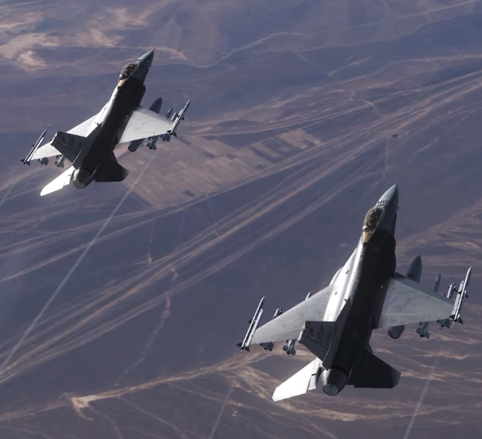
The F-16C Fighting Falcon, often called the Viper, is a single-engine multi-role fighter jet airplane. The F-16 was created by General Dynamics (now Lockheed Martin) and operated by the United States Air Force and numerous other militaries. Despite the «F» (fighter) designation, it is designed for both air-to-air and air-to-ground missions and can use an array of weapons and sensors; built into the Viper is a 20mm cannon as well as a multifunction radar. The DCS F-16C models a Block 50 aircraft with the new F110-GE-129 engine and the Common Configuration Implementation Program (CCIP) avionics upgrade.
Contents
- 1 Weapons List
- 1.1 Implemented
- 1.2 Planned
- 2 HOTAS
- 2.1 Control Stick
- 2.2 Throttle
- 3 Flight Controls & Landing Gear
- 3.1 Flight Controls
- 3.2 Speedbrake
- 3.3 Landing Gear
- 3.3.1 Nosewheel Steering
- 4 Digital Systems Overview
- 4.1 Sensor of Interest
- 4.2 Multifunction Displays
- 4.3 HUD
- 4.4 HMCS
- 4.5 UFC
- 4.5.1 ICP
- 4.5.2 DED
- 5 Air-to-Air Radar
- 5.1 Trackfiles
- 5.2 FCR Page Overview
- 5.3 CRM Submodes
- 5.3.1 Range While Search (RWS)
- 5.3.1.1 Situational Awareness Mode (SAM)
- 5.3.2 Track While Scan (TWS)
- 5.3.1 Range While Search (RWS)
- 5.4 ACM Submodes
- 5.5 Single Target Track (STT)
- 5.6 A/A Radar HUD Indications
- 6 Air-to-Air Weapons
- 6.1 AIM-120 AMRAAM
- 6.2 AIM-9 Sidewinder
- 6.3 Air-to-Air Gun
- 7 Air-to-Ground Weapons
Weapons List
Implemented
Partially or fully implemented weapons of the F-16C Viper:
- BDU-33, BDU-50LD/HD Training Bombs
- Mk-82LDGP, Mk-82AIR, Mk-84LDGP
- CBU-87 CEM, CBU-97 SFW
- 2.75” LAU-68, LAU-131 Rockets
- AIM-9L/M/P/X Sidewinder
- AIM-120B/C AMRAAM
- M61A1 20mm Cannon
- GBU-10, GBU-12
- GBU-31/A, GBU-38/B JDAM
- AGM-154A/B JSOW
- AGM-88C HARM
- AGM-65D/G/H/K Maverick
Planned
Weapons not yet implemented into the Viper:
- CBU-103, CBU-105 Cluster Bombs
- GBU-24
- BRU-57/A
- ALE-50 Towed Decoy
HOTAS
The Fighting Falcon’s hands on throttle and stick (HOTAS) system is designed to allow the pilot to manipulate important avionics functions without releasing the hands from the throttle or control stick. This section will provide a summarized description of all HOTAS controls — detailed functionality will be described in other appropriate sections.
Control Stick

The control stick is a side-mounted stick used to manipulate the Flight Control System (FLCS), but also has numerous other HOTAS controls. The stick is mostly stationary and uses pressure sensitivity to be manipulated; it does, however, move a small physical distance to give tactile movement response to the pilot.
- Trim Switch: The Trim Switch commands pitch (up/down) and roll (left/right) trim to the FLCS.
- Display Management Switch (DMS): The Display Management Switch (DMS) is used for avionics display manipulation and to assign the Sensor of Interest.
- Forward: Sensor of Interest assigned to HUD/HMCS
- Aft: Sensor of Interest assigned and cycles between the left and right MPDs
- Left: Cycles three configured quick access pages on the left MPD from right to left
- Right: Cycles three configured quick access pages on the right MPD from left to right
- Target Management Switch (TMS): The Target Management Switch (TMS) manipulates various sensors depending on what is the Sensor of Interest.
- Forward
- HUD SOI: When an A/G bomb is selected, designates SPI in DTOS/EO.
- FCR SOI: Commands SAM in RWS mode or commands BORE scan in ACM
- TGP SOI: Commands point track
- WPN SOI: Commands track
- HSD SOI: Designate active waypoint
- Aft
- HUD/FCR/WPN SOI: Target reject
- HSD SOI: Drop
- Left
- FCR SOI: Expanded data
- TGP/WPN SOI: Toggles seeker polarity
- Right
- FCR SOI: Steps bugged track in TWS or commands HUD scan in ACM
- TGP SOI: Commands area track
- Right [long hold]
- FCR SOI: Toggles TWS and RWS mode
- Forward
Throttle

The throttle for the F-16 is mounted on the left side, thought it is not rail-mounted to the side of the fuselage as its appearance would suggest. Instead the throttle pivots on its mounted location to the panel. It has the following HOTAS controls:
- Communications Switch (Radio)
- Forward (VHF): keys up the VHF radio on the selected frequency for talking to JTAC, ATC, and other land/sea based assets
- Aft (UHF): keys up the UHF radio on the selected frequency for communication to air assets, such as flight members, AWACS or refueling aircraft
- Left (Out) [short press]: Toggles on and off datalink symbology on the MPDs
- Left (Out) [long hold]: Commands a datalink update
- Right (In): Transmits the current air-to-ground target over datalink
- Manual Range / Uncage Switch: this switch controls the range for air-to-air guns, uncages the missiles, or zooms the TGP depending on the selected SOI and master mode
- Antenna Elevation: This dial wheel (with center detent) controls the radar antenna elevation, allowing the pilot to slew the radar up or down to adjust the radar focus accordingly
- Dogfight / Missile Override
- Speedbrake
- Forward this position locks in place and retracts the airbrake.
- Aft this temporary position extends the airbrake as long as the switch is held in place, keeping it there after release.
- Cursor Control / Enable — This allows for the current Sensor of Interest to be manipulated, such as the FCR Acquisition Cursor or pointing the TGP camera.
- Black-out Switch
Flight Controls & Landing Gear
Flight Controls
The F-16C has multiple flight control surfaces for maneuvering the aircraft. It has a «fly-by-wire» (FBW) system, which, opposed to a traditional mechanical or «direct» control system, the inputs given by the cockpit controls are inputted to a computer which then decides what controls to move in order to accomplish the desired maneuver. This computerized system is called the Flight Control System (FLCS, pronounces «flickus»). The FLCS also moves surfaces as a function of the angle of attack to provide the best control.
The F-16C’s primary flight controls are:
- Stabilators: Two «stabilators» (stabilizer + elevator) located at the tail move on a single axis independently of one another to control both pitch and roll of the aircraft.
- Ailerons: Two normal ailerons located on the outer area of the wings to control roll of the aircraft. They also both droop down to add lift.
- Rudder: A single vertical rudder to control yaw.
- Leading Edge Flaps: Normal slats located on the leading (front) edge of the wings to add lift.
- Trailing Edge Flaps: Normal flaps located on the trailing (back) edge of the wings to add lift.
The control stick controls the stabilators, ailerons, and rudder and the rudder pedals control the rudder. The control stick mainly focuses on using force sensing for feedback, not to be confused for force feedback.
Speedbrake
The speedbrake is a set of four retractable flaps on the back of the aircraft on either side of the engine, used to provide drag to decelerate faster. It is activated via the speed brake switch on the throttle. There are three positions — aft is momentary, the others are permanent.
- Aft: Speedbrake will extend as long as it is held.
- Center: The speedbrake is neither retracted nor extended.
- Forward: The speed brake retracts as long as it is in this position.
Landing Gear
Nosewheel Steering
With weight off wheels, it is disengaged. It automatically engages upon there being weight on wheels. NWS is disengaged manually via the paddle switch on the stick.
Digital Systems Overview
The F-16’s avionics are interfaced with via two Multifunction Displays (MFDs), the Upfront Controls consisting of the Integrated Control Panel (ICP) the Data Entry Display (DED), and the head-up display (HUD)/helmet mounted cueing system (HMCS). The hands on throttle and stick (HOTAS) system of the aircraft is also used for manipulating these systems, which is detailed in its own section and the sections relevant to specific HOTAS uses.
Sensor of Interest
In the F-16, either the HUD/HMCS, the left MFD, or the right MFD is the designated Sensor of Interest, or «SOI.» The SOI is used to dictate what HOTAS buttons do what function. The SOI is changed via the Display Management Switch (DMS) on the stick — forward will assign SOI to the HUD/HMCS while aft will cycle SOI between the left and right MFDs. If an MFD is SOI, a white border around it is displayed. If the HUD is SOI, an asterisk is put in the upper left corner.
Multifunction Displays
The F-16 has two Multifunction Displays (MFDs) on the left and right sides of the cockpit: each has 5 option select buttons (OSBs) on all four sides. The MFDs can display various software pages to manipulate the aircraft’s avionics. Up to three pages per MFD can be selected on either MFD for quick access via pushbutton or HOTAS. These three pages always occupy the bottom center three pushbutton areas. In addition to these, a universal declutter (DCLT) button is provided, which will declutter the symbology depending on the page, and a SWAP button, which simply swaps the two MFD’s quick access pages and selected page.
Selecting any of the three pushbuttons once they have already been selected prompts the main page menu. Any page can then be selected and will be filled at that pushbutton. That page can then be selected by either pressing the corresponding pushbutton or using the Display Management Switch (DMS) on the stick, and it will be highlighted. TMS LEFT and RIGHT respectively cycle the three quick access pages on the left/right MFDs in an outward fashion.
HUD
HMCS
UFC
ICP
DED
Air-to-Air Radar
The F-16C is equipped with the AN/APG-68 pulse Doppler radar. This section will cover its air-to-air (A/A) functionality for surveillance of aircraft and to provide A/A weapon systems guidance in engaging aerial targets. The A/A radar is accessed from the Fire Control Radar (FCR) page. This section will provide an overview of the Fire Control Radar page in Combined Radar Mode (CRM) and Air Combat Maneuvering (ACM) mode; these are the two air-to-air main modes of the FCR.
Trackfiles
The F-16 avionics display most radar target data as «trackfiles» — single objects in the air the computer determines to exist based on the return of one or more raw radar contacts. Trackfiles are displayed in Track While Scan and Single Target Track, and the designated target in the RWS Situational Awareness Mode (SAM) also displays as a trackfile.
Trackfiles are represented by a triangle symbol, with a stem coming out of one corner of the trackfile to indicate its track (velocity) across the ground. Underneath the trackfile is displayed its altitude in thousands of feet.
FCR Page Overview
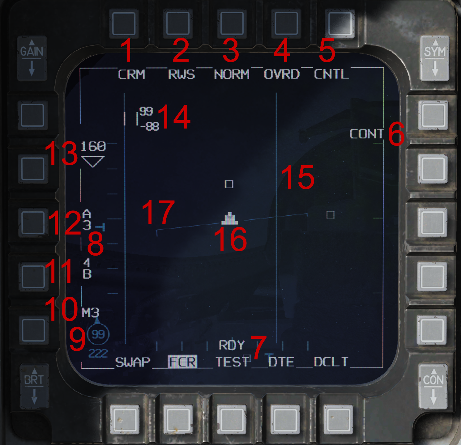
The Fire Control Radar page is presented in an azimuth over range format with the aircraft at the bottom center of the display. The range axis is displayed in a vertical format, where higher range is higher on the physical MFD screen. Azimuth is horizontal, where something at the center of the display is directly in front of the ownship aircraft, and accordingly left/right of it when left/right of the display center.
- Radar Mode — This option allows for the selection of the A/A Combined Radar Mode (CRM) or Air Combat Maneuvering (ACM) mode, as well as any of the A/G radar modes (which is not covered in this section).
- Sub-mode — In CRM, this toggles between the Range While Search (RWS) and Track While Scan (TWS) modes. In ACM, this toggles between the Boresight (BORE), 10° x 60° (60), and 30°x 20° (20) modes. These may alternatively be selected with the HOTAS: TMS right (long) will toggle between RWS/TWS in CRM, while in ACM TMS forward commands BORE, down commands 60, and right commands 20.
- Expand View — This toggles the Normal/Expand view. With Expand view activated, the display is zoomed in on the Acquisition Cursor. A box indicates the region of the Expand view relative to the regular display scale. Expand can be toggled with the Pinky Switch.
- Not yet implemented.
- Not yet implemented.
- Not yet implemented.
- Azimuth Caret — This vertical «T» shaped indication indicates the current location of the radar antenna with respect to azimuth (left/right) of the aircraft. The tick marks each indicate 10° azimuth, with the center tick being 0° (60° left/right is the physical maximum).
- Elevation Caret — This horizontal «T» shape indicates the current vertical elevation of the radar with respect to the horizon. The radar elevation is always stabilized to the horizon. The elevation is shifted up and down via the Antenna Elevation Knob on the throttle and may also change automatically as a result of the bar setting. Each blue tick mark indicates 10° above or below the horizon, with the middle tick being the horizon.
- Bullseye Information — This arrow indicates the bearing from the aircraft to the bullseye. The number within indicates the bearing to the bullseye.
- Not yet implemented.
- Bar Setting — The radar antenna may automatically change position after each azimuth sweep to scan multiple elevations or «bars.» The bar number corresponds to the number of different elevations scanned. The first bar is always the manually set elevation with the Antenna Elevation Knob, while the second and fourth bars are automatic and based off the manual setting of the first bar.
- Azimuth Setting — The radar horizontal azimuth setting is set here. The number displayed is the left/right azimuth (i.e. half of the total) in tens of degrees (6=60°, total 120°). The azimuth may be set to 10°, 30°, or 60°.
- Range Scale — The scale of the FCR page may be set with these two arrows. The number represents the maximum range it displays in nautical miles. This setting is only what the page displays; the radar will always scan to the farthest distance possible. The available options are 5, 10, 20, 40, 80, and 160 nautical miles.
- Acquisition Cursor — This is a cursor controlled with the Cursor/Enable Switch on the throttle, used for acquiring tracks and contacts into either Single Target Track or Situational Awareness Mode. Two numbers are displayed to the right indicating the maximum and minimum altitudes in thousands of feet the radar can see at the point the cursor is placed; this naturally changes with the elevation/bar setting.
- Horizon Line — This line is always aligned with the horizon and indicates the pitch and roll of the aircraft.
- Steerpoint — The current steerpoint is indicated by this «wedding cake» shape.
- Scan Limit Lines — When the scan azimuth is, under any circumstance except Single Target Track, less than 60° two blue lines indicate the area covered with the current azimuth setting. The azimuth center is centered on the Acquisition Cursor except in RWS SAM or TWS with a bugged track.
CRM Submodes
Range While Search (RWS)
Range While Search (RWS) provides the largest scan volume selection available and is designed for surveillance of a large area. With its Situational Awareness Mode (SAM), it also allows for weapons guidance.
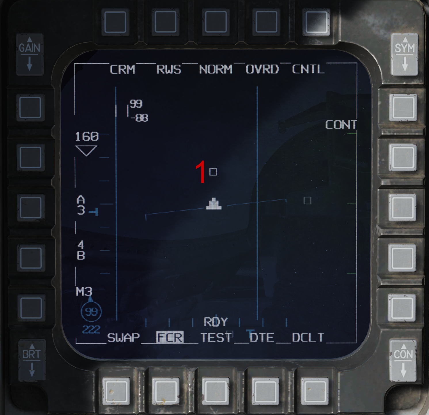
- Raw Contacts — «Raw» radar contacts are displayed as hollow squares. As a contact ‘ages’ (the time passed since it has been swept over by the antenna), it visually fades and will eventually disappear. These are the raw returns of the radar, and as such multiple raw contacts may be a single aerial target.
Situational Awareness Mode (SAM)
Situational Awareness Mode (SAM) is a Range While Search function which allows for a contact to be designated, which will then center the scan azimuth on it and display it as a trackfile as opposed to a raw contact. Weapon guidance is available in SAM mode on the designated trackfile; as the radar continues to scan it will continue to display other raw contacts.
SAM is entered by slewing the Acquisition Cursor over a contact and pressing TMS forward. The cursor is then slaved onto the trackfile. Normal RWS can be returned to via TMS aft.
Track While Scan (TWS)
Not yet implemented.
ACM Submodes
Single Target Track (STT)
WIP.
A/A Radar HUD Indications
WIP.
Air-to-Air Weapons
The F-16C Viper carries a variety of Air-to-Air weapons that are mainly missiles. These weapons are to be included as these categories.
AIM-120 AMRAAM
WIP.
AIM-9 Sidewinder
WIP.
Air-to-Air Gun
WIP.
Air-to-Ground Weapons
WIP.