
- Manuals
- Brands
- KTM Manuals
- Motorcycle
- 690 SMC R
- Owner’s manual
-
Contents
-
Table of Contents
-
Troubleshooting
-
Bookmarks
Quick Links
OWNER’S MANUAL
2016
690 SMC R
Art. no. 3213394en
Related Manuals for KTM 690 SMC R
Summary of Contents for KTM 690 SMC R
-
Page 1
OWNER’S MANUAL 2016 690 SMC R Art. no. 3213394en… -
Page 3
KTM accepts no liability for delivery options, devi- ations from illustrations and descriptions, misprints, and other errors. -
Page 4
Reproduction, even in part, as well as copying of all kinds, is permitted only with the express written permission of the copyright owner. ISO 9001(12 100 6061) According to the international quality management standard ISO 9001, KTM uses quality assurance processes that lead to the maximum possible quality of the products. -
Page 5: Table Of Contents
TABLE OF CONTENTS Shock absorber article number ……22 TABLE OF CONTENTS MEANS OF REPRESENTATION ……..7 CONTROLS…………..23 Symbols used …………7 Clutch lever…………23 Formats used…………8 Hand brake lever……….23 SAFETY ADVICE………….. 9 Throttle grip …………24 Use definition — intended use ……..
-
Page 6
TABLE OF CONTENTS 6.13 Seat release …………38 10.6 Adjusting the high-speed compression damping of the shock absorber ……… 65 6.14 Handrails …………38 10.7 Adjusting the rebound damping of the shock 6.15 Passenger footrests ……….39 absorber…………66 6.16 Shift lever ………… -
Page 7
TABLE OF CONTENTS 11.19 Adjusting the basic position of the clutch lever ..86 14.3 Recharging the battery ……..117 11.20 Checking/rectifying the fluid level of the 14.4 Changing the main fuse ……..120 hydraulic clutch……….87 14.5 Changing the ABS fuses ……..121 12 BRAKE SYSTEM ………… -
Page 8
TABLE OF CONTENTS 17.4 Removing the oil filter ……..146 25 STANDARDS ………….. 188 17.5 Cleaning the oil screens …….. 148 26 INDEX OF SPECIAL TERMS ……… 189 17.6 Installing the oil filter ……..150 27 LIST OF ABBREVIATIONS……….190 17.7 Filling up with engine oil ……. -
Page 9: Means Of Representation
All work marked with this symbol requires specialist knowledge and technical understanding. In the interest of your own safety, have these jobs performed by an authorized KTM workshop. There, your motorcycle will be optimally cared for by specially trained experts using the specialist tools required.
-
Page 10: Formats Used
MEANS OF REPRESENTATION Formats used The typographical formats used in this document are explained below. Specific name Identifies a proprietary name. Name ® Identifies a protected name. Brand™ Identifies a brand available on the open market. Underlined terms Refer to technical details of the vehicle or indicate technical terms that are explained in the glossary.
-
Page 11: Safety Advice
SAFETY ADVICE Use definition — intended use KTM sport motorcycles are designed and constructed to meet the normal demands of regular road operation but not for use on race courses or offroad. Info The motorcycle is only authorized for operation on public roads in the homologated version.
-
Page 12: Degrees Of Risk And Symbols
SAFETY ADVICE Degrees of risk and symbols Danger Indicates a danger that will immediately and invariably lead to fatal or serious permanent injury if the appropriate measures are not taken. Warning Indicates a danger that is likely to lead to fatal or serious injury if the appropriate measures are not taken. Caution Indicates a danger that may lead to minor injuries if the appropriate measures are not taken.
-
Page 13: Safe Operation
Only operate the vehicle when it is in perfect technical condition, in accordance with its intended use, and in a safe and environmentally compatible manner. An appropriate driver’s license is needed to ride the vehicle on public roads. Have malfunctions that impair safety promptly eliminated by an authorized KTM workshop. Adhere to the information and warning labels on the vehicle.
-
Page 14: Protective Clothing
Wear protective clothing (helmet, boots, gloves, pants and jacket with protectors) every time you ride the vehicle. Always wear protective clothing that is in good condition and meets the legal requirements. In the interest of your own safety, KTM recommends that you only operate the vehicle while wearing protective clothing. Work rules Special tools are necessary for certain tasks.
-
Page 15: Owner’s Manual
Keep the Owner’s Manual in an accessible place to enable you to refer to it as needed. If you would like to know more about the vehicle or have questions on the material you read, please contact an authorized KTM dealer.
-
Page 16: Important Notes
Manufacturer and implied warranty The work specified in the service schedule may only be performed in an authorized KTM workshop and must be recorded in both the Service & Warranty Booklet and in KTM Dealer.net, otherwise any warranty coverage will become void. Damage or secondary damage caused by tampering with and/or conversions on the vehicle are not covered by the warranty.
-
Page 17: Service
Please follow the instructions in the text. Customer service Your authorized KTM dealer will be happy to answer any questions you may have on your vehicle and KTM. A list of authorized KTM dealers can be found on the KTM website.
-
Page 18: View Of Vehicle
VIEW OF VEHICLE View of vehicle, front left side (example) 101971-10…
-
Page 19
VIEW OF VEHICLE Hand brake lever ( p. 23) Clutch lever ( p. 23) Handrails ( p. 38) Filler cap Engine number ( p. 21) Shift lever ( p. 39) Side stand ( p. 41) Seat release ( p. 38) Compression damping of the shock absorber ( p. -
Page 20: View Of Vehicle, Rear Right Side (Example)
VIEW OF VEHICLE View of vehicle, rear right side (example) 101972-10…
-
Page 21
VIEW OF VEHICLE Ignition/steering lock ( p. 27) Fork compression adjustment Light switch ( p. 25) Turn signal switch ( p. 25) Horn button ( p. 24) Function buttons ( p. 28) Indicator lamps ( p. 29) Emergency OFF switch ( p. -
Page 22: Serial Numbers
SERIAL NUMBERS Chassis number The chassis number is stamped on the steering head on the right. 401945-10 Type label The type label is located on the right side of the frame. H01049-10…
-
Page 23: Key Number
SERIAL NUMBERS Key number can be found on the KEYCODECARD. The key number Info You need the key number to order a spare key. Keep the KEYCODECARD in a safe place. 402241-10 Engine number The engine number is stamped on the left side of the engine under the engine sprocket. 401949-10…
-
Page 24: Fork Part Number
SERIAL NUMBERS Fork part number The fork part number is stamped on the inner side of the fork stub. 401947-10 Shock absorber article number The shock absorber article number is on the left side of the shock absorber. 402025-10…
-
Page 25: Controls
CONTROLS Clutch lever The clutch lever is fitted on the left side of the handlebar. The clutch is hydraulically operated and self-adjusting. B01943-10 Hand brake lever The hand break lever is fitted on the right side of the handlebar. The hand brake lever operates the front brake.
-
Page 26: Throttle Grip
CONTROLS Throttle grip The throttle grip is fitted on the right side of the handlebar. B01945-10 Horn button The horn button is fitted on the left side of the handlebar. Possible states • Horn button in neutral position pressed –…
-
Page 27: Light Switch
CONTROLS Light switch The light switch is fitted on the left side of the handlebar. Possible states Low beam on – Light switch is turned downward. In this position, the low beam and tail light are switched on. High beam on – Light switch is turned upward. In this position, the high beam and tail light are switched on.
-
Page 28: Emergency Off Switch
CONTROLS Emergency OFF switch The emergency OFF switch is fitted on the right side of the handlebar. Possible states Emergency OFF switch off – In this position, the ignition circuit is inter- rupted, a running engine stops, and the engine cannot be started. Emergency OFF switch on –…
-
Page 29: Ignition/Steering Lock
CONTROLS Ignition/steering lock The ignition/steering lock is located in front of the seat. Possible states Ignition OFF – In this position, the ignition circuit is interrupted, a running engine stops, and a non-running engine will not start. The ignition key can be removed.
-
Page 30: Function Buttons
CONTROLS 6.10.2 Function buttons You can change the display mode with the MODE button Possible display modes are distance traveled (ODO), trip master 1 (TRIP 1) and trip mas- ter 2 (TRIP 2). Press the SET button to reset the trip master 1 function (TRIP 1) and trip master 2 func- tion (TRIP 2) to 0.0.
-
Page 31: Indicator Lamps
CONTROLS 6.10.4 Indicator lamps The indicator lamps offer additional information about the operating state of the motorcy- cle. Possible states The turn signal indicator lamp flashes green simultaneously with the turn signal – The turn signal is switched on. The idling speed indicator lamp lights up green – The transmission is shifted to idle.
-
Page 32: Display
CONTROLS 6.10.5 Display When the ignition is switched on, all display segments light up for one second as a function check. 400836-01 LEnGth After the display function check, the wheel circumference LEnGth is displayed for one sec- ond. Info The number 1870 mm equals the circumference of the 17″ front wheel with a series production tire.
-
Page 33: Speed Display
CONTROLS 6.10.6 Speed display The speed is shown in kilometers per hour km/h or in miles per hour mph. 401443-10 6.10.7 Setting the kilometers or miles Info If the unit is changed, the value is retained and converted accordingly. Make the setting according to the country.
-
Page 34: Time
CONTROLS – Switch on the ignition by turning the ignition key to position ON – Press the MODE button repeatedly until the ODO display mode is active. – Keep the MODE button pressed until the display mode changes from km/h to mph or from mph to km/h.
-
Page 35: 6.10.10 Odo Display
CONTROLS – Switch on the ignition by turning the ignition key to position ON – Press the MODE button repeatedly until the ODO mode is active. – Keep the MODE button and the SET button pressed simultaneously. The time display begins to flash. –…
-
Page 36: Setting/Resetting Display Trip 2
CONTROLS – Switch on the ignition by turning the ignition key to position ON – Press the MODE button repeatedly until the TRIP 1 mode is active. – Keep the SET button pressed. The TRIP 1 display is set to 0.0. 401445-01 6.10.12 Setting/resetting display TRIP 2 Info…
-
Page 37: 6.10.13 Trip F Display
CONTROLS 6.10.13 TRIP F display If the fuel level drops to the reserve mark, the display automatically changes to TRIP F and starts to count from 0.0, regardless of the previous display mode. Info The low fuel warning lamp lights up in parallel to the TRIP F display. 401447-01 6.10.14 GEAr display In display mode GEAr, the gear currently engaged is displayed.
-
Page 38: 6.10.15 Coolant Temperature Indicator
CONTROLS 6.10.15 Coolant temperature indicator The temperature display consists of 12 bars. The more bars that light up, the hotter the coolant. When the upper bar lights up, all bars in the display begin to flash and the temper- ature warning lamp lights up. Possible states Engine cold –…
-
Page 39: Closing Filler Cap
CONTROLS Warning Environmental hazard Improper handling of fuel is a danger to the environment. – Do not allow fuel to get into the ground water, the ground, or the sewage system. – Lift cover of filler cap and insert the ignition key. –…
-
Page 40: Seat Release
CONTROLS 6.13 Seat release The seat can be released using strap 101977-10 6.14 Handrails The handrails are used for moving the motorcycle around. When you have a passenger, the passenger can hold on the handrails during the journey. 101978-10…
-
Page 41: Passenger Footrests
CONTROLS 6.15 Passenger footrests The passenger footrests can be folded up and down. Possible states Passenger footrests folded up – For operation without a passenger. • Passenger footrests folded down – For operation with a passenger. • 101979-01 6.16 Shift lever …
-
Page 42: Foot Brake Lever
CONTROLS The gear positions can be seen in the photograph. The neutral or idle position is between the first and second gears. 401950-11 6.17 Foot brake lever Foot brake lever is located in front of the right footrest. The rear brake is engaged with the foot brake lever. 401956-10…
-
Page 43: Side Stand
CONTROLS 6.18 Side stand The side stand is located on the left side of the vehicle. The side stand is used for parking the motorcycle. Info The side stand must be folded up during motorcycle use. The side stand is coupled with the safety starting system – see the riding instruc- tions.
-
Page 44: Preparing For Use
The front and rear wheels must be fitted with tires with similar tread patterns to prevent loss of control over the vehicle. Warning Danger of accidents Uncontrollable handling characteristic due to non-approved and/or non-recommended tires/wheels. – Only tires/wheels approved by KTM and with the corresponding speed index should be used. Warning Danger of accidents Reduced road grip with new tires. –…
-
Page 45: Running In The Engine
When using your vehicle, remember that others may feel disturbed by excessive noise. – Make sure that the pre-delivery inspection work has been carried out by an authorized KTM workshop. You receive a delivery certificate and the Service and Warranty Booklet at vehicle handover.
-
Page 46: Loading The Vehicle
PREPARING FOR USE – Avoid fully opening the throttle! Loading the vehicle Warning Danger of accidents Unstable handling characteristics. – Do not exceed the maximum permitted weight and axle loads. The overall weight consists of: motorcycle operational and with a full tank, driver and passenger with protective clothing and helmet, baggage. Warning Danger of accidents Unstable handling characteristics due to incorrect mounting of suitcase and/or tank rucksack.
-
Page 47
PREPARING FOR USE Warning Danger of accidents Unstable handling characteristics due to slipped baggage. – Check the way your baggage is fixed regularly. Warning Danger of burns A hot exhaust system can burn baggage. – Fasten your baggage in such a way that it cannot be burned or singed by the hot exhaust system. –… -
Page 48: Riding Instructions
RIDING INSTRUCTIONS Performing checks and vehicle care when preparing for use Info Before each use, check the state and roadworthiness of the vehicle. Make sure that the vehicle is in perfect technical condition before use. – Check the engine oil level. ( p.
-
Page 49: Starting
RIDING INSTRUCTIONS Starting Danger Danger of poisoning Exhaust gases are toxic and inhaling them may result in unconsciousness and/or death. – When running the engine, always make sure there is sufficient ventilation, and do not start or run the engine in an enclosed space without an effective exhaust extraction system.
-
Page 50
Take the weight off the side stand and swing it back up with your foot as far as it will Switching off ABS KTM recommends riding with ABS at all times. However, situations may arise in which ABS is not advantageous. -
Page 51: Starting Off
RIDING INSTRUCTIONS Starting off – Pull the clutch lever, engage 1st gear, release the clutch lever slowly and simultaneously open the throttle carefully. Shifting, riding Warning Danger of accidents Abrupt load alterations can cause the vehicle to get out of control. –…
-
Page 52
RIDING INSTRUCTIONS Warning Danger of accidents Reduced road grip with cold tires. – On every journey, take the first miles carefully at moderate speed until the tires reach operating temperature and optimal road grip is ensured. Warning Danger of accidents Reduced road grip with new tires. –… -
Page 53
Info If unusual noises arise during operation, stop immediately, switch off the engine, park the vehicle properly, and contact an autho- rized KTM workshop. – Shift into a higher gear when conditions allow (incline, road situation, etc.). –… -
Page 54: Applying The Brakes
Danger of accidents Reduced braking efficiency caused by spongy pressure point of front or rear brake. – Check the brake system and do not continue riding. (Your authorized KTM workshop will be glad to help.) Warning Danger of accidents Failure of brake system.
-
Page 55
RIDING INSTRUCTIONS Warning Danger of accidents Longer stopping distance due to higher overall weight. – Take the longer stopping distance into account when carrying a passenger and baggage. Warning Danger of accidents Delayed brake action on salted roads. – There may be salt deposits on the brake discs. In order to restore the normal braking efficiency, you will need to remove the deposits from the discs by carefully applying the brakes. -
Page 56: Stopping, Parking
RIDING INSTRUCTIONS Warning Danger of accidents Road grip is reduced when braking with the motorcycle at an angle or on a laterally inclined surface. – Braking should be completed before you enter into a bend. – Always finish braking before you go into a bend. Change down to a lower gear appropriate to your road speed. –…
-
Page 57: Transport
RIDING INSTRUCTIONS Note Fire hazard Some vehicle components become very hot when the vehicle is operated. – Do not park the vehicle near flammable or explosive substances. Do not place objects on the vehicle while it is still warm from being run.
-
Page 58: Refueling
RIDING INSTRUCTIONS Note Fire hazard Some vehicle components become very hot when the vehicle is operated. – Do not park the vehicle near flammable or explosive substances. Do not place objects on the vehicle while it is still warm from being run.
-
Page 59
– In some countries and regions, the available fuel quality and cleanliness may not be sufficient. This will result in problems with the fuel system. (Your authorized KTM workshop will be glad to help.) – Only refuel with clean fuel that meets the specified standards. -
Page 60
RIDING INSTRUCTIONS – Press the SET button for two seconds. The fuel level warning lamp switches off. TRIP F is set to 0.0 and the display returns to the previous display mode. Info If you do not press the SET button , the reset takes place automatically after approx. -
Page 61: Service Schedule
○ ● ● Check that the electrical equipment is functioning correctly. ○ ● ● Read out the fault memory using the KTM diagnostics tool. ● ● Check the measured service values with the KTM diagnostics tool. ○ ● ● Change the engine oil and filter, clean the oil screens.
-
Page 62
Final check: Check the vehicle for roadworthiness and take a test ride. ○ ● ● Read out the fault memory using the KTM diagnostics tool after a test ride. ○ ● ● Make the service entry in the KTM Dealer.net and in the Service and Warranty Booklet. -
Page 63
SERVICE SCHEDULE ○ One-time interval ● Periodic interval… -
Page 64: Tuning The Chassis
TUNING THE CHASSIS 10.1 Fork/shock absorber The fork and the shock absorber offer many options of adapting the chassis to your riding style and the payload. Info To help you adapt the vehicle, we have summarized our findings in Table .
-
Page 65: Adjusting The Rebound Damping Of The Fork
TUNING THE CHASSIS Guideline Compression damping Comfort 20 clicks Standard 15 clicks Sport 10 clicks Full payload 10 clicks Info Turn clockwise to increase damping; turn counterclockwise to reduce damping. 10.3 Adjusting the rebound damping of the fork Info The hydraulic rebound damping determines the fork suspension behavior. –…
-
Page 66: Compression Damping Of The Shock Absorber
Adjusting the low-speed compression damping of the shock absorber Caution Danger of accidents Disassembly of pressurized parts can lead to injury. – The shock absorber is filled with high density nitrogen. Adhere to the description provided. (Your authorized KTM workshop will be glad to help.)
-
Page 67: Adjusting The High-Speed Compression Damping Of The Shock Absorber
Adjusting the high-speed compression damping of the shock absorber Caution Danger of accidents Disassembly of pressurized parts can lead to injury. – The shock absorber is filled with high density nitrogen. Adhere to the description provided. (Your authorized KTM workshop will be glad to help.)
-
Page 68: Adjusting The Rebound Damping Of The Shock Absorber
Adjusting the rebound damping of the shock absorber Caution Danger of accidents Disassembly of pressurized parts can lead to injury. – The shock absorber is filled with high density nitrogen. Adhere to the description provided. (Your authorized KTM workshop will be glad to help.)
-
Page 69: Handlebar Position
TUNING THE CHASSIS – Turn adjusting screw clockwise up to the last perceptible click. – Turn counterclockwise by the number of clicks corresponding to the shock absorber type. Guideline Rebound damping Comfort 20 clicks Standard 15 clicks Sport 10 clicks 601891-10 Full payload 10 clicks…
-
Page 70: Adjusting The Handlebar Position
TUNING THE CHASSIS 10.9 Adjusting the handlebar position – Remove screws . Take off the handlebar clamps. Remove the handlebar and lay it to one side. Info Cover the components to protect them against damage. Do not kink the cables and lines. –…
-
Page 71: Service Work On The Chassis
SERVICE WORK ON THE CHASSIS 11.1 Raising the motorcycle with a lift stand Note Danger of damage The parked vehicle may roll away or fall over. – Always place the vehicle on a firm and even surface. – Raise the motorcycle in the area of the footrest bracket. Lift stand (78929955100) Neither wheel is in contact with the ground.
-
Page 72: Raising The Motorcycle With The Rear Wheel Stand
SERVICE WORK ON THE CHASSIS – Remove the motorcycle from the lift stand and rest it on side stand – Remove the lift stand. 401943-10 11.3 Raising the motorcycle with the rear wheel stand Note Danger of damage The parked vehicle may roll away or fall over. –…
-
Page 73: Removing The Rear Of The Motorcycle From The Wheel Stand
SERVICE WORK ON THE CHASSIS 11.4 Removing the rear of the motorcycle from the wheel stand Note Danger of damage The parked vehicle may roll away or fall over. – Always place the vehicle on a firm and even surface. – Secure the motorcycle against falling over.
-
Page 74: Taking The Motorcycle Off Of The Front Wheel Stand
SERVICE WORK ON THE CHASSIS Main work – Move the handlebar to the straight-ahead position. Align the front wheel stand with the fork legs using the adapters. Front wheel stand (61029055300) Info Always raise the rear of the motorcycle first. –…
-
Page 75
SERVICE WORK ON THE CHASSIS Main work – Push dust boots of both fork legs downward. Info The dust boots remove dust and coarse dirt particles from the inside fork tubes. Over time, dirt can accumulate behind the dust boots. If this dirt is not removed, the oil seals behind can start to leak. -
Page 76: Removing The Fork Protector
SERVICE WORK ON THE CHASSIS 11.8 Removing the fork protector – Remove screws and take off clamp. – Remove screws on left fork leg. Remove the fork protector. – Remove the screws on the right fork leg. Remove the fork protector. 101986-10 11.9 Installing the fork protector…
-
Page 77: Removing The Seat
SERVICE WORK ON THE CHASSIS 11.10 Removing the seat – Pull on strap and raise the rear of the seat at the same time. – Pull back the seat and lift it off. 101977-10 11.11 Mounting the seat 101988-10 –…
-
Page 78: Removing The Air Filter
SERVICE WORK ON THE CHASSIS 11.12 Removing the air filter Preparatory work – Remove the seat. ( p. 75) Main work – Remove screws . Take off air filter box top 601882-10 Note Engine failure Unfiltered intake air has a negative effect on the service life of the engine.
-
Page 79: Installing The Air Filter
SERVICE WORK ON THE CHASSIS 11.13 Installing the air filter Main work – Clean the air filter box. – Mount air filter Info The air filter must lie flush against the air filter box along the entire sealing sur- face …
-
Page 80: Checking The Chain For Dirt
SERVICE WORK ON THE CHASSIS 11.14 Checking the chain for dirt – Check the chain for heavy soiling. » If the chain is very dirty: – Clean the chain. ( p. 78) 400678-01 11.15 Cleaning the chain Warning Danger of accidents Oil or grease on the tires reduces their grip. –…
-
Page 81: Checking The Chain Tension
SERVICE WORK ON THE CHASSIS Info The service life of the chain depends largely on its maintenance. Preparatory work – Raise the motorcycle with the rear wheel stand. ( p. 70) Main work – Clean the chain regularly. – Rinse off loose dirt with a soft jet of water. –…
-
Page 82
SERVICE WORK ON THE CHASSIS – Lean the motorcycle on the side stand. – Shift gear to neutral. – Push the chain upward at a distance from the chain sliding guard and determine the chain tension Info The upper chain section must be taut. -
Page 83: Adjusting The Chain Tension
SERVICE WORK ON THE CHASSIS 11.17 Adjusting the chain tension Warning Danger of accidents Danger caused by incorrect chain tension. – If the chain is too taut, the components of the secondary power transmission (chain, engine sprocket, rear sprocket, bearings in the transmission and in the rear wheel) will be under additional load.
-
Page 84: Checking The Chain, Rear Sprocket, Engine Sprocket, And Chain Guide
SERVICE WORK ON THE CHASSIS Main work – Loosen nut – Loosen nuts – Adjust the chain tension by turning adjusting screws on the left and right. Guideline Chain tension 5 mm (0.2 in) Turn adjusting screws on the left and right so that the markings on the left and …
-
Page 85
SERVICE WORK ON THE CHASSIS Main work – Shift the transmission to idle. – Check the rear sprocket and engine sprocket for wear. » If the rear sprocket or engine sprocket is worn: – Change the power set. Info The engine sprocket, rear sprocket, and chain should always be replaced together. -
Page 86
SERVICE WORK ON THE CHASSIS Info When the chain is replaced, the rear sprocket and engine sprocket should also be changed. New chains wear out faster on an old, worn rear sprocket or engine sprocket. – Check the chain sliding guard for wear. »… -
Page 87
SERVICE WORK ON THE CHASSIS – Check the chain sliding piece for wear. » If the lower edge of the chain pins is in line with or below the chain sliding piece: – Change the chain sliding piece. – Check that the chain sliding piece is firmly seated. »… -
Page 88: Adjusting The Basic Position Of The Clutch Lever
SERVICE WORK ON THE CHASSIS – Check that the chain guide is firmly seated. » If the chain guide is loose: – Tighten the screws on the chain guide. Guideline Remaining screws, chassis 10 Nm (7.4 lbf ft) 601884-01 Finishing work –…
-
Page 89: Checking/Rectifying The Fluid Level Of The Hydraulic Clutch
SERVICE WORK ON THE CHASSIS – Adjust the basic position of the clutch lever to your hand size by turning adjusting screw – When adjusting the clutch lever, make sure to leave a minimum clearance to other parts of the vehicle. Guideline Minimum clearance 5 mm (0.2 in)
-
Page 90: Brake System
KTM. – Service work and repairs must be performed properly. (Your authorized KTM workshop will be glad to help.) The ABS is a safety system that prevents locking of the wheels when driving straight ahead without the influence of lateral forces.
-
Page 91: Adjusting The Basic Position Of The Hand Brake Lever
BRAKE SYSTEM the brake pressure. The regulating process causes a slight pulsing of the hand and foot brake levers. ABS warning lamp must light up after the ignition is switched on and go out after start- ing off. If it does not go out after starting off or if it lights up while riding, this indicates a fault in the ABS system.
-
Page 92: Checking The Brake Discs
Danger of accidents Reduced braking efficiency due to worn brake disc(s). – Change the worn brake disc(s) without delay. (Your authorized KTM workshop will be glad to help.) – Check the thickness of the front and rear brake discs in several places to ensure that it …
-
Page 93: Checking The Front Brake Fluid Level
Warning Danger of accidents Reduced braking efficiency due to old brake fluid. – Change the brake fluid of the front and rear brake according to the service schedule. (Your authorized KTM workshop will be glad to help.) – Move the brake fluid reservoir mounted on the handlebar to a horizontal position.
-
Page 94
Warning Danger of accidents Reduced braking efficiency due to old brake fluid. – Change the brake fluid of the front and rear brake according to the service schedule. (Your authorized KTM workshop will be glad to help.) Warning Environmental hazard Hazardous substances cause environmental damage. -
Page 95: Checking The Front Brake Linings
Checking the front brake linings Warning Danger of accidents Reduced braking efficiency caused by worn brake linings. – Change worn brake linings immediately. (Your authorized KTM workshop will be glad to help.) Note Danger of accidents Reduced braking efficiency caused by damaged brake discs. –…
-
Page 96: Checking The Free Travel Of Foot Brake Lever
BRAKE SYSTEM – Check the brake linings for minimum thickness ≥ 1 mm (≥ 0.04 in) Minimum thickness » If the minimum thickness is less than specified: – Change the brake linings of the front brake. – Check the brake linings for damage and cracking. »…
-
Page 97: Adjusting The Basic Position Of The Foot Brake Lever
BRAKE SYSTEM 12.8 Adjusting the basic position of the foot brake lever Warning Danger of accidents Brake system failure. – If there is no free travel on the foot brake lever, pressure builds up on the rear brake circuit. The rear brake can fail due to over- heating.
-
Page 98: Checking Rear Brake Fluid Level
Warning Danger of accidents Reduced braking efficiency due to old brake fluid. – Change the brake fluid of the front and rear brake according to the service schedule. (Your authorized KTM workshop will be glad to help.) – Stand the vehicle upright.
-
Page 99
Warning Danger of accidents Reduced braking efficiency due to old brake fluid. – Change the brake fluid of the front and rear brake according to the service schedule. (Your authorized KTM workshop will be glad to help.) Warning Environmental hazard Hazardous substances cause environmental damage. -
Page 100: Checking The Rear Brake Linings
Checking the rear brake linings Warning Danger of accidents Reduced braking efficiency caused by worn brake linings. – Change worn brake linings immediately. (Your authorized KTM workshop will be glad to help.) Note Danger of accidents Reduced braking efficiency caused by damaged brake discs. –…
-
Page 101
BRAKE SYSTEM – Check the brake linings for minimum thickness ≥ 1 mm (≥ 0.04 in) Minimum thickness » If the minimum thickness is less than specified: – Change the rear brake linings. – Check the brake linings for damage and cracking. »… -
Page 102: Wheels, Tires
WHEELS, TIRES 13.1 Removing the front wheel Preparatory work – Raise the motorcycle with the rear wheel stand. ( p. 70) – Raise the motorcycle with the front wheel stand. ( p. 71) Main work – Remove screw and pull wheel speed sensor out of the hole.
-
Page 103: Installing The Front Wheel
WHEELS, TIRES – Remove spacers H00934-12 13.2 Installing the front wheel Warning Danger of accidents Reduced braking efficiency due to oil or grease on the brake discs. – Always keep the brake discs free of oil and grease, and clean them with brake cleaner when necessary. Main work –…
-
Page 104
WHEELS, TIRES – Lift the front wheel into the fork, position it, and insert the wheel spindle. – Mount and tighten screw Guideline Screw, front wheel spindle M24x1.5 45 Nm (33.2 lbf ft) – Position the wheel speed sensor in the drill hole. -
Page 105: Removing The Rear Wheel
WHEELS, TIRES – Take the motorcycle off of the front wheel stand. ( p. 72) – Operate the front brake and compress the fork a few times firmly. The fork legs straighten. – Tighten screws Guideline Screw, fork stub 15 Nm (11.1 lbf ft) 101999-10…
-
Page 106: Installing The Rear Wheel
WHEELS, TIRES – Pull out wheel spindle to the point where the chain adjuster is no longer in contact with the adjusting screw. – Push the rear wheel forward as far as possible and take the chain off the rear sprocket. Info Cover the components to protect them against damage.
-
Page 107
WHEELS, TIRES Main work – Check the rear hub rubber dampers. p. 106) – Check the wheel bearing for damage and wear. » If the wheel bearing is damaged or worn: – Replace the wheel bearing. – Remove spacer. – … -
Page 108: Checking The Rear Hub Rubber Dampers
WHEELS, TIRES – Push the rear wheel forward as far as possible and lay the chain on the rear sprocket. – Mount wheel spindle and chain adjuster . Mount nut , but do not tighten it yet. –…
-
Page 109
WHEELS, TIRES Preparatory work – Raise the motorcycle with the rear wheel stand. ( p. 70) – Remove the rear wheel. p. 103) Main work – Check bearing » If the bearing is damaged or worn: – Replace the bearings. –… -
Page 110: Checking The Tire Condition
Danger of accidents Uncontrollable vehicle handling in the event of a flat tire. – In the interest of safety, replace damaged or worn tires immediately. (Your authorized KTM workshop will be glad to help.) Warning Danger of crashing Poor vehicle handling due to different tire tread patterns on front and rear wheels.
-
Page 111
DOT marking. The first two digits refer to the week of manufacture and last two digits refer to the year of manufacture. KTM recommends that the tires are changed regardless of the actual wear, at the latest after 5 years. -
Page 112: Tubeless Tire System
This results in better handling and riding comfort. The rigid rim design results in a spoke wheel that is almost entirely maintenance-free. KTM recommends that the tubeless sealing profile be changed after 5 years at the latest, regardless of the actual state of wear.
-
Page 113: Checking The Spoke Tension
Danger of accidents Instable handling due to incorrect spoke tension. – Ensure that the spoke tension is correct. (Your authorized KTM workshop will be glad to help.) Info A loose spoke causes wheel imbalance and rapidly leads to more loose spokes.
-
Page 114
WHEELS, TIRES – Briefly strike each spoke with a screwdriver blade. Info The frequency of the tone is a function of the spoke length and spoke diameter. If you hear different tone frequencies from individual spokes of the same length and thickness, this is an indication of different spoke tensions. -
Page 115: Electrical System
ELECTRICAL SYSTEM 14.1 Removing the battery Warning Risk of injury Battery acid and battery gases cause serious chemical burns. – Keep batteries out of the reach of children. – Wear suitable protective clothing and goggles. – Avoid contact with battery acid and battery gases. –…
-
Page 116
ELECTRICAL SYSTEM – Disconnect negative cable from the battery. – Take off the positive terminal cover S00622-10 – Disconnect the ABS connection cable and positive cable from the battery. S00620-10 – Remove screws – Pull retaining bracket of the battery forward and remove it. -
Page 117: Installing The Battery
ELECTRICAL SYSTEM 14.2 Installing the battery Main work – Insert the battery into the battery compartment with the terminals facing rearward. Battery (YTZ10S) ( p. 175) – Position retaining bracket and mount and tighten screws Guideline Remaining screws, chassis 10 Nm (7.4 lbf ft) S00621-11 –…
-
Page 118
ELECTRICAL SYSTEM – Position positive terminal cover – Position washer and negative cable , and mount and tighten the screw. Guideline Remaining screws, chassis 10 Nm (7.4 lbf ft) S00622-11 – Position EFI control unit – … -
Page 119: Recharging The Battery
– Do not dispose of batteries with the household waste. Dispose of a defective battery in an environmentally friendly manner. Give the battery to your authorized KTM dealer or dispose of it at a collection point for used batteries. Warning Environmental hazard Hazardous substances cause environmental damage.
-
Page 120
ELECTRICAL SYSTEM Info Even when there is no load on the battery, it still loses power steadily. The charging level and the method of charging are very important for the service life of the battery. Rapid recharging with a high charging current shortens the battery’s service life. If the charging current, charging voltage and charging time are exceeded, electrolyte escapes through the safety valves. -
Page 121
ELECTRICAL SYSTEM Main work – Connect the battery charger to the battery. Switch on the battery charger. Battery charger (58429074000) You can also use the battery charger to test rest potential and start potential of the bat- tery, and to test the alternator. With this device, you cannot overcharge the battery. Info … -
Page 122: Changing The Main Fuse
ELECTRICAL SYSTEM 14.4 Changing the main fuse Warning Fire hazard The electrical system can be overloaded if the wrong fuses are used. – Use only fuses with the prescribed amperage. Never bypass or repair fuses. Info The main fuse protects all power consumers in the vehicle. It is in the housing of the starter relay next to the battery. Preparatory work –…
-
Page 123: Changing The Abs Fuses
ELECTRICAL SYSTEM – Remove a defective main fuse with needle nose pliers. Info A defective fuse is indicated by a burned-out fuse wire A reserve fuse is located in the starter relay. – Install a new main fuse. Fuse (58011109130) ( p.
-
Page 124
ELECTRICAL SYSTEM Preparatory work – Switch off all power consumers and switch off the engine. – Remove the seat. ( p. 75) – Remove the battery cover. – Pull the EFI control unit off of the holder and set it to one side. To change the fuse of the ABS hydraulic unit: –… -
Page 125: Changing The Fuses Of Individual Power Consumers
ELECTRICAL SYSTEM 14.6 Changing the fuses of individual power consumers Info The fuse box containing the fuses of individual power consumers is located under the seat. Preparatory work – Switch off all power consumers and switch off the engine. – Remove the seat.
-
Page 126
ELECTRICAL SYSTEM – Remove the defective fuse. Guideline Fuse 1 — 10 A — ignition, combination instrument, clock, EFI control unit Fuse 2 — 10 A — ignition, combination instrument, EFI control unit Fuse 3 — 10 A — fuel pump Fuse 4 — 10 A — radiator fan Fuse 5 — 10 A — horn, brake light, turn signal Fuse 6 — 15 A — high beam, low beam, parking light, tail light, license plate lamp… -
Page 127: Removing The Headlight Mask With The Headlight
ELECTRICAL SYSTEM Replace the spare fuse in the fuse box so that it is available if needed. – Check that the power consumer is functioning properly. – Close the fuse box cover. Finishing work – Mount the seat. ( p. 75) 14.7 Removing the headlight mask with the headlight Preparatory work…
-
Page 128: Installing The Headlight Mask With The Headlight
ELECTRICAL SYSTEM – Disconnect plug-in connectors for the turn signals and for the headlight. – Remove the headlight mask. 102026-10 14.8 Installing the headlight mask with the headlight Main work – Connect plug-in connectors of the headlight and of the turn signals.
-
Page 129
ELECTRICAL SYSTEM – Remove the cloth from the fender and position the headlight mask. Holding lugs engage in the headlight mask. 102027-10 – Position groove on counterpiece 102028-10 – Position brake line guides . Mount and tighten screws Guideline Screw, headlight mask 5 Nm (3.7 lbf ft) -
Page 130: Changing The Headlight Bulb
ELECTRICAL SYSTEM Finishing work – Check the headlight setting. ( p. 132) 14.9 Changing the headlight bulb Note Damage to reflector Reduced brightness. – Grease on the lamp will evaporate due to the heat and be deposited on the reflector. Clean the lamp and keep it free of grease before mounting.
-
Page 131: Changing The Parking Light Bulb
ELECTRICAL SYSTEM – Detach spring bar – Remove headlight bulb – Insert a new headlight bulb into the headlight housing. Headlight (H4 / socket P43t) ( p. 176) – Fix the headlight bulb in the headlight using the spring bar. –…
-
Page 132
ELECTRICAL SYSTEM Main work – Remove protection cap 600610-12 – Pull bulb socket out of the reflector. – Pull parking light bulb out of the bulb socket. – Insert a new parking light bulb in the bulb socket. Parking light (W5W / socket W2.1×9.5d) ( p. -
Page 133: Changing The Turn Signal Bulb
ELECTRICAL SYSTEM 14.11 Changing the turn signal bulb Note Damage to reflector Reduced brightness. – Grease on the lamp will evaporate due to the heat and be deposited on the reflector. Clean the lamp and keep it free of grease before mounting.
-
Page 134: Checking The Headlight Setting
ELECTRICAL SYSTEM 14.12 Checking the headlight setting – Stand the vehicle upright on a horizontal surface in front of a light wall and make a mark at the height of the center of the low beam headlight. – Make another mark at a distance under the first mark.
-
Page 135
ELECTRICAL SYSTEM Main work – Turn adjusting screw to adjust the headlight range. Guideline The boundary between light and dark must be exactly on the lower mark for a motor- cycle with a rider (instructions on how to apply the mark: Checking the headlight set- ting). -
Page 136: Cooling System
COOLING SYSTEM 15.1 Cooling system The water pump in the engine forces the coolant to flow. The pressure in the cooling system resulting from heat is regulated by a valve in the radia- tor cap . The heat expansion causes the surplus coolant to flow into the compensating tank …
-
Page 137
COOLING SYSTEM Warning Danger of poisoning Coolant is poisonous and a health hazard. – Coolant must not come into contact with the skin, eyes, or clothing. If contact occurs with the eyes, rinse with water immedi- ately and contact a physician. Immediately clean contaminated areas on the skin with soap and water. If fuel is swallowed, con- tact a physician immediately. -
Page 138: Checking The Coolant Level
COOLING SYSTEM – Screw off the radiator cap – Check antifreeze of coolant. −25… −45 °C (−13… −49 °F) » If the antifreeze of the coolant does not meet specifications: – Correct the antifreeze of the coolant. – Check the coolant level in the radiator. The radiator must be completely filled.
-
Page 139: Draining The Coolant
COOLING SYSTEM Condition Engine is cold. – Stand the motorcycle on its side stand on a horizontal surface. – Check the coolant level in the compensating tank The coolant level must be within the range shown in the figure. »…
-
Page 140: Filling/Bleeding The Cooling System
COOLING SYSTEM Warning Danger of poisoning Coolant is poisonous and a health hazard. – Coolant must not come into contact with the skin, eyes, or clothing. If contact occurs with the eyes, rinse with water immedi- ately and contact a physician. Immediately clean contaminated areas on the skin with soap and water. If fuel is swallowed, con- tact a physician immediately.
-
Page 141
COOLING SYSTEM – Stand the motorcycle on its side stand on a horizontal surface. – Remove radiator cap 102015-11 – Refill the coolant. Coolant ( p. 183) – Fill the radiator completely with coolant. Mount radiator cap 102017-10 –… -
Page 142
COOLING SYSTEM Danger Danger of poisoning Exhaust gases are toxic and inhaling them may result in unconsciousness and/or death. – When running the engine, always make sure there is sufficient ventilation, and do not start or run the engine in an enclosed space without an effective exhaust extraction system. -
Page 143: Tuning The Engine
TUNING THE ENGINE 16.1 Adjusting the engine characteristic Preparatory work – Switch off the ignition by turning the ignition key to position OFF – Remove the seat. ( p. 75) Main work – Pull the Map‑Select switch and holder upward off of the retaining bracket.
-
Page 144: Checking The Basic Position Of The Shift Lever
TUNING THE ENGINE – Position the Map‑Select switch in the holder. – Slide the Map‑Select switch with the holder downward onto the retaining bracket. Finishing work – Mount the seat. ( p. 75) 16.2 Checking the basic position of the shift lever Info When driving, the shift lever must not touch the rider’s boot when in the basic position.
-
Page 145: Adjusting The Basic Position Of The Shift Lever
TUNING THE ENGINE 16.3 Adjusting the basic position of the shift lever – Remove screw with washers and take off shift lever 401950-12 – Clean gear teeth of the shift lever and shift shaft. – Mount shift lever on the shift shaft in the required position and engage the gearing.
-
Page 146: Service Work On The Engine
SERVICE WORK ON THE ENGINE 17.1 Checking the engine oil level Info The engine oil level must be checked when the engine is warm. Condition The engine is at operating temperature. Preparatory work – Stand the motorcycle upright on a horizontal surface. Main work –…
-
Page 147: Changing The Engine Oil And Filter, Cleaning The Oil Screens
SERVICE WORK ON THE ENGINE 17.2 Changing the engine oil and filter, cleaning the oil screens – Drain the engine oil. p. 145) – Remove the oil filter. p. 146) – Clean the oil screens. p. 148) – Install the oil filter. p.
-
Page 148: Removing The Oil Filter
SERVICE WORK ON THE ENGINE – Place a suitable container under the engine. – Remove oil drain plug with the magnet and seal ring. – Completely drain the engine oil. 100200-10 – Thoroughly clean the oil drain plug with magnet. –…
-
Page 149
SERVICE WORK ON THE ENGINE Warning Environmental hazard Hazardous substances cause environmental damage. – Oil, grease, filters, fuel, cleaners, brake fluid, etc., should be disposed of as stipulated in applicable regulations. Preparatory work – Place a suitable container under the engine. Main work –… -
Page 150: Cleaning The Oil Screens
SERVICE WORK ON THE ENGINE 17.5 Cleaning the oil screens Warning Danger of scalding Engine oil and gear oil get very hot when the motorcycle is ridden. – Wear appropriate protective clothing and safety gloves. In case of burns, rinse immediately with lukewarm water. Warning Environmental hazard Hazardous substances cause environmental damage.
-
Page 151
SERVICE WORK ON THE ENGINE – Remove screw plug with oil screen and the O-rings. – Completely drain the engine oil. – Thoroughly clean the parts and sealing area. 100206-10 – Position oil screen with the O-rings. –… -
Page 152: Installing The Oil Filter
SERVICE WORK ON THE ENGINE 17.6 Installing the oil filter – Insert oil filters – Oil the O-rings of the oil filter covers. Mount oil filter covers – Mount and tighten the screws. Guideline Screw, oil filter cover M5x16 6 Nm (4.4 lbf ft) 102022-10…
-
Page 153: Adding Engine Oil
SERVICE WORK ON THE ENGINE Danger Danger of poisoning Exhaust gases are toxic and inhaling them may result in unconsciousness and/or death. – When running the engine, always make sure there is sufficient ventilation, and do not start or run the engine in an enclosed space without an effective exhaust extraction system.
-
Page 154
SERVICE WORK ON THE ENGINE Danger Danger of poisoning Exhaust gases are toxic and inhaling them may result in unconsciousness and/or death. – When running the engine, always make sure there is sufficient ventilation, and do not start or run the engine in an enclosed space without an effective exhaust extraction system. -
Page 155: Cleaning, Care
CLEANING, CARE 18.1 Cleaning the motorcycle Note Material damage Damage and destruction of components by high-pressure cleaning equipment. – When cleaning the vehicle with a pressure cleaner, do not point the water jet directly onto electrical components, connectors, cables, bearings, etc. Maintain a minimum distance of 60 cm between the nozzle of the pressure cleaner and the component. Excessive pres- sure can cause malfunctions or destroy these parts.
-
Page 156
CLEANING, CARE – After rinsing the motorcycle with a gentle spray of water, allow it to dry thoroughly. – Remove the plug from the exhaust system. Warning Danger of accidents Reduced braking efficiency due to a wet or dirty brake sys- tem. -
Page 157: Checks And Maintenance Steps For Winter Operation
CLEANING, CARE Special cleaner for glossy and matte paint finishes, metal and plastic surfaces p. 187) – Lubricate the ignition/steering lock. Universal oil spray ( p. 187) 18.2 Checks and maintenance steps for winter operation Info If you use the motorcycle in winter, you must expect salt on the roads. You should therefore take precautions against aggressive road salt.
-
Page 158
CLEANING, CARE – Clean the chain. ( p. 78) -
Page 159: Storage
STORAGE 19.1 Storage Warning Danger of poisoning Fuel is poisonous and a health hazard. – Fuel must not come into contact with the skin, eyes, or clothing. Do not breathe in the fuel vapors. If contact occurs with the eyes, rinse with water immediately and contact a physician. Immediately clean contaminated areas on the skin with soap and water.
-
Page 160
– Store the vehicle in a dry location that is not subject to large fluctuations in tempera- ture. Info KTM recommends jacking up the motorcycle. – Raise the motorcycle with the rear wheel stand. ( p. 70) –… -
Page 161: Preparing For Use After Storage
STORAGE 19.2 Preparing for use after storage – Take the motorcycle off of the front wheel stand. ( p. 72) – Remove the rear of the motorcycle from the wheel stand. ( p. 71) – Recharge the battery. p. 117) –…
-
Page 162: Troubleshooting
Connect the plug-in connection of the fuel line. connection is not connected – Defect in fuel injection system Read out the fault memory using the KTM diag- nostics tool. – Engine has too little power. Air filter is very dirty Remove the air filter.
-
Page 163
Air in cooling system Fill/bleed the cooling system. p. 138) – FI warning lamp (MIL) lights/flashes Defect in fuel injection system Read out the fault memory using the KTM diag- nostics tool. – Engine dies during the journey Lack of fuel Refuel. ( p. -
Page 164
TROUBLESHOOTING Faults Possible cause Action – High oil consumption Engine oil too thin (low viscosity) Change the engine oil and filter, clean the oil screens. p. 145) – Headlight and parking light are not Fuse 6 blown Change the fuses of individual power consumers. functioning p. -
Page 165: Blink Code
BLINK CODE Blink code FI of warning lamp (MIL) 02 FI warning lamp (MIL) flashes briefly 2x Error level condition Crankshaft position sensor — circuit fault Blink code FI of warning lamp (MIL) 09 FI warning lamp (MIL) flashes briefly 9x Error level condition Manifold absolute pressure sensor cylinder 1 — input signal too low Manifold absolute pressure sensor cylinder 1 — input signal too high…
-
Page 166
BLINK CODE Blink code FI of warning lamp (MIL) 15 FI warning lamp (MIL) flashes 1x long, 5x short Error level condition Rollover sensor — input signal too low Rollover sensor — input signal too high Blink code FI of warning lamp (MIL) 17 FI warning lamp (MIL) flashes 1x long, 7x short Error level condition… -
Page 167
BLINK CODE Blink code FI of warning lamp (MIL) 27 FI warning lamp (MIL) flashes 2x long, 7x short Error level condition Accelerator position sensor circuit fault — accelerator position sensor voltage Blink code FI of warning lamp (MIL) 33 FI warning lamp (MIL) flashes 3x long, 3x short Error level condition Injector cylinder 1 — circuit fault Blink code FI of warning lamp… -
Page 168
BLINK CODE Blink code FI of warning lamp (MIL) 45 FI warning lamp (MIL) flashes 4x long, 5x short Error level condition Lambda sensor heater cylinder 1, sensor 1 — short circuit to ground or open circuit Lambda sensor heater cylinder 1, sensor 1 — input signal too high Blink code FI of warning lamp (MIL) 65 FI warning lamp (MIL) flashes 6x long, 5x short… -
Page 169
BLINK CODE Blink code FI of warning lamp (MIL) 85 FI warning lamp (MIL) flashes 8x long, 5x short Error level condition Accelerator position sensor circuit A — input signal too low Accelerator position sensor circuit A — input signal too high Blink code FI of warning lamp (MIL) 86 FI warning lamp (MIL) flashes 8x long, 6x short… -
Page 170
BLINK CODE Blink code FI of warning lamp (MIL) 92 FI warning lamp (MIL) flashes 9x long, 2x short Error level condition DBW throttle actuator control IC — stuck open Blink code FI of warning lamp (MIL) 93 FI warning lamp (MIL) flashes 9x long, 3x short Error level condition CPU mutual — surveillance error Blink code FI of warning lamp… -
Page 171: Technical Data
TECHNICAL DATA 22.1 Engine Design 1-cylinder 4-stroke engine, water-cooled Displacement 690 cm³ (42.11 cu in) Stroke 84.5 mm (3.327 in) Bore 102 mm (4.02 in) Compression ratio 12.6:1 Idle speed Coolant temperature: ≥ 70 °C (≥ 158 °F) 1,550… 1,650 rpm Control OHC, 4 valves controlled via rocker arm, chain drive Valve diameter, intake…
-
Page 172: Engine Tightening Torques
TECHNICAL DATA 3rd gear 21:28 4th gear 21:23 5th gear 23:22 6th gear 23:20 Mixture preparation Electronic fuel injection Ignition Contactless controlled fully electronic ignition with digital ignition adjustment Alternator 12 V, 224 W Spark plug Inside spark plug NGK LKAR8BI-9 Outside spark plug NGK LMAR7A-9 Spark plug electrode gap…
-
Page 173
TECHNICAL DATA Screw, gear position sensor M5x16 5 Nm (3.7 lbf ft) Loctite ® 243™ – Screw, oil filter cover M5x16 6 Nm (4.4 lbf ft) Screw, oil pump cover, top 6 Nm (4.4 lbf ft) Loctite ® 243™ Loctite ®… -
Page 174
TECHNICAL DATA Screw, thermostat case M6x20 10 Nm (7.4 lbf ft) Loctite ® 243™ Screw, timing chain guide rail M6x30 10 Nm (7.4 lbf ft) Loctite ® 2701™ Screw, timing chain tensioning rail M6x30 10 Nm (7.4 lbf ft) Loctite ®… -
Page 175: Capacities
TECHNICAL DATA – Screw, unlocking of timing chain ten- M10x1 10 Nm (7.4 lbf ft) sioner – Spark plug outside M10x1 11 Nm (8.1 lbf ft) – Spark plug inside M12x1.25 18 Nm (13.3 lbf ft) – Coolant temperature sensor on cylinder M12x1.5 12 Nm (8.9 lbf ft) head…
-
Page 176: Coolant
TECHNICAL DATA 22.3.2 Coolant Coolant 1.20 l (1.27 qt.) Coolant ( p. 183) 22.3.3 Fuel Total fuel tank capacity, approx. 12 l (3.2 US gal) Super unleaded (ROZ 95/RON 95/PON 91) ( p. 185) Fuel reserve, approx. 2.5 l (2.6 qt.) 22.4 Chassis Frame…
-
Page 177: Electrical System
TECHNICAL DATA Rear 4.5 mm (0.177 in) Tire air pressure, solo Front 2.0 bar (29 psi) Rear 2.0 bar (29 psi) Tire air pressure with passenger / fully loaded Front 2.0 bar (29 psi) Rear 2.2 bar (32 psi) Secondary drive ratio 16:42 Chain 5/8 x 1/4”…
-
Page 178: Tires
Rear tires 120/70 R 17 M/C 58H TL 160/60 R 17 M/C 69H TL Continental Conti Attack SM Continental Conti Attack SM Additional information is available in the Service section under: http://www.ktm.com 22.7 Fork Fork part number 14.18.8N.12 Fork WP Performance Systems 4860 ROTA SPLIT…
-
Page 179: Shock Absorber
TECHNICAL DATA Sport 10 clicks Full payload 10 clicks Rebound damping Comfort 20 clicks Standard 15 clicks Sport 10 clicks Full payload 10 clicks Spring length with preload spacer(s) 463 mm (18.23 in) Spring rate Medium (standard) 5.3 N/mm (30.3 lb/in) Air chamber length mm (4.33 +0.79…
-
Page 180: Chassis Tightening Torques
TECHNICAL DATA Standard 20 clicks Sport 15 clicks Full load capacity 15 clicks Rebound damping Comfort 20 clicks Standard 15 clicks Sport 10 clicks Full payload 10 clicks Spring preload 20 mm (0.79 in) Spring rate Medium (standard) 80 N/mm (457 lb/in) Hard 85 N/mm (485 lb/in) Spring length…
-
Page 181
TECHNICAL DATA – Screw, side stand switch EJOT 2 Nm (1.5 lbf ft) – Screw, SLS valve EJOT 2 Nm (1.5 lbf ft) – Fitting, side stand switch 2 Nm (1.5 lbf ft) – Spoke nipple, front wheel M4.5 4 Nm (3 lbf ft) –… -
Page 182
TECHNICAL DATA – Screw, air filter box top 2 Nm (1.5 lbf ft) Screw, ball joint of push rod on foot 10 Nm (7.4 lbf ft) Loctite ® 243™ brake cylinder – Screw, brake assembly 5 Nm (3.7 lbf ft) –… -
Page 183
TECHNICAL DATA – Screw, chain sliding piece 15 Nm (11.1 lbf ft) Screw, connection lever on frame 30 Nm (22.1 lbf ft) Loctite ® 243™ Screw, foot brake lever 25 Nm (18.4 lbf ft) Loctite ® 243™ – Screw, fork stub 15 Nm (11.1 lbf ft) –… -
Page 184
TECHNICAL DATA – Screw, engine bearer on frame 45 Nm (33.2 lbf ft) Screw, handlebar support 40 Nm (29.5 lbf ft) Loctite ® 243™ Screw, side stand 35 Nm (25.8 lbf ft) Loctite ® 243™ Loctite ® 243™ Screw, top shock absorber 45 Nm (33.2 lbf ft) –… -
Page 185: Substances
SUBSTANCES Brake fluid DOT 4 / DOT 5.1 Standard/classification – Guideline – Use only brake fluid that complies with the specified standard (see specifications on the container) and that exhibits the corresponding properties. Recommended supplier Castrol – RESPONSE BRAKE FLUID SUPER DOT 4 Motorex ®…
-
Page 186
SUBSTANCES – KTM LC4 2007+ Guideline – Use only engine oils that comply with the specified standards (see specifications on the container) and that possess the corresponding properties. Synthetic engine oil Recommended supplier Motorex ® – Cross Power 4T Engine oil (SAE 10W/50) Standard/classification –… -
Page 187
SUBSTANCES Hydraulic fluid (15) Standard/classification – ISO VG (15) Guideline – Use only hydraulic oil that complies with the specified standard (see specifications on the container) and that possesses the corre- sponding properties. Recommended supplier Motorex ® – Hydraulic Fluid 75 Shock absorber fluid (SAE 2.5) (50180751S1) Standard/classification –… -
Page 188: Auxiliary Substances
AUXILIARY SUBSTANCES Chain cleaner Recommended supplier Motorex ® – Chain Clean Chain lube for road use Guideline Recommended supplier Motorex ® – Chainlube Road Fuel additive Recommended supplier Motorex ® – Fuel Stabilizer Long-life grease Recommended supplier Motorex ® – Bike Grease 2000 Motorcycle cleaner Recommended supplier…
-
Page 189
AUXILIARY SUBSTANCES Perfect Finish and high gloss polish for paints Recommended supplier Motorex ® – Moto Polish & Shine Preserving materials for paints, metal and rubber Recommended supplier Motorex ® – Moto Protect Special cleaner for glossy and matte paint finishes, metal and plastic surfaces Recommended supplier Motorex ®… -
Page 190: Standards
STANDARDS JASO T903 MA Different technical development directions required a new specification for 4-stroke motorcycles – the JASO T903 MA Standard. Ear- lier, engine oils from the automobile industry were used for 4-stroke motorcycles because there was no separate motorcycle specification. Whereas long service intervals are demanded for automobile engines, high performance at high engine speeds are in the foreground for motorcycle engines.
-
Page 191: Index Of Special Terms
INDEX OF SPECIAL TERMS Safety system that prevents locking of the wheels when driving straight ahead without the influence of lateral forces Malfunction indicator lamp Indicator lamp that supports vehicle diagnostics through flash codes On-board diagnosis Vehicle system that monitors emission- and safety-related values…
-
Page 192: List Of Abbreviations
LIST OF ABBREVIATIONS Art. no. Article number circa compare e.g. for example etc. et cetera i.a. inter alia number poss. possibly…
-
Page 193: List Of Symbols
LIST OF SYMBOLS 28.1 Red symbols Red symbols indicate an error condition that requires immediate intervention. The temperature warning lamp lights up red – The coolant temperature has reached a critical value. The oil pressure warning lamp lights up red – The oil pressure is too low. The battery warning lamp lights up red –…
-
Page 194
LIST OF SYMBOLS The idling speed indicator lamp lights up green – The transmission is shifted to idle. The high beam indicator lamp lights up blue – The high beam is switched on. -
Page 195: Index
INDEX INDEX Brake linings front brake, checking ……93 ABS ……… 88 rear brake, checking .
-
Page 196
INDEX coolant temperature indicator ….. 36 Engine characteristic display ……..30 adjusting . -
Page 197
INDEX rebound, adjusting ……63 Horn button ……..24 Fork part number . -
Page 198
INDEX removing ……..146 Oil screens Safe operation ……..11 cleaning . -
Page 199
INDEX rear right ……..18 Technical data Warranty . -
Page 200
*3213394en* 3213394en 09/2015 KTM Sportmotorcycle GmbH Photo: Mitterbauer/KTM 5230 Mattighofen/Austria http://www.ktm.com…
- Manuals
- Brands
- KTM Manuals
- Motorcycle
- Chassis 690 SMC
- Owner’s manual
-
Contents
-
Table of Contents
-
Troubleshooting
-
Bookmarks
Quick Links
OWNER’S MANUAL
2008
690 SMC USA
ART. NO. 3211305en
Related Manuals for KTM 690 SMC
Summary of Contents for KTM 690 SMC
-
Page 1
OWNER’S MANUAL 2008 690 SMC USA ART. NO. 3211305en… -
Page 3
KTM accepts no liability for delivery options, devi- ations from illustrations and descriptions, as well as printing and other errors. -
Page 4
Reproduction, even in part, is permitted only with the express written permission of the copyright owner. ISO 9001(12 100 6061) Within the meaning of the international quality management standard ISO 9001, KTM uses quality assurance processes that lead to the maximum possible quality of the products. -
Page 5: Table Of Contents
CONTENTS Combination instrument — control lamps ……32 CONTENTS MEANS OF REPRESENTATION ……….7 Combination instrument — Display ……..33 IMPORTANT NOTES …………… 8 Combination instrument — speed display ……34 Overview of warning labels……….10 Setting kilometers or miles ……….34 VIEW OF VEHICLE…………..
-
Page 6
Adjusting chain tension…………. 79 Important maintenance work to be carried out by an Checking rear sprocket / engine sprocket for wear ….81 authorized KTM workshop. (as additional order)….61 Checking chain wear …………82 MAINTENANCE WORK ON CHASSIS AND ENGINE ….63 Adjusting chain guide … -
Page 7
CONTENTS Tire condition checking……….. 107 Adjusting play in gas Bowden cable ……139 Checking spoke tension……….. 108 Checking engine oil level……….140 Checking tire air pressure ……….109 Changing engine oil and oil filter, cleaning oil screens …………..140 Removing the seat …………110 Mounting the seat ………… -
Page 8
CONTENTS SUBSTANCES…………..173 AUXILIARY SUBSTANCES……….. 176 STANDARDS…………..178 INDEX …………….179… -
Page 9: Means Of Representation
All work marked with this symbol requires specialist knowledge and technical understanding. In the interest of your own safety, have these jobs done in an authorized KTM workshop! There, your motorcycle will be serviced optimally by specially trained experts using the specialist tools required.
-
Page 10: Important Notes
IMPORTANT NOTES 2 I MPORTANT NOTES Use definition KTM sport motorcycles are designed and constructed to meet the normal demands of regular road operation but not for use on race courses or offroad. Info The motorcycle is authorized for public road traffic in the homologous version only.
-
Page 11
Spare parts, accessories In the interests of your own safety, use only spare parts and accessories approved and/or recommended by KTM, and have these fitted in an authorized KTM workshop. KTM accepts no liability for other products and any resulting damage. -
Page 12: Overview Of Warning Labels
IMPORTANT NOTES Overview of warning labels 100330-10…
-
Page 13
IMPORTANT NOTES Type label, Canada Type label, USA Information, emission control Information, noise emission Information, suspension setting Information, chain tension Information, fuel evaporation system Information, putting into operation 100341-01 Type label, Canada… -
Page 14
IMPORTANT NOTES 100340-01 Type label, USA 100339-01 Information, emission control… -
Page 15
IMPORTANT NOTES 100342-01 Information, noise emission Information, suspension setting 100344-01… -
Page 16
IMPORTANT NOTES Information, chain tension 100338-01 Information, fuel evaporation system 100336-01 Information, putting into operation 700210-01… -
Page 17
IMPORTANT NOTES notes/warnings Be sure to pay attention to the notes and warnings given here. Info Various notes and warning stickers are attached to the vehicle. Do not remove any notes and warning stickers. If these are removed, you or other persons may not recognize potential danger and therefore be liable to injury. Grades of risks Danger Danger of leading to immediate, certain, serious, permanent injuries or death. -
Page 18
Noise emission warranty KTM Sportmotorcycle AG warrants that this exhaust system, at the time of sale, meets all applicable U.S. EPA Federal noise standards. This warranty extends to the first person who buys this exhaust system for purposes other than resale, and to all subsequent buyers. -
Page 19
Consumer rights Limited warranty claims should be directed to an authorized KTM dealer. If you are not satisfied, please contact: KTM North America, Inc., Customer Support, 1119 Milan Ave., Amherst, OH 44001, USA Telephone: (440) 985–3553… -
Page 20: View Of Vehicle
VIEW OF VEHICLE 3 V IEW OF VEHICLE View of vehicle, front left side 100328-10…
-
Page 21
VIEW OF VEHICLE Hand brake lever Clutch lever Seat Filler cap Front brake caliper Shift lever Engine number Side stand Footrest Seat release strap… -
Page 22: View Of Vehicle, Rear Right Side
VIEW OF VEHICLE View of vehicle, rear right side 100329-10…
-
Page 23
VIEW OF VEHICLE Ignition/steering lock Light switch, flasher switch, horn button Rear mirror Combination instrument Emergency OFF switch, electric starter button Throttle grip Rear brake caliper Shock absorber rebound damping Foot brake pedal Engine oil level viewer… -
Page 24: Location Of Serial Numbers
LOCATION OF SERIAL NUMBERS 4 L OCATION OF SERIAL NUMBERS Chassis number The chassis number is stamped on the steering head on the right. 100217-10 Type label Type label is located on the upper right frame tube below the seat. …
-
Page 25: Key Number
LOCATION OF SERIAL NUMBERS Key number The key number can be found on the KEYCODECARD. Info You need the key number to order a spare key. Keep the KEYCODECARD in a safe place. 100179-10 Engine number The engine number is stamped on the left side of the engine under the engine sprocket. …
-
Page 26: Fork Part Number
LOCATION OF SERIAL NUMBERS Fork part number The fork part number is stamped on the inner side of the fork stub. 600480-10 Shock absorber part number Shock absorber part number can be viewed from the right side. 100216-10…
-
Page 27: Operating Elements
OPERATING ELEMENTS 5 O PERATING ELEMENTS Clutch lever The clutch lever is fitted on the left side of the handlebar. The clutch is hydraulically operated and self-adjusting. 600481-10 Hand brake lever The hand break lever is fitted on the right side of the handlebar. …
-
Page 28: Light Switch
OPERATING ELEMENTS Light switch The light switch is fitted on the left side of the handlebar. Possible states Low beam on – Light switch is turned downwards. In this position, the low beam and tail light are switched on. High beam on – Light switch is turned upwards. In this position, the high beam and the tail light are switched on.
-
Page 29: Headlight Flasher Switch
OPERATING ELEMENTS Headlight flasher switch The headlight flasher switch is fitted on the left side of the handlebar. Possible states • Headlight flasher switch in neutral position Headlight flasher switch pressed – In this position, the headlight flasher (high beam) •…
-
Page 30: Flasher Switch
OPERATING ELEMENTS Flasher switch The flasher switch is fitted on the left side of the handlebar. Possible states Flasher light off Flasher light, left, on – Flasher switch pressed to the right. The flasher switch returns automatically to the central position after use. Flasher light, right, on – Flasher switch pressed to the right.
-
Page 31: Horn Button
OPERATING ELEMENTS Horn button The horn button is fitted on the left side of the handlebar. Possible states • Horn button in neutral position pressed – The horn is operated in this position. • Horn button 100224-10 Emergency OFF switch 5.10 The emergency OFF switch …
-
Page 32: Electric Starter Button
OPERATING ELEMENTS Electric starter button 5.11 The electric starter button is fitted on the right side of the handlebar. Possible states • Electric starter button in basic position pressed – In this position, the electric starter is actuated. • Electric starter button 100226-10 Ignition/steering lock 5.12…
-
Page 33: Combination Instrument
OPERATING ELEMENTS Combination instrument 5.13 The combination instrument is attached in fromt of the handlebar. The combination instrument is divided into 4 function areas. Function buttons Tachometer Indicator lights Display 700116-01 Combination instrument — function buttons 5.14 Press the MODE button …
-
Page 34: Combination Instrument — Tachometer
OPERATING ELEMENTS Combination instrument — tachometer 5.15 The tachometer displays the engine speed in revolutions per minute. The red marking shows the excess engine speed range. 100118-10 Combination instrument — control lamps 5.16 The indicator lamps provide additional information on the operating state of the motorcycle. Possible states Flashing indicator flashes green in flash rhythm – Flasher light is switched Idling speed indicator lamp lights up green – Transmission is in neutral.
-
Page 35: Combination Instrument — Display
OPERATING ELEMENTS Battery warning lamp lights up – Voltage in electrical system too low. Combination instrument — Display 5.17 When you switch on the ignition, all display segments light up for a second as a function test. 700118-01 LEnGTth Following the display function test, the wheel circumference LEnGth is shown for one sec- ond.
-
Page 36: Combination Instrument — Speed Display
OPERATING ELEMENTS Combination instrument — speed display 5.18 The speed is displayed in kilometers per hour km/h or miles per hour Mph. 700114-01 Setting kilometers or miles 5.19 Info If you change the unit, the ODO value is retained and converted accordingly. Making the setting according to the country.
-
Page 37: Combination Instrument — Time
OPERATING ELEMENTS – Switch on the ignition by turning the ignition key in the position . – Press the MODE button several times until the ODO display mode is active. – Keep the MODE button pressed until the display mode changes from Km/h to Mph or from Mph to Km/h.
-
Page 38: Combination Instrument — Odo Display
OPERATING ELEMENTS – Switch on the ignition by turning the ignition key in the position . – Press the MODE button several times until the ODO display mode is active. – Keep the MODE button and the SET button pressed simultaneously. The time begins to flash. – Press the MODE button to adjust the hour.
-
Page 39: Combination Instrument — Setting/Resetting Trip 2 Display
OPERATING ELEMENTS – Switch on the ignition by turning the ignition key in the position . – Press the MODE button several times until the TRIP 1 display mode is active. – Keep the SET button pressed. The TRIP 1 display is at 0.0. 700121-01 Combination instrument — setting/resetting TRIP 2 display 5.24 Info The tripmaster TRIP 2 operates constantly and counts up to 999.9.
-
Page 40: Combination Instrument — Trip F Display
OPERATING ELEMENTS Combination instrument — TRIP F display 5.25 When the fuel level reaches the reserve mark, the display automatically changes to TRIP F and begins to count from 0.0, regardless of which display mode was previously active. Info Parallel to the TRIP F display, the fuel warning light begins to light up. 700123-01 Combination instrument — coolant temperature indicator 5.26…
-
Page 41: Opening Filler Cap
OPERATING ELEMENTS Opening filler cap 5.27 – Lift the cover of the filler cap and insert the ignition key. – Turn the ignition key 90° counterclockwise and remove the filler cap. Info The filler cap has a tank air vent system. 100227-10 Closing filler cap 5.28…
-
Page 42: Handrails
OPERATING ELEMENTS Handrails 5.29 The handrails are used for moving the motorcycle around. When you have a passenger, the passenger can hold on the handrails during the journey. 100229-10 Seat release 5.30 The seat can be released using strap …
-
Page 43: Passenger Footrests
OPERATING ELEMENTS Passenger footrests 5.31 The passenger footrests can be folded up and down. Possible states Passenger footrests folded up – For operation without a passenger. • Passenger footrests folded down – For operation with a passenger. • 600640-01 Shift lever 5.32 The shift lever is mounted on the left side of the engine.
-
Page 44: Foot Brake Pedal
OPERATING ELEMENTS The gear positions can be seen in the photograph. The neutral or idle position is between the first and second gears. 600484-11 Foot brake pedal 5.33 The footbrake pedal is located in front of the right footrest. The footbrake pedal operates the rear brake.
-
Page 45: Side Stand
OPERATING ELEMENTS Side stand 5.34 The side stand is coupled with the safety electric starter system — see the riding instruc- tions. Possible states Side stand folded out – The vehicle can be supported on the side stand. The safety •…
-
Page 46: General Tips On Putting Into Operation
The front and rear wheels must be fitted with tires with similar tread patterns to prevent loss of control over the vehicle. Warning Danger of accidents Uncontrollable handling characteristics due to non-approved and/or non-recommended tires/wheels. – Only tires/wheels approved by KTM and with the corresponding speed index should be used. Warning Danger of accidents Reduced road grip with new tires. –…
-
Page 47: Running In The Engine
When using your vehicle, remember that others may feel disturbed by excessive noise. – Make sure that the pre-delivery inspection work has been carried out by an authorized KTM workshop. You receive a delivery certificate and the service record at vehicle handover.
-
Page 48: Loading The Vehicle
GENERAL TIPS ON PUTTING INTO OPERATION – Avoid fully opening the throttle! Loading the vehicle Warning Danger of accidents Unstable riding behavior. – Do not exceed the maximum permitted weight and axle loads. The overall weight consists of: motorcycle operational and with a full tank, driver and passenger with protective clothing and helmet, baggage.
-
Page 49
GENERAL TIPS ON PUTTING INTO OPERATION Warning Danger of accidents Unstable handling characteristics due to slipped baggage. – Check the way your baggage is fixed regularly. Warning Danger of burns A hot exhaust system can burn baggage. – Fasten your baggage in such a way that it cannot be burned or singed by the hot exhaust system. –… -
Page 50: Riding Instructions
RIDING INSTRUCTIONS 7 R IDING INSTRUCTIONS Checks before putting into operation Info Make sure that the motorcycle is in a perfect technical condition before use. In the interests of riding safety, make a habit of making a general check before you ride. –…
-
Page 51: Starting
RIDING INSTRUCTIONS Starting Danger Danger of poisoning Exhaust gases are poisonous and can result in unconsciousness and/or death. – When running the engine, always make sure there is sufficient ventilation, and do not start or run the engine in a closed space. Caution Danger of accidents If the vehicle is operated with a discharged battery or without a battery, electronic components and safety equipment may be damaged.
-
Page 52
RIDING INSTRUCTIONS – Turn the emergency OFF switch to the position . – Switch on the ignition by turning the ignition key in the position . After switching on the ignition, you can hear the fuel pump working for about 2 seconds. -
Page 53: Starting Up
RIDING INSTRUCTIONS Starting up – Pull the clutch lever, engage 1st gear, release the clutch lever slowly and simultaneously open the throttle carefully. Shifting, riding Warning Danger of accidents An abrupt load alterations can cause the vehicle to get out of control. –…
-
Page 54
RIDING INSTRUCTIONS Warning Danger of accidents Reduced road grip with cold tires. – On every journey, take the first miles carefully at moderate speed until the tires reach operating temperature and optimal road grip is ensured. Warning Danger of accidents Reduced road grip with new tires. –… -
Page 55
If you continue with the coolant temperature warning lamp alight, you may have engine failure. Info If you hear unusual noises while riding, stop immediately, switch off the engine and contact an authorized KTM workshop. – When conditions allow (incline, road situation, etc.), you can shift into a higher gear. -
Page 56: Braking
Clean or dry dirty or wet brakes by riding and braking gently. Warning Danger of accidents Reduced braking caused by spongy pressure point of front or rear brake. – Have the brake system checked in an authorized KTM workshop, and do not ride any further.
-
Page 57: Stopping, Parking
RIDING INSTRUCTIONS Warning Danger of accidents Brake system failure. – If the foot brake pedal is not released, the brake linings drag permanently. The rear brake can fail due to overheating. Take your foot off the foot brake pedal if you do not want to brake. Warning Danger of accidents Longer stopping distance due to higher overall weight.
-
Page 58
RIDING INSTRUCTIONS Warning Danger of burns Some vehicle components get very hot when the machine is driven. – Do not touch hot components such as exhaust system, radiator, engine, shock absorber and brakes. Allow these components to cool down before starting work on them. Note Danger of damage Danger of damage by the vehicle running away or falling over. -
Page 59: Refueling
RIDING INSTRUCTIONS – Lock the steering by moving the handlebar to the left, pressing down the ignition key in the position and turning it to the position . To make locking the steering easier, move the handlebar a little to the left and right. Remove the ignition key. Refueling Danger Fire hazard Fuel can easily catch fire.
-
Page 60
RIDING INSTRUCTIONS – switch off engine. – Open the filler cap. ( S. 39) – Fill the fuel tank with fuel up to measurement Guideline Measurement of 20 mm (0.79 in) Fuel tank content 12 l (3.2 US gal) Super unleaded (ROZ 95 / RON 95 / PON 91) ( S. -
Page 61: Greasing And Service Table
GREASING AND SERVICE TABLE 8 G REASING AND SERVICE TABLE Important maintenance work to be carried out by an authorized KTM workshop. K10N K50A K100A Engine Change engine oil and oil filter, clean oil screens. S. 140) • • •…
-
Page 62
GREASING AND SERVICE TABLE K10N K50A K100A Attachments Check the functioning of the electrical equipment. • • • • • Check screws and nuts for tightness. • • • • • Brakes Check the front brake linings. ( S. 88) •… -
Page 63: Important Maintenance Work To Be Carried Out By An Authorized Ktm Workshop. (As Additional Order)
K50A: every 5,000 km (3,107 mi) / after every race K100A: every 10,000 km (6,214 mi) J1A: annually J2A: every 2 years Important maintenance work to be carried out by an authorized KTM workshop. (as additional order) K100A Carry out a complete fork service. •…
-
Page 64
GREASING AND SERVICE TABLE J2A: every 2 years… -
Page 65: Maintenance Work On Chassis And Engine
MAINTENANCE WORK ON CHASSIS AND ENGINE 9 M AINTENANCE WORK ON CHASSIS AND ENGINE Jacking up front of motorcycle Note Danger of damage Danger of damage by the vehicle running away or falling over. – Always place the vehicle on a firm and even surface. –…
-
Page 66: Jacking Up Rear Of Motorcycle
MAINTENANCE WORK ON CHASSIS AND ENGINE Jacking up rear of motorcycle Note Danger of damage Danger of damage by the vehicle running away or falling over. – Always place the vehicle on a firm and even surface. – Insert the work stand adapter in the work stand and screw it into the link forks. Work stand adapter (61029055110) Work stand rear (61029055100) –…
-
Page 67: Fork/Shock Absorber
MAINTENANCE WORK ON CHASSIS AND ENGINE Fork/shock absorber The fork and the shock absorber offer many options of adapting the chassis to your riding style and the payload. Info To help you adapt the vehicle, we have summarized our findings in Table .
-
Page 68: Adjusting Rebound Damping Of Fork
MAINTENANCE WORK ON CHASSIS AND ENGINE – Turn back counterclockwise the number of clicks corresponding to the fork type. Guideline Compression damping Comfort 20 clicks Standard 15 clicks Sport 10 clicks full payload 10 clicks Info Turn clockwise to increase damping, turn counterclockwise to reduce suspension damping.
-
Page 69: Compression Damping Of Shock Absorber
MAINTENANCE WORK ON CHASSIS AND ENGINE – Turn back counterclockwise the number of clicks corresponding to the fork type. Guideline Rebound damping Comfort 15 clicks Standard 10 clicks Sport 5 clicks full payload 5 clicks Info Turn clockwise to increase damping, turn counterclockwise to reduce suspension damping.
-
Page 70: Adjusting High-Speed Compression Damping Of The Shock Absorber
MAINTENANCE WORK ON CHASSIS AND ENGINE – Turn the adjusting screw clockwise with a screwdriver until it stops. Info Do not loosen nut – Turn back counterclockwise the number of clicks corresponding to the shock absorber type. Guideline Compression damping, low-speed Comfort 20 clicks…
-
Page 71
MAINTENANCE WORK ON CHASSIS AND ENGINE Info The high-speed setting can be seen during the fast compression of the shock absorber. – Turn the adjusting screw clockwise with an open-ended spanner until it stops. Info Do not loosen nut … -
Page 72: Adjusting Rebound Damping Of The Shock Absorber
MAINTENANCE WORK ON CHASSIS AND ENGINE Adjusting rebound damping of the shock absorber 9.11 Danger Danger of accidents The shock absorber is under high pressure. – The shock absorber is filled with highly compressed nitrogen, so never dismantle the shock absorber or carry out any mainte- nance on it yourself.
-
Page 73: Cleaning Dust Boots Of Fork Legs
MAINTENANCE WORK ON CHASSIS AND ENGINE – Remove bleeder screws briefly. Any excess pressure escapes from the interior of the fork. – Mount and tighten bleeder screws. Info Carry out this action on both fork legs. 100248-10 Cleaning dust boots of fork legs 9.13 –…
-
Page 74: Removing The Fork Protector
MAINTENANCE WORK ON CHASSIS AND ENGINE Warning Danger of accidents Reduced braking due to oil or grease on the brake discs. – Always keep the brake discs free of oil and grease, and clean them with brake cleaner when necessary. – Clean and oil the dust boots and inner fork tube of both fork legs.
-
Page 75: Installing The Fork Protector
Danger of accidents Unsafe riding behavior due to incorrect steering head bearing play. – The steering head bearing play should be adjusted immediately in an authorized KTM workshop. Info If the bike is driven for a longer time with play in the steering head bearing, the bearing and the bearing seats in the frame can be damaged after time.
-
Page 76: Adjusting Play Of Steering Head Bearing
MAINTENANCE WORK ON CHASSIS AND ENGINE – Move the handlebar to the straight-ahead position. Move the fork legs to and fro in the direction of travel. No play should be noticeable in the steering head bearing. » If there is noticeable play present: –…
-
Page 77: Handlebar Position
MAINTENANCE WORK ON CHASSIS AND ENGINE – Mount and tighten screw Guideline Screw, steering stem 20 Nm Loctite ® 243™ (14.8 lbf ft) – Check play of steering head bearing. S. 73) – Remove the motorcycle from the work stand. Handlebar position 9.18 On the upper triple clamp, there are 2 holes at a distance …
-
Page 78: Adjusting Handlebar Position
MAINTENANCE WORK ON CHASSIS AND ENGINE Adjusting handlebar position 9.19 – Remove the four screws . Remove the handlebar clamp. Remove the handlebar and 0 0 1 lay it to one side. 0 0 2 Info Protect the motorcycle and its attachments from damage by covering them. Do not bend the cables and lines.
-
Page 79: Adjusting The Handlebar Angle
MAINTENANCE WORK ON CHASSIS AND ENGINE Adjusting the handlebar angle 9.20 – Loosen screw – Move the handlebar to the desired position and slightly tichten the screws. – Move the handlebar carefully in both directions as far as it will go. »…
-
Page 80: Checking The Chain Tension
MAINTENANCE WORK ON CHASSIS AND ENGINE Warning Danger of accidents Reduced braking due to oil or grease on the brake discs. – Always keep the brake discs free of oil and grease, and clean them with brake cleaner when necessary. Warning Environmental hazard Problem materials cause environmental damage.
-
Page 81: Adjusting Chain Tension
MAINTENANCE WORK ON CHASSIS AND ENGINE – Lean the motorcycle on the side stand. – Shift gear to neutral. – Push the chain upward at a distance from the chain sliding guard and determine the chain tension Info The upper chain section …
-
Page 82
MAINTENANCE WORK ON CHASSIS AND ENGINE – Lean the motorcycle on the side stand. – Shift gear to neutral. – Loosen nut – Loosen nuts – Adjust the chain tension by turning the adjusting screws left and right. … -
Page 83: Checking Rear Sprocket / Engine Sprocket For Wear
The engine sprocket, rear sprocket and chain should always be replaced together. For safety reasons, the chain has no chain joint. Always have the chain replaced in an authorized KTM workshop, where the necessary chain rivet tool is available. 100132-10 –…
-
Page 84: Checking Chain Wear
A new chain will wear faster on an old, worn rear sprocket or engine 1 2 3 16 17 18 sprocket. 400409-10 For safety reasons, the chain has no chain joint. Always have the chain changed in an authorized KTM workshop, where they have the necessary special tools.
-
Page 85: Adjusting Chain Guide
Mount and tighten screws and Guideline Remaining screws, chassis 10 Nm (7.4 lbf ft) 600635-10 Checking brake discs 9.28 Warning Danger of accidents Reduced braking due to worn brake discs. – Worn brake discs should be replaced immediately in an authorized KTM workshop.
-
Page 86: Adjusting Basic Position Of Handbrake Lever
MAINTENANCE WORK ON CHASSIS AND ENGINE – Check the thickness of the front and rear brake discs at several places on the disc to see if it conforms to measurement Info Wear reduces the thickness of the brake disc around the area used by the brake linings.
-
Page 87: Checking Front Brake Fluid Level
Danger of accidents Reduced braking due to old brake fluid. – Have the front and rear brake fluid replaced according to the service plan in an authorized KTM workshop. – The brake fluid level must not fall below the center of the level viewer …
-
Page 88
If brake fluid gets into your eyes, rinse thoroughly with water and contact a doctor immediately. Warning Danger of accidents Reduced braking due to old brake fluid. – Have the front and rear brake fluid replaced according to the service plan in an authorized KTM workshop. Warning Environmental hazard Problem materials cause environmental damage. –… -
Page 89: Brake Linings
Clean up overflowed or spilt brake fluid immediately with water. Brake linings 9.32 The brake linings fitted by KTM were tested over long periods and ensure optimal braking properties. The type names of brake pads are entered in the homologation documents. Info Brake linings available from accessory suppliers are often not tested and approved for use on KTM vehicles.
-
Page 90: Checking The Front Brake Linings
If the minimum thickness is less than specified: – Change the front brake linings. S. 88) 600625-10 Changing the front brake linings 9.34 Warning Danger of accidents Improper brake maintenance and repair. – Always have your brake system maintained and repaired in an authorized KTM workshop.
-
Page 91
Brake linings available from accessory suppliers are often not tested and approved for use on KTM vehicles. The construction and friction factor of the brake linings and therefore the brake power can differ considerably from the original KTM brake lin- ings. -
Page 92: Removing Front Brake Linings
Position the cover with the membrane. Mount and tighten the screws. Info Clean up overflowed or spilt brake fluid immediately with water. 100254-12 Removing front brake linings 9.35 Warning Danger of accidents Improper brake maintenance and repair. – Always have your brake system maintained and repaired in an authorized KTM workshop.
-
Page 93: Mounting Front Brake Linings
MAINTENANCE WORK ON CHASSIS AND ENGINE – Press the spring hanger of the spring forwards and withdraw the bolt – Take off the springs . Remove brake linings 400421-11 – Remove screw and spacing sleeve . Remove the brake caliper. …
-
Page 94
Brake linings available from accessory suppliers are often not tested and approved for use on KTM vehicles. The construction and friction factor of the brake linings and therefore the brake power can differ considerably from the original KTM brake lin- ings. -
Page 95: Checking Free Play Of Foot Brake Lever
MAINTENANCE WORK ON CHASSIS AND ENGINE Checking free play of foot brake lever 9.37 Warning Danger of accidents Brake system failure. – If there is no free travel on the foot brake pedal, pressure builds up on the rear brake in the brake system. The rear brake can fail due to overheating.
-
Page 96: Checking Rear Brake Fluid Level
Danger of accidents Brake system failure. – MINIf the brake fluid level falls below the MIN mark, this indicates a leakage in the brake system or worn-out brake linings. Have the brake system checked in an authorized KTM workshop, and do not ride any further.
-
Page 97: Topping Up Brake Fluid Of Rear Brake
MAINTENANCE WORK ON CHASSIS AND ENGINE Warning Danger of accidents Reduced braking due to old brake fluid. – Have the front and rear brake fluid replaced according to the service plan in an authorized KTM workshop. – Stand the vehicle upright. –…
-
Page 98
MAINTENANCE WORK ON CHASSIS AND ENGINE Warning Danger of accidents Reduced braking due to old brake fluid. – Have the front and rear brake fluid replaced according to the service plan in an authorized KTM workshop. Warning Environmental hazard Problem materials cause environmental damage. –… -
Page 99: Checking The Rear Brake Linings
If the minimum thickness is less than specified: – Change the rear brake linings. S. 97) 100260-10 Changing rear brake linings 9.42 Warning Danger of accidents Improper brake maintenance and repair. – Always have your brake system maintained and repaired in an authorized KTM workshop.
-
Page 100
Brake linings available from accessory suppliers are often not tested and approved for use on KTM vehicles. The construction and friction factor of the brake linings and therefore the brake power can differ considerably from the original KTM brake lin- ings. -
Page 101
MAINTENANCE WORK ON CHASSIS AND ENGINE – Stand the vehicle upright. – Remove screw cover with membrane – Press the brake caliper by hand on to the brake disc in order to press back the brake piston. Ensure that brake fluid does not overflow from the brake fluid reservoir and suc- tion it off if necessary. -
Page 102: Removing Front Wheel
MAINTENANCE WORK ON CHASSIS AND ENGINE – Insert the brake pads, insert the bolt and mount the split pin. – Operate the foot brake lever repeatedly until the brake linings lie on the brake disc and there is a tight spot. –…
-
Page 103
MAINTENANCE WORK ON CHASSIS AND ENGINE – Loosed screw and screw – Screw out screw about 6 turns, press your hand on the screw to push the wheel spin- dle out of the fork stub. Remove screw … -
Page 104: Installing The Front Wheel
MAINTENANCE WORK ON CHASSIS AND ENGINE Installing the front wheel 9.44 Warning Danger of accidents Reduced braking due to oil or grease on the brake discs. – Always keep the brake discs free of oil and grease, and clean them with brake cleaner when necessary.
-
Page 105: Removing Rear Wheel
MAINTENANCE WORK ON CHASSIS AND ENGINE – Operate the hand brake lever several times until the brake pads are lying correctly on the brake disc. – Take the front from the work stand. ( S. 63) – Pull the front wheel brake and push down hard on the fork several times to align the fork legs.
-
Page 106: Installing The Rear Wheel
MAINTENANCE WORK ON CHASSIS AND ENGINE – Push the rear wheel forwards as far as possible and take the chain off the rear sprocket. Warning Danger of accidents Reduced braking due to damaged brake discs. – Always lay the wheel down in such a way that the brake disc is not damaged. –…
-
Page 107
MAINTENANCE WORK ON CHASSIS AND ENGINE – Check parts for damage and wear. Replace damaged or worn parts. – Remove the bushing . Clean and grease the roll surfaces of the bushing and the shaft seal ring Long-life grease ( S. -
Page 108: Checking The Rear Hub Rubber Dampers
MAINTENANCE WORK ON CHASSIS AND ENGINE Checking the rear hub rubber dampers 9.47 Info The engine power is transmitted from the rear sprocket to the rear wheel via 6 rubber dampers. They eventually wear out during operation. If the rubber dampers are not changed in time, the rear sprocket carrier and the rear hub will be damaged. –…
-
Page 109: Tire Condition Checking
The front and rear wheels must be fitted with tires with similar tread patterns to prevent loss of control over the vehicle. Warning Danger of accidents Uncontrollable handling characteristics due to non-approved and/or non-recommended tires/wheels. – Only tires/wheels approved by KTM and with the corresponding speed index should be used. Warning Danger of accidents Reduced road grip with new tires. –…
-
Page 110: Checking Spoke Tension
Danger of accidents Unstable riding behavior due to loose spokes. – If you ride with loose spokes, the spokes can break. Have the spoke tension corrected in an authorized KTM workshop. Info A loose spoke can cause wheel imbalance, which leads to more loose spokes in a short time.
-
Page 111: Checking Tire Air Pressure
MAINTENANCE WORK ON CHASSIS AND ENGINE – To check spoke tension, tap each spoke with a screwdriver. Guideline You should hear a high note. Spoke nipple, front wheel M4,5 4 Nm (3 lbf ft) Spoke nipple, rear wheel 4 Nm (3 lbf ft) Info If you hear different tone frequencies from different spokes, this is an indication 600632-01 of different spoke tensions.
-
Page 112: Removing The Seat
MAINTENANCE WORK ON CHASSIS AND ENGINE – Mount dust cap. Removing the seat 9.51 – Pull on strap and raise the rear of the seat at the same time. – Pull back the seat and lift it off. 100230-10 Mounting the seat 9.52 –…
-
Page 113: Removing The Battery
MAINTENANCE WORK ON CHASSIS AND ENGINE Removing the battery 9.53 Warning Risk of injury Battery acid and battery gases cause serious cauterization. – Keep batteries out of the reach of children. – Wear suitable protective clothing and goggles. – Avoid contact with battery acid and battery gases. –…
-
Page 114: Installing The Battery
MAINTENANCE WORK ON CHASSIS AND ENGINE Installing the battery 9.54 – Slide the battery into the battery rack. Info The battery terminals must be at the rear. – Attach the positive cable and mount positive terminal cover – Position retaining bracket …
-
Page 115
MAINTENANCE WORK ON CHASSIS AND ENGINE Warning Environmental hazard Components and battery acid are a danger to the environment. – Do not dispose of batteries in normal household waste. Take defective or used batteries to a battery recycling operator. Warning Environmental hazard Problem materials cause environmental damage. –… -
Page 116: Changing The Main Fuse
MAINTENANCE WORK ON CHASSIS AND ENGINE – Connect the battery charger to the battery. Switch on the battery charger. Battery charger (58429074000) You can also use the battery charger to test rest potential and start potential of the bat- tery, and to test the generator. With this device, you cannot overcharge the battery. Info Never remove the lid …
-
Page 117
A reserve fuse is located in the starter relay. – Fit a new main fuse. Fuse (58011109130) ( S. 165) 600605-10 Info If the new fuse burns out, contact an authorized KTM workshop. – Check the functioning of the electrical equipment. -
Page 118: Changing Fuses Of Individual Power Consumers
MAINTENANCE WORK ON CHASSIS AND ENGINE – Attach the protection covers. – Mount the seat. ( S. 110) – Set the clock. ( S. 35) Changing fuses of individual power consumers 9.57 Info The fuse box containing the fuses of individual power consumers is located under the seat. –…
-
Page 119
MAINTENANCE WORK ON CHASSIS AND ENGINE – Remove defective fuse. Guideline Fuse 1 — 10A — ignition, combination instrument, alarm system (optional) Fuse 2 — 10A — clock, ignition (EFI control unit) Fuse 3 — 10A — throttle valve control unit Fuse 4 — 10A — fuel pump Fuse 5 — 10A — radiator fan Fuse 6 — 10A — horn, brake light, flasher light, alarm system (optional) Fuse 7 — 15A — high beam, low beam, parking light, tail light, license plate lamp… -
Page 120: Adjusting The Engine Characteristic
Fuse (75011088015) ( S. 165) Info If the new fuse burns out, contact an authorized KTM workshop. Replace the spare fuse in the fuse box so that it will be available if needed. – Check the functioning of the power consumer.
-
Page 121
MAINTENANCE WORK ON CHASSIS AND ENGINE – Pull the Map‑Select switch and holder upward off of the retaining bracket. – Pull the Map‑Select switch out of the holder. 600641-10 – Turn the adjusting wheel until the desired digit is next to marking … -
Page 122: Removing Headlight Mask With Headlight
MAINTENANCE WORK ON CHASSIS AND ENGINE Removing headlight mask with headlight 9.59 – Switch off all power-consuming components and switch off the engine. – Protect the fender against damage by covering it with a cloth. – Remove the screws on the left and right. …
-
Page 123: Refitting The Headlight Mask With The Headlight
MAINTENANCE WORK ON CHASSIS AND ENGINE Refitting the headlight mask with the headlight 9.60 – Connect the connectors of headlight and flasher lights – Check lighting function. 100294-11 – Remove the cloth from the fender, attach the headlight mask to points on the fender …
-
Page 124: Changing The Headlight Bulb
MAINTENANCE WORK ON CHASSIS AND ENGINE – Position brake-hose guide . Mount and tighten screws Guideline Remaining screws, chassis 10 Nm (7.4 lbf ft) 100296-10 Changing the headlight bulb 9.61 Note Damage to reflector Keep the glass of the bulb free of grease. –…
-
Page 125: Changing The Parking Light Bulb
MAINTENANCE WORK ON CHASSIS AND ENGINE – Detach spring bar – Remove headlight bulb – Insert a new headlight bulb into the headlight housing. Headlight (H4/P43t) ( S. 165) – Fit the headlight bulb in the headlight using the spring bar. –…
-
Page 126: Changing The Rear Lamp
MAINTENANCE WORK ON CHASSIS AND ENGINE – Pull bulb socket out of the reflector. – Pull parking light bulb out of the bulb socket. – Check parts for damage and wear. Replace damaged or worn parts. – Insert a new parking light bulb into the bulb socket. Parking light (W2,1×9,5d) ( S.
-
Page 127: Changing The Flasher Bulb
MAINTENANCE WORK ON CHASSIS AND ENGINE – Check the function of the rear lamp and the brake light. – Check that the seal is correctly seated. Position the lens. – Insert the screws and turn them first counterclockwise until you feel them click into the thread.
-
Page 128: Checking Headlamp Setting
MAINTENANCE WORK ON CHASSIS AND ENGINE – Check the flasher function. Checking headlamp setting 9.65 – On a light-colored wall with a horizontal area in front of it, make a mark as high as the 0 0 A center of the low beam headlight. –…
-
Page 129: Removing The Air Filter
MAINTENANCE WORK ON CHASSIS AND ENGINE – Use a screwdriver (see illustration) to adjust the headlight range. Guideline The boundary between light and dark must be exactly on the lower mark for a motor- cycle with a rider (mark is applied under: Checking headlight adjustment). Info Turn clockwise to increase the light range, turn counterclockwise to reduce the light range.
-
Page 130: Installing The Air Filter
MAINTENANCE WORK ON CHASSIS AND ENGINE Note Engine failure Unfiltered intake air has a negative effect on the service life of the engine. – Never ride the vehicle without an air filter since dust and dirt can get into the engine and result in increased wear. –…
-
Page 131: Cooling System
MAINTENANCE WORK ON CHASSIS AND ENGINE – Mount and tighten screws Guideline Remaining screws, chassis 10 Nm (7.4 lbf ft) – Mount the seat. ( S. 110) 100285-11 Cooling system 9.69 The water pump in the engine forces the coolant to flow. …
-
Page 132: Checking The Antifreeze And Coolant Level
MAINTENANCE WORK ON CHASSIS AND ENGINE The coolant is cooled by the air stream and a radiator fan , which is controlled by a ther- moswitch. The lower the speed, the less the cooling effect. Dirty cooling fins also reduce the cooling effect.
-
Page 133
MAINTENANCE WORK ON CHASSIS AND ENGINE Condition Engine is cold. – Stand the motorcycle on its side stand on a horizontal surface. – Remove the cap of the compensating tank – Check antifreeze of coolant. −25… −45 °C (−13… −49 °F) »… -
Page 134: Checking The Coolant Level
MAINTENANCE WORK ON CHASSIS AND ENGINE – Screw off the radiator cap – Check antifreeze of coolant. −25… −45 °C (−13… −49 °F) » If the antifreeze of the cooling liquid does not meet specifications: – Correct antifreeze of coolant. – Check the coolant level in the radiator.
-
Page 135
MAINTENANCE WORK ON CHASSIS AND ENGINE Warning Danger of poisoning Coolants are poisonous and a health hazard. – Avoid contact between coolants and skin, eyes and clothing. If fuel gets into your eyes, rinse immediately with water and con- tact a doctor. Wash affected skin areas immediately with soap and water. If coolant is swallowed, contact a doctor immediately. Change clothes that have come into contact with coolants. -
Page 136: Draining Coolant
MAINTENANCE WORK ON CHASSIS AND ENGINE – Screw off the radiator cap and check the coolant level in the radiator. The radiator must be completely full. » If the level of the cooling liquid does not meet specifications: – Correct the coolant level and find out the cause of the loss.
-
Page 137: Filling The Cooling System
MAINTENANCE WORK ON CHASSIS AND ENGINE – Stand the vehicle upright. – Place a suitable container under the engine. – Remove screw . Remove the radiator cap. – Completely drain the coolant. – Fit screw with a new seal and tighten it. …
-
Page 138
MAINTENANCE WORK ON CHASSIS AND ENGINE – Refill the coolant. Alternative 1 Coolant ( S. 173) Alternative 2 Coolant (mixed ready to use) ( S. 173) – Fill the radiator completely with coolant. Mount radiator cap 600619-10 – Remove the cap from compensating tank and add coolant to the level shown in the … -
Page 139: Adjusting Basic Position Of Clutch Lever
MAINTENANCE WORK ON CHASSIS AND ENGINE Adjusting basic position of clutch lever 9.74 Info Turn the adjusting screw clockwise to increase the distance between the clutch lever and the handlebar. Turn the adjusting screw counterclockwise to decrease the distance between the clutch lever and the handlebar. The range of adjustment is limited.
-
Page 140: Checking Play In Gas Bowden Cable
MAINTENANCE WORK ON CHASSIS AND ENGINE – Remove screws – Remove the cover with membrane – Check the fluid level. Fluid level under top level of container. 4 mm (0.16 in) » If the fluid level does not meet specifications: –…
-
Page 141: Adjusting Play In Gas Bowden Cable
MAINTENANCE WORK ON CHASSIS AND ENGINE Danger Danger of poisoning Exhaust gases are poisonous and can result in unconsciousness and/or death. – When running the engine, always make sure there is sufficient ventilation, and do not start or run the engine in a closed space. –…
-
Page 142: Checking Engine Oil Level
MAINTENANCE WORK ON CHASSIS AND ENGINE Checking engine oil level 9.78 Info The engine oil level must be checked when the engine is at operating temperature. – Stand the motorcycle upright on a horizontal surface. Condition The engine is at operating temperature. –…
-
Page 143: Draining Engine Oil
MAINTENANCE WORK ON CHASSIS AND ENGINE Draining engine oil 9.80 Warning Danger of scalding Engine oil and gear oil get very hot when the motocycle is driven. – Wear suitable protective clothing and gloves. If you scald yourself, hold the affected area under cold water immediately. Warning Environmental hazard Problem materials cause environmental damage.
-
Page 144: Removing The Oil Filter
MAINTENANCE WORK ON CHASSIS AND ENGINE – Thoroughly clean the oil drain plug with a magnet. – Check parts for damage and wear. Replace damaged or worn parts. – Refit the oil drain plug with the magnet and seal ring and tighten it. Guideline Oil drain plug with magnet M12x1,5…
-
Page 145
MAINTENANCE WORK ON CHASSIS AND ENGINE – Remove screws . Remove oil filter cover with O-ring. – Pull the oil filter insert out of the oil filter casing. Circlip pliers reverse (51012011000) 100202-10 – Remove screws . Remove oil filter cover with O-ring. -
Page 146: Mounting Oil Filter
MAINTENANCE WORK ON CHASSIS AND ENGINE Mounting oil filter 9.82 – Check parts for damage and wear. Replace damaged or worn parts. – Insert oil filter and – Oil the O-rings of the oil filter cover. Refit the oil filter cover and …
-
Page 147
MAINTENANCE WORK ON CHASSIS AND ENGINE – Remove the plug with the oil screen and O-rings. 100205-10 – Remove the plug with the oil screen and O-rings. – Drain the remaining engine oil. – Thoroughly clean parts and sealing area. –… -
Page 148: Filling Up With Engine Oil
MAINTENANCE WORK ON CHASSIS AND ENGINE – Position oil screen with O-rings. – Refit plug with O-ring and tighten it. Guideline Plug, oil screen M20x1,5 15 Nm (11.1 lbf ft) 100208-10 Filling up with engine oil 9.84 Info Too little engine oil or poor-quality engine oil results in premature wear to the engine. –…
-
Page 149: Topping Up Engine Oil
MAINTENANCE WORK ON CHASSIS AND ENGINE Topping up engine oil 9.85 Info Too little engine oil or poor-quality engine oil results in premature wear to the engine. – Remove filler plug with O-ring from the clutch cover and add engine oil. …
-
Page 150: Troubleshooting
Socket connector of cable harness oxidized Clean socket connector and treat it with contact spray. – Defect in fuel injection system Read the error memory with the KTM diagnostics tool and correct the fault. – Engine has too little power. Air filter very dirty…
-
Page 151
Engine has too little power. Fuel filter very dirty Have the fuel filter changed. – Defect in fuel injection system Read the error memory with the KTM diagnostics tool and correct the fault. – Engine overheats. Too little coolant in cooling system Check the cooling system for leakage. -
Page 152
TROUBLESHOOTING Faults Possible cause Action – Headlight and parking light not functioning Fuse 7 blown Change the fuses of individual power consumers. ( S. 116) – Flasher light, brake light and horn not Fuse 6 blown Change the fuses of individual power functioning consumers. -
Page 153: Flashing Code
FLASHING CODE FLASHING CODE Fault Description Possible cause Action – FI warning lamp (MIL) flashes Malfunction in ignition pulse Check the ignition pulse briefly 2x generator circuit generator. – FI warning lamp (MIL) flashes Input signal from throttle valve Check the throttle valve sen- briefly 6x sensor too low/high sor. …
-
Page 154
FLASHING CODE Fault Description Possible cause Action – FI warning lamp (MIL) flashes 2x Malfunction in voltage supply Check the throttle valve con- long, 7x short circuit of throttle valve control trol unit voltage supply. unit – FI warning lamp (MIL) flashes 3x Malfunction in injection valve Check the injection long, 3x short… -
Page 155
FLASHING CODE Fault Description Possible cause Action – FI warning lamp (MIL) flashes 9x Throttle valve position not plau- Check the throttle valve long sible position. – FI warning lamp (MIL) flashes 9x Malfunction in CAN bus com- Check CAN bus communica- long, 1x short munication tion. … -
Page 156: Cleaning
CLEANING CLEANING Cleaning motorcycle 12.1 Note Material damage Damage and destruction of components by high-pressure cleaning equipment. – Never clean the vehicle with high-pressure cleaning equipment or a strong water-jet. The excessive pressure can penetrate electrical components, connects, Bowden cables, and bearings, etc., and can damage or destroy these parts. Warning Environmental hazard Problem materials cause environmental damage.
-
Page 157
CLEANING Warning Danger of accidents Reduced braking due to wet or dirty brakes. – Clean or dry dirty or wet brakes by riding and braking gently. – After cleaning, ride the vehicle a short distance until the engine warms up, and then apply the brakes. Info The heat produced causes water at inaccessible positions in the engine and the brakes to evaporate. -
Page 158: Conservation For Winter Operation
CONSERVATION FOR WINTER OPERATION CONSERVATION FOR WINTER OPERATION Conservation for winter operation 13.1 Info If you use the motorcycle in winter, you must expect salt on the roads. You should therefore take precautions against aggressive road salt. If you have ridden the vehicle on salted roads, clean it with cold water. Warm water would reinforce the effect of the salt. –…
-
Page 159: Storage
Storage temperature of battery without direct sunshine. 0… 35 °C (32… 95 °F) – The storage place should be dry and not subject to large temperature differences. Info KTM recommends jacking up the motorcycle. – Jack up the rear of the motorcycle. ( S. 64) –…
-
Page 160: Putting Into Operation After Storage
STORAGE – Cover the motorcycle with a porous sheet or blanket. Info Do not use non-porous materials since they prevent humidity from escaping, thus causing corrosion. Avoid running the engine for a short time only. Since the engine cannot warm up properly, the water vapor produced during combustion condenses and causes valves and exhaust system to rust.
-
Page 161: Technical Data — Engine
TECHNICAL DATA — ENGINE TECHNICAL DATA — ENGINE Design 1-cyliner 4-stroke engine, water-cooled Displacement 654 cm³ (39.91 cu in) Stroke 80 mm (3.15 in) Bore 102 mm (4.02 in) Compression ratio 11,8:1 Control OHC, 4 valves controlled via rocker arm, chain drive Valve diameter, intake 40 mm (1.57 in) Valve diameter, exhaust 34 mm (1.34 in) Valve play, cold…
-
Page 162: Capacity — Engine Oil
TECHNICAL DATA — ENGINE 6th gear 23:20 Mixture preparation Electronic fuel injection Ignition Contactless controlled fully electronic ignition with digital ignition adjustment Generator 12 V, 224 W Spark plug NGK LKAR 8AI — 9 spark plug electrode gap 0.9 mm (0.035 in) Cooling Water cooling, permanent circulation of coolant by water pump Starting aid Electric starter, automatic decompressor Capacity — engine oil…
-
Page 163: Technical Data — Engine Tightening Torques
TECHNICAL DATA — ENGINE TIGHTENING TORQUES TECHNICAL DATA — ENGINE TIGHTENING TORQUES ® Plug, oil bore self-tapping 9 Nm (6.6 lbf ft) Loctite 243™ ® Screw, membrane fixation 2.5 Nm (1.84 lbf ft) Loctite 243™ ® Oil jet, conrod lubrication 2 Nm (1.5 lbf ft) Loctite 243™ – Hose clamp, intake flange 1.5 Nm (1.11 lbf ft) –…
-
Page 164
TECHNICAL DATA — ENGINE TIGHTENING TORQUES – Screw, engine housing 10 Nm (7.4 lbf ft) ® Screw, shift drum locating 10 Nm (7.4 lbf ft) Loctite 243™ ® Screw, shift lever 10 Nm (7.4 lbf ft) Loctite ® Screw, timing chain tensioning rail 10 Nm (7.4 lbf ft) Loctite 243™ ® Screw, starter motor 10 Nm (7.4 lbf ft) Loctite 243™… -
Page 165
TECHNICAL DATA — ENGINE TIGHTENING TORQUES Screw, cylinder head Tightening sequence: lubricated with engine oil Tighten diagonally, beginning with the rear screw on the chain shaft. Step 1 15 Nm (11.1 lbf ft) Step 2 30 Nm (22.1 lbf ft) Step 3 45 Nm (33.2 lbf ft) Step 4 60 Nm (44.3 lbf ft) –… -
Page 166: Technical Data — Chassis
TECHNICAL DATA — CHASSIS TECHNICAL DATA — CHASSIS Frame Lattice frame made of chrome molybdenum steel tubing, powder- coated Fork WP Suspension Up Side Down 4860 ROMA Shock absorber WP Suspension 4618 with Pro‑Lever deflector Suspension travel front 275 mm (10.83 in) Rear 265 mm (10.43 in) Brake system front Disc brake with radially screwed four-piston brake caliper, floating…
-
Page 167: Lighting Equipment
TECHNICAL DATA — CHASSIS Steering head angle 63° Wheelbase 1,480±15 mm (58.27±0.59 in) Seat height unloaded 900 mm (35.43 in) Ground clearance unloaded 290 mm (11.42 in) Weight without fuel 139.5 kg (307.5 lb.) Maximum permissible front axle load 150 kg (331 lb.) Maximum permissible rear axle load 200 kg (441 lb.) Maximum permissible overall weight 350 kg (772 lb.) Battery…
-
Page 168: Capacity — Fuel
Front tire Rear tire 120/70 ZR 17 M/C 58W TL 160/60 ZR 17 M/C 69W TL Pirelli Dragon Supercorsa Pro Pirelli Dragon Supercorsa Pro For further information, see the Service section under: http://www.ktm.com Capacity — fuel 17.2 Fuel tank content 12 l (3.2 US gal) Super unleaded (ROZ 95 / RON 95 / PON 91) ( S. 175) Fuel reserve 2.5 l (2.6 qt.)
-
Page 169: Technical Data / Fork
TECHNICAL DATA / FORK TECHNICAL DATA / FORK Fork part number 14.18.7D.12 Fork WP Suspension Up Side Down 4860 ROMA Compression damping Comfort 20 clicks Standard 15 clicks Sport 10 clicks full payload 10 clicks Rebound damping Comfort 15 clicks Standard 10 clicks Sport 5 clicks full payload 5 clicks Spring length with preload spacer(s) 480 mm (18.9 in)
-
Page 170: Technical Data — Shock Absorber
TECHNICAL DATA — SHOCK ABSORBER TECHNICAL DATA — SHOCK ABSORBER Shock absorber part number 15.18.7D.12 Shock absorber WP Suspension 4618 with Pro‑Lever deflector Compression damping, high-speed Comfort 1.5 turns Standard 1 turn Sport 0.5 turn full payload 0.5 turn Compression damping, low-speed Comfort 20 clicks Standard 15 clicks Sport 10 clicks full payload…
-
Page 171
TECHNICAL DATA — SHOCK ABSORBER Static sag 20 mm (0.79 in) Riding sag 70… 80 mm (2.76… 3.15 in) Fitted length 400 mm (15.75 in) -
Page 172: Technical Data — Chassis Tightening Torques
TECHNICAL DATA — CHASSIS TIGHTENING TORQUES TECHNICAL DATA — CHASSIS TIGHTENING TORQUES – Spoke nipple, front wheel M4,5 4 Nm (3 lbf ft) – Spoke nipple, rear wheel 4 Nm (3 lbf ft) – Remaining screws, chassis 4 Nm (3 lbf ft) – Screw, exhaust heat shield 8 Nm (5.9 lbf ft) –…
-
Page 173
TECHNICAL DATA — CHASSIS TIGHTENING TORQUES ® Screw, magnetic holder on side stand 10 Nm (7.4 lbf ft) Loctite 243™ – Screw, voltage regulator/rectifier 8 Nm (5.9 lbf ft) – Screw, SLS valve 4 Nm (3 lbf ft) ® Screw, ignition lock 10 Nm (7.4 lbf ft) Loctite 243™ ® Nut, rear sprocket screw 35 Nm (25.8 lbf ft) Loctite 243™… -
Page 174
TECHNICAL DATA — CHASSIS TIGHTENING TORQUES – Screw, side stand bracket 25 Nm (18.4 lbf ft) – Screw, connection lever on frame 30 Nm (22.1 lbf ft) – Remaining nuts, chassis 50 Nm (36.9 lbf ft) – Remaining screws, chassis 45 Nm (33.2 lbf ft) ® Screw, front brake caliper M10x1.25 45 Nm (33.2 lbf ft) Loctite 243™… -
Page 175: Substances
Brake fluid DOT 4 / DOT 5.1 according to – Specification – Use only brake fluid that complies with the specified standards (see specifications on the container) and that possesses the corre- ® sponding properties. KTM recommends Castrol and Motorex products. Suppler Castrol – RESPONSE BRAKE FLUID SUPER DOT 4 ®…
-
Page 176
SAE ( S. 178) (SAE 10W/60) Specification – Use only engine oils that comply with the specified standards (see specifications on the container) and that possess the corresponding ® properties. KTM recommends Motorex products. Synthetic engine oil Suppler ® Motorex –… -
Page 177
SUBSTANCES Specification – Use only hydraulic fluid that complies with the specified standards (see specifications on the container) and that possesses the corre- ® sponding properties. KTM recommends Motorex products. Suppler ® Motorex – Hydraulic Fluid 75 Super unleaded (ROZ 95 / RON 95 / PON 91) according to –… -
Page 178: Auxiliary Substances
AUXILIARY SUBSTANCES AUXILIARY SUBSTANCES Chain cleaner Specification – ® KTM recommends Motorex products. Suppler ® Motorex – Chain Clean 611 Cleaning and polishing materials for metal, rubber and plastic Specification – ® KTM recommends Motorex products. Suppler ® Motorex – Protect & Shine 645 Contact spray Specification –…
-
Page 179
AUXILIARY SUBSTANCES Long-life grease Specification – ® KTM recommends Motorex products. Suppler ® Motorex – Fett 2000 Motorcycle cleaner Specification – ® KTM recommends Motorex products. Suppler ® Motorex – Moto Clean 900 Onroad chain spray Specification – ® KTM recommends Motorex products. Suppler ®… -
Page 180: Standards
STANDARDS STANDARDS JASO T903 MA Different technical development directions required a new specification for 4-stroke motorcycles – the JASO T903 MA Standard. Ear- lier, engine oils from the automobile industry were used for 4-stroke motorcycles because there was no separate motorcycle specification. Whereas long service intervals are demanded for automobile engines, high performance at high engine speeds are in the foreground for motorcycle engines.
-
Page 181: Index
INDEX of rear brake, checking ……97 INDEX Removing front brake linings ….. 90 Accessories .
-
Page 182
INDEX Function buttons ……31 Engine characteristic Indicator lights ……. 32 adjusting . -
Page 183
INDEX Bleeding fork legs ……70 removing ……..120 Fork part number . -
Page 184
INDEX Oil screen Rear wheel cleaning ……..140 installing . -
Page 185
INDEX Steering lock ……..30 Stopping ……..55 Storage . -
Page 186
*3211305en* 3211305en 03/2008 Photo Mitterbauer KTM-Sportmotorcycle AG 5230 Mattighofen/Austria http://www.ktm.com…
Информация, представленная на Сайте, носит информационный характер и ни при каких условиях не является публичной
офертой, определяемой положениями статьи 437 Гражданского кодекса Российской Федерации. Все содержащиеся на
Сайте сведения носят исключительно информационный характер и не являются исчерпывающими. Все условия
приобретения мототехники, цены, спецпредложения и комлектации мототехники указаны с целью ознакомления.
Комплектации и цены действительны на момент публикации и могут быть изменены без предварительного оповещения.
Представленная на Сайте мототехника может быть укомплектована дополнительным оборудованием, не входящим в
стандартную версию, но доступным за дополнительную плату. Сведения о продукции, касающиеся объёмов поставки,
внешнего вида, характеристик, габаритов и веса, эксплуатационных затрат и т.д. не являются обязательными,
рассматриваются как приблизительные и указаны с условием того, что могут возникнуть ошибки при печати, настройке
и/или наборе текста. Такая информация может быть изменена без предварительного уведомления. Чтобы получить
полную информацию о продукции, услугах, дополнительном оборудовании и спецпредложениях, интересных для Вас,
обращайтесь к менеджерам Дилерского центра
Не можете найти ответ на свой вопрос в руководстве? Вы можете найти ответ на свой вопрос ниже, в разделе часто задаваемых вопросов о KTM 690 SMC R (2017).
Как перевести мили в километры?
В чем разница между топливом E10 и E5?
Какова рекомендуемая частота замены масляного фильтра в двигателе KTM?
Как часто следует менять масло в двигателе KTM?
Как удалить ржавчину с устройства KTM Мотоцикл?
Инструкция KTM 690 SMC R (2017) доступно в русский?
Не нашли свой вопрос? Задайте свой вопрос здесь
 Loading…

OWNER’S MANUAL 2008
690 ENDURO EU
690 ENDURO AUS/UK
ART. NO. 3211239en
Congratulations on your decision to purchase a KTM motorcycle. You are now the owner of a state-of-the-art sports motorcycle that will give you enormous pleasure if you service and maintain it accordingly.
We wish you great pleasure riding the vehicle!
Enter the serial numbers of your vehicle below.
|
Chassis number ( P. 16) |
Dealer’s stamp |
Engine number ( P. 17)
Key number ( P. 17)
The owner’s manual corresponded to the latest state of this series at the time of printing. However, it is never possible to exclude small deviations arising from further development in design and construction.
All specifications are not binding. KTM Sportmotorcycle AG in particular reserves the right to modify or delete technical specifications, prices, colors, forms, materials, services, designs, equipment, etc., without prior notice and without specifying reasons, to adapt these to local conditions, as well as to stop production of a particular model without prior notice. KTM accepts no liability for delivery options, deviations from illustrations and descriptions, as well as printing and other errors. The models portrayed partly contain special equipment that does not belong to the regular scope of delivery.

© 2008 by KTM-Sportmotorcycle AG, Mattighofen Austria All rights reserved
Reproduction, even in part, is permitted only with the express written permission of the copyright owner.
ISO 9001(12 100 6061)
Within the meaning of the international quality management standard ISO 9001, KTM uses quality assurance processes that lead to the maximum possible quality of the products.
Issued by: TÜV Management Service
KTM-Sportmotorcycle AG
5230 Mattighofen, Austria
|
MEANS OF REPRESENTATION ……………………………………….. |
7 |
|
IMPORTANT NOTES……………………………………………………… |
8 |
|
VIEW OF VEHICLE………………………………………………………. |
12 |
|
View of vehicle, front left side…………………………………….. |
12 |
|
View of vehicle, rear right side ……………………………………. |
14 |
|
LOCATION OF SERIAL NUMBERS ………………………………….. |
16 |
|
Chassis number………………………………………………………. |
16 |
|
Type label……………………………………………………………… |
16 |
|
Key number …………………………………………………………… |
17 |
|
Engine number……………………………………………………….. |
17 |
|
Fork part number…………………………………………………….. |
18 |
|
Shock absorber part number………………………………………. |
18 |
|
OPERATING ELEMENTS………………………………………………. |
19 |
|
Clutch lever …………………………………………………………… |
19 |
|
Hand brake lever …………………………………………………….. |
19 |
|
Light switch …………………………………………………………… |
20 |
|
Light switch …………………………………………………………… |
20 |
|
Headlight flasher switch……………………………………………. |
21 |
|
Flasher switch………………………………………………………… |
21 |
|
Flasher switch………………………………………………………… |
22 |
|
Horn ……………………………………………………………………. |
22 |
|
Horn ……………………………………………………………………. |
23 |
|
Emergency OFF switch……………………………………………… |
23 |
|
Electric starter button ………………………………………………. |
24 |
|
Ignition/steering lock ……………………………………………….. |
24 |
|
Combination instrument……………………………………………. |
25 |
|
Combination instrument — function buttons ……………………. |
25 |
|
Combination instrument — tachometer…………………………… |
26 |
|
Combination instrument — control lamps ……………………….. |
26 |
|
Combination instrument — Display ……………………………….. |
27 |
|
Combination instrument — speed display ……………………….. |
28 |
|
Setting kilometers or miles ………………………………………… |
28 |
|
Combination instrument — time …………………………………… |
29 |
|
Setting the clock …………………………………………………….. |
29 |
|
Combination instrument — ODO display …………………………. |
30 |
|
Combination instrument — setting/resetting TRIP 1 display…. |
30 |
|
Combination instrument — setting/resetting TRIP 2 display…. |
31 |
|
Combination instrument — TRIP F display ………………………. |
32 |
|
Combination instrument — coolant temperature indicator …… |
32 |
|
Opening filler cap……………………………………………………. |
33 |
|
Closing filler cap …………………………………………………….. |
33 |
|
Handrails………………………………………………………………. |
34 |
|
Seat release …………………………………………………………… |
34 |
|
Passenger footrests………………………………………………….. |
35 |
|
Shift lever……………………………………………………………… |
35 |
|
Foot brake pedal …………………………………………………….. |
36 |
|
Side stand …………………………………………………………….. |
37 |
|
GENERAL TIPS AND HINTS ON PUTTING INTO |
|
|
OPERATION………………………………………………………………. |
38 |
|
Advice on first use…………………………………………………… |
38 |
|
Running in the engine………………………………………………. |
40 |
|
Loading the vehicle …………………………………………………. |
40 |
|
RIDING INSTRUCTIONS ………………………………………………. |
42 |
|
Checks before putting into operation ……………………………. |
42 |
|
Starting ………………………………………………………………… |
43 |
|
Starting up ……………………………………………………………. |
45 |
|
Shifting, riding……………………………………………………….. |
45 |
|
Braking ………………………………………………………………… |
48 |
|
Stopping, parking ……………………………………………………. |
49 |
|
Refueling………………………………………………………………. |
51 |
|
GREASING AND SERVICE TABLE …………………………………… |
53 |
|
Important maintenance work to be carried out by an |
|
|
authorized KTM workshop. ………………………………………… |
53 |
|
Important maintenance work to be carried out by an |
|
|
authorized KTM workshop. (as additional order)………………. |
55 |
|
MAINTENANCE WORK ON CHASSIS AND ENGINE…………….. |
56 |
|
Jacking up the motorcycle …………………………………………. |
56 |
|
Removing the motorcycle from the work stand………………… |
56 |
|
Fork/shock absorber…………………………………………………. |
57 |
|
Adjusting compression damping of fork ………………………… |
57 |
|
Adjusting rebound damping of fork………………………………. |
58 |
|
Compression damping of shock absorber……………………….. |
59 |
|
Adjusting the low-speed compression damping of the shock |
|
|
absorber ……………………………………………………………….. |
59 |
|
Adjusting high-speed compression damping of the shock |
|
|
absorber ……………………………………………………………….. |
60 |
|
Adjusting rebound damping of the shock absorber …………… |
62 |
|
Bleeding fork legs……………………………………………………. |
62 |
|
Cleaning dust boots of fork legs ………………………………….. |
63 |
|
Loosening the fork protection……………………………………… |
64 |
|
Positioning the fork protection ……………………………………. |
64 |
|
Checking play of steering head bearing x…………………….. |
65 |
|
Adjusting play of steering head bearing x…………………….. |
66 |
|
Adjusting the handlebar angle x………………………………… |
67 |
|
Handlebar position ………………………………………………….. |
67 |
|
Adjusting handlebar position x…………………………………. |
68 |
|
Checking chain dirt …………………………………………………. |
69 |
|
Cleaning the chain…………………………………………………… |
69 |
|
Checking the chain tension ……………………………………….. |
70 |
|
Adjusting chain tension…………………………………………….. |
71 |
|
Checking rear sprocket / engine sprocket for wear ……………. |
73 |
|
Checking chain wear………………………………………………… |
74 |
|
Adjusting chain guide x………………………………………….. |
75 |
|
Checking brake discs ……………………………………………….. |
75 |
|
Checking free play of hand brake lever………………………….. |
76 |
|
Adjusting free travel of handbrake lever ………………………… |
77 |
|
Checking front brake fluid level…………………………………… |
78 |
|
Adding brake fluid for front brake x……………………………. |
78 |
|
Brake linings………………………………………………………….. |
80 |
|
Checking the front brake linings………………………………….. |
81 |
|
Changing the front brake linings x……………………………… |
81 |
|
Checking free play of foot brake lever …………………………… |
85 |
|
Adjusting basic position of foot brake pedal x………………. |
85 |
|
Checking rear brake fluid level……………………………………. |
86 |
|
Topping up brake fluid of rear brake x………………………… |
87 |
|
Checking the rear brake linings …………………………………… |
89 |
|
Changing rear brake linings x…………………………………… |
89 |
|
Removing front wheel x………………………………………….. |
92 |
|
Fitting front wheel x………………………………………………. |
94 |
|
Removing rear wheel x……………………………………………. |
95 |
|
Fitting rear wheel x……………………………………………….. |
96 |
|
Checking the rear hub rubber dampers x…………………….. |
97 |
|
Tire condition checking…………………………………………….. |
98 |
|
Checking tire air pressure………………………………………… |
100 |
|
Checking spoke tension…………………………………………… |
101 |
|
Removing the seat …………………………………………………. |
102 |
|
Mounting the seat …………………………………………………. |
103 |
|
Removing the battery x…………………………………………. |
103 |
|
Installing the battery x………………………………………….. |
104 |
|
Recharging the battery x……………………………………….. |
105 |
|
Changing the main fuse ………………………………………….. |
107 |
|
Changing fuses of individual power consumers ……………… |
109 |
|
Adjusting the engine characteristic…………………………….. |
111 |
|
Removing headlight mask with headlight …………………….. |
113 |
|
Refitting the headlight mask with the headlight…………….. |
114 |
|
Changing the headlight bulb…………………………………….. |
115 |
|
Changing the parking light bulb ………………………………… |
116 |
|
Changing the flasher bulb ……………………………………….. |
117 |
|
Checking headlamp setting………………………………………. |
118 |
|
Adjusting the headlight range …………………………………… |
119 |
|
Removing the air filter x……………………………………….. |
119 |
|
Installing the air filter x………………………………………… |
120 |
|
Cooling system ……………………………………………………… |
121 |
|
Checking the antifreeze and coolant level ……………………. |
122 |
|
Checking the coolant level……………………………………….. |
124 |
|
Draining coolant x……………………………………………….. |
126 |
|
Filling the cooling system x……………………………………. |
127 |
|
Adjusting basic position of clutch lever……………………….. |
129 |
|
Checking/correcting fluid level of hydraulic clutch …………. |
129 |
|
Checking play in gas Bowden cable ……………………………. |
130 |
|
Adjusting play in gas Bowden cable x……………………….. |
131 |
|
Removing the engine guard ……………………………………… |
132 |
|
Installing the engine guard ………………………………………. |
132 |
|
Checking engine oil level…………………………………………. |
133 |
|
Changing engine oil and oil filter, cleaning oil |
|
|
screens x…………………………………………………………… |
133 |
|
Draining engine oil x……………………………………………. |
134 |
|
Removing the oil filter x………………………………………… |
135 |
|
Mounting oil filter x……………………………………………… |
137 |
|
Cleaning oil screens x…………………………………………… |
137 |
|
Filling up with engine oil x…………………………………….. |
139 |
|
Topping up engine oil …………………………………………….. |
140 |
|
TROUBLESHOOTING…………………………………………………. |
141 |
|
FLASHING CODE ……………………………………………………… |
144 |
|
CLEANING………………………………………………………………. |
147 |
|
Cleaning motorcycle ………………………………………………. |
147 |
|
CONSERVATION FOR WINTER OPERATION ……………………. |
149 |
|
Conservation for winter operation ………………………………. |
149 |
|
STORAGE ……………………………………………………………….. |
150 |
|
Storage……………………………………………………………….. |
150 |
|
Putting into operation after storage ……………………………. |
151 |
|
TECHNICAL DATA — ENGINE……………………………………….. |
152 |
|
Capacity — engine oil ………………………………………………. |
153 |
|
Capacity — coolant………………………………………………….. |
153 |
|
TECHNICAL DATA — ENGINE TIGHTENING TORQUES……….. |
154 |
|
TECHNICAL DATA — CHASSIS ……………………………………… |
157 |
|
Lighting equipment ……………………………………………….. |
158 |
|
Capacity — fuel………………………………………………………. |
159 |
|
TECHNICAL DATA — FORK…………………………………………… |
160 |
|
TECHNICAL DATA — SHOCK ABSORBER ………………………… |
161 |
|
TECHNICAL DATA — CHASSIS TIGHTENING TORQUES ……… |
163 |
|
SUBSTANCES………………………………………………………….. |
166 |
|
AUXILIARY SUBSTANCES…………………………………………… |
169 |

|
CONTENTS |
6 |
|
STANDARDS……………………………………………………………. |
171 |
|
INDEX ……………………………………………………………………. |
172 |
MEANS OF REPRESENTATION |
7 |
Symbols used
The symbols used are explained in the following.
Indicates an expected reaction (e.g. of a work step or a function).
Indicates an unexpected reaction (e.g. of a work step or a function).
All work marked with this symbol requires specialist knowledge and technical understanding. In the interest of your own safety, have these jobs done in an authorized KTM workshop! There, your motorcycle will be serviced optimally by specially trained experts using the specialist tools required.
Identifies a page reference (more information is provided on the specified page).
Formats used
The typographical and other formats used are explained in the following.
|
Eigenname |
Indicates a proprietary name. |
|
Name® |
Identifies a protected name. |
|
Marke™ |
Identifies a brand in merchandise traffic. |
Use definition
KTM sport motorcycles are designed and constructed to meet the normal demands of regular road and light offroad operation (dirt roads), but not for use on race courses.
Info
The motorcycle is authorized for public road traffic in the homologous version only.
Maintenance
A prerequisite for perfect operation and prevention of wear is that the engine and chassis maintenance and adjustment work described in the owner’s manual are properly carried out. Poor adjustment and tuning of the engine and chassis can lead to damage and breakage of components.
Using the motorcycle in extreme conditions such as very muddy or wet roads can lead to above-average wear of components such as the transmission train or the brakes. For this reason, it may be necessary to service or replace worn parts before the limit specified in the greasing and service table is reached.
Pay careful attention to the prescribed running-in period, inspection and maintenance intervals. If you observe these exactly, you will ensure a much longer service life for your motorcycle.
Warranty
The maintenance work prescribed in the greasing and service table must be carried out in an authorized KTM workshop and confirmed in the customer’s service record, since otherwise no warranty claims will be recognized. No warranty claims can be considered for damage resulting from manipulations and/or alterations to the vehicle.
Fuel, oils, etc.
You should use the fuels, oils and greases according to specifications as listed in the owner’s manual.
![]()
Spare parts, accessories
For your own safety, use only spare parts and accessories approved by KTM, and have these mounted only in an authorized KTM workshop. KTM accepts no liability for other products and any resulting damage or loss.
The current KTM PowerParts for your vehicle can be found on the KTM website.
International KTM Website: http://www.ktm.com
Transport
Note
Danger of damage Danger of damage by the vehicle running away or falling over.
–Always place the vehicle on a firm and even surface.
Note
Fire hazard Some components (engine, radiator and exhaust system) get very hot when the engine is running.
–Do not place the vehicle where there are flammable or explosive substances.
–Switch off the engine and remove the ignition key.
–Use straps or other suitable devices to secure the motorcycle against accidents or falling over.
Environment
Offroad motorcycling is a wonderful sport and we naturally hope that you will be able to enjoy it to the fullest. However, it is a potential problem for the environment and can lead to conflicts with other persons. But if you use your motorcycle responsibly, you can ensure that such problems and conflicts do not have to occur. To protect the future of motorcycle sport, make sure that you use your motorcycle legally, display environmental consciousness, and respect the rights of others.

Notes/warning notes
Pay attention to the specified notes and warnings.
Info
Various notes and warning labels are attached to the vehicle. Do not remove any notes or warning labels. If they are missing, you or others may not recognize dangers and may therefore be injured.
Grades of risks
Danger
Danger that leads immediately and certainly to severe and permanent injury or death.
Warning
Danger that will probably lead to severe and permanent injury or death.
Caution
Danger that could possibly lead to slight injuries.
Note
Danger of serious damage to machine or material.
Warning
Risk of environmental damage.
OWNER’S MANUAL
–Read this owner’s manual carefully and completely before making your first trip. It contains a lot of information and tips to help you operate and handle your motorcycle. Only then will you find out how to customize the motorcycle ideally for your own use and how you can protect yourself from injury. The owner’s manual also contains important information on servicing the motorcycle.
–The owner’s manual is an important component of the motorcycle and should be handed over to the new owner if the vehicle is sold.
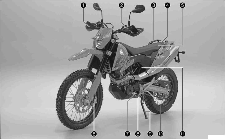
VIEW OF VEHICLE |
12 |
||
|
3View.1 of vehicle, front left side |
100234-10

1Hand brake lever
2Clutch lever
3Handrail
4Filler cap
5Seat
6Front brake caliper
7Shift lever
8Engine number
9Side stand
10Footrest
11Seat release strap
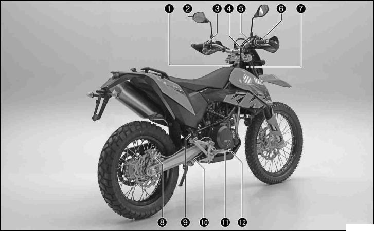
|
VIEW OF VEHICLE |
14 |
||
|
View3.2 of vehicle, rear right side |
|||
100235-10

1Ignition/steering lock
2Rear mirror
3Light switch, flasher switch, horn
4Combination instrument
5Emergency OFF switch, electric starter button
6Throttle grip
7Chassis number
8Rear brake caliper
9Passenger footrest
10Shock absorber rebound damping
11Foot brake pedal
12Engine oil level viewer
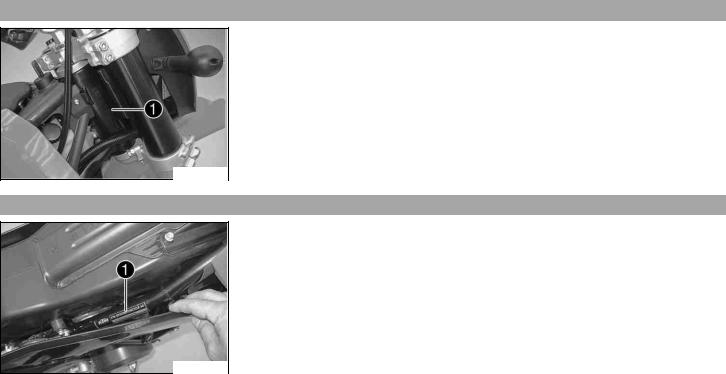
LOCATION OF SERIAL NUMBERS |
16 |
4Chassis.1 number
The chassis number is stamped on the steering head on the right.
100217-10
Type4.2 label
Type label is located on the upper right frame tube below the seat.
100218-10
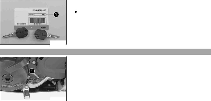
|
LOCATION OF SERIAL NUMBERS |
17 |
|||||||
|
Key4.3 number |
||||||||
|
The key number can be found on the KEYCODECARD. |
||||||||
|
Info |
||||||||
|
You need the key number to order a spare key. Keep the KEYCODECARD in a safe |
||||||||
|
place. |
||||||||
100179-10
Engine4.4 number
The engine number is stamped on the left side of the engine under the engine sprocket.
100211-10
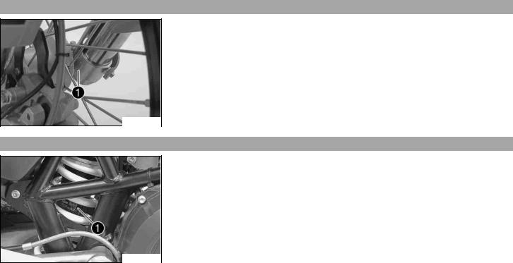
|
LOCATION OF SERIAL NUMBERS |
18 |
Fork4.5 part number
The fork part number is stamped on the inner side of the fork stub.
100214-10
Shock4.6 absorber part number
Shock absorber part number can be viewed from the right side.
100216-10
![]()
5Clutch.1 lever
The clutch lever is fitted on the left side of the handlebar.
The clutch is hydraulically operated and self-adjusting.
100219-10
Hand5.2 brake lever
The hand break lever is fitted on the right side of the handlebar.
The hand brake lever operates the front brake.
100220-10
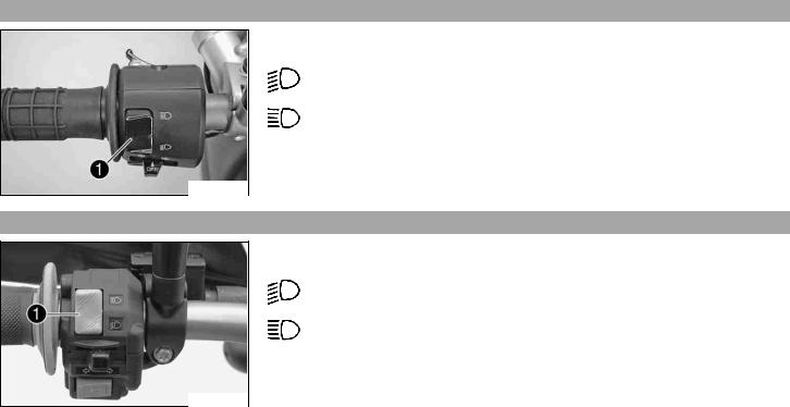
Light5.3 switch
The light switch is fitted on the left side of the handlebar.
Possible states
Low beam on – Light switch is turned downwards. In this position, the low
beam and tail light are switched on.
High beam on – Light switch is turned upwards. In this position, the high beam and the tail light are switched on.
500020-01
Light5.4 switch
The light switch is fitted on the left side of the handlebar.
Possible states
Low beam on – Light switch is turned downwards. In this position, the low
beam and tail light are switched on.
High beam on – Light switch is turned upwards. In this position, the high beam and the tail light are switched on.
100222-10
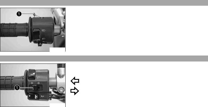
Headlight5.5 flasher switch
The headlight flasher switch is fitted on the left side of the handlebar.
Possible states
•Headlight flasher switch in neutral position
•Headlight flasher switch pressed – In this position, the headlight flasher (high beam) is actuated.
500020-11
Flasher5.6 switch
The flasher switch is fitted on the left side of the handlebar.
Possible states
Flasher light off
Flasher light, left, on – Flasher switch pressed to the right. The flasher switch returns automatically to the central position after use.
Flasher light, right, on – Flasher switch pressed to the right. The flasher switch returns automatically to the central position after use.
To switch off the flasher light, press the flasher switch towards the switch case.
500021-10
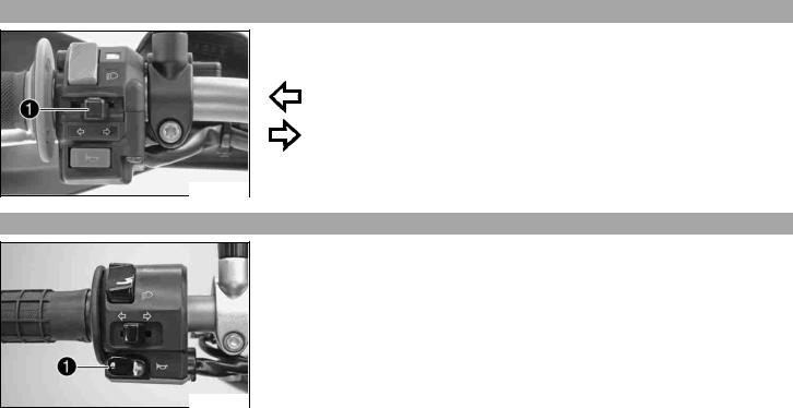
Flasher5.7 switch
The flasher switch is fitted on the left side of the handlebar.
Possible states
Flasher light off
Flasher light, left, on – Flasher switch pressed to the right. The flasher switch returns automatically to the central position after use.
Flasher light, right, on – Flasher switch pressed to the right. The flasher switch returns automatically to the central position after use.
To switch off the flasher light, press the flasher switch towards the switch case.
100223-10
Horn5.8
The horn button is fitted on the left side of the handlebar.
Possible states
•Horn button  in neutral position
•Horn button  pressed – The horn is operated in this position.
500021-11
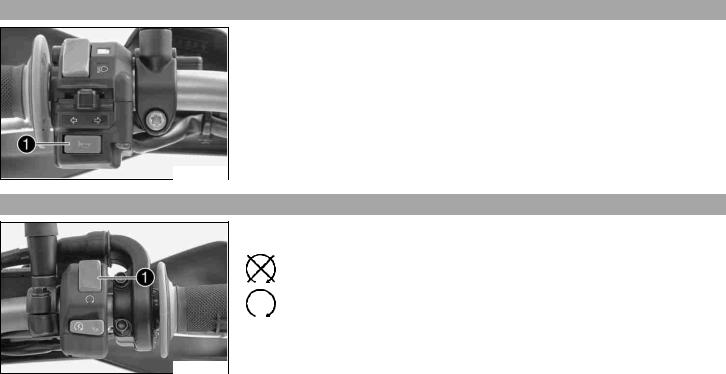
Horn5.9
The horn button is fitted on the left side of the handlebar.
Possible states
•Horn button  in neutral position
•Horn button  pressed – The horn is operated in this position.
100224-10
Emergency5.10 OFF switch
The emergency OFF switch is fitted on the left side of the handlebar.
Possible states
Emergency OFF switch off – In this position, the ignition circuit is interrupted, a running engine stops, and the engine cannot be started.
Emergency OFF switch on – This position is necessary for operation as the ignition circuit is closed.
100225-10
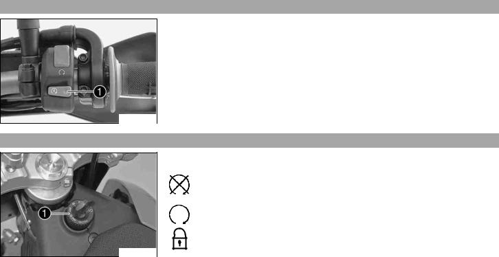
Electric5.11 starter button
The electric starter button is fitted on the right side of the handlebar.
Possible states
•Electric starter button  in basic position
 in basic position
•Electric starter button  pressed – In this position, the electric starter is actuated.
100226-10
Ignition/steering5.12 lock
The ignition/steering lock is located in front of the seat.
Possible states
Ignition off – In this position, the ignition circuit is interrupted, a running engine stops, and a non-running engine will not start. The ignition key can be removed.
Ignition on – In this position, the ignition circuit is closed, and the engine can be started.
Steering locked – In this position, the ignition circuit is interrupted and the steering locked. The ignition key can be removed.
100221-10
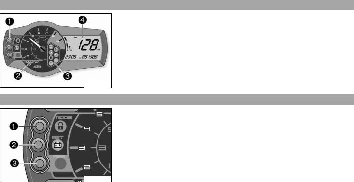
Combination5.13 instrument
The combination instrument is attached in fromt of the handlebar. The combination instrument is divided into 4 function areas.
Function buttonsTachometer
Indicator lightsDisplay
700116-01
Combination5.14 instrument — function buttons
Press the MODE button to change the display mode.
Possible display modes are total distance covered (ODO), tripmaster 1 (TRIP 1) and tripmaster 2 (TRIP 2).
Press the SET button to reset tripmaster 1 (TRIP 1) and tripmaster 2 (TRIP 2) to 0.0. Button has no function.
700117-01
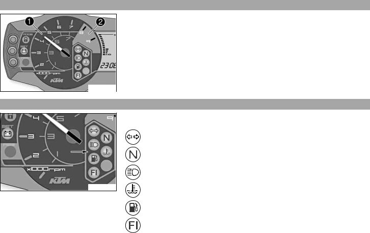
Combination5.15 instrument — tachometer
The tachometer displays the engine speed in revolutions per minute.
The red marking shows the excess engine speed range.
100118-10
Combination5.16 instrument — control lamps
100119-10
The indicator lamps provide additional information on the operating state of the motorcycle.
Possible states
Flashing indicator flashes green in flash rhythm – Flasher light is switched on.
Idling speed indicator lamp lights up green – Transmission is in neutral.
High beam indicator lamp lights up blue – High beam is switched on.
Temperature warning lamp lights up red – Coolant has reached a critical value.
Fuel level warning lamp lights up orange – Fuel level has reached the reserve mark. Display switches to TRIP F.
FI warning lamp (MIL) lights/flashes orange – The OBD has detected an emissionor safety-critical error.
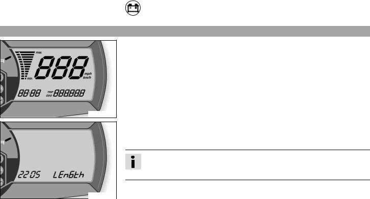
Combination5.17 instrument — Display
700118-01
400404-01
Battery warning lamp lights up – Voltage in electrical system too low.
When you switch on the ignition, all display segments light up for a second as a function test.
LEnGTth
Following the display function test, the wheel circumference LEnGth is shown for one second.
Info
2205 mm equals the circumference of the 21″ front wheel with a series production tire.
The display then changes to the last selected mode.
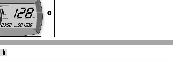
|
OPERATING ELEMENTS |
28 |
||||
|
Combination5.18 |
instrument — speed display |
||||
|
The speed is displayed in kilometers per hour km/h or miles per hour Mph. |
|||||
700114-01
Setting5.19 kilometers or miles
Info
If you change the unit, the ODO value is retained and converted accordingly.
Making the setting according to the country.
Condition
The motorcycle is standing.
![]()
–Switch on the ignition by turning the ignition key in the position  .
.
–Press the MODE button several times until the ODO display mode is active.
–Keep the MODE button pressed until the display mode changes from Km/h to Mph or from Mph to Km/h.
Specification
|
Activation duration of MODE button |
10 s |
700120-01
Combination5.20 instrument — time
The time is shown in area of the display.
Info
The time must be adjusted after the battery is disconnected or the fuse is changed.
700115-01
Setting5.21 the clock
Condition
The motorcycle is standing.

–Switch on the ignition by turning the ignition key in the position  .
.
–Press the MODE button several times until the ODO display mode is active.
–Keep the MODE button and the SET button pressed simultaneously.
 The time begins to flash.
–Press the MODE button to adjust the hour.
–Press the SET button to adjust the minute.
–Keep the MODE button and the SET button pressed simultaneously.
|
The time is set. |
||
|
700115-10 |
||
Combination5.22 instrument — ODO display
In ODO mode, the total distance covered is shown in kilometers or miles.
Info
This value remains intact even if the battery is disconnected and/or the fuse blows.
700120-01
Combination5.23 instrument — setting/resetting TRIP 1 display
Info
The tripmaster TRIP 1 operates constantly and counts up to 999.9.
You can use the tripmaster to measure trips or the distance between refuelling stops. After reaching 999.9, the tripmaster begins again at 0.0.

|
OPERATING ELEMENTS |
31 |
||
|
– |
Switch on the ignition by turning the ignition key in the position . |
||
|
– Press the MODE button several times until the TRIP 1 display mode is active. |
|||
|
– Keep the SET button pressed. |
|||
|
The TRIP 1 display is at 0.0. |
700121-01
Combination5.24 instrument — setting/resetting TRIP 2 display
Info
The tripmaster TRIP 2 operates constantly and counts up to 999.9.
You can use the tripmaster to measure trips or the distance between refuelling stops. After reaching 999.9, the tripmaster begins again at 0.0.
–Switch on the ignition by turning the ignition key in the position  .
.
–Press the MODE button several times until the TRIP 2 display mode is active.
–Keep the SET button pressed.
 The TRIP 2 display is at 0.0.
700122-01

Combination5.25 instrument — TRIP F display
When the fuel level reaches the reserve mark, the display automatically changes to TRIP F and begins to count from 0.0, regardless of which display mode was previously active.
Info
Parallel to the TRIP F display, the fuel warning light begins to light up.
700123-01
Combination5.26 instrument — coolant temperature indicator
The temperature indicator in the display consists of 12 bars. The more bars that light up, the hotter the coolant. When the top bar lights up, all bars begin to flash simultaneously and the temperature warning lamp begins to light up.
Possible states
•Engine cold – up to four bars light up.
•Engine at normal operating temperature – from five to eleven bars light up.
•Engine hot – all twelve bars flash.
700124-01

Opening5.27 filler cap
–Lift the cover of the filler cap and insert the ignition key.
–Turn the ignition key 90° counterclockwise and remove the filler cap.
Info
The filler cap has a tank air vent system.
100227-10
Closing5.28 filler cap
–Put the filler cap back on and turn the ignition key 90° clockwise.
–Remove the ignition key and fold down the cover.
100228-01

Handrails5.29
The handrails are used for moving the motorcycle around.
When you have a passenger, the passenger can hold on the handrails during the journey.
100229-10
Seat5.30 release
The seat can be released using strap .
100230-10

Passenger5.31 footrests
The passenger footrests can be folded up and down.
Possible states
•Passenger footrests folded up – For operation without a passenger.
•Passenger footrests folded down – For operation with a passenger.
100231-01
Shift5.32 lever
The shift lever is mounted on the left side of the engine.
100215-10

The gear positions can be seen in the photograph.
The neutral or idle position is between the first and second gears.
100212-10
Foot5.33 brake pedal
The footbrake pedal is located in front of the right footrest.
The footbrake pedal operates the rear brake.
100232-10

|
OPERATING ELEMENTS |
37 |
||
|
Side5.34 stand |
|||
|
The side stand is coupled with the safety electric starter system — see the riding instruc- |
|||
|
tions. |
Possible states
•Side stand folded out – The vehicle can be supported on the side stand. The safety electric starter system is active.
•Side stand folded in – This position is mandatory for all journeys. The safety electric starter system is inactive.
100233-10

GENERAL TIPS AND HINTS ON PUTTING INTO OPERATION |
38 |
6Advice.1 on first use
Danger
Danger of accidents Danger from inadequate traffic experience.
–Do not use the vehicle if you are inexperienced or if you have consumed alcohol or drugs.
Warning
Risk of injury Risk of injury by missing/inadequate protective clothing.
–Wear protective clothing (helmet, boots, gloves, pants and jacket with protectors) every time you ride the motorcycle. Always wear protective clothing, which must be in perfect condition and meet legal requirements.
Warning
Danger of crashing Impairment of riding behavior due to different tire tread patterns on front and rear wheels.
–The front and rear wheels must be fitted with tires with similar tread patterns to prevent loss of control over the vehicle.
Warning
Danger of accidents Uncontrollable handling behavior caused by non-approved tires/wheels.
–Use only tires/wheels approved by KTM with the corresponding speed index.
Warning
Danger of accidents Reduced road grip with new tires.
–New tires have a smooth roll surface and therefore cannot provide full road grip. The entire roll surface must be roughened in the first 200 kilometers (124.3 miles) by moderate driving at alternating angles. The full grip is not reached until the vehicle has been run in.
Warning
Danger of accidents Brake system failure.
–If the foot brake pedal is not released, the brake linings drag permanently. The rear brake can fail due to overheating. Take your foot off the foot brake pedal if you do not want to brake.
![]()
|
GENERAL TIPS AND HINTS ON PUTTING INTO OPERATION |
39 |
Info
When using your vehicle, remember that others may feel disturbed by excessive noise.
–Make sure that the pre-delivery inspection work has been carried out by an authorized KTM workshop. You receive a delivery certificate and the service record at vehicle handover.
–Before your first trip, read the entire operating instructions carefully.
–Get to know the operating elements.
–adjust the basic position of clutch lever. ( P. 129)
–Adjust the free travel of the handbrake lever. ( P. 77)
–Adjust the basic position of the foot brake pedal. x( P. 85)
–Get used to handling the vehicle on a car park before making a longer trip. Try also to ride as slowly as possible and in a standing position to get a better feeling for the vehicle.
–Do not make any offroad trips that over-stress your ability and experience.
–Hold the handlebar firmly with both hands and keep your feet on the footrests when riding.
–Do not make any changes to the vehicle, and use only KTM approved parts.
Info
Parts from other manufacturers can reduce the operational safety of the vehicle.
–Run the engine in.

|
GENERAL TIPS AND HINTS ON PUTTING INTO OPERATION |
40 |
Running6.2 in the engine
–During the running-in phase, do not exceed the specified engine speed and engine performance. Specification
Maximum engine speed
|
During the first: 1,000 km (621.4 mi) |
6,000 rpm |
|
After the first: 1,000 km (621.4 mi) |
7,800 rpm |
– Avoid fully opening the throttle!
Loading6.3 the vehicle
Warning
Danger of accidents Unstable riding behavior.
–Do not exceed the maximum permitted weight and axle loads. The overall weight consists of: motorcycle operational and with a full tank, driver and passenger with protective clothing and helmet, baggage.
Warning
Danger of accidents Unstable handling characteristics due to incorrect mounting of suitcase and/or tank rucksack.
–Mount and secure suitcase and tank rucksack according to the manufacturer’s instructions.
Warning
Danger of accidents Unstable handling characteristics at high speed.
–Adapt your speed according to your payload. Ride more slowly if your motorcycle is loaded with cases or other baggage.
|
Maximum speed with baggage |
130 km/h (80.8 mph) |
Warning
Danger of accidents Risk of breakage of suitcase system.
–If you have fitted suitcases on your motorcycle, read the manufacturer’s specifications concerning the maximum payload.

|
GENERAL TIPS AND HINTS ON PUTTING INTO OPERATION |
41 |
Warning
Danger of accidents Poor visibility for other road users due to slipped baggage.
–If the tail light is covered, you are less visible to following traffic, especially in the dark. Check the way your baggage is fixed regularly.
Warning
Danger of accidents Changed handling characteristics and longer stopping distance with excessive payload.
–Adapt your speed according to your payload.
Warning
Danger of accidents Unstable handling characteristics due to slipped baggage.
–Check the way your baggage is fixed regularly.
Warning
Danger of burns A hot exhaust system can burn baggage.
–Fasten your baggage in such a way that it cannot be burned or singed by the hot exhaust system.
–If you carry any baggage, make sure it is fixed firmly as close as possible to the center of the vehicle and ensure even weight distribution between the front and rear wheels.
–Do not exceed the overall maximum permitted weight and the axle loads. Specification
|
Maximum permissible overall weight |
350 kg (772 lb.) |
|
Maximum permissible front axle load |
150 kg (331 lb.) |
|
Maximum permissible rear axle load |
200 kg (441 lb.) |

7Checks.1 before putting into operation
Info
Make sure that the motorcycle is in a perfect technical condition before use.
In the interests of riding safety, make a habit of making a general check before you ride.
–Check the engine oil level. ( P. 133)
–Check the engine for loss of oil.
–Check the fuel level.
–Bleed fork legs. ( P. 62) Specification
–Check the chain tension. ( P. 70)
–Clean the chain. ( P. 69)
–Check the tire condition. ( P. 98)
–Checking the tire air pressure. ( P. 100)
–Check the front brake brake fluid level. ( P. 78)
–Check the rear brake fluid level. ( P. 86)
–Check the front brake linings. ( P. 81)
–Check the rear brake linings. ( P. 89)
–Check brake system function.
–Check the coolant level. ( P. 124)
–Check that all operating elements are correctly adjusted and free to move.
–Check the functioning of the electrical equipment.
–Check that baggage is correctly secured.
–Sit on the motorcycle and check the rear mirror setting.

Starting7.2
Danger
Danger of poisoning Exhaust gases are poisonous and can result in unconsciousness and/or death.
–When running the engine, always make sure there is sufficient ventilation, and do not start or run the engine in a closed space.
Caution
Danger of accidents If the vehicle is operated with a discharged battery or without a battery, electronic components and safety equipment may be damaged.
–Never operate the vehicle with a discharged battery or without a battery.
Note
Engine failure High engine speeds in cold engines have a negative effect on the service life of the engine.
–Always warm up the engine at low engine speeds.

|
RIDING INSTRUCTIONS |
44 |
||||||
|
– |
Turn the emergency OFF switch to the position . |
||||||
|
– |
Switch on the ignition by turning the ignition key in the position . |
||||||
|
After switching on the ignition, you can hear the fuel pump working for about 2 |
|||||||
|
seconds. At the same time, the combination instrument runs a function test. |
|||||||
|
– Shift gear to neutral. |
|||||||
|
The green idling speed indicator lamp N lights up. |
|||||||
|
– |
Press the electric starter button . |
||||||
|
Info |
|||||||
|
Do not press the electric starter button until the combination instrument func- |
|||||||
|
tion test is finished. |
|||||||
|
Do not open the throttle when starting. If you open the throttle when starting, |
|||||||
|
the engine management injects no fuel and the engine cannot start. |
|||||||
|
Press the starter for a maximum of 5 seconds. Wait for at least 5 seconds until |
|||||||
|
trying again. |
|||||||
|
This motorcycle is equipped with a safety electric starter system. The engine |
|||||||
|
can be started only if the gearbox is in neutral or the clutch lever is pulled. If |
|||||||
|
you shift into gear when the side stand is folded out and then release the clutch |
|||||||
|
lever, the engine stalls. |
|||||||
|
– Take the weight off the side stand and swing it back up with your foot as far as it will |
|||||||
|
go. |
100239-10

Starting7.3 up
–Pull the clutch lever, engage 1st gear, release the clutch lever slowly and simultaneously open the throttle carefully.
Shifting,7.4 riding
Warning
Danger of accidents An abrupt load alterations can cause the vehicle to get out of control.
–Avoid abrupt load alterations and sudden braking actions, and adapt your speed to the road conditions.
Warning
Danger of accidents If you change down at high engine speed, the rear wheel can lock up.
–Do not change into a low gear at high engine speed. The engine races and the rear wheel can block.
Warning
Danger of accidents Malfunctions caused by incorrect ignition key position.
–Do not change the ignition key position during a journey.
Warning
Danger of accidents Distraction from traffic activity by adjustments to the vehicle.
–Make all adjustments when the vehicle is at a standstill.
Warning
Risk of injury The passenger must be capable of sitting correctly on the passenger seat.
–The passenger must hold on to the rider or the handrails and place his feet on the passenger footrests. Note the regulations governing the minimum age of passengers in your country.
Warning
Danger of accidents Danger of accidents caused by dangerous driving.
–Observe the traffic regulations and ride defensively and with foresight in order to recognize danger as early as possible.

Warning
Danger of accidents Reduced road grip with cold tires.
–On every journey, take the first miles carefully at moderate speed until the tires reach operating temperature and optimal road grip is ensured.
Warning
Danger of accidents Reduced road grip with new tires.
–New tires have a smooth roll surface and therefore cannot provide full road grip. The entire roll surface must be roughened in the first 200 kilometers (124.3 miles) by moderate driving at alternating angles. The full grip is not reached until the vehicle has been run in.
Warning
Danger of accidents Unstable riding behavior.
–Do not exceed the maximum permitted weight and axle loads. The overall weight consists of: motorcycle operational and with a full tank, driver and passenger with protective clothing and helmet, baggage.
Warning
Danger of accidents Unstable handling characteristics due to slipped baggage.
–Check the way your baggage is fixed regularly.
Warning
Danger of accidents After a fall, check the vehicle.
–After a fall, check the vehicle as usual before putting it into operation.
Note
Engine failure Unfiltered intake air has a negative effect on the service life of the engine.
–Never ride the vehicle without an air filter since dust and dirt can get into the engine and result in increased wear.

Note
Engine failure Overheating of engine.
–If the coolant temperature warning lamp lights up, stop and switch off the engine. Allow the engine to cool down and check the coolant level in the radiator, and top up if necessary. If you continue with the coolant temperature warning lamp alight, you may have engine failure.
Info
If you hear unusual noises while riding, stop immediately, switch off the engine and contact an authorized KTM workshop.
–When conditions allow (incline, road situation, etc.), you can shift into a higher gear.
–Release the throttle while simultaneously pulling the clutch lever, shift into the next gear, release the clutch and open the throttle.
|
Info |
|||||
|
For the positions of the 6 forward gears, see the illustration. The neutral or idle |
|||||
|
position is between the first and second gears. First gear is used for starting off |
|||||
|
or for steep inclines. |
|||||
|
The operating temperature is reached when 5 bars of the temperature indicator |
|||||
|
light up. |
|||||
|
100212-10 |
|||||
–When you reach maximum speed after fully opening the throttle, turn back the throttle to about ¾ of its range; the speed hardly drops, but the fuel consumption falls considerably.
–Open the throttle only as far as the road and weather conditions permit. Particularly in bends, do not shift and open the throttle only very cautiously.
–To shift down, brake if necessary and close the throttle at the same time.
–Pull the clutch lever and shift into a lower gear, release the clutch lever slowly and open the throttle or shift again.

|
RIDING INSTRUCTIONS |
48 |
||||||
|
– For example, if the engine stalls at a junction, just pull the clutch and press the electric |
|||||||
|
starter button. You do not need to shift into neutral. |
|||||||
|
– Switch off the engine if you expect to be standing for a long time. |
|||||||
|
– Avoid frequent and longer slipping of the clutch. This heats the engine oil, the engine |
|||||||
|
and the cooling system. |
|||||||
|
– Ride with a lower engine speed instead of with a high engine speed and a slipping |
|||||||
|
clutch. |
|||||||
|
– If the FI warning lamp (MIL) starts to light up during the journey, stop immediately. If |
|||||||
|
you shift to neutral, the FI warning lamp (MIL) begins to flash. |
|||||||
|
Info |
|||||||
|
From the flash rhythm, you can deduce a two-digit number, the so-called flash |
|||||||
|
code. The flash code tells you which component is affected by a fault. |
|||||||
Braking7.5 |
|||||||
|
Warning |
Danger of accidents If you brake too hard, the wheels can lock.
–Adapt your braking to the traffic situation and the road conditions.
Warning
Danger of accidents Reduced braking due to wet or dirty brakes.
–Clean or dry dirty or wet brakes by riding and braking gently.
Warning
Danger of accidents Reduced braking caused by spongy pressure point of front or rear brake.
–Have the brake system checked in an authorized KTM workshop, and do not ride any further.