Материал из BikesWiki — энциклопедия японских мотоциклов
Перейти к: навигация, поиск

Kawasaki ER-6n
Ниже представлены прямые ссылки на скачку сервисной документации.
Для Kawasaki ER-6
- Руководство пользователя (Owners Manual) на Kawasaki ER-6N (на русском)
- Сервисный мануал (Service Manual) на Kawasaki ER-6N (2006-2008)
- Сервисный мануал (Service Manual) на Kawasaki ER-6N (2009-2011)
- Сервисный мануал (Service Manual) на Kawasaki ER-6N (2012-2016)
- Руководство пользователя (Owners Manual) на Kawasaki ER-6F (на русском)
- Сервисный мануал (Service Manual) на Kawasaki ER-6F (2006-2008)
- Сервисный мануал (Service Manual) на Kawasaki ER-6F (2009-2011)
- Сервисный мануал (Service Manual) на Kawasaki ER-6F (2012-2016)
Обзор модели
- Kawasaki ER-6
Источник — «https://bikeswiki.ru/index.php?title=Kawasaki_ER-6:_мануалы&oldid=11838»
Категория:
- Сервисная документация
#1
![]()
Cher Tannov
-
Вконтакте:

- Пол:Мужчина
- Страна:Россия
- Город:Москва, Чер Танново
- Мото:ER-6F ’12
Отправлено 10 Март 2016 — 17:27
Инструкции по эксплуатации на русском языке:
Руководство по эксплуатации ER-6n, ER-6n ABS 2012-2016
Руководство по эксплуатации Ninja 650, Ninja 650 ABS, ER-6f, ER-6f ABS 2012-2016
Вот руководства по ремонту (на английском языке):
Руководство по ремонту ER-6n (ABS) 2006-2008
Руководство по ремонту ER-6n (ABS) 2009-2011
Руководство по ремонту ER-6n (ABS) 2012-2016
Руководство по ремонту Ninja 650R, ER-6f (ABS) 2006-2008
Руководство по ремонту Ninja 650R, ER-6f (ABS) 2009-2011
Руководство по ремонту Ninja 650R, ER-6f (ABS) 2012-2016
Руководство по ремонту Ninja 650R ER-6f (ABS) 2012-2016 на русском языке!
Часть 1-2. Технические характеристики и периодическое обслуживание
Часть 3. Система впрыска топлива (DFI)
Часть 4-5. Система охлаждения. Двигатель
Часть 6-8. Сцепление. Система смазки двигателя. Снятие/установка двигателя
Часть 9. Трансмиссия
Часть 10-11. Колёса/шины. Цепная передача
Часть 12. Тормозная система
Часть 13-15. Подвеска. Рулевое управление. Рама
Часть 16. Электрооборудование
Часть 17-18. Прокладка шлангов, тросов и кабелей. Поиск и устранение неисправностей
Каталог запчастей на русском языке!
Каталог запчастей мотоцикла ER-6f 2012
Желающие приобрести руководство и каталог в бумажном виде могут сделать это в специальной теме.
Народ, я довершил наконец одно большое дело, нарисовал схему Ерша. Адаптировал для лучшего восприятия, перевёл все надписи на русский язык. Пользуйтесь на здоровье.
Схема электрооборудования ER-6F 2012 ABS:

Для вашего удобства, та же схема, в формате .PDF доступна для скачивания по ссылке.
У меня ещё много планов впереди: перевести на русский мануал по ремонту (сделано), сделать каталог запчастей на русском языке (сделано), создать что-то вроде интерактивной карты мотоцикла с указанием наиболее популярных расходников со ссылками на магазины и ещё многое.
Это не быстрый процесс, буду выкладывать по мере готовности. Другие модели пока охватить не готов, объём работы просто колоссальный.
Сообщение отредактировал Cher Tannov: 08 Ноябрь 2020 — 08:06
Дополняю, расширяю…
- SShMeL, alllex, Валентин_Н и 9 другим это нравится
- Наверх
#2
![]()
SShMeL
SShMeL
- Пол:Мужчина
- Страна:Россия
- Город:Москва
- Мото:Ninja 650r > Ninja ZX12R + ZRX1100
Отправлено 10 Март 2016 — 20:42
Спасибо огромное за схему, очень поможет мне разобраться почему перегорает ECU предохранитель при срабатывание сигнализации. Только в схеме ты забыл расписать блок предохранителей 1 и 2 добавь пожалуйста, я в принципе и без этого обойдусь, но все же. Еще можешь выложить исходники я бы для себя поправил, так как у меня нет ABS, добавил свое дополнительное оборудование и распечатал бы на А3.
- Наверх
#3
![]()
Cher Tannov
Cher Tannov
-
Вконтакте:
- Пол:Мужчина
- Страна:Россия
- Город:Москва, Чер Танново
- Мото:ER-6F ’12
Отправлено 10 Март 2016 — 21:56
Опа!
Очень странно, описание блоков предохранителей было… Завтра поправлю. Влад, спасибо за то, что увидел упущение.
Сейчас на подходе схема мота без АВS, прошу тебя потерпеть.
Ребята, пишите, в чём ещё потребность, я буду прислушиваться.
Поправил схему, добавил описание блоков предохранителей. Обновил ссылки.
В работе ещё много проектов.
Сообщение отредактировал Cher Tannov: 15 Март 2016 — 15:50
- Наверх
#4
![]()
Wasilen
Wasilen
-
- Members
-
- 11 сообщений
Прохожий


- Пол:Мужчина
- Страна:Россия
- Город:Карасук, Новосибирской области
- Мото:Kawasaki Ninja EX650 2013
Отправлено 19 Март 2016 — 09:36
Спасибо за проделанную работу!
- Наверх
#5
![]()
Cher Tannov
Cher Tannov
-
Вконтакте:
- Пол:Мужчина
- Страна:Россия
- Город:Москва, Чер Танново
- Мото:ER-6F ’12
Отправлено 19 Март 2016 — 15:56
Пожалуйста.
Всё для вас.
Добавил в каталог запчастей ещё несколько разделов. Серьёзно переработал дизайн. Кажется, теперь каталог стал зрительно более восприимчив.
Пользуйтесь.
Кстати, если у вас есть вопросы, пожелания, предложения или дополнения, высказывайте. Да и от помощи я бы не отказался…
Сообщение отредактировал Cher Tannov: 08 Июнь 2017 — 22:38
- Валентин_Н и endorfirma это нравится
- Наверх
#6
![]()
snorky_KoLXo3HuK
snorky_KoLXo3HuK
- Пол:Мужчина
- Страна:РФ
- Город:Митино, Юбутово
- Мото:ER-6f 13 > GL 1800
Отправлено 04 Апрель 2016 — 21:55
схема просто отличная, всё видно и понятно
- Наверх
#7
![]()
Cher Tannov
Cher Tannov
-
Вконтакте:
- Пол:Мужчина
- Страна:Россия
- Город:Москва, Чер Танново
- Мото:ER-6F ’12
Отправлено 11 Май 2016 — 15:36
Братва, хорошая новость!
Я закончил перевод каталога запчастей на русский язык, выложил полную версию, пользуйтесь!
Не слабо, книжка получилась в палец толщиной:

Сообщение отредактировал Cher Tannov: 11 Май 2016 — 16:09
- SShMeL и Валентин_Н это нравится
- Наверх
#8
![]()
Dinis
Dinis
-
- Members
-
- 37 сообщений
Прохожий

- Пол:Мужчина
- Страна:Россия
- Город:Владимир
- Мото:ER-6F
Отправлено 28 Июнь 2016 — 11:34
Братва, хорошая новость!
Я закончил перевод каталога запчастей на русский язык, выложил полную версию, пользуйтесь!
Не слабо, книжка получилась в палец толщиной:
Хороший труд. Огромное спасибо!
- atomic это нравится
- Наверх
#9
![]()
Валентин_Н
Валентин_Н
- Пол:Мужчина
- Страна:Россия
- Город:Москва, Ярославский
- Мото:ER-6F ’13
Отправлено 02 Июль 2016 — 22:21
Спасибо, попробую распечатать и сверстать в переплёт на работе пока никто не видит 
- Наверх
#10
![]()
BazonXGK
BazonXGK
- Пол:Мужчина
- Страна:Россия
- Город:Севастополь
- Мото:Kawasaki Ninja EX650AF (2006г.)
Отправлено 20 Сентябрь 2016 — 16:22
Ну, что, народ, приступил я к переводу инструкции по ремонту. Быстро не ждите, объём титанический!
Идея нужная и полезная, будем ждать , удачи!
- Наверх
#11
![]()
PaulSankov
PaulSankov
-
- Members
-
- 16 сообщений
Прохожий

- Пол:Мужчина
- Страна:Россия
- Город:г. Москва
- Мото:Zx-6r 636 06, Er-6n 13
Отправлено 12 Октябрь 2016 — 00:19
Ну, что, народ, приступил я к переводу инструкции по ремонту. Быстро не ждите, объём титанический!
Бесконечно ценный материал будет, колоссальная работа предстоит! Надеюсь, что все у тебя пойдет как по маслу в этом деле!
- Наверх
#12
![]()
Валентин_Н
Валентин_Н
- Пол:Мужчина
- Страна:Россия
- Город:Москва, Ярославский
- Мото:ER-6F ’13
Отправлено 12 Октябрь 2016 — 12:47
Бесконечно ценный материал будет, колоссальная работа предстоит! Надеюсь, что все у тебя пойдет как по маслу в этом деле!
Очень круто!
Я когда каталог на запчасти распечатал и сброшюровал, на работе все автомобилисты обзавидовались…
- Наверх
#13
![]()
Cher Tannov
Cher Tannov
-
Вконтакте:
- Пол:Мужчина
- Страна:Россия
- Город:Москва, Чер Танново
- Мото:ER-6F ’12
Отправлено 03 Декабрь 2016 — 11:11
Давно я новостей не писал по теме, всё руки не доходили.
Наконец дело по переводу мануала хоть немного продвинулось.
Оказалось, что всё гораздо сложнее, чем мне представлялось сначала. Дело в том, что буржуйская система нумерации страниц и каталогизации содержания представляется мне крайне неудобной. Посудите сами, если всего в книге 500 листов, то где находится лист 4-28 или 1-18 совершенно непонятно. А вот лист 250, понятно и ежу, находится в середине. Буду перерабатывать под привычную нам нумерацию, хоть это и дополнительный объём работы.
А пока на ваш суд выношу несколько страниц мануала. Понимаю, что хвастаться пока особо нечем, но, может вы замечания какие сделаете или идею подкинете…
- BazonXGK это нравится
- Наверх
#14
![]()
vyrcnk
vyrcnk
-
Вконтакте:
- Пол:Мужчина
- Страна:Россия
- Город:Краснодар
- Мото:Honda CB1300SF Boldor 2007
Отправлено 05 Декабрь 2016 — 20:21
Хорошее дело! У меня с английским не очень. Вопрос по давлению в шинах. Неужели его раз в год проверять или через каждые 12 000 км? Может там что-то еще имелось ввиду? Встречал общие рекомендации для мотоцикла проверять перед каждым выездом. Лично мне каждый день это делать лень, хоть уже попадал. При экстренном торможении мотоцикл повел себя не так, как ожидалось. Хоть и закончилось все тогда нормально. Оказалось дело было в сниженном давлении. «На глаз» такое изменение давления не определить, а сцепные свойства, управляемость и износ могут измениться в больших пределах.
- Наверх
#15
![]()
Cher Tannov
Cher Tannov
-
Вконтакте:
- Пол:Мужчина
- Страна:Россия
- Город:Москва, Чер Танново
- Мото:ER-6F ’12
Отправлено 05 Декабрь 2016 — 22:28
Там имелось ввиду именно давление в шинах. А проверять его надо гораздо чаще. Особенно, если катаешь каждый день.
Я раз в 2-3 недели обязательно на заправках проверяюсь. И, если надо, подкачиваю (обычно изношенные баллоны плохо держат давление).
- Наверх
#16
![]()
Руслан Казанский
Руслан Казанский
-
- Читатели
- 3 сообщений

- Пол:Мужчина
- Страна:Россия
- Город:Севастополь
- Мото:Kawasaki ER6-N
Отправлено 06 Декабрь 2016 — 03:29
МЕГА-Человечище! Респект!
Отправлено с моего iPhone используя Tapatalk
- olv956 это нравится
- Наверх
#17
![]()
Cher Tannov
Cher Tannov
-
Вконтакте:
- Пол:Мужчина
- Страна:Россия
- Город:Москва, Чер Танново
- Мото:ER-6F ’12
Отправлено 01 Февраль 2017 — 18:13
Нерадостную весть я вам собираюсь сообщить. Обратил внимание, что осталось ещё 581 страница. Если я каждый день перевожу по 2 страницы, нескоро вы ещё дождётесь от меня результата.
Может имеет смысл разбить весь мануал на отдельные книги и выпускать по мере готовности? Или лучше целиком?
- Alpine это нравится
- Наверх
#18
![]()
untitled
untitled
- Пол:Мужчина
- Страна:Россия
- Город:Йошкар-Ола
- Мото:Kawasaki gpz400r, Kawasaki ER-6f
Отправлено 01 Февраль 2017 — 18:57
Может имеет смысл разбить весь мануал на отдельные книги и выпускать по мере готовности? Или лучше целиком?
Мое мнение — разбить на отдельные книги, кому нужно будет целиком, тот по завершению перевода объединит все книги в одну.
А если сделать отдельные книги по разделам, то будет проще работать с ними, т к по названию файла можно будет обратиться к тому или иному разделу.
- Наверх
#19
![]()
Cher Tannov
Cher Tannov
-
Вконтакте:
- Пол:Мужчина
- Страна:Россия
- Город:Москва, Чер Танново
- Мото:ER-6F ’12
Отправлено 10 Март 2017 — 17:28
Как обещал, выложил в доступ полностью переведённые и оформленные 1 и 2 часть мануала.
Ссылка также доступна и в первом сообщении темы.
Подустал немного…
- Everybody, SShMeL, Валентин_Н и 3 другим это нравится
- Наверх
#20
![]()
vyrcnk
vyrcnk
-
Вконтакте:
- Пол:Мужчина
- Страна:Россия
- Город:Краснодар
- Мото:Honda CB1300SF Boldor 2007
Отправлено 10 Март 2017 — 18:49
Великое и очень нужное дело! Благодарю!
- Наверх
Руководство на немецком языке по техническому обслуживанию и ремонту мотоциклов Kawasaki ER 5 Twister с 1997 года выпуска.
- Издательство: —
- Год издания: —
- Страниц: 113
- Формат: PDF
- Размер: 84,9 Mb

Руководство на английском языке по техническому обслуживанию и ремонту мотоциклов Kawasaki ER-5.
- Издательство: Kawasaki Heavy Industries, Ltd.
- Год издания: 2004
- Страниц: 334
- Формат: PDF
- Размер: 7,1 Mb

Руководство на английском языке по техническому обслуживанию и ремонту мотоциклов Kawasaki ER-6n.
- Издательство: Kawasaki Heavy Industries, Ltd.
- Год издания: 2005
- Страниц: 537
- Формат: PDF
- Размер: 11,0 Mb

Руководство на английском языке по техническому обслуживанию и ремонту мотоциклов Kawasaki Ninja 650R/ER-6f.
- Издательство: Kawasaki Heavy Industries, Ltd.
- Год издания: 2008
- Страниц: 623
- Формат: PDF
- Размер: 7,7 Mb

Руководство по эксплуатации и техническому обслуживанию мотоциклов Kawasaki ER-6f.
- Издательство: Kawasaki Heavy Industries, Ltd.
- Год издания: 2011
- Страниц: 166
- Формат: PDF
- Размер: 5,4 Mb
Руководство по эксплуатации и техническому обслуживанию мотоциклов Kawasaki ER-6n.
- Издательство: Kawasaki Heavy Industries, Ltd.
- Год издания: 2011
- Страниц: 163
- Формат: PDF
- Размер: 6,8 Mb

 Loading…
![]()
Motorcycle
Service Manual

Quick Reference Guide
This quick reference guide will assist you in locating a desired topic or procedure.
•Bend the pages back to match the black tab of the desired chapter number with the black tab on the edge at each table of contents page.
•Refer to the sectional table of contents for the exact pages to locate the specific topic required.
|
General Information |
1 |
j |
|
Periodic Maintenance |
2 |
j |
|
Fuel System (DFI) |
3 |
j |
|
Cooling System |
4 |
j |
|
Engine Top End |
5 |
j |
|
Clutch |
6 |
j |
|
Engine Lubrication System |
7 |
j |
|
Engine Removal/Installation |
8 |
j |
|
Crankshaft/Transmission |
9 |
j |
|
Wheels/Tires |
10 |
j |
|
Final Drive |
11 |
j |
|
Brakes |
12 |
j |
|
Suspension |
13 |
j |
|
Steering |
14 |
j |
|
Frame |
15 |
j |
|
Electrical System |
16 |
j |
|
Appendix |
17 |
j |

ER-6n
ER-6n ABS
Motorcycle
Service Manual
All rights reserved. No parts of this publication may be reproduced, stored in a retrieval system, or transmitted in any form or by any means, electronic mechanical photocopying, recording or otherwise, without the prior written permission of Quality Assurance Division/Consumer Products & Machinery Company/Kawasaki Heavy Industries, Ltd., Japan.
No liability can be accepted for any inaccuracies or omissions in this publication, although every possible care has been taken to make it as complete and accurate as possible.
The right is reserved to make changes at any time without prior notice and without incurring an obligation to make such changes to products manufactured previously. See your Motorcycle dealer for the latest information on product improvements incorporated after this publication.
All information contained in this publication is based on the latest product information available at the time of publication. Illustrations and photographs in this publication are intended for reference use only and may not depict actual model component parts.
|
© 2008 Kawasaki Heavy Industries, Ltd. |
First Edition (1) : Nov. 10, 2008 (M) |
LIST OF ABBREVIATIONS
|
A |
ampere(s) |
lb |
pound(s) |
|
ABDC |
after bottom dead center |
m |
meter(s) |
|
AC |
alternating current |
min |
minute(s) |
|
ATDC |
after top dead center |
N |
newton(s) |
|
BBDC |
before bottom dead center |
Pa |
pascal(s) |
|
BDC |
bottom dead center |
PS |
horsepower |
|
BTDC |
before top dead center |
psi |
pound(s) per square inch |
|
°C |
degree(s) Celsius |
r |
revolution |
|
DC |
direct current |
rpm |
revolution(s) per minute |
|
F |
farad(s) |
TDC |
top dead center |
|
°F |
degree(s) Fahrenheit |
TIR |
total indicator reading |
|
ft |
foot, feet |
V |
volt(s) |
|
g |
gram(s) |
W |
watt(s) |
|
h |
hour(s) |
Ω |
ohm(s) |
|
L |
liter(s) |
||
COUNTRY AND AREA CODES
|
AT |
Austria |
GB |
United Kingdom |
|
AU |
Australia |
MY |
Malaysia |
|
BR |
Brazil |
SEA |
South East Asia |
|
CA |
Canada |
TH |
Thailand |
|
CAL |
California |
US |
United States |
|
CH |
Switzerland |
WVTA (FULL H) |
WVTA Model with Honeycomb Catalytic |
|
Converter (Full Power) |
|||
|
DE |
Germany |
GB WVTA |
WVTA Model with Honeycomb Catalytic |
|
(FULL H) |
Converter (Left Side Traffic, Full Power) |
||
|
EUR |
Europe |
||

EMISSION CONTROL INFORMATION
To protect the environment in which we all live, Kawasaki has incorporated crankcase emission (1) and exhaust emission (2) control systems in compliance with applicable regulations of the United States Environmental Protection Agency and California Air Resources Board. Additionally, Kawasaki has incorporated an evaporative emission control system (3) in compliance with applicable regulations of the California Air Resources Board on vehicles sold in California only.
1. Crankcase Emission Control System
This system eliminates the release of crankcase vapors into the atmosphere. Instead, the vapors are routed through an oil separator to the inlet side of the engine. While the engine is operating, the vapors are drawn into combustion chamber, where they are burned along with the fuel and air supplied by the fuel injection system.
2. Exhaust Emission Control System
This system reduces the amount of pollutants discharged into the atmosphere by the exhaust of this motorcycle. The fuel, ignition, and exhaust systems of this motorcycle have been carefully designed and constructed to ensure an efficient engine with low exhaust pollutant levels.
The exhaust system of this model motorcycle manufactured primarily for sale in California includes a catalytic converter system.
3. Evaporative Emission Control System
Vapors caused by fuel evaporation in the fuel system are not vented into the atmosphere. Instead, fuel vapors are routed into the running engine to be burned, or stored in a canister when the engine is stopped. Liquid fuel is caught by a vapor separator and returned to the fuel tank.
The Clean Air Act, which is the Federal law covering motor vehicle pollution, contains what is commonly referred to as the Act’s “tampering provisions”.
“Sec. 203(a) The following acts and the causing thereof are prohibited.
(3)(A) for any person to remove or render inoperative any device or element of design installed on or in a motor vehicle or motor vehicle engine in compliance with regulations under this title prior to its sale and delivery to the ultimate purchaser, or for any manufacturer or dealer knowingly to remove or render inoperative any such device or element of design after such sale and delivery to the ultimate purchaser.
(3)(B) for any person engaged in the business of repairing, servicing, selling, leasing, or trading motor vehicles or motor vehicle engines, or who operates a fleet of motor vehicles knowingly to remove or render inoperative any device or element of design installed on or in a motor vehicle or motor vehicle engine in compliance with regulations under this title following its sale and delivery to the ultimate purchaser…”
NOTE
○The phrase “remove or render inoperative any device or element of design” has been generally interpreted as follows.
1.Tampering does not include the temporary removal or rendering inoperative of devices or elements of design in order to perform maintenance.
2.Tampering could include.
a.Maladjustment of vehicle components such that the emission standards are exceeded.
b.Use of replacement parts or accessories which adversely affect the performance or durability of the motorcycle.
c.Addition of components or accessories that result in the vehicle exceeding the standards.
d.Permanently removing, disconnecting, or rendering inoperative any component or element of design of the emission control systems.
WE RECOMMEND THAT ALL DEALERS OBSERVE THESE PROVISIONS OF FEDERAL LAW, THE VIOLATION OF WHICH IS PUNISHABLE BY CIVIL PENALTIES NOT EXCEEDING $10 000 PER VIOLATION.

TAMPERING WITH NOISE CONTROL SYSTEM PROHIBITED
Federal law prohibits the following acts or the causing thereof. (1) The removal or rendering inoperative by any person other than for purposes of maintenance, repair, or replacement, of any device or element of design incorporated into any new vehicle for the purpose of noise control prior to its sale or delivery to the ultimate purchaser or while it is in use, or (2) the use of the vehicle after such device or element of design has been removed or rendered inoperative by any person.
Among those acts presumed to constitute tampering are the acts listed below.
•Replacement of the original exhaust system or muffler with a component not in compliance with Federal regulations.
•Removal of the muffler(s) or any internal portion of the muffler(s).
•Removal of the air box or air box cover.
•Modifications to the muffler(s) or air inlet system by cutting, drilling, or other means if such modifications result in increased noise levels.
Foreword
This manual is designed primarily for use by trained mechanics in a properly equipped shop. However, it contains enough detail and basic information to make it useful to the owner who desires to perform his own basic maintenance and repair work. A basic knowledge of mechanics, the proper use of tools, and workshop procedures must be understood in order to carry out maintenance and repair satisfactorily. Whenever the owner has insufficient experience or doubts his ability to do the work, all adjustments, maintenance, and repair should be carried out only by qualified mechanics.
In order to perform the work efficiently and to avoid costly mistakes, read the text, thoroughly familiarize yourself with the procedures before starting work, and then do the work carefully in a clean area. Whenever special tools or equipment are specified, do not use makeshift tools or equipment. Precision measurements can only be made if the proper instruments are used, and the use of substitute tools may adversely affect safe operation.
For the duration of the warranty period, we recommend that all repairs and scheduled maintenance be performed in accordance with this service manual. Any owner maintenance or repair procedure not performed in accordance with this manual may void the warranty.
To get the longest life out of your vehicle.
•Follow the Periodic Maintenance Chart in the Service Manual.
•Be alert for problems and non-scheduled maintenance.
•Use proper tools and genuine Kawasaki Motorcycle parts. Special tools, gauges, and testers that are necessary when servicing Kawasaki motorcycles are introduced by the Service Manual. Genuine parts provided as spare parts are listed in the Parts Catalog.
•Follow the procedures in this manual carefully. Don’t take shortcuts.
•Remember to keep complete records of maintenance and repair with dates and any new parts installed.
How to Use This Manual
In this manual, the product is divided into its major systems and these systems make up the manual’s chapters. The Quick Reference
Guide shows you all of the product’s system and assists in locating their chapters. Each chapter in turn has its own comprehensive Table of Contents.
For example, if you want ignition coil information, use the Quick Reference Guide to locate the Electrical System chapter. Then, use the Table of Contents on the first page of the chapter to find the Ignition Coil section.
Whenever you see these WARNING and CAUTION symbols, heed their instructions! Always follow safe operating and maintenance practices.

 WARNING
This warning symbol identifies special instructions or procedures which, if not correctly followed, could result in personal injury, or loss of life.
CAUTION
This caution symbol identifies special instructions or procedures which, if not strictly observed, could result in damage to or destruction of equipment.
This manual contains four more symbols (in addition to WARNING and CAUTION) which will help you distinguish different types of information.
NOTE
○This note symbol indicates points of particular interest for more efficient and convenient operation.
•Indicates a procedural step or work to be done.
○Indicates a procedural sub-step or how to do the work of the procedural step it follows. It also precedes the text of a NOTE.
 Indicates a conditional step or what action to take based on the results of the test or inspection in the procedural step or sub-step it follows.
In most chapters an exploded view illustration of the system components follows the Table of Contents. In these illustrations you will find the instructions indicating which parts require specified tightening torque, oil, grease or a locking agent during assembly.
![]()
GENERAL INFORMATION 1-1
General Information |
|
|
Table of Contents |
|
|
1 |
|
|
Before Servicing ……………………………………………………………………………………………………… |
1-2 |
|
Model Identification………………………………………………………………………………………………….. |
1-7 |
|
General Specifications……………………………………………………………………………………………… |
1-10 |
|
Unit Conversion Table ……………………………………………………………………………………………… |
1-13 |
1-2 GENERAL INFORMATION
Before Servicing
Before starting to perform an inspection service or carry out a disassembly and reassembly operation on a motorcycle, read the precautions given below. To facilitate actual operations, notes, illustrations, photographs, cautions, and detailed descriptions have been included in each chapter wherever necessary. This section explains the items that require particular attention during the removal and reinstallation or disassembly and reassembly of general parts.
Especially note the following:
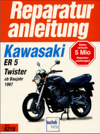
Battery Ground
Before completing any service on the motorcycle, disconnect the battery cables from the battery to prevent the engine from accidentally turning over. Disconnect the ground cable (–) first and then the positive (+). When completed with the service, first connect the positive (+) cable to the positive (+) terminal of the battery then the negative (–) cable to the negative terminal.
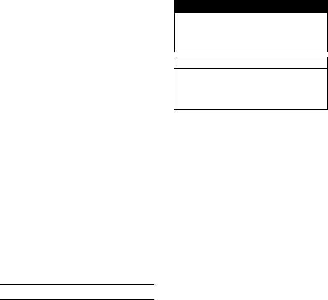
Edges of Parts
Lift large or heavy parts wearing gloves to prevent injury from possible sharp edges on the parts.
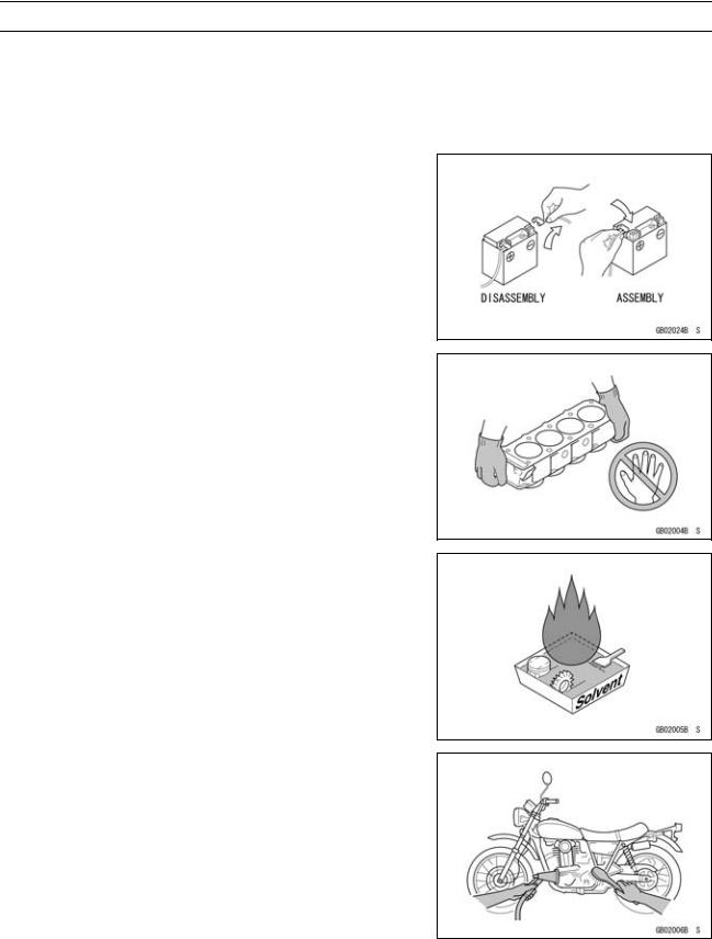
Solvent
Use a high-flash point solvent when cleaning parts. High -flash point solvent should be used according to directions of the solvent manufacturer.
Cleaning Vehicle before Disassembly
Clean the vehicle thoroughly before disassembly. Dirt or other foreign materials entering into sealed areas during vehicle disassembly can cause excessive wear and decrease performance of the vehicle.
GENERAL INFORMATION 1-3
Before Servicing
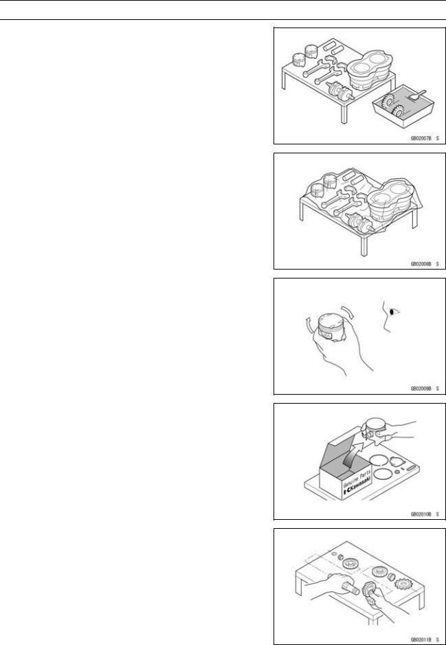
Arrangement and Cleaning of Removed Parts
Disassembled parts are easy to confuse. Arrange the parts according to the order the parts were disassembled and clean the parts in order prior to assembly.
Storage of Removed Parts
After all the parts including subassembly parts have been cleaned, store the parts in a clean area. Put a clean cloth or plastic sheet over the parts to protect from any foreign materials that may collect before re-assembly.
Inspection
Reuse of worn or damaged parts may lead to serious accident. Visually inspect removed parts for corrosion, discoloration, or other damage. Refer to the appropriate sections of this manual for service limits on individual parts. Replace the parts if any damage has been found or if the part is beyond its service limit.
Replacement Parts
Replacement parts must be KAWASAKI genuine or recommended by KAWASAKI. Gaskets, O-rings, oil seals, grease seals, circlips or cotter pins must be replaced with new ones whenever disassembled.
Assembly Order
In most cases assembly order is the reverse of disassembly, however, if assembly order is provided in this Service Manual, follow the procedures given.
1-4 GENERAL INFORMATION
Before Servicing
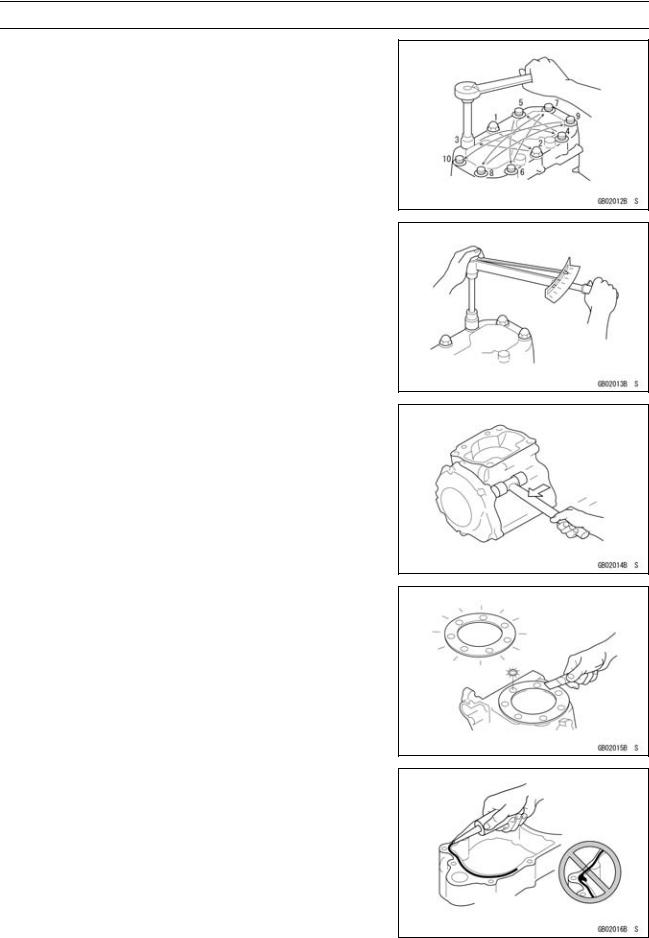
Tightening Sequence
Generally, when installing a part with several bolts, nuts, or screws, start them all in their holes and tighten them to a snug fit. Then tighten them according to the specified sequence to prevent case warpage or deformation which can lead to malfunction. Conversely when loosening the bolts, nuts, or screws, first loosen all of them by about a quarter turn and then remove them. If the specified tightening sequence is not indicated, tighten the fasteners alternating diagonally.
Tightening Torque
Incorrect torque applied to a bolt, nut, or screw may lead to serious damage. Tighten fasteners to the specified torque using a good quality torque wrench. Often, the tightening sequence is followed twice-initial tightening and final tightening with torque wrench.
Force
Use common sense during disassembly and assembly, excessive force can cause expensive or hard to repair damage. When necessary, remove screws that have a non -permanent locking agent applied using an impact driver. Use a plastic-faced mallet whenever tapping is necessary.
Gasket, O-ring
Hardening, shrinkage, or damage of both gaskets and O-rings after disassembly can reduce sealing performance. Remove old gaskets and clean the sealing surfaces thoroughly so that no gasket material or other material remains. Install new gaskets and replace used O-rings when re-assembling
Liquid Gasket, Non-permanent Locking Agent
For applications that require Liquid Gasket or a Non-permanent Locking Agent, clean the surfaces so that no oil residue remains before applying liquid gasket or non-permanent locking agent. Do not apply them excessively. Excessive application can clog oil passages and cause serious damage.
GENERAL INFORMATION 1-5
Before Servicing
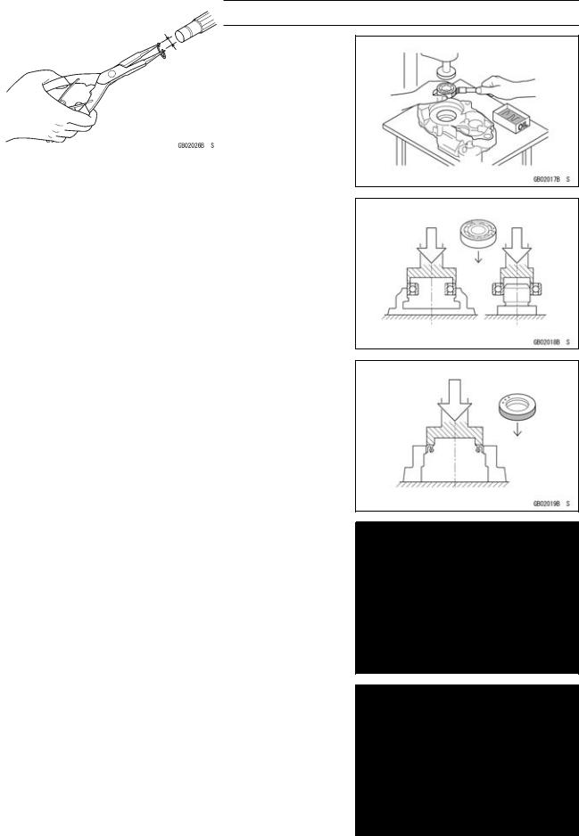
Press
For items such as bearings or oil seals that must be pressed into place, apply small amount of oil to the contact area. Be sure to maintain proper alignment and use smooth movements when installing.
Ball Bearing and Needle Bearing
Do not remove pressed ball or needle unless removal is absolutely necessary. Replace with new ones whenever removed. Press bearings with the manufacturer and size marks facing out. Press the bearing into place by putting pressure on the correct bearing race as shown.
Pressing the incorrect race can cause pressure between the inner and outer race and result in bearing damage.
Oil Seal, Grease Seal
Do not remove pressed oil or grease seals unless removal is necessary. Replace with new ones whenever removed. Press new oil seals with manufacture and size marks facing out. Make sure the seal is aligned properly when installing.
Apply specified grease to the lip of seal before installing the seal.
Circlips, Cotter Pins
Replace circlips or cotter pins that were removed with new ones. Take care not to open the clip excessively when installing to prevent deformation.
1-6 GENERAL INFORMATION
Before Servicing
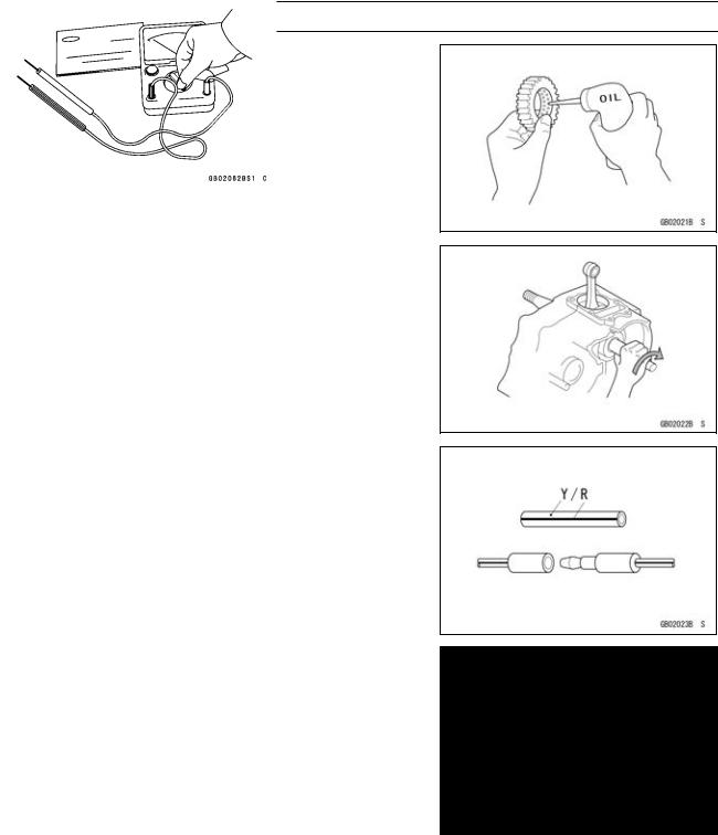
Lubrication
It is important to lubricate rotating or sliding parts during assembly to minimize wear during initial operation. Lubrication points are called out throughout this manual, apply the specific oil or grease as specified.
Direction of Engine Rotation
When rotating the crankshaft by hand, the free play amount of rotating direction will affect the adjustment. Rotate the crankshaft to positive direction (clockwise viewed from output side).
Electrical Leads
A two-color lead is identified first by the primary color and then the stripe color. Unless instructed otherwise, electrical leads must be connected to those of the same color.
Instrument
Use a meter that has enough accuracy for an accurate measurement. Read the manufacture’s instructions thoroughly before using the meter. Incorrect values may lead to improper adjustments.
GENERAL INFORMATION 1-7
Model Identification
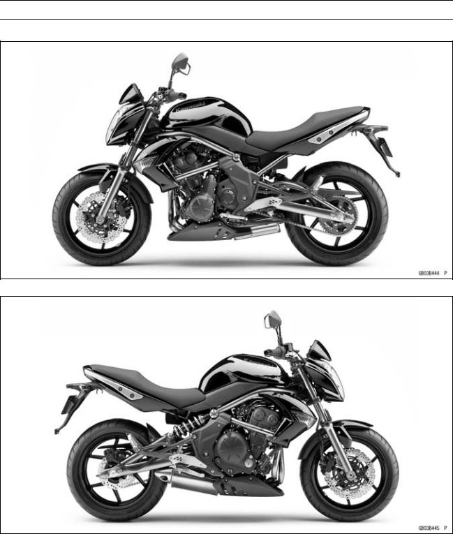
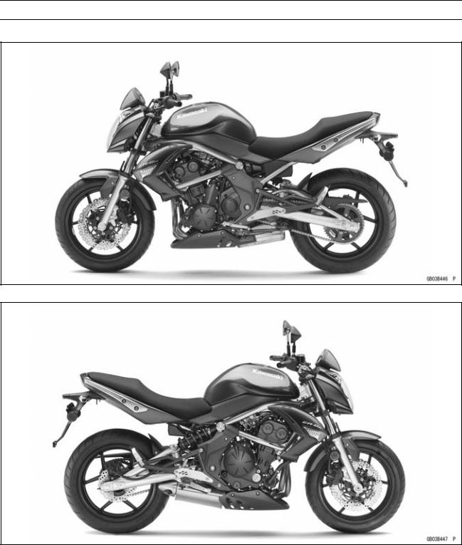
ER650C9F (EUR Models) Left Side View
ER650C9F (EUR Models) Right Side View
1-8 GENERAL INFORMATION
Model Identification
ER650C9F (US, CA Models) Left Side View
ER650C9F (US, CA Models) Right Side View
GENERAL INFORMATION 1-9
Model Identification
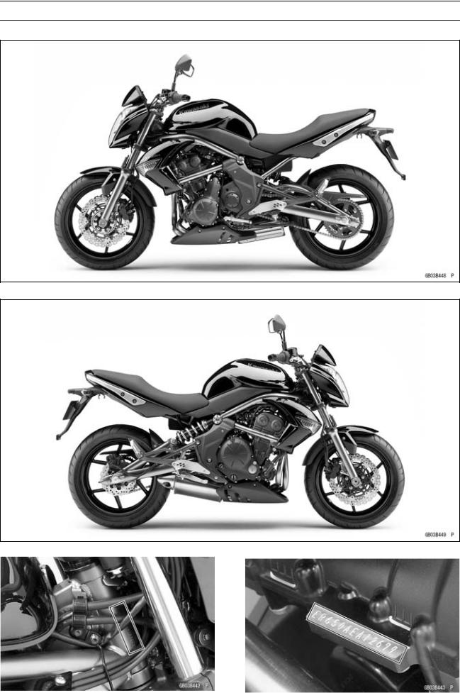
ER650D9F Left Side View
ER650D9F Right Side View
|
Frame Number |
Engine Number |
|

1-10 GENERAL INFORMATION
General Specifications
|
Items |
ER650C9F, ER650D9F |
|
|
Dimensions |
||
|
Overall Length |
2 100 mm (82.68 in.) |
|
|
Overall Width |
760 mm (29.9 in.) |
|
|
Overall Height |
1 100 mm (43.31 in.) |
|
|
Wheelbase |
1 405 mm (55.31 in.) |
|
|
Road Clearance |
140 mm (5.51 in.) |
|
|
Seat Height |
785 mm (30.9 in.) |
|
|
Curb Mass: |
||
|
ER650C Models: |
200 kg (441 lb) |
|
|
Front |
100 kg (221 lb) |
|
|
Rear |
100 kg (221 lb) |
|
|
ER650D Models: |
204 kg (450 lb) |
|
|
Front |
101 kg (223 lb) |
|
|
Rear |
103 kg (227 lb) |
|
|
Fuel Tank Capacity |
15.5 L (4.10 US gal.) |
|
|
Performance |
||
|
Minimum Turning Radius |
2.7 m (8.9 ft) |
|
|
Engine |
||
|
Type |
4-stroke, DOHC, 2-cylinder |
|
|
Cooling System |
Liquid-cooled |
|
|
Bore and Stroke |
83.0 × 60.0 mm (3.27 × 2.36 in.) |
|
|
Displacement |
649 cm³ (39.6 cu in.) |
|
|
Compression Ratio |
11.3 : 1 |
|
|
Maximum Horsepower |
53 kW (72 PS) @8 500 r/min (rpm) |
|
|
(MY) 52 kW (71 PS) @8 000 r/min (rpm) |
||
|
(US, CA, CAL) – – – |
||
|
Maximum Torque |
66 N·m (6.7 kgf·m, 49 ft·lb) @7 000 r/min (rpm) |
|
|
(US, CA, CAL) – – – |
||
|
Carburetion System |
FI (Fuel Injection), KEIHIN TTK38 × 2 |
|
|
Starting System |
Electric starter |
|
|
Ignition System |
Battery and coil (transistorized) |
|
|
Timing Advance |
Electronically advanced (IC igniter in ECU) |
|
|
Ignition Timing |
From 10° BTDC @1 300 r/min (rpm) |
|
|
To 34° BTDC @5 000 r/min (rpm) |
||
|
Spark Plug |
NGK CR9EIA-9 |
|
|
Cylinder Numbering Method |
Left to right, 1-2 |
|
|
Firing Order |
1-2 |
|
|
Valve Timing: |
||
|
Inlet: |
||
|
Open |
31° BTDC |
|
|
Close |
61° ABDC |
|
|
Duration |
272° |
|
|
GENERAL INFORMATION 1-11 |
|
|
General Specifications |
|
|
Items |
ER650C9F, ER650D9F |
|
Exhaust: |
|
|
Open |
50° BBDC |
|
Close |
30° ATDC |
|
Duration |
260° |
|
Lubrication System |
Forced lubrication (semi-dry sump) |
|
Engine Oil: |
|
|
Grade |
API SE, SF or SG |
|
API SH, SJ, SL or SM with JASO MA, MA1 or MA2 |
|
|
Viscosity |
SAE 10W-40 |
|
Capacity |
2.4 L (2.5 US qt) |
|
Drive Train |
|
|
Primary Reduction System: |
|
|
Type |
Gear |
|
Reduction Ratio |
2.095 (88/42) |
|
Clutch Type |
Wet multi disc |
|
Transmission: |
|
|
Type |
6-speed, constant mesh, return shift |
|
Gear Ratios: |
|
|
1st |
2.438 (39/16) |
|
2nd |
1.714 (36/21) |
|
3rd |
1.333 (32/24) |
|
4th |
1.111 (30/27) |
|
5th |
0.966 (28/29) |
|
6th |
0.852 (23/27) |
|
Final Drive System: |
|
|
Type |
Chain drive |
|
Reduction Ratio |
3.067 (46/15) |
|
Overall Drive Ratio |
5.473 @Top gear |
|
Frame |
|
|
Type |
Tubular, diamond |
|
Caster (Rake Angle) |
24.5° |
|
Trail |
102 mm (4.02 in.) |
|
Front Tire: |
|
|
Type |
Tubeless |
|
Size |
120/70 ZR17 M/C (58W) |
|
Rim Size |
17 × 3.50 |
|
Rear Tire: |
|
|
Type |
Tubeless |
|
Size |
160/60 ZR17 M/C (69W) |
|
Rim Size |
17 × 4.50 |
|
Front Suspension: |
|
|
Type |
Telescopic fork |
|
Wheel Travel |
120 mm (4.72 in.) |

1-12 GENERAL INFORMATION
General Specifications
|
Items |
ER650C9F, ER650D9F |
|
Rear Suspension: |
|
|
Type |
Swingarm |
|
Wheel Travel |
125 mm (4.92 in.) |
|
Brake Type: |
|
|
Front |
Dual discs |
|
Rear |
Single disc |
|
Electrical Equipment |
|
|
Battery |
12 V 10 Ah |
|
Headlight: |
|
|
Type |
Semi-sealed beam |
|
Bulb: |
|
|
High |
12 V 55 W + 55 W (quartz-halogen) |
|
Low |
12 V 55 W (quartz-halogen) |
|
Tail/Brake Light |
LED |
|
Alternator: |
|
|
Type |
Three-phase AC |
|
Rated Output |
24 A/14 V @5 000 r/min (rpm) |
Specifications are subject to change without notice, and may not apply to every country.
GENERAL INFORMATION 1-13
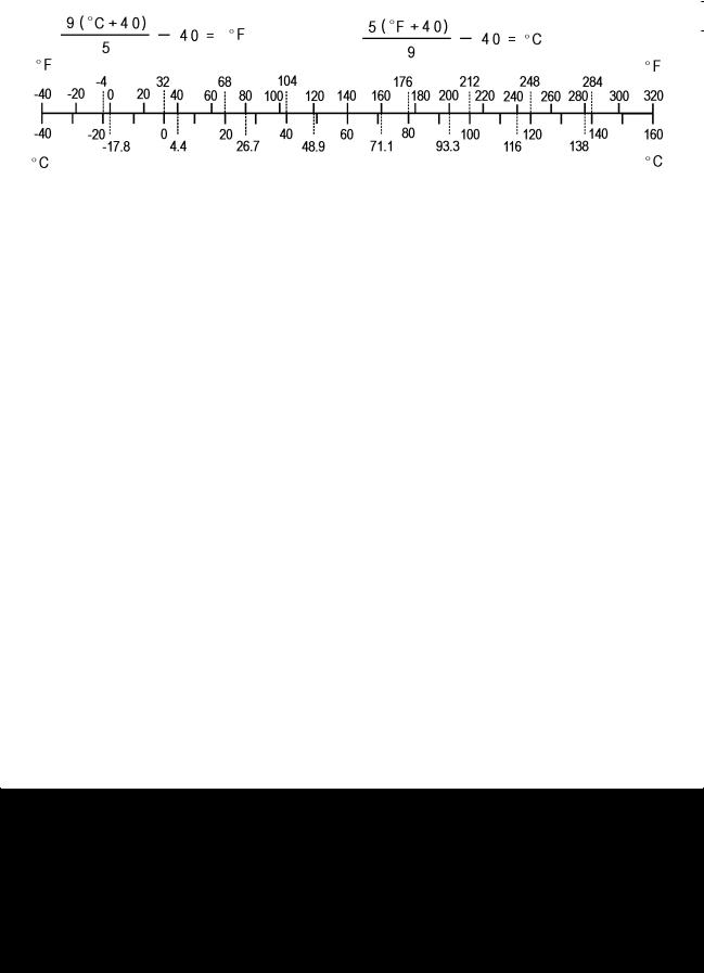
Unit Conversion Table
|
Prefixes for Units: |
Units of Length: |
|
Prefix |
Symbol |
Power |
||
|
mega |
M |
× 1 000 |
000 |
|
|
kilo |
k |
× |
1 000 |
|
|
centi |
c |
× |
0.01 |
|
|
milli |
m |
× |
0.001 |
|
|
micro |
µ |
× |
0.000001 |
Units of Mass:
|
kg |
× |
2.205 |
= |
lb |
|
g |
× |
0.03527 |
= |
oz |
Units of Volume:
|
L |
× |
0.2642 |
= |
gal (US) |
|
L |
× |
0.2200 |
= |
gal (imp) |
|
L |
× |
1.057 |
= |
qt (US) |
|
L |
× |
0.8799 |
= |
qt (imp) |
|
L |
× |
2.113 |
= |
pint (US) |
|
L |
× |
1.816 |
= |
pint (imp) |
|
mL |
× |
0.03381 |
= |
oz (US) |
|
mL |
× |
0.02816 |
= |
oz (imp) |
|
mL |
× |
0.06102 |
= |
cu in |
Units of Force:
|
km |
× |
0.6214 |
= |
mile |
|
m |
× |
3.281 |
= |
ft |
|
mm |
× |
0.03937 |
= |
in |
Units of Torque:
|
N·m |
× |
0.1020 |
= |
kgf·m |
|
N·m |
× |
0.7376 |
= |
ft·lb |
|
N·m |
× |
8.851 |
= |
in·lb |
|
kgf·m |
× |
9.807 |
= |
N·m |
|
kgf·m |
× |
7.233 |
= |
ft·lb |
|
kgf·m |
× |
86.80 |
= |
in·lb |
Units of Pressure:
|
kPa |
× |
0.01020 |
= |
kgf/cm² |
|
kPa |
× |
0.1450 |
= |
psi |
|
kPa |
× |
0.7501 |
= |
cmHg |
|
kgf/cm² |
× |
98.07 |
= |
kPa |
|
kgf/cm² |
× |
14.22 |
= |
psi |
|
cmHg |
× |
1.333 |
= |
kPa |
Units of Speed:
km/h × 0.6214 = mph
Units of Power:
|
N |
× |
0.1020 |
= |
kg |
kW |
× |
1.360 |
= |
PS |
||
|
N |
× |
0.2248 |
= |
lb |
|||||||
|
kW |
× |
1.341 |
= |
HP |
|||||||
|
kg |
× |
9.807 |
= |
N |
|||||||
|
PS |
× |
0.7355 |
= |
kW |
|||||||
|
kg |
× |
2.205 |
= |
lb |
|||||||
|
PS |
× |
0.9863 |
= |
HP |
|||||||
Units of Temperature:

PERIODIC MAINTENANCE 2-1
Periodic Maintenance
Table of Contents
|
Periodic Maintenance Chart ……………………………………………………………………………………… |
2-3 |
||
|
2 |
|||
|
Torque and Locking Agent………………………………………………………………………………………… |
2-6 |
||
|
Specifications |
2-12 |
||
|
Special Tools ………………………………………………………………………………………………………….. |
2-14 |
||
|
Periodic Maintenance Procedures……………………………………………………………………………… |
2-15 |
||
|
Fuel System (DFI)…………………………………………………………………………………………………. |
2-15 |
||
|
Air Cleaner Element Cleaning………………………………………………………………………………. |
2-15 |
||
|
Throttle Control System Inspection……………………………………………………………………….. |
2-16 |
||
|
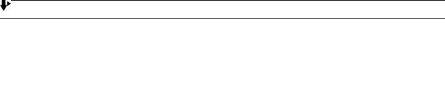
Engine Vacuum Synchronization Inspection…………………………………………………………… |
2-16 |
||
|
Idle Speed Inspection …………………………………………………………………………………………. |
2-18 |
||
|
Idle Speed Adjustment………………………………………………………………………………………… |
2-19 |
||
|
Fuel Hose Inspection (fuel leak, damage, installation condition) ……………………………….. |
2-19 |
||
|
Evaporative Emission Control System Inspection (CAL, SEA and TH Models) …………… |
2-19 |
||
|
Cooling System…………………………………………………………………………………………………….. |
2-20 |
||
|
Coolant Level Inspection……………………………………………………………………………………… |
2-20 |
||
|
Water Hose Damage and Installation Condition Inspection………………………………………. |
2-21 |
||
|
Engine Top End ……………………………………………………………………………………………………. |
2-21 |
||
|
Valve Clearance Inspection …………………………………………………………………………………. |
2-21 |
||
|
Valve Clearance Adjustment………………………………………………………………………………… |
2-22 |
||
|
Air Suction System Damage Inspection…………………………………………………………………. |
2-25 |
||
|
Clutch………………………………………………………………………………………………………………….. |
2-25 |
||
|
Clutch Operation Inspection…………………………………………………………………………………. |
2-25 |
||
|
Wheels/Tires………………………………………………………………………………………………………… |
2-26 |
||
|
Air Pressure Inspection……………………………………………………………………………………….. |
2-26 |
||
|
Wheel/Tire Damage Inspection…………………………………………………………………………….. |
2-26 |
||
|
Tire Tread Wear, Abnormal Wear Inspection ………………………………………………………….. |
2-26 |
||
|
Wheel Bearing Damage Inspection ………………………………………………………………………. |
2-27 |
||
|
Final Drive……………………………………………………………………………………………………………. |
2-28 |
||
|
Drive Chain Lubrication Condition Inspection …………………………………………………………. |
2-28 |
||
|
Drive Chain Slack Inspection ……………………………………………………………………………….. |
2-28 |
||
|
Drive Chain Slack Adjustment ……………………………………………………………………………… |
2-29 |
||
|
Wheel Alignment Inspection ………………………………………………………………………………… |
2-30 |
||
|
Drive Chain Wear Inspection ……………………………………………………………………………….. |
2-30 |
||
|
Chain Guide Inspection……………………………………………………………………………………….. |
2-31 |
||
|
Brake System ………………………………………………………………………………………………………. |
2-31 |
||
|
Brake Fluid Leak (Brake Hose and Pipe) Inspection ……………………………………………….. |
2-31 |
||
|
Brake Hose and Pipe Damage and Installation Condition Inspection…………………………. |
2-32 |
||
|
Brake Fluid Level Inspection………………………………………………………………………………… |
2-32 |
||
|
Brake Pad Wear Inspection …………………………………………………………………………………. |
2-33 |
||
|
Brake Operation Inspection …………………………………………………………………………………. |
2-34 |
||
|
Brake Light Switch Operation Inspection ……………………………………………………………….. |
2-34 |
||
|
Suspensions ………………………………………………………………………………………………………… |
2-35 |
||
|
Front Forks/Rear Shock Absorber Operation Inspection ………………………………………….. |
2-35 |
||
|
Front Fork Oil Leak Inspection……………………………………………………………………………… |
2-35 |
||
|
Rear Shock Absorber Oil Leak Inspection ……………………………………………………………… |
2-35 |
||
|
Steering System …………………………………………………………………………………………………… |
2-36 |
||
|
Steering Play Inspection ……………………………………………………………………………………… |
2-36 |
||
|
Steering Play Adjustment…………………………………………………………………………………….. |
2-36 |
||
|
Steering Stem Bearing Lubrication ……………………………………………………………………….. |
2-37 |
||
|
Electrical System ………………………………………………………………………………………………….. |
2-38 |

2-2 PERIODIC MAINTENANCE
|
Lights and Switches Operation Inspection……………………………………………………………… |
2-38 |
|
Headlight Aiming Inspection ………………………………………………………………………………… |
2-40 |
|
Sidestand Switch Operation Inspection …………………………………………………………………. |
2-41 |
|
Engine Stop Switch Operation Inspection………………………………………………………………. |
2-42 |
|
Others …………………………………………………………………………………………………………………. |
2-43 |
|
Chassis Parts Lubrication ……………………………………………………………………………………. |
2-43 |
|
Bolts, Nuts and Fasteners Tightness Inspection……………………………………………………… |
2-44 |
|
Replacement Parts ……………………………………………………………………………………………….. |
2-45 |
|
Air Cleaner Element Replacement………………………………………………………………………… |
2-45 |
|
Fuel Hose Replacement ……………………………………………………………………………………… |
2-45 |
|
Coolant Change …………………………………………………………………………………………………. |
2-46 |
|
Radiator Hose and O-ring Replacement………………………………………………………………… |
2-48 |
|
Engine Oil Change……………………………………………………………………………………………… |
2-48 |
|
Oil Filter Replacement ………………………………………………………………………………………… |
2-49 |
|
Brake Hose and Pipe Replacement………………………………………………………………………. |
2-50 |
|
Brake Fluid Change ……………………………………………………………………………………………. |
2-51 |
|
Master Cylinder Rubber Parts Replacement ………………………………………………………….. |
2-52 |
|
Caliper Rubber Parts Replacement ………………………………………………………………………. |
2-53 |
|
Spark Plug Replacement …………………………………………………………………………………….. |
2-56 |

PERIODIC MAINTENANCE 2-3
Periodic Maintenance Chart
The scheduled maintenance must be done in accordance with this chart to keep the motorcycle in good running condition.The initial maintenance is vitally important and must not be neglected.
Periodic Inspection
|
FREQUENCY |
Whichever |
* ODOMETER READING |
|||||||||||||
|
comes first |
× 1 000 km |
See |
|||||||||||||
|
(× 1 000 mile) |
|||||||||||||||
|
Page |
|||||||||||||||
|
1 |
6 |
12 |
18 |
24 |
30 |
36 |
|||||||||
|
ITEM |
Every |
(0.6) |
(3.75) |
(7.5) |
(11.25) |
(15) |
(18.75) |
(22.5) |
|||||||
|
Fuel System |
|||||||||||||||
|
Air cleaner element — clean |
• |
• |
• |
2–15 |
|||||||||||
|
Throttle control system (play, |
year |
• |
• |
• |
• |
2–16 |
|||||||||
|
smooth return, no drag) — inspect |
|||||||||||||||
|
Engine vacuum synchronization |
• |
• |
• |
2–16 |
|||||||||||
|
— inspect |
|||||||||||||||
|
Idle speed — inspect |
• |
• |
• |
• |
2–18 |
||||||||||
|
Fuel leak (fuel hose and pipe) — |
year |
• |
• |
• |
• |
2–19 |
|||||||||
|
inspect |
|||||||||||||||
|
Fuel hose and pipe damage — |
year |
• |
• |
• |
• |
2–19 |
|||||||||
|
inspect |
|||||||||||||||
|
Fuel hose and pipe installation |
year |
• |
• |
• |
• |
2–19 |
|||||||||
|
condition — inspect |
|||||||||||||||
|
Evaporative emission control |
• |
• |
• |
• |
• |
• |
• |
||||||||
|
system function (CAL, TH, SEA |
2–19 |
||||||||||||||
|
Models) — inspection |
|||||||||||||||
|
Cooling System |
|||||||||||||||
|
Coolant level — inspect |
• |
• |
• |
• |
2–20 |
||||||||||
|
Coolant leak (water hose and |
year |
• |
• |
• |
• |
2–21 |
|||||||||
|
pipe) — inspect |
|||||||||||||||
|
Water hose damage — inspect |
year |
• |
• |
• |
• |
2–21 |
|||||||||
|
Water hose installation condition |
year |
• |
• |
• |
• |
2–21 |
|||||||||
|
— inspect |
|||||||||||||||
|
Engine Top End |
|||||||||||||||
|
Valve |
US, CA, CAL |
• |
|||||||||||||
|
clearance — |
Models |
2–21 |
|||||||||||||
|
inspect |
Other than US, |
Every 42 000 km (26 250 mile) |
|||||||||||||
|
CA, CAL Models |
|||||||||||||||
|
Air suction system damage — |
• |
• |
• |
2–25 |
|||||||||||
|
inspect |
|||||||||||||||
|
Clutch |
|||||||||||||||
|
Clutch operation (play, |
• |
• |
• |
• |
|||||||||||
|
disengagement, engagement) — |
2–25 |
||||||||||||||
|
inspect |
|||||||||||||||
|
Wheels and Tires |
|||||||||||||||
|
Tire air pressure — inspect |
year |
• |
• |
• |
2–26 |
||||||||||
|
Wheel/tire damage — inspect |
• |
• |
• |
2–26 |
|||||||||||
|
Tire tread wear, abnormal wear |
• |
• |
• |
2–26 |
|||||||||||
|
— inspect |
|||||||||||||||
|
Wheel bearing damage — inspect |
year |
• |
• |
• |
2–27 |
2-4 PERIODIC MAINTENANCE
Periodic Maintenance Chart
|
FREQUENCY |
Whichever |
* ODOMETER READING |
|||||||||||||
|
comes first |
× 1 000 km |
See |
|||||||||||||
|
(× 1 000 mile) |
|||||||||||||||
|
Page |
|||||||||||||||
|
1 |
6 |
12 |
18 |
24 |
30 |
36 |
|||||||||
|
ITEM |
Every |
(0.6) |
(3.75) |
(7.5) |
(11.25) |
(15) |
(18.75) |
(22.5) |
|||||||
|
Final Drive |
|||||||||||||||
|
Drive chain lubrication condition |
Every 600 km (400 mile) |
2–28 |
|||||||||||||
|
— inspect # |
|||||||||||||||
|
Drive chain slack — inspect # |
Every 1 000 km (600 mile) |
2–28 |
|||||||||||||
|
Drive chain wear — inspect # |
• |
• |
• |
2–30 |
|||||||||||
|
Chain guide wear — inspect |
• |
• |
• |
2–31 |
|||||||||||
|
Brakes |
|||||||||||||||
|
Brake fluid leak (brake hose and |
year |
• |
• |
• |
• |
• |
• |
• |
2–31 |
||||||
|
pipe) — inspect |
|||||||||||||||
|
Brake hose and pipe damage — |
year |
• |
• |
• |
• |
• |
• |
• |
2–32 |
||||||
|
inspect |
|||||||||||||||
|
Brake hose and pipe installation |
year |
• |
• |
• |
• |
• |
• |
• |
2–32 |
||||||
|
condition — inspect |
|||||||||||||||
|
Brake fluid level — inspect |
6 months |
• |
• |
• |
• |
• |
• |
• |
2–32 |
||||||
|
Brake pad wear — inspect # |
• |
• |
• |
• |
• |
• |
2–33 |
||||||||
|
Brake operation (effectiveness, |
year |
• |
• |
• |
• |
• |
• |
• |
2–34 |
||||||
|
play, no drag) — inspect |
|||||||||||||||
|
Brake light switch operation — |
• |
• |
• |
• |
• |
• |
• |
2–34 |
|||||||
|
inspect |
|||||||||||||||
|
Suspension |
|||||||||||||||
|
Front forks/rear shock absorber |
• |
• |
• |
||||||||||||
|
operation (damping and smooth |
2–35 |
||||||||||||||
|
stroke) — inspect |
|||||||||||||||
|
Front forks/rear shock absorber |
year |
• |
• |
• |
2–35 |
||||||||||
|
oil leak — inspect |
|||||||||||||||
|
Steering |
|||||||||||||||
|
Steering play — inspect |
year |
• |
• |
• |
• |
2–36 |
|||||||||
|
Steering stem bearings — |
2 years |
• |
2–37 |
||||||||||||
|
lubricate |
|||||||||||||||
|
Electrical System |
|||||||||||||||
|
Lights and switches operation — |
year |
• |
• |
• |
2–38 |
||||||||||
|
inspect |
|||||||||||||||
|
Headlight aiming — inspect |
year |
• |
• |
• |
2–40 |
||||||||||
|
Sidestand switch operation — |
year |
• |
• |
• |
2–41 |
||||||||||
|
inspect |
|||||||||||||||
|
Engine stop switch operation — |
year |
• |
• |
• |
2–42 |
||||||||||
|
inspect |
|||||||||||||||
|
Others |
|||||||||||||||
|
Chassis parts — lubricate |
year |
• |
• |
• |
2–43 |
||||||||||
|
Bolts and nuts tightness — inspect |
• |
• |
• |
• |
2–44 |
#: Service more frequently when operating in severe conditions; dusty, wet, muddy, high speed or frequent starting/stopping.
*: For higher odometer readings, repeat at the frequency interval established here.
PERIODIC MAINTENANCE 2-5
Periodic Maintenance Chart
Periodic Replacement Parts
|
FREQUENCY |
Whichever |
* ODOMETER |
|||||||||
|
comes |
READING |
||||||||||
|
× 1 000 km |
See |
||||||||||
|
first |
|||||||||||
|
(× 1 000 mile) |
|||||||||||
|
Page |
|||||||||||
|
1 |
12 |
24 |
36 |
48 |
|||||||
|
ITEM |
Every |
(0.6) |
(7.5) |
(15) |
(22.5) |
(30) |
|||||
|
Air cleaner element # — replace |
2 years |
2–45 |
|||||||||
|
Fuel hose — replace |
4 years |
• |
2–45 |
||||||||
|
Coolant — change |
3 years |
• |
2–46 |
||||||||
|
Radiator hose and O-ring — replace |
3 years |
• |
2–48 |
||||||||
|
Engine oil # — change |
year |
• |
• |
• |
• |
• |
2–48 |
||||
|
Oil filter — replace |
year |
• |
• |
• |
• |
• |
2–49 |
||||
|
Brake hose and pipe — replace |
4 years |
• |
2–50 |
||||||||
|
Brake fluid — change |
2 years |
• |
• |
2–51 |
|||||||
|
Rubber parts of master cylinder and caliper — replace |
4 years |
• |
2–52 |
||||||||
|
Spark plug — replace |
• |
• |
• |
• |
2–56 |
#: Service more frequently when operating in severe conditions; dusty, wet, muddy, high speed or frequent starting/stopping.
*: For higher odometer readings, repeat at the frequency interval established here.

2-6 PERIODIC MAINTENANCE
Torque and Locking Agent
The following tables list the tightening torque for the major fasteners requiring use of a non-permanent locking agent or silicone sealant etc.
Letters used in the “Remarks” column mean:
AL: Tighten the two clamp bolts alternately two times to ensure even tightening torque. EO: Apply engine oil.
L: Apply a non-permanent locking agent to the threads. Lh: Left-hand Threads
MO: Apply molybdenum disulfide oil solution.
(mixture of the engine oil and molybdenum disulfide grease in a weight ratio 10 : 1)
R:Replacement Parts
S:Follow the specified tightening sequence. Si: Apply silicone grease (ex. PBC grease).
SS:Apply silicone sealant.
|
Fastener |
Torque |
Remarks |
|||||
|
N·m |
kgf·m |
ft·lb |
|||||
|
Fuel System (DFI) |
|||||||
|
Crankshaft Sensor Bolts |
6.0 |
0.61 |
53 in·lb |
||||
|
Fuel Level Sensor Bolts |
6.9 |
0.70 |
61 in·lb |
L |
|||
|
Fuel Pump Bolts |
9.8 |
1.0 |
87 in·lb |
L, S |
|||
|
Oxygen Sensor (Equipped Models) |
44 |
4.5 |
32 |
||||
|
Speed Sensor Bolt |
7.8 |
0.80 |
69 in·lb |
L |
|||
|
Speed Sensor Bracket Bolts |
1.0 |
87 in·lb |
|||||
|
9.8 |
|||||||
|
Switch Housing Screws |
3.5 |
0.36 |
31 in·lb |
||||
|
Timing Rotor Bolt |
40 |
4.1 |
30 |
||||
|
Water Temperature Sensor |
12 |
1.2 |
106 in·lb |
||||
|
Cooling System |
|||||||
|
Baffle Plate Bolts |
5.9 |
0.60 |
52 in·lb |
||||
|
Radiator Bolt |
15 |
1.5 |
11 |
||||
|
Water Hose Clamp Screws |
2.0 |
0.20 |
18 in·lb |
||||
|
Thermostat Housing Bolts |
9.8 |
1.0 |
87 in·lb |
||||
|
Water Pump Cover Bolts |
87 in·lb |
||||||
|
9.8 |
1.0 |
||||||
|
Water Pump Drain Bolt |
9.8 |
1.0 |
87 in·lb |
||||
|
Water Pump Impeller Bolt |
9.8 |
1.0 |
87 in·lb |
||||
|
Water Temperature Sensor |
12 |
1.2 |
106 in·lb |
||||
|
Engine Top End |
|||||||
|
Air Suction Valve Cover Bolts |
9.8 |
1.0 |
87 in·lb |
||||
|
Baffle Plate Bolts |
5.9 |
0.60 |
52 in·lb |
||||
|
Camshaft Cap Bolts |
12 |
1.2 |
106 in·lb |
S |
|||
|
Camshaft Chain Tensioner Cap Bolt |
20 |
2.0 |
15 |
||||
|
Camshaft Chain Tensioner Mounting Bolts |
9.8 |
1.0 |
87 in·lb |
||||
|
Camshaft Sprocket Bolts |
15 |
1.5 |
11 |
L |
|||
|
Cylinder Head Bolts (M10) |
56 |
5.7 |
41 |
MO, S |
|||
|
Cylinder Head Bolts (M6) |
12 |
1.2 |
106 in·lb |
S |
|||
|
Cylinder Head Cover Bolts |
9.8 |
1.0 |
87 in·lb |
||||
|
Rear Camshaft Chain Guide Bolts |
20 |
2.0 |
15 |
L |
|||
|
Spark Plugs |
15 |
1.5 |
11 |
||||
![]()
PERIODIC MAINTENANCE 2-7
Torque and Locking Agent
|
Fastener |
Torque |
Remarks |
|||
|
N·m |
kgf·m |
ft·lb |
|||
|
Throttle Body Assy Holder Bolts |
12 |
1.2 |
106 in·lb |
||
|
Cylinder Bolt (M8) |
27.5 |
2.8 |
20 |
MO, S |
|
|
Cylinder Nut |
49 |
5.0 |
36 |
MO, S |
|
|
Cylinder Bolts (M6) |
106 in·lb |
S |
|||
|
12 |
1.2 |
||||
|
Exhaust Pipe Manifold Holder Nuts |
17 |
1.7 |
13 |
||
|
Muffler Body Mounting Bolt (Front) |
20 |
2.0 |
15 |
||
|
Muffler Body Mounting Bolt (Rear) |
20 |
2.0 |
15 |
||
|
Clutch |
|||||
|
Clutch Cable Clamp Bracket Bolt |
9.8 |
1.0 |
87 in·lb |
||
|
Clutch Cable Holder Bolts |
9.8 |
1.0 |
87 in·lb |
L |
|
|
Clutch Cover Bolts |
9.8 |
1.0 |
87 in·lb |
||
|
Clutch Hub Nut |
130 |
13.3 |
96 |
R |
|
|
Clutch Lever Clamp Bolts |
7.8 |
0.80 |
69 in·lb |
S |
|
|
Clutch Spring Bolts |
9.8 |
1.0 |
87 in·lb |
||
|
Timing Rotor Bolt Cap |
4.9 |
0.50 |
43 in·lb |
||
|
Oil Filler Plug |
– |
– |
– |
Hand-tighten |
|
|
Oil Pump Chain Guide Bolts |
12 |
1.2 |
106 in·lb |
L (1) |
|
|
Oil Pump Sprocket Bolt |
12 |
1.2 |
106 in·lb |
L, Lh |
|
|
Timing Inspection Cap |
3.9 |
0.40 |
35 in·lb |
||
|
Engine Lubrication System |
|||||
|
Engine Oil Drain Plug |
30 |
3.1 |
22 |
||
|
Filter Plate Bolts |
9.8 |
1.0 |
87 in·lb |
L |
|
|
Holder Mounting Bolt |
25 |
2.5 |
18 |
L |
|
|
Lower Fairing Bracket Bolts |
12 |
1.2 |
106 in·lb |
L |
|
|
Oil Filter |
17.5 |
1.8 |
13 |
EO, R |
|
|
Oil Pan Bolts |
12 |
1.2 |
106 in·lb |
S |
|
|
Oil Passage Plug |
20 |
2.0 |
15 |
L |
|
|
Oil Passage Plug (M6) |
3.9 |
0.40 |
35 in·lb |
||
|
Oil Pipe Plate Bolt |
9.8 |
1.0 |
87 in·lb |
L |
|
|
Oil Plate Bolts |
9.8 |
1.0 |
87 in·lb |
L |
|
|
Oil Pressure Relief Valve |
15 |
1.5 |
11 |
L |
|
|
Oil Pressure Switch |
15 |
1.5 |
11 |
SS |
|
|
Oil Pump Chain Guide Bolts |
12 |
1.2 |
106 in·lb |
L (1) |
|
|
Oil Pump Cover Bolts |
9.8 |
1.0 |
87 in·lb |
L |
|
|
Oil Pump Sprocket Bolt |
12 |
1.2 |
106 in·lb |
L, Lh |
|
|
Engine Removal/Installation |
|||||
|
Engine Bracket Bolts (Left) |
25 |
2.5 |
18 |
S |
|
|
Engine Bracket Bolts (Right) |
25 |
2.5 |
18 |
S |
|
|
Engine Mounting Nut (Lower) |
44 |
4.5 |
32 |
S |
|
|
Engine Mounting Nut (Rear) |
44 |
4.5 |
32 |
S |
|
|
Engine Mounting Bolt (Left) |
44 |
4.5 |
32 |
S |
|
|
Engine Mounting Bolt (Right) |
44 |
4.5 |
32 |
S |
|

2-8 PERIODIC MAINTENANCE
Torque and Locking Agent
|
Fastener |
Torque |
Remarks |
|||||
|
N·m |
kgf·m |
ft·lb |
|||||
|
Crankshaft/Transmission |
|||||||
|
Breather Plate Bolts |
9.8 |
1.0 |
87 in·lb |
L |
|||
|
Race Holder Screw |
4.9 |
0.50 |
43 in·lb |
L |
|||
|
Connecting Rod Big End Nuts |
see Text |
← |
← |
MO |
|||
|
Crankcase Bolt (M8, L = 110 mm) |
27.5 |
2.8 |
20 |
S |
|||
|
Crankcase Bolt (M6, L = 32 mm) |
19.6 |
2.0 |
14 |
S |
|||
|
Crankcase Bolts (M6, L = 38 mm) |
19.6 |
2.0 |
14 |
S |
|||
|
Crankcase Bolts (M6, L = 45 mm) |
19.6 |
2.0 |
14 |
S |
|||
|
Crankcase Bolt (M8, L = 50 mm) |
27.5 |
2.8 |
20 |
S |
|||
|
Crankcase Bolts (M8, L = 60 mm) |
35 |
3.6 |
26 |
MO, S |
|||
|
Crankcase Bolt (M8, L = 60 mm) |
27.5 |
2.8 |
20 |
S |
|||
|
Crankcase Bolts (M8, L = 73 mm) |
35 |
3.6 |
26 |
MO, S |
|||
|
Crankcase Bolts (M9, L = 113 mm) |
44 |
4.5 |
32 |
MO, S |
|||
|
Crankcase Bolts (M9, L = 83 mm) |
44 |
4.5 |
32 |
MO, S |
|||
|
Upper Crankcase Bolt (M8, L = 120 mm) |
27.5 |
2.8 |
20 |
S |
|||
|
Upper Crankcase Bolts (M8, L = 110 mm) |
27.5 |
2.8 |
20 |
S |
|||
|
Oil Pipe Bolts |
9.8 |
1.0 |
87 in·lb |
L |
|||
|
Oil Plate Bolts |
9.8 |
1.0 |
87 in·lb |
L |
|||
|
Shift Shaft Return Spring Pin |
29 |
3.0 |
21 |
L |
|||
|
Timing Rotor Bolt |
40 |
4.1 |
30 |
||||
|
Drive Shaft Bearing Holder Screw |
4.9 |
0.50 |
43 in·lb |
L |
|||
|
Gear Positioning Lever Bolt |
12 |
1.2 |
106 in·lb |
L |
|||
|
Neutral Switch |
15 |
1.5 |
11 |
||||
|
Neutral Switch Holder Screw |
4.9 |
0.50 |
43 in·lb |
L |
|||
|
Transmission Case Oil Nozzle |
2.9 |
0.30 |
26 in·lb |
L |
|||
|
Shift Drum Bearing Holder Screws |
4.9 |
0.50 |
43 in·lb |
L |
|||
|
Shift Drum Cam Bolt |
12 |
1.2 |
106 in·lb |
L |
|||
|
Shift Lever Bolt |
12 |
1.2 |
106 in·lb |
||||
|
Shift Rod Plate Bolt |
9.8 |
1.0 |
87 in·lb |
L |
|||
|
Shift Shaft Cover Bolts |
9.8 |
1.0 |
87 in·lb |
L (3) |
|||
|
Shift Shaft Cover Screw |
4.9 |
0.50 |
43 in·lb |
L, S |
|||
|
Transmission Case Bolts |
20 |
2.0 |
15 |
||||
|
Wheels/Tires |
|||||||
|
Front Axle |
108 |
11.0 |
80 |
||||
|
Front Axle Clamp Bolt |
34 |
3.5 |
25 |
||||
|
Rear Axle Nut |
108 |
11.0 |
80 |
||||
|
Final Drive |
|||||||
|
Engine Sprocket Nut |
125 |
12.7 |
92 |
MO |
|||
|
Rear Axle Nut |
108 |
11.0 |
80 |
||||
|
Rear Sprocket Nuts |
59 |
6.0 |
44 |
||||
|
Speed Sensor Bolt |
7.8 |
0.80 |
69 in·lb |
L |
|||
|
Speed Sensor Bracket Bolts |
9.8 |
1.0 |
87 in·lb |
||||

PERIODIC MAINTENANCE 2-9
Torque and Locking Agent
|
Fastener |
Torque |
Remarks |
|||
|
N·m |
kgf·m |
ft·lb |
|||
|
Brakes |
|||||
|
Caliper Bleed Valve |
7.8 |
0.80 |
69 in·lb |
||
|
Brake Hose Banjo Bolts |
25 |
2.5 |
18 |
||
|
Brake Lever Pivot Bolt |
1.0 |
0.10 |
9 in·lb |
Si |
|
|
Brake Lever Pivot Bolt Locknut |
5.9 |
0.60 |
52 in·lb |
||
|
Brake Disc Mounting Bolts |
27 |
2.8 |
20 |
L |
|
|
Front Brake Light Switch Screw |
1.2 |
0.12 |
11 in·lb |
||
|
Front Brake Reservoir Cap Screws |
1.5 |
0.15 |
13 in·lb |
||
|
Front Caliper Mounting Bolts |
34 |
3.5 |
25 |
||
|
Front Master Cylinder Clamp Bolts |
11 |
1.1 |
97 in·lb |
S |
|
|
Brake Pedal Bolt |
8.8 |
0.90 |
78 in·lb |
||
|
Rear Caliper Mounting Bolts |
25 |
2.5 |
18 |
||
|
Rear Master Cylinder Mounting Bolts |
25 |
2.5 |
18 |
||
|
Rear Master Cylinder Push Rod Locknut |
17 |
1.7 |
13 |
||
|
Brake Pipe Joint Nuts (ER650D Models) |
18 |
1.8 |
13 |
||
|
Wheel Rotation Sensor Bolts (ER650D Models) |
|||||
|
20 |
2.0 |
15 |
|||
|
Suspension |
|||||
|
Front Axle Clamp Bolt |
34 |
3.5 |
25 |
||
|
Front Fork Bottom Allen Bolts |
30 |
3.1 |
22 |
L |
|
|
Front Fork Clamp Bolts (Lower) |
20 |
2.0 |
15 |
AL |
|
|
Front Fork Clamp Bolts (Upper) |
20 |
2.0 |
15 |
||
|
Front Fork Top Plugs |
25 |
2.5 |
18 |
||
|
Rear Shock Absorber Bolts |
59 |
6.0 |
44 |
||
|
Swingarm Pivot Shaft Nut |
108 |
11.0 |
80 |
||
|
Steering |
|||||
|
Front Fork Clamp Bolts (Lower) |
20 |
2.0 |
15 |
AL |
|
|
Front Fork Clamp Bolts (Upper) |
20 |
2.0 |
15 |
||
|
Handlebar Holder Bolts |
25 |
2.5 |
18 |
S |
|
|
Handlebar Holder Mounting Nuts |
34 |
3.5 |
25 |
||
|
Switch Housing Screws |
3.5 |
0.36 |
31 in·lb |
||
|
Steering Stem Head Bolt |
108 |
11.0 |
80 |
||
|
Steering Stem Nut |
20 |
2.0 |
15 |
||
|
Frame |
|||||
|
Footpeg Stay Bolts |
25 |
2.5 |
18 |
S |
|
|
Front Fender Mounting Bolts |
8.8 |
0.90 |
78 in·lb |
||
|
Front Turn Signal Light Mounting Screws |
1.2 |
0.12 |
11 in·lb |
||
|
Grab Rail Mounting Bolts |
25 |
2.5 |
18 |
||
|
Lower Fairing Bracket Bolts |
12 |
1.2 |
106 in·lb |
L |
|
|
Lower Fairing Mounting Bolts |
8.8 |
0.90 |
78 in·lb |
||
|
Seat Lock Mounting Screws |
1.2 |
0.12 |
11 in·lb |
||
|
Sidestand Bolt |
44 |
4.5 |
32 |
||
|
Sidestand Switch Bolt |
8.8 |
0.90 |
78 in·lb |
L |
|

2-10 PERIODIC MAINTENANCE
Torque and Locking Agent
|
Fastener |
Torque |
Remarks |
|||||
|
N·m |
kgf·m |
ft·lb |
|||||
|
Electrical System |
|||||||
|
Tail/Brake Light Mounting Bolts |
8.8 |
0.90 |
78 in·lb |
||||
|
License Plate Light Mounting Screws |
1.2 |
0.12 |
11 in·lb |
||||
|
Alternator Cover Bolts |
9.8 |
1.0 |
87 in·lb |
||||
|
Alternator Lead Holding Plate Bolt |
9.8 |
1.0 |
87 in·lb |
L |
|||
|
Alternator Rotor Bolt |
155 |
15.8 |
114 |
MO |
|||
|
Engine Ground Lead Terminal Bolt |
9.8 |
1.0 |
87 in·lb |
||||
|
Front Brake Light Switch Screw |
1.2 |
0.12 |
11 in·lb |
||||
|
Front Turn Signal Light Mounting Screws |
1.2 |
0.12 |
11 in·lb |
||||
|
Fuel Pump Bolts |
9.8 |
1.0 |
87 in·lb |
L, S |
|||
|
Meter Cover Screws |
1.2 |
0.12 |
11 in·lb |
||||
|
Regulator/Rectifier Bolts |
8.8 |
0.90 |
78 in·lb |
||||
|
Switch Housing Screws |
3.5 |
0.36 |
31 in·lb |
||||
|
Sidestand Switch Bolt |
8.8 |
0.90 |
78 in·lb |
L |
|||
|
Starter Motor Terminal Nut |
6.0 |
0.61 |
53 in·lb |
||||
|
Starter Motor Clutch Bolts |
3.5 |
L |
|||||
|
34 |
25 |
||||||
|
Starter Motor Mounting Bolts |
9.8 |
1.0 |
87 in·lb |
L |
|||
|
Starter Motor Terminal Locknut |
11 |
1.1 |
97 in·lb |
||||
|
Starter Motor Through Bolts |
5.0 |
0.51 |
44 in·lb |
||||
|
Stator Coil Bolts |
12 |
1.2 |
106 in·lb |
L |
|||
|
Crankshaft Sensor Bolts |
6.0 |
0.61 |
53 in·lb |
||||
|
Neutral Switch |
15 |
1.5 |
11 |
||||
|
Oil Pressure Switch |
15 |
1.5 |
11 |
SS |
|||
|
Oxygen Sensor (Equipped Models) |
44 |
4.5 |
32 |
||||
|
Spark Plugs |
15 |
1.5 |
11 |
||||
|
Speed Sensor Bolt |
7.8 |
0.80 |
69 in·lb |
L |
|||
|
Timing Rotor Bolt |
40 |
4.1 |
30 |
||||
|
Water Temperature Sensor |
12 |
1.2 |
106 in·lb |
||||
|
Fuel Level Sensor Bolts |
6.9 |
0.70 |
61 in·lb |
L |
|||

PERIODIC MAINTENANCE 2-11
Torque and Locking Agent
The table below, relating tightening torque to thread diameter, lists the basic torque for the bolts and nuts. Use this table for only the bolts and nuts which do not require a specific torque value. All of the values are for use with dry solvent-cleaned threads.
Basic Torque for General Fasteners
|
Threads Diameter |
Torque |
||||||||
|
(mm) |
N·m |
kgf·m |
ft·lb |
||||||
|
5 |
3.4 |
4.9 |
0.35 |
0.50 |
30 |
43 in·lb |
|||
|
6 |
5.9 |
7.8 |
0.60 |
0.80 |
52 |
69 in·lb |
|||
|
8 |
14 |
19 |
1.4 |
1.9 |
10.0 |
13.5 |
|||
|
10 |
25 |
34 |
2.6 |
3.5 |
19.0 |
25 |
|||
|
12 |
44 |
61 |
4.5 |
6.2 |
33 |
45 |
|||
|
14 |
73 |
98 |
7.4 |
10.0 |
54 |
72 |
|||
|
16 |
115 |
155 |
11.5 |
16.0 |
83 |
115 |
|||
|
18 |
165 |
225 |
17.0 |
23.0 |
125 |
165 |
|||
|
20 |
225 |
325 |
23.0 |
33.0 |
165 |
240 |
|||

2-12 PERIODIC MAINTENANCE
Specifications
|
Item |
Standard |
Service Limit |
|||
|
Fuel System (DFI) |
|||||
|
Throttle Grip Free Play |
2 3 mm (0.08 0.12 in.) |
– – – |
|||
|
Idle Speed |
1 300 ±50 r/min (rpm) |
– – – |
|||
|
Bypass Screws (Turn out) |
0 2 1/2 (for reference) |
– – – |
|||
|
Engine Vacuum |
35.3 ±1.3 kPa (265 ±10 mmHg) |
– – – |
|||
|
Air Cleaner Element |
Polyurethane Foam |
– – – |
|||
|
Cooling System |
|||||
|
Coolant: |
|||||
|
Type (recommended) |
Permanent type of antifreeze |
– – – |
|||
|
Color |
Green |
– – – |
|||
|
Mixed Ratio |
Soft water 50%, Coolant 50% |
– – – |
|||
|
Freezing Point |
–35°C (–31°F) |
– – – |
|||
|
Total Amount |
1.2 L (1.3 US qt) |
– – – |
|||
|
Engine Top End |
|||||
|
Valve Clearance: |
|||||
|
Exhaust |
0.22 |
0.31 mm (0.0087 |
0.0122 in.) |
– – – |
|
|
Inlet |
0.15 |
0.21 mm (0.0059 |
0.0083 in.) |
– – – |
|
|
Clutch |
|||||
|
Clutch Lever Free Play |
2 3 mm (0.08 0.12 in.) |
– – – |
|||
|
Engine Lubrication System |
|||||
|
Engine Oil: |
|||||
|
Type |
API SE, SF or SG |
– – – |
|||
|
API SH, SJ, SL or SM with JASO MA, |
|||||
|
MA1 or MA2 |
|||||
|
Viscosity |
SAE 10W-40 |
– – – |
|||
|
Capacity |
1.7 L (1.8 US qt) (when filter is not |
– – – |
|||
|
removed) |
|||||
|
1.9 L (2.0 US qt) (when filter is removed) |
– – – |
||||
|
2.4 L (2.5 US qt) (when engine is |
– – – |
||||
|
completely dry) |
|||||
|
Level |
Between upper and lower level lines |
– – – |
|||
|
(after idling or running) |
|||||
|
Wheels/Tires |
|||||
|
Tread Depth: |
|||||
|
Front |
4.5 mm (0.18 in.) |
1 mm (0.04 in.), |
|||
|
(AT, CH, DE) |
|||||
|
1.6 mm (0.06 in.) |
|||||
|
Rear |
6.4 mm (0.25 in.) |
Up to 130 km/h (80 mph): |
|||
|
2 mm (0.08 in.), |
|||||
|
Over 130 km/h (80 mph): |
|||||
|
3 mm (0.12 in.) |
|||||
|
Air Pressure (when Cold): |
|||||
|
Front |
Up to 180 kg (397 lb) load: |
– – – |
|||
|
225 kPa (2.25 kgf/cm², 32 psi) |
|||||

PERIODIC MAINTENANCE 2-13
Specifications
|
Item |
Standard |
Service Limit |
|
Rear |
Up to 180 kg (397 lb) load: |
– – – |
|
250 kPa (2.50 kgf/cm², 36 psi) |
||
|
Final Drive |
||
|
Drive Chain Slack |
25 35 mm (1.0 1.4 in.) |
– – – |
|
Chain 20-link Length |
317.5 318.2 mm (12.50 12.53 in.) |
323 mm (12.7 in.) |
|
Standard Chain: |
||
|
Make |
DAIDO |
– – – |
|
Type |
DID 520VP2-T |
– – – |
|
Link |
114 links |
– – – |
|
Brakes |
||
|
Brake Fluid: |
||
|
Grade |
DOT4 |
– – – |
|
Brake Pad Lining |
||
|
Thickness: |
||
|
Front |
4.5 mm (0.18 in.) |
1 mm (0.04 in.) |
|
Rear |
5.0 mm (0.20 in.) |
1 mm (0.04 in.) |
|
Brake Light Timing: |
||
|
Front |
Pulled ON |
– – – |
|
Rear |
ON after about 10 mm (0.39 in.) of |
– – – |
|
pedal travel |
||
|
Electrical System |
||
|
Spark Plug: |
||
|
Type |
NGK CR9EIA-9 |
– – – |

2-14 PERIODIC MAINTENANCE
Special Tools
|
Inside Circlip Pliers: |
Throttle Sensor Setting Adapter: |
|
|
57001-143 |
57001-1538 |
|
Steering Stem Nut Wrench: 57001-1100
Extension Tube: 57001-1578
Oil Filter Wrench: 57001-1249
Pilot Screw Adjuster, E: 57001-1603
Vacuum Gauge: 57001-1369

PERIODIC MAINTENANCE 2-15
Periodic Maintenance Procedures
Fuel System (DFI)
Air Cleaner Element Cleaning
NOTE
○In dusty areas, the element should be cleaned more frequently than the recommended interval.
○After riding through rain or on muddily roads, the element should be cleaned immediately.

 WARNING
If dirt or dust is allowed to pass through into the throttle body assy, the throttle may become stuck, possibly causing accident.
CAUTION
If dirt gets through into the engine, excessive engine wear and possibly engine damage will occur.
•Remove:
Fuel Tank (see Fuel Tank Removal in the Fuel System (DFI) chapter)
Air Switching Valve Hose [A]
Air Cleaner Element Screw [B] Air Cleaner Element [C]
•Remove:
Plastic Holder [A] Element [B]

 WARNING
Clean the element in a well-ventilated area, and make sure that there are no sparks or flame anywhere near the working area.
Because of the danger of highly flammable liquids, do not use gasoline or a low-flash point solvent to clean the element.
•Clean the element [A] in a bath of high-flash point solvent, and then dry it with compressed air or by shaking it.
•After cleaning, saturate a clean, lint-free towel with SE, SF, or SG class SAE 30 oil and apply the oil to the element by tapping the element outside with the towel.
•Visually inspect the element for tears or breaks.
•If the element has any tears or breaks, replace the element with a new one.
•Install the element.

2-16 PERIODIC MAINTENANCE
Periodic Maintenance Procedures
Throttle Control System Inspection
•Check that the throttle grip [A] moves smoothly from full open to close, and the throttle closes quickly and completely by the return spring in all steering positions.
 If the throttle grip does not return properly, check the throttle cable routing, grip free play, and cable damage. Then lubricate the throttle cable.
•Check the throttle grip free play [B].
Throttle Grip Free Play
Standard: 2 3 mm (0.08 0.12 in.)
 If the free play is incorrect, adjust the throttle cable as follows.
•Loosen the locknut [A] at the upper end of the accelerator cable.
•Turn the adjuster [B] in completely so as to give the throttle grip plenty of play.
•Loosen the locknut [A] at the middle of the decelerator cable.
•Turn the adjuster [B] until there is no play when the throttle grip is completely closed.
•Tighten the locknut.
•Turn the accelerator cable adjuster until the proper amount of throttle grip free play is obtained.
•Tighten the locknut.
Engine Vacuum Synchronization Inspection
NOTE
○These procedures are explained on the assumption that the inlet and exhaust systems of the engine are in good condition.
•Situate the motorcycle so that it is vertical.
•Disconnect the inlet air pressure sensor hose temporary.
•Pull off the rubber caps [A] from the fitting of each throttle
body.
CAUTION
Connect the inlet air pressure sensor hose on the left fitting of the throttle body.
![]()
PERIODIC MAINTENANCE 2-17
Periodic Maintenance Procedures
•Connect a vacuum gauge (special tool) and hoses [A] to the fittings of the throttle body as shown in the figure.
Special Tool — Vacuum Gauge: 57001-1369
•Connect a highly accurate tachometer to one of the stick coil primary leads.
•Start the engine and warm it up thoroughly.
•Check the idle speed, using a highly accurate tachometer.
•Open and close the throttle.
 If the idle speed is out of the specified range, adjust it.
CAUTION
Do not measure the idle speed by the tachometer of the meter unit.
•While idling the engine, inspect the engine vacuum, using the vacuum gauge.
Engine Vacuum
Standard: 35.3 ±1.3 kPa (265 ±10 mmHg) at Idle Speed 1 300 ±50 r/min (rpm)
 If any one vacuum is not within the specification, turn in the bypass screws until it seats fully but not tightly.
Special Tool — Pilot Screw Adjuster, E [A]: 57001-1603
CAUTION
Do not over tighten them. They could be damaged, requiring replacement.
•Turn out the bypass screw of the higher vacuum between #1 [A] and #2 [B] to the lower vacuum.
•Open and close the throttle valves after each measurement and adjust the idle speed as necessary.
•Inspect the vacuums as before.
 If both vacuums are within the specification, finish the engine vacuum synchronization.
 If any vacuum can not be adjusted within the specification, remove the bypass screws #1, #2 and clean them.

2-18 PERIODIC MAINTENANCE
Periodic Maintenance Procedures
•Remove the bypass screw [A], spring [B], washer [C] and O-ring [D].
•Check the bypass screw and its hole for carbon deposits.  If any carbon accumulates, wipe the carbon off from the bypass screw and the hole, using a cotton pad penetrated with a high-flash point solvent.
•Replace the O-ring with a new one.
•Check the tapered portion [E] of the bypass screw for wear or damage.
 If the bypass screw is worn or damaged, replace it.
•Turn in the bypass screw until it seats fully but not tightly.
•Repeat the same procedure for other bypass screws.
•Repeat the synchronization.
 If the vacuums are correct, check the output voltage of the main throttle sensor (see Main Throttle Sensor Output Voltage Inspection in the Fuel System (DFI) chapter).
Special Tool — Throttle Sensor Setting Adapter: 57001
-1538
Main Throttle Sensor Output Voltage
Connections to Adapter:
Meter (+) → R (Sensor Y/W) lead
Meter (–) → W (Sensor BR/BK) lead
Standard: DC 1.005 1.035 V at idle throttle opening
 If the output voltage is out of the range, check the main throttle sensor input voltage (see Main Throttle Sensor Input Voltage Inspection in the Fuel System (DFI) chapter).
•Remove the vacuum gauge hoses and install the rubber caps onto the original positions.
Idle Speed Inspection
•Start the engine and warm it up thoroughly.
•With the engine idling, turn [A] the handlebar to both sides.
 If handlebar movement changes the idle speed, the throttle cables may be improperly adjusted or incorrectly routed or damaged. Be sure to correct any of these conditions before riding (see Throttle Control System Inspection and Cable, Wire, and Hose Routing section in the Appendix chapter).

 WARNING
Operation with improperly adjusted, incorrectly routed or damaged cables could result in an unsafe riding condition.
•Check idle speed.
 If the idle speed is out of the specified range, adjust it.
Idle Speed
Standard: 1 300 ±50 r/min (rpm)

PERIODIC MAINTENANCE 2-19
Periodic Maintenance Procedures
Idle Speed Adjustment
•Start the engine and warm it up thoroughly.
•Turn the adjusting screw [A] until the idle speed is correct. ○Open and close the throttle a few times to make sure that the idle speed is within the specified range. Readjust if
necessary.
Fuel Hose Inspection (fuel leak, damage, installation condition)
○If the motorcycle is not properly handled, the high pressure inside the fuel line can cause fuel to leak [A] or the hose to burst. Remove the fuel tank (see Fuel Tank Removal in the Fuel System (DFI) chapter) and check the fuel hose.
 Replace the fuel hose if any fraying, cracks [B] or bulges [C] are noticed.
•Check that the hoses are routed according to Cable, Wire, and Hose Routing section in the Appendix chapter.
 Replace the hose if it has been sharply bent or kinked. Hose Joints [A]
Fuel Hose [B]
•Check that the hose joints are securely connected. ○Push and pull [A] the hose joint [B] back and forth more
than two times, and make sure it is locked.  If it does not locked, reinstall the hose joint.

 WARNING
Make sure the hose joint is installed correctly on the delivery pipe by sliding the joint, or the fuel could leak.
Evaporative Emission Control System Inspection
(CAL, SEA and TH Models)
•Inspect the canister as follows.
○Remove the canister cover on the left side of the frame. ○Remove the canister [A], and disconnect the hoses from
the canister.
○Visually inspect the canister for cracks or other damage.  If the canister has any cracks or bad damage, replace it with a new one.
NOTE
○The canister is designed to work well through the motorcycle’s life without any maintenance if it is used under normal conditions.

2-20 PERIODIC MAINTENANCE
Periodic Maintenance Procedures
•Check the liquid/vapor separator as follows.
○Remove the canister cover on the left side of the frame. ○Disconnect the hoses from the separator, and remove the
separator [A].
○Visually inspect the separator for cracks and other damage.
 If the separator has any cracks or damage, replace it with a new one.
○To prevent the gasoline from flowing into or out of the canister, hold the separator perpendicular to the ground.
•Check the hoses of the evaporative emission control system as follows.
○Check that the hoses are securely connected and clips are in position.
○Replace any kinked, deteriorated or damaged hoses. ○Route the hoses according to Cable, Wire, and Hose
Routing section in the Appendix chapter.
○When installing the hoses, avoid sharp bending, kinking, flattening or twisting, and route the hoses with a minimum of bending so that the emission flow will not be obstructed.
Cooling System
Coolant Level Inspection
NOTE
○Check the level when the engine is cold (room or ambient temperature).
•Check the coolant level in the reserve tank [A] with the motorcycle held perpendicular (do not use the sidestand).
 If the coolant level is lower than the “L” level line [B], remove the right middle fairing (see Middle Fairing Removal in the Frame chapter) and unscrew the reserve tank cap, and add coolant to the “F” level line [C].
“L”: Low
“F”: Full
CAUTION
For refilling, add the specified mixture of coolant and soft water. Adding water alone dilutes the coolant and degrades its anticorrosion properties. The diluted coolant can attack the aluminum engine parts. In an emergency, soft water alone can be added. But the diluted coolant must be returned to the correct mixture ratio within a few days.
If coolant must be added often or the reservoir tank has run completely dry, there is probably leakage in the cooling system. Check the system for leaks.
Coolant ruins painted surfaces. Immediately wash away any coolant that spills on the frame, engine, wheels or other painted parts.

PERIODIC MAINTENANCE 2-21
Periodic Maintenance Procedures
Water Hose Damage and Installation Condition Inspection
○The high pressure inside the water hose can cause coolant to leak [A] or the hose to burst if the line is not properly maintained.
•Visually inspect the hoses for signs of deterioration. Squeeze the hoses. A hose should not be hard and brittle, nor should it be soft or swollen.
 Replace the hose if any fraying, cracks [B] or bulges [C] are noticed.
•Check that the hoses are securely connected and clamps are tightened correctly.
Torque — Water Hose Clamp Screws: 2.0 N·m (0.20 kgf·m, 18 in·lb)
Engine Top End
Valve Clearance Inspection
NOTE
○Valve clearance must be checked and adjusted when the engine is cold (room temperature).
•Remove:
Cylinder Head Cover (see Cylinder Head Cover Removal in the Engine Top End chapter)
Timing Inspection Cap [A]
Timing Rotor Bolt Cap [B]
•Check the valve clearance when the pistons are at TDC. ○The pistons are numbered beginning with the engine left
side.
•Using a wrench on the timing rotor bolt, turn the crankshaft clockwise until the 1/T mark line [A] on the timing rotor is aligned with the notch [B] in the edge of the timing inspection hole [C] in the clutch cover for #1 piston and 2/T mark line [D] for #2 piston.
○Measure the valve clearance of the valves for which the cams [A] are turned away from each other.

2-22 PERIODIC MAINTENANCE
Periodic Maintenance Procedures
•Using the thickness gauge [A], measure the valve clearance between cam and valve lifter.
Valve Clearance
Standard:
|
Exhaust |
0.22 |
0.31 mm (0.0087 |
0.0122 in.) |
|
Inlet |
0.15 |
0.21 mm (0.0059 |
0.0083 in.) |
○Each piston has two inlet and two exhaust valves. Measure these two inlet or exhaust valves at the same crankshaft position.
NOTE
○Check the valve clearance using this method only. Checking the clearance at any other cam position may result in improper valve clearance.
Valve Clearance Measuring Position
#1 Piston TDC at End of Compression Stroke: Inlet valve clearances of #1 piston, and Exhaust valve clearances of #1 piston
#2 Piston TDC at End of Compression Stroke: Inlet valve clearances of #2 piston, and Exhaust valve clearances of #2 piston
 If the valve clearance is not within the specified range, first record the clearance, and then adjust it.
Valve Clearance Adjustment
•To change the valve clearance, remove the camshaft chain tensioner, camshafts and valve lifters. Replace the shim with one of a different thickness.
NOTE
○Mark and record the locations of the valve lifters and shims so that they can be reinstalled in their original positions.
•To select a new shim which brings the valve clearance within the specified range, refer to the Valve Clearance Adjustment Charts.
•Apply a thin coat of molybdenum disulfide grease to the valve lifters.
•Install the camshafts. Be sure to time the camshafts properly (see Camshaft Installation in the Engine Top End chapter).
•Remeasure any valve clearance that was adjusted. Readjust if necessary.
CAUTION
Do not put shim stock under the shim. This may cause the shim to pop out at high rpm, causing extensive engine damage.
Do not grind the shim. This may cause it to fracture, causing extensive engine damage.

PERIODIC MAINTENANCE 2-23
Periodic Maintenance Procedures
VALVE CLEARANCE ADJUSTMENT CHART INLET VALVE
1.Measure the clearance (when engine is cold).
2.Check present shim size.
3.Match clearance in vertical column with present shim size in horizontal column.
4.Install the shim specified where the lines intersect. This shim will give the proper clearance.
Example: Present shim is 2.95 mm.
Measured clearance is 0.42 mm.
Replace 2.95 mm shim with 3.20 mm shim.
5. Remeasure the valve clearance and readjust if necessary.

2-24 PERIODIC MAINTENANCE
Periodic Maintenance Procedures
VALVE CLEARANCE ADJUSTMENT CHART EXHAUST VALVE
1.Measure the clearance (when engine is cold).
2.Check present shim size.
3.Match clearance in vertical column with present shim size in horizontal column.
4.Install the shim specified where the lines intersect. This shim will give the proper clearance.
Example: Present shim is 2.95 mm.
Measured clearance is 0.47 mm.
Replace 2.95 mm shim with 3.15 mm shim.
5. Remeasure the valve clearance and readjust if necessary.
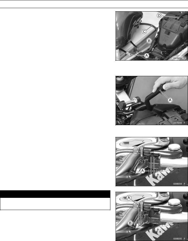
PERIODIC MAINTENANCE 2-25
Periodic Maintenance Procedures
Air Suction System Damage Inspection
•Remove:
Fuel Tank (see Fuel Tank Removal in the Fuel System (DFI) chapter)
Fuel Hose (see Fuel Hose Replacement)
•Connect the following parts temporary. Fuel Pump Lead Connector [A]
Fuel Level Sensor Lead Connector [B] Extension Tube [C]
Special Tool — Extension Tube: 57001-1578
•Pull the air switching valve hose [D] out of the air cleaner housing.
•Start the engine and run it at idle speed.
•Plug [A] the air switching valve hose end with your finger and feel vacuum pulsing in the hose.
 If there is no vacuum pulsation, check the hose line for leak. If there is no leak, check the air switching valve (see Air Switching Valve Unit Test in the Electrical System chapter) or air suction valve (see Air Suction Valve Inspection in the Engine Top End chapter).
Clutch
Clutch Operation Inspection
•Pull the clutch lever just enough to take up the free play [A].
•Measure the gap between the lever and the lever holder.  If the gap is too wide, the clutch may not release fully. If the gap is too narrow, the clutch may not engage fully. In either case, adjust it.
Clutch Lever Free Play
Standard: 2 3 mm (0.08 0.12 in.)

 WARNING
To avoid a serious burn, never touch the engine or exhaust pipe during clutch adjustment.
•Turn the adjuster [A] so that 5 6 mm (0.20 0.24 in.) [B] of threads are visible.

2-26 PERIODIC MAINTENANCE
Periodic Maintenance Procedures
•Open the clamp [A].
•Slide the dust cover [B] out of place.
•Loosen the locknut [C].
•Turn the adjusting nut [D] until the free play is correct.

 WARNING
Be sure that the outer cable end at the clutch lever is fully seated in the adjuster at the clutch lever, or it could slip into place later, creating enough cable play to prevent clutch disengagement.
•Tighten the locknut, and slip the dust cover back onto place.
•After the adjustment, start the engine and check that the clutch does not slip and that it releases properly.
Wheels/Tires
Air Pressure Inspection
•Remove the air valve cap.
•Measure the tire air pressure with an air pressure gauge [A] when the tires are cold (that is, when the motorcycle has not been ridden more than a mile during the past 3 hours).
•Install the air valve cap.
 Adjust the tire air pressure according to the specifications if necessary.
Air Pressure (when Cold)
Front: Up to 180 kg (397 lb)
225 kPa (2.25 kgf/cm², 32 psi)
|
Rear: |
Up to 180 kg (397 lb) |
|
250 kPa (2.50 kgf/cm²,36 psi) |
Wheel/Tire Damage Inspection
•Remove any imbedded stones [A] or other foreign particles [B] from tread.
•Visually inspect the tire for cracks and cuts, and replace the tire if necessary. Swelling or high spots indicate internal damage, requiring tire replacement.
•Visually inspect the wheel for cracks, cuts and dents damage.
 If any damage is found, replace the wheel if necessary.
Tire Tread Wear, Abnormal Wear Inspection
As the tire tread wears down, the tire becomes more susceptible to puncture and failure. An accepted estimate is that 90% of all tire failures occur during the last 10% of tread life (90% worn). So it is false economy and unsafe to use the tires until they are bald.
•Measure the tread depth at the center of the tread with a depth gauge [A]. Since the tire may wear unevenly, take measurement at several places.
 If any measurement is less than the service limit, replace the tire (see Tire Removal/Installation in the Wheels/Tires chapter).
Specifications:
|
Accompanying Data:
Kawasaki ER-6N — Motorcycle, Other PDF Owner’s Manual (Updated: Monday 19th of September 2022 07:55:26 PM)
Rating: 4.7 (rated by 98 users)
Compatible devices: Ninja H2R, FX801V -, 750 turbo, Z1000SX ABS, ZR1100-C1, W650 2001, Z750R ABS, VN900 CLASSIC.
Recommended Documentation:
Kawasaki ER-6N -: Text of Owner’s Manual
(Ocr-Read Version Summary of Contents, UPD: 19 September 2022)
-
96, 94 MAINTENANCE AND ADJUSTMENT • Apply a thin film of oil to the packing and tighten the cartridge to the spec- ified torque. A. Packing • Install the drain plug with its new gas- ket. Tighten it to the specified torque. NOTE Replace any gaskets with new ones. • Fill the engine up to the upper level line with a good quality engine oil specified in the table. • Sta…
-
146, 144 MAINTENANCE AND ADJUSTMENT NOTE On high beam , the brightest p oint should be sligh tly below horizontal. The proper angle is 0.4 degrees be- low horizontal. This is a 50 mm ( 2.0 in.) drop at 7.6 m (25 ft) measured from the center of the headlight, with the motorcycle on its wheels and the rider seated. A. 50 mm (2.0 in.) B. Center of Brightest Spot C. 7.6 m (…
-
117, MAINTENANCE AND ADJUSTMENT 115 • If the drive chain is too tight or too loose, adjust it so that the chain slack will be within the standard value. Drive Chain Slack Standard 25 a 35 mm (1.0 a 1.4 in.) Adjustment • Loosen the left and right chain ad- juster locknuts. • Remove the cotter pin, and loosen the rear axle nut. A. Axle Nut B. Cotter Pin C. Adjus…
-
73, SAFE OPERATION 71 Engine stop switch …… Stops engine. Side stand ………………. Returns to its fully up position by spring tension. Returns spring not weak or not damaged. Refer to the “Daily Safety Checks” caution label attached to the Tool Kit/U-Shaped Lock compartment. http://www.motorcycle.in.th
… -
66, 64 HOW TO RIDE THE MOTORCYCLE Catalytic Converter This motorcycle is equipped with a catalytic converter in the exhaust system. Platinum and rhodium in the converter react with carbon monox- ide, hydrocarbons and nitrogen oxides to convert them into carbon dioxide, water, nitrogen and oxygen resulting in much cleaner exhaust gases to be discharged into the at…
-
150, 148 MAINTENANCE AND ADJUSTMENT Apply grease to the following points — (K) Clutch Inner Cable Upper End (K) Throttle Inner Cable Upper Ends (K): Shouldbeservicedbyanauthorized Kawasaki dealer. NOTE After connecting the cables, adjust them. Cleaning Your Motorcycle General Precautions Frequent and proper care of your Kawasaki motorcycle will enhance its appearance, optimize ove…
-
133, MAINTENANCE AND ADJUSTMENT 131 • If any doubt about the rear shock ab- sorber, it should be done by an au- thorized Kawasaki dealer. A. Rear Shock Absorber The rear shock absorber can be ad- justed by changing the spring preload and rebound damping force for various riding and loading conditions. Spring Preload Adjustment The spring preload adjuster on the rear sho…
-
61, HOW TO RIDE THE MOTORCYCLE 59 Braking • Close the throttle completely, leav- ing the clutch engaged (except when shifting gears) so that the engine will help slow down the motorcycle. • Shift down one gear at a time so that you are in 1st gear when you come toacompletestop. • When stopping, always apply both brakes at the same time. Normally thefrontbrakeshouldbeappliedalit- tle…
-
115, MAINTENANCE AND ADJUSTMENT 113 If the play is incorrect, adjust the lever play as follows. Adjustment • Loosen the locknut, and turn the adjuster so that the clutch lever will have the proper play. WARNING Too much cable play can pre- vent clutch disengagement and cause an accident resulting in serious injury or death. When adjusting the clutch or replac- ing the cable, be sure the up- per end o…
-
59, HOW TO RIDE THE MOTORCYCLE 57 Shifting Gears • Close the throttle while pulling in the clutch lever. • Shift into the next higher or lower gear. • Open the throttle half way, while re- leasing the clutch lever. • For smooth riding, each gear position should cover the proper rate of speed shown in the table. WARNING Downshifting to a lower gear at high speed causes engine rpm …
-
9, Stopping the Motorcycle in an Emergency …………………………….. 61 Parking……………………………………… 62 Catalytic Converter……………………… 64 SAFE OPERATION……………………….. 66 Safe Riding Technique ………………… 66 Daily Safety Checks……………………. 69 Additional Considerations for High Speed Operation ………………….…
-
20, 18 LOADING AND ACCESSORIES INFORMATION 6. Do not install accessories or carry baggage that impairs the perfor- mance of the motorcycle. Make sure that you have not adversely affected any lighting components, road clearance, banking capability (i.e., lean angle), control operation, wheel travel, front fork movement, or any other aspect of the motorcy- cle’s opera…
-
79, MAINTENANCE AND ADJUSTMENT 77 You should keep a maintenance record for your motorcycle. To assist you in keeping this record, we have provided space on pages 173 through 177 of this manual where an authorized Kawasaki dealer, or someone equally competent, can record the maintenance. You should also retain copies of maintenance work orders, bills, etc., as verif…
Kawasaki ER-6N -: Recommended Instructions
TF-DVD7060 — DVD Player — 7, 300X, T2030W, IW16, Wildcat, HQ6889/01


-
1 of 9 YAMAHA 650 BUYER’S GUIDE This guide is intended to aid the purchaser or seller of a Yamaha 650 twin in evaluating the bike and determining the ballpark costs associated with any problems found. This information is only a guideline and cannot protect the buyer from all possible problems. Each buying decision is unique and the buyer must use judgment and …
650 9
-
1ForewordFOREWORDThis handbook contains information on the Triumph Speed Triple motorcycle. Always store thisowner’s handbook with the motorcycle and refer to it for information whenever necessary.Warnings, Cautions and NotesThroughout this owner’s handbookparticularly important information ispresented in the following form:Note:• This note symbol indicates …
Speed Triple 128
-
Holtvej 8-10, Høruphav6470 SydalsTelefon: +45 73 15 11 00Fax: +45 73 15 11 01E-mail: [email protected]: 27 73 31 07ServiceManualGT 125 RGT 250 REuro 2, karburatormodelSe også FI ServiceManual for indsprøjtnings-delene og GT250 Naked forøvrige serviceinformation …
GT250R 37
-
SafetyFirstSafeOperatingRulesBeforeoperatingyournewmotorcycleitisyourresponsibilitytoreadandfollowtheoperatingandmaintenanceinstructionsinthismanual,andfollowthesebasicrulesforyourpersonalsafety.Knowandrespecttherulesoftheroad(seeRULESOFTHE� …
Dyna Super Glide Custom 2005 146
-
SafetyFirstSafeOperatingRules:TouringModelsBeforeoperatingyournewmotorcycleitisyourresponsibilitytoreadandfollowtheoperatingandmaintenanceinstructionsinthismanual,andfollowthesebasicrulesforyourpersonalsafety.Knowandrespecttherulesoftheroad(seeRULESOFTHERO …
Road King Classic 188
-
I49cc Dirt RunnerRead this manual carefully. It contains important safety information.Children under the age of 16 should be supervised by a responsible adult. Always wear a helmet; It could save your Life!Do not remove this operator’s manual from this vehicle.Please obtain, review, and follow provincial / municipal government acts and regulations pertaining …
49CC DIRT RUNNER 33
-
No part of this publication may be reproduced without written permission.This publication includes the latest production information available before printing.Honda Motor Co., Ltd. reserves the right to make changes at any time without notice and withoutincurring any obligation.This manual should be considered a permanent part of the motorcycle and should remain with themoto …
CRF230F 2004 189
-
� …
HP2 MEGAMOTO 3
Popular Right Now:
Operating Impressions, Questions and Answers:
Table of Contents for Kawasaki ER-6N -:
-
ELECTRICAL SYSTEM 16-15 Wiring Diagram
-
5-20 ENGINE TOP END Cylinder Head Cylinder Compression Measure ment NOTE ○ Use the battery which is fully charged. • Warm up the engine thoroughly. • Stop the engine. • Remove: Seat (see Seat Removal in the Frame chapter) Fuel Tank (see Fuel Tank Removal in the Fuel System (DFI) chapter) Air Cleaner Housing (see Air Cleaner Housing Removal in the Fuel System (DFI) chapter) Stick Coils (see Stick Coil (Ignition Coil together wi
-
2-46 PERIODIC M AINTENANCE Periodic Maintenance Procedures Oil Filter Replacement • Drain the engine oil (see Engine Oil C hange). • Remove the oil filter [A] with the oil filter wrench [B]. Special Tool — Oil Filter Wrench: 57001-1249 • Replace the filter with a new one. • Apply engine oil to the gasket [A] before installation. • Tighten the filter with the oil filter wrenc
-
ELECTRICAL SYSTEM 16-5 Exploded View Torque No. Fastener N·m kgf·m ft·lb Remarks 1 License Plate Light Cover Screws 0.90 0.090 8in·lb 2 License Plate Light Mounting Screws 1.2 0.12 11 in·lb 3 Meter Screws 1.2 0.12 11 in·lb
-
16-34 ELECTRICAL SYSTEM Ignition System WARNING The ignition system produces extremely high volt- age. Do not touch the spark plugs or stick coils while the engine is running, or you could receive a severe electrical shock. CAUTION Do not disconnect the battery cables or any other electrical connections when the ignition switch is on, or while the engine is running. This is to prevent ECU (Electric Control Unit) damage. Do not install the battery backwards. The negative side is grounded. This is to prevent damage to the ECU. Crankshaft
-
GENERAL INFORMATION 1-1 1 General Information Table of Contents Before Servicing ……………………………………………………………………………………………………… 1-2 Model Identification………………………………………………………………………………………………….. 1-7 General Specifications…
-
ENGINE TOP END 5-29 Valves • Measure the outside diameter of the s eating surface with a vernier caliper. If the outside diameter of the seating surface is too small, repeat the 45° grind until the diameter is within the spec- ified range. Widened Width [A] of engagement by machining with 45° cutter Ground Volume [B] by 32° cutter 32° [C] Correct Width [D] Ground Volume [E] by 60° or 55° cutter 60° or 55° [F] • Measure the outside diam
-
NOTE ○ This note symbol indicates points of par- ticular interest for more efficient and con — venient operation. • Indicates a procedural step or work to be done. ○ Indicates a procedural sub-step or how to do the work of the procedural step it follows. It also precedes the text of a NOTE. Indicates a conditional step or what action to take based on the results of the test or inspec- tion in the procedural step or sub-step it fol- lows. In most chapters an exploded view illustration of the system components follows the Table of Contents. In these ill
-
9-2 CRANKSHAFT/TRANSMISSION Exploded View
-
APPENDIX 17-11 Cable, Wire, and Hose Routing 1. Clamp (Through the right switch housing lead, and insert the clamp in the frame.) 2. Clutch Cable 3. Throttle Cables 4. Clamp 5. Right Switch Housing Lead 6. Clamp (Insert the clamp in the bracket.) 7. Clamp (Insert the clamp in the frame.) 8. About 45° 9. Clamp (Insert the clamp in the frame.) 10. Coolant Hose 11. Clamp 12. Clamp (Through the clutch cable in the clamp.)
-
CRANKSHAFT/TRANSMISSION 9-23 Crankshaft and Connecting Rods If any crankpin has worn past the service limit, replace the crankshaft with a new one. If the measured crankpin diameters are not less than the service limit, but do not coincide with the original diameter markings on the crankshaft, make new marks on it. Crankpin Diameter Marks None 37.984 ∼ 37.992 mm (1.4954 ∼ 1.4957 in.) ○ 37.993 ∼ 38.000 mm (1.4958 ∼ 1.4961 in.) ∆: Crankpin Diameter Marks, “ ○ ”orn
-
CRANKSHAFT/TRANSMISSION 9-3 Exploded View Torque No. Fastener N·m kgf·m ft·lb Remarks 1 Connecting Rod Big End Nuts see Text ← ← ← 2 Timing Rotor Bolt 40 4.1 30 3 Oil Plate Bolts 9.8 1.0 87 in·lb L 4 Breather Plate Bolts 9.8 1.0 87 in·lb L 5 Shift Shaft Return Spring Pin 29 2.9 22 L 6 Oil Pipe Bolts 9.8 1.0 87 in·lb L 7 Crankcase Bolts (M9, L = 113 mm) 44 4.5 32 MO, S 8 Crankcase Bolts (M9, L = 83 mm) 44 4.5 32 MO, S 9 Crankcase Bolts (M8, L = 73 mm) 35 3.6 26 MO, S 10 Crankcase Bolts (M8, L = 60 mm) 35 3.6 26 MO, S 11 Crankcase
-
17-18 APPENDIX Cable, Wire, and Hose Routing
-
FINAL DRIVE 11-5 Special Tools Inside Circlip P l ie r s: 57001-143 Bearing Driver Set: 57001-1129
-
4-14 COOLING SYSTEM Radiator Radiator an d Radiator Fan Installation • Install the grommet [A] so that its large side faces the front. • Install the radiator [B] to the frame. ○ Align [C] the projection on the radiator with the hole on the frame. ○ Align[D]theprojectionontheframewiththeholeonthe radiator. ○ Note the baffle plate on the cylinder head cover when intalling the radiator. ○ Position the radiator hose clamp screws [E] as shown.
-
FUEL SYSTEM (DFI) 3-9 DFI System 1. Ignition Switch 2. Starter Lockout Switch 3. Starter Relay 4. Tachometer 5. FI Indicator L ight (LED) 6. Inlet Air Pressure Sensor 7. Spark Plug 8. Crankshaft Sensor 9. Injector 10. Main Throttle Sensor 11. Delivery Pipe 12. Subthrottle Sensor 13. Subthrottle Valve 14. Main Throttle Valve 15. Subthrottle Valve Actuator 16. Fuel Pump 17. Pressure Regulator 18. Fuel Tank 19. Air Cleaner Element 20. Air Switching Valve 21. Inlet Air Temperature Sensor 22
Questions, Opinions and Exploitation Impressions:
You can ask a question, express your opinion or share our experience of Kawasaki ER-6N — device using right now.