Материал из BikesWiki — энциклопедия японских мотоциклов
Перейти к: навигация, поиск

Yamaha XJ 900 S Diversion
Ниже представлены прямые ссылки на скачку сервисной документации.
Для Yamaha XJ900S Diversion
- Руководство пользователя (Owners Manual) для Yamaha XJ900S Diversion
- Сервисный мануал (Service Manual) для Yamaha XJ900S Diversion
Обзор модели
- Yamaha XJ900S Diversion
Источник — «https://bikeswiki.ru/index.php?title=Yamaha_XJ900_Diversion:_мануалы&oldid=10063»
Категория:
- Сервисная документация
Мотоциклы Yamaha XJ900S Diversion — инструкция пользователя по применению, эксплуатации и установке на русском языке. Мы надеемся, она поможет вам решить возникшие у вас вопросы при эксплуатации техники.
Вы можете скачать инструкцию к Yamaha XJ900S Diversion по ссылке ниже, если не хотите ждать загрузки. Если остались вопросы, задайте их в комментариях после инструкции.
«Загружаем инструкцию», означает, что нужно подождать пока файл загрузится и можно будет его читать онлайн. Некоторые инструкции очень большие и время их появления зависит от вашей скорости интернета.
Остались вопросы?
Не нашли свой ответ в руководстве или возникли другие проблемы? Задайте свой вопрос в форме ниже с подробным описанием вашей ситуации, чтобы другие люди и специалисты смогли дать на него ответ. Если вы знаете как решить проблему другого человека, пожалуйста, подскажите ему


Часто задаваемые вопросы

Как посмотреть инструкцию к Yamaha XJ900S Diversion?
Необходимо подождать полной загрузки инструкции в сером окне на данной странице или скачать кликнув по специальной кнопке.
Руководство на русском языке?
Все наши руководства представлены на русском языке или схематично, поэтому вы без труда сможете разобраться с вашей моделью
Как можно распечатать инструкцию?
Скачайте ее по специальной кнопке над формой чтения на ваше устройства и отправьте на печать.
- Manuals
- Brands
- Yamaha Manuals
- Motorcycle
- Diversion 900
- Owner’s manual
-
Contents
-
Table of Contents
-
Troubleshooting
-
Bookmarks
Related Manuals for Yamaha Diversion 900
Summary of Contents for Yamaha Diversion 900
-
Page 1
OWNER’S MANUAL XJ900S 4KM-28199-E5… -
Page 2
EAU00001 Welcome to the Yamaha world of motorcycling! As the owner of a XJ900S, you are benefiting from Yamaha’s vast experience in and newest technology for the design and the manufacture of high-quality products, which have earned Yamaha a reputation for dependability. -
Page 3
This manual should be considered a permanent part of this motorcycle and should remain with it even if the motorcycle is subsequently sold. Yamaha continually seeks advancements in product design and quality. Therefore, while this manual contains the most current product information available at the time of printing, there may be minor discrepancies between your motorcycle and this manual. -
Page 4: Important Manual Information
IMPORTANT MANUAL INFORMATION EW000002 WARNING PLEASE READ THIS MANUAL CAREFULLY AND COMPLETELY BEFORE OPERATING THIS MOTORCYCLE.
-
Page 5
IMPORTANT MANUAL INFORMATION EAU00008 XJ900S OWNER’S MANUAL © 1999 by Yamaha Motor Co., Ltd. 1st Edition, July 1999 All rights reserved. Any reprinting or unauthorized use without the written permission of Yamaha Motor Co., Ltd. is expressly prohibited. Printed in Japan. -
Page 6: Table Of Contents
EAU00009 TABLE OF CONTENTS 1 GIVE SAFETY THE RIGHT OF WAY 2 DESCRIPTION 3 INSTRUMENT AND CONTROL FUNCTIONS 4 PRE-OPERATION CHECKS 5 OPERATION AND IMPORTANT RIDING POINTS 6 PERIODIC MAINTENANCE AND MINOR REPAIR 7 MOTORCYCLE CARE AND STORAGE 8 SPECIFICATIONS 9 CONSUMER INFORMATION INDEX…
-
Page 8: Give Safety The Right Of Way
GIVE SAFETY THE RIGHT OF WAY GIVE SAFETY THE RIGHT OF WAY……….1-1…
-
Page 9
G IVE SAFETY THE RIGHT OF WAY EAU00021 Motorcycles are fascinating vehicles, which can give you an unsurpassed feeling of power and freedom. However, they also impose certain limits, which you must accept; even the best motorcycle does not ignore the laws of physics. Regular care and maintenance are essential for preserving your motorcycle’s value and operating condition. -
Page 10: Description
DESCRIPTION Left view ………………… 2-1 Right view………………. 2-2 Controls/Instruments …………….2-3…
-
Page 11
D ESCRIPTION EAU00026 Left view 1. Headlight (page 6-26) 5. Final gear case 2. Helmet holder (page 3-15) 6. Rear shock absorber spring 3. Seat lock (page 3-15) preload adjusting ring (page 3-17) 4. Luggage strap hook 7. Shift pedal (page 3-11) -
Page 12
DESCRIPTION Right view 8. Tail/brake light (page 6-19) 13. Front fork spring preload 9. Fuse boxes (page 6-25) adjusting bolt (page 3-16) 10. Seat (page 3-15) 14. Engine oil level window (page 6-8) 11. Tool kit (page 6-1) 15. Rear brake pedal (page 3-11) 12. -
Page 13
DESCRIPTION Controls/Instruments 1. Clutch lever (page 3-10) 7. Digital clock (page 3-8) 2. Left handlebar switches (page 3-9) 8. Right handlebar switches (page 3-10) 3. Starter (choke) “ ” (page 3-14) 9. Front brake lever (page 3-11) 4. Speedometer (page 3-6) 10. -
Page 14: Instrument And Control Functions
INSTRUMENT AND CONTROL FUNCTIONS Main switch/steering lock ……..3-1 Front brake lever ……….3-11 Indicator lights …………3-3 Rear brake pedal……….3-11 Oil level indicator circuit check……3-4 Fuel tank cap …………. 3-12 Fuel indicator circuit check ……..3-5 Fuel …………..3-13 Speedometer …………3-6 Fuel tank breather hose (for Germany only) ..
-
Page 15: Main Switch/Steering Lock
I NSTRUMENT AND CONTROL FUNCTIONS EAU00027 1. Push 2. Turn EAU00029* EAU00040 Main switch/steering lock LOCK EW000016 The steering is locked in this position WARNING The main switch controls the ignition and all electrical circuits are switched and lighting systems. Its operation is Never turn the key to “OFF”…
-
Page 16
INSTRUMENT AND CONTROL FUNCTIONS EAU01590 (Parking) The steering is locked in this position, and the taillight and auxiliary light come on but all other circuits are off. The key can be removed in this position. To use the parking position, first lock the steering, then turn the key to “… -
Page 17: Indicator Lights
INSTRUMENT AND CONTROL FUNCTIONS EAU01154 EAU01313 Fuel indicator light “ ” Oil level indicator light “ ” When the fuel level drops below ap- This indicator comes on when the oil proximately 5 L, this light will come on. level is low. This light circuit can be When this light comes on, fill the tank at checked by the procedure on page 3-4.
-
Page 18: Oil Level Indicator Circuit Check
Oil level indicator light Oil level Oil level comes on. does not come on. is OK. is low. Ask a Yamaha dealer to Engine oil level and Supply inspect electrical circuit. electrical circuit are OK. engine oil. Go ahead with riding.
-
Page 19: Fuel Indicator Circuit Check
Fuel indicator light Fuel indicator light Fuel level Fuel level comes on. does not come on. is OK. is low. Fuel level and electrical Ask a Yamaha dealer to Supply fuel. circuit are OK. inspect electrical circuit. Go ahead with riding.
-
Page 20: Speedometer
INSTRUMENT AND CONTROL FUNCTIONS 1. Tripmeter 1. Tachometer 2. Odometer 2. Red zone 3. Reset button EAU00101 Tachometer EAU00094 Speedometer This model is equipped with an electric The speedometer shows riding speed. tachometer so the rider can monitor the This speedometer is equipped with an engine speed and keep it within the odometer and trip odometer.
-
Page 21: Diagnosis Device
CAUTION: If some trouble should occur in any of To prevent engine damage, be sure these circuits, the tachometer will re- to consult a Yamaha dealer as soon peatedly display as follows: as possible if the tachometer dis- CB-72E plays a repeated change in r/min.
-
Page 22: Fuel Gauge
INSTRUMENT AND CONTROL FUNCTIONS NOTE: When setting the clock after its power source is cut by a removed battery, etc., first set the time for 1:00 AM, then, go on to set it for the correct time. 1. Fuel gauge 1.
-
Page 23: Handlebar Switches
INSTRUMENT AND CONTROL FUNCTIONS EAU00144 EAU00127 Hazard switch “ ” Turn signal switch The hazard switch should be turned on To signal a right-hand turn, push the under emergency or hazardous condi- switch to “ ”. To signal a left-hand tions.
-
Page 24: Clutch Lever
INSTRUMENT AND CONTROL FUNCTIONS EAU00134 Lights switch Turning the light switch to “ ”, turns on the auxiliary light, meter lights and taillight. Turning the light switch to “ ” turns the headlight on also. EAU00143 Start switch “ ” The starter motor cranks the engine 1.
-
Page 25: Shift Pedal
INSTRUMENT AND CONTROL FUNCTIONS 1. Shift pedal 1. Front brake lever 1. Rear brake pedal 2. Position adjusting nut EAU00157 EAU00162 Shift pedal Rear brake pedal 3. Proper position a. Adjusting range This motorcycle is equipped with a con- The rear brake pedal is on the right EAU00160 stant-mesh 5-speed transmission.
-
Page 26: Fuel Tank Cap
INSTRUMENT AND CONTROL FUNCTIONS NOTE: This tank cap cannot be closed unless the key is in the lock. The key cannot be removed if the cap is not locked properly. EW000023 WARNING Be sure the cap is properly installed and locked in place before riding the 1.
-
Page 27: Fuel
INSTRUMENT AND CONTROL FUNCTIONS EAU00186 EAU00191 CAUTION: Recommended fuel: Always wipe off spilled fuel im- Regular unleaded gasoline with a mediately with a dry and clean research octane number of 91 or soft cloth. Fuel may deteriorate higher. painted surfaces plastic Fuel tank capacity: parts.
-
Page 28: Fuel Tank Breather Hose (For Germany Only)
INSTRUMENT AND CONTROL FUNCTIONS 1. Fuel tank breather hose 1. Starter (choke) “ ” EAU00196 EAU02976 Fuel tank breather hose Starter (choke) “ ” (for Germany only) Starting a cold engine requires a richer air-fuel mixture. A separate starter cir- This model is equipped with a fuel tank cuit supplies this mixture.
-
Page 29: Seat
INSTRUMENT AND CONTROL FUNCTIONS 1. Seat lock 1. Projection ( 2) 1. Helmet holder 2. Seat holder EAU02925 EAU00263 Seat Helmet holder To install To remove The helmet holder is under the seat. Insert the projections on the front of the Insert the key in the lock and turn it Remove the seat and hook the helmet seat into the seat holder, then push…
-
Page 30: Storage Compartment
Front fork adjustment EC000013 CAUTION: This compartment is designed to store This front fork is equipped with spring a genuine Yamaha U-LOCK. (Other preload adjusting bolts. The grooves are provided to show locks may not fit.) Be sure the lock is EW000037 the adjustment level.
-
Page 31: Rear Shock Absorber Adjustment
Make sure that damage will result in poor the appropriate notch in the adjusting damping performance. ring is aligned with the position indica- Take your shock absorber to a tor on the rear shock absorber. Yamaha dealer for any service. 3-17…
-
Page 32: Sidestand
Please check carefully PULL IN CLUTCH LEVER AND the operating instructions listed be- PUSH START SWITCH. low and if there is any indication of a malfunction, return the motorcycle ENGINE WILL START. to a Yamaha dealer immediately for repair. 3-18…
-
Page 34: Pre-Operation Checks
PRE-OPERATION CHECKS Pre-operation check list…………..4-1…
-
Page 35: Pre-Operation Check List
P RE-OPERATION CHECKS EAU01114 Owners are personally responsible for their vehicle’s condition. Your motorcycle’s vital functions can start to deteriorate quickly and unexpectedly, even if it remains unused (for instance, if it is exposed to the elements). Any damage, fluid leak or loss of tire pressure could have serious consequences.
-
Page 36
PRE-OPERATION CHECKS ITEM CHECKS PAGE • Make sure that all nuts, bolts and screws are properly tightened. Chassis fasteners — • Tighten if necessary. • Check fuel level. Fuel 3-13 • Fill with fuel if necessary. Lights, signals and • Check for proper operation. 6-26 ~ 6-27 switches NOTE:… -
Page 38: Operation And Important Riding Points
OPERATION AND IMPORTANT RIDING POINTS Starting the engine…………….5-1 Starting a warm engine …………..5-4 Shifting ………………..5-4 Recommended shift points (for Switzerland only) ……5-5 Tips for reducing fuel consumption ………… 5-5 Engine break-in ……………… 5-5 Parking ………………..5-6…
-
Page 39: Starting The Engine
Consult The engine can be started only under Yamaha dealer regarding any one of the following conditions: control or function that you do The transmission is in neutral. not thoroughly understand. The sidestand is up, the transmis-…
-
Page 40
OPERATION AND IMPORTANT RIDING POINTS CF-28E TURN THE MAIN SWITCH TO “ON” AND THE ENGINE STOP SWITCH TO “ ”. IF TRANSMISSION IS IN NEUTRAL AND IF TRANSMISSION IS IN GEAR AND SIDESTAND IS DOWN, SIDESTAND IS UP, PUSH THE START SWITCH. PULL IN THE CLUTCH LEVER AND PUSH START ENGINE WILL START. -
Page 41
(choke) turned off. Yamaha dealer to inspect it. is released. If the oil level indicator light flickers or remains on, immedi- 3. Turn on the starter (choke) and completely close the throttle grip. -
Page 42: Starting A Warm Engine
OPERATION AND IMPORTANT RIDING POINTS EAU01258 EC000048 Starting a warm engine CAUTION: The starter (choke) is not required Do not coast for long periods when the engine is warm. with the engine off, and do not EC000046 tow the motorcycle a long dis- CAUTION: tance.
-
Page 43: Recommended Shift Points (For Switzerland Only)
OPERATION AND IMPORTANT RIDING POINTS EAU02941 EAU00424 EAU00436 Recommended shift points Tips for reducing fuel Engine break-in (for Switzerland only) consumption There is never a more important period in the life of your motorcycle than the The recommended shift points are Your motorcycle’s fuel consumption period between zero and 1,000 km.
-
Page 44: Parking
WARNING cur during the break-in period, from time to time. Do not operate it at The exhaust system is hot. Park the consult a Yamaha dealer imme- one set throttle position. motorcycle in a place where pedes- diately. trians or children are not likely to 500 ~ 1,000 km touch the motorcycle.
-
Page 46: Periodic Maintenance And Minor Repair
PERIODIC MAINTENANCE AND MINOR REPAIR Tool kit…………..6-1 Brake fluid replacement ……..6-21 Periodic maintenance and lubrication….6-2 Cable inspection and lubrication ……6-21 Cowling removal and installation ……6-5 Throttle cable and grip lubrication …… 6-21 Cowling A…………..6-5 Brake and shift pedal lubrication ……6-22 Cowling B…………..6-6 Brake and clutch lever lubrication ……
-
Page 47: Tool Kit
If you do not have necessary tools re- brication will keep your motorcycle in quired during a service operation, take the safest and most efficient condition your motorcycle to a Yamaha dealer for possible. Safety is an obligation of the service. motorcycle owner. The maintenance…
-
Page 48: Periodic Maintenance And Minor Repair
PERIODIC MAINTENANCE AND MINOR REPAIR EAU00473 PERIODIC MAINTENANCE AND LUBRICATION CP-01E EVERY 6,000 km 12,000 km INITIAL ITEM CHECKS AND MAINTENANCE JOBS (1,000 km) 6 months 12 months (whichever (whichever comes first) comes first) • Check fuel hoses for cracks or damage. Fuel line •…
-
Page 49
PERIODIC MAINTENANCE AND MINOR REPAIR EVERY 6,000 km 12,000 km INITIAL ITEM CHECKS AND MAINTENANCE JOBS (1,000 km) 6 months 12 months (whichever (whichever comes first) comes first) • Check bearing for looseness or damage. Wheel bearings • Replace if necessary. •… -
Page 50
Final gear oil • Change oil at initial 1,000 km and thereafter every 24,000 km or 24 months (whichever comes first). * Since these items require special tools, data and technical skills, they should be serviced by a Yamaha dealer. EAU02970 NOTE: The air filter needs more frequent service if you are riding in unusually wet or dusty areas. -
Page 51: Cowling Removal And Installation
PERIODIC MAINTENANCE AND MINOR REPAIR 1. Cowling A 1. Cowling A 2. Cowling B 2. Screw ( 2) 3. Pull the cowling up, and then slide EAU01065 EAU00490* it back. Cowling removal and Cowling A To install installation To remove 1.
-
Page 52: Cowling B
PERIODIC MAINTENANCE AND MINOR REPAIR 1. Grab bar 1. Bolt ( 4) 1. Screw ( 2) 2. Cowling B 2. Remove the bolts and the grab 3. Remove the screws and pull the EAU00486* bar. cowling off as shown. Cowling B To install To remove 1.
-
Page 53: Spark Plug Inspection
When installing a spark plug, the gas- lems yourself. Instead, take the motor- ket surface should always be cleaned cycle to a Yamaha dealer. The spark and a new gasket used. Any grime plugs should be periodically removed should be wiped off from the threads…
-
Page 54: Engine Oil
PERIODIC MAINTENANCE AND MINOR REPAIR 2. With the engine stopped, check the oil level through the level win- dow located at the lower part of the right side crankcase cover. NOTE: Wait a few minutes until the oil level settles before checking. 3.
-
Page 55
NOTE: Make sure the O-ring is seated proper- An oil filter wrench is available at a nearby Yamaha dealer. 7. Install the new oil filter and tighten 5. Install the drain bolt and tighten it it to the specified torque with an oil to the specified torque. -
Page 56
After the engine is started, the oil level 3.4 L indicator light should go off if the oil is at the specified level. EC000067 CAUTION: If the indicator light flickers or re- mains on, immediately stop the en- gine and consult with a Yamaha dealer. 6-10… -
Page 57: Final Gear Oil Replacement
PERIODIC MAINTENANCE AND MINOR REPAIR 5. Fill the gear case with the recom- mended oil. Recommended oil: SAE 80 API GL-4 Hypoid gear oil If desired, an SAE 80W90 hypoid gear oil may be used for all condi- tions. Final gear oil quantity: 1.
-
Page 58
PERIODIC MAINTENANCE AND MINOR REPAIR 1. Bolt ( 2) 1. Screw ( 4) 1. Air filter 3. Remove the fuel tank bolts. 5. Remove the air filter case cover by 6. Pull out the air filter. 4. Disconnect the fuel sender lead removing the screws. -
Page 59: Carburetor Adjustment
Most adjustments 1,000 to 2,000 r/min. Occasionally should be left to a Yamaha dealer who rev the engine to 4,000 to has the professional knowledge and 5,000 r/min. The engine is warm experience to do so.
-
Page 60: Throttle Cable Free Play Inspection
There should be a free play of 3 ~ speed and in direction b to de- 5 mm at the throttle grip. If the free play is incorrect, ask a Yamaha dealer to crease engine speed. make this adjustment. Standard idle speed:…
-
Page 61: Tires
PERIODIC MAINTENANCE AND MINOR REPAIR EAU00658 CE-33E EW000083 Maximum load* 205 kg Tires WARNING Cold tire pressure Front Rear To ensure maximum performance, Proper loading of your motorcycle 225 kPa 250 kPa long service and safe operation, note Up to 90 kg load* (2.25 kg/cm (2.50 kg/cm is important for several characteris-…
-
Page 62
Yamaha dealer immediately. Brakes, tires, and relat- ed wheel parts replacement should 1. Side wall 1. Tire valve be left to a Yamaha Service Techni- a. Tread depth 2. Valve core cian. 3. Valve cap with seal Tire inspection Tire information… -
Page 63
ME33 mentioned below have been ap- high-speed running tires. The fol- Dunlop 120/70-17 58V K505F proved by Yamaha Motor Co., Bridgestone 120/70-17 58V G601 lowing points must be observed in Ltd. for this model. No guaran- order for you to make fully effective… -
Page 64: Wheels
Check for cracks, bends, or warpage of the wheels. If any ab- normal condition exists in a wheel, 1. Locknut 1. Locknut consult a Yamaha dealer. Do not 2. Adjusting bolt 2. Adjusting nut attempt even small repairs to the c. Free play If the specified free play cannot be ob- wheel.
-
Page 65: Brake Light Switch Adjustment
If they have almost disap- switch body so it does not rotate while peared, ask a Yamaha dealer to re- turning the adjusting nut. place the pads. Turn the adjusting nut in direction a to make the brake light come on earlier.
-
Page 66: Inspecting The Brake Fluid Level
Insufficient brake fluid may let air enter leakage and poor brake perfor- Have a Yamaha dealer check the the brake system, possibly causing the mance. cause if the brake fluid level goes brakes to become ineffective.
-
Page 67: Brake Fluid Replacement
Yamaha service personnel. EW000112 The throttle twist grip assembly should Have the Yamaha dealer replace the WARNING be greased at the time that the cable is following components during periodic Damage to the outer housing of ca-…
-
Page 68: Brake And Shift Pedal Lubrication
Recommended lubricant: Check to see that the center and side- Engine oil Engine oil stand move up and down smoothly. Recommended lubricant: Engine oil EW000114 WARNING If the center and/or sidestand does not move smoothly, consult a Yamaha dealer. 6-22…
-
Page 69: Front Fork Inspection
If EC000098 any free play can be felt, ask a Yamaha CAUTION: dealer to inspect and adjust the steer- If any damage or unsmooth move- ing.
-
Page 70: Wheel Bearings
Therefore it is not dangerous, causing severe burns, smoothly, have a Yamaha dealer in- necessary to check the electrolyte or fill etc. It contains sulfuric acid. Avoid spect the wheel bearings.
-
Page 71: Fuse Replacement
If tions are correct when reinstall- improper rating can cause extensive the fuse immediately blows again, con- ing the battery. electrical system damage and pos- sult a Yamaha dealer. sibly a fire. 6-25…
-
Page 72: Headlight Bulb Replacement
PERIODIC MAINTENANCE AND MINOR REPAIR Specified fuses: Main fuse: 30 A Headlight fuse: 15 A Signaling system fuse: 20 A Hazard light fuse: 10 A Ignition fuse: 10 A Clock fuse: 10 A 1. Connector 1. Bulb holder 2. Bulb holder cover 2.
-
Page 73: Front Wheel Removal
EW000122 holder. WARNING EC000105 It is advisable to have a Yamaha CAUTION: dealer service the wheel. Avoid touching the glass part of a Securely support the motor- bulb. Keep it free from oil; other-…
-
Page 74
PERIODIC MAINTENANCE AND MINOR REPAIR Right Left 1. Bolt ( 3) 1. Pinch bolt 2. Brake hose holder 2. Wheel axle 3. Caliper 4. Loosen the pinch bolt and wheel 3. Remove the brake hose holders axle. and the calipers by removing the 5. -
Page 75: Front Wheel Installation
PERIODIC MAINTENANCE AND MINOR REPAIR 6. Push down hard on the handle- bars several times to check for proper fork operation. 7. Install the speedometer cable. 4. Install the calipers and caliper EAU01469 Front wheel installation bolts. Make sure there is enough 1.
-
Page 76: Rear Wheel Removal
EW000122 4. Remove the brake torque rod cot- WARNING ter pin, nut and bolt. It is advisable to have a Yamaha 5. While supporting the brake cali- dealer service the wheel. per, pull out the wheel axle. Securely support the motor- 6.
-
Page 77: Rear Wheel Installation
If your motorcycle requires any repair, 1. Apply a light coating of lithium and brake torque rod nut to the bring it to a Yamaha dealer. The skilled soap base grease to the final gear specified torques. technicians at a Yamaha dealership…
-
Page 78: Troubleshooting Chart
Remove spark plugs and check electrodes. Engine doesn’t start, go to battery Dry. Ask a Yamaha dealer to inspect. check. 4. Battery Engine turns over Battery good. quickly. Engine doesn’t start, ask a Yamaha Use the electric starter.
-
Page 80: Motorcycle Care And Storage
MOTORCYCLE CARE AND STORAGE Care ………………..7-1 Storage………………..7-4…
-
Page 81
M OTORCYCLE CARE AND STORAGE EAU01521 Care Before cleaning Cleaning 1. Cover up the muffler outlets with After normal use The exposure of its technology makes plastic bags. Remove dirt with warm water, a neutral a motorcycle charming but also vulner- 2. -
Page 82
MOTORCYCLE CARE AND STORAGE ECA00010 Do not use any harsh chemical For motorcycles equipped with CAUTION: products on plastic parts. Be a windshield: Do not use strong Avoid using strong acidic wheel sure to avoid using cloths or cleaners or hard sponges as cleaners, especially on spoked sponges which have been in they… -
Page 83
MOTORCYCLE CARE AND STORAGE 1. Clean your motorcycle with cold After cleaning EWA00001 WARNING water and soap after the engine 1. Dry the motorcycle with a chamois Make sure that there is no oil or wax has cooled down. or an absorbing cloth. on the brakes and tires. -
Page 84
NOTE: “OFF” position: Turn the fuel cock To prevent corrosion, avoid Consult a Yamaha dealer for advice on to “OFF”. damp cellars, stables (because what products to use. 4. Fill up the fuel tank and add fuel… -
Page 85
MOTORCYCLE CARE AND STORAGE a. Remove the spark plug caps and 6. Lubricate all control cables and 9. Remove the battery and fully spark plugs. the pivoting points of all levers and charge it. Store it in a cool, dry b. -
Page 86: Specifications
SPECIFICATIONS Specifications ………………8-1 HOW TO USE THE CONVERSION TABLE ……..8-5…
-
Page 87: Specifications
S PECIFICATIONS EAU01038 Specifications Model XJ900S Engine oil Dimensions Type -20˚ -10˚ 0˚ 10˚ 20˚ 30˚ 40˚ 50˚C Overall length 2,230 mm SAE 10W/30 Overall width 750 mm SAE 10W/40 Overall height 1,300 mm SAE 15W/40 Seat height 795 mm Wheelbase 1,505 mm SAE 20W/40…
-
Page 88
SPECIFICATIONS Final gear oil Gear ratio Type SAE 80 API “GL-4” hypoid gear 2.188 oil or SAE 80W90 all-purpose 1.500 hypoid gear oil 1.154 Quantity 0.2 L 0.933 Air filter Dry type element 0.813 Fuel Chassis Type Regular unleaded gasoline Frame type Double cradle Fuel tank capacity… -
Page 89
SPECIFICATIONS Maximum load* 205 kg Rear Air pressure (cold tire) Type Single disc brake up to 90 kg load* Operation Right foot operation Front 225 kPa (2.25 kg/cm , 2.25 bar) Fluid DOT 4 Rear 250 kPa (2.50 kg/cm , 2.50 bar) Suspension 90 kg load ~ maximum load* Front… -
Page 90
SPECIFICATIONS Headlight type Quartz bulb (halogen) Bulb voltage, wattage quantity Headlight 12 V, 60/55 W Tail/brake light 12 V, 5/21 W Auxiliary light 12 V, 4 W Turn signal light 12 V, 21 W Meter light 12 V, 3.4 W Neutral indicator light 12 V, 3.4 W High beam indicator light… -
Page 91: How To Use The Conversion Table
SPECIFICATIONS EAU01064 HOW TO USE THE CONVERSION TABLE CS-02E CONVERSION TABLE All specification data in this manual are listed in SI and METRIC TO IMPERIAL METRIC UNITS. Metric unit Multiplier Imperial unit Use this table to convert METRIC unit data to IMPERIAL m·kg 7.233 ft·lb…
-
Page 92: Consumer Information
CONSUMER INFORMATION Identification number records…………. 9-1 Key identification number …………..9-1 Vehicle identification number………….. 9-1 Model label………………9-2…
-
Page 93: Identification Number Records
Record the key identification number, vehicle identification number and mod- el label information in the spaces pro- vided for assistance when ordering spare parts from a Yamaha dealer or for reference in case the vehicle is sto- len. 1. Key identification number 1.
-
Page 94: Model Label
The model label is affixed to the frame under the seat. (See page 3-15 for seat removal procedures.) Record the infor- mation on this label in the space pro- vided. This information will be needed to order spare parts from your Yamaha dealer.
-
Page 95: Left View
I NDEX 1 0 — Air filter ……….6-11 Final gear oil replacement ….. 6-11 Identification number records ….9-1 Antitheft alarm (optional) ……3-7 Front brake lever ……..3-11 Idle speed adjustment ……6-13 Front fork adjustment……3-16 Indicator lights……….3-3 Front fork inspection ……6-23 Fuel indicator light…….3-3 Battery ………..6-24 Front wheel installation ……
-
Page 96: Right View
INDEX Troubleshooting ……..6-31 Troubleshooting chart ……6-32 Rear brake pedal ……..3-11 Turn indicator lights……… 3-3 Rear shock absorber adjustment … 3-17 Turn signal switch ……..3-9 Rear wheel installation……6-31 Rear wheel removal……. 6-30 Recommended shift points Valve clearance adjustment ….6-14 (for Switzerland only)……
-
Page 97
YAMAHA MOTOR CO., LTD. PRINTED ON RECYCLED PAPER PRINTED IN JAPAN 99 · 7 — 0.3…
-
Contents
-
Table of Contents
-
Troubleshooting
-
Bookmarks
Quick Links
 Loading…

OWNER’S MANUAL
XJ900S
4KM-28199-E6
Welcome to the Yamaha world of motorcycling!
As the owner of an XJ900S, you are benefiting from Yamaha’s vast experience and newest technology regarding the design and manufacture of high-quality products, which have earned Yamaha a reputation for dependability.
Please take the time to read this manual thoroughly, so as to enjoy all advantages of your XJ900S. The owner’s manual does not only instruct you in how to operate, inspect and maintain your motorcycle, but also in how to safeguard yourself and others from trouble and injury.
In addition, the many tips given in this manual will help keep your motorcycle in the best possible condition. If you have any further questions, do not hesitate to contact your Yamaha dealer.
The Yamaha team wishes you many safe and pleasant rides. So, remember to put safety first!

|
IMPORTANT MANUAL INFORMATION |
EAU00005 |
Particularly important information is distinguished in this manual by the following notations:
The Safety Alert Symbol means ATTENTION! BECOME ALERT! YOUR SAFETY IS
INVOLVED!
|
WARNING |
Failure to follow WARNING instructions could result in severe injury or death to the |
|
|
motorcycle operator, a bystander, or a person inspecting or repairing the |
||
|
motorcycle. |
||
|
CAUTION: |
A CAUTION indicates special precautions that must be taken to avoid damage to the |
|
|
motorcycle. |
||
NOTE: A NOTE provides key information to make procedures easier or clearer.
NOTE:
●This manual should be considered a permanent part of this motorcycle and should remain with it even if the motorcycle is subsequently sold.
●Yamaha continually seeks advancements in product design and quality. Therefore, while this manual contains the most current product information available at the time of printing, there may be minor discrepancies between your motorcycle and this manual. If you have any questions concerning this manual, please consult your Yamaha dealer.

IMPORTANT MANUAL INFORMATION
EW000002
 WARNING
PLEASE READ THIS MANUAL CAREFULLY AND COMPLETELY BEFORE OPERATING THIS MOTORCYCLE.

IMPORTANT MANUAL INFORMATION
EAU03337
XJ900S
OWNER’S MANUAL
© 2000 by Yamaha Motor Co., Ltd. 1st Edition, June 2000
All rights reserved.
Any reprinting or unauthorized use without the written permission of Yamaha Motor Co., Ltd.
is expressly prohibited. Printed in Japan.

|
EAU00009 |
TABLE OF CONTENTS |
|
1 |
GIVE SAFETY THE RIGHT OF WAY |
1 |
|
|
2 |
DESCRIPTION |
2 |
|
|
3 |
INSTRUMENT AND CONTROL FUNCTIONS |
3 |
|
|
4 |
PRE-OPERATION CHECKS |
4 |
|
|
5 |
OPERATION AND IMPORTANT RIDING POINTS |
5 |
|
|
6 |
PERIODIC MAINTENANCE AND MINOR REPAIR |
6 |
|
|
7 |
MOTORCYCLE CARE AND STORAGE |
7 |
|
|
8 |
SPECIFICATIONS |
8 |
|
|
9 |
CONSUMER INFORMATION |
9 |
|
INDEX

GIVE SAFETY THE RIGHT OF WAY

 GIVE SAFETY THE RIGHT OF WAY
|
GIVE SAFETY THE RIGHT OF WAY ………………………………………… |
1-1 |
1

|
GIVE SAFETY THE RIGHT OF WAY |
EAU00021 |
Motorcycles are fascinating vehicles, which can give you an unsurpassed feeling of power and freedom. However, they also impose certain limits, which you must accept; even the best motorcycle does not ignore the laws of physics.
1
Regular care and maintenance are essential for preserving value and operating condition of your motorcycle. Moreover, what is true for the motorcycle is also true for the rider: good performance depends on being in good shape. Riding under the influence of medication, drugs and alcohol is, of course, out of the question. Motorcycle riders—more than car drivers—must always be at their mental and physical best. Under the influence of even small amounts of alcohol, there is a tendency to take dangerous risks.
Protective clothing is as essential for the motorcycle rider as seat belts are for car drivers and passengers. Always wear a complete motorcycle suit (whether made of leather or tear-resistant synthetic materials with protectors), sturdy boots, motorcycle gloves and a properly fitting helmet. Optimum protective wear, however, should not encourage carelessness. Although full-coverage helmets and suits, in particular, create an illusion of total safety and protection, motorcyclists will always be vulnerable. Riders who lack critical self-control run the risk of going too fast and are apt to take chances. This is even more dangerous in wet weather. The good motorcyclist rides safely, predictably and defensively—avoiding all dangers, including those caused by others.
Enjoy your ride!
1-1
![]()
DESCRIPTION |
|
|
Left view ………………………………………………………………………………… |
2-1 |
|
Right view………………………………………………………………………………. |
2-2 |
|
Controls and instruments …………………………………………………………. |
2-3 |
2

Left view
2
|
1. Headlight |
(page 6-30) |
5. Final gear case |
(page 6-11) |
|
2. Helmet holder |
(page 3-11) |
6. Rear shock absorber spring |
|
|
3. Seat lock |
(page 3-11) |
preload adjusting ring |
(page 3-14) |
|
4. Luggage strap holders |
7. Shift pedal |
(page 3-8) |
2-1

DESCRIPTION
Right view
2
|
8. Tail/brake light |
13. Front fork spring preload |
||
|
9. Fuse boxes |
(page 6-29) |
adjusting bolt |
(page 3-13) |
|
10. Seat |
(page 3-11) |
14. Engine oil level check window |
(page 6-8) |
|
11. Owner’s tool kit |
(page 6-1) |
15. Brake pedal |
(page 3-8) |
|
12. Air filter element |
(page 6-13) |
2-2

DESCRIPTION
Controls and instruments
2
|
1. Clutch lever |
(page 3-7) |
7. Clock |
(page 3-5) |
|
2. Left handlebar switches |
(page 3-6) |
8. Right handlebar switches |
(page 3-7) |
|
3. Starter (choke) lever |
(page 3-10) |
9. Brake lever |
(page 3-8) |
|
4. Speedometer unit |
(page 3-3) |
10. Throttle grip |
(page 6-16) |
|
5. Tachometer |
(page 3-4) |
11. Main switch/steering lock |
(page 3-1) |
|
6. Fuel gauge |
(page 3-5) |
2-3

INSTRUMENT AND CONTROL FUNCTIONS
|
Main switch/steering lock ………………………………. |
3-1 |
|
Indicator and warning lights ………………………….. |
3-2 |
|
Speedometer unit ………………………………………… |
3-3 |
|
Tachometer …………………………………………………. |
3-4 |
|
Self-diagnosis device ……………………………………. |
3-4 |
|
Anti-theft alarm (optional) ……………………………… |
3-5 |
|
Fuel gauge ………………………………………………….. |
3-5 |
|
Clock ………………………………………………………….. |
3-5 |
|
Handlebar switches ……………………………………… |
3-6 |
|
Clutch lever …………………………………………………. |
3-7 |
|
Shift pedal …………………………………………………… |
3-8 |
|
Brake lever …………………………………………………. |
3-8 |
|
Brake pedal ………………………………………………… |
3-8 |
||
|
Fuel tank cap ……………………………………………… |
3-9 |
||
|
Fuel …………………………………………………………… |
3-9 |
||
|
Fuel tank breather hose (for Germany only) ….. |
3-10 |
||
|
Starter (choke) lever …………………………………… |
3-10 |
||
|
Seat |
3-11 |
||
|
3 |
|||
|
Helmet holder |
3-11 |
||
|
…………………………………Storage compartment |
3-12 |
||
|
Adjusting the front fork ……………………………….. |
3-13 |
||
|
Adjusting the shock absorber assembly ………… |
3-13 |
||
|
Sidestand …………………………………………………. |
3-15 |
||
|
Ignition circuit cut-off system ……………………….. |
3-15 |

|
INSTRUMENT AND CONTROL FUNCTIONS |
EAU00027 |
3
1. Push.
2. Turn.
Main switch/steering lock
The main switch/steering lock controls the ignition and lighting systems, and is used to lock the steering. The various positions are described below.
EAU00036
ON
All electrical systems are supplied with power, and the engine can be started. The key cannot be removed.
EAU00038
LOCK
The steering is locked, and all electrical systems are off. The key can be removed.
To lock the steering
1.Turn the handlebars all the way to the left.
2.Push the key in from the “OFF” position, and then turn it to “LOCK” while still pushing it.
3.Remove the key.
EW000016
 WARNING
@
Never turn the key to “OFF” or “LOCK” while the motorcycle is moving, otherwise the electrical systems will be switched off, which may result in loss of control or an accident. Make sure that the motorcycle is stopped before turning the key to “OFF” or “LOCK”.
@
OFF
All electrical systems are off. The key can be removed.
To unlock the steering
Push the key in, and then turn it to “OFF” while still pushing it.
3-1

INSTRUMENT AND CONTROL FUNCTIONS
EAU01590
 (Parking)
The steering is locked, and the taillight and auxiliary light are on, but all other electrical systems are off. The key can be removed.
The steering must be locked before the key can be turned to “ ”.
”.
ECA00043
CAUTION:
Do not use the parking position for an extended length of time, otherwise the battery may discharge.
1.Left turn signal indicator light “  ”
”
2.Fuel level warning light “  ”
”
3.Neutral indicator light “  ”
”
4.High beam indicator light “  ”
”
5.Oil level warning light “ 

 ”
”
6.Right turn signal indicator light “  ”
”
EAU03034
Indicator and warning lights
EAU03299
|
EAU03680 |
||||||
|
Fuel level warning light “ |
” |
|||||
|
This warning light comes on when the |
||||||
|
fuel level drops below approximately |
||||||
|
5 L. When this occurs, refuel as soon |
||||||
|
as possible. |
||||||
|
The electrical circuit of the warning light |
||||||
|
can be checked according to the fol- |
||||||
|
3 |
||||||
|
lowing procedure. |
||||||
1.Set the engine stop switch to “  ” and turn the key to “ON”.
2.Shift the transmission into the neutral position or pull the clutch lever.
3.Push the start switch. If the warning light does not come on, have a Yamaha dealer check the electrical circuit.
Turn signal indicator lights “  ” / “ ”
The corresponding indicator light flashes when the turn signal switch is pushed to the left or right.
3-2

INSTRUMENT AND CONTROL FUNCTIONS
3
1.Left turn signal indicator light “  ”
”
2.Fuel level warning light “  ”
”
3.Neutral indicator light “  ”
”
4.High beam indicator light “  ”
”
5.Oil level warning light “ 

 ”
”
6.Right turn signal indicator light “  ”
”
EAU00061
Neutral indicator light “  ”
”
This indicator light comes on when the transmission is in the neutral position.
EAU00063
High beam indicator light “  ”
”
This indicator light comes on when the high beam of the headlight is switched on.
EAU03201
Oil level warning light “ 

 ”
”
This warning light comes on when the engine oil level is low.
The electrical circuit of the warning light can be checked according to the following procedure.
1.Set the engine stop switch to “  ” and turn the key to “ON”.
2.Shift the transmission into the neutral position or pull the clutch lever.
3.Push the start switch. If the warning light does not come on while pushing the start switch, have a Yamaha dealer check the electrical circuit.
NOTE:
Even if the oil level is sufficient, the warning light may flicker when riding on a slope or during sudden acceleration or deceleration, but this is not a malfunction.
1.Tripmeter
2.Odometer
3.Tripmeter reset button
EAU00094
Speedometer unit
The speedometer unit is equipped with a speedometer, an odometer and a tripmeter. The speedometer shows riding speed. The odometer shows the total distance traveled. The tripmeter shows the distance traveled since it was last set to zero with the reset button. The tripmeter can be used to estimate the distance that can be traveled with a full tank of fuel. This information will enable you to plan future fuel stops.
3-3

INSTRUMENT AND CONTROL FUNCTIONS
1.Tachometer
2.Red zone
EAU00101
Tachometer
The electric tachometer allows the rider to monitor the engine speed and keep it within the ideal power range.
EC000003
CAUTION:
Do not operate the engine in the tachometer red zone.
Red zone: 9,500 r/min and above
EAU01559
Self-diagnosis device
This model is equipped with a self-di- agnosis device for the following electrical circuits:
●throttle position sensor
●ignition system
If any of those circuits are defective, the tachometer will repeatedly display the following error code:
|
0 r/min for |
Circuit-specific |
Current |
|
|
number of r/min |
engine |
||
|
3 seconds |
|||
|
for 3 seconds |
speed for |
||
|
(See the table |
3 seconds |
||
|
below.) |
Use the table below to identify the faulty electrical circuit.
|
Specific r/min |
Faulty electrical circuit |
|
10,000 r/min |
Throttle position sensor |
|
9,000 r/min |
Ignition system |
If the tachometer displays such an error code, note the circuit-specific number of r/min, and then have a Yamaha dealer check the motorcycle.
EC000004
CAUTION:
@
When the tachometer displays an error code, the motorcycle should 3 be checked as soon as possible in order to avoid engine damage.
@
3-4

INSTRUMENT AND CONTROL FUNCTIONS
EAU00109
Anti-theft alarm (optional)
This motorcycle can be equipped with an optional anti-theft alarm by a Yamaha dealer. Contact a Yamaha dealer for more information.
3
1. Fuel gauge
EAU00110
Fuel gauge
The fuel gauge indicates the amount of fuel in the fuel tank. The needle moves towards “E” (Empty) as the fuel level decreases. When the needle reaches “E”, approximately 5 L of fuel remain in the fuel tank. If this occurs, refuel as soon as possible.
NOTE:
Do not allow the fuel tank to empty itself completely.
1.Digital clock
2.Minute setting button “M”
3.Hour setting button “H”
EAU00117
Clock
The digital clock shows the time regardless of the main switch position. To set the clock:
1.Turn the key to “ON”.
2.Push or hold the hour setting button “H” to change the hours.
3.Push or hold the minute setting button “M” to change the minutes.
NOTE:
@
To set the clock after the battery has been disconnected, first set the time to 1:00 AM, and then set the clock to the correct time.
@
3-5
![]()
INSTRUMENT AND CONTROL FUNCTIONS
1.Pass switch “PASS”
2.Hazard switch “  ”
”
3.Turn signal switch
4.Horn switch “  ”
”
5.Dimmer switch
EAU00118
Handlebar switches
EAU00120
Pass switch “PASS”
Press this switch to flash the headlight.
EAU00144
Hazard switch “  ”
”
With the key in the “ON” or “  ” position, use this switch to turn on the hazard light (simultaneous flashing of all turn signal lights).
The hazard light is used in case of an emergency or to warn other drivers when your motorcycle is stopped where it might be a traffic hazard.
EC000006
CAUTION:
Do not use the hazard light for an extended length of time, otherwise the battery may discharge.
EAU00127
Turn signal switch
To signal a right-hand turn, push this switch to “  ”. To signal a left-hand turn, push this switch to “
  ”. When released, the switch returns to the center position. To cancel the turn signal lights, push the switch in after it has returned to the center position.
EAU00129
Horn switch “  ”
”
Press this switch to sound the horn.
EAU00121
Dimmer switch
Set this switch to “  ” for the high beam and to “
  ” for the low beam.
3
3-6

INSTRUMENT AND CONTROL FUNCTIONS
EAU00143
Start switch “  ”
”
Push this switch to crank the engine with the starter.
EC000005
CAUTION:
See page 5-1 for starting instruc-
tions prior to starting the engine.
3
1.Engine stop switch
2.Light switch
3.Start switch “  ”
”
EAU00138
Engine stop switch
Set this switch to “  ” to stop the engine in case of an emergency, such as when the motorcycle overturns or when the throttle cable is stuck.
EAU00134
Light switch
Set this switch to “  ” to turn on the auxiliary light, meter lighting and taillight. Set the switch to “
  ” to turn on the headlight also.
1. Clutch lever
EAU00152
Clutch lever
The clutch lever is located at the left handlebar grip. To disengage the clutch, pull the lever toward the handlebar grip. To engage the clutch, release the lever. The lever should be pulled rapidly and released slowly for smooth clutch operation.
The clutch lever is equipped with a clutch switch, which is part of the ignition circuit cut-off system. (See page 3-15 for an explanation of the ignition circuit cut-off system.)
3-7

INSTRUMENT AND CONTROL FUNCTIONS
1. Shift pedal
EAU00157
Shift pedal
The shift pedal is located on the left side of the engine and is used in combination with the clutch lever when shifting the gears of the 5-speed con- stant-mesh transmission equipped on this motorcycle.
1.Brake lever
2.Brake lever position adjusting nut
3.Properly aligned marks
a. Adjusting range
EAU00160
Brake lever
The brake lever is located at the right handlebar grip. To apply the front brake, pull the lever toward the handlebar grip.
The brake lever is equipped with a position adjusting nut. To adjust the distance between the brake lever and the handlebar grip, turn the adjusting nut while holding the lever pushed away from the handlebar grip. Make sure that the mark “  ” on the adjusting nut is aligned with the mark “
  ” on the brake lever.
3
1. Brake pedal
EAU00162
Brake pedal
The brake pedal is on the right side of the motorcycle. To apply the rear brake, press down on the brake pedal.
3-8

INSTRUMENT AND CONTROL FUNCTIONS
3
1.Fuel tank cap lock cover
2.Unlock.
EAU02935
Fuel tank cap
To open the fuel tank cap
Open the fuel tank cap lock cover, insert the key into the lock, and then turn it 1/4 turn clockwise. The lock will be released and the fuel tank cap can be opened.
To close the fuel tank cap
1.Push the fuel tank cap into position with the key inserted in the lock.
2.Turn the key counterclockwise to the original position, remove it, and then close the lock cover.
NOTE:
The fuel tank cap cannot be closed unless the key is in the lock. In addition, the key cannot be removed if the cap is not properly closed and locked.
EWA00025
 WARNING
Make sure that the fuel tank cap is properly closed before riding.
1.Fuel tank filler tube
2.Fuel level
EAU01183
Fuel
Make sure that there is sufficient fuel in the tank. Fill the fuel tank to the bottom of the filler tube as shown in the illustration.
EW000130
WARNING
@
●Do not overfill the fuel tank, otherwise it may overflow when the fuel warms up and expands.
●Avoid spilling fuel on the hot engine.
@
3-9

INSTRUMENT AND CONTROL FUNCTIONS
EAU00186
CAUTION:
●Immediately wipe off spilled fuel with a clean, dry, soft cloth, since fuel may deteriorate painted surfaces or plastic parts.
●For Germany only: Whenever replacement is necessary, use a fuel tank cap of the same special design as the original.
EAU00191
Recommended fuel:
Regular unleaded gasoline with a research octane number of 91 or higher
Fuel tank capacity: Total amount:
24 L
Reserve amount: 5 L
NOTE:
If knocking (or pinging) occurs, use gasoline of a different brand or with a higher octane grade.
1. Fuel tank breather hose
EAU00196
Fuel tank breather hose (for Germany only)
Before operating the motorcycle:
●Check the fuel tank breather hose connection.
●Check the fuel tank breather hose for cracks or damage, and replace it if damaged.
●Make sure that the end of the fuel tank breather hose is not blocked and clean it if necessary.
3
1. Starter (choke) lever
EAU02976
Starter (choke) lever
Starting a cold engine requires a richer air-fuel mixture, which is supplied by the starter (choke).
Move the lever in direction a to turn on the starter (choke).
Move the lever in direction b to turn off the starter (choke).
3-10

INSTRUMENT AND CONTROL FUNCTIONS
3
1.Seat lock
2.Unlock.
EAU02925
Seat
To remove the seat
Insert the key into the seat lock, turn it counterclockwise, and then pull the seat off.
1.Projection (× 2)
2.Seat holder
To install the seat
Insert the projections on the front of the seat into the seat holder, push the rear of the seat down to lock it in place, and then remove the key.
NOTE:
Make sure that the seat is properly secured before riding.
1. Helmet holder
EAU00263*
Helmet holder
The helmet holder is located under the seat.
To secure a helmet to the helmet holder
1.Remove the seat.
2.Attach the helmet to the helmet holder, and then securely install the seat.
3-11

INSTRUMENT AND CONTROL FUNCTIONS
EW000030
 WARNING
Never ride with a helmet attached to the helmet holder, since the helmet may hit objects, causing loss of control and possibly an accident.
careful not to let any water enter the storage compartment.
|
To release the helmet from the hel- |
3 |
|
|
met holder |
||
|
1. U-LOCK |
||
|
Remove the seat, remove the helmet |
2. Strap (× 2) |
|
|
from the helmet holder, and then install |
EAU01688 |
|
|
the seat. |
Storage compartment |
|
|
This storage compartment is designed |
||
|
to hold a genuine Yamaha U-LOCK. |
||
|
(Other locks may not fit.) When placing |
||
|
a U-LOCK in the storage compartment, |
||
|
securely fasten it with the straps. When |
||
|
the U-LOCK is not in the storage com- |
||
|
partment, be sure to secure the straps |
||
|
to prevent losing them. |
||
|
When storing the owner’s manual or |
||
|
other documents in the storage com- |
||
|
partment, be sure to wrap them in a |
||
|
plastic bag so that they will not get wet. |
||
|
When washing the motorcycle, be |
3-12

INSTRUMENT AND CONTROL FUNCTIONS
3
1. Spring preload adjusting bolt
EAU00285
Adjusting the front fork
This front fork is equipped with spring preload adjusting bolts.
EW000035
 WARNING
Always adjust both fork legs equally, otherwise poor handling and loss of stability may result.
Adjust the spring preload as follows. To increase the spring preload and thereby harden the suspension, turn the adjusting bolt on each fork leg in direction a. To decrease the spring preload and thereby soften the suspension, turn the adjusting bolt on each fork leg in direction b.
1.Current setting
2.Front fork cap bolt
NOTE:
Align the appropriate groove on the adjusting mechanism with the top of the front fork cap bolt.
|
Minimum (soft) |
Stan- |
Maximum (hard) |
|||||
|
dard |
|||||||
|
Setting |
7 |
6 |
5 |
4 |
3 |
2 |
1 |
EAU00295
Adjusting the shock absorber assembly
This shock absorber assembly is equipped with a spring preload adjusting ring.
EC000015
CAUTION:
@
Never attempt to turn an adjusting mechanism beyond the maximum or minimum settings.
@
3-13

INSTRUMENT AND CONTROL FUNCTIONS
1.Spring preload adjusting ring
2.Position indicator
Adjust the spring preload as follows. To increase the spring preload and thereby harden the suspension, turn the adjusting ring in direction a. To decrease the spring preload and thereby soften the suspension, turn the adjusting ring in direction b.
NOTE:
Align the appropriate notch in the adjusting ring with the position indicator on the shock absorber.
1. Special wrench
|
Minimum |
Stan- |
Maximum (hard) |
||||||||
|
(soft) |
dard |
|||||||||
|
Setting |
1 |
2 |
3 |
4 |
5 |
6 |
7 |
|||
EAU00315
WARNING
@
This shock absorber contains high-
|
ly pressurized nitrogen gas. For |
||
|
proper handling, read and under- |
||
|
stand the following information be- |
||
|
fore handling the shock absorber. |
||
|
The manufacturer cannot be held re- |
3 |
|
|
sponsible for property damage or |
||
|
personal injury that may result from |
||
|
improper handling. |
●Do not tamper with or attempt to open the gas cylinder.
●Do not subject the shock absorber to an open flame or other high heat sources, otherwise it may explode due to excessive gas pressure.
●Do not deform or damage the gas cylinder in any way, as this will result in poor damping performance.
●Always have a Yamaha dealer service the shock absorber.
@
3-14

INSTRUMENT AND CONTROL FUNCTIONS
EAU00330
Sidestand
The sidestand is located on the left side of the frame. Raise the sidestand or lower it with your foot while holding the motorcycle upright.
NOTE:
3The built-in sidestand switch is part of the ignition circuit cut-off system, which cuts the ignition in certain situations. (See further down for an explanation of the ignition circuit cut-off system.)
EW000044
 WARNING
The motorcycle must not be ridden with the sidestand down, or if the sidestand cannot be properly moved up (or does not stay up), otherwise the sidestand could contact the ground and distract the operator, resulting in a possible loss of control. Yamaha’s ignition circuit cut-off system has been designed to assist the operator in fulfilling the responsibility of raising the sidestand before starting off. Therefore, check this system regularly as described below and have a Yamaha dealer repair it if it does not function properly.
EAU00332
Ignition circuit cut-off system
The ignition circuit cut-off system (comprising the sidestand switch, clutch switch and neutral switch) has the following functions.
●It prevents starting when the transmission is in gear and the sidestand is up, but the clutch lever is not pulled.
●It prevents starting when the transmission is in gear and the clutch lever is pulled, but the sidestand is still down.
●It cuts the running engine when
the sidestand is moved down. Periodically check the operation of the ignition circuit cut-off system according to the following procedure.
3-15

Руководство по эксплуатации и техническому обслуживанию мотоциклов Yamaha моделей XJ6F и XJ6FA Diversion F.
- Издательство: Yamaha Motor Co., Ltd.
- Год издания: 2009
- Страниц: 100
- Формат: PDF
- Размер: 3,7 Mb
Руководство по эксплуатации и техническому обслуживанию мотоциклов Yamaha XJ6N.
- Издательство: Yamaha Motor Co., Ltd.
- Год издания: 2008
- Страниц: 99
- Формат: PDF
- Размер: 2,1 Mb

Руководство по эксплуатации и техническому обслуживанию мотоциклов Yamaha моделей XJ6S и XJ6SA Diversion.
- Издательство: Yamaha Motor Co., Ltd.
- Год издания: 2008
- Страниц: 102
- Формат: PDF
- Размер: 11,7 Mb

Руководство по эксплуатации и техническому обслуживанию мотоциклов Yamaha моделей XJ600S и XJ600N Diversion.
- Издательство: Yamaha Motor Co., Ltd.
- Год издания: 2001
- Страниц: 104
- Формат: PDF
- Размер: 2,9 Mb
Сборник руководств на английском языке по эксплуатации и техническому обслуживанию мотоциклов Yamaha моделей XJ6, XJ600 и XJ900 Diversion различных модификаций.
- Издательство: Yamaha Motor Co., Ltd.
- Год издания: —
- Страниц: —
- Формат: PDF
- Размер: 56,5 Mb
Руководство на английском языке по техническому обслуживанию и ремонту мотоциклов Yamaha моделей FJ600, FZ600, XJ600 и YX600 Radian.
- Издательство: Haynes Publishing
- Год издания: —
- Страниц: 200
- Формат: PDF
- Размер: 89,6 Mb
Руководство на французском языке по техническому обслуживанию и ремонту мотоциклов Yamaha XJ600S Diversion 1992-1993 годов выпуска.
- Издательство: —
- Год издания: —
- Страниц: 78
- Формат: JPG
- Размер: 36,7 Mb

Руководство на английском языке по техническому обслуживанию и ремонту мотоциклов Yamaha моделей XJ600S Diversion, Seca II 1992-1999 и XJ600N 1995-1999 годов выпуска.
- Издательство: Haynes Publishing
- Год издания: 2001
- Страниц: 162
- Формат: PDF
- Размер: 42,7 Mb
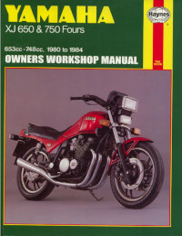
Руководство на английском языке по техническому обслуживанию и ремонту мотоциклов Yamaha моделей XJ650 и XJ750 Fours.
- Издательство: Haynes Publishing
- Год издания: 1994
- Страниц: 277
- Формат: PDF
- Размер: 124,8 Mb
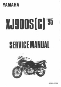
Руководство на английском языке по ремонту мотоциклов Yamaha моделей XJ900S и XJ900SG 1995 года выпуска.
- Издательство: Yamaha Motor Co., Ltd.
- Год издания: —
- Страниц: 352
- Формат: PDF
- Размер: 102,4 Mb
