-
Contents
-
Table of Contents
-
Troubleshooting
-
Bookmarks
Quick Links
Related Manuals for Polaris Sportsman 550 Touring EPS
Summary of Contents for Polaris Sportsman 550 Touring EPS
-
Page 2
WARNING The engine exhaust from this product contains chemicals known to the State of California to cause cancer, birth defects or other reproductive harm. A card containing important ATV safety information should be attached to the owner’s manual on the next page. If you cannot locate this card, or if it has been removed, please call 1-800- 342-3764 for assistance. -
Page 3
The text is printed on 100% recycled with 40% post-consumer waste (PCW). -
Page 4
NEVER CARRY NEVER USE MORE THAN WITH DRUGS 1 PASSENGER OR ALCOHOL For your nearest Polaris dealer, call 1-800-POLARIS or visit www.polarisindustries.com Polaris Sales Inc., 2100 Hwy 55 Medina, MN 55340 Phone 1-888-704-5290 Part No. 9922090 Rev 02 Printed in USA… -
Page 5
® • Victory Motorcycles ® We believe Polaris sets a standard of excellence for all utility and recre- ational vehicles manufactured in the world today. Many years of experi- ence have gone into the engineering, design, and development of your Polaris vehicle, making it the finest machine we’ve ever produced. -
Page 6
POLARIS, THE WAY OUT and SPORTSMAN are registered trademarks of Polaris Industries Inc. Copyright 2009 Polaris Sales Inc. All information contained within this publication is based on the latest product information at the time of publication. Due to constant improvements in the design and quality of production components, some minor discrep- ancies may result between the actual vehicle and the information presented in this publi- cation. -
Page 7: Table Of Contents
Troubleshooting ….. . . 131 Polaris Products….. . . 135 Specifications .
-
Page 8: Introduction
The following signal words and symbols appear throughout this manual and on your vehicle. Your safety is involved when these words and sym- bols are used. Become familiar with their meanings before reading the manual. The safety alert symbol indicates a potential personal injury hazard. WARNING A WARNING indicates a hazardous situation which, if not avoided, may result in death or serious injury.
-
Page 9: Safety
Failure to heed the warnings and safety precautions contained in this manual can result in severe injury or death. A Polaris ATV is not a toy and can be hazardous to operate. This vehicle handles differently than other vehicles, such as motorcycles and cars.
-
Page 10: Vehicle Identification Numbers
Record your vehicle’s identification numbers and key number in the spaces provided. Remove the spare key and store it in a safe place. An ignition key can be duplicated only by ordering a Polaris key blank (using your key number) and mating it with one of your existing keys.
-
Page 11: Safety
You should review this information on a regular basis. If you purchased a used Polaris ATV in the United States, you can enroll in the ATV RiderCourse for a fee. Call ATV Enrollment Express at (800) 887-2887 or visit www.atvsafety.org.
-
Page 12: Safe Riding Gear
Boots Helmet Wearing a helmet can prevent a severe head injury. Whenever riding a Polaris vehicle, always wear a helmet that meets or exceeds established safety standards. Approved helmets in the USA and Canada bear a U.S. Department of Transportation (DOT) label.
-
Page 13: Eye Protection
Eye Protection Do not depend on eyeglasses or sunglasses for eye protection. When- ever riding a Polaris vehicle, always wear shatterproof goggles or use a shatterproof helmet face shield. Polaris recommends wearing approved Personal Protective Equipment (PPE) bearing markings such as VESC 8, V-8, Z87.1, or CE.
-
Page 14: Safety Warnings
SAFETY Safety Warnings WARNING Failure to operate the ATV properly can result in a collision, loss of control, accident or overturn, which may result in serious injury or death. Heed all safety warnings outlined in this section of the owner’s manual. See the OPERATION section of the owner’s manual for proper operating procedures.
-
Page 15: Handling Gasoline
Safety Warnings Handling Gasoline Gasoline is highly flammable and explosive under certain conditions. • Always exercise extreme caution whenever handling gasoline. • Always refuel with the engine stopped, and outdoors or in a well ventilated area. • Do not smoke or allow open flames or sparks in or near the area where refueling is performed or where gasoline is stored.
-
Page 16: Protective Apparel
SAFETY Safety Warnings Protective Apparel Riding in this vehicle without wearing an approved helmet and protective eyewear increases the risk of a serious injuries in the event of an accident. Operator and passenger must always wear an approved helmet that fits properly and eye protection (goggles or face shield).
-
Page 17: Operating On Pavement
SAFETY Safety Warnings Operating on Pavement Operating an ATV on paved surfaces (including sidewalks, paths, parking lots and driveways) may adversely affect the handling of the ATV and could result in loss of control and accident or overturn. Avoid operating the ATV on pavement. ATV tires are designed for off-road use.
-
Page 18: Physical Control Of The Atv
SAFETY Safety Warnings Physical Control of the ATV Removing even one hand or foot can reduce ability to control the vehicle or could cause loss of balance and ejection from the ATV. If a person’s feet are not firmly planted on the footrests, they could come into contact with the wheels or other moving parts and lead to accident or injury.
-
Page 19: Improper Hill Climbing
Safety Warnings Improper Hill Climbing Improper hill climbing could cause loss of control or overturn. Always follow proper procedures for climbing hills as described in the owner’s manual. See page 63. Always move the 4X4 switch to ADC 4X4 before ascending or descending a hill. Descending Hills Improperly Improperly descending a hill could cause loss of control or overturn.
-
Page 20: Stalling While Climbing A Hill
SAFETY Safety Warnings Stalling While Climbing a Hill Stalling, rolling backwards or improperly dismounting while climbing a hill could cause an overturn. • Always maintain a steady speed when climbing a hill. • Always move the 4X4 switch to ADC 4X4 before ascending or descending a hill.
-
Page 21: Operating On Slippery Terrain
SAFETY Safety Warnings Operating on Slippery Terrain Failure to use extra caution when operating on excessively rough, slippery or loose terrain could cause loss of traction, loss of control, accident or overturn. Do not operate on excessively rough, slippery or loose terrain until you’ve learned and practiced the skills necessary to control the ATV on such terrain.
-
Page 22: Skidding Or Sliding
SAFETY Safety Warnings Improper Tire Maintenance Operating this ATV with improper tires or with improper or uneven tire pressure could cause loss of control or accident. Always use the size and type of tires specified for your ATV. Always maintain proper tire pressure as described in the owner’s manual and on safety labels.
-
Page 23: Improper Cargo Loading
Safety Warnings Operating Through Deep Water Operating the ATV through deep or fast- flowing water could cause the tires to float, causing loss of control or overturn. Avoid operating the ATV through deep or fast-flowing water. If it’s unavoidable to enter water that exceeds the recommended maximum depth (see page 68):…
-
Page 24: Poor Visibility
SAFETY Safety Warnings Operating on Frozen Bodies of Water Operating on frozen bodies of water may result in serious injury or death if the ATV and/or riders fall through the ice. Never operate the ATV on a frozen body of water.
-
Page 25: Operating A Damaged Atv
SAFETY Safety Warnings Operating a Damaged ATV Operating a damaged ATV can result in an accident. After any overturn or accident, have a qualified service dealer inspect the entire machine for possible damage, including (but not limited to) brakes, throttle and steering systems. Physical Skills Safe operation of this rider-active vehicle requires good judgement and physical skills.
-
Page 26: Age 16 Warning
If an informational or graphic label becomes illegible or comes off, con- tact your Polaris dealer to purchase a replacement. Replacement safety labels are provided by Polaris at no charge. The part number is printed on the label. Reverse Override Warning/AWD Caution…
-
Page 27: General Warning
Safety Labels and Locations General Warning WARNING Improper ATV use can result in SEVERE INJURY or DEATH ALWAYS USE AN APPROVED HELMET AND PROTECTIVE GEAR FOR DRIVER AND PASSENGER NEVER USE ON PUBLIC ROADS NEVER CARRY MORE THAN 1 PASSENGER NEVER USE WITH DRUGS OR ALCOHOL NEVER operate: •…
-
Page 28: Tire Pressure/Load Warning
Safety Labels and Locations Passenger Warning/Discretionary Warning WARNING PASSENGER SAFETY To reduce the risk of SEVERE INJURY or DEATH NEVER CARRY MORE THAN ONE PASSENGER NEVER RIDE AFTER USING DRUGS OR ALCOHOL NEVER carry a passenger too small to firmly plant feet on footrests and securely grasp hand holds.
-
Page 29: Clutch Cover Warning
Safety Labels and Locations Rack/Box Warning Rack/Box Warning WARNING • DO NOT TOW FROM RACK OR BUMPER. Vehicle damage or tipover may result causing severe injury or death. Tow only from tow hooks or hitch. • Maximum Rack Loads: Front 120 lbs. (54 kg) Rear 240 lbs. (109 kg) Clutch Cover Warning WARNING •…
-
Page 30: Features And Controls
FEATURES AND CONTROLS Switches Headlight Switch Switch Mode/Reverse Override Switch Main Key Engine Switch Stop Switch Mode/Reverse Override Switch This vehicle is equipped with a reverse speed limiter system.To gain additional wheel speed while backing, depress the override switch. WARNING! Pressing the override button while the throttle is open can cause loss of control, which may result in serious injury or death.
-
Page 31: Engine Stop Switch
FEATURES AND CONTROLS Switches Engine Stop Switch Move the stop switch either left or right to the OFF position to stop the engine quickly. Move the stop switch to the RUN position before attempt- ing to start the engine. The engine will not start or run when the switch is off.
-
Page 32: Operation
The throttle lever is spring loaded. Engine speed returns to idle when the lever is released. This ATV is equipped with Polaris Electronic Throttle Con- trol (ETC), which is designed to reduce the risk of a frozen or stuck throttle.
-
Page 33: Brake Lever
FEATURES AND CONTROLS Brake Lever WARNING Operating the ATV with a spongy brake lever can result in loss of braking, which could cause an accident. Never operate the ATV with a spongy-feeling brake lever. Always contact your dealer for service before operating the vehicle. Squeeze the brake lever toward the handlebar to apply the front and rear brakes.
-
Page 34
FEATURES AND CONTROLS Master Cylinder/Brake Fluid WARNING An over-full master cylinder may cause brake drag or brake lock-up, which could result in an accident. Maintain brake fluid at the recommended level. Do not overfill. Never store or use a partial bottle of brake fluid. Brake fluid is hygroscopic, meaning it rapidly absorbs moisture from the air. -
Page 35: Parking Brake
Parking Brake Locking the Parking Brake 1. Place the transmission in PARK. 2. Squeeze and release the brake lever two or three times, then squeeze and hold. 3. Push the parking brake lock forward to engage the lock. 4. Release the brake lever. 5.
-
Page 36
FEATURES AND CONTROLS Auxiliary Foot Brake WARNING Aggressively applying the auxiliary brake when backing down a hill may cause rear tipover, which could result in serious injury or death. Never back down a hill. Use caution when applying the auxiliary brake. Do not aggressively apply the auxiliary brake when going forward. -
Page 37
FEATURES AND CONTROLS Automatic Transmission Gear Selector The transmission gear Gear selector is located on the Selector right side of the vehicle. H: High Gear L: Low Gear N: Neutral R: Reverse P: Park To shift gears, brake to a complete stop. -
Page 38: Passenger Seat
Test the seat latch by attempting to pull the seat upward. If the lock-out is not working properly, do not allow a passenger to ride the vehicle. See your Polaris dealer for ser- vice. See pages 95-96 for passenger seat adjustment procedures.
-
Page 39: Fuel Tank
FEATURES AND CONTROLS Fuel Tank Always refuel with the engine Fuel Tank stopped, and outdoors or in a well ventilated area. Refuel on a level surface. Remove the fuel tank cap and add fuel. Use either leaded or unleaded gasoline with a minimum pump octane number of 87=(R+ M/2) octane.
-
Page 40
FEATURES AND CONTROLS Front Storage Box Open the front storage box to access the under-compartment area. 1. Release the front box cover latches and lift the cover. 2. Release the plunger latches that secure the box to the frame. 3. Close the cover and lift the unlatched edge of the box to disengage the plungers. -
Page 41: All Wheel Drive System
FEATURES AND CONTROLS All Wheel Drive System The All Wheel Drive system is ADC 4X4 controlled by the 4X4 switch. ADC 4X4 Mode When the switch is on ADC 4X4, the ADC system allows engine braking to all four wheels when the vehicle descends a hill or incline.
-
Page 42: Engaging 4X
FEATURES AND CONTROLS All Wheel Drive System Engaging 4X4 The 4X4 switch may be turned on or off while the vehicle is moving. Initially, the vehicle’s electronic system will not enable 4X4 until the engine RPM is below 3100. Once enabled, 4X4 remains enabled until the 4X4 switch is turned off.
-
Page 43: Engaging Active Descent Control
FEATURES AND CONTROLS Active Descent Control (ADC) System The ADC system allows engine braking to all four wheels when the vehicle descends a hill or incline. Always move the 4X4 switch to ADC 4X4 before ascending or descending a hill. Engaging Active Descent Control The ADC system will automatically engage when all four of the follow- ing conditions occur:…
-
Page 44: Instrument Cluster
Instrument Cluster Your ATV is equipped with an instrument cluster that senses vehicle speed from a gear in the transmission. The instrument cluster measures distance in miles/kilometers as well as hours of operation. In addition to showing vehicle speed, the instrument cluster also dis- plays the following items: engine speed, odometer, resettable trip meters (2), total engine hours of operation, service interval timer and indicator, gear position, fuel level, AWD status, EPS status (if equipped), high…
-
Page 45: Rider Information Center
If this occurs, take the ATV to your Polaris dealer for proper diagno- sis. The information center is set to display standard units of measurement and a 12-hour clock at the factory.
-
Page 46
12. EPS Warning Indicator — This indicator illuminates when the key is turned to the ON position and goes off when the engine is started. If the light remains on after starting the engine, the EPS system is inoperative. See your authorized Polaris dealer for service. -
Page 47
Instrument Cluster Rider Information Center Speed Display Area Use the MODE button to toggle through the speed display options. MODE button operation is locked out at speeds above approximately 15 MPH (25 km/h). Tip: The reverse override button also acts as a MODE button when held down for approximately one half second. -
Page 48: Standard/Metric Display
Instrument Cluster Rider Information Center Information Display Area Use the SELECT button (SEL) to toggle through the information area options. SELECT button operation is locked out at speeds above approximately 15 MPH (25 km/h). Tip: The reverse override button also acts as the SELECT button when pressed and released quickly.
-
Page 49: Information Display Area
FEATURES AND CONTROLS Instrument Cluster Rider Information Center Information Display Area Odometer Mode The odometer records and displays the distance traveled by the ATV. Trip Meter Mode The trip meters record the distance traveled by the ATV on each trip if reset before each trip.
-
Page 50
FEATURES AND CONTROLS Instrument Cluster Rider Information Center Information Display Area Programmable Service Interval When the hours of engine operation equal the programmed service interval setting, the wrench icon will flash for 5 seconds each time the engine is started. When this feature is enabled, it provides a convenient reminder to perform routine maintenance. -
Page 51
Diagnostic Display Mode The EFI diagnostic display mode is for informational purposes only. Please see your Polaris dealer for all major repairs. The diagnostic mode is accessible only when the check engine warning indicator activates after the key has been turned on. Leave the key on if you want to view the active code (failure code). -
Page 52
Short-to-Battery: The wire leading from the item listed in the chart to the electronic control unit is shorted to a wire at battery voltage. SPORTSMAN 550 Touring EPS Diagnostic Codes Component Throttle Position Sensor… -
Page 53
Instrument Cluster Rider Information Center SPORTSMAN 550 Touring EPS Diagnostic Codes Component Idle Air Control Starter Enable Circuit All Wheel Drive Control System Power Throttle Safety Signal Active Descent Control System Steering Over Current Shut Down Steering Excessive Current Error… -
Page 54
FEATURES AND CONTROLS Instrument Cluster Rider Information Center SPORTSMAN 850 Touring EPS Diagnostic Codes Component Throttle Position Sensor Engine Temperature Sensor Intake Air Temperature Sensor Manifold Absolute Pressure Sensor Crankshaft Position Sensor Vehicle Speed Signal Gear Sensor Signal Injector 1 (MAG) (SDI Part Load) Injector 2 (PTO) (SDI Part Load) Ignition Coil Primary Driver 1 (MAG) Ignition Coil Primary Driver 2 (PTO) -
Page 55
Instrument Cluster Rider Information Center SPORTSMAN 850 Touring EPS Diagnostic Codes Component Chassis Relay All Wheel Drive Control System Power Throttle Safety Signal Active Descent Control System Idle Speed Steering Over Current Shutdown Current Above Normal/Grounded Steering Excessive Current Error Current Above Normal/Grounded Steering Torque Sensor T1 Par- tial Failure Steering Torque Sensor T2 Par-… -
Page 56: Operation
Break-In Period The break-in period for your new Polaris ATV is the first ten hours of operation, or the time it takes to use the first two full tanks of gasoline. No single action on your part is as important as following the proce- dures for a proper break-in.
-
Page 57
Break-In Period Engine and Drivetrain Break-in 1. Fill the fuel tank with gasoline. See page 35. Always exercise extreme caution whenever handling gasoline. 2. Check the engine oil level on the dipstick. See page 81. Add oil if necessary to maintain the level between the safe and add marks. 3. -
Page 58: Pre-Ride Checklist
OPERATION Pre-Ride Checklist Failure to inspect and verify that the ATV is in safe operating condition before operating increases the risk of an accident. Always inspect the ATV before each use to make sure it’s in safe operating condition. Item Passenger seat latch Brake system/lever travel Brake fluid…
-
Page 59: Safe Operation Practices
Safe Operation Practices 1. Complete the recommended safety training before operating this vehicle. See page 7. 2. Do not allow anyone under 16 years of age to operate this vehicle. Do not allow anyone with cognitive or physical disabilities to oper- ate this vehicle.
-
Page 60: Trail Etiquette
Respect the environment in which you ride. Find out where the designated riding areas are by con- tacting your Polaris dealer, a local riding club or local officials. Help keep our trails open for recreational vehicle use. As an off-road enthusiast, you represent the sport and can set a good example (or a poor example) for others to follow.
-
Page 61: Starting The Engine
Starting the Engine 1. Position the vehicle on a level surface outdoors or in a well-venti- lated area. 2. Place the transmission in PARK. 3. Lock the parking brake. Tip: The starter interlock will prevent the engine from starting if the transmission is in gear and the brake is not engaged.
-
Page 62
OPERATION Driving Procedures 1. Wear protective riding gear. See page 8. 2. Perform the pre-ride inspection. See page 54. 3. Place the transmission in PARK. 4. Lock the parking brake. 5. Mount the vehicle from the left side. 6. Sit upright with both feet on the footrests and both hands on the handlebars. -
Page 63: Turning The Vehicle
Turning the Vehicle Both rear wheels drive equally at all times. This means that the outside wheel must travel a greater distance than the inside wheel when turning, and the inside tire must slip traction slightly. 1. Slow down. 2. Never turn quickly when carrying a passenger or cargo.
-
Page 64: Driving With A Passenger
Driving with a Passenger 1. Never allow anyone under 12 years of age to ride as a passenger on this 2-up ATV. Make sure any passenger is tall enough to comfort- ably and safely reach the grab handles and footrests. 2.
-
Page 65
Driving with a Passenger 11. Ride to the ability of your passenger, instead of to your own ability. Avoid unexpected or aggressive maneuvers that could cause a pas- senger to fall from the vehicle. 12. Do not cross a hillside with a passenger on board. See page 64. 13. -
Page 66: Driving On Slippery Surfaces
Driving on Slippery Surfaces Whenever riding on slippery surfaces such as wet trails or loose gravel, or during freezing weather, follow these precautions: 1. Do not operate on excessively rough, slippery or loose terrain. 2. Slow down when entering slippery areas. 3.
-
Page 67: Driving Uphill
Driving Uphill Braking and handling are greatly affected when operating in hilly ter- rain. Improper procedure could cause loss of control or overturn. When- ever traveling uphill, follow these precautions: 1. Always move the 4X4 switch to ADC 4X4 before ascending or descending a hill.
-
Page 68
Driving on a Sidehill (Sidehilling) Driving on a sidehill is not recommended. Improper procedure could cause loss of control or overturn. Avoid crossing the side of any hill unless absolutely necessary. If crossing a sidehill is unavoidable, follow these precautions: 1. -
Page 69: Driving Downhill
Driving Downhill When driving downhill, follow these precautions: 1. Always check the terrain carefully before descending a hill. 2. Always move the 4X4 switch to ADC 4X4 before ascending or descending a hill. See page 39. 3. Always descend a hill with the transmission in forward gear. Do not descend a hill with the transmission in neutral.
-
Page 70
OPERATION Turning Around on a Hill (K-Turn) If the vehicle stalls while climbing a hill, never back it down the hill! Use the K-turn to turn around. 8 ft. (2.4 m) -
Page 71
Turning Around on a Hill (K-Turn) 1. Stop and lock the parking brake while keeping body weight uphill. 2. Always move the 4X4 switch to ADC 4X4 before ascending or descending a hill. See page 39. 3. Leave the transmission in forward and shut off the engine. 4. -
Page 72: Driving Through Water
OPERATION Driving Through Water Your ATV can operate through water with a maximum recommended depth equal to the bottom of the footrests. Follow these procedures when operating through water: 1. Determine water depths and current before entering water. 2. Choose a crossing where both banks have gradual inclines.
-
Page 73: Driving Over Obstacles
Driving Over Obstacles Follow these precautions when operating over obstacles: 1. Always check for obstacles before operating in a new area. 2. Look ahead and learn to read the terrain. Be constantly alert for haz- ards such as logs, rocks and low hanging branches. 3.
-
Page 74: Driving In Reverse
Driving in Reverse Follow these precautions when operating in reverse: 1. Always check for obstacles or people behind the vehicle. Be aware that a passenger can obstruct your view. 2. Always avoid backing downhill. 3. Back slowly. 4. Apply the brakes lightly for stopping. 5.
-
Page 75: Parking On An Incline
OPERATION Parking on an Incline Avoid parking on an incline if possible. If it’s unavoidable, follow these precautions: 1. Stop the engine. 2. Place the transmission in PARK. 3. Lock the parking brake. 4. Always block the rear wheels on the downhill side.
-
Page 76: Hauling Cargo
OPERATION Hauling Cargo WARNING Overloading the vehicle or carrying or towing cargo improperly can alter vehicle handling and may cause loss of control or brake instability, which can result in serious injury or death. Always follow these precautions when hauling cargo: Never carry cargo on the rear rack when operating the ATV in the 2-up mode with a passenger.
-
Page 77
Hauling Cargo Never exceed the weight capacities specified for your ATV on warning labels and in the specifications sec- tion of this manual. 1. Cargo weight should be evenly distributed (1/3 on the front rack and 2/3 on the rear rack) and mounted as low as possible. -
Page 78: Towing Loads
ATV warranty. Never install a hitch longer than 4″ (10 cm). Never install automotive accessories on your Polaris ATV. Always install Polaris- approved (or equivalent) accessories designed for ATV use. Maximum Towing Capacities Do not exceed maximum towing capacities. Avoid towing on inclines.
-
Page 79: Emission Control Systems
CFR 205) and local noise level requirements. Operation on Public Lands in the U.S.A. Your Polaris vehicle has a spark arrestor that was tested and qualified to be in accordance with the USFS standard 5100-1c. Federal law requires that this spark arrestor be installed and functional when the vehicle is operated on public lands.
-
Page 80: Maintenance
Inspect, clean, lubricate, adjust and replace parts as necessary. When inspection reveals the need for replacement parts, use genuine Polaris parts available from your Polaris dealer. Record maintenance and service in the Maintenance Log beginning on page 149.
-
Page 81: Periodic Maintenance Chart
Improperly performing the procedures marked with a component failure and cause an accident, which may result in serious injury or death. Always have an authorized Polaris dealer perform these services. Maintenance Chart Key Perform these operations more often for vehicles subjected to severe use.
-
Page 82
MAINTENANCE Periodic Maintenance Chart Item Hours Calendar Air filter, main element Engine oil change Brake pad wear Battery ADC fluid Rear gearcase oil (if equipped) Transmission oil Demand drive fluid General lubrication Throttle Cable/ ETC Switch E Throttle Body Intake Duct Drive belt Cooling system Radiator… -
Page 83
Valve clearance 1000 H Toe adjustment Headlight aim Perform these procedures more often for vehicles subjected to severe use. E Emission-Related Service Have an authorized Polaris dealer perform these services. Maintenance Interval (whichever comes first) Miles (Km) 100 H 12 M 1000 (1600) Inspect;… -
Page 84: Lubrication Guide
Fluid (or GL5 80- 90 weight gear lube) Brake Fluid DOT 4 Only ADC Fluid Demand Drive PLUS Fluid Front Prop Polaris Premium Shaft Yoke U-Joint Lube Front Prop Shaft Yoke Capacity Fill Plug at Fluid Torque Change 2 qt.
-
Page 85: Engine Oil
2W-50 4-cycle oil or a similar oil for this engine. See the table on page 80 for fluid recommendations, capacities and plug torques. Oil may need to be changed more frequently if Polaris oil is not used. Always use 2W-50 oil. Follow the manufacturer’s recommendations for ambient temperature operation.
-
Page 86: Oil And Filter Change
Engine Oil Oil and Filter Change See the table on page 80 for fluid recommendations, capacities and plug torques. Always change the oil and filter at the intervals outlined in the Periodic Maintenance Chart beginning on page 76. Always change the oil filter whenever changing oil.
-
Page 87
Oil and Filter Change 9. Place shop towels beneath the oil filter. Using an oil fil- ter wrench (available from your Polaris dealer), turn the filter counter-clockwise to remove it. 10. Using a clean dry cloth, clean the filter sealing surface on the crankcase. -
Page 88: Transmission Oil
Transmission Oil Polaris recommends the use of Polaris Synthetic SPORTSMAN XP Transmission Fluid for this transmission. See the table on page 80 for fluid recommendations, capacities and plug torques. Always check and change the transmission oil at the intervals outlined in the Periodic Maintenance Chart beginning on page 76.
-
Page 89: Oil Change
Transmission Oil Oil Change 1. Remove the footwell. 2. Place a drain pan under the gearcase. Remove the drain plug. Allow the oil to drain completely. 3. Clean and reinstall the drain plug. Torque to specification. 4. Remove the fill plug. Add the proper amount of the recommended oil.
-
Page 90: Fluid Change
Always check and change the demand drive fluid at the inter- vals outlined in the Periodic Maintenance Chart beginning on page 76. See page 135 for the part numbers of Polaris products. Use the recommended fluid. Use of other fluids may result in improper operation of components.
-
Page 91: Rear Gearcase Oil
Always check and change the rear gearcase oil at the intervals outlined in the Periodic Maintenance Chart beginning on page 76. See page 135 for the part numbers of Polaris products. The fill plug is located on the rear of the gearcase. The drain plug is located on the bottom of the gearcase.
-
Page 92
We recommend the use of Polaris Demand Drive Plus Fluid for the ADC unit. Maintain the fluid level between the minimum and maximum marks on the reservoir. See page 135 for the part numbers of Polaris products. NOTICE: Do not use brake fluid. Brake fluid will damage rubber components in the hydraulic system. -
Page 93
Active Descent Control (ADC) Fluid Fluid Change 1. Position the vehicle on a level surface. Before performing the fluid change, allow the vehicle to sit for at least 30 minutes. 2. Thoroughly clean the areas around and on the ADC reservoir and bleeder valves (one on each side of the differential). -
Page 94: Cooling System
Steering Assembly The steering assembly of the ATV should be checked periodically for loose nuts and bolts. If loose nuts and bolts are found, see your Polaris dealer for service before operating the vehicle. Cooling System The engine coolant level is controlled, or maintained, by the recovery system.
-
Page 95
Cooling System Recovery Bottle Coolant The recovery bottle fluid level can be viewed from inside the front right wheel well. Access the recovery bottle cap under the front box. See page 1. View the fluid level in the bottle. 2. If the level is low, remove the bottle cap and add coolant as needed. Maintain the coolant level between the minimum and maximum marks on the bottle (when the fluid is cool). -
Page 96: Radiator Coolant
Radiator Coolant To ensure that the coolant maintains its ability to protect the engine, Polaris recommends that you drain the system completely every two years and add a fresh mixture of antifreeze and water. Replace the coolant any time the cooling system has been drained for maintenance or repair.
-
Page 97: Hand Brake
Brakes Hand Brake The front and rear brakes are hydraulic disc brakes, activated by moving the single brake lever toward the handlebar. These brakes are self- adjusting. Under normal operation, the diaphragm extends into the reservoir as fluid level drops. If the fluid level is low and the diaphragm is not extended, a leak is likely and the diaphragm should be replaced.
-
Page 98: Toe Alignment
0″ to 1/8″ (0-3 mm) toe out alignment. 5. Repeat the measurement procedure on the other side of the vehicle. 6. If you discover improper alignment, see your Polaris dealer for ser- vice. Stand…
-
Page 99
Seats Passenger Seat Removal 1. Pull the latch at the rear of the seat. 2. Pivot the rear of the seat upward and remove the front legs of the seat base from the frame. 3. To reinstall the seat, position the front legs of the seat base under the frame. -
Page 100
MAINTENANCE Seats Passenger Seat Suspension 1. Remove the passenger seat. 2. Remove the fastener retaining the passenger seat shock to the passenger seat support. 3. Pivot the seat support upward to access the lower shock fastener. Remove the lower shock fastener. 4. -
Page 101
MAINTENANCE Side Panel/Footwell Removal 1. Remove the seat before removing a side panel. 2. Remove the fasteners securing the side panel or footwell to remove Plastic Rivet Hex Head Screw Plastic Rivet… -
Page 102: Tire Tread Depth
MAINTENANCE Tires WARNING Operating your ATV with worn tires, improperly inflated tires, non-standard tires or improperly installed tires will affect vehicle handling and could cause an accident resulting in serious injury or death. Always follow all tire maintenance procedures as outlined in this manual and on the labels on the vehicle. Always use original equipment size and type when replacing tires.
-
Page 103: Wheel Removal
Tires Front Wheel Hub Tightening Front wheel bearing tightness and spindle nut retention are critical com- ponent operations. All service must be performed by your authorized Polaris dealer. Wheel Removal 1. Stop the engine. 2. Place the transmission in PARK.
-
Page 104: Wheel Installation
Tires Wheel Installation 1. Place the transmission in PARK. 2. Lock the parking brake. 3. Place the wheel on the hub with the valve stem toward the outside and rotation arrows on the tire pointing toward forward rotation. 4. Install the wheel nuts and finger-tighten them. 5.
-
Page 105: Air Filter
Air Filter 1. Remove the seat. 2. Remove the air box cover screws, and remove the air box cover. 3. Remove the filter. 4. Remove the fabric type pre- filter from the main filter. Wash the pre-filter in soapy water, then rinse and let dry. 5.
-
Page 106: Fuse Replacement
MAINTENANCE Fuse Replacement If the engine stops or will not start, or if you experience other electrical failures, a fuse may need replacement. Locate and correct any short cir- cuits that may have caused the blown fuse, then replace the fuse. Spare fuses are provided in the fuse box.
-
Page 107: Headlight Lamp Replacement
Lights Poor lighting can result in reduced visibility when driving. Headlight and taillight lenses become dirty during normal operation. Clean head- lights frequently and replace burned out headlamps promptly. Always make sure lights are adjusted properly for best visibility. Headlight Lamp Replacement When servicing a halogen lamp, avoid touching the lamp with bare fin- gers.
-
Page 108: High Beam Adjustment
Lights High Beam Adjustment The headlight beam can be adjusted slightly upward or downward. Use the following procedure to make the adjustment. 1. Position the vehicle on a level surface with the headlight approxi- mately 25 ft. (7.6 m) from a wall. Place the transmission in PARK. 2.
-
Page 109
Lights Low Beam Adjustment The low beam can be adjusted slightly upward or downward. 1. Loosen the phillips screw located at the rear of the headlamp. 2. Tilt the headlamp upward or downward. 3. Tighten the screw. MAINTENANCE Phillips Screw… -
Page 110: Headlight Housing Replacement
MAINTENANCE Lights Headlight Housing Replacement 1. Remove the five (5) headlight pod screws. 2. Lift the pod cover and disconnect the speedometer harnesses from the speedometer. 3. Unplug the headlamp from the wiring harness. 4. Use a small screwdriver to remove the o-rings from the headlight mounting tabs.
-
Page 111: Lower Headlamp Replacement
Lights Lower Headlamp Replacement 1. Turn the back of the headlight harness counter-clockwise and pull the harness assembly away from the headlight assembly. 2. Remove the headlamp and install the new headlamp. 3. Reinstall the harness assembly into the headlight assembly. 4.
-
Page 112: Spark Plugs
Refer to the specifications section beginning on page 136 for the recom- mended spark plug type and gap for your vehicle. Torque spark plugs to specification. NOTICE: Using non-recommended spark plugs can result in serious engine damage. Always use Polaris-recommended spark plugs. Plug Condition New Spark Plug Previously Installed…
-
Page 113
MAINTENANCE Spark Plugs Spark Plug Inspection Normal Spark Plug The normal insulator tip is gray, tan or light brown. There will be few combustion deposits. The electrodes are not burned or eroded. This indi- cates the proper type and heat range for the engine and the service. The tip should not be flaky and white. -
Page 114: Vehicle Immersion
Vehicle Immersion If your vehicle becomes immersed, major engine damage can result if the machine is not thoroughly inspected. Take the vehicle to your dealer before starting the engine. If it’s impossible to take your ATV to a dealer before starting it, follow the steps outlined below. 1.
-
Page 115: Spark Arrestor
Spark Arrestor WARNING Failure to heed the following warnings while servicing the spark arrestor could result in serious injury or death. Never run the engine in an enclosed area. Remove any combustible materials from the area. Wear eye protection and leather work gloves.
-
Page 116: Pvt System
• Always follow all recommended maintenance procedures. See your dealer as outlined in the owner’s manual. • This PVT system is intended for use on Polaris products only. Do not install it in any other product. • Always make sure the PVT housing is securely in place during operation.
-
Page 117
MAINTENANCE PVT System The basic operation of the Polaris PVT system is dependent on engine speed and vehicle torque requirements. As engine speed increases, the force exerted on the movable drive sheave by the flyweights also increases. This, in turn, increases the amount of pinch applied to the drive belt. -
Page 118: Pvt Drying
PVT System When To Use Low Range and High Range Operating at speeds less than 7 MPH (11 km/h) Towing heavy loads Operating in rough terrain (swamps, mountains, etc.) Operating at speeds greater than 7 MPH (11 km/h) PVT Drying There may be some instances when water is accidently ingested into the PVT system.
-
Page 119
Battery WARNING Improperly connecting or disconnecting battery cables can result in an explosion and cause serious injury or death. When removing the battery, always disconnect the negative (black) cable first. When reinstalling the battery, always connect the negative (black) cable last. WARNING Battery electrolyte is poisonous. -
Page 120: Battery Removal
MAINTENANCE Battery Battery Removal 1. Remove the passenger seat and the seat pivot bolt. 2. Disconnect the black (negative) battery cable first. 3. Disconnect the red (positive) battery cable last. 4. Disconnect the battery hold-down strap. 5. On conventional batteries, remove the battery vent tube. 6.
-
Page 121: Battery Installation
Battery Battery Installation Using a new battery that has not been fully charged can damage the bat- tery and result in a shorter life. It can also hinder vehicle performance. Follow the battery charging instructions on page 119 before installing the battery.
-
Page 122: Battery Storage
Check battery voltage each month during storage and recharge as needed to maintain a full charge. Polaris recommends maintaining battery charge by using a Polaris Bat- tery Tender charger or by charging about once a month to make up for normal self-discharge.
-
Page 123
Battery Battery Charging (Conventional Battery) 1. Remove the battery from the vehicle to prevent damage from leak- ing or spilled electrolyte during charging. See page 116. 2. Charge the battery with a charging output no larger than 1/10 of the battery’s amp/hr rating. -
Page 124
Battery Battery Charging (Sealed Battery) Always verify battery condition before and 1-2 hours after the end of charging. State of Voltage Charge 100% 12.8-13.0 volts 75%-100% 12.5-12.8 volts 50%-75% 12.0-12.5 volts 25%-50% 11.5-12.0 volts 0%-25% 11.5 volts or less Action specified on top of battery) None, check at 3 mos. -
Page 125: Camber And Caster
Follow the adjustment procedures exactly, or see your Polaris dealer for service. 1. Remove the upper headlight pod.
-
Page 126: Throttle Cable Freeplay
Throttle Body/Idle RPM Idle RPM is preset by the manufacturer. If the engine idle speed is not satisfactory, please see your Polaris dealer for adjustment. Throttle Cable Freeplay 1. Remove the four cover screws from the right han- dlebar control and remove the cover.
-
Page 127
6. If idle speed remains above or below the recommended setting (see specification pages), verify the correct gap. If gap is correct and idle speed is still not satisfactory, please see your Polaris dealer for ser- vice. 7. With the engine running, turn the handlebars fully to the left and right. -
Page 128: Cleaning And Storage
Do not allow these types of products to contact the vehicle. The best and safest way to clean your Polaris vehicle is with a garden hose and a pail of mild soap and water. 1. Use a professional-type washing cloth, cleaning the upper body first and the lower parts last.
-
Page 129: Polishing The Vehicle
Polishing the Vehicle Polaris recommends the use of common household aerosol furniture polish for polishing the finish on your Polaris vehicle. Follow the instructions on the container. Polishing Tips • Avoid the use of automotive products, some of which can scratch the finish of your vehicle.
-
Page 130
MAINTENANCE Cleaning and Storage Chrome Wheel Care (if equipped) Proper maintenance will protect chrome wheels from corrosion, pre- serve wheel life and ensure a “like new” appearance for many years. Chrome wheels exposed to road salt (or salt in the air in coastal areas) are more susceptible to corrosion if not properly cleaned. -
Page 131: Storage Tips
124. Stabilize the Fuel 1. Fill the fuel tank. 2. Add Polaris Carbon Clean Fuel Treatment or Polaris Fuel Stabilizer. Follow the instructions on the container for the recommended amount. Carbon Clean removes water from fuel systems, stabilizes fuel and removes carbon deposits from pistons, rings, valves and exhaust systems.
-
Page 132: Fluid Levels
6. If Polaris fuel system additive is not used, the fuel tank, fuel lines, and injectors should be completely drained of gasoline.
-
Page 133
Set the tire pressure and safely support the ATV with the tires slightly off the ground. Be sure the storage area is well ventilated. Cover the vehicle with a genuine Polaris cover. Do not use plastic or coated mate- rials. They do not allow enough ventilation to prevent condensation, and may promote corrosion and oxidation. -
Page 134: Transporting The Atv
MAINTENANCE Transporting the ATV Follow these procedures when transporting the vehicle. 1. Stop the engine. 2. Place the transmission in PARK. 3. Lock the parking brake. 4. Secure the fuel cap and oil cap. 5. Always tie the frame of the ATV to the transporting unit securely with suitable straps or rope.
-
Page 135: Troubleshooting
Dry out the PVT. See page 114. Inspect clutch seals for damage if repeated leaking occurs. See your Polaris dealer. Check for fouled plugs or foreign material in gas tank or fuel lines. See your dealer.
-
Page 136
Drain the fuel system and refuel Replace with fresh recommended fuel Inspect plugs and replace if necessary Inspect plugs, verify stop switch is on Immediately see your Polaris dealer Recharge the battery to 12.8 VDC See your dealer Solution Inspect, clean and/or replace spark… -
Page 137
Engine Pings or Knocks Possible Cause Poor quality or low octane fuel Incorrect ignition timing Incorrect spark plug gap or heat range Engine Runs Irregularly, Stalls or Misfires Possible Cause Fouled or defective spark plug(s) Worn or defective spark plug wires Incorrect spark plug gap or heat range Loose ignition connections Water present in fuel… -
Page 138: Engine Overheating
TROUBLESHOOTING Engine Stops or Loses Power Possible Cause Out of fuel Kinked or plugged fuel vent line Water is present in fuel Fouled or defective spark plug(s) Worn or defective spark plug wires Incorrect spark plug gap or heat range Loose ignition connections Low battery voltage Incorrect fuel…
-
Page 139: Polaris Products
Premium U-Joint Lube (14 oz./414 ml cartridge) 2871329 Dielectric Grease (Nyogel 2871326 Carbon Clean Plus 2870652 Fuel Stabilizer 2872189 DOT 4 Brake Fluid 2871956 Loctite 565 Thread Sealant 2859044 Polaris Battery Tender POLARIS PRODUCTS Engine Lubricant Coolant Additives / Miscellaneous Charger…
-
Page 140: Specifications
SPECIFICATIONS SPORTSMAN 550 Touring EPS Maximum Weight Capacity Dry Weight Front Rack/Storage Box Capacity 120 lbs. (54 kg) Rear Rack Capacity Hitch Tongue Weight Hitch Towing Rating Unbraked Trailer Towing Capacity* Overall Length Overall Width Overall Height Wheelbase Ground Clearance…
-
Page 141
SPORTSMAN 550 Touring EPS Lubrication System Transmission Type Front Suspension Rear Suspension Gear Reduction, Low Gear Reduction, Reverse Gear Reduction, High Drive Ratio, Front Drive Ratio, Rear Tire Type/Pressure, Front Tire Type/Pressure, Rear Brakes, Front/Rear Brake, Auxiliary Brake, Parking Headlight… -
Page 142
SPECIFICATIONS SPORTSMAN 850 Touring EPS Maximum Weight Capacity Dry Weight Front Rack/Storage Box Capacity 120 lbs. (54 kg) Rear Rack Capacity Hitch Tongue Weight Hitch Towing Rating Unbraked Trailer Towing Capacity* Overall Length Overall Width Overall Height Wheelbase Ground Clearance Minimum Turning Radius Fuel Capacity Engine Oil Capacity… -
Page 143
Altitude Meters 0-1800 (Feet) (0-6000) 1800-3700 (6000-12000) SPECIFICATIONS Pressurized Wet Sump Automatic PVT (Polaris Variable Transmission) In-Line H-L-N-R-P Dual a-arm, 9″ (22.9 cm) travel Dual a-arm with Rolled IRS, 10″ (25.4 cm) travel 5.034:1 4.508:1 2.367:1 3.818:1 3.7:1 Maxxis AT 26 x 8 — 14… -
Page 144: Declaration Of Conformity
Polaris Industries Inc., 2100 Hwy 55, Medina, MN 55340 U.S.A. Telephone 763-542-0500 We, Polaris Industries Inc., declare that the vehicles listed below conform to the essential health and safety requirements applicable to off-road all-terrain vehicles. APPLICABLE EUROPEAN DIRECTIVES 98/37/EC as amended (Machinery Directive)
-
Page 145: Warranty
WARRANTY LIMITED WARRANTY Polaris Sales Inc., 2100 Highway 55, Medina, MN 55340, gives a SIX MONTH LIM- ITED WARRANTY on all components of the Polaris All Terrain Vehicle (ATV) against defects in material or workmanship. Polaris also gives a one year limited warranty on the final drive chain (if equipped) for failure due to defects.
-
Page 146
WARRANTY COVERAGE AND EXCLUSIONS: LIMITATIONS OF WARRANTIES AND REMEDIES The Polaris limited warranty excludes any failures that are not caused by a defect in material or workmanship. This warranty does not cover accidental damage, normal wear and tear, abuse or improper handling. This warranty also does not cover any ATV that… -
Page 147
ATV. The exclusive remedy for breach of this warranty shall be, at Polaris’ exclusive option, repair or replacement of any defective materials, or com- ponents or products. THE REMEDIES SET FORTH IN THIS WARRANTY ARE THE ONLY REMEDIES AVAILABLE TO ANY PERSON FOR BREACH OF THIS WAR- RANTY. -
Page 148
HOW TO OBTAIN WARRANTY SERVICE If your ATV requires warranty service, you must take it to a Polaris dealer authorized to repair Polaris ATVs. When requesting warranty service you must present your copy of the Warranty Registration form to the dealer. -
Page 149
How to Get Service In the Country where your vehicle was purchased: Warranty or Service Bulletin repairs must be done by an authorized Polaris dealer. If you move or are traveling within the country where your vehicle was purchased, Warranty or Service Bulletin repairs may be requested from any authorized Polaris dealer who sells the same line as your vehicle. -
Page 150
How to Get Service If Purchased From A Private Party: If you purchase a Polaris product from a private citizen, to be kept and used outside of the country in which the vehicle was originally purchased, all warranty coverage will be denied. -
Page 151
This emissions limited warranty is in addition to the Polaris standard limited warranty for your vehicle. Polaris Industries Inc. warrants that at the time it is first purchased, this emissions-certified vehicle is designed, built and equipped so it conforms with applica- ble U.S. -
Page 152
Polaris dealer to perform any service that may be necessary for your vehicle. Polaris also recommends that you use only Pure Polaris parts. It is a potential violation of the Clean Air Act if a part supplied by an aftermarket parts manufacturer reduces the effectiveness of the vehicle’s emission controls. -
Page 153: Maintenance Log
MAINTENANCE LOG Present this section of your manual to your dealer each time your vehicle is serviced. This will provide you and future owners with an accurate log of maintenance and ser- vices performed. DATE MILES (KM) TECHNICIAN SERVICE PERFORMED / COMMENTS OR HOURS…
-
Page 154
MAINTENANCE LOG DATE MILES (KM) TECHNICIAN SERVICE PERFORMED / COMMENTS OR HOURS… -
Page 155: Index
4X4 Switch ….26, 37 Accessories ….129 Active Descent Control Fluid .
-
Page 156: Fluid Level
INDEX Fluid Active Descent Control ..88 ADC….88-89 Brake ….30 Demand Drive .
-
Page 157
Passenger Seat….34 Periodic Maintenance Chart ..76-79 Polaris Product List… . . 135 Polishing the Vehicle … 125 Power Steering . -
Page 158
INDEX Safety Warnings… . . 10-21 Protective Apparel ..12 Reverse Operation ..17 Skidding or Sliding .
ДОБРО ПОЖАЛОВАТЬ Мы признательны вам за приобретение продукции нашей компании и рады приветствовать во всемирном клубе любителей техники Polaris. Обязательно посетите наш веб-сайт www.brandtpolaris.ru чтобы узнать о последних новостях, новых продуктах, предстоящих событий, возможности карьерного
POLARIS, THE WAY OUT и SPORTSMAN являются зарегистрированными торговыми марками POLARIS Industries Inc. Copyright 2012 POLARIS Sales Inc. Весь материал в этом издании основывается на самой последней информации доступной на момент издания. Поскольку конструкция и качество выпускаемых нами
СОДЕРЖАНИЕ Введение . . . . . . . . . . . . . . . . . . . . . . . . . . . . . . 4 Безопасность . . . . . . . . . . . . . . . . . . . . . . . . . . 7 Органы управления, узлы и механизмы . . 26 Эксплуатация . . . . . . . . . . . . . . . . . . . . . . . . . 52 Система контроля вредных выбросов . . .
ВВЕДЕНИЕ На протяжении всего руководства пользователя появляются следующие сигнальные слова и символы. Когда используются эти слова и символы, речь идет о вашей безопасности и безопасности других. Прежде, чем читать данное руководство, ознакомьтесь с их значением. Предупредительный символ указывает
ВВЕДЕНИЕ ВНИМАНИЕ Не соблюдение инструкций приведенных ниже может привести к серьезным травмам или смерти. Квадроцикл Polaris не игрушка и при неправильной эксплуатации может представлять серьезную опасность. Специфика управления данным квадроциклом значительно отличается от других транспортных
ВВЕДЕНИЕ Идентификационные номера Запишите идентификационные номера квадроцикла и номер ключа зажигания в расположенной ниже таблице. Храните запасной ключ в надежном месте. Дубликат ключа зажигания выдается по заказу с использованием болванки для ключа Polaris (используйте номер вашего ключа)
Обучение по безопасности БЕЗОПАСНОСТЬ Прохождение обучения по безопасному вождению квадроцикла это приоритетное требование Polaris. Polaris настоятельно рекомендует всем пользователям квадроциклов пройти специальное обучение. При покупке квадроцикла в США, Ваш Дилер предоставит Вам информацию о
БЕЗОПАСНОСТЬ Экипировка водителя Соображения безопасности требуют, чтобы водитель мотовездехода был экипирован надлежащим образом. Надевайте специальную защитную одежду для комфорта и снижения опасности получения травмы. Шлем Защита глаз Длинные Рукава Перчатки Длинные Ботинки Шлем Ношение шлема
Экипировка водителя БЕЗОПАСНОСТЬ Защита глаз Не пользуйтесь обычными или солнцезащитными очками для защиты глаз. При движении на квадроцикле Polaris всегда носите защитные очки или шлем с защитным стеклом. Polaris рекомендует использовать защитное оборудование с маркировкой персональных средств
БЕЗОПАСНОСТЬ Предупредительные таблички ВНИМАНИЕ Пренебрежение предостережениями может привести к потере управления, повреждениям техники, личным травмам или смерти. Соблюдайте все правила безопасности, изложенные в данном разделе Руководства пользователя. Для правильной эксплуатации Вашего
БЕЗОПАСНОСТЬ Предупредительные таблички Бензин Бензин является легко воспламеняемой жидкостью и может быть взрывоопасным в определенных условиях. • Соблюдайте следующие предосторожности при заправке топливом. • Заправляйте квадроцикл топливом всегда в хорошо проветриваемом помещении, двигатель
БЕЗОПАСНОСТЬ Предупредительные таблички Защитная экипировка Движение на квадроцикле без специальной защитной экипировки может привести к личным травмам. Водитель и пассажир во время движения должны находится в специальных шлемах и защитных очках. Перевозка пассажира Не перевозите пассажира пока у
БЕЗОПАСНОСТЬ Предупредительные таблички Движение по дороге с асфальтовым покрытием, выезд на тротуар, подъездные пути, места стоянки Вождение по мощеным поверхностям может отрицательным образом сказаться на управлении квадроциклом и привести к потери контроля, аварии и/или травме. Не выезжайте на
БЕЗОПАСНОСТЬ Предупредительные таблички Отпускание руля, езда без надежного контакта ног с подножками Снятие даже одной руки с рукоятки руля или снятие ноги с подножки уменьшает Вашу способность контролировать мотовездеход, приводит к потере равновесия и падению с мотовездехода. Если нога водителя
БЕЗОПАСНОСТЬ Предупредительные таблички Неправильная техника движения вверх по склону Неправильный подъем на склоны может стать причиной потери управления или опрокидывания. При движении вверх по склону действуйте в соответствии с рекомендациями в настоящем Руководстве. См. стр. 65. Всегда
БЕЗОПАСНОСТЬ Предупредительные таблички Вынужденная остановка на склоне. Скатывание по склону. Остановка скатывание, неверное начало движение на склоне могут привести к перевороту квадроцикла. • Всегда поддерживайте постоянную скорость при движении вверх по склону. • Всегда включайте режим 4X4 ADC
БЕЗОПАСНОСТЬ Предупредительные таблички Движение по скользкой местности Пренебрежение правилами безопасности во время езды по чрезмерно крутым, сыпучим или скользким склонам, это может привести к потере управления, опрокидыванию мотовездехода или к потере сцепления с грунтом. Не используйте
БЕЗОПАСНОСТЬ Предупредительные таблички Эксплуатация мотовездехода с нерекомендованным типом шин или неравномерно накачанными шинами Эксплуатация мотовездехода с нерекомендованными или неисправными шинами может привести к потере управления и травмам и даже смерти. Всегда используйте только
БЕЗОПАСНОСТЬ Предупредительные таблички Движение по глубокой воде Во время движения по глубокой воде или быстром водном потоке возможно всплывание колес, что приведет утрате контроля над мотовездеходом и в результате – несчастному случаю. Никогда не передвигайтесь на мотовездеходе по быстрым
следуйте инструкциям в настоящем руководстве. См. стр. 62. 20
21
БЕЗОПАСНОСТЬ Предупредительные таблички Вождение по замерзшим водоемам Вождение по замерзшим водоемам может привести к внезапному пролому льда, что в свою очередь станет причиной травмы или гибели в случае ухода под лед. Никогда не двигайтесь по замершим водоемам и льду, пока не убедитесь что лед
БЕЗОПАСНОСТЬ Предупредительные таблички Эксплуатация неисправного мотовездехода Эксплуатация неисправного мотовездехода приводит к авариям, несчастным случаям, травмам и гибели людей. Если Вы попали в ДТП, покажите мотовездеход дилеру, так как машине могут быть нанесены серьезные повреждения.
БЕЗОПАСНОСТЬ Предупредительные таблички и их расположение На корпусе мотовездехода прикреплены таблички с важной информацией, касающейся Вашей безопасности. Внимательно прочитайте таблички и следуйте содержащимся в них инструкциям. Если содержание табличек на Вашем мотовездеходе отличается от того,
БЕЗОПАСНОСТЬ Предупредительные таблички и их расположение Общие предупреждения ВНИМАНИЕ Неправильная эксплуатация мотовездехода может привести к СЕРЬЕЗНОЙ ТРАВМЕ, НЕСЧАСТНОМУ СЛУЧАЮ или ЛЕТАЛЬНОМУ ИСХОДУ ВСЕГДА ИСПОЛЬЗУЙТЕ ЗАЩИТНЫЙ ШЛЕМ И ЗАЩИТНУЮ ОДЕЖДУ ДЛЯ ВОДИТЕЛЯ И ПАССАЖИРА ЗАПРЕЩАЕТСЯ
БЕЗОПАСНОСТЬ Предупредительные таблички и их расположение Предупреждение по перевозке пассажира/общего характера ВНИМАНИЕ Безопасность пассажира Для того, чтобы снизить риск ТРАВМ или даже СМЕРТИ НИКОГДА НЕ ПЕРЕВОЗИТЕ БОЛЕЕ ОДНОГО ПАССАЖИРА НИКОГДА НЕ ЭКСПЛУАТИРУЙТЕ КВАДРОЦИКЛ НАХОДЯСЬ ПОД
БЕЗОПАСНОСТЬ Предупредительные таблички и их расположение Багажная площадка/ Предупреждающая Предупреждение на крышке вари- Предупреждение по фаркопу Предупреждающая табличка по багажной площадке ВНИМАНИЕ • НЕ БУКСИРУЙТЕ ГРУЗ, ПРИКРЕПИВ ЕГО К БАГАЖНЫМ ПЛОЩАДКАМ ИЛИ БАМПЕРУ Возможно повреждение или
ОРГАНЫ УПРАВЛЕНИЯ, УЗЛЫ И МЕХАНИЗМЫ Переключатели Переключатель фар 2×4 E km 88:88 Mode/Reverse Override ПереключаВыключатель двигателя Переключатель 4X4 F RPM Trip 1 mi Замок зажигания Кнопка Mode/Кнопка Оverride На данном квадроцикле присутствует система ограничения скорости при движение задним
ОРГАНЫ УПРАВЛЕНИЯ, УЗЛЫ И МЕХАНИЗМЫ Переключатели Выключатель двигателя Чтобы быстро остановить работу двигателя переведите выключатель вправо или влево в положение ВЫКЛ (OFF). Перед запуском двиВЫКЛ RUN ВЫКЛ гателя переведите выключатель в положение RUN (ВКЛ.). Запуск и работа двигателя
ОРГАНЫ УПРАВЛЕНИЯ, УЗЛЫ И МЕХАНИЗМЫ Рычаг акселератора ВНИМАНИЕ Эксплуатация мотовездехода с неисправным приводом дроссельной заслонки может привести к несчастному случаю, травмам или гибели. Эксплуатация мотовездехода с неисправным приводом дроссельной заслонки ЗАПРЕЩЕНА. В случае неисправности
ОРГАНЫ УПРАВЛЕНИЯ, УЗЛЫ И МЕХАНИЗМЫ Рычаг тормоза ВНИМАНИЕ Эксплуатация мотовездехода с «проваливающимся» рычагом тормоза ЗАПРЕЩЕНА. Никогда не управляйте мотовездеходом с излишне «мягким» рычагом тормоза. В случае неисправности обратитесь к Дилеру для проведения ремонта. Передние и задние тормоза
ОРГАНЫ УПРАВЛЕНИЯ, УЗЛЫ И МЕХАНИЗМЫ Главный тормозной цилиндр/Тормозная жидкость ВНИМАНИЕ Переполнение главного цилиндра может стать причиной подклинивания или полной блокировки колес, что может привести к травмам или несчастному случаю. Поддерживайте необходимый уровень тормозной жидкости. Не
ОРГАНЫ УПРАВЛЕНИЯ, УЗЛЫ И МЕХАНИЗМЫ Стояночный тормоз Включение стояночного тормоза 1. Включите парковочную передачу. 2. Два или три раза надавите на тормозной рычаг и удерживайте его. 3. Сдвиньте замок стояночного тормоза вперед. 4. Отпустите рычаг тормоза. 5. Чтобы снять машину со стояночного
ОРГАНЫ УПРАВЛЕНИЯ, УЗЛЫ И МЕХАНИЗМЫ Дополнительный ножной тормоз ВНИМАНИЕ Не спускайтесь с холма задним ходом. Резкое включение дополнительного тормоза при спуске с холма может привести к опрокидыванию мотовездехода, причинить травмы водителю или стать причиной его гибели. Будьте осторожны при
ОРГАНЫ УПРАВЛЕНИЯ, УЗЛЫ И МЕХАНИЗМЫ Рычаг выбора режима трансмиссии Рычаг выбора режима Передача трансмиссии располоРукоятка жен с правой стороны мотовездехода. H Повышающая передача L: Понижающая передача N: Нейтраль R: Задний ход P: Парковка Для того чтобы переключить передачу, полностью
ОРГАНЫ УПРАВЛЕНИЯ, УЗЛЫ И МЕХАНИЗМЫ Электроусилитель рулевого управления (EPS) Если на Вашем квадроцикле установлен электроусилитель рулевого управления, он включается в работа сразу же при включении зажигания. Электроусилитель продолжает функционировать в любой момент при включенном двигателе. На
ОРГАНЫ УПРАВЛЕНИЯ, УЗЛЫ И МЕХАНИЗМЫ Топливный бак Заправляйте квадроцикл топливом всегда в хорошо проветриваемом помещении, двигатель должен быть выключен. Заправляйте квадроцикл на ровной поверхности. Снимите крышку топливного бака и залейте топливо. Используйте бензин с октановым числом не менее
ОРГАНЫ УПРАВЛЕНИЯ, УЗЛЫ И МЕХАНИЗМЫ Передний багажный короб Для доступа под багажное отделение — откройте его. 1. Откройте фиксаторы и откройте крышку. 2. Ослабьте анкерные фиксаторы багажного отделения. 3. Закройте крышку отделения и приподнимите незакрепленную Фиксаторы Фиксаторы багажного часть
ОРГАНЫ УПРАВЛЕНИЯ, УЗЛЫ И МЕХАНИЗМЫ Система полного привода Система полного привода ADC 4X4 управляется переключателем 4X4. Режим ADC 4X4 Когда включен режим ADC 4X4, система ADC обеспечивает торможение двигателем всех четырех колес на спуске. Всегда включайте режим 4X4 ADC перед спуском или
ОРГАНЫ УПРАВЛЕНИЯ, УЗЛЫ И МЕХАНИЗМЫ Система полного привода Включение режима 4X4 Во время движения мотовездехода переключатель 4X4 можно включать и выключать. Электронная система управления блокирует включение полного привода до тех пор, пока обороты двигателя не превысят 3100 об/мин. Режим полного
ОРГАНЫ УПРАВЛЕНИЯ, УЗЛЫ И МЕХАНИЗМЫ Система ADC Система ADC обеспечивает торможение двигателем всех четырех колес на спуске. Всегда включайте режим 4X4 ADC перед спуском или подъемом на холм. Включение системы ADC Система ADC включается при совпадении всех четырех условий: • Выключатель должен быть
ОРГАНЫ УПРАВЛЕНИЯ, УЗЛЫ И МЕХАНИЗМЫ Цифровой прибор ПРИМЕЧАНИЕ:Высокое давление воды может повредить элементы квадроцикла. Мойте квадроцикл вручную с использованием слабого мыльного раствора. Некоторые химические составы при попадании на цифровой прибор пластик или фары повредят эти элементы. Не
ОРГАНЫ УПРАВЛЕНИЯ, УЗЛЫ И МЕХАНИЗМЫ Цифровой прибор Комбинированный Цифровой/Аналоговый прибор Контрольные лампы Лампа Индикатор Скорость Условие При выборе стандартного режима, скорость будет показана в милях в час. При выборе метрического режима, скорость будет показана в км/ч. Перегрев Эта лампа
ОРГАНЫ УПРАВЛЕНИЯ, УЗЛЫ И МЕХАНИЗМЫ Цифровой прибор Комбинированный Цифровой/Аналоговый прибор Информационный центр Информационный дисплей расположен в центральной части цифрового прибора Все сегменты информационного центра включаться на несколько секунд при включении зажигания. В случае, если
ОРГАНЫ УПРАВЛЕНИЯ, УЗЛЫ И МЕХАНИЗМЫ Цифровой прибор Комбинированный Цифровой/Аналоговый прибор Информационный центр 1. Индикатор передачи — Указывает текущий режим трансмиссии. H = Повышающая L = Понижающая N = Нейтраль R = Задний ход P = Парковочная — = Ошибка переключения 2. Уровень топлива —
ОРГАНЫ УПРАВЛЕНИЯ, УЗЛЫ И МЕХАНИЗМЫ Цифровой прибор Комбинированный Цифровой/Аналоговый прибор Информационный центр Кнопка Override при кратковременных дискретных нажатиях функционирует как кнопка MODE. Для использования переключателя Override, как MODE, рычаг КПП не должен находится в режиме
ОРГАНЫ УПРАВЛЕНИЯ, УЗЛЫ И МЕХАНИЗМЫ Цифровой прибор Комбинированный Цифровой/Аналоговый прибор Информационный центр Часы Подсказка:Часы сохраняют настройки до тех пор, пока аккумулятор не будет отсоединен или разряжен. 1. Переведите ключ в положение «ON». Используйте кнопку MODE для переключения
ОРГАНЫ УПРАВЛЕНИЯ, УЗЛЫ И МЕХАНИЗМЫ Цифровой прибор Комбинированный Цифровой/Аналоговый прибор Информационный центр Программируемые сервисные интервалы Когда наработка двигателя будет соответствовать запрограммированному сервисному интервалу, на дисплее появится значок гаечного ключа, который будет
ОРГАНЫ УПРАВЛЕНИЯ, УЗЛЫ И МЕХАНИЗМЫ Цифровой прибор Комбинированный Цифровой/Аналоговый прибор Информационный центр Коды ошибок Предполагаемый Номер кода Индикация ошибок возномер параметра неисправности можна только когда активен индикатор CHECK ENGINE или он включается-выключается в течение
ОРГАНЫ УПРАВЛЕНИЯ, УЗЛЫ И МЕХАНИЗМЫ Цифровой прибор Расшифровка диагностических кодов ошибок Размыкание цепи: Имеет место обрыв в цепи. Замыкание на “массу”: Имеет место замыкание на массу между ECU и элементом нагрузки. Межпроводное замыкание цепи: Имеет место замыкание между двумя проводами цепи.
ОРГАНЫ УПРАВЛЕНИЯ, УЗЛЫ И МЕХАНИЗМЫ Цифровой прибор Расшифровка диагностических кодов ошибок Диагностические коды SPORTSMAN Touring 550 Элемент Моторчик холостого хода Цепь стартера Цепь системы полного привода Питание системы Состояние SPN 520193 FMI 5 520193 11 1321 520207 168 168 520194 520194
ОРГАНЫ УПРАВЛЕНИЯ, УЗЛЫ И МЕХАНИЗМЫ Цифровой прибор Расшифровка диагностических кодов ошибок Диагностические коды SPORTSMAN Touring 850 Элемент Датчик положения дросселя Состояние Повышенное напряжение Пониженное напряжение Датчик температуры двигателя Повышенное напряжение Пониженное напряжение
ОРГАНЫ УПРАВЛЕНИЯ, УЗЛЫ И МЕХАНИЗМЫ Цифровой прибор Расшифровка диагностических кодов ошибок Диагностические коды SPORTSMAN Touring 850 Элемент SPN FMI 520208 520208 520208 520207 520207 520207 168 168 520194 520194 520194 520194 520203 520203 520203 520211 520211 5 3 4 5 3 4 3 4 3 4 2 7 5 3 4 3 4
ЭКСПЛУАТАЦИЯ ВНИМАНИЕ Пренебрежение предостережениями может привести к потере управления, повреждениям техники, личным травмам или смерти. Соблюдайте все правила безопасности, изложенные в данном разделе Руководства пользователя. Обкатка Периодом обкатки нового мотовездехода Polaris считаются
Обкатка ЭКСПЛУАТАЦИЯ Обкатка двигателя и ходовой части 1. Залейте топливо в бак. См. стр. 37. Соблюдайте следующие предосторожности при заправке топливом. 2. Проверьте уровень масла при помощи щупа. См. стр. 83. При необходимости долейте масло до требуемого уровня. 3. Первое время перемещайтесь
ЭКСПЛУАТАЦИЯ Перечень предварительных проверок Пренебрежение проверкой состояния мотовездехода перед эксплуатацией и нарушение технологии обслуживания мотовездехода повышает вероятность возникновения аварий и несчастных случаев. Обязательно проверяйте состояние Вашего мотовездехода перед каждой
ЭКСПЛУАТАЦИЯ Практика безопасной эксплуатации 1. Перед началом эксплуатации пройдите курс по безопасному вождению квадроциклов. См. стр. 7. 2. Не позволяйте детям младше 16 лет использовать данный мотовездеход. Не позволяйте людям с ограниченными физическими и умственными способностями управлять
ЭКСПЛУАТАЦИЯ Изучите местность Перед началом эксплуатации квадроцикла изучите все местные правила и законы, регламентирующие движение на подобного рода технике. Относитесь ответственно к природе. Выясните где находятся самые безопасные места для катания. Помогите сохранить трассы открыты для
Запуск двигателя ЭКСПЛУАТАЦИЯ 1. Установите мотовездеход на ровной площадке. 2. Включите парковочную передачу. 3. Включите стояночный тормоз. Подсказка:Система блокировки запуска двигателя сработает, при попытке запустить двигатель в режиме движения или отпущенном рычаге тормоза. 4. Сядьте на
ЭКСПЛУАТАЦИЯ Вождение 1. Эксплуатируйте мотовездеход только в специальной защитной экипировке См. стр. 8. 2. Выполните предэксплуатационные проверки. См. стр. 56. 3. Включите парковочную передачу. 4. Включите стояночный тормоз. 5. Сядьте на мотовездеход с левой стороны 6. Сядьте на квадроцикл, обе
Поворот ЭКСПЛУАТАЦИЯ Оба задних колеса имеют одинаковую скорость вращения. Это означает, что при повороте наружное колесо проходит большее расстояние по сравнению с внутренним при повороте и внутренняя шина слегка проскальзывает. 1. Двигайтесь на малой скорости. 2. Не делайте резких поворотов и
ЭКСПЛУАТАЦИЯ Езда с пассажиром 1. Не перевозите ребенка младше 12 лет в качестве пассажира. Убедитесь, что пассажир достаточно высокий, чтобы сидя на сиденье, надежно держаться за рукоятки и упираться ногами в подножки. 2. Не перевозите пассажира пока у Вас не появится опыт эксплуатации не менее 2
Езда с пассажиром ЭКСПЛУАТАЦИЯ 11. Согласуйте условия поездки с пассажиром, не опираясь только на собственные ощущения. Избегайте резких маневров, вследствие которых пассажир может выпасть. 12. Не двигайтесь поперек склона вместе с пассажиром. См. стр. 66. 13. Пассажир всегда должен сидеть на
ЭКСПЛУАТАЦИЯ Движение по скользким поверхностям Если Вы двигаетесь по скользким грунтам (грязь, песок, снег и т.д.) следуйте указаниям: 1. Старайтесь избегать движения по такому типу покрытия. 2. Снизьте скорость при подъезде к скользкому участку. 3. Включите режим 4X4 при подъезде к скользкому
Движение вверх по склону ЭКСПЛУАТАЦИЯ 15° максимум Тормозной эффект и управляемость сильно изменяются при движении по склону. Неправильное движение по склону может привести к потере управления. При движении по склону следуйте инструкциям: 1. Всегда включайте режим 4X4 ADC перед спуском или подъемом
ЭКСПЛУАТАЦИЯ Движение поперек склона Не рекомендуется двигаться вдоль склона. Неправильное движение по склону может привести к потере управления. Старайтесь на двигаться вдоль склона. В случае, если Вам необходимо проехать поперек склона: 1. Двигайтесь на малой скорости. 2. Движение поперек склона
ЭКСПЛУАТАЦИЯ Спуск с холма 15° максимум Двигаясь вниз по склону, соблюдайте следующие правила: 1. Перед спуском внимательно исследуйте рельеф местности. 2. Всегда включайте режим 4X4 ADC перед спуском или подъемом на холм. См. стр. 41. 3. При спуске со склона всегда включайте переднюю передачу. Не
ЭКСПЛУАТАЦИЯ Разворот на склоне (K-образный разворот) Если двигатель мотовездехода заглох при движении вверх по склону, не спускайтесь на нем задним ходом! Развернитесь, используя K-образный разворот. 2.4 м 68
ЭКСПЛУАТАЦИЯ Разворот на склоне (K-образный разворот) 1. Остановитесь и включите стояночный тормоз, перенеся центр тяжести тела в направлении, к вершине склона. 2. Всегда включайте режим 4X4 ADC перед спуском или подъемом на холм. См. стр. 41. 3. Оставайтесь на передней передаче и остановите
ЭКСПЛУАТАЦИЯ Преодоление водных преград Мотовездеход Polaris может двигаться по водоему с максимальной глубиной, при которой подножки находятся выше уровня воды. При пересечении водной преграды соблюдайте следующие правила: 1. Определите глубину и направление потока. Максимальная глубина 2.
Преодоление препятствий ЭКСПЛУАТАЦИЯ Следуйте инструкциям при преодолении препятствий: 1. Изучите все препятствия на местности перед началом эксплуатации квадроцикла там. 2. Научитесь «читать» характер местности. Постоянно будьте готовы к появлению препятствий в виде бревен, камней, свисающих веток
ЭКСПЛУАТАЦИЯ Движение задним ходом При движении задним ходом соблюдайте следующие правила: 1. Всегда проверяйте наличие препятствий или людей позади мотовездехода. Будьте осторожны, пассажир может загораживать обзор. 2. Всегда старайтесь избегать движения задним ходом вниз по склону. 3. Двигайтесь
Парковка на склоне ЭКСПЛУАТАЦИЯ При возможности избегайте стоянки на склоне. Если это неизбежно, соблюдайте следующие правила: 1. Выключите двигатель. 2. Включите парковочную передачу. 3. Включите стояночный тормоз. 4. Заблокируйте задние колеса при помощи какого-либо предмета со стороны, которая
ЭКСПЛУАТАЦИЯ Перевозка грузов ВНИМАНИЕ Нарушение правил перевозки груза приводит к потере контроля над машиной и ухудшению эффективности торможения, что, как правило, заканчивается серьезными травмами, увечьями или гибелью людей. Соблюдайте правила техники безопасности при транспортировке грузов:
Перевозка грузов ЭКСПЛУАТАЦИЯ 1. Никогда не превышайте грузоподъемность Вашего мото2:3 вездехода, указанную на 1:3 предупреждающих табличках и в спецификациях в руководстве пользователя. 2. Груз должен быть равномерно распределен (1/3 веса на передней багажной площадке и 2/3 веса на задней багажной
ЭКСПЛУАТАЦИЯ Перевозка грузов Буксировка грузов Цепляйте прицеп только за специальное прицепное устройство. Снимайте фаркоп, если не планируете ездить с прицепом. При буксировке прицепа с грузом, уменьшите вес груза на задней багажной площадке на величину нагрузки на фаркоп. • Общий вес веса груза
ЗАЩИТА ОКРУЖАЮЩЕЙ СРЕДЫ Система шумоподавления Самостоятельное изменение конструкции двигателя, системы впуска и системы выпуска выхлопных газов ЗАПРЕЩЕНО! Уровень шума соответствует требованиям 40 CFR 205, а также местным нормам. Система контроля вредных выбросов Картер двигателя выполнен по
ТЕХНИЧЕСКОЕ ОБСЛУЖИВАНИЕ Регламент технического обслуживания Надлежащий уход и обслуживание сохранят Ваш мотовездеход в наилучшем состоянии. Проверка, затяжка, очистка, замена при необходимости. При необходимости замены деталей используйте только подлинные компоненты POLARIS, поставляемые дилером.
ТЕХНИЧЕСКОЕ ОБСЛУЖИВАНИЕ Регламент технического обслуживания Расшифровка символов Символ Описание ► Выполняйте эти операции более часто для мотовездеходов, которые эксплуатируются в тяжелых условиях. E Обслуживание компонентов влияющих на чистоту отработавших газов. D Обращайтесь авторизованному
ТЕХНИЧЕСКОЕ ОБСЛУЖИВАНИЕ Регламент технического обслуживания Необходимо производить операции в соответствие с рекомендациями по периодичности проведения, в зависимости от того, что наступит ранее. Элемент Периодичность (что наступит ранее) Мили (KM) Часы Период Рулевое управление — перед выездом —
ТЕХНИЧЕСКОЕ ОБСЛУЖИВАНИЕ Регламент технического обслуживания Элемент Периодичность (что наступит ранее) Мили (KM) Часы Период D Тросик привода дросселя/ E Выключатель ETC 50 ч 6 Месяцев E Впускной патрубок 50 ч 6 Месяцев Приводной ремень. 50 ч 6 Месяцев Система охлаждения 50 ч 6 Месяцев ► Радиатор
ТЕХНИЧЕСКОЕ ОБСЛУЖИВАНИЕ Рекомендации по смазке Проверяйте и смазывайте все компоненты через интервалы, указанные в регламенте ТО, стр. 78. Позиции, не перечисленные в регламенте, через общие интервалы смазки аналогичных узлов. А-образные рычаги смазываются на заводе при установке и не нуждаются в
ТЕХНИЧЕСКОЕ ОБСЛУЖИВАНИЕ Масло двигателя Требования к моторному маслу Polaris рекомендует использовать масло Polaris PS-4 PLUS Performance Synthetic 2W-50 для данного двигателя. См таблицу на стр 82. При использовании масел других производителей, гарантия POLARIS теряет силу. Используйте только
ТЕХНИЧЕСКОЕ ОБСЛУЖИВАНИЕ Масло двигателя Замена масла и фильтра См таблицу на стр 82. Меняйте масло в соответствии с интервалами, указываемыми в таблице регламента технического обслуживания, начинающейся на стр. 78. При замене масла необходимо заменять масляный фильтр. Сливная пробка 550 Перед
ТЕХНИЧЕСКОЕ ОБСЛУЖИВАНИЕ Масло двигателя Замена масла и фильтра 9. Расположите ветошь под 550 850 масляным фильтром. С помощью специального ключа открутите фильтр. Вращайте фильтр против часовой стрелки для того, чтобы его снять. 10. Используя чистую ткань, очистите посадочное место фильтра. 11.
ТЕХНИЧЕСКОЕ ОБСЛУЖИВАНИЕ Трансмиссионное Масло Polaris рекомендует использовать масло POLARIS AGL PLUS для данной трансмиссии. См таблицу на стр 82. Выполняйте периодическое техническое обслуживание в соответствии с интервалами, указываемыми в таблице регламента технического обслуживания,
ТЕХНИЧЕСКОЕ ОБСЛУЖИВАНИЕ Трансмиссионное масло Замена масла 1. Снимите подножку. 2. Расположите емкость для использованного масла под сливной пробкой. Снимите сливную пробку. Полностью слейте масло. 3. Очистите и установите сливную пробку. Затяните в соответствие со спецификацией. 4. Снимите
ТЕХНИЧЕСКОЕ ОБСЛУЖИВАНИЕ Передний редуктор (Жидкость Demand Drive) См таблицу на стр 82. Выполняйте периодическое техническое обслуживание в соответствии с интервалами, указываемыми в таблице регламента технического обслуживания, начинающейся на стр. 78. На стр. 133 указаны каталожные номера
Жидкость ADC ТЕХНИЧЕСКОЕ ОБСЛУЖИВАНИЕ Проверяйте и Обратитесь к Дилеру для замены масла в коробке передач в соответствии с интервалами, указываемыми в таблице регламента технического обслуживания, начинающейся на стр. 78. Polaris рекомендует использовать жидкость POLARIS Demand Drive Plus Fluid в
ТЕХНИЧЕСКОЕ ОБСЛУЖИВАНИЕ Жидкость ADC Замена жидкости 1. Расположите технику на Колпачок ровной поверхности. Перед штуцера началом процедуры, оставьте прокачки квадроцикл без движения как Винт минимум на 30 минут. штуцера прокачки 2. Тщательно очистите резервуар и штуцер клапана прокачки системы
ТЕХНИЧЕСКОЕ ОБСЛУЖИВАНИЕ Масло заднего редуктора См таблицу на стр 82. Выполняйте периодическое техническое обслуживание в соответствии с интервалами, указываемыми в таблице регламента технического обслуживания, начинающейся на стр. 78. На стр. 133 указаны каталожные номера продуктов POLARIS.
ТЕХНИЧЕСКОЕ ОБСЛУЖИВАНИЕ Электроусилитель руля Если Ваш квадроцикл оснащен Часто очищайте электроусилителем рулевого управления производите очистку указанных областей как можно чаще для обеспечения охлаждения устройства. Тщательно очищайте. Рулевое управление Необходимо периодически проверять
ТЕХНИЧЕСКОЕ ОБСЛУЖИВАНИЕ Система охлаждения Расширительный бачок Уровень охлаждающей жидкости в расширительном бачке можно видеть из-под крыла переднего правого колеса. Заливная горловина расширительного бачка находится под передней багажной площадкой. См. стр. 38. 1. Проверьте уровень жидкости в
ТЕХНИЧЕСКОЕ ОБСЛУЖИВАНИЕ Система охлаждения Радиатор Чтобы система охлаждения сохраняла способность эффективного охлаждения двигателя, охлаждающую жидкость необходимо менять раз в два года. Заменяйте охлаждающую жидкость всегда, когда система охлаждения сливается для проведения технического
ТЕХНИЧЕСКОЕ ОБСЛУЖИВАНИЕ Тормозная система Ручной тормоз Передние и задние тормоза — дисковые, с гидравлическим приводом, управляются одним рычагом на рукоятке руля. Тормоза— саморегулирующиеся. При нормальном функционировании диафрагма втягивается в бачок при понижении уровня жидкости. Если
ТЕХНИЧЕСКОЕ ОБСЛУЖИВАНИЕ Схождение Используйте процедуру для проверки схождения передних колес. Рекомендуемое схождение: -(6-12) мм (расхождение). ВНИМАНИЕ!Неверная регулировка схождения может привести к повреждениям или смерти. Не производите регулировку самостоятельно. Регулировку должен
Сиденья ТЕХНИЧЕСКОЕ ОБСЛУЖИВАНИЕ Снятие сиденья пассажира 1. Потяните за лямку фиксатора в задней части сиденья. 2. Поднимая заднюю часть сиденья достаньте сиденье из фиксатора и высвободите выступы в передней части сиденья. 3. Для того, чтобы установить сиденье, расположите выступы в местах на
ТЕХНИЧЕСКОЕ ОБСЛУЖИВАНИЕ Сиденья Подвеска сиденья пассажира 1. Снимите сиденье. 2. Снимите элемент крепления упругого элемента подвески сидения к кронштейну сиденья. 3. Поверните кронштейн сиденья вверх, чтобы добраться до нижнего элемента крепления упругого элемента. Снимите нижний элемент
ТЕХНИЧЕСКОЕ ОБСЛУЖИВАНИЕ Снятие боковой панели/ подножки 1. Снимите сиденье. 2. Снимите винты и заклепки, фиксирующие боковую панель и подножку. Поднимите правую панель вверх при этом снимая ее с рукоятки переключения режимов. Пластиковая Винт с шестигранной Пластиковая 99
ТЕХНИЧЕСКОЕ ОБСЛУЖИВАНИЕ Шины ВНИМАНИЕ Эксплуатация мотовездехода с изношенными шинами, неправильно накачанными шинами, нестандартными шинами или неправильно установленными шинами, приводит к ухудшению управляемости машины, что, в свою очередь, может закончиться аварией или несчастным случаем.
Шины ТЕХНИЧЕСКОЕ ОБСЛУЖИВАНИЕ Затяжка ступицы переднего колеса Правильная затяжка подшипника переднего колеса и гайки оси очень важна для Вашей безопасности. Все операции должны производится Дилером POLARIS. Снятие колеса. 1. 2. 3. 4. Выключите двигатель. Включите парковочную передачу. Включите
ТЕХНИЧЕСКОЕ ОБСЛУЖИВАНИЕ Шины Установка колеса 1. Включите парковочную передачу. 2. Включите стояночный тормоз. 3. Поставьте колесо так, чтобы ниппель располагался снаружи, а вращение колеса происходило в направлении, указанном стрелкой на шине. 4. Установите колесные гайки и затяните их от руки.
ТЕХНИЧЕСКОЕ ОБСЛУЖИВАНИЕ Воздушный фильтр 1. Снимите сиденье. Фиксаторный ремень 2. Снимите крышку воздушного фильтра открутив винты и сняв фиксаторный ремень. 3. Снимите фильтр. 4. Снимите тканевый префильтр с воздушного фильтра, промойте его в мыльной воде и высушите. Промойте его в мыльной
ТЕХНИЧЕСКОЕ ОБСЛУЖИВАНИЕ Замена предохранителя Невозможность запуска двигателя, а также иные неполадки в электрической системе, могут указывать на выход из строя плавкого предохранителя. Обнаружьте и устраните короткое замыкание цепей, которое привело к выходу из строя предохранителя. Запасные
Фары ТЕХНИЧЕСКОЕ ОБСЛУЖИВАНИЕ Плохая работа приборов освещения может привести к недостаточной видимости при движении. Стекла задних фонарей и фары обычно быстро загрязняются. Очищайте фары и заменяйте лампы по необходимости. Убедитесь, что фары правильно отрегулированы. Замена ламп фар Не касайтесь
ТЕХНИЧЕСКОЕ ОБСЛУЖИВАНИЕ Фары Регулировка дальнего света Фару дальнего света можно отрегулировать в вертикальной плоскости в небольшом диапазоне. Используйте данную специальная процедура для регулировки. 1. Установите квадроцикл на ровной горизонтальной площадке перед вертикальной стеной на
Фары ТЕХНИЧЕСКОЕ ОБСЛУЖИВАНИЕ Регулировка ближнего света фар Винт Philips Фары ближнего света можно отрегулировать в вертикальной плоскости в небольшом диапазоне. 1. Ослабьте винт расположенный сзади на фаре. 2. Переместите фару в необходимое положение. 3. Затяните винт. 107
ТЕХНИЧЕСКОЕ ОБСЛУЖИВАНИЕ Фары Замена фар 1. Снимите 5 винтов. 2. Снимите корпус, отсоединив спидометр от проводки. 3. Отсоедините лампу от проводки. 4. Используя маленькую отвертку для снятия фиксаторов с выступов на фаре. 5. Потяните фару вверх, для того, чтобы освободить ее. 6. Осторожно выньте
Фары ТЕХНИЧЕСКОЕ ОБСЛУЖИВАНИЕ Замена ламп ближнего света 1. Отверните против часовой стрелке заднюю часть фары. Достаньте проводку и лампу из корпуса фары. 2. Замените лампу. 3. Установите проводку обратно. 4. Заверните заднюю часть фары, вращая ее по часовой стрелке. Замена ламп задних фар/
ТЕХНИЧЕСКОЕ ОБСЛУЖИВАНИЕ Свечи зажигания Рекомендации по свечам зажигания Информация по выбору свечей зажигания и размерам межэлектродного зазора приведена на стр. 134. Затягивайте свечи зажигания в соответствии со спецификацией. ПРИМЕЧАНИЕ:Использование не рекомендованных типов свечей зажигания
ТЕХНИЧЕСКОЕ ОБСЛУЖИВАНИЕ Свечи зажигания Проверка свечей зажигания Нормальные свечи зажигания У нормальной свечи изолятор головки серого, желто-коричневого или светло-коричневого цвета. Возможно присутствие небольшого количества нагара. На электродах нет прогаров или эрозии. Такое состояние свечи
ТЕХНИЧЕСКОЕ ОБСЛУЖИВАНИЕ Затопленный квадроцикл Если вовремя не принять необходимых мер, то мотовездеход, побывавший вводе, может очень сильно пострадать. Немедленно доставьте мотовездеход дилеру. Не запускайте двигатель. При попытке запуска двигателя побывавшего в воде, он может быть серьезно
ТЕХНИЧЕСКОЕ ОБСЛУЖИВАНИЕ Пламегаситель ВНИМАНИЕ Пренебрежение рекомендациями в данном разделе может привести к серьезной травме или гибели. Не запускайте двигатель в закрытом помещении. Удалите все горючие материалы с места обслуживания пламегасителя. Наденьте защитные очки и кожаные рабочие
ТЕХНИЧЕСКОЕ ОБСЛУЖИВАНИЕ Система PVT (Вариатор) ВНИМАНИЕ Не соблюдение инструкций приведенных ниже может привести к серьезным травмам или смерти. Не вносите изменений в конструкцию вариатора. Это может уменьшить его прочность и привести к повреждению. Компоненты этой системы точно отбалансированы.
ТЕХНИЧЕСКОЕ ОБСЛУЖИВАНИЕ Система PVT (Вариатор) Режим эксплуатации системы вариатора Polaris зависит от частоты вращения коленчатого вала двигателя и требуемого крутящего момента. При увеличении оборотов вала сила, действующая на центробежные грузики, также начинает увеличиваться. Это, в свою
ТЕХНИЧЕСКОЕ ОБСЛУЖИВАНИЕ Система PVT (Вариатор) Рекомендации по использованию повышающей и понижающей передач Условие Передача Движение со скоростью меньше 11 км/час. Понижающая Буксировка тяжелых грузов Понижающая Движение по тяжелой местности (болота, горы и т.п.) Понижающая Движение со скоростью
Батарея ТЕХНИЧЕСКОЕ ОБСЛУЖИВАНИЕ ВНИМАНИЕ Неправильное подключение кабелей батареи или их ненадежное подключение может привести к взрыву, что приведет к травмам или смерти. При снятии батареи всегда отсоединяйте черный кабель первым. При установке батареи всегда подсоединяйте черный кабель
ТЕХНИЧЕСКОЕ ОБСЛУЖИВАНИЕ Батарея Установка батареи Использование нового, неполностью заряженного аккумулятора может повредить аккумулятор и сократить срок его службы. Это также может нарушить работу машины. Перед установкой аккумулятора, зарядите его в соответствии с указаниями на стр. 119. В
Батарея ТЕХНИЧЕСКОЕ ОБСЛУЖИВАНИЕ Зарядка батареи Приведенные ниже рекомендации по зарядке справедливы только для необслуживаемых аккумуляторов. Перед тем как приступить к заряду аккумулятора, внимательно прочитайте все инструкции. Необслуживаемые аккумуляторы уже заполнены электролитом и выходят с
ТЕХНИЧЕСКОЕ ОБСЛУЖИВАНИЕ Батарея Зарядка батареи (Герметичная батарея) Проверьте состояние аккумулятора до и через 1-2 часа после окончания зарядки. Время заряда Состояни е зарядки Напряжение Действие 100% 12.8-13.0 В 75%-100% 12.5-12.8 В 50%-75% 12.0-12.5 В 25%-50% 11.5-12.0 В Нет, проверьте через
ТЕХНИЧЕСКОЕ ОБСЛУЖИВАНИЕ Регулировка развала и угла наклона поворотной оси. Не регулируется Задние пружины Передние и задние пружины регулируются вращением регулятора. По часовой стрелке для увеличения или против часовой стрелке для уменьшения жесткости. Пружины увеличенной жесткости доступны к
ТЕХНИЧЕСКОЕ ОБСЛУЖИВАНИЕ Корпус дросселя/Холостой ход Холостые обороты выставляются производителем. При ухудшении качества холостого хода, обратитесь к Дилеру Polaris. Свободный ход тросика привода дросселя 1. Вывинтите 4 винта с крышки на правой рукоятке руля и снимите крышку. 2. Руль должен
ТЕХНИЧЕСКОЕ ОБСЛУЖИВАНИЕ Свободный ход тросика привода дросселя 4. Включите парковочную передачу. Включите стояночный тормоз. 5. Запустите двигатель и дайте ему поработать на холостых оборотах. Нажмите и отпустите рукоятку привода дросселя, чтобы стабилизировать холостой ход. 6. Если обороты
ТЕХНИЧЕСКОЕ ОБСЛУЖИВАНИЕ Очистка и хранение Мойка Чистка не только придает мотовездеходу опрятный, привлекательный внешний вид, но и продлевает срок его эксплуатации. ПРИМЕЧАНИЕ:Струя воды под высоким давлением может повредить некоторые детали мотовездехода. Рекомендуем мыть мотовездеход водой с
ТЕХНИЧЕСКОЕ ОБСЛУЖИВАНИЕ Очистка и хранение Мойка При использовании мойки автомобильного типа с водой, подаваемой под высоким давлением, будьте особенно осторожны. Возможно повреждение окрашенных кузовных панелей, и предупредительных табличек. Не направляйте струю на следующие элементы: •
ТЕХНИЧЕСКОЕ ОБСЛУЖИВАНИЕ Очистка и хранение Рекомендации по хранению ПРИМЕЧАНИЕ:Не запускайте двигатель во время хранения, чтобы не разрушить защитную пленку, созданную при обработке двигателя защитным составом. Не запускайте двигатель, находящийся на консервации. Наружная очистка После проведения
ТЕХНИЧЕСКОЕ ОБСЛУЖИВАНИЕ Очистка и хранение Рекомендации по хранению Обработка двигателя защитным составом 1. Выверните свечи зажигания и залейте в цилиндры 2-3 столовые ложки моторного масла. Чтобы проделать эту операцию, используйте шланг диаметром 6 мм и маленькую пластиковую бутылку с
ТЕХНИЧЕСКОЕ ОБСЛУЖИВАНИЕ Очистка и хранение Аксессуары Источники питания 12 В обеспечивают питание для аксессуаров. Дополнительные источники питания можно установить на все модели. POLARIS также предоставляет широкий ряд аксессуаров для Вашего мотовездехода. Всегда устанавливайте только аксессуары,
ПОИСК И УСТРАНЕНИЕ НЕИСПРАВНОСТЕЙ Износ приводного ремня Возможная причина Решение Погрузка мотовездехода в кузов пикапа или на прицеп на повышающей передаче. Во избежание нагрева ремня включите пониженную передачу при погрузке мотовездехода. Троганье с места на склону. Пользуйтесь только
ПОИСК И УСТРАНЕНИЕ НЕИСПРАВНОСТЕЙ Двигатель не проворачивается Возможная причина Низкий заряд батареи Плохой контакт аккумулятора Плохой контакт реле Решение Подзарядите аккумулятор до напряжения 12.8 В пост. тока. Проверьте и подтяните все соединения. Проверьте и подтяните все соединения. Коленвал
ПОИСК И УСТРАНЕНИЕ НЕИСПРАВНОСТЕЙ Детонация в двигателе Возможная причина Решение Низкое качество или низкое октановое число топлива Неверное опережение зажигания. Неверный зазор или температурный диапазон свечи Замените рекомендованным топливом Обратитесь к дилеру. Установите зазор согласно
ПОИСК И УСТРАНЕНИЕ НЕИСПРАВНОСТЕЙ Двигатель глохнет или не выдает мощность Возможная причина Нет топлива Пережата или заблокирована магистраль вентиляции топливного бака Вода в топливе Загрязнены/неисправны свечи зажигания Изношены или неисправны высоковольтные провода. Неверный зазор или
ПРОДУКЦИЯ POLARIS Артикул 2870791 2876244 2876245 2878068 2878069 2877922 2877923 2871653 2872276 2870465 2871323 2871534 2871312 2871322 2871423 2871460 2871515 2871551 2871329 2871326 2870652 2872189 2871956 2859044 Описание Масло двигателя Fogging Oil (12 oz./355 мл Aerosol) Performance
СПЕЦИФИКАЦИИ SPORTSMAN 550 Touring Грузоподъемность Сухой вес Грузоподъемность передней площадки 261 кг (включая водителя, груза и аксессуаров) 765 фунтов 347 кг 120 фунтов (54 кг) Грузоподъемность задней площадки 240 фунтов (109 кг) Нагрузка на фаркоп 68 кг (загрузка задней части не должна
СПЕЦИФИКАЦИИ SPORTSMAN 550 Touring Система смазки Тип трансмиссии Передняя подвеска Задняя подвеска Передаточное отношение (L) Передаточное отношение (R) Передаточное отношение (H) Главная передача (перед) Главная передача (зад) Передние шины/ давление Задние шины/ давление Тормозная система
СПЕЦИФИКАЦИИ SPORTSMAN 850 Touring Грузоподъемность Сухой вес Грузоподъемность передней площадки 261 кг (включая водителя, груза и аксессуаров) 798 фунтов (362 кг) 120 фунтов (54 кг) Грузоподъемность задней площадки 240 фунтов (109 кг) Нагрузка на фаркоп 55 кг (загрузка задней части не должна
СПЕЦИФИКАЦИИ SPORTSMAN 850 Touring Система смазки Тип трансмиссии Передняя подвеска Задняя подвеска Передаточное отношение (L) Передаточное отношение (R) Передаточное отношение (H) Главная передача (перед) Главная передача (зад) Передние шины/ давление Задние шины/ давление Тормозная система
ГАРАНТИЯ Ограниченная гарантия POLARIS обеспечивает ОГРАНИЧЕННУЮ ГАРАНТИЮ сроком 1 год на все узлы квадроцикла POLARIS в отношении дефектов материала и изготовления. На приводную цепь распространяется гарантия в 1 год. Эта гарантия распространяется на детали и работы, необходимые для ремонта или
ГАРАНТИЯ Ограничения гарантийных обязательств и возмещений Гарантия распространяется только на составляющие, но не «расходные» детали и материалы. Некоторые детали и материалы рассматриваются как «расходные», что означает, что их замена входит в нормальное сервисное обслуживание или необходима при
ГАРАНТИЯ Порядок получения гарантийного обслуживания Если Ваш квадроцикл POLARIS требует гарантийного обслуживания, Вы должны обратиться к дилеру Polaris, имеющему право на ремонт квадроциклов POLARIS. Чтобы запросить гарантийное обслуживание, необходимо представить дилеру Вашу копию гарантийной
ГАРАНТИЯ Техника проданная в странах вне США Как получить гарантийный сервис В стране приобретения единицы техники: Любое обслуживание и ремонт должны выполняться авторизованным дилером POLARIS. В случае, если Вы путешествуете по стране приобретения техники гарантии Polaris обязан поддерживать
ГАРАНТИЯ США Ограниченная гарантия по отсутствию превышению уровня вредных выбросов EPA Эта гарантия устанавливается в дополнение к стандартной гарантии Polaris. Polaris Industries Inc. гарантирует что на момент изначальной покупки это сертифицированное транспортное средство разработано, построено
ГАРАНТИЯ США Ограниченная гарантия по отсутствию превышению уровня вредных выбросов EPA Единственным возмещением при соблюдении условий поддержания гарантии могут быть, исключительно по выбору POLARIS, ремонт или замена дефектного материала, детали или узла. ПРЕДУСМОТРЕННЫЕ НАСТОЯЩЕЙ ГАРАНТИЕЙ
ЖУРНАЛ ТЕХНИЧЕСКОГО ОБСЛУЖИВАНИЯ Предоставляйте этот раздел инструкции Вашему дилер каждый раз, при обслуживании квадроцикла. Для получения гарантийного ремонта, необходимо предъявить дилеру данную страницу руководства пользователя с данными о своевременно выполненном техническом обслуживании. Дата
ЖУРНАЛ ТЕХНИЧЕСКОГО ОБСЛУЖИВАНИЯ Дата Миль / Км или Моточасов ТЕХНИК КОММЕНТАРИИ 145

Summary of Content for Polaris 550 Touring International, 850 Owner’s Manual v2 PDF
PMS 419
Read this manual carefully. It contains important safety information. This is an adult vehicle only.
Operation is prohibited for those under 16 years of age.
Owner’s Manual for Maintenance and Safety
550 Touring International 850 Touring International
Sportsman
The text is printed on 100% recycled with 40% post-consumer waste (PCW).
For your nearest Polaris dealer, visit www.polarisindustries.com
Polaris Sales Inc., 2100 Hwy 55 Medina, MN 55340 USA
Part No. 9922825 Rev 01 Printed in USA
PMS 419
*9922825 *
GB
D
E
F
I
FI
P
S
Before you operate or ride this vehicle, read the owners manual.
Lesen Sie die Bedienungsanleitung, bevor Sie dieses Fahrzeug bedienen oder fahren.
Antes de operar o conducir este vehculo, lea el Manual del propietario.
Lire le Manuel dutilisation avant dutiliser ou de conduire ce vhicule.
Prima di usare o guidare il vecolo, leggere il Manuale di istruzioni.
Lue aina kyttohjekirja ennen tmn ajoneuvon kytt tai ajamista.
Antes de utilizar ou andar neste veculo, leia o Manual do proprietrio.
Innan du hanterar eller kr detta fordon, ls Handboken.
PASSENGER UNDER 12
1
WELCOME Thank you for purchasing a POLARIS vehicle, and welcome to our world-wide family of POLARIS owners. We proudly produce an excit- ing line of utility and recreational products. Snowmobiles All-terrain vehicles (ATVs) RANGER utility vehicles Victory Motorcycles
Low emission vehicles (LEVs) Always follow the instructions and recommendations in this manual. The manual contains instructions for minor maintenance, but informa- tion about major repairs is outlined in the POLARIS Service Manual and should be performed only by a factory-certified Master Service Dealer (MSD) technician. Please see your dealer for all of your service needs during (and after) the warranty period. For more information about POLARIS, visit us online at www.polaris- industries.com.
2
POLARIS, THE WAY OUT and SPORTSMAN are registered trademarks of POLARIS Industries Inc. Copyright 2010 POLARIS Sales Inc. All information contained within this publication is based on the latest product information at the time of publication. Due to constant improvements in the design and quality of production components, some minor discrep- ancies may result between the actual vehicle and the information presented in this publi- cation. Depictions and/or procedures in this publication are intended for reference use only. No liability can be accepted for omissions or inaccuracies. Any reprinting or reuse of the depictions and/or procedures contained within, whether whole or in part, is expressly prohibited. The original instructions for this vehicle are in English. Other languages are provided as translations of the original instructions. Printed in U.S.A. 2011 SPORTSMAN 550/850 Touring International Owners Manual P/N 9922825
3
TABLE OF CONTENTS Introduction. . . . . . . . . . . . . . . . . . . . . . . . . . . . . . . . . 4 Safety . . . . . . . . . . . . . . . . . . . . . . . . . . . . . . . . . . . . . . 6 Features and Controls . . . . . . . . . . . . . . . . . . . . . . . 21 Operation. . . . . . . . . . . . . . . . . . . . . . . . . . . . . . . . . . 48 Emission Control Systems . . . . . . . . . . . . . . . . . . . . 69 Maintenance . . . . . . . . . . . . . . . . . . . . . . . . . . . . . . . 70 Troubleshooting . . . . . . . . . . . . . . . . . . . . . . . . . . . 121 POLARIS Products . . . . . . . . . . . . . . . . . . . . . . . . 125 Specifications. . . . . . . . . . . . . . . . . . . . . . . . . . . . . . 126 Declaration of Conformity. . . . . . . . . . . . . . . . . . . 130 Warranty . . . . . . . . . . . . . . . . . . . . . . . . . . . . . . . . . 131 Maintenance Log . . . . . . . . . . . . . . . . . . . . . . . . . . 135 Index . . . . . . . . . . . . . . . . . . . . . . . . . . . . . . . . . . . . 137
4
INTRODUCTION The following signal words and symbols appear throughout this manual and on your vehicle. Your safety is involved when these words and sym- bols are used. Become familiar with their meanings before reading the manual.
The safety alert symbol indicates a potential personal injury hazard.
WARNING A WARNING indicates a hazardous situation which, if not avoided, may result in death or serious injury.
CAUTION A CAUTION indicates a hazardous situation which, if not avoided, may result in minor or moderate injury.
NOTICE A NOTICE indicates a situation that may result in property damage.
The Prohibition Safety Sign indicates an action NOT to take in order to avoid a hazard.
The Mandatory Action Sign indicates an action that NEEDS to be taken to avoid a hazard.
5
INTRODUCTION As the operator of the vehicle, you are responsible for your personal safety, the safety of others (including your passenger), and the protec- tion of our environment. Read and understand your owner’s manual, which includes valuable information about all aspects of your vehicle, including safe operating procedures. Ride responsibly. Know all laws and regulations concerning the opera- tion of this vehicle in your area.
Vehicle Identification Numbers Record your vehicle’s identification numbers and key number in the spaces provided. Remove the spare key and store it in a safe place. An ignition key can be duplicated only by ordering a POLARIS key blank (using your key number) and mating it with one of your existing keys. The ignition switch must be replaced if all keys are lost.
Vehicle Model Number: ___________________________________________________________
Frame VIN: ____________________________________________________________________
Engine Serial Number: ____________________________________________________________
Key Number: ___________________________________________________________________
####
VIN
Engine Serial Number
Key Number 550 850
6
SAFETY
Failure to follow the warnings in this manual can result in serious injury or death. This POLARIS vehicle is not a toy and can be hazardous to operate. A collision or rollover can occur quickly, even during routine maneuvers, if you fail to take proper precautions. Read and understand your owner’s manual and all warnings before operating this POLARIS vehicle.
Safety Training When you purchased your new POLARIS vehicle, your dealer offered a hands-on safety training course. You were also provided with printed materials that explain safe operating procedures. Review this informa- tion on a regular basis. If you purchased a used POLARIS vehicle from a party other than a POLARIS dealer, please request free safety training from any autho- rized POLARIS dealer.
Age Restrictions This vehicle is an ADULT VEHICLE ONLY. Operation is prohibited for anyone under 16 years of age. Never allow anyone under 16 years of age to operate this vehicle. Never allow anyone under 12 years of age to ride as a passenger on this 2-up vehicle.
WARNING
7
SAFETY
Restrictions Towing is approved OFF-ROAD ONLY. Towing a trailer with this vehi- cle on public roads is prohibited. See your POLARIS dealer about con- figuring the vehicle to be certified to tow a trailer on-road.
Equipment Modifications The warranty on your Polaris vehicle may be terminated if any equip- ment has been added, or if any modifications have been made, that increase speed or power.
The addition of certain accessories, including (but not limited to) mowers, blades, tires, sprayers and large racks may change vehicle handling. Use only Polaris-approved accessories. Know their function and effect on the vehicle.
8
SAFETY Rider Safety
Read and understand all warnings, cautions and operating procedures in this manual and on the safety labels before operating the vehicle.
Never operate this vehicle without proper instruction. Take a training course. Beginners should receive training from a certified instructor. Contact an authorized POLARIS dealer or visit the POLARIS web site at www.polarisindustries.com.
Never permit others to operate the vehicle unless they have read and understand this manual and all product labels, and have completed a certified safety training course.
Never allow anyone under 16 years of age to operate this vehicle. Never allow anyone under 12 years of age to ride as a passenger on this 2-up vehicle.
Never carry more than one passenger on this 2-up vehicle.
Do not carry a passenger until you have at least two hours of driving experience with this vehicle.
9
SAFETY Rider Safety
Always wear an approved helmet that fits properly. Wear eye protection (goggles or face shield), gloves, boots, long sleeves and long pants.
Never consume alcohol or drugs before or while operating this vehicle.
Never operate at excessive speeds. Travel and turn at speeds appropriate for the terrain, visibility, operating conditions and your experience.
Never attempt jumps or other stunts.
10
SAFETY Rider Safety
Always inspect your vehicle before each use to verify that it’s in safe operating condition. Follow the inspection and maintenance procedures outlined in this manual. See page 50.
Keep both hands on the handlebars. Keep both feet on the footrests. A passenger should always be seated in the passenger seat with both feet on the footrests and both hands on the passenger grab handles at all times. The passenger should never hold on to the operator.
Always travel slowly when operating on unfamiliar terrain. Use extra caution.
Use caution when operating on rough, slippery or loose terrain.
11
SAFETY Rider Safety
Always follow the procedures outlined in this manual for turning. See page 54. Never turn sharply at excessive speeds, which can lead to vehicle overturn.
If the vehicle has been involved in an accident, always have an authorized POLARIS dealer inspect the entire vehicle for possible damage, including (but not limited to) brake, throttle and steering systems.
Always follow the procedures outlined in this manual for driving on hills. See page 57. Always move the 4X4 switch to ADC 4X4 before ascending or descending a hill. See page 35. Never operate on hills too steep for the vehicle or for your abilities. Practice on smaller hills before attempting larger hills. Avoid climbing hills steeper than 15.
Always follow the procedures outlined in this manual for driving downhill and for braking on hills. See page 59. Always move the 4X4 switch to ADC 4X4 before ascending or descending a hill. See page 35. Always descend a hill with the transmission in forward gear. Do not descend a hill with the transmission in neutral.
>15
12
SAFETY Rider Safety
Always follow the procedures outlined in this manual for crossing the side of a hill. See page 58. Never attempt to turn the vehicle around on any hill until you’ve mastered (on level ground) the turning technique outlined in this manual.
Always follow the procedures outlined in this manual for braking if you stall or roll backwards while climbing a hill. Never back down a hill. See page 60.
Always follow the procedures outlined in this manual for operating over obstacles. See page 63.
Always follow the procedures outlined in this manual for operating on slippery or loose surfaces. Use extra caution. Always avoid skidding or sliding. See page 56.
13
SAFETY Rider Safety
Always follow the procedures outlined in this manual for driving through water. Never drive through deep or fast-flowing water. See page 62.
Always follow the procedures outlined in this manual for driving in reverse. See page 64.
Always use the size and type of tires specified for your vehicle. Maintain the proper tire pressure.
Never modify the vehicle through improper installation or use of accessories.
14
SAFETY Rider Safety
Never exceed the stated load capacity for your vehicle. Cargo must be properly distributed and securely attached. Reduce speed and follow the instructions in this manual for carrying cargo or towing. See pages 66-68. Allow a greater distance for braking.
Never operate the vehicle on a frozen body of water unless you have independently verified that the ice is sufficiently thick to support the weight and moving force of the vehicle, you and your cargo, together with any other vehicles in your party. Variances in snow depth and/or water currents may result in uneven ice thickness. Always check with local authorities and residents to confirm ice conditions and thickness over your entire route. Vehicle operators assume all risk associated with ice conditions on frozen bodies of water.
Operating on paved surfaces may affect the handling and control of the vehicle and could result in loss of control. Avoid sudden turns or swift movement of the handlebars.
15
SAFETY Rider Safety
Always remove the ignition key when the vehicle is not in use to prevent unauthorized use or accidental starting.
Always unlock the steering before starting the engine. See page 31.
Handling Gasoline Gasoline is highly flammable and explosive under certain conditions. Always exercise extreme caution whenever handling gasoline. Always refuel with the engine stopped, and outdoors or in a well ventilated
area. Do not smoke or allow open flames or sparks in or near the area where refu-
eling is performed or where gasoline is stored. Do not overfill the tank. Do not fill the tank neck. If gasoline spills on your skin or clothing, immediately wash it off with soap
and water and change clothing.
Hot components can cause serious burns and fire. Do not touch hot exhaust system components. Always keep combustible materials away from the exhaust system.
For more information about safety, contact an authorized POLARIS dealer or visit the POLARIS web site at
www.polarisindustries.com.
16
SAFETY Safe Riding Gear Always wear protective clothing to reduce the chance of injury.
Helmet Always wear a helmet that meets or exceeds established safety stan- dards. Approved helmets in the USA and Canada bear a U.S. Department of Transportation (DOT) label. Approved helmets in Europe, Asia and Oceania bear the ECE 22.05 label. The ECE mark consists of a circle surrounding the letter E, followed by the distinguishing number of the country which has granted approval. The approval number and serial number will also be displayed on the label.
Helmet
Eye Protection
Gloves
Boots
Long Pants
Long Sleeves
E4
051039 0006.31
17
SAFETY Safe Riding Gear Eye Protection Do not depend on eyeglasses or sunglasses for eye protection. When- ever riding a POLARIS vehicle, always wear shatterproof goggles or use a shatterproof helmet face shield. POLARIS recommends wearing approved Personal Protective Equipment (PPE) bearing markings such as VESC 8, V-8, Z87.1, or CE. Make sure protective eye wear is kept clean. Gloves Off-road style gloves with knuckle pads are the best for comfort and protection. Boots The best footwear is a pair of sturdy over-the-calf boots with low heels. Clothing Always wear long sleeves and long pants to protect arms and legs. Riding pants with kneepads and a jersey with shoulder pads provide the best protection.
18
SAFETY Safety Labels and Locations Warning labels have been placed on the vehicle for your protection. Read and follow the instructions on each label carefully. If any of the labels shown in this manual differ from the labels on your vehicle, always read and follow the instructions of the labels on the vehicle. If an informational or graphic label becomes illegible or comes off, con- tact your POLARIS dealer to purchase a replacement. Replacement safety labels are provided by POLARIS at no charge. The part number is printed on the label.
2×4
Trip 1
km mi
RPM FE
88:88
H
General Alert
H HH
Age 16 Alert
Hill Operation
Alert
Reverse Override Warning
19
SAFETY Safety Labels and Locations
General Alert (Multi-Lingual) Before you operate or ride this vehicle, read the owners manual.
7174362
Reverse Override Warning/4X4 Caution WARNING Improper use of the override button can lead to loss of control resulting in severe injury or death. Do not activate override while throttle is engaged. Always apply throttle gradually, while in reverse. CAUTION Do not push switch to engage 4X4 (AWD) if the rear wheels are spinning. This may cause severe drive shaft and clutch damage.
7175512
Hill Operation Alert Never operate this vehicle on HILLS steeper than 15 degrees 15. To prevent flip-over on hilly terrain, when going up or down, use throttle and
brakes gradually. 7174361
Tire Pressure/Load Alert TIRE PRESSURE IN PSI (KPa):
Front: 7.0 psi (48.3 kPa) Rear: 5.0 psi (34.5 kPa)
MAXIMUM WEIGHT CAPACITY 735 lbs. (333 kg) INCLUDES WEIGHT OF OPERATOR, PASSENGER, CARGO AND ACCESSORIES. Read Owners Manual for more detailed loading information.
7176783
PASSENGER UNDER 12
Tire Pressure/Load Alert
20
SAFETY Safety Labels and Locations
Rack/Box Warning WARNING
DO NOT TOW FROM RACK OR BUMPER. Vehicle damage or tipover may result causing severe injury or death. Tow only from tow hooks or hitch.
Maximum Rack Loads: Front 120 lbs. (54 kg) Rear 240 lbs. (109 kg) 7175448
Clutch Cover Alert
Hitch Capacity Label TRAILER MAX WEIGHT: 1500 LBS. (682 KG) ON LEVEL GROUND 850 LBS. (386 KG) UP TO 15 GRADE HITCH MAX. VERTICAL WEIGHT: 150 LBS. (68 KG)
7170509
H
Clutch Cover Alert (under
seat)
HH
Rack/Box Warning
Rack/Box Warning
Hitch Capacity
Label
21
FEATURES AND CONTROLS Switches Main Key Switch Use the main key switch to start the engine. See page 52.
End all electrical power to the vehi- cle.
LIGHTS ON position turns the head- lights on.
Start the engine. The headlights are not on in this position.
After starting the engine, release the key switch to the POSITION LIGHTS ON position.
4X4 Switch Use the 4X4 switch to engage ADC 4X4, 4X4 or 2X4. See page 35. The vehicle automatically engages 4X4 when operating in reverse if the switch is set to either 4X4 position.
Trip 1
km mi
RPM FE
88:88
Main Key Switch
4X4 Switch
22
FEATURES AND CONTROLS Switches Engine Stop Switch The engine will not start or run when the switch is in the OFF position.
OFF
RUN Push the stop switch down to stop the engine quickly. Pull the stop switch up to the RUN position before attempt- ing to start the engine. Both the main switch and the engine stop switch will shut off all electrical power to the vehicle, including lights.
Hazard Switch
Push the hazard warning switch to cause all turn signal lights to flash simultaneously. Use this feature to alert others of an emer- gency or other situation requiring caution.
Turn Signal Switch Push the toggle switch either left or right to activate the corre- sponding turn signal light. Return the toggle to the center position to end the signal.
Horn Switch Press the horn switch to sound the horn.
Momentary High Beam Switch Press this switch with your left forefin- ger to activate the headlight high beam. The lights will return to low beam when the switch is released.
2×4
Trip 1
km mi
RPM FE
88:88
Override Switch
Engine Stop
Switch
Headlight Switch
Horn Switch
Hazard Switch
Turn Signal Switch
Momentary High-Beam Switch
23
FEATURES AND CONTROLS Switches Override Switch This vehicle is equipped with a reverse speed limiter system. To gain additional wheel speed while backing, release the throttle and press the override switch.
Pressing the override switch while the throttle is open can cause loss of control, which may result in serious injury or death. Always release the throttle before pressing the override switch.
The reverse override button also acts as a MODE button when held down for approximately one half second. See the instrument cluster information beginning on page 36. Tip: The override button will not function as a MODE button if the transmission
is in reverse.
Headlight Switch The main key switch must be on and the engine stop switch must be in the RUN position to operate the headlight switch.
High Beam
Low Beam
24
FEATURES AND CONTROLS Mirrors Use the mirrors to assist in traffic maneuvers. Always check and adjust the mirrors before driving the vehicle.
Throttle Lever
Failure to check or maintain proper operation of the throttle system can result in an accident if the throttle lever sticks during operation. Check the lever for proper operation before starting the engine. Check occasionally during operation.
Do not start or operate the vehicle with sticking or improperly operating throttle controls. Contact your dealer for repair if throttle problems arise.
Press the throttle lever to increase engine speed and vehicle movement. Release the lever to reduce engine speed and vehicle movement.
Electronic Throttle Control (ETC) ETC causes the engine to stop if the throttle cable sticks in an open posi- tion when the operator releases the throttle lever.
The Electronic Throttle Control (ETC) stops the engine in the event of a throttle system malfunction. Do not modify the ETC system or replace it with other throttle mechanisms.
Electronic Throttle Control
25
FEATURES AND CONTROLS Brake Lever
Operating the vehicle with a spongy brake lever can result in loss of braking, which could cause an accident. Never operate the vehicle with a spongy-feeling brake lever. Always contact your dealer for service before operating the vehicle.
Squeeze the brake lever toward the handlebar to apply the front and rear brakes. These brakes are hydraulically activated disc type brakes that are activated by only one lever. Always test brake lever travel and master cylinder fluid level before riding. When squeezed, the lever should feel firm. Any sponginess would indicate a possible fluid leak or low master cylinder fluid level, which must be corrected before riding. Contact your dealer for proper diagnosis and repairs.
26
FEATURES AND CONTROLS Master Cylinder/Brake Fluid
An over-full master cylinder may cause brake drag or brake lock-up, which could result in an accident. Maintain brake fluid at the recommended level. Do not overfill.
Never store or use a partial bottle of brake fluid. Brake fluid is hygroscopic, meaning it rapidly absorbs moisture from the air. The moisture causes the boiling temperature of the brake fluid to drop, which can lead to early brake fade and the possibility of brake failure, which could result in an accident. After opening a bottle of brake fluid, always discard any unused portion.
Check the brake fluid in the master cylinder before each ride. 1. Position the vehicle on a level
surface. 2. Position the handlebars so the
master cylinder is level. 3. View the brake fluid level
through the indicator window on the top of the master cylin- der. The eye will appear dark when the fluid level is full. When fluid is low, the eye will be clear.
4. If the fluid level is low, remove the cover screws and add fluid to the fill line. Do not overfill. Use DOT 4 brake fluid only.
5. Reinstall the cover. Torque screws to 7 in. lbs. (.8 Nm).
Master Cylinder
Indicator Window
27
FEATURES AND CONTROLS Parking Brake Locking the Parking Brake 1. Place the transmission in
PARK. 2. Squeeze and release the brake
lever two or three times, then squeeze and hold.
3. Push the parking brake lock forward to engage the lock.
4. Release the brake lever. 5. To release the parking brake lock, squeeze and release the brake
lever. It will return to its unlocked position.
Operating the vehicle while the parking brake is engaged could result in an accident or fire. Always check to be sure the parking brake is disengaged before operating.
The parking brake may relax if left on for a long period of time. Always block the wheels to prevent rolling. Always block the wheels on the downhill side of the vehicle if leaving it parked on a hill. Another option is to park the vehicle in a sidehill position. Never depend on the parking brake alone if the vehicle is parked on a hill. Always block the wheels to prevent rolling.
28
FEATURES AND CONTROLS Auxiliary Foot Brake
Never back down a hill. Applying the auxiliary brake when backing down a hill may cause rear tipover, which could result in serious injury or death.
Use caution when applying the auxiliary brake. Do not aggressively apply the auxiliary brake when going forward. The rear wheels may skid and slide sideways, causing loss of control and serious injury or death.
The auxiliary brake system is intended to be used as a backup for the main brake system. Should the main system fail, use the auxiliary foot brake. The auxiliary foot brake is located on the inside of the right footrest. Operate this brake with your right foot. If the rear wheels slide while using the auxiliary brake, reduce brake pedal pressure to brake the rear wheels without skidding. Brake Fluid Level Check the brake fluid level fre- quently for the auxiliary brake sys- tem. The reservoir is located under the front storage box. See page 32. Maintain the fluid level between the maximum and minimum marks. Use DOT 4 brake fluid only. NOTICE: Do not use ADC fluid in the
brake fluid reservoir. ADC fluid will damage the rubber components of the brake system.
Auxiliary Foot Brake
Brake Fluid Reservoir
29
FEATURES AND CONTROLS Automatic Transmission Gear Selector The transmission gear selector is located on the right side of the vehicle. H: High Gear L: Low Gear N: Neutral R: Reverse P: Park To shift gears, brake to a complete stop. When the engine is idling, move the lever to the desired gear. NOTICE: Shifting gears with the engine speed above idle or while the vehicle is
moving could cause transmission damage.
Whenever the vehicle is left unattended, always place the transmission in PARK and lock the parking brake. Belt Life To extend belt life, use low forward gear when pulling a heavy load at less than seven miles per hour for extended periods and when operating uphill at a slow speed.
Gear Selector
30
FEATURES AND CONTROLS Electronic Power Steering (EPS) Electronic power steering engages when the ignition key is turned to the ON position. EPS remains engaged whether the vehicle is moving or idle. See page 37 for EPS Warning Indicator information.
Passenger Seat Always make sure the passenger seat is installed and securely latched before operating with a passenger. Test the seat latch by attempting to pull the seat upward. If the lock-out is not working properly, do not allow a passenger to ride the vehicle. See your POLARIS dealer for ser- vice. See pages 89-90 for passenger seat adjustment procedures. See page 89 for passenger seat removal and installation procedures.
Beverage Holders This vehicle is equipped with beverage holders on each side of the passenger seat. To secure a beverage or other container, remove the rubber retainer strap from one side of the holder. Place the container into the recess and reinstall the strap over the top of the con- tainer. Place one of the rubber cylinders through one of the holes to secure a strap. When trailering the vehicle, and whenever a holder is not in use, always secure the rub- ber straps in one of the tighter positions to prevent loss of the retainer.
Tight Position
Less Tight Position
31
FEATURES AND CONTROLS Fuel Tank Always refuel with the engine stopped, and outdoors or in a well ventilated area. Refuel on a level surface. Remove the fuel tank cap and add fuel. Use either leaded or unleaded gasoline with a minimum pump octane number of 87=(R+ M/2) octane. Do not use fuel with ethanol content greater than 10%, such as E-85 fuel. The fuel tank is designed to allow for the normal expansion of fuel. Do not overfill. Do not fill the tank neck.
Steering Lock Lock the steering to prevent unau- thorized use or theft of the vehicle. 1. Turn the handlebars to the full
right position. Tip: The handlebars may also be locked
in the full left position.
2. Insert the steering lock key and turn it clockwise.
3. Remove the key. Place the steer- ing lock keys in a safe place. The lock must be replaced if the keys are lost.
4. Reverse the procedure to unlock the steering.
The handlebars are locked in the fully turned position when the steering is locked. Always unlock the steering before starting the engine.
Fuel Tank Cap
32
FEATURES AND CONTROLS Front Storage Box Open the front storage box to access the under-compartment area. 1. Release the front
box cover latches and lift the cover.
2. Release the plunger latches that secure the box to the frame.
3. Close the cover and lift the unlatched edge of the box to disengage the plungers. Pivot the box forward.
4. To remove the box completely, disengage the plungers and slide the box rearward and upward.
5. Always secure the plunger latches and the cover latches before operating the vehicle.
Access the following components under the front box: Radiator cap Coolant recovery bottle cap Brake fluid reservoir Electrical/fuse/relay components ADC fluid reservoir Battery
Cover Latches Plunger Latches
ADC Fluid Reservoir
Brake Fluid Reservoir
Radiator Cap
Coolant Bottle Cap
Electrical/Fuse/Relay
Battery
33
FEATURES AND CONTROLS All Wheel Drive System The All Wheel Drive system is controlled by the 4X4 switch.
ADC 4X4 Mode When the switch is on ADC 4X4, the ADC system allows engine braking to all four wheels when the vehicle descends a hill or incline. Always move the 4X4 switch to ADC 4X4 before ascending or descending a hill. See page 35.
4X4 Mode When the switch is on 4X4, the vehicle is in 4X4, and the 4X4 indicator icon in the instrument cluster display will be visible. When in 4X4, the demand drive unit will automatically engage any time the rear wheels lose traction. When the rear wheels regain traction, the demand drive unit will automatically disengage. There is no limit to the length of time the vehicle may remain in 4X4. The vehicle automatically engages 4X4 when operating in reverse if the switch is set to either 4X4 position.
2X4 Mode When the switch is on 2X4, the vehicle is in two-wheel drive at all times.
4X4 Switch
ADC 4X4
34
FEATURES AND CONTROLS All Wheel Drive System Engaging 4X4 The 4X4 switch may be turned on or off while the vehicle is moving. Initially, the vehicle’s electronic system will not enable 4X4 until the engine RPM is below 3100. Once enabled, 4X4 remains enabled until the 4X4 switch is turned off. If the switch is turned off while the demand drive unit is moving, it will not disengage until the rear wheels regain traction. Engage the 4X4 switch before getting into conditions where front wheel drive may be needed. If the rear wheels are spinning, release the throttle before switching to 4X4. NOTICE: Switching to 4X4 or ADC 4X4 while the rear wheels are spinning may
cause severe drive shaft and gearcase damage. Always switch to 4X4 or ADC 4X4 while the rear wheels have traction or are at rest.
35
FEATURES AND CONTROLS Active Descent Control (ADC) System The ADC system allows engine braking to all four wheels when the vehicle descends a hill or incline. Always move the 4X4 switch to ADC 4X4 before ascending or descending a hill.
Engaging Active Descent Control The ADC system will automatically engage when all four of the follow- ing conditions occur: The 4X4 switch must be in the ADC 4X4 position Vehicle speed must be 15 mph (24 km/h) or less The throttle must be closed (throttle lever released) The transmission must be in gear (high, low or reverse)
Disengaging Active Descent Control The ADC system will automatically disengage if at least one of the fol- lowing conditions occur: The 4X4 switch is moved out of the ADC 4X4 position Vehicle speed exceeds 15 mph (24 km/h) The throttle is open (throttle is applied) The transmission is shifted to neutral or park
36
FEATURES AND CONTROLS Instrument Cluster NOTICE: High water pressure may damage vehicle components. Wash the
vehicle by hand or with a garden hose using mild soap.
Certain products, including insect repellents and chemicals, will damage the speedometer lens and other plastic surfaces. Do not use alcohol to clean the instrument cluster. Do not allow insect sprays to contact the lens. Immediately clean off any gasoline that splashes on the instrument cluster.
Digital/Analog Gauge Speedometer The speedometer displays vehicle speed in either miles per hour (MPH) or kilometers per hour (km/h).
Trip 1
km mi
RPM FE
88:88 Rider
Information Center
Speedometer Indicator Lamps
37
FEATURES AND CONTROLS Instrument Cluster Digital/Analog Gauge Indicator Lamps
Lamp Indicates Condition
Vehicle Speed
When standard mode is selected, speed displays in miles per hour.
When metric mode is selected, speed displays in kilometers per hour.
Over Temperature
This lamp flashes to indicate an overheated engine. If the indicator stops flashing but remains illuminated, the overheating condition remains, and the system will automatically reduce engine power.
EPS Warning This indicator illuminates when the key is turned to the ON position and goes off when the engine is started. If the light remains on after starting the engine, the EPS system is inoperative. See your authorized POLARIS dealer for service.
Neutral This lamp illuminates when the transmission is in neutral and the ignition key is in the ON position.
High Beam This lamp illuminates when the headlamp switch is set to high beam.
Direction Indicators
A direction indicator flashes when a turn signal is active. Both indicators flash when the hazard signal is active.
Check Engine This indicator appears if an EFI-related fault occurs. Do not operate the vehicle if this warning appears. Serious engine damage could result. See your dealer.
38
FEATURES AND CONTROLS Instrument Cluster Digital/Analog Gauge Rider Information Center The rider information center is located in the instrument cluster. All seg- ments will light up for one second at start-up. If the instrument cluster fails to illuminate, a battery over-voltage may have occurred and the instrument cluster may have shut off to protect the electronic speedome- ter. If this occurs, take the vehicle to your POLARIS dealer for proper diagnosis. The information center is set to display standard units of measurement and a 12-hour clock at the factory. To change to metric and/or a 24-hour clock, see page 41.
Trip 1
km mi
RPM E F
88:88
1
2
6 57
3
4
39
FEATURES AND CONTROLS Instrument Cluster Digital/Analog Gauge Rider Information Center 1. Gear Display — This area displays gear shifter position.
H = High Gear L = Low Gear N = Neutral R = Reverse Gear P = Park — = Gear Signal Error (or shifter between gears)
2. Fuel Gauge Display — The segments of the fuel gauge show the level of fuel in the fuel tank. When the last segment clears, a low fuel warning is activated. All segments including the fuel icon will flash. Refuel immediately.
Tip: If the fuel icon fails to display, an open or short circuit has occurred in the fuel sensor circuit. See your dealer.
3. Information Display — This area displays odometer, trip meter, engine hour meter, engine speed and programmable service hour interval.
4. Active Descent Control Display — This icon displays when ADC is active. See page 35.
5. Clock Display — The clock displays time in a 12-hour or 24-hour format. If the engine is turned off, press the MODE button. The time will display for 5-10 seconds. See page 41 for resetting instruc- tions.
6. Service Reminder Display — A flashing wrench symbol alerts the operator that the preset service interval has been reached. The vehi- cle should be brought to your dealer for scheduled maintenance. See page 41 for resetting instructions.
7. 4X4 Display — This icon displays when the 4X4 system is engaged (switch is on either ADC 4X4 or 4X4).
40
FEATURES AND CONTROLS Instrument Cluster Digital/Analog Gauge Rider Information Center The reverse override button acts as the MODE button when pressed and released quickly. The transmission cannot be in reverse when using the override button as a MODE button. This feature does not contain a vehi- cle speed lockout function and can be used at any operating speed.
Display Units (Standard/Metric) The display can be changed to display either standard or metric units of measurement. Tip: To exit the set-up mode at any time, wait 10 seconds.The display automati-
cally exits and returns to the odometer display.
1. Turn the key to the OFF position. 2. Place the transmission in neutral. 3. Press and hold the MODE button while turning the key to the ON
position. 4. When the display flashes the distance setting, tap the MODE button
to advance to the desired setting. 5. Press and hold the MODE button to save the setting and advance to
the next display option. 6. Repeat the procedure to change remaining display settings.
Standard Display Metric Display
Distance Miles Kilometers
Fuel U.S. Gallons Liters, Imperial Gallons
Temperature Fahrenheit Celsius
Time 12-Hour Clock 24-Hour Clock
41
FEATURES AND CONTROLS Instrument Cluster Digital/Analog Gauge Rider Information Center Clock Mode Tip: The clock must be reset any time the battery has been disconnected or dis-
charged.
1. Turn the key to the ON position. Use the MODE button to toggle to the odometer display.
2. Press and hold the MODE button until the hour segment flashes. Release the button.
3. With the segment flashing, tap the MODE button to advance to the desired setting.
4. Press and hold the MODE button until the next segment flashes. Release the button.
5. Repeat steps 3-4 twice to set the 10-minute and 1-minute segments. After completing the 1-minute segment, step 4 will save the new settings and exit the clock mode.
6. Turn the key to the OFF position.
Odometer Mode The odometer records and displays the distance traveled by the vehicle.
Trip Meter Mode The trip meter records the distance traveled by the vehicle if reset before each trip. To reset, select the trip meter mode. Press and hold the MODE button until the meter resets to zero. In the Rider Information Center, the trip meter display contains a decimal point, but the odometer displays without a decimal point.
Hour Meter Mode This mode logs the total hours the engine has been in operation.
42
FEATURES AND CONTROLS Instrument Cluster Digital/Analog Gauge Rider Information Center Programmable Service Interval When the hours of engine operation equal the programmed service interval setting, the wrench icon will flash for 5 seconds each time the engine is started. When this feature is enabled, it provides a convenient reminder to perform routine maintenance. The service interval is pro- grammed at 50 hours at the factory. Use the following procedure to change the service interval. 1. Press the MODE button until remaining service hours display. 2. Press and hold the MODE button. 3. When the service hours flash, press and release the MODE button to
advance the hours to the desired setting (including OFF). Press and hold the MODE button to set the new service hour interval.
Diagnostic Display Mode The EFI diagnostic display mode is for informational purposes only. Please see your POLARIS dealer for all major repairs. The diagnostic mode is accessible only when the check engine warning indicator activates after the key has been turned on. Leave the key on if you want to view the active code (failure code). The diagnostic mode becomes inaccessible if the key is turned off and on and the warning indicator is no longer active. This allows the deter- mination of persistent as well as intermittent faults. Inactive codes are stored in the history of the unit.
43
FEATURES AND CONTROLS Instrument Cluster Digital/Analog Gauge Rider Information Center Engine Error Codes The error screen displays only when the CHECK ENGINE light is on or when it goes on and off during one ignition cycle. Error codes are not stored in the gauge when the key is turned off. The code and message is lost, but will reappear if the fault reoccurs after restart- ing the engine. If the CHECK ENGINE light illuminates, retrieve the error codes from the dis- play. Please see your POLARIS dealer for all major repairs. 1. If the error codes are not displayed, use the MODE button to toggle
until Ck ENG displays on the main line of the display. 2. Press and hold the MODE button to enter the diagnostics code
menu. 3. Record the numbers displayed in the gear position (if any), clock
and odometer displays. 4. Press the MODE button to advance to the next error code. 5. Press and hold the MODE button to exit the diagnostics code menu. 6. See pages 44-47 for code definitions and failure descriptions. Please
see your POLARIS dealer for all major repairs.
Suspect Parameter Number (SPN)Error Code
Number (0-9)
Failure Mode Indicator (FMI)
44
FEATURES AND CONTROLS Instrument Cluster Diagnostic Display Code Definitions Open Load: There is a break in the wires that lead to the item listed in the chart (injector, fuel pump, etc.), or the item has failed. Short-to-Ground: The wire is shorted to ground between the electronic control unit and the item listed in the chart. Shorted Load: The wires leading to the item listed in the chart are shorted together, or the item has shorted internally. Short-to-Battery: The wire leading from the item listed in the chart to the electronic control unit is shorted to a wire at battery voltage.
SPORTSMAN 550 Touring Diagnostic Codes Component Condition SPN FMI
Throttle Position Sensor
Voltage Too High 51 3 Voltage Too Low 51 4
Engine Temperature Sensor
Voltage Too High 110 3 Voltage Too Low 110 4 Temperature Too High 110 16 Engine Overheat Shutdown 110 0
Intake Air Temperature Sensor
Voltage Too High 105 3 Voltage Too Low 105 4
Manifold Absolute Pressure Sensor
Voltage Too High 102 3 Voltage Too Low 102 4
Crankshaft Position Sensor Circuit Fault 636 8 Gear Sensor Signal Voltage Too Low (to Calibrate) 523 4
Voltage Too High 523 3 Signal Fault 523 2
Injector 1 (MAG) Driver Circuit Open/Grounded 651 5 Driver Circuit Short to B+ 651 3
Ignition Coil Primary Driver 1 (MAG) Driver Open/Grounded 1268 5 Driver Circuit Short to B+ 1268 3
Fuel Pump Driver Circuit
Driver Circuit Open/Grounded 1347 5 Driver Circuit Short to B+ 1347 3
Fan Relay Driver Circuit Driver Circuit Open/Grounded 1071 5 Driver Circuit Short to B+ 1071 3
45
FEATURES AND CONTROLS Instrument Cluster Diagnostic Display Code Definitions
*Assumes unipolar configuration of stepper motor
SPORTSMAN 550 Touring Diagnostic Codes Component Condition SPN FMI
Idle Air Control Driver Circuit Grounded 520193 5 Shorted Load* 520193 11
Starter Enable Circuit Driver Circuit Short to B+ 1321 3 All Wheel Drive Control Driver Circuit Short to B+ 520207 3 System Power Voltage Too High 168 3
Voltage Too low 168 4 Throttle Safety Signal Voltage Too High 520194 3
Voltage Too Low 520194 4 Signal Out of Range 520194 2 Throttle Stuck 520194 7
Active Descent Control System Driver Circuit Short to B+ 520203 3
EPS Models Only
Steering Over Current Shut Down Current Above Normal or Grounded
520221 6
Steering Excessive Current Error Current Above Normal or Grounded
520222 6
Steering Torque Sensor T1 Partial Failure
T1 Shorted to Ground 520223 4 T1 Shorted to Bus 520223 3
Steering Torque Sensor T2 Partial Failure
T2 Shorted to Ground 520224 4 T2 Shorted to Bus 520224 3
Steering Torque Sensor Full Failure T1 and T2 Shorted to Ground 520225 4 T1 and T2 Shorted to Bus 520225 3 T1 Shorted to Ground & T2 Shorted to Bus
520225 16
T2 Shorted to Ground & T1 Shorted to Bus
520225 17
T1 and T2 are Shorted 520225 2 Steering Position Sensor P1 Partial Failure
P1 Shorted to Ground 520226 4 P1 Shorted to Bus 520226 3
Steering Position Sensor P2 Partial Failure
P2 Shorted to Ground 520227 4 P2 Shorted to Bus 520227 3
Steering Position Sensor Full Failure P1 and P2 Shorted to Ground 520228 4 P1 and P2 Shorted to bus 520228 3
EPAS Inverter Temperature Greater than 110 Degrees C 520229 16 Greater than 120 Degrees C 520229 0
EPAS CAN Communications Receive Error
No RX Message for 2 Seconds 520230 9
EPAS CAN Communications Transmit Error
No TX Message for 2 Seconds 520231 9
46
FEATURES AND CONTROLS Instrument Cluster Diagnostic Display Code Definitions
SPORTSMAN 850 Touring Diagnostic Codes Component Condition SPN FMI
Throttle Position Sensor Voltage Too High 51 3 Voltage Too Low 51 4
Engine Temperature Sensor Voltage Too High 110 3 Voltage Too Low 110 4 Temperature Too High 110 16 Engine Overheat Shutdown 110 0
Intake Air Temperature Sensor Voltage Too High 105 3 Voltage Too Low 105 4
Manifold Absolute Pressure Sensor Voltage Too High 102 3 Voltage Too Low 102 4 Signal Out of Range 102 2
Crankshaft Position Sensor Circuit Fault 636 8 Plausibility Fault 636 2
Vehicle Speed Signal Speed Too High 84 8 Plausibility Fault 84 2
Gear Sensor Signal Voltage Too Low 523 4 Voltage too high 523 3 Signal fault 523 2
Injector 1 (MAG) (SDI Part Load) Driver Circuit Open/Grounded 651 5 Driver Circuit Short to B+ 651 3 Driver Circuit Grounded 651 4
Injector 2 (PTO) (SDI Part Load) Driver Circuit Open/Grounded 652 5 Driver Circuit Short to B+ 652 3 Driver Circuit Grounded 652 4
Ignition Coil Primary Driver 1 (MAG) Driver Circuit Short to B+ 1268 3 Ignition Coil Primary Driver 2 (PTO) Driver Circuit Short to B+ 1269 3 Fuel Pump Driver Circuit Driver Circuit Open/Grounded 1347 5
Driver Circuit Short to B+ 1347 3 Driver Circuit Grounded 1347 4
Fan Relay Driver Circuit Driver Circuit Open/Grounded 1071 5 Driver Circuit Short to B+ 1071 3 Driver Circuit Grounded 1071 4
Idle Air Control Driver Circuit Open/Grounded 634 5 Driver Circuit Short to B+ 634 3 Driver Circuit Grounded 634 4 Position Out of Range 634 7
Starter Enable Circuit Driver Circuit Open/Grounded 1321 5 Driver Circuit Short to B+ 1321 3 Driver Circuit Grounded 1321 4
47
FEATURES AND CONTROLS Instrument Cluster Diagnostic Display Code Definitions
SPORTSMAN 850 Touring Diagnostic Codes Component Condition SPN FMI
Chassis Relay Driver Circuit Open/Grounded 520208 5 Driver Circuit Short to B+ 520208 3 Driver Circuit Grounded 520208 4
All Wheel Drive Control Driver Circuit Open/Grounded 520207 5 Driver Circuit Short to B+ 520207 3 Driver Circuit Grounded 520207 4
System Power Voltage Too High 168 3 Voltage Too low 168 4
Throttle Safety Signal Voltage Too High 520194 3 Voltage Too Low 520194 4 Signal Out of Range 520194 2 Throttle Stuck 520194 7
Active Descent Control System Driver Circuit Open/Grounded 520203 5 Driver Circuit Short to B+ 520203 3 Driver Circuit Grounded 520203 4
Idle Speed Speed Too High 520211 3 Speed Too Low 520211 4
EPS Models Only
Steering Over Current Shutdown Current Above Normal/Grounded 520221 6 Steering Excessive Current Error Current Above Normal/Grounded 520222 6 Steering Torque Sensor T1 Par- tial Failure
T1 Shorted to Ground 520223 4 T1 Shorted to Bus 520223 3
Steering Torque Sensor T2 Par- tial Failure
T2 Shorted to Ground 520224 4 T2 Shorted to Bus 520224 3
Steering Torque Sensor Full Failure
T1 and T2 Shorted to Ground 520225 4 T1 and T2 Shorted to Bus 520225 3 T1 Short to Ground & T2 Short to Bus 520225 16 T2 Short to Ground & T1 Short to Bus 520225 17 T1 and T2 are Shorted 520225 2
Steering Position Sensor P1 Partial Failure
P1 Shorted to Ground 520226 4 P1 Shorted to Bus 520226 3
Steering Position Sensor P2 Partial Failure
P2 Shorted to Ground 520227 4 P2 Shorted to Bus 520227 3
Steering Position Sensor Full Failure
P1 and P2 Shorted to Ground 520228 4 P1 and P2 Shorted to bus 520228 3
EPAS Inverter Temperature Greater than 110 Degrees C 520229 16 Greater than 120 Degrees C 520229 0
EPAS CAN Comm. Receive Err No RX Message for 2 Seconds 520230 9 EPAS CAN Comm. Transmit Err No TX Message for 2 Seconds 520231 9 IC CAN Comm. w/EPAS EPAS Offline 520230 31
48
OPERATION
Failure to operate the vehicle properly can result in a collision, loss of control, accident or overturn, which may result in serious injury or death. Read and understand all safety warnings outlined in the safety section of this owners manual.
Break-In Period The break-in period for your new POLARIS vehicle is the first ten hours of operation, or the time it takes to use the first two full tanks of gaso- line. No single action on your part is as important as following the pro- cedures for a proper break-in. Careful treatment of a new engine and drive components will result in more efficient performance and longer life for these components. NOTICE: Excessive heat build-up during the first three hours of operation will
damage close-fitted engine parts and drive components. Do not operate at full throttle or high speeds during the first three hours of use.
49
OPERATION Break-In Period Engine and Drivetrain Break-in 1. Fill the fuel tank with gasoline. See page 31. Always exercise
extreme caution whenever handling gasoline. 2. Check the engine oil level on the dipstick. See page 75. Add oil if
necessary to maintain the level between the safe and add marks. 3. Drive slowly at first. Select an open area that allows room to famil-
iarize yourself with vehicle operation and handling. 4. Vary the throttle positions. Do not operate at sustained idle. 5. Perform regular checks on fluid levels, controls and areas outlined
on the daily pre-ride inspection checklist. See page 50. 6. Pull only light loads. 7. Change both the oil and the filter at 20 hours, one month or 500
miles (800 km), whichever comes first.
PVT Break-in (Clutches/Belt) A proper break-in of the clutches and drive belt will ensure a longer life and better performance. Break in the clutches and belt by operating at slower speeds during the break-in period as recommended. Pull only light loads. Avoid aggressive acceleration and high speed operation dur- ing the break-in period.
50
OPERATION Pre-Ride Checklist Failure to inspect and verify that the vehicle is in safe operating condi- tion before operating increases the risk of an accident. Always inspect the vehicle before each use to make sure it’s in safe operating condition.
Item Remarks Page
Passenger seat latch Ensure latch is secure 30
Brake system/lever travel Ensure proper operation 25 87
Brake fluid Ensure proper level 26
Auxiliary brake Ensure proper operation 28
Front suspension Inspect, lubricate if necessary 74
Rear suspension Inspect, lubricate if necessary 74
Steering/steering lock Unlock the steering; ensure free oper- ation
31
Steering Ensure free operation —
Tires Inspect condition and pressure 92
Wheels/fasteners Inspect, ensure fastener tightness 94
Frame nuts, bolts, fasteners Inspect, ensure tightness —
Fuel and oil Ensure proper levels 31 75
Coolant level Ensure proper level 85 86
Coolant hoses Inspect for leaks —
Throttle Ensure proper operation 24 114
Switches Ensure operation 21
Engine stop switch Ensure proper operation 22
Mirrors Adjust for best side/rear vision 24
Turn signals, indicators Ensure operation 22
Air filter, pre-filter Inspect, clean 95
Headlamp Check operation 23 97
Brake light/taillight Check operation 101
Riding gear Wear approved helmet, goggles, and protective clothing
16
ADC Fluid Ensure proper level 81
51
OPERATION Safe Operation Practices 1. Complete the recommended safety training before operating this
vehicle. See page 6. 2. Do not allow anyone under 16 years of age to operate this vehicle.
Do not allow anyone with cognitive or physical disabilities to oper- ate this vehicle.
3. Engine exhaust fumes are poisonous. Never start the engine or let it run in an enclosed area.
4. Before operating, learn how to use the auxiliary brake for emer- gency situations (if service brakes become inoperable).
5. Use caution and drive at reduced speeds in conditions of reduced visibility such as fog, rain and darkness. Clean headlights fre- quently and replace burned out headlamps promptly.
6. Drive in a manner appropriate for your skills, your passengers skills and operating conditions. Never operate at excessive speeds. Never attempt wheelies, jumps or other stunts. Never remove your hands from the handlebars while operating, and always keep both feet on the footrests.
7. Never consume alcohol or drugs before or while operating this vehi- cle.
8. Always use the size and type of tires specified for your vehicle. Always maintain proper tire pressure.
9. Never operate a damaged vehicle. After any overturn or accident, have a qualified service dealer inspect the entire machine for possi- ble damage.
10. Never operate the vehicle on a frozen body of water unless you have independently verified that the ice is sufficiently thick to support the weight and moving force of the vehicle, you and your cargo, together with any other vehicles in your party.
11. Do not touch hot exhaust system components. Always keep com- bustible materials away from the exhaust system.
12. Always remove the ignition key when the vehicle is not in use to prevent unauthorized use.
52
OPERATION Starting the Engine 1. Position the vehicle on a level surface outdoors or in a well-venti-
lated area. 2. Place the transmission in PARK. 3. Lock the parking brake. Tip: The starter interlock will prevent the engine from starting if the transmission
is in gear and the brake is not engaged.
4. Sit on the vehicle and move the engine stop switch to RUN. 5. Do not press the throttle while starting the engine. 6. Turn the ignition key past the POSITION
LIGHTS ON position to engage the starter. Activate the starter for a maximum of five seconds, releasing the key when the engine starts.
7. If the engine does not start, return the key to the OFF position and wait five seconds before attempting to start again. Activate the starter for another five seconds if necessary. Repeat this procedure until the engine starts.
NOTICE: Operating the vehicle immediately after starting could cause engine damage. Allow the engine to warm up for several minutes before operating the vehicle.
Cold Weather Operation If the vehicle is used year-round, check the oil level frequently. A rising oil level could indicate the accumulation of contaminates such as water or excess fuel in the bottom of the crankcase. Water in the bottom of the crankcase can lead to engine damage and must be drained. Water accu- mulation increases as outside temperature decreases.
53
OPERATION Driving Procedures
1. Wear protective riding gear. See page 16. 2. Perform the pre-ride inspection. See page 50. 3. Place the transmission in PARK. 4. Lock the parking brake. 5. Mount the vehicle from the left side. 6. Sit upright with both feet on the footrests and both hands on the
handlebars. 7. Start the engine and allow it to warm up. 8. Shift the transmission into gear. 9. Check your surroundings and determine your path of travel. 10. Release the parking brake. 11. Slowly depress the throttle with your right thumb and begin driving. 12. Drive slowly. Practice maneuvering and using the throttle and
brakes on level surfaces.
54
OPERATION Turning the Vehicle 1. Before turning, activate a
turn signal to alert others of your intentions. Activate the left signal before a left turn. Activate the right signal before a right turn.
2. Steer in the direction of the turn, leaning your upper body to the inside of the turn while supporting your weight on the outer footrest. Use the same leaning tech- nique for turning in reverse.
3. Practice making turns at slow speeds before attempt- ing to turn at faster speeds.
Turning improperly can result in vehicle overturn. Never turn abruptly or at sharp angles. Never turn at high speeds.
55
OPERATION Driving with a Passenger 1. Never allow anyone under 12 years of age to ride as a passenger on
this 2-up vehicle. Make sure any passenger is tall enough to com- fortably and safely reach the grab handles and footrests.
2. Do not carry a passenger until you have at least two hours of driving experience with this vehicle.
3. Make sure the passenger is wearing appropriate riding gear, includ- ing an approved helmet with a rigid chin guard. See page 16.
4. Perform the pre-ride inspection. See page 50. 5. Always make sure the passenger seat is installed and securely
latched before operating with a passenger. 6. Lock the parking brake. 7. Mount the vehicle from the left side. After the operator is seated, the
passenger should mount the vehicle from the left side. Always make sure the brake is engaged to ensure the vehicle remains motionless whenever a passenger mounts or dismounts.
8. Allow a passenger to ride only in the approved passenger seat. 9. Do not carry more than one passenger. 10. Slow down. Control may be more difficult with a passenger on
board. Allow more time and distance for braking. 11. Ride to the ability of your passenger, instead of to your own ability.
Avoid unexpected or aggressive maneuvers that could cause a pas- senger to fall from the vehicle.
12. Do not cross a hillside with a passenger on board. See page 58. 13. A passenger should always be seated in the passenger seat with both
feet on the footrests and both hands on the passenger grab handles at all times. The passenger should never hold on to the operator.
14. Make sure the passenger understands the importance of «active riding.» When hill-climbing or performing maneuvers, a passenger should shift body weight in the same manner in which the driver shifts body weight. For example, the passenger should lean to the inside of a turn along with the operator and should always lean uphill when climbing and descending hills.
56
OPERATION Driving on Slippery Surfaces
Whenever driving on slippery or loose surfaces such as wet trails, gravel, snow or ice, follow these precautions: 1. Do not operate on excessively rough, slippery or loose terrain. 2. Slow down when entering slippery areas. 3. Engage 4X4 before wheels begin to lose traction. NOTICE: Severe damage to drive train may occur if the 4X4 is engaged while
the wheels are spinning. Allow the rear wheels to stop spinning before engaging 4X4, or engage 4X4 before wheels begin to lose traction.
4. Be alert. Watch the trail. Avoid quick, sharp turns. 5. Never apply the brakes during a skid. Correct a skid by turning the
handlebars in the direction of the skid and shifting your body weight forward.
Sideways skid
Turn in direction of
skid
57
OPERATION Driving Uphill
Whenever traveling uphill, follow these precautions: 1. Always move the 4X4 switch to ADC 4X4 before ascending or
descending a hill. See page 35. 2. Drive straight uphill. 3. Avoid steep hills (15 maximum). 4. Always check the terrain carefully before ascending any hill. 5. Avoid hills with slippery or loose surfaces. 6. Keep both feet on the footrests. 7. Shift body weight uphill. A passenger should also shift body weight
uphill. 8. Proceed at a steady rate of speed to avoid stalling. 9. Never open the throttle suddenly or make sudden gear changes. 10. Be alert. Be prepared to take emergency action. This may include
dismounting quickly.
15 Maximum
58
OPERATION Driving on a Sidehill (Sidehilling)
Avoid crossing the side of a hill (sidehilling) if possible. If sidehilling is necessary, follow these precautions: 1. Slow down. 2. Do not cross a hillside with a passenger on board. Ask the passenger
to dismount and walk across the hillside before remounting the vehicle.
3. Lean into the hill, transferring your upper body weight toward the hill while keeping your feet on the footrests.
4. If the vehicle begins to tip, quickly turn the front wheel downhill, if possible, or dismount on the uphill side immediately!
59
OPERATION Driving Downhill
When driving downhill, follow these precautions: 1. Always move the 4X4 switch to ADC 4X4 before ascending or
descending a hill. See page 35. 2. Always descend a hill with the transmission in forward gear. Do not
descend a hill with the transmission in neutral. 3. Slow down. Never travel down a hill at high speed. 4. Drive straight downhill. Avoid traveling down a hill at an angle,
which would cause the vehicle to lean sharply to one side. 5. Shift body weight uphill. A passenger should also shift body weight
uphill. 6. Apply the brakes slightly to aid in slowing. Applying the brakes too
firmly may cause the rear wheels to lock, which could result in loss of control.
15 Maximum
60
OPERATION Turning Around on a Hill (K-Turn) If the vehicle stalls while climbing a hill, never back it down the hill! Use the K-turn to turn around.
8 ft. (2.4 m)
61
OPERATION Turning Around on a Hill (K-Turn) 1. Stop and lock the parking brake while keeping body weight uphill. 2. Always move the 4X4 switch to ADC 4X4 before ascending or
descending a hill. See page 35. 3. Leave the transmission in forward and shut off the engine. 4. If a passenger is on board, ask the passenger to dismount first, then
the operator may dismount. Dismount on the uphill side of the vehi- cle, or on the left if the vehicle is pointing straight uphill. A passen- ger should not remount until the vehicle returns to firm, level ground.
5. Staying uphill of the vehicle, turn the handlebars full left. 6. While holding the brake lever, release the parking brake lock and
slowly allow the vehicle to roll around to your right until it’s point- ing across the hill or slightly downward.
7. Lock the parking brake. Remount the vehicle from the uphill side, keeping body weight uphill. A passenger should not remount until the vehicle returns to firm, level ground.
8. Start the engine with the transmission still in forward. 9. Release the parking brake and proceed slowly, controlling speed
with the brake lever, until the vehicle is on more level ground.
62
OPERATION Driving Through Water Follow these procedures when driving through water:
1. Check water depth and current before cross- ing.
2. Choose a crossing where both banks have gradual inclines.
3. Drive slowly. Avoid rocks and obstacles.
4. Avoid operating in water deeper than the bottom of the footrests. If it’s unavoidable, travel slowly, balance your weight carefully and avoid sudden movements. Maintain a slow and steady forward motion. Do not make sudden turns, stops or throttle changes.
NOTICE: Major engine damage can result if the vehicle is not thoroughly inspected after operation in water. Perform the services outlined in the maintenance chart. See page 70. The following areas need special attention: engine oil, transmission oil, demand drive fluid and all grease fittings. If the vehicle tips or overturns in water, or if the engine stops during or after operating in water, restarting can result in serious engine damage. Transport the vehicle to your dealer for service before restarting the engine. If this is not possible, follow the vehicle immersion inspection and drying procedures outlined on page 104, then see your dealer for service at the first opportunity.
5. After leaving water, test the brakes. Apply them lightly several times while driving slowly. The friction will help dry out the pads.
Maximum Depth
63
OPERATION Driving Over Obstacles
Follow these precautions when operating over obstacles: 1. Always check for obstacles before operating in a new area. 2. Be alert. Watch the terrain. Use extra caution. 3. Never operate over large obstacles. 4. Avoid hazards such as logs, rocks and low branches. 5. Always have a passenger dismount before operating over an obsta-
cle that could cause a fall from the vehicle or vehicle tipover.
64
OPERATION Driving in Reverse
Follow these precautions when operating in reverse: 1. Always check for obstacles or people behind the vehicle. Be aware
that a passenger can obstruct your view. 2. Always avoid backing downhill. 3. Drive slowly. Apply the brakes lightly for stopping. 4. Avoid turning at sharp angles. 5. Never open the throttle suddenly. 6. Do not use the override switch unless additional wheel speed is
required for vehicle movement. Use with caution. NOTICE: Excessive throttle operation while in the speed limit mode may cause
fuel to build in the exhaust, resulting in engine popping and/or engine damage.
65
OPERATION Parking on an Incline
Avoid parking on an incline if possible. If it’s unavoidable, follow these precautions: 1. Stop the engine. 2. Place the transmission in PARK. 3. Lock the parking brake. 4. Always block the rear wheels on the downhill side.
66
OPERATION Hauling Cargo
Overloading the vehicle or carrying or towing cargo improperly can alter vehicle handling and may cause loss of control or brake instability. Always follow these precautions when hauling cargo:
Read and understand the load distribution warnings listed on the vehicle warning labels.
Never carry cargo on the rear rack when operating the vehicle in the 2-up mode with a passenger.
REDUCE SPEED AND ALLOW GREATER DISTANCES FOR BRAKING WHEN HAULING CARGO.
Never exceed the stated load capacity for this vehicle. When determining the weight you are adding to the vehicle, include the weight of the operator, passenger, accessories, loads in the rack or box and the load on the trailer tongue. The combined weight of these items must not exceed the maximum weight capacity.
CARGO WEIGHT DISTRIBUTION should be 1/3 on the front rack and 2/3 on the rear rack. When operating over rough or hilly terrain, reduce speed and cargo to maintain stable driving conditions. Carrying loads on only one rack increases the possibility of vehicle overturn.
CARRY LOADS AS LOW ON THE RACKS AS POSSIBLE. Carrying loads high on the racks raises the center of gravity of the vehicle and creates a less stable operating condition.
SECURE ALL LOADS BEFORE OPERATING. Unsecured loads can create unstable operating conditions, which could result in loss of control of the vehicle.
OPERATE ONLY WITH STABLE AND SAFELY ARRANGED LOADS. When handling off-centered loads that cannot be centered, securely fasten the load and operate with extra caution. Always attach the tow load to the hitch point designated for your vehicle.
HEAVY LOADS CAN CAUSE BRAKING AND CONTROL PROBLEMS. Use extreme caution when applying brakes with a loaded vehicle. Avoid terrain or situations that may require backing downhill.
USE EXTREME CAUTION when operating with loads that extend over the rack sides. Stability and maneuverability may be adversely affected, causing the vehicle to overturn.
TOWING is approved OFF-ROAD ONLY. DO NOT BLOCK THE FRONT HEADLIGHT BEAM when carrying loads on
the front rack. TOWING SPEED should never exceed 16 km/h. Never exceed 8 km/h when
towing loads in rough terrain, while cornering, or while ascending or descending hills.
67
OPERATION Hauling Cargo Never exceed the weight capacities specified for your vehicle on warn- ing labels and in the specifications section of this manual. 1. Cargo weight should be evenly
distributed (1/3 on the front rack and 2/3 on the rear rack) and mounted as low as possible.
2. When operating over rough or hilly terrain, reduce speed and cargo weight to maintain stable driving conditions.
3. Do not obstruct the headlight beam with cargo. 4. Slow down. 5. Use low forward gear when hauling or towing heavy cargo to
extend belt life. 6. Always operate the vehicle with extreme caution whenever hauling
or towing loads. Balance, handling, and control may be affected.
2/3 1/3
68
OPERATION Hauling Cargo Towing Loads Towing is approved OFF-ROAD ONLY. See your Polaris dealer about configuring the vehicle to be certified to tow a trailer on-road. Do not tow any trailer on a grade steeper than 15 Always attach a towed load to the hitch point. Remove the hitch from
the vehicle when not towing a trailer. If towing a load, reduce rear rack cargo weight by the amount of
tongue weight. The combination of rear rack cargo weight and tongue weight must not exceed the rear rack capacity.
The total load (operator, passenger, accessories, cargo and weight on hitch) must not exceed the maximum weight capacity of the vehicle.
NOTICE: Using an improper hitch or exceeding the maximum tongue weight capacity can result in serious damage to the vehicle and will void your POLARIS warranty. Never install a hitch longer than 10 cm. Never install automotive accessories on your POLARIS vehicle. Always install POLARIS- approved (or equivalent) accessories designed for use on this vehicle.
Maximum Towing Capacities
Do not exceed maximum towing capacities. Avoid towing on inclines. 550 850
Maximum Towed Load (Level Ground) 1500 lbs. (680 kg) 1500 lbs. (680 kg)
Maximum Vertical Hitch Weight 150 lbs. (68 kg) 150 lbs. (68 kg)
Maximum 10 cm
69
EMISSION CONTROL SYSTEMS Noise Emission Control System Do not modify the engine, intake or exhaust components, as doing so may affect compliance with governmental noise level requirements.
Spark Arrestor Your Polaris vehicle has a spark arrestor that was designed for on-road and off-road operation. It is required that this spark arrestor remain installed and functional when the vehicle is operated.
Exhaust Emission Control System Exhaust emissions are controlled by engine design. An electronic fuel injection (EFI) system controls fuel delivery. The engine and EFI com- ponents are set at the factory for optimal performance and are not adjustable.
Electromagnetic Interference This spark ignition system complies with Canadian standard ICES-002. This vehicle complies with the EMC requirements of European direc- tives 97/24/EC and 2004/108/EC. Non-ionizing Radiation: This vehicle emits some electromagnetic energy. People with active or non-active implantable medical devices (such as heart monitoring or controlling devices) should review the lim- itations of their device and the applicable electromagnetic standards and directives that apply to this vehicle.
70
MAINTENANCE Periodic Maintenance Chart Careful periodic maintenance will help keep your vehicle in safe, reli- able condition. Inspect, clean, lubricate, adjust and replace parts as nec- essary. When inspection reveals the need for replacement parts, use genuine POLARIS parts available from your POLARIS dealer. Record maintenance and service in the Maintenance Log beginning on page 135. Service and adjustments are important for proper vehicle operation. If you’re not familiar with safe service and adjustment procedures, have a qualified dealer perform these operations. Maintenance intervals in the following chart are based upon average riding conditions and an average vehicle speed of approximately 10 miles per hour. Vehicles subjected to severe use must be inspected and serviced more frequently. Severe Use Definition Frequent immersion in mud, water or sand Racing or race-style high RPM use Prolonged low speed, heavy load operation Extended idle Short trip cold weather operation Pay special attention to the oil level. A rise in oil level during cold weather can indicate contaminants collecting in the oil sump or crank- case. Change oil immediately if the oil level begins to rise. Monitor the oil level, and if it continues to rise, discontinue use and determine the cause or see your dealer.
71
MAINTENANCE Periodic Maintenance Chart
Improperly performing the procedures marked with a n could result in component failure and cause an accident, which may result in serious injury or death. Always have an authorized POLARIS dealer perform these services.
Maintenance Chart Key Perform more often for vehicles subjected to severe use. E Emission-related service (Failure to conduct this maintenance will
not void the emissions warranty but may affect emissions.) n Have an authorized POLARIS dealer perform these services.
72
MAINTENANCE Periodic Maintenance Chart Perform all services at whichever maintenance interval is reached first.
Perform these procedures more often for vehicles subjected to severe use. E Emission-Related Service n Have an authorized POLARIS dealer perform these services.
Item Maintenance Interval (whichever comes first)
Remarks
Hours Calendar Miles (Km)
Steering — Pre-Ride — Make adjustments as needed. See Pre-Ride Checklist on page 50.
Front suspension — Pre-Ride — Rear suspension — Pre-Ride — Tires — Pre-Ride — Brake fluid level — Pre-Ride — Brake lever travel — Pre-Ride — Brake system — Pre-Ride — Passenger seat latch
— Pre-Ride —
Wheels/fasteners — Pre-Ride — Frame fasteners — Pre-Ride — Engine oil level — Pre-Ride —
E
Air filter, pre-filter — Daily — Inspect; clean often; replace as needed
Coolant — Daily — Check level daily, change coolant every 2 years
ADC fluid — Daily — Check level, add as needed Power steering unit — Daily — Inspect daily; clean often
Headlight/taillight — Daily — Check operation E
Air filter, main element
— Weekly — Inspect; replace as needed
Engine oil change 20 H 1 Month 500 (800) Perform break-in oil and filter change (see page 48)
n
Brake pad wear 10 H Monthly 100 (160) Inspect periodically
Battery 20 H Monthly 200 (320) Check terminals; clean; test Rear gearcase oil 25 H Monthly 250 (400) Inspect level Transmission oil 25 H Monthly 250 (400) Inspect level Demand drive fluid 25 H Monthly 250 (400) Inspect level Demand drive fluid
(extreme use) 25 H 1 M 250 (400) Change fluid every 25 hours
if ADC is subjected to extreme use. See page 80.
General lubrication
50 H 3 M 500 (800) Lubricate all fittings, pivots, cables, etc.
Shift linkage 50 H 6 M 500 (800) Inspect, lubricate n Steering 50 H 6 M 500 (800) Lubricate Front suspension 50 H 6 M 500 (800) Lubricate Rear suspension 50 H 6 M 500 (800) Lubricate
73
MAINTENANCE Periodic Maintenance Chart
Item Maintenance Interval (whichever comes first)
Remarks
Hours Calendar Miles (Km)
nE Throttle Cable/ ETC Switch
50 H 6 M 500 (800) Inspect; adjust; lubricate; replace if necessary
E Throttle Body Intake Duct
50 H 6 M 500 (800) Inspect duct for proper seal- ing/air leaks
Drive belt 50 H 6 M 500 (800) Inspect; adjust; replace as needed
Cooling system 50 H 6 M 1000 (1600) Inspect coolant strength seasonally; pressure test system yearly
Radiator 50 H 6 M 1000 (1600) Inspect; clean external surfaces
Cooling hoses 50 H 6 M 1000 (1600) Inspect for leaks Engine oil change 100 H 6 M 1000 (1600) Change the oil and filter Rear gearcase oil 100 H 12 M 1000 (1600) Change fluid Transmission oil 100 H 12 M 1000 (1600) Change fluid Demand drive fluid
(normal use) 100 H 12 M 1000 (1600) Change fluid
Fuel system 100 H 12 M 1000 (1600) Check for leaks at tank cap, lines, filter, pump; replace lines every two years
Engine mounts 100 H 12 M 1000 (1600) Inspect Exhaust muffler/ pipe
100 H 12 M 1000 (1600) Inspect
nE Spark plug 100 H 12 M 1000 (1600) Inspect; replace as needed Wiring 100 H 12 M 1000 (1600) Inspect for wear, routing,
security; apply dielectric grease to connectors subjected to water, mud, etc.
n Clutches (drive and driven)
100 H 12 M 1000 (1600) Inspect; clean; replace worn parts
n Front wheel bearings
100 H 12 M 1000 (1600) Inspect; replace as needed
n Brake fluid 200 H 24 M 2000 (3200) Change every two years n
ADC fluid 200 H 24 M 2000 (3200) Change every two years
Spark arrestor 300 H 36 M 3000 (4800) Clean out nE Valve clearance 1000 H — 10000
(16000) Inspect; adjust
n Toe adjustment — Inspect periodically; adjust when parts are replaced
Headlight aim — Adjust as needed
74
MAINTENANCE Lubrication Guide Check and lubricate all components at the intervals outlined in the Peri- odic Maintenance Chart beginning on page 70. Items not listed in the chart should be lubricated at the General Lubrication interval. The a-arms and upper control arms are lubricated at the factory, and no additional lubrication will be needed. However, if these components are subjected to severe use, grease zerks have been provided for additional lubrication at the user’s discretion.
Item Recommended Lubricant
Capacity at Fluid Change
Fill Plug Torque
Drain Plug Torque
Inspection Procedure
550 Engine Oil PS-4 PLUS Performance Synthetic 2W-50
2 qt. (1.9 l)
— 15-17 ft. lbs. (20-23 Nm)
Page 75.
850 Engine Oil PS-4 PLUS Performance Synthetic 2W-50
2 qt. (1.9 l)
— 12 ft. lbs. (16 Nm)
Page 75.
Transmission Oil
AGL PLUS Transmission Fluid
32 oz. (946 ml)
10-14 ft. lbs. (14-19 Nm)
10-14 ft. lbs. (14-19 Nm)
Page 78.
Demand Drive Fluid (Front Gearcase)
Demand Drive PLUS Fluid
9.3 oz. (275 ml)
8-10 ft. lbs. (11-14 Nm)
11 ft. lbs. (15 Nm)
Page 80.
Rear Gearcase Oil
ATV Angle Drive Fluid (or GL5 80- 90 weight gear lube)
7.1 oz. (210 ml)
10-14 ft. lbs. (14-19 Nm)
10-14 ft. lbs. (14-19 Nm)
Page 83.
Brake Fluid DOT 4 Only — — — Page 26.
ADC Fluid Demand Drive PLUS Fluid
— — — Page 81.
Front Prop Shaft Yoke
POLARIS Premium U-Joint Lube
Grease fittings (3 pumps maximum) every 500 miles, before long periods of storage, or after pressure washing or submerging.
A-Arms, Front and Rear
POLARIS Premium All- Season Grease
Grease fittings after extreme use or if suspension becomes squeaky.
Front Prop Shaft Yoke
Front
75
MAINTENANCE Engine Oil Oil Recommendations POLARIS recommends the use of POLARIS PS-4 PLUS Performance Synthetic 2W-50 4-cycle oil or a similar oil for this engine. See the table on page 74 for fluid recommendations, capacities and plug torques. Oil may need to be changed more frequently if POLARIS oil is not used. Always use 2W-50 oil. Follow the manufacturer’s recommenda- tions for ambient temperature operation. See page 125 for the part num- bers of POLARIS products. NOTICE: Mixing brands or using a non-recommended oil may cause serious
engine damage. Always use the recommended oil. Never substitute or mix oil brands.
Oil Level Check the oil level when the engine is cold. Never check the oil with the engine running. 1. Position the vehicle on a
level surface. 2. Access the oil dipstick and
fill tube from the left side of the vehicle. Remove the dip- stick. Wipe it dry with a clean cloth.
3. Reinstall and tighten the dip- stick.
4. Remove the dipstick and check the oil level.
5. Add the recommended fluid as needed. Maintain the oil level in the safe range between the FULL and ADD marks. Do not overfill.
6. Reinstall and tighten the dip- stick.
Dipstick
Full Add
850
Full Add
550
76
MAINTENANCE Engine Oil Oil and Filter Change See the table on page 74 for fluid recommendations, capacities and plug torques. Always change the oil and filter at the intervals outlined in the Periodic Maintenance Chart beginning on page 70. Always change the oil filter whenever changing oil.
1. Position the vehicle on a level surface. 2. Start the engine. Allow it to warm up at idle for two to three min-
utes. 3. Stop the engine. 4. Clean the area around the drain plug. 5. Place a drain pan under the crankcase. 6. Remove the drain plug. Allow the oil to drain completely.
Hot oil can cause burns to skin. Do not allow hot oil to contact skin.
7. Install a new sealing washer on the drain plug. The sealing surfaces on drain plug and crankcase should be clean and free of burrs, nicks or scratches.
8. Reinstall the drain plug. Torque to specification.
550 Drain Plug
to front 850 Drain Plug
Filter Access
77
MAINTENANCE Engine Oil Oil and Filter Change 9. Place shop towels beneath
the oil filter. Using an oil fil- ter wrench (available from your POLARIS dealer), turn the filter counter-clockwise to remove it.
10. Using a clean dry cloth, clean the filter sealing surface on the crankcase.
11. Lubricate the o-ring on the new filter with a film of fresh engine oil. Check to make sure the o-ring is in good condition.
12. Install the new filter and rotate it clockwise by hand until the filter gasket contacts the sealing surface, then turn it an additional 1/2 turn.
13. Remove the dipstick. Add the proper amount of the recommended oil. Do not overfill.
14. Reinstall the dipstick. 15. Place the transmission in PARK. 16. Lock the parking brake. 17. Start the engine. Allow it to idle for one to two minutes. 18. Stop the engine. 19. Check for leaks. 20. Check the oil level. Add oil as needed to bring the level to the upper
mark on the dipstick. 21. Dispose of used filter and oil properly.
Oil Filter
850550
78
MAINTENANCE Transmission Oil POLARIS recommends the use of POLARIS AGL PLUS Transmission Fluid for this transmission. See the table on page 74 for fluid recom- mendations, capacities and plug torques. Always check and change the transmission oil at the intervals outlined in the Periodic Maintenance Chart beginning on page 70. See page 125 for the part numbers of POLARIS products. Maintain the oil level at the bot- tom of the fill plug hole. The fill plug is located on the right side of the vehicle behind the footwell. The drain plug is located on the bottom rear side of the gearcase.
Oil Check 1. Remove the footwell (see
page 91). 2. Remove the fill plug. Check
the oil level. 3. Add the recommended fluid
as needed to bring the level to the bottom of the fill hole threads.
4. Reinstall the fill plug. Torque to specification. 5. Reinstall the footwell.
Drain Plug Fill Plug
Fill Level
79
MAINTENANCE Transmission Oil Oil Change 1. Remove the footwell. 2. Place a drain pan under the gearcase. Remove the drain plug. Allow
the oil to drain completely. 3. Clean and reinstall the drain plug. Torque to specification. 4. Remove the fill plug. Add the proper amount of the recommended
oil. 5. Reinstall the fill plug. Torque to specification. 6. Check for leaks. 7. Reinstall the footwell. 8. Dispose of used oil properly.
80
MAINTENANCE Front Gearcase (Demand Drive) Fluid See the table on page 74 for fluid recommendations, capacities and plug torques. Always check and change the demand drive fluid at the inter- vals outlined in the Periodic Maintenance Chart beginning on page 70. See page 125 for the part numbers of POLARIS products. Change the front gearcase fluid every 25 hours if the ADC unit is exposed to extreme use. Extreme use includes any of the following: operation in ADC mode for prolonged periods constant ADC operation on hilly or mountainous terrain ADC is the primary mode of all-wheel-drive operation Tip: If the front gearcase is makes excessive noise during ADC operation,
change the demand drive fluid. If the noise continues, please see your POLARIS dealer for service.
Use the recommended fluid. Use of other fluids may result in improper operation of components. Maintain the fluid level at the bottom of the fill hole threads. The fill plug is located on the right side of the demand drive unit. The drain plug is located on the bottom right side of the unit.
Fluid Check 1. Position the vehicle on a level sur-
face. Remove the fill plug. Check the fluid level.
2. Add the recommended fluid as needed to bring the level to the bot- tom of the fill hole threads.
3. Reinstall the fill plug. Torque to specification.
Fluid Change 1. Position the vehicle on a level surface. Remove the fill plug. 2. Place a drain pan under the demand drive unit. Remove the drain
plug. Allow the fluid to drain completely. 3. Clean and reinstall the drain plug. Torque to specification. 4. Add the proper amount of the recommended fluid. 5. Reinstall the fill plug. Torque to specification. 6. Check for leaks. Dispose of used fluid properly.
Drain Plug
Fill Plug
Fill Level
81
MAINTENANCE Active Descent Control (ADC) Fluid Check and change the ADC fluid at the intervals outlined in the Periodic Maintenance Chart beginning on page 70. We recommend the use of POLARIS Demand Drive Plus Fluid for the ADC unit. Maintain the fluid level between the minimum and maximum marks on the reservoir. See page 125 for the part numbers of POLARIS products. NOTICE: Do not use brake fluid. Brake fluid will damage rubber components in
the hydraulic system.
Fluid Check 1. Access the reservoir under
the front box. See page 32. 2. View the fluid level in the
reservoir. 3. If the level is below the
minimum mark, remove the cap and add the recommended fluid.
4. Reinstall the cap. 5. Close and secure the front
box and cover.
ADC Fluid Reservoir
82
MAINTENANCE Active Descent Control (ADC) Fluid Fluid Change 1. Position the vehicle on a level
surface. Before performing the fluid change, allow the vehicle to sit for at least 30 minutes.
2. Thoroughly clean the areas around and on the ADC reservoir and bleeder valves (one on each side of the differential).
3. Remove the reservoir cap and diaphragm assembly. Use a shop towel or suction tool to remove debris from the fluid and reservoir. Debris in the reservoir may result in inadequate bleeding and reduced performance of the system.
4. Fill the reservoir to the maximum line with fresh fluid. 5. Remove the protective caps from the bleeder valves. 6. Slowly loosen one of the bleeder valve screws (turn counter-clock-
wise) and allow fluid and trapped air to flow from the fitting. Tighten the screw when clean fluid begins to flow. Repeat this step for the remaining valve.
IMPORTANT: Close the bleeder valve screws before the reservoir fluid level drops below the minimum fill line. Adding fluid to an empty reservoir will result in trapped air. If the level drops below the minimum line, add fluid to the maximum line and repeat step 6 before proceeding.
7. Torque the bleeder valve screws to 80 in. lbs. (9 Nm). Reinstall the bleeder valve caps.
8. Add fresh ADC fluid to the reservoir until the level is between the minimum and maximum marks. Make sure the reservoir is free of debris.
9. Reinstall the cap securely. Clean up any drips or spills.
Bleeder Screw Cap
Bleeder Valve Screw
83
MAINTENANCE Rear Gearcase Oil See the table on page 74 for fluid recommendations, capacities and plug torques. Always check and change the rear gearcase oil at the intervals outlined in the Periodic Maintenance Chart beginning on page 70. See page 125 for the part numbers of POLARIS products. The fill plug is located on the rear of the gearcase. The drain plug is located on the bottom of the gearcase. Maintain the fluid level at the bottom of the fill hole threads. Do not overfill.
Oil Check 1. Position the vehicle on a
level surface. 2. Remove the fill plug.
Check the oil level. 3. Add the recommended oil
as needed to bring the level to the bottom of the fill hole threads. Do not overfill.
4. Reinstall the fill plug. Torque to specification.
Oil Change 1. Position the vehicle on a level surface. 2. Place a drain pan under the drain hole. 3. Remove the drain plug. Allow the oil to drain completely. 4. Clean and reinstall the drain plug with a new sealing washer. Torque
to specification. 5. Remove the fill plug. Add the proper amount of the recommended
oil. Do not overfill. 6. Reinstall the fill plug. Torque to specification. 7. Check for leaks. 8. Dispose of used oil properly.
Drain Plug
Fill Plug
Fill Level
84
MAINTENANCE Power Steering Unit If your model is equipped with power steering, frequently clean the areas around and on the power steering unit to allow proper cooling. Clean these areas thoroughly.
Steering Assembly The steering assembly of the vehicle should be checked periodically for loose nuts and bolts. If loose nuts and bolts are found, see your POLARIS dealer for service before operating the vehicle.
Cooling System The engine coolant level is controlled, or maintained, by the recovery system. The recovery system components are the recovery bottle, the radiator filler neck, the radiator pressure cap and the connecting hose. As coolant operating temperature increases, the expanding (heated) excess coolant is forced out of the engine, past the pressure cap, and into the recovery bottle. As engine coolant temperature decreases the con- tracting (cooled) coolant is drawn back up from the bottle, past the pres- sure cap, and into the radiator. Some coolant level drop on new vehicles is normal as the system is purging itself of trapped air. Check the coolant level and maintain as recommended by adding coolant to the recovery bottle. POLARIS recommends the use of POLARIS Premium 60/40 anti- freeze/coolant or a 50/50 mixture of high quality aluminum compatible anti-freeze/coolant and distilled water. POLARIS Premium 60/40 is already premixed and ready to use. Do not dilute with water. See page 125 for the part numbers of POLARIS products. Always follow the manufacturer’s mixing recommendations for the freeze protection required in your area.
Clean Often
85
MAINTENANCE Cooling System Recovery Bottle Coolant The recovery bottle fluid level can be viewed from inside the front right wheel well. Access the recovery bottle cap under the front box. See page 32. 1. View the fluid level in the bottle. 2. If the level is low, remove the bottle cap and add coolant as needed.
Maintain the coolant level between the minimum and maximum marks on the bottle (when the fluid is cool).
3. Reinstall the cap. 4. Close and secure the front box and cover.
Maximum Mark
Minimum Mark
Recovery Bottle Cap
86
MAINTENANCE Cooling System Radiator Coolant To ensure that the coolant maintains its ability to protect the engine, POLARIS recommends that you drain the system completely every two years and add a fresh mixture of antifreeze and water. Replace the coolant any time the cooling system has been drained for maintenance or repair. If the recovery bottle has run dry, check the level in the radiator. Add coolant as needed.
Escaping steam can cause burns. Never remove the pressure cap while the engine is warm or hot. Always allow the engine to cool before removing the pressure cap.
1. Access the pressure cap under the front box. See page 32.
2. Remove the pressure cap. 3. Using a funnel, slowly add cool-
ant through the radiator filler neck.
4. Reinstall the pressure cap. Use of a non-standard pressure cap will not allow the recovery system to function properly. Contact your dealer for the correct replacement part.
5. Close and secure the front box and cover.
Radiator Cap
87
MAINTENANCE Brakes Hand Brake The front and rear brakes are hydraulic disc brakes, activated by moving the single brake lever toward the handlebar. These brakes are self- adjusting. Under normal operation, the diaphragm extends into the reservoir as fluid level drops. If the fluid level is low and the diaphragm is not extended, a leak is likely and the diaphragm should be replaced. To ensure proper diaphragm operation, always fill the reservoir as needed whenever the cover is loosened or removed. Do not overfill.
An over-full master cylinder may cause brake drag or brake lock-up, which could result in serious injury or death. Maintain brake fluid at the recommended level. Do not overfill.
The following checks are recommended to keep the brake system in good operating condition. Check more often if brakes are used heavily under normal operation. 1. Always keep brake fluid at an adequate
level. See page 26. 2. Check the brake system for fluid leaks. 3. Check the brakes for excessive travel or
spongy feel. 4. Check the friction pads for wear, damage
and looseness. Replace brake pads when they are worn to 3/64″ (1 mm).
5. Check the security and surface condition of the disc.
Auxiliary Foot Brake The hydraulic auxiliary brake system requires no adjustment. Check the brake fluid level frequently for the auxiliary brake system. See page 28.
3/64″ (1 mm)
88
MAINTENANCE Toe Alignment Use the following procedure to check the toe alignment of the vehicle. The recommended toe alignment is 0 to 1/8 (0-3 mm).
Severe injury or death can result from improper toe alignment and adjustment. Do not attempt to adjust tie rod alignment. All tie rod adjustments should be performed by an authorized POLARIS dealer.
1. Position the vehicle on a level surface.
2. Place the handlebars in a straight-ahead position.
3. Tie a length of string between two stands as shown in the illustration. Position the stands so that the string is flush with the side of the rear tire. If available, you may use a long straight- edge instead of string.
4. Measure the distance from the string to the rim at the front (1) and rear (2) of the front rim. The rear measurement should be 1.5 mm more than the front measurement on each side of the vehicle to obtain the recommended 0 to 1/8 (0-3 mm) toe out alignment.
5. Repeat the measurement procedure on the other side of the vehicle. 6. If you discover improper alignment, see your POLARIS dealer for
service.
String
Stand
2
1
89
MAINTENANCE Seats Passenger Seat Removal 1. Pull the latch at the rear of the seat. 2. Pivot the rear of the seat upward and
remove the front legs of the seat base from the frame.
3. To reinstall the seat, position the front legs of the seat base under the frame. Pivot the rear of the seat downward onto the latch. Press down firmly on the seat pad until the latch clicks. Test the seat latch by attempting to pull the seat upward.
Passenger Seat Backrest Adjustments The passenger backrest can be adjusted horizontally and vertically. 1. Unzip the two zippers at the bot-
tom of the backrest pad. Lift the pad upward to remove it from the backrest frame.
2. To adjust the backrest forward or rearward, loosen the top adjuster bolt. Pivot the adjuster forward or rearward to one of the three adjustment positions and tighten the bolt.
3. To adjust the backrest upward or downward, loosen the four verti- cal adjustment screws on the front side of the backrest frame. Slide the backrest upward or downward to the desired position and tighten the screws.
4. Reinstall the backrest pad.
90
MAINTENANCE Seats Passenger Seat Suspension 1. Remove the passenger seat. 2. Remove the fastener retaining the
passenger seat shock to the passenger seat support.
3. Pivot the seat support upward to access the lower shock fastener. Remove the lower shock fastener.
4. Remove the shock from the vehicle. If adjustment is necessary, use a suit- able pliers or spanner wrench. Adjust the shock to the desired spring pre- load. Rotate the adjustment cam to the left to increase preload.
5. Reinstall the shock. 6. Torque the upper and lower shock
fasteners to 38 ft. lbs. (51 Nm). 7. Reinstall the passenger seat.
Operator Seat Removal 1. Remove the passenger
seat. See page 89. 2. Grasp one side of the oper-
ators seat near the rear edge.
3. Pull upward abruptly to disengage the under-seat fasteners.
4. Remove the seat.
91
MAINTENANCE Side Panel/Footwell Removal 1. Remove the seat before removing a side panel. 2. To remove a side panel or footwell, remove the fasteners securing it
to the frame. Lift the right side panel upward while removing it to clear the shifter knob
Plastic Rivet Hex Head Screw
Plastic Rivet
92
MAINTENANCE Tires
Operating your vehicle with worn tires, improperly inflated tires, non-standard tires or improperly installed tires will affect vehicle handling and could cause an accident resulting in serious injury or death. Always follow all tire maintenance procedures as outlined in this manual and on the labels on the vehicle. Always use original equipment size and type when replacing tires.
Refer to the specifications section beginning on page 126 for recom- mended tire type, size and pressure.
Tire Tread Depth Always replace tires when tread depth is worn to 1/8 (3 mm) or less.
1/8″ (3 mm)
93
MAINTENANCE Tires Front Wheel Hub Tightening Front wheel bearing tightness and spindle nut retention are critical com- ponent operations. All service must be performed by your authorized POLARIS dealer.
Wheel Removal 1. Stop the engine. 2. Place the transmission in PARK. 3. Lock the parking brake. 4. Loosen the wheel nuts slightly.
Do not service axle nuts that have a cotter pin installed. See your POLARIS dealer.
5. Elevate the side of the vehicle by placing a suitable stand under the footrest frame.
6. Remove the wheel nuts. 7. Remove the wheel.
94
MAINTENANCE Tires Wheel Installation 1. Place the transmission in PARK. 2. Lock the parking brake. 3. Place the wheel on the hub with the valve stem toward the outside
and rotation arrows on the tire pointing toward forward rotation. 4. Install the wheel nuts and finger-tighten them. 5. Lower the vehicle to the ground. 6. Torque the wheel nuts to specification.
Loose nuts could cause a tire to come off during operation, which could result in an accident or overturn. Always ensure that all nuts are torqued to specification.
Wheel Nut Torque Specifications Check the wheel nut torques occasionally and when they’ve been loos- ened for service.
Wheel Type Nut Type Nut Torque
Aluminum Lug Nut 75 ft. lbs. (102 Nm)
Steel Lug Nut 45 ft. lbs. (61 Nm)
Cast Aluminum Steel
75 ft. lbs. (102 Nm)
45 ft. lbs. (61 Nm)
95
MAINTENANCE Air Filter 1. Remove the seat. 2. Remove the air box cover
screws, and remove the air box cover.
3. Remove the filter. 4. Remove the fabric type pre-
filter from the main filter. Wash the pre-filter in soapy water, then rinse and let dry.
5. Reinstall the pre-filter over the main filter. Install a new main filter if needed.
6. Reinstall the filter into the air box.
7. Reinstall the air box cover and the seat.
Main Filter
Pre-Filter
Screws
96
MAINTENANCE Fuse Replacement If the engine stops or will not start, or if you experience other electrical failures, a fuse may need replacement. Locate and correct any short cir- cuits that may have caused the blown fuse, then replace the fuse. Spare fuses are provided in the fuse box. 1. Access the fuses under the front box. See page 32. 2. Remove the fuse box cover. 3. Remove the suspect fuse from the fuse panel. If the fuse is blown,
install a new fuse with the same amperage rating. 4. Reinstall the fuse box cover. 5. Close and secure the front box and cover.
550 850
Fuse Box
97
MAINTENANCE Lights Poor lighting can result in reduced visibility when driving. Headlight and taillight lenses become dirty during normal operation. Clean head- lights frequently and replace burned out headlamps promptly. Always make sure lights are adjusted properly for best visibility.
Headlight Lamp Replacement When servicing a halogen lamp, avoid touching the lamp with bare fingers. Oil from your skin leaves a residue, causing a hot spot that will shorten the life of the lamp. If fingers do touch a lamp, clean it with denatured alcohol. 1. Remove the five (5) headlight pod
screws. 2. Lift the pod cover and disconnect
the speedometer harnesses from the speedometer.
Hot components can cause burns to skin. Allow lamps to cool before servicing.
3. Unplug the headlamp from the wiring harness. Be sure to pull on the connector, not on the wiring.
4. Turn the lamp counter-clockwise to remove it. 5. Install the new lamp. Make sure the tab on the lamp locates properly
in the housing. 6. Reassemble the pod.
98
MAINTENANCE Lights High Beam Adjustment The headlight beam can be adjusted slightly upward or downward. Use the following procedure to make the adjustment. 1. Position the vehicle on a level surface with the headlight approxi-
mately 25 ft. (7.6 m) from a wall. Place the transmission in PARK.
2. Measure the distance from the floor to the center of the headlight and make a mark on the wall at the same height.
3. Start the engine.Turn the headlight switch to high beam. 4. Observe the headlight aim on the wall. The most intense part of the
headlight beam should be two inches (5 cm) below the mark on the wall. Include rider weight on the seat when measuring.
5. The adjustment knob is located on the right side of the headlight pod. Adjust the beam to the desired position by turning the knob either clockwise or counter-clockwise.
2″ (5 cm)
Lamp Center Height
25 ft. (7.6 m)
Adjustment Screw
99
MAINTENANCE Lights Low Beam Adjustment The low beam can be adjusted slightly upward or downward. 1. Loosen the phillips screw
located at the rear of the headlamp.
2. Tilt the headlamp upward or downward.
3. Tighten the screw.
Phillips Screw
100
MAINTENANCE Lights Headlight Housing Replacement 1. Remove the five (5)
headlight pod screws. 2. Lift the pod cover and
disconnect the speedometer harnesses from the speedometer.
3. Unplug the headlamp from the wiring harness.
4. Use a small screwdriver to remove the o-rings from the headlight mounting tabs.
5. Pull the headlight housing up to release it from the locking tabs. 6. Carefully pull the assembly up and out of the pod. 7. Reverse the steps to install the new housing and reassemble the pod.
101
MAINTENANCE Lights Lower Headlamp Replacement 1. Turn the back of the headlight
harness counter-clockwise and pull the harness assembly away from the headlight assembly.
2. Remove the headlamp and install the new headlamp.
3. Reinstall the harness assembly into the headlight assembly.
4. Turn the headlight harness clock- wise to secure the headlamp.
Front Turn Signal Replacement If a front turn signal light becomes inoperable, the lamps cannot be replaced. Replace the entire signal lamp assembly.
Taillight/Brakelight Lamp Replacement 1. Remove the harness connector
from the back of the light assem- bly.
2. Turn the lamp counter-clockwise to remove it.
3. Install the new lamp. 4. Reinstall the harness connector. 5. Test the light for proper operation.
Harness
LampConnector
102
MAINTENANCE Spark Plugs Spark Plug Recommendations Refer to the specifications section beginning on page 126 for the recom- mended spark plug type and gap for your vehicle. Torque spark plugs to specification. NOTICE: Using non-recommended spark plugs can result in serious engine
damage. Always use POLARIS-recommended spark plugs.
Spark Plug Inspection Spark plug condition is indicative of engine operation. Check the spark plug firing end condition after the engine has been warmed up and the vehicle has been driven at higher speeds. Immediately check the spark plug for correct color. See page 103.
A hot exhaust system and engine can cause burns. Wear protective gloves when removing a spark plug for inspection.
1. Rotate the spark plug cap 1/4 turn and pull it off the spark plug. 2. Rotate the spark plug counter-clockwise to remove it. 3. Reverse the procedure for spark plug installation. Torque to specifi-
cation.
Plug Condition Torque Specification
550 850
New Spark Plug 9-11 ft. lbs. (12-15 Nm)
18-20 ft. lbs. (24-27 Nm)
Previously Installed Spark Plug
17-20 ft. lbs. (23-27 Nm)
18-20 ft. lbs. (24-27 Nm)
103
MAINTENANCE Spark Plugs Spark Plug Inspection Normal Spark Plug The normal insulator tip is gray, tan or light brown. There will be few combustion deposits. The electrodes are not burned or eroded. This indi- cates the proper type and heat range for the engine and the service. The tip should not be flaky and white. A white insulator tip indicates overheating, caused by use of an improper spark plug or incorrect fuel.
Wet Fouled Spark Plug The wet fouled insulator tip is black. A damp oil film covers the firing end. There may be a carbon layer over the entire nose. Generally, the electrodes are not worn. General causes of fouling are excessive oil, use of non-recommended oil or incorrect throttle body adjustments.
104
MAINTENANCE Vehicle Immersion If your vehicle becomes immersed, major engine damage can result if the machine is not thoroughly inspected. Take the vehicle to your dealer before starting the engine. If it’s impossible to take your vehicle to a dealer before starting it, follow the steps outlined below. 1. Move the vehicle to dry land or at the very least, to water below the
footrests. 2. Check the air box. If water is present, dry the air box and replace the
filter with a new filter. 3. Remove the spark plug. 4. Turn the engine over several times using the electric start. 5. Dry the spark plugs. Reinstall the plugs or install new plugs. 6. Attempt to start the engine. If necessary, repeat the drying proce-
dure. NOTICE: Serious damage can occur after immersion if fluids are not changed
promptly. See your dealer as recommended.
7. Take the vehicle to your dealer for service as soon as possible, whether you succeed in starting it or not.
8. If water has been ingested into the PVT, follow the procedure on page 108 for drying out the PVT.
105
MAINTENANCE Spark Arrestor
Failure to heed the following warnings while servicing the spark arrestor could result in serious injury or death. Never run the engine in an enclosed area. Remove any combustible materials from the area. Wear eye protection and leather work gloves. Do not stand behind or in front of the vehicle while purging. Never go under the vehicle while it’s inclined.
The exhaust system can get extremely hot. Do not perform service on the spark arrestor while the system is hot. Allow components to cool sufficiently before proceeding.
Use the following procedure to periodically purge accumulated carbon from the exhaust pipe/muffler. 1. Remove the arrestor clean-
out plug from the bottom of the muffler.
2. Place the transmission in PARK.
3. Start the engine. 4. Quickly squeeze and
release the throttle lever several times to purge car- bon from the system.
5. If carbon comes out of the exhaust, cover or plug the exhaust outlet(s). Wear protective gloves.
6. Lightly tap on the exhaust pipe with a rubber mallet while repeating step 4.
7. If particles are still suspected to be in the muffler, elevate the rear of the vehicle one foot (30 cm) higher than the front. Block the wheels.
8. Repeat steps 4 to 6 until no more particles are expelled. 9. Stop the engine. Allow the arrestor to cool. 10. Reinstall the arrestor plug and remove the exhaust outlet cover or
plug.
Clean-Out Plug
106
MAINTENANCE PVT System
Failure to comply with the instructions in this warning can result in severe injury or death.
Do not modify any component of the PVT system. Doing so may reduce its strength so that a failure may occur at a high speed. The PVT system has been precision balanced. Any modification will cause the system to be out of balance, creating vibration and additional loads on components.
The PVT system rotates at high speeds, creating large amounts of force on clutch components. Extensive engineering and testing has been conducted to ensure the safety of this product. However, as the owner, you have the following responsibilities to make sure this system remains safe:
Always follow all recommended maintenance procedures. See your dealer as outlined in the owner’s manual.
This PVT system is intended for use on POLARIS products only. Do not install it in any other product.
Always make sure the PVT housing is securely in place during operation.
107
MAINTENANCE PVT System The basic operation of the POLARIS PVT system is dependent on engine speed and vehicle torque requirements. As engine speed increases, the force exerted on the movable drive sheave by the fly- weights also increases. This, in turn, increases the amount of pinch applied to the drive belt. Similarly, if the engine speed decreases, the amount of centrifugal force decreases, reducing the amount of belt pinch. The approximate gear ratio difference between high and low range is 1:2.25. This difference in gearing affects the operation of the PVT, espe- cially at speeds less than 7 MPH (11 km/h), due to the system’s depen- dence on engine speed. For example, when operating at a ground speed of 3 MPH (5 km/h) in low range, the engine speed would be around 3000 RPM. This is well above the engagement speed of 1600 — 1800 RPM. However, in high range at 3 MPH (5 km/h), the engine would be running at only 1500 RPM. Whenever operating this close to the engagement speed, the engine may be running at a speed too low to provide the pinch needed to prevent belt slip. Belt slip is responsible for creating the excessive heat that destroys belts, wears clutch components and causes outer clutch covers to fail. The air temperature in the clutch cover is substantially reduced by using low range while operating at low ground speeds. Reducing the tempera- ture inside the clutch cover greatly extends the life of the PVT compo- nents (belt, cover, etc.).
108
MAINTENANCE PVT System When To Use Low Range and High Range
PVT Drying There may be some instances when water is accidently ingested into the PVT system. Use the following instructions to dry it out before operat- ing. 1. Position the vehicle on a level surface. 2. Remove the drain plug. Allow the water to drain completely. Rein-
stall the drain plug. 3. Start the engine. Place the transmission in PARK. 4. Apply varying throttle for 10-15 seconds to expel the moisture and
air-dry the belt and clutches. Do not hold the throttle wide open for more than 5 seconds.
5. Allow the engine RPM to settle to idle speed, then shift the trans- mission to low range.
6. Test for belt slippage. If the belt slips, repeat the process. 7. Take the vehicle to your dealer for service as soon as possible.
Condition Range to Use
Operating at speeds less than 7 MPH (11 km/h) Low
Towing heavy loads Low
Operating in rough terrain (swamps, mountains, etc.) Low
Operating at speeds greater than 7 MPH (11 km/h) High
109
MAINTENANCE Battery
Improperly connecting or disconnecting battery cables can result in an explosion and cause serious injury or death. When removing the battery, always disconnect the negative (black) cable first. When reinstalling the battery, always connect the negative (black) cable last.
Your vehicle is equipped with a sealed battery, which requires little maintenance. POLARIS does not recommend using a conventional bat- tery in this vehicle. The orientation of the battery could result in electro- lyte leakage, which would shorten the life of the battery considerably. Always keep battery terminals and connections free of corrosion. If cleaning is necessary, remove corrosion with a stiff wire brush. Wash with a solution of one tablespoon baking soda and one cup water. Rinse well with tap water and dry off with clean shop towels. Coat the termi- nals with dielectric grease or petroleum jelly.
Battery Removal 1. Access the battery under the front box. See page 32. 2. Disconnect the black (negative) battery cable first. 3. Disconnect the red (positive) battery cable last. 4. Disconnect the battery hold-down strap. 5. Lift the battery out of the vehicle.
110
MAINTENANCE Battery Battery Installation Using a new battery that has not been fully charged can damage the bat- tery and result in a shorter life. It can also hinder vehicle performance. Follow the battery charging instructions on page 111 before installing the battery. 1. Ensure that the battery is fully charged. 2. Place the battery in the battery holder. 3. Coat the terminals with dielectric grease or petroleum jelly. 4. Secure the battery hold-down strap. 5. Connect and tighten the red (positive) cable first. 6. Connect and tighten the black (negative) cable last. 7. Verify that cables are properly routed. Cables should be safely
tucked away at the front and rear of the battery. 8. Close and secure the front box and cover.
Battery Storage Whenever the vehicle is not used for a period of three months or more, remove the battery from the vehicle, ensure that it’s fully charged, and store it out of the sun in a cool, dry place. Check battery voltage each month during storage and recharge as needed to maintain a full charge. POLARIS recommends maintaining battery charge by using a POLARIS Battery Tender charger or by charging about once a month to make up for normal self-discharge. Battery Tender can be left connected during the storage period, and will automatically charge the battery if the voltage drops below a pre-determined point. See page 125 for the part numbers of POLARIS products.
111
MAINTENANCE Battery Battery Charging The following battery charging instructions apply only to the installa- tion of a sealed battery. Read all instructions before proceeding with the installation of this battery. The sealed battery is already filled with electrolyte and has been sealed and fully charged at the factory. Never pry the sealing strip off or add any other fluid to this battery. The single most important thing about maintaining a sealed battery is to keep it fully charged. Since the battery is sealed and the sealing strip cannot be removed, you must use a voltmeter or multimeter to measure DC voltage.
An overheated battery may explode, causing severe injury or death. Always watch charging times carefully. Stop charging if the battery becomes very warm to the touch. Allow it to cool before resuming charging.
For a refresh charge, follow all instructions carefully. 1. The battery should be disconnected from a load or charger for at
least two hours before checking voltage. Check the battery voltage with a voltmeter or multimeter. A fully charged battery will register 12.8 V or higher.
2. If the voltage is less than 12.8 volts, recharge the battery at 1.2 amps or less until battery voltage is 12.8 or greater.
3. When using an automatic charger, refer to the charger manufac- turer’s instructions for recharging. When using a constant current charger, use the guidelines on the next page for recharging.
112
MAINTENANCE Battery Battery Charging (Sealed Battery) Always verify battery condition before and 1-2 hours after the end of charging.
State of Charge
Voltage Action Charge Time
(Using constant current charger @ standard amps
specified on top of battery)
100% 12.8-13.0 volts None, check at 3 mos. from date of
manufacture
None required
75%-100% 12.5-12.8 volts May need slight charge, if no charge
given, check in 3 months
3-6 hours
50%-75% 12.0-12.5 volts Needs charge 5-11 hours
25%-50% 11.5-12.0 volts Needs charge At least 13 hours, ver- ify state of charge
0%-25% 11.5 volts or less Needs charge with desulfating charger
At least 20 hours
113
MAINTENANCE Camber and Caster The camber and caster are non-adjust- able.
Rear Spring The rear shock absorber spring is adjusted by rotating the adjuster either clockwise or counter-clockwise to increase or decrease spring tension. Accessory springs are available through your POLARIS dealer.
Handlebars The handlebars can be adjusted for rider preference.
Improper adjustment of the handlebars or incorrect torquing of the adjuster block tightening bolts can cause limited steering or loosening of the handlebars, resulting in loss of control and serious injury or death. Follow the adjustment procedures exactly, or see your POLARIS dealer for service.
1. Remove the upper headlight pod.
2. Loosen the four handlebar bolts.
3. Adjust the handlebar to the desired height. Be sure the handlebars do not contact the gas tank or any other part of the machine when turned fully to the left or right.
4. Torque the front two bolts to 10-12 ft. lbs. (14-17 Nm), then torque the rear two bolts. A gap of up to 1/8 (3 mm) will remain at the rear of the clamp blocks.
Adjuster
Handlebar Bolts
114
MAINTENANCE Throttle Body/Idle RPM Idle RPM is preset by the manufacturer. If the engine idle speed is not satisfactory, please see your POLARIS dealer for adjustment.
Throttle Cable Freeplay 1. Remove the four cover
screws from the right han- dlebar control and remove the cover.
2. With the handlebars straight ahead, place very light pressure on the throt- tle lever. A gap of 2-3 mm should be visible between the throttle arm stop pin and the throttle arm.
If adjustment is needed: 1. Locate the throttle cable
adjuster. Squeeze the end of the rubber boot and slide it back far enough to expose the inline cable adjuster locknut.
2. Loosen the adjuster lock nut. 3. Rotate the boot to turn the
adjuster until 2-3 mm of freeplay is achieved between the stop pin and the throttle arm. While adjusting free- play, flip the throttle lever back and forth repeatedly.
(continued on next page)
2-3 mm Gap
Throttle Arm
Arm Stop Pin
Lock Nut Adjuster
Boot
Cable Adjuster
115
MAINTENANCE Throttle Cable Freeplay 4. Place the transmission in PARK. Lock the parking brake. 5. Start the engine and allow the idle to stabilize. If necessary, tap the
throttle lever to ensure the idle speed settles. 6. If idle speed remains above or below the recommended setting (see
specification pages), verify the correct gap. If gap is correct and idle speed is still not satisfactory, please see your POLARIS dealer for service.
7. With the engine running, turn the handlebars fully to the left and right. Tap the throttle lever at each turn, verifying that idle RPM returns to the recommended setting. If idle speed increases, it may be necessary to increase the gap between the stop pin and throttle arm, but do not exceed the recommended 2-3 mm gap.
8. When adjustments are complete, tighten the locknut. 9. Squeeze the end of the rubber boot and slide it over the cable
adjuster to its original position. 10. Ensure the control cover seal is in place, then reinstall the cover and
screws.
116
MAINTENANCE Cleaning and Storage Washing the Vehicle Keeping your POLARIS vehicle clean will not only improve its appear- ance but it can also extend the life of various components. NOTICE: High water pressure may damage components. POLARIS
recommends washing the vehicle by hand or with a garden hose, using mild soap.
Certain products, including insect repellents and chemicals, will damage plastic surfaces. Do not allow these types of products to contact the vehicle.
The best and safest way to clean your POLARIS vehicle is with a gar- den hose and a pail of mild soap and water. 1. Use a professional-type washing cloth, cleaning the upper body first
and the lower parts last. 2. Rinse with clean water frequently. 3. Dry surfaces with a chamois to prevent water spots.
Washing Tips Avoid the use of harsh cleaners, which can scratch the finish. Do not use a power washer to clean the vehicle. Do not use medium to heavy duty compounds on the finish. Always use clean cloths and pads for cleaning and polishing. Old or
reused cloths and pads may contain dirt particles that will scratch the finish.
117
MAINTENANCE Cleaning and Storage Washing the Vehicle If a high pressure water system is used for cleaning (not recommended), exercise extreme caution. The water may damage components and could remove paint and decals. Avoid directing the water stream at the follow- ing items:
If an informational or graphic label becomes illegible or comes off, con- tact your POLARIS dealer to purchase a replacement. Replacement safety labels are provided by POLARIS at no charge. Grease all zerk fittings immediately after washing. Allow the engine to run for a while to evaporate any water that may have entered the engine or exhaust system.
Polishing the Vehicle POLARIS recommends the use of common household aerosol furniture polish for polishing the finish on your POLARIS vehicle. Follow the instructions on the container.
Polishing Tips Avoid the use of automotive products, some of which can scratch the
finish of your vehicle. Always use clean cloths and pads for cleaning and polishing. Old or
reused cloths and pads may contain dirt particles that will scratch the finish.
Wheel bearings Electrical components Radiator Switches and controls Transmission seals Fuel system components Cab and body panels Labels and decals
118
MAINTENANCE Cleaning and Storage Storage Tips NOTICE: Starting the engine during the storage period will disturb the
protective film created by fogging and damage could occur. Never start the engine during the storage period.
Clean the Exterior Make any necessary repairs and clean the vehicle as recommended. See page 116.
Stabilize the Fuel 1. Fill the fuel tank. 2. Add POLARIS Carbon Clean Fuel Treatment or POLARIS Fuel
Stabilizer. Follow the instructions on the container for the recom- mended amount. Carbon Clean removes water from fuel systems, stabilizes fuel and removes carbon deposits from pistons, rings, valves and exhaust systems.
3. Allow the engine to run for 15-20 minutes to allow the stabilizer to disperse through the entire fuel delivery system.
Oil and Filter Change the oil and filter. See page 76.
Air Filter / Air Box 1. Inspect and clean (or replace) the pre-cleaner and air filter. See page
95. 2. Clean the air box.
Fluid Levels Inspect the fluid levels. Add or change fluids as recommended in the Periodic Maintenance Chart beginning on page 70. Demand drive unit (front gearcase) ADC fluid (ADC models) (change every two years) Rear gearcase Transmission Brake fluid (change every two years and any time the fluid looks dark
or contaminated) Coolant (test strength/fill)
119
MAINTENANCE Cleaning and Storage Storage Tips Fog the Engine 1. After stabilizing the fuel, remove the spark plug and add 2-3 table-
spoons of engine oil. To access the plug hole, use a section of clear 1/4 hose and a small plastic squeeze bottle filled with the pre-mea- sured amount of oil.
2. Reinstall the spark plug. Torque to specification. 3. Apply dielectric grease to the inside of each spark plug cap and rein-
stall the caps onto the plugs. 4. Turn the engine over several timesusing electric start. Oil will be
forced in and around the piston rings and ring lands, coating the cyl- inder with a protective film of fresh oil.
5. If POLARIS fuel system additive is not used, the fuel tank, fuel lines, and injectors should be completely drained of gasoline.
Inspect and Lubricate Inspect all cables and lubricate all areas of the vehicle as recommended in the Periodic Maintenance Chart beginning on page 70.
Battery Storage See pages 110-111 for storage and charging procedures. Store the bat- tery in a cool, dry place.
Storage Area/Covers Set the tire pressure and safely support the vehicle with the tires slightly off the ground. Be sure the storage area is well ventilated. Cover the vehicle with a genuine POLARIS cover. Do not use plastic or coated materials. They do not allow enough ventilation to prevent condensa- tion, and may promote corrosion and oxidation.
120
MAINTENANCE Cleaning and Storage Accessories Auxiliary power outlets provide 12-volt power for operating accesso- ries. Accessory outlets are available for all models. POLARIS also has a wide range of additional accessories available for your vehicle. Always install accessories that are approved by POLARIS for your vehicle. Please see your POLARIS dealer.
Transporting the Vehicle Follow these procedures when transporting the vehicle. 1. Stop the engine. 2. Place the transmission in PARK. 3. Lock the parking brake. 4. Secure the fuel cap, oil cap and seats. 5. Always tie the frame of the vehicle to the transporting unit securely
with suitable straps or rope. Do not attach tie straps to the front A- arm bolt pockets, racks or handlebars.
6. Remove the key to prevent loss during transporting.
121
TROUBLESHOOTING Drive Belt Wear/Burn
Possible Cause Solution
Driving onto a pickup or tall trailer in high range
Use low range during loading.
Starting out going up a steep incline
Use low range or turn around using the K-turn (see page 60).
Driving at low RPM or ground speed (3-7 MPH)
Drive at a higher speed or use low range more frequently. See page 108.
Insufficient warm-up at low ambient tempera- tures
Warm the engine at least 5 minutes. With the transmission in neutral, advance the throttle to about 1/8 throttle in short bursts, 5 to 7 times. The belt will become more flex- ible and prevent belt burning.
Slow/easy clutch engage- ment
Use the throttle quickly and effectively.
Towing/pushing at low RPM/low ground speed
Use low range only.
Utility use/plowing Use low range only.
Stuck in mud or snow Shift the transmission to low range and carefully use fast, aggressive throttle application to engage clutch.
WARNING! Excessive throttle may cause loss of control and vehicle overturn.
Climbing over large objects from a stopped position
Shift the transmission to low range and carefully use fast, brief, aggressive throttle application to engage clutch.
WARNING! Excessive throttle may cause loss of control and vehicle overturn.
Belt slippage from water or snow ingestion into the PVT system
Dry out the PVT. See page 108. Inspect clutch seals for damage if repeated leaking occurs.
Clutch malfunction See your POLARIS dealer.
Poor engine performance Check for fouled plugs or foreign material in gas tank or fuel lines. See your dealer.
Slippage from failure to warm up belt
Always warm up the belt by operating below 30 mph for one mile (5 miles or more when temperature is below freezing).
Wrong or missing belt Install the recommended belt.
Improper break-in Always break in a new belt and/or clutch. See page 49.
122
TROUBLESHOOTING Engine Doesn’t Turn Over
Engine Turns Over, Fails to Start
Engine Backfires
Possible Cause Solution
Low battery voltage Recharge the battery to 12.8 VDC
Loose battery connections Check all connections and tighten
Loose solenoid connections Check all connections and tighten
Possible Cause Solution
Out of fuel Refuel, cycle key to ON position three times for 5 seconds each, then start
Water is present in fuel Drain the fuel system and refuel
Old or non-recommended fuel Replace with fresh recommended fuel
Fouled or defective spark plug(s) Inspect plugs and replace if necessary
No spark to spark plug Inspect plugs, verify stop switch is on
Water or fuel in crankcase Immediately see your POLARIS dealer
Low battery voltage Recharge the battery to 12.8 VDC
Mechanical failure See your dealer
Possible Cause Solution
Weak spark from spark plug Inspect, clean and/or replace spark plug(s)
Incorrect spark plug gap or heat range Set gap to specs or replace plugs
Old or non-recommended fuel Replace with fresh recommended fuel
Incorrectly installed spark plug wires See your dealer
Incorrect ignition timing See your dealer
Mechanical failure See your dealer
Loose ignition connections Check all connections and tighten
Water present in fuel Replace with fresh recommended fuel
Leaking exhaust components See your dealer
123
TROUBLESHOOTING Engine Pings or Knocks
Engine Runs Irregularly, Stalls or Misfires
Possible Cause Solution
Poor quality or low octane fuel Replace with recommended fuel
Incorrect ignition timing See your dealer
Incorrect spark plug gap or heat range Set gap to specs or replace plugs
Possible Cause Solution
Fouled or defective spark plug(s) Inspect, clean and/or replace spark plugs
Worn or defective spark plug wires See your dealer
Incorrect spark plug gap or heat range Set gap to specs or replace plugs
Loose ignition connections Check all connections and tighten
Water present in fuel Replace with new fuel
Low battery voltage Recharge battery to 12.8 VDC
Kinked or plugged fuel tank vent line Inspect and replace
Incorrect fuel Replace with recommended fuel
Clogged air filter Inspect and clean or replace
Reverse speed limiter malfunction See your dealer
Electronic throttle control malfunction See your dealer
Other mechanical failure See your dealer
Possible Lean Fuel Cause Solution
Low or contaminated fuel Add or change fuel, clean the fuel system
Kinked or plugged fuel tank vent line Inspect and replace
Low octane fuel Replace with recommended fuel
Incorrect fuel Replace with recommended fuel
Possible Rich Fuel Cause Solution
Fuel is very high octane Replace with lower octane fuel
Stopping/starting without adequate warm-up
Allow engine to warm up before operat- ing and/or stopping
Incorrect fuel Replace with recommended fuel
Clogged air filter Inspect and clean or replace
124
TROUBLESHOOTING Engine Stops or Loses Power
Engine Overheating
Possible Cause Solution
Out of fuel Refuel, cycle key to ON position three times for 5 seconds each, then start
Kinked or plugged fuel vent line Inspect and replace
Water is present in fuel Replace with new fuel
Fouled or defective spark plug(s) Inspect, clean and/or replace spark plugs
Worn or defective spark plug wires See your dealer
Incorrect spark plug gap or heat range Set gap to specs or replace plug
Loose ignition connections Check all connections and tighten
Low battery voltage Recharge the battery to 12.8 VDC
Incorrect fuel Replace with fresh recommended fuel
Clogged air filter Inspect and clean or replace
Reverse speed limiter malfunction See your dealer
Electronic throttle control malfunction See your dealer
Other mechanical failure See your dealer
Overheated engine Clean radiator screen and core, clean engine exterior, see your dealer
Possible Cause Solution
Debris lodged in screen Clean the screen.
Plugged Radiator Use a garden hose to flush any debris from the radiator fins. NOTICE: High pressure washers can deform the radiator fins and reduce cooling efficiency.
125
POLARIS PRODUCTS
Part Number
Description
Engine Lubricant
2870791 Fogging Oil (12 oz./355 ml Aerosol)
2876244 PS-4 PLUS Performance Synthetic 2W-50 4-Cycle Oil (qt./.95 l)
2876245 PS-4 PLUS Performance Synthetic 2W-50 4-Cycle Oil (gal./3.8 l)
Gearcase / Transmission Lubricants
2878068 AGL PLUS Transmission Fluid (qt./.95 l)
2878069 AGL PLUS Transmission Fluid (gal./3.8 l)
2877922 Demand Drive Plus Fluid (qt./.95 l)
2877923 Demand Drive Plus Fluid (gal./3.8 l)
2871653 Premium ATV Angle Drive Fluid (8 oz./237 ml)
2872276 Premium ATV Angle Drive Fluid (2.5 gal./9.5 l)
2870465 Pump for Gallon (3.8 l) Jug
Coolant
2871323 60/40 Coolant (gal./3.8 l)
2871534 60/40 Coolant (qt./.95 l)
Grease / Specialized Lubricants
2871312 Grease Gun Kit, Premium All Season
2871322 Premium All Season Grease (3 oz./89 ml cartridge)
2871423 Premium All Season Grease (14 oz./414 ml cartridge)
2871460 Starter Drive Grease
2871515 Premium U-Joint Lube (3 oz./89 ml cartridge)
2871551 Premium U-Joint Lube (14 oz./414 ml cartridge)
2871329 Dielectric Grease (NyogelTM)
Additives / Miscellaneous
2871326 Carbon Clean Plus
2870652 Fuel Stabilizer
2872189 DOT 4 Brake Fluid
2871956 LoctiteTM 565 Thread Sealant
2859044 POLARIS Battery TenderTM Charger
126
SPECIFICATIONS
* Based on EU Directive 76/432/EC **A higher initial idle speed of 1800 RPM will occur for the first few minutes of operation.
SPORTSMAN 550 Touring Maximum Weight Capacity 735 lbs. (333 kg) (includes operator, passenger,
cargo, accessories)
Dry Weight 765 lbs. (347 kg)
Front Rack/Storage Box Capacity 120 lbs. (54 kg)
Rear Rack Capacity 240 lbs. (109 kg)
Hitch Tongue Weight 150 lbs. (68 kg) (Rear rack capacity and tongue weight not to exceed 240 lbs./109 kg)
Hitch Towing Rating 1500 lbs. (680 kg) on level ground
Unbraked Trailer Towing Capacity*
1995 lbs. (905 kg)
Overall Length 86.5 in. (219.7 cm)
Overall Width 47.6 in. (121 cm)
Overall Height 58.25 in. (148 cm)
Wheelbase 57 in. (145 cm)
Ground Clearance 11.6 in. (29.5 cm)
Minimum Turning Radius 96 in. (244 cm) unloaded
Fuel Capacity 5.25 gal. (20 l)
Engine Oil Capacity 2 qts. (1.9 l)
Coolant Capacity 2 qts. (1.9 l)
Demand Drive Fluid Capacity 9.3 oz. (275 ml)
Transmission Fluid Capacity 32 oz. (946 ml)
Rear Gearcase Fluid Capacity 7.1 oz. (210 ml)
Fuel System Visteon Electronic Fuel Injection
Fuel Delivery Electronic Fuel Pump (in tank)
Engine ES550PLE011
Displacement 549 cc
Bore x Stroke 96.6 x 75 mm
Alternator Output 490w @ 1350 RPM/Peak 630w
Compression Ratio 9.6:1
Starting System Electric
Ignition System Visteon EFI (ECU Controlled)
Ignition Timing 13 +/- 3 BTDC @ 1650 RPM
Idle RPM** 1750 +/- 50
Throttle Body/Size Mikuni/42 mm
Spark Plug / Gap NGK BKR6E / .035 in. (0.9 mm)
127
SPECIFICATIONS
Clutching
*EBS models require no helix/spring adjustment
SPORTSMAN 550 Touring Lubrication System Pressurized Wet Sump
Transmission Type Automatic PVT (POLARIS Variable Transmis- sion) In-Line H-L-N-R-P
Front Suspension Dual a-arm, 9″ (22.9 cm) travel
Rear Suspension Dual a-arm with Rolled IRS, 10″ (25.4 cm) travel
Gear Reduction, Low 5.034:1
Gear Reduction, Reverse 4.508:1
Gear Reduction, High 2.693:1
Drive Ratio, Front 3.818:1
Drive Ratio, Rear 3.7:1
Tire Size/Pressure, Front 26 x 8 — 14 / 7 psi (48.3 kPa)
Tire Size/Pressure, Rear 26 x 10 — 14 / 5 psi (34.5 kPa)
Brakes, Front/Rear Single-Control Hydraulic Disc, All-Wheel
Brake, Auxiliary Foot-Activated Hydraulic Disc, Rear Wheel
Brake, Parking Hydraulic lock, all wheel
Headlight 1 Single Beam on Headlight Pod (50 watt) 2 Single Beam on Bumper (50 watt)
Taillight 12v/7 watts
Brake Light 12v/27 watts
Instrumentation Digital/Analog
Altitude Shift Weight
Drive Clutch Spring
Driven Clutch Spring
Helix*
Meters (Feet)
0-1800 (0-6000)
23-58 PN 1322911
Red/Black PN 7043500
Red/White PN 3235088
105-165 BA3 PN 3235092
1800-3700 (6000-12000)
23-54 PN 1322914
Red/Black PN 7043500
Red/White PN 3235088
105-165 BA3 PN 3235092
128
SPECIFICATIONS
* Based on EU Directive 76/432/EC
SPORTSMAN 850 Touring Maximum Weight Capacity 735 lbs. (333 kg) (includes operator, passenger,
cargo, accessories)
Dry Weight 798 lbs. (362 kg)
Front Rack/Storage Box Capacity 120 lbs. (54 kg)
Rear Rack Capacity 240 lbs. (109 kg)
Hitch Tongue Weight 150 lbs. (55 kg) (Rear rack capacity and tongue weight not to exceed 240 lbs./55 kg)
Hitch Towing Rating 1500 lbs. (680 kg) on level ground
Unbraked Trailer Towing Capacity*
1995 lbs. (905 kg)
Overall Length 86.5 in. (219.7 cm)
Overall Width 47.6 in. (121 cm)
Overall Height 58.25 in. (148 cm)
Wheelbase 57 in. (145 cm)
Ground Clearance 11.6 in. (29.5 cm)
Minimum Turning Radius 96 in. (244 cm) unloaded
Fuel Capacity 5.25 gal. (20 l)
Engine Oil Capacity 2 qts. (1.9 l)
Coolant Capacity 2 qts. (1.9 l)
Demand Drive Fluid Capacity 9.3 oz. (275 ml)
Transmission Fluid Capacity 32 oz. (946 ml)
Rear Gearcase Fluid Capacity 7.1 oz. (210 ml)
Fuel System Bosch Multi-Port Sequential Electronic Fuel Injection
Fuel Delivery Electronic Fuel Pump (in tank)
Engine EH085OLE013
Displacement 850 cc
Bore x Stroke 87 x 71.5 mm
Alternator Output 475w @ 1200 RPM/Peak 630w
Compression Ratio 11.0:1
Starting System Electric
Ignition System Bosch EFI (ECU Controlled)
Ignition Timing 6 +/- 5 BTDC @ 1200 RPM
Idle RPM 1200 +/- 50
Throttle Body/Size Mikuni Dual Bore/40 mm
Spark Plug / Gap REA8MCX / .035 in. (0.9 mm)
129
SPECIFICATIONS
Clutching
*EBS models require no helix/spring adjustment
SPORTSMAN 850 Touring Lubrication System Pressurized Wet Sump
Transmission Type Automatic PVT (POLARIS Variable Transmis- sion) In-Line H-L-N-R-P
Front Suspension Dual a-arm, 9″ (22.9 cm) travel
Rear Suspension Dual a-arm with Rolled IRS, 10″ (25.4 cm) travel
Gear Reduction, Low 5.034:1
Gear Reduction, Reverse 4.508:1
Gear Reduction, High 2.367:1
Drive Ratio, Front 3.818:1
Drive Ratio, Rear 3.7:1
Tire Size/Pressure, Front 26 x 8 — 14 / 7 psi (48 kPa)
Tire Size/Pressure, Rear 26 x 10 — 14 / 5 psi (34.5 kPa)
Brakes, Front/Rear Single-Control Hydraulic Disc, All-Wheel
Brake, Auxiliary Foot-Activated Hydraulic Disc, Rear Wheel
Brake, Parking Hydraulic lock, all wheel
Headlight 1 Single Beam on Headlight Pod (50 watt) 2 Single Beam on Bumper (50 watt)
Taillight 12v/7 watts
Brake Light 12v/27 watts
Instrumentation Digital/Analog
Altitude Shift Weight
Drive Clutch Spring
Driven Clutch Spring
Helix*
Meters (Feet)
0-1800 (0-6000)
24-68 PN5632418
Red/Green PN 7043382
Red/White PN 3235088
105-165 BA3 PN 3235092
1800-3700 (6000-12000)
24-63 PN 5632215
Red/White PN 7043349
Red/White PN 3235088
105-165 BA3 PN 3235092
130
DECLARATION OF CONFORMITY POLARIS Industries Inc., 2100 Hwy 55, Medina, MN 55340 U.S.A. Telephone 763-542-0500 April 22, 2010
We, POLARIS Industries Inc., declare that the vehicles listed below conform to the essential health and safety requirements applicable to off-road all-terrain vehicles.
PRODUCT IDENTIFICATION
APPLICABLE EUROPEAN DIRECTIVES TEST / EVALUATION METHODS 2006/42/EC as amended (Machinery Directive) EN 1050 hazard analysis
prEN 15997 driver-perceived noise level prEN 15997 vibration
2004/108/EC as amended (EMC Directive) CISPR 12:2009 CAN/CSA-C108.4-M92
EN 55012:2007 EN 61000-6-2:2005
VEHICLE SERIES TRADE NAME MODEL YEARS
___KA05__ / ___KA09__ OUTLAW 50 / 90 2008, 2009, 2010, 2011 ___FA09__ SPORTSMAN 90 2008, 2009, 2010, 2011 ___VA17__ RZR 170 2009, 2010, 2011 ___PB20__ PHOENIX 200 2008, 2009, 2010, 2011 ___BA32__, ___NA32__ TRAIL BLAZER 330 2008, 2009, 2010, 2011 ___CA32__, ___EA32__ TRAIL BOSS 330 2008, 2009, 2010, 2011 ___BA50__, ___BG50__ SCRAMBLER 500 2008, 2009, 2010, 2011 ___GJ45__ OUTLAW 450 2008, 2009, 2010, 2011 ___GJ52__, ___GP52__ OUTLAW 525 / 525 S 2008, 2009, 2010, 2011 ___LH46__ SPORTSMAN 400 2008, 2009, 2010, 2011 ___MH50__ SPORTSMAN 500 HO 2008, 2009, 2010, 2011 ___DH50__ SPORTSMAN 500 HO TOURING 2010, 2011 ___ZN55__ ___ZX55__ SPORTSMAN 550 EFI 2009, 2010, 2011 ___TN55__, ___TX55__ SPORTSMAN 550 X2 2010, 2011 ___DN55__, ___DX55__ SPORTSMAN 550 TOURING 2010, 2011 ___MN76__ SPORTSMAN 800 2008, 2009, 2010, 2011 ___CL76__, ___CF76__ SPORTSMAN 800 6X6 2009, 2010, 2011 ___ZN85__, ___ZX85__ SPORTSMAN 850 EFI 2009, 2010, 2011 ___TN85__, ___TX85__ SPORTSMAN 850 X2 2010, 2011 ___DN85__, ___DX85__ SPORTSMAN 850 TOURING 2010, 2011 ___RH45__ RANGER 400 / 450 2010, 2011 ___RH50__ RANGER 500 4X4 2010, 2011 ___TH76__ RANGER 800 EFI 4X4 2010, 2011 ___WH50__ RANGER 500 CREW 2011 ___WH76__ RANGER 800 EFI CREW 2010, 2011 ___HR76__ RANGER 800 6X6 2010, 2011 ___HY76__, ___TY76__ RANGER HD 800 4X4 2010, 2011 ___TH90__ RANGER DIESEL 2011 ___WH90__ RANGER DIESEL CREW 2011 ___VH76__, ___VY76__ RANGER RZR / RZR S 2008, 2009, 2010, 2011 ___XH76__ RANGER RZR 4 2011
European Community Person Authorized to Compile the Technical File:
Ross Clifford, General Manager POLARIS Britain Ltd Forge Mills Park, Station Road Coleshill, Warwickshire B46 1HT
Authorized Manufacturer Signatory Empowered to Draw up the EC Declaration of Conformity:
Lawrence E. Keller, Product Compliance Manager 7290 East Viking Blvd. Wyoming, MN 55092
131
WARRANTY LIMITED WARRANTY POLARIS Industries Inc., 2100 Highway 55, Medina, MN 55340, gives a SIX MONTH LIMITED WARRANTY on all components of the POLARIS vehicle against defects in material or workmanship. This warranty covers the parts and labor charges for repair or replacement of defective parts which are covered by this warranty. This warranty begins on the date of purchase. This warranty is transferable to another consumer during the warranty period through a POLARIS dealer.
REGISTRATION At the time of sale, the Warranty Registration Form must be completed by your dealer and submitted to POLARIS within ten days. Upon receipt of this registration, POLARIS will record the registration for warranty. No verification of registration will be sent to the purchaser as the copy of the Warranty Registration Form will be the warranty entitle- ment. If you have not signed the original registration and received the customer copy, please contact your dealer immediately. NO WARRANTY COVERAGE WILL BE ALLOWED UNLESS YOUR VEHICLE IS REGISTERED WITH POLARIS. Initial dealer preparation and set-up of your vehicle is very important in ensuring trou- ble-free operation. Purchasing a machine in the crate or without proper dealer set-up will void your warranty coverage.
132
WARRANTY WARRANTY COVERAGE AND EXCLUSIONS: LIMITATIONS OF WARRANTIES AND REMEDIES The POLARIS limited warranty excludes any failures that are not caused by a defect in material or workmanship. This warranty does not cover accidental damage, normal wear and tear, abuse or improper handling. This warranty also does not cover any vehicle that has been altered structurally, modified, neglected, improperly maintained, used for rac- ing, or used for purposes other than for which it was manufactured, or for any damages which occur during trailer transit or as a result of unauthorized service or the use of unauthorized parts. In addition, this warranty does not cover physical damage to paint or finish, stress cracks, tearing or puncturing of upholstery material, corrosion, or defects in parts, components or the vehicle due to fire, explosions or any other cause beyond POLARIS’ control.
Warranty does not apply to parts exposed to friction surfaces, stresses, environmental conditions and/or contamination for which they were not designed or not intended, including but not limited to the following items:
Warranty applies to the product only and does not allow for coverage of personal loss. Some items are considered «consumable,» meaning they are considered part of normal maintenance or part of completing an effective repair. The following items are excluded from warranty coverage in the event of a warranty claim:
Wheels and tires Finished and unfinished surfaces Suspension components Carburetor/Throttle body components Brake components Engine components Seat components Drive belts Clutches and components Hydraulic components Steering components Circuit breakers/Fuses Batteries Electronic components Light bulbs/Sealed beam lamps
Spark Plugs Lubricants such as oil, grease, etc. Filters Batteries (unless defective) Fuel Cosmetic damage/repair Sealants Coolants Hotel fees Meals Towing charges Shipping/ handling fees Mileage Product pick-up/delivery Rentals/Loss of product use Loss of vacation/personal time
133
WARRANTY LIMITATIONS OF WARRANTIES AND REMEDIES This warranty also excludes failures resulting from improper lubrication; improper engine timing; improper fuel; surface imperfections caused by external stress, heat, cold or contamination; operator error or abuse; improper component alignment, tension, adjustment or altitude compensation; failure due to snow, water, dirt or other foreign substance ingestion/contamination; improper maintenance; modified components; use of aftermarket components resulting in failure; unauthorized repairs; repairs made after the warranty period expires or by an unauthorized repair center; use of the product in competition or for commercial purposes. Warranty will not apply to any product which has been damaged by abuse, accident, fire or any other casualty not determined a defect of materials or workmanship.
This warranty does not cover the use of unauthorized lubricants, chemicals, or fuels that are not compatible with the vehicle. The exclusive remedy for breach of this warranty shall be, at POLARIS’ exclusive option, repair or replacement of any defective materi- als, or components or products. THE REMEDIES SET FORTH IN THIS WARRANTY ARE THE ONLY REMEDIES AVAILABLE TO ANY PERSON FOR BREACH OF THIS WARRANTY. POLARIS SHALL HAVE NO LIABILITY TO ANY PERSON FOR INCIDENTAL, CONSEQUENTIAL OR SPECIAL DAMAGES OF ANY DESCRIPTION, WHETHER ARISING OUT OF EXPRESS OR IMPLIED WAR- RANTY OR ANY OTHER CONTRACT, NEGLIGENCE, OR OTHER TORT OR OTHERWISE. THIS EXCLUSION OF CONSEQUENTIAL, INCIDENTAL, AND SPECIAL DAMAGES IS INDEPENDENT FROM AND SHALL SURVIVE ANY FINDING THAT THE EXCLUSIVE REMEDY FAILED OF ITS ESSENTIAL PUR- POSE. Some states do not permit the exclusion or limitation of incidental or consequen- tial damages or implied warranties, so the above limitations or exclusions may not apply to you if inconsistent with controlling state law.
134
WARRANTY ALL IMPLIED WARRANTIES (INCLUDING BUT NOT LIMITED TO THE IMPLIED WARRANTIES OF MERCHANTABILITY AND FITNESS FOR A PAR- TICULAR PURPOSE) ARE LIMITED IN DURATION TO THE ABOVE SIX MONTH WARRANTY PERIOD. POLARIS FURTHER DISCLAIMS ALL EXPRESS WARRANTIES NOT STATED IN THIS WARRANTY. Some states do not allow limi- tations on how long an implied warranty lasts, so the above limitation may not apply to you if inconsistent with controlling state law.
HOW TO OBTAIN WARRANTY SERVICE If your vehicle requires warranty service, you must take it to a POLARIS dealer autho- rized to repair POLARIS vehicles. When requesting warranty service you must present your copy of the Warranty Registration form to the dealer. (THE COST OF TRANS- PORTATION TO AND FROM THE DEALER IS YOUR RESPONSIBILITY). POLARIS suggests that you use your original selling dealer; however, you may use any POLARIS Servicing Dealer to perform warranty service. Please work with your dealer to resolve any warranty issues. Should your dealer require any additional assistance they will contact the appropriate person at POLARIS. This warranty gives you specific legal rights, and you may also have other rights which vary from state to state. If any of the above terms are void because of state or federal law, all other warranty terms will remain in effect.
135
MAINTENANCE LOG Present this section of your manual to your dealer each time your vehicle is serviced. This will provide you and future owners with an accurate log of maintenance and ser- vices performed.
DATE MILES (KM)
OR HOURS
TECHNICIAN SERVICE PERFORMED / COMMENTS
136
MAINTENANCE LOG
DATE MILES (KM)
OR HOURS
TECHNICIAN SERVICE PERFORMED / COMMENTS
137
INDEX 0-9
4X4 Switch . . . . . . . . . . . . . . . . . 21, 33
A Accessories . . . . . . . . . . . . . . . . . . . 120 Active Descent Control Fluid . . . 81-82 Active Descent Control System . . . . 35 ADC System . . . . . . . . . . . . . . . . . . . 35 Age Restrictions . . . . . . . . . . . . . . . . . 6 Air Filter . . . . . . . . . . . . . . . . . . . . . . 95 All Wheel Drive System . . . . . . . 33-34 Auxiliary Foot Brake . . . . . . . . . . . . 87
B Battery . . . . . . . . . . . . . . . . . . 109-112
Charging . . . . . . . . . . . . . 111-112 Installation . . . . . . . . . . . . . . . 110 Removal . . . . . . . . . . . . . . . . . 109 Storage . . . . . . . . . . . . . . . . . . 110
Belt Life . . . . . . . . . . . . . . . . . . . . . . 29 Beverage Holders . . . . . . . . . . . . . . . 30 Boots . . . . . . . . . . . . . . . . . . . . . . . . . 17 Box, Front . . . . . . . . . . . . . . . . . . . . . 32 Brake Fluid, Auxiliary Foot Brake . . 28 Brake Fluid, Main Brake System . . . 26 Brake Lever. . . . . . . . . . . . . . . . . . . . 25 Brake, Foot . . . . . . . . . . . . . . . . . 28, 87 Brake, Hand Lever . . . . . . . . . . . . . . 87 Brake, Parking . . . . . . . . . . . . . . . . . 27 Brakelight Lamp Replacement . . . . 101 Brakes . . . . . . . . . . . . . . . . . . . . . . . . 87 Break-In Period. . . . . . . . . . . . . . 48-49
C Camber Adjustment . . . . . . . . . . . . 113 Cargo. . . . . . . . . . . . . . . . . . . . . . 67-68 Cargo Loading . . . . . . . . . . . . . . . . . 66 Caster Adjustment. . . . . . . . . . . . . . 113 Check Engine Indicator . . . . . . . . . . 43 Cleaning and Storage . . . . . . . 116-120 Clothing . . . . . . . . . . . . . . . . . . . . . . 17 Clutching (550) . . . . . . . . . . . . . . . . 127 Clutching (850) . . . . . . . . . . . . . . . . 129
C Cold Weather Operation . . . . . . . . . . 52 Coolant Bottle . . . . . . . . . . . . . . . . . . 85 Coolant, Radiator . . . . . . . . . . . . . . . 86 Cooling System. . . . . . . . . . . . . . 84-86
D Demand Drive Fluid . . . . . . . . . . . . . 80 Diagnostic Codes (550) . . . . . . . 44-45 Diagnostic Codes (850) . . . . . . . 46-47 Disengaging Active Descent Control 35 Display Units, Standard/Metric . . . . 40 Drink Holders . . . . . . . . . . . . . . . . . . 30 Drive Belt Wear/Burn. . . . . . . . . . . 121 Drivetrain Break-In. . . . . . . . . . . . . . 49 Driving Downhill . . . . . . . . . . . . . . . 59 Driving in Reverse . . . . . . . . . . . . . . 64 Driving on a Sidehill. . . . . . . . . . . . . 58 Driving on Slippery Surfaces . . . . . . 56 Driving Over Obstacles . . . . . . . . . . 63 Driving Procedures . . . . . . . . . . . . . . 53 Driving Through Water . . . . . . . . . . 62 Driving Uphill. . . . . . . . . . . . . . . . . . 57 Driving with a Passenger . . . . . . . . . 55
E Electromagnetic Interference . . . . . . 69 Electronic Power Steering . . . . . . . . 30 Electronic Throttle Control. . . . . . . . 24 Engaging 4X4 . . . . . . . . . . . . . . . . . . 34 Engaging Active Descent Control . . 35 Engine Break-In . . . . . . . . . . . . . . . . 49 Engine Fogging. . . . . . . . . . . . . . . . 119 Engine Oil . . . . . . . . . . . . . . . . . . 75-77 Engine Stop Switch. . . . . . . . . . . . . . 22 EPS . . . . . . . . . . . . . . . . . . . . . . . . . . 30 Equipment Modifications . . . . . . . . . . 7 Error Codes, Engine . . . . . . . . . . . . . 43 Exhaust Emission Control System . . 69 Eye Protection. . . . . . . . . . . . . . . . . . 17
138
INDEX F
Fluid Active Descent Control . . . . 81-82 Brake . . . . . . . . . . . . . . . . . . . . 26 Demand Drive . . . . . . . . . . . . . 80 Engine Oil . . . . . . . . . . . . . . 75-77 Front Gearcase . . . . . . . . . . . . . 80 Rear Gearcase Oil . . . . . . . . . . 83 Transmission . . . . . . . . . . . . 78-79
Fluid Change Active Descent Control . . . . . . 82 Demand Drive . . . . . . . . . . . . . 80 Engine Oil . . . . . . . . . . . . . . 76-77 Rear Gearcase . . . . . . . . . . . . . 83 Transmission . . . . . . . . . . . . . . 79
Fluid Level Active Descent Control . . . . . . 81 Brake . . . . . . . . . . . . . . . . . . . . 26 Brake (Auxiliary). . . . . . . . . . . 28 Brake Fluid . . . . . . . . . . . . . . . 26 Coolant (Bottle) . . . . . . . . . . . . 85 Coolant (Radiator) . . . . . . . . . . 86 Demand Drive . . . . . . . . . . . . . 80 Engine Oil . . . . . . . . . . . . . . . . 75 Rear Gearcase . . . . . . . . . . . . . 83 Transmission . . . . . . . . . . . . . . 78
Foot Brake, Auxiliary . . . . . . . . . . . 28 Footwell Removal . . . . . . . . . . . . . . 91 Front Box. . . . . . . . . . . . . . . . . . . . . 32 Front Gearcase Fluid . . . . . . . . . . . . 80 Fuel Recommendations . . . . . . . . . . 31 Fuel Safety . . . . . . . . . . . . . . . . . . . . 15 Fuel Tank Cap . . . . . . . . . . . . . . . . . 31 Fuse Replacement . . . . . . . . . . . . . . 96
G Gasoline Handling . . . . . . . . . . . . . . 15 Gauge, Code Definitions . . . . . . . 44-47 Gauge, Digital/Analog. . . . . . . . . 36-43 Gear Selector . . . . . . . . . . . . . . . . . . 29 Gearcase Oil, Front . . . . . . . . . . . . . 80 Gearcase Oil, Rear . . . . . . . . . . . . . . 83 Gloves . . . . . . . . . . . . . . . . . . . . . . . 17
H Hand Brake . . . . . . . . . . . . . . . . . . . . 87 Handlebar Adjustment. . . . . . . . . . . 113 Hauling Cargo . . . . . . . . . . . . . . . 66-68 Hazard Switch . . . . . . . . . . . . . . . . . . 22 Headlight Housing Replacement . . . 100 Headlight Lamp Replacement . . . . . . 97 Headlight Switch . . . . . . . . . . . . . . . . 23 Helmet . . . . . . . . . . . . . . . . . . . . . . . . 16 High Beam Adjustment . . . . . . . . . . . 98 High Range Use. . . . . . . . . . . . . . . . 108 Horn Switch. . . . . . . . . . . . . . . . . . . . 22 Hub Tightening . . . . . . . . . . . . . . . . . 93
I Idle RPM Adjustment . . . . . . . . . . . 114 Immersion Maintenance . . . . . . . . . 104 Indicator Lamps. . . . . . . . . . . . . . . . . 37 Instrument Cluster . . . . . . . . . . . . 36-47
K Key Switch . . . . . . . . . . . . . . . . . . . . 21 K-Turn . . . . . . . . . . . . . . . . . . . . . 60-61
L Lights . . . . . . . . . . . . . . . . . . . . 97-101
Headlight Housing. . . . . . . . . . 100 Headlight Lamp . . . . . . . . . . . . . 97 High Beam Adjustment . . . . . . . 98 Low Beam Adjustment . . . . . . . 99 Lower Headlamp Replacement 101 Taillight/Brakelight/Worklight 101 Turn Signal Replacement . . . . 101
Low Beam Adjustment . . . . . . . . . . . 99 Low Range Use . . . . . . . . . . . . . . . . 108 Lower Headlamp Replacement . . . . 101 Lubrication Guide . . . . . . . . . . . . . . . 74
M Maintenance Chart. . . . . . . . . . . . 70-73 Master Cylinder . . . . . . . . . . . . . . . . . 26 Metric Display . . . . . . . . . . . . . . . . . . 40 Mirrors . . . . . . . . . . . . . . . . . . . . . . . . 24 Modifications. . . . . . . . . . . . . . . . . . . . 7 Momentary High-Beam Switch . . . . 22
139
INDEX N
Noise Emission Control System . . . . 69
O Oil
Engine . . . . . . . . . . . . . . . . . 75-77 Rear Gearcase . . . . . . . . . . . . . . 83 Transmission. . . . . . . . . . . . 78-79
Oil and Filter Change . . . . . . . . . 76-77 Oil Change
Rear Gearcase . . . . . . . . . . . . . . 83 Transmission . . . . . . . . . . . . . . . 79
Oil Level Engine . . . . . . . . . . . . . . . . . . . . 75 Rear Gearcase . . . . . . . . . . . . . . 83 Transmission . . . . . . . . . . . . . . . 78
Oil Recommendations. . . . . . . . . . . . 75 Override Switch . . . . . . . . . . . . . . . . 23
P Parking Brake . . . . . . . . . . . . . . . . . . 27 Parking on an Incline . . . . . . . . . . . . 65 Passenger Seat. . . . . . . . . . . . . . . . . . 30 Periodic Maintenance Chart . . . . 70-73 Polaris Product List. . . . . . . . . . . . . 125 Polishing the Vehicle . . . . . . . . . . . 117 Power Steering . . . . . . . . . . . . . . . . . 30 Power Steering Unit (Cleaning) . . . . 84 Pre-Ride Checklist . . . . . . . . . . . . . . 50 PVT Break-In . . . . . . . . . . . . . . . . . . 49 PVT Drying. . . . . . . . . . . . . . . . . . . 108 PVT System . . . . . . . . . . . . . . 106-108
R Rear Gearcase Oil . . . . . . . . . . . . . . . 83 Reverse Operation. . . . . . . . . . . . . . . 64 Rider Information Center . . . . . . 38-43 Rider Safety . . . . . . . . . . . . . . . . . 8-15 Riding Gear. . . . . . . . . . . . . . . . . 16-17
S Safe Operation Practices. . . . . . . . . . 51 Safety Labels . . . . . . . . . . . . . . . 18-20 Safety Training . . . . . . . . . . . . . . . . . . 6 Seat Backrest, Passenger . . . . . . . . . 89 Seat Removal, Operator . . . . . . . . . . 90 Seat Removal, Passenger . . . . . . . . . 89 Seat Suspension, Passenger . . . . . . . 90 Seats . . . . . . . . . . . . . . . . . . . . . . 89-90 Severe Use . . . . . . . . . . . . . . . . . . . . 70 Side Panel Removal . . . . . . . . . . . . . 91 Sidehilling. . . . . . . . . . . . . . . . . . . . . 58 Signal Words . . . . . . . . . . . . . . . . . . . 4 Spark Arrestor. . . . . . . . . . . . . . . . . 105 Spark Arrestor Requirements . . . . . . 69 Spark Plug Inspection . . . . . . . 102-103 Spark Plug Recommendations . . . . 102 Spark Plug Torque Specification . . 102 Spark Plugs . . . . . . . . . . . . . . . 102-103 Specifications . . . . . . . . . . . . . 126-129 Speedometer . . . . . . . . . . . . . . . . . . . 36 Spring Adjustment, Rear Shock . . . 113 Starting the Engine . . . . . . . . . . . . . . 52 Steering Assembly . . . . . . . . . . . . . . 84 Steering Lock . . . . . . . . . . . . . . . . . . 31 Stop Switch . . . . . . . . . . . . . . . . . . . . 22 Storage . . . . . . . . . . . . . . . . . . 116-120 Storage Box, Front . . . . . . . . . . . . . . 32 Storage Tips . . . . . . . . . . . . . . 118-119 Suspension, Passenger Seat . . . . . . . 90 Switches
4X4 Switch . . . . . . . . . . . . . 21, 33 Engine Stop Switch. . . . . . . . . . 22 Hazard Switch. . . . . . . . . . . . . . 22 Headlight Switch . . . . . . . . . . . 23 Horn Switch . . . . . . . . . . . . . . . 22 Main Key Switch . . . . . . . . . . . 21 MODE Button. . . . . . . . . . . . . . 23 Momentary High-Beam Switch 22 Override Switch . . . . . . . . . . . . 23 Turn Signal Switch . . . . . . . . . . 22
140
INDEX T
Taillight Lamp Replacement . . . . . 101 Throttle Body Adjustment . . . . . . . 114 Throttle Cable Freeplay . . . . . . 114-115 Throttle Lever . . . . . . . . . . . . . . . . . 24 Tire Tread Depth . . . . . . . . . . . . . . . 92 Tires . . . . . . . . . . . . . . . . . . . . . . 92-94
Wheel Installation . . . . . . . . . . 94 Wheel Nut Torque . . . . . . . . . . 94 Wheel Removal . . . . . . . . . . . . 93
Toe Alignment . . . . . . . . . . . . . . . . . 88 Towing Capacities . . . . . . . . . . . . . . 68 Towing Loads . . . . . . . . . . . . . . . . . 68 Training, Safety . . . . . . . . . . . . . . . . . 6 Transmission . . . . . . . . . . . . . . . . . . 29 Transmission Oil . . . . . . . . . . . . . 78-79 Transporting the Vehicle . . . . . . . . 120 Turn Signal Replacement . . . . . . . 101 Turn Signal Switch . . . . . . . . . . . . . 22 Turning Around on a Hill . . . . . . 60-61 Turning the Vehicle . . . . . . . . . . . . . 54
V Vehicle Identification Numbers. . . . . . 5 Vehicle Immersion . . . . . . . . . . . . . 104 VIN . . . . . . . . . . . . . . . . . . . . . . . . . . . 5
W Warning Symbols . . . . . . . . . . . . . . . . 4 Washing the Vehicle . . . . . . . . 116-117 Wheel Installa
Manualsnet FAQs
If you want to find out how the 550 Touring International Polaris works, you can view and download the Polaris 550 Touring International, 850 Owner’s Manual v2 on the Manualsnet website.
Yes, we have the Owner’s Manual for Polaris 550 Touring International as well as other Polaris manuals. All you need to do is to use our search bar and find the user manual that you are looking for.
The Owner’s Manual should include all the details that are needed to use a Polaris 550 Touring International. Full manuals and user guide PDFs can be downloaded from Manualsnet.com.
The best way to navigate the Polaris 550 Touring International, 850 Owner’s Manual v2 is by checking the Table of Contents at the top of the page where available. This allows you to navigate a manual by jumping to the section you are looking for.
This Polaris 550 Touring International, 850 Owner’s Manual v2 consists of sections like Table of Contents, to name a few. For easier navigation, use the Table of Contents in the upper left corner.
You can download Polaris 550 Touring International, 850 Owner’s Manual v2 free of charge simply by clicking the “download” button in the upper right corner of any manuals page. This feature allows you to download any manual in a couple of seconds and is generally in PDF format. You can also save a manual for later by adding it to your saved documents in the user profile.
To be able to print Polaris 550 Touring International, 850 Owner’s Manual v2, simply download the document to your computer. Once downloaded, open the PDF file and print the Polaris 550 Touring International, 850 Owner’s Manual v2 as you would any other document. This can usually be achieved by clicking on “File” and then “Print” from the menu bar.
|
Title |
File Size |
Download Links |
|
1971 Polaris Playmate Shop Manual.pdf |
3.4Mb |
Download |
|
1973 Polaris TX Starfire Owner`s Manual.pdf |
8.3Mb |
Download |
|
2001 Polaris Owner`s Safety and Maintenance Manual.pdf |
8.9Mb |
Download |
|
2002 Polaris 120 XC SP Owner’s Safety And Maintenance Manual.pdf |
4Mb |
Download |
|
2002 Polaris Frontier Owner`s Manual.pdf |
2Mb |
Download |
|
2003-2013 Polaris 120/PRO R/Xer/XC SP Service Owner’s Manual.rar |
22.7Mb |
Download |
|
2004 Polaris PRO X Owner`s Manual.pdf |
11.1Mb |
Download |
|
2004 Polaris RMK Owner`s Manual.pdf |
10.1Mb |
Download |
|
2005-2006 Polaris Edge Owner`s Manual.rar |
11.5Mb |
Download |
|
2006 Polaris 900 Fusion/RMK/Switchback Owner`s Manual.rar |
21.6Mb |
Download |
|
2006 Polaris Dragon RMK Owner`s Manual.pdf |
7.8Mb |
Download |
|
2006 Polaris Indy 340 Touring Owner`s Manual.pdf |
7Mb |
Download |
|
2006-2008 Polaris 700 Classic/Fusion/IQ/RMK/Switchback/Touring Owner`s Manual.rar |
36.6Mb |
Download |
|
2006-2009 Polaris FS Classic/IQ Touring/Touring Owner`s Manual.rar |
42.7Mb |
Download |
|
2006-2010 Polaris FST Classic/IQ/IQ Cruiser/IQ LX/IQ Touring/Switchback/Touring Owner`s Manual.rar |
50.7Mb |
Download |
|
2006-2010 Polaris Trail Touring/DLX Owner`s Manual.rar |
13.5Mb |
Download |
|
2006-2010 Polaris WideTrak/LX Owner`s Manual.rar |
16.5Mb |
Download |
|
2007 Polaris 340 LX, 340 TOURING, WIDETRACK LX, 500 XC SP, SUPER SPORT, 550 LX, TRAIL RMK, TRAIL TOURING DELUXE Service Manual.pdf |
23.1Mb |
Download |
|
2007 Polaris 440 IQ Service Owner’s Manual.pdf |
5.9Mb |
Download |
|
2007 Polaris 500 XC SP Owner`s Manual.pdf |
3Mb |
Download |
|
2007 Polaris DRAGON RMK, HO RMK 144 F/O, HO RMK 155 F/O Service Manual.pdf |
23.1Mb |
Download |
|
2007 Polaris HO IQ LX CLEANFIRE, HO SWITCHBACK, HO SWITCHBACK CLEANFIRE, HO IQ TOURING CLEANFIRE Service Manual.pdf |
23.1Mb |
Download |
|
2007 Polaris Two Stroke Service Manual.pdf |
23.1Mb |
Download |
|
2007-2008 Polaris 340 Edge/LX/Touring Service Owner’s Manual.rar |
8.4Mb |
Download |
|
2007-2008 Polaris Supersport Owner`s Manual.rar |
5.8Mb |
Download |
|
2007-2010 Polaris 550 IQ Shift/LX/Transport Owner`s Manual.rar |
12.6Mb |
Download |
|
2007-2010 Polaris 600 Owner`s Manual.rar |
105.8Mb |
Download |
|
2008-2010 Polaris IQ Cruiser/Shift/Shift 136/Turbo/Turbo Dragon/Turbo LX/Turbo Switchback Owner`s Manual.rar |
41.4Mb |
Download |
|
2009-2013 Polaris 800 Dragon IQ/Dragon SP/Dragon Switchback/IQ/PRO RMK/RMK/RMK Assault/Rush/Switchback Owner`s Manual.rar |
19.5Mb |
Download |
|
2010 Polaris Rush Owner`s Manual.pdf |
8.9Mb |
Download |
|
2010 Polaris Trial RMK Owner`s Manual.pdf |
2.4Mb |
Download |
|
2010 Polaris Turbo LX Owner`s Manual.pdf |
6.1Mb |
Download |
|
2017 Polaris 600 Rush Owner’s Manual For Maintenance And Safety.pdf |
2.7Mb |
Download |
|
Polaris INDY TRAIL RMK, INDY 500 RMK, INDY 700 SKS, INDY 700 EURO SKS, 700 EDGE RMK, 800 EDGE RMK, INDY 500 SKS EURO, 600 EDGE RMK Service Manual.pdf |
6.7Mb |
Download |
Snowmobile «Polaris» — one of the best caterpillar all-terrain vehicles of our time — was created in 1954 by the brothers Edgar and Allan Hittons. The first device was generally
successful, although the creators expected more. Nevertheless, the Motosleds were bought for a decent amount by the Hitton neighbor, and this was the impetus for the construction of the next
instance. The money ($ 465) from the sale, the brothers invested in a new, improved machine.
If the brothers equipped their first snowmobile with a lawnmower engine, low-power and unreliable, then for the next car they purchased a two-cylinder motorcycle engine that develops traction of
12 horsepower. This power, according to Edgar’s calculations, should have been enough to transport two riders at a speed of 30 miles per hour. The engine was mounted on a frame of thin-walled
pipes, which they themselves made using a primitive welding machine for homework.
It was impossible to create a real classic tracked vehicle in a garage, and the brothers decided to use the drive wheels from the garden tractor, a relatively small diameter, but wide enough so
that they would not fall into the snow. The calculation turned out to be correct, and after the pressure was reduced in the tires and the wheels settled, the movement on the virgin snow became
optimal — the design worked.
The new snowmobile, called the Polaris, was already more maneuverable, moreover, it literally “took off the bat”: the torquey motorcycle engine easily dispersed a light car. The Hitton brothers
decided to engage in the design and production of snowmobile equipment.
However, the inventors did not have enough money for the development of the project, and the brothers bought wholesale waste metal pipes of various profiles at a mechanical plant that worked
nearby. When enough material was collected, work began to boil in the garage under the house. To begin with, the Hitton brothers made three snowmobiles, which they immediately sold to local
residents, and purchased money for the next batch, which already consisted of five snow bikes, with the proceeds. The garage became crowded, I had to rent an additional room on the outskirts of
the city. So there was a workshop for the production of snowmobiles — «The Hitton Brothers and Company.»
- Polaris IQ 550/600 Shift is a brand of a sports snowmobile with a throttle engine, which allows to reach a speed of 100 km / h with stable control.
- Indy 600 SP — a machine with a powerful Liberty Cleafire engine with a capacity of 600 cc / cm. High engine performance is combined with low fuel consumption, thanks to the latter’s variable
injection system. - 600 RR — Race Replica snowmobile, model 2008, provides a fairly comfortable off-road driving. The machine is light, maneuverable, behaves stably at any speed.
- The 600 Rush is an innovative 2010 sports snowmobile. Almost all the latest proprietary developments are included in the design, the machine is characterized by an aggressive design and high
engine throttle response. - Rush 600 Pro-R is a popular 2011 model with an engine capacity of 125 liters. S., does not need an introduction. Sports contours are organically combined with a relatively low weight of 212
kilograms. - Switchback 600 Adventure — Polaris 600 SA snowmobile from the 2012 model line, features an elongated contour that allows you to place a 136-inch truck. The engine is two-stroke, well-proven
in racing. - Dragon 600/800 SP — sports snowmobile, 2009 release, created on the IQ platform. Available in two versions, with a forced motor and a calmer dynamics.
- 600/800 IQ — 2009 model, features a powerful motor that throws the car «straight off the bat.» Ideal for lovers of extreme driving.
- The Indy 800 SP is an excellent technical snowmobile with a lightweight and sturdy Pro-Ride chassis for easy handling at high speeds. Differs in engine efficiency.
- Rush 800 Pro-R — one of the first Polaris snowmobiles, smoothly enters turns at speeds above 80 km / h while maintaining a sense of comfort.
- The Switchback 800 Pro-R is equipped with a 136-inch track, high-performance Walker Evans shock absorbers that are installed on all Pro-index vehicles. Model 800 features a wide, comfortable
seat. - 600 Dragon FST — the snowmobile has a truly draconian character, super-dynamic, although obedient to control. It is irreplaceable in races and in any other sports competitions.
- The IQ 700 is a sporty snowmobile with aggressive looks thanks to its 142 liter engine. with. provides the owner with a high level of adrenaline throughout the trip.
- IQ Shift — a wonderful tool for breathtaking journeys on the snowy plain, the extreme nature of the snowmobile will not let you get bored.
- Turbo IQ Dragon is a car from the 2009 lineup. Ideal for outdoor activities, sports competitions and just dizzying trips. A snowmobile driven by a 140 horsepower engine will always be ahead.
- Turbo IQ — a fast car for snowy spaces. Sporting performance is impeccable, the car runs smoothly and confidently in a given mode.
- Shift 550 136 is a universal machine for various activities in mountain conditions.
- 600 LX — comfortable and reliable mountain all-terrain vehicle. Equipped with an engine of 125 horsepower.
- 600 Pro-RMK — the snowmobile features a spring-hydraulic rear suspension with Walker Evans shock absorbers and other know-how.
- Shift 600 136 — a car designed for long trips, equipped with a powerful engine and a spacious fuel tank.
- Dragon 800 Switchback — the snowmobile of the increased comfort, differs in ease in management.

 Loading…

PMS 419
Read this manual carefully. It contains important safety information.
This is an adult vehicle only.
Operation is prohibited for those under 16 years of age.
Owner’s Manual
for Maintenance and Safety
Sportsman
550 Touring
Sportsman
850 Touring
A card containing important ATV safety information should be
attached to the owner’s manual on the next page. If you cannot
locate this card, or if it has been removed, please call 1-800-
342-3764 for assistance.
WARNING
The engine exhaust from this product contains chemicals
known to the State of California to cause cancer, birth defects
or other reproductive harm.

The text is printed on 100% recycled
with 40% post-consumer waste (PCW).
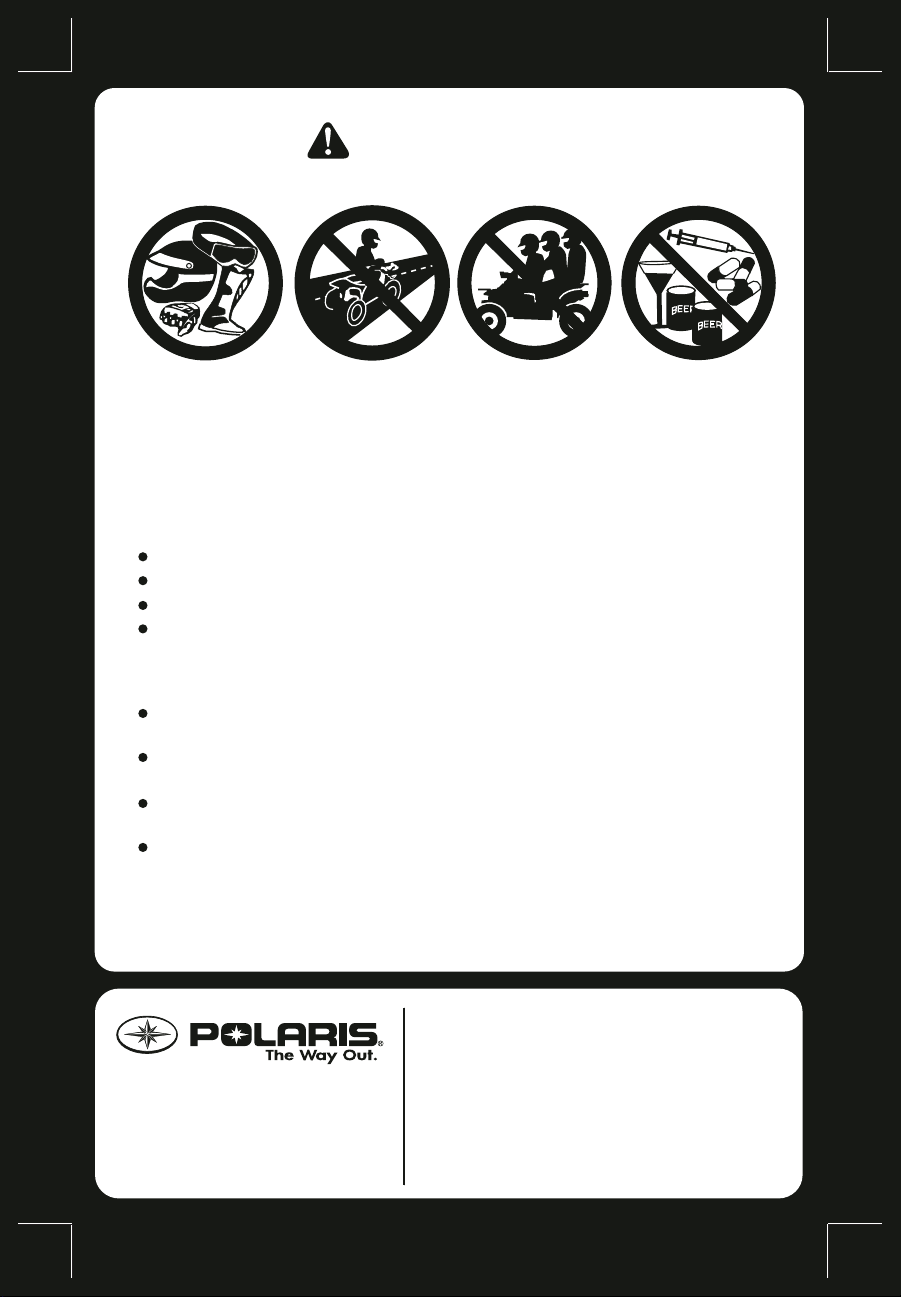
For your nearest Polaris dealer,
call 1-800-POLARIS
or visit www.polarisindustries.com
Polaris Sales Inc., 2100 Hwy 55
Medina, MN 55340
Phone 1-888-704-5290
Part No. 9922730 Rev 01
Printed in USA
Improper vehicle use can result in SEVERE INJURY or DEATH.
READ OWNER’S MANUAL.
FOLLOW ALL INSTRUCTIONS AND WARNINGS.
ALWAYS USE
AN APPROVED
HELMET AND
PROTECTIVE GEAR
FOR DRIVER
AND PASSENGER
NEVER USE
ON PUBLIC
ROADS
NEVER CARRY
MORE THAN
1 PASSENGER
NEVER USE
WITH DRUGS
OR ALCOHOL
without proper ATV training or instruction
at speeds too fast for your skills or the conditions
on public roads — a collision can occur with another vehicle
with a passenger unless passenger seat is securely in place
THE OPERATOR MUST ALWAYS:
use proper riding techniques to avoid vehicle overturns on hills
and rough terrain and in turns
avoid paved surfaces — pavement may seriously affect handling
and control
reduce speed and use extra caution at all times when carrying a
passenger — dismount passenger when conditions require
make sure passenger reads and understands this label and
passenger safety label
NEVER operate:
PMS 419
*9922730 *
WARNING

1
WELCOME
Thank you for purchasing a POLARIS vehicle, and welcome to our
world-wide family of POLARIS owners. We proudly produce an excit-
ing line of utility and recreational products.
• Snowmobiles
• All-terrain vehicles (ATVs)
• RANGER
®
utility vehicles
• Victory Motorcycles
®
• Low emission vehicles (LEVs)
We believe POLARIS sets a standard of excellence for all utility and
recreational vehicles manufactured in the world today. Many years of
experience have gone into the engineering, design, and development of
your POLARIS vehicle, making it the finest machine we’ve ever pro-
duced.
For safe and enjoyable operation of your vehicle, be sure to follow the
instructions and recommendations in this owner’s manual. Your manual
contains instructions for minor maintenance, but information about
major repairs is outlined in the POLARIS Service Manual and should be
performed only by a factory certified Master Service Dealer
®
(MSD)
technician.
Your POLARIS dealer knows your vehicle best and is interested in your
total satisfaction. Be sure to return to your dealership for all of your ser-
vice needs during, and after, the warranty period.
We also take great pride in our complete line of apparel, parts and acces-
sories, available through our online store at www .purepolaris.co m. Have
your accessories and clothing delivered right to your door!

2
POLARIS, THE WAY OUT and SPORTSMAN are registered trademarks of POLARIS
Industries Inc.
Copyright 2010 POLARIS Sales Inc. All information contained within this publication
is based on the latest product information at the time of publication. Due to constant
improvements in the design and quality of production components, some minor discrep-
ancies may result between the actual vehicle and the information presented in this publi-
cation. Depictions and/or procedures in this publication are intended for reference use
only. No liability can be accepted for omissions or in acc uracies. Any reprinting or reuse
of the depictions and/or procedures contained within, whether whole or in part, is
expressly prohibited.
The original instructions for this vehicle are in English. Other languages are provided as
translations of the original instructions.
Printed in U.S.A.
2011 SPORTSMAN 550/850 Touring Owner’s Manual
P/N 9922730

3
TABLE OF CONTENTS
Introduction. . . . . . . . . . . . . . . . . . . . . . . . . . . . . . . . . 4
Safety . . . . . . . . . . . . . . . . . . . . . . . . . . . . . . . . . . . . . . 7
Features and Controls . . . . . . . . . . . . . . . . . . . . . . . 26
Operation. . . . . . . . . . . . . . . . . . . . . . . . . . . . . . . . . . 52
Emission Control Systems . . . . . . . . . . . . . . . . . . . . 75
Maintenance . . . . . . . . . . . . . . . . . . . . . . . . . . . . . . . 76
Troubleshooting . . . . . . . . . . . . . . . . . . . . . . . . . . . 127
POLARIS Products . . . . . . . . . . . . . . . . . . . . . . . . 131
Specifications. . . . . . . . . . . . . . . . . . . . . . . . . . . . . . 132
Declaration of Conformity. . . . . . . . . . . . . . . . . . . 136
Warranty . . . . . . . . . . . . . . . . . . . . . . . . . . . . . . . . . 137
Maintenance Log . . . . . . . . . . . . . . . . . . . . . . . . . . 144
Index . . . . . . . . . . . . . . . . . . . . . . . . . . . . . . . . . . . . 146

4
INTRODUCTION
The following signal words and symbols appear throughout this manual
and on your vehicle. Your safety is involved when these words and sym-
bols are used. Become familiar with their meanings before reading the
manual.
The safety alert symbol indicates a potential personal injury hazard.
WARNING
A WARNING indicates a hazardous situation which, if not avoided, may result in
death or serious injury.
CAUTION
A CAUTION indicates a hazardous situation which, if not avoided, may result in
minor or moderate injury.
NOTICE
A NOTICE indicates a situation that may result in property damage.
The Prohibition Safety Sign indicates an action NOT to take in order
to avoid a hazard.
The Mandatory Action Sign indicates an action that NEEDS to be
taken to avoid a hazard.

5
INTRODUCTION
Failure to heed the warnings and safety precautions contained in this manual
can result in severe injury or death. A POLARIS ATV is not a toy and can be
hazardous to operate. This vehicle handles differently than other vehicles, such
as motorcycles and cars. A collision or rollover can occur quickly , even during
routine maneuvers like turning, or driving on hills or over obstacles, if you fail to
take proper precautions.
• Read this owner’s manual. Understand all safety warnings, precautions and
operating procedures before operating a POLARIS ATV. Keep this manual
with the ATV.
• Never operate an ATV without proper instruction. Take a training course.
• This vehicle is an ADULT VEHICLE ONL Y. Operation is prohibited for anyone
under 16 years of age.
• Never permit a guest to operate the ATV unless the guest has read this
manual and all product labels and has completed a certified safety training
course.

6
INTRODUCTION
Vehicle Identification Numbers
Record your vehicle’s identification numbers and key number in the
spaces provided. Remove the spare key and store it in a safe place. An
ignition key can be duplicated only by ordering a POLARIS key blank
(using your key number) and mating it with one of your existing keys.
The ignition switch must be replaced if all keys are lost.
Vehicle Model Number: __________________________________________________________
Frame VIN: ____________________________________________________________________
Engine Serial Number: ___________________________________________________________
Key Number: ___________________________________________________________________
####
VIN
Engine Serial Number
Key
Number
550 850

7
SAFETY
Safety Training
ATV safety training is a top priority for POLARIS. POLARIS strongly
encourages you and any family members who will be riding the ATV to
take a training course.
If you purchased a new POLARIS A T V in the United States, your dealer
provided information about the authorized ATV RiderCourse
sm
that is
available to you and your eligible family members. This training is
included in the purchase price of your ATV. You were also provided
with printed materials that explain safe operating procedures. You
should review this information on a regular basis.
If you purchased a used POLARIS ATV in the United States, you can
enroll in the ATV RiderCourse
sm
for a fee. Call ATV Enrollment Express
at (800) 887-2887 or visit www.atvsafety.org.
If you purchased a POLARIS ATV outside the United States, please
contact your dealer or local law enforcement agencies for information
about safety training.
A POLARIS ATV is an off-road vehicle. Familiarize yourself with all
laws and regulations concerning the operation of this vehicle in your
area.
W e strongly advise you to strictly follow the recommended maintenance
program outlined in your owner’s manual. This preventive maintenance
program is designed to ensure that all critical components on your vehi-
cle are thoroughly inspected at specific intervals.
FOR MORE INFORMATION ABOUT ATV SAFETY in the United
States, call the Consumer Product Safety Commission at 1-800-
638-2772, or visit www.cpsc.gov, visit www.atvsafety.org, or call
POLARIS at 1-800-342-3764.
8
SAFETY
Safe Riding Gear
Always wear appropriate clothing when riding an ATV. Wear protective
clothing for comfort and to reduce the chance of injury.
Helmet
Wearing a helmet can prevent a severe head injury. Whenever riding a
POLARIS vehicle, always wear a helmet that meets or exceeds estab-
lished safety standards.
Approved helmets in the USA and Canada bear a U.S. Department of
Transportation (DOT) label.
Approved helmets in Europe, Asia and Oceania
bear the ECE 22.05 label. The ECE mark consists
of a circle surrounding the letter E, followed by the
distinguishing number of the country which has
granted approval. The approval number and serial
number will also be displayed on the label.
Helmet
Eye Protection
Gloves
Boots
Long Pants
Long
Sleeves

9
SAFETY
Safe Riding Gear
Eye Protection
Do not depend on eyeglasses or sunglasses for eye protection. When-
ever riding a POLARIS vehicle, always wear shatterproof goggles or
use a shatterproof helmet face shield. POLARIS recommends wearing
approved Personal Protective Equipment (PPE) bearing markings such
as VESC 8, V-8, Z87.1, or CE. Make sure protective eye wear is kept
clean.
Gloves
Off-road style gloves with knuckle pads are the best for comfort and
protection.
Boots
The best footwear is a pair of sturdy over-the-calf boots with low heels.
Clothing
Always wear long sleeves and long pants to protect arms and legs.
Riding pants with kneepads and a jersey with shoulder pads provide the
best protection.
Equipment Modifications
We strongly recommend that consumers do not install on a POLARIS
ATV any equipment that may increase the speed or power of the vehicle,
or make any other modifications to the vehicle for these purposes.
The warranty on your POLARIS ATV is terminated if any equipment
has been added to the vehicle, or if any modifications have been made to
the vehicle, that increase its speed or power.
The addition of certain accessories, including (but not limited to) mow-
ers, blades, tires, sprayers, or large racks, may change the handling char-
acteristics of the vehicle. Use only POLARIS-approved accessories, and
familiarize yourself with their function and effect on the vehicle.

10
SAFETY
Safety Warnings
Failure to operate the ATV properly can result in a collision, loss of control,
accident or overturn, which may result in serious injury or death. Heed all safety
warnings outlined in this section of the owner’s manual. See the OPERATION
section of the owner’s manual for proper operating procedures.
Operating Without Instruction
Operating this ATV without proper instruction
increases the risk of an accident. The operator
must understand how to operate the ATV properly
in different situations and on different types of
terrain.
Beginning and inexperienced operators should
complete the recommended safety training before
operating this vehicle. See page 7.
Never permit a guest to operate the ATV unless the
guest has read this manual and all product labels
and has completed a certified safety training
course.
Age Restrictions
This vehicle is an ADULT VEHICLE ONLY. Operation is prohibited for anyone
under 16 years of age. Never allow anyone under 12 years of age to ride as a
passenger on this 2-up ATV.
Even though a child may be within the recommended age group for operating
some ATVs, he/she may not have the skills, abilities, or judgment needed to
operate or ride on this ATV safely and could be susceptible to accident or injury.
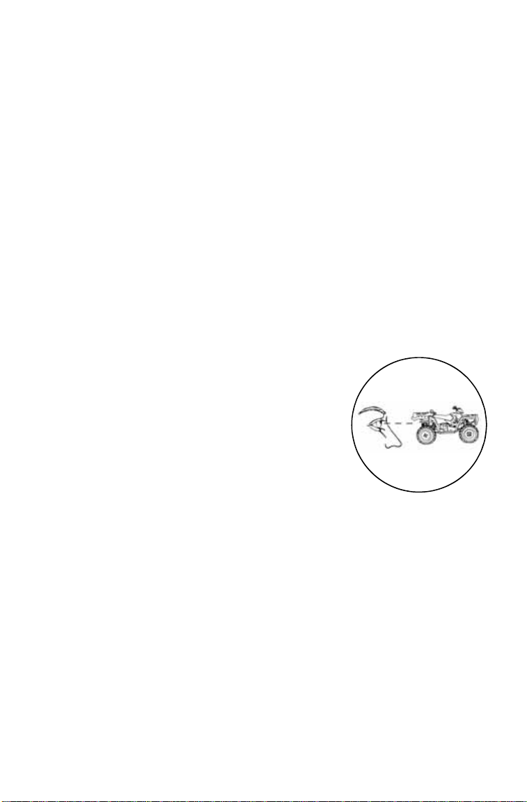
11
SAFETY
Safety Warnings
Handling Gasoline
Gasoline is highly flammable and explosive under certain conditions.
• Always exercise extreme caution whenever handling gasoline.
• Always refuel with the engine stopped, and outdoors or in a well ventilated
area.
• Do not smoke or allow open flames or sparks in or near the area where
refueling is performed or where gasoline is stored.
• Do not overfill the tank. Do not fill the tank neck.
• If gasoline spills on your skin or clothing, immediately wash it off with soap
and water and change clothing.
Exposure to Exhaust
Engine exhaust fumes are poisonous and can cause loss of consciousness or
death in a short time. Never start the engine or let it run in an enclosed area.
The engine exhaust from this product contains chemicals known to cause
cancer, birth defects or other reproductive harm. Operate this vehicle only
outdoors or in well-ventilated areas.
Failure to Inspect Before Operating
Failure to inspect and verify that the ATV is in safe
operating condition before operating increases the
risk of an accident.
Always inspect the ATV before each use to make
sure it’s in safe operating condition.
Always follow all inspection and maintenance
procedures and schedules described in the
owner’s manual.
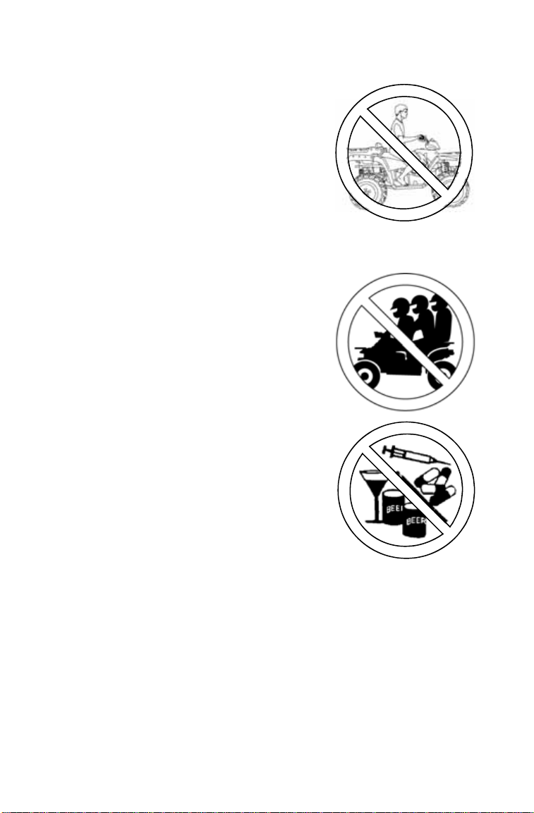
12
SAFETY
Safety Warnings
Protective Apparel
Riding in this vehicle without wearing an
approved helmet and protective eyewear
increases the risk of a serious injuries in the
event of an accident.
Operator and passenger must always wear an
approved helmet that fits properly and eye
protection (goggles or face shield).
Carrying a Passenger
Do not carry a passenger until you have at
least two hours of driving experience with this vehicle.
Carrying More Than One
Passenger
Carrying more than one passenger greatly
reduces the operator’s ability to balance and
control the ATV, which may result in an
accident or overturn.
Never carry more than one passenger on this
2-up ATV.
Using Alcohol or Drugs
Operating the ATV after consuming alcohol or
drugs could adversely affect operator
judgment, reaction time, balance and
perception.
Never consume alcohol or drugs before or
while operating an ATV.

13
SAFETY
Safety Warnings
Operating on Pavement
Operating an ATV on paved surfaces
(including sidewalks, paths, parking lots and
driveways) may adversely affect the
handling of the ATV and could result in loss
of control and accident or overturn.
Avoid operating the ATV on pavement. ATV
tires are designed for off-road use. If it’s
unavoidable, travel slowly and avoid sudden
turns or stops.
Operating on Public Roads
Operating this ATV on public streets, roads
or highways could result in a collision with
another vehicle.
Never operate the ATV on any public street,
road or highway, including dirt and gravel
roads. In many states it’s unlawful to
operate ATVs on public streets, roads and
highways.
Operating at Excessive
Speeds
Operating the ATV at excessive
speeds increases the operator’s risk
of losing control.
Never operate at excessive speeds.
Travel at speeds appropriate for
your skills, your passenger’s skills,
and operating conditions.
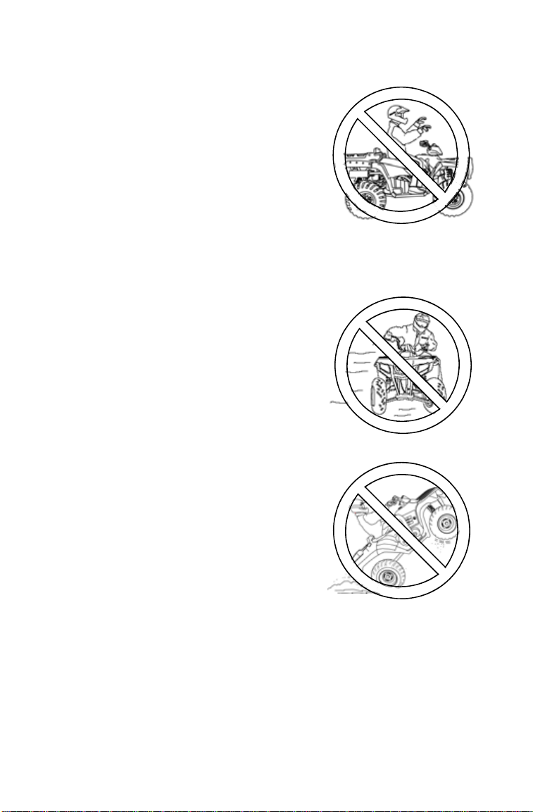
14
SAFETY
Safety Warnings
Physical Control of the ATV
Removing even one hand or foot can reduce
ability to control the vehicle or could cause loss
of balance and ejection from the ATV.
If a person’s feet are not firmly planted on the
footrests, they could come into contact with the
wheels or other moving parts and lead to
accident or injury.
Always keep both hands on the handlebars
and both feet on the footrests of the ATV during
operation. A passenger should always be
seated in the passenger seat with both feet on the footrests and both hands on
the passenger grab handles at all times. The passenger should never hold on to
the operator.
Turning Improperly
Turning improperly could cause loss of
traction, loss of control, accident or
overturn.
Always follow proper procedures for
turning as described in the owner’s
manual.
Practice turning at slow speeds before
attempting to turn at faster speeds.
Never turn at excessive speed.
Jumps and Stunts
Attempting wheelies, jumps and other
stunts increases the risk of an accident or
overturn.
Never attempt wheelies, jumps, or other
stunts. Avoid exhibition driving.
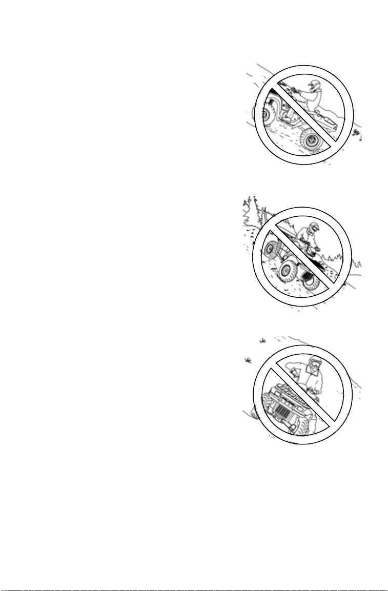
15
SAFETY
Safety Warnings
Improper Hill Climbing
Improper hill climbing could cause loss of control
or overturn. Always follow proper procedures for
climbing hills as described in the owner’s manual.
See page 63. Always move the 4X4 switch to
ADC 4X4 before ascending or descending a hill.
Descending Hills Improperly
Improperly descending a hill could cause loss of
control or overturn.
• Always follow proper procedures for traveling
down hills as described in the owner’s manual.
See page 65.
• Always descend a hill with the transmission in
forward gear. Do not descend a hill with the
transmission in neutral. Always move the 4X4
switch to ADC 4X4 before ascending or
descending a hill. See page 39.
• Always check the terrain carefully before
descending a hill.
• Shift your weight rearward.
• Never travel down a hill at high speed.
• Avoid traveling down a hill at an angle, which
would cause the vehicle to lean sharply to one
side. Travel straight down the hill when
possible.
Crossing Hillsides
Driving on a sidehill is not recommended.
Improper procedure could cause loss of control
or overturn. Avoid crossing the side of any hill
unless absolutely necessary.
If crossing a hillside is unavoidable, always
follow proper procedures as described in the
owner’s manual. See page 64.
Never attempt to turn the ATV around on any
hill until you’ve mastered the turning technique
(on level ground) as described in the owner’s
manual. See page 66.

16
SAFETY
Safety Warnings
Stalling While Climbing a Hill
Stalling, rolling backwards or improperly
dismounting while climbing a hill could cause
an overturn.
• Always maintain a steady speed when
climbing a hill.
• Always move the 4X4 switch to ADC 4X4
before ascending or descending a hill. See
page 39.
If all forward speed is lost:
• Lean forward to keep body weight uphill. A
passenger should also lean uphill.
• Apply the single lever brakes.
• Lock the parking brake when fully stopped.
• Dismount on the uphill side of the vehicle, or on the left if the vehicle is
pointing straight uphill. Have a passenger dismount first, then the operator
may dismount.
• Turn the ATV around and remount, following the procedure described in the
owner’s manual. See page 66.
If the ATV begins rolling backwards:
• Keep operator and passenger body weight uphill.
• Never apply engine power.
• Never apply the rear brake while rolling backwards.
• Apply the single-lever brake gradually.
• When fully stopped, apply th e foot brake as well, and then lock the parking
brake.
• Dismount on the uphill side of the vehicle, or on the left if the vehicle is
pointing straight uphill. Have a passenger dismount first, then the operator
may dismount.
• Turn the ATV around and remount, following the procedure described in the
owner’s manual. See page 66.
Operating on Steep Hills
Operating on excessively steep hills could
cause an overturn.
Never operate on hills too steep for the ATV or
for your abilities. Never operate the ATV on
hills steeper than 15 degrees.
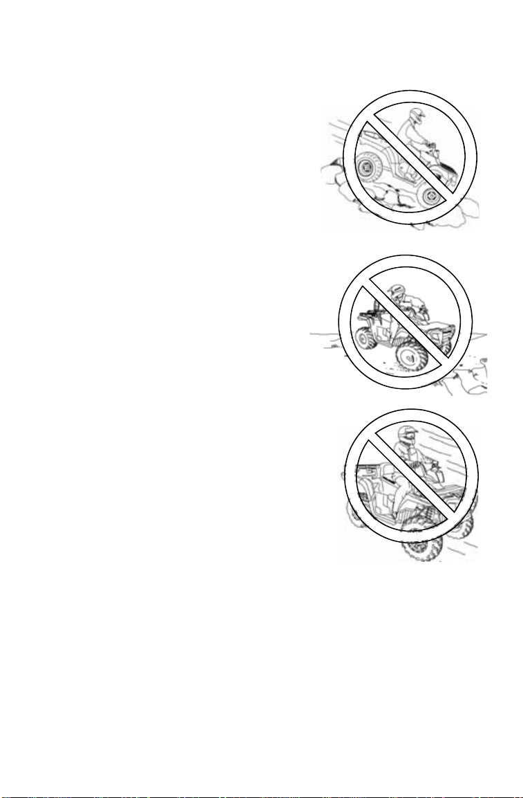
17
SAFETY
Safety Warnings
Operating on Slippery Terrain
Failure to use extra caution when operating
on excessively rough, slippery or loose terrain
could cause loss of traction, loss of control,
accident or overturn.
Do not operate on excessively rough, slippery
or loose terrain until you’ve learned and
practiced the skills necessary to control the
ATV on such terrain.
Always use extra caution on rough, slippery
or loose terrain.
Operating in Unfamiliar Terrain
Failure to use extra caution when operating
on unfamiliar terrain could result in an
accident or overturn.
Unfamiliar terrain may contain hidden rocks,
bumps, or holes that could cause loss of
control or overturn.
Travel slowly and use extra caution when
operating on unfamiliar terrain. Always be
alert to changing terrain conditions.
Operating Improperly in
Reverse
Improperly operating in reverse could result
in a collision with an obstacle or person.
Always follow proper operating procedures
as outlined in this manual. See page 70.
Before shifting into reverse gear, always
check for obstacles or people behind the ATV.
When it’s safe to proceed, back slowly.

18
SAFETY
Safety Warnings
Improper Tire Maintenance
Operating this ATV with improper tires or
with improper or uneven tire pressure could
cause loss of control or accident.
Always use the size and type of tires
specified for your ATV.
Always maintain proper tire pressure as
described in the owner’s manual and on
safety labels.
Operating Over Obstacles
Improperly operating over obstacles could
cause loss of control or overturn.
Before operating in a new area, check for
obstacles. Avoid operating over large
obstacles such as rocks and fallen trees. If
unavoidable, use extreme caution and
always follow proper operating procedures
as outlined in this manual. See page 69.
Skidding or Sliding
Skidding or sliding can cause loss of control
or overturn (if tires regain traction
unexpectedly).
On slippery surfaces such as ice or loose
gravel, travel slowly and use extra caution
to reduce the chance of skidding or sliding.
Do not operate on excessively slippery
surfaces.

19
SAFETY
Safety Warnings
Operating Through Deep Water
Operating the ATV through deep or fast-
flowing water could cause the tires to float,
causing loss of control or overturn.
Avoid operating the ATV through deep or
fast-flowing water. If it’s unavoidable to
enter water that exceeds the
recommended maximum depth (see page
68):
• Travel slowly.
• Balance your weight carefully.
• Avoid sudden movements.
• Maintain a slow and steady forward motion. Do not make sudden turns or
stops, and do not make sudden throttle changes.
Wet brakes may have reduced stopping ability. After leaving water, test the
brakes. Apply them lightly several times while driving. The friction will help dry
out the pads.
Improper Cargo Loading
Overloading the ATV or carrying/towing
cargo improperly may cause changes in
handling, which could cause loss of control
or an accident.
• Never exceed the stated load capacity for
this ATV.
• Cargo should be properly distributed and
securely attached.
• Reduce speed when carrying cargo or
pulling a trailer. Allow a greater distance
for braking.
• Always follow the instructio ns in the owner’s manual for carrying cargo or
pulling a trailer. See pages 72-74.
• Always follow the instructions in the owner’s manual for operating with a
passenger. See page 60.

20
SAFETY
Safety Warnings
Operating on Frozen Bodies of
Water
Operating on frozen bodies of water may
result in serious injury or death if the ATV
and/or riders fall through the ice.
Never operate the ATV on a frozen body of
water unless you have independently
verified that the ice is sufficiently thick to
support the weight and moving force of the
ATV, you and your cargo, together with any
other vehicles in your party. Variances in
snow depth and/or water currents may result
in uneven ice thickness. Always check with
local authorities and residents to confirm ice
conditions and thickness over your entire
route. ATV operators assume all risk
associated with ice conditions on frozen
bodies of water.
Poor Visibility
Operating the ATV in darkness or inclement weather could result in a collision or
accident, especially if operating on a road or street. This A TV is not equipped
with highway-approved lights. Operate this vehicle off-road only. Use caution
and drive at reduced speeds in conditions of reduced visibility such as fog, rain
and darkness. Clean headlights frequently and replace burned out headlamps
promptly.

21
SAFETY
Safety Warnings
Operating a Damaged ATV
Operating a damaged ATV can result in an accident. After any overturn or
accident, have a qualified service dealer inspect the entire machine for possible
damage, including (but not limited to) brakes, throttle and steering systems.
Physical Skills
Safe operation of this rider-active vehicle requires good judgement and physical
skills. Persons with cognitive or physical disabilities who operate this veh icle
have an increased risk of overturn and loss of control. Never secure a
passenger to the vehicle or to the operator with a belt, rope or similar device.
Hot Exhaust Systems
Exhaust system components are very hot during and after use of the vehicle.
Hot components can cause burns and fire. Do not touch hot exhaust system
components. Always keep combustible materials away from the exhaust
system. Use caution when traveling through tall grass, especially dry grass.
Unauthorized Use of the ATV
Leaving the keys in the ignition can lead to unauthorized use of the vehicle,
which could result in an accident or overturn. Always remove the ignition key
when the vehicle is not in use.
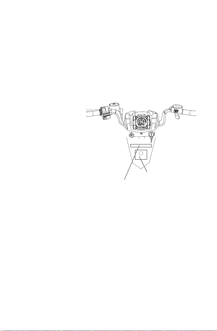
22
SAFETY
Safety Labels and Locations
Warning labe ls have been placed on the vehicle for your protection.
Read and follow the instructions on each label carefully. If any of the
labels shown in this manual differ from the labels on your vehicle,
always read and follow the instructions of the labels on the vehicle.
If an informational or graphic label becomes illegible or comes off, con-
tact your POLARIS dealer to purchase a replacement. Replacement
safety labels are provided by POLARIS at no charge. The part number is
printed on the label.
Reverse Override Warning/AWD Caution
WARNING
Improper use of override
button can lead to loss of
control resulting in severe
injury or death. Do not
activate override while throttle
is engaged. Always apply
throttle gradually while in
reverse.
CAUTION
Do not push switch to engage
4×4 (AWD) if the rear wheels
are spinning. This may cause
severe drive shaft and clutch
damage.
7175512
Age 16 Warning
WARNING
Operating this ATV if you are under the age of 16 increases the chances of
severe injury or death to both operator and passenger.
NEVER operate this ATV if you are under age 16.
7175375
Reverse Override Warning
AWD Caution
Age 16 Wa rning

23
SAFETY
Safety Labels and Locations
General Warning
WARNING
Improper ATV use can result in SEVERE
INJURY or DEATH
ALWAYS USE AN APPROVED HELMET AND
PROTECTIVE GEAR FOR DRIVER AND
PASSENGER
NEVER USE ON PUBLIC ROADS
NEVER CARRY MORE THAN 1 PASSENGER
NEVER USE WITH DRUGS OR ALCOHOL
NEVER operate:
• without proper ATV training or instruction
• at speeds too fast for your skills or the
conditions
• on public roads — a collision can occur with
another vehicle
• with a passenger unless passenger seat is securely in place
THE OPERATOR MUST ALWAYS:
• use proper riding techniques to avoid overturns on hills and rough terrain and
in turns
• avoid paved surfaces — pavement may seriously affect handling and control
• reduce speed and use extra caution at all times when carrying a passenger —
dismount passenger when conditions require
• make sure passenger reads and understands this label and passenger safety
label
LOCATE AND READ OPERATOR’S MANUAL.
FOLLOW ALL INSTRUCTIONS AND WARNINGS.
7175844
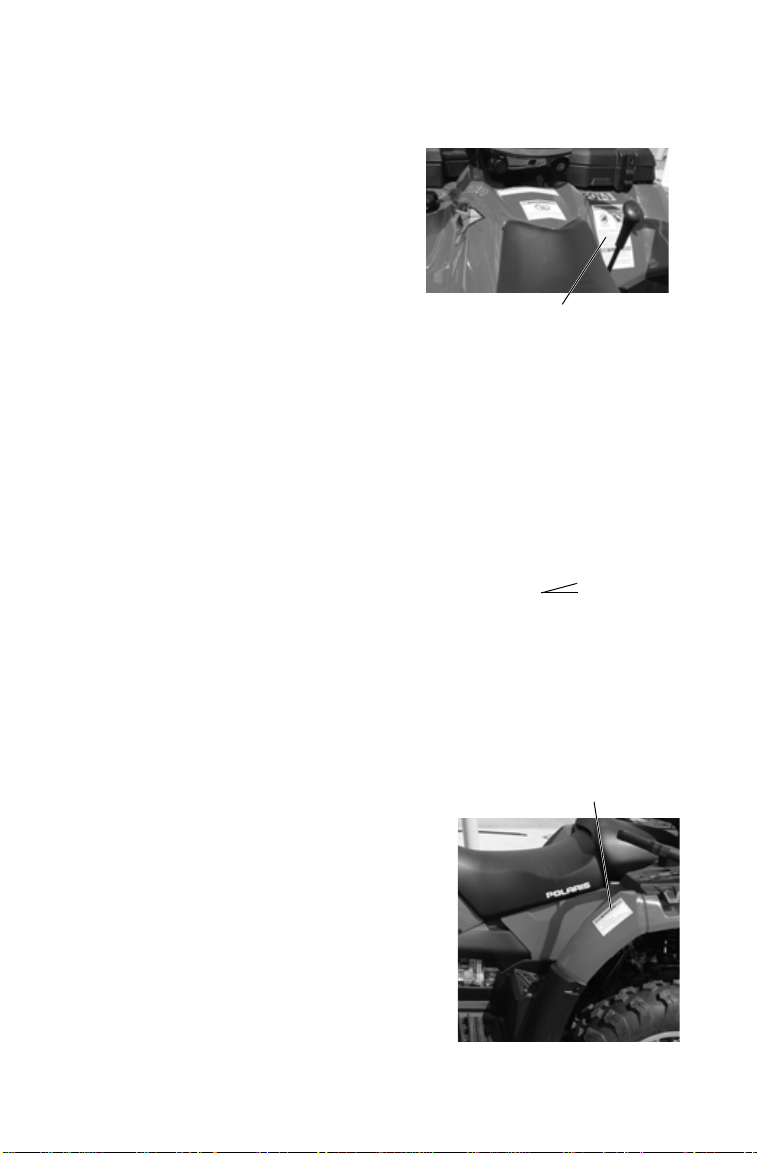
24
SAFETY
Safety Labels and Locations
Passenger Warning/Discretionary Warning
WARNING
PASSENGER SAFETY
To reduce the risk of SEVERE INJURY or
DEAT H
NEVER CARRY MORE THAN ONE
PASSENGER
NEVER RIDE AFTER USING DRUGS OR
ALCOHOL
NEVER carry a passenger too small to firmly
plant feet on footrests and securely grasp
hand holds.
THE PASSENGER MUST ALWAYS:
• use an approved helmet and protective gear
• securely grasp hand holds and plant feet firmly on footrests while seated in
the passenger seat
• tell operator to slow down or stop if uncomfortable — get off and walk if
conditions require
WARNING
• Never operate this ATV on HILLS steeper than 15 degrees 15°. To
prevent overturn on hilly terrain, use throttle and brakes gradually, and shift
weight uphill.
• REVERSE operation can be dangerous even at low speeds. Steering
becomes difficult. To prevent loss of control, avoid sudden braking or sharp
turns.
7175845
Tire Pressure/Load Warning
WARNING
Improper tire pressure or overloading can cause
loss of control.
Loss of control can result in severe injury or
death.
• Cold tire pressure:
Front: 7.0 psi (48.3 kPa)
Rear: 5.0 psi (34.5 kPa)
• Maximum weight capacity: 735 lbs. (333 kg)
• Lug nut torque values:
Steel rims 45 ft-lbs. (61 Nm)
Aluminum rims 75 ft-lbs. (102 Nm)
7175846
Passenger Warning
Discretionary Warning
Tire Pressure/Load
Warning

25
SAFETY
Safety Labels and Locations
Rack/Box Warning
WARNING
• DO NOT TOW FROM RACK OR BUMPER. Vehicle damage or tipover may
result causing severe injury or death. Tow only from tow hooks or hitch.
• Maximum Rack Loads: Front 120 lbs. (54 kg) Rear 240 lbs. (109 kg)
7175448
Clutch Cover Warning
WARNING
• Moving parts hazard under belt-clutch guard. T o prevent serious injury , do not
operate vehicle with guard removed.
• Do not modify engine or clutch. Doing so can cause part failure, possible
imbalance, and excessive engine RPM, which can result in serious injury or
death.
7175488
Hitch Capacity Label
TRAILER MAX WEIGHT:
1500 LBS. (682 KG) ON LEVEL GROUND
850 LBS. (386 KG) UP TO 15° GRADE
HITCH MAX. VERTICAL WEIGHT: 150 LBS. (68 KG)
7170509
H
Clutch Cover
W arning (under
seat)
H
H
Rack/Box
Warning
Rack/Box
Warning
Hitch
Capacity
Label
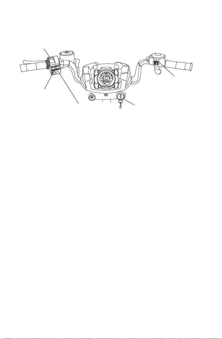
26
FEATURES AND CONTROLS
Switches
Mode/Reverse Override Switch
This vehicle is equipped with a reverse speed limiter system.To gain
additional wheel speed while backing, release the throttle and depress
the override button.
WARNING! Pressing the override button while the throttle is open can cause
loss of control, which may result in serious injury or death. Always release the
throttle before pressing the override button.
The reverse override button also acts as a MODE button when held
down for approximately one half second. See the instrument cluster
information beginning on page 40.
Tip: The override button will not functi on as a MODE button if the transmission
is in reverse.
4X4 Switch
Use the 4X4 switch to engage ADC 4X4, 4X4 or 2X4. See page 39. The
vehicle automatically engages 4X4 when operating in reverse if the
switch is set to either 4X4 position.
Mode/Reverse
Override
Switch
Main Key
Switch
Engine
Stop Switch
Headlight
Switch
4X4
Switch

27
FEATURES AND CONTROLS
Switches
Engine Stop Switch
Move the stop switch either
left or right to the OFF position
to stop the engine quickly.
Move the stop switch to the
RUN position before attempt-
ing to start the engine. The
engine will not start or run
when the switch is off.
Both the main switch and the engine stop switch will shut off all electri-
cal power to the vehicle, including lights.
Main Key Switch
Use the main key switch to start the engine. See page 57.
Headlight Switch
Use the headlight switch to turn the lights on and off and to change the
lights from high beam to low beam. The key must be in the ON position
and the engine stop switch must be in the RUN position.

28
FEATURES AND CONTROLS
Throttle Lever
Operating an ATV with sticking or improperly operating throttle controls could
cause an accident. Never start or operate an ATV that has a sticking or
improperly operating throttle. Always contact your dealer for service before
operating the vehicle.
Failure to check or maintain proper operation of the throttle system can result in
an accident if the throttle lever sticks during operation. Always check the lever
for free movement and return before starting the engine. Also check
occasionally during operation.
Modifications to the electronic throttle control could result in failure to perform as
designed, which could result in an accident. Do not attempt to modify the throttle
control system or replace it with any after market throttle mechanisms. Always
ensure that the throttle cable is installed and properly routed to the throttle
control.
Engine speed and vehicle movement are controlled by pressing the
throttle lever. The throt tle lever is spring loaded. Engine speed returns to
idle when the lever is released.
This ATV is equipped with
POLARIS Electronic Throttle
Control (ETC), which is
designed to reduce the risk of a
frozen or stuck throttle.
If the throttle cable should stick
in an open position when the
operator releases the throttle
lever, engine speed will be lim-
ited, and power to the rear
wheels will be reduced.

29
FEATURES AND CONTROLS
Brake Lever
Operating the ATV with a spongy brake lever can result in loss of braking, which
could cause an accident. Never operate the ATV with a spongy-feeling brake
lever. Always contact your dealer for service before operating the vehicle.
Squeeze the brake lever toward the
handlebar to apply the front and
rear brakes. These brakes are
hydraulically activated disc type
brakes that are activated by only
one lever.
Always test brake lever travel and
master cylinder fluid level before
riding. When squeezed, the lever
should feel firm. Any sponginess
would indicate a possible fluid leak or low master cylinder fluid level,
which must be corrected before riding. Contact your dealer for proper
diagnosis and repairs.

30
FEATURES AND CONTROLS
Master Cylinder/Brake Fluid
An over-full master cylinder may cause brake drag or brake lock-up, which could
result in an accident. Maintain brake fluid at the recommended level. Do not
overfill.
Never store or use a partial bottle of brake fluid. Brake fluid is hygroscopic,
meaning it rapidly absorbs moisture from the air. The moisture causes the
boiling temperature of the brake fluid to drop, which can lead to early brake fade
and the possibility of brake failure, which could result in an accident. After
opening a bottle of brake fluid, always discard any unused portion.
Check the brake fluid in the master
cylinder before each ride.
1. Position the ATV on a level
surface.
2. Position the handlebars so the
master cylinder is level.
3. View the brake fluid level
through the indicator window
on the top of the master cylin-
der. The eye will appear dark
when the fluid level is full.
When fluid is low , the eye will
be clear.
4. If the fluid level is low, remove the cover screws and add fluid to the
fill line. Do not overfill. Use DOT 4 brake fluid only.
5. Reinstall the cover. Torque screws to 7 in. lbs. (.8 Nm).
Master Cylinder
Indicator
Window

31
FEATURES AND CONTROLS
Parking Brake
Locking the Parking Brake
1. Place the transmission in
PARK.
2. Squeeze and release the brake
lever two or three times, then
squeeze and hold.
3. Push the parking brake lock
forward to engage the lock.
4. Release the brake lever.
5. To release the parking brake lock, squeeze and release the brake
lever. It will return to its unlocked position.
WARNING! Operating the ATV while the parking brake is engaged could result
in an accident or fire. Always check to be sure the parking brake is disengaged
before operating.
The parking brake may relax if left on for a long period of time. Always
block the wheels to prevent rolling. Always block the wheels on the
downhill side of the ATV if leaving it parked on a hill. Another option is
to park the ATV in a sidehill position. Never depend on the parking
brake alone if the ATV is parked on a hill. Always block the wheels to
prevent rolling.

32
FEATURES AND CONTROLS
Auxiliary Foot Brake
Never back down a hill. Applying the auxiliary brake when backing down a hill
may cause rear tipover, which could result in serious injury or death.
Use caution when applying the auxiliary brake. Do not aggressively apply the
auxiliary brake when going forward. The rear wheels may skid and slide
sideways, causing loss of control and serious injury or death.
The auxiliary brake system is
intended to be used as a backup for
the main brake system. Should the
main system fail, use the auxiliary
foot brake.
The auxiliary foot brake is located
on the inside of the right footrest.
Operate this brake with your right
foot.
If the rear wheels slide while using
the auxiliary brake, reduce brake
pedal pressure to brake the rear
wheels without skidding.
Brake Fluid Level
Check the brake fluid level fre-
quently for the auxiliary brake sys-
tem. The reservoir is located under
the front storage box. See page 36.
Maintain the fluid level between
the maximum and minimum marks.
Use DOT 4 brake fluid only.
NOTICE: Do not use ADC fluid in the
brake fluid reservoir. ADC
fluid will damage the rubber
components of the brake
system.
Auxiliary
Foot Brake
Brake Fluid
Reservoir

33
FEATURES AND CONTROLS
Automatic Transmission Gear Selector
The transmission gear
selector is located on the
right side of the vehicle.
H: High Gear
L: Low Gear
N: Neutral
R: Reverse
P: Park
To shift gears, brake to a
complete stop. When the
engine is idling, move
the lever to the desired
gear.
NOTICE: Shifting gears with the engine speed above idle or while the vehicle is
moving could cause transmission damage.
Whenever the ATV is left unattended, always place the transmission in
PARK and lock the parking brake.
Belt Life
To extend belt life, use low forward gear when pulling a heavy load at
less than seven miles per hour for extended periods and when operating
uphill at a slow speed.

34
FEATURES AND CONTROLS
Electronic Power Steering (EPS)
Electronic power steering engages when the ignition key is turned to the
ON position. EPS remains engaged whether the vehicle is moving or
idle. See page 41 for EPS Warning Indicator information.
Passenger Seat
Always make sure the passenger seat is installed and securely latched
before operating with a passenger. Test the seat latch by attempting to
pull the seat upward. If the lock-out is not working properly, do not
allow a passenger to ride the vehicle. See your POLARIS dealer for ser-
vice.
See pages 95-96 for passenger seat adjustment procedures.
See page 95 for passenger seat removal and installation procedures.
Beverage Holders
This vehicle is equipped with
beverage holders on each side
of the passenger seat. To
secure a beverage or other
container, remove the rubber
retainer strap from one side of
the holder. Place the container
into the recess and reinstall the
strap over the top of the con-
tainer. Place one of the rubber
cylinders through one of the
holes to secure a strap.
When trailering the vehicle,
and whenever a holder is not
in use, always secure the rub-
ber straps in one of the tighter
positions to prevent loss of the
retainer.
Tight Position
Less Tight Position

35
FEATURES AND CONTROLS
Fuel Tank
Always refuel with the engine
stopped, and outdoors or in a well
ventilated area. Refuel on a level
surface.
Remove the fuel tank cap and add
fuel. Use either leaded or unleaded
gasoline with a minimum pump
octane number of 87=(R+ M/2)
octane. Do not use fuel with ethanol
content greater than 10%, such as
E-85 fuel.
The fuel tank is designed to allow
for the normal expansion of fuel. Do
not overfill. Do not fill the tank
neck.

36
FEATURES AND CONTROLS
Front Storage Box
Open the front storage box to access the under-compartment area.
1. Release the front
box cover latches
and lift the cover.
2. Release the plunger
latches that secure
the box to the
frame.
3. Close the cover and
lift the unlatched
edge of the box to
disengage the plungers. Pivot the box forward.
4. T o remove the box completel y, disengage the plungers and slide the
box rearward and upward.
5. Always secure the plunger latches and the cover latches before
operating the vehicle.
Access the following components under the front box:
• Radiator cap • Coolant recovery bottle cap
• Brake fluid reservoir • Electrical/fuse/relay components
• ADC fluid reservoir • Battery
Cover Latches Plunger Latches
ADC Fluid
Reservoir
Brake Fluid
Reservoir
Radiator
Cap
Coolant
Bottle Cap
Electrical/Fuse/Relay
Battery

37
FEATURES AND CONTROLS
All Wheel Drive System
The All Wheel Drive system is
controlled by the 4X4 switch.
ADC 4X4 Mode
When the switch is on ADC 4X4,
the ADC system allows engine
braking to all four wheels when
the vehicle descends a hill or
incline. Always move the 4X4
switch to ADC 4X4 before
ascending or descending a hill.
See page 39.
4X4 Mode
When the switch is on 4X4, the
ATV is in 4X4, and the 4X4 indi-
cator icon in the instrument clus-
ter display will be visible.
When in 4X4, the demand drive
unit will automatically engage
any time the rear wheels lose
traction. When the rear wheels
regain traction, the demand drive
unit will automatically disengage.
There is no limit to the length of time the vehicle may remain in 4X4.
The vehicle automatically engages 4X4 when operating in reverse if the
switch is set to either 4X4 position.
2X4 Mode
When the switch is on 2X4, the ATV is in two-wheel drive at all times.

38
FEATURES AND CONTROLS
All Wheel Drive System
Engaging 4X4
The 4X4 switch may be turned on or off while the vehicle is moving.
Initially, the vehicle’s electronic system will not enable 4X4 until the
engine RPM is below 3100. Once enabled, 4X4 remains enabled until
the 4X4 switch is turned off. If the switch is turned of f while the demand
drive unit is moving, it will not disengage until the rear wheels regain
traction.
Engage the 4X4 switch before getting into conditions where front wheel
drive may be needed. If the rear wheels are spinning, release the throttle
before switching to 4X4.
NOTICE: Switching to 4X4 or ADC 4X4 while the rear wheels are spinning may
cause severe drive shaft and gearcase damage. Always switch to
4X4 or ADC 4X4 while the rear wheels have traction or are at rest.

39
FEATURES AND CONTROLS
Active Descent Control (ADC) System
The ADC system allows engine braking to all four wheels when the
vehicle descends a hill or incline. Always move the 4X4 switch to ADC
4X4 before ascending or descending a hill.
Engaging Active Descent Control
The ADC system will automatically engage when all four of the follow-
ing conditions occur:
• The 4X4 switch must be in the ADC 4X4 position
• Vehicle speed must be 15 mph (24 km/h) or less
• The throttle must be closed (throttle lever released)
• The transmission must be in gear (high, low or reverse)
Disengaging Active Descent Control
The ADC system will automatically disengage if at least one of the fol-
lowing conditions occur:
• The 4X4 switch is moved out of the ADC 4X4 position
• Vehicle speed exceeds 15 mph (24 km/h)
• The throttle is open (throttle is applied)
• The transmission is shifted to neutral or park
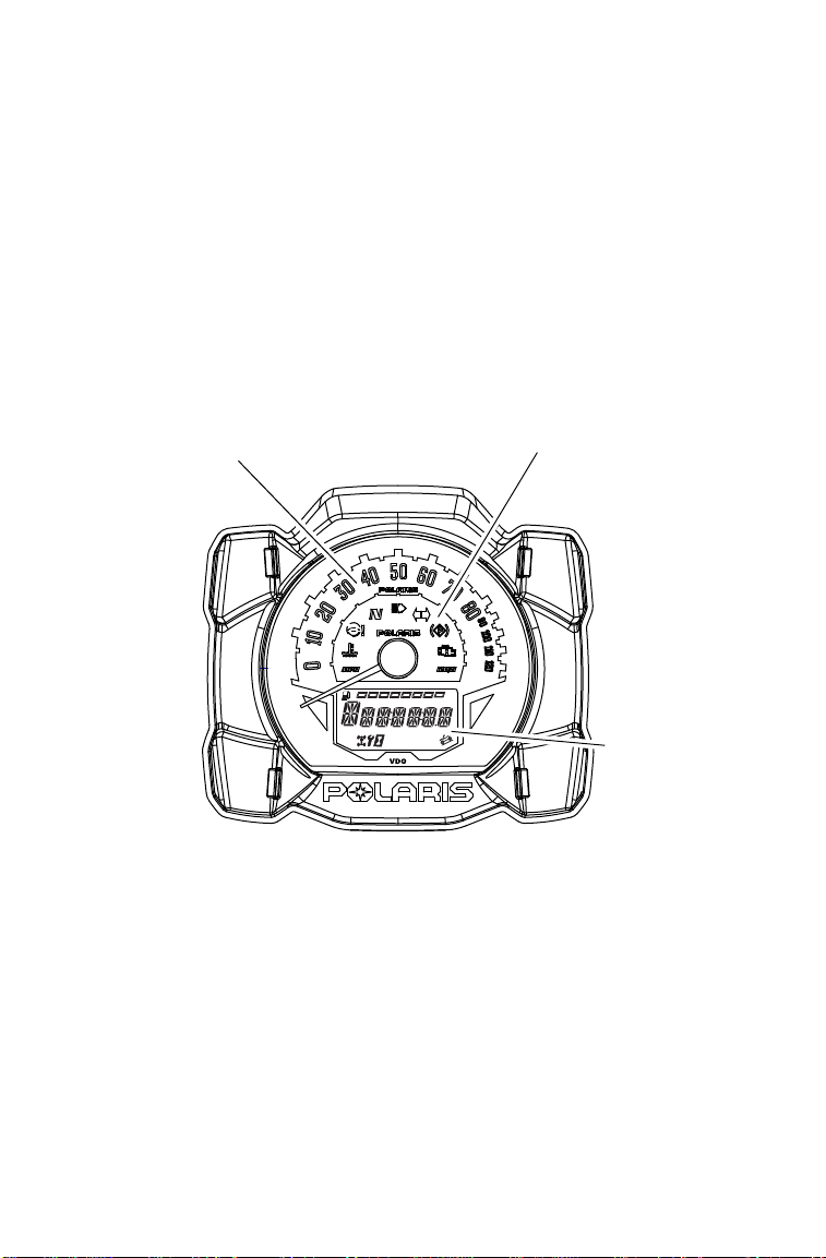
40
FEATURES AND CONTROLS
Instrument Cluster
NOTICE: High water pressure may damage ATV components. Wash the ATV
by hand or with a garden hose using mild soap.
Certain products, including insect repellents and chemicals, will
damage the speedometer lens and other plastic surfaces. Do not use
alcohol to clean the instrument cluster. Do not allow insect sprays to
contact the lens. Immediately clean off any gasoline that splashes on
the instrument cluster.
Digital/Analog Gauge
Speedometer
The speedometer displays vehicle speed in either miles per hour (MPH)
or kilometers per hour (km/h).
Rider
Information
Center
Speedometer
Indicator Lamps

41
FEATURES AND CONTROLS
Instrument Cluster
Digital/Analog Gauge
Indicator Lamps
Lamp Indicates Condition
Vehicle
Speed
When standard mode is selected, speed displays in
miles per hour.
When metric mode is selected, speed displays in
kilometers per hour.
Over
Temperature
This lamp flashes to indicate an overheated engine. If
the indicator stops flashing but remains illuminated,
the overheating condition remains, and the system
will automatically reduce engine power.
EPS Warning This indicator illuminates when the key is turned to
the ON position and goes off when the engine is
started. If the light remains on after starting the
engine, the EPS system is inoperative. See your
authorized POLARIS dealer for service.
Neutral This lamp illuminates when the transmission is in
neutral and the ignition key is in the ON position.
High Beam This lamp illuminates when the headlamp switch is
set to high beam.
Check Engine This indicator appears if an EFI-related fault occurs.
Do not operate the ATV if this warning appears.
Serious engine damage could result. See your dealer.

42
FEATURES AND CONTROLS
Instrument Cluster
Digital/Analog Gauge
Rider Information Center
The rider information center is located in the instrument cluster . All seg-
ments will light up for one second at start-up. If the instrument cluster
fails to illuminate, a battery over-voltage may have occurred and the
instrument cluster may have shut off to protect the electronic speedome-
ter. If this occurs, take the ATV to your POLARIS dealer for proper
diagnosis.
The information center is set to display standard units of measurement
and a 12-hour clock at the factory. To change to metric and/or a 24 -hour
clock, see page 45.
Trip 1
km
mi
RPM
EF
88
:
88