Термотрансферный принтер 8018 Markem Imaje
Общий вид
https://ru.markem-imaje.com/products_2011/product_coding/thermal_transfer/8018
“Как заменить печатающую головку Markem-Imaje 8018?”
В этой статье речь пойдет о процедуре замены печатающей головки на термотрансферном маркираторе Markem-Imaje 8018. Причиной принятия данного решения могут служить следующие факторы:
- Отпечатанный оттиск имеет пропуски (полосы) перпендикулярные печатающей головке.
- Оттиск отсутствует частично или полностью.
- Контраст маркировки заметно снизился (маркировка стала бледной).
В любом случае, мы рекомендуем перед заменой печатающей головки получить бесплатную консультацию у наших специалистов.
При замене печатающей головки стоит обратить особое внимание на статическое напряжение, которое собирается на одежде. Мы рекомендуем использовать атистатический браслет при выполнении последующих работ.
- Отключите питание принтера.
- Извлеките поврежденную печатающую головку.
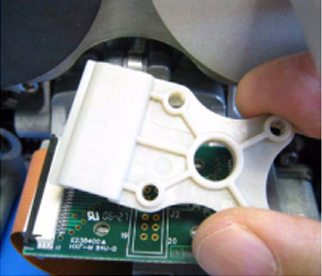
а. Открутите с помощью шестигранника четыре крепежных винта с фиксатора разъема подключения печатающей головки.
b. Снимите фиксатор разъема.
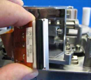
c. Ослабьте разъем подключения гибкого шлейфа печатающей головки сдвинув черный фиксатор в сторону шлейфа печатающей головки.
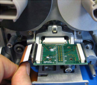
d. Отключите гибкий шлейф печатающей головки от платы.
e. Ослабляем винт фиксации головки находящийся под печатающей головкой. Слегка прижав печатающую головку вниз извлекаем ее в сторону гибкого шлейфа.
3. Новая печатающая головка Markem-Imaje 8018 устанавливается в обратном порядке. При установке печатающей головки обратите внимание на фиксатор черного цвета, который мы ослабляли в пункте С, он должен быть ослаблен, а шлейф головки свободно заходить в разъем на плате.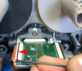
 Отключаем шлейф печатающей головки
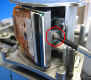


Создаем или меняем образ отпечатка:
Для создания образа используется программное обеспечение ColosCreative скачать бесплатную версию можно на сайте markem-imaje.
При создании нового образа выбираем устройство 8018.
Создаем дату (переносим из левого меню в печатающее поле. Определив размер шрифта 14. Font Ariel по умолчанию. Изменяем свойства даты, если ее нужно корректировать UserPromtedDate Там формируем изменяемое поле сточками или дефисами например 00.00.00
Текстовую приставку (цех, номер бригады). Изменяем свойства TEXT, если ее нужно корректировать UserPromtedDate и Shift Number. Определив размер шрифта 14. Font Ariel по умолчанию.
Сохраняем файл, присвоив ему имя, на флешку размером не более 2Gb отформатированную в FAT обозначаем имя sablon.itf.
Затем печатаем Print to File выбирая устройство 8018 нажимая Send, получаем два файла имя.image и имя.bff. Переименовываем их добавляя _dat получаем sablon_dat.image и sablon_dat.bff.
Устанавливаем флешку в USB разъем расположенный под крышкой принтера вверху ленты Риббон. вводим пароль. По умолчанию 1234.
Попадаем в меню управления файлами. загружаем файл образа.
Можем выгрузить все текущие файлы образа.на флешку.
Приятной работы!
Благодарность — пополнение счета телефона +792232399076
Популярные сообщения из этого блога
Неисправности ротационных печей Revent 725
Появление излишек воды с парогенератора: 1. Чистка трубы форсунки подачи воды от накипи. 2. Чистка шариков парогенератора. РАзбираем парогенератор. Вынимаем трубу форсунку подачи воды.Снимаем Щитки. Достаем шары. Помещаем их в бетономешалку на пол. часа. Устанавливаем очищенные шары на штатное место. Щитки. трубу. Вода больше не образуется, превращаясь в пар. Недостаточно пара в парогенераторе, отсутствие гланца на продукции: Проверяем расход воды. В ручном режиме за 20 секунд вытекает около 10 литров. Отсоединяем клапан от трубки. Подставляем ведро. Переводим печь в ручной режим. Настраиваем работу клапана на 20 сек. Включаем выпекание. После останова процесса выключаем и взвешиваем массу воды. Если ее значительно меньше 10л (например 2 литра). Снимем и проверяем электромагнитный клапан 6213 24V. Проверяем состояние седла и мембраны. В случае значительного износа меняем электро-магнитный клапан.. Неисправность горелки Honeywell MMI962. Mod23. Ошибка на пульту печи Е8. 1. Отк
Машина тестоделительная Восход ТД 2М В384.00.00.000РЭ
вместимость бункера 180кг. масса дозированных заготовок — 0,15-1кг. погрешность до 0,2/св. 0,2 — +3/+2% Производительность — шт/ч (шт/мин) — 1080-2520 (18-42) Номинальная потребляемая мощность 1,78 кВт.(ЭД 0,75кВт 3,34А, 0,18кВт 1,14А, 1500об/мин) Номинальное напряжение — ШТЗУ ~220в. Частота — 50Гц. Длина (вправо/влево)/ширина/высота — (1191/1182)/2186/1778 мм Масса — 720 кг. Состав: Загрузочный бункер. делительный механизм. механизм регулировки массы тестовых заготовок. камера всасывания. Главный поршень (всасывание и передача в мерные камеры. Нож для отделения теста от содержимого бункера. механизм хода главного поршня. привод механизма тестоделителя. привод транспортеров. вал съема тестовых заготовок. система смазки поверхности барабана делительного механизма, главного поршня, ножа. Барабан делительного механизма имеет две мерных камеры и два мерных поршня. Для смазки транспортерной ленты и механизмов залить 5л в бак масла и масляный барабан. Довидол, масло
Автор: admin в рубриках: Компьютерное, модернизация, новое оборудование, полезное
Поставили на днях задачу — перенести с одного фасовочного станка-автомата на другой датер (принтер для печати текстовой информации на упаковках продукции). Автомат с принтером стоял на складе за ненадобностью — пошел его разбирать.
Принтер оказался довольно сложной и капризной конструкцией. Термотрансферный принтер Markem 18 серии а точнее 18с. Принтеры эти бывают двух модификаций по типу печати: старт-стоповые и непрерывные. Первые производят печать в момент останова движения подложки, вторы печатают прямо на движущемся материале. У меня в руках оказался второй. А автомат, на который его предполагалось перенести первого типа.
Позвонил в фирму, которая занималась наладкой принтера, начал консультироваться по поводу переделки «c» модификации в «i». Сказали, что такое вполне возможно и стоить будет примерно 450 евро замена механизма принтера и еще 450 евро замена станины.
В принтере непрерывного действия на станине находится вал с энкодером, с помощью которого вычисляется точная скорость движения материала и с соответственно такой же скоростью шаговый двигатель перемещает печатаюшую головку при печати. Пытался поначалу открутить энкодер от валика – попытка не удалась. Переписал с него информацию, нарыл в инете инструкцию, оказывается, он снимается хитрым шестигранником размером с иголку, вобщем я такого не нашел…
В принтере старт-стопного действия вал с энкодером соответственно не нужны и шаговый двигатель тоже. Вместо этого на станине крепится площадка, на которой реализуется прижим печатающей головки в момент печати.
Еще интересный момент с самой печатью. У принтера, как видно на фотографии, красуется USB разъем. Через него с флешки можно загружать прошивки, языковые файлы и собственно макеты отпечатков, которые создаются в программе CoLOS на компьютере. Так вот для реализации печати логотипа принтером (или любого другого графического объекта, отличного от текста) необходимо купить Professional версию программы, которая стоит ни много ни мало 650 евро.
Порадовала обширная техническая документация на прилагаемом диске, хоть и на английском. На русском только работа, наладка описана.
Оставьте отзыв
Термотрансферный принтер модели 8018 обеспечивает экономичную и высококачественную печать на гибких упаковочных пленках, фольге и этикетках.
Модель 8018 обеспечивает новый уровень эффективности и качества для развивающегося рынка маркировки. Компании, стремящиеся улучшить свой корпоративный имидж и рентабельность, имеют возможность заменить имеющуюся технологию ручного тиснения на цифровую маркировку в режиме реального времени.
Высокое качество – цифровая технология равномерного высокого качества, обеспечивающая четкость кодовой маркировки. Отсутствие необходимости в ручной настройке от первого отпечатка до последнего. Устранение дорогостоящих отзывов продукции, отбраковки и неверных кодов. Маркировка в реальном времени – обмен информацией в режиме реального времени для управления производством. Автоматизация нанесения даты и времени печати, срока годности, кодов партии и серии, логотипа заказчика и прочей полезной информации. Машина предназначена для эксплуатации в составе линий непрерывной или пошаговой подачи. Эффективность – снижение расхода ленты с помощью цифрового управления лентой, обеспечивающего большее количество отпечатков на рулон. Устранение ручной корректировки текста, уменьшение влияния человеческого фактора. Цифровая технология увеличивает производительность, за счет чего увеличивается рентабельность.
Возможности печати
Скорость печати:
– прерывистая: 100 мм/с, 150 мм/с, 200 мм/с,225 мм/с
– непрерывная: от 20 мм/с до 450 мм/с
Область печати: 32 мм x 40 мм
Разрешающая способность: 8 точек/мм, 1 мм зазор между отпечатками
Печать времени (часы/минуты) и дат в реальном времени, автоматическое обновление дат сроков годности
Печать буквенно-цифровой информации, вводимой пользователем (номер партии, индекс линии и т.п.)
Выбор изменяемых полей для ввода пользовательских данных
Автоматическая смена регистра по коду регистра
Автоматическая простановка серийного номера
Логотипы, фиксированные штрих-коды и прочие импортированные растровые изображения (при помощи приобретаемого дополнительно программного обеспечения CoLOS® Create Pro)
Полная поддержка шрифтов True Type
Эксплуатация
Пользовательский интерфейс — ЖК дисплэй
Программное обеспечение для создания изображений CoLOS® Create в комплекте поставки
USB-карта памяти для загрузки изображений
Выбор из 9 стандартных языков: арабский, китайский, английский, польский, португальский, русский, испанский, турецкий
Отображение остатка ленты
Диагностика и защита паролем
Аппаратный интерфейс:
– Входы: запуск печати (24 В постоянного тока)
– Выходы: Сбой и предупреждение
(релейные контакты)
Основные характеристики
Расходные материалы: термотрансферная лента, различного цвета и размера
Максимальная длина ленты: 450 м, 500 м для ленты 3818
Минимальная ширина ленты: 22 мм
Максимальная ширина ленты: 33 мм
Параметры рабочей среды:
– Температура: от 4° до 40° C.
– Относительная влажность: 20-90% без конденсации. Сухая среда (класс защиты по IP отсутствует), без заливания
Электрические характеристики:
– Напряжение: 90 В – 260 В, 47 Гц – 63 Гц
– Потребляемый ток: 1 A при 230 В – 2 A при 100 В
Масса:
– Принтер: 8,5 кг
– Блок питания: 2 кг
– Пользовательский интерфейс: 0,5 кг
– Кронштейн: 10 кг
-
Contents
-
Table of Contents
-
Bookmarks
Quick Links
Related Manuals for Dover markem-imaje SmartDate 5
Summary of Contents for Dover markem-imaje SmartDate 5
-
Page 3: Table Of Contents
TABLE OF CONTENTS General Information Uptime™ Total Services Setup and Timing Issues Introduction Setup Issues 2.2.1 Air Pressure Settings 2.2.2 Print Anvil 2.2.3 Printhead Gap 2.2.4 Ribbons Important Printer Settings Print Darkness 2.4.1 Print Speed Print Signal Issues 2.5.1 Debounce Time 2.5.2 Debounce Distance 2.5.3…
-
Page 4
TABLE OF CONTENTS Maintenance Introduction Cleaning and Care Maintenance Scheme 3.3.1 Quick/Regular Checks 3.3.2 Monthly Checks Care of the Printhead Cleaning the Printhead Replacing the Printhead 3.6.1 Removing the damaged printhead 3.6.2 Setting the correct Printhead voltage Replacing the Peel Roller 3-11 Replacing the Ribbon Guide Rollers 3-13… -
Page 5
TABLE OF CONTENTS Technical Information Introduction The SmartDate 5 Printers Printer Components 4.3.1 Linear Slides 4.3.2 Intermittent Drive System — SmartDate 5 Printer 4.3.3 Continuous Drive System — SmartDate 5 Printer 4.3.4 Continuous Drive System — SmartDate 5s Shuttle Printer 4-10 4.3.5 Ribbon Drive System… -
Page 6
TABLE OF CONTENTS Printer Electrical Components 4-37 4.8.1 Stepper Motors 4-38 4.8.2 Ribbon Movement Sensor 4-39 4.8.3 Ribbon Tension Sensor 4-40 4.8.4 Micro Switches 4-42 4.8.5 Solenoid Operated Cylinders 4-45 4.8.6 Encoder 4-46 4.8.7 Printer PCB 4-47 4.8.8 Printer PCB Components 4-48 4.8.9 Printer PCB Connectors… -
Page 7
TABLE OF CONTENTS Troubleshooting Introduction Status LEDs Fault and Warning Messages 5.3.1 Fault Messages 5.3.2 Warning Messages 5-14 Common Issues 5-21 5.4.1 No Power to the Printer 5-21 5.4.2 Printhead Cables 5-21 5.4.3 Encoder 5-21 No Information Is Printed 5-22 The Printhead Does Not Move Out 5-22 Drive System Issues… -
Page 8
TABLE OF CONTENTS 5.12 Print Quality Problems 5-29 5.12.1 Poor Print Quality (when in DRS Mode) 5-30 5.12.2 Faded print 5-30 5.12.3 Faded on one side 5-31 5.12.4 Blurred edges 5-31 5.12.5 Missing lines perpendicular to printhead 5-31 5.12.6 Text missing at start of print 5-32 5.12.7 Text missing at end of print… -
Page 9: General Information
SECTION 1 GENERAL INFORMATION SmartDate 5 Maintenance Manual…
-
Page 11
SECTION 1 — GENERAL INFORMATION General Information This manual is designed to assist with keeping your SmartDate 5 in good working order. Topics covered in the following sections include: • General maintenance and cleaning. • Technical information about the SmartDate 5. •… -
Page 12: Uptime™ Total Services
SECTION 1 — GENERAL INFORMATION Uptime™ Total Services • Application Specialists • Installation • myMARKEM • Repair Centre • Training As part of the Markem.Imaje continuous commitment to helping customers succeed, Markem.Imaje has introduced the Uptime Total Solutions Program, a comprehensive array of services to maximize uptime, productivity and customer satisfaction.
-
Page 13: Setup And Timing Issues
SECTION 2 SETUP AND TIMING ISSUES SmartDate 5 Maintenance Manual…
-
Page 15: Introduction
SECTION 2 — SETUP AND TIMING ISSUES Setup and Timing Issues Introduction The following section provides general advice for ensuring that your SmartDate 5 is working at its most efficient. Topics covered in this section include: • Air pressure • Printhead Gap •…
-
Page 16: Setup Issues
SECTION 2 — SETUP AND TIMING ISSUES Setup Issues 2.2.1 Air Pressure Settings Make sure that the air is connected on the side of the printer body. The setting of the air pressure is critical to the performance of the printhead. •…
-
Page 17: Printhead Gap
SECTION 2 — SETUP AND TIMING ISSUES 2.2.3 Printhead Gap This is the distance between the printhead in its prime position and the contact point on the substrate. This should be measured with the Cassette in its closed position. Do not use metal objects to test the gap distance, use only wood, plastic or other non conductive materials.
-
Page 18: Important Printer Settings
SECTION 2 — SETUP AND TIMING ISSUES Important Printer Settings Various Printer Settings will affect the performance of the SmartDate 5 The initial setup of the machine would normally be performed by a qualified Markem.Imaje Technician, but if not the following information should prove helpful.
-
Page 19: Print Speed
SECTION 2 — SETUP AND TIMING ISSUES 2.4.1 Print Speed The Speed that Printhead moves along the linear slide (SmartDate 5 Intermittent) The speed the ribbon moves on the print part of the cycle. (SmartDate 5 Continuous and SmartDate 5s) With Intermittent printers the speed is determined by the dwell time when the substrate has stopped moving.
-
Page 20: Print Signal Issues
SECTION 2 — SETUP AND TIMING ISSUES Print Signal Issues 2.5.1 Debounce Time This is an Intermittent printer setting. This is the time that the PRINT GO signal must be present before it is actioned. This avoids double triggering of the print signal if the signal is particularly noisy (e.g ringing on a relay contact) If the signal used is arriving as a double pulse, set the Debounce time just high enough to stop the printer double printing.
-
Page 21: Print Quality Issues
SECTION 2 — SETUP AND TIMING ISSUES Print Quality Issues The spreadsheet that is available with the CD can be used to assess the best configuration for the following printer settings. These settings will vary depending on such things as the printhead gap, air pressure, print speed etc. 2.6.1 Head Out Time The time delay between moving the head out and starting to print.
-
Page 22: Start Border
SECTION 2 — SETUP AND TIMING ISSUES 2.6.2 Start Border This setting allows a number of blank lines (steps)(1 line = 0.083mm or 0.0033”) before printing. This helps to compensate for certain printing applications where it is difficult to obtain good print quality at the start of the print. The value should be set to the lowest value possible to ensure good print quality.
-
Page 23: Moving The Printed Image
SECTION 2 — SETUP AND TIMING ISSUES Moving the Printed Image The position of print within the printing area can be changed. Altering the Registration and Offset co-ordinates moves the printed information in the head feeding direction and up and down the Printhead. On intermittent printers, when the Registration is altered the printhead will move to its new datum position immediately and will use this new datum until the Registration is altered again.
-
Page 24: Timing Issues
SECTION 2 — SETUP AND TIMING ISSUES Timing issues Many timing issues (speeding up the line/host machine) can arise when setting up a new application, or when changing the way an existing application works. Timing issues can be common to the SmartDate 5 and SmartDate 5s. Since the machines work differently, it is likely that timing issues will vary with the machine type.
-
Page 25: Print Timings
SECTION 2 — SETUP AND TIMING ISSUES 2.8.1 Print Timings This option lists speeds and times for the last print cycle performed. To access the Print Timings menu: From the Engineering screen menus select Diagnostics. The Diagnostics screen is displayed. Menu 1.
-
Page 26
SECTION 2 — SETUP AND TIMING ISSUES Table 2– 1: Print Timings Title Description Printing Time This is the time taken to print the image This is the time taken for the printhead to move Print Cycle Time out, print and return to the Home position. Time after selection to image the design in the Imaging Time printer memory. -
Page 27: Smartdate 5 — Intermittent Mode
SECTION 2 — SETUP AND TIMING ISSUES 2.8.2 SmartDate 5 — Intermittent Mode The SmartDate 5 does not accelerate in a linear manner. As an example, it takes 7mm to accelerate to 500mm/s. It is therefore more difficult to give theoretical timings to the print cycle.
-
Page 28: Printing Time — Intermittent Printers
SECTION 2 — SETUP AND TIMING ISSUES 2.8.3 Printing Time — Intermittent Printers The Printing Time (in the Timing menu) consists of the following: • Head Out time • Start Border • Print (Print speed set in Controller) • End Border •…
-
Page 29: Smartdate 5 — Continuous Mode And Smartdate 5S
SECTION 2 — SETUP AND TIMING ISSUES 2.8.5 SmartDate 5 — Continuous Mode and SmartDate 5s The timing on the continuous printers is slightly different. It is not the Print Time that is the critical timing but generally the Repeat Time. 2.8.6 Printing Time — Continuous Printers The Printing Time (in the Timing menu) consists of the following:…
-
Page 30: Speed Profile Recorder
SECTION 2 — SETUP AND TIMING ISSUES 2.8.8 Speed Profile Recorder The Speed Profile Recorder can be used on Continuous printers to determine if the print is occurring at the most appropriate time. For example, on certain Form — Fill — Seal machines or Flow Wrappers, the speed of the moving substrate can ramp up and down.
-
Page 31
SECTION 2 — SETUP AND TIMING ISSUES To record a Speed Profile on the SmartDate 5 Continuous or SmartDate 5s, the following conditions apply: • The Printer must be connected to the controller. • The Encoder must be set to External — Quadrature or External — Pulse Train •… -
Page 32
SECTION 2 — SETUP AND TIMING ISSUES The Settings menu screen is displayed. Menu 1. Machine 2. Image 3. Print Features Back Select Use the bottom Quad button to scroll to Encoder. Select Encoder by pressing the right button. The Encoder menu screen is displayed. Menu 1. -
Page 33
SECTION 2 — SETUP AND TIMING ISSUES Select Encoder Type by pressing the right button. Menu 1. Encoder Type 2. Encoder Direction 3. Encoder Resolution Back Select Ensure that the Encoder type is set to External — Quadrature or External — Pulse Train Select Back by pressing the left button. -
Page 34
SECTION 2 — SETUP AND TIMING ISSUES Resolution This sets the period between speed samples in the profile. The speed profile once initiated records 1500 speed samples. A low resolution (100 ms) will record over a longer period. (2.5 mins) A high resolution (1 ms) will record over a shorter period but will provide more detailed information. -
Page 35: Distance Between Prints On The Ribbon
SECTION 2 — SETUP AND TIMING ISSUES Distance between prints on the ribbon Two things can affect the distance between each print on the ribbon. • If the substrate accelerates or decelerates between the end of the registration and the start of print, the gap will be affected. •…
-
Page 36: Minimum Distance Between Prints In Drs Mode
SECTION 2 — SETUP AND TIMING ISSUES 2.10.1 Minimum Distance between prints in DRS mode When using DRS mode the percentage of ribbon saving will affect the distance travelled. Shuttle printer — DRS mode — 10.91 mm + Start border x max ribbon save ratio The maximum ribbon save ratio will be the ratio the printer uses at 1800mm/s If the DRS ratio is set at less than 56% the maximum ribbon save ratio will be 2.25:1…
-
Page 37: Maintenance
SECTION 3 MAINTENANCE SmartDate 5 Maintenance Manual…
-
Page 39: Introduction
SECTION 3 — MAINTENANCE Maintenance Introduction The SmartDate series of Overprinters are extremely successful, however as with any machine, if it is not set up and maintained correctly, problems can occur. This section is designed to provide information about how to keep your SmartDate 5 in good working order.
-
Page 40: Cleaning And Care
SECTION 3 — MAINTENANCE Cleaning and Care To ensure that your SmartDate 5 operates correctly, the entire unit should be cleaned on a regular basis. Particular attention should be given to the inside of the printer body, especially if food products are able to fall into the unit. •…
-
Page 41: Maintenance Scheme
SECTION 3 — MAINTENANCE Maintenance Scheme These recommended actions will ensure consistent high quality from the Markem.Imaje SmartDate 5 technology for package identification. 3.3.1 Quick/Regular Checks • Check and clean printhead (daily check). • Check that the ribbon is tracking through the cassette correctly. Pull the ribbon through by hand, and visually check to see if the ribbon is creasing across the width of the ribbon.
-
Page 42: Monthly Checks
SECTION 3 — MAINTENANCE 3.3.2 Monthly Checks • Check condition of peel roller: Remove roller and inspect internally for wear. Replace if necessary. • Check condition of the ribbon guide rollers: Check that bearings are smooth. • Check the condition of the shuttle rollers (SmartDate 5s). •…
-
Page 43: Care Of The Printhead
SECTION 3 — MAINTENANCE Care of the Printhead Although purpose-built for its application, the printhead is still subject to wear and tear. Careful consideration at the time of installation and regular preventative maintenance can significantly help to maximise printhead life. The most frequent cause of printhead damage is abrasion — either from ingress of airborne particles or from an abrasive substrate surface.
-
Page 44: Cleaning The Printhead
SECTION 3 — MAINTENANCE Cleaning the Printhead The printhead should be cleaned at regular intervals. These depend on machine use, operating environment, and choice of thermal ribbon. Turn off the power to the controller and remove the ribbon cassette. Allow the printhead to cool to normal room temperature before proceeding in order to prevent the possibility of thermal shock damage.
-
Page 45: Replacing The Printhead
SECTION 3 — MAINTENANCE Replacing the Printhead The SmartDate 5 printhead can be changed quickly and easily. Turn off the power to the controller and isolate the air supply to the printer body. Remove the ribbon cassette. Always ensure anti static precautions are used when handling new printheads. 3.6.1 Removing the damaged printhead 1.
-
Page 46
SECTION 3 — MAINTENANCE 5. Connect the printhead cable to a 6. Push the printhead forwards in the replacement printhead. direction of the print line, against the retaining spring. 7. Swing the back of printhead inwards, this allows it to be secured into the print module. -
Page 47: Setting The Correct Printhead Voltage
SECTION 3 — MAINTENANCE 3.6.2 Setting the correct Printhead voltage Note the resistance value printed on the PCB side of the new Printhead. This value must be entered into the controller menu structure. The processor will then adjust the voltage level to suit the particular printhead resistance level.
-
Page 48
SECTION 3 — MAINTENANCE The Engineering Menus screen is displayed. Menu 10. File Management 11. Printhead Resistance 12. Speed Profile Back Select Use the bottom Quad button to scroll to the Printhead Resistance menu. Press the right button to Select the menu. The Printhead Resistance menu screen is displayed. -
Page 49: Replacing The Peel Roller
SECTION 3 — MAINTENANCE Replacing the Peel Roller The Peel Roller body is a wear part and should be checked for damage and changed if necessary. 1. Remove the retaining screw from 2. Remove the screw and washer and the end of Peel roller. lift off the roller body.
-
Page 50
SECTION 3 — MAINTENANCE 5. If the peel roller shaft has been 6. Fit a new peel roller assembly damaged, undo the retaining nut at and ensure that the retaining nut is the base and remove the complete secure. assembly. 3-12 SmartDate 5 06/08… -
Page 51: Replacing The Ribbon Guide Rollers
SECTION 3 — MAINTENANCE Replacing the Ribbon Guide Rollers The ribbon guide rollers are vulnerable to damage through misuse and may have to be changed if they become bent or damaged. The procedure is as follows: 2. Before fitting a replacement roller, 1.
-
Page 52: Replacing The Ribbon Movement Roller
SECTION 3 — MAINTENANCE Replacing the Ribbon Movement Roller 3.9.1 Replacing the Roller Magnet If the magnet on the movement roller has been damaged it will have to be replaced. The procedure is as follows: 1. Remove the securing screw on 2.
-
Page 53: Replacing The Movement Roller
SECTION 3 — MAINTENANCE 3.9.2 Replacing the Movement Roller The procedure for replacing the ribbon movement roller is the same as for the ribbon guide rollers. The procedure is as follows: 1. Remove the damaged roller by 2. Before fitting a replacement roller, applying a spanner to the two flat apply Loctite 222 to the screw thread surfaces at the base of the roller.
-
Page 54: Replacing The Ribbon Movement Sensor
SECTION 3 — MAINTENANCE 3.9.3 Replacing the Ribbon Movement Sensor If the sensor has to be replaced, the procedure should be as follows: Switch off and disconnect the power to the machine. 1. Remove the cover from the 2. Remove the retaining screw printer body and disconnect the from the printer base plate.
-
Page 55: Replacing The Ribbon Tension Roller
SECTION 3 — MAINTENANCE 3.10 Replacing the Ribbon Tension Roller If the tension roller becomes damaged the whole assembly will require changing. Dependant on the hand of the cassette the ribbon supply flange (red) may have to be removed to gain access to the securing screws. The procedure is as follows: 2.
-
Page 56: Replacing The Ribbon Tension Sensor
SECTION 3 — MAINTENANCE 3.11 Replacing the Ribbon Tension Sensor If the tension sensor has to be replaced, the procedure should be as follows: Switch off and disconnect the power to the machine. 2. Remove the sensor retaining screws 1. Remove the cover from the printer from the printer base plate.
-
Page 57: Replacing The Micro Switches
SECTION 3 — MAINTENANCE 3.12 Replacing the Micro Switches If the micro switches have to be replaced, the procedure should be as follows: Switch off and disconnect the power to the machine. 1. Remove the cover from the 2. Remove the micro switch printer body and disconnect the retaining screws from the printer appropriate micro switch connector.
-
Page 58: Replacing The Solenoid Valves
SECTION 3 — MAINTENANCE 3.13 Replacing the Solenoid Valves If the solenoid valves have to be replaced, the procedure should be as follows: Switch off and disconnect the power to the machine. 1. Remove the cover from the printer 2. Disconnect the air pipes from the body and disconnect the PCB appropriate valve.
-
Page 59: Replacing The Drive Belts
SECTION 3 — MAINTENANCE 3.14 Replacing the Drive Belts The Combined printer and Shuttle printer drive belts can become worn or damaged after long periods of running. The belt should be checked at regular intervals for wear or damage. If the belt has to be replaced, the procedure is as follows: 3.14.1 Replacing the Drive Belt — Combined Printer 2.
-
Page 60
SECTION 3 — MAINTENANCE 6. Remove the belt clamp and re-fit it 5. Remove the damaged drive belt. to the new belt. 7. Fit the new belt onto the printer. 8. Refit the Drive belt clamp. 10. Position and re-secure the print 9. -
Page 61: Replacing The Drive Belt — Shuttle Printer
SECTION 3 — MAINTENANCE 3.15 Replacing the Drive Belt — Shuttle Printer 2. Remove the four retaining screws 1. Remove the two retaining screws from the print module. from the finger guard and place to the side. 4. Remove the three retaining screws 3.
-
Page 62
SECTION 3 — MAINTENANCE 5.Remove the printhead module 6. Loosen off the belt tensioner adapter plate, and place to the side. screws. 8. Remove the shuttle carriage and 7. Remove the securing screws from damaged drive belt. the shuttle carriage. 3-24 SmartDate 5 06/08… -
Page 63
SECTION 3 — MAINTENANCE 9. Remove the belt clamp and re-fit it 10. Fit a new belt to the printer and re- to the new belt. connect the Shuttle carriage. 12. Adjust the belt tensioner, allowing 11. Secure the Shuttle carriage approximately 4 mm of movement on screws. -
Page 64
SECTION 3 — MAINTENANCE 13. Re-fit and secure the print module 14. Position and re-secure the print adaptor plate. module. 15.Re — fit the finger guard and the printer covers. 3-26 SmartDate 5 06/08… -
Page 65: Changing The Printer Hand — Combined Printer
SECTION 3 — MAINTENANCE 3.16 Changing the Printer Hand — Combined Printer Note: We strongly recommend that re-handing of the printers should not be attempted by anyone who has not received the relevant training from Markem.Imaje. Switch off and disconnect the power to the machine. Disconnect the printer from the controller and remove the side covers.
-
Page 66
SECTION 3 — MAINTENANCE 5. Reposition the air pipes to suit the 6. Re- fold the printhead cable to suit opposite hand. Ensure that the rubber the opposite hand. ring is close to the edge of the support bracket. 7. Re-fit the printhead cable cover 8. -
Page 67
SECTION 3 — MAINTENANCE 9. Position and re-secure the print 10. Re-connect the printhead cable, module. and printer side covers. 3-29 SmartDate 5 06/08… -
Page 68: Changing The Printer Hand — Shuttle Printer
SECTION 3 — MAINTENANCE 3.17 Changing the Printer Hand — Shuttle Printer Note: We strongly recommend that re-handing of the printers should not be attempted by anyone who has not received the relevant training from Markem.Imaje. Switch off and disconnect the power to the machine. Disconnect the printer from the controller and remove the side covers.
-
Page 69
SECTION 3 — MAINTENANCE 6. Undo the retaining nut from the Peel 5. Move the printhead adaptor plate to roller and move it to the opposite side. the opposite side, and secure it using Loctite 222. 7. Secure the Peel roller in the new 8. -
Page 70
SECTION 3 — MAINTENANCE 9.Turn the print module over and re — 10.Re-fit the cover plate, ensuring that position the air pipes and ribbon cable. the ribbon cable and air pipes are not trapped. 11.Re-connect the print module to the 12.Re-connect the printhead to the adaptor plate and secure the screws. -
Page 71: Changing The Cassette Hand
SECTION 3 — MAINTENANCE 3.18 Changing the Cassette Hand If the printer hand is changed the handing of the associated cassette must also be changed. Below is an example of how to re-hand the shuttle cassette, the procedure for the combined cassette is the same.
-
Page 72: Replacing The Printer Pcbs
SECTION 3 — MAINTENANCE 3.19 Replacing the Printer PCBs If the printer PCB has to be replaced the procedure should be as follows: Switch off and disconnect the power to the printer. Remove the printer base cover. 2. Disconnect the connectors from the 1.
-
Page 73
SECTION 3 — MAINTENANCE 4. Remove the securing nuts from the 5. Remove the retaining nuts from the printer power / control connector. printer PCB. 6. Pull back the connector plate and 7. Remove any remaining connectors release the PCB. from the underside of the PCB. -
Page 74
SECTION 3 — MAINTENANCE 9. Remove the printer PCB from the printer body. 10. Replace the printer PCB with a new one. Note: When a Printer PCB is replaced, the Printhead resistance has to be re- entered and the Tension Sensor has to be re-calibrated. 3-36 SmartDate 5 06/08… -
Page 75: Replacing The Controller Pcb
SECTION 3 — MAINTENANCE 3.20 Replacing the Controller PCB If the Controller PCB has to be replaced, the procedure should be as follows: Switch off and disconnect the power to the printer. 1. Remove the six retaining screws 2. Remove the four retaining screws from the D type connectors.
-
Page 76
SECTION 3 — MAINTENANCE Carefully remove the PCB from the 5. Remove the two PCB securing controller unit. screws. Fitting a new controller PCB is the reversal of this process. 3-38 SmartDate 5 06/08… -
Page 77: Technical Information
SECTION 4 TECHNICAL INFORMATION SmartDate 5 Maintenance Manual…
-
Page 79: Introduction
SECTION 4 — TECHNICAL INFORMATION Technical Information Introduction This section is designed to provide quick access to Technical information about the SmartDate 5 machines. Topics covered in this section include: • Printer Components • Printhead Module • Printer Orientation • Printer Cassette •…
-
Page 80
SECTION 4 — TECHNICAL INFORMATION The SmartDate 5 Printers The SmartDate 5 printer is the unit that contains all the printer mechanics together with an intelligent control board. Two distinct versions of the printer are available: SmartDate 5 — Intermittent / Continuous Printer SmartDate 5s — Shuttle Continuous Printer The mechanical components vary between printer types within the SmartDate 5 family. -
Page 81
SECTION 4 — TECHNICAL INFORMATION Printer Components The image below shows the main components of the printers: SmartDate 5 Figure 4–3: SmartDate 5 Printer Components Ribbon Tension Sensor. Ribbon Movement Sensor. Ribbon Motor Drive Couplings. Cassette Lock. Carriage Drive Belt. Micro Switch. -
Page 82
SECTION 4 — TECHNICAL INFORMATION SmartDate 5s Figure 4–4: SmartDate 5s Printer Components Ribbon Tension Sensor. Ribbon Movement Sensor. Ribbon Motor Drive Couplings. Cassette Lock. Carriage Drive Belt. Micro Switch. Shuttle Carriage. Linear Slide. Printhead Module. 10. Peel Roller. SmartDate 5 08/08… -
Page 83: Linear Slides
SECTION 4 — TECHNICAL INFORMATION 4.3.1 Linear Slides Two linear slides are used on the SmartDate 5 machines, one for transportation of the Print module carriage and one for the Shuttle carriage. The linear slides are supplied with a linear ball bearing carriage which provides a smooth motion for the assemblies.
-
Page 84
SECTION 4 — TECHNICAL INFORMATION The SmartDate 5 printers have the print module carriage plate mounted onto the bearing carriage. This slide is positioned near the edge of the printer plate. Print Module Carriage Plate. Linear Slide. Micro Switch. Linear Bearing Carriage SmartDate 5 08/08… -
Page 85
SECTION 4 — TECHNICAL INFORMATION The SmartDate 5s printers have the shuttle carriage plate mounted onto the bearing carriage. This slide is positioned in between the carriage drive belts. Print Module Mounting Plate. Linear Slide. Micro Switch. Shuttle Carriage. SmartDate 5 08/08… -
Page 86: Intermittent Drive System — Smartdate 5 Printer
SECTION 4 — TECHNICAL INFORMATION 4.3.2 Intermittent Drive System — SmartDate 5 Printer The intermittent version of this printer requires the printhead to move over the substrate while printing occurs. When this model is used as an Intermittent printer, the printhead module is driven backward and forward along a linear slide by means of a printhead carriage that is connected to the drive belt.
-
Page 87: Continuous Drive System — Smartdate 5 Printer
SECTION 4 — TECHNICAL INFORMATION 4.3.3 Continuous Drive System — SmartDate 5 Printer The Continuous version of this printer does not require the printhead to move over the substrate while printing occurs. When this model is used as a continuous printer the printhead module is held in a fixed position and has no motion on the linear slide.
-
Page 88: Continuous Drive System — Smartdate 5S Shuttle Printer
SECTION 4 — TECHNICAL INFORMATION 4.3.4 Continuous Drive System — SmartDate 5s Shuttle Printer The Continuous shuttle version of this printer does not require the printhead to move over the substrate while printing occurs. With this model the printhead module is held in a fixed position and is independent of the linear slide.
-
Page 89
SECTION 4 — TECHNICAL INFORMATION A stepper motor is used to drive a toothed drive belt around two geared pulley’s, one of which is used to tension the belt. This drive belt is connected to the shuttle carriage. When the ribbon cassette is inserted into the printer body, the drive shafts of the shuttle are engaged into the two bushed holes in the shuttle carriage. -
Page 90: Ribbon Drive System
SECTION 4 — TECHNICAL INFORMATION 4.3.5 Ribbon Drive System The ribbon drive system is responsible for control of the ribbon tension, ribbon movement and ribbon operating speed. Ribbon Stepper Motor Drive Dogs The ribbon drive is a direct drive system and does not require the use of a clutch. This is achieved by the use of two stepper motors.
-
Page 91: Printhead Module
SECTION 4 — TECHNICAL INFORMATION Printhead Module The SmartDate 5 Print Module is designed to be used on all versions of the SmartDate 5 series printers. The modular design means that it can be used for both Combined and Shuttle versions of the printer.
-
Page 92: Print Module Components
SECTION 4 — TECHNICAL INFORMATION 4.4.1 Print Module Components The print module consists of a housing unit, an actuator block assembly, three solenoid operated air cylinders, a linear slide, a printhead mounting block and printhead. All three cylinders are mounted into an actuator block assembly. The actuator block also provides connection points for the cylinder air supplies.
-
Page 93: Printhead Module Operation
SECTION 4 — TECHNICAL INFORMATION 4.4.2 Printhead Module Operation When the ribbon cassette is interlocked with the printer body, the two prime cylinders are activated and the printhead is moved to its prime position ready print. (1) This action is performed by the air cylinder pistons moving the actuator block assembly on the linear slide.
-
Page 94: Printhead Assembly
SECTION 4 — TECHNICAL INFORMATION Printhead Assembly The printhead assembly is designed for easy removal and replacement. The assembly plate is attached to the printhead by two 3 mm dowel pins and two 3 mm cap head screws. The complete assembly can be detached from the print module easily by pushing against the retaining spring and pulling the assembly away from the print module.
-
Page 95: Printhead Type Detection
SECTION 4 — TECHNICAL INFORMATION 4.5.1 Printhead Type Detection The SmartDate 5 printer can support two different widths of printhead a 53 mm wide printhead and a 128mm wide printhead. Both printhead types have thermistors and these have separate inputs to the printer board.
-
Page 96: Printer Orientation
SECTION 4 — TECHNICAL INFORMATION Printer Orientation It is critical to the success of the printer that all parties understand the orientation of the printer. Orientation is common to both Intermittent and Continuous printers. Both Combined and Shuttle versions of the SmartDate 5 printers can be Left or Right hand orientated.
-
Page 97
SECTION 4 — TECHNICAL INFORMATION Left Hand Printer showing: Right Hand Printer showing: Angle of the Printhead. Angle of the Printhead. Direction of the Substrate Direction of the Substrate travel. travel. If the SmartDate 5 is to print from the underside of the substrate, and the Cassette is to face in the same direction the opposite hand would be required. -
Page 98: Orientation — Smartdate 5 Printer
SECTION 4 — TECHNICAL INFORMATION 4.6.1 Orientation — SmartDate 5 Printer The Combined version of the SmartDate 5 printer calibrates the printer carriage on power up to establish if it is a left or right hand printer. The print module is always moved towards the left hand limit switch and handing switch.
-
Page 99
SECTION 4 — TECHNICAL INFORMATION Direction of Substrate Travel Figure 4–8: SmartDate 5 Combined LH — Intermittent Mode Direction of Substrate Travel Figure 4–9: SmartDate 5 Combined RH — Intermittent Mode 4-21 SmartDate 5 08/08… -
Page 100
SECTION 4 — TECHNICAL INFORMATION Below are examples of the print module in offset positions. Direction of Substrate Travel Figure 4–10: SmartDate 5 Combined LH — Continuous Mode Direction of Substrate Travel Figure 4–11: SmartDate 5 Combined RH — Continuous Mode 4-22 SmartDate 5 08/08… -
Page 101: Orientation — Smartdate 5S Shuttle Printer
SECTION 4 — TECHNICAL INFORMATION 4.6.2 Orientation — SmartDate 5s Shuttle Printer The print module on the shuttle version of the SmartDate 5 printer does not move. It is held in a fixed position on the printer plate. A micro-switch determines if the printer is a left hand or a right hand. The switch is situated under the position for the left hand module and is only activated when the module is a left hand.
-
Page 102
SECTION 4 — TECHNICAL INFORMATION Direction of Substrate Travel Figure 4–12: SmartDate 5s Shuttle LH Direction of Substrate Travel Figure 4–13: SmartDate 5s Shuttle RH 4-24 SmartDate 5 08/08… -
Page 103: Printer Calibration
SECTION 4 — TECHNICAL INFORMATION Printer Calibration The SmartDate 5 printer calibrates on power up or if the ribbon cassette has been removed and replaced. SmartDate 5 Combined printer The style of the printer (Intermittent or Continuous) is determined by a printer parameter setting.
-
Page 104
SECTION 4 — TECHNICAL INFORMATION SmartDate 5s Shuttle printer The position of the print module on the SmartDate 5s shuttle version is fixed and a micro-switch is used to determine the hand of the printer. The shuttle is moved to the appropriate position for a left or right hand machine. Power up On power up the printer establishes the following information: •… -
Page 105: Print Module / Shuttle Carriage Calibration
SECTION 4 — TECHNICAL INFORMATION 4.7.1 Print Module / Shuttle Carriage Calibration SmartDate 5 requires that the print module / shuttle carriage is calibrated. On power up the printer will initiate the calibration sequence to determine if the printer is a left or right hand version. A stepper motor is used to drive a toothed drive belt around two geared pulley’s, one of which is used to tension the belt.
-
Page 106
SECTION 4 — TECHNICAL INFORMATION Print Module Calibration — SmartDate 5 Left and Right hand limit switches are used along with a handing switch. With this printer model the “handing switch” is mounted above the left hand limit switch. Print Module Handing Switch Datum Switch… -
Page 107
SECTION 4 — TECHNICAL INFORMATION Shuttle Calibration — SmartDate 5s A Handing micro-switch determines if the printer is a left hand or a right hand printer. The switch is situated under the position for the left hand module and is only activated when the module is a left hand. -
Page 108: Ribbon Calibration
SECTION 4 — TECHNICAL INFORMATION 4.7.2 Ribbon Calibration Both Combined and Shuttle versions of the SmartDate 5 printer require the ribbon drive to be calibrated. Ribbon Calibration — SmartDate 5 and SmartDate 5s Ribbon calibration is performed by running the two ribbon drive stepper motors. This in turn drives the ribbon round a movement roller which has a 16 pole magnet on the end of it.
-
Page 109
SECTION 4 — TECHNICAL INFORMATION Hall Effect Sensor Movement Roller Combined Printer LH Cassette Combined Printer LH Intermittent Hall Effect Sensor Movement Roller Shuttle Printer LH Cassette Shuttle Printer LH 4-31 SmartDate 5 08/08… -
Page 110: Printer Cassette
SECTION 4 — TECHNICAL INFORMATION 4.7.3 Printer Cassette The Printer Cassette is used to house the ribbon for the SmartDate 5 printers. Two styles of cassette are available: • SmartDate 5 cassette • SmartDate 5s Shuttle cassette The cassettes comprise of a ribbon supply reel and waste take up reel, ribbon guide rollers, ribbon movement and tension rollers.
-
Page 111: Cassette Components
SECTION 4 — TECHNICAL INFORMATION 4.7.4 Cassette Components Figure 4–15: SmartDate 5 Cassette Ribbon Movement Roller. Ribbon Tension Roller. Ribbon Waste Take up. Ribbon Supply Ribbon Guide Rollers and Cassette location Pins. 4-33 SmartDate 5 08/08…
-
Page 112
SECTION 4 — TECHNICAL INFORMATION Figure 4–16: SmartDate 5s Shuttle Cassette Ribbon Movement Roller. Ribbon Tension Roller. Ribbon Waste Take up. Ribbon Supply. Ribbon Guide Rollers and Cassette location Pins. Ribbon Guide Rollers. Shuttle. 4-34 SmartDate 5 08/08… -
Page 113: Ribbon Calibration / Movement Roller
SECTION 4 — TECHNICAL INFORMATION 4.7.5 Ribbon Calibration / Movement Roller The ribbon movement roller has a high friction coating and houses a 16 pole magnet which is located into a Hall effect sensor when the cassette is interlocked with the printer body. As the roller and magnet rotate, the magnetic field strength varies.
-
Page 114
SECTION 4 — TECHNICAL INFORMATION 4.7.6 Ribbon Tension Roller The ribbon tension roller is used to help maintain a constant tension on the ribbon. The roller is mounted on a linear slide on the cassette, the end of the shaft is dome shaped and does not rotate. -
Page 115
SECTION 4 — TECHNICAL INFORMATION Printer Electrical Components The image below show the main electrical components of the printers: Motor and Sensor Connectors Printer Stepper Motors Printer Power and Signals Connector Encoder Connector Solenoid Valves Printhead 4-37 SmartDate 5 08/08… -
Page 116
SECTION 4 — TECHNICAL INFORMATION 4.8.1 Stepper Motors SmartDate 5 uses three stepper motors, one to drive the carriage for the printhead module/shuttle and two for control of the ribbon. The position of the stepper motors is the same for all models of the SmartDate 5 printer. -
Page 117
SECTION 4 — TECHNICAL INFORMATION 4.8.2 Ribbon Movement Sensor The ribbon sensor is monitored to determine the ribbon supply and waste take up reel diameters, and to enable ribbon break detection. The ribbon sensor input is connected to a Hall-effect sensor mounted on the printer base plate. -
Page 118
SECTION 4 — TECHNICAL INFORMATION 4.8.3 Ribbon Tension Sensor The ribbon tension sensor is a pressure type sensor (transducer) The sensor is mounted into the base plate of the printer. When the cassette is interlocked with the printer body, the end of the ribbon tension roller shaft comes into contact with the ribbon tension sensor. -
Page 119: Ribbon Tension Roller
SECTION 4 — TECHNICAL INFORMATION Cassette Linear Slide Ribbon Tension Roller Roller moves as the ribbon tension increases Ribbon Tension Sensor Printer Body Note: The end of the ribbon roller shaft does not rotate. 4-41 SmartDate 5 08/08…
-
Page 120
SECTION 4 — TECHNICAL INFORMATION 4.8.4 Micro Switches The SmartDate 5 printer uses three micro switches. There is one «Printer Hand» switch: used to determine the handing of the machine. There is a Left Hand “Home” switch. There is one «Cassette Open/Closed» switch. The position of these switches is different for the SmartDate 5 printer and the SmartDate 5s Shuttle printer. -
Page 121
SECTION 4 — TECHNICAL INFORMATION Handing Detection SmartDate 5 Printer The handing detect switch is operated by the printhead carriage. Following power up the printhead is always driven toward the left-hand «Home» switch. The «Handing switch» is activated first but the firmware ignores this signal until the «Home switch»… -
Page 122
SECTION 4 — TECHNICAL INFORMATION Carriage Direction SmartDate 5 Printer The (Printhead) carriage is attached to the «lower edge» of the drive belt. To drive the carriage towards the left hand Home switch the motor must rotate anti-clockwise. SmartDate 5s — Shuttle Continuous Printer The (Shuttle) carriage is attached to the «upper edge»… -
Page 123
SECTION 4 — TECHNICAL INFORMATION 4.8.5 Solenoid Operated Cylinders SmartDate 5 uses two solenoid operated valves to activate the printhead module cylinders. One is used to activate the two «Prime» position cylinders. These move the printhead to the Ready position. One is used to activate the «Print»… -
Page 124
SECTION 4 — TECHNICAL INFORMATION 4.8.6 Encoder The Encoder is used in conjunction with Continuous printers. The Encoder is used to calculate the current Substrate speed and adjust the ribbon speed to match. The recommended Encoder used with SmartDate 5 is a Quadrature style encoder. -
Page 125
SECTION 4 — TECHNICAL INFORMATION 4.8.7 Printer PCB The SmartDate 5 printer PCB is located in the printer unit. The printer PCB controls the printhead signals, motor movement and solenoid actuation inputs and outputs. The Continuous shuttle version of the printer interfaces with a speed encoder for matching of print speed. -
Page 126
SECTION 4 — TECHNICAL INFORMATION 4.8.8 Printer PCB Components The main components of the printer PCB are shown below: V11 V6 TP10 TP29 4.8.9 Printer PCB Connectors The printer PCB connectors are listed below: 4-48 SmartDate 5 08/08… -
Page 127
SECTION 4 — TECHNICAL INFORMATION Table 4– 1: Printer PCB Connectors Number Connector Function 37W-D-PLG Controller to Printer Interface 6W-Molex Carriage Stepper Motor 3 2W-Molex Cassette Interlock Switch 6W-Molex Ribbon Wind Stepper Motor 1 4W-Molex Right Head Home Switch 2W-Molex Ribbon Roller Hall Effect Sensor 6W-Molex Ribbon Wind Stepper Motor 2… -
Page 128
SECTION 4 — TECHNICAL INFORMATION 4.8.10 Printer PCB Test Points The printer PCB Test points are listed below: Table 4– 2: Printer PCB Test Points Test Point Function +45VCP (Controller to Printer) +5V (Logic) 0VCP +VPH (Printhead “Variable” Voltage) 0VPH +3.3V (Logic) +2.5V (Logic) 0V (Logic) -
Page 129
SECTION 4 — TECHNICAL INFORMATION 4.8.12 Printer PCB LEDs The printer PCB LEDs are listed below: Table 4– 3: Printer PCB LEDs Description Function On when Printhead is in Print Head Print Solenoid (Yellow) position. On when Printhead is in Prime or Head Prime Solenoid (Yellow) Print position. -
Page 130
SECTION 4 — TECHNICAL INFORMATION The SmartDate 5 Controller The SmartDate 5 Controller contains the system power supplies, the controller board, the user interface panel and various external connection points. The User Interface panel uses a monochrome (1 bit) 240 x 64 pixel screen with a six button membrane keypad. -
Page 131
SECTION 4 — TECHNICAL INFORMATION 4.9.1 Controller Components The main components of the Controller are shown below: PCB Power Connector PCB Ethernet Connector Power Supply Unit User Interface Mains Power Connector LCD Connector Back Light Connector Keypad Connector Main Power Battery Switch RS-232… -
Page 132
SECTION 4 — TECHNICAL INFORMATION 4.9.2 Mains Power Switch The power supply connector comprises of an On/Off switch, a IEC320 socket and a 250V Fuse holder. On / Off Switch Fuse Holder Power Connection No voltage configuration is required as the unit uses a universal input power supply. -
Page 133
SECTION 4 — TECHNICAL INFORMATION 4.9.3 Power Supply The SmartDate 5 power supply unit has a Universal input and 45V DC output. The unit can deal with AC input voltages from 90 to 264V AC Input frequency of 47 to 63 Hz The unit provides power for the Controller and for the Printer and is convection cooled. -
Page 134
SECTION 4 — TECHNICAL INFORMATION 4.9.4 Controller PCB The SmartDate 5 Controller PCB is located in the SmartDate 5 Controller unit and provides connection points for Communication signals, External I/O and the SmartTouch user Interface. The Controller PCB also provides power and control signals for the printer. 4.9.5 Controller PCB Micro-processor The Micro-processor is responsible for the following:… -
Page 135
SECTION 4 — TECHNICAL INFORMATION 4.9.6 Controller PCB Components X11&12 V9 — V12 V13 — V16 4-57 SmartDate 5 08/08… -
Page 136
SECTION 4 — TECHNICAL INFORMATION 4.9.7 Controller PCB Connectors The Controller PCB connectors are listed below: Table 4– 4: Controller PCB Connectors Number Connector Function 37W D Type SKT Printer Power and Signals 15W D Type PLG External I/O 9W D Type PLG Auxiliary Communications 20W Molex Expansion I/O… -
Page 137
SECTION 4 — TECHNICAL INFORMATION 4.9.8 Controller PCB Test Points The Controller PCB Test points are listed below: Table 4– 5: Controller PCB Test Points Test Point Function TP10 +5VI Isolated Comms Supply TP12 0VI (Isolated) TP14 +45V Main PCB Supply TP15 +5VL Logic TP16… -
Page 138
SECTION 4 — TECHNICAL INFORMATION 4.9.9 Controller PCB LEDs The main Controller PCB LED’s are listed below: Table 4– 6: Controller PCB LEDs Description Function Flashes when Ethernet RCV — Ethernet Receive communications occur. LK — Ethernet Link On when an Ethernet link is present. SPD — Ethernet 10/100 Base Off = 10 Base — T T Speed… -
Page 139
SECTION 4 — TECHNICAL INFORMATION Table 4– 7: Controller PCB I/O LEDs Description Function Normally Open Relay WRN — Warning Output Close on Warning PG — Print Go Input PNP Input IN1 — User Configurable PNP Input Input TX — RS-232/RS-485 On when transmit is enabled Transmit Enable Flashes when active… -
Page 140
SECTION 4 — TECHNICAL INFORMATION 4.9.10 Controller PCB Links The Controller PCB use various links to configure functions on the board. The Controller PCB links are listed below: Table 4– 8: Controller PCB Links Link Description Function PNP Input PG — Print Go Input Position A — PNP IN1 — User Configurable PNP Input… -
Page 141
SECTION 4 — TECHNICAL INFORMATION 4.9.12 SmartDate 5 Interfaces The controller PCB uses various interfaces to communicate with the printer and the outside world. A description of these follows: 4.9.13 Controller to Printer Interface The Interface between the Controller and Printer is a single multi-core cable that carries the following: •… -
Page 142
SECTION 4 — TECHNICAL INFORMATION 4.9.14 Controller PCB to User Interface The Interface between the Controller and User Interface is a combination of three cables. The function of these connections follows: The User Interface Keypad connects via a 8-way single in line connector to X13 on the Controller PCB. -
Page 143
SECTION 4 — TECHNICAL INFORMATION 4.9.17 External I/O Interface A 15 way D type connector provides for customer I/O signals. All the external inputs and outputs are made available to the customer on connector X2. Inputs All customer inputs can be individually set to suit either PNP or NPN style devices. Selection is made via jumper links X11 and X12 where position A is PNP (default) and B is NPN. -
Page 144
SECTION 4 — TECHNICAL INFORMATION The table below shows the Default configuration for the X2 pin numbers. Table 4– 10: X2 Default Configuration Pin Number Function +24V — IO Print Go 0V — IO User Configurable Input 1 Fault — C Fault — N/O Warning — C Warning — N/O… -
Page 145
SECTION 5 TROUBLESHOOTING SmartDate 5 Maintenance Manual… -
Page 147
SECTION 5 — TROUBLESHOOTING Troubleshooting Introduction This section is designed to provide information that will help you quickly solve problems which may stop your SmartDate 5 working efficiently. Topics covered in this section include: • Status LEDs • Fault messages •… -
Page 148
SECTION 5 — TROUBLESHOOTING Status LEDs Status LED indicators on the printer will indicate if the machine is in Producing mode or Ready mode. LEDs will also indicate if the printer is in a Fault condition. The SmartDate 5 user Interface will also display any Warning or Error messages. Some basic guidelines for troubleshooting follow: Fault and Warning Messages The messages are listed below along with potential causes and remedial actions. -
Page 149
SECTION 5 — TROUBLESHOOTING 5.3.1 Fault Messages In the event of a fault, a message is displayed on the Home screen or Menu screen being accessed at the time. Some fault messages can be temporarily hidden by pressing the “Hide” option button. This allows the action being performed in a particular menu to be completed. -
Page 150
SECTION 5 — TROUBLESHOOTING Table 5– 1: Fault Messages Fault Message 1003 — Controller Hardware Fault Description Controller will not function. Possible A problem has occurred with the controller hardware. Causes Remedial Return the controller to the Markem.Imaje service centre. Action Fault Message 1004 — Printhead Detect Failure Description… -
Page 151
SECTION 5 — TROUBLESHOOTING Table 5– 1: Fault Messages Fault Message 1007 — Printhead Resistance Not Set Description The printhead resistance requires setting. Possible A new printer PCB has been fitted. Causes Remedial Set the printhead resistance level. Action Fault Message 1008 — Tension Not Calibrated Description The Tension sensor requires calibration. -
Page 152
SECTION 5 — TROUBLESHOOTING Table 5– 1: Fault Messages Fault Message 1100 — Bootstrap Failure Description Printer fails to program. Possible Faulty printer. Causes Remedial Return printer to Markem.Imaje for repair. Action Fault Message 1101 — Carriage Failed to Home The print module / shuttle carriage is not reaching the home Description position limit switch. -
Page 153
SECTION 5 — TROUBLESHOOTING Table 5– 1: Fault Messages Fault Message 1106 — Calibration Diameter Out of Range Description The ribbon reel diameter is out of range. Incorrect ribbon fitted. Possible The ribbon is wound directly onto the take up spool without a Causes ribbon core. -
Page 154
SECTION 5 — TROUBLESHOOTING Table 5– 1: Fault Messages Fault Message 1200- Ribbon Fault Description The printer will stop functioning. The ribbon has broken during calibration. Possible The ribbon has broken during printing. Causes The ribbon movement sensor is faulty. Remove the cassette and re- web the ribbon. -
Page 155
SECTION 5 — TROUBLESHOOTING Table 5– 1: Fault Messages Fault Message 1204 — Printhead Voltage Fault Description The Printhead voltage is out of range. Faulty printhead. Possible Faulty printhead ribbon cable. Causes Faulty printer PCB Check the printhead and ribbon cable for damage. Remedial Try fitting a different printhead or ribbon cable. -
Page 156
SECTION 5 — TROUBLESHOOTING Table 5– 1: Fault Messages Fault Message 1209 — Print Go Expected While Substrate Moving Description Possible The print trigger sensor has been triggered before the Causes substrate has stopped moving. (Intermittent printer) Remedial Check the sensor. Action Fault Message 1210 — Encoder Failed Description… -
Page 157
SECTION 5 — TROUBLESHOOTING Table 5– 1: Fault Messages Fault Message 1300- Cassette Open Description The printer will not calibrate. Possible The Printer Cassette is not closed correctly. Causes The cassette closed micro switch is faulty. Ensure that the cassette is engaged with the printer body Remedial and close the cassette locking lever. -
Page 158
SECTION 5 — TROUBLESHOOTING Table 5– 1: Fault Messages Fault Message 1400- Corrupt File system Description The job file can not be selected. Possible The database has become corrupted. Causes Remedial Use the “Restore to Factory” defaults function and re- Action download the jobs. -
Page 159
SECTION 5 — TROUBLESHOOTING Table 5– 1: Fault Messages Fault Message — 1500 Printer Overheat Description The printer temperature has reached an unacceptable level. Possible High ambient temperature Causes The pack rate is too high. Remedial Switch off the SmartDate 5 and allow to cool down. Action Reduce the line speed. -
Page 160
SECTION 5 — TROUBLESHOOTING 5.3.2 Warning Messages In the event of a warning, a message is displayed on the Home screen or Menu screen being accessed at the time. Home screen warnings can be hidden by pressing the “Hide” option button. If the same warning re-occurs the message will be displayed again. -
Page 161
SECTION 5 — TROUBLESHOOTING Table 5– 2: Warning Messages Warning Message 2100 — Image Not Ready Possible The SmartDate 5 was unable to locate the image due to a Causes timing issue Remedial Reduce the pack rate speed or reduce the number of updating Action fields on the image. -
Page 162
SECTION 5 — TROUBLESHOOTING Table 5– 2: Warning Messages Warning Message 2105 — Discarded Print Possible The printer has auto-aborted a print in Low speed reprint Causes mode. Increase the substrate speed. Remedial Run a Speed profile to establish if the print is occurring at the Action correct point of the packaging machine cycle. -
Page 163
SECTION 5 — TROUBLESHOOTING Table 5– 2: Warning Messages Warning Message 2110 — Low Ribbon Tension Corrected During Print Possible Adjustments were made to correct the ribbon tension during a Causes print. Remedial Warning message cleared by operator action. Action Warning Message 2111 — End of Ribbon Detaected Possible The end of ribbon sensor has detected the end of the ribbon. -
Page 164
SECTION 5 — TROUBLESHOOTING Table 5– 2: Warning Messages Warning Message 2200 — Corrupt File Possible The image file being selected has been corrupted Causes Remedial Re-download the image. Action Warning Message 2201 — Settings Corrupt Possible The printer settings have become corrupted. Causes Remedial By clearing this message the settings will be set to default… -
Page 165
SECTION 5 — TROUBLESHOOTING Table 5– 2: Warning Messages Warning Message 2207 — File System Nearly Full Possible The file system is almost full. Causes Remedial Delete unnecessary files from the system. Action Warning Message 2208 — File System is Full Possible The file system is full. -
Page 166
SECTION 5 — TROUBLESHOOTING Table 5– 2: Warning Messages Warning Message 2300 — Printer High Temperature Possible The printer temperature is reaching an unacceptable level. Causes Remedial Turn off the power to the SmartDate 5 and allow the printer to Action cool down. -
Page 167
SECTION 5 — TROUBLESHOOTING Common Issues Listed below are a number of possible faults and suggestions for possible corrective actions. 5.4.1 No Power to the Printer • Power switch must be in the ON position. This switch is located at the rear of the controller. -
Page 168
SECTION 5 — TROUBLESHOOTING No Information Is Printed If the printer appears to be operating correctly but no data is printed, check the following: • Is a valid design selected? • Check that the print speed and contrast values are at appropriate levels for the thermal ribbon and substrate. -
Page 169
SECTION 5 — TROUBLESHOOTING Drive System Issues 5.7.1 Ribbon is not driving • Check that the ribbon cores on the supply and take up spools are not slipping. You can see this by taking the ribbon core off and looking on the inside. •… -
Page 170
SECTION 5 — TROUBLESHOOTING 5.7.4 Ribbon Breaking or Scuffing Prints (Continuous printers) If there are problems with ribbon breaking or scuffing prints, it is possible that the Head Out Time is set too long. The printhead will move out as the ribbon begins to accelerate.The printhead will then make contact with the ribbon before it is up to speed. -
Page 171
SECTION 5 — TROUBLESHOOTING 5.7.7 Head not returning to home position (SmartDate 5 — Intermittent mode only) This problem only relates to the Intermittent printer. If the head feeds satisfactorily, but does not return to the correct home position, check the amount of registration that has been set. -
Page 172
SECTION 5 — TROUBLESHOOTING Printhead Module / Shuttle Carriage Drive Problems A stepper motor, drive belt and linear slide are used to move the Printhead module / Shuttle carriage. The carriage drive may stall when the SmartDate 5 is under excessive load. If the carriage does not drive, check the following: •… -
Page 173
SECTION 5 — TROUBLESHOOTING Cassette Problems 5.9.1 Cassette Release Problems (SmartDate 5s only) It is likely that the printer is in the middle of a print, or you have an error message that has stopped the machine in the middle of the print cycle. The print light on the front of the printer may or may not be on, depending at what stage of the print cycle it is at. -
Page 174
SECTION 5 — TROUBLESHOOTING 5.11 Display Issues 5.11.1 Back light only lit If the Controller LCD screen is lit, but the text or icons are just visible check the following: • Has the LCD contrast been set too high or low? •… -
Page 175
SECTION 5 — TROUBLESHOOTING 5.12 Print Quality Problems The most common causes of poor print quality are: • Dirty printhead: Clean the printhead with the Markem.Imaje Isopropanol wipes and try again. Take care not to damage the printhead during cleaning. Always allow the printhead to cool prior to cleaning. -
Page 176
SECTION 5 — TROUBLESHOOTING 5.12.1 Poor Print Quality (when in DRS Mode) If in Ribbon Save mode reduce the ratio gradually until an acceptable print is achieved. Note that other parameters such as print darkness and / or air pressure may require adjustment when altering the ratio. -
Page 177
SECTION 5 — TROUBLESHOOTING 5.12.3 Faded on one side This is generally due to a misalignment of the printer to the platen roller/ pad. The printhead will move down to print on the substrate, and will hit one side of the roller/ pad first. -
Page 178
SECTION 5 — TROUBLESHOOTING 5.12.6 Text missing at start of print This can usually be resolved by increasing the Start Border setting. This will allow the printhead to run along the ribbon before it starts printing. 5.12.7 Text missing at end of print This can usually be resolved by increasing the End Border setting. -
Page 179
SECTION 5 — TROUBLESHOOTING 5.12.9 First Dots Missing or Ragged Increase the Start Border if you experience print quality problems such as the first dots of the print are missing. The printhead will move X Lines (Set in Start Border) on the ribbon before starting to print. -
Page 180
SECTION 5 — TROUBLESHOOTING 5.12.12 Double printing Check the sensor/ signal source to make sure that it is not triggering twice per product. If the input is a relay, and you find that it is bouncing, then increase the Debounce Time or Debounce distance to filter out the bounce. 5.12.13 Prints occur on every other product (or less) The likely causes for this are timing issue (refer to Timing Issues, Section 3, for… -
Page 181
SECTION 5 — TROUBLESHOOTING 5.13 Job Selection Problems 5.13.1 Selecting a Job A valid Job or test pattern must be present in the printer memory for SmartDate 5 to able to print something. This can be done by selecting a test pattern in Engineer mode or selecting a Job by using select Job in Producing or Ready mode. -
Page 182
SECTION 5 — TROUBLESHOOTING 5.14 Checking Database Information 5.14.1 Local You can check whether the Job is present in the local memory by scrolling through the database using SELECT JOB. If the Job is not visible then it is not present. -
Page 183
SECTION 5 — TROUBLESHOOTING 5.15 Communication Problems 5.15.1 Communications Do Not Work If DCP communication fails between SmartDate 5 and CoLOS Control, check the following: Ethernet Communications • Is the correct IP address configured? • Is the correct IP Subnet mask configured? •… -
Page 184
SECTION 5 — TROUBLESHOOTING 5.15.2 Selecting RS-232/RS-485 operation SmartDate 5 is capable of RS-232 and networked RS-485 operation. The mode of operation is selected in software using the Comms — Serial Port 1 options. RS-232 is used only for NGPCL communication. This for external devices to communicate with the SmartDate 5. -
Page 185
SECTION 5 — TROUBLESHOOTING 5.15.5 Networking Issues The most common problems with down loading data are incompatibility between the PC baud rate settings or wrong RS232/RS485 settings. 5.15.6 Communication ports Check that the cable is installed on the correct communication port on your PC. RS232 If you are connected to the RS232 port on your External device, confirm that the Communications configuration is correct. -
Page 186
SECTION 5 — TROUBLESHOOTING 5.16 Disaster Recovery Data Backup For SmartDate 5 With all electronic memory systems, it is still possible to lose the contents if something extra-ordinary happens. It is therefore recommended that you have some means of backing up the data located in that memory. Your SmartDate 5 printer is no exception. -
Page 187
SECTION 5 — TROUBLESHOOTING 5.16.1 Recovery Using CoLOS Create Pro Job Files The Markem.Imaje CoLOS Create Pro image design software can be used transfer your Job files to the selected SmartDate 5. Back up copies of your images can be kept in CoLOS Create Pro. See your CoLOS Create Pro Help files for details on how to download Jobs. -
Page 188
SECTION 5 — TROUBLESHOOTING 5.16.2 Recovery Using CoLOS Control Job Files If your SmartDate 5 is linked to CoLOS Control via an Ethernet (multi-link) you can re-download all your Jobs by selecting the previously designed images and sending them to the required SmartDate 5. See your CoLOS Control help files for details on how to select and download Jobs. -
Page 189
SECTION 6 RECOMMENDED SPARES SmartDate 5 Maintenance Manual… -
Page 191
SECTION 6 — RECOMMENDED SPARES Recommended Spares Note: Fasteners may be sold in economic pre-packed quantities. Consumables Table 6– 1: Consumables Part Number Description Quantity 5825525 Printhead — 53mm wide 35688BA Anvil rubber 98mm x 98mm 35689BA Anvil rubber 128mm x 128mm B03285AA Head cleaning kit B03286AA… -
Page 192
SECTION 6 — RECOMMENDED SPARES Spares Kits Table 6– 3: Summary of Spares Kits Available Part Number Description Quantity 5564972 Combined — Basic Spares Kit 5564974 Shuttled — Basic Spares Kit 5825371 Printer Hardware Kit 5825343 Controller Hardware Kit 5825286 Roller magnet replacement kit 5825358 Ribbon retention spring kit… -
Page 193
SECTION 6 — RECOMMENDED SPARES Table 6– 4: Combined — Basic Spares Kit (5564972) Part Number Description Quantity B04297AA T5AH250V Fuse. 5825052 Ribbon cable assembly. 5825303 Print solenoid valve assembly. 5825396 Cassette latch switch assembly. 5825050 Limit switch assembly. 5630381 Toothed drive belt. -
Page 194
SECTION 6 — RECOMMENDED SPARES Table 6– 6: Spare Controller Part Number Description Quantity 5825273 Controller Table 6– 7: Spare Printer only Part Number Description 10019083 SmartDate 5 Combined printer (Right Hand) 10019082 SmartDate 5 Combined printer (Left Hand) 10019085 SmartDate 5s Shuttled printer (Right Hand) 10019084 SmartDate 5s Shuttled printer (Left Hand) -
Page 195
SECTION 6 — RECOMMENDED SPARES Table 6– 10: Recommended Cable Spares (Plastic Moulded) (MET Approved) Part Description Number Low Profile 5686420 Printer power and signals cable 1.0 m. 37 way D type connector — UL approved Low Profile 5686412 Printer power and signals cable 3.0 m. 37 way D type connector — UL approved Low Profile 5686423… -
Page 196
SECTION 6 — RECOMMENDED SPARES Table 6– 11: Recommended Communication Cable Spares Part Description Number Local area network cable (LAN) 5686405 Ethernet — RJ45 connector PC cross over cable 5686406 Ethernet — RJ45 connector Communication 232 Cable assembly 5824644 9 way D type connector — UL approved Table 6–…

Еще один шаг к безупречной работе!
На кондитерском предприятии в Пензе специалисты нашей компании поставили и запустили в работу два термотрансферных принтера Markem-Imaje 8018i.
Принтеры встроены в вертикальные упаковочные машины Бестром. В упаковочной машине продукция фасуется в пакеты из термосвариаемой плёнки. Плёнка подаётся из рулона и на этапе размотки плёнки принтер Markem-Imaje 8018 наносит дату производства и срок годности продукции. Информация наносится в две строки.
Ранее функцию маркировки в упаковочных машинах Бестром выполняли датеры. Теперь обновление дат происходит в автоматическом режиме, без участия оператора.
Принтер Markem-Imaje 8018 отлично подходит для ситуаций, когда нужно бюджетное решение для замены ручного тиснения на цифровую маркировку в режиме реального времени.
ООО»АСпром» поставляет маркировочное оборудование и оригинальные расходные материалы Markem-Imaje на правах официального дистрибьютора на территориях Саратовской, Пензенской, Волгоградской, Тамбовской областей и республики Мордовия.

Клиентоориентированность — это основной закон нашей компании. Наша работа
заключается в том, чтобы найти эффективный способ решения задачи для каждого клиента и сделать все
возможное,
чтобы клиент обратился к нам снова.

Упаковочное оборудование, система транспортёров по подаче гофрокоробов в зону укладки продукции

Конвейерные системы, маркировочное оборудование, системы по наклейке этикеток

Конвейерные системы, маркировочное оборудование, системы по наклейке этикеток

Воздушный транспортёр

Комплекс маркировочного оборудования

Маркировочное и упаковочное оборудование

Конвейерные системы, маркировочное и упаковочное оборудование, системы по наклейке этикеток

Система по наклейке этикетки на пластиковые стаканчики

Конвейерные системы

Система по нанесению этикетки на колбасные изделия вкруговую

Конвейерные системы, маркировочное и упаковочное оборудование, системы по наклейке этикеток

Конвейерные системы с подъемными транспортёрами по перемещению, объединению и разведению потоков продукции

Конвейерные системы, маркировочное оборудование, системы по наклейке этикеток

Системы по маркировке и наклейке этикеток на групповую упаковку

Конвейерные системы, маркировочное и упаковочное оборудование, системы по наклейке этикеток

Конвейерные системы по перемещению групповой упаковки в холодную зону до -35°С

Конвейерные системы с комплексом маркировочного оборудования

Конвейерные системы с комплексом маркировочного оборудования

Двухярусные конвейерные системы, маркировочное и упаковочное оборудование

Конвейерная система по перемещению групповой упаковки с продукцией

Конвейерные системы, маркировочное и упаковочное оборудование

Система по нанесению этикетки на колбасные изделия вкруговую

Конвейерные системы, маркировочное и упаковочное оборудование, системы этикетировки

Система конвейеров по совмещению потоков кофейной продукции

Конвейерные системы под линии по производству подсолнечного масла и маргарина

Система по нанесению этикетки на колбасные изделия вкруговую

Конвейерные системы, маркировочное, упаковочное и компрессорное оборудование

Конвейерная система по объединению и перемещению потоков продукции

Конвейерные системы из цепных транспортёров и рольгангов