mcu8051ide: Itegrated development enviroment for MCS-51 based microcontrollers
Command to display mcu8051ide manual in Linux: $ man 1 mcu8051ide
NAME
MCU 8051 IDE — Itegrated development enviroment for MCS-51 based microcontrollers
SYNOPSIS
mcu8051ide
[—help]
[-h]
[—compile
asm_file]
[—iram-size
size]
[—code-size
size]
[—xram-size
size]
[—no-opt]
[—quiet]
[-q]
[—nosplash]
[—nocolor]
[-n]
[—version]
[-V]
[—defaults]
[—disassemble]
[—minimalized]
[—config-file
filename]
[—check-libraries]
[—ignore-last-session]
[—open-project
project]
[—reset-user-settings]
[—hex2bin
input
output]
[—bin2hex
input
output]
[—sim2hex
input
output]
[—sim2bin
input
output]
[—normalize-hex
input]
[—auto-indent
input]
[—comp-quiet]
[—no-sim]
[—no-bin]
[—no-lst]
[—no-hex]
[—warning-level
N]
DESCRIPTION
MCU 8051 IDE is tool for developing programs in assembly language and C languge (with SDCC) for micronstollers based on industrial standard MCS-51. It consist of editor with syntax highlight, auto completion, syntax validation and command line, compiler with support for macro-instructions (even macro in macro), simulator, scientific calculator, (rich) text editor for writing to do lists, hexadecimal editor and many other tools.
OPTIONS
- —help, -h
- Display short help text
- —quiet, -q
- Don’t display status of initialization progress on startup
- —nosplash
- Don’t show splash screen
- —nocolor, -n
- Disable color output
- —version, -V
- Display version information
- —defaults
- Start with default settings (low level GUI settings (panel sizes …))
- —minimalized
- Start with minimalized window
- —config-file filename
- Specify path to file containg user settings
- —check-libraries
- Check if all nessesary Tcl libraries are avaible
- —ignore-last-session
- Start with an empty session (no project will be opened at startup)
- —open-project project
- Open only this project
- —reset-user-settings
- Reset all user settings to defaults
- —hex2bin input output
- Convert Intel Hex 8 file to binary file
- —bin2hex input output
- Convert binary file to Intel Hex 8 file
- —sim2hex input output
- Convert MCU 8051 IDE v0.9.1 simulator file to Intel Hex 8 file
- —sim2bin input output
- Convert MCU 8051 IDE v0.9.1 simulator file to binary file
- —normalize-hex input
- Normalize IHEX8 file
- —auto-indent input
- Reformat indention in source code
- —disassemble input
- Disaseble IHEX8 code and store result in input.asm
- —compile asm_file
- Compile asm_file and exit program
- —iram-size size
- Set size of internal data memory (eg. 1K or 1024) (default: 0x100)
- —code-size size
- Set size of program memory (eg. 1K or 1024) (default: 0x10000)
- —xram-size size
- Set size of external data memory (eg. 1K or 1024) (default: 0x10000)
- —no-opt
- Disable compiler optimalizations
- —comp-quiet
- Suppress compiler console output
- —no-sim
- Do not generate SIM file (for MCU 8051 IDE simulator)
- —no-bin
- Do not generate binary object code
- —no-lst
- Do not generate code listing
- —no-hex
- —warning-level N
- Do not generate IHEX8 object code; 3 — Nothing; 2 — Errros only; 1 — Errors + Warnings; 0 — All (Default)
FILES
- /usr/share/mcu8051ide/data/tips.conf
- XML file containing tips. (Dialog «Tip of the day»)
- /usr/share/mcu8051ide/data/mcus.conf
- XML definition of supported MCUs. Warning: MCU 8051 IDE cannot run without this file. Please do not rely on format of this file. It may be changed in future version without any warning.
- ~/.mcu8051ide/last_session.conf
- INI like definition of the last session.
- ~/.mcu8051ide/base.conf
- Base configuration file. It contains only three configuration keys separated by spaces, please do not rely on format of this file. It may be changed in future version without any warning.
- ~/.mcu8051ide/config.conf
- Main configuration file (INI like). Readable and I hope user friendly.
NOTES
List of supported porcessors is very short yet. Please post suggestions to martin.osmera [at] gmail.com .
SUPPORTED PROCESSORS
8051, 80C51, 8052, AT89C2051, AT89C4051, AT89C51, AT89C51RC, AT89C52, AT89C55WD, AT89LV51, AT89LV52, AT89LV55, AT89S52, AT89LS51, AT89LS52, AT89S8253, AT89S2051, AT89S4051, AT89S52, AT89LS51, AT89LS52, AT89S8253, AT89S2051, AT89S4051, T87C5101, T83C5101, T83C5102, TS80C32X2, TS80C52X2, TS87C52X2, AT80C32X2, AT80C52X2, AT87C52X2, AT80C54X2, AT80C58X2, AT87C54X2, AT87C58X2, TS80C54X2, TS80C58X2, TS87C54X2, TS87C58X2, TS80C31X2, AT80C31X2
TO DO
Add support for more MCS-51 based microcontrollers.
Fix all bugs.
AUTHOR
Martin Osmera <martin.osmera [at] gmail.com>
Introduction: Getting Started With a 8051 Micro-controller
Hi all,
I love micro-controllers projects. I use often both Arduino cards and «naked» AVR micro-controllers (ATTINY and ATMEGA devices) for my projects.
For my culture, I choose to study an other kind of micro-controllers, the ones based on the 8051 architecture : http://en.wikipedia.org/wiki/Intel_MCS-51
The 8051 architecture was created by Intel in the last 70’s. Ok, it’s an old architecture, but very simple to understand, and easy to use. Modern micro-controllers based on this architecture are of course filled with up to date characteristics.
The advantages of these micro-controllers is that they are cheap, easy to use, and very well documented. Also, the code language and the pinout is an industry standard : It means that you can change the chip to an other one taken from an other supplier, they should work the same. The only cons is that you need to set up a new development process : new assembly language, new compiler, new programmer, new development boards… The hardest part was for me to find a simple tutorial that covers everything… As this kind of help doesn’t exist, I choose to write down everything here… So, in this Instructable, we will see how to begin from scratch : how to set up the development environment, how to create sample programs and how to wire and flash the final chip.
I’m not an expert with these chips, but I’m still learning…
I assume that you have some knowledge in electronics and in micro-controllers programming… The process is still the same : writing the program, compile it to an HEX file, then upload it on the chip.
If you have questions / doubts, just ask. I’ll try to do my best to answer…!
Step 1: Hardware List
Ok, I choose to work with the AT89S52 from Atmel. I don’t really remember why this one was in my stock… But this chip is very cheap : less than 2€ from a supplier. This chip has the following features:
- 8K Bytes of In-System Programmable (ISP) Flash Memory
- 32 Programmable I/O Line, divided in 4 ports (P0, P1, P2 and P3)
- Three 16-bit Timer/Counters
- 256 bytes on internal RAM
- Eight Interrupt Sources
- Full duplex UART
- Watchdog…
The datasheet of the chip is here : http://www.atmel.com/Images/doc1919.pdf
This chip follows the industry-standard 80C51 instruction set and pin-out. It means that you can replace it by a compatible model from an other supplier, they should work the same way.
For this project, you will also need :
- an arduino card (acts as a programmer and 5V power supply),
- breadboard wires,
- breadboard,
- a 10k resistor,
- 100 nF capacitor,
- two 22 pF capacitors,
- one 11.0592 MHz quartz,
- 1k resistors,
- leds,
- switch buttons,
- a 10k pot, and a 1602 LCD screen (optional)
In my case, I’ve got a simple development board, with all the parts needed to run the AT89S52. Don’t worry if you don’t have it, you can do the same on a breadboard. The wiring is not as hard as it looks…!
So, I’ll use :
- an arduino card,
- breadboard wires,
- an AT89S52 chip,
- a development board,
- and 1602 LCD screen.
Step 2: Software Needed
Ok, we will program this chip in assembly language. For this, you will need :
- a simple text editor. My favorite is Notepad ++, you can find it here : http://notepad-plus-plus.org/
- the 8051 compiler, taken from Atmel. You can download it here (for free): http://www.atmel.com/tools/C51ASM.aspx
All the necessary and includes files are into the archive. You don’t need anything else…
You will also have to use an arduino card, so you should have the arduino IDE installed on your computer. We will also have to use a small utility to download the HEX file into the chip. More on this later…
Step 3: Set Up the Dev Environnement
Ok, unzip the «c51asm_win_1-2.zip» file.
Open the BIN folder, and create a file called «COMPILATION.BAT» containing the following code :
@Echo off
@c51asm %1 —include ..INC
@pause
Save it. Now, to compile a file, just drop it on the batch file. The compiler will be called and the HEX file written in the same folder.
That’s all, you are ready to create you first program ! But before, some explanations on the assembly language. I tried to put a lot of comments in my program sources, but we need first to study some instructions…
Step 4: Notes on Assembly Langage
Ok, the assembly language can looks strange (and I don’t pretend to know everything) but here are the main instructions used for it. More information on the instruction set is available here :http://en.wikipedia.org/wiki/Intel_MCS-51#Instruc…
Everything after a «;» is a comment.
A word that finishes with a «:» is a line label. Used for jumps. Spaces are not allowed.
.equ A, B : Placed at the beginning of a file, allow the programmer to define a symbol A equals to B. Ex : .equ InputButton , P3.5 means that InputButton is now attached to the P3.5 pin.
MOV A,B : Put the value B into A (B can be a constant, a register, a memory address…)
DJNZ register, line : Decrement and Jump if Not Zero. Decrements the register, then jump to the given line if the register contains 0. Useful to create simple loops.
CALL line : Calls an external function.
RET : move back to the master program. Used into a sub function called by CALL.
JB bit, line : Jump if Bit set. if the specified bit is SET (so true),the program jumps to the given line. If not, moves to the next instruction.
SETB bit : set the given bit to TRUE
CLR bit : set the given bit to FALSE
R0, R1 , R2 : general purpose byte registers.
A register is simply a byte that is used to store data. The chip contains also special functions registers (SFR), used to drive the I/O ports and general configuration.
The Accumulator («A» in the code) is also a general-purpose register, like R0, R1 or R2.
The general I/O ports of the chip are named here with numbers (unlike letters used with ATMEGA and ATTINY devices). P2 is a register byte, so the total eight individual ports. P2.0 is a bit that indicates the first individual port. The ports are form P2.0 to P2.7
You can also read the «doc3710_C51ASM» PDF file available in the DOC folder from the compiler zip file. Everything is explained in details : full instructions set, how to use the compiler…
Step 5: Setting Up the Hardware
Ok, connect the arduino card to the computer. Load the attached sketch in the editor, compile and upload it on the card. You should not get errors.
(Note : the flashing process was taken from this other Instructable :https://www.instructables.com/id/ARDUINO-AS-A-8051-… Thanks ! I didn’t take credits…)
Follow the attached schematic to wire the AT89S52 (see the picture for more details). It’s quite similar than others ATMEL micro-controllers (ATTINYs and ATMEGAs…), the main difference is the RESET pin, now pulled down with a 10k resistor. Also, put the pin 31 (/EA — VPP) to 5V, it means that the chip will use it’s internal memory to run the program.
Connect the arduino board to the AT89S52 chip :
Arduino / AT89S52
- digital pin 2 / physical pin 9 (reset)
- digital pin 3 / pin 8 (P1.7, MOSI)
- digital pin 4 / pin 7 (P1.6, MISO)
- digital pin 5 / pin 6 (P1.5)
We use the 5v pin of the arduino to feed power into the chip :
- arduino 5V : pin 40 of the AT89S52 (Vcc)
- arduino GND : pin 20 of the AT89S52 (GND)
Step 6: About My Development Board
Ok, for this project I’ll use a special development board. This one is quite simple, you can find it easily on the web. It have the following features:
- USB powered
- direct ICSP download port (Unfortunately I don’t use it !)
- zero-insertion-force support for the DIL40 pin
- leds (pulled-down) on the P2 port
- integrated LCD ports, with contrast pot
- four switches buttons (pulled down) from P3.2 to P3.5
- RS232 interface, with MAX232 chip
- reset button
I also have a second one, with less features, but still useful. It contains only the required parts used to run the chip (quartz, oscillators caps, pull-down reset resistor)…
Again, you can find it on the web.
Now, it’s time to create our first program.
Step 7: First Program
Ok, go back in the «BIN» folder. With the notepad, create a file called «BLINK_LED.ASM» and enter the following code :
;Blinking LED test<br>;written by yoruk for Instructables.com
$INCLUDE (at89s52.inc) ; include the header file
org 000h ; starts program
start:               ; this is a line label name
        setb p2.0 ; setting pin p2.0 to high (so turn the led off)
        setb p2.1 ; setting pin p2.1 to high
        setb p2.2 ; setting pin p2.2 to high

        clr p2.5  ; setting pin 2.5 to LOW,so turn on the led

        lcall delay  ;wait a little bit by calling the Delay function

        clr p2.0 ; setting p2.0 to low
        clr p2.1 ; so turn on the leds
        clr p2.2

        lcall delay ;wait again

        jmp start ; go to the first line... in a loop
delay :
        mov R2,  #40
outer :
        mov R1, #200
inner :
        mov R0, #240
take :
        djnz R0, Take
        djnz R1, inner
        djnz R2, outer
ret

end  ;end of this file, no more assembly language after
As you can see, we will just blink a led to begin. How it works ? We turn off the led wired on the P2.0, P2.1 and P2.2 pins. Then we call a delay function, we turn on the leds, we wait again, and we do it again. The delay function just do a couple of loops to have dummy computing time. By putting loops together, we can wait a lot.
Save the file, then drop it on the batch file. You should not have any errors or warnings. The result of the compilation is an HEX file (also attached in this step), ready to upload.
Step 8: Upload It !
Ok, get the following utility, attached in this step. Again, I didn’t take credits about it.
- Launch it, then select the port COM of your arduino (in my case, the COM14). Use the arduino IDE to check it.
- Select Connect
- Click on Identify. The programmer then reads the signature of the chip, then display it. In my case, the AT89S52. Everything is working correctly.
- Select OPEN HEX, then select the LED_BLINK hex file.
- Push UPLOAD. Wait until the flashing is done (this programmer software is a bit slow).
- Once done, reset the chip. Reset it after every uploads. (Sometimes, the chip doesn’t restart correctly by himself…)
You should see the LED blinking on the P3_0 port at about 1 Hz !
Congratulations, you make it work !
Step 9: Use an LCD Screen
Ok, a little bit more complicated : we will put a LCD screen.
We will use a standard 1602 LCD screen. Mine came with a nice blue back-light.
Follow this wiring, the rest of the circuit is the same (you can keep the leds, if you want…)
Lcd module pinout, from left to right, connector on the top : 1 2 3 4 5 6 7 8 9 10 11 12 13 14 15 16
- lcd pin 1 : GND
- pin 2 : VCC 5v
- pin 3 : contrast, middle pin of the 10k potentiometer
- pin 4 : p1.2 ( RS)
- pin 5 : p1.1 ( RW, connected to GND here)
- pin 6 : p1.0 ( E )
- pin 7 : p2.0 ( D0)
- pin 8 : p2.1 ( D1)
- pin 9 : p2.2 ( D2)
- pin 10 : p2.3 ( d3)
- pin 11 : p2.4 ( d4)
- pin 12 : p2.5 ( d5)
- pin 13 : p2.6 ( d6 )
- pin 14 : p2.7 ( d7)
- pin 15 : Back-light power supply (if your module got one)
- pin 16 : back-light ground
Fortunately, my development board contains directly a port to connect the screen. I had to manually check the connections, as I don’t have the schematics of this board.
I learned almost everything on this web page : http://www.dnatechindia.com/Tutorial/8051-Tutoria…
Watch out, the code on their page contains some errors.
Again, compile this new file and upload it on the chip. Check the contrast pot to get a nice rendering of the letters.
How the program works ? The screen is driven by sending commands. First, we initialize the screen, by setting its size, the behavior of the cursor, the font size… Then, we clear the screen, then we sent each character one by one.
Sending a character or a commands works the same way : the data is loaded into the Accumulator register, then a function is called (lcd_datadisplay for the characters, lcd_command for system commands). The last part of the program contains the functions used to drive the screen, and a delay function.
Step 10: Bigger Project : a Simple Dice
Ok, in this last step we will use the screen as a dice. A button connected to an input will help us to randomize the numbers.
Random numbers are something strange for the chip… In this case, the program will count numbers from 1 to 6 in a (very fast) loop while a button is pressed. As soon as the button is released, the last number stays on the screen. Due to the fast execution speed, it’s almost impossible to get the number we want. Push the button again to browse the loop again… Push reset if you want to see the «welcome» screen again.
The wiring of the screen is similar than the previous step. We will add a pull-down button on the port P3.5.
The code and HEX file are attached in this step.
How it works ? First, we display a welcome message. The program waits for a low level on P3.5. Once this button is pressed, the program displays one, two, three… in a loop, until the button is released. Then the last number stays on the screen, and the program waits again for a new push on the P3.5 button. So it’s not a real random generator, we just assume that the user can’t push the button during the same amount of time…
Step 11: What About C ?
Ok, you can think that the assembly language is a bit hard to understand. If you are familiar with arduino boards, you have a knowledge in C programming. But can we use the C language to program our boards ?
Maybe yes. I heard about an open-source program called SDCC (http://sdcc.sourceforge.net) (Small Device C compiler). The MCS 51 chips are supported. I’ll try this out, and maybe write an Instructable on this subject. Again, all the hardware will be the same, even the flashing process will be the same, the only real difference is that we will use an other compiler to get the HEX file…
Step 12: Last Words
Ok, here we are for this Instructable. Again, I’m not an expert with this kind of chips, and I still have a small knowledge in this assembly language. But now, I am able to create something from scratch, as the entire development process is now OK.
If you look on the web, you can find some development boards and other stuff. It’s a great way to learn more things ! I’ll try to use this chip for my projects… But the main problem will be that it’s hard to find libraries and ready-made code for external modules. It’s easier to use them with a modern chip, like arduino cards.
Have you ideas for some great projects to make with this chip ?
Thanks for reading !
Tutorial on 8051 IDE for Assembly language
Assembly level language is the low level language that uses the specific instruction sets to command the microcontrollers. Every different vendors of microcontrollers can specify different instruction sets, so it becomes necessary for the developer to learn instruction of the microcontroller which he is using. There is an easy tool to develop program in assembly level language using 8051 IDE.
 The 8051 Integrated Development Environment (IDE) combines a text editor, assembler and software simulator into a single program. All components needed to develop 8051 programs (and its various derivatives) available and controllable from this single IDE.
Software Installation:
1. Download the compressed file: win8051.zip and Extract the file to a folder. This IDE is available only for Windows based system (not for Windows 7, Windows 8 and Mac OS).
2. After extracting the file, you will find the Setup.exe. Click on it and run the program to install the file.
3. Once, setup is completed. a 8051 IDE program group will be added to the ‘Start menu’ under ‘Programs’. A short cut to the 8051 IDE executable is located in this new file group.
Assemble the program:
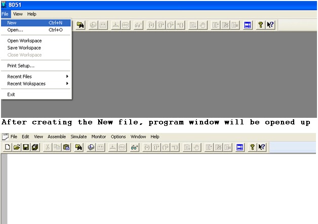
1. Before assembling the program, go to File -> New to create new .asm file. Now, write the assembly level language program for 8051 microcontrollers. It supports many 8051 microcontrollers IC.
2. After writing the program, save your file and click on Assemble(main menu bar)-> Assemble. It is similar to compile the program in Keil software. Selecting Assemble from the Assemble menu assembles the source in the currently active editor window. The number of errors found in the source will be displayed in the Output window.
3. Now, to check the program is correct or not. Click on the View-> Output option. Here, you will see the compile report of your program. If there is no error and no warning, you can simulate your program. If any errors are located double clicking on an error message will load the associated source code and position the cursor at the location of the line containing that error.

Simulation Steps:
The simulator allows you to step through your source code watching registers, flags, ports and RAM change. You can step into, step over and execute to source lines. Selecting Start Simulator via the Simulate menu enters the simulator. While the simulator is running it will control the display of source code and values in the associated windows (Registers, DRAM, IRAM, XRAM and Ports).
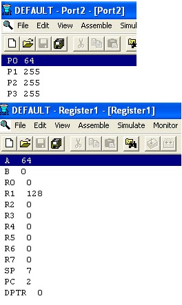
To open the Ports and Register window for the output, click on View menu and select the Port or Register option. To see both output window together, restore down the window.
This program is only recommended for beginners. If you are into advanced programming of other components, embedded systems, etc., you will need a more powerful program, like Keil RealView, Vissim, Proteus, etc.
Pros:
- Supports all microprocessors from the 8051 series.
- Real-time view of registers and RAM.
- Inbuilt text editor and assembler.
Cons:
- Not a good interface.
- Few features.
- The windows cannot be arranged easily.
-
Carta.tech
-
Man Pages
-
Executable programs or shell commands
-
mcu8051ide: None
-
Carta.tech
-
Packages
-
mcu8051ide
-
mcu8051ide: None
NAME MCU8051IDE — Integrated development environment for MCS-51 based microcontrollers
SYNOPSIS
mcu8051ide [—help] [-h] [—assemble asm_file] [—compile asm_file] [—iram-size size] [—code-size size] [—xram-size size] [—no-opt] [—quiet] [-q] [—nosplash] [—nocolor] [-n] [—version] [-V] [—defaults] [—disassemble] [—minimalized] [—config-file filename] [—check-libraries] [—ignore-last-session] [—open-project project] [—reset-user-settings] [—hex2bin input output] [—bin2hex input output] [—sim2hex input output] [—sim2bin input output] [—normalize-hex input] [—auto-indent input] [—comp-quiet] [—no-sim] [—no-bin] [—no-lst] [—no-hex] [—warning-level N]
DESCRIPTION
MCU 8051 IDE is tool for developing programs in assembly language and C languge (with SDCC) for micronstollers based on industrial standard MCS-51. It consist of editor with syntax highlight, auto completion, syntax validation and command line, compiler with support for macro-instructions (even macro in macro), simulator, scientific calculator, (rich) text editor for writing to do lists, hexadecimal editor and many other tools.
OPTIONS
-
—help, -h
-
Display short help text
-
—quiet, -q
-
Don’t display status of initialization progress on startup
-
—nosplash
-
Don’t show splash screen
-
—nocolor, -n
-
Disable color output
-
—version, -V
-
Display version information
-
—defaults
-
Start with default settings (low level GUI settings (panel sizes …))
-
—minimalized
-
Start with minimalized window
-
—config-file filename
-
Specify path to file containg user settings
-
—check-libraries
-
Check if all nessesary Tcl libraries are avaible
-
—ignore-last-session
-
Start with an empty session (no project will be opened at startup)
-
—open-project project
-
Open only this project
-
—reset-user-settings
-
Reset all user settings to defaults
-
—hex2bin input output
-
Convert Intel Hex 8 file to binary file
-
—bin2hex input output
-
Convert binary file to Intel Hex 8 file
-
—sim2hex input output
-
Convert MCU 8051 IDE v0.9.1 simulator file to Intel Hex 8 file
-
—sim2bin input output
-
Convert MCU 8051 IDE v0.9.1 simulator file to binary file
-
—normalize-hex input
-
Normalize IHEX8 file
-
—auto-indent input
-
Reformat indention in source code
-
—disassemble input
-
Disaseble IHEX8 code and store result in input.asm
-
—assemble asm_file
-
Assemble the asm_file and exit program
-
—compile asm_file
-
The same as —assemble
-
—iram-size size
-
Set size of internal data memory (eg. 1K or 1024) (default: 0x100)
-
—code-size size
-
Set size of program memory (eg. 1K or 1024) (default: 0x10000)
-
—xram-size size
-
Set size of external data memory (eg. 1K or 1024) (default: 0x10000)
-
—no-opt
-
Disable compiler optimalizations
-
—comp-quiet
-
Suppress compiler console output
-
—no-sim
-
Do not generate SIM file (for MCU 8051 IDE simulator)
-
—no-bin
-
Do not generate binary object code
-
—no-lst
-
Do not generate code listing
-
—no-hex
-
—warning-level N
-
Do not generate IHEX8 object code; 3 — Nothing; 2 — Errros only; 1 — Errors + Warnings; 0 — All (Default)
FILES
-
/usr/share/mcu8051ide/data/tips.conf
-
XML file containing tips. (Dialog «Tip of the day»)
-
/usr/share/mcu8051ide/data/mcus.conf
-
XML definition of supported MCUs. Warning: MCU 8051 IDE cannot run without this file. Please do not rely on format of this file. It may be changed in future version without any warning.
-
~/.mcu8051ide/last_session.conf
-
INI like definition of the last session.
-
~/.mcu8051ide/base.conf
-
Base configuration file. It contains only three configuration keys separated by spaces, please do not rely on format of this file. It may be changed in future version without any warning.
-
~/.mcu8051ide/config.conf
-
Main configuration file (INI like). Readable and I hope user friendly.
NOTES
List of supported porcessors is very short yet. Please post suggestions to [email protected] .
SUPPORTED PROCESSORS
8051, 80C51, 8052, AT89C2051, AT89C4051, AT89C51, AT89C51RC, AT89C52, AT89C55WD, AT89LV51, AT89LV52, AT89LV55, AT89S52, AT89LS51, AT89LS52, AT89S8253, AT89S2051, AT89S4051, AT89S52, AT89LS51, AT89LS52, AT89S8253, AT89S2051, AT89S4051, T87C5101, T83C5101, T83C5102, TS80C32X2, TS80C52X2, TS87C52X2, AT80C32X2, AT80C52X2, AT87C52X2, AT80C54X2, AT80C58X2, AT87C54X2, AT87C58X2, TS80C54X2, TS80C58X2, TS87C54X2, TS87C58X2, TS80C31X2, AT80C31X2
TO DO
Add support for more MCS-51 based microcontrollers. Fix all bugs.
AUTHOR
In this example I am using P89V51RD2 micro-controller, MCU 8051IDE for programming on micro-controller and p89pgm-0.1.0 for burning Hex file into the P89V51R2 chip.
MCU 8051 IDE
MCU 8051 IDE is a free software integrated development environment for microcontrollers based on 8051. MCU 8051 IDE has its own simulator and assembler (support for some external assemblers is also available). This IDE supports 2 programming languages: C and Assembly language. For C language it uses SDCC.
Installation on MCU 8051 IDE
Open Ubuntu Software center by clicking on Dash Home icon on the left top corner of your screen and searching for the Ubuntu Software Center application.

After opening Software canter you search for MCU 8051 IDE, when you find MUC 8051IDE you can click on More Info button. Before doing this make sure that INTERNET is connected.

After clicking on More Info the following window will appear. To install the IDE click on Install button.

Writing first C program in MCU 8051 IDE
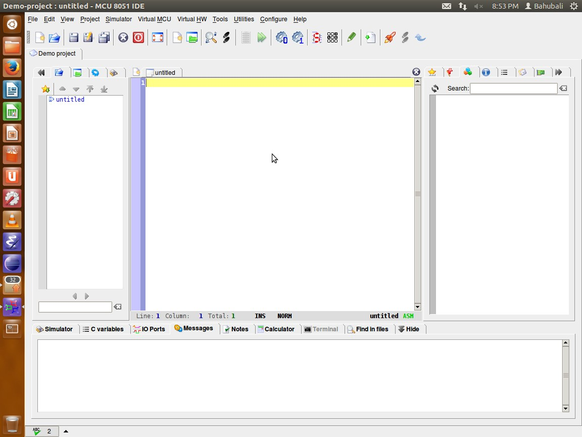
Open MCU 8051 IDE from Ubuntu applications. After opening IDE you can see a window something like a window shown below.
Creating new project
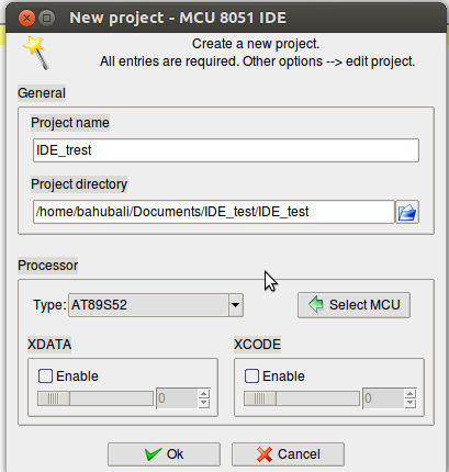
To create a new project click on Project → New from the main menu of IDE. After selecting the New option from project following window will appear. Write the project name and specify the project directory and select the processor AT89S51 (this will also work for P89V51RD2 IC ) and click on OK
Writing C program
Write the C program in the editor window of IDE, you can also copy and pest the
following code to your editor and save the file with ( .c ) extension.

/****************************************************
***** this code will blink the LEDs connected ******
*****on Port P0 ******
***** Author : Bahubali Fuladi ******
***** Date : 08032014 *****
****************************************************/
#include<at89x51.h>
/******** function for delay **********************/
void delay()
{
unsigned char i,j;
for(i=0;i<200;i++);
{
for(j=0;j<250;j++);
}
}
/******** main function *************************/
void main()
{
while(1)
{
P0 = 0x00; //shitch ON the LEDs
delay(); //wait for some time
P0 = 0xFF; //switch OFF the LEDs
delay(); //wait for some time
}
}
Compiling your C Program
To compile your C code click on Tool → Compile (F11) from main menu. If there is no error in C code then Compilation successful message will appear on Message window. The HEX file will automatically be generated after compilation.

Simulation
To start simulation click on simulator → start/shutdown (F2) from main menu, this will show all the SFRs and internal resistors of 8051 in the simulator window. You can also connect some virtual hardware from Virtual HW menu. After connecting the virtual hardware click on Simulator → Animate to see the output on virtual hardware, you can also see the contains of all SFRs during simulation.

Burning Hex File into the P89V51R2
To write Hex file into the chip you have to first download a tar file of software p89pgm-0.1.0 . The downloaded file will be in tar format (tar is compressed file format) so first you have to un-tar the tar file. To un-tar right click of the file icon and select Extract here option this will create a folder with name “p89pgm-0.1.0”. (Note : copy p89pgm-0.1.0 folder in to your Documents folder).
Making the executable of burning software
open the Linux Terminal by pressing keys Ctrl+Alt+T here you write the following commands.
First change the directory to p89pgm-0.1.0 by writing the following commands.
$ cd Documents/p89pgm0.1.0/
Now write the following command to create the executable
$ make
now you are ready to burn your chip.
connect your 8051 Kit to the PC using RS232 serial cable (USB to RS232 it serial port is not available on your PC) and power on your 8051 Kit. To burn the chip write the following command
$ ./p89pgm ../IDE_test/IDE_test.hex /dev/ttyS0
this command is divided into three parts first the name of executable starting with ( . / ) second the complete path of your hex file and third is the path of your serial port (if you are using USB to Serial module then give path /dev/ttyUSB0) after executing this command it will ask you to reset your 8051 board. And after reseting the hex file writing will start. Reset your board again after the burning process id done. and see the output by connecting LEDs on port0 of 8051.