-
Contents
-
Table of Contents
-
Troubleshooting
-
Bookmarks
Quick Links
Operation Manual
Multi-parameter
Transmitter M400
Transmitter Multi-parameter M400
30 413 330
Related Manuals for Mettler Toledo M400
Summary of Contents for Mettler Toledo M400
-
Page 1
Operation Manual Multi-parameter Transmitter M400 Transmitter Multi-parameter M400 30 413 330… -
Page 2
Subject to technical changes. © 05/2017 Mettler-Toledo GmbH, Process Analytics, Switzerland 30 413 330. Printed in Switzerland… -
Page 3
Transmitter M400 Operation Manual Multi-parameter Transmitter M400 © 05/2017 Mettler-Toledo GmbH, CH-8606 Greifensee, Switzerland Transmitter M400 Printed in Switzerland 30 413 330… -
Page 4
Transmitter M400 © 05/2017 Mettler-Toledo GmbH, CH-8606 Greifensee, Switzerland Transmitter M400 Printed in Switzerland 30 413 330… -
Page 5: Table Of Contents
________________________________________________________________ 10 Correct disposal of the unit ________________________________________________________________________ 11 2.3 Ex Classification _________________________________________________________________________________ 12 Unit Overview _________________________________________________________________________________________ 13 M400 1/2 DIN Versions ____________________________________________________________________________ 13 Menu Structure __________________________________________________________________________________ 14 Display ________________________________________________________________________________________ 15 Operating Elements _______________________________________________________________________________ 16 Entry of Data ____________________________________________________________________________________ 16 Selection Menus _________________________________________________________________________________ 16 ”Save changes”…
-
Page 6
Transmitter M400 6.7 Calibration of Optical Oxygen Sensors (ISM Sensors only) _________________________________________________ 46 6.7.1 One-Point Calibration _____________________________________________________________________ 47 6.7.2 Two-Point Calibration _____________________________________________________________________ 47 6.7.3 Process Calibration _______________________________________________________________________ 48 6.8 Calibration of Dissolved Carbon Dioxide Sensors (ISM Sensors only) ________________________________________ 49 6.8.1 One-Point Calibration _____________________________________________________________________ 49 6.8.2 Two-Point Calibration _____________________________________________________________________ 50 6.8.3 Process Calibration _______________________________________________________________________ 51… -
Page 7
Set Favorite ____________________________________________________________________________________ 104 Maintenance _________________________________________________________________________________________ 105 10.1 Front panel cleaning _____________________________________________________________________________ 105 Software History ______________________________________________________________________________________ 105 11.1 M400 Type 1 __________________________________________________________________________________ 105 11.2 M400 Type 2 __________________________________________________________________________________ 105 11.3 M400 Type 3 __________________________________________________________________________________ 105 Troubleshooting ______________________________________________________________________________________ 106 12.1 Conductivity (resistive) Error messages / Warning- and Alarm list for analog sensors _________________________________________________________________ 106 12.2 Conductivity (resistive) Error messages /… -
Page 8
Transmitter M400 Buffer tables _________________________________________________________________________________________ 120 16.1 Standard pH buffers _____________________________________________________________________________ 120 16.1.1 Mettler-9 _______________________________________________________________________________ 120 16.1.2 Mettler-10 _____________________________________________________________________________ 121 16.1.3 NIST Technical Buffers ____________________________________________________________________ 121 16.1.4 NIST standard buffers (DIN and JIS 19266: 2000–01) __________________________________________ 122 16.1.5 Hach buffers ___________________________________________________________________________ 122 16.1.6 Ciba (94) buffers ________________________________________________________________________ 123 16.1.7 Merck Titrisole, Riedel-de-Haën Fixanale _____________________________________________________ 123 16.1.8 WTW buffers ___________________________________________________________________________ 124… -
Page 9: Introduction
A menu-lockout feature, with password protection, is available to prevent the unauthorized use of the meter. The M400 Multi- parameter transmitter can be configured to use up to four analog and / or up to four relay outputs as well as HART communication protocol for process control.
-
Page 10: Safety Instructions
The following is a list of general safety instructions and warnings. Failure to adhere to these in- structions can result in damage to the equipment and / or personal injury to the operator. – The M400 Transmitter should be installed and operated only by personnel familiar with the transmitter and who are qualified for such work. – The M400 Transmitter must only be operated under the specified operating conditions (see chapter “14 Specifications“ on page 114).
-
Page 11: Correct Disposal Of The Unit
Transmitter M400 NOTE: RELAY CONTROL ACTION the M400 Transmitter relays will always de-energize on loss of power, equivalent to nor- mal state, regardless of relay state setting for powered operation. Configure any control system using these relays with fail-safe logic accordingly. NOTE: PROCESS UPSETS Because process and safety conditions may depend on consistent operation of this trans- mitter, provide appropriate means to maintain operation during sensor cleaning, replace- ment, or sensor or instrument calibration.
-
Page 12: Ex Classification
Transmitter M400 Ex Classification NOTE: The Ex classification is valid for the transmitters M400 Type 1, M400 Type 2 and M400 Type 3. Type plate Standards CSA Std C22.2 No. 213-16; UL 60079-0-2013 CAN/CSA-C22.2 No. 60079-0-15 UL 60079-15-2013 CAN/CSA-C22.2 No. 60079-15-16 EN 60079-0:2012/A11:2013 ANSI/ISA-12.12.01-2016 EN 60079-15:2010 Special condition of safe use 1. This equipment uses external non-metallic components, therefore may generate an ignition- capable level of electrostatic charge under certain extreme conditions.
-
Page 13: Unit Overview
Transmitter M400 Unit Overview The M400 transmitter is available as 1/2 DIN version. For dimensions refer to chapter “13 Ordering Information, Accessories and Spare Parts“ on page 113. M400 1/2 DIN Versions 150 mm /5.9″ 136 mm/ 5.35″ 26 mm 1.02″ 68 mm / 2.68″ 80 mm / 3.15″ 90 mm / 3.54″…
-
Page 14: Menu Structure
Transmitter M400 Menu Structure Below is the structure of the M400 menu tree: Menu Screen M400 Custom Key Calibration Configuration – iMonitor – Default: Favorite – Measurement – Calibrate Sensor – Messages – Depending – Calibrate Electronics – Analog Outputs – ISM Diagnostics on setting –…
-
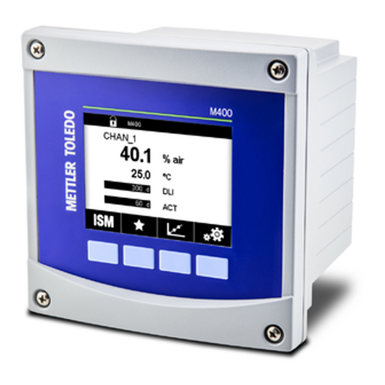
Page 15: Display
C ISM Menu screen NOTE: In the event of an alarm or other error conditions the M400 Transmitter will display a symbol in the head line of the display. This head line is blinking until the condition that caused it has been cleared (see chapter “12.5 Warning- and Alarm Indication“ on page 111).
-
Page 16: Operating Elements
Enter selected menu or item for soft key operation Entry of Data The M400 displays a keypad for modifying values. Press the e button and the transmitter will store the value. Press the ESC button to exit the keypad without changing data.
-
Page 17: Save Changes» Dialog
Transmitter M400 ”Save changes” Dialog If the M400 brings up the ”Save changes” dialog there are the following options. No will discard the entered values, Yes will save changes made and Cancel will bring you back to continue configuring. Security Passwords The M400 Transmitter allows a security lock-out of various menus. If the security lock-out feature of the transmitter has been enabled, a security password must be entered to allow ac- cess to the menu. See chapter “7.14 User Management“ on page 93.
-
Page 18: Activation Trend Display Screen
Transmitter M400 3.9.1 Activation Trend Display Screen While the M400 is displaying the Menu Screen, touch any measurement value line of the dis- play screen once to activate the trend display for that measurement. Or you can use custom key setup to access this function when operating with tactile keys. (See chapter “9 Custom Key“ on page 104.).
-
Page 19: Settings For Trend Display Screen
Transmitter M400 3.9.2 Settings for Trend Display Screen For setting configurations, touch any area of the graphic trend display to go to the pop-up win- dow of this measurement parameter. Settings are at the default values. However, these settings may be changed when options are available, as needed.
-
Page 20: Installation Instruction
Transmitter M400 Installation instruction Unpacking and inspection of equipment Inspect the shipping container. If it is damaged, contact the shipper immediately for instructions. Do not discard the box. If there is no apparent damage, unpack the container. Be sure all items shown on the packing list are present.
-
Page 21: Mounting Procedure — 1/2 Din Version
Transmitter M400 4.2.2 Mounting Procedure – 1/2 DIN Version 1/2 DIN versions transmitters are designed for the following mounting versions: panal mount, wall mount or pipe mount. For wall mount the integral rear cover is used. Optional hardware accessories are available that allow for panel- or pipe-mount. Refer to section “13 Ordering Information, Accessories and Spare Parts“ on page 113. Assembly: Fig. 5: Assembly 1 1 piece M25 x 1.5 cable gland 2 4 pieces M20 x 1.5 cable glands…
-
Page 22: 1/2 Din — Panel Mounting
Transmitter M400 4.2.3 1/2 DIN – Panel Mounting To insure a good seal, the panel or door must be flat and have a smooth finish. Textured or rough surfaces are not recommended and may limit the effectiveness of the gasket seal provid- Fig. 6: Panel mounting…
-
Page 23: 1/2 Din Version — Wall Mounting
Transmitter M400 4.2.4 1/2 DIN Version – Wall Mounting DANGER! Mortal danger by electric shock or risk of electrical shock: The maximum screw-in depth of the mounting holes in the housing is 12 mm (0.47 inch). Do not exceed maximum screw-in depth. Fig. 7: Wall mounting with wall mounting kit Mount wall mounting kit to the housing. Do not exceed maximum screw-in depth.
-
Page 24: 1/2 Din Version — Pipe Mounting
1/2 DIN Version – Pipe Mounting ∅ 40 … ∅ 60 mm ∅ 1.57 … ∅ 2.36″ Fig. 8: Pipe mounting 1/2 DIN version – Use only manufacturer-supplied components for pipe-mounting the M400 transmitter. See chapter “13 Ordering Information, Accessories and Spare Parts“ on page 113 for ordering information. – Tighten the fixing screws with a tightening torque of 2 to 3 Nm. Electrical Connection DANGER! Mortal danger by electric shock: Power off instrument during electrical connection.
-
Page 25: Terminal Definition
Transmitter M400 Terminal Definition Fig. 9: M400 1/2 DIN versions 1 TB3 – Terminal block for sensor connection 2 Terminals for supply voltage 3 TB1 – Terminal block for relay outputs 4 HART 5 TB2 – Terminal block for analog output and digital input signals 6 USB Device –…
-
Page 26: Tb1 Terminal Definition — All Transmitter Versions
Transmitter M400 4.4.1 TB1 Terminal definition – All transmitter versions Terminal Description Contact rating NC 1 250 V AC or 30 V DC, 3 A COM 1 NO 1 NC 2 250 V AC or 30 V DC, 3 A COM 2 NO 2 NO 3 250 V AC or 30 V DC, 0.5 A, 10 W…
-
Page 27: Tb3 Terminal Definition — Analog Sensors
Transmitter M400 4.4.3 TB3 Terminal definition – Analog sensors Conductivity 2-e / 4-e Terminal Function Color Cnd inner 1 White Cnd outer 1 White / blue Cnd outer 1 – Not used – Cnd outer 2 – Cnd inner 2 Blue Cnd outer 2 (GND) Black Not used –…
-
Page 28
Transmitter M400 Amperometric oxygen and 0zone – Analog sensors (continued) Oxygen Ozone InPro 6800 InPro 6900 InPro 6950 Hi Perfor- InPro 6510 mance Oxygen Terminal Function Color Color Color Color Color Not used – – – – – Anode Anode – – – –… -
Page 29: Tb3 Terminal Definition — Ism Sensors
Transmitter M400 4.4.4 TB3 Terminal definition – ISM sensors pH / ORP, amperometric oxygen, dissolved ozone, conductivity 4-e, dissolved CO Terminal Function Color 1 to 11 Not used – 1-wire Transparent (cable core) Red (shield) RS 485-B – RS 485-A – – GND 24 V – 24 V –…
-
Page 30: Placing Transmitter In, Or Out, Of Service
Transmitter M400 Placing transmitter in, or out, of service Placing transmitter in service After connecting the transmitter to power supply circuit, it will be active as soon as the circuit is powered. Placing transmitter out of service First disconnect the unit from the main power source, then disconnect all remaining electrical connections.
-
Page 31: Calibration
Transmitter M400 Calibration For the menu structure refer to chapter “3.9 Graphic Trend Measurement“ on page 17. PATH: H Cal NOTE: During calibration, the outputs for the corresponding channel will default to be held at their current values until 20 seconds after the calibration menu is exited. A flashing H appears in the upper right corner of the display while outputs are held. Refer to chapter “7.3 Analog Out- puts“ on page 76 and chapter “7.4 Set Points“ on page 77 to change the HOLD output…
-
Page 32: Terminate Sensor Calibration
(ISM Sensors only) 6.2.1 Conductivity Calibration of UniCond 2-e and UniCond 4-e Sensors The M400 provides the ability to perform a one-point, two-point or process conductivity or resis- tivity calibration for 2-e-sensors and 4-e-sensors. NOTE: When performing calibration on a conductivity sensor, results will vary depending on the method, calibration apparatus and / or quality of reference standards used to perform the calibra- tion.
-
Page 33
Transmitter M400 The following menus can be called up: Unit: Choose between the units for conductivity (S/cm) and resistivity ( Ω -cm). Method: Select the desired calibration procedure. Available are 1-point, 2-point or process calibration. Options: The desired compensation mode for the calibration process can be selected. Choices are “None”, ”Standard”, “Light 84”, “Std 75 °C”, ”Linear 25°C”, ”Linear 20°C”, “Glycol.5”, “Glycol1”, “Cation”, “Alcohol” and “Ammonia”. None does not make any compensation of the measured conductivity value. The uncompen- sated value will be displayed and proceeded. -
Page 34: One-Point Calibration
Press the input field for Point1 to enter the value for the calibration point. The M400 displays a keypad for modifying the value. Press the e button and the transmitter will take over the value.
-
Page 35: Two-Point Calibration
The second value displayed on the screen is the value being measured by the transmitter and sensor in the units selected by the user. Press the input field for Point1 to enter the calibration point. The M400 displays a keypad for modifying the value. Press the e button to accept the value.
-
Page 36: Process Calibration
Transmitter M400 The screen shows the entered value for the second reference solution (1st line) and the mea- sured value of the M400 (2nd line). Press the Next button to start the calculation of the calibration results. The display shows the value for the slope and the offset as the result of the calibration. The calibration values are stored in the calibration history. To save (press button SaveCal) or to discard (press button Cancel). Use the Back button to go one step back in the calibration procedure.
-
Page 37: Temperature Calibration Of Unicond 2-E Sensors And Unicond 4-E Sensors
The calibration values are stored in the calibration history. To save (press button SaveCal) or to discard (press button Cancel). Use the Back button to go one step back in the calibration procedure. 6.2.2 Temperature Calibration of UniCond 2-e Sensors and UniCond 4-e Sensors The M400 provides the ability to perform a one-point or two-point calibration for the temperature sensor of the UniCond 2-e and UniCond 4-e. Enter the menu Calibrate Sensor (see chapter “6.1 Sensor Calibration“ on page 31; PATH: H Cal Calibrate Sensor). The following menus can be called up: Unit: Choose between the units °C and °F.
-
Page 38: Two-Point Calibration
The second value displayed on the screen is the value being measured by the transmitter and sensor. Press the input field or EDIT button for Point1 to enter the value for the calibration point. The M400 displays a keypad for modifying the value. Press the e button to accept the value. The screen shows the entered value for the reference solution (1st line) and the measured value of the M400 (2nd line).
-
Page 39
The second value displayed on the screen is the value being measured by the transmitter and sensor in the units selected by the user. Press the input field for Point1 to enter the calibration point. The M400 displays a keypad for modifying the value. Press the e button and to accept the value. -
Page 40: Calibration Of Cond2E Sensors Or Cond4E Sensors
Calibration of Cond2e Sensors or Cond4e Sensors PATH: H Cal Calibrate Sensor The M400 provides the ability to perform a one-point, two-point or process conductivity or resis- tivity calibration for 2-e-sensors and 4-e-sensors. NOTE: When performing calibration on a conductivity sensor, results will vary depending on the method, calibration apparatus and / or quality of reference standards used to perform the calibra- tion.
-
Page 41: Two-Point Calibration
Transmitter M400 6.3.2 Two-Point Calibration With 2-e-sensors or 4-e-sensors a two-point calibration is always performed as an offset and slope calibration. The following procedure shows the calibration with a 2-e-sensor. The calibra- tion with a 4-e-sensor works respectively. Press the button Cal for starting calibration.
-
Page 42: Ph Calibration
Place the electrode in the buffer solution and press the Next button. The display shows the buffer the transmitter has recognized Point 1 and the measured value. The M400 checks the stability of the measuring signal and proceeds as soon as the signal is sufficiently stable.
-
Page 43: Two-Point Calibration
Place the electrode in buffer solution 1 and press Next button. The display shows the buffer the transmitter has recognized Point 1 and the measured value. The M400 checks the stability of the measuring signal and proceeds as soon as the signal is sufficiently stable.
-
Page 44: Orp Calibration Of Ph Sensors
Transmitter M400 ORP Calibration of pH Sensors PATH: H Cal Calibrate Sensor For pH sensors with solution ground based on ISM technology the M400 Transmitter gives the option to make, in addition to the pH calibration, an ORP calibration. NOTE: In case of choosing ORP calibration the parameters defined for pH (see chapter “7.1.4.2 pH Settings“ on page 67) will not be considered. For pH sensors, the M400 Transmitter fea-…
-
Page 45: One-Point Calibration
Place the sensor in air or the calibration gas and press Next button Enter the value for the calibration point (Point1). The M400 checks the stability of the measuring signal and proceeds as soon as the signal is sufficiently stable. NOTE: If option Stability is set to Manual press ‘Next’ after the measuring signal is stable enough to go on with the calibration.
-
Page 46: Process Calibration
Transmitter M400 6.6.2 Process Calibration A process calibration of oxygen sensors is always either a slope or an offset calibration. Choose Slope or Offset calibration through pressing the corresponding field. Press the Cal button to start calibration. Take a sample and press the e button to store the current measuring value. To show the ongo- ing calibration process, P is blinking in the Start and Menu screen if the related channel is se- lected in the display.
-
Page 47: One-Point Calibration
Place the sensor in air or the calibration gas and press Next button Enter the value for the calibration point (Point1). The M400 checks the stability of the measuring signal and proceeds as soon as the signal is sufficiently stable. NOTE: If option Stability is set to Manual press ‘Next’ after the measuring signal is stable enough to go on with the calibration.
-
Page 48: Process Calibration
Transmitter M400 The M400 checks the stability of the measuring signal and proceeds as soon as the signal is sufficiently stable. NOTE: If option Stability is set to Manual press ‘Next’ after the measuring signal is stable enough to go on with the calibration.
-
Page 49: Calibration Of Dissolved Carbon Dioxide Sensors (Ism Sensors Only)
Place the electrode in the buffer solution and press the Next button. The display shows the buffer the transmitter has recognized Point 1 and the measured value. The M400 checks the stability of the measuring signal and proceeds as soon as the signal is sufficiently stable.
-
Page 50: Two-Point Calibration
Place the electrode in buffer solution 1 and press Next button. The display shows the buffer the transmitter has recognized Point 1 and the measured value. The M400 checks the stability of the measuring signal and proceeds as soon as the signal is sufficiently stable.
-
Page 51: Process Calibration
Transmitter M400 6.8.3 Process Calibration With CO2 sensors a process calibration is always performed as an offset calibration. Press the Cal button to start calibration. Take a sample and press the e button to store the current measuring value. To show the ongo- ing calibration process, P is blinking in the Start and Menu Screen if the related channel is se- lected in the display.
-
Page 52: One-Point Calibration
Transmitter M400 6.9.1 One-Point Calibration With the thermal conductivity sensor a one-point calibration is always performed as a slope cal- ibration. Press the button Cal for starting calibration. Expose the TC-Sensor to a reference gas of a known CO concentration and press Next button.
-
Page 53: Calibration Of O Sensors
The second value displayed on the screen is the value being measured by the transmitter and sensor in the units selected by the user. Press the input field for Point1 to enter the value for the calibration point. The M400 displays a keypad for modifying the value. Press the e button to accept the value.
-
Page 54: Process Calibration
Transmitter M400 The display shows the value for the slope and the offset as result of the calibration. For ISM (digital) sensors select “Adjust”, “Calibrate” or “Cancel” to finish calibration. For Analog sensors select “SaveCal” or “Cancel” to finish calibration. See “6.1.2 Terminate Sensor Calibra- tion“ on page 32. Use the Back button to go one step back in the calibration procedure 6.10.2 Process Calibration Select the Process calibration method. A Process calibration of O sensors can be performed as a slope or offset calibration.
-
Page 55: Calibration Of A Tunable Diode Laser (Tdl) Analyzer
Transmitter M400 The display shows the value for the slope and the offset as the result of the calibration. For ISM (digital) sensors select “Adjust”, “Calibrate” or “Cancel” to finish calibration. For Analog sensors select “SaveCal” or “Cancel” to finish calibration. See “6.1.2 Terminate Sensor Calibra- tion“ on page 32. Use the Back button to go one step back in the calibration procedure. 6.11 Calibration of a tunable diode laser (TDL) analyzer PATH: HCalCalibrate Sensor Calibration for a TDL sensor is performed as a one-point or process calibration.
-
Page 56: Process Calibration For Tdl Gas Sensors
Place the sensor in the calibration gas (e.g. air). Press NEXT. Enter the value for the calibration point then press Next to start the calculation. The M400 checks the deviation of the measuring signal and proceeds as soon as the signal is sufficiently stable. The display shows the value of the sensor as the result of calibration.
-
Page 57: Sensor Verification
Transmitter M400 Enter the value for the calibration point then press Next to start the calculation. The M400 checks the deviation of the measuring signal and proceeds as soon as the signal is sufficiently stable. The display shows the value of the sensor as the result of calibration.
-
Page 58: Unicond 2-E Electronics Calibration (Ism Sensor Only)
Transmitter M400 6.13 UniCond 2-e Electronics Calibration (ISM Sensor only) The M400 provides the ability to calibrate or verify the electronic circuits of UniCond 2-e conduc- tivity sensors. UniCond 2-e sensors have 3 resistance range circuits that require individual cali- bration. These measuring circuits are calibrated using the THORNTON ISM Conductivity Sensor Calibration Module part number 58 082 305 and supplied Y-connector. Before calibration, re- move the sensor from the process, rinse with deionized water and allow to completely dry. Pow- er the transmitter and sensor at least 10 minutes prior to calibration to assure stable operating temperature of the circuitry.
-
Page 59: Resistance (Analog Sensors Only)
Connect source 1 to input terminals. Each resistance range consists of a two-point calibration. Press the Next button to continue. Press input field for Point1 to enter the calibration point. The M400 displays a keypad for modi- fying the value. Press the e button and the transmitter will take over the value.
-
Page 60: Temperature (Analog Sensors Only)
Transmitter M400 Press input field for Point2 to enter the calibration point. The M400 displays a keypad for modi- fying the value. Press the e button to accept the value. The second line shows the current value. The display shows the value for the slope and the offset as the result of the calibration.
-
Page 61: Voltage (Analog Sensors Only)
Connect source 1 to input terminals. Press the Next button to start the calibration process. Press input field for Point1 to enter the calibration point. The M400 displays a keypad for modi- fying the value. Press the e button to accept the value.
-
Page 62: Rg (Analog Sensors Only)
Transmitter M400 6.14.5 Rg (Analog Sensors only) Rg Diagnostic calibration is performed as a two-point calibration. Perform current calibration according to chapter “6.14.3 Voltage (Analog Sensors only)“ on page 61. 6.14.6 Rr (Analog Sensors only) Rr Diagnostic calibration is performed as a two-point calibration. Perform current calibration according to chapter “6.14.3 Voltage (Analog Sensors only)“ on page 61. 6.15 Analog Output Calibration PATH: H CAL Calibrate Analog Outputs Each analog output can be calibrated at 4 and 20 mA.
-
Page 63: Analog Input Calibration
If “SaveCal” is chosen, ”Calibration Saved Successfully” is displayed. 6.17 Maintenance PATH: H CAL Maintenance The different channels of the M400 Transmitter can be switched manually into HOLD state. Fur- thermore a cleaning cycle can be started / stopped manually. Press Start button for Manual HOLD to activate the HOLD state for the selected channel. To deac- tivate the HOLD state again, press the Stop button, which is now displayed instead of the Start button. Press the Start button for Manual Clean to switch the cleaning relay to the state for starting a cleaning cycle.
-
Page 64: Configuration
Press the right input field in the line of the setting for the transmitter. A parameter for the corre- sponding channel is chosen through pressing the according field. If Auto is selected, M400 Transmitter automatically recognizes the ISM sensor type. The channel can also be fixed to a certain measurement parameter, depending on the type of trans mitter.
-
Page 65: Ism Sensor
Transmitter M400 7.1.3 ISM sensor Select sensor type ISM. If an ISM sensor is connected, the transmitter automatically (Parameter = Auto) Recognizes the type of sensor. You can also fix the transmitter to a certain measurement parameter e.g. “pH”, depending on the type of transmitter you have. M400 Type 1 M400 Type 2 M400 Type 3 pH / ORP • • • pH / pNa • • •…
-
Page 66: Parameter Related Settings
Transmitter M400 Option Description None No averaging or filtering Equivalent to a 3 point moving average Medium Equivalent to a 6 point moving average High equivalent to a 10 point moving average Special Averaging depending on signal change (normally High averaging, but Low averaging for large changes in input signal) Custom 1 point to 15 points moving average selection 7.1.4 Parameter Related Settings PATH: H CONFIG Meas Parameter Setting Measuring and calibration parameters can be set for the parameters pH, conductivity and oxy- gen.
-
Page 67: Ph Settings
Transmitter M400 Linear 20 °C compensation adjusts the reading by a coefficient or factor expressed as %/°C (deviation from 20 °C). Use only if the solution has a well-characterized linear temperature coef- ficient. The factory default setting is 2.0% /°C. Glycol.5 compensation matches the temperature characteristics of 50% ethylene glycol in water. Compensated measurements using this solution may go above 18 Mohm-cm. Glycol1 compensation matches the temperature characteristics of 100% ethylene glycol. Com- pensated measurements may go well above 18 Mohm-cm. Cation compensation is used in power industry applications measuring the sample after a cat- ion exchanger. It takes into account the effects of temperature on the dissociation of pure water in the presence of acids.
-
Page 68
Transmitter M400 IP is the isothermal point value (Default = 7.000 for most applications). For specific compensa- tion requirements or non standard inner buffer value, this value can be changed. Adjust the value of the parameter STC pH/°C. STC is the solution temperature coefficient in units of pH / °C referenced to the defined tempera- ture. (Default = 0.000 pH/°C for most applications). For pure waters, a setting of – 0.016 pH / °C should be used. For low conductivity power plant samples near 9 pH, a setting of – 0.033 pH / °C should be used. If the value for STC is ≠ 0.000 pH/°C an additional input field for the reference temperature will be displayed. The value for pH Ref Temperature indicates to which temperature the solution temperature com- pensation is referenced. The displayed value and the output signal is referenced to this tempera- ture. Most common reference temperature is 25°C. -
Page 69: Settings For Oxygen Measurement Based On Amperometric Sensors
The applied process pressure can be entered by choosing Edit or measured over the analog in- put of the M400 by choosing Ain_1. If Edit has been chosen an input field for entering the value manually is displayed on the screen.
-
Page 70: Settings For Oxygen Measurement Based On Optical Sensors
The applied process pressure can be entered by choosing Edit or measured over the analog in- put of the M400 by choosing AIN_1. If Edit has been chosen an input field for entering the value manually is displayed on the screen.
-
Page 71: Dissolved Carbon Dioxide Settings
Select the LED Mode of the sensor. There are the following options. Off: LED is permanently switched off. On: LED is permanently switched on. Auto: T he LED is switched on as long as the measured media temperature is smaller then Toff (see next value) or switched off through a digital input signal (see chapter “7.10 Digital Inputs“ on page 85). NOTE: If the LED is switched off, no oxygen measurement is performed. Enter the limit for the measuring temperature to switch off the LED of the sensor automatically for the M400 through the parameter Toff. If the media temperature is higher then Toff, the LED will switched off. The LED will be switched on as soon as the media temperature falls below Toff –3 K. This function give the option to in- crease the lifetime of the OptoCap by switching off the LED during SIP or CIP cycles. NOTE: This function is only active if the LED Mode is set to “Auto”. 7.1.4.5 Dissolved Carbon Dioxide Settings If an dissolved carbon dioxide sensor is connected while during the channel setup (see chapter “7.1.1 Channel Setup“ on page 64) Auto or CO has been chosen, the buffer used for calibra- tion and the parameters stability, salinity, HCO , TotPres can be set resp.
-
Page 72: Settings For Thermal Conductivity Dissolved Co Measurement (Co Hi)
Transmitter M400 7.1.4.6 Settings for Thermal Conductivity Dissolved CO Measurement (CO If during the channel setup (see chapter “7.1.1 Channel Setup“ on page 64) the parameter Hi has been chosen, the parameters stability (manual/auto) and CO solubility (CO -solu- bility and Temperature Factor), be set resp. adjusted. Select the required Stability of the measuring signal during the calibration procedure. Choose manual if the user will decide when a signal is stable enough to complete the calibration. Select Auto if an automatic stability control of the sensor signal during calibration through the transmit- ter should be done.
-
Page 73: Settings For Tunable Diode Laser (Tdl) Analyzer
Transmitter M400 7.1.4.7 Settings for Tunable Diode Laser (TDL) Analyzer (PATH: HConfigMeasurementTDL quick setup) If a TDL analyzer is connected, while during the channel setup (see chapter “7.1.1 Channel Set- up“ on page 64) Auto has been chosen, the parameters Pressure, Temperature and Path length can be set or adjusted. The same parameters will be displayed if during the channel set- up not Auto but TDL has been set. Press the button for Pressure.
-
Page 74: Setting The Correct Process Side Purging
Transmitter M400 Last, select the initial optical path length corresponding to the probe length installed: – 290 mm probe: 200 mm – 390 mm probe: 400 mm – 590 mm probe: 800 mm This initial value is valid when instrument purging on the instrument and on the process side is running. Depending on the process conditions and after the optimum of the process purging flow has been found (see next chapter), this value may have to be slightly adapted.
-
Page 75: Concentration Curve Table
Transmitter M400 7.1.5 Concentration Curve Table To specify a concentration curve for customer-specific solutions, up to 5 concentration values can be edited in a matrix together with up to 5 temperatures. To do so the desired values are ed- ited under the concentration curve table menu. Beside the temperature values, the conductivity and concentration values for the corresponding temperature are edited.
-
Page 76: Analog Outputs
Transmitter M400 Analog Outputs PATH: H CONFIG Analog Outputs See the following explanation to get more details about the different settings for the analog out- puts. Press the input field in the line of the setting for Aout and select the desired output signal for configuration by pressing button #1 for output signal 1, #2 for output signal 2 etc.
-
Page 77: Set Points
Transmitter M400 Max1 is the maximum limit of the low range on auto-range. The maximum value for the high range on auto-range is set with the Max Value. Both ranges have the same minimum value that is set through Min Value. If the input value is higher then value of Max1, the transmitter switches automatically to the second range.
-
Page 78: Ism Setup (Ism Sensors Only)
Transmitter M400 Enter the Delay time in seconds. A time delay requires the setpoint to be exceeded continuously for the specified length of time before activating the relay. If the condition disappears before the delay period is over, the relay will not be activated. Enter the value for the Hysteresis. A hysteresis value requires the measurement to return within the setpoint value by a specified percentage before the relay is deactivated.
-
Page 79
Transmitter M400 Press the input field for TTM Reset. Select Yes if Time To Maintenance (TTM) for the sensor should be reset to the initial value. Time To Maintenance needs to be reset after the following operations. pH sensors: manual maintenance cycle on the sensor. Oxygen or ozone sensor: m anual maintenance cycle on the sensor or exchanging of the mem- brane of the sensor NOTE: By connecting a sensor, the actual value for TTM of the sensor is read out from the sensor. -
Page 80: Cip Cycle Limit
Transmitter M400 7.5.2 CIP Cycle Limit If a pH/ORP, oxygen or conductivity sensor is connected during the channel setup (see chapter “7.1.1 Channel Setup“ on page 64) Auto has been chosen the parameter CIP Cycle Limit can be set or adjusted. The menu CIP Cycle Limit will also be displayed if during the channel setup not Auto but one of the mentioned sensors has been set. Press the button CIP Cycle Limit. Press the button in the input field for the parameter Max Cycles and enter the value for the maxi- mum CIP cycles.
-
Page 81: Autoclave Cycle Limit
Transmitter M400 Press the button in the input field for the parameter Temp and enter the temperature, which has to be exceeded, that the a SIP cycle will be counted. SIP Cycles will be automatically recognized by the transmitter. Since SIP cycles will vary in in- tensity (duration and temperature) for each application the algorithm of the counter recognizes an increase of the measurement temperature above the level defined through the value for Temp.
-
Page 82: Dli Stress Adjustment
Transmitter M400 7.5.5 DLI Stress Adjustment If a pH/ORP is connected during the channel setup (see chapter “7.1.1 Channel Setup“ on page 64) Auto has been chosen the parameter DLI Stress Adjustment can be adjusted. With this setting the user can adjust the sensor sensitivity to the stress of his specific application for the DLI calculation. Browse to page 2 of “ISM Setup”. Press the button DLI Stress Adjustment. Select between low / medium / high for the Type of DLI Stress Adjustment.
-
Page 83: Reset Counters For Unicond 2-E Sensors
Transmitter M400 7.5.7 Reset Counters for UniCond 2-e Sensors For UniCond 2-e sensors, the following counters can be reset: High Temp and High Conductivity. Press the button Reset Counters. Select Yes for the desired counter to be reset and press enter. The reset will be done after saving the changes. Press e to exit the menu Reset Counters. 7.5.8 Set Calibration Interval for UniCond 2-e Sensors For UniCond 2-e sensor the Cal Interval (calibration interval) can be set. Press the button Cal Interval. Press the input field next to Cal Interval and enter the value for the calibration interval. Based on this value the Time To Calibration (TTCal) will be calculated by the transmitter. Press e to ac-…
-
Page 84: Ism / Sensor Alarm
Transmitter M400 ISM / Sensor Alarm PATH: H CONFIG ISM / Sensor Alarm See the following explanation to get more details about the different settings for ISM / Sensor Alarm. Depending on the assigned sensor the Events that will be considered for generating an alarm can be selected.
-
Page 85: Display Setup
PATH: H CONFIG Display Setup See the following explanation to get more details about the different settings for Display Setup Enter the name for the M400 Transmitter (Instrument Tag). The instrument tag will also be dis- played on the line at the top of the Start Screen and Menu Screen.
-
Page 86: System
Transmitter M400 7.11 System PATH: H CONFIG System See the following explanation to get more details about the different settings for the System. Select the desired Language. The following languages are available: English, French, German, Italian, Spanish, Portuguese, Russian, Chinese, Korean or Japanese. Enter Date&Time. The automatic change-over from summertime to wintertime and vice-versa frees the users from having to correct the time twice a year.
-
Page 87: Pid Controller
Transmitter M400 7.12 PID Controller PATH: H CONFIG PID Controller PID control is proportional, integral and derivative control action that can provide smooth regula- tion of a process. Before configuring the transmitter, the following process characteristics must be identified.
-
Page 88
Process Variable See the following explanation to get more details about the different settings for PID Controller. The M400 provides to one PID controller. Press the related button for the assignment of the channel (Chan). Select the channel, which has to be linked to the PID Controller. To deactivate the PID controller press None. -
Page 89
117). Do not connect to this relays higher current devices. If the PID Mode is set to Relay PL, the Puls Length for the output signal of the transmitter can be adjusted. Press the button for Pulse Length and the M400 displays a keypad for modifying the value. Enter the new value in the unit seconds according to the table below and press e. NOTE: A longer pulse length will reduce wear on the solenoid valve. The % “on” time in the cy- cle is proportional to the control output. -
Page 90
Transmitter M400 Relay Position = #3 Relay Position = #4 Pulse Frequency (PF) Max allowed for the Controlling concentrating Conductivity Controlling dilution water pump used (typically chemical feed 60–100 pulses / minute) Max allowed for the pH / ORP Feeding base Feeding acid pump used (typically 60–100 pulses / minute) Max allowed for the… -
Page 91: Service
Transmitter M400 7.13 Service PATH: H CONFIG Service This menu is a valuable tool for troubleshooting and provides diagnostic functionality for the fol- lowing items: Calibrate TouchPad, Set Analog Outputs, Read Analog Outputs, Read Analog In- puts, Set Relays, Read Relays, Read Digital Inputs, Memory and Display. Select through the parameter System the desired item for diagnostic by pressing the according field.
-
Page 92: Memory
Transmitter M400 7.13.6 Memory If Memory is selected the transmitter will perform a memory test of all connected transmitter boards and ISM sensors. 7.13.7 Display The transmitter shows every 5 seconds red, green, blue, grey and dark grey display and returns afterwards to the menu Service.
-
Page 93: User Management
Transmitter M400 7.14 User Management PATH: H CONFIG User Management This menu allows for the configuration of different user and administrator passwords, as well as setting up a list of allowed menus for the different users. The administrator has rights to access all menus.
-
Page 94: Reset
See the following explanation to get more details about the different option to reset data and / or configurations. 7.15.1 System Reset This menu option allows the reset of the M400 Transmitter to the factory default settings (set- points off, analog outputs off, passwords, etc.). Furthermore the calibration factors for analog in- and outputs, meter etc. can be set to the last factory values. Press the input field for Options and select System.
-
Page 95: Usb
At each print cycle, the output will include a header line with data and time based on the M400 internal clock, and one line for each configured measurement including channel, measurement descriptor, mea- surement value and unit of measure.
-
Page 96: Usb Data Logging
At each logging cycle, the output will include a header line with data and time based on the M400 internal clock, and one line for each configured measurement including channel, measurement descriptor, measurement value and unit of measure.
-
Page 97: Configuration Via Usb
Transmitter M400 NOTE: A “Rec” symbol will blink while the data is logging to a USB memory stick on the top of the menu screen. 7.17 Configuration via USB PATH: HConfigConfiguration via USB This menu allows the configuration of the current transmitter to be saved to a USB memory stick as a file or upload the configuration from a USB memory stick.
-
Page 98: Ism
Transmitter M400 For the menu structure refer to chapter 3.9 “Graphic Trend Measurement”. PATH: H ISM iMonitor PATH: H ISM iMonitor The iMonitor gives an overview of the current state of the complete loop at a glance. The iMonitor of the first channel is displayed on the screen. To browse through the iMonitor for the different channels press >…
-
Page 99: Messages
ISM Diagnostics PATH: H ISM ISM Diagnostics The M400 Transmitter provides for all ISM sensors a diagnostic menu. Access the menu Chan- nel and select the channel by pressing the related input field. Depending on the selected channel and assigned sensor different diagnostic menus are dis- played.
-
Page 100: Ph/Orp, Oxygen, O , Cond4E Sensors And Tdl
Transmitter M400 8.3.1 pH/ORP, Oxygen, O , Cond4e Sensors and TDL If an pH/ORP, oxygen, O or Cond4e sensor is connected, the diagnostic menus cycles, sensor monitor and max. temperature are available. Press the Cycle button and the information for CIP, SIP and Autoclave cycles of the connected sensor are displayed.
-
Page 101: Calibration Data
Calibration Data PATH: H ISM Calibration Data The M400 Transmitter provides a calibration history for all ISM sensors. Depending on the as- signed sensor different data is available for the calibration history. See the following explanation to get more details about the different data available for the cali- bration history.
-
Page 102: Sensor Info
PATH: H ISM Sensor Info The model, hardware and software version, last calibration date as well as the product and seri- al number of the ISM sensors, that are connected to the M400 Transmitter can be displayed on the screen.
-
Page 103: Hw / Sw Version
M400 Transmitter itself or the different boards, that are plugged in can be displayed on the screen. The data of the transmitter is displayed on the screen. Press the input field in the line of M400. To select the data of the desired board or the transmitter itself press the corresponding field.
-
Page 104: Custom Key
Transmitter M400 Custom Key PATH: H Config Custom Key Setup This menu allows the setting of a customize menu to the second left button on the menu screen as a shortcut. The custom key is a convenient option for soft key operation especially when touch-screen is not used.
-
Page 105: Maintenance
Maintenance 10.1 Front panel cleaning Clean the surfaces with a soft damp cloth and dry the surfaces with a cloth carefully. Software History 11.1 M400 Type 1 Software version Release date Software changes Documentation / Issue 30 413 330 V1.0.0 March 2016 –…
-
Page 106: Troubleshooting
Transmitter M400 Troubleshooting If the equipment is used in a manner not specified by Mettler-Toledo, the protection provided by the equipment may be void. Review the table below for possible causes of common problems: Problem Possible Cause – No power to M400. Display is blank. – Hardware failure. – Sensor improperly installed. – Incorrect units multiplier entered. – Temperature compensation incorrectly set or disabled. Incorrect measurement readings. – Sensor or transmitter needs calibration.
-
Page 107: Conductivity (Resistive) Error Messages / Warning- And Alarm List For Ism Sensors
Transmitter M400 12.2 Conductivity (resistive) Error messages / Warning- and Alarm list for ISM sensors Alarms Description Watchdog time-out* SW/System fault Dry Cond sensor* Cell running dry (no measurement solution) Cell deviation* Multiplier out of tolerance** (depends on sensor model). * A ctivate this function in the transmitter settings (see chapter “7.7 ISM / Sensor Alarm“ on page 84 PATH: Menu/ISM/Sensor Alarm). ** For further information refer to the sensor documentation 12.3…
-
Page 108: Orp Messages
Transmitter M400 12.3.2 ORP messages Warnings* Description Warning ORP ZeroPt > 30 mV Zero offset too big Warning ORP ZeroPt < – 30 mV Zero offset too small Alarms* Description Watchdog time-out SW/System fault Error ORP ZeroPt > 60 mV Zero offset too big Error ORP ZeroPt < – 60 mV Zero offset too small * ISM sensors only © 05/2017 Mettler-Toledo GmbH, CH-8606 Greifensee, Switzerland Transmitter M400 Printed in Switzerland 30 413 330…
-
Page 109: Amperometric O 2 Error Messages
Transmitter M400 12.4 Amperometric O Error messages / Warning- and Alarm list 12.4.1 High level oxygen sensors Warnings Description Warning O Slope < – 90 nA Slope too big Warning O Slope > – 35 nA Slope too small Warning O ZeroPt > 0.3 nA…
-
Page 110: Trace Oxygen Sensors
Transmitter M400 12.4.3 Trace oxygen sensors Warnings Description Warning O Slope < – 5000 nA Slope too big Warning O Slope > – 3000 nA Slope too small Warning O ZeroPt > 0.5 nA Zero offset too big Warning O ZeroPt < – 0.5 nA Zero offset too small Alarms Description Watchdog time-out…
-
Page 111: Warning- And Alarm Indication
Transmitter M400 12.5 Warning- and Alarm Indication 12.5.1 Warning Indication Warnings are indicated by a warning symbol in the head line of the display. A warning message will be recorded and can be selected through the menu Messages (PATH: HISMMessages; see also chapter 8.2 “Messages”). NOTE: If the warning has not been acknowledged, the head line of the display will blink. If the warning has already been acknowledged, the head line will displayed continuously.
-
Page 112: Alarm Indication
Transmitter M400 12.5.2 Alarm Indication Alarms are indicated by an alarm symbol in the head line of the display. An alarm message will be recorded and can be selected through the menu Messages (PATH: HISMMessages; see also chapter 8.2 “Messages”). NOTE: If the alarm has not been acknowledged, the head line of the display will blink. If the alarm has already been acknowledged, the head line will be displayed continuously. See also chapter 8.2 “Messages”. In the case of an unacknowledged warning or alarm the transmitter…
-
Page 113: Ordering Information, Accessories And Spare Parts
Ordering Information, Accessories and Spare Parts Please contact your local Mettler-Toledo sales office or representative for details on additional accessories and spare parts. Transmitter Order no. M400 Type 1 30 374 111 M400 Type 2 30 374 112 M400 Type 3 30 374 113 1) Included: 1 piece M 25 × 1.5 cable gland, 4 pieces M 20 × 1.5 cable glands…
-
Page 114: Specifications
Transmitter M400 Specifications 14.1 General specifications pH / ORP (incl. pH / pNa) Measurement parameters pH, mV and temperature pH display range – 2.00 to + 16.00 pH pH resolution Auto / 0.001 / 0.01 / 0.1 / 1 (can be selected) pH accuracy Analog: ± 0.02 pH mV range – 1500 to + 1500 mV mV resolution Auto / 0.001 / 0.01 / 0.1 / 1 mV (can be selected) mV accuracy Analog: ± 1 mV Temperature input Pt 1000 / Pt 100 / NTC 22k Temperature measuring range – 30 to + 140 °C (– 22 to + 284 °F)
-
Page 115
Transmitter M400 Optical oxygen Measurement parameters Dissolved Oxygen (DO): Saturation or concentration and temperature Oxygen in gas: Concentration and temperature Oxygen display ranges • Dissolved Oxygen Saturation: 0 to 500 % air, 0 to 200 % O -sat Concentration: 0 ppb (ug / L) to 50.00 ppm (mg / L) • In gas Saturation: 0 to 100 vol-% O Concentration: 0 to 9999 ppb O Oxygen accuracy ± 1 digit Oxygen resolution Auto / 0.001 / 0.01 / 0.1 / 1 (can be selected) Temperature compensation Automatic Temperature measuring range – 30 to + 150 °C (– 22 to + 302 °F) Temperature resolution Auto / 0.001 / 0.01 / 0.1 / 1 °C (°F) (can be selected) Temperature accuracy ± 1 digit Max. sensor cable length… -
Page 116
Transmitter M400 GPro 500 TDL Measurement parameters and temperature, CO (ppm), CO (%), H O, CO (%) Gas display ranges 0 to 100 % Gas accuracy, resolution, Depending on sensor model repeatability and low detection limit Linearity Better than 1 % Drift Negligible (< 2 % of measurement range between maintenance inter- vals) Sampling rate 1 second Response time (t Depending on sensor model… -
Page 117: Electrical Specifications
Transmitter M400 14.2 Electrical specifications Supply voltage • 80 to 255 V AC, 50 to 60 Hz, 10 VA • 20 to 30 V DC, 10 VA Connection terminal Detachable screw terminals, appropriate for wire cross section 0.2 to 1.5 mm (AWG 16 – 24)
-
Page 118: Mechanical Specifications
Transmitter M400 14.4 Mechanical specifications Dimensions Housing – Height Width Depth 136 136 116 mm (5.35 5.35 4.57″) Front bezel – Height x Width 150 150 mm (5.91 5.91″) Max. depth – panel mounted 116 mm (4.57″) (excludes plug-in connectors) Weight 1.50 kg (3.3 lb) Material Aluminum (ADC12) die cast Enclosure rating IP 66 / NEMA 4X © 05/2017 Mettler-Toledo GmbH, CH-8606 Greifensee, Switzerland…
-
Page 119: Warranty
Transmitter M400 Warranty METTLER TOLEDO warrants this product to be free from significant deviations in material and workmanship for a period of one year from the date of purchase. If repair is necessary and not the result of abuse or misuse within the warranty period, please return by pre-paid freight and an amendment will be made without any charge. METTLER TOLEDO’s Customer Service Dept. will determine if the product problem is due to deviations or customer abuse.
-
Page 120: Buffer Tables
Transmitter M400 Buffer tables M400 Transmitters have the ability to do automatic pH buffer recognition. The following tables show different buffers that are automatically recognized. 16.1 Standard pH buffers 16.1.1 Mettler-9 Temp (°C) pH of buffer solutions 2.03 4.01 7.12 9.52 2.02…
-
Page 121: Mettler-10
Transmitter M400 16.1.2 Mettler-10 Temp (°C) pH of buffer solutions 2.03 4.01 7.12 10.65 2.02 4.01 7.09 10.52 2.01 4.00 7.06 10.39 2.00 4.00 7.04 10.26 2.00 4.00 7.02 10.13 2.00 4.01 7.00 10.00 1.99 4.01 6.99 9.87 1.99 4.02 6.98 9.74…
-
Page 122: Nist Standard Buffers (Din And Jis 19266: 2000-01)
Transmitter M400 16.1.4 NIST standard buffers (DIN and JIS 19266: 2000–01) Temp (°C) pH of buffer solutions 1.668 4.004 6.950 9.392 1.670 4.001 6.922 9.331 1.672 4.001 6.900 9.277 1.676 4.003 6.880 9.228 1.680 4.008 6.865 9.184 1.685 4.015 6.853 9.144 1.694…
-
Page 123: Ciba (94) Buffers
Transmitter M400 16.1.6 Ciba (94) buffers Temp (°C) pH of buffer solutions 2.04 4.00 7.10 10.30 2.09 4.02 7.08 10.21 2.07 4.00 7.05 10.14 2.08 4.00 7.02 10.06 2.09 4.01 6.98 9.99 2.08 4.02 6.98 9.95 2.06 4.00 6.96 9.89 2.06 4.01…
-
Page 124: Wtw Buffers
Transmitter M400 16.1.8 WTW buffers Temp (°C) pH of buffer solutions 2.03 4.01 7.12 10.65 2.02 4.01 7.09 10.52 2.01 4.00 7.06 10.39 2.00 4.00 7.04 10.26 2.00 4.00 7.02 10.13 2.00 4.01 7.00 10.00 1.99 4.01 6.99 9.87 1.99 4.02 6.98…
-
Page 125: Dual Membrane Ph Electrode Buffers
Transmitter M400 16.2 Dual membrane pH electrode buffers 16.2.1 Mettler-pH / pNa buffers (Na+ 3.9M) pH of buffer solutions Temp (°C) 1.98 3.99 7.01 9.51 1.98 3.99 7.00 9.43 1.99 3.99 7.00 9.36 1.99 3.99 6.99 9.30 1.99 4.00 7.00 9.25 2.00…
-
Page 126
METTLER TOLEDO Market Organizations METTLER TOLEDO Market Organizations METTLER TOLEDO Market Organizations Sales and Service: Sales and Service: Sales and Service: Australia Australia Australia France France France Malaysia Malaysia Malaysia South Korea South Korea South Korea Mettler-Toledo Limited Mettler-Toledo Limited…
Трансмиттер М400: перечень измеряемых параметров
Параметр
pH/ОВП
pH/pNa
Электропроводность, 2-электродный датчик /
электропроводность, 4-электродный датчик
Амперометрический, содержание
растворенного кислорода (ppm, ppb, следовые
количества)
Амперометрический, кислород (газ)
Оптический датчик растворенного кислорода
(ppm, ppb)
Датчик растворенного углекислого газа
(низкая концентрация CO
2
Технические данные и дополнительная информация
Самые важные технические данные, такие как напряжение питания, указаны на
паспортной табличке снаружи или внутри корпуса трансмиттера. Подробные технические
характеристики, например точность, приводятся в руководстве по эксплуатации. Данный
документ, руководство по эксплуатации и программное обеспечение находятся на
входящем в комплект компакт-диске. Документацию можно также скачать на сайте www.
mt.com/M400.
3
Установка
Для трансмиттера М400 предусмотрена установка на рейку 1/2 DIN.
Чертежи установки можно найти в руководстве по эксплуатации.
1. Установите входящие в комплект кабельные уплотнения на корпус.
2. Установите трансмиттер. Возможны следующие варианты:
• установка в панель, на стену и на трубопровод.
Аналоговый Датчик ISM Аналоговый Датчик ISM
)
2
M400/2H, M400/2XH
•
•
–
•
• / •
– / •
• / • / •
• / • / •
–
–
–
• / •
–
–
M400G/2XH
•
•
–
•
• / •
– / •
• / • / •
• / • / •
•
•
–
• / •
•
•
ru
173
Назначение
Анализаторы комбинированные модели М400/(0)2(Х)Н, М420/(0)2(Х)Н предназначены для измерений рН, окислительно-восстановительного потенциала (ОВП), удельной электрической проводимости (УЭП), температуры, массовой концентрации растворенного в воде и газообразных средах кислорода, растворенного в воде углекислого газа.
Описание
Принцип действия анализаторов модели М400/(0)2(Х)Н, М420/(0)2(Х)Н заключается в измерении электрических сигналов, поступающих с потенциометрических (рН, ОВП, массовая концентрация растворенного углекислого газа), амперометрических (массовая концентрация растворенного в воде и газообразных средах кислорода), кондуктометрических (удельная электрическая проводимость) датчиков, датчиков по теплопроводности (массовая концентрация растворенного углекислого газа) и преобразовании этих сигналов в единицы измеряемых параметров.
Конструктивно приборы представляют собой одноканальные анализаторы и состоят из вторичного и первичного преобразователей. Вторичный преобразователь представляет собой микропроцессорный блок с жидкокристаллическим дисплеем и сенсорной клавиатурой. Конструкция преобразователя позволяет подключать как стандартные аналоговые датчики (электроды), так и цифровые ISM датчики. Вторичный преобразователь можно монтировать как на стене (класс промышленной защиты IP65), так и на трубчатом проводе.
Результаты измерений и параметры конфигурации приборов отображаются на четырехстрочном жидкокристаллическом дисплее с подсветкой. Функция блокировки меню с помощью пароля дает возможность предотвратить несанкционированное использование прибора. В приборах имеются четыре свободно программируемых аналоговых токовых выходных сигнала (0)4…20 мА для передачи измеренных значений на соответствующие регистрирующие устройства, до восьми программируемых релейных контактов: максимум, минимум, аварийная сигнализация, промывка.
Анализаторы имеют встроенный интерфейс USB для передачи данных. Этот интерфейс может использоваться для вывода данных и централизованного конфигурирования прибора с персонального компьютера.
Анализаторы модели М400/(0)2(Х)Н, М420/(0)2(Х)Н выпускаются в трех различных модификациях, которые различаются количеством последовательно измеряемых параметров.
|
Таблица 1 И |
дентификационные данные программного обеспечения |
|||
|
Наименование программного обеспечения |
Идентификационное наименование программного обеспечения |
Номер версии (идентификационный номер) программного обеспечения |
Цифровой идентификатор программного обеспечения (контрольная сумма исполняемого кода) |
Алгоритм вычисления цифрового идентификатора программного обеспечения |
|
SW |
SW.bin |
0.23.03 |
3C72PP96F159J2KW3V29 4659378S2L5X |
MD6 |
Степень защиты ПО соответствует уровню «С» в соответствии с МИ 3286-2010. Метрологически значимая часть ПО СИ и измеренные данные достаточно защищены с помощью специальных средств защиты от преднамеренных изменений. Влияние встроенного программного обеспечения анализаторов учтено при нормировании метрологических характеристик.
Технические характеристики
Т аблица 2_
|
Наименование характеристики |
|
|
Диапазоны показаний удельной электрической проводимости (УЭП): с датчиком с постоянной 0,01 см1, мкСм/см с датчиком с постоянной 0,1 см1, мкСм/см с индуктивным датчиком с постоянной 2,175 см1, мСм/см |
от 0,002 до 200 от 0,02 до 2000 от 0,01 до 2000 |
|
Диапазоны измерений удельной электрической проводимости (УЭП): с датчиком с постоянной 0,01 см1, мкСм/см с датчиком с постоянной 0,1 см1, мкСм/см с датчиком с постоянной 10 см1, мкСм/см с 4-хэлектродным датчиком с постоянной 0,25 см1, мСм/см с индуктивным датчиком с постоянной 2,175 см1, мСм/см |
от 0,01 до 200 от 0,01 до 2000 от 10 до 40 000 от 0,01 до 650 от 0,01 до 1000 |
|
Пределы допускаемых значений относительной погрешности измерений УЭП, % |
± 5 |
|
Диапазон показаний рН |
от минус 1 до 15 |
|
Диапазон измерений рН |
от 0 до 14,00 |
|
Пределы допускаемых значений абсолютной погрешности измерений рН |
± 0,03 |
|
Диапазон измерений ОВП, мВ |
от минус 1500 до 1500 |
|
Пределы допускаемых значений абсолютной погрешности измерений ОВП, мВ |
± 2 |
|
Диапазоны показаний массовой концентрации растворённого кислорода, мг/дм3: с датчиком InPro6050 с датчиком InPro6800(i), InPro6850(i) с датчиком InPro6900(i) с датчиком InPro6950(i) с датчиком InPro6880(i) с датчиком InPro6870(i) с датчиком InPro6970(i) |
от 0,03 до 50 от 0,003 до 50 от 0,001 до 50 от 0,0001 до 50 от 0,008 до 850 от 0,008 до 850 от 0,002 до 20 |
|
Наименование характеристики |
|
|
с датчиком InPro6960(i) |
от 0,008 до 25 |
|
Диапазон измерений массовой концентрации растворенного кислорода, мг/дм3 |
от 0,1 до 20 |
|
Пределы допускаемых значений приведённой погрешности измерений массовой концентрации растворённого кислорода, % |
± 0,5 |
|
Диапазоны измерений объёмной доли кислорода в газовой фазе: с датчиком InPro6950(i)G, млн-1 с датчиком InPro6900(i)G, млн-1 с датчиком InPro6800G, % с датчиком СРго500 TDL, % |
от 5 до 50 от 50 до 50 000 от 0,1 до 100 от 0,01 до 100 |
|
Пределы допускаемых значений погрешности измерений объёмной доли кислорода в газовой фазе, %: приведённой с датчиком InPro6950(i)G с датчиком InPro6900(i)G относительной с датчиком InPro6900(i)G с датчиком InPro6800G с датчиком GРro500 TDL с датчиком InPro6900(i)G с датчиком InPro6800G с датчиком GРro500 TDL |
± 8 в диапазонах от 5 до 50 млн-1 от 50 до 120 млн-1 ± 8 в диапазонах от 120 до 10 000 млн-1 от 0,1 до 1 % от 0,01 до 1 % ± 2 в диапазонах от 10 000 до 50 000 млн-1 от 1 до 100 % |
|
Диапазоны показаний массовой концентрации растворенного углекислого газа, мг/дм3: с датчиком InPro5000(i) с датчиком InPro5500(i) |
от 0,001 до 5000 от 10 до 11 700 |
|
Диапазоны измерений массовой концентрации растворенного углекислого газа, мг/дм3: с датчиком InPro5000(i) с датчиком InPro5500(i) |
от 0,001 до 1500 от 10 до 1500 |
|
Пределы допускаемых значений погрешности измерений массовой концентрации растворенного углекислого газа, %: приведённой с датчиком InPro5000(i) относительной с датчиком InPro5000(i) с датчиком InPro5000(i) с датчиком InPro5500(i) |
± 10 в диапазоне от 0,001 до 0,01 мг/дм3 ± 10 в диапазоне от 0,01 до 1 мг/дм3 ± 5 в диапазонах от 1 до 1500 мг/дм3 от 10 до 1500 мг/дм3 |
|
Диапазон показаний температуры, оС |
от минус 40 до 200 |
|
Наименование характеристики |
|
|
Диапазон измерений температуры, оС |
от минус 5,00 до 150,00 |
|
Пределы допускаемых значений абсолютной погрешно- о/~л сти измерений температуры, С |
± 0,25 |
|
Потребляемая мощность, ВА |
10 |
|
Г абаритные размеры, не более, мм |
144x144x116 |
|
Масса, не более, кг |
0,95 |
Условия эксплуатации:
— температура окружающего воздуха, оС от минус 10 до 50
— относительная влажность (без конденсации), % от 0 до 90
— напряжение питания переменного тока, В 220 (+^ ) %
Знак утверждения типа
наносится на титульный лист руководства по эксплуатации методом компьютерной графики и на корпус прибора в виде наклейки.
Комплектность
Анализатор комбинированный модели М400/^)2(Х)Н, М420/^)2(Х)Н (по заказу)
— 1 шт.
Первичные преобразователи pH серий InPro2xxx(i), InPro3xxx(i), InPro4xxx(i), DPA, DPA(S), DXK, 405.
Первичные преобразователи УЭП серий InPro70xx(i), InPro71xx(i), InPro72хх(i). Первичные преобразователи температуры Pt100/ Pt1000/Nтc30к0м/ МТС22кОм. Первичные преобразователи ОВП серий InPro3xxxSG(i), InPro4xxx(i).
Первичные преобразователи массовой концентрации растворённого кислорода серии InPro6xxx(i) и объёмной доли кислорода в газовой фазе серии InPro6xxx(i)G.
Первичный преобразователь объёмной доли кислорода в газовой фазе GPro500
TDL.
Первичные преобразователи массовой концентрации растворенного СО2 серии In-Pro5xxx(i).
Соединительные кабели — 1 комп.
Установочные корпуса серий InFit, InDip, InFlow, InTrac.
Система очистки и калибровки EasyClean.
Комплекты анодно-катодных модулей — 1 комп.
Устройства для тестирования трансмиттера и измерительных модулей — 1 комп. Устройства для тестирования электродов и датчиков — 1 комп.
Внутренние электролиты и чистящие растворы — 1 комп.
Буферные растворы рН с номинальными значениями: 2,00; 4,01; 7,00; 9,21; 10,00;
11,00.
Стандарты проводимости (12,88 мСм/см; 1413 мкСм/см; 84 мкСм/см).
Руководство по эксплуатации — 1 экз.
Методика поверки — 1 экз.
Поверка
осуществляется по документу МП 55436-13 «Инструкция. Анализаторы комбинированные модели М400/^)2(Х)Н, М420/^)2(Х)Н. Методика поверки», разработанному и утвержденному ФГУП «ВНИИМС» 28 августа 2013 г. и входящему в комплект поставки. Основные средства поверки:
буферные растворы — рабочие эталоны рН 2-го разряда по ГОСТ 8.120-99 (готовят из стандарт-титров по ТУ 2642-001-42218836-96),
Лист № 5 Всего листов 6
стандарт-титры СТ-ОВП-01 2-го разряда для приготовления буферных растворов, воспроизводящих значения окислительно-восстановительного потенциала (ЕЙ) относительно нормального водородного электрода по ГОСТ 8.450-81,
ГСО-ПГС (диоксид углерода-гелий) №№ 8969-2008, 8970-2008, 9577-2010, ГСО-ПГС (диоксид углерода-азот) № 3785-87,
ГСО-ПГС (кислород-азот) №№ 3717-87, 3723-87, 3726-87, 3729-87, 9121-2008, 9122-2008, 9708-2010, 9716-2010,
ГСО-ПГС (кислород-гелий) № 9226-2008,
кондуктометр КЛ-4 «Импульс» по ТУ 6-5Ж2.840.047ТУ-89, погрешность измерений ± 0,25 %,
магазин сопротивления по ГОСТ 23737-79, класс точности от 0,05 до 0,2 в зависимости от точности поверяемого анализатора,
эталонные растворы удельной электрической проводимости жидкостей 2-го разряда по Р 50.2.021-2002,
вольтметры и миллиамперметры, обеспечивающие измерение напряжения и силы постоянного тока в диапазонах по ГОСТ 26.011-80, класс точности не ниже 0,05-0,4 в зависимости от точности поверяемого анализатора,
лабораторные весы высокого (II) класса точности по ГОСТ Р 53228-2008, термометр ртутный стеклянный лабораторный типа ТЛ-4, класс 1 по ТУ 25-2021.003-88,
барометр-анероид БАММ-1, диапазон измерений от 80 до 160 кПа, пределы допускаемой основной абсолютной погрешности ± 0,2 кПа,
водяной термостат с диапазоном регулирования температуры от 0С до 100С, допускаемая погрешность установления температуры контролируемой среды — в пределах ± 0,2°С,
тераомметр типа Е6-13А.
Сведения о методах измерений
приведены в руководстве по эксплуатации.
Нормативные и технические документы, устанавливающие требования к анализаторам комбинированным модели М400/(С)2(Х)Н, М420/(С)2(Х)Н
ГОСТ 27987-88 «Анализаторы жидкости потенциометрические ГСП. Общие технические условия».
ГОСТ 8.457-2000 «ГСИ. Государственная поверочная схема для средств измерений удельной электрической проводимости жидкостей».
ГОСТ 22171-90 «Анализаторы жидкости кондуктометрические лабораторные. Общие технические условия».
ГОСТ 22018-84 «Анализаторы растворённого в воде кислорода амперометрические ГСП. Общие технические требования».
ГОСТ 8.120-99 «ГСИ. Государственная поверочная схема для средств измерений
рН».
Техническая документация фирмы «Mettler-Toledo AG», Швейцария.
Рекомендации к применению
— при осуществлении деятельности в области охраны окружающей среды,
— при выполнении работ по оценке соответствия промышленной продукции и продукции других видов, а также иных объектов установленным законодательством Российской Федерации обязательным требованиям.
Download Operation manual of Mettler Toledo M400 Kitchen Appliances, Transmitter for Free or View it Online on All-Guides.com.

1

2

3

4

5

6

7

8

9

10

11

12

13

14

15

16

17

18

19

20

21

22

23

24

25

26

27

28

29

30

31

32

33

34

35

36

37

38

39

40

41

42

43

44

45

46

47

48

49

50

51

52

53

54

55

56

57

58

59

60

61

62

63

64

65

66

67

68

69

70

71

72

73

74

75

76

77

78

79

80

81

82

83

84

85

86

87

88

Operation Manual
Multiparameter
Transmitter M400
Transmitter Multiparameter M400
52 121 378