-
Contents
-
Table of Contents
-
Bookmarks
Quick Links
MS-4419 Intel740
TM
Accelerated Graphic Port
M S — 4 4 1 9
TM
Intel740
A G P G R A P H I C S A C C E L E R A T O R
VERSION 1.0
1998/06/30 ROC
Related Manuals for MSI Micro-Star MS-4419
Summary of Contents for MSI Micro-Star MS-4419
-
Page 1
MS-4419 Intel740 Accelerated Graphic Port M S — 4 4 1 9 Intel740 A G P G R A P H I C S A C C E L E R A T O R VERSION 1.0 1998/06/30 ROC… -
Page 2
User’s Guide FCC-B Radio Frequency Interference Statement This equipment has been tested and found to comply with the limits for a class B digital device, pursuant to part 15 of the FCC rules. These limits are designed to provide reasonable protection against harmful interference when the equipment is operated in a commercial environment. -
Page 3
MS-4419 Intel740 Accelerated Graphic Port Copyright Notice The material in this document is the intellectual property of MICRO- STAR INTERNATIONAL. We take every care in the preparation of this document, but no guarantee is given as to the correctness of its contents. -
Page 4: Table Of Contents
User’s Guide Table of Contents Chapter 1 MS-4419 Intel740 Graphics Accelerator 1. Overview …………… 1-1 2. Features …………..1-2 Chip List…………….1-2 Breakthrough 3D……………1-2 Highest perf. AGP …………1-2 Advanced Memory Interface ……… 1-2 64-bit 2D Accelerator ………… 1-2 Video Acceleration …………1-2 Video Capture Port …………
-
Page 5: Chapter 1 Ms-4419 Intel740
MS-4419 Intel740 Accelerated Graphic Port Chapter 2 Installation of MS-4419 VGA Drivers 1. Driver …………..2-1 ® 1.1 Install Enhance Drivers for Windows 95 ….2-1 ® 1.2 Install Enhance Drivers for Windows NT ….. 2-15…
-
Page 6: Graphics Accelerator
User’s Guide Chapter 1 MS-4419 Intel740 AGP Graphics Accelerator 1. Overview The MS-4419 Intel740 AGP VGA card is a highly integrated graphics solution which provide high-performance 3D, 2D and video, and full support for multimedia applications, (VBI), TV Out and video capture. The Intel740 graphics accelerator uses a breakthrough 3D architecture that enables maximum memory bandwidth for…
-
Page 7: Features
MS-4419 Intel740 Accelerated Graphic Port 2. Features Chip List: Intel740 : 2D & 3D accelerator processor. Breakthrough 3D 844K + poly/sec 45-55 Mpixels/s, 425-500K poly/s (sustained) 14K polygons/frame (sustained) Bilinear mip-mapping Gouraud, Specular shading 16-bit z-buffer Alpha blend, edge smoothing Highest perf.
-
Page 8: Full Software Solution
User’s Guide Power Management Supports VESA Display Power Management Signaling (DPMS) compliant VGA monitor for power management Multimedia Application Supports DDC1 and DDC2B specification Full Software Solution ISV kit, install & config utilities ® ® Windows 95 & Windows NT 4.0 ®…
-
Page 9: System Requirements
MS-4419 Intel740 Accelerated Graphic Port 3. System Requirements To install MS-4419 VGA card, your computer system needs to meet the following requirements: ® ® Computer Intel Pentium processor, Intel Pentium processor or compatible system Expansion Slot AGP slot Monitor VGA Support, minimum 640×480 resolution ®…
-
Page 10: Card Layout
User’s Guide 5. Card Layout JP1/JP2/JP3/J2 Jumpers RCA jack (optional) VGA connector S-Video connector (optional) VMI connector (optional) Feature connector 66.6667MHz Bt829 Video in (optional) Bt868/Bt869 TV-Out (optional) VGA BIOS Intel740 AGP chip U16/U17/U18/U19 1Mx16 SDRAM 35.4689MHz (optional) 28.63636MHz (optional) 13.50MHz (optional)
-
Page 11: Db 15 Pin Connector
MS-4419 Intel740 Accelerated Graphic Port 6. DB 15 Pin Connector Analog Video Display Connector(DB15-S) Signal Description Green Blue Not used Ground Ground Ground Ground Not used Ground Not used Horizontal Sync Vertical Sync…
-
Page 12: Vertical Refresh Rate
User’s Guide 7. Vertical Refresh Rate If you set the monitor to “Plug and Play”, you can only use 75Hz vertical refresh rate. But if you set the monitor type correctly, then you can set the vertical refresh rate up to 85Hz. Resolution Color Vertical Refresh…
-
Page 13
MS-4419 Intel740 Accelerated Graphic Port Chapter 2 Installation of MS-4419 VGA Drivers 1. Driver ® 1.1 Install Enhance Drivers for Windows ® After installing MS-4419 card in the mainboard, Windows 95 will auto-detect the changes in your hardware configuration, and will install the Standard VGA Driver. -
Page 14
User’s Guide Step 4: Click on Yes button. Step 5: Click on Yes button. -
Page 15
MS-4419 Intel740 Accelerated Graphic Port This will first scan the C: drive, then copy the necessary file needed. Step 4: Click on Ok button. Step 5: Click on the OK button. This will restart your system. -
Page 16
User’s Guide To install MS-4419 enhanced driver, follow the steps below: Step 1: Insert the CD provided into your CD-ROM drive. After inserting the CD, this will autorun showing this window. Step 2: Click on Intel i740 Display Drivers button. Step 3: Click on the OK button. -
Page 17
MS-4419 Intel740 Accelerated Graphic Port Step 4: This will be the new Display Properties. -
Page 18
User’s Guide Using Display Properties new function: This function is used to show the Display Driver version and memory size. -
Page 19
MS-4419 Intel740 Accelerated Graphic Port This function is used to adjust the Gamma Ramp, Gamma, Brightness, Contrast, and color. -
Page 20
User’s Guide Another way to install MS-4419 Enhance Drivers, follow the steps below: Step 1: Insert the CD provided into your CD-ROM drive. ® Step 2: In Windows 95, click on the Start Menu. Step 3: Choose Settings, then open Control Panel. -
Page 21
MS-4419 Intel740 Accelerated Graphic Port Step 4: Double click on Display Icon. Step 5: Choose Settings. Then, click on the Advanced Properties. -
Page 22
User’s Guide Step 6: Look for Adapter Type, then click on Change. Step 7: Click on Have Disk. 2-10… -
Page 23
MS-4419 Intel740 Accelerated Graphic Port Step 8: Click Browse. Step 9: Look for the CD-ROM drive and search for Win95 Directory. Then, click OK. 2-11… -
Page 24
User’s Guide Step 10: Select Intel 740-854 Win9x , then click OK. This will start copying the necessary files. Step 11: Click on the Apply button. 2-12… -
Page 25
MS-4419 Intel740 Accelerated Graphic Port Step 12: Click on the OK button. Step 13: Click on the Apply button. 2-13… -
Page 26
User’s Guide ® It will then prompt you to restart Windows Step 14: Click on the Yes button. This will be the new Display Properties. 2-14… -
Page 27
MS-4419 Intel740 Accelerated Graphic Port ® 1.2 Install Enhance Drivers For Windows ® You need to install the Windows NT “Service Pack 3”, before installing the driver. ® After installing MS-4419 Card, Windows NT will default to Standard VGA mode 640x480x16 colors. Follow the steps below to install the VGA driver. -
Page 28
User’s Guide Step 3: Double Click on the Display Icon. Step 4: Choose Settings, then click on the Display Type. 2-16… -
Page 29
MS-4419 Intel740 Accelerated Graphic Port Step 5: Click on the Change button. Step 6: Click on the Have Disk button. 2-17… -
Page 30
User’s Guide Step 7: Click on the Browse button. Step 8: Look for the CD-ROM drive. Open the Intel folder. 2-18… -
Page 31
MS-4419 Intel740 Accelerated Graphic Port Step 9: Open the i740 folder. Step 10: Open the NT40 folder. 2-19… -
Page 32
User’s Guide Step 11: Choose oemsetup. Step 12: Click on the OK button. 2-20… -
Page 33
MS-4419 Intel740 Accelerated Graphic Port Step 13: Choose Intel 740 Video Accelerator, then click OK. This will prompt you about a Third Party Driver. Step 14: Click the Yes button. 2-21… -
Page 34
User’s Guide Step 15: Click the OK button. Step 16: Click the Close button. 2-22… -
Page 35
MS-4419 Intel740 Accelerated Graphic Port Step 17: Click the Close button. ® It will then prompt you to restart Windows Step 18: Click on the Yes button. 2-23… -
Page 36
User’s Guide Using Display Properties new function: This function is used to show the Display Driver version and memory size. 2-24… -
Page 37
MS-4419 Intel740 Accelerated Graphic Port This function is used to adjust the Gamma Ramp, Gamma, Brightness, Contrast, and color. 2-25… -
Page 38
User’s Guide MS-4419 Bug Notes: 1. TV-out Bug List — If your VGA card contains a TV-out function. You need to connect the TV-Cable before turning the power on. — During boot up, the TV and monitor will be blank for 3 seconds.
![]() погружать
погружать
GH62
БЕСПРОВОДНЫЕ НАУШНИКИ

Введение
Благодарим вас за выбор MSI IMMERSE GH62 в качестве вашего компаньона. Эти изысканные беспроводные наушники, несомненно, подарят вам восхитительный и профессиональный мультимедийный опыт. Это руководство содержит инструкции и иллюстрации, которые помогут вам максимально эффективно использовать продукт, и рекомендуется прочитать это руководство перед его использованием.
Обзор

| 1. Микрофон 2. Индикатор наушников 3. Датчик касания 4. Зарядный чехол. |
5. Индикатор батареи зарядного футляра 6. Кнопка сопряжения Bluetooth® 7. Порт зарядки USB Type-C |
Чтобы зарядить ваше устройство
Рекомендуется полностью зарядить MSI GH62 перед первым использованием или не использовать более 2 недель.
Шаги зарядки
1. Поместите наушники в футляр во время зарядки 2. Соедините футляр и USB-порт с внешним питанием с помощью зарядного кабеля.
Индикатор батареи во время зарядки
Наушники
- Красный свет горит: зарядка
- Красный свет не горит: полностью заряжен
- Мигает красный свет: Низкий заряд батареи (голосовая подсказка «Батарея разряжена»)
Зарядное устройство
![]()
Сопряжение с устройством
Пожалуйста, убедитесь, что ваше устройство поддерживает функцию Bluetooth®, и держите его на расстоянии не более 1 метра во время сопряжения. Следуйте инструкциям по подключению.
- Включите Bluetooth® на устройствах
- Открой кейс, вынь наушники
- При первом сопряжении найдите и выберите «MSI GH62» в списке устройств Bluetooth®.
- При успешном подключении вы увидите, как на одном наушнике попеременно мигают синий и красный индикаторы; каждые 5 секунд мигает еще одна синяя лампочка
- Вставьте наушники в уши и услышите голосовую подсказку: «Подключено». 6. После того, как индикаторы на обоих наушниках погаснут, ваш MSI GH62 будет готов к использованию.
Режим активного шумоподавления
Режим ANC (активное шумоподавление) предназначен для обнаружения окружающего шума и создания противоположных звуков для подавления шума. Обратите внимание, что включение режима ANC во время вызова может привести к отключению текущего вызова.
Предусмотрено 5 режимов ANC. Вы можете быстро нажать на левый наушник для повторного выбора из этих 5 режимов ANC. Вы также можете настроить режимы ANC в своем мобильном приложении.
5 режимов активного шумоподавления
- Режим ANC OFF: отключить режим ANC
- ANC Level ONE: подавление небольшого фонового шума, например, разговоров людей на заднем плане.
- ANC Level TWO: Сбалансированное шумоподавление, которое подходит для большинства ситуаций с фоновым шумом в повседневной жизни.
- ТРЕТИЙ уровень шумоподавления: наиболее активное подавление фонового шума, например шума кондиционера или двигателя в самолете. Ambient Mode: чтобы четко слышать окружающий звук.
Игровой режим
Чтобы уменьшить задержку до 40 мс и добиться синхронизации звука в режиме реального времени в играх, просто активируйте игровой режим.
После активации игрового режима оба наушника светятся синим светом в течение 2 секунд. При использовании игрового режима вы услышите голосовое сообщение «Игровой режим включен», если он включен, или «Игровой режим выключен», если он выключен.
Инструкция сенсорного управления
Инструкция сенсорного управления доступна только при сопряжении MSI GH62.
| Действие | Левый наушник | Правый наушник | |
| Нажмите один раз (на 0.5 секунды) | Переключить коды AN | Воспроизведение / Пауза | |
| Нажмите 2 раза | Volume + | Следующий трек | |
| Нажмите 3 раза | Объем — | Предыдущий трек | |
| Нажмите и удерживайте 2 секунды | Игровой режим | Голосовой помощник | |
| Нажмите и удерживайте 5 секунды | |||
| Нажмите и удерживайте 10 секунды |
Решение Проблем
Вам может потребоваться сбросить настройки наушников, если вы столкнулись с ситуациями, описанными ниже.
Один из наушников без звука
- Поместите наушники в зарядный футляр.
- Нажмите и удерживайте кнопку сопряжения Bluetooth®, расположенную на задней стороне зарядного чехла, в течение 5 секунд, чтобы повторно выполнить сопряжение Bluetooth® с устройством.
- После успешного повторного подключения вы увидите, что красный индикатор наушников мигает каждые 5 секунд.
- Снова выньте наушники и снова вставьте их в уши.
- Проверьте звук еще раз.
- Если звука по-прежнему нет, следуйте инструкциям «Ошибка подключения устройства», чтобы сбросить подключение устройства.
Ошибка подключения устройства
- Поместите наушники в зарядный футляр.
- Нажмите и удерживайте кнопку сопряжения Bluetooth® в течение 10 секунд, чтобы сбросить настройки наушников.
- После успешного сброса вы увидите, что красный индикатор наушников мигнет 4 раза.
- Удалите сопряжение с устройства.
- Еще раз следуйте инструкциям по сопряжению.
![]() Заявление FCC-B о радиочастотных помехах
Заявление FCC-B о радиочастотных помехах
Это оборудование было протестировано и признано соответствующим ограничениям для цифровых устройств класса B согласно части 15 правил FCC. Эти ограничения разработаны для обеспечения разумной защиты от вредных помех при установке в жилых помещениях.
Это оборудование генерирует, использует и излучает радиочастотную энергию и, если оно не установлено и не используется в соответствии с инструкциями, может создавать вредные помехи для радиосвязи. Однако нет гарантии, что помехи не возникнут в конкретной установке. Если это оборудование создает вредные помехи для радио- или телевизионного приема, что можно определить, выключив и включив оборудование, пользователю рекомендуется попытаться устранить помехи одним или несколькими из следующих способов:
- Изменить ориентацию или местоположение приемной антенны.
- Увеличьте расстояние между оборудованием и приемником.
- Подключить оборудование к розетке в цепи, отличной от той, к которой подключен приемник.
- Обратитесь за помощью к дилеру или опытному радио / телевизионному технику.
ЗАМЕТКА Изменения или модификации, явно не одобренные стороной, ответственной за соответствие, могут лишить пользователя права на эксплуатацию оборудования.
Экранированные интерфейсные кабели и шнур питания переменного тока, если таковой имеется, должны использоваться для соответствия ограничениям на излучение.
Условия FCC
Это устройство соответствует требованиям части 15 правил FCC. Эксплуатация возможна при соблюдении следующих двух условий:
Это устройство не должно создавать вредных помех. Это устройство должно принимать любые принимаемые помехи, включая помехи, которые могут вызвать нежелательную работу. Идентификатор Федеральной комиссии по связи: I4L-GH62
Заявления FCC о воздействии радиочастотного излучения
Изделие соответствует требованиям FCC для портативных радиочастотных устройств, установленным для неконтролируемой среды, и безопасно для предполагаемой эксплуатации, как описано в данном руководстве. Дальнейшее снижение воздействия радиочастотного излучения может быть достигнуто, если продукт можно держать как можно дальше от тела пользователя или настроить устройство на более низкую выходную мощность, если такая функция доступна.
Беспроводной наушник (левый/правый)
- Радиочастота: Bluetooth работает
- Частота: 2400-2483.5Mhz
- Выходная мощность: <12 дБм
Заявление о соответствии ЕС
Настоящим компания MSI Inc. заявляет, что данное беспроводное устройство соответствует Директиве 2014/53/ЕС.
Micro-Star INT’L CO., LTD.
№ 69, улица Лиде, район Чжунхэ, Нью-Тайбэй 235,
Тайвань: +886-2-3234-5599
факс: + 886-2-3234-5488
www.msi.com
MSI-NL Эйндховен 5706 5692 ER Сын
Документы / Ресурсы
Краткое содержание страницы № 1
K8T Master2-FAR Series
MS-9130 (v1.X) Mainboard
Version 1.0
G52-S9130X1
i
Краткое содержание страницы № 2
Manual Rev: 1.0 Release Date: July 2003 FCC-A Radio Frequency Interference Statement This equipment has been tested and found to comply with the limits for a class A digital device, pursuant to part 15 of the FCC rules. These limits are designed to provide reasonable protection against harmful interference when the equip- ment is operated in a commercial environment. This equipment generates, uses and can radiate radio frequency energy and, if not installed and used in accor- dance with the ins
Краткое содержание страницы № 3
Copyright Notice The material in this document is the intellectual property of MICRO-STAR INTERNATIONAL. We take every care in the preparation of this document, but no guarantee is given as to the correctness of its contents. Our products are under continual improvement and we reserve the right to make changes without notice. Trademarks All trademarks are the properties of their respective owners. AMD, Athlon™, Athlon™ XP, Thoroughbred™, and Duron™ are registered trademarks of AMD Corporation.
Краткое содержание страницы № 4
Safety Instructions 1. Always read the safety instructions carefully. 2. Keep this User’s Manual for future reference. 3. Keep this equipment away from humidity. 4. Lay this equipment on a reliable flat surface before setting it up. 5. The openings on the enclosure are for air convection hence protects the equipment from overheating. Do not cover the openings. 6. Make sure the voltage of the power source and adjust properly 110/220V before connecting the equipment to the power inlet. 7. Place t
Краткое содержание страницы № 5
CONTENTS FCC-A Radio Frequency Interference Statement …………………………………… iii Copyright Notice ……………………………………………………………………………… iii Revision History ………………………………………………………………………………. iii Safety Instructions …………………………………………………………………………… v Chapter 1. Getting Started ……………………………….
Краткое содержание страницы № 6
RJ-45 LAN Jack: Giga-bit LAN ……………………………………………. 2-13 Parallel Port ………………………………………………………………………. 2-14 Connectors …………………………………………………………………………….. 2-15 Floppy Disk Drive Connector: FDD1……………………………………. 2-15 Hard Disk Connectors: IDE1 & IDE2 ……………………………………. 2-15 Fan Power Connectors: CFAN1/2, SFAN1/2,
Краткое содержание страницы № 7
Advanced Chipset Features ……………………………………………………… 3-11 Integrated Peripherals ……………………………………………………………… 3-14 Power Management Setup ……………………………………………………….. 3-18 PNP/PCI Configuration ……………………………………………………………. 3-21 PC Health ………………………………………………………………………………. 3-22 Frequ
Краткое содержание страницы № 8
Getting Started Chapter 1. Getting Started Getting Started Thank you for purchasing the K8T Master2-FAR (MS- 9130 v1.x), an excellent ATX serverboard from MSI. Based on the innovative VIA K8T 800 and VIA VT8237 chipsets for optimal system efficiency, the K8T Master2-FAR mainboard accommodates dual latest AMD Opteron DP processors in the 940-pin lidded ceramic micro PGA package, and supports up to four 144-bit DDR registered ECC DIMMs (at 200, 266 and 333 MHz) to provide the maximum of 8 GB memo
Краткое содержание страницы № 9
MS-9130 Workstation Mainboard Mainboard Specifications Target Market Segment Target in the workstation/high-end desktop user. CPU TM Supports dual Socket 940 for AMD Opteron DP (SledgeHammer DP) processors. TM Supports Opteron DP 244 and higher. AMD x86-64 Technology. — AMD’s 64-bit, x86 instruction set extensions. — 64-bit integer registers, 48-bit virtual address, 40-bit physical address. — Eight new 64-bit integer registers (16 total). — Eight new 128-bit SSE/SSE2 registers (16
Краткое содержание страницы № 10
Getting Started Slots One AGP Pro 8x/4x slot. Four 32-bit/33 MHz PCI slots. Networking Broadcom BCM5705 LAN controller. Provides 1000/100/10 MB per second data rates Power Management Features Wake-on-LAN (WOL), USB, PCI, mouse. RTC alarm. Supports ACPI S1/S4/S5 functions. System Management SMBus (I2C). Temperature, voltage, and fan monitors. Chassis intrusion. BIOS 4 Mb flash EEPROM. PCI 2.2 compliant, VPD, and DMI. PnP 1.0A, SMBIOS 2.3, ACPI 1.0A/2.0. Supports PXE boot protocol.
Краткое содержание страницы № 11
MS-9130 Workstation Mainboard Mainboard Layout Top : mouse Bottom: keyboard JPR1 USB CFAN1 ports Top : Parallel Port Bottom: COM A COM B JLCD1 CFAN2 JPWR1 LAN Jack BATT JPWR2 + Broadcom NBFAN1 5705 VIA AGP Pro Slot K8T 800 PCI Slot 1 JUSB1 JUSB2 JFP2 BIOS PCI Slot 2 JFP1 Winbond IDE 1 W83627THF JCI1 PCI Slot 3 VIA VT8237 IDE 2 J7 PCI Slot 4 Codec FDD 1 JCD1 JAUX1 JIR1 JAUD1 SATA2 SATA1 JBAT1 SFAN1 K8T Master2-FAR (MS-9130 v1.X) Mainboard 1-4 DDR 1 DDR 2 DDR 3 DDR 4
Краткое содержание страницы № 12
Getting Started MSI Special Features Core Center The Core Center is a new utility you can find in the CD-ROM disk. The utility is just like your PC doctor that can detect, view and adjust the PC hardware and system status during real time operation. In the left side it shows the current system status, including the Vcore, 3.3V, +5V and 12V. In the right side it shows the current PC hardware status such as the CPU & system temperatures and all fans speeds. When you click the red triangles in the
Краткое содержание страницы № 13
MS-9130 Workstation Mainboard Left-side: Current system status In the left sub-menu, you can configure the settings of FSB, Vcore, Memory Voltage and AGP Voltage by clicking the radio button in front of each item and make it available (the radio button will be lit as yellow when selected), use the “+” and “-” buttons to adjust, then click “ok” to apply the changes. Then you can click Save to save the desired FSB you just configured. Also you may click Auto to start testing the maximal CPU overc
Краткое содержание страницы № 14
Hardware Setup Chapter 2. Hardware Setup Hardware Setup This chapter provides you with the information about hard- ware setup procedures. While doing the installation, be careful in holding the components and follow the installation procedures. For some components, if you install in the wrong orientation, the components will not work properly. Use a grounded wrist strap before handling computer components. Static electricity may damage the components. 2-1
Краткое содержание страницы № 15
MS-9130 Workstation Mainboard Quick Components Guide DDR1~4, p.2-6 JPR1, p.2-9 CFAN1, p.2-15 CPU1, p.2-3 I/O Ports, p.2-10 CFAN2, p.2-15 JLCD1, p.2-15 JPWR1, CPU2, p.2-3 p.2-10 BATT + JPWR2, p.2-8 NBFAN1, p.2-15 JUSB1, p.2-20 AGP1, p.2-22 JUSB2, p.2-20 JFP2, p.2-17 PCI Slots, p.2-22 JFP1, p.2-17 JCI1, p.2-20 IDE1/2, p.2-14 J7, p.2-21 JCD1, p.2-21 JBAT1, p.2-21 JAUX1, p.2-21 FDD1, p.2-14 JAUD1, p.2-19 SATA1/2, p.2-16 SFAN1, p.2-15 JIR1, p.2-20 2-2
Краткое содержание страницы № 16
Hardware Setup Central Processing Unit: CPU ® The mainboard supports Single/Dual AMD Opteron DP™ processor (s). The mainboard uses two CPU sockets called Socket 940 for easy CPU installation. You can install SINGLE or DUAL CPUs on the mainboard to meet your own needs. Keep the following points in mind before installing CPU(s): 1. If SINGLE CPU is intended, always install the CPU on the CPU1 socket. CPU1 & CPU2 2. To install DUAL CPUs on the board, you must use the same type of CPUs running at
Краткое содержание страницы № 17
MS-9130 Workstation Mainboard CPU Installation Procedures for Socket 940 Open Lever 1. Make sure that the computer is turned off, and the power cord disconnected before in- stalling the CPU. 2. Pull the lever sideways away from the socket, and raise it up to a 90-degree angle. 3. Locate the cut edge of the Cut edge CPU. When the CPU is in- stalled into the socket, this cut edge should be aligned with the corner marking an arrow on the Socket 940. Please note that the CPU can only fit in a corr
Краткое содержание страницы № 18
Hardware Setup Installing the CPU heatsink/cooler As processor technology pushes to faster speeds and higher performance, thermal management becomes increasingly important. To dissi- pate heat, you need to attach the CPU heatsink/cooler on top of the CPU. Follow the instructions below to install the heatsink/cooler: 1. Locate the CPU and its retention mod- 2. Position the heatsink/cooler onto the ules on the motherboard. retention modules. Connect the wires to the fan powers (CFAN1/CFAN2), then
Краткое содержание страницы № 19
MS-9130 Workstation Mainboard Memory The mainboard provides four slots for 184-pin DDR SDRAM DIMM (Double In-Line Memory Module) modules and supports up to 4GB memory size. You can install PC2700/DDR333, PC2100/DDR266, or PC1600/DDR200 modules on the DDR DIMM slots (DDR 1~4). DDR DIMM Slots (DDR1~4) Installing DDR Modules 1. The DDR DIMM has only one notch on the center of module. The module will only fit in the right orientation. 2. Insert the DIMM memory module vertically into the DIMM slot.
Краткое содержание страницы № 20
Hardware Setup Memory Population Rules The mainboard supports DDR333/266/200 memory interface. Each DIMM slot supports up to a maximum size of 2GB. Users can install either single- or double-sided modules depending on their needs. Memory modules can be installed in any combination as follows: Slot Memory Module Population Rules (Dual channel — 128 bits) DIMM 1 Install Install DIMM 2 Install Install DIMM 3 Install Install DIMM 4 Install Install Slot Memory Module Population Rules (Single
User Instructions
©
American DJ
®
— www.americandj.com — Micro Star Instruction Manual Page 2
Unpacking:
Thank you for purchasing the Micro Star by American DJ
®
.
Every Micro Star has been thoroughly tested and has been shipped in
perfect operating condition. Carefully check the shipping carton for
damage that may have occurred during shipping. If the carton appears
to be damaged, carefully inspect your fixture for any damage and be
sure all equipment necessary to operate the unit has arrived intact. In
the event damage has been found or parts are missing, please contact
our toll free customer support number for further instructions. Please
do not return this unit to your dealer without contacting customer sup-
port first.
Introduction:
The Micro Star is an simple, small, bright, green and
red laser fixture. The Micro Star produces more than 200 beams with
star patterns that may be projected on a wall, ceiling, or dance floor.
The Micro Star is a stand alone fixture with 2 operating modes; sound
active and auto. The Micro Star’s compact, light weight case design
make it ideal for mobile entertainers, bands, night clubs and bar. For
best results use fog or special effects smoke to enhance the beams
projections.
Customer Support:
American DJ
®
provides a toll free customer sup-
port line, to provide set up help and to answer any question should
you encounter problems during your set up or initial operation. You
may also visit us on the web at www.americandj.com for any com-
ments or suggestions. For service related issue please contact Ameri-
can DJ
®
. Service Hours are Monday through Friday 9:00 a.m. to 4:30
p.m. Pacific Standard Time.
Voice:
(800) 322-6337
Fax:
(323) 582-2941
E-mail:
support@americandj.com
To purchase parts online visit http://parts.americandj.com
Warning!
To prevent or reduce the risk of electrical shock or fire, do
not expose this unit to rain or moisture.
Caution!
There are no user serviceable parts inside this unit. Do not
attempt any repairs yourself, doing so will void your manufactures war-
ranty. In the unlikely event your unit may require service please contact
American DJ customer support.
PLEASE recycle the shipping carton whenever possible.
Micro Star
General Introduction
11/10
Перед использованием интерфейса BIOS мы рекомендуем скачать руководство пользователя по материнской плате и ознакомиться с введением в интерфейс BIOS.
Как найти Руководство пользователя
Введение в интерфейс BIOS
Как найти Руководство пользователя
Введите название устройства в строке поиска на официальном сайте MSI.
Например, введите «MPG Z390M GAMING EDGE AC» и нажмите клавишу Enter.

Щелкните по ссылке Manual («Руководство пользователя») под строкой с названием устройства.

Выберите файл на нужном языке и скачайте его, щелкнув по пиктограмме со стрелкой.

Щелкните правой кнопкой мыши по загруженному файлу и выберите пункт меню Extract All («Извлечь все»).

Щелкните по кнопке Extract («Извлечь»).

Откройте извлеченный из архива PDF-файл.

Найдите в файле раздел BIOS Setup («Настройки BIOS»).

Введение в интерфейс BIOS
EZ MODE — Упрощенный режим
Advanced MODE — Расширенный режим
SETTINGS — Настройки
OC — Разгон
M-FLASH — M-FLASH (утилита для обновления BIOS)
HARDWARE MONITOR — Аппаратный мониторинг
BOARD EXPLORER — Обзор материнской платы
EZ MODE — Упрощенный режим

Advanced MODE — Расширенный режим
В расширенном режиме интерфейс BIOS разделен на шесть частей: Настройки, Разгон, M-FLASH, Разгонные профили, Аппаратный мониторинг и Обзор платы.

SETTINGS — Настройки
System Status: обзор состояния компьютерной системы
Advanced: расширенные настройки
Boot: настройки, связанные с загрузкой компьютера
Security: параметры безопасности
Save and Exit: сохранение настроек и выход из интерфейса BIOS

System Status — Статус системы
Настройка системных даты и времени, идентификация накопителей, сведения об интерфейсе DMI.

Advanced — Расширенные настройки
PCI sub-system Settings: Настройки шины PCI/PCIe
ACPI Settings:Настройки электропитания ACPI
Integrated peripherals: Встроенные периферийные контроллеры (сеть, звук, накопители и т.д.)
Integrated graphics configuration: Настройки встроенного графического ядра
USB Settings: Настройки шины USB
Super IO settings: Настройки контроллера ввода/вывода
Power management Settings: Управление питанием (ErP)
Windows operating system configuration: Настройки операционной системы Windows
Wake up event settings: Выход из спящего режима
Secure Erase+: Функция Secure Erase+

PCI Subsystem Settings («Настройки подсистемы PCI»)
Настройки протокола PCIe, латентности, многопроцессорной графической конфигурации.

ACPI Settings («Настройки интерфейса ACPI»)
Настройка индикатора питания и извещений о высокой температуре процессора.

Integrated Peripherals («Встроенные компоненты»)
Настройки встроенных контроллеров (сеть, SATA, звук).

Integrated Graphics Configuration («Конфигурация встроенной графики»)
Настройки, связанные со встроенным графическим ядром.

USB Configuration («Конфигурация шины USB»)
Настройки встроенного контроллера USB.

Super IO Configuration («Настройки контроллера ввода/вывода»)
Настройка параметров COM-порта.

Power Management («Управление энергопотреблением»)
Настройки энергосбережения (ErP).
Реакция компьютера на временное отключение питания от сети.
Защита от перепадов напряжения.
Настройки питания USB в состояниях S4/S5.

Windows OS Configuration («Конфигурация Windows»)
Настройки аутентификации Windows 10 (CSM/UEFI).
Функция ускоренной загрузки MSI.
Сведения о протоколе GOP.
Безопасная загрузка (Secure Boot).

Wake Up Event Setup («Настройки выхода из спящего режима»)
Выход компьютера из спящего режима по сигналу от сети или периферийных устройств.

Secure Erase+
Функция Secure Erase применяется только для твердотельных накопителей, работающих в режиме AHCI.
Boot («Загрузка»)
Настройка параметров загрузки компьютера. Указание порядка опроса загрузочных устройств:
Enable boot configuration settings
Enable boot mode settings
Boot order priorities
Hard drive priorities

Security («Безопасность»)
Пароль для интерфейса BIOS, настройки TPM-модуля, извещение об открытии корпуса компьютера:
BIOS password settings
TPM module settings
Set chassis intrusion warning

Save And Exit («Сохранить и выйти»)
Сохранение или отказ от внесенных в настройки BIOS изменений. Выход из интерфейса BIOS:
Save and cancel BIOS changes
Exit BIOS settings

Overclocking («Разгон»)
Разгон автоматически и вручную, Настройки напряжения питания, Расширенные параметры процессора:
Automatic overclocking
Manual overclocking
Voltage settings
CPU advanced parameter settings


CPU features («Параметры процессора»)
Число активных ядер, технология Hyper-Threading, виртуализация, мониторинг температуры, параметры энергосбережения и т.д.:
Number of Active processor cores
hyper-threading
Intel Virtualization technology
Temperature monitor
C-State
power mode and other Settings

M-FLASH
Данная утилита служит для обновления кода BIOS.
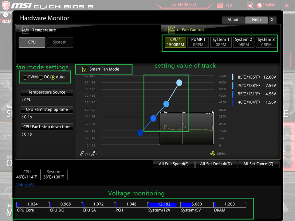
HARDWARE MONITOR
Информация о состоянии процессора и других системных компонентов.
BOARD EXPLORER
Обзор установленных периферийных устройств и компонентов.
