
I
Quick Start
Quick Start
Thank you for purchasing the MSI
®
B450 TOMAHAWK MAX
motherboard. This Quick Start section provides demonstration
diagrams about how to install your computer. Some of the
installations also provide video demonstrations. Please link to the
URL to watch it with the web browser on your phone or tablet. You
may have even link to the URL by scanning the QR code.
Kurzanleitung
Danke, dass Sie das MSI
®
B450 TOMAHAWK MAX Motherboard
gewählt haben. Dieser Abschnitt der Kurzanleitung bietet eine Demo
zur Installation Ihres Computers. Manche Installationen bieten
auch die Videodemonstrationen. Klicken Sie auf die URL, um diese
Videoanleitung mit Ihrem Browser auf Ihrem Handy oder Table
anzusehen. Oder scannen Sie auch den QR Code mit Ihrem Handy,
um die URL zu öffnen.
Présentation rapide
Merci d’avoir choisi la carte mère MSI
®
B450 TOMAHAWK MAX.
Ce manuel fournit une rapide présentation avec des illustrations
explicatives qui vous aideront à assembler votre ordinateur. Des
tutoriels vidéo sont disponibles pour certaines étapes. Cliquez sur
le lien fourni pour regarder la vidéo sur votre téléphone ou votre
tablette. Vous pouvez également accéder au lien en scannant le QR
code qui lui est associé.
Быстрый старт
Благодарим вас за покупку материнской платы MSI
®
B450
TOMAHAWK MAX. В этом разделе представлена информация,
которая поможет вам при сборке комьютера. Для некоторых
этапов сборки имеются видеоинструкции. Для просмотра
видео, необходимо открыть соответствующую ссылку в
веб—браузере на вашем телефоне или планшете. Вы также
можете выполнить переход по ссылке, путем сканирования
QR-кода.
II
Quick Start
Installing a Processor/ Installation des Prozessors/ Installer un
processeur/ Установка процессора
1
2
3
6
4
5
7
8
9
CPU_FAN1
III
Quick Start
If you are installing the screw-type CPU heatsink, please follow the figure below
to remove the retention module first and then install the heatsink.
Wenn Sie einen CPU-Kühler mit Schraubenbefestigung einsetzen, folgen Sie bitte
den Anweisungen unten um das Retention-Modul zu entfernen und den Kühler zu
installieren.
Si vous voulez installer un ventirad pour processeur à vis, veuillez suivre les
instructions ci-dessous pour d’abord retirer le module de rétention puis installer le
ventirad.
В случае установки процессорного кулера с системой крепления на винтах,
следуйте указаниям на рисунке ниже для снятия пластикового модуля
крепления. Затем установите кулер.
1
2
3
IV
Quick Start
Installing DDR4 memory/ Installation des DDR4-Speichers/
Installer une mémoire DDR4/ Установка памяти DDR4
DIMMB2 DIMMB2
DIMMB1
DIMMA2 DIMMA2 DIMMA2
DIMMA1
1
1
2
2
3
3
V
Quick Start
Connecting the Front Panel Header/ Anschließen der
Frontpanel-Stiftleiste/ Connecter un connecteur du panneau
avant/ Подключение разъемов передней панели
RESET SW
POWER SW
POWER LED+
POWER LED-
HDD LED
HDD LED
RESET SW
JFP1
HDD LED
HDD LED —
HDD LED +
POWER LED —
POWER LED +
POWER LED
1
2 10
9
+
+
+—
——
—
+
Power LED
HDD LED Reset Switch
Reserved
Power Switch
JFP1
1 HDD LED + 2 Power LED +
3 HDD LED — 4 Power LED —
5 Reset Switch 6 Power Switch
7 Reset Switch 8 Power Switch
9 Reserved 10 No Pin
VII
Quick Start
1
2
3
4
5
Installing SATA Drives/ Installation der SATA-Laufwerke/
Installer le disque dur SATA/ Установка дисков SATA
IX
Quick Start
Connecting Peripheral Devices/ Peripheriegeräte/
Connecter un périphérique anschliessen/ Подключение
периферийных устройств
Processor with integrated
graphics
X
Quick Start
Connecting the Power Connectors/ Stromanschlüsse
anschliessen/ Connecter les câbles du module d’alimentation/
Подключение разъемов питания
ATX_PWR1
CPU_PWR1
8
Package contents
Package contents
Please check the contents of your motherboard package. It should contain:
y Motherboard
y Driver DVD
y User Manual
y Quick Installation Guide
y I/O Shielding
y SATA 6G Cable x2
y Case Badge
y Product Registration Card
y M.2 Screw x1
Important
If any of the above items are damaged or missing, please contact your retailer.

11
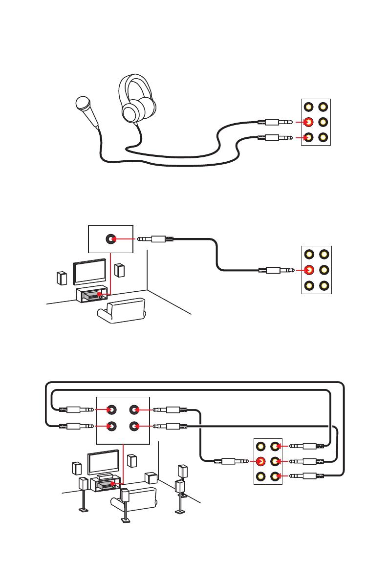
Rear I/O Panel
Audio jacks to headphone and microphone diagram
Audio jacks to stereo speakers diagram
Audio jacks to 7.1-channel speakers diagram
AUDIO INPUT
Rear Front
Side Center/
Subwoofer
AUDIO INPUT
12
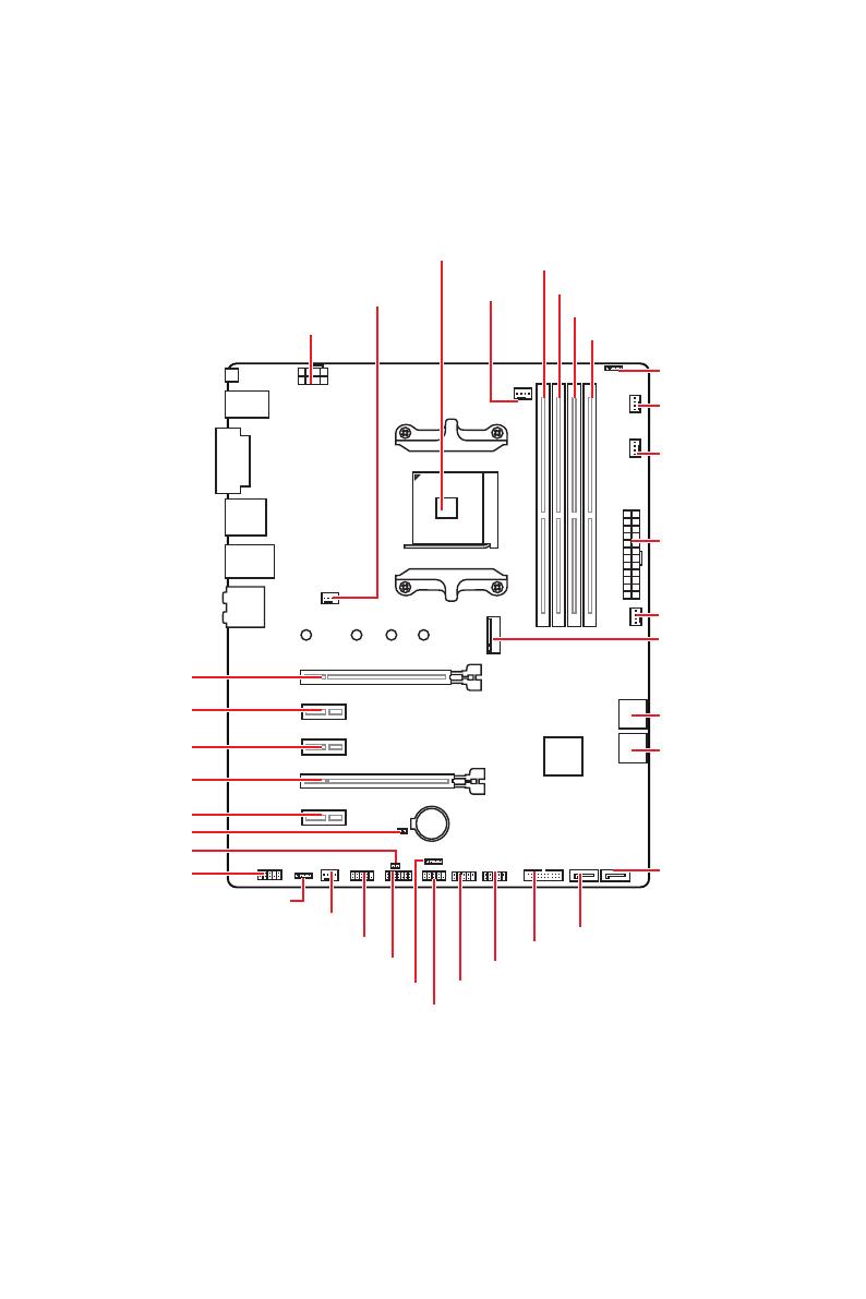
Overview of Components
Overview of Components
BAT1
JFP2
JFP1
SATA▼5▲6
SATA▼3▲4
CPU_FAN1
SYS_FAN1
PUMP_FAN1
JRGB2
PCI_E1
PCI_E2
PCI_E3
PCI_E4
PCI_E5
JBAT1
JAUD1
JTPM1
Processor
Socket
CPU_PWR1
DIMMA1
SYS_FAN4
M2_1
DIMMA2
DIMMB1
DIMMB2
JUSB3
SATA2
JUSB2
JUSB1
SATA1
JRGB1
SYS_FAN2
JCOM1
ATX_PWR1
SYS_FAN3
JCI1

18
Overview of Components
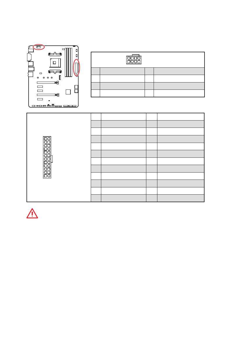
24
131
12
ATX_PWR1
1 +3.3V 13 +3.3V
2 +3.3V 14 -12V
3 Ground 15 Ground
4 +5V 16 PS-ON#
5 Ground 17 Ground
6 +5V 18 Ground
7 Ground 19 Ground
8 PWR OK 20 Res
9 5VSB 21 +5V
10 +12V 22 +5V
11 +12V 23 +5V
12 +3.3V 24 Ground
5
4 1
8
CPU_PWR1
1 Ground 5 +12V
2 Ground 6 +12V
3 Ground 7 +12V
4 Ground 8 +12V
Important
Make sure that all the power cables are securely connected to a proper ATX power
supply to ensure stable operation of the motherboard.
CPU_PWR1, ATX_PWR1: Power Connectors
These connectors allow you to connect an ATX power supply.
19
Overview of Components
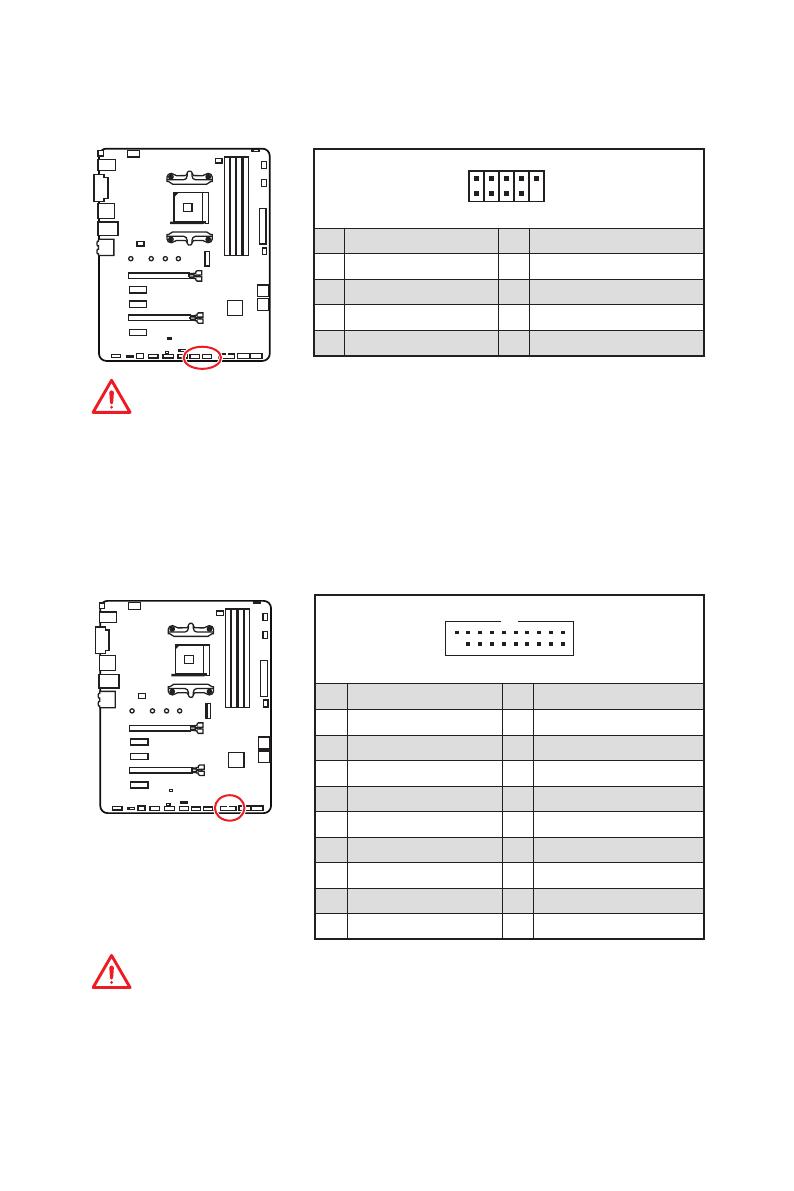
JUSB1~2: USB 2.0 Connectors
These connectors allow you to connect USB 2.0 ports on the front panel.
1
2 10
9
1 VCC 2 VCC
3 USB0- 4 USB1-
5 USB0+ 6 USB1+
7 Ground 8 Ground
9 No Pin 10 NC
Important
y
Note that the VCC and Ground pins must be connected correctly to avoid possible
damage.
y
In order to recharge your iPad,iPhone and iPod through USB ports, please install
MSI
®
SUPER CHARGER utility.
JUSB3: USB 3.2 Gen1 Connector
This connector allows you to connect USB 3.2 Gen1 ports on the front panel.
Important
Note that the Power and Ground pins must be connected correctly to avoid possible
damage.
1
10
11
20
1 Power 11 USB2.0+
2 USB3_RX_DN 12 USB2.0-
3 USB3_RX_DP 13 Ground
4 Ground 14 USB3_TX_C_DP
5 USB3_TX_C_DN 15 USB3_TX_C_DN
6 USB3_TX_C_DP 16 Ground
7 Ground 17 USB3_RX_DP
8 USB2.0- 18 USB3_RX_DN
9 USB2.0+ 19 Power
10 NC 20 No Pin
22
Overview of Components
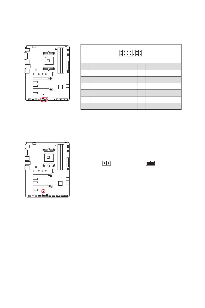
JBAT1: Clear CMOS (Reset BIOS) Jumper
There is CMOS memory onboard that is external powered from a battery located on
the motherboard to save system configuration data. If you want to clear the system
configuration, set the jumper to clear the CMOS memory.
Keep Data
(default)
Clear CMOS/
Reset BIOS
Resetting BIOS to default values
1. Power off the computer and unplug the power cord.
2. Use a jumper cap to short JBAT1 for about 5-10 seconds.
3. Remove the jumper cap from JBAT1.
4. Plug the power cord and Power on the computer.
1
2 14
13
1 LPC Clock 2 3V Standby power
3 LPC Reset 4 3.3V Power
5 LPC address & data pin0 6 Serial IRQ
7 LPC address & data pin1 8 5V Power
9 LPC address & data pin2 10 No Pin
11 LPC address & data pin3 12 Ground
13 LPC Frame 14 Ground
JTPM1: TPM Module Connector
This connector is for TPM (Trusted Platform Module). Please refer to the TPM security
platform manual for more details and usages.
5
Spezifikationen
Fortsetzung der vorherigen Seite
Hintere Ein-/ und
Ausgänge
y 1x Flash BIOS Taste
y 1x PS/2 Tastatur/ Maus-Combo-Anschluss
y 2x USB 2.0 Typ-A Anschlüsse
y 1x DVI-D Anschluss
y 1x HDMI
™
Anschluss
y 2x USB 3.2 Gen1 Typ-A Anschlüsse
y 1x LAN (RJ45) Anschluss
y 1x USB 3.2 Gen2 Typ-A Anschluss
y 1x USB 3.2 Gen2 Typ-C Anschluss
y 6x Audiobuchsen
Interne Anschlüsse
y 1x 24-poliger ATX Stromanschluss
y 1x 8-poliger ATX 12 V Stromanschluss
y 6x SATA 6Gb/s Anschlüsse
y 2x USB 2.0 Anschlüsse (unterstützt zusätzliche 4 USB 2.0
-Ports)
y 1x USB 3.2 Gen1 Anschluss (unterstützt zusätzliche 2 USB
3.2 Gen1-Ports)
y 1x 4-poliger CPU-Lüfter-Anschluss
y 1x 4-poliger Anschluss für die Wasserpumpe
y 4x 4-polige System-Lüfter-Anschlüsse
y 1x TPM Anschluss
y 1x Audioanschluss des Frontpanels
y 2x System-Panel-Anschlüsse
y 1x Gehäusekontaktschalter
y 1x Serieller Anschluss
y 1x Clear CMOS Steckbrücke
y 2x 5050 RGB LED Streifen 12 V Anschlüsse
E/A Anschluss NUVOTON NCT6797 Controller Chip
Hardware Monitor
y CPU/System Temperaturerfassung
y CPU/System Geschwindigkeitserfassung
y CPU/System Lüfterdrehzahlregelung
Fortsetzung auf der nächsten Seite
11
Rückseite E/A
Audiobuchsen für den Anschluss von einem Kopfhörer und Mikrofon
Audiobuchsen für Stereo-Lautsprecher
Audiobuchsen für 7.1 Kanal Anlage
AUDIO INPUT
Rear Front
Side Center/
Subwoofer
AUDIO INPUT

18
Übersicht der Komponenten
24
131
12
ATX_PWR1
1 +3.3V 13 +3.3V
2 +3.3V 14 -12V
3 Ground 15 Ground
4 +5V 16 PS-ON#
5 Ground 17 Ground
6 +5V 18 Ground
7 Ground 19 Ground
8 PWR OK 20 Res
9 5VSB 21 +5V
10 +12V 22 +5V
11 +12V 23 +5V
12 +3.3V 24 Ground
5
4 1
8
CPU_PWR1
1 Ground 5 +12V
2 Ground 6 +12V
3 Ground 7 +12V
4 Ground 8 +12V
Wichtig
Stellen Sie sicher, dass alle Anschlüsse mit den richtigen Anschlüssen des Netzteils
verbunden sind, um einen stabilen Betrieb der Hauptplatine sicherzustellen.
CPU_PWR1, ATX_PWR1: Stromanschlüsse
Mit diesen Anschlüssen verbinden Sie die ATX Stromstecker.

6
Spécifications
Suite du tableau de la page précédente
Dimensions
y Format ATX
y 30,5 cm x 24,4 cm (12” x 9,6”)
Fonctions BIOS
y 1 x flash BIOS 256 Mb
y UEFI AMI BIOS
y ACPI 6.1, SM BIOS 2.8
y Multilingue
Logiciel
y Pilotes
y APP MANAGER
y SUPER CHARGER
y COMMAND CENTER
y LIVE UPDATE 6
y SMART TOOL
y RAMDISK
y X-BOOST
y GAMING APP
y MYSTIC LIGHT
y Open Broadcaster Software (OBS)
y CPU-Z MSI GAMING
y Norton
™
Internet Security Solution
y Google Chrome
™
, Google Toolbar et Google Drive
Fonctions spéciales
y Audio
Audio Boost
y Stockage
Turbo M.2
StoreMI
y Ventilateur
Ventilateurs pour la pompe
Contrôle des ventilateurs GAMING
Suite du tableau sur la page suivante
18
Vue d’ensemble des composants
24
131
12
ATX_PWR1
1 +3.3V 13 +3.3V
2 +3.3V 14 -12V
3 Ground 15 Ground
4 +5V 16 PS-ON#
5 Ground 17 Ground
6 +5V 18 Ground
7 Ground 19 Ground
8 PWR OK 20 Res
9 5VSB 21 +5V
10 +12V 22 +5V
11 +12V 23 +5V
12 +3.3V 24 Ground
5
4 1
8
CPU_PWR1
1 Ground 5 +12V
2 Ground 6 +12V
3 Ground 7 +12V
4 Ground 8 +12V
Important
Veuillez vous assurer que tous les câbles d’alimentation sont branchés aux
connecteurs adéquats afin garantir une opération stable de la carte mère.
CPU_PWR1, ATX_PWR1 : Connecteurs d’alimentation
Ces connecteurs vous permettent de relier une alimentation ATX.
/
на других языках
Похожие инструкции
Другие инструкции
-
Contents
-
Table of Contents
-
Bookmarks
Quick Links
Quick Start
Thank you for purchasing the MSI
motherboard. This Quick Start section provides demonstration
diagrams about how to install your computer. Some of the
installations also provide video demonstrations. Please link to the
URL to watch it with the web browser on your phone or tablet. You
may have even link to the URL by scanning the QR code.
クイ ックスタート
この度は MSI
B450 TOMAHAWK MAX II
®
ただき、 誠にありがとうございます 。 このクイックスタートにはPCの組み
立て方法のデモンストレーション図を掲載しています。 いく つかの組み立
て手順に付きましては、 実演ビデオを提供しています。 スマートフ ォンやタ
ブレッ ト端末のウェブブラウザで本書に記載されたURLにアクセスしてご
覧ください。 QRコードをスキャンすることでもURLのリンク先をご参照頂
けます。
퀵 스타트
MSI
B450 TOMAHAWK MAX II
®
이 부분에서는 컴퓨터를 설치하는 방법에 대한 데모 다이어그램과 일부
데모 동영상을 제공하고 있습니다. 휴대전화 또는 태블릿의 웹 브라우저를
통하여 URL에 링크한 후 설치 동영상을 감상하시기 바랍니다. 또는 QR
코드를 스캔하여 URL에 링크할 수도 있습니다.
快速指引
感謝您購買 MSI
供您安裝電腦的示範圖解 , 亦提供部分組件的安裝示範影片 ; 請您以智
慧型手機或平板的瀏覽器連上 URL 網址進行觀看。 您也可以掃描 QR
code 的方式快速連接至網址 。
快速入门
感谢您购买 MSI
了有关如何安装计算机演示图。 某些设施还提供了视频演示。 请使用您
的手机或平板电脑上的网页浏览器链接至网址观看。 您也可以通过扫描
QR码链接到URL。
메인보드를 선택해주셔서 감사합니다.
B450 TOMAHAWK MAX II
®
B450 TOMAHAWK MAX II
®
B450 TOMAHAWK MAX II
®
マザーボードをお買い上げい
主機板 。 本快速指引章節提
主板。 本快速入门部分提供
I
Quick Start
Chapters
Summary of Contents for MSI B450 TOMAHAWK MAX II
инструкцияMSI B450 Tomahawk Max

1
Quick Start
DDR4 Memory
Graphics Card
SATA Hard Disk Drive
SATA DVD Drive
Phillips Screwdriver
Chassis
Power Supply Unit
A Package of Screws
Thermal Paste
Quick Start
Thank you for purchasing the MSI
®
B450 TOMAHAWK motherboard. This Quick Start
section provides demonstration diagrams about how to install your computer. Some
of the installations also provide video demonstrations. Please link to the URL to watch
it with the web browser on your phone or tablet. You may have even link to the URL by
scanning the QR code
Preparing Tools and Components
AMD
®
AM4 CPU
CPU Fan
Посмотреть инструкция для MSI B450 Tomahawk Max бесплатно. Руководство относится к категории Материнские платы, 16 человек(а) дали ему среднюю оценку 8.7. Руководство доступно на следующих языках: английский. У вас есть вопрос о MSI B450 Tomahawk Max или вам нужна помощь? Задайте свой вопрос здесь
- Quick Start
- Safety Information
- Specifications
- Package contents
- Block Diagram
- Rear I/O Panel
- Overview of Components
- BIOS Setup
- Software Description
- RAID Configuration
- Troubleshooting
- Regulatory Notices
- CPU_FAN1, PUMP_FAN1, SYS_FAN1~4: Fan Connectors
- CPU_PWR1, ATX_PWR1: Power Connectors
- DIMM Slots
- JAUD1: Front Audio Connector
- JBAT1: Clear CMOS (Reset BIOS) Jumper
- JCI1: Chassis Intrusion Connector
- JCOM1: Serial Port Connector
- JFP1, JFP2: Front Panel Connectors
- JRGB1~2: RGB LED connectors
- JTPM1: TPM Module Connector
- JUSB1~2: USB 2.0 Connectors
- JUSB3: USB 3.1 Gen1 Connector
- M2_1: M.2 Slot (Key M)
- PCI_E1~5: PCIe Expansion Slots
- Processor Socket
- SATA1~6: SATA 6Gb/s Connectors

Главная
| MSI | |
| B450 Tomahawk Max | B450 TOMAHAWK MAX | |
| Материнская плата | |
| 4719072659226, 0824142191699 | |
| английский | |
| Руководство пользователя (PDF) |
Содержимое упаковки
| Поставляемые кабели | SATA |
| Драйвера в комплекте | Да |
Прочие свойства
| Краткое руководство по установке | Да |
Вес и размеры
| Ширина | 305 mm |
| Глубина | 244 mm |
Свойства
| Количество отверстий для монтажа | 9 |
| Чипсет материнской платы | AMD B450 |
| Семейство чипсета материнской платы | AMD |
| Формат материнской платы | ATX |
| Выходные звуковые каналы | 7.1 канала |
| Поддерживаемые операционные системы Windows | Windows 10 Education x64, Windows 10 Enterprise x64, Windows 10 Home x64, Windows 10 Pro x64, Windows 10 x64, Windows 7 Enterprise x64, Windows 7 Home Basic x64, Windows 7 Home Premium x64, Windows 7 Professional x64, Windows 7 Starter x64, Windows 7 Ultimate x64, Windows 7 x64 |
| Комплектующие для | ПК |
| Аудио чип | Realtek ALC892 |
| Мониторинг состояния ПК | CPU, FAN, Temperature |
Процессор
| Производитель процессора | AMD |
| Сокет процессора | Разъем AM4 |
| Совместимые серии процессоров | AMD Athlon, AMD Ryzen 3, AMD Ryzen 3 2nd Gen, AMD Ryzen 3 3rd Gen, AMD Ryzen 5, AMD Ryzen 5 2nd Gen, AMD Ryzen 5 3rd Gen, AMD Ryzen 7, AMD Ryzen 7 2nd Gen, AMD Ryzen 7 3rd Gen, AMD Ryzen 9 3rd Gen |
| Максимальное число процессоров для SMP | 1 |
Порты на задней панели
| Количество портов Ethernet LAN ( RJ-45) | 1 |
| Количество портов PS/2 | 1 |
| Количество портов USB 2.0 | 2 |
| Количество портов USB 3.2 Gen 1 (3.1 Gen 1) Type-A | 2 |
| Количество портов USB 3.2 Gen 1 (3.1 Gen 1) Type-С | 0 |
| Количество портов USB 3.2 Gen 2 (3.1 Gen 2) Type-A | 1 |
| Количество портов USB 3.2 Gen 2 (3.1 Gen 2) Type-С | 1 |
| Количество портов eSATA | 0 |
| Порты FireWire | 0 |
| Количество портов VGA (D-Sub) | 0 |
| Количество HDMI портов | 1 |
| Количество портов DVI-D | 1 |
| Версия HDMI | 1.4 |
Внутренние порты
| Разъем питания ATX (24-конт.) | Да |
| 12В разъем питания | Да |
| Количество разъемов SATA III | 6 |
| Количество разъемов SATA II | 0 |
| Разъемы USB 2.0 | 2 |
| Разъемы USB 3.2 Gen 2 (3.1 Gen 2) | 0 |
| Разъемы USB 3.2 Gen 1 (3.1 Gen 1) | 1 |
| Разъем вентилятора центрального процессора | Да |
| Количество разъемов вентилятора корпуса | 4 |
| TPM коннектор | Да |
| Аудиоразъем передней панели | Да |
| Разъем передней панели | Да |
| Разъем Chassis intrusion | Да |
| Коннекторы последовательного порта | 1 |
| Количество параллельных разъемов ATA (PATA) | 0 |
| RGB LED контактный разъем | Да |
BIOS
| Перемычка Clear CMOS | Да |
| Тип BIOS | UEFI AMI |
| Размер памяти BIOS | 256 Mbit |
| Версия ACPI | 6.1 |
| Версия BIOS (SMBIOS) | 2.8 |
Сеть
| Wi-Fi | Нет |
| Контроллер LAN | Realtek 8111H |
| Тип Ethernet интерфейса | Гигабитный Ethernet |
| Подключение Ethernet | Да |
Контроллеры хранения данных
| Поддерживаемые интерфейсы носителя | SATA III |
| Уровни RAID | 0, 1,10 |
Слоты расширения
| Количество M.2 (M) слотов | 1 |
| Слоты PCI Express x16 (поколение 3.x) | 1 |
| Слоты PCI Express x16 (поколение 2.x) | 1 |
| Слоты PCI Express x1 (поколение 2.x) | 3 |
Графический адаптер
| Поддержка технологии параллельной обработки | 2-Way CrossFireX |
| Максимальное разрешение | 4096 x 2160 пикселей |
| Объём памяти графического адаптера | 2048 MB |
Память
| Каналы памяти | Dual-channel |
| Поддерживаемые типы памяти | DDR4-SDRAM |
| Количество слотов памяти | 4 |
| Тип слотов памяти | DIMM |
| Максимальная внутренняя память | 64 GB |
| Поддерживаемые частоты памяти | 2667,2800,2933,3000,3066,3200,3466,4100,4133 MHz |
| Error-correcting code (ECC) | Да |
| без функции коррекции ошибок | Да |
показать больше
Не можете найти ответ на свой вопрос в руководстве? Вы можете найти ответ на свой вопрос ниже, в разделе часто задаваемых вопросов о MSI B450 Tomahawk Max.
Какая ширина MSI B450 Tomahawk Max?
Какая толщина MSI B450 Tomahawk Max?
Инструкция MSI B450 Tomahawk Max доступно в русский?
Не нашли свой вопрос? Задайте свой вопрос здесь
![]()
Quick Start
Thank you for purchasing the MSI® B450 TOMAHAWK MAX II motherboard. This Quick Start section provides demonstration diagrams about how to install your computer. Some of the installations also provide video demonstrations. Please link to the URL to watch it with the web browser on your phone or tablet. You may have even link to the URL by scanning the QR code.
Preparing Tools and Components
AMD® AM4 CPU
DDR4 Memory
|
Power Supply Unit |
Graphics Card |
Thermal Paste
|
SATA Hard Disk Drive |
SATA DVD Drive |
|
Phillips Screwdriver |
A Package of Screws |
Quick Start 1
Safety Information
∙∙The components included in this package are prone to damage from electrostatic discharge (ESD). Please adhere to the following instructions to ensure successful computer assembly.
∙∙Ensure that all components are securely connected. Loose connections may cause the computer to not recognize a component or fail to start.
∙∙Hold the motherboard by the edges to avoid touching sensitive components. ∙∙It is recommended to wear an electrostatic discharge (ESD) wrist strap when
handling the motherboard to prevent electrostatic damage. If an ESD wrist strap is not available, discharge yourself of static electricity by touching another metal object before handling the motherboard.
∙∙Store the motherboard in an electrostatic shielding container or on an anti-static pad whenever the motherboard is not installed.
∙∙Before turning on the computer, ensure that there are no loose screws or metal components on the motherboard or anywhere within the computer case.
∙∙Do not boot the computer before installation is completed. This could cause permanent damage to the components as well as injury to the user.
∙∙If you need help during any installation step, please consult a certified computer technician.
∙∙Always turn off the power supply and unplug the power cord from the power outlet before installing or removing any computer component.
∙∙Keep this user guide for future reference. ∙∙Keep this motherboard away from humidity.
∙∙Make sure that your electrical outlet provides the same voltage as is indicated on the PSU, before connecting the PSU to the electrical outlet.
∙∙Place the power cord such a way that people can not step on it. Do not place anything over the power cord.
∙∙All cautions and warnings on the motherboard should be noted.
∙∙If any of the following situations arises, get the motherboard checked by service personnel:
▪▪Liquid has penetrated into the computer.
▪▪The motherboard has been exposed to moisture.
▪▪The motherboard does not work well or you can not get it work according to user guide.
▪▪The motherboard has been dropped and damaged. ▪▪The motherboard has obvious sign of breakage.
∙∙Do not leave this motherboard in an environment above 60°C (140°F), it may damage the motherboard.
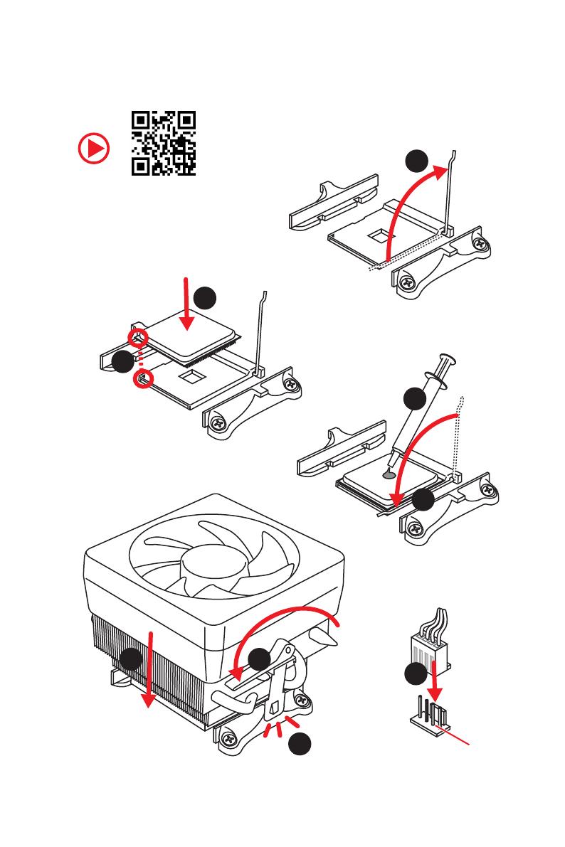
2 Quick Start
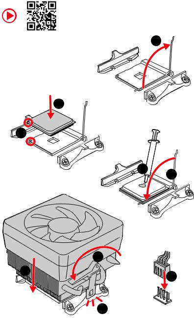
Installing a Processor
|
1 |
3
2 


5 4
|
6 |
8 |
|
|
9 |
||
|
7 |
Quick Start 3

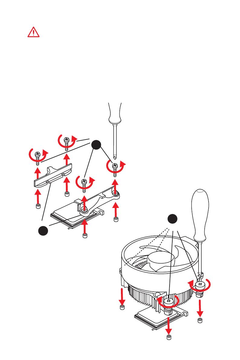
Important
If you are installing the screw-type CPU heatsink, please follow the figure below to remove the retention module first and then install the heatsink.
1
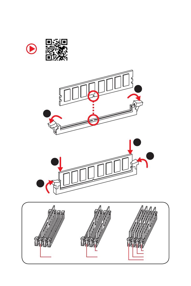
4 Quick Start
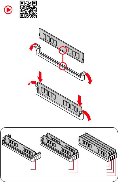
Installing DDR4 memory
|
DIMMA2 |
DIMMA2 |
DIMMA1 |
|
DIMMA2 |
||
|
DIMMB2 |
DIMMB1 |
|
|
DIMMB2 |
Quick Start 5
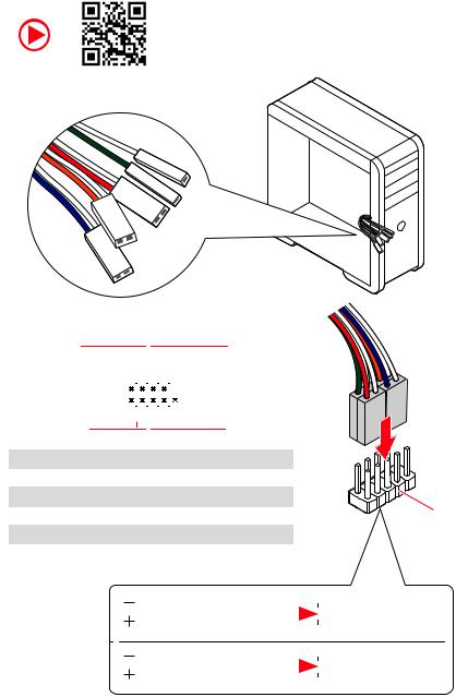
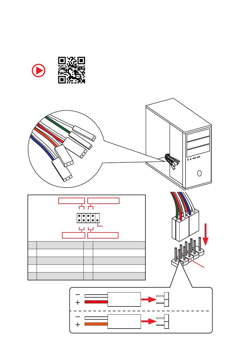
Connecting the Front Panel Header
|
— |
|||
|
LED |
|||
|
LED+ |
POWER |
||
|
POWER |
|||
|
LED |
|||
|
SW |
HDD |
||
|
POWER |
|||
|
SW |
|||
|
RESET |
|
Power LED |
Power Switch |
||||||||||||||||||
|
-+-+ |
|||||||||||||||||||
|
JFP1 |
2 |
10 |
|||||||||||||||||
|
1 |
9 |
Reserved |
|||||||||||||||||
|
+ — +- |
|||||||||||||||||||
|
HDD LED |
Reset Switch |
||||||||||||||||||
|
1 |
HDD LED + |
2 |
Power LED + |
||||||||||||||||
|
3 |
HDD LED — |
4 |
Power LED — |
||||||||||||||||
|
5 |
Reset Switch |
6 |
Power Switch |
||||||||||||||||
|
7 |
Reset Switch |
8 |
Power Switch |
||||||||||||||||
|
9 |
Reserved |
10 |
No Pin |
HDDLED RESETSW
|
HDD LED — |
|||||||
|
HDD LED |
|||||||
|
HDD LED + |
|||||||
|
POWER LED — |
|||||||
|
POWER LED |
POWER LED + |
||||||
6 Quick Start

Installing the Motherboard
BAT1
2
BAT1
*3 kgf·cm = 0.3 N·m = 2.6 lbf·in
Quick Start 7
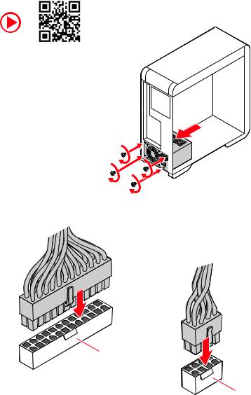
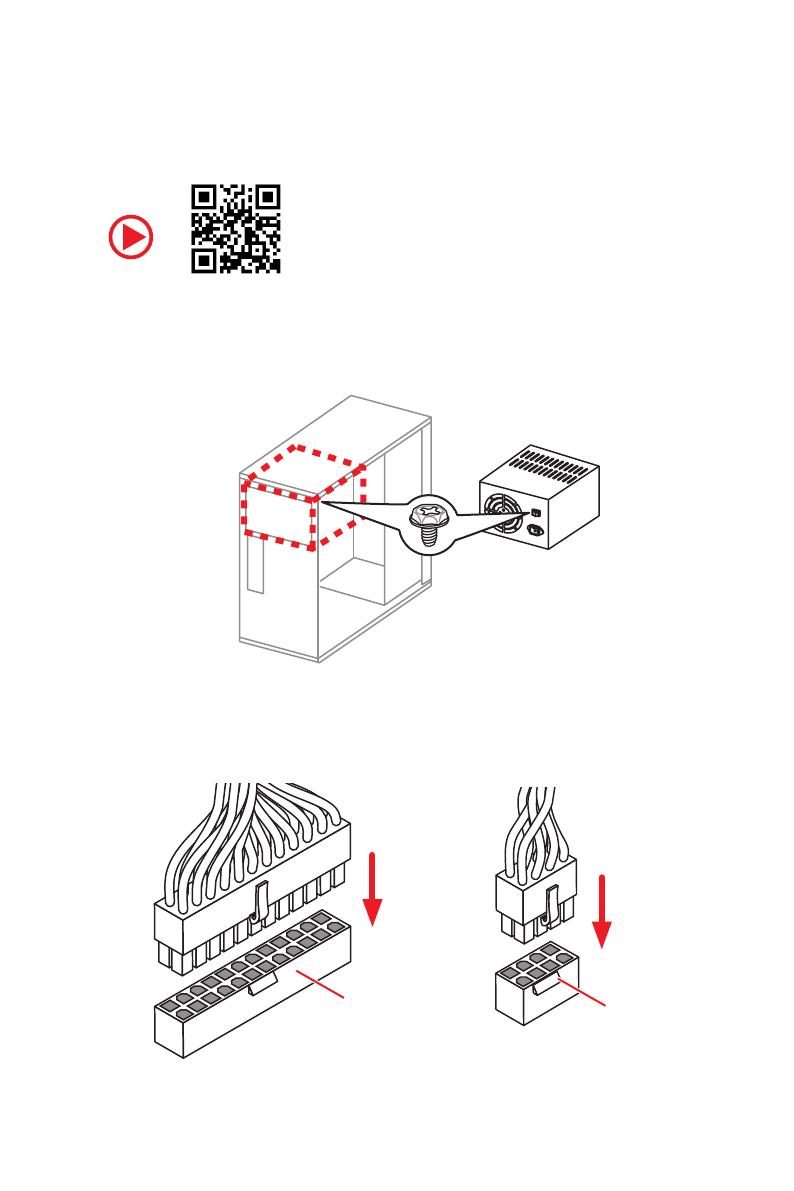
Connecting the Power Connectors
ATX_PWR1
CPU_PWR1
8 Quick Start
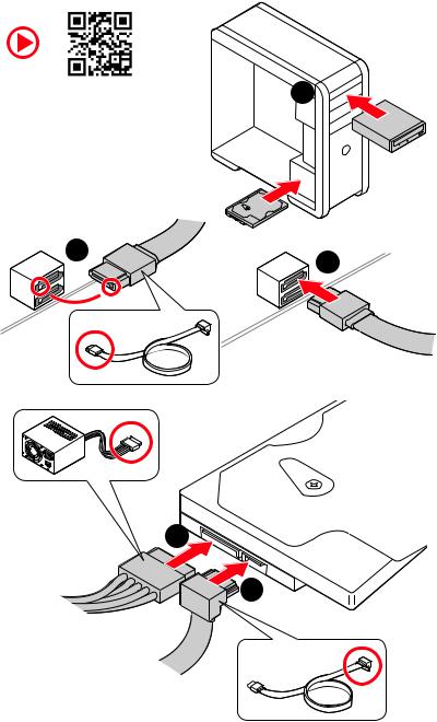
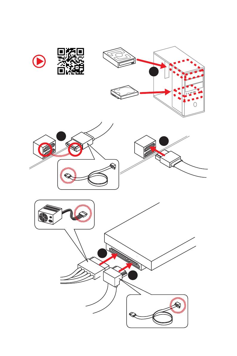
Installing SATA Drives
|
1 |
5
4
Quick Start 9
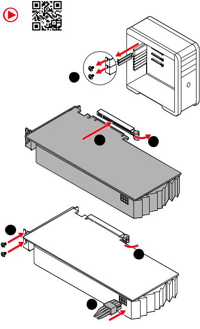
Installing a Graphics Card
1
5
 4
4
6
10 Quick Start
![]()
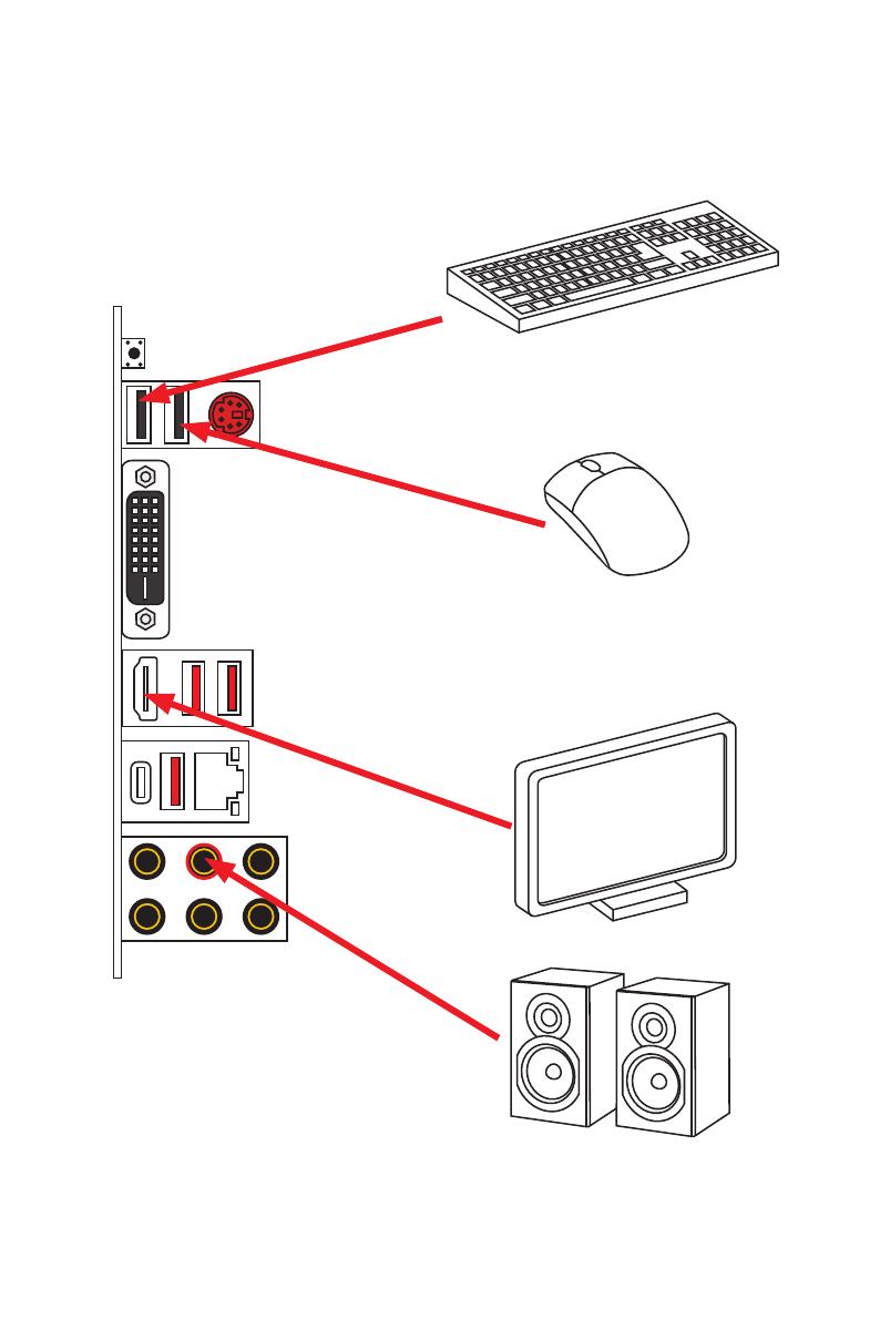
Connecting Peripheral Devices
Processor with Radeon™ Graphics
Quick Start 11
|
Contents |
|
|
Quick Start ………………………………………………………………………………………………. |
1 |
|
Preparing Tools and Components……………………………………………………………….. |
1 |
|
Safety Information …………………………………………………………………………………….. |
2 |
|
Installing a Processor………………………………………………………………………………… |
3 |
|
Installing DDR4 memory ……………………………………………………………………………. |
5 |
|
Connecting the Front Panel Header…………………………………………………………….. |
6 |
|
Installing the Motherboard…………………………………………………………………………. |
7 |
|
Connecting the Power Connectors………………………………………………………………. |
8 |
|
Installing SATA Drives………………………………………………………………………………… |
9 |
|
Installing a Graphics Card ………………………………………………………………………… |
10 |
|
Connecting Peripheral Devices …………………………………………………………………. |
11 |
|
Power On………………………………………………………………………………………………… |
12 |
|
Specifications…………………………………………………………………………………………. |
15 |
|
Package contents……………………………………………………………………………………. |
20 |
|
Block Diagram ………………………………………………………………………………………. |
21 |
|
Rear I/O Panel………………………………………………………………………………………… |
22 |
|
LAN Port LED Status Table……………………………………………………………………….. |
22 |
|
Audio Ports Configuration ………………………………………………………………………… |
22 |
|
Realtek Audio Console …………………………………………………………………………….. |
23 |
|
Overview of Components ………………………………………………………………………… |
25 |
|
Processor Socket…………………………………………………………………………………….. |
27 |
|
DIMM Slots……………………………………………………………………………………………… |
28 |
|
PCI_E1~5: PCIe Expansion Slots……………………………………………………………….. |
29 |
|
M2_1: M.2 Slot (Key M) …………………………………………………………………………….. |
30 |
|
SATA1~6: SATA 6Gb/s Connectors …………………………………………………………….. |
30 |
|
JFP1, JFP2: Front Panel Connectors …………………………………………………………. |
31 |
|
JAUD1: Front Audio Connector …………………………………………………………………. |
31 |
|
CPU_PWR1, ATX_PWR1: Power Connectors ………………………………………………. |
32 |
|
JUSB1~2: USB 2.0 Connectors………………………………………………………………….. |
33 |
|
JUSB3: USB 3.2 Gen 1 Connector ……………………………………………………………… |
33 |
|
CPU_FAN1, PUMP_FAN1, SYS_FAN1~4: Fan Connectors…………………………….. |
34 |
|
JCI1: Chassis Intrusion Connector…………………………………………………………….. |
35 |
|
JCOM1: Serial Port Connector ………………………………………………………………….. |
35 |
|
JTPM1: TPM Module Connector………………………………………………………………… |
36 |
|
JBAT1: Clear CMOS (Reset BIOS) Jumper ………………………………………………….. |
36 |
|
JRGB1~2: RGB LED connectors ………………………………………………………………… |
37 |
|
EZ Debug LEDs ……………………………………………………………………………………….. |
38 |
Contents 13
|
Installing OS, Drivers & Utilities ………………………………………………………………. |
39 |
|
Installing Windows® 10 …………………………………………………………………………… |
39 |
|
Installing Drivers …………………………………………………………………………………….. |
39 |
|
Installing Utilities ……………………………………………………………………………………. |
39 |
|
UEFI BIOS………………………………………………………………………………………………. |
40 |
|
BIOS Setup……………………………………………………………………………………………… |
41 |
|
Entering BIOS Setup………………………………………………………………………………… |
41 |
|
Resetting BIOS………………………………………………………………………………………… |
42 |
|
Updating BIOS…………………………………………………………………………………………. |
42 |
|
EZ Mode …………………………………………………………………………………………………. |
44 |
|
Advanced Mode ………………………………………………………………………………………. |
47 |
|
SETTINGS Menu ……………………………………………………………………………………… |
48 |
|
OC Menu…………………………………………………………………………………………………. |
50 |
|
M-FLASH Menu ………………………………………………………………………………………. |
52 |
|
OC PROFILE Menu…………………………………………………………………………………… |
53 |
|
HARDWARE MONITOR Menu…………………………………………………………………….. |
54 |
|
AMD RAID Configuration …………………………………………………………………………. |
56 |
|
Enabling RAIDXpert2 Configuration Utility …………………………………………………. |
56 |
|
Initializing Disks ……………………………………………………………………………………… |
57 |
|
Creating Arrays……………………………………………………………………………………….. |
58 |
|
Deleting Arrays……………………………………………………………………………………….. |
59 |
|
Installing RAID Driver………………………………………………………………………………. |
60 |
|
Troubleshooting …………………………………………………………………………………….. |
61 |
14 Contents

Specifications
|
Supports 1st, 2nd and 3rd Gen AMD Ryzen™/ Ryzen™ with |
|
|
CPU |
Radeon™ Vega Graphics and 2nd Gen AMD Ryzen™ with |
|
Radeon™ Graphics/ Athlon™ with Radeon™ Vega Graphics |
|
|
Desktop Processors for Socket AM4 |
|
|
Chipset |
AMD® B450 Chipset |
|
∙∙4x DDR4 memory slots, support up to 128GB* |
|
|
▪▪Supports 1866/ 2133/ 2400/ 2667Mhz (by JEDEC) |
|
|
▪▪For AMD Ryzen Gen3 (R5/R7/R9) |
|
|
▫▫Supports 2667/ 2800/ 2933/ 3000/ 3066/ 3200/ 3466/ |
|
|
4000/ 4133 MHz (by A-XMP OC MODE) |
|
|
Memory |
▪▪For AMD Other CPU |
|
▫▫Supports 2667/ 2800/ 2933/ 3000/ 3066/ 3200/ 3466 |
|
|
MHz (by A-XMP OC MODE) |
|
|
∙∙ Dual channel memory architecture |
|
|
∙∙ Supports non-ECC UDIMM memory |
|
|
∙∙ Supports ECC UDIMM memory (non-ECC mode) |
|
|
*Please refer to www.msi.com for more information on compatible memory. |
|
|
∙∙1x PCIe 3.0 x16 slot (PCI_E1) |
|
|
▪▪supports x16 speed (1st, 2nd and 3rd Gen AMD Ryzen™ |
|
|
processors) |
|
|
▪▪supports x8 speed (Ryzen™ with Radeon™ Vega |
|
|
Graphics and 2nd Gen AMD Ryzen™ with Radeon™ |
|
|
Expansion Slots |
Graphics processors) |
|
▪▪supports x4 speed (Athlon™ with Radeon™ Vega |
|
|
Graphics processors) |
|
|
∙∙1x PCIe 2.0 x16 slot (PCI_E4, supports x4 mode)* |
|
|
∙∙3x PCIe 2.0 x1 slots* |
|
|
* PCI_E4 will run at x2 speed when installing devices in PCI_E2/ PCI_E3 slot. |
|
|
∙∙1x DVI-D port, supports a maximum resolution of |
|
|
1920×1200 @60Hz*/** |
|
|
∙∙1x HDMI™ 2.1 port, supports a maximum resolution of |
|
|
Onboard Graphics |
4096×2160 @60Hz*/**/*** |
|
* Maximum shared memory of 16GB |
|
|
** Only available when using Ryzen™ with Radeon™ Vega Graphics and 2nd Gen |
|
|
AMD Ryzen™ with Radeon™ Graphics/ Athlon™ with Radeon™ Vega Graphics |
|
|
processors. |
|
|
*** Graphics specifications may vary depending on the CPU installed. |
|
|
Continued on next page |
Specifications 15

Continued from previous page
|
AMD® CPU |
|
|
∙∙2x SATA 6Gb/s ports* |
|
|
∙∙1x M.2 slot (Key M)* |
|
|
▪▪Supports PCIe 3.0 x4 (1st, 2nd and 3rd Gen AMD |
|
|
Ryzen™/ Ryzen™ with Radeon™ Vega Graphics and 2nd |
|
|
Storage |
Gen AMD Ryzen™ with Radeon™ Graphics) or PCIe 3.0 x2 |
|
(Athlon™ with Radeon™ Vega Graphics) and SATA 6Gb/s |
|
|
▪▪Supports 2242/ 2260/ 2280/ 22110 storage devices |
|
|
AMD® B450 Chipset |
|
|
∙∙ 4x SATA 6Gb/s ports |
|
|
* SATA5 and SATA6 ports will be unavailable when installing a M.2 device in M.2 |
|
|
slot. |
|
|
RAID |
AMD® B450 Chipset |
|
∙∙Supports RAID 0, RAID 1 and RAID 10 for SATA storage |
|
|
devices |
|
|
∙∙AMD® CPU |
|
|
▪▪2x USB 3.2 Gen 1 5Gbps Type-A ports on the back |
|
|
panel |
|
|
∙∙AMD® B450 Chipset |
|
|
▪▪1x USB 3.2 Gen 2 10Gbps Type-C port on the back |
|
|
USB |
panel |
|
▪▪1x USB 3.2 Gen 2 10Gbps Type-A port on the back |
|
|
panel |
|
|
▪▪2x USB 3.2 Gen 1 5Gbps ports available through the |
|
|
internal USB connector |
|
|
▪▪6x USB 2.0 ports (2 Type-A ports on the back panel, 4 |
|
|
ports available through the internal USB 2.0 connectors) |
|
|
LAN |
∙∙1x Realtek® 8111H Gigabit LAN controller |
|
Audio |
Realtek® ALC892/ALC897 Codec |
|
∙∙7.1-Channel High Definition Audio |
|
|
Continued on next page |
16 Specifications

LED Feature
I/O Controller
Hardware Monitor
Back Panel
Connectors
Continued from previous page
∙∙1x Flash BIOS Button
∙∙1x PS/2 keyboard/ mouse combo port ∙∙2x USB 2.0 Type-A ports
∙∙1x DVI-D port ∙∙1x HDMI port
∙∙2x USB 3.2 Gen 1 5Gbps Type-A ports ∙∙1x USB 3.2 Gen 2 10Gbps Type-A port ∙∙1x USB 3.2 Gen 2 10Gbps Type-C port ∙∙1x LAN(RJ45) port
∙∙6x audio jacks
∙∙1x 24-pin ATX main power connector ∙∙1x 8-pin ATX 12V power connector ∙∙6x SATA 6Gb/s connectors
∙∙1x USB 3.2 Gen 1 5Gbps connector (support additional 2 USB 3.2 Gen 1 5Gbps ports)
∙∙2x USB 2.0 connectors (support additional 4 USB 2.0 ports) ∙∙1x 4-pin CPU fan connector
∙∙1x 4-pin water pump connector Internal Connectors ∙∙4x 4-pin system fan connectors ∙∙1x front panel audio connector
∙∙2x system panel connectors ∙∙1x serial port connector
∙∙1x Chassis Intrusion connector ∙∙1x Clear CMOS jumper
∙∙2x 5050 RGB LED strip 12V connectors ∙∙1x TPM module connector
∙∙4x EZ Debug LED
NUVOTON NCT6797 Controller Chip
∙∙CPU/System temperature detection ∙∙CPU/System fan speed detection ∙∙CPU/System fan speed control
Continued on next page
Specifications 17

Continued from previous page
|
Form Factor |
∙∙ATX Form Factor |
|
|
∙∙12 in. x 9.6 in. (30.5 cm x 24.4 cm) |
||
|
∙∙1x 256 Mb flash |
||
|
BIOS Features |
∙∙UEFI AMI BIOS |
|
|
∙∙ACPI 6.1, SM BIOS 2.8 |
||
|
∙∙Multi-language |
||
|
∙∙Drivers |
||
|
∙∙DRAGON CENTER |
||
|
Software |
∙∙MSI App Player(BlueStacks) |
|
|
∙∙Open Broadcaster Software (OBS) |
||
|
∙∙CPU-Z MSI GAMING |
||
|
∙∙Google Chrome™, Google Toolbar, Google Drive |
||
|
∙∙Norton™ Internet Security Solution |
||
|
∙∙Gaming Mode |
||
|
∙∙Gaming Hotkey |
||
|
∙∙Mystic Light |
||
|
Dragon Center |
∙∙User Scenario |
|
|
∙∙Hardware Monitor |
||
|
Features |
∙∙True Color |
|
|
∙∙Live Update |
||
|
∙∙Speed Up |
||
|
∙∙Smart Tool |
||
|
∙∙Super Charger |
||
|
∙∙Audio |
||
|
▪▪Audio Boost |
||
|
Special Features |
∙∙Network |
|
|
▪▪Realtek LAN |
||
|
∙∙Storage |
||
|
▪▪Turbo M.2 |
||
|
Continued on next page |
18 Specifications

Continued from previous page
∙∙Cooling
▪▪Extended heatsink ▪▪Pump Fan ▪▪GAMING Fan Control
∙∙LED
▪▪Mystic Light
▪▪Mystic Light Extension (RGB) ▪▪Mystic light SYNC
▪▪EZ DEBUG LED ∙∙Protection
▪▪PCIe Steel Armor
▪▪PCIe Steel Slot
∙∙Performance
▪▪Multi GPU-CrossFire Technology
▪▪DDR4 Boost
Special Features ▪▪CORE Boost
▪▪GAME Boost ▪▪USB with type A+C
▪▪AMD Turbo USB 3.2 Gen 2
∙∙VR
▪▪VR Ready
∙∙Gamer Experience
▪▪GAMING HOTKEY
▪▪GAMING MOUSE Control
∙∙BIOS
▪▪Click BIOS 5 ▪▪Flash BIOS Button ▪▪StoreMI (SW feature)
▪▪AMD FreeSync™ Ready
▪▪AMD Precision Boost OverDrive™ ∙∙Certification
▪▪GAMING Certified
Specifications 19
Package contents
Please check the contents of your motherboard package. It should contain:
|
Motherboard |
B450 TOMAHAWK MAX II |
||
|
Cable |
SATA 6G cables (2 cables/pack) |
1 |
|
|
M.2 screws (3 pcs./pack) |
1 |
||
|
Accessories |
Case badge |
1 |
|
|
I/O Shielding |
1 |
||
|
Product registration card |
1 |
||
|
Application |
Driver DVD |
1 |
|
|
Documentation |
User manual |
1 |
|
|
Quick installation guide |
1 |
||
Important
If any of the above items are damaged or missing, please contact your retailer.
20 Package contents