
Preface
6
WEEE Statement
WEEE (Waste Electrical and Electronic Equipment)
ENGLISH
To protect the global environment and as an environmentalist, MSI must
remind you that…
Under the European Union (“EU”) Directive on Waste Electrical and
Electronic Equipment, Directive 2002/96/EC, which takes eect on August 3, 2005,
products of “electrical and electronic equipment” cannot be discarded as municipal
wastes anymore, and manufacturers of covered electronic equipment will be
obligated to take back such products at the end of their useful life. MSI will comply
with the product take back requirements at the end of life of MSI-branded products
that are sold into the EU. You can return these products to local collection points.
DEUTSCH
Hinweis von MSI zur Erhaltung und Schutz unserer Umwelt
Gemäß der Richtlinie 2002/96/EG über Elektro- und Elektronik-Altgeräte dürfen
Elektro- und Elektronik-Altgeräte nicht mehr als kommunale Abfälle entsorgt werden.
MSI hat europaweit verschiedene Sammel- und Recyclingunternehmen beauftragt,
die in die Europäische Union in Verkehr gebrachten Produkte, am Ende seines
Lebenszyklus zurückzunehmen. Bitte entsorgen Sie dieses Produkt zum gegebenen
Zeitpunkt ausschliesslich an einer lokalen Altgerätesammelstelle in Ihrer Nähe.
FRANÇAIS
En tant qu’écologiste et an de protéger l’environnement, MSI tient à rappeler ceci…
Au sujet de la directive européenne (EU) relative aux déchets des équipement
électriques et électroniques, directive 2002/96/EC, prenant eet le 3 août 2005,
que les produits électriques et électroniques ne peuvent être déposés dans les
décharges ou tout simplement mis à la poubelle. Les fabricants de ces équipements
seront obligés de récupérer certains produits en n de vie. MSI prendra en compte
cette exigence relative au retour des produits en n de vie au sein de la communauté
européenne. Par conséquent vous pouvez retourner localement ces matériels dans
les points de collecte.
РУССКИЙ
Компания MSI предпринимает активные действия по защите окружающей
среды, поэтому напоминаем вам, что….
В соответствии с директивой Европейского Союза (ЕС) по предотвращению
загрязнения окружающей среды использованным электрическим и электронным
оборудованием (директива WEEE 2002/96/EC), вступающей в силу 3
августа 2005 года, изделия, относящиеся к электрическому и электронному
оборудованию, не могут рассматриваться как бытовой мусор, поэтому
производители вышеперечисленного электронного оборудования обязаны
принимать его для переработки по окончании срока службы. MSI обязуется
соблюдать требования по приему продукции, проданной под маркой MSI на
территории EC, в переработку по окончании срока службы. Вы можете вернуть
эти изделия в специализированные пункты приема.
Русский
99
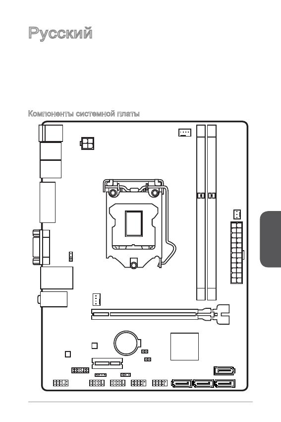
Top : mouse
Bottom: keyboard
Top: LAN jack
Bottom: USB ports
T:Line—In
M:Line— Out
B:MIC—Int
USB2.0 ports
USB3.0 ports
DVI—D port
(for H81M—P33/
H87M—P33/ B85M—P33)
HDMI port
(for H81M—E33/
H87M—E33/ B85M—E33)
VGA port
PCI _E2
PCI _E1
JUSB2 JUSB1
SYSF
AN
2
CPUFAN
JPWR2
JUSB_PW1
DIMM1
DIMM2
JAUD1
JTPM1
SYSFAN1
JCI1
JBAT1
JUSB_PW2
JCOM1
SATA4 SATA3 SATA1
SATA2
JPWR1
JFP1
JFP2
Русский
Благодарим вас за выбор системной платы серии H8M-P33/ H8M-E33/ H87M-
P33/ H87M-E33/ B85M-P33/ B85M-E33 (MS-787 v.X) Micro-ATX. Материнские
платы серии H8M-P33/ H8M-E33/ H87M-P33/ H87M-E33/ B85M-P33/
B85M-E33 на базе чипсета Intel H8/ H87/ B85 и обеспечивают оптимальную
производительность системы. Серия H8M-P33/ H8M-E33/ H87M-P33/
H87M-E33/ B85M-P33/ B85M-E33 обеспечивает высокую производительность
и является профессиональной платформой для настольных ПК, благодаря
совместимости с усовершенствованным процессором Intel LGA50.
Компоненты системной платы
Русский
00
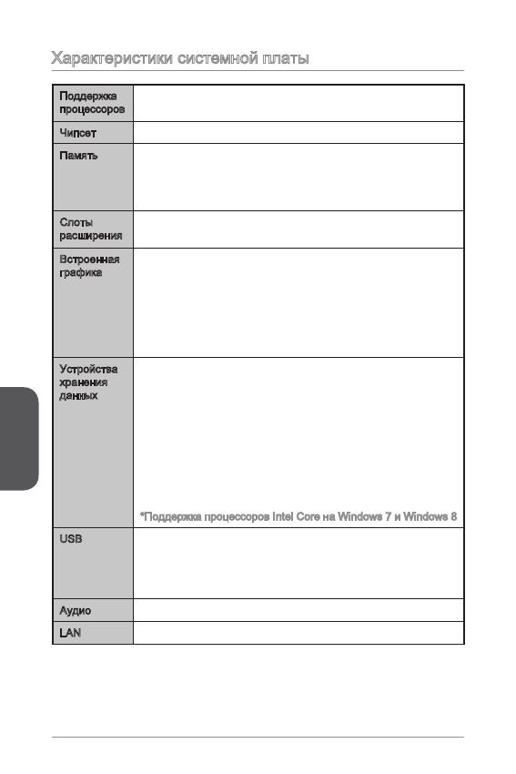
Характеристики системной платы
Поддержка
процессоров
Поддержка процессоров Intel
®
Core™ i7 / Core™ i5 / Core™
i3 / Pentium
®
/ Celeron
®
4-го поколения для сокета LGA 50
■
Чипсет Intel
®
H8/ H87/ B85 Express■
Память 2x DDR3 слота памяти с поддержкой до 6ГБ
Поддержка DDR3 600/ 333/ 066 МГц
Двухканальная архитектура памяти
Поддержка non-ECC, небуферизованной памяти
■
■
■
■
Слоты
расширения
x слот PCIe x6 (дополнительлно)
x слот PCIe 2.0 x
■
■
Встроенная
графика
x порт HDMI (дополнительлно), с поддержкой
x порт DVI-D (дополнительлно), с поддержкой
максимального разрешения 920x200 @ 60Гц, 24bpp
x порт VGA, с поддержкой максимального разрешения
920x200 @ 60Гц, 24bpp
■
■
■
Устройства
хранения
данных
Чипсет Intel H8/ H87/ B85 Express
4x портов SATA (дополнительно)
Поддержка RAID 0, RAID, RAID 5 и RAID 0
(дополнительно)
Поддержка Технологии Intel Smart Response
(дополнительно)*
Поддержка Технологии Intel Rapid Start
(дополнительно)*
Поддержка Технологии Intel Smart Connect
(дополнительно)*
*Поддержка процессоров Intel Core на Windows 7 и Windows 8
■
—
—
—
—
—
USB Чипсет Intel H8/ H87/ B85 Express
2x портов USB 3.0 на задней панели
8x портов USB 2.0 (4 порта на задней панели, 4 порта
доступны через внутренние USB разъемы*)
■
—
—
Аудио Realtek
®
ALC887 Codec■
LAN Realtek
®
RTL8G Гигабитный Сетевой контроллер■
Русский
0
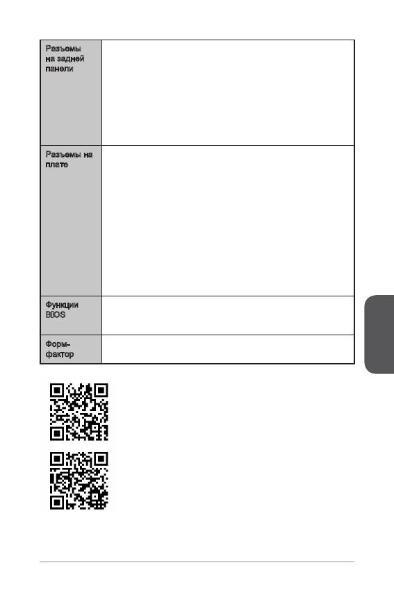
Разъемы
на задней
панели
x порт PS/2 клавиатуры
x порт PS/2 мыши
4x портов USB 2.0
2x порта USB 3.0
x порт HDMI (дополнительно)
x порт DVI-D (дополнительно)
x порт VGA
x порт LAN (RJ45)
3x аудиоразъемов
■
■
■
■
■
■
■
■
■
Разъемы на
плате
x 24-
контактный ATX основной разъем питания
x 4-
контактный ATX 2В разъем питания
4x разъемов SATA
2x разъемов USB 2.0 (Поддержка 4 дополнительных
портов USB 2.0)
x 4-
контактный разъем вентилятора ЦП
x 4-
контактный разъем вентилятора системы
x 3-
контактный разъем вентилятора системы
x аудиоразъем на передней панели
2x разъема панели системы
x разъем датчика открывания корпуса
x перемычка очистки CMOS
2x перемычки USB питания
■
■
■
■
■
■
■
■
■
■
■
■
Функции
BIOS
UEFI AMI BIOS
ACPI 5.0, PnP .0a, SM BIOS 2.7, DMI 2.0
Multi-язык
■
■
■
Форм-
фактор
Micro-ATX Форм-факторы
8.9 дюймов x 6.8 дюймов (22.6 см x 7.3 см)
■
■
Последние сведения о поддержке ЦП см. на веб-
странице http://www.msi.com/service/cpu-support/
Дополнительные сведения о совместимых компонентах
см. на веб-странице
http://www.msi.com/service/test-report/
Русский
02
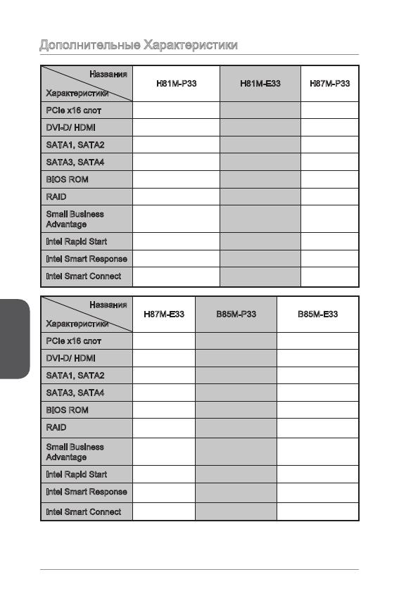
Дополнительные Характеристики
Названия
Характеристики
H8M-P33 H8M-E33 H87M-P33
PCIe x6 слот Gen2 Gen2 Gen3
DVI-D/ HDMI DVI-D HDMI DVI-D
SATA, SATA2 SATA 6Гб/с SATA 6Гб/с SATA 6Гб/с
SATA3, SATA4 SATA 3Гб/с SATA 3Гб/с SATA 6Гб/с
BIOS ROM 64Mб 64Mб 28Mб
RAID Не поддерживает Не поддерживает Поддержка
Small Business
Advantage
Не поддерживает Не поддерживает Поддержка
Intel Rapid Start Не поддерживает Не поддерживает Поддержка
Intel Smart Response Не поддерживает Не поддерживает Поддержка
Intel Smart Connect
Поддержка Поддержка Поддержка
Названия
Характеристики
H87M-E33 B85M-P33 B85M-E33
PCIe x6 слот Gen3 Gen3 Gen3
DVI-D/ HDMI HDMI DVI-D HDMI
SATA, SATA2 SATA 6Гб/с SATA 6Гб/с SATA 6Гб/с
SATA3, SATA4 SATA 6Гб/с SATA 3Гб/с SATA 3Гб/с
BIOS ROM 28Mб 28Mб 28Mб
RAID
Поддержка Не поддерживает Не поддерживает
Small Business
Advantage
Поддержка Поддержка Поддержка
Intel Rapid Start Поддержка Поддержка Поддержка
Intel Smart Response
Поддержка Не поддерживает Не поддерживает
Intel Smart Connect
Поддержка Поддержка Поддержка
Русский
03
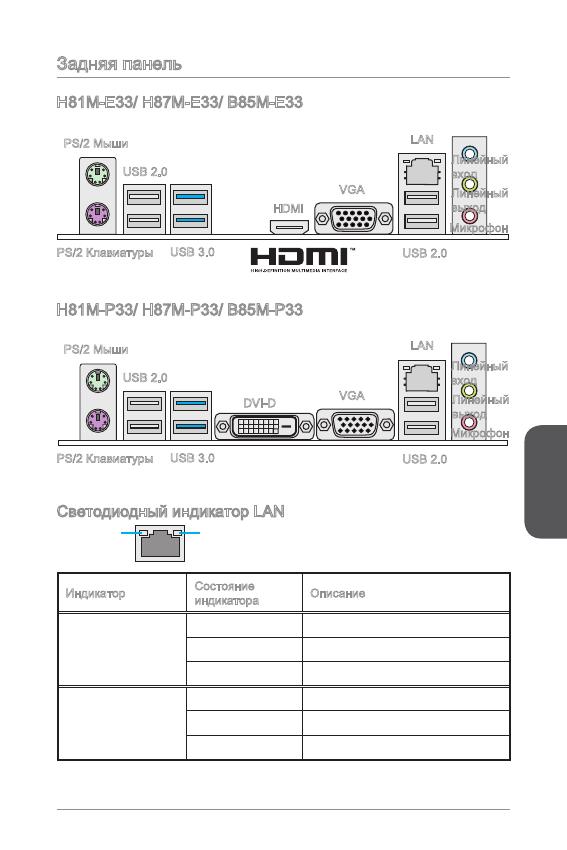
Задняя панель
Светодиодный индикатор LAN
LINK/ACT
LED
SPEED
LED
Индикатор
Состояние
индикатора
Описание
Link/ Activity LED
(Подключение/
Работа индикатора)
Выкл. Не подключен
Желтый Подключен
Мигает Передача данных
Speed LED
(Скорость
передачи данных)
Выкл. 0 Мбит/с подключение
Зеленый 00 Мбит/с подключение
Оранжевый Гбит/с подключение
H8M-E33/ H87M-E33/ B85M-E33
H8M-P33/ H87M-P33/ B85M-P33
PS/2 Мыши
PS/2 Клавиатуры
USB 2.0
USB 3.0
HDMI
VGA
Линейный
вход
Линейный
выход
Микрофон
USB 2.0
LAN
PS/2 Мыши
PS/2 Клавиатуры
USB 2.0
USB 3.0
DVI-D
VGA
Линейный
вход
Линейный
выход
Микрофон
USB 2.0
LAN
Русский
04
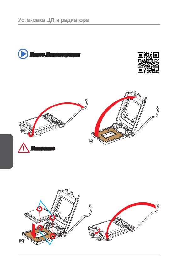
Установка ЦП и радиатора
При установке процессоора обязательно установите радиатор ЦП.Радиатор ЦП
предупреждает перегревание и обеспечивает стабильность работы системы.
Ниже представлены инструкции по правильной установке процессора и
радиатора ЦП.Неправильная установка приводит к выходу из строя процессора
и материнской платы.
. Отцепите и полностью поднимите рычаг фиксации.
2. При подъеме рычага фиксации автоматически поднимается прижимная
пластина.
Внимание
Не трогайте контакты разъема или нижней части процессора.
Видео Демонстрация
Смотрите видео,чтобы узнать как установить процессор и кулер:
http://youtu.be/bf5La099urI
Ключи совмещения
Выемки процессора
3. Выравняйте выемки на процессоре к ключами совмещения на сокете.
Опустите процессор вниз, без наклона или движения процессора в сокете.
Проверьте надежность установки процессора в сокете.
4. Закройте и сдвиньте прижимную пластину под ручку ужержания. Закройте и
зацепите рычаг фиксации.
Русский
05
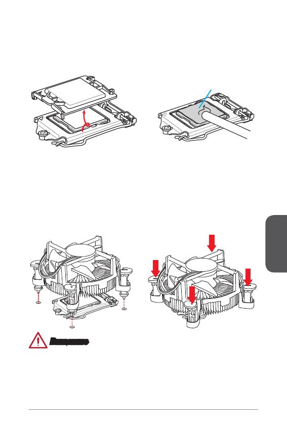
Термопаста
Внимание
Перед включением системы проверьте герметичность соединения между
процессором и радиатором.
Если процессор не установлен, всегда защищайте контакты процессорного
сокета пластиковой крышкой.
Если вы приобрели отдельно процессор и процессорный кулер, подробное
описание установки см. в документации в данному кулеру.
•
•
•
5. При нажатии на рычаг фиксации защитная крышка автоматически выскочит
из гнезда процессора. Не выбрасывайте защитную крышку. Всегда
устанавливайте защитную крышку, если процессор вынимается из сокета.
6. Равномерно нанесите тонкий слой термопасты (или термоленту) на
верхнюю крышку процессора. Это позволит увеличить теплопередачу и
предотвратит перегрев процессора.
7.
Найдите разъем для подключения вентилятора ЦП на материнской плате.
8. Установите кулер на материнскую плату, направив его кабель в сторону
разъема для подключения вентилятора.
9. Нажмите на радиатор сверху так, чтобы закрепить четыре защелки в
отверстиях на материнской плате. Нажмите на защелки для закрепления
вентилятора. Каждый из защелок фиксируется с характерным щелчком.
0. Осмотрите материнскую плату и определите правильность закрепления
зажимов.
. И, наконец, подключите кабель вентилятора процессора к разъему
вентилятора на системной плате.
Русский
06
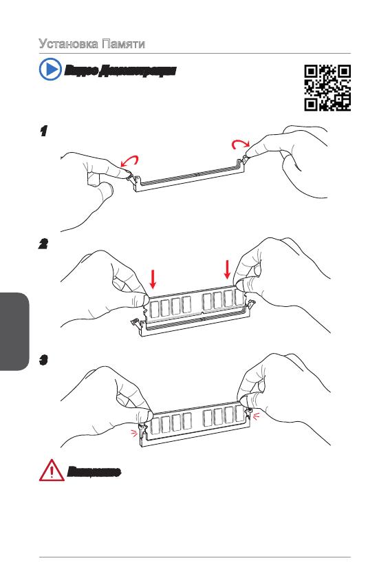
Установка Памяти
Видео Демонстрация
Смотрите видео,чтобы узнать как установить память по
указанному адресу.
2
3
Внимание
Модули DDR3 не взаимозаменяемы с модулями DDR2, стандарт DDR3 не
поддерживает обратную совместимость. Модули памяти DDR3 следует
устанавливать в разъемы DDR3 DIMM.
Для обеспечения стабильной работы системы в двухканальном режиме
устанавливаются модули памяти одинакового типа и емкости.
•
•
Русский
07
Внутренние разъемы
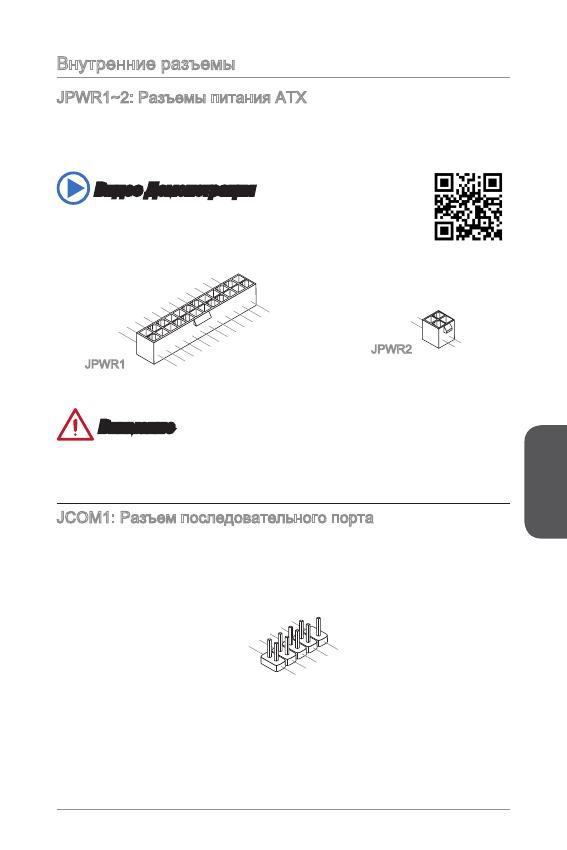
JPWR~2: Разъемы питания ATX
Эти разъемы предназначены для подключения разъема питания ATX. Для
подключения ATX разъема питания совместите кабель питания с разъемом и
прочно закрепите его. При правильном выполнении подключения защелка на
кабеле питания закрепляется в силовом разъеме материнской платы.
Видео Демонстрация
Смотрите видео,чтобы узнать как установить разъем питания.
13.+3.3
V
1.+3.3
V
14.—12V
2.+3.3
V
15.Ground
3
.Ground
16.PS—ON
#
4.+5
V
17.Ground
5
.Ground
18.Ground
6.+5
V
19.Ground
7
.Ground
22.+5
V
10.+12V
20.Res
8.PW
R O
K
23.+5
V
11
.+12V
21.+5
V
9.5VSB
24.Ground
12.+3.3
V
JPWR
4.+12V
2
.Ground
3.+12V
1
.Ground
JPWR2
Внимание
Для обеспечения стабильной работы системной платы проверьте надежность
подключения всех кабелей питания к соответствующему блоку питания АТХ.
JCOM: Разъем последовательного порта
Данный разъем является высокоскоростным последовательным портом
передачи данных 6550А с 6-разрядной передачей FIFO. К этому разъему
можно подключить устройство c последовательным интерфейсом.
1
.
D
C
D
3
.
S
O
U
T
1
0
.
N
o
P
i
n
5
.
G
r
o
u
n
d
7
.
R
T
S
9
.
R
I
8
.
C
T
S
6
.
D
S
R
4
.
D
T
R
2
.
S
I
N
Русский
08
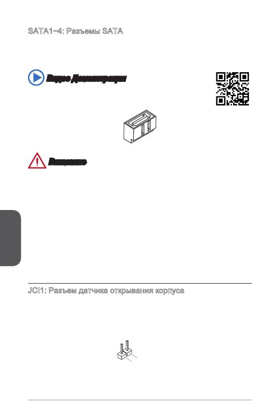
SATA~4: Разъемы SATA
Данный разъем является высокоскоростным интерфейсом SATA. К любому
разъему SATA можно подключить одно устройство SATA. К устройствам
SATA относятся жесткие диски, твердотельные накопители и накопители на
оптических дисках (компакт-диски/ DVD-диски/ Blu-Ray-диски).
Видео Демонстрация
Смотрите видео,чтобы узнать как установить SATA жесткие
диски.
Внимание
Многие устройства SATA требуют подключения к источнику питания с
помощью кабеля питания. К таким устройствам относятся жесткие диски,
твердотельные накопители и накопители на оптических дисках (компакт-
диски/ DVD-диски/ Blu-Ray-диски). Дополнительную информацию можно
получить в руководствах к соответствующим устройствам.
Во многих системных блоках устройства SATA большого размера (в том
числе, жесткие диски, твердотельные накопители и накопители на оптических
дисках) прикрепляются с помощью винтов. Дополнительные инструкции по
установке см. в руководствах к системному блоку или устройству SATA.
Избегайте перегибов кабеля SATA под прямым углом. В противном случае,
возможна потеря данных при передаче.
Кабели SATA оснащены одинаковыми вилками с обеих сторон. Однако для
экономии занимаемого пространства рекомендуется к материнской плате
подключать плоский разъем.
JCI: Разъем датчика открывания корпуса
К этому разъему подключается кабель датчика, установленного в корпусе. Этот
датчик срабатывает при вскрытии системного блока. Система запоминает это
событие и выдает предупреждение на экран. Для отключения предупреждения
необходимо удалить записанное событие в настройках BIOS.
•
•
•
•
Русский
09
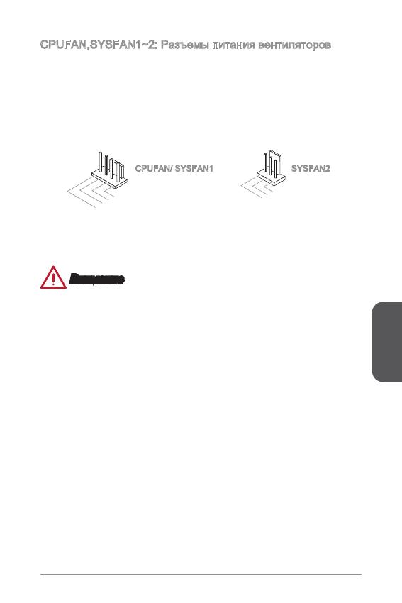
CPUFAN,SYSFAN~2: Разъемы питания вентиляторов
Разъемы питания вентиляторов поддерживают вентиляторы с питанием +2 В.
Если на системной плате установлена микросхема аппаратного мониторинга,
необходимо использовать специальные вентиляторы с датчиками скорости для
использования функции управления вентиляторами. Обязательно подключите
все системные вентиляторы. Некоторые системные вентиляторы невозможно
подключить к материнской плате.Вместо этого они подключаются к источнику
питания напрямую. Системные вентиляторы подключаются к свободным
разъемам для вентиляторов.
1
.Ground
2.+12V
3.Sens
e
4.Speed
C
ontro
l
CPUFAN/ SYSFAN SYSFAN2
Внимание
Для получения кулеров, рекомендованных для охлаждения процессора,
обратитесь на официальный веб-сайт производителя процессора или к
местному поставщику.
Эти разъемы поддерживают функцию управления скоростью вращения
вентиляторов в линейном режиме. Установите утилиту Command Center
для автоматического управления скоростью вращения вентиляторов в
зависимости от температуры процессора и системы.
В том случае, если на материнской плате не достаточно разъемов для
подключения всех системных вентиляторов, вентиляторы подключают
напрямую к источнику питания с помощью переходника.
Перед первой загрузкой проверьте, чтобы кабели не мешали вращению
вентиляторов.
•
•
•
•
Русский
0
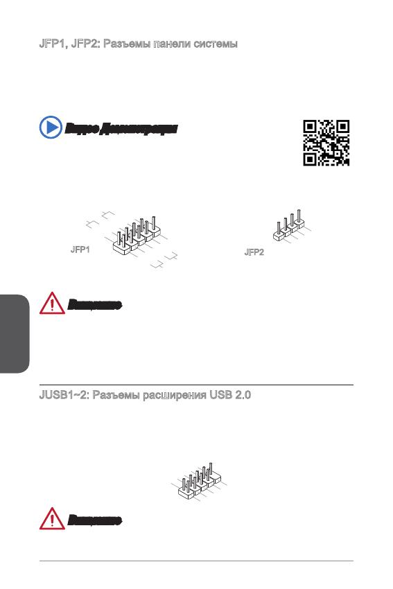
JFP, JFP2: Разъемы панели системы
Эти разъемы служат для подключения кнопок и светодиодных индикаторов,
расположенных на передней панели. Разъем JFP соответствует стандартам
Intel
®
Front Panel I/O Connectivity Design. При установке разъемов передней
панели для удобства используются переходники и кабели, входящие в комплект
поставки. Подключите все провода системного блока к разъемам, а затем
подключите разъемы к материнской плате.
Видео Демонстрация
Смотрите видео,чтобы узнать как подключить разъемы
передней панели.
3.Speaker
4.VCC5
1.Speaker
2.VCC5
1.
+
3.
—
10.No
Pi
n
5.
—
Reset
S
witch
HDD
LE
D
P
ower
S
witch
P
ower
LE
D
7.
+
9.Res erve
d
8.
—
6.
+
4.
—
2.
+
JFP
JFP2
Внимание
На разъемах, выходящих из системного блока, плюсовым проводам
соответствуют контакты, обозначенные небольшими треугольниками.
Для определения правильности направления и расположения служат
вышеуказанные схемы и надписи на дополнительных разъемах.
Большинство кнопок, расположенных на передней панели системного блока,
подключены к разъему JFP.
JUSB~2: Разъемы расширения USB 2.0
Этот разъем служит для подключения таких высокоскоростных периферийных
устройств, как жесткие диски с интерфейсом USB, цифровые камеры, МРЗ
плееры, принтеры, модемы и т. д.
1
.
V
C
C
3
.
U
S
B
0
—
1
0
.
NC
5
.
U
S
B
0
+
7
.
G
r
o
u
n
d
9
.
N
o
P
i
n
8
.
G
r
o
u
n
d
6
.
U
S
B
1
+
4
.
U
S
B
1
—
2
.
V
C
C
Внимание
Помните, что во избежание повреждений необходимо правильно подключать
контакты VCC и GND.
•
•
Русский
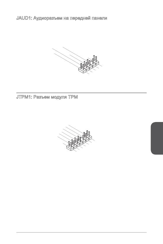
JAUD: Аудиоразъем на передней панели
Этот разъем служит для подключения аудиоразъема на передней панели
системного блока. Этот разъем соответствует стандарту Intel
®
Front Panel I/O
Connectivity Design.
1.MI
C L
3.MI
C R
10.Head
P
hone
Detection
5.Head
P
hone
R
7.SENSE_SEN
D
9.Head
P
hone
L
8.No
Pi
n
6.MI
C D
etection
4.NC
2
.Ground
JTPM: Разъем модуля ТРМ
Данный разъем подключается к модулю ТРМ (Trusted Platform Module).
Дополнительные сведения см. в описании модуля безопасности ТРМ.
10.No
Pi
n
14.Ground
8.5V
P
ower
12.Ground
6.Serial
IR
Q
4.3.3V
P
ower
2.3V
Standby
p
ower
1.LP
C C
loc
k
3.LP
C
Rese
t
5.LP
C a
ddres
s &
data
pin0
7.LP
C a
ddres
s &
data
p
in1
9.LP
C a
ddres
s &
data
pin2
11
.LPC
a
ddres
s &
data
pin3
13.LP
C
Fram
e
Русский
2
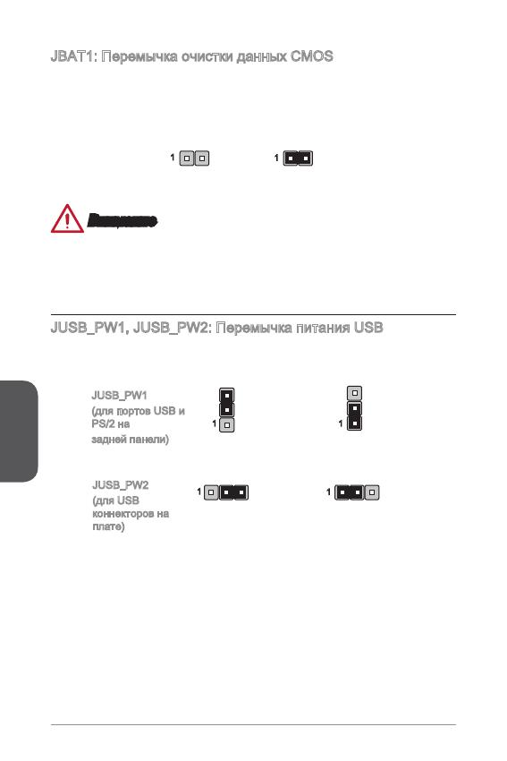
JBAT: Перемычка очистки данных CMOS
На плате установлена CMOS память с питанием от батарейки для хранения
данных о конфигурации системы. С помощью памяти CMOS операционная
система (ОС) автоматически загружается каждый раз при включении. Для
сброса конфигурации системы (очистки данных CMOS памяти), воспользуйтесь
этой перемычкой.
Сохранение
данных
Очистка
данных
Внимание
Очистка CMOS памяти производится замыканием указанных контактов
перемычкой при выключенной режиме. После выполнения очистки разомкните
перемычку. Очистка CMOS памяти во время работы системы не допустима, т.к.
это приведет к выходу материнской платы из строя.
JUSB_PW, JUSB_PW2: Перемычка питания USB
Данные джамперы используются для включения функции “Wake Up Event Setup”
посредством БИОС для USB или PS/2 устройства.
Поддержка
Не поддерживает (По
умолчанию)
JUSB_PW
(для портов USB и
PS/2 на
задней панели)
JUSB_PW2
(для USB
коннекторов на
плате)
Поддержка
Не поддерживает (По
умолчанию)
Русский
3
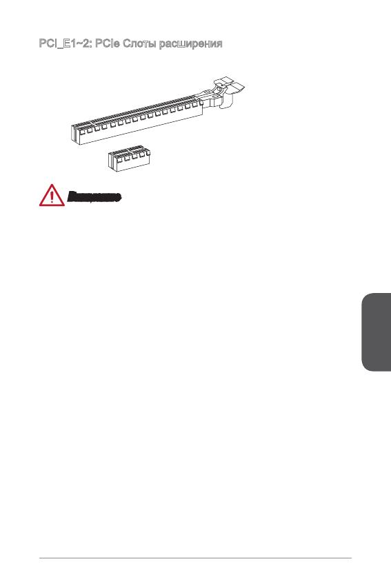
PCI_E~2: PCIe Слоты расширения
Слот PCIe поддерживает платы расширения с интерфейсом PCIe.
PCIe 2.0 x Слот
PCIe 3.0 x6 Слот
Внимание
Перед установкой или извлечением плат расширения убедитесь, что шнур
питания отключен от электрической сети. Прочтите документацию на карту
расширения и выполните необходимые дополнительные аппаратные или
программные изменения для данной карты.
Русский
4
Настройка BIOS
Параметры по умолчанию предлагают оптимальную производительность
для стабильности системы в нормальных условиях. Этот режим может
потребоватья в следующих условиях:
Во время загрузки системы появляется сообщение об ошибке с требованием
запустить SETUP.
В случае необходимости заменить заводские настройки на собственные.
Внимание
Пожалуйста, загрузите заводские настройки для восстановления
оптимальной производительности и стабильности системы, ести система
становится неустойчивой после изменения настроек BIOS. Выберите
«Восстановить настройки по умолчанию» и нажмите <Enter> в BIOS для
загрузки настройки по умолчанию.
Если вы не знакомы с настройками BIOS, мы рекомендуем сохранить
настройки по умолчанию для избежания возможности повреждения системы
или неудачи загрузки из-за неуместного конфигурирования BIOS.
Вход в настройки BIOS
Включите компьютер и дождитесь начала процедуры самотестирования POST
(Power On Self Test). При появлении на экране сообщения, приведенного ниже,
нажмите клавишу <DEL> для запуска программы настройки:
Press DEL key to enter Setup Menu, F to enter Boot Menu (Нажмите
на клавишу DEL для входа в меню настройки, F для входа в меню
загрузки)
Если вы не успели нажать клавишу до отображения сообщения и по-прежнему
требуется войти в программу настройки, перезапустите систему, либо
включив и выключив ее, либо нажав кнопку RESET. Можно также выполнить
перезагрузку, одновременно нажав клавиши <Ctrl>+<Alt>+<Delete>.
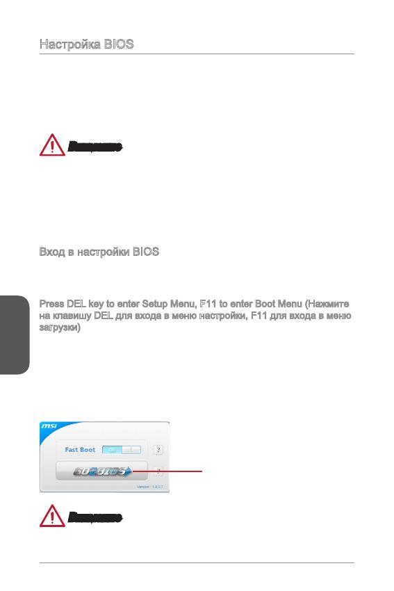
MSI также дополнительно предоставляет два метода для входа в настройки
BIOS. Вы можете нажать “GO2BIOS” на экране в утилите “MSI Fast Boot” или
нажать физическую кнопку “GO2BIOS» (опционально) на материнской плате для
непосредственно входа в настройки BIOS при следующей загрузке.
Нажмите «GO2BIOS» на экране
утилиты «MSI Fast Boot».
Внимание
Не забудьте установить “MSI Fast Boot” до того как войти в настройки BIOS.
■
■
•
•
Русский
5
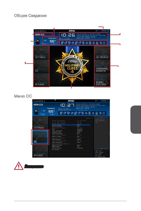
Общие Сведения
После входа в BIOS отображается следующий экран.
Выбор
меню BIOS
Мониторинг температур
Системная
Информация
Приоритет
загрузочных
устройств
Экран просмотра раздела
Выбор
меню BIOS
Язык
Кнопка Virtual
OC Genie
Название
модели
Меню OC
Внимание
Разгонять ПК вручную рекомендуется только опытным пользователям.
Производитель не гарантирует успешность разгона. Неправильное
выполнение разгона может привести к аннулированию гарантии и серьезному
повреждению оборудования.
Неопытным пользователям, рекомендуется использовать OC Genie.
•
•
•
Русский
6
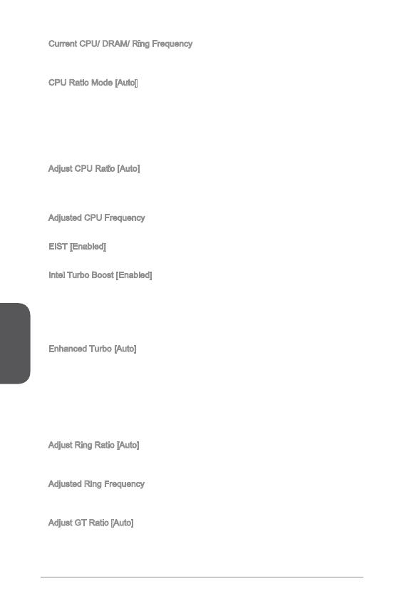
Current CPU/ DRAM/ Ring Frequency
Эти элементы показывают текущие частоты установленного процессора,
памяти и шины Ring. Эти значения нельзя изменять.
CPU Ratio Mode [Auto]
Выбор множителя процессора.
[Auto] Этот параметр будет настроен автоматически с помощью
BIOS.
[Fixed Mode] Фиксирует множитель процессора.
[Dynamic Mode] Множитель процессора будет меняться в зависимости от
загрузки процессора.
Adjust CPU Ratio [Auto]
Задание множителя процессора для установки его тактовой частоты
процессора. Изменение данного параметра возможно только в том случае, если
процессор поддерживает данную функцию.
Adjusted CPU Frequency
Показывает текущую частоту ЦП. Это значение нельзя изменять.
EIST [Enabled]
Включение или выключение технологии Enhanced Intel
®
SpeedStep.
Intel Turbo Boost [Enabled]
Включение или выключение Intel
®
Turbo Boost. Этот пункт появляется, когда
установленный процессор поддерживает данную функцию.
[Enabled] Включение этой функции приводит к автоматическому
увеличению производительности процессора.
[Disabled] Функция выключена.
Enhanced Turbo [Auto]
Функция Enhanced Turbo позволяет увеличивать частоту на всех ядрах
процессора.
[Auto] Этот параметр будет настроен автоматически с помощью
BIOS.
[Enabled] Увеличение частоты всех процессорных ядер до
максимального значения.
[Disabled] Функция выключена.
Adjust Ring Ratio [Auto]
Установка множителя шины Ring. Диапазон допустимых значений зависит от
установленного процессора.
Adjusted Ring Frequency
Показывает скорректированную частоту шины Ring. Это значение нельзя
изменять.
Adjust GT Ratio [Auto]
Установка множителя для интегрированной графики. Диапазон допустимых
значений зависит от установленного процессора.
▶
▶
▶
▶
▶
▶
▶
▶
▶
▶
Русский
7
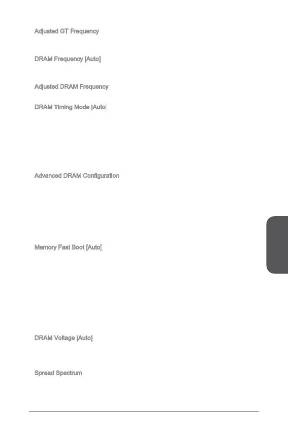
Adjusted GT Frequency
Показывает настроенную частоту интегрированной графики. Это значение
нельзя изменять.
DRAM Frequency [Auto]
Установка частоты памяти (DRAM). Обратите внимание, что возможность
успешного разгона не гарантируется.
Adjusted DRAM Frequency
Показывает текущую частоту DRAM. Это значение нельзя изменять.
DRAM Timing Mode [Auto]
Режимы таймингов памяти.
[Auto] Временные параметры DRAM устанавливаются на основе
SPD (Serial Presence Detect) модуля памяти.
[Link] Позволяет пользователю настроить тайминги DRAM вручную
для всех каналов памяти.
[UnLink] Позволяет пользователю настроить тайминги DRAM вручную
для соответствующего канала памяти.
Advanced DRAM Conguration
Нажмите <Enter> для входа в подменю. Данное подменю будет доступно после
установки [Link] или [Unlink] в режиме “DRAM Timing Mode”. Пользователь
может настроить тайминги для каждого канала памяти. Система может
работать нестабильно или не загружается после изменения тамингов памяти.
Если система работает нестабильно, пожалуйста, очистите данные CMOS
и восстановите настройки по умолчанию. (см. перемычка очистки данных
CMOS/раздел кнопки для очистки данных CMOS и вход в BIOS, чтобы загрузить
настройки по умолчанию.)
Memory Fast Boot [Auto]
Включает или выключает инициализацию тренировки памяти при каждой
загрузке.
[Auto] Этот параметр будет настроен автоматически с помощью
BIOS.
[Enabled] Память будет полностью имитирует настройки при первой
инициализации и тренировке. После этого память не будет
инициализированна с измененными настройками для
ускорения загрузки.
[Disabled] Память будет инициализирована и тренирована при каждой
загрузке.
DRAM Voltage [Auto]
Установка напряжения памяти. Если значение установлено в “Auto”, BIOS
устанавливает напряжения на памяти автоматически. Вы также можете
настроить его вручную.
Spread Spectrum
Данная функция уменьшает EMI (электромагнитные помехи), вызванные
колебаниями импульсного генератора тактовых сигналов.
▶
▶
▶
▶
▶
▶
▶
▶
-
Contents
-
Table of Contents
-
Bookmarks
Quick Links
English
Thank you for choosing the H81M-P33/ H81M-E33/ H87M-P33/ H87M-E33/ B85M-
P33/ B85M-E33 Series (MS-7817 v1.X) Micro-ATX motherboard. The H81M-P33/
H81M-E33/ H87M-P33/ H87M-E33/ B85M-P33/ B85M-E33 Series motherboards
are based on Intel H81/ H87/ B85 chipset for optimal system efficiency. Designed to
fit the advanced Intel LGA1150 processor, the H81M-P33/ H81M-E33/ H87M-P33/
H87M-E33/ B85M-P33/ B85M-E33 Series motherboards deliver a high performance
and professional desktop platform solution.
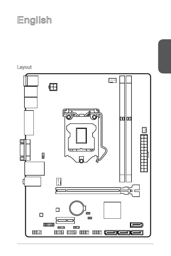
Layout
Top : mouse
Bottom: keyboard
USB2.0 ports
USB3.0 ports
DVI-D port
(for H81M-P33/
H87M-P33/ B85M-P33)
HDMI port
(for H81M-E33/
H87M-E33/ B85M-E33)
VGA port
JUSB_PW1
Top: LAN jack
Bottom: USB ports
T:Line-In
M:Line- Out
B:MIC-Int
JTPM1
JAUD1
JPWR2
SYSFAN1
PCI _E1
PCI _E2
JFP2
JUSB_PW2
JCOM1
JFP1
JUSB2
CPUFAN
JBAT1
JCI1
SATA4
JUSB1
11
SATA2
SATA3
SATA1
Summary of Contents for MSI H81M-P33 Series
Preface
Copyright Notice
The material in this document is the intellectual property of MICRO-STAR
INTERNATIONAL. We take every care in the preparation of this document, but no
guarantee is given as to the correctness of its contents. Our products are under
continual improvement and we reserve the right to make changes without notice.
Trademarks
All trademarks in this manual are properties of their respective owners.
MSI
®
is registered trademark of Micro-Star Int’l Co.,Ltd.
NVIDIA
®
is registered trademark of NVIDIA Corporation.
ATI
®
is registered trademark of AMD Corporation.
AMD
®
is registered trademarks of AMD Corporation.
Intel
®
is registered trademarks of Intel Corporation.
Windows
®
is registered trademarks of Microsoft Corporation.
AMI
®
is registered trademark of American Megatrends Inc.
Award
®
is a registered trademark of Phoenix Technologies Ltd.
Sound Blaster
®
is registered trademark of Creative Technology Ltd.
Realtek
®
is registered trademark of Realtek Semiconductor Corporation.
JMicron
®
is registered trademark of JMicron Technology Corporation.
Netware
®
is registered trademark of Novell, Inc.
Lucid
®
is trademark of LucidLogix Technologies, Ltd.
VIA
®
is registered trademark of VIA Technologies, Inc.
ASMedia
®
is registered trademark of ASMedia Technology Inc.
iPad, iPhone, and iPod are trademarks of Apple Inc.
Qualcomm Atheros and Killer are trademarks of Qualcomm Atheros Inc.
Revision History
Revision Revision History Date
V.0
First release 203/07
■
■
■
■
■
■
■
■
■
■
■
■
■
■
■
■
■
G52-787X

Preface
2
Safety Instructions
Always read the safety instructions carefully.
Keep this User’s Manual for future reference.
Keep this equipment away from humidity.
Lay this equipment on a reliable at surface before setting it up.
The openings on the enclosure are for air convection hence protects the
equipment from overheating. DO NOT COVER THE OPENINGS.
Make sure the voltage of the power source is at 0/220V before connecting the
equipment to the power inlet.
Place the power cord such a way that people can not step on it. Do not place
anything over the power cord.
Always Unplug the Power Cord before inserting any add-on card or module.
All cautions and warnings on the equipment should be noted.
Never pour any liquid into the opening that can cause damage or cause electrical
shock.
If any of the following situations arises, get the equipment checked by service
personnel:
The power cord or plug is damaged.
Liquid has penetrated into the equipment.
The equipment has been exposed to moisture.
The equipment does not work well or you can not get it work according to
User’s Manual.
The equipment has been dropped and damaged.
The equipment has obvious sign of breakage.
DO NOT LEAVE THIS EQUIPMENT IN AN ENVIRONMENT ABOVE 60
o
C
(40
o
F), IT MAY DAMAGE THE EQUIPMENT.
■
■
■
■
■
■
■
■
■
■
■
◯
◯
◯
◯
◯
◯
■
California, USA:
The button cell battery may contain perchlorate material and requires
special handling when recycled or disposed of in California.
For further information please visit:
http://www.dtsc.ca.gov/hazardouswaste/perchlorate/
Taiwan:
For better environmental protection, waste batteries should be
collected separately for recycling or special disposal.
廢電池請回收
European Union:
Batteries, battery packs, and accumulators should not be disposed
of as unsorted household waste. Please use the public collection
system to return, recycle, or treat them in compliance with the local
regulations.
Battery Information
CAUTION: There is a risk of explosion, if battery is incorrectly replaced.
Replace only with the same or equivalent type recommended by the manufacturer.

Preface
3
FCC-B Radio Frequency Interference Statement
This equipment has been tested and found to comply with the limits for a Class
B digital device, pursuant to Part 5 of the FCC Rules. These limits are designed
to provide reasonable protection against harmful interference in a residential
installation. This equipment generates, uses and can radiate radio frequency
energy and, if not installed and used in accordance with the instructions, may cause
harmful interference to radio communications. However, there is no guarantee that
interference will not occur in a particular installation. If this equipment does cause
harmful interference to radio or television reception, which can be determined
by turning the equipment o and on, the user is encouraged to try to correct the
interference by one or more of the measures listed below.
Reorient or relocate the receiving antenna.
Increase the separation between the equipment and receiver.
Connect the equipment into an outlet on a circuit dierent from that to which
the receiver is connected.
Consult the dealer or an experienced radio/television technician for help.
Notice
The changes or modications not expressly approved by the party responsible for
compliance could void the user’s authority to operate the equipment.
Notice 2
Shielded interface cables and A.C. power cord, if any, must be used in order to
comply with the emission limits.
VOIR LA NOTICE D’INSTALLATION AVANT DE RACCORDER AU RESEAU.
Micro-Star International
MS-787
This device complies with Part 5 of the FCC Rules. Operation is subject to the
following two conditions:
this device may not cause harmful interference, and
this device must accept any interference received, including interference that
may cause undesired operation.
CE Conformity
Hereby, Micro-Star International CO., LTD declares that this device is
in compliance with the essential safety requirements and other relevant
provisions set out in the European Directive.
◯
◯
◯
◯
)
2)
Preface
4
Radiation Exposure Statement
This equipment complies with FCC radiation exposure limits set forth for an
uncontrolled environment. This equipment and its antenna should be installed and
operated with minimum distance 20 cm between the radiator and your body. This
equipment and its antenna must not be co-located or operating in conjunction with
any other antenna or transmitter.
European Community Compliance Statement
The equipment complies with the RF Exposure Requirement 999/59/EC, Council
Recommendation of 2 July 999 on the limitation of exposure of the general public
to electromagnetic elds (0–300GHz). This wireless device complies with the R&TTE
Directive.
Taiwan Wireless Statements
無線設備警告聲明
經型式認證合格之低功率射頻電機,非經許可,公司、商號或使用者均不得擅自變更
頻率、加大功率或變更原設計之特性及功能。
低功率射頻電機之使用不得影響飛航安全及干擾合法通信;經發現有干擾現象時,應
立即停用,並改善至無干擾時方得繼續使用。前項合法通信,指依電信法規定作業之
無線電通信。低功率射頻電機須忍受合法通信或工業、科學及醫療用電波輻射性電機
設備之干擾。
警告使用者:這是甲類資訊產品,在居住的環境中使用時,可能會造成無線電干擾,在
這種情況下,使用者會被要求採取某些適當的對策。
Japan VCCI Class B Statement
クラス B 情報技術装置
この装置は、情報技術装置等電波障害自主規制協議会(VCCI)の基準に基づくクラ
スB情報技術装置です。この装置が家庭内でラジオやテレビジョン受信機に近接して
使われると、受信障害を引き起こすことがあります。取扱説明書にしたがって正し
い取り扱いをしてください。
Korea Warning Statements
당해 무선설비는 운용중 전파혼신 가능성이 있음
Chemical Substances Information
In compliance with chemical substances regulations, such as the EU REACH
Regulation (Regulation EC No. 907/2006 of the European Parliament and the
Council), MSI provides the information of chemical substances in products at:
http://www.msi.com/html/popup/csr/evmtprtt_pcm.html
Preface
6
WEEE Statement
WEEE (Waste Electrical and Electronic Equipment)
ENGLISH
To protect the global environment and as an environmentalist, MSI must
remind you that…
Under the European Union (“EU”) Directive on Waste Electrical and
Electronic Equipment, Directive 2002/96/EC, which takes eect on August 3, 2005,
products of “electrical and electronic equipment” cannot be discarded as municipal
wastes anymore, and manufacturers of covered electronic equipment will be
obligated to take back such products at the end of their useful life. MSI will comply
with the product take back requirements at the end of life of MSI-branded products
that are sold into the EU. You can return these products to local collection points.
DEUTSCH
Hinweis von MSI zur Erhaltung und Schutz unserer Umwelt
Gemäß der Richtlinie 2002/96/EG über Elektro- und Elektronik-Altgeräte dürfen
Elektro- und Elektronik-Altgeräte nicht mehr als kommunale Abfälle entsorgt werden.
MSI hat europaweit verschiedene Sammel- und Recyclingunternehmen beauftragt,
die in die Europäische Union in Verkehr gebrachten Produkte, am Ende seines
Lebenszyklus zurückzunehmen. Bitte entsorgen Sie dieses Produkt zum gegebenen
Zeitpunkt ausschliesslich an einer lokalen Altgerätesammelstelle in Ihrer Nähe.
FRANÇAIS
En tant qu’écologiste et an de protéger l’environnement, MSI tient à rappeler ceci…
Au sujet de la directive européenne (EU) relative aux déchets des équipement
électriques et électroniques, directive 2002/96/EC, prenant eet le 3 août 2005,
que les produits électriques et électroniques ne peuvent être déposés dans les
décharges ou tout simplement mis à la poubelle. Les fabricants de ces équipements
seront obligés de récupérer certains produits en n de vie. MSI prendra en compte
cette exigence relative au retour des produits en n de vie au sein de la communauté
européenne. Par conséquent vous pouvez retourner localement ces matériels dans
les points de collecte.
РУССКИЙ
Компания MSI предпринимает активные действия по защите окружающей
среды, поэтому напоминаем вам, что….
В соответствии с директивой Европейского Союза (ЕС) по предотвращению
загрязнения окружающей среды использованным электрическим и электронным
оборудованием (директива WEEE 2002/96/EC), вступающей в силу 3
августа 2005 года, изделия, относящиеся к электрическому и электронному
оборудованию, не могут рассматриваться как бытовой мусор, поэтому
производители вышеперечисленного электронного оборудования обязаны
принимать его для переработки по окончании срока службы. MSI обязуется
соблюдать требования по приему продукции, проданной под маркой MSI на
территории EC, в переработку по окончании срока службы. Вы можете вернуть
эти изделия в специализированные пункты приема.
English
Top : mouse
Bottom: keyboard
Top: LAN jack
Bottom: USB ports
T:Line—In
M:Line— Out
B:MIC—Int
USB2.0 ports
USB3.0 ports
DVI—D port
(for H81M—P33/
H87M—P33/ B85M—P33)
HDMI port
(for H81M—E33/
H87M—E33/ B85M—E33)
VGA port
PCI _E2
PCI _E1
JUSB2 JUSB1
SYSF
AN
2
CPUFAN
JPWR2
JUSB_PW1
DIMM1
DIMM2
JAUD1
JTPM1
SYSFAN1
JCI1
JBAT1
JUSB_PW2
JCOM1
SATA4 SATA3 SATA1
SATA2
JPWR1
JFP1
JFP2
English
Thank you for choosing the H8M-P33/ H8M-E33/ H87M-P33/ H87M-E33/ B85M-
P33/ B85M-E33 Series (MS-787 v.X) Micro-ATX motherboard. The H8M-P33/
H8M-E33/ H87M-P33/ H87M-E33/ B85M-P33/ B85M-E33 Series motherboards
are based on Intel H8/ H87/ B85 chipset for optimal system eciency. Designed to
t the advanced Intel LGA50 processor, the H8M-P33/ H8M-E33/ H87M-P33/
H87M-E33/ B85M-P33/ B85M-E33 Series motherboards deliver a high performance
and professional desktop platform solution.
Layout
English
2
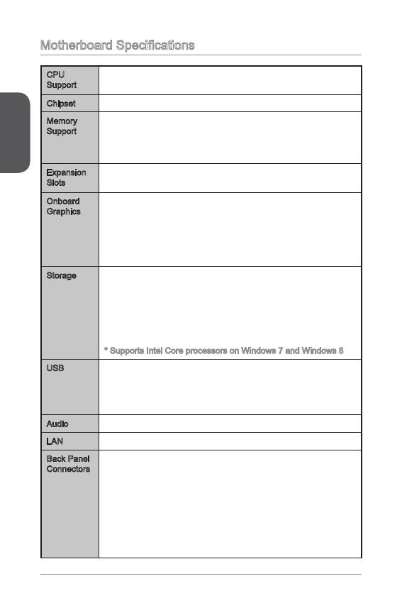
Motherboard Specications
CPU
Support
4th Generation Intel
®
Core™ i7 / Core™ i5 / Core™ i3 /
Pentium
®
/ Celeron
®
processors for LGA 50 socket
■
Chipset Intel
®
H8/ H87/ B85 Express Chipset■
Memory
Support
2x DDR3 memory slots supporting up to 6GB
Supports DDR3 600/ 333/ 066 MHz
Dual channel memory architecture
Supports non-ECC, un-buered memory
■
■
■
■
Expansion
Slots
x PCIe x6 slot (optional)
x PCIe 2.0 x slot
■
■
Onboard
Graphics
x HDMI port (optional), supporting a maximum resolution of
x DVI-D port (optional), supporting a maximum resolution of
920x200 @ 60Hz, 24bpp
x VGA port, supporting a maximum resolution of 920x200
@ 60Hz, 24bpp
■
■
■
Storage Intel H8/ H87/ B85 Express Chipset
4x SATA ports (optional)
Supports RAID 0, RAID, RAID 5 and RAID 0 (optional)
Supports Intel Smart Response Technology (optional)*
Supports Intel Rapid Start Technology (optional)*
Supports Intel Smart Connect Technology (optional)*
* Supports Intel Core processors on Windows 7 and Windows 8
■
—
—
—
—
—
USB Intel H8/ H87/ B85 Express Chipset
2x USB 3.0 ports on the back panel
8x USB 2.0 ports (4 ports on the back panel, 4 ports avail-
able through the internal USB connectors*)
■
—
—
Audio Realtek
®
ALC887 Codec■
LAN Realtek
®
RTL8G Gigabit LAN controller■
Back Panel
Connectors
x PS/2 keyboard port
x PS/2 mouse port
4x USB 2.0 ports
2x USB 3.0 ports
x HDMI port (optional)
x DVI-D port (optional)
x VGA port
x LAN (RJ45) port
3x audio jacks
■
■
■
■
■
■
■
■
■
English
3
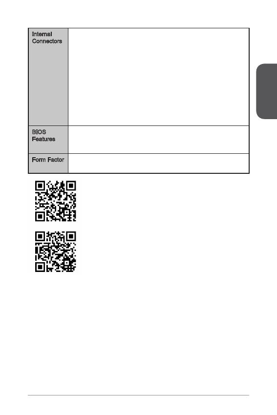
Internal
Connectors
x 24-pin ATX main power connector
x 4-pin ATX 2V power connector
4x SATA connectors
2x USB 2.0 connectors (supports additional 4 USB 2.0 ports)
x 4-pin CPU fan connector
x 4-pin system fan connector
x 3-pin system fan connector
x Front panel audio connector
2x System panel connectors
x Chassis Intrusion connector
x Clear CMOS jumper
2x USB power jumpers
■
■
■
■
■
■
■
■
■
■
■
■
BIOS
Features
UEFI AMI BIOS
ACPI 5.0, PnP .0a, SM BIOS 2.7, DMI 2.0
Multi-language
■
■
■
Form Factor Micro-ATX Form Factor
8.9 in. x 6.8 in. (22.6 cm x 7.3 cm)
■
■
For the latest information about CPU, please visit
http://www.msi.com/service/cpu-support/
For more information on compatible components, please
visit http://www.msi.com/service/test-report/
English
4
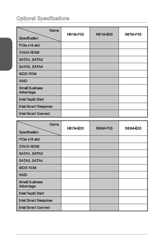
Optional Specications
Name
Specication
H8M-P33 H8M-E33 H87M-P33
PCIe x6 slot Gen2 Gen2 Gen3
DVI-D/ HDMI DVI-D HDMI DVI-D
SATA, SATA2 SATA 6Gb/s SATA 6Gb/s SATA 6Gb/s
SATA3, SATA4 SATA 3Gb/s SATA 3Gb/s SATA 6Gb/s
BIOS ROM 64Mb 64Mb 28Mb
RAID Not supported Not supported Supported
Small Business
Advantage
Not supported Not supported Supported
Intel Rapid Start Not supported Not supported Supported
Intel Smart Response Not supported Not supported Supported
Intel Smart Connect Supported Supported Supported
Name
Specication
H87M-E33 B85M-P33 B85M-E33
PCIe x6 slot Gen3 Gen3 Gen3
DVI-D/ HDMI HDMI DVI-D HDMI
SATA, SATA2 SATA 6Gb/s SATA 6Gb/s SATA 6Gb/s
SATA3, SATA4 SATA 6Gb/s SATA 3Gb/s SATA 3Gb/s
BIOS ROM 28Mb 28Mb 28Mb
RAID Supported Not supported Not supported
Small Business
Advantage
Supported Supported Supported
Intel Rapid Start Supported Supported Supported
Intel Smart Response Supported Not supported Not supported
Intel Smart Connect Supported Supported Supported
English
5
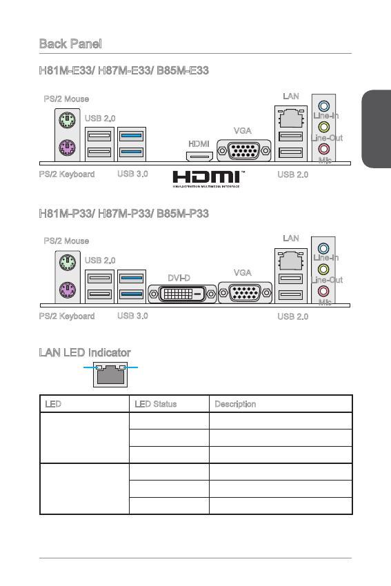
Back Panel
LAN LED Indicator
LINK/ACT
LED
SPEED
LED
LED LED Status Description
Link/ Activity LED
O No link
Yellow Linked
Blinking Data activity
Speed LED
O 0 Mbps connection
Green 00 Mbps connection
Orange Gbps connection
H8M-E33/ H87M-E33/ B85M-E33
H8M-P33/ H87M-P33/ B85M-P33
PS/2 Mouse
PS/2 Keyboard
USB 2.0
USB 3.0
HDMI
VGA
Line-In
Line-Out
Mic
USB 2.0
LAN
PS/2 Mouse
PS/2 Keyboard
USB 2.0
USB 3.0
DVI-D
VGA
Line-In
Line-Out
Mic
USB 2.0
LAN
English
6
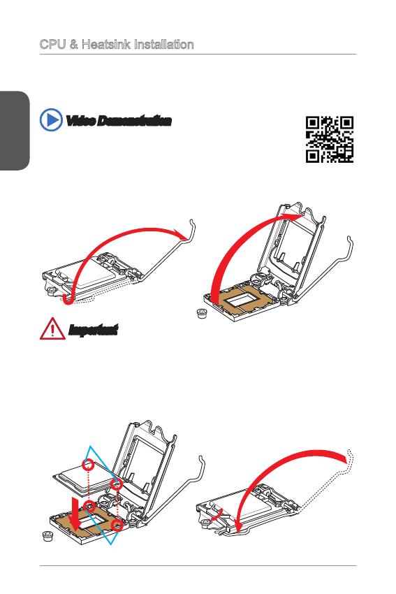
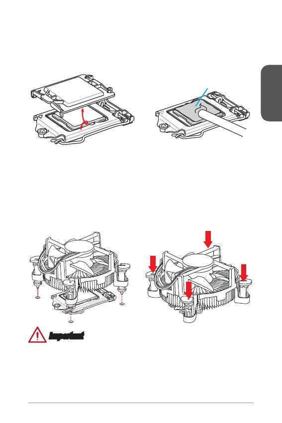
CPU & Heatsink Installation
When installing a CPU, always remember to install a CPU heatsink. A CPU heatsink
is necessary to prevent overheating and maintain system stability. Follow the steps
below to ensure correct CPU and heatsink installation. Wrong installation can
damage both the CPU and the motherboard.
. Push the load lever down to unclip it and lift to the fully open position.
2. The load plate will automatically lift up as the load lever is pushed to the fully
open position.
Important
Do not touch the socket contacts or the bottom of the CPU.
Video Demonstration
Watch the video to learn how to install CPU & heatsink. at the
address below.
http://youtu.be/bf5La099urI
Alignment Key
CPU notches
3. Align the notches with the socket alignment keys. Lower the CPU straight down,
without tilting or sliding the CPU in the socket. Inspect the CPU to check if it is
properly seated in the socket.
4. Close and slide the load plate under the retention knob. Close and engage the
load lever.
English
7
Thermal paste
Important
Conrm that the CPU heatsink has formed a tight seal with the CPU before booting
your system.
Whenever the CPU is not installed, always protect the CPU socket pins by
covering the socket with the plastic cap.
If you purchased a separate CPU and heatsink/ cooler, Please refer to the
documentation in the heatsink/ cooler package for more details about installation.
•
•
•
5. When you press down the load lever the PnP cap will automatically pop up from
the CPU socket. Do not discard the PnP cap. Always replace the PnP cap if the
CPU is removed from the socket.
6. Evenly spread a thin layer of thermal paste (or thermal tape) on the top of the
CPU. This will help in heat dissipation and prevent CPU overheating.
7. Locate the CPU fan connector on the motherboard.
8. Place the heatsink on the motherboard with the fan’s cable facing towards the
fan connector and the fasteners matching the holes on the motherboard.
9. Push down the heatsink until the four fasteners get wedged into the holes on
the motherboard. Press the four fasteners down to fasten the heatsink. As each
fastener locks into position a click should be heard.
0. Inspect the motherboard to ensure that the fastener-ends have been properly
locked in place.
. Finally, attach the CPU fan cable to the CPU fan connector on the motherboard.
English
8
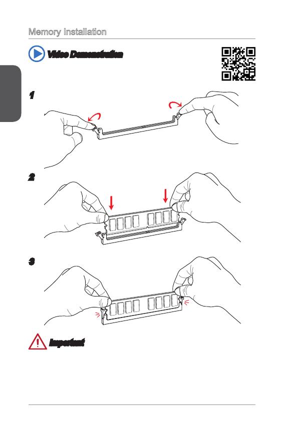
Memory Installation
Video Demonstration
Watch the video to learn how to install memories at the address below.
2
3
Important
DDR3 memory modules are not interchangeable with DDR2, and the DDR3
standard is not backward compatible. Always install DDR3 memory modules in
DDR3 DIMM slots.
To ensure system stability, memory modules must be of the same type and density
in Dual-Channel mode.
•
•
English
9
Internal Connectors
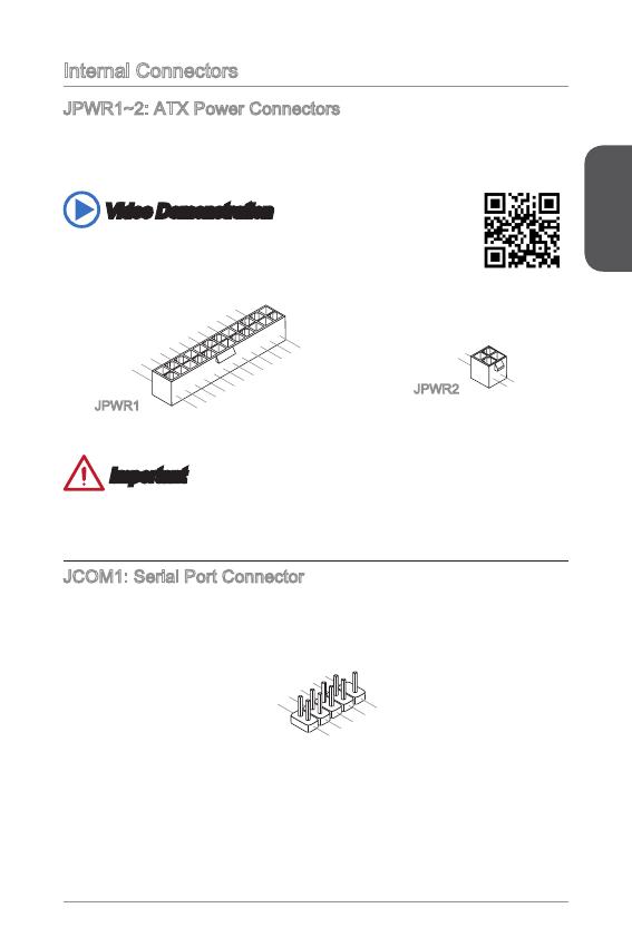
JPWR~2: ATX Power Connectors
These connectors allow you to connect an ATX power supply. To connect the ATX
power supply, align the power supply cable with the connector and rmly press the
cable into the connector. If done correctly, the clip on the power cable should be
hooked on the motherboard’s power connector.
Video Demonstration
Watch the video to learn how to install power supply connectors.
13.+3.3
V
1.+3.3
V
14.—12V
2.+3.3
V
15.Ground
3
.Ground
16.PS—ON
#
4.+5
V
17.Ground
5
.Ground
18.Ground
6.+5
V
19.Ground
7
.Ground
22.+5
V
10.+12V
20.Res
8.PW
R O
K
23.+5
V
11
.+12V
21.+5
V
9.5VSB
24.Ground
12.+3.3
V
JPWR
4.+12V
2
.Ground
3.+12V
1
.Ground
JPWR2
Important
Make sure that all the power cables are securely connected to a proper ATX power
supply to ensure stable operation of the motherboard.
JCOM: Serial Port Connector
This connector is a 6550A high speed communication port that sends/receives 6
bytes FIFOs. You can attach a serial device.
1
.
D
C
D
3
.
S
O
U
T
1
0
.
N
o
P
i
n
5
.
G
r
o
u
n
d
7
.
R
T
S
9
.
R
I
8
.
C
T
S
6
.
D
S
R
4
.
D
T
R
2
.
S
I
N
English
20
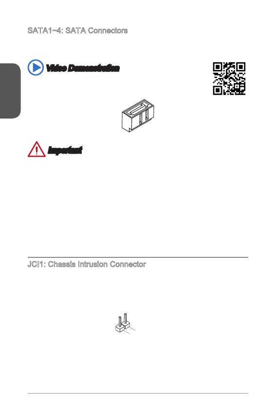
SATA~4: SATA Connectors
This connector is a high-speed SATA interface port. Each connector can connect to
one SATA device. SATA devices include disk drives (HDD), solid state drives (SSD),
and optical drives (CD/ DVD/ Blu-Ray).
Video Demonstration
Watch the video to learn how to Install SATA HDD.
Important
Many SATA devices also need a power cable from the power supply. Such devices
include disk drives (HDD), solid state drives (SSD), and optical drives (CD / DVD /
Blu-Ray). Please refer to the device’s manual for further information.
Many computer cases also require that large SATA devices, such as HDDs, SSDs,
and optical drives, be screwed down into the case. Refer to the manual that came
with your computer case or your SATA device for further installation instructions.
Please do not fold the SATA cable at a 90-degree angle. Data loss may result
during transmission otherwise.
SATA cables have identical plugs on either sides of the cable. However, it is
recommended that the at connector be connected to the motherboard for space
saving purposes.
JCI: Chassis Intrusion Connector
This connector connects to the chassis intrusion switch cable. If the computer case
is opened, the chassis intrusion mechanism will be activated. The system will record
this intrusion and a warning message will ash on screen. To clear the warning, you
must enter the BIOS utility and clear the record.
•
•
•
•
English
2
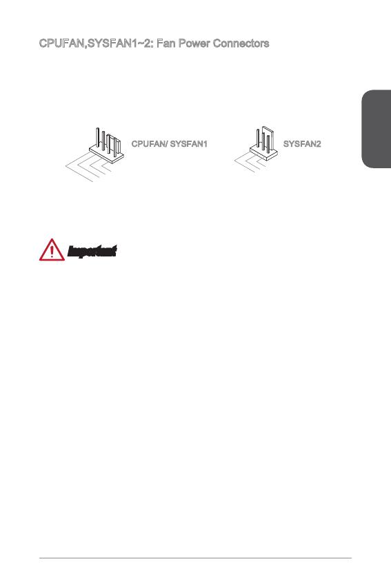
CPUFAN,SYSFAN~2: Fan Power Connectors
The fan power connectors support system cooling fans with +2V. If the motherboard
has a System Hardware Monitor chipset on-board, you must use a specially designed
fan with a speed sensor to take advantage of the CPU fan control. Remember to
connect all system fans. Some system fans may not connect to the motherboard and
will instead connect to the power supply directly. A system fan can be plugged into
any available system fan connector.
1
.Ground
2.+12V
3.Sens
e
4.Speed
C
ontro
l
CPUFAN/ SYSFAN SYSFAN2
Important
Please refer to your processor’s ocial website or consult your vendor to nd
recommended CPU heatsink.
These connectors support Smart Fan Control with liner mode. The Command
Center utility can be installed to automatically control the fan speeds according to
the CPU’s and system’s temperature.
If there are not enough ports on the motherboard to connect all system fans,
adapters are available to connect a fan directly to a power supply.
Before rst boot up, ensure that there are no cables impeding any fan blades.
•
•
•
•
English
22
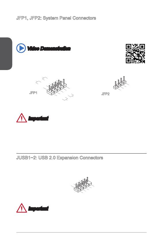
JFP, JFP2: System Panel Connectors
These connectors connect to the front panel switches and LEDs. The JFP
connector is compliant with the Intel
®
Front Panel I/O Connectivity Design Guide.
When installing the front panel connectors, please use the optional M-Connector to
simplify installation. Plug all the wires from the computer case into the M-Connector
and then plug the M-Connector into the motherboard.
Video Demonstration
Watch the video to learn how to Install front panel connectors.
3.Speaker
4.VCC5
1.Speaker
2.VCC5
1.
+
3.
—
10.No
Pi
n
5.—
Reset
S
witch
HDD
LE
D
P
ower
Switc h
P
ower
LE
D
7.
+
9.Res erve
d
8.
—
6.
+
4.
—
2.
+
JFP
JFP2
Important
On the connectors coming from the case, pins marked by small triangles are
positive wires. Please use the diagrams above and the writing on the optional M-
Connectors to determine correct connector orientation and placement.
The majority of the computer case’s front panel connectors will primarily be
plugged into JFP.
JUSB~2: USB 2.0 Expansion Connectors
This connector is designed for connecting high-speed USB peripherals such as USB
HDDs, digital cameras, MP3 players, printers, modems, and many others.
1
.
V
C
C
3
.
U
S
B
0
—
1
0
.
NC
5
.
U
S
B
0
+
7
.
G
r
o
u
n
d
9
.
N
o
P
i
n
8
.
G
r
o
u
n
d
6
.
U
S
B
1
+
4
.
U
S
B
1
—
2
.
V
C
C
Important
Note that the VCC and GND pins must be connected correctly to avoid possible
damage.
•
•

English
23
JAUD: Front Panel Audio Connector
This connector allows you to connect the front audio panel located on your computer
case. This connector is compliant with the Intel
®
Front Panel I/O Connectivity Design
Guide.
1.MI
C L
3.MIC R
10.Head
P
hone
Detection
5.Head
P
hone
R
7.SENSE_SEN
D
9.Head
P
hone
L
8.No
Pi
n
6.MI
C D
etection
4.NC
2
.Ground
JTPM: TPM Module Connector
This connector connects to a TPM (Trusted Platform Module). Please refer to the
TPM security platform manual for more details and usages.
10.No
Pi
n
14.Ground
8.5V
P
ower
12.Ground
6.Serial
IR
Q
4.3.3V
P
ower
2.3V
Standby
p
ower
1.LP
C C
loc
k
3.LP
C
Rese
t
5.LP
C a
ddres
s &
data
p
in0
7.LP
C a
ddres
s &
data
p
in1
9.LP
C a
ddres
s &
data
pin2
11
.LPC
a
ddres
s &
data
p
in3
13.LP
C
Fram
e
English
24
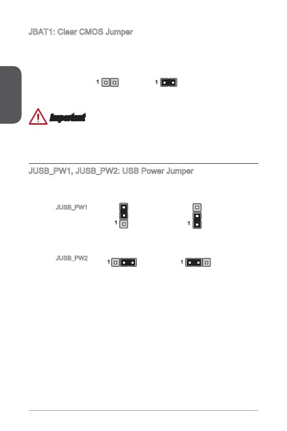
JBAT: Clear CMOS Jumper
There is CMOS RAM onboard that is external powered from a battery located on the
motherboard to save system conguration data. With the CMOS RAM, the system
can automatically boot into the operating system (OS) every time it is turned on. If
you want to clear the system conguration, set the jumpers to clear the CMOS RAM.
Keep Data Clear Data
Important
You can clear the CMOS RAM by shorting this jumper while the system is o.
Afterwards, open the jumper . Do not clear the CMOS RAM while the system is on
because it will damage the motherboard.
JUSB_PW, JUSB_PW2: USB Power Jumper
These jumpers are used to assign which USB and PS/2 ports could support “Wake
Up Event Setup” eld of BIOS.
Support
No Support (Default)
JUSB_PW
(for back panel
USB ports &
PS/2 ports)
JUSB_PW2
(for onboard
USB connectors)
Support
No Support (Default)
English
25
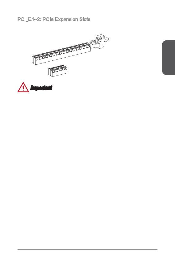
PCI_E~2: PCIe Expansion Slots
The PCIe slot supports the PCIe interface expansion card.
PCIe 2.0 x Slot
PCIe 3.0 x6 Slot
Important
When adding or removing expansion cards, always turn o the power supply and
unplug the power supply power cable from the power outlet. Read the expansion
card’s documentation to check for any necessary additional hardware or software
changes.
Table Of Contents
📚 MSI H81M-P33 Series User Manual
-
TABLE OF CONTENTS
- Motherboard specifications
- Optional specifications
- Back panel
- Memory installation
- Atx power connectors
- Fan Power Connectors
- System panel connectors
- Front panel audio connector
- Clear cmos jumper
- Entering bios setup
Manufacturer: MSI
Category: Motherboard
Download Manual (1.33 MB)
Related manuals

MSI H81M-P33 Series User Manual
Motherboard
MSI H81M-P33 Series User Manual
Motherboard
MSI H81M-P33 Series Manual
Motherboard
More by MSI
MSI MS-6117 User Manual
Motherboard
88 pages
Nov 28, 2022
MSI Z170A KRAIT GAMING User Manual
Motherboard
90 pages
Nov 30, 2022
MSI Wind Board 330 Manual
Motherboard
51 pages
MSI A88X-G41 PC Mate Product Manual
Motherboard
195 pages
MSI MS-7520 ECLIPSE Series User Manual
Motherboard
158 pages
SEE MORE ❯
More products and manuals for Motherboards MSI
| Models | Document Type |
|---|---|
|
Z97A GAMING 6 |
User Manual
108 pages |
|
Z97 XPOWER AC |
User Manual
118 pages |
|
FM2-A55-G43 series |
User Manual
94 pages |
|
Z97A GAMING 7 |
User Manual
114 pages |
|
Z87 XPOWER |
User Manual
120 pages |
|
B75MA-E31 |
User Manual
30 pages |
|
Z87M GAMING |
User Manual
112 pages |
|
Z87 MPOWER SP |
User Manual
118 pages |
|
H81TI |
User Manual
186 pages |
|
H97 PC MATE |
User Manual
102 pages |
|
A88XM GAMING |
User Manual
102 pages |
|
H87-G43 GAMING |
User Manual
217 pages |
|
G41M-P43 Combo |
Instruction Manual
153 pages |
|
Z97 GAMING 5 |
User Manual
108 pages |
|
760GM-P23 (FX) |
Instruction Manual
169 pages |
|
870S-C45 (FX) |
Instruction Manual
153 pages |
|
G31TM-P25 |
User Manual
54 pages |
|
970A-G46 |
User’s Guide
74 pages |
|
H61M-E33 |
User Manual
138 pages |
|
MS-7758 (v1.x) |
User Manual
82 pages |


