
I
Quick Start
Quick Start
Thank you for purchasing the MSI
®
Z170A GAMING M5
motherboard. This Quick Start section provides demonstration
diagrams about how to install your computer. Some of the
installations also provide video demonstrations. Please link to the
URL to watch it with the web browser on your phone or tablet. You
may have even link to the URL by scanning the QR code.
Kurzanleitung
Danke, dass Sie das MSI
®
Z170A GAMING M5 Motherboard
gewählt haben. Dieser Abschnitt der Kurzanleitung bietet eine Demo
zur Installation Ihres Computers. Manche Installationen bieten
auch die Videodemonstrationen. Klicken Sie auf die URL, um diese
Videoanleitung mit Ihrem Browser auf Ihrem Handy oder Table
anzusehen. Oder scannen Sie auch den QR Code mit Ihrem Handy,
um die URL zu öffnen.
Présentation rapide
Merci d’avoir choisi la carte mère MSI
®
Z170A GAMING M5.
Ce manuel fournit une rapide présentation avec des illustrations
explicatives qui vous aideront à assembler votre ordinateur. Des
tutoriels vidéo sont disponibles pour certaines étapes. Cliquez sur
le lien fourni pour regarder la vidéo sur votre téléphone ou votre
tablette. Vous pouvez également accéder au lien en scannant le QR
code qui lui est associé.
Быстрый старт
Благодарим вас за покупку материнской платы MSI
®
Z170A
GAMING M5. В этом разделе представлена информация,
которая поможет вам при сборке комьютера. Для некоторых
этапов сборки имеются видеоинструкции. Для просмотра видео,
необходимо открыть соответствующую ссылку в веб-браузере
на вашем телефоне или планшете. Вы также можете выполнить
переход по ссылке, путем сканирования QR-кода.

1
Содержание
Содержание
Безопасное использование продукции ………………………………………………….2
Технические характеристики …………………………………………………………………..3
Задняя панель ввода/ вывода ………………………………………………………………..9
Таблица состояния индикатора порта LAN …………………………………………….. 9
Конфигурация портов Аудио ………………………………………………………………….. 9
Компоненты материнской платы ………………………………………………………….11
Процессорный сокет ……………………………………………………………………………. 12
Слоты DIMM ……………………………………………………………………………………….. 13
PCI_E1~7: Слоты расширения PCIe ……………………………………………………… 14
SATA1~6: Разъемы SATA 6 Гб/с…………………………………………………………… 16
SE1_43-SE2_65: Разъемы SATAe…………………………………………………………. 16
M2_1~2: Разъемы M.2 …………………………………………………………………………. 17
JPWR1~2: Разъемы питания ……………………………………………………………….. 20
JUSB1~2: Разъемы USB 2.0 …………………………………………………………………. 21
JUSB3: Разъем USB 3.1 Gen1 ……………………………………………………………… 21
JFP1, JFP2: Разъемы передней панели ……………………………………………….. 22
JAUD1: Разъем аудио передней панели……………………………………………….. 22
JTPM1: Разъем модуля ТРМ………………………………………………………………… 22
JCOM1: Разъем последовательного порта …………………………………………… 23
JCI1: Разъем датчика открытия корпуса ……………………………………………….. 23
CPUFAN1~2, SYSFAN1~3: Разъемы вентиляторов ……………………………….. 24
SLOW_1: Переключатель режима медленной загрузки …………………………. 25
JBAT1: Джампер очистки данных CMOS (Сброс BIOS) ………………………….. 25
POST: Код индикатора отладки ……………………………………………………………. 26
Таблица кодов индикатора отладки ……………………………………………………… 26
Настройка BIOS……………………………………………………………………………………….27
Вход в настройки BIOS ………………………………………………………………………… 27
Сброс BIOS …………………………………………………………………………………………. 28
Обновление BIOS ……………………………………………………………………………….. 28
Режим EZ ……………………………………………………………………………………………. 29
Режим разгона …………………………………………………………………………………… 31
Меню OC …………………………………………………………………………………………….. 32
Описание программного обеспечения ………………………………………………….41
Установка Windows
®
7/ 8.1/ 10 ……………………………………………………………… 41
Установка драйверов ………………………………………………………………………….. 41
Установка утилит ………………………………………………………………………………… 41

2
Безопасное использование продукции
Безопасное использование продукции
● Компоненты, входящие в комплект поставки могут быть повреждены
статическим электричеством. Для успешной сборки компьютера, пожалуйста,
следуйте указаниям ниже.
● Убедитесь, что все компоненты компьютера подключены должным образом.
Ослабленные соединения компонентов могут привести как к сбоям в работе,
так и полной неработоспособности компьютера.
● Чтобы избежать повреждений компонентов платы всегда держите ее за края.
● При сборке комьютера рекомендуется пользоваться электростатическим
браслетом. В случае, если это невозможно, перед работой с платой снимите
электростатический заряд со своего тела, прикоснувшись к металлическому
предмету.
● В случае, если материнская плата не установлена в корпус, храните ее в
антистатической упаковке или на антистатическим коврике.
● Перед включением компьютера убедитесь, что все винты крепления и другие
металлические компоненты на материнской плате и внутри корпуса надежно
зафиксированы.
● Не включайте компьютер, если сборка не завершена. Это может привести к
повреждению компонентов, а также травмированию пользователя.
● Если вам нужна помощь на любом этапе сборки компьютера, пожалуйста,
обратитесь к сертифицированному компьютерному специалисту.
● Всегда выключайте питание и отсоединяйте шнур питания от электрической
розетки перед установкой или удалением любого компонента компьютера.
● Сохраните это руководство для справки.
● Не допускайте воздействия на материнскаую плату высокой влажности.
● Перед тем как подключить блок питания компьютера к электрической
розетке убедитесь, что напряжение электросети соответствует напряжению,
указанному на блоке питания.
● Располагайте шнур питания так, чтобы на него не могли наступить люди. Не
ставьте на шнур питания никаких предметов.
● Необходимо учитывать все предостережения и предупреждения, указанные
на материнской плате.
● При возникновении любой из перечисленных ниже ситуаций обратитесь в
сервисный центр для проверки материнской платы:
▶ Попадание жидкости внутрь компьютера.
▶ Материнская плата подверглась воздействию влаги.
▶ Материнская плата не работает должным образом или невозможно наладить
ее работу в соответствии с руководством пользователя.
▶ Материнская плата получила повреждения при падении.
▶ Материнская плата имеет явные признаки повреждения.
● Не храните материнскую плату в местах с температурой выше 60 °C (140 °F),
так как это может привести к ее повреждению.
3
Технические характеристики
Технические характеристики
Процессор
Поддержка процессоров Intel
®
Core
™
i3/i5/i7, Intel
®
Pentium
®
и Celeron
®
6-го поколения для сокета LGA1151
Чипсет Intel
®
Z170
Память
● 4x DDR4 слота памяти с поддержкой до 64 ГБ
▶ Поддержка DDR4 3600(OC)/ 3200(OC)/ 3000(OC)/
2800(OC)/ 2600(OC)/ 2400/ 2133 МГц
● Двухканальная архитектура памяти
● Поддержка ECC, небуферизованной памяти
● Поддержка Intel
®
Extreme Memory Profile (XMP)
Слоты расширения
● 3x слота PCIe 3.0 x16 (поддержка режимов x16, x8/x8,
x8/x8/x4 or x8/x8/x1)
● 4x слота PCIe 3.0 x1
Встроенная
графика
● 1x порт HDMI
™
, с поддержкой максимального
● 1x порт DVI-D, с поддержкой максимального
Поддержка Multi-
GPU
● Поддержка Технологии 3-Way AMD
®
CrossFire
™
● Поддержка Технологии 2-Way NVIDIA
®
SLI
™
Подключение
накопителей
Чипсет Intel
®
Z170
● 6x портов SATA 6 Гб/с* (4 порта зарезервированы для
порта SATA Express)
● 2x разъема M.2
▶ Поддержка стандартов PCIe 3.0 x4 и SATA 6 Гб/с,
карт M.2 SSD, длиной 4.2/ 6/ 8 см
▶ Поддержка PCIe 3.0 x4 NVMe Mini-SAS SSD с Turbo
U.2 хост-картой**
● 2x порта SATAe (PCIe 3.0 x2)***
● Поддержка Технологии Intel
®
Smart Response для
процессоров Intel Core™
* Порты M.2, SATA и SATAe максимально поддерживают 1x M.2_PCIe +
6x SATAs или 1x M.2_SATA + 1x M.2_PCIe + 4x SATAs.
** Turbo U.2 хост-карта не входит в комплект поставки и приобретается
отдельно.
*** Порт SATAe обратно совместим с SATA.
Продолжение на следующей странице
4
Технические характеристики
Продолжение с предыдущей страницы
RAID
Чипсет Intel
®
Z170
● Поддерживает RAID 0, RAID 1, RAID 5 и RAID 10 для
устройств хранения данных SATA
● Поддерживает RAID 0 и RAID 1 для устройств
хранения данных M.2 PCIe*
* Объем массива M.2 PCIe RAID можно определить при помощи UEFI
BIOS
USB
● Чипсет ASMedia
®
ASM1142
▶ 1x порт USB 3.1 Gen2 (SuperSpeed USB 10 Гбит) на
задней панели
▶ 1x порт USB 3.1 Gen2 Type-C на задней панели
● Чипсет Intel
®
Z170
▶ 6x портов USB 3.1 Gen1 (SuperSpeed USB) (4
порта на задней панели, 2 порта доступны через
внутренние USB разъемы)
▶ 6x портов USB 2.0 (High-speed USB) (2 порта на
задней панели, 4 порта доступны через внутренние
USB разъемы)
Аудио
● Realtek
®
ALC1150 Codec
● 7.1-канальный High Definition Audio
● Выход S/PDIF
LAN 1x Гигабитный сетевой контроллер Killer
™
E2400
Разъемы задней
панели
● 1x порт PS/2 клавиатура/ мышь
● 2x порта USB 2.0
● 1x порт DVI-D
● 1x порт USB 3.1 Gen2
● 1x порт USB 3.1 Gen2 Type-C
● 4x порта USB 3.1 Gen1
● 1x порт HDMI
™
● 1x порт LAN (RJ45)
● 1x оптический разъем S/PDIF ВЫХОД
● 5x аудиоразъемов OFC
Продолжение на следующей странице
5
Технические характеристики
Продолжение с предыдущей страницы
Разъемы на плате
● 1x 24-контактный разъем питания ATX
● 1x 8-контактный разъем питания ATX 12В
● 6x разъемов SATA 6 Гб/с
● 2x разъема SATAe
● 2x разъема USB 2.0 (Поддержка 4-х дополнительных
портов USB 2.0)
● 1x разъем USB 3.1 Gen1 (Поддержка 2-х
дополнительных портов USB 3.1)
● 2x 4-контактных разъема вентилятора процессора
● 3x 4-контактных разъема вентилятора системы
● 1x аудиоразъем передней панели
● 2x разъема передней панели
● 1x разъем модуля TPM
● 1x разъем последовательного порта
● 1x разъем датчика открытия корпуса
● 1x переключатель режима медленной загрузки
● 1x джампер очистки данных CMOS
● 1x 2-значный индикатор отладки
Контроллер ввода-
вывода
NUVOTON NCT6793
Аппаратный
мониторинг
● Определение температуры процессора/системы
● Определение скорости вентиляторов процессора/
системы
● Управление скоростью вентиляторов процессора/
системы
Форм-фактор
● ATX Форм-фактор
● 12 x 9.6 дюйма (30.5 x 24.4 см)
Параметры BIOS
● 1x 128 Мб флэш
● UEFI AMI BIOS
● ACPI 5.0, PnP 1.0a, SM BIOS 2.8
● Мультиязычный интерфейс
Продолжение на следующей странице

7
Технические характеристики
Продолжение с предыдущей страницы
ГЕЙМЕРСКИЕ
функции
● AUDIO BOOST 3
▶ Изолированная плата аудио
▶ Защита от электромагнитных помех
▶ Сдвоенный усилитель наушников
▶ Высококачественные аудио конденсаторы
▶ Позолоченные разъемы аудио
● GAME BOOST
▶ Легкий разгон
● GAMING LAN
▶ Killer E2400 Ethernet
▶ Killer Network Manager
▶ Защита от электромагнитных помех
▶ Electric Wave Surge
● GAMING APP
▶ Переключение режима работы системы: OC/Gaming/
Silent
▶ Gaming Hotkey
▶ Gaming Mouse Control
● Optimized Thermal Design
▶ Heat-pipe Direct Touch Technology
▶ Dual Touch Thermal Design
● Nahimic
▶ Эквалайзер звуковых эффектов
▶ Шумоподавление микрофона
▶ HD Audio Recorder
● XSplit
▶ XSplit Gamecaster
▶ XSplit Broadcaster
● GAMING CERTIFIED
Продолжение на следующей странице

8
Технические характеристики
Продолжение с предыдущей страницы
MSI Эксклюзивные
функции
● CLICK BIOS 5
▶ Режим EZ и расширенный режим
▶ Board Explorer
▶ Аппаратный мониторинг
● MILITARY CLASS 5
▶ Компоненты Military Class
▶ Стабильность и надежность в соответсветствии с
военными стандартами Military Class
— Защита от электростатических разрядов
— Защита от электромагнитных помех
— Защита от влажности
— Защита от замыканий
— Защита от высокой температуры
— Слоты Steel Armor PCIe
— Слот VGA Armor
● COMMAND CENTER
▶ Мониторинг системы
▶ Интеллектуальное управление скоростью вращения
вентиляторов
● RAMDISK
● LIVE UPDATE 6
● M-CLOUD
● CPU-Z
Мелирование
характеристики
● Поддержка DDR4 Boost
▶ Поддержка двухканальной памяти DDR4
▶ Изолированные электрические цепи DDR4
▶ DDR4 XMP Ready
● Поддержка PCI Express 3.0
▶ Поддержка 2-Way Nvidia SLI
TM
▶ Поддержка 3-Way AMD CrossFire
TM
● USB 3.1 Gen2 Ready
▶ USB 3.1 Gen2 (10 Гб/с) Type-C Ready
▶ USB 3.1 Gen2 (10 Гб/с) Type-A Ready
● Twin Turbo M.2 Ready
▶ Поддержка Dual M.2 RAID
▶ Поддержка PCIe 3.0 x4 (32 Гб/с)
▶ Поддержка двойного режима PCIe/ SATA
● Поддержка SATA Express
● Поддержка драйвера NVMe / AHCI
● Поддержка U.2 (опционально)
9
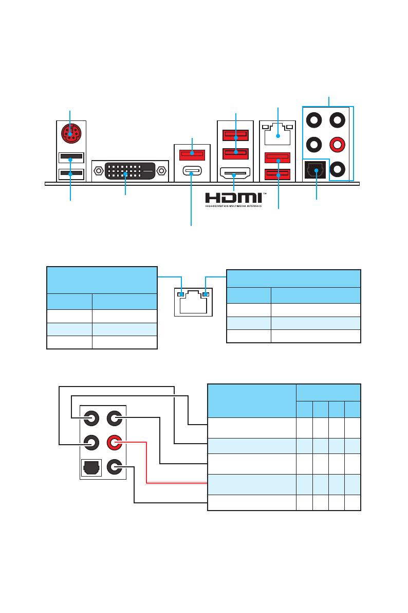
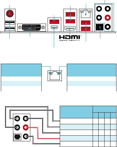
Задняя панель ввода/ вывода
Задняя панель ввода/ вывода
PS/2
LAN
USB 3.1 Gen2
Порты Аудио
USB 2.0
USB 3.1 Gen2 Type-C
Оптический разъем
S/PDIF ВЫХОД
Подключение/ Работа
индикатора
Состояние Описание
Выкл. Не подключен
Желтый Подключен
Мигает Передача данных
Скорость передачи данных
Состояние Описание
Выкл. 10 Мбит/с подключение
Зеленый 100 Мбит/с подключение
Оранжевый 1 Гбит/с подключение
Таблица состояния индикатора порта LAN
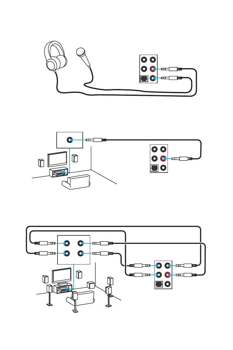
Конфигурация портов Аудио
Порты Аудио
Канал
2 4 6 8
Выход центральной
колонки/ сабвуфера
● ●
Тыловые колонки ● ● ●
Линейный вход/ Выход
боковых колонок
●
Линейный выход/ Выход
фронтальных колонок
● ● ● ●
Микрофонный вход
(●: подключен, пусто: не подключен)
USB 3.1 Gen1
USB 3.1 Gen1
DVI-D
10
Задняя панель ввода/ вывода
AUDIO INPUT
Rear Front
Side Center/
Subwoofer
Подключение наушников и микрофона
Подключение внешнего стерео усилителя (колонок)
Подключение звуковой системы 7.1
AUDIO INPUT
11
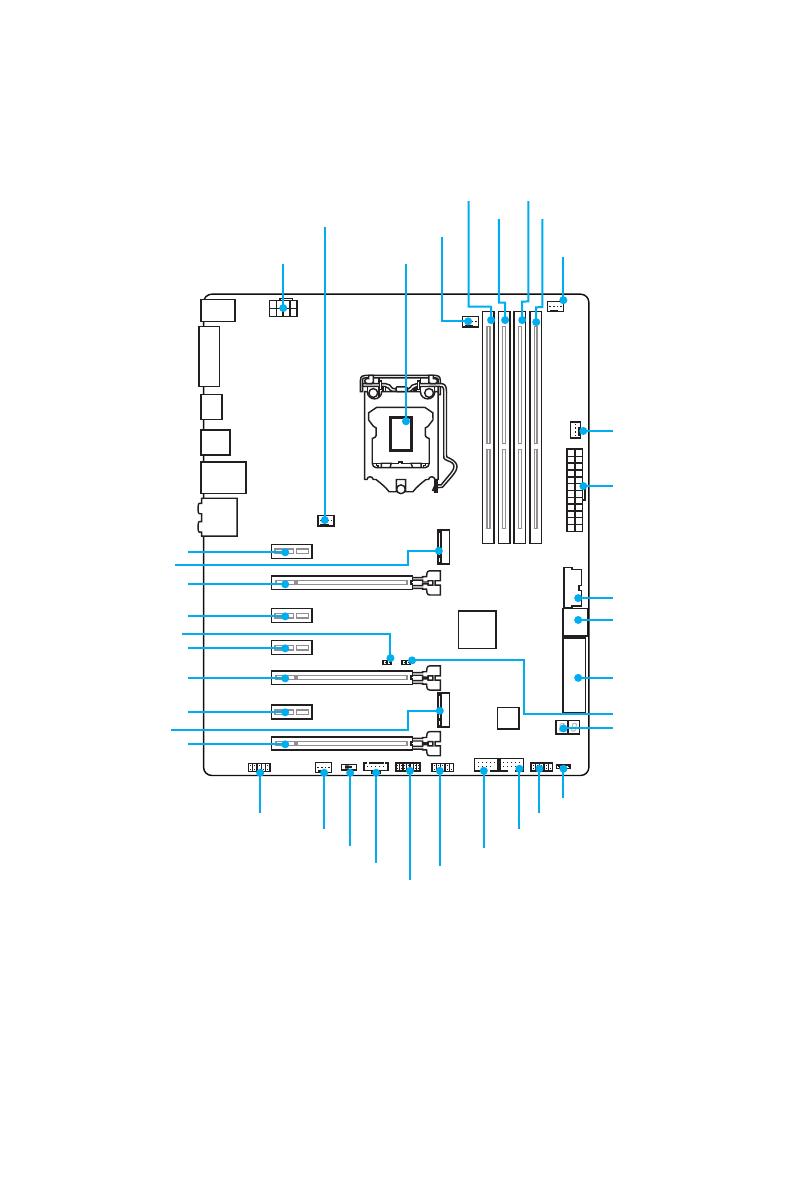
Компоненты материнской платы
Компоненты материнской платы
CPUFAN1
CPUFAN2
PCI_E1
PCI_E2
PCI_E3
JBAT1
PCI_E4
PCI_E5
PCI_E6
PCI_E7
Процессорный
сокет
JPWR2
M2_2
M2_1
DIMM1
SYSFAN1 DIMM2
DIMM3
DIMM4
JUSB1
JUSB2
JFP1
JFP2
SYSFAN2
JAUD1
JTPM1
SLOW_1
SYSFAN3
JPWR1
JUSB3
SATA1_2
SE1_43-SE2_65
JCI1
JCOM1
JTBT1*
POST
* JTBT1 используется для подключения специальной карты.
12
Компоненты материнской платы
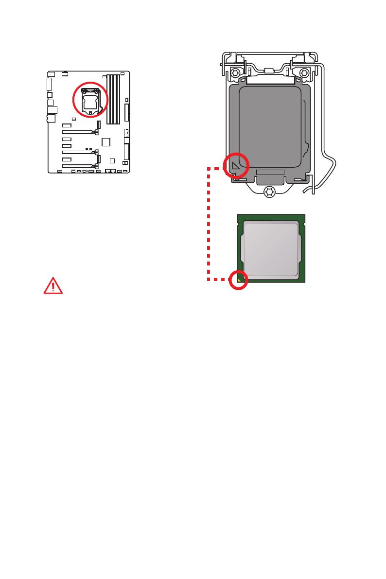
Процессорный сокет
Процессор LGA 1151
На поверхности процессора LGA 1151
имеются два ключа совмещения
и золотой треугольник для
правильной установки процессора
относительно поцессорного сокета
материнской платы. Золотой
треугольник указывает на контакт 1.
Внимание!
●
ВНИМАНИЕ! Перед установкой или заменой процессора, необходимо
отключить кабель питания.
●
Пожалуйста, сохраните защитную крышку процессорного сокета после
установки процессора. Любые возможные гарантийные случаи, связанные с
работой материнской платы, MSI будет рассматривать только, при наличии
защитной крышки на процессорном сокете.
●
При установке процессора обязательно установите процессорный
кулер. Кулер, представляющий собой систему охлаждения процессора,
предупреждает перегрев и обеспечивает стабильную работу системы.
●
Перед включением системы проверьте герметичность соединения между
процессором и радиатором.
●
Перегрев может привести к серьезному повреждению процессора и
материнской платы. Всегда проверяйте работоспособность вентилятора для
защиты процессора от перегрева. При установке кулера нанесите ровный
слой термопасты (или термоленту) на крышку установленного процессора для
улучшения теплопередачи.
●
Если процессор не установлен, всегда защищайте контакты процессорного
сокета пластиковой крышкой.
●
Если вы приобрели отдельно процессор и процессорный кулер, подробное
описание установки см. в документации в данному кулеру.
●
Данная системная плата разработана с учетом возможности ее «разгона».
Перед выполнением разгона системы убедитесь в том, что все компоненты
системы смогут его выдержать. Производитель не рекомендует использовать
параметры, выходящие за пределы технических характеристик устройств.
Гарантия MSI
®
не распространяется на повреждения и другие возможные
последствия ненадлежащей эксплуатации оборудования.
13
Компоненты материнской платы
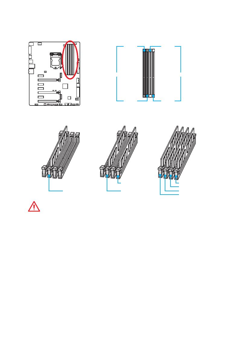
Слоты DIMM
DIMM1 DIMM3
Канал A Канал B
DIMM2 DIMM4
Рекомендации по установке модулей памяти
DIMM4 DIMM4
DIMM3
DIMM2 DIMM2 DIMM2
DIMM1
Внимание!
●
Всегда устанавливайте модуль памяти сначала в слот DIMM2.
●
В связи со спецификой использования ресурсов чипсета, доступный объем
памяти будет немного меньше, чем объем установленный.
●
На основе характеристик процессора, рекомендуется устанавливать
напряжение на памяти DIMM менее 1.35 В. Это позволит защитить процессор.
●
Пожалуйста, обратите внимание на то, что максимальная емкость адресуемой
памяти для 32-бит ОС Windows, составляет не более 4 ГБ. Если вы хотите
использовать более 4ГБ оперативной памяти на материнской плате,
рекомендуется устанавливать 64-бит ОС Windows.
●
Некоторые модули памяти при разгоне могут работать на частотах ниже
заявленной производителем, поскольку выставляемая для памяти частота
зависит от информации, записанной в SPD (Serial Presence Detect). Зайдите
в BIOS и выберите опцию Memory Try It!, чтобы установить заявленную или
более высокую частоту.
●
При установке памяти во все слоты, а также при ее разгоне, рекомендуется
использовать более эффективную систему охлаждения памяти.
●
Совместимость и стабильность работы установленного модуля памяти при
разгоне зависит от установленного процессора и других устройств.
14
Компоненты материнской платы
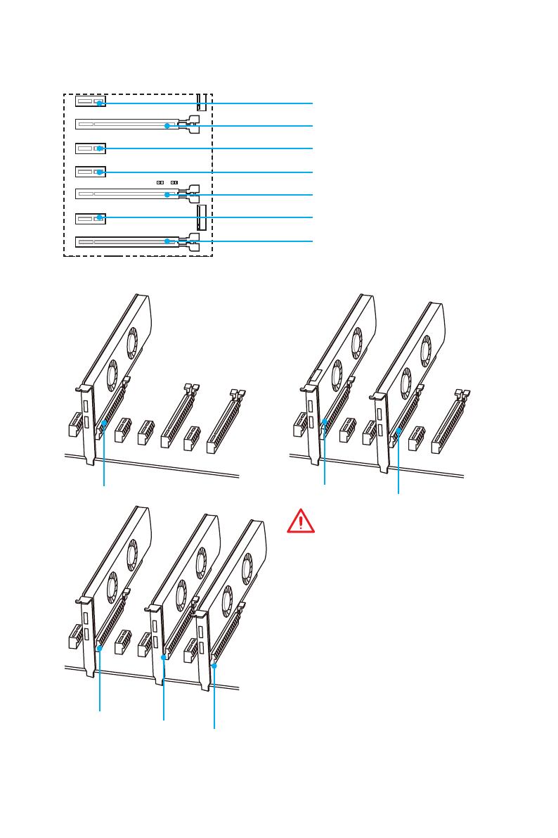
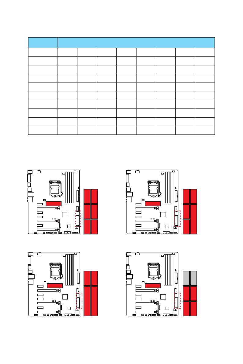
PCI_E1~7: Слоты расширения PCIe
PCI_E1: PCIe 3.0 x1 слот
PCI_E2: PCIe 3.0 x16 x8 слот
PCI_E3: PCIe 3.0 x1 слот
PCI_E4: PCIe 3.0 x1 слот
PCI_E5: PCIe 3.0 x8 слот
PCI_E6: PCIe 3.0 x1 слот
PCI_E7: PCIe 3.0 x4/ x1 слот
x16
x8
x8
x8
x8
x4
Рекомендации по установке нескольких видеокарт
Внимание!
●
Слот PCI_E7 будет работать
только в режиме x1, когда плата
расширения устанавлена в слоте
PCI_E3/ PCI_E4/ PCI_E6.
●
Для установки одной карты
расширения PCIe x16 с
оптимальной производительностью
рекомендуется использовать слот
PCI_E2.
●
Перед установкой или извлечением
плат расширения убедитесь,
что кабель питания отключен от
электрической сети. Прочтите
документацию на карту расширения
и выполните необходимые
дополнительные аппаратные или
программные изменения для данной
карты.
15
Компоненты материнской платы
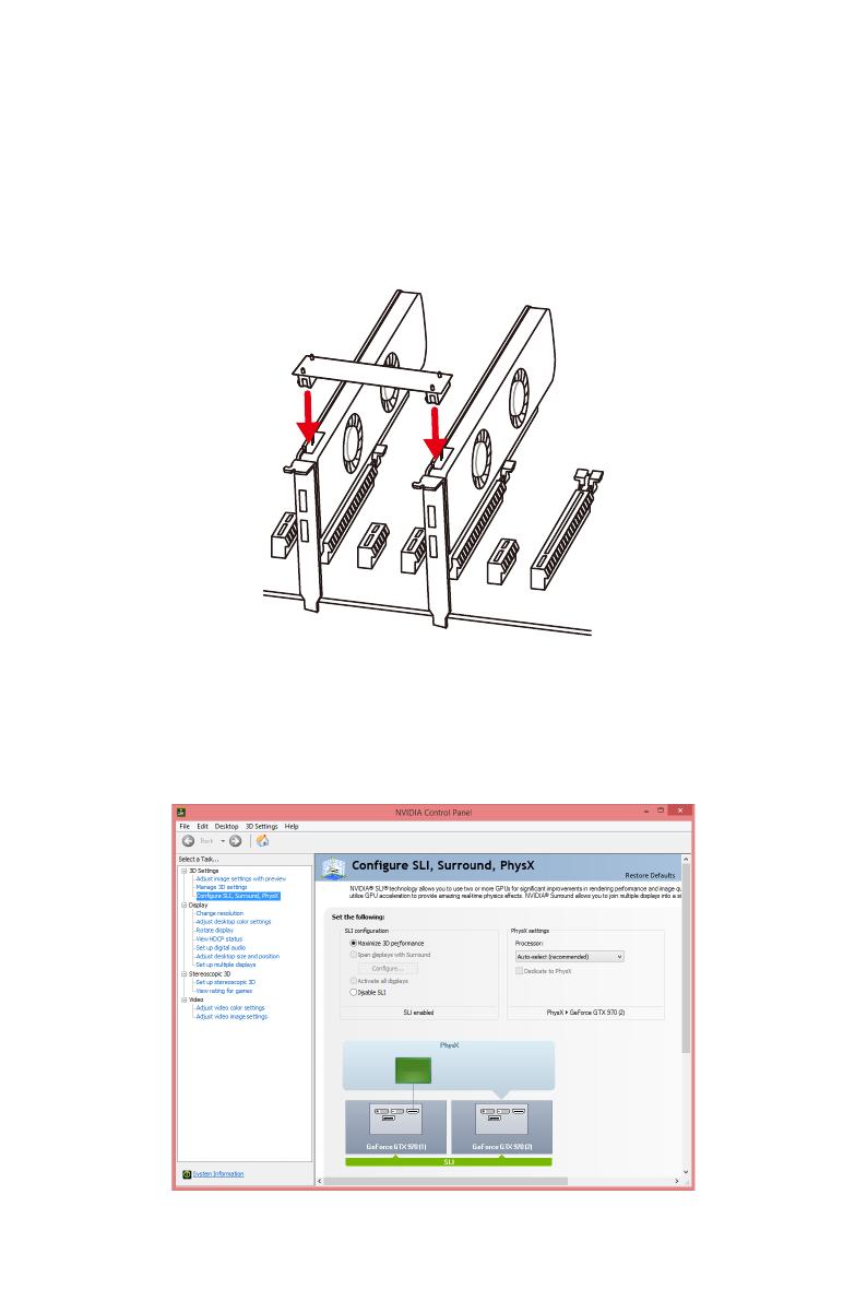
Установка видеокарт в режиме SLI
Для выполнения рекоммендаций по питанию в SLI конфигурациях, пожалуйста,
обратитесь к руководству пользователя вашей видеокарты, чтобы убедиться,
что видеокарта соответствует всем требованиям системы.
Для установки видеокарт в SLI:
1. Выключите компьютер и отсоедините шнур питания. Установите две
видеокарты в слот PCI_E2 и PCI_E5.
2. Соедините видеокарты разъемом SLI Bridge.
3. Подключите все разъемы питания PCIe видеокарт.
4. Подключите кабель питания, включите компьютер, установите драйверы и
программное обеспечение из комплекта поставки видеокарты.
5. Щелкните правой кнопкой мыши на Рабочем столе Windows и выберите
NVIDIA Control Panel из раскрывшегося меню. Нажмите на Configure
SLI, Surround, PhysX в левой панели задач и выберите Maximize 3D
performance в меню конфигурации SLI, а затем нажмите кнопку Apply.
16
Компоненты материнской платы
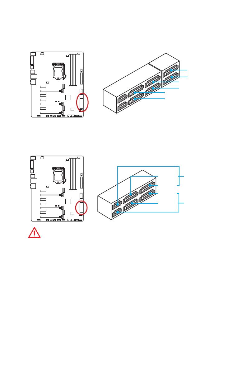
SATA1~6: Разъемы SATA 6 Гб/с
Эти разъемы представляют собой интерфейсные порты SATA 6 Гб/с. К каждому
порту можно подключить одно устройство SATA.
SATA2
SATA5
SATA4
SATA1
SATA6
SATA3
SE1_43—SE2_65: Разъемы SATAe
Эти разъемы представляют собой порты интерфейса SATAe (SATA Expreess). К
каждому порту можно подключить одно устройство SATAe или два устаревших
устройства SATA.
SATA3
SATA5
SATA4
SATA6
SE1_43
(SATA_EX1)
SE2_65
(SATA_EX2)
Внимание!
●
Избегайте перегибов кабеля SATA или SATAe под прямым углом. В противном
случае, возможна потеря данных при передаче.
●
Кабель SATA оснащен одинаковыми коннекторами с обеих сторон. Однако,
для экономии занимаемого пространства к материнской плате рекомендуется
подключать плоский разъем.
17
Компоненты материнской платы
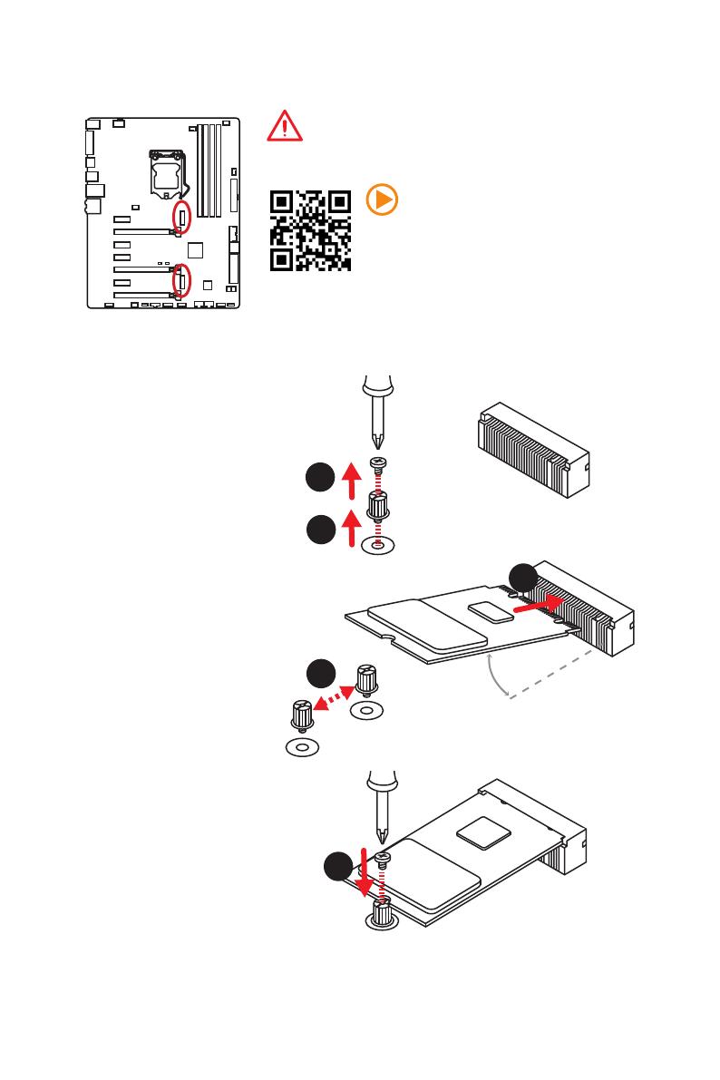
Внимание!
●
Intel
®
RST поддерживает только PCIe M.2 SSD с
UEFI ROM, и не поддерживает Legacy ROM.
Видео Инструкция
Смотрите видео, чтобы узнать как
установить модуль M.2.
Установка модуля M.2
M2_1~2: Разъемы M.2
1
2
3
30°
3. Закрутите базовый
винт в отверстие,
на расстоянии,
соответствующем длине
вашего модуля М.2.
4. Вставьте модуль М.2 в
разъем М.2 под углом
30 градусов.
5. Совместите винт с
выемкой на задней
кромке модуля M.2 и
закрутите его в базовом
винте.
1. Выкрутите винт из
базового винта.
2. Выкрутите базовый
винт.
4
5
M.2_1
M.2_2
18
Компоненты материнской платы
Таблица комбинации M.2/ SATA и SATAe
Слот Доступные разъемы SATA/ SATAe
M2_1 Пусто SATA PCIe PCIe SATA Пусто SATA PCIe
M2_2 PCIe PCIe PCIe SATA SATA SATA Пусто Пусто
SATA_EX1 ✓ ✓ ✓ ✓ ✓ ✓ ✓ ✓
SATA_EX2 ─ ─ ─ ─ ─ ─ ✓ ✓
SATA1 ✓ ─ ✓ ✓ ─ ✓ ─ ✓
SATA2 ✓ ─ ✓ ✓ ─ ✓ ─ ✓
SATA3 ✓ ✓ ✓ ✓ ✓ ✓ ✓ ✓
SATA4 ✓ ✓ ✓ ✓ ✓ ✓ ✓ ✓
SATA5 ─ ─ ─ ─ ─ ─ ✓ ✓
SATA6 ─ ─ ─ ─ ─ ─ ✓ ✓
(SATA: M.2 SATA SSD, PCIe: M.2 PCIe SSD, ✓: Доступно, ─: Недоступно)
Разъемы М.2, а также различные возможные примеры
использования
PCIe
SATA1SATA5SATA6
SATA2SATA3SATA4
SATA1
SATA2SATA_EX1
SATA_EX2
SATA1SATA5SATA5 SATA6SATA6
SATA2SATA_EX1
1xM.2 PCIe SSD + 6xSATA HDDs
1xM.2 PCIe SSD + 2xSATAe HDDs +
2xSATA HDDs
1xM.2 PCIe SSD + 1xSATAe HDD +
4xSATA HDDs
1xM.2 SATA SSD + 4xSATA HDDs
PCIe
SATA3SATA4
PCIe SATA
20
Компоненты материнской платы
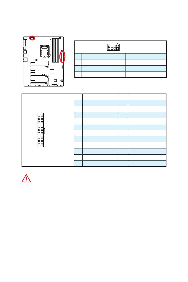
24
131
12
JPWR1
1 +3.3V 13 +3.3V
2 +3.3V 14 -12V
3 Ground 15 Ground
4 +5V 16 PS-ON#
5 Ground 17 Ground
6 +5V 18 Ground
7 Ground 19 Ground
8 PWR OK 20 Res
9 5VSB 21 +5V
10 +12V 22 +5V
11 +12V 23 +5V
12 +3.3V 24 Ground
5
4 1
8
JPWR2
1 Ground 5 +12V
2 Ground 6 +12V
3 Ground 7 +12V
4 Ground 8 +12V
Внимание!
Для обеспечения стабильной работы системной платы проверьте надежность
подключения всех кабелей питания к блоку питания АТХ.
JPWR1~2: Разъемы питания
Данные разъемы предназначены для подключения коннекторов питания ATX.
21
Компоненты материнской платы
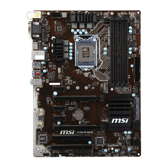
JUSB3: Разъем USB 3.1 Gen1
Данный разъем предназначен для подключения портов USB 3.1 Gen1 на
передней панели.
1
10 11
20
1 Power 11 USB2.0+
2 USB3_RX_DN 12 USB2.0-
3 USB3_RX_DP 13 Ground
4 Ground 14 USB3_TX_C_DP
5 USB3_TX_C_DN 15 USB3_TX_C_DN
6 USB3_TX_C_DP 16 Ground
7 Ground 17 USB3_RX_DP
8 USB2.0- 18 USB3_RX_DN
9 USB2.0+ 19 Power
10 Ground 20 No Pin
Внимание!
Помните, что во избежание повреждений необходимо правильно подключать
контакты питания и земли.
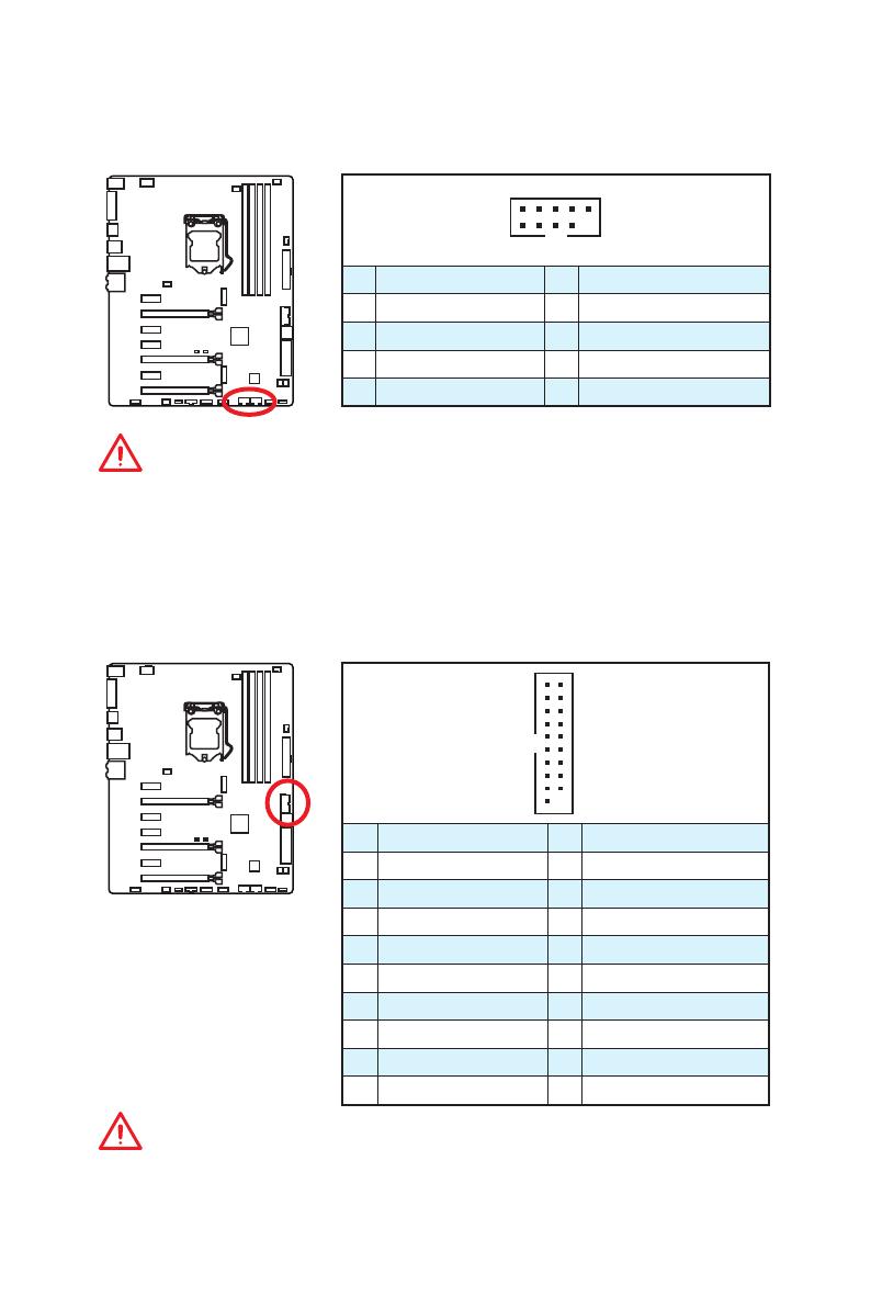
JUSB1~2: Разъемы USB 2.0
Данные разъемы предназначены для подключения портов USB 2.0 на передней
панели.
1
2 10
9
1 VCC 2 VCC
3 USB0- 4 USB1-
5 USB0+ 6 USB1+
7 Ground 8 Ground
9 No Pin 10 NC
Внимание!
●
Помните, что во избежание повреждений необходимо правильно подключать
контакты VCC и Ground.
●
Для того, чтобы зарядить ваш iPad, iPhone и iPod портами USB, пожалуйста,
установите утилиту MSI
®
SUPER CHARGER.
/
на других языках
Похожие инструкции
- Manuals
- Brands
- MSI Manuals
- Motherboard
- Z170A PC MATE
- Manual
-
Contents
-
Table of Contents
-
Troubleshooting
-
Bookmarks
Quick Links
Unpacking
Thank you for buying the MSI
Z170A PC MATE
motherboard. Check to make sure
®
your motherboard box contains the following items. If something is missing, contact
your dealer as soon as possible.
Drivers & Utilities
Motherboard User
Disc
Guide
Motherboard
I/O Shield
SATA Cable x2
1
Unpacking
Related Manuals for MSI Z170A PC MATE
Summary of Contents for MSI Z170A PC MATE
-
Page 1: Unpacking
Unpacking Thank you for buying the MSI Z170A PC MATE motherboard. Check to make sure ® your motherboard box contains the following items. If something is missing, contact your dealer as soon as possible. Drivers & Utilities Motherboard User Disc…
-
Page 2: Safety Information
Safety Information ● The components included in this package are prone to damage from electrostatic discharge (ESD). Please adhere to the following instructions to ensure successful computer assembly. ● Ensure that all components are securely connected. Loose connections may cause the computer to not recognize a component or fail to start.
-
Page 3: Quick Start
Quick Start Preparing Tools and Components Intel LGA 1151 CPU ® CPU Fan Thermal Paste DDR4 Memory Power Supply Unit Chassis SATA Hard Disk Drive Graphics Card SATA DVD Drive A Package of Screws Phillips Screwdriver Quick Start…
-
Page 4: Installing A Processor
Installing a Processor http://youtu.be/bf5La099urI Quick Start…
-
Page 5: Installing Ddr4 Memory
Installing DDR4 memory http://youtu.be/T03aDrJPyQs Quick Start…
-
Page 6: Connecting The Front Panel Header
Connecting the Front Panel Header http://youtu.be/DPELIdVNZUI HDD LED + Power LED + HDD LED — Power LED — Reset Switch Power Switch Reset Switch Power Switch JFP1 Reserved No Pin JFP1 HDD LED — HDD LED HDD LED + POWER LED — POWER LED POWER LED + Quick Start…
-
Page 7: Installing The Motherboard
Installing the Motherboard Quick Start…
-
Page 8: Installing Sata Drives
Installing SATA Drives http://youtu.be/RZsMpqxythc Quick Start…
-
Page 9: Installing A Graphics Card
Installing a Graphics Card http://youtu.be/mG0GZpr9w_A Quick Start…
-
Page 10: Connecting Peripheral Devices
Connecting Peripheral Devices Quick Start…
-
Page 11: Connecting The Power Connectors
Connecting the Power Connectors http://youtu.be/gkDYyR_83I4 JPWR1 JPWR2 Quick Start…
-
Page 12: Power On
Power On Quick Start…
-
Page 13: Table Of Contents
Contents Unpacking ……………………1 Safety Information ………………..2 Quick Start……………………3 Preparing Tools and Components …………… 3 Installing a Processor ………………4 Installing DDR4 memory ………………5 Connecting the Front Panel Header …………..6 Installing the Motherboard ………………. 7 Installing SATA Drives ………………8 Installing a Graphics Card ……………….
-
Page 14
EZ Debug LED: Debug LED indicators …………35 BIOS Setup ………………….36 Entering BIOS Setup ………………36 Resetting BIOS ………………..37 Updating BIOS ………………..37 EZ Mode ………………….38 Advanced Mode ………………..40 SETTINGS ………………….41 Advanced ………………….41 Boot ……………………47 Security …………………. -
Page 15: Specifications
Specifications Supports 6th Gen Intel Core i3/i5/i7 processors, and Intel ® ™ ® Pentium and Celeron processors for Socket LGA1151 ® ® Chipset Intel Z170 Express Chipset ® ● 4x DDR4 memory slots, support up to 64GB ▶ Supports DDR4 3200(OC)/ 3000(OC)/ 2800(OC)/ 2600(OC)/ 2400/ 2133 MHz Memory ●…
-
Page 16
Continued from previous page ● ASMedia ASM1142 Chipset ® ▶ 2x USB 3.1 Gen2 (SuperSpeed USB 10Gbps) ports on the back panel ● Intel Z170 Express Chipset ® ▶ 6x USB 3.1 Gen1 (SuperSpeed USB) ports (4 ports on the back panel, 2 ports available through the internal USB 3.1 Gen1 connector) ▶… -
Page 17
Continued from previous page ● 1x 24-pin ATX main power connector ● 1x 8-pin ATX 12V power connector ● 6x SATA 6Gb/s connectors ● 1x SATAe connector (is compatible with SATA1~2) ● 2x USB 2.0 connectors (support additional 4 USB 2.0 ports) ●… -
Page 18
Google Chrome™ ,Google Toolbar, Google Drive ● CLICK BIOS 5 ▶ EZ Mode & Advanced Mode Switching ▶ Board Explorer ▶ Hardware Monitor ● COMMAND CENTER MSI Exclusive Features ▶ System Monitor ▶ Smart Fan Control ● RAMDISK ● LIVE UPDATE 6 ●… -
Page 19: Block Diagram
Block Diagram HDMI DVI-D Dual Channel DDR4 Memory PCI Express Bus DMI 3.0 PCIe x1 PCIe x1 PCIe x1 1 x SATA Express (2 x SATA 6Gb/s) PCIe x4 1 x M.2 4 x SATA 6Gb/s PCI Bus Z170 PCI x2 6 x USB 3.1 Gen1 (5 Gbps) PCI Express Bus…
-
Page 20: Rear I/O Panel
Rear I/O Panel Line-in PS/2 Mouse VGA Port Line-out Mic-in PS/2 Keyboard USB 3.1 Gen2 DVI-D Port USB 3.1 Gen1 LAN Port LED Status Table Link/ Activity LED Speed LED Status Description Status Description No link 10 Mbps connection Yellow Linked Green 100 Mbps connection…
-
Page 21
● Device Selection — allows you to select a audio output source to change the related options. The check sign indicates the devices as default. ● Application Enhancement — the array of options will provide you a complete guidance of anticipated sound effect for both output and input device. ●… -
Page 22: Overview Of Components
Overview of Components DIMM4 CPUFAN1 SYSFAN1 DIMM3 JPWR2 CPU Socket DIMM2 DIMM1 CPUFAN2 SYSFAN3 EZ Debug LED JPWR1 PCI_E1 JUSB3 M2_1 PCI_E2 PCI_E3 SE1_21 PCI_E4 JCI1 JBAT1 PCI_E5 SATA3_4 SATA5 PCI1 SATA6 PCI2 JFP1 JAUD1 JFP2 SYSFAN2 JUSB1 JCOM1 JUSB2 JTPM1 JLTP1 Overview of Components…
-
Page 23
Component Contents Port Name Port Type Page CPUFAN1~2,SYSFAN1~3 Fan Connectors CPU Socket LGA1151 CPU Socket DIMM1~4 DIMM Slots EZ Debug LED Debug LED indicators JAUD1 Front Audio Connector JBAT1 Clear CMOS (Reset BIOS) Jumper JCI1 Chassis Intrusion Connector JCOM1 Serial Port Connector JFP1, JFP2 Front Panel Connectors JLPT1… -
Page 24: Cpu Socket
Always unplug the power cord from the power outlet before installing or removing ● the CPU. Please retain the CPU protective cap after installing the processor. MSI will deal ● with Return Merchandise Authorization (RMA) requests if only the motherboard comes with the protective cap on the CPU socket.
-
Page 25: Dimm Slots
DIMM Slots DIMM1 DIMM3 Channel A Channel B DIMM2 DIMM4 Memory module installation recommendation DIMM4 DIMM4 DIMM3 DIMM2 DIMM2 DIMM2 DIMM1 Important ● Always insert memory modules in the DIMM2 slot first. ● Due to chipset resource usage, the available capacity of memory will be a little less than the amount of installed.
-
Page 26: Pci_E1~5, Pci1~2: Pcie/ Pci Expansion Slots
PCI_E1~5, PCI1~2: PCIe/ PCI Expansion Slots PCI_E1: PCIe 3.0 x1 slot PCI_E2: PCIe 3.0 x16 slot PCI_E3: PCIe 3.0 x1 slot PCI_E4: PCIe 3.0 x1 slot PCI_E5: PCIe 3.0 x4 slot PCI1: PCI slot PCI2: PCI slot PCIe slots Bandwidth table Slot Bandwidth PCI_E1…
-
Page 27: Sata1~6: Sata 6Gb/S Connectors
SATA1~6: SATA 6Gb/s Connectors These connectors are SATA 6Gb/s interface ports. Each connector can connect to one SATA device. SATA1 SATA5 SATA2 SATA4 SATA3 SATA6 Important ● SATA1~2 ports will be unavailable when installing the M.2 SATA interface module in M.2 slot. ●…
-
Page 28: M2_1: M.2 Slot
M2_1: M.2 Slot Important Intel RST only supports PCIe M.2 SSD with UEFI option ® ROM, does not support Legacy option ROM. Video Demonstration Watch the video to learn how to Install M.2 module. http://youtu.be/JCTFABytrYA Installing M.2 module Remove the screw from the base screw.
-
Page 29: Jfp1, Jfp2: Front Panel Connectors
M.2/ SATA & SATAe combination table Slot Available SATA/ SATA Express connectors M2_1 Empty M.2 SATA M.2 PCIe SATA Express ✓ ✓ ✓ SATA1 ✓ ─ ✓ SATA2 ✓ ─ ✓ SATA3 ✓ ✓ ─ SATA4 ✓ ✓ ─ SATA5 ✓…
-
Page 30: Jpwr1~2: Power Connectors
JPWR1~2: Power Connectors These connectors allow you to connect an ATX power supply. JPWR2 Ground +12V Ground +12V Ground +12V Ground +12V +3.3V +3.3V +3.3V -12V Ground Ground PS-ON# Ground Ground Ground JPWR1 Ground Ground PWR OK 5VSB +12V +12V +3.3V Ground Important…
-
Page 31: Jusb3: Usb 3.1 Gen1 Connector
JUSB3: USB 3.1 Gen1 Connector This connector allows you to connect USB 3.1 Gen1 ports on the front panel. Power USB2.0+ USB3_RX_DN USB2.0- USB3_RX_DP Ground Ground USB3_TX_C_DP USB3_TX_C_DN USB3_TX_C_DN USB3_TX_C_DP Ground Ground USB3_RX_DP USB2.0- USB3_RX_DN USB2.0+ Power Ground No Pin Important Note that the Power and Ground pins must be connected correctly to avoid possible damage.
-
Page 32: Jaud1: Front Audio Connector
JAUD1: Front Audio Connector This connector allows you to connect audio jacks on the front panel. MIC L Ground MIC R Head Phone R MIC Detection SENSE_SEND No Pin Head Phone L Head Phone Detection JTPM1: TPM Module Connector This connector is for TPM (Trusted Platform Module). Please refer to the TPM security platform manual for more details and usages.
-
Page 33: Cpufan1~2,Sysfan1~3: Fan Connectors
CPUFAN1~2,SYSFAN1~3: Fan Connectors Fan connectors can be classified as PWM (Pulse Width Modulation) Mode and Voltage Mode. PWM Mode fan connectors provide constant 12V output and adjust fan speed with speed control signal. Voltage Mode fan connectors control fan speed by changing voltage.
-
Page 34: Jlpt1: Parallel Port Connector
JLPT1: Parallel Port Connector This connector allows you to connect the optional parallel port with bracket. RSTB# AFD# PRND0 ERR# PRND1 PINIT# PRND2 LPT_SLIN# PRND3 Ground PRND4 Ground PRND5 Ground PRND6 Ground PRND7 Ground ACK# Ground BUSY Ground Ground SLCT No Pin JBAT1: Clear CMOS (Reset BIOS) Jumper There is CMOS memory onboard that is external powered from a battery located on…
-
Page 35: Jci1: Chassis Intrusion Connector
JCI1: Chassis Intrusion Connector This connector allows you to connect the chassis intrusion switch cable. Normal Trigger the chassis intrusion event (default) Using chassis intrusion detector Connect the JCI1 connector to the chassis intrusion switch/ sensor on the chassis. Close the chassis cover. Go to BIOS >…
-
Page 36: Bios Setup
Press Delete key, when the Press DEL key to enter Setup Menu, F11 to enter Boot Menu message appears on the screen during the boot process. Use MSI FAST BOOT application. Click on GO2BIOS button and choose OK. The ●…
-
Page 37: Resetting Bios
Updating BIOS Updating BIOS with M-FLASH Before updating: Please download the latest BIOS file that matches your motherboard model from MSI website. And then save the BIOS file into the USB flash drive. Updating BIOS: Press Del key to enter the BIOS Setup during POST.
-
Page 38: Ez Mode
EZ Mode At EZ mode, it provides the basic system information and allows you to configure the basic setting. To configure the advanced BIOS settings, please enter the Advanced Mode by pressing the Setup Mode switch or F7 function key. XMP switch Setup Mode switch Screenshot…
-
Page 39
OC Genie 4 toggle — click on it to toggle the OC Genie 4 function which can ● automatically overclock the CPU with MSI optimized setting. Important Please don’t make any changes in OC menu and don’t load defaults to keep the optimal performance and system stability after enabling the OC GENIE 4 function. -
Page 40: Advanced Mode
Advanced Mode Press Setup Mode switch or F7 function key can switch between EZ Mode and Advanced Mode in BIOS setup. XMP switch Setup Mode switch Screenshot Favorites Language System information OC Genie 4 toggle Boot device priority bar BIOS menu BIOS menu selection selection…
-
Page 41: Settings
SETTINGS System Status ▶ System Date Sets the system date. Use tab key to switch between date elements. The format is <day> <month> <date> <year>. <day> Day of the week, from Sun to Sat, determined by BIOS. Read-only. <month> The month from Jan. through Dec. <date>…
-
Page 42
PEG X — Max Link Speed [Auto] ▶ Sets PCI Express protocol of PCIe x16 slots for matching different installed devices. [Auto] This item will be configured automatically by BIOS. [Gen1] Enables PCIe Gen1 support only. [Gen2] Enables PCIe Gen2 support only. [Gen3] Enables PCIe Gen3 support only. -
Page 43
SATAx Hot Plug [Disabled] ▶ Allows user to enable or disable the SATA hot plug support. [Enabled] Enables hot plug support for the SATA ports. [Disabled] Disables hot plug support for the SATA ports. ▶ HD Audio Controller [Enabled] Enables or disables the onboard High Definition Audio controller. ▶… -
Page 44
Super IO Configuration ▶ Sets system Super I/O chip parameters including LPT and COM ports. Press <Enter> to enter the sub-menu. Serial (COM) Port 0 Configuration ▶ Sets detailed configuration of serial(COM) port x. Press <Enter> to enter the sub- menu. -
Page 45: Windows Os Configuration
Disables this function. ▶ MSI Fast Boot [Disabled] MSI Fast Boot is the fastest way to boot the system. It will disable more devices to speed up system boot time which is faster than the boot time of Fast Boot. [Enabled] Enables the MSI Fast Boot function to speed up booting time.
-
Page 46: Wake Up Event Setup
Secure Boot Support [Disabled] ▶ Enables or disables secure boot support. [Enabled] Enables the secure boot function and allow you to set the secure boot settings. [Disabled] Disables this function. ▶ Secure Boot Mode [Standard] Selects the secure boot mode. This item is to select how the secure boot keys be loaded.
-
Page 47: Boot
Resume by USB Device [Disabled] ▶ Enables or disables the system wake up by USB devices. [Enabled] Enables the system to be awakened from sleep state when activity of USB device is detected. [Disabled] Disables this function. ▶ Resume From S3/S4/S5 by PS/2 Mouse [Disabled] Enables or disables the system wake up by PS/2 mouse.
-
Page 48: Security
AUTO CLR_CMOS [Disabled] ▶ Enables or disables the CMOS data to be resumed automatically when the booting process hang-up over 5 seconds. Boot Mode Select [LEGACY+UEFI] ▶ Sets the system boot mode from legacy or UEFI architecture depending on OS installation requirement.
-
Page 49: Save & Exit
Device select [Auto] ▶ Selects TPM 1.2 or TPM 2.0 for installed discrete TPM device. If set to Auto, BIOS will detect it automatically. Chassis Intrusion Configuration ▶ Press <Enter> to enter the sub-menu. ▶ Chassis Intrusion [Disabled] Enables or disables recording messages when the chassis is opened. This function is ready for the chassis equips a chassis intrusion switch.
-
Page 50
Important ● Overclocking your PC manually is only recommended for advanced users. ● Overclocking is not guaranteed, and if done improperly, it could void your warranty or severely damage your hardware. ● If you are unfamiliar with overclocking, we advise you to use OC GENIE 4 function for easy overclocking. -
Page 51
Adjusted GT Frequency ▶ Shows the adjusted integrated graphics frequency. Read-only. ▶ Misc Setting* Press Enter, + or — key to open or close the following 3 items related to CPU features. ▶ EIST [Enabled]* Enables or disables the Enhanced Intel SpeedStep Technology. -
Page 52
Advanced DRAM Configuration ▶ Press <Enter> to enter the sub-menu. User can set the memory timing for each/ all memory channel. The system may become unstable or unbootable after changing memory timing. If it occurs, please clear the CMOS data and restore the default settings. -
Page 53
Limit CPUID Maximum [Disabled] ▶ Enables or disables the extended CPUID value. [Enabled] BIOS limits the maximum CPUID input value to circumvent boot problems with older operating system that do not support the processor with extended CPUID value. [Disabled] Use the actual maximum CPUID input value. ▶… -
Page 54
Intel Adaptive Thermal Monitor [Enabled] ▶ Enables or disables the Intel adaptive thermal monitor function to protect the CPU from overheating. [Enabled] Throttles down the CPU core clock speed when the CPU is over the adaptive temperature. [Disabled] Disables this function. ▶… -
Page 55
Intel Turbo Boost [Enabled] ▶ Enables or disables the Intel Turbo Boost. This item is for Simple mode and ® appears when a CPU that support Turbo Boost is installed. [Enabled] Enables this function to boost CPU performance automatically over specification when system request the highest performance state. -
Page 56: M-Flash
M-FLASH provides the way to update BIOS with a USB flash drive. Please download the latest BIOS file that matches your motherboard model from MSI website, save the BIOS file into your USB flash drive. And then follow the steps below to update BIOS.
-
Page 57: Oc Profile
OC PROFILE ▶ Overclocking Profile 1/ 2/ 3/ 4/ 5/ 6 Overclocking Profile 1/ 2/ 3/ 4/ 5/ 6 management. Press <Enter> to enter the sub- menu. ▶ Set Name for Overclocking Profile 1/ 2/ 3/ 4/ 5/ 6 Name the current overclocking profile. ▶…
-
Page 58: Hardware Monitor
HARDWARE MONITOR Current Temperature & Speed information Fan control field Setting Buttons Voltage display ▶ Current Temperature & Speed information Shows the current CPU temperature, system temperature and fans’ speeds. ▶ Fan control field This motherboard provides a fan speed control feature call Smart Fan. Please check the Smart Fan Mode box to enable the Smart Fan.
-
Page 59: Software Description
® Installing Drivers Start up your computer in Windows 7/ 8.1/ 10. ® Insert MSI Driver Disc into your optical drive. ® The installer will automatically appear and it will find and list all necessary drivers. Click Install button. The software installation will then be in progress, after it has finished it will prompt you to restart.
-
Page 60: Command Center
COMMAND CENTER COMMAND CENTER is an user-friendly software and exclusively developed by MSI, helping users to adjust system settings and monitor status under OS. With the help of COMMAND CENTER, making it possible to achieve easier and efficient monitoring process and adjustments than that under BIOS. In addition, the COMMAND CENTER can be a server for mobile remote control application.
-
Page 61
CPU Fan CPU Fan control panel provides Smart mode and Manual Mode. You can switch the control mode by clicking the Smart Mode and Manual Mode buttons on the top of the CPU Fan control panel. ● Manual Mode — allows you to manually control the CPU fan speed by percentage. -
Page 62
OC Genie 4 OC Genie 4 provides a specified CPU frequency for overclocking the CPU. Option Buttons — Advanced When click the Advanced button, The Voltage, Fan and DRAM icons will appear. ● Voltage — allows you to adjust advanced voltage values of CPU and chipset. ●… -
Page 63: Gadget Mode
Find the IP address on the SoftAP Management Setting area, and enter the IP address on your MSI COMMAND CENTER APP to link your system. ® Press Refresh on the MSI COMMAND CENTER APP to verify that monitoring ® and OC functions are working properly.
-
Page 64: Live Update 6
LIVE UPDATE 6 LIVE UPDATE 6 is an application for the MSI system to scan and download the latest ® drivers, BIOS and utilities. With LIVE UPDATE 6, you don’t need to search the drivers on websites, and don’t need to know the models of motherboard and graphics cards.
-
Page 65: Total Installer
Select the Live Update tab. Choose Automatic scan, system will automatically scan all the items and search for the latest update files. Or you can choose Manual scan and select the items you wish to scan. Click the Scan button at the bottom. It may take several moments to complete the process.
-
Page 66: M-Cloud
M-CLOUD M-CLOUD is an application of MSI network sharing. It allows you to turn your computer into Wi-Fi AP. It can also transfer files between your MSI computers. Soft AP ON/OFF History Server Information Users & Permissions Server Local Directory…
-
Page 67
Setting up Soft AP (optional) The Soft AP function is only available for the motherboard with the built-in WiFi module. You can share your network connection to your smartphones, tablets and laptops with the Soft AP function. Important ● You must have an active network connection and an installed Wi-Fi moudle to enable Soft AP. -
Page 68
Managing User Accounts This section describes how to create/ remove a user account and configure individual access permissions. Click the Users & Permissions button and the Users & Permissions Management window will pop up. Click Add Account button create a new user account. Fill in user’s ID, password and Confirm Password fields. -
Page 69: Ramdisk
RAMDISK RAMDISK creates a virtual RAM drive using the available memory in your computer, the performance of the RAMDISK is faster than an SSD and hard drive. RAMDISK allows you to store any temporary information on it. Furthermore, using the RAMDISK will extend your SSD’s life by sparing it from excessive reading and writing.
-
Page 70: Network Genie
Exit — exits NETWORK GENIE. ● In case no icon is shown on the system tray, it is possible to activate NETWORK GENIE manually by clicking Start > Programs > MSI > NETWORK GENIE > NETWORK GENIE. NETWORK GENIE Control Panel ●…
-
Page 71
Configuring Application’s Network Priority Go to Application tab. Click L to assign the low network priority to the application, and H to hight. You can also click the Lock icon to block an application network connection. Click the Save button to store your settings. Configuring Network Speed There are two parts in the Advanced tab, one is Internet Speed, and another is Delay/Sensitivity Settings. -
Page 72: Intel ® Extreme Tuning Utility
Intel Extreme Tuning Utility ® Intel Extreme Tuning Utility (Intel XTU) is a simple overclocking software for you to ® tune, test and monitor your system. Tuning Controls Views Settings Help System Navigation Table System System Monitors Graphs ● Views Settings Help ▶…
-
Page 73: Raid Configuration
RAID Configuration Below are the different types of a RAID. RAID 0 breaks the data into blocks which are written to separate hard drives. Spreading the hard drive I/O load across independent channels greatly improves I/O performance. RAID 1 provides data redundancy by mirroring data between the hard drives and provides enhanced read performance.
-
Page 74
Creating RAID Volume Select option Create RAID Volume and press Enter key. The following screen appears. CREATE VOLUME MENU Name : Volume0 RAID Level : RAID1(Mirror) Disks : Select Disks Strip Size : N / A Capacity : XXX.X GB Sync : N / A Create Volume… -
Page 75: Delete Raid Volume
Delete RAID Volume Here you can delete the RAID volume, but please be noted that all data on RAID drives will be lost. Important If your system currently boots to RAID and you delete the RAID volume in the IRST Option ROM, your system will become unbootable.
-
Page 76: Degraded Raid Array
Important ● You will lose all data on the RAID drives and any internal RAID structures when you perform this operation. Possible reasons to Reset Disks to Non-RAID could include issues such as ● incompatible RAID configurations or a failed volume or failed disk. Recovery Volume Options Select option Recovery Volume Options from the main menu screen and press Enter to change recovery volume mode.
-
Page 77: Failed Hard Drive Member
Reboot to Windows ; the rebuild will occur automatically. ® Failed Hard Drive Member Power off. Replace the failed hard drive with a new one that is of equal or greater capacity. Reboot the system to IRST Option ROM by press Ctrl + I keys during the POST. Select the port of the destination disk for rebuilding, and then press Enter.
-
Page 78: Troubleshooting
Troubleshooting Lost BIOS password Before sending the motherboard for RMA repair, try to go over troubleshooting ● Clear the CMOS, but that will cause guide first to see if your got similar you to lose all customized settings in symptoms as mentioned below. the BIOS.
-
Page 79: Regulatory Notices
EU REACH Regulation (Regulation EC No. 1907/2006 of the European Parliament and the This device complies with part 15 of the FCC Rules. Council), MSI provides the information of chemical Operation is subject to the following two conditions: substances in products at: (1) This device may not cause harmful interference, http://www.msi.com/html/popup/csr/evmtprtt_pcm.html…
-
Page 80
MSI will comply with the product take entregar a una empresa autorizada para la recogida de back requirements at the end of life of MSI-branded estos residuos. -
Page 81
MSI si adeguerà a tale Direttiva ritirando tutti i prodotti marchiati MSI che sono stati venduti all’interno dell’Unione Europea alla fine del loro ciclo di vita. -
Page 82: Technical Support
Alternatively, please try the following help resources for further guidance. ● Visit the MSI website for technical guide, BIOS updates, driver updates, and other information: http://www.msi.com ● Register your product at: http://register.msi.com…
-
Contents
-
Table of Contents
-
Bookmarks
Quick Links
Quick Start
Z170-A PRO
Thank you for purchasing the MSI
motherboard. This
®
Quick Start section provides demonstration diagrams about how to
install your computer. Some of the installations also provide video
demonstrations. Please link to the URL to watch it with the web
browser on your phone or tablet. You may have even link to the URL
by scanning the QR code.
Kurzanleitung
Z170-A PRO
Danke, dass Sie das MSI
Motherboard gewählt
®
haben. Dieser Abschnitt der Kurzanleitung bietet eine Demo zur
Installation Ihres Computers. Manche Installationen bieten auch
die Videodemonstrationen. Klicken Sie auf die URL, um diese
Videoanleitung mit Ihrem Browser auf Ihrem Handy oder Table
anzusehen. Oder scannen Sie auch den QR Code mit Ihrem Handy,
um die URL zu öffnen.
Présentation rapide
Merci d’avoir choisi la carte mère MSI
Z170-A
PRO. Ce manuel
®
fournit une rapide présentation avec des illustrations explicatives
qui vous aideront à assembler votre ordinateur. Des tutoriels vidéo
sont disponibles pour certaines étapes. Cliquez sur le lien fourni
pour regarder la vidéo sur votre téléphone ou votre tablette. Vous
pouvez également accéder au lien en scannant le QR code qui lui
est associé.
Быстрый старт
Z170-A
Благодарим вас за покупку материнской платы MSI
®
PRO. В этом разделе представлена информация, которая
поможет вам при сборке комьютера. Для некоторых этапов
сборки имеются видеоинструкции. Для просмотра видео,
необходимо открыть соответствующую ссылку в веб-браузере
на вашем телефоне или планшете. Вы также можете выполнить
переход по ссылке, путем сканирования QR-кода.
I
Quick Start
Chapters
Summary of Contents for MSI Z170-A PRO
 Loading…
![]()
Unpacking
Thank you for buying the MSI® Z170A GAMING M6 motherboard. Check to make sure your motherboard box contains the following items. If something is missing, contact your dealer as soon as possible.
|
Drivers & Utilities |
Motherboard User |
||||||||||||||||||||||||||
|
Disc |
Guide |
||||||||||||||||||||||||||
Motherboard
|
SATA Cable x4 |
|||||||||||||||||
|
I/O Shield |
SLI Bridge
Connector x1
Unpacking 1
Safety Information
yThe components included in this package are prone to damage from electrostatic discharge (ESD). Please adhere to the following instructions to ensure successful computer assembly.
yEnsure that all components are securely connected. Loose connections may cause the computer to not recognize a component or fail to start.
yHold the motherboard by the edges to avoid touching sensitive components.
yIt is recommended to wear an electrostatic discharge (ESD) wrist strap when handling the motherboard to prevent electrostatic damage. If an ESD wrist strap is not available, discharge yourself of static electricity by touching another metal object before handling the motherboard.
yStore the motherboard in an electrostatic shielding container or on an anti-static pad whenever the motherboard is not installed.
yBefore turning on the computer, ensure that there are no loose screws or metal components on the motherboard or anywhere within the computer case.
yDo not boot the computer before installation is completed. This could cause permanent damage to the components as well as injury to the user.
yIf you need help during any installation step, please consult a certified computer technician.
yAlways turn off the power supply and unplug the power cord from the power outlet before installing or removing any computer component.
yKeep this user guide for future reference.
yKeep this motherboard away from humidity.
yMake sure that your electrical outlet provides the same voltage as is indicated on the PSU, before connecting the PSU to the electrical outlet.
yPlace the power cord such a way that people can not step on it. Do not place anything over the power cord.
yAll cautions and warnings on the motherboard should be noted.
yIf any of the following situations arises, get the motherboard checked by service personnel:
Liquid has penetrated into the computer.
The motherboard has been exposed to moisture.
The motherboard does not work well or you can not get it work according to user guide.
The motherboard has been dropped and damaged.
The motherboard has obvious sign of breakage.
yDo not leave this motherboard in an environment above 60°C (140°F), it may damage the motherboard.
2 Safety Information
Quick Start
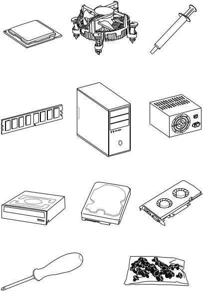
Preparing Tools and Components
|
Intel® LGA 1151 CPU |
CPU Fan |
Thermal Paste |
DDR4 Memory
Power Supply Unit
Chassis
|
SATA DVD Drive |
SATA Hard Disk Drive |
Graphics Card |
|
Phillips Screwdriver |
A Package of Screws |
Quick Start 3

Installing a Processor |
2 |
|
http://youtu.be/bf5La099urI |
1 |
3
6

8
 9
9
4 Quick Start
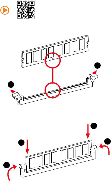
Installing DDR4 memory
 1
1
1
3
Quick Start 5
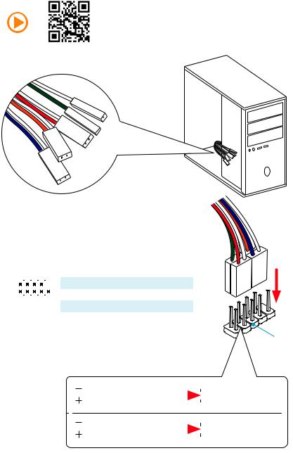
Connecting the Front Panel Header
|
— |
|||
|
LED |
|||
|
LED+ |
POWER |
||
|
POWER |
|||
|
LED |
|||
|
SW |
HDD |
||
|
POWER |
|||
|
SW |
|||
|
RESET |
|
2 |
10 |
1 |
HDD LED + |
2 |
Power LED + |
||||||
|
3 |
HDD LED — |
4 |
Power LED — |
||||||||
|
5 |
Reset Switch |
6 |
Power Switch |
||||||||
|
1 |
9 |
||||||||||
|
JFP1 |
7 |
Reset Switch |
8 |
Power Switch |
|||||||
|
9 |
Reserved |
10 |
No Pin |
||||||||
|
HDD LED |
HDD LED — |
||||||
|
HDD LED + |
|||||||
|
POWER LED — |
|||||||
|
POWER LED |
POWER LED + |
||||||
6 Quick Start
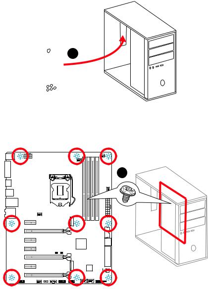
Installing the Motherboard
1
2
Quick Start 7
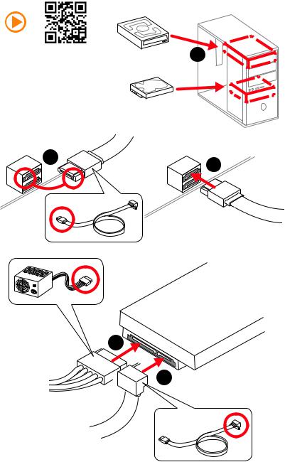
Installing SATA Drives
|
1 |
|
5
 4
4
8 Quick Start
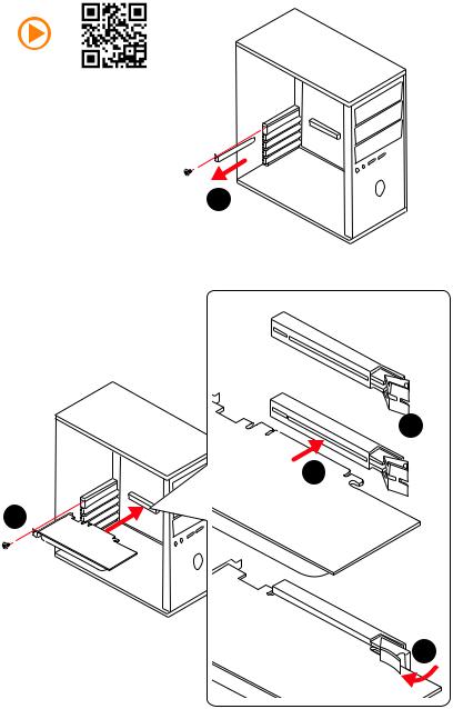
Installing a Graphics Card
1
 2
2
3
5
4
Quick Start 9
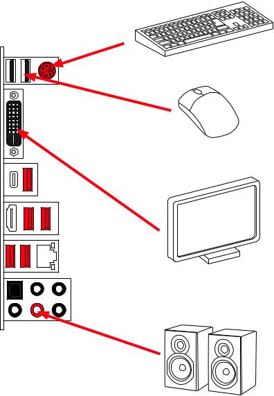
Connecting Peripheral Devices
10 Quick Start
![]()
Connecting the Power Connectors
Quick Start 11
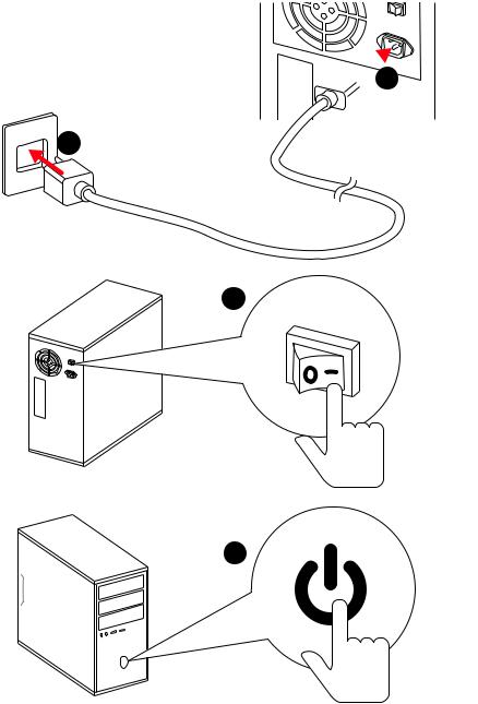
Power On
 1
1
2
3
4
12 Quick Start
|
Contents |
|
|
Unpacking……………………………………………………………………………………………….. |
1 |
|
Safety Information……………………………………………………………………………………. |
2 |
|
Quick Start ………………………………………………………………………………………………. |
3 |
|
Preparing Tools and Components……………………………………………………………….. |
3 |
|
Installing a Processor………………………………………………………………………………… |
4 |
|
Installing DDR4 memory ……………………………………………………………………………. |
5 |
|
Connecting the Front Panel Header…………………………………………………………….. |
6 |
|
Installing the Motherboard…………………………………………………………………………. |
7 |
|
Installing SATA Drives………………………………………………………………………………… |
8 |
|
Installing a Graphics Card ………………………………………………………………………….. |
9 |
|
Connecting Peripheral Devices …………………………………………………………………. |
10 |
|
Connecting the Power Connectors…………………………………………………………….. |
11 |
|
Power On………………………………………………………………………………………………… |
12 |
|
Specifications…………………………………………………………………………………………. |
15 |
|
Block Diagram ………………………………………………………………………………………. |
21 |
|
Rear I/O Panel ……………………………………………………………………………………….. |
22 |
|
LAN Port LED Status Table……………………………………………………………………….. |
22 |
|
Audio Ports Configuration ………………………………………………………………………… |
22 |
|
Realtek HD Audio Manager ………………………………………………………………………. |
23 |
|
Overview of Components ………………………………………………………………………… |
25 |
|
CPU Socket …………………………………………………………………………………………….. |
27 |
|
DIMM Slots……………………………………………………………………………………………… |
28 |
|
PCI_E1~7: PCIe Expansion Slots……………………………………………………………….. |
29 |
|
SATA1~6: SATA 6Gb/s Connectors …………………………………………………………….. |
31 |
|
SE1_43-SE2_65: SATAe Connectors ………………………………………………………….. |
31 |
|
M2_1~2: M.2 Slots (M-Key)……………………………………………………………………….. |
32 |
|
CPU_PWR1, ATX_PWR1: Power Connectors ………………………………………………. |
35 |
|
JUSB1~2: USB 2.0 Connectors………………………………………………………………….. |
36 |
|
JUSB3: USB 3.1 Gen1 Connector ………………………………………………………………. |
36 |
|
JFP1, JFP2: Front Panel Connectors …………………………………………………………. |
37 |
|
JAUD1: Front Audio Connector …………………………………………………………………. |
37 |
|
JTPM1: TPM Module Connector………………………………………………………………… |
37 |
|
JCOM1: Serial Port Connector ………………………………………………………………….. |
38 |
|
JCI1: Chassis Intrusion Connector…………………………………………………………….. |
38 |
|
CPU_FAN1~2, SYS_FAN1~3: Fan Connectors……………………………………………… |
39 |
|
SLOW_1: Slow Mode Booting Switch………………………………………………………….. |
40 |
Contents 13
|
JBAT1: Clear CMOS (Reset BIOS) Jumper ………………………………………………….. |
40 |
|
LED Status Indicators……………………………………………………………………………… |
41 |
|
LED Status Table……………………………………………………………………………………… |
41 |
|
Debug Code LED……………………………………………………………………………………… |
41 |
|
BIOS Setup…………………………………………………………………………………………….. |
45 |
|
Entering BIOS Setup………………………………………………………………………………… |
45 |
|
Resetting BIOS………………………………………………………………………………………… |
46 |
|
Updating BIOS…………………………………………………………………………………………. |
46 |
|
Advanced Mode ………………………………………………………………………………………. |
49 |
|
SETTINGS……………………………………………………………………………………………….. |
50 |
|
Advanced………………………………………………………………………………………………… |
50 |
|
Boot……………………………………………………………………………………………………….. |
56 |
|
Security………………………………………………………………………………………………….. |
57 |
|
Save & Exit……………………………………………………………………………………………… |
58 |
|
OC………………………………………………………………………………………………………….. |
59 |
|
M-FLASH ……………………………………………………………………………………………….. |
67 |
|
OC PROFILE……………………………………………………………………………………………. |
68 |
|
HARDWARE MONITOR……………………………………………………………………………… |
69 |
|
Software Description………………………………………………………………………………. |
70 |
|
Installing Windows® 7/ 8.1/ 10…………………………………………………………………… |
70 |
|
Installing Drivers …………………………………………………………………………………….. |
70 |
|
Installing Utilities ……………………………………………………………………………………. |
70 |
|
COMMAND CENTER ………………………………………………………………………………… |
71 |
|
LIVE UPDATE 6………………………………………………………………………………………… |
75 |
|
GAMING APP…………………………………………………………………………………………… |
77 |
|
M-CLOUD ……………………………………………………………………………………………….. |
81 |
|
RAMDISK………………………………………………………………………………………………… |
84 |
|
Killer Network Manager…………………………………………………………………………… |
85 |
|
Nahimic………………………………………………………………………………………………….. |
86 |
|
XSplit Gamecaster V2 ………………………………………………………………………………. |
88 |
|
Intel® Extreme Tuning Utility…………………………………………………………………….. |
92 |
|
RAID Configuration…………………………………………………………………………………. |
93 |
|
Using Intel® Rapid Storage Technology Option ROM ……………………………………. |
93 |
|
Degraded RAID Array ………………………………………………………………………………. |
96 |
|
M.2 PCIe SSD RAID………………………………………………………………………………….. |
98 |
|
Regulatory Notices……………………………………………………………………………….. |
100 |
14 Contents

Specifications
|
CPU |
Supports 6th Gen Intel® Core™ i3/i5/i7 processors, and Intel® |
||
|
Pentium® and Celeron® processors for Socket LGA1151 |
|||
|
Chipset |
Intel® Z170 Chipset |
||
|
y 4x DDR4 memory slots, support up to 64GB* |
|||
|
Supports DDR4 3600(OC)/ 3200(OC)/ 3000(OC)/ 2800(OC)/ |
|||
|
2600(OC)/ 2400/ 2133 MHz |
|||
|
Memory |
y Dual channel memory architecture |
||
|
y |
Supports ECC, un-buffered memory |
||
|
ECC UDIMM memory (non-ECC mode) |
|||
|
y Supports Intel® Extreme Memory Profile (XMP) |
|||
|
* For the latest information about memory, please visit http://www.msi.com |
|||
|
y 3x PCIe 3.0 x16 slots (support x16, x8/x8, x8/x8/x4 or x8/ |
|||
|
Expansion Slots |
x8/x1 modes) |
||
|
y 4x PCIe 3.0 x1 slots |
|||
|
y 1x HDMI™ port, support a maximum resolution of |
|||
|
Onboard Graphics |
4096×2160@24Hz, 2560×1600@60Hz |
||
|
y |
1x DVI-D port, support a maximum resolution of |
||
|
1920×1200@60Hz |
|||
|
Multi-GPU |
y Supports 3-Way AMD® CrossFire™ Technology |
||
|
y |
Supports 2-Way NVIDIA® SLI™ Technology |
||
|
Intel® Z170 Chipset |
|||
|
y 6x SATA 6Gb/s ports* (4 ports from SATAe ports) |
|||
|
y 2x M.2 slots (Key M) |
|||
|
Supports up to PCIe 3.0 x4 and SATA 6Gb/s |
|||
|
Supports 2242/ 2260/ 2280 storage devices |
|||
|
Supports PCIe 3.0 x4 NVMe Mini-SAS SSD with Turbo U.2 |
|||
|
Storage |
Host Card** |
||
|
y |
2x SATAe ports (compatible with 4 SATA ports) |
||
|
Supports up to PCIe 3.0 x2 |
|||
|
y Supports Intel® Smart Response Technology for Intel |
|||
|
Core™ processors*** |
|||
|
* M.2, SATA and SATAe ports maximum support 1x M.2_PCIe + 6x SATAs or 1x |
|||
|
M.2_SATA + 1x M.2_PCIe + 4x SATAs. Please refer to page 33 for M.2 slots |
|||
|
with examples of various combination possibilities. |
|||
|
** The Turbo U.2 Host Card is not included, please purchase separately. |
|||
|
*** This function will be supported depend on the CPU. |
|||
|
Continued on next page |
Specifications 15

|
Continued from previous page |
||
|
Intel® Z170 Chipset |
||
|
y Supports RAID 0, RAID 1, RAID 5 and RAID 10 for SATA |
||
|
RAID |
storage devices |
|
|
y Supports RAID 0 and RAID 1 for M.2 PCIe storage devices* |
||
|
* M.2 PCIe RAID volume can be created with UEFI BIOS |
||
|
y ASMedia® ASM2142 Chipset |
||
|
1x USB 3.1 Gen2 (SuperSpeed USB 10Gbps) port on the |
||
|
back panel |
||
|
1x USB 3.1 Gen2 (SuperSpeed USB 10Gbps) Type-C port |
||
|
on the back panel |
||
|
USB |
y Intel® Z170 Chipset |
|
|
6x USB 3.1 Gen1 (SuperSpeed USB) ports (4 ports on the |
||
|
back panel, 2 ports available through the internal USB |
||
|
connector) |
||
|
6x USB 2.0 (High-speed USB) ports (2 ports on the |
||
|
back panel, 4 ports available through the internal USB |
||
|
connectors) |
||
|
y Realtek® ALC1150 Codec |
||
|
Audio |
y 7.1-Channel High Definition Audio |
|
|
y Supports S/PDIF output |
||
|
LAN |
1x Killer™ E2500 Gigabit LAN controller |
|
|
y 1x PS/2 keyboard/ mouse port |
||
|
y 2x USB 2.0 ports |
||
|
y 1x DVI-D port |
||
|
y 1x USB 3.1 Gen2 port |
||
|
Back Panel |
y 1x USB 3.1 Gen2 Type-C port |
|
|
Connectors |
y 4x USB 3.1 Gen1 ports |
|
|
y 1x HDMI™ port |
||
|
y 1x LAN (RJ45) port |
||
|
y 1x Optical S/PDIF OUT connector |
||
|
y 5x OFC audio jacks |
||
|
Continued on next page |
16 Specifications

Continued from previous page
y1x 24-pin ATX main power connector
y1x 8-pin ATX 12V power connector
y6x SATA 6Gb/s connectors
y2x SATAe connectors
y2x USB 2.0 connectors (supports additional 4 USB 2.0 ports)
y1x USB 3.1 Gen1 connector (supports additional 2 USB 3.1 Gen1 ports)
y2x 4-pin CPU fan connectors
Internal Connectors y 3x 4-pin system fan connectors
y1x Front panel audio connector
y2x Front panel connectors
y1x TPM module connector
y1x Serial port connector
y1x Chassis Intrusion connector
y1x Slow mode switch
y1x Clear CMOS jumper
y1x 2-Digit Debug Code LED
|
I/O Controller |
NUVOTON NCT6793 Controller Chip |
|
|
y CPU/System temperature detection |
||
|
Hardware Monitor |
y CPU/System fan speed detection |
|
|
y CPU/System fan speed control |
||
|
Form Factor |
y ATX Form Factor |
|
|
y 12 in. x 9.6 in. (30.5 cm x 24.4 cm) |
||
|
y 1x 128 Mb flash |
||
|
BIOS Features |
y UEFI AMI BIOS |
|
|
y ACPI 5.0, PnP 1.0a, SM BIOS 2.8 |
||
|
y Multi-language |
||
|
Continued on next page |
Specifications 17
Continued from previous page
|
y Drivers |
|
|
y COMMAND CENTER |
|
|
y LIVE UPDATE 6 |
|
|
y FAST BOOT |
|
|
y SUPER CHARGER |
|
|
y GAMING APP |
|
|
y DRAGON EYE |
|
|
y M-CLOUD |
|
|
Software |
y RAMDISK |
|
y Killer Network Manager |
|
|
y Nahimic Audio |
|
|
y XSplit Gamecaster V2 |
|
|
y Intel® Extreme Tuning Utility |
|
|
y Norton™ Security |
|
|
y Google Chrome™ ,Google Toolbar, Google Drive |
|
|
y SteelSeries Engine 3 |
|
|
y CPU-Z MSI GAMING |
|
|
y AUDIO BOOST 3 |
|
|
Isolated Audio PCB |
|
|
EMI Shielding |
|
|
Dual Headphone Amplifiers |
|
|
High Quality Audio Capacitors |
|
|
Golden Audio Connectors |
|
|
y GAME BOOST |
|
|
Easy Overclocking |
|
|
y GAMING LAN |
|
|
Enthusiast GAMING |
Killer E2500 Ethernet |
|
Features |
Killer Network Manager |
|
EMI Shielding |
|
|
Electric Wave Surge |
|
|
y GAMING APP |
|
|
System Mode Switching: OC/Gaming/Silent |
|
|
Gaming Hotkey |
|
|
Gaming Mouse Control |
|
|
y Optimized Thermal Design |
|
|
Heat-pipe Direct Touch Technology |
|
|
Dual Touch Thermal Design |
|
|
Continued on next page |
18 Specifications
Continued from previous page
|
y Nahimic |
|||
|
Sound Effect Equalizer |
|||
|
Microphone Noise Reduction |
|||
|
HD Audio Recorder |
|||
|
y XSplit |
|||
|
Enthusiast GAMING |
XSplit Gamecaster |
||
|
XSplit Broadcaster |
|||
|
Features |
y GAMING CERTIFIED |
||
|
y WTFast GPN* |
|||
|
2-Month Premium License |
|||
|
Multi-Server Network Optimization |
|||
|
Advanced Lag Spike & Disconnect Reduction |
|||
|
* This offer is valid for a limited period only, for more information please visit |
|||
|
www.msi.com |
|||
|
y CLICK BIOS 5 |
|||
|
EZ Mode & Advanced Mode Switching |
|||
|
Board Explorer |
|||
|
Hardware Monitor |
|||
|
y MILITARY CLASS 5 |
|||
|
Military Class Component |
|||
|
Military Class Stability and Reliability |
|||
|
ESD Protection |
|||
|
EMI Protection |
|||
|
MSI Exclusive |
Humidity Protection |
||
|
Circuit Protection |
|||
|
Features |
|||
|
High Temperature Protection |
|||
|
Steel Armor PCIe Slots |
|||
|
VGA Armor Slot |
|||
|
y COMMAND CENTER |
|||
|
System Monitor |
|||
|
Smart Fan Control |
|||
|
y RAMDISK |
|||
|
y LIVE UPDATE 6 |
|||
|
y M-CLOUD |
|||
|
y CPU-Z MSI GAMING |
|||
|
Continued on next page |
Specifications 19
Continued from previous page
|
y DDR4 Boost Support |
|
|
Dual-Channel DDR4 Memory Support |
|
|
Isolated DDR4 Circuit Design |
|
|
DDR4 XMP Ready |
|
|
Steel Armor Ready |
|
|
y PCI Express 3.0 Support |
|
|
2-Way Nvidia SLITM Support |
|
|
3-Way AMD CrossFireTM Support |
|
|
Specification |
y USB 3.1 Gen2 Ready |
|
Highlights |
USB 3.1 Gen2 (10 Gb/s) Type-C Ready |
|
USB 3.1 Gen2 (10 Gb/s) Type-A Ready |
|
|
y Twin Turbo M.2 Ready |
|
|
Dual M.2 RAID Support |
|
|
PCIe 3.0 x4 (32 Gb/s) Support |
|
|
PCIe / SATA Dual Mode Support |
|
|
y SATA Express Support |
|
|
y NVMe / AHCI Driver Support |
|
|
y U.2 Support (Optional) |
|
20 Specifications
![]()
Block Diagram
|
x8 |
x16 |
|
|
PCI Express Bus |
||
|
2 x M.2 |
x4 |
|
|
2 x SATA Express |
x2 |
Switch |
|
(4 x SATA 6Gb/s) |
||
|
2 x SATA 6Gb/s |
||
|
6 x USB 3.1 Gen1 |
||
|
6 x USB 2.0 |
2 Channel DDR4 Memory
CPU
|
x1 |
PCIe x1 |
||||||
|
x1 |
PCIe x1 |
||||||
|
Switch |
x1 |
PCIe x1 |
|||||
|
DMI 3.0 |
PCI |
x1 |
PCIe x1 |
||||
|
ExpressPCI |
|||||||
|
BusExpress |
x4 |
PCIe x4 |
|||||
|
Bus |
Z170 |
||||||
|
PCI Express Bus x2 |
ASMEDIA |
||||||
|
ASM2142 |
2 x USB 3.1 Gen2 |
||||||
LPC Bus
|
NV6793 |
Realtek |
|
Super I/O |
ALC1150 |
|
P/S2 Mouse / Keyboard |
Audio Jacks |
Block Diagram 21
Rear I/O Panel
|
Audio Ports |
||
|
PS/2 |
USB 3.1 Gen1 |
LAN |
|
USB 3.1 Gen2 |
|
USB 2.0 |
DVI-D |
Optical S/PDIF-Out |
|
USB 3.1 Gen1 |
USB 3.1 Gen2 Type-C
LAN Port LED Status Table
Link/ Activity LED
|
Status |
Description |
|
Off |
No link |
|
Yellow |
Linked |
|
Blinking |
Data activity |
Speed LED
|
Status |
Description |
|
Off |
10 Mbps connection |
|
Green |
100 Mbps connection |
|
Orange |
1 Gbps connection |
Audio Ports Configuration
|
Audio Ports |
Channel |
||||
|
2 |
4 |
6 |
8 |
||
|
Center/ Subwoofer Out |
● |
● |
|||
|
Rear Speaker Out |
● |
● |
● |
||
|
Line-In/ Side Speaker Out |
● |
||||
|
Line-Out/ Front Speaker Out |
● |
● |
● |
● |
|
|
Mic In |
|||||
|
(●: connected, Blank: empty) |
22 Rear I/O Panel
Realtek HD Audio Manager
After installing the Realtek HD Audio driver, the Realtek HD Audio Manager icon will appear in the system tray. Double click on this icon to launch.
Device
Selection Advanced
Settings
Jack Status
Application
Enhancement
|
Main Volume |
Connector |
||||||||||
|
Strings |
|||||||||||
|
Profiles |
|||||||||||
yDevice Selection — allows you to select a audio output source to change the related options. The check sign indicates the devices as default.
yApplication Enhancement — the array of options will provide you a complete guidance of anticipated sound effect for both output and input device.
yMain Volume — controls the volume or balance the right/left side of the speakers that you plugged in front or rear panel by adjust the bar.
yProfiles — toggles between profiles.
yAdvanced Settings — provides the mechanism to deal with 2 independent audio streams.
yJack Status — depicts all render and capture devices currently connected with your computer.
yConnector Settings — configures the connection settings.
Auto popup dialog
When you plug into a device at an audio jack, a dialogue window will pop up asking you which device is current connected.
Each jack corresponds to its default setting as shown on the next page.
Rear I/O Panel 23
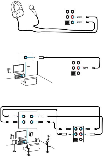
Audio jacks to headphone and microphone diagram
Audio jacks to stereo speakers diagram
AUDIO INPUT
Audio jacks to 7.1-channel speakers diagram
AUDIO INPUT
|
Rear |
Front |
|
Side |
Center/ |
|
Subwoofer |
24 Rear I/O Panel
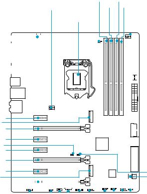
Overview of Components
PCI_E1
M2_1
PCI_E2
PCI_E3
JBAT1 PCI_E4
PCI_E5
PCI_E6
M2_2
PCI_E7
|
DIMMA1 DIMMB1 |
||||||||||||||||||||
|
SYS_FAN1 |
DIMMA2 DIMMB2 |
|||||||||||||||||||
|
CPU_FAN1 |
||||||||||||||||||||
|
CPU_PWR1 |
CPU Socket |
CPU_FAN2 |
||||||||||||||||||

 SYS_FAN3
 ATX_PWR1
 JUSB3
JUSB3


 SATA1_2
 SE1_43-SE2_65
JCI1
POST
|
JFP2 |
||||||||||||||||||||||||||||||||||||||||||||||||||||||||||||||
|
JAUD1 |
JFP1 |
|||||||||||||||||||||||||||||||||||||||||||||||||||||||||||||
|
SYS_ |
FAN2 |
JUSB1 |
||||||||||||||||||||||||||||||||||||||||||||||||||||||||||||
|
SLOW_1 |
JUSB2 |
|||||||||||||||||||||||||||||||||||||||||||||||||||||||||||||
|
JTBT1* |
JCOM1 |
|||||||||||||||||||||||||||||||||||||||||||||||||||||||||||||
|
JTPM1 |
* JTBT1 is used to connect a specific card.
Overview of Components 25

Component Contents
|
Port Name |
Port Type |
Page |
|
CPU_FAN1~2, SYS_FAN1~3 |
Fan Connectors |
39 |
|
CPU Socket |
LGA1151 CPU Socket |
27 |
|
DIMMA1~2, DIMMB1~2 |
DIMM Slots |
28 |
|
JAUD1 |
Front Audio Connector |
37 |
|
JBAT1 |
Clear CMOS (Reset BIOS) Jumper |
40 |
|
JCI1 |
Chassis Intrusion Connector |
38 |
|
JCOM1 |
Serial Port Connector |
38 |
|
JFP1, JFP2 |
Front Panel Connectors |
37 |
|
CPU_PWR1, ATX_PWR1 |
Power Connectors |
35 |
|
JTPM1 |
TPM Module Connector |
37 |
|
JUSB1~2 |
USB 2.0 Connectors |
36 |
|
JUSB3 |
USB 3.1 Gen1 Connector |
36 |
|
M2_1~2 |
M.2 Slots (M-Key) |
32 |
|
PCI_E1~7 |
PCIe Expansion Slots |
29 |
|
SATA1~6 |
SATA 6Gb/s Connectors |
31 |
|
SE1_43-SE2_65 |
SATAe Connectors |
31 |
|
SLOW_1 |
Slow Mode Booting Switch |
40 |
26 Overview of Components
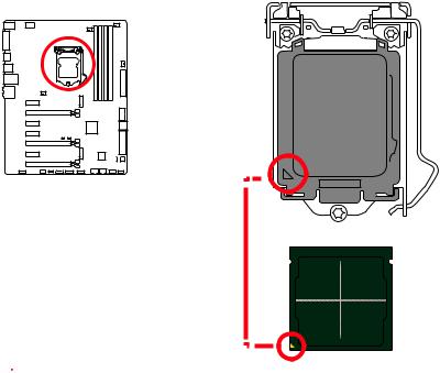
CPU Socket
Introduction to the LGA 1151 CPU
The surface of the LGA 1151 CPU has two notches and a golden triangle to assist in correctly lining up the CPU for motherboard placement. The golden triangle is the Pin 1 indicator.
 Important
yAlways unplug the power cord from the power outlet before installing or removing the CPU.
yPlease retain the CPU protective cap after installing the processor. MSI will deal with Return Merchandise Authorization (RMA) requests if only the motherboard comes with the protective cap on the CPU socket.
yWhen installing a CPU, always remember to install a CPU heatsink. A CPU heatsink is necessary to prevent overheating and maintain system stability.
yConfirm that the CPU heatsink has formed a tight seal with the CPU before booting your system.
yOverheating can seriously damage the CPU and motherboard. Always make sure the cooling fans work properly to protect the CPU from overheating. Be sure to apply an even layer of thermal paste (or thermal tape) between the CPU and the heatsink to enhance heat dissipation.
yWhenever the CPU is not installed, always protect the CPU socket pins by covering the socket with the plastic cap.
yIf you purchased a separate CPU and heatsink/ cooler, Please refer to the documentation in the heatsink/ cooler package for more details about installation.
yThis motherboard is designed to support overclocking. Before attempting to overclock, please make sure that all other system components can tolerate overclocking. Any attempt to operate beyond product specifications is not recommended. MSI® does not guarantee the damages or risks caused by inadequate operation beyond product specifications.
Overview of Components 27
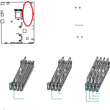
DIMM Slots
|
DIMMA1 |
DIMMB1 |
||||||||||||||||||||||||||||||||||||
|
Channel A |
Channel B |
||||||||||||||||||||||||||||||||||||
|
DIMMA2 |
DIMMB2 |
||||||||||||||||||||||||||||||||||||
Memory module installation recommendation
|
DIMMB2 |
DIMMB2 |
|
|
DIMMB1 |
||
|
DIMMA2 |
DIMMA2 |
DIMMA2 |
|
DIMMA1 |
 Important
yAlways insert memory modules in the DIMMA2 slot first.
yDue to chipset resource usage, the available capacity of memory will be a little less than the amount of installed.
yBased on Intel CPU specification, the Memory DIMM voltage below 1.35V is suggested to protect the CPU.
yPlease note that the maximum capacity of addressable memory is 4GB or less for 32-bit Windows OS due to the memory address limitation. Therefore, we
recommended that you to install 64-bit Windows OS if you want to install more than 4GB memory on the motherboard.
ySome memory may operate at a lower frequency than the marked value when overclocking due to the memory frequency operates dependent on its Serial Presence Detect (SPD). Go to BIOS and find the Memory Try It! to set the memory frequency if you want to operate the memory at the marked or at a higher frequency.
yIt is recommended to use a more efficient memory cooling system for full DIMMs installation or overclocking.
yThe stability and compatibility of installed memory module depend on installed CPU and devices when overclocking.
28 Overview of Components
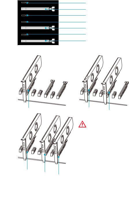
PCI_E1~7: PCIe Expansion Slots
PCI_E1: PCIe 3.0 x1
PCI_E2: PCIe 3.0 x16/ x8
PCI_E3: PCIe 3.0 x1
PCI_E4: PCIe 3.0 x1
PCI_E5: PCIe 3.0 x8
PCI_E6: PCIe 3.0 x1
PCI_E7: PCIe 3.0 x4/ x1
Multiple graphics cards installation recommendation
|
Important |
||||
|
y PCI_E7 will only run x1 mode, when an |
||||
|
extension card is installed in PCI_E3/ |
||||
|
PCI_E4/ PCI_E6 slot. |
||||
|
y For a single PCIe x16 expansion |
||||
|
card installation with optimum |
||||
|
performance, using the PCI_E2 slot is |
||||
|
recommended. |
||||
|
y When adding or removing expansion |
||||
|
cards, always turn off the power supply |
||||
|
and unplug the power supply power |
||||
|
x8 |
cable from the power outlet. Read the |
|||
|
x8 |
x4 |
expansion card’s documentation to |
||
|
check for any necessary additional |
hardware or software changes.
Overview of Components 29
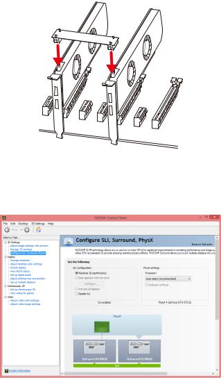
Installing SLI graphics cards
For power supply recommendations for SLI configurations, please refer to the user guide of your graphics card to make sure you meet all the system requirements.
To install SLI graphics cards:
1.Turn off your computer and disconnect the power cord, install two graphics cards into the PCI_E2 and PCI_E5 slots.
2.Connect the two cards together using the SLI Bridge Connector.
3.Connect all PCIe power connectors of the graphics cards.
4.Reconnect the power cord, power up the computer and install the drivers and software included in your graphics card package.
5.Right-click the Windows desktop and select NVIDIA Control Panel from the menu, click on Configure SLI, Surround, PhysX in the left task pane and select Maximize 3D performance in the SLI configuration menu, and then click Apply.
30 Overview of Components
![]()
SATA1~6: SATA 6Gb/s Connectors
These connectors are SATA 6Gb/s interface ports. Each connector can connect to one SATA device.
SATA2
SATA1
SATA5
SATA6 SATA3
SATA4
SE1_43-SE2_65: SATAe Connectors
These connectors are SATAe (SATA Express) interface ports. Each SATAe connector can be used with a single SATAe device or two legacy SATA devices.
SATA6 SE2_65
 SATA5
SATA5
 SATA3
SATA3
SATA4 SE1_43
 Important
yPlease do not fold the SATA or SATAe cable at a 90-degree angle. Data loss may result during transmission otherwise.
ySATA or SATAe cables have identical plugs on either sides of the cable. However, it is recommended that the flat connector be connected to the motherboard for space saving purposes.
Overview of Components 31