
Параметры продукта
• Модель продукта: KT4H• Вин: 85-265 В переменного тока• Выход: постоянный ток 0-330 в (автоматический + регулируемый)• Точность вольтметра по уровню поверхности: < (± 0,5 ± 1% Vout) v-образный вырез• Iout: 0-150 мА (автоматический + регулируемый)• Постоянный ток тестового тока: 0-999 мА• Точность амперметра: <(± 2 ± 1% Iout) mA• Pinput: 50VA (макс.)• Температура: -20 ℃ ~ + 40 ℃
Введение продукта
Тестирование напряжения и тока платы постоянного тока в режиме реального времени.1. Светодиодный тест-полоски, СВЕТОДИОДНЫЙ панели, один светодиодный шарик, источники освещения COB и так далее.2. Тестирование подсветки светодиодный-телевизора, дисплеев, компьютеров и так далее.3. Совместим со всеми светодиодный полоски (высокого напряжения или низкого напряжения).4. Ручная регулировка диапазона испытательного напряжения (20-330 в/постоянный ток) и тока (20-150 мА).Регулировка напряжения при открытой цепи (без нагрузки) и регулировка тока с нагрузками или контактными зондами вместе.5. Не выгорает при тестировании один светодиодный шарик с неправильной полярностью. (Установите напряжение около 20 в и переключатель тока до 1 мА)6. Параметры тестирования напряжения различных электронных компонентов.7. Испытательный светодиодный светильник на транспортном средстве.
Методы тестирования
Заводская установка по умолчанию: выходное напряжение 330 в, выходной ток 30 мА. Вы можете протестировать подсветку телевизора с любым размером в этих настройках по умолчанию.1. Самостоятельное тестирование: Подключите, включите выключатель питания. Напряжение около 330 В, ток 0; Свяжитесь с зондами вместе, изменение напряжения на 0 и изменение тока на около 50 мА, затем можно начать тестирование.2. При тестировании:Напряжение = 0, короткое замыкание.Напряжение = ‘330V’, открытая цепь.3. Тестирование одного светодиодный бусин (Установите напряжение около 20 в и переключатель тока до 1 мА):А. С правильной полярностью: напряжение показывает на тестере нормальный светодиодный шарик составляет около 80% от номинального напряжения, например, рабочее напряжение светодиодный шарик 2,4 V в том случае, если его номинальное напряжение 3В;B. С неправильной полярностью: напряжение Отображает напряжение открытой цепи.4. Светодиодный тест-полоски: Установите напряжение около 200 в, измените ток, если требуется Регулировка яркости.

Метод тестирования без демонтажа экрана
Отключите питание от ТВ, отключите интерфейс розетки постоянного пластина тока и светильник бар, вставьте Красного и черного цветов ручки тестера в аноды и катоды интерфейса светодиодный светильник бар.1. Несколько светодиодный полоскиПроверка напряжения каждой ленты и запись их. Сравните Напряжение каждой ленты, это нормально, если разница <2 в или <3%.2. Однополосный светодиодныйА. Светодиодный индикатор не включен (для ремонта необходимо снять экран):Напряжение = 0, короткое замыкание. Напряжение ≥ 300 В, открытая цепь.B. Светодиодный индикатор горит (для определения нормальной подсветки или нет Нужны ссылки на тестирование платы драйвера постоянного тока).
Метод тестирования платы драйвера постоянного тока
Условия тестирования: Светодиодный индикатор подсветки включен с тестером, но он не работает с платой постоянного тока;А. Отключите питание от ТВ, отключите интерфейс розетки постоянного пластина тока и светильник бар;B. Подключите панель постоянного тока с тестером, используя кабели в наборе на правой полярности.C. Вставьте красные и черные ручки тестера в анод и катод интерфейса светодиодный светильникD. Включите питание телевизора.Е. Испытательное напряжение> 30 В, ток> 30 мА и стабильный, и светодиодный индикатор работает нормально, затем плата постоянного тока является нормальной.

Обратите внимание, что напряжение настраивается при открытии цепи, а ток регулируется во время короткого замыкания.
Введение дополнительной функции
Проверка напряжения электролитического конденсатора:Подключите черную ручку с катодом электролитического конденсатора и красной ручкой с анодом. Значение напряжения, отображаемое в вольтметре, будет быстро расти в начале. При достижении определенной точки скорость подъема заметно замедляется. В это время отображаемое значение напряжения-это фактическое Выдерживаемое Напряжение испытанного электролитического конденсатора. (Конденсаторы квалифицированы, если фактическое значение напряжения выше указанного значения напряжения)Примечание: Избегайте поломки конденсатора, время тестирования не должно быть слишком длинным.1. Установите напряжение около 20 в и ток до 1 мА при тестировании ссылки на напряжение диодов, триодов, MOS труб и IC.2. Установите напряжение около 330 в и ток до 1 мА при тестировании напряжения поломки конденсаторов, stabilivolts, пьезорезисторов и телевизоров.


Гарантия
1. Этот продукт гарантирован до одного года от покупки.2. Если есть некоторые проблемы с производительностью, просто верните его в исходное состояние в течение 30 дней с момента получения. В течение гарантийного срока, мы отремонтируем его и отправим вам хороший тестер.3. Гарантийный срок будет продлен на три месяца после ремонта.4. В течение гарантийного срока перевозка AA.5. Обратите внимание, что политика гарантии не распространяется на:А. Продукт поврежден человеком или случайно поврежден, например, чрезмерное входное напряжение, высокая температура, повреждение воды, падение иПоломки, механические повреждения и коррозии.B. Несанкционированная модификация и разрыв метка даты продукта.


Параметры продукта
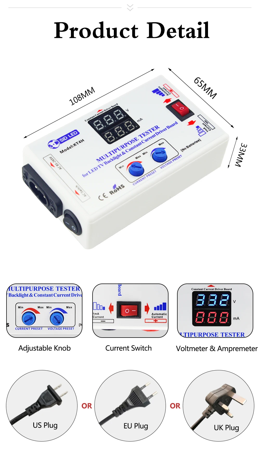
• Модель продукта: KT4H
• Вин: 85-265 В переменного тока
• Выход: постоянный ток 0-330 в (автоматический + регулируемый)
• Точность вольтметра по уровню поверхности: < (± 0,5 ± 1% Vout) v-образный вырез
• Iout: 0-150 мА (автоматический + регулируемый)
• Постоянный ток тестового тока: 0-999 мА
• Точность амперметра: <(± 2 ± 1% Iout) mA
• Pinput: 50VA (макс.)
• Температура: -20 ℃ ~ + 40 ℃
Введение продукта
Тестирование напряжения и тока платы постоянного тока в режиме реального времени.
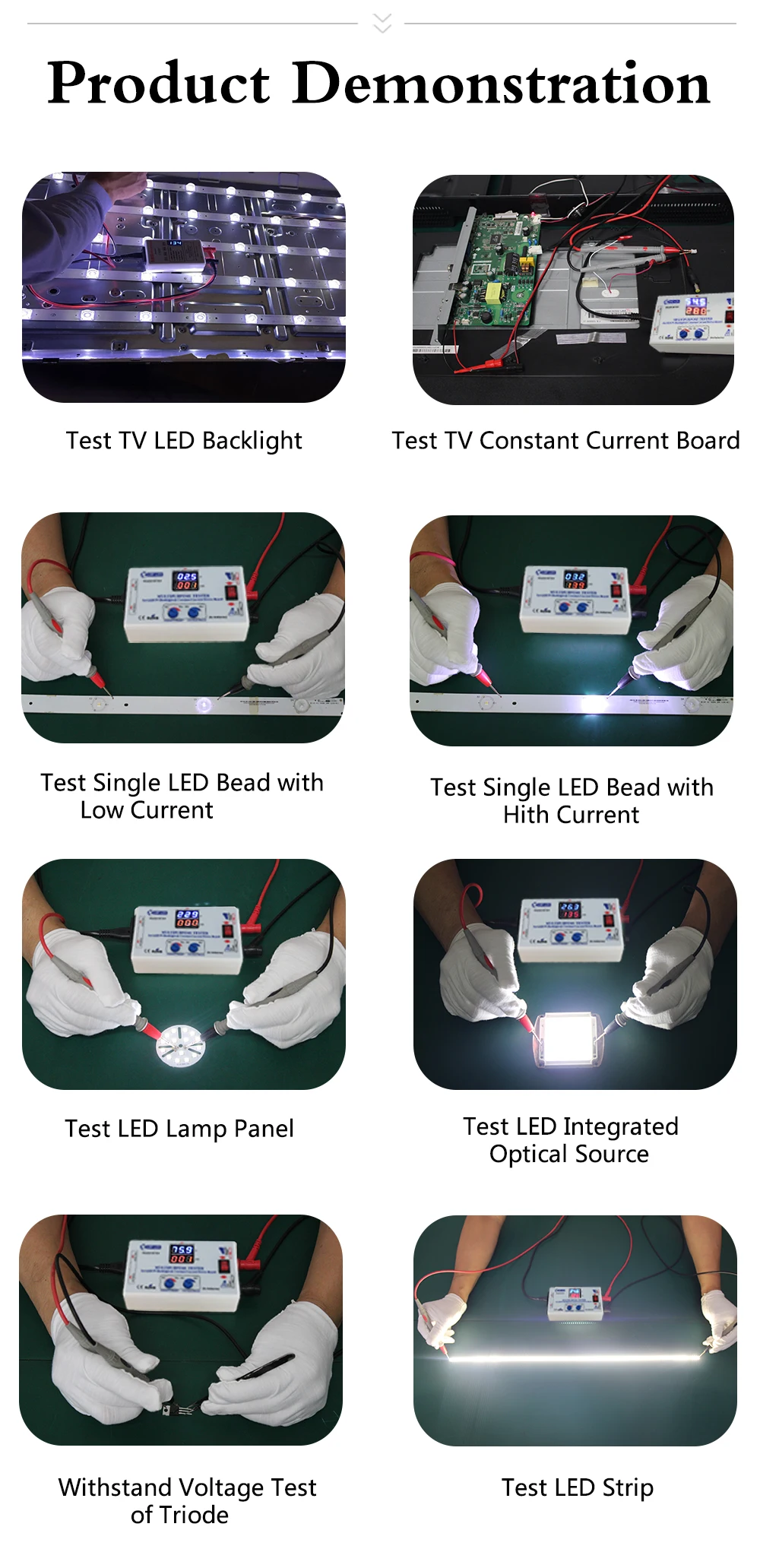
1. Светодиодный тест-полоски, СВЕТОДИОДНЫЙ панели, один светодиодный шарик, источники освещения COB и так далее.
2. Тестирование подсветки светодиодный-телевизора, дисплеев, компьютеров и так далее.
3. Совместим со всеми светодиодный полоски (высокого напряжения или низкого напряжения).
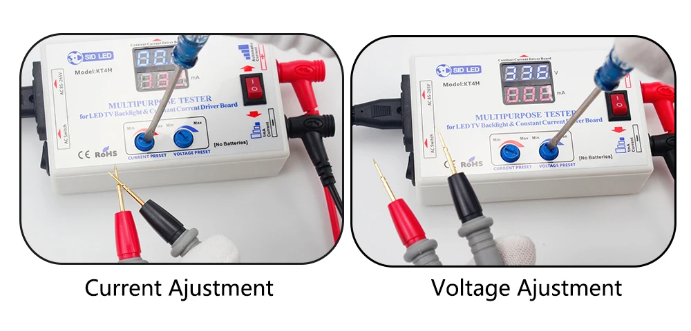
4. Ручная регулировка диапазона испытательного напряжения (20-330 в/постоянный ток) и тока (20-150 мА).
Регулировка напряжения при открытой цепи (без нагрузки) и регулировка тока с нагрузками или контактными зондами вместе.
5. Не выгорает при тестировании один светодиодный шарик с неправильной полярностью. (Установите напряжение около 20 в и переключатель тока до 1 мА)
6. Параметры тестирования напряжения различных электронных компонентов.
7. Испытательный светодиодный светильник на транспортном средстве.
Методы тестирования
Заводская установка по умолчанию: выходное напряжение 330 в, выходной ток 30 мА. Вы можете протестировать подсветку телевизора с любым размером в этих настройках по умолчанию.
1. Самостоятельное тестирование: Подключите, включите выключатель питания. Напряжение около 330 В, ток 0; Свяжитесь с зондами вместе, изменение напряжения на 0 и изменение тока на около 50 мА, затем можно начать тестирование.
2. При тестировании:
Напряжение = 0, короткое замыкание.
Напряжение = ‘330V’, открытая цепь.
3. Тестирование одного светодиодный бусин (Установите напряжение около 20 в и переключатель тока до 1 мА):
А. С правильной полярностью: напряжение показывает на тестере нормальный светодиодный шарик составляет около 80% от номинального напряжения, например, рабочее напряжение светодиодный шарик 2,4 V в том случае, если его номинальное напряжение 3В;
B. С неправильной полярностью: напряжение Отображает напряжение открытой цепи.
4. Светодиодный тест-полоски: Установите напряжение около 200 в, измените ток, если требуется Регулировка яркости.

Метод тестирования без демонтажа экрана
Отключите питание от ТВ, отключите интерфейс розетки постоянного пластина тока и светильник бар, вставьте Красного и черного цветов ручки тестера в аноды и катоды интерфейса светодиодный светильник бар.
1. Несколько светодиодный полоски
Проверка напряжения каждой ленты и запись их. Сравните Напряжение каждой ленты, это нормально, если разница <2 в или <3%.
2. Однополосный светодиодный
А. Светодиодный индикатор не включен (для ремонта необходимо снять экран):
Напряжение = 0, короткое замыкание. Напряжение ≥ 300 В, открытая цепь.
B. Светодиодный индикатор горит (для определения нормальной подсветки или нет Нужны ссылки на тестирование платы драйвера постоянного тока).
Метод тестирования платы драйвера постоянного тока
Условия тестирования: Светодиодный индикатор подсветки включен с тестером, но он не работает с платой постоянного тока;
А. Отключите питание от ТВ, отключите интерфейс розетки постоянного пластина тока и светильник бар;
B. Подключите панель постоянного тока с тестером, используя кабели в наборе на правой полярности.
C. Вставьте красные и черные ручки тестера в анод и катод интерфейса светодиодный светильник
D. Включите питание телевизора.
Е. Испытательное напряжение> 30 В, ток> 30 мА и стабильный, и светодиодный индикатор работает нормально, затем плата постоянного тока является нормальной.


Обратите внимание, что напряжение настраивается при открытии цепи, а ток регулируется во время короткого замыкания.
Введение дополнительной функции
Проверка напряжения электролитического конденсатора:
Подключите черную ручку с катодом электролитического конденсатора и красной ручкой с анодом. Значение напряжения, отображаемое в вольтметре, будет быстро расти в начале. При достижении определенной точки скорость подъема заметно замедляется. В это время отображаемое значение напряжения-это фактическое Выдерживаемое Напряжение испытанного электролитического конденсатора. (Конденсаторы квалифицированы, если фактическое значение напряжения выше указанного значения напряжения)
Примечание: Избегайте поломки конденсатора, время тестирования не должно быть слишком длинным.
1. Установите напряжение около 20 в и ток до 1 мА при тестировании ссылки на напряжение диодов, триодов, MOS труб и IC.
2. Установите напряжение около 330 в и ток до 1 мА при тестировании напряжения поломки конденсаторов, stabilivolts, пьезорезисторов и телевизоров.


Гарантия
1. Этот продукт гарантирован до одного года от покупки.
2. Если есть некоторые проблемы с производительностью, просто верните его в исходное состояние в течение 30 дней с момента получения. В течение гарантийного срока, мы отремонтируем его и отправим вам хороший тестер.
3. Гарантийный срок будет продлен на три месяца после ремонта.
4. В течение гарантийного срока перевозка AA.
5. Обратите внимание, что политика гарантии не распространяется на:
А. Продукт поврежден человеком или случайно поврежден, например, чрезмерное входное напряжение, высокая температура, повреждение воды, падение и
Поломки, механические повреждения и коррозии.
B. Несанкционированная модификация и разрыв метка даты продукта.

- Manuals
- Brands
- Panasonic Manuals
- Temperature Controller
- KT4H
- User manual
-
Contents
-
Table of Contents
-
Troubleshooting
-
Bookmarks
Quick Links
Related Manuals for Panasonic KT4H
Summary of Contents for Panasonic KT4H
-
Page 2: Table Of Contents
CONTENTS 1. Model number Page 1.1 Model number —————————————————————————— 5 1.2 How to read the rated label ———————————————————— 5 2. Name and functions of the sections ——————————————- 6 3. External dimensions 3.1 External dimensions ———————————————————————- 7 3.2 Tool cable (AKT4H820) external dimensions ————————————— 7 3.3 CT (Current transformer) external dimensions ———————————— 7 3.4 Terminal cover (AKT4H801) external dimensions ——————————— 8 4.
-
Page 3: Safety Precautions
• This instrument must be used under the conditions and environment described in this manual. Panasonic Industrial Devices SUNX Co., Ltd. does not accept liability for any injury, loss of life or damage occurring due to the instrument being used under conditions not otherwise stated in this manual.
-
Page 4: Installation Precautions
• Do not leave bits of wire in the instrument, because they could cause fire or malfunction. • Use the solderless terminal with an insulation sleeve in which the M3 screw fits when wiring the KT4H/B. • The terminal block of this instrument is designed to be wired from the left side.
-
Page 5: Model Number
1. Model number 1.1 Model number A K T 4 (1) (2) (3) (4) (5) (6) (7) (8) (1) Color —————————————- H: Gray, B: Black (2) Supply voltage —————————- 1: 100 to 240V AC 2: 24V AC/DC (3) Input type ———————————- 1: Multi-input (Thermocouple, RTD, DC current and DC voltage can be selected by key operation.
-
Page 6: Name And Functions Of The Sections
2. Name and functions of the sections Model KT4H or KT4B Bottom view (Fig. 2-1) Display (1) Action indicators : Lights respectively when temperature unit is selected. : Lights during Serial communication (optional) TX output. : Flashes during auto-tuning or auto-reset.
-
Page 7: External Dimensions
3. External dimensions 3.1 External dimensions (Unit: mm) Common to KT4H/B Mounting frame Terminal cover (sold separately) Rubber gasket M3 screw (Fig. 3.1-1) 3.2 Tool cable (AKT4H820) external dimensions (Unit: mm) ø2.5 Plug 3-Pole type USB Plug (Fig. 3.2-1) 3.3 CT (current transformer) external dimensions (Unit: mm)
-
Page 8: Terminal Cover (Akt4H801) External Dimensions
3.4 Terminal cover (AKT4H801) external dimensions (Unit: mm) (Fig. 3.4-1) Note when using a Terminal cover (AKT4H801) When using a Terminal cover (AKT4H801), pass terminal wires numbered 7 to 12 into the holes of the terminal cover. See (Fig. 3.4-2). Terminal cover (Fig.
-
Page 9: Mounting To The Control Panel
Tighten screws with one rotation upon the screw tips touching the panel. The torque is approximately 0.05 to 0.06 N•m. How to mount the KT4H Mount the controller vertically to the flat, rigid panel to ensure it adheres to the Dust-proof/Drip-proof specification (IP66).
-
Page 10: Wiring
5. Wiring Warning Turn the power supply to the instrument off before wiring. Working on or touching the terminal with the power switched on may result in severe injury or death due to Electric Shock. 5.1 Terminal arrangement • EVT1 : Alarm 1 output •…
-
Page 11: Settings
Default values: Input (K, -200 to 1370 ), Alarm 1 type (No alarm action), Reverse (Heating) action If the users’ specifications are the same as the default value of the KT4H/B, it is not necessary to set up the controller.
-
Page 12: Operation Flowchart
6.4 Operation flowchart This instrument has been classified into the following modes and setting items. For 3 seconds after power on, the PV display indicates the Power ON input type, and the SV display indicates input range high limit value (thermocouple, RTD input) or scaling high limit value (DC voltage, current input).
-
Page 13: Main Setting Mode
6.5 Main setting mode To enter the Main setting mode, press key in the PV/SV display mode. To set or select each setting item, use key, then register the value with key. Setting item numbers such as [1], [2], etc. are the same as those on the “6.4 Operation flowchart” (p.12). Character Name, Function, Setting range Default value…
-
Page 14: Sub Setting Mode
6.6 Sub setting mode To enter the Sub setting mode, press key while pressing key in the PV/SV display mode. To set or select each setting item, use key, then register the value with key. Setting item numbers such as [5], [6], etc. are the same as those on the “6.4 Operation flowchart” (p.12). Character Name, Function, Setting range Default value…
-
Page 15
• Sets the heater current value for Heater burnout alarm. CT1 current value is indicated on the PV display. When OUT1 is ON, the CT1 current value is updated. When OUT1 is OFF, the KT4H/B memorizes the previous value when OUT1 was ON. -
Page 16: Auxiliary Function Setting Mode
6.7 Auxiliary function setting mode To enter the Auxiliary function setting mode, press key for approximately 3 seconds while pressing key in the PV/SV display mode. To set or select each setting item, use key, then register the value with key.
-
Page 17
Character Name, Function, Setting range Default value [22] Data bit/Parity selection 7 bits/Even parity • Selects the data bit and parity. Not available if the Serial communication option is not added or if Contact input option is added. • : 8 bits/No parity : 7 bits/No parity : 8 bits/Even parity : 7 bits/Even parity… -
Page 18: Setup Mode
6.8 Setup mode To enter the Setup mode, press key while pressing key for approximately 3 seconds in the PV/SV display mode. To set or select each setting item, use key, then register the value with key. Setting item numbers such as [25], [26], etc. are the same as those on the “6.4 Operation flowchart” (p.12). Character Name, Function, Setting range Default value…
-
Page 19
Character Name, Function, Setting range Default value [29] PV filter time constant setting 0.0 seconds • Sets PV filter time constant. If the value is set too large, it affects control result due to the delay of response. • Setting range: 0.0 to 10.0 seconds [30] OUT1 high limit setting 100%… -
Page 20
Character Name, Function, Setting range Default value [38] Alarm 1 type selection No alarm action • Selects an action type for Alarm 1. (Refer to Section “11.4 Alarm action” on p.30.) • : No alarm action : High limit alarm : Low limit alarm : High/Low limits alarm : High/Low limit range alarm… -
Page 21
Character Name, Function, Setting range Default value [46] SV rise rate setting minute • Sets SV rise rate (rising value for 1 minute). Setting to 0 disables the function. • Setting range: 0 to 10000 /min. ( /min.) Thermocouple, RTD input with a decimal point: 0.0 to 1000.0 /min. -
Page 22
Character Name, Function, Setting range Default value [54] PV color selection Green • Selects PV display color. (Refer to Section “8.4 Changing PV color” on p.26.) • : Green : Red : Orange : When Alarm 1 or Alarm 2 is ON, PV color turns from green to red. : When Alarm 1 or Alarm 2 is ON, PV color turns from orange to red. -
Page 23: Operation
After the unit is mounted to the control panel and wiring is completed, operate the unit following the procedures below. (1) Turn the power supply to the KT4H ON. After the power is turned on, the PV display indicates the input type, and the SV display indicates the input range high limit value (for thermocouple, RTD input) or scaling high limit value (for DC input) for approximately 3 seconds.
-
Page 24: Auto/Manual Control Switching
By pressing key again, the unit reverts to the PV/SV display mode (automatic control). Whenever the power to the KT4H is turned on, automatic control starts. 7.4 Indicating output MV (manipulated variable) To indicate output MV (manipulated variable), press key for approx.
-
Page 25: Basic Usage
8. Basic usage 8.1 ON/OFF control In ON/OFF control action, the control output is turned ON when PV is lower than SV, and turned OFF when PV exceeds SV. Overshoot, undershoot and hunting phenomenon occur during ON/OFF action. Therefore, ON/OFF action is not suitable for control which requires accuracy.
-
Page 26: Changing Pv Color
8.4 Changing PV color (1) In the PV/SV display mode, press key for approximately 3 seconds while pressing key. The unit proceeds to the Setup mode, and the Input type selection item appears. (2) Press key several times until [54] PV color selection item appears. (3) Select the PV color with key.
-
Page 27: Auto-Reset And Arw
9. Auto-reset and ARW 9.1 Auto-reset Auto-reset is performed to correct the offset at the point at which PV indication is stabilized within the proportional band during the PD action. Since the corrected value is internally memorized, it is not necessary to perform the auto-reset again as long as the process is the same.
-
Page 28: Auto-Tuning
10. Auto-tuning In order to set each value of P, I, D and ARW automatically, the auto-tuning process should be made to fluctuate to obtain an optimal value. One of 3 types of fluctuation below is automatically selected. For DC input, the auto-tuning process will fluctuate around the SV for conditions of [1], [2] and [3] below. Notice •…
-
Page 29: Out1 Pid, Pi, Pd, P Actions
11. Action explanation 11.1 OUT1 PID, PI, PD, P actions PI action : When derivative time is set to “0” PD action : When integral time is set to “0” P action : When both integral and derivative time are set to “0” [8] Integral time and [9] Derivative time can be set in the Sub setting mode.
-
Page 30: Heater Burnout Alarm Action
11.3 Heater burnout alarm action [15] Heater burnout alarm value and [16] Heater burnout alarm 2 value can be set in the Sub setting mode. (p.15) Alarm action Setting Small Large Load current Output Indicator (EVT2) Unlit If Heater burnout alarm, Heater burnout alarm 2 and Alarm 2 are added together, they (EVT2) utilize common output terminals.
-
Page 31: Out2 (Heating/Cooling Control) Action [Reverse (Heating) Action]
11.5 OUT2 (Heating/Cooling control) action [Reverse (Heating) action] Heating P-band (Cooling P-band) Heating/Cooling control can be used Control Heating (Cooling by adding Heating/Cooling control action action action) option. SV setting Heating proportional band can be Relay contact set during [6] OUT1 proportional band output (OUT1) setting, and cooling proportional band Cycle action is performed according to deviation.
-
Page 32: Out2 (Heating/Cooling Control) Action [Reverse (Heating) Action] (When Setting Overlap Band)
11.7 OUT2 (Heating/Cooling control) action [Reverse (Heating) action] (When setting overlap band) Heating P-band Heating/Cooling control can be used Cooling P-band by adding Heating/Cooling control Overlap band option. Control action Heating (Cooling action action) Heating proportional band can be set during [6] OUT1 proportional band setting, SV setting and cooling proportional band can be set…
-
Page 33: Out2 (Heating/Cooling Control) Action [Direct (Cooling) Action] (When Setting Dead Band)
11.9 OUT2 (Heating/Cooling control) action [Direct (Cooling) action] (When setting dead band) Cooling P-band Dead band Heating P-band Heating/Cooling control can be used (Cooling Heating Control action by adding Heating/Cooling control action) action option. SV setting Heating proportional band can be Relay contact set during [6] OUT1 proportional output (OUT1)
-
Page 34: Sv Rise Rate, Sv Fall Rate Setting Action
11.11 SV rise rate, SV fall rate setting action [46] SV rise rate and [47] SV fall rate can be set in the Setup mode. (p.21) When the SV is adjusted, it approaches the new SV by the preset SV rise rate or SV fall rate. When SV is adjusted while SV is rising (or falling), SV at the given time becomes a starting point, and approaches the new SV.
-
Page 35
When power is turned on or when control output OFF function is cancelled by the key, SV changes as follows in relation to PV. (e.g.) SV=200 , SV rise rate=6 /Min, SV fall rate=30 /Min [When SV>PV] Temperature SV=200 SV display 200 C (on the SV display) approaches by the SV rise rate. -
Page 36: Communication
Serial communication and Tool port communication cannot be used together. When performing Serial communication, remove the tool cable (AKT4H820) from the USB port of the PC and tool connector of the KT4H/B. When performing Tool port communication, it is not required to remove the Serial communication cables.
-
Page 37
Do not connect a terminator with the communication line because each KT4H/B has built-in pull-up and pull-down resistors instead of a terminator. Even though a terminator is not necessary for communication between the PLC and KT4H/B, if a terminator is required due to signal reflection, connect the terminator on the PLC side. -
Page 38: Communication Parameter Setting
12.3 Communication parameter setting Set each parameter following the procedures below. Setting item numbers such as [17, [19], etc. are the same as those on the “6.4 Operation flowchart”. (p.12) Proceed to Auxiliary function setting mode. Press key while pressing key in the PV/SV display mode.
-
Page 39: Communication Procedures
12.4 Communication procedures Communication starts with command transmission from the host computer (hereafter Master) and ends with the response of the KT4H/B (hereafter Slave). Master Slave • Response with data Command When the master sends the reading command, the slave Data responds with the corresponding set value or current status.
-
Page 40: Mewtocol
(23H) (25H) (Decimal) (0DH) (Decimal) (*) (Decimal) (*) (*): KT4H/B cannot read plural word data. Make sure that both top data items are the same. Acknowledgement Command Reading Address code top data (25H) (Decimal) (24H)
-
Page 41
$ (24H) Response (Normal) ! (21H) Response (Error) Command code: RD; Word data reading (Continuous reading of plural data from the KT4H/B is impossible.) WD; Word data writing (Continuous writing of plural data to the KT4H/B is impossible.) Data code : ASCII code D (44H) is used. -
Page 42
12.5.4 Message example (1) Reading (Address 1, PV) • RD (Word data reading) command from the master Command Data Top data item Top data item Address code code (Decimal) (Decimal) (Decimal) 00356 00356 25H 30H 31H 23H 52H 44H 44H 30H 30H 33H 35H 36H 30H 30H 33H 35H 36H 35H 35H 0DH •… -
Page 43
MEWTOCOL Data item Data command code Use in the system DT00100 (Never use WD command. If WD command is sent to the KT4H/B, the KT4H/B may not be operable.) RD/WD DT00102 Set value, Decimal point ignored 0000H: Cancel RD/WD DT00106… -
Page 44
MEWTOCOL Data item Data command code RD/WD DT00202 SV rise rate Set value, Decimal point ignored RD/WD DT00204 SV fall rate Set value, Decimal point ignored RD/WD DT00210 Control output OUT/OFF 0000H: Control output ON 0001H: Control output OFF RD/WD DT00212 Auto/Manual control 0000H: Automatic control… -
Page 45
MEWTOCOL Data item Data command code RD/WD DT00260 Backlight 0000H: All are backlit 0001H: Only PV display is backlit 0002H: Only SV display is backlit 0003H: Only action indicators are backlit 0004H: PV+SV displays are backlit 0005H: PV+ action indicators are backlit 0006H: SV+ action indicators are backlit RD/WD DT00262… -
Page 46
MEWTOCOL Data item Data command code DT00422 Instrument specification flag 0000 0000 0000 0000 : Contact input 0: Not added, 1: Added : Serial communication 0: Not added, 1: Added : Heater burnout alarm 0: Not added, 1: Added : Heater burnout alarm rating 0: 20A, 1: 50A : Heater burnout alarm specification 0: Single phase, 1: 3-phase : Alarm 2 output… -
Page 47: Modbus Protocol
12.6 Modbus protocol 12.6.1 Transmission mode There are 2 transmission modes (ASCII and RTU) in Modbus protocol. 12.6.2 ASCII mode Hexadecimal (0 to 9, A to F), which is divided into high order (4-bit) and low order (4-bit) out of 8-bit binary data in command is transmitted as ASCII characters.
-
Page 48
(2) Error check of ASCII mode After calculating LRC (Longitudinal Redundancy Check) from the slave address to the end of data, the calculated 8-bit data is converted to two ASCII characters and are appended to the end of message. How to calculate LRC Create a message in RTU mode. -
Page 49
Reading (Address 1, SV) • A request message from the master The number of data means the data item to be read, and it is fixed as 1 (30H 30H 30H 31H). Header Slave Function Data item Number of data Error check Delimiter address… -
Page 50
12.6.2 RTU mode 8-bit binary data in command is transmitted as it is. Data format Start bit : 1 bit Data bit : 8 bits Parity : No parity (Even, Odd) Selectable Stop bit : 1 bit (2 bits) Selectable Error detection: CRC-16 (Cyclic Redundancy Check) Data interval : 3.5 character transmission time or less (1) Message configuration… -
Page 51
(2) Error check of RTU mode After calculating CRC-16 (Cyclic Redundancy Check) from the slave address to the end of data, the calculated 16-bit data is appended to the end of message in sequence from low order to high order. How to calculate CRC In the CRC system, the information is divided by the polynomial series. -
Page 52
Reading (Address 1, SV) • A request message from the master The number of data means the data item to be read, and it is fixed as 1 (0001H). Slave Function Data item Number of data Error check 3.5 idle 3.5 idle address code… -
Page 53
Data item Data function code Use in the system 0000H (Never use function code 06H. If function code 06H is sent to the KT4H/B, the KT4H/B may not be operable.) 03H/06H 0001H Set value, Decimal point ignored 0000H: Cancel 03H/06H… -
Page 54
Modbus Data item Data function code 03H/06H 0033H SV rise rate Set value, Decimal point ignored 03H/06H 0034H SV fall rate Set value, Decimal point ignored 0000H: Control output ON 03H/06H 0037H Control output OUT/OFF 0001H: Control output OFF 0000H: Automatic control 03H/06H 0038H Auto/Manual control… -
Page 55
Modbus Data item Data function code 03H/06H 0050H Backlight 0000H: All are backlit 0001H: Only PV display is backlit 0002H: Only SV display is backlit 0003H: Only action indicators are backlit 0004H: PV+SV displays are backlit 0005H: PV+ action indicators are backlit 0006H: SV+ action indicators are backlit 03H/06H 0051H… -
Page 56
Modbus Data item Data function code 00A1H Instrument specification flag 0000 0000 0000 0000 : Contact input 0: Not added, 1: Added : Serial communication 0: Not added, 1: Added : Heater burnout alarm 0: Not added, 1: Added : Heater burnout alarm rating 0: 20A, 1: 50A : Heater burnout alarm specification 0: Single phase 1: 3-phase : Alarm 2 output 0: Not added, 1: Added… -
Page 57: Specifications
13. Specifications 13.1 Standard specifications Mounting : Flush Setting : Input system using membrane sheet key Display PV display : 11-segment backlight LCD Red/Green/Orange, character size 12.0 x 5.4mm (H x W) SV display : 11-segment backlight LCD Green, character size 6.0 x 3.5mm (H x W) MEMO display : 11-segment backlight LCD Green, character size 4.8 x 2.8mm (H x W) : Backlight Orange Action indicators…
-
Page 58
(Depth of control panel interior when rubber gasket is not used: 56.0mm) Material : Flame resistant resin (Case) Color : KT4H: Ash gray (Case) KT4B: Black (Case) Attached functions: [Power failure countermeasure] The setting data is backed up in the non-volatile IC memory. -
Page 59
PV/SV display mode. Auto/Manual control can be switched. [Tool port communication] By connecting to the tool connector of the KT4H/B, the following operations can be conducted from the external computer. (1) Reading and setting of SV, PID and various set values… -
Page 60: Optional Specifications
Accessories included: Mounting frame 1 piece Rubber gasket (Front mounted to the KT4H/B) 1 piece Installation instructions (A3 unfolded, English/Japanese) 1 copy Communication installation instructions (When Serial communication option is added) 1 copy CT (Current transformer) CT1 (AKT4815) (When Heater burnout alarm Single phase 20A option is added) 1piece…
-
Page 61
Serial communication Cannot be used with Tool port communication. If this option is added, Contact input option cannot be added. The following operations can be carried out from the external computer. (1) Reading and setting of the SV, PID values and various set values (2) Reading of the PV and action status (3) Function change Communication line : EIA RS-485… -
Page 62: Troubleshooting
14. Troubleshooting If any malfunctions occur, refer to the following items after checking the power supply to the controller. 14.1 Indication Problem Presumed cause and solution • Control output OFF function is working. ] is indicated on the PV Press the key for approx.
-
Page 63: Key Operation
• Check whether the input lead wire terminals for DC voltage (0 to 5V DC, 0 to 10V DC) or DC current (0 to 20mA DC) are securely mounted to the instrument input terminals. The indication of PV display is •…
-
Page 64: Communication
• The setting command data exceeds the setting range of the slave. “NAK”. • The controller cannot be set when functions such as AT are performing. • The KT4H/B is in the front key operation setting mode. For all other malfunctions, please contact our main office or dealers.
-
Page 65: Revision History
Revision History Issue Date Manual no. Content of revision May, 2005 ARCT1F412E First edition October, 2005 ARCT1F412E-1 edition P.14 P.15 P.16 P.18 Addition of explanation in detail P.19 P.20 P.21 April, 2007 ARCT1F412E-2 edition Addition of explanation in detail P.32~33 Addition of explanation in detail P.34~35 Addition of explanation of “SV rise…
This manual is also suitable for:
Kt4b
Используя этот сайт, вы соглашаетесь на использование файлов cookie. Больше информации — в нашей Политике конфиденциальности.
Выберите язык
Домашняя страница Joom
Войти
Мои заказы
Корзина
ГлавнаяКаталогАвтомобили и мотоциклыИнструменты и оборудованиеСредства диагностикиЭлектрические тестеры и диагностические инструменты
Текущая цена
Цена 7 504 ₽ руб.
Исходная цена
Цена 11 633 ₽ руб.
Бесплатная доставка,
24 – 49 дней
Цвет
Как на картинке

Магазин
SS
sun shine-7
200
+
товаров
4,9
Описание
Нашли неточность?
Принимаем оплату российскими картами, выкупаем и доставляем ваши заказы из магазинов США и Германии. Наша доставка работает в стандартном режиме.
×
Сейчас вы находитесь в городе Москва
Выберите город, в который Вы хотите осуществить доставку
Товар временно не доступен

![]()
![]()
Вопрос по товару?
Мы перезвоним!
Похожие товары
Основные характеристики
Оригинальное название:
KT4H LED Backlight Tester Multipurpose For LED TV Backlight & Constant Current
Товар из США
Доставим в Ваш город
Артикул:185077942594
Продавец:
topskyrc
(9274)
Местонахождение:Shenzhen, CN
Доставка до склада США
517 ₽ ($5)

Товары из магазинов
США и Европы
без наценок!
Отправили
67 000 посылок
с 2008 года!
Знаменитый
каталог eBay
на русском языке!
Доставка курьером
до двери
Почтой или в удобный пункт выдачи!
KT4H LED Backlight Tester Multipurpose For LED TV Backlight & Constant Current
KT4H LED Backlight Tester Multipurpose For LED TV Backlight & Constant Current – можно купить на shopozz.ru с доставкой
из Shenzhen, CN. Все товары из
категории «другой» быстро и вовремя доставляются в Россию и страны СНГ.
Полную информацию о доставке можно посмотреть в разделе «Доставка».
На товары категории «другой» действует доступная цена,
поэтому KT4H LED Backlight Tester Multipurpose For LED TV Backlight & Constant Current можно
приобрести всего за
7773 руб.
Не можете сделать выбор? Посмотрите другие товары продавца
topskyrc
(9274)
–
«Смотреть все товары».
Возникли вопросы о товаре, условиях оплаты либо доставки?
Закажи обратный
звонок!
Другие бренды категории
В чем наша ценность
Покупки без ограничений
- Доставка в любой город СНГ
- Простой процесс оплаты
- Каталог на русском языке
Доступ к 3 млн. товаров
- Доставка в любой город СНГ
- Простой процесс оплаты
- Каталог на русском языке
Консолидация и сервис
- Доставка в любой город СНГ
- Простой процесс оплаты
- Каталог на русском языке
Покупки в США и Европе — это просто
Вы делаете заказ — мы выкупаем товары и доставляем вам
Склад

$46
Косметика M.A.C.maccosmetics.com

$46
Часы Timexamazon.com

$15
Джинсы levi’sebay.com
К вам домойОтправляем в Россию и
во все страны СНГ
Начать выгодные покупки в зарубежных интернет-магазинах