-
Bookmarks
Quick Links
BpaQ IO INDD.indd
BoosterpaQ
Grundfos CR-Booster Systems
60 Hz
1
GRUNDFOS INSTRUCTIONS
®
Installation and operating instructions
Factory settings are documented in this manual.
Please leave these instructions with the BoosterpaQ
for future reference.
For technical support, call your supplier or contact
Grundfos Pumps Corporation at 913 227 3400 (USA).
1/28/2005, 11:00 AM
Related Manuals for Grundfos BoosterpaQ PFU 2000
Summary of Contents for Grundfos BoosterpaQ PFU 2000
-
Page 1
Installation and operating instructions Factory settings are documented in this manual. Please leave these instructions with the BoosterpaQ for future reference. For technical support, call your supplier or contact Grundfos Pumps Corporation at 913 227 3400 (USA). BpaQ IO INDD.indd 1/28/2005, 11:00 AM… -
Page 2
Model: Part Number: PFU 2000 Eprom P/N: PMU 2000 Eprom P/N: Serial Number: Production Date: Your BoosterpaQ was factory assembled and tested with the factory set control parameters listed at the beginning of one of the following sections as marked. Standard PFU 2000 System Controller (See pages 6 and 7 for Installation and Start-up) Standard PMU 2000 System Controller… -
Page 3
Technical information ……34 as described in Article 250-80 of the National Electrical Code. Application BoosterpaQ System Types Grundfos BoosterpaQ systems are designed for transfer System System and boosting of clean water in commercial buildings, Type… -
Page 4
BoosterpaQs offer the following functions: • Closed-loop control Grundfos BoosterpaQ systems consist of 1-8 pumps with all necessary fittings and a Grundfos Control 2000 • Automatic shut-off at zero flow mounted on a common base frame, ready for installation. • Automatic cascade control of pumps The Control 2000 has its own base for large BoosterpaQs. -
Page 5
Grundfos BoosterpaQ MSH maintains a pressure range by cutting in/out the half-size pump and the full-size pumps. The half-size pump will always start first. The half-size pump will be cut out again when a full-size pump is cut in. The operating range of the pumps will lie between the lines Hset and Hstop (cut-out pressure). -
Page 6
VFD failure or other system causes, a pressure relief device must be installed. Another option is to install a pressure sustaining valve to return discharged fluid back to the suction manifold. Grundfos offers this option. BpaQ IO INDD.indd 1/28/2005, 11:01 AM… -
Page 7
PFU 2000 PFU 2000 Startup 7. Turn Function Selector (small knob Setpoint 1. Have a qualified person Function Selector on the PFU Controller) in the PFU 2000 check for proper power on the PFU 2000 to supply plumbing 100% “Max” (see drawing STOP connections. -
Page 8
3 phase pumps, switch any 2 of the 3 power main wires supplied to the control panel (L1, L2, L3). If that 4. Prime the system as follows. doesn’t correct the rotation, call your Grundfos repre- Suction Pressure System (pumps are flooded at least as sentative. -
Page 9
Call your Grundfos dis- 16. There should be no more faults. If there are, you will tributor or the Grundfos factory if you believe you have need to review the Troubleshooting section beginning discovered incorrect wiring or documentation. -
Page 10
12 depending or whether your system has only a below the set-point. If the system stops and starts PFU 2000 or a PMU 2000. Call your Grundfos distribu- frequently the tank pre-pressure may be too low or too tor or the Grundfos factory if you believe you have high. -
Page 11
Troubleshooting/Fault-finding chart Fault Cause Remedy 1. Motor does not run when a) Electricity supply disconnected or loose Connect the electricity supply. Check for loose started. wires. wires. DO NOT over tighten terminal screws. b) Automatic circuit breakers cut out. Correct the fault and cut in the automatic circuit breakers. -
Page 12
PMU fault indication menu Press the button on the PMU to see the following faults. The PMU will keep the last 10 faults in memory. Alarm type: Zone, Pump, Detail of alarm: See chart PFU, System. below. Alarm zone A min. -
Page 13
Faults, general Automatic resetting (restarting of PFU 2000) Fault conditions in the system are indicated by: When a fault has been corrected, the system will attempt • Red indicator light (LED) on PFU or PMU to restart automatically at the following intervals: •… -
Page 14
Controller” was marked). The factory settings cover most standard booster applications. Please contact your DIP/Switch #1 DIP/Switch #2 Grundfos representative if you believe the settings should be changed to match your application or the system is not operating properly. PFU 2000 front cover «X»… -
Page 15
2 of this manual (if “Optional” PMU 2000 system control- ler” was marked). The factory settings cover most standard booster applications. Please contact your Grundfos repre- sentative if you believe the settings should be changed to match your application or the system is not operating properly. -
Page 16
PMU factory settings All Pumps Set to Zone A Other ( Alarm Suppression Pump Communication Configuration Pre-Setting Other ( 8 With Pre-Pressure Monitoring Set-point Max _______ Clock Program — See Below Set-point Influence Set-point Influence ____% System Time _____ seconds Min Sequence _____seconds Medium Sequence* ______seconds On/Off Band _______… -
Page 17
201 clock program Daily Sa-Su Time Set-point Time Set-point Time Set-point 219 discharge sensor 227 pump priority Pump 1 Pump 4 4-20mA Other ( __________ ) Pump 2 Pump 5 _____ to _____PSI Other (________________) Pump 3 Pump 6 220 suction sensor 227 pump maximum head 4-20mA Other ( __________ ) -
Page 18
Danfoss VLT 2800 Factory Settings Field changes Parameter Description Factory setting New value Date Local/Remote Operation Local Reference Default Torque Characteristics Motor Power, kW Motor Voltage Motor Frequency, Hz Motor Current, SFA Rated Motor Speed, RPM Automatic Motor Adaptation Thermal Motor Protection Minimum Reference Maximum Reference Ramp Type… -
Page 19
Danfoss VLT 8000 Factory Settings Factory Setting Field Changes Item Number Parameter Value Value # New Value Date 001 Language English 102 Motor Power 103 Motor Voltage 104 Motor Frequency 105 Motor Current 106 Motor Speed 201 Minimum Freq. 202 Maximum Freq. 206 Ramp Up Time 207 Ramp Down Time 323 Relay 1 Function… -
Page 20
Danfoss VLT 8000 Factory Settings (continued) Extended Menu Programming Factory Setting Field Changes Item Number Parameter Value Value # New Value Date Level 0 007 Large Readout 008 Small Display Readout 009 Small Display Readout 010 Small Display Readout Level 1 101 Torque Characteristics VT Low 112 Motor Preheater… -
Page 21
Baldor SmartMotor Settings Factory Setting Field Changes Section Parameter Value New Value Date Level 2 Blocks Output Limits Min Output Freq. 12 Hz Output Limits Max Output 60 Hz Output Limits PK Current Limit Output Limits PWM Frequency 6 kHz Miscellaneous Restat Aut/Man Auto… -
Page 22
PMU 2000 LCD display overview WITH pre-pressure measuring The following PMU 2000 LCD Display Overview illus- trates the LCD Menus and Displays for the Optional PMU 2000. To return to Display 100, repeatedly press “Esc.” Refer to page 24 for “PMU 2000 LCD Display Notes.” Pump status menu Zone status menu Zone A… -
Page 23
Basic menu Zone A 8 press. Fault indication menu On/off menu Setting menu Set A medium sequence Set A Setting of hydraulic parallel control parameters pump priority Set A min. speed Available only when service code is activated (Display 106). Moves one display up in menu… -
Page 24
[-] under all other pump numbers. Press “Enter” to Grundfos for service. If this display does not come up, the store each entry and advance to the next pump number. -
Page 25
111 — Presetting Possible settings for days: See Display 102. 1 — [daily] The same switching times apply to each day of the week. SETTING MENU (“SET BUTTON”) 2 — [Mon, Tue, Wed, Thu, Fri, Sat, Sun] 200 — Setting of Set-point Max. Different switching times for each day. -
Page 26
From 12:31 to the next time, the set-point will be 55 psi. The First of all the progressive influence needs to be switched next time is at 6:30 am, which was the first entry. “on”. Once this is done the PMU display should look like the following: 202 — Set-point Influence Set A… -
Page 27
Approximately every 30 seconds or when the operating Notice that the temperature will most likely shoot past the new set-point because of the 0.4 setting, but now point changes (consumption changes), the PMU 2000 will you will change the system time constant to 0.7 times the estimate the flow by reducing the speed for a short while. -
Page 28
Other influences are available for applications other than [invers] If the actual value is higher than the set-point, the pressure boosting. Please consult Grundfos if you want to pump performance is increased. This might be used in a use one of the other influences. -
Page 29
PMU 2000 LCD display notes (continued) operate under “reduced op” is set in this display. The selec- tion range is from 0 pumps to one pump less than the total 220 — Suction Pressure Sensor Measuring Range, Input 2 number of pumps on the BoosterpaQ. The default value is (AI 2) 0, resulting in all pumps stopping when a switch is closed The suction pressure sensor signal output is recorded here. -
Page 30
This function can be used to check for a broken pipe. The START/STOP MENU system designer must confirm what the limit should be to indicate a broken pipe to avoid nuisance tripping. If a pipe 300 — Start/Stop of Zones has actually broken, the pressure won’t rise and the system The top line indicates the specific zone (“A”… -
Page 31
403 — Actual Value [invers] If the actual value is smaller than the set-point, the This display indicates the actual discharge pressure. pump performance will be reduced. 404 — Speed 413 — Medium Sequence This display indicates the performance sum of all the oper- Timing function, only available when service code is ating pumps. -
Page 32
425 — Min. Limit Operation FAULT INDICATION MENU Indicates whether “min. limit operation” is active or inac- tive as selected in Display 230. 600 — Examples of Fault Indications Examples of fault indications for the PFU 2000: [on] No pumps are switched off if the value falls below the minimum limit, but a fault is indicated. -
Page 33
PMU 2000 GRUNDFOS BUS PFU 2000 Maintenance PMU 2000 Care must be taken to ensure that escaping water does not cause injury to persons or damage to the motor or other components. In hot water installations, special attention GRUNDFOS BUS should be paid to the risk of injury caused by scalding hot water. -
Page 34
Technical information DIP Switch Setting for PFU 2000. See the factory settings sections of this manual. DIP Switch DIP 1 DIP 2 Setting of On/Off Band Very Small 7 psi Small 10 psi Normal 15 psi Large 22 psi Setting of system time, minimum switching sequence and medium switching sequence Quick… -
Page 35
Technical information (continued) Expansion module — PFU Expansion module — Control Board, 2000/9 Only. PFU 2000/4 PFU 2000/9 & PFU 2000/4 on MS and MSH systems do not have an expansion board. Expansion module — Control Board, PFU 2000/9 & PFU 2000/4 AI 2 AI 1 Also refer… -
Page 36
Recommended Diaphragm Tank Size (gallons) more than 5%. Pump Type CR(E) 3 Sound pressure level CR(E) 5 For individual pump sound pressure values, call Grundfos. The sound pressure level for a number of pumps can be CR(E) 10 calculated as follows: CR(E) 15 Lmax… -
Page 37
Maximum inlet pressure Discharge pressure must not exceed the tank, sensor and gauge ratings. Pump psi (bar) CR, CRI, CRN 1s 1s-2 1s-27 145 (10) CR(E), CRI(E), CRN(E) 1 1-25 145 (10) 1-27 218 (15) CR(E), CRI(E), CRN(E) 3 3-15 145 (10) 3-17 3-25… -
Page 38
1 x 230-240V + 6% / -10%, 60 Hz, PE A, Y, B Communication among the units in the GRUNDFOS BUS, RS-485, GRUNDFOS BUS protocol Grundfos Pump Management System 2000 Analog/digital input for motor protection PTC or thermal switch (NC) -
Page 39
GRUNDFOS’ liability under this warranty shall be limited to repairing or replacing at GRUNDFOS’ option, without charge, F.O.B. GRUNDFOS’ factory or authorized service sta- tion, any product of GRUNDFOS’ manufacture. GRUNDFOS will not be liable for any costs of removal, installation, transportation, or any other charges which may arise in connection with a warranty claim. -
Page 40
Innovation is the essence L-BP-TL-001 Rev. 1/05 PRINTED IN USA GRUNDFOS Pumps Corporation GRUNDFOS Canada, Inc. Bombas GRUNDFOS de Mexico, S.A. de C.V. 17100 W. 118th Terrace 2941 Brighton Road Boulevard TLC #15 Olathe, KS 66061 Oakville, Ontario, Canada L6H 6C9…
- Manuals
- Brands
- Grundfos Manuals
- Water Pump
- Hydro 2000 F
- Installation and operating instructions manual
-
Contents
-
Table of Contents
-
Bookmarks
Quick Links
GRUNDFOS INSTRUCTIONS
Hydro 2000 F
Installation and operating instructions
Related Manuals for Grundfos Hydro 2000 F
Summary of Contents for Grundfos Hydro 2000 F
-
Page 1
GRUNDFOS INSTRUCTIONS Hydro 2000 F Installation and operating instructions… -
Page 2: Declaration Of Conformity
Declaration of Conformity We GRUNDFOS declare under our sole responsibility that the products Hydro 2000 F, to which this declaration relates, are in conformity with the Council Directives on the approximation of the laws of the EC Member States relating to: —…
-
Page 3: Table Of Contents
GRUNDFOS Hydro 2000 F 7.3.2 Water shortage GRUNDFOS Control 2000 F 7.3.3 Maximum limit of actual value 2.2.1 Examples of booster sets Hydro 2000 F 7.3.4 Minimum limit of actual value 7.3.5 Any fault in the zone Functions 7.3.6 Fault in any motor…
-
Page 5: General
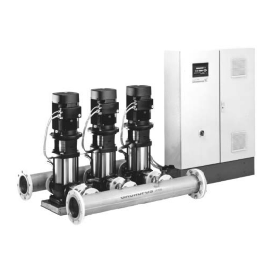
A diaphragm tank must be included in the installation. blocks of flats, hotels, industry, hospitals, schools, etc. Fig. 1 The Hydro 2000 F range includes two types of systems, i.e. MF, GRUNDFOS booster set Hydro 2000 F and MFH. System…
-
Page 6: Grundfos Control 2000 F
2.2 GRUNDFOS Control 2000 F Fig. 2 PFU 2000 front cover The GRUNDFOS Control 2000 F controls a number of pumps, some are operated via a frequency converter and some are mains-operated. The Control 2000 F always includes the PFU 2000 with applica- tion-optimized software, but it is also available with a PMU 2000.
-
Page 7: Examples Of Booster Sets Hydro 2000 F
2.2.1 Examples of booster sets Hydro 2000 F Example: Example: GRUNDFOS Hydro 2000 MF. GRUNDFOS Hydro 2000 MFH. Four pumps and a diaphragm tank. Two half-size pumps, two full-size pumps and a diaphragm tank. PFU 2000 PFU 2000 One pump in operation via frequency con- One half-size pump in operation via fre- verter.
-
Page 8: Functions
Operation with PFU 2000 EPROM settings or PFU 2000 RAM settings can be changed by means of the DIP switches in the PFU 2000. 1. Connect the GRUNDFOS BUS between the PMU 2000 and the PFU 2000. The PFU 2000 EPROM default settings and the PFU 2000 RAM settings are listed in the “List of Control Parameters”.
-
Page 9: Closed-Loop Control
The frequency of starts and stops is limited by the setting of mini- mum and medium switching sequences. PMU 2000 For further information, see sections 3.2.9 Minimum switching sequence, GRUNDFOS BUS 3.2.10 Medium switching sequence and 3.2.17 Minimum pump speed limit. PFU 2000 3.1.5 Manual on/off and setting to max. or local Operation with PFU 2000 RAM / PMU 2000 settings: Fig.
-
Page 10: Water Shortage Monitoring
3.1.6 Water shortage monitoring 3.1.7 On/off mode at low flow The water shortage monitoring function switches off all One of the advantages of variable-speed pump systems is the pumps. possibility of maintaining a constant discharge pressure, irrespec- tive of flow and pre-pressure. To avoid unnecessary energy con- Note: If the booster set has been delivered without a water short- sumption at low flow, it is possible to operate the system with an age monitor, it should not be started until a water shortage moni-…
-
Page 11: Automatic Pump Change
3.1.8 Automatic pump change 3.1.10 Clock functions There are three possibilities of automatic pump change: Operation with PFU 2000 RAM / PMU 2000 settings: If the system demand varies during the day and/or during the 1. Operation-dependent pump change. week, the pump performance required will also vary. In this case, This applies to pumps of equal priority.
-
Page 12: Reduced Operation
Different settings will be ignored. nected via a GRUNDFOS BUS, the numbering of the pumps, i.e. The default setting is 1. from 1 to 8, must be made on the GRUNDFOS BUS level. Operation with PFU 2000 EPROM settings: Zone A…
-
Page 13: Control Parameters
DIP switches in the Stop PFU 2000 and will be applied by the PMU 2000. Max. If several units are connected via the GRUNDFOS BUS, the GRUNDFOS BUS protocol must be observed. Stop For further information, see sections 3.1.14 GRUNDFOS BUS and…
-
Page 14: Setpoint Influences
3.2.4 Setpoint 3.2.5 Setpoint influences Operation with PFU 2000 RAM / PMU 2000 settings: Operation with PFU 2000 RAM / PMU 2000 settings: The maximum setpoint is set in “setpoint max.” (display 200). In order to optimize the operation of the system, it is often advan- This value is the upper limit of the setpoint and forms the basis of tageous to operate the system with a variable setpoint instead of the calculation of “setpoint act.”…
-
Page 15: On/Off Band
Remote control of setpoint via a PCU 2000: Via PCU 2000 inputs for the pumps connected to the zone and the GRUNDFOS BUS, the setpoint may be controlled linearly to the PCU 2000 input signal. Operation with PFU 2000 EPROM settings:…
-
Page 16: Measuring Unit For Control Value
3.2.7 Measuring unit for control value 3.2.9 Minimum switching sequence Operation with PFU 2000 RAM / PMU 2000 settings: Minimum switching sequence is the time between two switchings (on/off of pumps). If the signal transmitter used features a measuring unit different from the one in the presetting, an alternative measuring unit can Operation with PFU 2000 RAM / PMU 2000 settings: be selected (display 213).
-
Page 17: Control Function
3.2.11 Control function 3.2.12 PFU 2000 analog input 1 configuration Operation with PFU 2000 RAM / PMU 2000 settings: The PFU 2000 analog input 1 value is the measured value in the system. The PFU 2000 receives a signal from the signal transmit- The “control function”…
-
Page 18: Pfu 2000 Input 4 Configuration
3.2.15 PFU 2000 input 4 configuration • “reduced op” (reduced operation) When the PFU 2000 input 4 contact is closed, the pumps The PFU 2000 digital input 4 can be used for external control of which have not been set to reduced operation will be switched the zone.
-
Page 19: Minimum Pump Speed Limit
3.2.17 Minimum pump speed limit 3.2.19 Minimum limit Operation with PFU 2000 RAM / PMU 2000 settings: Operation with PFU 2000 RAM / PMU 2000 settings: Minimum pump speed limits the lowest operating point. The value This setting defines the minimum limit at which the system is to is set in the setting menu.
-
Page 20: Maximum Head
If the pre-pressure is not measured, it is set to zero in the for- mula. The booster sets Hydro 2000 F must be installed in a well venti- lated room. Hydro 2000 F is not suitable for outdoor installation. The value must be set according to the H stated on the pump nameplate.
-
Page 21: Start-Up
Establish a consumption of approx. 50% of the perform- ance of one pump and await stable operation. 7. If Hydro 2000 F is to be operated without a PMU 2000, it can operate either on the basis of the EPROM settings in the 7.
-
Page 22: Taking Out Of Operation
5.4 Taking out of operation 6. Operation To take the booster set Hydro 2000 F out of operation, switch off the mains switch. 6.1 Operation of PMU 2000 The leads in front of the mains switch are still ener- Fig. 29 gized.
-
Page 23: Display Rules
As an example, figure 31 shows the positions of DIPs 1 and 2 and The displays which are not relevant according to the settings and the following settings: the units connected to the GRUNDFOS BUS will be suppressed. • Pump number of the first pump in the zone: 1.
-
Page 24: Pfu 2000 Dip Switch Settings
6.3.1 PFU 2000 DIP switch settings DIP switch setting for PFU 2000: DIP 1 DIP 2 Pump number of the first pump of the PFU 2000: 1 OFF OFF OFF Pump number of the first pump of the PFU 2000: 2 OFF OFF Pump number of the first pump of the PFU 2000: 3 Pump number of the first pump of the PFU 2000: 4…
-
Page 25: Configuration Of Pcu Relays
5th — ? time once every 24 hours until the fault has been cor- rected. System time 10 secs. Hydro 2000 F will not restart automatically until the fault has been Minimum switching sequence 10 secs. corrected. Medium switching sequence 120 secs.
-
Page 26: Pump- And Motor-Related Faults
“communicat” “fault zone X sensor AIX” If a fault occurs in the communication via the GRUNDFOS BUS to If a transmitter fault is registered, the fault indication “fault zone X the units connected, the fault indication “communicat” will be gen- sensor AI X”…
-
Page 27: System-Related Faults
Motors fitted with grease nipples should be lubricated with a high- temperature lithium-based grease, see the instructions on the fan cover of GRUNDFOS motors. In the case of seasonal operation (motor is idle for more than 6 months of the year), it is recommended to grease the motor when the pump is taken out of operation.
-
Page 28: Operating And Fault Indications
9. Operating and fault indications The two indicator lights (LED) on the front cover of PFU 2000/ PMU 2000 indicate pump operation (green) and/or fault (red). Two external indicator lights (LED) can be connected instead of the two indicator lights (LED) on the front cover. The function of the indicator lights (LED) and the operating and fault signal outputs appears from the table below.
-
Page 29: Fault Finding Chart
15 secs. and the fault indication will remain. 3. Unstable water delivery a) Pre-pressure too low. Check the suction pipe and possible suction strainer. from Hydro 2000 F b) Suction pipe/pumps partly blocked Clean the suction pipe/pumps. (applies only to very low by impurities.
-
Page 30: Technical Data
11. Technical data 11.1 Hydraulic data Minimum pre-pressure: The minimum pre-pressure “H” in metres head required to avoid cavitation in the pumps is calculated as follows: H = p x 10.2 – NPSH – H – H – H = Barometric pressure in bar. Barometric pressure can be set to 1 bar.
-
Page 31: Electrical Data
Designation or number L, N, PE Voltage supply for PFU 2000. 1 x 230-240 V –10%/+6%, 50 Hz, PE. Communication among the units in the GRUNDFOS GRUNDFOS BUS. RS-485, GRUNDFOS BUS proto- A, Y, B Pump Management System 2000. col.
-
Page 32: Glossary
PCU 2000 The Pump Communication Unit 2000 is used for communication Analog input between the GRUNDFOS BUS and external control and monitor- Analog signals from transmitters can be connected to the analog ing systems. inputs of PFU 2000 or PCU 2000.
-
Page 33: Display Overviews
104 Configuration Zone A alarm suppression 2 tempdif 105 Configuration Zone A pump comm. alarm 3 temp. 106 Configuration Zone A GRUNDFOS 00620194/9420 4 flow 107 Configuration Zone A GRUNDFOS 00610194/9420 5 level 108 Configuration Zone A GRUNDFOS 00630194/9420 6 op.loop.
-
Page 34
PFU 7: Pressure Setting menu Set A clock program Set A 12345678 Set A → -> press. setpoint max. 5.0 bar Set A clock program Set A <<< menu >>> on/off 1.0 bar Set A unit Set A setp. influence Set A progressive infl clock program→… -
Page 35
Zone status menu Zone Zone Zone A 401 Zone A 402 Zone A setp. influence status status → → press. setpoint act. 5.0 bar setpoint max. 5.0 bar 403 Zone A Zone A setp. influence actual value 0.0 bar remote ->… -
Page 36
PFU 8: Pressure with pre-pressure measuring Setting menu Set A clock program Set A 12345678 Set A → -> press. setpoint max. 5.0 bar Set A clock program Set A <<< menu >>> on/off 1.0 bar Set A unit Set A setp. -
Page 37
Zone status menu Zone Zone Zone A 401 Zone A 402 Zone A setp. influence → → status status press. setpoint act. 5.0 bar setpoint max. 5.0 bar 403 Zone A Zone A setp. influence actual value 0.0 bar remote ->… -
Page 38
Glenmarie Industrial Park Telefax: +66-2-744 1775 … 6 Telefax: +420-585-438 906 40150 Shah Alam Turkey Selangor GRUNDFOS POMPA SAN. ve TIC. LTD. STI Finland Phone: +60-3-5569 2922 Bulgurlu Caddesi no. 32 OY GRUNDFOS Pumput AB Telefax: +60-3-5569 2866 Mestarintie 11 TR-81190 Üsküdar Istanbul… -
Page 39
Being responsible is our foundation Thinking ahead makes it possible Innovation is the essence 96 40 69 17 0104 Repl. 96 40 69 17 0502 www.grundfos.com…
!
Автоматический перевод может быть не точным! Если Вы не уверены в
правильности перевода обратитесь к нашей команде
поддержки.
![]()
![]()
![]()
Sterownik pomp
GRUNDFOS PFU 2000/9 V05
W ofercie 4000 części i elementów maszyn
Wystawiamy F-re VAT
Мы доставляем посылки в г. Калининград и отправляем по всей России
-
1
Товар доставляется от продавца до нашего склада в Польше. Трекинг-номер не
предоставляется. -
2
После того как товар пришел к нам на склад, мы организовываем доставку в г. Калининград.
-
3
Заказ отправляется курьерской службой EMS или Почтой России. Уведомление с трек-номером вы
получите по смс и на электронный адрес.
!
Ориентировочную стоимость доставки по России менеджер выставит после
оформления заказа.
Гарантии и возврат
Гарантии
Мы работаем по договору оферты, который является юридической гарантией того, что мы выполним
свои обязательства.
Возврат товара
Если товар не подошел вам, или не соответсвует описанию, вы можете вернуть его, оплатив
стоимость обратной пересылки.
- У вас остаются все квитанции об оплате, которые являются подтверждением заключения сделки.
- Мы выкупаем товар только с проверенных сайтов и у проверенных продавцов, которые полностью отвечают за доставку товара.
- Мы даем реальные трекинг-номера пересылки товара по России и предоставляем все необходимые документы по запросу.
- 5 лет успешной работы и тысячи довольных клиентов.
Купить Контроллер насоса GRUNDFOS PFU 2000/9 V05 по выгодной цене 14 907 ₽ с доставкой из Польши в Калининград,
по России и в страны СНГ, вы можете на сайте Aredi! Мы доставляем Драйверы и регуляторы из Allegro и
других магазинов Польши!