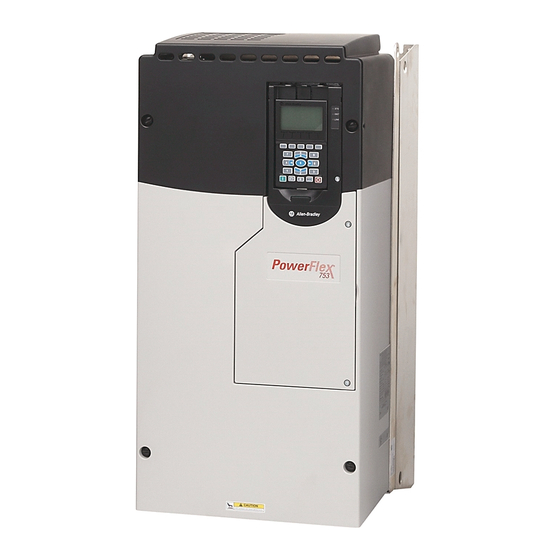
Преобразователь частоты PowerFlex 753 – удобство эксплуатации и простая интеграция в АСУ
Преобразователи частоты PowerFlex 753 серии отличаются поддержкой всевозможных методов управления асинхронными двигателями, а также наличием большого спектра различных опций, направленных на оптимизацию, повышение качества и безопасности производственных процессов.
PowerFlex 753 является экономически эффективным решением, идеальным для производителей оборудования и системных интеграторов, которые стремятся к сокращению расходов на проектирование, ускорению вывода продукции на рынок и удовлетворению спроса конечных пользователей на более продуктивные и более безопасные механизмы.
Упрощенная интеграция в среду Logix
Преобразователи PowerFlex 753 легко интегрируются с другими устройствами и компонентами платформы Logix, предоставляющей общую модель управления, программную среду и средства коммуникации для дискретного управления, управления приводами, сервоприводами и непрерывными процессами. Встроенный процессор Logix позволяет реализовать управление выходами и обработку данных на локальном уровне (внутри преобразователя), благодаря чему появляется возможность использования PowerFlex 753, как для централизованного управления распределенными системами электроприводов, так и для управления автономными объектами.
Удобная интеграция в промышленные сети
Частотные преобразователи Allen-Bradley PowerFlex используют архитектуру открытой сети NetLinx и поддерживают стандартные функции промышленных сетей DeviceNet, ControlNet и EtherNet/IP. Кроме того, привод легко интегрируется в промышленные сети по протоколам Remote I/O, RS485 DF1, BACnet, Modbus RTU, Metasys N2, Siemens P1, ProfiBus DP, Interbus, CANopen, LonWorks и других.
Конфигурирование для индивидуального применения
Каждый преобразователь имеет слотовую архитектуру, что обеспечивает возможность гибкого выбора типов карт для индивидуального применения, а также возможность расширения функциональности преобразователя для его перспективного использования. Поддерживаемые аппаратные опции управления являются общими для данной серии, что позволяет сократить ваши потребности в оборудовании и запасных частях.
- Manuals
- Brands
- Rockwell Automation Manuals
- Controller
- PowerFlex 753
- Reference manual
-
Contents
-
Table of Contents
-
Bookmarks
Quick Links
Reference Manual
Rockwell Automation Library of Process Objects: PowerFlex
753 Drive (P_PF753)
Version 3.5
Related Manuals for Rockwell Automation PowerFlex 753
Summary of Contents for Rockwell Automation PowerFlex 753
-
Page 1
Reference Manual Rockwell Automation Library of Process Objects: PowerFlex 753 Drive (P_PF753) Version 3.5… -
Page 2
If this equipment is used in a manner not specified by the manufacturer, the protection provided by the equipment may be impaired. In no event will Rockwell Automation, Inc. be responsible or liable for indirect or consequential damages resulting from the use or application of this equipment. -
Page 3: Table Of Contents
Alarms Tab ……….60 PowerFlex 753 Drive Faceplate Help ……62…
-
Page 4
Table of Contents Notes: Rockwell Automation Publication SYSLIB-RM044D-EN-P — February 2017… -
Page 5: Preface
For the latest compatible software information and to download the Rockwell Automation® Library or Process Objects, see the Product Compatibility and Download Center at http://www.rockwellautomation.com/rockwellautomation/support/pcdc.page. For general library considerations, see Rockwell Automation Library of Process Objects, publication PROCES-RM002. Additional Resources These documents contain additional information concerning related products from Rockwell Automation.
-
Page 6
Inhibit for Large Motor (P_ResInh) Reference Manual, caused by repeated starts. publication SYSLIB-RM009 Rockwell Automation Library of Process Objects: Run Time Explains how to accumulate the total run time and and Starts (P_RunTime) Reference Manual, count of starts for a motor or other equipment. -
Page 7: Guidelines
PowerFlex 753 Drive (P_PF753) The P_PF753 (PowerFlex 753 Drive) object is used to operate one variable-speed motor by using a PowerFlex 753 AC variable frequency drive in various modes, and monitoring for fault conditions. The global objects and following faceplate are examples of the graphical interface tools for this Add-On Instruction.
-
Page 8: Functional Description
PowerFlex 753 Drive (P_PF753) • If your PowerFlex 753 drive uses the 20-750-ENETR EtherNet interface, use the P_PF755 instruction instead. The PowerFlex 753 drive with the 20-750-ENETR interface uses the same interface data structures as the PowerFlex 755 drive, giving you more data.
-
Page 9: Required Files
FactoryTalk View ME Software Description All .png files in the images folder All .png files in the images folder These are the common icons used in the global objects and standard displays for all Process Objects. Rockwell Automation Publication SYSLIB-RM044D-EN-P — February 2017…
-
Page 10
(RA-BAS-ME) P_Perm-Faceplate Optional Permissive faceplate that is used for the object Use this file if your object has an associated P_Perm object and you enable navigation to the P_Perm faceplate from the object faceplate. Rockwell Automation Publication SYSLIB-RM044D-EN-P — February 2017… -
Page 11: Controller Code
Table 7 — P_PF753 Drive InOut Parameters Tag Name Data Type Description P_PF753_Inp Common part of PowerFlex 753 input assembly. P_PF753_Out Common part of PowerFlex 753 output assembly. Ref_FaultCodeList P_DescList[*] Array tag containing list of fault codes (DINT) and their descriptions (STRING_40).
-
Page 12
Each fault code list has preset codes and descriptions that provide human- readable descriptions of drive fault conditions. For a complete list of fault codes for the PowerFlex 753 Drive, refer to the PowerFlex 750 Series AC Drivers Programming Manual, publication 750-PM001. -
Page 13: Powerflex 753 Drive Input Structure
1 = Stop 2 = Start Fwd 3 = Start Rev Inp_OvrdSpeed REAL Value to set Speed Reference in Override mode (SpeedRef engineering units). Inp_Reset BOOL 1 = Reset drive fault conditions and latched Alarms. Rockwell Automation Publication SYSLIB-RM044D-EN-P — February 2017…
-
Page 14
Program if no mode is being requested. When this parameter is 0, the mode defaults to Operator if no mode is being requested. IMPORTANT: Changing this parameter online can cause unintended mode changes. Rockwell Automation Publication SYSLIB-RM044D-EN-P — February 2017… -
Page 15
Fail.OCmd_Ack) is required to acknowledge the alarm. When set to 0, the Cfg_IntlkTripAckReqd IntlkTrip.Cfg_AckReqd Acknowledge bit is set when an alarm occurs indicating an acknowledged alarm and no acknowledge command is required. Cfg_DriveFaultAckReqd DriveFault.Cfg_AckReqd Cfg_IOFaultAckReqd IOFault.Cfg_AckReqd Rockwell Automation Publication SYSLIB-RM044D-EN-P — February 2017… -
Page 16
When Cfg_PCmdClear is 0: • Set PCmd_Start to 1 to start the drive • Set PCmd_Start to 0 to stop the drive • PCmd_Stop is not used • These parameters do not reset automatically Rockwell Automation Publication SYSLIB-RM044D-EN-P — February 2017… -
Page 17
• Set PCmd_<Alarm>Suppress to 1 to suppress alarm • Set PCmd_<Alarm>Suppress to 0 to unsuppress alarm PCmd_IOFaultSuppress IOFault.PCmd_Suppress • PCmd_<Alarm>Unsuppress is not used PCmd_FailToStartUnsuppress FailToStart.PCmd_Unsuppress • These parameters do not reset automatically PCmd_FailToStopUnsuppress FailToStop.PCmd_Unsuppress PCmd_IntlkTripUnsuppress IntlkTrip.PCmd_Unsuppress PCmd_DriveFaultUnsuppress DriveFault.PCmd_Unsuppress PCmd_IOFaultUnsuppress IOFault.PCmd_Unsuppress Rockwell Automation Publication SYSLIB-RM044D-EN-P — February 2017… -
Page 18
BOOL Operator command to reset all alarms requiring reset and trigger a drive reset if the drive is faulted. OCmd_ResetAckAll BOOL Operator command to acknowledge and reset all alarms and latched Shed conditions. Rockwell Automation Publication SYSLIB-RM044D-EN-P — February 2017… -
Page 19: Powerflex 753 Drive Output Structure
Minimum of Speed Reference = MIN (Cfg_SpeedFdbkEUMin, Cfg_SpeedFdbkEUMax). (engineering units) Val_SpeedRefEUMax REAL Maximum of Speed Reference = MAX (Cfg_SpeedFdbkEUMin, Cfg_SpeedFdbkEUMax). (engineering units) Val_SpeedFdbkEUMin REAL Minimum of Speed Feedback = MIN (Cfg_SpeedFdbkEUMin, Cfg_SpeedFdbkEUMax). (engineering units) Rockwell Automation Publication SYSLIB-RM044D-EN-P — February 2017…
-
Page 20
33 = Disabled Val_Fault SINT Device fault status: 0 = None 16 = Fail to Start 17 = Fail to Stop 18 = Drive Fault 32 = I/O Fault 34 = Configuration Error Rockwell Automation Publication SYSLIB-RM044D-EN-P — February 2017… -
Page 21
Predictive Maintenance status (bit mapped) (Par 469). Sts_StartInhibits DINT Drive Start Inhibit reasons (bit mapped) (Par. 933). Sts_Available BOOL 1 = Drive available for control by automation (Program). Sts_Bypass BOOL 1 = Bypassable Interlocks and Permissives are bypassed. Rockwell Automation Publication SYSLIB-RM044D-EN-P — February 2017… -
Page 22
1 = Drive was stopped by an Interlock Not OK (One-Shot). Sts_DriveFault DriveFault.Inp 1 = Drive Fault (see drive display or manual). Sts_IOFault IOFault.Inp I/O Comm Fault status (0 = OK, 1 = Bad). Rockwell Automation Publication SYSLIB-RM044D-EN-P — February 2017… -
Page 23
1 = At least one alarm or latched Shed condition requires Reset or Acknowledged. Rdy_SpeedRef BOOL 1 = Ready to receive OSet_SpeedRef (enables data entry field). P_PF753 BOOL Unique Parameter Name for auto-discovery. Rockwell Automation Publication SYSLIB-RM044D-EN-P — February 2017… -
Page 24: Powerflex 753 Drive Local Configuration Tags
PowerFlex 753 Drive (P_PF753) PowerFlex 753 Drive Local Configuration Tags Configuration parameters that are array, string, or structure data types cannot be configured as parameters for Add-On Instructions. Configuration parameters of these types appear as local tags to the Add-On Instruction. Local tags can be configured through the HMI faceplates or in Studio 5000 Logix Designer®…
-
Page 25: Alarms
Instructions with Cfg_OperKeep and Cfg_ProgKeep keep some aspects of the IMPORTANT device operation with the operator or program regardless of whether the main mode is Program or Operator mode. See Rockwell Automation Library of Process Objects: Common Mode Block (P_Mode) Reference Manual, publication SYSLIB-RM005, for more information. Alarms This instruction uses the following alarms, which are implemented by using embedded P_Alarm and P_Gate Add-On Instructions.
-
Page 26: Simulation
Use this if raw ranges for feedback and reference are different. You can also use Cfg_SimRampT to ramp the speed feedback (in seconds). When you have finished in simulation, set the Inp_Sim parameter in the controller to ‘0’ to return to normal operation. Rockwell Automation Publication SYSLIB-RM044D-EN-P — February 2017…
-
Page 27: Execution
1. On the Controller Organizer, add your PowerFlex drive to the I/O Configuration and name the drive. 2. Under Tasks, click the plus sign ( ) in front of Main Task. 3. Double-click Main_Routine to open this ladder logic routine. Rockwell Automation Publication SYSLIB-RM044D-EN-P — February 2017…
-
Page 28
Final Name column. Your ladder logic routine now looks like the example. Observe that the tag names and your drive’s name are automatically placed in the instruction. Rockwell Automation Publication SYSLIB-RM044D-EN-P — February 2017… -
Page 29
• Drive Status 1 (Port 0, Parameter 935) • Drive Status 2 (Port 0, Parameter 936) • Last Fault Code (Port 0, Parameter 951) • Fault Status A (Port 0, Parameter 952) • Fault Status B (Port 0, Parameter 953) Rockwell Automation Publication SYSLIB-RM044D-EN-P — February 2017… -
Page 30: Display Elements
These display elements show the different motor positions (right, up, and down). GO_P_VSD_U GO_P_VSD_D GO_P_VSD_Blower_R These display elements show the different blower positions (right, left, up, and down). GO_P_VSD_Blower_L GO_P_VSD_Blower_U GO_P_VSD_Blower_D GO_P_VSD_Conveyer_R This display element illustrates a conveyer. Rockwell Automation Publication SYSLIB-RM044D-EN-P — February 2017…
-
Page 31
These display elements show the different pump positions (left, up, and down). GO_P_VSD_Pump_L GO_P_VSD_Pump_U GO_P_VSD_Agitator_D This display element illustrates an agitator in the down position. GO_P_VSD_Mixer_U This display element shows a mixer in the up position. Rockwell Automation Publication SYSLIB-RM044D-EN-P — February 2017… -
Page 32
• Color changing alarm border that blinks on unacknowledged alarm • Alarm indicator that changes color with the severity of an alarm State Maintenance Bypass Indicator Alarm Border Alarm Indicator Status/Quality Indicator Mode Indicator Status/Quality Indicator Speed Feedback Display Engineering Units Label Rockwell Automation Publication SYSLIB-RM044D-EN-P — February 2017… -
Page 33: State Indicators
Data Quality degraded: uncertain, test, simulation, substitution, or out of specification. The input or device has been disabled. Device not ready to operate. Speed reference limited to minimum/maximum. Motor is at target speed. Drive is accelerating. Drive is decelerating. Rockwell Automation Publication SYSLIB-RM044D-EN-P — February 2017…
-
Page 34
When you navigate to the tab, the condition preventing operation is flagged. For the PowerFlex 753 Drive Instruction, the Device Not Ready indicator appears under the following conditions: • Device has been disabled by Maintenance. -
Page 35: Mode Indicators
This behavior can be changed by replacing the image files for these mode indicators with images that are not transparent. See Rockwell Automation Library of Process Objects: Common Mode Block (P_Mode) Reference Manual, publication SYSLIB-RM005, for more information.
-
Page 36: Maintenance Bypass Indicator
Once you navigate to the tab, the bypassed item is flagged with this indicator. For the PowerFlex 753 Drive Instruction, the Maintenance Bypass Indicator appears when the bypassable interlocks and permissives have been bypassed.
-
Page 37: Using Display Elements
1. Copy the global object from the global object file and paste it in the display file. 2. In the display, right-click the global object and choose Global Object Parameter Values. The Global Object Parameter Values dialog box appears. Rockwell Automation Publication SYSLIB-RM044D-EN-P — February 2017…
-
Page 38
3. Type the tag or value in the Value column as specified in the Description column. You can click the ellipsis (…) to browse and select a tag. Values for items marked ‘(optional)’ can be left blank. 4. Click OK. Rockwell Automation Publication SYSLIB-RM044D-EN-P — February 2017… -
Page 39: Quick Display
When a given input is restricted via FactoryTalk View security, the required user security-code letter is shown in the tables that follow. Rockwell Automation Publication SYSLIB-RM044D-EN-P — February 2017…
-
Page 40: Operator Tab
Run Time Navigation Button Navigation Button Speed Reference Reverse Permissive Navigation Button Forward Direction Command Button Drive Ready Indicator Reverse Direction Command Button Input Source and Quality Indicator Input Source and Quality Icon Rockwell Automation Publication SYSLIB-RM044D-EN-P — February 2017…
-
Page 41
Click to Stop drive. Click to Jog drive. Click to select forward direction. Click to select reverse direction. Click to open Reverse Permissive faceplate. None Click to open Forward Permissive faceplate. Click to open Interlock faceplate. Rockwell Automation Publication SYSLIB-RM044D-EN-P — February 2017… -
Page 42
P_RunTime instruction, the Runtime button is not displayed. See these publications for more information: • Rockwell Automation Library of Process Objects: Interlock with First Out and Bypass (P_Intlk) Reference Manual, publication SYSLIB-RM004 • Rockwell Automation Library of Process Objects: Permissives with Bypass… -
Page 43
All conditions OK, bypass active All conditions OK Alarm indicators appear on the Operator tab when the corresponding alarm occurs. Fail to Start Fail to Stop Alarm Alarm Interlock Trip Alarm Drive Fault Alarm I/O Fault Alarm Rockwell Automation Publication SYSLIB-RM044D-EN-P — February 2017… -
Page 44: Maintenance Tab
• Requested modes Indicator — This display highlights all modes that have been requested. The leftmost highlighted mode is the active mode. • Whether the motor is enabled or disabled. • Interlock and Permissive Bypassed/Enabled indicator. Rockwell Automation Publication SYSLIB-RM044D-EN-P — February 2017…
-
Page 45
Table 15 — Maintenance Tab Page 1 Description Function Action Security Configuration Parameters Click for Maintenance mode. Equipment None Maintenance (Code C) Click to release Maintenance mode. Click to enable drive. Click to disable drive. Rockwell Automation Publication SYSLIB-RM044D-EN-P — February 2017… -
Page 46
(Code H) bypassable interlocks and permissives. In Override mode, Check to have the bypassable Cfg_OvrdPermIntlk bypass Interlocks interlocks and permissives bypassed and Permissives in Override mode. that can be bypassed Maintenance Tab Page 2 Rockwell Automation Publication SYSLIB-RM044D-EN-P — February 2017… -
Page 47
Type the clamping limits for the • Cfg_MaxSpdRef Limits (Minimum speed reference. If a speed reference • Cfg_MinSpdRef and Maximum) outside this range is entered, the speed is clamped at these limits and Sts_SpeedLimited is asserted. Rockwell Automation Publication SYSLIB-RM044D-EN-P — February 2017… -
Page 48: Engineering Tab
Raw Maximum and Minimum Speed Feedback EU Maximum and Minimum Speed Feedback Engineering Units Speed Reference Engineering Units Simulated Speed Speed Reference Loopback Options EU Maximum and Minimum Speed Reference Raw Maximum and Minimum Rockwell Automation Publication SYSLIB-RM044D-EN-P — February 2017…
-
Page 49
Use this setting if the reference and feedback ranges do not correspond. Rockwell Automation Publication SYSLIB-RM044D-EN-P — February 2017… -
Page 50
Name for forward direction. Cfg_FwdText Reverse Text Name for reverse direction. Cfg_RevText Clear Program Check to have the P_PF753 Cfg_PCmdClear Commands on instruction clear Program commands Receipt (PCmd) as soon as they are received (default). Rockwell Automation Publication SYSLIB-RM044D-EN-P — February 2017… -
Page 51
If no mode is being requested, changing the default mode changes the mode IMPORTANT of the instruction. You must have FactoryTalk View security code E to select the default mode on this display. Rockwell Automation Publication SYSLIB-RM044D-EN-P — February 2017… -
Page 52
Forward Permissive object in the controller must be this object’s name with the suffix ‘_FwdPerm’ . For example, if your P_PF753 object has the name ’Drive123’ , then its Forward Permissive object must be named ‘Drive123_FwdPerm’ . Rockwell Automation Publication SYSLIB-RM044D-EN-P — February 2017… -
Page 53
‘_RunTime’ . For example, if your P_PF753 object has the name ‘Drive123’ , then its runtime object must be named ‘Drive123_RunTime’ . Rockwell Automation Publication SYSLIB-RM044D-EN-P — February 2017… -
Page 54
Stop Drive on The drive always stops on an None None Interlock Trip Interlock trip. This item cannot be cleared. It is displayed as a reminder that the Interlock Trip function always stops the drive. Rockwell Automation Publication SYSLIB-RM044D-EN-P — February 2017… -
Page 55
Program keeps Speed Reference with the Program, control in Operator even if the instruction is in Operator mode mode. Clear this checkbox to have control of the drive Speed Reference follow the Instruction mode. Rockwell Automation Publication SYSLIB-RM044D-EN-P — February 2017… -
Page 56
HMI or program only. Time to ramp speed Enter the time, in seconds, to ramp Cfg_SimRampT feedback when in speed feedback when in Loopback Loopback Test Test. (seconds) Rockwell Automation Publication SYSLIB-RM044D-EN-P — February 2017… -
Page 57: Diagnostics Tabs
‘Not Ready’ , device warnings and faults, warning and fault history, and predictive/preventive maintenance data. This tab is divided into six pages. Each page provides you with diagnostic feedback on the drive. Rockwell Automation Publication SYSLIB-RM044D-EN-P — February 2017…
-
Page 58: Diagnostic Tab (Continued)
PowerFlex 753 Drive (P_PF753) Diagnostic Tab (continued) Rockwell Automation Publication SYSLIB-RM044D-EN-P — February 2017…
-
Page 59: Trends Tab
The Trends tab shows trend charts of key device data over time. These faceplate trends provide a quick view of current device performance to supplement, but not replace, dedicated historical or live trend displays. Speed Reference Speed Feedback Rockwell Automation Publication SYSLIB-RM044D-EN-P — February 2017…
-
Page 60: Alarms Tab
The color of the bell icon at the top of the faceplate shows the severity of the highest active alarm, and the icon blinks if any alarm is unacknowledged or requires reset. Rockwell Automation Publication SYSLIB-RM044D-EN-P — February 2017…
-
Page 61
The Alarm Acknowledge button is enabled if the alarm requires acknowledgment. Click the button with the check mark to acknowledge the alarm. See Rockwell Automation Library of Process Objects: Common Alarm Block (P_Alarm) Reference Manual, publication SYSLIB-RM002, for more information. -
Page 62: Powerflex 753 Drive Faceplate Help
PowerFlex 753 Drive (P_PF753) PowerFlex 753 Drive Faceplate Help The Faceplate Help is divided into two pages. Faceplate Help Page 1 Faceplate Help Page 2 Rockwell Automation Publication SYSLIB-RM044D-EN-P — February 2017…
-
Page 64
New Product Satisfaction Return Rockwell Automation tests all of its products to help ensure that they are fully operational when shipped from the manufacturing facility. However, if your product is not functioning and needs to be returned, follow these procedures.
Главная » Rockwell » Справочное руководство по автоматизации Rockwell 753 PowerFlex
Содержание скрывать
1
Роквелл 753 Автоматизация PowerFlex
2
Похожие сообщения
Роквелл 753 Автоматизация PowerFlex
View Fullscreen
Похожие сообщения
-

Справочное руководство по командам SCSI
Справочное руководство по командам SCSI — оптимизированный PDF-файл Справочное руководство по командам SCSI — Исходный PDF-файл
-
Справочное руководство X-Browse
Справочное руководство X-Browse — Загрузить [оптимизировано] Справочное руководство X-Browse — Загрузить
-
Справочное руководство по командам Seagate SCSI
Справочное руководство по командам Seagate SCSI — Загрузить [оптимизированное] Справочное руководство по командам Seagate SCSI — Скачать
-
Allen-Bradley PowerFlex 525 Руководство пользователя
Allen-Bradley PowerFlex 525 Руководство пользователя


Оставить комментарий
Ваш электронный адрес не будет опубликован. Обязательные поля помечены * *
КОММЕНТАРИЙ *
Имя и фамилия
Эл. адрес
Cайт
Сохраните мое имя, адрес электронной почты и веб-сайт в этом браузере для следующего комментария.
-
PowerFlex 750-Series AC Drives
User Manual
-
PowerFlex 750-Series User Manual Publication 750-UM001C-EN-P
September 2009Important User Information Solid state equipment has operational
characteristics differing from those of electromechanical
equipment. Safety Guidelines for the Application, Installation and
Maintenance of Solid State Controls (Publication SGI-1.1 available
from your local Rockwell Automation sales office or online at
http://www.rockwellautomation.com/literature) describes some
important differences between solid state equipment and hard-wired
electromechanical devices. Because of this difference, and also
because of the wide variety of uses for solid state equipment, all
persons responsible for applying this equipment must satisfy
themselves that each intended application of this equipment is
acceptable.In no event will Rockwell Automation, Inc. be responsible or
liable for indirect or consequential damages resulting from the use
or application of this equipment.The examples and diagrams in this manual are included solely for
illustrative purposes. Because of the many variables and
requirements associated with any particular installation, Rockwell
Automation, Inc. cannot assume responsibility or liability for
actual use based on the examples and diagrams.No patent liability is assumed by Rockwell Automation, Inc. with
respect to use of information, circuits, equipment, or software
described in this manual.Reproduction of the contents of this manual, in whole or in
part, without written permission of Rockwell Automation, Inc. is
prohibited.Throughout this manual, when necessary we use notes to make you
aware of safety considerations.Important: Identifies information that is critical for
successful application and understanding of the product.PowerFlex, DriveExplorer, DriveExecutive, DPI, and SCANport are
either trademarks or registered trademarks of Rockwell Automation,
Inc.!WARNING: Identifies information about practices or
circumstances that can cause an explosion in a hazardous
environment, which may lead to personal injury or death, property
damage, or economic loss.!ATTENTION: Identifies information about practices or
circumstances that can lead to personal injury or death, property
damage, or economic loss. Attentions help you identify a hazard,
avoid a hazard, and recognize the consequences.Shock Hazard labels may be located on or inside the equipment
(e.g., drive or motor) to alert people that dangerous voltage may
be present.Burn Hazard labels may be located on or inside the equipment
(e.g., drive or motor) to alert people that surfaces may be at
dangerous temperatures. -
PowerFlex 750-Series User Manual Publication 750-UM001C-EN-P
September 2009Summary of Changes
This information below summarizes the changes to the PowerFlex
750-Series AC Drives User Manual, publication 750-UM001 since the
last release.Manual UpdatesChange Page(s)Catalog Number Explanation updated
P-6Lifting instructions for Frame 6 and 7 IP54, NEMA/UL Type 12
enclosures added 1-2, 1-4Acceptable Surrounding Air Temperature for
Frame 6 and 7 IP54, NEMA/UL Type 12 Stand-alone/Wall Mount drives
added1-7
Common Bus Power Wiring section added 1-181-20PowerFlex 753 I/O
Terminal Block Specifications added 1-28PowerFlex 753 Control
Module details added 1-31, 1-32,1-34, 1-35PowerFlex 753 Main Control Board I/O wiring examples
added 1-38Auxiliary Power Supply installation details for PowerFlex
753 added 1-46RF Emission Compliance and Installation Requirements
table updated 1-53PowerFlex 753 control block diagrams added
Appendix B -
ii Summary of ChangesThe following parameters were added:
3-353-119Frame 6 IP54, NEMA/UL Type 12 enclosure dimensions added
A-30Frame 7 IP54, NEMA/UL Type 12 enclosure dimensions added
A-34Change Page(s)
222 [Dig In Fltr Mask] 286 [RO0 Load Type] 1166 [Rod Torque]223
[Dig In Filt] 287 [RO0 Load Amps] 1167 [Rod Speed Cmd]225 [Dig Out
Sts] 288 [RO0 TotalLife] 1168 [TorqAlarm Action]226 [Dig Out
Invert] 289 [RO0 ElapsedLife] 1169 [TorqAlarm Config]227 [Dig Out
Setpoint] 290 [RO0 RemainLife] 1170 [TorqAlarm Dwell]230 [RO0 Sel]
291 [RO0 LifeEvntLvl] 1171 [TorqAlarm Level]231 [RO0 Level Sel] 292
[RO0 LifeEvntActn] 1172 [TorqAlm Timeout]232 [RO0 Level] 883 [Drive
Ref Rslt] 1173 [TorqAlarm TOActn]233 [RO0 Lvl CmpSts] 884 [Drive
Ramp Rslt] 1174 [Total Gear Ratio]234 [RO0 On Time] 1120 [Fiber
Control] 1175 [Max Rod Speed]235 [RO0 Off Time] 1121 [Fiber Status]
1176 [Max Rod Torque]240 [TO0 Sel] 1122 [Sync Time] 1177 [Min Rod
Speed]241 [TO0 Level Sel] 1123 [Traverse Inc] 1178 [Motor
Sheave]242 [TO0 Level] 1124 [Traverse Dec] 1179 [OilWell Pump
Cfg]243 [TO0 Level CmpSts] 1125 [Max Traverse] 1180 [PCP Pump
Sheave]244 [TO0 On Time] 1126 [P Jump] 1181 [Gearbox Limit]245 [TO0
Off Time] 1129 [DI Fiber SyncEna] 1182 [Gearbox Rating]250 [PTC
Cfg] 1130 [DI Fiber TravDis] 1183 [Gearbox Ratio]251 [PTC Status]
1131 [Adj Vltg Config] 1184 [Gearbox Sheave]255 [Anlg In Type] 1133
[Adj Vltg Select] 1187 [Pump Off Config]256 [Anlg In Sqrt] 1134
[Adj Vltg Ref Hi] 1188 [Pump Off Setup]257 [Anlg In Loss Sts] 1135
[Adj Vltg Ref Lo] 1189 [Pump Off Action]260 [Anlg In0 Value] 1136
[Adj Vltg TrimSel] 1190 [Pump Off Control]261 [Anlg In0 Hi] 1137
[Adj Vltg Trim Hi] 1191 [Pump Off Status]262 [Anlg In0 Lo] 1138
[Adj Vltg Trim Lo] 1192 [Pump Cycle Store]263 [Anlg In0 LssActn]
1139 [Adj Vltg Command] 1193 [Set Top ofStroke]264 [Anlg In0 Raw
Val] 1140 [Adj Vltg AccTime] 1194 [Torque Setpoint]265 [Anlg In0
Filt Gn] 1141 [Adj Vltg DecTime] 1195 [Pump Off Level]266 [Anlg In0
Filt BW] 1142 [Adj Vltg Preset1] 1196 [Pump Off Speed]270 [Anlg Out
Type] 1143 [Adj Vltg Preset2] 1197 [Pump Off Time]271 [Anlg Out
Abs] 1144 [Adj Vltg Preset3] 1198 [Pct Cycle Torque]275 [Anlg Out0
Sel] 1145 [Adj Vltg Preset4] 1199 [Pct Lift Torque]276 [Anlg Out0
Stpt] 1146 [Adj Vltg Preset5] 1200 [Pct Drop Torque]277 [Anlg Out0
Data] 1147 [Adj Vltg Preset6] 1201 [Stroke Pos Count]278 [Anlg Out0
DataHi] 1148 [Adj Vltg Preset7] 1202 [Stroke Per Min]279 [Anlg Out0
DataLo] 1149 [Adj Vltg RefMult] 1203 [Pump Off Count]280 [Anlg Out0
Hi] 1150 [Adj Vltg Scurve] 1204 [Pump Off SleepCnt]281 [Anlg Out0
Lo] 1151 [Adj Vltg TrimPct] 1205 [Day Stroke Count]282 [Anlg Out0
Val] 1152 [Min Adj Voltage] 1206 [DI PumpOff Disbl]285 [RO
PredMaint Sts] 1165 [Rod Speed] 1207 [Pump OffSleepLvl]PowerFlex
750-Series User Manual Publication 750-UM001C-EN-P September
2009 -
PowerFlex 750-Series User Manual Publication 750-UM001C-EN-P
September 2009Table of Contents
Preface OverviewWho Should Use This Manual . . . . . . . . . . .
. . . . . . . . . . . . . . . . . . . . . . . . . . . . . . . . . .
P-1What Is Not In This Manual . . . . . . . . . . . . . . . . . . .
. . . . . . . . . . . . . . . . . . . . . . . . . . . .
P-1Recommended Documentation . . . . . . . . . . . . . . . . . . .
. . . . . . . . . . . . . . . . . . . . . . . . . . P-1Obtaining
Manuals . . . . . . . . . . . . . . . . . . . . . . . . . . . . . .
. . . . . . . . . . . . . . . . . . . . . . . . P-2Allen-Bradley
Drives Technical Support . . . . . . . . . . . . . . . . . . . . .
. . . . . . . . . . . . . . . . P-2Product Certification . . . . .
. . . . . . . . . . . . . . . . . . . . . . . . . . . . . . . . . .
. . . . . . . . . . . . . . P-2Manual Conventions . . . . . . . . .
. . . . . . . . . . . . . . . . . . . . . . . . . . . . . . . . . .
. . . . . . . . . . P-3Drive Frame Sizes . . . . . . . . . . . . .
. . . . . . . . . . . . . . . . . . . . . . . . . . . . . . . . . .
. . . . . . . . P-3General Precautions . . . . . . . . . . . . . .
. . . . . . . . . . . . . . . . . . . . . . . . . . . . . . . . . .
. . . . . P-4Catalog Number Explanation . . . . . . . . . . . . . .
. . . . . . . . . . . . . . . . . . . . . . . . . . . . . . . .
P-6Chapter 1 Installation/WiringChapter Objectives . . . . . . . .
. . . . . . . . . . . . . . . . . . . . . . . . . . . . . . . . . .
. . . . . . . . . . . . 1-1Lifting the Drive . . . . . . . . . . .
. . . . . . . . . . . . . . . . . . . . . . . . . . . . . . . . . .
. . . . . . . . . . . 1-2Opening the Cover . . . . . . . . . . . .
. . . . . . . . . . . . . . . . . . . . . . . . . . . . . . . . . .
. . . . . . . . 1-5Mounting Considerations . . . . . . . . . . . .
. . . . . . . . . . . . . . . . . . . . . . . . . . . . . . . . . .
. . . 1-7AC Supply Source Considerations . . . . . . . . . . . . .
. . . . . . . . . . . . . . . . . . . . . . . . . . . . .
1-8Grounding Requirements . . . . . . . . . . . . . . . . . . . . .
. . . . . . . . . . . . . . . . . . . . . . . . . . . . 1-9Fuses
and Circuit Breakers . . . . . . . . . . . . . . . . . . . . . . .
. . . . . . . . . . . . . . . . . . . . . . . . 1-11Power Wiring. .
. . . . . . . . . . . . . . . . . . . . . . . . . . . . . . . . . .
. . . . . . . . . . . . . . . . . . . . . . 1-11Common Bus Power
Wiring . . . . . . . . . . . . . . . . . . . . . . . . . . . . . .
. . . . . . . . . . . . . . . . 1-18IP65, NEMA Type 12
Installations . . . . . . . . . . . . . . . . . . . . . . . . . . .
. . . . . . . . . . . . . . 1-21Using Input/Output Contactors . . .
. . . . . . . . . . . . . . . . . . . . . . . . . . . . . . . . . .
. . . . . . . 1-22Using PowerFlex 750-Series Drives with
Regenerative Power Units. . . . . . . . . . . . . . . 1-23Drive
Power Jumper Configuration. . . . . . . . . . . . . . . . . . . . .
. . . . . . . . . . . . . . . . . . . . 1-23I/O Wiring . . . . . .
. . . . . . . . . . . . . . . . . . . . . . . . . . . . . . . . . .
. . . . . . . . . . . . . . . . . . . . 1-28Option Module
Installation . . . . . . . . . . . . . . . . . . . . . . . . . . .
. . . . . . . . . . . . . . . . . . . . 1-36Option Module Parameter
Access. . . . . . . . . . . . . . . . . . . . . . . . . . . . . . .
. . . . . . . . . . . 1-36750-Series I/O Module . . . . . . . . . .
. . . . . . . . . . . . . . . . . . . . . . . . . . . . . . . . . .
. . . . . . 1-37I/O Wiring Examples. . . . . . . . . . . . . . . .
. . . . . . . . . . . . . . . . . . . . . . . . . . . . . . . . . .
. . 1-38Relay Wiring Examples. . . . . . . . . . . . . . . . . . .
. . . . . . . . . . . . . . . . . . . . . . . . . . . . . . .
1-43Safe Torque Off Option Module . . . . . . . . . . . . . . . . .
. . . . . . . . . . . . . . . . . . . . . . . . . . 1-44Universal
Feedback Encoder Option Module . . . . . . . . . . . . . . . . . .
. . . . . . . . . . . . . . . 1-44Incremental Encoder Option
Modules . . . . . . . . . . . . . . . . . . . . . . . . . . . . . .
. . . . . . . . 1-44Safe Speed Monitor Option Module . . . . . . .
. . . . . . . . . . . . . . . . . . . . . . . . . . . . . . . . .
1-45Auxiliary Power Supply Option Module . . . . . . . . . . . . .
. . . . . . . . . . . . . . . . . . . . . . . 1-46DeviceNet Option
Module . . . . . . . . . . . . . . . . . . . . . . . . . . . . . .
. . . . . . . . . . . . . . . . . 1-47ControlNet Option Module . .
. . . . . . . . . . . . . . . . . . . . . . . . . . . . . . . . . .
. . . . . . . . . . . 1-4820-COMM Carrier . . . . . . . . . . . . .
. . . . . . . . . . . . . . . . . . . . . . . . . . . . . . . . . .
. . . . . . 1-49CE Conformity . . . . . . . . . . . . . . . . . . .
. . . . . . . . . . . . . . . . . . . . . . . . . . . . . . . . . .
. . . 1-50Chapter 2 Start UpStart-Up Check List. . . . . . . . . . . . . .
. . . . . . . . . . . . . . . . . . . . . . . . . . . . . . . . . .
. . . . . . 2-1Start-Up Menu. . . . . . . . . . . . . . . . . . . .
. . . . . . . . . . . . . . . . . . . . . . . . . . . . . . . . . .
. . . . 2-3Drive Status Indicators . . . . . . . . . . . . . . . .
. . . . . . . . . . . . . . . . . . . . . . . . . . . . . . . . . .
. 2-4Establishing A Connection With EtherNet/IP. . . . . . . . . .
. . . . . . . . . . . . . . . . . . . . . . . . 2-5 -
2 Table of Contents
Chapter 3 Programming and ParametersAbout Parameters. . . . . .
. . . . . . . . . . . . . . . . . . . . . . . . . . . . . . . . . .
. . . . . . . . . . . . . . . . 3-1How Drive Parameters are
Organized . . . . . . . . . . . . . . . . . . . . . . . . . . . . .
. . . . . . . . . . . 3-3How Option Module Parameters are Organized
. . . . . . . . . . . . . . . . . . . . . . . . . . . . . . .
3-15Drive Monitor File . . . . . . . . . . . . . . . . . . . . . .
. . . . . . . . . . . . . . . . . . . . . . . . . . . . . . . .
3-19Drive Motor Control File . . . . . . . . . . . . . . . . . . .
. . . . . . . . . . . . . . . . . . . . . . . . . . . . . .
3-20Drive Feedback & I/O File . . . . . . . . . . . . . . . . .
. . . . . . . . . . . . . . . . . . . . . . . . . . . . . .
3-28Drive Cfg File . . . . . . . . . . . . . . . . . . . . . . . .
. . . . . . . . . . . . . . . . . . . . . . . . . . . . . . . . .
3-42Drive Protection File . . . . . . . . . . . . . . . . . . . . .
. . . . . . . . . . . . . . . . . . . . . . . . . . . . . . .
3-54Drive Speed Control File . . . . . . . . . . . . . . . . . . .
. . . . . . . . . . . . . . . . . . . . . . . . . . . . . .
3-62Drive Torque Control File . . . . . . . . . . . . . . . . . . .
. . . . . . . . . . . . . . . . . . . . . . . . . . . . . 3-78Drive
Position Control File . . . . . . . . . . . . . . . . . . . . . . .
. . . . . . . . . . . . . . . . . . . . . . . . 3-83Drive
Communication File . . . . . . . . . . . . . . . . . . . . . . . .
. . . . . . . . . . . . . . . . . . . . . . . 3-95Drive Diagnostics
File . . . . . . . . . . . . . . . . . . . . . . . . . . . . . . .
. . . . . . . . . . . . . . . . . . . 3-100Drive Applications File
. . . . . . . . . . . . . . . . . . . . . . . . . . . . . . . . . .
. . . . . . . . . . . . . . . 3-109Drive Parameter Cross Reference
By Name . . . . . . . . . . . . . . . . . . . . . . . . . . . . . .
. . . 3-131I/O Module Parameters . . . . . . . . . . . . . . . . .
. . . . . . . . . . . . . . . . . . . . . . . . . . . . . . . .
3-137Safe Speed Monitor Module Parameters . . . . . . . . . . . . .
. . . . . . . . . . . . . . . . . . . . . . . 3-148Single
Incremental Encoder Module Parameters. . . . . . . . . . . . . . .
. . . . . . . . . . . . . . . 3-159Dual Incremental Encoder Module
Parameters . . . . . . . . . . . . . . . . . . . . . . . . . . . .
. . . 3-161Universal Feedback Module Parameters . . . . . . . . . .
. . . . . . . . . . . . . . . . . . . . . . . . . . 3-166Embedded
EtherNet/IP Parameters . . . . . . . . . . . . . . . . . . . . . .
. . . . . . . . . . . . . . . . . . 3-178Chapter 4 TroubleshootingFaults, Alarms and Configurable
Conditions . . . . . . . . . . . . . . . . . . . . . . . . . . . .
. . . . . . 4-1Drive Status Indicators. . . . . . . . . . . . . . .
. . . . . . . . . . . . . . . . . . . . . . . . . . . . . . . . . .
. . . 4-2HIM Indication . . . . . . . . . . . . . . . . . . . . . .
. . . . . . . . . . . . . . . . . . . . . . . . . . . . . . . . . .
. 4-3Manually Clearing Faults. . . . . . . . . . . . . . . . . . .
. . . . . . . . . . . . . . . . . . . . . . . . . . . . . . .
4-3Fault and Alarm Display Codes. . . . . . . . . . . . . . . . . .
. . . . . . . . . . . . . . . . . . . . . . . . . . . 4-4Drive
Fault and Alarm Descriptions . . . . . . . . . . . . . . . . . . .
. . . . . . . . . . . . . . . . . . . . . . 4-4I/O Faults and
Alarms . . . . . . . . . . . . . . . . . . . . . . . . . . . . . .
. . . . . . . . . . . . . . . . . . . . . 4-12Safe Torque Off Fault
. . . . . . . . . . . . . . . . . . . . . . . . . . . . . . . . . .
. . . . . . . . . . . . . . . . . 4-12Single Incremental Encoder
Faults and Alarms . . . . . . . . . . . . . . . . . . . . . . . . .
. . . . . . 4-12Dual Incremental Encoder Faults and Alarms. . . . .
. . . . . . . . . . . . . . . . . . . . . . . . . . . .
4-13Universal Feedback Faults and Alarms . . . . . . . . . . . . .
. . . . . . . . . . . . . . . . . . . . . . . . . 4-14Common
Symptoms and Corrective Actions . . . . . . . . . . . . . . . . . .
. . . . . . . . . . . . . . . 4-20Technical Support Options. . . .
. . . . . . . . . . . . . . . . . . . . . . . . . . . . . . . . . .
. . . . . . . . . . 4-22Appendix A Supplemental Drive InformationSpecifications. . . . .
. . . . . . . . . . . . . . . . . . . . . . . . . . . . . . . . . .
. . . . . . . . . . . . . . . . . . . . A-1Ports and Devices. . . .
. . . . . . . . . . . . . . . . . . . . . . . . . . . . . . . . . .
. . . . . . . . . . . . . . . . . . A-4Communication
Configurations. . . . . . . . . . . . . . . . . . . . . . . . . . .
. . . . . . . . . . . . . . . . . . A-8Output Devices . . . . . . .
. . . . . . . . . . . . . . . . . . . . . . . . . . . . . . . . . .
. . . . . . . . . . . . . . . A-11Drive, Fuse & Circuit Breaker
Ratings . . . . . . . . . . . . . . . . . . . . . . . . . . . . . .
. . . . . . . . A-11Dimensions . . . . . . . . . . . . . . . . . .
. . . . . . . . . . . . . . . . . . . . . . . . . . . . . . . . . .
. . . . . . . A-14PowerFlex 750-Series User Manual Publication
750-UM001C-EN-P September 2009 -
Table of Contents 3
Appendix B Control Block DiagramsList of PowerFlex 753 Control
Block Diagrams. . . . . . . . . . . . . . . . . . . . . . . . . . .
. . . . . B-1Diagram Conventions and Definitions . . . . . . . . .
. . . . . . . . . . . . . . . . . . . . . . . . . . . . . . B-2List
of PowerFlex 755 Control Block Diagrams. . . . . . . . . . . . . .
. . . . . . . . . . . . . . . . . B-28Diagram Conventions and
Definitions . . . . . . . . . . . . . . . . . . . . . . . . . . . .
. . . . . . . . . . B-29Appendix C Application NotesVoltage Tolerance . . . . . . . . .
. . . . . . . . . . . . . . . . . . . . . . . . . . . . . . . . . .
. . . . . . . . . . . . C-1External Brake Resistor. . . . . . . . .
. . . . . . . . . . . . . . . . . . . . . . . . . . . . . . . . . .
. . . . . . . . C-2Lifting/Torque Proving . . . . . . . . . . . . .
. . . . . . . . . . . . . . . . . . . . . . . . . . . . . . . . . .
. . . . C-3Appendix D Human Interface Module (HIM) OverviewLCD Display
Elements . . . . . . . . . . . . . . . . . . . . . . . . . . . . .
. . . . . . . . . . . . . . . . . . . . . . D-1Status Bar . . . . .
. . . . . . . . . . . . . . . . . . . . . . . . . . . . . . . . . .
. . . . . . . . . . . . . . . . . . . . . . D-1Soft Keys . . . . .
. . . . . . . . . . . . . . . . . . . . . . . . . . . . . . . . . .
. . . . . . . . . . . . . . . . . . . . . . . D-2Navigation and
Number Keys . . . . . . . . . . . . . . . . . . . . . . . . . . . .
. . . . . . . . . . . . . . . . . . D-2Single Function Keys . . . .
. . . . . . . . . . . . . . . . . . . . . . . . . . . . . . . . . .
. . . . . . . . . . . . . . D-3Navigate to Start-Up Menu Using the
HIM . . . . . . . . . . . . . . . . . . . . . . . . . . . . . . . .
. . . D-4Select A Device . . . . . . . . . . . . . . . . . . . . .
. . . . . . . . . . . . . . . . . . . . . . . . . . . . . . . . . .
. . D-5Setting Factory Defaults . . . . . . . . . . . . . . . . . .
. . . . . . . . . . . . . . . . . . . . . . . . . . . . . . . .
D-6Appendix E Universal Feedback Encoder Option Module
Specifications . . . . . . . . . . . . . . . . . . . . . . . . . .
. . . . . . . . . . . . . . . . . . . . . . . . . . . . . . . .
E-1Terminal Block Designations . . . . . . . . . . . . . . . . . .
. . . . . . . . . . . . . . . . . . . . . . . . . . . . E-3Wiring
Examples. . . . . . . . . . . . . . . . . . . . . . . . . . . . . .
. . . . . . . . . . . . . . . . . . . . . . . . . . E-4Appendix F Incremental Encoder Option Modules Specifications . .
. . . . . . . . . . . . . . . . . . . . . . . . . . . . . . . . . .
. . . . . . . . . . . . . . . . . . . . . . F-1Wiring Examples. . .
. . . . . . . . . . . . . . . . . . . . . . . . . . . . . . . . . .
. . . . . . . . . . . . . . . . . . . F-3Appendix G Using DeviceLogixIntroduction . . . . . . . . . . . .
. . . . . . . . . . . . . . . . . . . . . . . . . . . . . . . . . .
. . . . . . . . . . . . . . G-1Parameters . . . . . . . . . . . . .
. . . . . . . . . . . . . . . . . . . . . . . . . . . . . . . . . .
. . . . . . . . . . . . . . G-3Function Block Elements . . . . . .
. . . . . . . . . . . . . . . . . . . . . . . . . . . . . . . . . .
. . . . . . . . . G-5Bit and Analog I/O Points . . . . . . . . . .
. . . . . . . . . . . . . . . . . . . . . . . . . . . . . . . . . .
. . . . . G-5Tips . . . . . . . . . . . . . . . . . . . . . . . . .
. . . . . . . . . . . . . . . . . . . . . . . . . . . . . . . . . .
. . . . . . . G-7Program Examples . . . . . . . . . . . . . . . . .
. . . . . . . . . . . . . . . . . . . . . . . . . . . . . . . . . .
. . . G-9Appendix H Permanent Magnet MotorsCompatible Allen-Bradley Servo
Motors . . . . . . . . . . . . . . . . . . . . . . . . . . . . . .
. . . . . . . H-1IndexPowerFlex 750-Series User Manual Publication
750-UM001C-EN-P September 2009 -
4 Table of Contents
PowerFlex 750-Series User Manual Publication 750-UM001C-EN-P
September 2009 -
PowerFlex 750-Series User Manual Publication 750-UM001C-EN-P
September 2009Preface
Overview
The purpose of this manual is to provide you with the basic
information needed to install, start-up and troubleshoot PowerFlex
750-Series Adjustable Frequency AC Drives.Who Should Use This Manual
This manual is intended for qualified personnel. You must be
able to program and operate Adjustable Frequency AC Drive devices.
In addition, you must have an understanding of the parameter
settings and functions.What Is Not In This Manual The PowerFlex 750-Series User Manual
is designed to provide only basic start-up information.Recommended Documentation
All the recommended documentation listed in this section is
available online at www.rockwellautomation.com/literature.The following publications provide general drive
information.For information on See page…Who Should Use This Manual P-1What
Is Not In This Manual P-1Recommended Documentation P-1Manual
Conventions P-3Drive Frame Sizes P-3General Precautions P-4Catalog
Number Explanation P-6Title PublicationWiring and Grounding Guidelines for Pulse Width
Modulated (PWM) AC Drives DRIVES-IN001Safety Guidelines for the
Application, Installation and Maintenance of Solid State
ControlSGI-1.1
A Global Reference Guide for Reading Schematic Diagrams
100-2.10Guarding Against Electrostatic Damage 8000-4.5.2 -
P-2 OverviewThe following publications provide specific
PowerFlex 750-Series drive features information:The following publications provide necessary information when
applying the DriveLogix Controller:The following publications provide information that is useful
when planning and installing communication networks:Obtaining Manuals To order paper copies of technical
documentation, contact your local Rockwell Automation distributor
or sales representative.To find your local Rockwell Automation distributor, visit
www.rockwellautomation.com/locationsAllen-Bradley Drives Technical Support
For Automation and Control Technical Support:
Product Certification Product Certifications and Declarations of
Conformity are available on the internet at:
www.rockwellautomation.com/products/certificationTitle PublicationEnhanced PowerFlex 7-Class Human Interface
Module (HIM) User Manual 20HIM-UM001PowerFlex 750-Series Safe
Torque Off User Manual 750-UM002Safe Speed Monitor Option Module
for PowerFlex 750-Series AC Drives Reference Manual750-RM001
PowerFlex 7-Class Network Communication Adapter User Manuals
750COM-UMDynamic Braking Resistor Calculator PFLEX-AT001DeviceLogix
User Manual RA-UM003Title PublicationDriveLogix5730 Controller User Manual
20D-UM003PowerFlex 755 Drive & DriveLogix Controller
20D-RN007Logix5000 Controllers Common Procedures
1756-PM001Logix5000 Controllers General Instructions
1756-RM003Logix5000 Controllers Process Control and Drives
Instructions 1756-RM006RSLogix 5000 Getting Results
9399-RLD300GRTitle PublicationContolNet Coax Tap Installation Instructions
1786-5.7ControlNet Cable System Planning and Installation Manual
1786-6.2.1ContolNet Fiber Media Planning and Installation Guide
CNET-IN001Online at By Email at By Telephone atwww.ab.com/support/abdrives
[email protected] 262-512-8176Title Online atRockwell Automation Technical Support
http://support.rockwellautomation.com/knowledgebasePowerFlex
750-Series User Manual Publication 750-UM001C-EN-P September
2009 -
Overview P-3Manual Conventions In this manual we refer to
PowerFlex 750-Series Adjustable Frequency AC Drives as: drive,
PowerFlex 750, PowerFlex 750 drive or PowerFlex 750 AC drive.Specific drives within the PowerFlex 750-Series may be referred
to as: PowerFlex 753, PowerFlex 753 drive or PowerFlex 753 AC
drivePowerFlex 755, PowerFlex 755 drive or PowerFlex 755 AC drive
To help differentiate parameter names and LCD display text from
other text, the following conventions will be used:Parameter Names will appear in [brackets] after the Parameter
Number. For example: parameter 308 [Direction Mode].Display text will appear in quotes. For example: Enabled.
The following words are used throughout the manual to describe
an action:Drive Frame Sizes Similar PowerFlex 750-Series drive sizes are
grouped into frame sizes to simplify spare parts ordering,
dimensioning, etc. A cross reference of drive catalog numbers and
their respective frame size is provided in Appendix A.Word MeaningCan Possible, able to do somethingCannot Not
possible, not able to do somethingMay Permitted, allowedMust
Unavoidable, you must do thisShall Required and necessaryShould
RecommendedShould Not Not recommendedPowerFlex 750-Series User
Manual Publication 750-UM001C-EN-P September 2009 -
P-4 OverviewGeneral Precautions Qualified Personnel
Personal Safety
!!ATTENTION: Only qualified personnel familiar with adjustable
frequency AC drives and associated machinery should plan or
implement the installation, start-up and subsequent maintenance of
the system. Failure to comply may result in personal injury and/or
equipment damage.!!ATTENTION: To avoid an electric shock hazard, verify that the
voltage on the bus capacitors has discharged completely before
servicing. Check the DC bus voltage at the Power Terminal Block by
measuring between the +DC and -DC terminals (refer to Chapter 1 for
location), between the +DC terminal and the chassis, and between
the -DC terminal and the chassis. The voltage must be zero for all
three measurements.!!ATTENTION: Hazard of personal injury or equipment damage
exists when using bipolar input sources. Noise and drift in
sensitive input circuits can cause unpredictable changes in motor
speed and direction. Use speed command parameters to help reduce
input source sensitivity.!!ATTENTION: Risk of injury or equipment damage exists. DPI or
SCANport host products must not be directly connected together via
1202 cables. Unpredictable behavior can result if two or more
devices are connected in this manner.!!ATTENTION: The drive start/stop/enable control circuitry
includes solid state components. If hazards due to accidental
contact with moving machinery or unintentional flow of liquid, gas
or solids exists, an additional hardwired stop circuit may be
required to remove the AC line to the drive. An auxiliary braking
method may be required.!!ATTENTION: Hazard of personal injury or equipment damage due
to unexpected machine operation exists if the drive is configured
to automatically issue a Start or Run command. Do not use these
functions without considering applicable local, national and
international codes, standards, regulations or industry
guidelines.PowerFlex 750-Series User Manual Publication
750-UM001C-EN-P September 2009 -
Overview P-5Product Safety
Class 1 LED Product
!!ATTENTION: An incorrectly applied or installed drive can
result in component damage or a reduction in product life. Wiring
or application errors such as under sizing the motor, incorrect or
inadequate AC supply, or excessive surrounding air temperatures may
result in malfunction of the system.!!ATTENTION: This drive contains ESD (Electrostatic Discharge)
sensitive parts and assemblies. Static control precautions are
required when installing, testing, servicing or repairing this
assembly. Component damage may result if ESD control procedures are
not followed. If you are not familiar with static control
procedures, reference Guarding Against Electrostatic Damage,
publication 8000-4.5.2 or any other applicable ESD protection
handbook.!!ATTENTION: Configuring an analog input for 0-20 mA operation
and driving it from a voltage source could cause component damage.
Verify proper configuration prior to applying input signals.!!ATTENTION: A contactor or other device that routinely
disconnects and reapplies the AC line to the drive to start and
stop the motor can cause drive hardware damage. The drive is
designed to use control input signals that will start and stop the
motor. If an input device is used, operation must not exceed one
cycle per minute or drive damage will occur.!!ATTENTION: Hazard of permanent eye damage exists when using
optical transmission equipment. This product emits intense light
and invisible radiation. Do not look into module ports or fiber
optic cable connectors.PowerFlex 750-Series User Manual Publication
750-UM001C-EN-P September 2009 -
P-6 OverviewCatalog Number ExplanationPosition
13 4 5 6 7 810 11 12 13 14 15 16 17 18
20F 1 1 N D 248 A A 0 N N N N Na b c d e f g h
aDrive
Code Type
20F PowerFlex 753
20G PowerFlex 755
bFuture Use
gFiltering and CM Cap Configuration
Code Filtering Default CM CapConnection
A Yes Jumper Removed
J Yes Jumper Installed
In all cases, jumpers are included for fieldreconfiguration as
desired.hDynamic Braking
Code Internal Resistor Internal Transistor
A No Yes
B Yes Yes
N No No
Frame 2 only.
Standard on Frames 25, Optional onFrames 67.
cInput Type
Code Description Frames
1 6 Pulse, w/DC Terminals 27
4DC Common Bus with
Precharge57
A 6 Pulse, w/o DC Terminals 6, 7
For Frames 24, Code 1 also provides thefunctionality of DC
Common Bus withPrecharge. For Frames 5 and larger, Code 4
isrequired for DC Common Bus with Precharge.dEnclosure
Code Description
F Flange (NEMA/UL Type 4X back)
G IP54, NEMA/UL Type 12
N IP20/IP00, NEMA/UL Type Open
For Frames 67 a User Installed Flange Kit isavailable to convert
a Code N drive thatprovides a NEMA/UL Type 4X back.Frames 25 only.
Frames 25 are IP20, Frames 67 are IP00.
eVoltage Rating
Code Voltage
C 400V AC
D 480V AC
f1ND Rating
400V, 50 Hz Input
Code Amps kW
Frame
Enclosure Code
N F G
2P1 2.1 0.75
2 2 2
3P5 3.5 1.5
5P0 5.0 2.2
8P7 8.7 4
011 11.5 5.5
015 15.4 7.5
022 22 11
030 30 15
3 3 3037 37 18.5
043 43 22
060 60 304 4
4
072 72 375
085 85 455 5
104 104 55
6140 140 75
6
170 170 90
205 205 110
260 260 132
7302 302 160
7367 367 200
456 456 250
For Frames 67 a User Installed Flange Kit isavailable to convert
a Code N drive thatprovides a NEMA/UL Type 4X back.f2ND Rating
480V, 60 Hz Input
Code Amps Hp
Frame
Enclosure Code
N F G
2P1 2.1 1
2 2 2
3P4 3.4 2
5P0 5.0 3
8P0 8.0 5
011 11 7.5
014 14 10
022 22 15
027 27 20
3 3 3034 34 25
040 40 30
052 52 404 4
4
065 65 505
077 77 605 5
096 96 75
6125 125 100
6
156 156 125
186 186 150
248 248 200
7302 302 250
7361 361 300
415 415 350
For Frames 67 a User Installed Flange Kit isavailable to convert
a Code N drive thatprovides a NEMA/UL Type 4X back.PowerFlex
750-Series User Manual Publication 750-UM001C-EN-P September
2009 -
PowerFlex 750-Series User Manual Publication 750-UM001C-EN-P
September 2009Chapter 1
Installation/Wiring
Chapter Objectives This chapter provides the information needed
to mount and wire PowerFlex 750-Series AC drives, frames 27.Most start-up difficulties are the result of incorrect wiring.
Every precaution must be taken to assure that the wiring is done as
instructed. All items must be read and understood before the actual
installation begins.For Information on See Page Lifting the Drive 1-2Opening the
Cover 1-5Mounting Considerations 1-7AC Supply Source Considerations
1-8Grounding Requirements 1-9Fuses and Circuit Breakers 1-11Power
Wiring 1-11Common Bus Power Wiring 1-18IP65, NEMA Type 12
Installations 1-21Using Input/Output Contactors 1-22Using PowerFlex
750-Series Drives with Regenerative Power Units 1-23Drive Power
Jumper Configuration 1-23I/O Wiring 1-28Option Module Installation
1-36Option Module Parameter Access 1-36750-Series I/O Module
1-37I/O Wiring Examples 1-38Relay Wiring Examples 1-43Safe Torque
Off Option Module 1-44Safe Speed Monitor Option Module
1-45Auxiliary Power Supply Option Module 1-46DeviceNet Option
Module 1-4720-COMM Carrier 1-49CE Conformity 1-50!ATTENTION: The following information is merely a guide for
proper installation. Rockwell Automation, Inc. cannot assume
responsibility for the compliance or the noncompliance to any code,
national, local or otherwise for the proper installation of this
drive or associated equipment. A hazard of personal injury and/or
equipment damage exists if codes are ignored during
installation. -
1-2 Installation/Wiring
Lifting the Drive The dimensions and weights specified must be
taken into consideration when mounting the drive. All lifting
equipment and lifting components (hooks, bolts, lifts, slings,
chains, etc.) must be properly sized and rated to safely lift and
hold the weight of the drive while mounting.Figure 1.1 Frame 6 Open Type and Flange Mount: Weight: 38.6 kg
(85.0 lb)Figure 1.2 Frame 7 Open Type and Flange Mount: Weight: 72.6108.9
kg (160240 lb)Frame 6 NEMA/UL Type 4X/12: Weight: 90.7 kg (200
lb)Frame 7 NEMA/UL Type 4X/12: Weight: 171 kg (377 lb)!ATTENTION: To guard against possible personal injury and/or
equipment damage Inspect all lifting hardware for proper attachment
beforelifting drive. Do not allow any part of the drive or lifting
mechanism tomake contact with electrically charged conductors or
components.Do not subject the drive to high rates of acceleration or
deceleration while transporting to the mounting location or when
lifting.Do not allow personnel or their limbs directly underneath the
drive when it is being lifted and mounted.>1/2 A
A
1/2 A
A
-
Installation/Wiring 1-3
IP00, NEMA/UL Open TypeFrame 6 Lifting Points 6 Places
Frame 7 Lifting Points 8 Places
Flange Mount (Back/Heatsink: IP66, NEMA/UL Type 4X/12)Frame 6
Lifting Points 2 PlacesFrame 7 Lifting Points 4 PlacesPowerFlex 750-Series User Manual
Publication 750-UM001C-EN-P September 2009 -
1-4 Installation/Wiring
IP54, NEMA/UL Type 12Frame 6 and 7 Lifting Points 4
PlacesPowerFlex 750-Series User Manual Publication 750-UM001C-EN-P
September 2009 -
Installation/Wiring 1-5
Opening the Cover Figure 1.3 IP20, NEMA/UL Open Type, Frames
25Figure 1.4 IP54, NEMA/UL Type 12, Frames 25
When cover is replaced:
Recommended torque (screws and nuts) = 0.68 Nm (6.0 lbin)
Recommended screwdriver = 6.4 mm (0.25 in.) flat orT20 Hexalobular Recommended hex socket = 7 mm
2x:M4 X 0.7PowerFlex 750-Series User Manual Publication
750-UM001C-EN-P September 2009 -
1-6 Installation/Wiring
Figure 1.5 IP00, NEMA/UL Open Type, Frames 6 & 7
When cover is replaced:
Recommended screwdriver = 6.4 mm (0.25 in.) flatFigure 1.6 IP00,
NEMA/UL Open Type, Frames 6 & 7 Access DoorWhen door is replaced:
Recommended screwdriver = 6.4 mm (0.25 in.) flat or T20
Hexalobular90PowerFlex 750-Series User Manual Publication 750-UM001C-EN-P
September 2009 -
Installation/Wiring 1-7
Mounting Considerations Operating Conditions and
TemperaturesPowerFlex 750-Series drives are designed to operate at the
following air temperatures without derating.Table 1.A Acceptable Surrounding Air Temperature
Minimum Mounting Clearances
Specified vertical clearance requirements are intended to be
from drive to drive. Other objects can occupy this space; however,
reduced airflow may cause protection circuits to fault the drive.
The drive must be mounted in a vertical orientation as shown. In
addition, inlet air temperature must not exceed the product
specification.Enclosure Rating Temperature Range DriveIP20, NEMA/UL Open Type
050 C (32122 F) Frames 25, All RatingsIP00, NEMA/UL Open Type 050 C
(32122 F) Frames 67, All RatingsIP20, NEMA/UL Type 1 (with Debris
Hood) 040 C (32104 F) Frames 25, All RatingsIP20, NEMA/UL Type 1
(with Debris Label) 040 C (32104 F) Frames 67, All RatingsFlange
Mount -Front:IP20, NEMA/UL Open TypeIP00, NEMA/UL Open Type
Back/Heat Sink:IP66, NEMA/UL Type 4X
050 C (32122 F)050 C (32122 F)
040 C (32104 F)
Frames 25, All RatingsFrames 67, All Ratings
All Frames, All RatingsStand-alone/Wall Mount —
IP54, NEMA/UL Type 12 040 C (32104 F) All Frames, All
Ratings76.2 mm (3.0 in.)
76.2 mm (3.0 in.) Airflow through the drive must not be
impeded.PowerFlex 750-Series User Manual Publication
750-UM001C-EN-P September 2009 -
1-8 Installation/Wiring
AC Supply Source Considerations
PowerFlex 750-Series drives are suitable for use on a circuit
capable of delivering up to a maximum of 200,000 rms symmetrical
amperes, 480 volts with recommended fuses/circuit breakers.If a Residual Current Detector (RCD) is used as a system ground
fault monitor, only Type B (adjustable) devices should be used to
avoid nuisance tripping.Unbalanced, Ungrounded, Impedance or Phase Grounded Distribution
SystemsIf phase to ground voltage will exceed 125% of normal line to
line voltage or the supply system is ungrounded, refer to Wiring
and Grounding Guidelines for Pulse Width Modulated (PWM) AC Drives,
publication DRIVES-IN001.Input Power Conditioning
Certain events on the power system supplying a drive can cause
component damage or shortened product life. These conditions are
divided into 2 basic categories:1. All Drives
The power system has power factor correction capacitors switched
in and out of the system, either by the user or by the power
company.The power source has intermittent voltage spikes in excess of
6000 volts. These spikes could be caused by other equipment on the
line or by events such as lightning strikes.The power source has frequent interruptions.
2. 5 Hp or Less Drives (in addition to 1 above) The supply
transformer is larger than 100 kVA or the available shortcircuit (fault) current is greater than 100,000A. The impedance
on the input side of the drive is less than 0.5%.!ATTENTION: To guard against personal injury and/or equipment
damage caused by improper fusing or circuit breaker selection, use
only the recommended line fuses/circuit breakers specified in
Appendix A.!ATTENTION: PowerFlex 750-Series drives contain protective MOVs
and common mode capacitors that are referenced to ground. To guard
against drive damage, these devices must be configured according to
the recommendations in Table 1.J on page 1-24. See pages 1-251-26
for jumper locations.PowerFlex 750-Series User Manual Publication
750-UM001C-EN-P September 2009 -
Installation/Wiring 1-9
If any of these conditions exist, additional source impedance is
required. The total input impedance is a function of all
transformers, cabling, and reactors (if used) that supply power to
the drive. The impedance can be calculated using the information
supplied in Wiring and Grounding Guidelines for Pulse Width
Modulated (PWM) AC Drives, publication DRIVES-IN001.Grounding Requirements The drive Safety Ground-PE must be
connected to system ground. Ground impedance must conform to the
requirements of national and local industrial safety regulations
and/or electrical codes. The integrity of all ground connections
should be periodically checked.Recommended Grounding Scheme
A single point (PE only) grounding scheme should be used. Some
applications may require alternate grounding schemes, refer to
Wiring and Grounding Guidelines for Pulse Width Modulated (PWM) AC
Drives, publication DRIVES-IN001, for more information. These
applications include installations with long distances between
drives or drive line-ups, which could cause large potential
differences between the drive or line-up grounds.For installations within a cabinet, a single safety ground point
or ground bus bar connected directly to building steel should be
used. All circuits including the AC input ground conductor should
be grounded independently and directly to this point/bar.Figure 1.7 Typical Grounding
Shield Termination — SHLD
The Shield terminal (see page 1-15) provides a grounding point
for the motor cable shield. It must be connected to an earth ground
by a separate continuous lead. The motor cable shield should be
connected to this terminal on the drive (drive end) and the motor
frame (motor end). Use a shield terminating or EMI clamp to connect
shield to this terminal.U (T1)V (T2)W (T3)
R (L1)S (L2)T (L3)
PE
SHLDPowerFlex 750-Series User Manual Publication 750-UM001C-EN-P
September 2009 -
1-10 Installation/Wiring
RFI Filter Grounding
Using an optional RFI filter may result in relatively high
ground leakage currents. Therefore, the filter must only be used in
installations with grounded AC supply systems and be permanently
installed and solidly grounded (bonded) to the building power
distribution ground. Ensure that the incoming supply neutral is
solidly connected (bonded) to the same building power distribution
ground. Grounding must not rely on flexible cables and should not
include any form of plug or socket that would permit inadvertent
disconnection. Some local codes may require redundant ground
connections. The integrity of all connections should be
periodically checked. Refer to the instructions supplied with the
filter.PowerFlex 750-Series User Manual Publication 750-UM001C-EN-P
September 2009 -
Installation/Wiring 1-11
Fuses and Circuit Breakers PowerFlex 750-Series drives can be
installed with either input fuses or an input circuit breaker.
National and local industrial safety regulations and/or electrical
codes may determine additional requirements for these
installations. Refer to Appendix A for recommended fuses/circuit
breakers.Power Wiring Most start-up difficulties are the result of
incorrect wiring. Every precaution must be taken to assure that the
wiring is done as instructed. All items must be read and understood
before the actual installation begins.Power Cable Types Acceptable for 200600 Volt Installations
A variety of cable types are acceptable for drive installations.
For many installations, unshielded cable is adequate, provided it
can be separated from sensitive circuits. As an approximate guide,
allow a spacing of 0.3 meters (1 foot) for every 10 meters (32.8
feet) of length. In all cases, long parallel runs must be avoided.
Do not use cable with an insulation thickness less than or equal to
15 mils (0.4mm/0.015 in.). Use copper wire only. Wire gauge
requirements and recommendations are based on 75 C. Do not reduce
wire gauge when using higher temperature wire.!ATTENTION: PowerFlex 750-Series drives do not provide input
power short circuit protection. Specifications for the recommended
fuse or circuit breaker to provide drive input power protection
against short circuits are provided in Appendix A.!ATTENTION: The following information is merely a guide for
proper installation. Rockwell Automation, Inc. cannot assume
responsibility for the compliance or the noncompliance to any code,
national, local or otherwise for the proper installation of this
drive or associated equipment. A hazard of personal injury and/or
equipment damage exists if codes are ignored during
installation.!ATTENTION: National Codes and standards (NEC, BSI etc.) and
local codes outline provisions for safely installing electrical
equipment. Installation must comply with specifications regarding
wire types, conductor sizes, branch circuit protection and
disconnect devices. Failure to do so may result in personal injury
and/or equipment damage.PowerFlex 750-Series User Manual
Publication 750-UM001C-EN-P September 2009 -
1-12 Installation/Wiring
Table 1.B Recommended Cable Design
Unshielded
THHN, THWN or similar wire is acceptable for drive installation
in dry environments provided adequate free air space and/or conduit
fill rates limits are provided. Do not use THHN or similarly coated
wire in wet areas. Any wire chosen must have a minimum insulation
thickness of 15 Mils and should not have large variations in
insulation concentricity.Shielded/Armored Cable
Shielded cable contains all of the general benefits of
multi-conductor cable with the added benefit of a copper braided
shield that can contain much of the noise generated by a typical AC
Drive. Strong consideration for shielded cable should be given in
installations with sensitive equipment such as weigh scales,
capacitive proximity switches and other devices that may be
affected by electrical noise in the distribution system.
Applications with large numbers of drives in a similar location,
imposed EMC regulations or a high degree of
communications/networking are also good candidates for shielded
cable.Shielded cable may also help reduce shaft voltage and induced
bearing currents for some applications. In addition, the increased
impedance of shielded cable may help extend the distance the motor
can be located from the drive without the addition of motor
protective devices such as terminator networks. Refer to Reflected
Wave in Wiring and Grounding Guidelines for Pulse Width Modulated
(PWM) AC Drives, publication DRIVES-IN001.Consideration should be given to all of the general
specifications dictated by the environment of the installation,
including temperature, flexibility, moisture characteristics and
chemical resistance. In addition, a braided shield should be
included and specified by the cable manufacturer as having coverage
of at least 75%. An additional foil shield can be greatly improve
noise containment.A good example of recommended cable is Belden 295xx (xx
determines gauge). This cable has 4 XLPE insulated conductors with
a 100% coverage foil and an 85% coverage copper braided shield
(with drain wire) surrounded by a PVC jacket.Other types of shielded cable are available, but the selection
of these types may limit the allowable cable length. Particularly,
some of the newer cables twist 4 conductors of THHN wire and wrap
them tightly with a foil shield. This construction can greatly
increase the cable charging current requiredRating/Type Description600V75 C (167 F)
Four tinned copper conductors with XLPE insulation. Copper
braid/aluminum foil combination shield and tinnedcopper drain wire. PVC jacket.PowerFlex 750-Series User Manual
Publication 750-UM001C-EN-P September 2009and reduce the overall drive performance. Unless specified in
the individual -
Installation/Wiring 1-13
distance tables as tested with the drive, these cables are not
recommended and their performance against the lead length limits
supplied is not known.EMC Compliance
Refer to CE Conformity on page 1-50 for details.
Cable Trays and Conduit
If cable trays or large conduits are to be used, refer to
guidelines presented in Wiring and Grounding Guidelines for Pulse
Width Modulated (PWM) AC Drives, publication DRIVES-IN001.Motor Cable Lengths
Typically, motor lead lengths less than 30 meters (100 feet) are
acceptable. However, if your application dictates longer lengths,
refer to Wiring and Grounding Guidelines for Pulse Width Modulated
(PWM) AC Drives, publication DRIVES-IN001 for details.Motor Considerations
Due to the operational characteristics of AC variable frequency
drives, motors with inverter grade insulation systems designed to
meet or exceed NEMA MG1 Part 31.40.4.2 standards for resistance to
spikes of 1600 volts are recommended.Guidelines must be followed when using non-inverter grade motors
to avoid premature motor failures. Refer to Wiring and Grounding
Guidelines for Pulse Width Modulated (PWM) AC Drives, publication
DRIVES-IN001 for recommendations.!ATTENTION: To avoid a possible shock hazard caused by induced
voltages, unused wires in the conduit must be grounded at both
ends. For the same reason, if a drive sharing a conduit is being
serviced or installed, all drives using this conduit should be
disabled. This will help minimize the possible shock hazard from
cross coupled motor leads.PowerFlex 750-Series User Manual
Publication 750-UM001C-EN-P September 2009 -
1-14 Installation/Wiring
Single-Phase Input Power
The PowerFlex 750-Series drive is typically used with a
three-phase input supply. Single-phase operation of the drive is
not currently rated under UL508C listing. Rockwell Automation has
verified that single-phase operation with output current derated by
50% of the three-phase ratings identified on page A-11 will meet
all safety requirements.Power Terminal BlocksTable 1.C Frames 25 Power Terminal
BlockTable 1.D Frames 6 & 7 Power Terminal Block
Table 1.E Frames 27 PE Grounding Stud
FrameWire Size Range(1) (2)
(1) Maximum/minimum wire sizes that the terminal block will
accept — these are not recommendations.(2) Terminal blocks are
designed to accept a single wire.Strip LengthRecommended Torque Recommended Tool(s)Maximum
Minimum2 4.0 mm2
(10 AWG)0.2 mm2
(24 AWG)8.0 mm(0.31 in.)
0.5 Nm(4.4 lbin)
#1 Flat Screwdriver
3 16.0 mm2
(6 AWG)0.5 mm2
(20 AWG)10.0 mm(0.39 in.)
1.2 Nm(10.6 lbin)
#2 Flat Screwdriver
4 25.0 mm2
(3 AWG)2.5 mm2
(14 AWG)10.0 mm(0.39 in.)
2.7 Nm(24 lbin)
#2 Pozidrive492-C Phillips0.25 in. Flat Screwdriver
5 35.0 mm2
(1 AWG)10.0 mm2
(8 AWG)12.0 mm(0.5 in.)
4.0 Nm(35 lbin)
#2 Pozidrive492-C Phillips0.25 in. Flat Screwdriver
FrameMaximum Lug Width
Recommended Torque
Terminal Bolt Size
Recommended Tool
6 34.6 mm(1.36 in.)
11.3 Nm(100 lbin)
M8 x 1.25 13 mm Hex Socket
7 43.5 mm(1.71 in.)
11.3 Nm(100 lbin)
M8 x 1.25 13 mm Hex Socket
FrameRecommended Torque
Terminal Bolt Size
Recommended Tool
2 1.36 Nm(12 lbin)
M4 7 mm Hex Deep Socket
3 3.4 Nm(30 lbin)
M6 10 mm Hex Deep Socket
4 3.4 Nm(30 lbin)
M6 10 mm Hex Deep Socket
5 3.4 Nm(30 lbin)
M6 10 mm Hex Deep Socket
6 11.3 Nm(100 lbin)
M8 13 mm Hex Socket
7 11.3 Nm(100 lbin)
M8 13 mm Hex SocketPowerFlex 750-Series User Manual Publication
750-UM001C-EN-P September 2009 -
Installation/Wiring 1-15
Figure 1.8 Typical Terminal Block Location and Termination
PointsTable 1.F Frames 25
Frame 2Frame 3
Frame 4
Frame 5
No. Name Description Power Terminal Block R/L1, S/L2, T/L3, BR1,
BR2, +DC, -DC, U/T1, V/T2, W/T3 PE Grounding Studs Terminating
point to chassis ground for incoming AC line andmotor shields. PE-A and PE-B MOV and CMC Jumper Screws Optional
NEMA/UL Type 1Conduit BoxTerminating point to chassis ground for incoming AC
line, motor shields, and control wire shields.Optional EMC Plate Terminating point to chassis ground for
incoming AC line, motor shields, and control wire shields.PowerFlex
750-Series User Manual Publication 750-UM001C-EN-P September
2009 -
1-16 Installation/Wiring
Figure 1.9 Typical Terminal Block Location and Termination
Points (continued)Table 1.G Frames 67
Frame 6
Frame 7
No. Name Description Power Terminals R/L1, S/L2, T/L3, U/T1,
V/T2, W/T3 PE Grounding Studs Terminating point to chassis ground
for incoming AC line andmotor shield. DC Bus and Brake Terminals +DC, -DC, BR1, BR2 PE-A
and PE-B MOV and CMC Jumper Wires DC+ and DC- Bus Voltage Test
PointsPowerFlex 750-Series User Manual Publication 750-UM001C-EN-P
September 2009 -
Installation/Wiring 1-17
Power Terminal BlocksFrame Power Terminal Blocks2
3
4
5
6 (1)
(1) DC Bus Terminals are optional on Frame 6 and 7 drives:
catalog number position 5.Dynamic Brake Resistor Terminals are
optional on Frame 6 and 7 drives: catalog number position 12.Refer
to Catalog Number Explanation on page P-6.7 (1)
L1R
L2S
L3T
BR1
BR2
+DC
-DC
T1U
T2V
T3W
L1R
L2S
L3T
BR1
BR2
+DC
—
DCT1U
T2V
T3WPowerFlex 750-Series User Manual Publication 750-UM001C-EN-P
September 2009 -
1-18 Installation/Wiring
Common Bus Power Wiring Figure 1.10 Common Bus Terminal Block
Location and Termination PointsTable 1.H Frame 5 Common Bus
Terminal Description Notes+DC DC Bus (+) DC Input Power or
Dynamic Brake Chopper-DC DC Bus () DC Input Power or Dynamic Brake
ChopperBR1 DC Brake (+) Dynamic Brake Resistor Connection (+)BR2 DC
Brake () Dynamic Brake Resistor Connection ()U U (T1) Motor
Connections (1)(1) Important: Motors with NEMA MG1 Part 31.40.4.2 inverter
grade insulation systems are recommended. If you intend to connect
a motor that is not rated inverter grade, refer to Wiring and
Grounding Guidelines for Pulse Width Modulated (PWM) AC Drives,
publication DRIVES-IN001 for recommendations.V V (T2)W W (T3)R R (L1) AC Line Input PowerS S (L2)T T (L3)PE /
PE Ground Terminating point to chassis ground for incoming AC
lineand motor shield.
No. Name Description Power Terminal Connections +DC, -DC, U/T1,
V/T2, W/T3 PE Grounding Studs Terminating point to chassis ground
for incoming DC line andmotor shields. PE-B CMC Jumper Screw Optional NEMA/UL Type 1
Conduit BoxTerminating point to chassis ground for incoming AC
line, motor shields, and control wire shields.Optional EMC Plate Terminating point to chassis ground for
incoming AC line, motor shields, and control wire shields.Frame 5PowerFlex 750-Series User Manual Publication
750-UM001C-EN-P September 2009 -
Installation/Wiring 1-19
Figure 1.11 Common Bus Terminal Block Location and Termination
Points (continued)Table 1.I Frames 67 Common Bus
Frame 6
Frame 7
No. Name Description Power Terminals +DC, -DC, U/T1, V/T2, W/T3
PE Grounding Studs Terminating point to chassis ground for incoming
DC line andmotor shield. DC Bus and Brake Terminals +DC, -DC, BR1, BR2 PE-B
CMC Jumper Wire DC+ and DC- Bus Voltage Test PointsPowerFlex
750-Series User Manual Publication 750-UM001C-EN-P September
2009 -
1-20 Installation/Wiring
Common Bus Power Terminal BlocksFrame Power Terminal Blocks5
6 (1)
(1) Dynamic Brake Resistor Terminals are optional on Frame 6 and
7 drives: catalog number position 12.Refer to Catalog Number
Explanation on page P-6.7 (1)
Terminal Description Notes+DC DC Bus (+) DC Input Power-DC DC
Bus () DC Input PowerBR1 DC Brake (+) Dynamic Brake Resistor
Connection (+)BR2 DC Brake () Dynamic Brake Resistor Connection ()U
U (T1) Motor Connections (1)(1) Important: Motors with NEMA MG1 Part 31.40.4.2 inverter
grade insulation systems are recommended. If you intend to connect
a motor that is not rated inverter grade, refer to Wiring and
Grounding Guidelines for Pulse Width Modulated (PWM) AC Drives,
publication DRIVES-IN001 for recommendations.V V (T2)W W (T3)PE / PE Ground Terminating point to chassis
ground for incoming DC lineand motor shield.PowerFlex 750-Series User Manual Publication
750-UM001C-EN-P September 2009 -
Installation/Wiring 1-21
IP65, NEMA Type 12 Installations
Use the plugs supplied with IP65 (NEMA Type 12) rated drives to
seal unused holes in the conduit entry plate.Important: Completely seat the plug inner rim for the best
seal.PowerFlex 750-Series User Manual Publication 750-UM001C-EN-P
September 2009 -
1-22 Installation/Wiring
Using Input/Output Contactors
Input Contactor Precautions
Output Contactor Precautions
Dynamic Brake Resistor Considerations
!ATTENTION: A contactor or other device that routinely
disconnects and reapplies the AC line to the drive to start and
stop the motor can cause drive hardware damage. The drive is
designed to use control input signals that will start and stop the
motor. If an input device is used, operation must not exceed one
cycle per minute or drive damage will occur.!ATTENTION: The drive start/stop/enable control circuitry
includes solid state components. If hazards due to accidental
contact with moving machinery or unintentional flow of liquid, gas
or solids exist, an additional hardwired stop circuit may be
required to remove the AC line to the drive. An auxiliary braking
method may be required.!ATTENTION: To guard against drive damage when using output
contactors, the following information must be read and understood.
One or more output contactors may be installed between the drive
and motor(s) for the purpose of disconnecting or isolating certain
motors/loads. If a contactor is opened while the drive is
operating, power will be removed from the respective motor, but the
drive will continue to produce voltage at the output terminals. In
addition, reconnecting a motor to an active drive (by closing the
contactor) could produce excessive current that may cause the drive
to fault. If any of these conditions are determined to be
undesirable or unsafe, an auxiliary contact on the output contactor
should be wired to a drive digital input that is programmed as
Enable. This will cause the drive to execute a coast-to-stop (cease
output) whenever an output contactor is opened.!ATTENTION: The drive does not offer protection for externally
mounted brake resistors. A risk of fire exists if external braking
resistors are not protected. External resistor packages must be
self-protected from over temperature or a circuit equivalent to
Figure C.1 on page C-2 must be supplied.PowerFlex 750-Series User
Manual Publication 750-UM001C-EN-P September 2009 -
Installation/Wiring 1-23
Using PowerFlex 750-Series Drives with Regenerative Power
UnitsIf a Regenerative unit (i.e., 1336 REGEN) is used as a bus
supply or a brake, the common mode capacitors should be
disconnected (see Drive Power Jumper Configuration).Regenerative Unit to Drive Connections
Regenerative Brake Mode
Regenerative Bus Supply Mode
Refer to 1336 REGEN Line Regeneration Package User Manual,
publication 1336-REGEN-5.0, for more information.Drive Power Jumper Configuration
PowerFlex 750-Series drives contain protective MOVs and common
mode capacitors that are referenced to ground. To guard against
drive damage and/or operation problems, these devices must be
properly configured according to Table 1.J.MOV, AC EMI Capacitor, and Common Mode Capacitor Circuits
Figure 1.12 MOV and AC EMI Capacitor Phase to Ground
Figure 1.13 Common Mode Capacitors to Ground
Frame(s)Terminals1336 Regen PowerFlex 750-Series Drive
27 DC+ & DC- +DC & -DC
Frame(s)Terminals1336 Regen PowerFlex 750-Series Drive
27 DC+ & DC- +DC & -DC
R/L1S/L2T/L3
1
2 3 4
PEA
1
2 3 4
DC+
DCPEBPowerFlex 750-Series User Manual Publication
750-UM001C-EN-P September 2009 -
1-24 Installation/Wiring
Table 1.J Recommended Power Jumper Configurations
To connect or disconnect these devices, refer to the jumper
locations shown in Figure 1.15, Figure 1.16 and Figure 1.17.In addition, on an ungrounded distribution system where the
line-to-ground voltages on any phase could exceed 125% of the
nominal line-to-line voltage, an isolation transformer should be
installed. See Wiring and Grounding Guidelines for Pulse Width
Modulated (PWM) AC Drives, publication DRIVES-IN001 at
www.rockwellautomation.com/literature for more information on
impedance grounded and ungrounded systems.!ATTENTION: PE-A and PE-B jumpers must be configured according
to the recommendations in Table 1.J.!ATTENTION: To avoid an electric shock hazard, verify that the
voltage on the bus capacitors has discharged completely before
removing/installing jumpers. Check the DC bus voltage at the Power
Terminal Block by measuring between the +DC and -DC terminals
(refer to Figure 1.8 and Figure 1.9 for location), between the +DC
terminal and the chassis, and between the -DC terminal and the
chassis. The voltage must be zero for all three measurements.Power Source Type (1)
(1) It is highly recommended to accurately determine the power
source type and then configure appropriately.MOV / Input Filter Caps (PE-A) (2)
(2) When MOVs are disconnected, the power system must have its
own transient protection to insure known and controlled
voltages.DC Bus Common Mode Caps (PE-B)
Default Configuration (Cat. No. Position 11)
Benefits Of Correct Configuration on Power Source Type
Unknown Connected Disconnected A See below. AC fed Solidly
Grounded DC fed from passive
rectifier which has a Solidly Grounded AC source
Connected Connected J UL compliance,Reduced electrical
noise,Most stable operation,EMC compliance,Reduced voltage stress
on components and motor bearingsAC fed Ungrounded Impedance Grounded DC fed from an active
converter
Disconnected Disconnected N/A Helps avoid severe equipment
damage when ground fault occursPowerFlex 750-Series User Manual
Publication 750-UM001C-EN-P September 2009 -
Installation/Wiring 1-25
Power Jumper Screw Removal and Storage
Frames 25 use jumper screws to complete an electrical connection
when installed. Install or remove jumper screws according to the
recommendations in Table 1.J.When power Jumper screws are not used, they are stored on the
left interior chassis wall as shown.Figure 1.14 Typical Frame 25 Jumper Screw Storage Location
(Frame 4 shown)When screws are installed:
Recommended torque = 1.36 Nm (12.0 lbin) +/- 0.14 Nm (1.2 lbin)
Recommended screwdriver = 6.4 mm (0.25 in.) flat orT15 Hexalobular
Figure 1.15 Typical Frame 25 Jumper Screw Installation Locations
(Frame 4 shown)!ATTENTION: Hazard of equipment damage exists if jumpers are not
properly disconnected. For Frames 25, completely remove the jumper
screw from the circuit board.DisconnectedConnectedPowerFlex 750-Series User Manual
Publication 750-UM001C-EN-P September 2009 -
1-26 Installation/Wiring
Power Jumper Wire Removal and Storage
Frames 67 use jumper wires to complete an electrical connection
when installed. Install or remove jumper wires according to the
recommendations in Table 1.J.Figure 1.16 Frame 6 Jumper Wire Locations
When jumper wires are connected:
Recommended torque (screws and nuts) = 1.36 Nm (12.0 lbin)
Recommended hex socket = 7 mm Recommended screwdriver = T20
Hexalobular!ATTENTION: Hazard of equipment damage exists if jumpers are not
properly disconnected. For Frames 67, secure the disconnected
jumper wire to the standoff provided.DisconnectedConnected
MOV
Common ModePowerFlex 750-Series User Manual Publication
750-UM001C-EN-P September 2009 -
Installation/Wiring 1-27
Figure 1.17 Frame 7 Jumper Wire Locations
When jumper wires are connected:
Recommended torque (screws and nuts) = 1.36 Nm (12.0 lbin)
Recommended hex socket = 7 mm Recommended screwdriver = T20
HexalobularDisconnectedConnected
MOV
Common ModePowerFlex 750-Series User Manual Publication
750-UM001C-EN-P September 2009 -
1-28 Installation/Wiring
I/O Wiring Important points to remember about I/O wiring:
Always use copper wire. Wire with an insulation rating of 600V
or greater is recommended. Control and signal wires should be
separated from power wires by atleast 0.3 meters (1 foot). In order to maintain electrical
safety for all user-accessible low voltagecircuits (ELV and PELV circuits), I/O terminals designated for
24V or lower voltage must not be connected to a circuit of higher
voltage or a circuit which is not adequately insulated from
dangerous voltages with double or reinforced insulation within
other connected equipment or wiring.In order to provide electrical safety for user-accessible low
voltage I/O circuits which are referenced to earth (PELV circuits)
and which may be touched simultaneously, care should be taken to
provide a common earth reference for all equipment connected to the
drive.Important: I/O terminals labeled () or Common are not referenced
to earth ground and are designed to greatly reduce common mode
interference. Grounding these terminals can cause signal noise.I/O Terminal BlocksTable 1.K I/O Terminal Block
Specifications!ATTENTION: Hazard of personal injury or equipment damage exists
when using bipolar input sources. Noise and drift in sensitive
input circuits can cause unpredictable changes in motor speed and
direction. Use speed command parameters to help reduce input source
sensitivity.NameWire Size Range Torque Strip
LengthMaximum Minimum Maximum Recommended753 Control Module TB2
2.5 mm2(14 AWG)0.3 mm2
(28 AWG)0.25 Nm(2.2 lbin)
0.2 Nm(1.8 lbin)
6 mm(0.24 in.)
753 Control Module TB1 and TB3
2.5 mm2
(14 AWG)0.3 mm2
(28 AWG)0.25 Nm(2.2 lbin)
0.2 Nm(1.8 lbin)
6 mm(0.24 in.)
755 Control Module TB1 2.5 mm2
(14 AWG)0.3 mm2
(28 AWG)0.25 Nm(2.2 lbin)
0.2 Nm(1.8 lbin)
6 mm(0.24 in.)
755 I/O Module TB1 2.5 mm2
(14 AWG)0.3 mm2
(28 AWG)0.25 Nm(2.2 lbin)
0.2 Nm(1.8 lbin)
6 mm(0.24 in.)
755 I/O Module TB2 4.0 mm2
(12 AWG)0.25 mm2
(24 AWG)0.5 Nm(4.4 lbin)
0.4 Nm(3.5 lbin)
7 mm(0.28 in.)
Safe Torque Off 0.8 mm2
(18 AWG)0.3 mm2
(28 AWG)N/A 10 mm
(0.39 in.)Single Incremental Encoder 0.8 mm2
(18 AWG)0.3 mm2
(28 AWG)N/A 10 mm
(0.39 in.)Safe Speed Monitor TB1 and TB2
2.5 mm2
(14 AWG)0.25 mm2
(24 AWG)0.25 Nm(2.2 lbin)
0.2 Nm(1.8 lbin)
6 mm(0.24 in.)
Dual Incremental Encoder 0.8 mm2
(18 AWG)0.3 mm2
(28 AWG)N/A 10 mm
(0.39 in.)Universal Feedback Module 0.8 mm2
(18 AWG)0.3 mm2
(28 AWG)N/A 10 mm
(0.39 in.)Auxiliary Power Supply TB1 2.5 mm2
(14 AWG)0.3 mm2
(28 AWG)0.25 Nm(2.2 lbin)
0.2 Nm(1.8 lbin)
6 mm(0.24 in.)PowerFlex 750-Series User Manual Publication
750-UM001C-EN-P September 2009 -
Installation/Wiring 1-29
Access Drive Control Pod
1. Remove drive cover
Frames 25
Squeeze locking tabs and pull out bottom of cover.
Pull cover down and away from the chassis.
Frames 67
Loosen door screws.
Gently pry the door open to remove.PowerFlex 750-Series User
Manual Publication 750-UM001C-EN-P September 2009 -
1-30 Installation/Wiring
2. Lift the Human Interface Module (HIM) cradle.All Frames
Loosen the retention screw.
Lift the cradle until the latch engages.PowerFlex 750-Series
User Manual Publication 750-UM001C-EN-P September 2009 -
Installation/Wiring 1-31
PowerFlex 753 Main Control Board
Table 1.L 753 Main Control Board DetailsNo. Name Description HIM
Connector DPI Port 1 (HIM Cradle) connection. Fan Connector Power
supply for internal cooling fan (Frames 2 & 3). Battery
Receptacle User installed CR1220 lithium coin cell battery
providespower to the Real Time Clock (Optional, not supplied). Jumper J1
ENABLE Hardware enable jumper. Removed when a hardware enableconfiguration is utilized. Jumper J2 SAFETY Safety enable
jumper. Removed when safety option isinstalled. Jumper J4 Input Mode Input mode jumper. Select
voltage mode or current mode. TB1 I/O terminal block. DPI Port 2
Cable connection for handheld and remote HIM options. TB3 Digital
input power terminal block. TB2 Relay terminal block.PowerFlex 750-Series User Manual Publication 750-UM001C-EN-P
September 2009 -
1-32 Installation/Wiring
Table 1.M J4 Input Mode Jumper
Table 1.N TB1 Terminal Designations
Note: 753 Main Control Board I/O TB1 wiring examples begin on
page 1-38.Table 1.O TB2 Terminal Designations
Table 1.P TB3 Terminal Designations
Important: Wiring to pluggable terminal block connectors should
beJumper Position Voltage Mode Current Mode
Terminal Name DescriptionRelated Param
Ao0 Analog Out 0 () Bipolar, 10V, 11 bit & sign, 2 k ohm
minimum load.4-20 mA, 11 bit & sign, 400 ohm maximum load.Ao0+ Analog Out 0 (+)
10VC 10 Volt Common For (+) 10 Volt references.2k ohm
minimum.+10V +10 Volt ReferenceAi0 Analog Input 0 () Isolated (1), bipolar, differential, 10V,
11 bit & sign, 88k ohm input impedance.(1) Differential Isolation — External source must be maintained
at less than 160V with respect to PE. Input provides high common
mode immunity.Ai0+ Analog Input 0 (+)
Ptc Motor PTC () Motor protection device(Positive Temperature
Coefficient).Ptc+ Motor PTC (+)T0 Transistor Output 0 Open drain output, 48V DC 250 mA maximum
load.24VC 24 Volt Common Drive supplied logic input power.150 mA
maximum+24V +24 Volt DCDi C Digital Input Common 24V DC — Opto isolatedLow State: less
than 5V DCHigh State: greater than 20V DCDi 1 Digital Input 1Di 2 Digital Input 2
J43 1
4 2J4
3 1
4 2
Ao0-Ao0+10VC+10VAi0-Ai0+Ptc-Ptc+To024VC+24VDi CDi 1Di 2
Fixed I/O Terminal Name DescriptionR0NC Relay 0 N.C. Output
Relay 0 normally closed contact.R0C Relay 0 Common Output Relay 0
commonR0NO Relay 0 N.O. Output Relay 0 normally open contact.R0NC
R0C
R0NO
Power Block Terminal Name DescriptionDi 0dc Digital Input 24V DC
Connections for DC power supply.Di C Digital Input Common Digital
input commonDi 0ac Digital Input 120V AC Connections for AC power
supply.Di 0dc
Di C
Di 0acPowerFlex 750-Series User Manual Publication
750-UM001C-EN-P September 2009supported by wire ties or other means to help prevent
unintentional disconnection. -
Installation/Wiring 1-33
PowerFlex 755 Main Control Board
Table 1.Q 755 Main Control Board Details
Table 1.R TB1 I/O Terminal Designations
Important: Wiring to pluggable terminal block connectors should
be supported by wire ties or other means to help prevent
unintentional disconnection.No. Name Description HIM Connector DPI Port 1 (HIM Cradle)
connection. Fan Connector Power supply for internal cooling fan
(Frames 2 & 3). Battery Receptacle User installed CR1220
lithium coin cell battery providespower to the Real Time Clock (Optional, not supplied). DPI Port
2 Cable connection for handheld and remote HIM options. Embedded
EtherNet/IP(1)Address Selectors
(1) Refer to the PowerFlex 755 Drive Embedded EtherNet/IP
Adapter User Manual, publication 750COM-UM001.Rotary switches for setting lowest octet of EtherNet address
(forces address to 192.168.1.xxx). Refer to page 2-5 for
instructions on setting the IP address.Embedded EtherNet/IP(1) Connector
Network cable connection.
Jumper J2 SAFETY Safety enable jumper. Removed when safety
option is installed.Jumper J1 ENABLE Hardware enable jumper. Removed when a hardware
enable configuration is utilized.TB1 I/O terminal block.
Fixed I/O Terminal Name DescriptionDi 0ac Digital Input 120V AC
Connections for AC power supply.Di C Digital Input Common Digital
input commonDi 0dc Digital Input 24V DC Connections for DC power
supply.+24V +24 Volt Power Connections for drive supplied 24V
power.24VC 24 Volt CommonDi 0ac
Di C
Di 0dc
+24V
24VCPowerFlex 750-Series User Manual Publication 750-UM001C-EN-P
September 2009 -
1-34 Installation/Wiring
Hardware Enable Circuitry
The main control board has one digital input that can be used as
a general purpose programmable input, or by removal of a jumper,
configured as a dedicated hardware enable, which is unaffected by
parameter settings. To configure the input as a dedicated hardware
enable, complete the following steps.1. Access the control pod as described beginning on page
1-29.2. Locate and remove Jumper J1 ENABLE on the main control board
(see diagram).PowerFlex 753 — J1 Jumper Location
PowerFlex 755 — J1 Jumper Location
J1
J1PowerFlex 750-Series User Manual Publication 750-UM001C-EN-P
September 2009 -
Installation/Wiring 1-35
Safety Enable Circuitry
The drive ships with the safety enable jumper (J2 SAFETY)
installed. This jumper must be removed when using the safe torque
off or speed monitoring safety options.Important: Failure to remove the jumper will cause the drive to
fault when a start command is issued.PowerFlex 753 — J2 Jumper Location
PowerFlex 755 — J2 Jumper Location
J2
J2PowerFlex 750-Series User Manual Publication 750-UM001C-EN-P
September 2009 -
1-36 Installation/Wiring
Option Module Installation Compatible port locations may be
restricted for each module. An icon with position number(s) is
provided to indicate which option module ports are compatible. For
example, the icon to the right indicates that the option module is
only compatible with port 4.To install an option module:
1. Firmly press the module edge connector into the desired
port.2. Tighten the top and bottom retaining screws. Recommended
torque = 0.45 Nm (4.0 lbin) Recommended screwdriver = T15
HexalobularImportant: Do not over-tighten retaining screws.
Option Module Parameter Access
Refer to Select A Device on page D-5 for instructions on how to
access parameters on an option module.!ATTENTION: Hazard of equipment damage exists if an option
module is installed or removed while the drive is powered. To avoid
damaging the drive, verify that the voltage on the bus capacitors
has discharged completely and all control power is removed before
performing any work on the drive. Check the DC bus voltage at the
Power Terminal Block by measuring between the +DC and -DC terminals
(refer to page 1-17 for location), between the +DC terminal and the
chassis, and between the -DC terminal and the chassis. The voltage
must be zero for all three measurements.PowerFlex 750-Series User
Manual Publication 750-UM001C-EN-P September 2009 -
Installation/Wiring 1-37
750-Series I/O ModuleTable 1.S Input Mode Jumpers
Table 1.T TB1 Terminal Designations
Note: 750-Series I/O Module TB1 wiring examples begin on page
1-41.Table 1.U TB2 Terminal Designations (2 Relay Outputs: 2R)
20-750-2262C-2R20-750-2262D-2R20-750-2263C-1R2T
Jumper Position Voltage Mode Current Mode
Terminal Name DescriptionRelated Param
Sh Shield Terminating point for wiring shields when an EMC plate
or conduit box is not installed.Sh
Ptc Motor PTC () Motor protection device (Positive Temperature
Coefficient).40Ptc+ Motor PTC (+)Ao0 Analog Out 0 () Bipolar, 10V, 11 bit
& sign, 2 k ohmminimum load.4-20 mA, 11 bit & sign, 400 ohm maximum
load.75Ao0+ Analog Out 0 (+)Ao1 Analog Out 1 () 85Ao1+ Analog Out 1
(+)10V 10 Volt Reference 2k ohm minimum.10VC 10 Volt Common For ()
and (+) 10 Volt references.+10V +10 Volt Reference 2k ohm
minimum.Ai0 Analog Input 0 () Isolated (2), bipolar, differential,
10V,11 bit & sign, 88k ohm input impedance.
(2) Differential Isolation — External source must be maintained
at less than 160V with respect to PE. Input provides high common
mode immunity.50, 70Ai0+ Analog Input 0 (+)Ai1 Analog Input 1 () 60, 70Ai1+
Analog Input 1 (+)24VC 24 Volt Common Drive supplied logic input
power.200 mA max.+24V +24 Volt DCDi C Digital Input Common Common for
Digital Inputs 05Di 0 Digital Input 0 (1)(1) Digital Inputs are either 24 Volts DC (2262C) or 115 Volts
AC (2262D) based on module catalog number. Ensure applied voltage
is correct for I/O module.24V DC — Opto isolatedLow State: less than 5V DCHigh State:
greater than 20V DC 11.2 mA DC115V AC, 50/60 Hz — Opto isolatedLow
State: less than 30V ACHigh State: greater than 100V AC1Di 1 Digital Input 1 (1)
Di 2 Digital Input 2 (1)
Di 3 Digital Input 3 (1)
Di 4 Digital Input 4 (1)
Di 5 Digital Input 5 (1)
Relay Out Terminal Name DescriptionRelated Param
R0NO Relay 0 N.O. Relay contact outputRating: 240V AC or 24V DC
= 2 A max.Inductive/Resistive10R0C Relay 0 CommonR0NC Relay 0 N.C.R1NO Relay 1 N.O. 20R1C
Relay 1 CommonR1NC Relay 1 N.C.Ai0
Ai1Ai0
Ai1
ShShPtcPtc+Ao0Ao0+Ao1Ao1+10V10VC+10VAi0Ai0+Ai1Ai1+24VC+24VDi CDi
0Di 1Di 2Di 3Di 4Di 5R0NO
R0C
R0NC
R1NO
R1C
R1NCPowerFlex 750-Series User Manual Publication 750-UM001C-EN-P
September 2009 -
1-38 Installation/Wiring
Table 1.V TB2 Terminal Designations (1 Relay and 2 Transistor
Outputs: IR2T)Parameter Descriptions
I/O option module parameter descriptions begin on page
3-137.I/O Wiring Examples Important: Wiring to pluggable terminal
block connectors should be supported by wire ties or other means to
help prevent unintentional disconnection.753 Main Control Board TB1 Wiring Examples
Relay Out Terminal Name DescriptionRelated Param
R0NO Relay 0 N.O. Relay contact outputRating: 240V AC or 24V DC
= 2 A max.Inductive/Resistive10R0C Relay 0 CommonR0NC Relay 0 N.C.T0 Transistor Output 0
Transistor outputRating: 24V DC = 1 A max.Resistive
20TC Transistor Output
CommonT1 Transistor Output 1 30
R0NO
R0C
R0NC
T0
TC
T1
Input/Output Connection Example Required Parameter
ChangesPotentiometer Unipolar Speed Reference10k Ohm Pot.
Recommended(2k Ohm Minimum)Set Direction ModePort 0: P308 [Direction Mode] = 0 Unipolar
Set SelectionPort 0: P545 [Spd Ref A Sel] = Port 0: P260 [Anlg
In0 Value]Adjust ScalingPort 0: P261 [Anlg In0 Hi] = 10 VoltPort 0: P262
[Anlg In0 Lo] = 0 VoltPort 0: P547 [Spd Ref A AnlgHi] = 60 HzPort
0: P548 [Spd Ref A AnlgLo] = 0 HzView ResultsPort 0: P260 [Anlg In0 Value]Port 0: P592 [Selected
Spd Ref]Analog Input Bipolar Speed Reference10V Input
Set Direction ModePort 0: P308 [Direction Mode] = 1 Bipolar
Set SelectionPort 0: P545 [Spd Ref A Sel] = Port 0: P260 [Anlg
In0 Value]Adjust ScalingPort 0: P261 [Anlg In0 Hi] = +10 VoltPort 0: P262
[Anlg In0 Lo] = -10 VoltPort 0: P547 [Spd Ref A AnlgHi] = +60
HzPort 0: P548 [Spd Ref A AnlgLo] = -60 HzView ResultsPort 0: P260 [Anlg In0 Value]Port 0: P592 [Selected
Spd Ref]Analog Voltage Input Unipolar Speed Reference0 to +10V Input
Set Direction ModePort 0: P308 [Direction Mode] = 0 Unipolar
Set SelectionPort 0: P545 [Spd Ref A Sel] = Port 0: P260 [Anlg
In0 Value]Adjust ScalingPort 0: P261 [Anlg In0 Hi] = 10 VoltPort 0: P262
[Anlg In0 Lo] = 0 VoltPort 0: P547 [Spd Ref A AnlgHi] = 60 HzPort
0: P548 [Spd Ref A AnlgLo] = 0 HzView ResultsPort 0: P260 [Anlg In0 Value]Port 0: P592 [Selected
Spd Ref]10VC+10VAi0Ai0+
Ai0Ai0+
Common+
Ai0Ai0+
Common+
J43 1
4 2PowerFlex 750-Series User Manual Publication 750-UM001C-EN-P
September 2009 -
Installation/Wiring 1-39
Analog Current Input Unipolar Speed Reference0-20 mA Input
Set Direction ModePort 0: P308 [Direction Mode] = 0 Unipolar
Set SelectionPort 0: P545 [Spd Ref A Sel] = Port 0: P260 [Anlg
In0 Value]Adjust ScalingPort 0: P261 [Anlg In0 Hi] = 20 mAPort 0: P262
[Anlg In0 Lo] = 0 mAPort 0: P547 [Spd Ref A AnlgHi] = 60 HzPort 0:
P548 [Spd Ref A AnlgLo] = 0 HzView ResultsPort 0: P260 [Anlg In0 Value]Port 0: P592 [Selected
Spd Ref]HW Input PTCPTC Nominal = 1.8 k OhmPTC Trip = 3.1k OhmPTC Reset
= 2.2 k OhmConfigurationPort 0: P250 [PTC Cfg] = 0 Ignore, 1 Alarm, 2 Flt
Minor,3 FltCoastStop, 4 Flt RampStop, or 5 Flt CL StopView ResultsPort 0: P251 [PTC Status]
Analog Voltage Output10V, 020 mA Bipolar+10V Unipolar
ConfigurationPort 0: P270 [Anlg Out Type], bit 0 = 0
Set SelectionPort 0: P275 [Anlg Out0 Sel] = Port 0: P3 [Mtr Vel
Fdbk]Adjust ScalingPort 0: P278 [Anlg Out0 DataHi] = 60 HzPort 0:
P279 [Anlg Out0 DataLo] = 0 HzPort 0: P280 [Anlg Out0 Hi] =10V/20
mAPort 0: P281 [Anlg Out0 Lo] = 0V/0 mAView ResultsPort 0: P277 [Anlg Out0 Data]Port 0: P282 [Anlg Out0
Val]2-Wire Control Non-Reversing24V DC internal supply
Set Direction ModePort 0: P308 [Direction Mode] = 2 Rev
DisableConfigurationPort 0: P150 [Digital In Cfg] = 1 Run Level
Set SelectionPort 0: P163 [DI Run] = Port 0: P220 [Digital In
Sts], bit 1 = Digital In 1View ResultsPort 0: P220 [Digital In Sts]Port 0: P935 [Drive
Status 1]2-Wire Control ReversingExternal supply
Set Direction ModePort 0: P308 [Direction Mode] = 0 Unipolar
ConfigurationPort 0: P150 [Digital In Cfg] = 1 Run Level
Set SelectionPort 0: P164 [DI Run Forward] = Port 0: P220
[Digital In Sts], bit 1 = Digital In 1Port 0: P165 [DI Run Reverse]
= Port 0: P220 [Digital In Sts], bit 2 = Digital In 2View ResultsPort 0: P220 [Digital In Sts]Port 0: P935 [Drive
Status 1]Input/Output Connection Example Required Parameter Changes
Ai0Ai0+
Common+
J43 1
4 2
1.8kPTC
PtcPtc+
!ATTENTION: To avoid an electric shock hazard, the connection of
the motor temperature sensor requires double or reinforced
insulation between motor live parts and the PTC.Ao0Ao0+
+
24VC+24VDi CDi 1
Stop-Run
Di CDi 1Di 2
+24V Common
Run Fwd
Run RevPowerFlex 750-Series User Manual Publication
750-UM001C-EN-P September 2009 -
1-40 Installation/Wiring
3-Wire ControlInternal supply
Set SelectionPort 0: P158 [DI Stop] = Port 0: P220 [Digital In
Sts], bit 1 = Digital In 1Port 0: P161 [DI Start] = Port 0: P220
[Digital In Sts], bit 2 = Digital In 2View ResultsPort 0: P220 [Digital In Sts]Port 0: P935 [Drive
Status 1]3-Wire ControlExternal supply
Set SelectionPort 0: P158 [DI Stop] = Port 0: P220 [Digital In
Sts], bit 1 = Digital In 1Port 0: P161 [DI Start] = Port 0: P220
[Digital In Sts], bit 2 = Digital In 2View ResultsPort 0: P220 [Digital In Sts]Port 0: P935 [Drive
Status 1]Digital InputPLC Output Module
Set SelectionPort 0: P158 [DI Stop] = Port 0: P220 [Digital In
Sts], bit 1 = Digital In 1Port 0: P161 [DI Start] = Port 0: P220
[Digital In Sts], bit 2 = Digital In 2View ResultsPort 0: P220 [Digital In Sts]Port 0: P935 [Drive
Status 1]Digital OutputInternal supply
Set SelectionPort 0: P240 [TO0 Sel] = Port 0: P935 [Drive Status
1], bit 7 = FaultedView ResultsPort 0: P225 [Dig Out Sts]
Digital OutputExternal supply
Input/Output Connection Example Required Parameter Changes
24VC+24VDi CDi 1Di 2
Stop
Start
Di CDi 1Di 2
Stop
Start
+24V Common
DiCDi1Di2
Neutral/Common
Control fromProg. Controller
10k Ohm, 2 Watt
To0
+24V
To024VC
+24V Common
5k Ohm2 Watt
To024VC
+24V Common
PLC
ORPowerFlex 750-Series User Manual Publication 750-UM001C-EN-P
September 2009 -
Installation/Wiring 1-41
750-Series I/O Module TB1 Wiring Examples
Input/Output Connection Example Required Parameter
ChangesPotentiometer Unipolar Speed Reference10k Ohm Pot.
Recommended(2k Ohm Minimum)Set Direction ModePort 0: P308 [Direction Mode] = 0 Unipolar
Set SelectionPort 0: P545 [Spd Ref A Sel] = Port X (I/O Module):
P50 [Anlg In0 Value]Adjust ScalingPort X (I/O Module): P51 [Anlg In0 Hi] = 10
VoltPort X (I/O Module): P52 [Anlg In0 Lo] = 0 VoltPort 0: P547
[Spd Ref A AnlgHi] = 60 HzPort 0: P548 [Spd Ref A AnlgLo] = 0
HzView ResultsPort X (I/O Module): P50 [Anlg In0 Value]Port 0:
P592 [Selected Spd Ref]Joystick Bipolar Speed Reference10V Input
Set Direction ModePort 0: P308 [Direction Mode] = 1 Bipolar
Set SelectionPort 0: P545 [Spd Ref A Sel] = Port X (I/O Module):
P50 [Anlg In0 Value]Adjust ScalingPort X (I/O Module): P51 [Anlg In0 Hi] = +10
VoltPort X (I/O Module): P52 [Anlg In0 Lo] = -10 VoltPort 0: P547
[Spd Ref A AnlgHi] = +60 HzPort 0: P548 [Spd Ref A AnlgLo] = -60
HzView ResultsPort X (I/O Module): P50 [Anlg In0 Value]Port 0:
P592 [Selected Spd Ref]Analog Input Bipolar Speed Reference10V Input
Set Direction ModePort 0: P308 [Direction Mode] = 1 Bipolar
Set SelectionPort 0: P545 [Spd Ref A Sel] = Port X (I/O Module):
P50 [Anlg In0 Value]Adjust ScalingPort X (I/O Module): P51 [Anlg In0 Hi] = +10
VoltPort X (I/O Module): P52 [Anlg In0 Lo] = -10 VoltPort 0: P547
[Spd Ref A AnlgHi] = +60 HzPort 0: P548 [Spd Ref A AnlgLo] = -60
HzView ResultsPort X (I/O Module): P50 [Anlg In0 Value]Port 0:
P592 [Selected Spd Ref]Analog Voltage Input Unipolar Speed Reference0 to +10V Input
Set Direction ModePort 0: P308 [Direction Mode] = 0 Unipolar
Set SelectionPort 0: P545 [Spd Ref A Sel] = Port X (I/O Module):
P50 [Anlg In0 Value]Adjust ScalingPort X (I/O Module): P51 [Anlg In0 Hi] = 10
VoltPort X (I/O Module): P52 [Anlg In0 Lo] = 0 VoltPort 0: P547
[Spd Ref A AnlgHi] = 60 HzPort 0: P548 [Spd Ref A AnlgLo] = 0
HzView ResultsPort X (I/O Module): P50 [Anlg In0 Value]Port 0:
P592 [Selected Spd Ref]Analog Current Input Unipolar Speed Reference0-20 mA Input
Set Direction ModePort 0: P308 [Direction Mode] = 0 Unipolar
Set SelectionPort 0: P545 [Spd Ref A Sel] = Port X (I/O Module):
P50 [Anlg In0 Value]Adjust ScalingPort X (I/O Module): P51 [Anlg In0 Hi] = 20 mAPort
X (I/O Module): P52 [Anlg In0 Lo] = 0 mAPort 0: P547 [Spd Ref A
AnlgHi] = 60 HzPort 0: P548 [Spd Ref A AnlgLo] = 0 HzView ResultsPort X (I/O Module): P50 [Anlg In0 Value]
10VC+10VAi0Ai0+
10V10VC+10VAi0Ai0+
Ai0Ai0+
Common+
Ai0Ai0+
Common+
Ai0
Ai1
Ai0Ai0+
Common+
Ai0
Ai1PowerFlex 750-Series User Manual Publication 750-UM001C-EN-P
September 2009Port 0: P592 [Selected Spd Ref]
-
1-42 Installation/Wiring
HW Input PTCPTC Nominal = 1.8 k OhmPTC Trip = 3.1k OhmPTC Reset
= 2.2 kOhmConfigurationPort X (I/O Module): P40 [PTC Cfg] = 0 Ignore, 1
Alarm, 2 Flt Minor,3 Flt CoastStop, 4 Flt RampStop, or 5 Flt CL
StopView ResultsPort X (I/O Module): P41 [PTC Sts]Port X (I/O
Module): P42 [PTC Raw Value]Analog Voltage Output10V, 020 mA Bipolar+10V Unipolar
ConfigurationPort X (I/O Module): P70 [Anlg Out Type], bit 0 =
0Set SelectionPort X (I/O Module): P75 [Anlg Out0 Sel] = Port 0:
P3 [Mtr Vel Fdbk]Adjust ScalingPort X (I/O Module): P78 [Anlg Out0 DataHi] = 60
HzPort X (I/O Module): P79 [Anlg Out0 DataLo] = 0 HzPort X (I/O
Module): P80 [Anlg Out0 Hi] =10V/20 mAPort X (I/O Module): P81
[Anlg Out0 Lo] = 0V/0 mAView ResultsPort X (I/O Module): P77 [Anlg Out0 Data]Port X (I/O
Module): P82 [Anl