
MGE
TM
Galaxy
TM
5000
20 — 120 kVA
Installation and user manual
Краткое содержание страницы № 1
www.mgeups.com
MGE Galaxy 5000
40– 130KVA
Installation and User Manual
Critical Power and Cooling Services Division
Краткое содержание страницы № 2
Краткое содержание страницы № 3
Installation and User Manual MGE Galaxy 5000 40– 130KVA Uninterruptible Power Systems Installation and User Manual Schneider Electric 1660 Scenic Avenue, Costa Mesa, CA 92626, (714) 557-1636 Service Solutions Team: 1-800-438-7373 (Hours: 24/7) Revision History: A00 ECN-005986 5/28/08 B00 ECN-006020 6/20/08 Copyright © 2008 American Power Conversion Corporation. All rights reserved. Printed in U.S.A. 86-174010-00 B00 i
Краткое содержание страницы № 4
MGE Galaxy 5000 IMPORTANT SAFETY INSTRUCTIONS SAVE THESE INSTRUCTIONS – This manual contains important instructions for Galaxy 5000 that must be followed during operation and maintenance of the equipment. Opening enclosures expose hazardous voltages. Always refer service to qualified WARNING personnel only. L’ouverture des cellules expose à des tensions dangereuses. Assurez-vous ATTENTION toujours que le service ne soit fait que par des personnes qualifiees. Das öffnen der Gehäuse legen gefährl
Краткое содержание страницы № 5
Installation and User Manual WARNING HIGH LEAKAGE CURRENT. Ground connection essential before connecting supply. ATTENTION COURANT DE FUITE ELEVE. Raccordement a la terre indispensable avant le raccordement au reseau. WARNUNG! Hoher Ableitstrom Vor Inbetriebnahme Schutzleiterverbindung herstellen. Certification Standards – Three Phase UPS ◗ IEC1004/ANSI C62.41 Standards for Surge Withstand Ability. ◗ FCC Part 15, Subpart J, Class A. ◗ UL/CUL 1778, Standards for Uninterruptible Power Supply Equi
Краткое содержание страницы № 6
MGE Galaxy 5000 (This page left blank intentionally) iv 86-174010-00 B00
Краткое содержание страницы № 7
Contents IMPORTANT SAFETY INSTRUCTIONS . . . . . . . . . . . . . . . . . . . . . . . . . . . . . . . .ii Certification Standards – Three Phase UPS . . . . . . . . . . . . . . . . . . . . . . . . . . . . .iii Environment . . . . . . . . . . . . . . . . . . . . . . . . . . . . . . . . . . . . . . . . . . . . . . . . . . . . . .iii Contents CAUTION: Record All Serial Numbers! . . . . . . . . . . . . . . . . . . . . . . . . . . . . . . . . .IV Safety Rules . . . . . . . . . . . . . . . . . . . . . .
Краткое содержание страницы № 8
MGE Galaxy 5000 3.6 Operating Modes . . . . . . . . . . . . . . . . . . . . . . . . . . . . . . . . . . . . . . . . . . . .3 — 5 3.7 Load on Battery Power . . . . . . . . . . . . . . . . . . . . . . . . . . . . . . . . . . . . . . .3 — 5 3.8 UPS Personalization . . . . . . . . . . . . . . . . . . . . . . . . . . . . . . . . . . . . . . . . .3 — 6 3.9 Display Messages List . . . . . . . . . . . . . . . . . . . . . . . . . . . . . . . . . . . . . . . .3 — 7 3.10 Operation of the Relay Communicatio
Краткое содержание страницы № 9
Installation and User Manual Figures 1-1 MGE Galaxy 5000 UPS Cabinet. . . . . . . . . . . . . . . . . . . . . . . . . . . . . . . . .1 — 2 1-2 Single Line Diagram . . . . . . . . . . . . . . . . . . . . . . . . . . . . . . . . . . . . . . . . . .1 — 2 1-3 Inside MGE Galaxy 5000 UPS Cabinet . . . . . . . . . . . . . . . . . . . . . . . . . . .1 — 3 1-4 Power Connection Terminals . . . . . . . . . . . . . . . . . . . . . . . . . . . . . . . . . . .1 — 4 1-5 INTN PCA for Auxiliary Interconnections
Краткое содержание страницы № 10
MGE Galaxy 5000 CAUTION: Record All Serial Numbers! RECORD ALL SERIAL NUMBERS FOR THE MGE GALAXY 5000 AND ACCESSORIES. THESE SERIAL NUMBERS WILL BE REQUIRED IF YOUR SYSTEM NEEDS SERVICE. KEEP THIS MANUAL IN A PLACE WHERE YOU CAN REFERENCE THE SERIAL NUMBERS IF SERVICE IS REQUIRED! UPS SERIAL NUMBER: ____________________________________________________________ BATTERY SERIAL NUMBER: _______________________________________________________ AUXILIARY SERIAL NUMBER: _______________________________
Краткое содержание страницы № 11
Installation and User Manual Safety Rules Safety of persons The UPS must be installed in a room with restricted access (qualified personnel only). A UPS has its own external power source (the battery). Consequently, the power outlets may be energized even if the UPS is disconnected from the AC-power source. Dangerous voltage levels are present within the UPS. It should be opened exclusively by qualified service personnel. The UPS must be properly grounded. The battery supplied with the UPS conta
Краткое содержание страницы № 12
MGE Galaxy 5000 Symbol Usage Document Icons Display Icons Danger, these instructions Vertical selection Move up or down one are imperative. page Other selection Event selection in log Information, advice, help may by date and time Enter / Confirm Visual indication Increase Event scroll in log Action Decrease Page scroll in log Audio signal Save Fast forward LED OFF Alarm Forward LED flashing Status conditions Details LED ON Settings Ground cables Circular menu Maintenance Other cables Control
Краткое содержание страницы № 13
Installation and User Manual Section Descriptions 1 Introduction Provides a general description of the MGE Galaxy 5000 system’s intended use, single line, major components, and mechanical specifications. 2 Setup and Installation Guides the user through performing connections required for initial installation. Included are the electrical specifi- cations and connection details. 3 Operation Provides startup, shutdown, and normal operation of the MGE Galaxy 5000 UPS. Describes the operation of the
Краткое содержание страницы № 14
MGE Galaxy 5000 (This page left blank intentionally) VIII 86-174010-00 B00
Краткое содержание страницы № 15
Introduction Thank you for selecting a Schneider Electric product to protect your electrical equipment. The MGE Galaxy 5000 range has been designed with the utmost care. We recommend that you take the time to read this manual to take full advantage of the many features of your UPS. Schneider Electric pays great attention to the environmental impact of its products. Measures that have made MGE Galaxy 5000 a reference in environmental protection include: ◗ the eco-design approach used in product d
Краткое содержание страницы № 16
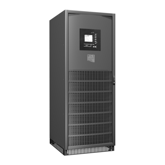
MGE Galaxy 5000 Figure 1-1: MGE Galaxy 5000 UPS Cabinet. UPS power rating (KVA) Dimensions (H x W x D) 40-130 75” x 28” x 33.4” 1900 x 712 x 850 mm Figure 1-2: Single Line Diagram MGE GALAXY 5000 UPS SYSTEM WITH BATTERY SINGLE LINE DIAGRAM Q3BP Bypass Optional KA2 Q4S Input Bypass Input 480Y VAC Input PFC Output Static Static Input Boost Output Main Rectifier Switch Inverter Switch Q1 Fuses KA1 Fuses Q5N Output To Main Input Critical Input Load 480 VAC Battery Static Switch Battery Charger UPS
Краткое содержание страницы № 17
Installation and User Manual 1.2 Inside the UPS Cabinet, Access to Connections Figure 1-3: Inside MGE Galaxy 5000 UPS Cabinet (1) Connectors for auxiliary interconnections of parallel UPS units (INTN PCA), optional (2) User-machine interface display (3) Slot for relay communications card (4) Open slots for optional communication cards (5) Open cabinet door (6) Screw-type terminal block for connections of contacts and coils for two external battery circuit breakers XMB07,
Краткое содержание страницы № 18
MGE Galaxy 5000 Figure 1-4: Power Connection Terminals (14) Terminals for load output (15) Terminals for bypass AC input (16) Terminals for normal AC input (17) Main grounding connector (22) Connection of external battery (+/- poles) Figure 1-5: INTN PCA for Auxiliary Interconnections of Parallel UPSs (19) DB9 connectors: exchange-current information (20) Screw connectors: position information on Q5N, Q4S and Q3BP switches, from the external bypass (21)
Краткое содержание страницы № 19
Installation and User Manual 1.4 User-Machine Interface Display Figure 1-7: User-Machine Interface Display (30) Graphical display (31) Load protected LED (32) Minor fault LED (33) Major fault LED (34) Help key (35) Function keys (36) Menu key (38) OFF button (37) ON button (42) Load supplied LED (40) UPS ON LED (41) Operation on battery power LED (43) Bypass in operation LED (39) PFC ON LED 86-174010-00 B00 Introduction 1 — 5
Краткое содержание страницы № 20
MGE Galaxy 5000 1.5 Display Screens Figure 1-8: Display Screens Frequency measurements Personalization 1 — 6 Introduction 86-174010-00 B00
Посмотреть инструкция для APC MGE Galaxy 5000 бесплатно. Руководство относится к категории Источники бесперебойного питания, 2 человек(а) дали ему среднюю оценку 8. Руководство доступно на следующих языках: английский. У вас есть вопрос о APC MGE Galaxy 5000 или вам нужна помощь? Задайте свой вопрос здесь
Не можете найти ответ на свой вопрос в руководстве? Вы можете найти ответ на свой вопрос ниже, в разделе часто задаваемых вопросов о APC MGE Galaxy 5000.
Какой вес APC MGE Galaxy 5000?
Какие сертификаты APC MGE Galaxy 5000 имеет?
Какая высота APC MGE Galaxy 5000?
Какая ширина APC MGE Galaxy 5000?
Какая толщина APC MGE Galaxy 5000?
Инструкция APC MGE Galaxy 5000 доступно в русский?
Не нашли свой вопрос? Задайте свой вопрос здесь
-
Contents
Table of Contents -
Bookmarks
Quick Links
www.mgeups.com
Galaxy 5000
20 — 120 kVA
Battery circuit-breaker
cabinet
Installation manual
— Page 1
34003641FR/AA
Summary of Contents for MGE UPS Systems Galaxy 5000
-
Page 1
Galaxy 5000 20 — 120 kVA Battery circuit-breaker cabinet Installation manual — Page 1 34003641FR/AA… -
Page 2: Table Of Contents
Galaxy 5000 at the end of its service life. To discover the entire range of MGE UPS SYSTEMS products and the options available for the Galaxy 5000 range, we invite you to visit our web site, www.mgeups.com, or contact your local MGE UPS SYSTEMS representative.
-
Page 3: Installation Of Cabinet
1. Installation of cabinet ◗ the circuit-breaker cabinet must be located as close to the battery as possible, ◗ the cabinet is fixed to a vertical wall by means of 4 screws of diameter 8 using the fastening lugs placed in the vertical or horizontal position, ◗…
-
Page 4: Characteristics Of Cabinet
2. Characteristics of cabinet ◗ the characteristics of the cabinets indicated in the tables below are valid for a linear load charge with power factor of 0.8 and a minimum battery voltage set to 335 V on the inverter side (340 V on the battery side), ◗…
-
Page 5: Electrical Characteristics Of Cabinet
2. Characteristics of cabinet 2.2 Electrical characteristics of cabinet Inverter Maximum battery backup QF1 circuit-breaker rated power times at Pn Type Release Magnetic Thermal in kVA setting setting < or = to 10 mn NS100 TM100D 800 A > 10 mn NS100 TM100D 800 A…
-
Page 6: Connections
3. Connection 3.1 Connection points Cabinet for Galaxy 5000 of 20 kVA to 160 kVA (with battery backup time < or = to 10 mn), and of 20 kVA to 100 kVA (with battery backup time > 10 mn): ◗…
-
Page 7
Vigilohm TR5A terminal 10 8 block terminal block insulation fault Galaxy 5000 to the insulation circuit-breaker of AC normal source in the Galaxy 5000 cubicle (see figure on next page) XMB 08 XMB 07 XMS 06 — Page 7 34002025EN/AA… -
Page 8: Auxiliary Cabinet Connections In The Galaxy 5000 Cubicles
3. Connection Insulation circuit-breaker To terminals 1-2-3-4 of QF1 circuit-breaker To terminals 1-2 of cabinet XB4B XB1B To insulation circuit-breaker XB2B XB3B — Page 8 34002025EN/AA…
APC by Schneider Electric
MGE GALAXY 5000
Data Center Grade Three Phase Uninterruptible Power Supply
Parallel Module — Guide Specifications
40-130 kVA UPS
1.0 GENERAL
1.1 SUMMARY
This specification describes a three-phase, on-line, double conversion, solid state Uninterruptible
Power System hereafter referred to as the UPS. The UPS shall operate in conjunction with the
existing building electrical system to provide high quality power conditioning, back-up power
protection and distribution for electronic equipment loads. The system shall consist of a solid state
IGBT rectifier/inverter, power factor corrected rectifier, a 100% rated for continuous duty static
switch, battery plant, graphical status/control panel, and synchronizing circuitry as described herein.
1.2 STANDARDS
The UPS shall meet the requirements of the following standards:
A. UL listed under 1778, standards for uninterruptible power supply equipment
B. UL Canada (cUL)
C. FCC rules and regulations of part 15, subpart J, class A
D. IEC 1004/ANSI C62.41 Standards for Surge Withstand Ability
E. ISO 9001
F. The UPS shall be designed in accordance with the applicable sections of the documents
published by:
National Fire Protection Association (NFPA)/National Electric Code (NEC)
National Electrical Manufacturer’s Association (NEMA) & (NEMA PE 1)
Occupational Safety & Health Administration (OSHA)
1.3 SUBMITTALS
Submittals shall contain the following documentation:
A. Installation Package: Complete electrical characteristics and connection requirements.
Provide detailed equipment outlines with cabinet dimensions and spacing requirements;
location of conduit entry/exit paths; location of floor/seismic mounting; available battery
types/sizes; all cabinet weights; heat rejection and air flow requirements; single-line diagram;
control and external wiring.
B. Product Data: Provide catalog sheets and technical data sheets to indicate physical data and
electrical performance, electrical characteristics, and connection requirements.
C. Manufacturer’s Installation Instructions: Indicate application conditions and limitations of
use stipulated by Product testing agency. Include instructions for storage, handling, protection,
examination, preparation, installation, and starting of Product. Include equipment installation
APC – MGE Galaxy 5000 Specification (60Hz)
1
Effective: June 1, 2008 REV X0 JJG
Parallel Module