
- Manuals
- Brands
- Kverneland Manuals
- Farm Equipment
- ES
- Operator’s manual
-
Contents
-
Table of Contents
-
Troubleshooting
-
Bookmarks
Quick Links
Operator’s manual
Original operator’s manual
Edition
Date of printing
Language
Machine number
Model
Document number
ES/LS
06.2015
06.2015
EN
ES/LS
A133309940.EN
Related Manuals for Kverneland ES
Summary of Contents for Kverneland ES
-
Page 1
ES/LS Operator‘s manual Original operator‘s manual Edition 06.2015 Date of printing 06.2015 Language Machine number Model ES/LS Document number A133309940.EN… -
Page 2
Copyright by Kverneland Group Operations Norway AS. Reproduction, transfer to other media, translation or the use of extracts or parts of this manual without the explicit permission of Kverneland, is not permitted. All rights reserved. The contents of this operator’s manual are subject to… -
Page 3: Table Of Contents
Set the bodies Proper use Possible modifications ……Features Reversing direction Components Restrictor position Technical specifications Spring release system [ES] Cross shaft The position of the cross shaft Tire pressure Information plate Parking and storage ……..Parking and storage Optional equipment ……..
-
Page 4: Preface
Preface Preface Target group for This operator‘s manual is intended for personnel concerned with the inspection, use and maintenance of the plow. It contains all the infor- this operator‘s mation needed for safe handling, use and maintenance of the plow. manual For your safety Before starting to adjust and use your plow, familiarize yourself with…
-
Page 5: Terminology Used
Preface In addition to these symbols, the following pictograms are used to help you find the text sections: “Tip” indicates useful tips and advice. The warning triangle indicates that there is a risk involved with the work of fitting or adjustment. Shut off the engine, set the parking brake, remove the ignition key and secure the tractor against rolling away.
-
Page 6: Safety
Safety Safety California Proposition 65 WARNING Engine exhaust, some of its constituents, certain machine compo- nents and fluids, contain or emit chemicals known to the State of California to cause cancer and birth defects or other reproductive harm. SAFETY FIRST This symbol, the industry’s «Safety Alert Symbol», is used through- out this manual and on labels on the machine itself to warn of the possibility of personal injury.
-
Page 7: Danger, Warning And Caution Labels
Safety DANGER, This chapter describes general safety information for this product. Each section of this operator‘s manual also contains its own specific WARNING and safety information. CAUTION labels Safety decals are placed on important parts of the plow for your own safety.
-
Page 8
Safety Meaning of DANGER, The meaning of the safety decals is explained below. WARNING and CAUTION labels… -
Page 9
Safety… -
Page 10: General Safety Information
Safety General safety Please read and ensure you understand the following general safety information. Specific safety information is pointed out in the relevant information chapters. For your safety Read and ensure you understand the instructions Before starting to operate the plow, read the operator‘s manual and follow the instructions.
-
Page 11
Safety No riding on the plow Persons or objects must never be transported on the plow. Carrying passengers, especially children, on the plow is life threatening and prohibited. Serious or fatal injury may be caused as a result. Safety for children Never assume that children will remain where you last saw them.Be alert and shut your machine down if children come into the work area. -
Page 12
Use original spare parts Use only genuine Kverneland spare parts. Other products may adversely affect the correct operation of the plow and safety. The warranty will no longer be valid if parts not produced by Kverneland are used. Check the tire pressure Regularly check that the tire pressure meets the requirements. -
Page 13
Safety Driving on the road Be aware of the plow’s length The plow is very long and swings out when turning. Avoid allowing the rear of the plow to hit obstacles during sharp swings. Stabilize the lower links During all operations other than plowing, stabilize the tractor’s lower links. -
Page 14
Safety Hydraulics Hydraulic connection at zero pressure only Only connect hydraulic hoses to the tractor hydraulic system if the tractor and machine hydraulic system is at zero pressure. A pressurize hydraulic system can trigger unforeseen movements on the machine and can cause serious machine damage and personal injury. Serious or fatal injury may be caused as a result. -
Page 15: Getting To Know The Plow
Features Two types of beam The ES plow is equipped with Kverneland’s automatic stone release system. The singel leaf spring system cushions the plow body when a hard object is impacted. Once the plow has passed the obstacle, the body automatically reverts to the correct plow depth.
-
Page 16: Components
Getting to know the plow Components General – ES Headstock Main frame Beam bracket Automatic beam Skimmer Spring Depth wheel Disc coulter Front piece Front piece Parallel rod Parking stand General – LS Main frame Beam bracket Shear bolt beam…
-
Page 17
Getting to know the plow Headstock 200 Tower Turnover cylinder Turnover valve Cross shaft Body Mouldboard Stay Landside Saddle Share Reversible plow Breast piece (This figure shows body no. 9. Other types of body have similar components) -
Page 18: Technical Specifications
Getting to know the plow Technical specifications General Clear- Beam No. of Frame Furrow Recom- Weight Lift req ance be- height bodies width mended Model Head- tween stock bodies (inches) (inches) (inches) (inch- (lbs) (lbs) 70/75 150×150 30–50 –120 1055 2350 (33) (28/30)
-
Page 19: Cross Shaft
Getting to know the plow Cross shaft Headstock Type Category Diameter Length (inches) (inches) fixed 825 (32) (2.3) 935 (37) fixed 60 / 70 860 (34) (2.3/2.7) 965 (38) quick coupling 935 (37) (2.3) quick coupling 60 / 70 860 (34) (2.3/2.7) 965 (38) turnable…
-
Page 20: Information Plate
Getting to know the plow Information plate The information plate is attached to the setting beam. When ordering spare parts or consulting services, please state the full model code and plow ID, to avoid any mistakes or misunderstandings. Type Body distance Model QR head Headstock…
-
Page 21: Optional Equipment
Optional equipment This chapter provides an overview of optional equipment for the ES/ Optional equipment LS plow. Restrictions apply. Contact your Kverneland dealer for more information. Skimmer Recommended for effective down-plowing of grass and stubble. Two types of skimmer are available: the standard skimmer and the maize skimmer.
-
Page 22
Optional equipment Landside knife Can be used together with all types of share. An alternative to the disc coulter, when the weight needs to be reduced or when there is a strong likelihood of a lot of waste or stones. Ideal for combining with skims and suitable for all types of share. -
Page 23
Optional equipment Share with Quick-Fit Reduces the down time in replacing the points. Can be fitted to all plow point bodies. Very good ground penetration. Share with Knock-on Reduces the down time in replacing the points. Can be fitted to all plow point®… -
Page 24
Optional equipment Furrow opener Used on the rear body to increase the width of the base of the furrow, to accommodate tractors with wider tires. Wear plate Can be fitted to landsides to reduce wear to the landsides. Fitted to the landsides’… -
Page 25
Available for transport both in plowing setting and semi-rotated setting. Packomat Kverneland Packomat is a soil packer which is integrated into the plow and which ensures optimum combination of both. Kverneland’s inte- grated soil packer harrows and packs the soil once it is in an easily workable state, and in some cases (lightweight soil) saves all harrow- ing, and in all cases some harrowing. -
Page 26
Hydraulic Auto-Reset As an alternative to the leaf spring design, a hydraulic release, com- prising a single-acting cylinder, is available [ES]. Leaf springs are replaced by a hydraulic cylinder which is connected to an accumulator, the pressure of which can be regulated to obtain an… -
Page 27: Preparation For Use
Preparation for use This chapter details how to prepare the plow and tractor before putting Preparation for use the plow into operation. Tractor Hydraulic connections The following table shows the tractor’s required connections. Hydraulic functions Single-acting Double-acting Turnover Hydraulic furrow width [+] Hydraulic first furrow width [+] Hydraulic depth wheel [+] Hydraulic release system [+]…
-
Page 28: Remove Paint
Preparation for use Be mindful when ordering the plow so that the slide can be fitted cor- rectly. Tire pressure To prevent uneven furrows, the air pressure must be the same in both the tractor’s rear wheels. Front weights > Fit sufficient weights at the front to ensure safe driving. Lower links >…
-
Page 29: Connecting
Connecting This chapter explains how to connect the plow to the tractor. Connecting Safety WARNING Increased risk of injury when coupling There is an increased risk of injury when the plow is coupled to the tractor. Therefore: • Shut off the engine, set the parking brake, remove the ignition key.
-
Page 30: Connection Geometry
Connecting Connection geom- To obtain a stable first furrow width, the intended pulling point between the lower link arms must be 1/3 of the axle distance behind the front etry axle. If this is not the case, use a cross shaft with a different length. →…
-
Page 31: Transport
Transport This chapter explains how to drive safely on the road. Transport When you use a Kverneland Packomat together with the plow, other instructions apply. Read the operator‘s manual for Kverneland Packo- mat. Safety WARNING Stabilize the lower links During transport, stabilize the tractor’s lower links. This will pre- vent the plow from accidentally moving sideways.
-
Page 32: Before Transport
Transport Before transport Before transport > Remove dirt and soil from the plow > Raise the plow carefully > Stabilize the lower links > Adjust the plow to the narrowest working width Close valve > Close the valve on the working-width cylinder [+] >…
-
Page 33: Put Into Transport Position
Transport Put into transport position Without transport wheel If the plow is not equipped with a transport wheel, it should be trans- ported as shown. Transport position Transport wheel for butterfly position > Lift the plow 10 cm (4 inches) above the ground >…
-
Page 34
Transport > Turn the spring-loaded stop. The wheel will then be able to rotate Turn the spring- loaded stop freely through 360°. Unlock WARNING > Activate the transport lock on the headstock so that the locking pin (spring-loaded) pops out. Handle >… -
Page 35
Transport Transport wheel for transport in plowing po- sition > Put the plow onto the ground (right body) > Remove the locking piece and turn it through 180º > Fasten it in the same place, it having been rotated through 180º >… -
Page 36
Transport Hydraulic depth wheel To change to transport position > Lift the plow slightly > Stabilize the lower links Bolt and ring pin > Adjust the plow to it’s narrowest working width > Lift the wheel slightly. This eases removing of the bolt. Release plate >… -
Page 37: Set Into The Plowing Position
Transport Set into the plow- After transport, set the plow back to the working position. ing position Transport wheel for butterfly position > Connect the top link to the tower Transport position > Lift the plow right up. Unlock > Deactivate the transport lock on the headstock, i.e. press in the locking pin Lock >…
-
Page 38
Transport > Release the locking hooks for the upper and lower depth stops so that these can move freely. Rotate… -
Page 39: Set Into The Plowing Position
Transport Set into the plow- ing position Transport wheel for plowing position > Connect the top link > Lift the plow > Remove the bolt from position 1 > Put the bolt into the hole to fasten the wheel arm (position 2) >…
-
Page 40
Transport Hydraulic depth wheel To change to plowing position > Connect the top link to the tower > Lift the plow right up. Transport position Unlock > Deactivate the transport lock on the headstock(pull the locking pin back) > Turn the plow into plowing position Lock Handle Bolt… -
Page 41: Adjust The Plow
Adjust the plow This chapter explains how to adjust the plow in order to achieve the Adjust the plow desired plowing result. The adjustments can be made either before or during plowing. Recommended procedure We recommend that you use the following procedure, in this order, when adjusting the plow in the field >…
-
Page 42
Adjust the plow Working width Mechanically > Adjust the working width on the turnbuckle. Use the spanner which is supplied. Hydraulically [plows without alignment cylinder] This diagram shows hydraulic working-width adjustment > Adjust the working-width cylinder using the tractor’s hydraulic out- Hydraulically [plows with sequence valve] >… -
Page 43: First Furrow Width
Adjust the plow First furrow width WARNING Do not adjust when lifted Do not adjust the first furrow width when the plow is lifted from the ground. This may lead to damage or injury. In general, the first furrow must agree with the width of the others. Pay careful attention to the following: •…
-
Page 44: Working Depth
Adjust the plow • Working depth The plow frame should always remain parallel to the ground. • The top link should be in the centre of the tractor. • After changing the working depth, the sideways levelling should be checked (see next section) Wrong adjustment Right adjustment Changing the plowing depth…
-
Page 45
Adjust the plow Hydraulic depth wheel Adjust the working depth more shallow than adjusted with mechanical stops by activating the single-acting cylinder > Activate the tractor’s spool valve. • Pull the cylinder back towards the stop in order to plow deeper. •… -
Page 46: Levelling
Adjust the plow Levelling Seen from behind, the plow beams should be at right angles to the ground. Right adjustment Wrong adjustment Headstock 200 Levelling the plow > Turn the plow slightly > Turn the adjustment bolts on the headstock. Adjust both sides the same to begin with.
-
Page 47
Adjust the plow CAUTION Extremely deep or shallow plowing The rotating system on headstock 200 must never be in contact with the frame of the headstock. This can occur when • You are plowing shallow and the bodies rotate over the frame •… -
Page 48: Disc Coulter [+]
When the distance between the disc coulter and the landside is be- tween 1 and 4 cm (0.4-1.6 inches). 1-4 cm (0.4-1.6 in.) ES without parallel side adjustment Adjusting the depth > Support the disc coulter to prevent it falling down >…
-
Page 49
Adjust the plow ES with parallel side adjustment Adjusting the depth > Support the disc coulter to prevent it falling down > Loosen the bolt (R) > Turn the arm > Tighten the bolt again (R) Bolt R Adjusting the side position >… -
Page 50: Skimmer [+]
Adjust the plow Skimmer [+] The skims are correctly adjusted when • The skims have a working depth of approx. 3–5 cm (1.2-2 inches). • All the skims have been adjusted the same. Adjusting the depth > Support the skims to prevent them falling down >…
-
Page 51: Trash Board [+]
Adjust the plow Trash board [+] The trash board should be positioned with its front edge tight up to the mouldboard; its back edge should be adjusted in accordance with the plowing depth. The bracket for the trash board has two adjustment holes, one for deep plowing and one for more shallow plowing (A).
-
Page 52
Adjust the plow Direction of the packer • The packer arm should always be fitted at an angle of 15° to the direction of drive direction of drive. • There are three possible settings. When using setting 1, a pusher is fitted to protect the hydraulic hose. -
Page 53: Plowing
Plowing Plowing Safety Be careful when you reverse when driving backwards (when turning with bodies under) Be careful when reversing the plow while driving backwards. There is a risk of mouldboards or the depth wheel hitting the ground. This may result in damage.
-
Page 54: Reversing The Plow
Plowing Reversing the plow CAUTION Complete the turning sequence Always complete the entire turning sequence. Only then the turn- over cylinder will be locked, and will not rotate during plowing. The plow reverses when you apply pressure to the P side of the turn- over valve.
-
Page 55: Care And Maintenance
Use original spare parts Only use original Kverneland spare parts. Using other products may lead to malfunction of the machine or a reduced safety. War- ranty is not valid if parts not produced by Kverneland are used. WARNING Wear protective clothing Wear protective clothing, e.g.
-
Page 56: Maintenance Table
Care and maintenance Maintenance table This maintenance table shows the maintenance interval for the vari- ous maintenance procedures. Check condition of the plow Lubrication Replace the hydraulic hoses Replace worn parts Retighten bolts and nuts Check the release-system springs Check the tire pressure Protect parts which are in direct contact with the ground against corrosion Align the bodies…
-
Page 57
Care and maintenance Lubrication Use appropriate grease Only use EP (Extreme Pressure) grease. The use of inappropriate grease will reduce the lifetime of the bearings. Lubricate the plow • Daily during plowing. This prevents water and dirt from penetrating into the bearings and moving parts. •… -
Page 58
Care and maintenance The diagrams below show the lubrication points (S) Lubrication points (S) Headstock 2000 Disc coulter Automatic beam In front [ES] In front [LS]… -
Page 59
Care and maintenance Lubrication points (S) Depth/transport wheel for plowing position Depth/transport wheel for butterfly position Depth wheel Hydraulic depth wheel [+] Hydraulic depth wheel [+]… -
Page 60: Replace Hoses
Replace all parts which go down into the ground and other parts when they are worn out or damaged. parts • Use original Kverneland parts only. > Remove the old part. > Fit the new part > Remove paint from all surfaces which are in contact with the ground.
-
Page 61: Replace Quick-Fit Points
Care and maintenance Replace Quick-fit points WARNING Wear eye protection • Wear eye protection when replacing Quick-fit points. Other- wise, there is a risk that splinters from the Quick-Fit points can cause eye damage. Removing a worn point > Place the gore tool >…
-
Page 62: Tighten Bolts And Nuts
Care and maintenance Fitting a new point > Place the new point in front of the share and move it backwards > Use the gore tool as a buffer between the point and the hammer > Knock the point into place ! There must be no paint on the angled surfaces Tighten bolts and Tighten all bolts and nuts on the plow again.
-
Page 63: Check Springs For Correct Length
> Check the length of the springs every year. > Adjust the length if they are shorter or longer than 70 cm (28 inch- es). → page 69…
-
Page 64: Tire Pressure
Care and maintenance Use the long spanner to measure the spring length. The notches on the spanner indicate 70 cm (28 inches). 70 cm (28 inches) Check the spring bolts (F) for wear. Replace them if necessary. Tire pressure Ensure that the tires are inflated to the necessary pressure. →…
-
Page 65
Care and maintenance Check the preload pressure of the WARNING hydraulic release Couple to the tractor and support the beams system [+] When checking, couple the plow to the tractor and place the plow on firm and level floor. Support the beams with a wedge under the landsides. -
Page 66
Care and maintenance To check again > Set the system under pressure to 100 bar (1450.4 psi) > Repeat the checking procedure. After checking > Set the pressure of the system to 100–160 bar (1450.4- 2320.6 psi), depending on the conditions on the ground >… -
Page 67: Possible Modifications
Possible modifications This chapter explains how you can alter some of the plow’s basic con- Possible modifications figurations in order to adapt it to the tractor and your requirements. Reversing The plow can be turned with the bodies either over or under the frame. direction In order to change the reversing direction, you must change •…
-
Page 68: Spring Release System [Es]
Possible modifications Spring release This section explains how you can • Fit or remove an automatic beam system [ES] • Change the automatic beams’ spring tension • Adjust the spring tension of automatic beams Safety WARNING Support the beam Support the beam firmly when disassembling it, by using appropri- ate equipment.
-
Page 69
Possible modifications Spring tension The diagram shows how the transfer mechanism for the power from the spring is to be set Bolt E: Clearance to the hole in the wall Bolt X: Adjusting the length of the spring 1–2 mm (0.03-0.07 inches) clearance 70 cm (28 inches) For instructions, see next page. -
Page 70
Possible modifications To release the spring tension > Park the plow on a firm, level surface. Loosen a little Press forwards > Support the beams correctly. Place a wedge under the back side of the landside > Loosen bolt X >… -
Page 71
Possible modifications Change the release force The release setting’s release force is correct when the beams do not become loose during plowing unless they strike an object. setting You can change the release force of the automatic beam by • Adding or removing spring leaf no. -
Page 72
Possible modifications Standard Heavy Duty Extra Heavy Duty Leaf F Leaf F Leaf F No. 1 No. 1 No. 1 No. 2 No. 2 No. 2 No. 3 No. 3 No. 3 No. 4 No. 4 No. 4 No. 5 No. -
Page 73
Possible modifications Adjust the pressure to the minimum pressure when the bodies are maintained in the working position during normal plowing. > Remove the dust covers > First connect the filling hose to the tractor > Then connect the filling hose to the quick connection on the accu- mulator >… -
Page 74: The Position Of The Cross Shaft
Possible modifications The position of the The cross shaft has various possible configurations, to change • The clearance to the tractor cross shaft • The clearance to the ground during rotation • The lifting requirement Headstock 200 The diagrams below show the various configurations. Quick connection (long) Quick connection (short) Fixed…
-
Page 75: Parking And Storage
Parking and storage Parking and storage Safety WARNING Parking stand Use the parking stand when parking the plow. If the plow is not properly supported, it may tip over. This may damage the plow or lead to injury. Park on a firm, even surface Park the plow on a firm and level surface.
-
Page 76: Troubleshooting
Troubleshooting Troubleshooting Problem Possible cause Solution Rotating system The plow will not start reversing The connections to the tractor have Ensure that the quick connections been installed incorrectly. have been correctly connected (see the colour coding on the hos- The plow will not start reversing – The valve pressure is wrong Increase the valve pressure by the plow reacts with an abrupt start…
-
Page 77: Checklist
Checklist Checklist Tractor Check • Is the internal track (the distance between the inside of the wheels) 110–160 cm (43-63 inches)? • Is the pressure in the left-hand and right-hand tires the same? • Are both of the lower link arms at the same height? Fitting Check •…
-
Page 78
Checklist Daily maintenance To be done > Check condition of the plow > Lubricate the plow Regular maintenance To be done > Replace worn-out parts > Retighten bolts and nuts Check • Is the spring length of the automatic release system 70 cm (28 inches)? •… -
Page 79: Disposing Of The Plow
Disposing of the plow Dispose of the plow in the proper manner when its working life is over. Disposing of the plow Please observe locally applicable regulations regarding the disposal of waste. Metal All metal components can be sent for ferrous-metal recycling. Tires Tires can be sent to a tire recycling plant.
-
Page 80: Eu Goods Certificate
EU goods certificate EU goods certificate In accordance with EU directive 2006/42/EU Kverneland Group Operations Norway AS Plogfabrikkvegen 1 4353 Klepp Stasjon Norway Sign declare, exclusively for that which is our own responsibility, that the product ES/LS and accessories which this certificate covers fulfils the relevant and fundamental re- quirements of EU directive 2006/42/EU regarding health and safety.
-
Page 81: Index
Direction of the packer arm Disc coulter Driving on the road Eco-plowshare EU goods certificate Extremely deep or shallow plowing First furrow width Furrow opener Furrow splitter General – ES General – LS Headstock 200 Hydraulic connections Hydraulic depth wheel Hydraulic release system Hydraulics…
-
Page 82
Index Transport lock Transport position Information plate Trash board Type of spring Kverneland Group Valve hydraulic Labels on the plow Landside knife WARNING Levelling Warranty Lighting for transport Wear plate Lubrication Working depth Lubrication points Maintenance table Mouldboard extension Packomat…
This manual is also suitable for:
Ls


-
Описание
Описание
Таблицы настроек Kverneland
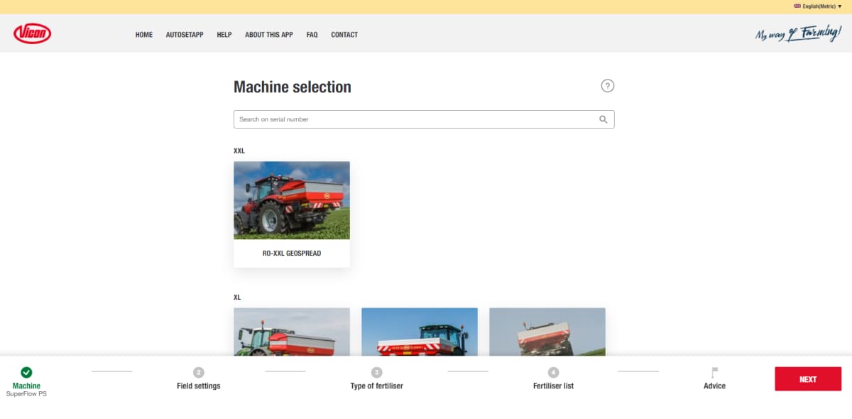
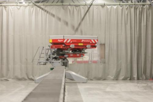
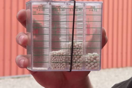
Разбрасыватели Exacta уже многие годы имеют репутацию надёжных, простых в эксплуатации и настройках машин для внесения удобрений. Их непревзойдённая равномерность распределения является результатом многолетних испытаний и опыта. Тестирование равнораспределения происходит на основе жесточайших интернациональных требований и стандартов. Следовательно, при покупке разбрасывателя Kverneland Вы получаете больше, чем просто «лейку». Вам открывается доступ к самым свежим результатам испытаний и настройкам под все Ваши удобрения.
Прямой доступ к новейшим таблицам настройки!
- Сайт: www.kvernelandspreadingcharts.com — где также можно скачать обновление для Tellus терминалов
- Таблицы настроек в качестве мобильного приложения App store и Google play
Участвуя в моих аукционах, вы соглашаетесь с действующими на них правилами
Руководство по эксплуатации на польском языке
пневматическая сеялка
и вспомогательное оборудование
ACCORD
DL, DT, DA, DA-S, DE-S,
DV, DF, DG
Подробно проиллюстрировано и описано в разделах:
Введение
Указыва —
Описание и технические характеристики
Настройка и подготовка к работе
рядная сеялка
Особенности машины DL
Особенности машины DT
Особенности машин DA; DA-S
Особенности машины de-S
Особенности машины DV
Особенности машин DF1 и DF2
Особенности детали-lne DG машины
Электронная дорожка
FGS (FGS)
Электронный контроль сеялки (ESC)
Электронный привод сеялки (ESA)
Гидравлический привод воздуходувки
Дополнительное оборудование
Уход и обслуживание
Поведение при неисправностях на работе
Ссылка на пароль
У вас есть вопрос ? из моих аукционов/объявлений руководств ничто по сравнению со стоимостью ремонта в сервисе дилера. Все просто ремонт можно сделать самому себе.
Необходимые учебники для всех, кто является владельцем или оказывает услуги и занимается в ремонт и обслуживание этих машин, позволят Вам разобраться в их конструкции и принципы работы.
Виды публикаций: —
Инструкции эксплуатации и техническому обслуживанию содержат информацию из области обслуживания, безопасности, технического обслуживания и обслуживания, периодического, в том числе и замены эксплуатационных жидкостей и фильтров. Содержит описания индикации, функции и принципы работы, входящих в комплект поставки переключателей, рычагов и т. д.
Руководство ремонту (книжка) — содержит сведения о принципе действия основных систем и узлов машины, выполнять действия проверки и регулировки, поиска и устранения неисправностей, а также разборки и сборки. Содержит электрические схемы и гидравлические.
ПРИМЕЧАНИЕ: Инструкции по ремонту двигателей чаще всего являются отдельными изданиями.
Каталог запчастей включает в себя чертежиzłożeniowe всех деталей машины, подлежащих обслуживании.
В нем содержится также рекомендации по заказу оригинальных запасных частей, наряду со сведениями о маркировке с цифрами.