- Manuals
- Brands
- Mitsubishi Electric Manuals
- Inverter
- A800
- Instruction manual
-
Contents
-
Table of Contents
-
Bookmarks
Quick Links
INVERTER
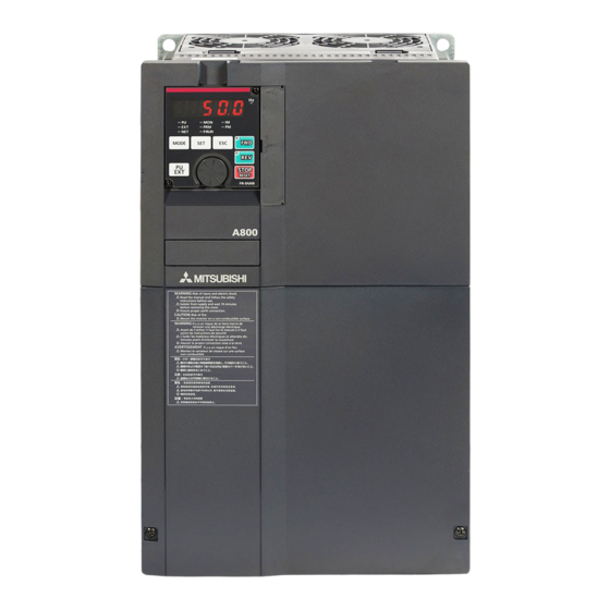
A800
FR-A802-P (SEPARATED CONVERTER TYPE FOR PARALLEL OPERATION)
INSTRUCTION MANUAL (HARDWARE)
High functionality and high performance
FR-A842-09620(400K) to 12120(500K)-P
INTRODUCTION
INSTALLATION AND WIRING
PRECAUTIONS FOR USE OF
THE INVERTER
PROTECTIVE FUNCTIONS
PRECAUTIONS FOR
MAINTENANCE AND
INSPECTION
SPECIFICATIONS
1
2
3
4
5
6
Related Manuals for Mitsubishi Electric A800
Summary of Contents for Mitsubishi Electric A800
-
Page 1
INVERTER A800 FR-A802-P (SEPARATED CONVERTER TYPE FOR PARALLEL OPERATION) INSTRUCTION MANUAL (HARDWARE) High functionality and high performance FR-A842-09620(400K) to 12120(500K)-P INTRODUCTION INSTALLATION AND WIRING PRECAUTIONS FOR USE OF THE INVERTER PROTECTIVE FUNCTIONS PRECAUTIONS FOR MAINTENANCE AND INSPECTION SPECIFICATIONS… -
Page 2
(separated converter type for parallel operation) that are different from the FR-A800. Information about the software, such as basic operations and parameters, is described in the FR-A800 Instruction Manual (Detailed) in the CD-ROM enclosed with the product. Also, for information about the parameters and restrictions on the parallel operation specifications, refer to the Parallel Operation Function Manual in the enclosed CD-ROM. -
Page 3
CAUTION CAUTION Transportation and Mounting Usage The storage temperature (applicable for a short time, e.g. during The electronic thermal relay function does not guarantee transit) must be between -20 and +65°C. Otherwise the inverter protection of the motor from overheating. It is recommended to may be damaged. -
Page 4: Table Of Contents
CONTENTS 1 INTRODUCTION Product checking and accessories Inverter component names About the related manuals 2 INSTALLATION AND WIRING Peripheral devices 2.1.1 Inverter and peripheral devices ……………………12 2.1.2 Peripheral devices ……………………….13 Removal and reinstallation of the operation panel or the front covers Installation of the inverter and enclosure design 2.3.1 Inverter installation environment……………………17…
-
Page 5
Electro-magnetic interference (EMI) and leakage currents 3.1.1 Leakage currents and countermeasures………………….62 3.1.2 Countermeasures against inverter-generated EMI ………………65 3.1.3 Converter unit built-in EMC filter ……………………68 Power supply harmonics 3.2.1 Power supply harmonics ……………………..69 3.2.2 Harmonic Suppression Guidelines in Japan ………………..70 Power-OFF and magnetic contactor (MC) Countermeasures against deterioration of the 400 V class motor insulation Checklist before starting operation… -
Page 6
6 SPECIFICATIONS Inverter rating Common specifications Outline dimension drawings APPENDIX Appendix 1 Instructions for compliance with the EU Directives…………106 Appendix 2 Instructions for UL and cUL ………………..109 Appendix 3 Instructions for EAC………………….111 Appendix 4 Restricted Use of Hazardous Substances in Electronic and Electrical Products … 112 CONTENTS… -
Page 7
MEMO… -
Page 8: Introduction
INTRODUCTION This chapter contains the descriptions that must be read before using this product. Always read the instructions before using the equipment. 1.1 Product checking and accessories………8 1.2 Inverter component names …………9 <Abbreviations> DU……….. Operation panel (FR-DU08) Operation panel ……Operation panel (FR-DU08) and LCD operation panel (FR-LU08) Parameter unit ……..
-
Page 9: Product Checking And Accessories
Product checking and accessories Product checking and accessories Unpack the product and check the rating plate and the capacity plate of the inverter to ensure that the model agrees with the order and the product is intact. Applicable inverter model ∗1 Symbol Description…
-
Page 10: Inverter Component Names
Cooling fan Cools the inverter. Switches for manufacturer setting ─ Do not change the initial setting (OFF (SW3 and SW4) Refer to the FR-A800 Instruction Manual (Detailed). The Vector control compatible options cannot be used with the slave. INTRODUCTION…
-
Page 11: About The Related Manuals
About the related manuals About the related manuals The manuals related to this inverter are shown below. Manual name Manual number Parallel Operation Function Manual IB-0600654ENG FR-A800 Instruction Manual (Detailed) IB-0600503ENG FR-CC2-P Instruction Manual IB-0600657ENG INTRODUCTION…
-
Page 12: Installation And Wiring
INSTALLATION AND WIRING This chapter explains the «installation» and the «wiring» of this product. Always read the instructions before using the equipment. 2.1 Peripheral devices …………..12 2.2 Removal and reinstallation of the operation panel or the front covers …………….15 2.3 Installation of the inverter and enclosure design ….17 2.4 Terminal connection diagrams ……….24…
-
Page 13: Peripheral Devices
Peripheral devices Peripheral devices 2.1.1 Inverter and peripheral devices • For operating two inverters in parallel One circuit breaker and one magnetic contactor in total in a system (c) Three-phase AC (d) Molded case circuit (e) Magnetic power supply breaker (MCCB) or fuse contactor (MC) (f) Noise filter…
-
Page 14: Peripheral Devices
Peripheral devices Refer Symbol Name Overview page The life of the inverter and the converter unit is influenced by the surrounding air temperature. Inverter (FR-A802-P) The surrounding air temperature should be as low as possible within the permissible range. This must be noted especially when the inverter is installed in an enclosure.
-
Page 15
Peripheral devices Selecting the breaker/magnetic contactor Check the model of the inverter and the converter unit you purchased. Appropriate peripheral devices must be selected according to the capacity. Refer to the table below to prepare appropriate peripheral devices. • One circuit breaker and one magnetic contactor in total in a system Motor Molded case circuit breaker (MCCB) … -
Page 16: Removal And Reinstallation Of The Operation Panel Or The Front Covers
Removal and reinstallation of the operation panel or the front covers Removal and reinstallation of the operation panel or the front covers Removal and reinstallation of the operation panel • Loosen the two screws on the operation panel. • Push the upper part of the operation panel and pull the (These screws cannot be removed.) operation panel to remove.
-
Page 17
Removal and reinstallation of the operation panel or the front covers Removal of the front cover (upper side) Loosen Loosen Loosen With the front cover (lower side) removed, loosen the mounting screws on the front cover (upper side). These screws cannot be removed. -
Page 18: Installation Of The Inverter And Enclosure Design
Installation of the inverter and enclosure design Installation of the inverter and enclosure design When designing or manufacturing an inverter enclosure, determine the structure, size, and device layout of the enclosure by fully considering the conditions such as heat generation of the contained devices and the operating environment. An inverter uses many semiconductor devices.
-
Page 19
Installation of the inverter and enclosure design Humidity Operate the inverter within the ambient air humidity of usually 45 to 90% (up to 95% with circuit board coating). Too high humidity will pose problems of reduced insulation and metal corrosion. On the other hand, too low humidity may cause a spatial electrical breakdown. -
Page 20: Amount Of Heat Generated By The Inverter
Installation of the inverter and enclosure design Vibration, impact The vibration resistance of the inverter is up to 2.9 m/s at 10 to 55 Hz frequency and 1 mm amplitude for the directions of X, Y, Z axes. Applying vibration and impacts for a long time may loosen the structures and cause poor contacts of connectors, even if those vibration and impacts are within the specified values.
-
Page 21: Cooling System Types For Inverter Enclosure
Installation of the inverter and enclosure design 2.3.3 Cooling system types for inverter enclosure From the enclosure that contains the inverter, the heat of the inverter and other equipment (transformers, lamps, resistors, etc.) and the incoming heat such as direct sunlight must be dissipated to keep the in-enclosure temperature lower than the permissible temperatures of the in-enclosure equipment including the inverter.
-
Page 22: Inverter Installation
Installation of the inverter and enclosure design 2.3.4 Inverter installation Inverter placement • Install the inverter on a strong surface securely with screws. • Leave enough clearances and take cooling measures. • Avoid places where the inverter is subjected to direct sunlight, high temperature and high humidity. •…
-
Page 23: Protruding The Heatsink
Installation of the inverter and enclosure design Encasing multiple inverters and converter units When multiple inverters and converter units are placed in the same enclosure, generally arrange them horizontally as shown in the figure on the right. Converter Converter Inverter Inverter unit unit…
-
Page 24
Installation of the inverter and enclosure design Removal of the rear installation frame Two installation frames are attached to each of the upper and lower parts of the inverter. Remove the rear side installation frame on the top Upper installation and bottom of the inverter as shown on the right. -
Page 25: Terminal Connection Diagrams
Terminal connection diagrams Terminal connection diagrams FM type Sink logic Main circuit terminal Control circuit terminal Converter unit R/L1 S/L2 To motor T/L3 Jumper R1/L11 S1/L21 Earth Main circuit (Ground) Control circuit Control input signals Relay output (No voltage input allowed) Forward rotation start Relay output 1 Reverse rotation start…
-
Page 26
Terminal connection diagrams Terminals R1/L11 and S1/L21 are connected to terminals P/+ and N/- with a jumper respectively. When using separate power supply for the control circuit, remove the jumpers from R1/L11 and S1/L21. The function of these terminals can be changed with the input terminal assignment (Pr.178 to Pr.189). … -
Page 27
Terminal connection diagrams CA type Source logic Main circuit terminal Control circuit terminal Converter unit R/L1 S/L2 To motor T/L3 Jumper R1/L11 S1/L21 Earth Main circuit (Ground) Control circuit Control input signals Relay output (No voltage input allowed) Forward rotation start Relay output 1 Reverse rotation start… -
Page 28
Terminal connection diagrams Terminals R1/L11 and S1/L21 are connected to terminals P/+ and N/- with a jumper respectively. When using separate power supply for the control circuit, remove the jumpers from R1/L11 and S1/L21. The function of these terminals can be changed with the input terminal assignment (Pr.178 to Pr.189). … -
Page 29
Terminal connection diagrams System configuration (for operating two inverters in parallel) • Install wiring of the RS-485 terminals in between the converter units and between the inverters as shown in the figure in page 29. (For the details of wiring of the RS-485 terminals, refer to page 50.) •… -
Page 30
Terminal connection diagrams • Terminal connection diagram for two inverters in parallel FR-CC2-P (master) FR-A802-P (master) Three-phase R/L1 AC power S/L2 supply T/L3 R1/L11 R1/L11 S1/L21 S1/L21 MRS(X10) TXD1+ TXD1+ TXD1- TXD1- TXD2+ TXD2+ TXD2- TXD2- RXD1+ RXD1+ RXD1- RXD1- RXD2+ RXD2+ RXD2-… -
Page 31
Terminal connection diagrams System configuration (for operating three inverters in parallel) • Install wiring of the RS-485 terminals in between the converter units and between the inverters as shown in the figure in page 31. (For the details of wiring of the RS-485 terminals, refer to page 50.) •… -
Page 32
Terminal connection diagrams • Terminal connection diagram for three inverters in parallel FR-CC2-P (master) FR-A802-P (master) Three-phase R/L1 AC power S/L2 supply T/L3 R1/L11 R1/L11 S1/L21 S1/L21 MRS(X10) TXD1+ TXD1+ TXD1- TXD1- TXD2+ TXD2+ TXD2- TXD2- RXD1+ RXD1+ RXD1- RXD1- RXD2+ RXD2+ RXD2-… -
Page 33
Terminal connection diagrams Wiring between the converter units and the inverters Main circuit terminal • Wire terminal P (+) on the converter unit to terminal P on the inverter, and do likewise for terminal N (-). Pair the masters or the slaves (1 with 1 or 2.with 2). -
Page 34: Main Circuit Terminals
Main circuit terminals Main circuit terminals 2.5.1 Details on the main circuit terminals of the inverter Terminal Refer Terminal name Terminal function description symbol to page U, V, W Inverter output Connect these terminals to a three-phase squirrel cage motor. Connected to terminals P/+ and N/-.
-
Page 35
Main circuit terminals 2.5.3 Terminal layout of the main circuit terminals, wiring of power supply and the motor FR-CC2-H400K to H560K-P FR-A842-09620(400K) to 12120(500K)-P R1/L11 S1/L21 R1/L11 S1/L21 Charge lamp Charge lamp Jumper Jumper R/L1 T/L3 S/L2 To converter To motor To inverter Power supply unit… -
Page 36: Applicable Cables And Wiring Length
Main circuit terminals 2.5.4 Applicable cables and wiring length Select a recommended cable size to ensure that the voltage drop will be 2% or less. If the wiring distance is long between the inverter and motor, the voltage drop in the main circuit will cause the motor torque to decrease especially at a low speed.
-
Page 37
Main circuit terminals Total wiring length The total wiring length between the inverters in parallel connection and a motor must be 500 m or less. It is determined by calculating the sum of length of «a» (a cable from the master inverter to the node point), «a’ » (a cable from each slave inverter to the node point), and «b»… -
Page 38: Earthing (Grounding) Precautions
Main circuit terminals 2.5.5 Earthing (grounding) precautions • Always earth (ground) the motor, the inverter, and the converter unit. Purpose of earthing (grounding) Generally, an electrical apparatus has an earth (ground) terminal, which must be connected to the ground before use. An electrical circuit is usually insulated by an insulating material and encased.
-
Page 39: Control Circuit
Details on the control circuit terminals of the inverter The input signal function of the terminals in can be selected by setting Pr.178 to Pr.196 (I/O terminal function selection). For the parameter details, refer to the FR-A800 Instruction Manual (Detailed). Input signal Terminal Rated Terminal name…
-
Page 40
Applying a voltage with the voltage/current input switch ON (current input is selected) or a current with the switch OFF (voltage input is selected) could cause component damage of the inverter or analog circuits of output devices. (For the details, refer to the FR-A800 Instruction Manual (Detailed).) -
Page 41
Control circuit Terminal Rated Terminal name Terminal function description symbol Specification Switched to LOW when the inverter output frequency is equal to or Inverter running higher than the starting frequency (initial value 0.5 Hz). Switched to Permissible load 24 HIGH during stop or DC injection brake operation. VDC (maximum 27 Switched to LOW when the output frequency VDC) 0.1 A… -
Page 42: Details On The Control Circuit Terminals Of The Converter Unit
Control circuit Terminals for manufacturer setting Terminal Terminal function description symbol Terminals S1, S2, SIC, So (SO), and SOC are for manufacturer setting. Do not connect anything to these. Doing so may cause an inverter failure. Do not remove the shorting wires across terminals S1 and PC, terminals S2 and PC, and terminals SIC and SD. So (SO) Removing either shorting wire disables the inverter operation.
-
Page 43: Control Logic (Sink/Source) Change
Control circuit Output signal Terminal Terminal name Terminal function description Rate Specification symbol 1 changeover contact output that indicates that the protective function of Contact capacity Relay output 1 (fault the converter unit has been activated and the outputs are stopped. 230 VAC 0.3 A output) Fault: discontinuity across B and C (continuity across A and C), Normal:…
-
Page 44
Control circuit Sink logic and source logic • In the sink logic, a signal switches ON when a current flows from the corresponding signal input terminal. Terminal SD is common to the contact input signals. Terminal SE is common to the open collector output signals. •… -
Page 45: Wiring Of Inverter Control Circuit
Control circuit 2.6.4 Wiring of inverter control circuit Control circuit terminal layout ∗1 1 F/C +24 SD So SOC S1 S2 PC 5 10E 10 SE SE IPF OL FU PC RL RM RH RT AU STP MRS SD SD STF STR JOG ∗4 ∗2…
-
Page 46
Control circuit NICHIFU Co., Ltd. Cable gauge Blade terminal Insulation cap Crimping tool product number product number product number 0.3 to 0.75 BT 0.75-11 VC 0.75 NH 69 (3) Insert the wires into a socket. When using a single wire or stranded wires without a blade terminal, push the open/close button all the way down with a flathead screwdriver, and insert the wire. -
Page 47: Wiring Precautions
Control circuit Signal inputs by contactless switches The contact input terminals of the inverter (STF, STR, STOP, RH, RM, RL, JOG, RT, MRS, RES, AU, CS) can be controlled using a transistor instead of a contact switch as shown below. Inverter +24 V +24 V…
-
Page 48: When Using Separate Power Supplies For The Control Circuit And The Main Circuit
Control circuit 2.6.6 When using separate power supplies for the control circuit and the main circuit Cable size for the control circuit power supply (terminals R1/L11 and S1/ L21) • Terminal screw size: M4 • Cable gauge: 0.75 mm to 2 mm •…
-
Page 49: When Supplying 24 V External Power To The Control Circuit
Control circuit 2.6.7 When supplying 24 V external power to the control circuit Connect the 24 V external power supply across terminals +24 and SD. The 24 V external power supply enables I/O terminal ON/OFF operation, operation panel displays, control functions, and communication during communication operation even during power-OFF of inverter’s main circuit power supply.
-
Page 50
Control circuit Operation while the 24 V external power is supplied • Faults history and parameters can be read and parameters can be written (when the parameter write from the operation panel is enabled) using the operation panel keys. • During the 24 V external power supply operation, monitored items and signals related to inputs to main circuit power supply, such as output current and converter output voltage, are invalid. -
Page 51: Communication Connectors And Terminals
Communication connectors and terminals Communication connectors and terminals 2.7.1 RS-485 terminal block Connecting between the RS-485 terminals of the master/slave inverters enables communication for the parallel operation. For wiring, refer to page RS-485 terminal layout Terminating resistor switch Name Description Initially-set to «OPEN».
-
Page 52
Communication connectors and terminals RS-485 terminal wiring method • For operating two inverters in parallel Ferrite core ∗1 Master station Slave station • For operating three inverters in parallel Ferrite core Ferrite core ∗1 Master station Slave station 1 Slave station 2 … -
Page 53: Pu Connector
FA or other computer by a communication cable, a user program can run to monitor the inverter or read and write parameters. Communication can be performed with the Mitsubishi inverter protocol (computer link operation). (For details, refer to the FR-A800 Instruction Manual (Detailed).) INSTALLATION AND WIRING…
-
Page 54: Usb Connector
• Do not connect devices other than a USB memory device to the inverter. • If a USB device is connected to the inverter via a USB hub, the inverter cannot recognize the USB memory device properly. • For the details of usage, refer to the FR-A800 Instruction Manual (Detailed). INSTALLATION AND WIRING…
-
Page 55: Connection Of Motor With Encoder (Vector Control)
Connection of motor with encoder (Vector control) Connection of motor with encoder (Vector control) Using encoder-equipped motors together with a vector control compatible option enables speed, torque, and positioning control operations under orientation control, encoder feedback control, and full-scale vector control. (The Vector control compatible options can be installed only to the master inverter.) This section explains wiring for use of the FR-A8AP.
-
Page 56
Connection of motor with encoder (Vector control) Switches of the FR-A8AP • Encoder type selection switch (SW3) Differential line Selects either the differential line driver or complementary setting. driver (initial status) It is initially set to the differential line driver. Switch its position according to the output circuit. -
Page 57
• Shield earthing P-clip is Model Length L (m) Model Length L (m) included. FR-JCBL5 FR-V7CBL5 FR-JCBL15 FR-V7CBL15 FR-JCBL30 FR-V7CBL30 FR-A800 FR-A800 (FR-A8AP) (FR-A8AP) Positioning keyway Positioning keyway D/MS3106B20-29S D/MS3106B20-29S (As viewed from wiring side) (As viewed from wiring side) 2 mm 2 mm … -
Page 58
Connection of motor with encoder (Vector control) • Connection terminal compatibility table Encoder cable FR-V7CBL FR-JCBL Do not connect anything to this. Do not connect anything to this. FR-A8AP terminal Do not connect anything to this. Wiring example • Speed control Vector control dedicated motor, Standard motor with encoder, 5 V differential line driver 12 V complementary… -
Page 59
Connection of motor with encoder (Vector control) • Position control Vector control dedicated motor, 12 V complementary Positioning unit Vector control MELSEC-Q QD75P[]N/QD75P[] dedicated motor MELSEC-L LD75P[] Inverter To converter unit Earth (ground) STOP Forward stroke end FR-A8AP Reverse stroke end ∗1 Pre-excitation/servo on ∗7… -
Page 60
To protect the cables from noise, run them away from any source of noise (such as the main circuit and power supply voltage). Example of parallel connection with two cables (with complementary encoder output) FR-A800 (FR-A8AP) Encoder 2 mm Wiring length… -
Page 61: Parameter Settings For A Motor With Encoder
Number of Constant-torque motor Rated motor current 1 (13) Motor capacity motor poles Offline auto tuning is required (Refer to the FR-A800 Instruction Manual (Detailed)) Set this parameter according to the motor. INSTALLATION AND WIRING…
-
Page 62: Precautions For Use Of The Inverter
PRECAUTIONS FOR USE OF THE INVERTER This chapter explains the precautions for use of this product. Always read the instructions before using the equipment. 3.1 Electro-magnetic interference (EMI) and leakage currents ..62 3.2 Power supply harmonics …………69 3.3 Power-OFF and magnetic contactor (MC) ……72 3.4 Countermeasures against deterioration of the 400 V class motor…
-
Page 63: Electro-Magnetic Interference (Emi) And Leakage Currents Leakage Currents And Countermeasures
Electro-magnetic interference (EMI) and leakage currents Electro-magnetic interference (EMI) and leakage currents 3.1.1 Leakage currents and countermeasures Capacitances exist between the inverter I/O cables, other cables and earth and in the motor, through which a leakage current flows. Its value depends on the static capacitances, etc. Take the following countermeasures. To select the earth leakage circuit breaker, refer to its rated sensitivity current.
-
Page 64
Electro-magnetic interference (EMI) and leakage currents Selecting the rated sensitivity current for the earth leakage circuit breaker When using the earth leakage circuit breaker with the inverter circuit, select its rated sensitivity current as follows. • Breaker designed for harmonic and surge suppression Ig1, Ig2: Leakage currents in wire path during commercial Rated sensitivity current… -
Page 65
Electro-magnetic interference (EMI) and leakage currents NOTE • Install the earth leakage circuit breaker (ELB) on the input side of the converter unit. • In the connection earthed-neutral system, the sensitivity current is blunt against a ground fault in the inverter output side. Earthing (Grounding) must conform to the requirements of national and local safety regulations and electrical codes. -
Page 66: Countermeasures Against Inverter-Generated Emi
Electro-magnetic interference (EMI) and leakage currents 3.1.2 Countermeasures against inverter-generated Some electromagnetic noises enter the inverter or the converter unit to cause its malfunction, and others are radiated by the inverter or the converter unit to cause the peripheral devices to malfunction. Though the inverter or the converter unit is designed to have high immunity performance, it handles low-level signals, so it requires the following basic techniques.
-
Page 67
Electro-magnetic interference (EMI) and leakage currents Noise Countermeasure propagation path When devices that handle low-level signals and are liable to malfunction due to electromagnetic noises, e.g. instruments, receivers and sensors, are contained in the enclosure that contains the inverter or the converter unit, or when their signal cables are run near the inverter, the devices may malfunction due to by air-propagated electromagnetic noises. -
Page 68
Electro-magnetic interference (EMI) and leakage currents EMI countermeasure example Enclosure Install filter on inverter output side. Inverter Line noise Converter power Inverter Motor filter filter unit supply Use 4-core cable for motor Separate inverter, power cable and use one cable converter unit and as earth (ground) cable. -
Page 69: Converter Unit Built-In Emc Filter
Electro-magnetic interference (EMI) and leakage currents 3.1.3 Converter unit built-in EMC filter The converter unit (FR-CC2) is equipped with a built-in EMC filter (capacitive filter). These filters are effective in reducing air-propagated noise on the input side of the converter unit. Two EMC filter ON/OFF connectors are provided.
-
Page 70: Power Supply Harmonics Power Supply Harmonics
Power supply harmonics Power supply harmonics 3.2.1 Power supply harmonics The inverter may generate power supply harmonics from its converter circuit to affect the power generator, power factor correction capacitor etc. Power supply harmonics are different from noise and leakage currents in source, frequency band and transmission path.
-
Page 71: Harmonic Suppression Guidelines In Japan
Power supply harmonics 3.2.2 Harmonic Suppression Guidelines in Japan Inverters have a converter section (rectifier circuit) and generate a harmonic current. The Harmonic Suppression Guidelines was established to protect other consumers from these outgoing harmonic currents. The three-phase 200 V input specifications 3.7 kW or lower were previously covered by «the Harmonic Suppression Guidelines for Household Appliances and General-purpose Products»…
-
Page 72
Power supply harmonics • Calculation of equivalent capacity P0 of harmonic generating equipment «Equivalent capacity» is the capacity of a 6-pulse converter converted from the capacity of consumer’s harmonic generating equipment and is calculated by the following equation: If the sum of equivalent capacities is higher than the limit in (refer to page 70), harmonics must be calculated with the following procedure: P0 = ∑… -
Page 73: Power-Off And Magnetic Contactor (Mc)
Power-OFF and magnetic contactor (MC) Power-OFF and magnetic contactor (MC) Converter unit input side magnetic contactor (MC) On the converter unit input side, it is recommended to provide an MC for the following purposes: (Refer to page 13 for selection.) •…
-
Page 74: Countermeasures Against Deterioration Of The 400 V Class Motor Insulation
Countermeasures against deterioration of the 400 V class motor insulation Countermeasures against deterioration of the 400 V class motor insulation In the PWM type inverter, a surge voltage attributable to wiring constants is generated at the motor terminals. Especially in a 400 V class motor, the surge voltage may deteriorate the insulation.
-
Page 75: Checklist Before Starting Operation
Checklist before starting operation Checklist before starting operation The FR-A800 series inverter and converter unit are highly reliable products, but incorrect peripheral circuit making or operation/handling method may shorten the product life or damage the products. Before starting operation, always recheck the following points.
-
Page 76
Checklist before starting operation Refer Check Checkpoint Countermeasure to page by user Application of a voltage higher than the permissible voltage to the I/O signal The voltage applied to the I/O signal circuits of the inverter and the converter unit or opposite polarity may circuits of the inverter and the damage the I/O devices. -
Page 77
Checklist before starting operation Refer Check Checkpoint Countermeasure to page by user When performing frequent starts/stops by the inverter, rise/fall in the temperature of the transistor element of the inverter will repeat due to a repeated flow of large current, shortening the life from thermal fatigue.Since thermal fatigue is related to the amount of current, the life can be increased A countermeasure is provided for an by reducing current at locked condition, starting current, etc. -
Page 78: Failsafe System Which Uses The Inverter
Failsafe system which uses the inverter Failsafe system which uses the inverter When a fault is detected by the protective function, the protective function is activated and outputs a fault signal. However, a fault signal may not be output at an inverter’s fault occurrence when the detection circuit or output circuit fails, etc. Although Mitsubishi assures the best quality products, provide an interlock which uses inverter status output signals to prevent accidents such as damage to the machine when the inverter fails for some reason.
-
Page 79
• Changing the terminal assignment using Pr.190 and Pr.196 (Output terminal function selection) may affect the other functions. Set parameters after confirming the function of each terminal. • For the details of the parameters and signals, refer to the FR-A800 Instruction Manual (Detailed). Backup method outside the inverter Even if the interlock is provided by the inverter status signal, enough failsafe is not ensured depending on the failure status of the inverter itself. -
Page 80: Protective Functions
PROTECTIVE FUNCTIONS This chapter explains the «PROTECTIVE FUNCTIONS» that operates in this product. Always read the instructions before using the equipment. 4.1 Inverter fault and alarm indications ……..80 4.2 Reset method for the protective functions……80 4.3 Check and clear of the faults history ……..81 4.4 List of fault displays …………..83…
-
Page 81: Inverter Fault And Alarm Indications
A protective function is activated to shut off the inverter output and output a Fault (ALM) signal. NOTE • For the details of fault displays and other malfunctions, refer to the FR-A800 Instruction Manual (Detailed). • The past eight faults can be displayed on the operation panel. (Faults history) (For the operation, refer to page 81.)
-
Page 82: Check And Clear Of The Faults History
Check and clear of the faults history Check and clear of the faults history The operation panel stores the fault indications which appears when a protective function is activated to display the fault record for the past eight faults. (Faults history) Check for the faults history Monitor mode Parameter setting mode…
-
Page 83
Check and clear of the faults history Faults history clearing procedure POINT POINT • Set Err.CL Fault history clear = «1» to clear the faults history. Operation Screen at power-ON The monitor display appears. Parameter setting mode Press to choose the parameter setting mode. (The parameter number read previously appears.) Selecting the parameter number Turn until «… -
Page 84: List Of Fault Displays
Availability of the protective function for the master and the slave during the parallel operation are as follows. indicates that the protective function is enabled. indicates that the protective function is disabled. For the details of each protective function, refer to the Instruction Manual (Detailed) of the FR-A800 or the Parallel Operation Function Manual.
-
Page 85
List of fault displays Master Slave Operation panel indication Name station station E.OLT Stall prevention stop E.GF Output side earth (ground) fault overcurrent E.LF Output phase loss E.OHT External thermal relay operation E.PTC PTC thermistor operation … -
Page 86
List of fault displays Master Slave Operation panel indication Name station station E—- Faults history 24 V external power supply operation Backup in progress Restoration in progress SLV.1 Parallel operation slave 1 … -
Page 87
MEMO… -
Page 88: Precautions For Maintenance And Inspection
PRECAUTIONS FOR MAINTENANCE AND INSPECTION This chapter explains the «PRECAUTIONS FOR MAINTENANCE AND INSPECTION» for this product. Always read the instructions before using the equipment. 5.1 Inspection item…………….88 5.2 Measurement of main circuit voltages, currents and powers ………………94 PRECAUTIONS FOR MAINTENANCE AND INSPECTION…
-
Page 89: Inspection Item Daily Inspection
Inspection item The inverter is a static unit mainly consisting of semiconductor devices. Daily inspection must be performed to prevent any fault from occurring due to the adverse effects of the operating environment, such as temperature, humidity, dust, dirt and vibration, changes in the parts with time, service life, and other factors.
-
Page 90: Daily And Periodic Inspection
Contact the manufacturer. deformation trace. Aluminum electrolytic (2) Visual check and judge by the life check of the capacitor control circuit capacitor. (Refer to the FR-A800 Instruction Manual (Detailed)). (1) Check for unusual vibration and noise. Replace the fan. …
-
Page 91: Checking The Inverter And Converter Modules
Inspection item 5.1.4 Checking the inverter and converter modules Preparation • Disconnect the external power supply cables (R/L1, S/L2, T/L3) and motor cables (U, V, W). (The cables between the inverter and the converter unit, between the inverters, and between the converter units does not need to be removed.) •…
-
Page 92: Cleaning
Parts Judgment level Control circuit capacitor Estimated remaining life 10% Cooling fan Approx. less than 1700 r/min NOTE • Refer to the FR-A800 Instruction Manual (Detailed) to perform the life check of the inverter parts. PRECAUTIONS FOR MAINTENANCE AND INSPECTION…
-
Page 93
Inspection item Replacement procedure of the cooling fan The replacement interval of the cooling fan used for cooling the parts generating heat such as the main circuit semiconductor is greatly affected by the surrounding air temperature. When unusual noise and/or vibration are noticed during inspection, the cooling fan must be replaced immediately. -
Page 94: Inverter Replacement
• Check for external crack, discoloration, liquid leakage, etc. Judge that the capacitor has reached its life when the measured capacitance of the capacitor reduced below 80% of the rating. NOTE • The inverter diagnoses the control circuit capacitor by itself and can judge its life. (Refer to the FR-A800 Instruction Manual (Detailed)) Relays •…
-
Page 95: Measurement Of Main Circuit Voltages, Currents And Powers
Measurement of main circuit voltages, currents and powers Measurement of main circuit voltages, currents and powers Since the voltages and currents on the inverter power supply and output sides include harmonics, measurement data depends on the instruments used and circuits measured. When instruments for commercial frequency are used for measurement, measure the following circuits with the instruments given on the next page.
-
Page 96
Measurement of main circuit voltages, currents and powers Measuring points and instruments Item Measuring point Measuring instrument Remarks (reference measured value) Power supply Across R/L1 and S/L2, Commercial power supply voltage S/L2 and T/L3, Moving-iron type AC voltmeter Within permissible AC voltage fluctuation (Refer … -
Page 97: Measurement Of Powers
Measurement of main circuit voltages, currents and powers Use an FFT to measure the output voltage accurately. A tester or general measuring instrument cannot measure accurately. When the setting of Pr.195 ABC1 terminal function selection is the positive logic …
-
Page 98: Measurement Of Currents
Measurement of main circuit voltages, currents and powers 5.2.3 Measurement of currents Use moving-iron type meter on the input side of the converter unit and the output side of the inverter. Since current on the converter unit input side tends to be unbalanced, measurement of three phases is recommended. Correct value cannot be obtained by measuring only one or two phases.
-
Page 99: Measurement Of Inverter Output Frequency
5 VDC is indicated at the maximum frequency. For detailed specifications of the pulse train output terminal FM, refer to the FR-A800 Instruction Manual (Detailed). In the initial setting of the CA-type inverter, a pulse train proportional to the output frequency is output across the analog current output terminals CA and 5 of the inverter.
-
Page 100: Specifications
SPECIFICATIONS This chapter explains the «SPECIFICATIONS» of this product. Always read the instructions before using the equipment. 6.1 Inverter rating…………….100 6.2 Common specifications …………101 6.3 Outline dimension drawings…………103 SPECIFICATIONS…
-
Page 101: Inverter Rating
However, the maximum point of the voltage waveform at the inverter output side is the power supply voltage multiplied by about ND rating reference value For the power voltage exceeding 480 V, set Pr.977 Input voltage mode selection. (For details, refer to the FR-A800 Instruction Manual (Detailed).) FR-DU08: IP40 (except for the PU connector section) …
-
Page 102: Common Specifications
Common specifications Common specifications Soft-PWM control, PWM control (selectable among V/F control, Advanced magnetic flux vector control, Real sensorless Control method vector control), and vector control Output frequency range 0.2 to 120 Hz 0.015 Hz/60 Hz (terminal 2, 4: 0 to 10 V/12 bits) Frequency Analog input 0.03 Hz/60 Hz (0 to 5 V/11 bits or 0 to 20 mA/approx.
-
Page 103
Common specifications Surrounding air -10°C to +50°C (non-freezing) temperature 95% RH or less (non-condensing) (With circuit board coating (conforming to IEC60721-3-3 3C2/3S2)) Surrounding air humidity 90% RH or less (non-condensing) (Without circuit board coating) Storage temperature -20°C to +65°C Atmosphere Indoors (without corrosive gas, flammable gas, oil mist, dust and dirt, etc.) Altitude/vibration… -
Page 104: Outline Dimension Drawings
Outline dimension drawings Outline dimension drawings FR-A842-09620(400K), 10940(450K), 12120(500K)-P 3-φ12 hole 8-φ25 hole (100) (Unit: mm) Operation panel (FR-DU08) Outline drawing Panel cutting dimension drawing 120 or more ∗1 Panel 3.2max 27.8 Operation panel FR-DU08 connection cable (FR-CB2[ ] )(option) Air-bleeding hole Operation panel…
-
Page 105
MEMO… -
Page 106: Appendix
APPENDIX APPENDIX provides the reference information for use of this product. Refer to APPENDIX as required. Appendix 1 Instructions for compliance with the EU Directives ..106 Appendix 2 Instructions for UL and cUL ………109 Appendix 3 Instructions for EAC ………….111 Appendix 4 Restricted Use of Hazardous Substances in Electronic and Electrical Products ……112…
-
Page 107: Appendix 1 Instructions For Compliance With The Eu Directives
CE marking. • The authorized representative in the EU The authorized representative in the EU is shown below. Company name: Mitsubishi Electric Europe B.V. Address: Mitsubishi-Electric-Platz 1, 40882 Ratingen, Germany • Note We declare that this inverter conforms with the EMC Directive in industrial environments and affix the CE marking on the inverter.
-
Page 108
Low Voltage Directive We have self-confirmed our inverters as products compliant to the Low Voltage Directive (Conforming standard EN 61800-5- 1) and affix the CE marking on the inverters. Outline of instructions • Do not use an earth leakage current breaker as an electric shock protector without connecting the equipment to the earth. -
Page 109
However, the maximum point of the voltage waveform at the inverter output side is the power supply voltage multiplied by about FR-DU08: IP40 (except for the PU connector section) For the power voltage exceeding 480 V, set Pr.977 Input voltage mode selection. (For details, refer to the FR-A800 Instruction Manual (Detailed).) APPENDIX… -
Page 110: Appendix 2 Instructions For Ul And Cul
Appendix 2 Instructions for UL and cUL (Standard to comply with: UL 508C, CSA C22.2 No.14) General Precaution CAUTION — Risk of Electric Shock — The bus capacitor discharge time is 10 minutes. Before starting wiring or inspection, switch power off, wait for more than 10 minutes, and check for residual voltage between terminal P/+ and N/- with a meter etc., to avoid a hazard of electrical shock.
-
Page 111
However, the maximum point of the voltage waveform at the inverter output side is the power supply voltage multiplied by about FR-DU08: IP40 (except for the PU connector section) For the power voltage exceeding 480 V, set Pr.977 Input voltage mode selection. (For details, refer to the FR-A800 Instruction Manual (Detailed).) APPENDIX… -
Page 112: Appendix 3 Instructions For Eac
• Authorized sales representative (importer) in the CU area The authorized sales representative (importer) in the CU area is shown below. Name: Mitsubishi Electric (Russia) LLC Address: 52, bld 1 Kosmodamianskaya Nab 115054, Moscow, Russia Phone: +7 (495) 721-2070…
-
Page 113: Appendix 4 Restricted Use Of Hazardous Substances In Electronic And Electrical Products
Appendix 4 Restricted Use of Hazardous Substances in Electronic and Electrical Products The mark of restricted use of hazardous substances in electronic and electrical products is applied to the product as follows based on the “Management Methods for the Restriction of the Use of Hazardous Substances in Electrical and Electronic Products”…
-
Page 114
WARRANTY When using this product, make sure to understand the warranty described below. 1. Warranty period and coverage We will repair any failure or defect (hereinafter referred to as «failure») in our FA equipment (hereinafter referred to as the «Product») arisen during warranty period at no charge due to causes for which we are responsible through the distributor from which you purchased the Product or our service provider. -
Page 115
• The copyright and other rights of the enclosed CD-ROM all belong to Mitsubishi Electric Corporation. • No part of the enclosed CD-ROM may be copied or reproduced without the permission of Mitsubishi Electric Corporation. • Specifications of the enclosed CD-ROM are subject to change for modification without notice. -
Page 116
MEMO… -
Page 117
REVISIONS *The manual number is given on the bottom left of the back cover. Print Date *Manual Number Revision Nov. 2016 IB(NA)-0600651ENG-A First edition For Maximum Safety • Mitsubishi inverters are not designed or manufactured to be used in equipment or systems in situations that can affect or endanger human life. -
Page 118
HEAD OFFICE: TOKYO BUILDING 2-7-3, MARUNOUCHI, CHIYODA-KU, TOKYO 100-8310, JAPAN IB(NA)-0600651ENG-A(1611)MEE Printed in Japan Specifications subject to change without notice.
-
Contents
-
Table of Contents
-
Troubleshooting
-
Bookmarks
Quick Links
三菱 汎用 インバータ
INVERTER
A800
FR-A820-00046(0.4K)-04750(90K)
FR-A840-00023(0.4K)-06830(280K)
取扱説明書(導入編) (日本語)
このたびは、三菱汎用インバータをご採用いただき、誠にありがとうございます。
この取扱説明書(導入編)と同梱CD-ROM内の情報は、ご使用いただく場合の取扱い、留意点について述べて
あります。
機器の知識、安全の情報そして注意事項のすべてについて習熟してからご使用ください。
なお、この取扱説明書(導入編)と同梱CD-ROMは、ご使用になるお客様の手元に届くようご配慮をお願いい
たします。
INSTRUCTION MANUAL (STARTUP) (ENGLISH)
Thank you for choosing this Mitsubishi Inverter.
This Instruction Manual (Startup) and the enclosed CD-ROM give handling information and precautions for use of
this product.
Do not use this product until you have a full knowledge of the equipment, safety information and instructions.
Please forward this Instruction Manual (Startup) and the enclosed CD-ROM to the end user.
使用手册 ( 导入篇 )( 中文 )
非常感谢您选择三菱变频器。
本使用手册(导入篇)与附带CD-ROM内的信息,包括有变频器使用时的操作说明和注意事项。
在熟悉机器的知识,安全信息以及全部有关注意事项以后使用。
请将本使用手册(导入篇)与附带CD-ROM送至使用本产品的客户手中为盼。
800
Chapters
Summary of Contents for Mitsubishi Electric A800
Скачать
INVERTER
FR-A800/F800
Safety Stop Function Instruction Manual
CONTENTS
1. GENERAL DESCRIPTION …………………………………….. 2
2. INSTALLATION AND WIRING……………………………….. 3
3. EXAMPLE OF SAFETY SYSTEM CONFIGURATION …. 7
4. TEST AND CHECKING FAILURE …………………………. 10
5. SAFETY PARAMETERS OF FR-A800/F800 ……………. 11
-
Mitsubishi Electronics A800 — page 1
INVERTER A800 INVERTER FR-A802 INSTRUCTION MANUAL (HARDW ARE) A INTRODUCTION 1 INST ALLA TION AND WIRING 2 PRECAUTIONS FOR USE OF THE INVERTER 3 PROTECTIVE FUNCTIONS 4 PRECAUTIONS FOR MAINTENANCE AND INSPECTION 5 SPECIFICA TION S 6 Model FR-A802 INSTRUCTION MANUAL (HARDW ARE) Model code 1A2-P54 IB(NA)-0600534ENG-A(1402)MEE Printed in Japan S peci f …
-
Mitsubishi Electronics A800 — page 2
Safety Instruct ions 1 Thank y ou for choosing this Mi t subishi inver ter . This Instruction Manual describes hand ling and cautions about the hardware, such as installation and wiring, for the FR-A802 (separated converter type) that are different from the FR-800. Information about the software, such as basic operations and parameters, is describe …
-
Mitsubishi Electronics A800 — page 3
2 Safety Instruct ions Caution T ransport ation and M ounting The storage temperature ( applicable for a short time, e.g. during transit) must be between -20 and +65°C. Otherwise the inverter may be damaged. The inverter m ust be used indoors (without corrosive gas, flammable gas, oil m ist, dust and dirt etc.) Otherwise the inverter may b …
-
Mitsubishi Electronics A800 — page 4
CONTENTS 3 1 INTRODUCTION 7 1.1 Product c hecking and access ories 8 1.2 Inve rter component names 9 1.3 Abo ut the related manuals 10 2 INSTALLATION AND WIRING 11 2.1 Peripheral devices 12 2.1.1 Inverter and peripheral d evices …………… ………………….. ……………. ………… ……………. ……… ………….. ……… …
-
Mitsubishi Electronics A800 — page 5
4 CONTENTS 3 PRECAUTIONS FOR US E OF THE INVERTER 59 3.1 Elect ro-magn etic inter ference ( EMI) and leakage currents 60 3.1.1 Leakage c urrents an d counterme asures ……. …………….. …………….. …………………. …………….. …… ……………. .. 60 3.1.2 Countermeas ures against inv erter-generat ed EMI ………… …
-
Mitsubishi Electronics A800 — page 6
CONTENTS 5 5.2.8 Insula tion resis tance tes t using me gger …………. …………….. ………………….. ……………. ………….. ………….. …….. 96 5.2.9 Pressure test……………. …………………. …………….. …………….. ………………….. ………….. ………………. ………………. …
-
Mitsubishi Electronics A800 — page 7
MEMO 6 …
-
Mitsubishi Electronics A800 — page 8
1 INTRODUCTION 7 1 INTR O DUCTION This chapter cont ains the descripti on s that must be read before using this prod uct. Always read the instructions b efore using the equipment. 1.1 P roduct check ing and accessorie s ……… …….. ……….. ………. … 8 1.2 In verte r c ompon ent nam es .. ……. ….. ….. ….. ……. ….. …. …
-
Mitsubishi Electronics A800 — page 9
Product checking and accessori es 8 INTRODUCTION 1.1 Pr oduct c hecking and accessories Unp ack the p roduct and check the cap acity plate on the fron t cover a nd the ratin g plate on the s ide to ens ure that th e model agrees wit h the order and the product is int act. Applicable inv erter model S pecifi catio n diff ers by the t ype …
-
Mitsubishi Electronics A800 — page 10
Inverter compon ent names INTRODUCTION 9 1 1.2 In v er ter component names Compon ent names are show n below . Refe r t o th e F R-A80 0 In structi on M anual ( Detai led) Symbol Name De scri ption Refer t o pa g e (a) RS-485 terminals Enables RS-485 and Modbus-RTU communication. 49 (b) Plug-in option connector 1 Connects a plug-in op tion o …
-
Mitsubishi Electronics A800 — page 11
About the related manuals 10 INTRODUCTION 1.3 About the related manuals The manu als relate d to FR-A8 00 are sho wn belo w . Manua l n ame Manua l n umbe r FR-A800 Instruction Manual (Detailed) IB-0600503ENG FR-CC2 I nstruction Manual IB-0600543ENG FR Configurator2 Instruction Manual IB-0600516ENG FR-A800 PLC Function Programm ing Manual IB-060049 …
-
Mitsubishi Electronics A800 — page 12
2 INSTALLATION AND WIRING 11 2 INST ALLA TION AND WIRING This chapter explains the «inst allation» and the «wiring» of this product. Always read the instructions b efore using the equipment. 2.1 P erip heral dev ices …. ……. ….. ….. ……. ….. ….. …. …….. …. ….. ……. .. 12 2.2 Re mova l and rei nst all …
-
Mitsubishi Electronics A800 — page 13
Peripheral devic es 12 INSTALLATION AND WIRING 2.1 P eripher al de vices 2.1.1 In v er t er and peripher al de vices NOTE • T o preve nt an el ectric sh ock, a lways earth (ground) the motor, the inverter, and the conver ter unit. • Do not install a powe r factor corr ection capaci tor or surge sup pressor or capacitor type filte r on the inver …
-
Mitsubishi Electronics A800 — page 14
Peripheral devic es INSTALLATION AND WIRING 13 2 Symbol Name Overview Refer to pag e (a) Inverter (FR- A802) The life of t he inverter and the converter unit is influenced by the surrounding air temperature. The surrounding air temperature should be as low as pos sible within the permissible range. This must be noted especially when the inverter is …
-
Mitsubishi Electronics A800 — page 15
Peripheral devic es 14 INSTALLATION AND WIRING 2.1.2 P eripher al de vices Selecting the converter unit (FR-CC2) Select the capa city of th e FR-CC2 converte r unit accord ing to the connected moto r capa city . The app licable motor capaci ty ind icated is t he max imum ca pacity applica ble for use of t he Mitsubish i 4-pol e standard …
-
Mitsubishi Electronics A800 — page 16
Removal and reinstalla tion of the front cover INSTALLATION AND WIRING 15 2 2.2 R emo val and r einstallation of the front co v er Removal and reinst allation of the operation p anel Removal of the t erminal block cover (a) Remove the m ounting screws to remove the terminal block cov e r . (The number of the mounting screws differs by the c …
-
Mitsubishi Electronics A800 — page 17
Removal and reinstalla tion of the front cover 16 INSTALLATION AND WIRING Removal of the front cover (a) With the terminal block cover removed , loosen the mounting screws on the f ront cover . These screws cannot be removed. (b) While holding the areas around the inst allation hooks on the sides of the front cover , pull out the f ront cover u …
-
Mitsubishi Electronics A800 — page 18
Installat ion of the i nverter and enclosure desi gn INSTALLATION AND WIRING 17 2 2.3 Install a tion of the in ve r ter and en c losure design When des igning or manufacturing a n inverter enclosure, deter m ine t he structu re, size, and devi ce layou t of the enc losure b y fully co nsider ing the con ditions s uch as he at generati on of the con …
-
Mitsubishi Electronics A800 — page 19
Installat ion of t he inverter and enclosure design 18 INSTALLATION AND WIRING (a) Measur es against high hum idity • Make th e enclos ure enclo sed, and provide i t with a hygrosco pic agen t. • Provi de dry air into th e enclos ure from ou tside . • Provide a space hea ter in the e nclosure. (b) Measur es against low humid ity Air with prop …
-
Mitsubishi Electronics A800 — page 20
Installat ion of the i nverter and enclosure desi gn INSTALLATION AND WIRING 19 2 2.3.2 Cooling system types f or in v er ter enc losur e From the e nclosure tha t contains t he inverte r , the heat of t he inverter and o ther equipm ent (trans formers, lam ps, res istors, etc.) and the incoming he at such as direct sunlight must be dissi pated to …
-
Mitsubishi Electronics A800 — page 21
Installat ion of t he inverter and enclosure design 20 INSTALLATION AND WIRING 2.3.3 In v er ter installation Inverter placement • Inst all the in verter on a strong surface s ecurely with screws. • Leave e nough cleara nces and take cooli ng measu res. • A void pla ces where t he inverter is s ubjected to direct s unlight, high temp erat …
-
Mitsubishi Electronics A800 — page 22
Installat ion of the i nverter and enclosure desi gn INSTALLATION AND WIRING 21 2 Encasing multipl e inverters and converter unit s Arrangement of the ventilation fan and inverter When mul tiple inv erters and converter unit s are pla ced in th e same en closure, general ly arrange them horizont ally as shown in the figure on the right. Do …
-
Mitsubishi Electronics A800 — page 23
Installat ion of t he inverter and enclosure design 22 INSTALLATION AND WIRING 2.3.4 Protr uding the heatsink When enc asing an inverter to an enclosure, the hea t generated in the en closure can be greatly re duced by protruding the heat sink of the inverter . When ins tallin g the inverter in a comp act enclosure , etc., thi s inst allat ion meth …
-
Mitsubishi Electronics A800 — page 24
Installat ion of the i nverter and enclosure desi gn INSTALLATION AND WIRING 23 2 Removal of the rear inst allation fra me Inst allation of the i nverter Push the i nverter hea tsink portion o utside the en closure and fix th e enclos ure and in verter with uppe r and lower instal lat ion fram e. NOTE • Having a cooling f an, the cooling …
-
Mitsubishi Electronics A800 — page 25
Terminal connection diagrams 24 INSTALLATION AND WIRING 2.4 T er minal connection dia g r ams FM type R1/L11 S1/L21 PC Frequency setting signals (Analog) 10E(+10V) 10(+5V) 2 (Analog common) 2 3 1 Auxiliary input Terminal 4 input (Current input) 1 4 Frequency setting potentiometer 1/2W1k Ω Running Up to frequency Overload Frequency detection Op …
-
Mitsubishi Electronics A800 — page 26
Terminal connection dia grams INSTALLATION AND WIRING 25 2 The ter minals R1/L1 1 and S1/L21 are con nected to th e termi nals P/ + and N/- with a jum per respect ively . Wh en us ing separ ate po we r su pply for the contr ol circuit, rem ove the jum pers f rom R1/L1 1 and S1/L 21. The fun ction of t hese te rminals can be change d w …
-
Mitsubishi Electronics A800 — page 27
Terminal connection diagrams 26 INSTALLATION AND WIRING CA type R1/L11 S1/L21 PC Frequency setting signals (Analog) 10E(+10V) 10(+5V) 2 (Analog common) 2 3 1 Auxiliary input Terminal 4 input (Current input) 1 4 Frequency setting potentiometer 1/2W1k Ω Running Up to frequency Overload Frequency detection Open collector output common Sink/source …
-
Mitsubishi Electronics A800 — page 28
Terminal connection dia grams INSTALLATION AND WIRING 27 2 The ter minals R1/L1 1 and S1/L21 are con nected to th e termi nals P/ + and N/- with a jum per respect ively . Wh en us ing separ ate po we r su pply for the contr ol circuit, rem ove the jum pers f rom R1/L1 1 and S1/L 21. The fun ction of t hese te rminals can be change d w …
-
Mitsubishi Electronics A800 — page 29
Main circuit ter m inals 28 INSTALLATION AND WIRING 2.5 Main cir cuit ter minals 2.5.1 Details on the main cir cuit ter minals of the in ver ter 2.5.2 Details on the main cir cuit ter minals of the con v er ter unit (FR-CC2) Te r m i n a l symbol T erminal name T erminal function des c ription Refer to p age U, V , W Inverter output Connect these t …
-
Mitsubishi Electronics A800 — page 30
Main circuit ter minals INSTALLATION AND WIRING 29 2 2.5.3 T er minal layout of the main circuit ter minals, wiring of po wer supply and t he motor NOTE • Make sure the pow er cables ar e connected to the R /L1, S/L2, and T/L3 of the con verter unit. (Pha se need not be matched.) Never connect the power cable to the U, V , and W of the inverter . …
-
Mitsubishi Electronics A800 — page 31
Main circuit ter m inals 30 INSTALLATION AND WIRING 2.5.4 A pplicable cables and wiring length Select a r ecommended c able siz e to ensur e that the volt age drop will be 2% or le ss. If the wiri ng dist ance is lon g betwee n the inverte r and motor , the volta ge drop in the main ci rcuit will c ause the mo tor torque to decrease especially a t …
-
Mitsubishi Electronics A800 — page 32
Main circuit ter minals INSTALLATION AND WIRING 31 2 T ot al wiri ng leng th With induction motor Connect on e or more g eneral-purpose m otors withi n the tot al wiring length 500 m. (The wiri ng length should b e 100 m o r less u nder vecto r co ntrol. ) When dri ving a 400 V class moto r b y the in vert er , sur ge v oltage s attr ibu ta …
-
Mitsubishi Electronics A800 — page 33
Main circuit ter m inals 32 INSTALLATION AND WIRING 2.5.5 Ear thing (g r ounding) pr ecautions • Always earth (gro und) the motor , the inve rter , and th e converte r unit. Purpose of eart hing (ground ing) Generall y , an electrical appara tus has an earth (gro und) terminal, whi c h must be connected to the ground before us e. An el ect ri …
-
Mitsubishi Electronics A800 — page 34
Control cir cuit INSTALLATION AND WIRING 33 2 2.6 Control cir cuit 2.6.1 Details on the control cir cuit ter minals of the in ver ter The input signal functio n of the termi nals in can be selec ted by se tting Pr .178 to Pr .196 (I/O termina l function selection) . For the p arameter det ails, refer to the FR-A800 In struction Manual (De tailed). …
-
Mitsubishi Electronics A800 — page 35
Control circui t 34 INSTALLATION AND WIRING Set Pr .73 , Pr .267 , and the voltage/cur rent in put switch correct ly , the n input an analog signal i n accorda nce with the sett ing. Applyi ng a voltage with th e voltage/cur rent inp ut switch ON (current inp ut is sele cted) or a curr ent wit h the switch OF F (volta ge input is selected) c …
-
Mitsubishi Electronics A800 — page 36
Control cir cuit INSTALLATION AND WIRING 35 2 T ermi nal FM is pro vided in the FM- type in vert er . T erminal CA is provide d in the CA-type inverter . Communication Ope n co llec tor RUN Inverter running Switched to LO W when the inve rter output fre quency is equal to or higher than the starting frequency (initial value 0.5 Hz …
-
Mitsubishi Electronics A800 — page 37
Control circui t 36 INSTALLATION AND WIRING Safety stop signal For the safety stop function, refer to pa g e 4 5 . Te r m i n a l Symbol T erminal n ame T erminal function description Rate S pecificatio n S1 Safety stop input (Channel 1) The terminals S1 and S2 are used for the safety stop input signal for the safety relay module. The terminals …
-
Mitsubishi Electronics A800 — page 38
Control cir cuit INSTALLATION AND WIRING 37 2 2.6.2 Details on the control cir cuit ter minals of the con v er ter unit (FR-CC2) The inpu t s ignal fu ncti on of th e ter min als in can be se lecte d by set ting Pr .178, Pr .187, P r .189 to Pr .195 (I/O te rminal function selectio n) . For the p a rame ter det ails, refe r to the FR-CC2 In structi …
-
Mitsubishi Electronics A800 — page 39
Control circui t 38 INSTALLATION AND WIRING Output signa l 2.6.3 Control logic (sink/source) change Change the contro l logic of inpu t signals as n ecessary . T o c hange the control logic, c hange the jumper connec tor positi on on the control circuit board. Connec t the jum per connec tor to the connecto r pin of the de sired con trol logic …
-
Mitsubishi Electronics A800 — page 40
Control cir cuit INSTALLATION AND WIRING 39 2 Sink logic and source logic • In the sink lo gic, a si gnal switches O N when a current fl ows from the corres ponding signal i nput termi nal. T erminal SD is common to th e contact in put sign als. T erminal SE is common to the open coll ector outp ut signal s. • In the source l ogic, a s igna …
-
Mitsubishi Electronics A800 — page 41
Control circui t 40 INSTALLATION AND WIRING 2.6.4 W iring of in ver ter contr ol circuit Control circuit termi nal layout This term inal operat es as the terminal F M for the FM ty pe, and as the ter minal CA fo r the CA type. Repres ents the term inal STOP . The X10 signal is assigne d in the initial setting. No sig …
-
Mitsubishi Electronics A800 — page 42
Control cir cuit INSTALLATION AND WIRING 41 2 NICHIFU Co.,Ltd. NOTE • When using stranded wires without a blade terminal, twist enoug h to avoid short circuit with a nearby terminals or wires. • Never change t he control logic while po wer is ON. •W i r e r e m o v a l Common terminals of the control circuit (SD, PC, 5, SE) • T erminals …
-
Mitsubishi Electronics A800 — page 43
Control circui t 42 INSTALLATION AND WIRING Signal input s by contact less switches The cont act input term inals of the inverter (ST F , STR, ST OP , RH, RM, RL, JOG , RT , MRS, RES, AU, CS) ca n be cont rolled using a transistor in stead of a cont act swit ch as shown b elow . 2.6.5 W iring pr ecautions • It is rec ommende d to use a cable …
-
Mitsubishi Electronics A800 — page 44
Control cir cuit INSTALLATION AND WIRING 43 2 2.6.6 W hen using separ ate po wer supplies for the control circuit and the main cir cuit Cable size for the control circuit power supply (termin als R1/L1 1 and S1/ L21 ) • T erminal s crew size : M4 • Cab le gauge: 0.75 mm 2 to 2 mm 2 • Tighteni ng to rq ue: 1. 5 N ·m Connected to When …
-
Mitsubishi Electronics A800 — page 45
Control circui t 44 INSTALLATION AND WIRING 2.6.7 W hen suppl ying 24 V exter nal pow er to the control cir cuit Connect the 24 V external power supply across terminal s +24 and SD. The 24 V external power supply enables I/O terminal ON/OFF operation, operation panel di splays, control functions, and communication during com munication operation ev …
-
Mitsubishi Electronics A800 — page 46
Control cir cuit INSTALLATION AND WIRING 45 2 Operation while the 24 V external power is supplied • Fault s history an d param eters ca n be read a nd para meters c an be wri tten (when th e param eter wri te from the operation pane l is enabled) us ing th e operatio n pane l keys. • The s afety sto p function is d isabled d uring the 24 V …
-
Mitsubishi Electronics A800 — page 47
Control circui t 46 INSTALLATION AND WIRING Connection di agram T o pre v ent rest art at fault oc currenc e, conne ct terminals SO and SOC to the res et button, which are th e feedback inp ut terminal s of the s afety rela y module. Safety stop function operation At an int ernal sa fety circu it failure , the o peratio n panel disp …
-
Mitsubishi Electronics A800 — page 48
Communication connectors and terminals INSTALLATION AND WIRING 47 2 2.7 Communica tion connector s and ter minals 2.7.1 PU connector Mounting the operation panel (FR-DU08) or p aram eter unit (FR-PU07) on the enclosure sur face • Havin g an operation p anel (FR -DU08) or a param eter unit (FR-PU07) on the enclosure s urface is c onvenien t. W …
-
Mitsubishi Electronics A800 — page 49
Communication connectors and termi nals 48 INSTALLATION AND WIRING 2.7.2 USB connector USB host communication • Dif ferent inv erter dat a can be saved i n a USB mem ory device. The USB host commu nication enables the followi ng functions . • When the inverter reco gnizes t he USB memory d evice wit hout any prob lem, is briefl y displa yed …
-
Mitsubishi Electronics A800 — page 50
Communication connectors and terminals INSTALLATION AND WIRING 49 2 USB device communic ation A USB (V er . 1.1) cab le conne cts th e inverter with a personal c omputer . Parameter s etting an d monitoring ca n be perform ed by FR Co nfigurator 2. NOTE • For the details of FR Conf igurator2, refer to the I nstruction Manual of F R Configurat …
-
Mitsubishi Electronics A800 — page 51
Connection of motor with encoder ( vector control) 50 INSTALLATION AND WIRING 2.8 Connection of motor with encoder (v ector contr ol) Using an encoder-equipped motor tog ether wit h the plug -in option FR-A8AP ena bles spe ed, torque , and posi tioning c ontrol operation s unde r orient ation con trol, enco der feedback c ontrol, and full-sca le ve …
-
Mitsubishi Electronics A800 — page 52
Connection of motor with encoder (vect or control) INSTALLATION AND WIRING 51 2 Switches of the FR-A8AP • Encoder type s election switch (SW3) Select s either the dif ferential line driv er or comp lementary s etting. It is ini tially s et to th e dif ferential l ine drive r . Switch it s posi tion accordi ng to the output c ircuit. • T erm …
-
Mitsubishi Electronics A800 — page 53
Connection of motor with encoder ( vector control) 52 INSTALLATION AND WIRING Encoder cable • As the te rminal block o f the FR-A8 AP is an in sertion ty pe, cabl es need to be treated when the enco der cable s of the inverter are crimp ing termin als. Cu t the crim ping term inal of the encoder cable and strip its s heath to m ake it s cable …
-
Mitsubishi Electronics A800 — page 54
Connection of motor with encoder (vect or control) INSTALLATION AND WIRING 53 2 • Connection t erminal com patibi l ity table Wiring example • S peed control • T orque control Encoder cab le FR-V7 CBL FR-JCBL FR-A8AP term inal PA 1 PA PA P A 2 Do not connect anything to this. P AR PB1 PB PB PB2 Do not connect anything to this. PBR PZ1 PZ …
-
Mitsubishi Electronics A800 — page 55
Connection of motor with encoder ( vector control) 54 INSTALLATION AND WIRING • Pos iti on con tr ol V ector control dedic ated motor , 12 V complem enta ry The pi n numbe r differs acco rding to the e ncoder us ed. S peed , control, torque contr ol, and po sition control by p ulse train in put are a vailabl e with or wi thout th e Z-phase …
-
Mitsubishi Electronics A800 — page 56
Connection of motor with encoder (vect or control) INSTALLATION AND WIRING 55 2 Instructions for encoder cable wiri ng • Use shielded t w isted p air cable s (0.2 mm 2 or l arger) to co nnect the FR-A8AP . For the wirin g to the termin als PG a nd SD, use sev eral cab les in p aral lel or use a thick cable, ac cording t o the wiring le ngth. …
-
Mitsubishi Electronics A800 — page 57
Connection of motor with encoder ( vector control) 56 INSTALLATION AND WIRING Parameter for the encoder (Pr .359, Pr .369) Parameter settings for the motor u nder vector control Pr . Name Initial valu e Setting range Description 359 C14 1 Encoder rot ation direct ion 1 0 Set when using a motor for which forward rotation (encoder) is clockwi …
-
Mitsubishi Electronics A800 — page 58
Connection of stand-al one option units INSTALLATION AND WIRING 57 2 2.9 Connection of stand-alone option units The inve rter accepts a variety of stand-alon e option unit s as required. Incorrect c onnectio n will ca use inverte r damage or ac cident. Con nect and operate the o ption unit c arefully in accordance with the corres ponding o ption un …
-
Mitsubishi Electronics A800 — page 59
Connection of stand-al one option units 58 INSTALLATION AND WIRING 2.9.2 Connection of the high pow er factor con ver ter (FR-HC2) When con necting th e high po wer factor converte r (FR-HC2) to s uppress p ower harmon ics, perfo rm wiring s ecurely a s shown below . Incorrect con nection will dam age the h i gh pow er factor c onverter an d the in …
-
Mitsubishi Electronics A800 — page 60
3 PRECAUTIONS FOR USE OF TH E INVERTER 59 3 PRECA UTIONS FOR USE OF THE INVER TER This chapter explains the precautions for use of this product. Always read the instructions b efore using the equipment. 3.1 E lectro-magneti c interference (EMI) and leakage current s .. 60 3.2 P ower s upp ly ha rmoni cs ….. ….. ….. ……. ….. …. …….. …
-
Mitsubishi Electronics A800 — page 61
Electro -magnetic interference (EMI) and leakage currents 60 PRECAUTIONS FOR USE OF THE INVERTER 3.1 Electro-ma gnetic interf er ence (EMI) and leaka ge cur r ents 3.1.1 Leakage cur r ents and counter measures Cap acitan ces exi st between the inverter I/O cables , other c ables an d earth an d in the motor , through whi ch a lea kage cu rrent flow …
-
Mitsubishi Electronics A800 — page 62
Electro-magneti c interf erence (EMI) and leakage cur rents PRECAUTIONS FOR USE OF TH E INVERTER 61 3 Selecting the r ated sensitivity current for the earth l eakage circuit breaker When usi ng an earth leakage circuit b reaker with the inverter c ircuit, s elect it s rated s ensitiv ity curren t as follo ws, independ ently of the PWM carrier f …
-
Mitsubishi Electronics A800 — page 63
Electro -magnetic interference (EMI) and leakage currents 62 PRECAUTIONS FOR USE OF THE INVERTER NOTE • Install the earth leakage circuit break er (ELB ) on the input side of the converter unit . • In the connection earthed-neutral system , the sensitivity cur rent is blunt against a gr ound fault in the inv erter output sid e. Earthing (Ground …
-
Mitsubishi Electronics A800 — page 64
Electro-magneti c interf erence (EMI) and leakage cur rents PRECAUTIONS FOR USE OF TH E INVERTER 63 3 3.1.2 Counter measur es a gainst in v er ter-generated EMI Some elec tromagnetic noises enter th e inverter or the con verter unit to cause it s malfunctio n, and oth ers are rad iated by t he inverter o r the converter un it to cause the p eripher …
-
Mitsubishi Electronics A800 — page 65
Electro -magnetic interference (EMI) and leakage currents 64 PRECAUTIONS FOR USE OF THE INVERTER Data line filter Data line fil ter is ef fective as an EM I counterm easure. Pro vide a da ta lin e filter for the detect or cable, etc. <Example > Data l ine filter: ZCA T3035-1330 (by TDK) ESD-SR-250 (by NEC TOKIN) Impeda nce (ZCA T3035-1 33 …
-
Mitsubishi Electronics A800 — page 66
Electro-magneti c interf erence (EMI) and leakage cur rents PRECAUTIONS FOR USE OF TH E INVERTER 65 3 EMI countermeasure ex ample NOTE • For compliance with the EU EMC Directive, refer to pag e 10 9 . Converter unit Line noise filter Install filter on inverter output side. Inverter Sensor Use a twisted pair shielded cable Enclosure Decrease c …
-
Mitsubishi Electronics A800 — page 67
Electro -magnetic interference (EMI) and leakage currents 66 PRECAUTIONS FOR USE OF THE INVERTER 3.1.3 Con v er ter unit (FR-CC2) built-in EMC filter The conv erter unit ( FR-CC2) i s equipped w ith a bu ilt-in EMC filter (c apacitiv e filter). These fil ters are ef fective in reducing air-propagated noise on the in put side of the c onverter u nit …
-
Mitsubishi Electronics A800 — page 68
Power supply harmonics PRECAUTIONS FOR USE OF TH E INVERTER 67 3 3.2 P o wer supply har monics 3.2.1 P ow er suppl y har monics The inve rter may generate power su pply harm onics from its c onverter c ircuit to a ffect the powe r generator , power fa ctor correctio n capacitor etc. Powe r supply har monics are dif ferent from noise an d leakag e c …
-
Mitsubishi Electronics A800 — page 69
Power supply harmonics 68 PRECAUTIONS FOR USE OF THE INVERTER 3.2.2 Har monic Suppr ession Guidelines in Japan Harmonic currents f low from the inverter to a power receiv ing poin t via a po wer trans former . The Harmonic Suppression Guideli nes was e stabli shed to p rotect othe r consumers from t hese outg oing harm onic curre nts. The th ree-p …
-
Mitsubishi Electronics A800 — page 70
Power supply harmonics PRECAUTIONS FOR USE OF TH E INVERTER 69 3 • Cal culation of equiv alent cap acity P0 of ha rmonic g enerating equipmen t «Equ ival ent ca pacit y» i s the ca pacit y of a 6-pu lse conv erte r co nvert ed fr om t he capaci ty o f con sum er’s harmo nic gener at ing equipm ent and is calcul ated by th e follow …
-
Mitsubishi Electronics A800 — page 71
Installat ion of a reactor 70 PRECAUTIONS FOR USE OF THE INVERTER 3.3 Installa tion of a r eactor When the inverter is conn ected nea r a large-c apacity power transform er (1000 kV A or mo re) or when a powe r factor correctio n cap a citor is to be sw itched over , an exce ssive p eak curren t may flo w in the po wer input circuit, damaging the c …
-
Mitsubishi Electronics A800 — page 72
Power-OFF and magnet ic contactor (MC) PRECAUTIONS FOR USE OF TH E INVERTER 71 3 3.4 P o wer- OFF and magnetic contactor (MC) Converter unit input side magnetic cont actor (MC) On the c onverter un it input s ide, it is recomm ended to p rovide an MC for the foll owing p urposes: (Refer to page 1 4 for selection.) • T o disconnec t the invert …
-
Mitsubishi Electronics A800 — page 73
Countermeasures agai nst deteri oration of t he 400 V class motor i nsulation 72 PRECAUTIONS FOR USE OF THE INVERTER NOTE • Before wiring or inspection for a PM motor , confirm that the PM m otor is st opped. In an application, such as fan and blower , where the motor is driven by the load, a low-voltage m anual c ontactor must be c onnected at t …
-
Mitsubishi Electronics A800 — page 74
Checklist bef ore start ing operation PRECAUTIONS FOR USE OF TH E INVERTER 73 3 3.6 Chec klist bef or e star ting operation The FR-A80 0 series in verter and F R -CC2 co nverter unit are h ighly reli able produ cts, but incor rect peripheral circuit m aking or operation /handling me thod may sh orten the produ ct life o r damage the p roduct s . Be …
-
Mitsubishi Electronics A800 — page 75
Checklist be fore start ing operati on 74 PRECAUTIONS FOR USE OF THE INVERTER The converter unit and the inverter are correct ly connected. • Make sur e that the terminal P /+ of the converter unit and the terminal P /+ of the inverter , and the terminal N/- of the convert er unit and the terminal N- of the inverter are correctly connected. Conne …
-
Mitsubishi Electronics A800 — page 76
Checklist bef ore start ing operation PRECAUTIONS FOR USE OF TH E INVERTER 75 3 A countermeasure is pr ovided for an overload operation. When performing frequent starts/stops by the inverter , rise/fall in the temperature of t he transistor element o f the inverter w ill repeat due to a repeated flow of larg e current, shortening the life from ther …
-
Mitsubishi Electronics A800 — page 77
Failsafe system which uses the inve rter 76 PRECAUTIONS FOR USE OF THE INVERTER 3.7 F ailsafe system whic h uses the in v er ter When a fa ult is detected by the pro tective fu nction, th e protecti ve functi on activ ates and outputs a fault s ignal. Howe ver , a fault sig n al may not be out put at an inverte r’s fault occurrenc e when the d …
-
Mitsubishi Electronics A800 — page 78
Failsafe sy stem which uses t he inverter PRECAUTIONS FOR USE OF TH E INVERTER 77 3 NOTE • Changing the terminal ass ignment using Pr.190 and Pr .196 (output terminal function selection ) may affect the other functions. Set parameters a fter confirming the function of eac h terminal. • For the details of the parameters and signals, r efer to th …
-
Mitsubishi Electronics A800 — page 79
MEMO 78 …
-
Mitsubishi Electronics A800 — page 80
4 PROTECTIVE FUNCTIONS 79 4 PR O TECTIVE FUNCTIONS This chapter explains the » PROTECTIVE FUNCTIONS» that operates in this product. Always read the instructions befo re using the equipment. 4.1 In verte r f ault and al arm indic ation s ….. ……. ….. ….. …. …….. …. .. 80 4.2 Reset method for the protective functions …… …
-
Mitsubishi Electronics A800 — page 81
Inverter faul t and alarm indications 80 PROTECTIVE FUNCTIONS 4.1 In v er ter fault and alar m indications • When the inverter dete cts a fault, depe nding on the nature of th e fault, th e operatio n panel disp lays an error message or warnin g, or a prote c tive function activate s to trip t he inverte r . • When an y fault occu rs, tak e an …
-
Mitsubishi Electronics A800 — page 82
Check and clear of the faults histor y PROTECTIVE FUNCTIONS 81 4 4.3 Chec k and c lear of the faults histor y The operat ion panel st ores the fault in dications which appears w hen a p rotective function is ac tivated to display the fault record for t he pas t eight fa ults. (F aults history) Check for the faul t s history When an over …
-
Mitsubishi Electronics A800 — page 83
Check and clear of the faults hi story 82 PROTECTIVE FUNCTIONS Fault s history clearing procedure POINT POINT •S e t Err .CL Fault history clear = «1» to clear the faults history . Operation 1. Screen at power-ON The monitor display appears. 2. Parameter setting mode Press to choose the parameter setting mode. (The parameter number …
-
Mitsubishi Electronics A800 — page 84
List of fault displays PROTECTIVE FUNCTIONS 83 4 4.4 List of fault displays For det ails, refer to the FR-A800 In struction Manual (De tailed). Operatio n pa nel indication Name Erro r mess age E—- Faults history HOLD Operation p anel lock LOCD Password locked to Er1 t o Er 4 Er8 Parameter write error to to rE1 t o rE4 rE6 to rE8 Copy operation e …
-
Mitsubishi Electronics A800 — page 85
List of fault displays 84 PROTECTIVE FUNCTIONS If fault s oth er than the above ap pear , cont act your sales represent ative. Fault E.PCH Pre-charge fault E.PID PID s ignal fault to E. 1 to E. 3 Option fault E.1 1 Opposite rotation deceleration fault Operation p anel indicatio n Name …
-
Mitsubishi Electronics A800 — page 86
5 PRECAUTIONS FOR MAINTENANCE AND INSPECTION 85 5 PRECA UTIONS FOR MAINTEN ANCE AND INSPECTION This chapter explains the «PRE CAUTIONS FOR MAINTENANCE AND INSP ECTIO N» for t his pro duct. Always read the instructions befo re using the equipment. 5.1 In spect ion i tem …….. …. ….. ……. ….. ….. ……. ….. ….. ….. …. …
-
Mitsubishi Electronics A800 — page 87
Inspection it em 86 PRECAUTIONS FOR MAINTENANCE AND INSPECTION The inve rter is a stati c uni t mainly consisting of semicon ductor de vices. Da ily inspectio n must be performed to prev ent an y fault from occurrin g due to th e adverse ef fects of the operating environment, su ch as tem perature, h u midity , dus t, dirt and vibratio n, changes i …
-
Mitsubishi Electronics A800 — page 88
Inspection i tem PRECAUTIONS FOR MAINTENANCE AND INSPECTION 87 5 5.1.3 Daily and periodic inspection Oil comp onent o f the heat d issipation grease use d inside th e invert er may leak out. The oil co mpone nt, howe ver , is not fl ammabl e, cor rosi ve, n or conducti ve and i s not har mful to h umans. W ipe off such oil comp onent . ? …
-
Mitsubishi Electronics A800 — page 89
Inspection it em 88 PRECAUTIONS FOR MAINTENANCE AND INSPECTION 5.1.4 Chec king the in v er ter and con v er ter modules Prep aration • Disconnec t the externa l power supp ly cables (R/L1, S/L2, T/L 3) and motor c ables (U, V , W). (The inverter a nd the conv erter unit (FR -CC2) can be meas ured with those ca bles co nnected.) • Prep are a …
-
Mitsubishi Electronics A800 — page 90
Inspection i tem PRECAUTIONS FOR MAINTENANCE AND INSPECTION 89 5 5.1.5 Cleaning Alw ays ru n the i nve rter in a c lean s tatus . When cle aning the inverter , gently w ipe dirty areas wi th a sof t cloth immersed in ne utral de tergent or e thanol. NOTE • Do not use solvent , such as acetone, benzene, toluene and alcohol, as these will cause the …
-
Mitsubishi Electronics A800 — page 91
Inspection it em 90 PRECAUTIONS FOR MAINTENANCE AND INSPECTION Replacement procedure of the cooling fan The replac ement inte rval of the coolin g fan used for cooli ng the p arts generat ing heat su ch as the m ain circu it semico nductor is great ly affe cted by the surround ing air temperature. When un usual noise and/or vi bration are noti …
-
Mitsubishi Electronics A800 — page 92
Inspection i tem PRECAUTIONS FOR MAINTENANCE AND INSPECTION 91 5 Smoothing cap acitors A lar ge-c apaci ty alu min um el ect rolyt ic ca pacit or is used for sm oot hing i n th e mai n circ uit DC se ction , an d an al umin um electr olytic cap acitor is used for stab ilizing th e control pow er in the contro l circuit. Their ch aracterist ics …
-
Mitsubishi Electronics A800 — page 93
Measurement of main circuit voltages , currents and powers 92 PRECAUTIONS FOR MAINTENANCE AND INSPECTION 5.2 Measur ement of main cir cuit v olta ges, cur r ents and pow er s Since the volt ages an d current s on th e inve rter power supply a nd output sides include harmonic s, measuremen t data depends on the instrume nts us ed and ci rcuits measu …
-
Mitsubishi Electronics A800 — page 94
Measurement of main circuit volt ages, currents and powers PRECAUTIONS FOR MAINTENANCE AND INSPECTION 93 5 Measuring point s and instrument s Item Measu r ing point Measuring ins trument Re marks (referenc e measured value) Converter unit (FR-CC2) Power s upply voltage V 1 Across R/ L1 and S/L2, S/L2 and T/L3, T/L3 and R/L1 Moving-iron type AC …
-
Mitsubishi Electronics A800 — page 95
Measurement of main circuit voltages , currents and powers 94 PRECAUTIONS FOR MAINTENANCE AND INSPECTION Use an FFT to m easur e the o utput voltage a ccurate ly . A tester or general meas uring in strument ca nnot m easur e accuratel y . When the c arrier freque ncy exceeds 5 kHz, do not use this instr ument since using it may incr e …
-
Mitsubishi Electronics A800 — page 96
Measurement of main circuit volt ages, currents and powers PRECAUTIONS FOR MAINTENANCE AND INSPECTION 95 5 5.2.3 Measurement of cur r ents Use mo ving-iron type met er on the in put side of the converter unit (FR-CC 2) and the output si de of t he inverte r . However , if the carrie r frequency exce eds 5 kH z, do not use that m eter sinc e an over …
-
Mitsubishi Electronics A800 — page 97
Measurement of main circuit voltages , currents and powers 96 PRECAUTIONS FOR MAINTENANCE AND INSPECTION 5.2.7 Measurement of in ver ter output fr equenc y In the ini tial setting of t he FM-type in verter , a puls e train pro portional to t he output frequency is outpu t across t he pulse t rain output term inals FM and SD of the inv erter . This …
-
Mitsubishi Electronics A800 — page 98
6 SPECIFICATIONS 97 6 SPECIFICA TIONS This chapter expl ains the «SPECIFICA TIONS» of this product . Always read the instructions befo re using the equipment. 6.1 In ver ter ra tin g ……. ……. ….. ….. ….. ……. ….. ….. …. …….. …. ….. ……. .. 98 6.2 Com mon sp ecif icat ions ….. …. …….. …. ….. … …
-
Mitsubishi Electronics A800 — page 99
Inverter rat i ng 98 SPECIFICATIONS 6.1 In v er ter r a ting 400 V class • Inv ert er The app licable motor capaci ty ind icated is t he max imum ca pacity applica ble for use of t he Mitsubish i 4-pol e standard motor. The rate d output c apacity in dicated assu mes th at the outp ut voltage is 440 V . The % v alue of th …
-
Mitsubishi Electronics A800 — page 100
Inve rter ra tin g SPECIFICATIONS 99 6 • Converter u nit (FR-CC2) The % value of the overloa d curr ent ra ting indica ted is th e ratio of the overload cu rrent to the i nverter’s r ated ou tput curre n t. For re peated duty , allow ti me for th e conve rter unit and the inverte r to retur n to or below t he temper ature s under 100% …
-
Mitsubishi Electronics A800 — page 101
Common specifications 100 SPECIFICATIONS 6.2 Common specifica tions Con trol sp ecific atio ns Control method Soft-PWM con trol, hi gh carr ier fre quency PWM contro l (selectable amon g V/F cont rol, Adva nced mag netic fl ux vector control, Re al sensorles s vector cont rol), Optimum excitation contro l, vector con trol , and P M sensorle …
-
Mitsubishi Electronics A800 — page 102
Common specificati ons SPECIFICATIONS 101 6 Protect ive/ warni ng function Protecti ve function Over current tr ip durin g acceler ation, O vercurren t trip d uring constant speed, Overcurrent t rip dur ing decel eration or stop, Rege nerative overvoltage tr ip dur ing accele ration, Regenera tive over voltage trip during constant s peed, Rege nera …
-
Mitsubishi Electronics A800 — page 103
Outline dimension drawi ngs 102 SPECIFICATIONS 6.3 Outline dimension drawings 6.3.1 In v er ter outline dimension dr awings FR-A842-0 7700(315K), FR-A84 2-08660(35 5K) FR-A842-0 9620(400K), FR-A84 2-10940(45 0K), FR -A842-12120 (500K) (Unit: mm) (Unit: mm) 185 185 23 12 70 200 540 440 4.5 4.5 200 (70) (15) 1300 (17) 17 1296 15 1330 3- φ 12 hole 8- …
-
Mitsubishi Electronics A800 — page 104
Outline dimension drawi ngs SPECIFICATIONS 103 6 Oper ati on panel (FR -DU08) (Unit: mm) 27.8 FR-DU08 Operation panel connection connector (FR-ADP)(option) 66 72.5 78.5 3 3 3 3 72 16 17 3.2max ∗1 Denotes the space required to connect an optional parameter unit connection cable (FR-CB2[ ]). When using another cable, leave the space required for th …
-
Mitsubishi Electronics A800 — page 105
Outline dimension drawi ngs 104 SPECIFICATIONS 6.3.2 Con v er ter unit (FR-CC2) outline dimension drawings FR-CC2-H315K, FR-CC2-H355K FR-CC2-H400K, FR-CC2-H450K, FR-CC2-H 500K Do not remove th e cover on the side of the converter unit. (Unit: mm) (Unit: mm) 185 185 23 12 100 200 600 440 4.5 4.5 200 (100) (15) 1300 (17) 17 1296 15 1330 ∗1 ? …
-
Mitsubishi Electronics A800 — page 106
APPENDIX 105 APPENDIX APPENDIX provides the reference information for use of this product. Refer to APPENDIX as required. Appendix1 For custom ers replacing the co nventional model with th is in vert er ……… ….. ….. ……. ….. ….. ….. ……. ….. …. .. 106 Appendi x2 Com p ariso n wit h FR-A 840 .. ……. ….. ……. ….. .. …
-
Mitsubishi Electronics A800 — page 107
106 APPENDIX A ppendix1 F or customer s r eplacing the con v entional model with this in v er ter Appendix1.1 R eplacement of the FR-A740 series Difference and c o mp atibility with FR-A740 series Inst allation precautions • Removal procedure of the fron t cover is d i ff erent. (Refer t o pag e 1 5 .) • Plug-in o ptions of the FR-A70 0 …
-
Mitsubishi Electronics A800 — page 108
APPENDIX 107 Wiring precautions • The s pring cla mp type terminal b lock has c hanged to the screw type. U se of bl ade termi nals is re commen ded. Instructions for conti nuous use of the FR-PU07 (p arameter unit) • For the FR-A800 series, m any func tions (p arameters ) have be en added. When setting the se pa rameter s, the p aramet …
-
Mitsubishi Electronics A800 — page 109
108 APPENDIX A ppendix2 Comparison with FR-A840 Item FR-A840 FR-A842 Power failure time deceleration -to-stop function (Pr .261 to Pr .266, Pr .294, Pr .668) With the parameter Without the parameter Pr .30 Regenerative function sel ection Setting ranges «0 to 2, 10, 1 1, 20, 21, 100, 101, 1 10, 1 1 1, 120, 121» Initial v alue «0» …
-
Mitsubishi Electronics A800 — page 110
APPENDIX 109 A ppendix3 Instr uctions f or compliance with the EU Dir ectiv es The EU Dire ctive s are issue d to st andardize dif ferent natio nal regula tions of t he EU Me mber S tates and to facilitate fre e moveme nt of the equipm ent, whos e safety is ensu red, in the EU territory . Since 199 6, compl iance with the EMC Directive that is on e …
-
Mitsubishi Electronics A800 — page 111
110 APPENDIX Low V olt age Directi ve We ha ve self-confirm ed our inv erters as product s comp liant to th e Low V oltage D irectiv e (Conformi ng sta ndard EN 61800-5 — 1) an d affix t he CE marki ng on t he i nvert ers. Outline of instructions Do not use an ear th leaka ge curren t brea ker as an e lectric sh ock pro tector w itho …
-
Mitsubishi Electronics A800 — page 112
APPENDIX 111 A ppendix4 Instr uctions f or UL and cUL (St an dard to comply with: UL 5 08C, CSA C22.2 No.14) General Precauti on CAUTION — Risk of Elec tric Shock — The bu s capacitor d ischarg e time is 10 minu tes. Befo re starting wiring o r inspect ion, switch power o ff, wait f or more t han 10 m in utes, an d check for re sidual voltage b …
-
Mitsubishi Electronics A800 — page 113
112 About the enclosed CD-ROM The encl osed CD-ROM co ntains PDF cop ies of the manuals related t o this prod uct. Before using the enclosed CD-ROM • The cop yright and other righ ts of th e enclosed CD-ROM al l belong to Mit subishi Electric Co rporation. • No p art of the enclosed CD-R OM may be copied or reproduc ed witho ut the perm …
-
Mitsubishi Electronics A800 — page 114
113 MEMO …
-
Mitsubishi Electronics A800 — page 115
114 REVISIONS *The m anual nu mber is g iven on t he bottom lef t of the back cover . For Maximum S afety • Mitsubish i inve rters ar e not designe d or man ufactu red t o be u sed in e quipme nt or s ystems in situ ations th at can affect or endan ger human life. • When cons idering this prod uct for ope ratio n in speci al applic ations s uch …
-
Mitsubishi Electronics A800 — page 116
INVERTER A800 INVERTER FR-A802 INSTRUCTION MANUAL (HARDW ARE) A INTRODUCTION 1 INST ALLA TION AND WIRING 2 PRECAUTIONS FOR USE OF THE INVERTER 3 PROTECTIVE FUNCTIONS 4 PRECAUTIONS FOR MAINTENANCE AND INSPECTION 5 SPECIFICA TION S 6 Model FR-A802 INSTRUCTION MANUAL (HARDW ARE) Model code 1A2-P54 IB(NA)-0600534ENG-A(1402)MEE Printed in Japan S peci f …
Универсальные преобразователи частоты серии FR-A800 предназначены со временем заменить серию FR-A700. Новый встроенный логический контроллер обладает дополнительными возможностями, которые дают преобразователю частоты FR-A800 ещё большую функциональность, удобство настройки и обслуживания, а также еще большие коммуникационные возможности.
Отличительные особенности:
Наличие USB для ввода/вывода параметров или программирования встроенного ПЛК
Поддержка абсолютного энкодера
Простое подключение к панелям оператора GOT2000 и поддержка сетей CC-Link IE Field, CC-Link, Profibus DP, Profinet, Ethetrnet IP, EtherCAT
Увеличение рабочих частот: до 600 Гц (скалярное управление).
Управление двигателями на постоянных магнитах (дополнительное энергосбережение, ввиду отсутствия потерь связанным с намагничиванием)
Функции противодействия раскачивания груза и подавления резонансов
Часы реального времени и ПИД регулятор натяжения, позволяют решать небольшие задачи автоматизации без дополнительного оборудования
Функции безопасности (двухканальный аварийный останов для надёжного отключения)
Срок службы охлаждающих вентиляторов и встроенных конденсаторов не менее 10 лет
Основные особенности преобразователя частоты Mitsubishi Electric универсальной серии FR-A800
Среди выдающихся особенностей преобразователя можно назвать встроенный интерфейс USB для программирования и копирования параметров, легко считываемый пульт, оптимальный баланс мощности, функции экономии энергии, повышенная безопасность системы и три расширительных слота для широкого выбора опциональных карт и карт сетевой коммуникации.
Благодаря впечатляющей приспособляемости к требованиям, предъявляемым к системе – будь то обычная станочная обработка, обработка форм или намоточная техника – FR-A800 обеспечит экономное и чрезвычайно универсальное решение для множества задач.
Серия FR-A800 обладает полной обратной совместимостью с серией FR-A700. Параметры можно без проблем копировать с помощью наладочного программного обеспечения FR Configurator2. Для согласования с более длительным временем реагирования, свойственным более старым станкам, имеется возможность задержки входных и выходных сигналов FR-A800.
Бессенсорное векторное управление дает возможность прецизионного регулирования частоты вращения с малым временем реакции для открытых контуров
регулирования. В сочетании с автоматическим измерением данных двигателя можно при выходной частоте 0.2–400 Гц вырабатывать крутящий момент до 200 %.
Превосходная автонастройка на двигатели с постоянными магнитами и асинхронные двигатели
Благодаря новаторским алгоритмам регулирования, подстройка возможна и при питании двигателей с постоянными магнитами.
Позиционирование по абсолютным координатам и функция контроллера
Благодаря встроенному позиционированию по абсолютным координатам и функции контроллера, всем станком может управлять один лишь преобразователь. Применение двигателей с внутренним постоянным магнитом дает возможность позиционирования без обратной связи от датчика импульсов.
Регулирование на оптимальный ток возбуждения
Регулирование на оптимальный ток возбуждения доводит до максимума КПД двигателя и тем самым экономит дополнительную энергию. Eсли двигатель эксплуатируется под 10%-ной нагрузкой, то по сравнению с управлением по характеристике U/f возможен прирост эффективности приблизительно на 15 %.
Высокая гибкость благодаря встроенному контроллеру
FR-A800 удобно программируется с помощью стандартного программного обеспечения для контроллеров Mitsubishi Electic, входящего в состав пакета FR Configurator2. Возможно также связать программу контроллера с часами реального времени пульта LU-08.
24-вольтное питание управляющего контура
24-вольтное питание управляющего контура позволяет эксплуатировать систему даже при выключенном главном напряжении питания. Можно продолжать регулировать параметры, и сетевая коммуникация также сохраняет работоспособность. Это облегчает техническое обслуживание. Значительной экономии энергии можно достичь благодаря применению функции готовности, при которой главная цепь отделяется от сети. Эта функция отключает конденсаторы и прочие компоненты, что снижает тепловые потери.
Повышенная безопасность системы
Серия FR-A800 имеет двухканальный аварийный останов для надежного отключения. Это означает безопасную эксплуатацию в соответствии с европейской директивой «Машины», без необходимости установки дополнительного контактора в цепи питания. Тем самым преобразователь FR-A800 соответствует стандартам ISO 13849-1, PLd и IEC 60204-1 Cat. 3, EN 61508 и EN 61800-5-2 SIL2.
Простое управление

С помощью поворотного диска, встроенного в пульт, пользователь получает непосредственный доступ ко всем важным параметрам. Вы можете самостоятельно выбрать тип пульта, наилучшим образом отвечающий вашим потребностям. Это может быть либо пульт LU с жидкокристаллическим дисплеем, расширенными функциями индикации и часами реального времени, либо более экономичный вариант DU с 5-разрядным 12-сегментным дисплеем. Кроме того, к преобразователям частоты серии FR-A800 можно подключать графические панели управления (GOT) Mitsubishi Electic. Параметры коммуникации для подключения операторской панели устанавливаются автоматически в качестве пакетного файла. Панели GOT оснащены хорошо различимым, интуитивным дисплеем с высокой разрешающей способностью и сенсорным управлением для высокого комфорта пользования.
Эффективные меры для подавления помех

Благодаря серийно встроенному помехоподавляющему фильтру привод отвечает требованиям директивы «Электромагнитная совместимость (ЭМС)» (EN
61800-3, 2-я окружающая среда, категория C3), и поэтому в отдельной сертификации нет необходимости. Новоразработанная техника приводов и электропитания существенно уменьшает электромагнитные помехи.
Функции экономии энергии
Выберите функцию экономии энергии, оптимально подходящую для вашего применения. Например, вы можете снизить потребляемую мощность, активировав
функцию управления охлаждающим вентилятором – чтобы вентилятор выключался при неподвижном состоянии. В рабочем режиме экономить энергию помогает регулирование на оптимальный ток возбуждения или питание других преобразователей частоты генераторной энергией двигателя. Впечатляющую экономию энергии можно воочию наблюдать в меню контроля энергии.
Дополнительная экономия энергии при питании двигателей с постоянными магнитами
В промышленности преобразователь FR-A800 может внести дополнительный вклад в экономию энергии, так как обычные асинхронные двигатели можно заменить двигателями с постоянными магнитами. Двигатель с постоянными магнитами эффективен потому, что через его ротор не течет ток и поэтому не возникают вторичные потери в обмотках. Вместо этого магнитный поток вырабатывают встроенные магниты. Для привода двигателя требуется меньшее количество энергии.
Привязка к различным коммуникационным сетям

Управлять преобразователями частоты серии FR-A800 и контролировать их можно через многочисленные коммуникационные сети. Предлагаются опциональные устройства для наиболее важных сетей: CC-Link IE Field, CC-Link, Profibus DP/DPV1, Profinet/EtherNet IP/EtherCat (в ближайшем будущем) и SSCNETIII/H, DeviceNet™, а также LONWORKS. В стандартном исполнении поддерживается коммуникация RS485(протокол преобразователей частоты Mitsubishi Electic, протокол Modbus-RTU).
Удобство обслуживания
Для проверки проводки требуется удалить всего одну крышку, открывающую доступ ко всей зоне выводов. Сильно упростилось администрирование различных приводов, так как опрос серийных номеров возможен через коммуникационную сеть.
Простой ввод в эксплуатацию
Программное обеспечение FR Configurator2 представляет собой удобную среду для наладки преобразователя частоты. В стандартное оснащение преобразователя
входит интерфейс USB, позволяющий подключение по принципу Plug-and-Play. Параметры можно легко копировать на обычные носители данных USB.
Долговечные компоненты
Срок службы охлаждающих вентиляторов и встроенных конденсаторов составляет приблизительно 10 лет. С помощью функции управления вентиляторами срок их службы можно увеличить еще больше.
Технические данные частотных преобразователей Mitsubishi Electric серии FR-A800

Пульт управления преобразователя частоты Mitsubishi Electric универсальная серия FR-A800


