- Manuals
- Brands
- CUMMINS Manuals
- Engine
- QSK19
- Shop manual
-
Contents
-
Table of Contents
-
Bookmarks
Related Manuals for CUMMINS QSK19 Series
Summary of Contents for CUMMINS QSK19 Series
-
Page 1
Shop Manual QSK19 Series Engines Copyright 1997 Bulletin No. 3666232 Cummins Engine Company, Inc. Printed 12/97 All rights reserved… -
Page 2
The specifications and rebuild information in this manual is based on the information in effect at the time of printing. Cummins Engine Company, Inc. reserves the right to make any changes at any time without obligation. If differences are found between your engine and the information in this manual, contact a Cummins Authorized Repair Location or call 1-800-DIESELS (1-800-343-7357). -
Page 3
Table of Contents Section Introduction ……………………….Engine Identification …………………….. Complete Engine – Group 00 ………………….Cylinder Block – Group 01 ……………………. Cylinder Head – Group 02 ……………………Rocker Levers – Group 03 ……………………Cam Followers/Tappets – Group 04 ………………..Fuel System – Group 05 ……………………Injectors and Fuel Lines –… -
Page 4
QSK19 Section i — Introduction Page i-a Section i — Introduction Section Contents Page About the Manual ……………………….. i-1 General Cleaning Instructions…………………….. i-9 Glass or Plastic Bead Cleaning ……………………i-9 Solvent and Acid Cleaning ……………………..i-9 Steam Cleaning ……………………….i-9 General Repair Instructions…………………….. -
Page 5
Page i-1 About the Manual This manual contains information needed to correctly operate and maintain your engine as recommended by Cummins Engine Company, Inc. Additional service literature (Shop Manual, Troubleshooting and Repair Manual, etc.) can be ordered by filling out and mailing the Literature Order Form located in Service Literature, Section L. -
Page 6
Symbols QSK19 Page i-2 Section i — Introduction Symbols The following symbols have been used in this manual to help communicate the intent of the instructions. When one of the symbols appears, it conveys the meaning defined below: g-01 (full-sym) -
Page 7
QSK19 Symbols Section i — Introduction Page i-3… -
Page 8
Symbols QSK19 Page i-4 Section i — Introduction… -
Page 9
QSK19 Symbols Section i — Introduction Page i-5… -
Page 10
Illustrations QSK19 Page i-6 Section i — Introduction Illustrations Some of the illustrations throughout this manual are ge- neric and will not look exactly like the engine or parts used in your application. The illustrations can contain symbols to indicate an action required and an acceptable or not acceptable condition. -
Page 11
• Always use tools that are in good condition. Make sure you understand how to use them before performing any service work. Use ONLY genuine Cummins or Cummins ReCon replacement parts. • Always use the same fastener part number (or equivalent) when replacing fasteners. Do not use a fastener of lesser quality if replacements are necessary. -
Page 12
• Follow the specified disassembly and assembly procedures to avoid damage to the components Complete rebuild instructions are available in the shop manual which can be ordered or purchased from a Cummins Authorized Repair Location. Refer to Section L — Service Literature for ordering instructions. -
Page 13
90 to 95 degrees Celsius [180 to 200 degrees Fahrenheit]. A cleaning tank that provides a constant mixing and filtering of the cleaning solution will give the best results. Cummins Engine Company, Inc. -
Page 14
General Cleaning Instructions QSK19 Page i-10 Section i — Introduction NOTES… -
Page 15: Table Of Contents
Section Contents Page Engine Diagrams ……………………….. E-6 Engine Views …………………………. E-6 Engine Identification ……………………….E-1 Cummins Engine Nomenclature ……………………E-1 ECM Dataplate ……………………….E-1 Engine Dataplate ……………………….E-1 Specifications…………………………E-2 Air Intake System ……………………….E-2 Batteries (Specific Gravity) ……………………..E-5 Cooling System ……………………….
-
Page 16: Cummins Engine Nomenclature
List (CPL) (2), Model (3), and Horsepower and rpm rating (4) provide information for ordering parts and service needs. NOTE: The engine dataplate must not be changed unless approved by Cummins Engine Company, Inc. ECM Dataplate The external ECM dataplate is located on top on the ECM.
-
Page 17: Specifications
Specifications QSK19 Page E-2 Section E — Engine Identification Specifications General Specifications NOTE: For performance and fuel rate values, refer to the engine data sheet, or the fuel pump code for the particular model involved. Engine Speed ……….. Refer to the fuel pump calibration data for optional speed rating. Displacement ……………………
-
Page 18
• 1800 rpm: ……………………. 1655 kPa [240 psi] • 2100 rpm: …………………….. 1861 kPa [270 psi] • 2350 rpm: ……………………. 1999 kPa [290 psi] Fuel Filter Specifications (Cummins Engine Company, Inc. Standard No. 14,223) Efficiency: ……………………. 98.7% at 10 microns 96.0% at 8 microns 86.0% at 5 microns… -
Page 19: Cooling System
Specifications QSK19 Page E-4 Section E — Engine Identification NOTE: When the rear gear train option is specified, add 7.6 liters [2 U.S. gallons] to the oil pan capacity listed above. Cooling System Coolant Capacity (Engine Only) ………………….32.2 liters [34 U.S.
-
Page 20
QSK19 Specifications Section E — Engine Identification Page E-5 Batteries (Specific Gravity) -
Page 21
Engine Diagrams QSK19 Page E-6 Section E — Engine Identification Engine Diagrams Engine Views The illustrations show the locations of the major external engine components, the filters, and other service and maintenance points. Some external components will be at different locations for different engine models. 1. -
Page 22
QSK19 Engine Diagrams Section E — Engine Identification Page E-7 EXHAUST SIDE — QSK19 1. Coolant Outlet A. Turbocharger 2. Coolant Inlet B. Thermostat Housing 3. Alternate Location for Engine C. Fan Idler and Assembly Speed Sensor (ESS)(G-Drive ONLY) D. Coolant Filter 4. -
Page 23
Engine Diagrams QSK19 Page E-8 Section E — Engine Identification NOTES… -
Page 24
QSK19 Section 0 — Complete Engine — Group 00 Page 0-a Section 0 — Complete Engine — Group 00 Section Contents Page Engine Assembly ……………………….0-58 Assemble …………………………0-58 Engine Disassembly ……………………….0-8 Disassemble …………………………0-9 General Information ……………………….0-8 Assembly ………………………… -
Page 25
Engine Disassembly and Assembly The following special tools are recommended to perform procedures in this section. The use of these tools is shown in the appropriate procedure. These tools can be purchased from your local Cummins Authorized Repair Location. Tool No. -
Page 26
Service Tools QSK19 Page 0-2 Section 0 — Complete Engine — Group 00 Tool No. Tool Description Tool Illustration Connecting Rod Guide Pins Special nylon pins used to protect the crankshaft journal by guiding the connecting rod during installation or removal. 3375098 Liner Installation Tool Install cylinder liner in engine. -
Page 27
Tool Illustration Pulley Installation Tool Install the alternator and accessory drive pulleys. 3376326 Cummins Sealant Used to prevent coolant or oil leaks. This is one part Room Temperature Vulcanizing (RTV) silicone rubber, adhesive, and 3823494 sealant material having high heat and oil resistance, and low compression rate. -
Page 28
Service Tools QSK19 Page 0-4 Section 0 — Complete Engine — Group 00 Tool No. Tool Description Tool Illustration Water Tube Driver Used to install or remove the water transfer tubes from the rocker housings. ST-1319 Torque Wrench A dial-type torque wrench used to accurately adjust injectors in inch-pounds. -
Page 29
QSK19 Service Tools Section 0 — Complete Engine — Group 00 Page 0-5 Tool No. Tool Description Tool Illustration Torque Wrench This is a [3/8 inch] drive, [300 in-lb], torque wrench used to set injector preload adjustments on engines with the high pressure 3824783 fuel injection systems such as the QUANTUM™… -
Page 30
Service Tools QSK19 Page 0-6 Section 0 — Complete Engine — Group 00 Tool No. Tool Description Tool Illustration O-Ring Pick Use to remove and install o-rings. 3376399 Lubricating Oil Sampling Filter Used to monitor oil contamination. ST-1135 Dowel Pin Extractor Remove dowel pins. -
Page 31
QSK19 Service Tools Section 0 — Complete Engine — Group 00 Page 0-7 Tool No. Tool Description Tool Illustration Heat Gun Used to repair connector wires. 3822860 Wiring Repair Kit Contains a variety of connectors, pins, seals, terminals, test leads, and other tools used to repair connectors. -
Page 32
Engine Disassembly (000-003) QSK19 Page 0-8 Section 0 — Complete Engine — Group 00 Engine Disassembly (000-003) General Information General Information These procedures apply to all QSK19 engines. The differences between engine model due to the application, the optional equipment on an engine, and the year an engine was built are included in the instructions. Omit the steps that do not apply to the engine being rebuilt. -
Page 33
QSK19 Engine Disassembly (000-003) Section 0 — Complete Engine — Group 00 Page 0-9 Disassemble Remove the Water Filter Open the draincock on the oil cooler housing and on the water pump. Remove and discard the coolant filter. Prepare Engine to be Mounted on Rebuild Stand WARNING When using steam, wear protective clothing and safety glasses or a face shield. -
Page 34
Engine Disassembly (000-003) QSK19 Page 0-10 Section 0 — Complete Engine — Group 00 WARNING Hot oil can cause serious personal injury. Drain the oil when the oil temperature is approximately 60°C [140°F]. WARNING Some State and Federal agencies in the United States of America have determined that used engine oil can be carcinogenic and can cause reproductive toxicity. -
Page 35
QSK19 Engine Disassembly (000-003) Section 0 — Complete Engine — Group 00 Page 0-11 Rail Applications Remove the lubricating oil filters and filter head. Remove the fuel filter and filter head. Remove the coolant filter and filter head. Rail Applications Remove 15 capscrews on the top of the oil pan. -
Page 36
Engine Disassembly (000-003) QSK19 Page 0-12 Section 0 — Complete Engine — Group 00 Remove the thread adapter sealing ring (1). Use a clean, lint-free towel to clean the surface of the filter head gasket. Remove the Oil Filters The external appearance of the full-flow (1) the bypass (2) and the combination (3) filters are the same. -
Page 37
QSK19 Engine Disassembly (000-003) Section 0 — Complete Engine — Group 00 Page 0-13 Remove the Cooling Fan Drive Belt CAUTION The fan belt idler is under tension. Do NOT allow your hands to get between the idler and the belt, or the fan hub. -
Page 38
Engine Disassembly (000-003) QSK19 Page 0-14 Section 0 — Complete Engine — Group 00 Check the belt for wear. If the belt indicates any wear, it must be replaced. Remove the Alternator WARNING Always disconnect the negative (-) cable first to avoid sparks that can ignite explosive battery gases. -
Page 39
QSK19 Engine Disassembly (000-003) Section 0 — Complete Engine — Group 00 Page 0-15 Remove the Fan Drive Idler Arm Assembly CAUTION The belt tensioner and the pivot arm assembly will rotate during removal. Personal injury can result. To avoid personal injury, use a hoist or get personal as- sistance to lift the component. -
Page 40
Engine Disassembly (000-003) QSK19 Page 0-16 Section 0 — Complete Engine — Group 00 Remove the aftercooler water supply tube clip (7). Loosen the hose clamps. Remove the support bracket (34). Remove the tube (31). Remove and discard the o-ring. Remove the Coolant Tubes and Hoses — Low Tempera- ture Aftercooling Remove the bypass tube clamp (9). -
Page 41
QSK19 Engine Disassembly (000-003) Section 0 — Complete Engine — Group 00 Page 0-17 Remove the Turbocharger Coolant Supply and Return Hoses NOTE: This procedure applies to a turbocharger with a water-cooled bearing housing. Disconnect the coolant supply hose and the coolant return hose from the turbocharger. -
Page 42
Engine Disassembly (000-003) QSK19 Page 0-18 Section 0 — Complete Engine — Group 00 Rail Applications Remove the 24 capscrews and intake manifold. Remove the Exhaust Manifold Use two [7/16-14×5 in] guide studs (12). Remove two capscrews as shown. Install the guide studs as shown. CAUTION This assembly weighs more than 23 kg [50 lb]. -
Page 43
QSK19 Engine Disassembly (000-003) Section 0 — Complete Engine — Group 00 Page 0-19 OEM Interface Harness — General Information The QSK equipped engines use three separate wiring har- ness to control the engine and some of the vehicle opera- tions. -
Page 44
Engine Disassembly (000-003) QSK19 Page 0-20 Section 0 — Complete Engine — Group 00 Disconnect the 2-pin and 6-pin Deutsch connectors. Remove the 21-pin and 31-pin connectors from the harness support brackets. Use a 4 mm [5/32 in] hex head wrench to disconnect the OEM interface harness Deutsch connector from the ECM. -
Page 45
QSK19 Engine Disassembly (000-003) Section 0 — Complete Engine — Group 00 Page 0-21 Remove the Engine Wiring Harness Disconnect the engine harness from the coolant pressure sensor. Remove the engine harness clamps. Cut the ties on the alternator bracket and front engine cover bracket. -
Page 46
Engine Disassembly (000-003) QSK19 Page 0-22 Section 0 — Complete Engine — Group 00 Disconnect the intake manifold temperature sensor and intake manifold pressure sensor. Cut the tie on the engine datalink connector bracket. Remove the bracket. Remove the clamp from the hose. Disconnect the engine harness from the following: 1. -
Page 47
QSK19 Engine Disassembly (000-003) Section 0 — Complete Engine — Group 00 Page 0-23 Disconnect the engine block ground from the block. Use a 4 mm [5/32 in] hex head wrench to disconnect the engine harness Deutsch connector from the ECM. Cut the seventeen ties holding the engine harness to the support bracket. -
Page 48
Engine Disassembly (000-003) QSK19 Page 0-24 Section 0 — Complete Engine — Group 00 Remove the Torque Converter Cooler Cover (if equipped) Remove the oil supply (1) and oil return (2) hoses from the torque converter cooler. Remove the torque converter cooler cover mounting capscrews. -
Page 49
QSK19 Engine Disassembly (000-003) Section 0 — Complete Engine — Group 00 Page 0-25 Remove the torque converter cooler element mounting nuts. Remove the elements. Remove and discard the o-rings. Remove the Oil Cooler Elements NOTE: There is little clearance between the capscrews and the block on some engines. -
Page 50
Engine Disassembly (000-003) QSK19 Page 0-26 Section 0 — Complete Engine — Group 00 CAUTION This assembly weighs more than 23 kg [50 lb]. To avoid personal injury, use a hoist or get personal assistance. Remove the starting motor capscrews, the starter, spacers, and the gaskets. -
Page 51
QSK19 Engine Disassembly (000-003) Section 0 — Complete Engine — Group 00 Page 0-27 Remove the Dipstick and Dipstick Tube (if equipped on this side of engine) Remove the dipstick and dipstick tube. Remove the turbocharger oil supply and drain lines. Disconnect the oil drain hose and the oil supply hose from the turbocharger. -
Page 52
Engine Disassembly (000-003) QSK19 Page 0-28 Section 0 — Complete Engine — Group 00 Remove the Alternator Drive Oil Seal Remove the six button hex head socket capscrews. Use three [1/4-20 x 1 in] capscrews to remove the seal from the alternator drive shaft. -
Page 53
QSK19 Engine Disassembly (000-003) Section 0 — Complete Engine — Group 00 Page 0-29 Prepare the Engine Rebuild Stand The following instructions apply to the Engine Roll over Stand, Part No. 3375194. If another engine stand is used, follow the manufacturer’s instructions. Disengage the locking pin. -
Page 54
Engine Disassembly (000-003) QSK19 Page 0-30 Section 0 — Complete Engine — Group 00 WARNING Engine weighs 2045 kg [4508 lb]. Use a properly rated hoist and engine lifting fixture, Part No. 3822512, to lift the engine. Lift the engine. WARNING Be sure the locking pin on the engine stand is in the “LOCKED”… -
Page 55
QSK19 Engine Disassembly (000-003) Section 0 — Complete Engine — Group 00 Page 0-31 Remove the Aftercooler Assembly Remove the coolant lines from the aftercooler assembly. CAUTION This assembly weighs more than 23 kg [50 lb]. To avoid personal injury, use a hoist or get personal assistance to lift the component. -
Page 56
Engine Disassembly (000-003) QSK19 Page 0-32 Section 0 — Complete Engine — Group 00 Remove the Fuel Manifold Remove the 12 capscrews. Remove the front fuel manifold. Discard the o-rings. Repeat this process for the removal of the rear fuel manifold. Remove the ECM Remove the six capscrews which hold the ECM to the control valve body. -
Page 57
QSK19 Engine Disassembly (000-003) Section 0 — Complete Engine — Group 00 Page 0-33 Remove the four capscrews. Remove the control valve body assembly. Remove the Rocker Lever Covers NOTE: Crankcase breathers can be mounted in any cyl- inder location. Record the number of breathers and their correct location before mounting. -
Page 58
Engine Disassembly (000-003) QSK19 Page 0-34 Section 0 — Complete Engine — Group 00 Remove the Injector and Clamp NOTE: The hold-down clamp can not be removed until the injector is removed. Remove the injector hold-down capscrew. Remove the injector and clamp. Use injector puller, Part No. -
Page 59
QSK19 Engine Disassembly (000-003) Section 0 — Complete Engine — Group 00 Page 0-35 Remove the Rocker Lever Housing Remove the seven mounting capscrews and the rocker lever housing. Remove and discard rocker lever housing gasket. Remove the Cylinder Head CAUTION This component weighs 23 kg [50 lb] or more. -
Page 60
Engine Disassembly (000-003) QSK19 Page 0-36 Section 0 — Complete Engine — Group 00 Remove the cam follower assembly. Pull straight out until the shaft is off the ring dowels. Remove the Dipstick and Dipstick Tube (if equipped on this side of engine) Remove the dipstick and dipstick tube. -
Page 61
NOTE: The illustrations shown will be the SS model single cylinder air compressor. Differences in procedures for SS, QE and ST Cummins air will be shown where necessary. Use steam to clean the air compressor. Dry with compressed air. -
Page 62
Engine Disassembly (000-003) QSK19 Page 0-38 Section 0 — Complete Engine — Group 00 Remove the coolant lines from the air compressor. CAUTION This assembly weighs more than 23 kg [50 lb]. Handle securely to avoid dropping. Remove the air connections from the air compressor. Remove the air compressor support bracket and capscrews. -
Page 63
QSK19 Engine Disassembly (000-003) Section 0 — Complete Engine — Group 00 Page 0-39 CAUTION Use a capscrew in the shaft to prevent damage to the shaft threads. Install a [7/16-20×1 in] capscrew in the shaft. Use a standard puller, Part No. ST–647, or equivalent. Remove the accessory drive pulley. -
Page 64
Engine Disassembly (000-003) QSK19 Page 0-40 Section 0 — Complete Engine — Group 00 Remove the Accessory Drive Assembly CAUTION The woodruff key must be removed before removing the accessory drive assembly. Damage to the bushing can result. Remove the four capscrews and the nut (31). Remove the accessory drive assembly. -
Page 65
QSK19 Engine Disassembly (000-003) Section 0 — Complete Engine — Group 00 Page 0-41 Remove the piston cooling nozzle mounting capscrew. Use a slide hammer with a [3/8 x 16 in] thread to remove the nozzle. Remove the Vibration Damper and Pulley Assembly CAUTION This assembly weighs more than 23 kg. -
Page 66
Engine Disassembly (000-003) QSK19 Page 0-42 Section 0 — Complete Engine — Group 00 Remove the Front Crankshaft Seal Remove the eight button head hex socket capscrews. Use four [1/4-20 UNCx1 in] capscrews to remove the seal from the crankshaft. Install the capscrews into the clinch nuts in the seal case. -
Page 67
QSK19 Engine Disassembly (000-003) Section 0 — Complete Engine — Group 00 Page 0-43 Rail Applications Remove the front support mounting bracket by removing fifteen capscrews and washers. Rail Applications Remove the scavenge line by disconnecting the tube from the 90 degree elbow at the base of the front gear cover. Remove the Front Gear Cover NOTE: The master dowel must be removed before the gear cover can be removed. -
Page 68
Engine Disassembly (000-003) QSK19 Page 0-44 Section 0 — Complete Engine — Group 00 Remove the Water Pump Idler Gear NOTE: The bolt-in idler shafts have a flange that require the shaft, the idler gear, and the thrust washer to be removed as an assembly. -
Page 69
QSK19 Engine Disassembly (000-003) Section 0 — Complete Engine — Group 00 Page 0-45 Remove the Camshaft CAUTION Pilots must be used to prevent damage to the camshaft and the bushings. Be sure the hooks do not damage the camshaft bushings. Use camshaft installation pilots, Part No. -
Page 70
Engine Disassembly (000-003) QSK19 Page 0-46 Section 0 — Complete Engine — Group 00 Remove the Flywheel CAUTION This component weighs 23 kg [50 lb] or more. To avoid personal injury, use a hoist or get assistance to lift the component. -
Page 71
QSK19 Engine Disassembly (000-003) Section 0 — Complete Engine — Group 00 Page 0-47 Remove the Camshaft Cover Plate Remove the three capscrews. Remove the camshaft cover. Remove and discard the gasket. Remove the Lubricating Oil Pan and Lubricating Oil Pan Adapter Cover Plate Remove the 28 capscrews from the oil pan. -
Page 72
Engine Disassembly (000-003) QSK19 Page 0-48 Section 0 — Complete Engine — Group 00 Remove the Lubricating Oil Pan Adapter Remove the two [7/16-14 inch] capscrews, and the five [3/8-16 inch] capscrews from the flywheel housing. CAUTION The component weighs 23 kg [50 lb] or more. To avoid personal injury, use a hoist or get assistance to lift the component. -
Page 73
QSK19 Engine Disassembly (000-003) Section 0 — Complete Engine — Group 00 Page 0-49 Use a hoist, a tee handle, and a lifting sling. Install the tee handle. Adjust the hoist until there is tension in the lifting sling. Remove the remaining capscrews. Use a mallet and tap the flywheel housing off the two locating dowels. -
Page 74
Engine Disassembly (000-003) QSK19 Page 0-50 Section 0 — Complete Engine — Group 00 WARNING Care must be taken to avoid possible breakage of the capscrew mounting flanges. CAUTION This component weighs 23 kg [50 lb.] or more. To avoid personal injury, use a hoist or get assistance to lift the component. -
Page 75
QSK19 Engine Disassembly (000-003) Section 0 — Complete Engine — Group 00 Page 0-51 Remove the Rear Gear Drive — Lower Unit CAUTION The component weighs 23 kg [50 lb.] or more. To avoid personal injury, use a hoist or get assistance to lift the component. -
Page 76
Engine Disassembly (000-003) QSK19 Page 0-52 Section 0 — Complete Engine — Group 00 After installing two guide pins, Part No. 3375098, in the connecting rod, push the rod up far enough to allow the upper bearing shell to be removed. Use a “T handle” piston pusher to push the rod away from the crankshaft. -
Page 77
QSK19 Engine Disassembly (000-003) Section 0 — Complete Engine — Group 00 Page 0-53 WARNING Wear eye protection to prevent serious eye damage during this operation. An alternative method to remove the carbon ridge is to use a high quality-steel wire wheel installed in a drill. NOTE: Do not use a steel wire wheel of inferior quality because the wire wheel will lose steel bristles during op- eration, and cause additional contamination. -
Page 78
Engine Disassembly (000-003) QSK19 Page 0-54 Section 0 — Complete Engine — Group 00 CAUTION To prevent personal injury and damage to the piston, do not drop the piston while removing the piston pin. When the piston pin is removed from an articulated piston, the skirt will separate from the crown. -
Page 79
QSK19 Engine Disassembly (000-003) Section 0 — Complete Engine — Group 00 Page 0-55 Remove the Lower Main Bearing CAUTION Remove the bearings one pair at a time. Personal injury and damage to the crankshaft can result if the crank- shaft falls. -
Page 80
Engine Disassembly (000-003) QSK19 Page 0-56 Section 0 — Complete Engine — Group 00 Remove the Upper Thrust Bearings Remove the upper thrust bearings from the block at the No. 6 location. Mark them for position. NOTE: If necessary, slide the crankshaft to the front or to the rear to allow the thrust bearings to be removed. -
Page 81
QSK19 Engine Disassembly (000-003) Section 0 — Complete Engine — Group 00 Page 0-57 Turn the puller screw until the liner loosens in the block. Remove the tool and the liner. Use a liquid metal marker to mark the cylinder number on each liner. -
Page 82
Engine Assembly (000-004) QSK19 Page 0-58 Section 0 — Complete Engine — Group 00 Engine Assembly (000-004) Assemble Clean the bottom of the cylinder liner flange with solvent. NOTE: The seal rings have three locating tabs on the I.D. The tabs have an interference fit to the liner Lower Press Fit (LPF) diameter to hold the seal ring in place during liner installation. -
Page 83
QSK19 Engine Assembly (000-004) Section 0 — Complete Engine — Group 00 Page 0-59 Use liner installation tool, Part No. 3375422, or equivalent. Install the bridge assembly and two cylinder head capscrews. Tighten the capscrews. Torque Value: 65 N•m [50 ft-lb] Install the pusher plate in the liner. -
Page 84
Engine Assembly (000-004) QSK19 Page 0-60 Section 0 — Complete Engine — Group 00 Main Bearings — General Information NOTE: The upper bearings contain an oil hole. The lower bearings do not have an oil hole. Both bearings are marked on the back side indicating location (UPPER or LOWER) and size (STANDARD [STD] or OVERSIZE [OS]). -
Page 85
QSK19 Engine Assembly (000-004) Section 0 — Complete Engine — Group 00 Page 0-61 WARNING This part weighs more than 23 kg [50 lb]. Personal injury can result. Use a lint free cloth. Clean the bearing and the mounting surface. CAUTION Do not lubricate the back of the bearing. -
Page 86
Engine Assembly (000-004) QSK19 Page 0-62 Section 0 — Complete Engine — Group 00 Lubricate the cap screw head and threads with SAE EP 140W oil. Allow excess oil to drip off of the capscrews before installing in the block. Install capscrews in the cap. -
Page 87
QSK19 Engine Assembly (000-004) Section 0 — Complete Engine — Group 00 Page 0-63 CAUTION Do not rotate the crankshaft until all of the main bearing caps are pulled to the block. Damage will result if the bearings move out of location. NOTE: Use your hands to install the capscrews. -
Page 88
Engine Assembly (000-004) QSK19 Page 0-64 Section 0 — Complete Engine — Group 00 Use a dial indicator and measure the crankshaft end clear- ance. Crankshaft End Clearance 0.10 0.004 0.41 0.016 If the clearance is not within specifications, check for for- eign material. -
Page 89
QSK19 Engine Assembly (000-004) Section 0 — Complete Engine — Group 00 Page 0-65 NOTE: Do not install the piston rings until the pistons are installed of the rods. NOTE: The piston rings are marked with the part number. The shipping package is marked with the location. The part number on the ring must be positioned toward the top of the piston. -
Page 90
Engine Assembly (000-004) QSK19 Page 0-66 Section 0 — Complete Engine — Group 00 CAUTION The connecting rods and caps are not interchangeable. The rods and the caps are machined as an assembly. Failure will result if they are mixed. Install the lower bearing shell in the rod cap. -
Page 91
QSK19 Engine Assembly (000-004) Section 0 — Complete Engine — Group 00 Page 0-67 Check to be sure the ring gap position is still correct. CAUTION Be sure the rings fit correctly in the piston rings. Use a piston ring compressor, Part No. 3375342, or equiva- lent. -
Page 92
Engine Assembly (000-004) QSK19 Page 0-68 Section 0 — Complete Engine — Group 00 Install the rod and piston until the ring compressor touches the block. Align the rod with the crankshaft journal. Hold the ring compressor firmly against the block. Use a wooden hammer handle to push the piston into the liner. -
Page 93
QSK19 Engine Assembly (000-004) Section 0 — Complete Engine — Group 00 Page 0-69 Check the side clearance between the rod and the crank- shaft. The rod must move freely from side-to-side. Measurements over 0.51 mm [0.020 in] must be measured with dial indicator. -
Page 94
CAUTION Do not use gasket cement. Damage to the gasket will result. Use Cummins sealant, Part No. 3823494, or equivalent. Apply a small amount to both sides of the gasket at the butt joint. Install the gasket. NOTE: The bottom of the gasket must be even with the bottom of the block and the spacer plate. -
Page 95
QSK19 Engine Assembly (000-004) Section 0 — Complete Engine — Group 00 Page 0-71 NOTE: If the oil pan adapter is removed, spacer plate alignment must be checked. If the oil pan adapter is in- stalled, alignment does not require checking. Use a gauge block, Part No. -
Page 96
Engine Assembly (000-004) QSK19 Page 0-72 Section 0 — Complete Engine — Group 00 CAUTION Wear protective clothing to prevent personal injury from burns. CAUTION Do not exceed the specified time or the temperature. Damage to the gear and the gear teeth will result. CAUTION Do not attempt to install the gear without using heat. -
Page 97
QSK19 Engine Assembly (000-004) Section 0 — Complete Engine — Group 00 Page 0-73 Install the hydraulic pump idler gear. CAUTION Engines that contain a hydraulic pump must have the oil holes in the hydraulic pump idler shaft as shown. Idler gear bushing failure will result if the oil holes are not aligned correctly. -
Page 98
Engine Assembly (000-004) QSK19 Page 0-74 Section 0 — Complete Engine — Group 00 CAUTION Engines that do not have a hydraulic pump drive must have a plug installed in place of the idler shaft. Low oil pressure will result if the plug is omitted. CAUTION The capscrew that is used for the lug must not protrude beyond the block. -
Page 99
QSK19 Engine Assembly (000-004) Section 0 — Complete Engine — Group 00 Page 0-75 Align the oil holes in the shaft to an angle 45 degrees to the left of vertical. Use the capscrew to pull the shaft into the bore. tighten the capscrew. -
Page 100
Engine Assembly (000-004) QSK19 Page 0-76 Section 0 — Complete Engine — Group 00 CAUTION The grooves in the thrust bearing must be positioned toward the gear. NOTE: The timing marks on the camshaft gear must be visible when the gear is installed. Use Lubriplate No. -
Page 101
QSK19 Engine Assembly (000-004) Section 0 — Complete Engine — Group 00 Page 0-77 Static Injection Timing-Check If the camshaft or camshaft gear was replaced, check the injection timing. Machine tolerances can cause the timing to be out of specifications. CAUTION Use ONLY the crankshaft to rotate the engine. -
Page 102
Engine Assembly (000-004) QSK19 Page 0-78 Section 0 — Complete Engine — Group 00 Turn the indicator so that the stem is touching the plunger. Carefully move the indicator downward until the needle has turned a minimum of five revolutions 12.7 mm [0.500 inch]. -
Page 103
QSK19 Engine Assembly (000-004) Section 0 — Complete Engine — Group 00 Page 0-79 CAUTION The crankshaft must be turned slowly to accurately count the indicator revolutions. Turn the crankshaft opposite the direction of normal rota- tion until the indicator needle moves two and one-half revo- lutions 6.35 mm [0.250 inch]. -
Page 104
Engine Assembly (000-004) QSK19 Page 0-80 Section 0 — Complete Engine — Group 00 If the injection timing is not within specification, repeat the measurement procedure to check the tool setup and the ZERO settings. If the timing is still not within specification, the camshaft key must be changed. -
Page 105
QSK19 Engine Assembly (000-004) Section 0 — Complete Engine — Group 00 Page 0-81… -
Page 106
Engine Assembly (000-004) QSK19 Page 0-82 Section 0 — Complete Engine — Group 00… -
Page 107
QSK19 Engine Assembly (000-004) Section 0 — Complete Engine — Group 00 Page 0-83… -
Page 108
Engine Assembly (000-004) QSK19 Page 0-84 Section 0 — Complete Engine — Group 00… -
Page 109
Install the service gasket piece on top of the oil pan adapter. Use a spray adhesive to hold it in position. Use Cummins sealant, Part No. 3823494, at the joints. This illustration shows the capscrew length requirements for the front cover. -
Page 110
Engine Assembly (000-004) QSK19 Page 0-86 Section 0 — Complete Engine — Group 00 Put the clamping plate in position and begin the installation of the capscrew. NOTE: The plate must remain loose until the fan hub or the cover plate is installed. Use a 5/16-8×3 inch capscrew and a mallet. -
Page 111
QSK19 Engine Assembly (000-004) Section 0 — Complete Engine — Group 00 Page 0-87 Install the hydraulic pump drive. Using engine oil, lubricate the bushing in the cover. Install the gasket, drive or cover, washers, and capscrews. Tighten the capscrews. Torque Value: 45 N•m [35 ft-lb] NOTE: If an SAE 1 flywheel housing option is used, there… -
Page 112
Engine Assembly (000-004) QSK19 Page 0-88 Section 0 — Complete Engine — Group 00 Use a dial indicator. Be sure the two capscrews are holding the lower housing firmly against the cylinder block. Check the gear lash. Lower Housing-To-Cylinder Block Gear Backlash 0.05 0.002 0.51… -
Page 113
QSK19 Engine Assembly (000-004) Section 0 — Complete Engine — Group 00 Page 0-89 Install the two capscrews 7/16-14×4 3/4 inch, Part No. 190799, and the five capscrews 3/8-16×4 3/4 inch, Part No. S106-C, with flat washers and lockwashers. Torque Value: 3/8-16 inch 45 N•m [35 ft-lb]… -
Page 114
Engine Assembly (000-004) QSK19 Page 0-90 Section 0 — Complete Engine — Group 00 Use only SAE Grade 8 capscrews to install the upper housing. Install the following capscrews according to the table below. Location Part No. Size [inch] Qty Top-Front 3202224 1/2-13 x 9… -
Page 115
QSK19 Engine Assembly (000-004) Section 0 — Complete Engine — Group 00 Page 0-91 Use Lubriplate No. 105, or equivalent. Lubricate the outer hydraulic pump support bushing in the upper housing. Lubricate the bushing surfaces on both shafts in the outer hydraulic pump support drive assemblies. -
Page 116
Engine Assembly (000-004) QSK19 Page 0-92 Section 0 — Complete Engine — Group 00 Install four capscrews. Hand-tighten the capscrews. Remove the guide studs. Install the remaining three capscrews. Use the sequence and torque as shown. Tighten the capscrews. Torque Value: 70 N•m [50 ft-lb] Install the other outer hydraulic pump using the same procedure. -
Page 117
QSK19 Engine Assembly (000-004) Section 0 — Complete Engine — Group 00 Page 0-93 Measure the flywheel housing alignment. NOTE: The bore and the face of the housing must be in alignment with the crankshaft. NOTE: The indicator arm must be rigid for an accurate reading. -
Page 118
Engine Assembly (000-004) QSK19 Page 0-94 Section 0 — Complete Engine — Group 00 Record the indicator reading at 3 different points; 3 o’clock, 6 o’clock, and 9 o’clock. Turn backward to the original position. Be sure the needle still points to ZERO. Determine the total indicator runout (TIR). -
Page 119
QSK19 Engine Assembly (000-004) Section 0 — Complete Engine — Group 00 Page 0-95 Install the flywheel housing mounting capscrews. Tighten the capscrews. Torque Value: 205 N•m [150 ft-lb] Install a new o-ring on the seal housing. Use vegetable oil to lubricate the o-ring. To aid in seal installation, use a small nonmetallic bristle brush to apply a thin film of 15W-40 oil to the inside di- ameter of the seal case. -
Page 120
Engine Assembly (000-004) QSK19 Page 0-96 Section 0 — Complete Engine — Group 00 Use the pin supplied in the seal kit to align the seal mount- ing holes with the mounting capscrew holes in the flywheel housing. Attach the seal installation tool that is supplied with the seal to the crankshaft, using three flywheel mounting capscrews. -
Page 121
QSK19 Engine Assembly (000-004) Section 0 — Complete Engine — Group 00 Page 0-97 Remove the seal installation tool. Install the seal mounting capscrews. Tighten the capscrews. Torque Value: 11 N•m [95 in-lb] NOTE: Use a contact adhesive such as 3M Spray 77 or 3M 4693 to hold the bolt seals in position. -
Page 122
Engine Assembly (000-004) QSK19 Page 0-98 Section 0 — Complete Engine — Group 00 Use Cummins sealant, Part No.3823494, or equivalent. Apply the sealant as shown. CAUTION The component weighs 23 kg [50 lb] or more. To avoid personal injury, use a hoist or get assistance to lift the component. -
Page 123
QSK19 Engine Assembly (000-004) Section 0 — Complete Engine — Group 00 Page 0-99 Install the two [7/16-inch] washers and capscrews shown. Tighten the capscrews. Torque Value: 65 N•m [50 ft-lb] NOTE: Capscrews No. 24 through 28 thread into the front cover on engines. -
Page 124
Engine Assembly (000-004) QSK19 Page 0-100 Section 0 — Complete Engine — Group 00 CAUTION This component weighs 23 kg [50 lbs.] or more. To avoid personal injury, use a hoist or get assistance to lift the component. Install the support, washers, and capscrews. Tighten the capscrews. -
Page 125
QSK19 Engine Assembly (000-004) Section 0 — Complete Engine — Group 00 Page 0-101 Rail Applications CAUTION Gasket cement will prevent the gasket from sealing properly. NOTE: Use a contact adhesive such as 3M Spray 77 or 3M 4693 to hold the gasket in position. Install the gasket and lubricating oil pan. -
Page 126
Engine Assembly (000-004) QSK19 Page 0-102 Section 0 — Complete Engine — Group 00 To aid in seal installation, use a small nonmetallic bristle brush to apply a thin film of clean SAE 15W-40 oil to the inside diameter of the seal. NOTE: Do not allow oil to come in contact with other areas of the seal. -
Page 127
QSK19 Engine Assembly (000-004) Section 0 — Complete Engine — Group 00 Page 0-103 Put the pulley installation housing on the pulley installer. Align the three clinch nuts on the back of the seal carrier flange with the three counterbores in the gear cover seal mounting surface. -
Page 128
Engine Assembly (000-004) QSK19 Page 0-104 Section 0 — Complete Engine — Group 00 Install the six, button head hex socket capscrews. Tighten the capscrews alternately and evenly. Torque Value: 11 N•m [96 in-lb] CAUTION Do not use a hammer to drive the pulley into position. The thrust washers will be damaged. -
Page 129
QSK19 Engine Assembly (000-004) Section 0 — Complete Engine — Group 00 Page 0-105 Install the seal on the accessory drive shaft. Use the seal installation tool that is supplied with the ser- vice seal to push the seal on the accessory drive shaft. Put the installation tool against the seal. -
Page 130
Engine Assembly (000-004) QSK19 Page 0-106 Section 0 — Complete Engine — Group 00 Align the three clinch nuts on the back of the seal carrier flange with the three counterbores in the gear cover seal mounting surface. Use the tool to push the seal on the shaft until the seal carrier flange contacts the gear cover. -
Page 131
QSK19 Engine Assembly (000-004) Section 0 — Complete Engine — Group 00 Page 0-107 Install the keyway seal. Install the woodruf key into accessory drive shaft. NOTE: Keyway seal must be installed prior to installation of keyway and accessory drive pulley. Install the accessory drive pulley. -
Page 132
Engine Assembly (000-004) QSK19 Page 0-108 Section 0 — Complete Engine — Group 00 Use vegetable oil to lubricate the new o-ring. Do not soak the new o-ring in engine oil. CAUTION Use care when handling the piston cooling nozzle. Any damage to the piston cooling nozzle can result in major engine damage. -
Page 133
QSK19 Engine Assembly (000-004) Section 0 — Complete Engine — Group 00 Page 0-109 Rotate the barring device and align the next valve set mark with the mark cast into the gear cover. Repeat the process to install the remaining piston cooling nozzles. -
Page 134
Engine Assembly (000-004) QSK19 Page 0-110 Section 0 — Complete Engine — Group 00 Tighten the compressor to the accessory drive capscrews (2). Torque Value: 60 N•m [45 ft-lb] Tighten the bracket to the block capscrews (5). Torque Value: 45 N•m [35 ft-lb] CAUTION The bracket MUST be flat against the compressor. -
Page 135
QSK19 Engine Assembly (000-004) Section 0 — Complete Engine — Group 00 Page 0-111 CAUTION The support MUST be flat against the block. Rotate the compressor until the support is aligned properly against the block. If the support in NOT flat, the compressor and/or accessory drive will fail. -
Page 136
Engine Assembly (000-004) QSK19 Page 0-112 Section 0 — Complete Engine — Group 00 Clean the top of the cylinder block and the cylinder liners. Use a scraper or a fibrous abrasive pad such as Scotch- Brite 7477, or equivalent, and solvent. Clean the top deck surface of the block. -
Page 137
QSK19 Engine Assembly (000-004) Section 0 — Complete Engine — Group 00 Page 0-113 Install the cylinder head. It must slide easily over the groove pins. Lubricate the capscrew head flange with SAE EP 140W oil. Lubricate the capscrew threads with clean engine oil. Allow excess oil to drip off of the capscrews before installing in the block. -
Page 138
Engine Assembly (000-004) QSK19 Page 0-114 Section 0 — Complete Engine — Group 00 Use clean, 15W-40 oil. Lubricate the o-rings. Install the hold-down clamp on the side of the injector. Install the injector and hold-down clamp in the cylinder head. -
Page 139
QSK19 Engine Assembly (000-004) Section 0 — Complete Engine — Group 00 Page 0-115 Use vegetable oil. Lubricate the o-rings (2). Install the o-rings. Install the water transfer tube (1). NOTE: The gasket and housing must be aligned correctly with the dowel pins. Install the gasket and the housing. -
Page 140
Engine Assembly (000-004) QSK19 Page 0-116 Section 0 — Complete Engine — Group 00 Install the rocker levers. NOTE: Be sure the ring dowel that aligns the rocker shaft is installed in the housing. NOTE: Be sure the adjusting screws are loose. Position the rocker lever assembly on the housing. -
Page 141
QSK19 Engine Assembly (000-004) Section 0 — Complete Engine — Group 00 Page 0-117 Determine the Cylinder in Position for Valve Set The valves will be adjusted on the cylinder that has all the valves closed. Use the table to determine the cylinders for valve position. -
Page 142
Engine Assembly (000-004) QSK19 Page 0-118 Section 0 — Complete Engine — Group 00 Valves – Setting Valve Adjustment (Initial Set) Reference Point 0.81 Exhaust 0.032 0.36 Intake 0.014 NOTE: To provide a consistent set, lubricate the adjusting screws prior to setting the valves. NOTE: Be sure the crosshead is firmly in place on the valve stem tips. -
Page 143
QSK19 Engine Assembly (000-004) Section 0 — Complete Engine — Group 00 Page 0-119 NOTE: The feeler gauge must slide backward and for- ward with only a slight drag. NOTE: The adjusting screw must not turn when the lock nut is tightened. Torque Value: With Torque Wrench Adapter, Part No. -
Page 144
Engine Assembly (000-004) QSK19 Page 0-120 Section 0 — Complete Engine — Group 00 1. Engine firing order 1-5-3-6-2-4 2. Cylinders are numbered from the front gear cover end of the engine. 3. Two crankshaft revolutions are required to adjust all of the valves and the injectors. 4. -
Page 145
QSK19 Engine Assembly (000-004) Section 0 — Complete Engine — Group 00 Page 0-121 NOTE: Do not use gasket cement. It will prevent the gasket from sealing properly. Install the rocker lever cover, gasket, and capscrews. Tighten the capscrews. Torque Value: 45 N•m [35 ft-lb] Install the coolant thermostat housing support. -
Page 146
Engine Assembly (000-004) QSK19 Page 0-122 Section 0 — Complete Engine — Group 00 Use vegetable oil to lubricate the o-ring. Install a new o-ring on the aftercooler water supply tube (31). Install the tube in the bore of the thermostat housing. Install the retainer clip (7) and capscrew. -
Page 147
QSK19 Engine Assembly (000-004) Section 0 — Complete Engine — Group 00 Page 0-123 Low Temperature Aftercooling Install the o-rings (19) on the water transfer tube. Use vegetable oil. Lubricate the o-rings. Install the tube in the bore of the rocker lever housing. Align the bore in the thermostat housing support with the transfer tube. -
Page 148
Engine Assembly (000-004) QSK19 Page 0-124 Section 0 — Complete Engine — Group 00 Use vegetable oil to lubricate the o-ring. Install a new o-ring on the aftercooler water supply tube (31). Install the tube in the bore of the thermostat housing. Install the retainer clip (7) and capscrew. -
Page 149
QSK19 Engine Assembly (000-004) Section 0 — Complete Engine — Group 00 Page 0-125 Install the cam follower assembly. The shaft must fit on both ring dowels. Install the capscrews. Torque Value: Step 1 55 N•m [40 ft-lb] 2 110 N•m [80 ft-lb] 3 165 N•m [120 ft-lb]… -
Page 150
Engine Assembly (000-004) QSK19 Page 0-126 Section 0 — Complete Engine — Group 00 Rail Applications Connect the turbocharger drain hose to the scavenge cross. Torque Value: 80 N•m [60 ft-lb] NOTE: The dipstick tube and fuel filter mounting locations vary depending on the application of the engine. -
Page 151
QSK19 Engine Assembly (000-004) Section 0 — Complete Engine — Group 00 Page 0-127 Remove the two straight threaded o-ring plugs from the timing holes in the front cover. Check the index mark alignment. CAUTION Do not use the ‘‘A’’ on the camshaft idler gear for the accessory drive alignment unless the ‘‘X’’… -
Page 152
Engine Assembly (000-004) QSK19 Page 0-128 Section 0 — Complete Engine — Group 00 Install the accessory drive seal. NOTE: The keyway seal must be installed before installing the woodruff key. Install the keyway seal. Install the woodruff key. CAUTION Do not use a hammer to drive the pulley into position. -
Page 153
QSK19 Engine Assembly (000-004) Section 0 — Complete Engine — Group 00 Page 0-129 Lubricate the shaft O.D. and the pulley I.D. with engine oil. Align the keyway in the pulley with the key in the shaft. Use the tool to push the pulley on the shaft until it touches the step on the shaft. -
Page 154
Engine Assembly (000-004) QSK19 Page 0-130 Section 0 — Complete Engine — Group 00 Connect the fuel line to the fuel filter head. Install a new thread adapter sealing ring supplied with the new filter. A fuel-water separator or fuel filter and water separator combination must be installed. -
Page 155
QSK19 Engine Assembly (000-004) Section 0 — Complete Engine — Group 00 Page 0-131 Tighten the nut that holds the electrical connection post on the fuel shutoff valve coil. Torque Value: 3 N•m [25 in-lb] Install the electrical connection on the fuel shutoff valve. Install the nut on the threaded post of the coil. -
Page 156
Engine Assembly (000-004) QSK19 Page 0-132 Section 0 — Complete Engine — Group 00 Connect the fuel supply hose (1), the timing rail pressure line (2), and the metering rail pressure lines (3) to the control valve body. Tighten the fuel supply hose (1). Tighten the timing pressure (2) and rail pressure lines (3). -
Page 157
QSK19 Engine Assembly (000-004) Section 0 — Complete Engine — Group 00 Page 0-133 Install the engine wiring harness and brackets. Fuel Tank-To-Fuel Filter Install and tighten the fuel inlet line. Torque Value: 115 N•m [85 ft-lb] Fuel Rail Supply Line Fuel Timing Supply Line Loosely assemble the fuel tubes and clamps. -
Page 158
Engine Assembly (000-004) QSK19 Page 0-134 Section 0 — Complete Engine — Group 00 Tighten the fuel tube clamps. Torque Value: 27 N•m [20 ft-lb] On engines equipped with an air compressor, install the air compressor air inlet connection with a new hose and gas- ket. -
Page 159
QSK19 Engine Assembly (000-004) Section 0 — Complete Engine — Group 00 Page 0-135 Fuel Inlet Line Install new o-rings on the fuel pump inlet fitting and fuel filter head outlet fitting. Check for proper o-ring installation. Install the hose at the fuel pump inlet and fuel filter head outlet fitting. -
Page 160
Engine Assembly (000-004) QSK19 Page 0-136 Section 0 — Complete Engine — Group 00 CAUTION This component weighs 23 kg [50 lb] or more. To avoid personal injury, use a hoist or get assistance to lift the component. Install the aftercooler and the bottom row of capscrews. Tighten the capscrews only enough to hold the part. -
Page 161
QSK19 Engine Assembly (000-004) Section 0 — Complete Engine — Group 00 Page 0-137 Rail Applications Install the face seal o-ring. Install the turbocharger drain line to scavenge cross. Torque Value: 80 N•m [60 ft-lb] Rail Applications Install hose and tighten hose clamp. Torque Value: 8 N•m [75 in-lb] Connect the inlet hose. -
Page 162
Engine Assembly (000-004) QSK19 Page 0-138 Section 0 — Complete Engine — Group 00 Install two guide studs. Put the gasket and housing into position. Install, but do not tighten, capscrews. CAUTION Do not tighten the capscrews until the oil cooler cover or torque converter cooler cover is installed. -
Page 163
QSK19 Engine Assembly (000-004) Section 0 — Complete Engine — Group 00 Page 0-139 Install the oil cooler cover. Install the elements. Tighten the self-locking nuts. Torque Value: 130 N•m [95 ft-lb] Use new o-rings. Lubricate the o-rings with vegetable oil. Install the o-rings on the cooler elements. -
Page 164
Engine Assembly (000-004) QSK19 Page 0-140 Section 0 — Complete Engine — Group 00 NOTE: Be sure the capscrews are the correct length. Use vegetable oil to lubricate the o-rings on the cooler element and the bores in the cover. Install the gasket and cover. -
Page 165
QSK19 Engine Assembly (000-004) Section 0 — Complete Engine — Group 00 Page 0-141 Use vegetable oil. Lubricate the o-ring on the water bypass tube. Install the bypass tube. Install the retainer (9) and capscrew. Tighten the capscrew and hose clamp. Torque Value: Capscrew 45 N•m… -
Page 166
Engine Assembly (000-004) QSK19 Page 0-142 Section 0 — Complete Engine — Group 00 Tighten the capscrews to the values specified and in the sequence shown. Torque Value: 45 N•m [35 ft-lb] Use vegetable oil. Lubricate the o-rings (13). Install the transfer tube in the water pump outlet connec- tion. -
Page 167
QSK19 Engine Assembly (000-004) Section 0 — Complete Engine — Group 00 Page 0-143 CAUTION Do not use gasket cement or the gasket will fail. Install the guide studs used during removal. Use contact adhesive and attach the gasket on the cylinder head exhaust ports. -
Page 168
Engine Assembly (000-004) QSK19 Page 0-144 Section 0 — Complete Engine — Group 00 Holset turbocharger(s) are used on the QSK19 engine. Refer to the data tag on the turbocharger to determine the model. NOTE: The name is also cast on the housing of a turbocharger. -
Page 169
QSK19 Engine Assembly (000-004) Section 0 — Complete Engine — Group 00 Page 0-145 Bearing Housing Adjustment Bend the lockplate off the capscrew heads. Remove the capscrews. Rotate the bearing housing. Align the drain tube and the capscrew holes. Install the lockplates and capscrews. Tighten the capscrews. -
Page 170
Engine Assembly (000-004) QSK19 Page 0-146 Section 0 — Complete Engine — Group 00 Connect the oil supply hose. Tighten the hose fitting. Torque Value: 31 N•m [23 ft-lb] Connect the coolant supply hose and the coolant return hose to the turbocharger. Tighten the hose fittings. -
Page 171
QSK19 Engine Assembly (000-004) Section 0 — Complete Engine — Group 00 Page 0-147 Install the hose and two hose clamps on the air crossover tube. Install the air crossover. Slide the hose down and over the turbocharger outlet. Install the gasket and capscrews. Use the sequence illustrated. -
Page 172
Engine Assembly (000-004) QSK19 Page 0-148 Section 0 — Complete Engine — Group 00 Install the belt tensioner on the idler arm. Tighten the capscrews. Torque Value: 201 N•m [75 ft-lb] Install the idler arm assembly and capscrews (2). Tighten the capscrews. Torque Value: 45 N•m [35 ft-lb] Install the belt tensioning nut (1). -
Page 173
QSK19 Engine Assembly (000-004) Section 0 — Complete Engine — Group 00 Page 0-149 Install the inlet connection (1), gasket, and capscrews. Tighten the capscrews. Torque Value: 40 N•m [30 ft-lb] NOTE: Do not tighten the support bracket until the water pump is assembled to the engine. -
Page 174
Engine Assembly (000-004) QSK19 Page 0-150 Section 0 — Complete Engine — Group 00 Use vegetable oil and lubricate the o-rings (13). Install the transfer tube in the water pump outlet connec- tion. Install the water pump outlet connection, gasket, and capscrews. -
Page 175
QSK19 Engine Assembly (000-004) Section 0 — Complete Engine — Group 00 Page 0-151 Install the coolant filter. Turn the filter until the seal touches the filter head. Turn an additional 1/2 to 3/4 of a turn after contact. Turn the valve to the ON position. Lubricate the shaft with engine oil. -
Page 176
Engine Assembly (000-004) QSK19 Page 0-152 Section 0 — Complete Engine — Group 00 CAUTION Do not attempt to pry the belt on the pulley to avoid damage to pulley and belt. Install the belt. Turn the adjusting screw counterclockwise to shorten the link if necessary. -
Page 177
QSK19 Engine Assembly (000-004) Section 0 — Complete Engine — Group 00 Page 0-153 NOTE: Not all engines use spacers. NOTE: The wet type flywheel housing requires gaskets for the starting motor. Install any spacer or gaskets. Install the starting motor and capscrews. Use the following to tighten the capscrews. -
Page 178
Engine Assembly (000-004) QSK19 Page 0-154 Section 0 — Complete Engine — Group 00 NOTES… -
Page 179
Section 1 — Cylinder Block — Group 01 Page 1-a Section 1 — Cylinder Block — Group 01 Section Contents Page Bearings, Connecting Rod ……………………..1-5 Clean …………………………..1-5 Inspect for Reuse ……………………….1-5 Bearings, Main …………………………1-5 Clean …………………………..1-5 Inspect for Reuse ………………………. -
Page 180
Page 1-b Section 1 — Cylinder Block — Group 01 Page Cylinder Liner…………………………1-51 Clean …………………………… 1-51 Inspect for Reuse ……………………….1-52 Cylinder Liner Protrusion ……………………..1-79 Adjust …………………………… 1-79 Gear Cover Accessory Drive Bushing ………………….1-80 Install …………………………… 1-80 Remove ………………………… -
Page 181
NOTE: The camshaft does not have to be removed to remove the camshaft gear. Use the Camshaft gear puller, Part No. 3376400. Camshaft’s that are damaged or worn on the injector or the valve lobes must be replaced. Cummins Engine Co., Inc. does not recommend the grinding of camshaft lobes. -
Page 182
Service Tools Cylinder Block The following special tools are recommended to perform procedures in this section. The use of these tools is shown in the appropriate procedure. These tools can be purchased from your local Cummins Authorized Repair Location. Tool No. -
Page 183
Service Tools Section 1 — Cylinder Block — Group 01 Page 1-3 Tool No. Tool Description Tool Illustration Liner Installation Tool Install cylinder liner in engine. 3375422 Crack Detection Kit Check for cracks in any engine component. Contains cleaner, developer, and penetrant. 3375432 Injection Timing Tool Check injection timing. -
Page 184
Section 1 — Cylinder Block — Group 01 Tool No. Tool Description Tool Illustration Cummins Sealant Used to prevent coolant or oil leaks. This is one part Room Temperature Vulcanizing (RTV) silicone rubber, adhesive, and 3823494 sealant material having high heat and oil resistance, and low compression rate. -
Page 185: Bearings, Connecting Rod
Bearings, Connecting Rod (001-005) Section 1 — Cylinder Block — Group 01 Page 1-5 Bearings, Connecting Rod (001-005) Clean The bearings must be marked for location as they are removed for future identification. Each bearing must be installed in its original location if the bearing is installed again.
-
Page 186: Inspect For Reuse
Bearings, Thrust (001-007) Page 1-6 Section 1 — Cylinder Block — Group 01 Inspect for Reuse Use a ball-end micrometer. Measure the bearing thickness at the wear location. The bearing must be replaced if it is not within specifications. Main Bearing Thickness Standard or Oversize (OS) Size Standard…
-
Page 187: Assemble
Camshaft (001-008) Section 1 — Cylinder Block — Group 01 Page 1-7 Assemble Camshaft (001-008) Clean Use solvent and compressed air. Clean the camshaft. After the camshaft has been cleaned, do not touch the machined surfaces with bare hands. This will cause rust to form.
-
Page 188
Camshaft (001-008) Page 1-8 Section 1 — Cylinder Block — Group 01 Inspect the camshaft thrust bearing. . Visually inspect the amount of copper exposure on the camshaft bushing. If it extends more than 180 degrees around the bushing, the bushing must be replaced. Measure the I.D. -
Page 189
Camshaft (001-008) Section 1 — Cylinder Block — Group 01 Page 1-9 CAUTION Use the coil shot method. Use a coil that is a minimum of 305 mm [12 in]. Apply coil shot. Use the continuous method. Amperage (Ampere Turns) 3600 D.C. -
Page 190
Camshaft Gear (Camshaft Removed) (001-013) Page 1-10 Section 1 — Cylinder Block — Group 01 Limits of Acceptance- Open Indications An open indication is visible to the eye after the suspension has been removed. An indication below the surface is not visible to the eye after the suspension has been removed. -
Page 191: Inspect For Reuse
The push rod travel numerical value will increase. NOTE: This applies to ALL Cummins engines. NOTE: The direction of normal rotation on a QSK19 engine crankshaft is clockwise as viewed from the front of the engine.
-
Page 192: Magnetic Crack Inspect
Camshaft Gear (Camshaft Removed) (001-013) Page 1-12 Section 1 — Cylinder Block — Group 01 Visually inspect the camshaft gear for cracks, chipped or broken teeth. Visually inspect the bore of the gear for fretting or burrs. Measure the I.D. Camshaft Gear I.D.
-
Page 193
Camshaft Gear (Camshaft Removed) (001-013) Section 1 — Cylinder Block — Group 01 Page 1-13 CAUTION If the gear contains a keyway, position the gear so that the keyway points toward the coil. Use the residual method. Apply coil shot amperage. Adjust the amperage to the specified value. -
Page 194
Camshaft Gear (Camshaft Removed) (001-013) Page 1-14 Section 1 — Cylinder Block — Group 01 Limits of Acceptance — on Forged Surfaces Do not use the gear if: • There is an open indication that is in a circumfer- ential direction. •… -
Page 195: Camshaft Bushings
Camshaft Bushings (001-010) Section 1 — Cylinder Block — Group 01 Page 1-15 WARNING Wear protective clothing to prevent personal injury from burns. CAUTION Do not exceed the specified time or the temperature. Damage to the gear and the gear teeth will result. CAUTION Do not attempt to install the gear without using heat.
-
Page 196
Camshaft Bushings (001-010) Page 1-16 Section 1 — Cylinder Block — Group 01 Remove the camshaft bushings. Inspect for Reuse Inspect the camshaft bores in the block for reuse. Use an emery cloth to remove any burrs and sharp edges from the bore. -
Page 197
Camshaft Bushings (001-010) Section 1 — Cylinder Block — Group 01 Page 1-17 CAUTION Clean the oil groove in the back of the camshaft bush- ing to prevent contamination of the lubrication system. Use the camshaft bushing driver assembly, Part No. 3376637, and the specified engine kit (mandrel). -
Page 198: Clean
Connecting Rod (001-014) Page 1-18 Section 1 — Cylinder Block — Group 01 Connecting Rod (001-014) Clean WARNING When using solvents, acids or alkaline materials for cleaning, follow the manufacture’s recommendations for use. Wear goggles and protective clothing to avoid personal injury.
-
Page 199
Connecting Rod (001-014) Section 1 — Cylinder Block — Group 01 Page 1-19 Visually inspect the bearing seating surface for nicks or burrs. If it is not possible to remove any nicks or burrs with a fine crocus cloth, the rod must be replaced. Measure the connecting rod wrist pin bearing I.D. -
Page 200
Connecting Rod (001-014) Page 1-20 Section 1 — Cylinder Block — Group 01 CAUTION Use a vise with brass jaws to hold the rod. Notches, scratches, or dents in the I-beam area will cause engine failure. CAUTION The number on the connecting rod must be the same as the number on the rod cap. -
Page 201
Connecting Rod (001-014) Section 1 — Cylinder Block — Group 01 Page 1-21 CAUTION The rod cap must be installed and torqued to specifi- cation or the measurements will be wrong. A connecting rod of known length, bend, and twist, called a master rod, is required to calibrate the fixture. -
Page 202
Connecting Rod (001-014) Page 1-22 Section 1 — Cylinder Block — Group 01 Be sure the indicators are at the “0” setting. If the indicator needles do not return to “0”, adjust the indicator so that the “0” moves 1/2 of the indicated differ- ence from the needle to the “0”… -
Page 203
Connecting Rod (001-014) Section 1 — Cylinder Block — Group 01 Page 1-23 Record the indicator reading. The difference of the cali- brated “0” of the indicators must be added or subtracted from the known length of the master rod to determine the length of the rod being measured. -
Page 204
Connecting Rod (001-014) Page 1-24 Section 1 — Cylinder Block — Group 01 Magnetic Crack Inspect Use a magnetic particle testing machine. The connecting rod and cap must be assembled during this check. Use the residual method. Apply head shot amperage. Ad- just the amperage to 1500 ampere D.C. -
Page 205: Crankshaft
Crankshaft (001-016) Section 1 — Cylinder Block — Group 01 Page 1-25 Crankshaft (001-016) Clean NOTE: New crankshafts are coated with a heavy preser- vative. Use solvent to remove the coating thoroughly. Brush or flush the packing debris from the oil drilling before in- stalling the crankshaft in the engine.
-
Page 206
Crankshaft (001-016) Page 1-26 Section 1 — Cylinder Block — Group 01 Use a bristle brush and solvent to clean all of the oil drilling. To prevent rust use, a light preservative oil to lubricate the crankshaft. Inspect for Reuse Measure the O.D. -
Page 207
Crankshaft (001-016) Section 1 — Cylinder Block — Group 01 Page 1-27 Measure the O.D. Rod Bearing Journal O.D. (4) 101.524 3.997 101.600 4.000 Main Bearing Journal O.D. (5) 139.637 5.4975 139.700 5.5000 Measure the thrust distance between the thrust faces on the No. -
Page 208
Crankshaft (001-016) Page 1-28 Section 1 — Cylinder Block — Group 01 Use the coil shot method. Use a coil that is a minimum of 514 mm [20 1/4-inch] in diameter. Use the continuous method. Apply coil shot. Amperage — (Ampere Turns) 4500 D.C. -
Page 209: Bend And Twist Inspect
Crankshaft (001-016) Section 1 — Cylinder Block — Group 01 Page 1-29 CAUTION The crankshaft must be demagnetized completely and cleaned thoroughly. Small metal particles will cause engine damage. Demagnetize the crankshaft. CAUTION Wear protective clothing to prevent personal injury from burns.
-
Page 210
Crankshaft (001-016) Page 1-30 Section 1 — Cylinder Block — Group 01 3. Adjacent Journal Run Out: The relationship of the TIR of a main bearing journal as it is rotated on a common axis to the TIR of an adjacent journal. -
Page 211
Crankshaft (001-016) Section 1 — Cylinder Block — Group 01 Page 1-31 Rotate the crankshaft and measure the TIR at each bearing journal. Record the value and the clock position for each journal. Determine the Crankshaft Bow Crankshaft bow as specified, is the TIR of the center journal when the crankshaft is rotated thru 360 degrees, while supported on the end of the journals. -
Page 212
Crankshaft (001-016) Page 1-32 Section 1 — Cylinder Block — Group 01 Draw a straight line between the plotted points, (from jour- nal No. 1 to No. 2, and from No. 2 to No. 3), until all journals are plotted on the chart. To determine the Adjacent Journal Run Out, measure the length of the line from each journal to its corresponding journal point. -
Page 213
Crankshaft (001-016) Section 1 — Cylinder Block — Group 01 Page 1-33… -
Page 214: Remove
Crankshaft Gear, Front (Crankshaft Installed) (001-018) Page 1-34 Section 1 — Cylinder Block — Group 01 Crankshaft Gear, Front (Crankshaft Installed) (001-018) Remove Remove the gear cover and all related components. Refer to the QSK19 Troubleshooting and Repair Manual, Bulletin No.
-
Page 215: Install
Crankshaft Gear, Front (Crankshaft Installed) (001-018) Section 1 — Cylinder Block — Group 01 Page 1-35 Inspect for Reuse Clean and visually inspect the crankshaft for reuse. Mea- sure the O.D. Crankshaft O.D. (Gear Location) 111.25 4.380 111.28 4.381 Install Install the key.
-
Page 216: Crankshaft Pulley
Crankshaft Gear, Rear (Crankshaft Installed) (001-020) Page 1-36 Section 1 — Cylinder Block — Group 01 CAUTION Wear protective clothing to prevent personal injury from burns. CAUTION Allow the gear to air cool slowly. Do not use water or oil to reduce the cooling time.
-
Page 217: Inspect For Reuse
Crankshaft Pulley (001-022) Section 1 — Cylinder Block — Group 01 Page 1-37 Inspect for Reuse Check all mounting pilots and surfaces for damage from fretting. If it is not possible to remove the damage with a 240 grit abrasive cloth, the part must be replaced. CAUTION The mounting pilots and surfaces control the center and spacing of the pulleys.
-
Page 218: Cylinder Block
Cylinder Block (001-026) Page 1-38 Section 1 — Cylinder Block — Group 01 Cylinder Block (001-026) Worksheet Cylinder Block Inspection Checklist 1. Cylinder Liner Counterbore a.Upper Bore I.D. b. Lower Bore I.D. c. Depth d. Ledge Flatness e. Ledge Cracking 2.
-
Page 219: Clean
Cylinder Block (001-026) Section 1 — Cylinder Block — Group 01 Page 1-39 Clean Use a drill, a sheet metal screw, and the following parts from a light duty puller kit, Part No. 3375784: • Slide hammer • Hook Remove the following cup plugs: 1.
-
Page 220
Cylinder Block (001-026) Page 1-40 Section 1 — Cylinder Block — Group 01 Remove the cup plug from the hydraulic pump idler oil passage. Remove the straight thread pipe plug from the lubricating pump oil passage. Use a dowel pin extractor, Part No. ST-1134, or equivalent. Remove the 12 cylinder head groove pins. -
Page 221
Remove the block from the engine stand. Follow the instructions of the manufacturer of the cleaning tank and the manufacturer of the cleaning solution. NOTE: Cummins Engine Co., Inc. does not recommend any specific cleaning solution. Past experience shows that the best results are obtained using a cleaning solution that can be heated from 80°C to… -
Page 222
Cylinder Block (001-026) Page 1-42 Section 1 — Cylinder Block — Group 01 CAUTION Do not install any cup plugs or pipe plugs in the block until the inspection and any necessary repair proce- dures are completed. This will prevent dirt from being trapped in the oil passages. -
Page 223
Cylinder Block (001-026) Section 1 — Cylinder Block — Group 01 Page 1-43 If the block height is less than 408.20 mm [16.071 inch] a 0.51 mm [0.020 inch] oversize head gasket must be used. The height of the block must not vary more than 0.05 mm [0.002 inch] from end to end of the block. -
Page 224
Cylinder Block (001-026) Page 1-44 Section 1 — Cylinder Block — Group 01 Use your hands to install the checking ring in the main bearing bore. If the ring will not slide through the bore, check the bore for burrs. If the ring will still not slide through the bore, the bore is undersized and must be repaired. -
Page 225
Cylinder Block (001-026) Section 1 — Cylinder Block — Group 01 Page 1-45 Check the main bearing caps that are loose. The main bearing cap must be replaced if : • The clearance causes the main bore alignment not to be within specifications. •… -
Page 226
Cylinder Block (001-026) Page 1-46 Section 1 — Cylinder Block — Group 01 Capscrew Hole Cracks Cracks that extend from the counterbore wall to the capscrew hole are acceptable for reuse only if it does not extend into the threaded portion of the hole. Cracks that extend into threaded portion of the hole require repair with a blind end thread insert. -
Page 227: General Information
Cylinder Block and Liner Seats (001-027) Section 1 — Cylinder Block — Group 01 Page 1-47 Cylinder blocks with vertical cracks that extend from a coolant passage down over the counterbore ledge can not be repaired. Cylinder Block and Liner Seats (001-027) General Information Definition of numerical terms (call-outs):…
-
Page 228
Cylinder Block and Liner Seats (001-027) Page 1-48 Section 1 — Cylinder Block — Group 01 Inspect the cylinder block to determine if an oversize or a standard size head gasket is required. NOTE: An oversize head gasket may be required on blocks that have had material removed from the top surface of the block. -
Page 229
Cylinder Block and Liner Seats (001-027) Section 1 — Cylinder Block — Group 01 Page 1-49 Measure NOTE: Be sure the micrometer contacts the flat surface of the ledge. It must not touch the radius. NOTE: If the counterbore depth does not meet specifica- tions, a thicker or thinner seal ring may have been used in a previous machining bore process. -
Page 230
Cylinder Block and Liner Seats (001-027) Page 1-50 Section 1 — Cylinder Block — Group 01 Measure the I.D. of the upper counterbore (1). The point of measurement must be within 2.54 mm [0.100 inch] from the top of the block. Counterbore Diameter — UPPER Press Fit Diameter 188.16 7.409… -
Page 231: Leak Test
Cylinder Liner (001-028) Section 1 — Cylinder Block — Group 01 Page 1-51 Leak Test Cylinder Liner (001-028) Clean CAUTION Do not use a hone, deglazing, or prebrushing to clean the cylinder liners. Abrasives can damage the finish and the crosshatch pattern and can contaminate the liner. WARNING Wear eye protection.
-
Page 232
Cylinder Liner (001-028) Page 1-52 Section 1 — Cylinder Block — Group 01 Inspect for Reuse Visually inspect the liners for cracks on the inside and the outside diameters. Inspect for cracks under the flange. NOTE: Cracks can also be detected by using either mag- netic inspection or the dye method. -
Page 233
Cylinder Liner (001-028) Section 1 — Cylinder Block — Group 01 Page 1-53 Visually inspect the inside diameter for liner bore polishing. A moderate polish produces a bright mirror finish in the worn area with traces of the original hone marks or an indication of an etch pattern. -
Page 234
Cylinder Liner (001-028) Page 1-54 Section 1 — Cylinder Block — Group 01 NOTE: The liner design incorporates a press fit between the upper liner bore and the area of the liner directly below the liner flange. This is referred to as the Lower Press Fit (LPF) design. -
Page 235
Gear Cover Spacer Plate (001-029) Section 1 — Cylinder Block — Group 01 Page 1-55 Gear Cover Spacer Plate (001-029) Clean Use solvent, clean the Gear Cover Spacer Plate. Dry with compressed air. Inspect for Reuse Inspect the plate for reuse. Check for fretting damage on both sides of the gasket surface. -
Page 236
Gear Cover, Front (001-031) Page 1-56 Section 1 — Cylinder Block — Group 01 Inspect for Reuse Measure the I.D. of the bushings. The bushings must be replaced if not within specifications. Accessory Drive & Water Pump Drive Bushing I.D. 39.75 1.565 39.90… -
Page 237: Measure
Idler Gear, Camshaft (001-036) Section 1 — Cylinder Block — Group 01 Page 1-57 Install the retaining ring. Rotate the shaft. Check for correct assembly. Measure Barring Mechanism Bushing Bore Measure the I.D. of the bushing bore. Barring Mechanism Bushing Bore 18.215 0.717 18.265…
-
Page 238
Idler Gear, Camshaft (001-036) Page 1-58 Section 1 — Cylinder Block — Group 01 Magnetic Crack Inspect CAUTION Use a copper braid contact that has neoprene covers to avoid burning the teeth of the gear. CAUTION If the gear contains a keyway, position the gear so that the keyway points toward one of the contacts when checking. -
Page 239
Idler Gear, Hydraulic Pump (001-039) Section 1 — Cylinder Block — Group 01 Page 1-59 Limits of Acceptance — on Machined Surfaces An open indication is visible to the eye after the wetting operation has been completed. An indication below the surface is not visible to the eye after the wetting operation has been completed. -
Page 240
Idler Gear, Water Pump (001-040) Page 1-60 Section 1 — Cylinder Block — Group 01 Inspect for Reuse Check the gear and parts for any damage. Idler Gear, Water Pump (001-040) Clean Use solvent clean the part. Dry with compressed air Inspect for Reuse Check all parts for damage. -
Page 241
Piston (001-043) Section 1 — Cylinder Block — Group 01 Page 1-61 CAUTION Do not contaminate the wash tank solution with bead blast materials. Use a kerosene emulsion-based solvent. Do not use a solvent that is higher than 9.5 pH. Do not use a solvent that contains chlorinated hydrocarbons with cresol, phenols, or cresylic components. -
Page 242
Piston (001-043) Page 1-62 Section 1 — Cylinder Block — Group 01 Visually inspect the ring grooves. The pistons must be replaced if there is a visible ridge in the back of the groove. The piston must be replaced if a lip has formed on the O.D. of the groove. -
Page 243
Vibration Damper (001-052) Section 1 — Cylinder Block — Group 01 Page 1-63 Measure the piston pin outside diameter and length. Piston Pin O.D. 60.929 2.3988 60.935 2.3990 Piston Pin Length 132.59 5.220 132.85 5.230 Vibration Damper (001-052) Clean Vibration dampers have a limited service life. The damper must be replaced after 15,000 hours in service. -
Page 244
Vibration Damper (001-052) Page 1-64 Section 1 — Cylinder Block — Group 01 NOTE: The following illustrates the procedure to check the damper for fluid leakage. Use the crack detection kit, Part No. 3375434, or equiva- lent, and spray the rolled lip of the damper. NOTE: The crack detection kit, Part No. -
Page 245: Cylinder Block Counterbore
NOTE: The cylinder block counterbore tool, Part No. 3376684, contains the tools listed above. The same kit contains the tools to machine the counterbore depth on all Cummins engines except the L10. Install the drive unit (1) on the adapter plate (2). Torque Value: 40 N•m…
-
Page 246
Cylinder Block Counterbore (001-058) Page 1-66 Section 1 — Cylinder Block — Group 01 CAUTION Part No. 3377468 must be used to machine the count- erbore ledge. Install the tool bit in the cutter plate. Position the bit so it will cut when the plate is moving clockwise. -
Page 247
Cylinder Block Counterbore (001-058) Section 1 — Cylinder Block — Group 01 Page 1-67 There must be no clearance between the adapter plate mounting surface and the block head surface. Align the holes in the adapter plate (2) with two cylinder head capscrew holes in the block. -
Page 248
Cylinder Block Counterbore (001-058) Page 1-68 Section 1 — Cylinder Block — Group 01 CAUTION Do not turn the handle clockwise. The tool will damage the bore. Use the handle to turn the tool counterclockwise. Listen for the sound of the tool bit scraping the bore wall as it is turned a minimum of 180 degrees. -
Page 249
Cylinder Block Counterbore (001-058) Section 1 — Cylinder Block — Group 01 Page 1-69 CAUTION Loosen and retract the tool bit before attempting to raise the tool. Raise the cutter plate. Remove the tool from the block. Use a fine, India type stone. Remove any burrs and sharp edges from the counterbore ledge. -
Page 250
Cylinder Block Counterbore (001-058) Page 1-70 Section 1 — Cylinder Block — Group 01 Check the counterbore for cracks. NOTE: Liners and sealing ring(s) must be identified by cylinder number for proper assembly. Measure the liner flange thickness at four equally spaced points around the flange. -
Page 251
These instructions cover the counterbore depth and the upper counterbore I.D. machining at the same time. NOTE: Cummins Engine Company, Inc., recommends that the accuracy of the tool be checked before machining the customer’s block. If possible, machine a scrap block and check the accuracy of the cut. -
Page 252
Cylinder Block Counterbore (001-058) Page 1-72 Section 1 — Cylinder Block — Group 01 Install the base plate to the main housing. Install the four capscrews. Torque Value: 40 N•m [30 ft-lb] Position the cutter plate assembly with the tapered edge away from the housing. -
Page 253
Cylinder Block Counterbore (001-058) Section 1 — Cylinder Block — Group 01 Page 1-73 INSTALL THE TOOL To “LOCK” the feed mechanism, turn the knob on top clockwise. To “UNLOCK” the feed mechanism, turn the knob coun- terclockwise. Put the tool on the block. “UNLOCK”… -
Page 254
Cylinder Block Counterbore (001-058) Page 1-74 Section 1 — Cylinder Block — Group 01 Tighten the set screw. Move the micrometer to check the setting. Repeat the setting process until the cutter assembly is accurately set. ADJUST MACHINING DEPTH Raise and “LOCK” the drive assembly. Put the cutter assembly in the cutter plate. -
Page 255
Cylinder Block Counterbore (001-058) Section 1 — Cylinder Block — Group 01 Page 1-75 FINAL ADJUSTMENTS FOR DEPTH The style of the block being machined determines the next adjustment. CAUTION Do not cut the counterbore depth with this tool. Follow these instructions for the QSK19. Turn the depth stoop collar 1/2 of a turn (180 degrees) counterclockwise. -
Page 256
Cylinder Block Counterbore (001-058) Page 1-76 Section 1 — Cylinder Block — Group 01 WARNING Hold the drill firmly. The drill will be hard to hold when the tool first contacts the block. Lower the cutting plate until the cutting assembly is 1.50 mm [1/16-inch] above the block. -
Page 257
Cylinder Block Counterbore (001-058) Section 1 — Cylinder Block — Group 01 Page 1-77 Use a hone stone. Remove burrs from the sharp corner of the I.D. Measure the upper counterbore I.D. (1) in the location shown. Machine the diameter again if the I.D. is smaller than specification. -
Page 258
Cylinder Block Counterbore (001-058) Page 1-78 Section 1 — Cylinder Block — Group 01 CAUTION The upper counterbore and the top surface of the block must be clean. Put the tool in the cylinder block liner bore to be checked. Slide the contact plate until both contact pins touch the upper counterbore I.D. -
Page 259
Cylinder Liner Protrusion (001-064) Section 1 — Cylinder Block — Group 01 Page 1-79 Move the tool 180 degrees backward to the original “ZERO” position. Repeat the measurement procedure when the indicator does not read “ZERO”. CAUTION Concentricity must be within specification. Engine dam- age will result when the liner is not seated correctly in the bore. -
Page 260
Gear Cover Accessory Drive Bushing (001-066) Page 1-80 Section 1 — Cylinder Block — Group 01 Gear Cover Accessory Drive Bushing (001-066) Remove Use the appropriate bushing mandrel and an arbor press. Remove the accessory drive, water pump, and the hydrau- lic pump drive bushings. -
Page 261
QSK19 Section 2 — Cylinder Head — Group 02 Page 2-a Section 2 — Cylinder Head — Group 02 Section Contents Page Crosshead ………………………….. 2-4 Clean …………………………..2-4 Inspect for Reuse ……………………….2-4 Cylinder Head …………………………2-5 Assemble …………………………2-14 Clean ………………………….. -
Page 262
QSK19 Cylinder Head — General Information Section 2 — Cylinder Head — Group 02 Page 2-1 Cylinder Head — General Information General Information The QSK19 uses a torque-turn method for torquing all cylinder head capscrews. This method provides better con- trol of the load on the capscrews. -
Page 263
Service Tools Cylinder Head The following special tools are recommended to perform procedures in this section. The use of these tools is shown in the appropriate procedure. These tools can be purchased from your local Cummins Authorized Repair Location. Tool No. -
Page 264
QSK19 Service Tools Section 2 — Cylinder Head — Group 02 Page 2-3 Tool No. Tool Description Tool Illustration Valve Seat Grinding Machine Used to grind the valve seats. ST-685 Valve Vacuum Tester Used to test the valve to valve seat connection. ST-1257 Valve Seat Extractor Used to remove the valve seats. -
Page 265
Crosshead (002-001) QSK19 Page 2-4 Section 2 — Cylinder Head — Group 02 Crosshead (002-001) Clean WARNING When using solvents, acids or alkaline materials for cleaning, follow the manufactures recommendations for use. Wear goggles and protective clothing to avoid personal injury. Use solvent. -
Page 266
QSK19 Cylinder Head (002-004) Section 2 — Cylinder Head — Group 02 Page 2-5 Cylinder Head (002-004) Exploded View 1. Screw, Twelve Point Cap 11. Insert, Valve, Intake 2. Gasket, Cylinder Head 12. Plug, Expansion 3. Seal, Valve Stem 13. Plug, Expansion 4. -
Page 267
Cylinder Head (002-004) QSK19 Page 2-6 Section 2 — Cylinder Head — Group 02 Clean WARNING When using solvents, acids, or alkaline materials for cleaning, follow the manufacturer’s recommendations for use. Wear goggles and protective clothing to avoid personal injury. Clean the heads with solvent. -
Page 268
QSK19 Cylinder Head (002-004) Section 2 — Cylinder Head — Group 02 Page 2-7 Using flange head capscrews with the torque plus angle method of installation, places the capscrew beyond the yield point and permanently stretches the capscrew. These capscrews can be reused throughout the life of the engine unless the capscrew exceeds the specified free length. -
Page 269
Cylinder Head (002-004) QSK19 Page 2-8 Section 2 — Cylinder Head — Group 02 The capscrew can also be checked using a set of calipers. The maximum allowable free length is measured from the bottom of the flange to the end of the capscrew (Dimension Cylinder Head Capscrew Free Length 207.3 8.160… -
Page 270
QSK19 Cylinder Head (002-004) Section 2 — Cylinder Head — Group 02 Page 2-9 Install the pressure regulator between the air supply and the quick disconnect fitting. NOTE: The arrow on the top of the pressure regulator must point in the direction of the air flow (toward the quick dis- connect fitting). -
Page 271
The valve and the valve seats must be clean and dry. NOTE: The valve vacuum tester, Part No. ST-1257 can be used to test all Cummins’ engine models. Choose the correct cup for the engine model that is to be… -
Page 272
QSK19 Cylinder Head (002-004) Section 2 — Cylinder Head — Group 02 Page 2-11 Chose the correct seal. 1. Intake valve 2. Exhaust valve NOTE: A new seal is available that has the appearance of (1), but is manufactured from a softer material. The new seal is to be used on cylinder heads that are machined with a relief valve between all four bores. -
Page 273
Cylinder Head (002-004) QSK19 Page 2-12 Section 2 — Cylinder Head — Group 02 When the gauge indicates between 20 in-Hg and 25 in-Hg, turn the vacuum control valve (4) to the “CLOSED” or “OFF” position. Turn the toggle switch (3) to the “OFF” position. Use a stop watch. -
Page 274
QSK19 Cylinder Head (002-004) Section 2 — Cylinder Head — Group 02 Page 2-13 Disassemble CAUTION The valve springs are under compression. Be cautious when using the valve spring compressor. Personal in- jury can result if the tool slips from your hands. Use a valve spring compressor, Part No. -
Page 275
Cylinder Head (002-004) QSK19 Page 2-14 Section 2 — Cylinder Head — Group 02 Assemble Use cup plug Loctite sealant, Part No. 3375068. NOTE: Use the correct expansion plug driver to make sure the expansion plugs are installed to the correct depth in the cylinder head. -
Page 276
QSK19 Cylinder Head Injector Bore (002-011) Section 2 — Cylinder Head — Group 02 Page 2-15 CAUTION The valve springs are under compression. Be cautious when using the valve spring compressor. Personal in- jury can result if the tool slips from your hands. Use a valve spring compressor, Part No. -
Page 277
Cylinder Head Injector Bore (002-011) QSK19 Page 2-16 Section 2 — Cylinder Head — Group 02 Use a dummy injector with no injector o-rings installed. Use Prussian Blue™, apply a thin coating on the sealing ring. CAUTION Support the cylinder head to prevent damage to the injector tip that protrudes from the combustion face. -
Page 278
QSK19 Cylinder Head Injector Bore (002-011) Section 2 — Cylinder Head — Group 02 Page 2-17 Adjust Use a gauge block, Part No. ST-547, or equivalent to mea- sure the injector protrusion. Measure as shown. Injector Protrusion 2.42 0.095 2.92 0.115 If the protrusion is not within specifications, use an oversize sealing ring. -
Page 279
Valve Guide, Cylinder Head (002-017) QSK19 Page 2-18 Section 2 — Cylinder Head — Group 02 Inspect the contact pattern in the injector bore. A blue band 1.52 mm (0.060 in) wide and 360 degrees full circumfer- ence minimum must be visible. NOTE: If the pattern does not meet the specification, clean the injector bore with a tapered brush. -
Page 280
QSK19 Valve Guide, Cylinder Head (002-017) Section 2 — Cylinder Head — Group 02 Page 2-19 Inspect Measure the I.D. of the valve guide bore. Valve Guide Bore I.D. 21.438 0.8440 21.463 0.8450 If the bore is not within specifications, ream the bore for oversize valve guides. -
Page 281
Valve Seat Bore (002-018) QSK19 Page 2-20 Section 2 — Cylinder Head — Group 02 Valve Seat Bore (002-018) Initial Check With the valve seats removed, measure the I.D. and the depth of the insert bore in the head Valve Seat Bore Measurements Intake Diameter 60.37 2.377… -
Page 282
QSK19 Valve Seat Insert, Cylinder Head (002-019) Section 2 — Cylinder Head — Group 02 Page 2-21 Install Clean the valve seat insert bore. Check the length of any cracks extending into the valve seat insert bore. NOTE: The cylinder head must be replaced if a crack extends into the bottom of the bore. -
Page 283
Valve, Cylinder Head (002-020) QSK19 Page 2-22 Section 2 — Cylinder Head — Group 02 If the width of the valve seat is not within specifications, remove surface material on the I.D. and the O.D. to de- crease the width of the seat. NOTE: If the valve seat specifications are not obtained by grinding, the insert must be replaced. -
Page 284
QSK19 Valve, Cylinder Head (002-020) Section 2 — Cylinder Head — Group 02 Page 2-23 Inspect for Reuse Inspect the collet grooves for wear. Measure the O.D. of the valve stem. Valve Stem O.D. 10.490 0.4130 10.510 0.4138 Use a valve head checking tool, Part No. 3824861, to mea- sure the head thickness of the valve. -
Page 285
Valve, Cylinder Head (002-020) QSK19 Page 2-24 Section 2 — Cylinder Head — Group 02 Coil Shot Amperage (Ampere Turns) 400 D.C. or rectified A.C. 800 D.C. or rectified A.C. NOTE: An ampere turn is an electrical current of one am- pere flowing through the coil, multiplied by the number of turns in the coil. -
Page 286
QSK19 Valve, Cylinder Head (002-020) Section 2 — Cylinder Head — Group 02 Page 2-25 Use a valve facing machine, Part No. 3376256 or equiva- lent, to grind the face of the valve. NOTE: Follow the instructions supplied with the valve fac- ing machine for the correct setup before grinding the valves. -
Page 287
Valve, Cylinder Head (002-020) QSK19 Page 2-26 Section 2 — Cylinder Head — Group 02 Use a fine lapping compound, Part No. 3375805, or equiva- lent. Apply a thin and even coating on the valve. Use a power or a hand suction lapping tool to provide pressure in the center of the valve. -
Page 288
QSK19 Valve, Cylinder Head (002-020) Section 2 — Cylinder Head — Group 02 Page 2-27 CAUTION The valve springs are under compression. Use caution when using the valve spring compressor. Personal in- jury can result. Use a valve spring compressor, Part No. ST-448, or Part No. -
Page 289
Valve, Cylinder Head (002-020) QSK19 Page 2-28 Section 2 — Cylinder Head — Group 02 NOTES… -
Page 290
Section 3 — Rocker Levers — Group 03 Page 3-a Section 3 — Rocker Levers — Group 03 Section Contents Page Crankcase Breather (External)……………………. 3-4 Clean …………………………..3-5 Install …………………………..3-6 Remove ………………………….. 3-4 Rocker Lever …………………………3-7 Assemble …………………………3-9 Disassemble ………………………… -
Page 291
Rocker Levers — General Information Section 3 — Rocker Levers — Group 03 Page 3-1 Rocker Levers — General Information General Information The QSK19 utilizes the Outer Base Circle (OBC) overhead set procedure. NOTE: The OBC procedure requires the use of an accurate inch-pound torque wrench. -
Page 292
Service Tools Rocker Levers The following special tools are recommended to perform procedures in this section. The use of these tools is shown in the appropriate procedure. These tools can be purchased from your local Cummins Authorized Repair Location. Tool No. -
Page 293
Service Tools Section 3 — Rocker Levers — Group 03 Page 3-3 Tool No. Tool Description Tool Illustration Rocker Lever Bushing Mandrel Used to install and/or remove the rocker lever bushings 3162458… -
Page 294: Crankcase Breather (External)
Crankcase Breather (External) (003-001) Page 3-4 Section 3 — Rocker Levers — Group 03 Crankcase Breather (External) (003-001) Remove Loosen the hose clamp at the breather vent tube. Remove the tube support bracket capscrew and the bracket. Remove the vent tube and the hose from the engine. If the vent tube is blocked, it should be cleaned to prevent excess crankcase pressure buildup.
-
Page 295: Clean
Crankcase Breather (External) (003-001) Section 3 — Rocker Levers — Group 03 Page 3-5 Rail Applications Loosen the hose clamp and remove the crankcase breather hose from breather canister. Loosen the tube clamp between the breather canister and the hand hole cover. Remove the breather canister from the hand hole cover.
-
Page 296
Crankcase Breather (External) (003-001) Page 3-6 Section 3 — Rocker Levers — Group 03 Rail Applications Loosen the hose clamp and remove the crankcase breather hose from breather canister. Check hose internally for obstructions or sludge buildup. If the hose is blocked, clean it to prevent excess crankcase pressure buildup. -
Page 297: Disassemble
Rocker Lever (003-008) Section 3 — Rocker Levers — Group 03 Page 3-7 Install the parts in the following order: (4) Screen Mesh (5) Element (4) Screen Mesh (3) Breather Cap (2) Washer (1) Wing Nut If the breather is not used, install the service plug and o-ring.
-
Page 298: Magnetic Crack Inspect
Rocker Lever (003-008) Page 3-8 Section 3 — Rocker Levers — Group 03 Remove the socket from the ball on the rocker lever shaft. Place the ball in a vise as shown. Wiggle the rocker lever until the ball swivels. Use a mallet to tap the rocker lever until the ball comes out.
-
Page 299
Rocker Lever (003-008) Section 3 — Rocker Levers — Group 03 Page 3-9 Assemble Install the adjusting screw and the lock nut in each lever. Do not completely tighten the lock nut until the assembly is installed on the engine. CAUTION Do not overstress the press fit. -
Page 300: Rocker Lever Assembly
Rocker Lever Assembly (003-009) Page 3-10 Section 3 — Rocker Levers — Group 03 Rocker Lever Assembly (003-009) Exploded View…
-
Page 301
Rocker Lever Assembly (003-009) Section 3 — Rocker Levers — Group 03 Page 3-11 1. Screw, Hexagon Head Cap 11. Seal, O-ring 2. Washer, Plain 12. Washer, Plain 3. Dowel, Ring 13. Screw, Rocker Lever Adjusting 4. Gasket, Rocker Lever Housing 14. -
Page 302: Clean
Rocker Lever Assembly (003-009) Page 3-12 Section 3 — Rocker Levers — Group 03 Clean WARNING When using solvents, acids, or alkaline materials for cleaning, follow the manufacturer’s recommendations for use. Wear goggles and protective clothing to avoid personal injury. Use solvent.
-
Page 303: Disassemble
Rocker Lever Assembly (003-009) Section 3 — Rocker Levers — Group 03 Page 3-13 Inspect the socket for wear on both the injector and valve sockets. Inspect the crosshead pad for wear. NOTE: If there is damage that can be felt with the finger- nail, the parts should be replaced.
-
Page 304: Install
Rocker Lever Bushings (003-010) Page 3-14 Section 3 — Rocker Levers — Group 03 Assemble Use clean engine oil to lubricate the shaft. CAUTION The oil drillings in the shaft must be in alignment with the oil drillings in the rocker levers. The plug (4) in the main oil drilling must be nearest to the exhaust lever (1).
-
Page 305: Rocker Lever Cover
Rocker Lever Cover (003-011) Section 3 — Rocker Levers — Group 03 Page 3-15 Rocker Lever Cover (003-011) Clean WARNING When using solvents, acids or alkaline materials for cleaning, follow the manufacturer’s recommendations for use. Wear goggles and protective clothing to avoid personal injury.
-
Page 306: Assemble
Rocker Lever Housing (003-013) Page 3-16 Section 3 — Rocker Levers — Group 03 Inspect for Reuse Inspect the parts for damage. If the ring dowel (4) is dam- aged, it must be replaced. Use a blind hole puller con- tained in light duty puller kit, Part No.
-
Page 307
Section 4 — Cam Followers/Tappets — Group 04 Page 4-a Section 4 — Cam Followers/Tappets — Group 04 Section Contents Page Cam Follower Assembly ……………………..4-2 Assemble …………………………4-5 Clean …………………………..4-3 Disassemble …………………………4-3 Exploded View ………………………… 4-2 Inspect for Reuse ……………………….4-4 Cam Follower Cover………………………. -
Page 308
Cam Followers/Tappets — General Information Section 4 — Cam Followers/Tappets — Group 04 Page 4-1 Cam Followers/Tappets — General Information CAUTION The cam follower mounting capscrews are special 12- point flange heads. Failure will result if standard capscrews are used. Pressurized engine oil is supplied to each cam follower assembly through an oil cavity around the mounting capscrews of each assembly. -
Page 309: Cam Follower Assembly
Cam Follower Assembly (004-001) Page 4-2 Section 4 — Cam Followers/Tappets — Group 04 Cam Follower Assembly (004-001) Exploded View 1. Ring, Retaining 9. Roller, Cam Follower 2. Lever, Cam Follower 10. Lockwire, Tpt Roller Pin 3. Lockwire, Tpt Roller Pin 11.
-
Page 310: Clean
Cam Follower Assembly (004-001) Section 4 — Cam Followers/Tappets — Group 04 Page 4-3 Disassemble Remove the 12 point capscrews. Remove the retaining ring. Pull the shaft out. Mark and tag the parts for future installation identification. Clean CAUTION When using solvents, acids or alkaline materials for cleaning, follow the manufacture’s recommendations for use.
-
Page 311
Cam Follower Assembly (004-001) Page 4-4 Section 4 — Cam Followers/Tappets — Group 04 Inspect for Reuse Inspect the cam follower assembly for reuse. The shaft must rotate easily. If resistance is apparent, disassemble and check for burrs on the shaft. Inspect the cam follower shaft for damage and roughness. -
Page 312
Cam Follower Assembly (004-001) Section 4 — Cam Followers/Tappets — Group 04 Page 4-5 The roller must rotate easily. Check the clearance of the roller. Cam Follower Roller Clearance Reference Point 0.230 0.009 0.610 0.024 0.076 0.003 0.114 0.0045 NOTE: If the clearances do not meet specifications, the cam follower lever assembly must be replaced. -
Page 313: Cam Follower Cover
Cam Follower Cover (004-002) Page 4-6 Section 4 — Cam Followers/Tappets — Group 04 Cam Follower Cover (004-002) General Information The QSK19 has a one-piece, aluminum cam follower cover with an oil fill. NOTE: This is the only style of cam follower cover available. Clean CAUTION When using solvents, acids, or alkaline materials for…
-
Page 314: Clean
Push Rods or Tubes (004-014) Section 4 — Cam Followers/Tappets — Group 04 Page 4-7 Push Rods or Tubes (004-014) General Information The QSK19 uses push rods that are machined from solid bar stock instead of tubing. The ball end and the socket are machined on the rod.
-
Page 315
Push Rods or Tubes (004-014) Page 4-8 Section 4 — Cam Followers/Tappets — Group 04 Visually inspect the socket end of the push rod for uneven wear or scratches. If a worn socket is found, the mating adjusting screw in the rocker lever must also be replaced. -
Page 316
Section 5 — Fuel System — Group 05 Page 5-a Section 5 — Fuel System — Group 05 Section Contents Page Fuel Pump………………………….. 5-6 Calibrate …………………………5-7 Clean …………………………..5-6 Inspect for Reuse ……………………….5-6 Fuel Shutoff Valve (FSOV) ……………………..5-9 Clean …………………………… -
Page 317
NOTE: Warranty repairs are not to be made to the fuel pump unless the work is performed in a shop meeting all requirements established by Cummins Engine Company, Inc. to accurately calibrate, test and repair the fuel systems on Cummins engines. -
Page 318
Fuel System — General Information Page 5-2 Section 5 — Fuel System — Group 05 The QSK fuel pump throttle shaft is locked in the full closed position. There is no mechanical throttle on the QSK fuel pump. The QSK fuel pump does not contain an AFC valve. The pump only has an AFC cover plate. -
Page 319
Fuel System — General Information Section 5 — Fuel System — Group 05 Page 5-3 Rail Applications NOTE: The lubricating oil scavenge pump (A) must be removed prior to removing the fuel pump (B) to allow ac- cess to the fuel pump mounting capscrews. NOTE: The fuel pump (B) must be installed prior to in- stalling the lubricating oil scavenge pump (A). -
Page 320
Service Tools Fuel System The following special tools are recommended to perform procedures in this section. The use of these tools is shown in the appropriate procedure. These tools can be purchased from your local Cummins Authorized Repair Location. Tool No. -
Page 321
Service Tools Section 5 — Fuel System — Group 05 Page 5-5 Tool No. Tool Description Tool Illustration Remote Starter Switch Used to crank the engine to measure the cranking fuel pressure. 3376506 Optical Tachometer Measure engine rpm. 3377462 Adapter S-Tool Kit Used to hook QSK fuel pump to a fuel pump test stand. -
Page 322
Fuel Pump (005-016) Page 5-6 Section 5 — Fuel System — Group 05 Fuel Pump (005-016) Clean WARNING When using solvents, acids or alkaline materials for cleaning, follow the manufacturer’s recommendations for use. Wear goggles and protective clothing to avoid personal injury. -
Page 323
CPL number. NOTE: Calibration of the fuel pump must be performed at a Cummins Authorized Repair location. NOTE: The throttle shaft is purposely locked in the closed position. Rotation of the shaft is not necessary for pressure checks. -
Page 324
Fuel Pump (005-016) Page 5-8 Section 5 — Fuel System — Group 05 Mount the fuel pump on the test stand. Refer to your par- ticular test stand manufacturer’s operating and service manual for pump installation instructions. Set the test stand pump drive to 2100 rpm and purge any air from the fuel pump and test stand. -
Page 325
Fuel Shutoff Valve (FSOV) (005-043) Section 5 — Fuel System — Group 05 Page 5-9 Check point three 1. Reduce the test stand drive speed to 600 rpm. 2. Adjust the flow to about 286 Pph. 3. Record the rpm, flow, and inlet restriction. 4. -
Page 326
Fuel Shutoff Valve (FSOV) (005-043) Page 5-10 Section 5 — Fuel System — Group 05 Remove the four capscrews. Remove the coil housing and the fuel shield. Discard the o-ring. Remove the spring washer, valve disc, actuator disc, and actuator spacer from the valve housing. Discard the o-ring. -
Page 327
Fuel Shutoff Valve (FSOV) (005-043) Section 5 — Fuel System — Group 05 Page 5-11 Check the coil assembly with a multimeter. Replace the coil if it does not have 28 to 32 Ω of resistance. NOTE: If the coil assembly shows 0 ohms, there is an electrical short in the coil. -
Page 328
Fuel Shutoff Valve (FSOV) (005-043) Page 5-12 Section 5 — Fuel System — Group 05 Align the actuator disc (5), spacer (7), and valve disc (4) on the electronic control valve body (8). Install a new o-ring (6). Put the spring washer (3) on the valve disc (4), with the cavity side positioned upward. -
Page 329
Section 6 — Injectors and Fuel Lines — Group 06 Page 6-a Section 6 — Injectors and Fuel Lines — Group 06 Section Contents Page Fuel Filter Head …………………………. 6-2 Install …………………………..6-2 Remove ………………………….. 6-2 Fuel Manifold (Supply)……………………….. 6-3 Clean ………………………….. -
Page 330
Injectors and Fuel Lines — General Information Section 6 — Injectors and Fuel Lines — Group 06 Page 6-1 Injectors and Fuel Lines — General Information General Information The QSK19 uses a QSK fuel system that requires a split fuel manifold and three fuel circuits. The three circuits are rail (1), timing (2), and drain (3). -
Page 331: Fuel Filter Head
Fuel Filter Head (006-017) Page 6-2 Section 6 — Injectors and Fuel Lines — Group 06 Rail Applications The ten-micron fuel filters/water separators (A) are remote mounted on the lubricating oil pan on the front side of the engine. Fuel Filter Head (006-017) Remove Disconnect the fuel line from the fuel filter head.
-
Page 332: Fuel Manifold (Supply)
Fuel Manifold (Supply) (006-022) Section 6 — Injectors and Fuel Lines — Group 06 Page 6-3 Connect the fuel line to the fuel filter head. Fuel Manifold (Supply) (006-022) Clean Remove the four fuel connection block capscrews. Remove the fuel connection block. Discard the o-rings.
-
Page 333: Inspect For Reuse
Fuel Supply Lines (006-024) Page 6-4 Section 6 — Injectors and Fuel Lines — Group 06 Inspect for Reuse Check the manifold for cracks in the fuel passages. The manifold must be replaced if damaged. Use clean engine oil to lubricate the o-rings. Install the 3/8 in (2) and 1/2 in plugs (1).
-
Page 334: Inspect For Reuse
Fuel Supply Lines (006-024) Section 6 — Injectors and Fuel Lines — Group 06 Page 6-5 Inspect for Reuse Fuel Tank-To-Fuel Filter Visually inspect the inside of the hose. • The inner lining of the hose can separate from the center hose section.
-
Page 335: Fuel Inlet Line
Injector (006-026) Page 6-6 Section 6 — Injectors and Fuel Lines — Group 06 Use compressed air. Flush the lines and remove any loose dirt particles. Fuel Inlet Line Visually inspect the inside of the hose. • The inner lining of the hose can separate from the center hose section.
-
Page 336
Injector (006-026) Section 6 — Injectors and Fuel Lines — Group 06 Page 6-7 NOTE: The four new o-rings must be installed and oriented correctly on the injector. Identify the o-rings to install them in the correct grooves. Remove the o-rings (2, 3, 4, and 5). Carefully check the area where the sealing ring touches the injector. -
Page 337
Injector (006-026) Page 6-8 Section 6 — Injectors and Fuel Lines — Group 06 Check the rail (6) and timing (7) filter for proper installation. Screens must be securely snapped into correct position. Use a small screwdriver to remove the filter screen by gently prying up on the connector clip. -
Page 338
Section 7 — Lubricating Oil System — Group 07 Page 7-a Section 7 — Lubricating Oil System — Group 07 Section Contents Page Lubricating Oil Cooler……………………….7-3 Clean …………………………..7-4 Exploded View ………………………… 7-3 General Information ……………………….7-4 Inspect for Reuse ……………………….7-4 Lubricating Oil Filter Head …………………….. -
Page 339
Lubricating Oil System — General Information Section 7 — Lubricating Oil System — Group 07 Page 7-1 Lubricating Oil System — General Information General Information WARNING Some state and federal agencies in the United States of America have determined that used engine oil can be carcinogenic and can cause reproductive toxicity. -
Page 340
Lubricating Oil System The following special tools are recommended to perform procedures in this section. The use of these tools is shown in the appropriate procedure. These tools can be purchased from your local Cummins Authorized Repair Location. Tool No. -
Page 341
Lubricating Oil Cooler (007-003) Section 7 — Lubricating Oil System — Group 07 Page 7-3 Lubricating Oil Cooler (007-003) Exploded View 1. Screw, Hexagon Head Cap 2. Washer, Lock 3. Adirondack 4. Washer, Plain 5. Seal, O-ring 6. Screw, Twelve Point Cap 7. -
Page 342
Lubricating Oil Cooler (007-003) Page 7-4 Section 7 — Lubricating Oil System — Group 07 General Information All QSK19 engine oil cooler housings are cast iron. Clean WARNING When using solvents, acids, or alkaline materials for cleaning, follow the manufacturer’s recommendations for use. -
Page 343
Lubricating Oil Filter Head (007-015) Section 7 — Lubricating Oil System — Group 07 Page 7-5 Lubricating Oil Filter Head (007-015) General Information The oil filter head contains two spring loaded plungers. One plunger controls the oil pressure for the piston cooling nozzles. -
Page 344
Lubricating Oil Filter Head (007-015) Page 7-6 Section 7 — Lubricating Oil System — Group 07 Exploded View… -
Page 345
Lubricating Oil Filter Head (007-015) Section 7 — Lubricating Oil System — Group 07 Page 7-7 1. Screw, Captive Washer Cap 2. Gasket, Lube Oil Fill Cover 3. Seal, O-ring 4. Elbow, Male Union 5. Seal, O-ring 6. Screw, Hexagon Head Cap 7. -
Page 346
Lubricating Oil Filter Head (007-015) Page 7-8 Section 7 — Lubricating Oil System — Group 07 Disassemble WARNING The threaded plug is under pressure, wear goggles to prevent personal injury. Remove the bypass regulator plunger and related parts. 2. Regulator plug 3. -
Page 347
Lubricating Oil Filter Head (007-015) Section 7 — Lubricating Oil System — Group 07 Page 7-9 LF670 Filter Head Adapter Use a 1-1/2 inch socket to remove the adapters. Clean WARNING When using solvents, acids, or alkaline materials for cleaning, follow the manufacturer’s recommendations for use. -
Page 348
Lubricating Oil Filter Head (007-015) Page 7-10 Section 7 — Lubricating Oil System — Group 07 Check the piston cooling nozzle spring. Piston Cooling Nozzle Spring Free Length 88.98 3.500 Working Height (6) 50.80 2.000 Use a valve spring tester, Part No. 3375182, or equivalent to measure the spring force (7) and the working height (6). -
Page 349
Lubricating Oil Filter Head (Remote-Mounted) (007-017) Section 7 — Lubricating Oil System — Group 07 Page 7-11 LF3000 Filter Head Adapter Lubricate the o-ring (1) and install in the filter head before the adapter. Lubricate the o-rings (2 and 3) and install in the adapter. NOTE: When installing the filter head adapter, use a lo- cating pin to properly align the filter head adapter to the filter head. -
Page 350
Lubricating Oil Filter Head (Remote-Mounted) (007-017) Page 7-12 Section 7 — Lubricating Oil System — Group 07 Clean WARNING When using solvents, acids, or alkaline materials for cleaning, follow the manufacturer’s recommendations for use. Wear goggles and protective clothing to avoid personal injury. -
Page 351
Lubricating Oil Filter Head Adapter (007-018) Section 7 — Lubricating Oil System — Group 07 Page 7-13 Lubricating Oil Filter Head Adapter (007-018) General Information When installing a new filter element, always check to be sure there is no interference between the filter head adapter and the filter element. -
Page 352
Lubricating Oil Filter Head Adapter (007-018) Page 7-14 Section 7 — Lubricating Oil System — Group 07 LF670 Check the threads on the adaptors for damage. Replace if any damage is found. -
Page 353
Lubricating Oil Pan (007-025) Section 7 — Lubricating Oil System — Group 07 Page 7-15 Lubricating Oil Pan (007-025) General Information Oil pan sumps are available in various capacities. Compare the part number to the chart below to find the correct high and low capacities. -
Page 354
Lubricating Oil Pan Adapter (007-027) Page 7-16 Section 7 — Lubricating Oil System — Group 07 Lubricating Oil Pan Adapter (007-027) Clean WARNING Always read and follow the solvent manufacturers safety precautions to avoid severe personal injury or death. Remove any hand hole covers not previously removed. Use a solvent that will not harm aluminum clean the oil pan adapter and hand hole covers. -
Page 355
Lubricating Oil Pump (007-031) Section 7 — Lubricating Oil System — Group 07 Page 7-17 Lubricating Oil Pump (007-031) General Information The QSK19 lubricating oil pump uses a retaining ring to secure the pressure regulator assembly. Use pressure regulator removal tool, Part No. 3375055, to service the pressure regulator assembly when the lube oil pump is installed in the engine. -
Page 356
Lubricating Oil Pump (007-031) Page 7-18 Section 7 — Lubricating Oil System — Group 07 Exploded View 1. Seal, O-ring 2. Seal, Rectangular Ring 3. Screw, Captive Washer Cap 4. Screw. Hexagon Head Cap 5. Washer, Lock 6. Screw, Captive Washer Cap 7. -
Page 357
Lubricating Oil Pump (007-031) Section 7 — Lubricating Oil System — Group 07 Page 7-19 Disassemble Remove the four capscrews. Remove the cover from the housing. Use a mallet to tap on the dowel to separate the cover from the housing. Lift the idler gear and the shaft from the housing. -
Page 358
Lubricating Oil Pump (007-031) Page 7-20 Section 7 — Lubricating Oil System — Group 07 Inspect for Reuse WARNING Some State and Federal agencies in the United States of America have determined that used engine oil can be carcinogenic and can cause reproductive toxicity. Avoid inhalation of vapors, ingestion, and prolonged contact with used engine oil. -
Page 359
Lubricating Oil Pump (007-031) Section 7 — Lubricating Oil System — Group 07 Page 7-21 Check the gears for damage. Measure the O.D. Shaft O.D. 22.212 0.8745 22.225 0.8750 Only disassemble when the gear or the shaft must be replaced. Support the gear, use an arbor press to push the shaft through the gear. -
Page 360
Lubricating Oil Pump (007-031) Page 7-22 Section 7 — Lubricating Oil System — Group 07 Assemble Use clean engine oil to lubricate the regulator plunger (5) and the bore. Install the regulator plunger, spring, and retainer (4). Use and arbor press, and mandrel (1), to compress the spring, and put the retainer in position. -
Page 361
Oil Transfer Connection (007-061) Section 7 — Lubricating Oil System — Group 07 Page 7-23 Oil Transfer Connection (007-061) Disassemble Remove the straight thread o-ring plugs (1), (2), and (3). Discard the o-rings Remove the vent tube (1). CAUTION The threaded plug (2) is under spring pressure. Remove the piston cooling nozzle plunger (3) and spring (4). -
Page 362
Oil Transfer Connection (007-061) Page 7-24 Section 7 — Lubricating Oil System — Group 07 Check the piston cooling nozzle spring. Piston Cooling Nozzle Spring Free Length 88.98 3.500 Working Height (6) 50.80 2.000 Use a valve spring tester, Part No. 3375182, or equivelent to measure the spring force and the working height Spring Force (7) N•m… -
Page 363
Section 8 — Cooling System — Group 08 Page 8-a Section 8 — Cooling System — Group 08 Section Contents Page Coolant Thermostat ……………………….8-4 Install …………………………..8-6 Conventional Aftercooling……………………8-6 Low Temperature Aftercooling ………………….. 8-7 Remove ………………………….. 8-4 Test …………………………..8-8 Engine Thermostats …………………….. -
Page 364
Cooling System — General Information Section 8 — Cooling System — Group 08 Page 8-1 Cooling System — General Information General Information The primary function of the cooling system is to remove heat energy, created by the combustion process, from the engine. -
Page 365
Page 8-2 Section 8 — Cooling System — Group 08 The following publications, available through Cummins Dis- tributors or Cummins Dealers, provide cooling system in- stallation recommendations and specifications approved by Cummins Engine Company, Inc. • Automotive Installation Recommendations (Cooling System), Bulletin No. -
Page 366
Service Tools Cooling System The following special tools are recommended to perform procedures in this section. The use of these tools is shown in the appropriate procedure. These tools can be purchased from your local Cummins Authorized Repair Location. Tool No. -
Page 367: Coolant Thermostat
Coolant Thermostat (008-013) Page 8-4 Section 8 — Cooling System — Group 08 Coolant Thermostat (008-013) Remove Conventional Aftercooling WARNING Some coolants are poisonous. Keep away from children and animals. Save for reuse or dispose of in accordance with local authorities. NOTE: If the engine is equipped with an air compressor, remove the air compressor coolant return tube.
-
Page 368: Low Temperature Aftercooling
Coolant Thermostat (008-013) Section 8 — Cooling System — Group 08 Page 8-5 Low Temperature Aftercooling WARNING Allow the engine to cool before draining to avoid burns from hot liquid. WARNING Some coolants are poisonous. Keep away from children and animals. Save for reuse or dispose of in accordance with local authorities.
-
Page 369
Coolant Thermostat (008-013) Page 8-6 Section 8 — Cooling System — Group 08 Install Engine Thermostats Conventional Aftercooling CAUTION The seal must be installed with the part number point- ing up. Use a mallet and thermostat seal driver, Part No. 3375411, or equivalent. -
Page 370
Coolant Thermostat (008-013) Section 8 — Cooling System — Group 08 Page 8-7 Low Temperature Aftercooling CAUTION The seal must be installed with the part number point- ing up. Use a mallet and thermostat seal driver, Part No. 3375411, or equivalent. Install the thermostat seal no more than 0.51 mm [0.020 in] below the top of the cast edge. -
Page 371: Test
Coolant Thermostat (008-013) Page 8-8 Section 8 — Cooling System — Group 08 Install the aftercooler water return tube (1), tube clip, and capscrew. Install the connecting hose (2). Tighten the hose clamps and capscrew. Torque Value: Capscrew 20 N•m [15 ft-lb] Torque Value: Hose Clamp…
-
Page 372: Low Temperature Aftercooling Thermostat
Coolant Thermostat (008-013) Section 8 — Cooling System — Group 08 Page 8-9 Low Temperature Aftercooling Thermostat Suspend the thermostat and a 100°C [212°F] thermometer in a container of water. NOTE: Do not allow the thermostat or thermometer to touch the container. Heat the water and check the thermostat as follows.
-
Page 373: Coolant Thermostat Housing Support
Coolant Thermostat Housing Support (008-015) Page 8-10 Section 8 — Cooling System — Group 08 Coolant Thermostat Housing Support (008-015) General Information LTA Cooling System The Low Temperature Aftercooling (LTA) arrangement incorporates a dual loop cooling system that shares a single water pump. Thermostat Support The thermostat assembly contains a support and thermostat housing.
-
Page 374
Fan Drive Idler Arm Assembly (008-029) Section 8 — Cooling System — Group 08 Page 8-11 Fan Drive Idler Arm Assembly (008-029) Disassemble Remove the three mounting capscrews holding the pivot shaft support to the alternator support. Remove the snap ring from the idler lever. Remove the idler lever. -
Page 375: Clean
Fan Drive Idler Pulley Assembly (008-030) Page 8-12 Section 8 — Cooling System — Group 08 Assemble Use an arbor press to install the new bushings. Install new oil seals. Install the idler lever into the pivot shaft support. Install the snap ring into the snap ring groove on the idler lever.
-
Page 376
Fan Drive Idler Pulley Assembly (008-030) Section 8 — Cooling System — Group 08 Page 8-13 Inspect for Reuse Check the clearance. Bearing End Clearance 0.08 0.003 0.25 0.010 Rotate the pulley. Check for rough or damaged bearings. The bearings must be replaced if any of the above con- ditions are found. -
Page 377
Fan Hub, Belt Driven (008-036) Page 8-14 Section 8 — Cooling System — Group 08 Fan Hub, Belt Driven (008-036) General Information NOTE: For service and parts information for the fan hub with a clutch, refer to Bulletin No. 3810250, Rockford Fan Clutch Service and Parts Manual. -
Page 378
Fan Hub, Belt Driven (008-036) Section 8 — Cooling System — Group 08 Page 8-15 Clean WARNING When using solvents, acids, or alkaline materials for cleaning, follow the manufacturer’s recommendations for use. Wear goggles and protective clothing to avoid personal injury. Use solvent to clean the fan hub. -
Page 379: Assemble
Fan Hub, Belt Driven (008-036) Page 8-16 Section 8 — Cooling System — Group 08 Assemble CAUTION Do not lubricate the seal surface of the shaft. The seal and seal surface must be clean and dry. Lightly grease the bearing (11) with Mobiplex 48 grease or equivalent.
-
Page 380
Fan Hub, Belt Driven (008-036) Section 8 — Cooling System — Group 08 Page 8-17 CAUTION Remove all grease from the threads on the shaft before installing the lock nut. Grease on the threads reduce the torque retention of the lock nut. Install the hardened washer (5). -
Page 381
The majority of equipment that has a Cummins engine has a radiator and a fan. The radiator and fan transfer heat from the cooling water to the atmosphere. The fan selection process must conclude that the fan, the fan mounting arrangement, and the fan drive system are designed and matched for compatibility. -
Page 382
Water Pump (008-062) Section 8 — Cooling System — Group 08 Page 8-19 Water Pump (008-062) Inspect for Reuse Rotate the shaft and inspect for rough or damaged bearings. Inspect the drive shaft for wear. If the drive shaft splines are worn, check the female splines in the pump and in the water pump drive. -
Page 383
Water Pump (008-062) Page 8-20 Section 8 — Cooling System — Group 08 Remove the parts. 5. Shutoff valve capscrew 6. Water shutoff valve 7. Washer 8. O-ring 9. Water transfer tube (Loosen the flare nut at each end.) 10. Grommets Discard the o-ring and grommets. -
Page 384: Clean
Water Pump (008-062) Section 8 — Cooling System — Group 08 Page 8-21 Support the water pump body as shown. Use an arbor press to push on the impeller end of the shaft. Remove the bearing and shaft assembly. Discard the water pump seal seat. Remove and discard the water seal and oil seal.
-
Page 385
Water Pump (008-062) Page 8-22 Section 8 — Cooling System — Group 08 Measure the I.D. of the water pump housing bore. Housing Bore I.D. (13) Water Seal 36.45 1.435 36.47 1.436 (14) Oil Seal 44.43 1.749 44.48 1.751 (15) Rear Bearing 51.996 2.0471 52.215… -
Page 386
Water Pump (008-062) Section 8 — Cooling System — Group 08 Page 8-23 Support the water pump housing. Use an arbor press and water pump bearing mandrel, Part No. 3375318, or equivalent, or push on the end of the shaft. Install the shaft and bearing assembly. -
Page 387
Water Pump (008-062) Page 8-24 Section 8 — Cooling System — Group 08 CAUTION More than one drop will glue the faces of the seal to- gether. It can result in damage to the seal. Apply one drop of Loctite 290, or equivalent to the seal seat as shown. -
Page 388
Water Pump (008-062) Section 8 — Cooling System — Group 08 Page 8-25 Use vegetable oil to lubricate the o-ring. Install the parts as shown. Install the capscrews. Torque Value: 45 N•m [35 ft-lb] Install the inlet connection (1), gasket, and capscrews. Torque Value: 40 N•m [30 ft-lb] NOTE: Do not tighten the support bracket until the water… -
Page 389: Torque Converter Cooler
Torque Converter Cooler (008-065) Page 8-26 Section 8 — Cooling System — Group 08 Torque Converter Cooler (008-065) General Information The engine mounted torque converter cooler is available as an option. This option can be added to a standard engine by purchasing the torque converter cooler housing, the cooler cover, and the elements.
-
Page 390: Assemble
Torque Converter Cooler (008-065) Section 8 — Cooling System — Group 08 Page 8-27 Inspect for Reuse NOTE: Heating the water in the tank to 50° C [120° F] will improve the test results. Pressure test the elements. Apply air pressure, and check for leaks. NOTE: Discard the elements if any debris is found, the engine has had a debris causing failure, or the torque converter has failed.
-
Page 391: Clean
Water Pump Bearings (008-071) Page 8-28 Section 8 — Cooling System — Group 08 Disassemble Remove the torque converter cover mounting bolts and cover. NOTE: The cover must be pried from the housing, because of the tight fit between the cover and the o-rings on the elements.
-
Page 392
Water Pump Bearings (008-071) Section 8 — Cooling System — Group 08 Page 8-29 Install CAUTION The mandrel must make contact on the inner race of the bearing to prevent damage to the bearing. Support the shaft. Use an arbor press and a water pump bearing mandrel, Part No. -
Page 393
Water Pump Bearings (008-071) Page 8-30 Section 8 — Cooling System — Group 08 NOTES… -
Page 394
Section 9 — Drive Units — Group 09 Page 9-a Section 9 — Drive Units — Group 09 Section Contents Page Accessory Drive Pulley ………………………. 9-3 Inspect for Reuse ……………………….9-3 Install …………………………..9-3 Remove ………………………….. 9-3 Drive Units — General Information……………………9-1 General Information ………………………. -
Page 395
Page 9-b Section 9 — Drive Units — Group 09 Page Water Pump Drive Pulley ……………………..9-52 Clean …………………………… 9-52 Inspect for Reuse ……………………….9-53… -
Page 396
Drive Units — General Information Section 9 — Drive Units — Group 09 Page 9-1 Drive Units — General Information General Information The accessory drive housing is manufactured of aluminum. The aluminum housing does not contain a bushing, and does not require thrust washers. CAUTION Installation of an air compressor on a fuel pump drive housing will result in failure due to the lack of lubrication. -
Page 397
Service Tools Drive Units The following special tools are recommended to perform procedures in this section. The use of these tools is shown in the appropriate procedure. These tools can be purchased from your local Cummins Authorized Repair Location. Tool No. -
Page 398: Remove
Accessory Drive Pulley (009-004) Section 9 — Drive Units — Group 09 Page 9-3 Accessory Drive Pulley (009-004) Remove CAUTION Use a capscrew in the shaft to prevent damage to the shaft threads. Install a [7/16-20×1 in] capscrew in the shaft. Use a standard puller, Part No.
-
Page 399
Accessory Drive Pulley (009-004) Page 9-4 Section 9 — Drive Units — Group 09 Install the woodruff key. CAUTION Do not use a hammer to drive the pulley into position. Damage to the thrust bearing will result. Use pulley installation tool kit, Part No. 3376326. Insert the appropriate adapter (7) in the pusher. -
Page 400: General Information
Fuel Pump Drive (009-011) Section 9 — Drive Units — Group 09 Page 9-5 Fuel Pump Drive (009-011) General Information The accessory drive housing is manufactured of aluminum. The aluminum housing does not contain a bushing, and does not require thrust washers. CAUTION Installation of an air compressor on a fuel pump drive housing will result in failure due to the lack of lubrication.
-
Page 401
Fuel Pump Drive (009-011) Page 9-6 Section 9 — Drive Units — Group 09 Exploded View 1. Coupling, Lovejoy Type (Upper) 1. Coupling, Spline Type (Lower) 2. Gear, Air Compressor and Fuel Pump Drive 3. Key, Plain Woodruff 5. Shaft, Accessory Drive 6. -
Page 402
Fuel Pump Drive (009-011) Section 9 — Drive Units — Group 09 Page 9-7 Clean WARNING When using solvents, acids, or alkaline materials for cleaning, follow the manufacturer’s recommendations for use. Wear goggles and protective clothing to avoid personal injury. Use solvent to clean the outer housing of the fuel pump drive. -
Page 403
Fuel Pump Drive (009-011) Page 9-8 Section 9 — Drive Units — Group 09 Check the grooved surface for damage. Measure the thickness. Thrust Bearing Thickness 2.36 0.093 2.41 0.095 NOTE: On an aluminum housing ONLY, check the two machined thrust surfaces for damage. Use a depth micrometer. -
Page 404
Fuel Pump Drive (009-011) Section 9 — Drive Units — Group 09 Page 9-9 Measure the I.D. of the coupling. Lovejoy Coupling I.D. 25.425 1.0010 25.438 1.0015 Spline Coupling I.D. 25.400 1.0000 25.425 1.0010 Disassemble Remove the special capscrew and the washer. CAUTION Install the capscrew back into the drive unit without the washer until it touches the shaft to prevent damage to… -
Page 405: Assemble
Fuel Pump Drive (009-011) Page 9-10 Section 9 — Drive Units — Group 09 Assemble Position the grooved surface of the thrust bearing as shown. Install the thrust bearing. NOTE: An aluminum housing does not contain thrust bearings. Use Lubriplate No.
-
Page 406
Fuel Pump Drive Gear and Shaft (009-013) Section 9 — Drive Units — Group 09 Page 9-11 Rotate the shaft to check for correct assembly. Use a dial indicator. Measure the end clearance. End Clearance 0.05 0.002 0.30 0.012 If the end clearance is not within specifications, be sure the coupling is positioned tightly against the clamping washer. -
Page 407: Fuel Pump Drive Gear And Shaft
Fuel Pump Drive Gear and Shaft (009-013) Page 9-12 Section 9 — Drive Units — Group 09 Assemble Support the gear. Use engine oil to lubricate the shaft. Align the key with the key slot in the gear. Use an arbor press to press the shaft through the gear until the shoulder of the shaft touches the gear.
-
Page 408
Fuel Pump Drive Gear and Shaft (009-013) Section 9 — Drive Units — Group 09 Page 9-13 CAUTION Allow the air to cool the gear. Do not use water or oil to reduce the cooling time. Damage to the gear can result. Use a feeler gauge to measure the distance between the shoulder of the shaft and the gear. -
Page 409
Hydraulic Pump Drive (009-016) Page 9-14 Section 9 — Drive Units — Group 09 Hydraulic Pump Drive (009-016) General Information A hydraulic pump can be mounted on the front or at the rear of the gear cover. The SAE A two-bolt type flange is required to mount a hydraulic pump at the rear of the gear cover. The SAE B four-bolt type flange is required for a hydraulic pump to be mounted on the front of the gear cover. -
Page 410: Disassemble
Hydraulic Pump Drive (009-016) Section 9 — Drive Units — Group 09 Page 9-15 Clean Remove the capscrews and the lockwashers. Remove the cover from the pump. WARNING When using solvents, acids or alkaline materials for cleaning, follow the manufacture’s recommendation for use.
-
Page 411: Assemble
Hydraulic Pump Drive (009-016) Page 9-16 Section 9 — Drive Units — Group 09 Remove the retaining ring. Remove the clamping washer. Remove the thrust bearing. Remove the housing. Remove the thrust bearing. Assemble Use Lubriplate No. 105 or equivalent to lubricate the grooved surface of the thrust bearing.
-
Page 412: Disassemble
Hydraulic Pump Drive Gear and Shaft (009-019) Section 9 — Drive Units — Group 09 Page 9-17 Use Lubriplate No. 105 or equivalent to lubricate the grooved surface of the thrust bearing. With the grooved surface positioned up, slide the thrust bearing over the shaft.
-
Page 413: Assemble
Rear Gear Drive (Lower Assembly) (009-023) Page 9-18 Section 9 — Drive Units — Group 09 Assemble Use Loctite 609 or the equivalent, apply a smooth layer on the I.D. of the gear. Support the gear and position the part number down. Use an arbor press to press the shaft through the gear until the shaft shoulder touches the gear.
-
Page 414
Rear Gear Drive (Lower Assembly) (009-023) Section 9 — Drive Units — Group 09 Page 9-19 CAUTION The component weighs 23 kg [50 lb] or more. To avoid personal injury, use a hoist or get assistance to lift the component. Use a 5/8 in guide stud. -
Page 415
Rear Gear Drive (Lower Assembly) (009-023) Page 9-20 Section 9 — Drive Units — Group 09 Remove the adapter cover plate or the oil pan (whichever is in the rear position). Angle the cover plate to allow the oil to drain. Remove and discard the gasket. -
Page 416
Rear Gear Drive (Lower Assembly) (009-023) Section 9 — Drive Units — Group 09 Page 9-21 CAUTION Be sure the rear gear train lower housing is secure BEFORE removing the flywheel housing. The lower housing rests on the guide studs and dowel pins, but is NOT fastened to the block. -
Page 417
Rear Gear Drive (Lower Assembly) (009-023) Page 9-22 Section 9 — Drive Units — Group 09 Use a mallet to tap the lower housing of the rear gear train off the two locating dowel pins in the rear face of the cylinder block. -
Page 418
Rear Gear Drive (Lower Assembly) (009-023) Section 9 — Drive Units — Group 09 Page 9-23 Exploded View Rear Gear Drive… -
Page 419
Rear Gear Drive (Lower Assembly) (009-023) Page 9-24 Section 9 — Drive Units — Group 09 Rear Gear Drive Exploded View Table 42. Gasket, Hydraulic Pump Flange Cover 1. Dowel Pin 43. Cover, Hydraulic Pump Flange 2. Seal, Rectangular Ring 44. -
Page 420: Disassemble
Rear Gear Drive (Lower Assembly) (009-023) Section 9 — Drive Units — Group 09 Page 9-25 Disassemble Remove the three capscrews from the idler shaft. If the idler shaft has three holes, use a soft punch and a mallet. Rotate the idler shaft 30 degrees until the capscrew holes in the housing are not visible through the capscrew holes in the idler shaft.
-
Page 421
Rear Gear Drive (Lower Assembly) (009-023) Page 9-26 Section 9 — Drive Units — Group 09 Inspect for Reuse Remove all pipe plugs and clean all oil drillings. Be sure the oil drillings intersect. Clean and check the lower housing for damage. CAUTION Check for debris in the main oil rifle. -
Page 422
Rear Gear Drive (Lower Assembly) (009-023) Section 9 — Drive Units — Group 09 Page 9-27 Use pipe sealant, Part No. 3375066, or equivalent sealant with liquid Teflon . Install five 1/8 in internal hex pipe plugs into the lower housing. Torque Value: 16 N•m [12 ft-lb] Position the lower housing horizontally with the block mat-… -
Page 423
Rear Gear Drive (Lower Assembly) (009-023) Page 9-28 Section 9 — Drive Units — Group 09 Make sure the machined surface on the back side of the lower housing is supported to prevent cracking of the hous- ing. Use an arbor press to press the idler shaft into the lower housing until the mounting flange contacts the housing. -
Page 424: Install
Rear Gear Drive (Lower Assembly) (009-023) Section 9 — Drive Units — Group 09 Page 9-29 Install NOTE: If an SAE 1 flywheel housing option is used, there must be two [5/8–11 x 6 1/2 in] studs, Part No. 3065777, installed in the upper holes of the cylinder block.
-
Page 425
Rear Gear Drive (Lower Assembly) (009-023) Page 9-30 Section 9 — Drive Units — Group 09 Use a dial indicator. Be sure the two capscrews are holding the lower housing firmly against the cylinder block. Check the gear lash. Lower Housing-To-Cylinder Block Gear Backlash 0.05 0.002 0.51… -
Page 426
Rear Gear Drive (Lower Assembly) (009-023) Section 9 — Drive Units — Group 09 Page 9-31 Install the two capscrews 7/16-14×4 3/4 inch, Part No. 190799, and the five capscrews 3/8-16×4 3/4 inch, Part No. S106-C, with flat washers and lockwashers. Torque Value: 3/8-16 inch 45 N•m… -
Page 427
Rear Gear Drive (Lower Assembly) (009-023) Page 9-32 Section 9 — Drive Units — Group 09 Use only SAE Grade 8 capscrews to install the upper housing. Install the following capscrews according to the table below. Location Part No. Size [inch] Qty Top-Front 3202224 1/2-13 x 9… -
Page 428
Rear Gear Drive (Lower Assembly) (009-023) Section 9 — Drive Units — Group 09 Page 9-33 Use Lubriplate No. 105, or equivalent. Lubricate the outer hydraulic pump support bushing in the upper housing. Lubricate the bushing surfaces on both shafts in the outer hydraulic pump support drive assemblies. -
Page 429
Rear Gear Drive (Lower Assembly) (009-023) Page 9-34 Section 9 — Drive Units — Group 09 Install four capscrews. Hand-tighten the capscrews. Remove the guide studs. Install the remaining three capscrews. Use the sequence and torque as shown. Tighten the capscrews. Torque Value: 70 N•m [50 ft-lb] Install the other outer hydraulic pump using the same… -
Page 430
Rear Gear Drive (Upper Assembly) (009-024) Section 9 — Drive Units — Group 09 Page 9-35 Rear Gear Drive (Upper Assembly) (009-024) Exploded View Rear Gear Drive… -
Page 431
Rear Gear Drive (Upper Assembly) (009-024) Page 9-36 Section 9 — Drive Units — Group 09 Rear Gear Drive Exploded View Table 42. Gasket, Hydraulic Pump Flange Cover 1. Dowel Pin 43. Cover, Hydraulic Pump Flange 2. Seal, Rectangular Ring 44. -
Page 432: Disassemble
Rear Gear Drive (Upper Assembly) (009-024) Section 9 — Drive Units — Group 09 Page 9-37 Disassemble NOTE: The hydraulic pump supports and the hydraulic pump adapters can be different. Mark the parts for loca- tion. Remove the hydraulic pump support and the hydraulic pump adapters or cover plates.
-
Page 433
Rear Gear Drive (Upper Assembly) (009-024) Page 9-38 Section 9 — Drive Units — Group 09 CAUTION This component weighs 23 kg [50 lb] or more. To avoid personal injury, use a hoist or get assistance to lift the component. Use a hoist and lifting sling. -
Page 434
Rear Gear Drive (Upper Assembly) (009-024) Section 9 — Drive Units — Group 09 Page 9-39 Remove the tapered retaining ring from the hydraulic pump drive shaft on the pump side. Remove the bearing spacer and the thrust bearing. Check the bearing spacer for wear against the shaft shoulder. -
Page 435
Rear Gear Drive (Upper Assembly) (009-024) Page 9-40 Section 9 — Drive Units — Group 09 Inspect for Reuse Use a bore cleaning brush and safety solvent. Clean and inspect the upper housing for damage. Clean and inspect all oil drillings for debris. NOTE: Do not remove the 1-inch internal hex pipe plug in the upper housing near the center drive bore. -
Page 436
Rear Gear Drive (Upper Assembly) (009-024) Section 9 — Drive Units — Group 09 Page 9-41 Check the center drive shaft. Check the external splines for wear. Inspect the bushing diameters on the shaft for wear. If a fingernail will catch on scratches or grooves, replace the shaft. -
Page 437: Assemble
Rear Gear Drive (Upper Assembly) (009-024) Page 9-42 Section 9 — Drive Units — Group 09 Inspect the hydraulic pump support bushing in the shaft support plate. If a fingernail will catch on the scratches or grooves, replace the bushing. Measure the bushing inside diameter.
-
Page 438
Rear Gear Drive (Upper Assembly) (009-024) Section 9 — Drive Units — Group 09 Page 9-43 Install the bearing spacers and tapered retaining ring with the beveled side facing the pump side of the drive shaft. Use Lubriplate 105 or equivalent. Lubricate the engine side bushing surface on the center hydraulic pump drive shaft and the bushing in the hydraulic pump drive shaft and the bushing in the hydraulic pump drive shaft. -
Page 439
Rear Gear Drive (Upper Assembly) (009-024) Page 9-44 Section 9 — Drive Units — Group 09 Use Lubriplate 105 or equivalent. Lubricate the outer hy- draulic pump support bushings in the upper housing. Lu- bricate the bushing surfaces on both shafts in the outer hydraulic pump support drive assemblies. -
Page 440
Rear Gear Drive (Upper Assembly) (009-024) Section 9 — Drive Units — Group 09 Page 9-45 Use a dial indicator. Make sure the outer hydraulic drive shaft will not move. Measure the center drive gear to the outer drive gear backlash. Center Drive Gear to Outer Drive Gear Backlash 0.10 0.004… -
Page 441
Rear Gear Drive (Upper Assembly) (009-024) Page 9-46 Section 9 — Drive Units — Group 09 Install four capscrews. Hand tighten the capscrews. Re- move the guide studs. Install the remaining three capscrews. Use the sequence and tighten as shown. Torque Value: 70 N•m [50 ft-lb] Use the same procedures to install the other hydraulic drive… -
Page 442
Rear Gear Drive (Upper Assembly) (009-024) Section 9 — Drive Units — Group 09 Page 9-47 The water pump drive is mounted on the front gear housing. It is connected to the water pump with a spline coupling. A pulley on the end of the water pump drive shaft provides power to the vehicle alternator with a belt. There is a bushing in the front gear cover at the front of the water pump drive shaft. -
Page 443
Rear Gear Drive (Upper Assembly) (009-024) Page 9-48 Section 9 — Drive Units — Group 09 Exploded View 1. Plug, Protective 2. Pulley, Alternator Drive 3. Gear, Water Pump and Alternator Drive 4. Shaft, Water Pump and Alternator Drive 5. Gasket, Water Pump Support 6. -
Page 444: Disassemble
Rear Gear Drive (Upper Assembly) (009-024) Section 9 — Drive Units — Group 09 Page 9-49 Inspect for Reuse Measure the water pump drive end clearance. Water Pump Drive End Clearance 0.23 0.009 0.33 0.013 If the end clearance is not within specifications, replace or rebuild the assembly.
-
Page 445: Assemble
Rear Gear Drive (Upper Assembly) (009-024) Page 9-50 Section 9 — Drive Units — Group 09 Remove the gear and front thrust bearing. Remove the pipe plug from the water pump support housing. Remove the shaft and rear thrust bearing. Check the water pump support for an orifice expansion plug (A).
-
Page 446: Disassemble
Water Pump Drive Gear and Shaft (009-031) Section 9 — Drive Units — Group 09 Page 9-51 CAUTION The front thrust bearing MUST be installed with the oil grooves TOWARD the gear. Failure will result if the bear- ing is NOT installed correctly. Lubricate the oil groove surface of the front thrust bearing with Lubriplate No.
-
Page 447: Assemble
Water Pump Drive Bushing (009-030) Page 9-52 Section 9 — Drive Units — Group 09 Assemble Use Loctite 609 or equivalent. Apply a smooth coating on the I.D. of the gear. Support the gear. Use an arbor press to press the shaft in the gear until it touches the shoulder of the shaft.
-
Page 448: Disassemble
Outer Hydraulic Pump Support Drive (009-036) Section 9 — Drive Units — Group 09 Page 9-53 Inspect for Reuse Check the grooves of the pulley for wear. Check the wear sleeve on the accessory drive pulley. If the wear sleeve needs replaced, use a chisel and remove the wear sleeve.
-
Page 449
Outer Hydraulic Pump Support Drive (009-036) Page 9-54 Section 9 — Drive Units — Group 09 Remove the thrust bearing, gear, and non-tapered retain- ing ring from the splined drive shaft. Inspect for Reuse Visually inspect the idler gear for chipped, broken, or cracked teeth. -
Page 450
Outer Hydraulic Pump Support Drive (009-036) Section 9 — Drive Units — Group 09 Page 9-55 Clean and inspect the thrust bearings. Measure the thrust bearing thickness. Thrust Bearing Thickness 2.27 0.085 2.31 0.091 Check the retaining rings for damage. Inspect the hydraulic pump support bushing. -
Page 451
Outer Hydraulic Pump Support Drive (009-036) Page 9-56 Section 9 — Drive Units — Group 09 Assemble Install the non-tapered snap ring onto the drive shaft. Use Lubriplate 105 or equivalent. Lubricate the external splines on the drive shaft and the internal splines on the gear. -
Page 452
Hydraulic Pump Support Bushing (009-037) Section 9 — Drive Units — Group 09 Page 9-57 With the beveled side up, install the bearing spacer over the drive shaft. With the beveled side up, install the tapered retaining ring into the groove on the drive shaft. Measure the gear end clearance. -
Page 453
Hydraulic Pump Support Bushing (009-037) Page 9-58 Section 9 — Drive Units — Group 09 Inspect for Reuse Measure the bushing bore. Hydraulic Pump Support Bore I.D. 53.86 2.121 53.92 2.123 NOTE: If the bushing bore is not within specifications, replace the support. -
Page 454
Section 10 — Air Intake System — Group 10 Page 10-a Section 10 — Air Intake System — Group 10 Section Contents Page Aftercooler Assembly ………………………. 10-3 Assemble …………………………10-5 Clean …………………………… 10-4 Disassemble …………………………. 10-4 Exploded View……………………….. 10-3 Inspect for Reuse ……………………….10-4 Aftercooler Coolant Tube …………………….. -
Page 455
Air Intake System — General Information Section 10 — Air Intake System — Group 10 Page 10-1 Air Intake System — General Informa- tion Preparatory The combustion air system consists of air intake system, turbocharger (A), air crossover (C), and aftercooler assem- bly (D). -
Page 456
Air Intake System The following special tools are recommended to perform procedures in this section. The use of these tools is shown in the appropriate procedure. These tools can be purchased from your local Cummins Authorized Repair Location. Tool No. -
Page 457: Aftercooler Assembly
Aftercooler Assembly (010-002) Section 10 — Air Intake System — Group 10 Page 10-3 Aftercooler Assembly (010-002) Exploded View 1. Gasket, Intake Manifold 15. Screw, Captive Washer Cap 2. Seal, Grommet 16. Gasket, Exhaust Manifold 3. Retainer, Seal 17. Screw, Hex Flange Head Cap 4.
-
Page 458: Inspect For Reuse
Aftercooler Assembly (010-002) Page 10-4 Section 10 — Air Intake System — Group 10 Clean WARNING When using solvents, acids, or alkaline materials for cleaning, follow the manufacturer’s recommendations for use. Wear goggles and protective clothing to avoid personal injury. Use solvent to clean the exterior of the aftercooler assem- bly.
-
Page 459
Aftercooler Assembly (010-002) Section 10 — Air Intake System — Group 10 Page 10-5 Remove the aftercooler cover capscrews and cover. Remove the element and gaskets. Inspect the cover and intake manifold gasket surfaces for damage. Inspect the threaded holes for damage. Discard the gaskets. -
Page 460: Aftercooler Coolant Tube
Aftercooler Coolant Tube (010-006) Page 10-6 Section 10 — Air Intake System — Group 10 Use engine oil to lubricate the seals. Install the seal on the retainer. Use clean engine oil to lubricate the O.D. of the water bosses on the aftercooer element. Slide the gasket on the water bosses.
-
Page 461: Air Crossover
Air Crossover (010-019) Section 10 — Air Intake System — Group 10 Page 10-7 Air Crossover (010-019) Clean WARNING When using solvents, acids, or alkaline materials for cleaning, follow the manufacturer’s recommendations for use. Wear goggles and protective clothing to avoid personal injury.
-
Page 462: Clean
Charge Air Cooler (CAC) (010-027) Page 10-8 Section 10 — Air Intake System — Group 10 Charge Air Cooler (CAC) (010-027) Clean If the engine experiences a turbocharger failure or any other occasion where oil or debris is put into the CAC, (charge air cooler) the CAC must be cleaned.
-
Page 463
Charge Air Cooler (CAC) (010-027) Section 10 — Air Intake System — Group 10 Page 10-9 Leak Test WARNING To prevent possible injury if either plug blows off during the test, secure safety chains on the test plugs to any convenient capscrew on the radiator assembly. -
Page 464
Turbocharger, Water-Cooled (010-037) Page 10-10 Section 10 — Air Intake System — Group 10 Turbocharger, Water-Cooled (010-037) Clean WARNING When using solvents, acids, or alkaline materials for cleaning, follow the manufacturer’s recommendations for use. Wear goggles and protective clothing to avoid personal injury. -
Page 465: Turbocharger Heat Shield
Turbocharger Heat Shield (010-076) Section 10 — Air Intake System — Group 10 Page 10-11 Turbocharger Heat Shield (010-076) Remove Marine Applications CAUTION Do not remove insulation from inside of turbocharger heat shield. Insulation is permanently affixed to the heat shield. Remove the turbocharger heat shield mounting capscrews.
-
Page 466
Turbocharger Heat Shield (010-076) Page 10-12 Section 10 — Air Intake System — Group 10 NOTES… -
Page 467
Section 11 — Exhaust System — Group 11 Page 11-a Section 11 — Exhaust System — Group 11 Section Contents Page Exhaust Manifold, Dry ………………………. 11-1 Assemble …………………………11-3 Clean …………………………..11-1 Marine Applications ……………………..11-2 Disassemble …………………………. 11-2 Inspect for Reuse ……………………….11-2 Marine Applications …………………….. -
Page 468: Section 11 — Exhaust System — Group 11
Exhaust System — General Information Section 11 — Exhaust System — Group 11 Page 11-1 Exhaust System — General Information General Information This section covers ONLY those repairs to the exhaust manifold. Please refer muffler and exhaust pipe repairs to the original equipment manufacturer.
-
Page 469: Marine Applications
Exhaust Manifold, Dry (011-007) Page 11-2 Section 11 — Exhaust System — Group 11 Use a 240 grit emery cloth to clean all of the exhaust manifold gasket surfaces. Marine Applications WARNING When using solvents, acids, or alkaline materials for cleaning, follow the manufacturer’s recommendations for use.
-
Page 470: Marine Applications
Exhaust Manifold Heat Shield (011-015) Section 11 — Exhaust System — Group 11 Page 11-3 Inspect the capscrew holes in the center section for dam- age. NOTE: The manifold has been subjected to high tempera- tures if the capscrew threads are visible on the side of the capscrew holes.
-
Page 471: Inspect For Reuse
Exhaust Manifold Heat Shield (011-015) Page 11-4 Section 11 — Exhaust System — Group 11 Inspect for Reuse Inspect the heat shield for any cracks or damage.
-
Page 472
Section 12 — Compressed Air System — Group 12 Page 12-a Section 12 — Compressed Air System — Group 12 Section Contents Page Compressed Air System — General Information ……………….. 12-1 General Information ………………………. 12-1… -
Page 473: General Information
The compressed air system normally consists of a gear- driven air compressor, an air governor, air tanks and all necessary plumbing. The Holset and Cummins single and two cylinder air com- pressors are engine-driven, piston-type compressors which supply compressed air to operate air activated devices.
-
Page 474
Compressed Air System — General Information Page 12-2 Section 12 — Compressed Air System — Group 12 Typical Schematic for Twin Cylinder Air Compressor 1. Engine air filter 10. 2500 cubic inch receiver tank 2. Engine 11. Heated spitter valve 3. -
Page 475
Section 13 — Electrical Equipment — Group 13 Page 13-a Section 13 — Electrical Equipment — Group 13 Section Contents Page Alternator Adjusting Link ……………………..13-4 Clean …………………………… 13-4 Inspect for Reuse ……………………….13-4 Alternator Bracket……………………….13-2 Clean …………………………… 13-2 Inspect for Reuse ………………………. -
Page 476
Electrical Equipment — General Information Section 13 — Electrical Equipment — Group 13 Page 13-1 Electrical Equipment — General Information General Information The basic heavy-duty electrical system consists of: • Batteries (1) — (Usually two or four connected in parallel) •… -
Page 477
Alternator Bracket (013-003) Page 13-2 Section 13 — Electrical Equipment — Group 13 Alternator Bracket (013-003) Clean WARNING When using solvents, acids, or alkaline materials for cleaning, follow the manufacturer’s recommendations for use. Wear goggles and protective clothing to avoid personal injury. -
Page 478
Starting Motor (013-020) Section 13 — Electrical Equipment — Group 13 Page 13-3 Turn the adjusting screw clockwise to tighten the belt tension. NOTE: The lower jam nut has left-hand threads. Tighten the jam nuts on the adjusting screw. Tighten the adjusting link and alternator mounting capscrews. -
Page 479
Alternator Adjusting Link (013-022) Page 13-4 Section 13 — Electrical Equipment — Group 13 Inspect for Reuse Inspect the gear, shaft, and the bushing for wear or dam- age. Lubricate the bushing with engine oil. NOTE: A pipe plug must be removed to lubricate the bush- ing on some starter motors. -
Page 480
QSK19 Section 14 — Engine Testing — Group 14 Page 14-a Section 14 — Engine Testing — Group 14 Section Contents Page Dynamometer Worksheet……………………..14-10 Worksheet …………………………14-10 Engine Run-in (Chassis Dynamometer) …………………. 14-23 General Information ……………………..14-23 Engine Throttle Control……………………14-24 Run-In Instructions ……………………… -
Page 481
QSK19 Engine Testing — General Information Section 14 — Engine Testing — Group 14 Page 14-1 Engine Testing — General Information General Information This section outlines engine testing and engine run-in rec- ommendations for QSK19 engines. All engines must be run-in after a rebuild or a repair involving the replacement of one or more piston ring sets, cylinder liners or pistons. -
Page 482
Below is a description of the fuel measuring device, available from Cummins Engine Com- pany, along with installation and operation recommenda- tions. The fuel measuring device, Part No. 3376375, can be used with either a chassis or engine dynamometer. -
Page 483
QSK19 Engine Testing — General Information Section 14 — Engine Testing — Group 14 Page 14-3 Operation This is a schematic of the fuel measuring device, Part No. 3376375. The device consists of the following components: • Fuel Filter • Flowmeter •… -
Page 484
Engine Testing — General Information QSK19 Page 14-4 Section 14 — Engine Testing — Group 14 The fuel measuring device recirculates return fuel to the engine fuel inlet by routing the return fuel to the top side of the float tank. The fuel is deaerated as it passes through the baffling in the float tank. A ball float valve at the bottom of the float tank maintains an adequate volume in the tank for deaeration. -
Page 485
QSK19 Engine Testing — General Information Section 14 — Engine Testing — Group 14 Page 14-5 The fuel measuring device is installed in series between the fuel supply tank and the engine fuel inlet. The quantity of fuel being drawn through the flowmeter is known as MAKE-UP fuel or the amount of fuel being burned by the engine. The flowmeter is graduated to read fuel flow in pounds per hour. -
Page 486
Specifications QSK19 Page 14-6 Section 14 — Engine Testing — Group 14 Specifications Engine Testing Maintain the following limits during the engine test/run-in procedures: Due to variations in ratings of different engine models, refer to the specific ‘‘Engine Data Sheet’’ for the particular engine model being tested. -
Page 487
QSK19 Specifications Section 14 — Engine Testing — Group 14 Page 14-7 Lubricating Oil System Oil Pressure (With 15W-40 Oil at 107° C [225° F]) At Idle (Minimum Allowable) ………………..138 kPa [20 psi] At No Load Governed Speed …………….345 to 483 kPa [50 to 70 psi] Oil Temperature Maximum …………………….. -
Page 488
Service Tools Engine Testing The following special tools are recommended to perform procedures in this section. The use of these tools is shown in the appropriate procedure. These tools can be purchased from your local Cummins Authorized Repair Location. Tool No. -
Page 489
Section 14 — Engine Testing — Group 14 Page 14-9 Tool No. Tool Description Tool Illustration Fuel Measuring Device Measure the rate of fuel consumption of a Cummins diesel en- gine. 3376375 Digital Optical Tachometer Used to measure engine speed (RPM). 3377462 Blowby Check Tool Used with manometer, Part No. -
Page 490
Dynamometer Worksheet (014-001) QSK19 Page 14-10 Section 14 — Engine Testing — Group 14 Dynamometer Worksheet (014-001) Worksheet Date: Repair Order No: Operator: ESN: CPL: Fuel Pump Code: Complaint: SC Code: PARAMETER CODE SPECIFICATIONS ACTUAL READING Fuel Pressure (psi @ rpm) 150 to 180 psi at Idle Fuel Pressure (psi @ rpm) 225 to 250 psi at 1800 rpm… -
Page 491
QSK19 Engine Testing (Chassis Dynamometer) (014-002) Section 14 — Engine Testing — Group 14 Page 14-11 Engine Testing (Chassis Dynamometer) (014-002) Setup The performance of an engine installed in on-highway ve- hicles can be tested on a chassis dynamometer. NOTE: Due to driveline inefficiencies and engine-driven accessories, the rated horsepower will be reduced by ap- proximately: •… -
Page 492
Engine Testing (Chassis Dynamometer) (014-002) QSK19 Page 14-12 Section 14 — Engine Testing — Group 14 Adjust the vehicle and dynamometer room exhaust system to be sure that all exhaust gases are removed from the room. Refer to the chassis dynamometer and vehicle manufac- turer’s recommendations and specifications for testing procedures. -
Page 493
API gravity) than No. 2 diesel fuel. The lighter the fuel, the lower the energy content (BTU) per gallon (liter, etc.). Engine operating specifications can be found in publica- tions available from your local Cummins Authorized Repair Location. -
Page 494
Engine Testing (Chassis Dynamometer) (014-002) QSK19 Page 14-14 Section 14 — Engine Testing — Group 14 Test To properly monitor engine performance, record the fol- lowing parameters. To limit dynamometer operating time, instrument the engine to perform as many checks as pos- sible. -
Page 495
QSK19 Engine Testing (Chassis Dynamometer) (014-002) Section 14 — Engine Testing — Group 14 Page 14-15 Fuel Rate Use fuel measuring device, Part No. 3376375, to measure the rate of fuel consumption. Refer to General Information located in the front of this section. Fuel Inlet Restriction Measure the fuel inlet restriction. -
Page 496
Engine Testing (Chassis Dynamometer) (014-002) QSK19 Page 14-16 Section 14 — Engine Testing — Group 14 Intake Air Temperature Control — Chassis Dynamometer Test When operating an engine on a chassis dynamometer, follow these steps for best results and safe operation. If the engine is equipped with automatic fan, lock the cool- ing fan in the ON mode. -
Page 497
QSK19 Engine Testing (Chassis Dynamometer) (014-002) Section 14 — Engine Testing — Group 14 Page 14-17 Exhaust Restriction Measure the exhaust air restriction. Install the pressure gauge, Part No. ST-1273, or a manometer in the exhaust air piping. The gauge adapter must be installed near the turbocharger in a straight section of pipe at the turbine outlet. -
Page 498
Engine Testing (Chassis Dynamometer) (014-002) QSK19 Page 14-18 Section 14 — Engine Testing — Group 14 Operate the engine at rated rpm and full load (wide open throttle) until a steady reading is obtained. Compare the blowby readings to previous readings on the engine. -
Page 499
QSK19 Engine Testing (Chassis Dynamometer) (014-002) Section 14 — Engine Testing — Group 14 Page 14-19 Specifications Engine Blowby New/Rebuilt Used 7.67 mm [0.302 in] Orifice: mm H [in H mm H [in H All ratings [20] 1270 [50] 2000 and above [14] [35] 1500 to 1900… -
Page 500
Engine Testing (Chassis Dynamometer) (014-002) QSK19 Page 14-20 Section 14 — Engine Testing — Group 14 Isolate the turbocharger to determine if the high crankcase pressure is due to seal leakage in the turbocharger. WARNING Some state and federal agencies in the United States of America have determined that used engine oil can be carcinogenic and can cause reproductive toxicity. -
Page 501
QSK19 Engine Testing (Chassis Dynamometer) (014-002) Section 14 — Engine Testing — Group 14 Page 14-21 Operate the engine at rated speed. Record the blowby value. CAUTION Do not operate the engine with valve A open and valve B closed for more than 1 minute. Operation for more than 1 minute can result in severe engine damage. -
Page 502
No Pressure Cap 241 kPa [35 psi] Air Compressor NOTE: All air compressors manufactured by Cummins En- gine Company, Inc. must be operating during the engine run-in. During the performance check, all air compressors must be in the unload or non-operating mode. -
Page 503
QSK19 Engine Run-in (Chassis Dynamometer) (014-003) Section 14 — Engine Testing — Group 14 Page 14-23 Use an air tank (2). Install an air regulator (3) capable of maintaining 345 to 517 kPa [50 to 75 psi] air pressure at both minimum and maximum engine rpm. -
Page 504
Engine Run-in (Chassis Dynamometer) (014-003) QSK19 Page 14-24 Section 14 — Engine Testing — Group 14 Check the engine lubricating oil level to be sure it is filled to the proper level. WARNING Check the coolant level only when the engine is stopped. -
Page 505
QSK19 Engine Run-in (Chassis Dynamometer) (014-003) Section 14 — Engine Testing — Group 14 Page 14-25 Engine operating specifications can be found in publica- tions available from your local Cummins Authorized Repair Location. -
Page 506
Engine Run-in (Chassis Dynamometer) (014-003) QSK19 Page 14-26 Section 14 — Engine Testing — Group 14 Run-In Instructions Refer to Chassis Dynamometer — Operation, Procedure No. 014-002, for general operating procedures and safety precautions. Use this chart to determine the test load. Example: The test load for a 475 HP engine rated at 2000 rpm with a 15 percent torque rise is 225 ft-lb. -
Page 507
QSK19 Engine Run-in (Chassis Dynamometer) (014-003) Section 14 — Engine Testing — Group 14 Page 14-27 Adjust the engine rpm to 1200 rpm. Adjust the dynamom- eter load to the test load as previously determined. Operate the engine at this setting until the coolant temperature indicates 70°C [160°F]. -
Page 508
Engine Run-in (Without Dynamometer) (014-004) QSK19 Page 14-28 Section 14 — Engine Testing — Group 14 Decrease the dynamometer load until the engine rpm in- creases to the rated RPM. Operate the engine at this load for 5 minutes. Check all the gauges and record the readings. Decrease the dynamometer load completely. -
Page 509
QSK19 Engine Run-in (Without Dynamometer) (014-004) Section 14 — Engine Testing — Group 14 Page 14-29 Use a pump capable of supplying 205 kPa [30 psi] con- tinuous pressure. Connect the pump to the front of the engine oil cooler as shown. Use a supply of clean oil. -
Page 510
QSK19 Page 14-30 Section 14 — Engine Testing — Group 14 Engine operating specifications can be found in publica- tions available from your local Cummins Authorized Repair Location. Run-In Instructions Engines that are run on an engine dynamometer require that the engine harness be installed, and connected to the engine. -
Page 511
QSK19 Engine Testing (Engine Dynamometer) (014-005) Section 14 — Engine Testing — Group 14 Page 14-31 Do not idle the engine for more than 5 minutes at any one time. Do not operate the engine at rated rpm. Operate at 75 percent of rated RPM or lower. -
Page 512
Intake Air Temperature Control The use of a remote heat exchanger is mandatory when- ever a Cummins LTA engine is attached to an engine dy- namometer for the purpose of engine run-in, performance testing and engine diagnostics. Do not attempt to run a Cummins LTA engine without any means of controlling the intake manifold air temperature. -
Page 513
QSK19 Engine Testing (Engine Dynamometer) (014-005) Section 14 — Engine Testing — Group 14 Page 14-33 Use a pump capable of supplying 205 kPa [30 psi] con- tinuous pressure. Connect the pump to the front of the engine oil cooler as shown. Use a supply of clean oil. -
Page 514
Engine Dynamometer Kit Part No. 3162245. Engine operating specifications are available from your local Cummins Authorized Repair Location. Test To properly monitor engine performance, record the fol- lowing parameters. To limit dynamometer operating time, instrument the engine to make as many checks as possible. -
Page 515
QSK19 Engine Testing (Engine Dynamometer) (014-005) Section 14 — Engine Testing — Group 14 Page 14-35 Engine Speed (RPM) With a Verified Tachometer Use digital optical tachometer, Part No. 3377462, to check and verify engine speed. Fuel Supply Pressure Refer to Procedure 005-016. Fuel Rate Use fuel measuring device, Part No. -
Page 516
Engine Testing (Engine Dynamometer) (014-005) QSK19 Page 14-36 Section 14 — Engine Testing — Group 14 Fuel Drain Line Restriction Use Pressure Gauge, Part No. ST-1273, to measure fuel drain line restriction. NOTE: Do not measure fuel drain line restriction with the fuel measuring device installed. -
Page 517
QSK19 Engine Testing (Engine Dynamometer) (014-005) Section 14 — Engine Testing — Group 14 Page 14-37 Engine Blowby NOTE: Excessive blowby indicates an air compressor, a turbocharger, or an engine malfunction, allowing combus- tion gases or air to enter the crankcase and build a pressure higher than normal. -
Page 518
Engine Testing (Engine Dynamometer) (014-005) QSK19 Page 14-38 Section 14 — Engine Testing — Group 14 QSK19 Blowby Limits (using 0.302 inch diameter orifice at rated load and speed) Engine HP (RPM Rating) New/Rebuilt Used Engine Limit 699 HP and Below 305 mm H 762 mm H (1500 — 1900) -
Page 519
QSK19 Engine Testing (Engine Dynamometer) (014-005) Section 14 — Engine Testing — Group 14 Page 14-39 Isolate the turbocharger to determine if the high crankcase pressure is due to seal leakage in the turbocharger. Disconnect the turbocharger drain line from the oil pan adaptor. -
Page 520
Engine Testing (Engine Dynamometer) (014-005) QSK19 Page 14-40 Section 14 — Engine Testing — Group 14 Compare the value to the original reading. If the blowby is now acceptable, replace the turbocharger. Isolate the air compressor to determine if it is malfunction- ing and causing the high blowby pressure. -
Page 521
Measure the coolant pressure at the water manifold (1). Coolant Pressure NOMINAL Air Compressor NOTE: All air compressors manufactured by Cummins En- gine Company, Inc. must be operating during the engine run-in. During the performance check, all air compressors must be in the unload or non-operating mode. -
Page 522
Engine Run-in (Engine Dynamometer) (014-006) QSK19 Page 14-42 Section 14 — Engine Testing — Group 14 Starting Motor Inspect the voltage rating on the starting motor before installing the electrical wiring. Install the electrical wiring to the starting motor and bat- teries, if used. -
Page 523
QSK19 Engine Run-in (Engine Dynamometer) (014-006) Section 14 — Engine Testing — Group 14 Page 14-43 Engine Dynamometer Run-In This is the preferred method of run-in for engines that have been rebuilt out-of-chassis. It is not practical, nor recom- mended that an engine be removed from the application to conduct the run-in after a rebuild or cylinder repair has been performed in-chassis. -
Page 524
Engine Run-in (Engine Dynamometer) (014-006) QSK19 Page 14-44 Section 14 — Engine Testing — Group 14 Run-In Instructions Refer to Engine Testing-Engine Dynamometer, Procedure No. 014-005, for general operating procedures and safety precautions. Use this chart to determine the test load. The run-in test must be performed with the engine operating at torque peak rpm. -
Page 525
QSK19 Engine Run-in (Engine Dynamometer) (014-006) Section 14 — Engine Testing — Group 14 Page 14-45 CAUTION Do not crank the starting motor for more than 30 sec- onds. Excessive heat will damage the starter. START the engine. If the engine does not begin operating after 30 seconds, allow two minutes for the starting motor to cool. -
Page 526
Engine Run-in (Engine Dynamometer) (014-006) QSK19 Page 14-46 Section 14 — Engine Testing — Group 14 Adjust the engine rpm to the torque peak rpm. Adjust the dynamometer load to equal two times the test load. Op- erate the engine for two minutes. Check all the gauges and record the readings. -
Page 527
QSK19 Engine Testing (In Chassis) (014-008) Section 14 — Engine Testing — Group 14 Page 14-47 Decrease the dynamometer load completely. CAUTION Do not turn the engine OFF immediately. The engine must be allowed to cool. Move the throttle lever to the LOW IDLE position. Operate the engine at this setting for 3 to 5 minutes. -
Page 528
Engine Testing (In Chassis) (014-008) QSK19 Page 14-48 Section 14 — Engine Testing — Group 14 The following equipment is needed for this check: • Stop watch • Digital tachometer, Part No. 3375631. or a hand held optical tachometer, Part No. ST-3377462. •… -
Page 529
QSK19 Engine Testing (In Chassis) (014-008) Section 14 — Engine Testing — Group 14 Page 14-49 Operate the engine until the coolant temperature is up to 70°C [160°F] and the converter temperature is 80°C [180°F] or above. Alternately, shift from neutral to the highest speed gear possible and operate at part throttle. -
Page 530
Engine Testing (In Chassis) (014-008) QSK19 Page 14-50 Section 14 — Engine Testing — Group 14 Check the stall speed (rpm) against the specifications that are for the equipment, converter, or automatic transmis- sion. NOTE: The stall speed for the engine and converter/ transmission can vary plus/minus 8 percent (±8%) from the manufacturer’s specifications. -
Page 531
QSK19 Engine Testing (In Chassis) (014-008) Section 14 — Engine Testing — Group 14 Page 14-51 Quickly move the throttle to the full open position and start the stop watch at the same time. When the engine speed is 90 percent (90%) of the stall speed rpm, stop the stop watch. -
Page 532
Engine Testing (In Chassis) (014-008) QSK19 Page 14-52 Section 14 — Engine Testing — Group 14 Stall Speed Check List If The Stall Speed Is Too Low, Check The Following: _____ _____ The tachometer is in error. _____ _____ The engine is up to or above 70°C [160°F]. _____ _____ The converter oil is up to temperature 80°C [180°F]. -
Page 533
The converter charging pressure is correct. The reasons for abnormal stall speeds listed above are some which have been encountered by Cummins represen- tatives and probably do not include all possible causes. The correction of the problem is either covered in the vehicle… -
Page 534
Engine Testing (In Chassis) (014-008) QSK19 Page 14-54 Section 14 — Engine Testing — Group 14 NOTES… -
Page 535
Section 16 — Mounting Adaptations — Group 16 Page 16-a Section 16 — Mounting Adaptations — Group 16 Section Contents Page Engine Support Bracket, Front……………………16-4 Clean …………………………… 16-4 Inspect for Reuse ……………………….16-4 Flywheel …………………………… 16-4 Clean …………………………… 16-4 Inspect for Reuse ………………………. -
Page 536
Mounting Adaptations — General Information Section 16 — Mounting Adaptations — Group 16 Page 16-1 Mounting Adaptations — General Information General Information The Mounting Adaptations group consists of the flywheel housing, flywheel, and the front engine support. Flywheel Housing For various applications, the flywheel housings are available in different styles, sizes, and materials. Check the appropriate parts book and the engine parts listing for the correct part number for the engine application being serviced. -
Page 537
Mounting Adaptations — General Information Page 16-2 Section 16 — Mounting Adaptations — Group 16 Rail Applications The flywheel housing has been modified to allow the en- gine to be mounted horizontally (intake side down). The intake side starter option in mandatory to keep a low profile design for the railcar applications. -
Page 538
Service Tools Mounting Adaptations The following special tools are recommended to perform procedures in this section. The use of these tools is shown in the appropriate procedure. These tools can be purchased from your local Cummins Authorized Repair Location. Tool No. -
Page 539: Engine Support Bracket, Front
Engine Support Bracket, Front (016-002) Page 16-4 Section 16 — Mounting Adaptations — Group 16 Engine Support Bracket, Front (016-002) Clean WARNING When using steam or hot, high pressure water for clean- ing, wear goggles and protective clothing to avoid per- sonal injury.
-
Page 540: Inspect For Reuse
Flywheel (016-005) Section 16 — Mounting Adaptations — Group 16 Page 16-5 Inspect for Reuse Visually inspect for nicks or burrs. Use a crocus cloth to remove small nicks and burrs. WARNING Do not use a cracked flywheel. A cracked flywheel can break or cause serious personal injury.
-
Page 541: Flywheel Housing
Flywheel Housing (016-006) Page 16-6 Section 16 — Mounting Adaptations — Group 16 Flywheel Housing (016-006) Clean WARNING When using solvents, acids, or alkaline materials for cleaning, follow the manufacturer’s recommendations for use. Wear goggles and protective clothing to avoid personal injury.
-
Page 542: Redowel
Flywheel Housing (016-006) Section 16 — Mounting Adaptations — Group 16 Page 16-7 Redowel The tools needed to perform this procedure are: Drill Ream Fixture, Part No. ST-1232, that contains: 1. Plate, Part No. ST-1232-1 2. Locator Pin, Part No. 3375052 3.
-
Page 543
0.001 in] smaller than the dowel. The dowel must be long enough to protrude from the block one-half of the flywheel housing wall thickness. NOTE: There are three oversize dowel pins available from Cummins Engine Company, Inc. Oversize Dowel Pin O.D. Overall Dimension Oversize 13.08 mm [0.515 in]… -
Page 544
Flywheel Housing (016-006) Section 16 — Mounting Adaptations — Group 16 Page 16-9 Install the appropriate drill bushings (4). The table shows the bushings available from Cummins Engine Company, Inc. Drill/Ream Bushing Sets — 25.4 mm [1 Inch] O.D. Oversize… -
Page 545: Flywheel Ring Gear
Flywheel Ring Gear (016-008) Page 16-10 Section 16 — Mounting Adaptations — Group 16 Remove the plate from the crankshaft. CAUTION Be sure the dowel hole does not contain any metal chips. Engine damage will result. Use a square nose drift. Drive each dowel in until it touches the bottom of the hole in the block.
-
Page 546: Assemble
Flywheel Ring Gear (016-008) Section 16 — Mounting Adaptations — Group 16 Page 16-11 Assemble CAUTION Wear protective clothing to prevent personal injury from burns. CAUTION Do not exceed the specified time or temperature. Dam- age to the gear and to the gear teeth will result. CAUTION Do not attempt to install the gear without using heat.
-
Page 547
Flywheel Ring Gear (016-008) Page 16-12 Section 16 — Mounting Adaptations — Group 16 NOTES… -
Page 548
Section 19 — Electronic Engine Controls — Group 19 Page 19-a Section 19 — Electronic Engine Controls — Group 19 Section Contents Page Electronic Engine Controls — General Information ………………19-1 General Information ………………………. 19-1 Connector Pins — Checking ………………….. 19-3 Continuity Check …………………….. -
Page 549: General Information
Electronic Engine Controls — General Information Section 19 — Electronic Engine Controls — Group 19 Page 19-1 Electronic Engine Controls — General Information General Information How To Use A Digital Volt/Ohm Meter On most meters, the negative (black) meter lead must be plugged in the “COM”…
-
Page 550
Electronic Engine Controls — General Information Page 19-2 Section 19 — Electronic Engine Controls — Group 19 How To Measure Voltage Select the AC voltage (Vz) or DC voltage (V−) function on the meter. Turn on the power in the circuit being measured. Put the leads of the meter in parallel with the component to measure the voltage potential difference between the two points of the component. -
Page 551
Electronic Engine Controls — General Information Section 19 — Electronic Engine Controls — Group 19 Page 19-3 Connector Pins — Checking When disconnecting connectors during troubleshooting, the pins must always be inspected to make sure they are not the cause of a bad connection. The three things to look for are bent, corroded, and pushed back pins. -
Page 552
Electronic Engine Controls — General Information Page 19-4 Section 19 — Electronic Engine Controls — Group 19 Short Circuit To Ground — Check Short circuit to ground is a condition where a connection from a wire to ground exists when it is not suppose to. The procedure for checking for a short circuit to ground is as follows: Turn the key switch to the “OFF”… -
Page 553
Electronic Engine Controls — General Information Section 19 — Electronic Engine Controls — Group 19 Page 19-5 Short Circuit From Pin To Pin — Check Short circuit from pin to pin is a condition where an elec- trical path exists between two pins where it is not suppose to exist. -
Page 554
Electronic Engine Controls — General Information Page 19-6 Section 19 — Electronic Engine Controls — Group 19 Use the appropriate test leads from the wiring harness repair kit, Part No. 3822926, to avoid damage to the con- nector pins. Touch one of the VOM test leads to the correct lead to be tested. -
Page 555
Electronic Engine Controls — General Information Section 19 — Electronic Engine Controls — Group 19 Page 19-7 Continuity Check Continuity is an electrical connection between two pins that is less than a certain resistance value. For harness wires, the specification is less than 10 ohms. Turn the key switch to the “OFF”… -
Page 556
Engine Wiring Harness (019-043) Page 19-8 Section 19 — Electronic Engine Controls — Group 19 Resistance Check — Coil Disconnect the harness from the coil. Turn the dial of the VOM to measure resistance. Turn the key switch to the “OFF” position. CAUTION Use the appropriate test leads from the wiring harness repair kit, Part No. -
Page 557
OEM Wiring Harness (019-071) Section 19 — Electronic Engine Controls — Group 19 Page 19-9 OEM Wiring Harness (019-071) General Information The OEM harness is supplied and installed by the vehicle manufacturer. Follow the vehicle manufacturer’s instructions, if replace- ment is necessary. Refer to the vehicle manufacturer’s troubleshooting and repair manual. -
Page 558
OEM Interface Harness (019-072) Page 19-10 Section 19 — Electronic Engine Controls — Group 19 NOTES… -
Page 559
QSK19 Section L — Service Literature Page L-a Section L — Service Literature Section Contents Page Additional Service Literature……………………… L-1 Literature Order Form……………………….L-3 Service Literature Ordering Location………………….L-2… -
Page 560
The following publications can be purchased by filling in and mailing the Literature Order Form: Bulletin No. Title of Publication 3666098–01 Troubleshooting and Repair Manual QSK19 Series Engines 3885786 Users Guide Electronic Software and Database Network Version 3.1 3666120 Operation and Maintenance Manual QSK Fuel System/QSK19 Engine Series… -
Page 561
Australia and New Zealand) Literature Center 8 Tanjong Penjuru Jurong Industrial Estate Singapore Australia and New Zealand Cummins Diesel Australia Maroondah Highway, P .O.B. 139 Ringwood 3134 Victoria, Australia Obtain current price information from your local Cummins Distributor. g-01 (loc) -
Page 562
Quantity Each Amount Order Total Contact your Cummins distributor for prices and availability. For problems with literature orders (for U.S.A. and Canada), contact 1-800-DIESELS (1-800-343-7357). All other locations contact your local Distributor. Prices subject to change without notice. Please cut on dotted line —… -
Page 563
Literature Order Form QSK19 Page L-4 Section L — Service Literature Mail the Literature Order Form along with your ship-to address to your nearest Cummins distributor. FROM: Name: Street Address: City: State/Province: Zip/Postal Code: Country: SHIP TO: (Name and address where literature is to be shipped) -
Page 564
QSK19 Section M — Component Manufacturers Page M-a Section M — Component Manufacturers Section Contents Page Component Manufacturers’ Addresses ………………….M-1 Air Compressors……………………….M-1 Air Cylinders …………………………M-1 Air Heaters …………………………M-1 Air Starting Motors ……………………….M-1 Alternators…………………………M-1 Auxiliary Brakes ……………………….M-1 Belts………………………….. -
Page 565
Section M — Component Manufacturers Page M-1 Component Manufacturers’ Addresses NOTE: The following list contains addresses and telephone numbers of suppliers of accessories used on Cummins engines. Suppliers can be contacted directly for any specifications not covered in this manual. Air Compressors… -
Page 566
Component Manufacturers’ Addresses QSK19 Page M-2 Section M — Component Manufacturers Fault Lamps Twin Disc Incorporated The Nason Company 1328 Racine Street 2810 Blue Ridge Blvd. Cutler-Hammer Products Racine, WI 53403 West Union, SC 29696 Eaton Corporation Telephone: (414) 634-1981 Telephone: (803) 638-9521 4201 N. -
Page 567
QSK19 Component Manufacturers’ Addresses Section M — Component Manufacturers Page M-3 Heat Sleeves Grasslin U.K. Ltd. Kim Hotstart Co. Vale Rise P .O. Box 11245 Bentley Harris Manufacturing Co. Tonbridge Spokane, WA 99211-0245 100 Bentley Harris Way Kent Telephone: (509) 534-6171 Gordonville, TN 38563 TN9 1TB Prelubrication Systems… -
Page 568
Component Manufacturers’ Addresses QSK19 Page M-4 Section M — Component Manufacturers NOTES… -
Page 569
Section V — Specifications Page V-a Section V — Specifications Section Contents Page Air Intake System — Specifications …………………… V-42 Aftercooler Assembly ……………………..V-42 Turbocharger, Water-Cooled ……………………V-42 Air Intake System — Torque Values …………………… V-43 Aftercooler Assembly ……………………..V-43 Turbocharger Heat Shield…………………….. -
Page 570
Page V-b Section V — Specifications Page Valve Seat Bore……………………….V-21 Valve Seat Insert, Cylinder Head ……………………. V-21 Drive Belt Tension ……………………….V-47 Drive Units — Specifications……………………… V-35 Fuel Pump Drive ……………………….V-35 Fuel Pump Drive Gear and Shaft …………………… V-36 Hydraulic Pump Drive …………………….. -
Page 571
Complete Engine — Specifications Section V — Specifications Page V-1 Component or Assembly (Procedure) Ref.No./Steps Metric U.S. Complete Engine — Specifications Engine Assembly (001-058) Cylinder Liner I.D. (New) 158.737 mm 6.2495 in 158.775 mm 6.2510 in Cylinder Liner Protrusion 0.13 mm 0.003 in 0.18 mm 0.007 in… -
Page 572
Complete Engine — Specifications Page V-2 Section V — Specifications Component or Assembly (Procedure) Ref.No./Steps Metric U.S. Camshaft Idler Gear End Clearance 0.29 mm 0.012 in 0.51 mm 0.020 in Lower Housing-To-Cylinder Block Gear Backlash 0.05 mm 0.002 in 0.51 mm 0.015 in Idler Gear Backlash 0.05 mm… -
Page 573
Complete Engine — Torque Values Section V — Specifications Page V-3 Component or Assembly (Procedure) Ref.No./Steps Metric U.S. Complete Engine — Torque Values Engine Disassembly (009-029) Engine Stand Mounting Capscrews 45 N•m 35 ft-lb Engine Assembly (001-016) Main Bearing Cap Bolts 265 N•m 195 ft-lb 605 N•m… -
Page 574
Complete Engine — Torque Values Page V-4 Section V — Specifications Component or Assembly (Procedure) Ref.No./Steps Metric U.S. Camshaft Idler Gear Install Camshaft Idler Gear Mountig Capscrew 45 N•m 35 ft-lb 95 N•m 70 ft-lb 150 N•m 110 ft-lb Flywheel Housing Mounting Capscrews 100 N•m 75 ft-lb 205 N•m… -
Page 575
Complete Engine — Torque Values Section V — Specifications Page V-5 Component or Assembly (Procedure) Ref.No./Steps Metric U.S. Air Compressor Mounting Capscrews Capscrew 5 60 N•m 45 ft-lb Capscrew 4 45 N•m 35 ft-lb Capscrew 2 45 N•m 35 ft-lb Cylinder Head Capscrews Step 1 68 N•m… -
Page 576
Complete Engine — Torque Values Page V-6 Section V — Specifications Component or Assembly (Procedure) Ref.No./Steps Metric U.S. Thermostat Housing Support Capscrews 45 N•m 35 ft-lb Capscrew 20 N•m 15 ft-lb Hose Clamp 6 N•m 50 in-lb Aftercooler Coolant Return Tube Capscrews 6 N•m 50 in-lb… -
Page 577
Complete Engine — Torque Values Section V — Specifications Page V-7 Component or Assembly (Procedure) Ref.No./Steps Metric U.S. Cam Follower Mounting Capscrews 55 N•m 40 ft-lb 110 N•m 80 ft-lb 165 N•m 120 ft-lb Cam Follower Cover Capscrews 27 N•m 20 ft-lb Filter Head Capscrews 45 N•m… -
Page 578
Complete Engine — Torque Values Page V-8 Section V — Specifications Component or Assembly (Procedure) Ref.No./Steps Metric U.S. Fuel Control Valve Body Assembly Capscrew 45 N•m 35 ft-lb Electrical Connection Post 3 N•m 25 in-lb Electrical Connection Nut 2 N•m 15 in-lb Control Valve Body Hoses Fuel Supply Hose (1) -
Page 579
Complete Engine — Torque Values Section V — Specifications Page V-9 Component or Assembly (Procedure) Ref.No./Steps Metric U.S. Aftercooler Capscrews Step 1 25 N•m 20 ft-lb 45 N•m 35 ft-lb Turbocharger Oil Return Line 45 N•m 35 ft-lb Rail Applications, Air Crossover Clamp 8 N•m 75 in-lb Oil Cooler Element Capscrews… -
Page 580
Complete Engine — Torque Values Page V-10 Section V — Specifications Component or Assembly (Procedure) Ref.No./Steps Metric U.S. Oil Cooler Cover Capscrews 45 N•m 35 ft-lb Water Pump Outlet Connection Capscrews 45 N•m 35 ft-lb Water Pump Outlet Connection Hose Clamps 6 N•m 50 in-lb… -
Page 581
Complete Engine — Torque Values Section V — Specifications Page V-11 Component or Assembly (Procedure) Ref.No./Steps Metric U.S. Turbocharger Inlet Piping Clamp 8 N•m 75 in-lb Turbocharger Exhaust Piping Clamp 8 N•m 75 in-lb Belt Tensioner Capscrews 201 N•m 75 ft-lb Idler Arm Assembly Capscrews 45 N•m 35 ft-lb… -
Page 582
Complete Engine — Torque Values Page V-12 Section V — Specifications Component or Assembly (Procedure) Ref.No./Steps Metric U.S. Water Pump Support Bracket Capscrew 206 N•m 150 ft-lb Alternator Pulley Nut 100 N•m 75 ft-lb Belt Tensioning Jam Nuts 55 N•m 40 ft-lb Alternator Mounting Capscrews 55 N•m… -
Page 583
Cylinder Block — Specifications Section V — Specifications Page V-13 Component or Assembly (Procedure) Ref.No./Steps Metric U.S. Cylinder Block — Specifications Bearings, Main (001-006) Thrust Bearing Thickness Standard or Oversize (OS) Standard 3.82 mm 0.1505 in 3.90 mm 0.1535 in 0.010 (OS) 4.08 mm 0.1605 in… -
Page 584
Cylinder Block — Specifications Page V-14 Section V — Specifications Component or Assembly (Procedure) Ref.No./Steps Metric U.S. Camshaft Bushing I.D. 82.550 mm 3.2500 in 82.640 mm 2.2535 in Connecting Rod (001-014) Capscrew Length (1) 117.09 mm 4.610 in 117.86 mm 4.640 in Capscrew O.D. -
Page 585
Cylinder Block — Specifications Section V — Specifications Page V-15 Component or Assembly (Procedure) Ref.No./Steps Metric U.S. Measure the Connecting Rod Twist Maximum Connecting Rod Twist Bushing Installed 0.25 mm 0.010 in Bushing Removed 0.51 mm 0.020 in Crankshaft (001-016) Crankshaft O.D. -
Page 586
Cylinder Block — Specifications Page V-16 Section V — Specifications Component or Assembly (Procedure) Ref.No./Steps Metric U.S. Counterbore Diameter — UPPER Press Fit Diameter 188.16 mm 7.409 in 188.21 mm 7.410 in Counterbore Diameter — LOWER Press Fit Diameter 180.09 mm 7.090 in 180.14 mm 7.092 in… -
Page 587
Cylinder Block — Specifications Section V — Specifications Page V-17 Component or Assembly (Procedure) Ref.No./Steps Metric U.S. Gear Cover Spacer Plate (001-029) Accessory Drive Stud (1)- Installed Height 31.88 mm 1.255 in 33.15 mm 1.305 in Water Pump Drive Stud (2) — Installed Height Gear Spacer Plate and Gear Housing 62.99 mm… -
Page 588
Cylinder Block — Specifications Page V-18 Section V — Specifications Component or Assembly (Procedure) Ref.No./Steps Metric U.S. Piston Pin O.D. 60.929 mm 2.3988 in 60.935 mm 2.3990 in Piston Pin Length 132.59 mm 5.220 in 132.85 mm 5.230 in Cylinder Block Counterbore (001-058) Cylinder Liner Protrusion 0.13 mm 0.003 in… -
Page 589
Cylinder Block — Torque Values Section V — Specifications Page V-19 Component or Assembly (Procedure) Ref.No./Steps Metric U.S. Cylinder Block — Torque Values Crankshaft Pulley (001-052) Vibration Damper 140 N•m 105 ft-lb Cylinder Block (001-026) Step 1 270 N•m 200 ft-lb Step 2 610 N•m 450 ft-lb… -
Page 590
Cylinder Head — Specifications Page V-20 Section V — Specifications Component or Assembly (Procedure) Ref.No./Steps Metric U.S. Cylinder Head — Specifications Cylinder Head (002-004) Allowable Crack Length 6 mm 0.25 in Allowable Valve Depth from the Combustion Face 0.00 mm 0.000 in 0.51 mm 0.020 in… -
Page 591
Cylinder Head — Specifications Section V — Specifications Page V-21 Component or Assembly (Procedure) Ref.No./Steps Metric U.S. Valve Guide Bore I.D. 21.438 mm 0.8440 in 21.463 mm 0.8450 in Valve Guide Height (to Spring Pocket) 37.97 mm 1.495 in 38.48 mm 1.515 in Valve Guide Height (to Top of Head) 13.97 mm… -
Page 592
Cylinder Head — Specifications Page V-22 Section V — Specifications Component or Assembly (Procedure) Ref.No./Steps Metric U.S. Coil Shot Amperage Coil Shot Amperage (Ampere Turns) 400 D.C. or rectified A.C. 800 D.C. or rectified A.C. Head Shot Amperage Head Shot Amperage (Ampere) 500 D.C. -
Page 593
Rocker Levers — Specifications Section V — Specifications Page V-23 Component or Assembly (Procedure) Ref.No./Steps Metric U.S. Rocker Levers — Specifications Rocker Lever (003-008) Amperage (Ampere Turns) Amperage (Ampere Turns) 1200 D.C. or rectified A.C. 2000 D.C. or rectified A.C. Rocker Lever Assembly (003-009) Rocker Arm Shaft O.D. -
Page 594
Cam Followers/Tappets — Specifications Page V-24 Section V — Specifications Component or Assembly (Procedure) Ref.No./Steps Metric U.S. Cam Followers/Tappets — Specifications Cam Follower Assembly (004-001) Cam Follower Shaft O.D. 28.538 mm 1.1235 in 28.575 mm 1.125 in Cam Follower Roller Clearance Cam Follower Roller Clearance Reference Point 0.230… -
Page 595
Fuel System — Torque Values Section V — Specifications Page V-25 Component or Assembly (Procedure) Ref.No./Steps Metric U.S. Fuel System — Torque Values Fuel Shutoff Valve (FSOV) (005-043) 3 N•m 25 in-lb 8 N•m 72 in-lb 2 N•m 15 in-lb… -
Page 596
Injectors and Fuel Lines — Torque Values Page V-26 Section V — Specifications Component or Assembly (Procedure) Ref.No./Steps Metric U.S. Injectors and Fuel Lines — Torque Values Fuel Manifold (Supply) (006-022) Manifold Plugs Plug (1): 20 N•m 180 in-lb Plug (2): 7 N•m 60 in-lb Fuel Connection Block… -
Page 597
Lubricating Oil System — Specifications Section V — Specifications Page V-27 Component or Assembly (Procedure) Ref.No./Steps Metric U.S. Lubricating Oil System — Specifications Lubricating Oil Filter Head (007-015) Bypass Plunger Spring Free Length 88.98 mm 3.500 in Working Height (6) 50.80 mm 2.000 in Spring Force (7) -
Page 598
Lubricating Oil System — Specifications Page V-28 Section V — Specifications Component or Assembly (Procedure) Ref.No./Steps Metric U.S. Pressure Regulator Spring Free Length 95 mm Nominal 3.75 in Spring Force @ 63.88 mm [2.5 in] Working Height 322 N 72 lb 344 N 77 lb Shaft O.D. -
Page 599
Lubricating Oil System — Torque Values Section V — Specifications Page V-29 Component or Assembly (Procedure) Ref.No./Steps Metric U.S. Lubricating Oil System — Torque Values Lubricating Oil Cooler (007-003) Lube Oil Cooler Element Pressure Test 415 kPa 60 psi Lubricating Oil Filter Head (007-015) Bypass Plunger and Spring 54 N•m 40 ft-lb… -
Page 600
Lubricating Oil System — Torque Values Page V-30 Section V — Specifications Component or Assembly (Procedure) Ref.No./Steps Metric U.S. Oil Transfer Connection (007-061) 9/16 Plug 14 N•m 10 ft-lb 1 3/16 Plug 54 N•m 40 ft-lb 1 7/8 Plug 95 N•m 70 ft-lb… -
Page 601
Cooling System — Specifications Section V — Specifications Page V-31 Component or Assembly (Procedure) Ref.No./Steps Metric U.S. Cooling System — Specifications Fan Drive Idler Pulley Assembly (008-030) Bearing End Clearance 0.08 mm 0.003 in 0.25 mm 0.010 in Fan Hub, Belt Driven (008-036) Bearing End Clearance 0.025 mm 0.001 in… -
Page 602
Cooling System — Specifications Page V-32 Section V — Specifications Component or Assembly (Procedure) Ref.No./Steps Metric U.S. Water Pump Bearings (008-071) Bearing to Shaft Differences Clearance 0.003 mm 0.0001 in Interference 0.018 mm 0.0007 in… -
Page 603
Cooling System — Torque Values Section V — Specifications Page V-33 Component or Assembly (Procedure) Ref.No./Steps Metric U.S. Cooling System — Torque Values Coolant Thermostat (008-013) Thermostat Housing Capscrews 45 N•m 35 ft-lb Thermostat Housing Capscrews 45 N•m 35 ft-lb Hose Clamp 6 N•m 50 in-lb… -
Page 604
Cooling System — Torque Values Page V-34 Section V — Specifications Component or Assembly (Procedure) Ref.No./Steps Metric U.S. Water Pump (008-062) Water Pump Shut Off Valve Capscrew 20 N•m 15 ft-lb 45 N•m 35 ft-lb Water Pump Inlet Connection Capscrews 40 N•m 30 ft-lb Torque Converter Cooler (007-018) -
Page 605
Drive Units — Specifications Section V — Specifications Page V-35 Component or Assembly (Procedure) Ref.No./Steps Metric U.S. Drive Units — Specifications Fuel Pump Drive (009-011) Fuel Pump/Compressor Drive End Clearance 0.05 mm 0.002 in 0.30 mm 0.012 in Bushing I.D. 33.43 mm 1.316 in 33.50 mm… -
Page 606
Drive Units — Specifications Page V-36 Section V — Specifications Component or Assembly (Procedure) Ref.No./Steps Metric U.S. Fuel Pump Drive Gear and Shaft (009-013) Gear I.D. 39.73 mm 1.564 in 39.75 mm 1.565 in Shaft O.D. 39.789 mm 1.5665 in 39.802 mm 1.5670 in Fuel Pump Drive Gear to Shaft… -
Page 607
Drive Units — Specifications Section V — Specifications Page V-37 Component or Assembly (Procedure) Ref.No./Steps Metric U.S. Idler Gear Backlash 0.05 mm 0.002 in 0.51 mm 0.020 in Rear Gear Drive (Upper Assembly) (009-024) Upper to Lower Housing Gasket Thickness-Nominal (New*) Part No. -
Page 608
Drive Units — Specifications Page V-38 Section V — Specifications Component or Assembly (Procedure) Ref.No./Steps Metric U.S. Center Drive Gear to Outer Drive Gear Backlash 0.10 mm 0.004 in 0.51 mm 0.020 in Center Drive Gear to Outer Drive Gear Backlash 0.10 mm 0.004 in… -
Page 609
Drive Units — Specifications Section V — Specifications Page V-39 Component or Assembly (Procedure) Ref.No./Steps Metric U.S. Hydraulic Drive Gear End Clearance 0.10 mm 0.004 in 0.51 mm 0.020 in Hydraulic Pump Support Bushing (009-037) Hydraulic Pump Support Bore I.D. 53.86 mm 2.121 in 53.92 mm… -
Page 610
Drive Units — Torque Values Page V-40 Section V — Specifications Component or Assembly (Procedure) Ref.No./Steps Metric U.S. Drive Units — Torque Values Rear Gear Drive (Lower Assembly) (009-023) Drain Plugs 100 N•m 75 ft-lb 11 N•m 8 in-lb 20 N•m 15 ft-lb Rear Gear Drive Capscrews Step 1… -
Page 611
Drive Units — Torque Values Section V — Specifications Page V-41 Component or Assembly (Procedure) Ref.No./Steps Metric U.S. Adapter 95 N•m 70 ft-lb Cover Plate SAE C/SAE B Drive 95 N•m 70 ft-lb Cover Plate SAE A Drive 40 N•m 35 ft-lb 40 N•m 30 ft-lb… -
Page 612
Air Intake System — Specifications Page V-42 Section V — Specifications Component or Assembly (Procedure) Ref.No./Steps Metric U.S. Air Intake System — Specifications Aftercooler Assembly (010-002) Air Pressure 415 kPa 60 psi Turbocharger, Water-Cooled (010-037) Turbocharger End Clearance 0.05 mm 0.002 in 0.13 mm 0.005 in… -
Page 613
Air Intake System — Torque Values Section V — Specifications Page V-43 Component or Assembly (Procedure) Ref.No./Steps Metric U.S. Air Intake System — Torque Values Aftercooler Assembly (010-002) 35 N•m 25 ft-lb Step 1 35 N•m 25 ft-lb Step 2 50 N•m 35 ft-lb Turbocharger Heat Shield (010-076) -
Page 614
Exhaust System — Specifications Page V-44 Section V — Specifications Component or Assembly (Procedure) Ref.No./Steps Metric U.S. Exhaust System — Specifications Exhaust Manifold, Dry (011-007) Exhaust Manifold Capscrew Holes 191.5 mm 7.54 in 193.5 mm 7.62 in… -
Page 615
Electrical Equipment — Specifications Section V — Specifications Page V-45 Component or Assembly (Procedure) Ref.No./Steps Metric U.S. Electrical Equipment — Specifications Drive Belt, Alternator (013-005) Alternator Belt Tension 670 N 150 lbf… -
Page 616
Engine Testing — Specifications Page V-46 Section V — Specifications Component or Assembly (Procedure) Ref.No./Steps Metric U.S. Engine Testing — Specifications Engine Testing (Chassis Dynamometer) (014-005) Maximum Coolant Pressure with Closed Thermostat and No Pressure Cap 241 kPa 35 psi Hose Temperature (Minimum) 260 °C 500 °F… -
Page 617
Drive Belt Tension Section V — Specifications Page V-47 Drive Belt Tension SAE Belt Size Belt Tension Gauge Part No. Belt Tension New Belt Tension Range Used* Click-type Burroughs 0.380 in 3822524 270 to 490 60 to 110 0.440 in 3822524 270 to 490 60 to 110… -
Page 618
Capscrew Markings and Torque Values Page V-48 Section V — Specifications Capscrew Markings and Torque Values CAUTION When replacing capscrews, always use a capscrew of the same measurement and strength as the capscrew being replaced. Using the wrong capscrews can result in engine damage. Metric capscrews and nuts are identified by the grade number stamped on the head of the capscrew or on the surface of the nuts. -
Page 619
Capscrew Markings and Torque Values Section V — Specifications Page V-49 Capscrew Markings and Torque Values — Metric Body Size Torque Torque Torque Diam. Cast Iron Aluminum Cast Iron Aluminum Cast Iron Aluminum N•m ft-lb N•m ft-lb N•m ft-lb N•m ft-lb N•m ft-lb… -
Page 620
Capscrew Markings and Torque Values Page V-50 Section V — Specifications Capscrew Markings and Torque Values — U.S. Customary Capscrew Body Size Cast Iron Aluminum Cast Iron Aluminum N•m ft-lb N•m ft-lb N•m ft-lb N•m ft-lb 1/4 — 20 — 28 5/16 — 18 — 24 3/8 — 16… -
Page 621
Fraction, Decimal, Millimeter Conversions Section V — Specifications Page V-51 Fraction, Decimal, Millimeter Conversions Fraction inch Fraction inch 1/64 0.0156 0.397 33/64 0.5156 13.097 1/32 0.0313 0.794 17/32 0.5313 13.494 3/64 0.0469 1.191 35/64 0.5469 13.891 1/16 0.0625 1.588 9/16 0.5625 14.288 5/64… -
Page 622
Newton-Meter to Foot-Pound Conversion Chart Page V-52 Section V — Specifications Newton-Meter to Foot-Pound Conversion Chart N•m ft-lb N•m ft-lb N•m ft-lb 8.850756 in-lb 44 in-lb 53 in-lb 62 in-lb 71 in-lb 80 in-lb 89 in-lb 0.737562 ft-lb NOTE: To convert from Newton-Meters to Kilogram-Meters divide Newton-Meters by 9.803. g-01 (newton) -
Page 623
Pipe Plug Torque Values Section V — Specifications Page V-53 Pipe Plug Torque Values Size Torque Torque In Cast Iron or Thread Actual Thread O.D. In Aluminum Components Steel Components N•m ft-lb N•m ft-lb 1/16 0.32 45 in-lb 0.41 0.54 0.68 0.85 1.05… -
Page 624
Tap-Drill Chart — U.S. Customary and Metric Page V-54 Section V — Specifications Tap-Drill Chart — U.S. Customary and Metric g-01 (tap) -
Page 625
Weights and Measures — Conversion Factors Section V — Specifications Page V-55 Weights and Measures — Conversion Factors Quantity U.S. Customary Metric From U.S. From Metric Customary To U.S. To Metric Customary Multiply By Multiply By Unit Name Abbr. Unit Name Abbr. -
Page 626
Weights and Measures — Conversion Factors Page V-56 Section V — Specifications NOTES… -
Page 627
Index Page 1 About the Manual…………..i-1 Complete Engine — Torque Values ……….. V-3 Accessory Drive Pulley …………9-3 Engine Assembly …………..V-3 Inspect for Reuse …………..9-3 Engine Disassembly …………… V-3 Install ………………9-3 Component Manufacturers’ Addresses ……..M-1 Remove …………….. -
Page 628
Leak Test…………….1-51 Disassembly …………..0-8 Measure …………….1-49 Engine Identification …………… E-1 Cylinder Block Counterbore ……….1-65 Cummins Engine Nomenclature ……….E-1 Machine …………….1-65 ECM Dataplate …………..E-1 Cylinder Head …………….2-5 Engine Dataplate …………..E-1 Assemble …………….2-14 Engine Run-in (Chassis Dynamometer)……. -
Page 629
Index Page 3 Engine Testing (Chassis Dynamometer) ……14-11 Clean ………………6-4 Setup …………….. 14-11 Inspect for Reuse …………..6-5 Test ………………14-14 Fuel Control Supply Line………… 6-5 Engine Testing (Engine Dynamometer) ……. 14-31 Fuel Inlet Line …………..6-6 Install …………….. 14-31 Fuel Rail Supply Line………… -
Page 630
Index Page 4 General Information …………. 7-13 Assemble …………….3-14 Inspect for Reuse …………..7-13 Clean ………………. 3-12 Lubricating Oil Filter Head (Remote-Mounted) …… 7-11 Disassemble ……………. 3-13 Assemble …………….7-12 Exploded View …………..3-10 Clean ………………. 7-12 Inspect for Reuse …………..3-12 Disassemble …………….. -
Page 631
Index Page 5 Inspect …………….. 2-19 Inspect for Reuse …………..2-18 Install ………………. 2-19 Remove …………….2-18 Valve Seat Bore …………..2-20 Initial Check …………….. 2-20 Valve Seat Insert, Cylinder Head ……….. 2-20 Grind ………………2-21 Install ………………. 2-21 Remove …………….2-20 Vibration Damper ………….. -
Page 632
IN THE UNITED STATES BUSINESS REPLY MAIL FIRST CLASS PERMIT NO. 15, COLUMBUS INDIANA –POSTAGE WILL BE PAID BY ADDRESSEE— CUMMINS ENGINE COMPANY, INC. MAIL CODE 41302 BOX 3005 COLUMBUS, IN 47202-3005 Do not use this form to order additional literature. Refer to… -
Page 633
Literature Survey Form 3666232-00 Bulletin No.: We are always open to any suggestions or recommendations that will aid in improving our manuals. Use this postage paid survey form to evaluate this manual. Please check the appropriate response and use the space provided below to list any additional comments: Is the needed information easy to locate in the manual? Is the information easy to read? Is the information easy to understand? -
Page 634
Cummins Engine Company, Inc. Box 3005 Columbus, Indiana, U.S.A., 47202 Cable: CUMDIEX COLUMBUS Registered Office Cummins Engine Company, Ltd. 46-50 Coombe Road New Malden, Surrey KT3 4QL, England Cable: CUMEUR G Registration No. 573951 England Copyright 1997 Cummins Engine Company, Inc.
Note for Owners:
Guidesimo.com webproject is not a service center of CUMMINS trademark and does not carries out works for diagnosis and repair of faulty CUMMINS QSK19 equipment. For quality services, please contact an official service center of CUMMINS company. On our website you can read and download documentation for your CUMMINS QSK19 device for free and familiarize yourself with the technical specifications of device.
-
Scania DC12
Operator’s ManualDI12, DC12EMS with S6/PDEIndustrial engineopm_d12ind_en-GB01 1 920 785IMPORTANT INFORMATIONWhen work is being carried out on the engine such as adjusting drive belts, changing oil or adjusting the clutch, it is important not to start the engine. The engine may be damaged and there isA SERIOUS RISK OF INJURYFor this reason, always secure the starting device or disconnect a batter …
DC12 Engine, 65
-
ABB HT843217
Operation ManualABB TurbochargingABB Turbo Systems LtdCH 5401 BadenType VTC254-13 HT843217nMmax495 tMmax680nBmax471 tBmax6501/s °CSTLC24 00500 8 15 15Year 2017made in SwitzerlandApplication according tothe Operation Manualkg HZTL2203 EnglishVTC254-13Original Operation Manual …
HT843217 Industrial Equipment, 206
-
REXROTH A2 Series
IndustrialHydraulics Electric Drivesand ControlsLinear Motion andAssembly Technologies PneumaticsServiceAutomationMobileHydraulicsKonstantmotor A2FM/EFixed Displacement Motor A2FM/EBaureihe / Series 61Reparaturanleitung / Repair InstructionsRDE 91 001-03-R/05.03ersetzt / replaces 04.00 …
A2 Series Engine, 28
-
ZLTECH ZLIM42C
Shenzhen ZhongLing Technology Co.,Ltd. Add: 8th Floor, Building 3, Qiyu Industrial City, Gongle Tiezai Rd., Xixiang St., Bao’an Dist, Shenzhen, China Postcode: 518102 Tel: +86-0755-2979 9302 Fax: +86-0755-2912 4283 Email: [email protected] Web: www.zlingkj.com ZLIM42C Integrated Open Loop Step Motor Manual(CANOPEN CONTROL) 【 Please read the manual in detail before use, to avoid damage to t …
ZLIM42C Engine, 25
-
Yamaha F250
F250 featuring Mechanical ControlsYamaha’s legendary 3.3L F250 has a long-standing reputation for powerful yet fuel-effi cient performance, while proudly featuring Yamaha’s signature reliability and convenience.This proven performer is again offered with a mechanical control box.* Ideal for re-powers where mechanical control boxes are already installed, or those applications where drive-by-w …
F250 Outboard Motor, 2
-
GEIGER GJ5606k F03
1www.geiger.deENENDEOriginal-Montage- und BetriebsanleitungOriginal assembly and operating instructionsNotice originale de montage et d’utilisation Instrucciones originales de instalación y funcionamientoIstruzioni originali di installazione e funzionamentoENFRESITMotor for Venetian blinds: GEIGER GJ56.. AIR (GJ56.. F03)for Venetian blinds …
GJ5606k F03 Engine, 12
-
Westerbeke L-25
TECHNICAL MANUAL WESTERBEKE L25 Marine Diesel Engine PUBLICATION 19419 EDITION 3 MAY 1978 ~r-.v-‘WESTERBEKE J WESTERBEKECORPORATION • MYLES STANDISH INDUSTRIAL PARK 150 JOHN HANCOCK ROAD, TAUNTON, MA 02780-7319 …
L-25 Engine, 99
-
Weber Motor MPE 850 SNO NA
404753_SHB Rev 1.204.06.2012MPE 850 SNO NA – 404753This service manual is valid for the following engine variants:Read this service manual thoroughly before operating the engine for the first time. SERVICE MANUAL4-Stroke Engine en_English …
MPE 850 SNO NA Engine, 50
-
Wood-mizer LT15 AL-KO
Wood-Mizer® SawmillSafety, Setup, Operation & Maintenance ManualLT15 rev. E8.13LT15W rev. A1.14 Safety is our #1 concern! Read and understandall safety information and instructions before oper-ating, setting up or maintaining this machine.Form #798 …
LT15 AL-KO Saw, 102
Popular Engine User Guides:
This Cummins Qsk19 Series Diesel Engine manual contains complete rebuild procedures and specifications. Disassembly, cleaning, inspection, and assembly instructions are included. A listing of accessory and component suppliers is located in Section M – Component Manufacturers. Suppliers can be contacted directly for any information not covered in this manual. Read and follow all safety instructions. Refer to the WARNING in the General Safety Instructions in Section i Introduction.
The repair procedures in this manual are based on the engine or component removed from chassis. Some rebuild procedures require the use of special service tools. Make sure the correct tools are used as described in the procedures.
When a specific brand name, number, or special tool is referenced in this manual, an equivalent product can be used in place of the recommended item. A series of specific service manuals (for example: Troubleshooting and Repair, Specifications, and Alternative Repair) are available and can be ordered by filling out and mailing the Literature Order Form located in Section L – Service Literature. Cummins Engine.
CONTENTS
- Introduction
- Engine Identification
- Complete Engine
- Cylinder Block
- Cylinder Head
- Rocker Levers
- Cam Followers/Tappets
- Fuel System
- Injectors and Fuel Lines
- Lubricating Oil System
- Cooling System
- Drive Units
- Air Intake System
- Exhaust System
- Compressed Air System
- Electrical Equipment
- Engine Testing
- Mounting Adaptations
- Electronic Engine Controls
- Service Literature
- Component Manufacturers
- Specifications
- Index
Language: English
Format: PDF
Pages: 634
Cummins Qsk19 Series Diesel Engine Service Repair Manual PDF free online
Только оригинальные руководства
Доступно сразу после оплаты
Полное соответствие бумажным изданиям
100% защита ваших оплат
Издательство: © «Motorist»
ISBN: 977-316-174-331-4
Количество страниц: 630
Формат: файл PDF
О руководстве
Тип двигателя: Cummins QSK19
В руководстве вы найдете
- Пошаговое руководство по ремонту различных узлов и агрегатов
- Инструкцию по самостоятельному уходу и обслуживанию
- Сведения о конструкции двигателя и о том как предупредить неисправность
- Информацию для поездки на СТО, если самостоятельный ремонт невозможен
Содержание
Введение
- О руководстве
- Общие инструкции по очистке
- Общие инструкции по ремонту
- Общие инструкции по технике безопасности
- Как пользоваться руководством
- Иллюстрации
- Символы
Идентификация двигателя
- Схемы двигателя
- Идентификация двигателя
- Технические характеристики
Двигатель в сборе
- Двигатель в сборе
- Разборка двигателя
- Сервисные инструменты
Блок цилиндров
- Подшипники, шатун
- Подшипники коренные
- Подшипники упорные
- Распределительный вал
- Втулки распредвала
- Шестерня распредвала (распредвал снят)
- Шатун
- Коленчатый вал
- Шестерня коленчатого вала, передняя часть (коленвал установлен)
- Шестерня коленчатого вала задняя (коленвал установлен)
- Шкив коленчатого вала
- Блок цилиндров
- Блок цилиндров – общая информация
- Блок цилиндров и седла гильзы
- Расточение блока цилиндров
- Гильза цилиндра
- Выступ гильзы цилиндра
- Втулка привода вспомогательных агрегатов крышки шестерни
- Крышка редуктора, передняя
- Распорная пластина крышки редуктора
- Промежуточная шестерня, распределительный вал
- Промежуточная шестерня, гидравлический насос
- Промежуточная шестерня, водяной насос
- Сервисные инструменты
Головка цилиндра
- Крестовина
- Головка блока цилиндров – общая информация
- Клапан, головка блока цилиндров
- Направляющая клапана, головка блока цилиндров
- Отверстие седла клапана
- Вставка седла клапана, головка блока цилиндров
Рычаги коромысел
- Сапун картера (наружный)
- Кулисный рычаг
- Втулки коромысел
- Крышка кулисного рычага
- Корпус кулисного рычага
- Кулисные рычаги – общая информация
- Сервисные инструменты
Последователи кулачков / толкатели
- Кулачковый толкатель в сборе
- Крышка кулачкового толкателя
- Камеры/толкатели — общая информация
- Толкатели или трубки
Топливная система
- Топливный насос
- Клапан отсечки топлива (КЗОВ)
- Топливная система – общая информация
- Сервисные инструменты
Форсунки и топливопроводы
- Головка топливного фильтра
- Топливный коллектор (подача)
- Линии подачи топлива
- Линия подачи топливной рампы
- Инжектор
- Форсунки и топливопроводы – общая информация
Система смазки
- Маслоохладитель
- Головка фильтра смазочного масла
- Адаптер головки фильтра смазочного масла
- Головка фильтра смазочного масла (выносная)
- Масляный поддон
- Емкость масляного поддона
- Масляный насос
- Система смазки – общая информация
- Соединение для перекачки масла
- Сервисные инструменты
Система охлаждения
- Термостат охлаждающей жидкости
- Система охлаждения – общая информация
- Вентилятор, охлаждение
- Натяжной рычаг привода вентилятора в сборе
- Натяжной шкив привода вентилятора в сборе
- Ступица вентилятора с ременным приводом
- Система охлаждения
- Водяной насос
- Подшипники водяного насоса
Приводные агрегаты
- Шкив привода вспомогательного оборудования
- Приводные агрегаты – общая информация
- Привод топливного насоса
- Шестерня и вал привода топливного насоса
- Привод гидравлического насоса
- Ведущая шестерня и вал гидравлического насоса
- Опорная втулка гидронасоса
- Внешний привод опоры гидронасоса
- Задний редуктор (нижний узел)
- Задний редукторный привод (верхний узел)
- Втулка привода водяного насоса
- Шестерня и вал привода водяного насоса
- Шкив привода водяного насоса
Система впуска воздуха
- Доохладитель в сборе
- Трубка охлаждающей жидкости доохладителя
- Воздушный кроссовер
- Система впуска воздуха – общая информация
- Охладитель наддувочного воздуха (CAC)
- Система впуска воздуха
- Тепловой экран турбокомпрессора
- Проверка на предмет повторного использования
- Турбокомпрессор с водяным охлаждением
Выхлопная система
- Выпускной коллектор, сухой
- Тепловой экран выпускного коллектора
- Выхлопная система — общая информация
Система сжатого воздуха
- Ссылка для регулировки генератора
- Кронштейн генератора
- Приводной ремень, генератор
- Электрооборудование – общая информация
- Запуск двигателя
Электрооборудование
- Рабочий лист динамометра
- Обкатка двигателя (динамометрический стенд)
- Обкатка двигателя (без динамометра)
- Испытания двигателя — общая информация
- Испытание двигателя (динамометрический стенд)
- Тестирование двигателя (в шасси)
- Сервисные инструменты
Испытание двигателя
- Кронштейн опоры двигателя, передний
- Маховик
- Корпус маховика
- Проверка на предмет повторного использования
- Зубчатый венец маховика
- Монтажные приспособления – общая информация
- Сервисные инструменты
Электронные системы управления двигателем
- Электронные системы управления двигателем — общая информация
- Жгут проводов двигателя
- Жгут интерфейса OEM
- Жгут проводов OEM
Служебная литература
Написать отзыв
Ваше Имя:
Ваш отзыв:
Оценка:
Отзывы покупателей
Ich habe Probleme mit meiner Abgasanlage. Das Buch hat bei der Reparatur geholfen.

- Manuals
- Brands
- CUMMINS Manuals
- Engine
ManualsLib has more than 200 CUMMINS Engine manuals
Click on an alphabet below to see the full list of models starting with that letter:
4
5
6
B
C
F
I
K
L
M
N
P
Q
R
S
V
Popular manuals
587 pages
N14 Shop Manual
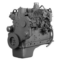
462 pages
5.9 Shop Manual
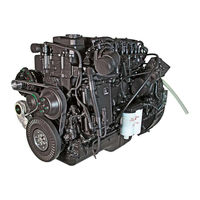
917 pages
ISB Service Manual
253 pages
NTA-855-L4 Maintenance And Operator’s Manual
81 pages
ISB Troubleshooting And Repair Manual
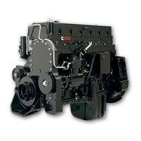
714 pages
K19 Series Troubleshooting And Repair Manual
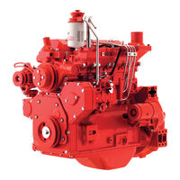
128 pages
B3.3 Service Manual
51 pages
QSB6.7 Service Manual
693 pages
Big Cam III Troubleshooting And Repair Manual
741 pages
B3.9 Service Manual
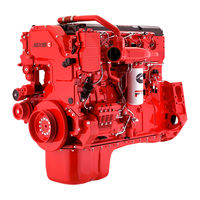
77 pages
ISX15 600 Reference Manual
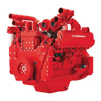
184 pages
QST30 Service Manual
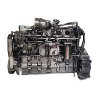
363 pages
QSC8.3 Operation And Maintenance Manual
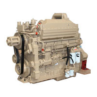
83 pages
NH 855 Shop Manual
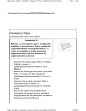
20 pages
Signature ISX Service Manual
355 pages
L10 Series Repair Manual

116 pages
QSB4.5 Owner’s Manual
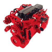
3 pages
ISB Series Quick Reference Manual
30 pages
Signature ISX Service Manual
209 pages
QSX15L Owner’s Manual
4
485ST

Reference Manual
4BT3.9
Shop Manual • Service Manual
5
5.9
Shop Manual
6
6BT5.9
Shop Manual • Service Manual
6IRQ9AE
Operation And Maintenance Manual
B
B Series 1991
Shop Manual
B Series 1994
Shop Manual
B109
Troubleshooting Manual
B112
Troubleshooting Manual
B3.3
Service Manual
B3.9 Series
Service Manual • Installation Manual, Operation And Maintenance Manual
B4.5 RGT
Service Manual
B4.5 Series
Service Manual • Installation Manual, Operation And Maintenance Manual
B5.9 Series
Service Manual • Installation Manual, Operation And Maintenance Manual
Big Cam III
Troubleshooting And Repair Manual
Big Cam IV
Troubleshooting And Repair Manual
C
C100D6C
Operator’s Manual • Operator’s Manual
C125D6C
Operator’s Manual • Operator’s Manual
C50D6C
Operator’s Manual • Operator’s Manual
C60D6C
Operator’s Manual • Operator’s Manual
C80D6C
Operator’s Manual • Operator’s Manual
CELECT L10 Series
Shop Manual
CELECT M11
Troubleshooting And Repair Manual
CELECT Plus M11
Troubleshooting And Repair Manual
CFP11E SERIES
Operation & Maintenance Manual • Operation And Maintenance Manual • Operation And Maintenance Manual • Installation, Operation And Maintenance Manual
CFP15E Series
Operation & Maintenance Manual • Operation & Maintenance Manual • Installation, Operation And Maintenance Manual
CFP15E/EVS
Operation And Maintenance Manual
CFP23E Radiator-cooled Series
Operation And Maintenance Manual
CFP23E/EVS
Operation And Maintenance Manual
CFP30E
Operation And Maintenance Manual
CFP59 F10
Installation, Operation And Maintenance Manual
CFP59 F15
Installation, Operation And Maintenance Manual
CFP59 F20
Installation, Operation And Maintenance Manual
CFP59 F25
Installation, Operation And Maintenance Manual
CFP59 F40
Installation, Operation And Maintenance Manual
CFP59 F50
Installation, Operation And Maintenance Manual
CFP59 Series
Installation, Operation And Maintenance Manual
CFP5E Series
Installation, Operation And Maintenance Manual
CFP5E/EVS
Installation, Operation And Maintenance Manual
CFP60E
Installation, Operation And Maintenance Manual
CFP7E Series
Operation And Maintenance Manual • Operation And Maintenance Manual
CFP7E/EVS
Installation, Operation And Maintenance Manual
CFP7E/EVS F-10
Operation And Maintenance Manual • Operation And Maintenance Manual
CFP7E/EVS F-20
Operation And Maintenance Manual • Operation And Maintenance Manual
CFP7E/EVS F-30
Operation And Maintenance Manual • Operation And Maintenance Manual
CFP7E/EVS F-40
Operation And Maintenance Manual • Operation And Maintenance Manual
CFP7E/EVS F-50
Operation And Maintenance Manual • Operation And Maintenance Manual
CFP7E/EVS F-60
Operation And Maintenance Manual • Operation And Maintenance Manual
CFP83 SERIES
Operation & Maintenance Manual
CFP83-F10
Operation & Maintenance Manual • Installation, Operation And Maintenance Manual
CFP83-F20
Operation & Maintenance Manual • Installation, Operation And Maintenance Manual
CFP83-F30
Operation & Maintenance Manual • Installation, Operation And Maintenance Manual
CFP83-F40
Operation & Maintenance Manual
CFP9E HHP Series
Operation And Maintenance Manual • Installation, Operation And Maintenance Manual
CFP9E SERIES
Operation And Maintenance Manual • Operation & Maintenance Manual
CFP9E/EVS
Installation, Operation And Maintenance Manual
CM2150
Troubleshooting Manual
CM2350
Service Manual • Troubleshooting Manual
CM850
Troubleshooting And Repair Manual
F
Fire Power CFP50
Manual
Fire Power CFP50-F10
Manual
Fire Power CFP50-F20
Manual
Fire Power CFP50-F30
Manual
Fire Power CFP50-F40
Manual
Fire Pump Drive Engines
Operation & Maintenance Manual
FIxed Time L10 Series
Shop Manual
Formula L10-240
Troubleshooting And Repair Manual
Formula L10-270
Troubleshooting And Repair Manual
Formula L10-300
Troubleshooting And Repair Manual
Formula LTA10B-270
Troubleshooting And Repair Manual
I
ISB
Operation And Maintenance Manual • Service Manual • Troubleshooting And Repair Manual
ISB 300
Quick Start Manual
ISB Series
Quick Reference Manual
ISB6.7 CM2350 B101
Quick Reference Manual • Service Manual
ISBE
Service Manual
ISBe2
Troubleshooting And Repair Manual
ISBe3
Troubleshooting And Repair Manual
ISBe4
Troubleshooting And Repair Manual
ISC
Troubleshooting And Repair Manual
ISL
Troubleshooting And Repair Manual
ISL G 250
Reference Manual
ISL G 260
Reference Manual
ISL G 280
Reference Manual
ISL G 300
Reference Manual
ISL G 320
Reference Manual
ISLe3
Troubleshooting And Repair Manual
ISLe4
Troubleshooting And Repair Manual
ISM
Servicing
ISX11.9
Servicing • Manual
ISX12
Manual
ISX12 310
Reference Manual
ISX12 320V
Reference Manual
ISX12 330
Reference Manual
ISX12 330ST
Reference Manual
ISX12 350
Reference Manual
ISX12 350ST
Reference Manual
ISX12 350V
Reference Manual
ISX12 370
Reference Manual
ISX12 385V
Reference Manual
ISX12 400
Reference Manual
ISX12 400ST
Reference Manual
ISX12 400V
Reference Manual
ISX12 425
Reference Manual
ISX12 425ST
Reference Manual
ISX12 425V
Reference Manual
ISX12 450 Series
Reference Manual
ISX12 500 Series
Reference Manual
ISX12 G 320
Reference Manual
ISX12 G 330
Reference Manual
ISX12 G 350
Reference Manual
ISX12 G 385
Reference Manual
ISX12 G 400
Reference Manual
ISX15
Reference Manual • Owner’s Manual • Service Manual
ISX15 400
Reference Manual
ISX15 400ST
Reference Manual
ISX15 425
Reference Manual
ISX15 425ST
Reference Manual
ISX15 450
Reference Manual
ISX15 450ST
Reference Manual
ISX15 455
Reference Manual
ISX15 455V
Reference Manual
ISX15 485
Reference Manual
ISX15 500
Reference Manual
ISX15 500ST
Reference Manual
ISX15 500V
Reference Manual
ISX15 525
Reference Manual
ISX15 550
Reference Manual
ISX15 600
Reference Manual
K
K19 Series
Troubleshooting And Repair Manual
KTA19
Troubleshooting And Repair Manual
KTTA19
Troubleshooting And Repair Manual
L
L10 Series
Repair Manual • Troubleshooting And Repair Manual
L10-300F
Troubleshooting And Repair Manual
L10-320
Troubleshooting And Repair Manual
L11 Series
Repair Manual
LT10-A
Troubleshooting And Repair Manual
LT10-C
Troubleshooting And Repair Manual
LTA10-C
Troubleshooting And Repair Manual
M
M11 Series
Shop Manual • Troubleshooting And Repair Manual
MDKAA
Installation Manual
MDKAB
Installation Manual
MDKAL
Installation Manual
MerCruiser QSD 2.8
Manual
MerCruiser QSD 4.2
Manual
N
N14
Shop Manual • Troubleshooting And Repair Manual
N14 Celect Plus
Shop Manual
N14330E
Shop Manual
NH 855
Shop Manual
NH-250
Operation And Maintenance Manual
NT 855
Shop Manual • Troubleshooting And Repair Manual
NT-335
Operation And Maintenance Manual
NT-380
Operation And Maintenance Manual
NTA-855-L4
Maintenance And Operator’s Manual
NTC-475
Troubleshooting And Repair Manual
P
Power Torque L10-240
Troubleshooting And Repair Manual
Power Torque L10-250
Troubleshooting And Repair Manual
Power Torque L10-270
Troubleshooting And Repair Manual
Power Torque L10-285
Troubleshooting And Repair Manual
Power Torque LTA10B-240
Troubleshooting And Repair Manual
Power Torque LTA10B-270
Troubleshooting And Repair Manual
Power Torque LTA10B-320
Troubleshooting And Repair Manual
Q
QSB
Service Manual
QSB4.5 CM2350 B106
Owner’s Manual • Owner’s Manual • Troubleshooting And Repair Manual
QSB5-G13
Operator’s Manual • Operator’s Manual
QSB5-G5
Operator’s Manual • Operator’s Manual
QSB5-G6
Operator’s Manual • Operator’s Manual
QSB5.9
Troubleshooting And Repair Manual
QSB6.7 CM2250 EC
Owner’s Manual • Owner’s Manual • Troubleshooting And Repair Manual • Service Manual • Troubleshooting Manual • Troubleshooting Manual • Owner’s Manual
QSB6.7 CM2350 B105
Owner’s Manual
QSC8.3
Operation And Maintenance Manual • Troubleshooting And Repair Manual • Owner’s Manual
QSD 2.8 Sterndrive 170 HP
Service Manual
QSD 2.8 Sterndrive 200 HP
Service Manual
QSD 2.8 Sterndrive 230 HP
Service Manual
QSD 4.2 Sterndrive 270 HP
Service Manual
QSD 4.2 Sterndrive 320 HP
Service Manual
QSD 4.2 Sterndrive 350 HP
Service Manual
QSK19
Troubleshooting And Repair Manual • Shop Manual • Troubleshooting And Repair Manual
QSK23 Series
Installation And Mounting Manual
QSK45
Manual
QSL9
Operation And Maintenance Manual • Troubleshooting And Repair Manual • Service Manual • Owner’s Manual
QST30
Service Manual
QSX15 CM2350 X105
Owner’s Manual
QSX15L
Owner’s Manual
QUANTUM K19 Series
Troubleshooting And Repair Manual
R
R2.8 CM2220 R101B
Installation Manual
S
S3.8
Workshop Manual
Signature ISX
Service Manual • Service Manual
Signature QSX15
Service Manual • Service Manual
STC L10 Series
Shop Manual
STC M11
Troubleshooting And Repair Manual
STC N14
Shop Manual • Troubleshooting And Repair Manual
V
V-504
Operation And Maintenance Manual
V-555
Operation And Maintenance Manual
V-903
Operation And Maintenance Manual
V12-500
Operation And Maintenance Manual
V8-300
Operation And Maintenance Manual
VT12-635
Operation And Maintenance Manual
VT12-700
Operation And Maintenance Manual
VT12-800
Operation And Maintenance Manual
VT8-370
Operation And Maintenance Manual
- Автоцентр
- Каталоги
- Cummins
У нас вы всегда можете скачать каталоги деталей двигателей Cummins (Камминз) для автомобилей КАМАЗ. А также скачать руководства по эксплуатации и техническому обслуживанию двигателей Камминз всех серий. Вам так же доступна техническая литература по двигателям сummins.
Каталоги Cummins
- Каталог деталей двигателя Cummins серии ISF2.8
PDF — 8,32 Мб. - Автомобили «КАМАЗ» с двигателями «Cummins» (Камминз)
PDF — 0,41 Мб. - Автомобиль «КАМАЗ» с двигателем «Cummins» (Камминз) серии ISBe
PDF — 0,1 Мб. - Автомобиль «КАМАЗ» с двигателем «Cummins» (Камминз) серии ISLe
PDF — 0,07 Мб. - Автомобиль «КАМАЗ» с двигателем «Cummins» (Камминз) серии ISXe
PDF — 0,04 Мб. - Виды автомобильных двигателей Камминз и их технические характеристики
PDF — 6,78 Мб. - Автомобильные двигатели Камминз серии ISBe 140-300 л.с. — передовые технологии для российских условий
PDF — 2,73 Мб. - Автомобильные двигатели Камминз серии ISBe 140-300 л.с.
PDF — 1,74 Мб. - Двигатель Камминз (Cummins) серии A
PDF — 0,04 Мб. - Двигатель Камминз (Cummins) серии B, EQB
PDF — 0,09 Мб. - Двигатель Камминз (Cummins) серии C GAS Plus
PDF — 0,04 Мб. - Двигатель Камминз (Cummins) серии C
PDF — 0,06 Мб. - Двигатель Камминз (Cummins) серии ISB G
PDF — 0,04 Мб. - Двигатель Камминз (Cummins) серии ISB QSB
PDF — 0,05 Мб. - Двигатель Камминз (Cummins) серии ISBe
PDF — 0,08 Мб. - Двигатель Камминз (Cummins) серии ISF
PDF — 0,05 Мб. - Двигатель Камминз (Cummins) серии ISL G
PDF — 0,04 Мб. - Двигатель Камминз (Cummins) серии ISLe
PDF — 0,07 Мб. - Двигатель Камминз (Cummins) серии ISMe
PDF — 0,05 Мб. - Двигатель Камминз (Cummins) серии ISXе
PDF — 0,04 Мб.
Руководство по эксплуатации и техническому обслуживанию двигателей Камминз
- Руководство по эксплуатации и техническому обслуживанию двигателей Камминз серии QSK45 и QSK60
PDF — 0,61 Мб. - Руководство по эксплуатации и техническому обслуживанию двигателей Камминз серии QSC8.3 и QSL9
PDF — 1,12 Мб. - Руководство по эксплуатации двигателей Камминз серии С
PDF — 1,17 Мб. - Руководство по эксплуатации двигателей Камминз серии В3.9, B4.5 и B5.9
PDF — 1,23 Мб. - Руководство по эксплуатации двигателей Камминз серии QSB4.5 и QSB6.7
PDF — 1,25 Мб. - Руководство по эксплуатации двигателей Камминз серии ISLe3 и ISLe4 common rail
PDF — 1,51 Мб. - Руководство по эксплуатации двигателей Камминз серии ISC, ISLе и ISL
PDF — 1,35 Мб. - Руководство по эксплуатации двигателей Камминз серии ISBe и ISB
PDF — 1,47 Мб.
Техническая литература
- Гарантийные обязательства Cummins Filtration
PDF — 0,35 Мб. - Гарантия Cummins Filtration
PDF — 0,26 Мб. - Моторное масло Valvoline Premium Blue E одобренное фирмой Камминз
PDF — 0,23 Мб. - О компании Cummins_brochure_en
PDF — 1,55 Мб. - Обновленние фильтров Fleetguard_en
PDF — 0,05 Мб. - Определение оригинальной и контрофактной продукции
PDF — 0,61 Мб. - Применяемость фильтров Fleetguard_en
PDF — 0,61 Мб. - Рекомендации фирмы Камминз по применению и анализу моторных масел
PDF — 0,31 Мб. - Технические требования фирмы Камминз к охлождающей жидкости и обслуживанию систем охлаждения
PDF — 0,48 Мб. - Фильтрующие элементы Elemaх, StrataPore
PDF — 0,46 Мб.
Брошюры на английском
- seria A_brochure_en
PDF — 0,98 Мб. - seria B3.3_brochure_en
PDF — 1,48 Мб. - seria C_brochure_en
PDF — 0,58 Мб. - seria ISL_brochure_en
PDF — 0,58 Мб. - seria QSB_brochure_en
PDF — 0,3 Мб. - seria QSC, ISC_brochure_en
PDF — 0,68 Мб. - seria QSL_brochure_en
PDF — 0,26 Мб.
Запчасти
Двигатели Cummins, Запчасти, Корейские запчасти, Двигатель, Автобус, Экскаватор, Спецтехника, Hyundai Robex, Daewoo-Doosan, Volvo, Samsung MX, MX132, MX202, MX8, MX6, Robex1300, Robex130, Robex2000, Cummins b3.9, Cummins 4BT, Cummins b5.9, Cummins 6BT, Cummins isf2.8, Cummins isf3.8, Cummins 4isbe, Cummins 6isbe, Cummins M11, Cummins KTA19, Cummins qsb6.7, Cummins EQB5.9, Cummins 6isl8.9, Cummins NT855, Cummins LTA10, Грузовик, Автозапчасти, МКПП, Коробка передач, Раздатка, Прокладка, Стартер, Двигатель, Запчасти, Карданный вал, Мост, Редуктор, Поршня, Гильза, Кольца, Коленвал, Шатун, Гидроцилиндр, ТНВД, Форсунка, Радиатор, Сальник, Амортизатор, Фильтр, Топливный, Масляный, Воздушный, Коронки, Зубы, Ремкомплект, ДВС, Насос, ГУР, Подрезы, Выжимной, Подшипник, Корзина, Сцепления, Диск, Сцепление, Коробка Передач, Поршень, Средний, мост, Шкворень, Шкворня, Сайлентблок, Сальник, Рулевая, Колонка, Кардан, Амортизатор, Рессора, Рессорный Лист, Поросёнок, Вкладыши, Коренные, Шатунные, Турбина, Компрессор, ПГУ, Подушка, Палец, МКПП, Тормоз, Ступица, Шестерня, Колодки, Тормозные, Накладка, Hyndai, Daewoo, Samsung, Doosan, Cosmos, KIA, Aero City, Aero Space, GRANBIRD, GRANTO, Aero Town, Transtar, ULTRA, Самсунг, ASIA, AM 937, Хундай, L6, L7, LX, ДЭУ, Гранбёрд, КИЯ, Аэротаун, АэроСити, 6BT, 4BT, Корея, 6BT 5.9, Каминз, Каминс, Камминз, Cummins, Cumins, 4BT 3.9, EF750, F17E, D1146, DE12, dv15, DE08TIS, DV11, D6BR, D6AU, D6AV, H07C, D6AB, D6AC, D6CA, D6CB, D6DA, D2366, D8AY, D8AB, DC23, JT, VM39, Am 948, BS 106, BM 090, BH 115, BH 117, BH 120, D8AB
Срочная Доставка во все города России, Казахстана
Абакан, Алмата, Альметьевск, Армавир, Архангельск, Астрахань, Ачинск, Байкальск, Балаково, Барнаул, Белгород, Белогорск, Березники, Бийск, Биробиджан, Благовещенск, Бодайбо, Братск, Брянск, Великий Новгород, Вихоревка, Владивосток, Владимир, Волгоград, Волжский, Вологда, Воронеж, Глазов, Екатеринбург, Иваново, Ижевск, Иркутск, Йошкар-Ола, Железногорск-Илимский, Зима, Казань, Калуга, Канск, Кемерово, Киров, Комсомольск-на-Амуре, Кострома, Краснодар, Красноярск, Курган, Курск, Липецк, Магадан, Магистральный, Магнитогорск, Махачкала, Миасс, Москва, Мурманск, Набережные, Челны, Находка, Нерюнгри, Нефтекамск, Нижневартовск, Нижнеудинск, Нижний Новгород, Нижний Тагил, Новая Игирма, Новокузнецк, Новороссийск, Новосибирск, Новый Уренгой, Ноябрьск, Омск, Орел, Оренбург, Орск, Пенза, Пермь, Петрозаводск, Петропавловск-Камчатский, Псков, Пятигорск, Ростов-на-Дону, Рубцовск, Рязань, Самара, Санкт-Петербург, Саранск, Саратов, Саянск, Слюдянка, Смоленск, Сочи, Ставрополь, Стерлитамак, Сургут, Сыктывкар, Таганрог, Тайшеь, Тамбов, Тверь, Тольятти, Томск, Тула, Тулун, Тюмень, Улан-Удэ, Улькан, Ульяновск, Усть-Илимск, Усть-Кут, Уфа, Хабаровск, Ханты-Мансийск, Чайковский, Чебоксары, Челябинск, Черемхово, Череповец, Чита, Чунский, Южно-Сахалинск, Якутск, Ярославль, Алупка, Алушта, Армянск, Бахчисарай, Белогорск, Джанкой, Евпатория, Инкерман, Керчь, Красноперекопск, Саки, Севастополь, Симферополь, Старый Крым, Судак, Феодосия, Щёлкино, Ялта

1,54 Мб
Каталог запчастей автобусов Tata LP/LPO 1512C
Формат: pdf
-
Год:
2006
-
Страниц:
426
-
Язык:
английский
-
Размер:
1,54 Мб
-
Категории:
Двигатели Cummins

19,1 Мб
Бульдозеры Shantui SD22, SD22E, SD22S, SD22D: Руководство
Формат: pdf
-
Год:
2012
-
Страниц:
313
-
Язык:
русский
-
Размер:
19,1 Мб
-
Категории:
Двигатели Cummins
18,5 Мб
Каталог запчастей двигателей Cummins NT/NTA855
Формат: pdf
-
Год:
2008
-
Страниц:
129
-
Язык:
английский, китайский
-
Размер:
18,5 Мб
-
Категории:
Двигатели Cummins
9,06 Мб
Каталог запчастей экскаваторов Komatsu PC200-7, PC200LC-7,
Формат: pdf
-
Год:
2004
-
Страниц:
536
-
Язык:
английский
-
Размер:
9,06 Мб
-
Категории:
Двигатели Cummins

12,1 Мб
Руководство по эксплуатации тракторов Versatile 435, 485,
Формат: pdf
-
Год:
2009
-
Страниц:
250
-
Язык:
русский
-
Размер:
12,1 Мб
-
Категории:
Двигатели Cummins

4,88 Мб
Руководство по эксплуатации карьерных самосвалов БелАЗ-7530
Формат: pdf
-
Год:
2015
-
Страниц:
198
-
Язык:
русский
-
Размер:
4,88 Мб
-
Категории:
Двигатели Cummins

9,47 Мб
Руководство по эксплуатации БелАЗ-7547 и его модификаций
Формат: pdf
-
Год:
2007
-
Страниц:
276
-
Язык:
русский
-
Размер:
9,47 Мб
-
Категории:
Двигатели Cummins

5,5 Мб
Руководство по ремонту БелАЗ-75131 и его модификаций
Формат: pdf
-
Год:
2007
-
Страниц:
208
-
Язык:
русский
-
Размер:
5,5 Мб
-
Категории:
Двигатели Cummins
8,92 Мб
Руководство по эксплуатации мини-погрузчиков КМЗ МКСМ-800Н,
Формат: pdf
-
Год:
2007
-
Страниц:
291
-
Язык:
русский
-
Размер:
8,92 Мб
-
Категории:
Двигатели Cummins
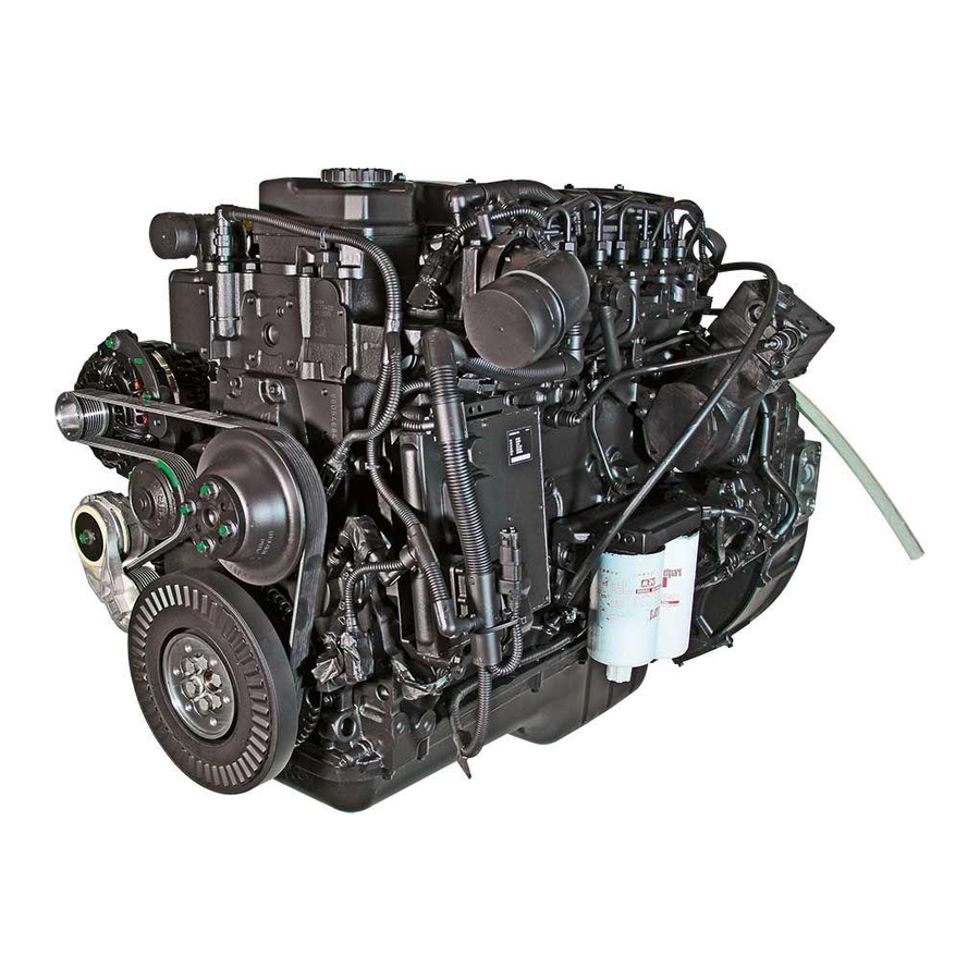
-
Contents
-
Table of Contents
-
Troubleshooting
-
Bookmarks
Related Manuals for CUMMINS ISB
Summary of Contents for CUMMINS ISB
-
Page 1
Service Manual , ISB, and QSB (Common Rail Fuel System) Volume 1… -
Page 2
Service Manual , ISB, and QSB (Common Rail Fuel System) Volume 1 Copyright© 2014 Bulletin 4021271 Cummins Inc. Printed 29-OCTOBER-2014 All rights reserved To buy Cummins Parts and Service Manuals, Training Guides, or Tools go to our website at https://store.cummins.com… -
Page 3
The specifications and rebuild information in this manual are based on the information in effect at the time of printing. Cummins Inc. reserves the right to make any changes at any time without obligation. If differences are found between your engine and the information in this manual, contact a Cummins Authorized Repair Location or call 1-800-DIESELS (1-800-343-7357) toll free in the U.S. -
Page 4
Cylinder Block — Group 01 ……………………..Cylinder Head — Group 02 ……………………..Rocker Levers — Group 03 ……………………..Cam Followers/Tappets — Group 04 ……………………. Back …………………………….back To buy Cummins Parts and Service Manuals, Training Guides, or Tools go to our website at https://store.cummins.com… -
Page 5
To buy Cummins Parts and Service Manuals, Training Guides, or Tools go to our website at https://store.cummins.com… -
Page 6: Table Of Contents
General Safety Instructions ……………………….i-8 Important Safety Notice………………………….i-8 How to Use the Manual …………………………i-2 General Information…………………………i-2 Illustrations ……………………………..i-7 General Information…………………………i-7 Symbols …………………………….i-3 General Information…………………………i-3 To buy Cummins Parts and Service Manuals, Training Guides, or Tools go to our website at https://store.cummins.com…
-
Page 7
ISB, ISBe and QSB (Common Rail […] Page i-b Section i — Introduction This Page Left Intentionally Blank… -
Page 8: About The Manual
Additionally the manual is intended to aid mechanics in disassembly, inspecting parts for reuse, rebuilding and assembly of components. The manual is divided into sections. Each section is equivalent to a group used in Cummins’ filmcard system. Some sections contain reference numbers and procedure numbers. Reference numbers provide general information, specifications, diagrams, and service tools where applicable.
-
Page 9: How To Use The Manual
How to Use the Manual General Information This manual is divided into the same group system used for previous manuals and the Cummins’ filmcard system. Section 00 is organized into a logical sequence of engine disassemble/assemble, all other sections are in numerical sequence.
-
Page 10: Symbols
Minor personal injury can result or a part, and assembly, or the engine can be damaged if the caution instructions are not followed. Indicates a REMOVAL or Dissassembly step. To buy Cummins Parts and Service Manuals, Training Guides, or Tools go to our website at https://store.cummins.com…
-
Page 11
Section i — Introduction Indicates an INSTALLATION or ASSEMBLY step. INSPECTION is required. CLEAN the part or assembly. PERFORM a mechanical or time MEASUREMENT. To buy Cummins Parts and Service Manuals, Training Guides, or Tools go to our website at https://store.cummins.com… -
Page 12
LUBRICATE the part or assembly. Indicates that a WRENCH or TOOL SIZE will be given. TIGHTEN to a specific torque. PERFORM an electrical MEASUREMENT. To buy Cummins Parts and Service Manuals, Training Guides, or Tools go to our website at https://store.cummins.com… -
Page 13
The component weighs 23kg [50 lbs] or more. To reduce the possibility of personal injury, use a hoist or get assistance to lift the component. To buy Cummins Parts and Service Manuals, Training Guides, or Tools go to our website at https://store.cummins.com… -
Page 14: Illustrations
The illustrations are intended to show repair or replacement procedures. The procedure will be the same for all applications, although the illustration can differ. To buy Cummins Parts and Service Manuals, Training Guides, or Tools go to our website at https://store.cummins.com…
-
Page 15: General Safety Instructions
All fasteners must be replaced on re-fitting the guards. • Do not perform any repair when fatigued or after consuming alcohol or drugs that can impair your functioning. To buy Cummins Parts and Service Manuals, Training Guides, or Tools go to our website at https://store.cummins.com…
-
Page 16
California Proposition 65 Warning — Diesel engine exhaust and some of its constituents are known to the State of California to cause cancer, birth defects, and other reproductive harm. To buy Cummins Parts and Service Manuals, Training Guides, or Tools go to our website at https://store.cummins.com… -
Page 17: General Repair Instructions
• Perform the inspections specified in the procedures • Replace all components or assemblies which are damaged or worn beyond the specifications To buy Cummins Parts and Service Manuals, Training Guides, or Tools go to our website at https://store.cummins.com…
-
Page 18: Welding On A Vehicle With An Electronic Controlled Fuel System
The assembly instructions have been written to use again as many components and assemblies as possible. When it is necessary to replace a component or assembly, the procedure is based on the use of new Cummins or Cummins ReCon® components. All of the repair services described in this manual are available from all Cummins Distributors and most Dealer locations.
-
Page 19: General Cleaning Instructions
Cummins Inc. does not recommend sanding or grinding the carbon ring at the top of cylinder liners until clean metal is visible. The liner will be ruined and any signs of a problem at the top ring reversal point (like a dust-out) will be destroyed.
-
Page 20: Gasket Surfaces
The object of cleaning gasket surfaces is to remove any gasket material, not refinish the gasket surface of the part. Cummins Inc. does not recommend any specific brand of liquid gasket remover. If a liquid gasket remover is used, check the directions to make sure the material being cleaned will not be harmed.
-
Page 21: Plastic Bead Cleaning
Plastic Bead Cleaning Cummins Inc. does not recommend the use of glass bead blast or walnut shell media on any engine part. Cummins Inc. recommends using only plastic bead media, Part Number 3822735 or equivalent on any engine part. Never use sand as a blast media to clean engine parts.
-
Page 22: Fuel System
Cummins Inc. now recommends glass bead media NOT used to clean any engine parts. Glass media is too easily embedded into the material particularly in soft materials and when air pressures greater than media manufacturer’s recommend are used.
-
Page 23
Clean and dry the tools before returning them to the tool box. • If possible, store fuel system tools in sealed containers. • Make sure fuel system tools are clean before use. To buy Cummins Parts and Service Manuals, Training Guides, or Tools go to our website at https://store.cummins.com… -
Page 24: Acronyms And Abbreviations
Liquified Petroleum Gas Low Temperature Aftercooling MCRS Modular Common Rail System Malfunction Indicator Lamp Megapascal Miles Per Hour Miles Per Quart N•m Newton-meter To buy Cummins Parts and Service Manuals, Training Guides, or Tools go to our website at https://store.cummins.com…
-
Page 25
Selective Catalytic Reduction Step Timing Control Subsystem Identification Descriptions Top Dead Center Volts of Direct Current Variable Geometry Turbocharger Variable Speed Vehicle Speed Sensor To buy Cummins Parts and Service Manuals, Training Guides, or Tools go to our website at https://store.cummins.com… -
Page 26
Cummins® Service Engine Model Product Identification ………………E-45 General Information…………………………E-45 Engine Diagrams …………………………..E-6 Engine Views…………………………..E-6 Engine Identification …………………………E-1 Cummins® Engine Nomenclature……………………..E-3 ECM Dataplate…………………………..E-4 Engine Dataplate…………………………..E-1 Fuel Injection Pump Dataplate………………………E-4 To buy Cummins Parts and Service Manuals, Training Guides, or Tools go to our website at https://store.cummins.com… -
Page 27
ISB, ISBe and QSB (Common Rail […] Page E-b Section E — Engine and System Identification This Page Left Intentionally Blank… -
Page 28: Engine Identification
1 Engine serial number 2 Control parts list (CPL) 3 Model 4 Horsepower and rpm rating. To buy Cummins Parts and Service Manuals, Training Guides, or Tools go to our website at https://store.cummins.com…
-
Page 29
(CPL) provide information for service and for ordering parts. The engine dataplate must not be changed unless approved be changed unless approved by Cummins Inc. To buy Cummins Parts and Service Manuals, Training Guides, or Tools go to our website at https://store.cummins.com… -
Page 30
Marine Applications The Cummins MerCruiser Diesel engine nomenclature provides the engine model, displacement in liters and horsepower rating. To buy Cummins Parts and Service Manuals, Training Guides, or Tools go to our website at https://store.cummins.com… -
Page 31: Fuel Injection Pump Dataplate
NOTE: The presence of an ECM dataplate depends on the manufacturing plant andthe date the engine was manufactured. If an ECM dataplate was not installed by the manufacturing plant, calibration data can be found on the engine dataplate. To buy Cummins Parts and Service Manuals, Training Guides, or Tools go to our website at https://store.cummins.com…
-
Page 32
If an ECM dataplate was not installed by the manufacturing plant, calibration data can be found on the engine dataplate. To buy Cummins Parts and Service Manuals, Training Guides, or Tools go to our website at https://store.cummins.com… -
Page 33: Engine Views
Some external components will be at different locations for different engine models. NOTE: The illustrations are only a reference to show a typical engine. To buy Cummins Parts and Service Manuals, Training Guides, or Tools go to our website at https://store.cummins.com…
-
Page 34
15 Ambient air pressure sensor (internal to ECM) 16 Fuel inlet to cooling plate 17 Air intake inlet 18 Coolant outlet 19 Rail pressure sensor 20 Fuel rail. To buy Cummins Parts and Service Manuals, Training Guides, or Tools go to our website at https://store.cummins.com… -
Page 35
15 Ambient air pressure sensor (internal to ECM) 16 Fuel inlet to cooling plate 17 Air intake inlet 18 Coolant outlet 19 Rail pressure sensor 20 Fuel rail. To buy Cummins Parts and Service Manuals, Training Guides, or Tools go to our website at https://store.cummins.com… -
Page 36
8 Fan or PTO drive flange mounting 9 Starter 10 Water pump 11 Coolant inlet 12 Belt tensioner 13 Alternator 14 Coolant outlet 15 Coolant temperature sensor. To buy Cummins Parts and Service Manuals, Training Guides, or Tools go to our website at https://store.cummins.com… -
Page 37
8 Fan or PTO drive flange mounting 9 Starter 10 Water pump 11 Coolant inlet 12 Belt tensioner 13 Alternator 14 Coolant outlet 15 Coolant temperature sensor. To buy Cummins Parts and Service Manuals, Training Guides, or Tools go to our website at https://store.cummins.com… -
Page 38
2 Air outlet from turbocharger 3 Air inlet to turbocharger 4 Flywheel 5 Flywheel housing 6 Crankcase breather tube 7 Fuel return line 8 Engine lifting brackets. To buy Cummins Parts and Service Manuals, Training Guides, or Tools go to our website at https://store.cummins.com… -
Page 39
2 Air outlet from turbocharger 3 Air inlet to turbocharger 4 Flywheel 5 Flywheel housing 6 Crankcase breather tube 7 Fuel return line 8 Engine lifting brackets. To buy Cummins Parts and Service Manuals, Training Guides, or Tools go to our website at https://store.cummins.com… -
Page 40
4 Coolant inlet 5 Oil filter 6 Oil pan drain plug 7 Turbocharger exhaust outlet 8 Starter 9 Flywheel housing 10 Turbocharger compressor inlet. To buy Cummins Parts and Service Manuals, Training Guides, or Tools go to our website at https://store.cummins.com… -
Page 41
4 Coolant inlet 5 Oil filter 6 Oil pan drain plug 7 Turbocharger exhaust outlet 8 Starter 9 Flywheel housing 10 Turbocharger compressor inlet. To buy Cummins Parts and Service Manuals, Training Guides, or Tools go to our website at https://store.cummins.com… -
Page 42
12 Engine speed sensor (crankshaft) 13 Tone wheel 14 Coolant temperature sensor 15 Vibration damper 16 Coolant outlet 17 Alternator 18 Oil pressure/temperature sensor 19 Exhaust manifold. To buy Cummins Parts and Service Manuals, Training Guides, or Tools go to our website at https://store.cummins.com… -
Page 43
12 Engine speed sensor (crankshaft) 13 Tone wheel 14 Vibration damper 15 Coolant temperature sensor 16 Coolant outlet 17 Alternator 18 Oil pressure/temperature sensor 19 Exhaust manifold. To buy Cummins Parts and Service Manuals, Training Guides, or Tools go to our website at https://store.cummins.com… -
Page 44
9 Engine speed sensor (crankshaft) 10 Electronic control module (ECM) 11 Engine position sensor (camshaft) 12 Air intake inlet 13 Rail pressure sensor 14 Dipstick To buy Cummins Parts and Service Manuals, Training Guides, or Tools go to our website at https://store.cummins.com… -
Page 45
7 Vibration damper 8 Water pump 9 Starter 10 Belt tensioner 11 Alternator 12 Coolant outlet 13 Coolant temperature sensor 14 Turbocharger air outlet To buy Cummins Parts and Service Manuals, Training Guides, or Tools go to our website at https://store.cummins.com… -
Page 46
1 Rear engine lifting bracket 2 Turbocharger exhaust outlet 3 Clutch mounting holes 4 Flywheel housing 5 Flywheel/flexplate 6 Crankcase breather tube 7 Injector drain line To buy Cummins Parts and Service Manuals, Training Guides, or Tools go to our website at https://store.cummins.com… -
Page 47
4 Lubricating oil cooler 5 Oil filter 6 Oil pan drain plug 7 Turbocharger exhaust outlet 8 Starter 9 Flywheel housing 10 Turbocharger compressor inlet. To buy Cummins Parts and Service Manuals, Training Guides, or Tools go to our website at https://store.cummins.com… -
Page 48
8 Tone wheel 9 Vibration damper 10 Coolant temperature sensor 11 Coolant outlet 12 Alternator 13 Exhaust manifold 14 Rail pressure relief valve To buy Cummins Parts and Service Manuals, Training Guides, or Tools go to our website at https://store.cummins.com… -
Page 49
12 Dipstick/oil level sensor 13 Electronic control module (ECM) 14 Air intake inlet 15 Coolant outlet 16 Fuel rail pressure relief valve 17 Fuel rail. To buy Cummins Parts and Service Manuals, Training Guides, or Tools go to our website at https://store.cummins.com… -
Page 50
7 Fan or PTO drive flange mounting 8 Starter mounting location 9 Coolant inlet 10 Water pump 11 Belt tensioner 12 Alternator 13 Coolant outlet 14 Coolant temperature sensor. To buy Cummins Parts and Service Manuals, Training Guides, or Tools go to our website at https://store.cummins.com… -
Page 51
2 Air outlet from turbocharger 3 Air inlet to turbocharger 4 Flywheel 5 Flywheel housing 6 Crankcase breather tube 7 Fuel return line 8 Engine lifting brackets. To buy Cummins Parts and Service Manuals, Training Guides, or Tools go to our website at https://store.cummins.com… -
Page 52
4 Coolant inlet 5 Oil filter 6 Oil pan drain plug 7 Turbocharger exhaust outlet 8 Starter 9 Flywheel housing 10 Turbocharger compressor inlet. To buy Cummins Parts and Service Manuals, Training Guides, or Tools go to our website at https://store.cummins.com… -
Page 53
9 High-pressure fuel lines 10 Oil fill cap 11 Tone wheel 12 Coolant temperature sensor 13 Vibration damper (Optional) 14 Coolant outlet 15 Exhaust manifold. To buy Cummins Parts and Service Manuals, Training Guides, or Tools go to our website at https://store.cummins.com… -
Page 54
16 Electronic control module (ECM) 17 Engine speed sensor (camshaft) 18 Air intake inlet 19 EGR temperature sensor 20 Fuel heater 21 Rail pressure sensor. To buy Cummins Parts and Service Manuals, Training Guides, or Tools go to our website at https://store.cummins.com… -
Page 55
14 Starter 15 Coolant inlet 16 Belt tensioner 17 Water pump 18 Freon compressor 19 Alternator 20 Coolant outlet 21 Coolant temperature sensor. To buy Cummins Parts and Service Manuals, Training Guides, or Tools go to our website at https://store.cummins.com… -
Page 56
7 Flywheel 8 Gear housing 9 Crankcase breather 10 Fuel out (return to tank) 11 Coolant connection for air compressor 12 Fuel return line. To buy Cummins Parts and Service Manuals, Training Guides, or Tools go to our website at https://store.cummins.com… -
Page 57
12 Turbocharger speed sensor 13 Turbocharger exhaust outlet 14 Starter 15 Flywheel housing 16 Gear housing 17 EGR cooler 18 EGR valve 19 EGR actuator. To buy Cummins Parts and Service Manuals, Training Guides, or Tools go to our website at https://store.cummins.com… -
Page 58
13 EGR differential pressure sensor 14 Tone wheel 15 Vibration damper 16 Oil fill cap 17 Coolant temperature sensor 18 Coolant outlet 19 Alternator 20 Oil filter. To buy Cummins Parts and Service Manuals, Training Guides, or Tools go to our website at https://store.cummins.com… -
Page 59
Engine Diagrams ISB, ISBe and QSB (Common Rail […] Page E-32 Section E — Engine and System Identification To buy Cummins Parts and Service Manuals, Training Guides, or Tools go to our website at https://store.cummins.com… -
Page 60
10 Mounting brackets 11 Oil pan 12 Lubricating oil drain 13 Belt and pulley guards 14 Lubricating oil filter 15 Lubricating oil filter head inlet. To buy Cummins Parts and Service Manuals, Training Guides, or Tools go to our website at https://store.cummins.com… -
Page 61
19 Fuel return from high pressure fuel pump 20 Crankshaft speed sensor 21 Camshaft speed sensor 22 Oil pressure sensor 23 Fuel pump 24 Fuel cooler 25 Sea water pump. To buy Cummins Parts and Service Manuals, Training Guides, or Tools go to our website at https://store.cummins.com… -
Page 62
18 Closed crankcase breather oil drain line 19 Flywheel housing 20 Heat exchanger engine coolant outlet 21 Heat exchanger sea water inlet 22 Marine gear oil cooler 23 Turbocharger To buy Cummins Parts and Service Manuals, Training Guides, or Tools go to our website at https://store.cummins.com… -
Page 63
9 Flywheel housing 10 Flywheel 11 Aftercooler air inlet 12 Aftercooler zinc anode 13 Marine gear oil cooler 14 Air cleaner and filter. To buy Cummins Parts and Service Manuals, Training Guides, or Tools go to our website at https://store.cummins.com… -
Page 64
18 Exhaust outlet connection 19 Closed crankcase breather blow-by connection 20 Air inlet restriction indicator 21 Air cleaner connection 22 Closed crankcase breather/air cleaner assembly To buy Cummins Parts and Service Manuals, Training Guides, or Tools go to our website at https://store.cummins.com… -
Page 65
4 Exhaust elbow 5 Tailstock assembly 6 Driveshaft 7 Trim cylinder zinc anode 8 Ventilation plate zinc anode 9 Sterndrive™ 10 Trim cylinder. To buy Cummins Parts and Service Manuals, Training Guides, or Tools go to our website at https://store.cummins.com… -
Page 66
4 Bearing support assembly 5 Tailstock assembly 6 Driveshaft 7 Trim cylinder 8 Ventilation plate zinc anode (bottom of ventilation plate) 9 Trim cylinder zinc anode. To buy Cummins Parts and Service Manuals, Training Guides, or Tools go to our website at https://store.cummins.com… -
Page 67
5 Gear oil drain plug 6 Sea water outlet valve 7 Transmission drain 8 Steering and transmission oil cooler 9 Exhaust outlet connection. To buy Cummins Parts and Service Manuals, Training Guides, or Tools go to our website at https://store.cummins.com… -
Page 68
6 Propeller shaft 7 Drive skeg 8 Gear housing 9 Sea water inlet and seacock 10 Drive shaft (under shield) 11 Drive shaft shield. To buy Cummins Parts and Service Manuals, Training Guides, or Tools go to our website at https://store.cummins.com… -
Page 69
Section E — Engine and System Identification Zeus™ 3500 (Top View) 1 Transmission dipstick 2 Steering and transmission fluid reservoir fill 3 Transmission filter. To buy Cummins Parts and Service Manuals, Training Guides, or Tools go to our website at https://store.cummins.com… -
Page 70
Engine Diagrams Section E — Engine and System Identification Page E-43 Zeus™ 3500 Drop Box (Starboard View) 1 Exhaust riser 2 Transmission drop box. To buy Cummins Parts and Service Manuals, Training Guides, or Tools go to our website at https://store.cummins.com… -
Page 71
ISB, ISBe and QSB (Common Rail […] Page E-44 Section E — Engine and System Identification Zeus™ 3500 Drop Box (Port View) 1 Drop box drain plug To buy Cummins Parts and Service Manuals, Training Guides, or Tools go to our website at https://store.cummins.com… -
Page 72
If the engine operates on a fuel type other than diesel, the type will be identified after the liter size. To buy Cummins Parts and Service Manuals, Training Guides, or Tools go to our website at https://store.cummins.com… -
Page 73
Example: 1 On-Highway automotive «X» 15 liter engine 2 Control system number 871 3 Technology supported; Electric EGR and Diesel Particulate Filter To buy Cummins Parts and Service Manuals, Training Guides, or Tools go to our website at https://store.cummins.com… -
Page 74
Modular Common Rail System Used only on QSK19, 38, 50 , 60 MCRS HHP Engines Integrated Dosing Control Unit Not Used None Integrated To buy Cummins Parts and Service Manuals, Training Guides, or Tools go to our website at https://store.cummins.com… -
Page 75
Cummins® Service Engine Model Product Identification ISB, ISBe and QSB (Common Rail […] Page E-48 Section E — Engine and System Identification Notes… -
Page 76
Fuel System — Overview ………………………..F-6 General Information…………………………F-6 Injectors and Fuel Lines — Overview ……………………F-14 General Information…………………………F-14 Lubricating Oil System — Overview …………………….F-16 General Information…………………………F-16 To buy Cummins Parts and Service Manuals, Training Guides, or Tools go to our website at https://store.cummins.com… -
Page 77
ISB, ISBe and QSB (Common Rail […] Page F-b Section F — Familiarization This Page Left Intentionally Blank… -
Page 78
General Information Connecting Rods This familiarization section helps to identify and orient the various styles of ISB connecting rods for installation. These details are important because some connecting rods are not marked with a part number and identification can be difficult. -
Page 79
ISB 4.5, ISB 6.7 Connecting Rod Joint: Machined Cylinder Bore: 107 mm [4.212 in] Cylinder Stroke: 124 mm [4.881 in] Orientation: Through hole toward camshaft To buy Cummins Parts and Service Manuals, Training Guides, or Tools go to our website at https://store.cummins.com… -
Page 80
ISB 4.5, ISB 6.7 Connecting Rod Joint: Fractured Cylinder Bore: 107 mm [4.212 in] Cylinder Stroke: 124 mm [4.881 in] Orientation: Blind hole toward camshaft To buy Cummins Parts and Service Manuals, Training Guides, or Tools go to our website at https://store.cummins.com… -
Page 81
Use the following illustrations to identify 3.9 Liter, 4.5 Liter, 5.9 Liter, and 6.7 Liter (6 cylinder) connecting rods. Note: Lead-free bushings (10) Part Numbers 4983518 and 5257363 are not serviceable. Connecting Rod Characteristics 1 Balancer 2 Machined surface To buy Cummins Parts and Service Manuals, Training Guides, or Tools go to our website at https://store.cummins.com… -
Page 82
9 Oil grooves in leaded bushing Part Number 4891178 5 Smooth 10 Oil grooves in lead-free bushings Part Numbers 4983518/5257363. (These bushings 6 Single dimple serviceable) 7 Three dimple To buy Cummins Parts and Service Manuals, Training Guides, or Tools go to our website at https://store.cummins.com… -
Page 83
The fuel that enters the high-pressure fuel pump is pressurized between 250 and 1800 bar [3626 to 26107 psi] by three radial pumping chambers. An M-Prop valve, or electronic fuel control (EFC) valve, at the inlet to the three radial To buy Cummins Parts and Service Manuals, Training Guides, or Tools go to our website at https://store.cummins.com… -
Page 84
Exceeding the maximum capacity will cause the gauge to read incorrectly. If the maximum is exceeded, check the gauge against a reference gauge. To buy Cummins Parts and Service Manuals, Training Guides, or Tools go to our website at https://store.cummins.com… -
Page 85
NOTE: Always use the same size and material of line or hoses that were originally supplied with the gauge. To buy Cummins Parts and Service Manuals, Training Guides, or Tools go to our website at https://store.cummins.com… -
Page 86
Tools required to troubleshoot the common rail system include: • M10 Compuchek® fittings • Orificed diagnostic fuel line, 0.043 mm [.002 in] To buy Cummins Parts and Service Manuals, Training Guides, or Tools go to our website at https://store.cummins.com… -
Page 87
Maximum high pressure pump leakage 300 cc [.32 quart] per 30 seconds @ 1500 rpm 300 cc [.32 quart] per 30 seconds @ cranking To buy Cummins Parts and Service Manuals, Training Guides, or Tools go to our website at https://store.cummins.com… -
Page 88
NOTE: * Engines are either equipped with an air cooled or fuel cooled ECM. If an air cooled ECM is used, the fuel enters the engine from the OEM connection at the gear pump inlet. To buy Cummins Parts and Service Manuals, Training Guides, or Tools go to our website at https://store.cummins.com… -
Page 89
14 High-pressure connector to fuel injector 15 Fuel injector 16 Injector return line 17 Pressure relief return line 18 Fuel pump return line 19 Fuel return manifold. To buy Cummins Parts and Service Manuals, Training Guides, or Tools go to our website at https://store.cummins.com… -
Page 90
18 Injector return line 19 Fuel pump to fuel manifold return 20 Fuel manifold to fuel cooler 21 Fuel cooler 22 Fuel return to tank. To buy Cummins Parts and Service Manuals, Training Guides, or Tools go to our website at https://store.cummins.com… -
Page 91
NOTE: The edge filters are not a substitute for cleaning and covering all fuel system connections during repair. Edge filters are not a substitute for maintaining the recommended engine mounted fuel filter. To buy Cummins Parts and Service Manuals, Training Guides, or Tools go to our website at https://store.cummins.com… -
Page 92
Exceeding the maximum capacity will cause the gauge to read incorrectly. If the maximum is exceeded, check the gauge against a reference gauge. To buy Cummins Parts and Service Manuals, Training Guides, or Tools go to our website at https://store.cummins.com… -
Page 93
This is due to the fact that all B series engines use sliding tappets. NOTE: If CI/SK oils are not available, see the appropriate Operation and Maintenance manual for your engine for alternatives. To buy Cummins Parts and Service Manuals, Training Guides, or Tools go to our website at https://store.cummins.com… -
Page 94
When the diagnosing lubricating system malfunctions, check all obvious items related to oil pressure, such as gauges, high level, excessive contamination, and oil viscosity. To buy Cummins Parts and Service Manuals, Training Guides, or Tools go to our website at https://store.cummins.com… -
Page 95
To buy Cummins Parts and Service Manuals, Training Guides, or Tools go to our website at https://store.cummins.com… -
Page 96
The engine will have low pressure or no oil pressure during starting, followed by normal oil pressure. To buy Cummins Parts and Service Manuals, Training Guides, or Tools go to our website at https://store.cummins.com… -
Page 97
Coolant in the oil can be caused by: • Expansion plugs leaking • Oil cooler element leaking • Damaged cylinder head or gasket • Cracked engine block • Casting porosity. To buy Cummins Parts and Service Manuals, Training Guides, or Tools go to our website at https://store.cummins.com… -
Page 98
Lubricating oil drain plug. Refer to Procedure Procedure 007-037. Leaks indicate defective oil cooler, cylinder head gasket, or cracked cylinder head or block. To buy Cummins Parts and Service Manuals, Training Guides, or Tools go to our website at https://store.cummins.com… -
Page 99
An injector leak will also cause the engine to run rough and have low power. Remove and repair, or replace leaking injectors. Refer to Procedure Procedure 006-026 To buy Cummins Parts and Service Manuals, Training Guides, or Tools go to our website at https://store.cummins.com… -
Page 100
NOTE: If the engine experiences a turbocharger failure or any other occasion where oil or debris is put into the charge air cooler, the charge air cooler must be cleaned. To buy Cummins Parts and Service Manuals, Training Guides, or Tools go to our website at https://store.cummins.com… -
Page 101
Also, a failed air compressor head gasket or cylinder head gasket can allow oil to leak into the coolant or coolant to leak into the oil during a hot shutdown. To buy Cummins Parts and Service Manuals, Training Guides, or Tools go to our website at https://store.cummins.com… -
Page 102
10 Filter bypass valve open 11 To lubricating oil filter 12 Full-flow lubricating oil filter 13 From lubricating oil filter 14 Main lubricating oil rifle. To buy Cummins Parts and Service Manuals, Training Guides, or Tools go to our website at https://store.cummins.com… -
Page 103
© Cummins Inc. © Cummins Inc. 07d00074 Lubrication for the Turbocharger, Non Marine Engines 1 Turbocharger lubricating oil supply 2 Turbocharger lubricating oil drain. To buy Cummins Parts and Service Manuals, Training Guides, or Tools go to our website at https://store.cummins.com… -
Page 104
2 Filtered oil supply to main oil rifle 3 Lubricating oil cooler 4 Unfiltered lubricating oil to filter 5 Turbocharger lubricating oil supply 6 Turbocharger lubricating oil drain. To buy Cummins Parts and Service Manuals, Training Guides, or Tools go to our website at https://store.cummins.com… -
Page 105
6 To camshaft 7 Crankshaft main journal 8 Oil supply to rod bearings 9 Directed piston-cooling nozzle 10 To internal lubrication of air compressor. To buy Cummins Parts and Service Manuals, Training Guides, or Tools go to our website at https://store.cummins.com… -
Page 106
1 Main lubricating oil rifle 2 Rocker lever support 3 Transfer slot 4 Rocker lever shaft 5 Rocker lever bore 6 Rocker lever. To buy Cummins Parts and Service Manuals, Training Guides, or Tools go to our website at https://store.cummins.com… -
Page 107
Lubrication for the Accessory Drive 1 Oil feed from block 2 Oil supply to accessory drive. NOTE: Oil returns to pan through the gear housing. To buy Cummins Parts and Service Manuals, Training Guides, or Tools go to our website at https://store.cummins.com… -
Page 108
On engines with EGR, the vent pipe plug located in the EGR cooler bundle return must be removed any time the engine is filled with coolant. To buy Cummins Parts and Service Manuals, Training Guides, or Tools go to our website at https://store.cummins.com… -
Page 109
Refer to Procedure Procedure 007-999 (Lubricating Oil System- Overview). NOTE: Transmission fluid can also leak into the coolant through radiator bottom tank transmission oil coolers. To buy Cummins Parts and Service Manuals, Training Guides, or Tools go to our website at https://store.cummins.com… -
Page 110
8 Coolant bypass passage 9 Coolant flow back to radiator 10 Bypass open 11 Coolant bypass in cylinder head 12 Coolant flow to water pump inlet. To buy Cummins Parts and Service Manuals, Training Guides, or Tools go to our website at https://store.cummins.com… -
Page 111
8 Coolant flow from cylinder block to turbocharger bearing housing 9 Coolant flow return from turbocharger bearing housing back to the rear of the cylinder head. To buy Cummins Parts and Service Manuals, Training Guides, or Tools go to our website at https://store.cummins.com… -
Page 112
12 Turbocharger vent line 13 Cylinder head vent line 14 Exhaust manifold vent line 15 Coolant recovery bottle 16 Heat exchanger zinc anode. To buy Cummins Parts and Service Manuals, Training Guides, or Tools go to our website at https://store.cummins.com… -
Page 113
11 Turbocharger with Water Cooled Turbine Housing 12 Turbocharger Coolant Outlet 13 Engine Coolant Outlet to Thermostat Housing 14 Coolant Outlet to Keel Cooler. To buy Cummins Parts and Service Manuals, Training Guides, or Tools go to our website at https://store.cummins.com… -
Page 114
3 Fuel cooler 4 Aftercooler zinc anode 5 Aftercooler housing 6 Marine gear oil cooler 7 Heat exchanger 8 Exhaust outlet 9 Sea water discharge To buy Cummins Parts and Service Manuals, Training Guides, or Tools go to our website at https://store.cummins.com… -
Page 115
The combustion air system on Marine engines consists of the following: • Air cleaner with oil separator system • Water-cooled turbocharger • Aftercooler • Air piping • Wet exhaust manifold. To buy Cummins Parts and Service Manuals, Training Guides, or Tools go to our website at https://store.cummins.com… -
Page 116
1 Intake air inlet to turbocharger 2 Turbocharger air to aftercooler 3 Aftercooler 4 Intake manifold 5 Intake valve. To buy Cummins Parts and Service Manuals, Training Guides, or Tools go to our website at https://store.cummins.com… -
Page 117
See the corresponding Operation and Maintenance, or Owner’s Manual for the engine being serviced. To buy Cummins Parts and Service Manuals, Training Guides, or Tools go to our website at https://store.cummins.com… -
Page 118
Low-boost pressures can cause excessive smoke and low power. High-boost pressures can cause major engine damage. To buy Cummins Parts and Service Manuals, Training Guides, or Tools go to our website at https://store.cummins.com… -
Page 119
NOTE: If this occurs, it is necessary to flush the charge air cooler to clean oil from the intake system. Refer to Procedure 010-027 and Refer to Procedure 010-023 To buy Cummins Parts and Service Manuals, Training Guides, or Tools go to our website at https://store.cummins.com… -
Page 120
If suspect, check for turbocharger blade damage and bearing clearance. Refer to Procedure 010-033 If leaks, blade damage, or improper clearances are found, replace the turbocharger. Refer to Procedure 010-033 To buy Cummins Parts and Service Manuals, Training Guides, or Tools go to our website at https://store.cummins.com… -
Page 121
NOTE: The long-term integrity of the charge air cooling system is the responsibility of the vehicle and component manufacturers. To buy Cummins Parts and Service Manuals, Training Guides, or Tools go to our website at https://store.cummins.com… -
Page 122
2 Turbocharger air to charge air cooler 3 Charge air cooler 4 Intake manifold (integral part of the cylinder head) 5 Intake valve. To buy Cummins Parts and Service Manuals, Training Guides, or Tools go to our website at https://store.cummins.com… -
Page 123
2 Turbocharger air to charge air cooler 3 Charge air cooler 4 EGR mixer 5 Intake manifold (integral part of the cylinder head) 6 Intake valve. To buy Cummins Parts and Service Manuals, Training Guides, or Tools go to our website at https://store.cummins.com… -
Page 124
© Cummins Inc. © Cummins Inc. © Cummins Inc. 10d00197 1 Intake air inlet 2 Turbocharger 3 Aftercooler 4 Intake manifold 5 Intake valve To buy Cummins Parts and Service Manuals, Training Guides, or Tools go to our website at https://store.cummins.com… -
Page 125
© Cummins Inc. © Cummins Inc. © Cummins Inc. © Cummins Inc. 11d00018 1 Exhaust valve 2 Exhaust manifold 3 Turbocharger 4 Turbocharger exhaust outlet. To buy Cummins Parts and Service Manuals, Training Guides, or Tools go to our website at https://store.cummins.com… -
Page 126
6 Exhaust gas from EGR valve to EGR cooler connection 7 EGR cooler 8 Cooled exhaust gas to EGR connection tube and EGR mixer. To buy Cummins Parts and Service Manuals, Training Guides, or Tools go to our website at https://store.cummins.com… -
Page 127
© Cummins Inc. © Cummins Inc. © Cummins Inc. 11d00095 1 Exhaust valve 2 Exhaust manifold (wet) 3 Turbocharger (water cooled) 4 Exhaust outlet. To buy Cummins Parts and Service Manuals, Training Guides, or Tools go to our website at https://store.cummins.com… -
Page 128
The intake air would be approximately equal ambient air pressure. Various brands of compressors can be used on the ISB and QSB (4 and 6 cylinder) engines. Troubleshooting procedures are very similar for these air compressors but refer to the compressor manufacturer’s manual for information including detailed repair information and torque values. -
Page 129
3 Coolant in 4 Coolant out 5 Lubricating oil in (internal to the gear housing) 6 Lubricating oil out (internal to the gear housing). To buy Cummins Parts and Service Manuals, Training Guides, or Tools go to our website at https://store.cummins.com… -
Page 130
All necessary wiring. All components must be carefully matched. The accompanying illustrations show typical parallel and series battery connections: • Parallel connection • Series connection. To buy Cummins Parts and Service Manuals, Training Guides, or Tools go to our website at https://store.cummins.com… -
Page 131
50 percent indicate that something is wrong. The engine test must be discontinued until the cause has been determined and corrected. To buy Cummins Parts and Service Manuals, Training Guides, or Tools go to our website at https://store.cummins.com… -
Page 132
Driveability/Low Power/Excessive Fuel Consumption — Checklist…………….TS-8 Engine Noise Diagnostic Procedures — General Information………………TS-3 Fuel Consumption — Customer Complaint Form…………………TS-10 Fuel Consumption — General Information…………………….TS-9 To buy Cummins Parts and Service Manuals, Training Guides, or Tools go to our website at https://store.cummins.com… -
Page 133
ISB, ISBe and QSB (Common Rail […] Page TS-b Section TS — Troubleshooting Symptoms Main Bearing Noise…………………………TS-3 Oil Consumption…………………………TS-11 Piston Noise…………………………..TS-3 To buy Cummins Parts and Service Manuals, Training Guides, or Tools go to our website at https://store.cummins.com… -
Page 134
Determine the cause of the problem and make a thorough repair • After repairs have been made, operate the engine to make sure the cause of the complaint has been corrected To buy Cummins Parts and Service Manuals, Training Guides, or Tools go to our website at https://store.cummins.com… -
Page 135
Follow through the chart to identify the corrective action. WARNING Troubleshooting presents the risk of equipment damage, personal injury or death. Troubleshooting must be performed by trained, experienced technicians. To buy Cummins Parts and Service Manuals, Training Guides, or Tools go to our website at https://store.cummins.com… -
Page 136
To buy Cummins Parts and Service Manuals, Training Guides, or Tools go to our website at https://store.cummins.com… -
Page 137
Engine-related poor acceleration or response can be caused by several different factors such as: Failed boost sensor, if equipped Excessive drainline restriction Accelerator deadband. To buy Cummins Parts and Service Manuals, Training Guides, or Tools go to our website at https://store.cummins.com… -
Page 138
After change in selected programmable parameters? Yes ________ No________ • If so, what was repaired and when?______________________________________________________________ • Does the vehicle also experience poor fuel economy? Yes ________No ________ To buy Cummins Parts and Service Manuals, Training Guides, or Tools go to our website at https://store.cummins.com… -
Page 139
Troubleshooting Overview ISB, ISBe and QSB (Common Rail […] Page TS-6 Section TS — Troubleshooting Symptoms To buy Cummins Parts and Service Manuals, Training Guides, or Tools go to our website at https://store.cummins.com… -
Page 140
POWER/EXCESSIVE FUEL CONSUMPTION CHECKLIST, AND GO TO THE POOR ACCELERATION/RESPONSE SYMPTOM TREE. Additional Comments: • ___________________________________________________________________________________________ ___________________________________________________________________________________________ ___________________________________________________________________________________________ _________ These Pages Can Be Copied for Your Convenience. To buy Cummins Parts and Service Manuals, Training Guides, or Tools go to our website at https://store.cummins.com… -
Page 141
Percent Asphalt Percent Concrete Additional Comments: ______________________________________________________________________________________________ ______________________________________________________________________________________________ __________________ NOTE: Use this information for VE/VMS® run. This Page Can Be Copied for Your Convenience To buy Cummins Parts and Service Manuals, Training Guides, or Tools go to our website at https://store.cummins.com… -
Page 142
Additional vehicle factors, vehicle specifications, and axle alignment can also affect fuel consumption. For additional information on troubleshooting fuel consumption complaints, see Troubleshooting Excessive Fuel Consumption, Bulletin 3387245. To buy Cummins Parts and Service Manuals, Training Guides, or Tools go to our website at https://store.cummins.com… -
Page 143
ENVIRONMENTAL FACTORS, OR DRIVER TECHNIQUE, FILL OUT THE DRIVEABILITY/LOW-POWER/ EXCESSIVE FUEL CONSUMPTION CHECKLIST, AND GO TO THE FUEL CONSUMPTION EXCESSIVE TROUBLESHOOTING SYMPTOM TREE. This Page Can Be Copied for Your Convenience. To buy Cummins Parts and Service Manuals, Training Guides, or Tools go to our website at https://store.cummins.com… -
Page 144: Oil Consumption
KM PER KM PER FAMILY LITER QUART LITER IMPERIAL IMPERIAL QUART LITER IMPERIAL QUART QUART QUART 10.0 10.6 12.0 10.0 L, M, N To buy Cummins Parts and Service Manuals, Training Guides, or Tools go to our website at https://store.cummins.com…
-
Page 145
Last Mileage/Hours/Kilometers_________________________ Minus Start Mileage/Hours/ Kilometers_________________________ Equals Test Mileage/Hours/Kilometers_________________________ Divided by Oil Added_________________________ Equals_________________________ Usage Rate_________________________ Customer Signature Cummins® Dealer Cummins® Distributor Cummins Inc. Form 4755 To buy Cummins Parts and Service Manuals, Training Guides, or Tools go to our website at https://store.cummins.com… -
Page 146
Page TS-13 Oil Consumption OIL CONSUMPTION REPORT Customer Name: D/r: Engine Model: Mi/Km/Hr: Engine Serial Number: CPL Number: Vehicle Make/Model: Date: Signed: __________________________________________________ To buy Cummins Parts and Service Manuals, Training Guides, or Tools go to our website at https://store.cummins.com… -
Page 147
Procedure 012-019 in Section 12 and the OEM ….. Air system leaks service manual. For vehicles equipped with air assisted aftertreatment components, check for leaks in the air supply lines. To buy Cummins Parts and Service Manuals, Training Guides, or Tools go to our website at https://store.cummins.com… -
Page 148
Procedure 012-019 in Section 12 and the OEM ….. Air system leaks service manual. For vehicles equipped with air assisted aftertreatment components, check for leaks in the air supply lines. To buy Cummins Parts and Service Manuals, Training Guides, or Tools go to our website at https://store.cummins.com… -
Page 149
Air compressor is excessively worn or internally ….. Refer to Procedure 012-014 in Section 12 and the damaged OEM service manual. To buy Cummins Parts and Service Manuals, Training Guides, or Tools go to our website at https://store.cummins.com… -
Page 150
Perform the oil carry-over test and inspect the ….. compressor passes the test, inspect the intake system for restriction. compressor intake system for restrictions. Go To Next Step To buy Cummins Parts and Service Manuals, Training Guides, or Tools go to our website at https://store.cummins.com… -
Page 151
Go To Next Step STEP 15 Inspect the air compressor. Refer to Procedure Air compressor is excessively worn or internally ….. 012-014 in Section 12. damaged To buy Cummins Parts and Service Manuals, Training Guides, or Tools go to our website at https://store.cummins.com… -
Page 152
Procedure 012-019 in Section 12 and the OEM ….. Air system leaks service manual. For vehicles equipped with air assisted aftertreatment components, check for leaks in the air supply lines. To buy Cummins Parts and Service Manuals, Training Guides, or Tools go to our website at https://store.cummins.com… -
Page 153
Air system leaks service manual.. For vehicles equipped with air assisted aftertreatment components, check for leaks in the air supply lines. Go To Next Step To buy Cummins Parts and Service Manuals, Training Guides, or Tools go to our website at https://store.cummins.com… -
Page 154
Correction STEP 7 Inspect the air compressor. Refer to Procedure Air compressor is excessively worn or internally ….. 012-014 in Section 12. damaged To buy Cummins Parts and Service Manuals, Training Guides, or Tools go to our website at https://store.cummins.com… -
Page 155
Procedure 012-019 in Section 12 and the OEM ….. Air system leaks service manual. For vehicles equipped with air assisted aftertreatment components, check for leaks in the air supply lines. To buy Cummins Parts and Service Manuals, Training Guides, or Tools go to our website at https://store.cummins.com… -
Page 156
Refer to ….. Alternator or voltage regulator is malfunctioning Procedure Procedure 013-001 and the OEM service manual. Go To Next Step To buy Cummins Parts and Service Manuals, Training Guides, or Tools go to our website at https://store.cummins.com… -
Page 157
Refer to the corresponding Electronic Control Electronic fault codes active or high counts of ….. System Troubleshooting and Repair Manual for inactive fault codes the engine being serviced. To buy Cummins Parts and Service Manuals, Training Guides, or Tools go to our website at https://store.cummins.com… -
Page 158
Go To Next Step STEP 5 Refer to boat manufacturer’s specification and ….. Battery isolator failed (if equipped) wiring. To buy Cummins Parts and Service Manuals, Training Guides, or Tools go to our website at https://store.cummins.com… -
Page 159
Gradual Overheat symptom tree or the Coolant ….. Engine is overheating Temperature is Above Normal — Sudden Overheat symptom tree . Go To Next Step To buy Cummins Parts and Service Manuals, Training Guides, or Tools go to our website at https://store.cummins.com… -
Page 160
Go To Next Step STEP 9 Pressure-test the coolant system. Refer to Wet exhaust manifold and turbine housing leaking ….. Procedure 008-020. coolant To buy Cummins Parts and Service Manuals, Training Guides, or Tools go to our website at https://store.cummins.com… -
Page 161
Go To Next Step Inspect the cylinder block. Refer to Procedure STEP 9 ….. Cylinder block is cracked or porous 001-026 in Section 1. To buy Cummins Parts and Service Manuals, Training Guides, or Tools go to our website at https://store.cummins.com… -
Page 162
Fan shroud is damaged or missing or the air ….. Repair, replace, or install, if necessary. Refer to recirculation baffles are damaged or missing Procedure 008-038. Go To Next Step To buy Cummins Parts and Service Manuals, Training Guides, or Tools go to our website at https://store.cummins.com… -
Page 163
Refer to the Intake Manifold Air Temperature Intake manifold air temperature is above ….. Above Specification symptom tree . specification Go To Next Step To buy Cummins Parts and Service Manuals, Training Guides, or Tools go to our website at https://store.cummins.com… -
Page 164
STEP 25 ….. are using the correct components. Refer to the Vehicle cooling system is not adequate OEM service manual. Go To Next Step To buy Cummins Parts and Service Manuals, Training Guides, or Tools go to our website at https://store.cummins.com… -
Page 165
Check for air or combustion gases in the cooling Air or combustion gases are entering the cooling ….. system. Refer to Procedure 008-020. system To buy Cummins Parts and Service Manuals, Training Guides, or Tools go to our website at https://store.cummins.com… -
Page 166
Test the temperature gauge. Repair or replace the STEP 8 ….. gauge, if necessary. Refer to the OEM service Coolant temperature gauge is malfunctioning manual. Go To Next Step To buy Cummins Parts and Service Manuals, Training Guides, or Tools go to our website at https://store.cummins.com… -
Page 167
Go To Next Step Perform the cooling system diagnostics test. Refer STEP 16 ….. Cooling system component is malfunctioning to Procedure 008-020. Go To Next Step To buy Cummins Parts and Service Manuals, Training Guides, or Tools go to our website at https://store.cummins.com… -
Page 168
Remove and inspect the cooler cores and o-rings. Torque converter cooler or hydraulic oil cooler is ….. Refer to the OEM service manual. malfunctioning To buy Cummins Parts and Service Manuals, Training Guides, or Tools go to our website at https://store.cummins.com… -
Page 169: Coolant Temperature Below Normal
Fan drive or fan controls are malfunctioning the engine’s ECM. If OEM controlled, refer to the OEM service manual. Go To Next Step To buy Cummins Parts and Service Manuals, Training Guides, or Tools go to our website at https://store.cummins.com…
-
Page 170
OEM service manual Go To Next Step STEP 9 Perform the cooling system diagnostics test. Refer ….. Cooling system component is malfunctioning to Procedure 008-020. To buy Cummins Parts and Service Manuals, Training Guides, or Tools go to our website at https://store.cummins.com… -
Page 171: Coolant In The Lubricating Oil
Procedure 002-004. Go To Next Step Inspect the cylinder block. Refer to Procedure STEP 7 ….. Cylinder block is cracked or porous 001-026. To buy Cummins Parts and Service Manuals, Training Guides, or Tools go to our website at https://store.cummins.com…
-
Page 172
Go To Next Step Inspect the sea water pump impeller. Refer to STEP 6 ….. Sea water pump is not pumping water Procedure 008-057. To buy Cummins Parts and Service Manuals, Training Guides, or Tools go to our website at https://store.cummins.com… -
Page 173
Check the valve stems and seals. Refer to Valve stem clearance is excessive or the valve ….. Procedure 002-004 in Section 2. stem seals are damaged Go To Next Step To buy Cummins Parts and Service Manuals, Training Guides, or Tools go to our website at https://store.cummins.com… -
Page 174
001-043 in Section 1. For cylinder block inspection and reuse; Refer to Procedure 001-026 in Section 1. For piston ring inspection; Refer to Procedure 001-047 in Section 1. To buy Cummins Parts and Service Manuals, Training Guides, or Tools go to our website at https://store.cummins.com… -
Page 175
Check the fuel pump output pressure with INSITE™, an electronic service tool. Replace the STEP 9 ….. Fuel pump is malfunctioning fuel pump if necessary. Refer to Procedure 005-016. To buy Cummins Parts and Service Manuals, Training Guides, or Tools go to our website at https://store.cummins.com… -
Page 176: Engine Decelerates Slowly
STEP 6 ….. recommendations. Check the clutch for correct Clutch is malfunctioning or is not correct operation. Refer to the OEM service manual. To buy Cummins Parts and Service Manuals, Training Guides, or Tools go to our website at https://store.cummins.com…
-
Page 177
STEP 8 ….. Lubricating oil pressure is below specification is low, refer to the Lubricating Oil Pressure Low symptom tree. Go To Next Step To buy Cummins Parts and Service Manuals, Training Guides, or Tools go to our website at https://store.cummins.com… -
Page 178
Go To Next Step Check the torque converter. Refer to the OEM STEP 17 ….. Torque converter is loose service manual. Go To Next Step To buy Cummins Parts and Service Manuals, Training Guides, or Tools go to our website at https://store.cummins.com… -
Page 179
001-047. Analyze the lubricating oil and oil filters to Piston or piston rings are worn or damaged locate an area of probable damage and cause. Procedure 007-044 and Procedure Procedure 007-083. To buy Cummins Parts and Service Manuals, Training Guides, or Tools go to our website at https://store.cummins.com… -
Page 180
….. the orientation and tops of the pistons for debris. Piston is misassembled Procedure 001-054 for piston orientation and if necessary, piston removal. To buy Cummins Parts and Service Manuals, Training Guides, or Tools go to our website at https://store.cummins.com… -
Page 181
Inspect the connecting rod and bearings. Refer to ….. worn, are not assembled correctly, or are the Procedure 001-014. wrong bearings Go To Next Step To buy Cummins Parts and Service Manuals, Training Guides, or Tools go to our website at https://store.cummins.com… -
Page 182
Go To Next Step Inspect the crankshaft journals. Refer to Procedure STEP 10 ….. Crankshaft journals are damaged or out of round 001-016. To buy Cummins Parts and Service Manuals, Training Guides, or Tools go to our website at https://store.cummins.com… -
Page 183
Check the flywheel or flexplate and the mounting Flywheel or flexplate capscrews are loose or ….. capscrews. Refer to Procedures 016-004 and broken 016-005. To buy Cummins Parts and Service Manuals, Training Guides, or Tools go to our website at https://store.cummins.com… -
Page 184
Piston pin or bushing is loose, worn, or not ….. bushing for damage, wear, and correct installation. installed correctly Refer to Procedure 001-043 or 001-054. To buy Cummins Parts and Service Manuals, Training Guides, or Tools go to our website at https://store.cummins.com… -
Page 185
Check the turbocharger for damage. Measure the STEP 7 ….. turbine and compressor wheel clearances. Refer Turbocharger is worn or damaged to Procedure 010-033 in Section 10. To buy Cummins Parts and Service Manuals, Training Guides, or Tools go to our website at https://store.cummins.com… -
Page 186
Check for air in the fuel system. Refer to STEP 7 ….. Air in the fuel system Procedure 006-003. Go To Next Step To buy Cummins Parts and Service Manuals, Training Guides, or Tools go to our website at https://store.cummins.com… -
Page 187
Refer to OEM service manual and/or Procedure 019-085 in the corresponding Troubleshooting and Repair Manual for the engine being serviced. Go To Next Step To buy Cummins Parts and Service Manuals, Training Guides, or Tools go to our website at https://store.cummins.com… -
Page 188
STEP 19 ….. Fuel connector is leaking fuel that can cause fuel leaks. Refer to Procedures 006-026 and 006-052. Go To Next Step To buy Cummins Parts and Service Manuals, Training Guides, or Tools go to our website at https://store.cummins.com… -
Page 189
Inspect the turbocharger. Repair or Turbocharger wheel clearance is out of ….. replace the turbocharger if necessary. Refer to specification Procedure 010-033. Go To Next Step To buy Cummins Parts and Service Manuals, Training Guides, or Tools go to our website at https://store.cummins.com… -
Page 190
Analyze the oil and inspect the filters to locate an STEP 32 ….. area of probable damage. Refer to Procedure Internal engine damage 007-044. To buy Cummins Parts and Service Manuals, Training Guides, or Tools go to our website at https://store.cummins.com… -
Page 191
Battery cables are not the correct gauge or length manual. Go To Next Step STEP 9 ….. Disengage engine-driven units. Engine-driven units are engaged Go To Next Step To buy Cummins Parts and Service Manuals, Training Guides, or Tools go to our website at https://store.cummins.com… -
Page 192
Analyze the oil and inspect the filters to locate an STEP 14 ….. area of probable damage. Refer to Procedure Internal engine damage 007-083 in Section 7. To buy Cummins Parts and Service Manuals, Training Guides, or Tools go to our website at https://store.cummins.com… -
Page 193
….. shorter length cables. Refer to the OEM service Battery cables are not the correct gauge or length manual. Go To Next Step To buy Cummins Parts and Service Manuals, Training Guides, or Tools go to our website at https://store.cummins.com… -
Page 194
Analyze the oil and inspect the filters to locate an STEP 16 ….. area of probable damage. Refer to Procedure Internal engine damage 007-083 in Section 7. To buy Cummins Parts and Service Manuals, Training Guides, or Tools go to our website at https://store.cummins.com… -
Page 195
Fill the system to the ….. Lubricating oil level is above specification specified level. Refer to Procedures 007-009 and 007-043. Go To Next Step To buy Cummins Parts and Service Manuals, Training Guides, or Tools go to our website at https://store.cummins.com… -
Page 196
Analyze the oil and inspect the filters to locate an STEP 12 ….. area of probable damage. Refer to Procedure Internal engine damage 007-044. To buy Cummins Parts and Service Manuals, Training Guides, or Tools go to our website at https://store.cummins.com… -
Page 197
STEP 5 ….. the Electronic Control System Troubleshooting and Electronic control module (ECM) is malfunctioning Repair Manual for the engine being serviced . To buy Cummins Parts and Service Manuals, Training Guides, or Tools go to our website at https://store.cummins.com… -
Page 198: Fuel Consumption Excessive
19 in the corresponding Electronic Control System Troubleshooting and Repair Manual for the engine being serviced. Go To Next Step To buy Cummins Parts and Service Manuals, Training Guides, or Tools go to our website at https://store.cummins.com…
-
Page 199
STEP 14 Vessel is malfunctioning or parasitics are ….. and driven accessories. Refer to the OEM service excessive manual. Go To Next Step To buy Cummins Parts and Service Manuals, Training Guides, or Tools go to our website at https://store.cummins.com… -
Page 200
Inspect the air intake and exhaust systems for air STEP 21 ….. leaks. Refer to Procedure Procedure 010-024 in Air intake or exhaust leaks Section 10. Go To Next Step To buy Cummins Parts and Service Manuals, Training Guides, or Tools go to our website at https://store.cummins.com… -
Page 201
Analyze the oil and inspect the filters to locate an STEP 28 ….. area of probable damage. Refer to Procedure Internal engine damage Procedure 007-044 in Section 7. To buy Cummins Parts and Service Manuals, Training Guides, or Tools go to our website at https://store.cummins.com… -
Page 202
Cylinder head is cracked or porous Pressure test the cooling system and look for coolant leaks. See Procedure 008-020. To buy Cummins Parts and Service Manuals, Training Guides, or Tools go to our website at https://store.cummins.com… -
Page 203: Fuel In The Lubricating Oil
STEP 8 ….. sealing washer thickness. Refer to Procedure Injector sealing washer is not correct 006-026 in Section 6. Go To Next Step To buy Cummins Parts and Service Manuals, Training Guides, or Tools go to our website at https://store.cummins.com…
-
Page 204
Analyze the oil and inspect the filters to locate an STEP 10 ….. area of probable damage. Refer to Procedure Internal engine damage 007-044 in Section 7. To buy Cummins Parts and Service Manuals, Training Guides, or Tools go to our website at https://store.cummins.com… -
Page 205
Control System Troubleshooting and Repair Manual for the engine being serviced, to monitor and check the manifold temperature sensor. Go To Next Step To buy Cummins Parts and Service Manuals, Training Guides, or Tools go to our website at https://store.cummins.com… -
Page 206
Refer to Procedure ….. Incorrect/Excessive exhaust brake operation 020-016 in Section 20 and/or the manufacturers instructions Go To Next Step To buy Cummins Parts and Service Manuals, Training Guides, or Tools go to our website at https://store.cummins.com… -
Page 207
Verify that the fan is the correct size. Refer to the ….. Fan is not an adequate size for the application OEM service manual. To buy Cummins Parts and Service Manuals, Training Guides, or Tools go to our website at https://store.cummins.com… -
Page 208
Turbocharger wastegate is damaged or is stuck ….. Inspect the wastegate for damage. Refer to open Procedure 010-050 in Section 10. Go To Next Step To buy Cummins Parts and Service Manuals, Training Guides, or Tools go to our website at https://store.cummins.com… -
Page 209
Go To Next Step Refer to the Engine Power Output Low STEP 11 ….. Engine power output is low troubleshooting symptom tree in Section TS. To buy Cummins Parts and Service Manuals, Training Guides, or Tools go to our website at https://store.cummins.com… -
Page 210: Lubricating Oil Consumption Excessive
QSB6.7 engines, use the following procedure in the QSB4.5 and QSB6.7 Engines Operation and Maintenance Manual, Bulletin 4021531. Refer to Procedure 102-002 in Section 2. Go To Next Step To buy Cummins Parts and Service Manuals, Training Guides, or Tools go to our website at https://store.cummins.com…
-
Page 211
Check the valve stems and seals. Refer to Valve stem clearance is excessive or the valve ….. Procedure 002-004 in Section 2. stem seals are damaged Go To Next Step To buy Cummins Parts and Service Manuals, Training Guides, or Tools go to our website at https://store.cummins.com… -
Page 212
Analyze the oil and inspect the filters to locate an STEP 16 ….. area of probable damage. Refer to Procedure Internal engine damage 007-044 and Procedure 007-083 in Section 7. To buy Cummins Parts and Service Manuals, Training Guides, or Tools go to our website at https://store.cummins.com… -
Page 213: Lubricating Oil Contaminated
Change the oil filters….Bulk oil supply is contaminated Refer to Procedure 007-013 and Procedure 007-037 in Section 7. To buy Cummins Parts and Service Manuals, Training Guides, or Tools go to our website at https://store.cummins.com…
-
Page 214: Lubricating Oil Pressure High
STEP 6 ….. is correct. Refer toProcedure Procedure 007-092 Lubricating oil filter plumbing not routed correctly in Section 7. Go To Next Step To buy Cummins Parts and Service Manuals, Training Guides, or Tools go to our website at https://store.cummins.com…
-
Page 215
STEP 8 Replace the main oil pressure regulator assembly….Main oil pressure regulator is malfunctioning Refer to Procedure 007-029 in Section 7. To buy Cummins Parts and Service Manuals, Training Guides, or Tools go to our website at https://store.cummins.com… -
Page 216: Lubricating Oil Pressure Low
Refer to the Lubricating Oil Contaminated STEP 7 ….. Lubricating oil is contaminated with coolant or fuel symptom tree . Go To Next Step To buy Cummins Parts and Service Manuals, Training Guides, or Tools go to our website at https://store.cummins.com…
-
Page 217
See the appropriate parts manual and /or the QuickServe® Online Internet Website. If necessary replace the oil pump. Go To Next Step To buy Cummins Parts and Service Manuals, Training Guides, or Tools go to our website at https://store.cummins.com… -
Page 218
Internal engine damage or internal lubricating oil ….. probable damage. Places for probable damage leak include internal cup plugs, main bearings, rod bearings, cam bushings and rocker levers. To buy Cummins Parts and Service Manuals, Training Guides, or Tools go to our website at https://store.cummins.com… -
Page 219: Lubricating Oil Sludge In The Crankcase Excessive
Go To Next Step STEP 8 Check for excessive blowby. Refer to Procedure ….. Crankcase pressure is excessive 014-010. Go To Next Step To buy Cummins Parts and Service Manuals, Training Guides, or Tools go to our website at https://store.cummins.com…
-
Page 220
Cause Correction STEP 9 Check the exhaust system for restriction. Refer to Exhaust system restriction is above or below ….. Procedure 011-009. specification To buy Cummins Parts and Service Manuals, Training Guides, or Tools go to our website at https://store.cummins.com… -
Page 221: Lubricating Oil Temperature Above Specification
Analyze the oil and inspect the filters to locate an STEP 8 ….. area of probable damage. Refer to Procedure Internal engine damage 007-083 and Procedure 007-044. To buy Cummins Parts and Service Manuals, Training Guides, or Tools go to our website at https://store.cummins.com…
-
Page 222
Go To Next Step Replace the cylinder block. Refer to Procedure STEP 8 ….. Cylinder block is cracked or porous 001-026 in Section 1. To buy Cummins Parts and Service Manuals, Training Guides, or Tools go to our website at https://store.cummins.com… -
Page 223: Turbocharger Leaks Engine Oil Or Fuel
STEP 8 Check the exhaust system for restrictions. Refer to Exhaust system restriction is not within ….. Procedure 011-009. specification Go To Next Step To buy Cummins Parts and Service Manuals, Training Guides, or Tools go to our website at https://store.cummins.com…
-
Page 224
Check the valve stems and seals. Refer to Valve stem clearance is excessive or the valve ….. Procedures 002-004. stem seals are damaged To buy Cummins Parts and Service Manuals, Training Guides, or Tools go to our website at https://store.cummins.com… -
Page 225
STEP 5 ….. catalyst. Repair as necessary. Refer to Procedure Urea leak (internal) Procedure 011-036, Exhaust Catalyst. Procedure 011-040, Aftertreatment Nozzle. To buy Cummins Parts and Service Manuals, Training Guides, or Tools go to our website at https://store.cummins.com… -
Page 226
Refer to Procedure 008-002 in Section 8 or the OEM service manual. Go To Next Step To buy Cummins Parts and Service Manuals, Training Guides, or Tools go to our website at https://store.cummins.com… -
Page 227
STEP 9 belt alignment laser tool, Part Number 3163524, or ….. Accessory pulley is out of alignment equivalent. Refer to Procedure 008-002 in Section To buy Cummins Parts and Service Manuals, Training Guides, or Tools go to our website at https://store.cummins.com… -
Page 228
Engine Performance Troubleshooting Tree — ISB, ISBe, and QSB engines without EGR (CM800 and CM850 Electronic Control System) ………………………..TT-1 Engine Performance Troubleshooting Tree for QSB5.9 Marine Engines with CM850 Electronic Control System ………………………………TT-49 Vibration Excessive ………………………..TT-141 To buy Cummins Parts and Service Manuals, Training Guides, or Tools go to our website at https://store.cummins.com… -
Page 229
ISB, ISBe and QSB (Common Rail […] Page TT-b Section TT — Troubleshooting Symptoms (New Format) This Page Left Intentionally Blank… -
Page 230
Poor acceleration or response is difficult to troubleshoot, since it can be caused by several factors. To buy Cummins Parts and Service Manuals, Training Guides, or Tools go to our website at https://store.cummins.com… -
Page 231
STEP 3C: Monitor the engine speed during Is the engine speed greater than cranking. 150 rpm during cranking? To buy Cummins Parts and Service Manuals, Training Guides, or Tools go to our website at https://store.cummins.com… -
Page 232
STEP 4K: Measure fuel drain line Is the drain line restriction less restriction. than specification? To buy Cummins Parts and Service Manuals, Training Guides, or Tools go to our website at https://store.cummins.com… -
Page 233
STEP 7: Perform base engine mechanical checks. STEP 7A: Verify overhead adjustments are Are the overhead settings within correct. the lash check limits? To buy Cummins Parts and Service Manuals, Training Guides, or Tools go to our website at https://store.cummins.com… -
Page 234
STEP 8I-1: Check the internal engine Is the internal engine balancer balancer. timing incorrect or is the balancer damaged? To buy Cummins Parts and Service Manuals, Training Guides, or Tools go to our website at https://store.cummins.com… -
Page 235
• Verify there are no visible coolant leaks. • Verify the crankshaft position and the camshaft position sensors are correctly connected to the engine harness. To buy Cummins Parts and Service Manuals, Training Guides, or Tools go to our website at https://store.cummins.com… -
Page 236
Start or Will Not Start (With or Without Exhaust Smoke), Engine Shuts Off or Dies Unexpectedly or Dies During Deceleration, or Engine Starts but Will Not Keep Running? To buy Cummins Parts and Service Manuals, Training Guides, or Tools go to our website at https://store.cummins.com… -
Page 237
Step 6 — Electronics Checks Step 7 — Base Engine Checks Is the engine symptom Excessive White Smoke and is the engine using coolant? To buy Cummins Parts and Service Manuals, Training Guides, or Tools go to our website at https://store.cummins.com… -
Page 238
Coolant Loss coolant is being used. — Internal Troubleshoot Check the coolant level. ing Symptom (TS) Tree. Is the engine using coolant? 2D-2 To buy Cummins Parts and Service Manuals, Training Guides, or Tools go to our website at https://store.cummins.com… -
Page 239
Perform the troubleshooting steps in the recommended order listed below: Step 4 — Fuel System Checks Step 7 — Perform Base Engine Mechanical Checks. To buy Cummins Parts and Service Manuals, Training Guides, or Tools go to our website at https://store.cummins.com… -
Page 240
Response Poor, Engine Power Output Low, Engine Decelerates Slowly, Intake Manifold Pressure (Boost) is Below Normal or Engine Will Not Reach Rated Speed (RPM)? To buy Cummins Parts and Service Manuals, Training Guides, or Tools go to our website at https://store.cummins.com… -
Page 241
Is the engine symptom Engine Vibration Excessive? Is the engine symptom Engine Vibration For engine Excessive? related symptoms, see the correct troubleshooti ng symptom (TS) tree. To buy Cummins Parts and Service Manuals, Training Guides, or Tools go to our website at https://store.cummins.com… -
Page 242
Program the electronic features per the Protection. customer or OEM requirements. Are electronic features and programmable parameters the cause for the engine shutting down or the no-start complaint? To buy Cummins Parts and Service Manuals, Training Guides, or Tools go to our website at https://store.cummins.com… -
Page 243
Consult the corresponding wiring diagram for the engine being serviced for connector pin identification. To buy Cummins Parts and Service Manuals, Training Guides, or Tools go to our website at https://store.cummins.com… -
Page 244
Check the battery connections and fuse terminals. Consult the corresponding wiring diagram for the engine being serviced for connector pin identification. To buy Cummins Parts and Service Manuals, Training Guides, or Tools go to our website at https://store.cummins.com… -
Page 245
ISC, QSC8.3, ISL, ISLe3, ISLe4, and QSL9 CM850 Electronic Control System Troubleshooting and Repair Manual, Bulletin 4021416. Refer to Procedure 019-115 in Section 19. To buy Cummins Parts and Service Manuals, Training Guides, or Tools go to our website at https://store.cummins.com… -
Page 246
If Fault Code 2215 or 559 becomes active, adequate fuel rail pressure is not being developed. Discontinue using this troubleshooting tree and troubleshoot Fault Code 2215 or 559. To buy Cummins Parts and Service Manuals, Training Guides, or Tools go to our website at https://store.cummins.com… -
Page 247
Is air present in the fuel supply? To buy Cummins Parts and Service Manuals, Training Guides, or Tools go to our website at https://store.cummins.com… -
Page 248
• Fuel pressure range: 3 to 11 bar [44 to 160 psi]. Record the fuel filter inlet pressure measured. To buy Cummins Parts and Service Manuals, Training Guides, or Tools go to our website at https://store.cummins.com… -
Page 249
Procedure 005-016 in Section 5. minder can be checked to see if there is something on the OEM side causing an intermittent high restriction. To buy Cummins Parts and Service Manuals, Training Guides, or Tools go to our website at https://store.cummins.com… -
Page 250
It may be necessary to cut out multiple 006-026 in Section 6 cylinders at a time. Can the miss or excessive smoke be attributed to a single cylinder? To buy Cummins Parts and Service Manuals, Training Guides, or Tools go to our website at https://store.cummins.com… -
Page 251
Attempt to start the engine or operate the engine smoke be attributed to a cylinder(s)? at idle. Repeat the above test, as necessary, with each cylinder blocked off. To buy Cummins Parts and Service Manuals, Training Guides, or Tools go to our website at https://store.cummins.com… -
Page 252
Fuels with low viscosity will result in higher injector leakage and greater drain flow rates. To buy Cummins Parts and Service Manuals, Training Guides, or Tools go to our website at https://store.cummins.com… -
Page 253
STEP 4I: Check the fuel pressure relief valve for excessive leakage. Condition: • Use the following procedure in the ISBe, ISB, and QSB (Common Rail Fuel System) Service Manual, Bulletin 4021271. Refer to Procedure 006-061 in Section 6. Action Specification/Repair Next Step Measure the fuel pressure relief valve drain flow. -
Page 254
STEP 4J: Measure the high-pressure fuel supply pump fuel drain flow. Condition: • Use the following procedure in the ISBe, ISB, and QSB (Common Rail Fuel System) Service Manual, Bulletin 4021271. Refer to Procedure 005-016 in Section 5. Action Specification/Repair… -
Page 255
Were any air intake system leaks found? air compressor intake line. The intake line supplies intake air from the intake of the engine to the air compressor. To buy Cummins Parts and Service Manuals, Training Guides, or Tools go to our website at https://store.cummins.com… -
Page 256
Dirty Filter Is the air intake restriction greater than the specification? 635 mm-H O; [25 in-H Clean Filter 254 mm-H O; [10 in-H To buy Cummins Parts and Service Manuals, Training Guides, or Tools go to our website at https://store.cummins.com… -
Page 257
Specification/Repair Next Step Determine if the turbocharger is a wastegated Is the turbocharger a wastegated turbocharger. turbocharger? Is the turbocharger a wastegated turbocharger? To buy Cummins Parts and Service Manuals, Training Guides, or Tools go to our website at https://store.cummins.com… -
Page 258
QSB (Common Rail Fuel System) Service Manual, Bulletin 4021271. Refer to Procedure 010-050 in Section 10. Holes or cracks found in the wastegate actuator hose? To buy Cummins Parts and Service Manuals, Training Guides, or Tools go to our website at https://store.cummins.com… -
Page 259
No air should be heard (i.e., leaking noise) through a functional Did the wastegate actuator capsule leak air? 5G-1 wastegate capsule. To buy Cummins Parts and Service Manuals, Training Guides, or Tools go to our website at https://store.cummins.com… -
Page 260
Use Cummins® tool, Part Number 382379, to apply a regulated air supply of 59 in-Hg (29 psi) to the wastegate actuator capsule. Check for wastegate actuator rod for movement. To buy Cummins Parts and Service Manuals, Training Guides, or Tools go to our website at https://store.cummins.com… -
Page 261
ISBe, ISB, and QSB (Common Rail Fuel System) Service Manual, Bulletin 4021271. Refer to Procedure 010-050 in Section 10. To buy Cummins Parts and Service Manuals, Training Guides, or Tools go to our website at https://store.cummins.com… -
Page 262
ISBe, ISB, and QSB (Common Rail Fuel System) Service Manual, Bulletin 4021271. Refer to Procedure 010-033 in Section 10. To buy Cummins Parts and Service Manuals, Training Guides, or Tools go to our website at https://store.cummins.com… -
Page 263
Use the following procedure in the ISBe, ISB, and QSB (Common Rail Fuel System) Service Manual, Bulletin 4021271. Refer to Procedure 010-027 in Section 10. To buy Cummins Parts and Service Manuals, Training Guides, or Tools go to our website at https://store.cummins.com… -
Page 264
Repair vehicle is not moving? complete Repair: Verify the VSS parameters are adjusted correctly in the ECM. Check the VSS and OEM harness. To buy Cummins Parts and Service Manuals, Training Guides, or Tools go to our website at https://store.cummins.com… -
Page 265
Refer to Procedure 019-360 in Section 19. See Section 19 for specifications on each temperature sensor. To buy Cummins Parts and Service Manuals, Training Guides, or Tools go to our website at https://store.cummins.com… -
Page 266
INSITE™ electronic service tool reading is Repair within 50.8 mm-Hg [2 in-Hg] of local complete barometric pressure? Repair: Replace the barometric pressure sensor. To buy Cummins Parts and Service Manuals, Training Guides, or Tools go to our website at https://store.cummins.com… -
Page 267
ISBe, ISB, and QSB (Common Rail Fuel System) Service Manual, Bulletin 4021271. Refer to Procedure 003-004 in Section 3. To buy Cummins Parts and Service Manuals, Training Guides, or Tools go to our website at https://store.cummins.com… -
Page 268
Is the exhaust back pressure greater than • 10 kPa (1.5 psi) the specification? • 15 kPa (2.2 psi). To buy Cummins Parts and Service Manuals, Training Guides, or Tools go to our website at https://store.cummins.com… -
Page 269
014-010 in Section 14. less than specification? Crankcase Gases (Blowby) Repair: Excessive Troubleshoot See the Crankcase (Blowby) Excessive ing Symptom Troubleshooting Symptom (TS) tree. (TS) tree. To buy Cummins Parts and Service Manuals, Training Guides, or Tools go to our website at https://store.cummins.com… -
Page 270
Is the engine idle speed within specification? Repair See the engine dataplate for idle speed Complete specifications. Repair: Adjust or increase the engine idle speed. To buy Cummins Parts and Service Manuals, Training Guides, or Tools go to our website at https://store.cummins.com… -
Page 271
Disabling the Fast Idle Warm Up feature can affect warranty. Is the feature Fast Idle Warm Up becoming active? To buy Cummins Parts and Service Manuals, Training Guides, or Tools go to our website at https://store.cummins.com… -
Page 272
Service Manual, ISBe, ISB, and QSB (Common Rail Fuel System) Series Engines, Bulletin 4021271. Refer to Procedure 001-071 in Section 1. To buy Cummins Parts and Service Manuals, Training Guides, or Tools go to our website at https://store.cummins.com… -
Page 273
Does the engine have an engine gear driven/ 8F-2 air compressor driven hydraulic pump? To buy Cummins Parts and Service Manuals, Training Guides, or Tools go to our website at https://store.cummins.com… -
Page 274
Is the engine equipped with an engine gear 8F-3 gear driven air compressor. driven air compressor? Is the engine equipped with an engine gear driven air compressor? To buy Cummins Parts and Service Manuals, Training Guides, or Tools go to our website at https://store.cummins.com… -
Page 275
Use the following procedure in the ISBe, ISB, and QSB (Common Rail Fuel System) Service Manual, Bulletin 4021271. Refer to Procedure 012-014 in Section 12. To buy Cummins Parts and Service Manuals, Training Guides, or Tools go to our website at https://store.cummins.com… -
Page 276
Service Manual, ISBe, ISB, and QSB (Common Rail Fuel System) Series Engines, Bulletin 4021271. Refer to Procedure 016-006 in Section 16. To buy Cummins Parts and Service Manuals, Training Guides, or Tools go to our website at https://store.cummins.com… -
Page 277
Check for any damage to the internal engine incorrect or is the balancer damaged? balancer. Only 4 cylinder engines can be equipped with an internal engine balancer. To buy Cummins Parts and Service Manuals, Training Guides, or Tools go to our website at https://store.cummins.com… -
Page 278
Poor acceleration or response is difficult to troubleshoot, since it can be caused by several factors. To buy Cummins Parts and Service Manuals, Training Guides, or Tools go to our website at https://store.cummins.com… -
Page 279
STEP 3F: Verify the rail fuel pressure Is the rail fuel pressure sensor sensor accuracy. (measured) value less than 30 bar [435 psi]? To buy Cummins Parts and Service Manuals, Training Guides, or Tools go to our website at https://store.cummins.com… -
Page 280
STEP 5I: Inspect the aftercooler. Is the aftercooler free of cracks or other damage? STEP 6: Electronic feature troubleshooting procedures. To buy Cummins Parts and Service Manuals, Training Guides, or Tools go to our website at https://store.cummins.com… -
Page 281
STEP 8K: Check the propeller. Is the propeller out of balance or not fitted properly to the shaft? To buy Cummins Parts and Service Manuals, Training Guides, or Tools go to our website at https://store.cummins.com… -
Page 282
System) Series Engines, CM850 Electronic Control System Troubleshooting and Repair Manual, Bulletin 4021416 for fault code troubleshooting. Active fault codes or high counts of inactive fault codes? To buy Cummins Parts and Service Manuals, Training Guides, or Tools go to our website at https://store.cummins.com… -
Page 283
• Verify the engine throttle and throttle wiring is correct for the engine response issues. • Verify the condition of the hull (clean and no damage). To buy Cummins Parts and Service Manuals, Training Guides, or Tools go to our website at https://store.cummins.com… -
Page 284
• Fuel System Checks • Air Handling Checks • Electronics Checks Is the engine symptom engine misfire, engine speed surge, or engine speed unstable? To buy Cummins Parts and Service Manuals, Training Guides, or Tools go to our website at https://store.cummins.com… -
Page 285
• Air Handling Checks • Fuel System Checks • Base Engine Checks Is the engine symptom low boost pressure? To buy Cummins Parts and Service Manuals, Training Guides, or Tools go to our website at https://store.cummins.com… -
Page 286
Is the symptom engine vibration is excessive Return to the occurring when the engine is in or out of correct gear? symptom tree. To buy Cummins Parts and Service Manuals, Training Guides, or Tools go to our website at https://store.cummins.com… -
Page 287
ISB, ISBe, ISBe4, QSB4.5, QSB5.9, and QSB6.7 (Common Rail Fuel System) Series Engines Service Manual, Bulletin 4021271. Is the fuel cooler damaged or collapsed internally? To buy Cummins Parts and Service Manuals, Training Guides, or Tools go to our website at https://store.cummins.com… -
Page 288
Find and correct the cause for low cranking speed. Check the batteries, engine starting motor and accessory loads. See the troubleshooting symptom tree Engine Will Not Crank or Cranks Slowly. To buy Cummins Parts and Service Manuals, Training Guides, or Tools go to our website at https://store.cummins.com… -
Page 289
Refer to the wiring diagram for connector pin Repair: identification. Repair or replace the ECM power harness. Check the battery connections and fuse terminals. To buy Cummins Parts and Service Manuals, Training Guides, or Tools go to our website at https://store.cummins.com… -
Page 290
Look for loose fuel lines or filters that allow for loss of fuel prime. To buy Cummins Parts and Service Manuals, Training Guides, or Tools go to our website at https://store.cummins.com… -
Page 291
If Fault Code 2215 or Fault Code 559 become active during the failed start becomes active, then fuel rail pressure is not attempt? being developed. To buy Cummins Parts and Service Manuals, Training Guides, or Tools go to our website at https://store.cummins.com… -
Page 292
• New Filter: 63.5 mm-Hg [2.5 in-Hg] the OEM fuel tank. • Dirty Filter: 101.6 mm-Hg [4.0 in-Hg] Is the fuel inlet restriction above specification? To buy Cummins Parts and Service Manuals, Training Guides, or Tools go to our website at https://store.cummins.com… -
Page 293
QSB6.7 (Common Rail Fuel System) Series Engines Service Manual, Bulletin 4021271. Can the miss or excessive smoke be attributed to a single cylinder? To buy Cummins Parts and Service Manuals, Training Guides, or Tools go to our website at https://store.cummins.com… -
Page 294
Is the fuel drain line restriction within Repair specification? complete Repair: Look for causes of high drain line restriction, such as kinked or blocked fuel lines. To buy Cummins Parts and Service Manuals, Training Guides, or Tools go to our website at https://store.cummins.com… -
Page 295
(Common Rail Fuel System) Series Engines Repair or replace the damaged component. Service Manual, Bulletin 4021271. Were any air intake system leaks found? To buy Cummins Parts and Service Manuals, Training Guides, or Tools go to our website at https://store.cummins.com… -
Page 296
ISB, ISBe, ISBe4, QSB4.5, QSB5.9, and QSB6.7 (Common Rail Fuel System) Series Engines Service Manual, Bulletin 4021271. Are the turbocharger blades damaged? To buy Cummins Parts and Service Manuals, Training Guides, or Tools go to our website at https://store.cummins.com… -
Page 297
ISB, ISBe, ISBe4, QSB4.5, QSB5.9, and QSB6.7 (Common Rail Fuel System) Series Engines Service Manual, Bulletin 4021271. Are holes or cracks found in the wastegate actuator hose? To buy Cummins Parts and Service Manuals, Training Guides, or Tools go to our website at https://store.cummins.com… -
Page 298
Refer to Procedure 010-050 in Section 10 in the ISB, ISBe, ISBe4, QSB4.5, QSB5.9, and QSB6.7 (Common Rail Fuel System) Series Engines Service Manual, Bulletin 4021271. To buy Cummins Parts and Service Manuals, Training Guides, or Tools go to our website at https://store.cummins.com… -
Page 299
Refer to Procedure 010-033 in Section 10 in the ISB, ISBe, ISBe4, QSB4.5, QSB5.9, and QSB6.7 (Common Rail Fuel System) Series Engines Service Manual, Bulletin 4021271. To buy Cummins Parts and Service Manuals, Training Guides, or Tools go to our website at https://store.cummins.com… -
Page 300
100 percent when the complete throttle is actuated? Repair: Determine and correct the cause of the throttle lever restriction. To buy Cummins Parts and Service Manuals, Training Guides, or Tools go to our website at https://store.cummins.com… -
Page 301
127 mm-Hg [5 in-Hg] or 1763 mm-H complete [68 in-H O] or 17 kPa [2.5 psi]? Repair: Fix or clear the source of high exhaust system restriction. To buy Cummins Parts and Service Manuals, Training Guides, or Tools go to our website at https://store.cummins.com… -
Page 302
Procedure 000-001 in Section 0 in the ISB, ISBe, ISBe4, QSB4.5, QSB5.9, and QSB6.7 (Common Rail Fuel System) Series Engines Service Manual, Bulletin 4021271 and the engine rebuild specifications. To buy Cummins Parts and Service Manuals, Training Guides, or Tools go to our website at https://store.cummins.com… -
Page 303
Engine Mounting/Drive Systems section in the Marine Recreational Installation Directions, Bulletin 3884649. If the isolators are not manufactured by Cummins Inc., refer to the OEM service manual. To buy Cummins Parts and Service Manuals, Training Guides, or Tools go to our website at https://store.cummins.com… -
Page 304
Exhaust System section in the Marine Recreational Installation Directions, Bulletin 3884649 and the OEM service manual and instructions. Is the exhaust system deficient? To buy Cummins Parts and Service Manuals, Training Guides, or Tools go to our website at https://store.cummins.com… -
Page 305
Engine Mounting/Drive Systems section in the Marine Recreational Installation Directions, Bulletin 3884649, and the gear manufacturer’s recommendations. Is the shaft coupling to gear coupling misaligned? To buy Cummins Parts and Service Manuals, Training Guides, or Tools go to our website at https://store.cummins.com… -
Page 306
Is the propeller shaft straightness within the Repair OEM specification? complete Repair: Repair or replace the propeller shaft as needed. Contact a Cummins® Authorized Repair Location. To buy Cummins Parts and Service Manuals, Training Guides, or Tools go to our website at https://store.cummins.com… -
Page 307
Check the strut for mounting stiffness. Repair or replace as needed. Contact a Authorized Cummins® Repair Location. Is the strut/cutlass bearing misaligned or strut mounting not secure? To buy Cummins Parts and Service Manuals, Training Guides, or Tools go to our website at https://store.cummins.com… -
Page 308
Does the V-angle on the V-strut match the Repair angle of the blade on the prop? complete Repair: Repair or replace as needed. Contact a Cummins® Authorized Repair Location To buy Cummins Parts and Service Manuals, Training Guides, or Tools go to our website at https://store.cummins.com… -
Page 309
Repair: Repair or replace as needed. Contact a Cummins® Authorized Repair Location Does the rudder have excessive play in the rudder post? To buy Cummins Parts and Service Manuals, Training Guides, or Tools go to our website at https://store.cummins.com… -
Page 310
Service Manual, Bulletin 4021271 and the engine rebuild specifications. If the engine is not damaged, the problem might be the vessel design. Contact a Cummins Authorized Repair Location To buy Cummins Parts and Service Manuals, Training Guides, or Tools go to our website at https://store.cummins.com… -
Page 311
Poor acceleration or response is difficult to troubleshoot since it can be caused by several factors. To buy Cummins Parts and Service Manuals, Training Guides, or Tools go to our website at https://store.cummins.com… -
Page 312
STEP 3C: Monitor the engine speed during Is the engine speed greater than cranking. 150 rpm during cranking? To buy Cummins Parts and Service Manuals, Training Guides, or Tools go to our website at https://store.cummins.com… -
Page 313
Commanded Fuel Rail Pressure? STEP 4K: Check the fuel pressure relief Is the fuel pressure relief valve valve for excessive leakage. within specification? To buy Cummins Parts and Service Manuals, Training Guides, or Tools go to our website at https://store.cummins.com… -
Page 314
There is less than a 102 mm-Hg sensor accuracy. [4 in-Hg] difference between the exhaust pressure sensor reading and the barometric air pressure sensor reading? To buy Cummins Parts and Service Manuals, Training Guides, or Tools go to our website at https://store.cummins.com… -
Page 315
STEP 9B-1: Monitor if the Fast Idle Is the feature Fast Idle Warm Up Warm Up Status. becoming active? To buy Cummins Parts and Service Manuals, Training Guides, or Tools go to our website at https://store.cummins.com… -
Page 316
For engines equipped with a CM850 Electronic Control Module, reference Bulletin 4021416. Active fault codes or high counts of inactive fault codes? To buy Cummins Parts and Service Manuals, Training Guides, or Tools go to our website at https://store.cummins.com… -
Page 317
• Verify there are no visible signs (soot streaks) of an external EGR leak. • Verify the crankshaft position and the camshaft position sensors are correctly connected to the engine harness. To buy Cummins Parts and Service Manuals, Training Guides, or Tools go to our website at https://store.cummins.com… -
Page 318
Start or Will Not Start (With or Without Exhaust Smoke), Engine Shuts Off or Dies Unexpectedly or Dies during Deceleration, or Engine Starts but Will Not Keep Running? To buy Cummins Parts and Service Manuals, Training Guides, or Tools go to our website at https://store.cummins.com… -
Page 319
Step 4 — Fuel System Checks Step 7 — Electronics Checks Step 8 — Base Engine Checks Is the engine symptom Smoke, Black Excessive? To buy Cummins Parts and Service Manuals, Training Guides, or Tools go to our website at https://store.cummins.com… -
Page 320
Verify if, along with the white smoke complaint, — Internal coolant is being used. Troubleshoot Check the coolant level. ing Symptom (TS) Tree. Is the engine using coolant? Step 2D-2 To buy Cummins Parts and Service Manuals, Training Guides, or Tools go to our website at https://store.cummins.com… -
Page 321
Repair: procedure. Perform the troubleshooting steps in the recommended order listed below: Step 4 — Fuel System Checks Step 7 — Electronics Checks To buy Cummins Parts and Service Manuals, Training Guides, or Tools go to our website at https://store.cummins.com… -
Page 322
Response Poor, Engine Power Output Low, Engine Decelerates Slowly, Intake Manifold Pressure (Boost) is Below Normal or Engine Will Not Reach Rated Speed (RPM)? To buy Cummins Parts and Service Manuals, Training Guides, or Tools go to our website at https://store.cummins.com… -
Page 323
Step 8 — Base Engine Checks Is the engine symptom Engine Vibration For engine Excessive? related symptoms, refer to the correct troubleshooti ng symptom (TS) tree. To buy Cummins Parts and Service Manuals, Training Guides, or Tools go to our website at https://store.cummins.com… -
Page 324
Manual, Bulletin 4021271. Refer to Procedure 007-001 in Section 7. • For any OEM installed cold starting aids (radiator shutters, etc.), refer to the OEM service manual. To buy Cummins Parts and Service Manuals, Training Guides, or Tools go to our website at https://store.cummins.com… -
Page 325
(TS) tree. To buy Cummins Parts and Service Manuals, Training Guides, or Tools go to our website at https://store.cummins.com… -
Page 326
ON position and also with the keyswitch in connections and fuse terminals. the cranking position. Refer to the corresponding wiring diagram for the engine being serviced for connector pin identification. To buy Cummins Parts and Service Manuals, Training Guides, or Tools go to our website at https://store.cummins.com… -
Page 327
Use INSITE™ electronic service tool to measure the fuel rail pressure. Is the Fuel Rail Pressure (measured) less Repair than 30 bar (435 psi)? Complete To buy Cummins Parts and Service Manuals, Training Guides, or Tools go to our website at https://store.cummins.com… -
Page 328
Fault Code 2215 or 559 becomes active, adequate fuel rail pressure is not being developed. Discontinue using this troubleshooting tree and troubleshoot Fault Code 2215 or 559. To buy Cummins Parts and Service Manuals, Training Guides, or Tools go to our website at https://store.cummins.com… -
Page 329
INSITE™ electronic fuel flow rates. service tool lift pump override test. Is air present in the fuel supply? To buy Cummins Parts and Service Manuals, Training Guides, or Tools go to our website at https://store.cummins.com… -
Page 330
• Fuel pressure range lift pump (engine operating) — 0 to 0.8 bar [0 to 11.6 psi]. Record the fuel filter inlet flow and pressure measured. To buy Cummins Parts and Service Manuals, Training Guides, or Tools go to our website at https://store.cummins.com… -
Page 331
If the issue occurs again, the fuel filter minder can be checked to see if there is something on the OEM side causing an intermittent high restriction. To buy Cummins Parts and Service Manuals, Training Guides, or Tools go to our website at https://store.cummins.com… -
Page 332
ISBe, ISB, and QSB (Common Rail Fuel System) Service Manual, Bulletin 4021271. Refer to Procedure 005-045 in Section 5. To buy Cummins Parts and Service Manuals, Training Guides, or Tools go to our website at https://store.cummins.com… -
Page 333
0.35 bar [5 psi]. If the engine will not start, use INSITE™ electronic service tool Fuel Lift Pump Override Test to operate the lift pump. To buy Cummins Parts and Service Manuals, Training Guides, or Tools go to our website at https://store.cummins.com… -
Page 334
It may be necessary to cut out multiple Can the miss or excessive smoke be cylinders at a time. attributed to a single cylinder? To buy Cummins Parts and Service Manuals, Training Guides, or Tools go to our website at https://store.cummins.com… -
Page 335
Did the engine start after blocking off a cylinder(s) or can the miss or excessive smoke be attributed to a cylinder(s)? To buy Cummins Parts and Service Manuals, Training Guides, or Tools go to our website at https://store.cummins.com… -
Page 336
6 cylinder engines — 180 ml/minute [6 fl-oz per minute] maximum Cranking Conditions Make sure not to overheat the starter 6 cylinder engines — 90 ml/minute [3 fl-oz per minute] maximum To buy Cummins Parts and Service Manuals, Training Guides, or Tools go to our website at https://store.cummins.com… -
Page 337
Fuels with low viscosity will result in higher injector leakage and greater drain flow rates. To buy Cummins Parts and Service Manuals, Training Guides, or Tools go to our website at https://store.cummins.com… -
Page 338
STEP 4K: Check the fuel pressure relief valve for excessive leakage. Condition: • Use the following procedure in the ISBe, ISB, and QSB (Common Rail Fuel System) Service Manual, Bulletin 4021271. Refer to Procedure 006-061 in Section 6. Action Specification/Repair Next Step Measure the fuel pressure relief valve drain flow. -
Page 339
STEP 4L: Measure the high-pressure fuel supply pump fuel drain flow. Condition: • Use the following procedure in the ISBe, ISB, and QSB (Common Rail Fuel System) Service Manual, Bulletin 4021271. Refer to Procedure 005-016 in Section 5. Action Specification/Repair… -
Page 340
Complete psi). Repair: Check OEM fuel drain lines to tank for proper size, leaks, bends, clogs and fuel tank vents for plugging. To buy Cummins Parts and Service Manuals, Training Guides, or Tools go to our website at https://store.cummins.com… -
Page 341
The intake line supplies intake air from the intake of the engine to the air compressor. To buy Cummins Parts and Service Manuals, Training Guides, or Tools go to our website at https://store.cummins.com… -
Page 342
Maximum Air Intake Restriction: Is the air intake restriction greater than the Dirty Filter: 25 in-H O/635 mm-H specification? Clean Filter: 10 in-H O/254 mm-H To buy Cummins Parts and Service Manuals, Training Guides, or Tools go to our website at https://store.cummins.com… -
Page 343
Determine if the turbocharger is a variable Is the turbocharger a variable geometry geometry turbocharger. turbocharger? Is the turbocharger a variable geometry turbocharger? To buy Cummins Parts and Service Manuals, Training Guides, or Tools go to our website at https://store.cummins.com… -
Page 344
Use the following procedure in the ISBe, ISB, and QSB (Common Rail Fuel System) Service Manual, Bulletin 4021271. Refer to Procedure 010-033 in Section 10. To buy Cummins Parts and Service Manuals, Training Guides, or Tools go to our website at https://store.cummins.com… -
Page 345
QSB (Common Rail Fuel System) Service Manual, Bulletin 4021271. Refer to Procedure 010-050 in Section 10. Holes or cracks found in the wastegate actuator hose? To buy Cummins Parts and Service Manuals, Training Guides, or Tools go to our website at https://store.cummins.com… -
Page 346
Procedure 010-050 in Section 10. be heard (i.e., leaking noise) through a functional wastegate capsule. Did the wastegate actuator capsule leak air? 5H-1 To buy Cummins Parts and Service Manuals, Training Guides, or Tools go to our website at https://store.cummins.com… -
Page 347
Use Cummins® tool, Part Number 3823799, to apply a regulated air supply of 59 in-Hg (29 psi) to the wastegate actuator capsule. Check for wastegate actuator rod for movement. To buy Cummins Parts and Service Manuals, Training Guides, or Tools go to our website at https://store.cummins.com… -
Page 348
ISBe, ISB, and QSB (Common Rail Fuel System) Service Manual, Bulletin 4021271. Refer to Procedure 010-050 in Section 10. To buy Cummins Parts and Service Manuals, Training Guides, or Tools go to our website at https://store.cummins.com… -
Page 349
ISBe, ISB, and QSB (Common Rail Fuel System) Service Manual, Bulletin 4021271. Refer to Procedure 010-033 in Section 10. To buy Cummins Parts and Service Manuals, Training Guides, or Tools go to our website at https://store.cummins.com… -
Page 350
Use the following procedure in the ISBe, ISB, and QSB (Common Rail Fuel System) Service Manual, Bulletin 4021271. Refer to Procedure 010-027 in Section 10. To buy Cummins Parts and Service Manuals, Training Guides, or Tools go to our website at https://store.cummins.com… -
Page 351
• Soot streaks can be noticeable where leaks are present. Repair any leaks in the EGR system. Air leaks found in the EGR connection tubing? To buy Cummins Parts and Service Manuals, Training Guides, or Tools go to our website at https://store.cummins.com… -
Page 352
5 mm-Hg [0.2 in-Hg] when the EGR valve is Once the engine has reached normal operating open greater than 50 percent? temperature, quick throttle snaps can help induce EGR valve movement. To buy Cummins Parts and Service Manuals, Training Guides, or Tools go to our website at https://store.cummins.com… -
Page 353
Replace the EGR valve. Use the following procedure in the ISBe, ISB, QSB (Common Rail Fuel System) Service Manual, Bulletin 4021271. Refer to Procedure 011-022 in Section 11. To buy Cummins Parts and Service Manuals, Training Guides, or Tools go to our website at https://store.cummins.com… -
Page 354
EGR valve to close. No engine derate will be commanded by the ECM. Fault Code 2274 will become active with the EGR valve differential pressure sensor disconnected. To buy Cummins Parts and Service Manuals, Training Guides, or Tools go to our website at https://store.cummins.com… -
Page 355
Refer to Procedure 010-080 in Section 10. Was blockage or excessive carbon build up 6F-2 found in the EGR valve differential pressure sensor and/or intake connection passages? To buy Cummins Parts and Service Manuals, Training Guides, or Tools go to our website at https://store.cummins.com… -
Page 356
Use the following procedure in the ISBe, ISB, QSB (Common Rail Fuel System) Service Manual, Bulletin 4021271. Refer to Procedure 010-080 in Section 10. To buy Cummins Parts and Service Manuals, Training Guides, or Tools go to our website at https://store.cummins.com… -
Page 357
Does the vehicle speed read zero when the Repair vehicle is not moving? complete Repair: Check the vehicle speed sensor and circuit for problems. Refer to the OEM service manual. To buy Cummins Parts and Service Manuals, Training Guides, or Tools go to our website at https://store.cummins.com… -
Page 358
If no short is found, replace the temperature sensor that is reading higher or lower than the other sensors. See Section 19 for specifications on each temperature sensor. To buy Cummins Parts and Service Manuals, Training Guides, or Tools go to our website at https://store.cummins.com… -
Page 359
ISBe (4 and 6 cylinder) Electronic Control System Troubleshooting and Repair manual, Bulletin 3666477. Refer to Procedure 019-004 in Section 19. To buy Cummins Parts and Service Manuals, Training Guides, or Tools go to our website at https://store.cummins.com… -
Page 360
Adjust the overhead settings. Use the following procedure in the ISBe, ISB, QSB (Common Rail Fuel System) Service Manual, Bulletin 4021271. Refer to Procedure 003-004 in Section 3. To buy Cummins Parts and Service Manuals, Training Guides, or Tools go to our website at https://store.cummins.com… -
Page 361
Maximum Exhaust Back Pressure = 10.2 kPa [1.5 PSI]. Is the exhaust back pressure greater than the specification? To buy Cummins Parts and Service Manuals, Training Guides, or Tools go to our website at https://store.cummins.com… -
Page 362
Refer the less than specification? Crankcase Gases (Blowby) Repair: Excessive troubleshooti Record the engine blowby pressure for later ng symptom use. (TS) tree. To buy Cummins Parts and Service Manuals, Training Guides, or Tools go to our website at https://store.cummins.com… -
Page 363
See the engine dataplate for idle speed specifications. Is the engine idle speed within specification? Repair Complete Repair: Adjust or increase the engine idle speed. To buy Cummins Parts and Service Manuals, Training Guides, or Tools go to our website at https://store.cummins.com… -
Page 364
Disabling the fast idle warm up feature can affect warranty. Is the feature Fast Idle Warm Up becoming active? To buy Cummins Parts and Service Manuals, Training Guides, or Tools go to our website at https://store.cummins.com… -
Page 365
ISBe, ISB, QSB (Common Rail Fuel System) Service Manual, Bulletin 4021271. Refer to Procedure 001-071 in Section 1. To buy Cummins Parts and Service Manuals, Training Guides, or Tools go to our website at https://store.cummins.com… -
Page 366
ISBe, ISB, QSB (Common Rail Fuel the vibration? System) Service Manual, Bulletin 4021271. Refer to Procedure 009-001 in Section 9. To buy Cummins Parts and Service Manuals, Training Guides, or Tools go to our website at https://store.cummins.com… -
Page 367
On turbocharged air compressors, make sure to plug the air intake hose attached to the intake manifold. To buy Cummins Parts and Service Manuals, Training Guides, or Tools go to our website at https://store.cummins.com… -
Page 368
• For flexplates, use the following procedure in the ISBe, ISB, QSB (Common Rail Fuel System) Service Manual, Bulletin 4021271. Refer to Procedure 016-004 in Section 16. To buy Cummins Parts and Service Manuals, Training Guides, or Tools go to our website at https://store.cummins.com… -
Page 369
For flywheel housing repair options, use the following procedure in the ISBe, ISB, QSB (Common Rail Fuel System) Service Manual, Bulletin 4021271. Refer to Procedure 016-006 in Section 16. To buy Cummins Parts and Service Manuals, Training Guides, or Tools go to our website at https://store.cummins.com… -
Page 370
The cause can be transmitted or generated from a remote point that is not readily apparent. Cummins Inc. experience has shown that the engine is rarely the cause of an operator complaint. The majority of the time, it is the engine mounts or design of the various components on the equipment. The engine is only at fault if there is a misfire or an engine component that is out of balance. -
Page 371
Likewise, because of weight differential, a particular isolator designed for the rear of an engine, probably will not be ideal for the front. To buy Cummins Parts and Service Manuals, Training Guides, or Tools go to our website at https://store.cummins.com… -
Page 372
STEP 2F-1: Check the engine mount Vibration go away during the transmissibility for all test condition? mounts. To buy Cummins Parts and Service Manuals, Training Guides, or Tools go to our website at https://store.cummins.com… -
Page 373
STEP 5B: Check for the correct engine Engine mount isolators correct mounting isolators and for and installed correctly? To buy Cummins Parts and Service Manuals, Training Guides, or Tools go to our website at https://store.cummins.com… -
Page 374
Documentation completed? Complete the vibration troubleshooting documentation information questions contained in the Shop Talk section of this procedure. Documentation completed? Repair: Complete the documentation. To buy Cummins Parts and Service Manuals, Training Guides, or Tools go to our website at https://store.cummins.com… -
Page 375
(use INSITE™ electronic service tool for electronic engines) • Air in the fuel • Fuel pressure • Inlet restriction. To buy Cummins Parts and Service Manuals, Training Guides, or Tools go to our website at https://store.cummins.com… -
Page 376
Repair or replace the engine mounts. Refer A more detail inspection will be carried out later to Procedure 016-010 in Section 16. in the procedure. Visible engine mount damage? To buy Cummins Parts and Service Manuals, Training Guides, or Tools go to our website at https://store.cummins.com… -
Page 377
To buy Cummins Parts and Service Manuals, Training Guides, or Tools go to our website at https://store.cummins.com… -
Page 378
To buy Cummins Parts and Service Manuals, Training Guides, or Tools go to our website at https://store.cummins.com… -
Page 379
Alternator Failure Warning feature inactive? Repair Failure Warning feature is active. complete Repair: Disable the Alternator Failure Warning feature and retest for the customer’s complaint. To buy Cummins Parts and Service Manuals, Training Guides, or Tools go to our website at https://store.cummins.com… -
Page 380
Vibration go away during the test condition? 2F-1 rpm range. • Loosen only the isolator capscrews for the front engine mount(s) and run the engine at idle. To buy Cummins Parts and Service Manuals, Training Guides, or Tools go to our website at https://store.cummins.com… -
Page 381
Cummins® Technical Support Repair: Specialist or the OEM Recheck for shorts, a rough running engine, or malfunctioning engine mounts. To buy Cummins Parts and Service Manuals, Training Guides, or Tools go to our website at https://store.cummins.com… -
Page 382
Repair or replace the malfunctioning belt during the test. Engine damage will occur. driven accessory. Vibration go away with the drive belts removed? To buy Cummins Parts and Service Manuals, Training Guides, or Tools go to our website at https://store.cummins.com… -
Page 383
Overhead adjustments correct? Repair complete Repair: Repair or adjust the overhead. Reference Procedure 003-004 in Section 3 of the appropriate service manual. To buy Cummins Parts and Service Manuals, Training Guides, or Tools go to our website at https://store.cummins.com… -
Page 384
This applies to 4 cylinder B-Series engines only. complete Repair: Repair the internal balancer. Reference Procedure 001-004 in Section 1 of the appropriate service manual. To buy Cummins Parts and Service Manuals, Training Guides, or Tools go to our website at https://store.cummins.com… -
Page 385
Flywheel housing meet specifications? Repair complete Repair: Repair or replace the flywheel housing. Reference Procedure 016-006 in Section 16 of the appropriate service manual. To buy Cummins Parts and Service Manuals, Training Guides, or Tools go to our website at https://store.cummins.com… -
Page 386
• Idler gear bushing damaged or worn • Main or connecting rod bearing damage • Gears out of balance or gear bushing damage • Connecting rod damage. To buy Cummins Parts and Service Manuals, Training Guides, or Tools go to our website at https://store.cummins.com… -
Page 387
• If the equipment is new, check for the proper mount specification. Reference Procedure 016-010 in Section 16 of the appropriate service manual. To buy Cummins Parts and Service Manuals, Training Guides, or Tools go to our website at https://store.cummins.com… -
Page 388
Repair: Contact a Cummins® Distributor or a Marine District Field Service Manager. Gear ratio and the propeller incorrectly matched to the engine power? To buy Cummins Parts and Service Manuals, Training Guides, or Tools go to our website at https://store.cummins.com… -
Page 389
Marine Recreational Installation Directions, Bulletin 3884649. If the isolators are not manufactured by Cummins Inc.; see the OEM service manual. To buy Cummins Parts and Service Manuals, Training Guides, or Tools go to our website at https://store.cummins.com… -
Page 390
See the Exhaust System section in the Marine Recreational Installation Directions, Bulletin 3884649, and the OEM service manual. Engine driven accessory malfunctioning? To buy Cummins Parts and Service Manuals, Training Guides, or Tools go to our website at https://store.cummins.com… -
Page 391
Procedure 016-025 in Section 16 of the appropriate service manual and the Engine Mounting/Drive Systems section in the Marine Recreational Installation Directions, Bulletin 3884649, and the gear manufacturer’s recommendations. To buy Cummins Parts and Service Manuals, Training Guides, or Tools go to our website at https://store.cummins.com… -
Page 392
Check the engine vibration damper for damage. Repair or replace as needed. Reference Procedure 001-052 in Section 1 of the appropriate service manual. Engine vibration persist? To buy Cummins Parts and Service Manuals, Training Guides, or Tools go to our website at https://store.cummins.com… -
Page 393
Check the propeller for accuracy. Repair or replace as needed. Contact an authorized OEM service location. Propeller out of balance or not fitted properly to the shaft? To buy Cummins Parts and Service Manuals, Training Guides, or Tools go to our website at https://store.cummins.com… -
Page 394
Torsional coupling incorrect or worn? Repair coupling. complete Repair: Replace the coupling. Contact an authorized OEM service location. Torsional coupling incorrect or worn? To buy Cummins Parts and Service Manuals, Training Guides, or Tools go to our website at https://store.cummins.com… -
Page 395
If the engine is not damaged, the problem can possibly be the vessel design. Contact an authorized OEM service location. To buy Cummins Parts and Service Manuals, Training Guides, or Tools go to our website at https://store.cummins.com… -
Page 396
Remove…………………………… DS-45 Crankshaft Wear Sleeve, Rear ……………………..DS-15 Remove…………………………… DS-15 Crosshead …………………………..DS-24 Remove…………………………… DS-24 Cylinder Head ……………………………DS-49 Remove…………………………… DS-49 Cylinder Head Gasket ……………………….DS-49 To buy Cummins Parts and Service Manuals, Training Guides, or Tools go to our website at https://store.cummins.com… -
Page 397
Lubricating Oil Filter (Spin-On) ……………………..DS-41 Remove…………………………… DS-41 Lubricating Oil Lines ………………………….DS-2 Remove……………………………..DS-2 Lubricating Oil Pan …………………………DS-51 Remove…………………………… DS-51 Lubricating Oil Pump ………………………..DS-49 To buy Cummins Parts and Service Manuals, Training Guides, or Tools go to our website at https://store.cummins.com… -
Page 398
Turbocharger Oil Supply Line ……………………..DS-41 Remove……………………………DS-41 Vibration Damper, Rubber ……………………….DS-44 Remove……………………………DS-44 Vibration Damper, Viscous ………………………DS-45 Remove……………………………DS-45 Water Inlet Connection ……………………….DS-44 Remove……………………………DS-44 Water Pump …………………………..DS-44 Remove……………………………DS-44 To buy Cummins Parts and Service Manuals, Training Guides, or Tools go to our website at https://store.cummins.com… -
Page 399
ISB, ISBe and QSB (Common Rail […] Page DS-d Section DS — Engine Disassembly — Group 00 This Page Left Intentionally Blank… -
Page 400
NOTE: Two of the studs are attached with nuts from the rear side of the gear housing. Remove the locknut, if applicable. Remove the stud. To buy Cummins Parts and Service Manuals, Training Guides, or Tools go to our website at https://store.cummins.com… -
Page 401
Disconnect the oil lines from the adapter head. Sea Water Pump Pulley (008-127) Remove Remove the four mounting capscrews and the sea water pump pulley. To buy Cummins Parts and Service Manuals, Training Guides, or Tools go to our website at https://store.cummins.com… -
Page 402
Remove the side engine mount capscrews and the brackets. Engine Support Bracket, Rear (016-003) Remove Remove the rear support capscrews and bracket. To buy Cummins Parts and Service Manuals, Training Guides, or Tools go to our website at https://store.cummins.com… -
Page 403
Remove the upper alternator link capscrew. Remove the mounting capscrew and nut at the bottom of the alternator and alternator mounting bracket. Remove the alternator. To buy Cummins Parts and Service Manuals, Training Guides, or Tools go to our website at https://store.cummins.com… -
Page 404
Remove the capscrew from the top of the alternator and alternator link. Remove the mounting capscrew at the bottom of the alternator and alternator mounting bracket. To buy Cummins Parts and Service Manuals, Training Guides, or Tools go to our website at https://store.cummins.com… -
Page 405
Remove the alternator bracket mounting capscrews. Remove the alternator bracket. Marine Applications Remove the two alternator mounting bracket capscrews. Remove the alternator mounting bracket. To buy Cummins Parts and Service Manuals, Training Guides, or Tools go to our website at https://store.cummins.com… -
Page 406
Coolant Thermostat Housing (008-014) General Information This procedure applies to QSB5.9 keel cooled engines only To buy Cummins Parts and Service Manuals, Training Guides, or Tools go to our website at https://store.cummins.com… -
Page 407
NOTE: If equipped with a starting motor spacer, remove the spacer and clean all surfaces between the starting motor, starting motor spacer, and flywheel housing with a wire brush. To buy Cummins Parts and Service Manuals, Training Guides, or Tools go to our website at https://store.cummins.com… -
Page 408
Determine the capscrew thread design and size, and install two T-handles in the flywheel at points (1 and 2). Remove the remaining six flywheel mounting capscrews. To buy Cummins Parts and Service Manuals, Training Guides, or Tools go to our website at https://store.cummins.com… -
Page 409
[9/64 in] Mount the replacer screw assembly (1) onto the crankshaft nose. Install the two M12 x 1.25 x 60-mm socket head capscrews (3). To buy Cummins Parts and Service Manuals, Training Guides, or Tools go to our website at https://store.cummins.com… -
Page 410
Complete the removal procedure, remove the tool, and discard the old seal. To buy Cummins Parts and Service Manuals, Training Guides, or Tools go to our website at https://store.cummins.com… -
Page 411
If equipped, remove and note the locations of any p-clips securing the crankcase breather tube. Remove the hose clamp, if equipped, and disconnect the crankcase breather tube. Remove the crankcase breather tube. To buy Cummins Parts and Service Manuals, Training Guides, or Tools go to our website at https://store.cummins.com… -
Page 412
Clamp Plate Breather Tube Adapter Remove the capscrew securing the clamp plate to the flywheel housing. Remove the clamp plate. Remove the breather tube adapter. To buy Cummins Parts and Service Manuals, Training Guides, or Tools go to our website at https://store.cummins.com… -
Page 413
2 The flywheel housing and camshaft journal bore of the block. NOTE: When removing the flywheel housing, note the location of any locating dowel rings. To buy Cummins Parts and Service Manuals, Training Guides, or Tools go to our website at https://store.cummins.com… -
Page 414
Make one or two soft blows with a hammer to make chisel marks across the wear sleeve. This will expand the wear sleeve, allowing the sleeve to be removed. To buy Cummins Parts and Service Manuals, Training Guides, or Tools go to our website at https://store.cummins.com… -
Page 415
2 A clamped hose. Remove/loosen the clamp and pull straight up on the hose to remove the breather tube connection. To buy Cummins Parts and Service Manuals, Training Guides, or Tools go to our website at https://store.cummins.com… -
Page 416
Remove the breather oil drain back tube. Remove the check valve from the side of the engine by removing the two capscrews and the connection block. To buy Cummins Parts and Service Manuals, Training Guides, or Tools go to our website at https://store.cummins.com… -
Page 417
Accessory Drive (009-001) Remove Remove the two capscrews securing the accessory drive to the rear gear housing. Remove the accessory drive and gasket. To buy Cummins Parts and Service Manuals, Training Guides, or Tools go to our website at https://store.cummins.com… -
Page 418
Use the barring tool, Part Number 3824591, or equ Align the vibration damper so that the TDC indicator on the vibration damper is at the 12-o’clock position. To buy Cummins Parts and Service Manuals, Training Guides, or Tools go to our website at https://store.cummins.com… -
Page 419
Prior to removing any components, clean around the mounting fasteners and sealing joints with compressed air to remove any loose debris. To buy Cummins Parts and Service Manuals, Training Guides, or Tools go to our website at https://store.cummins.com… -
Page 420
On some engines the breather oil drain line is internal to the breather connection tube (1). To buy Cummins Parts and Service Manuals, Training Guides, or Tools go to our website at https://store.cummins.com… -
Page 421
NOTE: If equipped, it may be necessary to gently pry the breather tube connection from the back of the rocker lever cover while removing. Remove the rocker lever cover. To buy Cummins Parts and Service Manuals, Training Guides, or Tools go to our website at https://store.cummins.com… -
Page 422
Once the gasket is removed it must be replaced. NOTE: Check for cracks in the rocker housing bridge area before removing the mounting capscrews. Remove the rocker housing, capscrews, and gasket. To buy Cummins Parts and Service Manuals, Training Guides, or Tools go to our website at https://store.cummins.com… -
Page 423
NOTE: Make note of the crosshead location and orientation. If the crossheads are reused, they must be installed in their original location and orientation. Remove the crossheads. To buy Cummins Parts and Service Manuals, Training Guides, or Tools go to our website at https://store.cummins.com… -
Page 424
EGR mixer in place. Remove the v-band clamp, seal, and air intake connection adapter. Remove the air compressor intake line from the adapter (if applicable). To buy Cummins Parts and Service Manuals, Training Guides, or Tools go to our website at https://store.cummins.com… -
Page 425
Remove the front portion of the connection. Remove the four mounting capscrews at the aftercooler assembly. Remove the rear portion of the connection. To buy Cummins Parts and Service Manuals, Training Guides, or Tools go to our website at https://store.cummins.com… -
Page 426
NOTE: The fuel rail pressure relief valve drain line can have either a banjo fitting or a quick-disconnect fitting. Disconnect the fuel pressure relief valve drain line. To buy Cummins Parts and Service Manuals, Training Guides, or Tools go to our website at https://store.cummins.com… -
Page 427
Procedure 006-051 in Section 6. • For marine applications, open the fuel supply and return valves. • Operate the engine and check for leaks. To buy Cummins Parts and Service Manuals, Training Guides, or Tools go to our website at https://store.cummins.com… -
Page 428
Remove the fuel drain line from the injector drain port at the back of the cylinder head. Remove the fuel drain line from the fuel injector pump. To buy Cummins Parts and Service Manuals, Training Guides, or Tools go to our website at https://store.cummins.com… -
Page 429
4 From the combined fuel manifold to the fuel cooler. Shut off the fuel supply and return valves. Remove the banjo bolts, fittings, clips, and fuel drain lines. To buy Cummins Parts and Service Manuals, Training Guides, or Tools go to our website at https://store.cummins.com… -
Page 430
NOTE: The fuel filter may be remote mounted off of the engine. Remove the fuel supply line connecting the fuel filter outlet to the gear pump inlet. To buy Cummins Parts and Service Manuals, Training Guides, or Tools go to our website at https://store.cummins.com… -
Page 431
Disconnect the fuel line from the fuel lift pump to the ECM cooling plate. Disconnect the fuel line from the high pressure fuel pump to the fuel rail. To buy Cummins Parts and Service Manuals, Training Guides, or Tools go to our website at https://store.cummins.com… -
Page 432
Loosen and remove the fuel filter. Make sure the seal ring does not stick to the fuel filter head. Remove the ring with an o-ring pick, if necessary. To buy Cummins Parts and Service Manuals, Training Guides, or Tools go to our website at https://store.cummins.com… -
Page 433
Remove the fuel filter head bracket capscrews. Remove the fuel filter head. Remove the capscrews holding the fuel filter head bracket in place. To buy Cummins Parts and Service Manuals, Training Guides, or Tools go to our website at https://store.cummins.com… -
Page 434
NOTE: Keep the gasket material, and any other material out of the air intake. Remove the air intake manifold capscrews and remove the air intake manifold. To buy Cummins Parts and Service Manuals, Training Guides, or Tools go to our website at https://store.cummins.com… -
Page 435
NOTE: On engines with an aluminum ECM mounting plate, the steel yolk and ECM mounting plate are removed as an assembly. To buy Cummins Parts and Service Manuals, Training Guides, or Tools go to our website at https://store.cummins.com… -
Page 436
ECM connectors. Disconnect voltage regulator wiring harness connectors and remove the voltage regulator assembly. To buy Cummins Parts and Service Manuals, Training Guides, or Tools go to our website at https://store.cummins.com… -
Page 437
The gear, gear housin, or gear cover can be damaged. Remove the fuel pump drive gear retaining nut and lock washer. To buy Cummins Parts and Service Manuals, Training Guides, or Tools go to our website at https://store.cummins.com… -
Page 438
Remove the fuel pump assembly. Marine Applications Remove the three fuel pump flanged mounting nuts. Remove the fuel pump drive access cover with a 3/8-inch drive ratchet. To buy Cummins Parts and Service Manuals, Training Guides, or Tools go to our website at https://store.cummins.com… -
Page 439
3163381, onto the fuel pump drive shaft and gear. Use a ratchet and remove the fuel pump drive gear from the fuel pump drive shaft. To buy Cummins Parts and Service Manuals, Training Guides, or Tools go to our website at https://store.cummins.com… -
Page 440
NOTE: Use a wrench to hold the fitting at the oil filter head (1) while loosening the oil supply line fitting. This will help prevent the filter head fitting from accidental loosening. To buy Cummins Parts and Service Manuals, Training Guides, or Tools go to our website at https://store.cummins.com… -
Page 441
Turbocharger (010-033) Remove Automotive and Industrial • Remove the exhaust piping. • Remove turbocharger compressor inlet connection. Refer to Procedure 010-022 in Section 10. To buy Cummins Parts and Service Manuals, Training Guides, or Tools go to our website at https://store.cummins.com… -
Page 442
Remove the exhaust manifold mounting capscrews, lock plates, and spacers. Remove the exhaust manifold and gaskets. Discard the exhaust manifold gaskets. They are not reusable. To buy Cummins Parts and Service Manuals, Training Guides, or Tools go to our website at https://store.cummins.com… -
Page 443
Remove the vibration damper and crankshaft speed indicator ring. To buy Cummins Parts and Service Manuals, Training Guides, or Tools go to our website at https://store.cummins.com… -
Page 444
NOTE: Some engines may have an addition dust seal installed in front of the front crankshaft seal. To buy Cummins Parts and Service Manuals, Training Guides, or Tools go to our website at https://store.cummins.com… -
Page 445
(2) onto the replacer screw assembly. Advance the crankshaft seal replacer toward the seal by rotating it clockwise until it is positioned against the front gear cover. To buy Cummins Parts and Service Manuals, Training Guides, or Tools go to our website at https://store.cummins.com… -
Page 446
Complete the removal procedure, remove the tool, and discard the old seal. To buy Cummins Parts and Service Manuals, Training Guides, or Tools go to our website at https://store.cummins.com… -
Page 447
NOTE: Some engines have an additional dust seal installed in front of the front crankshaft seal. To buy Cummins Parts and Service Manuals, Training Guides, or Tools go to our website at https://store.cummins.com… -
Page 448
Refer to Procedure 002-021 in Section 2. Cylinder Head Gasket (002-021) Remove Remove the cylinder head gasket. To buy Cummins Parts and Service Manuals, Training Guides, or Tools go to our website at https://store.cummins.com… -
Page 449
Refer to Procedure 006-051 in Section 6. • For Marine applications, open fuel supply and return valves. • Operate the engine and check for leaks. To buy Cummins Parts and Service Manuals, Training Guides, or Tools go to our website at https://store.cummins.com… -
Page 450
Remove the lubricating oil pan and gasket. Discard the gasket. Remove the suction tube, if necessary. Refer to Procedure 007-035 in Section 7. To buy Cummins Parts and Service Manuals, Training Guides, or Tools go to our website at https://store.cummins.com… -
Page 451
Remove the capscrews and block stiffener plate. To buy Cummins Parts and Service Manuals, Training Guides, or Tools go to our website at https://store.cummins.com… -
Page 452
NOTE: The following illustrations show the engine in the upright position for clarity. To buy Cummins Parts and Service Manuals, Training Guides, or Tools go to our website at https://store.cummins.com… -
Page 453
Remove the capscrews from the thrust plate. To buy Cummins Parts and Service Manuals, Training Guides, or Tools go to our website at https://store.cummins.com… -
Page 454
Some of the capscrews are an internal torx fastener and must be installed in the same location as removed to ensure proper clearance. To buy Cummins Parts and Service Manuals, Training Guides, or Tools go to our website at https://store.cummins.com… -
Page 455
J-jet piston cooling nozzle location. If it is necessary to remove these capscrews, follow the J-jet piston cooling nozzle removal procedure below. To buy Cummins Parts and Service Manuals, Training Guides, or Tools go to our website at https://store.cummins.com… -
Page 456
Use a fine fibrous abrasive pad, Part Number 3823258 or equivalent, and solvent to remove the carbon. To buy Cummins Parts and Service Manuals, Training Guides, or Tools go to our website at https://store.cummins.com… -
Page 457
Do not remove the capscrews from the rods at this time. Use a rubber hammer to hit the connecting rod capscrews to loosen the caps. To buy Cummins Parts and Service Manuals, Training Guides, or Tools go to our website at https://store.cummins.com… -
Page 458
Remove the upper rod bearing. Mark the cylinder number and the letter “U” (upper) on the flat surface of the bearing tang. To buy Cummins Parts and Service Manuals, Training Guides, or Tools go to our website at https://store.cummins.com… -
Page 459
Use an awl to mark the bearing position in the tang area. NOTE: Mark the bearing’s position for future identification or possible failure analysis. To buy Cummins Parts and Service Manuals, Training Guides, or Tools go to our website at https://store.cummins.com… -
Page 460
The camshaft bushing can be retrieved from the bottom of the engine. NOTE: Once removed, camshaft bushings can not be reused. To buy Cummins Parts and Service Manuals, Training Guides, or Tools go to our website at https://store.cummins.com… -
Page 461
Camshaft Bushings ISB, ISBe and QSB (Common Rail […] Page DS-62 Section DS — Engine Disassembly — Group 00 Notes… -
Page 462
Crankshaft Seal, Rear ……………………….AS-80 Install…………………………….AS-80 Crankshaft Speed Indicator Ring ……………………. AS-62 Install…………………………….AS-62 Crankshaft Wear Sleeve, Rear ……………………..AS-74 Install…………………………….AS-74 Crosshead …………………………..AS-65 Install…………………………….AS-65 Cylinder Head ……………………………AS-28 Install…………………………….AS-28 To buy Cummins Parts and Service Manuals, Training Guides, or Tools go to our website at https://store.cummins.com… -
Page 463
Lubricating Oil Cooler ……………………….AS-84 Install…………………………….AS-84 Lubricating Oil Dipstick Tube ……………………..AS-98 Install…………………………….AS-98 Lubricating Oil Filter (Spin-On) ……………………..AS-85 Install…………………………….AS-85 Lubricating Oil Lines ……………………….AS-101 Install…………………………….AS-101 Lubricating Oil Pan …………………………AS-22 To buy Cummins Parts and Service Manuals, Training Guides, or Tools go to our website at https://store.cummins.com… -
Page 464
Turbocharger Oil Supply Line ……………………..AS-89 Install…………………………….AS-89 Vibration Damper, Rubber ………………………..AS-63 Install…………………………….AS-63 Vibration Damper, Viscous ………………………AS-63 Install…………………………….AS-63 Water Inlet Connection ……………………….AS-64 Install…………………………….AS-64 Water Pump …………………………..AS-65 Install…………………………….AS-65 To buy Cummins Parts and Service Manuals, Training Guides, or Tools go to our website at https://store.cummins.com… -
Page 465
ISB, ISBe and QSB (Common Rail […] Page AS-d Section AS — Engine Assembly — Group 00 This Page Left Intentionally Blank… -
Page 466
Be sure the large lubricating oil hole is aligned. A 3.2 mm [0.128 in] diameter rod must be able to pass through the lubricating oil hole. To buy Cummins Parts and Service Manuals, Training Guides, or Tools go to our website at https://store.cummins.com… -
Page 467
Install the upper crankshaft thrust bearing. 4 cylinder engines — The number 4 main bearing position. 6 cylinder engines — The number 6 main bearing position. To buy Cummins Parts and Service Manuals, Training Guides, or Tools go to our website at https://store.cummins.com… -
Page 468
Check the main bearing caps to make sure the ring dowels are installed. To buy Cummins Parts and Service Manuals, Training Guides, or Tools go to our website at https://store.cummins.com… -
Page 469
Install the main bearing caps. Make sure to align the ring dowels on the main bearing cap with the corresponding drillings in the cylinder block. To buy Cummins Parts and Service Manuals, Training Guides, or Tools go to our website at https://store.cummins.com… -
Page 470
Do not tighten to the final torque value at this time. Final torque should be applied after all main bearing caps are installed. To buy Cummins Parts and Service Manuals, Training Guides, or Tools go to our website at https://store.cummins.com… -
Page 471
3 Check if the main bearing cap ring dowels or mounting surfaces were damaged during installation 4 Check if the correct main bearings were installed. To buy Cummins Parts and Service Manuals, Training Guides, or Tools go to our website at https://store.cummins.com… -
Page 472
NOTE: If the connecting rod bushing is removed for any reason, a new bushing must be used. To buy Cummins Parts and Service Manuals, Training Guides, or Tools go to our website at https://store.cummins.com… -
Page 473
Part Number 3164330, to compress the rings. For 4.5 L and 6.7 L engines, use piston ring compressor, Part Number 4918294, to compress the rings. To buy Cummins Parts and Service Manuals, Training Guides, or Tools go to our website at https://store.cummins.com… -
Page 474
(2) will be on the exhaust side of the engine. If not, verify the piston is installed correctly onto the connecting rod. To buy Cummins Parts and Service Manuals, Training Guides, or Tools go to our website at https://store.cummins.com… -
Page 475
Install the connecting rod cap and capscrews. To buy Cummins Parts and Service Manuals, Training Guides, or Tools go to our website at https://store.cummins.com… -
Page 476
Move the dial indicator directly over the piston pin to eliminate any side-to-side movement. Do not place the indicator tip on the anodized area. To buy Cummins Parts and Service Manuals, Training Guides, or Tools go to our website at https://store.cummins.com… -
Page 477
J-jet piston cooling nozzle location. If previously removed, follow the J-jet piston cooling nozzle installation procedure later in this procedure. To buy Cummins Parts and Service Manuals, Training Guides, or Tools go to our website at https://store.cummins.com… -
Page 478
[ 37 ft-lb ] Torque Value: Step 1 47 N•m [ 35 ft-lb ] Torque Value: Step 1 24 N•m [ 212 in-lb ] To buy Cummins Parts and Service Manuals, Training Guides, or Tools go to our website at https://store.cummins.com… -
Page 479
Number 3164067. Be sure there is a bead of sealant at the intersecting joint of the cylinder block, oil pan, and gear housing. To buy Cummins Parts and Service Manuals, Training Guides, or Tools go to our website at https://store.cummins.com… -
Page 480
Install and tighten the mounting capscrews in the defined order. Torque Value: 24 N•m [ 18 ft-lb ] To buy Cummins Parts and Service Manuals, Training Guides, or Tools go to our website at https://store.cummins.com… -
Page 481
If reusing the tappets, the tappets must be installed in the same location in which the tappets were removed. NOTE: Anytime new tappets are used, the push rods must be replaced as well. To buy Cummins Parts and Service Manuals, Training Guides, or Tools go to our website at https://store.cummins.com… -
Page 482
NOTE: The following illustrations show the engine in the upright position for clarity. To buy Cummins Parts and Service Manuals, Training Guides, or Tools go to our website at https://store.cummins.com… -
Page 483
Apply assembly lubricant, Part Number 3163087, to the front camshaft bore. Lubricate the camshaft lobes, journals, and thrust plate with assembly lubricant, Part Number 3163087. To buy Cummins Parts and Service Manuals, Training Guides, or Tools go to our website at https://store.cummins.com… -
Page 484
When installed properly, the camshaft must rotate freely. Align the timing marks as illustrated and install the camshaft. To buy Cummins Parts and Service Manuals, Training Guides, or Tools go to our website at https://store.cummins.com… -
Page 485
Refer to Procedure 012-014 in Section 12. NOTE: The engine can have a mark on the crankshaft gear or chamfered tooth. To buy Cummins Parts and Service Manuals, Training Guides, or Tools go to our website at https://store.cummins.com… -
Page 486
Torque Value: 24 N•m [ 212 in-lb ] NOTE: Take care to ensure the oil suction tube gasket openings align with both the oil suction tube and the block. To buy Cummins Parts and Service Manuals, Training Guides, or Tools go to our website at https://store.cummins.com… -
Page 487
Oil Pan, Suspended Assemble the gasket onto the oil pan. Install the support mounting flange to the oil pan and gasket assembly. To buy Cummins Parts and Service Manuals, Training Guides, or Tools go to our website at https://store.cummins.com… -
Page 488
Assemble a new gasket onto the oil pan. Four-Cylinder Tighten all capscrews in the sequence shown in the illustration. Torque Value: 28 N•m [ 249 in-lb ] To buy Cummins Parts and Service Manuals, Training Guides, or Tools go to our website at https://store.cummins.com… -
Page 489
Use a barring tool, Part Number 3824591, to rotate the crankshaft to top dead center. Move the dial indicator directly over the piston pin to eliminate any side-to-side movement. To buy Cummins Parts and Service Manuals, Training Guides, or Tools go to our website at https://store.cummins.com… -
Page 490
For thin cylinder head gaskets (A), the holes are spaced close together. For thick cylinder head gaskets (B), the holes are more widely spaced. To buy Cummins Parts and Service Manuals, Training Guides, or Tools go to our website at https://store.cummins.com… -
Page 491
Head Gasket Determination Average Piston Head Gasket Grade Protrusion >= 0.30 mm [0.012 in] Thick (B) < 0.30 mm [0.012 in] Thin (A) To buy Cummins Parts and Service Manuals, Training Guides, or Tools go to our website at https://store.cummins.com… -
Page 492
QSB5.9 Marine gaskets do not have graded gaskets or service gaskets for oversize bores. A new gasket must be installed. Do not reuse an old gasket. Install the cylinder head gasket. To buy Cummins Parts and Service Manuals, Training Guides, or Tools go to our website at https://store.cummins.com… -
Page 493
Lubricate the threads and under the heads on the cylinder head mounting capscrews with clean engine oil. Install the capscrews and tighten finger-tight. To buy Cummins Parts and Service Manuals, Training Guides, or Tools go to our website at https://store.cummins.com… -
Page 494
Use the illustrated sequence to tighten the cylinder head capscrews. Tighten the capscrews. 4.5L Engine — Cylinder Head Torque Values Step Capscrews N•m ft-lb capscrews capscrews Rotate 90- capscrews degrees clockwise To buy Cummins Parts and Service Manuals, Training Guides, or Tools go to our website at https://store.cummins.com… -
Page 495
Automotive and Industrial Install the fuel pump on the gear housing. NOTE: Timing of the high-pressure pump with the crankshaft is not required. To buy Cummins Parts and Service Manuals, Training Guides, or Tools go to our website at https://store.cummins.com… -
Page 496
Install the drive gear retaining nut and lock washer onto the drive shaft. Tighten the gear retaining nut. Torque Value: 105 N•m [ 77 ft-lb ] To buy Cummins Parts and Service Manuals, Training Guides, or Tools go to our website at https://store.cummins.com… -
Page 497
5- o’clock position (2). The dowel pin can also be visible in the 9-o’clock position (1). To buy Cummins Parts and Service Manuals, Training Guides, or Tools go to our website at https://store.cummins.com… -
Page 498
To buy Cummins Parts and Service Manuals, Training Guides, or Tools go to our website at https://store.cummins.com… -
Page 499
This will help minimize noise from the gear train during normal engine operation. Loosen the six air compressor mounting capscrews. To buy Cummins Parts and Service Manuals, Training Guides, or Tools go to our website at https://store.cummins.com… -
Page 500
M8 24 N•m [ 212 in-lb ] Torque Value: M10 43 N•m [ 32 ft-lb ] Torque Value: M12 77 N•m [ 57 ft-lb ] To buy Cummins Parts and Service Manuals, Training Guides, or Tools go to our website at https://store.cummins.com… -
Page 501
Tighten the air compressor support bracket mounting capscrews in the sequence shown. Torque Value: 24 N•m [ 212 in-lb ] To buy Cummins Parts and Service Manuals, Training Guides, or Tools go to our website at https://store.cummins.com… -
Page 502
VDC or 24-VDC) is installed. Install the lift pump on the mounting bracket behind the ECM cooling plate. Torque Value: 7 N•m [ 62 in-lb ] To buy Cummins Parts and Service Manuals, Training Guides, or Tools go to our website at https://store.cummins.com… -
Page 503
Install the three outer grommets and nuts. Tighten the capscrew and nuts evenly. Torque Value: 24 N•m [ 212 in-lb ] To buy Cummins Parts and Service Manuals, Training Guides, or Tools go to our website at https://store.cummins.com… -
Page 504
If the engine was equipped with an integral cold starting aid, install the cold starting aid. Refer to Procedure Procedure 010-029 To buy Cummins Parts and Service Manuals, Training Guides, or Tools go to our website at https://store.cummins.com… -
Page 505
Torque Value: 24 N•m [ 212 in-lb ] Install the fuel filter. Refer to Procedure 006-015. Install fuel supply and drain lines. Refer to Procedure 006-024. To buy Cummins Parts and Service Manuals, Training Guides, or Tools go to our website at https://store.cummins.com… -
Page 506
Install the fuel filter head. Tighten the retaining capscrews. Torque Value: 30 N•m [ 25 ft-lb ] To buy Cummins Parts and Service Manuals, Training Guides, or Tools go to our website at https://store.cummins.com… -
Page 507
Install the fuel supply line connecting the fuel filter head to the inlet to the high pressure pump. Install p-clips and p-clip mounting cap screws in locations noted during removal. To buy Cummins Parts and Service Manuals, Training Guides, or Tools go to our website at https://store.cummins.com… -
Page 508
Fuel Filter Connection Step 1 37 N•m [ 27 ft-lb ] Torque Value: Banjo Bolt Connection Step 1 24 N•m [ 221 in-lb ] To buy Cummins Parts and Service Manuals, Training Guides, or Tools go to our website at https://store.cummins.com… -
Page 509
Connect the fuel line from the combined fuel manifold and the fuel lift pump. Torque Value: Banjo Bolt Connections Step 1 24 N•m [ 221 in-lb ] To buy Cummins Parts and Service Manuals, Training Guides, or Tools go to our website at https://store.cummins.com… -
Page 510
NOTE: For marine applications each of the fuel drain lines individually connect to the fuel return manifold. Install the fuel drain line on the fuel rail pressure relief valve. To buy Cummins Parts and Service Manuals, Training Guides, or Tools go to our website at https://store.cummins.com… -
Page 511
Open the fuel supply and return valves. Prime the fuel system. Refer to Procedure Procedure 005-016 Operate the engine and check for leaks. To buy Cummins Parts and Service Manuals, Training Guides, or Tools go to our website at https://store.cummins.com… -
Page 512
Wire terminals could break off if they are used to push on the injector. Install the injector hold-down and injector hold-down capscrews, but do not tighten. To buy Cummins Parts and Service Manuals, Training Guides, or Tools go to our website at https://store.cummins.com… -
Page 513
Torque Value: 15 N•m [ 133 in-lb ] This is not the final torque for the high-pressure fuel connector retaining nut. To buy Cummins Parts and Service Manuals, Training Guides, or Tools go to our website at https://store.cummins.com… -
Page 514
Use service tool, Part Number 3823208, or a torque wrench. Be sure the solenoid wires can not make contact with the rocker levers when installed. To buy Cummins Parts and Service Manuals, Training Guides, or Tools go to our website at https://store.cummins.com… -
Page 515
Procedure 006-051 in Section 6. • For marine applications, open the fuel supply and return valves. • Operate the engine and check for leaks. To buy Cummins Parts and Service Manuals, Training Guides, or Tools go to our website at https://store.cummins.com… -
Page 516
Install the injector supply line(s) that connect the fuel rail to the fuel injectors. Refer to Procedure 006-051 in Section 6. To buy Cummins Parts and Service Manuals, Training Guides, or Tools go to our website at https://store.cummins.com… -
Page 517
Loosen the capscrews for the fuel rail. Do not remove the fuel rail. The capscrews are loosened to allow proper alignment of the fuel rail after installing the new fuel line. To buy Cummins Parts and Service Manuals, Training Guides, or Tools go to our website at https://store.cummins.com… -
Page 518
EGR measurement venturi pre- installed. Position the cold starting aid (if equipped) using new gaskets. Refer to Procedure 010-029 in Section 10. To buy Cummins Parts and Service Manuals, Training Guides, or Tools go to our website at https://store.cummins.com… -
Page 519
Install the rear connection on the aftercooler assembly with a new gasket and the four mounting capscrews. Tighten the capscrews. Torque Value: 15 N•m [ 133 in-lb ] To buy Cummins Parts and Service Manuals, Training Guides, or Tools go to our website at https://store.cummins.com… -
Page 520
Install the seal, air intake connection adapter elbow, and V-band clamp. Tighten the V-band clamp. Torque Value: 8 N•m [ 71 in-lb ] To buy Cummins Parts and Service Manuals, Training Guides, or Tools go to our website at https://store.cummins.com… -
Page 521
Using the sequence shown, torque the capscrews in the following sequence: Initial Torque Torque Value: 8 N•m [ 70 in-lb ] Final Torque Torque Value: 24 N•m [ 212 in-lb ] To buy Cummins Parts and Service Manuals, Training Guides, or Tools go to our website at https://store.cummins.com… -
Page 522
If the paper gasket is torn, it can be repaired. Cut the torn gasket off even with the front of the cylinder block. To buy Cummins Parts and Service Manuals, Training Guides, or Tools go to our website at https://store.cummins.com… -
Page 523
Use common thread or very fine wire to hold the gasket splice in position as illustrated. To buy Cummins Parts and Service Manuals, Training Guides, or Tools go to our website at https://store.cummins.com… -
Page 524
NOTE: Depending on the type of lubricating oil pan, there are two or four mounting capscrews. Torque Value: 24 N•m [ 212 in-lb ] To buy Cummins Parts and Service Manuals, Training Guides, or Tools go to our website at https://store.cummins.com… -
Page 525
Using a mallet, tap around the installation tool to drive the front crankshaft seal into the front gear cover until the installation tool bottoms against the front gear cover. To buy Cummins Parts and Service Manuals, Training Guides, or Tools go to our website at https://store.cummins.com… -
Page 526
Install the dust seal until it is even with the front gear cover. Use tool, Part Number 3164659, to install the oil seal into the front gear cover. To buy Cummins Parts and Service Manuals, Training Guides, or Tools go to our website at https://store.cummins.com… -
Page 527
Tighten crankshaft speed indicator ring/pulley capscrews. Torque Value: Step 1 50 N•m [ 37 ft-lb ] Step 2 Rotate 90 degrees To buy Cummins Parts and Service Manuals, Training Guides, or Tools go to our website at https://store.cummins.com… -
Page 528
For front gear train engines, tighten the four damper capscrews in a criss-cross pattern. Torque Value: Step 1 40 N•m [ 30 ft-lb ] Step 2 Rotate 60 degrees To buy Cummins Parts and Service Manuals, Training Guides, or Tools go to our website at https://store.cummins.com… -
Page 529
The dowel pins are for making sure of correct belt alignment. Install the three mounting capscrews in the connection. Tighten the capscrews. Torque Value: 43 N•m [ 32 ft-lb ] To buy Cummins Parts and Service Manuals, Training Guides, or Tools go to our website at https://store.cummins.com… -
Page 530
If crossheads are being reused, make sure to install them in their original location and orientation. Install the crossheads on the valve stems. To buy Cummins Parts and Service Manuals, Training Guides, or Tools go to our website at https://store.cummins.com… -
Page 531
Install the crossheads and rocker levers. Refer to Procedure 003-008 Adjust the valves. Refer to Procedure 003-004 Install the rocker lever cover and gasket. Refer to Procedure 003-011 To buy Cummins Parts and Service Manuals, Training Guides, or Tools go to our website at https://store.cummins.com… -
Page 532
Failure to do so can result in an oil leak. Install the rocker housing and a new rocker housing gasket, if removed. Torque Value: 24 N•m [ 212 in-lb ] To buy Cummins Parts and Service Manuals, Training Guides, or Tools go to our website at https://store.cummins.com… -
Page 533
Install the rocker lever cover over the mounting capscrews. Install the isolators and mounting nuts. Tighten the mounting nuts. Torque Value: 24 N•m [ 212 in-lb ] To buy Cummins Parts and Service Manuals, Training Guides, or Tools go to our website at https://store.cummins.com… -
Page 534
Prior to connecting the breather connection tube to the rocker lever cover, apply clean engine oil to the o-ring located on the breather tube connection. To buy Cummins Parts and Service Manuals, Training Guides, or Tools go to our website at https://store.cummins.com… -
Page 535
Tighten the banjo bolt. Torque Value: 12 N•m [ 106 in-lb ] To buy Cummins Parts and Service Manuals, Training Guides, or Tools go to our website at https://store.cummins.com… -
Page 536
(Internal) (003-002) Install Prior to installing the breather connection tube, apply clean engine oil to the o’ring(s) located on the breather tube connection. To buy Cummins Parts and Service Manuals, Training Guides, or Tools go to our website at https://store.cummins.com… -
Page 537
On some engines the breather oil drain line is internal to the breather connection tube (1). To buy Cummins Parts and Service Manuals, Training Guides, or Tools go to our website at https://store.cummins.com… -
Page 538
Install the p-clamp around the breather oil drain back tube to the side of the engine block. Torque Value: 24 N•m [ 18 ft-lb ] To buy Cummins Parts and Service Manuals, Training Guides, or Tools go to our website at https://store.cummins.com… -
Page 539
Loosely tighten the rear seal carrier mounting capscrews at this time. NOTE: The seal installation will properly align the rear seal carrier. To buy Cummins Parts and Service Manuals, Training Guides, or Tools go to our website at https://store.cummins.com… -
Page 540
Do not exceed ½ of a turn of each nut to prevent wear sleeve binding and irregular stretch. Torque Value: 20 N•m [ 15 ft-lb ] Remove the installation tool and threaded studs. To buy Cummins Parts and Service Manuals, Training Guides, or Tools go to our website at https://store.cummins.com… -
Page 541
Torque Value: 10 N•m [ 89 in-lb ] Install the four rear oil pan mounting capscrews into the pan. Torque Value: 24 N•m [ 18 ft-lb ] To buy Cummins Parts and Service Manuals, Training Guides, or Tools go to our website at https://store.cummins.com… -
Page 542
If previously equipped, install a new rectangular seal on the rear seal carrier and apply assembly lube, Part Number 3163087. To buy Cummins Parts and Service Manuals, Training Guides, or Tools go to our website at https://store.cummins.com… -
Page 543
Remove the guide pins. Install the mounting capscrews. Tighten the flywheel housing capscrews in the sequence shown. Torque Value: 77 N•m [ 57 ft-lb ] To buy Cummins Parts and Service Manuals, Training Guides, or Tools go to our website at https://store.cummins.com… -
Page 544
Install the breather tube adapter into the flywheel housing. Install the one capscrew and tighten. Torque Value: 24 N•m [ 18 ft-lb ] To buy Cummins Parts and Service Manuals, Training Guides, or Tools go to our website at https://store.cummins.com… -
Page 545
NOTE: Make certain the seal is positioned squarely with the crankshaft. If used, remove the seal pilot. To buy Cummins Parts and Service Manuals, Training Guides, or Tools go to our website at https://store.cummins.com… -
Page 546
While holding the crankshaft seal replacer, rotate the replacer screw counterclockwise until the crankshaft seal replacer is positioned against the flywheel housing. Remove the service tools. To buy Cummins Parts and Service Manuals, Training Guides, or Tools go to our website at https://store.cummins.com… -
Page 547
Hit the tool at 12, 3, 6 and 9 o’clock positions to drive the crankshaft seal evenly and to prevent bending the seal carrier. To buy Cummins Parts and Service Manuals, Training Guides, or Tools go to our website at https://store.cummins.com… -
Page 548
Attach the disposable driver to the crankshaft seal replacer using a number 2 sheet metal screw (number 10 by 19 mm [.75 in] long). To buy Cummins Parts and Service Manuals, Training Guides, or Tools go to our website at https://store.cummins.com… -
Page 549
QuickServe OnLine to ensure the use of the correct part. Assemble the lubricating oil cooler cover, capscrews, gaskets, and oil cooler. To buy Cummins Parts and Service Manuals, Training Guides, or Tools go to our website at https://store.cummins.com… -
Page 550
Puncturing the seal with a knife or sharp object can create debris in the oil container. To buy Cummins Parts and Service Manuals, Training Guides, or Tools go to our website at https://store.cummins.com… -
Page 551
Torque Value: 53 N•m [ 39 ft-lb ] For all other engines: Tighten the exhaust manifold mounting capscrews. Torque Value: 43 N•m [ 32 ft-lb ] To buy Cummins Parts and Service Manuals, Training Guides, or Tools go to our website at https://store.cummins.com… -
Page 552
Torque Value: 8 N•m [ 71 in-lb ] • Install the exhaust pipe and tighten the clamp. Torque Value: 8 N•m [ 71 in-lb ] To buy Cummins Parts and Service Manuals, Training Guides, or Tools go to our website at https://store.cummins.com… -
Page 553
Install the hose connection over the end of the drain line connection. Install two hose clamps over the oil drain hose. To buy Cummins Parts and Service Manuals, Training Guides, or Tools go to our website at https://store.cummins.com… -
Page 554
Be sure to use the correct capscrews. Determine the capscrew thread design and size, and install two T-handles into the flywheel (at points 1 and 2). To buy Cummins Parts and Service Manuals, Training Guides, or Tools go to our website at https://store.cummins.com… -
Page 555
Tighten the capscrews in a star pattern. Torque Value: Step 1 30 N•m [ 22 ft-lb ] Step 2 Plus 60-degree turn To buy Cummins Parts and Service Manuals, Training Guides, or Tools go to our website at https://store.cummins.com… -
Page 556
NOTE: If a starting motor spacer is required, make sure to apply sealant to the side of the spacer that contacts the starting motor. To buy Cummins Parts and Service Manuals, Training Guides, or Tools go to our website at https://store.cummins.com… -
Page 557
NOTE: Use the location tags to help identify where each wire connection goes. Install the starter motor electrical connections. For Non-Cummins® branded starters, refer to the OEM service manual for torque specifications. To buy Cummins Parts and Service Manuals, Training Guides, or Tools go to our website at https://store.cummins.com… -
Page 558
General Information This procedure applies to QSB5.9 keel cooled engines only Install Place the vibration isolators on top of the thermostat housing support bracket. To buy Cummins Parts and Service Manuals, Training Guides, or Tools go to our website at https://store.cummins.com… -
Page 559
Connect the coolant vent line to the top of the turbocharger. Connect the coolant vent line from the top of the expansion tank and to the top of the thermostat housing. To buy Cummins Parts and Service Manuals, Training Guides, or Tools go to our website at https://store.cummins.com… -
Page 560
Install the alternator bracket. Install and tighten the alternator bracket mounting capscrew. Torque Value: 45 N•m [ 33 ft-lb ] To buy Cummins Parts and Service Manuals, Training Guides, or Tools go to our website at https://store.cummins.com… -
Page 561
Torque Value: M10 Capscrew Step 1 36 N•m [ 27 ft-lb ] Torque Value: M12 Capscrew Step 1 64 N•m [ 47 ft-lb ] To buy Cummins Parts and Service Manuals, Training Guides, or Tools go to our website at https://store.cummins.com… -
Page 562
Torque Value: Capscrews (1,3) Step 1 44 N•m [ 33 ft-lb ] Torque Value: Capscrew (2) Step 1 35 N•m [ 26 ft-lb ] To buy Cummins Parts and Service Manuals, Training Guides, or Tools go to our website at https://store.cummins.com… -
Page 563
Lubricating Dipstick Tube (007-011) Install Apply a thin bead of thread sealant around the bottom of the knurled end of the tube. To buy Cummins Parts and Service Manuals, Training Guides, or Tools go to our website at https://store.cummins.com… -
Page 564
Torque Value: Grade 10.9 Step 1 115 N•m [ 85 ft-lb ] Torque Value: Grade 12.9 Step 1 125 N•m [ 95 ft-lb ] To buy Cummins Parts and Service Manuals, Training Guides, or Tools go to our website at https://store.cummins.com… -
Page 565
Sea Water Pump Pulley (008-127) Install Install the sea water pump pulley using four mounting capscrews. Tighten the capscrews. Torque Value: 10 N•m [ 89 in-lb ] To buy Cummins Parts and Service Manuals, Training Guides, or Tools go to our website at https://store.cummins.com… -
Page 566
Install and tighten the five studs and nuts as shown. Torque Value: 15 N•m [ 133 in-lb ] To buy Cummins Parts and Service Manuals, Training Guides, or Tools go to our website at https://store.cummins.com… -
Page 567
Attach the top belt guard to the lower belt guard and engine; use the three mounting capscrews (B). Torque Value: 5 N•m [ 44 in-lb ] To buy Cummins Parts and Service Manuals, Training Guides, or Tools go to our website at https://store.cummins.com… -
Page 568
General Information…………………………0-2 Remove…………………………….0-2 Engine Steam Cleaning ……………………….0-23 Clean…………………………….0-23 Engine Storage — Long Term ……………………….0-19 General Information…………………………0-19 Service Tools …………………………..0-1 Engine Removal and Installation……………………..0-1 To buy Cummins Parts and Service Manuals, Training Guides, or Tools go to our website at https://store.cummins.com… -
Page 569
ISB, ISBe and QSB (Common Rail […] Page 0-b Section 0 — Product — Group 00 This Page Left Intentionally Blank… -
Page 570
Used to mount the engine to the rebuild stand. 3163625 Engine Rebuild Stand Tilt type of engine rebuild stand: 3375194 — Portable, 3375193 — 3375194 or Stationary 3375193 To buy Cummins Parts and Service Manuals, Training Guides, or Tools go to our website at https://store.cummins.com… -
Page 571
Disconnect the battery cables, negative (-) cable first. Drain the engine coolant. Refer to Procedure 008-018 Steam clean the engine. Refer to Procedure Procedure 000-009 To buy Cummins Parts and Service Manuals, Training Guides, or Tools go to our website at https://store.cummins.com… -
Page 572
Disconnect the intake and exhaust pipes from the turbocharger. Refer to Procedure 010-022 and Refer to Procedure Procedure 011-017 Disconnect chassis-mounted engine-driven accessories. To buy Cummins Parts and Service Manuals, Training Guides, or Tools go to our website at https://store.cummins.com… -
Page 573
Remove all chassis components necessary to remove the engine from the equipment. Cover all engine openings to prevent dirt and debris from entering the engine. To buy Cummins Parts and Service Manuals, Training Guides, or Tools go to our website at https://store.cummins.com… -
Page 574
Refer to the OEM’s manual for instructions. Remove the engine from the vehicle. To buy Cummins Parts and Service Manuals, Training Guides, or Tools go to our website at https://store.cummins.com… -
Page 575
Disconnect and tag the starter cable, engine ground straps, vessel or vessel to engine hoses, tubing, electrical wires, wire harnesses, and hydraulic lines. To buy Cummins Parts and Service Manuals, Training Guides, or Tools go to our website at https://store.cummins.com… -
Page 576
Wait until the temperature is below 50°C [120°F] before removing the pressure cap. Heated coolant spray or steam can cause personal injury. Drain the engine coolant. Refer to Procedure 008-018 To buy Cummins Parts and Service Manuals, Training Guides, or Tools go to our website at https://store.cummins.com… -
Page 577
Remove all components necessary to remove the engine from the vessel. Cover all engine openings to prevent dirt and debris from entering the engine. To buy Cummins Parts and Service Manuals, Training Guides, or Tools go to our website at https://store.cummins.com… -
Page 578
Install all accessories and brackets that were removed from the engine during engine removal. engine supplied components, reference corresponding procedure in this manual. vehicle installed components, reference corresponding OEM Manual. To buy Cummins Parts and Service Manuals, Training Guides, or Tools go to our website at https://store.cummins.com… -
Page 579
Refer to the OEM manual for instructions. Remove covers from all openings that were covered during removal. To buy Cummins Parts and Service Manuals, Training Guides, or Tools go to our website at https://store.cummins.com… -
Page 580
Procedure 007-037 in Section 7. NOTE: On engines with EGR, the pipe plug in the EGR coolant line must be removed during filling. To buy Cummins Parts and Service Manuals, Training Guides, or Tools go to our website at https://store.cummins.com… -
Page 581
Connect the batteries. Disconnect the engine injector harness connectors at the rocker housing to make sure the engine will not start. To buy Cummins Parts and Service Manuals, Training Guides, or Tools go to our website at https://store.cummins.com… -
Page 582
After pressure is observed, connect the engine harness injector connector at the rocker housing. Remove the pressure gauge. Prime the fuel system. Refer to Procedure 005-016 in Section 5. To buy Cummins Parts and Service Manuals, Training Guides, or Tools go to our website at https://store.cummins.com… -
Page 583
Procedures. Use INSITE™ service tool to read and clear any fault codes. See the appropriate electronic controls manual for the engine being serviced. To buy Cummins Parts and Service Manuals, Training Guides, or Tools go to our website at https://store.cummins.com… -
Page 584
Make sure all sea water and fuel lines, hoses, and tubes are properly routed and fastened to prevent damage. Make sure the exhaust pipe connections are tight and free of leaks. To buy Cummins Parts and Service Manuals, Training Guides, or Tools go to our website at https://store.cummins.com… -
Page 585
Perform a final inspection to make sure all hoses, wires, linkages, and components have been properly installed and tightened. Make sure all alarms and lights are working prior to starting the engine. To buy Cummins Parts and Service Manuals, Training Guides, or Tools go to our website at https://store.cummins.com… -
Page 586
Crank the engine until the lubricating oil pressure gauge indicates a positive pressure. After pressure is observed, connect the engine harness injector connectors at the rocker housing. To buy Cummins Parts and Service Manuals, Training Guides, or Tools go to our website at https://store.cummins.com… -
Page 587
Check for proper operation, unusual noises, and coolant, fuel, or lubricating oil leaks. Repair all leaks and component problems. Refer to Procedure 014-008 for the Engine Run-In and Test Procedures. To buy Cummins Parts and Service Manuals, Training Guides, or Tools go to our website at https://store.cummins.com… -
Page 588
Repeat after each 12-month period. Alternatively you can use the diesel fuel with 0 percent bio components content for Internal Preservation of the Fuel System. To buy Cummins Parts and Service Manuals, Training Guides, or Tools go to our website at https://store.cummins.com… -
Page 589
The engine has been treated with preservatives. • The coolant has been removed. • The date of treatment. • The date of the 6 week inspection if required. To buy Cummins Parts and Service Manuals, Training Guides, or Tools go to our website at https://store.cummins.com… -
Page 590
(if the fuel has been treated with fuel system preservative oil). • Install the exhaust aftertreatment components (if applicable). • Force an active regeneration (if applicable). To buy Cummins Parts and Service Manuals, Training Guides, or Tools go to our website at https://store.cummins.com… -
Page 591
Flywheel housing transmission mounting surface • Electrical connections • All decals • All pulley belt surfaces • Any exposed fittings, threads, and electrical wire terminals. To buy Cummins Parts and Service Manuals, Training Guides, or Tools go to our website at https://store.cummins.com… -
Page 592
If steam is not available, use a solvent to wash the engine. Protect all electrical components, openings, and wiring from the full force of the cleaner spray nozzle. To buy Cummins Parts and Service Manuals, Training Guides, or Tools go to our website at https://store.cummins.com… -
Page 593
Engine Steam Cleaning ISB, ISBe and QSB (Common Rail […] Page 0-24 Section 0 — Product — Group 00 Notes… -
Page 594
Remove…………………………….1-42 Camshaft Gear (Camshaft Installed) ……………………1-44 Clean and Inspect for Reuse……………………….1-46 Finishing Steps……………………………1-49 General Information…………………………1-44 Install…………………………….1-47 Measure…………………………….1-48 Preparatory Steps…………………………1-45 Remove…………………………….1-45 To buy Cummins Parts and Service Manuals, Training Guides, or Tools go to our website at https://store.cummins.com… -
Page 595
General Information…………………………1-101 Install…………………………….1-104 Preparatory Steps…………………………1-101 Remove…………………………….1-103 Crankshaft Wear Sleeve, Rear ……………………..1-186 Clean and Inspect for Reuse……………………..1-189 Finishing steps…………………………..1-193 General Information…………………………1-186 Install…………………………….1-190 Preparatory steps…………………………1-187 To buy Cummins Parts and Service Manuals, Training Guides, or Tools go to our website at https://store.cummins.com… -
Page 596
Clean and Inspect for Reuse……………………..1-158 Finishing Steps………………………….1-159 General Information…………………………1-156 Install…………………………….1-159 Preparatory Steps…………………………1-157 Remove…………………………….1-157 Piston Rings …………………………..1-160 Failure Analysis Inspection………………………..1-160 Service Tools …………………………..1-1 Cylinder Block…………………………..1-1 To buy Cummins Parts and Service Manuals, Training Guides, or Tools go to our website at https://store.cummins.com… -
Page 597
Clean and Inspect for Reuse……………………..1-163 Finishing Steps………………………….1-165 Install…………………………….1-165 Preparatory Steps…………………………1-163 Remove…………………………….1-163 Vibration Damper, Viscous ……………………….1-166 Clean and Inspect for Reuse……………………..1-166 Finishing Steps………………………….1-168 Install…………………………….1-168 Preparatory Steps…………………………1-166 Remove…………………………….1-166 To buy Cummins Parts and Service Manuals, Training Guides, or Tools go to our website at https://store.cummins.com… -
Page 598: Cylinder Block
Depth Gauge Assembly Used to measure liner protrusion, cylinder block counterbore depths, and valve intrusion and/or protrusion. Equipped with digital, 3164438 electronic, indicator. To buy Cummins Parts and Service Manuals, Training Guides, or Tools go to our website at https://store.cummins.com…
-
Page 599
Used to install piston with rings into the cylinder bore. 3164330 — 102 3164330, mm bore engines. 4918294 — 107 mm bore engines. 4918294 To buy Cummins Parts and Service Manuals, Training Guides, or Tools go to our website at https://store.cummins.com… -
Page 600
Used in most locations requiring RTV sealant. 3164067 Dowel Pin Extractor Use to remove solid locating pins from cylinder block. Kit includes SAE and Metric sizes. 3163720 To buy Cummins Parts and Service Manuals, Training Guides, or Tools go to our website at https://store.cummins.com… -
Page 601
Tool Description Tool Illustration Crack Detection Kit Used to locate cracks in cylinder blocks, cylinder heads, as well as other engine components. 3375432 To buy Cummins Parts and Service Manuals, Training Guides, or Tools go to our website at https://store.cummins.com… -
Page 602
Place the balancer assembly on a work bench. Remove the capscrews from the cover plate. Remove the cover plate. Remove the balancer assembly shaft assemblies. To buy Cummins Parts and Service Manuals, Training Guides, or Tools go to our website at https://store.cummins.com… -
Page 603
Assemble Apply Lubriplate™ 105 to the balancer housing and shaft journals. To buy Cummins Parts and Service Manuals, Training Guides, or Tools go to our website at https://store.cummins.com… -
Page 604
Mesh the timing mark of the balancer shaft drive gear with the crankshaft gear timing marks. To buy Cummins Parts and Service Manuals, Training Guides, or Tools go to our website at https://store.cummins.com… -
Page 605
Narrowed bearings (for some Naturally Aspirated engines). Reference the appropriate Part Information resources when replacing the connecting rod bearings, so the correct connecting rod bearings are installed. To buy Cummins Parts and Service Manuals, Training Guides, or Tools go to our website at https://store.cummins.com… -
Page 606
Use the barring tool, Part Number 3824591, to bar the engine over to bottom dead center of the connecting rod bearing to be removed. To buy Cummins Parts and Service Manuals, Training Guides, or Tools go to our website at https://store.cummins.com… -
Page 607
Mark the connecting rod bearings for position and cylinder number as they are removed. Example: U1 — upper rod bearing for cylinder number 1. To buy Cummins Parts and Service Manuals, Training Guides, or Tools go to our website at https://store.cummins.com… -
Page 608
If bearings are damaged, they must be replaced as a set. For more detailed information of bearing damage, see Analysis and Prevention of Bearing Failures, Bulletin 3810387. To buy Cummins Parts and Service Manuals, Training Guides, or Tools go to our website at https://store.cummins.com… -
Page 609
See the appropriate parts catalog. Check the rod bearing journals for damage or excessive wear. Minor scratches are acceptable. To buy Cummins Parts and Service Manuals, Training Guides, or Tools go to our website at https://store.cummins.com… -
Page 610
To buy Cummins Parts and Service Manuals, Training Guides, or Tools go to our website at https://store.cummins.com… -
Page 611
Fill with clean lubricating oil. Refer to Procedure 007-037 • Connect the battery cables. Refer to Procedure 013-009 • Operate the engine, check for leaks and proper oil pressure. To buy Cummins Parts and Service Manuals, Training Guides, or Tools go to our website at https://store.cummins.com… -
Page 612
0.432 0.017 If the crankshaft end play is not within specification, make sure to inspect the crankshaft and thrust bearing surfaces for damage. To buy Cummins Parts and Service Manuals, Training Guides, or Tools go to our website at https://store.cummins.com… -
Page 613
Use an awl to mark the bearing’s position in the tang area. NOTE: Marking the bearing’s position is for future identification or possible failure analysis. To buy Cummins Parts and Service Manuals, Training Guides, or Tools go to our website at https://store.cummins.com… -
Page 614
Inspect all main bearing caps, capscrews and thrust bearings for deep scoring, overheating, etc. Replace any damaged components. If the main bearing cap is damaged, the block must be replaced. To buy Cummins Parts and Service Manuals, Training Guides, or Tools go to our website at https://store.cummins.com… -
Page 615
NOTE: If bearings are damaged they must be replaced as a set. NOTE: For more detailed information on bearing damage, refer to Analysis and Prevention of Bearing Failures, Bulletin 3810387. To buy Cummins Parts and Service Manuals, Training Guides, or Tools go to our website at https://store.cummins.com… -
Page 616
Oversize service main bearings are available for use with crankshafts that have been machined undersize. See the appropriate parts catalog. To buy Cummins Parts and Service Manuals, Training Guides, or Tools go to our website at https://store.cummins.com… -
Page 617
Apply assembly lube, Part Number 3163086, to the upper main bearings. To buy Cummins Parts and Service Manuals, Training Guides, or Tools go to our website at https://store.cummins.com… -
Page 618
Use a flat blade screwdriver to push the main bearing into position while rotating the crankshaft. Make sure the tang on the main bearing is located in the notch of the cylinder block. To buy Cummins Parts and Service Manuals, Training Guides, or Tools go to our website at https://store.cummins.com… -
Page 619
Install the main bearing caps. Make sure to align the ring dowels on the main bearing cap with the corresponding drillings in the cylinder block. To buy Cummins Parts and Service Manuals, Training Guides, or Tools go to our website at https://store.cummins.com… -
Page 620
3 Check if the main bearing cap ring dowels or mounting surfaces were damaged during installation 4 Check if the correct main bearings where installed. To buy Cummins Parts and Service Manuals, Training Guides, or Tools go to our website at https://store.cummins.com… -
Page 621
NOTE: Oversize thrust bearings are available if the end play is not within specifications. Oversize thrust bearings of 0.25 to 0.51 mm [0.010 to 0.020 in] are available. To buy Cummins Parts and Service Manuals, Training Guides, or Tools go to our website at https://store.cummins.com… -
Page 622
(radiator, charge-air cooler assembly, etc.) for access. Refer to the OEM service manual. If adequate clearance can not be obtained, the engine must be removed. To buy Cummins Parts and Service Manuals, Training Guides, or Tools go to our website at https://store.cummins.com… -
Page 623
• Remove the push rods. Refer to Procedure 004-014 in Section 4. • Raise the tappets. Refer to Procedure 004-015 in Section 4. To buy Cummins Parts and Service Manuals, Training Guides, or Tools go to our website at https://store.cummins.com… -
Page 624
• Remove the gear cover. Refer to Procedure 001-031 in Section 1. • Raise the tappets. Refer to Procedure 004-015 in Section 4. To buy Cummins Parts and Service Manuals, Training Guides, or Tools go to our website at https://store.cummins.com… -
Page 625
NOTE: On engines equipped with an air compressor/ accessory drive, it may be necessary to move the air compressor/accessory drive to gain clearance to remove the camshaft gear. To buy Cummins Parts and Service Manuals, Training Guides, or Tools go to our website at https://store.cummins.com… -
Page 626
Remove the capscrews from the thrust plate. To buy Cummins Parts and Service Manuals, Training Guides, or Tools go to our website at https://store.cummins.com… -
Page 627
Refer to Procedure 001-012 in Section 1. Use the following procedure for front gear train engines. Refer to Procedure 001-013 in Section 1. To buy Cummins Parts and Service Manuals, Training Guides, or Tools go to our website at https://store.cummins.com… -
Page 628
See Service Bulletin 3666475, Camshaft and Tappet Reuse Guidelines, for reuse guidelines for cast iron camshafts. To buy Cummins Parts and Service Manuals, Training Guides, or Tools go to our website at https://store.cummins.com… -
Page 629
Diameter of Peak of Lobe Intake 47.175 1.857 47.855 1.884 Exhaust 45.632 1.797 46.312 1.823 Measure the camshaft bearing journals. Journal Diameter 53.995 2.1258 54.045 2.1278 To buy Cummins Parts and Service Manuals, Training Guides, or Tools go to our website at https://store.cummins.com… -
Page 630
Torque Value: 10 N•m [ 89 in-lb ] Front Gear Train Install the camshaft gear locating key, camshaft gear, and thrust plate. Refer to Procedure 001-013 in Section 1. To buy Cummins Parts and Service Manuals, Training Guides, or Tools go to our website at https://store.cummins.com… -
Page 631
Rotating the camshaft will free the lobe from the bushing and allow the camshaft installation to continue. To buy Cummins Parts and Service Manuals, Training Guides, or Tools go to our website at https://store.cummins.com… -
Page 632
Part Number 3377399, to verify the camshaft has proper end play and backlash. Camshaft End Play (A) 0.10 0.004 0.36 0.014 Camshaft Gear Backlash Limits (B) 0.076 0.003 0.280 0.011 To buy Cummins Parts and Service Manuals, Training Guides, or Tools go to our website at https://store.cummins.com… -
Page 633
Apply assembly lubricant, Part Number 3163087, to the front camshaft bore. Lubricate the camshaft lobes, journals, and thrust plate with assembly lubricant, Part Number 3163087. To buy Cummins Parts and Service Manuals, Training Guides, or Tools go to our website at https://store.cummins.com… -
Page 634
Align the timing marks as illustrated and install the camshaft. Install the thrust plate capscrews. Torque Value: 24 N•m [ 212 in-lb ] To buy Cummins Parts and Service Manuals, Training Guides, or Tools go to our website at https://store.cummins.com… -
Page 635
Install the transmission and all related components, if equipped. Refer to the OEM service manual. • Connect the battery cables. • Operate the engine and check for leaks. To buy Cummins Parts and Service Manuals, Training Guides, or Tools go to our website at https://store.cummins.com… -
Page 636
• Connect the battery cables. • Operate the engine at idle for 5 to 10 minutes and check for leaks and loose parts. To buy Cummins Parts and Service Manuals, Training Guides, or Tools go to our website at https://store.cummins.com… -
Page 637
001-008 Drain the lubricating oil. Refer to Procedure Procedure 007-037 Remove the oil pan and oil pan gasket. Refer to Procedure Procedure 007-025 To buy Cummins Parts and Service Manuals, Training Guides, or Tools go to our website at https://store.cummins.com… -
Page 638
Inspect Reuse step specifications. If the damage to the bore(s) is beyond machining, replace the block. Refer to Procedure Procedure 001-026 To buy Cummins Parts and Service Manuals, Training Guides, or Tools go to our website at https://store.cummins.com… -
Page 639
Mark the camshaft bushing and cylinder block so you can align the lubricating oil hole in the cylinder block with the large lubricating oil hole in the bushing. To buy Cummins Parts and Service Manuals, Training Guides, or Tools go to our website at https://store.cummins.com… -
Page 640
Install the oil pan gasket and oil pan. Refer to Procedure Procedure 007-025 Fill the engine with clean lubricating oil. Refer to Procedure Procedure 007-037 To buy Cummins Parts and Service Manuals, Training Guides, or Tools go to our website at https://store.cummins.com… -
Page 641
(001-012) General Information This procedure applies to rear gear train engines only. Front gear train engine? Refer to Procedure 001-013 in Section 1. To buy Cummins Parts and Service Manuals, Training Guides, or Tools go to our website at https://store.cummins.com… -
Page 642
It is not necessary to remove the air compressor completely. Loosening the air compressor will give enough clearance to remove the camshaft gear. To buy Cummins Parts and Service Manuals, Training Guides, or Tools go to our website at https://store.cummins.com… -
Page 643
Inspect for fretting on the camshaft gear teeth. Inspect for cracked or broken teeth on the camshaft gear. To buy Cummins Parts and Service Manuals, Training Guides, or Tools go to our website at https://store.cummins.com… -
Page 644
Refer to Procedure 012-014 in Section 12. NOTE: The engine can have a mark on the crankshaft gear or chamfered tooth. To buy Cummins Parts and Service Manuals, Training Guides, or Tools go to our website at https://store.cummins.com… -
Page 645
Part Number 3377399, to check the camshaft end play. Camshaft End Play 0.100 0.004 0.360 0.014 Check the camshaft backlash. Camshaft Backlash 0.076 0.003 0.280 0.011 To buy Cummins Parts and Service Manuals, Training Guides, or Tools go to our website at https://store.cummins.com… -
Page 646
Procedure Procedure 001-008 NOTE: For rear gear train engines, the camshaft gear must be removed to remove the camshaft. Refer to Procedure Procedure 001-012 To buy Cummins Parts and Service Manuals, Training Guides, or Tools go to our website at https://store.cummins.com… -
Page 647
Remove the thrust plate. Remove the camshaft gear locating key or dowel pin. To buy Cummins Parts and Service Manuals, Training Guides, or Tools go to our website at https://store.cummins.com… -
Page 648
Scotch-Brite™ 7448, replace camshaft gear Inspect the camshaft bore for fretting or burrs. Inspect the camshaft gear for burrs. To buy Cummins Parts and Service Manuals, Training Guides, or Tools go to our website at https://store.cummins.com… -
Page 649
If the camshaft thrust plate is out of specification, replace the thrust plate. Install Lubricate the camshaft nose with Lubriplate™ 105, or equivalent. To buy Cummins Parts and Service Manuals, Training Guides, or Tools go to our website at https://store.cummins.com… -
Page 650
Install the camshaft gear onto the nose of the camshaft. Align the camshaft gear keyway with the camshaft locating key/dowel pin. To buy Cummins Parts and Service Manuals, Training Guides, or Tools go to our website at https://store.cummins.com… -
Page 651
2 Protrusion on short side of connecting rod 3 Smooth edge on short side of connecting rod 4 I-Beam Design 5 Oil grooves and thickness of connecting rod bushing. To buy Cummins Parts and Service Manuals, Training Guides, or Tools go to our website at https://store.cummins.com… -
Page 652
Remove the piston and connecting rod assemblies from the engine. Refer to Procedure 001-054. • Disassemble the pistons from the connecting rods. Refer to Procedure 001-054 in Section 1. To buy Cummins Parts and Service Manuals, Training Guides, or Tools go to our website at https://store.cummins.com… -
Page 653
This surface should not be considered damaged unless there are deep nicks or cracks across the surface. Inspect the contact surface between the connecting rod and the connecting rod cap. To buy Cummins Parts and Service Manuals, Training Guides, or Tools go to our website at https://store.cummins.com… -
Page 654
Connecting Rod Crankshaft Bore Diameter Bearings Removed 72.99 2.873 73.01 2.875 NOTE: connecting crankshaft bore measurements within specifications, connecting rod must be replaced. To buy Cummins Parts and Service Manuals, Training Guides, or Tools go to our website at https://store.cummins.com… -
Page 655
1.00 mm [0.040 in] 67.962 2.6767 68.013 2.6787 NOTE: If crankshaft connecting rod journals are not within the given specifications, the crankshaft must be reground. To buy Cummins Parts and Service Manuals, Training Guides, or Tools go to our website at https://store.cummins.com… -
Page 656
NOTE: If the clearance is found to be out of specification, replace or try another set of connecting rod bearings. To buy Cummins Parts and Service Manuals, Training Guides, or Tools go to our website at https://store.cummins.com… -
Page 657
Cummins Inc. recommends regrinding all the main or connecting rod journals when requires regrinding. appropriate parts catalog. To buy Cummins Parts and Service Manuals, Training Guides, or Tools go to our website at https://store.cummins.com… -
Page 658
For front gear train engines, remove the rear seal and rear seal carrier. Refer to Procedure 001-067 in Section 1. • Remove the connecting rod caps. Refer to Procedure 001-005 in Section 1. To buy Cummins Parts and Service Manuals, Training Guides, or Tools go to our website at https://store.cummins.com… -
Page 659
For 4 cylinder engines, install the nylon lift sling, Part Number 3375957, around the number 2 and number 3 rod bearing journals. Attach the sling to a hoist and remove the crankshaft. To buy Cummins Parts and Service Manuals, Training Guides, or Tools go to our website at https://store.cummins.com… -
Page 660
If fretting can not be removed using abrasive pad, Part Number 3823258, or equivalent, the crankshaft must be replaced. To buy Cummins Parts and Service Manuals, Training Guides, or Tools go to our website at https://store.cummins.com… -
Page 661
Check the main bearing journals and the rod bearing journals for damage or excessive wear. Minor scratches are acceptable. To buy Cummins Parts and Service Manuals, Training Guides, or Tools go to our website at https://store.cummins.com… -
Page 662
Bearing clearance equals the connecting rod crankshaft bore (with bearing) minus the crankshaft connecting rod journal diameter. Connecting Rod to Crankshaft Bearing Clearance 0.04 0.002 0.12 0.005 To buy Cummins Parts and Service Manuals, Training Guides, or Tools go to our website at https://store.cummins.com… -
Page 663
Always grind all the journals when one is not within specifications. Oversize main bearings available; see the appropriate parts catalog. To buy Cummins Parts and Service Manuals, Training Guides, or Tools go to our website at https://store.cummins.com… -
Page 664
2 A machinist’s rule. If the measurement is above the maximum specification, the main bearing capscrew must be replaced. Main Bearing Underhead Capscrew Length 120.00 4.724 To buy Cummins Parts and Service Manuals, Training Guides, or Tools go to our website at https://store.cummins.com… -
Page 665
Crankshaft Damper Pilot Outside Diameter 24.92 0.981 25.00 0.984 Measure the crankshaft gear journal outside diameter. Crankshaft Gear Journal Outside Diameter 70.59 2.779 70.61 2.780 To buy Cummins Parts and Service Manuals, Training Guides, or Tools go to our website at https://store.cummins.com… -
Page 666
NOTE: If used bearing shells are to be installed, they must be installed in their original locations, as marked during disassembly. To buy Cummins Parts and Service Manuals, Training Guides, or Tools go to our website at https://store.cummins.com… -
Page 667
Check the main bearing caps to make sure the ring dowels are installed. To buy Cummins Parts and Service Manuals, Training Guides, or Tools go to our website at https://store.cummins.com… -
Page 668
Install the main bearing caps. Make sure to align the ring dowels on the main bearing cap with the corresponding drillings in the cylinder block. To buy Cummins Parts and Service Manuals, Training Guides, or Tools go to our website at https://store.cummins.com… -
Page 669
Do not tighten to the final torque value at this time. Final torque should be applied after all main bearing caps are installed. To buy Cummins Parts and Service Manuals, Training Guides, or Tools go to our website at https://store.cummins.com… -
Page 670
3 Check if the main bearing cap ring dowels or mounting surfaces were damaged during installation 4 Check if the correct main bearings were installed. To buy Cummins Parts and Service Manuals, Training Guides, or Tools go to our website at https://store.cummins.com… -
Page 671
NOTE: Oversize thrust bearings are available if the end clearance is not within specifications. Oversize thrust bearings of 0.25 to 0.51 mm [0.010 to 0.020 in] are available. To buy Cummins Parts and Service Manuals, Training Guides, or Tools go to our website at https://store.cummins.com… -
Page 672
Fill the lubricating oil pan with oil. Refer to Procedure 007-037 in Section 7. • Connect the batteries. See equipment manufacturer service information. • Check for leaks and proper engine operation. To buy Cummins Parts and Service Manuals, Training Guides, or Tools go to our website at https://store.cummins.com… -
Page 673
Refer to Procedure 001-025 Use a heavy-duty bearing separator, Part Number 3162427, or a gear puller, as illustrated, to remove the crankshaft gear. To buy Cummins Parts and Service Manuals, Training Guides, or Tools go to our website at https://store.cummins.com… -
Page 674
Measure the crankshaft gear bore inside diameter. Crankshaft Gear Bore Inside Diameter 70.51 2.776 70.55 2.779 To buy Cummins Parts and Service Manuals, Training Guides, or Tools go to our website at https://store.cummins.com… -
Page 675
2 hours at 177°C [350°F]. Use assembly lube, Part Number 3163087 or equivalent, to lubricate the outside diameter of the crankshaft gear journal. To buy Cummins Parts and Service Manuals, Training Guides, or Tools go to our website at https://store.cummins.com… -
Page 676
If the gear is damaged, the crankshaft assembly must be replaced. Refer to Procedure 001-016 in Section 1 for crankshaft assembly removal. To buy Cummins Parts and Service Manuals, Training Guides, or Tools go to our website at https://store.cummins.com… -
Page 677
Engines that commonly use a unitized front crankshaft seal include: Automotive 3.9L and 5.9L engines Industrial and Automotive 4.5L and 6.7L engines To buy Cummins Parts and Service Manuals, Training Guides, or Tools go to our website at https://store.cummins.com… -
Page 678
(-) battery cable first and attach the negative (-) battery cable last. Disconnect the batteries. To buy Cummins Parts and Service Manuals, Training Guides, or Tools go to our website at https://store.cummins.com… -
Page 679
Drill. 3.57 mm [9/64 in] NOTE: The front gear cover does not need to be removed to remove and install the crankshaft seal. To buy Cummins Parts and Service Manuals, Training Guides, or Tools go to our website at https://store.cummins.com… -
Page 680
The sheet metal screws need to be uniformly tightened in order to pull out the inner and outer casings of the seal together. To buy Cummins Parts and Service Manuals, Training Guides, or Tools go to our website at https://store.cummins.com… -
Page 681
Flying debris and dirt can cause personal injury. Using solvent, clean the oil and seal residue from the crankshaft surface. Dry with compressed air. To buy Cummins Parts and Service Manuals, Training Guides, or Tools go to our website at https://store.cummins.com… -
Page 682
If the groove is deeper than 0.25 mm [0.010 in], a wear sleeve and oversize seal must be used. Refer to Procedure 001-025 To buy Cummins Parts and Service Manuals, Training Guides, or Tools go to our website at https://store.cummins.com… -
Page 683
Using a mallet, tap around the installation tool to drive the front crankshaft seal into the front gear cover until the installation tool bottoms against the front gear cover. To buy Cummins Parts and Service Manuals, Training Guides, or Tools go to our website at https://store.cummins.com… -
Page 684
Install the dust seal until it is even with the front gear cover. Use tool, Part Number 3164659, to install the oil seal into the front gear cover. To buy Cummins Parts and Service Manuals, Training Guides, or Tools go to our website at https://store.cummins.com… -
Page 685
While holding the crankshaft seal replacer, rotate the replacer screw counterclockwise until the crankshaft seal replacer contacts the front gear cover. Remove the service tools. To buy Cummins Parts and Service Manuals, Training Guides, or Tools go to our website at https://store.cummins.com… -
Page 686
Refer to Procedure 001-051. If equipped with a crankshaft speed indicator ring only, Refer to Procedure Procedure 001-071 Install the cooling fan drive belt. Refer to Procedure 008-002 To buy Cummins Parts and Service Manuals, Training Guides, or Tools go to our website at https://store.cummins.com… -
Page 687
(-) battery cable first and attach the negative (-) battery cable last. • Disconnect batteries. Refer instructions. To buy Cummins Parts and Service Manuals, Training Guides, or Tools go to our website at https://store.cummins.com… -
Page 688
Remove the starting motor. Refer to Procedure 013-020 in Section 13. • Remove the flywheel. Refer to Procedure 016-005 in Section 16. • Remove and seal the exhaust system. To buy Cummins Parts and Service Manuals, Training Guides, or Tools go to our website at https://store.cummins.com… -
Page 689
(2) onto the replacer screw assembly. Advance the crankshaft seal replacer toward the seal by rotating it clockwise until it is positioned against the flywheel housing. To buy Cummins Parts and Service Manuals, Training Guides, or Tools go to our website at https://store.cummins.com… -
Page 690
This procedure should not be followed on an engine with a unitized seal. Drill two (2) holes 180-degrees apart into the seal carrier. To buy Cummins Parts and Service Manuals, Training Guides, or Tools go to our website at https://store.cummins.com… -
Page 691
If the groove is deeper than 0.25 mm [0.010 in], a wear sleeve and oversize seal must be used. Refer to Procedure 001-067 in Section 1. To buy Cummins Parts and Service Manuals, Training Guides, or Tools go to our website at https://store.cummins.com… -
Page 692
(1) onto the rear of the crankshaft. Install the two M12 x 1.25 x 60-mm socket head capscrews (3). To buy Cummins Parts and Service Manuals, Training Guides, or Tools go to our website at https://store.cummins.com… -
Page 693
Refer to Procedure 001-067. For front gear train engines, this service tool can be used in place of the disposable seal driver that comes with the crankshaft seal. To buy Cummins Parts and Service Manuals, Training Guides, or Tools go to our website at https://store.cummins.com… -
Page 694
Hit the tool at 12, 3, 6 and 9 o’clock positions to drive the crankshaft seal evenly and to prevent bending the seal carrier. To buy Cummins Parts and Service Manuals, Training Guides, or Tools go to our website at https://store.cummins.com… -
Page 695
Attach the disposable driver to the crankshaft seal replacer using a number 2 sheet metal screw (number 10 by 19 mm [.75 in] long). To buy Cummins Parts and Service Manuals, Training Guides, or Tools go to our website at https://store.cummins.com… -
Page 696
Remove the service tools. To buy Cummins Parts and Service Manuals, Training Guides, or Tools go to our website at https://store.cummins.com… -
Page 697
Install the exhaust system. • Open the sea water valve. Refer to the OEM service manual. • Operate the engine and check for leaks. To buy Cummins Parts and Service Manuals, Training Guides, or Tools go to our website at https://store.cummins.com… -
Page 698
(-) battery cable first and attach the negative (-) battery cable last. Disconnect the batteries. To buy Cummins Parts and Service Manuals, Training Guides, or Tools go to our website at https://store.cummins.com… -
Page 699
Refer to Procedure 001-051. If equipped with a crankshaft speed indicator ring only, Refer to Procedure 001-071 Remove the front crankshaft seal. Refer to Procedure Procedure 001-023 To buy Cummins Parts and Service Manuals, Training Guides, or Tools go to our website at https://store.cummins.com… -
Page 700
Inspect the crankshaft flange for nicks or burrs. Use an abrasive pad, Part Number 3823258 or equivalent, to remove any minor damage. To buy Cummins Parts and Service Manuals, Training Guides, or Tools go to our website at https://store.cummins.com… -
Page 701
Capscrew M14 x 1.5 x 60 mm Hairpin Cotter Apply a thin coat of clean 15W-40 lubricating oil to the inside diameter and capscrew threads. To buy Cummins Parts and Service Manuals, Training Guides, or Tools go to our website at https://store.cummins.com… -
Page 702
Alternately tighten the capscrews one-half turn until the sleeve is installed to a depth of approximately 16 mm [0.625 in]. Torque Value: 20 N•m [ 15 ft-lb ] To buy Cummins Parts and Service Manuals, Training Guides, or Tools go to our website at https://store.cummins.com… -
Page 703
Continue to tighten the capscrews alternately until the bottom of the driver contacts the end of the crankshaft. Remove the crankshaft front wear sleeve installation tool. To buy Cummins Parts and Service Manuals, Training Guides, or Tools go to our website at https://store.cummins.com… -
Page 704
Refer to Procedure 001-051. If equipped with a crankshaft speed indicator ring only, Refer to Procedure 001-071 Install the engine water pump (cooling fan) drive belt. Refer to Procedure 008-002 To buy Cummins Parts and Service Manuals, Training Guides, or Tools go to our website at https://store.cummins.com… -
Page 705
Procedure 001-054 in Section 1. Measuring piston protrusion prior to disassembly will aid in determining if the cylinder block, if required, can be resurfaced. To buy Cummins Parts and Service Manuals, Training Guides, or Tools go to our website at https://store.cummins.com… -
Page 706
Refer to Procedure 017-002 in Section 17. Refer to Procedure 017-007 in Section 17. Refer to Procedure 017-011 in Section 17. To buy Cummins Parts and Service Manuals, Training Guides, or Tools go to our website at https://store.cummins.com… -
Page 707
[50 lb]. To prevent serious personal injury, be sure have assistance appropriate lifting equipment to lift this component or assembly. Remove the block from the engine stand. To buy Cummins Parts and Service Manuals, Training Guides, or Tools go to our website at https://store.cummins.com… -
Page 708
NOTE: If the cylinder block is not used immediately, apply a coating of preservative oil to prevent rust. Cover the block to prevent dirt from sticking to the oil. To buy Cummins Parts and Service Manuals, Training Guides, or Tools go to our website at https://store.cummins.com… -
Page 709
NOTE: Coiled thread inserts must not be used to repair main bearing saddle threaded capscrew holes. If damaged, the block must be replaced. To buy Cummins Parts and Service Manuals, Training Guides, or Tools go to our website at https://store.cummins.com… -
Page 710
(Cylinder bores, main bearing bores, camshaft bores, etc). To buy Cummins Parts and Service Manuals, Training Guides, or Tools go to our website at https://store.cummins.com… -
Page 711
Measure the tappet bores. Tappet Bore Diameter 16.000 0.630 16.055 0.632 NOTE: If the tappet bores are out of specification, the block must be replaced. To buy Cummins Parts and Service Manuals, Training Guides, or Tools go to our website at https://store.cummins.com… -
Page 712
2 A machinist’s rule. If the measurement is above the maximum specification, the main bearing capscrew must be replaced. Main Bearing Underhead Capscrew Length 120.00 4.724 To buy Cummins Parts and Service Manuals, Training Guides, or Tools go to our website at https://store.cummins.com… -
Page 713
If the combustion deck can not be resurfaced such that the correct piston protrusion can be reached, the cylinder block must be replaced. To buy Cummins Parts and Service Manuals, Training Guides, or Tools go to our website at https://store.cummins.com… -
Page 714
If the combustion seal has a non-circular shape, as illustrated, a service gasket must be used. To buy Cummins Parts and Service Manuals, Training Guides, or Tools go to our website at https://store.cummins.com… -
Page 715
Prior to any reconditioning of the cylinder bores, make sure to cover the lubricating holes and tappet holes in the top of the cylinder block with waterproof tape. To buy Cummins Parts and Service Manuals, Training Guides, or Tools go to our website at https://store.cummins.com… -
Page 716
Follow boring machine manufacturer’s recommendations for machine setup to achieve the best quality bore. To buy Cummins Parts and Service Manuals, Training Guides, or Tools go to our website at https://store.cummins.com… -
Page 717
The installation of a repair sleeve will allow for the use of standard size pistons and piston rings. To buy Cummins Parts and Service Manuals, Training Guides, or Tools go to our website at https://store.cummins.com… -
Page 718
Apply a coat of Loctite® 620 to the top of the cylinder bores, as the sleeves are installed. To buy Cummins Parts and Service Manuals, Training Guides, or Tools go to our website at https://store.cummins.com… -
Page 719
Bore the installed sleeve to 106.880 mm [4.2079 in]. Machine the top of the sleeve to less than 0.050 mm [0.0019 in] protrusion above the combustion deck. To buy Cummins Parts and Service Manuals, Training Guides, or Tools go to our website at https://store.cummins.com… -
Page 720
After deglazing/finishing honing, use a strong solution of hot water and laundry detergent to clean the cylinder bores. To buy Cummins Parts and Service Manuals, Training Guides, or Tools go to our website at https://store.cummins.com… -
Page 721
Make sure to cover the cylinder block to prevent dust and debris from collecting on and in the cylinder block. To buy Cummins Parts and Service Manuals, Training Guides, or Tools go to our website at https://store.cummins.com… -
Page 722
For the second stage honing, or finish honing, use a 280 grit silicon carbide stone. Hone the cylinders to 106.990 mm [4.2122 in] minimum diameter (107.000 mm [4.2125 in] maximum diameter). Use a Plateau Honing Tools (PHT) brush for 10 to 12 strokes. To buy Cummins Parts and Service Manuals, Training Guides, or Tools go to our website at https://store.cummins.com… -
Page 723
Failure to do so can result in engine damage. Rinse the cylinder bores until the detergent is removed. Dry the cylinder block with compressed air. To buy Cummins Parts and Service Manuals, Training Guides, or Tools go to our website at https://store.cummins.com… -
Page 724
If replacing the cylinder block or using a previously stored cylinder block, make sure clean oil/rust preventative solvent from the cylinder bores, gasket sealing areas, and main bearing bores prior to use. To buy Cummins Parts and Service Manuals, Training Guides, or Tools go to our website at https://store.cummins.com… -
Page 725
(-) battery cable first and attach the negative (-) battery cable last. Disconnect the batteries. To buy Cummins Parts and Service Manuals, Training Guides, or Tools go to our website at https://store.cummins.com… -
Page 726
(-) battery cable first and attach the negative (-) battery cable last. Disconnect the batteries. To buy Cummins Parts and Service Manuals, Training Guides, or Tools go to our website at https://store.cummins.com… -
Page 727
. Be careful not to damage the front gear cover when breaking the seal to the front gear housing. Remove the front gear cover. To buy Cummins Parts and Service Manuals, Training Guides, or Tools go to our website at https://store.cummins.com… -
Page 728
Use solvent or steam to clean the front gear cover. Dry the cover with compressed air. To buy Cummins Parts and Service Manuals, Training Guides, or Tools go to our website at https://store.cummins.com… -
Page 729
If the groove is deeper than 0.25 mm [0.010 in], a wear sleeve and oversize seal must be used. Refer to Procedure 001-025 in Section 1. To buy Cummins Parts and Service Manuals, Training Guides, or Tools go to our website at https://store.cummins.com… -
Page 730
Number 3164067. Make sure there is a bead of sealant at the intersecting joint of the cylinder block, oil pan, and front gear cover. To buy Cummins Parts and Service Manuals, Training Guides, or Tools go to our website at https://store.cummins.com… -
Page 731
Do not tighten the capscrews at this time. If installed, remove the thread or wire holding the oil pan paper gasket in place. To buy Cummins Parts and Service Manuals, Training Guides, or Tools go to our website at https://store.cummins.com… -
Page 732
3824498, with the seal dust lip facing outward. Apply a bead of sealant, Part Number 3375068, to the outside circumference of the seal. To buy Cummins Parts and Service Manuals, Training Guides, or Tools go to our website at https://store.cummins.com… -
Page 733
Install and tighten the front gear cover capscrews in the order indicated. Torque Value: 24 N•m [ 212 in-lb ] Remove the plastic pilot tool from the crankshaft. To buy Cummins Parts and Service Manuals, Training Guides, or Tools go to our website at https://store.cummins.com… -
Page 734
Refer to Procedure 001-071 in Section 1. For marine applications, install the engine water pump (cooling fan) drive belt. Refer to Procedure 008-002 in Section 8. To buy Cummins Parts and Service Manuals, Training Guides, or Tools go to our website at https://store.cummins.com… -
Page 735
(-) battery cable first and attach the negative (-) battery cable last. Connect the batteries. Operate engine and check for leaks. To buy Cummins Parts and Service Manuals, Training Guides, or Tools go to our website at https://store.cummins.com… -
Page 736
(-) battery cable first and attach the negative (-) battery cable last. Disconnect the batteries. To buy Cummins Parts and Service Manuals, Training Guides, or Tools go to our website at https://store.cummins.com… -
Page 737
Remove the camshaft. Refer to Procedure 001-008 Remove the fuel pump and gear. Refer to Procedure 005-016 Remove or disconnect driven accessories (i.e., hydraulic pump). To buy Cummins Parts and Service Manuals, Training Guides, or Tools go to our website at https://store.cummins.com… -
Page 738
Using a feeler gauge, separate the lubricating oil pan gasket from the gear housing. Use a plastic hammer to loosen the front gear housing. Remove the gear housing. To buy Cummins Parts and Service Manuals, Training Guides, or Tools go to our website at https://store.cummins.com… -
Page 739
Clean all gasket material from the cylinder block. Inspect the gear housing for cracks or damage. If any damage is found, replace the gear housing. To buy Cummins Parts and Service Manuals, Training Guides, or Tools go to our website at https://store.cummins.com… -
Page 740
Use common thread or very fine wire to hold the new gasket splice in position as illustrated. To buy Cummins Parts and Service Manuals, Training Guides, or Tools go to our website at https://store.cummins.com… -
Page 741
Torque Value: 24 N•m [ 18 ft-lb ] Start the oil pan capscrews into the holes not being used to tie the gasket in place. To buy Cummins Parts and Service Manuals, Training Guides, or Tools go to our website at https://store.cummins.com… -
Page 742
Remove the thread or wire holding the gasket in place. Install the remaining two capscrews. Tighten the capscrews. Torque Value: 24 N•m [ 18 ft-lb ] To buy Cummins Parts and Service Manuals, Training Guides, or Tools go to our website at https://store.cummins.com… -
Page 743
Connect the batteries. Operate the engine at idle for 5 to 10 minutes and check for leaks or loose parts. To buy Cummins Parts and Service Manuals, Training Guides, or Tools go to our website at https://store.cummins.com… -
Page 744
To buy Cummins Parts and Service Manuals, Training Guides, or Tools go to our website at https://store.cummins.com… -
Page 745
Use a feeler gauge to separate the lubricating oil pan gasket from the gear housing. Remove the rear gear housing capscrews and housing. To buy Cummins Parts and Service Manuals, Training Guides, or Tools go to our website at https://store.cummins.com… -
Page 746
If the pan gasket is torn, it can be repaired. Cut the torn gasket off even with the front of the cylinder block. To buy Cummins Parts and Service Manuals, Training Guides, or Tools go to our website at https://store.cummins.com… -
Page 747
Once installed, allow the sealant to dry for 30 minutes before running the engine. To buy Cummins Parts and Service Manuals, Training Guides, or Tools go to our website at https://store.cummins.com… -
Page 748
Remove the thread or wire holding the gasket in place. Install the remaining two (2) oil pan capscrews and tighten. Torque Value: 28 N•m [ 248 in-lb ] To buy Cummins Parts and Service Manuals, Training Guides, or Tools go to our website at https://store.cummins.com… -
Page 749
• Connect the batteries. Refer to Procedure 013-009 (Battery Cables and Connections) in Section 13. • Operate the engine and check for leaks. To buy Cummins Parts and Service Manuals, Training Guides, or Tools go to our website at https://store.cummins.com… -
Page 750
Clean the remaining deposits from the ring grooves with the square end of a broken ring. To buy Cummins Parts and Service Manuals, Training Guides, or Tools go to our website at https://store.cummins.com… -
Page 751
Inspect the piston for damage and wear to the skirt, pin bore, top, and ring lands. Inspect the piston pin for damage and wear. To buy Cummins Parts and Service Manuals, Training Guides, or Tools go to our website at https://store.cummins.com… -
Page 752
NOTE: The top piston ring clearance is not measured due to the type of piston ring used. The clearance can not be measured accurately with a typical feeler gauge To buy Cummins Parts and Service Manuals, Training Guides, or Tools go to our website at https://store.cummins.com… -
Page 753
The cylinder blocks for these engines are not machined for saddle jet piston cooling nozzles. No saddle jet plugs are necessary. To buy Cummins Parts and Service Manuals, Training Guides, or Tools go to our website at https://store.cummins.com… -
Page 754
J-jet piston cooling nozzle location. If it is necessary to remove these capscrews, follow the J-jet piston cooling nozzle removal procedure below. To buy Cummins Parts and Service Manuals, Training Guides, or Tools go to our website at https://store.cummins.com… -
Page 755
Clean the J-jet piston cooling nozzle and oil passage in the block using solvent. Dry with compressed air. Inspect the capscrew and J-jet piston cooling nozzle for damage. To buy Cummins Parts and Service Manuals, Training Guides, or Tools go to our website at https://store.cummins.com… -
Page 756
Install the oil pan and oil pan gasket. Refer to Procedure Procedure 007-025 Fill the engine with clean lubricating oil. Refer to Procedure Procedure 007-037 To buy Cummins Parts and Service Manuals, Training Guides, or Tools go to our website at https://store.cummins.com… -
Page 757
3 Particles embedded in the bore 4 High soot content in the lubricating oil from extended oil drain intervals 5 Scuffing and scoring. To buy Cummins Parts and Service Manuals, Training Guides, or Tools go to our website at https://store.cummins.com… -
Page 758
The piston ring type and location can be identified by piston ring profile. 1 Top piston ring 2 Intermediate piston ring 3 Oil control ring. To buy Cummins Parts and Service Manuals, Training Guides, or Tools go to our website at https://store.cummins.com… -
Page 759
3 Verify the piston ring gap measurement is being taken 89 mm or 3.5 in below the cylinder block deck. 4 Try another set of piston rings. To buy Cummins Parts and Service Manuals, Training Guides, or Tools go to our website at https://store.cummins.com… -
Page 760
Using soapy water, clean any oil from the crankshaft speed indicator ring and vibration damper. Dry the crankshaft speed indicator ring and vibration damper with compressed air. To buy Cummins Parts and Service Manuals, Training Guides, or Tools go to our website at https://store.cummins.com… -
Page 761
NOTE: Look for forward movement of the damper ring on the hub. Replace the damper if any movement is detected. To buy Cummins Parts and Service Manuals, Training Guides, or Tools go to our website at https://store.cummins.com… -
Page 762
(-) battery cable first and attach the negative (-) battery cable last. Connect the batteries. To buy Cummins Parts and Service Manuals, Training Guides, or Tools go to our website at https://store.cummins.com… -
Page 763
Using soapy water, clean any oil from the crankshaft speed indicator ring and vibration damper. Dry the crankshaft speed indicator ring and vibration damper with compressed air. To buy Cummins Parts and Service Manuals, Training Guides, or Tools go to our website at https://store.cummins.com… -
Page 764
Spray the damper with spot check developer, type SKD- NF, or its equivalent. Heat the damper in an oven, rolled-lip side down, at 93°C [200°F] for 2 hours. To buy Cummins Parts and Service Manuals, Training Guides, or Tools go to our website at https://store.cummins.com… -
Page 765
Install the drive belt. Refer to Procedure 008-002 • Connect the batteries. Refer to Procedure 013-009 • On marine applications, install the belt guards. Refer to Procedure 008-001 To buy Cummins Parts and Service Manuals, Training Guides, or Tools go to our website at https://store.cummins.com… -
Page 766
2 Protrusion on the short side of the connecting rod 3 Smooth edge on the short side of the connecting rod 4 I-beam design. To buy Cummins Parts and Service Manuals, Training Guides, or Tools go to our website at https://store.cummins.com… -
Page 767
Refer to Procedure 001-046 Drain the coolant. Refer to Procedure 008-018 Remove the cylinder head. Refer to Procedure 002-004 To buy Cummins Parts and Service Manuals, Training Guides, or Tools go to our website at https://store.cummins.com… -
Page 768
Mark each connecting rod and rod cap according to the cylinder number location. Some engines are equipped with an external Torx bit (E-12). To buy Cummins Parts and Service Manuals, Training Guides, or Tools go to our website at https://store.cummins.com… -
Page 769
Push the connecting rod and piston assembly out of the cylinder bore. Care must be taken not to damage the connecting rod or bearing. Remove the upper rod bearing. To buy Cummins Parts and Service Manuals, Training Guides, or Tools go to our website at https://store.cummins.com… -
Page 770
Using piston ring expander, Part Number 3823137, remove the piston rings. Use internal snap ring pliers to remove the snap rings from both sides of the piston. To buy Cummins Parts and Service Manuals, Training Guides, or Tools go to our website at https://store.cummins.com… -
Page 771
Clean and inspect the pistons and piston pins. Refer to Procedure 001-043 Inspect the piston rings. Refer to Procedure 001-047 Inspect the connecting rods. Refer to Procedure 001-014 To buy Cummins Parts and Service Manuals, Training Guides, or Tools go to our website at https://store.cummins.com… -
Page 772
NOTE: Pistons do not require heating to install the pin, however, the pistons do need to be at room temperature or above. Install the pin through the piston and connecting rod. To buy Cummins Parts and Service Manuals, Training Guides, or Tools go to our website at https://store.cummins.com… -
Page 773
Then install the oil control ring, followed by the intermediate ring and finally the top ring. Install the second retaining ring. To buy Cummins Parts and Service Manuals, Training Guides, or Tools go to our website at https://store.cummins.com… -
Page 774
The piston ring type and location can be identified by piston ring profile. 1 Top Piston Ring 2 Intermediate Piston Ring 3 Oil Control Ring. To buy Cummins Parts and Service Manuals, Training Guides, or Tools go to our website at https://store.cummins.com… -
Page 775
Use assembly lube, Part Number 3163087, or equivalent, to coat the inside circumference of the bearing shell. Apply a film of clean 15W-40 oil to the cylinder block wall. To buy Cummins Parts and Service Manuals, Training Guides, or Tools go to our website at https://store.cummins.com… -
Page 776
Part Number 4918294, to compress the rings. Rotate the crankshaft so the connecting rod journal of the connecting rod being installed is at bottom dead center. To buy Cummins Parts and Service Manuals, Training Guides, or Tools go to our website at https://store.cummins.com… -
Page 777
Push the piston until the top ring is completely in the cylinder bore. NOTE: If the piston does not move freely, remove the piston and inspect for broken or damaged rings. To buy Cummins Parts and Service Manuals, Training Guides, or Tools go to our website at https://store.cummins.com… -
Page 778
Torque Value: Step 1 30 N•m [ 22 ft-lb ] Step 2 60 N•m [ 44 ft-lb ] Step 3 Rotate 60 degrees clockwise To buy Cummins Parts and Service Manuals, Training Guides, or Tools go to our website at https://store.cummins.com… -
Page 779
If the piston protrusion is not within specification, verify that the correct parts are installed and/or the cylinder block combustion deck has been machined improperly. Refer to Procedure 001-026 To buy Cummins Parts and Service Manuals, Training Guides, or Tools go to our website at https://store.cummins.com… -
Page 780
(-) battery cable first and attach the negative (-) battery cable last. Connect the battery cables. Operate the engine to normal operating temperature and check for leaks. To buy Cummins Parts and Service Manuals, Training Guides, or Tools go to our website at https://store.cummins.com… -
Page 781
NOTE: In most instances the data plate will be damaged during removal, contact your local Cummins Inc. Service location to obtain a new data plate. To buy Cummins Parts and Service Manuals, Training Guides, or Tools go to our website at https://store.cummins.com… -
Page 782
NOTE: The data plate should be located in the same area as it was previously installed. Install the data plate with new blind rivets. Drive the rivets until they contact the data plate. To buy Cummins Parts and Service Manuals, Training Guides, or Tools go to our website at https://store.cummins.com… -
Page 783
Engines that commonly use a unitized rear crankshaft seal include: Automotive 3.9L and 5.9L engines. Only engines with a lip style front crankshaft seal can use a wear sleeve. To buy Cummins Parts and Service Manuals, Training Guides, or Tools go to our website at https://store.cummins.com… -
Page 784
(-) battery cable first and attach the negative (-) battery cable last. Disconnect the batteries. To buy Cummins Parts and Service Manuals, Training Guides, or Tools go to our website at https://store.cummins.com… -
Page 785
Support the rear seal carrier on a flat work surface with wooden blocks, and using a suitable punch and hammer, drive the old seal out of the rear seal carrier. To buy Cummins Parts and Service Manuals, Training Guides, or Tools go to our website at https://store.cummins.com… -
Page 786
Dry these areas with compressed air. If equipped, inspect the rear seal carrier for cracks or other damage. Replace the rear seal carrier if any damage is found. To buy Cummins Parts and Service Manuals, Training Guides, or Tools go to our website at https://store.cummins.com… -
Page 787
The new oversize seal and wear sleeve comes preassembled and will be installed on the crankshaft as an assembly. • Crankshaft oil seal • Wear sleeve. To buy Cummins Parts and Service Manuals, Training Guides, or Tools go to our website at https://store.cummins.com… -
Page 788
To aid in installation, the lubricating oil seal requires the application of a mild soap on the outside diameter of the seal case. To buy Cummins Parts and Service Manuals, Training Guides, or Tools go to our website at https://store.cummins.com… -
Page 789
An engine oil leak will result. Align the rear cover even with both sides of the oil pan rail on the cylinder block. To buy Cummins Parts and Service Manuals, Training Guides, or Tools go to our website at https://store.cummins.com… -
Page 790
If previously removed, attach any OEM attached components (mufflers, shift mechanisms, air filters, etc.) to the flywheel housing. Refer to the OEM instructions. To buy Cummins Parts and Service Manuals, Training Guides, or Tools go to our website at https://store.cummins.com… -
Page 791
(-) battery cable first and attach the negative (-) battery cable last. Connect the batteries. Operate engine and check for leaks. To buy Cummins Parts and Service Manuals, Training Guides, or Tools go to our website at https://store.cummins.com… -
Page 792
If the engine is not equipped with a vibration damper, remove the six capscrews that hold the crankshaft speed indicator ring/pulley to the nose of the crankshaft. To buy Cummins Parts and Service Manuals, Training Guides, or Tools go to our website at https://store.cummins.com… -
Page 793
Crankshaft Speed/Position Sensor Air Gap 0.032 0.060 If the air gap is not within specification, remove and inspect the crankshaft speed/position sensor for damage. To buy Cummins Parts and Service Manuals, Training Guides, or Tools go to our website at https://store.cummins.com… -
Page 794
(-) battery cable first and attach the negative (-) battery cable last. Disconnect the batteries. To buy Cummins Parts and Service Manuals, Training Guides, or Tools go to our website at https://store.cummins.com… -
Page 795
Wear appropriate eye and face protection when using compressed air. Flying debris and dirt can cause personal injury. Clean the block stiffener plate with solvent. Dry with compressed air. To buy Cummins Parts and Service Manuals, Training Guides, or Tools go to our website at https://store.cummins.com… -
Page 796
Procedure 007-035 Install the lubricating oil pan. Refer to Procedure Procedure 007-025 Fill the engine with clean lubricating oil. Refer to Procedure Procedure 007-037 To buy Cummins Parts and Service Manuals, Training Guides, or Tools go to our website at https://store.cummins.com… -
Page 797
(-) battery cable first and attach the negative (-) battery cable last. Disconnect the batteries. To buy Cummins Parts and Service Manuals, Training Guides, or Tools go to our website at https://store.cummins.com… -
Page 798
Inspect the ECM mounting plate for cracks. Replace if any damage is found. Remove all grease and paint from the contact surfaces of the ground strap. To buy Cummins Parts and Service Manuals, Training Guides, or Tools go to our website at https://store.cummins.com… -
Page 799
(-) battery cable first and attach the negative (-) battery cable last. Connect the batteries. Operate engine and check for proper operation. To buy Cummins Parts and Service Manuals, Training Guides, or Tools go to our website at https://store.cummins.com… -
Page 800
Cylinder Head…………………………..2-1 Valve Guide Seal, Cylinder Head ……………………..2-37 Clean and Inspect for Reuse……………………….2-41 Finishing Steps……………………………2-45 General Information…………………………2-37 Install…………………………….2-42 Preparatory Steps…………………………2-37 Remove…………………………….2-38 To buy Cummins Parts and Service Manuals, Training Guides, or Tools go to our website at https://store.cummins.com… -
Page 801
ISB, ISBe and QSB (Common Rail […] Page 2-b Section 2 — Cylinder Head — Group 02 This Page Left Intentionally Blank… -
Page 802: Cylinder Head
Used to measure the length of the cylinder head capscrews. 3164057 Valve Stem Seal Installer Used to install the valve stem seal. 3164055 To buy Cummins Parts and Service Manuals, Training Guides, or Tools go to our website at https://store.cummins.com…
-
Page 803
Requires cutter bit Part Number 3376407. Cutter Bit is 3376405 sold separately. Valve Seat Cutters 3165183 = .010 Oversize, 3165184 = .020 Oversize. Used with Valve Seat Cutter ST-257. 3165183 To buy Cummins Parts and Service Manuals, Training Guides, or Tools go to our website at https://store.cummins.com… -
Page 804
Number 3165184 also required. Valve Spring Compressor Used with cylinder head removed. Quickly removes springs using shop air. 3375960 Crack Detection Kit (dye type) 3375432 To buy Cummins Parts and Service Manuals, Training Guides, or Tools go to our website at https://store.cummins.com… -
Page 805
Inspect the contact pads for cracks and other damage. Replace the crossheads if any damage is found. To buy Cummins Parts and Service Manuals, Training Guides, or Tools go to our website at https://store.cummins.com… -
Page 806
Install rocker lever. Refer to Procedure Procedure 003-008 Install rocker lever cover and gasket. Refer to Procedure Procedure 003-011 Run the engine and check for leaks. To buy Cummins Parts and Service Manuals, Training Guides, or Tools go to our website at https://store.cummins.com… -
Page 807
(-) battery cable first and attach the negative (-) battery cable last. Disconnect the batteries. Refer to the OEM service manual. To buy Cummins Parts and Service Manuals, Training Guides, or Tools go to our website at https://store.cummins.com… -
Page 808
NOTE: Do not remove the injectors at this time. Remove the cylinder head with the injectors installed so that injector protrusion can be checked. To buy Cummins Parts and Service Manuals, Training Guides, or Tools go to our website at https://store.cummins.com… -
Page 809
(-) battery cable first and attach the negative (-) battery cable last. Disconnect the batteries. Refer to the OEM service manual. To buy Cummins Parts and Service Manuals, Training Guides, or Tools go to our website at https://store.cummins.com… -
Page 810
NOTE: Do not remove the injectors at this time. Remove the cylinder head with the injectors installed so that injector protrusion can be checked. To buy Cummins Parts and Service Manuals, Training Guides, or Tools go to our website at https://store.cummins.com… -
Page 811
Install the cylinder head in the cylinder head holding fixture, Part Number ST-583. Scrape the gasket material and clean the combustion deck surfaces on the cylinder block and cylinder head. To buy Cummins Parts and Service Manuals, Training Guides, or Tools go to our website at https://store.cummins.com… -
Page 812
Also make sure that sealing washers are not ‘stacked’ in the injector bore. If the injector protrusion is within specification, remove the injector. Refer to Procedure 006-026 in Section 6. To buy Cummins Parts and Service Manuals, Training Guides, or Tools go to our website at https://store.cummins.com… -
Page 813
If out of specification, determine if the cylinder block can be resurfaced or if the cylinder block must be replaced. Refer to Procedure 001-026 in Section 1. To buy Cummins Parts and Service Manuals, Training Guides, or Tools go to our website at https://store.cummins.com… -
Page 814
Remove valve collets valve spring compressor service tool. To buy Cummins Parts and Service Manuals, Training Guides, or Tools go to our website at https://store.cummins.com… -
Page 815
Yellow (used for intake valves). 1 “Top-Hat” Seal Colors Used: • Green (used for exhaust valves) • Yellow (used for intake and exhaust valves). To buy Cummins Parts and Service Manuals, Training Guides, or Tools go to our website at https://store.cummins.com… -
Page 816
Strike the slide hammer remover against the top nut until the valve insert is removed. Turn the T-handle counterclockwise to release the valve insert from the remover. To buy Cummins Parts and Service Manuals, Training Guides, or Tools go to our website at https://store.cummins.com… -
Page 817
Refer to Procedure 017-002 in Section 17. If required, clean the buildup of deposits in the coolant passages. To buy Cummins Parts and Service Manuals, Training Guides, or Tools go to our website at https://store.cummins.com… -
Page 818
Use a wire brush and solvent to clean the deposits from the valve seat insert bores if it was necessary to remove the valve seat inserts. Dry with compressed air. To buy Cummins Parts and Service Manuals, Training Guides, or Tools go to our website at https://store.cummins.com… -
Page 819
Failure to replace the cylinder head for a crack that extends into or through the valve seat bore will result in a valve seat insert falling out. Engine damage will result. To buy Cummins Parts and Service Manuals, Training Guides, or Tools go to our website at https://store.cummins.com… -
Page 820
If the valve guide bore is worn larger than the maximum specified or if inspection reveals damaged valve guides, the cylinder head must to be replaced. To buy Cummins Parts and Service Manuals, Training Guides, or Tools go to our website at https://store.cummins.com… -
Page 821
0.2740 7.01 0.2760 If the valves are damaged or the stems are worn smaller than the minimum specified, the valves must be replaced. To buy Cummins Parts and Service Manuals, Training Guides, or Tools go to our website at https://store.cummins.com… -
Page 822
Inspect the valve spring retainers and valve collets for damage or worn areas. Discard and replace damaged and worn parts. To buy Cummins Parts and Service Manuals, Training Guides, or Tools go to our website at https://store.cummins.com… -
Page 823
NOTE: Most new cylinder head gaskets and upper engine gaskets include the capscrew length gauge, Part Number 3164057. To buy Cummins Parts and Service Manuals, Training Guides, or Tools go to our website at https://store.cummins.com… -
Page 824
Install a rubber cap and hose clamp over the water outlet connection to prevent air from leaking through the check balls. To buy Cummins Parts and Service Manuals, Training Guides, or Tools go to our website at https://store.cummins.com… -
Page 825
Torque Value: 80 N•m [ 59 ft-lb ] Use the illustrated sequence to tighten the six-cylinder nuts. Torque Value: 80 N•m [ 59 ft-lb ] To buy Cummins Parts and Service Manuals, Training Guides, or Tools go to our website at https://store.cummins.com… -
Page 826
• water outlet connection If the above checks out OK and bubbles are present, the cylinder head leaks and it must be replaced. To buy Cummins Parts and Service Manuals, Training Guides, or Tools go to our website at https://store.cummins.com… -
Page 827
Use a dead blow hammer with the seat drivers to install the new valve seat inserts. To buy Cummins Parts and Service Manuals, Training Guides, or Tools go to our website at https://store.cummins.com… -
Page 828
NOTE: If the cylinder head will not be used right away, lubricate the valve stems with assembly lube, Part Number 3163087, or equivalent. To buy Cummins Parts and Service Manuals, Training Guides, or Tools go to our website at https://store.cummins.com… -
Page 829
Use hand pressure to keep the valves from falling out during installation. Install the valve spring retainer and valve springs. To buy Cummins Parts and Service Manuals, Training Guides, or Tools go to our website at https://store.cummins.com… -
Page 830
After assembly, hit the valve stems with a plastic hammer to make sure the collets are seated. To buy Cummins Parts and Service Manuals, Training Guides, or Tools go to our website at https://store.cummins.com… -
Page 831
Also make sure that sealing washers are not ‘stacked’ in the injector bore. To buy Cummins Parts and Service Manuals, Training Guides, or Tools go to our website at https://store.cummins.com… -
Page 832
Carefully put the cylinder head on the cylinder block and seat it onto the dowels. To buy Cummins Parts and Service Manuals, Training Guides, or Tools go to our website at https://store.cummins.com… -
Page 833
Use the illustrated sequence to tighten the cylinder head capscrews. Tighten the capscrews. 4.5L Engine — Cylinder Head Torque Values Step Capscrews N•m ft-lb capscrews capscrews Rotate 90- capscrews degrees clockwise To buy Cummins Parts and Service Manuals, Training Guides, or Tools go to our website at https://store.cummins.com… -
Page 834
5.9L and 6.7L Engines with Equal Length Cylinder Head Capscrews — Cylinder Head Torque Values Step Capscrews N•m ft-lb capscrews capscrews Rotate 90- capscrews degrees clockwise To buy Cummins Parts and Service Manuals, Training Guides, or Tools go to our website at https://store.cummins.com… -
Page 835
Install any OEM accessories attached to the cylinder head. Refer to the OEM service manual. Fill the engine with coolant. Refer to Procedure 008-018 in Section 8. To buy Cummins Parts and Service Manuals, Training Guides, or Tools go to our website at https://store.cummins.com… -
Page 836
Connect the batteries. Refer to the OEM service manual. Prime the fuel system. Refer to Procedure 005-016 in Section 5. Operate the engine and check for leaks. To buy Cummins Parts and Service Manuals, Training Guides, or Tools go to our website at https://store.cummins.com… -
Page 837
Section 8. Install the coolant expansion tank. Refer to Procedure 008-052 in Section 8. Fill engine coolant. Refer to Procedure 008-018 in Section 8. To buy Cummins Parts and Service Manuals, Training Guides, or Tools go to our website at https://store.cummins.com… -
Page 838
(-) battery cable first and attach the negative (-) battery cable last. • Disconnect the batteries. Refer to Procedure 013-009 • Remove the rocker lever cover. Refer to Procedure 003-011 To buy Cummins Parts and Service Manuals, Training Guides, or Tools go to our website at https://store.cummins.com… -
Page 839
• Mark the damper with the TDC indicator for each cylinder as shown. Two cylinders correspond to each 120-degree line. To buy Cummins Parts and Service Manuals, Training Guides, or Tools go to our website at https://store.cummins.com… -
Page 840
(5) in the cylinder head where the hold-down clamp screws were removed. Tighten the capscrews (5). Torque Value: 5 N•m [ 44 in-lb ] To buy Cummins Parts and Service Manuals, Training Guides, or Tools go to our website at https://store.cummins.com… -
Page 841
Remove the four valve spring retainers and valve springs. To buy Cummins Parts and Service Manuals, Training Guides, or Tools go to our website at https://store.cummins.com… -
Page 842
Note the type, color and location of the seal, then discard the old seal. Clean and Inspect for Reuse Clean the seal tower and valve stem with contact cleaner, Part Number 3824510. To buy Cummins Parts and Service Manuals, Training Guides, or Tools go to our website at https://store.cummins.com… -
Page 843
Lubricate the stems with SAE 15W-40 engine oil before installing the valve stem seals. Install new valve stem seals. Use a valve stem installation tool, Part Number 3164055. To buy Cummins Parts and Service Manuals, Training Guides, or Tools go to our website at https://store.cummins.com… -
Page 844
(4) and align the slots in the valve spring compressor plate with the valve springs. Install the washer (3) and nut (2) on the replacer screw (4). To buy Cummins Parts and Service Manuals, Training Guides, or Tools go to our website at https://store.cummins.com… -
Page 845
Repeat the previous steps until all of the valve stem seals are replaced. To buy Cummins Parts and Service Manuals, Training Guides, or Tools go to our website at https://store.cummins.com… -
Page 846
Remove the cylinder head. Refer to Procedure 002-004 in Section 2 To buy Cummins Parts and Service Manuals, Training Guides, or Tools go to our website at https://store.cummins.com… -
Page 847
Use a barring tool, Part Number 3824591, to rotate the crankshaft to top dead center. Move the dial indicator directly over the piston pin to eliminate any side-to-side movement. To buy Cummins Parts and Service Manuals, Training Guides, or Tools go to our website at https://store.cummins.com… -
Page 848
For thin cylinder head gaskets (A), the holes are spaced close together. For thick cylinder head gaskets (B), the holes are more widely spaced. To buy Cummins Parts and Service Manuals, Training Guides, or Tools go to our website at https://store.cummins.com… -
Page 849
Head Gasket Determination Average Piston Head Gasket Grade Protrusion >= 0.30 mm [0.012 in] Thick (B) < 0.30 mm [0.012 in] Thin (A) To buy Cummins Parts and Service Manuals, Training Guides, or Tools go to our website at https://store.cummins.com… -
Page 850
QSB5.9 Marine gaskets do not have graded gaskets or service gaskets for oversize bores. A new gasket must be installed. Do not reuse an old gasket. Install the cylinder head gasket. To buy Cummins Parts and Service Manuals, Training Guides, or Tools go to our website at https://store.cummins.com… -
Page 851
• Install the cylinder head. Refer to Procedure 002-004 in Section 2 To buy Cummins Parts and Service Manuals, Training Guides, or Tools go to our website at https://store.cummins.com… -
Page 852
Disconnect the lubricating oil lines to the filter head. Refer to Procedure 007-092 • Disconnect the fuel supply and return lines at the fuel filter head. Refer to Procedure 006-024 To buy Cummins Parts and Service Manuals, Training Guides, or Tools go to our website at https://store.cummins.com… -
Page 853
Inspect for Reuse Inspect the bracket for cracks or damage. Inspect the fuel head sealing surfaces and bypass, if equipped. To buy Cummins Parts and Service Manuals, Training Guides, or Tools go to our website at https://store.cummins.com… -
Page 854
[ 160 in-lb ] Install Install the filter mounting bracket on the engine using the four mounting capscrews. Torque Value: 24 N•m [ 18 ft-lb ] To buy Cummins Parts and Service Manuals, Training Guides, or Tools go to our website at https://store.cummins.com… -
Page 855
Open the fuel supply and return lines. • Prime the fuel system. Refer to Procedure 005-016 Operate the engine and check for leaks. To buy Cummins Parts and Service Manuals, Training Guides, or Tools go to our website at https://store.cummins.com… -
Page 856
Install…………………………….3-28 Preparatory Steps…………………………3-23 Remove…………………………….3-23 Rocker Lever Housing …………………………3-31 Clean…………………………….3-32 Inspect for Reuse…………………………3-32 Install…………………………….3-32 Remove…………………………….3-31 Service Tools …………………………..3-1 Rocker Levers…………………………..3-1 To buy Cummins Parts and Service Manuals, Training Guides, or Tools go to our website at https://store.cummins.com… -
Page 857
ISB, ISBe and QSB (Common Rail […] Page 3-b Section 3 — Rocker Levers — Group 03 This Page Left Intentionally Blank… -
Page 858
Used to engage the flywheel ring gear to rotate the crankshaft. 3824591 Barring Plug Remover Quickly removes stubborn barring plugs from flywheel housing. 3165175 To buy Cummins Parts and Service Manuals, Training Guides, or Tools go to our website at https://store.cummins.com… -
Page 859
OEM instructions. Disconnect the crankcase breather tube from the crankcase breather assembly. Disconnect the crankcase breather oil drain line from the crankcase breather assembly. To buy Cummins Parts and Service Manuals, Training Guides, or Tools go to our website at https://store.cummins.com… -
Page 860
Inspect the breather for cracks or other damage. Replace if any damage is found. Make sure to inspect the O-ring for cracks, tears, or brittleness. Replace if any damage is found. To buy Cummins Parts and Service Manuals, Training Guides, or Tools go to our website at https://store.cummins.com… -
Page 861
Connect the crankcase breather oil drain line to the crankcase breather assembly. NOTE: It may be necessary to install an engine cover previously removed. Refer to the OEM instructions. To buy Cummins Parts and Service Manuals, Training Guides, or Tools go to our website at https://store.cummins.com… -
Page 862
(-) battery cable first and attach the negative (-) battery cable last. Disconnect the batteries. To buy Cummins Parts and Service Manuals, Training Guides, or Tools go to our website at https://store.cummins.com… -
Page 863
2 A clamped hose. Remove/loosen the clamp and pull straight up on the hose to remove the breather tube connection. To buy Cummins Parts and Service Manuals, Training Guides, or Tools go to our website at https://store.cummins.com… -
Page 864
Disconnect the breather oil drain back tube fitting from the check valve on the side of the engine block. Remove the breather oil drain back tube. To buy Cummins Parts and Service Manuals, Training Guides, or Tools go to our website at https://store.cummins.com… -
Page 865
(2). It is not necessary to remove the baffle. There is no mesh or screening located internal to the breather baffle. To buy Cummins Parts and Service Manuals, Training Guides, or Tools go to our website at https://store.cummins.com… -
Page 866
2 A clamped hose. Install the breather tube connection hose onto the inlet at the rear gear housing and install/ tighten the clamp. To buy Cummins Parts and Service Manuals, Training Guides, or Tools go to our website at https://store.cummins.com… -
Page 867
Install a new gasket and the check valve connection to the side of the engine block. Tighten the capscrews. Torque Value: 24 N•m [ 18 ft-lb ] To buy Cummins Parts and Service Manuals, Training Guides, or Tools go to our website at https://store.cummins.com… -
Page 868
(-) battery cable first and attach the negative (-) battery cable last. Connect the batteries. To buy Cummins Parts and Service Manuals, Training Guides, or Tools go to our website at https://store.cummins.com… -
Page 869
Disconnect the batteries. Refer to Procedure 013-009 in Section 13. • Remove the rocker lever cover and gasket. Refer to Procedure 003-011 in Section 3. To buy Cummins Parts and Service Manuals, Training Guides, or Tools go to our website at https://store.cummins.com… -
Page 870
9-o’clock position (1). Check that both number 1 cylinder rocker levers are loose. If they are not loose, rotate the crankshaft 360 degrees and recheck. To buy Cummins Parts and Service Manuals, Training Guides, or Tools go to our website at https://store.cummins.com… -
Page 871
(E = exhaust, I = Intake) Four-cylinder 2E, 3I, 4E, and 4I: Six-cylinder 2E, 3I, 4E, 5I, 6I, and 6E. Reset if out of specification. To buy Cummins Parts and Service Manuals, Training Guides, or Tools go to our website at https://store.cummins.com… -
Page 872
Valve Lash Specifications (Nominal) Intake 0.254 0.010 Exhaust 0.508 0.020 Tighten the locknut and measure the lash again. Torque Value: 24 N•m [ 212 in-lb ] To buy Cummins Parts and Service Manuals, Training Guides, or Tools go to our website at https://store.cummins.com… -
Page 873
(-) battery cable first and attach the negative (-) battery cable last. Disconnect the batteries. Remove the rocker lever cover and gasket. Refer to Procedure 003-011 To buy Cummins Parts and Service Manuals, Training Guides, or Tools go to our website at https://store.cummins.com… -
Page 874
Remove the push rods. Refer to Procedure 004-014 Disassemble NOTE: All rocker lever components must be installed in their original location and position. Remove the rocker levers from the pedestal. To buy Cummins Parts and Service Manuals, Training Guides, or Tools go to our website at https://store.cummins.com… -
Page 875
Remove the locknut and adjusting screw. Clean and Inspect for Reuse Clean all parts in a strong solution of laundry detergent and hot water. To buy Cummins Parts and Service Manuals, Training Guides, or Tools go to our website at https://store.cummins.com… -
Page 876
Inspect for the following to determine rocker lever shaft reusability. Measure the rocker lever shaft diameter. Rocker Lever Shaft 21.965 0.865 To buy Cummins Parts and Service Manuals, Training Guides, or Tools go to our website at https://store.cummins.com… -
Page 877
Lubricate the rocker lever shafts with clean 15W-40 engine lubricating oil. Install the rocker lever shafts into the rocker levers. Position the rocker levers on the rocker pedestal. To buy Cummins Parts and Service Manuals, Training Guides, or Tools go to our website at https://store.cummins.com… -
Page 878
Lubricate the push rod sockets with clean 15W-40 lubricating engine oil. Install the rocker lever assemblies and pedestals in their original position. Install the pedestal mounting capscrews. To buy Cummins Parts and Service Manuals, Training Guides, or Tools go to our website at https://store.cummins.com… -
Page 879
(-) battery cable first and attach the negative (-) battery cable last. Connect the batteries. Run the engine and check for leaks. To buy Cummins Parts and Service Manuals, Training Guides, or Tools go to our website at https://store.cummins.com… -
Page 880
OEM instructions. Disconnect the crankcase breather tube from the crankcase breather assembly. Disconnect the crankcase breather oil drain line from the crankcase breather assembly. To buy Cummins Parts and Service Manuals, Training Guides, or Tools go to our website at https://store.cummins.com… -
Page 881
Remove the capscrew and the cover plate. Remove the banjo bolt and sealing washers connecting the breather oil drain line to the rocker lever cover. To buy Cummins Parts and Service Manuals, Training Guides, or Tools go to our website at https://store.cummins.com… -
Page 882
External Mounted Crankcase Breather. Remove the two mounting capscrews. Remove the breather from the rocker lever cover by pulling straight up on the breather assembly. To buy Cummins Parts and Service Manuals, Training Guides, or Tools go to our website at https://store.cummins.com… -
Page 883
Replace the gasket if it is removed from the groove in the rocker lever cover. Stud Mounted Rocker Lever Cover. Inspect the rubber isolators for cracks. Replace if cracked or broken. To buy Cummins Parts and Service Manuals, Training Guides, or Tools go to our website at https://store.cummins.com… -
Page 884
Lubricate the o-ring and the rocker lever cover with lubricating oil. Tighten the capscrews. Torque Value: 10 N•m [ 89 in-lb ] To buy Cummins Parts and Service Manuals, Training Guides, or Tools go to our website at https://store.cummins.com… -
Page 885
Connect the crankcase breather oil drain line to the crankcase breather assembly. NOTE: It may be necessary to install an engine cover previously removed. Refer to the OEM instructions. To buy Cummins Parts and Service Manuals, Training Guides, or Tools go to our website at https://store.cummins.com… -
Page 886
Torque Value: 10 N•m [ 89 in-lb ] NOTE: Some breather tube connections use internal torx capscrews to secure the breather tube connection to the rocker lever cover. To buy Cummins Parts and Service Manuals, Training Guides, or Tools go to our website at https://store.cummins.com… -
Page 887
(-) battery cable first and attach the negative (-) battery cable last. Connect the batteries. Refer to the OEM service manual. Operate the engine and check for leaks. To buy Cummins Parts and Service Manuals, Training Guides, or Tools go to our website at https://store.cummins.com… -
Page 888
Once the gasket is removed it must be replaced. NOTE: Check for cracks in the rocker housing bridge area before removing the mounting capscrews. Remove the rocker housing, capscrews, and gasket. To buy Cummins Parts and Service Manuals, Training Guides, or Tools go to our website at https://store.cummins.com… -
Page 889
NOTE: If a torque wrench capable of 1.5 N•m [13 in-lb] is not available, then the following specification can be used. The alternate torque is finger-tighten with an additional 30-degree turn. To buy Cummins Parts and Service Manuals, Training Guides, or Tools go to our website at https://store.cummins.com… -
Page 890
(-) battery cable first and attach the negative (-) battery cable last. Disconnect the batteries. To buy Cummins Parts and Service Manuals, Training Guides, or Tools go to our website at https://store.cummins.com… -
Page 891
Remove the one capscrew and the breather tube adapter located on the flywheel housing. Breather Tube Mounting Plate Adapter Remove the three capscrews and the breather tube mounting plate. To buy Cummins Parts and Service Manuals, Training Guides, or Tools go to our website at https://store.cummins.com… -
Page 892
On components equipped with an o’ring seal, make sure to inspect the o’ring for cracks, tears, or brittleness. If any damage is found, replace the o’ring. To buy Cummins Parts and Service Manuals, Training Guides, or Tools go to our website at https://store.cummins.com… -
Page 893
Install the breather tube adapter into the flywheel housing. Install the one capscrew and tighten. Torque Value: 24 N•m [ 18 ft-lb ] To buy Cummins Parts and Service Manuals, Training Guides, or Tools go to our website at https://store.cummins.com… -
Page 894
(-) battery cable first and attach the negative (-) battery cable last. Connect the batteries. Operate the engine and check for leaks. To buy Cummins Parts and Service Manuals, Training Guides, or Tools go to our website at https://store.cummins.com… -
Page 895
Refer to Procedure 010-013 Preparatory Steps Remove the air filter. Refer to Procedure 010-013 Remove Remove the o-ring from the closed-crankcase breather element assembly. To buy Cummins Parts and Service Manuals, Training Guides, or Tools go to our website at https://store.cummins.com… -
Page 896
Use a clean rag to wipe the inside of the canister clean. Inspect the canister for damage. Inspect the o-rings for cuts or other damage. To buy Cummins Parts and Service Manuals, Training Guides, or Tools go to our website at https://store.cummins.com… -
Page 897
Install the clean filter into the canister. Install the o-ring. Finishing Steps Install the air filter. Refer to Procedure 010-013 Operate the engine and check for leaks. To buy Cummins Parts and Service Manuals, Training Guides, or Tools go to our website at https://store.cummins.com… -
Page 898
Inspect for Reuse…………………………..4-3 Install…………………………….4-3 Preparatory Steps………………………….4-2 Remove…………………………….4-2 Service Tools …………………………..4-1 Cam Followers/Tappets…………………………4-1 Tappet …………………………….4-4 Clean and Inspect for Reuse……………………….4-7 Finishing Steps……………………………4-10 General Information…………………………4-4 Install…………………………….4-8 Remove…………………………….4-4 To buy Cummins Parts and Service Manuals, Training Guides, or Tools go to our website at https://store.cummins.com… -
Page 899
ISB, ISBe and QSB (Common Rail […] Page 4-b Section 4 — Cam Followers/Tappets — Group 04 This Page Left Intentionally Blank… -
Page 900
These tools can be purchased from a local Cummins® Authorized Repair Location. Tool No. Tool Description Tool Illustration Tappet Replacement Kit Used to remove and install valve tappets. 3822513 To buy Cummins Parts and Service Manuals, Training Guides, or Tools go to our website at https://store.cummins.com… -
Page 901
NOTE: The push rods must be installed in their original location and position. Remove the push rods. Clean Clean the push tubes in hot, soapy water. To buy Cummins Parts and Service Manuals, Training Guides, or Tools go to our website at https://store.cummins.com… -
Page 902
Install the push rods into the sockets of the valve tappets. Lubricate the push rod sockets with clean 15W-40 engine oil. Install the crossheads and rocker levers. Refer to Procedure 003-008 To buy Cummins Parts and Service Manuals, Training Guides, or Tools go to our website at https://store.cummins.com… -
Page 903
Mark the position of the tappets as they are removed. If reused, the tappets must be installed in the same position when the engine is assembled. To buy Cummins Parts and Service Manuals, Training Guides, or Tools go to our website at https://store.cummins.com… -
Page 904
Number 3822513, to the full length of the cam bore. NOTE: Make sure the trough is positioned so that it will catch the tappet when the wooden dowel is removed. To buy Cummins Parts and Service Manuals, Training Guides, or Tools go to our website at https://store.cummins.com… -
Page 905
Carefully pull the trough and tappet from the cam bore, and remove the tappet. Repeat the process until all tappets are removed. To buy Cummins Parts and Service Manuals, Training Guides, or Tools go to our website at https://store.cummins.com… -
Page 906
If the tappet stem is not within specifications, replace the tappet. Make sure to inspect the tappet bore for wear. Refer to Procedure 001-026 To buy Cummins Parts and Service Manuals, Training Guides, or Tools go to our website at https://store.cummins.com… -
Page 907
The barrier at the rear of the trough will pull the tool out most of the time. Lubricate the tappets with assembly lubricant, Part Number 3163087, or equivalent. To buy Cummins Parts and Service Manuals, Training Guides, or Tools go to our website at https://store.cummins.com… -
Page 908
Pull the tappet up into the bore. To buy Cummins Parts and Service Manuals, Training Guides, or Tools go to our website at https://store.cummins.com… -
Page 909
Wrap rubber bands around the wooden dowels to secure the tappets. Repeat this process until all tappets have been installed. Finishing Steps Install the camshaft. Refer to Procedure 001-008 To buy Cummins Parts and Service Manuals, Training Guides, or Tools go to our website at https://store.cummins.com… -
Page 910
Index Page X-1 About the Manual ………………..i-1 Finishing Steps…………………1-199 General Information……………….i-1 Install………………….1-199 Accessory Drive ………………..DS-18 Preparatory Steps………………1-197 Remove………………….DS-18 Remove………………….1-198 Accessory Drive ………………..AS-37 Camshaft ………………….DS-53 Initial Check………………..AS-37 Remove………………….DS-53 Install………………….AS-37 Camshaft ………………….AS-17 Acronyms and Abbreviations …………….i-17 Install………………….AS-17 General Information………………i-17 Camshaft ………………….1-25 Air Compressor …………………DS-19 Assemble………………….1-33 Remove………………….DS-19 Clean and Inspect for Reuse…………….1-30… -
Page 911
Finishing Steps………………..2-5 General Information………………3-33 Install…………………….2-5 Install…………………..3-36 Preparatory Steps…………………2-4 Preparatory Steps……………….3-33 Remove………………….2-4 Remove………………….3-34 Cummins® Service Engine Model Product Identification ……E-45 Crankcase Gases (Blowby) Excessive…………TS-40 General Information………………E-45 Cranking Fuel Pressure is Low…………..TS-42 Cylinder Block ………………..1-108 Crankshaft ………………….DS-60 Clean and Inspect for Reuse…………….1-109 Remove………………….DS-60 Finishing Steps…………………1-128… -
Page 912
Engine Painting ………………..0-22 Install………………….AS-42 Preparatory Steps……………….0-22 Fuel Filter Head …………………DS-34 Engine Performance Troubleshooting Tree — ISB Engines Equipped with EGR Remove………………….DS-34 (CM850 Electronic Control System) ………….TT-82 Low Mount Fuel Filter…………….DS-34 Engine Performance Troubleshooting Tree — ISB, ISBe, and QSB engines High Mount Fuel Filter…………….DS-34… -
Page 913
Index Page X-4 Remove………………….DS-56 Piston and Connecting Rod Assembly …………DS-57 Gear Housing, Rear ………………AS-13 Remove………………….DS-57 Install………………….AS-13 Piston and Connecting Rod Assembly …………AS-7 Gear Housing, Rear ………………1-147 Install………………….AS-7 Clean and Inspect for Reuse…………….1-149 Piston and Connecting Rod Assembly …………1-169 Finishing Steps…………………1-152 Assemble………………….1-175 Install………………….1-149 Clean and Inspect for Reuse…………….1-174… -
Page 914
Index Page X-5 Install………………….AS-91 Symbols ……………………i-3 General Information……………….i-3 Tappet ………………….DS-55 Remove………………….DS-55 Tappet ………………….AS-16 Install………………….AS-16 Tappet ……………………4-4 Clean and Inspect for Reuse…………….4-7 Finishing Steps………………..4-10 General Information………………4-4 Install…………………….4-8 Remove………………….4-4 Troubleshooting Overview …………….TS-3 Connecting Rod Bearing Noise…………..TS-3 Driveability — General Information…………..TS-3 Driveability/Low Power — Customer Complaint Form……..TS-5 Driveability/Low Power/Excessive Fuel Consumption — Checklist….TS-8 Engine Noise Diagnostic Procedures — General Information……TS-3 Fuel Consumption — Customer Complaint Form………..TS-10… -
Page 915
To buy Cummins Parts and Service Manuals, Training Guides, or Tools go to our website at https://store.cummins.com… -
Page 916
Cummins Inc. Box 3005 Columbus, Indiana, U.S.A., 47202 Registered Office Cummins Ltd. 49 — 51 Gresham Road, Staines, Middlesex TW18 2BD, England Registration 573951 England Copyright 2014 © Cummins Inc. Bulletin 4021271 Printed in U.S.A. 29-OCTOBER-2014…
This manual is also suitable for:
IsbeQsb
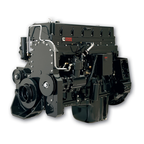
- Manuals
- Brands
- CUMMINS Manuals
- Engine
- K19 Series
- Troubleshooting and repair manual
-
Contents
-
Table of Contents
-
Troubleshooting
-
Bookmarks
Quick Links
Copyright® 1986
Cum m ins Engine Company, Inc.
Troubleshooting and
Repair Manual
K19 Engines
Bulletin No. 3810307-00
Printed 9-86
Related Manuals for CUMMINS K19 Series
Summary of Contents for CUMMINS K19 Series
-
Page 1
Troubleshooting and Repair Manual K19 Engines Copyright® 1986 Bulletin No. 3810307-00 Cum m ins Engine Company, Inc. Printed 9-86… -
Page 2
Page 2 NOTES… -
Page 3
Repair Location, A Cummins Division Office, or the factory The latest technology and the highest quality components were used to produce this engine. When replacement parts are needed, we recommend using only genuine Cummins or ReCon® exchange parts. These parts can be identified by the following trademarks:… -
Page 4: Table Of Contents
Table of Contents Section Introduction……………………Engine identification………………….. — General Engine Specifications……………… — Engine Diagrams………………….Troubleshooting………………….. — Procedures and Techniques………………- Symptoms List………………….- Symptoms Cause and Corrections Charts…………… Engine Systems Repair………………..- Cooling……………………- Lubricating Oil………………….- Combustion Air………………….- Compressed Air………………….- Fuel……………………..
-
Page 5
Table of Contents Page 4 NOTES… -
Page 6
Section i — Introduction Page i-1 Section i — Introduction Section Contents Page About the Manual…………………………..i-2 Definition Of Term s…………………………..i-11 General Cleaning Instructions……………………….i-10 Glass or Plastic Bead C leaning……………………… i-10 Solvent and Acid Cleaning……………………….i-10 Steam Cleaning…………………………..i-10 General Repair Instructions…………………………. -
Page 7: Cooling
About the Manual Section i — Introduction Page i-2 About the Manual This Troubleshooting and Repair Manual is intended to aid in determ ining the cause of engine-related problems and to provide recommended repair procedures. The manual is divided into sections. Some sections contain reference numbers and procedure numbers.
-
Page 8
Section i — Introduction Symbols Page i-3 Symbols The following symbols have been used in this manual to help communicate the intent of the instructions. When one of the symbols appears, it conveys the meaning defined below: WARNING — Serious personal injury or extensive property damage can result if the warning instructions are not followed. -
Page 9
Symbols Section i — Introduction Page i-4 Simbolos Los simbolos siguientes son usados en este manual para clarificar el proceso de las instrucciones. Cuando aparece uno de estos simbolos, su significado se especifica en la parte inferior. ADVERTENCIA — Serios danos personales o dano a la propiedad puede resultar si las instruc ciones de Advertencia no se consideran. -
Page 10
Section i — Introduction Symbols Page i-5 Symbole In diesem Handbuch werden die folgenden Symbole verwendet, die wesentliche Funktionen hervorheben. Die Symbole haben folgende Bedeutung: WARNUNG — Wird W arnung nicht beachtet, dann besteht erhohte Unfall- Beschadigungsgefahr. VORSICHT — Werden die Vorsichtsmassnahmen nicht beachtet, dann besteht Unfall- und Beschadigungsgefahr. -
Page 11
Symbols Section i — Introduction Page i-6 Symboles Les symboles suivants sont utilises dans ce manuel pour aider a com m uniquer le but des instructions. Quand l’un de ces symboles apparaTt, il evoque le sens defini ci-dessous: AVERTISSEMENT — De graves lesions corporelles ou des dommages materiels considerables peuvent survenir si les instructions donnees sous les rubriques Avertissement ne sont pas suivies. -
Page 12
Section i — Introduction Illustrations Page i-7 Illustrations The illustrations used in the Repair Sections of this manual are intended to give an example of a problem and to show what to look for and where the problem can be found. -
Page 13: General Safety Instructions
• Always use tools that are in good condition. Make sure you understand how to use them before performing any service work. Use ONLY genuine Cummins or Cummins Recon replacement parts. • Always use the same fastener part number (or equivalent) when replacing fasteners. Do not use a fastener of lessor quality if replacements are necessary.
-
Page 14
Follow The Specified Disassembly and Assembly Procedures to Avoid Damage to the Components. Complete rebuild instructions are available in the shop manual which can be ordered or purchased from a Cummins Authorized Repair Location. Refer to Section 14, Literature, for ordering instructions. -
Page 15: General Cleaning Instructions
General Cleaning Instructions Solvent and Acid Cleaning Several solvent and acid-type cleaners can be used to clean the engine parts. Cummins Engine Company, Inc. does not recommend any specific cleaners. Always follow the cleaner m anufacturer’s instructions. Experience has shown that the best results can be obtained using a cleaner that can be heated to 90 to 95 degrees Celsius [180 to 200 degrees Fahrenheit].
-
Page 16
In the direction of a circle in respect to the centerline of a round part or a bore. Centimeter Compulink™: A Cummins service tool used for electronic system analysis and to reprogram the system Concentricity: A measurement of the difference between the centers of either two or more parts, or the bores in one part. -
Page 17
The clearance in an assembly determined by pushing the shaft in an axial direction one way, and then pushing the shaft the other way. Echek™ A Cummins hand held service tool used for electronic system analysis, ad justing features and programmable parameters. ECM: Electronic Control Module. -
Page 18
Section i — Introduction Definition Of Terms Page i-13 Mallet: A hand tool consisting of a soft head; either wood, plastic, lead, brass, or rawhide on a handle. MAX: Maximum allowed MIN: Minimum allowed Mini-Gen: Speed Sensor Millimeter MPa: Megapascal MPH: Miles Per Hour MPQ:… -
Page 19
SRI, Amoco Rykon Premium No. 2, Texaco Premium RB, and Shell Dolium Aeroshell No. 5 is not compatible with the other greases and must not be mixed. Cummins Engine Co., Inc., uses Aeroshell No. 5 on new engines and components. -
Page 20: Table Of Contents
Section E — Engine and Component Identification Page E-1 Section E — Engine and Component Identification Section Contents Page Engine Identification…………………………… E-2 Cummins Engine Nom enclature……………………..E-2 Engine Dataplate…………………………..E-2 Fuel Pump Dataplate…………………………E-2 External Engine Components……………………….E-7 General Specifications…………………………E-3 Air Induction System…………………………E-5 Cooling System …………………………..
-
Page 21: Engine Identification
RPM rating provide inform ation for ordering parts and service needs. NOTE: The engine dataplate must not be changed unless approved by Cummins Engine Company, Inc. Fuel Pump Dataplate FUEL PUMP DATAPLATE The fuel pump dataplate is located on the top of the fuel Fuel Revision pump.
-
Page 22: General Specifications
Section E — Engine and Component Identification General Specifications Page E-3 General Specifications Metric (U.S. Customary) NOTE: Listed below are general specifications for this engine. Refer to each System Section for additional specifications. Engine Speed …………..Refer to the engine dataplate for optional speed rating. Displacem ent ……………………..
-
Page 23: General Engine D Ata
General Specifications Section E — Engine and Component Identification Page E-4 General Engine Data Cylinder location and Firing Order: K19 CYLINDER LOCATION 1-5-3-6-2-4 e w 4 0 0 g c Intake and Exhaust Valve locations. o Intake • Exhaust e w 4 0 0 g d…
-
Page 24: Lubricating Oil
Section E — Engine and Component Identification General Specifications Page E-5 Air Induction System Maximum Allowable Intake Restriction: • With Clean Filter E le m e n t……………………380 mm-H [15 in-H • With Dirty Filter Element ……………………635 mm-H [25 in-H Lubricating Oil System Oil Pressure, Main Oil Rifle (15W40 oil at 107°C [225°F]):…
-
Page 25: Electrical System
General Specifications Section E — Engine and Component Identification Page E-6 Fuel System NOTE: For performance and fuel rate values, refer to the engine data sheet, or the fuel pump code for the particular model involved. Maximum Allowable Restriction to Pump (at rated power): •…
-
Page 26: External Engine Components
Section E — Engine and Component Identification External Engine Components Page E-7 External Engine Components The illustrations which follow show the locations of the major external engine components, the filters, and other service and maintenance points. Some external components will be at different locations for different engine models.
-
Page 27
External Engine Components Section E — Engine and Component Identification Page E-8… -
Page 28
Section T — Troubleshooting Procedures and Techniques Page T-1 Section T — Troubleshooting Procedures and Techniques A thorough analysis of the problem is the key to successful troubleshooting. The more information known about the problem, the faster and easier it can be solved. The Troubleshooting Symptoms Charts beginning on page T-6 are organized so that a problem can be located and corrected by doing the easiest and most logical things first. -
Page 29: Troubleshooting Charts
Troubleshooting Charts Section T — Troubleshooting Page T-2 Troubleshooting Charts (Alphabetical Listing) Page No. Air Compressor Noise — Excessive…………………….. T-31 Air Compressor Pumping Excessive Lubricating O il……………….. T-28 Air Compressor Slow Air Pressure R ise……………………T-26 Air Compressor Will Not Maintain Adequate Air Pressure But Not Pumping C ontinuously….T-27 Air Compressor Will Not P um p……………………
-
Page 30: K19 Page
Section T — Troubleshooting Troubleshooting Charts Page T-3 Troubleshooting Charts (Continued) (Alphabetical Listing) Page No. 38. Lubricating Oil Temperature Above N orm al………………….T-16 39. Lubricating Oil Sludge in the Engine Crankcase Excessive……………….T-20 40. Lubricating or Hydraulic Oil in the C o ola nt………………….T-17 41.
-
Page 31: Combustion Air
Troubleshooting Charts Section T — Troubleshooting Page T-4 Troubleshooting Charts (By System) Page No. Cooling System Coolant Temperature Above N o rm a l……………………T-6 Coolant Temperature Below N o rm a l……………………T-9 Coolant L o s s …………………………..T-10 Fuel In C o o la n t…………………………..T-12 Lubricating Or Hydraulic Oil In the C o o la n t………………….
-
Page 32
Section T — Troubleshooting Troubleshooting Charts Page T-5 Troubleshooting Charts (Continued) (By System) Page No. Fuel System Engine Cranks, But Will Not Start (No Exhaust Sm oke)……………….T-32 Engine Decelerates P o o rly……………………….T-52 Engine Hard To Start, Or W ill Not Start (Exhaust Smoke P resent)…………..T-34 Engine Power O utput Low ……………………….T-44 Engine Runs Rough Or M isfiring — In Operating Range (Warm E ngine)…………T-38 Engine Starts, But Will Not Keep R unning…………………. -
Page 33
Troubleshooting Charts Section T — Troubleshooting Page T-6 Coolant Temperature Above Normal Cause Corrections (Continued) -
Page 34
Section T — Troubleshooting Troubleshooting Charts Page T-7 Coolant Temperature Above Normal (Continued) Cause Corrections… -
Page 35
Troubleshooting Charts Section T — Troubleshooting Page T-8 Coolant Temperature Below Normal Cause Corrections Refer to Bulletin No. 3387266-R (Cold Continuously Operating in Low Ambi Weather Operation). ent Temperature Check/repair/replace (refer to Radiator Shutters Stuck in Open Position manufacturer). Check/replace gauge Temperature Gauge Malfunction Fan Clutch Malfunction (Continuous Refer to Procedure 01-24… -
Page 36
Section T — Troubleshooting Troubleshooting Charts Page T-9 Coolant Loss Cause Corrections… -
Page 37
Troubleshooting Charts Section T — Troubleshooting Page T-10 Fuel In Coolant Cause Corrections Check coolant supply. Drain coolant Bulk Coolant Supply Contaminated and replace with non-contaminated coolant. Replace the fuel heater. Refer to the Fuel Heater Malfunction manufacturer’s recommendations. Pressurize cooling system, refer to Cylinder Head Cracked Procedure 01-12. -
Page 38
Section T — Troubleshooting Troubleshooting Charts Page T-11 Lubricating Oil Pressure Low Cause Corrections Check level, add or drain oil. To check Incorrect Oil Level dipstick calibration, refer to Procedure 02-15. Check gauge. Replace if necessary. Oil Pressure Gauge Malfunction Check location, refer to specifications. -
Page 39
Troubleshooting Charts Section T — Troubleshooting Page T-12 Lubricating Oil Pressure Low (Continued) Cause Corrections… -
Page 40
Section T — Troubleshooting Troubleshooting Charts Page T-13 Lubricating Oil Pressure High Cause Corrections Check gauge. Replace if necessary. Oil Pressure Gauge Malfunction Change oil and filters. Use type Incorrect Oil for Operating Conditions recommended (15W-40). Check operation. Check location, refer to specifications. Oil Pressure Sensor Not in Correct Relocate sensor. -
Page 41
Troubleshooting Charts Section T — Troubleshooting Page T-14 Lubricating Oil Temperature Above Normal Cause Corrections… -
Page 42
Section T — Troubleshooting Troubleshooting Charts Page T-15 Lubricating Or Hydraulic Oil In The Coolant Cause Corrections… -
Page 43
Troubleshooting Charts Section T — Troubleshooting Page T-16 Lubricating Oil Consumption Excessive Cause Corrections Check engine. Pressurize lube system if External Oil Leaks necessary, refer to Procedure 02-06. Check breather and tube. Refer to Crankcase Breather or Breather Tube Procedure 02-13. Plugged Check level. -
Page 44
Section T — Troubleshooting Troubleshooting Charts Page T-17 Lubricating Oil Consumption Excessive (Continued) Cause Corrections To check, refer to Procedure 07-03 Refer to Engine Blow-by Excessive the ‘‘Excessive Crankcase Gases (Blow- by)’ ’ Troubleshooting Chart. To check, refer to Procedure 07-13. To Piston/Piston Ring/Cylinder Liner replace piston rings, refer to Procedure Malfunction… -
Page 45
Troubleshooting Charts Section T — Troubleshooting Page T-18 Lubricating Oil Sludge In The Engine Crankcase Excessive Cause Corrections Check bulk oil supply. Change engine Bulk Oil Supply Contaminated oil and filters. Change oil and filters. Use type Incorrect Oil for Operating Conditions recommended (15W-40). -
Page 46
Section T — Troubleshooting Troubleshooting Charts Page T-19 Coolant In The Lubricating Oil Cause Corrections… -
Page 47
Troubleshooting Charts Section T — Troubleshooting Page T-20 Fuel In The Lubricating Oil Cause Corrections Check oil supply. Drain oil and replace Bulk Oil Supply Contaminated with non-contaminated oil. Shorten idle period or raise idle speed to Low Oil and Coolant Temperature increase temperature. -
Page 48
Section T — Troubleshooting Troubleshooting Charts Page T-21 Turbocharger Noise Cause Corrections Refer to CPL Manual for specification. Incorrect Turbocharger Installed Check for loose/damaged/porous piping Intake Air Leaks and connections. Check for loose at damaged exhaust Exhaust Air Leaks piping and connections. To check, refer to Procedure 03-08. -
Page 49
Troubleshooting Charts Section T — Troubleshooting Page T-22 Turbocharger Boost Pressure Low Cause Corrections… -
Page 50
Section T — Troubleshooting Troubleshooting Charts Page T-23 Turbocharger Leaks (Engine Oil or Fuel) Cause Corrections… -
Page 51
Troubleshooting Charts Section T — Troubleshooting Page T-24 Air Compressor Slow Air Pressure Rise Cause Corrections Replace air compressor air cleaner (if installed). Check engine intake air restriction Excessive Intake Air Restriction to Air if air compressor inlet is installed in intake Compressor piping between air cleaner and turbocharger. -
Page 52
Section T — Troubleshooting Troubleshooting Charts Page T-25 Air Compressor Will Not Maintain Adequate Air Pressure (Not Pumping Continuously) Cause Corrections Check for leaks. Tighten fittings or Excessive Air System Leaks replace failed parts. To check, refer to Procedure 04-08. Air Governor Malfunction or Not Set to Repair/replace as necessary. -
Page 53
Troubleshooting Charts Section T — Troubleshooting Page T-26 Air Compressor Pumping Excessive Lubricating Oil Cause Corrections Replace air compressor air cleaner (if installed). Check engine intake restriction if Excessive Intake Air Restriction to Air air compressor inlet is installed in intake Compressor piping between air cleaner and turbocharger. -
Page 54
Section T — Troubleshooting Troubleshooting Charts Page T-27 Air Compressor Will Not Pump Cause Corrections To check, refer to Procedure 04-08. Air Governor Malfunction or Not Set to Repair/replace as necessary. Correct Value To check, refer to Procedure 04-11. To Air Compressor Unloader Valve replace the unloader assembly, refer to Assembly Malfunction… -
Page 55
Troubleshooting Charts Section T — Troubleshooting Page T-28 Air Compressor Will Not Stop Pumping Cause Corrections Check for leaks. Tighten fittings or Air System Leaks replace failed parts. Air Dryer Automatic Drain Stuck or Refer to the manufacturer’s instructions. Frozen Open To check, refer to Procedure 04-07. -
Page 56
Section T — Troubleshooting Troubleshooting Charts Page T-29 Air Compressor Noise Excessive Cause Corrections To check, refer to Procedure 04-05. To Excessive Carbon Buildup in the Air replace air compressor head, refer to Compressor Procedure 04-14. To replace air discharge line(s), refer to equipment manufacturer. -
Page 57
Troubleshooting Charts Section T — Troubleshooting Page T-30 Engine Cranks But Will Not Start (No Smoke From Exhaust) Cause Corrections (Continued) -
Page 58
Section T — Troubleshooting Troubleshooting Charts Page T-31 Engine Cranks But Will Not Start (No Smoke From Exhaust) (Continued) Cause Corrections Check suction of gear pump, refer to Fuel Pump Gear Shaft Broken Procedure 05-18. To replace the fuel pump, refer to Procedure 05-11. Replace fuel filters. -
Page 59
Troubleshooting Charts Section T — Troubleshooting Page T-32 Engine Hard To Start Or Will Not Start (Exhaust Smoke Present) Cause Corrections Refer to the ‘‘Engine Will Not Crank or Engine Cranking Speed Too Slow Cranks Slowly’’ Troubleshooting Chart. Refer to the ‘‘Cold Climate Service’’, Cold Start Aid Needed or Not Working Bulletin, No. -
Page 60
Troubleshooting Charts Section T — Troubleshooting Page T-34 Engine Starts But Will Not Keep Running Cause Corrections Use the manual override to check, refer Electrical System Malfunction Causing to Procedure 05-16. Repair the electrical Shutoff Valve to Close system, refer to manufacturer’s instructions. -
Page 61
Section T — Troubleshooting Troubleshooting Charts Page T-35 Engine Starts But Will Not Keep Running (Continued) Cause Corrections Check restriction, refer to Procedure Excessive Exhaust Air Restriction 03-09. Replace damaged exhaust system components. Adjust to specification. Refer to the K19 Jacobs Engine Brake Adjusted Wrong Shop Manual. -
Page 62
Section T — Troubleshooting Troubleshooting Charts Page T-36 Engine Runs Rough Or Misfires (Warm Engine) Cause Corrections To check for air, refer to Procedure 05-19. Air in Fuel Tighten all fittings between fuel pump and tank. Adjust to specification. Refer to the K19 Jacobs Engine Brake Adjusted Wrong Shop Manual. -
Page 63
Troubleshooting Charts Section T — Troubleshooting Page T-37 Engine Runs Rough or Misfires (Warm Engine) (Continued) Cause Corrections… -
Page 64
Section T — Troubleshooting Troubleshooting Charts Page T-38 Idle Rough Cause Corrections… -
Page 65
Troubleshooting Charts Section T — Troubleshooting Page T-39 Engine Surges At Low Idle Cause Corrections Check for air, refer to Procedure 05-19. Air in Fuel Tighten all fittings and connections between the fuel pump and the fuel tank. Adjust idle rpm to specification, refer to Engine Idle Speed Set Too Low Procedure 05-05. -
Page 66
Section T — Troubleshooting Troubleshooting Charts Page T-40 Engine Will Not Reach Rated RPM When Loaded Cause Corrections Reduce load. Engine Overloaded Check gauge. Tachometer Not Correct Check for full throttle travel. Refer to Throttle Linkage Adjustment Wrong Procedure 05-12. Replace fuel filters. -
Page 67
Troubleshooting Charts Section T — Troubleshooting Page T-41 Engine Power Output Low Cause Corrections (Continued) -
Page 68
Section T — Troubleshooting Troubleshooting Charts Page T-42 Engine Power Output Low (Continued) Cause Corrections Use inside air to turbocharger in cold Low Intake Air Temperature (Below 0°C weather. [32°F]) Check for leaks. Repair or replace Air or Exhaust Leaks Between Turbo malfunctioning parts. -
Page 69
Troubleshooting Charts Section T — Troubleshooting Page T-43 Engine Power Output Low (Continued) Cause Corrections Application Specific Problem — Construction Cause Corrections Application Specific Problem — Genset Cause Corrections (Continued) -
Page 70
Section T — Troubleshooting Troubleshooting Charts Page T-44 Engine Power Output Low (Continued) Cause Corrections Application Specific Problem — Marine Cause Corrections… -
Page 71
Troubleshooting Charts Section T — Troubleshooting Page T-45 Performance Measurement Cause Corrections Perform the following measurements to Fuel or Air Delivery Problem determine the problem. Repair/Replace based on the measurements. To check restriction, refer to Procedure Excessive Intake Air Restriction 03-08. -
Page 72
Section T — Troubleshooting Troubleshooting Charts Page T-46 Performance Measurement Cause Corrections Replace turbocharger, refer to Proce Fuel Rate OK, Fuel Pressure OK, dure 03-14 or 03-13. Intake Manifold Pressure Low Adjust Fuel Pressure (Rate). Refer to Fuel Rate Low, Fuel Pressure Low, Procedure 05-07. -
Page 73
Troubleshooting Charts Section T — Troubleshooting Page T-47 Exhaust Smoke Excessive Under Load Cause Corrections To check restriction, refer to Procedure 03-08. Clean/replace air filter element or damaged air intake piping. Check turbocharger mounting and exhaust manifold mounting. Tighten connections or replace damaged parts. -
Page 74
Section T — Troubleshooting Troubleshooting Charts Page T-48 Engine Will Not Shut Off Cause Corrections Check to be sure the manual override Fuel Pump Manual Override Open screw is out to maximum travel. Fuel Pump Shut-off Valve Check operation, refer to Procedure Malfunction or Auxiliary Shut-off 05-16. -
Page 75
Troubleshooting Charts Section T — Troubleshooting Page T-49 Engine Decelerates Poorly Cause Corrections Check operation adjust or replace Throttle Lever, Return Spring, or damaged parts. Linkage Damaged or Mis-Adjusted Check restriction, refer to Procedure Fuel Drain Lines Restricted 05-24. Replace/reroute fuel lines. Clean/ replace in-line check valve. -
Page 76
Section T — Troubleshooting Troubleshooting Charts Page T-50 Engine Surges Under Load Cause Corrections Check for air, refer to Procedure 05-19. Tighten all fittings and connections Air in Fuel between the fuel pump and the fuel tank. Normal operation for a fast acting gover RPM Change Not Measurable nor. -
Page 77
Troubleshooting Charts Section T — Troubleshooting Page T-51 Engine Surges At High Idle Cause Corrections… -
Page 78
Section T — Troubleshooting Troubleshooting Charts Page T-52 Throttle Response Slow (Engine Dies Going Down Hill) Cause Corrections… -
Page 79
Troubleshooting Charts Section T — Troubleshooting Page T-53 Fuel Consumption Excessive Cause Corrections Check tires and driveline for damage or Vehicle Factors improper operation. Check all fuel lines, fittings, connections, External Fuel Leak and filters. Repair/replace parts as necessary. Check level. To check dipstick calibra Incorrect Oil Level tion, refer to Procedure 02-15. -
Page 80
Section T — Troubleshooting Troubleshooting Charts Page T-54 Engine Will Not Crank Or Cranks Slowly (Air Starter) Cause Corrections… -
Page 81
Troubleshooting Charts Section T — Troubleshooting Page T-55 Engine Will Not Crank Or Cranks Slowly (Electric Starter) Cause Corrections (Continued) -
Page 82
Section T — Troubleshooting Troubleshooting Charts Page T-56 Engine Will Not Crank Or Cranks Slowly (Electric Starter) (Continued) Cause Corrections… -
Page 83
Troubleshooting Charts Section T — Troubleshooting Page T-57 Alternator Malfunctioning Cause Corrections… -
Page 84
Section T — Troubleshooting Troubleshooting Charts Page T-58 Crankcase Gases (Blowby) Excessive Cause Corrections… -
Page 85
Troubleshooting Charts Section T — Troubleshooting Page T-59 Engine Vibration Excessive Cause Corrections… -
Page 86
Section T — Troubleshooting Troubleshooting Charts Page T-60 Engine Noise — Diagnostic Procedures NOTE: When diagnosing engine noise problems, make sure that noises caused by accessories, such as the air compressor and power take-off, are not mistaken for engine noises. Remove the accessory drive belts to eliminate noise caused by these units. -
Page 87
Troubleshooting Charts Section T — Troubleshooting Page T-61 Engine Noise Excessive Cause Corrections Fan Belt Malfunction (Too Tight, Loose, or Not in Alignment) Fan Blades Damaged or Contacting Shroud or Radiator Core Check turbocharger part number, refer to Incorrect Turbocharger Installed Procedure 03-07. -
Page 88
Section T — Troubleshooting Troubleshooting Charts Page T-62 Engine Noise Excessive (Continued) Cause Corrections… -
Page 89
Troubleshooting Charts Section T — Troubleshooting Page T-63 Exhaust Smoke (White) At Idle Excessive (Warm Engine) Cause Corrections (Continued) -
Page 90
Section T — Troubleshooting Troubleshooting Charts Page T-64 Exhaust Smoke (White) At Idle Excessive (Warm Engine) (Continued) Cause Corrections NOTE: A warm engine is one where the coolant temperature is 70°C [160°F] or higher. -
Page 91
Troubleshooting Charts Section T — Troubleshooting Page T-65 NOTES… -
Page 92
Section 1 — Cooling System Page 1-1 Section 1 — Cooling System Section Contents Reference No. Page No. 01-00 Service Tools………………General Inform ation…………….01-01 Specifications………………01-02 Flow Charts……………….. 01-03 Venting………………..01-04 1-11 System Troubleshooting and Repair List Procedure No. Page No. -
Page 93: Illustrations
The following special tools are recom m ended to perform the procedures in Section 01. The use of these tools is shown in the appropriate procedure. These tools can be purchased from your local Cummins Authorized Repair Location. Tool No.
-
Page 94
The following publications, available through Cum m ins Distributors or Cum m ins Dealers, provide cooling system installation recommendations and specifications approved by Cummins Engine Company, Inc. • Automotive Installation recommendations (Cooling System), Bulletin No. 3382413. • Construction, Mining, Logging, and Agriculture In… -
Page 95
Cooling System Specifications (01-02) Section 1 — Cooling System Page 1-4 Cooling System Specifications (01-02) KTA/KTTA Coolant Capacity (Engine Only)………. 26 Liters 30 Liters [28 U.S.Qts.] [32 U.S.Qts.] Standard Modulating Thermostat- R ange……80°-90°C 80°-90°C [175-195°F] [175-195°F] Maximum Coolant Pressure (Exclusive of Pressure Cap). 241 kPa 241 kPa [35 psi]… -
Page 96
4 (1 pint) DCA80L 3317428 1760 (55 gallons) Table 3: DCA4 Powder DCA95 3318320 Table 4: RESTORE Heavy-Duty Cooling System Cleaner CC2610 None 1 gallon CC2611 None 5 gallons CC2612 None 55 gallons (A) Recommended for use with all Cummins engines. -
Page 97
Cooling System Specifications (01-02) Section 1 — Cooling System Page 1-6 DCA4 Maintenance Guide System Capacity (A) Precharge Filter (B) Service Filter (C) Litres Gallons 19-26 WF-2072 WF-2070 30-38 8-10 WF-2073 WF-2071 42-57 11-15 WF-2074 WF-2071 61-76 16-20 WF-2075 WF-2071 80-114 21-30 WF-2076… -
Page 98
Cooling System Cooling System Specifications (01-02) Page 1-7 Instructions For Using Test Kit Part No. 3300846S To Test For DCA4 1. Fill the dropper pipet to the 1.0 ml. mark with coolant to be tested. 2. Dispense the 1.0 ml. coolant sample from the dropper pipet into the empty vial. 3. -
Page 99
Cooling System Specifications (01-02) Section 1 — Cooling System Page 1-8 Maintain a nominal of one DCA4 unit per gallon of coolant in your system. Less than 0.5 (1/2) unit per gallon indicates an Underconcentrated coolant solution. More than two units per gallon indicates an Overconcentrated coolant solution. -
Page 100
Cooiing System Flow Charts (01-03) Cooling System Page i * 9 Cooling FJow System Charts (01-03) 1. C oolant to aftercooler 2. C oolant out of aftercooler 3. C ylin de r lin e r 4. W a te r pum p 5. -
Page 101
Cooling System Cooling System Flow Charts (01-03) K 19 Page 1-10 3. Vent to radiator 9. Coolant to radiator 10. Coolant out of aftercooler 11. Thermostats 12. Coolant bypass 13. Coolant manifold… -
Page 102
Section 1 — Cooling System Cooling System Venting (01-04) Page 1-11 Cooling System Venting (01-04) The cooling system must be designed to allow air to escape while filling. On aftercooled engines the vent line is routed from the aftercooler outlet tube to the top of the therm ostat housing (6). -
Page 103
Cooling System — Maintenance (01-05) Section 1 — Cooling System Page 1-12 D uring engine operation coolant will continue to flow through the engine vent line to remove air from the coolant. Cooling System — Maintenance (01-05) Water Always use good quality soft water in the coolant mixture. Water added to the cooling system must meet the speci… -
Page 104
Section 1 — Cooling System Cooling System — Drain (01-06) Page 1-13 Soluble oils Do not use soluble oils in the cooling system. The use of soluble oils will: • allow cylinder liner pitting, • corrode brass and copper, • damage heat transfer surfaces, and •… -
Page 105
Cooling System — Fill (01-07) Section 1 — Cooling System Page 1-14 Drain the cooling system as follows: • Open the radiator draincock. • Remove the lower radiator hose(s). • Open the water pump draincock. • Open the oil cooler draincock. Cooling System — Fill (01-07) 1. -
Page 106
Section 1 — Cooling System Cooling System — Fill (01-07) Page 1-15 6. Use a mixture of 50 percent ethylene glycol antifreeze and 50 percent water to fill the cooling system. NOTE: Use the correct DCA4 initial charge filter to obtain the correct cooling system protection. -
Page 107
Coolant Filter — Replace (01-08) Section 1 — Cooling System Page 1-16 Caution: Do not add cold coolant to a hot engine. Engine castings may be damaged. Allow the engine to cool to below 50°C [120°F] before adding coolant. Remove the radiator or fill cap, and check the coolant level. -
Page 108
Section 1 — Cooling System Diesel Coolant Additives (DCA4) (01-09) Page 1-17 2. Turn the valve to the ‘‘ON’’ position. Diesel Coolant Additives (DCA4) (01-09) 1. Diesel coolant additives (or equivalent) are used to prevent the buildup of corrosion and scale deposits in the cooling system. -
Page 109
Cooling System Cooling System — Clean (01-10) Page 1-18 3. W hen changing the coolant, the initial DCA4 (or equiv alent) concentration must be between 1 and 2 units per 3.8 liters [1 U .S. gallon] of coolant (initial charge). Note: The cooling system must be clean before adding DCA4 (or equivalent). -
Page 110
Section 1 — Cooling System Cooling System — Clean (01-10) Page 1-19 NOTE: The performance of RESTORE is dependent on time, temperature, and concentration levels. An extremely scaled or flow restricted system, for example, may require higher concentrations of cleaners, higher temperatures, or longer cleaning times. -
Page 111
Cooling System — Clean (01-10) Section 1 — Cooling System Page 1-20 7. Fill the cooling system with clean water. Refer to Pro cedure 01-07. 8. Operate the engine at high idle for 5 minutes with the coolant temperature above 85°C [185°F]. 9. -
Page 112
Cooling System Cooling System • Test For Air Or Combustion Gases (01-11) Page 1-21 Cooling System — Test For Air Or Combustion Gases (01-11) ® m tr l Warning: Wait until the temperature is below 50°C w r*T u ? J J V r- % [120°F] before removing the coolant system pressure TEW P… -
Page 113
Cooling System — Test For Air Or Combustion Gases (01-11) Section 1 — Cooling System Page 1-22 6. A continuous flow of air bubbles indicates excessive air in the system. Continue to operate the engine for 25 minutes. 7. If the flow of bubbles does not stop, check for the following: •… -
Page 114
Cooling System Cooling System — Test For Air Or Combustion Gases (01-11) Page 1-23 2. Operate the engine at 75 percent of rated RPM until it reaches an operating tem perature of 8 0 ° C [18 0°F ]. 3. Check for a continuous flow of air bubbles in the hose. 4. -
Page 115
Cooling System Cooling System • Test For Air Or Combustion Gases (01-11) Page 1-24 To determine which liner is leaking, perform the following: Remove the water pump. Refer to Procedure 01 -30. b. Remove the drive shaft. c. Install the water pump without the drive shaft. d. -
Page 116
Section 1 — Cooling System Cooling System — Test For Air Or Combustion Gases (01-11) Page 1-25 Defective Air Control Valve To check the air control valve perform the following: a. Remove air pressure from the tank that supplies the valve in question. -
Page 117
Cooling System — Pressure Test (01-12) Section 1 — Cooling System Page 1-26 Cooling System — Pressure Test (01-12) Warning: Wait until the temperature is below 50°C [120°F] before removing the coolant system pressure cap. Failure to do so can cause personal injury from heated coolant spray. -
Page 118
Section 1 — Cooling System Cooling System — Pressure Test (01-12) Page 1-27 Check for Internal Leaks 5. Check the oil cooler housing for coolant leakage. Re move the oil plugs from the cooler housing and check for coolant. If coolant is present, replace the oil cooler cores. -
Page 119
Cooling System — Pressure Test (01-12) Section 1 — Cooling System Page 1-28 11. Disconnect the aftercooler coolant hoses. Plug one hose and apply 415 kPa [60 PSI] air pressure to the other hose. If the air pressure decreases, replace the aftercooler element. -
Page 120
Section 1 — Cooling System Hoses — Check (01-13) Page 1-29 Hoses — Check (01-13) Caution: Do not bend or deform the hoses during in spection. This can cause the hoses to crack. 1. Inspect all hoses for cracks or cuts. 2. -
Page 121
Radiator Pressure Cap — Check (01-15) Section 1 — Cooling System Page 1-30 Radiator Pressure Cap — Check (01-15) 1. Visually inspect the rubber seal of the pressure cap for damage. 2. Visually inspect the radiator fill neck for cracks or other damage. -
Page 122
Cooling System Radiator Baffle Leakage — Check (01*17) Page 1-31 Radiator Baffle Leakage — Check (01-17) 1. Open the draincock on the bottom of the radiator and remove the lower radiator hose to drain the cooling system. 2. Fill the top tank to within 50 m m [2 inch] of the top with water. -
Page 123
Cooling System Radiator — Check for Obstruction (01-19) Page 1-32 3. If the bottom tank begins to warm to the touch and the top tank remains cold, the radiator has reverse flow. Refer to the m anufacturer’s instructions for repair Procedures. -
Page 124
Cooling System Shutter Operation — Check (01-20) Page 1-33 4. Operate the engine at rated RPM. a. Close valve «1» and open valve «2 » . Record the pressure at the top of the radiator. b. Close valve «2» and open valve «1 » . Record the pressure at the water pump inlet. -
Page 125
Shutter Operation — Check (01-20) Section 1 — Cooling System Page 1-34 3. Restrict the radiator air flow. 4. Operate the engine at rated RPM. 5. When the coolant temperature reaches the tempera ture stamped on the control, check the shutters to see if they are open. -
Page 126
NOTE: Replace the original equipment fan with a fan of the identical part number. Cummins Engine Company, Inc. must approve any fan change. 1. Visually check the fan for cracks, loose rivets, and bent or loose blades. -
Page 127
Fan — Replace (01-22) Section 1 — Cooling System Page 1-36 Fan Shroud 1. Inspect the fan shroud for the correct fan clearance. Refer to the vehicle manufacture’s specifications and the appropriate installation recommendations bulletin. 2. Visually inspect the shroud for cracks, air leaks, or other damage. -
Page 128
Fan Belt — Replace (01-23) Page 1-37 Install Caution: Replace the original equipment fan with a fan ▲ of the identical part number. Cummins Engine Co., Inc. must approve any fan changes. 1. Install the fan. /^JaN (• H n n 2. -
Page 129
Install Cooling System Page 1-38 Remove the fan belt. Check For Reuse Visually inspect the belt for: • Cracks • Glazing • Tears or cuts Install Caution: Be sure the fan idler spring tension is released. Install the belt. 2. Rotate the idler against the spring tension until the capscrew holes are aligned. -
Page 130
Cooling System Fan Clutch — Check Operation (01-24) Page 1-39 Fan Clutch — Check Operation (01-24) 1. This Procedure assumes that the fan is not turning at the correct RPM . Refer to Procedure 01-25 to check. At idle, on a cold engine, the fan should turn less than 350 RPM . -
Page 131
Fan Clutch — Check Operation (01-24) Section 1 — Cooling System Page 1-40 7. If the vehicle is air-conditioned, make sure the air- conditioning is turned off to prevent continuous op eration of the fan. 8. Operate the engine and read the pressure gauge. If the air pressure is less than 69 kPa [10 psi] replace the thermal control valve. -
Page 132
Section 1 — Cooling System Fan Clutch — Check Operation (01-24) Page 1-41 11. Restrict the radiator air flow. Operate the engine until the coolant temperature rises to the temperature stamped on the thermal control valve. 12. Continue to operate the engine allowing the coolant temperature to rise another 7°F. -
Page 133
2. Mark a spot on the fan, so the fan RPM can be mea sured. 3. Mark another spot on the vibration damper or acces sory drive pulley to measure engine RPM NOTE: When using the Cummins optical tachometer, use a piece of reflective tape, Part No. 3377464, to mark the part. -
Page 134
Section 1 — Cooling System Fan RPM — Check (01-25) Page 1-43 NOTE: The fan center distance is the distance between the center of the fan and the center of the crankshaft. 4. Measure the fan center distance or the fan pulley di ameter to determine the fan ratio. -
Page 135
Cooling System Fan Hub (Belt Driven) — Replace (01-26) Page 1-44 Fan Hub (Belt Driven) — Replace (01-26) Remove 1. Rem ove the fan. Refer to Procedure 01-21. 2. Rem ove the fan belt. Refer to Procedure 01-22. Caution: This assembly weighs more than 23 kg [50 lb]. Personal injury can result. -
Page 136
Cooling System Fan Hub (Gear Driven) — Replace (01-27) Page 1-45 3. Install the fan belt. Refer to Procedure 01-23. 4. Install the fan. Refer to Procedure 01-22. Fan Hub (Gear Driven) — Replace (01-27) Remove Remove the fan. Refer to Procedure 01-22. Caution: This assembly weighs more than 23 kg [50 lb]. -
Page 137
Cooling System Fan Hub (Gear Driven) — Replace (01-27) Page 1-46 3. Use a feeier gauge (11) and measure the shaft depth in the gear. Gear Shaft Depth 0.00 0.000 0.020 0.51 Note: If the shaft depth is not within specifications, replace the shaft and gear as an assembly. -
Page 138
Cooling System Fan Hub Idler And Shock Absorber (Or Turnbuckle) • Replace (01-28) Page 1-47 Fan Hub Idler And Shock Absorber (Or Turnbuckle) — Replace (01-28) Remove 1. Loosen the adjusting link and the alternator mounting capscrews. Note: The lower jam nut is left-hand threads. 2. -
Page 139
Cooling System Fan Hub Idler And Shock Absorber (Or Turnbuckle) — Replace (01-28) Page 1-48 Check For Reuse 1. Check the shock absorber for fluid leakage and bush ing wear. Push the shock absorber up and down. Check the vibration absorption. 2. -
Page 140
Cooling System Water Pump Block Pressure — Check (01-29) Page 1-49 3. Install the fan belt. Refer to Procedure 01-23. 4. Do not attempt to pry the belt on the pulley. Turn the adjusting screw counterclockwise to shorten the link if necessary. -
Page 141
Cooling System Water Pump Block Pressure — Check (01-29) Page 1-50 4. If the above measurement location is not accessible, install the gauge in the oil cooler housing. Engine Minimum Coolant Pressure 1800 1900 2100 Note: The maximum coolant pressure with the pressure cap removed, is 241 kPa [35 psi]. -
Page 142
Cooling System Water Pump — Replace (01-30) Page 1-51 Water Pump — Replace (01-30) Remove Open the draincock on the bottom of the radiator and remove the lower radiator hose to drain the cooling system. 2. Open the draincock on the oil cooler housing and on the water pump. -
Page 143
Cooling System Water Pump • Replace (01-30) Page 1-52 6. Remove the water pump outlet connection assembly. 7. Remove the water transfer tube from the water con nection. Remove and discard the two o-rings (13) and the gasket. 8. Disconnect the lower radiator hose from the water pump inlet. -
Page 144
Cooling System Water Pump — Replace (01-30) Page 1-53 Check For Reuse Check the water pump for reuse. Refer to Procedure 01-31. Install 1. Install the inlet connection (1), gasket and capscrews. Tighten the capscrews to 40 N»m [30 ft-lb]. Note: Do not tighten the support bracket until the water pump is assembled to the engine. -
Page 145
Cooling System Water Pump — Replace (01-30) Page 1-54 7. The support bracket must be flat against the water pump and the cylinder block. Align the bracket before tightening the capscrews. 8. Install the capscrew through the bracket. Tighten the capscrew to 205 N *m [150 ft-lb]. -
Page 146
Cooling System Water Pump — Check For Reuse (01-31) Page 1-55 16. Install the bypass connection gasket. Tighten the capscrews to 40 N»m [30 ft-lb], 17. Use vegetable oil and lubricate the o-ring on the by-pass tube. Install the by-pass tube. Note: The raised lip on the retainer (9) must point away from the thermostat housing. -
Page 147
Cooling System Thermostat — Test (Thermostat in chassis) (01-32) Page 1-56 2. Check the drive shaft for wear. If the drive shaft splines are worn, check the female splines in the pump and in the water pump drive. 3. Use a feeler gauge and measure the impeller to pump body clearance. -
Page 148
Section 1 — Cooling System Thermostat — Test (Thermostat in chassis) (01-32) Page 1-57 2. Install 2 hoses of the same size on the thermostat housing outlets long enough to reach a remote dry container. 3. Install and tighten hose clamps on the housing outlets. 4. -
Page 149
Cooling System Thermostat — Replace (01-33) Page 1-58 11. Record the tem perature of the coolant outlet hoses. Coolant in these hoses indicates the thermostats have started to open. Use a contact pyrometer (shown) or install a tem per ature gauge in the desired locations prior to operating the engine. -
Page 150
Cooling System Thermostat — Replace (01-33) Page 1-59 2. Remove both upper radiator hoses from the thermo stat housing. 3. Remove the vent line from the top of the thermostat housing. 4. Remove by-pass tube clamp (9). Loosen both hose clamps. -
Page 151
Thermostat — Replace (01-33) Cooling System Page 1-60 Check For Reuse 1. Clean and inspect the thermostat housing for cracks, pitting, or other damage. .— . 2. Check the thermostat for wear or dam age. Check for proper operation, refer to Procedure 01-34. Install Note: The seal must be installed with the part number up. -
Page 152
Cooling System Thermostat • Replace (01-33) Page 1-61 4. Use vegetable oil and lubricate the o-ring on the by-pass tube. Install the by-pass tube. Note: The raised lip on the retainer (9) must point away from the thermostat housing. 5. Install the retainer (9) and capscrew. 6. -
Page 153
Thermostat — Check Operating Temperature (01-34) Cooling System Page 1-62 Thermostat — Check Operating Tem perature (01-34) 1. Check the thermostat to see at what tem perature it is designed to open. Note: The design temperature of this thermostat is 185°F. Suspend the thermostat and a therm om eter in a con… -
Page 154
Cooling System Thermostat Housing — Replace (01-35) Page 1-63 Thermostat Housing — Replace (01-35) Remove 1. Open the draincock on the bottom of the radiator and remove the lower radiator hose to drain the cooling system. 2. Remove both upper radiator hoses from the thermo stat housing. -
Page 155
Cooling System Thermostat Housing • Replace (01-35) Page 1-64 Install 1. Install the o-rings (19) on the transfer tube. 2. Use vegetable oil and lubricate the o-rings. Install the tube in the bore of the rocker lever housing. 3. Align the bore in the thermostat housing support with the transfer tube. -
Page 156
Section 1 — Cooling System Thermostat — Replace (01-33) Page 1-61 3. Install a new gasket. Install the thermostat housing and capscrews. Tighten the capscrews to 45 N»m [35 ft-lb], 4. Use vegetable oil and lubricate the o-ring on the by pass tube. -
Page 157
Section 1 — Cooling System Check For Coolant Leaks At Counterbore (01-36) Page 1-65 12. Install the two upper radiator hoses. 13. Tighten the hoses clamps to 5.6 N^m [50 in-lb]. 14. Fill the cooling system. Refer to Procedure 01-07. 15. -
Page 158
Check For Coolant Leaks At Counterbore (01-36) Section 1 — Cooling System Page 1-66 2. Fill the radiator with water until there is at least a 152 mm [6 inch ] static head of water above the cylinder block deck. 3. -
Page 159
Lubrication Oil System Table Of Contents Page 2-1 Section 02 — Lubrication Oil System Table Of Contents Reference No. Page No. Service Tools………………02-00 General Inform ation…………….02-01 Specifications………………02-02 Flow Diagrams………………02-03 System Troubleshooting and Repair List Procedure No. -
Page 160
The following special tools are recommended to perform the procedures in Section 02. The use of these tools is shown in the appropriate procedure. These tools can be purchased from your local Cummins Authorized Repair Location. Tool No. Tool Description… -
Page 161
Lubrication Oil System Required Service Tools • (02-00) Page 2-3 Tool No. Tool Description Tool Illustration Pressure Regulator Removal Tool Remove retaining ring from lube pump regulator (on engine). 3375055… -
Page 162
General Information (02-01) Page 2-4 General Information (02-01) Cummins Engine Company, Inc. recommends the use of multi-viscosity lubricating oil, preferable 15W -40, if am bient conditions permit. The oil m ust meet API Classifi cation C C /C D for turbocharged engines. -
Page 163
Lubrication Oil System Lubricating Oil System Specifications (02-02) Page 2-5 Lubricating Oil System Specifications (02-02) Oil Pressure At idle (minimum allowable)………………….. 138 kPa [20 psi] At no load governed s p e e d ………………..345-483 kPa [50-70 psi] Oil Filter Capacity Bypass filter (spin-on).. -
Page 164
Lubrication Oil System Flow Diagrams (02-03) Page 2-6 Flow Diagrams (02-03) 1. Oil cooler elements 2. Turbocharger oil supply 3. Oil cooler housing 4. Lubricating pump 5. Lubricating pump regulator 6. Oil Inlet tube 7. Oil to filter head 8. Turbocharger oil drain… -
Page 165
Flow Diagrams (02-03) Lubrication Oil System Page 2-7 1. Rocker lever 2. Cam follower 3. Main oil rifle 4. Oil supply to main bearings 5. Oil supply to connecting rod 6. Oil supply to piston pin bushing… -
Page 166
Lubrication Oil System Flow Diagrams (02-03) Page 8 Filterhead Filterhead 1. Main oil rifle 1. Filterhead 2. Oil filter head 2. Filter bypass valve 3. Full flow filter 3. Oil before filter 4. Piston cooling control valve 4. Full flow filter 5. -
Page 167
Lubrication Oil System Internal Engine Damage — Check (02-04) Page 2-9 Internal Engine Damage — Check (02-04) Lubricating Oil Analysis A used oil analysis can help diagnose internal dam age and determine if it was caused by one of the following: •… -
Page 168
Lubrication Oil System Oil Leaks (External) — Checks (02-05) Page 2-10 Oil Leaks (External) — Checks (02-05) 1. Use a steam cleaner or a high pressure washer to clean the engine. Check the engine crankcase breather elements and l^pU hose for restriction. If not restricted check blowby. -
Page 169
Lubrication Oil System Oil System — Leak Check Using Dye (02-06) Page 2-11 Oil System — Leak Check Using Dye 1. Add one unit of Part No. 3376891 Fluorescent Tracer to each 38 liters [10.0 U.S. gallons] of engine lubri cating oil. -
Page 170
Lubrication Oil System Oil Pressure Gauge — Check (02-07) Page 2-12 Oil Pressure Gauge — Check (02-07) Check the following for defects: a. Electrical wiring broken. b. Sending unit malfunction. c. Plumbing loose or broken. « % < A rr ‘ 6 V 2. -
Page 171
Lubrication Oil System Drain Oil (02-09) Page 2-13 If the suspect gauge does not read the sam e tem perature as the reference gauge, check the following for defects: a. Electrical wiring. b. Sending unit malfunction. Replace the defective parts. 7. -
Page 172
Oil Pan • Fill (02-10) Lubrication Oil System Page 2-14 Oil Pan — Fill (02-10) 1. Install the oil drain plugs and tighten them to 100 N«m [75 ft-lb]. 2. Add the specified amount of clean 15W -40 oil to fill the oil pan. -
Page 173
Lubrication Oil System Oil Filters (Full Flow And Bypass) — Replace (02-11) Page 2-15 5. Shut the engine off and wait 5 to 7 minutes for the oil to drain back to the oil pan. 6. C heck the oil level. Add oil as necessary to bring the level up to the «H «… -
Page 174
Oil Filter (Full Flow) — Measure Pressure Drop (02-12) Lubrication Oil System Page 2-16 3. Fill the filters with clean 15W -40 oil. Install the filters on the oil filter head. Note: Mechanical overtightening may distort the threads or damage the filter element seal. 4. -
Page 175
Lubrication Oil System Crankcase Breather And Tube — Replace (02-13) Page 2-17 3. Install the other hose in either the [1-NPTF inch] pipe plug hole (2) or one of the two [1/8-N PTF inch] pipe plug holes (3). This reading will indicate oil pressure after the oil goes through the filters. -
Page 176: Compressed Air
Lubrication Oil System Crankcase Breather And Tube — Replace (02*13) Page 2-18 Remove the following parts from the breather body(6): (1) Wing nut (2) Washer (3) Breather Cap (4) Screen mesh (5) Element Screen mesh Check For Reuse 1. Use solvent to clean the screen and wire mesh breather element.
-
Page 177: Fuel
Lubrication Oil System Dipstick Tube — Replace (02-14) Page 2-19 Dipstick Tube — Replace (02-14) Remove 1. Rem ove the dipstick and dipstick tube. Install Note: The dipstick tube and fuel filter mounting locations vary by application. Install the dipstick tube. Tighten the nut three-quarters of a turn to one turn after contact with the ferrule.
-
Page 178
Lubrication Oil System Dipstick — Calibrate (02-15) Page 2-20 3. Remove the dipstick and scribe a mark across the dipstick at the oil level. M ark the «H IG H » oil level with an «H «. Note: The dipstick will break if the scribe mark is too deep. 4. -
Page 179
Lubrication Oil System Oil Pan — Replace (02*16) Page 2*21 Oil Pan — Replace (02-16) Remove Drain the lubricating oil. Refer to Procedure 02-09. Remove the capscrews, the oil pan sump and the oil pan adapter cover. Remove and discard the gaskets. Check For Reuse 1. -
Page 180
Lubrication Oil Syatem Oil Pan — Replace (02-16) Page 2-22 2. Use the sequence shown and tighten the capscrews to 45 N *m [35 ft-lb]. @ ® @ © ® © ® ® ® @ ® @ ® © 0 ©… -
Page 181
Lubrication Oil System Oil Pan Adapter — Replace (02-17) Page 2-23 Oil Pan Adapter — Replace (02-17) Remove 1. Remove the oil pan and oil pan adapter cover. Refer to Procedure 02-16. 2. Rem ove the three capscrews from the suction tube. Rem ove the oil pan suction tube. -
Page 182
Lubrication Oil Sy8tem Oil Pan Adapter — Replace (02-17) Page 2-24 5. Remove the dipstick and dipstick tube. 6. Remove the front engine support. Refer to Procedure 07-46. 7. Use an oil filter wrench, Part No. 3375049, or equiv alent. Remove the full flow oil filters. Discard the filters if they are not needed for failure analysis. -
Page 183
Lubrication Oil System Oil Pan Adapter — Replace (02-17) Page 2-25 Note: You will need help from another person or a floor jack to lower the adapter to floor. 9. Rem ove all of the capscrews and the pan adapter. Rem ove and discard the gasket, the two rectangle seals (41), and the seven bolt seals (42) from the adapter. -
Page 184
Lubrication Oil System Oil Pan Adapter — Replace (02-17) Page 2-26 4. Use Cummins sealant, Part No. 3377132, or equiv alent. Apply the sealant as shown. Note: You will need help from another person or a floor jack to lift the adapter into place. -
Page 185
Lubrication Oil System Oil Pan Adapter — Replace (02-17) Page 2-27 9. Install the three capscrews and tighten them in the sequence shown. Use the steps and torque values ‘515’ below when tightening the capscrews. Oil Pan Adapter Capscrew Torque Values Step N»m ft-lb… -
Page 186
Lubrication Oil System Oil Pan Adapter — Replace (02-17) Page 2-28 13. Install the front engine support. Refer to Procedure 07-46. Note: The dipstick tube mounting locations vary with ap plications. 14. Install the dipstick tube and dipstick. Tighten the nut three-quarters of a turn to one turn after contact with the ferrule. -
Page 187
Lubrication Oil System Oil Pan Adapter — Replace (02-17) Page 2-29 screw to 35 N *m [25 ft-lb]. 19. Install new oil filter elem ents. Refer to Procedure 02-11. -
Page 188
Lubrication Oil System Oil Filter Head — Replace (02-18) Page 2-30 21. O perate the engine to normal operating tem perature and check for leaks. Oil Filter Head — Replace (02-18) Remove Use an oil filter wrench, Part No. 3375049, or equiv alent. -
Page 189
Lubrication Oil System Oil Filter Head — Replace (02-18) Page 2-31 Install 1. Install the gasket, filter head and six capscrews. Tighten the capscrews to 45 N *m [35 ft-lb]. Note: Do not use Fleetguard No. LF3325 filters on K19 engines. -
Page 190
Lubrication Oil System Oil Cooler — Measure Pressure Drop (02-19) Page 2-32 Oil Cooler — Measure Pressure Drop (02-19) 1. Use a differential pressure gauge or one pressure gauge with 2 oil hoses and 2 valves to eliminate gauge error. Minimum gauge capacity should be 517 kPa [75 psi]. -
Page 191
Lubrication Oil System Oil Cooler Cover — Replace (02-20) Page 2-33 5. Open valve 1 and close valve 2. Read the pressure of the oil being supplied to the oil coolers. 6. Com pare the difference between the two pressures. If the difference is more than 138 kPa [20 psi], replace the oil cooler cores. -
Page 192
Lubrication Oil System Oil Cooler Cover — Replace (02-20) Page 2-34 4. Rem ove the water by-pass tube clamp (9). Loosen both hose clamps. Rem ove the water by-pass tube. 5. Disconnect the aftercooler supply hose from the w a ter pump outlet connection. -
Page 193
Lubrication Oil System Oil Cooler Cover — Replace (02-20) Page 2-35 Check For Reuse Clean and check the cover for reuse. Check alumi num covers for corrosion. Install 1. Install the oil cooler cover and gasket. Use several capscrews to hold the cover in place, but do not tighten them. -
Page 194
Lubrication Oil System Oil Cooler Cover — Replace (02-20) Page 2-36 3. Use vegetable oil and lubricate the o-rings (13). 4. Install the transfer tube in the water pump outlet connection. 5. Install the water pump outlet connection, gasket and capscrews. -
Page 195
Lubrication Oil System Torque Converter Cooler — Replace (02-21) Page 2-37 11. Fill the cooling system. Refer to Procedure 01-07. 12. Operate the engine to normal operating temperature and check for leaks. Torque Converter Cooler — Replace (02-21) Remove Open the draincock on the bottom of the radiator and remove the lower radiator hose to drain the cooling system. -
Page 196
Torque Converter Cooler — Replace (02-21) Lubrication Oil System Page 2-38 5. Remove the water by-pass tube clamp (9). Loosen both hose clamps. Remove the by-pass tube and discard the o-ring. 6. Disconnect the aftercooler supply hose from the w a ter pump outlet connection. -
Page 197
Lubrication Oil System Torque Converter Cooler — Replace (02-21) Page 2-39 Remove the torque converter cooler cover mounting cap screws. The cover must be pried off because of the tight fit between the cover and the o-rings on the elements. Caution: This assembly weighs more than 23 kg [50 lb]. -
Page 198
Torque Converter Cooler — Replace (02-21) Lubrication O il System Page 2-40 Note: The length and location of all the capscrews on the torque converter cooler and cover are shown. Be sure the 11 in. capscrews are the correct length. 4. -
Page 199
Lubrication Oil System Torque Converter Cooler — Replace (02-21) Page 2-41 13. Use vegetable oil and lubricate the o-ring on the water by-pass tube. Install the by-pass tube. Note: The raised lip on the retainer (9) must point away from the thermostat housing. -
Page 200
Lubrication Oil System Oil Cooler Element — Replace (02-22) Page 2-42 18. Fill the cooling system. Refer to Procedure 01-07. 19. O perate the engine to normal operating tem perature and check for leaks. Oil Cooler Core — Replace (02-22) Remove Rem ove the oil cooler cover. -
Page 201
Lubrication Oil System Oil Cooler Core — Check For Reuse (02-23) Page 2-43 Install Note: Remove the plastic shipping plugs from new oil cooler cores. 1. Install the gaskets, oil cooler cores, and capscrews. Tighten the capscrews to 45 N *m [35 ft-lb]. Note: The cores must not touch the cylinder block. -
Page 202
Lubrication Oil System Oil Cooler Housing — Replace (02-25) Page 2-44 2. Pressure test the elements to check for leaks. Use 415 kPa [60 psi] air pressure. Note: Heating the tank water to 50°C [120°F] will improve the test results. 3. -
Page 203
Lubrication Oil System Oil Cooler Housing — Replace (02-25) Page 2-45 2. Remove the water pump. Refer to Procedure 01-30. Note: If the starting motor is located on the right side of the engine it must be removed. 3. Rem ove the starting motor capscrews, the starter, spacer and gaskets. -
Page 204
Oil Cooler Housing — Replace (02-25) Lubrication Oil System Page 2-46 Install Note: Do not use transfer tubes with o-rings between the oil cooler housing and the block when using the style of gasket shown. 1. Install two guide studs. Put the gasket and housing into position. -
Page 205
Lubrication Oil System Main Oil Pressure Regulator — Replace (02-26) Page 2-47 4. Install the water pump. Refer to Procedure 01-30. 5. Install the oil cooler cover or the torque converter cooler. Refer to Procedure 02-20 or 02-21. Main Oil Pressure Regulator — Replace Note: The oil pump does not need to be removed on engines manufactured prior to engine serial number 31117702. -
Page 206
Main Oil Pressure Regulator — Replace (02-26) Lubrication Oil System Page 2-48 Check For Reuse 1. Clean and check the parts for reuse. Place the plunger in the bore and move it to check for free movement. If the bore is damaged the pump must be rebuilt or replaced. -
Page 207
Lubrication Oil System Oil Pump — Replace (02-27) Page 2-49 Oil Pump — Replace (02-27) Remove 1. Drain the lubricating oil. Refer to Procedure 02-09. Rem ove the oil pan sump or the oil pan adapter cover located at the front of the engine. Remove and dis card the gasket. -
Page 208
Lubrication Oil System Oil Pump — Replace (02-27) Page 2-50 Check For Reuse 1. Clean and check the oil pump for reuse. Rotate the drive gear slowly and check the pump gears for dam age. 2. M easure the oil pump gear end clearance. Oil Pump End Clearance 0.064 0.0025… -
Page 209
Lubrication Oil System Lubricating Oil Pump — Check For Reuse (02-28) Page 2-51 5. Check the oil pump gear backlash. Refer to Proce dure 07-44. Adjust the backlash if necessary by loos ening the mounting capscrews and rotating the pump. 6. -
Page 210
Lubrication Oil System Lubricating Oil Pump — Check For Reuse (02-28) Page 2-52 2. Using solvent, flush the lubricating oil pump. 3. Check the gears of the oil pump for dam age. -
Page 211
Combustion Air System Page 3-1 Section 03 — Combustion Air System Section Contents Reference No. Page No. General Information …………….3-01 Specifications………………3-02 Flow Diagram s………………3-03 Service Tools………………3-04 System Troubleshooting and Repair List Procedure No. Page No. -
Page 212
General Information — (03-01) Combustion Air System Page 3-2 General Inform ation — (03-01) The combustion air system consists of intake air piping, turbocharger, and exhaust air piping. The turbocharger uses exhaust gas energy to turn the turbine wheel. This turbine wheel drives a compressor im peller which provides pressurized air to the engine for combustion. -
Page 213
Combustion Air System Combustion Air System Specifications (03-02) Page 3-3 Com bustion A ir System Specifications (03-02) A ir Induction System M axim um intake restriction (clean air filter elem ent)…………380 mm H 20 [15.0 in. H 20] M axim um intake restriction (dirty air filter element) …………635 mm H 20 [25.0 in. H 20] Exhaust System M axim um back pressure 75 mm Hg [3.0 in. -
Page 214
Combustion Air System Flow Diagrams (03-03) Page 3-4 Flow Diagrams (03-03) in take S y s te m 1. Intake Air Inlet to Turbocharger 2. Turbocharger Air to Aftercooler 3. Aftercooler 4. intake Manifold 5. Intake Valve Ports Exhaust System 1. -
Page 215
Combustion Air System KTTA Intake 1. Intake Air inlet to Turbocharger 2. Turbocharger Air to High Stage Turbocharger 3. High Stage Turbocharger 4. Turbocharger Air to Aftercooler 5. Aftercooler 6. Intake Manifold 7. Intake Vaive Ports KTTA Exhaust 1. Exhaust Valve Ports 2. -
Page 216
The following special tools are recom m ended to perform the procedures in Section 03. The use of these tools is shown in the appropriate procedure. These tools can be purchased from your local Cummins Authorized Repair Location. Tool No. -
Page 217
Combustion Air System Turbocharger Turbine Seal Leaks — Check (03-05) Page 3-7 Turbocharger Turbine Seal Leaks — Check (03-05) 1. Add one unit of Flourescent Tracer, Part No. 3376891, to each 38 liters [10.0 U .S. gallons] of engine lubri cating oil. -
Page 218
Combustion Air System Turbocharger Turbine Seal Leaks — Check (03-05) Page 3-8 d. If oil is found in the turbine housing, remove the oil drain tube and check for restrictions. C lear any restrictions found. e. Check the angle of the drain tube. The angle of the tube must be within 35 degrees of vertical. -
Page 219
Combustion Air System Compressor Seal Leakage — Check (03-06) Page 3-9 h. If the above checks do not reveal the problem, measure the crankcase pressure (blowby). Refer to Procedure 07-03. blowby acceptable, replace turbocharger. If the blowby is not acceptable, isolate the turbo- charger, and test the blowby again. -
Page 220
Combustion Air System Compressor Seal Leakage — Check (03-06) Page 3-10 4. Check for intake restriction. Refer to Procedure 03-08. If the restriction exceeds specifications replace or clean the air filter element. Refer to the equipment manufacturer’s instructions. 63.5 cm [25.0 in. -
Page 221
Combustion Air System Correct Turbocharger Installed — Check (03-07) Page 3-11 8. If the above checks do not reveal the problem, m ea sure the crankcase pressure (blowby). Refer to Pro cedure 07-03. Correct Turbocharger Installed — Check (03-07) 1. Compare the assembly number (1) on the turbo- | ^ charger dataplate with the turbocharger specified in the engine C P L (Control Parts List) manual. -
Page 222
Intake Air Restriction — Check (03-08) Combustion Air System Page 3-12 Note: The gauge adapter (or fitting) must be installed at a 90 degree angle to the air flow in a straight section of pipe. The adapter location must be at least one pipe diameter before the turbocharger. -
Page 223
Combustion Air System Exhaust Restriction — Check (03-09) Page 3-13 Remove the test equipment. Exhaust Restriction — Check (03-09) Install a manometer or pressure gauge in the exhaust piping. The gauge must have a capacity of 75 mm — Hg [3 inch — Hg] or 1270 mm — H20 [50 inch — H 20]. Note: The gauge adapter (or fitting) must be installed at a «… -
Page 224
Combustion Air System Air Leaks — Check (03-10) Page 3-14 4. If the exhaust pressure exceeds the specification, visually inspect the exhaust piping for dam age. Refer to the equipment manufacturer’s instructions. Note: If no damage is visible, check the size and routing of the exhaust piping. -
Page 225
Combustion Air System Air Leaks — Check (03-10) Page 3-15 5. This type of noise can be caused by an air leak from the following: a. Turbocharger to aftercooler air supply hose. Inspect the hose for dam age. Replace o-rings. Tighten the hose clamps. -
Page 226
Combustion Air System Turbocharger Blade Damage — Check (03-11) Page 3-16 Compressor housing sealing surface air leaks. Tighten the V-band clamp or capscrew as follows. Turbocharger V-band Capscrew HC-5A 14N«m [120in-4b] 27N*m [230in-lb] T18A 5.5N«m [50in-lb] If an air leak is still present, remove and replace the turbocharger. -
Page 227
Combustion Air System Turbocharger Axial And Radial Clearance — Check (03-12) Page 3-17 5. Inspect the turbine wheel for dam age. 6. Rebuild or replace the turbocharger if dam age is found. Refer to Procedure 03-14 (KTTA) or 03-13 (KT/KTA). Turbocharger Axial And Radial Clear… -
Page 228
Combustion Air System Turbocharger — Replace (03-13) Page 3-18 R eplace the turbocharger if the radial clearance is less than specified below. Model HC5A Compressor Impeller Min. Max. 0.15 mm [0.006 in] 0.45 [0.018 in] Turbine W heel 0.20 mm [0.008 in] 0.55 [0 021 in] _________________ Model T18A_______________ Compressor Impeller… -
Page 229
Combustion Air System Turbocharger — Replace (03-13) Page 3-19 2. Remove the turbocharger air crossover. Rem ove the two retaining straps and four capscrews from the crossover. Remove the air crossover assembly. Remove and discard the o-rings, and dust seal. Note: Some engines contain a hose and clamps in place of the o-ring, dust seal and retainer straps. -
Page 230
Combustion A ir System Turbocharger — Replace (03-13) Page 3-20 install Turbochargers are available with two types of com pressor housings. ___ f — Type 1, requires 2 o-rings, dust seal, connector pipe, and two retainer straps. Type 2, requires 2 hose clamps and a hose. Note: Changing from one type to another, requires a new air crossover. -
Page 231
Combustion Air System Turbocharger — Replace (03-13) Page 3-21 5. Position the turbocharger drain tube. The drain tube must be within 35 degrees of vertical. Turn the bear ing housing to align the tube if necessary. Note: Some turbochargers use the through bolt style to attach the bearing housing to the turbine housing. -
Page 232
Combustion Air System Turbocharger — Replace (03-13) Page 3-22 3) Tighten the capscrews to 12 N *m [105 in-lb]. Bend the lockplates over the capscrew heads. Caution: These parts are a safety-related item. Be sure the parts are clamped correctly to prevent fretting. 6. -
Page 233
Combustion Air System Turbocharger — Replace (03-13) Page 3-23 10. To adjust the turbocharger compressor housing align ment: a. Loosen the V band clamp. b. Turn the compressor housing to the correct align ment. c. Tighten the clamp: AiResearch 6.8 N »m [60 in-lb] Holset 13.6 N»m [120 in-lb] d. -
Page 234
Combustion Air System Series Turbocharger — Replace (03-14) Page 3-24 18. Connect the exhaust piping to the turbocharger. Tighten the V band clamp to 4 .0 N»m [35 in-lb]. Note: Some engines contain a flanged exhaust connection, ffv ^ l Tighten the capscrews to 45 N»m [35 ft-lb]. -
Page 235
Combustion Air System Series Turbocharger — Replace (03-14) Page 3-25 Disconnect supply hoses from both turbochargers. 6. Remove the oil drain tubes and hoses from both turbochargers. Note: Tag the turbocharger mounting nuts and washers for future identification. The nuts are designed for high strength. 7. -
Page 236
Combustion Air System Series Turbocharger — Replace (03-14) Page 3-26 9. Loosen the v band clamp. Separate the high stage turbocharger and mounting support. Check For Reuse 1. Clean and check the turbochargers and components for reuse. Refer to Procedure 03-12. Install 1. -
Page 237
Combustion Air System Series Turbocharger — Replace (03-14) Page 3-27 3. Tw o different types of oil supply fittings are used. T h e AiResearch turbocharger uses a 1/4 N P T F (pipe plug) fitting. T h e Holset turbocharger uses a 9/16-18 U N F (straight thread) O-ring type fitting. -
Page 238
Combustion Air System Series Turbocharger — Replace (03-14) Page 3-28 Note: Do not use anti-seize compound on the mounting studs or nuts. 5. Install the gasket (3) on the exhaust manifold. The word «O U T » must be towards the turbocharger. 6. -
Page 239
Combustion Air System Series Turbocharger — Replace (03-14) Page 3-29 12. Install the gaskets, oil drain tubes, hoses, and the capscrews as shown. Tighten the capscrews to 45 N»m [35 ft-lb]. Tighten the clamps to 5.6 N *m [50 in-lb]. Caution: These parts are a safety-related item. -
Page 240
Combustion Air System Series Turbocharger — Replace (03-14) Page 3-30 15. Check the air crossover to turbocharger alignment. a. Install the air crossover on the intake manifold or aftercooler. b. Look at the alignment between the crossover and the turbocharger compressor outlet. c. -
Page 241
Combustion Air System Series Turbocharger • Replace (03-14) Page 3-31 18. Install the transfer tube a. Use the transfer tube (14), without o-rings, to check the alignment. The tube must slide easily onto both turbochargers. Adjust the compressor hous ing of the low stage turbocharger to allow align ment if necessary. -
Page 242
Combustion Air System Exhaust Manifold — Replace (03-15) Page 3-32 Exhaust Manifold — Replace (03-15) Remove 1. Rem ove the turbochargers. R efer to Procedure 03-13 (KT/KTA) or 03-14 (KTTA). 2. Rem ove the water by-pass clamp (9). Loosen both clamps. -
Page 243
Combustion Air System Exhaust Manifold — Replace (03-15) Page 3-33 5. Use two [7/16-14×5] inch guide studs (12). Remove four capscrews and two lockplates as shown. Install the guide studs as shown. Caution: This assembly weighs more than 23 kg [50 lb]. ▲… -
Page 244
Combustion Air System Exhaust Manifold • Replace (03-15) Page 3-34 Install Note: The procedure for the installation of both wet and dry exhaust manifolds is the same. Parts used ONLY with the wet type manifold are covered later in the procedure. Note: Three styles of fasteners are used on K19 exhaust manifolds. -
Page 245
Combustion Air System Exhaust Manifold — Replace (03-15) Page 3-35 4. Install the sam e guide studs used during removal. 5. Use contact adhesive and attach the gasket on the cylinder head exhaust ports. The word «O U T » on the gasket must face the exhaust manifold. -
Page 246
Exhaust Manifold — Replace (03-15) Combustion Air System Page 3-36 9. Install wet manifold water tubes. a. Slide the hose ( ) and hose clamps (11) on the front w ater connection (1).Install the seal ring (7) in the flange. Install the front w ater connection, wash ers, and capscrews. -
Page 247
Combustion Air System Exhaust Manifold — Check (03-16) Page 3-37 Exhaust Manifold — Check (03-16) Remove Use 240 grit emery cloth and clean all of the exhaust manifold gasket surfaces. Use a mallet and remove the end section from the exhaust manifold center section. -
Page 248
Combustion Air System Aftercooler — Replace (03-17) Page 3-38 3. C heck the capscrew holes in the center section for dam age. Note: The manifold has been subjected to high tempera tures if the capscrew threads are visible on the side of the capscrew holes. -
Page 249
Combustion Air System Aftercooler — Replace (03-17) Page 3-39 3. Remove the two retaining straps and four capscrews from the crossover. 4. Remove the air crossover assembly. Remove and discard the o-rings, and dust seal. Note: Some engines contain a hose and clamps in place of the o-ring and dust seal. -
Page 250
Combustion Air System Aftercooler — Replace (03-17) Page 3-40 9. Remove the AFC air tube and oil filler cap. If the engine contains a crankcase breather in one of the cam follower covers, remove the cam follower cover. Caution: This assembly weighs more than 23 kg [50 lb]. Personal Injury can result. -
Page 251
Combustion Air System Aftercooler — Replace (03-17) Page 3-41 Install . Install the bolt seals in the aftercooler housing. Caution: This assembly weighs more than 23 kg [50 lb]. Personal injury can result. Note: Use guide studs long enough to protrude beyond the installed part. -
Page 252
Combuation Air System Aftercooler — Replace (03-17) Page 3-42 Note: The AFC assembly is not used on all fuel pumps. 7. Connect the tube to the fittings on the intake manifold and fuel pump. Install the tube clip and tighten the capscrew to 45 N»m [35 ft-lb]. -
Page 253
Combustion Air System Aftercooler — Replace (03-17) Page 3-43 14. Connect the inlet hose. Tighten the clamps to 5.6 N«m [50 in-lb]. Connect the water outlet hose. Tighten the clamps to 5 .6 N«m [50 in-lb]. Install (hose connection) crossover 16. -
Page 254
Aftercooler Element — Replace (03-18) Combustion Air System Page 3-44 22. Use the transfer tube (14), without o-rings, to check the alignment. The tube must slide easily into both turbochargers. Adjust the compressor housing of the low stage turbocharger to allow alignment if neces sary. -
Page 255
Combustion Air System Aftercooler Element — Replace (03-18) Page 3-45 . Loosen the two hose clamps and remove the inlet hose. 7. Remove the capscrews, seal retainer (3), gaskets (4), and seals (5). Discard the seals and gaskets. . Remove the aftercooler cover capscrews and cover. -
Page 256
Combustion Air System Aftercooler Element — Replace (03-18) Page 3-46 9. Remove the element and gaskets. Check For Reuse Clean and check the elem ent for reuse. Refer to Procedure 03-19 to check the element. Note: Heating the tank water to 50 °C [120°F] will improve f ^ j the test results. -
Page 257
Combustion Air System Aftercooler Element — Replace (03-18) Page 3-47 3. Lubricate the seal (5) with engine oil. Install the seal on the retainer (3). 4. Lubricate the O .D . of the w ater bosses on the after cooler element with engine oil. 5. -
Page 258
Aftercooler Element — Test (03-19) Combustion Air System Page 3-48 Install (hose connection) crossover 10. Install the hose ( ) and two hose clamps (10) on the air crossover tube. 11. Install the air crossover, slide the hose down over the turbocharger outlet. -
Page 259
Combustion Air System Intake Manifold Pressure — Check (03-20) Page 3-49 Intake Manifold Pressure — Check (03-20) Install a 0-2030 mm-Hg [0-80 in-Hg] m anometer (or gauge) in the [3/8 inch] pipe plug hole in the after- u _ J cooler housing. -
Page 260
Intake Manifold Pressure — Check (03-20) Combustion Air System Page 3-50 NOTES… -
Page 261
Section 04 — Compressed Air System Page 4-1 Section 04 — Compressed Air System Section Contents Reference No. Page No. 04-01 General Inform ation………………Specifications………………..04-02 Flow Diagrams………………..04-03 Service Tools………………… 04-04 System Troubleshooting and Repair List Procedure No. Page No. Carbon Buildup, Air Compressor — Check…………. -
Page 262
Differences in procedures for one and two cylinder air compressors will be shown where necessary. The Cummins Holset single and two cylinder air com pressors are engine driven piston type compressors which supply compressed air to operate air activated devices. -
Page 263
Section 04 — Compressed Air System Compressed Air System Specifications — (04-02) Page 4-3 Compressed Air System Specifications — (04-02) Single Cylinder Air Compressor C y lin d e rs ………………………………1 Compressor Capacity @ 1250 RPM ………………6.2 L per sec. [13.20 CFM] Piston D isplacem ent…………………….. -
Page 264
Compressed Air System Specifications — (04-02) Section 04 — Compressed Air System Page 4-4 Two Cylinder Air Compressor Specifications (Continued) Height, Overall (Approximate) 34.3 cm [13.50 in.] W idth, Overall (Approximate) ……………………17.8 cm [7.00 in.] Length, Overall (Approximate) 28.7 cm [11.30 in.] W eight (Approxim ate)……………………..33.5 kg [74.50 lb.] NOTE: In applications where duty cycles average 10 percent or more, (refuse trucks, pickup and delivery trucks, transit buses and equipment with high accessory air usage) or air pressures are above 862 kPa [125 psi], use a discharge line… -
Page 265
Section 04 — Compressed Air System Compressed Air System Flow Diagrams — (04-03) Page 4-5 Compressed Air System Flow Diagrams — (04-03) -
Page 266
Service Tools — (04-04) The following special tools are recommended to perform the procedures in Section 04. The use of these tools is shown in the appropriate procedure. These tools can be purchased from your local Cummins Authorized Repair Location. -
Page 267
Note: The illustrations shown will be of the single cylinder air compressor. Differences in procedures for one and two cylinder Cummins air compressors will be shown where necessary. 1. Shut off the engine. 2. O pen the draincock on the «w et tank» to release air pressure from the system. -
Page 268
Carbon Buildup, Air Compressor — Check (04-05) Compressed Air System Page 4-8 Continue to check for carbon buildup in the air discharge line connections up to the first or «wet» tank. Clean or replace any fittings with carbon deposits greater than [0.06 (1/16) -
Page 269
Note: The illustrations shown will be of the single cylinder air compressor. Differences in procedures for one and two cylinder Cummins air compressors will be shown where necessary. 1. Shut off the engine. 2. Open the draincock on the «wet tank» to release air pressure from the system;… -
Page 270
Note: The illustrations shown will be of the single cylinder air compressor. Differences in procedures for one and two cylinder Cummins air compressors will be shown where necessary. 1. Rem ove the accessory air lines from the air governor unloader port. -
Page 271
Compressed Air System Air Governor — Check (04-08) Page 4-11 Note: Be sure the air pressure gauge is accurate and the supply lines and fittings are in good condition before per forming any air pressure checks. Use a master gauge of known accuracy to check the air pressure gauge. -
Page 272
Note: The illustrations shown will be of the single cylinder air compressor. Differences in procedures for one and two cylinder Cummins air compressors will be shown where necessary. 1. Cycle the air compressor 5 times while viewing the discharge from the air dryer. If the discharge appears excessively oily, perform the following check. -
Page 273
Compressed Air System Unloader Valve, Air Compressor — Replace (04*10) Page 4-13 4. Operate the engine at low idle for 10 minutes with the air compressor unloaded (shop air applied to the unloader port). 5. Remove the shop air pressure from the unloader port. . -
Page 274
Unloader Valve, Air Compressor — Replace (04-10) Compressed Air System Page 4-14 Remove the copper tubing from the top of the two cylinder air compressor (early models only). Warning: The unloader valve body is installed with spring tension. To avoid personal injury, hold the unloader body down while removing the capscrews. -
Page 275
Compressed Air System Unloader Valve, Air Compressor — Replace (04-10) Page 4-15 Install . Install the unloader valve cap spring in the air com pressor. Note: Some unloader bodies require 2 yellow o-rings. Note: The rectangular ring seal must be installed with the grooved side up. -
Page 276
Note: The illustrations shown will be of the single cylinder air compressor. Differences in procedures for one and two cylinder Cummins air compressors will be shown where necessary. . Remove the air compressor unloader assembly. Re fer to Procedure 04-10. -
Page 277
Compressed Air System Intake / Exhaust Valves, Air Compressor — Check (04*12) Page 4-17 Visually inspect the unloader body o-ring for damage. Note: Replace the o-ring if it is damaged. Determine the cause for the damage and repair the problem. . -
Page 278
intake / Exhaust Valves, Air Compressor — Check (04-12) Compressed Air System Page 4-18 Install 2 Cylinder 1 Cylinder 1. M ake a plate to fit over the air compressor inlet. Put a fitting in the plate to attach the hose from the valve 95 mm [3 7/8 in.^ vacuum tester. -
Page 279
Compressed Air System Cylinder Head, Air Compressor — Rebuild On Engine (04-13) Page 4-19 3. When the gauge reads between 20 in-Hg and 25 in-Hg, turn the toggle switch (3) to the «C LO SED » (or «O F F «) position. Close the vacuum control valve (4). W atch for a decay in the vacuum. -
Page 280
Cylinder Head, Air Compressor — Rebuild On Engine (04>13) Compressed A ir System Page 4-20 Remove 1. Remove the unloader body and all related parts. Refer to Procedure 04-10. 2. Remove the intake valve seat, intake valve, and in take valve spring. 3. -
Page 281
Compressed Air System Cylinder Head, Air Compressor — Rebuild On Engine (04-13) Page 4-21 4. Check for correct unloader spring usage. A fiat hat unloader (1) must use Part No. 150631 spring. A three prong unloader can use Part No. 217557 or 3003101, depending on the amount of turbocharger boost. -
Page 282
Cylinder Head, Air Compressor — Rebuild On Engine (04-13) Compressed Air System Page 4-22 . Measure the intake valve seat height. 6.86 if the seat height is less than mm [0.270 inch], replace the seat. 9. Visually inspect the intake and exhaust valves for cracks or dam age. -
Page 283
The illustrations shown will be for a single cylinder air compressor. Differences in procedures for the one and two cylinder air compressors will be shown where necessary. Note: On Cummins two cylinder air compressors, complete the disassembly and assembly steps for the valve assem blies on both cylinders. -
Page 284
Cylinder Head, Air Compressor — Replace (04*14) Compressed Air System Page 4-24 . Drain the coolant. Refer to Procedure 01-06. 2. Remove the coolant lines from the air compressor. Disconnect the batteries to prevent accidental starting. Remove the air inlet and outlet connections from the air compressor. -
Page 285
Compressed Air System Cylinder Head, Air Compressor — Replace (04-14) Page 4-25 . Remove the capscrews, lockwashers, and plain wash ers. 7. Remove the cover and discard the gasket. . Remove the head and discard the gasket. Check for Reuse 1. -
Page 286
Cylinder Head, Air Compressor — Replace (04*14) Compressed Air System Page 4-26 Note: On two cylinder air compressors, install the center l,v v unloader assembly before the cylinder head capscrews are tightened. e. Refer to Procedure 04-10. — f. Tighten the cylinder head capscrews on the two cylinder air compressor, in the sequence shown and to the following values: g. -
Page 287
Compressed Air System Air Compressor (Single Cylinder) Replace (04-15) Page 4-27 I. Connect the coolant lines to the air compressor. Caution: If rubber gromments are used on the coolant lines, be sure they are installed carefully to prevent cuts or tears to the grommet. A damaged grommet will leak. m. -
Page 288
Compressed Air System Air Compressor (Single Cylinder) — Replace (04-15) Page 4-28 Rem ove the air inlet and outlet connections from the air compressor. Remove the fuel pump. Refer to Procedure 05-11. Caution: This assembly weighs more than 23 kg [50 lb]. Handle securely to avoid dropping. -
Page 289
Compressed Air System Air Compressor (Single Cylinder) — Replace (04-15) Page 4-29 Install 1. Install the spline coupling (1), gasket, and the com pressor. Caution: Do not tighten any capscrews until the support bracket is aligned. 2. Install the four capscrews and two nuts (2). The cap screw (4) must be loose. -
Page 290
Com pressor (Tw o Cylinder) — Replace (04-16) Compressed Air System Page 4-30 . Install the air inlet and outlet connections to the air compressor. Tighten the clamps to 5.6 N«m [50 in-lb]. Install the coolant lines to the air compressor. . -
Page 291
Air Compressor (Two Cylinder) — Replace (04*16) Compressed Air System Page 4-31 3. Remove the air inlet and outlet connections from the air compressor. 4. Remove the fuel pump. Refer to Procedure 05-11. 5. Remove the air compressor support mounting cap screws (5). -
Page 292
Air Compressor (Two Cylinder) — Replace (04-16) Compressed Air System Page 4-32 Install 1. Install the gasket and the cover plate (support bracket) on the compressor. 2. Do not tighten the six capscrews. The support must be adjusted. Note: Do not install the splined coupling or the mounting gasket. -
Page 293
Compressed Air System Air Compressor (Two Cylinder) • Replace (04-16) Page 4-33 . Install the splined coupling ( ), the gasket, and the compressor. Caution: The support must be flat against the block » before any capscrews are tightened. 9. Install the four capscrews ( ) and two capscrews (5). -
Page 294
Air Compressor — Check For Reuse (04-17) Compressed Air System Page 4-34 14. Operate the engine to operating temperature. Check for leaks. Air Compressor — Check For Reuse (04-17) 1. Use solvent and clean the exterior of the air com pressor. -
Page 295
Compressed Air System Air Compressor — Check For Reuse (04-17) Page 4-35 Check the crankshaft end clearance on the two cyl inder air compressor. End Clearance mm________________________________in_________ .038 .0015 .008 Refer to the ST676 Two Cylinder Air Compressor Shop M anual for rebuild instructions. -
Page 296
Air Compressor Check For Reuse (04-17) Section 04 — Compressed Air System Page 4-36 NOTES… -
Page 297
Section 05 — Fuel System Page 5-1 Section 05 — Fuel System Section Contents Reference No. Page No. General Information 05-01 Specifications…………….. 05-02 Flow Diagram s…………… 05-03 Service Tools…………….05-04 5-14 System Troubleshooting and Repair List Procedure No. Page No. -
Page 298
Page 5-2 Fuel System — Genera! information (05-01) T h e PT fuel system is used exclusively on Cummins Diesels. The identifying letters, «P T «, are an abbreviation of «pressure-time.» The PT Fuei System consists of the fuel pump, supply lines, drain lines, fuel passages, and injectors. -
Page 299
Section 05 — Fuel System Fuel System Specifications (05-02) Page 5-3 Fuel System Specifications (05-02) Basic Application Requirements Engine Idle Speed ………………………. 650 to 725 RPM Fuel Inlet Maximum Restriction Clean Fuel Filter ………………….. 100 mm Hg. (4.0 inch Hg.) Dirty Fuel Filter ……………………. -
Page 300
Fuel System Specifications (05-02) Section 05 — Fuel System Page 5-4 Contact the nearest Cummins authorized repair loca tion for engine fuel system specifications and require ments provided on the ‘‘Engine Data Sheet’’ for your specific engine and application. Overhead Tank Installation Requirements 1. -
Page 301
Section 05 — Fuel System Fuel System Specifications (05-02) Page 5-5 When the maximum fuel level is above the injector drain, install the check valve in the fuel line between the fuel pump and the cylinder head with arrow pointed toward the cylinder head. -
Page 302
Fuel System Specifications (05-02) Section 05 — Fuel System Page 5-6 Air Connection Check Valve Installation 1. Install a pipe tee in the AFC air connection in the AFC cover. 2. Install the pipe clamp that holds the check valve on the lower front cover capscrew. -
Page 303
Cum m ins diesel engines have been developed to take advantage of the high energy content and generally lower cost of No. 2 diesel fuels. A Cummins diesel engine will also operate satisfactorily on No. 1 fuels or other fuels within the following specifications. -
Page 304
fu e i System Flow Diagrams (05-03) Fuel System Page 5-3 Fuel System Flow Diagrams (05-03) Fuel F low T hrough Fuel P u m p… -
Page 305
Section 05 — Fuel System Fuel System Flow Diagrams (05-03) Page 5-9 PT (Type G) AFC Connection And Adjustment Locations 1. Tachometer Drive 2. AFC Fuel Return 3. AFC Air Supply 4. Priming Plug 5. Fuel to the Injector 6. Shutoff Valve Electric Connection 7. -
Page 306
Fuel System Flow Diagram s (05-03) Fuel System Page 5-10 Injector Drive Train (Without STC) 1. Injector 2. Injector Link 3. Rocker Lever 4. Push Rod 5. Cam Follower 6. Camshaft injector Drive Train (With STC) 1. Injector 2. STC Tappet 3. -
Page 307
Fuel System Fuel System Flow Diagrams (05-03) Page 5-11 STC Oil Flow (Advanced Timing) Description Ref. No. Description Ref. No. Fuel Pressure Switch Oil Supply to Oil Control Valve Oil Filter Head Oil Manifold STC Tappet Oil Control Valve Oil Transfer Connection Pressure Relief Valve Fuel Supply to Injectors 1. -
Page 308
Fuel System Fuel System Flow Diagrams (05-03) Page 5-12 STC Oil Flow (Normal Timing) Ref. No. Description Ref. No. Description Oil Supply to Oil Control Valve Pressure Relief Valve Fuel Supply to Injectors Oil Filter Head Oil Control Valve Fuel Pressure Switch 1. -
Page 309
The tappet assembly and injector are not matched sets. The tappet assembly can be used in any STC injector. Cummins Engine Company, Inc., recommends STC tappet disassembly ONLY if there is evidence that the debris that caused the failure has moved beyond the full-flow oil filters. Any debris in the t sip pet will adversely effect the tappet operation. -
Page 310
The following special tools are recommended to perform the procedures in Section 05. The use of these tools is shown in the appropriate procedure. These tools can be purchased from your local Cummins Authorized Repair Location. Tool Description Tool No. -
Page 311
Fuel System Service Tools for Fuel System (05-04) 5-15 Page Tool No. Tool Description Tool Illustration… -
Page 312
Service Tools for Fuel System (05-04) Fuel System Page 5-16 Tool No. Tool Description Tool Illustration… -
Page 313
Section 05 — Fuel System Service Tools for Fuel System (05-04) Page 5-17 Proper Use of Fuel System Gauges NOTE: To be sure the reading is correct, always remove the air from the pressure gauge line before taking a reading. 1. -
Page 314
Service Tools for Fuel System (05-04) Section 05 — Fuel System Page 5-18 5. When measuring the fuel inlet and drain line restric tion, the back pressure and vacuum gauges must be on the same level as the connection point. NOTE: Always use the same size and material of lines or hoses as was originally supplied with the gauge. -
Page 315
Section 05 — Fuel System Idle Speed — Check And Adjust (05-05) Page 5-19 Idle Speed — C heck And Adjust (05-05) Check 1. To check the engine speed, use the vehicle tachom eter, Part No. ST-744 Hand Tachometer, Part No. 3375631 Digital Tachometer, or Part No. -
Page 316
Idle Speed — Check And Adjust (05-05) Section 05 — Fuel System Page 5-20 5. Operate the engine for 30 seconds at high idle to remove the air from the fuel system. a. Make sure the engine coolant temperature is at or above 70°C [160°F]. -
Page 317
Section 05 — Fuel System Idle Speed — Check And Adjust (05-05) Page 5-21 e. Check the idle speed again. Variable Speed (VS) Governor — Adjust 1. To adjust the VS idle speed, remove the lock nut and jam nut from the screw in the rear of the VS cover. Discard the copper washers. -
Page 318
Horsepower — Measure Engine Performance (05-06) Section 05 — Fuel System Page 5-22 e. To adjust the VS high speed, remove the lock nut and jam nut from the top screw of the VS cover. Discard the copper washers. f. Install a new copper washer and the jam nut. g. -
Page 319
40 A.F.C. Nc An PS. 53 — 249 If additional engine data is required, refer to the engine data sheet, available from a Cummins au thorized service location. For equipment with a torque converter, the stall speed and time are avail… -
Page 320
Horsepower • Measure Engine Performance (05-06) Fuel System Page 5-24 Remove the plug from the fuel pump shutoff valve. h. Install service tool Part No.ST-435 Pressure Gauge i. The pressure gauge in the fuel measuring device, Part No. 3376375, to the shutoff valve. Minimum Gauge Capacity: 2070 kPa [300 psi]… -
Page 321
Section 05 — Fuel System Horsepower — Measure Engine Performance (05-06) Page 5-25 Install the fuel measuring device, Part No. 3376375, to the engine. k. The fuel return line from the engine to the fuel measuring device. l. The fuel inlet line to the fuel filter inlet. m. -
Page 322
Horsepower — Measure Engine Performance (05-06) Section 05 — Fuel System Page 5-26 b. Operate the engine until the coolant temperature is at or above 70°C [160°F] by applying a light load on the dynamometer. c. Check the accuracy of the vehicle tachometer with the digital tachometer. -
Page 323
Section 05 — Fuel System Horsepower — Measure Engine Performance (05-06) Page 5-27 f. Record the following information: g. Rated speed h. Fuel rate in pounds per hour Turbocharger pressure j. Engine fuel (rail) pressure k. Gear pump fuel inlet restriction NOTE: The maximum fuel (rail) pressure and turbocharger pressure must occur at rated speed. -
Page 324
Fuel Rate — Adjust (05-07) Section 05 — Fuel System Page 5-28 m. If all of the values are within the specifications, the engine is producing the correct horsepower. n. If the values are not within the specifications, refer to the ‘‘Engine Power Output Low’’ troubleshooting chart and the ‘‘Driveability and Low Power Check list.’… -
Page 325
Section 05 — Fuel System Fuel Rate — Adjust (05-07) Page 5-29 d. Adjust the throttle shaft plunger screw to raise or lower the fuel rate. e. Turn the screw in (clockwise) to lower the fuel rate. f. Turn the screw out to raise the fuel rate. Caution: Do not turn the plunger out closer than 6 mm Minimum [0.250 inch](1/4 inch) from the end of the shaft. -
Page 326
AFC No-Air Valve Setting — Check And Adjust (05-08) Section 05 — Fuel System Page 5-30 AFC No-Air Valve Setting — Check And Adjust (05-08) This adjustm ent must be made on: • chassis dynamometer, • Over the road or •… -
Page 327
Section 05 — Fuel System AFC No-Air Valve Setting — Check And Adjust (05-08) Page 5-31 c. Install a rail pressure gauge, Part No. ST-435, to the shutoff valve. The minimum gauge capacity must be 2070 kPa [300 psi]. d. Install a tachometer, Part No. ST-774, 3375631, or 3377462. -
Page 328
AFC No-Air Valve Setting — Check And Adjust (05-08) Section 05 — Fuel System Page 5-32 h. Progressively increase the load and depress the accelerator or open the fuel pump throttle lever to the full throttle position. i. On a chassis dynamometer, increase the load until the engine is at the specified (1600) RPM. -
Page 329
Section 05 — Fuel System AFC No-Air Valve Setting — Check And Adjust (05-08) Page 5-33 l. Read the fuel rail pressure gauge. This is the AFC no-air rail pressure. Adjust 1. If the pressure is not within the specifications, remove the throttle lever from the fuel pump. -
Page 330
Injectors — Replace (05-09) Section 05 — Fuel System Page 5-34 f. Install the throttle shaft cover plate and the throttle lever. Caution: It is illegal to adjust the fuel pump greater than 1 P u m p C ode 4 1 4 7 — C the given specifications in the Fuel Pump Calibration 2 Date — Control Parts L st… -
Page 331
Fuel System Injectors — Replace (05-09) Page 5-35 Note: This step applies only to engines equipped with STC. 4. Remove the STC banjo connector mounting screw. Remove the banjo connector. Remove and discard the sealing washers (48) and the o-ring (49). 5. -
Page 332
Injectors — Replace (05-09) Fuel System Page 5-36 Check For Reuse NOTE: Injector plungers and barrels have a very precise fit and are damaged easily. Do not remove the plungers unless you have been trained using the proper techniques. Do not allow the plunger to fall out of the injector. -
Page 333
Fuel System Injectors — Replace (05-09) Page 5-37 Note: Do not let the STC tappet fall out of the STC (Top Stop) injector. Damage can result. 2. The STC tappet must be installed correctly. The large holes in the side must be near the rocker lever assembly. -
Page 334
Fuel System Injectors — Replace (05-09) Page 5-38 6. Install the o-ring (1) on the jumper tube. Lubricate the o-ring with engine oil. Install the jumper tube and the copper sealing washers (2). Install the connector screw. Tighten the screw to 25 N»m [20 ft-lb]. 7. -
Page 335
Fuel System Injectors — Clean Exterior For Reuse (05-10) Page 5-39 Injectors — Clean Exterior For Reuse (05-10) NOTE: Injector plungers and barrels have a very precise fit damaged easily. Do not remove the plungers unless you have been trained using the proper techniques. Do not allow the plunger to fall out of the injector. -
Page 336
Fuel System Fuel Pump — Replace (05-11) Page 5-40 2. Disconnect the battery cables. 3. Remove the wire to the fuel shutoff valve. 4. Remove the linkage from the throttle lever. Note: This step applies only to engines equipped with STC. 5. -
Page 337
Fuel System Fuel Pump — Replace (05-11) Page 5-41 7. Remove the four mounting capscrews, and the fuel pump. Remove the drive coupling (23). Remove and discard the gasket. Check for Reuse 1. Clean the fuel pump, and the air compressor or ac cessory drive mounting surfaces. -
Page 338
Fuel Pump — Replace (05-11) Fuel System Page 5-42 2. Install the fuel tubing and air hose. • Fuel drain (1). • Gear pump cooling drain (2). • Gear pump suction line (3). • AFC fuel drain (4). • Fuel supply to the injectors (5). •… -
Page 339
Fuel System Throttle Travel — Check (05-12) Page 5-43 7. Operate the engine to normal operating temperature and check for leaks. Throttle Travel — Check (05-12) NOTE: This step applies only to an automotive fuel pump. 1. Throttle Lever Breakover — Check a. -
Page 340
Fuel System Maintenance (05-13) Fuel System Page 5-44 f. Move the VS lever and linkage to the maximum speed position. g. If the lever and the linkage are not aligned, adjust the linkage. NOTE: Throttle travel on a VS lever is not adjustable. The pump may be recalibrated with a stiffer VS Governor spring to reduce throttle travel. -
Page 341
Fuel System Fuel System Maintenance (05-13) Page 5-45 3. Apply a light film of clean engine oil to the filter gasket surface. 4. Fill the filter with clean fuel. Install the filter on the filter head. Tighten the filter until the gasket contacts the filter head surface. -
Page 342
Fuel System Maintenance (05-13) Fuel System Page 5-46 d. In stall th e fu el hose. Fuel Lines — Inspect 1. Check the metal fuel lines for sharp bends which can cause a pressure restriction. 2. Check for cracks which can cause a pressure loss. If a line(s) is damaged, replace the line(s). -
Page 343
Fuel System Gear Pump Check Valve — Replace (05-14) Page 5-47 Gear Pump Check Valve — Replace (05-14) 1. If the check valve in the gear pump return elbow stays open or closed, replace the elbow. NOTE: Check the elbow threads. Do not install an elbow that has straight machine threads in a hole that has pipe threads. -
Page 344
Variable Speed (VS) Governor Leaking Fuel (05-15) Fuel System Page 5-48 5. Install the drain line. Variable Speed (VS) Governor Leaking Fuel (05-15) VS Governor Adjusting Screws are Leaking Fuel 1. Remove the lock nuts and jam nuts. Discard the cop per washers. -
Page 345
Fuel System Variable Speed (VS) Governor Leaking Fuel (05-15) Page 5-49 2. Remove the VS spring pack housing cover. 3. Loosen the set screw in the VS throttle stop. 4. Remove the VS throttle shaft from the cover. Discard the o-rings. 5. -
Page 346
Variable Speed (VS) Governor Leaking Fuel (05-15) Fuel System Page 5-50 Install the new bushing in the cover. 7. Install new dust seals in the cover. 8. Install an 0-ring on the shaft near the lever end. Place the throttle stop in the cover. NOTE: The longest lever of the stop goes towards the rear adjusting screw. -
Page 347: Electrical
Fuel System Fuel Shutoff Valve — Check (05-16) Page 5-51 13. Align the setscrew hole in the stop with the hole in the shaft. 14. Install the setscrew in the stop. Tighten the setscrew to 7.0 N^m [60 in-lb]. 15. Assemble the cover to the fuel pump with a new gasket. 16.
-
Page 348
Fuel System Fuel Shutoff Valve — Check (05-16) Page 5-52 2. Most of the valves are internally grounded. If the valve has a long post and a short post, the short post is internally grounded. 3. Make sure all of the wire connection nuts are tight, whether a wire is attached or not. -
Page 349
Fuel System Fuel Shutoff Valve — Check (05-16) Page 5-53 7. Check the voltage to the coil. 8. Turn the vehicle ignition ‘‘on’’. 9. Use a volt meter and check the voltage as shown. If the voltage is not correct check the electrical system. Re fer to Procedure 06-06. -
Page 350
Fuel Pump — Flow Check And Prime (05-17) Fuel System Page 5-54 Fuel Pump — Prime To reduce engine cranking time, prime the fuel pump. NOTE: If the fuel pump is dirty, clean the outside of the pump. NOTE: Only automotive fuel pumps contain a priming plug. 2. -
Page 351
Fuel System Fuel Pump Rotation Check (05-18) Page 5-55 7. Install the supply hose to the gear pump. 8. Use the starter and crank the engine until fuel comes out of the connection at the shutoff valve. If the pump does not prime, refer to Procedure 05-18. -
Page 352
Air Leaks (05-19) Fuel System Page 5-56 2. Crank the engine and make sure the tachometer drive shaft is turning. 3. If the tachometer drive shaft does not turn, remove the fuel pump. Refer to Procedure 05-11. Check the air compressor and accessory drive operation. -
Page 353
Fuel System Air Leaks (05-19) Page 5-57 c. In most cases, operation at high idle will provide sufficient fuel flow to determine if an air leak exists. However, in some cases it may be necessary to check for air at the full fuel position. d. -
Page 354
Air Leaks (05-19) Fuel System Page 5-58 Air Leak in Fuel Suction Line — Check gear Pump Drain 1. Remove the gear pump cooling drain line from the check valve and plug the line. 2. Install a hose on the check valve and place the other end of the hose in a container. -
Page 355
Fuel System Air Leaks (05-19) Page 5-59 Correct the air leak and test again for other leaks. d. Remove the hose from the check valve and the plug from the cooling drain line. e. Install the drain line on the check valve. Air Leak in Fuel Suction Line — Check With Sight Glass. -
Page 356
Fuel System AFC — Check For Air Leak (05-20) Page 5-60 6. Remove the sight glass and install the suction hose. 7. Test the engine again for other fuel leaks. Air leak in fuel pump — check 1. Operate the engine to create pressure in the fuel lines. -
Page 357
Fuel System AFC — Check For Air Leak (05-20) Page 5-61 3. Install the pressure pump, Part No. 3375515, or equiva lent. a. If the pressure pump is not available, install a regu lated air pressure hose, with shutoff valve, to the line. -
Page 358
Fuel System AFC — Check For Air Leak (05<20) Page 5-62 8. Apply 170 kPa [25 psi] air pressure to the AFC air supply line. Note: If shop air is in use, close the shutoff valve. 9. If the pressure drops any within 10 seconds, check the line and connections for leaks. -
Page 359
Fuel System AFC — Check For Air Leak (05-20) Page 5-63 15. Remove and clean or replace the check valve. 16. If the air flow is continuous from the top of the fuel pump, the AFC bellows is defective. 17. Replace the fuel pump. Refer to Procedure 05-11. 18. -
Page 360
Cylinder M isfire (05-21) Fuel System Page 5-64 20. Remove the test cap (1) from the AFC leak kit valve. Cylinder Misfire (05-21) Note: A cylinder that is not firing will have a lower exhaust temperature than the other cylinders. Method 1 1. -
Page 361
Fuel System Caution: Whenever the engine is running and the rocker lever covers are removed, there is significant oil splash. Wear safety glasses and protective clothing to prevent personal injury. 2. Place a shield over the exhaust manifold to prevent the possibility of fire. -
Page 362
Engine Oil Dilution By Fuel (05-22) Fuel System Page 5-66 2. Shut the engine off. 3. Remove the rocker lever covers, refer to Procedure 07-04. 4. Use a high intensity black light, Part No. 3377253 or 3377394. Check for fuel leakage around the injectors. 5. -
Page 363
Fuel System Engine Oil Dilution By Fuel (05-22) Page 5-67 Fuel Passage — Pressurize 1. Remove the injector drain and return check valve (if used). Remove the fuel line from the solenoid valve and in stall a cap on the line. fp 8 h o h e 3. -
Page 364
Engine Oil Dilution By Fuel (05-22) Fuel System Page 5-68 4. Install a regulated air supply to the fuel drain line connection. 5. Adjust the air pressure to 10 psi. 6. Pour a steady stream of engine oil over each injector and check for bubbles. -
Page 365
Fuel System Fuel Line Restriction (Suction) — Check (05-23) Page 5-69 9. Remove the air line from the fuel drain connection. Install the fuel line. 10. Remove the cap from the fuel supply line. Install the fuel line to the shutoff valve. 11. -
Page 366
Fuel Line Restriction (Suction) — Check (05-23) Fuel System Page 5-70 Perform a stall speed check, refer to Procedure 05-32. W ith the valve installed, operate the engine at high idle. Slowly open the needle valve until the engine RPM drops to rated rpm. -
Page 367
Fuel System Fuel Drain Restriction — Check (05-24) Page 5-71 Hold the gauge at the same level as the gear pump. NOTE: The gauge will not measure the correct vacuum if it is not held at the same level as the gear pump. 5. -
Page 368
Fuel Drain Restriction — Check (05-24) Fuel System Page 5-72 NOTE: Make sure the drain line does not have any loops or is not crimped. Observe the reading on the gauge. Hold the gauge at the same level as the connection. NOTE: The maximum drain line restriction is as follows: Without check valves With check valves… -
Page 369
Fuel System STC Oil Control Valve — Check (05-25) Page 5-73 6. If the restriction is still above specifications, check for a return stand-pipe. a. Remove the fuel return line from the fuel tank. b. Install an adapter that will allow a hand pump and manometer to be connected to the tank. -
Page 370
STC Oil Control Valve — Check (05-25) Fuel System Page 5-74 4. Check the gauge reading. a. If the oil pressure is less than 138 kPa [20 psi] the S TC is in the normal (retarded) mode. Check for voltage at the oil control valve. If voltage is present, check for oil leaks at the oil connections in the rocker housings. -
Page 371
Fuel System STC Fuel Pressure Switch — Check (05-26) Page 5-75 STC Fuel Pressure Switch — Check (05-26) 1. Turn the ignition switch ‘‘on’ ’, but do not start the engine. 2. Check for voltage at each post on the fuel pressure switch. -
Page 372
STC W iring Harness — Check For Reuse (05-27) Fuel System Page 5-76 d. If there is no voltage at either terminal on the fuel pressure switch, check for voltage at the fuel pump solenoid. e. If there is voltage at the solenoid, replace the wiring harness. -
Page 373
Fuel System STC Oil Control Valve — Replace (05-28) Page 5-77 Check the diode (6). If the m eter readings are different than described the diode and/or wiring harness must be replaced. Refer to Procedure 05-29. a. Connect the positive wire on the meter to terminal (4). -
Page 374
STC Oil Control Valve — Replace (05-28) Fuel System Page 5-78 Check for Reuse 1. Clean the parts in solvent and dry with compressed air. Visually inspect the parts for dam age, replace the valve if necessary. Install 1 . Lubricate the o-ring (7) with engine oil. Install the o-ring (7) and the check ball (6) in the valve body. -
Page 375
Fuel System STC W iring Harness — Replace (05-29) Page 5-79 STC Wiring Harness — Replace (05-29) Remove 1. Put tags on all of the STC wiring harness wires to identify mounting locations. Rem ove the wiring har ness. nstall 1. -
Page 376
Fuel Consumption Check (05-30) Fuel System Page 5-80 1. Install a remote fuel tank (1) with enough capacity to run 80 kilometers [50 miles] or 1 hour. 2. Fill the fuel tank. Weigh the tank with the fuel. The weight of No. 2 diesel fuel is nominally 0.844 kg per liter [7.03 pounds per gallon]. -
Page 377
Fuel System Fuel Consumption Check (05-30) Page 5-81 In addition to the measurement of the fuel used, the following factors provide points for running the recog nized Type II Society of Automotive Engineers Test. NOTE: Although the SAE test applies to highway applica Type II tions, the principles described should be used in off-highway Fuel Test… -
Page 378
Fuel Consumption Check (05-30) Fuel System Page 5-82 5. All of the test results are based on comparing the fuel used by the test truck to the fuel used by the control truck. 6. Drive the truck on a ‘‘warm up’’ test run. Drive enough tests to achieve: a. -
Page 379
Fuel System Fuel Consumption Check (05-30) Page 5-83 e. Use the same, experienced drivers for all of the tests. The vehicle speeds should be representative of a typical operation. f. During the test, record the following: g. Ambient temperature h. Humidity i. -
Page 380
Low Power Check (05-31) Fuel System Page 5-84 Low Power C heck (05-31) A com plaint of Low Power is not sufficient to correct a problem unless a necessary and tim e-consuming inves tigation is made. Ask the Operator: 1. Low power on level road? Low power uphill? Low power after a shift? -
Page 381
Fuel System Low Power Check (05-31) Page 5-85 4. Low power or hesitation at bottom of hill after coasting? 5. Are you sure the fuel system is at fault or something else? Before any disassembly, refer to the Low Power Trouble shooting Chart and the Driveability Low Power Check List at the end of this section. -
Page 382
Fuel System Engine Stall Speed And Time Check (05*32) Page 5-86 Engine Stall Speed And Time Check (05-32) Converter Transmissions Stall Speed Check 1. T h e stall speed is the engine speed (RPM ) obtained at full throttle when the converter output shaft is locked. -
Page 383
Fuel System Engine Stall Speed And Time Check (05-32) Page 5-87 4. Place the gear selector in the highest gear or full forward. In some types of equipment it is also necessary to engage the hydraulics. 5. Make sure the vehicle has good brakes and air pres sure in the brake system. -
Page 384
Engine Stall Speed And Time Check (05-32) Fuel System Page 5-88 NOTE: Do not exceed 120°C [250°F] converter oil tempera ture. 9. Quickly move the throttle to the full open position. Do not perform this test for more than 15 seconds. If the engine speed continues to slowly increase, the torque convertor fluid is being overheated. -
Page 385
Fuel System Engine Stall Speed And Time Check (05-32) Page 5-89 16. If the cause for the stall speed being too low is low engine power output, refer to the ‘‘Engine Power Out put Low’ ’ Troubleshooting Chart. Make the correct re pair based on the fuel rate, fuel pressure, and intake manifold pressure readings. -
Page 386
Fuel System Fuel Manifold — Replace (05-33) Page 5-90 5. Check the equipment manufacturer’s specifications ^ 2 ^ for the time to stall or the acceleration time. 6 . If the time is excessive, check the fuel pump AFC for an air leak. -
Page 387
Fuel System Fuel Manifold — Replace (05-33) Page 5-91 Install NOTE: The fuel junction box on older engines can be toward the rear of the engine. 1. Lubricate the o-rings with vegetable oil. 2. Install the o-rings on the fuel manifold. Install the mani fold, washers, and the capscrews. -
Page 388
STC Oil Manifold — Replace (05-34) Fuel System Page 5-92 STC Oil M anifold — Replace (05-34) Remove 1. Remove the Aftercooler or Intake Manifold. Refer to Procedure 03-17. 2. Remove the HVT oil manifold assembly. Discard the six o-rings. Install 1. -
Page 389
Fuel System Stall Speed Check List (05-35) Page 5-93 Stall Speed C heck List (05-35) If The Stall Speed Is Too Low, Check The Following: The tachometer is in error. The engine is up to or above 70°C [160°F]. The converter oil is up to temperature 80°C [180°F] minimum. The stall has been held long enough for the engine to acceler… -
Page 390
The converter is performing to the published absorption curve. The converter charging pressure is correct. The reasons for abnormal stall speeds listed above are some which have been encountered by Cummins representatives and probably do not include all possible causes. The correction of the problem is either covered… -
Page 391
Fuel System Driveability — Low Power Check List (05-36) Page 5-95 Driveability — Low Power C heck List (05-36) Engine Data Engine SN Fuel Pump SN Engine Model Fuel Pump Code Engine Rating Fuel Pump Type (AFC, VS) Equipm ent Data Type Model Work Duty (What is equipm ent primarily used for) -
Page 392
Driveability — Low Power Check List (05-36) Fuel System Page 5-96 Performance Problems (please circle) A. Insufficient power to start form a stop. B. Engine will not reach rated rpm. C. Equipment road speed too slow. D. Engine dies when load is applied. E. -
Page 393
Fuel System Dynamometer Sheet Page 5-97 Engine Factors (Use D ynam om eter Sheet Included Below) A ir Inlet Restriction _______ (Spec: 25 Water, 1.8” Hg. @ Rated Speed & Load) Exhaust Restriction _______ (Spec: 40 Water, 3 Hg. @ Rated Speed Load) Fuel Inlet Restriction (Spec: 4 Hg. -
Page 394
Fuel Consumption Check List (05-37) Fuel System Page 5-98 Fuel Consum ption C heck List (05-37) Excessive fuel consumption is hard to find. Ask the operator or user the following questions. The questions will help in determ ining the cause. By analysis of the present operating practices, it can be determined what changes can be made to improve fuel consum ption. -
Page 395
Fuel System Fuel Consumption Check List (05-37) Page 5-99 Fuel Consum ption Check List (Vehicle Factors) Engine versus vehicle specification can be based upon economy or fast trip schedules which will not produce what the owner desires. An analysis can often point out a compromise to more closely fit the current requirements. Engine Rated Speed Horsepower Type Trailer… -
Page 396
Fuel Consumption Check List (05-37) Fuel System Page 5-100 Fuel Consum ption Check List (Engine O r Fuel System Factors) Be sure to use this check list with the troubleshooting charts in the front of the book or the driveability, low power, fuel economy check list. -
Page 397
Section 06 — Electrical System Page 6-1 Section 06 — Electrical System Section Contents Reference No. Page No. General Inform ation 06-01 Specifications………………06-02 Service Tools………………06-03 System Troubleshooting and Repair List Procedure No. Page No. Battery Terminals — C h e ck…………..06-04 Batteries — C heck……………… -
Page 398
General Information — (06-01) Section 06 — Electrical System Page 6-2 General Information — (06-01) The basic heavy-duty electrical system consists of: • Batteries (1) (usually three or four connected in par allel). • A starting motor (2). • An alternator (3). •… -
Page 399
Section 06 — Electrical System Electrical System Specifications — (06-02) Page 6-3 Electrical System Specifications — (06-02) Minimum battery capacity @ -18 to 0°C [0 to 32°F ] ambient temperature 12-volt starter 400 ampere hour 1800 cold cranking amps @ -18°C [0°F] 24-volt starter 200 ampere h o u r …………..900 cold cranking amps @ -18°C [0°… -
Page 400
Cummins Service Tools • (06-03) Electrical System Page 6-4 Cummins Service Tools — (06-03) The following special tools are recom m ended to perform the procedures in Section 06. T h e use of these tools is shown in the appropriate procedure. These tools can be purchased from your local Cum m ins Authorized Repair Location. -
Page 401
Section 06 — Electrical System Battery Terminal Connections — Check (06-04) Page 6-5 Battery Terminal Connections — Check (06-04) 1. Visually inspect the battery terminals for loose, broken or corroded connections. Repair or replace broken cables or terminals. 2. If the connections are corroded, remove the cables and use a battery brush to clean the cable and battery terminals. -
Page 402
Starting Circuit — Check (06-06) Section 06 — Electrical System Page 6-6 4. Refer to the accompanying chart to determine the battery state-of-charge based on the specific gravity readings. 5. Use a hydrometer to measure the specific gravity of each cell. NOTE: If the specific gravity of any cell is below 1.200, the battery must be charged. -
Page 403
Section 06 — Electrical System Starting Circuit — Check (06-06) Page 6-7 Magnetic Switch — Check Warning: Be sure the starter switch is in the “ off’’ po sition to prevent electrical shock and personal injury. 1. Remove the cable connecting the magnetic switch to the starter solenoid from the magnetic switch terminal. -
Page 404
Starting Circuit — Check (06-06) Section 06 — Electrical System Page 6-8 c. Connect one multimeter lead to the magnetic switch ground wire terminal and the other lead to the small magnetic switch terminal. d. Turn the starter switch to the ‘‘START’’ position. e. -
Page 405
Section 06 — Electrical System Starting Circuit — Check (06-06) Page 6-9 NOTE: With the starter switch in the “ off” position, there must be no voltage at the starter switch terminal. If the multimeter indicates voltage, the starter switch is malfunc tioning and must be replaced. -
Page 406
Starting Circuit — Check (06-06) Section 06 — Electrical System Page 6-10 7. If the multimeter indicates no voltage, the switch is not the cause of the complaint. 8. Check the wiring from the starter switch to the starter solenoid and from the starter solenoid to the battery. Replace any broken or damaged wires. -
Page 407
Section 06 — Electrical System Starting Circuit — Check (06-06) Page 6-11 If the multimeter indicates system voltage but the start ing motor will not operate, check the wire connecting the starter solenoid to the starter switch for breaks, loose or corroded connections. 5. -
Page 408
Alternator Belt — Adjust (06-07) Section 06 — Electrical System Page 6-12 6. If the wire connecting the starter solenoid to the mag netic switch is not loose or damaged and the starting motor will not operate: a. Check the cable connecting the starter solenoid to the starting motor for breaks, loose or corroded connections. -
Page 409
Section 06 — Electrical System Alternator Belt — Adjust (06-07) Page 6-13 Adjust 1. Loosen the alternator and adjusting link mounting capscrews. 2. Loosen the jam nuts on the adjusting screw. 3. Turn the adjusting screw clockwise to tighten the belt tension. -
Page 410
Alternator — Output Test (06-08) Section 06 — Electrical System Page 6-14 Alternator — Output Test (06-08) 1. The following instructions are for use with the Part No. 3377193 Inductive Charging and Cranking system Ana lyzer, or equivalent. NOTE: Before performing the following test, be sure the alternator belt is tightened to the correct specifications. -
Page 411
Section 06 — Electrical System Alternator — Replace (06-09) Page 6-15 7. Operate the engine at high idle and turn the analyzer load control knob clockwise until a maximum amps reading is reached. NOTE: Do not let the load volts drop below 26 volts for a 24 volt system. -
Page 412
Alternator — Replace (06-09) Electrical System Page 6-16 2. Loosen the adjusting link and the alternator mounting capscrews. Caution: The lower jam nut has left-hand threads. 3. Loosen both of the jam nuts. Turn the adjusting screw to relieve the belt tension. 4. -
Page 413
Electrical System Alternator — Replace (06-09) Page 6-17 2. The belt must be adjusted before the capscrews are tightened. Note: The end of the adjusting link with the largest area at the capscrew hole must be nearest to the alternator. 3. -
Page 414
Accessory/Alternator Drive Pulley — Check for Reuse (06*10) Electrical System Page 6-18 8 . Connect the wiring to the alternator. •*(57 9. Connect the batteries. Accessory/Alternator Drive Pulley — Check for Reuse (06-10) 1. Clean the alternator drive and accessory drive pulley with steam or solvent. -
Page 415
Electrical System Starter Motor — Check for Reuse (06-12) Page 6-19 Install Note: All engines do not use spacers. Note: The wet type flywheel housing requires gaskets for the starting motor. 1. Install any spacer or gaskets. 2. Install the starting motor and capscrews. Use the following to tighten the capscrews. -
Page 416
Starter Motor — Check for Reuse (06-12) Section 06 Electrical System Page 6-20 NOTES… -
Page 417: Base Engine Components
Section 07 — Base Engine Components Page 1 Section 07 — Base Engine Components Section Contents Reference No. Page No. Service Tools 07-01 General Information …………….07-02 S y ste m T ro u b le s h o o tin g and R e p air List Reference No.
-
Page 418
Section 07 — Base Engine Components Page 2 Reference No. Page No. Water Pump Drive — Replace …………07-37 7-137 Water Pump Drive — Clean and Check for Reuse ……07-38 7-141 Gear Cover (One Piece) — R e p la c e ……….. 07-39 7-141 Camshaft Gear — Replace (Camshaft In sta lle d )……. -
Page 419
The following special tools are recommended to perform the procedures in Section 07. The use of these tools is shown in the appropriate procedure. These tools can be purchased from your local Cummins Authorized Repair Location. Tool No. Tool Description… -
Page 420
Service Tools (07-01) Base Engine Components Page 7-4 Tool No. Tool Description Tool Illustration Camshaft Bushing Mandrel Install and remove camshaft bushings for engines with a 3.254 3376635 inch cam bore. Use with Part No. 3376637 Driver. Camshaft Gear Puller Kit Rem ove camshaft gear from camshaft without removing cam … -
Page 421
Base Engine Components Service Tools (07-01) Page 7-5 Tool No. Tool Description Tool Illustration… -
Page 422
Dowel Pin Extractor Hill i Rem ove dowel pins and crosshead guides. ST-1134 Cummins Sealant Used to prevent coolant or oil leaks. This is a one part Room 3377132 Tem perature Vulcanizing (RTV) silicone rubber, adhesive, and [ffil sealant material having high heat and oil resistance and low compression set. -
Page 423
Base Engine Components Service Tools (07-01) Page 7-7 Tool No. Tool Description Tool Illustration Engine Support Bracket Kit Support the front of the engine to allow the front support or oil 3375272 pan adapter to be removed. Injection Timing Tool Check injection timing. -
Page 424
Service Tools (07-01) Base Engine Components Page 7-8 Tool No. Tool Description Tool Illustration Dial Indicator Extension Check and adjust Injector travel on engines that contain STC. 3376870 Use with Part No. 3375004 Injector and Valve Adjustment Kit. Torque Wrench Adapter Hold the rocker lever or crosshead adjusting screw while tight… -
Page 425
Base Engine Components General Inform ation (07-02) Page 7-9 General Information (07-02) The base engine components chapter consist of the re moval, cleaning, inspection, testing and assembly of all internal and external components not previously covered in the troubleshooting and repair of the various engine systems. -
Page 426
Crankcase Gas (Blowby) — Check (07-03) Base Engine Components Page 7-10 Operate the engine at rated RPM and full load (wide open throttle) until a steady reading is obtained. Compare the blowby readings to previous readings on the engine. If previous readings for the engine are not available, com pare the blowby reading to new engine specifications. -
Page 427
Base Engine Components Crankcase Gas (Blowby) — Check ( Page 7-1 Check the engine oil level. If the level is too high it can cause a higher than normal crankcase pressure. Disconnect the air line from the fan clutch. Check the blowby again to see if compressed air leakage from the fan clutch is causing the high crankcase pressure. -
Page 428
Crankcase Gas (Blowby) • Check (07-03) Base Engine Components Page 7-12 Close the valve (A) that allows the oil to drain to the bucket. Open the valve (B) that allows the oil to drain into the engine. Operate the engine at rated speed Caution: Do not operate the engine with valve ‘ A ‘ open and valve «B»… -
Page 429
Base Engine Components Rocker Lever Cover — Replace (07*04) Page 7-13 Isolate the air compressor to determ ine if it is malfunc tioning and causing the high blowby pressure. Relieve the air pressure on the first air tank in the system after the air compressor (wet tank). -
Page 430
Rocker Lever Cover — Replace (07-04) Base Engine Components Page 7-14 2. Remove the four mounting capscrews at the intake manifold. 3. Loosen the hose clamps and remove the air crossover (hose connection design). 4. Remove the retainer straps (o-ring connection design — shown). -
Page 431
Base Engine Components Rocker Lever Cover — Replace (07-04) Page 7-15 Install Note: If the engine has an engine brake, connect the so lenoid wire to the terminal inside the cover. Caution: Gasket cement will prevent the gasket from sealing properly. 1. -
Page 432
Base Engine Components Rocker Lever Cover — Replace (07-04) Page 7-16 11. Slide the dust seal (15), and clamps (16) on the tube (14). 12. Lubricate the o-rings with vegetable oil and install them on the tube (14). 13. Install the tube into the turbochargers. Put the dust seal and clamps in position. -
Page 433
Section 07 — Base Engine Components Check/Adjust Valves And Injectors (07-05) Page 7-17 Check/Adjust Valves And Injectors (07-05) General Information 1. Engine firing order 1-5-3-6-2-4. 2. Cylinders are numbered from the front gear cover end of the engine. 3. Two crankshaft revolutions are required to adjust all of the valves and the injectors. 4. -
Page 434
Check/Adjust Valves And Injectors (07-05) Section 07 — Base Engine Components Page 7-18 Check/Adjust Valves And Injectors 1. On engines with STC. remove the wire from the ter minal on the oil control valve. This will prevent the engine from going to advance timing. 2. -
Page 435
Base Engine Components Check/Adjust Valves And Injectors (07-05) Page 7-19 Note: Some older engines have different index marks than ’A’, ’B’.and ’C ’. On older engines, • 1-6 VS is the sam e as ‘A ’. • 2-5 VS is the sam e as ‘B •… -
Page 436
Base Engine Components Check/Adjust Valves And Injectors (07*05) Page 7*20 2. If the rocker lever assemblies have been removed, use this step to determine the cylinder to set. Note: All adjusting screws must be loose on all cylinders, and the push rod must remain in alignment. Note: Perform this step on both cylinders to be checked. -
Page 437
Base Engine Components Check/Adjust Valves And Injectors ( Page 7-21 Adjust the Crossheads Note: must always Crosshead adjustment be made before attempting to adjust the valves. Adjust the crossheads on the cylinder that has both valves closed. Loosen the crosshead adjusting screw locknuts on the intake and exhaust valve crossheads. -
Page 438
Base Engine Components Check/Adjust Valves And Injectors (07-05) Page 7-22 1. Select a feeler gauge for the correct valve lash spec ification. Insert the gauge (2) between the rocker le ver and the crosshead. Two different methods for establishing valve lash clear ance are described below. -
Page 439
Base Engine Components Check/Adjust Valves And Injectors (07-05) Page 7-23 Adjust The Injector 1. Assemble the parts of an injector and valve adjust ment kit (3), Part No. 3375004, or equivalent. Install the adjustment kit on the cylinder to be adjusted as shown. -
Page 440
Base Engine Components Check/Adjust Valves And Injectors (07*05) Page 7-24 Reset 1. Turn the adjusting screw until the indicator reads the specified travel. Injector Travel Specifications Model 7.72 Less STC 0.304 10.24 With STC 0.403 Note: The adjusting screw must not turn when the locknut is tightened. -
Page 441
Base Engine Components Check/Adjust Valves And Injectors (07-05) Page 7-25 3. Rotate the engine. Align the next mark. Adjust the appropriate valves and injectors. Repeat the process to adjust all of the valves and the injectors correctly. 4. Turn the barring device in a clockwise direction to disengage the barring mechanism (worm gear). -
Page 442
Base Engine Components Jacobs Engine Brake — Adjust (07-06) Page 7-26 Jacobs Engine Brake — Adjust (07-06) If Valve Check V alve 1. The slave piston will be adjusted on the cylinder that Set M ark Is: Position On: has all the valves closed. 2. -
Page 443
Section 07 — Base Engine Components Jacobs Engine Brake — Adjust (07-06) Page 7-27 Model K-1200 — Adjust 1. Loosen the slave piston adjusting screw locknut, and the adjusting screw. 2. Put a 0.46mm [0.018 inch] thick shim between the slave piston feet and the crosshead. -
Page 444
Jacobs Engine Brake — Adjust (07-06) Section 07 — Base Engine Components Page 7-28 Model K-1150 — Adjust 1. Loosen the exhaust rocker lever adjusting screw. 2. Put a 0.46mm [0.018 inch] thick feeler gauge between the slave piston feet and the crosshead. 3. -
Page 445
Section 07 — Base Engine Components Jacobs Engine Brake — Replace (07-07) Page 7-29 5. Adjust the valves and injectors if desired. Refer to Procedure 07-05. NOTE: The exhaust valves must be adjusted. Caution: Running the engine with the valve covers re moved will produce a significant amount of oil splash. -
Page 446
Jacobs Engine Brake — Replace (07-07) Section 07 — Base Engine Components Page 7-30 3. Remove the three capscrews and the Jacobs engine brake assembly. Install 1. Position the engine brake on the rocker lever housing and install the three washers and capscrews. Tighten the capscrews to 95 N^m [70 ft-lb]. -
Page 447
Section 07 — Base Engine Components Push Rod — Replace (07-08) Page 7-31 Push Rod — Replace (07-08) Remove 1. Remove the rocker lever cover. Refer to Procedure 07-04. 2. Remove the Jacobs engine brake. Refer to Procedure 07-07. Remove the rocker levers and the STC injector link. Refer to Procedure 07-09. -
Page 448
Push Rod — Replace (07-08) Section 07 — Base Engine Components Page 7-32 2. Check both ends of the push rods for wear or damage. NOTE: The cam follower socket must be replaced if the push rod is worn or damaged in the area where it contacts the socket. -
Page 449
Section 07 — Base Engine Components Rocker Lever Assembly — Replace (07-09) Page 7-33 5. Adjust the Jacobs Engine Brake. Refer to Procedure 07-06. 6. Adjust the valves and injectors. Refer to Procedure 07-05. 7. Install the rocker lever cover and all related parts. Refer to Procedure 07-04. -
Page 450
Rocker Lever Assembly — Replace (07*09) Base Engine Components Page 7-34 Note: Do not allow the rocker levers to fall off the shaft during removal. Remove the rocker lever assemblies. Check For Reuse Clean and check the rockers and shaft. Refer to Procedure 07-10. -
Page 451
Section 07 — Base Engine Components Rocker Lever Assembly — Clean And Check For Reuse (07-10) Page 7-35 5. Install the Jacobs engine brake. Refer to Procedure 07-07. 6. Adjust the Jacobs engine brake. Refer to Procedure 07-06. 7. Adjust the valves and injectors. Refer to Procedure 07-05. -
Page 452
Rocker Lever Assembly — Clean And Check For Reuse (07-10) Base Engine Components Page 7-36 3. Check the shaft for damage or roughness. Check the socket for wear. Check the valve lever pad for wear. Check the bushing wear. Measure the I.D. of the bushing. -
Page 453
Base Engine Components Rocker Lever Housing — Replace (07-11) Page 7-37 Rocker Lever Housing — Replace (07-11) Rem ove 1. Drain the cooling system. Open the draincock and remove the lower radiator hose to drain the cooling system. Refer to Procedure 01-06. 2. -
Page 454
Base Engine Components Rocker Lever Housing — Replace (07-11) Page 7-38 6. Remove the rocker lever cover. Refer to Procedure 07-04. 7. Remove the Jacobs engine brake. Refer to Procedure 07-07. 8. Remove the STC injector link and the rocker lever assembly. -
Page 455
Base Engine Components Rocker Lever Housing — Replace (07-11) Page 7-39 11. Rem ove the six mounting capscrews and the rocker lever housing. Caution: Some rocker lever housing gaskets have a thin metal core. Handle with care to avoid personal injury. Use pliers. -
Page 456
Rocker Lever Housing — Replace (07-11) Base Engine Components Page 7-40 Install 1. Lubricate the o-rings (2) with vegetable oil. Install the o-rings. 2. Install the w ater transfer tube (1). Note: The gasket and housing must be aligned correctly with the dowel pins. -
Page 457
Base Engine Components Rocker Lever Housing — Replace (07-11) Page 7-41 Install T h e Crossheads 1. Lubricate the crosshead guides and valve stems with engine oil. Note: The adjusting screws must be toward the exhaust side of the engine. 2. -
Page 458
Rocker Lever Housing — Replace (07-11) Section 07 — Base Engine Components Page 7-42 4. Install the Jacobs engine brake. Refer to Procedure 07-07. 5. Adjust the Jacobs engine brake. Refer to Procedure 07-06. 6. Adjust the valves and injectors. Refer to Procedure 07-05. -
Page 459
Section 07 — Base Engine ComponeiCtheck Cylinder Head Gasket For Combustion, Coolant Or Oil Leak (07-12) Page 7-43 10. Install the aftercooler or intake manifold and related parts. Refer to Procedure 03-17. 11. Use water tube driver Part No. ST-1319 and a hammer. Drive the water tube into the adjacent housing until the f e r jn groove is visible. -
Page 460
Check Cylinder Head Gasket For Combustion, Coolant Or Oil Leak (07-t3|ction 07 — Base Engine Components Page 7-44 2. Operate the engine at low idle. 3. Check for oil or coolant leaks between the cylinder head and the engine block. 4. -
Page 461
Base Engine Components Power Cylinder — Locate Failed Cylinder (07-13) Page 7-45 7. Install the cylinder head and all related components. Refer to Procedure 07-14. U — J Power Cylinder — Locate Failed Cylin der (07-13) Note: This procedure describes a method for locating a cylinder which is burning oil or loosing compression due to piston ring leakage. -
Page 462
Power Cylinder — Locate Failed Cylinder (07-13) Section 07 — Base Engine Components Page 7-46 Use a high intensity blacklight, Part No. 3377253 or 3377394, or equivalent. Inspect the exhaust ports. A yellow glow indicates a fuel leak. A dark blue glow indicates an oil leak. -
Page 463
Section 07 — Base Engine Components Cylinder Head Gasket — Replace (07-14) Page 7-47 11. Remove the piston. Check the piston and rings for damage. Refer to Procedure 07-24. 12. Remove the liner. Refer to Procedure 07-26. 13. Install the liner, piston, cylinder head, exhaust mani fold and turbocharger. -
Page 464
Base Engine Components Cylinder Head Gasket — Replace (07-14) Page 7-48 3. Remove the turbocharger(s). R eferto Procedure 03-13 (KT or KTA) or 03-14 (KTTA). 4. Remove the exhaust manifold. Refer to Procedure 03-15. 5. Remove the aftercooler or intake manifold. Refer to Procedure 03-17. -
Page 465
Base Engine Components Cylinder Head Gasket — Replace (07-14) Page 7-49 On engines equipped with STC remove the oil man ifold assembly. Discard the six o-rings (47). Remove the fuel manifold. Discard the twelve o-rings. 9. Remove the rocker lever cover. Refer to Procedure 07-04. -
Page 466
Base Engine Components Cylinder Head Gasket — Replace (07-14) Page 7-50 12. Remove the vaive push rods (17), the injector push (18), injector standard link, crossheads. 13. Disconnect the air compressor water outlet tube from the thermostat housing. 14. Remove the four mounting capscrews and the ther mostat housing assembly. -
Page 467
Base Engine Components Cylinder Head Gasket — Replace (07-14) Page 7-51 19. Remove the injector. Refer to Procedure 05-09. Caution: This assembly weighs more than 23 kg [50 lb]. 20. Remove the six capscrews and the cylinder head. Remove and discard the gasket. Check For Reuse 1. -
Page 468
Cylinder Head Gasket — Replace (07-14) Base Engine Components Page 7-52 3. Clean and check all of the components removed for reuse. Refer to the following. ■ J Part Procedure Cylinder head 07-15 Injector 05-10 Aftercooler 03-19 Exhaust manifold 03-16 Rocker levers 07-10 Turbochargers… -
Page 469
Base Engine Components Cylinder Head Gasket • Replace (07-14) Page 7-53 Note: Two different length cylinder head capscrews have been used on the K19 engine. Engines with E.S.N. greater than 31103629 and all service blocks, use 203 mm [8 inch] long capscrews. -
Page 470
Cylinder Head Gasket — Replace (07-14) Base Engine Components Page 7-54 7. Install the rocker lever housing, push rods and cross heads. Refer to Procedure 07-11. 8. Install the injector. Refer to Procedure 05-09. 9. Install the rocker levers and the STC injector link. Refer to Procedure 07-09. -
Page 471
Base Engine Components Cylinder Head Gasket • Replace (07-14) Page 7-55 11. Adjust the Jacobs engine brake. Refer to Procedure 07-06. 12. Adjust the valves and injectors. Refer to Procedure 07-05. Note: Gasket cement will prevent the gasket from sealing properly. -
Page 472
Base Engine Components Cylinder Head Gasket — Replace (07-14) Page 7-56 15. Install the o-rings (19) on the transfer tube. 16. Use vegetable oil and lubricate the o-rings. Install the tube in the bore of the rocker lever housing. 17. Align the bore in the thermostat housing support with the transfer tube. -
Page 473
Base Engine Components Cylinder Head Gasket — Replace ( Page 7-57 Connect the oil supply hose. Install the aftercooler or intake manifold. Refer to Procedure 03-17. -
Page 474
Base Engine Components Cylinder Head — Clean And Check For Reuse (07-15) Page 7-58 27. Connect the batteries or air starter supply line. 28. Fill the cooling system. Refer to Procedure 01-07. 29. Operate the engine to 7 0 °C [1 60°F ] coolant tem per ature and check for leaks. -
Page 475
Base Engine Components Page 7-59 3. Use a gauge block, Part No. ST-547, or equivalent and measure the valve depth. Note: If the valve depth is more than 0.51 mm [0.020 inch], the cylinder head must be rebuilt. Refer to the K19 Shop Manual. -
Page 476
Base Engine Components Pressure Test Cylinder Head — Head Removed (07-16) Page 7-60 Use a gauge block, Part No. ST-547, or equivalent. Turn the cylinder head over. Measure as shown. Injector Protrusion 2.29 0.090 0.110 2.79 If the protrusion is within specifications, use an over… -
Page 477
Base Engine Components Pressure Test Cylinder Head — Head Removed (07-16) Page 7-61 Caution: The valve springs are under compression. Use caution when using the valve spring compressor. Per sonal injury can result. Use a valve spring compressor, Part No. ST-448, or Part No. -
Page 478
Base Engine Components Pressure Test Cylinder Head — Head Removed (07-16) Page 7-62 4. Install the pressure regulator between the air supply and the quick disconnect fitting. Note: The arrow on the top of the pressure regulator must point in the direction of the air flow (towards the quick disconnect fitting). -
Page 479
Base Engine Components Pressure Test Cylinder Head • Head Removed (07-16) Page 7-63 9. Attach the lifting arm to the clamp assembly with the lock pins. Note: One mounting location on each piece is color coded red. 10. Adjust the air pressure to 552 kPa [80 psi]. Lower the head into a tank of water. -
Page 480
Base Engine Components Cam Follower Assembly — Replace (07-17) Page 7-64 Note: The Service valve stem seals (7) include an installa tion cap (6). Install the cap (6) on the valve stem. Push the seal (7) over the cap and on the valve guide. Push the seal down on the guide until the lower spring is in the groove on the guide. -
Page 481
Base Engine Components Cam Follower Assembly — Replace (07-17) Page 7-65 Note: It is good service practice to mark the push rods so they can be reinstalled in their original location. 4. Remove the push rods and the standard injector link. Note: Some cam follower covers cannot be removed until other parts, such as the wiring harness, fuel tubing, and the… -
Page 482
Cam Follower Assembly — Replace (07-17) Base Engine Components Page 7-66 2. Clean and check the push rods. Check to be sure the rod is straight. View the rod whiie rolling it across a level surface. 3. Check both ends of the push rods for wear or dam age. Note: The cam follower socket must be replaced if the push Z s… -
Page 483
Base Engine Components Cam Follower Assembly — Replace (07-17) Page 7-67 Note: Only one of the cam follower covers contains an oil drainback tube. Install the cam follower cover for the crank case vent hose in the No. 4 position. Note: Two different types of gaskets have been used on the K19 engine. -
Page 484
Cam Follower Assembly — Clean And Check For Reuse (07-18) Section 07 — Base Engine Components Page 7-68 9. Adjust the Jacobs engine brake. Refer to Procedure 07-06. 10. Adjust the valves and injectors. Refer to Procedure 07-05. 11. Install the rocker lever cover and all related parts. Refer to Procedure 07-04. -
Page 485
Injection Timing — General Inform ation (07-19) Base Engine Components Page 7-69 3. The roller must rotate easily. Check roller clearance. Roller Clearance mm________________________________ in (1) 0.23 0.009 0.61 0.024 (2) 0.076 0.0030 0.114 0.0045 Note: If clearances do not meet specifications, rebuild or replace the cam follower. -
Page 486
Injection Timing — General Information (07-19) Base Engine Components Page 7-70 The next six frames are a brief review of injector timing Advanced Retarded and how it can be adjusted. Advanced timing means the fuel is injected earlier into the cylinder during the compression stroke. Retarded timing means the fuel injection occurs closer to T D C in B f j r n the cylinder. -
Page 487
Base Engine Components Measure The Injection Timing (07-20) Page 7-71 Offset keys can be identified by measuring the offset and referring to the following chart. Note: 0.025 [0.001 Each inch] of offset will cause a 0.0127 [0.0005 inch] change in the push rod travel from a straight key. -
Page 488
Measure The Injection Timing (07-20) Base Engine Components Page 7-72 4. Install the injector push rod (8). 5. Install the timing tool in the injector bore. Install the hold-down adapter. Align the push rod plunger and the rod to be sure they are straight. -
Page 489
Base Engine Components Measure The Injection Timing (07*20) Page 7-73 Establish Top Dead Center (TDC) 1. Slowly rotate the crankshaft in the direction of normal rotation while observing the piston plunger (10). The plunger will move upward, STO P, then begin to move downward. -
Page 490
Measure The Injection Timing (07-20) Base Engine Components Page 7-74 Set The Piston At 0.2032 Inch BTDC 1. Observe the piston travel indicator as you slowly rotate the crankshaft opposite the direction of normal rotation. S TO P rotating the crankshaft when the piston travel indicator indicates the piston is at T D C («Z E R O «). -
Page 491
Base Engine Components Measure The Injection Tim ing (07-20) Page 7-75 Note: ONLY move the piston to 0.2032 inch BTDC by turn ing the crankshaft in the direction of normal rotation. If you accidently turn the crankshaft too far, you must turn the crankshaft opposite the direction of normal rotation MORE than 0.2032 inch BTDC. -
Page 492
Answer each o f the f o l l o w i n g questi ons in the spaces p rovi ded. The answers to the ques t i on s and the use o f Tables A, B, and C w i l l determine the t iming key r e qui red to c o r r e c t the i n j e c t i o n t i m i n g . -
Page 493
TABLE C fart Direction • 200714 216294 216782 3000491 3000492 3000493 3000494 S-302 200704 200706 200708 200709 200711 3000496 ! of Offset • 3000495 1 Opposite ■ 0.0471 0.0256 0.0351 0.0411 0.0366 0.0326 0.0289 0.0441 0.0273 0.0311 0.0391 0.0436 0.0491 0.0512 0.0415 0.0471… -
Page 494
, and C Answer each o f the f o l l o w i n g questi ons in the spaces p rovi de d. The answers to the q ues t i ons and the use o f Tables A, B w i l l determine the t i mi ng key r e qui red to c o r r e c t the i n j e c t i o n t i mi ng . -
Page 495
TABLE C New Key F^art «* Direction 3000494 3000495 S-302 200704 200706 200708 200709 200711 200714 216294 216782 3000491 3000492 3000493 of Offset Opposite 0.0441 0.0273 0.0311 0.0471 0.0491 0.0512 3000495 0.0256 0.0351 0.0411 0.0366 0.0326 0.0289 0.0391 0.0436 0.0471 0.0491 3000494 Opposite… -
Page 496
Piston Cooling Nozzle — Replace (07-21) Section 07 — Base Engine Components Page 7-80 Piston Cooling Nozzle — Replace (07-21) Remove Jo Remove the piston cooling nozzles. If the fuel pump or air compressor must be removed to gain access to the piston cooling nozzles, refer to Procedure 05-11 or 04-15. -
Page 497
Base Engine Components Main Crankshaft Bearing — Replace (07-22) Page 7-81 2. Remove the oil suction tube. Discard the gasket. 3. Remove the oil pan adapter. Refer to Procedure 02-17. Caution: Replace the bearings one at a time. Personal ▲ injury and damage to the crankshaft can result if the crankshaft falls. -
Page 498
Main Crankshaft Bearing — Replace (07-22) Base Engine Components Page 7-82 6. Rem ove the lower bearing. Use an awl and mark the bearing position in the tang area. Note: Mark the bearing position for future identification or for failure analysis. 7. -
Page 499
Base Engine Components Main Crankshaft Bearing — Replace (07-22) Page 7-83 Check For Reuse 1. Use a lint free cloth or a paper towel and clean the crankshaft journal. Visually inspect the journal for dam age. Install Note: The upper bearings contain an oil hole. The lower bearings do not. -
Page 500
Main Crankshaft Bearing — Replace (07-22) Base Engine Components Page 7-84 Thrust bearings are available in 3 sizes, std., .010, .020 OS. The upper and lower thrust bearings must be the same size. The front and rear may be different sizes. Use the same size as those removed. -
Page 501
Base Engine Components Main Crankshaft Bearing • Replace (07-22) Page 7-85 Caution: Use ONLY the correct capscrew and washer combination. (Typical) Two types of main bearing capscrews have been used on K19 engines. • The capscrews with O N LY an «x34» marking on j h l the top have a small radius between the shank and the head. -
Page 502
Base Engine Components Main Crankshaft Bearing — Replace (07-22) Page 7-86 Caution: The numbers on the main bearing caps must be the same as the numbers on the block. 11. Check the number on the main bearing caps. The last digit of each number (1 to 7), as illustrated on the caps, shows the location. -
Page 503
Base Engine Components Main Crankshaft Bearing — Replace (07-22) Page 7-87 15. Use the following steps and tighten the capscrews in the sequence shown. Main Bearing Capscrew Torque Values N*m _____________ Step_____________ ft-lb Loosen Loosen 16. Turn the crankshaft. If the pistons have been removed use your hands. -
Page 504
Base Engine Components Connecting Rod Bearing — Replace (07-231 Page 7-88 Note: Tighten the suction tube to block capscrews (1) before installing any support bracket capscrews. Note: The suction tube shape can vary from the illustration. All suction tubes attach to the block in the same manner. 19. -
Page 505
Base Engine Components Connecting Rod Bearing — Replace (07-23) Page 7-89 2. Remove the oil suction tube. Discard the gasket. 3. Use the barring mechanism to rotate the engine. Rotate the crankshaft to position the connecting rod at «B D C» (bottom dead center). 4. -
Page 506
Connecting Rod Bearing — Replace (07-23) Section 07 — Base Engine Components Page 7-90 Push the rods up enough to allow the upper bearing shells to be removed. Remove the bearing shell and mark its location. Check For Reuse 1. Use a lint free cloth or paper towel and clean the connecting rod journal. -
Page 507
Base Engine Components Connecting Rod Bearing — Replace (07-23) Page 7-91 Install Note: Used bearings must be installed in the same location they were removed from. 1. Lubricate the bearing shell with engine oil. Install the upper bearing shell in the connecting rod with the tang (1) of the bearing in the slot (2) of the rod. -
Page 508
Connecting Rod Bearing — Replace (07-23) Section 07 — Base Engine Components Page 7-92 Caution: The connecting rods and caps are not inter changeable. The rods and the caps are machined as an assembly. Failure will result if they are mixed. Caution: The cylinder number on the rod and cap must be the same. -
Page 509
Base Engine Components Piston And Rod Assembly — Replace (07-24) Page 7-93 9. Install the oil sump and related components. Refer to Procedure 02-16. Install new oil filter elements. Refer to Procedure 02-11. 11. Fill the engine with clean 15W -40 oil. Refer to Pro cedure 02-10 for engine oil capacity. -
Page 510
Piston And Rod Assembly — Replace (07-24) Base Engine Components Page 7-94 2. Drain the oil, remove the oil sump and adapter cover. Refer to Procedure 02-16. 3. Rem ove the capscrew from the mounting clamp. Rem ove the two capscrews from the mounting flange. Rem ove the oil pan suction tube. -
Page 511
Base Engine Components Piston And Rod Assembly — Replace (07-24) Page 7-95 Caution: Use extreme care to assure that no abrasive is used in the ring travel area. 3. Remove the remaining carbon with a nylon abrasive r r — ] pad, Scotch-Brite 7448, or equivalent, and solvent. -
Page 512
Base Engine Components Piston And Rod Assembly — Replace (07-24) Page 7-96 7. Connecting rods must have the cylinder num ber marked on both the rod and the cap on the side positioned towards the camshaft. Check the rods for correct markings. -
Page 513
Base Engine Components Piston And Rod Assembly — Replace (07-24) Page 7-97 Caution: Do not attempt to remove the piston pin with- ▲ £ 3 ^ out applying heat as directed. Damage to the piston will result. 14. Remove one piston pin retaining ring. Caution: Wear protective gloves to prevent personal injury when handling hot parts. -
Page 514
Piston And Rod Assembly — Replace (07-24) Base Engine Components Page 7-98 C heck fo r Reuse Note: The cross-hatching visible in the bore is the result of the final honing process which establishes a surface finish to retain an oil film for ring lubrication and sealing. 1. -
Page 515
Base Engine Components Piston And Rod Assembly — Replace (07-24) Page 7-99 Check Piston Ring Gap To check the ring gap, install the piston ring in the cylinder liner which it will be used. Use the top part of the piston to position the ring in the liner correctly. Use a feeler gauge to check the ring gap. -
Page 516
Piston And Rod Assembly — Replace (07-24) Base Engine Components Page 7-100 Install Note: The piston rings are marked with the part number. The shipping package is marked with the location. The part number on the ring must be positioned toward the top of the piston. -
Page 517
Base Engine Components Piston And Rod Assembly — Replace (07-24) Page 7-101 Caution: The connecting rods and caps are not inter changeable. The rods and the caps are machined as an assembly. Failure will result if they are mixed. 7. Install the lower bearing shell in the rod cap. Make sure the tang of the bearing shell is in the slot of the cap and the end of the bearing is even with the cap surface. -
Page 518
Base Engine Components Piston And Rod Assembly — Replace (07-24) Page 7-102 11. Check to be sure the ring gap position is still correct. Caution: Be sure the rings fit correctly in the piston ring grooves. 12. Use a piston ring compressor, Part No. 3375342, or equivalent. -
Page 519
Base Engine Components Piston And Rod Assembly — Replace (07-24) Page 7-103 16. Push the piston into the bore until the rod bearing contacts the crankshaft journal. Rem ove the guide pins. Caution: The cylinder number on the rod and cap must be the same. -
Page 520
Piston And Rod Assembly — Replace (07-24) Base Engine Components Page 7-104 Check for missing or bent piston cooling nozzles. Refer to Procedure 07-21 to replace the nozzle. Note: Tighten the suction tube to the block capscrews (1) before installing any support bracket capscrews. Note: The suction tube shape can vary from the illustration. -
Page 521
Base Engine Components Piston — Clean And Check For Reuse (07-25) Page 7-105 25. Install new oil filter elements. Refer to Procedure 02-11. 26. Fill the engine with clean 15W -40 oil. Refer to Pro cedure 02-10 for engineoil capacity. 27. -
Page 522
Piston — Clean And Check For Reuse (07-25) Base Engine Components Page 7-106 Caution: Do not contaminate the wash tank solution with bead blast materials. Use a kerosene emulsion based solvent. Do not use a solvent that is higher than 9.5 pH. Do not use a solvent that contains chlorinated hydrocarbons with cresols, phenols, or cresylic components. -
Page 523
Base Engine Components Piston — Clean And Check For Reuse (07-25) Page 7-107 7. Use piston ring gauge, Part No. ST-560, and measure both compression ring grooves. T h e piston must be replaced if any measurement is not within specification. 8. -
Page 524
Cylinder Liner — Remove (07-26) Base Engine Components Page 7-108 / g The piston m easurem ent is to be recorded at room tem- ( j r l perature of approximately 21 °C [70°F]. 11. M easure and record the I.D. of the piston pin bore at several points as shown. -
Page 525
Base Engine Components Cylinder Liner — Remove (07-26) Page 7-109 2. Remove the piston and connecting rod. Refer to Pro cedure 07-24. Remove The Cylinder Liner 1. Use the universal liner puller, Part No. 3376015. Loosen the set screws (44). Turn the feet (45) of the puller until the curved side turns away from the center as shown. -
Page 526
Cylinder Liner — Remove (07-26) Base Engine Components Page 7-110 Check for Reuse Warning: Naptha and methyl ethyl ketone are flamma ble materials. Use caution to prevent personal injury. Follow the manufacturer’s instructions. Do not use start ing fluid. 1. Use a hydrocarbon solvent, such as naptha, methyl ethyl ketone, trichorethane 1,1,1 (methyl chloroform), or equivalent to clean the counterbore. -
Page 527
Base Engine Components Cylinder Liner — Remove (07-26) Page 7-111 Capscrew Hole Cracks Cracks which extend from the counterbore wall to the capscrew hole are acceptable for reuse if it does not extend into threaded portion of hole. Cracks which extend into threaded portion of the hole require salvage with a blind end thread insert. -
Page 528
Cylinder Liner — Remove (07-26) Base Engine Components Page 7-112 Thick flange production: 1. Most engines with engine serial number (E .S .N .) greater than 31121670 contain this design. (1) The actual size will depend on whether standard or oversize liners were installed. 188.16 to 188.21 [7.408 to 7.410] 188.66 to 188.71… -
Page 529
Base Engine Components Cylinder Liner — Remove (07-26) Page 7-113 Thin flange — field modified to thick flange design. 1. Engines with an E.S.N. between 31103629 and 3 11 21 669 were originally manufactured with the thin flange design. Som e of the engines have been mod ified to the thick flange design in the field. -
Page 530
Cylinder Liner — Remove (07-26) Base Engine Components Page 7-114 Counterbore ring — thick flange design 1. Engines with an E .S .N . between 31101150 and 31103628 contain this design. (1) The actual size wilt depend on whether standard or oversize liners w ere installed. -
Page 531
Base Engine Components Cylinder Liner — Remove (07-26) Page 7-115 Measure Counterbore Dimensions Note: Be sure the micrometer contacts the flat surface of the ledge. It must not touch the radius. 1. Use a depth micrometer and measure the counterbore depth at the four places shown. -
Page 532
Base Engine Components Cylinder Liner — Remove (07-26) Page 7-116 3. Measure the I.D. of the lower counterbore. T h e point of measurement must be within 2.54 mm [0.100 inch] from the top of the counterbore ledge. The I.D. of the lower counterbore must be completely round within 0.025 mm [0.001 inch]. -
Page 533
Caution: An excessive amount of sealant will cause en gine damage. 6. Use Cummins sealant, Part No. 3377132. Apply a bead of sealant to the bottom of the cylinder liner. If the block is a counterbore ring type, the sealant must be applied to the bottom of the counterbore ring (5). -
Page 534
Cylinder Liner — Remove (07-26) Base Engine Components Page 7-118 Note: New cylinder liners can be 0.005 mm to 0.015 mm [0.0002 inch to 0.0006 inch] smaller than the minimum spec ifications because of the Lubrite coating. Use a dial bore gauge and measure the I.D. of the liner at the Top, Bottom, and Middle. -
Page 535
Base Engine Components Check Liner Protrusion (07-27) Page 7-119 12. install the cylinder head and related components. Refer to Procedure 07-27. Check Liner Protrusion (07-27) Caution: The clamps must touch the highest part of the liner. 1. Use two cylinder liner clamps, Part No. 3376944 and two cylinder head capscrews. -
Page 536
Accessory Drive Pulley — Replace (07-28) Base Engine Components Page 7-120 6. If the liner protrusion is not correct the liner must be removed. Refer to Procedure 07-26. Note: Use shims to increase the protrusion. Machine the counterbore ledge to decrease the protrusion. Refer to the K19 Shop Manual. -
Page 537
Base Engine Components Wear Sleeve, Accessory Drive Pulley • Replace (07*29) Page 7-121 Caution: Do not use a hammer to drive the pulley into position. Damage to the thrust bearing will result. 2. Use the pulley installation tool kit, Part No. 3376326. Install the appropriate adapter (7) in the pusher. -
Page 538
Base Engine Components W ear Sleeve, Accessory Drive Pulley — Replace (07-29) Page 7-122 4. Remove the wear sleeve. Check For Reuse 1. Clean and check the pulley for reuse. 2. Use crocus cloth to clean the wear sleeve area of the pulley. -
Page 539
Base Engine Components Accessory Drive Seal — Replace (07-30) Page 7-123 3. Place a flat steel plate on top of the w ear sleeve. Press the sleeve on the pulley until the steel plate contacts the pulley. 4. Inspect the w ear sleeve for dam age or burrs. Accessory Drive Seal — Replace (07-30) R em ove Caution: Use a capscrew in the shaft to prevent damage… -
Page 540
Accessory Drive Seal — Replace (07-30) Base Engine Components Page 7-124 Install M easure the height of the accessory drive seal boss. Height of Boss: Install Seal to: 35 mm (1 3/8 inch] even with the top of the boss 38 mm [1 1/2 inch] 3 mm [1/8inch] below the top of the boss… -
Page 541
Base Engine Components Accessory Drive Assembly — Replace (07-31) Page 7-125 5. Lubricate the shaft O .D . and the pulley I.D. with en gine oil. Caution: The dust lip on the accessory drive seal must not be folded under when the pulley is installed. To prevent the dust lip (yellow lip) from folding under, bend the lip outward by running your finger around it 8 to 10 times applying gentle pressure. -
Page 542
Accessory Drive Assembly — Replace (07-31) Base Engine Components Page 7-126 Caution: The woodruff key must be removed before re moving the accessory drive assembly. Damage to the bushing can result. 5. Remove the four capscrews and the nut (31). Rem ove the accessory drive assembly. -
Page 543
Base Engine Components Accessory Drive Assembly • Replace (07-31) Page 7-127 Caution: Do not use the «A” on the camshaft idler gear for the accessory drive alignment unless the «X» marks on the camshaft and the camshaft idler gears are aligned and centered in the upper timing plug hole. -
Page 544
Accessory Drive Assembly — Replace (07-31) Base Engine Components Page 7-128 6. Install the accessory drive pulley. Refer to Procedure ►Xte 07-28. 7. Install the air compressor. Refer to Procedure 04-15 (single cylinder) or 04-16 (two cylinder). ‘515’ 8. Install the fuel pump and related components. Refer to Procedure 05-11. -
Page 545
-ae Engine Components Fuel Pump/Compressor Drive — Clean And Check For Reuse (07-32) Page 7-129 Fuel Pump/Compressor Drive — Clean And Check For Reuse (07-32) 1. Clean and check the accessory for reuse. Check the end clearance. End Clearance 0.002 0.05 0.30 0.012… -
Page 546
Vibration Damper — Replace (07-33) Base Engine Components Page 7-130 4. Remove the pulley from the damper. Check For Reuse 1. Clean and check the viscous dam per for reuse. Refer to Procedure 07-34. 2. Clean and check the rubber damper for reuse. Refer to Procedure 07-35. -
Page 547
Base Engine Components Vibration Damper — Replace (07-33) Page 7-131 Measure Vibration Damper Eccentricity Note: When adjusting the indicator on a rubber member damper, the indicator tip must touch a machined surface. The indicator stem must not fall into a balance hole. 1. -
Page 548
Viscous Vibration Damper — Clean And Check For Reuse (07-34) Base Engine Components Page 7-132 2. Install the fan belt and related components. R efer to Procedure 01-23. Viscous Vibration Damper — Clean And Check For Reuse (07-34) Note: Vibration dampers have a limited service life. The damper must be replaced after 576,000 km, [360,000 miles], or 15,000 hours of service. -
Page 549
Base Engine Components Rubber Vibration Damper — Clean And Check For Reuse (07-35) Page 7-133 Caution: Wear protective clothing to prevent personal injury from burns. Step Two: Use an oven with the tem perature adjusted to 9 3 ° C (2 0 0 °FJ. Place the dam per in the oven with the rolled lip down. -
Page 550
Crankshaft Front Seal — Replace (07*36) Base Engine Components Page 7-134 Caution: Do not try to press the parts into alignment as the parts may separate and cause personal injury. Check the alignment of the hub and the inertia m em ber. -
Page 551
Base Engine Components Crankshaft Front Seal — Replace (07-36) Page 7-135 4. Remove the seal from the front cover. Check For Reuse 1. Check for dam age on the crankshaft seal area. If the crankshaft is grooved, install a repair sleeve. Refer to the Alternative Repair Manual. -
Page 552
Crankshaft Front Seal — Replace (07-36) Base Engine Components Page 7-136 Note: Do not lubricate. The lips on the seal (1) and the seal surface of the crankshaft must be clean and dry. Use the installation sleeve that is included with the seal. Position the sleeve on the crankshaft. -
Page 553
Base Engine Components W ater Pump Drive — Replace (07-37) Page 7-137 Water Pump Drive — Replace (07-37) Remove 1. Rem ove the w ater pump. Refer to Procedure 01-30. 2. Loosen the adjusting link and the alternator mounting capscrews. Caution: The lower jam nut is a left-hand thread. -
Page 554
Base Engine Components W ater Pump Drive • Replace (07-37) Page 7-138 7. Remove the water pump drive assembly. Remove and discard the gasket. Note: If necessary, tap on the end of the shaft with a mallet. Remove the alternator drive oil seal. Check For Reuse 1. -
Page 555
Base Engine Components W ater Pump Drive — Replace (07-37) Page 7-139 3. Check the alternator drive pulley for reuse. Refer to .— , Procedure 06-10. 4. Check the water pump for reuse. Refer to Procedure 01-31. ii if ij i f Install 1. -
Page 556
Base Engine Components Water Pump Drive — Replace (07-37) Page 7-140 7. Install the plastic plug that protects the threads. 8. Remove the capscrew from the water pump drive. Install the alternator belt. Refer to Procedure 06-07. v j w 10. -
Page 557
Base Engine Components W ater Pump Drive — Clean And Check For Reuse (07-38) Page 7-141 Water Pump Drive — Clean And Check For Reuse (07-38) M easure the clearance. If the clearance is not within / g N specifications, check the retainer for correct assembly. The retainer M U S T be positioned tightly against the shoul… -
Page 558
Gear Cover (One Piece) — Replace (07*39) Base Engine Components Page 7-142 3. Remove the fan. Refer to Procedure 01-22. Remove the fan belt. Refer to Procedure 01-23. 5. Remove the alternator belt and alternator. Refer to Procedure 06-09. Caution: This assembly weighs more than 23 kg [50 lbs]. -
Page 559
Base Engine Components Gear Cover (One Piece) — Replace (07-39) Page 7-143 Caution: This assembly weighs more than 23 kg [50 lbs.]. Handle securely to avoid dropping. 7. To remove the belt driven fan hub, remove the seven nuts. Remove the o-ring (4) and the seal (5). Discard the o-ring and the seal. -
Page 560
Gear Cover (One Piece) — Replace (07-39) Base Engine Components Page 7-144 11. Remove the aftercooler water inlet tube. Remove the hoses. 12. Remove the thermostat housing. a. Disconnect the air compressor water outlet tube from the thermostat housing. b. Remove the remaining three capscrews. Remove the thermostat housing assembly. -
Page 561
Base Engine Components Gear Cover (One Piece) — Replace (07-39) Page 7-145 15. Remove the fuel pump. Refer to Procedure 05-11. 16. Remove the air compressor. Refer to Procedure 04-15 (single cylinder) or 04-16 (two cylinder). 17. Remove the accessory drive pulley and assembly. Refer to Procedure 07-31. -
Page 562
Gear Cover (One Piece) — Replace (07-39) Base Engine Components Page 7-146 19. Remove the front gear cover. Note: The master dowel must be removed before the one- piece gear cover can be removed. a. Use a 5/16-18 inch capscrew or a threaded rod. Use an old piston pin or a slide ham m er (33). -
Page 563
Base Engine Components Gear Cover (One Piece) — Replace (07-39) Page 7-147 Remove and check the barring mechanism. a. Push the shaft in. Hold in position. Slide the worm gear until the spring is compressed. b. Use a screwdriver. Remove the retaining ring. c. -
Page 564
3. Install the service gasket piece on top of the oil pan adapter. Use a spray adhesive to hold it in position. Use Cummins sealant, Part No. 3377132, at the joints. 4. This illustration shows the capscrew length require ments for the one-piece front cover. -
Page 565
Base Engine Components Gear Cover (One Piece) — Replace (07-39) Page 7-149 Note: Do not tighten the capscrews until the master dowel pin is installed. 5. The use of guide bolts will help during assembly. Install the front cover gasket, cover, and capscrews. 6. -
Page 566
Gear Cover (One Piece) — Replace (07-39) Base Engine Components Page 7-150 9. Install the five capscrews (34) that attach to the bot tom of the oil pan adapter. Tighten the capscrews to 45 N *m [35 ft-lb]. 10. Install the hydraulic pump drive. a. -
Page 567
Base Engine Components Gear Cover (One Piece) — Replace (07-39) Page 7-151 13. Install the fuel pump. Refer to Procedure 05-11. 14. Install the water pump drive and alternator drive pul ley. Refer to Procedure 07-37. 15. Install the front crankshaft seal. Refer to Procedure 07-36. -
Page 568
Base Engine Components Gear Cover (One Piece) — Replace (07*39) Page 7-152 19. Install the parts for the aftercooler w ater inlet tube as shown. Tighten the capscrews to 45 N»m [35 ft-lb]. Tighten the clamps to 5.6 N»m [50 in-lb]. 20. -
Page 569
Base Engine Components Gear Cover (One Piece) — Replace (07-39) Page 7-153 21. Install the Fan Hub Idler Assembly. Refer to Proce dure 01-28. Install the Belt Driven Fan Hub. Refer to Procedure 01-26. Install the G ear Driven Fan Hub. Refer to Procedure 01-27. -
Page 570
Gear Cover (One Piece) — Replace (07-39) Base Engine Components Page 7-154 25. Install the fan belt. Refer to Procedure 01-23. 26. Install the fan. Tighten the capscrews to 135 N *m [100 ft-lb]. 27. Install new full flow oil filters. Refer to Procedure 28. -
Page 571
Base Engine Components Camshaft Gear — Replace (Camshaft Installed) (07-40) Page 7-155 29. Fill the cooling system. Refer to Procedure 01-07. 30. Operate the engine to normal operating temperature and check for leaks. Camshaft Gear — Replace (Camshaft Installed) (07-40) 1. -
Page 572
Camshaft Gear — Replace (Camshaft Installed) (07-40) Base Engine Components Page 7-156 5. Attach the puller to the gear. Rem ove the gear. Camshaft keys are available in different sizes (amount of offset). The injection timing is controlled by • The selection of the camshaft key. •… -
Page 573
Base Engine Components Camshaft Gear — Replace (Camshaft Installed) (07-40) Page 7-157 3. Inspect the gear keyway for burrs. 4. Remove burrs with fine crocus cloth. Note: If the keyway is dam aged or the burrs cannot be removed with fine crocus cloth, the gear must be replaced. -
Page 574
Camshaft Gear — Replace (Camshaft Installed) (07-40) Base Engine Components Page 7-158 8. Check the thrust bearing for damage. Measure the thickness. Camshaft Thrust Bearing Thickness mm________________________________ in 9.12 0.359 9.44 0.372 Install 1. Use Lubriplate@ No. 105, or equivalent. Lubricate the O .D. -
Page 575
Base Engine Components Camshaft Gear — Replace (Cam shaft Installed) (07-40) Page 7-159 Caution: Wear protective clothing to prevent personal injury from bums. Note: The timing mark on the camshaft gear must be visible from the front of the gear after it is installed on the camshaft. 5. -
Page 576
Base Engine Components Gear Cover Plate (Spacer Plate) — Replace (07-41) Page 7-160 9. Use a hammer and drift. Bend one tab of the lockplate over the thrust plate, and the other tab over the cap screw head. This will prevent the capscrews from turning. -
Page 577
Base Engine Components Gear Cover Plate (Spacer Plate) — Replace (07-41) Page 7-161 5. Use the slide hammer to remove the shaft (38), the two thrust washers (39), and the gear. Remove the items as an assembly. Note: Newer engines do not have threads in the shaft. To remove the gear assembly, use two pry bars and pry the gear and shaft from the block. -
Page 578
1. Install the service gasket piece on top of the oil pan adapter. Use a spray adhesive to hold it in position. Use Cummins sealant, Part No. 3377132, at the joints. 2. Separate the gasket as shown. Discard the center tab sections. -
Page 579
It is not necessary to trim the gasket at this location. 5. Use Cummins sealant, Part No. 3377132, or equiv alent. Apply a small amount to both sides of the gasket at the butt joint. Install the gasket. -
Page 580
Gear Cover Plate (Spacer Plate) — Replace (07-41) Base Engine Components Page 7-164 9. Use the sequence shown and tighten the capscrews to 45 N *m [35 ft-lb]. Measure the plate or housing to block alignment again to be sure it is within specifications. 10. -
Page 581
Base Engine Components Gear Cover Plate (Spacer Plate) — Replace (07-41) Page 7-165 14. Start the capscrew in the threads in the block. Caution: Do not allow the inner thrust washer to fall between the shaft and the block. 15. Use the capscrew to pull the shaft into the bore. Note: The camshaft idler gear is the only idler gear that has timing marks. -
Page 582
Gear Cover (Two Piece) — Replace (07-42) Base Engine Components Page 7-166 21. Use a dial indicator and measure the idler gear end clearance. Idler Gear End Clearance mm________________________________ in_________ 0.10 0.004 0.36 0.014 Note: If the clearance is not within specifications, check for foreign material between the parts or check for proper lo… -
Page 583
Base Engine Components Gear Cover (Two Piece) — Replace (07-42) Page 7-167 Remove the fan. Refer to Procedure 01-22. Remove the fan belt. Refer to Procedure 01-23. 4. Loosen the adjusting link and the alternator mounting capscrews. Note: The lower jam nut is left-hand threads. 5. -
Page 584
Base Engine Components Gear (Two Piece) — Replace (07-42) C o v e r Page 7-16J 8. Remove belt driven fan hub. Caution: This assembly weighs more than 23 kg [50 lbs]. Handle securely to prevent dropping. a. Remove the seven nuts and the fan hub. b. -
Page 585
Base Engine Components Gear Cover (Two Piece) — Replace (07-42) Page 7-169 12. Remove the aftercooler water inlet tube, hoses, and clamps. 13. Remove the vibration damper. Caution: This assembly weighs more than 23 kg. [50 lbs]. Personal injury can result. a. -
Page 586
Base Engine Components Gear Cover (Two Piece) — Replace (07-42) Page 7-170 17. Disconnect the turbocharger oil supply line from the front cover. 18. There is one capscrew (35) that must be removed from the back of the gear housing. 19. -
Page 587
Base Engine Components Gear Cover (Two Piece) — Replace (07-42) Page 7-171 Check For Reuse 1. Clean and check the front cover for reuse. Measure the I.D. of the accessory drive and hydraulic pump drive bushings. Bushing I.D. _______mm_________________________________in________ Accessory Drive and Water Pump Drive (1) 39.75 1.565 39.90… -
Page 588
Gear Cover (Two Piece) — Replace (07-42) Base Engine Components Page 7-172 1. Install the guide studs. Install the gasket, front cover, and capscrews. Note: Sequence No. 4 capscrew is located at the rear of the gear housing. Tighten the capscrews in the sequence shown. l f N| Tighten the capscrews to 45 N«m [35 ft-lb]. -
Page 589
Base Engine Components Gear Cover (Two Piece) — Replace (07-42) Page 7-173 5. Install the front crankshaft seal. Refer to Procedure 07-36. Install the vibration damper and fan drive pulley. Refer to Procedure 07-33. Install the water pump. Refer to Procedure 01-30. -
Page 590
Gear Cover (Two Piece) — Replace (07-42) Base Engine Components Page 7-174 9. Install the aftercooler water outlet tube, hose, and clamps. Tighten the capscrews to 45 N«m [35 ft-lb]. Tighten the clamps to 5.6 N *m [50 in-lb]. Install the belt driven fan hub. Refer to Procedure 01-26. -
Page 591
Base Engine Components Gear Cover (Two Piece) — Replace (07-42) Page 7-175 13. Install the alternator belt. Refer to Procedure 06-07. Install the fan belt. Refer to Procedure 01-23. Install the fan. Tighten the capscrews to 135 N«m [100 ft-lb]. 16. -
Page 592
Gear Housing (Two Piece Design) — Replace (07-43) Base Engine Components Page 7-176 17. Fill the cooling system. Refer to Procedure 01-07. 18. O perate the engine to 7 0 °C [160°F ] coolant tem per ature and check for leaks. Gear Housing (Two Piece Design) — Replace (07-43) Remove… -
Page 593
Base Engine Components Gear Housing (Two Piece Design) — Replace (07-43) Page 7-177 5. Remove the fuel pump. Refer to Procedure 05-11. 6. Rem ove the air compressor. Refer to Procedure 04-15 (Single Cylinder) or 04-16 (Two Cylinder). Note: Some engines contain a cover plate insted of a hy draulic pump drive assembly. -
Page 594
Base Engine Components Gear Housing (Two Piece Design) — Replace (07-43) Page 7-178 9. Bar the engine by turning the crankshaft until the index marks on the camshaft gear and the crankshaft gear are in alignment. 10. Remove the idler gear (Bolt-in design). Note: The bolt-in idler shaft has a flange that requires the shaft, the idler gear, and the thrust washers to be removed… -
Page 595
Base Engine Components Gear Housing (Two Piece Design) — Replace (07-43) Page 7-179 11. Rem ove idler gear (Press fit design). Note: Some engines have press fit design idler shafts that do not have to be removed from the block to remove the idler gears. -
Page 596
1. Install the service gasket piece on top of the oil pan adapter. Use a spray adhesive to hold it in position. Use Cummins sealant, Part No. 3377132, at the joints. 2. Separate the gasket as shown. Discard the center tab… -
Page 597
It is not necessary to trim the gasket at this location. 5. Use Cummins sealant, Part No. 3377132, or equiv alent. Apply a small amount to both sides of the gasket at the butt joint. Install the gasket. -
Page 598
Gear Housing (Two Piece Design) — Replace (07-43) Base Engine Components Page 7-182 Note: If the oil pan adapter is removed, gear housing align ment must be checked. If the oil pan adapter is installed, alignment does not require checking. 7. -
Page 599
Base Engine Components Gear Housing (Two Piece Design) — Replace (07-43) Page 7-183 12. Install the cam shaft gear. Refer to Procedure 07-40. Caution: Engines that contain a hydraulic pump must have the oil holes in the hydraulic pump idler shaft as shown, idler gear bushing failure will result if the oil holes are not aligned correctly. -
Page 600
Base Engine Components Gear Housing (Two Piece Design) — Replace (07-43) Page 7-184 Note: The camshaft idler gear is the only idler gear that has timing marks. e. Align the «Z E R O » on the idler gear with the «Z E R O «… -
Page 601
Base Engine Components Gear Housing (Two Piece Design) — Replace (07-43) Page 7-185 c. Use a dial indicator and measure the idler gear end clearance. Idler Gear End Clearance 0.10 0.004 0.36 0.014 Note: II the clearance is not within specifications, check for foreign material between the parts or check for proper lo… -
Page 602
Base Engine Components Gear Housing (Two Piece Design) — Replace (07-43) Page 7-186 19. Install the air compressor. Refer to Procedure 04-15 (Single cylinder) or 04-16 (Two cylinder). >Vv 21. Install the spring (1) and the retainer (2). Install the gasket, barring mechanism, washers, and capscrews. -
Page 603
Base Engine Components Gear Housing (Two Piece Design) — Replace (07-43) Page 7-187 25. Fill the engine with clean 15W -40 oil. Refer to Pro cedure 02-10 for engine oil capacity. 26. Operate the engine to 7 0 °C [160°F ] coolant temper ature and check for leaks. -
Page 604
Base Engine Components Check Gear Train Backlash (07*44) Page 7-188 Check Gear Train Backlash (07-44) Note: This check must be performed after the gear cover is removed. If the cover is not already removed, refer to Pro cedure 07-39. 1. Position a dial indicator so the tip is contacting the face of the gear tooth (as shown). -
Page 605
Base Engine Components Idler Shaft (Press-in) — Replace (07-45) Page 7-189 2. Remove the capscrew, washers, gear, and thrust washer. Note: Do not remove the idler shaft unless it is loose or damaged. 3. Remove the shaft if necessary. Check For Reuse 1. -
Page 606
Idler Shaft (Press-in) — Replace (07-45) Base Engine Components Page 7-190 Caution: Do not attempt to install the shafts in the bores with a hammer. Damage to the parts will result. 2. Freeze the shaft so it will shrink. Pack the shaft in dry ice for a minimum of 40 minutes. -
Page 607
Base Engine Components Front Engine Support — Replace (07-46) Page 7-191 Front Engine Support — Replace (07-46) 1. Install lifting hook, Part No. S T-1286 or 3376879, on the cast boss of the rocker housing shown. 2. Remove the two capscrews that attach the support to the equipment frame. -
Page 608
Check For Reuse Base Engine Components Page 7-192 5. Remove the front engine support. Check For Reuse Clean and check the support for reuse. Check for cracks or damage. Install Install the support, washers and capscrews. Tighten the capscrews to 195 N«m [145 ft-lb]. 2. -
Page 609
Base Engine Components Crankshaft Gear — Remove And Install (07-47) Page 7-193 3. Lower the engine until the front engine support is in position. Install the capscrews. Tighten the capscrews to 205 N *m [150 ft-lb]. Crankshaft Gear — Remove And Install (07-47) Remove Note:… -
Page 610
Base Engine Components Crankshaft Gear — Remove And Install (07-47) Page 7-194 Check For Reuse 1. Clean and check the crankshaft for reuse. Measure the O.D. Crankshaft O.D. (Gear Location) ( ® mm________________________________in_________ 111.25 4.380 111.28 4.381 Install 1. Install the key. Caution: Wear protective clothing to prevent personal injury from burns. -
Page 611
Base Engine Components Camshaft — Replace (07-48) Page 7-195 Camshaft — Replace (07-48) Remove Remove the gear cover and all related components. Refer to Procedure 07-39 (O ne-piece design) or 07-42 VL> (Two-piece design). Remove all of the cam follower assemblies. Refer to Procedure 07-17. -
Page 612
Camshaft — Replace (07-48) Base Engine Components Page 7-196 Note: The bolt-in idler shaft has a flange that requires the shaft, the idler gear, and the thrust washers to be removed as an assembly. 5. Remove the camshaft idler gear. Remove the cap screw (36). -
Page 613
Base Engine Components Camshaft • Replace (07-48) Page 7-197 8. Remove the sea water pump drive gear. 9. Use a mallet and a drift. Bend the lockplate off of the two mounting capscrews. Rem ove the capscrews and the lockplates. Caution: Pilots must be used to prevent damage to the camshaft and the bushings. -
Page 614
Camshaft — Replace (07-48) Base Engine Components Page 7-198 Check For Reuse 1. Check the amount of copper exposure on the cam shaft bushing. If it extends more than 180 degrees © around the bushing, the bushing must be replaced. Refer to Procedure 07-50. -
Page 615
Base Engine Components Camshaft — Replace (07-48) Page 7-199 4. Measure the seven camshaft bushing journals. Camshaft Bushing Journal O.D. mm________________________________ in 76.07 2.995 76.12 2.997 5. Visually inspect the camshaft lobes for cracks, scratches or other dam age. Install 1. -
Page 616
Camshaft — Replace (07*48) Base Engine Components Page 7-200 Caution: Engines that contain a hydraulic pump must have the oil holes in the hydraulic pump idler shaft ori ented as shown. Idler gear bushing failure will result if the oil holes are not aligned correctly. 3. -
Page 617
Base Engine Components Cam shaft — Replace (07-48) Page 7-201 7. Install four camshaft installation pilots, Part No. 3376280, on the valve lobes for the last two cylinders of the camshaft. 8. Lubricate the camshaft and camshaft bushings with Lubriplate No. 105, or equivalent. Caution: If the installation pilots are not available, use ▲… -
Page 618
Base Engine Components Camshaft — Replace (07*48) Page 7-202 12. Use a dial indicator and measure the camshaft end clearence. The clearance must be the same as m ea sured during inspection. Camshaft End Clearance mm________________________________ in_________ 0.15 0.006 0.33 0.013 Note: If the end clearance is not the same as measured… -
Page 619
Base Engine Components Camshaft — Replace (07-48) Page 7-203 15. Check the injection timing. Remove the camshaft and change the key if required. Refer to Procedure 07-20. 16. If the timing was checked on the No. 3 cylinder, the camshaft gear is almost in alignment for the acces sory drive gear. -
Page 620
Camshaft Gear — Remove And Install (07-49) Base Engine Components Page 7-204 19. Install the injector. Refer to Procedure 05-09. 20. Install the remaining camfollower assemblies and related components. Refer to Procedure 07-17. 21. Install the gear cover and related components. Refer to Procedure 07-39 (One-piece design) or 07-42 (Two- piece design). -
Page 621
Base Engine Components Camshaft Gear • Remove And install (07-49) Page 7-205 Note: Camshaft keys are available in different sizes (amount of offset). The injection timing is controlled by: • The selection of.the camshaft key. • The direction of the key offset when compared to the camshaft gear rotation. -
Page 622
Camshaft Gear — Remove And Install (07-49) Base Engine Components Page 7-206 4. Check the thrust bearing for damage. Measure the thickness. Camshaft Thrust Bearing Thickness mm________________________________ in 9.12 0.359 9.44 0.372 Install 1. The camshaft gear must be removed to adjust the injection timing. -
Page 623
Base Engine Components Cylinder Block — Replace Camshaft Bushings (07-50) Page 7-207 Caution: Wear protective clothing to prevent personal injury from bums. 4. Lubricate the O .D. of the cam shaft at the gear location with Lubriplate No. 105, or equivalent. Note: The grooves in the thrust plate must be positioned toward the camshaft gear. -
Page 624
Cylinder Block — Replace Camshaft Bushings (07-50) Base Engine Components Page 7-208 Check For Reuse 1. Clean and check the camshaft bores in the block for reuse. Use emery cloth to remove any burrs and sharp edges from the bore. M easure the I.D. Camshaft Bushing Bore in the Block (After E.S.N. -
Page 625
Base Engine Components Camshaft Rear Cover-Replace (07-51) Page 7-209 Caution: Clean the oil groove in the back of the cam- ▲ shaft bushing to prevent contamination the lubrication system. 2. Use the camshaft bushing driver assembly, Part No. 3 376637 and the specified engine kit (mandrel). In stall the bushing until the edge of the groove on the back (O .D .) is even with the edge of the block. -
Page 626
Flywheel — Replace (07-52) Base Engine Components Page 7-210 Flywheel — Replace (07-52) Remove 1. Disconnect the batteries or starter air to prevent ac cidental engine starting. 2. Remove the transmission, clutch, and all related com ponents. Refer to the equipment manufacturer’s instructions. -
Page 627
Base Engine Components Flywheel — Replace (07-52) Page 7-211 2. Visually inspect for nicks or burrs. Use fine crocus cloth to remove small nicks and burrs. 3. Inspect the flywheel for cracks. Warning: Do not use a cracked flywheel. A cracked fly wheel can break or cause serious personal injury or property damage. -
Page 628
Base Engine Components Flywheel — Replace (07-52) Page 7-212 3. Use the following steps and the torque sequence shown. Capscrew Flywheel Housing Torque Values N«m Step ft-lb 4. M easure The Flywheel Alignment Note: The crankshaft end clearance must be pushed or pulled in the same direction each time a point is measured. -
Page 629
Base Engine Components Crankshaft Seal,Rear — Replace (07-53) Page 7-213 6. Connect the batteries and starter air. 7. Start the engine. Check equipment operation. Crankshaft Seal,Rear — Replace (07-53) Remove 1. Remove the transmission, clutch, and all related com- ponents. Refer to the equipment manufacturer’s in- structions. -
Page 630
Base Engine Components Flywheel Housing — Replace (07-54) Page 7-214 Check For Reuse 1. Check for dam age on the crankshaft in the seal lo cation. If the crankshaft is grooved, install a repair sleeve. Refer to the Alternate Repair Manual. Install Note: Do not lubricate. -
Page 631
Base Engine Components Flywheel Housing — Replace (07-54) Page 7-215 1. Rem ove the transmission, clutch, and all related com ponents. Refer to the equipment manufacturer’s in structions. 2. Remove the flywheel. Refer to Procedure 07-52. Note: Drain the oil when the oil temperature is approxi mately 6 0°C [140°F], Caution: Hot oil can cause minor injury. -
Page 632
Flywheel Housing — Replace (07-54) Base Engine Components Page 7-216 6. Remove the adapter cover plate or oil sump (which ever is in the rear position). 7. Place a wooden block the width of the oil pan adapter between the floor jack and the oil pan adapter to prevent dam age to the engine. -
Page 633
Base Engine Components Flywheel Housing — Replace (07-54) Page 7-217 Caution: This part weighs more than 23 kg [50 lbs]. Personal injury can result. 10. Use a guide stud. Rem ove one capscrew. Install the guide stud. Use a hoist, a tee handle, and a lifting sling. Install the tee handle. -
Page 634
Flywheel Housing — Replace (07-54) Base Engine Components Page 7-218 3. Inspect all threaded capscrew holes for damage. Repair or replace the housing if the capscrew holes are damaged. Install Note: Be sure the flywheel housing dowels have been in stalled in the block. -
Page 635
Base Engine Components Flywheel Housing • Replace (07-54) Page 7-219 b. Position the indicator at the 12 o ’clock position. Adjust the dial until the needle points to «ZE R O «. Rotate the crankshaft one complete revolution (360 degrees). Record the TIR. The maximum allowable TIR depends on the diameter of the bore. -
Page 636
Base Engine Components Flywheel Housing — Replace (07-54) Page 7-220 f. Record the indicator reading at three different points; 3 o’clock, 6 o’clock, and 9 o ’clock. g. Turn backward to the original position. Be sure the needle still points to «Z E R O «. Determ ine the total indicator run out (TIR). -
Page 637
Base Engine Components Flywheel Housing — Replace (07-54) Page 7-221 6. Install the two 7/16-inch washers and capscrews shown. Tighten the capscrews to 65 N»m [50 ft-lb]. 7. Install the flywheel housing mounting capscrews. Tighten the capscrews to 205 N«m [150 ft-lb]. Note: Gasket cement will prevent the gasket from sealing properly. -
Page 638
Base Engine Components Flywheel Housing — Replace (07-54) Page 7-222 Note: Starting motor spacers are not on all engines. Note: The wet type flywheel housing requires gaskets for starting motor installation. 10. Install any spacer or gaskets. Install the starting motor and the capscrews. -
Page 639
Base Engine Components Flywheel Housing Redowel To Cylinder Block (07-55) Page 7-223 Connect the batteries and starter air to allow engine starting. Operate the engine to operating tem perature. Check for leaks. Check equipment operation. Flywheel Housing Redowel To Cylin der Block (07-55) The tools needed to perform this procedure are: Drill Ream Fixture, Part No. -
Page 640
Flywheel Housing Redowel To Cylinder Block (07-55) Base Engine Components Page 7-224 2. Remove the flywheel housing (9). Rem ove the rect angular seals (8). If necessary, refer to Procedure 07-54 for additional details. 3. Use a dowel pin extractor, Part No. S T -1134, or equiv alent. -
Page 641
[0.0005 inch to 0.001 inch] smaller than the dowel. 16. The dowel must be long enough to protrude from the block one-half of the flywheel housing wall thickness. Note: There are three oversize dowel pins available from Cummins Engine Co.,Inc.: Oversize Dowel Pin O.D. Oversize 0.515 0.015 13.08… -
Page 642
Base Engine Components Flywheel Housing Redowel To Cylinder Block (07*55) Page 7-226 17. Install the appropriate drill bushings (4). The table shows the bushings available from Cummins Engine Co., Inc. Drill/Ream Bushing Sets — [1 inch] O.D. 25.4 mm Oversize… -
Page 643
Base Engine Components Pipe Plugs And Cup Plugs — Replace (07-56) Page 7-227 22. Remove the plate from the crankshaft. Caution: Be sure the dowel hole does not contain any metal chips. Engine damage will result. 23. Use a square nose drift. Drive each dowel in until it touches the bottom of the hole in the block. -
Page 644
Pipe Plugs And Cup Plugs — Replace (07-56) Base Engine Components Page 7-228 2. Visually inspect the threads of the pipe plugs for dam age. 3. Visually inspect the threaded bores for dam age. 4. Repair the bores if necessary. Refer to the Alternative Repair Manual. -
Page 645
Section 07 — Base Engine Components Pipe Plugs and Cup Plugs — Replace (07-56) Page 7-229 3. Use a dent puller to remove the plug. NOTE: Discard used cup plugs. Do not use them again. Cup Plugs — Check for Reuse 1. -
Page 646
Pipe Plugs and Cup Plugs Replace (07-56) Section 07 — Base Engine Components Page 7-230 Use one of the following plug drivers and install the plug. Plug Driver Part No. Cup Plug Size 3376794 [0.375 inch] 3376048 [0.38 inch] 3376793 [0.50 inch] 3376813 [0.875 inch]… -
Page 647
Engine Testing (‘In -C h a ss is’) Table of Contents Page 8-1 Section 08 — Engine Testing — («In-Chassis») Table of Contents Procedure No. Page No. General Engine Test Specifications and Procedures…………08-01 Chassis Dynamometer Operation………………08-02 Engine Run-In Procedure (Chassis Dynamometer)…………08-03 8-10 Engine Run-In Procedure «In-Chassis»… -
Page 648
General Engine Test Specifications and Procedures (08-01) Section 08 — Engine Testing (“ In-Chassis’’) Page 8-2 General Engine Test Specifications and Procedures (08-01) Maintain the following limits during a chassis dynamometer test: Air Inlet Restriction (Maximum at Rated Speed and Load): Clean F ilte r ………………. -
Page 649
Engine Testing («In-Chassis’’ ) General Engine Test Procedures (08-01) Page 8-3 General Engine Test Procedures (08-01) Note: The lubricating oil system must be primed before operating the engine after rebuild to avoid internal compo nent damage. Do not prime the system from the bypass filter as the fitter will be damaged. -
Page 650
General Engine Test Procedures (08-01) Engine Testing (» In-Chassis”) Page 8-4 Note: Excessive blowby indicates a fan clutch, an air com pressor, a turbocharger, or an internal engine component malfunction. Use one of the three blow-by service tools and a m a nometer. -
Page 651: Engine Testing («In-Chassis»)
Engine Testing («In-Chassis») Chassis Dynamometer Operation (08-02) Page 8-5 Caution: Do not shut the engine off immediately after the last step of the run-in is completed. Allow the engine to cool by operating at low idle for a minimum of 3 to 5 Minutes minutes to avoid internal component damage.
-
Page 652
Chassis Dynamometer Operation (08*02) Engine Testing («In-Chassis») Page 8-6 Note: The following are general safety precautions to be observed while operating the chassis dynamometer: Never operate with tires that have been used less than 160 kilometers [100 miles]. New tires must be changed. Never operate with recapped tires or tires of different sizes or designs. -
Page 653
Engine Testing («In-Chassis») Engine Run-In Procedure (chassis dynamometer) (08-03) Page 8-7 Adjust the vehicle and dynam ometer room exhaust sys tem to be sure that all exhaust gases are removed from the room. Refer chassis dynamometer vehicle manufacturer’s recommendations and specifications for testing procedures. -
Page 654
Engine Run-In Procedure (chassis dynamometer) (08-03) Engine Testing («In-Chassis») Page 8-8 Use this chart to determ ine the test load. Example: The test load for a 4 7 5 hp engine rated at 2000 RPM with a 15% torque rise is 225 ft-lb. NOTE: This chart assumes the dynamometer constant is 5252. -
Page 655
Engine Testing (‘In -C h a ss is’) Engine Run-In Procedure (chassis dynamometer) (08-03) Page 8-9 Adjust the engine rpm to the torque peak rpm. Adjust the dynam om eter load to equal two times the test load. Op To rq ue Peak erate the engine for two minutes. -
Page 656
Engine run-in procedure ‘in-chassis” (on and off-highway vehicles) (08-04) Engine Testing («In-Chassis”) Page 8-10 Decrease the dynam om eter load completely. Caution: Do not turn the engine «OFF” immediately. The engine must be allowed to cool. Move the throttle lever to the «L O W IDLE» position. O p erate the engine at this setting for three to five minutes. -
Page 657
Section 08 — Engine Testing (“ In-Chassis’’) Engine Run-In Procedure ‘‘In-Chassis’’ (08-04) Page 8-11 Power Generation Caution: Refer to procedure 08-01 before operating en gine to avoid internal component damage. 1. Operate the engine in steps, varying the load from 25% to 100%, until blow-by remains constant. -
Page 658
Engine Configurations And Models (08-05) Section 08 — Engine Testing (‘‘In-Chassis’’) Page 8-12 Engine Configurations And Models (08-05) NOTE: Refer to a Cummins’ Authorized Repair Location for additional engine model information. Automotive Models Configuration Number Engine Model HP @ RPM… -
Page 659
Section 08 Engine Testing (‘‘In-Chassis’’) Engine Configurations And Models (08-05) Page 8-13 Military Models Configuration Number Engine Model HP @ RPM Note D19 3 072 TX00 KTA19-T 730 @ 2100 D19 3 072 TX02 KTA19-T 730 @ 2100 (1) (3) Locomotive Models Configuration Number Engine Model… -
Page 660
Engine Configurations And Models (08-05) Section 08 — Engine Testing (‘‘In-Chassis’’) Page 8-14 NOTES… -
Page 661
Engine Remove and Install Table of Contents Page 9-1 Section 09 — Engine Remove and Install Table of Contents Procedure No. Page No. General Information 9-01 Service Tools……………………..9-02 Engine — R em ove……………………9-03 Engine Mounts — Inspect………………….. 9-04 Engine — Install……………………. -
Page 662
General Information (09-01) Section 09 — Engine Remove and Install Page 9-2 General Information (09-01) The procedures required to replace an engine will vary with different engine models, the type of equipment, op tional equipment, and the shop facilities. Use the follow ing procedures as a guide. -
Page 663
The following special tools are recommended to perform the procedures in Section 09. The use of these tools is shown in the appropriate procedure. These tools can be purchased from your local Cummins Authorized Repair Location. Tool N o. T o ol D escription… -
Page 664
Engine — Remove (09-03) Section 09 — Engine Remove and Install Page 9-4 Engine — Remove (09-03) NOTE: Place a tag on all hoses, lines, linkage, and electrical connections as they are removed to identify their locations. 1. Disconnect the battery cables. 2. -
Page 665
Section 09 — Engine Remove and Install Engine — Remove (09-03) Page 9-5 . Disconnect the throttle linkage from the fuel pump control lever. 7. Disconnect the drive units from the flywheel. Warning: If a liquid refrigerant system (air conditioning) is used, wear eye and face protection and wrap a cloth around the fittings before removal. -
Page 666
Engine — Remove (09-03) Engine Remove and Install Page 9-6 9. Use a properly rated hoist, engine lifting fixture, and two Part No. 3376879 lifting hooks to remove the engine. Note: If the transmission is not removed, place a support under the transmission to prevent it from falling. -
Page 667
Section 09 — Engine Remove and Install Engine Mount — Inspect (09-04) Page 9-7 Engine Mount — Inspect (09-04) 1. Clean and check the mounts for reuse. Inspect all rubber-cushioned mounts for cracks or damage. 2. Inspect all mounting brackets for cracks or damaged bolt holes. -
Page 668
Engine — Install (09-05) Section 09 — Engine Remove and Install Page 9-8 3. Align the engine in the chassis and tighten the engine mounting capscrews. Refer to the equipment manu facturer’s torque specifications. 4. Connect all engine and chassis mounted accessories which were removed. -
Page 669
Section 09 — Engine Remove and Install Engine — Install (09-05) Page 9-9 . Operate the engine at low idle for 2 to 3 minutes. 9. Stop the engine and wait 5 to 7 minutes for the oil to drain to the oil pan and check the oil and coolant levels again. -
Page 670
Engine — Install (09-05) Section 09 — Engine Remove and Install Page 9-10 NOTES… -
Page 671: Engine Component Specifications
Table of Contents Engine Component Specifications Page 10-1 Section 10 — Engine Component Specifications Table of Contents Reference No. Page No. General Information 10-01 10-2 Conversion Factors……………………. 10-02 10-3 Pipe Plug Torque Values 10-03 10-4 Capscrew Markings and Torque Values…………….10-04 10-4 Decimal and Metric Equivalents…
-
Page 672
General Information — (10-01) Section 10 — Engine Component Specifications Page 10-2 General Information — (10-01) This section contains the engine and component specifications used in this manual, separated by systems in the same sequence they appear in the manual. A procedure number will appear with each component description to aid in locating illustrations that describe inspection procedures. -
Page 673
Section 10 — Engine Component Specifications Conversion Factors — (10-02) Page 10-3 Conversion Factors — (10-02) QUANTITY U.S. METRIC FROM U.S. FROM CUSTOMARY CUSTOMARY METRIC TO U.S. METRIC CUSTOMARY MULTIPLY BY MULTIPLY BY Unit Unit Name Abbr. Name Abbr. m m 2 Area sq. -
Page 674
Pipe Plug Torque Values — (10-03) Section 10 — Engine Component Specifications Page 10-4 Pipe Plug Torque Values — (10-03) Size Torque Torque In Cast Iron or Thread_______ Actual Thread O.D.__________ In Aluminum Components__________Steel Components [ft-lbs] [ft-lbs] [in] 8 .1 1/16 [0.32] [45 in-lbs]… -
Page 675
Section 10 — Engine Component Specifications Capscrew Markings and Torque Values U.S. Customary Page 10-5 Capscrew Markings and Torque Values — U.S. Customary SAE Grade Number Capscrew Head Markings These are all SAE Grade 5 (3) line Capscrew Torque — Grade 5 Capscrew Capscrew Torque — Grade 8 Capscrew crew Body Size Cast Iron… -
Page 676
Decimal and Metric Equivalents — (10-05) Section 10 — Engine Component Specifications Page 10-6 Metric Decimal Fractions Metric Decimal Fractions 0.39688 0.015625 1/64 13.09687 0.515625 33/64 0.79375 0.03125 1/32 13.49375 0.53125 17/32 1.19062 0.046875 3/64 13.89062 0.546875 35/64 1.58750 0.0625 1/16 14.28750 0.5625… -
Page 677
Section 10 — Engine Component Specifications Cooling System (10-06) Page 10-7 Cooling System (10-06) Torque Values TorqueN^m [ ft-lb] Procedure No. 0 1-2 1 Fan — Mounting Capscrews 135 [100] Fan Hub (Belt Driven) — Mounting Nuts 01-25 35 [25] Fan Hub (Gear Driven) — Mounting Capscrews 01-26 45 [35]… -
Page 678
Cooling System (10-06) Section — Engine Component Specifications Page 10-8 Fan Hub — Belt Driven (Refer to Procedure 01-25) End Clearance 0.08 0.003 0.41 0.016 Fan Hub — Gear Driven (Refer to Procedure 01-26) End Clearance 0.08 0.003 0 .0 10 0.25 Shaft Depth 0 .0 0… -
Page 679
Section 10 — Engine Component Specifications Cooling System (10-06) Page 10-9 Fan Hub Idler (Refer to Procedure 01-27) Idler Pulley End Clearance 0.08 0.003 0 .0 10 0.25 Minimum Water Pump Block Pressure (Refer to Procedure 01-28) Engine Block Pressure Block Pressure at Water Manifold at Oil Cooler… -
Page 680
Lubricating Oil System (10-07) Section 10 — Engine Component Specifications Page 10-10 Lubricating Oil System (10-07) Torque Values Torque Procedure No. N^m [ft-lb] Dipstick Gauge Tube 02-14 3/4-1 Turn Hose Clamps 02-13 5.6 [50 in-lb] 0 2 -2 0 Oil Cooler Cover (Aluminum) — Mounting Capscrews 40 [30] 0 2 -2 0 Oil Cooler Cover (Cast Iron) — Mounting Capscrews… -
Page 681
Section 10 — Engine Component Specifications Lubricating Oil System (10-07) Page 10-11 Oil Filter Head Pressure Drop (Refer to Procedure 02-12) Oil Cooler (Refer to Procedure 02-19) Pressure Drop Oil Pressure Regulator (Refer to Procedure 02-26) Spring — Free Length Spring Load at 63.88 mm [2.515 in] 3.75 Oil Pump (Refer to Procedure 02-28) -
Page 682
Combustion Air System (10-08) Section 10 — Engine Component Specifications Page 10-12 Combustion Air System (10-08) Torque Values Torque Procedure No. N^m [ft-lb] Aftercooler — Mounting capscrews 03-17 45 [35] Aftercooler Cover — Mounting Capscrews 03-18 49 [36] Aftercooler Water Tube Retainer — Mounting Capscrews 03-18 35 [25] Air Crossover — Mounting Capscrews… -
Page 683
Section 10 — Engine Component Specifications Combustion Air System (10-08) Page 10-13 Exhaust Air Restriction (Refer to Procedure 03-09) _______________Maximum 1016 mm-H2O [40.0 in-H O]_________ Maximum 7.5 cm-Hg [3.0 in-Hg] Turbocharger (Refer to Procedure 03-12) Radial Clearance (Side to Side) Turbocharger Dimension Model No. -
Page 684
Compressed Air System (10-09) Section 10 — Engine Component Specifications Page 10-14 Compressed Air System (10-09) Torque Values Torque Procedure No. N^m [ft-lb] Air Compressor Mounting Capscrews (Single Cylinder) 04-15 45 [35] (Two Cylinder) 04-16 65 [45] Air Compressor Support Bracket (Single Cylinder) — Mounting Capscrews to Air Compressor 04-15 45 [35]… -
Page 685
Section 10 — Engine Component Specifications Compressed Air System (10-09) Page 10-15 Compressor Spring Force Specifications Spring Approx.Free Number Wire Force Part Length Diameter Measurement Minimum Maximum Number mm [inch] Coils mm [inch] Length N kg [lb.] N kg [lb.] 128080 Exhaust Valve 17.02 [0.670] 3.0… -
Page 686
Fuel System (10-10) Section 10 — Engine Component Specifications Page 10-16 Fuel System (10-10) Torque Values Torque Procedure No. N^m [ft-lb] AFC No-Air Screw Lock Nut 05-08 5 [40 in-lbs] Fuel Filter 05-13 1/2-3/4 turn Fuel Manifold Mounting Capscrews 05-33 9.5 [85 in-lbs] Fuel Pump Mounting Capscrews 05-11… -
Page 687
Section 10 — Engine Component Specifications Electrical System (10-11) Page 10-17 Electrical System (10-11) Torque Values Torque Procedure No. N^m [ft-lb] Alternator Adjusting Link Jam Nuts 06-09 55 [40] Alternator Adjusting Link Mounting Capscrews — To Alternator 06-09 55 [40] — To Gear Housing 06-09 55 [40]… -
Page 688
Base Engine Components (10-12) Section 10 — Engine Component Specifications Page 10-18 Base Engine Components (10-12) Torque Values Torque Procedure No. N^m [ft-lb] Accessory Drive Support Mounting Capscrew 07-31 45[35] Air Crossover Mounting Capscrew 07-04 40 [30] Air Crossover Retainer Strap 07-04 20 [15] Air Transfer Pipe Retainer Strap… -
Page 689
Section 10 — Engine Component Specifications Base Engine Components (10-12) Page 10-19 Torque Values (Continued) Torque Procedure No. N^m [ft-lb] Main Bearing Cap Mounting Capscrews 07-22 605 [445] Piston Cooling Nozzle Mounting Capscrew 07-21 12.5 [110in-lb] Rocker Lever Adjusting Screw Locknut (With Adapter) 07-05 45 [35]… -
Page 690
Base Engine Components (10-12) Section — Engine Component Specifications Page 10-20 Valves and Injectors — Adjust (Refer to Procedure 07-05) Valve Clearance Intake Exhaust Initial Set 0.36 0.014 0.69 0.027 Recheck Limits 0.28 0.011 0.60 0.024 0.43 0.017 0.76 0.030 Injector Travel Without STC With STC… -
Page 691
Section 10 — Engine Component Specifications Base Engine Components (10-12) Page 10-21 Injection Timing (Refer to Procedure 07-19) K-19 T im in g Codes T im ing Recom m ended D irection o f Code O ffset Push Rod Travel Tolerance Code mm (in.) -
Page 692
Base Engine Components (10-12) Section 10 — Engine Component Specifications Page 10-22 Piston (Refer to Procedure 07-25) Oil Pin Groove Pin Bore I.D. 4.788 0.1855 60.922 2.3985 4.813 0.1895 60.932 2.3989 Piston Skirt O.D. Part No. 3004730 All Other Part No.’s 158.42 6.237 At pin… -
Page 693
Section 10 — Engine Component Specifications Base Engine Components (10-12) Page 10-23 Accessory Drive (Refer to Procedure 07-32) End Clearance 0 .0 0 2 0.05 0 .0 12 0.30 Vibration Damper (Refer to Procedure 07-33) Maximum Eccentricity Damper Maximum Wobble 1.0 2 1.40 0.055… -
Page 694
Base Engine Components (10-12) Section — Engine Component Specifications Page 10-24 Idler Gear (Refer to Procedure 07-41) End Clearance Backlash 0 .10 0.004 0.07 0.003 0 .0 12 0.36 0.014 0.30 Crankshaft (Refer to Procedure R7-32) O.D. at Gear Location 111.25 4.380 111.28… -
Page 695
Section 10 — Engine Component Specifications Base Engine Components (10-12) Page 10-25 Flywheel Housing (Refer to Procedure 07-54) Flywheel Housing Bore and Face Runout SAE No. Bore I.D. Maximum T.I.R. 0 .0 12 31.0 0.31 0 .0 10 25.5 0.25 0 .0 10 23.0 0.25… -
Page 696
Base Engine Components (10-12) Section 10 — Engine Component Specifications Page 10-26 NOTES… -
Page 697
Index Troubleshooting and Repair Page 11-1 Index Section No. Procedure No. Accessory Drive — C heck………………..07-32 — R eplace………………. 07-31 Accessory Drive Pulley -C h e c k 06-10 — R eplace………………. 07-28 — Replace Wear Sleeve 07-29 Adapter — Crankshaft — Replace 07-33 — Check for Air Leak…………….. -
Page 698
Troubleshooting and Repair Index Page 11-2 Section No. Procedure No. Alternator Pulley -C h e c k ………………….06-10 — R eplace…………………. 06-09 Barring Mechanism (Two Piece Design) — Replace……..07-43 Batteries — C heck………………… 06-05 Battery Terminals — Check…………….06-04 Bearings — Main and Thrust — Replace…………… -
Page 699
Index Troubleshooting and Repair Page 11-3 Section No. Procedure No. Crankcase Breather and Tube — R eplace……… 02-13 Crankcase Pressure (Blowby) — Measure……….. 07-03 Crankshaft Gear — Replace…………..07-47 Crosshead — Adjust ………………..07-05 -R e p la c e ………………. 07-11 Cup Plugs — Replace……………. -
Page 700
Troubleshooting and Repair Index Page 11-4 Section No. Procedure No. Exhaust System — Flow Diagram……………… 03-03 — Specifications……………… 03-02 — Check R P M 01-25 — Inspect 01-21 0 1-2 2 -R e p la c e Fan Clutch — Check Operation 01-24 Fan Drive Belt -C h e c k… -
Page 701
Index Troubleshooting and Repair Page 11-5 Section No. Procedure No. Fuel System — Flow Diagram……………… 05-03 -M ain ten an ce ………………. 05-13 — Specifications……………… 05-02 Gear Cover (One Piece Design) — Replace……….07-39 Gear Cover (Two Piece Design) — Replace ……….07-42 Gear Cover Plate (Spacer Plate) — Replace ………. -
Page 702
Troubleshooting and Repair Index Page 11-6 Section No. Procedure No. Oil Cooler Cover — Replace 02-20 Oil Cooler Housing — Replace 02-25 Oil Dilution — by Fuel O il 05-22 Oil Filter (Full Flow) — Measure Pressure Drop 02-12 Oil Filter Head — Replace 02-18 Oil Filters (Full Flow and Bypass) — Replace 02-11… -
Page 703
Index Troubleshooting and Repair Page 11-7 Section No. Procedure No. Radiator — Check Baffle for Leakage…. 01-17 — Check for O bstruction….01-19 — Check for Reverse Flow ….01-18 — Check Pressure C ap….01-15 — Inspect F in s……..01-16 Rocker Lever Cover — R eplace.. -
Page 704
Troubleshooting and Repair Index Page 11-8 Section No. Procedure No. Starting Motor -C h e c k 06-12 -R e p la c e 06-11 STC Flow Diagrams…………….05-03 STC Fuel Pressure Switch — C heck………… 05-26 STC General Inform ation…………..05-03 STC Oil Control Valve — Check………… -
Page 705
Index Troubleshooting and Repair Page 11-9 Section No. Procedure No. Vibration Damper — Check (Rubber Design)…………..07-35 — Check (Viscous Design)…………..07-34 — R eplace………………. 07-33 Water Pump -C h e c k 01-31 — Check Block Pressure 01-29 -R e p la c e 01-30 Water Pump Drive — C heck……………….. -
Page 706
Section 12 — Service Literature Page 12-1 Section 12 — Service Literature The following publications contain inform ation and specifications not contained in this manual. They may be ordered by filling in and m ailing the Service Literature Order Form. Title of Publication Bulletin No. -
Page 707
Hialeah, Florida 33104 Brazil and Mexico International Parts Order Dept. Cummins Engine Company Columbus, Indiana 47202 Mail Code 40931 Far East (excluding Cummins Diesel Sales Corp. Australia and Literature Center New Zealand) 100-G Pasir Panjang Road Singapore 0511 Australia and New Zealand Cummins Diesel Australia Maroondah Highway, P.O.B. -
Page 708
Service Literature Page 12-3 Service Literature Order Form Use this form for prompt handling of your literature order. Bulletin Literature U.S. Price Description Each* Number Quantity Amount Subtotal Indiana Residents add 5% sales tax Total Service Literature Order Form Use this form for prompt handling of your literature order. Bulletin Literature U.S. -
Page 709
Service Literature Order Form Page 12-4 Payment enclosed. Make certified check or money order payable to Cummins Engine Company, Inc. From: Name: Street Address: City: _______________________________ State: Zip Code: Country: _______________________________ Ship To: (Name and address where literature is to be shipped) -
Page 710
Page 13-1 COMPONENT MANUFACTURERS UNITED STATES AND UNITED KINGDOM OFFICES The following list contains addresses and telephone numbers of suppliers of accessories used on Cummins engines. Suppliers may be contacted directly for any specifications not covered in this manual. AIR CYLINDERS… -
Page 711
U.S. and U.K. Suppliers Page 13-2 DRIVE PLATES FAN CLUTCHES (CONTIN GAUGES (CONTINUED) UED) Detroit Diesel Allison Superb Tool and Div. of General Motors Gauge Co. Rockford Division P.O. Box 894 21 Princip Street Borg-Warner Corporation Indianapolis, IN 46206 Birmingham 1200 W indsor Road Telephone: (317) 244-1511 B4 61E… -
Page 712
U.S. and U.K. Suppliers Page 13-3 GOVERNORS (CONTINUED) SAFETY CONTROLS (CON TINUED) United Technologies Diesel Systems The Nason Company 1000 Jorie Blvd. 10388 Enterprise Drive Oak Brook, IL 60521 Davisburg, M 48019 Telephone: (312) 325-2020 Telephone: (313) 625-5381 HYDRAULIC AND POWER TORQUE CONVERTERS STEERING PUMPS Twin Disc Intl. -
Page 713
U.S. and U.K. Suppliers Page 13-4 NOTES…
Cummins Руководство и каталог
Подлинная Cummins руководство и Cummins каталог от ET питания Machinery Co., Ltd..
Мы компания, специализирующаяся на поставке подлинного руководства и каталог для всех моделей (4BT, 6BT, 6Коннектикут, 6L, QSB, QSC, QSL, МОВООС, ОСЗ, QSM11, ISMA, QSX15, ISF2.8, ISF3.8, M11, NTA855, KTA19 KTA38 и KTA50 серии. ).
Найди больше подлинные Камминз части из Китая.
запрос
| Cummins Руководство | ||
| Нет ET. | Наименование | деталь за номером. |
| ETML001 | операция&Руководство по эксплуатации | 3666341 |
| ETML002 | операция&Руководство по эксплуатации | 4021330 |
| ETML003 | операция&Руководство по эксплуатации | 4941225 |
| ETML004 | операция&Руководство по эксплуатации | 4982478 |
| ETML005 | операция&Руководство по эксплуатации | 4982479 |
| ETML006 | операция&Руководство по эксплуатации | 4982480 |
| ETML007 | операция&Руководство по эксплуатации | 4982481 |
| ETML008 | операция&Руководство по эксплуатации | 5262891 |
| ETML009 | операция&Руководство по эксплуатации | 5263534 |
| ETML010 | операция&Руководство по эксплуатации | 5262893 |
| ETML011 | DCEC Операция&Руководство по ремонту | 3666343 |
| ETML012 | DCEC Операция&Руководство по ремонту | 4021389 |
| ETML013 | DCEC Операция&Руководство по ремонту | 4992295 |
| ETML014 | K19 Операция&Руководство по эксплуатации | 3166108 |
| ETML015 | K19 GENSET Операция&Руководство по эксплуатации | 3166111 |
| ETML016 | K38、K50 Руководство по ремонту | 3166133 |
| ETML017 | KT(А)-1150 руководство по ремонту | 3166134 |
| ETML018 | M11 Руководство по ремонту | 3166135 |
| ETML019 | NH Руководство по ремонту | 3166184 |
| ETML020 | Сервис-мануал M11 | 3666546 |
| ETML021 | руководство NT / N14 | 3666547 |
| ETML022 | Сервис-мануал K19 | 3666548 |
| ETML023 | Сервис-мануал K38 | 3666549 |
| ETML024 | Руководство по эксплуатации | 4061301 |
| ETML025 | NT Операция&Руководство по эксплуатации | 4061353 |
| ETML026 | NT Операция&Руководство по эксплуатации | 4061357 |
| ETML027 | NT Операция&Руководство по эксплуатации | 4061364 |
| ETML028 | К операции&Руководство по эксплуатации | 4061368 |
| ETML029 | M11 Операция&Руководство по эксплуатации | 4913887 |
| ETML030 | CCEC Cummins руководство | 4914534 |
| ETML031 | К операции&Руководство по эксплуатации | 4915103 |
| ETML032 | QSK19 Операция&Руководство по эксплуатации | 4915185 |
| ETML033 | K50 Операция&Руководство по эксплуатации | 4915188 |
| ETML034 | Cummins QSK19 Руководство | 4960448 |
| ETML035 | Руководство по ремонту Cummins QSK19 | 4960454 |
| ETML036 | K38、k50、QSK38、Руководство по ремонту QSK50 | 4960472 |
| ETML037 | QSK38、QSK50、QSK60 Руководство | 4960517 |
| ETML038 | использование нефти&руководство по эксплуатации | 3165408 |
| ETML039 | Руководство Cummins PT насос | 3166131 |
| ETML040 | Instrucment Box Руководство | 4061346 |
| ETML041 | АЛЬТЕРНАТИВА РУКОВОДСТВО ПО РЕМОНТУ | 3379035 |
| ETML042 | РУКОВОДСТВО, A M | 3379052 |
| ETML043 | РУКОВОДСТВО,МАГАЗИН | 3379057 |
| ETML044 | РУКОВОДСТВО МАГАЗИН | 3379091 |
| ETML045 | РУКОВОДСТВО,SPEC | 3379133 |
| ETML046 | GEN SET SERV. РУЧНОЙ II | 3379143 |
| ETML047 | РУКОВОДСТВО МАГАЗИН | 3379347 |
| ETML048 | РУКОВОДСТВО InPower G-DR | 3397100 |
| ETML049 | TURBO REBUILD MANUAL HX50 | 3580500 |
| ETML050 | РУКОВОДСТВО,МАГАЗИН | 3580555 |
| ETML051 | TURBO REPAIR MANUAL HX HT60 | 3580600 |
| ETML052 | TURBO REPAIR MANUAL H1C | 3580700 |
| ETML053 | РУКОВОДСТВО,МАГАЗИН | 3580800 |
| ETML054 | TURBO REPAIR MANUAL HC5A HX80 | 3580999 |
| ETML055 | TURBO REPAIR MANUAL H2B | 3581000 |
| ETML056 | РУКОВОДСТВО, A M | 3666002 |
| ETML057 | РУКОВОДСТВО, T T(КИТАЙСКИЙ NO3666329) | 3666003 |
| ETML058 | РУКОВОДСТВО МАГАЗИН | 3666008 |
| ETML059 | РУКОВОДСТВО,A M (КИТАЙСКИЙ PN3666350) | 3666013 |
| ETML060 | РУКОВОДСТВО,МАГАЗИН | 3666014 |
| ETML061 | РУКОВОДСТВО,МАГАЗИН | 3666017 |
| ETML062 | РУКОВОДСТВО, A M | 3666022 |
| ETML063 | РУКОВОДСТВО,SRT | 3666028 |
| ETML064 | РУКОВОДСТВО,SRT | 3666029 |
| ETML065 | РУКОВОДСТВО,SRT 4021472 | 3666030 |
| ETML066 | SRT РУКОВОДСТВО | 3666031 |
| ETML067 | РУКОВОДСТВО,SPEC S | 3666037 |
| ETML068 | Т РУЧНОЙ / Р 4021449 | 3666070 |
| ETML069 | РУКОВОДСТВО,МАГАЗИН | 3666075 |
| ETML070 | РУКОВОДСТВО,SPEC S | 3666076 |
| ETML071 | РУКОВОДСТВО, A M | 3666077 |
| ETML072 | SRT РУКОВОДСТВО(КИТАЙСКИЙ НЕТ 3666546) | 3666083 |
| ETML073 | Т РУЧНОЙ / Р | 3666084 |
| ETML074 | РУКОВОДСТВО,T T(КИТАЙСКИЙ НЕТ 3666364) | 3666087 |
| ETML075 | A / M руководство | 3666093 |
| ETML076 | РУКОВОДСТВО,A M(КИТАЙСКИЙ НЕТ 3666362) | 3666095 |
| ETML077 | РУКОВОДСТВО, T T 4021592 | 3666098 |
| ETML078 | РУКОВОДСТВО,АЛЬТЕРНАТИВА РЕМОНТ | 3666109 |
| ETML079 | РУКОВОДСТВО,T / T | 3666113 |
| ETML080 | РУКОВОДСТВО,A M (КИТАЙСКИЙ НЕТ 3666331 | 3666117 |
| ETML081 | РУКОВОДСТВО, A M | 3666120 |
| ETML082 | РУКОВОДСТВО,T / T 4021454 | 3666130 |
| ETML083 | РУКОВОДСТВО,A M(КИТАЙСКИЙ НЕТ 3666337) | 3666134 |
| ETML084 | РУКОВОДСТВО,T T(КИТАЙСКИЙ НЕТ 3666376) | 3666139 |
| ETML085 | РУКОВОДСТВО, T T | 3666142 |
| ETML086 | Cense СИС. INST. РУКОВОДСТВО | 3666161 |
| ETML087 | РУКОВОДСТВО,A / M, | 3666170 |
| ETML088 | РУКОВОДСТВО,SRT(КИТАЙСКИЙ НЕТ 3666596) | 3666174 |
| ETML089 | РУКОВОДСТВО, A M | 3666175 |
| ETML090 | РУКОВОДСТВО,МАГАЗИН | 3666178 |
| ETML091 | РУКОВОДСТВО,МАГАЗИН | 3666180 |
| ETML092 | C8.3G O&M РУКОВОДСТВО | 3666183 |
| ETML093 | РУКОВОДСТВО, 4021282 | 3666190 |
| ETML094 | РУКОВОДСТВО, T T | 3666193 |
| ETML095 | РУКОВОДСТВО,T / T 4021456 | 3666194 |
| ETML096 | troubeshootong руководство | 3666206 |
| ETML097 | РУКОВОДСТВО, 4021539 | 3666217 |
| ETML098 | ИНСТРУКЦИЯ ПО ГАРАНТИИ УПРАВЛЕНИЯ | 3666226 |
| ETML099 | РУКОВОДСТВО QSK19 МАГАЗИН | 3666232 |
| ETML100 | ПОДПИСЬ, Т Р РУЧНОЙ | 3666239 |
| ETML101 | РУКОВОДСТВО,T / T | 3666245 |
| ETML102 | ПОДПИСЬ O&M РУКОВОДСТВО | 3666251 |
| ETML103 | РУКОВОДСТВО, ГАРАНТИЯ (Г-Н.) | 3666255 |
| ETML104 | РУКОВОДСТВО, ГАРАНТИЯ (H.D.) | 3666256 |
| ETML105 | РУКОВОДСТВО, ГАРАНТИЯ (H.H.P.) | 3666257 |
| ETML106 | РУКОВОДСТВО,T / T 4021460 | 3666259 |
| ETML107 | РУКОВОДСТВО, A M | 3666260 |
| ETML108 | РУКОВОДСТВО, T T 4021530 | 3666261 |
| ETML109 | РУКОВОДСТВО,A / M, 4021427 | 3666262 |
| ETML110 | РУКОВОДСТВО,T / T | 3666266 |
| ETML111 | РУКОВОДСТВО,T / T 4021443 | 3666271 |
| ETML112 | РУКОВОДСТВО, A M 4021427 | 3666285 |
| ETML113 | РУКОВОДСТВО,ПОДПИСЬ 3666251 | 3666311 |
| ETML114 | РУКОВОДСТВО,A M | 3666319 |
| ETML115 | РУКОВОДСТВО,T T(КИТАЙСКИЙ НЕТ 3666590) | 3666322 |
| ETML116 | О / М ИНСТРУКЦИЯ ПО КИТАЙСКИЙ К19 | 3666350 |
| ETML117 | РУКОВОДСТВО, A M 4021355 | 3666409 |
| ETML118 | РУКОВОДСТВО, A M | 3666417 |
| ETML119 | РУКОВОДСТВО, T T 4021540 | 3666418 |
| ETML120 | QSX15 O&M РУКОВОДСТВО | 3666423 |
| ETML121 | QSL ДВИГАТЕЛЬ вывода&M РУКОВОДСТВО | 3666472 |
| ETML122 | РУКОВОДСТВО,Т / Т сс к 4021463 | 3666477 |
| ETML123 | QSX15 T&R РУКОВОДСТВО | 3666541 |
| ETML124 | ISM11 / QSM11 двигателя T&R Руководство | 3666590 |
| ETML125 | ISB Т&R РУКОВОДСТВО | 3666599 |
| ETML126 | РУКОВОДСТВО,A / M, | 3666748 |
| ETML127 | O&M MANUAL ENGLISH | 3666880 |
| ETML128 | Поиск и устранение неисправностей руководство по ремонту | 3667034 |
| ETML129 | ISBe двигателя T&R Руководство | 3667060 |
| ETML130 | QSK19G O&M Manual | 3667070 |
| ETML131 | ИНСТРУКЦИЯ ПО CUMMINS | 3667146 |
| ETML132 | РУКОВОДСТВО,МАГАЗИН | 3810206 |
| ETML133 | РУКОВОДСТВО, 3666087 | 3810207 |
| ETML134 | РУКОВОДСТВО, A M 4021389 | 3810208 |
| ETML135 | РУКОВОДСТВО,AUTO TRANSFER SWH | 3810217 |
| ETML136 | РУКОВОДСТВО МАГАЗИН | 3810235 |
| ETML137 | L10 O&M РУКОВОДСТВО | 3810239 |
| ETML138 | A / M руководство | 3810240 |
| ETML139 | РУКОВОДСТВО МАГАЗИН | 3810243 |
| ETML140 | РУКОВОДСТВО, Т Р | 3810246 |
| ETML141 | A / M руководство | 3810249 |
| ETML142 | РУКОВОДСТВО МАГАЗИН 4021499 | 3810258 |
| ETML143 | РУКОВОДСТВО SPEC 4021499 | 3810259 |
| ETML144 | РУКОВОДСТВО, T T | 3810261 |
| ETML145 | РУКОВОДСТВО,МАГАЗИН | 3810275 |
| ETML146 | РУКОВОДСТВО, Т Р | 3810298 |
| ETML147 | РУКОВОДСТВО, МАГАЗИН 4021528 | 3810304 |
| ETML148 | РУКОВОДСТВО, Т Р 4021499 | 3810307 |
| ETML149 | РУКОВОДСТВО,АЛЬТЕРНАТИВА РЕМОНТ | 3810310 |
| ETML150 | РУКОВОДСТВО МАГАЗИН | 3810313 |
| ETML151 | РУКОВОДСТВО МАГАЗИН | 3810325 |
| ETML152 | SRT РУКОВОДСТВО | 3810332 |
| ETML153 | SRT РУКОВОДСТВО | 3810333 |
| ETML154 | SRT РУКОВОДСТВО | 3810334 |
| ETML155 | SRT РУКОВОДСТВО | 3810335 |
| ETML156 | РУКОВОДСТВО ИНЖЕКТОР МАГАЗИН | 3810344 |
| ETML157 | РУЧНОЙ HOLSET H2 TURBO | 3810351 |
| ETML158 | РУКОВОДСТВО, T T | 3810366 |
| ETML159 | 6Bta 5.9 ИНСТРУКЦИЯ О FL | 3810374 |
| ETML160 | МАГАЗИН РУКОВОДСТВА | 3810384 |
| ETML161 | РУКОВОДСТВО HT100 МАГАЗИН | 3810386 |
| ETML162 | РУКОВОДСТВО МАГАЗИН | 3810395 |
| ETML163 | РУКОВОДСТВО, A M | 3810428 |
| ETML164 | РУКОВОДСТВО, T T 4021528 | 3810432 |
| ETML165 | РУКОВОДСТВО, T T | 3810439 |
| ETML166 | РУКОВОДСТВО, A M | 3810445 |
| ETML167 | Т РУЧНОЙ / Р | 3810456 |
| ETML168 | РУКОВОДСТВО, A M 3810205 | 3810464 |
| ETML169 | РУКОВОДСТВО, A M 3810248 | 3810465 |
| ETML170 | РУКОВОДСТВО МАГАЗИН | 3810476 |
| ETML171 | РУКОВОДСТВО МАГАЗИН | 3810487 |
| ETML172 | S Руководство | 3810492 |
| ETML173 | S Руководство(КИТАЙСКИЙ NO.3666198) | 3810497 |
| ETML174 | РУКОВОДСТВО QSX15,45,60 | 3884960 |
| ETML175 | РУКОВОДСТВО 3396716 | 3885798 |
| ETML176 | РУКОВОДСТВО, T T | 4021271 |
| ETML177 | РУКОВОДСТВО,МАГАЗИН QST30 3666217 | 4021282 |
| ETML178 | РУКОВОДСТВО ISB ВЛАДЕЛЬЦЫ | 4021336 |
| ETML179 | QSK45G / 60G GENSET Т РУЧНОЙ / Р | 4021353 |
| ETML180 | QSK19G GEN SET T R ИНСТРУКЦИЯ ПО | 4021372 |
| ETML181 | QSK23 T&R РУКОВОДСТВО | 4021375 |
| ETML182 | QSK45 60 GENSET Т Р РУЧНОЙ | 4021396 |
| ETML183 | CELECT T&R MANUAL KIT | 4021452 |
| ETML184 | QSK45G 60G GENSET Т Р РУЧНОЙ | 4021470 |
| ETML185 | ISM-CM870 Т Р РУЧНОЙ НАБОР | 4021485 |
| ETML186 | MANUAL K19 SERVICE | 4021499 |
| ETML187 | РУКОВОДСТВО,ОКАЗАНИЕ УСЛУГ | 4360446 |
| ETML188 | РУКОВОДСТВО,ОКАЗАНИЕ УСЛУГ | 4374989 |
| ETML189 | РУКОВОДСТВО,ОКАЗАНИЕ УСЛУГ | 4375217 |
| ETML190 | РУКОВОДСТВО,TSG РЕМОНТ | 4375385 |
| ETML191 | РУКОВОДСТВО,ОКАЗАНИЕ УСЛУГ | 4375789 |
| ETML192 | MANUAL QSC8.3 / QSL9 ВЛАДЕЛЬЦЫ | 4915536 |
| ETML193 | ISM / ИСМ O + M РУЧНОЙ Китай | 4960480 |
| ETML194 | РУКОВОДСТВО,ОКАЗАНИЕ УСЛУГ | 5406414 |
| Каталог запчастей Cummins | ||
| ETCL001 | K19-DM Каталог | 4915331 |
| ETCL002 | К38-М Каталог запчастей | 4296027 |
| ETCL003 | К38-М Каталог запчастей | 4296028 |
| ETCL004 | KT(А)19 Каталог запчастей | 4915148 |
| ETCL005 | KT(А)38-G Каталог запчастей | 3166124 |
| ETCL006 | KT(А)38 Каталог запчастей | 4915149 |
| ETCL007 | KT38-G / KTA38-G2 Каталог запчастей | 3166156 |
| ETCL008 | KT38-G Каталог запчастей | 3166187 |
| ETCL009 | KT38-M Каталог запчастей | 4061279 |
| ETCL010 | KT38-P780 Каталог запчастей | 4061270 |
| ETCL011 | ATC(19)-M Каталог запчастей | 3166197 |
| ETCL012 | KTA19-C525 Каталог запчастей | 4061321 |
| ETCL013 | KTA19-Д(M) Каталог запчастей | 4915170 |
| ETCL014 | KTA19-D (M) Каталог запчастей | 3166165 |
| ETCL015 | KTA19-G2 Каталог запчастей | 3166185 |
| ETCL016 | KTA19-G2 Каталог запчастей | 3166123 |
| ETCL017 | KTA19-G3 / G4 каталог запчастей | 3166155 |
| ETCL018 | KTA19-G3 / G4 каталог запчастей | 3166186 |
| ETCL019 | KTA19-M Каталог запчастей | 3166163 |
| ETCL020 | KTA19-M Каталог запчастей | 3166164 |
| ETCL021 | KTA19-P600 Каталог запчастей | 4061291 |
| ETCL022 | KTA38-С10 каталог запчастей | 4915128 |
| ETCL023 | KTA38-G2 / D (M) Каталог запчастей | 4915101 |
| ETCL024 | KTA38-G2 Каталог запчастей | 3166188 |
| ETCL025 | KTA38-G4 Каталог запчастей | 4061345 |
| ETCL026 | KTA38-G5 Каталог запчастей | 3166189 |
| ETCL027 | KTA38-G5 Каталог запчастей | 4915099 |
| ETCL028 | KTA38-M10 Каталог запчастей | 4061297 |
| ETCL029 | KTA38-P900 Каталог запчастей | 4061273 |
| ETCL030 | KTA38 каталог запчастей | 4915150 |
| ETCL031 | KTAA19-G5 Каталог запчастей | 4061277 |
| ETCL032 | KTAA19-G6 / G7 Каталог запчастей | 4061330 |
| ETCL033 | KTAA38-G9a Каталог запчастей | 4061359 |
| ETCL034 | M11-C225H Каталог запчастей | 4061272 |
| ETCL035 | M11-C300 Каталог запчастей | 4061331 |
| ETCL036 | M11-C300 Каталог запчастей | 4061339 |
| ETCL037 | M11-C350 E каталог запчастей | 4061281 |
| ETCL038 | M11-C350E30 / C385E30 Каталог | 4915104 |
| ETCL039 | M11-C350E Каталог запчастей | 4915100 |
| ETCL040 | M11-C380E Каталог запчастей | 4061342 |
| ETCL041 | M11 Каталог запчастей | 3672081 |
| ETCL042 | M11 Каталог запчастей | 4061351 |
| ETCL043 | MTA11-G1 / G2 Каталог запчастей | 3672108 |
| ETCL044 | MTAA11-G3 Каталог запчастей | 4915171 |
| ETCL045 | NT(А)855-C360 Каталог запчастей | 3166158 |
| ETCL046 | NT(А)855-D(M) Каталог запчастей | 4915169 |
| ETCL047 | NT(А)855-M Каталог запчастей | 4915168 |
| ETCL048 | NT855-C280-BC3 Каталог запчастей | 3166196 |
| ETCL049 | CCEC NT855 Каталог | 4915177 |
| ETCL050 | NTA855-Д(M) Каталог запчастей | 3166152 |
| ETCL051 | NTA855-G1 / G2 Каталог запчастей | 3166190 |
| ETCL052 | NTA855-G3 Каталог запчастей | 4061354 |
| ETCL053 | NTA855-G4 Каталог запчастей | 3166153 |
| ETCL054 | NTA855-G4 Каталог запчастей | 3166191 |
| ETCL055 | NTA855-M350 Каталог запчастей | 3166182 |
| ETCL056 | NTA855-M450 Каталог запчастей | 4061363 |
| ETCL057 | NTA855-M Каталог запчастей | 3166198 |
| ETCL058 | NTA855-P330 насос Генераторная Каталог | 4061302 |
| ETCL059 | NTA855-Р Каталог запчастей | 4915152 |
| ETCL060 | NTAA855-G7 Каталог запчастей | 4061332 |
| ETCL061 | NTC-290 Каталог запчастей | 4061286 |
| ETCL062 | Каталог запчастей Cummins | 4915175 |
| ETCL063 | K50 Каталог запчастей | 4915314 |
| ETCL064 | KT(А)19-C525 Каталог запчастей | 3166125 |
| ETCL065 | KT38-P780 Каталог запчастей | 3166200 |
| ETCL066 | NT(А)855-C250-BJ374 Каталог | 3166177 |
| ETCL067 | НТ (А) 855-С Каталог запчастей | 3166115 |
| ETCL068 | НТ (А) 855-С Каталог запчастей | 3166116 |
| ETCL069 | НТ (А) 855-С Каталог запчастей | 3166117 |
| ETCL070 | НТ (А) 855-G, каталог запчастей | 3166120 |
| ETCL071 | NTC-290 Каталог запчастей | 3166118 |
| ETCL072 | QSK19-C Каталог запчастей | 4915187 |
| ETCL073 | QSK19-G Каталог запчастей | 4915186 |
| ETCL074 | Каталог запчастей Cummins | PO3379001 |
| ETCL075 | КАТАЛОГ,СЕРВИС ПРОДУКЦИЯ | 3377710 |
| ETCL076 | КАТАЛОГ,ЧАСТЕЙ | 3379512 |
| ETCL077 | КАТАЛОГ,ЧАСТЕЙ | 3379559 |
| ETCL078 | КАТАЛОГ,ЧАСТЕЙ | 3379578 |
| ETCL079 | КАТАЛОГ,ЧАСТЕЙ | 3379597 |
| ETCL080 | КАТАЛОГ,ЧАСТЕЙ | 3379630 |
| ETCL081 | КАТАЛОГ,ЧАСТЕЙ | 3379663 |
| ETCL082 | Каталоги запчастей NTC-855 | 3379682 |
| ETCL083 | КАТАЛОГ,ЧАСТЕЙ | 3379876 |
| ETCL084 | КАТАЛОГ,ЧАСТЕЙ | 3666470 |
| ETCL085 | КАТАЛОГ,ЧАСТЕЙ | 3672008 |
| ETCL086 | VTA28-G каталог запчастей | 3672011 |
| ETCL087 | КАТАЛОГ,ЧАСТЕЙ | 3672021 |
| ETCL088 | КАТАЛОГ,ЧАСТЕЙ | 3672026 |
| ETCL089 | КАТАЛОГ,ЧАСТЕЙ | 3672027 |
| ETCL090 | КАТАЛОГ,ЧАСТЕЙ | 3672028 |
| ETCL091 | КАТАЛОГ,ЧАСТЕЙ | 3672046 |
| ETCL092 | КАТАЛОГ,ЧАСТЕЙ | 3672047 |
| ETCL093 | КАТАЛОГ,ЧАСТЕЙ | 3672079 |
| ETCL094 | КАТАЛОГ,ЧАСТЕЙ | 3672082 |
| ETCL095 | КАТАЛОГ,ЧАСТЕЙ | 3672093 |
| ETCL096 | КАТАЛОГ,ЧАСТЕЙ | 3672094 |
| ETCL097 | КАТАЛОГ,ЧАСТЕЙ | 3672095 |
| ETCL098 | КАТАЛОГ,ЧАСТЕЙ QST30-G1 G2 G3 | 3672102 |
| ETCL099 | Каталог запчастей Cummins | 3672103 |
| ETCL100 | C8.3G прайс | 3672107 |
| ETCL101 | КАТАЛОГ,ЧАСТЕЙ | 3672137 |
| ETCL102 | КАТАЛОГ,ЧАСТЕЙ | 3672143 |
| ETCL103 | КАТАЛОГ,ЧАСТЕЙ | 3672199 |
| ETCL104 | КАТАЛОГ,ЧАСТЕЙ | 3822009 |
| ETCL105 | Каталоги запчастей NTCC-855 | 3822016 |
| ETCL106 | КАТАЛОГ,ЧАСТЕЙ | 3822100 |
| ETCL107 | КАТАЛОГ,ЧАСТЕЙ | 3822120 |
| ETCL108 | Каталог запчастей Cummins | 3884212 |
| ETCL109 | КАТАЛОГ,ЧАСТЕЙ | 3884220 |
| ETCL110 | КАТАЛОГ,ЧАСТЕЙ | 3884221 |
| ETCL111 | КАТАЛОГ,ЧАСТЕЙ | 3884222 |
| ETCL112 | КАТАЛОГ,ЧАСТЕЙ | 3884232 |
| ETCL113 | КАТАЛОГ,ЧАСТЕЙ | 3884236 |
| ETCL114 | КАТАЛОГ,ЧАСТЕЙ | 3884249 |
| ETCL115 | КАТАЛОГ,ЧАСТЕЙ | 3884251 |
| ETCL116 | КАТАЛОГ,ЧАСТЕЙ | 3884252 |
| ETCL117 | КАТАЛОГ,ЧАСТЕЙ | 3884253 |
| ETCL118 | КАТАЛОГ,ЧАСТЕЙ | 3884254 |
| ETCL119 | КАТАЛОГ,ЧАСТЕЙ | 3884255 |
| ETCL120 | КАТАЛОГ,ЧАСТЕЙ | 3884262 |
| ETCL121 | КАТАЛОГ,ЧАСТЕЙ | 3884269 |
| ETCL122 | КАТАЛОГ,ЧАСТЕЙ | 3884280 |
| ETCL123 | КАТАЛОГ,KT KTA38M ЧАСТЕЙ | 3884296 |
| ETCL124 | Каталог запчастей Cummins | 3884297 |
| ETCL125 | КАТАЛОГ,NTA885-M ЧАСТЕЙ | 3884298 |
| ETCL126 | КАТАЛОГ,ЧАСТЕЙ | 3884315 |
| ETCL127 | КАТАЛОГ,ЧАСТЕЙ | 3884333 |
| ETCL128 | КАТАЛОГ,ЧАСТЕЙ | 3884342 |
| ETCL129 | КАТАЛОГ,ЧАСТЕЙ | 3884345 |
| ETCL130 | КАТАЛОГ,ЧАСТЕЙ | 3884354 |
| ETCL131 | КАТАЛОГ,ЧАСТЕЙ | 3884386 |
| ETCL132 | КАТАЛОГ,ЧАСТЕЙ | 3884387 |
| ETCL133 | КАТАЛОГ,ЧАСТЕЙ | 3884390 |
| ETCL134 | КАТАЛОГ,ЧАСТЕЙ | 3884392 |
| ETCL135 | КАТАЛОГ,ЧАСТЕЙ | 3884394 |
| ETCL136 | КАТАЛОГ,ЧАСТЕЙ | 3884395 |
| ETCL137 | КАТАЛОГ,ЧАСТЕЙ | 4056475 |
| ETCL138 | КАТАЛОГ,ЧАСТЕЙ | 4056477 |
| ETCL139 | QSM11 GEN прайс | 4056489 |
| ETCL140 | КАТАЛОГ ДЕТАЛЕЙ, 4ISBe | 4056496 |
| ETCL141 | КАТАЛОГ ДЕТАЛЕЙ, 6ISBe | 4056497 |
| ETCL142 | QSKTA38-G5 прайс | 4296043 |
| ETCL143 | KTA50-М2 каталог запчастей | 4296044 |
| ETCL144 | Каталог запчастей Cummins | 4297136 |
| ETCL145 | NT (A) 855 Каталог запчастей | 3166119 |
| ETCL146 | K38-G Каталог запчастей | 3166121 |
| ETCL147 | M11 Каталог запчастей | 3166127 |
| ETCL148 | K19G2 каталог запчастей | 3667019 |
| ETCL149 | 6CT Каталог запчастей | 3667047 |
| ETCL150 | 6CT Каталог запчастей | 3667048 |