-
Contents
-
Table of Contents
-
Troubleshooting
-
Bookmarks
Related Manuals for Emerson ROC809
Summary of Contents for Emerson ROC809
-
Page 1
Part Number D301217X012 July 2017 ROC800-Series Remote Operations Controller Instruction Manual ROC809 ROC827 Remote Automation Solutions… -
Page 2
ROC800-Series Instruction Manual Revision Tracking Sheet July 2017 This manual may be revised periodically to incorporate new or updated information. The revision date of each page appears at the bottom of the page opposite the page number. A change in revision date to any page also changes the date of the manual that appears on the front cover. -
Page 3: Table Of Contents
ROC800-Series Instruction Manual Contents Chapter 1 – General Information Scope of Manual ……………………..1-2 Series 1 versus Series 2 Architecture ………………..1-3 Hardware ……………………….1-5 1.3.1 Central Processor Unit (CPU) ………………..1-9 1.3.2 Real-Time Clock (RTC) ………………….1-9 1.3.3 Diagnostic Monitoring ………………….1-9 1.3.4 Options ……………………..
-
Page 4
ROC800-Series Instruction Manual 2.7.1 Installing a License Key ………………… 2-19 2.7.2 Removing a License Key ………………..2-19 Startup and Operation ……………………2-20 2.8.1 Startup ……………………..2-20 2.8.2 Operation ……………………… 2-21 Chapter 3 – Power Connections Power Input Module Descriptions ………………..3-1 3.1.1 12-Volt DC Power Input Module (PM-12) ……………. -
Page 5
ROC800-Series Instruction Manual 5.5.1 Using the LOI ……………………5-7 Ethernet Communication ……………………5-7 EIA-232 (RS-232) Serial Communication ………………5-9 EIA-422/485 (RS-422/485) Serial Communications Module …………5-10 5.8.1 EIA-422/485 (RS-422/485) Jumpers & Termination Resistors ………. 5-11 Dial-up Modem Communication Module ………………5-13 5.10 Multi-Variable Sensor (MVS) Interface Module ……………. -
Page 6
ROC800-Series Instruction Manual Index Revised July-2017… -
Page 7: Chapter 1 — General Information
1.11 Security Gateway ……………… 1-24 1.12 Additional Technical Information …………1-25 This manual focuses on the hardware aspects of the ROC809 and ROC827 Remote Operations Controllers – also known as the ROC800- Series controllers (“ROC800”) – and the ROC800-Series expansion backplanes (“EXPs”), that attach only to the ROC827 and provide…
-
Page 8: Scope Of Manual
ROC800-Series Instruction Manual ROC800 or The ROC800-Series are principally designed to measure the flow of ROC800L? natural gas in accordance with AGA and other standards. Firmware and user programs enhance that functionality. To meet market demands, Remote Automation Solutions initially developed user programs to perform flow calculations for certain liquids.
-
Page 9: Series 1 Versus Series 2 Architecture
Series 2 enhancements, you must obtain and use a Series 2 CPU module. The architecture of the ROC809’s fixed backplane allows you to insert a black Series 2 CPU module into a Series 1 (green) backplane. However, firmware is not available to upgrade a Series 1 CPU module to the new functionality.
-
Page 10: Dial-Up Modem
Black With firmware version 2.13 or greater With firmware version 2.10 or greater The ROC809 supports a maximum of two MVS modules With firmware version 3.10 or greater With firmware version 3.20 or greater Table 1-2. ROC827 Module Placement (Series 1 CPU vs. Series 2 CPU)
-
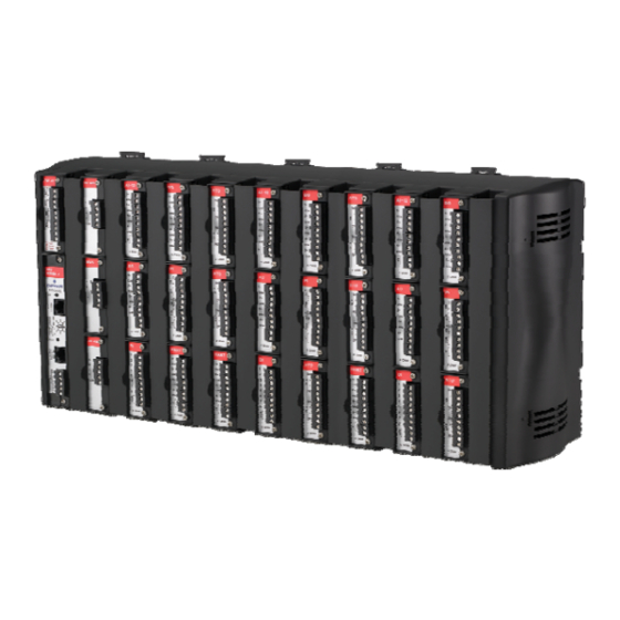
Page 11: Hardware
(CPU), power input module, communication modules, and I/O modules connect. The ROC809 (see Figure 1-1) has nine module slots, of which three can house communication modules. The ROC827 base unit (shown on the left-hand side of Figure 1-2) has three I/O module slots.
-
Page 12
Right End Cap Figure 1-1. ROC809 Module Placement The left-most slots in the ROC809 (Figure 1-1) accommodate the Power Input module and the CPU module. The remaining nine slots can accommodate either communication modules or I/O modules (see Table 1-1). -
Page 13: Discrete Inputs
ROC800-Series Instruction Manual Power Supply Module LOI (Local Port) EIA-232 (RS-232D) Built-in Ethernet (Comm1) Built-in EIA-232 (RS-232C) (Comm2) Module (1 of 27 max) Wire Channel Cover Right End Cap Figure 1-2. ROC827 Base Unit with One Expansion Backplane (separated for clarity) I/O Modules The ROC800 and EXPs support various types of Input/Output (I/O) modules, which can satisfy a wide variety of field I/O requirements…
-
Page 14: Communication Modules
ROC800-Series Instruction Manual Communication Ports The ROC800 provides up to six communication ports (refer to and Modules Chapter 5, Communications). Three communication ports are built-in: ▪ Local Operator Interface (LOI) – Local Port EIA-232 (RS-232D). ▪ Ethernet – 10BASE-T twisted pair. IEEE multi-segment 10 MB/second baseband Ethernet.
-
Page 15: Central Processor Unit (Cpu)
ROC800-Series Instruction Manual 1.3.1 Central Processor Unit (CPU) The CPU contains the microprocessor, the firmware, connectors to the backplane, the three built-in communication ports (two with LEDs), a LED low power wakeup button, a RESET button, the application license key connectors, a STATUS LED indicating system integrity, and the main processor.
-
Page 16: Options
ROC800-Series Instruction Manual Table 1-3. System Analog Inputs System AI PM-12 PM-24 PM-30 Point Function Function Function Number Module Voltage Battery Input Voltage Module Voltage Voltage In Charge in Voltage Module Voltage Module Voltage Module Voltage Module Voltage Not Used Not Used Not Used On Board Temperature…
-
Page 17: Fcc Information
If you experience trouble with this equipment or the dial-up modem, contact Emerson Process Management’s Remote Automation Solutions (at 1-800-537-9313) for repair or warranty information. If the equipment harms the telephone network, the telephone company may request that you disconnect the equipment until the problem is resolved.
-
Page 18
ROC800-Series Instruction Manual : To convert a ROC800 to a ROC800L, refer to the ROC800L Note Field Conversion Guide (part D301683X012 ). The ROC800-Series Operating System firmware provides a complete operating system for the ROC800. The firmware in the ROC800 is field-upgradeable using a serial connection or the Local Operator Interface (LOI) local port. -
Page 19
ROC800-Series Instruction Manual database point to be one of the possible types of points available to the system. Together, these three components—the type (T), the logical (L), and the parameters (P)—can be used to identify specific pieces of data that reside in a ROC800’s data base. -
Page 20
ROC800-Series Instruction Manual Security The ROCLINK 800 software also secures access to the ROC800. You can define and store a maximum of 16 case-sensitive user identifiers (User IDs). In order for the ROC800 to communicate, a case sensitive log-on ID supplied to the ROCLINK 800 software must match one of the IDs stored in the ROC800. -
Page 21: Historical Database And Event & Alarm Log
ROC800-Series Instruction Manual Slot Number Logicals (16 pt) Logicals (8 pt) 120–127 128–135 136–143 144–151 152–159 160–167 168–175 176–183 184–191 192–199 200–207 208–215 216–223 ROC800L The ROC800L firmware provides many of the same capabilities as the ROC800 firmware. We recommend, however, that the ROC800L supports only six gas runs (using a single AGA key).
-
Page 22: Meter Runs And Stations
ROC800-Series Instruction Manual is recorded along with a date and time stamp. The Alarm Log records the last 450 configured occurrences of alarms (set and clear). You can view the logs, save them to a disk file, or print them using ROCLINK 800 software.
-
Page 23: Roc800L Flow Calculations
ROC800-Series Instruction Manual The AGA 7 calculations conform to methods described in American Gas Association Report No. 7, Measurement of Gas by Turbine Meters, and use the AGA 8 method for determining the compressibility factor. The AGA 8 method calculates the compressibility factor based on the physical chemistry of the component gasses at specified temperatures and pressures.
-
Page 24: Low Power Modes
ROC800-Series Instruction Manual The ROC800 periodically performs the following self-tests: ▪ Voltage tests (battery low and battery high) ensure the ROC800 has enough power to run. The ROC800 operates with 12 Volts dc (nominal) power provided through a PM-12, PM-24, or PM-30 power input module (see Figures 3-1, 3-2, or 3-3).
-
Page 25: Proportional, Integral, And Derivative (Pid)
ROC800-Series Instruction Manual ▪ The design of the PM-30 and PM-24 power modules does not include the low voltage cutoff feature present in the PM-12 module: should power fall below the set LoLo alarm (a default of 10.1V), the PM-12 module ceases to provide power to the backplane.
-
Page 26: Roclink 800 Configuration Software
ROC800-Series Instruction Manual The FST Editor provides a workspace into which you can enter—for each FST—either a maximum of 500 lines or a maximum of 3000 bytes. Since the total amount of memory each FST uses is based on the number of steps and the commands used in each step and since different commands consume different amounts of memory, estimating the memory usage of an FST is difficult.
-
Page 27: Roclink 800 Dynamic Graphical Interface
ROC800-Series Instruction Manual Figure 1-3. ROCLINK 800 Dynamic Graphical Interface You can build custom displays for the ROC800 that combine both graphic and dynamic data elements. The displays can monitor the operation of the ROC800 either locally or remotely. You can archive historical values for any numeric parameter in the ROC800.
-
Page 28: Roc800L Software
ROC800-Series Instruction Manual Use ROCLINK 800 to: ▪ Configure and view Input/Output (I/O) points, flow calculations, meter runs, PID control loops, system parameters, and power management features. ▪ Retrieve, save, and report historical data. ▪ Retrieve, save, and report events and alarms. ▪…
-
Page 29: Ds800 Development Suite Software
ROC800-Series Instruction Manual ▪ Batch Queuing: Sequences future batches, if appropriate for your organization. Used in conjunction with the batching program. : The integrity of metrology results is critical to the measurement Note aspects of the ROC800L. You can lock certain configuration parameters to ensure the accuracy of liquid hydrocarbon calculations.
-
Page 30: Expansion Backplane
ROC800-Series Instruction Manual Expansion Backplane The expansion backplane is a key component to the ability of the ROC827 to expand its I/O capabilities to meet your needs. The ROC827 base unit can accommodate up to four additional expansion backplanes, which easily snap together. This increases the total number of available I/O slots to 27.
-
Page 31: Additional Technical Information
ROC800-Series Instruction Manual 1.12 Additional Technical Information Refer to the following technical documentation (available at www.EmersonProcess.com/Remote) for additional and most-current information. Table 1-5. Additional Technical Information Name Form Number Part Number ROC800-Series Remote Operations Controller ROC800 D301155X012 ROC800L Remote Operations Controller ROC800:800L D301678X012 ROC800-Series Operating System Firmware…
-
Page 32
ROC800-Series Instruction Manual [This page is intentionally left blank.] 1-26 General Information Revised July-2017… -
Page 33: Chapter 2 — Installation And Use
ROC800-Series Instruction Manual Chapter 2 – Installation and Use In This Chapter 2.1 Installation Requirements …………… 2-1 2.1.1 Environmental Requirements …………2-2 2.1.2 Site Requirements …………… 2-2 2.1.3 Compliance with Hazardous Area Standards ……2-3 2.1.4 Power Installation Requirements ……….2-3 2.1.5 Grounding Installation Requirements ……….
-
Page 34: Environmental Requirements
ROC800-Series Instruction Manual 2.1.1 Environmental Requirements Always install the ROC800 in a user-supplied building or enclosure to protect it from direct exposure to rain, snow, ice, blowing dust or debris, and corrosive atmospheres. If you install the ROC800 outside of a building, it must be placed in a National Electrical Manufacturer’s Association (NEMA) 3 or higher rated enclosure to ensure the necessary level of protection.
-
Page 35: Compliance With Hazardous Area Standards
ROC800-Series Instruction Manual The site must comply with class limits of Part 15 of the FCC rules. Operation is subject to the following two conditions: (1) The device may not cause harmful interference, and (2) the device must accept any interference received, including interference that may cause undesired operation.
-
Page 36: Grounding Installation Requirements
ROC800-Series Instruction Manual Although the ROC800 can operate on different DC voltages based on the installed Power Input module, it is good practice when using a battery-backed system to install a low-voltage cutoff device to help protect batteries and other devices the ROC800 does not power. Similarly, when the ROC800 uses a PM-24 Power Input module with a 24 V dc battery-backed system, it is a good practice to install an appropriate low voltage cutoff device to protect the battery back-up.
-
Page 37: I/O Wiring Requirements
ROC800-Series Instruction Manual A pipeline with cathodic protection is not a good ground. Do not tie common to the cathodic part of the pipeline. When connecting shielded cable, be sure to tie the shielded cable to earth ground at the end of the cable attached to the ROC800 only. Leave the other end of the shielded cable open to avoid ground loops.
-
Page 38: Removing And Installing Wire Channel Covers
ROC800-Series Instruction Manual Place the tip of a flat-blade screwdriver into the bottom pry hole of the end cap and loosen the end cap by pulling the handle of the screwdriver away from the backplane. Pivot the front end cap away from the back edge of the housing. To replace the end caps: Align the back edge of the end cap on the housing.
-
Page 39: Mounting The Roc800 On A Din Rail
ROC800-Series Instruction Manual Unscrew the two captive screws on the face of the cover. Using the tab at the left side of the removable terminal block, pull the module cover straight out from the ROC800 housing. : If you remove a module for an extended period, install a module Note cover plate over the empty module slot to keep dust and other matter from getting into the ROC800.
-
Page 40: Installing The Din Rail
ROC800-Series Instruction Manual : The distance from the mounting panel to the front of the Note ROC800 is 174mm (6.85”). If you mount the ROC800 inside an enclosure and want to connect a cable to the LOI or Ethernet port, ensure adequate clearance for the cable and the enclosure door.
-
Page 41: Securing The Roc800 To The Din Rail
When placed correctly, the DIN rail catches (see Figure 2-3) secure the ROC to the DIN rail. Place the catches according to the following configuration: ROC809: Two catches. ROC827: One catch. ROC827 and one EXP: Place catches on ROC827 and EXP.
-
Page 42: Attaching An Expansion Backplane
ROC800-Series Instruction Manual Figure 2-4. ROC827 and Expansion Backplane Removing the backplane from the housing is not recommended, as there are no field serviceable parts. If the backplane requires maintenance, please contact your local sales representative. 2.5.1 Attaching an Expansion Backplane To attach an EXP to an existing ROC827 base unit or to another EXP: 1.
-
Page 43: Removing An Expansion Backplane
ROC800-Series Instruction Manual Figure 2-5. Power Connectors on the EXP Backplane 5. Pivot the back edges of the ROC827 and the EXP toward each other until they click together. : The plastic locking clips at the back of the EXP click when Note the two units securely fasten together.
-
Page 44
ROC800-Series Instruction Manual Locking clips and tabs Figure 2-6. Plastic Snaps on the Back of the EXP 4. Using a flat-bladed screwdriver, gently pry the plastic locking clips at the upper and lower back edge of the EXP housing away from their securing tabs. -
Page 45: Central Processing Unit (Cpu)
ROC800-Series Instruction Manual Central Processing Unit (CPU) The ROC800 uses a standard ROC800-Series central processing unit (CPU) containing the microprocessor, the firmware, connectors to the backplane, three built-in communication ports (two with LEDs), a LED low power wakeup button, a RESET button, the application license key connectors, a STATUS LED indicating system integrity, and the main processor (refer to Figures 2-7 and 2-8 and Tables 2-1 and 2-2).
-
Page 46
ROC800-Series Instruction Manual Series 1 CPU Faceplate Series 2 CPU Faceplate (Gray) (Black) Securing Screw LED Button LOI – EIA-232 (RS-232D) Status LED Ethernet EIA-232 (RS-232C) Securing Screw Figure 2-7. CPU Front View (Series 1 and Series 2 CPU Modules) 2-14 Installation and Use Revised July-2017… -
Page 47
ROC800-Series Instruction Manual Series 1 CPU (Green) Series 2 CPU (Black) Battery LED Button RJ-45 Port License Keys RESET Button RJ-45 Port RS-232 Port Microprocessor Battery backup jumper Figure 2-8. CPU Connectors (Series 1 and Series 2 CPU Modules) Table 2-1. CPU Connector Locations CPU Number Series 1 Series 2… -
Page 48
ROC800-Series Instruction Manual internal Analog to Digital Converter (A/D). The A/D monitors the supply voltage and board temperature (refer to “Automatic Self-Tests” in Chapter 1, General Information). The CPU has two buttons, LED and Reset (see Figures 2-7 or 2-8): … -
Page 49: Removing The Cpu Module
ROC800-Series Instruction Manual the default setting of five minutes, all LEDs turn off after five minutes. If you press the LED button, LEDs light and stay lit again for five minutes. By entering a 0 (zero), the LED always stays lit. 2.6.1 Removing the CPU Module Failure to exercise proper electrostatic discharge precautions (such as Caution…
-
Page 50: License Keys
ROC800-Series Instruction Manual Press the CPU firmly into the slot, ensuring the ejector clips rest on the module rail guides. The connectors at the back of the CPU module fit securely into the connectors on the backplane. Place the CPU faceplate on the CPU. Tighten the two screws on the faceplate of the CPU module firmly (see Figure 2-7).
-
Page 51: Installing A License Key
ROC800-Series Instruction Manual 2.7.1 Installing a License Key Failure to exercise proper electrostatic discharge precautions (such as Caution wearing a grounded wrist strap) may reset the processor or damage electronic components, resulting in interrupted operations. When working on units located in a hazardous area (where explosive gases may be present), make sure the area is in a non-hazardous state before performing procedures.
-
Page 52: Startup And Operation
ROC800-Series Instruction Manual To remove a license key: Perform the backup procedure described in Preserving Configuration and Log Data in Chapter 6, Troubleshooting. Remove power from the ROC800. Remove the wire channel cover. Unscrew the captive screws from the CPU faceplate and remove it. Remove the license key from the appropriate terminal slot (P2 or P3) in the CPU (refer to Figure 2-8).
-
Page 53: Operation
ROC800-Series Instruction Manual indicator should light green to indicate that the applied voltage is correct. Then, the STATUS indicator on the CPU should light to indicate a valid operation. Depending on the Power Saving Mode setting, the STATUS indicator may not remain lit during operation (refer to Table 2-2).
-
Page 54
ROC800-Series Instruction Manual [This page is intentionally left blank.] 2-22 Installation and Use Revised July-2017… -
Page 55: Chapter 3 — Power Connections
ROC800-Series Instruction Manual Chapter 3 – Power Connections In This Chapter Power Input Module Descriptions …………….3-1 3.1.1 12-Volt DC Power Input Module (PM-12) ……….3-1 3.1.2 24-Volt DC Power Input Module (PM-24) ……….3-3 3.1.3 30-Volt DC Power Input Module (PM-30) ……….3-4 3.1.4 Auxiliary Output (AUX+ and AUX–) …………3-8 3.1.5…
-
Page 56
ROC800-Series Instruction Manual backplane. The ROC800 requires 11.5 to 14.5 Volts dc for proper operation. BAT+ / BAT– CHG+ / CHG– AUX+ / AUX– – + / AUX OVER TEMP LED Figure 3-1. 12 Volt dc Power Input Module The CHG+ and CHG– terminals comprise an Analog Input channel that allows you to monitor an external voltage between 0 to 18 Volts dc. -
Page 57: 24-Volt Dc Power Input Module (Pm-24)
ROC800-Series Instruction Manual Table 3-1. 12 Volt dc Power Input Terminal Block Connections Terminal Blocks Definition Volts DC Maximum Range: 11.5 to 16 Volts dc BAT+ and BAT– Accepts 12 Volts dc nominal from an AC/DC converter or other 12 Volts dc …
-
Page 58: 30-Volt Dc Power Input Module (Pm-30)
ROC800-Series Instruction Manual + / – AUX+ / AUX– Figure 3-2. 24 Volt dc Power Input Module Table 3-3. 24 Volt dc Power Input Terminal Block Connections Terminal Blocks Definition Volts DC + and – Accepts 24 Volts dc nominal from an AC/DC converter 20 to 30 Volts dc or other 24 Volts dc supply.
-
Page 59
ROC800-Series Instruction Manual expanded backplanes. With this module installed, the ROC800 requires 10.5 to 30 Volts dc for proper operation. Use the AUX+ and AUX– terminals to supply reverse polarity protected source voltage to external devices, such as a radio or solenoid. Power Input Voltage + / –… -
Page 60
ROC800-Series Instruction Manual Low Voltage The design of the PM-30 power module (like the PM-24 power Cutoff module it replaces) does not include the low voltage cutoff feature present in the PM-12 power module. In the PM-12 module, when power falls below the set LoLo alarm (a default of 10.1V), the module ceases to provide power to the backplane. -
Page 61
ROC800-Series Instruction Manual SOLAR PANEL SOLAR VOLTAGE POWER DISCONNECT REGULATOR Figure 3-5. Low voltage disconnect device between the solar regulatory circuitry and the ROC800 Use the Auxiliary Switch (AUX SW) output terminals on the PM-30. If shutting down power to an external device is sufficient, then connecting to the Auxiliary Switch (AUX SW) terminals on the PM-30 power module ensures power is cut off when the LoLo alarm is triggered. -
Page 62: Auxiliary Output (Aux+ And Aux-)
ROC800-Series Instruction Manual 3.1.4 Auxiliary Output (AUX+ and AUX–) You can use the AUX+ and AUX–terminals to supply reverse polarity protected source voltage to external devices, such as a radio or a solenoid. All module terminal blocks accept 12 to 22 AWG wiring. Refer to Figures 3-3 and 3-4.
-
Page 63
ROC800-Series Instruction Manual Figure 3-8. Auxiliary Power Wiring for PM-24 Module PM-30 For the 30 volt dc Power Input module (PM-30), the auxiliary output follows the voltage located at BAT+ minus ~1.0 Volts dc, which is the protection diode voltage drop. For example, if the BAT+ voltage is 13 volts dc, then AUX+ is ~12.3 Volts dc. -
Page 64: Switched Auxiliary Output (Auxsw+ And Auxsw-)
ROC800-Series Instruction Manual Removing the To remove the auxiliary output fuse: Auxiliary Output Fuse Perform the procedure described in Section 3.3, Removing a Power Input Module. Remove the fuse located at F1 on the Power Input module. Installing the Auxiliary To re-install the auxiliary output fuse: Output Fuse Replace the fuse located at F1 on the Power Input module.
-
Page 65: Determining Power Consumption
ROC800-Series Instruction Manual detect circuit includes approximately 0.75 Volts dc of hysteresis between turn-off and turn-on levels. For further information on the STATUS LED functions, refer to Table 2-2 in Chapter 2, Installation and Use. Determining Power Consumption Determining the power consumption requirements for a ROC800 configuration involves the following steps: Determine your ideal ROC800 configuration, which includes identifying all modules, device relays, meters, solenoids, radios,…
-
Page 66
ROC800-Series Instruction Manual individual worksheets to determine how to best “tune” your configuration and lessen power demands. General Calculation To calculate the power requirements of a ROC800 configuration Process requires: Determine the kind and number of communication modules and the kind and number of expanded backplanes you are implementing. -
Page 67
ROC800-Series Instruction Manual : This value represents a safety factor to the power system to Note account for losses and other variables not factored into the power consumption calculations. This safety factor may vary depending on external influences. Adjust the factor value up or down accordingly. Add the value for the Power System Safety Factor (0.25) to the value for Total for ROC800 Base Unit, All Modules, and Other Devices to determine the total estimated power consumption for the… -
Page 68: Di Modules
Quantity Sub-Total Device Used (mW) Description TYPICAL CPU and ROC809 Backplane Power Input Module PM-12 (60W max) 87.5 mA @ 12 volts dc 1050 mW Power Input Module PM-24 (24W max) 102.1 mA @ 24 volts dc 2450 mW Power Input Module PM-30 (70W max)
-
Page 69: Tuning The Configuration
ROC800-Series Instruction Manual 3.2.1 Tuning the Configuration The PM-12 Power Input module can supply a maximum of 60 W (60,000 mW) to the backplane. The PM-24, when operating between –40C to 55C, can supply a maximum of 30 W (30000 mW) to the backplane.
-
Page 70: Description
ROC800-Series Instruction Manual Table 3-8. Power Consumption of the Analog Input Module Power Consumption (mW) Quantity Duty Sub-Total I/O Module Used Cycle (mW) Description TYPICAL Analog Input AI Module Base 84 mA @ 12 volts dc 1008 mW Jumper set for +T @ 12 volts dc Channel’s mA current Channel 1 draw from +T * 1.25 * 12…
-
Page 71
ROC800-Series Instruction Manual Table 3-9. Power Consumption of the Analog Output Module Power Consumption (mW) Quantity Duty Sub-Total I/O Module Used Cycle (mW) Description TYPICAL AO Module Base 100 mA @ 12 volts dc 1200 mW Jumper set for +T @ 12 volts dc Channel’s mA current Channel 1 draw from +T * 1.25 * 12… -
Page 72
ROC800-Series Instruction Manual Table 3-10. Power Consumption of the Discrete Input Module Power Consumption (mW) Quantity Duty Sub-Total I/O Module Used Cycle (mW) Description TYPICAL 19 mA @ 12 volts dc No DI Module Base 228 mW Channels Active Channel 1 3.2 mA @ 12 volts dc 38.4 mW Channel 2… -
Page 73
ROC800-Series Instruction Manual Table 3-11. Power Consumption of the Discrete Output Module Power Consumption (mW) Quantity Duty Sub-Total I/O Module Used Cycle (mW) Description TYPICAL 20 mA @ 12 volts dc No DO Module 240 mW Channels Active Channel 1 1.5 mA 18 mW Channel 2… -
Page 74
ROC800-Series Instruction Manual Table 3-12. Power Consumption of the Discrete Output Relay Module Power Consumption (mW) Quantity Duty Sub-Total I/O Module Used Cycle (mW) Description TYPICAL 6.8 mA @ 12 volts dc DOR Module 81.6 mW No Channels Active 150 mA for 10 mSec 1800 mW Channel 1 during transition… -
Page 75
ROC800-Series Instruction Manual Table 3-13. Power Consumption of the High and Low Speed Pulse Input Module Power Consumption (mW) Quantity Duty Sub-Total I/O Module Used Cycle (mW) Description TYPICAL 21 mA @ 12 volts dc No PI Module 252 mW Channels Active Channel 1 7.4 mA… -
Page 76
ROC800-Series Instruction Manual Table 3-14. Power Consumption of the MVS Module Power Consumption (mW) Quantity Duty Sub-Total I/O Module Used Cycle (mW) Description TYPICAL MVS Module 112 mA @ 12 volts dc 1344 mW Per Active LED 1.5 mA 18 mW 1.25 * Measured Power provided by the module Current Draw at +… -
Page 77
ROC800-Series Instruction Manual Table 3-16. Power Consumption of the APM Module Power Consumption (mW) Quantity Duty Sub-Total I/O Module Used Cycle (mW) Description TYPICAL APM Module 110 mA @ 12 volts dc 1300 mW 1.25 * Measured Power provided by the Current Draw (from +T module’s +T port port in mA) * 24… -
Page 78
ROC800-Series Instruction Manual Table 3-19. Power Consumption of the HART-2 Module Power Consumption (mW) Quantity Duty Sub-Total Other Device Used Cycle (mW) Description TYPICAL HART-2 Module Base 110 mA @ 12 volts dc 1320 mW Channel’s mA current Each Channel draw from +T * 2.50 * 12 Table Total Table 3-20. -
Page 79: Removing A Power Input Module
ROC800-Series Instruction Manual Power Consumption (mW) Quantity Duty Sub-Total I/O Module Used Cycle (mW) Description TYPICAL PM-30 (24V) Joining 912 mW Network PM-30 (30V) Joining 900 mW Network Pm-12 (12V) linked to 240 mW Network Pm-24 (24V) linked to 240 mW Network PM-30 (12V) linked to 396 mW…
-
Page 80
ROC800-Series Instruction Manual Failure to exercise proper electrostatic discharge precautions, such as Caution wearing a grounded wrist strap may reset the processor or damage electronic components, resulting in interrupted operations. When working on units located in a hazardous area (where explosive gases may be present), make sure the area is in a non-hazardous state before performing procedures. -
Page 81: Installing A Power Input Module
ROC800-Series Instruction Manual Installing a Power Input Module To install the Power Input module: Failure to exercise proper electrostatic discharge precautions, such as Caution wearing a grounded wrist strap may reset the processor or damage electronic components, resulting in interrupted operations. When working on units located in a hazardous area (where explosive gases may be present), make sure the area is in a non-hazardous state before performing procedures.
-
Page 82: Wiring The Dc Power Input Module
ROC800-Series Instruction Manual The ROC800 should have a minimum of bare wire exposed to prevent short circuits. Allow some slack when making connections to prevent strain. 3.5.1 Wiring the DC Power Input Module Use 12 to 22 American Wire Gauge (AWG) wire for all power wiring. It is important to use good wiring practice when sizing, routing, and connecting power wiring.
-
Page 83: Wiring The External Batteries
ROC800-Series Instruction Manual If you are monitoring an external charge voltage (12 Volts dc Power Input Module only), wire the CHG+ and CHG– terminal block connector. Refer to Figure 3-12. Figure 3-12. 12 Volt dc Power Supply and CHG+ / CHG– Wiring Replace all other power sources (if necessary) to the ROC800.
-
Page 84: Replacing The Internal Battery
ROC800-Series Instruction Manual Battery Reserve Battery reserve is the amount of time that the batteries can provide power without discharging below 20% of their total output capacity. The battery reserve should be a minimum of five days, with ten days of reserve preferred.
-
Page 85
ROC800-Series Instruction Manual Table 3-23. Replacement Battery Types Part Battery, Lithium, 3V Size 24 mm (0.94 in) diameter x 3 mm (0.12 in) height Type Coin Type Capacity 280 mAh minimum Duracell DL2430 Acceptable Types Eveready CR2430 Sanyo CR2430 … -
Page 86: Additional Technical Information
ROC800-Series Instruction Manual Replace the wire channel cover. Review Restarting the ROC800 in Chapter 6, Troubleshooting. Apply power to the ROC800. Additional Technical Information Refer to the following technical documentation (available at www.EmersonProcess.com/Remote) for additional and most-current information. Table 3-24. Power Input Modules Technical Specifications Name Form Number Part Number…
-
Page 87: Chapter 4 — Input/Output Modules
ROC800-Series Instruction Manual Chapter 4 – Input/Output Modules In This Chapter I/O Module Overview …………….4-1 Installation ………………..4-4 4.2.1 Removing and Installing Wire Channel Covers ……4-4 4.2.2 Removing and Installing Module Slot Covers ……4-5 4.2.3 Installing an I/O Module ………….. 4-5 4.2.4 Removing an I/O Module …………
-
Page 88
ROC800-Series Instruction Manual DOC0513A Front View Side View Terminal Blocks Figure 4-1. Typical I/O Module I/O Slot #1 (Comm 3) I/O Slot #5 I/O Slot #2 (Comm 4) I/O Slot #8 I/O Slot #3 (Comm 5) I/O Slot #6 Wire Channel Cover I/O Slot #9 I/O Slot #4 Module Slot Cover… -
Page 89: Discrete Input
ROC800-Series Instruction Manual I/O modules for the ROC800 include: Analog Input (AI) modules that provide the ability to monitor various analog field values. Discrete Input (DI) and Pulse Input (PI) modules that provide the ability to monitor various discrete and pulse input field values. …
-
Page 90: Installation
ROC800-Series Instruction Manual Installation Failure to exercise proper electrostatic discharge precautions, such as Caution wearing a grounded wrist strap may reset the processor or damage electronic components, resulting in interrupted operations. When installing units in a hazardous area, make sure all installation components selected are labeled for use in such areas.
-
Page 91: Removing And Installing Module Slot Covers
ROC800-Series Instruction Manual : The tabs on the top side of the wire channel cover should rest in Note the slots on the top edge of the channel. 4.2.2 Removing and Installing Module Slot Covers Before you insert an I/O or communications module, remove the module cover (see Figure 4-2) over the empty module slots in which you intend to install the modules.
-
Page 92
ROC800-Series Instruction Manual If the slot is currently empty, remove the module cover. Insert the new I/O module through the module slot on the front of the ROC800 or EXP housing. Make sure the label on the front of the module faces right side up (refer to Figure 4-3). -
Page 93: Removing An I/O Module
ROC800-Series Instruction Manual 4.2.4 Removing an I/O Module To remove an I/O module: Remove the wire channel cover. Disconnect the field wiring. Unscrew the two captive screws holding the module in place. Gently pull the module’s lip out and remove the module from the slot.
-
Page 94
ROC800-Series Instruction Manual D301250X012) or the ROCLINK 800 Configuration Software User Manual (for ROC800L) (part D301246X012). : The AI-16 module provides 16-bit resolution and uses a 24-bit Note A/D converter. DIP switches on the AI-16 module (see Figure 4- 6) allow you to select between current and voltage loop input. You can configure the AI (+T) module as either 12 or 24 Volt dc using jumper J4 on the AI-12 module (see Figure 4-4). -
Page 95: Analog Output (Ao) Modules
ROC800-Series Instruction Manual On the AI-16 module, you use jumper J3 to configure the AI (+T) as 12 or 24 Volts dc. Additionally, two DIP switches on the module allow you to select between current and voltage loop input. I indicates current loop input; V indicates voltage loop input Figure 4-6.
-
Page 96: Discrete Input (Di) Modules
ROC800-Series Instruction Manual 12V / 24V dc Jumper Figure 4-7. Analog Output Jumper J4 (Shown Set to +12V) Representative Field Wiring Internal Circuit CURRENT LOOP CONTROL CURRENT LOOP DEVICE 4-20mA CURRENT LOOP ROC800 POWERED CONTROL CURRENT LOOP CONTROL CURRENT LOOP CONTROL 1-5 VOLT CONTROL DEVICE DOC0505A…
-
Page 97: Discrete Input Module
ROC800-Series Instruction Manual The DI module provides a source voltage for dry relay contacts or for an open-collector solid-state switch. The DI module’s LEDs light when each input is active. Each DI channel can be software-configured to function as a momentary or latched DI (see the ROCLINK 800 Configuration Software User Manual (for ROC800-Series) (part D301250X012 or the ROCLINK 800 Configuration Software User Manual (for ROC800L) (part…
-
Page 98: Pulse Input (Pi) Modules
ROC800-Series Instruction Manual Pulse Input (PI) Modules The Pulse Input (PI) module provides two channels for measuring either a low speed or high speed pulse signal. The PI module processes signals from pulse-generating devices and provides a calculated rate or an accumulated total over a configured period.
-
Page 99: Discrete Output (Do) Modules
ROC800-Series Instruction Manual Representative Field Wiring Internal Circuit OPEN DRAIN TYPE 12KHz PI FILTER & OPEN COLLECTOR DEVICE LEVEL DETECTION EXTERNALLY POWERED 125KHz PI FILTER & LEVEL DETECTION CONTACT-CLOSURE DEVICE EXTERNALLY POWERED DOC0510B Figure 4-11. Externally Powered Pulse Input Module Field Wiring Representative Field Wiring Internal Circuit…
-
Page 100: Discrete Output Module
ROC800-Series Instruction Manual configured to either retain the last value on reset or use a user-specified fail-safe value. The DO module provides LEDs that light when each output is active. When a request is made to change the state of a DO, the request is immediately sent to the DO module.
-
Page 101: Discrete Output Relay (Dor) Modules
ROC800-Series Instruction Manual ROCLINK 800 provides a “virtual DO” software setting to support Virtual DO fieldbus devices, which may require the toggle characteristics of DO. For further information, see the ROCLINK 800 Configuration Software User Manual (for ROC800-Series) (part D301250X012) or the ROCLINK 800 Configuration Software User Manual (for ROC800L) (part D301246X012).
-
Page 102: Resistance Temperature Detector (Rtd) Input Modules
ROC800-Series Instruction Manual RELA DISCRETE DEVICE SELF- POWERED CONTROL LATCHING RELAY NOTE: S = SET R = RESET DISCRETE DEVICE EXTERNALLY POWERED CONTROL 5 CHAN DOC0509A Figure 4-14. Discrete Output Relay Module Field Wiring Resistance Temperature Detector (RTD) Input Modules The Resistance Temperature Detector (RTD) module monitors the temperature signal from an RTD source.
-
Page 103
ROC800-Series Instruction Manual the RTD module. See Table 4-1, Table 4-2, and Figure 4-15. The ROC800 provides terminations for a four-wire 100-ohm platinum RTD with a DIN 43760 curve. The RTD module supports RTDs with alphas equal to 0.00385 or 0.00392 //C. You can use a two-wire or three-wire RTD probe instead of a four-wire probe, but they may produce measurement errors due to signal loss on the wiring. -
Page 104: Advanced Pulse Module (Apm)
ROC800-Series Instruction Manual Table 4-2. RTD Wiring Terminal 4-Wire RTD 3-Wire RTD 2-Wire RTD Jumper to + Jumper to + Red, Jumper to REF Red, Jumper to REF – White White White, Jumper to RET Jumper to – White White : The wire colors for the RTD being used may differ.
-
Page 105
ROC800-Series Instruction Manual GENERIC DENSITOMETER ROC800 POWERED DRY CONTACT EXTERNALLY POWERED DEVICE OPEN COLLECTOR OPEN DRAIN TYPE Figure 4-18. Generic Densitometer Wiring on APM Figure 4-19. Input Detector Wiring on APM DET SW 1 DET SW 2 DET SW 1 DET SW 2 Figure 4-20. -
Page 106: Dip Switches
ROC800-Series Instruction Manual NO CONNECTION EXTERNAL DEVICE CONTROL Figure 4-24. Pulse Output Wiring on APM The APM card’s daughterboard contains several DIP switches which DIP Switch you use to control the module’s activities. See Figure 4-25 for the Settings switch locations and labels; see Table 4-3 for the settings. Figure 4-25.
-
Page 107: Multi-Variable Sensor Input/Output (Mvs I/O)
ROC800-Series Instruction Manual Switch Channel Side Function Switch Position Left 10 k Pullup to 12 V dc Left No Pullup Resistor Down Right 10 k Pullup to 12 V dc Right No Pullup Resistor Down Left 10 k Pullup to 12 V dc Left No Pullup Resistor Down…
-
Page 108
ROC800-Series Instruction Manual Figure 4-26. MVS and MVS I/O Modules The MVS I/O module consists of interface electronics that provide the communications link between the ROC800 and the MVS devices. The interface electronics controls communications with the sensor module, provides scaling of process variables, aids calibration, stores operating parameters, performs protocol conversion, and responds to requests from the ROC800. -
Page 109
ROC800-Series Instruction Manual terminals on the devices are electrically connected to the ROC800’s “A” terminal and so on. Wire each remote MVS transmitter in parallel (“daisy-chaining”), as shown in Figure 4-27. 120 Ohm MVS I/O transmitter resistor at Module (up to 6 per end of line module) 1000+ meters… -
Page 110
ROC800-Series Instruction Manual Figure 4-29. MVS I/O Field Wiring : A “star” configuration for transmitters may not be reliable. Note Terminations are recommended for long distances (greater that 1000 meters) at the extreme ends of the circuit. Terminate the two outermost devices to reduce signal reflection in the circuit. -
Page 111
ROC800-Series Instruction Manual : Pay close attention to the connections; do not reverse the Note power wires. Make these connections only after removing power from the ROC800. Double-check connections for the proper orientation before applying power. If the connections are reversed and power is applied, you may damage both the MVS module and the ROC800-Series processor board. -
Page 112: Alternating Current Input/Output (Ac I/O) Module
ROC800-Series Instruction Manual 4.12 Alternating Current Input/Output (AC I/O) Module EMC issues restrict the use of the AC I/O module only to devices using Warning a PM-12 power module. You cannot use the AC I/O module in a device that uses either a PM-24 or PM-30 power module. Switchable I/O and The module has one bank of six DIP switches on its daughterboard LEDs…
-
Page 113
ROC800-Series Instruction Manual EXTERNAL AC PWR/PERMISSIVE SOURCE SOLID-STATE RELAY CONTROL AC CONTROLLED DEVICE SOLID-STATE RELAY CONTROL AC CONTROLLED DEVICE Figure 4-33. AC I/O Module (Output Field Wiring) : If the label on your AC I/O module does not indicate 120/240V, Note your module is designed for use only with 120V. -
Page 114: Thermocouple (Tc) Input Module
ROC800-Series Instruction Manual : If the label on your AC I/O module does not indicate 120/240V, Note your module is designed for use only with 120V. Additionally, all AC wiring must be shielded. Table 4-5. Field Wiring Terminals Terminal Label Definition AC In AC Input (Permissive Power)
-
Page 115
ROC800-Series Instruction Manual errors due to any voltage inducted at the wiring terminals by the junction between the different metal of the TC wiring and the TC module’s terminal blocks. : The use of dissimilar metals is not supported. It does not provide Note the correct results, as CJC is applied at the module level. -
Page 116
ROC800-Series Instruction Manual Figure 4-35. Thermocouple Input Module Wiring Be sure to use the correct type of thermocouple wire to connect the thermocouple to the ROC800. Minimize connections and make sure connections are tight. If you use any dissimilar metals (such as copper wire) to connect a thermocouple to the ROC800, you can create the junction of dissimilar metals that can generate millivolt signals and increase reading errors. -
Page 117
ROC800-Series Instruction Manual Take care to properly shield thermocouple wiring from noise by separating the thermocouple wiring runs from signals that are switching loads and AC signals. Route wires away from noisy areas and twist the two insulated leads of the thermocouple cable together to help ensure both wires pick up the same noise. -
Page 118: Highway Addressable Remote Transducer (Hart ) Module
ROC800-Series Instruction Manual ® 4.14 Highway Addressable Remote Transducer (HART ) Module : The HART-2 module (labeled HART-2 with black faceplate) Note replaces the HART module (with gray faceplate). The HART-2 module allows a ROC800 to communicate with HART devices using the HART protocol. The HART-2 module receives signals from and transmit signals to HART devices.
-
Page 119
ROC800-Series Instruction Manual commands conform to HART Universal Command Specification Revision 5.1 and Common Practice Command Specification Revision 7, (HCF SPEC 127 and 151). Refer to www.hartcomm.org for more information on the specifications. The HART-2 module polls the channels simultaneously. If more than one device is connected to a channel in a multi-drop configuration, the module polls one device per channel at a time. -
Page 120: Iec 62591 Module
ROC800-Series Instruction Manual Figure 4-39. Input Point-to-Point Wiring on Figure 4-40. Input Multi-Drop Wiring on HART- HART-2 Module 2 Module Figure 4-41. Output Wiring on HART-2 Module 4.15 IEC 62591 Module The IEC 62591 Interface module allows a ROC800-Series Remote Operations Controller (ROC800) to communicate with any mix of up to 60 WirelessHART™…
-
Page 121
ROC800-Series Instruction Manual The IEC 62591 Interface consists of two parts: the Smart Wireless Field Link that provides the radio link to the WirelessHART field devices, and the IEC 62591 Interface Module that installs into the ROC800. Installation and The IEC 62591 Interface module connects to the Smart Wireless Field Configuration Link through a four-wire connection. -
Page 122: App 485 Module
ROC800-Series Instruction Manual 4.16 APP 485 Module The Application module (APP 485) provides a solution to add user applications to the ROC800-Series (ROC800) by simply installing a module. The APP 485 module streamlines the installation process by including all point types and screens associated with the application, and the module is automatically recognized by ROC800 firmware.
-
Page 123: Additional Technical Information
ROC800-Series Instruction Manual 4.17 Additional Technical Information Refer to the following technical documentation (available at www.EmersonProcess.com/Remote) for additional and most-current information on each of the I/O modules. Table 4-6. I/O Module Technical Specifications Name Form Number Part Number ROC800-Series Analog Input Modules ROC800:AI D301238X012 ROC800-Series Alternating Current I/O Module…
-
Page 124
ROC800-Series Instruction Manual [This page is intentionally left blank.] 4-38 Input/Output Modules Revised July-2017… -
Page 125: Chapter 5 — Communications
ROC800-Series Instruction Manual Chapter 5 – Communications In This Chapter Communication Ports and Modules Overview ……..5-1 Installing Communication Modules …………5-3 Removing a Communication Module …………. 5-5 Wiring Communication Modules …………5-5 Local Operator Interface (LOI) …………… 5-5 5.5.1 Using the LOI …………….5-7 Ethernet Communication …………….
-
Page 126
ROC800-Series Instruction Manual The communication modules consist of a printed circuit board, a communication port, wiring terminal block, LEDs, and connectors to the backplane. The ROC800 can hold up to three communication modules in the first three module slots. Refer to Figure 5-1. LOI (Local Port) EIA-232 (RS-232D) Built-in Ethernet (Comm1) Built-in EIA-232 (RS-232) (Comm2) -
Page 127: Installing Communication Modules
ROC800-Series Instruction Manual 232) module, every communication module is isolated from other modules and the backplane, including power and signal isolation. The field interface has been designed to protect the electronics in the module. Filtering is provided on each module to reduce communication errors.
-
Page 128: Communication Module
ROC800-Series Instruction Manual : With the exception of the HART module, you can install Note communication modules only in slots 1, 2, or 3 of the ROC800. Refer to Figure 5-1 and Table 5-1. Remove the wire channel cover. : Leaving the wire channel cover in place can prevent the Note module from correctly connecting to the socket on the backplane.
-
Page 129: Removing A Communication Module
ROC800-Series Instruction Manual Connect to ROCLINK 800 software and login. The modules are self-identifying after re-connecting to ROCLINK 800 software. Removing a Communication Module To remove a communication module: Remove the wire channel cover. Unscrew the two captive screws holding the module in place. Gently pull the module’s lip out and remove the module from the slot.
-
Page 130: Direct Connect
ROC800-Series Instruction Manual ® interface device, such as a personal computer running Microsoft ® Windows . The interface allows you to access the ROC800 with a direct connection using ROCLINK 800 software to configure and transfer stored data. The LOI uses the Local Port in ROCLINK 800 software. The LOI terminal (RJ-45) on the CPU provides wiring access to a built- in EIA-232 (RS-232) serial interface, which is capable of 57.6K baud operation.
-
Page 131: Using The Loi
ROC800-Series Instruction Manual EIA-232 RJ-45 Pins ROC800- (RS-232) on ROC800- Series Series – Adaptor Cable Remote Automation Solutions offers an adaptor cable to resolve this cabling issue. Order CBL8A from your Remote Automation Solutions salesperson. 5.5.1 Using the LOI Plug the LOI cable into the LOI RJ-45 connector of the ROC800. Connect the LOI cable to the D-Sub 9 pin (F) to RJ-45 modular converter.
-
Page 132
ROC800-Series Instruction Manual The Medium Access Control (MAC) mechanism embedded in each station interface determines access to the shared medium. The MAC mechanism is based on Carrier Sense Multiple Access with Collision Detection (CSMA/CD). If two stations begin to transmit a packet at the same instant, the stations stop transmitting (Collision Detection). -
Page 133: Rs-232) Serial Communication
ROC800-Series Instruction Manual Signal coupling between the different cable pairs contained within a multi-pair cable bundle causes “crosstalk.” 10BASE-T transceivers are designed so that you do not need to be concerned about cable crosstalk, provided the cable meets all other requirements. Noise can be caused by crosstalk of externally induced impulses.
-
Page 134: Eia-422/485 (Rs-422/485) Serial Communications Module
ROC800-Series Instruction Manual LOI – Local Port EIA-232 (RS-232D). Refer to Section 5.5, Local Operator Interface. Built-in – Comm2 EIA-232 (RS-232C). Module – Comm3 to Comm5 EIA-232 (RS-232C). EIA-232 (RS-232) uses point-to-point asynchronous serial communication and is commonly used to provide the physical interface for connecting serial devices, such as gas chromatographs and radios to the ROC800-Series.
-
Page 135: Eia-422/485 (Rs-422/485) Jumpers & Termination Resistors
ROC800-Series Instruction Manual used to multi-drop units on a serial network over long distances using inexpensive twisted-pair wiring. EIA-422 (RS-422) drivers are designed for party-line applications where one driver is connected to, and transmits on, a bus with up to ten receivers.
-
Page 136
ROC800-Series Instruction Manual Terminations are required on the two EIA-422/485 (RS-422/485) communication modules located at the extremities of the circuit. That is to say, the two outside modules require terminations in order to complete the communication circuit. Figure 5-5. EIA-422/485 (RS-422/485) Jumpers Table 5-10. -
Page 137: Dial-Up Modem Communication Module
ROC800-Series Instruction Manual Dial-up Modem Communication Module The dial-up modem module interfaces to a Public-Switched Telephone Network (PSTN) line, and requires a telephone line connection. The module provides a telephone interface on the host port that is capable of both answering and originating telephone calls. The module also provides electronics that conserve power when the phone line is not in use.
-
Page 138: Multi-Variable Sensor (Mvs) Interface Module
ROC800-Series Instruction Manual Notes If you are installing a modem module, it is recommended that you install a surge protector between the RJ-11 jack and the outside line. The dial-up modem is not hot-swappable or hot-pluggable. When installing a dial-up modem module, you must remove power from the ROC800.
-
Page 139
ROC800-Series Instruction Manual The NRM provides a wireless solution of transferring data from RTU to another RTU within the Distributed RTU Network (DRN). The data can be any type of information that the RTU has in its database, such as I/O, soft points, or other information. -
Page 140: Additional Technical Information
ROC800-Series Instruction Manual 5.12 Additional Technical Information Refer to the following technical documentation (available at www.EmersonProcess.com/Remote) for additional and most-current information. Table 5-14. Communication Modules Technical Specifications Name Form Number Part Number ROC800-Series Communication Modules ROC800:COM D301171X012 ROC800-Series Network Radio Module ROC800:NRM D301732X012 Distributed RTU™…
-
Page 141: Chapter 6 — Troubleshooting
ROC800-Series Instruction Manual Chapter 6 – Troubleshooting In This Chapter Guidelines ………………..6-1 Checklists ………………..6-2 6.2.1 Serial Communications …………..6-2 6.2.2 I/O Point ………………6-3 6.2.3 Software ………………6-3 6.2.4 Powering Up……………… 6-4 6.2.5 MVS or MVS I/O Module …………… 6-4 6.2.6 IEC 62591 Module …………….
-
Page 142: Checklists
ROC800-Series Instruction Manual When you are done troubleshooting, perform the restart procedure as described in Restarting the ROC800 in this chapter. Checklists If the LEDs do not display: By default, LEDs on the communication modules and I/O modules enter Sleep mode after five minutes. …
-
Page 143: I/O Point
ROC800-Series Instruction Manual 6.2.2 I/O Point If you are experiencing troubles with an I/O point (Analog Input, Analog Output, Discrete Input, Discrete Output, Pulse Input, RTD Input, or Thermocouple Input): Check (using ROCLINK 800 software) to see how the channel is configured.
-
Page 144: Powering Up
ROC800-Series Instruction Manual Restore to To restore the ROC800 to factory defaults (that is, as the ROC800 Factory Defaults was delivered to you from the factory without installed user programs, FLASH memory contents, FSTs, DS800 applications, or configurations) without connecting to ROCLINK 800, use this procedure: Remove power from the ROC800.
-
Page 145: Iec 62591 Module
ROC800-Series Instruction Manual 6.2.6 IEC 62591 Module If you are experiencing trouble with the IEC 62591 module: If the IEC 62591module is already set up, a power cycle of the devices will speed up the discovery of other devices. Procedures Use the following procedures to resolve various issues with the I/O modules.
-
Page 146: Troubleshooting Analog Input Modules
ROC800-Series Instruction Manual Ensure all input devices, output devices, and processes remain in a Caution safe state upon restoring power. An unsafe state could result in property damage. When working on units located in a hazardous area (where explosive gases may be present), make sure the area is in a non-hazardous state before performing procedures.
-
Page 147
ROC800-Series Instruction Manual Failure to exercise proper electrostatic discharge precautions, such as Caution wearing a grounded wrist strap may reset the processor or damage electronic components, resulting in interrupted operations. Connect a multimeter across the scaling resistor connected to the + and COM terminals of the module and set the multimeter to measure voltage. -
Page 148: Troubleshooting Analog Output Modules
ROC800-Series Instruction Manual Remove the test equipment. 6.3.4 Troubleshooting Analog Output Modules Equipment Required: Multimeter. PC running ROCLINK 800 software. Failure to exercise proper electrostatic discharge precautions, such as Caution wearing a grounded wrist strap may reset the processor or damage electronic components, resulting in interrupted operations.
-
Page 149: Troubleshooting Discrete Input Modules
ROC800-Series Instruction Manual Select the General tab on the Analog Output screen. Remove the test equipment, and reconnect the field device. If possible, verify the correct operation of the AO module by setting the values in the High Reading EU and Low Reading EU fields to the values you recorded in step 9 and observing the field device.
-
Page 150: Troubleshooting Discrete Output Relay Modules
ROC800-Series Instruction Manual Remove all wiring from the DO module. Connect the multimeter set up to measure ohms to the channel that you are testing. Measure the resistance with the DO Status OFF. It should be over 2 megohms. Measure the resistance with the DO Status ON. It should be approximately 1 ohm.
-
Page 151: Troubleshooting Rtd Input Modules
ROC800-Series Instruction Manual Select Configure > I/O > PI Points. The Pulse Input screen displays. Select the correct Pulse Input Point number. Connect a pulse generator having sufficient output to drive the module to terminals L+ or H+ and COM. The pulse generator must synthesize a square wave signal of 50% for every cycle.
-
Page 152: Troubleshooting Thermocouple Input (T/C) Modules
ROC800-Series Instruction Manual Select Configure > I/O > RTD Points. The RTD Input screen displays. Disconnect the RTD and connect one jumper between the – terminal and RET and another jumper between the + terminal and the REF of the RTD module. Connect either an accurate resistor or decade resistance box with a value to give a low end reading across the + and –…
-
Page 153
ROC800-Series Instruction Manual To test the thermocouple module: Disconnect the thermocouple from the thermocouple module. Generate the correct J or K signal using a multimeter and connect the wiring from the multimeter to the T/C module. Verify the ROC is reading the generated temperature from the multimeter. -
Page 154: Troubleshooting Advanced Pulse Modules
ROC800-Series Instruction Manual 6.3.11 Troubleshooting Advanced Pulse Modules Equipment Required Pulse Generator Voltage Generator Frequency Counter Jumper wire PC running ROCLINK 800 software Failure to exercise proper electrostatic discharge precautions, such as Caution wearing a grounded wrist strap may reset the processor or damage electronic components, resulting in interrupted operations.
-
Page 155
ROC800-Series Instruction Manual If a duplicate Network ID and Channel exists on the network, a node may indicate connectivity to a Network but will not appear in the Discovery list. A node will not appear on the Access Points Discovery list if there is a second unit setup as an access point. -
Page 156
ROC800-Series Instruction Manual [This page is intentionally left blank] 6-16 Troubleshooting Revised July-2017… -
Page 157: Chapter 7 — Calibration
ROC800-Series Instruction Manual Chapter 7 – Calibration In This Chapter Calibration Overview ……………. 7-1 Calibration Frequency …………..7-1 Preparing for Calibration …………..7-2 This chapter provides overview information about calibration procedures for the Analog Input (AI) modules, HART module, RTD Input module, and Multi-Variable Sensor modules (MVS and MVS I/O).
-
Page 158: Preparing For Calibration
ROC800-Series Instruction Manual Establishing verification and calibration routines ensures not only that your devices and software are functioning optimally but that your organization is in compliance with appropriate industry and governmental requirements. 7.3 Preparing for Calibration Before calibrating the inputs from a sensor, HART device, or other device, you should prepare the ROC800.
-
Page 159: Appendix A — Glossary
ROC800-Series Instruction Manual Appendix A – Glossary Note: This is a generalized glossary of terms. Not all the terms may necessarily correspond to the particular device or software described in this manual. For that reason, the term “ROC” is used to identify all varieties of Remote Operations Controllers (including ROC800-Series, ROC800L, DL8000, FloBoss™…
-
Page 160
ROC800-Series Instruction Manual Communications port on a personal computer (PC). (continued) COMM Communications port on a ROC used for host communications. . Note: On FloBoss 500-Series and FloBoss 407s, COMM1 is built-in for RS-232 serial communications. Comm Module Module that plugs into a ROC to provide a channel for communications via a specified communications protocol, such as EIA-422 (RS-422) or HART. -
Page 161
ROC800-Series Instruction Manual Distributed RTU Network, in which two or more remotely distributed RTU devices (RRTUs) are wirelessly connected in a peer-to-peer network to share data. (continued) DRTU A primary component of the Distributed RTU Network, consisting of a FB107 chassis housing a focused functionality CPU and a Network Radio module (NRM). -
Page 162: Analog Output
Fieldbus (www.fieldbus.org). Compressibility Factor. Frequency Shift Keypad. Function Sequence Table, a type of user-written program in a high-level language designed by Emerson Process Management’s Flow Computer Division. Foot or feet. Ground Fault Analysis. Gigahertz, 10 cycles per second Electrical ground, such as used by the ROC’s power supply.
-
Page 163
ROC800-Series Instruction Manual Kilobytes. KiloHertz. Liquid Crystal Display. Local Display Panel, a display-only device that plugs into ROC300-Series units (via a parallel interface cable) used to access information stored in the ROC. Light-Emitting Diode. Logical Number The point number the ROC and ROC Plus protocols use for I/O point types are based on a physical input or output with a terminal location;… -
Page 164
ROC800-Series Instruction Manual (continued) Node A basic structural component of the Distributed RTU Network. A node (usually a FB107 chassis housing a focused-functionality CPU and a Network Radio module) provides a data collection point that wirelessly transmits data throughout the designed network. Network Radio module;… -
Page 165
ROC800-Series Instruction Manual Protocol A set of standards that enables communication or file transfers between two computers. Protocol parameters include baud rate, parity, data bits, stop bit, and the type of duplex. PSTN Public Switched Telephone Network. Process Temperature. Push-to-Talk signal. Pulse Transient variation of a signal whose value is normally constant. -
Page 166
ROC800-Series Instruction Manual (continued) Script An uncompiled text file (such as keystrokes for a macro) that a program interprets in order to perform certain functions. Typically, the end user can easily create or edit scripts to customize the software. Soft Points A type of ROC point with generic parameters that can be configured to hold data as desired by the user. -
Page 167: Appendix B — Wiring Diagrams
ROC800-Series Instruction Manual Appendix B – Wiring Diagrams This appendix presents wiring examples between select ROC800 module and several standard Emerson devices. For other devices, refer to the manufacturer’s specifications. Daniel Senior Sonic Meter to PI Module DANIEL SENIOR SONIC METER 12KHz PI FILTER &…
-
Page 168: Daniel 1818A And 1838 Turbine Pre-Amp To Pi Module
ROC800-Series Instruction Manual Daniel 1818A and 1838 Turbine Pre-Amp to PI Module DANIEL PREAMP TURBINE 1818A PICKUP METER COIL 15-28 VDC 12KHz PI FILTER & LEVEL DETECTION SQR. WAVE COMMON 12KHz PI FILTER & TURBINE LEVEL DETECTION PICKUP METER COIL 15-28 VDC SQR.
-
Page 169: Micro Motion Rft9739 & 2400S Transmitters To Pi Module
ROC800-Series Instruction Manual Micro Motion RFT9739 & 2400S Transmitters to PI Module MICRO MOTION RFT9739 TRANSMITTER 12KHz PI FILTER & LEVEL DETECTION 12KHz PI FILTER & LEVEL DETECTION MICRO MOTION RFT9739 TRANSMITTER DOC0740A MICRO MOTION 2400S TRANSMITTER 12KHz PI FILTER & LEVEL DETECTION 12KHz PI FILTER &…
-
Page 170: Micro Motion Rft9739 & 2400S Transmitters To Apm Module
ROC800-Series Instruction Manual Micro Motion RFT9739 & 2400S Transmitters to APM Module MICRO MOTION RFT9739 TRANSMITTER MICRO MOTION RFT9739 TRANSMITTER MICRO MOTION 2400S TRANSMITTER MICRO MOTION 2400S TRANSMITTER Wiring Diagrams Revised July-2017…
-
Page 171: 3- And 4-Wire Rtd To Rtd Module
ROC800-Series Instruction Manual 3- and 4-Wire RTD to RTD Module 4 — WIRE RTD 3 — WIRE RTD Revised July-2017 Wiring Diagrams…
-
Page 172: Daniel Senior Sonic Meter To Apm Module
ROC800-Series Instruction Manual Daniel Senior Sonic Meter to APM Module DANIEL SENIOR SONIC METER DANIEL SENIOR SONIC METER Wiring Diagrams Revised July-2017…
-
Page 173: Daniel 1818A And 1838 Dual Turbine Pre-Amp To Apm Module
ROC800-Series Instruction Manual Daniel 1818A and 1838 Dual Turbine Pre-Amp to APM Module DANIEL PREAMP TURBINE 1818A PICKUP METER COIL 15-28 VDC SQR. WAVE COMMON TURBINE PICKUP METER COIL 15-28 VDC SQR. WAVE COMMON DANIEL PREAMP 1818A TURBINE PICKUP DANIEL PREAMP METER COIL 1838…
-
Page 174: Daniel 1818A And 1838 Turbine Pre-Amp To Apm Module
ROC800-Series Instruction Manual Daniel 1818A and 1838 Turbine Pre-Amp to APM Module DANIEL PREAMP TURBINE 1818A PICKUP METER COIL 15-28 VDC SQR. WAVE COMMON PICKUP 15-28 VDC COIL SQR. WAVE COMMON DANIEL PREAMP 1818A TURBINE PICKUP DANIEL PREAMP METER COIL 1838 PICKUP COIL…
-
Page 175: Two-Stage Valve With Two Limit Switches To Acio Module
ROC800-Series Instruction Manual Two-Stage Valve with Two Limit Switches to ACIO Module PERMISSIVE POWER AC L1 PERMISSIVE NEUTRAL UPSTR N.O. MICRO SWITCH DNSTR N.C. MICRO SWITCH UPSTREAM SOLENOID N.O. DOWNSTREAM SOLENOID N.C. Revised July-2017 Wiring Diagrams…
-
Page 176
ROC800-Series Instruction Manual [This page is intentionally left blank.] B-10 Wiring Diagrams Revised July-2017… -
Page 177
ROC800-Series Instruction Manual Index Attaching an EXP ……….2-11 Automatic Self Tests ……… 1-17 Numerics AUX Terminal …………3-2 +12 V dc AUX+ and AUX– ……..3-2, 3-3, 3-8 Analog Input ……….. 4-8 LEDs …………… 3-3 Pulse Input ………… 4-12 Auxiliary +24 V dc Wiring ………….. -
Page 178
ROC800-Series Instruction Manual Communication modules Discrete Input ……….3-18 Specifications ……….5-16 Discrete Output ……….3-19 Communications Discrete Output Relay ……..3-20 HART Interface module …….. 4-31 MVS ………….. 3-22 Port Locations ……….5-1 Pulse Input ………… 3-21 Configuration Data RTD …………. 3-23, 3-24 Preserving …………6-5 TC ………….. -
Page 179
ROC800-Series Instruction Manual 2-7. CPU Front View (Series 1 and Series 2 4-25. DIP Switches on APM ……4-20 CPU Modules) ……….2-14 4-26. MVS and MVS I/O Modules ….4-21 2-8. CPU Connectors ……..2-15 4-27. MVS Wiring (with Terminators) … 4-22 2-9. -
Page 180
ROC800-Series Instruction Manual Pulse Inputs ……….4-12 RS-232 Communications ……. 5-2 I/O modules …………4-1 STATUS …………2-16 AC I/O …………4-25 License key …………2-18 AI-12 …………..4-7 License Key AI-16 …………..4-7 Installing …………2-19 Analog Outputs ……….4-9 Removing …………. 2-20 APM ………….. -
Page 181
Public Switched Telephone Networks PSTNs …………5-12 Pulse Inputs …………4-12 Tables +12 and +24 V dc ……… 4-12 1-1. ROC809 Module Placement J4 Jumper …………. 4-12 (Series 1 CPU vs. Series 2 CPU) ….1-3 LEDs …………. 4-12 1-2. Module Placement (Series 1 CPU vs. -
Page 182
Relay module ……….3-20 FFI …………..1-25 3-13. Power Consumption, Pulse Input ROC800 …………1-25 module …………3-21 ROC809 …………1-25 3-14. Power Consumption, MVS module ..3-22 ROC829 …………1-25 3-15. Power Consumption, MVS I/O TEMP module …………3-22 LED ………….. -
Page 183
ROC800-Series Instruction Manual Wire Channel Covers ………. 2-6 Dial-up modem ……….5-13 Wire gauges ……….4-7, 5-5 External Batteries ……… 3-29 Wiring …………..B-1 I/O Modules ………… 4-7 3- and 4-Wire RTD ……… B-5 I/O Requirements ……….. 2-5 Auxiliary Power ……….3-8 Micro Motion Transmitters …… -
Page 184
Emerson Automation Solutions Remote Automation Solutions Emerson FZE P.O. Box 17033 © 2006–2017 Remote Automation Solutions, a business unit of Emerson Automation Jebel Ali Free Zone – South 2 Solutions. All rights reserved. Dubai U.A.E. This publication is for informational purposes only. While every effort has been made to ensure…
This manual is also suitable for:
Roc827
-
Oleg TON
- Сообщения: 1
- Зарегистрирован: 26 июл 2016, 09:50
- Имя: Тутыхин Олег Николаевич
- Страна: Казахстан
- город/регион: ЗКО г Уральск
Roclink800
Сообщение
Oleg TON » 26 июл 2016, 10:18
Добрый день коллеги!
Не могу найти руководство Roclink800 на русском для конфигурации FloBoss103
-

servo85
- специалист по B&R

- Сообщения: 150
- Зарегистрирован: 15 фев 2014, 23:37
- Имя: Волоснов Сергей
- Страна: Казахстан
- город/регион: Актобе
- Благодарил (а): 13 раз
- Поблагодарили: 9 раз


Roclink800
Сообщение
servo85 » 26 июл 2016, 14:27
Автоматизация бардака порождает только автоматизированный бардак
-
poladovs313
- здесь недавно
- Сообщения: 23
- Зарегистрирован: 14 май 2016, 11:49
- Имя: Poladov Zaur
- Страна: Azerbaydjan
- город/регион: Baku
- Благодарил (а): 2 раза

Roclink800
Сообщение
poladovs313 » 12 авг 2016, 11:36
Добрый день, Уважаемый.Для рок 809 на русском языке у вас не будет?
-
poladovs313
- здесь недавно
- Сообщения: 23
- Зарегистрирован: 14 май 2016, 11:49
- Имя: Poladov Zaur
- Страна: Azerbaydjan
- город/регион: Baku
- Благодарил (а): 2 раза
Roclink800
Сообщение
poladovs313 » 14 авг 2016, 22:24
Уважаемый,Сергей.Большое спасибо вам за то, что вы выложили на форум «руководство Roclink800» на русском языке.Но к сожалению начав читать его я выяснил что там не полная версия…т.е в содержании написано , что он(руководство) состоит и 10-ти частей а фактически там всего 6 частей.Если можете выложите и остальные части…Мне это крайне важно.Я работаю с ПЛК РОК809 и там мне нужно начертить новую мнемосхему…Как раз таки этих частей там нет….:((((
-
servo85
- специалист по B&R
- Сообщения: 150
- Зарегистрирован: 15 фев 2014, 23:37
- Имя: Волоснов Сергей
- Страна: Казахстан
- город/регион: Актобе
- Благодарил (а): 13 раз
- Поблагодарили: 9 раз
Roclink800
Сообщение
servo85 » 15 авг 2016, 15:04
Уважаемый Заур, к сожалению я не работаю с ПЛК ROC, а только с расходомером FloBoss-107. Ранее даже не обращал внимания, на то что в русскоязычном руководстве отсутствуют четыре последних части. Выкладываю полный англоязычный оригинал, т.к. ничего другого на русском языке нет. Надеюсь он сможет вам чем нибудь помочь.
Автоматизация бардака порождает только автоматизированный бардак
-
poladovs313
- здесь недавно
- Сообщения: 23
- Зарегистрирован: 14 май 2016, 11:49
- Имя: Poladov Zaur
- Страна: Azerbaydjan
- город/регион: Baku
- Благодарил (а): 2 раза
Roclink800
Сообщение
poladovs313 » 15 авг 2016, 18:19
servo85 писал(а): Уважаемый Заур, к сожалению я не работаю с ПЛК ROC, а только с расходомером FloBoss-107. Ранее даже не обращал внимания, на то что в русскоязычном руководстве отсутствуют четыре последних части. Выкладываю полный англоязычный оригинал, т.к. ничего другого на русском языке нет. Надеюсь он сможет вам чем нибудь помочь.
хм…жаль однако…все равно спасибо и за это….
ROC800-Series Instruction Manual
1.6
Graphical
Interface
1-20
The FST Editor provides a workspace into which you can enter—for
each FST—either a maximum of 500 lines or a maximum of 3000
bytes. Since the total amount of memory each FST uses is based on the
number of steps and the commands used in each step and since different
commands consume different amounts of memory, estimating the
memory usage of an FST is difficult. Only after compiling an individual
FST can you conclusively know its memory usage.
For further information on FSTs, refer to the Function Sequence Table
(FST) User Manual (part D301058X012).
ROCLINK 800 Configuration software («ROCLINK 800») is a
®
Microsoft
Windows
and enables you to monitor, configure, and calibrate the ROC800.
ROCLINK 800 has a standard, easy-to-use Windows interface. Tree-
based navigation makes accessing features quick and easy.
Many of the configuration screens, such as stations, meters, I/O, and
PIDs, are available while ROCLINK 800 is off-line. This enables you to
configure the system while either on-line or off-line with the ROC800.
The Local Operator Interface (LOI local port) provides a direct link
between the ROC800 unit and a personal computer (PC). The LOI port
uses an RJ-45 connector with standard EIA-232 (RS-232D) pinout.
With a personal computer running ROCLINK 800, you can locally
configure the ROC800, extract data, and monitor its operation.
Remote configuration is possible from a host computer using a serial or
dial-up modem communications line. Configurations can be duplicated
and saved to a disk. In addition to creating a backup, this feature is
useful when you are similarly configuring multiple ROC800s for the
first time, or when you need to make configuration changes off-line.
Once you create a backup configuration file, you can load it into a
ROC800 by using the Download function.
Access to the ROC800 is restricted to authorized users with correct User
ID and password.
ROCLINK 800’s graphic interface dynamically represents the
modules currently installed in your ROC800 and simplifies the
configuration process. Move the mouse over a module to highlight it,
and click to access the configuration parameter screen for that module
(see Figure 1-3).
General Information
-based program that runs on a personal computer
Revised July-2017
- About
- Blog
- Projects
- Help
-
Donate
Donate icon
An illustration of a heart shape - Contact
- Jobs
- Volunteer
- People
Bookreader Item Preview
texts
ROCLINK 800 User Manual — Welcome to Emerson Process
- Topics
- manualzilla, manuals, user manuals, user manual, owners manual, owners manuals, manual, manuals, instruction, instructions, guide, guides,
- Collection
- manuals_contributions; manuals; additional_collections
- Addeddate
- 2021-02-28 02:06:00
- Identifier
- manualzilla-id-5641852
- Identifier-ark
- ark:/13960/t16n41n1d
- Ocr
- tesseract 5.0.0-alpha-20201231-10-g1236
- Ocr_autonomous
- true
- Ocr_detected_lang
- en
- Ocr_detected_lang_conf
- 1.0000
- Ocr_detected_script
- Latin
- Ocr_detected_script_conf
- 0.9996
- Ocr_module_version
- 0.0.13
- Ocr_parameters
- -l eng+Latin
- Ppi
- 600
comment
Reviews
There are no reviews yet. Be the first one to
write a review.
16
Views
DOWNLOAD OPTIONS
Uploaded by
chris85
on February 28, 2021
SIMILAR ITEMS (based on metadata)
Created by
abstanolap1974
2017-10-12
———————————————————
>>> СКАЧАТЬ ФАЙЛ <<<
———————————————————
Проверено, вирусов нет!
———————————————————

.
.
.
.
.
.
.
.
.
.
.
.
.
.
.
.
.
.
.
.
.
.
.
.
.
.
.
.
.
.
.
.
.
.
.
ROCLINK 800 представляет собой новейшее программное обеспечение для. нужную информацию в случаях, когда пользователю требуется помощь. Website: . Form A6121. Part Number D301159X012. December 2005. ROCLINK™ 800 Configuration Software. User Manual. Руководство по эксплуатации контроллеров серии ROC800. Ноябрь 2010 г. iii. Конфигурационное программное обеспечение ROCLINK 800. Пользоваться программой ROCLINK 800 легко. Раскрывающиеся меню. реализовать функции защиты пользователя. ▫ создавать и. ROCLINK и FloBoss являются товарными знаками одной из компаний. ROCLINK™ 800, Руководство пользователя конфигурационного программного. Surface Control Manager Program User Manual (ROC800-Series and FloBoss 107) ii. Revised. ROCLINK. ™. 800 Configuration Software User Manual (for. ROCLINK 800 User Manual (for FloBoss 107) ii. Revised November-2016. Revision Tracking Sheet. November 2016. This manual may be revised periodically. Руководство по эксплуатации контроллера-дозатора DL8000 ii. Редакция. FloBoss, ROCLINK, Bristol, Bristol Babcock, ControlWave, TeleFlow и Helicoid являются. программного обеспечения ROCLINK™ 800. Приложение C. Данное руководство периодически пересматривается с целью внесения. Конфигурационное программное обеспечение ROCLINK 800. ROCLINK 800 User Manual (for DL8000) ii. Revised January-2016. Revision Tracking Sheet. January 2016. This manual may be revised periodically to. Honeywell Process Solutions. Руководство по эксплуатации многопараметрических датчиков. SMV800 SmartLine. 34-SM-25-03-RU. Редакция 2.0. Декабрь. This manual may be revised periodically to incorporate new or updated information. The revision. o ROCLINK 800 Configuration Software User Manual (for. ROCLINK™ 800 Configuration Software User Manual. Flow Computer Division Website: . ROCLINK 800 User Manual Revision. As a Remote Terminal Unit (RTU), the ROC800 has built a strong reputation as a. ROCLINK 800 Configuration Software User Manual (for ROC800-Series) Factory Default Settings for the Emerson ROCLINK 800 Software Software. 100%. Username: User 01. Password: 100. IP Address. 16 Mar 2016. At the RocLink 800 login window simply type Alt + Enter. having to enter the default User ID (loi) and Password (1000) over and over again. Пользователь может сконфигурировать. FloBoss. С помощью программы ROCLINK 800, установленной. руководство по эксплуатации Т10.00.60. syntax: ROCLINK 800 Point Numbers use an alphanumeric code, whereas. KEPServerEX Logical. 4. FloBoss 107 Device User Manual: Form Number A4199. 1 Jan 2000. protocol, refer to the device s ROC Plus protocol user manual. based on the device s configuration file or a ROCLINK 800 project file by. ROCLINK™ 800 Configuration Software. function codes are selected using the ROCLINK 800. The Modbus program and user manual are supplied.
Comments ()
You can clone a snippet to your computer for local editing.
Learn more.