Инструкция для тахеометров Topcon ES-102/102L/103/105/105L
![]()
Руководство по эксплуатации тахеометров Topcon ES-102/102L/103/105/105L
-
Скачать -
Просмотр -
Подробности
Инструкция для тахеометров Topcon OS-101L/103L/105L
![]()
Руководство по эксплуатации тахеометров Topcon OS-101L/103L/105L
-
Скачать -
Просмотр -
Подробности
Инструкция для тахеометров Topcon GPT-3002/3003/3005/3007
![]()
Руководство по эксплуатации тахеометров Topcon GPT-3002/3003/3005/3007.
-
Скачать -
Просмотр -
Подробности
Инструкция для тахеометров Topcon GPT-3102N/3103N/3105N3107N
![]()
Руководство по эксплуатации тахеометров Topcon GPT-3102N/3103N/3105N3107N.
-
Скачать -
Просмотр -
Подробности
Инструкция для тахеометров Topcon GPT-7501/7503/7505 (GTS-751/753/755)
![]()
Руководство по эксплуатации тахеометров Topcon GPT-7501/7503/7505 (GTS-751/753/755).
-
Скачать -
Просмотр -
Подробности
Инструкция для тахеометров Topcon GPT-8200A
![]()
Руководство по эксплуатации тахеометров Topcon GPT-8201A/8202A/8203A/8205A.
-
Скачать -
Просмотр -
Подробности
Инструкция для тахеометров Topcon GTS 900A/ GPT-9000A
![]()
Руководство по эксплуатации тахеометров GTS-901A/GPT-9001A, GTS-903A/GPT-9003A, GTS-905A/GPT-9005A, GTS-901A/GPT-9001A, GTS-903A/GPT-9003A, GTS-905A/GPT-9005A.
-
Скачать -
Просмотр -
Подробности
Инструкция для тахеометров Topcon GTS-102/105
![]()
Руководство по эксплуатации тахеометров Topcon GTS-102N/105N.
-
Скачать -
Просмотр -
Подробности
Инструкция для тахеометров Topcon GTS-233N/235N/236N/239N
![]()
Руководство по эксплуатации тахеометров Topcon GTS-233N/235N/236N/239N.
-
Скачать -
Просмотр -
Подробности
КаталогПрайс-лист
Например: ГНСС, тахеометр, нивелир, теодолит, дальномер, штатив, рейка, рулетка
0
Инструкции
Тахеометры SOKKIA
- Тахеометры Sokkia серии iM (PDF, 10 Mb) Модели iM-102, iM-102L, iM-103, iM-105, iM-105L, iM-52, iM-55)
- Тахеометры Sokkia серии CX (PDF, 12.1 Mb) Модели CX-102, CX-102L, CX-105, CX-105L, CX-103, CX-106
- Тахеометры Sokkia серии CX-LN (PDF, 14.7 Mb) Модели CX-102 LN, CX-102 LNL, CX-105 LN, CX-105 LNL
- Тахеометры Sokkia серии FX (PDF, 7.7 Mb) Модели FX-101, FX-102, FX-105
- Краткое справочное руководство FX – Functional X-ellence Station (PDF, 2.8 Mb) Модели FX-101, FX-102, FX-105
- Тахеометры Sokkia серии DX (PDF, 2.5 Mb) Модели DX-101AC, DX-103AC, DX-105AC
- Тахеометры Sokkia серии PowerSet (PDF, 15.9 Mb) Модели SET1000, SET2000, SET3000, SET4000, SET400S
- Тахеометры Sokkia SET4110R (PDF, 1.1 Mb) Модель SET4110R
- Тахеометры Sokkia серии SETx00 (PDF, 6.16 Mb) Модели SET300, SET300s, SET500, SET500s, SET600, SET600s
- Тахеометры Sokkia серии SET10 (PDF, 9.0 Mb) Модели SET210, SET310, SET310S, SET510, SET510S, SET610, SET610S
- Тахеометры Sokkia серии SET30R (PDF, 7.5 Mb) Модели SET230R, SET330R, SET530R, SET530RS, SET630R
- Тахеометры Sokkia серии SET30RK (PDF, 11.6 Mb) Модели SET230RK, SET230RK3, SET330RK, SET330RK3, SET530RK, SET530RK3, SET630RK
- Тахеометры Sokkia серии SET50RX (PDF, 12.7 Mb) Модели SET250X, SET250RX, SET350X, SET350RX, SET550X, SET550RX, SET650X, SET650RX
- Тахеометры Sokkia серии SETX (PDF, 4.5 Mb) Модели SET1X, SET2X, SET3X, SET5X
Тахеометры TOPCON
- Тахеометры Topcon серии GM (PDF, 3 Mb) Модели GM-102, GM-105, GM-52, GM-55
- Тахеометры Topcon серии ES (PDF, 12.5 Mb) Модели ES-102L, ES-102, ES-103, ES-105L, ES-105
- Тахеометры Topcon серии ES-50 (PDF, 5.38 Mb) Модели ES-52, ES-52L, ES-55, ES-55L
- Тахеометры Topcon серии OS (PDF, 7.1 Mb) Модели OS-101L, OS-103L, OS-105L
- Тахеометры Topcon серии DS (PDF, 2.5 Mb) Модели DS-101, DS-103, DS-105
- Тахеометры Topcon серии IS-200 (PDF, 11.3 Mb) Модели IS-201, IS-203, IS-205
- Тахеометры Topcon серии IS-300 (PDF, 16.8 Mb) Модели IS-301, IS-303, IS-305
- Тахеометры Topcon серии GPT-3000 (PDF, 2.35 Mb) Модели GPT-3002, GPT-3003, GPT-3005, GPT-3007
- Тахеометры Topcon серии GPT-3100N (PDF, 2.38 Mb) Модели GPT-3102N, GPT-3103N, GPT-3105N, GPT-3107N
- Тахеометры Topcon серии GPT-7000 (PDF, 4.5 Mb) Модели GPT-7001, GPT-7002, GPT-7003, GPT-7005
- Тахеометры Topcon серии GPT-8200A (PDF, 3.65 Mb) Модели GPT-8201A, GPT-8202A, GPT-8203A, GPT-8203A
- Тахеометры Topcon серии GTS-100N (PDF, 2.2 Mb) Модели GTS-102N, GTS-105N
- Тахеометры Topcon серии GTS-230 (PDF, 3.5 Mb) Модели GTS-233, GTS-235, GTS-236, GTS-239
- Тахеометры Topcon серии GTS-230N (PDF, 1.5 Mb) Модели GTS-233N, GTS-235N, GTS-236N, GTS-239N
- Тахеометры Topcon серии GTS-720 (PDF, 2.1 Mb) Модели GTS-721, GTS-722, GTS-723, GTS-725
- Тахеометры Topcon серий GTS-750, GPT-7500 (PDF, 3.25 Mb) Модели GTS-751, GTS-753, GTS-755, GPT-7501, GPT-7503, GPT-7505
- Тахеометры Topcon серий GTS-900A, GPT-9000A (PDF, 4.65 Mb)
Нивелиры SOKKIA
- Оптические нивелиры Sokkia B20/B30/B40 (PDF, 0.8 Mb) Модели B20, B30-35, B40-35
- Оптические нивелиры Sokkia C300/310/320/330 (PDF, 2.35 Mb) Модели C300, C310, C320, C330
- Электронный нивелир Sokkia SDL50 (PDF, 2 Mb) Модель SDL50
- Электронный нивелир Sokkia SDL1X (PDF, 2.5 Mb) Модели SDL1X Standard, SDL1X Advanced
Полевые контроллеры TOPCON
- Полевой контроллер Topcon FC-200 (PDF, 0.6 Mb)
- Полевой контроллер Topcon FC-336 (PDF, 1.1 Mb)
- Полевой контроллер Topcon FC-500 (PDF, 2.1 Mb)
Полевые контроллеры SOKKIA
- Полевой контроллер Sokkia SHC336 (PDF, 1.1 Mb)
- Полевой контроллер Sokkia SHC-5000 (PDF, 15.6 Mb)
- Полевой контроллер Sokkia T-18 (PDF, 7.6 Mb)
- Полевой контроллер Sokkia Archer2 (PDF, 2.41 Mb)
ГНСС приемники SOKKIA
- Спутниковые приемники Sokkia GRX3 (PDF, 5.98 Mb)
- Спутниковые приемники Sokkia GRX2 (PDF, 3 Mb)
- Спутниковые приемники Sokkia GRX1 (PDF, 3.75 Mb)
- Спутниковые приемники Sokkia GSX2 (PDF, 1.5 Mb)
- Спутниковые приемники Sokkia GCX3 (PDF, 35.5 Mb)
- Выполнение RTK съемки приемниками GRX2 с GSM модемами (PDF, 1.1 Mb)
- Выполнение RTK съемки приемниками GRX2 с УВЧ модемами (PDF, 1.2 Mb)
- Подготовка приёмника Sokkia GRX1 (2) — Topcon HiPer II (V) для совместной работы с внешним радиомодемом Satelline Easy Pro 35W (PDF, 0.2 Mb)
- Настройка проекта съемки для GRX2 с внешним радиомодемом (PDF, 1.2 Mb)
- Создание проекта для выполнения RTK съемки ГНСС приемниками GRX2 (PDF, 2.2 Mb)
- Создание проекта MAGNET Field и выполнение съемки точек в режиме RTK ГНСС от базовых станций ГСИ (PDF, 2.4 Mb)
ГНСС приемники TOPCON
- Спутниковые приемники Topcon GR-3 (PDF, 2.8 Mb)
- Спутниковые приемники Topcon GR-5 (PDF, 6.65 Mb)
- Спутниковые приемники Topcon GRS-1 (PDF, 2.75 Mb)
- Спутниковые приемники Topcon Hiper (PDF, 0.3 Mb)
- Спутниковые приемники Topcon Hiper SR (PDF, 3.0 Mb)
- Спутниковые приемники Topcon Hiper V (PDF, 1.6 Mb)
- Выполнение RTK съемки приемниками GR-5 с GSM модемами (PDF, 1.2 Mb)
- Выполнение RTK съемки приемниками GR-5 с УВЧ модемами (PDF, 1.2 Mb)
- Руководство по созданию проекта RTK съемки ГНСС (PDF, 2.1 Mb)
- Создание проекта MAGNET Field и выполнение съемки точек в режиме RTK ГНСС от базовых станций ГСИ (PDF, 2.4 Mb)
Программное обеспечние
- Программа PC-CDU (PDF, 3.2 Mb)
- Программа Topcon Tools (PDF, 21.1 Mb)
- Программа Magnet Office Tools Adv. Post processing (PDF, 3.36 Mb)
- Использование лазерного дальномера для определения координат недоступного объекта (PDF, 0.4 Mb)
Заполните поля формы, специалист в течении дня обработает Ваше сообщение и ответит на электронную почту, или перезвонит. Отправляя заявку, Вы соглашаетесь с обработкой собственных персональных данных в соответствии с Политикой конфиденциальности компании.
Имя*:
Телефон или E-mail*:
Сообщение:
Спасибо, Ваше сообщение отправлено!
Цена по запросу
Нужны дополнительные вводные для просчета цены, закажите звонок или напишите менеджеру в WhatsApp:
Спасибо за заявку
Наш менеджер свяжется с вами в ближайшее время
Узнать цену в WhatsApp
- Наличие
- уточняйте
- Гарантия
- Самовывоз
-
Тюмень
- Возможна доставка до адреса
-
Способы оплаты
Арт. GM-105
Госреестр №71232-18
Описание
Характеристики
Комплектация
Стандартный комплект: Электронный тахеометр на трегере, Li-Ion аккумулятор BDC70, зарядное устройство CDC68, крышка объектива, бленда, юстировочные инструменты, руководство пользователя на русском языке (на CD), футляр, плечевые ремни, программа TOPCON LINK (на CD), свидетельство о поверке.
Программное обеспечение:
Топография, Вынос в натуру координат, Вынос относительно базовой линии Измерения относительно базовой линии Обратная засечка, Высота недоступного объекта, Определение недоступного расстояния, Измерения с промерами Вычисление площади, Измерения со смещением, Дорожные работы.
Файлы

Оформить заказ
Штатив для тахеометра В ПОДАРОК!!! По промокоду #Штатив в подарок# (Сообщите менеджеру при заказе) Уточняйте подробности 8-800-551-11-01
Экспертные мнения
Экспертные мнения
Радиостанции
Трегеры RGK
Рюкзаки и сумки RGK
Вехи RGK
Минипризмы RGK
Отражатель на веху
Трегеры GeoMax
Вехи SECO
Рюкзаки Vega
Аккумуляторные батареи
Рюкзаки и кейсы Geobond
Трегеры GEOBOND
Подставки для штативов
Переходники для штативов
Винты становые
Круговые отражатели
Чехлы для штативов
Штативы GeoBond
Окуляры для тахеометра
Призменные системы
Вехи GEOBOND
Минипризмы GEOBOND
Плёночные отражатели Geobond
Минипризмы Leica
Рулетки
Резьба станового винта — 5/8″;
Стандарт — WILD.
Подробнее
Резьба станового винта — 5/8″;
Стандарт — WILD;
Отвес — оптический (4Х).
Подробнее
- Резьба станового винта — 5/8″;
Подробнее
- Резьба станового винта — 5/8″;
- Стандарт -WILD;
- Отвес — оптический (4Х) .
Подробнее
- Резьба станового винта — 5/8″;
- Стандарт -WILD;
- Отвес — лазерный.
Подробнее
- Для тахеометров всех типов и аксессуаров;
Подробнее
- Назначение — для траиссоискателей Ridgid SR-20/24
- Габариты — 60*36*23 см
- Масса — 2,5 кг
Подробнее
- Назначение — для тахеометров
- Вес — 3,99 кг
Подробнее
- Высота — 2,5 м.
- Резьбовое соединение — 5/8»;
- Зажим — винт типа барашек;
Подробнее
- Высота — 2,5 м.
- Резьбовое соединение — 5/8»;
- Пузырьковый уровень;
- Зажим — вертикальная клипса;
Подробнее
- Высота — 3,6 м.
- Резьбовое соединение — 5/8»;
- Пузырьковый уровень;
- Зажим — винт типа барашек;
Подробнее
- Высота — 3,6 м.
- Резьбовое соединение — 5/8»;
- Пузырьковый уровень;
- Зажим — вертикальная клипса;
Подробнее
- Высота — 4,6 м.
- Резьбовое соединение — 5/8»;
- Пузырьковый уровень;
- Зажим — винт типа барашек;
Подробнее
- Высота — до 2,5 м;
- Масса — 1,09 кг;
- Тип зажима — винт;
- Материал — карбон.
Подробнее
- Высота — 5 м;
- Масса — 2,7 кг;
- Тип зажима — винт.
Подробнее
- Высота — 2.5 м;
- Масса — 0.93 кг;
- Резьбовое соединение — 5/8»;
- Тип — телескопическая;
- Количество секций — 2.
Подробнее
- Высота — 3.6 м;
- Масса — 1.29 кг;
- Резьбовое соединение — 5/8»;
- Тип — телескопическая;
- Количество секций — 3.
Подробнее
- Высота — 4.6 м;
- Масса — 1,99 кг;
- Резьбовое соединение — 5/8»;
- Тип — телескопическая;
- Количество секций — 4.
Подробнее
- Диаметр — 25 мм;
- Постоянная призмы (офсет) — 0 мм;
- Высота вехи — 1,3 м.
Подробнее
- Диаметр — 23 мм;;
- Высота вехи — 1,8 м.
- Вертикальное перемещение по вешке
Подробнее
Диаметр Ø=38 мм;
Постоянная призмы (офсет) К=0 мм;
Подробнее
- Диаметр — 35 мм.;
- Коэффициент — 30 мм. (0 мм.);
- Длина минивехи — 0.5-1.5 м;
- возможность вертикального перемещения по вешке
Подробнее
Постоянная призмы — 9 мм.
Подробнее
Постоянная призмы — 2 мм
Подробнее
- Винтовая резьба крепления — 5/8″;
- Диаметр призмы — Ø=64 мм;
- Константа = 0мм / -30мм.
Подробнее
- Винтовая резьба крепления — 5/8″;
- Константа =0мм / -30мм
- Подсветка отражателя
Подробнее
- Постоянная призмы — 30 мм / 0 мм;
- Диаметр призмы — 64 мм;
- Винтовая резьба крепления — 5/8″;
- Увеличенная марка
Подробнее
- Постоянная призмы — 30 мм / 0 мм;
- Диаметр призмы — 64 мм;
- Винтовая резьба крепления — 5/8″.
Подробнее
2,6 м, универсальная, TLV механизм (США)
Подробнее
фиберглассовая (вес 0,88 кг) , 2,6 м TLV механизм (США)
Подробнее
3.6м, универсальная (США)
Подробнее
фиберглассовая (вес 1,13 кг) , 3,6 м TLV механизм (США)
Подробнее
4.6м, универсальная (США)
Подробнее
для GNSS приемников
Подробнее
Материал: Алюминий
Подробнее
- Тип крепления:Резьба 5/8″
- Резьба в основании:5/8″
Подробнее
- Тип крепления:Leica
- Резьба в основании:5/8″
Подробнее
Резьба станового винта:5/8″
Подробнее
Отражатель круговой, призма круговая, призма 360
Подробнее
- Бренд:Geobond
- Коэффициент:23,1 мм
- Крепление на веху:Leica
Подробнее
- Бренд:Geobond
- Коэффициент:-30 мм (0 мм)
- Диаметр призмы:64 мм
- Крепление на веху:5/8″
Подробнее
- Бренд:Geobond
- Коэффициент:-30 мм (0 мм)
- Диаметр призмы:64 мм
- Крепление на веху:5/8″
Подробнее
- Длина: 130 см
- Материал: Нейлон
Подробнее
- Материал: Алюминий
- Рабочая высота: 1.55 м
Подробнее
- Материал:Алюминий
- Рабочая высота:1.6 м
- Длина в сложенном виде:1 м
Подробнее
- Материал:Алюминий
- Рабочая высота:1.55 м
Подробнее
Для тахеометров: Topcon GTS/GPT
Подробнее
Для тахеометров: Sokkia
Подробнее
Для тахеометров:Leica (кроме FlexLine и TS02 plus), GeoMax (кроме Zoom20 Pro, Zoom25, Zoom30 Pro)
Подробнее
Диаметр призмы:25 мм
Подробнее
Наконечник для вех Geobond серии ВК
Подробнее
Наконечник для вех Geobond серии SK
Подробнее
Съемный уровень для вех
Подробнее
- Материал: Карбон
- Рабочая высота: 2.5 м
Подробнее
- Материал:Алюминий
- Рабочая высота:2.5 м
Подробнее
- Материал:Алюминий
- Рабочая высота:3.6 м
- Длина в сложенном виде:1.5 м
Подробнее
- Материал:Алюминий
- Рабочая высота:5 м
- Длина в сложенном виде:1.6 м
Подробнее
- Бренд:Geobond
- Коэффициент:30 мм
- Диаметр призмы:22 мм
- Длина минивехи:0.3 — 1.25 м
Подробнее
- Бренд:Geobond
- Коэффициент:17.5 мм (0 мм)
- Диаметр призмы:25 мм
- Длина минивехи:0.3 — 1.25 м
Подробнее
- Бренд:Geobond
- Коэффициент:-30 мм (0 мм)
- Диаметр призмы:35 мм
- Длина минивехи:0.3 — 1.25 м
Подробнее
30 м / 13 мм / Сталь
Подробнее
Трегеры RGK
Резьба станового винта — 5/8″;
Стандарт — WILD.
Подробнее
Резьба станового винта — 5/8″;
Стандарт — WILD;
Отвес — оптический (4Х).
Подробнее
- Резьба станового винта — 5/8″;
Подробнее
- Резьба станового винта — 5/8″;
- Стандарт -WILD;
- Отвес — оптический (4Х) .
Подробнее
- Резьба станового винта — 5/8″;
- Стандарт -WILD;
- Отвес — лазерный.
Подробнее
Рюкзаки и сумки RGK
- Для тахеометров всех типов и аксессуаров;
Подробнее
- Назначение — для траиссоискателей Ridgid SR-20/24
- Габариты — 60*36*23 см
- Масса — 2,5 кг
Подробнее
- Назначение — для тахеометров
- Вес — 3,99 кг
Подробнее
Вехи RGK
- Высота — 2,5 м.
- Резьбовое соединение — 5/8»;
- Зажим — винт типа барашек;
Подробнее
- Высота — 2,5 м.
- Резьбовое соединение — 5/8»;
- Пузырьковый уровень;
- Зажим — вертикальная клипса;
Подробнее
- Высота — 3,6 м.
- Резьбовое соединение — 5/8»;
- Пузырьковый уровень;
- Зажим — винт типа барашек;
Подробнее
- Высота — 3,6 м.
- Резьбовое соединение — 5/8»;
- Пузырьковый уровень;
- Зажим — вертикальная клипса;
Подробнее
- Высота — 4,6 м.
- Резьбовое соединение — 5/8»;
- Пузырьковый уровень;
- Зажим — винт типа барашек;
Подробнее
- Высота — до 2,5 м;
- Масса — 1,09 кг;
- Тип зажима — винт;
- Материал — карбон.
Подробнее
- Высота — 5 м;
- Масса — 2,7 кг;
- Тип зажима — винт.
Подробнее
- Высота — 2.5 м;
- Масса — 0.93 кг;
- Резьбовое соединение — 5/8»;
- Тип — телескопическая;
- Количество секций — 2.
Подробнее
- Высота — 3.6 м;
- Масса — 1.29 кг;
- Резьбовое соединение — 5/8»;
- Тип — телескопическая;
- Количество секций — 3.
Подробнее
- Высота — 4.6 м;
- Масса — 1,99 кг;
- Резьбовое соединение — 5/8»;
- Тип — телескопическая;
- Количество секций — 4.
Подробнее
Минипризмы RGK
- Диаметр — 25 мм;
- Постоянная призмы (офсет) — 0 мм;
- Высота вехи — 1,3 м.
Подробнее
- Диаметр — 23 мм;;
- Высота вехи — 1,8 м.
- Вертикальное перемещение по вешке
Подробнее
Диаметр Ø=38 мм;
Постоянная призмы (офсет) К=0 мм;
Подробнее
- Диаметр — 35 мм.;
- Коэффициент — 30 мм. (0 мм.);
- Длина минивехи — 0.5-1.5 м;
- возможность вертикального перемещения по вешке
Подробнее
Постоянная призмы — 9 мм.
Подробнее
Постоянная призмы — 2 мм
Подробнее
Отражатель на веху
- Винтовая резьба крепления — 5/8″;
- Диаметр призмы — Ø=64 мм;
- Константа = 0мм / -30мм.
Подробнее
- Винтовая резьба крепления — 5/8″;
- Константа =0мм / -30мм
- Подсветка отражателя
Подробнее
- Постоянная призмы — 30 мм / 0 мм;
- Диаметр призмы — 64 мм;
- Винтовая резьба крепления — 5/8″;
- Увеличенная марка
Подробнее
- Постоянная призмы — 30 мм / 0 мм;
- Диаметр призмы — 64 мм;
- Винтовая резьба крепления — 5/8″.
Подробнее
Вехи SECO
2,6 м, универсальная, TLV механизм (США)
Подробнее
фиберглассовая (вес 0,88 кг) , 2,6 м TLV механизм (США)
Подробнее
3.6м, универсальная (США)
Подробнее
фиберглассовая (вес 1,13 кг) , 3,6 м TLV механизм (США)
Подробнее
4.6м, универсальная (США)
Подробнее
Рюкзаки и кейсы Geobond
для GNSS приемников
Подробнее
Подставки для штативов
Материал: Алюминий
Подробнее
Переходники для штативов
- Тип крепления:Резьба 5/8″
- Резьба в основании:5/8″
Подробнее
- Тип крепления:Leica
- Резьба в основании:5/8″
Подробнее
Винты становые
Резьба станового винта:5/8″
Подробнее
Круговые отражатели
Отражатель круговой, призма круговая, призма 360
Подробнее
- Бренд:Geobond
- Коэффициент:23,1 мм
- Крепление на веху:Leica
Подробнее
- Бренд:Geobond
- Коэффициент:-30 мм (0 мм)
- Диаметр призмы:64 мм
- Крепление на веху:5/8″
Подробнее
- Бренд:Geobond
- Коэффициент:-30 мм (0 мм)
- Диаметр призмы:64 мм
- Крепление на веху:5/8″
Подробнее
Чехлы для штативов
- Длина: 130 см
- Материал: Нейлон
Подробнее
Штативы GeoBond
- Материал: Алюминий
- Рабочая высота: 1.55 м
Подробнее
- Материал:Алюминий
- Рабочая высота:1.6 м
- Длина в сложенном виде:1 м
Подробнее
- Материал:Алюминий
- Рабочая высота:1.55 м
Подробнее
Окуляры для тахеометра
Для тахеометров: Topcon GTS/GPT
Подробнее
Для тахеометров: Sokkia
Подробнее
Для тахеометров:Leica (кроме FlexLine и TS02 plus), GeoMax (кроме Zoom20 Pro, Zoom25, Zoom30 Pro)
Подробнее
Призменные системы
Диаметр призмы:25 мм
Подробнее
Вехи GEOBOND
Наконечник для вех Geobond серии ВК
Подробнее
Наконечник для вех Geobond серии SK
Подробнее
Съемный уровень для вех
Подробнее
- Материал: Карбон
- Рабочая высота: 2.5 м
Подробнее
- Материал:Алюминий
- Рабочая высота:2.5 м
Подробнее
- Материал:Алюминий
- Рабочая высота:3.6 м
- Длина в сложенном виде:1.5 м
Подробнее
- Материал:Алюминий
- Рабочая высота:5 м
- Длина в сложенном виде:1.6 м
Подробнее
Минипризмы GEOBOND
- Бренд:Geobond
- Коэффициент:30 мм
- Диаметр призмы:22 мм
- Длина минивехи:0.3 — 1.25 м
Подробнее
- Бренд:Geobond
- Коэффициент:17.5 мм (0 мм)
- Диаметр призмы:25 мм
- Длина минивехи:0.3 — 1.25 м
Подробнее
- Бренд:Geobond
- Коэффициент:-30 мм (0 мм)
- Диаметр призмы:35 мм
- Длина минивехи:0.3 — 1.25 м
Подробнее
Плёночные отражатели Geobond
Рулетки
30 м / 13 мм / Сталь
Подробнее
Купить Тахеометр Topcon GM-105 в Тюмени легко — просто позвоните по телефону:: 8-800-551-11-01
-
Contents
-
Table of Contents
-
Bookmarks
Quick Links
INSTRUCTION MANUAL
PULSE TOTAL STATION
GPT-3000
SERIES
GPT-3002
GPT-3003
GPT-3005
GPT-3007
Related Manuals for Topcon GPT-3000 Series
Summary of Contents for Topcon GPT-3000 Series
-
Page 1
INSTRUCTION MANUAL PULSE TOTAL STATION GPT-3000 SERIES GPT-3002 GPT-3003 GPT-3005 GPT-3007… -
Page 3
FOREWORD Thank you for purchasing the TOPCON Pulse Total Station, GPT-3000 series. For the best performance of the instruments, please carefully read these instructions and keep them in a convenient location for future reference. -
Page 4: General Handling Precautions
General Handling Precautions Before starting work or operation, be sure to check that the instrument is functioning correctly with normal performance. Do not submerge the instrument into water. The instrument can not be submerged underwater. The instrument is designed based on the International Standard IP66, therefore it is protected from the normal rainfall.
-
Page 5: Display For Safe Use
•There is a risk of fire, electric shock or physical harm if you attempt to disassemble or repair the instrument yourself. This is only to be carried out by TOPCON or an authorized dealer, only! •Cause eye injury or blindness.
-
Page 6: User
CAUTION •Use of controls or adjustment or performance of procedures other than those specified herein may result in hazardous radiation exposure. •Let the laser beam reach the aimed object or the target without anybody else in the laser beam path. In case you operate laser beam open, avoid radiating laser beam to the height of man’s head.
-
Page 7: Laser Safety
Classification, Requirements and User`s Guide» (IEC Publication 825) provided on the safety standard for laser beam. As per the said standard, the GPT-3000 series plumb laser type is classified as «Class 2 (II) Laser Products». In case of any failure, do not disassemble the instrument. Contact TOPCON or your TOPCON dealer.
-
Page 8: Table Of Contents
Contents FOREWORD ……….1 General Handling Precautions .
-
Page 9
6.1 Application Measurement (PROGRAMS) ……..6-2 6.1.1 Remote Elevation measurement (REM) ……. 6-2 6.1.2 Missing Line Measurement (MLM) . -
Page 10
9.3.3 Deleting a File ……….. 9-9 9.4 Coordinate Data Direct Key Input . -
Page 11: Standard Set Composition
Standard Set Composition The numerical value in parentheses shows the quantity. GPT-3000 series (with lens cap) (1) Plastic carrying case(1) The form of a case will differ depending on a market. On-board Battery BT-52QA (2) Battery charger BC-27BR or BC-27CR (1)
-
Page 12: Nomenclature And Functions
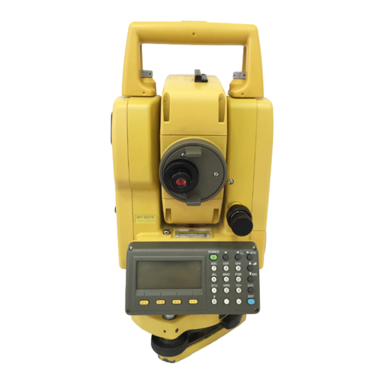
1 NOMENCLATURE AND FUNCTIONS NOMENCLATURE AND FUNCTIONS 1.1 Nomenclature Handgrip locking screw Handgrip Objective lens Laser pointer Instrument center mark Laser aperture Point guide Display unit Optical plummet (Only for GPT-3002/ telescope 3003/3005) (Optical plummet telescope type only) Circular level Adjustment screw for circular level Leveling screw…
-
Page 13
1 NOMENCLATURE AND FUNCTIONS Sighting collimator Battery locking lever Telescope focusing knob Telescope grip On-board battery BT-52QA Telescope eyepiece Instrument center mark *Vertical motion clamp *Vertical tangent screw Horizontal tangent screw Plate level Horizontal Display unit motion clamp Power supply connector Serial Signal connector… -
Page 14: Display
1 NOMENCLATURE AND FUNCTIONS 1.2 Display ● Display The display uses a graphic LCD which has 4 lines and 20 characters per line. In general, the upper three lines display measured data, and the bottom line displays the soft key function which changes with the measuring mode.
-
Page 15: Operating Key
1 NOMENCLATURE AND FUNCTIONS 1.3 Operating Key Keys Name of Key Function Star key mode is used for each presetting or displaying as follows. 1 Contrast of the display 2 Reticle illumination 3 Back Light Star key 4 Non-prism/Prism 5 Laser pointer 6 Laser plummet 7 Tilt correction 8 Point guide 9 Set audio mode Coordinate…
-
Page 16: Function Key (Soft Key)
1 NOMENCLATURE AND FUNCTIONS 1.4 Function Key (Soft Key) The Soft Key message is displayed at the bottom line of displ a y. The functions are according to the displayed message. Angle measurement mode Distance measurement mode V: 90°10’20» HR:120°30’40» HR:120°30’40″…
-
Page 17
1 NOMENCLATURE AND FUNCTIONS Coordinate measurement mode MEAS Start measuring. MODE Sets a measuring mode, Fine/Coarse/Tracking. NP/P Switches non-prism mode or prism mode. ↓ The function of soft keys is shown on next page (P2). R.HT Sets a prism height by input values. INSHT Sets an instrument height by input values. -
Page 18: Star Key Mode
1 NOMENCLATURE AND FUNCTIONS 1.5 Star key mode Press the (★) key to view the instrument options. The following instrument options can be selected from the (★): 1.Adjustment the contrast of the display (0 to 9 steps) 2.Adjustment the reticle illumination (1 to 9 steps) [ 3.Turn the backlight of the display ON / Blink / OFF 4.Select Non-prism mode / Prism mode 5.Turn the Laser pointer option ON/OFF…
-
Page 19
1 NOMENCLATURE AND FUNCTIONS ● Adjustment the contrast (0 to 9 ) of the display (CONT) This enable you to adjust the contrast of the display. Press the up or down arrow keys to adjust the contrast. ● Adjustment the reticle illumination (1 to 9 ) (RTCL) This enable you to adjust the reticle illumination. -
Page 20
1 NOMENCLATURE AND FUNCTIONS ● Tilt correction The tilt setting mode performed here will not be memorized after powering OFF. To set TILT correction in the initialized setting (it is memorized after powering OFF), see Section 6.4.3 “Vertical and Horizontal Angle Tilt correction ( Tilt ON/OFF)” . ●… -
Page 21: Serial Signal Rs-232C Connector
1 NOMENCLATURE AND FUNCTIONS 1.6 Serial signal RS-232C connector The serial signal connector is used for connecting the GPT-3000 series with a computer or TOPCON Data Collector, which enables the computer to receive measured data from the GPT-3000 series or to send preset data of horizontal angle, etc.
-
Page 22: Preparation For Measurement
2 PREPARATION FOR MEASUREMENT PREPARATION FOR MEASUREMENT 2.1 Power Connection (unnecessary if on-board Ni-MH battery BT-52QA is used) See below for connecting the external battery pack. ● Battery pack BT-3Q Power cord , PC-5 is used. ● Large capacity battery pack BT-3L Power cord PC-6 is used.
-
Page 23: Setting Instrument Up For Measurement
Mount the instrument to the tripod. Level and center the instrument precisely to insure the best performance. Use tripods with a tripod screw of 5/8 in. diameter and 11 threads per inch, such as the Type E TOPCON wide- frame wooden tripod. Reference: Leveling and Centering the Instrument 1.
-
Page 24: Power Switch Key On
2 PREPARATION FOR MEASUREMENT 2.3 Power Switch Key ON Confirm the instrument is leveled. Press the power key.. Press the power key TOPCON GPT-3000 90°10’20» 0°00’00» Battery Power Remaining Display ↓ 0SET HOLD HSET ● Confirm the battery power remaining display. Replace with charged battery or charge when battery level is low or indicates “Battery empty”.
-
Page 25: Battery Power Remaining Display
2 PREPARATION FOR MEASUREMENT 2.4 Battery Power Remaining Display Battery power remaining display indicates the power condition. 90°10’20» 0°00’00» Measurement is possible. ↓ 0SET HOLD HSET The power is poor. The battery Battery power remaining display should be recharged or replaced. Blinking Measurement is impossible.
-
Page 26: Vertical And Horizontal Angle Tilt Correction
2 PREPARATION FOR MEASUREMENT 2.5 Vertical and Horizontal Angle Tilt Correction (GPT-3007 has vertical angle tilt correction only.) When the tilt sensors are activated, automatic correction of vertical and horizontal angle for mislevelment is displayed. To ensure a precise angle measurement, tilt sensors must be turned on. The display can also be used to fine level the instrument.
-
Page 27
2 PREPARATION FOR MEASUREMENT ● Setting Tilt Correction by Soft Key To enable you to select tilt ON/OFF function. setting is not memorized after power is OFF. [Example] Setting X,Y Tilt OFF Operating procedure Option Display Press [F4] key to get the function page 2. 90°10’20″… -
Page 28: How To Enter Alphanumeric Characters
2 PREPARATION FOR MEASUREMENT 2.6 How to Enter Alphanumeric characters This enables you to enter alphanumeric characters such as the instrument height, prism height, occupied point, backsight point etc.. ● How to select a item [Example setting] Occupied point in the data collection mode. The arrow indicates a item to enter.
-
Page 29: Point Guide
2 PREPARATION FOR MEASUREMENT Press soft key to select a character. INS.HT: 0.000 m Example: [F4](T) key is pressed. MNOP QRST UVWX [ENT] =TOPCON-1 Select next character in the same manner. INS.HT : 0.000 m MNOP QRST UVWX [ENT] Press [F4](ENT) key.
-
Page 30: Laser Plummet On/Off (Only For Laser Plummet Type)
2 PREPARATION FOR MEASUREMENT 2.8 Laser Plummet ON/OFF (Only for Laser Plummet type) Laser plummet option will help you to center the instrument easily onto the measurement point. There are two ways to turn on/off of laser plummet option as follows. ●…
-
Page 31: Angle Measurement
3 ANGLE MEASUREMENT ANGLE MEASUREMENT 3.1 Measuring Horizontal Angle Right and Vertical Angle Make sure the mode is in Angle measurement. Operating procedure Operation Display Collimate the 1st target (A). Collimate A 90°10’20» HR: 120°30’40» ↓ 0SET HOLD HSET P1 Set horizontal angle of target A at 0°…
-
Page 32: Switching Horizontal Angle Right/Left
3 ANGLE MEASUREMENT 3.2 Switching Horizontal Angle Right/Left Make sure the mode is Angle measurement. Operating procedure Operation Display ↓ Press the [F4]( ) key twice to get the function 90°10’20» [F4] on page 3. twice HR: 120°30’40» ↓ 0SET HOLD HSET ↓…
-
Page 33: Setting A Horizontal Angle From The Keys
3 ANGLE MEASUREMENT 3.3.2 Setting a Horizontal Angle from the Keys Make sure the mode is Angle measurement. Operating procedure Operation Display Collimate the target. Collimate 90°10’20» HR: 170°30’20» ↓ 0SET HOLD HSET P1 Press the [F3](HSET) key. H ANGLE SET [F3] INPUT — — ENTER 1234 5678 90.-[ENT]…
-
Page 34: Repetition Angle Measurement
3 ANGLE MEASUREMENT 3.5 Repetition Angle Measurement ● Repetition angle measurement can be done by horizontal angle right measurement mode. Make sure the mode is Horizontal Angle Right measurement. Operating procedure Operation Display ↓ Press the [F4]( ) key to get the function on page 2. [F4] 90°10’20″…
-
Page 35: Buzzer Sounding For Horizontal Angle 90° Increments
3 ANGLE MEASUREMENT To return to the normal angle mode, press the [ESC] REPETITION ANGLE [F2](V/H) key or [ESC] key. Exit [F2] > OK? [YES][NO] Press the [F3](YES) key. [F3] 90°10’20» HR: 170°30’20» ↓ 0SET HOLD HSET P1 ● Horizontal angle can be accumulated up to (3600°00’00″…
-
Page 36: Compasses ( Vertical Angle)
3 ANGLE MEASUREMENT 3.7 Compasses ( vertical angle) Vertical angle is displayed as shown below. +90° 0° 0° LOCK LOCK -90° Operating procedure Operation Display ↓ Press the [F4]( ) key twice to get the function [F4] 98°10’20» on page 3. twice HR: 170°30’20″…
-
Page 37: Distance Measurement
4.2 Setting of the Correction for Prism Constant / Non-prism Constant Topcon’s prism constant value is 0. Set correction for prism at 0. If the prism is of another manufacture, the appropriate constant shall be set beforehand. Refer to Chapter 11 “SETTING THE PRISM / NON- PRISM CONSTANT VALUE”.
-
Page 38
4 DISTANCE MEASUREMENT 4.3 Distance Measurement (Continuous Measurement) Make sure the mode displays angle measurement. Operating procedure Operation Display Collimate the center of prism. 90°10’20» Collimate P HR: 120°30’40» ↓ 0SET HOLD HSET P1 HR: 120°30’40» Press the [ ] key. HD*[r] <<… -
Page 39: Distance Measurement (N-Time Measurement/Single Measurement)
4 DISTANCE MEASUREMENT 4.4 Distance Measurement (N-time Measurement/Single Measurement) When the number of times measurement is preset, the GPT-3000 series measures the distance the set number of times. The average distance will be displayed. When presetting the number of times as 1, it does not display the average distance, because of single measurement.
-
Page 40: Fine Mode/Tracking Mode/Coarse Mode
4 DISTANCE MEASUREMENT ● Choose meter /feet / feet+inch unit by soft key It is possible to change the unit for distance measurement mode by soft key. This setting is not memorized after power off. Refer to 16 “SELECTING MODE” to set at the initial setting (memorized after power off).
-
Page 41: Stake Out (S.o)
4 DISTANCE MEASUREMENT 4.6 Stake Out (S.O) The difference between the measured distance and the input stake out distance is displayed. Measured distance — Stake out distance = Displayed value ● In stake out operation, you can select either horizontal distance (HD), relative elevation (VD) and slope distance (SD) Operating procedure Operation…
-
Page 42: Offset Measurement
4 DISTANCE MEASUREMENT 4.7 Offset Measurement There are four offset measurement modes in the Offset Measurement. ● Angle offset ● Distance offset ● Plane offset ● Column offset To show the offset measurement menu, press the [OFSET] soft key from distance or coordinate measurement mode.
-
Page 43: Angle Offset
4 DISTANCE MEASUREMENT 4.7.1 Angle Offset This mode is useful when it is difficult to set up the prism directl y , for example at the center of a tree. Place the prism at the same horizontal distance from the instrument as that of point A0 to measure. To measure the coordinates of the center position, operate the offset measurement after setting the instrument height/prism height.
-
Page 44
4 DISTANCE MEASUREMENT The horizontal distance from the instrument to the OFFSET-MEASUREMENT prism will be measured. 110°20’30» 56.789 m NEXT Collimate point A using the horizontal motion OFFSET-MEASUREMENT Collimate clamp and horizontal tangent screw. 113°30’50» 56.789 m NEXT Show the relative elevation of point A OFFSET-MEASUREMENT 113°20’30″… -
Page 45: Distance Offset Measurement
4 DISTANCE MEASUREMENT 4.7.2 Distance Offset Measurement Measuring distance and coordinate of the center of a pond or a tree of which the radius is known. Measuring the distance or coordinate till P0 point, input oHD value as an offset value and measure P1 point showing as following draw in distance offset measurement.
-
Page 46
4 DISTANCE MEASUREMENT After measuring, the result added offset value will DISTANCE OFFSET be shown. 80°30’40» 10.000 m NEXT Show the relative elevation of point P0. DISTANCE OFFSET ● Each time pressing the [ ] key, horizontal 80°30’40» distance, relative elevation and slope distance are 11.789 m shown in sequence. -
Page 47: Plane Offset Measurement
4 DISTANCE MEASUREMENT 4.7.3 Plane Offset Measurement Measuring will be taken for the place where direct measuring can not be done, for example distance or coordinate measuring for a edge of a plane. Three random prism points (P1, P2, P3) on a plane will be measured at first in the plane offset measurement to determine the measured plane.
-
Page 48
4 DISTANCE MEASUREMENT Measure the second and third points in the same Collimate PLANE way. N002#: [F1] MEAS NP/P — Collimate PLANE N003#: [F1] MEAS NP/P — The instrument calculates and displays coordinate 80°30’40» and distance value of cross point between 54.321 m collimation axis and of the plane. -
Page 49: Column Offset Measurement
4 DISTANCE MEASUREMENT 4.7.4 Column Offset Measurement If it is possible to measure circumscription point (P1) of column directly, the distance to the center of the column (P0), coordinate and direction angle can be calculated by measured circumscription points (P2) and (P3).
-
Page 50
4 DISTANCE MEASUREMENT Collimate the center of the column (P1) and press Collimate COLUMN OFFSET the [F1](MEAS) key. Center N-time measuring will start. [F1] HD* [n] << m After the measurement, angle measuring display >Measuring… of the left side (P2) will be shown. Collimate the left side of the column (P2) and Collimate COLUMN OFFSET… -
Page 51: Coordinate Measurement
5 COORDINATE MEASUREMENT COORDINATE MEASUREMENT 5.1 Setting Coordinate Values of Occupied Point Set the coordinates of the instrument (occupied point) according to coordinate origin, and the instrument automatically converts and displays the unknown point (prism point) coordinates following the origin. It is possible to retain the coordinates of the occupied point after turning the power off.
-
Page 52: Setting Height Of The Instrument
5 COORDINATE MEASUREMENT 5.2 Setting Height of the Instrument It is possible to retain the height of instrument after turning the power off. Refer to Chapter 16 “SELECTING MODE”. Operating procedure Operation Display ↓ Press the [F4]( ) key from the coordinate [F4] 123.456 m measurement mode to get the function on page 2.
-
Page 53: Execution Of Coordinate Measuring
5 COORDINATE MEASUREMENT 5.4 Execution of Coordinate Measuring Measure the coordinates by entering the instrument height and prism height, coordinates of unknown point will be measured directly. ● When setting coordinate values of occupied point, see Section 5.1 “Setting Coordinate Values of Occupied Point”…
-
Page 54: Special Mode (Menu Mode)
6 SPECIAL MODE (Menu Mode) SPECIAL MODE (Menu Mode) By pressing the [MENU] key, the instrument will be in MENU mode. In this mode, special measuring , setting and adjustment are possible. Normal measurement mode [ESC] [MENU] [ESC] [F1] MENU «DATA COLLECTION MODE»…
-
Page 55: Application Measurement (Programs)
6 SPECIAL MODE (Menu Mode) 6.1 Application Measurement (PROGRAMS) 6.1.1 Remote Elevation measurement (REM) To obtain elevation of the point at which setting the target prism is not possible, place the prism at any point on the vertical line from the target then carry out REM procedure as follows. Target K Prism Prism height…
-
Page 56
6 SPECIAL MODE (Menu Mode) Horizontal distance (HD) between the instrument REM-1 and prism will be shown. <STEP-2> HD* 123.456 m >Measuring… REM-1 1.500 m ––– R.HT HD ––– Collimate target K. Collimate K REM-1 Vertical distance (VD) will be shown. *2),3) VD: 10.456 m –––… -
Page 57
6 SPECIAL MODE (Menu Mode) The prism position will be decided. REM-2 <STEP-2> V : 60°45’50» ––– ––– ––– Collimate ground point G. Collimate G REM-2 <STEP-2> V : 123°45’50» ––– ––– ––– Press the [F4](SET) key. [F4] REM-2 The position of point G will be decided. *1) 0.000 m –––… -
Page 58: Missing Line Measurement (Mlm)
6 SPECIAL MODE (Menu Mode) 6.1.2 Missing Line Measurement (MLM) Measurement for horizontal distance (dHD), slope distance (dSD), elevation (dVD) and horizontal bearing (HR) between two target prisms. It is possible to enter the coordinate value directly or calculate from coordinate data file. MLM mode has two modes.
-
Page 59
6 SPECIAL MODE (Menu Mode) Press the [F1] or [F2] key to select using [F2] GRID FACTOR. F1:MLM-1(A-B, A-C) [Example:F2 : DON’T USE] F2:MLM-2(A-B, B-C) Press the [F1] key. MLM-1(A-B, A-C) [F1] <STEP-1> MEAS R.HT NEZ NP/P Collimate prism A, and press the [F1](MEAS) key. Collimate A MLM-1(A-B, A-C) Horizontal distance (HD) between the instrument… -
Page 60
6 SPECIAL MODE (Menu Mode) The horizontal distance (dHD) and relative MLM-1(A-B, A-C) elevation (dVD) between prism A and C. dHD : 234.567 m dVD : 23.456 m ––– ––– ––– To measure the distance between points A and D, repeat procedure 12 to14. -
Page 61: Setting Z Coordinate Of Occupied Point
6 SPECIAL MODE (Menu Mode) 6.1.3 Setting Z Coordinate of Occupied Point Occupied point coordinate data and known point actual measuring data are utilized, z coordinate of occupied point is calculated and reset again. Known point data and coordinate data can use the coordinate data file. 1) Setting occupied coordinate [Example setting] Using coordinate data file.
-
Page 62
6 SPECIAL MODE (Menu Mode) 2) Z Coordinate Calculation from Known Point Measuring Data [Example setting] Using coordinate data file Operating procedure Operation Display ↓ After pressing [MENU] key, press [F4](P ) key to [MENU] MENU get the menu on page 2. [F4] F1:PROGRAMS F2:GRID FACTOR… -
Page 63
6 SPECIAL MODE (Menu Mode) HR: 120°30’40» 12.345 m 23.456 m NEXT ––– ––– CALC Press the [F4](CALC) key.*2) Z COORD. SETTING [F4] Z : Z coordinate 1.234 m dZ: Standard deviation dZ : 0.002 m ––– ––– Press the [F4](SET) key. *3) [F4] BACKSIGHT Z coordinate of the occupied point will be set. -
Page 64: Area Calculation
6 SPECIAL MODE (Menu Mode) 6.1.4 Area Calculation This mode calculate the area of a closed figure. There are two area calculation methods as follows. 1) Area Calculation from Coordinate data file 2) Area Calculation from Measured data ● Area is not calculated correctly if enclosed lines cross each other. ●…
-
Page 65
6 SPECIAL MODE (Menu Mode) When 3 or more points are set, the area AREA 0021 surrounded by the points is calculated and the 123.456 m.sq result will be shown. NEXT# :DATA-22 LIST UNIT NEXT *1) To set specify point, press the [F1](PT#) key. *2) To show the list of the coordinate data in the file, press the [F2](LIST) key. -
Page 66
6 SPECIAL MODE (Menu Mode) When 3 or more points are measured, the area AREA 0003 surrounded by the points is calculated and the 234.567 m.sq result will be shown. MEAS ––– UNIT NP/P *1) Measurement is Fine N-times measurement mode. ●… -
Page 67: Point To Line Measurement
6 SPECIAL MODE (Menu Mode) 6.1.5 Point to Line Measurement This mode is used to obtain the coordinate data with the origin point A(0,0,0) and the line AB as N axis. Place the 2 prisms at the points A and B on the line, and place the instrument at unknown point C. After measuring the 2 prisms , the coordinate data and the direction angle of the instrument will be calculated and restored.
-
Page 68
6 SPECIAL MODE (Menu Mode) Collimate prism P1 (Origin) and press [F1](MEAS) Collimate POINT TO LINE key. MEAS.P1 Measuring starts. *1) [F1] HD*[n] << m >Measuring… Input display of reflector B(P2) height will be REFLECTOR HEIGHT shown. INPUT R.HT: 0.000 m INPUT –––… -
Page 69: Setting The Grid Factor
6 SPECIAL MODE (Menu Mode) 6.2 Setting the GRID FACTOR GRID FACTOR can reset in this menu mode. For more information, refer to Section 8.1.1 “Setting the GRID FACTOR”. Grid Factor can be applied to the following application programs. It is also possible to cancel the Grid factor function by selecting «DON’T USE» in “SELECTING MODE” . At this time the setting and selecting screens for Grid Factor will be omitted.
-
Page 70: Setting Illumination Of Display And Cross Hairs
6 SPECIAL MODE (Menu Mode) Press the [F3](YES) key. [F3] GRID FACTOR ELEV.→1000 m SCALE:0.999000 INPUT ––– ––– ENTER 1234 5678 90. –[ENT] Press the [F1] (INPUT) key and enter Elevation. [F1] Press the [F4](ENT) key. Enter ELEV. [F4] Enter Scale Factor in the same way. [F1] GRID FACTOR Enter Scale…
-
Page 71: Setting Mode 1
6 SPECIAL MODE (Menu Mode) 6.4 Setting Mode 1 In this mode, the following settings are possible. 1. Setting Minimum Reading 2. Auto Power off 3. Vertical and Horizontal Angle Tilt Correction (Tilt ON/OFF) (GPT-3007 has vertical angle tilt correction onl y .). 4.
-
Page 72: Auto Power Off
6 SPECIAL MODE (Menu Mode) Press the [F1] key and press the [F4](ENTER) key. [F1] MINIMUM READING [F4] F1:ANGLE F2:COARSE ● To return to previous mode, press the [ESC] key. 6.4.2 Auto Power Off If no key operation is given or no process of measurement is performed for more than 30 minutes ( No change exceeding 30”…
-
Page 73: Vertical And Horizontal Angle Tilt Correction ( Tilt On/Off)
6 SPECIAL MODE (Menu Mode) 6.4.3 Vertical and Horizontal Angle Tilt correction ( Tilt ON/OFF) (GPT-3007 has vertical angle tilt correction only.) In case the instrument is used in an unstable situation, constant indexing of vertical and horizontal angle may be impossible. In this case, the function of tilt correction can be stopped by selecting TILT OFF.
-
Page 74: Selecting Battery Type
6 SPECIAL MODE (Menu Mode) 6.4.5 Selecting Battery Type On-board battery BT-32Q can be also available for GPT-3000 series. When you use BT-32Q (Ni-Cd) battery, select [Ni-Cd] type of battery in this parameters 1 menu. If you select wrong type of battery, the battery remaining display may work incorrectly.
-
Page 75: Setting Rs-232C Communication With External Device
6 SPECIAL MODE (Menu Mode) 6.4.7 Setting RS-232C communication with external device you can set the parameters for RS-232C communication with external device from parameters setting menu . The following parameters can be set. Item Selecting items Baud rate 1200, 2400, 4800, 9600, 19200, 38400 Character bit/Parity 7/Even, 7/Odd, 8/None Stop bit…
-
Page 76: Setting Contrast Of Display
6 SPECIAL MODE (Menu Mode) 6.5 Setting Contrast of Display Setting level for contrast of display (LCD) Operating procedure Operation Display ↓ After pressing the [MENU] key, press the [F4](P MENU [MENU] key twice to get the menu on page 3. [F4] F1:PARAMETERS 1 [F4]…
-
Page 77: Data Collection
7 DATA COLLECTION DATA COLLECTION The GPT-3000 is able to store the measured data into the internal memory. The internal memory is shared by the measured data files and the coordinate data files. ● Measured data The collected data is memorized into a files. ●…
-
Page 78
7 DATA COLLECTION ● Data collect menu operation By pressing the [MENU] key, the instrument will be in MENU 1/3 mode. Press the [F1](DATA COLLECT) key, the menu of data collect 1/2 will be shown. Normal measurement mode [ESC] [MENU] MENU F1:DATA COLLECT F2:LAYOUT… -
Page 79: Preparation
7 DATA COLLECTION 7.1 Preparation 7.1.1 Selecting a File for Data Collection A file used by data collection mode must be selected at first. Select a file before beginning data collection mode because selection screen of a file is displayed. And a selection from data collection menu is possible in the mode.
-
Page 80: Selecting A Coordinate File For Data Collection
7 DATA COLLECTION 7.1.2 Selecting a Coordinate File for Data Collection When coordinate data in a coordinate data file are used for occupied point or backsight point, select a coordinate file from the data collect menu 2/2 beforehand. Operating procedure Operation Display DATA COLLECT…
-
Page 81
7 DATA COLLECTION Press the [F3](YES) key. →PT-11 [F3] INS.HT: 0.000 m INPUT SRCH REC OCNEZ Enter ID, INS.HT in the same way. *2),3) Enter ID, :PT-11 INS.HT INS.HT→ 1.335 m INPUT SRCH REC OCNEZ >REC ? [YES][NO] Press [F3](REC) key. [F3] Press [F3](YES) key. -
Page 82
7 DATA COLLECTION ● Example for setting the direction angle: The following is to memorize the data of the backsight after setting the backsight point from point number. Operating procedure Operation Display → Press the [F2](BACKSIGHT) key from the data [F2] collect menu 1/2. -
Page 83: Operational Procedure Of Data Collect
1234 5678 90.– [ENT] :PT-01 PCODE → R.HT 0.000 m INPUT SRCH MEAS ALL Enter PCODE, R.HT in the same way. *2),3) →PT-01 [F1] Enter PCODE :TOPCON PCODE R.HT 1.200 m [F4] INPUT SRCH MEAS ALL [F1] ↓ Press the [F3](MEAS) key. EnterR.HT [F4] Collimate the target point.
-
Page 84: Searching The Recorded Data
R.HT 1.200 m 1234 5678 90.– [ENT] Enter a register number linked with PCODE library Enter No :PT-02 and press the [F4](ENT) key. [F4] PCODE :TOPCON (Example) → R.HT 1.200 m Register number, 32 = TOPCON INPUT SRCH MEAS ALL…
-
Page 85: Entering Pcode / Id From The List Of Pcode
]:By ten Increasing or Decreasing. *1) EDIT ––– CLR ENTER Press the [F4](ENTER) key. [F4] :PT-02 PCODE :TOPCON → R.HT 1.200 m INPUT SRCH MEAS ALL *1) To edit the PCODE library, press the [F1](EDIT) key. To delete the PCODE registered with shown an arrow, press the [F3](CLR) key.
-
Page 86: Data Collect Offset Measurement Mode
To set this option, refer to Chapter 16 “SELECTING MODE”. Instrument height Occ.Point Operating procedure Operation Display →PT-11 PCODE :TOPCON R.HT 1.200 m INPUT SRCH MEAS ALL Press the [F3](MEAS) key and press the [F4]key to →PT-11 [F3] get to the next soft key page.
-
Page 87
] key, N,E and Z –12.345 m coordinate are shown in sequence. >OK? [YES][NO] →PT-12 Press the [F3](YES) key. [F3] PCODE :TOPCON R.HT 1.200 m The data is recorded and the next measuring point INPUT SRCH MEAS ALL is displayed. 7-11… -
Page 88: Distance Offset Measurement
When measuring coordinates of point A Set the instrument height only. (Set the prism height to 0 ). Operating procedure Operation Display →PT-11 PCODE :TOPCON R.HT 1.200 m INPUT SRCH MEAS ALL Press the [F3](MEAS) key and press the [F4]key to →PT-11 [F3] get to the next soft key page.
-
Page 89
7 DATA COLLECTION Press the [F1](INPUT) key and enter Forward [F1] :PT-11 direction offset value. *1) Enter HD PCODE : TOPCON [F4] R.HT 1.200 m ––– *SD NP/P Collimate the prism. Collimate P Press the [F2] or [F3] key. [F3] N*[n] <<<… -
Page 90: Plane Offset Measurement
Edge Target heights of P1 to P3 is set to zero automatically. Operating procedure Operation Display →PT-11 PCODE :TOPCON R.HT 1.200 m INPUT SRCH MEAS ALL Press the [F3](MEAS) key and press the [F4]key to →PT-11 [F3] get to the next soft key page.
-
Page 91
MEAS NP/P — The display changes to PT# input in the plane PLANE offset measurement. →PT-11 Input point number if necessary. PCODE :TOPCON INPUT SRCH — MEAS Press the [F4](MEAS) key. [F4] 80°30’40» The instrument calculates and displays coordinate 54.321 m and distance value of cross point between 10.000 m… -
Page 92: Column Offset Measurement
The direction angle of the center of the column is 1/2 of total direction angle of circumscription points (P2) and (P3). Example: Non-prism measurement Operating procedure Operation Display →PT-11 PCODE :TOPCON R.HT 1.200 m INPUT SRCH MEAS ALL Press the [F3](MEAS) key and press the [F4]key to →PT-11 [F3] get to the next soft key page.
-
Page 93: Nez Auto Calculation
→PT-12 Press the [F3](YES) key. The display returns to the [F3] next point number in data collect mode. PCODE :TOPCON R.HT 1.200 m INPUT SRCH MEAS ALL 7.4 NEZ Auto Calculation As measured data is collected, coordinates are calculated and stored for traverse or topo collection.
-
Page 94: Point To Line Measurement
OCC.PT Offset 7.5.1 To change to the point to line measurement Operating procedure Operation Display →PT-01 PCODE :TOPCON R.HT 1.500 m INPUT SRCH MEAS ALL Press the [F3](MEAS) key and press the [F4]key to →PT-01 [F3] get to the next soft key page.
-
Page 95: Executing A Point To Line Measurement
Display PT#PTL→PT-01 Conduct data measurement according to the same procedure as with ordinary FS/SS (ALL can also be PCODE :TOPCON selected). However, when you conduct observation in R.HT 1.500 m the angle mode, PTL data will not be displayed (only…
-
Page 96: Editing Pcode Library [Pcode Input]
Display DATA COLLECT F1:SELECT A FILE F2:PCODE INPUT ↓ F3:CONFIG. Press the [F2](PCODE INPUT) key from Data [F2] Collect menu 2/2. →001:TOPCON 002:TOKYO EDIT ––– ––– By pressing the following keys, the list will increase 011:URAH ]or[ or decrease. →012:AMIDAT…
-
Page 97: Setting Parameter Of Data Collect [Config.]
7 DATA COLLECTION 7.7 Setting Parameter of Data Collect [CONFIG.] In this mode, the following settings of data collect mode are possible. ● Setting Items Menu Selecting Item Contents Select Fine /Coarse(1) /Coarse(10) mode in distance measurement mode. The unit to be displayed is as follows. FINE / CRS(1) / F1:DIST MODE CRS(10)
-
Page 98: Layout
8 LAYOUT LAYOUT LAYOUT mode has two functions which are setting of layout points and setting new points using coordinate data in the internal memory. Also, if the coordinate data is not stored in the internal memory, this can be input from key board. The coordinate data is loaded from PC to the internal memory via RS-232C.
-
Page 99
8 LAYOUT ● Layout menu operation By pressing the [MENU] key, the instrument will be in MENU 1/3 mode. Press the [F2](LAYOUT) key, the menu of layout 1/2 will be shown. Normal measurement mode [ESC] [MENU] MENU F1:DATA COLLECT F2:LAYOUT ↓… -
Page 100: Preparation
8 LAYOUT 8.1 Preparation 8.1.1 Setting the GRID FACTOR ● Calculation Formula 1) Elevation Factor : The average radius of the earth Elevation Factor = R+ELEV. ELEV. : The elevation above mean sea level 2) Scale Factor Scale Factor : Scale Factor at the surveying station 3) Grid Factor Grid Factor = Elevation Factor ×…
-
Page 101: Selecting Coordinate Data File
8 LAYOUT 8.1.2 Selecting Coordinate Data File You can execute a Layout from selected coordinate data file, also you can record New point measured data into the selected coordinate data file. ● The only coordinate data file existing can be selected and you can not make a new file in this mode. For more information about File, refer to Chapter 9 “MEMORY MANAGER MODE”.
-
Page 102: Setting Occupied Point
8 LAYOUT 8.1.3 Setting Occupied Point Occupied point can be set by two setting methods as follow. 1) Setting from the coordinate data stored in the internal memory. 2) Direct key input of coordinate data. ● Example setting :Setting the occupied point from the internal coordinate data file Operating procedure Operation Display…
-
Page 103
8 LAYOUT ● Example setting :Setting Instrument point coordinates directly Operating procedure Operation Display Press the [F1](OCC.PT INPUT) key from the [F1] OCC.PT Layout menu 1/2. PT#: The previous data is shown. INPUT LIST NEZ ENTER Press the [F3] (NEZ) key. [F3] N→… -
Page 104: Setting Backsight Point
8 LAYOUT 8.1.4 Setting Backsight Point The following three setting methods for Backsight point can be selected. 1) Setting from the coordinate data file stored in the internal memory. 2) Direct key input of coordinate data. 3) Direct key input of setting angle. ●…
-
Page 105
8 LAYOUT ● Example setting: Setting the backsight point coordinates directly Operating procedure Operation Display Press the [F2](BACKSIGHT) key from the Layout [F2] BACKSIGHT menu 1/2. PT#: The previous data is shown. INPUT LIST NE/AZ ENT Press the [F3] (NE/AZ) key. [F3] N→… -
Page 106: Executing A Layout
8 LAYOUT 8.2 Executing a Layout The following methods can be selected for executing a Layout: 1) Recalling points from internal memory by point number. 2) Direct key input of coordinate values. Example setting : Recalling point from internal memory. Operating procedure Operation Display…
-
Page 107
8 LAYOUT When the display value dHR, dHD and dZ are equal to 0, the layout point is established.*3 ) Press the [F2](NEZ) key. [F2] 100.000 m The coordinate data is shown. 100.000 m 1.015 m MODE ANGLE NP/P NEXT Press the [F4](NEXT) key to set next layout point . -
Page 108: Layout Of Coordinates Of Point To Line
8 LAYOUT 8.2.1 Layout of Coordinates of Point to Line The coordinate data of point to line can be used during execution of layout. When a point name including PTL coordinates (including ‘From’ and ‘To’ data) is specified, the mode will change to PTL mode automatically.
-
Page 109: Setting A New Point
8 LAYOUT 8.3 Setting a New Point New point is required for example when a layout point cannot be sighted from existing control points. 8.3.1 Side Shot Method Set up the instrument at a known point, and measure the coordinate of the new points by the side shot method Known Point B New Point…
-
Page 110
8 LAYOUT Press the [F4](ENTER) key. [F4] SIDE SHOT The file will be set . PT#: INPUT SRCH ––– ENTER Press the [F1](INPUT) key, and enter the new [F1] REFLECTOR HEIGHT point name. *4) Enter PT# INPUT Press the [F4](ENT) key. [F4] R.HT 0.000 m… -
Page 111: Resection Method
8 LAYOUT 8.3.2 Resection Method Set up the instrument at a new point, and calculate the coordinate of the new point using the coordinate data of maximum seven known points and the measurements made to these points. By following observation, resection is possible. •…
-
Page 112
8 LAYOUT Enter instrument height in the same way. [F1] NO01# Enter PT#: INS.HT [F4] INPUT LIST NEZ ENTER Enter the known point A number. *3) [F1] REFLECTOR HEIGHT Enter PT# INPUT [F4] R.HT 0.000 m INPUT ––– ––– ENTER Enter reflector height. -
Page 113
8 LAYOUT Press the [F4](CALC) key. *6) [F4] Standard Deviation Standard Deviation will be shown. 1.23 sec. Unit : (sec.) or (mGON) or (mMIL) ↓ ––– ––– ↓ Press the [F2]( ) key. SD(n) : 1.23 mm [F2] Standard Deviations of each coordinate will be SD(e) : 1.23 mm shown. -
Page 114
[Example: Executing Layout Mode] Operating procedure Operation Display LAYOUT PT#: INPUT LIST NEZ ENTER While executing the LAYOUT mode, press the [F2] [TOPCON [F2](LIST) key. →DATA-01 → The arrow( ) indicates selected data. DATA-02 VIEW SRCH ––– ENTER By pressing the following keys, the list will increase… -
Page 115: Memory Manager Mode
9 MEMORY MANAGER MODE MEMORY MANAGER MODE The following items for internal memory are available in this mode. 1) FILE STATUS Checking the number of stored data / Remaining internal memory capacity. 2) SEARCH Searching the recorded data. 3) FILE MAINTAN. Deleting files / Editing file name 4) COORD.
-
Page 116: Display Internal Memory Status
9 MEMORY MANAGER MODE 9.1 Display Internal Memory Status This mode is used to check the internal memory status. Operating procedure Operation Display Press the [F3](MEMORY MGR. ) key from the MEMORY MGR. [F3] menu 1/3. F1:FILE STATUS F2:SEARCH ↓ F3:FILE MAINTAN P Press the [F1](FILE STATUS) key.
-
Page 117: Searching Data
9 MEMORY MANAGER MODE 9.2 Searching Data This mode is used to search the recorded file data in the DATA COLLECT or LAYOUT mode. The following 3 search methods in each type of files can be selected. First data search Last data search Point number search(MEAS.DATA, COORD.DATA) Number search (PCODE LIB.)
-
Page 118
9 MEMORY MANAGER MODE ● To edit the data in searching mode Point name (PT#, BS#) , ID, PCODE and Height data (INS.HT, R.HT) can be corrected in the searching mode. Measured value can not be corrected. Operating procedure Operation Display … -
Page 119: Coordinate Data Searching
9 MEMORY MANAGER MODE 9.2.2 Coordinate Data Searching Example searching :Point number searching Operating procedure Operation Display Press the [F3](MEMORY MGR.) key from the [F3] MEMORY MGR. menu 1/3. F1:FILE STATUS F2:SEARCH ↓ F3:FILE MAINTAN Press the [F2](SEARCH) key. SEARCH [F2] F1:MEAS.
-
Page 120: Pcode Library Searching
9 MEMORY MANAGER MODE 9.2.3 PCODE LIBRARY Searching Example searching :Number searching Operating procedure Operation Display Press the [F3](MEMORY MGR.) key from the [F3] MEMORY MGR. menu 1/3. F1:FILE STATUS F2:SEARCH ↓ F3:FILE MAINTAN Press the [F2](SEARCH) key. SEARCH [F2] F1:MEAS.
-
Page 121: File Maintenance
9 MEMORY MANAGER MODE 9.3 FILE MAINTENANCE In this mode, the following items are available. Renaming file name / Searching data in a file / Deleting files ● FILE MAINTAN. menu MEMORY MGR. F1:FILE STATUS F2:SEARCH ↓ F3:FILE MAINTAN. P [ESC] [F3] @AMIDAT…
-
Page 122: Rename A File
9 MEMORY MANAGER MODE 9.3.1 Rename a File An existing file in internal memory can be renamed. Operating procedure Operation Display Press the [F3](FILE MAINTAN.) key from the [F3] Memory manager menu 1/3. →MEASD1 /M0123 COORD1 /C0056 SRCH ––– Select a file by pressing []or [] key.
-
Page 123: Deleting A File
9 MEMORY MANAGER MODE 9.3.3 Deleting a File This mode erases a file from internal memory. Only one file can be erased at a time. Operating procedure Operation Display Press the [F3](FILE MAINTAN.) key from the [F3] Memory manager menu 1/3. →MEASD1 /M0123 COORD1…
-
Page 124: Coordinate Data Direct Key Input
[F4] INPUT LIST ––– ENTER Enter PCODE and press the [F4](ENTER). [F1] COORD. DATA INPUT Enter PCODE PT#:TOPCON-102 Next input display is shown, point number (PT#) is [F4] automatically incremented. INPUT ––– ––– ENTER *1) Refer to Section 2.6 “How to Enter Alphanumeric characters”.
-
Page 125: Ptl (Point To Line) Data Input
E: Elevation Enter PCODE , FROM and TO data and press the [F1] COORD. DATA INPUT [F4](ENTER).*2) Enter PCODE PT#:TOPCON-102 [F4] Next input display is shown, point number (PT#) is INPUT ––– ––– ENTER automatically incremented. *1) Refer to Section 2.6 “How to Enter Alphanumeric characters”.
-
Page 126: Delete A Coordinate Data From A File
9 MEMORY MANAGER MODE 9.5 Delete a Coordinate Data from a File Coordinate data in a file can be erased. Operating procedure Operation Display Press the [F3](MEMORY MGR.) key from the MEMORY MGR. [F3] menu 1/3. F1:FILE STATUS F2:SEARCH ↓ F3:FILE MAINTAN ↓…
-
Page 127: Editing Pcode Library
Press the [F4](P ) key. [F4] MEMORY MGR. F1:COORD. INPUT F2:DELETE COORD. ↓ F3:PCODE INPUT Press the [F3](PCODE INPUT) key. [F3] →001:TOPCON 002:TOKYO EDIT ––– ––– By pressing the following keys, the list will increase 011:URAH ]or[ or decrease. →012:AMIDAT ]or[…
-
Page 128: Data Communications
9 MEMORY MANAGER MODE 9.7 Data Communications You can send a data file stored in the internal memory to a computer directly. Also, you can directly load a coordinate data file and PCODE Library data to the internal memory from the computer. 9.7.1 Sending Data Example: Sending a Measured data file Operating procedure…
-
Page 129: Loading Data
9 MEMORY MANAGER MODE 9.7.2 Loading Data Coordinate data files and PCODE Library data can be loaded from PC. Example: Loading a coordinate data file Operating procedure Operation Display Press the [F3](MEMORY MGR.) key from the [F3] MEMORY MGR. menu 1/3. F1:FILE STATUS F2:SEARCH ↓…
-
Page 130: Setting Parameter Of Data Communications
9 MEMORY MANAGER MODE 9.7.3 Setting Parameter of Data Communications ● Items of the Parameter Item Selecting Item Contents Setting Protocol [ACK/NAK], F1: Protocol [ONE WAY] [ACK/NAK] or [ONE WAY] communication Setting transfer speed 1200, 2400, 4800, F2: Baud rate 9600, 19200, 38400 1200/2400/4800/9600/19200/38400 baud Setting data length and parity.
-
Page 131: Initialization
9 MEMORY MANAGER MODE 9.8 Initialization This mode is used to initialize the internal memory. Following data can be initialized. FILE DATA :All files of measuring data and coordinate data PCODE DATA: PCODE LIST ALL DATA: FILE DATA and PCODE DATA Note that the following data are not initialized even if initialization is executed.
-
Page 132: Set Audio Mode
10 SET AUDIO MODE SET AUDIO MODE The light acceptance quantity level for the EDM (SIGNAL), the atmospheric correction value (PPM), correction value of prism constant (PSM) and correction value of non-prism constant (NPM) are displayed in this mode. When reflected light from the prism is received a buzzer sounds. This function is good for easy collimation when the target is difficult to find.
-
Page 133: Setting The Prism / Non-Prism Constant Value
SETTING THE PRISM / NON-PRISM CONSTANT VALUE The prism constant value of Topcon is set to zero. When using prisms other than Topcon’s, it is necessary to set the prism constant correction value of that specific prism. Once you set the correction value for prism constant, it is retained after power is OFF.
-
Page 134: Setting Atmospheric Correction
12 SETTING ATMOSPHERIC CORRECTION SETTING ATMOSPHERIC CORRECTION The velocity of light through air is not constant and depends on the atmospheric temperature and pressure. The atmospheric correction system of this instrument corrects automatically when the correction value is set. 15°C/59°F, and 1013.25hPa / 760mmHg / 29.9 inHg is as a standard value for 0ppm in this instrument.
-
Page 135
12 SETTING ATMOSPHERIC CORRECTION ● How to Set the Atmospheric Correction Value Directly Measure the temperature and air pressure to find atmospheric correction value (PPM) from the chart or correction formula. Operating procedure Operation Display HR: 120°30’40» HD* 123.456 m 5.678 m Press the [F4] key to get the soft key page 2 in the [F4]… -
Page 136
12 SETTING ATMOSPHERIC CORRECTION Atmospheric Correction Chart (For your reference) The atmospheric correction value is obtained easily with the atmospheric correction chart. Find the measured temperature in horizontal, and pressure in vertical on the chart. Read the value from the diagonal line, which represents the required atmospheric correction value. Example: The measured temperature is +26°C The measured pressure is 1013 hPa… -
Page 137
12 SETTING ATMOSPHERIC CORRECTION 12-4… -
Page 138
12 SETTING ATMOSPHERIC CORRECTION 12-5… -
Page 139: Correction For Refraction And Earth Curvature
13 CORRECTION FOR REFRACTION AND EARTH CURVATURE CORRECTION FOR REFRACTION AND EARTH CURVATURE The instrument measures distance, taking into account correction for refraction and earth curvature. 13.1 Distance Calculation Formula Distance Calculation Formula; with correction for refraction and earth curvature taken into account. Follow the Formula below for converting horizontal and vertical distances.
-
Page 140: Power Source And Charging
14 POWER SOURCE AND CHARGING POWER SOURCE AND CHARGING 14.1 On-board Battery BT-52QA ● To remove Push the battery locking lever and pull out the BT-52QA on-board battery as shown below. ● To charge Outlet Battery BT-52QA Charger BC-27BR/CR Plug the charger into the outlet. Connect the charger connector to the battery, then charging will start.
-
Page 141
14 POWER SOURCE AND CHARGING ● To install Place the base of the on-board battery into the GPT-3000 series, push the on-board battery toward the instrument side till the battery clicks into position. ● Do not charge or discharge continuously, otherwise the battery and the charger may be deteriorated. -
Page 142: Detach/Attach Of Tribrach
15 DETACH/ATTACH OF TRIBRACH DETACH/ATTACH OF TRIBRACH The instrument is easily detached or attached to the tribrach, with a tribrach locking lever loosened or tightened for this purpose. ● Detachment Loosen the tribrach locking lever, by revolving it 180° or 200gon in the counterclockwise direction (which will point the triangle mark upwards).
-
Page 143: Selecting Mode
16 SELECTING MODE SELECTING MODE 16.1 Items of the Selecting Mode The following modes are available. Menu Items Selecting item Display TEMP . & °C / °F Select the unit of temperature for atmospheric UNIT SET PRES. hPa / mmHg / correction.
-
Page 144
16 SELECTING MODE EDM OFF 0-99 The time when EDM is cut off from distance TIME measurement is completed can be changed. This function is effective for shortening the first time measuring time when distance measurement is started from distance measurement completing state. -
Page 145: How To Set Selecting Mode
16 SELECTING MODE ACK MODE STANDARD / Set the procedure of the communication with OMITTED external device. STANDARD:Normal procedure OMITTED:Even though the [ACK] is omitted from the external device, the data is not sent again. GRID USE G.F. / Select using GRID FACTOR in calculation of FACTOR DON’T USE measurement data.
-
Page 146
16 SELECTING MODE Press [F3](OTHERS SET) key. [F3] OTHERS SET F1:H-ANGLE BUZZER F2:S/A BUZZER ↓ F3:W-CORRECTION ↓ Press [F4](P ) key, to get the function in page 2 . OTHERS SET [F4] F1:NEZ MEMORY F2:REC TYPE F3:CR,LF ↓ Press [F1] key. [F1] NEZ MEMORY [OFF]… -
Page 147: Check And Adjustment
5) If using above procedure and no difference is found from the instrument constant at the factory or a difference of over 5mm or over (Prism mode) or 10mm or over (Non-prism mode) is found, contact TOPCON or your TOPCON dealer. 17-1…
-
Page 148: Checking The Optical Axis
To check if the optical axis of EDM and theodolite are matched, follow the procedure below. It is especially important to check after adjustment of the eyepiece reticle is carried out. 1) Position a prism about 30 to 50m apart from GPT-3000 series . 2) Turn the power ON while pressing the [F1] key.
-
Page 149
17 CHECK AND ADJUSTMENT 7) Turn the horizontal tangent screw slowl y , and move the collimating point to the prism center gradually until at the position buzzer starts. Confirm the level of the signal (light quantity level) in display to adjust at the level of one to two as shown in below by turning the horizontal tangent screw. -
Page 150
Reading to prism center 90°08’50» Difference 20″ If the difference is more than mentioned value, contact with your Topcon dealer or Topcon. ● For non-prism mode If the instrument is in the hold mode, press the [F4](HOLD) key to release the hold mode. -
Page 151: Checking The Optical Axis Of Laser Pointer
17 CHECK AND ADJUSTMENT 17.2.2Checking the optical axis of Laser pointer Check whether the optical axis of the laser pointer coincides with the optical axis of the telescope by carrying out the following steps. e: The laser pointer indicates the approximate collimation position of the telescope. It does not indicate the exact collimation position.
-
Page 152
17 CHECK AND ADJUSTMENT About30 ° The direction of the laser pointer About30 ° As seen from above Adjustment screws when screws A, B and C are turned clockwise (the direction for tightening them), the laser pointer, as seen on the target from the standpoint of the GPT-3000, will move in the direction shown in the drawing. -
Page 153: Checking/Adjusting The Theodolite Functions
17 CHECK AND ADJUSTMENT 17.3 Checking/Adjusting the Theodolite Functions ● Pointers on the Adjustment 1) Adjust the eyepiece of the telescope properly prior to any checking operation which involves sighting through the telescope. Remember to focus properly, with parallax completely eliminated. 2) Carry out the adjustments in the order of item numbers, as the adjustments are dependent one upon another.
-
Page 154: Checking /Adjusting The Plate Level
17 CHECK AND ADJUSTMENT 17.3.1Checking /Adjusting the Plate Level Adjustment is required if the axis of the plate level is not perpendicular to the vertical axis. ● Check 1) Place the plate level parallel to a line running through the centers of two leveling screws, say, A and B.
-
Page 155: Adjustment Of The Vertical Cross-Hair
17 CHECK AND ADJUSTMENT 17.3.3Adjustment of the Vertical Cross-hair Adjustment is required if the vertical cross-hair is not in a place perpendicular to the horizontal axis of the telescope ( since it must be possible to use any point on the hair for measuring horizontal angles or running lines).
-
Page 156: Collimation Of The Instrument
17 CHECK AND ADJUSTMENT 17.3.4Collimation of the Instrument Collimation is required to make the line of sight of the telescope perpendicular to the horizontal axis of the instrument, otherwise, it will not be possible to extend a straight line by direct means. ●…
-
Page 157: Checking / Adjusting The Optical Plummet Telescope
17 CHECK AND ADJUSTMENT Note: 1 First, loosen the capstan adjustment screw on the side to which the vertical cross-hair line must be moved. Then tighten the adjustment screw on the opposite side by an equal amount which will leave the tension of the adjustment screws unchanged. Revolve in the counterclockwise direction to loosen and in the clockwise direction to tighten, but revolve as little as possible.
-
Page 158: Checking / Adjusting The Laser Plummet (For Laser Plummet Type)
17 CHECK AND ADJUSTMENT 17.3.6Checking / Adjusting the Laser Plummet (For Laser Plummet type) ● Check 1) Turn on the laser plummet and coincide the center of the laser with a measuring point. 2) Rotate the instrument 180° or 200g around the vertical axis and check the measuring point. If the laser is properly centered in the measuring point, adjustment is not required.
-
Page 159: Adjustment Of Vertical Angle 0 Datum
17 CHECK AND ADJUSTMENT 17.3.7Adjustment of Vertical Angle 0 Datum If when measuring the vertical angle of target A at telescope position normal (direct) and reverse settings, the amount of normal and reverse measurements combined is other than 360° (ZENITH-0), half of the difference from 360°…
-
Page 160: How To Set The Instrument Constant Value
17 CHECK AND ADJUSTMENT 17.4 How to Set the Instrument Constant Value To set the Instrument constant which is obtained in Section 17.1 “Check and adjusting of instrument constant”, follow as below. Note: Each of the Prism mode and Non-prism mode has instrument constant. You must check the instrument constants in each mode and obtain the instrument constants of Prism mode and Non-prism mode.
-
Page 161: Adjustment Of Compensation Systematic Error Of Instrument
17 CHECK AND ADJUSTMENT 17.5 Adjustment of Compensation Systematic Error of Instrument (Only for GPT-3002/3003/3005) Operating procedure Operation Display Level the instrument properly with the ADJUSTMENT MODE [F1] plate level. F1:V ANGLE 0 POINT Power ON F2:INST. CONSTANT While pressing the [F1] key, turn power switch ON. ↓…
-
Page 162: Edm Alignment Checking Mode
17 CHECK AND ADJUSTMENT Press the [F4](SET) key. Repeat the procedures in step so that the count of measured COMPLETE times matches to the one in FACE(2). Then the display returns to main menu. ● To show the constant list of systematic error of ADJUSTMENT MODE instrument F1:V ANGLE 0 POINT…
-
Page 163: Precautions
12) Even if any abnormality occurs, never attempt to disassemble or lubricate the instrument yourself. Always consult with TOPCON or your dealer. 13) To remove the dust on the case, never use thinner or benzine. Use a clean cloth moistened with neutral detergent.
-
Page 164: Special Accessories
19 SPECIAL ACCESSORIES SPECIAL ACCESSORIES MENU Data entry keyboard DK-7/DK-7W Occupied point, coordinate data and other data can be input from DK-7. It is also possible to control GPT-3000 series from DK-7. Power cord PC-6 (For AC-6) Auto Converter AC-6 ●…
-
Page 165
19 SPECIAL ACCESSORIES Optical plummet tribrach Mini prism This is detachable tribrach having built-in optical The mini prism (25.4mm) is made from precision plummet telescope. ground glass and mounted in high impact plastic (Compatible with Wild) housings. ● The mini has the unique capability of being positioned either at a «0»… -
Page 166
19 SPECIAL ACCESSORIES Wide-frame extension leg tripod, Type E (Wood) Aluminum extension leg tripod, Type E ● Flat head 5/8″ × 11 threads with adjustable legs. ● Flat head 5/8″ × 11 threads with adjustable legs. 19-3… -
Page 167: Battery System
20 BATTERY SYSTEM BATTERY SYSTEM In case of On-board battery BT-52QA GPT-3000 series In case of External battery Pack Battery pack BT-3L Cord PC-6 External 12V battery PC-6 AC-6 GPT-3000 series Charging Charger Battery pack Charging time Quick BC-27BR/CR BC-27BR for AC 120V use BC-27CR for AC 230V use Approx.
-
Page 168: Prism System
21 PRISM SYSTEM PRISM SYSTEM Arrangement according to your needs is possible. Target pole-2 (not used with 9 prisms) Prism-2 Tilting prism Tilting prism Single prism Triple prism Tilting triple prism holder-1 9 prism holder-2 holder-3 holder-2 holder-2 holder-2 with target plate-2 Tribrach Tribrach…
-
Page 169: Error Displays
Level the instrument then carry the angle 0-position is adjusted. adjustment work. Mainly at the time data transmission Confirm operation procedure is correct or the E80’s between GPT-3000 series and external connection cables are correct. instrument. Abnormality in internal memory Repair is required. E90’s system.
-
Page 170
If this error code continues to display, repair is H ANGLE Abnormality in angle measuring system. ERROR required. VH ANGLE ERROR ● If error still persist after attempting to clear them, contact your local Topcon dealer or Topcon head office. 22-2… -
Page 171: Specifications
23 SPECIFICATIONS SPECIFICATIONS Telescope Length : 150mm Objective lens : 45mm (EDM 50mm) Magnification : 30× Image : Erect Field of view : 1°30′ Resolving power : 2.8″ Minimum focus : 1.3m Reticle illumination : Provided Distance measurement Measurement range Non-prism mode Atmospheric conditions Target…
-
Page 172
23 SPECIFICATIONS Atmospheric Correction Range : –999.9 ppm to +999.9 ppm, in 0.1 ppm increments Prism Constant Correction Range : –99.9 mm to +99.9 mm, in 0.1 mm increments Coefficient Factor : Meter / Feet International feet 1meter = 3.2808398501 ft. US SURVEY feet 1meter = 3.2808333333 ft. -
Page 173
23 SPECIFICATIONS Laser Plummet (only for Laser plummet type) Light source : L.D (Visible laser) Wave length : 633nm Out put : 1mW maximum Laser class : Class 2(IEC Publication 825) : Class II(FDA/BHR 21 CFR 1040) Dimension : 336(H)×184(W)×174(L) mm (13.2(H)×7.2(W)×6.9(L) in) Weight Instrument… -
Page 174: Appendix
APPENDIX Dual Axis Compensation Inclination of the vertical axis with respect to true vertical will result in incorrectly measured horizontal angles. The extent of the error in horizontal angle measurement due to axis tilt depends on three factors : ● the amount of the tilt of axis ●…
-
Page 175
It is clear from the table that dual axis compensation has the most benefit when the elevation of the target is greater then 30° and the axis is tilted more than 10″. The entries indicated in bold in the table show, in fact, that for many common surveying applications i.e. target elevation <30°… -
Page 176: Precaution When Charging Or Storing Batteries
Precaution when Charging or Storing Batteries The capacity of battery will be affected and its service life shortened in any of the following cases while it is recharged, discharged or stored. 1) Recharging Fig. 1 shows how ambient temperature at recharging is related to charging efficiency or as affecting discharge capacity.
-
Page 177
0.1C charge Discharge : 0.2, E.V.=1.0V Temperature at Fig.1 Recharging APPENDIX-4… -
Page 178
EMC NOTICE In industrial locations or in proximity to industrial power installations, this instrument might be affected by electromagnetic noise. Under such conditions, please test the instrument performance befor use. This is a CLASS A product. Ina domestic environment this product may cause radio interference in which case the user may be required to take adequate measures. -
Page 180
TOPCON CORPORATION BEIRUT OFFICE P. O. BOX 70-1002 Antelias, BEIRUT-LEBANON. TOPCON (GREATBRITAIN) LTD. Phone: 961-4-523525/961-4-523526 Fax: 961-4-521119 Topcon House Kennet Side, Bone Lane, Newbury, Berkshire RG14 5PX U.K. TOPCON CORPORATION DUBAI OFFICE Phone: 44-1635-551120 Fax: 44-1635-551170 survey.sales@topcon.co.uk laser.sales@topcon.co.uk C/O Atlas Medical FZCO., P. O. Box 54304, C-25, Dubai Airport Free Zone,UAE…