- Manuals
- Brands
- Mercedes-Benz Manuals
- Automobile
- Unimog
- Operating instructions manual
-
Contents
-
Table of Contents
-
Bookmarks
Related Manuals for Mercedes-Benz Unimog
Summary of Contents for Mercedes-Benz Unimog
-
Page 1
Unimog Operating Instructions… -
Page 2
Symbols WARNING Warning notes make you aware of dangers which could pose a threat to your health or life, or to the health and life of others. Environmental note Environmental notes provide you with infor- mation on environmentally aware actions or disposal. -
Page 3
Welcome to the world of Mercedes-Benz You can also use the Mercedes-Benz Guide smartphone app: Before you first drive off, read these Operat- ing Instructions carefully and familiarise your- self with your vehicle. Please adhere to the information and warning notes in these Oper-… -
Page 5: Contents
Contents Index …………4 At a glance ……….. 35 Introduction ……… 27 Safety ……….. 47 Opening and closing ……55 Driver’s workstation ……63 Climate control ……..97 On-board computer and displays ..109 Audio systems ……..147 Driving mode ……..157 Hydraulic system ……
-
Page 6: Table Of Contents
Index Adjusting the volume 1, 2, 3 … Audio equipment ……122 24 V socket Radio ……….122 Centre console …….. 92 Air conditioning General notes ……..98 Air-conditioning system Climate control …….. 99 ABS (Anti-lock Braking System) Switching on/off ……101 ABS Off-road program ….
-
Page 7
Index Axle loads Brake fluid Vehicle identification plate …. 356 Hydraulic clutch mechanism sys- Axle reduction ratio tem ……….361 Vehicle identification plate …. 356 Notes ……….361 Brake lamp Replacing bulbs ……. 85 Brake supply pressure in circuit 1 Ballast weights too low (display message) Weights ………. -
Page 8
Index Changing a bulb Replacing the fuel prefilter ….. 319 Square spanner ……312 Front foglamps ……… 83 Starting and stopping the engine Overview of bulbs ……81 with the cab tilted ……318 Rotating beacon ……. 86 Tilting the cab …….. 314 Side-mounted turn signal lamps .. -
Page 9
Index Cleaning the air filter Clutch actuation system Maintenance ……..304 see Hydraulic clutch actuation system Cleaning the interior Clutch faulty (display message) Cleaning and care ……286 Red event window ……141 Cleaning the radiator Clutch pedal Air conditioning condenser …. 301 Folding out (display message, Charge-air cooler …… -
Page 10
Index Compressed-air reservoir regener- Coolant temperature too high (dis- ation play message) Draining ……… 304 Yellow event window ….. 135 Compressed-air system Crawler gears Charging from an outside source … 330 ® With Telligent automatic gear- Display message in the yellow shift ………. -
Page 11
Index Diagnostics connection Setting for driving abroad (sym- Operating safety and vehicle metrical) ………. 73 approval ……….. 29 Switching on/off ……74 Diesel Direction of travel preselection Refuelling ……..216 Telligent automatic gearshift with Diesel fuels cruise control lever ……176 Fuel additives …….. -
Page 12
Index Compressed-air reservoir for tyre Symmetrical dipped beam ….73 pressure control system ….304 Use of cable winches ….. 213 Compressed-air reservoir regen- Warning buzzer ……216 Dual-mode steering eration ……….. 304 Fuel prefilter ……..321 Changing steering position ….70 Drive control faulty (display mes- Important safety notes …. -
Page 13
Index Exterior mirrors Quality ……….. 361 SAE classification ……361 Adjusting ……… 71 Scope of use ……..361 Adjusting the exterior mirrors Setting viscosity (on-board com- when using dual-mode steering ..72 puter) ……….127 Adjusting the mirror arm ….72 Single-grade engine oil …. -
Page 14
Front foglamps (display message) Replacing bulbs ……. 83 Yellow event window ….. 137 Front mounting plate Genuine Mercedes-Benz parts … 32 Equipment operation ….. 268 Getting into and out of the vehicle Front PTO shaft Overview ………. 60 Constant working speed ….263 Grey event window Correct use …….. -
Page 15
Index Checking the oil level of the steer- Menus, general notes ….234 ing ……….297 Overview ……..228 Environmentally-compatible Overview of controls …… 228 hydraulic fluids ……364 Power hydraulics circuit III/IV ..258 General notes …….. 363 Problems connecting hydraulic Topping up (power hydraulics) .. -
Page 16
Index Driving with the cruise control Switching on/off ……76 lever ……….205 Driving, driving mode ….. 202 Driving, handling characteristics ..201 Jack Driving, work mode ……202 Pump lever ……..313 General notes …….. 198 Vehicle tool kit ……. 312 Work limiter …….. -
Page 17
Index Replacing bulbs ……. 82 Rotating beacons ……79 Main-beam headlamps Strobe lights ……..79 Replacing bulbs ……. 82 Working-area lamps ……77 Switching on/off ……75 Lights Maintenance Combination switch ……75 Batteries ……..306 Daytime driving lights …… 74 Checking anti-corrosion protec- Dipped-beam headlamps …. -
Page 18
Index Replacing the wiper blades …. 300 Restraint system introduction ..48 Torque converter clutch ….296 Seat belt ………. 48 Odometer Windscreen washer system … 296 Manoeuvring/tow-starting and Trip meter ……..112 towing away Off-road driving Notes ……….333 Check list after driving …. -
Page 19
Index Hydraulics, menus and input win- ® Telligent gearshift ……170 dows ……….234 Operating safety Layout ……….115 Implied warranty ……27 Menus at a glance ……117 Operating safety and registration Monitoring info ……124 Attachments/add-on equipment ..31 Notes on messages ……. -
Page 20
Index Platform dropsides Protection of the environment Access steps ……… 276 General notes ……..28 Pulling away Letting the tailgate swing freely ..275 Opening ……… 275 Vehicle ……….. 162 Pump lever Opening the tailgate …… 275 Rear platform dropside ….275 Assembling/disassembling … -
Page 21
Index Rev counter Engine oil pressure too low …. 140 Hydrostatic unit faulty. Please Overview ……..110 Reversing camera apply brakes! ……… 144 Increased brake force and pedal Driving systems ……196 travel ……….142 General notes …….. 197 Reversing lamp Torque converter clutch …. -
Page 22
Index Seat heating ……..69 Switching to standby mode using Standard seat ……..65 buttons ………. 251 Suspension seat ……66 Switching to standby mode using Swivel seat ……..67 the control lever ……250 Seats Working hydraulics circuit I …. 248 Socket Cleaning the cover …… -
Page 23
Index Stowage space and stowage com- Telephone partments Adjusting the volume for calls ..121 Cup and bottle holder …… 93 Operating (on-board computer) ..121 Strobe light see Mobile phone Telligent automatic gearshift Replacing bulbs ……. 87 Strobe lights Cruise control lever ……. -
Page 24
Index Engaging reverse gear ….173 Raising/lowering the tipper plat- Important safety notes ….168 form trailer, vehicles with working Multifunction lever and gear indi- hydraulics ……..279 cator ……….168 Raising/lowering the tipper plat- Operating lever ……170 form trailer, vehicles without Pulling away …….. -
Page 25
Index Trip meter Towing a vehicle with operational gearshift ……..335 Instrument cluster ……112 Turn signal lamp Towing a vehicle with transmis- sion, transfer case or axle dam- Auxiliary headlamp ……83 Turn signals age ……….335 Towing the vehicle ……334 Switching on/off …… -
Page 26
Index Stowage space in the rear left of the cab ………. 312 Underbody protection Vehicle tool kit and emergency Cleaning and care ……290 equipment Unit of measurement Important safety notes ….312 Setting (on-board computer) ..126 Ventilation Units Climate control …….. -
Page 27
Index Windscreen washer system Load-sensing connections, vehi- Topping up fluid ……296 cles with positioning pump …. 231 Windscreen, operation ….. 89 Overview of load sensing connec- Windscreen wiper and washer sys- tions ……….231 Schematic ……..370 Working hydraulics circuit I Mowing door …….. -
Page 28
Index Working with equipment For earth-moving ……270 For maintenance of grassland and plant protection ……271 Front loader operation ….271 Important safety notes ….270 With a wide working range ….. 271 Working-area lamps Replacing bulbs ……. 86 Yellow event window ®… -
Page 29: Implied Warranty
Operating Instructions. Dis- dangers. Leave warning stickers in position. regarding them may lead to damage to the The Unimog is designed as an equipment car- vehicle or personal injury. rier, tractor unit and chassis for a variety of different equipment.
-
Page 30
Introduction If you carry out modifications to electronic Fuel consumption and the rate of engine, components, their software or wiring, this transmission, brake and tyre wear depend on could result in the invalidation of your vehi- the following factors: cle’s operating permit. the operating conditions of your vehicle WARNING your personal driving style… -
Page 31: Declarations Of Conformity
You can obtain further information from any nents, wheels or tyres could be damaged Mercedes-Benz Service Centre. even if this is not visible from the outside. Components that have been damaged in this Electromagnetic compatibility…
-
Page 32: Notes
It is advisable to register your vehicle with a Mercedes-Benz Service Centre. Inform Qualified specialist workshops Mercedes-Benz as soon as possible about any change of address or vehicle ownership. A qualified specialist workshop has the nec- essary specialist knowledge, tools and quali- fications to correctly carry out the work ®…
-
Page 33: Notes On Body/Equipment Mounting Directives
The  indicator lamp warns you if the sat- mends that: uration level of the diesel particle filter is crit- no other modifications should be made ical and indicates any malfunction. to the vehicle. approval should be obtained from Mercedes-Benz in the event of deviations…
-
Page 34: Genuine Mercedes-Benz Parts
Even seemingly small changes to the vehicle, such as attaching a radiator trim for winter The Unimog is an equipment carrier. It can be driving, is not permitted. Do not cover up the combined with a large number of attach- radiator.
-
Page 35
Mercedes-Benz accepts no responsibility for its individual components, e.g. number of the use of such parts in Mercedes-Benz vehi- wheel revolutions/speed, deceleration in cles, even if they have been independently or movement, lateral acceleration, accelera- officially approved. -
Page 36
Introduction After a fault has been rectified, the informa- tion is deleted from the fault memory or is continually overwritten. When operating the vehicle, situations are conceivable in which this technical data, in connection with other information — if neces- sary, under consultation with an authorised expert — could be traced to a person. -
Page 37
Cockpit ……….36 Overhead control panel …… 37 Instrument cluster ……38 Centre console ……..40 Multifunction steering wheel ….. 42 Combination switch ……44 Cruise control lever ……44 Multifunction lever ……45… -
Page 38
Cockpit Cockpit Function Page Function Page Light switch Universal carrier Headlamp range control Centre console Cruise control lever Multifunction lever Instrument cluster Ignition lock Multifunction steering To adjust the multifunction wheel steering wheel Differential locks Horn Cup holder Combination switch… -
Page 39
Overhead control panel Overhead control panel Function Page Function Page Tachograph, see the manu- i Switches the work- facturer’s operating ing-area lamp on/off instructions é Switches the auxili- z Switches the front ary headlamps windscreen heating on/off on/off À Switching the rotat- I Switches the lateral ing beacons or end position of wind-… -
Page 40: Instrument Cluster
Instrument cluster Instrument cluster Displays Example: instrument cluster Function Page Function Page Speedometer Clock and outside temper- ature display On-board computer Fuel level Rev counter ® AdBlue level Total distance and trip dis- tance On vehicles without display A and B, scroll in the on-board computer to the Truck info menu window in the ß…
-
Page 41: Warning And Indicator Lamps
Instrument cluster Warning and indicator lamps Example: instrument cluster Function Page Function Page É Diesel particle filter, Warning and indicator automatic regeneration lamps in the speedome- Â Diesel particle filter malfunction ; Engine diagnostics º Cab tilt lock Warning and indicator lamps below the on- i Differential lock board computer…
-
Page 42: Centre Console Front
Centre console Centre console Function Page Front centre console Õ Activates/deacti- vates the tyre pres- sure control system F Manually activates/ deactivates engine speed mode Î Activates/deacti- vates hydrostatic drive system Operates the hydrostatic drive system Operates the hydraulic sys- Changes the installation position of the control lever and hydraulic system con-…
-
Page 43: Rear
Centre console Rear centre console Function Page Vehicles with tipper plat- form, without hydraulic sys- tem: Q Raises the tipper platform R Lowers the tipper platform Heating/air-conditioning system control panel Function Page Adjusts the exterior mirrors É Diesel particle filter, starts stationary manual regeneration Ê…
-
Page 44
Multifunction steering wheel Multifunction steering wheel Function Page Parking brake FleetBoard (see the manu- facturer’s operating instructions) Device mounting bracket Auxiliary heating timer Ï Applies/releases the four-wheel park- ing brake Function Page Operating the on-board £ Switches engine pre- computer: heating on/off u Selects the next main J Switching the 12 V… -
Page 45
Multifunction steering wheel Function Page Deactivates the speed lim- iter Deactivates cruise control Switches off the working mode cruise control and working mode limiter Input window: Ù Cruise control, adjusts the speed tolerance Function Page Equipment operation, Operating the speed lim- engine speed setting iter: Operating the telephone:… -
Page 46
Cruise control lever Combination switch Cruise control lever Function Page Speed limiter: activating/ deactivating the speed lim- iter Cruise control: activat- Function Page ing/deactivating cruise Main-beam headlamps on control (when dipped-beam head- ® Telligent gearshift: gear lamps are switched on) preselection (shifting Turn signal, right down) -
Page 47
Multifunction lever Multifunction lever Function Page Speed Limiter: reducing set limit speed Cruise control: decreasing set speed ® Telligent gearshift: selecting direction of travel (backwards) ® Telligent automatic gearshift: selecting direc- tion of travel (backwards) Function Page Continuous brake ® Telligent automatic gearshift: automatic gear-… -
Page 48
Multifunction lever Function Page ® Telligent gearshift: selecting direction of travel h Drive/forwards i Neutral k Reverse ® Telligent automatic gearshift: selecting direc- tion of travel h Drive/forwards i Neutral k Reverse… -
Page 49
Useful information ……48 Occupant safety ……..48 Children in the vehicle ……51 Pets in the vehicle ……. 53… -
Page 50: Useful Information
Occupant safety Useful information Never modify parts of the restraint system. Do not attempt to modify the wiring as well as These Operating Instructions describe all the electronic components or their software. models and standard and optional equipment of your vehicle that were available at the time of going to print.
-
Page 51: Occupant Safety
Persons under 1.50 m tall cannot wear the seat belts correctly without a suitable, addi- Mercedes-Benz recommends that you only tional restraint system. The seat belt cannot use seat belts which have been approved perform its intended protective function if it is specifically for your vehicle by Mercedes- not fastened correctly.
-
Page 52: Fastening
Occupant safety If you have such items located on or in your Adjust the seat ( page 64). clothing, e.g. pens, keys or spectacles, The seat backrest must be in an almost store these in a suitable place. upright position. only one person is using a seat belt Pull the seat belt smoothly out of belt sash guide = and engage belt tongue ;…
-
Page 53: Children In The Vehicle
Important safety notes If a child younger than twelve years old and under 1.50 m in height is travelling in the vehicle: always secure the child in a child restraint system suitable for Mercedes-Benz vehi- cles. The child restraint system must be…
-
Page 54: Child Restraint System
Children in the vehicle appropriate to the age, weight and size of Never leave children unattended in the vehi- the child. cle. be sure to observe the instructions and Always ensure that all vehicle occupants have safety notes in this section in addition to their seat belts fastened correctly and are sit- the child restraint system manufacturer’s ting properly.
-
Page 55: Pets In The Vehicle
You can obtain child restraint systems and cialist workshop before fitting a child restraint information about the correct child restraint system again. system from any Mercedes-Benz Service Centre. Observe the warning labels on the child restraint system. If children are travelling in the vehicle, be sure Pets in the vehicle to observe the notes on «Children in the Vehi-…
-
Page 57
Useful information ……56 Locking system ……..56 Getting into and out of the vehicle ..60 Side windows ……..60 Rear window ……..61… -
Page 58: Useful Information
The engine can only be started using the key coded to the vehicle. If a vehicle key is lost, obtaining a replace- ment is a time-consuming process. This can only be done through a Mercedes-Benz Ser- vice Centre. Left-hand door Mercedes-Benz recommends that you always…
-
Page 59: Locking System
Locking system Unlocking/locking with the remote con- Close both doors. trol To lock: push release lever : downwards in the direction of arrow =. Vehicles without central locking: the cor- responding door is locked. Vehicles with central locking: both doors are locked.
-
Page 60: Checking The Batteries
Locking system Use grab handles :, door frame surface ! Only open the mowing door when traffic A and the steps underneath the mowing conditions allow you to do so. Ensure that door to enter or exit. there is enough clearance when opening the mowing door.
-
Page 61: Deactivating
Locking system Teaching-in the remote control Keep batteries out of the reach of children. If a battery is swallowed, seek medical attention If central locking no longer works after replac- immediately. ing the batteries, you must teach in the remote control again. Environmental note Batteries and rechargeable batteries contain pollutants.
-
Page 62: Getting Into And Out Of The Vehicle
Side windows Activating the immobiliser Make sure that protective grid ; is closed page 301). Apply the parking brake. Keep grab handles :, steps = and your Turn the key to position 0 in the ignition own footwear free of dirt (e.g. mud, snow lock.
-
Page 63: Rear Window
Rear window Opening/closing the side windows Side window (left) Side window (right) Make sure that the key in the ignition lock is in position 1 or 2. To open: press and hold button ? until the side window is in the desired position. To close: press and hold button = until the side window is in the desired position.
-
Page 65
Useful information ……64 Seats ………… 64 Adjusting the multifunction steer- ing wheel ……….70 Dual-mode steering ……70 Exterior mirrors ……..71 Lighting system ……..73 Good visibility ……..88 Power supply ……..90 Features ……….93… -
Page 66: Useful Information
Seats Useful information Make sure that no one has any part of their body within the sweep of the seat when These Operating Instructions describe all the adjusting it. models and standard and optional equipment of your vehicle that were available at the time WARNING of going to print.
-
Page 67: Standard Seat
Seats body. The lap belt must always be routed getting out, lower the suspension seat com- across your lap as low as possible, i.e. pletely. across your hips. WARNING Maintain a distance to the pedals that allows you to depress them fully. If you push the suspension seat bellows Also observe the safety notes in the «Children inwards, your hand could become trapped.
-
Page 68: Luxury Suspension Seat
Seats Seat height Make sure that the J warning lamp in the instrument cluster is not lit. Pull lever ; up and hold it. The vehicle’s compressed air system has Apply pressure to or relieve pressure from sufficient reservoir pressure. It is possible the seat in order to move it to the desired to carry out all possible seat adjustments.
-
Page 69: Swivel Seat
Seats Swivel seat Seat angle Pull lever ; up and hold it. Overview Apply pressure to or relieve pressure from the seat cushion or backrest in order to move it to the desired position. Release lever ;. Seat height Pull lever = up or push it down to the desired level.
-
Page 70
Seats Seat suspension Lumbar support Push lever : back. Lower lumbar support: press the upper or The seat suspension is deactivated. lower section of switch ?. The lower lumbar support is increased or Push lever : forwards. decreased. The seat suspension is activated. Upper lumbar support: press the upper or Seat cushion depth lower section of switch =. -
Page 71: Seat Heating
Seats Double co-driver’s seat Seat heating Overview General notes ! Observe the following instructions; you could otherwise damage the seat heating: do not leave any objects on the seat. do not cover the seat, e.g. with a towel or cushion. if the co-driver’s seat is not occupied, switch the seat heating off on the co- driver’s side.
-
Page 72: Adjusting The Multifunction Steering Wheel
Dual-mode steering Otherwise, the batteries could discharge. Adjust the steering wheel height and angle. Press button :. To switch on: press switch B. The steering wheel locks. Indicator lamp A lights up. The steering wheel locks automatically To switch off: press switch = until switch approximately ten seconds after it is B is in the centre position.
-
Page 73: Exterior Mirrors
Exterior mirrors Push release lever = until it engages. Align the bottom of trim ; with the guides, then push the upper section inwards until trim ; engages. If release lever = has engaged and trim ; is fitted, you can start the engine. Exterior mirrors Adjusting the exterior mirrors Example: dual-mode steering, vehicles with Telli-…
-
Page 74: Vehicles With Mowing Door
Exterior mirrors Left and right exterior mirrors: make Exterior mirror heating sure that the key in the ignition lock is in position 1 or 2. Turn switch : to position 1 for the left- hand exterior mirror or to position 2 for the right-hand exterior mirror.
-
Page 75: Lighting System
Lighting system Folding down the additional mirror Switching headlamp settings Additional mirror (example: vehicles without auxil- iary headlamps) If you need to open/close or fit/detach the front flap, you must fold down additional mir- ror =. Pull out hand rail ; by ball coupling :. Swing mirror holder A downwards ?.
-
Page 76: Important Safety Notes
Lighting system oncoming traffic from being dazzled. Sym- operated using the combination switch metrical dipped-beam headlamps do not illu- page 75). minate as large an area of the edge of the When parking lamps or dipped-beam head- carriageway. You must have the conversion lamps are switched on, the warning buzzer performed at a qualified specialist workshop sounds if you open the driver’s door and:…
-
Page 77: Headlamp Flasher
Lighting system indicator lamps next to the light switch light Combination switch Main-beam headlamps/headlamp If the vehicle only has a rear foglamp, turn flasher the light switch to the L position and pull the light switch out one level. Headlamp range control Ensure that the key is in position 2 in the ignition lock.
-
Page 78: Reading Lamp
Lighting system Ensure that the key is in position 2 in the Hazard warning lamps ignition lock. To indicate right: push the combination switch upwards : and engage. The right-hand turn signal lamps and the . indicator lamp in the instrument cluster flash.
-
Page 79: Auxiliary Headlamps General Notes
Lighting system To switch on automatic control of the Only use the working-area lamps when on interior lighting: put switch : into posi- public roads while working. Make sure that no tion 3. other road users are dazzled. When you open one of the front doors, the interior lighting switches on or off automat- ically.
-
Page 80: Auxiliary Headlamps
Lighting system equipment. Observe the relevant legal Light/dark boundary (B) at requirements for each country. 5 m = approx. 1.67 m 1/3 of the installation height, measured at Adjusting the auxiliary headlamps 5 m, yields the light/dark boundary (B) with dipped-beam headlamps.
-
Page 81: Notes
Lighting system Rotating beacons or strobe lights Switching the rotating beacons or strobe lights on/off Example: rotating beacon Hold stand :. Loosen wing nut ;. Move stand : to the desired height. To switch on: press button :. Tighten wing nut ;. Indicator lamp ;…
-
Page 82
Lighting system exterior lighting control assists you while checking the bulbs ( page 77). In order to avoid a short circuit, switch off the lights before changing a bulb and turn the key to position 0 in the ignition lock Wear eye protection and gloves when removing defective bulbs. -
Page 83: Overview Of Bulbs
Lighting system Overview of bulbs Always carry bulbs in your vehicle for each type of lamp in case of an emergency. Headlamps Main-beam/dipped-beam H7 24 V headlamps 70 W Daytime driving lamps Daytime driving lights 24 V 21 W Side lamps Turn signal lamps, brake lamps, reversing 24 V 21 W lamp, rear foglamp…
-
Page 84: Replacing Bulbs
Lighting system Insert new bulb ? in such a way that the Replacing bulbs recess in the base fits into lug = of Headlamps, front turn signal lamp socket ;. Push new bulb ? into socket ; as far as it Overview will go.
-
Page 85: Turn Signal Lamp
Lighting system Auxiliary headlamps Turn socket : anti-clockwise in the direc- tion of the arrow as far as it will go. Pull out socket :. Applying light pressure, turn bulb ; anti- clockwise and remove it. Insert new bulb ; and turn clockwise, applying light pressure.
-
Page 86: Side-Mounted Turn Signal Lamps
Lighting system Main-beam/dipped-beam headlamps: remove cable connector B from bulb ?. Lift left and right locking springs A and fold them outwards. Remove bulb ?. Insert new bulb ? in such a way that its base fits into the recess of the socket. Lift left and right locking springs A and fold them inwards onto the base of the bulb.
-
Page 87: Perimeter Lamp
Lighting system Tail lamp Licence plate lamp Tail lamp, right The licence plate lamp is behind the reflector unit. Remove screws :. Remove the lamp lens. Remove reflector units ; and ?. Applying light pressure, turn bulb = anti- clockwise and remove it. Insert new bulb = and turn clockwise, applying light pressure.
-
Page 88: Rotating Beacon
Lighting system Working-area lamps Position housing : at the bottom using the lug and swing it upwards. Tighten screws ;. Exit lamp Remove screws :. Remove headlamp unit ; of the working- area lamp. Remove cable connectors = and ?. Open the door.
-
Page 89: Strobe Light
Lighting system Slide stand = with rotating beacon : Slide stand = with strobe light : down- downwards ( page 79). wards ( page 79). Loosen wing nut ;. Loosen wing nut ;. Remove rotating beacon : upwards from Pull strobe light : upwards to remove stand =.
-
Page 90: Windscreen
Good visibility Interior lamp ! Switch off the windscreen wipers before you stop the engine. Otherwise, undesired wiper sweeps could occur when starting the next journey. This may damage the wiper blades or windscreen, especially if the windscreen is dirty or iced up. The windscreen will no longer be wiped prop- erly if the wiper blades are worn.
-
Page 91: Good Visibility
Good visibility Headlamp cleaning system Make sure that the key in the ignition lock is in position 1. To switch on: press and hold button :. Press switch :. The headlamp cleaning system cleans the Indicator lamp ; in the switch lights up. relevant light projecting areas of the head- The windscreen wipers move to the lateral lamp.
-
Page 92: Windscreen Heating
Power supply To switch on intermittent wipe: make Windscreen heating sure that the key in the ignition lock is in position 2. Press switch :. To switch off intermittent wipe: press switch ;. Windscreen washer system If you only activate windscreen heating on one side of the windscreen, that side will thaw out quicker than the other.
-
Page 93: Power Supply
Power supply Reconnecting the voltage supply ! Vehicles with auxiliary heating: during heat output and the cooling-off period, the Push in lever : of the battery isolator power supply should only be disconnected, switch. in the event of danger, using the battery Turn lever : of the battery isolator switch isolator switch.
-
Page 94: Centre Console
Power supply 24 V socket in the centre console Socket on the vehicle exterior 24 V, 7-pin power socket for equipment 24 V socket : can be used for accessories, e.g. torches or cigarette lighters. The 24 V The equipment socket complies with socket can carry a maximum load of 360 W.
-
Page 95: Features
Features mounting directives in the Mercedes-Benz Cup and bottle holder body manufacturer portal: http://bb- WARNING portal.mercedes-benz.com Cup and bottle holders cannot hold liquid con- tainers securely in place while you drive. If you Jump-start socket use cup or bottle holders while driving, con- tainers could be flung around and liquids could be spilled.
-
Page 96
Features Universal carrier in the centre con- Always hold the compressed-air pistol away sole from your body. Never aim the compressed- air pistol towards other people. ! Do not clean the air filter with the compressed-air pistol. Replace soiled air filters. -
Page 97: Cable Ducts
Features Unscrew electrical plug-type coupling D of Changes the installation position of control lever ? and separate. the control lever and hydraulic sys- tem controls Mark cable connector A at the corre- sponding sockets of hydraulic system con- trols = and remove. Place control lever ? and hydraulic system controls = in front of the alternative open- ing.
-
Page 98: Important Safety Notes
You must observe the legal requirements in the country in which you are driving when operating mobile communications equip- ment in the vehicle. The Mercedes-Benz installation specifica- tions must be observed if you subsequently install one of the following communication devices:…
-
Page 99
Useful information ……98 General notes ……..98 Heating/air conditioning and ven- tilation ……….99 Auxiliary heating ……. 102… -
Page 100: Useful Information
General notes Useful information when the air-conditioning system is switched These Operating Instructions describe all the models and standard and optional equipment of your vehicle that were available at the time of going to print. Country-specific differences are possible. Bear in mind that your vehicle may not be equipped with all the functions described.
-
Page 101: Overview
Heating/air conditioning and ventilation Heating/air conditioning and ventilation Overview and control panel Functions B Control panel C Sets the airflow: : Side air vents: ventilation and heating vents for the vehicle interior 1 to 3 Heating/ventilating/cool- ; Front windscreen vents: ventilation/ 4 Demisting/ventilating/cooling demister vent g Air supply switched off…
-
Page 102: Setting
Heating/air conditioning and ventilation Setting the air distribution D Sets the air distribution: Turn air-distribution control D to the b Airflow to the footwell desired position. c Airflow to the windscreen, side and centre air vents and to the foot- wells Switching air recirculation mode d z Airflow to the windscreen,…
-
Page 103: Heating/Air Conditioning And Ventilation
( page 101). Set the airflow, air distribution and temper- ature as desired. Mercedes-Benz recommends cooling the Residual heat temperature in the vehicle interior down to a maximum of 6 to 8 † below the outside The vehicle interior can still be heated for a temperature.
-
Page 104: Fuels
Auxiliary heating from obstruction to ensure that the air can To adjust the airflow direction: use flow freely into the cab. slider : to set the fins in the desired posi- tion. Centre air vents To close the side air vent: turn thumb- wheel ;…
-
Page 105: Auxiliary Heating
Auxiliary heating WARNING guarantee a sufficient supply of fresh air, open the roof hatch or a door on the side of the Parts of the vehicle, e.g. the exhaust system, vehicle away from the wind. may become very hot when the auxiliary heat- ing system is switched on.
-
Page 106: Immediate Heating Mode
Auxiliary heating Setting the time and day Operation using the timer Make sure that the key is in position 2 in the Overview ignition lock. Using the timer, you can: Press and hold the Ï button until the activate/deactivate immediate heating time flashes in the display.
-
Page 107: Air Distribution And Temperature
Auxiliary heating switched on, the auxiliary heating remains Use the , or . button to set the on for a further 15 minutes. The display time. shows remaining heating time =. When the switch-on time no longer flashes, the switch-on time has been stored. Preselected heating mode To preselect the switch-on time: press the E button repeatedly until the…
-
Page 108: Engine Preheating
Auxiliary heating Press and hold the f temperature button Alarm function until the maximum temperature is set Press the E button repeatedly until the page 99). æ alarm symbol flashes in the display. Adjust the air-distribution switch and the Press the , or . button. air vents as desired ( page 99).
-
Page 109
Auxiliary heating Problems with the auxiliary heating Display messages Possible causes/consequences and M Solutions Have the auxiliary heating checked at a qualified specialist F:01through workshop. F:09and F:11through F:17 While the auxiliary heating was switched on, the voltage F:10 supply was interrupted: Switch on the voltage supply with the battery isolator switch page 90). -
Page 111
Useful information ……110 Instrument cluster ……110 On-board computer ……115 On-board computer event window .. 128 Warning/indicator lamps in the status area of the on-board com- puter ……….144… -
Page 112: Useful Information
Instrument cluster Useful information Rev counter ! If you exceed the maximum permissible These Operating Instructions describe all the engine speed, the warning buzzer sounds. models and standard and optional equipment You should not drive and change gear by of your vehicle that were available at the time the sound of the engine, but according to of going to print.
-
Page 113: Instrument Cluster
Instrument cluster engine speed range :, e.g. on uphill gra- If the yellow event window is ignored and the dients or when overtaking. ® AdBlue level drops further to approximately 2.5 %, engine output may be reduced. If you drive the vehicle within economical engine speed range :, you achieve low ®…
-
Page 114: Outside Temperature
Instrument cluster Clock and outside temperature Odometer Instrument cluster (example: display in speedom- Instrument cluster (example: display in rev coun- eter) ter) You should pay particularly close attention to Ensure that the key is in position 2 in the road conditions as soon as temperatures ignition lock.
-
Page 115: Diagnostics Indicator Lamp
Instrument cluster Engine diagnostics indicator lamp Indicator lamp Problem Possible causes/consequences and M Solutions The ; indicator After you have turned the key in the ignition lock to position 2, the lamp flashes. indicator lamp indicates the system’s status by means of a sequence of flashes.
-
Page 116: Status Indicator
Instrument cluster Problem Possible causes/consequences and M Solutions The ; indicator You have not had a detected emissions-related malfunction rec- lamp lights up. tified. The engine power out- Follow the instructions in the event window. put is reduced. The on- Drive carefully to the nearest qualified specialist workshop and board computer also have the malfunction rectified as soon as possible.
-
Page 117: On-Board Computer
On-board computer If an emissions-related malfunction is detec- ted, the indicator lamp flashes three times and then goes out for approximately five sec- onds. This flashing sequence is repeated until the engine is started. The indicator lamp remains lit for approximately 15 seconds after the engine is started.
-
Page 118
On-board computer time the display also shows the date and Areas in the on-board computer dis- time. play Turn the key to position 2 in the ignition lock. The on-board computer shows the last Truck info active menu window, e.g. the menu window in the ß… -
Page 119: Displaying Vehicle Speed
On-board computer Status area: status area = shows: Driving mode page 119) ® the gear indicator of the Telligent gear- à ® automatic gearshift, e.g. N. shift/Telligent Speed Displaying vehicle speed when cruise control is selected, the é Backup drive Selecting shift position 85 km/h symbol and the set speed, e.g.
-
Page 120: Time
On-board computer Operation and page 123) page 126) Settings ä maintenance Menu Setting the units of â measurement (e.g. dis- Hydraulics Displaying operating play of † or ‡) conditions and changing Lighting Making the instrument settings cluster lighting and Trailer Displaying trailer data audio display lighting darker/brighter…
-
Page 121: On-Board Computer
On-board computer To reset the trip meter: press 9. To reset the trip data: press 9. Reset trip The input window shows The input window shows, for example, meter? No/Yes. Reset values for: Since start — all No/Yes. Using the r button, select the menu bar and press u or 9 to confirm.
-
Page 122: Alarm
On-board computer Backup drive mode menu window Select gear, neutral position or towing mode with the r or s button and General notes confirm your selection with the u but- If the automated transmission shift system is ton. malfunctioning, you may, under certain cir- The on-board computer displays the selec- cumstances, be able to continue your journey ted direction of travel in the status area.
-
Page 123
On-board computer Select the desired menu bar with the r ® Bluetooth mobile phone: pair the mobile or s button. phone to the CD radio. Change the value with the u or t Use the u or t button to scroll to á button. -
Page 124: Radio
To close the MP3 browser: press and hold MP3 browser Audio menu window is available on vehi- Setting the volume cles with the Mercedes-Benz CD radio. Switch on the CD radio ( page 148). Use the u or t button to scroll to á audio and communications.
-
Page 125: Axles Menu Window
Refer to the «Menus and input windows in the computer shows additional event windows on-board computer“ section ( page 234) for page 134). further information. If the maintenance work is carried out at a Mercedes-Benz Service Centre, the fact that…
-
Page 126: Monitoring Info
On-board computer Diesel the work has been carried out professionally the maintenance point, e.g. particle filter will be confirmed in the on-board computer and the Maintenance Booklet. the maintenance due date, e.g. 23.09.2014 WARNING 2000 km the remaining distance, e.g. If you do not have the prescribed service/ If no prediction for the maintenance due maintenance work or necessary repairs car-…
-
Page 127
Low Top the engine oil level 4, e.g. information can be obtained from a up oil:4 l Mercedes-Benz Service Centre. the ý operating hours of the engine, Use the u or t button to scroll to the 10000 h 27 min. -
Page 128: Settings Menu
On-board computer Displaying the operating hours Displaying diagnostics data Press the 9 button. Press the 9 button. The input window shows a list of all control Press the r or s button to select unit system abbreviations. ICM. Select the desired control unit using the Press the u button.
-
Page 129: Instrument Panel
You can prevent damage to the engine, set the install more languages. Further information sheet number of the engine oil with the can be obtained from a Mercedes-Benz Ser- Engine oil grade. lower grade under vice Centre.
-
Page 130: On-Board Computer Event Window
Under dow in different colours: mission oil grade used according to the Sheet Numbers of the Mercedes-Benz Specifica- grey event window for a malfunction/ tions for Service Products. notification of low priority Observe the instructions in the event win- Setting the service products dow.
-
Page 131
On-board computer event window Grey event window Note Important safety notes If you ignore warning and indicator lamps and the event window, you will not be able to rec- ognise failures and malfunctions in components or systems. Driving/braking characteristics may be affected and the operating and road safety of your vehicle may be limited. Have the affected system checked and repaired at a qualified specialist workshop. -
Page 132
On-board computer event window Transmission and clutch Display messages Possible causes/consequences and M Solutions The clutch is under a heavy load but not overloaded. You should Ô only pull away in first gear. Clutch under heavy Keep the pulling away or manoeuvring procedure as brief as strain possible. -
Page 133: Adblue Reserve
On-board computer event window button on the multifunction steering wheel. Observe the information and instructions in the event window. ® BlueTec exhaust gas aftertreatment Display messages Possible causes/consequences and M Solutions Please top up AdBlue. Supplementary text Û: Ø ® The AdBlue level has dropped to approximately 10%.
-
Page 134
On-board computer event window Display messages Possible causes/consequences and M Solutions Please top up with AdBlue Risk Supplementary text Û: · of limit speed Engine power Additionally, the on-board computer displays the · indicator reduced ® lamp in the status area. The AdBlue level has dropped to approx- imately 2.5%. -
Page 135
On-board computer event window Display messages Possible causes/consequences and M Solutions Please start regeneration at Supplementary text Û: Â once Press and hold regeneration switch for 3 s while Diesel particle vehicle is stationary Please observe Operating filter full Instructions The Â… -
Page 136: Event Window
On-board computer event window Service products and maintenance Display messages Possible causes/consequences and M Solutions The fuel has dropped to the reserve level. Refill the fuel tank ( page 216). The ¦ indicator lamp lights up yellow in the status area of the ¦…
-
Page 137: Event Window
On-board computer event window Compressed-air system, engine and cooling system Display messages Possible causes/consequences and M Solutions There is too much condensation in the compressed-air braking system and/or the compressed-air dryer is malfunctioning. Condensation in WARNING compressed-air reservoir If the condensation level in the compressed-air reservoir is too high or the condensed water freezes, the braking effect may be reduced.
-
Page 138: Event Window
On-board computer event window Display messages Possible causes/consequences and M Solutions One of the following systems is malfunctioning: ÿ engine Engine faulty engine cooling engine management diesel injection system Have the systems checked at a qualified specialist workshop. The coolant temperature is too high. Engine power output is auto- matically reduced.
-
Page 139: Generator Is Not Charging Battery
On-board computer event window Lighting system and electrical system Display messages Possible causes/consequences and M Solutions Visit workshop. Supplementary text Û: ª Risk of accident Generator is not charging battery. The ª indicator lamp lights up yellow in the status area of the on-board computer as well as in the event window.
-
Page 140: Working Hydraulics: Oil Level Too Low
On-board computer event window Hydraulic system Display messages Possible causes/consequences and M Solutions Working hydraulics: top up oil Supplementary text Û: or switch off engine Working hydraul‐ The working hydraulics oil level has fallen below the normal level. ics: oil level too The operating safety of the working hydraulics is jeopardised.
-
Page 141: Diesel Particle Filter Full
On-board computer event window ® BlueTec exhaust gas aftertreatment Display messages Possible causes/consequences and M Solutions Stop vehicle. Consult service Supplementary text Û:  centre. Regeneration is no longer possible. Diesel particle The  indicator lamp also lights up red in the instrument clus- filter full ter.
-
Page 142: Coolant Level Too Low
On-board computer event window Engine and cooling Display messages Possible causes/consequences and M Solutions Stop vehicle. Switch off Supplementary text Û: engine. Engine oil pres‐ The 5 indicator lamp lights up red in the status area of the on- sure too low board computer as well as in the event window.
-
Page 143: Clutch Faulty
On-board computer event window Transmission and clutch Display messages Possible causes/consequences and M Solutions Stop vehicle. Contact service Supplementary text Û: Ø centre. Clutch faulty WARNING The transmission no longer changes gear. The reservoir pressure in the transmission/clutch may be too low. Stop the vehicle as quickly as possible, paying attention to traf- fic conditions.
-
Page 144: Window
On-board computer event window Display messages Possible causes/consequences and M Solutions The oil temperature does not decrease: Stop the vehicle, paying attention to road and traffic conditions. Apply the parking brake. Check the oil level and top up the engine oil if necessary page 296).
-
Page 145: Check Tyre Pressure
On-board computer event window Display messages Possible causes/consequences and M Solutions Stop vehicle. Contact service Supplementary text Û: centre. Increased brake In addition, the J warning lamp lights up red in the instrument force and pedal cluster. travel Full braking power may not be available. WARNING Driving and braking characteristics are affected.
-
Page 146: Lamps
Warning/indicator lamps in the status area of the on-board computer Hydrostatic drive system Display messages Possible causes/consequences and M Solutions Visit workshop. Supplementary text: The hydrostatic drive system has been deactivated due to a mal- Hydrostatic drive function (overheating, damage, short circuit) and no longer exerts malfunctioning any force.
-
Page 147: Warning/Indicator Lamps In The Status Area Of The On-Board Computer
Warning/indicator lamps in the status area of the on-board computer Warning and indicator lamps Warning and indicator lamps Transmission-driven power take- The oil level in the torque con- Ô off engaged ( page 265) verter clutch is too low page 296) Engine-driven power take-off engaged ( page 265)
-
Page 148
Warning/indicator lamps in the status area of the on-board computer Yellow warning or indicator lamp Problem Possible causes/consequences and M Solutions The Û indicator Risk of accident lamp in the status area The trailer’s brake system is malfunctioning. Driving/braking of the on-board com- characteristics may change. -
Page 149
Important safety notes ….. 148 General notes ……..148 Anti-theft protection ……148 Operating system ……150 ® Bluetooth settings ……153… -
Page 150: General Notes
All further information on the individual func- communications equipment while driving will tions can be found on the Internet at distract you from traffic conditions. You could www.mercedes-benz.de/betriebsanleitung- then lose control of the vehicle. There is a risk lkw. of an accident.
-
Page 151
Anti-theft protection active. The display of the switched on CD radio shows BLOCKED. Switch on the ignition. You can now use the CD radio. -
Page 152
Operating system Operating system CD radio overview Function Control knob Press: Switches on/off Turn: Sets the volume Changes settings in menus ´ Switches folders in MP3 and USB mode Press briefly: Accepts a call Press and hold: ® Activates Bluetooth ®… -
Page 153
Operating system Function Press briefly: Selects menu: Activates/deactivates the TP function Changes the track time display Activates/deactivates XMUT Switches RDS on/off ® Sets the type of Bluetooth pairing Press and hold: Displays connected mobile phone CD drive Display Press briefly: Mutes the audio source Press and hold: Ejects a CD… -
Page 154
Operating system Function Press briefly: Selects an audio source: Radio CD playback AUX function BT audio (MP3 playback) Exits the menu Press and hold: Ends the current traffic report Press briefly: Switches wavebands Press and hold: Stores stations automatically Radio: Press briefly: Station search backwards Press and hold:… -
Page 155: Notes
® ® via Bluetooth (if supported by your device) necting Bluetooth -capable mobile phones to the audio system from your Mercedes-Benz play external devices, which are connected Service Centre. via the AUX jack…
-
Page 156: Pairing A Mobile Phone
® Bluetooth settings ® Requirements for a Bluetooth connec- Pairing a mobile phone tion ® Pairing the mobile phone via Bluetooth The following requirements must be met for pairing the CD radio to detect the mobile phone: Press the t button repeatedly until the the mobile phone is located inside the vehi- BT PAIR EXT.
-
Page 157
® Bluetooth settings Using the number keys, enter an easily- Using the number keys, enter an easily- remembered number consisting of one to remembered number consisting of one to six digits (e.g. 1111). six digits (e.g. 1111). Press and hold the ; mute button. Press and hold the ;… -
Page 159
Useful information ……158 Driving ……….158 Brakes ……….163 ® Telligent gearshift ……168 ® Telligent automatic gearshift ..174 Shifting gears ……..182 Driving mode ……..185 Driving systems …….. 191 Hydrostatic drive system ….198 Driving tips ……..208 Refuelling ……….. -
Page 160: Breakdown Assistance
Driving Make sure that trailer cables and Useful information compressed-air lines are connected cor- rectly ( page 220). These Operating Instructions describe all the models and standard and optional equipment Make sure that the trailer coupling is of your vehicle that were available at the time locked and secured correctly.
-
Page 161: Driving
Driving ment in all countries concerned. Supplement your emergency equipment accordingly. ® Checking the fuel/AdBlue supply ® Check the fuel level/AdBlue level shown on the fuel gauge ( page 111) and on the ® AdBlue gauge ( page 111). If necessary, refuel ( page 216) and top ®…
-
Page 162: Starting
Driving WARNING There is a risk of an accident and injury. Unsuitable footwear can hinder correct usage When leaving the vehicle, always take the key of the pedals, e.g.: with you and lock the vehicle. Never leave children and animals unattended in the vehi- shoes with thick soles cle.
-
Page 163: Checking The Reservoir Pressure
Driving key, the on-board computer will show an In the event of loss of pressure while driving, event window. Use a valid spare key. immediately bring the vehicle to a halt in Check the engine oil level ( page 125). accordance with the traffic conditions.
-
Page 164: Stopping
Driving reserve pressure too low event win- Warm up the engine quickly by driving at dow in the on-board computer goes out. moderate engine speeds. After approx- imately10 to 20 minutes, the engine will reach its operating temperature between approximately 85 and 100 †. Pulling away You can utilise the full engine power output ! Do not pull away as soon as the engine…
-
Page 165: Brakes
Brakes power when testing the brakes, stop the vehi- WARNING cle as soon as possible in accordance with If you leave children unattended in the vehi- traffic conditions. Have the brake system cle, they could set the vehicle in motion by, for checked and repaired in a qualified specialist example: workshop.
-
Page 166: Important Safety Notes
Brakes Do not let anyone enter or exit the vehicle ABS (Anti-lock Braking System) during the test. This will help to prevent you Important safety notes from mistaking pressure loss, due to air- sprung seats or the level control system, for If you fail to adapt your driving style or if you leakage.
-
Page 167: Braking With Anti-Lock Protection
Brakes ABS off-road program ® Vehicles with Telligent gearshift: on slippery road surfaces, also depress the The ABS off-road program can be activated clutch pedal. for off-road driving. When braking at speeds The engine braking effect cannot affect the of between approximately 40 and 15 km/h, ABS control system.
-
Page 168: Four-Wheel Parking Brake
Brakes Trailer with EC brake system: when a trailer Parking brake is attached, the parking brake actuates the WARNING trailer’s service brake. If the parking brake lever is not in the fully Vehicle with trailer: check the parking applied position, it automatically returns to brake when parking the vehicle the released position.
-
Page 169: Important Safety Notes
Brakes and ensures sufficient support, e.g. when car- The four-wheel parking brake is released rying out rescue operations using the winch. automatically and the parking brake remains applied. Continuous brake Important safety notes The engine brake is used as the continuous brake.
-
Page 170: Important Safety Notes
® Telligent gearshift Activating and deactivating the contin- gearshift shifts the transmission automati- uous brake cally. WARNING ! If the continuous brake is deactivated and the à indicator lamp in the instrument If there is a loss of pressure or insufficient cluster does not go out, have the continu- reservoir pressure in the transmission/clutch ous brake checked at a qualified specialist…
-
Page 171: Telligent ® Gearshift
® Telligent gearshift changing gear Possible displays: stopping the vehicle – 1st to 8th gear ® If the Telligent gearshift malfunctions, it is Neutral position possible to continue driving in backup drive – 1st to 6th reverse gear mode ( page 120).
-
Page 172: Trol Lever
® Telligent gearshift lection is stored for approximately Operating lever 120 seconds. Overview The control lever has equal status with the To upshift: briefly pull the cruise control multifunction lever and the cruise control lever towards = the steering wheel. lever.
-
Page 173: Driving
® Telligent gearshift display lights up. The on-board computer A clacking noise in the instrument cluster display shows the engaged gear. confirms the gear change. Slowly release the clutch pedal and The on-board computer display shows the depress the accelerator pedal. engaged gear.
-
Page 174
® Telligent gearshift Overview up (to shift up) : or push and hold it down (to shift down) ;. The transmission control determines the most suitable gear (target gear) for the desired gearshift direction, depending on the vehicle load. The transmission control shifts up or down at least one gear to a suitable gear. -
Page 175: Engaging Reverse Gear
® Telligent gearshift The on-board computer display shows the Reverse gear and changing direction engaged gear. quickly Slowly release the clutch pedal and Engaging reverse gear depress the accelerator pedal. Stopping the vehicle To pull away, you can only shift from neutral to the 1st to 4th reverse gear.
-
Page 176: Important Safety Notes
® Telligent automatic gearshift You can shift up or down by single reverse entirely depressed. The gear change is gears in succession while reversing: complete when the on-board computer dis- play shows the gear. Pull the multifunction lever up briefly (to shift up) ;…
-
Page 177: Telligent ® Automatic Gearshift
® Telligent automatic gearshift Multifunction lever Automatic drive program Manual drive program Cruise control lever Overview The cruise control lever has equal status with the multifunction lever and can be used alter- nately. This enables simplified equipment operation using the control lever, for exam- ple, since the right hand is not needed for To select the direction of travel: drive functions.
-
Page 178: Operating Lever
® Telligent automatic gearshift Direction of travel preselection Make sure that the vehicle speed is below 30 km/h. Make sure that cruise control and the speed limiter are deactivated. Turn the direction of travel selection switch to the h (drive/driving forwards) position. Direction of travel preselection, reverse: briefly push the cruise control lever to the left ?.
-
Page 179: Tions
® Telligent automatic gearshift You can switch between the drive programs Drive programs and drive functions at any time. Automatic drive program To activate the manual drive program: The transmission control shifts gears depend- press the o button and hold :. ing on a number of factors including: The on-board computer display shows the manual drive program…
-
Page 180: Kickdown
® Telligent automatic gearshift The gear change is complete when the on- Driving using the automatic drive pro- board computer display shows the selected gram gear. Accelerating Stopping the vehicle You can use the accelerator pedal position to actively influence the shift point: Depress the brake pedal.
-
Page 181
® Telligent automatic gearshift Selecting a gear manually the vehicle load. The transmission control shifts up or down at least one gear to a suitable gear. The gear change is complete when the on-board computer display shows the selected gear. Driving using the manual drive pro- gram General notes… -
Page 182: Engaging Reverse Gear
® Telligent automatic gearshift Depending on the number of gears to be With the vehicle stationary and the transmis- shifted, briefly pull up the multifunction sion in neutral: lever (to shift up) : or briefly push it down Depress the brake pedal or apply the park- (to shift down) ;…
-
Page 183: Rapid Change Of Direction
® Telligent automatic gearshift Rapid changes of direction ® found in the «Telligent gearshift» section page 168). Folding out the clutch pedal Vehicles without dual-mode steering At speeds of up to approximately 30 km/h, you can preselect a reverse or forward gear while driving.
-
Page 184: Working Gears
Shifting gears Vehicle with dual-mode steering Slide release catch : to the left. Lever ; folds upwards and the clutch pedal folds out. Depress the clutch pedal. Clutch pedal folded down mes- sage appears in the on-board computer dis- play. ®…
-
Page 185: Shifting Gears
Shifting gears Engaging working gears Engaging working gears Vehicles with hydrostatic drive system: stop the vehicle and apply the parking brake. ® Vehicles with Telligent gearshift: select the desired gears with the multifunc- tion lever. Pull the multifunction lever up briefly (to shift up) or push it down briefly (to shift down) ( page 171).
-
Page 186: With Telligent ® Automatic Gear Shift
Shifting gears ® Crawler gears Vehicles with Telligent automatic gear- shift: the on-board computer display shows General notes the manual drive program M. If the O symbol does not briefly If you engage the working gears, you can drive appear in the on-board computer dis- at a slower speed with the same engine revs.
-
Page 187: Driving Mode
Driving mode the O symbol: briefly pull away and The torque converter clutch is opened when changing gears. If you release the accelerator stop again. pedal slightly, you can determine when the The gear change will be repeated automat- torque converter lock-up clutch closes. Clos- ically.
-
Page 188: Tyre Pressure Control System
Driving mode Tyre pressure control system, auto- Tyre pressure control system matic mode Important safety notes Activating/deactivating automatic mode The tyre pressure control system serves to enhance off-road capability and traction on soft surfaces. The pressures of the tyres on the front and rear axles are shown in the on-board com- puter display.
-
Page 189
Driving mode Pressure Road sur- Speed level face condi- tions Highway Road with Up to maxi- normal driv- mum road ing condi- speed tions Cross Unpaved max. Country road with 50 km/h loose sur- face Sand Mud Sand, mud max. If you exceed the specified speeds, a warning Snow and snow… -
Page 190: Manual Mode, General Notes
Driving mode Press «reduce pressure level» button ?. load fully laden = is automatically selec- Emergency A tone sounds and pressure ted. level is selected. The corresponding target Press the 9 button on the multifunction Emergency tyre pressure is displayed. The steering wheel.
-
Page 191
Driving mode Using the r or s button on the mul- tifunction steering wheel, scroll to the Tyres menu window. Press the 9 button on the multifunction steering wheel. Press. selection appears in the menu window. To adjust the tyre pressure: use the r or s button on the multifunction steer- ing wheel to select the front = or rear axle tyres ?. -
Page 192: Engaging
Driving mode Engaging the differential lock Differential lock Important safety notes Engage the differential lock when required, e.g. when driving off-road or on slippery road surfaces. The differential locks can also be engaged/ disengaged while driving, without disengag- ing the clutch, but only if the wheels are not spinning.
-
Page 193: Driving Systems
Driving systems If the indicator in the on-board computer dis- tem is switched on automatically every ten play does not go out when the lock is disen- minutes. gaged: To switch off: press button : again. Indicator lamp ; in switch goes out. Change the load.
-
Page 194: Activation Conditions
Driving systems Overview Activating Activation conditions If you are driving slower than 15 km/h, the speed limiter cannot be activated. If the speed limiter cannot be activated, the — — — km/h on-board computer will display grey. Selecting the speed limiter Press the È…
-
Page 195: Important Safety Notes
Driving systems the desired speed is shown in the on-board Cruise control computer. Important safety notes Cruise control maintains the set speed of the To adjust in 5 km/h increments: press vehicle for you. In order to keep the speed the q or Ñ…
-
Page 196: Activation Conditions
Driving systems or winding roads). You could otherwise The é symbol in the on-board computer cause an accident. shows the status of cruise control in colour: on slippery roads. The drive wheels may Grey symbol: cruise control is selected, but lose their grip when braking or accelerating not activated.
-
Page 197: Driving
Driving systems Setting the road speed tolerance The on-board computer shows the é symbol and the set speed in white. Release the accelerator pedal. In order to maintain the set speed, cruise control automatically brakes or acceler- ates the vehicle. Cruise control lever: Select cruise control ( page 194).
-
Page 198: Important Safety Notes
Driving systems If the continuous brake is deactivated, the vehicle will accelerate to the last stored Only when the continuous brake is speed. deactivated: when cruise control causes If cruise control is decelerating the vehicle the vehicle to accelerate, depress the using the continuous brake and you simulta- brake pedal.
-
Page 199: General Notes
Driving systems Do not use the front camera, reversing cam- You see the reversing camera image on the era or device camera under these circum- monitor display : if: stances. You may injure others or cause dam- the key is in position 2 in the ignition lock age to objects and the vehicle while parking.
-
Page 200: Hydrostatic Drive System
Hydrostatic drive system Connection to the front end: open the Insert the cable of the equipment camera to the open end of wire ; and tighten the front flap ( page 291). electrical screw connection. Position the device camera in a suitable Secure the cable of the device camera with position on the attached equipment.
-
Page 201: Working Speeds
Hydrostatic drive system Telligent gearshift, there is also no need to Operation Working depress the clutch pedal when engaging a speed of gear. 0.1 km/h Using the hydrostatic drive system, you can Snow clearing machine up to 15 km/h drive on uphill or downhill slopes with a gra- for roads dient of less than 25%.
-
Page 202: Deactivating
Hydrostatic drive system Release the clutch pedal. All vehicles: if necessary, select the alter- M work nate mode; work mode A or driv- A drive ing mode page 201). If necessary, turn the direction switch to the h (drive/driving forwards) or k (reversing) position.
-
Page 203: Hydrostatic Drive System
Hydrostatic drive system the clutch pedal is folded in Activating/deactivating standby page 181) ® mode, vehicles with Telligent auto- matic gearshift the hydrostatic drive system is activated page 199) You can switch the hydrostatic drive system Depress the accelerator pedal beyond the to standby mode during a journey.
-
Page 204
Hydrostatic drive system acteristics are the same as when using the standard drive system. The brake response of the accelerator pedal can be adapted to suit the work to be performed by applying the continuous brake ( page 167). Even at higher speeds, a safe full brake application is possible in conjunction with ABS. -
Page 205: Working Mode Cruise Control
Hydrostatic drive system If necessary, you can also activate working to adjust the vehicle speed with the working mode cruise control and the work limiter mode cruise control and to set the working page 203). speed separately. Hydrostatic drive system status indicator Working mode cruise control status indicator Working mode cruise control display Working mode cruise control deactivated…
-
Page 206: Work Limiter
Hydrostatic drive system To activate working mode cruise con- trol at speeds slower than the stored speed: press the q button briefly. Status indicator ? appears with a blue arrow in the on-board computer. Release the accelerator pedal. This maintains all speeds ranging from 0 km/h up to the stored speed.
-
Page 207: Lever
Hydrostatic drive system To change the load value for the attached equipment: press the È but- ton on the steering wheel. The input window for the load value opens in the on-board computer. Increase the load value by pressing the u button on the steering wheel.
-
Page 208
Hydrostatic drive system Changing direction speed: push the cruise control lever in the direction of arrow :. Make sure that vehicle speed is below The working mode cruise control status 30 km/h. indicator appears in the on-board computer Make sure that working mode cruise con- page 203). -
Page 209: Driving With The Control Lever
Hydrostatic drive system To activate the control lever for driving Driving with the control lever mode: Joystick Select the function in the on- board computer ( page 241). The following functions can now be carried out using the control lever. Engage the hydrostatic drive system page 199).
-
Page 210: Running-In
Driving tips To activate working mode cruise control: should normally be secured using the parking brake and wheel chocks. Press red button A and yellow button = simultaneously. WARNING Working mode cruise control is activated and the current speed is stored. If you load the vehicle unevenly, driving char- acteristics such as steering and braking To activate working mode cruise control…
-
Page 211: Driving Tips
Pay attention to the minimum rear axle load: nating directions. U 216 / U 218: 1,950 kg Mercedes-Benz does not take responsibility U 318: 2,200 kg for accidents resulting from driving that is not U 423 / U 427 / U 430 / U 527 / U 530: appropriate for the conditions.
-
Page 212: Important Safety Notes
Mercedes-Benz recommends the use of ist workshop as quickly as possible. Adapt approved equipment and bodies with Daimler your driving style to the altered braking con- mounting certification.
-
Page 213
Driving tips Challenging driving conditions, vehi- Please be particularly careful that, if neces- sary, the regeneration block is activated in ® cles with Telligent automatic gear- vehicles with low mounted exhaust pipes. shift: activate manual drive program page 177). Rules for off-road driving Undesired interruptions to the tractive power that may occur with automatic gear WARNING… -
Page 214: Fording
Driving tips Engage a low gear. Select 1st or 2nd gear Avoid declutching, changing gear or stop- depending on the uphill or downhill gradi- ping during the journey. ent. Pulling away in water can be difficult due to Only drive over embankments and on the unknown surface conditions.
-
Page 215: Important Safety Notes
Driving tips Check the tyre pressure ( page 340). Apply the four-wheel parking brake when recovering other objects ( page 166). Replace missing valve caps. Replace dented or damaged rims. Remove trapped plant matter and twigs. Diesel particle filter Remove flammable materials from the Important safety notes exhaust system, e.g.
-
Page 216
Driving tips Automatic regeneration can begin either To switch on/off: press button ;. while the vehicle is in motion or stationary. If indicator lamp : in the button lights up, regeneration is blocked. Automatic regeneration only begins when all operating conditions have been fulfilled, such Only switch on the regeneration block for the as sufficiently high engine oil and exhaust duration of the hazardous condition. -
Page 217: Consumption
Driving tips Replacing the filter Shift the transmission to neutral position WARNING Remove your foot from the accelerator. Direct contact or inhalation of soot particles is Press button : for approximately three hazardous to health. There is a risk of injury. seconds.
-
Page 218: Warning Buzzer
Refuelling binations may snake. This may also overload the vehicle is stationary for approximately the brakes and tyres. nine minutes with the engine running and a gear selected WARNING you select the reverse gear If the vehicle combination swerves, you could you exceed the maximum permissible lose control of the vehicle combination.
-
Page 219: Refuelling
Refuelling These fuel types cause irreversible damage vapours. Keep fuels out of the reach of chil- ® to the engine and BlueTec exhaust gas dren. aftertreatment, as well as also significantly If you or others come into contact with fuel, reducing the expected service life.
-
Page 220: Important Safety Notes
Refuelling Replace fuel filler cap = and screw it on. not allow fuels to run into the sewage system, Lock fuel filler cap = with the key. the surface waters, the ground water or into the ground. Vehicles with fuel prefilter with water separator: drain the fuel prefilter regularly Do not get into the vehicle again during the page 321).
-
Page 221: Trailer
Trailer Avoid inhaling ammonia vapours. Only fill the ® AdBlue tank in well-ventilated areas. ® AdBlue should not come into contact with skin, eyes or clothing, and should not be swal- ® lowed. Keep AdBlue out of the reach of chil- dren.
-
Page 222: Coupling Up
Trailer found in the vehicle’s registration papers. These values can also be found on the type plate of the trailer coupling, the trailer and the vehicle identification plate. Where the values differ, the lowest is valid. Coupling up WARNING If the trailer coupling has too much longitudi- nal play, the trailer can tear away.
-
Page 223: Winter Operation
Winter operation Make sure that you observe the correct order when disconnecting the hose couplings. ! After disconnecting the compressed-air lines, ensure that the covers of the coupling heads on the vehicle are closed. If the cov- ers are not closed, the coupling heads may become contaminated, causing a malfunc- tion.
-
Page 224: Parking In Extremely Cold Condi Tions
Ò30 †, it cannot be guaranteed Shift the transmission into neutral. that the engine will start, even with the cold- climate package. Mercedes-Benz advises Try to bring the vehicle under control by against parking the vehicle outdoors at out- using corrective steering.
-
Page 225: Important Safety Notes
! Mercedes-Benz recommends fitting snow Interrupt the voltage supply with the bat- chains on all wheels on the front and rear tery isolator switch ( page 90).
-
Page 226: Cold-Resistant Service Products
If the vehicle is to be used in extreme cold extremely low temperatures. on a frequent basis, Mercedes-Benz rec- ommends fitting the vehicle with the fol- Charge batteries in a low state of charge lowing equipment: before starting.
-
Page 227: Engine Does Not Start
Winter operation If the batteries are permanently subjected All vehicles: start the engine. to temperatures below Ò25 †: charge the Warm up the engine at low engine speed batteries every two days. with the vehicle stationary. Do this at out- door temperatures of below Ò20 †…
-
Page 229: Overview
Useful information ……228 Important safety notes ….. 228 Overview ……….228 Hydraulic connections ….. 230 Menus and input windows in the on-board computer ……234 Working hydraulics circuit I ….. 244 Working hydraulics circuit II … 253 Power hydraulics circuit III/IV ..258…
-
Page 230: Useful Information
Overview front working hydraulics circuit II, vehicles Useful information with positioning pump These Operating Instructions describe all the side and rear working hydraulics circuit II, models and standard and optional equipment vehicles with positioning pump of your vehicle that were available at the time power hydraulics circuit III/IV of going to print.
-
Page 231
Overview To move the control system to the left: Activates/deactivates continuous con- sumers, red hydraulic connection 1 Green hydraulic connection 3 or, if simul- Activates/deactivates float setting, blue taneously pressing white button G, blue hydraulic connection 7 hydraulic connections 7 and 8 Blue button, can be assigned specific Activates/deactivates float setting, yel- functions (… -
Page 232: Working Hydraulics
Hydraulic connections Working hydraulics circuit I and cir- Activates/deactivates float setting, yel- cuit II low hydraulic connections 5 and 6 Activates/deactivates float setting, green Hydraulic connections hydraulic connections 3 and 4 Activates/deactivates float setting, red DANGER hydraulic connections 1 and 2 If hydraulic connections of the same colour Activates/deactivates front working are connected at the front and rear simulta-…
-
Page 233: Hydraulic Connections
Hydraulic connections Front end, right Chassis, right Yellow hydraulic connection 5, circuit I Hydraulic connection, circuit II Yellow hydraulic connection 6, circuit I Hydraulic connection, separate return flow line, circuit II Blue hydraulic connection 7, circuit I Blue hydraulic connection 8, circuit I Load-sensing connections, vehicles Hydraulic connection, separate return with positioning pump…
-
Page 234: Connecting Attached Equipment With Load Sensing Connections
Hydraulic connections Chassis, right Load-sensing connection Connecting attached equipment with load-sensing connection If you connect attached equipment to the load-sensing connection, the required flow rate for this equipment is controlled automat- ically by the device. The attached equipment is then directly connected to the positioning pump, as soon as you have selected in the «Hydraulics»…
-
Page 235: Power Hydraulics
Hydraulic connections Problems connecting hydraulic lines to working hydraulics circuit II Problem Possible causes/consequences and M Solutions The hydraulic lines of The pressure in the hydraulic lines of working hydraulics circuit II the equipment fitted is too high. cannot be connected to Switch off the engine.
-
Page 236: On-Board Computer
Menus and input windows in the on-board computer Vehicle front with circuit III and circuit IV Rear area with circuit III and circuit IV Red hydraulic connection, pressure line, Red hydraulic connection, pressure line, circuit III circuit III Green hydraulic connection, pressure Green hydraulic connection, pressure line, circuit IV line, circuit IV…
-
Page 237: Hydraulics Menu Window
Menus and input windows in the on-board computer Brief instructions for operation using Structural Selection the control lever sequence in the on-board com- puter Axles Operation and main- tenance â Tyres Hydraulics Trailer Maintenance u button, to change direction F button, to set engine speed Yellow button, to adjust settings Black button, to call up menus Blue button, can be assigned specific…
-
Page 238: Working Functions Menu Window
Menus and input windows in the on-board computer the control lever and, if necessary, to change settings as well. Structural Selection sequence in the on-board com- puter Operation and main- tenance â Hydraulics Hydraulics menu windows, vehicles with position- Working func‐ Hydraulics ing pump (example) tions…
-
Page 239: Hydraulics Input Window
Menus and input windows in the on-board computer Structural Display sequence in the on-board com- puter Operation and main- tenance â Hydraulics Working func‐ tions Hydraulics The hydraulics input window appears. Operation using the control lever Make sure the vehicle is stationary. Press black button ?.
-
Page 240
Menus and input windows in the on-board computer Attached equipment with constant flow rate: flow rate Equipment with load sensing: display Attached equipment with constant flow rate: flow rate Equipment with load sensing: display Symbols for the working hydraulics circuit and power hydraulics circuit Symbols for hydraulics input window, vehicles with gear pump (example) -
Page 241: Menus And Input Windows In The On-Board Computer
Menus and input windows in the on-board computer Changing the value Working hydraulics circuit page 244) If necessary, switch the desired hydraulics Power hydraulics circuit ( page 258) circuit to standby mode: The indicator lamp in the corresponding Snow plough load relief ( page 248) button goes out.
-
Page 242: Settings», «Limits» Menu Win Dows
Menus and input windows in the on-board computer control lever. In this way, you can check your «Settings» menu window setting directly. Settings The limit does not apply to continuous con- sumers. Structural Selection sequence in the Structural Selection on-board com- sequence in the puter on-board com-…
-
Page 243: Settings, Function Button Menu Windows
Menus and input windows in the on-board computer If hydraulic connections of the same colour Structural Selection have: sequence in the on-board com- one red mark, then only the hydraulic con- puter nection with a yellow mark can be control- led.
-
Page 244: Settings, Automatic Menu Win Dows
Menus and input windows in the on-board computer be accelerated and decelerated using To switch the function on: press the u the control lever ( page 207) button. The checkbox next to the function is Work Drive: if the hydrostatic drive sys- marked.
-
Page 245: Settings, Back Menu Windows
Menus and input windows in the on-board computer «Settings», «Resetting» menu windows Structural Selection sequence in the Structural Selection on-board com- sequence in the puter on-board com- puter Operation and main- tenance â Operation and main- tenance â Hydraulics Hydraulics Working func‐…
-
Page 246: Controlling Hydraulic Connec Tions
Working hydraulics circuit I Deactivating working hydraulics circuit Settings Call up the menu window page 240). Press the r or s button to select the Press button I. Back entry. The indicator lamp in button I goes out. Press the 9 button. Working hydraulics circuit I is deactivated.
-
Page 247: Working Hydraulics Circuit I
Working hydraulics circuit I Hydraulic connections, red, 1, 2 and Controlling blue hydraulic connection 8, moving the control system to the right hydraulic connections, green, 3, 4; «Driving joystick» function in the on- Press and hold white button G and move board computer is selected the control lever in direction C.
-
Page 248: Working Hydraulics Circuit I
The indicator lamp in button U lights up. body/equipment mounting directives in the To deactivate the float setting: press Mercedes-Benz body manufacturer portal: button U. http://bb-portal.mercedes-benz.com The indicator lamp in button U goes out.
-
Page 249: Working Hydraulics Circuit Ii
Working hydraulics circuit I Activating/deactivating the float set- Float setting, yellow hydraulic connec- tions 5 and 6 tings with the control lever To activate the float setting: press but- ton S. The indicator lamp in button S lights up. To deactivate the float setting: press button S.
-
Page 250: Snow Plough Load Relief
Working hydraulics circuit I Float setting, yellow hydraulic connec- Depending on the weight of the snow plough, tions 7 and 8 Mercedes-Benz recommends a load relief function value for the snow plough between To activate the float setting: press and 5% and 20%.
-
Page 251
Working hydraulics circuit I Switching on snow plough load relief Activate working hydraulics circuit I page 244). Press button O. The indicator lamp in button O flashes. Hydraulics input window opens in the on-board computer. The line for load relief function value Z is selected. -
Page 252
Working hydraulics circuit I Switching snow plough load relief back to function value of the snow plough is selec- standby mode using the control lever ted ( page 235). Press and hold the 9 button on the steer- ing wheel. Red hydraulic connections 1 and 2 are in the float setting as long as the 9 button is pressed. -
Page 253: Float Setting
Working hydraulics circuit I Automatic snow plough system of the on-board computer goes on. Snow plough load relief is switched on. If you have selected the automatic snow plough system, the snow plough is raised Switching snow plough load relief back to when you engage reverse gear.
-
Page 254: Working Hydraulics Circuit I
Working hydraulics circuit I Switching the continuous consumers Press and hold red button A. on/off Move the control lever all the way in direc- tion B for approximately one second. The snow plough is in the float setting and is applying its full weight to the road. The indicator lamp in button O flashes.
-
Page 255: Cles With Gear Pump, Activating Deactivating
Working hydraulics circuit II sumer has a coloured border. The continu- ous consumer is in standby mode. Turn the key to position 1 in the ignition lock. Continuous consumer to green hydrau- lic connection 3: press button P. Working hydraulics circuit II The indicator lamp in button P flashes.
-
Page 256
Working hydraulics circuit II Switching working hydraulics circuit II to standby mode Turn the key to position 1 in the ignition lock. Connect the equipment to the working hydraulics (see the manufacturer’s sepa- rate operating instructions) ( page 230). Assignment of flow rate, vehicles with dual-circuit hydraulic system Start the engine. -
Page 257: Tion
Working hydraulics circuit II working hydraulics circuit I is deactiva- ted ( page 244) working hydraulics circuit II is deactiva- ted ( page 253) the continuous consumer has been switched off ( page 252) Press button L. The indicator lamp in button L lights up. The flow rate has been switched between circuit I Z and circuit II .
-
Page 258: Vehicles With Positioning Pump General Notes
Working hydraulics circuit II working hydraulics circuit I is deactiva- ted ( page 244) working hydraulics circuit II is deactiva- ted ( page 253) the continuous consumer has been switched off ( page 252) Press button K. The indicator lamp in button K goes out. The flow rates are again distributed to cir- cuit I Z and circuit II Z.
-
Page 259
Working hydraulics circuit II Activating working hydraulics circuit II Press the 9 button on the steering wheel or the black button on the control lever until the indicator lamp in button V lights up. Front working hydraulics circuit II is activa- ted. -
Page 260: Power Hydraulics Circuit Iii/Iv
Using the u and t buttons, increase can be removed, including the frame, from or decrease the flow rate. the platform subframe. Further information can be obtained from a Mercedes-Benz Ser- Activating side and rear working hydraul- vice Centre. ics system circuit II…
-
Page 261
Power hydraulics circuit III/IV The cumulative flow rate of the power power hydraulics for circuit III are in hydraulics is, however, limited to 180 l/min. standby mode. The stated flow rates apply to a rated engine Changing the flow rate speed of 2200 rpm. -
Page 262
Power hydraulics circuit III/IV Activating/deactivating power hydraul- Activating power hydraulics circuit IV ics circuit IV Press the 9 button on the steering wheel or the black button on the control lever until the indicator lamp in button N lights up. Power hydraulics circuit IV is switched on. -
Page 263
Useful information ……262 Ballast/weights …….. 262 Equipment operation ……262 Tipper platform ……… 272… -
Page 264: Equipment Operation
Activate constant working speed mode in it is necessary to load it with ballast weights. the on-board computer ( page 263). The weight of the Unimog must be adapted to suit the work to be performed. Set the working engine speed using the accelerator.
-
Page 265: Engine Speed Setting
Equipment operation when a device is connected to a working You can set the idling speed and switch on the hydraulic circuit. constant working speed. Idling speed setting To set and activate: press the Ù button on the multifunction steering wheel repeat- Rotational speed edly until the input…
-
Page 266: Button
Equipment operation To deactivate: press the Ù button repeat- «Settings», «Function button» menu window Rotational speed page 241). edly until the input window appears on the on-board com- Press the blue button on the control lever. puter. Constant working speed mode is activated. The working speed is set to the setpoint.
-
Page 267: Power Take-Off
Equipment operation Transmission-driven power take-off event window of the on-board computer for approximately two seconds. General notes The I indicator lamp in the status area The transmission driven power take-off can of the on-board computer and indicator be operated: lamp ; in the switch light up. when the vehicle is stationary ®…
-
Page 268: Pulling Away In Equipment Driving Mode
Equipment operation To engage: switch off the engine. with the crawler gears engaged page 184), select a gear Turn the key to position 2 in the ignition with the working gears engaged lock. page 182), select a gear (one to five) Press switch :.
-
Page 269: Front Pto Shaft
Equipment operation Front PTO shaft you could sustain burns. There is a risk of injury. Important safety notes Before removal, allow the engine to cool down and wear safety gloves. WARNING If you engage the PTO while driving, the ! The front PTO shaft stub may get dirty if it engine speed may be reduced and cause a is not protected.
-
Page 270: Front Mounting Plate
Equipment operation Front PTO shaft cover In the on-board computer display, the sym- bol and rotational speed for the front PTO Before fitting equipment: remove the shaft disappear. cover from front PTO shaft :. The W indicator lamp in the status area After fitting equipment: slide the cover of the on-board computer goes out.
-
Page 271: Notes On Connecting/Disconnect Ing Equipment
Observe the following notes: sure. Instructions for fitting equipment can be found in the body/equipment mounting Transporting equipment directives in the Mercedes-Benz body man- ufacturer portal: http://bb- Important safety notes portal.mercedes-benz.com ! Observe the permissible axle and wheel Familiarise yourself with the applicable loads.
-
Page 272: Working With Equipment
Power assistance can be Earth-moving equipment obtained from a Mercedes-Benz Service Familiarise yourself with your surroundings Centre. before commencing work. This could help you to avoid collisions with objects that do not lie within the driver’s field of vision.
-
Page 273: Plant Protection
Only install front loaders that fulfil the require- slopes ments of the Unimog equipment mounting unstable ground directives. Tested front loaders have mount- If the surface is not secure, take appropriate ing certification from Daimler AG. You can safety precautions.
-
Page 274: Working On Equipment
Mercedes-Benz fastening compo- float setting can be activated for the pur- nents. poses of pressure reduction, if necessary…
-
Page 275: Securing Loads
Mercedes-Benz Service Centre. page 274). Information on the correct securing of loads can be obtained from the manufac-…
-
Page 276: Platform Dropside Important Safety Notes
Tipper platform Instructions for fitting equipment can be found in the body/equipment mounting directives in the Mercedes-Benz body manu- facturer portal: http://bb- portal.mercedes-benz.com Safety prop DANGER When working beneath the raised tipper plat- Example: maximum load sticker of the lashing…
-
Page 277: Opening
Tipper platform Releasing the platform dropsides the case when it is subjected to a load and is therefore under increased strain. There is a A second person is required when closing the danger of injury. catches and when releasing the platform Before opening, make sure that no persons dropside.
-
Page 278: Tailgate
Tipper platform Removing the post to swing freely. The rear platform dropside will otherwise drop down and be damaged. Make sure that the tipper platform is unloa- Ensure that rear catch levers : on the left ded. and right are closed. Swing all catch levers : up and the plat- Pull platform dropside locking lever ;…
-
Page 279: Raising/Lowering The Tipper Plat Form
Tipper platform Raising/lowering the tipper platform, Tipper operation vehicles without working hydraulics Important safety notes Enabling/disabling the tipper function WARNING If you drive off with the tipper platform raised, it could get caught on buildings, bridges or trees, for example. There is a risk of an acci- dent.
-
Page 280
Tipper platform Start the engine. Start the engine. Enable the tipping function ( page 277). Enable the tipping function ( page 277). Ensure that in vehicles with a tipper plat- Press switch B. form trailer, switch C is pressed. The tipper platform trailer can be raised or lowered. -
Page 281
Tipper platform To enable the tipping function: press place until the tipper platform has reached the desired position. switch :. The Y indicator lamp in the status area Indicator lamp ; in the switch lights up. Joystick aktiv (Joystick of the on-board computer lights up. The Y active) message appears in the on-board… -
Page 282: Tipper Platform With A Crane Important Safety Notes
Tipper platform place until the tipper platform has reached tipper platform and trap you. There is a risk of the desired position. injury. To lower the tipper platform: make sure Make sure that nobody is in the area of danger that the key is in position 2 in the ignition of the tipper platform.
-
Page 283
Tipper platform Remove screws ? from lifting cylinder B Remove left and right locking pins H from on the underside of the tipper platform. pins F. Replace screws ? with two M12 x 50 mm Using the handle, turn left and right pins F set screws. -
Page 284: Removing
Tipper platform Installing the tipper platform Quick-change system for the tipper platform When fitting the tipper platform, you must get the assistance of a second person. Important safety notes Remove both M12 x 50 mm screws on the DANGER underside of the platform floor. If unsuitable lifting gear is used to fit/remove Remove magnet I on switch J.
-
Page 285
Tipper platform Make sure that the quick-change platform is lowered completely. The Y indicator lamp in the status area of the on-board computer must be not be lit and the ball sockets of the quick-change platform must rest completely on the balls. Switch off the engine. -
Page 286
Tipper platform Attach magnet E to switch F, e.g. with Insert pins : into the left and right sides of adhesive tape. the rear ball sockets ; and turn the handle The Y indicator lamp in the status area downwards. of the on-board computer remains off when Place locking pins = onto pins :. -
Page 287
Useful information ……286 Cleaning and care ……286 Maintenance ……..291… -
Page 288: Cleaning The Interior
This use care products that have been approved could impair the function of the seat for Mercedes-Benz. These care products can belts. be obtained from a Mercedes-Benz Service do not dry the seat belts in direct sunlight Centre.
-
Page 289: Cleaning
In the case of damage, contact a Wash your vehicle more frequently if it gets qualified specialist workshop. dirty more often. ! Vehicles with Mercedes-Benz protective When used in dirt-intensive operating condi- chassis sealing: tions, the vehicle and the body should be reg- ularly cleaned and cared for.
-
Page 290: High-Pressure Cleaning
Cleaning and care Examples of dirt-intensive operating condi- High-pressure cleaning tions or environments: WARNING Pesticide and fertiliser spreading: plant The water jet from a round-jet nozzle (dirt matter which touches, brushes against or grinder) can cause damage to tyres, suspen- gathers in the chassis or vehicle body, such sion components or air bellows that is not as cereal ears…
-
Page 291: Automatic Car Wash
Only use wax-based protective agents for cleaning the radiator ( page 301). for engines that comply with Sheet No. 385.4 of the Mercedes-Benz Specifications for Service Products. Automatic car wash ! When using high-pressure or steam clean- ers, do not point the spray directly at radi-…
-
Page 292: Cleaning And Care
Cleaning and care Clean the light-alloy wheels regularly. your driving style to the altered braking con- ditions. In addition, observe the notes in the «High- pressure cleaning» section ( page 288). The following vehicle parts in particular must be cleaned: lighting system After driving off-road or on a construc- windows…
-
Page 293: Opening/Closing
When working on the vehicle, comply with all The Unimog’s chassis and underbody have safety regulations, such as operating instruc- been treated with a special dual-layer protec- tions, regulations concerning hazardous tive coating.
-
Page 294: Front Flap Closing
Maintenance Take the square spanner out of the tool bag page 312). Unlock fasteners : with the square span- ner in the direction of arrow ;. Swing up the front flap in the centre. Remove safety prop A from retainer ? and swing it downwards.
-
Page 295: Coolant
Maintenance Tighten quick-release fasteners ; on grab handle :. Vehicles with a mowing door: swing the additional mirror up and secure the hand- rail ( page 72). Coolant level WARNING The cooling system is pressurised, particu- larly when the engine is warm. If you open the cap, you could be scalded if hot coolant sprays out.
-
Page 296: Important Safety Notes
Maintenance Replace green cap B and tighten it as far as it will go. Press on cover ? and insert spring A. If the coolant level in coolant expansion tank : is too low, the on-board computer displays the red event window with the * symbol .
-
Page 297: Automatic Gearshift
Maintenance Checking the coolant level and topping ® Vehicles with Telligent automatic gear- shift ® Vehicles with Telligent gearshift or Tell- ® igent automatic gearshift: Max. mark Min. mark Screws Raise the tipper platform ( page 277). Cover Tilt the cab forwards ( page 314).
-
Page 298: Torque Converter Clutch
Topping up the washer fluid Add a washer fluid concentrate according to Mercedes-Benz Specifications for Service Products Sheet No. 371.0 throughout the entire year. Adjust the mixing ratio to suit the outside temperature.
-
Page 299: Topping Up
Maintenance Engine oil level Oil level of steering Checking the engine oil level Important safety notes Check the engine oil level before the start of WARNING every journey. Certain components in the engine compart- Check the engine oil level via the on-board ment could be very hot, e.g.
-
Page 300: Ing Hydraulics
Maintenance Checking the oil level and topping up lifting cylinder of the tipper platform the oil auxiliary steering on the rear axle Important safety notes WARNING The hydraulic system is under high pressure and the hydraulic fluid may be hot. If work on the hydraulic system is carried out incor- rectly, high-pressure hydraulic fluid may spray out.
-
Page 301: Maintenance
Maintenance Check the oil level of the power hydraulics Oil level of power hydraulics page 125). Important safety notes The oil level display of the power hydraulics must show approximately 52 l. WARNING Activate and then deactivate the power The hydraulic system is under high pressure hydraulics ( page 258).
-
Page 302: Replacing The Wiper Blades
Maintenance After each period of use: ! When installing the new wiper blades, pay careful attention to the different lengths: Clean the stub of front PTO shaft : with a soft cloth. left wiper blade 900 mm Lightly grease the stub of front PTO right wiper blade 1000 mm shaft :.
-
Page 303: Engine Radiator
Maintenance Mowing door wiper blade ! Only direct the compressed-air, steam or water jet towards the radiator surface in a vertical direction. Ensure that the radiator fins are not damaged. Remove any dirt from the radiator fins. Damaged or dirty radiator fins can cause the engine to overheat.
-
Page 304: Charge-Air Cooler
Maintenance Cleaning the charge-air cooler and hydraulic oil cooling fan Swing air conditioning condenser = for- wards. Clean radiator core fin on air conditioning Protective grid = is designed so that the condenser = and on engine radiator ?. radiator core fin of charge-air cooler/oil Swing air conditioning condenser = and cooler ;…
-
Page 305: Fine Particle Filter
Maintenance Cleaning the working hydraulics oil Cleaning the fine particle filter or the cooler active charcoal filter Rear right oil cooler Example: fine particle filter Clean protective grid : and radiator core When operating in very dirty conditions, e.g. fin ; of the working hydraulics oil cooler. when mowing, check the fine particle filter or the active charcoal filter several times a day and clean if necessary.
-
Page 306: Maintenance
Maintenance Cleaning the air filter Cleaning the release valve on the air intake duct The release valve fills accordingly, depending on the nature of the work performed by your vehicle. Briefly press together release valve : on air intake duct ;. The dust particles in the valve fall out.
-
Page 307: Checking The Anti-Corrosion Pro Tection
Tighten drain plug ;. tection. The vehicle can be provided with Mercedes- Benz protective chassis sealing. The Mercedes-Benz protective chassis sealing is an anti-corrosion wax with outstanding pro- tective qualities. On vehicles without Mercedes-Benz protec- tive chassis sealing, the cab is provided with body cavity protection and underbody pro- tection.
-
Page 308: Important Safety Notes
Maintenance Mercedes-Benz Specification for Service If you come into contact with battery acid, Products. observe the following: immediately rinse battery acid off skin thor- Observe the notes in the «Tips on vehicle oughly with clean water and seek immedi- value retention» supplement.
-
Page 309
Pull out and remove battery cover ; from been tested and approved by Mercedes-Benz guide =. for your vehicle. These batteries have an To fit: position battery cover ; and slide it increased discharge protection so that occu- into guide =. -
Page 310: Disconnecting And Connecting
Maintenance Disconnecting and connecting batter- Reconnecting the batteries Observe the safety notes on handling batter- ies. Disconnecting the batteries Ensure that: ® ! Vehicles with BlueTec exhaust gas after- the key is removed from the ignition lock treatment: do not disconnect the battery until the engine has been switched off for at all electrical consumers are switched off least five minutes.
-
Page 311: Care
Maintenance The vent holes of the cell caps must be open. Otherwise, gases cannot escape. Clean blocked vent holes with a suitable tool, e.g. a piece of wire. Unscrew the cell caps first. Otherwise, there is the risk of a short circuit. Recharge batteries that are not in use with a no-load voltage of less than 12.4 V.
-
Page 312: Parking Up The Vehicle
Connect the battery charger (see the man- ufacturer’s operating instructions). Parking up the vehicle When parking up the vehicle, special meas- ures according to Mercedes-Benz Specifica- tions for Service Products Sheet No. 383.0 need to be taken. For example, on vehicles ®…
-
Page 313
Useful information ……312 Where will I find…? ……312 Cab …………. 314 Engine ……….318 Flat tyre ……….323 Electrical fuses ……… 327 Compressed-air system ….330 Jump-starting, tow-starting and towing away ……..331… -
Page 314: Useful Information
Where will I find…? Stowage compartment in the rear of the Useful information These Operating Instructions describe all the models and standard and optional equipment of your vehicle that were available at the time of going to print. Country-specific differences are possible.
-
Page 315: Where Will I Find
Where will I find…? Window cleaner/scraper with tele- Assembling/disassembling the pump scopic pole lever (2-part) WARNING If you do not assemble the pump lever as described, the handle can slip out of the guide while pumping. There is a risk of injury. Make sure that the locking pin of the pump lever is engaged in the hole intended for the purpose.
-
Page 316: Chock
Wheel chock WARNING There are moving components in the engine compartment. Certain components may con- tinue to move or suddenly move again even after the ignition has been switched off, e.g. the radiator fan. There is a risk of injury. If you have to carry out work in the engine compartment: switch off the ignition…
-
Page 317: Cab
Switch off the auxiliary heating system page 104). The engine starts after tipping: turn the key to position 2 in the ignition lock. The engine does not start after tipping: turn the key to position 0 in the ignition lock. The steering lock must not engage. Remove all loose objects (e.g.
-
Page 318: Tilting Back
Slide pump lever A from the vehicle tool Before every journey, make sure that: kit into wheel wrench ? ( page 312). the cab is locked Attach wheel wrench ? to bracket : the cab is engaged in driving position and using pump lever A.
-
Page 319
Make sure during the journey that valve lever = is in «Tilt back» position 2. Make sure that the º indicator lamp in the instrument cluster goes out after you start the engine. When the º indicator lamp goes out, the cab is locked. -
Page 320: Starting And Stopping The Engine With The Cab Tilted
Engine Problems when tilting the cab Problem Possible causes/consequences and M Solutions The cab cannot be til- The hydraulic pump valve lever is in the «tilt back» position. ted. Set valve lever on hydraulic pump to the «tilt forwards» position page 314).
-
Page 321: Engine
Engine Stopping the engine Environmental note Press external engine start/engine stop : Dispose of the water-fuel mixture in an envi- again. ronmentally responsible manner. Tilt the cab back to the driving position Environmental note page 314). Dispose of used filter elements, seals and fuel residue in accordance with relevant local reg- ulations.
-
Page 322: Fuel Prefilter With Water Separator Important Safety Notes
Engine Tilt the cab forwards ( page 314). Replacing the fuel filter WARNING Certain components in the engine compart- ment could be very hot, e.g. the engine, the radiator and parts of the exhaust system. There is a risk of injury when accessing the engine compartment.
-
Page 323: Draining The Fuel Prefilter
Engine Inspection window Avoid fire, naked flames, smoking and creat- ing sparks under all circumstances. Switch off Drain plug the ignition and auxiliary heating before car- Place a collector under drain plug C. rying out work to the fuel system. Always wear Open drain plug C.
-
Page 324: Bleeding The Fuel System
Engine Fuel system with fuel prefilter Unscrew filter element A from filter head :. ! Do not bleed the fuel system by operating Unscrew water separator D from filter ele- the starter motor for an extended period of ment A and clean it or replace as neces- time.
-
Page 325: Flat Tyre
The immobiliser may be activated. Turn the vehicle key back to the stop in the ignition lock. Restart the engine. approved by Mercedes-Benz. If the jack is Flat tyre used incorrectly, it could tip over while the Changing a wheel in the event of a flat vehicle is raised.
-
Page 326: Removing A Wheel
Flat tyre hydraulic supports. This would cause dam- Position jack : under axle tube ; as age to the chassis frame. close as possible to the hub drive. make sure that the distance between the Right front wheel: set the front wheels to underside of the tyres and the ground does the straight-ahead position and position not exceed 3 cm.
-
Page 327
Flat tyre All vehicles: loosen all wheel nuts and Wear protective eyewear. remove all but two opposing wheel nuts. Unscrew connector ; from tyre valve = and remove compressed-air hose :. Do not unscrew the last two wheel nuts until the wheel is resting on the wheel bolts On the spare wheel, unscrew cap A from and is not under load. -
Page 328: Tyre Inflator Connection
Flat tyre When using new or newly-painted wheel rims, check the tightening torque again after trav- elling approximately 1000 to 5000 km. Tyre inflator connection After fitting the wheel: Tighten the wheel nuts in a crosswise pat- tern. Observe the correct tightening torque page 357).
-
Page 329: Electrical Fuses
Blown fuses must be replaced by fuses of the same type, identifiable by the colour and amperage, with the amperages specified in the fuse allocation chart. Further information can be obtained from a Mercedes-Benz Ser- vice Centre. WARNING If you manipulate, bridge or replace a faulty fuse with a fuse of a higher amperage, the electric cables could be overloaded.
-
Page 330: Layout
(MCM) / exhaust gas after- ® treatment (ACM) AdBlue Drive control system (OPC) / supply unit (terminal 15) programmable special mod- ule (PSM) / Unimog trans- 15-pin trailer power socket / mission control module 7-pin trailer power socket, (TCMU) (terminal 15) front (terminal 30)
-
Page 331
Electrical fuses Fuse module FA1 Fuse module FA2 Consumers Consumers 12-V power sockets; behind Unimog transmission control driver’s seat / centre con- module (TCMU) (terminal 30) sole / voltage transformer Unimog transmission control for headlamp range control- module (TCMU) (terminal 30) -
Page 332: Compressed-Air System
Compressed-air system Fuse module FA3 Relay module A31 Consumers Description 32-pin and 11-pin power Voltage supply (CAN) valve block socket for equipment (termi- Auxiliary heating (engine preheating nal 15) cut-off at D+) Central locking terminal 30 Central locking 24-V selectable power sup- ply in roof, terminal 15 Additional FleetBoard fuses Lifting cylinder / tempera-…
-
Page 333: Jump-Starting
Jump-starting, tow-starting and towing away To fill with compressed air: remove cap cross section of approximately 35– on inflator connection :. 50 mm and insulated terminal clamps. Refill at filler connection :. When doing if the outside temperature drops below so, the filling pressure must correspond to Ò10 †, a discharged battery could freeze.
-
Page 334: Jump Lead
Jump-starting, tow-starting and towing away If the batteries are discharged, jump-start the Disconnect the positive terminal clamp of vehicle by connecting to another vehicle. the jumps lead from the positive terminals. Attach positive terminal clamp cap ; and Before jump-starting, disconnect any negative terminal clamp cap :.
-
Page 335: Jump-Starting, Tow-Starting And Towing Away
Further following when manoeuvring, tow-starting information can be obtained from a and towing away: Mercedes-Benz Service Centre. If the engine is not running and the spring-loaded parking brake cylinder is activated as a result of a loss of compressed air, the brakes may over- heat and be damaged.
-
Page 336: Attaching The Tow Bar
Jump-starting, tow-starting and towing away Attaching the towbar ® Vehicles with Telligent automatic gearshift: depress the accelerator pedal. ® Vehicles with Telligent gearshift: immediately after the engine has started, depress the clutch pedal and shift the transmission to the neutral position. ®…
-
Page 337: Releasing The Spring-Loaded Park Ing Brake Cylinders
Jump-starting, tow-starting and towing away Towing away vehicles with transmission, Releasing the spring-loaded parking transfer case or axle damage brake cylinders manually Remove the propeller shafts leading to the ! Undo the release bolt with a maximum driven axles. torque of 70 Nm. Do not use an impact wrench.
-
Page 338
Jump-starting, tow-starting and towing away U 423 / U 427 / U 430 / U 527 / U 530 Overview Spring-loaded parking brake cylinder for parking and service brake Releasing the spring-loaded parking brake cylinders manually ! Undo the release bolt with a maximum torque of 70 Nm. -
Page 339
Useful information ……338 Important safety notes ….. 338 Tyre pressure ……..340… -
Page 340: Tyres
Important safety notes Useful information load or speed increases. There is a risk of an accident. These Operating Instructions describe all the You should never reduce the pressure of models and standard and optional equipment warm tyres. Observe the specified tyre pres- of your vehicle that were available at the time sure.
-
Page 341: Condition
Important safety notes the condition of the tread across the entire Check the tyres regularly for signs of damage width of all tyres. and replace any damaged tyres immediately. Minimum tyre tread depth for: Check the condition of the tyres regularly, at summer tyres: 3 mm least every two weeks and before long jour- M+S tyres: 4 mm…
-
Page 342: Important Safety Notes
Observe You should never reduce the pressure of the relevant legal requirements for each warm tyres. Observe the specified tyre pres- country. Any Mercedes-Benz Service Centre sure. can provide information on obtaining a man- ufacturer’s certificate.
-
Page 343
Tyre pressure imum permissible axle loads given in the Determining tyre pressure vehicle documents. For off-road driving, the minimum tyre pres- sures must be set in accordance with the «Tyre pressure reductions for off-road driv- ing» table ( page 352). Example: tyre designation Read tyre size : and tyre load-bearing capacity ;… -
Page 344: On Firm Surfaces
Tyre pressure Tyre pressure table Tyre pressures for operation on firm surfaces U 216 / U 218 / U 318, gross vehicle weight 7,500 kg Tyres Axle load in kg Tyre pressure in bar Front Rear Up to / max. 335/80 R 20 2900 / 4400 4800…
-
Page 345
Tyre pressure U 216 / U 218 / U 318, gross vehicle weight 8,500 kg Tyres Axle load in kg Tyre pressure in bar Front Rear Up to / max. 335/80 R 20 3900 / 4800 4800 3.4 / 4.4 MPT81 147K 3.4 / 4.4… -
Page 346
Tyre pressure U 216 / U 218 / U 318, gross vehicle weight 10,000 kg Tyres Axle load in kg Tyre pressure in bar Front Rear Up to / max. 335/80 R 20 4700 / 5200 5500 4.3 / 5.0 MPT81 147K 4.3 / 4.9… -
Page 347
Tyre pressure U 318, gross vehicle weight 11,000 kg Tyres Axle load in kg Tyre pressure in bar Front Rear Up to / max. 405/70 R 20 5200 / 5500 6000 4.2 / 4.4 SP T9 152J 425/75 R 20 5200 / 5500 6000 3.3 / 3.5… -
Page 348
Tyre pressure U 423 / U 427 / U 430, gross vehicle weight 11,990 kg Tyres Axle load in kg Tyre pressure in bar Front Rear Up to / max. 385/65 R 22.5 5200 / 6800 7000 4.6 / 6.4 HTC1 / HSW2 SCAN 160K 4.2 / 5.9… -
Page 349
Tyre pressure U 423 / U 427 / U 430, gross vehicle weight 13,000 kg Tyres Axle load in kg Tyre pressure in bar Front Rear Up to / max. 275/90 R 22.5 6300 / 6900 6900 7.3 / 8.0 153J 365/85 R 20 5700 / 6800… -
Page 350
Tyre pressure U 423 / U 427 / U 430, gross vehicle weight 13,800 kg Tyres Axle load in kg Tyre pressure in bar Front Rear Up to / max. 385/65 R 22.5 6200 / 6900 7800 5.7 / 6.5 HTC1 / HSW2 SCAN 160K 5.3 / 6.0… -
Page 351
Tyre pressure U 527 / U 530, gross vehicle weight 11,990 kg Tyres Axle load in kg Tyre pressure in bar Front Rear Up to / max. 365/85 R 20 5200 / 6800 7000 3.6 / 4.9 164G 395/85 R 20 5200 / 6800 7000 3.6 / 4.9… -
Page 352
Tyre pressure U 527 / U 530, gross vehicle weight 13,000 kg Tyres Axle load in kg Tyre pressure in bar Front Rear Up to / max. 455/70 R 24 5500 7500 SP T9 154G U 527 / U 530, gross vehicle weight 13,200 kg Tyres Axle load in kg Tyre pressure in bar… -
Page 353
Tyre pressure U 527 / U 530, gross vehicle weight 15,500 kg Tyres Axle load in kg Tyre pressure in bar Front Rear Up to / max. 385/65 R 22.5 6700 / 7200 9000 6.3 / 6.9 HTC / HSW Scan 160K 5.8 / 6.4 162K/… -
Page 354
Tyre pressure U 527 / U 530, gross vehicle weight 16,500 kg Tyres Axle load in kg Tyre pressure in bar Front Rear Up to / max. 385/65 R 22.5 7500 9000 HTC / HSW Scan 160K 162K/ 164J 385/65 R 22.5 7200 / 7500 9500 6.4 / 6.7… -
Page 355
Tyre pressure Tyres Operating conditions A = slightly yielding surface (farmland, grassland, unpaved road), v 50 km/h B = highly yielding surface (sand, mud), v 20 km/h C = only in an emergency, only for a brief period, 0 to 10 km/h SP T9 MPT 81 SPPG8… -
Page 356
Tyre pressure ted in the table (size and tread). Applying these values to other designs/treads is not permitted. Inflate underinflated tyres at normal operating temperature to a level appro- priate for driving on the road: set a higher tyre pressure than that given in the table for on-road driving. -
Page 357
Useful information ……356 Vehicle identification plates …. 356 Operating data ……..357 Service products ……. 360 Capacities ………. 367 Hydraulic system ……370 Vehicle dimensions ……375 Information on the compressed-air reservoir ……….379 Compressed-air reservoir identifi- cation plates ……..380… -
Page 358: Useful Information
Information on the vehicle identifica- tion plate Engine number : is engraved on the lower section of the crankcase front edge. Further information can be obtained from a Mercedes-Benz Service Centre. Vehicle type Basic headlamp setting Rear axle ratio…
-
Page 359: Operating Data
Operating data Operating data Engine Type U 216 U 218 / U 318 Engine model ser- 934.971 934.971 Engine power output 115 kW 130 kW according to DIN at rated engine speed Cylinder arrange- 4-cylinder in-line 4-cylinder in-line ment Emission class Euro 6 Euro 6 Torque (max.) at…
-
Page 360
Operating data Engine Type U 430 / U 530 Engine model ser- 936.971 Engine power output 220 kW according to DIN at rated engine speed Cylinder arrange- 6-cylinder inline ment Emission class Euro 6 Torque (max.) at 1200 Nm engine speed at 1200 to 1600 rpm Idling speed Approx. -
Page 361: Spring-Loaded Parking Brake Cyl Inders
Operating data PTO shaft Engine speed at a front PTO shaft rotational 2140 rpm speed of 1000 rpm Direction of rotation Clockwise Continuous operation output 160 kW Profile of front PTO shaft in accordance with 1Ø inch splined shaft SAE J499a standard The front PTO shaft stub can be twisted to enable equipment to be coupled up easily Tyre pressure…
-
Page 362
® ® You can recognise service products approved AdBlue (BlueTec exhaust gas aftertreat- by Mercedes-Benz by the following inscrip- ment reduction agent) tion on the container: WARNING MB-Freigabe (e.g. MB-Freigabe 228.51) Service product can be poisonous and haz- ardous to health. There is a risk of injury. -
Page 363: Service Products
Operator’s Manual are not permitted. Only use engine oils complying with Sheet No. Brake fluid 228.51 or 228.31 of the Mercedes-Benz WARNING Specifications for Service Products. Service product can be poisonous and haz- Engine oils according to Sheet No. 228.51 ardous to health.
-
Page 364: Service Product
Sheet No. If, when changing the transmission oil, a min- 228.51 of the Mercedes-Benz Specifications eral oil is to be used instead of synthetic oil, for Service Products. you must first make sure that this is permis- sible.
-
Page 365: General Notes
Only use corrosion inhibitor/antifreeze equipment/assemblies. approved by Mercedes-Benz, according to If you change grades of hydraulic fluid, the Sheet No. 325.5 or 326.5. This prevents dam- entire hydraulic system must be fully emptied age to the engine cooling system and engine.
-
Page 366: Important Safety Notes
Service products Synthetic esters patible hydraulic oil is expressly ordered as an option (code HB2 or code H97). An environmentally compatible hydraulic fluid is extremely important. Besides the operating conditions, service life factor (oil Diesel fuels change interval) and the high price difference, the economic aspect must also be taken into Important safety notes account.
-
Page 367: Service Product
8 †. sulphur content can be obtained from the This improves the flow characteristics of the Mercedes-Benz Specification for Service fuel. Products according to Sheet No. 136.2. Fur- ther information can be obtained from a Mercedes-Benz Service Centre.
-
Page 368: Disposal
Service products unalloyed steel ® If you come into contact with AdBlue observe the following: galvanised steel ® If AdBlue is stored in these types of con- ® immediately wash AdBlue from your skin tainer, constituents of these metals may with water and soap.
-
Page 369: Capacities
Capacities Capacities Capacity approximately Service product (Sheet Number) Engine with oil fil- 4-cylinder 17.0 l SAE 5W-30 engine engine oil (228.51) page 361) 6-cylinder 25.0 l engine Transmission UG 100 11.0 l SAE 75W-80 trans- (718.840) mission oil (235.41) With working 13.0 l gears With crawler…
-
Page 370
Capacities Capacity approximately Service product (Sheet Number) Hydrostatic fan, Initial filling 75.0 l on vehicles with Permissible 35.0 l working hydraul- amount to be removed Working hydraul- Initial filling 75.0 l Permissible 35.0 l amount to be removed Power hydraulics Initial filling 52.0 l Permissible… -
Page 371
Capacities Capacity approximately Service product (Sheet Number) Battery cable Acid-proof grease terminals (350.0) Fuel tank U 216 / 145 l Diesel fuel (131.0, U 218 / U 137.0) 318 / U 423 K page 364) Optional 200 l equipment: U 318 / U 423 U 423 L / 200 l… -
Page 372: Schematic Diagram Of Working Hydraulics
Hydraulic system Hydraulic system Hydraulic system schematic: working hydraulics Vehicle with gear pump Schematic diagram of working hydraulics, circuit I and circuit II, 4-cell, with snow plough load relief Blue hydraulic connection 7, circuit I Blue hydraulic connection 8, circuit I Proportional valve for hydraulic connection 1 to 8, circuit I Hydraulic connection, separate return flow line, circuit II Hydraulic connection, circuit II…
-
Page 373
Hydraulic system Yellow hydraulic connection 5, circuit I Yellow hydraulic connection 6, circuit I Vehicles with positioning pump Schematic diagram of working hydraulics, circuit I and circuit II, 4-cell, with snow plough load relief Blue hydraulic connection 7, circuit I Blue hydraulic connection 8, circuit I Proportional valve for hydraulic connection 1 to 8, circuit I Hydraulic connection, separate return flow line, circuit II… -
Page 374: Schematic Diagram Of Power Hydraulics
Hydraulic system Hydraulic connection, circuit II Hydraulic connection, separate return flow line for circuit I or circuit II Load-sensing connection Yellow hydraulic connection 5, circuit I Yellow hydraulic connection 6, circuit I Hydraulic system schematic: power hydraulics Schematic diagram of power hydraulics (circuit III and circuit IV) Propeller shaft Positioning pump, circuit III Positioning pump, circuit IV…
-
Page 375
Hydraulic system Hydraulic connections Working hydraulics, without code H86: Circuit I Plug-type coupling ISO 16028 — size 12.5 Red hydraulic connections 1, 2 Green hydraulic connections 3, 4 Yellow hydraulic connections 5, 6 Blue hydraulic connections 7, 8 Circuit II red: pressure line: ISO 16028 — size 19, con- nector black: separate return flow line: ISO 16028… -
Page 376: Hydraulic System
Hydraulic system Hydraulic system flow rates Flow rates, vehicles with a gear pump Version Rated engine speed Pressure in bar Working hydraulics as single-cir- 2200 Approximately 240 cuit hydraulic system Working hydraulics as dual-circuit 2200 Approximately 240 hydraulic system Power hydraulics 2200 Approximately 280 Version…
-
Page 377: Vehicle Dimensions
Vehicle dimensions Version Circuit III Circuit IV Power hydraulics 125 l/min 125 l/min The flow rates are calculated on a theoretical basis. Losses are therefore not taken into account (efficiency). Vehicle dimensions All height values refer to the tyres and vehicle loads listed in the table below.
-
Page 378
Vehicle dimensions Vehicle type U 216 / 218 U 318 Vehicle model designation 405.090 405.104 number Tyres 365/80 R 20 365/80 R 20 Vehicle load: Front axle 3500 kg 3500 kg Rear axle 5500 kg 5500 kg Gross weight 9000 kg 9000 kg : Angle of approach, for 25°… -
Page 379: Vehicle Dimensions
Vehicle dimensions Vehicle type U 423 K U 427 K / U 430 K Vehicle load: Front axle 6100 kg 6100 kg Rear axle 7700 kg 7700 kg Gross weight 13800 kg 13800 kg : Angle of approach, for 33° 33°…
-
Page 380
Vehicle dimensions Vehicle type U 423 L / U 427 L / U 430 L ; Front overhang 1050-1150 mm = Wheelbase 3600 mm ? Overall length 5600 mm A Angle of departure 42° B Trailer coupling height 873 mm C Frame height at rear 1144 mm D Load platform height… -
Page 381: Information On The Compressed-Air Reservoir
Information on the compressed-air reservoir Vehicle type U 527 K / U 530 K U 527 L / U 530 L B Trailer coupling height 869 mm 869 mm C Frame height at rear 1141 mm 1141 mm D Load platform height 1435 mm 1435 mm E Dropside height…
-
Page 382: Compressed-Air Reservoir Identification Plates
Compressed-air reservoir identification plates formed on the pressure-bearing walls of the reservoir (casing, base, ring nuts). g – the internal supply pressure may exceed maximum operating pressure P by not more than 10% for a brief period. Compressed-air reservoir identifica- tion plates Example: identification plate on the steel reservoir Manufacturer…
-
Page 383
Publication details Internet Further information about Mercedes-Benz vehicles and about Daimler AG can be found on the following websites: http://www.mercedes-benz.com http://www.daimler.com Editorial office You are welcome to forward any queries or suggestions you may have regarding these Operating Instructions to:… -
Page 384
É4055840516_ËÍ 4055840516 Order no. 6518 5119 02 Part no. 405 584 05 16 Edition 04-15…
-
Добрый Фей
- ФАНАТИК
- Сообщения: 3138
- Зарегистрирован: 16.09.04 17:59
- Репутация: 7
- Модель: ГАЗ-66-15
- Откуда: Москва
-
Контактная информация:
Unimog. Всякие разные мануалы
Данная тема только для хранения мануалов. Все вопросы отдельно. Нарушителю бан.
Тел. +7 910 GAZ 66 15
Помогу с документами на переоборудование А/М
Строим машины
Устанавливаю и привожу КМУ
В умелых руках и член — балалайка, а в неумелых и «киска» хуже варежки!
-
Добрый Фей
- ФАНАТИК
- Сообщения: 3138
- Зарегистрирован: 16.09.04 17:59
- Репутация: 7
- Модель: ГАЗ-66-15
- Откуда: Москва
- Контактная информация:
Re: Unimog. Всякие разныемануалы
Сообщение Добрый Фей » 23.03.15 13:51
тормозная система.
Место расположение, функционал, варианты исполнения
Тел. +7 910 GAZ 66 15
Помогу с документами на переоборудование А/М
Строим машины
Устанавливаю и привожу КМУ
В умелых руках и член — балалайка, а в неумелых и «киска» хуже варежки!
-
Добрый Фей
- ФАНАТИК
- Сообщения: 3138
- Зарегистрирован: 16.09.04 17:59
- Репутация: 7
- Модель: ГАЗ-66-15
- Откуда: Москва
- Контактная информация:
Re: Unimog. Всякие разные мануалы
Сообщение Добрый Фей » 23.03.15 14:03
снятие установка топливной системы
Тел. +7 910 GAZ 66 15
Помогу с документами на переоборудование А/М
Строим машины
Устанавливаю и привожу КМУ
В умелых руках и член — балалайка, а в неумелых и «киска» хуже варежки!
-
Добрый Фей
- ФАНАТИК
- Сообщения: 3138
- Зарегистрирован: 16.09.04 17:59
- Репутация: 7
- Модель: ГАЗ-66-15
- Откуда: Москва
- Контактная информация:
Re: Unimog. Всякие разные мануалы
Сообщение Добрый Фей » 23.03.15 15:23
Тел. +7 910 GAZ 66 15
Помогу с документами на переоборудование А/М
Строим машины
Устанавливаю и привожу КМУ
В умелых руках и член — балалайка, а в неумелых и «киска» хуже варежки!
-
Добрый Фей
- ФАНАТИК
- Сообщения: 3138
- Зарегистрирован: 16.09.04 17:59
- Репутация: 7
- Модель: ГАЗ-66-15
- Откуда: Москва
- Контактная информация:
Re: Unimog. Всякие разные мануалы
Сообщение Добрый Фей » 23.03.15 15:24
Тел. +7 910 GAZ 66 15
Помогу с документами на переоборудование А/М
Строим машины
Устанавливаю и привожу КМУ
В умелых руках и член — балалайка, а в неумелых и «киска» хуже варежки!
-
Добрый Фей
- ФАНАТИК
- Сообщения: 3138
- Зарегистрирован: 16.09.04 17:59
- Репутация: 7
- Модель: ГАЗ-66-15
- Откуда: Москва
- Контактная информация:
Re: Unimog. Всякие разные мануалы
Сообщение Добрый Фей » 23.03.15 15:28
Тел. +7 910 GAZ 66 15
Помогу с документами на переоборудование А/М
Строим машины
Устанавливаю и привожу КМУ
В умелых руках и член — балалайка, а в неумелых и «киска» хуже варежки!
-
Добрый Фей
- ФАНАТИК
- Сообщения: 3138
- Зарегистрирован: 16.09.04 17:59
- Репутация: 7
- Модель: ГАЗ-66-15
- Откуда: Москва
- Контактная информация:
Re: Unimog. Всякие разные мануалы
Сообщение Добрый Фей » 23.03.15 15:29
- 09.pdf
- мойка чистка консервация американцы
- (4.48 МБ) 183 скачивания
Тел. +7 910 GAZ 66 15
Помогу с документами на переоборудование А/М
Строим машины
Устанавливаю и привожу КМУ
В умелых руках и член — балалайка, а в неумелых и «киска» хуже варежки!
-
Добрый Фей
- ФАНАТИК
- Сообщения: 3138
- Зарегистрирован: 16.09.04 17:59
- Репутация: 7
- Модель: ГАЗ-66-15
- Откуда: Москва
- Контактная информация:
Re: Unimog. Всякие разные мануалы
Сообщение Добрый Фей » 23.03.15 15:30
Тел. +7 910 GAZ 66 15
Помогу с документами на переоборудование А/М
Строим машины
Устанавливаю и привожу КМУ
В умелых руках и член — балалайка, а в неумелых и «киска» хуже варежки!
-
Добрый Фей
- ФАНАТИК
- Сообщения: 3138
- Зарегистрирован: 16.09.04 17:59
- Репутация: 7
- Модель: ГАЗ-66-15
- Откуда: Москва
- Контактная информация:
Re: Unimog. Всякие разные мануалы
Сообщение Добрый Фей » 23.03.15 15:31
Тел. +7 910 GAZ 66 15
Помогу с документами на переоборудование А/М
Строим машины
Устанавливаю и привожу КМУ
В умелых руках и член — балалайка, а в неумелых и «киска» хуже варежки!
-

rencom
- ГУРУ
- Сообщения: 6877
- Зарегистрирован: 17.09.04 9:56
- Репутация: 174
- Модель: ГАЗ-66-01
- Откуда: Н Тагил

Unimog. Всякие разные мануалы
Сообщение rencom » 07.12.15 21:27
Внедорожник может проехать через лес, если диаметр деревьев в дюймах не превышает вес внедорожника в тоннах.
-
rencom
- ГУРУ
- Сообщения: 6877
- Зарегистрирован: 17.09.04 9:56
- Репутация: 174
- Модель: ГАЗ-66-01
- Откуда: Н Тагил
Unimog. Всякие разные мануалы
Сообщение rencom » 07.12.15 21:29
Внедорожник может проехать через лес, если диаметр деревьев в дюймах не превышает вес внедорожника в тоннах.
-
rencom
- ГУРУ
- Сообщения: 6877
- Зарегистрирован: 17.09.04 9:56
- Репутация: 174
- Модель: ГАЗ-66-01
- Откуда: Н Тагил
Unimog. Всякие разные мануалы
Сообщение rencom » 07.12.15 21:31
Внедорожник может проехать через лес, если диаметр деревьев в дюймах не превышает вес внедорожника в тоннах.
-
rencom
- ГУРУ
- Сообщения: 6877
- Зарегистрирован: 17.09.04 9:56
- Репутация: 174
- Модель: ГАЗ-66-01
- Откуда: Н Тагил
Unimog. Всякие разные мануалы
Сообщение rencom » 07.12.15 21:34
Внедорожник может проехать через лес, если диаметр деревьев в дюймах не превышает вес внедорожника в тоннах.
-
rencom
- ГУРУ
- Сообщения: 6877
- Зарегистрирован: 17.09.04 9:56
- Репутация: 174
- Модель: ГАЗ-66-01
- Откуда: Н Тагил
Unimog. Всякие разные мануалы
Сообщение rencom » 07.12.15 21:37
Внедорожник может проехать через лес, если диаметр деревьев в дюймах не превышает вес внедорожника в тоннах.
-
rencom
- ГУРУ
- Сообщения: 6877
- Зарегистрирован: 17.09.04 9:56
- Репутация: 174
- Модель: ГАЗ-66-01
- Откуда: Н Тагил
Unimog. Всякие разные мануалы
Сообщение rencom » 07.12.15 21:38
Внедорожник может проехать через лес, если диаметр деревьев в дюймах не превышает вес внедорожника в тоннах.
-
Добрый Фей
- ФАНАТИК
- Сообщения: 3138
- Зарегистрирован: 16.09.04 17:59
- Репутация: 7
- Модель: ГАЗ-66-15
- Откуда: Москва
- Контактная информация:
Unimog. Всякие разные мануалы
Сообщение Добрый Фей » 20.04.16 16:34
Раритет мля. Инструкция по эксплуатации Unimog U1400-U1800
Тел. +7 910 GAZ 66 15
Помогу с документами на переоборудование А/М
Строим машины
Устанавливаю и привожу КМУ
В умелых руках и член — балалайка, а в неумелых и «киска» хуже варежки!
-
Добрый Фей
- ФАНАТИК
- Сообщения: 3138
- Зарегистрирован: 16.09.04 17:59
- Репутация: 7
- Модель: ГАЗ-66-15
- Откуда: Москва
- Контактная информация:
Unimog. Всякие разные мануалы
Сообщение Добрый Фей » 16.08.16 8:34
строительство надстроек на Unimog ( полезно не только унимоговодам)
Тел. +7 910 GAZ 66 15
Помогу с документами на переоборудование А/М
Строим машины
Устанавливаю и привожу КМУ
В умелых руках и член — балалайка, а в неумелых и «киска» хуже варежки!
-
Добрый Фей
- ФАНАТИК
- Сообщения: 3138
- Зарегистрирован: 16.09.04 17:59
- Репутация: 7
- Модель: ГАЗ-66-15
- Откуда: Москва
- Контактная информация:
Unimog. Всякие разные мануалы
Сообщение Добрый Фей » 16.08.16 8:35
строительство надстроек на Unimog ( полезно не только унимоговодам) часть 2
Тел. +7 910 GAZ 66 15
Помогу с документами на переоборудование А/М
Строим машины
Устанавливаю и привожу КМУ
В умелых руках и член — балалайка, а в неумелых и «киска» хуже варежки!
Посмотреть инструкция для Mercedes-Benz Unimog (2016) бесплатно. Руководство относится к категории Автомобили, 1 человек(а) дали ему среднюю оценку 7.7. Руководство доступно на следующих языках: английский. У вас есть вопрос о Mercedes-Benz Unimog (2016) или вам нужна помощь? Задайте свой вопрос здесь
Не можете найти ответ на свой вопрос в руководстве? Вы можете найти ответ на свой вопрос ниже, в разделе часто задаваемых вопросов о Mercedes-Benz Unimog (2016).
Как перевести мили в километры?
Где я могу узнать идентификационный номер транспортного средства Mercedes-Benz?
Что такое идентификационный номер транспортного средства (VIN)?
Когда транспортному средству Mercedes-Benz требуется техническое обслуживание?
Когда следует заменять тормозную жидкость на Mercedes-Benz?
В чем разница между топливом E10 и E5?
Одна или несколько дверей не открываются изнутри. Что мне делать?
Автомобильный радиоприемник не включается, что делать?
Инструкция Mercedes-Benz Unimog (2016) доступно в русский?
Не нашли свой вопрос? Задайте свой вопрос здесь
 Loading…

Unimog
Operating Instructions

Symbols
G WARNING
Warning notes make you aware of dangers which could pose a threat to your health or life, or to the health and life of others.
HEnvironmental note
Environmental notes provide you with information on environmentally aware actions or disposal.
! Notes on material damage alert you to dangers that could lead to damage to your vehicle.
i These symbols indicate useful instructions or further information that could be helpful to you.
XThis symbol designates an instruction you must follow.
XSeveral consecutive symbols indicate an instruction with several steps.
(Ypage) This symbol tells you where you can find further information on a topic.
YY This symbol indicates a warning or an instruction that is continued on the next page.
Display This text indicates a message on the display.

Welcome to the world of Mercedes-Benz
Before you first drive off, read these Operating Instructions carefully and familiarise yourself with your vehicle. Please adhere to the information and warning notes in these Operating Instructions for your own safety and to ensure a longer operating duration of the vehicle. Failure to observe the instructions may lead to damage to the vehicle or personal injury.
The equipment or model designation of your vehicle may differ according to:
Rmodel
Rorder
Rcountry specification Ravailability
The illustrations in this manual show a left- hand-drive vehicle. The location of vehicle parts and controls for right-hand drive vehicles differ accordingly.
Mercedes-Benz is constantly updating its vehicles to the state of the art.
Mercedes-Benz therefore reserves the right to introduce changes in:
Rdesign Requipment Rtechnical features
Therefore, the descriptions provided may occasionally differ from your own vehicle.
The following are components of the vehicle: ROperating Instructions
RMaintenance or Service Booklet REquipment-dependent supplements
Always keep these documents in the vehicle. If you sell the vehicle, always pass the documents on to the new owner.
i You can get to know some of the important features of your vehicle in German and English in the interactive Operating Instructions on the Internet at:
www.mercedes-benz.de/ betriebsanleitung-unimog
You can also use the Mercedes-Benz Guide smartphone app:
Apple® iOS
Android™
Please note that the Mercedes-Benz Guide app may not yet be available in your country.
The technical documentation team at Daimler AG wishes you safe and pleasant motoring.
4055840516 É4055840516_ËÍ

Contents 3
|
Index ………………………………………………. |
4 |
|
Introduction ………………………………….. |
27 |
|
At a glance ……………………………………. |
35 |
|
Safety …………………………………………… |
47 |
|
Opening and closing ……………………… |
55 |
|
Driver’s workstation ……………………… |
63 |
|
Climate control ……………………………… |
97 |
|
On-board computer and displays …. |
109 |
|
Audio systems ……………………………. |
147 |
|
Driving mode ………………………………. |
157 |
|
Hydraulic system ………………………… |
227 |
|
Working mode …………………………….. |
261 |
|
Maintenance and care …………………. |
285 |
|
Breakdown assistance ………………… |
311 |
|
Wheels and tyres ………………………… |
337 |
|
Technical data …………………………….. |
355 |

4Index
1, 2, 3 …
|
24 V socket |
92 |
|
Centre console ………………………….. |
|
|
A |
|
|
ABS (Anti-lock Braking System) |
165 |
|
ABS Off-road program ……………….. |
|
|
Braking with anti-lock protection … |
165 |
|
Important safety notes ……………… |
164 |
|
ABS off-road program |
|
|
Activating/deactivating …………….. |
165 |
|
Access steps |
|
|
Cleaning ………………………………….. |
288 |
|
Important safety notes ……………… |
288 |
|
Tailgate …………………………………… |
276 |
|
Active charcoal filter |
|
|
Cleaning ………………………………….. |
303 |
|
AdBlue® |
|
|
Additive ………………………………….. |
366 |
|
Consumption …………………………… |
215 |
|
Disposal ………………………………….. |
366 |
|
Gauge …………………………………….. |
111 |
|
General notes ………………………….. |
365 |
|
High outside temperatures ………… |
366 |
|
Important safety notes ……………… |
218 |
|
Low outside temperatures …………. |
366 |
|
Purity ……………………………………… |
366 |
|
Refuelling ………………………………… |
218 |
|
Service product ……………………….. |
365 |
|
Storage …………………………………… |
366 |
|
Tank ……………………………………….. |
218 |
|
AdBlue® empty (display message) |
|
|
Yellow event window ………………… |
131 |
|
AdBlue® reserve (display mes- |
|
|
sage) |
|
|
Yellow event window ………………… |
131 |
|
AdBlue® very low (display mes- |
|
|
sage) |
|
|
Yellow event window ………………… |
131 |
|
Additional mirror |
|
|
Vehicles with mowing door ………….. |
72 |
|
Additional turn signal |
|
|
Replacing bulbs …………………………. |
83 |
|
Adjusting |
|
|
Auxiliary headlamps ……………………. |
78 |
|
Adjusting the headlamp range ……….. |
75 |
|
Adjusting the volume |
|
|
Audio equipment ……………………… |
122 |
|
Radio ……………………………………… |
122 |
|
Air conditioning |
|
|
General notes ……………………………. |
98 |
|
Air-conditioning system |
|
|
Climate control ………………………….. |
99 |
|
Switching on/off ……………………… |
101 |
|
Air-recirculation mode |
|
|
Activating/deactivating …………….. |
100 |
|
Airflow |
|
|
Setting ……………………………………. |
100 |
|
Alarm |
|
|
Operating (on-board computer) ….. |
120 |
|
Attachments/add-on equipment ……. |
31 |
|
Audio equipment |
|
|
Adjusting the volume (steering |
|
|
wheel buttons) …………………………. |
122 |
|
Operating (on-board computer) ….. |
122 |
|
Audio system |
|
|
Bluetooth® settings ………………….. |
153 |
|
General notes ………………………….. |
148 |
|
Important safety notes ……………… |
148 |
|
Operating system (overview) ……… |
150 |
|
Automatic car wash …………………….. |
289 |
|
Automatic gearshift |
|
|
see Telligent automatic gearshift |
|
|
Auxiliary consumers ……………………. |
327 |
|
Auxiliary headlamp |
|
|
Turn signal lamp ………………………… |
83 |
|
Auxiliary headlamps |
|
|
General notes ……………………………. |
77 |
|
Lighting system …………………………. |
77 |
|
Replacing bulbs …………………………. |
83 |
|
Auxiliary heating |
|
|
Air distribution and temperature …. |
105 |
|
Engine preheating …………………….. |
106 |
|
Fuels ………………………………………. |
102 |
|
Immediate heating mode …………… |
104 |
|
Important safety notes ……………… |
102 |
|
Mandatory switch-off ………………… |
103 |
|
Preselected heating mode …………. |
105 |
|
Problem (fault) …………………………. |
107 |
|
Timer ……………………………………… |
104 |
|
Auxiliary heating system |
|
|
Alarm function …………………………. |
106 |

|
Axle loads |
|
|
Vehicle identification plate ………… |
356 |
|
Axle reduction ratio |
|
|
Vehicle identification plate ………… |
356 |
|
B |
|
|
Ballast weights |
|
|
Weights …………………………………… |
262 |
|
Batteries |
|
|
Care ……………………………………….. |
309 |
|
Charging …………………………………. |
309 |
|
Checking the fluid level …………….. |
308 |
|
Disconnecting and connecting ……. |
308 |
|
Disconnecting/connecting the |
|
|
battery cover …………………………… |
307 |
|
Important safety notes ……………… |
306 |
|
Maintenance ……………………………. |
306 |
|
Battery cover |
|
|
Disconnecting/connecting ………… |
307 |
|
Battery isolator switch |
|
|
Interrupting the voltage supply …….. |
91 |
|
Re-establishing a voltage supply …… |
91 |
|
Voltage supply …………………………… |
90 |
|
Before pulling away |
|
|
Checking the supply pressure in |
|
|
the compressed-air brake system .. |
161 |
|
Important safety notes ……………… |
159 |
|
Bleeding the fuel system |
|
|
With prefilter ……………………………. |
322 |
|
Without prefilter ……………………….. |
322 |
|
BlueTec® exhaust gas aftertreat- |
|
|
ment |
|
|
AdBlue® service product ……………. |
365 |
|
Notes ……………………………………….. |
30 |
|
Status indicator ……………………….. |
114 |
|
Bluetooth® |
|
|
Activating/deactivating …………….. |
154 |
|
Connection requirements ………….. |
154 |
|
Notes ……………………………………… |
153 |
|
Pairing a mobile phone ……………… |
154 |
|
Settings ………………………………….. |
153 |
|
Body |
|
|
Cleaning ………………………………….. |
287 |
|
Bottle holder |
|
|
Important safety notes ……………….. |
93 |
|
Index |
5 |
|
|
Brake fluid |
||
|
Hydraulic clutch mechanism sys- |
||
|
tem ………………………………………… |
361 |
|
|
Notes ……………………………………… |
361 |
|
|
Brake lamp |
||
|
Replacing bulbs …………………………. |
85 |
|
|
Brake supply pressure in circuit 1 |
||
|
too low (display message) |
||
|
Red event window ……………………. |
139 |
|
|
Brake system |
||
|
Checking for leaks ……………………. |
163 |
|
|
Service brake …………………………… |
163 |
|
|
Brakes |
||
|
Checking for leaks in the |
||
|
compressed-air brake system …….. |
163 |
|
|
Display message in the red event |
||
|
window …………………………………… |
142 |
|
|
Brakes, axle 1 Maintenance due |
||
|
immediately (display message) |
||
|
Yellow event window ………………… |
134 |
|
|
Braking |
||
|
ABS ………………………………………… |
164 |
|
|
Anti-lock protection ………………….. |
165 |
|
|
Continuous brake …………………….. |
167 |
|
|
Engine brake ……………………………. |
167 |
|
|
Four-wheel parking brake ………….. |
166 |
|
|
Parking brake ………………………….. |
166 |
|
|
Releasing the spring-loaded park- |
||
|
ing brake cylinders …………………… |
335 |
|
|
Breakdown assistance |
||
|
Bleeding the fuel system ……………. |
322 |
|
|
Cab safety prop ……………………….. |
312 |
|
|
Charging the compressed-air sys- |
||
|
tem from an outside source ……….. |
330 |
|
|
Chock …………………………………….. |
314 |
|
|
Compressed-air pistol with |
||
|
compressed-air hose ………………… |
312 |
|
|
Draining the fuel prefilter …………… |
321 |
|
|
Fire extinguisher ………………………. |
312 |
|
|
First-aid kit ……………………………… |
312 |
|
|
Fuses ……………………………………… |
327 |
|
|
Important safety notes ……………… |
312 |
|
|
Jack ……………………………………….. |
312 |
|
|
Jump-starting …………………………… |
331 |
|
|
Pump lever, storing …………………… |
312 |
|
|
Releasing the spring-loaded park- |
||
|
ing brake cylinders …………………… |
335 |
|
|
Renewing the fuel filter ……………… |
320 |

6Index
|
Replacing the fuel prefilter …………. |
319 |
|
Square spanner ……………………….. |
312 |
|
Starting and stopping the engine |
|
|
with the cab tilted …………………….. |
318 |
|
Tilting the cab ………………………….. |
314 |
|
Tool bag ………………………………….. |
312 |
|
Towing and tow-starting ……………. |
333 |
|
Tyre inflator hose ……………………… |
312 |
|
Warning lamp …………………………… |
312 |
|
Warning triangle ………………………. |
312 |
|
Wheel wrench ………………………….. |
312 |
|
Window cleaner/scraper …………… |
313 |
|
Buttons |
|
|
see On-board computer |
|
|
C |
|
|
Cab |
|
|
Cable ducts ……………………………….. |
95 |
|
Notes on tilting ………………………… |
314 |
|
Problems in tilting the cab …………. |
318 |
|
Tilting ……………………………………… |
314 |
|
Tilting back ……………………………… |
316 |
|
Tilting forwards ………………………… |
315 |
|
Tilting unit ……………………………….. |
314 |
|
Cab safety prop |
|
|
Vehicle tool kit …………………………. |
312 |
|
Cab tilting pump |
|
|
Pump lever ………………………………. |
313 |
|
Cable ducts |
|
|
Cab ………………………………………….. |
95 |
|
Cables and compressed-air lines |
|
|
Trailer …………………………………….. |
220 |
|
Camera |
|
|
Driving systems ……………………….. |
196 |
|
Important safety notes ……………… |
196 |
|
Capacities (technical data) …………… |
367 |
|
Care |
|
|
see Cleaning and care |
|
|
CD radio |
|
|
Anti-theft protection …………………. |
148 |
|
Bluetooth® settings ………………….. |
153 |
|
Function overview …………………….. |
153 |
|
Operating system (overview) ……… |
150 |
|
Centre console |
|
|
Front ………………………………………… |
40 |
|
Rear …………………………………………. |
41 |
|
Switch panel overview ………………… |
40 |
|
Changing a bulb |
|
|
Front foglamps …………………………… |
83 |
|
Overview of bulbs ………………………. |
81 |
|
Rotating beacon …………………………. |
86 |
|
Side-mounted turn signal lamps …… |
84 |
|
Strobe light ……………………………….. |
87 |
|
Working-area lamp ……………………… |
86 |
|
Changing a wheel |
|
|
Fitting a wheel …………………………. |
325 |
|
Important safety notes ……………… |
323 |
|
Positioning a jack …………………….. |
324 |
|
Removing a wheel …………………….. |
324 |
|
Retightening wheel nuts ……………. |
326 |
|
Tyre inflator connection …………….. |
326 |
|
Changing bulbs |
|
|
Licence plate lighting ………………….. |
85 |
|
Notes ……………………………………….. |
79 |
|
Perimeter lamp ………………………….. |
85 |
|
Chassis |
|
|
Cleaning ………………………………….. |
287 |
|
Chassis protection |
|
|
Cleaning and care …………………….. |
290 |
|
Check tyre pressure (display mes- |
|
|
sage) |
|
|
Red event window ……………………. |
143 |
|
Checking the anti-corrosion pro- |
|
|
tection ………………………………………… |
305 |
|
Child |
|
|
Restraint system ………………………… |
52 |
|
Cleaning |
|
|
Active charcoal filter …………………. |
303 |
|
Fine particle filter ……………………… |
303 |
|
Cleaning and care |
|
|
Access steps …………………………… |
288 |
|
After driving off-road or on a con- |
|
|
struction site …………………………… |
290 |
|
Automatic car wash ………………….. |
289 |
|
Chassis and body ……………………… |
287 |
|
Chassis and underbody protec- |
|
|
tion ………………………………………… |
290 |
|
cleaning seat covers …………………. |
286 |
|
Cleaning the exterior ………………… |
286 |
|
Cleaning the interior …………………. |
286 |
|
Engine cleaning ……………………….. |
289 |
|
High-pressure cleaning ……………… |
288 |
|
Light-alloy wheels …………………….. |
289 |
|
Notes on care ………………………….. |
286 |
|
Seat belts ……………………………….. |
286 |

|
Cleaning the air filter |
|
|
Maintenance ……………………………. |
304 |
|
Cleaning the interior |
|
|
Cleaning and care …………………….. |
286 |
|
Cleaning the radiator |
|
|
Air conditioning condenser ………… |
301 |
|
Charge-air cooler ……………………… |
302 |
|
Engine radiator ………………………… |
301 |
|
Hydraulic oil cooling fan ……………. |
302 |
|
Hydrostatic drive system oil |
|
|
cooler …………………………………….. |
303 |
|
Important safety notes ……………… |
301 |
|
Power hydraulics oil cooler ………… |
302 |
|
Radiator quick cleaning system ….. |
191 |
|
Torque converter clutch oil cooler .. |
303 |
|
Working hydraulics oil cooler ……… |
303 |
|
Cleaning the release valve on the |
|
|
air intake duct |
|
|
Maintenance ……………………………. |
304 |
|
Cleaning the vehicle exterior |
|
|
Cleaning and care …………………….. |
286 |
|
Important safety notes ……………… |
286 |
|
Climate control |
|
|
Air conditioning ……………………….. |
101 |
|
Auxiliary heater ………………………… |
102 |
|
Cooling …………………………………… |
101 |
|
Dehumidifying ………………………….. |
101 |
|
Demisting the windscreen …………. |
101 |
|
Function control panel ………………… |
99 |
|
Mixed air operation …………………… |
100 |
|
Overview …………………………………… |
99 |
|
Residual heat …………………………… |
101 |
|
Setting the air distribution …………. |
100 |
|
Setting the air vents …………………. |
101 |
|
Setting the airflow ……………………. |
100 |
|
Setting the temperature ……………. |
100 |
|
Switching air-recirculation mode |
|
|
on/off …………………………………….. |
100 |
|
Switching windscreen heating |
|
|
on/off ………………………………………. |
90 |
|
Clutch |
|
|
Faulty, Visit workshop (display |
|
|
message in the yellow event win- |
|
|
dow) ……………………………………….. |
136 |
|
Heavily loaded (display message |
|
|
in the grey event window) ………….. |
130 |
|
Heavily loaded (display message |
|
|
in the yellow event window) ……….. |
136 |
Index 7
Clutch actuation system
see Hydraulic clutch actuation system
Clutch faulty (display message)
|
Red event window ……………………. |
141 |
|
Clutch pedal |
|
|
Folding out (display message, |
|
|
grey event window) …………………… |
130 |
|
Clutch/transmission circuit |
|
|
Checking the supply pressure …….. |
161 |
|
Cockpit |
|
|
Overview …………………………………… |
36 |
|
Switch panel overview ………………… |
40 |
|
Cold climate package |
|
|
Before cold-starting ………………….. |
224 |
|
Cold-resistant service products ….. |
224 |
|
Cold-start limits ……………………….. |
224 |
|
Coolant preheating …………………… |
224 |
|
Engine does not start ………………… |
225 |
|
General notes ………………………….. |
224 |
|
Starting the engine …………………… |
225 |
|
Winter driving ………………………….. |
224 |
|
Combination switch |
|
|
Lighting system …………………………. |
75 |
|
Overview …………………………………… |
44 |
|
Compressed-air brake system |
|
|
Checking the reservoir pressure …. |
161 |
|
Draining ………………………………….. |
304 |
|
Compressed-air connection |
|
|
Cab ………………………………………….. |
94 |
|
Compressed-air lines and cables |
|
|
Trailer …………………………………….. |
220 |
|
Compressed-air pistol with |
|
|
compressed-air hose |
|
|
Vehicle tool kit …………………………. |
312 |
|
Compressed-air reservoir |
|
|
Draining ………………………………….. |
304 |
|
Identification plate ……………………. |
380 |
|
Technical data …………………………. |
379 |
|
Compressed-air reservoir circuit 1 |
|
|
Draining ………………………………….. |
304 |
|
Compressed-air reservoir circuit 2 |
|
|
Draining ………………………………….. |
304 |
|
Compressed-air reservoir for aux- |
|
|
iliary consumers |
|
|
Draining ………………………………….. |
304 |
|
Compressed-air reservoir for tyre |
|
|
pressure control system |
|
|
Draining ………………………………….. |
304 |

8Index
|
Compressed-air reservoir regener- |
|
|
ation |
|
|
Draining ………………………………….. |
304 |
|
Compressed-air system |
|
|
Charging from an outside source … |
330 |
|
Display message in the yellow |
|
|
event window …………………………… |
135 |
|
Condensation in compressed-air |
|
|
reservoir (display message) |
|
|
Yellow event window ………………… |
135 |
|
Constant working speed |
|
|
Engine speed setting ………………… |
263 |
|
Constant working speed mode |
|
|
Activating/deactivating using the |
|
|
control lever and with the blue |
|
|
button …………………………………….. |
264 |
|
Activating/deactivating using the |
|
|
control lever without the blue but- |
|
|
ton …………………………………………. |
264 |
|
Activating/deactivating with the |
|
|
buttons on the steering wheel ……. |
263 |
|
Consumption |
|
|
AdBlue® ………………………………….. |
215 |
|
Fuel ………………………………………… |
215 |
|
Oil (engine) ……………………………… |
215 |
|
Continuous brake |
|
|
Activating/deactivating …………….. |
168 |
|
Important safety notes ……………… |
167 |
|
Continuous consumers |
|
|
Working hydraulics circuit I ………… |
252 |
|
Control lever |
|
|
Changing the installation position …. |
95 |
|
Conversions/equipment ……………….. |
31 |
|
Coolant |
|
|
Additive with antifreeze protec- |
|
|
tion ………………………………………… |
362 |
|
Additive without antifreeze pro- |
|
|
tection ……………………………………. |
362 |
|
Checking coolant level and top- |
|
|
ping up ……………………………………. |
293 |
|
Service product ……………………….. |
362 |
|
Coolant level too low (display mes- |
|
|
sage) |
|
|
Red event window ……………………. |
140 |
|
Coolant temperature |
|
|
Checking (on-board computer) …… |
125 |
|
Coolant temperature too high (dis- |
|
|
play message) |
|
|
Yellow event window ………………… |
135 |
|
Crawler gears |
|
|
With Telligent® automatic gear- |
|
|
shift ……………………………………….. |
184 |
|
With Telligent® gearshift ……………. |
184 |
|
Cruise control |
|
|
Activating ………………………………… |
194 |
|
Activating while driving ……………… |
194 |
|
Activation conditions ………………… |
194 |
|
Adjusting the speed tolerance ……. |
195 |
|
Deactivating …………………………….. |
196 |
|
Driving ……………………………………. |
195 |
|
Driving tips ……………………………… |
195 |
|
Important safety notes ……………… |
193 |
|
Overtaking ………………………………. |
196 |
|
Overview …………………………………. |
194 |
|
Selecting …………………………………. |
194 |
|
Setting a speed ………………………… |
195 |
|
Setting the speed and the speed |
|
|
tolerance ………………………………… |
195 |
|
Cruise control lever |
|
|
Hydrostatic drive system …………… |
205 |
|
Overview …………………………………… |
44 |
|
Telligent automatic gearshift ……… |
175 |
|
Telligent gearshift …………………….. |
169 |
|
Cumulation |
|
|
Working hydraulics circuit II, vehi- |
|
|
cles with gear pump …………………. |
255 |
|
Cup holder |
|
|
Important safety notes ……………….. |
93 |
|
D |
|
|
Data plate |
|
|
Engine …………………………………….. |
356 |
|
Daylight driving lamps |
|
|
Switching on/off ………………………… |
74 |
|
Declarations of conformity …………….. |
29 |
|
Device camera |
|
|
Connecting ……………………………… |
197 |
|
Driving systems ……………………….. |
196 |
|
General notes ………………………….. |
197 |
|
Switching on/off ……………………… |
198 |
|
Diagnostic data |
|
|
Calling up (on-board computer) ….. |
125 |
![]()
|
Diagnostics connection |
|
|
Operating safety and vehicle |
|
|
approval ……………………………………. |
29 |
|
Diesel |
|
|
Refuelling ………………………………… |
216 |
|
Diesel fuels |
|
|
Fuel additives ………………………….. |
365 |
|
Important safety notes ……………… |
364 |
|
Low outside temperatures …………. |
365 |
|
Setting the fuel grade (sulphur |
|
|
content) in the on-board com- |
|
|
puter ………………………………………. |
364 |
|
Diesel particle filter |
|
|
Automatic regeneration …………….. |
213 |
|
Blocking regeneration ……………….. |
214 |
|
Filter replacement ……………………. |
215 |
|
Full, Stop vehicle, Consult service |
|
|
centre (display message in the red |
|
|
event window) …………………………. |
139 |
|
Important safety notes ……………… |
213 |
|
Manual regeneration not possible |
|
|
(display message, grey event win- |
|
|
dow) ……………………………………….. |
129 |
|
Regeneration disabled (display |
|
|
message in the grey event win- |
|
|
dow) ……………………………………….. |
129 |
|
Starting manual regeneration …….. |
214 |
|
Diesel particle filter full, engine |
|
|
performance is reduced (display |
|
|
message) |
|
|
Yellow event window ………………… |
131 |
|
Diesel particle filter saturated (dis- |
|
|
play message) |
|
|
Yellow event window ………………… |
131 |
|
Diesel particle filter saturation |
|
|
level increased (display message) |
|
|
Yellow event window ………………… |
131 |
|
Diesel reserve (display message) |
|
|
Yellow event window ………………… |
134 |
|
Differential lock |
|
|
Engaging …………………………………. |
190 |
|
Important safety notes ……………… |
190 |
|
Differential locks |
|
|
Disengaging …………………………….. |
190 |
|
Diodes |
|
|
Layout …………………………………….. |
328 |
|
Dipped-beam headlamps |
|
|
Replacing bulbs …………………………. |
82 |
|
Index |
9 |
|
|
Setting for driving abroad (sym- |
||
|
metrical) …………………………………… |
73 |
|
|
Switching on/off ………………………… |
74 |
|
|
Direction of travel preselection |
||
|
Telligent automatic gearshift with |
||
|
cruise control lever …………………… |
176 |
|
|
Telligent gearshift with cruise con- |
||
|
trol lever …………………………………. |
170 |
|
|
Telligent® automatic gearshift |
||
|
with operating lever ………………….. |
176 |
|
|
Telligent® gearshift with operat- |
||
|
ing lever ………………………………….. |
170 |
|
|
Display |
||
|
Instrument cluster ……………………… |
38 |
|
|
On-board computer ………………….. |
115 |
|
|
Outside temperature …………………. |
112 |
|
|
Setting the language (on-board |
||
|
computer) ……………………………….. |
127 |
|
|
Time ……………………………………….. |
112 |
|
|
Total distance recorder ……………… |
112 |
|
|
Trip meter ……………………………….. |
112 |
|
|
Display and instrument cluster |
||
|
controls malfunction (display mes- |
||
|
sage) |
||
|
Yellow event window ………………… |
137 |
|
|
Display messages |
||
|
see Grey event window |
||
|
see Red event window |
||
|
see Yellow event window |
||
|
Distance recorder |
||
|
Total distance recorder ……………… |
112 |
|
|
Doors |
||
|
Access steps (entering and exit- |
||
|
ing) ………………………………………….. |
60 |
|
|
Entering and exiting ……………………. |
60 |
|
|
Grab handles (entering and exit- |
||
|
ing) ………………………………………….. |
60 |
|
|
Mowing door, important safety |
||
|
notes ……………………………………….. |
57 |
|
|
Normal door, important safety |
||
|
notes ……………………………………….. |
56 |
|
|
Draining |
||
|
Compressed-air reservoir circuit |
||
|
1 ……………………………………………. |
304 |
|
|
Compressed-air reservoir circuit |
||
|
2 ……………………………………………. |
304 |
|
|
Compressed-air reservoir for aux- |
||
|
iliary consumers ………………………. |
304 |

10 Index
|
Compressed-air reservoir for tyre |
|
|
pressure control system ……………. |
304 |
|
Compressed-air reservoir regen- |
|
|
eration ……………………………………. |
304 |
|
Fuel prefilter ……………………………. |
321 |
|
Drive control faulty (display mes- |
|
|
sage) |
|
|
Yellow event window ………………… |
135 |
|
Driving abroad |
|
|
Lighting system …………………………. |
73 |
|
Symmetrical dipped beam …………… |
73 |
|
Driving and braking characteris- |
|
|
tics |
|
|
Changed (display message in the |
|
|
red event window) ……………………. |
142 |
|
Driving mode |
|
|
Differential lock ……………………….. |
190 |
|
Radiator quick cleaning system ….. |
191 |
|
Torque converter clutch …………….. |
185 |
|
Tyre pressure control system …….. |
186 |
|
Driving off-road |
|
|
ABS off-road program ……………….. |
165 |
|
Important safety notes ……………… |
210 |
|
Rules for driving off-road …………… |
211 |
|
see Off-road driving |
|
|
Driving style |
|
|
see Fuel consumption |
|
|
Driving systems |
|
|
Camera …………………………………… |
196 |
|
Cruise control ………………………….. |
193 |
|
Device camera …………………………. |
196 |
|
Front camera …………………………… |
196 |
|
Hydrostatic drive system …………… |
198 |
|
Reversing camera …………………….. |
196 |
|
Speed limiter …………………………… |
191 |
|
Driving the vehicle |
|
|
Attached equipment …………………. |
209 |
|
Important safety notes ……………… |
209 |
|
Driving time |
|
|
Checking (on-board computer) …… |
119 |
|
Driving tips |
|
|
Diesel particle filter ………………….. |
213 |
|
Driving ……………………………………. |
209 |
|
Driving abroad …………………………… |
73 |
|
Driving with a high centre of grav- |
|
|
ity ………………………………………….. |
209 |
|
Off-road driving ………………………… |
210 |
|
Running-in ………………………………. |
208 |
|
Symmetrical dipped beam …………… |
73 |
|
Use of cable winches ………………… |
213 |
|
Warning buzzer ………………………… |
216 |
|
Dual-mode steering |
|
|
Changing steering position ………….. |
70 |
|
Important safety notes ……………….. |
70 |
|
Overview …………………………………… |
70 |
|
E |
|
|
Electromagnetic compatibility |
|
|
Declaration of conformity ……………. |
29 |
|
Electronic immobiliser |
|
|
Overview …………………………………… |
59 |
|
Emergency equipment …………………. |
312 |
|
Engine |
|
|
Changing the power output …………. |
30 |
|
Checking the operating hours (on- |
|
|
board computer) ………………………. |
125 |
|
Cleaning ………………………………….. |
289 |
|
Cold start ………………………………… |
224 |
|
Data plate ……………………………….. |
356 |
|
Diagnostics indicator lamp ………… |
113 |
|
Does not start ………………………….. |
323 |
|
Oil consumption ………………………. |
215 |
|
Operating safety ………………………… |
30 |
|
Rectifying faults ……………………….. |
323 |
|
Setting the oil grade (on-board |
|
|
computer) ……………………………….. |
127 |
|
Setting the oil viscosity (on-board |
|
|
computer) ……………………………….. |
127 |
|
Starting …………………………………… |
160 |
|
Starting and stopping with the cab |
|
|
tilted ………………………………………. |
318 |
|
Stopping …………………………………. |
162 |
|
Technical data …………………………. |
357 |
|
Engine brake ……………………………….. |
167 |
|
Engine data plate ………………………… |
356 |
|
Engine faulty (display message) |
|
|
Yellow event window ………………… |
135 |
|
Engine oil |
|
|
Checking the oil level ………………… |
297 |
|
Checking the oil level (on-board |
|
|
computer) ……………………………….. |
125 |
|
Consumption …………………………… |
215 |
|
Miscibility ……………………………….. |
362 |
|
Multi-grade engine oils ……………… |
361 |
|
Oil change ……………………………….. |
361 |

|
Quality ……………………………………. |
361 |
|
SAE classification …………………….. |
361 |
|
Scope of use ……………………………. |
361 |
|
Setting viscosity (on-board com- |
|
|
puter) ……………………………………… |
127 |
|
Single-grade engine oil ……………… |
361 |
|
Topping up ………………………………. |
297 |
|
Engine oil level |
|
|
Checking …………………………………. |
297 |
|
Engine oil pressure too low (dis- |
|
|
play message) |
|
|
Red event window ……………………. |
140 |
|
Engine power output reduced |
|
|
(BlueTec® exhaust gas aftertreat- |
|
|
ment) (display message) |
|
|
Yellow event window ………………… |
131 |
|
Engine preheating |
|
|
Switching on/off ……………………… |
106 |
|
Engine speed mode |
|
|
Automatic activation …………………. |
262 |
|
Equipment operation ………………… |
262 |
|
General notes ………………………….. |
262 |
|
Manually activating/deactivating .. |
262 |
|
Engine speed setting |
|
|
Constant working speed ……………. |
263 |
|
General notes ………………………….. |
263 |
|
Idling speed …………………………….. |
263 |
|
Engine-driven power take-off |
|
|
Constant working speed ……………. |
263 |
|
Power take-off …………………………. |
265 |
|
Entry lamp |
|
|
Replacing bulbs …………………………. |
86 |
|
Equipment driving mode |
|
|
Power take-offs ………………………… |
264 |
|
Equipment operation |
|
|
Engine speed mode ………………….. |
262 |
|
Front mounting plate ………………… |
268 |
|
Front PTO shaft ………………………… |
267 |
|
Transport of equipment …………….. |
269 |
|
Working on equipment ………………. |
272 |
|
Working with equipment ……………. |
270 |
|
Equipment socket |
|
|
on the vehicle exterior ………………… |
92 |
|
Events |
|
|
Display (on-board computer) ……… |
125 |
|
Exterior lighting control |
|
|
Bulb failure indicator …………………… |
77 |
|
Index 11 |
|
|
Exterior mirrors |
|
|
Adjusting ………………………………….. |
71 |
|
Adjusting the exterior mirrors |
|
|
when using dual-mode steering ……. |
72 |
|
Adjusting the mirror arm ……………… |
72 |
|
Heating …………………………………….. |
72 |
|
Important safety notes ……………….. |
71 |
|
External mirror |
|
|
Additional mirror, vehicles with |
|
|
mowing door ……………………………… |
72 |
|
F |
|
|
Fine particle filter |
|
|
Cleaning ………………………………….. |
303 |
|
Fire extinguisher |
|
|
Vehicle tool kit …………………………. |
312 |
|
First-aid kit |
|
|
Vehicle tool kit …………………………. |
312 |
|
Fitting equipment |
|
|
Important safety notes ……………… |
269 |
|
Notes on connecting/disconnect- |
|
|
ing equipment ………………………….. |
269 |
|
To the tipper platform ……………….. |
274 |
|
Float settings |
|
|
Activating/deactivating using the |
|
|
keypad ……………………………………. |
246 |
|
Activating/deactivating with the |
|
|
control lever ……………………………. |
247 |
|
Working hydraulics circuit I ………… |
246 |
|
Fluid level |
|
|
Battery ……………………………………. |
308 |
|
Coolant …………………………………… |
293 |
|
Foglamps |
|
|
Switching on/off ………………………… |
74 |
|
Fording ……………………………………….. |
212 |
|
Four-wheel parking brake |
|
|
Applying/releasing …………………… |
166 |
|
Front camera |
|
|
Driving systems ……………………….. |
196 |
|
general instructions ………………….. |
197 |
|
Front flap |
|
|
Closing ……………………………………. |
292 |
|
Opening ………………………………….. |
292 |
|
Opening/closing ………………………. |
291 |
|
Removing ………………………………… |
293 |
|
Removing/replacing …………………. |
292 |
|
Replacing ………………………………… |
293 |

12 Index
|
Square spanner ……………………….. |
312 |
|
Front foglamps |
|
|
Replacing bulbs …………………………. |
83 |
|
Front mounting plate |
|
|
Equipment operation ………………… |
268 |
|
Front PTO shaft |
|
|
Constant working speed ……………. |
263 |
|
Correct use ……………………………… |
267 |
|
Cover ……………………………………… |
268 |
|
Displaying the operating hours …… |
125 |
|
Engaging/disengaging ………………. |
268 |
|
Important safety notes ……………… |
267 |
|
Limiting the PTO shaft speed ……… |
268 |
|
Limiting working speed ……………… |
268 |
|
Maintenance ……………………………. |
299 |
|
Method of operation …………………. |
267 |
|
Fuel |
|
|
Additives …………………………………. |
365 |
|
Bleeding the system …………………. |
322 |
|
Diesel …………………………………….. |
364 |
|
Gauge …………………………………….. |
111 |
|
Important safety notes ……………… |
216 |
|
Refuelling ………………………………… |
216 |
|
Fuel consumption |
|
|
Driving style …………………………….. |
215 |
|
General notes ………………………….. |
215 |
|
Operating conditions ………………… |
215 |
|
Fuel filter with water separator |
|
|
Draining the prefilter …………………. |
321 |
|
Replacing the prefilter ………………. |
321 |
|
Fuel prefilter |
|
|
Replacing ………………………………… |
319 |
|
Fuel prefilter with water separator |
|
|
Important safety notes ……………… |
320 |
|
Fuses |
|
|
Closing the fuse box …………………. |
327 |
|
Important safety notes ……………… |
327 |
|
Layout …………………………………….. |
328 |
|
Opening the fuse box ………………… |
327 |
|
G |
|
|
Gauge |
|
|
AdBlue® ………………………………….. |
111 |
|
Fuel ………………………………………… |
111 |
|
Gearshift |
|
|
see Telligent gearshift |
|
|
General driving tips ……………………… |
208 |
|
Generator is not charging battery |
|
|
(display message) |
|
|
Yellow event window ………………… |
137 |
|
Genuine Mercedes-Benz parts ……….. |
32 |
|
Getting into and out of the vehicle |
|
|
Overview …………………………………… |
60 |
|
Grey event window |
|
|
Clutch heavily loaded ………………… |
130 |
|
Folding out the clutch pedal ………. |
130 |
|
Manual regeneration not possible |
|
|
(diesel particle filter) …………………. |
129 |
|
Refill washer fluid reservoir ……….. |
130 |
|
Regeneration disabled (diesel par- |
|
|
ticle filter) ……………………………….. |
129 |
|
Gross vehicle weight |
|
|
Vehicle identification plate ………… |
356 |
|
H |
|
|
Hazard warning lamps |
|
|
Switching on/off ………………………… |
76 |
|
Headlamp cleaning system |
|
|
Operation ………………………………….. |
89 |
|
Headlamp flasher ………………………….. |
75 |
|
Headlamp range control |
|
|
Adjusting ………………………………….. |
75 |
|
Headlamps |
|
|
Replacing bulbs …………………………. |
82 |
|
Heating |
|
|
Windscreen heating ……………………. |
90 |
|
Heating system |
|
|
Climate control ………………………….. |
99 |
|
High-pressure cleaning ………………… |
288 |
|
Hydraulic clutch mechanism sys- |
|
|
tem |
|
|
Brake fluid ………………………………. |
361 |
|
Hydraulic clutch operation system |
|
|
Checking the fluid level and top- |
|
|
ping up ……………………………………. |
295 |
|
Important safety notes ……………… |
294 |
|
Hydraulic connections |
|
|
Controlling, working hydraulics |
|
|
circuit I …………………………………… |
244 |
|
Power hydraulics ……………………… |
233 |
|
Working hydraulics …………………… |
230 |
|
Hydraulic fluid |
|
|
Checking the oil level (working |
|
|
hydraulics) ………………………………. |
298 |

|
Checking the oil level of the steer- |
|
|
ing …………………………………………. |
297 |
|
Environmentally-compatible |
|
|
hydraulic fluids ………………………… |
364 |
|
General notes ………………………….. |
363 |
|
Topping up (power hydraulics) ……. |
299 |
|
Topping up (working hydraul- |
|
|
ics) …………………………………………. |
298 |
|
Hydraulic fluids |
|
|
Synthetic ester ………………………… |
364 |
|
Hydraulic system |
|
|
«Settings», «Limits» menu win- |
|
|
dows ………………………………………. |
240 |
|
Activating/deactivating …………….. |
230 |
|
Buttons overview, vehicles with |
|
|
gear pump ………………………………. |
229 |
|
Buttons overview, vehicles with |
|
|
positioning pump ……………………… |
229 |
|
Changing the installation position |
|
|
of the control lever and controls …… |
95 |
|
Continuous consumers ……………… |
252 |
|
Control lever overview ………………. |
228 |
|
Controlling hydraulic connec- |
|
|
tions ………………………………………. |
244 |
|
Displaying the operating hours …… |
125 |
|
Float positions …………………………. |
246 |
|
Flow rate …………………………………. |
374 |
|
Flow rates, vehicles with a gear |
|
|
pump ……………………………………… |
374 |
|
Flow rates, vehicles with a posi- |
|
|
tioning pump ……………………………. |
374 |
|
Front working hydraulics circuit II, |
|
|
activating/deactivating, vehicles |
|
|
with positioning pump ………………. |
256 |
|
Hydraulic connections ………………. |
230 |
|
Hydraulic connections, types ……… |
373 |
|
Hydraulics input window ……………. |
237 |
|
Hydraulics menu window …………… |
235 |
|
Important safety notes ……………… |
228 |
|
Load profile 1 or load profile 2 |
|
|
function ………………………………….. |
239 |
|
Lowering restrictor …………………… |
245 |
|
Menus and input windows in the |
|
|
on-board computer …………………… |
234 |
|
Menus, brief instructions for the |
|
|
control lever ……………………………. |
235 |
|
Menus, brief instructions, buttons |
|
|
on the steering wheel ……………….. |
234 |
|
Index 13 |
|
|
Menus, general notes ……………….. |
234 |
|
Overview …………………………………. |
228 |
|
Overview of controls …………………. |
228 |
|
Power hydraulics circuit III/IV ……. |
258 |
|
Problems connecting hydraulic |
|
|
lines to working hydraulics cir- |
|
|
cuit II ……………………………………… |
233 |
|
Schematic diagram of power |
|
|
hydraulics ……………………………….. |
372 |
|
Schematic diagram of working |
|
|
hydraulics ……………………………….. |
370 |
|
Settings menu window ……………… |
240 |
|
Settings, automatic menu win- |
|
|
dows ………………………………………. |
242 |
|
Settings, back menu windows ……. |
243 |
|
Settings, function button menu |
|
|
windows …………………………………. |
241 |
|
Settings, resetting menu win- |
|
|
dows ………………………………………. |
243 |
|
Settings, save menu windows …….. |
242 |
|
Side and rear working hydraulics |
|
|
circuit II, activating/deactivating, |
|
|
vehicles with positioning pump …… |
257 |
|
Snow plough load relief …………….. |
248 |
|
Types ……………………………………… |
228 |
|
Working functions menu window … |
236 |
|
Working functions menu window, |
|
|
control lever operation ……………… |
237 |
|
Working functions menu window, |
|
|
operation using the buttons on the |
|
|
steering wheel …………………………. |
236 |
|
Working hydraulics circuit I ………… |
244 |
|
Working hydraulics circuit II, vehi- |
|
|
cles with gear pump, activating/ |
|
|
deactivating …………………………….. |
253 |
|
Hydrostatic drive system |
|
|
Activating ………………………………… |
199 |
|
Activating/deactivating standby |
|
|
mode, vehicles with Telligent® |
|
|
automatic gearshift …………………… |
201 |
|
Checking oil level ……………………… |
299 |
|
Constant working speed ……………. |
263 |
|
Deactivating …………………………….. |
200 |
|
Display message, red event win- |
|
|
dow ………………………………………… |
144 |
|
Displaying the operating hours …… |
125 |
|
Driving ……………………………………. |
201 |
|
Driving with the control lever ……… |
207 |

14 Index
|
Driving with the cruise control |
|
|
lever ……………………………………….. |
205 |
|
Driving, driving mode ………………… |
202 |
|
Driving, handling characteristics …. |
201 |
|
Driving, work mode …………………… |
202 |
|
General notes ………………………….. |
198 |
|
Work limiter …………………………….. |
204 |
|
Working mode cruise control ……… |
203 |
|
Working mode cruise control with |
|
|
work limiter …………………………….. |
203 |
|
Working speeds ……………………….. |
199 |
|
Hydrostatic unit faulty. Please |
|
|
apply brakes! (Display message) |
|
|
Red event window ……………………. |
144 |
|
I |
|
|
Identification plate |
|
|
Compressed-air reservoir ………….. |
380 |
|
Vehicle ……………………………………. |
356 |
|
Idling speed |
|
|
Engine speed setting ………………… |
263 |
|
Ignition lock |
|
|
Key positions …………………………… |
159 |
|
Immobiliser |
|
|
Activating ………………………………….. |
60 |
|
Deactivating ………………………………. |
59 |
|
Notes ……………………………………….. |
59 |
|
Implied warranty …………………………… |
27 |
|
Increased brake force and pedal |
|
|
travel (display message) |
|
|
Red event window ……………………. |
142 |
|
Insect protection on the radiator …… |
32 |
|
Instrument cluster |
|
|
AdBlue® ………………………………….. |
111 |
|
Displays ……………………………………. |
38 |
|
Fuel gauge ………………………………. |
111 |
|
Important safety notes ……………… |
110 |
|
Odometer ……………………………….. |
112 |
|
Rev counter …………………………….. |
110 |
|
Time and outside temperature ……. |
112 |
|
Warning and indicator lamps ……….. |
39 |
|
Instrument lighting |
|
|
Setting (on-board computer) ………. |
126 |
|
Interior lamp |
|
|
Replacing bulbs …………………………. |
88 |
|
Interior lighting |
|
|
Reading lamp …………………………….. |
76 |
|
Switching on/off ………………………… |
76 |
|
J |
|
|
Jack |
|
|
Pump lever ………………………………. |
313 |
|
Vehicle tool kit …………………………. |
312 |
|
Jump-start |
|
|
Socket ……………………………………… |
93 |
|
Jump-starting |
|
|
Important safety notes ……………… |
331 |
|
Jump lead ………………………………… |
332 |
|
Jump-starting socket …………………. |
332 |
|
Socket ……………………………………… |
93 |
|
Jump-starting socket |
|
|
Jump-starting …………………………… |
332 |
|
K |
|
|
Key |
|
|
Replacement key ……………………….. |
56 |
|
Key positions |
|
|
Ignition lock …………………………….. |
159 |
|
L |
|
|
Language |
|
|
Setting (on-board computer) ………. |
127 |
|
Licence plate lamp |
|
|
Replacing bulbs …………………………. |
85 |
|
Light |
|
|
Working area lamp ……………………… |
77 |
|
Light switch |
|
|
Important safety notes ……………….. |
74 |
|
Lighting system …………………………. |
74 |
|
Overview …………………………………… |
74 |
|
Light-alloy wheels |
|
|
Cleaning ………………………………….. |
289 |
|
Lighting system |
|
|
Auxiliary headlamps ……………………. |
77 |
|
Combination switch ……………………. |
75 |
|
Driving abroad …………………………… |
73 |
|
Exterior lighting control ………………. |
77 |
|
Hazard warning lamps ………………… |
76 |
|
Headlamp range control ……………… |
75 |
|
Interior lighting ………………………….. |
76 |
|
Light switch ………………………………. |
74 |
|
Notes on changing bulbs …………….. |
79 |
|
Overview of bulbs ………………………. |
81 |

|
Index 15 |
||||
|
Replacing bulbs |
82 |
|||
|
M |
||||
|
Rotating beacons |
79 |
|||
|
Main-beam headlamps |
||||
|
Strobe lights |
79 |
82 |
||
|
Replacing bulbs |
||||
|
Working-area lamps |
77 |
|||
|
Switching on/off |
75 |
|||
|
Lights |
||||
|
Combination switch |
75 |
Maintenance |
||
|
Batteries |
306 |
|||
|
Daytime driving lights |
74 |
|||
|
Checking anti-corrosion protec- |
||||
|
Dipped-beam headlamps |
74 |
|||
|
tion |
305 |
|||
|
Driving abroad |
73 |
|||
|
Checking oil level, Hydrostatic |
||||
|
Foglamps and rear foglamps |
74 |
|||
|
drive system) |
299 |
|||
|
Hazard warning lamps |
76 |
|||
|
Checking the engine oil level |
297 |
|||
|
Headlamp range control |
75 |
|||
|
Checking the oil level of the power |
||||
|
Limit speed (display message) |
299 |
|||
|
Yellow event window |
131 |
hydraulics ……………………………….. |
||
|
Checking the oil level of the steer- |
||||
|
Limiter |
297 |
|||
|
Deactivating |
193 |
ing and topping up oil ……………….. |
||
|
Checking the oil level of the work- |
||||
|
Load-sensing connections, vehi- |
||||
|
cles with positioning pump |
ing hydraulics ………………………….. |
298 |
||
|
Connecting attached equipment |
Checking the vehicle assemblies |
|||
|
for leaks |
305 |
|||
|
with load sensing connections |
232 |
|||
|
Cleaning the active charcoal filter |
303 |
|||
|
Overview of connections |
231 |
|||
|
Cleaning the air filter |
304 |
|||
|
Working hydraulics |
231 |
|||
|
Cleaning the fine particle filter |
303 |
|||
|
Loads |
||||
|
Ballast weights |
262 |
Cleaning the radiator ………………… |
301 |
|
|
Cleaning the release valve on the |
||||
|
Locking (doors) |
304 |
|||
|
From inside (central locking but- |
air intake duct ………………………….. |
|||
|
Coolant level |
293 |
|||
|
ton) |
57 |
|||
|
Displaying maintenance due date |
||||
|
Locking system |
123 |
|||
|
Key |
56 |
(on-board computer) …………………. |
||
|
Draining compressed-air reser- |
||||
|
Locking/unlocking the doors |
304 |
|||
|
Mowing door, inside |
58 |
voir circuit 1 …………………………….. |
||
|
Draining compressed-air reser- |
||||
|
Mowing door, outside |
58 |
|||
|
voir circuit 2 |
304 |
|||
|
Normal door, from inside with but- |
||||
|
Draining compressed-air reser- |
||||
|
tons |
57 |
|||
|
voir for auxiliary consumers |
304 |
|||
|
Normal door, from inside with |
||||
|
Draining compressed-air reser- |
||||
|
release lever |
57 |
|||
|
voir for tyre pressure control sys- |
||||
|
Normal door, from outside with |
||||
|
tem |
304 |
|||
|
key |
56 |
|||
|
Draining compressed-air reser- |
||||
|
Normal door, from outside with |
||||
|
voir regeneration |
304 |
|||
|
remote control |
57 |
|||
|
Draining the compressed-air |
||||
|
Normal door, inside |
57 |
|||
|
brake system |
304 |
|||
|
Normal door, outside |
56 |
|||
|
Draining the tyre pressure control |
||||
|
Lowering restrictor |
304 |
|||
|
Working hydraulics circuit I |
245 |
system ……………………………………. |
||
|
Front PTO shaft |
299 |
|||
|
Hydraulic clutch operation sys- |
||||
|
tem ………………………………………… |
294 |
|||
|
Notes ……………………………………… |
291 |

16 Index
|
Replacing the wiper blades ………… |
300 |
|
Torque converter clutch …………….. |
296 |
|
Windscreen washer system ……….. |
296 |
|
Manoeuvring/tow-starting and |
|
|
towing away |
|
|
Notes ……………………………………… |
333 |
|
Maximum permissible axle loads |
|
|
Vehicle identification plate ………… |
356 |
|
Maximum permissible gross vehi- |
|
|
cle weight |
|
|
Vehicle identification plate ………… |
356 |
|
Menus |
|
|
On-board computer, hydraulics ….. |
234 |
|
On-board computer, overview …….. |
117 |
|
Minimum tyre tread depth …………… |
338 |
|
Mirror arm |
|
|
Adjusting ………………………………….. |
72 |
|
Mirror heating |
|
|
Exterior mirror …………………………… |
72 |
|
Mirrors |
|
|
Additional mirror ………………………… |
72 |
|
Adjusting the exterior mirrors |
|
|
when using dual-mode steering ……. |
72 |
|
Adjusting the mirror arm ……………… |
72 |
|
Mixed air operation |
|
|
Switching on/off ……………………… |
100 |
|
Mobile phone |
|
|
External pairing ………………………… |
155 |
|
Important safety notes ……………….. |
96 |
|
Operating (on-board computer) ….. |
121 |
|
Pairing ……………………………………. |
154 |
|
Mowing door washer system |
|
|
Operation ………………………………….. |
90 |
|
Mowing door windscreen wiper |
|
|
Switching on/off ………………………… |
89 |
|
Multifunction lever |
|
|
Overview …………………………………… |
45 |
|
Multifunction steering wheel |
|
|
Adjusting ………………………………….. |
70 |
|
Dual-mode steering ……………………. |
70 |
|
Overview …………………………………… |
42 |
|
O |
|
|
Occupant safety |
|
|
Children in the vehicle ………………… |
51 |
|
Important safety notes ……………….. |
48 |
|
Pets in the vehicle ……………………… |
53 |
|
Restraint system introduction ………. |
48 |
|
Seat belt …………………………………… |
48 |
|
Odometer |
|
|
Trip meter ……………………………….. |
112 |
|
Off-road driving |
|
|
Check list after driving ………………. |
212 |
|
Checklist before driving off-road …. |
210 |
|
Driving downhill ……………………….. |
211 |
|
Driving on sand ………………………… |
212 |
|
Fording …………………………………… |
212 |
|
Oil |
|
|
Topping up (steering system) ……… |
297 |
|
see Engine oil |
|
|
Oil change …………………………………… |
361 |
|
Oil level |
|
|
Checking (power hydraulics) ………. |
299 |
|
Checking (steering system) ……….. |
297 |
|
Checking (working hydraulics) ……. |
298 |
|
On-board computer |
|
|
Activating backup drive mode |
|
|
(transmission shift system) ………… |
120 |
|
Alarm ……………………………………… |
120 |
|
Areas in the display ………………….. |
116 |
|
Audio and communications menu .. |
120 |
|
Axles menu window ………………….. |
123 |
|
Calling up the diagnostic data ……. |
125 |
|
Calling up/resetting trip com- |
|
|
puter ………………………………………. |
119 |
|
Calling up/resetting trip data …….. |
119 |
|
Checking driving time ……………….. |
119 |
|
Checking the coolant tempera- |
|
|
ture ………………………………………… |
125 |
|
Checking the engine operating |
|
|
hours ……………………………………… |
125 |
|
Checking the oil level ………………… |
125 |
|
Checking the range …………………… |
119 |
|
Checking the reservoir pressure …. |
124 |
|
Checking the rest period …………… |
119 |
|
Controls ………………………………….. |
115 |
|
Displaying events ……………………… |
125 |
|
Displaying maintenance due date .. |
123 |
|
Displaying the operating hours …… |
125 |
|
Displaying trailer/semitrailer |
|
|
data ……………………………………….. |
123 |
|
Displaying vehicle speed ……………. |
119 |
|
Driving mode menu …………………… |
119 |
|
Event window (display messages) .. |
128 |
|
Hydraulics menu window …………… |
123 |

|
Hydraulics, menus and input win- |
|
|
dows ………………………………………. |
234 |
|
Layout …………………………………….. |
115 |
|
Menus at a glance ……………………. |
117 |
|
Monitoring info ………………………… |
124 |
|
Notes on messages ………………….. |
128 |
|
Operating the audio equipment ….. |
122 |
|
Operating the telephone ……………. |
121 |
|
Operation and maintenance |
|
|
menu ……………………………………… |
123 |
|
Outside temperature display ………. |
118 |
|
Overview of warning and indicator |
|
|
lamps ……………………………………… |
144 |
|
Red warning/ indicator lamp ……… |
146 |
|
Setting instrument lighting ………… |
126 |
|
Setting the display language ………. |
127 |
|
Setting the engine oil grade ……….. |
127 |
|
Setting the engine oil viscosity …… |
127 |
|
Setting the rear axle oil grade …….. |
128 |
|
Setting the transmission oil grade .. |
127 |
|
Setting the unit of measurement … |
126 |
|
Setting the units ………………………. |
126 |
|
Settings menu …………………………. |
126 |
|
Showing the power hydraulics oil |
|
|
level ……………………………………….. |
125 |
|
Time ……………………………………….. |
118 |
|
Total distance recorder ……………… |
118 |
|
Trip data menu …………………………. |
118 |
|
Trip meter ……………………………….. |
118 |
|
Tyres menu window ………………….. |
123 |
|
Yellow warning/ indicator lamp ….. |
146 |
|
Opening/closing |
|
|
Rear window ……………………………… |
61 |
|
Operating and road safety (tyres) |
|
|
General notes ………………………….. |
338 |
|
Tyres ………………………………………. |
338 |
|
Operating hours |
|
|
Checking (on-board computer) …… |
125 |
|
Front PTO shaft ………………………… |
125 |
|
Hydraulic system ……………………… |
125 |
|
Hydrostatic drive system …………… |
125 |
|
Operating Instructions |
|
|
Before the first journey ……………….. |
27 |
|
General notes ……………………………. |
27 |
|
Implied warranty ………………………… |
27 |
|
Vehicle equipment ……………………… |
27 |
|
Operating lever |
|
|
Telligent® automatic gearshift ……. |
176 |
|
Index 17 |
|
|
Telligent® gearshift …………………… |
170 |
|
Operating safety |
|
|
Implied warranty ………………………… |
27 |
|
Operating safety and registration |
|
|
Attachments/add-on equipment ….. |
31 |
|
BlueTec® exhaust gas aftertreat- |
|
|
ment ………………………………………… |
30 |
|
Changes in engine performance …… |
30 |
|
Installations and conversions ……….. |
31 |
|
Notes on body/equipment |
|
|
mounting directives ……………………. |
31 |
|
Notes on fitting equipment ………….. |
32 |
|
Operating safety and vehicle |
|
|
approval |
|
|
Correct use ……………………………….. |
27 |
|
Declaration of conformity ……………. |
29 |
|
Notes on operating the vehicle …….. |
29 |
|
Qualified specialist workshops …….. |
30 |
|
Registering your vehicle ………………. |
30 |
|
Operating system |
|
|
see On-board computer |
|
|
Outside temperature display |
|
|
Instrument cluster ……………………. |
112 |
|
On-board computer ………………….. |
118 |
|
Overhead control panel |
|
|
Overview …………………………………… |
37 |
|
Overview of hydraulic system con- |
|
|
trols ……………………………………………. |
228 |
|
P |
|
|
Pairing ………………………………………… |
154 |
|
Parking |
|
|
Vehicle ……………………………………. |
162 |
|
Parking brake |
|
|
Applying ………………………………….. |
166 |
|
Applying (display message) ………… |
142 |
|
Four-wheel parking brake ………….. |
166 |
|
Releasing ………………………………… |
166 |
|
Testing ……………………………………. |
166 |
|
Parking up the vehicle …………………. |
310 |
|
Perimeter lamp |
|
|
Replacing bulbs …………………………. |
85 |
|
Perimeter/side marker lamp |
|
|
Replacing bulbs …………………………. |
85 |
|
Pets in the vehicle …………………………. |
53 |
|
Platform dropside |
|
|
Important safety notes ……………… |
274 |

18 Index
|
Platform dropsides |
|
|
Access steps …………………………… |
276 |
|
Letting the tailgate swing freely ….. |
275 |
|
Opening ………………………………….. |
275 |
|
Opening the tailgate …………………. |
275 |
|
Rear platform dropside ……………… |
275 |
|
Removing ………………………………… |
275 |
|
Removing the post ……………………. |
276 |
|
Removing the tailgate ……………….. |
276 |
|
Tipper platform ………………………… |
274 |
|
Power hydraulics |
|
|
Checking the oil level ………………… |
299 |
|
Hydraulic connections ………………. |
233 |
|
Important safety notes ……………… |
299 |
|
Schematic diagram …………………… |
372 |
|
Showing the oil level (on-board |
|
|
computer) ……………………………….. |
125 |
|
Topping up the hydraulic fluid …….. |
299 |
|
Power hydraulics circuit III/IV |
|
|
Activating/deactivating …………….. |
258 |
|
General notes ………………………….. |
258 |
|
Power steering |
|
|
see Steering |
|
|
Power supply |
|
|
see Voltage supply |
|
|
Power take-off |
|
|
Pulling away in equipment driving |
|
|
mode ……………………………………… |
266 |
|
Shifting gears in equipment driv- |
|
|
ing mode …………………………………. |
266 |
|
Stopping in equipment operating |
|
|
mode ……………………………………… |
266 |
|
Power take-offs |
|
|
Engine-driven power take-off ……… |
265 |
|
General notes ………………………….. |
264 |
|
Transmission-driven power take- |
|
|
off ………………………………………….. |
265 |
|
Power windows |
|
|
see Side windows |
|
|
Preparing for a journey |
|
|
Checking emergency equipment/ |
|
|
first-aid kit ………………………………. |
158 |
|
Checking the vehicle lighting, turn |
|
|
signals and brake lamps ……………. |
158 |
|
Fuel/AdBlue® level …………………… |
159 |
|
Visual check of the vehicle exte- |
|
|
rior …………………………………………. |
158 |
|
Protection of the environment |
|
|
General notes ……………………………. |
28 |
|
Pulling away |
|
|
Vehicle ……………………………………. |
162 |
|
Pump lever |
|
|
Assembling/disassembling ……….. |
313 |
|
Cab tilting pump ………………………. |
313 |
|
Jack ……………………………………….. |
313 |
|
Vehicle tool kit, storing ……………… |
312 |
|
Wheel wrench ………………………….. |
313 |
|
Q |
|
|
Qualified specialist workshop ……….. |
30 |
|
Quick change system for the tipper |
|
|
platform |
|
|
Installing …………………………………. |
284 |
|
Removing ………………………………… |
282 |
|
R |
|
|
Radiator cover ………………………………. |
32 |
|
Radio |
|
|
Adjusting the volume ………………… |
122 |
|
Changing the audio source or |
|
|
title/station …………………………….. |
122 |
|
Radio-based vehicle components |
|
|
Declaration of conformity ……………. |
29 |
|
Range |
|
|
Checking (on-board computer) …… |
119 |
|
Rear axle |
|
|
Setting the oil grade (on-board |
|
|
computer) ……………………………….. |
128 |
|
Rear axle ratio |
|
|
Vehicle identification plate ………… |
356 |
|
Rear foglamp |
|
|
Replacing bulbs …………………………. |
85 |
|
Switching on/off ………………………… |
74 |
|
Red event window |
|
|
Brake supply pressure in circuit 1 |
|
|
is too low ………………………………… |
139 |
|
Check tyre pressure …………………. |
143 |
|
Clutch faulty ……………………………. |
141 |
|
Coolant level too low ………………… |
140 |
|
Diesel particle filter full, Stop vehi- |
|
|
cle, Consult service centre ………… |
139 |
|
Driving and braking characteris- |
|
|
tics changed ……………………………. |
142 |
|
Engage parking brake ……………….. |
142 |
![]()
|
Engine oil pressure too low ………… |
140 |
|
Hydrostatic unit faulty. Please |
|
|
apply brakes! …………………………… |
144 |
|
Increased brake force and pedal |
|
|
travel ……………………………………… |
142 |
|
Torque converter clutch …………….. |
141 |
|
Transmission faulty, Park vehicle |
|
|
safely ……………………………………… |
141 |
|
Refill washer fluid reservoir (dis- |
|
|
play message) |
|
|
Grey event window …………………… |
130 |
|
Refuelling |
|
|
AdBlue® ………………………………….. |
218 |
|
Fuels ………………………………………. |
216 |
|
Relays …………………………………………. |
328 |
|
Layout …………………………………….. |
328 |
|
Remote control |
|
|
Checking the batteries ………………… |
58 |
|
Locking/unlocking a normal door …. |
56 |
|
Replacing batteries …………………….. |
58 |
|
Teaching-in ……………………………….. |
59 |
|
Replacement key …………………………… |
56 |
|
Replacing bulbs |
|
|
Auxiliary headlamps ……………………. |
83 |
|
Bi-xenon bulbs …………………………… |
79 |
|
Entry lamp ………………………………… |
86 |
|
Headlamps ………………………………… |
82 |
|
Interior lighting ………………………….. |
88 |
|
Tail lamp …………………………………… |
85 |
|
Replacing the fuel filter ……………….. |
320 |
|
Replacing the window blades |
|
|
Important safety notes ……………… |
300 |
|
Replacing wiper blades |
|
|
Mowing door ……………………………. |
301 |
|
Windscreen ……………………………… |
300 |
|
Reserve level |
|
|
AdBlue® ………………………………….. |
111 |
|
Fuel ………………………………………… |
111 |
|
Reservoir pressure |
|
|
Checking (on-board computer) …… |
124 |
|
Residual heat |
|
|
Climate control ………………………… |
101 |
|
Rest period |
|
|
Checking (on-board computer) …… |
119 |
|
Restraint system |
|
|
Introduction ………………………………. |
48 |
|
Index 19 |
|
|
Rev counter |
|
|
Overview …………………………………. |
110 |
|
Reversing camera |
|
|
Driving systems ……………………….. |
196 |
|
General notes ………………………….. |
197 |
|
Reversing lamp |
|
|
Replacing bulbs …………………………. |
85 |
|
Rotating beacon |
|
|
Changing a bulb …………………………. |
86 |
|
Rotating beacons |
|
|
Adjusting the stand height …………… |
79 |
|
Lighting system …………………………. |
79 |
|
Switching on/off ………………………… |
79 |
|
Running-in |
|
|
Driving tips ……………………………… |
208 |
|
S |
|
|
SAE classification (engine oils) …….. |
361 |
|
Safety |
|
|
Children in the vehicle ………………… |
51 |
|
Operating safety ………………………… |
29 |
|
Safety inspection |
|
|
Supply pressure in the |
|
|
compressed-air brake system …….. |
161 |
|
Supply pressure in the transmis- |
|
|
sion/clutch circuit ……………………. |
161 |
|
Safety prop |
|
|
Tipper platform ………………………… |
274 |
|
Seat |
|
|
Double front passenger seat ………… |
69 |
|
Luxury suspension seat ………………. |
66 |
|
Standard seat ……………………………. |
65 |
|
Suspension seat ………………………… |
66 |
|
Swivel seat ………………………………… |
67 |
|
Seat belt |
|
|
Correct usage ……………………………. |
49 |
|
Lap belt …………………………………….. |
51 |
|
Seat belts |
|
|
Adjusting the height ……………………. |
50 |
|
Cleaning ………………………………….. |
286 |
|
Fastening ………………………………….. |
50 |
|
Important safety guidelines …………. |
48 |
|
Introduction ………………………………. |
48 |
|
Releasing ………………………………….. |
51 |
|
Seat operation |
|
|
Co-driver’s bench seat ………………… |
69 |
|
Luxury suspension seat ………………. |
66 |

20 Index
|
Seat heating ……………………………… |
69 |
|
Standard seat ……………………………. |
65 |
|
Suspension seat ………………………… |
66 |
|
Swivel seat ………………………………… |
67 |
|
Seats |
|
|
Cleaning the cover ……………………. |
286 |
|
Correct driver’s seat position ……….. |
64 |
|
Important safety notes ……………….. |
64 |
|
Switching seat heating on/off ……… |
69 |
|
Securing loads |
|
|
Tipper platform ………………………… |
273 |
|
Securing the load |
|
|
Tipper platform ………………………… |
273 |
|
Service products |
|
|
AdBlue® ………………………………….. |
365 |
|
Brake fluid ………………………………. |
361 |
|
Coolant …………………………………… |
362 |
|
Diesel …………………………………….. |
364 |
|
Diesel fuels ……………………………… |
364 |
|
Display message in the yellow |
|
|
event window …………………………… |
134 |
|
Engine oil ………………………………… |
361 |
|
For drive axles and transmissions .. |
362 |
|
Fuel additives ………………………….. |
365 |
|
General notes ………………………….. |
360 |
|
Hydraulic fluids ………………………… |
363 |
|
Settings (on-board computer) …….. |
127 |
|
Transmission oil ……………………….. |
362 |
|
Winter diesel fuel ……………………… |
365 |
|
Setting the air distribution …………… |
100 |
|
Setting the volume |
|
|
Telephone calls ………………………… |
121 |
|
Side windows |
|
|
Important safety notes ……………….. |
60 |
|
Opening/closing ………………………… |
61 |
|
Side-mounted turn signal lamps |
|
|
Changing a bulb …………………………. |
84 |
|
Snow chains |
|
|
Checking the tyre clearance ………. |
223 |
|
Important safety notes ……………… |
223 |
|
Snow plough load relief |
|
|
Automatic snow plough system ….. |
251 |
|
Float setting …………………………….. |
251 |
|
Important safety notes ……………… |
248 |
|
Pressing the snow plough briefly |
|
|
onto the road …………………………… |
252 |
|
Switching on/off ……………………… |
248 |
|
Switching to standby mode using |
|
|
buttons …………………………………… |
251 |
|
Switching to standby mode using |
|
|
the control lever ………………………. |
250 |
|
Working hydraulics circuit I ………… |
248 |
|
Socket |
|
|
12 V centre console ……………………. |
91 |
|
Cab rear wall ……………………………… |
92 |
|
Diagnostics connection ………………. |
92 |
|
Equipment socket, 32-pin ……………. |
92 |
|
on the vehicle exterior ………………… |
92 |
|
Sockets |
|
|
Centre console ………………………….. |
91 |
|
Spare key ……………………………………… |
56 |
|
Specialist workshop ………………………. |
30 |
|
Speed |
|
|
Display (on-board computer) ……… |
119 |
|
Speed limitation |
|
|
Maximum speed ………………………. |
215 |
|
Speed limiter |
|
|
Activating ………………………………… |
192 |
|
Activating while driving ……………… |
192 |
|
Activation conditions ………………… |
192 |
|
Driving ……………………………………. |
193 |
|
Important safety notes ……………… |
191 |
|
Overtaking ………………………………. |
193 |
|
Overview …………………………………. |
192 |
|
Selecting …………………………………. |
192 |
|
Setting limit speed ……………………. |
192 |
|
Spring-loaded parking brake cylin- |
|
|
ders |
|
|
Releasing ………………………………… |
335 |
|
Technical Data …………………………. |
357 |
|
Square spanner |
|
|
Vehicle tool kit …………………………. |
312 |
|
Steering |
|
|
Check oil level …………………………. |
297 |
|
Steering play (table) ………………….. |
357 |
|
Topping up oil ………………………….. |
297 |
|
Steering fluid too low (display mes- |
|
|
sage) |
|
|
Yellow event window ………………… |
134 |
|
Steering wheel buttons |
|
|
see On-board computer |
|
|
Stickers |
|
|
General safety notes …………………… |
27 |
|
Stopping |
|
|
Vehicle ……………………………………. |
162 |

Stowage space and stowage compartments
|
Cup and bottle holder …………………. |
93 |
|
|
Strobe light |
||
|
Replacing bulbs …………………………. |
87 |
|
|
Strobe lights |
||
|
Adjusting the stand height …………… |
79 |
|
|
Lighting system …………………………. |
79 |
|
|
Switching on/off ………………………… |
79 |
|
|
Sun visor |
||
|
Practical tips ……………………………… |
93 |
|
|
Supply pressure |
||
|
Checking in the compressed-air |
||
|
brake system …………………………… |
161 |
|
|
Checking in the transmission/ |
||
|
clutch circuit ……………………………. |
161 |
|
|
Switching the auxiliary headlamps |
||
|
on/off …………………………………………… |
78 |
|
|
Switching the flow rate |
||
|
Working hydraulics circuit II, vehi- |
||
|
cles with gear pump …………………. |
254 |
|
|
Swivel seat |
||
|
Fastening the lap belt …………………. |
51 |
|
|
T |
||
|
Tachograph |
||
|
On-board computer ………………….. |
119 |
|
|
Tail lamp |
||
|
Replacing bulbs …………………………. |
85 |
|
|
Technical data |
||
|
Capacities ……………………………….. |
367 |
|
|
Compressed-air reservoir ………….. |
379 |
|
|
Compressed-air system ……… |
357, 360 |
|
|
Coolant temperature ………………… |
357 |
|
|
Engine …………………………………….. |
357 |
|
|
Engine data plate ……………………… |
356 |
|
|
Front PTO shaft ………………………… |
357 |
|
|
Reservoir pressure in the |
||
|
compressed-air system ……………… |
357 |
|
|
Spring-loaded parking brake cyl- |
||
|
inders …………………………………….. |
357 |
|
|
Steering play ……………………………. |
357 |
|
|
Tightening torques for wheel nuts .. |
357 |
|
|
Tyre pressure …………………………… |
357 |
|
|
Vehicle dimensions …………………… |
375 |
|
|
Vehicle identification plate ………… |
356 |
|
Index 21 |
|
|
Telephone |
|
|
Adjusting the volume for calls ……. |
121 |
|
Operating (on-board computer) ….. |
121 |
|
see Mobile phone |
|
|
Telligent automatic gearshift |
|
|
Cruise control lever ………………….. |
175 |
|
Direction of travel preselection |
|
|
with the cruise control lever ………. |
176 |
|
Kickdown ………………………………… |
178 |
|
Rapid change of direction ………….. |
181 |
|
Telligent gearshift |
|
|
Cruise control lever ………………….. |
169 |
|
Direction of travel preselection |
|
|
with the cruise control lever ………. |
170 |
|
Telligent® automatic gearshift |
|
|
Automatic drive program, driving … |
178 |
|
Automatic drive program, select- |
|
|
ing …………………………………………. |
177 |
|
Automatic neutral position ………… |
178 |
|
Changing into neutral ……………….. |
178 |
|
Clutch pedal ……………………………. |
181 |
|
Crawler gears ………………………….. |
184 |
|
Direction of travel preselection |
|
|
with operating lever ………………….. |
176 |
|
Drive program, selecting ……………. |
177 |
|
Drive programs and drive func- |
|
|
tions ………………………………………. |
177 |
|
Engaging reverse gear ………………. |
180 |
|
Important safety notes ……………… |
174 |
|
Manual drive program, driving ……. |
179 |
|
Manual drive program, selecting …. |
177 |
|
Multifunction lever and gear indi- |
|
|
cator ………………………………………. |
174 |
|
Operating lever ………………………… |
176 |
|
Pulling away …………………………….. |
177 |
|
Stopping …………………………………. |
178 |
|
Working gears ………………………….. |
182 |
|
Telligent® automatic gearshift |
|
|
clutch pedal |
|
|
Folding in ………………………………… |
182 |
|
Folding out ………………………………. |
181 |
|
Malfunctions ……………………………. |
181 |
|
Telligent® gearshift |
|
|
Crawler gears ………………………….. |
184 |
|
Direction of travel preselection |
|
|
with operating lever ………………….. |
170 |
|
Driving ……………………………………. |
171 |

22 Index
|
Engaging reverse gear ………………. |
173 |
|
Important safety notes ……………… |
168 |
|
Multifunction lever and gear indi- |
|
|
cator ………………………………………. |
168 |
|
Operating lever ………………………… |
170 |
|
Pulling away …………………………….. |
171 |
|
Pulling away with gear preselec- |
|
|
tion ………………………………………… |
171 |
|
Quick change of direction ………….. |
174 |
|
Shifting gears …………………………… |
171 |
|
Stopping …………………………………. |
173 |
|
Working gears ………………………….. |
182 |
|
Telligent®-gearshift |
|
|
Pulling away without gear prese- |
|
|
lection …………………………………….. |
171 |
|
Temperature |
|
|
Outside temperature display ………. |
112 |
|
Setting (heating/air condition- |
|
|
ing) ………………………………………… |
100 |
|
Theft-deterrent system |
|
|
Immobiliser ……………………………….. |
59 |
|
Tightening torques |
|
|
Wheel nuts ………………………………. |
357 |
|
Tilting system |
|
|
Problems in tilting the cab …………. |
318 |
|
Time |
|
|
In the display …………………………… |
112 |
|
Tipper operation |
|
|
Before tipping ………………………….. |
277 |
|
Important notes ……………………….. |
277 |
|
Raising/lowering the tipper plat- |
|
|
form ……………………………………….. |
277 |
|
Tipper platform |
|
|
Correct use ……………………………… |
272 |
|
Enabling/disabling the tipper |
|
|
function, vehicles with working |
|
|
hydraulics ……………………………….. |
278 |
|
Enabling/disabling the tipper |
|
|
function, vehicles without working |
|
|
hydraulics ……………………………….. |
277 |
|
Fitting equipment to the tipper |
|
|
platform ………………………………….. |
274 |
|
Loading the tipper platform ……….. |
272 |
|
Method of operation …………………. |
272 |
|
Platform dropside access steps ….. |
276 |
|
Platform dropsides …………………… |
274 |
|
Quick change system for the plat- |
|
|
form ……………………………………….. |
282 |
|
Raising/lowering the tipper plat- |
|
|
form trailer, vehicles with working |
|
|
hydraulics ……………………………….. |
279 |
|
Raising/lowering the tipper plat- |
|
|
form trailer, vehicles without |
|
|
working hydraulics ……………………. |
278 |
|
Raising/lowering the tipper plat- |
|
|
form vehicle, vehicles with work- |
|
|
ing hydraulics ………………………….. |
279 |
|
Raising/lowering the tipper plat- |
|
|
form vehicle, vehicles without |
|
|
working hydraulics ……………………. |
277 |
|
Raising/lowering, vehicles with |
|
|
working hydraulics ……………………. |
278 |
|
Raising/lowering, vehicles with- |
|
|
out working hydraulics ………………. |
277 |
|
Removing the tipper platform with |
|
|
a crane ……………………………………. |
280 |
|
Safety prop ……………………………… |
274 |
|
Securing …………………………………. |
274 |
|
Securing loads …………………………. |
273 |
|
Tipper operation ………………………. |
277 |
|
Tipper platform with a crane |
|
|
Important safety notes ……………… |
280 |
|
Installing …………………………………. |
282 |
|
Removing ………………………………… |
280 |
|
Tool bag |
|
|
Vehicle tool kit …………………………. |
312 |
|
Topping up washer fluid ………………. |
296 |
|
Torque converter clutch |
|
|
Checking the oil level ………………… |
296 |
|
Driving mode …………………………… |
185 |
|
Driving mode with power take-off .. |
185 |
|
Red event window ……………………. |
141 |
|
Topping up the oil …………………….. |
296 |
|
Total distance recorder |
|
|
Instrument cluster ……………………. |
112 |
|
Tow-starting/towing away |
|
|
Releasing the spring-loaded park- |
|
|
ing brake cylinders …………………… |
335 |
|
Towing/tow-starting |
|
|
Attaching the tow bar ……………….. |
334 |
|
Important safety notes ……………… |
333 |
|
Tow-starting the vehicle …………….. |
334 |
|
Towing a vehicle while the engine |
|
|
is not running …………………………… |
334 |
|
Towing a vehicle while the engine |
|
|
is running ………………………………… |
335 |

Index 23
|
Towing a vehicle with operational |
|
|
gearshift …………………………………. |
335 |
|
Towing a vehicle with transmis- |
|
|
sion, transfer case or axle dam- |
|
|
age …………………………………………. |
335 |
|
Towing the vehicle ……………………. |
334 |
|
Trailer |
|
|
Compressed-air lines and cables … |
220 |
|
Coupling up …………………………….. |
220 |
|
Displaying data (on-board com- |
|
|
puter) ……………………………………… |
123 |
|
Testing the parking brake ………….. |
166 |
|
Trailer coupling ………………………… |
219 |
|
Transmission |
|
|
Faulty, Park vehicle safely (display |
|
|
message in the red event win- |
|
|
dow) ……………………………………….. |
141 |
|
Faulty, Visit workshop (display |
|
|
message in the yellow event win- |
|
|
dow) ……………………………………….. |
136 |
|
Setting the oil grade (on-board |
|
|
computer) ……………………………….. |
127 |
|
Transmission / clutch reservoir |
|
|
pressure too low (display mes- |
|
|
sage) |
|
|
Yellow event window ………………… |
135 |
|
Transmission oil |
|
|
Service product ……………………….. |
362 |
|
Transmission shift system |
|
|
Activating backup drive mode (on- |
|
|
board computer) ………………………. |
120 |
|
Transmission-driven power take- |
|
|
off |
|
|
Constant working speed ……………. |
263 |
|
Power take-off …………………………. |
265 |
|
Transmission/clutch |
|
|
Display message in the red event |
|
|
window …………………………………… |
141 |
|
Display message in the yellow |
|
|
event window …………………………… |
136 |
|
Transmission/clutch circuit |
|
|
Checking the supply pressure …….. |
161 |
|
Transporting |
|
|
Equipment ………………………………. |
269 |
|
Trip computer |
|
|
Calling up/resetting (on-board |
|
|
computer) ……………………………….. |
119 |
|
Trip data (on-board computer) ……… |
119 |
|
Trip meter |
|
|
Instrument cluster ……………………. |
112 |
|
Turn signal lamp |
|
|
Auxiliary headlamp ……………………… |
83 |
|
Turn signals |
|
|
Switching on/off ………………………… |
75 |
|
Tyre inflater hose |
|
|
Vehicle tool kit …………………………. |
312 |
|
Tyre inflator connection |
|
|
Flat tyre ………………………………….. |
326 |
|
Tyre pressure |
|
|
Effect ……………………………………… |
338 |
|
Important safety notes ……………… |
340 |
|
Tyre pressure control system |
|
|
Automatic mode, selecting the |
|
|
pressure level ………………………….. |
186 |
|
Automatic mode, selecting the |
|
|
vehicle load ……………………………… |
188 |
|
Draining ………………………………….. |
304 |
|
important safety notes ………………. |
186 |
|
Manual mode, adjusting via the |
|
|
on-board computer …………………… |
188 |
|
Manual mode, adjusting with the |
|
|
button …………………………………….. |
189 |
|
Manual mode, general notes ……… |
188 |
|
Preparing for a journey ……………… |
186 |
|
Switching automatic mode on/ |
|
|
off ………………………………………….. |
186 |
|
Tyre pressure control system limi- |
|
|
ted (display message) |
|
|
Yellow event window ………………… |
137 |
|
Tyre pressure table |
|
|
Explanatory notes for the table …… |
353 |
|
For off-road driving …………………… |
352 |
|
On firm surfaces ………………………. |
342 |
|
Tyre pressures |
|
|
Determining …………………………….. |
341 |
|
Tyres |
|
|
Changing tyres …………………………. |
340 |
|
Condition ………………………………… |
339 |
|
Damage ………………………………….. |
339 |
|
Load-bearing capacity ……………….. |
339 |
|
Minimum tyre tread depth …………. |
338 |
|
Retreaded ……………………………….. |
340 |
|
Service life ………………………………. |
339 |
|
Types ……………………………………… |
339 |
|
Tyre speed rating ……………………… |
339 |

24 Index
|
U |
|
|
Underbody protection |
|
|
Cleaning and care …………………….. |
290 |
|
Unit of measurement |
|
|
Setting (on-board computer) ………. |
126 |
|
Units |
|
|
Setting (on-board computer) ………. |
126 |
|
Universal carrier |
|
|
Centre console ………………………….. |
94 |
|
Using cable winches |
|
|
Driving tips ……………………………… |
213 |
|
V |
|
|
Vehicle |
|
|
Data acquisition …………………………. |
33 |
|
Equipment ………………………………… |
27 |
|
Implied warranty ………………………… |
27 |
|
Operating safety ………………………… |
29 |
|
Parking …………………………………… |
162 |
|
Pulling away …………………………….. |
162 |
|
Registration ………………………………. |
30 |
|
Socket ……………………………………… |
91 |
|
Stopping …………………………………. |
162 |
|
Unlocking/locking a mowing |
|
|
door …………………………………………. |
57 |
|
Unlocking/locking a normal door …. |
56 |
|
Vehicle assemblies |
|
|
Checking for leaks ……………………. |
305 |
|
Vehicle bodies ………………………………. |
31 |
|
Vehicle dimensions |
|
|
Technical data …………………………. |
375 |
|
Vehicle identification number |
|
|
(VIN) …………………………………………… |
356 |
|
Vehicle identification plate |
|
|
Axle loads ……………………………….. |
356 |
|
Axle reduction ratio ………………….. |
356 |
|
Maximum permissible axle loads … |
356 |
|
Maximum permissible gross vehi- |
|
|
cle weight ……………………………….. |
356 |
|
Overview …………………………………. |
356 |
|
Rear axle ratio …………………………. |
356 |
|
Vehicle tool kit |
|
|
Left-hand stowage compartment |
|
|
under the cab ………………………….. |
312 |
|
Stowage compartment in the rear |
|
|
of the cab ……………………………….. |
312 |
|
Stowage space in the rear left of |
|
|
the cab …………………………………… |
312 |
|
Vehicle tool kit and emergency |
|
|
equipment |
|
|
Important safety notes ……………… |
312 |
|
Ventilation |
|
|
Climate control ………………………….. |
99 |
|
Setting the vents ……………………… |
101 |
|
VIN |
|
|
Vehicle identification number …….. |
356 |
|
Voltage supply |
|
|
Battery isolator switch ………………… |
90 |
|
General notes ……………………………. |
90 |
|
W |
|
|
Warning and indicator lamps |
|
|
On-board computer ………………….. |
144 |
|
Warning buzzer |
|
|
Sounding ………………………………… |
216 |
|
Warning lamp |
|
|
Vehicle tool kit …………………………. |
312 |
|
Warning triangle |
|
|
Vehicle tool kit …………………………. |
312 |
|
Warning/indicator lamps |
|
|
Engine diagnostics (BlueTec®6 |
|
|
vehicles) …………………………………. |
113 |
|
Instrument cluster ……………………… |
39 |
|
Warnings |
|
|
Stickers ……………………………………. |
27 |
|
Wheel chock ……………………………….. |
314 |
|
Wheel nuts |
|
|
Retightening ……………………………. |
326 |
|
Tightening torques ……………………. |
357 |
|
Wheel wrench |
|
|
Pump lever ………………………………. |
313 |
|
Vehicle tool kit …………………………. |
312 |
|
Window |
|
|
Rear window ……………………………… |
61 |
|
Window cleaner/scraper |
|
|
Vehicle tool kit …………………………. |
313 |
|
Windows |
|
|
see Side windows |
|
|
Windscreen |
|
|
Demisting ……………………………….. |
101 |
|
Windscreen heating |
|
|
Switching on/off ………………………… |
90 |

|
Windscreen washer system |
|
|
Topping up fluid ……………………….. |
296 |
|
Windscreen, operation ………………… |
89 |
|
Windscreen wiper and washer sys- |
|
|
tem |
|
|
Mowing door ……………………………… |
89 |
|
Windscreen wipers |
|
|
Switching windscreen wipers on/ |
|
|
off ……………………………………………. |
88 |
|
Windscreen ……………………………….. |
88 |
|
Windscreen, lateral end position …… |
88 |
|
Winter diesel fuel |
|
|
Service products ………………………. |
365 |
|
Winter driving |
|
|
Cold climate package ……………….. |
224 |
|
Parking in extremely cold condi- |
|
|
tions ………………………………………. |
222 |
|
see Winter operation |
|
|
Winter operation |
|
|
AdBlue® ………………………………….. |
365 |
|
Before the journey ……………………. |
222 |
|
Driving in extremely cold condi- |
|
|
tions ………………………………………. |
222 |
|
Important safety notes ……………… |
221 |
|
Radiator cover …………………………… |
32 |
|
Snow chains ……………………………. |
223 |
|
Windscreen ……………………………… |
222 |
|
Winter diesel fuel ……………………… |
365 |
|
Winter driving ………………………….. |
221 |
|
Wiper blades |
|
|
Replacing ………………………………… |
300 |
|
Work limiter |
|
|
Hydrostatic drive system …………… |
204 |
|
Working area lamp |
|
|
Adjusting ………………………………….. |
77 |
|
Overview …………………………………… |
77 |
|
Switching on/off ………………………… |
77 |
|
Working gears |
|
|
General notes ………………………….. |
182 |
|
With Telligent® automatic gear- |
|
|
shift ……………………………………….. |
182 |
|
With Telligent® gearshift ……………. |
182 |
|
Working hydraulics |
|
|
Connecting attached equipment |
|
|
with load-sensing connection …….. |
232 |
|
Hydraulic connections ………………. |
230 |
|
Index 25 |
|
|
Load-sensing connections, vehi- |
|
|
cles with positioning pump ………… |
231 |
|
Overview of load sensing connec- |
|
|
tions ………………………………………. |
231 |
|
Schematic ……………………………….. |
370 |
|
Working hydraulics circuit I |
|
|
Activating ………………………………… |
244 |
|
Activating/deactivating …………….. |
244 |
|
Checking the oil level ………………… |
298 |
|
Continuous consumers ……………… |
252 |
|
Controlling hydraulic connec- |
|
|
tions ………………………………………. |
244 |
|
Deactivating …………………………….. |
244 |
|
Float settings …………………………… |
246 |
|
Hydraulic connections ………………. |
230 |
|
Hydraulic system ……………………… |
244 |
|
Lowering restrictor …………………… |
245 |
|
Schematic diagram …………………… |
370 |
|
Snow plough load relief …………….. |
248 |
|
Topping up the hydraulic fluid …….. |
298 |
|
Working hydraulics circuit II |
|
|
Checking the oil level ………………… |
298 |
|
Front, activating/deactivating, |
|
|
vehicles with positioning pump …… |
256 |
|
Hydraulic connections ………………. |
230 |
|
Schematic diagram …………………… |
370 |
|
Side and rear, activating/deacti- |
|
|
vating, vehicles with positioning |
|
|
pump ……………………………………… |
257 |
|
Topping up the hydraulic fluid …….. |
298 |
|
Vehicles with gear pump, activat- |
|
|
ing/deactivating ………………………. |
253 |
|
Vehicles with gear pump, assign- |
|
|
ment of flow rate ……………………… |
254 |
|
Vehicles with gear pump, cumula- |
|
|
tion ………………………………………… |
255 |
|
Vehicles with gear pump, switch- |
|
|
ing the flow rate ……………………….. |
254 |
|
Vehicles with positioning pump, |
|
|
general notes …………………………… |
256 |
|
Working hydraulics: oil level too |
|
|
low (display message) |
|
|
Yellow event window ………………… |
138 |
|
Working mode cruise control |
|
|
Hydrostatic drive system …………… |
203 |
|
Working on equipment |
|
|
Equipment operation ………………… |
272 |

26 Index
|
Working with equipment |
|
|
For earth-moving ……………………… |
270 |
|
For maintenance of grassland and |
|
|
plant protection ……………………….. |
271 |
|
Front loader operation ………………. |
271 |
|
Important safety notes ……………… |
270 |
|
With a wide working range …………. |
271 |
|
Working-area lamps |
|
|
Replacing bulbs …………………………. |
86 |
|
Y |
|
|
Yellow event window |
|
|
AdBlue reserve® ………………………. |
131 |
|
AdBlue® empty ………………………… |
131 |
|
AdBlue® very low ……………………… |
131 |
|
Brakes, axle 1 Maintenance due |
|
|
immediately …………………………….. |
134 |
|
Clutch faulty, Visit workshop ……… |
136 |
|
Clutch heavily loaded ………………… |
136 |
|
Compressed-air system …………….. |
135 |
|
Condensation in compressed-air |
|
|
reservoir …………………………………. |
135 |
|
Coolant temperature too high …….. |
135 |
|
Diesel particle filter fill level |
|
|
increased ………………………………… |
131 |
|
Diesel particle filter full ……………… |
131 |
|
Diesel particle filter full, engine |
|
|
performance is reduced …………….. |
131 |
|
Diesel reserve ………………………….. |
134 |
|
Display and instrument cluster |
|
|
controls malfunction …………………. |
137 |
|
Drive control faulty …………………… |
135 |
|
Engine faulty ……………………………. |
135 |
|
Engine power output reduced …….. |
131 |
|
Generator is not charging battery .. |
137 |
|
Speed limitation ……………………….. |
131 |
|
Steering fluid too low ………………… |
134 |
|
Transmission faulty, Visit work- |
|
|
shop ……………………………………….. |
136 |
|
Transmission/clutch reservoir |
|
|
pressure too low ………………………. |
135 |
|
Tyre pressure control system limi- |
|
|
ted …………………………………………. |
137 |
|
Working hydraulics: oil level too |
|
|
low …………………………………………. |
138 |

Operating Instructions
Before the first journey
The Operating Instructions, Maintenance or Service Booklet and the equipment-depend- ent Supplements are integral parts of the vehicle. Keep these documents in the vehicle at all times. If you sell the vehicle, always pass all of the documents on to the new owner.
Read these documents carefully and familiarise yourself with the vehicle before the first journey.
For your own safety and a longer vehicle life, always follow the instructions and warning notices in these Operating Instructions. Disregarding them may lead to damage to the vehicle or personal injury.
Implied warranty
! Follow the instructions in this manual about the proper operation of your vehicle as well as about possible vehicle damage. Damage to your vehicle that arises from culpable contraventions against these instructions are not covered either by Mercedes-Benz implied warranty or by the New or Used-Vehicle Warranty.
Vehicle equipment
These Operating Instructions describe all the models and standard and optional equipment of your vehicle that were available at the time of going to print. Country-specific deviations are possible. Bear in mind that your vehicle may not be equipped with all the functions described. This also applies to safety-relevant systems and functions. The equipment in your vehicle may therefore differ from that shown in the descriptions and illustrations.
All systems found in your vehicle are listed in your vehicle’s original purchase agreement.
Contact a Mercedes-Benz Service Centre if you have any questions about equipment or operation.
Introduction 27
Correct use
Observe the following information when driving your vehicle:
Rthe safety notes in these Operating Instructions
Rthe technical data in these Operating Instructions
Rtraffic rules and regulations
Rlaws and safety standards pertaining to motor vehicles
Various warning stickers are attached to the vehicle. If you remove any warning stickers, you or others could fail to recognise certain dangers. Leave warning stickers in position.
The Unimog is designed as an equipment carrier, tractor unit and chassis for a variety of different equipment.
Correct use includes:
Rusing the Unimog as a standard vehicle as delivered
Rusing the Unimog in conjunction with attachments and bodies that comply with the Mercedes-Benz body/equipment mounting directives
Rcompliance with Mercedes-Benz maintenance or service and care specifications
Ruse of genuine Mercedes-Benz spare parts
G WARNING
Modifications to electronic components, their software as well as wiring could affect their function and/or the operation of other networked components. This could in particular also be the case for systems relevant to safety. They might not function properly anymore and/or jeopardise the operational safety of the vehicle. There is an increased risk of an accident and injury.
Do not attempt to modify the wiring as well as electronic components or their software. Always have work on electrical and electronic components carried out at a qualified specialist workshop.
Z

28 Introduction
If you carry out modifications to electronic components, their software or wiring, this could result in the invalidation of your vehicle’s operating permit.
G WARNING
Gases and liquids from substances that constitute a health hazard or react aggressively can escape, even from securely closed containers. If you transport these substances inside the vehicle, this may affect your health and impair your concentration while you are driving. It may also cause malfunctions or electrical component system failures. There is a risk of fire and accident.
Do not store or transport any substances in the vehicle that are hazardous to health or react aggressively.
Substances that constitute a health hazard or react aggressively include, for example:
Rsolvents Rfuel
Roil and grease Rcleaning agents Racid
Protection of the environment
Economical and environmentally aware driving
HEnvironmental note
Daimler AG has a declared policy of comprehensive environmental protection.
The objective is to use natural resources sparingly and in a manner that takes the requirements of both nature and humanity into account.
You too can help to protect the environment by operating your vehicle in an environmentally responsible manner.
Fuel consumption and the rate of engine, transmission, brake and tyre wear depend on the following factors:
Rthe operating conditions of your vehicle Ryour personal driving style
You can influence both factors. For this reason, observe the following notes:
Operating conditions
Ravoid short trips as these increase fuel consumption.
Rmake sure that the tyre pressures are always correct.
Rdo not carry any unnecessary weight.
Ra regularly serviced vehicle will contribute to environmental protection. You should therefore adhere to the service intervals.
Rall maintenance work should be carried out at a qualified specialist workshop.
Personal driving style
Rdo not depress the accelerator pedal when starting the engine.
Rdo not warm up the engine with the vehicle stationary.
Rdrive carefully and maintain a safe distance from the vehicle in front.
Ravoid frequent and heavy acceleration and braking.
Rchange gear in good time and use each gear only up to Ôof its maximum engine speed.
Rswitch off the engine when waiting in stationary traffic.
Rkeep an eye on the vehicle’s fuel consumption.
![]()
Introduction 29
Operating safety and vehicle approval
Information on vehicle operation
There is a risk of damage to the vehicle if:
Rthe vehicle makes contact with the ground, e.g. on a high kerb or a loose road surface
Ryou drive too quickly over an obstacle, e.g. a kerb or a pothole
Ra heavy object hits the underbody or chassis component
In these or similar situations, the vehicle body/frame, the underbody, chassis components, wheels or tyres could be damaged even if this is not visible from the outside. Components that have been damaged in this way can unexpectedly fail or no longer be able to assimilate the loads occurring in the event of an accident. If the underbody panelling is damaged, flammable material, such as leaves, grass or twigs, could collect between the underbody and underbody panelling. These materials could ignite if they remain in contact with hot components of the exhaust system for an extended period.
G WARNING
Flammable material such as leaves, grass or twigs may ignite if they come into contact with hot parts of the exhaust system. There is a risk of fire.
When driving off road or on unpaved roads, check the vehicle’s underside regularly. In particular, remove parts of plants or other flammable materials which have become trapped. In the case of damage, contact a qualified specialist workshop.
Have the vehicle checked and repaired immediately at a qualified specialist workshop. If you become aware when continuing the journey that driving safety has been effected, stop as soon as possible in accordance with the traffic conditions. In such cases, consult a qualified specialist workshop.
Declaration of conformity
Radio-based vehicle components
The following note applies to all radio-based components of the vehicle and the information systems and communication devices integrated in the vehicle:
The components of the vehicle which receive and/or transmit radio waves are compliant with the basic requirements and all other relevant regulations stipulated by Directive 1999/5/EC.
You can obtain further information from any Mercedes-Benz Service Centre.
Electromagnetic compatibility
The electromagnetic compatibility of the vehicle components has been checked and certified according to the currently valid version of Regulation ECE-R 10.
Diagnostics connection
The diagnostics connection is only intended for the connection of diagnostic equipment at a qualified specialist workshop.
G WARNING
If you connect equipment to a diagnostics connection in the vehicle, it can affect the operation of the vehicle systems. This may affect the operating safety of the vehicle.
There is a risk of an accident.
Do not connect any equipment to a diagnostics connection in the vehicle.
! If the engine is switched off and equipment on the diagnostics connection is used, the starter battery may discharge.
Connecting equipment to the diagnostics connection can result in emissions monitoring information being reset, for example. As a result, it is possible that the vehicle will not fulfil the requirements of the next emissions inspection in the main inspection.
Z

30 Introduction
Changing the engine power output
! Increased power could: Rchange emission levels Rcause malfunctions
Rlead to consequential damage
The operating safety of the engine cannot be guaranteed in all situations.
Any tampering with the engine management system in order to increase the engine power output will lead to the loss of warranty entitlements.
If the vehicle’s engine power output is increased:
Rtyres, suspension, braking and engine cooling systems must be adapted to the increased engine power output.
Rhave the vehicle recertified.
Rreport changes in power output to the vehicle insurers.
This will otherwise lead to the invalidation of the vehicle’s general operating permit and its insurance cover.
If you sell the vehicle, inform the buyer of any alterations to the vehicle’s engine power output. If you do not inform the buyer, this may constitute a punishable offence under national legislation.
Qualified specialist workshops
A qualified specialist workshop has the necessary specialist knowledge, tools and qualifications to correctly carry out the work required on the vehicle.
This is especially the case for work relevant to safety. Observe the notes in the Maintenance or Service Booklet.
The following work should always be carried out at a qualified specialist workshop:
Rwork relevant to safety Rservice and maintenance work Rrepair work
Rmodifications as well as installations and alterations
Rwork on electronic components
Mercedes-Benz recommends that you use a Mercedes-Benz Service Centre.
! Only have work carried out on the engine electronics and its associated parts, such as control units, sensors, actuating components and connector leads, at a qualified specialist workshop. Vehicle components may otherwise wear more quickly and the vehicle’s operating permit may be invalidated.
Registering your vehicle
Mercedes-Benz may ask its Service Centres to carry out technical inspections on certain vehicles. This is always the case if the quality or safety of the vehicle is improved as a result of the inspection. Mercedes-Benz can only inform you about vehicle checks if it has your registration data.
Your registration data is not stored if:
Ryou did not purchase your vehicle at an authorised specialist dealer.
Ryour vehicle has not been inspected at a Mercedes-Benz Service Centre.
It is advisable to register your vehicle with a Mercedes-Benz Service Centre. Inform Mercedes-Benz as soon as possible about any change of address or vehicle ownership.
BlueTec® exhaust gas aftertreatment
The BlueTec® exhaust gas aftertreatment system must be operated in conjunction with the reducing agent AdBlue® if it is to function correctly.
You will find information about AdBlue® in the «Service products» section (Y page 365).
Topping up and operating the vehicle with AdBlue are necessary in order to comply with emissions laws and regulations, and are

therefore a condition of the vehicle’s operating permit. Operating the vehicle without AdBlue® will lead to the invalidation of its operating permit. The legal consequence of this is that the vehicle may no longer be operated on public roads.
This may be a criminal offence or breach road traffic regulations in certain countries. Special concessions granted either at the time of purchase or to reduce operating costs, e.g. reduced taxes or road charges, may also be rendered invalid retroactively. This may be the case in both the country of registration and in the country where the vehicle is operated.
Engine management monitors the BlueTEC® exhaust gas aftertreatment systems for compliance with emissions laws and regulations.
The on-board computer informs you, amongst other things, about the following:
Rthe status of the BlueTec® exhaust gas aftertreatment (Y page 213)
Rthe AdBlue® level (Y page 111)
Rthe saturation level of the diesel particle filter (Y page 213)
If you attempt to operate the vehicle without AdBlue®, with diluted AdBlue® or with a different reducing agent, this will be detected by the engine management system. Other emis- sions-relevant malfunctions, e.g. dosage malfunctions or sensor errors, are also detected and logged.
The ;indicator lamp shows emissionsrelevant malfunctions after the engine is started. For BlueTec®6 vehicles, the ;indicator lamp also shows the status of the BlueTec® exhaust gas aftertreatment for faster on-the-spot checks by the authorities.
The Âindicator lamp warns you if the saturation level of the diesel particle filter is critical and indicates any malfunction.
Introduction 31
The on-board computer informs you in good time about any emissions-relevant malfunctions or operating errors and displays in order of priority:
Rgrey event windows (Y page 129) Ryellow event windows (Y page 130) Rred event windows (Y page 138)
For BlueTec®6 vehicles, the on-board computer also displays the ·indicator lamp in the status area of the display for the duration of the malfunction detected.
If you do not observe these event windows and their instructions, it is possible that:
Rthe engine output is reduced
Rfor BlueTec®6 vehicles, the speed is then limited to approx. 20 km/h
Rthe diesel particle filter has to be replaced early
If there is a malfunction of the BlueTec® exhaust gas aftertreatment system, have it checked and repaired at a qualified specialist workshop.
Attachments, bodies, equipment and conversions
Notes on body/equipment mounting directives
! For safety reasons, have bodies manufactured and fitted in accordance with the applicable Mercedes-Benz body/equipment mounting directives. These body/ equipment mounting directives ensure that the chassis and the body form one unit and that maximum operating and road safety is achieved.
For safety reasons, Mercedes-Benz recommends that:
Rno other modifications should be made to the vehicle.
Rapproval should be obtained from Mercedes-Benz in the event of deviations
Z

32 Introduction
from approved body/equipment mounting directives.
Approval from certified inspection agencies or official approvals cannot rule out risks to your safety.
Technical modifications to the vehicle can affect the function of the stability control. Observe the information in the body/equipment mounting directives.
Observe the information on genuine Mercedes-Benz parts (Y page 32).
The Mercedes-Benz body/equipment mounting directives can be found on the Internet at https://bb-portal.mercedes-benz.com.
There you can also find information on PIN assignment and changing fuses.
You can obtain further information from any Mercedes-Benz Service Centre.
Notes on mounting equipment
The Unimog is an equipment carrier. It can be combined with a large number of attachments and equipment. For every combination of the basic vehicle with attachments or equipment, vehicle configurations are created which together can cause danger. If safety regulations, e.g. accident prevention regulations, are not observed, danger can arise with fitting equipment. Fitted equipment generally alters the centre of gravity and the dimensions of the vehicle, affecting the handling characteristics. Pay particular attention, especially when driving off-road. Do not exceed the permissible axle loads for the vehicle. If there is an unbalanced distribution of the axle loads, the vehicle must be ballasted.
G WARNING
When the permissible wheel loads, axle loads and/or the maximum permissible gross vehicle weight are exceeded, driving safety is compromised. The handling as well as steering and braking characteristics may be significantly impaired. Overloaded tyres may over-
heat, causing them to burst. There is a risk of an accident.
When transporting a load, always observe the permissible wheel loads, axle loads and the maximum permissible gross vehicle weight for the vehicle (including occupants).
! Read the body and equipment manufacturer’s operating instructions. You could otherwise fail to recognise dangers that could arise when working with your Unimog.
Always observe the information on the correct use of additional equipment.
! Make sure that the vehicle dimensions comply with the country’s regulations for road use.
Notes on the radiator
Even seemingly small changes to the vehicle, such as attaching a radiator trim for winter driving, is not permitted. Do not cover up the radiator. Do not use thermal mats, insect protection covers or anything similar.
Otherwise, the values of the diagnostic system may be affected. In some countries, the recording of engine diagnostic data is a legal requirement, and must always be verifiable and accurate.
Genuine Mercedes-Benz parts
HEnvironmental note
Daimler AG also supplies reconditioned assemblies and parts which are of the same quality as new parts. For these, the same warranty applies as for new parts.
If you use parts, tyres, wheels or safety-rele- vant equipment which has not been approved by Mercedes-Benz, the operational safety of the vehicle may be jeopardised. Safety-rele- vant systems, e.g. the brake system, may malfunction. Only use genuine MercedesBenz parts or parts of an equivalent quality

standard. Only use tyres, wheels and accessory parts that are approved for your type of vehicle.
Genuine Mercedes-Benz parts and conversion parts and accessories that have been approved for your vehicle are tested by Mercedes-Benz for:
Rreliability Rsafety Rsuitability
Despite ongoing market research, MercedesBenz is unable to assess other parts. Mercedes-Benz accepts no responsibility for the use of such parts in Mercedes-Benz vehicles, even if they have been independently or officially approved.
In Germany, certain parts are only officially approved for installation or modification if they comply with legal requirements. This also applies to some other countries. All genuine Mercedes-Benz parts meet the approval requirements. The use of non-approved parts may invalidate the vehicle’s general operating permit.
This is the case if:
Rit results in a change to the vehicle type from that for which the vehicle’s general operating permit was granted
Rthey pose a possible risk for road users
Rthey adversely affect the emission or noise levels
Always specify the vehicle identification number (VIN) when ordering genuine MercedesBenz parts (Y page 356).
Data stored in the vehicle
A wide range of electronic components in your vehicle contain data memories.
Introduction 33
These data memories temporarily or permanently store technical information about:
Rthe vehicle’s operating status Revents
Rmalfunctions
In general, this technical information documents the state of a component, a module, a system or the surroundings.
This includes, for example:
Roperating conditions of system components, e.g. fluid levels.
Rthe vehicle’s status messages and those of its individual components, e.g. number of wheel revolutions/speed, deceleration in movement, lateral acceleration, accelerator pedal position.
Rmalfunctions and defects in important system components, e.g. the brakes.
Rthe vehicle’s reactions and operating statuses in special driving situations.
Rambient conditions, e.g. outside temperature.
This data is exclusively technical in nature and can be used to:
Rassist in the detection and rectification of faults and defects
Ranalyse vehicle functions, e.g. after an accident
Roptimise vehicle functions
The data cannot be used to trace the vehicle’s movements.
When you use one of the available services, technical information may be read from the event data memory and fault data memory.
Services include, for example: Rrepair services
Rservice processes Rwarranty claims Rquality assurance
It is read by service network employees (including the manufacturer) using special diagnostic testers. Further information is available there if required.
Z

34 Introduction
After a fault has been rectified, the information is deleted from the fault memory or is continually overwritten.
When operating the vehicle, situations are conceivable in which this technical data, in connection with other information — if necessary, under consultation with an authorised expert — could be traced to a person.
Examples include: Raccident reports Rdamage to the vehicle Rwitness statements
Further additional functions which are contractually agreed with the customer likewise allow specific vehicle data to be obtained from the vehicle. Such additional functions include vehicle locating in an emergency, for example.
If your vehicle has telematics equipment (e.g. FleetBoard), additional data can be stored. This data can be transferred to the central fleet office for additional analyses, for example.

35
Cockpit ………………………………………….
Overhead control panel ………………….
Instrument cluster …………………………
Centre console ………………………………
Multifunction steering wheel ………….
Combination switch ……………………….
Cruise control lever ……………………….
Multifunction lever ………………………..
|
36 |
|||
|
37 |
|||
|
38 |
glance |
||
|
40 |
|||
|
42 |
a |
||
|
44 |
|||
|
At |
|||
|
44 |
|||
|
45 |
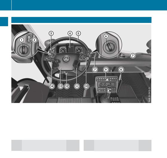
36 Cockpit
Cockpit
At a glance
|
Function |
Page |
|
|
: |
Light switch |
74 |
|
; |
Headlamp range control |
75 |
|
= |
Cruise control lever |
44 |
|
? |
Instrument cluster |
39 |
AMultifunction steering
|
wheel |
42 |
|
|
B |
Differential locks |
190 |
|
C |
Cup holder |
93 |
|
Function |
Page |
|
|
D |
Universal carrier |
94 |
|
E |
Centre console |
40 |
|
F |
Multifunction lever |
45 |
|
G |
Ignition lock |
159 |
HTo adjust the multifunction
|
steering wheel |
70 |
|
|
I |
Horn |
|
|
J |
Combination switch |
44 |
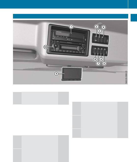
Overhead control panel 37
Overhead control panel
At a glance
:Tachograph, see the manufacturer’s operating instructions
|
; |
z Switches the front |
|
|
windscreen heating |
||
|
on/off |
90 |
|
|
= |
I Switches the lateral |
|
|
end position of wind- |
||
|
screen wipers |
||
|
on/off |
88 |
|
?Q Switches on the headlamp cleaning
AJ Switches the external lighting control
|
Function |
Page |
|
|
B |
i Switches the work- |
|
|
ing-area lamp on/off |
77 |
|
Cé Switches the auxiliary headlamps
DÀ Switching the rotating beacons or
EMonitor for front, rearview
|
and equipment cameras |
196 |
|
|
F |
CD radio |
148 |
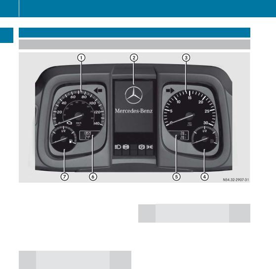
38 Instrument cluster
Instrument cluster
Displays
At a glance
|
Example: instrument cluster |
||
|
Function |
Page |
|
|
: |
Speedometer |
|
|
; |
On-board computer |
115 |
|
= |
Rev counter |
110 |
|
? |
AdBlue® level |
111 |
ATotal distance and trip dis-
i On vehicles without display A and B, scroll in the on-board computer to the Truck info menu window in the ßtour data menu (Y page 118). The menu window displays the total distance recorder, trip meter, time and outside temperature.
BClock and outside temper-
|
ature display |
112 |
|
|
C |
Fuel level |
111 |
![]()
Instrument cluster 39
Warning and indicator lamps
At a glance
|
Example: instrument cluster |
|
|
Function |
Page |
:Warning and indicator lamps in the speedometer
|
;Engine diagnostics |
113 |
|
|
ºCab tilt lock |
314 |
|
|
iDifferential lock |
190 |
|
|
WInstruction to brake at |
||
|
high engine speeds |
110 |
|
|
; |
Turn signals |
75 |
|
= |
Warning and indicator |
|
|
lamps in the rev counter |
||
|
!ABS (Anti-lock Brak- |
164 |
|
|
ing System) |
||
|
JBrake pressure |
161 |
|
Function |
Page |
|
|
ÉDiesel particle filter, |
||
|
automatic regeneration |
213 |
|
|
ÂDiesel particle filter |
||
|
malfunction |
213 |
|
|
A |
Warning and indicator |
|
|
lamps below the on- |
||
|
board computer |
||
|
KMain-beam head- |
75 |
|
|
lamps |
||
|
ÃContinuous brake |
167 |
|
|
!Parking brake |
166 |
|
|
USide lamps/dipped- |
74 |
|
|
beam headlamps |
||
?Warning and indicator lamps in the AdBlue® display
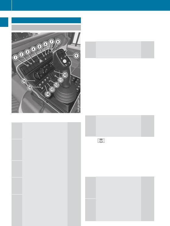
40 Centre console
Centre console
Front centre console
At a glance
:K Activates/deactivates ABS Off-road
;U Activates/deactivates transmissiondriven power take-
=T Activates/deactivates engine-driven
?£ Switches the hazard warning lamps
A÷ Tyre pressure control system: increa-
ÖTyre pressure control system: reduces
|
Function |
Page |
|
|
B |
Õ Activates/deacti- |
|
|
vates the tyre pres- |
||
|
sure control system |
186 |
|
CF Manually activates/ deactivates engine
|
speed mode |
262 |
|
|
D |
Î Activates/deacti- |
|
|
vates hydrostatic |
||
|
drive system |
198 |
|
|
E |
Operates the hydrostatic |
|
|
drive system |
198 |
|
|
Operates the hydraulic sys- |
||
|
tem |
228 |
|
|
Changes the installation |
||
|
position of the control lever |
||
|
and hydraulic system con- |
95 |
|
|
trols |
||
FL Front PTO shaft: activates/deactivates working speed
|
control |
267 |
|
|
G |
Engages/disen- |
|
|
gages the front PTO |
||
|
shaft |
267 |
|
|
H |
N Engages/disen- |
|
|
gages working gear |
182 |
|
|
O Engages/disen- |
||
|
gages crawler gear |
184 |
|
IVehicles with a trailermounted tipper platform:
|
Ö Enables/disables |
|
|
tipper function |
277 |
JVehicles with tipper platform:
|
P Enables/disables |
|
|
tipper function |
277 |
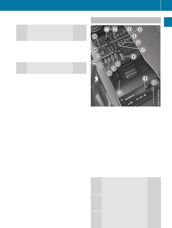
KVehicles with tipper platform, without hydraulic system:
|
Q Raises the tipper |
||
|
platform |
277 |
|
|
R Lowers the tipper |
||
|
platform |
277 |
|
LHeating/air-conditioning
Centre console 41
Rear centre console
At a glance
|
Function |
Page |
|
|
: |
Adjusts the exterior mirrors |
71 |
|
; |
É Diesel particle filter, |
|
|
starts stationary |
||
|
manual regeneration |
213 |
|
|
Ê Diesel particle filter, |
||
|
blocks regeneration |
214 |
|
|
= |
Õ Switches the equip- |
|
|
ment camera on/off |
196 |
|
|
? |
& Locks the doors |
57 |
|
% Unlocks the doors |
57 |
|
AS Vehicles with mowing door: wipes with
Bw Switches the righthand seat heating
Cw Switches the seat heating on the left-
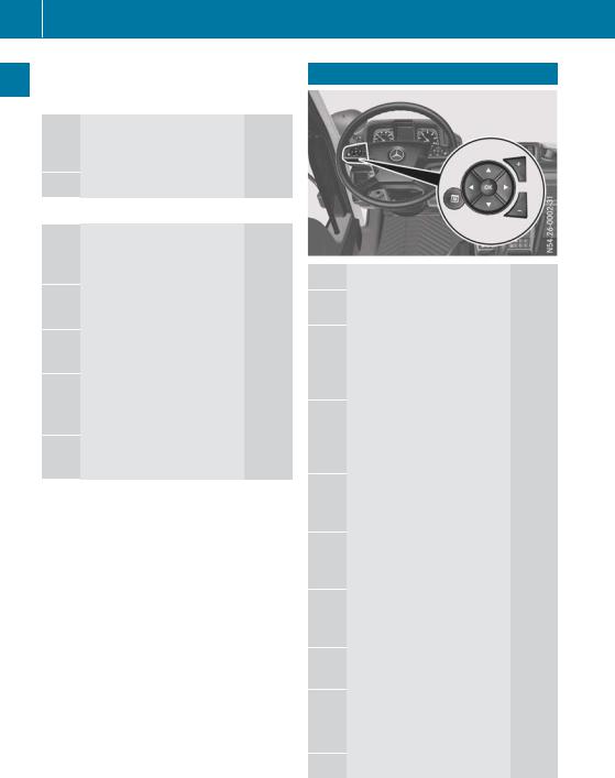
42 Multifunction steering wheel
At a glance
|
Function |
Page |
|
|
D |
Parking brake |
166 |
EFleetBoard (see the manufacturer’s operating instructions)
F Device mounting bracket
|
G |
Auxiliary heating timer |
102 |
HÏ Applies/releases the four-wheel park-
I£ Switches engine pre-
JJ Switching the 12 V
KÈ Switches radiator quick cleaning sys-
L¿ Opens/closes the
|
side windows |
60 |
|
|
M |
12 V socket |
91 |
|
N |
T Switches on the mir- |
|
|
ror heating |
72 |
|
|
U Switches off the mir- |
||
|
ror heating |
72 |
|
|
O |
24 V socket |
91 |
Multifunction steering wheel
Operating the on-board computer: 115
uSelects the next main menu/next entry in the input window, increases or resets value
tSelects the previous main menu/previous entry in the input window or decreases value
rNext menu window/next menu bar down in the input window
sPrevious menu window/ next menu bar up in the input window
9Opens and closes input window/acknowledges event window
|
Ú |
Stores/displays the favour- |
|
|
ite menu window |
||
|
W Increases the volume: |
||
|
Audio |
122 |
|
|
Telephone |
121 |
X Reduces the volume:
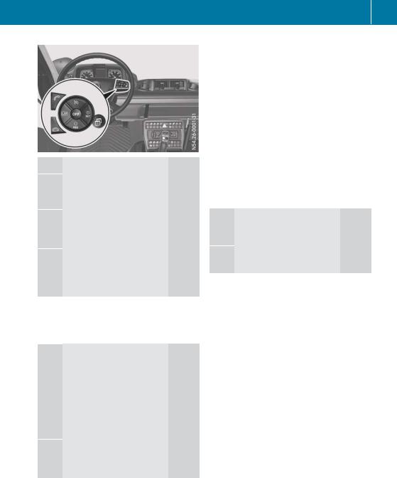
|
Function |
Page |
|
Operating the speed lim- |
|
|
iter: |
191 |
|
Operating cruise control: |
193 |
|
é Selects cruise control |
194 |
|
Switches off the working |
|
|
mode limiter |
204 |
ÑActivates and adjusts current speed/limit speed, increases the speed/limit speed
|
Speed limiter |
191 |
|
|
Cruise control |
193 |
|
|
Working mode cruise con- |
||
|
trol |
203 |
|
qActivates and calls up stored speed/limit speed, reduces set speed/limit speed
|
Speed limiter |
191 |
|
Cruise control |
193 |
|
Working mode cruise con- |
|
|
trol |
203 |
|
È Selects the speed limiter |
192 |
|
Switches on the working |
|
|
mode limiter |
204 |
|
Multifunction steering wheel |
43 |
|||
|
Function |
Page |
|||
|
o |
Deactivates the speed lim- |
|||
|
glance |
||||
|
iter |
193 |
|||
|
Deactivates cruise control |
196 |
|||
|
Switches off the working |
a |
|||
|
mode cruise control and |
||||
|
At |
||||
|
working mode limiter |
203 |
|||
|
Ù |
Input window: |
|||
|
Cruise control, adjusts the |
||||
|
speed tolerance |
195 |
|||
|
Equipment operation, |
||||
|
engine speed setting |
263 |
|||
|
Operating the telephone: |
121 |
|||
; Makes or accepts a call/ displays the Telephone menu window
= Ends/rejects an incoming call
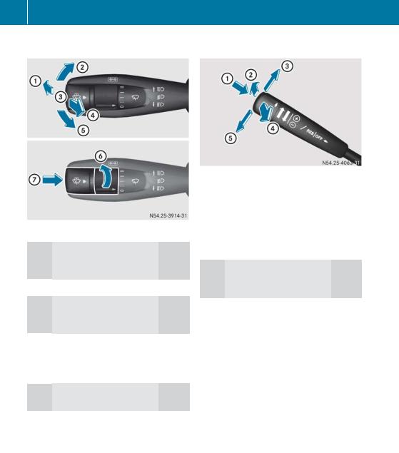
44 Cruise control lever
Combination switch |
Cruise control lever |
|||
At a glance
:Main-beam headlamps on (when dipped-beam head-
|
lamps are switched on) |
75 |
|
|
; |
Turn signal, right |
75 |
=Main-beam headlamps off (when dipped-beam head-
|
lamps are switched on) |
75 |
|
|
? |
Headlamp flasher |
75 |
|
A |
Turn signal, left |
75 |
|
B |
Windscreen wipers |
88 |
CTo wipe with washer
|
Function |
Page |
|
|
: |
Speed limiter: activating/ |
|
|
deactivating the speed lim- |
||
|
iter |
191 |
|
|
Cruise control: activat- |
||
|
ing/deactivating cruise |
193 |
|
|
control |
||
;Telligent® gearshift: gear
|
preselection (shifting |
||
|
down) |
169 |
|
|
Telligent® automatic |
||
|
gearshift: shifting down |
175 |
|
|
manually |
||
|
= |
Speed limiter: increasing |
191 |
|
set limit speed |
||
|
Cruise control: increasing |
||
|
set speed |
193 |
|
|
Telligent® gearshift: |
||
|
selecting direction of travel |
169 |
|
|
(forward) |
||
|
Telligent® automatic |
||
|
gearshift: selecting direc- |
175 |
|
|
tion of travel (forward) |
||
|
? |
Telligent® gearshift: gear |
|
|
preselection (shifting up) |
169 |
|
|
Telligent® automatic |
||
|
gearshift: shifting up man- |
175 |
|
|
ually |
||
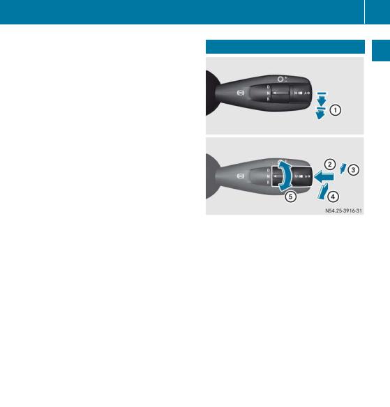
|
Function |
Page |
|
|
A |
Speed Limiter: reducing |
|
|
set limit speed |
191 |
|
|
Cruise control: decreasing |
193 |
|
|
set speed |
||
|
Telligent® gearshift: |
||
|
selecting direction of travel |
169 |
|
|
(backwards) |
||
|
Telligent® automatic |
||
|
gearshift: selecting direc- |
175 |
|
|
tion of travel (backwards) |
||
Multifunction lever 45
Multifunction lever
At a glance
|
Function |
Page |
|
|
: |
Continuous brake |
167 |
|
; |
Telligent® automatic |
|
|
gearshift: automatic gear- |
||
|
shift — drive program selec- |
||
|
tion |
177 |
|
|
d Automatic drive pro- |
||
|
gram A |
||
|
p Manual drive program M |
||
|
= |
Telligent® gearshift: gear |
|
|
preselection (shifting |
168 |
|
|
down) |
||
|
Telligent® automatic |
||
|
gearshift: shifting down |
174 |
|
|
manually |
||
|
? |
Telligent® gearshift: gear |
|
|
preselection (shifting up) |
168 |
|
|
Telligent® automatic |
||
|
gearshift: shifting up man- |
174 |
|
|
ually |
||

46 Multifunction lever
At a glance
|
Function |
Page |
|
|
A |
Telligent® gearshift: |
|
|
selecting direction of travel |
168 |
|
|
h Drive/forwards |
||
|
i Neutral |
||
|
k Reverse |
||
|
Telligent® automatic |
||
|
gearshift: selecting direc- |
174 |
|
|
tion of travel |
||
|
h Drive/forwards |
||
|
i Neutral |
||
|
k Reverse |
||

47
|
Useful information ………………………… |
48 |
|
Occupant safety ……………………………. |
48 |
|
Children in the vehicle …………………… |
51 |
|
Pets in the vehicle …………………………. |
53 |
Safety

|
48 |
Occupant safety |
||
Useful information |
|||
|
These Operating Instructions describe all the |
|||
|
models and standard and optional equipment |
|||
|
of your vehicle that were available at the time |
|||
Safety |
|||
|
of going to print. Country-specific differences |
|||
|
are possible. Bear in mind that your vehicle |
|||
|
may not be equipped with all the functions |
|||
|
described. This also applies to safety-relevant |
|||
|
systems and functions. |
|||
|
Read the information on qualified specialist |
|||
|
workshops (Y page 30). |
|||
|
Occupant safety |
|||
Restraint system introduction |
|||
|
The restraint system can reduce the risk of |
|||
|
vehicle occupants coming into contact with |
|||
|
parts of the vehicle’s interior in the event of |
|||
|
an accident. |
|||
|
The restraint system can only offer protection |
|||
|
if all vehicle occupants always: |
|||
|
Rhave the seat belt correctly fastened |
|||
|
(Y page 49) |
|||
|
Rhave the seat and head restraint adjusted |
|||
|
properly (Y page 64) |
|||
|
As the driver, you must also make sure that |
|||
|
the steering wheel is also adjusted properly. |
|||
|
Observe the information on the correct driv- |
|||
|
er’s seat position (Y page 64). |
|||
|
See «Children in the vehicle» for further infor- |
|||
|
mation on children travelling in the vehicle as |
|||
|
well as on child restraint systems |
|||
|
(Y page 51). |
|||
Important safety notes |
|||
|
G WARNING |
|||
|
If the restraint system is modified, it may no |
|||
|
longer work as intended. The restraint system |
|||
|
may then not perform its intended protective |
|||
|
function by failing in an accident or triggering |
|||
|
unexpectedly, for example. There is an |
|||
|
increased risk of injury, possibly even fatal. |
|||
Never modify parts of the restraint system. Do not attempt to modify the wiring as well as electronic components or their software.
Seat belts
Introduction
A correctly worn seat belt is the most effective means of restraining the movement of vehicle occupants in the event of a collision. This reduces the risk of vehicle occupants coming into contact with parts of the vehicle interior or being ejected from it.
If the seat belt is pulled quickly or sharply by the belt sash guide, the inertia reel locks. The belt strap cannot be pulled out any further.
Important safety notes
G WARNING
The seat belt cannot perform its intended protective function if it is not fastened correctly. Also, an improperly fastened seat belt can cause additional injuries in the event of an accident, sudden braking or abrupt changes of direction. There is an increased risk of injury, possibly even fatal.
Always make sure that all vehicle occupants are wearing their seat belt properly and are seated correctly.
G WARNING
The seat belt does not offer the intended level of protection if you have not moved the backrest to an almost vertical position. When braking or in the event of an accident, you could slide underneath the seat belt and sustain abdomen or neck injuries, for example. This poses an increased risk of injury or even fatal injury.
Adjust the seat properly before beginning your journey. Always ensure that the backrest is in an almost vertical position and that the shoulder section of your seatbelt is routed across the centre of your shoulder.
ОАО «РОССИЙСКИЕ ЖЕЛЕЗНЫЕ ДОРОГИ»
РАСПОРЯЖЕНИЕ
от 10 сентября 2014 г. N 2117р
ОБ УТВЕРЖДЕНИИ И ВВЕДЕНИИ В ДЕЙСТВИЕ ИНСТРУКЦИИ ПО ЭКСПЛУАТАЦИИ ЛОКОМОБИЛЯ MERCEDES-BENZ UNIMOG НА КОМБИНИРОВАННОМ ХОДУ НА ЖЕЛЕЗНОДОРОЖНЫХ ПУТЯХ ОБЩЕГО ПОЛЬЗОВАНИЯ, РАСПОЛОЖЕННЫХ В ГРАНИЦАХ ТЕРРИТОРИЙ ДИРЕКЦИЙ ПО УПРАВЛЕНИЮ ТЕРМИНАЛЬНО-СКЛАДСКИМ КОМПЛЕКСОМ — СТРУКТУРНЫХ ПОДРАЗДЕЛЕНИЙ ЦЕНТРАЛЬНОЙ ДИРЕКЦИИ ПО УПРАВЛЕНИЮ ТЕРМИНАЛЬНО-СКЛАДСКИМ КОМПЛЕКСОМ
В целях организации движения при эксплуатации локомобиля Mercedes-Benz UNIMOG на комбинированном ходу на железнодорожных путях общего пользования, расположенных в границах территорий дирекций по управлению терминально-складским комплексом — структурных подразделений Центральной дирекции по управлению терминально-складским комплексом:
1. Утвердить и ввести в действие с 1 сентября 2014 г. прилагаемую Инструкцию по эксплуатации локомобиля Mercedes-Benz UNIMOG на комбинированном ходу на железнодорожных путях общего пользования, расположенных в границах территории дирекции по управлению терминально-складским комплексом — структурных подразделений Центральной дирекции по управлению терминально-складским комплексом (далее — Инструкция).
2. Руководителям причастных филиалов и структурных подразделений ОАО «РЖД» обеспечить выполнение Инструкции.
3. Контроль за исполнением настоящего распоряжения возложить на начальника Центральной дирекции по управлению терминально-складским комплексом Хронопуло С.М.
Первый вице-президент ОАО «РЖД»
В.Н.Морозов
УТВЕРЖДЕНА
распоряжением ОАО «РЖД»
от 10.09.2014 г. N 2117р
ИНСТРУКЦИЯ
ПО ЭКСПЛУАТАЦИИ ЛОКОМОБИЛЯ MERCEDES-BENZ UNIMOG НА КОМБИНИРОВАННОМ ХОДУ НА ЖЕЛЕЗНОДОРОЖНЫХ ПУТЯХ, РАСПОЛОЖЕННЫХ В ГРАНИЦАХ ТЕРРИТОРИИ ДИРЕКЦИЙ ПО УПРАВЛЕНИЮ ТЕРМИНАЛЬНО-СКЛАДСКИМ КОМПЛЕКСОМ — СТРУКТУРНЫХ ПОДРАЗДЕЛЕНИИ ЦЕНТРАЛЬНОЙ ДИРЕКЦИИ ПО УПРАВЛЕНИЮ ТЕРМИНАЛЬНО-СКЛАДСКИМ КОМПЛЕКСОМ — ФИЛИАЛА ОАО «РЖД»
1. Общие положения
1.1 Настоящая Инструкция по эксплуатации локомобиля Mercedes-Benz UNIMOG на комбинированном ходу на железнодорожных путях, расположенных в границах территорий дирекций по управлению терминально-складским комплексом — структурных подразделений Центральной дирекции по управлению терминально-складским комплексом — филиала ОАО «РЖД» (далее — Инструкция) устанавливает порядок эксплуатации локомобиля Mercedes-Benz UNIMOG на комбинированном ходу на инфраструктуре ОАО «РЖД», действия работников железнодорожного транспорта при его эксплуатации, а также порядок выполнения маневров с использованием локомобиля Mercedes-Benz UNIMOG на комбинированном ходу на железнодорожных путях в границах территорий дирекций по управлению терминально-складским комплексом (далее — Дирекция) — структурных подразделений Центральной дирекции по управлению терминально-складским комплексом — филиала ОАО «РЖД» (далее — Центральная дирекция).
Локомобиль Mercedes-Benz UNIMOG на комбинированном ходу (далее — машина КХ) — мультиприводная машина, способная передвигаться по железнодорожным путям с шириной колеи 1520 мм и по автомобильным дорогам, а также самостоятельно заезжать и съезжать с железнодорожного пути. Базовым транспортным средством машины КХ является полноприводный автомобиль Mercedes-Benz с дизельным двигателем. Машина КХ оборудована автосцепкой типа СА-3, компрессором для осуществления питания сжатым воздухом тормозной магистрали железнодорожного подвижного состава, крано-манипуляторной установкой.
Машина КХ оборудована тормозным краном для управления пневматическими автотормозами железнодорожного маневрового состава и стоп-краном. Тормозной кран имеет два фиксированных положения «отпуск» и «торможение». Тормозной эффект регулируется путем установки рукоятки тормозного крана в определенное положение.
1.2 В настоящей Инструкции применяются следующие сокращения:
ТРА — техническо-распорядительный акт станции;
СЦБ — устройства сигнализации, централизации и блокировки;
ЧТО — частичное техническое освидетельствование;
ПТО — полное техническое освидетельствование;
ЕТО — ежесменное техническое обслуживание;
КТО — комиссионный технический осмотр;
ДСП — дежурный по железнодорожной станции;
ОПЦ — оператор поста централизации.
1.3 Машина КХ предназначена для производства маневров с грузовыми, пассажирскими, весоповерочными вагонами, вагонами весовых мастерских (далее — вагон), локомотивами по железнодорожным путям в границах территории грузовых дворов Дирекции, а также для выполнения погрузочно-разгрузочных работ и обслуживания территории Дирекции.
1.4 На работников, эксплуатирующих машины КХ на железнодорожных путях в границах территорий грузовых дворов Дирекций, распространяются требования нормативных правовых актов МПС России, Минтранса России, нормативных документов ОАО «РЖД», предъявляемые к машинам КХ.
1.5 Эксплуатация машины КХ должна осуществляться в соответствии с положениями настоящей Инструкции и местной инструкции с учетом конкретных условий эксплуатации.
Местная инструкция проверяется и согласовывается начальником станции, ревизором движения участка, коммерческим ревизором участка, начальником эксплуатационного локомотивного депо, начальником отдела по работе со станциями центра организации работы железнодорожных станций, ревизором по безопасности движения по региону (по хозяйству перевозок), начальником центра организации работы железнодорожных станций. Утверждает инструкцию начальник железной дороги.
На Калининградской железной дороге инструкция разрабатывается в Дирекции по управлению терминально-складским комплексом. Проверяют и согласовывают ее начальник станции, ревизор движения участка, при его отсутствии — ревизор службы движения, начальник эксплуатационного локомотивного депо, заместитель начальника Дирекции управления движением (по коммерческой работе в сфере грузовых перевозок), начальник Дирекции управления движением, ревизор по безопасности движения (по хозяйству перевозок). Утверждает инструкцию первый заместитель начальника железной дороги.
1.6. Машина КХ должна иметь следующие отличительные четкие знаки и надписи:
технический знак принадлежности к железнодорожному транспорту ОАО «РЖД»;
наименование организации — владельца эксплуатирующего машину КХ;
номер (государственный регистрационный знак);
табличку завода-изготовителя с указанием даты и места постройки;
идентификационные и приемочные номера на составных частях в местах, установленных нормативно-технической документацией;
конструкционная скорость для движения по железнодорожным путям;
серия и бортовой номер, наименование места приписки, таблички и надписи об освидетельствовании резервуаров, контрольных приборов;
число мест, предназначенных для перевозки людей;
регистрационный номер, паспортную грузоподъемность, дату проведения технического освидетельствования, ЧТО и ПТО для машин КХ, оборудованных крано-манипуляторными и экскаваторными установками, монтажными вышками;
Знаки и надписи на машинах КХ наносятся в соответствии с требованиями конструкторской документации.
1.7 Каждая машина КХ должна иметь:
паспорт, составленный поставщиком или разработчиком конструкторской документации (включая паспорт крано-манипуляторной установки);
руководство по эксплуатации машины КХ или другую эксплуатационную документацию предприятия — изготовителя;
руководство по эксплуатации системы обеспечения безопасности движения поездов;
паспорта колесных пар (бегунков);
паспорта воздушных резервуаров, имеющихся на машине КХ;
паспорта и руководства по эксплуатации основных комплектующих изделий: силовой установки, гидропередачи, генератора и других устройств согласно ведомости эксплуатационных документов;
журнал учета результатов осмотра, проведения технического обслуживания и ремонта машины;
график планово-предупредительного технического обслуживания и ремонта машины КХ.
Паспорт и другая эксплуатационная документация, включая документацию установленных на машинах КХ комплектующих изделий, должны храниться у лица, ответственного за его эксплуатацию и содержание в исправном состоянии. Руководство или инструкция по эксплуатации должны находиться у водителя машины КХ.
1.8 Паспорта установленных на машине КХ комплектующих изделий должны регулярно заполняться лицом, ответственным за эксплуатацию данной машины, в соответствии с имеющимися в них разделами и пунктами.
1.9 На каждой находящейся в эксплуатации машине КХ должны быть:
журнал технического обслуживания и учета работы подвижной единицы формы ТУ-152 (далее — журнал формы ТУ-152);
акт комиссионного технического осмотра;
маршрутный лист;
журнал учета работы на железнодорожном пути (приложение N 1);
вахтенный журнал для записи результатов осмотра при приемке и сдаче крано-манипуляторной установки;
основные запчасти согласно ведомости эксплуатационной документации;
два огнетушителя;
сигнальные приборы и принадлежности: два духовых рожка, два комплекта сигнальных флажков (красного и желтого цветов), два ручных сигнальных фонаря, петарды (12 шт.);
аптечка с набором медикаментов и перевязочных средств для оказания первой медицинской помощи;
два тормозных башмака или два противооткатных устройства для машин КХ;
двумя носимыми радиостанциями;
средства телефонной связи.
1.10 Для движения по железнодорожным путям машина КХ должна быть оборудована:
устройством для движения по рельсам железнодорожного пути;
штатным шунтирующим устройством;
временным шунтирующим устройством;
жестким сцепным устройством, для сцепления с транспортным средством железнодорожного транспорта;
специальными фонарями для осигнализирования;
звуковым сигналом;
радиостанцией для связи с ДСП, машинистами локомотивов;
проблесковым маячком желтого цвета;
локомотивными устройствами автоматической локомотивной сигнализации, а также устройствами безопасности для машин КХ.
Работоспособность радиостанций проверяется между водителем и помощником водителя, о чем делается отметка водителем в маршрутном листе.
Выезд машины КХ на железнодорожные пути, оборудованные устройствами электрической централизации, разрешается, если подвижная единица на комбинированном ходу обеспечивает надежное шунтирование рельсовых цепей и имеет штатное и временное шунтирующие устройства. Сопротивление шунтирующего устройства не должно превышать 0,01 Ом. Проверка штатного и временного шунтирующих устройств должна проводиться один раз в три месяца с отметкой их работоспособности в журнале формы ТУ-152 с составлением акта за подписью работника, производившего измерения, и водителя машины КХ.
Проверка шунтирующих устройств должна проводиться на контрольных пунктах AЛC (КП), в пунктах технического обслуживания локомотивных или моторвагонных депо, в центрах по техническому обслуживанию и ремонту локомотивных устройств безопасности или электромехаником СЦБ на месте базирования машины КХ с применением измерительных приборов, поверенных установленным порядком.
1.11 Перевозка людей на машине КХ в количестве большем, чем указано в техническом паспорте машины не допускается.
1.12 Выезд машины КХ на главные, приемо-отправочные, сортировочно-отправочные железнодоржные пути железнодорожной станции запрещается.
1.13 Категорически запрещается использование машины КХ для операций, не предусмотренных технической документацией. Запрещается работать крано-манипуляторной установкой при нахождении машины КХ на железнодорожном пути.
2. Требования к эксплуатации подвижных единиц на комбинированном ходу
2.1 Для управления машиной КХ приказом начальника механизированной дистанции погрузочно-разгрузочных работ и коммерческих операций (далее- механизированная дистанция) назначается водитель и помощник водителя.
2.2 К управлению машиной КХ в качестве водителя и помощника водителя допускаются лица:
не моложе 18 лет;
имеющие образование не ниже среднего, прошедшие при поступлении на работу в установленном порядке обязательные предварительные и периодические медицинские осмотры, психофизиологическое обследование, прошедшие обучение в специальном образовательном учреждении и получившие свидетельство помощника машиниста (водителя).
2.3 Водитель и помощник водителя проходят аттестацию в порядке, установленном в распоряжении ОАО «РЖД» от 26.03.2013 N 731р «О проведении аттестации работников ОАО «РЖД», производственная деятельность которых связана с движением поездов и маневровой работой на железнодорожных путях общего пользования».
Проходят проверку знаний должностных инструкций, ТРА станции, положений настоящей и местной инструкций.
2.4 Водитель машины КХ должен иметь свидетельство на право управления железнодорожной подвижной единицей в соответствии с Правилами технической эксплуатации железных дорог Российской Федерации, утвержденными приказом Минтранса России от 21.12.2010 N 286. Водительское удостоверение на право управления транспортным средством категории «С» в соответствии с Правилами дорожного движения Российской Федерации. Удостоверение на право управления крано-манипуляторной установкой, удостоверение формы ЭУ-43 о группе электробезопасности не ниже третьей, свидетельство о прохождении аттестации.
Помощник водителя — свидетельство о присвоении квалификации составителя поездов, удостоверение стропальщика, удостоверение формы ЭУ-43 о группе электробезопасности не ниже третьей, свидетельство о прохождении аттестации.
2.5 Вновь назначенному водителю машины КХ выдается служебный формуляр формы ТУ-57, в котором должно быть:
заключение машиниста-инструктора о допуске к самостоятельному управлению машиной КХ на железнодорожных путях и контрольно- заключительной поездки на железнодорожных путях в границах территории Дирекции;
запись начальника механизированной дистанции об аттестации, проведенных испытаниях в знании ТРА станции, настоящей и местной инструкции, собеседовании по вопросам обеспечения безопасности движения.
2.6 Водитель, имеющий перерыв в работе на железнодорожных путях до трех месяцев, допускается к работе после дополнительного инструктажа. Дополнительный инструктаж проводится руководителем, ответственным за эксплуатацию машины КХ, с записью в служебном формуляре машиниста (водителя) формы ТУ-57.
При перерыве в работе на железнодорожных путях свыше трех месяцев водитель допускается к самостоятельной работе только после дополнительного инструктажа и контрольно-инструкторской поездки с положительным заключением машиниста-инструктора с записью в служебном формуляре формы ТУ-57.
2.7 При отсутствии у водителя машины КХ заключения машиниста- инструктора для работы на железнодорожных путях и при необходимости заезда на них должен выделяться проводник из числа машинистов или водителей специального самоходного подвижного состава, имеющих заключение машиниста- инструктора о возможности самостоятельной работы на данных железнодорожных путях.
Водитель машины КХ и проводник являются в равной мере ответственными за обеспечение безопасности движения.
2.8 Водитель машины КХ при выполнении служебных обязанностей должен иметь при себе: свидетельство на право управления или его копию, удостоверение личности с отметкой о сдаче в отдел кадров свидетельства на право управления, служебный формуляр формы ТУ-57, свидетельство о прохождении аттестации, удостоверение формы ЭУ-43, выписку из ТРА станции, водительское удостоверение на право управления транспортным средством категории «С», свидетельство на право управления крано-манипуляторной установкой, заполненные путевой (форма N 3 спец.) и маршрутный лист, заверенный штампом и подписью фельдшера здравпункта.
Помощник водителя — свидетельство о присвоении квалификации составителя поездов или его копию, удостоверение личности с отметкой о сдаче в отдел кадров свидетельства о присвоении квалификации составителя поездов, удостоверение стропальщика, свидетельство о прохождении аттестации.
Указанные документы водитель и помощник водителя обязаны предъявить руководителю работ перед началом работ.
2.9 Ответственный за эксплуатацию машины КХ, содержание ее в исправном состоянии, обеспечение безопасных условий работы, а также за взаимодействие со смежными службами — начальник механизированной дистанции. Ответственный за организацию технического обслуживания и ремонта машины КХ, подготовку водителя и помощника водителя — главный инженер Дирекции.
2.10 Контроль за работой водителя и помощника водителя осуществляют первый заместитель начальника Дирекции по управлению терминально-складским комплексом, машинисты-инструкторы бригад путевых машин и моторно-рельсового транспорта.
2.11 Передислокация машин КХ по железнодорожным путям должна осуществляться только в погруженном состоянии на платформе. В случае аварийной или нестандартной ситуации допускается вывод машины КХ с железнодорожного пути отдельным локомотивом с объединением тормозной магистрали, при этом машина должна обеспечивать надежное шунтирование рельсовых цепей.
Ответственность за надежность сцепления машины КХ с локомотивом возлагается на водителя машины КХ.
2.12. Не допускается эксплуатация на железнодорожных путях машины КХ, не прошедшей комиссионный технический осмотр, а также если имеется хотя бы одна из следующих неисправностей:
неисправность прибора для подачи звукового сигнала;
неисправность тормозов, в том числе ручного тормоза;
неисправность привода передвижения;
неисправность ведущих мостов базового шасси;
неисправность рулевого управления базового шасси;
появление стука, постороннего шума в двигателе;
неисправность или отсутствие средств пожаротушения;
неисправность или отсутствие одного из двух тормозных башмаков или противооткатного устройства для машин КХ;
неисправность световых приборов, в том числе желтого проблескового маячка, и электрооборудования;
неисправность или несовместимость с устройствами поездной радиосвязи инфраструктуры устройств поездной радиосвязи на машине КХ, неисправность или отсутствие хотя бы одной из двух носимых радиостанций;
неисправность штатного и временного шунтирующих устройств;
неисправность устройства для движения по рельсам железнодорожного пути;
неисправность автосцепки типа СА-3;
неисправность, отсутствие или не соответствие конструкторской документации штатных транспортных запоров, стопорных и предохранительных устройств, крепления рабочих органов в транспортном положении;
выход за габарит подвижного состава частей оборудования, установленного на машинах КХ;
неисправность компрессора, предназначенного для питания сжатым воздухом тормозной магистрали железнодорожного подвижного состав;
неисправность локомотивных устройств автоматической локомотивной сигнализации, а также устройствами безопасности.
Комиссионный технический осмотр машины КХ с составлением акта проводится два раза в год. Осмотру подлежат приборы и устройства, установленные на машине КХ и используемые для работы на железнодорожных путях. Фактические замеры тормозных характеристик машин КХ производить на железнодорожном пути при скорости движения 20 км/ч с применением тормозов до полной остановки.
2.13 Перед выездом на работу водитель машины КХ должен пройти предрейсовый медицинский осмотр с отметкой в путевом листе и маршрутном листе, предрейсовый инструктаж и целевой инструктаж по охране труда.
Водитель обязан убедиться в исправности машины КХ, провести ЕТО, обращая особое внимание на работу тормозного оборудования, состояние двигателя, ходовых частей, рессорного подвешивания, шунтирующего устройства, правильности крепления рабочих органов в транспортном положении, обеспечении габарита, проверить наличие и исправность звукового сигнала, а также сигнальных принадлежностей, запасных частей и инструмента, комплекта тормозных башмаков или противооткатных устройств, аптечки с набором медикаментов и перевязочных средств для оказания первой медицинской помощи, исправности радиосвязи.
2.14 При выполнении маневров машиной КХ на железнодорожных путях помощник водителя несет ответственность за надежность сцепления машины КХ с вагонами и вагонов между собой, соединение воздушных рукавов, открытие концевых кранов в маневровом составе. Водитель несет ответственность за проведение сокращенного опробования автотормозов. Маневры на железнодорожных путях должны производиться с включенными автотормозами.
2.15 Во время движения машины КХ запрещается сходить и садиться на нее до полной остановки.
2.16 Скорость движения машины КХ не должна превышать скорости, указанной в руководстве по эксплуатации, по станционным путям не более 25 км/ч, а по стрелочным переводам не более 15 км/ч. При плохой видимости скорость движения машин КХ не должна превышать 25 км/ч, при этом освещение (фары и задний красный сигнальный фонарь) должны быть включены.
2.17 На железнодорожных станциях, где не обеспечивается регистрация служебных переговоров, маневры машиной КХ запрещаются.
3. Маневровая работа
3.1 Перед началом работ бригада машины КХ обязана получить план работ от руководителя работ. В случае работы машины на железнодорожных путях в плане работ обязательно указывается временной интервал нахождения машины на железнодорожных путях, номера железнодорожных путей, на которых будут производиться маневры, и номера перемещаемых вагонов с указанием мест перемещения.
Руководитель работ должен осуществлять контроль за действиями бригады и передвижением машины по железнодорожным путям.
3.2 Заезд (съезд) машины КХ на железнодорожный путь производится на железнодорожных переездах, на технологических проездах, по специальному съемному настилу, в тупиках, имеющих специально оборудованные площадки (указывается в местной инструкции).
Места заезда (съезда) должны быть заранее определены, согласованы с причастными хозяйствами, а их перечень утвержден начальником дирекции инфраструктуры.
3.3 Запрещается одновременно в одном маневровом районе производить маневровую работу машиной КХ и локомотивом или специальным самоходным подвижным составом.
3.4 При нахождении машины КХ на железнодорожном пути необходимо установить стрелки, ведущие на путь ее нахождения, в положение, исключающее возможность заезда на эти пути, при электрической централизации дополнительно на стрелочные рукоятки (кнопки) навесить красные колпачки, тщательно следить за занятостью этих путей.
Стоянка машин КХ (в отстое) на станционных железнодорожных путях допускается только в исключительных случаях с разрешения ДСП (ОПЦ).
3.5 Водитель машины КХ не имеет права заезжать на железнодорожный путь, не получив бланк предупреждения формы ДУ-61, который выдается согласно требованиям приложения 12 ИДП и соответствующего разрешения.
3.6 О приведении машины КХ в транспортное положение перед заездом на железнодорожный путь руководитель работ обязан сделать запись в журнале движения поездов формы ДУ-2 (ДУ-3) или журнале формы ДУ-46.
3.7 Перед заездом (съездом) машины КХ на железнодорожный путь, руководитель работ на рабочем месте ДСП (ОПЦ) оформляет в журнале формы ДУ-46 запись о месте заезда (съезда) машины КХ с указанием мер безопасности движения.
3.8 ДСП (ОПЦ) подписывает в журнале формы ДУ-46 запись (с отметкой времени), разрешая начать работу по заезду (съезду) машины КХ.
3.9 Руководитель работ установленным порядком организует ограждение места заезда (съезда) и смежного с ним пути (путей), как места требующего остановки.
Перед заездом (съездом) водитель машины КХ должен получить от ДСП (ОПЦ) устное разрешение по радиосвязи.
3.10 После заезда (съезда) и установки машины КХ на рельсы железнодорожного пути водитель машины КХ обязан доложить ДСП (ОПЦ) об окончании заезда (съезда), снятии сигналов ограждения, руководитель работ сделать об этом запись в журнале формы ДУ-46.
3.11 Маневровые передвижения машины КХ по железнодорожным путям должны осуществляться по приготовленным маршрутам с открытием соответствующих маневровых светофоров или по ручным сигналам, передаваемым работниками хозяйства перевозок, по указанию ДСП (ОПЦ) и руководителя маневров.
3.12 Переговоры должны производиться по регистрируемым средствам связи.
3.13 Вес и количество вагонов в маневровом составе определяется после проведения тяговых расчетов с учетом местных особенностей.
3.13 Выдача, порядок учета, контроля и использования тормозных башмаков осуществляется установленным порядком, в зависимости от местных условий. Ответственным за сохранность и правильность закрепления подвижного состава является руководитель работ.
4. Техническое обслуживание и ремонт машины КХ
4.1 Техническое обслуживание и ремонт базового автомобиля, шасси и крано-манипуляторной установки производятся с периодичностью и в сроки, указанные в руководстве по эксплуатации и сервисной книжке машины КХ.
4.2 Техническое обслуживание и ремонт рабочих органов, диагностического оборудования, устройства для движения по рельсовому пути и других устройств, установленных на машине КХ, производятся в соответствии с руководствами или инструкциями по эксплуатации данных устройств или данного типа машины КХ.
5. Меры безопасности при эксплуатации машины КХ на железнодорожных путях
5.1 Во избежание повреждения протектора базового автомобиля об контррельсы края настилов переездов и охранные брусы следует избегать резкого торможения перед переездами и на стрелочных переводах.
5.2 При эксплуатации машины КХ запрещается:
передавать управление машины КХ лицам, не имеющим свидетельства на право управления;
выезд (заезд) машины КХ на железнодорожный путь в темное время суток, при туманах, снегопадах и метелях, ливнях, при неработающих средствах связи и неисправном шунтирующем устройстве;
выезд (заезд) на железнодорожный путь и движение по нему без разрешения ДСП (ОПЦ) и руководителя маневров;
перевозка грузов и пассажиров, не предусмотренных технологией работы машины КХ. Количество людей, перевозимых машиной КХ, должно быть не более установленного формуляром (паспортом) на машину, включая водителя;
нарушать габарит подвижного состава при движении машины КХ по железнодорожному пути, а при остановке или стоянке возле железнодорожного пути габарит приближения строений;
выезд и остановка в междупутье с нарушением габарита приближения строений;
пользоваться верхними аварийными люками при нахождении машины КХ под контактной сетью до снятия с нее напряжения.
Приложение N 1
ЖУРНАЛ
учета работы на железнодорожном пути
_______________________________________________________________________
(наименование машины КХ)
ТИП ___________________ N ________________
_______________________________________________________________________
(наименование предприятия)
|
Дата |
Наименование |
Место и время |
Должность, |
Место и Время |
Должность, |
ФИО, |
|
1 |
2 |
3 |
4 |
5 |
6 |
7 |