- Review
- Open Access
- Published: 13 November 2020
International Journal of Retina and Vitreous
volume 6, Article number: 55 (2020)
Cite this article
-
21k Accesses
-
24 Citations
-
4 Altmetric
-
Metrics details
Abstract
Background
Optical coherence tomography angiography (OCTA) can image the retinal vasculature in vivo, without the need for contrast dye. This technology has been commercially available since 2014, however, much of its use has been limited to the research setting. Over time, more clinical practices have adopted OCTA imaging. While countless publications detail OCTA’s use for the study of retinal microvasculature, few studies outline OCTA’s clinical utility.
Body
This review provides an overview of OCTA imaging and details tips for successful interpretation. The review begins with a summary of OCTA technology and artifacts that arise from image acquisition. New methods and best practices to prevent image artifacts are discussed. OCTA has the unique ability among retinovascular imaging modalities to individually visualize each retinal plexus. Slabs offered in standard OCTA devices are reviewed, and clinical uses for each slab are outlined. Lastly, the use of OCTA for the clinical interpretation of retinal pathology, such as diabetic retinopathy and age-related macular degeneration, is discussed.
Conclusion
OCTA is evolving from a scientific tool to a clinical imaging device. This review provides a toolkit for successful image interpretation in a clinical setting.
Background
Optical coherence tomography angiography (OCTA) first became commercially available in 2014 [1]. This technology allowed for the visualization of retinal microvasculature in vivo. Prior to OCTA, fluorescein angiography (FA) and indocyanine green angiography (ICGA) were the mainstay modalities for retinovascular visualization. These imaging modalities generated a 2-dimensional en face view of the retinal vasculature and did not allow for the individual visualization of retinal capillary plexuses. OCTA offered in vivo visualization of the retinal microvasculature in a depth-resolved fashion, without the need for time-consuming dye administration.
Prior to its commercial release, OCTA was available as a research tool. Investigational groups explored the utility of OCTA in a wide range of ocular pathologies including age related macular degeneration (AMD), diabetic retinopathy (DR), and uveitis [2,3,4,5,6,7,8]. A large body of literature emerged to describe vascular findings on OCTA. Though scientifically novel and relevant to the understanding of ocular pathophysiology, these studies often reference language and metrics that remain inaccessible to clinical ophthalmologists. This review will offer a basic toolkit for OCTA interpretation in clinical practice and explore its utility in assessing retinal pathology.
Functioning principles
In 1991 optical coherence tomography (OCT) was described in the literature [9]. This novel imaging modality allowed for detailed visualization of the posterior retina in a cross sectional fashion. This non-invasive imaging technique changed the clinical management of many retinal diseases.
Though original clinical OCT units were based on time domain detection, spectral domain OCT (SD-OCT) is now the clinical standard. This technology utilizes a light beam that is split into an exploring arm and a reference arm to generate an image. Light from the exploring arm is reflected, absorbed or scattered as it passes through the structures of the posterior retina. The light from the exploratory arm is then compared to the undisturbed light path of the reference arm. The difference between the two light paths yields information regarding the depth and brightness of structures within the retina. Each data point generated is referred to as an A-scan. As the device travels transversely through tissue it collects a series of A-scans that are compiled together into a retinal cross-section known as a B-scan. A collection of B-scans produces a three-dimensional representation of the retina that can be used to interpret depth-resolved structural anatomy [10].
OCTA was developed as an extension of OCT imaging. OCTA technology utilizes motion contrast to detect blood flow. When two successive images of a scene are taken, stationary objects will not change, while moving objects will become apparent. OCTA captures successive A-scans at the same retinal location, and each scan capture is separated by a brief lapse in time. As light is reflected back, a difference in signal will be detected between the two scans. This difference is due to motion between the scans and is termed decorrelation signal. Because the retina is a static tissue, the decorrelation signal is attributed to the movement of blood through the retinal vasculature. Thus, a decorrelation map is generated that mirrors the flow of blood in the back of the eye, rendering a representation of its vascular networks.
The time delay between each B-scan captured is termed interscan time. Different interscan times allow for the detection of specific blood flow speeds. For OCTA technology to detect blood flow within a vessel, erythrocytes must move within the length of the OCT beam between successive scans. A short interscan time captures the movement of a fast-moving erythrocyte before it exits the length of the OCT beam. Short interscan times, therefore, improve the visualization of fast-moving vascular beds. Increasing the interscan time allows slow-moving erythrocytes a greater chance to move between successive scans, increasing the sensitivity to slow-moving vascular beds [11]. However, this increased sensitivity comes at the cost of increased image artifacts secondary to involuntary eye motion. Though interscan time manipulation has led to interesting discoveries regarding retinal vascular flow, commercial OCTA devices do not allow for interscan time adjustment [5]. Instead, OCTA manufacturers utilize preset interscan times to deliver an image that displays flow and minimizes artifact. In summary, OCTA is not a representation of retinal vessels, but of retinal blood flow within a predetermined range [12].
Spectral domain and swept source OCTA
The two most commonly available OCTA devices are spectral domain and swept source devices. These devices vary in their light source, as well as their light detectors. Spectral domain OCTA (SD-OCTA) utilizes a near-infrared super luminescent diode with a wavelength of ~ 840 nm as a light source, and a spectrometer as a detector. Swept Source OCTA (SS-OCTA) utilizes a tunable swept laser with a wavelength of ~ 1050 nm as a light source and a single photodiode as a detector [1]. The increased wavelength of swept source devices is safer for the eye and permits the use of a high power laser. The faster scanning speed of swept source devices allows for larger scan areas that visualize a greater portion of the posterior retina, as well as dense scanning patterns that increase detail visualization [13]. Overall the most clinically significant difference between the two devices is the longer wavelength of the swept source device. The increased wavelength of the swept source device reduces its axial resolution when compared to SD-OCTA [14]. However, longer wavelengths allow for improved penetration through the retinal pigment epithelium (RPE) and better visualize the choroid [15]. Regardless of this added benefit, swept source devices are costly, making SD-OCTA technology more widespread [10].
Strengths of OCTA
OCTA displays in vivo retinal vasculature in a depth-resolved fashion. Segmentation of volumetric data leads to identification of retinal capillary plexuses individually, providing detail and resolution similar to that of histologic studies [16]. Further, OCTA provides improved visualization of the deep capillary plexus and choroid when compared to FA and ICGA [17]. OCTA does not utilize dye to visualize vessels which confers it with multiple advantages. First, OCTA generates high-contrast images that are not obscured by dye leakage from vessels, leading to more pronounced definition of retinal vasculature. Second, this dye–free imaging modality does not expose patients to the risks associated with contrast dye, which range from mild allergic reactions to anaphylaxis [18]. Patients that have relative contraindications to dye imaging, including those with renal failure or poor intravenous access, can undergo OCTA imaging without limitations.
OCTA imaging is fast and thus useful for patients that require recurrent vascular imaging, such as those being treated with vascular endothelial growth factor antagonists (anti-VEGF) for wet AMD or diabetic macular edema (DME). Though FA remains the gold standard for imaging of the retinal vasculature, OCTA was found to be of great utility for detecting complications of retinal vein occlusion, DR and AMD [19,20,21].
Limitations of OCTA
Beyond its many advantages OCTA has a number of limitations. As aforementioned, flow detection on OCTA requires scanning a single location multiple times. This increases imaging times, especially for larger scan areas. Newer devices with faster scanning speeds have shorter image acquisition times, but capturing large amounts of data at fast speeds translates into slower processing and saving times.
Furthermore, device hardware and software are highly variable between OCTA manufacturers. Each device is programmed with a proprietary algorithm to detect flow. The difference between these algorithms is highly technical and beyond the scope of this discussion. However, clinicians must be aware that such differences exist, as they can affect imaging results. When possible, patients should be imaged on the same device to assure accurate comparison between visits. Moreover, image size can affect the degree of vascular detail captured [22]. The A-scan density for each scan size differs, affecting the visualization of fine vessels. Vessels that are clearly visualized on a 3 × 3 mm scan might not be as salient on a 6 × 6 mm scan, creating the illusion of vessel drop-out when the true difference lies in image resolution. Consistent imaging with the same device and scan size can improve vascular tracking overtime.
Lastly, though dye-free OCTA imaging is safer for patients, it has some disadvantages. OCTA cannot visualize dye leakage, a common landmark of inflammatory vascular pathology and a sign of blood-retinal barrier breakdown. OCTA cannot provide information on transit time or vascular filling either. Moreover, ultra-wide field fundus photography allows FA to capture vascular detail in the retinal periphery. Though newer OCTA devices have larger scan patterns available, the ability of OCTA to detect pathology in the retinal periphery, such as peripheral non-perfusion, remains limited.
OCTA interpretation pitfalls
OCTA is a powerful technology that provides a wealth of information, yet adequate image interpretation requires an understanding of the platform’s inherent shortcomings. OCTA imaging is vulnerable to artifacts that arise from image acquisition and processing. Artifacts can lower image quality and create the illusion that a spurious feature generated during image acquisition is part of the tissue being imaged. The next section will describe common OCTA artifacts and the tools available to correct them.
Signal strength
OCTA image quality is largely dependent on a high “signal-to-noise” ratio. Signal is defined as the information derived from the tissue being imaged. Noise is the spurious, unwanted information generated through image acquisition and processing. Image quality drops if signal levels are low or if noise levels are high. A common example of signal reduction is media opacity secondary to cataracts. Cataracts reduce light penetration through the vitreous as well as the signal produced by retinal tissue, the result is a reduction in signal-to-noise ratio and overall image quality. Unlike cataracts, which cannot be modified prior to image acquisition, other factors that reduce image signal, such as dry-eyes and patient positioning, can be easily overcome with proper lubrication and trained imaging professionals.
On most platforms built-in device software reports a signal strength score for each acquisition. Though algorithms used to determine this score are proprietary and differ between devices, signal strength scores provide a quick way to decide whether to attempt interpretation or reacquire the image.
Motion artifact
As explained earlier, OCTA deduces information from the motion of blood cells relative to the surrounding static retinal tissue. During imaging sessions patients may move their head, neck and eyes. This type of motion is referred to as bulk motion. Since OCTA attempts to derive information from movement, any movement that is not related to red blood cells can be misinterpreted as flow. Thus, bulk motion creates a type of artifact termed “motion artifact”. On an en face image, motion artifacts appear as horizontal lines through the scan (Fig. 1a). This is because movement has impeded proper data collection in that area. A cut through the artifact will show continuous, strong flow. This false flow is secondary to the detection of eye movement, not vascular flow (Fig. 1a, b).
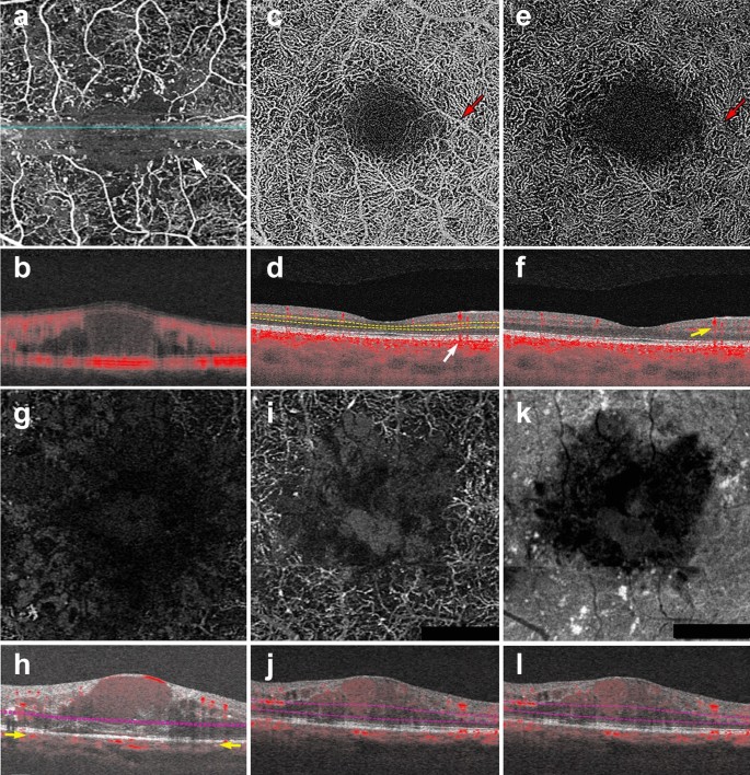
OCTA Artifacts. a, b Motion artifact: en face image of the full retinal projection, white arrow points to an example of motion artifact (a). The horizontal lines represent areas where OCTA acquisition was disrupted by movement. B-scan through this area (b) shows a blurry image with erroneous flow pixels. c–f Projection artifact: en face projection of the ddeep retinal layer before artifact removal c and after artifact removal e. Red arrows point to a projected vessel from the superficial retinal layer, note that the same vessel is no longer present after software correction. Corresponding B-scans (d, f) show a superficial retinal vessel reflected on the RPE (white arrow) and a decorrelation tail trailing below the vessel (yellow arrow). g, h Segmentation error: en face projection of the choriocapillaris in a patient with diabetic macular edema. At first glance, lack of flow pixels suggests widespread non-perfusion (g), however, B-scan reveals a significant segmentation error due to edema (h). Yellow arrows point to correct choriocapillaris segmentation level. i–l Shadowing: en face projection of the deep capillary plexus suggests central vascular loss (I). Corresponding structural en face image shows reduced signal in this area (k). Accompanying B-scan reveals signal attenuation is secondary to overlying edema, not vascular loss (j, l)
Full size image
Many device manufacturers rely on two types of technology to correct for motion artifact: mechanical eye tracking and software motion correction [1]. Eye tracking measures the position of the eye and corrects for eye movement when the change in eye position exceeds a predetermined threshold. Devices can rescan the area of detected motion and incorporate it into the original image [23]. Software motion correction obtains a horizontal and a vertical raster scan [24]. The software interprets the two scans together to calculate displacement between A-scans and corrects for motion in the final image. Today, most devices combine both technologies to produce high quality images.
Shadowing artifact
Shadowing occurs when the OCT beam is blocked and cannot reach the outer retinal layers. Many pathological features cause shadowing including drusen, hemorrhage and vitreous floaters [17]. Light is reflected off of these structural aberrations and does not penetrate the underlying tissue. Areas below these features appear as flow voids because the OCT beam cannot adequately assess them (Fig. 1g–j). The longer wavelength of SS-OCTA systems makes them less prone to shadowing than their spectral domain counterparts. SS-OCTA devices can assess the outer retinal layers below these features, though some signal attenuation persists. Recently, several groups have published algorithms that combine structural and angiography data to compensate for shadowing artifact below drusen [25, 26]. Though this technology is not currently available on commercial OCTA devices, this research shows promise and similar algorithms could be incorporated into future software updates.
Projection artifacts
Projection artifacts, or decorrelation tails, are perhaps the most prominent and important artifacts seen on OCTA. As the OCT beam penetrates the retina, it first encounters the superficial capillary plexus. A portion of light is reflected back from this plexus and interpreted by the device. Light that is not reflected continues to travel through the retina until it reaches the RPE. The RPE acts a natural reflector, reflecting light back towards the OCTA device. Light that arrives at the RPE is influenced by the flow above it and generates a decorrelation signal that mimics superficial vascular beds. The result is the erroneous appearance of superficial vessels in the outer retina and RPE (Fig. 1c, d). This misinterpretation of flow is termed projection artifact.
Device manufacturers have engineered many ways to overcome projection artifacts (Fig. 1e). The first form of projection artifact removal (PAR), slab-subtraction, subtracted inner retinal vascular patterns from outer retinal slabs [27]. Though this algorithm succeeded in reducing projection artifact, it also led to signal loss in the outer retinal layers. Further, slab-subtraction depended on pre-determined slab selection and did not successfully suppress projection artifacts on B-scan. In 2016, Zhang and colleagues published a projection-resolved PAR algorithm. Unlike slab-subtraction, this new algorithm worked on a voxel-by-voxel basis, utilizing intensity-normalized decorrelation values to distinguish in situ flow from projection artifact. This algorithm successfully identified the presence of multiple in situ vessels along an axial scan and did not suppress flow signal in the outer retina. Such improvements allowed for the visualization of three distinct retinal vascular plexi on en face and B-scan [28]. More recently, Garrity et al. proposed a three-dimensional PAR algorithm. Similar to the projection-resolved technique described by Zhang’s group, this new algorithm determines in situ flow by assessing intensity-normalized decorrelation signals on a voxel-by-voxel basis. However, the three-dimensional model incorporates signal intensity information along the Z-axis, assessing OCTA signal in all directions around a single voxel prior to determining if true flow is present [29, 30].
Though technological innovation has greatly improved PAR, compensation methods are not perfect, nor are they uniformly available across OCTA devices. When interpreting OCTA images, the easiest way to detect projection artifacts is to compare en face flow with the corresponding B-scan. On B-scan, projections artifacts appear as “tails” arising from overlying vessels and should not be interpreted as true flow (Fig. 1f).
Segmentation artifacts
The review software on commercially available devices provides a series of retinal slabs for analysis (i.e. full retinal, superficial retina, choriocapillaris, choroid). Each slab is generated by selecting an upper and lower boundary that slices horizontally through the three-dimensional OCTA cube. The vessels that lie within these two boundaries are projected to produce an en face image. Algorithms automatically detect predetermined retinal boundaries based on distinguishing characteristics such as reflectivity and texture [1]. However, segmentation algorithms were developed by imaging healthy eyes with distinct retinal layers [31]. Disease pathology, such as fluid seen in DME, drusen in AMD and even myopia, can drastically alter retinal anatomy and cause algorithms to mislabel boundaries (Fig. 1g, h). In such cases, assessing segmentation on the B-scan can reveal the error.
There are two ways to manipulate segmentation boundaries in order to correct for segmentation errors: slab selection and manual segmentation. Slab selection is simple and involves dragging a preset boundary up and down the z-axis. This action generates larger or smaller slabs to better assess pathology of interest (i.e. type 2 macular neovascularization in wet AMD). Manual segmentation allows the user to retrace the mislabeled retinal layer (i.e. Bruch’s membrane in a patient with drusen). Proper retracing must be completed for each B-scan which is a time consuming and laborious process. This type of boundary correction is largely reserved for research purposes, as it lacks utility in the time constraints of clinical practice.
OCTA interpretation: basic toolkit
To ensure correct interpretation, the three-dimensional quality of OCTA imaging must be respected. Viewing two-dimensional OCTA representations without simultaneously interacting with the three-dimensional dataset can confound interpretation. As a general rule, three images must be concurrently assessed for accurate OCTA interpretation: the en face OCTA image; the corresponding B-scan with flow overlay and segmentation lines displayed; and the structural en face intensity image for the selected slab. Assessing all three image components at once reduces erroneous findings.
The following section describes a step-by-step approach to OCTA interpretation (Fig. 2). The steps described can be applied to any device and to any type of ocular pathology. The model provides a foundation for OCTA interpretation and helps users avoid common mistakes.
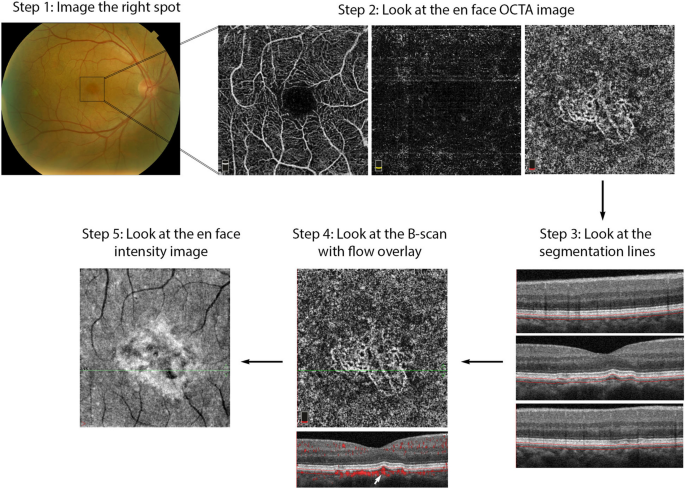
OCTA Interpretation Toolkit. How to apply step-by-step OCTA interpretation toolkit in a patient with AMD. Step 1: Image the right spot. Color fundus photograph of a patient with known AMD, the macula was selected as the area of interest and imaged. Step 2: Look at the en face OCTA images. 3 × 3 mm en face projections of each the full retinal depth, the avascular slab and the choriocapillaris (from left to right). The avascular and choriocapillaris slabs should be assessed in this AMD patient to check for presence of MNV. Note clearly defined vascular structures in the choriocapillaris slab (right most image), this is concerning for a type 1 MNV. Step 3: Look at the segmentation lines. Segmentation is assessed at multiple points throughout the slab to ensure accuracy. Step 4: Look at the B—scan with flow overlay. B-scan through lesion shows clear flow below the RPE (white arrow) and no projection artifact from overlying vasculature, suggesting this is in fact an MNV. Step 5: Look at the en face intensity image. En face intensity image for the choriocapillaris slab shows strong signal, shadowing artifact is not expected to disrupt image interpretation. Summary: Methodical OCTA image analysis uncovered a type 1 MNV that was not visible on fundus examination or on full depth retinal projection
Full size image
Step 1: image the correct spot
The first step in proper OCTA interpretation is to ensure the right location in the posterior retina is imaged. OCTA devices offer a range of scan sizes that can be centered at the macula and, in a subset of devices, the optic nerve head. To increase the scanning area, manufacturers developed montage options that stitch multiple scans together into a single image. Though montage images display a large portion of the posterior retina, the repeated imaging they require is time consuming and can be tiring for patients. Given decreased resolution in larger scan sizes, it is preferable to select the smallest scan size possible to visualize the pathology of interest. For instance, a small MNV can be visualized with greatest detail in a 3 × 3 mm scan. However, in a patient with DR, a larger scan size might be more appropriate for the assessment of proliferative diabetic retinopathy (PDR) and neovascularization elsewhere (NVE).
When the macular scan does not capture desired pathology, internal fixation targets can be moved to visualize different sectors of the posterior pole. For example, in the case of choroidal hemangiomas, lesions often occur far from the macula and might be missed by a macular scan [32]. Moving internal fixation targets, and employing external fixation targets when necessary, can help imaging technicians capture more peripheral lesions. For OCTA imaging to be effective, the clinician should first highlight what area of the posterior retina contains the pathology of interest. This ensures the technician will image the right location, allowing full visualization of desired pathology.
Step 2: look at the en face OCTA image
En face OCTA images provide a valuable overview of the retinal vasculature. These images can display a vascular projection of the full retinal depth or separate projections of each the superficial capillary plexus, the deep capillary plexus, the avascular retina, the choriocapillaris and the choroid.
The automated superficial retinal slab in most devices spans the internal limiting membrane, the ganglion cell layer and the inner plexiform layer (Fig. 3a). This slab captures the superficial capillary plexus of the retina and, often, part of the radial peripapillary capillary plexus. It also delineates the foveal avascular zone. This slab is important in retinal vascular diseases where drop out or malformation of the microvasculature can be seen. In DR, for example, enlargement of the foveal avascular zone, capillary drop out, and microaneurysms are best visualized on this slab. Additionally, some devices allow for quantitative evaluation of the vessels in this slab including vessel density and foveal avascular zone area.

OCTA slabs and corresponding segmentation boundaries. a Superficial retinal slab. This slab displays information for the internal limiting membrane, the ganglion cell layer and the inner plexiform layer. It is useful for FAZ area delineation in diabetic retinopathy. b Deep retinal slab. This slab displays information for the inner nuclear layer and the outer plexiform layer. Projection artifact removal was used to block signal from the superficial capillary plexus on this en face image. This slab may show the first signs of vascular loss in diabetic retinopathy. c Avascular slab. This slab displays information for the outer plexiform layer and the outer nuclear layer. Note that despite projection artifact removal remnants of overlying vessels are noted in this image. d Choriocapillaris slab. Along with the avascular slab, the choriocapillaris slab is important for detection of macular neovascularization in AMD. e Outer retinal choriocapillaris slab. This slab displays information for the outer plexiform layer, the outer nuclear layer and the choriocapillaris. It is useful as a screening tool for all types of macular neovascularization in AMD. f Choroid slab. Clear choroidal vessels are not visualized due to signal blockade from the RPE and overlying retinal layers
Full size image
On most devices, the deep retinal slab spans the inner nuclear layer and the outer plexiform layer and includes the intermediate and deep capillary plexuses (Fig. 3b). OCTA is the only clinically available commercial imaging modality that can visualize these two capillary plexuses in vivo [1]. Studies have shown that the deep capillary plexus is not visible on FA due to its intraretinal depth and the small size of its vessels [29]. The deep capillary plexus may be one of the first vascular beds to be affected in patients with retinal vascular diseases such as diabetes [33, 34]. In fact, OCTA studies of the deep capillary plexus have shown early changes associated with DR pathophysiology [34]. However, analysis of the deep retinal plexus must be conducted with care, as the presence of projection artifacts from the superficial plexus and the software used to remove these artifacts can often confound interpretation.
The avascular or outer retina slab spans the outer plexiform layer and the outer nuclear layer. This slab is avascular in healthy individuals (Fig. 3c). The presence of vessels in this layer is usually an indicator of pathology. For example, in patients with wet AMD the avascular layer may show type 2 or type 3 macular neovascularization (MNV). Though this layer should always be evaluated in patients with suspected AMD, it is prone to segmentation errors caused by outer retinal pathology such as a pigment epithelial detachments (PEDs).
The choriocapillaris slab is defined as a 20-micron slab below the RPE (Fig. 3d). Much like the avascular slab, the choriocapillaris slab should be evaluated in AMD and other pathologies associated with MNV formation. The choriocapillaris slab will not show distinct vascular channels. Instead, flow is represented on a pixel-by-pixel basis with hyper-reflective spots representing flow in this vascular layer. Presence of well-formed vascular channels in this slab (especially between Bruch’s membrane and the RPE) are very suspicious for choroidal neovascularization, specifically for type 1 MNV.
Due to the utility of the avascular and choriocapillaris slabs for MNV detection, some instruments display a combination of both slabs, known as the outer retinal and choriocapillaris (ORCC) slab (Fig. 3e). First described by Rosenfeld et al., this slab spans the outer plexiform layer, the outer nuclear layer and the choriocapillaris and can be used as a screening slab for type 1, 2 or 3 MNVs [13].
Lastly, the choroid slab displays a 50-micron slice posterior to the choriocapillaris (Fig. 3f). Differences in wavelength and light source lead to variable detection of choroidal vasculature between devices. Advances in laser technology allow for deeper penetration and visualization of choroidal vessels in investigative prototype models [35]. Though this technology is not yet commercially available, future device iterations might improve choroidal visualization and provide insight into pathologic changes occurring in this vascular layer.
Step 3: look at the segmentation lines
Pre-set slabs in OCTA devices are generated by automated segmentation. Retinal layer detection is remarkably accurate in healthy eyes, but can be distorted in the presence of retinal pathology [31]. Once a slab is selected for interpretation, it is important to assess the segmentation lines that define it to ensure correct identification of retinal boundaries. Improper slab placement can lead to pathology being missed or to the mislabeling of normal vasculature as pathologic. For instance, in AMD, inaccurate slab selection might cause an MNV to be missed or, contrastingly, it might cause a PED to be confused for an MNV. If pathology has in fact distorted the software’s ability to detect retinal layers, retinal slab selection can be coarsely adjusted by dragging the slab boundaries up or down.
Step 4: look at the B-scan with flow overlay
OCTA displays a two-dimensional projection of a three-dimensional structure, the retina. En face images should, therefore, always be interpreted in the context of their corresponding B-scan. For instance, en face projection can erroneously depict two vessels traveling at different retinal depths as a single branching vessel. Simultaneous assessment of the B-scan cross section provides a depth reference for the vasculature seen on en face and can help discern these optical illusions. Moreover, B-scan analysis can uncover projection artifacts. When assessing flow in the outer retinal layers, B-scan images can distinguish true flow from decorrelation tails produced by overlying vasculature. B-scans are critical when assessing pathology because they can help correlate vasculature to pathologic structural changes. For example, identification of flow between the RPE and the Bruch’s membrane in the presence of a PED gives a high level of confidence for the presence of a type 1 MNV (Figs. 2, 9).
Step 5: look at the en face intensity image
If light penetration through the retina is obfuscated by overlying pathology, such as fluid, hemorrhage or drusen, flow cannot be adequately assessed. The presence of these pathologic features reduces the signal produced by underlying retinal layers. As explained earlier, this reduction in signal is termed shadowing and can be misinterpreted as reduced flow.
Assessing the en face intensity image in concert with the OCT angiogram can help determine if loss of flow is real, or mere shadowing from overlying pathology. The structural and angiography projection for a given retinal slab should be examined in concert. If the structural en face image shows good signal intensity and the angiogram shows reduced flow in the same area, this can be interpreted as a true reduction in flow. If the structural en face image shows low signal intensity and the angiogram shows reduced flow in the same area, shadowing artifact is likely (Fig. 4).
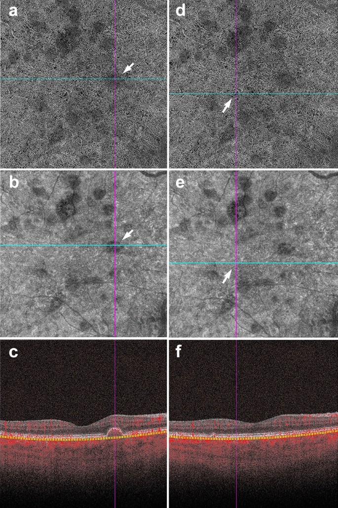
Shadowing in AMD. a–f Signal attenuation from drusen can be misinterpreted as non-perfusion in the choriocapillaris. Careful examination of the corresponding structural OCTA scan can rectify this error. a, d 6 x 6 mm choriocapillaris slab of a patient with AMD. a White arrow points to an area of apparent flow reduction. b Corresponding structural choriocapillaris slab. White arrow shows that the same area has reduced signal intensity. c B-scan shows a druse at this location. Signal reduction in this area should not be interpreted as non-perfusion, as it is likely due to signal attenuation and not flow reduction. d Identical choriocapillaris slab as that shown in panel A. White arrow points to an area of apparent flow reduction. e Corresponding structural choriocapillaris slab shows that this area has appropriate signal intensity (white arrow). f B-scan shows no druse or underlying pathology in this area. Signal reduction in this area can be appropriately interpreted as choriocapillaris loss
Full size image
Conversely, the presence of atrophy causes RPE disruption and increased signal penetration into the choroid. En face structural images will show increased signal intensity over atrophic areas. Accompanying choriocapillaris loss leads to upward displacement of the larger choroidal vasculature, which can mimic a MNV on OCTA en face (Fig. 5a). In this situation, evaluation of the B-Scan cross section will show choroidal flow and light hypertransmission associated with atrophy (Fig. 5d) [36].
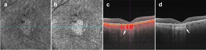
Choroidal vessels below atrophic areas. a–d Images of a patient with advanced AMD and geographic atrophy. Atrophy causes RPE and choriocapillaris disruption. a En face choriocapillaris angiogram shows displaced choroidal vessels mimicking well-formed vessels seen in macular neovascularization. b En face choriocapillaris structural image shows increased signal intensity in atrophic area due to RPE disruption and increased signal penetration into the choroid. c B-scan through atrophic area shows increased choroidal flow detection and upward displacement of choroidal vasculature below the atrophic area (white arrow). d B-scan without flow overlay shows choroidal hypertransmission (white arrow), a known OCT landmark for geographic atrophy
Full size image
Clinical utility of OCTA in retinal pathology
The above interpretation toolkit provides a foundation for OCTA image analysis. Understanding what OCTA features to focus on for specific disease entities can reduce interpretation times and prevent interpretation errors.
OCTA in diabetic retinopathy
FA studies conducted by the ETDRS group and others identified vascular changes associated with DR long ago [37,38,39]. OCTA research reproduced these findings and furthered our understanding of the vascular changes in DR [40]. Studies comparing FA to histology reveal that FA can only visualize a fraction of the retinal vasculature [41]. This suggests that FA lacks the sensitivity to detect vascular losses seen in the early stages of DR [10]. OCTA provides high resolution images of the retinal capillary beds, and can identify early vascular changes associated with DR that FA missed. In fact, recent studies show OCTA can identify vascular changes in diabetic patients without signs of retinopathy [42, 43]. These studies suggest the potential of OCTA as a screening tool for diabetic patients.
Aside from its promise in identifying early changes in diabetic eyes, OCTA can be used as a follow-up tool for patients with DR. Currently, FA is considered the gold standard for vessel visualization in DR [44]. However, FA is time consuming and invasive, making it difficult to obtain at every patient visit. OCTA is a fast and safe way to follow vascular changes in patients with DR. Much research has been done in the field of DR and OCTA, however, there are three main findings of particular relevance to clinical practice: foveal avascular zone (FAZ) enlargement, detection of microaneurysms, and vascular changes.
FAZ enlargement
Early FA studies show that FAZ area increases with DR severity [45]. OCTA studies have replicated these findings in the full retinal layer, the superficial capillary plexus and the deep capillary plexus [46, 47]. FAZ area is considered to be a reliable and reproducible metric between readers in both normal eyes and eyes with DR [48, 49]. Though FAZ can be assessed at both the deep capillary plexus and superficial capillary plexus, there is evidence to suggest that the retinal plexuses meet at the edge of the FAZ and it is, therefore, preferable to measure the FAZ on the superficial or the full retinal depth projection [50]. Assessing FAZ area on the full retinal depth projection obviates the need for segmentation and accompanying errors, increasing the measurement’s reproducibility [51, 52]. Clinically, assessing FAZ enlargement over time can be a useful tool for following DR progression (Fig. 6).
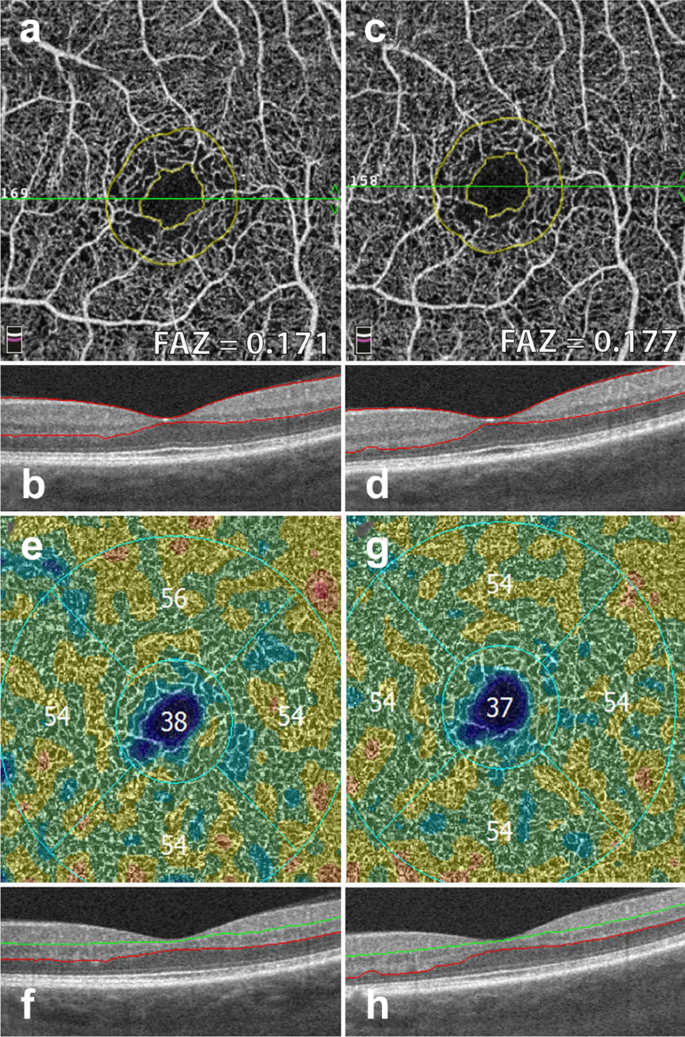
FAZ area and vessel density measurements. Example of a patient with severe non proliferative diabetic retinopathy. Images in the left column were taken 12 months prior to images in the right column. a, c Superficial retinal slab projection showing automated FAZ area measurements. Note parafoveal capillary drop out and slight increase in FAZ area over time. b, d B-scan showing corresponding segmentation boundaries. e, f Vessel density map of the deep retinal slab for the same patient and timepoints. Note slight drop in vessel density in the superior quadrant. f, g B-scan with corresponding segmentation lines
Full size image
Microaneurysms
Microaneurysms (MA) are a landmark finding in DR and are associated with an increased risk of progression to advanced disease stages [39, 53]. Studies show that OCTA can visualize approximately 60% of the MA identified on FA [46, 54]. MA are focal dilations of retinal capillaries. Flow can slow within these capillary dilations and drop below the OCTA detection threshold [1]. Prior to the advent of anti-VEGF agents, identifying the location of all MA was essential to proper laser treatment. As anti-VEGFs are increasingly used to treat complications of DR, including DME and PDR, OCTA can be used to track the response of MA to treatment (Fig. 7) [55, 56]. Though MA tracking has little utility in assessing treatment response in DME, the presence of increased MAs and ischemia may mark areas at higher risk of DME recurrence [57].
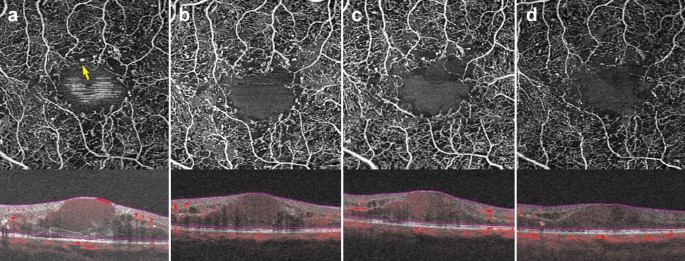
Microaneurysm response to anti-VEGF therapy. a–d 3 x 3 mm images of the full retinal depth projection of a patient treated with anti-VEGF therapy for diabetic macular edema. Images were taken 3 months apart over a 10-month period. a Yellow arrow points to an example of a microaneurysm. Note reduction in the number of parafoveal microaneurysms over time with concurrent improvement of edema
Full size image
Vascular changes
Research has uncovered associations between vascular changes seen on OCTA and increasing DR severity [58]. Studies point to significant vessel loss in patients with DR as compared to healthy controls [59]. A negative association between vessel density and increasing DR severity at both the superficial and deep capillary plexuses has been repeatedly identified [60,61,62]. Though quantitative vessel metrics on OCTA have been shown to have low reproducibility between devices, certain OCTA platforms provide color coded perfusion maps based on the vessel density of normal eyes [52]. These maps can help providers track DR severity and assess vessel loss in conjunction to disease progression (Fig. 6) [3].
In addition to the vascular changes associated with non-proliferative DR, OCTA is also useful in the clinical management of PDR. PDR is an advanced stage of DR that can lead to vision threatening complications such as hemorrhage and tractional retinal detachment [63]. Neovascular changes associated with PDR can been visualized on OCTA (Fig.  [2]. OCTA can identify neovascular growth and follow its regression in response to anti-VEGF treatment [64].
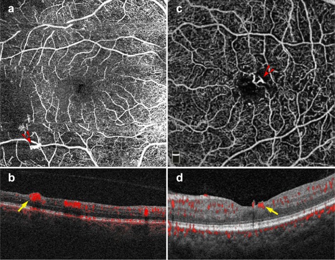
Proliferative diabetic retinopathy. a–d 6 x 6 mm images of the full retinal depth projection of two patients with proliferative diabetic retinopathy (PDR). a, c En face view of PDR, red arrowheads point to areas of neovascularization. b, d Corresponding B-scans show flow at the vitreoretinal interface (yellow arrows)
Full size image
Widefield OCTA imaging
Though original OCTA devices imaged only the central macula, newer OCTA technology offers a wider field of view. New swept source devices have larger scan areas of 15 × 9 mm and 12 × 12 mm and can visualize a greater portion of the posterior retina when compared to original devices offering only 3 × 3 and 6 x 6 mm scans [65]. As the field of view expands, however, resolution decreases and acquisition times lengthen. To offset resolution loss, montage protocols that offer fields of view of up to 100 degrees without sacrificing resolution have been developed. Though the 100-degree field of view offered by wide-angle OCTA is smaller than the 200-degree field of view offered by ultra-wide field (UWF) FA, OCTA images display higher levels of vascular detail and offer three-dimensional data not available on FA [66].
An increased field of view allows for improved imaging of the posterior pole, an important characteristic when assessing peripheral DR pathology. Wide-field SS-OCTA can be utilized to detect PDR and track response to panretinal photocoagulation. When compared to UWF FA, wide-field SS-OCTA was equivalent for the identification of PDR progression and regression, but SS-OCTA offered more detailed visualization of vascular changes [67]. Studies comparing UWF FA and wide-angle OCTA have found both imaging modalities equivalent for the detection of capillary drop out and retinal neovascularization in DR [68, 69]. These findings are encouraging and suggest wide-angle OCTA may provide a non-invasive alternative for vascular monitoring in DR.
OCTA in AMD and MNV
OCTA has proven invaluable for the study of AMD. The ability of OCTA to visualize the choriocapillaris in intermediate AMD and later stages of the disease has shed light onto the etiology of this vision threatening disease. Though OCTA has provided great investigative insight into the changes underlying dry AMD, the clinical use of OCTA in AMD is largely limited to the diagnosis of neovascular or wet AMD. Based on structural OCT, there are three types of MNV associated with wet AMD. Type 1 MNV lies below the RPE, type 2 MNV lies between the RPE and the retina, and type 3 MNV arises from the superficial retinal vasculature and grows downwards toward the neurosensory retina and eventually the choriocapillaris [70].
The ability to register flow information with structure makes OCTA a useful tool for MNV diagnosis and classification. En face OCTA images can depict the vascular networks associated with each type of MNV, while B-scans reveal their exact location within the retina (Fig. 9). OCTA can detect non-exudative MNV that were previously unnoticed. These lesions are generally type 1 MNV that lie below the RPE and are associated with a ‘double layer sign’, flat irregular, low lying PEDs that may go unnoticed in a superficial evaluation of OCT scans [71]. Studies suggest high sensitivities and specificities for the identification of type 1 and type 2 MNV on OCTA [72, 73]. However, MNV detection sensitivity drops precipitously with signal reduction secondary to hemorrhage and large PEDs, so OCTA should be used with caution in this context [74].
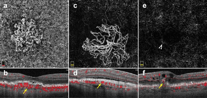
Macular neovascularization types. a–f 3 x 3 mm en face images and corresponding B-scans for the 3 MNV types seen in wet AMD. Segmentation was manually adjusted to reveal the best en face view for each lesion. a,b Type 1 MNV: distinct vascular inlets at the level of the choriocapillaris are seen on en face (a), B-scan reveals flow below the RPE (b, yellow arrow). c, d Type 2 MNV: en face view shows vascular branching suspicious for an MNV (c), B-scan shows flow between the retina and the RPE (d, yellow arrow). e, f Type 3 MNV: en face view shows a small bright tuft (e, white arrowhead), B-scan view shows intraretinal flow trailing downwards, towards the choriocapillaris (f, yellow arrow). Of note, type 3 MNV are very difficult to visualize on en face and often appear only as small, white tufts as depicted in the above example (e)
Full size image
Visualization of MNV on OCTA is helpful for diagnosis and classification. However, the clinical utility of OCTA for tracking MNV response to anti-VEGF treatment remains unclear. Several studies reveal MNV shrinking on OCTA after anti-VEGF treatment, albeit often without complete resolution [75,76,77,78]. A study by Lumbroso and colleagues showed that MNV reach maximal size reduction 1 week after intravitreal anti-VEGF injection, and progressively increase in size thereafter. Interestingly, this work also showed that MNV expansion predates MNV re-exudation [79]. Tracking MNV changes on OCTA to assess treatment response has not been proven to improve clinical outcomes. Thus, decisions regarding re-treatment are currently driven by visual acuity, clinical examination, presence of exudation and structural OCT changes.
Interpretation pitfalls discussed earlier in this review must be carefully considered when studying AMD and MNV on OCTA. Important points to remember include:
-
(1)
AMD features, such as drusen, geographic atrophy and MNV, can affect automatic device segmentation. Assessment of segmentation lines on B-scan is necessary prior to interpretation.
-
(2)
MNV lesions should always be interpreted in the context of their corresponding B scan. MNV types lie at different retinal depths. The preset slabs available on commercial OCTA devices often do not provide an ideal en face view of MNV lesions. Instead, manual slab selection can be used to fully encompass the lesion and improve en face visualization of MNV vessel networks.
-
(3)
Reflective surfaces such as the RPE above type 1 MNV and drusen can lead to projection of flow from overlying retinal vasculature. B-scan assessment can help highlight this type of artifact and reduce false-positive findings.
OCTA and other pathologies
The use of OCTA in clinical practice is not limited to DR and AMD. OCTA is useful in a range of retinal pathology including retinal vascular disease, retinal inflammatory disease, retinal tumors and retinal hereditary dystrophies.
In venous occlusive diseases, such as central and branch retinal vein occlusions, OCTA can identify areas of non-perfusion as well as collateral vessel formation [80, 81]. Manual slab selection provides information regarding the affected retinal vascular layers and the location of new collateral vessels. In retinal inflammatory disease, OCTA can detect vascular changes associated with inflammation including retinal hypo-perfusion in occlusive vasculitis and increased vessel density around the optic nerve head in uveitis [8, 82]. Moreover, OCTA aids in the identification of choroidal neovascularization secondary to inflammation (iCNV). Since inflammatory CNVs can mimic other types of inflammatory non-neovascular lesions, OCTA can detect flow within iCNVs and lead to prompt diagnosis and treatment [83].
OCTA has led to novel vascular findings in retinal hereditary dystrophies. For example, patients with choroidemia have reduced macular choriocapillaris density on OCTA when compared to controls, a finding not previously recognized by standard angiography [84]. OCTA was found to be superior to FA for the detection of CNV in patients with Best Vitelliform Macular Dystrophy, due to improved signal penetration through vitelliform material [85]. The use of OCTA for the vascular assessment of ocular tumors has also been extensively studied [86]. Vascular findings on OCTA, such as avascular areas and vascular abnormalities, might be of clinical utility in the differentiation of choroidal nevi from small choroidal melanomas [87]. In retinal capillary hemangioblastomas, OCTA can be used for diagnosis and assessment of treatment response to anti-VEGF therapy [88].
The future of OCTA
OCTA is evolving from a research tool to a clinically useful imaging modality. Its ease of use, depth resolution, and ability to analyze microvasculature provide a wealth of information beyond what other retinal vascular imaging offers.
The advent of swept source OCTA technology allowed for clear visualization of choroidal vasculature [15]. As laser technology continues to improve, newer devices with increased signal penetration will visualize choroidal vascular detail at greater depths. Further, faster scanning speeds will allow for wider and wider fields of view. This could have lasting implications for the assessment and risk stratification of a host of diseases from choroidal tumors and choroidal neovascularization, to retinal vascular disease.
Along with these hardware improvements, technical innovations in OCTA signal processing have reduced the presence of artifacts in prototype devices [28]. Device implementation of image alignment and tracking for longitudinal data will better serial assessment of progressive retinal diseases, including AMD and DR. As these improvements become commercially available, the clinical applicability and utility of OCTA will continue to expand and could have lasting implications in the way we image the retinal vasculature. Moreover, application of machine learning to OCTA will yield insights into new pathologic signals that were previously overlooked that could greatly impact the clinical management of retinal disease [89, 90].
The future of OCTA is promising, but clinicians require appropriate training to derive meaning out OCTA data and to avoid interpretation errors. This review provides eye care professionals with a toolkit for OCTA interpretation in the clinical setting. A solid understanding of the artifacts associated with OCTA imaging along with a step-wise approach to image interpretation offers the flexibility to apply OCTA analysis to a wide range of ocular pathology.
Availability of data and materials
Not applicable.
Abbreviations
- OCTA:
-
Optical coherence tomography angiography
- FA:
-
Fluorescein angiography
- ICGA:
-
Indocyanine green angiography
- AMD:
-
Age-related macular degeneration
- DR:
-
Diabetic retinopathy
- OCT:
-
Optical coherence tomography
- SD-OCT:
-
Spectral domain optical coherence tomography
- SD-OCTA:
-
Spectral domain optical coherence tomography angiography
- SS-OCTA:
-
Swept source optical coherence tomography angiography
- Anti-VEGF:
-
Vascular endothelial growth factor antagonists
- RPE:
-
Retinal pigment epithelium
- DME:
-
Diabetic macular edema
- MNV:
-
Macular neovascularization
- ORCC:
-
Outer retinal and choriocapillaris
- PED:
-
Pigment epithelial detachment
- FAZ:
-
Foveal avascular zone
- MA:
-
Microaneurysm
- PDR:
-
Proliferative diabetic retinopathy
- CNV:
-
Choroidal neovascularization
References
-
Spaide RF, Fujimoto JG, Waheed NK, Sadda SR, Staurenghi G. Optical coherence tomography angiography. Prog Retin Eye Res. 2018;64:1–55.
Article
PubMedGoogle Scholar
-
Choi W, Waheed NK, Moult EM, et al. Ultra high speed swept source optical coherence tomography angiography of retinal and choriocapillaris alterations in diabetic patients with and without retinopathy. Retina. 2017;37:11–21.
Article
CAS
PubMed
PubMed CentralGoogle Scholar
-
Agemy SA, Scripsema NK, Shah CM, et al. Retinal vascular perfusion density mapping using optical coherence tomography angiography in normals and diabetic retinopathy patients. Retina. 2015;35:2353–63.
Article
PubMedGoogle Scholar
-
Palejwala NV, Jia Y, Gao SS, et al. Detection of nonexudative choroidal neovascularization in age-related macular degeneration with optical coherence tomography angiography. Retina. 2015;35:2204–11.
Article
PubMed
PubMed CentralGoogle Scholar
-
Moult EM, Waheed NK, Novais EA, et al. Swept-source optical coherence tomography angiography reveals choriocapillaris alterations in eyes with nascent geographic atrophy and drusen-associated geographic atrophy. Retina. 2016;36(Suppl 1):S2–s11.
Article
PubMed
PubMed CentralGoogle Scholar
-
Iafe NA, Phasukkijwatana N, Sarraf D. Optical coherence tomography angiography of Type 1 neovascularization in age-related macular degeneration. Dev Ophthalmol. 2016;56:45–51.
Article
PubMedGoogle Scholar
-
Kim AY, Rodger DC, Shahidzadeh A, et al. Quantifying retinal microvascular changes in uveitis using spectral-domain optical coherence tomography angiography. Am J Ophthalmol. 2016;171:101–12.
Article
PubMed
PubMed CentralGoogle Scholar
-
Rougier MB, Le Goff M, Korobelnik JF. Optical coherence tomography angiography at the acute phase of optic disc edema. Eye Vis. 2018;5:15.
Article
Google Scholar
-
Huang D, Swanson EA, Lin CP, et al. Optical coherence tomography. Science. 1991;254:1178–81.
Article
CAS
PubMed
PubMed CentralGoogle Scholar
-
Kashani AH, Chen C-L, Gahm JK, et al. Optical coherence tomography angiography: a comprehensive review of current methods and clinical applications. Prog Retinal Eye Res. 2017;60:66–100.
Article
Google Scholar
-
Choi W, Moult EM, Waheed NK, et al. Ultrahigh-speed, swept-source optical coherence tomography angiography in nonexudative age-related macular degeneration with geographic atrophy. Ophthalmology. 2015;122:2532–44.
Article
PubMedGoogle Scholar
-
Ploner SB, Moult EM, Choi W, et al. Toward quantitative optical coherence tomography angiography: visualizing blood flow speeds in ocular pathology using variable interscan time analysis. Retina. 2016;36(Suppl 1):S118–s126.
Article
PubMed
PubMed CentralGoogle Scholar
-
Miller AR, Roisman L, Zhang Q, et al. Comparison between spectral-domain and swept-source optical coherence tomography angiographic imaging of choroidal neovascularization. Invest Ophthalmol Vis Sci. 2017;58:1499–505.
Article
PubMed
PubMed CentralGoogle Scholar
-
Lane M, Moult EM, Novais EA, et al. Visualizing the choriocapillaris under Drusen: comparing 1050-nm swept-source versus 840-nm spectral-domain optical coherence tomography angiography. Invest Ophthalmol Vis Sci. 2016;57:585–90.
Article
Google Scholar
-
Novais EA, Adhi M, Moult EM, et al. Choroidal neovascularization analyzed on ultrahigh-speed swept-source optical coherence tomography angiography compared to spectral-domain optical coherence tomography angiography. Am J Ophthalmol. 2016;164:80–8.
Article
PubMed
PubMed CentralGoogle Scholar
-
Matsunaga D, Yi J, Puliafito CA, Kashani AH. OCT angiography in healthy human subjects. Ophthalmic Surg Lasers Imaging Retina. 2014;45:510–5.
Article
PubMedGoogle Scholar
-
Borrelli E, Sarraf D, Freund KB, Sadda SR. OCT angiography and evaluation of the choroid and choroidal vascular disorders. Prog Retin Eye Res. 2018;67:30–55.
Article
PubMedGoogle Scholar
-
Kwiterovich KA, Maguire MG, Murphy RP, et al. Frequency of adverse systemic reactions after fluorescein angiography. Results of a prospective study. Ophthalmology. 1991;98:1139–42.
Article
CAS
PubMedGoogle Scholar
-
Kashani AH, Lee SY, Moshfeghi A, Durbin MK, Puliafito CA. Optical coherence tomogrpahy angiography of retinal venous occlusion. Retina. 2015;35:2323–31.
Article
PubMedGoogle Scholar
-
Hwang TS, Jia Y, Gao SS, et al. Optical coherence tomography angiography features of diabetic retinopathy. Retina. 2015;35:2371–6.
Article
PubMed
PubMed CentralGoogle Scholar
-
Moult E, Choi W, Waheed NK, et al. Ultrahigh-speed swept-source OCT angiography in exudative AMD. Ophthalmic Surg Lasers Imaging Retina. 2014;45:496–505.
Article
PubMed
PubMed CentralGoogle Scholar
-
Rabiolo A, Gelormini F, Marchese A, et al. Macular perfusion parameters in different angiocube sizes: does the size matter in quantitative optical coherence tomography angiography? Invest Ophthalmol Vis Sci. 2018;59:231–7.
Article
CAS
PubMedGoogle Scholar
-
Vienola KV, Braaf B, Sheehy CK, et al. Real-time eye motion compensation for OCT imaging with tracking SLO. Biomed Opt Express. 2012;3:2950–63.
Article
PubMed
PubMed CentralGoogle Scholar
-
Kraus MF, Potsaid B, Mayer MA, et al. Motion correction in optical coherence tomography volumes on a per A-scan basis using orthogonal scan patterns. Biomed Opt Express. 2012;3:1182–99.
Article
PubMed
PubMed CentralGoogle Scholar
-
Zhang Q, Zheng F, Motulsky EH, et al. A novel strategy for quantifying choriocapillaris flow voids using swept-source OCT angiography. Invest Ophthalmol Vis Sci. 2018;59:203–11.
Article
PubMed
PubMed CentralGoogle Scholar
-
Camino A, Guo Y, You Q, et al. Detecting and measuring areas of choriocapillaris low perfusion in intermediate, non-neovascular age-related macular degeneration. Neurophotonics. 2019;6:041108.
Article
PubMed
PubMed CentralGoogle Scholar
-
Zhang A, Zhang Q, Wang RK. Minimizing projection artifacts for accurate presentation of choroidal neovascularization in OCT micro-angiography. Biomed Opt Express. 2015;6:4130–43.
Article
CAS
PubMed
PubMed CentralGoogle Scholar
-
Zhang M, Hwang TS, Campbell JP, et al. Projection-resolved optical coherence tomographic angiography. Biomed Opt Express. 2016;7:816–28.
Article
PubMed
PubMed CentralGoogle Scholar
-
Garrity ST, Iafe NA, Phasukkijwatana N, Chen X, Sarraf D. Quantitative analysis of three distinct retinal capillary plexuses in healthy eyes using optical coherence tomography angiography. Invest Ophthalmol Vis Sci. 2017;58:5548–55.
Article
CAS
PubMedGoogle Scholar
-
Ashraf M, Sampani K, Abu-Qamar O, et al. Optical coherence tomography angiography projection artifact removal: impact on capillary density and interaction with diabetic retinopathy severity. Transl Vis Sci Technol. 2020;9:10.
Article
PubMed
PubMed CentralGoogle Scholar
-
Spaide RF, Fujimoto JG, Waheed NK. Image artifacts in optical coherence tomography angiography. Retina. 2015;35:2163–80.
Article
PubMed
PubMed CentralGoogle Scholar
-
Callaway NF, Mruthyunjaya P. Widefield imaging of retinal and choroidal tumors. Int J Retina Vitreous. 2019;5:49.
Article
PubMed
PubMed CentralGoogle Scholar
-
Moore J, Bagley S, Ireland G, McLeod D, Boulton ME. Three dimensional analysis of microaneurysms in the human diabetic retina. J Anat. 1999;194(Pt 1):89–100.
Article
PubMed
PubMed CentralGoogle Scholar
-
Carnevali A, Sacconi R, Corbelli E, et al. Optical coherence tomography angiography analysis of retinal vascular plexuses and choriocapillaris in patients with type 1 diabetes without diabetic retinopathy. Acta Diabetol. 2017;54:695–702.
Article
CAS
PubMedGoogle Scholar
-
Poddar R, Migacz JV, Schwartz DM, Werner JS, Gorczynska I. Challenges and advantages in wide-field optical coherence tomography angiography imaging of the human retinal and choroidal vasculature at 1.7-MHz A-scan rate. J Biomed Opt. 2017;22:1–14.
PubMed
Google Scholar
-
Sadda SR, Guymer R, Holz FG, et al. Consensus definition for atrophy associated with age-related macular degeneration on OCT: classification of atrophy report 3. Ophthalmology. 2018;125:537–48.
Article
PubMedGoogle Scholar
-
Fluorescein angiographic risk factors for progression of diabetic retinopathy. ETDRS report number 13. Early Treatment Diabetic Retinopathy Study Research Group. Ophthalmology 1991;98:834–40.
-
Davis MD, Fisher MR, Gangnon RE, et al. Risk factors for high-risk proliferative diabetic retinopathy and severe visual loss: early treatment diabetic retinopathy Study Report #18. Invest Ophthalmol Vis Sci. 1998;39:233–52.
CAS
PubMedGoogle Scholar
-
Lee CS, Lee AY, Baughman D, et al. The United Kingdom diabetic Retinopathy Electronic Medical Record Users Group: report 3: Baseline retinopathy and clinical features predict progression of diabetic retinopathy. Am J Ophthalmol. 2017;180:64–71.
Article
PubMed
PubMed CentralGoogle Scholar
-
Sun Z, Tang F, Wong R, et al. OCT angiography metrics predict progression of diabetic retinopathy and development of diabetic macular edema: a Prospective Study. Ophthalmology. 2019;126:1675–84.
Article
PubMedGoogle Scholar
-
Mendis KR, Balaratnasingam C, Yu P, et al. Correlation of histologic and clinical images to determine the diagnostic value of fluorescein angiography for studying retinal capillary detail. Invest Ophthalmol Vis Sci. 2010;51:5864–9.
Article
PubMedGoogle Scholar
-
Yasin Alibhai A, Moult EM, Shahzad R, et al. Quantifying microvascular changes using OCT angiography in diabetic eyes without clinical evidence of retinopathy. Ophthalmol Retina. 2018;2:418–27.
Article
CAS
PubMedGoogle Scholar
-
Takase N, Nozaki M, Kato A, Ozeki H, Yoshida M, Ogura Y. Enlargement of foveal avascular zone in diabetic eyes evaluated by en face optical coherence tomography angiography. Retina. 2015;35:2377–83.
Article
PubMedGoogle Scholar
-
Sorour OA, Sabrosa AS, Yasin Alibhai A, et al. Optical coherence tomography angiography analysis of macular vessel density before and after anti-VEGF therapy in eyes with diabetic retinopathy. Int Ophthalmol. 2019;39:2361–71.
Article
PubMedGoogle Scholar
-
Bresnick GH, Condit R, Syrjala S, Palta M, Groo A, Korth K. Abnormalities of the foveal avascular zone in diabetic retinopathy. Arch Ophthalmol. 1984;102:1286–93.
Article
CAS
PubMedGoogle Scholar
-
Salz DA, de Carlo TE, Adhi M, et al. Select features of diabetic retinopathy on swept-source optical coherence tomographic angiography compared with fluorescein angiography and normal eyes. JAMA Ophthalmol. 2016;134:644–50.
Article
PubMed
PubMed CentralGoogle Scholar
-
Samara WA, Shahlaee A, Adam MK, et al. Quantification of diabetic macular ischemia using optical coherence tomography angiography and its relationship with visual acuity. Ophthalmology. 2017;124:235–44.
Article
PubMedGoogle Scholar
-
Mastropasqua R, Toto L, Mastropasqua A, et al. Foveal avascular zone area and parafoveal vessel density measurements in different stages of diabetic retinopathy by optical coherence tomography angiography. Int J Ophthalmol. 2017;10:1545–51.
PubMed
PubMed CentralGoogle Scholar
-
Shiihara H, Sakamoto T, Yamashita T, et al. Reproducibility and differences in area of foveal avascular zone measured by three different optical coherence tomographic angiography instruments. Sci Rep. 2017;7:9853.
Article
PubMed
PubMed CentralGoogle Scholar
-
Gariano RF, Iruela-Arispe ML, Hendrickson AE. Vascular development in primate retina: comparison of laminar plexus formation in monkey and human. Invest Ophthalmol Vis Sci. 1994;35:3442–55.
CAS
PubMedGoogle Scholar
-
Coscas F, Sellam A, Glacet-Bernard A, et al. Normative data for vascular density in superficial and deep capillary plexuses of healthy adults assessed by optical coherence tomography angiography. Invest Ophthalmol Vis Sci. 2016;57:211–23.
Article
Google Scholar
-
Arya M, Rebhun CB, Alibhai AY, et al. Parafoveal retinal vessel density assessment by optical coherence tomography angiography in healthy eyes. Ophthalmic Surg Lasers Imaging Retina. 2018;49:S5–17.
Article
PubMedGoogle Scholar
-
Fundus photographic risk factors for progression of diabetic retinopathy. ETDRS report number 12. Early Treatment Diabetic Retinopathy Study Research Group. Ophthalmology 1991;98:823–33.
-
Ishibazawa A, Nagaoka T, Takahashi A, et al. Optical coherence tomography angiography in diabetic retinopathy: a prospective pilot study. Am J Ophthalmol. 2015;160(35–44):e1.
Google Scholar
-
Ghasemi Falavarjani K, Iafe NA, Hubschman JP, Tsui I, Sadda SR, Sarraf D. Optical Coherence Tomography Angiography Analysis of the Foveal Avascular Zone and Macular Vessel Density After Anti-VEGF Therapy in Eyes With Diabetic Macular Edema and Retinal Vein Occlusion. Invest Ophthalmol Vis Sci. 2017;58:30–4.
Article
PubMed
CASGoogle Scholar
-
Bahrami B, Hong T, Gilles MC, Chang A. Anti-VEGF Therapy for Diabetic Eye Diseases. Asia Pac J Ophthalmol. 2017;6:535–45.
CAS
Google Scholar
-
Hasegawa N, Nozaki M, Takase N, Yoshida M, Ogura Y. New insights into microaneurysms in the deep capillary plexus detected by optical coherence tomography angiography in diabetic macular edema. Invest Ophthalmol Vis Sci. 2016;57:Oct348–55.
Article
PubMedGoogle Scholar
-
Gildea D. The diagnostic value of optical coherence tomography angiography in diabetic retinopathy: a systematic review. Int Ophthalmol. 2019;39:2413–33.
Article
PubMedGoogle Scholar
-
Hwang TS, Gao SS, Liu L, et al. Automated quantification of capillary nonperfusion using optical coherence tomography angiography in diabetic retinopathy. JAMA Ophthalmol. 2016;134:367–73.
Article
PubMed
PubMed CentralGoogle Scholar
-
Sambhav K, Abu-Amero KK, Chalam KV. Deep capillary macular perfusion indices obtained with OCT angiography correlate with degree of nonproliferative diabetic retinopathy. Eur J Ophthalmol. 2017;27:716–29.
Article
PubMedGoogle Scholar
-
Durbin MK, An L, Shemonski ND, et al. Quantification of retinal microvascular density in optical coherence tomographic angiography images in diabetic retinopathy. JAMA Ophthalmol. 2017;135:370–6.
Article
PubMed
PubMed CentralGoogle Scholar
-
Nesper PL, Roberts PK, Onishi AC, et al. Quantifying microvascular abnormalities with increasing severity of diabetic retinopathy using optical coherence tomography angiography. Invest Ophthalmol Vis Sci. 2017;58:BIO307–15.
Article
PubMed
PubMed CentralGoogle Scholar
-
Zhao Y, Singh RP. The role of anti-vascular endothelial growth factor (anti-VEGF) in the management of proliferative diabetic retinopathy. Drugs Context. 2018;7:212532.
Article
PubMed
PubMed CentralGoogle Scholar
-
Hu Z, Su Y, Xie P, et al. OCT angiography-based monitoring of neovascular regression on fibrovascular membrane after preoperative intravitreal conbercept injection. Graefes Arch Clin Exp Ophthalmol. 2019;257:1611–9.
Article
CAS
PubMedGoogle Scholar
-
Pichi F, Smith SD, Abboud EB, et al. Wide-field optical coherence tomography angiography for the detection of proliferative diabetic retinopathy. Graefes Arch Clin Exp Ophthalmol. 2020;258:1901–9.
Article
PubMedGoogle Scholar
-
Zhang Q, Rezaei KA, Saraf SS, Chu Z, Wang F, Wang RK. Ultra-wide optical coherence tomography angiography in diabetic retinopathy. Quant Imaging Med Surg. 2018;8:743–53.
Article
PubMed
PubMed CentralGoogle Scholar
-
Russell JF, Shi Y, Hinkle JW, et al. Longitudinal wide-field swept-source OCT angiography of neovascularization in proliferative diabetic retinopathy after panretinal photocoagulation. Ophthalmol Retina. 2019;3:350–61.
Article
PubMedGoogle Scholar
-
Yasukura S, Murakami T, Suzuma K, et al. Diabetic nonperfused areas in macular and extramacular regions on wide-field optical coherence tomography angiography. Invest Ophthalmol Vis Sci. 2018;59:5893–903.
Article
CAS
PubMedGoogle Scholar
-
Sawada O, Ichiyama Y, Obata S, et al. Comparison between wide-angle OCT angiography and ultra-wide field fluorescein angiography for detecting non-perfusion areas and retinal neovascularization in eyes with diabetic retinopathy. Graefes Arch Clin Exp Ophthalmol. 2018;256:1275–80.
Article
PubMedGoogle Scholar
-
Freund KB, Zweifel SA, Engelbert M. Do we need a new classification for choroidal neovascularization in age-related macular degeneration? Retina. 2010;30:1333–49.
Article
PubMedGoogle Scholar
-
Carnevali A, Cicinelli MV, Capuano V, et al. Optical coherence tomography angiography: a useful tool for diagnosis of treatment-Naïve Quiescent choroidal neovascularization. Am J Ophthalmol. 2016;169:189–98.
Article
PubMedGoogle Scholar
-
Bonini Filho MA, de Carlo TE, Ferrara D, et al. Association of choroidal neovascularization and central serous chorioretinopathy with optical coherence tomography angiography. JAMA Ophthalmol. 2015;133:899–906.
Article
PubMedGoogle Scholar
-
Soomro T, Talks J. The use of optical coherence tomography angiography for detecting choroidal neovascularization, compared to standard multimodal imaging. Eye (Lond). 2018;32:661–72.
Article
CASGoogle Scholar
-
de Carlo TE, Bonini Filho MA, Chin AT, et al. Spectral-domain optical coherence tomography angiography of choroidal neovascularization. Ophthalmology. 2015;122:1228–38.
Article
PubMedGoogle Scholar
-
Muakkassa NW, Chin AT, de Carlo T, et al. Characterizing the effect of anti-vascular endothelial growth factor therapy on treatment-naive choroidal neovascularization using optical coherence tomography angiography. Retina. 2015;35:2252–9.
Article
CAS
PubMedGoogle Scholar
-
Faatz H, Farecki ML, Rothaus K, et al. Optical coherence tomography angiography of types 1 and 2 choroidal neovascularization in age-related macular degeneration during anti-VEGF therapy: evaluation of a new quantitative method. Eye. 2019;33:1466–71.
Article
CAS
PubMed
PubMed CentralGoogle Scholar
-
Xu D, Dávila JP, Rahimi M, et al. Long-term progression of type 1 neovascularization in age-related macular degeneration using optical coherence tomography angiography. Am J Ophthalmol. 2018;187:10–20.
Article
PubMedGoogle Scholar
-
Lumbroso B, Rispoli M, Savastano MC. Longitudinal optical coherence tomography-angiography study of type 2 naive choroidal neovascularization early response after treatment. Retina. 2015;35:2242–51.
Article
CAS
PubMedGoogle Scholar
-
Lumbroso B, Rispoli M, Savastano MC, Jia Y, Tan O, Huang D. Optical coherence tomography angiography study of choroidal neovascularization early response after treatment. Dev Ophthalmol. 2016;56:77–85.
Article
PubMedGoogle Scholar
-
Suzuki N, Hirano Y, Tomiyasu T, et al. Collateral vessels on optical coherence tomography angiography in eyes with branch retinal vein occlusion. Br J Ophthalmol. 2019;103:1373–9.
Article
PubMedGoogle Scholar
-
Novias E, Waheed NK. Optical coherence tomography angiography of retinal vein occlusion. In: Bandello F, Souied EH, Querques G, editors. OCT angiography in retinal and macular diseases. Basel: Karger; 2016. p. 132–8.
Chapter
Google Scholar
-
Pichi F, Sarraf D, Arepalli S, et al. The application of optical coherence tomography angiography in uveitis and inflammatory eye diseases. Prog Retin Eye Res. 2017;59:178–201.
Article
PubMedGoogle Scholar
-
Invernizzi A, Cozzi M, Staurenghi G. Optical coherence tomography and optical coherence tomography angiography in uveitis: a review. Clin Exp Ophthalmol. 2019;47:357–71.
Article
PubMedGoogle Scholar
-
Jain N, Jia Y, Gao SS, et al. Optical coherence tomography angiography in choroideremia: correlating choriocapillaris loss with overlying degeneration. JAMA Ophthalmol. 2016;134:697–702.
Article
PubMed
PubMed CentralGoogle Scholar
-
Guduru A, Gupta A, Tyagi M, Jalali S, Chhablani J. Optical coherence tomography angiography characterisation of Best disease and associated choroidal neovascularisation. Br J Ophthalmol. 2018;102:444–7.
Article
PubMedGoogle Scholar
-
Cennamo G, Romano MR, Breve MA, et al. Evaluation of choroidal tumors with optical coherence tomography: enhanced depth imaging and OCT-angiography features. Eye. 2017;31:906–15.
Article
CAS
PubMed
PubMed CentralGoogle Scholar
-
Garcia-Arumi Fuste C, Peralta Iturburu F, Garcia-Arumi J. Is optical coherence tomography angiography helpful in the differential diagnosis of choroidal nevus versus melanoma? Eur J Ophthalmol. 2020;30:723–9.
Article
PubMedGoogle Scholar
-
Russell JF, Shi Y, Gregori G, Rosenfeld PJ. Longitudinal Swept-Source OCT Angiography of Juxtapapillary Retinal Capillary Hemangioblastoma. Ophthalmol Retina. 2020;4:956–8.
Article
PubMed
PubMed CentralGoogle Scholar
-
Aslam TM, Hoyle DC, Puri V, Bento G. Differentiation of diabetic status using statistical and machine learning techniques on optical coherence tomography angiography images. Transl Vis Sci Technol. 2020;9:2.
Article
PubMed
PubMed CentralGoogle Scholar
-
Le D, Alam M, Yao CK, et al. Transfer learning for automated OCTA detection of diabetic retinopathy. Transl Vis Sci Technol. 2020;9:35.
Article
PubMed
PubMed CentralGoogle Scholar
Download references
Acknowledgements
None.
Declarations
Dr. Jay S. Duker is one of the Editors-in-Chief of the International Journal of Retina and Vitreous, for this reason the peer review process for this manuscript was entirely handled by the co-Editor-in-Chief Eduardo Rodrigues.
Funding
This research was supported, in part, by the Research to Prevent Blindness (RPB) Challenge grant, the Massachusetts Lions Club Research Fund made to the Department of Ophthalmology at Tufts Medical Center, and a Yale School of Medicine Medical Student Fellowship (New Haven, CT, USA).
Author information
Authors and Affiliations
-
New England Eye Center, Tufts Medical Center, 800 Washington Street, Box 450, Boston, MA, 02111, USA
Eugenia Custo Greig, Jay S. Duker & Nadia K. Waheed
-
Yale School of Medicine, New Haven, CT, USA
Eugenia Custo Greig
Authors
- Eugenia Custo Greig
You can also search for this author in
PubMed Google Scholar - Jay S. Duker
You can also search for this author in
PubMed Google Scholar - Nadia K. Waheed
You can also search for this author in
PubMed Google Scholar
Contributions
All authors made substantial contributions to the conception of this review article, they have all approved the submitted version and have all agreed both to be personally accountable for their own contributions and to ensure that questions related to the accuracy or integrity of any part of the work, even ones in which the author was not personally involved, are appropriately investigated, resolved, and the resolution documented in the literature. All authors read and approved the final manuscript.
Corresponding author
Correspondence to
Nadia K. Waheed.
Ethics declarations
Ethics approval and consent to participate
Not applicable.
Consent for publication
Not applicable.
Competing interests
Nadia Waheed receives financial support from a Massachusetts Lions Club Grant (Boston, Massachusetts, USA) and a Research to Prevent Blindness Challenge Grant (New York, New York, USA). She is a consultant for Topcon (Tokyo, Japan), Roche/Genentech (San Francisco, California, USA), Regeneron (Tarrytown, New York, USA), Apellis (Waltham, Massachusetts, USA), Astellas (Tokyo, Japan), Boehringer Ingelheim (Ingelheim, Germany), Novartis (Basel, Germany). She is a speaker for Nidek Medical Products (Gamagori, Japan) and Topcon (Tokyo, Japan). She is an officer of entity at Gyroscope (Ambler, Pennsylvania, USA). She has a personal financial interest in the Boston Imaging Reading Center (Boston, Massachusetts, USA) and Ocudyne. Dr. Jay S. Duker receives financial support from Carl Zeiss Meditec (Jena, Germany) and Optovue Inc (Fremont, CA, USA). He is a consultant at Aldeyra Therapeutics (Lexington, MA, USA), Allergan Pharmaceuticals (Dublin, Ireland), Aura Biosciences (Cambridge, MA, USA), Bausch Health (Laval, Canada), Beyeonics (Haifa, Israel), Merck (Kenilworth, NJ, USA), Novartis (Basel, Switzerland) and Roche (Basel, Switzerland). He is a director of entity at Sesen Bio (Cambridge, Massachusetts, USA) and Eye-Point Pharma (Watertown, MA, USA). He is a shareholder at Hemera Biosciences (Waltham, MA, USA). Eugenia Custo Greig has no financial disclosures or competing interests.
Additional information
Publisher’s Note
Springer Nature remains neutral with regard to jurisdictional claims in published maps and institutional affiliations.
Rights and permissions
Open Access This article is licensed under a Creative Commons Attribution 4.0 International License, which permits use, sharing, adaptation, distribution and reproduction in any medium or format, as long as you give appropriate credit to the original author(s) and the source, provide a link to the Creative Commons licence, and indicate if changes were made. The images or other third party material in this article are included in the article’s Creative Commons licence, unless indicated otherwise in a credit line to the material. If material is not included in the article’s Creative Commons licence and your intended use is not permitted by statutory regulation or exceeds the permitted use, you will need to obtain permission directly from the copyright holder. To view a copy of this licence, visit http://creativecommons.org/licenses/by/4.0/. The Creative Commons Public Domain Dedication waiver (http://creativecommons.org/publicdomain/zero/1.0/) applies to the data made available in this article, unless otherwise stated in a credit line to the data.
Reprints and Permissions
About this article
Cite this article
Greig, E.C., Duker, J.S. & Waheed, N.K. A practical guide to optical coherence tomography angiography interpretation.
Int J Retin Vitr 6, 55 (2020). https://doi.org/10.1186/s40942-020-00262-9
Download citation
-
Received: 04 June 2020
-
Accepted: 05 November 2020
-
Published: 13 November 2020
-
DOI: https://doi.org/10.1186/s40942-020-00262-9
Keywords
- Optical coherence tomography angiography
- Interpretation
- Artifacts
Показания к диагностике
Преимущества метода
Противопоказания к процедуре
Преимущества обращения в МЕДСИ
Оптическая когерентная томография является востребованным методом исследования тканей органов зрения. Она позволяет получить поперечные срезы различных структур глаза (роговицы, диска зрительного нерва, сетчатки и др.). Технология диагностики является бесконтактной и безболезненной. Для выполнения ОКТ применяется специальный аппарат – когерентный томограф. Он прост в использовании для специалиста и удобен для пациента.
Разберемся, что такое ОКТ сетчатки и других структур глаза, рассмотрим, зачем и когда проводится это исследование.
Показания к диагностике
Оптическая когерентная томография применяется с целью выявления таких патологий органов зрения, как:
- дистрофические процессы и отслойка сетчатки, а также заболевания ее центральной части, на которой фокусируется пучок света
- глаукома
- заболевания зрительного нерва
- патологии переднего отрезка глазного яблока (как воспалительные, так и дистрофические)
Благодаря специальному томографу строится особая пахиметрическая карта. Она отображает толщину роговицы. Измерение этого параметра вместе с определением внутриглазного давления является максимально информативным методом выявления глаукомы. Он позволяет определить и риски перфорации роговицы.
Преимущества метода
Оптическая когерентная томография (ОКТ) имеет множество достоинств.
К основным относят:
- Неинвазивность. Отсутствие необходимости проникновения в ткани глаза
- Безопасность для пациента. Благодаря этому свойству диагностика практически не имеет противопоказаний и назначается как маленьким детям, так и пожилым людям (в том числе с большим количеством хронических заболеваний)
- Отсутствие необходимости в подготовке
- Высокую информативность. Диагностика позволяет офтальмологу оценить анатомические изменения сетчатки и сосудистой оболочки, зрительного нерва, толщину слизистой пленки, особенности угла передней камеры, роговицы и хрусталика
- Быструю готовность результата. Он может быть рассмотрен врачом сразу же после окончания обследования
Сегодня ОКТ успешно заменяет биопсию/патоморфологическое исследование. Использование для получения изображения специального источника излучения (инфракрасного низкоинтенсивного лазера) дает возможности для обеспечения максимально высокого разрешения (до 5 микрон). Это гарантирует необходимую точность диагностики.
Противопоказания к процедуре
Абсолютных противопоказаний к диагностике не выявлено. Тем не менее выделяют состояния, при которых методика не обладает достаточной информативностью. К ним относят уменьшение прозрачности оптических сред. При этом снижается качество изображения, получаемого благодаря оборудованию. Также затруднения во время процедуры могут быть обусловлены тем, что пациент не может фиксировать взгляд хотя бы в течение 2 секунд.
ОКТ глаза: как проводится?
Выполняется диагностика в амбулаторных условиях. Обычно процедура занимает несколько минут.
Сначала пациент располагается на стуле, а его голову фиксируют. После этого просят сфокусировать взгляд на мигающей точке на экране аппарата. Если острота зрения у пациента снижена, ему достаточно зафиксировать положение тела, не двигаться и не моргать. Во время процедуры обследуемый не испытывает никаких неприятных ощущений.
Сразу же после диагностики оборудование выполняет анализ полученной информации. На мониторе у врача появляются соответствующие изображения. Они изучаются офтальмологом. Теперь может быть поставлен диагноз. При необходимости пациента направляют на дополнительные обследования.
Преимущества обращения в МЕДСИ
- Высококвалифицированные врачи. Наши офтальмологи располагают необходимыми знаниями и навыками для проведения экспертной диагностики и выявления различных заболеваний глаз. В Центре работают признанные эксперты в области офтальмологии, обладающие обширным опытом диагностики и лечения. При необходимости они заранее расскажут об ОКТ (оптической когерентной томографии глаза), сообщат, что это за метод и для чего он требуется
- Комплексная высокотехнологичная диагностика. В нашем Центре офтальмологии проводятся современные аппаратные обследования. Они позволяют выявить глаукому, отслойку сетчатки и другие заболевания на ранних стадиях и сразу же провести необходимое лечение (в том числе лазерное или хирургическое)
- Применение для диагностики новейшего оборудования. Установки экспертного уровня позволяют достичь высокой точности обследований и выявить даже скрытые патологии, которые протекают бессимптомно
- Комфорт посещения Центра офтальмологии. Мы позаботились об отсутствии очередей. Вам не придется долго ждать приема. Кроме того, наши специалисты внимательно и заботливо относятся к каждому пациенту. Благодаря этому даже длительная диагностика не утомляет и легко переносится как маленькими детьми, так и пожилыми пациентами
Чтобы уточнить условия проведения оптической когерентной томографии (ОКТ) или записаться на прием к офтальмологу, достаточно позвонить по номеру +7 (495) 7-800-500. Наш специалист ответит на все вопросы. Также запись возможна через приложение SmartMed.
Специализированные
центры
Центр офтальмологии
- Высокий уровень компетентности врачей
- Современные технологии диагностики и лечения
- Оказание многопрофильной офтальмологической помощи
- Экспертное оборудование
Подробнее
Не затягивайте с лечением, обратитесь к врачу прямо сейчас:
Книга является первым руководством по оптической когерентной томографии (ОКТ), издаваемым на русском языке. Сформулированы и обобщены принципы ОКТ, приведено описание технологических решений реализации этого метода, собраны и проанализированы примеры его клинического применения и представлен мультидисциплинарный атлас ОКТ-изображений. Представлены результаты российских ученых по разработке и внедрению эндоскопического варианта ОКТ в гастроэнтерологии, урологии, ларингологии, гинекологии, стоматологии и офтальмологии. Продемонстрированы возможности ОКТ в решении задач раннего обнаружения неоплазии, оптимизации процедуры прицельной биопсии, интраоперационного планирования при органосохраняющих и реконструктивных операциях. Для врачей, интересующихся разработкой и применением оптических методов диагностики, а также для аспирантов и студентов физических, технических, биологических и медицинских специальностей.
| Под редакцией |
Под редакцией д.м.н., проф. Н.Д. Гладковой, д.м.н. Н.М. Шаховой, чл.-корр. РАН, д.ф.-м.н. А.М. Сергеева |
| Издательство |
ООО «Физматлит» |
| Дата издания |
2007 |
| Кол-во страниц |
296 |
| ISBN |
978-5-9221-0820-1 |
| Тематика |
Биофизика. Медицинская физика. Медицина |
| № в каталоге |
820 |
Категории:
Учебная литература
1.1.1 Этапы развития технологии ОКТ
В последние годы ОКТ стала «золотым стандартом» в диагностике патологии заднего отрезка глаза [2, 7, 10, 17, 77, 99].
Первое упоминание об использовании когерентного томографа для визуализации структур глазного дна относится к 1991 году, когда группа ученых из Массачусетского технологического университета опубликовала результаты сканирования сетчатки и зрительного нерва [62] и в течение последующих нескольких лет продемонстрировала информативность метода при различной патологии макулярной области и ДЗН [50, 51, 92, 98, 108]. Результатом передачи технологии фирме Carl Zeiss Meditec стал выход в 1996 году первого серийного прибора для ОКТ.
Любой прибор для ОКТ формирует 2-мерное изображение (В-скан), состоящее из суммы вертикальных линий (А-сканов). Характеристики ОКТ определяются скоростью (количеством А-сканов в единицу времени) и аксиальным разрешением (минимальная толщина слоев сетчатки и расстояний между ними, которую можно измерить).
Ступени развития технологии ОКТ представлены в разработанной таблице (таблица 1.1.).
Первая из них – time-domain OCT (TD-OCT) или временная ОКТ. Для получения снимков необходимо последовательно(механически) сканировать интерференционный сигнал, что требует продолжительного времени сканирования. Наибольшее распространение получил прибор третьего поколения – Stratus OCT 3000, Carl Zeiss Meditec. Он надежно зарекомендовал себя в диагностике патологии сетчатки и области ДЗН [35, 80, 96]. Однако, скорость и разрешающая способность (осевое разрешение) были невелики (400 А-сканов/с и 10 µм, соответственно) и этого было недостаточно для качественного анализа всех слоев сетчатки.
Второй этап развития технологии – применение математического анализа Фурье для обработки полученной информации в ходе сканирования с помощью спектрометра (spectral domain OCT, SD-OCT) [105, 118]. При исследовании на приборе для спектральной ОКТ скорость сканирования существенно возросла – 23-27 тыс. А-сканов/с, увеличилось осевое разрешение до5-6 µм (Cirrus HD-OCT, Carl Zeiss Meditec) [36]. В настоящее время почти все производители увеличили скорость до60-70 тыс. А-сканов/с, и разрешающая способность возросла до 3-5 µм (OCT-HS100, Canon, Optopol REVO NX), что позволяет рассматривать эти приборы как спектральную ОКТ высокого разрешения [10]. Таким образом, исследование занимает несколько секунд и минимизируется количество артефактов, связанных с движениями глаз во время исследования. Благодаря увеличенной разрешающей способности также стало возможно более детально изучить витреоретинальный интерфейс, дифференцировать слои нейроэпителия сетчатки, в частности фоторецепторы (миоидная и эллипсоидная зона) [11, 107].
Еще одной разновидностью Fourier domain OCT является ОКТ [на основе лазера] с перестраиваемой длиной волны(swept-source OCT, SS-OCT). ОКТ с перестраиваемой длиной волны имеет высокую скорость сканирования — 100000 А-сканов/с, с разрешающей способностью в8 µм (DRI OCT Triton, Topcon). Использование излучения с длиной волны 1050 нм (у спектральной ОКТ 840 нм) позволяет исследовать глубжележащие структуры глаза такие как хориоидея, склера, решетчатая пластика зрительного нерва [38, 87]. За счет высокой скорости возможно сканирование больших участков глазного дна, в частности, одномоментное сканирование макулярной области и ДЗН.
Как следует из вышесказанного, современные приборы ОКТ представляют собой высокотехнологичное оборудование, обеспечивающее прижизненную визуализацию структур глазного дна с высоким разрешением.
1.1.2 Протоколы сканирования и анализа
Для сканирования интересующей зоны необходим выбор протокола, который определяет месторасположение (область макулы, ДЗН и др.), количество и разрешение сканов, площадь исследования и др. Затем совокупность полученных сканов анализируют с помощью имеющихся программ (протоколов анализа).
В каждом приборе ОКТ имеется несколько протоколов сканирования.
При сканировании макулярной области площадь исследования у различных приборов может варьировать: 6х6 мм(Сirrus HD-OCT, Carl Zeiss Meditec), 10х10 мм (OCT-HS100, Canon), 12х12 мм (DRI OCT Triton, Topcon; Copernicus REVO, Optopol); также имеется возможность выбора размера области исследования (Copernicus REVO, Optopol).
Сканирование может быть разнонаправленным. Наиболее распространенным является горизонтальное расположение сканов (Сirrus HD-OCT, Carl Zeiss Meditec и др.). Протокол Glaucoma 3D (OCT-HS100, Canon) позволяет сканировать макулярную область в вертикальном направлении, для более качественного сравнения верхних и нижних отделов сетчатки (несоответствие этих отделов является важным диагностическим признаком глаукомы). Ряд приборов, например, Copernicus REVO, Optopol, позволяют производить меридиональное (радиальное) сканирование через выбранную точку.
Каждому протоколу сканирования соответствует один или несколько вариантов анализа.
Вне зависимости от площади сканирования, на карту толщины сетчатки наносится ОКТ-решетка, называемая также схемой ETDRS, состоящая из трех концентрических кругов диаметром 1, 3 и 6 мм, с радиальными линиями, разделяющими круги на 4 равных части, кроме центрального (9 стандартных зон).
Также при исследовании сетчатки есть возможность анализа слоя ганглиозных клеток, что имеет диагностическую ценность в раннем выявлении и оценке прогрессирования глаукоматозной атрофии зрительного нерва. В приборах для ОКТ ряда производителей возможно сегментирование (послойный анализ) всех слоев сетчатки, в частности слоя ганглиозных клеток (Spectralis OCT, Heidelberg Engineering; 3D OCT-2000, Topcon; OCTHS100, Canon и др.). Однако, более информативно его измерение в комплексе с внутренним плекcиформным слоем – СГКВП (Cirrus HD-OCT, Carl Zeiss Meditec; Copernicus REVO, Optopol) или также со слоем нервных волокон сетчатки – так называемый«комплекс ганглиозных клеток» (RTVue XR 100 Avanti, Optovue Inc.; RS-3000, Nidek; Spectralis OCT, Heidelberg Engineering; OCT-HS100, Canon; Copernicus REVO, Optopol).
Помимо основных протоколов анализа имеются специализированные, менее распространённые. Например, возможно цветовое кодирование друз, сравнение их в динамике (3D OCT-2000, Topcon; Cirrus HD-OCT, Carl Zeiss Meditec).
Протокол анализа EDI-OCT (Enhanced depth imaging OCT) впервые разработанный для прибора Spectralis OCT, Heidelberg Engineering, позволяет оценить состояние сосудистой оболочки и визуализировать решетчатую пластинку зрительного нерва и ее деформацию в зависимости от стадии глаукомы. В настоящее время данный протокол анализа имеется на большинстве приборов.
Другой важной задачей исследования на приборе для ОКТ является оценка параметров ДЗН и толщины пСНВС, что наиболее важно в диагностике атрофии зрительного нерва различного генеза, особенно глаукоматозной. Сканирование области ДЗН может быть горизонтальным (Cirrus HD-OCT, Carl Zeiss Meditec) или радиальным (Spectralis OCT, Heidelberg Engineering). Толщина пСНВС измеряется по окружности диаметром 3,46 мм, центрированной относительно ДЗН. Анализ скана позволяет получить информацию о средней толщине пСНВС, распределении ее по 4 квадрантам (Cirrus HD-OCT, Carl Zeiss Meditec), 6 (Spectralis OCT, Heidelberg Engineering), 8 (RTVue XR 100 Avanti, Optovue Inc.) и12 секторам («часовым») (Cirrus HD-OCT, Carl Zeiss Meditec). Также возможно исследование параметров ДЗН таких, как площадь ДЗН, нейроретинального пояска, объем экскавации, отношение экскавации к ДЗН (среднее и по вертикали), и оценка симметричности полученных данных. Прибор Spectralis OCT обладает функцией FoDi – определение положения макулы относительно ДЗН.
Также нельзя не отметить наличие протокола сканирования и анализа для проведения ОКТ-ангиографии (первый серийный прибор — RTVue XR 100 Avanti), которым в настоящее время оснащены все приборы для ОКТ, а также анализа En Face. Исследования сосудистой системы сетчатки и хориоидеи набирают популярность в оценке патологии макулярной области и ДЗН [40, 86, 89, 93, 123]. Однако, в задачи настоящего исследования не входит анализ данного метода.
Современные проколы сканирования и анализа в различных приборах для ОКТ стандартизированы и позволяют получать расширенную информацию о состоянии структур глазного дна.
1.1.3 Нормативные базы данных
Для интерпретации протоколов сканирования необходим их качественный(визуализация полученных снимков) и количественный анализ. Полученные данные оценивают путем сравнения параметров структур глазного дна с нормативными базами, которые по своей структуре принципиально не различаются.
Общепринятым является цветовое кодирование результатов измерений относительно нормативов, полученных в сходной группе здоровых испытуемых. Зеленым цветом обозначают результаты ОКТ, встречающиеся у 90% здоровых лиц. Темно-желтым или светло-желтым окрашивают умеренные изменения, соответствующие уменьшению или увеличению показателя, на долю которых в норме приходится по 4% случаев. Красный или сиреневый цвета указывают на выраженное уменьшение или увеличение показателя, каждое из которых встречается в норме не более, чем в 1% случаев. Когда степень утолщения не имеет значения, зоны светло-желтой и сиреневой окраски объединяют в одну зону белой окраски(частота в норме – 5%). Умеренные изменения нередко сугубо условно обозначают как «пограничные», а выраженные как «патологические», поскольку они часто, хотя, естественно, далеко не всегда, бывают признаками той или иной патологии.
Нормативные базы являются важным компонентом любого прибора для ОКТ. Для их использования иногда могут требоваться даже отдельные лицензии, поскольку производители приборов рассматривают нормативные базы как ценную интеллектуальную собственность. По этой же причине такие базы всегда передаются пользователям во встроенном («зашитом») виде – как часть программного обеспечения прибора, а в анализах результатов параметры нормативных баз предстают не в явном виде, а только в качестве условных, скрытых от оператора цифр, с которыми было выполнено сравнение.
В большинстве своем приборы для ОКТ являются диверсифицированными (включают лиц различной этнической принадлежности), имеют существенные ограничения по возрасту и рефракции(длине глаз).
Сравнительные данные по нормативным базам приборов представлены в оригинальной таблице (некоторые приборы, например, Cirrus HD-OCT, имеют отдельные базы для пациентов азиатской расы, которые в таблицу не включены) (Таблица 1.2.).
Наибольшие сложности представляет оценка результатов у пациентов с крайними значениями рефракции/ длины оси глаза. Как видно из таблицы, диапазон рефракции (по сфероэквиваленту), считавшийся допустимым для включения испытуемого в нормативную базу, сильно различался у разных производителей, составляя от9 (-6 — +3; Topcon серия3D) до20 дптр(-12 -+8; Cirrus HD-OCT). При этом ни один из производителей, которые включали людей с аномалиями рефракции высокой и очень высокой степени в базы данных, не сообщил число(долю) подобных испытуемых.
Тем не менее, можно высказать предположения о доле таких лиц, считая, что распределение испытуемых по рефракции в нормативных базах и в населении примерно одинаково. Так, исходя из данных о распространенности высокой близорукости у взрослых лиц в популяционных исследованиях [106, 117] 1,4-3% можно рассчитать, что, даже в базе данных Cirrus HD-OCT с наибольшим диапазоном рефракции, это число было не более 5-8 (1,7-2,8%) из284 человек.
Установить число пациентов с дальнозоркостью высокой степени в нормативных базах еще сложнее, поскольку в зарубежных популяционных исследованиях, как правило, учитывается только гиперметропия ≥3,0 дптр. Частота ее по данным мета-анализа у взрослых европейцев составляет5,37%. До трети из этого числа приходится на гиперметропию свыше5 дптр, что в той же базе Cirrus HD-OCT ориентировочно составит до5 человек(1,7%) из 284.
Можно предположить, что в указанной нормативной базе лица даже с гиперметропией ≥3,0 дптр, а, тем более, с дальнозоркостью от5 дптр, так же, как и люди с высокой близорукостью попали в зоны выраженных и умеренных изменений с той только разницей, что у них имело место не истончение, а утолщение измеряемых структур.
Тогда априорно следует ожидать (и практика это подтверждает), что при обследовании пациентов с аномалиями рефракции высокой или даже средней степени многие из них будут демонстрировать выраженные(условно – «патологические») и умеренные («пограничные») изменения показателей. Однако такие оценки заведомо не могут считаться правомерными, если нормативная база не имеет весомого представительства испытуемых с подобными аномалиями рефракции.
Существующие нормативные базы приборов для ОКТ в большинстве своем являются диверсифицированными (включают лиц различной этнической принадлежности) и имеют существенные ограничения по возрасту и рефракции (длине глаз), что негативно сказывается на диагностических возможностях метода ОКТ, особенно у лиц с крайними значениями указанных параметров. Корректная оценка результатов у пациентов с аномалиями рефракции высокой степени возможна при использовании специализированных баз данных (пример – база «длинных глаз» Nidek), разработка которых весьма актуальна.
-
1
-
Куроедов А.В.2, 3
,
1
ФГАУ НМИЦ «МНТК «Микрохирургия глаза» им. акад. С. Н. Федорова» Минздрава России, Москва
2
РНИМУ им. Н.И. Пирогова Минздрава России, Москва, Россия
3
ФКУ «ЦВКГ им. П.В. Мандрыка» Минобороны России, Москва, Россия
Оптическая когерентная томография (ОКТ) впервые была применена для визуализации глазного яблока более 20 лет назад и до сих пор остается незаменимым методом диагностики в офтальмологии. С помощью ОКТ стало возможно неинвазивно получать оптические срезы тканей с разрешением выше, чем у любого другого метода визуализации. Динамическое развитие метода привело к повышению его чувствительности, разрешающей способности, скорости сканирования. В настоящее время ОКТ активно применяется для диагностики, мониторинга и скринига заболеваний глазного яблока, а также для выполнения научных исследований. Совмещение современных технологий ОКТ и фотоакустических, спектроскопических, поляризационных, допплеро- и ангиографических, эластографических методов дало возможность оценивать не только морфологию тканей, но и их функциональное (физиологическое) и метаболическое состояние. Появились операционные микроскопы с функцией интраоперационного выполнения ОКТ. Представленные устройства могут быть использованы для визуализации как переднего, так и заднего отрезка глаза. В данном обзоре рассматривается развитие метода ОКТ, представлены данные о современных ОКТ-приборах в зависимости от их технологических характеристик и возможностей. Описаны методы функциональной ОКТ.
Для цитирования: Захарова М.А., Куроедов А.В. Оптическая когерентная томография: технология, ставшая реальностью // РМЖ. Клиническая офтальмология. 2015. № 4. С. 204–211.
Optic coherent tomography — technology which became a reality
Zaharova M.A., Kuroedov A.V.
Mandryka Medicine and Clinical Center
The Russian National Research Medical University named after N.I. Pirogov, Moscow
Optical Coherence Tomography (OCT) was first applied for imaging of the eye more than two decades ago and still remains an irreplaceable method of diagnosis in ophthalmology. By OCT one can noninvasively obtain images of tissue with a resolution higher than by any other imaging method. Currently, the OCT is actively used for diagnosing, monitoring and screening of eye diseases as well as for scientific research. The combination of modern technology and optical coherence tomography with photoacoustic, spectroscopic, polarization, doppler and angiographic, elastographic methods made it possible to evaluate not only the morphology of the tissue, but also their physiological and metabolic functions. Recently microscopes with intraoperative function of the optical coherence tomography have appeared. These devices can be used for imaging of an anterior and posterior segment of the eye. In this review development of the method of optical coherence tomography is discussed, information on the current OCT devices depending on their technical characteristics and capabilities is provided.
Key words: оptical coherence tomography (OCT), functional optical coherence tomography, intraoperative optical coherence tomography.
For citation: Zaharova M.A., Kuroedov A.V. Optic coherent tomography — technology which became a reality. // RMJ. Clinical ophthalomology. 2015. № 4. P. 204–211.

Оптическая когерентная томография (ОКТ) – это метод диагностики, который позволяет с высокой разрешающей способностью получать томографические срезы внутренних биологических систем. Название метода впервые приводится в работе коллектива из Массачусетского технологического университета, опубликованной в Science в 1991 г. Авторами были представлены томографические изображения, демонстрирующие in vitro перипапиллярную зону сетчатки и коронарную артерию [1]. Первые прижизненные исследования сетчатки и переднего отрезка глаза с помощью ОКТ были опубликованы в 1993 и 1994 гг. соответственно [2, 3]. В следующем году вышел ряд работ, посвященных применению метода для диагностики и мониторинга заболеваний макулярной области (в т. ч. отека макулы при сахарном диабете, макулярных отверстий, серозной хориоретинопатии) и глаукомы [5–10]. В 1994 г. разработанная технология ОКТ была передана зарубежному подразделению фирмы Carl Zeiss Inc. (Hamphrey Instruments, Dublin, США), и уже в 1996 г. была создана первая серийная система ОКТ, предназначенная для офтальмологической практики.
Принцип метода ОКТ заключается в том, что световая волна направляется в ткани, где распространяется и отражается или рассеивается от внутренних слоев, которые имеют различные свойства. Получаемые томографические образы – это, по сути, зависимость интенсивности рассеянного или отраженного от структур внутри тканей сигнала от расстояния до них. Процесс построения изображений можно рассматривать следующим образом: на ткань направляется сигнал от источника, и последовательно измеряется интенсивность возвращающегося сигнала через определенные промежутки времени. Так как скорость распространения сигнала известна, то по этому показателю и времени его прохождения определяется расстояние. Таким образом, получается одномерная томограмма (А-скан). Если последовательно смещаться по одной из оси (вертикальной, горизонтальной, косой) и повторять предыдущие измерения, то можно получить двухмерную томограмму. Если последовательно смещаться еще по одной оси, то можно получить набор таких срезов, или объемную томограмму [10]. В ОКТ-системах применяется интерферометрия слабой когерентности. Интерферометрические методы позволяют значительно повысить чувствительность, т. к. с их помощью измеряется амплитуда отраженного сигнала, а не его интенсивность. Основными количественными характеристиками ОКТ-приборов являются осевое (глубинное, аксиальное, вдоль А-сканов) и поперечное (между А-сканами) разрешение, а также скорость сканирования (число А-сканов за 1 с).
В первых ОКТ-приборах использовался последовательный (временной) метод построения изображения (time-domain optical coherence tomography, TD-OC) (табл. 1). В основе этого метода лежит принцип работы интерферометра, предложенный А.А. Михельсоном (1852–1931 гг.). Луч света низкой когерентности от суперлюминесцентного светодиода разделяется на 2 пучка, один из которых отражается исследуемым объектом (глазом), в то время как другой проходит по референтному (сравнительному) пути внутри прибора и отражается специальным зеркалом, положение которого регулируется исследователем. При равенстве длины луча, отраженного от исследуемой ткани, и луча от зеркала возникает явление интерференции, регистрируемое светодиодом. Каждая точка измерения соответствует одному А-скану. Получаемые одиночные А-сканы суммируются, в результате чего формируется двухмерное изображение. Осевое разрешение коммерческих приборов первого поколения (TD-OCT) составляет 8–10 мкм при скорости сканирования 400 А-сканов/с. К сожалению, наличие подвижного зеркала увеличивает время исследования и снижает разрешающую способность прибора. Кроме этого, движения глаз, неизбежно возникающие при данной длительности сканирования, или плохая фиксация во время исследования приводят к формированию артефактов, которые требуют цифровой обработки и могут скрывать важные патологические особенности в тканях.
В 2001 г. была представлена новая технология – ОКТ сверхвысокого разрешения (Ultrahigh-resolution OCT, UHR-OCT), с помощью которой стало возможно получать изображения роговицы и сетчатки с осевым разрешением 2–3 мкм [12]. В качестве источника света использовался фемтосекундный титан-сапфировый лазер (Ti:Al2O3 laser). По сравнению со стандартным разрешением, составляющим 8–10 мкм, ОКТ высокого разрешения стала давать более качественную визуализацию слоев сетчатки in vivo. Новая технология позволяла дифференцировать границы между внутренними и наружными слоями фоторецепторов, а также наружную пограничную мембрану [13, 14]. Несмотря на улучшение разрешающей способности, применение UHR-OCT требовало дорогостоящего и специализированного лазерного оснащения, что не позволяло использовать его в широкой клинической практике [15].
С внедрением спектральных интерферометров, использующих преобразование Фурье (Spectral domain, SD; Fouirier domain, FD), технологический процесс приобрел ряд преимуществ по сравнению с использованием традиционных временных ОКТ (табл. 1). Хотя методика была известна еще с 1995 г., она не применялась для получения изображений сетчатки почти до начала 2000-х гг. Это связано с появлением в 2003 г. высокоскоростных камер (charge-coupled device, ССD) [16, 17]. Источником света в SD-OCT является широкополосный суперлюминесцентный диод, позволяющий получить низкокогерентный луч, содержащий несколько длин волн. Как и в традиционной, в спектральной ОКТ луч света разделяется на 2 пучка, один из которых отражается от исследуемого объекта (глаза), а второй – от фиксированного зеркала. На выходе интерферометра свет пространственно разлагается по спектру, и весь спектр регистрируется высокоскоростной CCD-камерой. Затем с помощью математического преобразования Фурье происходят обработка спектра интерференции и формирование линейного А-скана. В отличие от традиционной ОКТ, где линейный А-скан получается за счет последовательного измерения отражающих свойств каждой отдельной точки, в спектральной ОКТ линейный А-скан формируется за счет одномоментного измерения лучей, отраженных от каждой отдельной точки [17, 19]. Осевое разрешение современных спектральных ОКТ-приборов достигает 3–7 мкм, а скорость сканирования – более 40 тыс. А-сканов/с. Безусловно, основным преимуществом SD-OCT является его высокая скорость сканирования. Во-первых, она позволяет значительно улучшить качество получаемых изображений путем уменьшения артефактов, возникающих при движениях глаз во время исследования. К слову, стандартный линейный профиль (1024 А-сканов) можно получить в среднем всего за 0,04 с. За это время глазное яблоко совершает только микросаккадные движения с амплитудой в несколько угловых секунд, не влияющих на процесс исследования [19]. Во-вторых, стала возможна 3D-реконструкция изображения, позволяющая оценить профиль исследуемой структуры и ее топографию. Получение множества изображений одновременно при спектральной ОКТ дало возможность диагностики небольших по размерам патологических очагов. Так, при TD-OCT макула отображается по данным 6 радиальных сканов в противовес 128–200 сканам аналогичной области при выполнении SD-OCT [20]. Благодаря высокому разрешению можно четко визуализировать слои сетчатки и внутренние слои сосудистой оболочки. Итогом выполнения стандартного исследования SD-OCT является протокол, представляющий полученные результаты как графически, так и в абсолютных значениях. Первый коммерческий спектральный оптический когерентный томограф был разработан в 2006 г., им стал RTVue 100 (Optovue, США).

В настоящее время некоторые спектральные томографы обладают дополнительными протоколами сканирования, к которым относятся: модуль анализа пигментного эпителия, лазерный сканирующий ангиограф, модуль увеличенной глубины изображения (Enhanced depth imagine, EDI-OCT), глаукомный модуль (табл. 2).

Предпосылкой для разработки модуля увеличенной глубины изображения (EDI-OCT) было ограничение визуализации сосудистой оболочки с помощью спектральной ОКТ за счет поглощения света пигментным эпителием сетчатки и рассеивания его структурами хориоидеи [21]. Ряд авторов использовали спектрометр с длиной волны 1050 нм, с помощью которого удалось качественно визуализировать и провести количественную оценку собственно сосудистой оболочки [22]. В 2008 г. был описан способ получения изображения сосудистой оболочки, который был реализован путем размещения SD-OCТ прибора достаточно близко к глазу, в результате чего стало возможным получение четкого изображение хориоидеи, толщину которой также можно было измерить (табл. 1) [23, 24]. Принцип метода заключается в возникновении зеркальных артефактов из преобразования Фурье. При этом формируется 2 симметричных изображения – позитивное и негативное относительно нулевой линии задержки. Следует отметить, что чувствительность метода снижается с увеличением расстояния от интересующей ткани глаза до этой условной линии. Интенсивность отображения слоя пигментного эпителия сетчатки характеризует чувствительность метода – чем ближе слой к линии нулевой задержки, тем больше его рефлективность. Большинство приборов этого поколения предназначено для исследования слоев сетчатки и витреоретинального интерфейса, поэтому сетчатка расположена ближе к нулевой линии задержки, чем сосудистая оболочка. Во время обработки сканов нижняя половина изображения, как правило, удаляется, отображается только его верхняя часть. Если смещать ОКТ-сканы так, чтобы они пересекли линию нулевой задержки, то сосудистая оболочка окажется ближе к ней, это позволит визуализировать ее более четко [25, 26]. В настоящее время модуль увеличенной глубины изображения доступен у томографов Spectralis (Heidelberg Engineering, Германия) и Cirrus HD-OCT (Carl Zeiss Meditec, США) [23, 27]. Технология EDI-OCT применяется не только для исследования сосудистой оболочки при различной глазной патологии, но и с целью визуализации решетчатой пластинки и оценки ее смещения в зависимости от стадии глаукомы [28–30].
К методам Fourier-domain-OCT также относится ОКТ с перестраиваемым источником (swept-source OCT, SS-OCT; deep range imaging, DRI-OCT). В SS-OCT используются лазерные источники со свипированием частоты, т. е. лазеры, у которых частота излучения перестраивается с большой скоростью в пределах определенной спектральной полосы. При этом регистрируется изменение не частоты, а амплитуды отраженного сигнала во время цикла перестройки частоты [31]. В приборе используется 2 параллельных фотодетектора, благодаря которым скорость сканирования составляет 100 тыс. А-сканов/с (в отличие от 40 тыс. А-сканов в SD-OCT). Технология SS-OCT обладает рядом преимуществ. Длина волны 1050 нм, используемая в SS-OCT (в SD-OCT длина волны – 840 нм), обеспечивает возможность четкой визуализации глубоких структур, таких как хориоидеа и решетчатая пластинка, при этом качество изображения в значительно меньшей степени зависит от расстояния интересующей ткани до линии нулевой задержки, как в EDI-OCT [32]. Кроме того, при данной длине волны происходит меньшее рассеивание света при его прохождении сквозь мутный хрусталик, что обеспечивает более четкие изображения у пациентов с катарактой. Окно сканирования охватывает 12 мм заднего полюса (для сравнения: у SD-OCT – 6–9 мм), поэтому на одном скане одновременно могут быть представлены зрительный нерв и макула [33–36]. Результатами исследования методом SS-OCT являются карты, которые могут быть представлены в виде общей толщины сетчатки или отдельных ее слоев (слой нервных волокон сетчатки, слой ганглиозных клеток вместе с внутренним плексиморфным слоем, хориоидеа). Технология swept-source OCT активно применяется для исследований патологии макулярной зоны, хориоидеи, склеры, стекловидного тела, а также для оценки слоя нервных волокон и решетчатой пластинки при глаукоме [37–40]. В 2012 г. был представлен первый коммерческий Swept-Source OCT, реализованный в приборе Topcon Deep Range Imaging (DRI) OCT-1 Atlantis 3D SS-OCT (Topcon Medical Systems, Japan). С 2015 г. на зарубежном рынке стал доступен коммерческий образец DRI OCT Triton (Topcon, Japan) cо скоростью сканирования 100 тыс. А-сканов/с и разрешением 2–3 мкм.
Традиционно ОКТ использовалась для пред- и послеоперационной диагностики. С развитием технологического процесса стало возможно использование ОКТ-технологии, интегрированной в хирургический микроскоп. В настоящее время предлагаются сразу несколько коммерческих устройств с функцией выполнения интраоперационной ОКТ. Envisu SD-OIS (spectral-domain ophthalmic imaging system, SD-OIS, Bioptigen, США) – спектральный оптический когерентный томограф, предназначенный для визуализации ткани сетчатки, также с его помощью можно получить изображения роговицы, склеры и конъюнктивы. SD-OIS включает в себя портативный зонд и установки микроскопа, имеет осевое разрешение 5 мкм и скорость сканирования 27 кГц. Другая компания – OptoMedical Technologies GmbH (Германия) также разработала и представила ОКТ-камеру, которая может быть установлена на операционный микроскоп. Камера может быть использована для визуализации переднего и заднего сегментов глаза. Компания указывает, что данное устройство может быть полезным при выполнении таких хирургических пособий, как пересадка роговицы, операции по поводу глаукомы, хирургия катаракты и витреоретинальная хирургия. OPMI Lumera 700/Rescan 700 (Carl Zeiss Meditec, США), выпущенный в 2014 г., является первым коммерчески доступным микроскопом с интегрированным в него оптическим когерентным томографом. Оптические пути микроскопа используются для получения ОКТ-изображения в реальном времени. С помощью прибора можно измерить толщину роговицы и радужки, глубину и угол передней камеры во время хирургического вмешательства. ОКТ подходит для наблюдения и контроля нескольких этапов в хирургии катаракты: лимбальных разрезов, капсулорексиса и факоэмульсификации. Кроме того, система может обнаружить остатки вискоэластика и контролировать положение линзы во время и в конце операции. Во время хирургического вмешательства на заднем сегменте можно визуализировать витреоретинальные спайки, отслойку задней гиалоидной мембраны, наличие фовеолярных изменений (отек, разрыв, неоваскуляризация, кровоизлияние). В настоящее время в дополнение к уже имеющимся разрабатываются новые установки [41].
ОКТ – по сути, метод, позволяющий оценить на гистологическом уровне морфологию тканей (форму, структуру, размер, пространственную организацию в целом) и их составных частей. Приборы, которые включают в себя современные ОКТ-технологии и такие методы, как фотоакустическая томография, спектроскопическая томография, поляризационная томография, допплерография и ангиография, эластография, оптофизиология, дают возможность оценить функциональное (физиологическое) и метаболическое состояние исследуемых тканей. Поэтому в зависимости от возможностей, которыми может располагать ОКТ, ее принято классифицировать на морфологическую, функциональную и мультимодальную.
Фотоакустическая томография (photoacoustic tomography, PAT) использует различия в поглощении тканями коротких лазерных импульсов, последующем их нагреве и крайне быстром терморасширении для получения ультразвуковых волн, которые детектируются пьезоэлектрическими приемниками. Преобладание гемоглобина в качестве основного абсорбента данного излучения означает, что с помощью фотоакустической томографии можно получить контрастные изображения сосудистой сети. В то же время метод дает относительно мало информации о морфологии окружающей ткани. Таким образом, сочетание фотоакустической томографии и ОКТ позволяет оценить микрососудистую сеть и микроструктуру окружающих тканей [42].
Способность биологических тканей поглощать или рассеивать свет в зависимости от длины волны может быть использована для оценки функциональных параметров – в частности, насыщения гемоглобина кислородом. Этот принцип реализован в спектроскопической ОКТ (Spectroscopic OCT, SP-OCT). Хотя метод в настоящее время находится в стадии разработки, а его использование ограничивается экспериментальными моделями, тем не менее он представляется перспективным в плане исследования насыщения кислородом крови, предраковых поражений, внутрисосудистых бляшек и ожогов [43, 44].
Поляризационная ОКТ (Polarization sensitive OCT, PS-OCT) измеряет состояние поляризации света и основана на том факте, что некоторые ткани могут изменить состояние поляризации зондирующего светового пучка. Различные механизмы взаимодействия света и тканей могут вызвать такие изменения состояния поляризации, как двойное лучепреломление и деполяризацию, что уже частично ранее использовалось в лазерной поляриметрии. Двулучепреломляющими тканями являются строма роговицы, склера, глазные мышцы и сухожилия, трабекулярная сеть, слой нервных волокон сетчатки и рубцовая ткань [45]. Эффект деполяризации наблюдается при исследовании меланина, содержащегося в тканях пигментного эпителия сетчатки (ПЭС), пигментном эпителии радужки, невусах и меланомах хориоидеи, а также в виде скоплений пигмента сосудистой оболочки [46, 47]. Первый поляризационный низкокогерентный интерферометр был реализован в 1992 г. [48]. В 2005 г. PS-OCT был продемонстрирован для визуализации сетчатки человеческого глаза in vivo [49]. Одно из преимуществ метода PS-OCT заключается в возможности детальной оценки ПЭС, особенно в тех случаях, когда на ОКТ, например, при неоваскулярной макулодистрофии, пигментный эпителий плохо различим из-за сильного искажения слоев сетчатки и обратного светорассеяния (рис. 1). Есть и прямое клиническое предназначение этого метода. Дело в том, что визуализация атрофии слоя ПЭС может объяснить, почему у этих пациентов на фоне лечения после анатомического восстановления сетчатки острота зрения не улучшается [50]. Поляризационная ОКТ также применяется для оценки состояния слоя нервных волокон при глаукоме [51]. Следует отметить, что и другие структуры, деполяризующие в пределах пораженной сетчатки, могут быть обнаружены с помощью PS-OCT. Первоначальные исследования у больных с диабетическим макулярным отеком показали, что жесткие экссудаты являются деполяризующими структурами. Поэтому PS-OCT может быть использована для обнаружения и количественной оценки (размер, количество) жестких экссудатов при этом состоянии [52].
Оптическая когерентная эластография (optical coherence elastography, OCE) используется для определения биомеханического свойства тканей. ОКТ-эластография является аналогом ультразвуковой сонографии и эластографии, но с преимуществами, присущими ОКТ, такими как высокое разрешение, неинвазивность, получение изображений в реальном времени, глубина проникновения в ткани. Метод впервые был продемонстрирован в 1998 г. для изображения механических свойств in vivo кожи человека [53]. Экспериментальные исследования донорских роговиц с помощью данного метода продемонстрировали, что ОКТ-эластография может количественно оценить клинически значимые механические свойства данной ткани [53].
Первые спектральные ОКТ с функцией допплерографии (Doppler optical coherence tomography, D-OCT) для измерения глазного кровотока появились в 2002 г. [55]. В 2007 г. был измерен суммарный кровоток сетчатки с помощью кольцевых В-сканов вокруг зрительного нерва [56]. Однако метод имеет ряд ограничений. Например, с помощью допплеровской ОКТ трудно различить медленный кровоток в мелких капиллярах [56, 58]. Помимо этого, большинство сосудов проходят почти перпендикулярно к лучу скана, поэтому обнаружение сигнала допплеровского сдвига критически зависит от угла падающего света [59, 60]. Попыткой преодолеть недостатки D-OCT является ОКТ-ангиография. Для реализации данного метода была необходима высококонтрастная и сверхскоростная технология ОКТ. Ключевым в развитии и усовершенствовании методики стал алгоритм под названием «сплит-спектральная ангиография с декорреляцией амплитуды» (split-spectrum amplitude decorrelation angiography, SS-ADA). SS-ADA-алгоритм подразумевает проведение анализа при использовании разделения полного спектра оптического источника на несколько частей с последующим раздельным подсчетом декорреляции для каждого частотного диапазона спектра. Одновременно проводится анизотропный анализ декорреляции и выполняется ряд сканов с полной спектральной шириной, которые обеспечивают высокое пространственное разрешение сосудистой сети (рис. 2, 3) [61, 62]. Данный алгоритм используется в томографе Avanti RTVue XR (Optovue, США). ОКТ-ангиография является неинвазивной трехмерной альтернативой обычной ангиографии. К преимуществам метода относятся неинвазивность исследования, отсутствие необходимости применения флуоресцентных красителей, возможность измерения глазного кровотока в сосудах в количественном выражении.

Оптофизиология – способ неинвазивного изучения физиологических процессов в тканях с помощью ОКТ. ОКТ чувствительна к пространственным изменениям в оптическом отражении или рассеянии света тканями, связанными с локальными изменениями показателя преломления. Физиологические процессы, происходящие на клеточном уровне, такие как деполяризация мембраны, набухание клеток и изменения метаболизма, могут привести к небольшим, но обнаруживаемым изменениям локальных оптических свойств биологической ткани. Первые доказательства того, что ОКТ может быть использована для получения и оценки физиологической реакции на световую стимуляцию сетчатки, были продемонстрированы в 2006 г. [63]. В последующем данная методика была применена для исследования человеческой сетчатки in vivo. В настоящее время рядом исследователей продолжается работа в этом направлении [64].
ОКТ – один из самых успешных и широко используемых методов визуализации в офтальмологии. В настоящее время приборы для технологии находятся в списке продукции более чем 50 компаний в мире. За последние 20 лет разрешение улучшилось в 10 раз, а скорость сканирования увеличилась в сотни раз. Непрерывный прогресс в технологии ОКТ превратил этот метод в ценный инструмент для исследования структур глаза на практике. Разработка за последнее десятилетие новых технологий и дополнений ОКТ позволяет поставить точный диагноз, осуществлять динамическое наблюдение и оценивать результаты лечения. Это пример того, как новые технологии могут решать реальные медицинские проблемы. И, как это часто бывает с новыми технологиями, дальнейший опыт применения и разработка приложений могут дать возможность более глубокого понимания патогенеза патологии глаз.
1. Huang D., Swanson E.A., Lin C.P. et al. Optical coherence tomography // Science. 1991. Vol. 254. № 5035. P. 1178–1181.
2. Swanson E.A., Izatt J.A., Hee M.R. et al. In-vivo retinal imaging by optical coherence tomography // Opt Lett. 1993. Vol. 18. № 21. P. 1864–1866.
3. Fercher A.F., Hitzenberger C.K., Drexler W., Kamp G., Sattmann H. In-Vivo optical coherence tomography // Am J Ophthalmol. 1993. Vol. 116. № 1. P. 113–115.
4. Izatt J.A., Hee M.R., Swanson E.A., Lin C.P., Huang D., Schuman J.S., Puliafito C.A., Fujimoto J.G. Micrometer-scale resolution imaging of the anterior eye in vivo with optical coherence tomography // Arch Ophthalmol. 1994. Vol. 112. № 12. P. 1584–1589.
5. Puliafito C.A., Hee M.R., Lin C.P., Reichel E., Schuman J.S., Duker J.S., Izatt J.A., Swanson E.A., Fujimoto J.G. Imaging of macular diseases with optical coherence tomography // Ophthalmology. 1995. Vol. 102. № 2. P. 217–229.
6. Schuman J.S., Hee M.R., Arya A.V., Pedut-Kloizman T., Puliafito C.A., Fujimoto J.G., Swanson E.A. Optical coherence tomography: a new tool for glaucoma diagnosis // Curr Opin Ophthalmol. 1995. Vol. 6. № 2. P. 89–95.
7. Schuman J.S., Hee M.R., Puliafito C.A., Wong C., Pedut-Kloizman T., Lin C.P., Hertzmark E., Izatt .JA., Swanson E.A., Fujimoto J.G. Quantification of nerve fiber layer thickness in normal and glaucomatous eyes using optical coherence tomography // Arch Ophthalmol. 1995. Vol. 113. № 5. P. 586–596.
8. Hee M.R., Puliafito C.A., Wong C., Duker J.S., Reichel E., Schuman J.S., Swanson E.A., Fujimoto J.G. Optical coherence tomography of macular holes // Ophthalmology. 1995 Vol. 102. № 5. P. 748–756.
9. Hee M.R., Puliafito C.A., Wong C., Reichel E., Duker J.S., Schuman J.S., Swanson E.A., Fujimoto J.G. Optical coherence tomography of central serous chorioretinopathy // Am J Ophthalmol.1995. Vol. 120. № 1. P. 65–74.
10. Hee M.R., Puliafito C.A., Wong C., Duker J.S., Reichel E., Rutledge B., Schuman J.S., Swanson E.A., Fujimoto J.G. Quantitative assessment of macular edema with optical coherence tomography // Arch Ophthalmol. 1995. Vol. 113. № 8. P. 1019–1029.
11. Висковатых А.В., Пожар В.Э., Пустовойт В.И. Разработка оптического когерентного томографа для офтальмологии на быстроперестраиваемых акустооптических фильтрах // Сборник материалов III Евразийского конгресса по медицинской физике и инженерии «Медицинская физика – 2010». 2010. Т. 4. C. 68–70. М., 2010 [Viskovatykh A.V. Pozhar V.E., Pustovoyt V.I. The development of optical coherence tomography for ophthalmology at the acoustooptical filters // Collection of materials of the 3rd Eurasian Congress on Medical Physics and Engineering «Medical Physics 2010». 2010. № 4. P. 68–70 (in Russian)].
12. Drexler W., Morgner U., Ghanta R.K., Kartner F.X., Schuman J.S., Fujimoto J.G. Ultrahigh-resolution ophthalmic optical coherence tomography // Nat Med. 2001. Vol. 7. № 4. P. 502–507.
13. Drexler W., Sattmann H., Hermann B. et al. Enhanced visualization of macular pathology with the use of ultrahigh-resolution optical coherence tomography // Arch Ophthalmol. 2003. Vol. 121. P. 695–706.
14. Ko T.H., Fujimoto J.G., Schuman J.S. et al. Comparison of ultrahigh and standard resolution optical coherence tomography for imaging of macular pathology // Arch Ophthalmol. 2004. Vol. 111. P. 2033–2043.
15. Ko T.H., Adler D.C., Fujimoto J.G. et al. Ultrahigh resolution optical coherence tomography imaging with a broadband superluminescent diode light source // Opt Express. 2004. Vol. 12. P. 2112–2119.
16. Fercher A.F., Hitzenberger C.K., Kamp G., El-Zaiat S.Y. Measurement of intraocular distances by backscattering spectral interfereometry // Opt Commun. 1995. Vol. 117. P. 43–48.
17. Choma M.A., Sarunic M.V., Yang C.H., Izatt J.A. Sensitivity advantage of swept source and Fourier domain optical coherence tomography // Opt Express. 2003. Vol. 11. № 18. P. 2183–2189.
18. Астахов Ю.С., Белехова С.Г. Оптическая когерентная томография: как все начиналось и современные диагностические возможности методики // Офтальмологические ведомости. 2014. Т. 7. № 2. C. 60–68. [Astakhov Yu.S., Belekhova S.G. Optical coherence tomography: how it all began and advanced diagnostic capabilities technique // Oftalmologicheskie vedomosti. 2014. № 7 (2). P. 60–68 (in Russian)].
19. Свирин А.В., Кийко Ю.И., Обруч Б.В., Богомолов А.В. Спектральная когерентная оптическая томография: принципы и возможности метода // Клиническая офтальмология. 2009. Т. 10. № 2. C. 50–53 [Svirin A.V., Kiyko Yu.I., Obruch B.V., Bogomolov A.V. Spectral optic coherent tomography: principles and possibilities (Literary review) // Clinical Ophthalmology. 2009. № 10 (2). P. 50–53 (in Russian)].
20. Kiernan D.F., Hariprasad S.M., Chin E.K., Kiernan C.L, Rago J., Mieler W.F. Prospective comparison of cirrus and stratus оptical coherence tomography for quantifying retinal thickness // Am J Ophthalmol. 2009. Vol. 147. № 2. P. 267–275.
21. Wang R.K. Signal degradation by multiple scattering in optical coherence tomography of dense tissue: a monte carlo study towards optical clearing of biotissues // Phys Med Biol. 2002. Vol. 47. № 13. P. 2281–2299.
22. Povazay B., Bizheva K., Hermann B. et al. Enhanced visualization of choroidal vessels using ultrahigh resolution ophthalmic OCT at 1050 nm // Opt Express. 2003. Vol. 11. № 17. P. 1980–1986.
23. Spaide R.F., Koizumi H., Pozzoni M.C. et al. Enhanced depth imaging spectral-domain optical coherence tomography // Am J Ophthalmol. 2008. Vol. 146. P. 496–500.
24. Margolis R., Spaide R.F. A pilot study of enhanced depth imaging optical coherence tomography of the choroid in normal eyes // Am J Ophthalmol. 2009. Vol. 147. P. 811–815.
25. Ho J., Castro D.P., Castro L.C., Chen Y., Liu J., Mattox C., Krishnan C., Fujimoto J.G., Schuman J.S., Duker J.S. Clinical assessment of mirror artifacts in spectral-domain optical coherence tomography // Invest Ophthalmol Vis Sci. 2010. Vol. 51. № 7. P. 3714–3720.
26. Anand R. Enhanced depth optical coherence tomographyiImaging — a review // Delhi J Ophthalmol. 2014. Vol. 24. № 3. P. 181–187.
27. Rahman W., Chen F.K., Yeoh J. et al. Repeatability of manual subfoveal choroidal thickness measurements in healthy subjects using the technique of enhanced depth imaging optical coherence tomography // Invest Ophthalmol Vis Sci. 2011. Vol. 52. № 5. P. 2267–2271.
28. Park S.C., Brumm J., Furlanetto R.L., Netto C., Liu Y., Tello C., Liebmann J.M., Ritch R. Lamina cribrosa depth in different stages of glaucoma // Invest Ophthalmol Vis Sci. 2015. Vol. 56. № 3. P. 2059–2064.
29. Park S.C., Hsu A.T., Su D., Simonson J.L., Al-Jumayli M., Liu Y., Liebmann J.M., Ritch R. Factors associated with focal lamina cribrosa defects in glaucoma // Invest Ophthalmol Vis Sci. 2013. Vol. 54. № 13. P. 8401–8407.
30. Faridi O.S., Park S.C., Kabadi R., Su D., De Moraes C.G., Liebmann J.M., Ritch R. Effect of focal lamina cribrosa defect on glaucomatous visual field progression // Ophthalmology. 2014 Vol. 121. № 8. P. 1524–1530.
31. Potsaid B., Baumann B., Huang D., Barry S., Cable A.E., Schuman J.S., Duker J.S., Fujimoto J.G. Ultrahigh speed 1050nm swept source / Fourier domain OCT retinal and anterior segment imaging at 100,000 to 400,000 axial scans per second // Opt Express 2010. Vol. 18. № 19. P. 20029–20048.
32. Adhi M., Liu J.J., Qavi A.H., Grulkowski I., Fujimoto J.G., Duker J.S. Enhanced visualization of the choroido-scleral interface using swept-source OCT // Ophthalmic Surg Lasers Imaging Retina. 2013. Vol. 44. P. 40–42.
33. Mansouri K., Medeiros F.A., Marchase N. et al. Assessment of choroidal thickness and volume during the water drinking test by swept-source optical coherence tomography // Ophthalmology. 2013. Vol. 120. № 12. P. 2508–2516.
34. Mansouri K., Nuyen B., Weinreb R.N. Improved visualization of deep ocular structures in glaucoma using high penetration optical coherence tomography // Expert Rev Med Devices. 2013. Vol. 10. № 5. P. 621–628.
35. Takayama K., Hangai M., Kimura Y. et al. Three-dimensional imaging of lamina cribrosa defects in glaucoma using sweptsource optical coherence tomography // Invest Ophthalmol Vis Sci. 2013. Vol. 54. № 7. P. 4798–4807.
36. Park H.Y., Shin H.Y., Park C.K. Imaging the posterior segment of the eye using swept-source optical coherence tomography in myopic glaucoma eyes: comparison with enhanced-depth imaging // Am J Ophthalmol. 2014. Vol. 157. № 3. P. 550–557.
37. Michalewska Z., Michalewski J., Adelman R.A., Zawislak E., Nawrocki J. Choroidal thickness measured with swept source optical coherence tomography before and after vitrectomy with internal limiting membrane peeling for idiopathic epiretinal membranes // Retina. 2015. Vol. 35. № 3. P. 487–491.
38. Lopilly Park H.Y., Lee N.Y., Choi J.A., Park C.K. Measurement of scleral thickness using swept-source optical coherence tomography in patients with open-angle glaucoma and myopia // Am J Ophthalmol. 2014. Vol. 157. № 4. P. 876–884.
39. Omodaka K., Horii T., Takahashi S., Kikawa T., Matsumoto A., Shiga Y., Maruyama K., Yuasa T., Akiba M., Nakazawa T. 3D Evaluation of the Lamina Cribrosa with Swept-Source Optical Coherence Tomography in Normal Tension Glaucoma // PLoS One. 2015 Apr 15. Vol. 10 (4). e0122347.
40. Mansouri K., Nuyen B., Weinreb R. Improved visualization of deep ocular structures in glaucoma using high penetration optical coherence tomography // Expert Rev Med Devices. 2013. Vol. 10. № 5. P. 621–628.
41. Binder S. Optical coherence tomography/ophthalmology: Intraoperative OCT improves ophthalmic surgery // BioOpticsWorld. 2015. Vol. 2. P. 14–17.
42. Zhang Z.E., Povazay B., Laufer J., Aneesh A., Hofer B., Pedley B., Glittenberg C., Treeby B., Cox B., Beard P., Drexler W. Multimodal photoacoustic and optical coherence tomography scanner using an all optical detection scheme for 3D morphological skin imaging // Biomed Opt Express. 2011. Vol. 2. № 8. P. 2202–2215.
43. Morgner U., Drexler W., Ka..rtner F. X., Li X. D., Pitris C., Ippen E. P., and Fujimoto J. G. Spectroscopic optical coherence tomography // Opt Lett. 2000. Vol. 25. № 2. P. 111–113.
44. Leitgeb R., Wojtkowski M., Kowalczyk A., Hitzenberger C. K., Sticker M., Ferche A. F. Spectral measurement of absorption by spectroscopic frequency-domain optical coherence tomography // Opt Lett. 2000. Vol. 25. № 11. P. 820–822.
45. Pircher M., Hitzenberger C.K., Schmidt-Erfurth U. Polarization sensitive optical coherence tomography in the human eye // Progress in Retinal and Eye Research. 2011. Vol. 30. № 6. P. 431–451.
46. Geitzinger E., Pircher M., Geitzenauer W., Ahlers C., Baumann B., Michels S., Schmidt-Erfurth U., Hitzenberger C.K. Retinal pigment epithelium segmentation by polarization sensitive optical coherence tomography // Opt Express. 2008. Vol. 16. P. 16410–16422.
47. Pircher M., Goetzinger E., Leitgeb R., Hitzenberger C.K. Transversal phase resolved polarization sensitive optical coherence tomography // Phys Med Biol. 2004. Vol. 49. P. 1257–1263.
48. Mansouri K., Nuyen B., N Weinreb R. Improved visualization of deep ocular structures in glaucoma using high penetration optical coherence tomography // Expert Rev Med Devices. 2013. Vol. 10. № 5. P. 621–628.
49. Geitzinger E., Pircher M., Hitzenberger C.K. High speed spectral domain polarization sensitive optical coherence tomography of the human retina // Opt Express. 2005. Vol. 13. P. 10217–10229.
50. Ahlers C., Gotzinger E., Pircher M., Golbaz I., Prager F., Schutze C., Baumann B., Hitzenberger C.K., Schmidt-Erfurth U. Imaging of the retinal pigment epithelium in age-related macular degeneration using polarization-sensitive optical coherence tomography // Invest Ophthalmol Vis Sci. 2010. Vol. 51. P. 2149–2157.
51. Geitzinger E., Baumann B., Pircher M., Hitzenberger C.K. Polarization maintaining fiber based ultra-high resolution spectral domain polarization sensitive optical coherence tomography // Opt Express. 2009. Vol. 17. P. 22704–22717.
52. Lammer J., Bolz M., Baumann B., Geitzinger E., Pircher M., Hitzenberger C., Schmidt-Erfurth U. 2010. Automated Detection and Quantification of Hard Exudates in Diabetic Macular Edema Using Polarization Sensitive Optical Coherence Tomography // ARVO abstract 4660/D935.
53. Schmitt J. OCT elastography: imaging microscopic deformation and strain of tissue // Opt Express. 1998. Vol. 3. № 6. P. 199–211.
54. Ford M.R., Roy A.S., Rollins A.M. and Dupps W.J.Jr. Serial biomechanical comparison of edematous,normal, and collagen crosslinked human donor corneas using optical coherence elastography // J Cataract Refract Surg. 2014. Vol. 40. № 6. P. 1041–1047.
55. Leitgeb R., Schmetterer L.F., Wojtkowski M., Hitzenberger C.K., Sticker M., Fercher A.F. Flow velocity measurements by frequency domain short coherence interferometry. Proc. SPIE. 2002. P. 16–21.
56. Wang Y., Bower B.A., Izatt J.A., Tan O., Huang D. In vivo total retinal blood flow measurement by Fourier domain Doppler optical coherence tomography // J Biomed Opt. 2007. Vol. 12. P. 412–415.
57. Wang R. K., Ma Z., Real-time flow imaging by removing texture pattern artifacts in spectral-domain optical Doppler tomography // Opt. Lett. 2006. Vol. 31. № 20. P. 3001–3003.
58. Wang R. K., Lee A. Doppler optical micro-angiography for volumetric imaging of vascular perfusion in vivo // Opt Express. 2009. Vol. 17. № 11. P. 8926–8940.
59. Wang Y., Bower B. A., Izatt J. A., Tan O., Huang D. Retinal blood flow measurement by circumpapillary Fourier domain Doppler optical coherence tomography // J Biomed Opt. 2008. Vol. 13. № 6. P. 640–643.
60. Wang Y., Fawzi A., Tan O., Gil-Flamer J., Huang D. Retinal blood flow detection in diabetic patients by Doppler Fourier domain optical coherence tomography // Opt Express. 2009. Vol. 17. № 5. P. 4061–4073.
61. Jia Y., Tan O., Tokayer J., Potsaid B., Wang Y., Liu J.J., Kraus M.F., Subhash H., Fujimoto J.G., Hornegger J., Huang D. Split-spectrum amplitude-decorrelation angiography with optical coherence tomography // Opt Express. 2012. Vol. 20. № 4. P. 4710–4725.
62. Jia Y., Wei E., Wang X., Zhang X., Morrison J.C., Parikh M., Lombardi L.H., Gattey D.M., Armour R.L., Edmunds B., Kraus M.F., Fujimoto J.G., Huang D. Optical coherence tomography angiography of optic disc perfusion in glaucoma // Ophthalmology. 2014. Vol. 121. № 7. P. 1322–1332.
63. Bizheva K., Pflug R., Hermann B., Povazay B., Sattmann H., Anger E., Reitsamer H., Popov S., Tylor J.R., Unterhuber A., Qui P., Ahnlet P.K., Drexler W. Optophysiology: depth resolved probing of retinal physiology with functional ultrahigh resolution optical coherence tomography // PNAS (Proceedings of the National Academy of Sciences of America ). 2006. Vol. 103. № 13. P. 5066–5071.
64. Tumlinson A.R., Hermann B., Hofer B., Považay B., Margrain T.H., Binns A.M., Drexler W., Techniques for extraction of depth-resolved in vivo human retinal intrinsic optical signals with optical coherence tomography // Jpn. J. Ophthalmol. 2009. Vol. 53. P. 315–326.