Всем доброго дня!
Для удобства использования решил собрать в данной записи документацию, технические характеристики, мануалы, руководства, инструкции и прочий полезный материал для своей машины, найденные за несколько лет на просторах интернета. Предвижу, что данная подборка для местных олдовых корифеев покажется несколько скучной, тем не менее, не исключаю, что для кого-то она также может быть информативной и полезной. Информация актуальна для владельцев автомобилей Volvo C30/S40/V50/C70.
— Регламентированный перечень работ по ТО
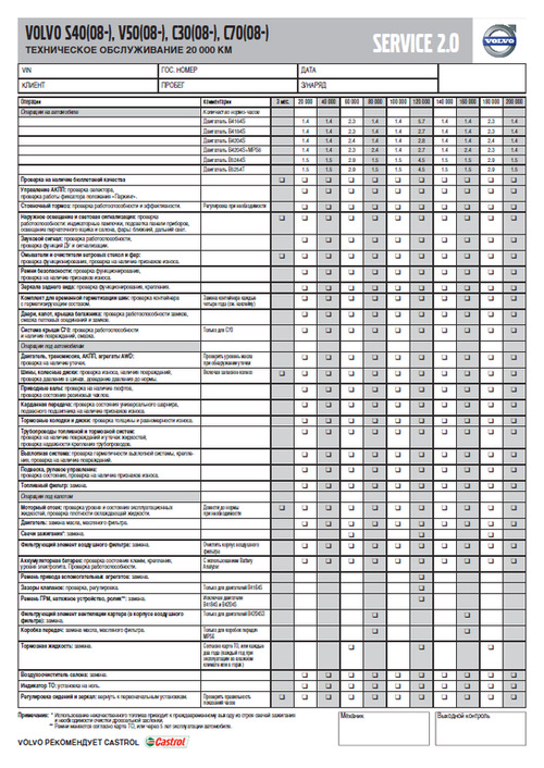
Регламентированный перечень работ по ТО для Volvo C30/S40/V50/C70
Ссылка на файл в формате PDF (ОД Обухов)
— Каталоги запчастей и аксессуаров Volvo
Carcats.ru
Elcats.ru
Emex.ru
accessories.volvocars.com — официальный каталог аксессуаров
Инструкция подбора запчастей и комплектующих Volvo по VIN-номеру — Часть 1, Часть 2
— Руководство/инструкция по эксплуатации
Ссылка на руководство для Volvo V50 MY2012
Ссылка на руководства для других моделей и/или модельных годов
Ссылка на различные инструкции для всех моделей Volvo (Eng, официальный сайт Volvo)
Ссылка на различные инструкции для Volvo S40/V50 (Eng, ресурс владельцев Volvo в UK)
— Quick Guide
Ссылка на файл в формате PDF
— Схемы соединений проводки (Электрика)

Полный размер
Схема по электрической проводке для Volvo C30/S40/V50/C70
Ссылка на файл в формате PDF
— Характеристики и годы производства двигателей для Volvo C30/S40/V50
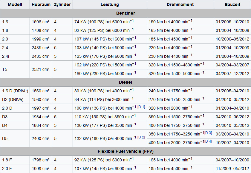
Характеристики и годы производства двигателей для Volvo C30/S40/V50
Ссылка на источник
— Технические характеристики бензиновых двигателей 2.4 (B5244S4/B5244S5) и 2.5 (B5254T3)
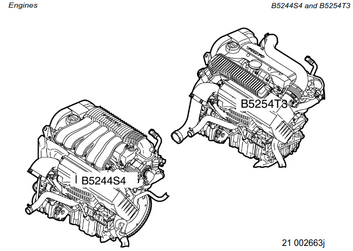
Manual Volvo C30/S40/V50 engines B5244S4 and B5254T3
Ссылка на файл в формате PDF (Eng)
— Технические характеристики бензинового двухлитрового двигателя B4204S3 (он же Mazda MZR LF 2.0, он же Ford Duratec HE 2.0)
Ссылка на изображение в полном размере (источник VIDA)
Ссылка на подборку полезной информации о двигателе Volvo B4204S3/Mazda MZR LF 2.0/Ford Duratec HE 2.0
— Моторное масло
Моторное масло — объём, допуск, эксплуатационные свойства, вязкость, артикулы канистр для бензиновых двигателей B4164S3, B4184S8, B4184S11, B4204S3, B4204S4, B5244S4, B5244S5, B5254T3, B5254T7 и дизельных двигателей D4162T, D4164T, D4204T, D4204T2, D5204T, D5204T5, D5244T8, D5244T9, D5244T13.

Полный размер
Моторное масло для двигателей Volvo C30/S40/V50
Ссылка на изображение в полном размере (источник VIDA)
— Объём масла между минимальной и максимальной отметками на щупе двигателей Volvo C30/S40/V50
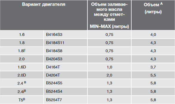
Объём масла между минимальной MIN и максимальной MAX отметкой на щупе моторов Volvo C30/S40/V50
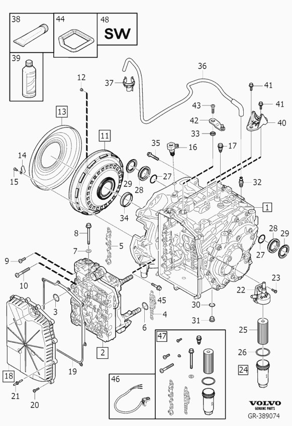
— Автоматическая 5-ти ступенчатая коробка передач Aisin AW55-50/51SN
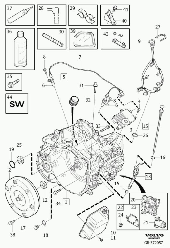
Запчасти на фото: 0835631, 303943
Ссылка на каталог запчастей в формате PDF (Eng)
Ссылка на мануал в формате PDF (Eng)
— Роботизированная 6-ти ступенчатая коробка передач Getrag 6DCT450 (MPS6, она же PowerShift)
Серия публикаций о PowerShift от технического специалиста Сергея glimmer:
Эксплуатация PowerShift (6DCT450)
Функции коробки PowerShift (6DCT450)
Принцип работы Powershift 6DCT450
Замена масла в коробке PowerShift (6DCT450)
VIDA 2021: Инструкция по замене масла АКПП PowerShift (6DCT450) — NEW!
Замена сцепления 6DCT450 и Eco Boost 203(240)л.с)
Замена уплатнения сцепления 6DCT450 и Eco Boost 203(240)л.с
Модуль управления коробки передач (TCM). Часть 1
Модуль управления коробки передач (TCM). Часть 2
Модуль управления коробки передач (TCM). Замена датчика входного вала
Powershift 6DCT450 в деталях. Часть 1
Powershift 6DCT450 в деталях. Часть 2. Принципиальные схемы ТСМ
Powershift 6DCT450 в деталях. Часть 3. Демпфер.
Powershift 6DCT450 в деталях. Часть 4. Соленоиды ТСМ.
— Типы цоколей и мощность ламп
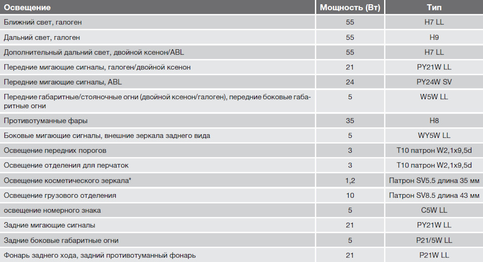
Полный размер
Типы цоколей и мощность ламп
— Брошюра Volvo V50 (Volvo Cars Russia)

Полный размер
Брошюра Volvo V50 (Volvo Cars Russia)
Скачать в формате PDF — описание, фото, комплектации, экстерьер, интерьер, аксессуары
— Официальные пресс-релизы и фото Volvo V50 (Volvo Cars)
Ссылка на официальные пресс-релизы, фото и видео
— Каталог оригинальных литых дисков Volvo (артикулы и размерность)

Каталог оригинальных литых дисков Volvo
Ссылка на каталог — названия дисков, размерность и артикулы
— Комплектации Volvo V50
Ссылка
— Проверка доступности обновлений Service 2.0 для всех автомобилей Volvo по VIN-коду

Обновления Volvo Service 2.0
Ссылка
— Расшифровка информации о комплектации для всех автомобилей Volvo по VIN-коду
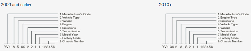
Ссылка на форму отправки запроса на расшифровку информации по VIN-коду в ОД Volvo Car M1
— Volvo VIDA

VIDA Online (для пользователей clubvolvo.ru)
VIDA 2014D + DiCE (Установка, настройка и использование)
— Кузов
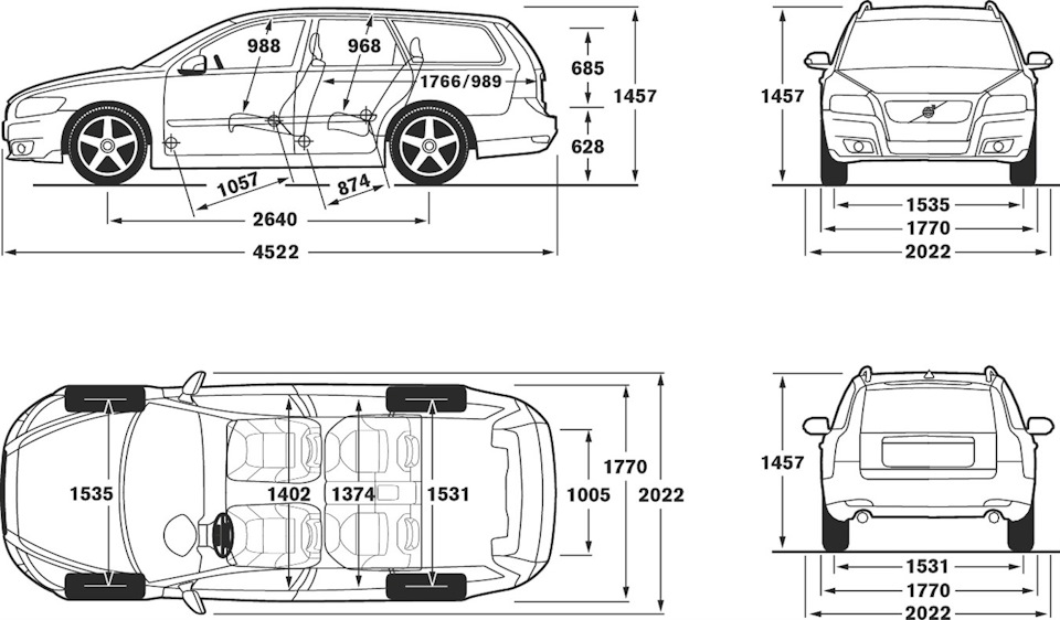
Полный размер
Размеры кузова Volvo V50
Перейти к контенту
Руководство по эксплуатации Вольво С30 на русском языке
Руководства по ремонту и техническому обслуживанию автомобилей Volvo C30 можно купить в магазине автомобильной литературы
Электронные версии книг по ремонту Volvo C30 в PDF формате можно купить на сайте
Пример руководства по ремонту Вольво
Данное руководство может применяться при ремонте.

VOLVO S40 / V50 2004-2007 бензин / турбодизель
Издательство Алфамер Паблишинг
Справочно-информационный мануал Руководство по ремонту Volvo S40, а также руководство по эксплуатации и техническому обслуживанию, устройство Volvo S40 в кузове седан и Volvo V50 в кузове универсал 2004-2007 гг. выпуска, оборудованных бензиновыми двигателями рабочим объемом 1,8 (1798 см3), 2,0 (1999 см3) и 2,4 л. (2435 см3), а также турбодизельными двигателями рабочим объемом 2,0 л. (1998 см3).
Содержание инструкции по ремонту VOLVO S40 / V50 2004-2007
ВАШ АВТОМОБИЛЬ VOLVO S40/V50
Безопасность — прежде всего! 0 — 1
Введение 0 — 3
Ремонт в дороге 0 — 4
Еженедельные проверки 0 — 8
Смазки и рабочие жидкости 0 — 15
Давление в шинах 0 — 15
Глава 1 часть А Техническое обслуживание — модификации с бензиновыми двигателями
Спецификации 1А — 2
График обслуживания 1А — 3
Расположение элементов 1А — 4
Процедуры обслуживания 1А — 6
Общие сведения и текущее обслуживание 1А — 6
Замена моторного масла и масляного фильтра 1А — 6
Проверка уровня жидкости в системе усиления рулевого управления 1А — 8
Проверка выключателя режимов Park/Neutral (модификации с автоматической коробкой передач) 1А — 8
Проверка ремня привода вспомогательных агрегатов 1А — 8
Проверка ламп и звуковых сигналов 1А — 9
Проверка на наличие утечек и проверка состояния шлангов 1А — 9
Проверка электропроводки, расположенной в моторном отсеке 1А — 10
Проверка уровня и замена жидкости в автоматической коробке переключения передач 1А — 11
Проверка тормозных колодок и дисков 1А — 12
Проверка системы выпуска отработавших газов 1А — 12
Проверка деталей подвески и рулевого управления 1А — 13
Проверка пыльников и шарниров приводных валов 1А — 13
Проверка состояния днища и магистралей 1А — 13
Смазывание петель и замков 1А — 14
Проверка колес 1А — 14
Дорожная проверка 1А — 14
Замена салонного и топливного фильтров 1А — 15
Проверка и регулировка стояночного тормоза 1А — 16
Проверка ремней безопасности 1А — 16
Проверка концентрации антифриза в охлаждающей жидкости 1А — 16
Обнуление индикатора необходимости выполнения обслуживания 1А — 16
Замена фильтрующего элемента воздушного фильтра 1А — 16
Замена свечей зажигания 1А — 17
Замена ремня привода газораспределительного механизма 1А — 19
Замена тормозной жидкости 1А — 19
Замена охлаждающей жидкости 1А — 19
Замена элемента питания в пульте дистанционного управления 1А — 21
Замена ремня привода вспомогательных агрегатов 1А — 22
Глава 1 часть Б Техническое обслуживание — модификации с дизельными двигателями
Спецификации 1Б — 2
График обслуживания 1Б — 3
Расположение элементов Вольво в50 1Б — 4
Процедуры обслуживания 1Б — 6
Общие сведения и текущее обслуживание 1Б — 6
Замена моторного масла и масляного фильтра 1Б — 6
Проверка уровня жидкости в системе усиления рулевого управления 1Б — 8
Проверка ремня привода вспомогательных агрегатов 1Б — 8
Проверка ламп и звуковых сигналов 1Б — 9
Проверка на наличие утечек и проверка состояния шлангов 1Б — 9
Проверка электропроводки, расположенной в моторном отсеке 1Б — 10
Проверка ремней безопасности 1Б — 10
Проверка тормозных колодок и дисков 1Б — 10
Проверка системы выпуска отработавших газов 1Б – 11
Проверка деталей подвески и рулевого управления 1Б — 11
Проверка пыльников и шарниров приводных валов 1Б — 11
Проверка состояния днища и магистралей 1Б — 12
Смазывание петель и замков 1Б — 12
Проверка колес 1Б — 12
Дорожная проверка 1Б — 12
Замена салонного фильтра 1Б — 13
Удаление воды из топливного фильтра и его замена 1Б — 14
Проверка и регулировка стояночного тормоза 1Б — 14
Проверка концентрации антифриза в охлаждающей жидкости 1Б — 14
Обнуление индикатора необходимости выполнения обслуживания 1Б — 14
Замена фильтрующего элемента топливного фильтра 1Б — 15
Замена фильтрующего элемента воздушного фильтра 1Б — 15
Заполнение бачка сажевого фильтра 1Б — 15
Замена ремня привода газораспределительного механизма 1Б — 1Б
Замена тормозной жидкости 1Б — 16
Замена охлаждающей жидкости 1Б — 16
Замена элемента питания в пульте дистанционного управления 1Б — 18
Замена сажевого фильтра 1Б — 18
Замена ремня привода вспомогательных агрегатов 1Б — 18
Глава 2 часть А Бензиновые двигатели 1.8и 2.0литра — ремонт без снятия с автомобиля
Спецификации 2А — 1
Общие сведения 2А — 3
Проверка компрессии — описание и анализ результатов 2А — 3
Верхняя мертвая точка поршня первого цилиндра — установка 2А — 4
Крышка головки блока цилиндров — снятие и установка 2А — 5
Рабочие зазоры клапанов — проверка и регулировка 2А — 5
Шкив коленвала — снятие и установка 2А — 6
Крышка цепи привода газораспределительного механизма — снятие и установка 2А — 6
Цепь привода ГРМ, натяжитель и направляющие — снятие, проверка и установка 2А — 7
Распредвалы и толкатели — снятие, проверка и установка 2А — 9
Манжеты коленвала — замена 2А — 11
Головка блока цилиндров — снятие и установка 2А — 12
Поддон — снятие и установка 2А — 13
Масляный насос — снятие, проверка и установка 2А — 14
Выключатель контрольной лампы давления моторного масла — снятие и установка 2А — 15
Маховик — снятие, проверка и установка 2А — 15
Опоры силового блока — проверка и замена 2А — 16
Глава 2 часть Б Бензиновые двигатели 2.4 литра — ремонт без снятия с автомобиля
Спецификации 2Б — 1
Общие сведения 2Б — 3
Проверка компрессии — описание и анализ результатов 2Б — 3
Ремень привода ГРМ — снятие и установка 2Б — 4
Звездочки распредвалов, блоки системы регулировки фаз газораспределения и правые манжеты — снятие и установка 2Б — 7
Левые манжеты распредвалов — замена 2Б — 9
Распредвалы и толкатели — снятие, проверка и установка 2Б — 9
Головка блока цилиндров — снятие и установка Volvo 2Б — 12
Манжеты коленвала — замена 2Б — 13
Масляный насос — снятие, проверка и установка 2Б — 13
Маховик (планшайба) — снятие, проверка и установка 2Б — 13
Опоры силового блока — снятие и установка 2Б — 14
Поддон — снятие и установка 2Б — 14
Выключатель контрольной лампы давления моторного масла — снятие и установка 2Б — 15
Глава 2 часть В Дизельные двигатели — ремонт без снятия с автомобиля
Спецификации 2В — 1
Общие сведения 2В — 3
Проверка компрессии и тест на утечки — описание и анализ результатов 2В — 3
Крышка головки блока цилиндров — снятие и установка 2В — 4
Шкив коленвала — снятие и установка 2В — 5
Ремень привода ГРМ и натяжитель — снятие и установка 2В — 5
Цепь привода ГРМ и натяжитель — снятие и установка 2В — 8
Распредвалы, коромысла и гидрокомпенсаторы — снятие, проверка и установка 2В — 8
Манжета распредвала — замена 2В — 11
Головка блока цилиндров — снятие, проверка и установка 2В — 11
Поддон — снятие и установка 2В — 13
Масляный насос — снятие, проверка и установка 2В — 14
Выключатель контрольной лампы давления моторного масла — снятие и установка 2В — 15
Маслоохладитель — снятие и установка 2В — 15
Манжеты коленвала — замена 2В — 15
Маховик — снятие, проверка и установка 2В — 16
Опоры силового блока — проверка и замена 2В — 17
Глава 2 часть Г Снятие двигателя и его капитальный ремонт
Спецификации 2Г — 1
Общие сведения 2Г — 3
Снятие силового блока — подготовка и меры предосторожности 2Г — 3
Силовой блок — снятие, разделение и установка 2Г — 3
Капитальный ремонт двигателя — общие сведения 2Г — 5
Головка блока цилиндров — разборка, очистка, проверка и сборка 2Г — 6
Промежуточная секция/крышки коренных подшипников — снятие 2Г — 7
Поршни и шатуны — снятие и проверка 2Г — 8
Коленвал — снятие и проверка 2Г — 9
Блок цилиндров и картер двигателя — очистка и проверка 2Г — 10
Коренные и шатунные подшипники — проверка и подбор 2Г — 10
Капитальный ремонт двигателя — последовательность сборки 2Г — 11
Коленвал — установка 2Г — 11
Поршни и кольца — сборка 2Г — 12
Поршни и шатуны — установка 2Г — 13
Первый запуск двигателя после капитального ремонта 2Г — 13
Глава 3 Системы охлаждения двигателя, отопления и кондиционирования
Спецификации 3 — 1
Общие сведения и меры предосторожности 3 — 2
Шланги системы охлаждения — снятие и установка 3 — 2
Охлаждающая жидкость — общие сведения 3 — 3
Вентилятор радиатора — снятие и установка 3 — 3
Радиатор — снятие и установка 3 — 4
Датчик температуры охлаждающей жидкости — проверка, снятие и установка 3 — 7
Помпа — снятие и установка 3 — 7
Термостат — снятие, проверка и установка 3 — 8
Системы отопления и кондиционирования — общие сведения и меры предосторожности 3 — 9
Компоненты системы кондиционирования — снятие и установка 3е 10
Дополнительный электрический обогреватель — снятие и установка 3 — 15
Глава 4 часть А Топливная система и система выпуска отработавших газов — модели с бензиновыми двигателями
Спецификации 4А — 1
Общие сведения и меры предосторожности 4А — 2
Корпус воздушного фильтра — снятие и установка 4А — 3
Педаль акселератора — снятие и установка 4А — 4
Топливный насос и датчик уровня топлива — снятие и установка 4А — 4
Топливный бак — снятие и установка 4А — 5
Система впрыска топлива — общие сведения 4А — 5
Система впрыска топлива — проверка и регулировка 4А — 7
Компоненты системы впрыска топлива — снятие и установка 4А — 7
Система поддержания заданной скорости (круиз — контроль) — общие сведения 4А — 11
Впускной коллектор — снятие и установка 4А — 11
Выпускной коллектор — снятие и установка 4А — 11
Система выпуска отработавших газов — общие сведения и замена компонентов 4А — 13
Глава 4 часть Б Топливная система и система выпуска отработавших газов — модели с дизельными двигателями
Спецификации 4Б — 1
Общие сведения и меры предосторожности 4Б — 2
Корпус воздушного фильтра — снятие и установка 4Б — 2
Топливный бак — снятие и установка 4Б — 2
Педаль акселератора — снятие и установка Volvo-s40 4Б — 3
Система впрыска топлива — общие сведения 4Б — 3
Топливная система — зарядка и удаление воздуха 4Б — 4
Топливный насос и датчик уровня топлива — снятие и установка 4Б — 5
Система впрыска топлива — проверка и регулировка 4Б — 5
Топливный насос высокого давления — снятие и установка 4Б — 5
Форсунки — снятие и установка 4Б — 6
Компоненты системы управления двигателем — снятие и установка 4Б — 7
Турбонагнетатель — общие сведения и меры предосторожности 4Б — 9
Турбонагнетатель — снятие и установка 4Б — 10
Турбонагнетатель — проверка и ремонт 4Б — 10
Промежуточный охладитель — снятие и установка 4Б — 10
Коллекторы — снятие и установка 4Б — 11
Система выпуска отработавших газов — общие сведения и замена компонентов 4Б — 12
Глава 4 часть В Системы снижения токсичности
Спецификации 4В — 1
Общие сведения 4В — 1
Каталитический нейтрализатор — общие сведения и меры предосторожности 4В — 2
Система вентиляции картера — проверка и замена компонентов 4В — 2
Система улавливания паров топлива — проверка и замена компонентов 4В — 3
Системы снижения токсичности отработавших газов — проверка и замена компонентов 4В — 4
Глава 5 часть А Системы запуска двигателя и зарядки аккумулятора
Спецификации 5А — 1
Общие сведения и меры предосторожности 5А — 2
Аккумулятор — проверка и зарядка 5А — 2
Аккумулятор — снятие и установка 5А — 3
Система зарядки аккумулятора — проверка 5А — 3
Генератор — снятие и установка 5А — 4
Генератор — замена щеток 5А — 5
Система запуска двигателя — проверка 5А — 5
Стартер — снятие и установка 5А — 5
Стартер — проверка и ремонт 5А — 6
Система предпускового подогрева (дизельные модификации) — общие сведения 5А — 6
Система предпускового подогрева (дизельные модификации) — проверка 5А — 6
Свечи накаливания — снятие, проверка и установка 5А — 7
Реле свечей накаливания — снятие и установка 5А — 7
Глава 5 часть Б Система зажигания — бензиновые двигатели
Спецификации 5Б — 1
Общие сведения 5Б — 2
Система зажигания — проверка 5Б — 2
Поиск неисправностей системы зажигания — общие сведения 5Б — 3
Катушки зажигания — снятие и установка 5Б — 4
Датчик(и) детонации — снятие и установка 5Б — 4
Глава 6 Сцепление
Спецификации 6 — 1
Общие сведения 6 — 1
Педаль сцепления — снятие и установка 6 — 1
Главный цилиндр сцепления — снятие и установка 6 — 2
Рабочий цилиндр сцепления — снятие и установка 6 — 3
Удаление воздуха из системы 6 — 3
Сцепление — снятие, проверка и установка 6 — 3
Выжимной подшипник — снятие, проверка и установка 6 — 5
Датчик положения педали — замена 6 — 5
Глава 7 часть А Механическая коробка передач
Спецификации 7А — 1
Общие сведения 7А — 2
Кожух рычага переключения передач — снятие и установка 7А — 3
Тросы переключения передач — снятие и установка 7А — 4
Манжеты — замена 7А — 6
Выключатель сигналов заднего хода — снятие и установка 7А — 6
Замена масла в коробке передач 7А — 7
Коробка передач — снятие и установка 7А — 7
Ремонт коробки передач — общие сведения 7А — 9
Глава 7 часть Б Автоматическая коробка передач
Спецификации 7Б — 1
Общие сведения 7Б — 2
Трос селектора режимов — снятие, установка и регулировка 7Б — 2
Кожух селектора режимов и панель индикации режимов — снятие и установка 7Б — 3
Блок управления коробкой передач — снятие и установка 7Б — 4
Манжеты — замена 7Б — 4
Автоматическая коробка передач — снятие и установка 7Б — 5
Поиск неисправностей автоматической коробки передач 7Б — 6
Глава 8 Приводные валы
Спецификации 8 — 1
Общие сведения 8 — 1
Приводные валы — снятие и установка 8 — 2
Пыльник наружного шарнира приводного вала — замена 8 — 3
Пыльник внутреннего шарнира приводного вала — замена 8 — 4
Промежуточный подшипник правого вала 8 — 4
Ремонт приводных валов — общие сведения 8 — 4
Глава 9 Тормозная система
Спецификации 9 — 1
Общие сведения 9 — 2
Удаление воздуха из системы 9 — 2
Шланги и магистрали — замена 9 — 3
Передние тормозные колодки — замена 9 — 3
Задние тормозные колодки — замена 9 — 5
Передний тормозной диск — проверка, снятие и установка 9 — 7
Задний тормозной диск — проверка, снятие и установка 9 — 7
Передний суппорт — снятие, ремонт и установка 9 — 7
Задний суппорт — снятие, ремонт и установка 9 — 8
Главный цилиндр — снятие и установка 9 — 8
Педаль тормоза — снятие и установка 9 — 9
Вакуумный усилитель — снятие и установка 9 — 10
Стояночный тормоз — регулировка 9 — 10
Трос стояночного тормоза — снятие и установка 9 — 11
Рычаг стояночного тормоза — снятие и установка 9 — 12
Выключатель контрольной лампы стояночного тормоза — снятие и установка 9 — 12
Выключатель сигналов торможения — снятие и установка 9 — 12
Антиблокировочная система (ABS) — общие сведения 9 — 12
Компоненты антиблокировочной системы — снятие и установка 9 — 13
Антиблокировочная система (ABS) — поиск неисправностей 9 — 14
Вакуумный насос — снятие и установка 9 — 14
Глава 10 Подвеска и рулевое управление
Спецификации 10 — 1
Общие сведения 10 — 2
Передний ступичный узел и подшипник — снятие и установка 10 — 3
Стойка передней подвески — снятие и установка 10 — 4
Стойка передней подвески — разборка, проверка и сборка 10 — 5
Поперечный рычаг и шаровый шарнир передней подвески — снятие, ремонт и установка 10 — 6
Передний стабилизатор поперечной устойчивости — снятие и установка 10 — 6
Задний ступичный подшипник — замена 10 — 7
Задний ступичный узел и продольный рычаг — снятие и установка 10 — 8
Задний амортизатор — снятие и установка 10 — 8
Пружина задней подвески — снятие и установка 10 — 9
Рычаги задней подвески — снятие и установка 10 — 9
Задний стабилизатор поперечной устойчивости — снятие и установка 10 — 10
Рулевое колесо — снятие и установка 10 — 10
Рулевая колонка — снятие и установка 10 — 11
Рулевой механизм — снятие и установка 10 — 12
Пыльник рулевого механизма — замена 10 — 12
Система усиления рулевого управления — удаление воздуха 10 — 13
Электронный блок и насос системы усиления рулевого управления — снятие и установка 10 — 13
Наконечник рулевой тяги — снятие и установка 10 — 14
Углы установки колес — общие сведения 10 — 14
Глава 11 Кузов и кузовное оборудование
Спецификации 11 — 1
Общие сведения 11 — 1
Кузов — обслуживание 11— 1
Декоративные панели и ковровые покрытия — обслуживание 11 — 2
Небольшие повреждения кузова — ремонт 11 — 2
Большие повреждения кузова — ремонт 11 — 3
Капот — снятие, установка и регулировка 11 — 3
Трос замка капота — снятие и установка 11 — 4
Замок капота — снятие и установка 11 — 4
Двери —снятие и установка 11 — 4
Внутренние панели отделки дверей — снятие и установка 11 — 5
Дверная ручка и замок — снятие и установка 11 — 5
Стекло двери и стеклоподъемник — снятие и установка 11 — 8
Внутренняя панель отделки двери багажного отделения — снятие и установка 11 — 10
Дверь багажного отделения — снятие и установка 11 — 11
Опорные стойки двери багажного отделения и капота — снятие и установка 11 — 11
Компоненты замка двери багажного отделения — снятие и установка 11 — 11
Крышка багажного отделения — снятие и установка 11 — 11
Опорные стойки крышки багажного отделения — снятие и установка 11 — 12
Компоненты замка крышки багажного отделения — снятие и установка 11 — 12
Ветровое стекло, стекло двери багажного отделения и заднее стекло — общие сведения 11 — 12
Зеркала заднего вида и сопутствующие компоненты — снятие и установка 11 — 12
Бамперы — снятие и установка 11 — 13
Решетка радиатора — снятие и установка 11 — 15
Кресла и приводы — снятие и установка 11 — 15
Заднее сиденье — снятие и установка Вольво С-40 11 — 16
Детали внутренней отделки салона — снятие и установка 11 — 16
Ремни безопасности — общие сведения, снятие и установка 11 — 21
Центральная консоль — снятие и установка 11 — 23
Лицевая панель — снятие и установка 11 — 24
Люк — общие сведения, замена и регулировка панели 11 — 27
Глава 12 Электрооборудование кузова
Спецификации 12 — 1
Общие сведения и меры предосторожности 12 — 2
Поиск неисправностей электрооборудования — общие сведения 12 — 2
Плавкие предохранители и реле — общие сведения 12 — 3
Выключатель зажигания — снятие и установка 12 — 4
Электронный блок рулевого колеса — общие сведения, снятие и установка 12 — 5
Выключатели — снятие и установка 12 — 5
Лампы наружного освещения — замена 12 — 7
Лампы освещения салона — замена 12 — 9
Фонари наружного освещения — снятие, установка и регулировка направления светового луча 12 — 11
Фары с ксеноновыми лампами — замена компонентов, установка и регулировка 12 — 12
Приборный щиток — снятие и установка 12 — 14
Очиститель ветрового стекла — снятие и установка компонентов 12 — 14
Компоненты омывателей — общие сведения 12 — 15
Очиститель заднего стекла — снятие и установка 12 — 15
Звуковые сигналы — снятие и установка 12 — 16
Люк — замена привода и блока управления 12 — 16
Центральный замок — общие сведения 12 — 16
Система облегчения парковки — общие сведения и замена компонентов 12 — 17
Компоненты информационно — развлекательной системы — снятие и установка 12 — 17
Антенный усилитель — снятие и установка 12 — 18
Динамики — снятие и установка Волво С40 / В 50 12 — 18
Подушки безопасности — общие сведения и меры предосторожности 12 — 18
Компоненты системы подушек безопасности — снятие и установка 12 — 18
Охранная сигнализация — общие сведения 12 — 20
Блоки электронного управления — снятие и установка 12 — 20
Привод замка лючка заправочной горловины — снятие и установка 12 — 21
Схемы электрооборудования 12 — 22
Руководство по эксплуатации Р — 1
Приложения
Размеры и массы П — 1
Покупка запасных частей П — 2
Идентификация автомобиля П — 2
Общие советы по выполнению ремонта П — 3
Подъем и фиксация автомобиля Вольво-в50 П — 4
Инструменты и приспособления П — 5
Проверка технического состояния автомобиля Вольво-с40 П — 7
Поиск неисправностей П — 12
Словарь технических терминов П — 21
Предметный указатель П — 27
- Manuals
- Brands
- Volvo Manuals
- Automobile
- C30 2007
- Service and repair manual
-
Contents
-
Table of Contents
-
Bookmarks
Quick Links
2007-2013 VOLVO C30 SERVICE
AND REPAIR MANUAL
Related Manuals for Volvo C30 2007
Summary of Contents for Volvo C30 2007
-
Page 1
2007-2013 VOLVO C30 SERVICE AND REPAIR MANUAL… -
Page 2
ENGINE Engine Control — Removal, Replacement And Installation ENGINE Engine Control — Removal, Replacement And Installation ENGINE Engine Control — Removal, Replacement And Installation ACCELERATOR PEDAL REMOVAL AND INSTALLATION Fig. 1: Identifying Accelerator Pedal Courtesy of VOLVO CARS CORPORATION Torque: M6 10 Nm… -
Page 3
ALTERNATOR GENERATOR (B5244S4; 2007-11) REMOVAL NOTE: Removal steps in this procedure may contain installation details. Battery, disconnection. See BATTERY DISCONNECTING AND CONNECTING Fig. 1: Identifying Bolts Courtesy of VOLVO CARS CORPORATION Remove the auxiliaries belt. See ACCESSORY DRIVE BELT TENSIONER… -
Page 4
2012 Volvo C30 T-5 ELECTRICAL Alternator And Regulator — Removal, Replacement And Installation Fig. 2: Identifying Generator B+ Terminal And Bolts Courtesy of VOLVO CARS CORPORATION Remove the following items: 1. Torque: Generator B+ terminal 15 Nm 2. Torque: M8… -
Page 5
2012 Volvo C30 T-5 ELECTRICAL Alternator And Regulator — Removal, Replacement And Installation Fig. 4: Identifying Oil Stick Bracket Bolt Courtesy of VOLVO CARS CORPORATION Fig. 5: Identifying Generator B+ Terminal And Nuts Courtesy of VOLVO CARS CORPORATION Remove the following items: 1. -
Page 6
REMOVAL AND INSTALLATION Remove the alternator. See GENERATOR (B5254T3; 2007, B5254T7; 2008-12) or GENERATOR (B5244S4; 2007-11) Fig. 6: Identifying Spanner 9997113 Courtesy of VOLVO CARS CORPORATION see 9997113 see 9997113 CHARGE REGULATOR CHARGE REGULATOR (B5244S4; 2007-11, B5254T3; 2007, B5254T7; 2008-12) -
Page 7
2012 Volvo C30 T-5 ELECTRICAL Alternator And Regulator — Removal, Replacement And Installation Fig. 7: Identifying Nuts Courtesy of VOLVO CARS CORPORATION Remove the generator (GEN). See GENERATOR (B5244S4; 2007-11) or GENERATOR (B5254T3; 2007, B5254T7; 2008-12). Fig. 8: Identifying M4 Generator Bolts… -
Page 8
Removal steps in this procedure may contain installation details. See SAFETY INFORMATION BATTERY AND CHARGING Fig. 1: Identifying Underhood Torsion Rod, Nuts And Cover Courtesy of VOLVO CARS CORPORATION Torque: M8 24 Nm Fig. 2: View Of Battery And Cover… -
Page 9
2012 Volvo C30 T-5 ELECTRICAL Battery And Mounting — Removal, Replacement And Installation Courtesy of VOLVO CARS CORPORATION Perform battery disconnecting and connecting, see BATTERY DISCONNECTING AND CONNECTING Fig. 3: Locating Battery Box And Terminal Connector Bolts Courtesy of VOLVO CARS CORPORATION Fig. -
Page 10
2012 Volvo C30 T-5 ELECTRICAL Battery And Mounting — Removal, Replacement And Installation when replacing battery (main battery) function. VIDA (Volvo Scan Tool) is necessary to perform this procedure. -
Page 11
NOTE: Removal steps in this procedure may contain installation details. Remove left-hand drive shaft, see DRIVESHAFT LEFT Remove the right drive shaft, see DRIVE SHAFT RIGHT Fig. 1: Identifying M7 Bolts Courtesy of VOLVO CARS CORPORATION Torque: M7 17 Nm… -
Page 12
2012 Volvo C30 T-5 TRANSMISSION Manual Transmission Fig. 2: Identifying Hose Strap Courtesy of VOLVO CARS CORPORATION Fig. 3: Identifying Hose Courtesy of VOLVO CARS CORPORATION Fig. 4: Identifying M8 And M10 Bolts… -
Page 13
TRANSMISSION Manual Transmission Remove the following items: 1. Torque: M8 24 Nm 2. Torque: M10 50 Nm Fig. 5: Identifying M10 Bolts Courtesy of VOLVO CARS CORPORATION Torque: M10 50 Nm Fig. 6: Removing Bevel Gear Courtesy of VOLVO CARS CORPORATION… -
Page 14
2012 Volvo C30 T-5 TRANSMISSION Manual Transmission Fig. 7: Identifying Bevel Gear Courtesy of VOLVO CARS CORPORATION For information about transmission lubricants, see LUBRICANT TRANSMISSION To install, reverse the removal procedure. -
Page 15
2012 Volvo C30 T-5 2012 Volvo C30 T-5 HVAC Automatic HVAC System HVAC Automatic HVAC System HVAC Automatic HVAC System HVAC GLOW PLUG FUEL-POWERED PREHEATER NOTE: The illustrations in this service information are used for different model years and/or models. Some variation may occur. However, the essential information in the illustrations is always correct. -
Page 16
2012 Volvo C30 T-5 HVAC Automatic HVAC System Fig. 1: Identifying Screws For Cover Over Fan Housing Courtesy of VOLVO CARS CORPORATION Remove the 4 screws for the cover over the fan housing. Remove the cover. NOTE: The nearest connection pipe may need to be adjusted in order to remove the cover. -
Page 17
2012 Volvo C30 T-5 HVAC Automatic HVAC System Fig. 3: Identifying Cable Terminals And Cables Courtesy of VOLVO CARS CORPORATION Remove: the cable terminal and cable for the flame sensor in positions 1 and 2 (blue and brown) the cable terminal and cable for the glow plug in positions 9 and 12 (white and brown). -
Page 18
2012 Volvo C30 T-5 HVAC Automatic HVAC System Fig. 4: Identifying Flame Sensor And Pressure Equalizer Courtesy of VOLVO CARS CORPORATION Disconnect the flame sensor (1) and with it the holder for the pressure equalizer (2). Remove: the glow plug … -
Page 19
2012 Volvo C30 T-5 HVAC Automatic HVAC System the flame sensor together with the holder. Tighten the glow plug. Tighten. Install the cable terminals and cables in the connectors. — Flame sensor in positions 1 and 2 (blue and brown). -
Page 20
LIFTING POINTS FOR LIFTING THE VEHICLE Fig. 1: Identifying Lifting Points Of Vehicle Courtesy of VOLVO CARS CORPORATION When lifting the vehicle, the lifting points indicated in the graphic must be used. The jacking plate must have a rubber pad to prevent damage to the vehicle. -
Page 21
NOTE: Some variation may occur. However, the essential information in the graphics is always correct. Fig. 2: View Of Symbol Numbers Courtesy of VOLVO CARS CORPORATION Symbol legend Measurement is given from centre Measurement is given from an edge Measurement is given from a cut marking Fig. -
Page 22
ACCESSORIES AND EQUIPMENT Body Frame — Specifications, Mechanical For measuring, the recommendation is to use an electronic measuring device type Alvis Light or similar. A deviation of +/- 2 mm is acceptable. Fig. 4: Identifying Rear Measurements (1 Of 2) Courtesy of VOLVO CARS CORPORATION… -
Page 23
2012 Volvo C30 T-5 ACCESSORIES AND EQUIPMENT Body Frame — Specifications, Mechanical Fig. 5: Identifying Rear Measurements (2 Of 2) Courtesy of VOLVO CARS CORPORATION SIDE MEMBERS, FRONT NOTE: Some variation may occur. However, the essential information in the graphics is always correct. -
Page 24
2012 Volvo C30 T-5 ACCESSORIES AND EQUIPMENT Body Frame — Specifications, Mechanical Courtesy of VOLVO CARS CORPORATION For measuring, the recommendation is to use an electronic measuring device type Alvis Light or similar. A deviation of +/- 2 mm is acceptable. -
Page 25
2012 Volvo C30 T-5 ACCESSORIES AND EQUIPMENT Body Frame — Specifications, Mechanical Fig. 10: Identifying Side Measurements (3 Of 3) Courtesy of VOLVO CARS CORPORATION B6 = 1583 mm B7 = 1421 mm ROOF, WINDSHIELD AND REAR WINDSHIELD FRAME ROOF Fig. -
Page 26
Measurement is given from a cut marking Fig. 12: Identifying Symbol Number 3 Measurement From The Bottom Of The Recess Courtesy of VOLVO CARS CORPORATION Measurement takes place from the bottom of the recess. If only a measuring point symbol is shown this applies to both points. -
Page 27
2012 Volvo C30 T-5 ACCESSORIES AND EQUIPMENT Body Frame — Specifications, Mechanical Fig. 14: Identifying Windshield Frame Measurements Courtesy of VOLVO CARS CORPORATION BODY SIDE Fig. 15: View Of Symbol Numbers Courtesy of VOLVO CARS CORPORATION Explanation of symbols As measured from centre… -
Page 28
As measured from cut marking Fig. 16: Identifying Symbol Number 3 Measurement From The Bottom Of The Recess Courtesy of VOLVO CARS CORPORATION As measured from the bottom of the recess. If only one measurement point symbol is shown, it applies to both points. -
Page 29
2012 Volvo C30 T-5 ACCESSORIES AND EQUIPMENT Body Frame — Specifications, Mechanical Fig. 18: Identifying Body Side Measurements (2 Of 5) Courtesy of VOLVO CARS CORPORATION Fig. 19: Identifying Body Side Measurements (3 Of 5) Courtesy of VOLVO CARS CORPORATION… -
Page 30
2012 Volvo C30 T-5 ACCESSORIES AND EQUIPMENT Body Frame — Specifications, Mechanical Fig. 20: Identifying Body Side Measurements (4 Of 5) Courtesy of VOLVO CARS CORPORATION Fig. 21: Identifying Body Side Measurements (5 Of 5) Courtesy of VOLVO CARS CORPORATION… -
Page 31
REMOVAL REMOVING THE FRONT BUMPER RAIL Fig. 1: Removing Front Bumper Rail Courtesy of VOLVO CARS CORPORATION Remove the front section. See: FRONT END . Remove the bracket for the power steering. It is secured using 4 M8 screws. -
Page 32
Support the radiator assembly. Detach the radiator. It is secured using 4 M8 screws. Remove the remaining 6 M8 screws for the bumper rail. Remove the bumper rail. INSTALLATION NOTE: For tightening torques, see: TIGHTENING TORQUE . INSTALLING THE FRONT BUMPER RAIL Fig. 2: Installing Front Bumper Rail Courtesy of VOLVO CARS CORPORATION… -
Page 33
2012 Volvo C30 T-5 ACCESSORIES AND BODY, CAB Body Frame — Removal, replacement and installation Install: the bumper rail using the 6 M6 screws. Wait before installing the 2 screws for the servo unit the radiator using the 4 M8 screws … -
Page 34
ACCESSORIES AND BODY, CAB Body Frame — Removal, replacement and installation Fig. 3: Aligning Front Wheel Arch Courtesy of VOLVO CARS CORPORATION Align and secure the wheel arch. See: FRONT END and SIDE MEMBERS, FRONT . Align the bracket on the battery shelf. See the dimensions below. -
Page 35
ACCESSORIES AND BODY, CAB Body Frame — Removal, replacement and installation Fig. 4: Identifying Welding Locations For Replacement Part Courtesy of VOLVO CARS CORPORATION Weld the replacement part into place. Lens diameter: Ø 4.5 mm. Also, see WELDING, GENERAL . -
Page 36
2012 Volvo C30 T-5 ACCESSORIES AND BODY, CAB Body Frame — Removal, replacement and installation Fig. 5: Removing Rear Bumper Rail Courtesy of VOLVO CARS CORPORATION Torque: M8 24 Nm Rust proof. See RUSTPROOFING . Install in the reverse order. -
Page 37
2012 Volvo C30 T-5 ACCESSORIES AND BODY, CAB Body Frame — Removal, replacement and installation Fig. 6: Removing Rear Bumper Rail Courtesy of VOLVO CARS CORPORATION Torque: M8 24 Nm For information about corrosion protection, see RUSTPROOFING INSTALLATION To install, reverse the removal procedure. -
Page 38
REMOVAL REMOVING THE REAR SIDE MEMBER Fig. 7: Identifying The Cutting Point Courtesy of VOLVO CARS CORPORATION If the entire side member does not need replacing, see the cutting point in the illustration. Drill and grind off the member. Grind clean and apply welding primer. -
Page 39
ACCESSORIES AND BODY, CAB Body Frame — Removal, replacement and installation Fig. 8: Installing Rear Side Member Courtesy of VOLVO CARS CORPORATION Spot-weld the replacement part. Tip diameter: Ø 4.5 mm. See the illustration for the location of the spot welds. -
Page 40
PREPARATORY WORK (COMMON TO BOTH METHODS) PREPARATORY WORK Fig. 9: Identifying Cut Points Courtesy of VOLVO CARS CORPORATION When welding body components, see: WELDING, GENERAL . Remove components. See: FRONT SECTION, EXPOSING . Determine the extent of the damage. See: SIDE MEMBERS, FRONT and FRONT END . -
Page 41
ACCESSORIES AND BODY, CAB Body Frame — Removal, replacement and installation REMOVING THE OUTER SECTION OF THE LOWER SIDE MEMBER Fig. 10: Identifying Side Member Cutting Area Courtesy of VOLVO CARS CORPORATION If the entire side member does not need replacing, see the cutting point in the illustration. Remove: the support plate … -
Page 42
ACCESSORIES AND BODY, CAB Body Frame — Removal, replacement and installation Fig. 11: Identifying Cutting Points Courtesy of VOLVO CARS CORPORATION If the entire side member does not need replacing, see the cutting point in the illustration. Cutting point (1) This cutting point is used in the event of minor damage to the side member. -
Page 43
ACCESSORIES AND BODY, CAB Body Frame — Removal, replacement and installation Fig. 12: Removing Upper Part Of Side Member Extension Courtesy of VOLVO CARS CORPORATION If the member is cut at cutting point (2), remove the upper part of the side member extension. -
Page 44
ACCESSORIES AND BODY, CAB Body Frame — Removal, replacement and installation Fig. 13: Removing Outer Part Of Cross Member Cowl Panel Courtesy of VOLVO CARS CORPORATION Remove the outer part of the cross member cowl panel. INSTALLING THE INNER SECTION OF THE LOWER SIDE MEMBER… -
Page 45
2012 Volvo C30 T-5 ACCESSORIES AND BODY, CAB Body Frame — Removal, replacement and installation Fig. 14: Installing Inner Section Of Lower Side Member (1 Of 2) Courtesy of VOLVO CARS CORPORATION Grind clean. Apply welding primer. Seam-weld the join. -
Page 46
ACCESSORIES AND BODY, CAB Body Frame — Removal, replacement and installation Fig. 15: Installing Inner Section Of Lower Side Member (2 Of 2) Courtesy of VOLVO CARS CORPORATION Weld the outer part of the cross member cowl panel. Drill Ø 8 mm diameter holes for plug welds. -
Page 47
2012 Volvo C30 T-5 ACCESSORIES AND BODY, CAB Body Frame — Removal, replacement and installation Fig. 16: Installing Outer Section Of Lower Side Member Courtesy of VOLVO CARS CORPORATION Grind clean. Apply welding primer. Spot-weld the replacement part. Tip diameter Ø 8 mm. -
Page 48
2012 Volvo C30 T-5 ACCESSORIES AND BODY, CAB Body Frame — Removal, replacement and installation Fig. 17: Identifying Spot-Weld Location Courtesy of VOLVO CARS CORPORATION INSTALLING COMPONENTS… -
Page 49
ACCESSORIES AND BODY, CAB Body Frame — Removal, replacement and installation Fig. 18: Identifying Seam-Weld Area On Collar Courtesy of VOLVO CARS CORPORATION Seam-weld the collar into place using 8 welding seams each measuring 30 mm. See the illustration. Install: the wheel arch. -
Page 50
2012 Volvo C30 T-5 ACCESSORIES AND BODY, CAB Body Frame — Removal, replacement and installation Fig. 19: Removing Outer Section Of Upper Side Member Courtesy of VOLVO CARS CORPORATION Drill or grind out the spot welds. Cut off the damaged section. -
Page 51
2012 Volvo C30 T-5 ACCESSORIES AND BODY, CAB Body Frame — Removal, replacement and installation Fig. 20: Removing Inner Section Of Upper Side Member Courtesy of VOLVO CARS CORPORATION Drill or grind out the spot welds. Cut off the damaged section. -
Page 52
SPARE WHEEL WELL Remove the outer back piece. See TAIL SECTION EXTERNAL Determine the extent of the damage. See REAR SECTION Welding body components. See WELDING, GENERAL Fig. 21: Removing Spare Wheel Well (1 Of 4) Courtesy of VOLVO CARS CORPORATION… -
Page 53
2012 Volvo C30 T-5 ACCESSORIES AND BODY, CAB Body Frame — Removal, replacement and installation Fig. 22: Removing Spare Wheel Well (2 Of 4) Courtesy of VOLVO CARS CORPORATION Fig. 23: Removing Spare Wheel Well (3 Of 4) Courtesy of VOLVO CARS CORPORATION… -
Page 54
Remove the rear fender. See FENDER . Determine the extent of the damage. See BODY SIDE . Fig. 25: Removing Rear Wheel Arch (1 Of 2) Courtesy of VOLVO CARS CORPORATION Fig. 26: Removing Rear Wheel Arch (2 Of 2) Courtesy of VOLVO CARS CORPORATION… -
Page 55
PRINCIPLES OF JOINING Fig. 27: Identifying Cutting Points For C And D-Posts Courtesy of VOLVO CARS CORPORATION Roof pillars must be joined as shown in the illustration unless otherwise indicated in the method. Cut the different panel sections with a 50 mm offset. This applies when replacing all roof pillars. -
Page 56
REMOVAL REMOVING THE CANTRAIL / ROOF SIDE Fig. 28: Removing Cantrail / Roof Side Courtesy of VOLVO CARS CORPORATION Remove components. See: ROOF SECTION, EXPOSING (2007-2009) or ROOF SECTION, EXPOSING (2010-2012) . Pull or press out the damaged section to make it easier to re-align internal components. -
Page 57
INSTALLATION INSTALLING THE CANTRAIL / ROOF SIDE Fig. 29: Installing Cantrail / Roof Side Courtesy of VOLVO CARS CORPORATION Install foam rubber replacement at (1). See: BODY SEAL, SEALING DIAGRAM . Secure the replacement part. Saw through the two panels at the cutting points. -
Page 58
Remove roof panel. See ROOF PANEL Determine the extent of the damage. See ROOF Fig. 30: Removing Roof Arch Courtesy of VOLVO CARS CORPORATION Seal body. See BODY SEAL, SEALING DIAGRAM Rustproof body. See RUSTPROOFING Install roof panel. See ROOF PANEL… -
Page 59
Remove roof section, exposing, see ROOF SECTION, EXPOSING (2007-2009) or ROOF SECTION, EXPOSING (2010-2012) . For information about roof, see ROOF INSTALLATION Fig. 31: Installing Roof Panel (1 Of Courtesy of VOLVO CARS CORPORATION Fig. 32: Installing Roof Panel (2 Of
 -
Page 60
2012 Volvo C30 T-5 ACCESSORIES AND BODY, CAB Body Frame — Removal, replacement and installation Courtesy of VOLVO CARS CORPORATION Fig. 33: Installing Roof Panel (3 Of Courtesy of VOLVO CARS CORPORATION Use: 2-component foam, 3M 08463 Fig. 34: Installing Roof Panel (4 Of -
Page 61
ACCESSORIES AND BODY, CAB Body Frame — Removal, replacement and installation Fig. 35: Installing Roof Panel (5 Of Courtesy of VOLVO CARS CORPORATION Use: Masking tape, 9511050-8 For information about body sealant, sealing diagram, see BODY SEAL, SEALING DIAGRAM Fig. -
Page 62
2012 Volvo C30 T-5 ACCESSORIES AND BODY, CAB Body Frame — Removal, replacement and installation Fig. 37: Installing Roof Panel (7 Of Courtesy of VOLVO CARS CORPORATION NOTE: Make sure that the seal is correctly located. Fig. 38: Installing Roof Panel (8 Of -
Page 63
3M 08463 Welding body components. See WELDING, GENERAL . Remove the side section. See SIDE SECTION, EXPOSING . Determine the extent of the damage. See BODY SIDE . Fig. 39: Removing/Installing A-Pillar (1 Of Courtesy of VOLVO CARS CORPORATION… -
Page 64
2012 Volvo C30 T-5 ACCESSORIES AND BODY, CAB Body Frame — Removal, replacement and installation Fig. 40: Removing/Installing A-Pillar (2 Of Courtesy of VOLVO CARS CORPORATION Use: Insulation foam, 3M 08463 Fig. 41: Removing/Installing A-Pillar (3 Of Courtesy of VOLVO CARS CORPORATION… -
Page 65
2012 Volvo C30 T-5 ACCESSORIES AND BODY, CAB Body Frame — Removal, replacement and installation Fig. 42: Removing/Installing A-Pillar (4 Of Courtesy of VOLVO CARS CORPORATION Fig. 43: Removing/Installing A-Pillar (5 Of Courtesy of VOLVO CARS CORPORATION… -
Page 66
2012 Volvo C30 T-5 ACCESSORIES AND BODY, CAB Body Frame — Removal, replacement and installation Fig. 44: Removing/Installing A-Pillar (6 Of Courtesy of VOLVO CARS CORPORATION Fig. 45: Removing/Installing A-Pillar (7 Of Courtesy of VOLVO CARS CORPORATION… -
Page 67
ACCESSORIES AND BODY, CAB Body Frame — Removal, replacement and installation Fig. 46: Removing/Installing A-Pillar (8 Of Courtesy of VOLVO CARS CORPORATION Install the side door’s hinges. See DOOR HALF HINGE Seal the A-pillar. See BODY SEAL, SEALING DIAGRAM . -
Page 68
2012 Volvo C30 T-5 ACCESSORIES AND BODY, CAB Body Frame — Removal, replacement and installation Fig. 47: 2-component foam, 3M 08463 Courtesy of VOLVO CARS CORPORATION Use: 2-component foam, 3M 08463 To install, reverse the removal procedure BODY SIDE INNER Welding body components. -
Page 69
ACCESSORIES AND BODY, CAB Body Frame — Removal, replacement and installation Fig. 48: Removing Body Side Inner Section (1 Of 3) Courtesy of VOLVO CARS CORPORATION Fig. 49: Removing Body Side Inner Section (2 Of 3) Courtesy of VOLVO CARS CORPORATION… -
Page 70
Remove. See SIDE SECTION, EXPOSING Determine the extent of the damage. See BODY SIDE . Fig. 51: Alternative Sill Molding Cutting Points Courtesy of VOLVO CARS CORPORATION Alternative sill molding cutting points. Fig. 52: View Of Sill Molding Reinforcement Assembly… -
Page 71
A-pillar. See A-PILLAR Alternative cutting points. Fig. 53: Identifying Body Sill Weld Points (1 of 2) Courtesy of VOLVO CARS CORPORATION Fig. 54: Identifying Body Sill Weld Points (2 of 2) Courtesy of VOLVO CARS CORPORATION Install the following items: B-pillar. -
Page 72
2012 Volvo C30 T-5 ACCESSORIES AND BODY, CAB Body Frame — Removal, replacement and installation Rear fender. See FENDER Seal. See BODY SEAL, SEALING DIAGRAM . Rust proof. See RUSTPROOFING Install the side section. See SIDE SECTION, EXPOSING . -
Page 73
2012 Volvo C30 T-5 ACCESSORIES AND BODY, CAB Body Frame — Removal, replacement and installation Fig. 55: Installing Inner Rear Section Courtesy of VOLVO CARS CORPORATION Apply welding primer. Spot-weld the replacement part. Tip diameter Ø 4, 5 mm. Also, see WELDING, GENERAL . -
Page 74
Remove the rear section. See REAR SECTION, EXPOSING (2007-2009) or REAR SECTION, EXPOSING (2010-2012) . Determine the extent of the damage. See REAR SECTION Fig. 56: Removing External Tail Section (1 Of 3) Courtesy of VOLVO CARS CORPORATION Alternative cutting points. Welding body components. See WELDING, GENERAL… -
Page 75
2012 Volvo C30 T-5 ACCESSORIES AND BODY, CAB Body Frame — Removal, replacement and installation Fig. 57: Removing External Tail Section (2 Of 3) Courtesy of VOLVO CARS CORPORATION Use: Insulation foam, 3M 08643 Fig. 58: Removing External Tail Section (3 Of 3) -
Page 76
ACCESSORIES AND BODY, CAB Body Frame — Removal, replacement and installation REMOVING THE REAR SECTION SIDE Fig. 59: Removing Rear Section Side Courtesy of VOLVO CARS CORPORATION Joints should be used to limit the painted surfaces on the rear fender. Grind and drill out the spot welds and bead welds. -
Page 77
2012 Volvo C30 T-5 ACCESSORIES AND BODY, CAB Body Frame — Removal, replacement and installation Fig. 60: Installing Side Rear Section Courtesy of VOLVO CARS CORPORATION Apply welding primer. Secure the replacement part. Spot-weld the replacement part. Tip diameter: Ø 4.5 mm. -
Page 78
2012 Volvo C30 T-5 ACCESSORIES AND BODY, CAB Body Frame — Removal, replacement and installation the rear bumper rail. See: REAR BUMPER RAIL. parts according to: REAR SECTION, EXPOSING (2007-2009) or REAR SECTION, EXPOSING (2010-2012) . NOTE: Check the whiplash system in the vehicle, seeCOLLISION PROTECTION UNIT… -
Page 79
2-component foam 3M 08463 SEALING PRODUCTS Fig. 1: Using Seal, 1161767 Courtesy of VOLVO CARS CORPORATION 1. Weatherstrip When replacing sheet metal parts, the joints between the different sheet metal parts shall be sealed according to illustration Use: Seal, 1161767… -
Page 80
ACCESSORIES AND BODY, CAB Body Frame — General Information Fig. 2: Spray sealant, 1161651 Courtesy of VOLVO CARS CORPORATION 2. Spray sealant The putty can be applied in a bead, be sprayed in a thin layer or brushed on with a paintbrush. -
Page 81
Soundproofing foam is installed in hollow spaces to counteract propagation of sound in the body. There are 2 types of approved soundproofing foam: Volvo’s soundproofing foam consists of a wax-treated cylinder 50×50 mm. It can be compressed for installation between metal parts. Several cylinders can be used if one is not enough. -
Page 82
1161682 Stone-chip protection 1161815 Underbody protection 116 1298 PREPARATION Fig. 5: Cavity protection, 1161682 Courtesy of VOLVO CARS CORPORATION Rustproofing diagram for cavity protection Attach the following items: see 9814075 Use: Cavity protection, 1161682 Cavity protection is used for, e. g., weld seams and areas that have been reworked in other ways. -
Page 83
Insert the hose in the cavity and spray at the same time as the hose is pulled out slowly. If repairs are made to the body, the areas marked in the illustrations are to rustproof extra thoroughly. Fig. 6: Identifying Areas Rustproofing Courtesy of VOLVO CARS CORPORATION Fig. 7: Identifying Areas Rustproofing Courtesy of VOLVO CARS CORPORATION… -
Page 84
2012 Volvo C30 T-5 ACCESSORIES AND BODY, CAB Body Frame — General Information Fig. 8: Stone-chip protection, 1161815 Courtesy of VOLVO CARS CORPORATION Rustproofing schedule for stone-chip protection Use: Stone-chip protection, 1161815 Apply stonechip protection to the areas of the vehicle marked in blue in the illustration. -
Page 85
2012 Volvo C30 T-5 ACCESSORIES AND BODY, CAB Body Frame — General Information see 9814076 SHEET METAL, MATERIAL INFORMATION STEEL, MATERIAL INFORMATION Fig. 10: Identifying Sheet Metal, Material Information Courtesy of VOLVO CARS CORPORATION… -
Page 86
2012 Volvo C30 T-5 ACCESSORIES AND BODY, CAB Body Frame — General Information Fig. 11: Identifying Steel, Material Information Courtesy of VOLVO CARS CORPORATION Fig. 12: Identifying Zinc Area Courtesy of VOLVO CARS CORPORATION… -
Page 87
ACCESSORIES AND BODY, CAB Body Frame — General Information Fig. 13: Identifying Zinc Area Courtesy of VOLVO CARS CORPORATION HSS (High Strength Steel) is a general term for steel material within a specific strength range. The vehicles are built of different steel material, partly to optimize the body (impact safety, rigidity, fuel economy, etc.) and partly to make it as repair-friendly as possible. -
Page 88
It is not possible to galvanized BORON steel during the production process. It is therefore very important to rustproof these components extra thoroughly. CAUTION: BORON steel must not be straightened. Fig. 14: Identifying Plastic, Material Information (Rear View) Courtesy of VOLVO CARS CORPORATION… -
Page 89
GENERAL Volvo bodies are manufactured to the highest quality. All bodywork repairs must therefore take place following the same principles. Use light tools. Take care of the surface coating, electro dip (ED) and phosphating. Always use welding primer between welded panel flanges. -
Page 90
ASSEMBLY Spot welding is mainly used when the bodies are manufactured, and use of this method should always be aimed for with a repair. CAUTION: Gas welding must not be used on Volvo bodywork. WARNING: Use ventilation / extraction equipment. -
Page 91
10 mm or more for thicknesses above 2.5 mm. Fig. 17: Identifying Welding Lens Diameter Courtesy of VOLVO CARS CORPORATION Test weld several test pieces. Break the panels apart and measure the size of the welding lens diameter (A), see… -
Page 92
2012 Volvo C30 T-5 ACCESSORIES AND BODY, CAB Body Frame — General Information Fig. 18: Identifying Proper Spot Welds On Both Panels Courtesy of VOLVO CARS CORPORATION NOTE: Use welding primer on all internal flanges. Add filling primer if there is grinding damage. -
Page 93
GENERAL Volvo bodies are manufactured to the highest quality. All bodywork repairs must therefore take place following the same principles. Use light tools. Take care of the surface coating, electro dip (ED) and phosphating. Always use welding primer between welded panel flanges. -
Page 94
ACCESSORIES AND BODY, CAB Body Frame — General Information Fig. 20: Identifying Welding Symbols Courtesy of VOLVO CARS CORPORATION There are a number of other assembly methods that are illustrated with the following symbols: 1. Spot weld/spot weld with the location of the weld and lens diameter specified with color (may be replaced with 2) 2. -
Page 95
10 mm or more for thicknesses above 2.5 mm. Fig. 21: Identifying Welding Lens Diameter Courtesy of VOLVO CARS CORPORATION Test weld several test pieces. Break the panels apart and measure the size of the welding lens diameter (A), see illustration. -
Page 96
2012 Volvo C30 T-5 ACCESSORIES AND BODY, CAB Body Frame — General Information Fig. 23: Grinding Properly And Improperly Courtesy of VOLVO CARS CORPORATION Grind down the plug weld. CAUTION: Only grind welds, not the adjacent panel. -
Page 97
2012 Volvo C30 T-5 2012 Volvo C30 T-5 ACCESSORIES AND BODY, CAB General — Removal, replacement and installation ACCESSORIES AND BODY, CAB General — Removal, replacement and installation ACCESSORIES AND BODY, CAB General — Removal, replacement and installation DISMANTLING WORK PRIOR TO BODY REPAIR… -
Page 98
2012 Volvo C30 T-5 ACCESSORIES AND BODY, CAB General — Removal, replacement and installation side door, see SIDE DOOR Inflatable curtain, see INFLATABLE CURTAIN (2010-2012) Front fender widener, see FRONT FENDER WIDENER fender extension rear, see REAR FENDER WIDENER … -
Page 99
2012 Volvo C30 T-5 ACCESSORIES AND BODY, CAB General — Removal, replacement and installation Inflatable curtain, see INFLATABLE CURTAIN Glass sun roof, see GLASS SUN ROOF Wind deflector sunroof, see WIND DEFLECTOR SUNROOF Windshield, see WINDSHIELD … -
Page 100
NOTE: Removal steps in this procedure may contain installation details. Remove battery. See BATTERY Fig. 1: Identifying Anti-Lock Brakes And Brake Pipe Courtesy of VOLVO CARS CORPORATION Install the following items: 1. Torque: Anti-lock brakes 14 Nm 2. Torque: Brake pipe M12 with wrench size 11mm… -
Page 101
INSTALLATION To install, reverse the removal procedure. Order and download software according to 30667171 Calibrate according to VIDA/DIAGNOSTICS/VEHICLE COMMUNICATION/Advanced/BCM/Calibration (only vehicles with DSTC) using Volvo specific VIDA scan tool. ANTI-LOCK BRAKE (ANTI-SKID) (2011-12) HYDRAULIC UNIT BRAKE SYSTEM REMOVAL VEHICLES WITH STABILITY ASSIST… -
Page 102
2012 Volvo C30 T-5 BRAKES Brake Control System — Removal, Replacement And Installation Fig. 3: Identifying Hydraulic Unit Brake System Courtesy of VOLVO CARS CORPORATION NOTE: When installing this component, do not download any new software. INSTALLATION To install, reverse the removal procedure. -
Page 103
METAL PEDALS METAL PEDALS Fig. 1: Removing Original Covers (Manual Transmissions) Courtesy of VOLVO CARS CORPORATION Graphic above applies to cars with manual transmissions. Graphic below applies to cars with automatic transmissions Remove the rubber covers from the pedals by grasping the upper edge and pulling backwards. -
Page 104
2012 Volvo C30 T-5 BRAKES Hydraulic-Vacuum-Hydraulic Brakes — Installation Instructions, Accessories Courtesy of VOLVO CARS CORPORATION Fig. 3: Opening the Tabs Courtesy of VOLVO CARS CORPORATION Take the accelerator pedal’s metal trimmed rubber cover from the kit. Hold as shown and fold out the three tabs. -
Page 105
2012 Volvo C30 T-5 BRAKES Hydraulic-Vacuum-Hydraulic Brakes — Installation Instructions, Accessories Fig. 5: Securing New Cover Courtesy of VOLVO CARS CORPORATION Pull the tabs down slightly and check that the edges of the cover surround the pedal edges. Pull the cover … -
Page 106
2012 Volvo C30 T-5 BRAKES Hydraulic-Vacuum-Hydraulic Brakes — Installation Instructions, Accessories Fig. 7: Peeling Protective Film Courtesy of VOLVO CARS CORPORATION Remove the protective film from both covers. Ensure that the surfaces of the pedals are clean. Fig. 8: Positioning Covers… -
Page 107
2012 Volvo C30 T-5 BRAKES Hydraulic-Vacuum-Hydraulic Brakes — Installation Instructions, Accessories Fig. 9: Opening the Tabs Courtesy of VOLVO CARS CORPORATION Take one of the remaining covers from the kit. Hold as shown and fold out the three tabs. -
Page 108
2012 Volvo C30 T-5 BRAKES Hydraulic-Vacuum-Hydraulic Brakes — Installation Instructions, Accessories Fig. 11: Securing New Cover Courtesy of VOLVO CARS CORPORATION Pull the tabs down slightly and check that the edges of the cover surround the pedal edges. Pull the cover … -
Page 109
2012 Volvo C30 T-5 BRAKES Hydraulic-Vacuum-Hydraulic Brakes — Installation Instructions, Accessories Fig. 13: Positioning Spacers Courtesy of VOLVO CARS CORPORATION Position the longer cover, which has markings, in the recess on the brake pedal and press securely. The thicker part of the cover must point downwards. -
Page 110
BRAKES Hydraulic-Vacuum-Hydraulic Brakes — Installation Instructions, Accessories Fig. 15: Fitting the Cover Courtesy of VOLVO CARS CORPORATION Hook the cover onto the right-hand shorter side of the pedal, at the same time hold the tabs and pull to the … -
Page 111
2012 Volvo C30 T-5 BRAKES Hydraulic-Vacuum-Hydraulic Brakes — Installation Instructions, Accessories Fig. 17: Identifying The Pedals Courtesy of VOLVO CARS CORPORATION Sport pedals Equipment Fig. 18: Weatherstrip Tool Courtesy of VOLVO CARS CORPORATION Kit contents… -
Page 112
2012 Volvo C30 T-5 BRAKES Hydraulic-Vacuum-Hydraulic Brakes — Installation Instructions, Accessories Fig. 19: Identify the Kit Contents Courtesy of VOLVO CARS CORPORATION… -
Page 113
2012 Volvo C30 T-5 BRAKES Hydraulic-Vacuum-Hydraulic Brakes — Installation Instructions, Accessories Fig. 20: Kit for Manual Transmission Courtesy of VOLVO CARS CORPORATION INSTALLATION Fig. 21: Verify Clean Surfaces Courtesy of VOLVO CARS CORPORATION… -
Page 114
2012 Volvo C30 T-5 BRAKES Hydraulic-Vacuum-Hydraulic Brakes — Installation Instructions, Accessories Clean the surface. Fig. 22: Removing Original Cover Courtesy of VOLVO CARS CORPORATION Fig. 23: New Cover Fully in Place Courtesy of VOLVO CARS CORPORATION… -
Page 115
2012 Volvo C30 T-5 BRAKES Hydraulic-Vacuum-Hydraulic Brakes — Installation Instructions, Accessories Fig. 24: Use Mirror to Check Courtesy of VOLVO CARS CORPORATION CAUTION: Using a mirror check that the pedal rubber covers the edges of the pedal. CARS WITH AUTOMATIC TRANSMISSIONS Fig. -
Page 116
BRAKES Hydraulic-Vacuum-Hydraulic Brakes — Installation Instructions, Accessories Fig. 26: Installing New Pad Courtesy of VOLVO CARS CORPORATION Hook the pedal rubber onto the pedal at the lower edge and pull the pedal rubber upward. Fig. 27: Use Tool As Needed… -
Page 117
2012 Volvo C30 T-5 BRAKES Hydraulic-Vacuum-Hydraulic Brakes — Installation Instructions, Accessories Fig. 28: Verify With Mirror Courtesy of VOLVO CARS CORPORATION CAUTION: Using a mirror check that the pedal rubber covers the edges of the pedal. CARS WITH MANUAL TRANSMISSIONS Fig. -
Page 118
BRAKES Hydraulic-Vacuum-Hydraulic Brakes — Installation Instructions, Accessories Fig. 30: Installing New Pad Courtesy of VOLVO CARS CORPORATION Hook the pedal rubber onto the pedal at the lower edge and pull the pedal rubber upward. Fig. 31: Use Tool as Needed… -
Page 119
2012 Volvo C30 T-5 BRAKES Hydraulic-Vacuum-Hydraulic Brakes — Installation Instructions, Accessories Fig. 32: Verify with Mirror Courtesy of VOLVO CARS CORPORATION CAUTION: Using a mirror check that the pedal rubber covers the edges of the pedal. LEFT HAND DRIVE VEHICLES… -
Page 120
48 hours after doing the work. APPLIES TO CARS WITHOUT ENGINE BLOCK HEATERS Fig. 1: Prying Off Panel At Lower Edge Courtesy of VOLVO CARS CORPORATION Carefully pry off the panel at the lower edge and remove it. … -
Page 121
2012 Volvo C30 T-5 ACCESSORIES AND EQUIPMENT Bumpers And Mudflaps — Installation Instructions, Accessories Fig. 2: Identifying Left Front Wheel Courtesy of VOLVO CARS CORPORATION Cars with 4-cyl. engines Remove the left front wheel. Cars with 5-cyl. engines Remove both the front wheels. -
Page 122
2012 Volvo C30 T-5 ACCESSORIES AND EQUIPMENT Bumpers And Mudflaps — Installation Instructions, Accessories Fig. 4: Removing Wheel Arch Lining Screws Courtesy of VOLVO CARS CORPORATION Remove the screws and the plastic nut from the left-hand inner wing. Fig. 5: Removing Wheel Arch Lining Courtesy of VOLVO CARS CORPORATION APPLIES TO CARS WITH 4-CYL. -
Page 123
ACCESSORIES AND EQUIPMENT Bumpers And Mudflaps — Installation Instructions, Accessories Fig. 6: Pressing Locking Sleeve Over Cable Splice Courtesy of VOLVO CARS CORPORATION Remove the lock sleeve over the joint to the engine heater’s cable on the left side by the stay on the sub- … -
Page 124
2012 Volvo C30 T-5 ACCESSORIES AND EQUIPMENT Bumpers And Mudflaps — Installation Instructions, Accessories Fig. 8: Identifying Ground Lead With Screw And Toothed Washer Courtesy of VOLVO CARS CORPORATION Disconnect the ground lead from the outside of the side member. … -
Page 125
ACCESSORIES AND EQUIPMENT Bumpers And Mudflaps — Installation Instructions, Accessories Fig. 10: Identifying Locking Sleeve Courtesy of VOLVO CARS CORPORATION Remove the lock sleeve over the joint to the engine heater’s cable on the right side by the stay on the sub- … -
Page 126
ACCESSORIES AND EQUIPMENT Bumpers And Mudflaps — Installation Instructions, Accessories Fig. 12: Identifying Tie Strap Courtesy of VOLVO CARS CORPORATION Remove the cable tie that holds the cable to the cable harness at the top in the engine compartment. … -
Page 127
ACCESSORIES AND EQUIPMENT Bumpers And Mudflaps — Installation Instructions, Accessories Fig. 14: Identifying Double Clamp Courtesy of VOLVO CARS CORPORATION Loosen the cable from the double clamp by the brake pipe in the top edge of the bulkhead on the left side. -
Page 128
2012 Volvo C30 T-5 ACCESSORIES AND EQUIPMENT Bumpers And Mudflaps — Installation Instructions, Accessories Fig. 16: Identifying Ground Lead With Screw And Toothed Washer Courtesy of VOLVO CARS CORPORATION Disconnect the ground lead from the outside of the side member. … -
Page 129
2012 Volvo C30 T-5 ACCESSORIES AND EQUIPMENT Bumpers And Mudflaps — Installation Instructions, Accessories Fig. 18: Prying Off Panel At Lower Edge Courtesy of VOLVO CARS CORPORATION Carefully pry off the panel at the lower edge and remove it. … -
Page 130
2012 Volvo C30 T-5 ACCESSORIES AND EQUIPMENT Bumpers And Mudflaps — Installation Instructions, Accessories Fig. 20: Cleaning Panel Courtesy of VOLVO CARS CORPORATION Fig. 21: Enlarging Markings On Inside Of Panel Courtesy of VOLVO CARS CORPORATION Enlarge the markings on the inside of the panel. -
Page 131
2012 Volvo C30 T-5 ACCESSORIES AND EQUIPMENT Bumpers And Mudflaps — Installation Instructions, Accessories Fig. 22: Drilling Out Holes Courtesy of VOLVO CARS CORPORATION Drill out the four holes according to the markings. Fig. 23: Cleaning Outside Of Panel… -
Page 132
2012 Volvo C30 T-5 ACCESSORIES AND EQUIPMENT Bumpers And Mudflaps — Installation Instructions, Accessories Fig. 24: Identifying Protective Panel Courtesy of VOLVO CARS CORPORATION Remove the protective tape from the new panel. Fig. 25: Identifying Tape Courtesy of VOLVO CARS CORPORATION… -
Page 133
2012 Volvo C30 T-5 ACCESSORIES AND EQUIPMENT Bumpers And Mudflaps — Installation Instructions, Accessories Fig. 26: Identifying Spacer Washers Courtesy of VOLVO CARS CORPORATION Secure the spacer washers around the tree studs on the new panel. Fig. 27: Inserting Studs Into Panel Courtesy of VOLVO CARS CORPORATION Insert the studs into the new panel in the holes on the old one, and secure. -
Page 134
2012 Volvo C30 T-5 ACCESSORIES AND EQUIPMENT Bumpers And Mudflaps — Installation Instructions, Accessories Fig. 28: Identifying Locking Washers Courtesy of VOLVO CARS CORPORATION NOTE: Position the panel on a surface that will not damage it when pressing the locking washers into place. -
Page 135
ACCESSORIES AND EQUIPMENT Bumpers And Mudflaps — Installation Instructions, Accessories Fig. 30: Inserting Cable Into New Panel Courtesy of VOLVO CARS CORPORATION Insert the cable through to the engine heater. Ensure the connector is turned so that the cover’s sides are … -
Page 136
2012 Volvo C30 T-5 ACCESSORIES AND EQUIPMENT Bumpers And Mudflaps — Installation Instructions, Accessories Fig. 32: Installing Cable And Panel Courtesy of VOLVO CARS CORPORATION Insert the cable through the hole for the panel. Fig. 33: Install Wheel To Wheel Hub Courtesy of VOLVO CARS CORPORATION Reinstall and clamp the loose cables to the heater. -
Page 137
Do not wash the vehicle for at least 48 hours after work has been carried out. Fig. 34: Identifying Bumper Casing Courtesy of VOLVO CARS CORPORATION Open the boot lid. Wash the bumper casing and wipe dry. -
Page 138
Take the bumper cover from the kit. Mark the center between the middle ribs using a piece of tape. Fig. 36: Applying Tape And Marking Center Of Bumper Casing Courtesy of VOLVO CARS CORPORATION Apply a piece of tape and mark the center of the bumper casing as shown. … -
Page 139
2012 Volvo C30 T-5 ACCESSORIES AND EQUIPMENT Bumpers And Mudflaps — Installation Instructions, Accessories Fig. 38: Applying Pieces Of Tape To Mark Out Dimensions Courtesy of VOLVO CARS CORPORATION Apply pieces of tape to mark out the dimensions. Fig. 39: Cleaning Marked Surface Courtesy of VOLVO CARS CORPORATION Remove the bumper cover. -
Page 140
2012 Volvo C30 T-5 ACCESSORIES AND EQUIPMENT Bumpers And Mudflaps — Installation Instructions, Accessories Fig. 40: Identifying Protective Tape Courtesy of VOLVO CARS CORPORATION Remove the protective tape from one side. Fig. 41: Identifying Bumper Cover Center Marking Courtesy of VOLVO CARS CORPORATION Position the bumper cover center marking and the outer corner on the side that had the protective tape … -
Page 141
2012 Volvo C30 T-5 ACCESSORIES AND EQUIPMENT Bumpers And Mudflaps — Installation Instructions, Accessories Fig. 42: Identifying Bumper Cover Courtesy of VOLVO CARS CORPORATION Press the bumper cover towards the bumper casing over the entire surface. NOTE: Do not use the vehicle for at least two hours after work has been carried out. -
Page 142
The two screws (1) will be reused, place the others to one side. Fig. 44: View Of Subframe Clips Courtesy of VOLVO CARS CORPORATION Remove the five clips in the subframe and bracket for the radiator. They will not be reused. … -
Page 143
ACCESSORIES AND EQUIPMENT Bumpers And Mudflaps — Installation Instructions, Accessories Fig. 46: View Of Covered Engine Bay Courtesy of VOLVO CARS CORPORATION Cover the underneath of the engine with cardboard or similar, so that drilling shavings does not blow up … -
Page 144
2012 Volvo C30 T-5 ACCESSORIES AND EQUIPMENT Bumpers And Mudflaps — Installation Instructions, Accessories Fig. 47: Identifying Tool P/N 9512782 Courtesy of VOLVO CARS CORPORATION Rivet the nuts in the drilled holes. Use tool part no. 9512782 . Fig. 48: View Of New Protective Plate Screws Courtesy of VOLVO CARS CORPORATION Install the new protective plate for marking and drilling holes for the left front mounting. -
Page 145
ACCESSORIES AND EQUIPMENT Bumpers And Mudflaps — Installation Instructions, Accessories Fig. 49: View Of Radiator Bracket Drill Hole Courtesy of VOLVO CARS CORPORATION Take a 8.5 mm (21/64″) drill bit and drill through the hole in the engine’s protective plate and through the … -
Page 146
Remove the cover from under the engine. Fig. 51: Identifying Tool P/N 9512782 Courtesy of VOLVO CARS CORPORATION Rivet the nut in the drilled hole. Use tool part no. 9512782 . Remove the three pieces of wood, plastic or metal from the inside of the radiator bracket. -
Page 147
The two rear screws must have two spacer washers each between the mounting lug and the subframe as shown. Fig. 53: View Of Washers Between Mounting Lug And Subframe Courtesy of VOLVO CARS CORPORATION Fig. 54: Identifying M8 Screws Courtesy of VOLVO CARS CORPORATION Torque tighten the M8 screws. -
Page 148
2012 Volvo C30 T-5 ACCESSORIES AND EQUIPMENT Bumpers And Mudflaps — Installation Instructions, Accessories Fig. 55: Identifying Splash Guard Screws Courtesy of VOLVO CARS CORPORATION Remove the screws for the engine splash guard and remove it. The two screws (1) will be reused, place the others to one side. -
Page 149
2012 Volvo C30 T-5 ACCESSORIES AND EQUIPMENT Bumpers And Mudflaps — Installation Instructions, Accessories Fig. 57: View Of Inner Wing Screws Courtesy of VOLVO CARS CORPORATION Remove the screws at the rear edge of the inner wings on both sides. … -
Page 150
2012 Volvo C30 T-5 ACCESSORIES AND EQUIPMENT Bumpers And Mudflaps — Installation Instructions, Accessories Fig. 59: Identifying Catch Pressed Up Courtesy of VOLVO CARS CORPORATION Press the catch up. Remove the cover. Do not damage the painted surfaces or the washer nozzles. … -
Page 151
ACCESSORIES AND EQUIPMENT Bumpers And Mudflaps — Installation Instructions, Accessories Fig. 61: Identifying Locating Lugs Courtesy of VOLVO CARS CORPORATION Pull the bumper cover at the lower edge slightly to access the locating lugs on top of the radiator. … -
Page 152
2012 Volvo C30 T-5 ACCESSORIES AND EQUIPMENT Bumpers And Mudflaps — Installation Instructions, Accessories Fig. 63: View Of Cutting The Left-Hand Side Courtesy of VOLVO CARS CORPORATION shows cutting on the left-hand side. Fig. 64: View Of Cardboard Covering Rear Edge Engine Bay… -
Page 153
Remove the cover from under the engine. Fig. 65: Identifying Tool P/N 9512782 Courtesy of VOLVO CARS CORPORATION Rivet the nuts in the drilled holes. Use tool part no. 9512782 . Fig. 66: View Of Splash Guard Center Line Marking… -
Page 154
ACCESSORIES AND EQUIPMENT Bumpers And Mudflaps — Installation Instructions, Accessories Fig. 67: View Of Radiator Bracket Marking Courtesy of VOLVO CARS CORPORATION Make a longitudinal marking 8.5 mm (21/64″) from the front edge and on the radiator bracket opposite … -
Page 155
Do not tighten too hard as the engine splash guard must be adjusted at the front edge according to the made markings. Fig. 69: Identifying Splash Guard Screw And Washer Kit Courtesy of VOLVO CARS CORPORATION Fig. 70: View Of Splash Guard Front Mounting Holes Courtesy of VOLVO CARS CORPORATION Center the engine splash guard’s two front mounting holes and the center hole above the made markings. -
Page 156
ACCESSORIES AND EQUIPMENT Bumpers And Mudflaps — Installation Instructions, Accessories Fig. 71: View Of Left Front And The Center Mounting Hole Courtesy of VOLVO CARS CORPORATION Now take a loose drill bit with the same diameter as the holes in the front mounting holes and rotate to … -
Page 157
ACCESSORIES AND EQUIPMENT Bumpers And Mudflaps — Installation Instructions, Accessories Fig. 73: View Of Left-Hand Hole Drill Mark Courtesy of VOLVO CARS CORPORATION NOTE: Use a smooth drill bit head and ensure that the drill bit does not slip off the surface to be drilled, the surface is small in relation to the completed size of the hole. -
Page 158
2012 Volvo C30 T-5 ACCESSORIES AND EQUIPMENT Bumpers And Mudflaps — Installation Instructions, Accessories Fig. 74: View Of Right-Hand Hole Drill Mark Courtesy of VOLVO CARS CORPORATION Previous graphic applies to the left-hand hole. Graphic above applies to the right-hand hole. -
Page 159
2012 Volvo C30 T-5 ACCESSORIES AND EQUIPMENT Bumpers And Mudflaps — Installation Instructions, Accessories Fig. 76: View Of Protective Plate Screws Courtesy of VOLVO CARS CORPORATION Install the new protective plate for marking and drilling the three holes in the mounting. … -
Page 160
2012 Volvo C30 T-5 ACCESSORIES AND EQUIPMENT Bumpers And Mudflaps — Installation Instructions, Accessories Fig. 78: Identifying Drill Bit P/N 9814112 Courtesy of VOLVO CARS CORPORATION Install the cover beneath the engine. Take drill bit part no. 9814112 and carefully drill out the three holes. -
Page 161
ACCESSORIES AND EQUIPMENT Bumpers And Mudflaps — Installation Instructions, Accessories Fig. 80: Identifying Engine Splash Guard Screws Courtesy of VOLVO CARS CORPORATION Install the engine splash guard using two existing screws and the seven screws with washers from the kit … -
Page 162
2012 Volvo C30 T-5 ACCESSORIES AND EQUIPMENT Bumpers And Mudflaps — Installation Instructions, Accessories Fig. 82: Tightening Splash Guard With Torque Specifications Courtesy of VOLVO CARS CORPORATION Torque tighten the M8 screws. APPLIES TO THE C30 Fig. 83: Identifying Front Bumper Inner Wing… -
Page 163
2012 Volvo C30 T-5 ACCESSORIES AND EQUIPMENT Bumpers And Mudflaps — Installation Instructions, Accessories Fig. 84: Identifying Front Bumper Inner Wing Screws Courtesy of VOLVO CARS CORPORATION Fig. 85: View Of Nozzle Cover Courtesy of VOLVO CARS CORPORATION SIDE SCUFF PLATE (2009-12) -
Page 164
2012 Volvo C30 T-5 ACCESSORIES AND EQUIPMENT Bumpers And Mudflaps — Installation Instructions, Accessories Fig. 86: Identifying Ignition Key In 0 Position Courtesy of VOLVO CARS CORPORATION Set the ignition key to position 0 . NOTE: Wait at least one minute before unplugging the connectors or removing other electrical equipment. -
Page 165
ACCESSORIES AND EQUIPMENT Bumpers And Mudflaps — Installation Instructions, Accessories Fig. 88: Cleaning Door Sill Panels Courtesy of VOLVO CARS CORPORATION Clean the door sill panels where the decor panel’s cradle is to sit on both sides using isopropanol. … -
Page 166
2012 Volvo C30 T-5 ACCESSORIES AND EQUIPMENT Bumpers And Mudflaps — Installation Instructions, Accessories Fig. 90: Identifying Screws Courtesy of VOLVO CARS CORPORATION Fig. 91: Identifying Panel Courtesy of VOLVO CARS CORPORATION Remove the panel. Remove the remains of the rivets. -
Page 167
2012 Volvo C30 T-5 ACCESSORIES AND EQUIPMENT Bumpers And Mudflaps — Installation Instructions, Accessories Fig. 92: Identifying Protective Tape Courtesy of VOLVO CARS CORPORATION Take the cradles for one side from the kit. The cradles are marked out and only fit in one place. -
Page 168
Press the middle of the pieces of mounting tape. Fig. 94: Drilling Out Marked Out Holes In Cradle Courtesy of VOLVO CARS CORPORATION Drill out the six marked out holes in the cradle using a 6 mm (15/64″) drill bit. … -
Page 169
2012 Volvo C30 T-5 ACCESSORIES AND EQUIPMENT Bumpers And Mudflaps — Installation Instructions, Accessories Fig. 96: Identifying Protective Tape Courtesy of VOLVO CARS CORPORATION Remove the protective tape from the pieces of mounting tape on the rear cradle. Fig. 97: Aligning Lugs At Front Edge In Rear Cradle In Holes At Front Courtesy of VOLVO CARS CORPORATION Align the lugs at the front edge in the rear cradle in the holes at the front. -
Page 170
2012 Volvo C30 T-5 ACCESSORIES AND EQUIPMENT Bumpers And Mudflaps — Installation Instructions, Accessories Fig. 98: Pressing Holder Onto Pieces Of Mounting Tape Courtesy of VOLVO CARS CORPORATION Press the holder onto the pieces of mounting tape. Fig. 99: Drilling Out Marked Out Holes In Cradle Courtesy of VOLVO CARS CORPORATION Drill out the seven marked out holes in the cradle using a 6 mm (15/64″) drill bit. -
Page 171
2012 Volvo C30 T-5 ACCESSORIES AND EQUIPMENT Bumpers And Mudflaps — Installation Instructions, Accessories Fig. 100: Riveting Holder To Door Sill Panel Courtesy of VOLVO CARS CORPORATION Take pop rivets from the kit. Rivet the holder to the door sill panel. … -
Page 172
ACCESSORIES AND EQUIPMENT Bumpers And Mudflaps — Installation Instructions, Accessories Fig. 102: Hooking Sill Decore Onto Cradle Courtesy of VOLVO CARS CORPORATION Hook the sill decor onto the cradle. Align the holes in the panel with the hooks in the cradles. -
Page 173
ACCESSORIES AND EQUIPMENT Bumpers And Mudflaps — Installation Instructions, Accessories Fig. 104: Riveting Mounting Lug To Car Body Courtesy of VOLVO CARS CORPORATION Rivet the mounting lug to the car body with a rivet. Now drill and rivet the holes alternately in front of … -
Page 174
ACCESSORIES AND EQUIPMENT Bumpers And Mudflaps — Installation Instructions, Accessories Remove any shavings. Fig. 106: Identifying Central Pin Courtesy of VOLVO CARS CORPORATION Fig. 107: Detaching Central Pin From Clip Courtesy of VOLVO CARS CORPORATION NOTE: First detach the central pin from the clip by tapping it in and then pulling it out, but leave it inside the clip a few millimeters. -
Page 175
2012 Volvo C30 T-5 ACCESSORIES AND EQUIPMENT Bumpers And Mudflaps — Installation Instructions, Accessories Fig. 108: Cutting Out Panel At Front Mounting Courtesy of VOLVO CARS CORPORATION Cut out the panel at the front mounting. Fig. 109: Identifying Underside Panel… -
Page 176
2012 Volvo C30 T-5 ACCESSORIES AND EQUIPMENT Bumpers And Mudflaps — Installation Instructions, Accessories Fig. 110: Identifying Screws Courtesy of VOLVO CARS CORPORATION NOTE: Do not tighten the clips and screws fully yet. Fig. 111: Identifying Screws And Clips Courtesy of VOLVO CARS CORPORATION… -
Page 177
2012 Volvo C30 T-5 ACCESSORIES AND EQUIPMENT Bumpers And Mudflaps — Installation Instructions, Accessories Fig. 112: Tightening Screws And Clips Courtesy of VOLVO CARS CORPORATION Tighten screws and clips. Repeat steps for the other side. SKID PLATE, FRONT BUMPER (2009-12) -
Page 178
Wipe dry. Fig. 114: Identifying Air Baffle Center Screws Courtesy of VOLVO CARS CORPORATION Remove the two center screws from the air baffle. They will not be reused. Fig. 115: Identifying Drilling Template And Skid Plate Courtesy of VOLVO CARS CORPORATION Take the drilling template and skid plate from the kit and press the drilling template into the hole in the … -
Page 179
2012 Volvo C30 T-5 ACCESSORIES AND EQUIPMENT Bumpers And Mudflaps — Installation Instructions, Accessories Fig. 116: Identifying Backing Tape Courtesy of VOLVO CARS CORPORATION Remove the backing tape from both templates. Fig. 117: Identifying Skid Plate And Screws Courtesy of VOLVO CARS CORPORATION Secure the skid plate using existing screws. -
Page 180
ACCESSORIES AND EQUIPMENT Bumpers And Mudflaps — Installation Instructions, Accessories Fig. 118: Identifying Skid Plate And Drilling Templates Courtesy of VOLVO CARS CORPORATION Now position the skid plate laterally (1). Ensure that the tape on the drilling templates does not adhere … -
Page 181
2012 Volvo C30 T-5 ACCESSORIES AND EQUIPMENT Bumpers And Mudflaps — Installation Instructions, Accessories Fig. 120: Drilling Out Holes Courtesy of VOLVO CARS CORPORATION Drill out the holes through the taped drilling templates. Fig. 121: Identifying Drilling Templates Courtesy of VOLVO CARS CORPORATION Remove the drilling templates on both sides. -
Page 182
2012 Volvo C30 T-5 ACCESSORIES AND EQUIPMENT Bumpers And Mudflaps — Installation Instructions, Accessories Fig. 122: Drilling Holes Courtesy of VOLVO CARS CORPORATION Drill the holes to 8 mm (5/16 «) . Remove the shavings and smooth off the hole edges. -
Page 183
ACCESSORIES AND EQUIPMENT Bumpers And Mudflaps — Installation Instructions, Accessories Fig. 124: Identifying Protective Tape Courtesy of VOLVO CARS CORPORATION Now carefully pull off the protective tape slightly from each piece of tape on both sides and secure on the … -
Page 184
2012 Volvo C30 T-5 ACCESSORIES AND EQUIPMENT Bumpers And Mudflaps — Installation Instructions, Accessories Fig. 126: Cleaning Marked Surfaces Courtesy of VOLVO CARS CORPORATION Clean the marked surfaces for the tape to the skid plate using isopropanol. Wipe dry. -
Page 185
2012 Volvo C30 T-5 ACCESSORIES AND EQUIPMENT Bumpers And Mudflaps — Installation Instructions, Accessories Fig. 128: Identifying Protection Tape Courtesy of VOLVO CARS CORPORATION Hold the skid plate with one hand at the same time as removing the protective tape. … -
Page 186
2012 Volvo C30 T-5 ACCESSORIES AND EQUIPMENT Bumpers And Mudflaps — Installation Instructions, Accessories Fig. 130: Identifying Skid Plate And Screws Courtesy of VOLVO CARS CORPORATION Tighten the skid plate underneath using existing screws. Fig. 131: Drilling Through Holes In Outer Ends Of Skid Plate And Through Air Baffle Courtesy of VOLVO CARS CORPORATION Drill through the existing holes in the outer ends of the skid plate and through the air baffle. -
Page 187
2012 Volvo C30 T-5 ACCESSORIES AND EQUIPMENT Bumpers And Mudflaps — Installation Instructions, Accessories Fig. 132: Riveting Skid Plate In Outer Ends Courtesy of VOLVO CARS CORPORATION Take the rivets from the kit and rivet the skid plate in the outer ends. … -
Page 188
2012 Volvo C30 T-5 ACCESSORIES AND EQUIPMENT Bumpers And Mudflaps — Installation Instructions, Accessories Fig. 134: Tightening Skid Plate Courtesy of VOLVO CARS CORPORATION Tighten the skid plate at the outer ends. SKID PLATE, REAR BUMPER (2009-12) SKID PLATE, REAR BUMPER Fig. -
Page 189
Take extra care not to damage the painted surface of the components. Smooth off the sawn edges with a fine toothed file. Fig. 136: Sawing Out New Skid Plate Courtesy of VOLVO CARS CORPORATION APPLIES TO CARS WITH PARKING ASSISTANCE Fig. 137: Identifying Sensor Courtesy of VOLVO CARS CORPORATION… -
Page 190
2012 Volvo C30 T-5 ACCESSORIES AND EQUIPMENT Bumpers And Mudflaps — Installation Instructions, Accessories Fig. 138: Cleaning Area Using Isopropanol Courtesy of VOLVO CARS CORPORATION Clean using isopropanol . Allow to dry. Fig. 139: Applying Layer Of Activator Courtesy of VOLVO CARS CORPORATION Apply a thin and even layer of activator to the cleaned surfaces. -
Page 191
2012 Volvo C30 T-5 ACCESSORIES AND EQUIPMENT Bumpers And Mudflaps — Installation Instructions, Accessories Fig. 140: Painting Sensor Courtesy of VOLVO CARS CORPORATION Paint the sensors with color code 426 . Only apply one layer. CAUTION: Protect the connection’s contact surfaces from paint. Too many layers of paint can result in the function partially or totally disappearing. -
Page 192
2012 Volvo C30 T-5 ACCESSORIES AND EQUIPMENT Bumpers And Mudflaps — Installation Instructions, Accessories Fig. 142: Drilling Holes Courtesy of VOLVO CARS CORPORATION Drill holes in the centers of the markings using a 3 mm (7/64) diameter drill bit. … -
Page 193
2012 Volvo C30 T-5 ACCESSORIES AND EQUIPMENT Bumpers And Mudflaps — Installation Instructions, Accessories Fig. 144: Cleaning Surfaces Where Holders Are Located Courtesy of VOLVO CARS CORPORATION Clean the surfaces where the holders are to be located using isopropanol and wipe dry. … -
Page 194
2012 Volvo C30 T-5 ACCESSORIES AND EQUIPMENT Bumpers And Mudflaps — Installation Instructions, Accessories Fig. 146: Identifying Holder Courtesy of VOLVO CARS CORPORATION Take the 2 holders from the kit. Clean the surfaces as shown using a cleaning cloth P/N 9192678 . -
Page 195
2012 Volvo C30 T-5 ACCESSORIES AND EQUIPMENT Bumpers And Mudflaps — Installation Instructions, Accessories Fig. 148: Identifying Left Side Wheel Arch Courtesy of VOLVO CARS CORPORATION Fig. 149: Identifying Right Side Wheel Arch Courtesy of VOLVO CARS CORPORATION… -
Page 196
2012 Volvo C30 T-5 ACCESSORIES AND EQUIPMENT Bumpers And Mudflaps — Installation Instructions, Accessories Fig. 150: Identifying Bolts And Washers Under Rear Bumper Courtesy of VOLVO CARS CORPORATION Fig. 151: Identifying Rear Sill Plates Courtesy of VOLVO CARS CORPORATION… -
Page 197
ACCESSORIES AND EQUIPMENT Bumpers And Mudflaps — Installation Instructions, Accessories Fig. 152: Identifying Piece Of Tape On Wind Extender’s Rear Section Courtesy of VOLVO CARS CORPORATION Attach a piece of tape to the wing extender’s rear section to protect it when removing the bumper cover at … -
Page 198
ACCESSORIES AND EQUIPMENT Bumpers And Mudflaps — Installation Instructions, Accessories Remove the pieces of tape. Fig. 154: Identifying Connector For License Plate Lighting Courtesy of VOLVO CARS CORPORATION APPLIES TO CARS WITH PARKING ASSISTANCE Fig. 155: Disconnecting Connectors For Center Sensors Courtesy of VOLVO CARS CORPORATION Disconnect the connectors for the two center sensors. -
Page 199
ACCESSORIES AND EQUIPMENT Bumpers And Mudflaps — Installation Instructions, Accessories Fig. 156: Prying Up Hooks On Each Sensor Holder Courtesy of VOLVO CARS CORPORATION Pry up the two hooks on each sensor holder and carefully pull out the sensors. They are to be reused. -
Page 200
2012 Volvo C30 T-5 ACCESSORIES AND EQUIPMENT Bumpers And Mudflaps — Installation Instructions, Accessories Fig. 158: Prying Off Hooks From Mountings In Bumper Cover Courtesy of VOLVO CARS CORPORATION NOTE: Take extra care when working with the bumper cover and Skid plate. -
Page 201
2012 Volvo C30 T-5 ACCESSORIES AND EQUIPMENT Bumpers And Mudflaps — Installation Instructions, Accessories Fig. 160: Installing Tape On The Holders Courtesy of VOLVO CARS CORPORATION Attach the tape to the holders. Fig. 161: Cutting Off Holders With Tape On Both Sides Courtesy of VOLVO CARS CORPORATION Cut off the holders with tape on both long sides so that a result is achieved shown below. -
Page 202
2012 Volvo C30 T-5 ACCESSORIES AND EQUIPMENT Bumpers And Mudflaps — Installation Instructions, Accessories Fig. 162: Identifying Result Of Cutting Off Holders With Tape Courtesy of VOLVO CARS CORPORATION Fig. 163: Identifying Centering Tool Courtesy of VOLVO CARS CORPORATION Install the centering tool in the holder as shown. -
Page 203
2012 Volvo C30 T-5 ACCESSORIES AND EQUIPMENT Bumpers And Mudflaps — Installation Instructions, Accessories Fig. 164: Identifying Remaining Protective Film Courtesy of VOLVO CARS CORPORATION Remove the remaining protective film. Fig. 165: Pressing Holders Into Place Using Centering Tool On Bumper Cover Courtesy of VOLVO CARS CORPORATION Press the holders into place using the centering tool on the bumper cover. -
Page 204
2012 Volvo C30 T-5 ACCESSORIES AND EQUIPMENT Bumpers And Mudflaps — Installation Instructions, Accessories Fig. 166: Identifying Skid Plate Courtesy of VOLVO CARS CORPORATION Install the new Skid plate. Ensure that all the catches engage. APPLIES TO CARS WITH PARKING ASSISTANCE Fig. -
Page 205
2012 Volvo C30 T-5 ACCESSORIES AND EQUIPMENT Bumpers And Mudflaps — Installation Instructions, Accessories Fig. 168: Identifying Sensors Courtesy of VOLVO CARS CORPORATION Install the two sensors. Fig. 169: Connecting Connectors To Sensors Courtesy of VOLVO CARS CORPORATION Connect the connectors to the sensors. -
Page 206
ACCESSORIES AND EQUIPMENT Bumpers And Mudflaps — Installation Instructions, Accessories Fig. 170: Connecting Connector To Number Plate Lighting Courtesy of VOLVO CARS CORPORATION Connect the connector to the number plate lighting and to the parking assistance connector, if applicable. … -
Page 207
2012 Volvo C30 T-5 ACCESSORIES AND EQUIPMENT Bumpers And Mudflaps — Installation Instructions, Accessories Fig. 172: Identifying Screws Courtesy of VOLVO CARS CORPORATION Fig. 173: Identifying Rear Sill Plates Courtesy of VOLVO CARS CORPORATION… -
Page 208
2012 Volvo C30 T-5 ACCESSORIES AND EQUIPMENT Bumpers And Mudflaps — Installation Instructions, Accessories Fig. 174: Identifying Left Side Wheel Arch Courtesy of VOLVO CARS CORPORATION Fig. 175: Identifying Right Side Wheel Arch Courtesy of VOLVO CARS CORPORATION… -
Page 209
ACCESSORIES AND EQUIPMENT Bumpers And Mudflaps — Installation Instructions, Accessories Fig. 176: Identifying VIDA (Service Information) To Program Software Courtesy of VOLVO CARS CORPORATION Download software for the accessory’s function according to service information in VIDA (Volvo Scan Tool). -
Page 210
2012 Volvo C30 T-5 ACCESSORIES AND EQUIPMENT Bumpers And Mudflaps — Installation Instructions, Accessories Fig. 178: Identifying Left Wheel Arch Lining And Screws Courtesy of VOLVO CARS CORPORATION Fig. 179: Identifying Bolts And Washers Under Rear Bumper Courtesy of VOLVO CARS CORPORATION… -
Page 211
2012 Volvo C30 T-5 ACCESSORIES AND EQUIPMENT Bumpers And Mudflaps — Installation Instructions, Accessories Fig. 180: Identifying Rear Sill Plates Courtesy of VOLVO CARS CORPORATION Fig. 181: Identifying Bumper Cover Courtesy of VOLVO CARS CORPORATION Remove the bumper cover from the body by carefully prying off the ends using a weatherstrip tool. Pull … -
Page 212
ACCESSORIES AND EQUIPMENT Bumpers And Mudflaps — Installation Instructions, Accessories Fig. 182: Identifying Connector For License Plate Lighting Courtesy of VOLVO CARS CORPORATION Unplug the connector for the license plate lighting on the left side. If the car is equipped with reverse … -
Page 213
ACCESSORIES AND EQUIPMENT Bumpers And Mudflaps — Installation Instructions, Accessories Fig. 184: Identifying Fender Liner With Clips Courtesy of VOLVO CARS CORPORATION Loosen the fender liner with the three clips from the panel’s clips by first pressing it in until the three clips … -
Page 214
2012 Volvo C30 T-5 ACCESSORIES AND EQUIPMENT Bumpers And Mudflaps — Installation Instructions, Accessories Fig. 186: Identifying Screws Courtesy of VOLVO CARS CORPORATION Fig. 187: Identifying Front Fender’s Panel Courtesy of VOLVO CARS CORPORATION Carefully bend loose the front fender’s panel starting at the leading edge and then backward. Bend with … -
Page 215
ACCESSORIES AND EQUIPMENT Bumpers And Mudflaps — Installation Instructions, Accessories Fig. 188: Identifying Fender Liner Courtesy of VOLVO CARS CORPORATION Loosen the fender liner with the three clips from the panel’s clips by first pressing it in until the three clips … -
Page 216
ACCESSORIES AND EQUIPMENT Bumpers And Mudflaps — Installation Instructions, Accessories APPLIES TO CARS WITH 4-CYLINDER ENGINE WHERE ELECTRIC ENGINE HEATER IS INSTALLED Fig. 190: Identifying Engine Splash Guard Courtesy of VOLVO CARS CORPORATION Remove the seven screws from the engine splash guard. … -
Page 217
2012 Volvo C30 T-5 ACCESSORIES AND EQUIPMENT Bumpers And Mudflaps — Installation Instructions, Accessories Fig. 192: Identifying Nut Holding Wing Liner At Left-Hand Front Member Courtesy of VOLVO CARS CORPORATION Remove the nut holding the left-hand wing liner to the front member. … -
Page 218
ACCESSORIES AND EQUIPMENT Bumpers And Mudflaps — Installation Instructions, Accessories Fig. 194: Identifying Cable Pressed Into Previously Installed Clips Courtesy of VOLVO CARS CORPORATION Loosen the cable from the double clamp (1) at the brake pipe and from clamps along the side member’s … -
Page 219
2012 Volvo C30 T-5 ACCESSORIES AND EQUIPMENT Bumpers And Mudflaps — Installation Instructions, Accessories Fig. 196: Identifying Tie Strap Courtesy of VOLVO CARS CORPORATION Cut off the cable tie (1) that holds the cable to the left radiator bracket. … -
Page 220
2012 Volvo C30 T-5 ACCESSORIES AND EQUIPMENT Bumpers And Mudflaps — Installation Instructions, Accessories Fig. 198: Identifying Screws Holding Bumper Cover At Left-Hand Wing Liner Courtesy of VOLVO CARS CORPORATION Remove the left and right-hand front wheels. Remove the five screws holding the bumper cover in the wing liner on the left and right-hand sides. -
Page 221
ACCESSORIES AND EQUIPMENT Bumpers And Mudflaps — Installation Instructions, Accessories Fig. 200: Identifying Locking Sleeve Courtesy of VOLVO CARS CORPORATION Remove the lock sleeve over the joint to the engine heater’s cable on the right side by the stay on the sub- … -
Page 222
ACCESSORIES AND EQUIPMENT Bumpers And Mudflaps — Installation Instructions, Accessories Fig. 202: Identifying Tie Strap Courtesy of VOLVO CARS CORPORATION Remove the cable tie that holds the cable to the cable harness at the top in the engine compartment. … -
Page 223
ACCESSORIES AND EQUIPMENT Bumpers And Mudflaps — Installation Instructions, Accessories Fig. 204: Identifying Double Clamp Courtesy of VOLVO CARS CORPORATION Loosen the cable from the double clamp by the brake pipe in the top edge of the bulkhead on the left side. -
Page 224
ACCESSORIES AND EQUIPMENT Bumpers And Mudflaps — Installation Instructions, Accessories Fig. 206: Identifying Ground Lead With Screw And Toothed Washer Courtesy of VOLVO CARS CORPORATION Does not apply to cars for USA. Loosen the ground cable from the leading edge of the side member’s outside. -
Page 225
2012 Volvo C30 T-5 ACCESSORIES AND EQUIPMENT Bumpers And Mudflaps — Installation Instructions, Accessories Fig. 208: Identifying Clips And Screws Courtesy of VOLVO CARS CORPORATION Push in the center of the five clips (1). Remove the clips. Remove the two screws (2). -
Page 226
ACCESSORIES AND EQUIPMENT Bumpers And Mudflaps — Installation Instructions, Accessories Fig. 210: Identifying Catch Pressed Up Courtesy of VOLVO CARS CORPORATION Press the catch up and remove the cover. Do not damage the painted surfaces or the high-pressure washer … -
Page 227
ACCESSORIES AND EQUIPMENT Bumpers And Mudflaps — Installation Instructions, Accessories Fig. 212: Identifying Corner Of Bumper Cover Courtesy of VOLVO CARS CORPORATION Carefully pry off the corner of the bumper cover using a weatherstrip tool until the three hooks on the … -
Page 228
2012 Volvo C30 T-5 ACCESSORIES AND EQUIPMENT Bumpers And Mudflaps — Installation Instructions, Accessories Fig. 214: Identifying Screws Courtesy of VOLVO CARS CORPORATION Fig. 215: Identifying Bottom Sill’s Panel Courtesy of VOLVO CARS CORPORATION Drive out the center pin in the clips on the underside of the bottom sill’s panel. On the two front clips, the … -
Page 229
2012 Volvo C30 T-5 ACCESSORIES AND EQUIPMENT Bumpers And Mudflaps — Installation Instructions, Accessories Fig. 216: Identifying Bottom Sill’s Panel Courtesy of VOLVO CARS CORPORATION Remove the bottom sill’s panel by carefully bending it loose directly opposite the clips along its entire … -
Page 230
Fig. 218: Bending And Pulling Loose Bumper’s Lower Part From Upper Part Courtesy of VOLVO CARS CORPORATION Get help from a colleague for this procedure. Place the bumper casing on a surface that will not damage the painted surface. -
Page 231
Do not damage the painted surface on the upper part. Fig. 220: Pressing In Clips For Cable Harness For Reverse Warning In Spoiler’s Catches Courtesy of VOLVO CARS CORPORATION Applies to cars with reverse warning Press in the clips for the cable harness for the reverse warning in the spoiler’s catches. -
Page 232
Fig. 222: Inserting Plastic String For Towing Eye’s In Rectangular Hole In Lower Edge Of Opening Courtesy of VOLVO CARS CORPORATION Insert the plastic string for the towing eye’s in the rectangular hole in the lower edge of the opening. -
Page 233
2012 Volvo C30 T-5 ACCESSORIES AND EQUIPMENT Bumpers And Mudflaps — Installation Instructions, Accessories Fig. 224: Connecting Connector To Number Plate Lighting Courtesy of VOLVO CARS CORPORATION Fig. 225: Identifying Bumper Cover Courtesy of VOLVO CARS CORPORATION… -
Page 234
2012 Volvo C30 T-5 ACCESSORIES AND EQUIPMENT Bumpers And Mudflaps — Installation Instructions, Accessories Fig. 226: Identifying Screws Courtesy of VOLVO CARS CORPORATION Fig. 227: Identifying Rear Sill Plates Courtesy of VOLVO CARS CORPORATION FRONT SPOILER… -
Page 235
2012 Volvo C30 T-5 ACCESSORIES AND EQUIPMENT Bumpers And Mudflaps — Installation Instructions, Accessories Fig. 228: Loosening Holder From Bumper Casing’s Upper Part Courtesy of VOLVO CARS CORPORATION Loosen the holder from the bumper casing’s upper part on both sides. … -
Page 236
2012 Volvo C30 T-5 ACCESSORIES AND EQUIPMENT Bumpers And Mudflaps — Installation Instructions, Accessories Fig. 230: Cleaning Areas Underneath Spoiler Courtesy of VOLVO CARS CORPORATION Take the front spoiler from the kit. NOTE: The unpainted spoiler must be painted first. -
Page 237
ACCESSORIES AND EQUIPMENT Bumpers And Mudflaps — Installation Instructions, Accessories Fig. 232: Securing Anti-Chafing Protector Aling Edges Of Spoiler Courtesy of VOLVO CARS CORPORATION Position and secure the anti-chafing protector along the edges of the spoiler at the rear edge. -
Page 238
2012 Volvo C30 T-5 ACCESSORIES AND EQUIPMENT Bumpers And Mudflaps — Installation Instructions, Accessories Fig. 234: Identifying Protective Tape Courtesy of VOLVO CARS CORPORATION Remove the protective tape from the anti-chafing protector. Fig. 235: Identifying Anti-Chafing Protector Courtesy of VOLVO CARS CORPORATION Press the anti-chafing protector into place. -
Page 239
2012 Volvo C30 T-5 ACCESSORIES AND EQUIPMENT Bumpers And Mudflaps — Installation Instructions, Accessories Fig. 236: Identifying Protective Tape Courtesy of VOLVO CARS CORPORATION Remove the protective tape from the anti-chafing protector. Fig. 237: Identifying Anti-Chafing Protector Courtesy of VOLVO CARS CORPORATION Press the anti-chafing protector into place. -
Page 240
2012 Volvo C30 T-5 ACCESSORIES AND EQUIPMENT Bumpers And Mudflaps — Installation Instructions, Accessories Fig. 238: Identifying Front Spoiler Courtesy of VOLVO CARS CORPORATION Press the front spoiler into the upper section. Make sure that all catches engage. … -
Page 241
2012 Volvo C30 T-5 ACCESSORIES AND EQUIPMENT Bumpers And Mudflaps — Installation Instructions, Accessories Fig. 240: Identifying Clips And Screws Courtesy of VOLVO CARS CORPORATION Secure the bumper casing with the clips (1) and screws (2). Fig. 241: Pulling Up High-Pressure Nozzle From Bumper Casing Courtesy of VOLVO CARS CORPORATION Pull up the high-pressure nozzle from the bumper casing and install the covers on both sides. -
Page 242
2012 Volvo C30 T-5 ACCESSORIES AND EQUIPMENT Bumpers And Mudflaps — Installation Instructions, Accessories Fig. 242: Identifying Spoiler’s Brackets And Baffle’s Outer Screw Courtesy of VOLVO CARS CORPORATION Tighten the spoiler’s brackets to the baffle. Tighten the baffle’s outer screw on both sides. -
Page 243
2012 Volvo C30 T-5 ACCESSORIES AND EQUIPMENT Bumpers And Mudflaps — Installation Instructions, Accessories Fig. 244: Identifying Fog Light Panel (2 Of 2) Courtesy of VOLVO CARS CORPORATION DOOR SILL PANEL Fig. 245: Identifying Bottom Sill Panel Courtesy of VOLVO CARS CORPORATION Get a new bottom sill panel and new clips from the kit. -
Page 244
2012 Volvo C30 T-5 ACCESSORIES AND EQUIPMENT Bumpers And Mudflaps — Installation Instructions, Accessories Fig. 246: Pressing In New Panel In Bottom Sill Courtesy of VOLVO CARS CORPORATION Press in the new panel in the bottom sill. Make sure all catches engage. … -
Page 245
2012 Volvo C30 T-5 ACCESSORIES AND EQUIPMENT Bumpers And Mudflaps — Installation Instructions, Accessories Fig. 248: Identifying Clips And Panel Courtesy of VOLVO CARS CORPORATION Get the new panel and new clips for the fender edge from the kit. … -
Page 246
2012 Volvo C30 T-5 ACCESSORIES AND EQUIPMENT Bumpers And Mudflaps — Installation Instructions, Accessories Fig. 250: Identifying Fender Liner And Clips Courtesy of VOLVO CARS CORPORATION Reinstall the fender liner. Get new clips from the kit and press in to the fender liner. -
Page 247
2012 Volvo C30 T-5 ACCESSORIES AND EQUIPMENT Bumpers And Mudflaps — Installation Instructions, Accessories Fig. 252: Identifying Screws On Front Fender Front Edge Courtesy of VOLVO CARS CORPORATION Fig. 253: Identifying Screws On Front Fender Rear Edge Courtesy of VOLVO CARS CORPORATION… -
Page 248
2012 Volvo C30 T-5 ACCESSORIES AND EQUIPMENT Bumpers And Mudflaps — Installation Instructions, Accessories Fig. 254: Identifying Screws On Rear Fender Front Edge Courtesy of VOLVO CARS CORPORATION Fig. 255: Identifying Screws On Rear Fender Rear Edge Courtesy of VOLVO CARS CORPORATION Repeat for all wheel housing edges. -
Page 249
2012 Volvo C30 T-5 ACCESSORIES AND EQUIPMENT Bumpers And Mudflaps — Installation Instructions, Accessories Fig. 256: Identifying Body Section Courtesy of VOLVO CARS CORPORATION Fig. 257: Turning Wheel Courtesy of VOLVO CARS CORPORATION… -
Page 250
2012 Volvo C30 T-5 ACCESSORIES AND EQUIPMENT Bumpers And Mudflaps — Installation Instructions, Accessories Fig. 258: Cleaning Area Where Mudflap Is To Be Positioned Courtesy of VOLVO CARS CORPORATION Fig. 259: Identifying Screws Courtesy of VOLVO CARS CORPORATION… -
Page 251
2012 Volvo C30 T-5 ACCESSORIES AND EQUIPMENT Bumpers And Mudflaps — Installation Instructions, Accessories Fig. 260: Identifying Rivets And Panel Courtesy of VOLVO CARS CORPORATION Fig. 261: Identifying Mud Guards, Front Drilling Location Courtesy of VOLVO CARS CORPORATION… -
Page 252
2012 Volvo C30 T-5 ACCESSORIES AND EQUIPMENT Bumpers And Mudflaps — Installation Instructions, Accessories Fig. 262: Identifying Body Section Courtesy of VOLVO CARS CORPORATION Fig. 263: Identifying Wheel Courtesy of VOLVO CARS CORPORATION… -
Page 253
2012 Volvo C30 T-5 ACCESSORIES AND EQUIPMENT Bumpers And Mudflaps — Installation Instructions, Accessories Fig. 264: Cleaning Installation Area Courtesy of VOLVO CARS CORPORATION Fig. 265: Removing Fender Clips Courtesy of VOLVO CARS CORPORATION… -
Page 254
2012 Volvo C30 T-5 ACCESSORIES AND EQUIPMENT Bumpers And Mudflaps — Installation Instructions, Accessories Fig. 266: Installing Rear Clips Courtesy of VOLVO CARS CORPORATION Fig. 267: Identifying Drilling Location Courtesy of VOLVO CARS CORPORATION… -
Page 255
2012 Volvo C30 T-5 ACCESSORIES AND EQUIPMENT Bumpers And Mudflaps — Installation Instructions, Accessories Fig. 268: Install Wheel And Tighten To Specification Courtesy of VOLVO CARS CORPORATION MUDFLAPS (2010-12) MUDFLAPS Fig. 269: Identifying Body Section Courtesy of VOLVO CARS CORPORATION… -
Page 256
2012 Volvo C30 T-5 ACCESSORIES AND EQUIPMENT Bumpers And Mudflaps — Installation Instructions, Accessories Fig. 270: Turning Wheel Courtesy of VOLVO CARS CORPORATION Turn the wheel. Fig. 271: Cleaning Area Where Mudflap Is To Be Positioned Courtesy of VOLVO CARS CORPORATION Clean the area where the mudflap is to be positioned. -
Page 257
2012 Volvo C30 T-5 ACCESSORIES AND EQUIPMENT Bumpers And Mudflaps — Installation Instructions, Accessories Fig. 272: Identifying Screws Courtesy of VOLVO CARS CORPORATION Fig. 273: Identifying Rivets And Panel Courtesy of VOLVO CARS CORPORATION… -
Page 258
2012 Volvo C30 T-5 ACCESSORIES AND EQUIPMENT Bumpers And Mudflaps — Installation Instructions, Accessories Fig. 274: Drilling Hole For Rivet Courtesy of VOLVO CARS CORPORATION Fig. 275: Identifying Body Section Courtesy of VOLVO CARS CORPORATION… -
Page 259
2012 Volvo C30 T-5 ACCESSORIES AND EQUIPMENT Bumpers And Mudflaps — Installation Instructions, Accessories Fig. 276: Identifying Wheel Courtesy of VOLVO CARS CORPORATION Fig. 277: Identifying Rivets Courtesy of VOLVO CARS CORPORATION NOTE: These will not be reused. -
Page 260
2012 Volvo C30 T-5 ACCESSORIES AND EQUIPMENT Bumpers And Mudflaps — Installation Instructions, Accessories Fig. 278: Identifying Area That Is To Be Cleaned Courtesy of VOLVO CARS CORPORATION Clean the area where the mudflap is to be positioned. Fig. 279: Identifying Wing Liner Courtesy of VOLVO CARS CORPORATION Fold the wing liner out of the way. -
Page 261
2012 Volvo C30 T-5 ACCESSORIES AND EQUIPMENT Bumpers And Mudflaps — Installation Instructions, Accessories Fig. 280: Identifying Clip Courtesy of VOLVO CARS CORPORATION Install the clip. Fig. 281: Identifying Mudflap Courtesy of VOLVO CARS CORPORATION Fold the inner wing back and install the mudflap. -
Page 262
2012 Volvo C30 T-5 ACCESSORIES AND EQUIPMENT Bumpers And Mudflaps — Installation Instructions, Accessories Fig. 282: Identifying Rivets Courtesy of VOLVO CARS CORPORATION Fig. 283: Drilling Hole For Rivet Courtesy of VOLVO CARS CORPORATION… -
Page 263
2012 Volvo C30 T-5 ACCESSORIES AND EQUIPMENT Bumpers And Mudflaps — Installation Instructions, Accessories Fig. 284: Install And Tighten Wheel To Wheel Hub Courtesy of VOLVO CARS CORPORATION Wheel to wheel hub tightening torque: Step 1: Wheel to wheel hub, 20 Nm. -
Page 264
COVER BUMPER FRONT (2007 — 2011 EARLY) REMOVAL VEHICLES EARLY VERSION Fig. 1: Identifying Bumper Attachment Screws On Front Frame Courtesy of VOLVO CARS CORPORATION Fig. 2: Identifying Bumper Screws On Inner Front Fender Courtesy of VOLVO CARS CORPORATION VEHICLES WITH FRONT SIDE UNDERBODY AIR DEFLECTOR… -
Page 265
ACCESSORIES AND BODY, CAB Bumpers And Mudflaps — Removal, replacement and installation Fig. 3: Identifying Rear Fender Splash Guard Attachment Screws Courtesy of VOLVO CARS CORPORATION VEHICLES WITH FRONT UNDERBODY AIR DEFLECTOR Fig. 4: Identifying Front Underbody Air Deflector Attachment Screws… -
Page 266
2012 Volvo C30 T-5 ACCESSORIES AND BODY, CAB Bumpers And Mudflaps — Removal, replacement and installation Fig. 5: Identifying Rear Bumper Attachment Screws Courtesy of VOLVO CARS CORPORATION ALL VEHICLES Fig. 6: Identifying Front Bumper Removal Points Courtesy of VOLVO CARS CORPORATION WARNING: Be prepared to collect escaping fluid. -
Page 267
2012 Volvo C30 T-5 ACCESSORIES AND BODY, CAB Bumpers And Mudflaps — Removal, replacement and installation Fig. 7: Identifying Fog Light Connectors Courtesy of VOLVO CARS CORPORATION VEHICLES WITHOUT UNDERBODY AIR DEFLECTORS Fig. 8: Identifying Underbody Air Deflector Attachment Screws… -
Page 268
2012 Volvo C30 T-5 ACCESSORIES AND BODY, CAB Bumpers And Mudflaps — Removal, replacement and installation Fig. 9: Identifying Fog Light Removal Points Courtesy of VOLVO CARS CORPORATION Remove the following items: headlight washers, see HEADLIGHT WASHERS Front fog lights, see FRONT FOG LIGHTS … -
Page 269
2012 Volvo C30 T-5 ACCESSORIES AND BODY, CAB Bumpers And Mudflaps — Removal, replacement and installation Fig. 11: Identifying Mating Face Courtesy of VOLVO CARS CORPORATION CAUTION: Take extra care not to damage the mating faces. On both sides. Fig. 12: Identifying Bumper Attachment Screws On Front Frame… -
Page 270
2012 Volvo C30 T-5 ACCESSORIES AND BODY, CAB Bumpers And Mudflaps — Removal, replacement and installation Fig. 13: Identifying Bumper Attachment Screws On Inner Front Fender Courtesy of VOLVO CARS CORPORATION On both sides. VEHICLES WITH FRONT SIDE UNDERBODY AIR DEFLECTOR Fig. -
Page 271
2012 Volvo C30 T-5 ACCESSORIES AND BODY, CAB Bumpers And Mudflaps — Removal, replacement and installation Fig. 15: Identifying Front Underbody Air Deflector Attachment Screws Courtesy of VOLVO CARS CORPORATION VEHICLES WITHOUT UNDERBODY AIR DEFLECTORS Fig. 16: Identifying Under Carriage Bumper Attachment Screws… -
Page 272
2012 Volvo C30 T-5 ACCESSORIES AND BODY, CAB Bumpers And Mudflaps — Removal, replacement and installation Fig. 17: Identifying Complete Front Bumper Removal Courtesy of VOLVO CARS CORPORATION NOTE: This step requires the aid of another technician. On both sides. -
Page 273
2012 Volvo C30 T-5 ACCESSORIES AND BODY, CAB Bumpers And Mudflaps — Removal, replacement and installation Fig. 19: Identifying Underbody Air Deflector Attachment Screws Courtesy of VOLVO CARS CORPORATION ALL VEHICLES Remove the following items: radiator grille, see RADIATOR GRILLE … -
Page 274
ACCESSORIES AND BODY, CAB Bumpers And Mudflaps — Removal, replacement and installation REMOVAL Fig. 21: Identifying Mating Face Courtesy of VOLVO CARS CORPORATION CAUTION: Take extra care not to damage the mating faces. On both sides. Fig. 22: Identifying Bumper Attachment Screws On Front Frame… -
Page 275
2012 Volvo C30 T-5 ACCESSORIES AND BODY, CAB Bumpers And Mudflaps — Removal, replacement and installation Fig. 23: Identifying Bumper Attachment Screws On Inner Front Fender Courtesy of VOLVO CARS CORPORATION On both sides. VEHICLES WITH FRONT SIDE UNDERBODY AIR DEFLECTOR Fig. -
Page 276
2012 Volvo C30 T-5 ACCESSORIES AND BODY, CAB Bumpers And Mudflaps — Removal, replacement and installation Fig. 25: Identifying Front Underbody Air Deflector Attachment Screws Courtesy of VOLVO CARS CORPORATION VEHICLES WITHOUT UNDERBODY AIR DEFLECTORS Fig. 26: Identifying Under Carriage Bumper Attachment Screws… -
Page 277
2012 Volvo C30 T-5 ACCESSORIES AND BODY, CAB Bumpers And Mudflaps — Removal, replacement and installation Fig. 27: Identifying Complete Front Bumper Removal Courtesy of VOLVO CARS CORPORATION WARNING: Be prepared to collect escaping fluid. NOTE: This step requires the aid of another technician. -
Page 278
2012 Volvo C30 T-5 ACCESSORIES AND BODY, CAB Bumpers And Mudflaps — Removal, replacement and installation Fig. 29: Identifying Underbody Air Deflector Attachment Screws Courtesy of VOLVO CARS CORPORATION ALL VEHICLES Remove the following items: radiator grille, see RADIATOR GRILLE … -
Page 279
ACCESSORIES AND BODY, CAB Bumpers And Mudflaps — Removal, replacement and installation Fig. 31: Removing Rear Bumper Cover — All Versions (1 Of 9) Courtesy of VOLVO CARS CORPORATION Fig. 32: Removing Rear Bumper Cover — All Versions (2 Of 9) -
Page 280
ACCESSORIES AND BODY, CAB Bumpers And Mudflaps — Removal, replacement and installation Fig. 33: Removing Rear Bumper Cover — All Versions (3 Of 9) Courtesy of VOLVO CARS CORPORATION On both sides. Fig. 34: Removing Rear Bumper Cover — All Versions (4 Of 9) -
Page 281
2012 Volvo C30 T-5 ACCESSORIES AND BODY, CAB Bumpers And Mudflaps — Removal, replacement and installation Fig. 35: Early Version (1 Of 5) Courtesy of VOLVO CARS CORPORATION NOTE: This step requires the aid of another technician. On both sides. -
Page 282
2012 Volvo C30 T-5 ACCESSORIES AND BODY, CAB Bumpers And Mudflaps — Removal, replacement and installation Fig. 37: Early Version (3 Of 5) Courtesy of VOLVO CARS CORPORATION On both sides. Fig. 38: Early Version (4 Of 5) Courtesy of VOLVO CARS CORPORATION… -
Page 283
2012 Volvo C30 T-5 ACCESSORIES AND BODY, CAB Bumpers And Mudflaps — Removal, replacement and installation Fig. 39: Early Version (5 Of 5) Courtesy of VOLVO CARS CORPORATION VEHICLES LATE VERSION Fig. 40: Late Version (1 Of Courtesy of VOLVO CARS CORPORATION NOTE: This step requires the aid of another technician. -
Page 284
2012 Volvo C30 T-5 ACCESSORIES AND BODY, CAB Bumpers And Mudflaps — Removal, replacement and installation Fig. 42: Late Version (3 Of Courtesy of VOLVO CARS CORPORATION Fig. 43: Late Version (4 Of Courtesy of VOLVO CARS CORPORATION… -
Page 285
2012 Volvo C30 T-5 ACCESSORIES AND BODY, CAB Bumpers And Mudflaps — Removal, replacement and installation Fig. 44: Late Version (5 Of Courtesy of VOLVO CARS CORPORATION Fig. 45: Late Version (6 Of Courtesy of VOLVO CARS CORPORATION Fig. -
Page 286
2012 Volvo C30 T-5 ACCESSORIES AND BODY, CAB Bumpers And Mudflaps — Removal, replacement and installation Fig. 47: Late Version (8 Of Courtesy of VOLVO CARS CORPORATION ALL VEHICLES Fig. 48: Removing Rear Bumper Cover — All Versions (5 Of 9) -
Page 287
ACCESSORIES AND BODY, CAB Bumpers And Mudflaps — Removal, replacement and installation Fig. 49: Removing Rear Bumper Cover — All Versions (6 Of 9) Courtesy of VOLVO CARS CORPORATION Fig. 50: Removing Rear Bumper Cover — All Versions (7 Of 9) -
Page 288
ACCESSORIES AND BODY, CAB Bumpers And Mudflaps — Removal, replacement and installation Fig. 51: Removing Rear Bumper Cover — All Versions (8 Of 9) Courtesy of VOLVO CARS CORPORATION Fig. 52: Removing Rear Bumper Cover — All Versions (9 Of 9) -
Page 289
ACCESSORIES AND BODY, CAB Bumpers And Mudflaps — Removal, replacement and installation Fig. 53: Removing Rear Bumper Cover (1 Of 17) Courtesy of VOLVO CARS CORPORATION Fig. 54: Removing Rear Bumper Cover (2 Of 17) Courtesy of VOLVO CARS CORPORATION Fig. -
Page 290
ACCESSORIES AND BODY, CAB Bumpers And Mudflaps — Removal, replacement and installation Fig. 56: Removing Rear Bumper Cover (4 Of 17) Courtesy of VOLVO CARS CORPORATION Fig. 57: Removing Rear Bumper Cover (5 Of 17) Courtesy of VOLVO CARS CORPORATION NOTE: This step requires the aid of another technician. -
Page 291
ACCESSORIES AND BODY, CAB Bumpers And Mudflaps — Removal, replacement and installation Fig. 58: Removing Rear Bumper Cover (6 Of 17) Courtesy of VOLVO CARS CORPORATION Fig. 59: Removing Rear Bumper Cover (7 Of 17) Courtesy of VOLVO CARS CORPORATION… -
Page 292
ACCESSORIES AND BODY, CAB Bumpers And Mudflaps — Removal, replacement and installation Fig. 60: Removing Rear Bumper Cover (8 Of 17) Courtesy of VOLVO CARS CORPORATION Fig. 61: Removing Rear Bumper Cover (9 Of 17) Courtesy of VOLVO CARS CORPORATION Fig. -
Page 293
ACCESSORIES AND BODY, CAB Bumpers And Mudflaps — Removal, replacement and installation Fig. 63: Removing Rear Bumper Cover (11 Of 17) Courtesy of VOLVO CARS CORPORATION Fig. 64: Removing Rear Bumper Cover (12 Of 17) Courtesy of VOLVO CARS CORPORATION… -
Page 294
ACCESSORIES AND BODY, CAB Bumpers And Mudflaps — Removal, replacement and installation Fig. 65: Removing Rear Bumper Cover (13 Of 17) Courtesy of VOLVO CARS CORPORATION Fig. 66: Removing Rear Bumper Cover (14 Of 17) Courtesy of VOLVO CARS CORPORATION Fig. -
Page 295
ACCESSORIES AND BODY, CAB Bumpers And Mudflaps — Removal, replacement and installation Fig. 68: Removing Rear Bumper Cover (16 Of 17) Courtesy of VOLVO CARS CORPORATION Fig. 69: Removing Rear Bumper Cover (17 Of 17) Courtesy of VOLVO CARS CORPORATION INSTALLATION To install, reverse the removal procedure. -
Page 296
ACCESSORIES AND BODY, CAB Bumpers And Mudflaps — Removal, replacement and installation Fig. 70: Removing Rear Bumper Cover Lower Section (1 Of 9) Courtesy of VOLVO CARS CORPORATION Fig. 71: Removing Rear Bumper Cover Lower Section (2 Of 9) Courtesy of VOLVO CARS CORPORATION… -
Page 297
2012 Volvo C30 T-5 ACCESSORIES AND BODY, CAB Bumpers And Mudflaps — Removal, replacement and installation Fig. 73: Removing Rear Bumper Cover Lower Section (4 Of 9) Courtesy of VOLVO CARS CORPORATION NOTE: This step requires assistance from another technician. -
Page 298
ACCESSORIES AND BODY, CAB Bumpers And Mudflaps — Removal, replacement and installation Fig. 75: Removing Rear Bumper Cover Lower Section (6 Of 9) Courtesy of VOLVO CARS CORPORATION Fig. 76: Removing Rear Bumper Cover Lower Section (7 Of 9) Courtesy of VOLVO CARS CORPORATION… -
Page 299
2012 Volvo C30 T-5 ACCESSORIES AND BODY, CAB Bumpers And Mudflaps — Removal, replacement and installation Fig. 78: Removing Rear Bumper Cover Lower Section (9 Of 9) Courtesy of VOLVO CARS CORPORATION REAR BUMPER COVER LOWER SECTION (2010 — 2011 EARLY) REMOVAL Fig. -
Page 300
ACCESSORIES AND BODY, CAB Bumpers And Mudflaps — Removal, replacement and installation Fig. 80: Removing Rear Bumper Cover Lower Section — All Vehicles (2 Of Courtesy of VOLVO CARS CORPORATION VEHICLES WITH REAR UNDERBODY AIR DEFLECTOR Fig. 81: Removing Rear Bumper Cover Lower Section — Vehicles With Rear Underbody Air Deflector… -
Page 301
ACCESSORIES AND BODY, CAB Bumpers And Mudflaps — Removal, replacement and installation Fig. 82: Removing Rear Bumper Cover Lower Section — Vehicles Without Underbody Air Deflectors Courtesy of VOLVO CARS CORPORATION ALL VEHICLES Fig. 83: Removing Rear Bumper Cover Lower Section — All Vehicles (3 Of -
Page 302
ACCESSORIES AND BODY, CAB Bumpers And Mudflaps — Removal, replacement and installation Fig. 84: Removing Rear Bumper Cover Lower Section — All Vehicles (4 Of Courtesy of VOLVO CARS CORPORATION Fig. 85: Removing Rear Bumper Cover Lower Section — All Vehicles (5 Of Courtesy of VOLVO CARS CORPORATION Fig. -
Page 303
ACCESSORIES AND BODY, CAB Bumpers And Mudflaps — Removal, replacement and installation Fig. 87: Removing Rear Bumper Cover Lower Section — All Vehicles (7 Of Courtesy of VOLVO CARS CORPORATION Fig. 88: Removing Rear Bumper Cover Lower Section — All Vehicles (8 Of -
Page 304
ACCESSORIES AND BODY, CAB Bumpers And Mudflaps — Removal, replacement and installation Fig. 89: Removing Rear Bumper Cover Upper Section (1 Of 4) Courtesy of VOLVO CARS CORPORATION Fig. 90: Removing Rear Bumper Cover Upper Section (2 Of 4) Courtesy of VOLVO CARS CORPORATION NOTE: This step requires the aid of another technician. -
Page 305
ACCESSORIES AND BODY, CAB Bumpers And Mudflaps — Removal, replacement and installation Fig. 91: Removing Rear Bumper Cover Upper Section (3 Of 4) Courtesy of VOLVO CARS CORPORATION Fig. 92: Removing Rear Bumper Cover Upper Section (4 Of 4) Courtesy of VOLVO CARS CORPORATION… -
Page 306
2012 Volvo C30 T-5 2012 Volvo C30 T-5 CABIN AIR FILTER Volvo — C30 & C70 CABIN AIR FILTER Volvo — C30 & C70 CABIN AIR FILTER Volvo — C30 & C70 REMOVAL & INSTALLATION NOTE: Manufacturer’s terminology for this filter is passenger compartment air cleaner or particle filter. -
Page 307
2012 Volvo C30 T-5 CABIN AIR FILTER Volvo — C30 & C70 the 3 screws and raise the cover Fig. 2: Identifying Passenger Compartment Air Cleaner (ACL) Courtesy of VOLVO CARS CORPORATION the filter by pulling it out behind the brake pedal. -
Page 308
2012 Volvo C30 T-5 CABIN AIR FILTER Volvo — C30 & C70 Fig. 3: Identifying Passenger Compartment Air Cleaner (ACL) Courtesy of VOLVO CARS CORPORATION NOTE: The direction of the air flow is indicated on the top of the filter. Ensure that the filter is installed with the text side facing up and so that the arrows on the filter point straight back into the vehicle. -
Page 309
2012 Volvo C30 T-5 2012 Volvo C30 T-5 ELECTRICAL Body Electrical ELECTRICAL Body Electrical ELECTRICAL Body Electrical CAN NETWORK FAULT TRACING ON CAN NETWORK SIGNAL MISSING GENERAL INFORMATION NOTE: Illustrations shown are only examples. HINT: For general information about CAN-troubleshooting: see GENERAL INFORMATION ABOUT FAULT-TRACING IN THE CAN NETWORK … -
Page 310
Central electronic module (CEM) should not be replaced in case of CAN- fault, unless troubleshooting reveals that Central electronic module (CEM) has an internal fault. Fig. 1: View Of Control Module Block Diagram, Communications Network, And Trouble Codes Courtesy of VOLVO CARS CORPORATION Continue Refer to CHECKING RESISTANCE IN CAN-NET CHECKING RESISTANCE IN CAN-NET Fig. -
Page 311
2012 Volvo C30 T-5 ELECTRICAL Body Electrical Connect OBDII-Box (951 3015) to the diagnostics socket. For general information about CAN-troubleshooting: see GENERAL INFORMATION ABOUT FAULT-TRACING IN THE CAN NETWORK Measure resistance between the following connections on the OBDII-box/diagnostics socket. -
Page 312
2012 Volvo C30 T-5 ELECTRICAL Body Electrical Fig. 3: Identifying Resistance Measurement In Low-Speed Net LS CAN Courtesy of VOLVO CARS CORPORATION Was a fault detected? Refer to VERIFICATION Refer to CHECKING SHORT-CIRCUITING TO GROUND/VOLTAGE IN CAN-NET CHECKING THE TRAFFIC LOAD ON THE CAN CABLES Fig. -
Page 313
2012 Volvo C30 T-5 ELECTRICAL Body Electrical Faults in the CAN network may be due to a control module sending faulty messages that disrupt normal communication. When messages are sent incorrectly, this results in a considerable increase in the amount of traffic on the CAN network. -
Page 314
TROUBLESHOOTING USING DICE ERROR FRAME FINDER see CHECKING WIRING AND TERMINALS Fig. 5: Identifying PCM Wiring Terminals Courtesy of VOLVO CARS CORPORATION Was a fault detected? Refer to IDENTIFYING A CONTROL MODULE IN THE CAN NETWORK … -
Page 315
2012 Volvo C30 T-5 ELECTRICAL Body Electrical For general information about CAN-troubleshooting: see GENERAL INFORMATION ABOUT FAULT-TRACING IN THE CAN NETWORK HINT: DiCE can be used as fault detection tool if fault is suspected on the CAN-net that cannot be detected with normal troubleshooting. -
Page 316
For certain faults in the CAN-net where control modules have stopped communicating, it may help to disconnect/reconnect the battery to «restart» the control module/CAN-net. Fig. 7: Identifying CCM Schematic Courtesy of VOLVO CARS CORPORATION Continue Refer to VERIFICATION VERIFICATION HINT: Once a fault has been repaired, conduct a verification to check that the fault has been remedied. -
Page 317
2012 Volvo C30 T-5 ELECTRICAL Body Electrical Fig. 9: Identifying Belt Routing Courtesy of VOLVO CARS CORPORATION Reinstall the connectors, components etc. Ignition on NOTE: For certain faults in the CAN-net where control modules have stopped communicating, it may help to disconnect/reconnect the battery to «restart»… -
Page 318
2012 Volvo C30 T-5 ELECTRICAL Body Electrical Connect OBDII-Box (951 3015) to the diagnostics socket. For general information about CAN-troubleshooting: see GENERAL INFORMATION ABOUT FAULT-TRACING IN THE CAN NETWORK Checking for a short-circuit to ground Measure resistance between the following connections on the OBDII-box/diagnostics socket. -
Page 319
2012 Volvo C30 T-5 ELECTRICAL Body Electrical Fig. 11: Identifying OWS Schematic Courtesy of VOLVO CARS CORPORATION Was a fault detected? Refer to VERIFICATION Refer to CHECKING THE TRAFFIC LOAD ON THE CAN CABLES CHECKING VOLTAGE-DROP IN CABLE FOR CAN-H AND CAN-L, RESPECTIVELY Fig. -
Page 320
2012 Volvo C30 T-5 ELECTRICAL Body Electrical In principle, the voltage measured in each cable in the CAN-net shall be the same at each control module in the network. This means that the voltage-drop in the cable for CAN-H and CAN-L, respectively, between the control modules should be very low. -
Page 321
2012 Volvo C30 T-5 ELECTRICAL Body Electrical Fig. 13: Identifying DIM Wiring Terminals Courtesy of VOLVO CARS CORPORATION Continue Refer to VERIFICATION INFORMATION FAULT-TRACING INFORMATION The fault should have been detected and remedied. As this is not the case fault-tracing has failed. -
Page 322
Wait at least five minutes before disassembling the connectors or removing other electrical equipment. Fig. 1: Identifying Door Handle Internal Panel Courtesy of VOLVO CARS CORPORATION Remove the door handle’s interior panel Carefully pry loose the door handle’s small interior panel by positioning a weatherstrip in the joint … -
Page 323
2012 Volvo C30 T-5 ACCESSORIES AND BODY, CAB Interior — Installation Instructions, Accessories Fig. 2: Identifying Door Handle Clips Courtesy of VOLVO CARS CORPORATION Carefully pry around the door handle panel with door module so that the six clips release and the … -
Page 324
2012 Volvo C30 T-5 ACCESSORIES AND BODY, CAB Interior — Installation Instructions, Accessories Fig. 4: Identifying Door Module Screws Courtesy of VOLVO CARS CORPORATION Removing the door module Remove the four screws holding the door module at the panel. … -
Page 325
ACCESSORIES AND BODY, CAB Interior — Installation Instructions, Accessories Fig. 5: Attaching Sun Visor To Top Of Child Seat Courtesy of VOLVO CARS CORPORATION The sun visor can be attached to the top of the child seat with the press studs. -
Page 326
ACCESSORIES AND BODY, CAB Interior — Installation Instructions, Accessories Fig. 7: Child Seat Sun Visor (2 Of 3) Courtesy of VOLVO CARS CORPORATION The sun visor can also be secured in the seat belt lead-ins in the seat backrest. … -
Page 327
2012 Volvo C30 T-5 ACCESSORIES AND BODY, CAB Interior — Installation Instructions, Accessories Fig. 9: Identifying Luggage Compartment Windows Courtesy of VOLVO CARS CORPORATION INSTALLING Fig. 10: Identifying Sun Blind Courtesy of VOLVO CARS CORPORATION… -
Page 328
2012 Volvo C30 T-5 ACCESSORIES AND BODY, CAB Interior — Installation Instructions, Accessories Fig. 11: View Of Sun Blind Clips Courtesy of VOLVO CARS CORPORATION Fig. 12: Identifying Sun Blind Clips Installation Courtesy of VOLVO CARS CORPORATION REMOVING NOTE: When removing the sun blind, hold the clips by the rear windscreen so that they… -
Page 329
2012 Volvo C30 T-5 ACCESSORIES AND BODY, CAB Interior — Installation Instructions, Accessories Fig. 13: Folding Rear Window Sun Blind (1 of 4) Courtesy of VOLVO CARS CORPORATION Fig. 14: Folding Rear Window Sun Blind (2 of 4) Courtesy of VOLVO CARS CORPORATION… -
Page 330
2012 Volvo C30 T-5 ACCESSORIES AND BODY, CAB Interior — Installation Instructions, Accessories Fig. 15: Folding Rear Window Sun Blind (3 of 4) Courtesy of VOLVO CARS CORPORATION Fig. 16: Folding Rear Window Sun Blind (4 of 4) Courtesy of VOLVO CARS CORPORATION… -
Page 331
2012 Volvo C30 T-5 ACCESSORIES AND BODY, CAB Interior — Installation Instructions, Accessories Fig. 17: Identifying Rear Side Window Sun Blind Courtesy of VOLVO CARS CORPORATION Fig. 18: Installing Rear Side Window Sun Blind Courtesy of VOLVO CARS CORPORATION… -
Page 332
2012 Volvo C30 T-5 ACCESSORIES AND BODY, CAB Interior — Installation Instructions, Accessories Fig. 19: View Of Rear Side Window Sun Blind Courtesy of VOLVO CARS CORPORATION ARMREST, REAR SEAT (2007-2008) ARMREST, REAR SEAT REMOVE Fig. 20: Identifying Backrest Panel… -
Page 333
ACCESSORIES AND BODY, CAB Interior — Installation Instructions, Accessories Fig. 21: Identifying Rear Seat Cushion Courtesy of VOLVO CARS CORPORATION Pull off the seat cushion, first at the rear edge where it is secured by one holder. Then at the front edge … -
Page 334
2012 Volvo C30 T-5 ACCESSORIES AND BODY, CAB Interior — Installation Instructions, Accessories Fig. 23: Identifying Armrest Mounting Courtesy of VOLVO CARS CORPORATION Fig. 24: Removing Backrest Courtesy of VOLVO CARS CORPORATION Fold the backrest away from the left-hand mounting. -
Page 335
2012 Volvo C30 T-5 ACCESSORIES AND BODY, CAB Interior — Installation Instructions, Accessories Fig. 25: View Of Control Arm Lug Components Courtesy of VOLVO CARS CORPORATION Fig. 26: Identifying Control Arm Lug Courtesy of VOLVO CARS CORPORATION Install the new bearing on the backrest’s shaft journal. Ensure that the control arm’s lug (1) locates in the … -
Page 336
2012 Volvo C30 T-5 ACCESSORIES AND BODY, CAB Interior — Installation Instructions, Accessories Fig. 27: Reinstall The Backrest Courtesy of VOLVO CARS CORPORATION Reinstall the backrest. Check that it is securely in its mountings. Fig. 28: View Of Screw And Lock Pin Courtesy of VOLVO CARS CORPORATION Secure the backrest in the left-hand mounting with the screw and lock pin. -
Page 337
2012 Volvo C30 T-5 ACCESSORIES AND BODY, CAB Interior — Installation Instructions, Accessories Fig. 29: Installing Backrest Cover Courtesy of VOLVO CARS CORPORATION Fig. 30: Repositioning Backseat Courtesy of VOLVO CARS CORPORATION Repeat points for the other backrest. … -
Page 338
2012 Volvo C30 T-5 ACCESSORIES AND BODY, CAB Interior — Installation Instructions, Accessories Fig. 31: Identifying Central Arm Rest Courtesy of VOLVO CARS CORPORATION Install the central armrest by grasping each end, moving it up towards the backrest lugs (1) and aligning … -
Page 339
2012 Volvo C30 T-5 ACCESSORIES AND BODY, CAB Interior — Installation Instructions, Accessories Fig. 33: Identifying Passenger Seat Backrest Forward Courtesy of VOLVO CARS CORPORATION Fold the passenger seat backrest forward. Fig. 34: View Of Seat Runners Courtesy of VOLVO CARS CORPORATION Slide the front seat as far forward as possible so that the seat wings are visible. -
Page 340
ACCESSORIES AND BODY, CAB Interior — Installation Instructions, Accessories Fig. 35: View Of Seat Runner Screw Courtesy of VOLVO CARS CORPORATION Remove the seat wings on the left side by using a screwdriver to pry between the wings and the seat rail … -
Page 341
2012 Volvo C30 T-5 ACCESSORIES AND BODY, CAB Interior — Installation Instructions, Accessories Fig. 37: Tighten Nut Jacket On Eyelet Courtesy of VOLVO CARS CORPORATION Tighten the nut jacket on the eyelet on the left and right side. NOTE: Store the removed seat wings in a suitable spot so that they can be reinstalled if the child seat eyelets are removed. -
Page 342
2012 Volvo C30 T-5 ACCESSORIES AND BODY, CAB Interior — Installation Instructions, Accessories Fig. 38: Folding Backrest Forward On Front Passenger Side Courtesy of VOLVO CARS CORPORATION Fold the backrest forward on the front passenger side. INSTALL Fig. 39: ISOFIX Attachment And Screws Courtesy of VOLVO CARS CORPORATION Install the ISOFIX attachment to the SIPS tube with the four screws from the kit. -
Page 343
ACCESSORIES AND BODY, CAB Interior — Installation Instructions, Accessories REMOVE / INSTALL Fig. 40: Identifying RH Tunnel Console Floor Carpet Courtesy of VOLVO CARS CORPORATION Fold down the floor carpet on the right-hand side of the tunnel console. Fig. 41: View Of Center Console Mounting Screw Courtesy of VOLVO CARS CORPORATION Remove the rear screw in the center console mounting. -
Page 344
ACCESSORIES AND BODY, CAB Interior — Installation Instructions, Accessories Fig. 42: Identifying LH Mounting Screw Courtesy of VOLVO CARS CORPORATION Install the left-hand mounting with the existing screw. Torque tighten the screw to 24 Nm (18 lbf. ft.) . … -
Page 345
ACCESSORIES AND BODY, CAB Interior — Installation Instructions, Accessories Fig. 44: View Of Floor Carpet Mounting Eyelet Courtesy of VOLVO CARS CORPORATION Make a small cut in the floor carpet opposite the marking, equally as wide as the mounting eyelet. -
Page 346
2012 Volvo C30 T-5 ACCESSORIES AND BODY, CAB Interior — Installation Instructions, Accessories Fig. 46: Identifying Cover Panel Courtesy of VOLVO CARS CORPORATION Remove the cover panel over the front right-hand mounting by carefully prizing it off with a weatherstrip … -
Page 347
2012 Volvo C30 T-5 ACCESSORIES AND BODY, CAB Interior — Installation Instructions, Accessories Fig. 48: Identifying T-Shape Cut In Carpet Courtesy of VOLVO CARS CORPORATION Fig. 49: View Of Mounting Eyelet Courtesy of VOLVO CARS CORPORATION Insert the mounting eyelet through the small cut in the floor carpet. Position the mounting over the hole … -
Page 348
2012 Volvo C30 T-5 ACCESSORIES AND BODY, CAB Interior — Installation Instructions, Accessories Fig. 50: View Of Mounting Eyelet Courtesy of VOLVO CARS CORPORATION CHILD SEAT, PROTECTIVE CUSHION (2007-2012) CHILD SEAT, PROTECTIVE CUSHION (2007-2009) REMOVE / INSTALL Fig. 51: View Of Protective Cushion In Position… -
Page 349
ACCESSORIES AND BODY, CAB Interior — Installation Instructions, Accessories Fig. 52: Washing Back Of Child Seat Courtesy of VOLVO CARS CORPORATION Wash the back of the child seat for affixing the Velcro strap using a mixture of 30% washer fluid and … -
Page 350
2012 Volvo C30 T-5 ACCESSORIES AND BODY, CAB Interior — Installation Instructions, Accessories Fig. 54: View Of Velcro Strap On The Centre Of Backrest Courtesy of VOLVO CARS CORPORATION Pull off the protective tape from the detached Velcro strap. … -
Page 351
Fold the backrest forward on the front passenger side. Fig. 56: ISOFIX Attachment And Screws Courtesy of VOLVO CARS CORPORATION Install the ISOFIX attachment to the SIPS tube with the four screws from the kit. Tighten the screws to 10 … -
Page 352
2012 Volvo C30 T-5 ACCESSORIES AND BODY, CAB Interior — Installation Instructions, Accessories Courtesy of VOLVO CARS CORPORATION Illustration applies to the rear seat and car models Fig. 58: Identifying Isofix Guide Courtesy of VOLVO CARS CORPORATION Installing the Isofix guide: Press the Isofix guide (1) into place between the backrest and seat cushion. -
Page 353
LOCATING THE CLIMATE CONTROL SYSTEM COMPONENTS IN THE PASSENGER COMPARTMENT/DOOR MIRROR Fig. 1: Identifying Climate Control System Components Courtesy of VOLVO CARS CORPORATION 1. Climate control unit (ECC or MCC) 2. Outside temperature sensor (left-hand side) 3. Passenger compartment temperature sensor (ECC) -
Page 354
5. Climate control unit 6. Air quality sensor (AQS). LOCATION OF THE CLIMATE CONTROL UNIT COMPONENTS Fig. 2: Identifying Climate Control Unit Components Courtesy of VOLVO CARS CORPORATION 1. Heat exchanger 2. Evaporator 3. Fan motor 4. Damper motor module (DMM) air distribution 5. -
Page 355
2012 Volvo C30 T-5 HVAC Climate Units — Component Location Fig. 3: Identifying Engine Compartment Components Courtesy of VOLVO CARS CORPORATION 1. Compressor 2. The pipe/hose between the compressor and the condenser 3. Condenser 4. Service valve HT, draining/vacuum pumping 5. -
Page 356
2012 Volvo C30 T-5 HVAC Climate Units — Component Location Fig. 4: Identifying Passenger Compartment Components Courtesy of VOLVO CARS CORPORATION Overview, passenger compartment 1. Climate control module (CCM) 2. Switch for STC/DSTC 3. Passenger compartment temperature sensor with blower fan 4. -
Page 357
2012 Volvo C30 T-5 HVAC Climate Units — Component Location Fig. 5: Identifying Climate Control Unit Components Courtesy of VOLVO CARS CORPORATION Overview, climate control unit 1. Damper motor module (DMM) recirculation 2. Damper motor module (DMM) temperature right. Only applies to vehicles equipped with ECC 3. -
Page 358
2012 Volvo C30 T-5 HVAC Climate Units — Component Location Fig. 6: Identifying Passenger Compartment Components Courtesy of VOLVO CARS CORPORATION Overview, passenger compartment 1. Climate control module (CCM) 2. Switch tunnel console front 3. Switch tunnel console rear 4. Passenger compartment temperature sensor with blower fan 5. -
Page 359
2012 Volvo C30 T-5 HVAC Climate Units — Component Location Fig. 7: Identifying Climate Control Unit Components Courtesy of VOLVO CARS CORPORATION Overview, climate control unit 1. Damper motor module (DMM) recirculation 2. Damper motor module (DMM) temperature right 3. Damper motor module (DMM) defroster 4. -
Page 360
The engine coolant heater is located in the rear right-hand part of the engine compartment. Fig. 8: Identifying Engine Coolant Heater Components Courtesy of VOLVO CARS CORPORATION Main components: 1. Engine coolant heater with radiator hose connections, exhaust system and external water pump (D5WS and B5WS) 2. -
Page 361
2012 Volvo C30 T-5 HVAC Climate Units — Component Location Fig. 9: Identifying Booster Heater Courtesy of VOLVO CARS CORPORATION… -
Page 362
2012 Volvo C30 T-5 HVAC Climate Units — Component Location Fig. 10: Exploded View Of Booster Heater Components Courtesy of VOLVO CARS CORPORATION 1. Combustion preheater module (CPM) 2. Fan shroud 3. Fan motor 4. Heat exchanger together with housing 5. -
Page 363
2012 Volvo C30 T-5 HVAC Climate Units — Component Location Fig. 11: Identifying Water Pump (Parking Heater), Combustion Preheater Module (CPM) And Fuel Pump (FP) Courtesy of VOLVO CARS CORPORATION Overview 1. Water pump (parking heater) 2. Combustion preheater module (CPM) -
Page 364
Some variation may occur. However, the essential information is always correct. PREPARATORY WORK IMPORTANT INFORMATION Fig. 1: Identifying Climate Control Module Components Courtesy of VOLVO CARS CORPORATION The unit is a complete control module that has many different functions in addition to controlling the climate functions. REMOVAL… -
Page 365
2012 Volvo C30 T-5 HVAC Climate Units — Removal, Replacement And Installation REMOVING CENTER CONSOLE Ignition off. Fig. 2: Identifying 4 Hidden Clips Courtesy of VOLVO CARS CORPORATION Remove the panel inside the center console. It is secured with 4 hidden clips. -
Page 366
HVAC Climate Units — Removal, Replacement And Installation Fig. 3: Identifying Radio Panel Courtesy of VOLVO CARS CORPORATION Remove the radio panel. It is secured with 2 hidden hooks. HINT: Insert a small screwdriver and push the hooks away, 1 per side. -
Page 367
HVAC Climate Units — Removal, Replacement And Installation Fig. 4: Identifying Infotainment Control Module Courtesy of VOLVO CARS CORPORATION Remove the infotainment control module (ICM). It is secured with 2 hidden clips. HINT: Grip the infotainment control module (ICM) with both hands. Push the control module straight out of the center console. -
Page 368
2012 Volvo C30 T-5 HVAC Climate Units — Removal, Replacement And Installation Fig. 5: Identifying 4 Screws Courtesy of VOLVO CARS CORPORATION Remove: the panel. See: POWER SOCKET 12V (2007) or POWER SOCKET 12V (2008-2012) the 4 screws. … -
Page 369
2012 Volvo C30 T-5 HVAC Climate Units — Removal, Replacement And Installation Fig. 6: Identifying Screws Courtesy of VOLVO CARS CORPORATION Remove: the 8 screws. … -
Page 370
2012 Volvo C30 T-5 HVAC Climate Units — Removal, Replacement And Installation Fig. 7: Identifying Climate Control Module (CCM) Screws Courtesy of VOLVO CARS CORPORATION the 4 screws the climate control module (CCM). INSTALLATION INSTALLING THE CLIMATE CONTROL MODULE (CCM) CAUTION: Tighten the screws carefully. -
Page 371
PROGRAMMING CUSTOMER PARAMETERS AND ADJUSTING DAMPER MOTORS Reprogram the customer programmed data Carry out self-adjustment of the damper motor end positions. This is carried out in VIDA (Volvo scan tool) Vehicle communication. Test drive the vehicle. Check that the engine and climate control system are functioning. -
Page 372
2012 Volvo C30 T-5 HVAC Climate Units — Removal, Replacement And Installation Fig. 8: Identifying Ventilation Grilles And Vent Housing Courtesy of VOLVO CARS CORPORATION Remove: the ventilation grilles. Pry off the grilles from inside the vent housing by prying up the hooks. See the illustration … -
Page 373
2012 Volvo C30 T-5 HVAC Climate Units — Removal, Replacement And Installation REMOVING OUTER VENTILATION VENTS Fig. 9: Identifying Ventilation Grilles And Vent Housing Courtesy of VOLVO CARS CORPORATION Remove: the ventilation grilles. Pry off the grilles from outside … -
Page 374
Remove the accelerator pedal (AP). See ACCELERATOR PEDAL . REMOVAL REMOVING THE PASSENGER COMPARTMENT AIR CLEANER (ACL) Fig. 10: Identifying Screws Courtesy of VOLVO CARS CORPORATION Fold the floor carpet out of the way. Remove: the 3 screws and raise the cover… -
Page 375
2012 Volvo C30 T-5 HVAC Climate Units — Removal, Replacement And Installation Fig. 11: Identifying Passenger Compartment Air Cleaner (ACL) Courtesy of VOLVO CARS CORPORATION the filter by pulling it out behind the brake pedal. INSTALLATION INSTALLING THE PASSENGER COMPARTMENT AIR CLEANER (ACL) -
Page 376
2012 Volvo C30 T-5 HVAC Climate Units — Removal, Replacement And Installation Fig. 12: Identifying Passenger Compartment Air Cleaner (ACL) Courtesy of VOLVO CARS CORPORATION NOTE: The direction of the air flow is indicated on the top of the filter. Ensure that the filter is installed with the text side facing up and so that the arrows on the filter point straight back into the vehicle. -
Page 377
2012 Volvo C30 T-5 HVAC Climate Units — Removal, Replacement And Installation Fig. 13: Identifying Screws Courtesy of VOLVO CARS CORPORATION Torque: M6 10 Nm Fig. 14: Identifying Screw Courtesy of VOLVO CARS CORPORATION… -
Page 378
2012 Volvo C30 T-5 HVAC Climate Units — Removal, Replacement And Installation Fig. 15: Identifying Pollen Filter Courtesy of VOLVO CARS CORPORATION Fig. 16: Identifying Air Flow Courtesy of VOLVO CARS CORPORATION VENTILATION DUCT FOOT SPACE REAR REMOVE / INSTALL… -
Page 379
2012 Volvo C30 T-5 HVAC Climate Units — Removal, Replacement And Installation Fig. 17: Identifying Air Ducts Courtesy of VOLVO CARS CORPORATION AIR DISTRIBUTION UNIT DASHBOARD LOUDSPEAKER, REPLACING REMOVING THE AIR DISTRIBUTION UNIT FROM THE DASHBOARD… -
Page 380
2012 Volvo C30 T-5 HVAC Climate Units — Removal, Replacement And Installation Fig. 18: Identifying Air Distribution Unit Courtesy of VOLVO CARS CORPORATION Remove the dashboard. See: DASHBOARD . Turn the dashboard upside down. Remove the 3 screws and the 2 tie straps. Lift up the cable duct. -
Page 381
2012 Volvo C30 T-5 HVAC Climate Units — Removal, Replacement And Installation Fig. 19: Identifying Air Duct Outer Vent Courtesy of VOLVO CARS CORPORATION Remove the dashboard. See: DASHBOARD Turn the dashboard upside down. Remove the screw and pull the duct away from the air vent. -
Page 382
2012 Volvo C30 T-5 HVAC Climate Units — Removal, Replacement And Installation the soundproofing panel on the driver’s side. See: INSTRUMENT PANEL LOWER the air duct on the driver’s side. Slacken off the screw a few turns and pry off the air duct … -
Page 383
2012 Volvo C30 T-5 HVAC Climate Units — Removal, Replacement And Installation Courtesy of VOLVO CARS CORPORATION Remove: the front seat as described in, see FRONT SEAT the tunnel compartment. See: FLOOR CONSOLE the front sill trim panel. See: SILL EDGE … -
Page 384
HVAC Climate Units — Removal, Replacement And Installation Fig. 21: Identifying Air Duct Courtesy of VOLVO CARS CORPORATION Remove center console. See: REMOVING CENTER CONSOLE. Pull down the top of the air duct. Angle the duct out from the dashboard. Remove the duct. -
Page 385
2012 Volvo C30 T-5 HVAC Climate Units — Removal, Replacement And Installation Fig. 22: Identifying Front Side Door Sill Trim Panel Courtesy of VOLVO CARS CORPORATION Pull the rear edge straight up. Ease out the front mount against the dashboard. -
Page 386
HVAC Climate Units — Removal, Replacement And Installation Fig. 23: Identifying Removal Of Sill Trim Panel From Rear Side Door Courtesy of VOLVO CARS CORPORATION Pull the front edge straight up. Ease out the rear mount against the C-post panel. -
Page 387
2012 Volvo C30 T-5 HVAC Climate Units — Removal, Replacement And Installation Fig. 24: Identifying Removal Of Sill Trim Panel Trunk Lid Courtesy of VOLVO CARS CORPORATION Lift up the cargo compartment floor. Remove the 2 screw clips. Pull the sill trim panel straight up. -
Page 388
REMOVING THE DAMPER MOTOR MODULE (DMM) FOR TEMPERATURE Fig. 25: Identifying Screws And Control Module Courtesy of VOLVO CARS CORPORATION Disconnect the connector. HINT: Using a small electrician’s screwdriver, pry up the connector at the lock. Pull the connector off. -
Page 389
the dashboard. See: DASHBOARD NOTE: Identify the damper motor module (DMM) temperature. See VIDA (Volvo scan tool) Vehicle communication. FINISHING TESTING THE CLIMATE CONTROL SYSTEM Carry out a performance test on the climate control unit. See: CLIMATE CONTROL SYSTEM, CHECK . -
Page 390
HVAC Climate Units — Removal, Replacement And Installation Fig. 26: Identifying Screws And Control Module Courtesy of VOLVO CARS CORPORATION Disconnect the connector. HINT: Using a small electrician’s screwdriver, pry up the connector at the lock. Pull the connector off. -
Page 391
2012 Volvo C30 T-5 HVAC Climate Units — Removal, Replacement And Installation NOTE: Identify the damper motor module (DMM) air distribution. See VIDA (Volvo scan tool) Vehicle communication. FINISHING TESTING THE CLIMATE CONTROL SYSTEM Carry out a performance test on the climate control unit. See: CLIMATE CONTROL SYSTEM, CHECK . -
Page 392
HVAC Climate Units — Removal, Replacement And Installation Fig. 27: Identifying Screws And Control Module Courtesy of VOLVO CARS CORPORATION Disconnect the connector. HINT: Using a small electrician’s screwdriver, pry up the connector at the lock. Pull the connector off. -
Page 393
2012 Volvo C30 T-5 HVAC Climate Units — Removal, Replacement And Installation NOTE: Identify the damper motor module (DMM) recirculation. See VIDA (Volvo scan tool) Vehicle communication. FINISHING TESTING THE CLIMATE CONTROL SYSTEM Carry out a performance test on the climate control unit. See: CLIMATE CONTROL SYSTEM, CHECK . -
Page 394
HVAC Climate Units — Removal, Replacement And Installation Fig. 28: Identifying Screws And Control Module Courtesy of VOLVO CARS CORPORATION Disconnect the connector. HINT: Using a small electrician’s screwdriver, pry up the connector at the lock. Pull the connector off. -
Page 395
2012 Volvo C30 T-5 HVAC Climate Units — Removal, Replacement And Installation NOTE: Identify the damper motor module (DMM) defroster. See VIDA (Volvo scan tool) Vehicle communication. FINISHING TESTING THE CLIMATE CONTROL SYSTEM Carry out a performance test on the climate control unit. See: CLIMATE CONTROL SYSTEM, CHECK . -
Page 396
REMOVING THE AIR QUALITY SENSOR (AQS) Fig. 30: Air Quality Sensor Courtesy of VOLVO CARS CORPORATION The air quality sensor (AQS) is located in front of the damper motor module (DMM) recirculation. Turn the air quality sensor (AQS) approximately 60 degrees counter-clockwise. -
Page 397
PREPARATORY WORK Remove the cowl. See PLENUM CHAMBER . CHECK CHECKING AIR QUALITY SENSOR (AQS) Fig. 31: Identifying Air Quality Sensor (AQS) Courtesy of VOLVO CARS CORPORATION Start the car with the climate control system automatic button in the ON position. -
Page 398
Wipe away any fluid around the air quality sensor (AQS). Install the cowl. See: PLENUM CHAMBER AIR QUALITY SENSOR (2008-2012) REMOVAL AND INSTALLATION Remove glove compartment, see GLOVE COMPARTMENT Fig. 32: Identifying Air Quality Sensor Courtesy of VOLVO CARS CORPORATION… -
Page 399
2012 Volvo C30 T-5 HVAC Climate Units — Removal, Replacement And Installation Fig. 33: Identifying Sensor Rotating 60 Degrees Courtesy of VOLVO CARS CORPORATION BLOWER MOTOR PASSENGER COMPARTMENT Special tools: see 9997115 NOTE: The illustrations in this service information are used for different model years and/or models. -
Page 400
2012 Volvo C30 T-5 HVAC Climate Units — Removal, Replacement And Installation Fig. 34: Identifying Air Distribution Damper Cover Screws Courtesy of VOLVO CARS CORPORATION the air quality sensor (AQS) the connector for the damper motor module (DMM) recirculation … -
Page 401
2012 Volvo C30 T-5 HVAC Climate Units — Removal, Replacement And Installation Fig. 35: Identifying Catch On Connector For Fan Motor Courtesy of VOLVO CARS CORPORATION Press in the catch on the connector for the fan motor and pull straight out. -
Page 402
2012 Volvo C30 T-5 HVAC Climate Units — Removal, Replacement And Installation Fig. 36: Identifying Lock Button And Limit Position Courtesy of VOLVO CARS CORPORATION Press the lock button (1). Turn the fan motor counter-clockwise to the limit position (2). -
Page 403
2012 Volvo C30 T-5 HVAC Climate Units — Removal, Replacement And Installation Fig. 37: Identifying Blower Fan Motor Courtesy of VOLVO CARS CORPORATION Remove the fan motor from the passenger side. Use: see 9997115 . INSTALLATION INSTALLING THE BLOWER FAN MOTOR… -
Page 404
2012 Volvo C30 T-5 HVAC Climate Units — Removal, Replacement And Installation Fig. 38: Identifying Blower Fan Motor Courtesy of VOLVO CARS CORPORATION Place the fan motor in the correct position for installation. Use: see 9997115 . NOTE: Turn the fan motor to the position for installation. -
Page 405
2012 Volvo C30 T-5 HVAC Climate Units — Removal, Replacement And Installation Test the operation of the fan motor. Install the dashboard. See: DASHBOARD CLIMATE UNITS NOTE: The illustrations in this service information are used for different model years and/or models. Some variation may occur. However, the essential information in the illustrations is always correct. -
Page 406
2012 Volvo C30 T-5 HVAC Climate Units — Removal, Replacement And Installation Fig. 39: Identifying Shield And Clips Courtesy of VOLVO CARS CORPORATION Remove the expansion tank cap. Raise the vehicle. Remove the shield under the vehicle. It is secured with 7 clips. -
Page 407
2012 Volvo C30 T-5 HVAC Climate Units — Removal, Replacement And Installation Fig. 40: Identifying Dashboard Courtesy of VOLVO CARS CORPORATION Remove the dashboard. See: DASHBOARD REMOVAL REMOVING THE CLIMATE CONTROL UNIT… -
Page 408
2012 Volvo C30 T-5 HVAC Climate Units — Removal, Replacement And Installation Fig. 41: Identifying Spacer And Right-Hand Half Of Lead-In Courtesy of VOLVO CARS CORPORATION Remove: the 2 screws and remove the right-hand half of the lead-in. the section that holds the heat exchanger and evaporator pipes apart. -
Page 409
HVAC Climate Units — Removal, Replacement And Installation Fig. 42: Identifying Screw Securing Air Conditioning (A/C) Pipes Courtesy of VOLVO CARS CORPORATION Lift up both air conditioning (A/C) hoses from their mountings below the right-hand spring strut turret. Remove the 1 screw securing the air conditioning (A/C) pipes to the evaporator. See the illustration. -
Page 410
HVAC Climate Units — Removal, Replacement And Installation Fig. 43: Identifying Drainage Hose From Lower Connection On Right-Hand Side Under Heat Exchanger Housing Courtesy of VOLVO CARS CORPORATION Remove: the drainage hose from the lower connection on the right-hand side under the heat exchanger housing … -
Page 411
2012 Volvo C30 T-5 HVAC Climate Units — Removal, Replacement And Installation the 1 M8 screw securing the air conditioning (A/C) pipes to the evaporator in the engine compartment. Tighten both the air conditioning (A/C) hoses in their mountings below the right-hand spring strut turret … -
Page 412
2012 Volvo C30 T-5 HVAC Climate Units — Removal, Replacement And Installation Fig. 44: Identifying Shield And Clips Courtesy of VOLVO CARS CORPORATION Install: the glove compartment. See GLOVE COMPARTMENT the shield under the vehicle using the 7 clips … -
Page 413
2012 Volvo C30 T-5 HVAC Climate Units — Removal, Replacement And Installation CAUTION: Always use new O-rings lubricated with compressor oil. NOTE: Plug the pipes and connections when working on the climate control system. Drain the refrigerant from the air conditioning (A/C) system. See: REFRIGERANT, DRAINING . -
Page 414
HVAC Climate Units — Removal, Replacement And Installation Fig. 45: Identifying Nut Under Front Fender Liner On Right-Hand Side Courtesy of VOLVO CARS CORPORATION Remove the nut under the front fender liner on the right-hand side. See the illustration. NOTE: Lubricate the thread using a little rustproofing agent so that the pressed in screw does not come loose. -
Page 415
2012 Volvo C30 T-5 HVAC Climate Units — Removal, Replacement And Installation Fig. 46: Identifying Pipe/Hose Connector Courtesy of VOLVO CARS CORPORATION Disconnect the pipe / hose connection to the receiver. See the illustration. -
Page 416
2012 Volvo C30 T-5 HVAC Climate Units — Removal, Replacement And Installation Fig. 47: Identifying Pipe Coupling Courtesy of VOLVO CARS CORPORATION Remove: the screw (A) for the pipe coupling the 3 screws (B) for mounting the receiver. … -
Page 417
2012 Volvo C30 T-5 HVAC Climate Units — Removal, Replacement And Installation the receiver together with 3 M8 screws. Tighten. the pipe couplings, 2 x M8. Make sure the O-rings are securely located. Tighten the screws. the M8 nut below the fender liner. Tighten. -
Page 418
HVAC Climate Units — Removal, Replacement And Installation Fig. 48: Identifying Screws For Right-Hand Mounting Bracket, Clamps For Cable Harness And Connectors Courtesy of VOLVO CARS CORPORATION Remove: the cable harness from the mounting bracket. This is secured with 2 clips … -
Page 419
2012 Volvo C30 T-5 HVAC Climate Units — Removal, Replacement And Installation Fig. 49: Identifying Preheater Screws Courtesy of VOLVO CARS CORPORATION WARNING: Do not perform any work on the electrical preheater until the heating coil has cooled to ambient temperature. -
Page 420
2012 Volvo C30 T-5 HVAC Climate Units — Removal, Replacement And Installation the 3 connectors the cable harness on the mounting bracket using the 2 clips the right-hand mounting bracket using the 4 screws (of which 3 M8). Tighten. -
Page 421
HVAC Climate Units — Removal, Replacement And Installation Fig. 50: Identifying Screws For Right-Hand Mounting Bracket, Clamps For Cable Harness And Connectors Courtesy of VOLVO CARS CORPORATION Remove: the cable harness from the mounting bracket. This is secured with 2 clips … -
Page 422
2012 Volvo C30 T-5 HVAC Climate Units — Removal, Replacement And Installation Fig. 51: Identifying Preheater Screws Courtesy of VOLVO CARS CORPORATION WARNING: Do not perform any work on the electrical preheater until the heating coil has cooled to ambient temperature. -
Page 423
2012 Volvo C30 T-5 HVAC Climate Units — Removal, Replacement And Installation the 3 connectors the cable harness on the mounting bracket using the 2 clips the right-hand mounting bracket using the 4 screws (of which 3 M8). Tighten. -
Page 424
2012 Volvo C30 T-5 HVAC Climate Units — Removal, Replacement And Installation Fig. 52: Identifying Engine Splash Guard Courtesy of VOLVO CARS CORPORATION Draining coolant and removing the engine splash guard. Remove: the cover for the expansion tank and raise the vehicle … -
Page 425
HVAC Climate Units — Removal, Replacement And Installation Fig. 54: Identifying Climate Control Unit Brackets, Air Duct And Screws Courtesy of VOLVO CARS CORPORATION Remove: the brackets on both sides of the climate control unit and the screws, 3 per bracket … -
Page 426
Press the pipes towards the firewall so that they protrude into the engine compartment. HINT: To facilitate, also route the pipes from the engine compartment. Fig. 56: Identifying Screws And Lead-In’s Right Half Courtesy of VOLVO CARS CORPORATION Remove: the 2 x screws and the lead-in’s right half. -
Page 427
Use new O-rings for the pipe ends. Install the pipes at the connection to the heat exchanger pipes. Fig. 57: Identifying Clips Courtesy of VOLVO CARS CORPORATION Install the clips so that they lock securely. A click must be heard. NOTE: The clips only fit one way in the pipe connection. -
Page 428
2012 Volvo C30 T-5 HVAC Climate Units — Removal, Replacement And Installation Install: the 8 x screws for the cover. Tighten the air duct the brackets on both sides of the climate control unit and the screws, 3 per bracket. Tighten. -
Page 429
2012 Volvo C30 T-5 HVAC Climate Units — Removal, Replacement And Installation Fig. 59: Identifying Passenger Compartment Temperature Sensor (ECC Only) Courtesy of VOLVO CARS CORPORATION REMOVING COMPONENTS Fig. 60: Identifying 4 Hidden Clips Courtesy of VOLVO CARS CORPORATION Use a weatherstrip tool and remove the panel inside the center console. It is secured with 4 hidden clips. -
Page 430
HVAC Climate Units — Removal, Replacement And Installation Fig. 61: Identifying Driver’s Side Soundproofing Panel Courtesy of VOLVO CARS CORPORATION Remove the end cover on the left-hand side. Use a weatherstrip tool and start at the rear edge. Remove the 3 screws and the clip for the driver’s side soundproofing panel. Leave the soundproofing panel hanging from the cable harness. -
Page 431
2012 Volvo C30 T-5 HVAC Climate Units — Removal, Replacement And Installation Fig. 62: Identifying Catches Courtesy of VOLVO CARS CORPORATION Disconnect the connector. Press in the catches. Lift straight up. INSTALLATION INSTALLING THE BLOWER FAN MOTOR PASSENGER COMPARTMENT TEMPERATURE SENSOR… -
Page 432
2012 Volvo C30 T-5 HVAC Climate Units — Removal, Replacement And Installation NOTE: The illustrations in this service information are used for different model years and/or models. Some variation may occur. However, the essential information in the illustrations is always correct. -
Page 433
2012 Volvo C30 T-5 HVAC Climate Units — Removal, Replacement And Installation Fig. 63: Identifying Shield And Clips Courtesy of VOLVO CARS CORPORATION Remove the cover under the vehicle. It is secured with 7 clips. REMOVAL REMOVING COMPRESSOR… -
Page 434
2012 Volvo C30 T-5 HVAC Climate Units — Removal, Replacement And Installation Fig. 64: Identifying Lower/Front Pipe/Hose Connector Courtesy of VOLVO CARS CORPORATION Remove: the connector to the magnetic clutch the pipe connections for the compressor (1) and (2). -
Page 435
2012 Volvo C30 T-5 HVAC Climate Units — Removal, Replacement And Installation Fig. 65: Identifying Compressor Mounting Screws Courtesy of VOLVO CARS CORPORATION the 3 mounting screws for the compressor. Remove the compressor. INSTALLATION NOTE: For tightening torques, see: TIGHTENING TORQUE . -
Page 436
2012 Volvo C30 T-5 HVAC Climate Units — Removal, Replacement And Installation Fig. 66: Identifying Lower/Front Pipe/Hose Connector Courtesy of VOLVO CARS CORPORATION Position the compressor. Fasten the compressor with screws, 3 pcs. M8 Install the longest screw in the rear mounting … -
Page 437
CHECKING THE PERFORMANCE Fig. 67: Identifying Shield And Clips Courtesy of VOLVO CARS CORPORATION Install the shield under the vehicle using the 7 clips. Carry out a performance test on the climate control unit. See: CLIMATE CONTROL SYSTEM, CHECK . -
Page 438
2012 Volvo C30 T-5 HVAC Climate Units — Removal, Replacement And Installation NOTE: The illustrations in this service information are used for different model years and/or models. Some variation may occur. However, the essential information in the illustrations is always correct. -
Page 439
HVAC Climate Units — Removal, Replacement And Installation Fig. 68: Identifying Nut Under Front Fender Liner On Right-Hand Side Courtesy of VOLVO CARS CORPORATION Remove the nut under the front fender liner on the right-hand side. See the illustration. NOTE: Lubricate the thread using a little rustproofing agent so that the pressed in screw does not come loose. -
Page 440
2012 Volvo C30 T-5 HVAC Climate Units — Removal, Replacement And Installation Fig. 69: Identifying Pipe/Hose Connector Courtesy of VOLVO CARS CORPORATION Disconnect the pipe / hose connection to the receiver. See the illustration. -
Page 441
2012 Volvo C30 T-5 HVAC Climate Units — Removal, Replacement And Installation Fig. 70: Identifying Pipe Coupling Courtesy of VOLVO CARS CORPORATION Remove: the screw (A) for the pipe coupling the 3 screws (B) for mounting the receiver. … -
Page 442
2012 Volvo C30 T-5 HVAC Climate Units — Removal, Replacement And Installation the receiver together with 3 M8 screws. Tighten the pipe couplings, 2 x M8. Make sure the O-rings are securely located. Tighten the screws the M8 nut below the fender liner. Tighten … -
Page 443
Plug the pipes and connections when working on the climate control system. Drain the refrigerant from the AC-system acc. to: REFRIGERANT, DRAINING . REMOVING COMPONENTS Fig. 71: Identifying Rear Connector Courtesy of VOLVO CARS CORPORATION Remove: the bumper shell. See COVER BUMPER FRONT (2010, 2011 EARLY) or COVER BUMPER … -
Page 444
2012 Volvo C30 T-5 HVAC Climate Units — Removal, Replacement And Installation Fig. 72: Removing The Condenser Courtesy of VOLVO CARS CORPORATION Press in the catch. Carefully pry off both sides using a screwdriver. Remove the condenser from the air conditioning unit. -
Page 445
2012 Volvo C30 T-5 HVAC Climate Units — Removal, Replacement And Installation Fig. 73: Installing The Condenser Courtesy of VOLVO CARS CORPORATION Fill the condenser with oil. See AC-SYSTEM, OIL, REFILLING . Press the condenser into the mounting points. NOTE: Ensure that both retaining clips secure the condenser. -
Page 446
2012 Volvo C30 T-5 HVAC Climate Units — Removal, Replacement And Installation Fig. 74: Identifying Rear Connector Courtesy of VOLVO CARS CORPORATION Install: the air conditioning unit. See: RADIATOR (B5254T3, B5254T7) or RADIATOR (B5244S4) the 2 M8 screws (1) and (2) at the condenser connection (see the illustration). Tighten. -
Page 447
2012 Volvo C30 T-5 HVAC Climate Units — Removal, Replacement And Installation CONDENSER (B5254T7) NOTE: The illustrations in this service information are used for different model years and/or models. Some variation may occur. However, the essential information in the illustrations is always correct. -
Page 448
2012 Volvo C30 T-5 HVAC Climate Units — Removal, Replacement And Installation Fig. 75: Identifying Screws And Cover From Frame Courtesy of VOLVO CARS CORPORATION Remove: the 4 screws the cover from the frame. … -
Page 449
2012 Volvo C30 T-5 HVAC Climate Units — Removal, Replacement And Installation Fig. 76: Identifying Condenser Courtesy of VOLVO CARS CORPORATION Lift the condenser straight up. INSTALLATION INSTALLING THE CONDENSER… -
Page 450
2012 Volvo C30 T-5 HVAC Climate Units — Removal, Replacement And Installation Fig. 77: Identifying Screws And Cover From Frame Courtesy of VOLVO CARS CORPORATION Fill the condenser with oil. See AC-SYSTEM, OIL, REFILLING . Install: the condenser the cover for the frame … -
Page 451
2012 Volvo C30 T-5 HVAC Climate Units — Removal, Replacement And Installation Leak trace the system. See: LEAK DETECTION, TRACER AGENT , LEAK TRACING, ELECTRONIC LEAK TRACER (2008-2009) or LEAK TRACING, ELECTRONIC LEAK TRACER (2007, 2010-11) . ELECTROMAGNETIC CLUTCH Special tools:… -
Page 452
2012 Volvo C30 T-5 HVAC Climate Units — Removal, Replacement And Installation Fig. 78: Identifying Shield And Clips Courtesy of VOLVO CARS CORPORATION Raise the vehicle. Remove: the shield under the vehicle. It is secured with 7 clips. See the illustration … -
Page 453
HVAC Climate Units — Removal, Replacement And Installation Fig. 79: Identifying Right-Hand Screw Securing Air Baffle Courtesy of VOLVO CARS CORPORATION the 5 screws and the plastic nut. Detach the front edge of the right-hand fender liner. Fold the fender … -
Page 454
2012 Volvo C30 T-5 HVAC Climate Units — Removal, Replacement And Installation Fig. 80: Identifying Clutch Plate And Counterhold Courtesy of VOLVO CARS CORPORATION Remove: the screw for the flex plate. Use: see 9995596 … -
Page 455
2012 Volvo C30 T-5 HVAC Climate Units — Removal, Replacement And Installation Fig. 81: Identifying Shims Courtesy of VOLVO CARS CORPORATION the flex plate. Use: see 9995596 … -
Page 456
2012 Volvo C30 T-5 HVAC Climate Units — Removal, Replacement And Installation Fig. 82: Identifying Snap Ring Courtesy of VOLVO CARS CORPORATION the snap ring. … -
Page 457
2012 Volvo C30 T-5 HVAC Climate Units — Removal, Replacement And Installation Fig. 83: Identifying Puller And Socket Courtesy of VOLVO CARS CORPORATION Pull off the pulley. Use: see 9995598 and: see 9995599 . -
Page 458
2012 Volvo C30 T-5 HVAC Climate Units — Removal, Replacement And Installation Fig. 84: Identifying Solenoid Coil’s Cable And Compressor Housing Courtesy of VOLVO CARS CORPORATION NOTE: Note the position of the solenoid coils cable in relation to the compressor housing. -
Page 459
HVAC Climate Units — Removal, Replacement And Installation Fig. 85: Identifying Cable And Retaining Clip Courtesy of VOLVO CARS CORPORATION Lower the compressor a little by slackening off the 3 mounting screws. Remove the cable from the solenoid coil connector. -
Page 460
2012 Volvo C30 T-5 HVAC Climate Units — Removal, Replacement And Installation Fig. 86: Identifying Magnet Coil Courtesy of VOLVO CARS CORPORATION the solenoid coil using the 3 screws. NOTE: Make sure that the solenoid coils cable is located correctly in relation to the… -
Page 461
2012 Volvo C30 T-5 HVAC Climate Units — Removal, Replacement And Installation Fig. 87: Identifying Puller And Socket Courtesy of VOLVO CARS CORPORATION Install a new belt pulley. Use: see 9995598 and: see 9995600 . NOTE: Place the tools behind the compressor mountings. -
Page 462
2012 Volvo C30 T-5 HVAC Climate Units — Removal, Replacement And Installation Fig. 88: Identifying Shims Courtesy of VOLVO CARS CORPORATION Install: the snap ring the shims the flex plate. Use: see 9995596 and tighten the screw acc. to: TIGHTENING TORQUE . -
Page 463
HVAC Climate Units — Removal, Replacement And Installation Fig. 89: Identifying Feeler Gauge Between Clutch Plate And Pulley Courtesy of VOLVO CARS CORPORATION Check the clearance between the clutch plate and pulley. Use a feeler gauge. The clearance should ideally be 0.3 mm all the way around, although a play up to max. 0.5 mm is allowed. -
Page 464
2012 Volvo C30 T-5 HVAC Climate Units — Removal, Replacement And Installation Fig. 90: Identifying Shield And Clips Courtesy of VOLVO CARS CORPORATION Install: the auxiliaries belts. See: ACCESSORY DRIVE BELT TENSIONER the right-hand screw securing the air baffle … -
Page 465
HVAC Climate Units — Removal, Replacement And Installation DRAINING COOLANT AND REMOVING THE COVER Fig. 91: Identifying Shield And Clips Courtesy of VOLVO CARS CORPORATION Remove the expansion tank cap. Raise the vehicle. Remove the shield under the vehicle. It is secured with 7 clips. See the illustration. -
Page 466
ENTERTAINMENT the glove compartment. See: GLOVE COMPARTMENT Fig. 92: Identifying Central Electrical Unit Bracket Nuts Courtesy of VOLVO CARS CORPORATION the central electrical unit from its bracket. See: CONTROL MODULE RELAY BOX PASSENGER COMPARTMENT the 2 nuts for the central electrical unit bracket (see the illustration). Disconnect the cable harness from … -
Page 467
HVAC Climate Units — Removal, Replacement And Installation Fig. 93: Identifying Screw Securing Air Conditioning (A/C) Pipes Courtesy of VOLVO CARS CORPORATION Lift up both air conditioning (A/C) pipes from their mountings below the right-hand spring strut turret. Remove the 1 screw securing the air conditioning (A/C) pipes to the evaporator. See the illustration. -
Page 468
2012 Volvo C30 T-5 HVAC Climate Units — Removal, Replacement And Installation Fig. 94: Identifying Spacer And Right-Hand Half Of Lead-In Courtesy of VOLVO CARS CORPORATION Remove: the 2 screws and remove the right-hand half of the lead-in. See the illustration … -
Page 469
2012 Volvo C30 T-5 HVAC Climate Units — Removal, Replacement And Installation Fig. 95: Identifying Evaporator Pipes Courtesy of VOLVO CARS CORPORATION Cut off the evaporator pipes. Pull and press out the pipes through the seal. See the illustration. -
Page 470
HVAC Climate Units — Removal, Replacement And Installation Fig. 96: Identifying Evaporator Screws Courtesy of VOLVO CARS CORPORATION Remove the 3 screws. Remove the cover. Pull out the evaporator. Pull alternately at the top and bottom edges. It may be hard to remove. -
Page 471
HVAC Climate Units — Removal, Replacement And Installation Fig. 97: Identifying Screws Courtesy of VOLVO CARS CORPORATION Install the evaporator far enough that the cover can be installed (approximately 3-4 mm inside the opening). Position the front edge of the cover between the evaporator and the heater unit. -
Page 472
2012 Volvo C30 T-5 HVAC Climate Units — Removal, Replacement And Installation Fig. 98: Identifying Spacer And Right-Hand Half Of Lead-In Courtesy of VOLVO CARS CORPORATION NOTE: Pull the insulation for the pipes as far in towards the evaporator as possible before installing the spacer and the right-hand half of the lead-in. -
Page 473
Leak trace the air conditioning (A/C) system. See: LEAK DETECTION, TRACER AGENT , LEAK TRACING, ELECTRONIC LEAK TRACER (2008-2009) or LEAK TRACING, ELECTRONIC LEAK TRACER (2007, 2010-11) . Fig. 99: Identifying Shield And Clips Courtesy of VOLVO CARS CORPORATION Install:… -
Page 474
2012 Volvo C30 T-5 HVAC Climate Units — Removal, Replacement And Installation the glove compartment. See: GLOVE COMPARTMENT the multimedia module (MMM) (if applicable). See: CONTROL MODULE INFORMATION AND ENTERTAINMENT the shield under the vehicle using the 7 clips. -
Page 475
2012 Volvo C30 T-5 HVAC Climate Units — Removal, Replacement And Installation Fig. 100: Identifying Cap Nut For Expansion Valve Courtesy of VOLVO CARS CORPORATION Clean the join thoroughly. Slacken off the cap nut. NOTE: Make a note of the position of the expansion valve in the pipe. -
Page 476
HVAC Climate Units — Removal, Replacement And Installation Fig. 101: Identifying Filter Sections Of Expansion Valve Courtesy of VOLVO CARS CORPORATION (A) shows an approved expansion valve. If 4 or 5 filter sections in the expansion valve are clogged (B) , the compressor oil must be inspected. -
Page 477
Carry out a performance test on the climate control unit. See: CLIMATE CONTROL SYSTEM, CHECK . LOW PRESSURE SWITCH CLIMATE CONTROL REMOVE / INSTALL NOTE: Removal steps in this procedure may contain installation details. Fig. 102: Identifying Low Pressure Switch Climate Control Courtesy of VOLVO CARS CORPORATION… -
Page 478
2012 Volvo C30 T-5 HVAC Climate Units — Removal, Replacement And Installation NOTE: For tightening torques, see TIGHTENING TORQUE To install, reverse the removal procedure NEEDLE VALVE Special tools: see 9511204 see 9811994 NOTE: The illustrations in this service information are used for different model years and/or models. -
Page 479
2012 Volvo C30 T-5 HVAC Climate Units — Removal, Replacement And Installation Fig. 103: Identifying Needle Valve/Service Valve Courtesy of VOLVO CARS CORPORATION Remove the needle valve in the service valve. Use: see 9511204 . INSTALLATION INSTALLING THE NEEDLE VALVE / SERVICE VALVE Install the needle valve. -
Page 480
2012 Volvo C30 T-5 HVAC Climate Units — Removal, Replacement And Installation Leak trace the air conditioning (A/C) system. See: LEAK DETECTION, TRACER AGENT , LEAK TRACING, ELECTRONIC LEAK TRACER (2008-2009) or LEAK TRACING, ELECTRONIC LEAK TRACER (2007, 2010-11) . -
Page 481
2012 Volvo C30 T-5 HVAC Climate Units — Removal, Replacement And Installation Fig. 104: Identifying Shield And Clips Courtesy of VOLVO CARS CORPORATION Raise the vehicle. Remove the shield under the vehicle. It is secured with 7 clips. PIPE/HOSE BETWEEN COMPRESSOR AND CONDENSER (PRESSURE SIDE), REPLACING… -
Page 482
2012 Volvo C30 T-5 HVAC Climate Units — Removal, Replacement And Installation Fig. 105: Identifying Lower/Front Pipe/Hose Connector Courtesy of VOLVO CARS CORPORATION Remove: the rear/upper pipe/hose connector (1) on the compressor. the front bumper cover. See: COVER BUMPER FRONT (2010-2011 EARLY) , COVER BUMPER … -
Page 483
2012 Volvo C30 T-5 HVAC Climate Units — Removal, Replacement And Installation Fig. 106: Identifying Rear Connector Courtesy of VOLVO CARS CORPORATION Lower the vehicle. Remove the upper charge air cooler (CAC) hose. Remove the dip stick. Disconnect the rear connector (1) to the condenser, to the left of the right-hand headlamp. See the illustration. -
Page 484
Carry out finishing work. See: FINISHING. PIPE/HOSE BETWEEN COMPRESSOR AND RECEIVER (SUCTION SIDE), REPLACING REMOVING THE PIPE/HOSE BETWEEN THE COMPRESSOR AND THE RECEIVER Fig. 107: Identifying Lower/Front Pipe/Hose Connector Courtesy of VOLVO CARS CORPORATION Remove the lower/front pipe/hose connector (2) on the compressor. -
Page 485
2012 Volvo C30 T-5 HVAC Climate Units — Removal, Replacement And Installation Fig. 108: Identifying Pipe/Hose Connector Courtesy of VOLVO CARS CORPORATION Lower the vehicle. Remove the upper connector of the charge air hose to the charge air cooler (CAC). -
Page 486
TRACING, ELECTRONIC LEAK TRACER (2008-2009) or LEAK TRACING, ELECTRONIC LEAK TRACER (2007, 2010-11) . INSTALLING SHIELD AND BUMPER COVER Fig. 109: Identifying Shield And Clips Courtesy of VOLVO CARS CORPORATION Install the shield under the vehicle with 7 clips. See the illustration. -
Page 487
2012 Volvo C30 T-5 HVAC Climate Units — Removal, Replacement And Installation Carry out a performance test on the climate control unit. See: CLIMATE CONTROL SYSTEM, CHECK . Install the front bumper cover. See: COVER BUMPER FRONT (2010, 2011 EARLY) , COVER BUMPER… -
Page 488
HVAC Climate Units — Removal, Replacement And Installation Fig. 110: Identifying Coolant Reservoir, Power Steering Fluid Reservoir And Hoses Courtesy of VOLVO CARS CORPORATION Remove: the coolant reservoir (1) but leave the hoses in place. Place the reservoir on the valve cover … -
Page 489
2012 Volvo C30 T-5 HVAC Climate Units — Removal, Replacement And Installation Fig. 111: Identifying Screw Securing Air Conditioning (A/C) Pipes Courtesy of VOLVO CARS CORPORATION Lift up the hose from the mounting below the right-hand suspension turret. Remove: the screw securing the air conditioning (A/C) pipes to the evaporator. See the illustration … -
Page 490
2012 Volvo C30 T-5 HVAC Climate Units — Removal, Replacement And Installation Fig. 112: Identifying Pipe Coupling Courtesy of VOLVO CARS CORPORATION Remove: the right-hand headlamp. See: HEADLAMP BULB (2007) or HEADLAMP BULB (2008-2012) . the nut. Disconnect the pipe coupling (A) at the receiver. -
Page 491
PIPE/HOSE BETWEEN CONDENSER AND EXPANSION VALVE, REPLACING REMOVING COMPONENTS Fig. 113: Identifying Coolant Reservoir, Power Steering Fluid Reservoir And Hoses Courtesy of VOLVO CARS CORPORATION Remove: the coolant reservoir (1) but leave the hoses in place. Place the reservoir on the valve cover … -
Page 492
REMOVING THE PIPE / HOSE BETWEEN THE CONDENSER AND THE EXPANSION VALVE Fig. 114: Identifying Cap Nut For Expansion Valve Courtesy of VOLVO CARS CORPORATION Lift up the hose from the mounting below the right-hand suspension turret. Remove the cap nut for the expansion valve. See the illustration. -
Page 493
2012 Volvo C30 T-5 HVAC Climate Units — Removal, Replacement And Installation Fig. 115: Identifying Rear Connector Courtesy of VOLVO CARS CORPORATION Unscrew the cover from the service valve. Remove: the service valve using an extended 24 mm sleeve … -
Page 494
PIPE BETWEEN EXPANSION VALVE AND EVAPORATOR, REPLACING REMOVING THE PIPE BETWEEN THE EXPANSION VALVE AND THE EVAPORATOR Fig. 116: Identifying Screw Securing Air Conditioning (A/C) Pipes Courtesy of VOLVO CARS CORPORATION Lift up the hose from the mounting below the right-hand suspension turret. Remove: the screw securing the air conditioning (A/C) pipes to the evaporator. -
Page 495
HVAC Climate Units — Removal, Replacement And Installation Fig. 117: Identifying Cap Nut For Expansion Valve Courtesy of VOLVO CARS CORPORATION Remove the cap nut for the expansion valve. See the illustration. INSTALLING THE PIPE BETWEEN THE EXPANSION VALVE AND THE EVAPORATOR NOTE: For tightening torques, see: TIGHTENING TORQUE . -
Page 496
TRACING, ELECTRONIC LEAK TRACER (2008-2009) or LEAK TRACING, ELECTRONIC LEAK TRACER (2007, 2010-11) . SWITCH HIGH PRESSURE (2007-2011) REMOVE / INSTALL NOTE: Removal steps in this procedure may contain installation details. Fig. 118: Identifying High Pressure Switch Courtesy of VOLVO CARS CORPORATION NOTE: For tightening torques, see TIGHTENING TORQUE… -
Page 497
To install, reverse the removal procedure SWITCH HIGH PRESSURE (2012) REMOVAL Fig. 119: Identifying High Pressure Switch Courtesy of VOLVO CARS CORPORATION Follow the instruction for tightening torques, see TIGHTENING TORQUE INSTALLATION To install, reverse the removal procedure. Perform climate unit, checking, see CLIMATE CONTROL SYSTEM, CHECK… -
Page 498
2012 Volvo C30 T-5 HVAC Climate Units — Removal, Replacement And Installation Fig. 120: Identifying Ignition In OFF Position Courtesy of VOLVO CARS CORPORATION Ignition off. REMOVAL REMOVING THE TEMPERATURE SENSOR FOR THE EVAPORATOR… -
Page 499
HVAC Climate Units — Removal, Replacement And Installation Fig. 121: Identifying Temperature Sensor For Evaporator Courtesy of VOLVO CARS CORPORATION Fold down the carpet in the driver’s side footwell towards the heater unit. Turn the temperature sensor together with the cable harness a 1/4 turn clockwise. -
Page 500
2012 Volvo C30 T-5 HVAC Climate Units — Removal, Replacement And Installation TESTING THE CLIMATE CONTROL SYSTEM Carry out a performance test on the climate control unit. See: CLIMATE CONTROL SYSTEM, CHECK . AUXILIARY HEATER, FUEL OPERATED COOLANT PIPE FUEL-POWERED PREHEATER (B5244S4) -
Page 501
HVAC Climate Units — Removal, Replacement And Installation Fig. 122: Identifying Heat Exchanger Cover Screws Courtesy of VOLVO CARS CORPORATION Remove cover over heat exchanger. It is secured using 4 screws. Lift up the cover a little until the snap rings for the pipe couplings release. -
Page 502
HVAC Climate Units — Removal, Replacement And Installation Fig. 123: Identifying Pipe Coupling And Snap Rings Courtesy of VOLVO CARS CORPORATION There are snap rings on the underneath of the cover that also hold the pipe couplings in place. The snap rings are located in a groove on the pipe coupling. -
Page 503
2012 Volvo C30 T-5 HVAC Climate Units — Removal, Replacement And Installation Fig. 124: Clamping Snap Ring By Compressing Groove Courtesy of VOLVO CARS CORPORATION Install the pipe. Clamp the snap ring by compressing the groove. See the illustration. Press in the pipes. Adjust the pipes so that they are positioned according to previous markings. -
Page 504
2012 Volvo C30 T-5 HVAC Climate Units — Removal, Replacement And Installation Perform a performance test of the engine’s preheater. See: FUEL-POWERED PREHEATER, CHECKING COOLANT PIPE FUEL-POWERED PREHEATER (B5254T3, B5254T7) NOTE: The illustrations in this service information are used for different model years and/or models. -
Page 505
HVAC Climate Units — Removal, Replacement And Installation Fig. 125: Identifying Heat Exchanger Cover Screws Courtesy of VOLVO CARS CORPORATION Remove cover over heat exchanger. It is secured using 4 screws. Lift up the cover a little until the snap rings for the pipe couplings release. -
Page 506
HVAC Climate Units — Removal, Replacement And Installation Fig. 126: Identifying Pipe Coupling And Snap Rings Courtesy of VOLVO CARS CORPORATION There are snap rings on the underneath of the cover that also hold the pipe couplings in place. The snap rings are located in a groove on the pipe coupling. -
Page 507
2012 Volvo C30 T-5 HVAC Climate Units — Removal, Replacement And Installation Fig. 127: Clamping Snap Ring By Compressing Groove Courtesy of VOLVO CARS CORPORATION Install the pipe. Clamp the snap ring by compressing the groove. See the illustration. Press in the pipes. Adjust the pipes so that they are positioned according to previous markings. -
Page 508
2012 Volvo C30 T-5 HVAC Climate Units — Removal, Replacement And Installation Perform a performance test of the engine’s preheater. See: FUEL-POWERED PREHEATER, CHECKING FAN MOTOR FUEL-POWERED PREHEATER (B5244S4) NOTE: The illustrations in this service information are used for different model years and/or models. -
Page 509
2012 Volvo C30 T-5 HVAC Climate Units — Removal, Replacement And Installation Courtesy of VOLVO CARS CORPORATION Remove the 4 screws for the cover over the fan housing. Remove the cover. NOTE: The nearest connection pipe may need to be adjusted in order to remove the cover. -
Page 510
2012 Volvo C30 T-5 HVAC Climate Units — Removal, Replacement And Installation Fig. 130: Identifying Cable Terminals And Cables Courtesy of VOLVO CARS CORPORATION Disconnect the cable terminals and wiring for the fan motor at positions 13 and 14 (black and brown). -
Page 511
2012 Volvo C30 T-5 HVAC Climate Units — Removal, Replacement And Installation Fig. 131: Identifying Screws Courtesy of VOLVO CARS CORPORATION Remove the 3 screws. Lift the fan motor away from the heat exchanger. TRANSFERRING COMPONENTS TRANSFERRING FLAME TRAP Transfer: the flame trap. -
Page 512
2012 Volvo C30 T-5 HVAC Climate Units — Removal, Replacement And Installation Fig. 132: Identifying Gasket, Combustion Chamber And Molded Gasket Courtesy of VOLVO CARS CORPORATION Replace both gaskets supplied with the fan motor. Install: the gasket (1) between the heat exchanger housing and the combustion chamber … -
Page 513
4 screws. Fig. 133: Identifying Cable Terminals And Cables Courtesy of VOLVO CARS CORPORATION If necessary adjust the pipe coupling. See: COOLANT PIPE FUEL-POWERED PREHEATER (B5244S4). Install: the control module. See: FUEL FIRED BOOSTER HEATER CONTROL UNIT (B5244S4) … -
Page 514
REMOVAL REMOVING THE FAN MOTOR FOR THE ENGINE COOLANT HEATER Fig. 134: Identifying Screws For Cover Over Fan Housing Courtesy of VOLVO CARS CORPORATION Remove the 4 screws for the cover over the fan housing. Remove the cover. NOTE: The nearest connection pipe may need to be adjusted in order to remove the… -
Page 515
2012 Volvo C30 T-5 HVAC Climate Units — Removal, Replacement And Installation Fig. 135: Identifying Fan Housing Courtesy of VOLVO CARS CORPORATION Carefully pull the fan housing straight out, viewed from the shorter side of the engine coolant heater. See the illustration. -
Page 516
2012 Volvo C30 T-5 HVAC Climate Units — Removal, Replacement And Installation Fig. 136: Identifying Cable Terminals And Cables Courtesy of VOLVO CARS CORPORATION Disconnect the cable terminals and wiring for the fan motor at positions 13 and 14 (black and brown). -
Page 517
2012 Volvo C30 T-5 HVAC Climate Units — Removal, Replacement And Installation Fig. 137: Identifying Screws Courtesy of VOLVO CARS CORPORATION Remove the 3 screws. Lift the fan motor away from the heat exchanger. TRANSFERRING COMPONENTS TRANSFERRING FLAME TRAP Transfer: the flame trap. -
Page 518
2012 Volvo C30 T-5 HVAC Climate Units — Removal, Replacement And Installation Fig. 138: Identifying Gasket, Combustion Chamber And Molded Gasket Courtesy of VOLVO CARS CORPORATION Replace both gaskets supplied with the fan motor. Install: the gasket (1) between the heat exchanger housing and the combustion chamber … -
Page 519
HVAC Climate Units — Removal, Replacement And Installation the cover over the fan motor using 4 screws. Fig. 139: Identifying Cable Terminals And Cables Courtesy of VOLVO CARS CORPORATION If necessary adjust the pipe coupling. See: COOLANT PIPE FUEL-POWERED PREHEATER (B5254T3, B5254T7). Install: the control module. -
Page 520
REMOVAL REMOVING THE FLAME SENSOR Fig. 140: Identifying Screws For Cover Over Fan Housing Courtesy of VOLVO CARS CORPORATION Remove the 4 screws for the cover over the fan housing. Remove the cover. NOTE: The nearest connection pipe may need to be adjusted in order to remove the… -
Page 521
2012 Volvo C30 T-5 HVAC Climate Units — Removal, Replacement And Installation Fig. 141: Identifying Fan Housing Courtesy of VOLVO CARS CORPORATION Carefully pull the fan housing straight out, viewed from the shorter side of the engine coolant heater. See the illustration. -
Page 522
2012 Volvo C30 T-5 HVAC Climate Units — Removal, Replacement And Installation Fig. 142: Identifying Cable Terminals And Cables Courtesy of VOLVO CARS CORPORATION Disconnect the cable terminal and cable for the flame sensor at positions 1 and 2 (blue and brown). -
Page 523
2012 Volvo C30 T-5 HVAC Climate Units — Removal, Replacement And Installation Fig. 143: Identifying Flame Sensor And Pressure Equalizer Courtesy of VOLVO CARS CORPORATION Remove the flame sensor (1). INSTALLATION INSTALLING THE FLAME SENSOR Install the flame sensor. Tighten. See TIGHTENING TORQUE . -
Page 524
2012 Volvo C30 T-5 HVAC Climate Units — Removal, Replacement And Installation like the others. Install the cover using 4 screws. If necessary adjust the pipe coupling. See: COOLANT PIPE FUEL-POWERED PREHEATER (B5244S4). Install the control module. See: FUEL FIRED BOOSTER HEATER CONTROL UNIT (B5244S4). -
Page 525
2012 Volvo C30 T-5 HVAC Climate Units — Removal, Replacement And Installation Fig. 144: Identifying Screws For Cover Over Fan Housing Courtesy of VOLVO CARS CORPORATION Remove the 4 screws for the cover over the fan housing. Remove the cover. NOTE: The nearest connection pipe may need to be adjusted in order to remove the cover. -
Page 526
2012 Volvo C30 T-5 HVAC Climate Units — Removal, Replacement And Installation Fig. 145: Identifying Fan Housing Courtesy of VOLVO CARS CORPORATION Carefully pull the fan housing straight out, viewed from the shorter side of the engine coolant heater. See the illustration. -
Page 527
2012 Volvo C30 T-5 HVAC Climate Units — Removal, Replacement And Installation Fig. 146: Identifying Cable Terminals And Cables Courtesy of VOLVO CARS CORPORATION Disconnect the cable terminal and cable for the flame sensor at positions 1 and 2 (blue and brown). -
Page 528
2012 Volvo C30 T-5 HVAC Climate Units — Removal, Replacement And Installation Fig. 147: Identifying Flame Sensor And Pressure Equalizer Courtesy of VOLVO CARS CORPORATION Remove the flame sensor (1). INSTALLATION INSTALLING THE FLAME SENSOR Install the flame sensor. Tighten. See TIGHTENING TORQUE . -
Page 529
2012 Volvo C30 T-5 HVAC Climate Units — Removal, Replacement And Installation like the others. Install the cover using 4 screws. If necessary adjust the pipe coupling. See: COOLANT PIPE FUEL-POWERED PREHEATER (B5254T3, B5254T7). Install the control module. See: FUEL FIRED BOOSTER HEATER CONTROL UNIT (B5254T3, B5254T7). -
Page 530
2012 Volvo C30 T-5 HVAC Climate Units — Removal, Replacement And Installation Fig. 148: Identifying Shield And Clips Courtesy of VOLVO CARS CORPORATION Remove the expansion tank cap. Raise the vehicle. Remove the shield under the vehicle. It is secured with 7 clips. See the illustration. -
Page 531
HVAC Climate Units — Removal, Replacement And Installation Fig. 149: Identifying Engine Coolant Hose, Connector, Fuel Line And Holder Courtesy of VOLVO CARS CORPORATION Disconnect the engine coolant hose (1). Plug the opening to prevent the remaining coolant in the heater running out in an uncontrolled way. -
Page 532
2012 Volvo C30 T-5 HVAC Climate Units — Removal, Replacement And Installation Fig. 150: Identifying Connector For Water Pump Courtesy of VOLVO CARS CORPORATION Disconnect the connector for the water pump. HINT: Mark the location of the upper hose on the water pump. -
Page 533
2012 Volvo C30 T-5 HVAC Climate Units — Removal, Replacement And Installation Fig. 151: Identifying Mounting Screw For Engine Coolant Heater Courtesy of VOLVO CARS CORPORATION Remove: the mounting screw for the engine coolant heater. See the illustration the bracket for the connector. -
Page 534
2012 Volvo C30 T-5 HVAC Climate Units — Removal, Replacement And Installation NOTE: Mark the internal position of the hoses in relation to each other before removal. This ensures that the hoses are correctly positioned and not under stress during installation. -
Page 535
2012 Volvo C30 T-5 HVAC Climate Units — Removal, Replacement And Installation Fig. 152: Identifying Shield And Clips Courtesy of VOLVO CARS CORPORATION Carry out a performance test of the engine coolant heater. See: FUEL-POWERED PREHEATER, CHECKING . Install the shield under the vehicle using the 7 clips. -
Page 536
2012 Volvo C30 T-5 HVAC Climate Units — Removal, Replacement And Installation Fig. 153: Identifying EVAP Canister Pipe And Upper Charge Air Pipe Courtesy of VOLVO CARS CORPORATION Remove: the EVAP canister hose (1) from the intake manifold the intake manifold (2) between the air cleaner and the turbocharger. -
Page 537
2012 Volvo C30 T-5 HVAC Climate Units — Removal, Replacement And Installation Fig. 154: Identifying Shield And Clips Courtesy of VOLVO CARS CORPORATION Remove the expansion tank cap. Raise the vehicle. Remove the shield under the vehicle. It is secured with 7 clips. See the illustration. -
Page 538
HVAC Climate Units — Removal, Replacement And Installation Fig. 155: Identifying Engine Coolant Hose, Connector, Fuel Line And Holder Courtesy of VOLVO CARS CORPORATION Disconnect the engine coolant hose (1). Plug the opening to prevent the remaining coolant in the heater running out in an uncontrolled way. -
Page 539
2012 Volvo C30 T-5 HVAC Climate Units — Removal, Replacement And Installation Fig. 156: Identifying Connector For Water Pump Courtesy of VOLVO CARS CORPORATION Disconnect the connector for the water pump. HINT: Mark the location of the upper hose on the water pump. -
Page 540
2012 Volvo C30 T-5 HVAC Climate Units — Removal, Replacement And Installation Fig. 157: Identifying Mounting Screw For Engine Coolant Heater Courtesy of VOLVO CARS CORPORATION Remove: the mounting screw for the engine coolant heater. See the illustration the bracket for the connector. -
Page 541
2012 Volvo C30 T-5 HVAC Climate Units — Removal, Replacement And Installation NOTE: Mark the internal position of the hoses in relation to each other before removal. This ensures that the hoses are correctly positioned and not under stress during installation. -
Page 542
HVAC Climate Units — Removal, Replacement And Installation TESTING THE ENGINE COOLANT HEATER AND INSTALLING THE COVER Fig. 158: Identifying Shield And Clips Courtesy of VOLVO CARS CORPORATION Carry out a performance test of the engine coolant heater. See: FUEL-POWERED PREHEATER, CHECKING . -
Page 543
REMOVING THE COMBUSTION PREHEATER MODULE (CPM) Fig. 159: Identifying Combustion Preheater Module (CPM) Screws Courtesy of VOLVO CARS CORPORATION Slacken off the 4 screws. See the illustration. Carefully pull the combustion preheater module (CPM) straight out to access the connector. -
Page 544
2012 Volvo C30 T-5 HVAC Climate Units — Removal, Replacement And Installation INSTALLING THE COMBUSTION PREHEATER MODULE (CPM) Install the switch so that it is properly secured. Position the control module. Ensure that the control module housing goes correctly into the grooves at the top edge. -
Page 545
HVAC Climate Units — Removal, Replacement And Installation Fig. 160: Identifying Combustion Preheater Module (CPM) Screws Courtesy of VOLVO CARS CORPORATION Slacken off the 4 screws. See the illustration. Carefully pull the combustion preheater module (CPM) straight out to access the connector. -
Page 546
The illustrations in this service information are used for different model years and/or models. Some variation may occur. However, the essential information in the illustrations is always correct. REMOVAL REMOVING THE EXHAUST PIPE FOR THE ENGINE COOLANT HEATER Fig. 161: Identifying Upper Mounting Courtesy of VOLVO CARS CORPORATION… -
Page 547
Pull off the intake hose that covers the upper mounting for the exhaust system. Move the intake hose to one side. Disconnect the upper mounting (as illustrated). Remove the screw. Fig. 162: Identifying Shield And Clips Courtesy of VOLVO CARS CORPORATION Raise the vehicle. Remove: the right-hand front wheel … -
Page 548
HVAC Climate Units — Removal, Replacement And Installation Fig. 163: Identifying Lower Mounting For Fuel Pipe Courtesy of VOLVO CARS CORPORATION Remove the fuel hose/pipe from the exhaust pipe for the engine coolant heater at the quick-release connector under the vehicle. -
Page 549
HVAC Climate Units — Removal, Replacement And Installation Fig. 164: Identifying Long Extension Rod Courtesy of VOLVO CARS CORPORATION Disconnect the lower mounting under the engine. Use a long extension rod. See the illustration. Pull the exhaust pipe down through the right-hand wheel arch. -
Page 550
2012 Volvo C30 T-5 HVAC Climate Units — Removal, Replacement And Installation Fig. 165: Identifying Shield And Clips Courtesy of VOLVO CARS CORPORATION Install: the right-hand front wheel the lower mounting on the nut for the exhaust system. Tighten. See: TIGHTENING TORQUE … -
Page 551
2012 Volvo C30 T-5 HVAC Climate Units — Removal, Replacement And Installation Fig. 166: Identifying EVAP Canister Pipe And Upper Charge Air Pipe Courtesy of VOLVO CARS CORPORATION Remove: the EVAP canister hose (1) from the intake manifold the intake manifold (2) between the air cleaner (ACL) and the turbocharger (TC). -
Page 552
2012 Volvo C30 T-5 HVAC Climate Units — Removal, Replacement And Installation Fig. 167: Identifying Upper Mounting Courtesy of VOLVO CARS CORPORATION Pull off the intake hose that covers the upper mounting for the exhaust system. Move the intake hose to one side. -
Page 553
2012 Volvo C30 T-5 HVAC Climate Units — Removal, Replacement And Installation Fig. 168: Identifying Shield And Clips Courtesy of VOLVO CARS CORPORATION Raise the vehicle. Remove: the right-hand front wheel the shield under the vehicle. It is secured with 7 clips. -
Page 554
HVAC Climate Units — Removal, Replacement And Installation Fig. 169: Identifying Lower Mounting For Fuel Pipe Courtesy of VOLVO CARS CORPORATION Remove the fuel hose/pipe from the exhaust pipe for the engine coolant heater at the quick-release connector under the vehicle. -
Page 555
HVAC Climate Units — Removal, Replacement And Installation Fig. 170: Identifying Long Extension Rod Courtesy of VOLVO CARS CORPORATION Disconnect the lower mounting under the engine. Use a long extension rod. See the illustration. Pull the exhaust pipe down through the right-hand wheel arch. -
Page 556
FINISHING INSTALLING COMPONENTS AND TESTING THE ENGINE COOLANT HEATER Fig. 171: Identifying Shield And Clips Courtesy of VOLVO CARS CORPORATION Install: the right-hand front wheel the lower mounting on the nut for the exhaust system. Tighten. See: TIGHTENING TORQUE … -
Page 557
PREPARATORY WORK REMOVING COMPONENTS Fig. 172: Identifying Screws For Cover Over Fan Housing Courtesy of VOLVO CARS CORPORATION Remove: the engine coolant heater. See: FUEL FIRED BOOSTER HEATER (B5254T3, B5254T7) or FUEL FIRED BOOSTER HEATER (B5244S4) the combustion preheater module (CPM). -
Page 558
REMOVAL REMOVING THE OVERHEAT PROTECTION THERMOSTAT/ENGINE COOLANT TEMPERATURE SENSOR Fig. 173: Identifying Overheat Protection Thermostat/Engine Coolant Temperature Sensor Courtesy of VOLVO CARS CORPORATION Remove the 1 screw for the holder. Remove the sensors from the recesses. Disconnect all the remaining cable terminals and cables apart from:… -
Page 559
Install the holders for the sensors using 1 screw. Tighten. Fig. 174: Identifying Cable Terminals And Cables Courtesy of VOLVO CARS CORPORATION Install the removed cables together with cable terminals. — Flame sensor in positions 1 and 2 (blue and brown). -
Page 560
2012 Volvo C30 T-5 HVAC Climate Units — Removal, Replacement And Installation Install: the housing around the fan motor the cover for the fan motor using 4 screws. Tighten the cover and the pipe couplings. See: COOLANT PIPE FUEL-POWERED PREHEATER … -
Page 561
2012 Volvo C30 T-5 HVAC Climate Units — Removal, Replacement And Installation Fig. 175: Identifying Screws For Cover Over Fan Housing Courtesy of VOLVO CARS CORPORATION Remove: the engine coolant heater. See: FUEL FIRED BOOSTER HEATER (B5254T3, B5254T7) the combustion preheater module (CPM). See: FUEL FIRED BOOSTER HEATER CONTROL UNIT … -
Page 562
2012 Volvo C30 T-5 HVAC Climate Units — Removal, Replacement And Installation Fig. 176: Identifying Overheat Protection Thermostat/Engine Coolant Temperature Sensor Courtesy of VOLVO CARS CORPORATION Remove the 1 screw for the holder. Remove the sensors from the recesses. Disconnect all the remaining cable terminals and cables apart from: — those for the overheat protection thermostat at positions 5 and 6 (red cables) — those for the engine coolant temperature sensor at positions 3 and 4 (blue cables). -
Page 563
2012 Volvo C30 T-5 HVAC Climate Units — Removal, Replacement And Installation Fig. 177: Identifying Cable Terminals And Cables Courtesy of VOLVO CARS CORPORATION Install the removed cables together with cable terminals. — Flame sensor in positions 1 and 2 (blue and brown). -
Page 564
2012 Volvo C30 T-5 HVAC Climate Units — Removal, Replacement And Installation FINISHING TESTING THE ENGINE COOLANT HEATER Carry out a performance test of the engine coolant heater. See: FUEL-POWERED PREHEATER, CHECKING . FUEL LINE FUEL-POWERED PREHEATER (B5244S4) Special tools:… -
Page 565
2012 Volvo C30 T-5 HVAC Climate Units — Removal, Replacement And Installation Fig. 178: Identifying Lower Mounting For Fuel Pipe Courtesy of VOLVO CARS CORPORATION Remove the lower mounting for the fuel pipe. Disconnect the quick-release connector. NOTE: Wipe up any fuel spills. -
Page 566
HVAC Climate Units — Removal, Replacement And Installation Fig. 179: Identifying Intake Hose, Exhaust System, Fuel Pipe And Mounting Screw Courtesy of VOLVO CARS CORPORATION Disconnect the intake hose (1). Disconnect the exhaust system (2) but do not remove it. See FUEL FIRED BOOSTER HEATER EXHAUST PIPE (B5244S4). -
Page 567
2012 Volvo C30 T-5 HVAC Climate Units — Removal, Replacement And Installation Position the fuel line. Install the upper fuel connection using a new clamp. HINT: Use: see 9512619 to secure the clamp. Secure the engine coolant heater in the bracket. Tighten. See: TIGHTENING TORQUE . -
Page 568
2012 Volvo C30 T-5 HVAC Climate Units — Removal, Replacement And Installation Fig. 180: Identifying Fuel Pump Connector Courtesy of VOLVO CARS CORPORATION Remove the fuel tank. See: FUEL TANK . -
Page 569
HVAC Climate Units — Removal, Replacement And Installation Fig. 181: Identifying Quick-Release Connector To Suction Pipe Courtesy of VOLVO CARS CORPORATION Place paper around the suction pipe connection to the fuel tank unit. Release the quick-release connector to the suction pipe. -
Page 570
2012 Volvo C30 T-5 HVAC Climate Units — Removal, Replacement And Installation TESTING THE ENGINE COOLANT HEATER Carry out a performance test of the engine coolant heater. See: FUEL-POWERED PREHEATER, CHECKING . FUEL LINE FUEL-POWERED PREHEATER (B5254T3, B5254T7) Special tools:… -
Page 571
2012 Volvo C30 T-5 HVAC Climate Units — Removal, Replacement And Installation Fig. 182: Identifying EVAP Canister Pipe And Upper Charge Air Pipe Courtesy of VOLVO CARS CORPORATION Remove: the EVAP canister pipe (1) the upper charge air pipe (2). -
Page 572
2012 Volvo C30 T-5 HVAC Climate Units — Removal, Replacement And Installation Fig. 183: Identifying Lower Mounting For Fuel Pipe Courtesy of VOLVO CARS CORPORATION Remove the lower mounting for the fuel pipe. Disconnect the quick-release connector. NOTE: Wipe up any fuel spills. -
Page 573
HVAC Climate Units — Removal, Replacement And Installation Fig. 184: Identifying Intake Hose, Exhaust System, Fuel Pipe And Mounting Screw Courtesy of VOLVO CARS CORPORATION Disconnect the intake hose (1). Disconnect the exhaust system (2) but do not remove it. See: FUEL FIRED BOOSTER HEATER EXHAUST PIPE. -
Page 574
2012 Volvo C30 T-5 HVAC Climate Units — Removal, Replacement And Installation Position the fuel line. Install the upper fuel connection using a new clamp. HINT: Use: see 9512619 to secure the clamp. Secure the engine coolant heater in the bracket. Tighten. See: TIGHTENING TORQUE . -
Page 575
2012 Volvo C30 T-5 HVAC Climate Units — Removal, Replacement And Installation Fig. 185: Identifying Fuel Pump Connector Courtesy of VOLVO CARS CORPORATION Remove the fuel tank. See: FUEL TANK . -
Page 576
HVAC Climate Units — Removal, Replacement And Installation Fig. 186: Identifying Quick-Release Connector To Suction Pipe Courtesy of VOLVO CARS CORPORATION Place paper around the suction pipe connection to the fuel tank unit. Release the quick-release connector to the suction pipe. -
Page 577
Some variation may occur. However, the essential information in the illustrations is always correct. PREPARATORY WORK IMPORTANT INFORMATION Fig. 187: Identifying Fuel Pump (FP) Courtesy of VOLVO CARS CORPORATION WARNING: Use protective gloves and protective goggles during all operations due to the risk of fuel spills. NOTE:… -
Page 578
Fig. 188: Identifying Fuel Pump Connector Courtesy of VOLVO CARS CORPORATION Lower the fuel tank a little so that the fuel hoses to and from the fuel pump (FP) can be reached over the top of the fuel tank. See: FUEL TANK . -
Page 579
HVAC Climate Units — Removal, Replacement And Installation Fig. 189: Identifying Fuel Lines, Fuel Pump (FP) And Hoses Courtesy of VOLVO CARS CORPORATION Remove the quick-release connector on the fuel hose routed to the fuel pump (FP) for the engine coolant heater at the suction hose on the fuel tank unit. -
Page 580
2012 Volvo C30 T-5 HVAC Climate Units — Removal, Replacement And Installation the fuel pump and its bracket in the rear sub-frame. Do not tighten the mounting screw yet the fuel lines on top of the fuel tank … -
Page 581
2012 Volvo C30 T-5 HVAC Climate Units — Removal, Replacement And Installation Fig. 190: Identifying Fuel Pump (FP) Courtesy of VOLVO CARS CORPORATION WARNING: Use protective gloves and protective goggles during all operations due to the risk of fuel spill. -
Page 582
HVAC Climate Units — Removal, Replacement And Installation Fig. 191: Identifying Fuel Pump Connector Courtesy of VOLVO CARS CORPORATION Lower the fuel tank a little so that the fuel hoses to and from the fuel pump (FP) can be reached over the top of the fuel tank. -
Page 583
HVAC Climate Units — Removal, Replacement And Installation Fig. 192: Identifying Fuel Lines, Fuel Pump (FP) And Hoses Courtesy of VOLVO CARS CORPORATION Remove the quick-release connector on the fuel hose routed to the fuel pump (FP) for the engine coolant heater at the suction hose on the fuel tank unit. -
Page 584
2012 Volvo C30 T-5 HVAC Climate Units — Removal, Replacement And Installation the fuel pump and its bracket in the rear sub-frame. Do not tighten the mounting screw yet the fuel lines on top of the fuel tank … -
Page 585
HVAC Climate Units — Removal, Replacement And Installation Fig. 193: Identifying Shield And Clips Courtesy of VOLVO CARS CORPORATION Remove the expansion tank cap. Open the holder for the radiator hoses behind the engine to expose the lower radiator hose to the water pump. -
Page 586
2012 Volvo C30 T-5 HVAC Climate Units — Removal, Replacement And Installation Fig. 194: Identifying Water Pump Courtesy of VOLVO CARS CORPORATION Remove: the screw holding the water pump and rubber mounting. the connector. Pull the water pump forward a little. -
Page 587
HVAC Climate Units — Removal, Replacement And Installation Fig. 195: Identifying Water Pump Courtesy of VOLVO CARS CORPORATION The water pump for the engine coolant heater has a rubber-mounted mounting. The lower section is hooked onto the mounting bracket on the vehicle. -
Page 588
Check for leakage from the coolant hoses. Top up the coolant if necessary. INSTALLING THE COVER Fig. 196: Identifying Shield And Clips Courtesy of VOLVO CARS CORPORATION Install the cover. It is secured with 7 clips. Lower the vehicle. WATER PUMP, FUEL-DRIVEN AUXILIARY HEATER (B5254T3, B5254T7) -
Page 589
DRAINING THE ENGINE COOLANT Fig. 197: Identifying Shield And Clips Courtesy of VOLVO CARS CORPORATION Remove the expansion tank cap. Open the holder for the radiator hoses behind the engine to expose the lower radiator hose to the water pump. -
Page 590
2012 Volvo C30 T-5 HVAC Climate Units — Removal, Replacement And Installation Fig. 198: Identifying Water Pump Courtesy of VOLVO CARS CORPORATION Remove: the screw holding the water pump and rubber mounting. the connector. Pull the water pump forward a little. -
Page 591
HVAC Climate Units — Removal, Replacement And Installation Fig. 199: Identifying Water Pump Courtesy of VOLVO CARS CORPORATION The water pump for the engine coolant heater has a rubber-mounted mounting. The lower section is hooked onto the mounting bracket on the vehicle. -
Page 592
CHECKING . Check for leakage from the coolant hoses. Top up the coolant if necessary. INSTALLING THE COVER Fig. 200: Identifying Shield And Clips Courtesy of VOLVO CARS CORPORATION Install the cover. It is secured with 7 clips. Lower the vehicle. -
Page 593
Materials Designation Part number Brake fluid 9437430 REMOVAL Fig. 1: Brake Fluid, 9437430 Courtesy of VOLVO CARS CORPORATION WARNING: Only use new specified brake fluid from airtight containers. CAUTION: The fluid level must remain between the MAX and MIN marks. -
Page 594
2012 Volvo C30 T-5 TRANSMISSION Clutch — Cleaning, Inspection And Adjustment Use: Brake fluid, 9437430 Fig. 2: Identifying Bleeding Tool Courtesy of VOLVO CARS CORPORATION see 9997446… -
Page 595
2012 Volvo C30 T-5 TRANSMISSION Clutch — Cleaning, Inspection And Adjustment Fig. 3: Clutch Bleeding Procedure (1 Of 11) Courtesy of VOLVO CARS CORPORATION Fig. 4: Clutch Bleeding Procedure (2 Of 11) Courtesy of VOLVO CARS CORPORATION… -
Page 596
2012 Volvo C30 T-5 TRANSMISSION Clutch — Cleaning, Inspection And Adjustment Fig. 5: Clutch Bleeding Procedure (3 Of 11) Courtesy of VOLVO CARS CORPORATION Fig. 6: Clutch Bleeding Procedure (4 Of 11) Courtesy of VOLVO CARS CORPORATION WARNING: Be prepared to collect escaping fluid. -
Page 597
2012 Volvo C30 T-5 TRANSMISSION Clutch — Cleaning, Inspection And Adjustment Fig. 7: Clutch Bleeding Procedure (5 Of 11) Courtesy of VOLVO CARS CORPORATION Fig. 8: Clutch Bleeding Procedure (6 Of 11) Courtesy of VOLVO CARS CORPORATION… -
Page 598
2012 Volvo C30 T-5 TRANSMISSION Clutch — Cleaning, Inspection And Adjustment Fig. 9: Clutch Bleeding Procedure (7 Of 11) Courtesy of VOLVO CARS CORPORATION Fig. 10: Clutch Bleeding Procedure (8 Of 11) -
Page 599
2012 Volvo C30 T-5 TRANSMISSION Clutch — Cleaning, Inspection And Adjustment Courtesy of VOLVO CARS CORPORATION Fig. 11: Clutch Bleeding Procedure (9 Of 11) Courtesy of VOLVO CARS CORPORATION Fig. 12: Clutch Bleeding Procedure (10 Of 11) Courtesy of VOLVO CARS CORPORATION… -
Page 600
2012 Volvo C30 T-5 TRANSMISSION Clutch — Cleaning, Inspection And Adjustment Fig. 13: Clutch Bleeding Procedure (11 Of 11) Courtesy of VOLVO CARS CORPORATION INSTALLATION To install, reverse the removal procedure. -
Page 601
2012 Volvo C30 T-5 2012 Volvo C30 T-5 TRANSMISSION Clutch — Removal, replacement and installation TRANSMISSION Clutch — Removal, replacement and installation TRANSMISSION Clutch — Removal, replacement and installation MECHANICAL CLUTCH CLUTCH DISC AND PRESSURE PLATE (B5244S4) Special tools 999 7068 Counterhold… -
Page 602
2012 Volvo C30 T-5 TRANSMISSION Clutch — Removal, replacement and installation Fig. 1: Identifying Counterhold Tool 9997068 And Gear Sector Tool 9997120 Courtesy of VOLVO CARS CORPORATION NOTE: Note the position of the component before removal. see 9997068 see 9997120 Fig. -
Page 603
TRANSMISSION Clutch — Removal, replacement and installation Fig. 3: Identifying Compression Tool 9995662 And Pressure Plate Bolts Courtesy of VOLVO CARS CORPORATION see 9995662 Fig. 4: Identifying Centering Tool 999 5663 And Socket Tool 999 5675 Attached To Clutch Disc… -
Page 604
2012 Volvo C30 T-5 TRANSMISSION Clutch — Removal, replacement and installation Fig. 5: Identifying Cleaning Agent, 1161721 Courtesy of VOLVO CARS CORPORATION Use: Cleaning agent, 1161721 Fig. 6: Identifying Compression Tool 9995662 Attached To Pressure Plate Courtesy of VOLVO CARS CORPORATION WARNING: Take care not to trap any fingers when removing the special tool. -
Page 605
2012 Volvo C30 T-5 TRANSMISSION Clutch — Removal, replacement and installation Fig. 7: Identifying Removal Of Centering Tool Assembly Courtesy of VOLVO CARS CORPORATION INSTALLATION Perform transmission installation CLUTCH DISC AND PRESSURE PLATE (B5254T3, B5254T7) Special tools 999 7068 Counterhold… -
Page 606
Designation Part number Cleaning agent 1161721 REMOVAL Remove transmission, see TRANSMISSION Fig. 8: Identifying Counterhold Tool 9997068 And Gear Sector Tool 9997120 Courtesy of VOLVO CARS CORPORATION NOTE: Note the position of the component before removal. see 9997068 see 9997120… -
Page 607
2012 Volvo C30 T-5 TRANSMISSION Clutch — Removal, replacement and installation Fig. 9: Identifying Compression Tool 9995662 And Pressure Plate Bolts Courtesy of VOLVO CARS CORPORATION see 9995662 INSTALLATION Fig. 10: Identifying Centering Tool 999 5663 And Socket Tool 999 5675 Attached To Clutch Disc… -
Page 608
TRANSMISSION Clutch — Removal, replacement and installation see 9995663 see 9995675 Fig. 11: Identifying Cleaning Agent, 1161721 Courtesy of VOLVO CARS CORPORATION Use: Cleaning agent, 1161721 Fig. 12: Identifying Compression Tool 9995662 Attached To Pressure Plate Courtesy of VOLVO CARS CORPORATION WARNING: Take care not to trap any fingers when removing the special tool. -
Page 609
2012 Volvo C30 T-5 TRANSMISSION Clutch — Removal, replacement and installation Fig. 13: Identifying Removal Of Centering Tool Assembly Courtesy of VOLVO CARS CORPORATION Install the transmission, see TRANSMISSION CLUTCH CONTROL (B5244S4) CLUTCH SLAVE CYLINDER REMOVAL NOTE: Removal steps in this procedure may contain installation details. -
Page 610
2012 Volvo C30 T-5 TRANSMISSION Clutch — Removal, replacement and installation Fig. 15: Locating Bolt For Clutch Slave Cylinder Courtesy of VOLVO CARS CORPORATION Torque: M6 10 Nm INSTALLATION To install, reverse the removal procedure Install the transaxle. See TRANSMISSION, INSTALLING. -
Page 611
2012 Volvo C30 T-5 TRANSMISSION Clutch — Removal, replacement and installation REMOVING THE LEFT-HAND ENGINE PAD Remove the left-hand engine pad. See ENGINE SUPPORT INSULATOR LEFT . REMOVING DRIVE SHAFTS Remove: the right drive shaft. See DRIVE SHAFT RIGHT … -
Page 612
2012 Volvo C30 T-5 TRANSMISSION Clutch — Removal, replacement and installation Fig. 16: Locating Ground Courtesy of VOLVO CARS CORPORATION Remove: the ground lead on the bracket. Tie up the ground lead the terminal for the back-up (reversing) lamp switch and the clip on the transmission. -
Page 613
2012 Volvo C30 T-5 TRANSMISSION Clutch — Removal, replacement and installation Fig. 17: Locating Bracket Bolts Courtesy of VOLVO CARS CORPORATION Remove the bracket from the transmission. REMOVING THE GEAR SELECTOR CABLES… -
Page 614
2012 Volvo C30 T-5 TRANSMISSION Clutch — Removal, replacement and installation Fig. 18: Identifying Gear Selector Cable Ball Joints Courtesy of VOLVO CARS CORPORATION Remove: the ball joints. Use: see 9997077 the sleeves for the gear selector cables from the transmission cable bracket. -
Page 615
TRANSMISSION Clutch — Removal, replacement and installation Fig. 19: Identifying Clutch Line Courtesy of VOLVO CARS CORPORATION Pull up the striker plate. Pull the clutch line including the bleed nipple from the terminal. Remove the rubber bushing from its bracket on the transmission. -
Page 616
2012 Volvo C30 T-5 TRANSMISSION Clutch — Removal, replacement and installation Fig. 20: Locating Bellhousing Bolts Courtesy of VOLVO CARS CORPORATION Remove: the starter motor. See STARTER MOTOR (TURBO) or STARTER MOTOR (NON-TURBO) the 4 screws between the engine and transmission. -
Page 617
2012 Volvo C30 T-5 TRANSMISSION Clutch — Removal, replacement and installation Fig. 21: Locating Bracket Bolts Courtesy of VOLVO CARS CORPORATION Remove the torque rod together with the mounting in the sub-frame, 3 +1 screws. ANGLING THE ENGINE AND TRANSMISSION… -
Page 618
TRANSMISSION Clutch — Removal, replacement and installation Fig. 22: Securing Transmission Courtesy of VOLVO CARS CORPORATION Install a tensioner strap between the rear engine mounting and the front cross member. Pull the engine and transmission as far forwards as possible without touching the radiator. -
Page 619
2012 Volvo C30 T-5 TRANSMISSION Clutch — Removal, replacement and installation Fig. 23: Locating Bellhousing Bolts Courtesy of VOLVO CARS CORPORATION There are 7 screws between the engine and transmission. Remove 5 screws, leaving 2 screws in position. -
Page 620
2012 Volvo C30 T-5 TRANSMISSION Clutch — Removal, replacement and installation Fig. 24: Locating Bellhousing Bolt Courtesy of VOLVO CARS CORPORATION NOTE: The screw above the drive shaft hole cannot be removed from the hole in the engine. Pull the screw backwards as far as possible and let it remain in the hole. -
Page 621
2012 Volvo C30 T-5 TRANSMISSION Clutch — Removal, replacement and installation Fig. 25: Identifying Mobile Jack And Transmission Fixture Courtesy of VOLVO CARS CORPORATION Install: see 9995463 to: see 9995972 . Use the fixture and plate together with: see 9985972 . NOTE: Tighten all the screws to the fixtures. -
Page 622
2012 Volvo C30 T-5 TRANSMISSION Clutch — Removal, replacement and installation Fig. 26: Locating Bolts Courtesy of VOLVO CARS CORPORATION Remove the remaining 2 screws between the engine and transmission. REMOVING THE TRANSMISSION NOTE: Ensure that the transmission is taken straight out in relation to the engine. -
Page 623
PREPARATORY WORK TRANSFERRING COMPONENTS Fig. 27: Applying Thread Lock To Bolt Threads Courtesy of VOLVO CARS CORPORATION Move the ball catch to the new gear box. Apply the thread lock 1161056 to the threads. Tighten to 32 Nm. -
Page 624
INSTALLING THE TRANSMISSION Fig. 28: Identifying Installation Of Transmission Courtesy of VOLVO CARS CORPORATION Adjust height and angle with the mobile jack and the transmission fixture. Locate the transmission on the engine. Ensure that the transmission goes straight in, in relation to the engine, and that no deviation occurs in the clutch driven plate center. -
Page 625
TRANSMISSION Clutch — Removal, replacement and installation Fig. 29: Identifying Mounting For Transmission And Screws Courtesy of VOLVO CARS CORPORATION Install the mounting for the transmission. Use 4 M10 screws and 1 M8 screw. Tighten. LIFTING THE ENGINE AND THE TRANSMISSION… -
Page 626
2012 Volvo C30 T-5 TRANSMISSION Clutch — Removal, replacement and installation Fig. 30: Identifying Lifting Tools Courtesy of VOLVO CARS CORPORATION Lift the engine/transmission. Align the mounting against the transmission in the engine pad. Install the M14 screw for the engine mounting. -
Page 627
2012 Volvo C30 T-5 TRANSMISSION Clutch — Removal, replacement and installation Courtesy of VOLVO CARS CORPORATION Install: the 4 x M10 screws for the transmission and engine. Tighten the starter motor. INSTALLING THE CLUTCH LINE Fig. 32: Identifying Clutch Line Courtesy of VOLVO CARS CORPORATION Use a new O-ring for the clutch line. -
Page 628
2012 Volvo C30 T-5 TRANSMISSION Clutch — Removal, replacement and installation Fig. 33: Identifying Bracket Holder, Bracket And Coolant Hose Courtesy of VOLVO CARS CORPORATION Install: the bracket holder the bracket and the coolant hose. INSTALLING THE GEAR SELECTOR CABLE… -
Page 629
2012 Volvo C30 T-5 TRANSMISSION Clutch — Removal, replacement and installation Fig. 34: Identifying Back-Up Lamp Switch Connector And Transmission Cables To Bracket And Levers Courtesy of VOLVO CARS CORPORATION NOTE: Ensure that the cable and sleeve do not crack or break. -
Page 630
2012 Volvo C30 T-5 TRANSMISSION Clutch — Removal, replacement and installation Fig. 36: Identifying Oil Line And Ground Lead Courtesy of VOLVO CARS CORPORATION Install: the ground lead on the transmission the torque rod mounting to the transmission, 3 x M10. Tighten. -
Page 631
2012 Volvo C30 T-5 TRANSMISSION Clutch — Removal, replacement and installation Fig. 38: Identifying Anti-Roll Bar Screws Courtesy of VOLVO CARS CORPORATION Install the anti-roll bar. Use 4 new M10 screws. Tighten. See TIGHTENING TORQUE . SECURING THE SUB-FRAME… -
Page 632
TRANSMISSION Clutch — Removal, replacement and installation Fig. 39: Identifying Adjustment Tool 9997089 Courtesy of VOLVO CARS CORPORATION Install see 9997089 on both sides. Carefully raise the sub-frame so that the adjustment tools are lined up with the holes in the side members. -
Page 633
Install the rubber mountings for the exhaust pipe mounting. INSTALLING THE SCREWS, CONTINUED Fig. 41: Identifying Screws For Steering Gear/Sub-Frame Courtesy of VOLVO CARS CORPORATION Tighten the front M12 screws to the subframe. See TIGHTENING TORQUE . Install new screws for the steering gear and sub-frame loosely. -
Page 634
Install the front wheels. See WHEELS . INSTALLING COMPONENTS IN ENGINE COMPARTMENT Fig. 42: Identifying Steering Gear Screws Courtesy of VOLVO CARS CORPORATION Tighten the two M12 screws for the steering gear. INSTALLING THE BATTERY LEAD Fig. 43: Identifying Battery Box… -
Page 635
2012 Volvo C30 T-5 TRANSMISSION Clutch — Removal, replacement and installation CHECK THE BRAKE FLUID Check the brake fluid level. Use only Volvo Genuine parts brake fluid (Volvo DOT 4+) when topping up. CLUTCH PEDAL (2011) REMOVAL AND INSTALLATION Remove clutch pedal, see MASTER CYLINDER, CLUTCH… -
Page 636
2012 Volvo C30 T-5 TRANSMISSION Clutch — Removal, replacement and installation Fig. 44: Identifying Clutch Pedal Courtesy of VOLVO CARS CORPORATION Fig. 45: Removing Clutch Pedal Spring Courtesy of VOLVO CARS CORPORATION… -
Page 637
2012 Volvo C30 T-5 TRANSMISSION Clutch — Removal, replacement and installation Fig. 46: Centering Steering Wheel Courtesy of VOLVO CARS CORPORATION WARNING: The steering column may contain pyrotechnic components. NOTE: Make sure that the road wheels are in the straight ahead position. -
Page 638
2012 Volvo C30 T-5 TRANSMISSION Clutch — Removal, replacement and installation Fig. 48: Removing Clutch Hose Courtesy of VOLVO CARS CORPORATION WARNING: Be prepared to collect escaping fluid. Fig. 49: Positioning Hose Above Fluid Level In Reservoir Courtesy of VOLVO CARS CORPORATION CAUTION: Make sure the open end of the hose is secured above the fluid level in the reservoir. -
Page 639
2012 Volvo C30 T-5 TRANSMISSION Clutch — Removal, replacement and installation Fig. 50: Removing/Installing Steering Shaft Joint Courtesy of VOLVO CARS CORPORATION NOTE: Make sure that a new component is installed. Torque: steering column to steering gear (steering shaft joint) 25 Nm Fig. -
Page 640
2012 Volvo C30 T-5 TRANSMISSION Clutch — Removal, replacement and installation Fig. 52: Identifying Clutch Line Removal Courtesy of VOLVO CARS CORPORATION Fig. 53: Identifying Steering Column To Dashboard Bolts Courtesy of VOLVO CARS CORPORATION Torque: Steering column to dashboard… -
Page 641
2012 Volvo C30 T-5 TRANSMISSION Clutch — Removal, replacement and installation Fig. 54: Identifying Steering Column Assembly Courtesy of VOLVO CARS CORPORATION Fig. 55: Locating Switch Cover Courtesy of VOLVO CARS CORPORATION Torque: M6 10 Nm Remove Start Inhibitor Switch clutch pedal passenger compartment, see START INHIBIT SWITCH… -
Page 642
2012 Volvo C30 T-5 TRANSMISSION Clutch — Removal, replacement and installation Fig. 56: Identifying Start Inhibit Switch Courtesy of VOLVO CARS CORPORATION VEHICLES MANUFACTURED FROM CHASSIS NUMBER: 22095 Remove the collision warning control module, see COLLISION WARNING CONTROL MODULE ALL VEHICLES Fig. -
Page 643
2012 Volvo C30 T-5 TRANSMISSION Clutch — Removal, replacement and installation Fig. 58: Identifying Special Tool 9995511 Courtesy of VOLVO CARS CORPORATION see 9995511 Fig. 59: Locating Clutch Pedal Mounting Bracket Bolts Courtesy of VOLVO CARS CORPORATION Torque: M8 24 Nm… -
Page 644
2012 Volvo C30 T-5 TRANSMISSION Clutch — Removal, replacement and installation Fig. 60: Identifying Wrench 9997172 To Adjust Clutch Tension Courtesy of VOLVO CARS CORPORATION see 9997172 Fig. 61: Identifying Seal Courtesy of VOLVO CARS CORPORATION NOTE: Note the position of each component before removal. -
Page 645
2012 Volvo C30 T-5 TRANSMISSION Clutch — Removal, replacement and installation Fig. 62: Locating Seal For Disposal Courtesy of VOLVO CARS CORPORATION NOTE: Use a new seal. INSTALLATION Fig. 63: Identifying Bracket Courtesy of VOLVO CARS CORPORATION NOTE: This step is not necessary when installing a new component. -
Page 646
2012 Volvo C30 T-5 TRANSMISSION Clutch — Removal, replacement and installation Fig. 64: Identifying Where to Cut Courtesy of VOLVO CARS CORPORATION Fig. 65: Visually Inspecting That Bracket Is At 90Degrees Courtesy of VOLVO CARS CORPORATION see 9997119… -
Page 647
2012 Volvo C30 T-5 TRANSMISSION Clutch — Removal, replacement and installation Fig. 66: Anti-squeak tape, 1161842 Courtesy of VOLVO CARS CORPORATION Use: Anti-squeak tape, 1161842 Fig. 67: Identifying Silicone grease, 1161687 Courtesy of VOLVO CARS CORPORATION… -
Page 648: Table Of Contents
999 7172 Wrench Tool number: 999 7172 Tool description: Wrench Tool boards: 43 REMOVAL NOTE: Removal steps in this procedure may contain installation details. Remove battery, see BATTERY Fig. 68: Identifying Removal Of M6 Screws Courtesy of VOLVO CARS CORPORATION Torque: M6…
-
Page 649
2012 Volvo C30 T-5 TRANSMISSION Clutch — Removal, replacement and installation Fig. 69: Identifying Removal Of Connector Courtesy of VOLVO CARS CORPORATION Fig. 70: Identifying Connector Removal Courtesy of VOLVO CARS CORPORATION WARNING: Be prepared to collect escaping fluid. -
Page 650
2012 Volvo C30 T-5 TRANSMISSION Clutch — Removal, replacement and installation Fig. 71: Identifying Method To Detach Line Courtesy of VOLVO CARS CORPORATION WARNING: Be prepared to collect escaping fluid. Fig. 72: Identifying Removal Of Clutch Line Courtesy of VOLVO CARS CORPORATION CAUTION: Make sure the open end of the hose is secured above the fluid level in the reservoir. -
Page 651
2012 Volvo C30 T-5 TRANSMISSION Clutch — Removal, replacement and installation Fig. 73: Centering Steering Wheel Courtesy of VOLVO CARS CORPORATION WARNING: The steering column may contain pyrotechnic components. NOTE: Make sure that the road wheels are in the straight ahead position. -
Page 652
2012 Volvo C30 T-5 TRANSMISSION Clutch — Removal, replacement and installation Fig. 75: Locating Clutch Line Attachment Point Courtesy of VOLVO CARS CORPORATION Fig. 76: Locating Clutch Line Steering Wheel Connectors Courtesy of VOLVO CARS CORPORATION Fig. 77: Identifying Connector… -
Page 653
2012 Volvo C30 T-5 TRANSMISSION Clutch — Removal, replacement and installation Fig. 78: Identifying Clutch Line Removal Courtesy of VOLVO CARS CORPORATION Fig. 79: Identifying Steering Column To Dashboard Bolts Courtesy of VOLVO CARS CORPORATION Torque: Steering column to dashboard… -
Page 654
2012 Volvo C30 T-5 TRANSMISSION Clutch — Removal, replacement and installation Fig. 80: Locating Clutch Line Fasteners Courtesy of VOLVO CARS CORPORATION Fig. 81: Identifying Clutch Piston Attachment Clips Courtesy of VOLVO CARS CORPORATION… -
Page 655
2012 Volvo C30 T-5 TRANSMISSION Clutch — Removal, replacement and installation Fig. 82: Identifying Clutch And M8 Bolts Courtesy of VOLVO CARS CORPORATION Torque: M8 24 Nm Fig. 83: Identifying Wrench 9997172 To Adjust Clutch Tension Courtesy of VOLVO CARS CORPORATION… -
Page 656: Removal
2012 Volvo C30 T-5 TRANSMISSION Clutch — Removal, replacement and installation Fig. 84: Locating Seal For Disposal Courtesy of VOLVO CARS CORPORATION NOTE: Use a new seal. INSTALLATION To install, reverse the removal procedure. Perform clutch system venting, see BLEEDING THE CLUTCH SYSTEM…
-
Page 657
2012 Volvo C30 T-5 TRANSMISSION Clutch — Removal, replacement and installation Fig. 85: Identifying Clutch Pedal Arm Courtesy of VOLVO CARS CORPORATION Fig. 86: Removing Connector Courtesy of VOLVO CARS CORPORATION Fig. 87: Identifying Start Inhibit Switch Courtesy of VOLVO CARS CORPORATION… -
Page 658: Note: Removal Steps In This Procedure May Contain Installation Details
2012 Volvo C30 T-5 TRANSMISSION Clutch — Removal, replacement and installation Fig. 88: Identifying Start Inhibit Switch Courtesy of VOLVO CARS CORPORATION To install, reverse the removal procedure. POSITION SENSOR CLUTCH PEDAL ENGINE COMPARTMENT Special tools 999 7402 Installer Tool number: 999 7402…
-
Page 659: Torque: M6
2012 Volvo C30 T-5 TRANSMISSION Clutch — Removal, replacement and installation Fig. 89: Identifying Removal Of M6 Screws Courtesy of VOLVO CARS CORPORATION Torque: M6 10 Nm Fig. 90: Identifying Removal Of Connector Courtesy of VOLVO CARS CORPORATION…
-
Page 660
2012 Volvo C30 T-5 TRANSMISSION Clutch — Removal, replacement and installation Fig. 91: Identifying Installer Tool 999 7402 And Clutch Pedal Position Sensor Courtesy of VOLVO CARS CORPORATION see 9997402 INSTALLATION To install, reverse the removal procedure. CLUTCH CONTROL (B5254T3) -
Page 661
2012 Volvo C30 T-5 TRANSMISSION Clutch — Removal, replacement and installation Fig. 92: Identifying Removal Of Retaining Pin To Link Arm Courtesy of VOLVO CARS CORPORATION Fig. 93: Locating Bolt For Clutch Slave Cylinder Courtesy of VOLVO CARS CORPORATION Torque: M6… -
Page 662
MASTER CYLINDER, CLUTCH POSITION SENSOR CLUTCH PEDAL ENGINE COMPARTMENT see POSITION SENSOR CLUTCH PEDAL ENGINE COMPARTMENT (2011) CLUTCH CONTROL START INHIBIT SWITCH REMOVAL Fig. 94: Identifying Clutch Pedal Arm Courtesy of VOLVO CARS CORPORATION Remove instrument panel lower, see INSTRUMENT PANEL LOWER… -
Page 663
2012 Volvo C30 T-5 TRANSMISSION Clutch — Removal, replacement and installation Fig. 95: Identifying Removal Start Inhibit Switch Courtesy of VOLVO CARS CORPORATION INSTALLATION Fig. 96: Identifying Start Inhibit Switch Courtesy of VOLVO CARS CORPORATION To install, reverse the removal procedure. -
Page 664
COLLISION WARNING CONTROL MODULE REMOVAL NOTE: Removal steps in this procedure may contain installation details. Remove the combined instrument panel, see COMBINED INSTRUMENT PANEL Fig. 1: View of Collision Warning Control Module Courtesy of VOLVO CARS CORPORATION Torque: M6 10 Nm… -
Page 665
2012 Volvo C30 T-5 ACCESSORIES & EQUIPMENT Collision Avoidance Fig. 2: Removing Collision Warning Control Module Courtesy of VOLVO CARS CORPORATION CAUTION: Take extra care not to damage the clips. NOTE: Make sure that the component terminals are not bent or damaged. -
Page 666
2012 Volvo C30 T-5 2012 Volvo C30 T-5 COMMON SPECS & PROCEDURES C30 COMMON SPECS & PROCEDURES C30 COMMON SPECS & PROCEDURES SPECIFICATIONS INDEX SPECIFICATIONS INDEX — C30 System Specification/Procedure Air Conditioning Service Procedures see CLIMATE UNITS — CLEANING, INSPECTION AND… -
Page 667
2012 Volvo C30 T-5 COMMON SPECS & PROCEDURES C30 Thermostat R & I see THERMOSTAT (B5254T7) Water Pump R & I see COOLANT PUMP Engine Mechanical Compression Oil Pressure @100 °C see appropriate engine under ENGINE — SPECIFICATIONS, MECHANICAL Overhaul… -
Page 668
2012 Volvo C30 T-5 COMMON SPECS & PROCEDURES C30 Start impulse lead: 8.5 Nm Wheel Alignment Adjustment Specifications see WHEEL ALIGNMENT Torque see SUMMARY OF TIGHTENING TORQUES FOR SPECIFIC COMPONENTS Wheel & Tire Wheel To Wheel Hub Stage 1: 20 Nm… -
Page 669
2012 Volvo C30 T-5 2012 Volvo C30 T-5 ELECTRICAL Cables And Fuses — Removal, Replacement And Installation ELECTRICAL Cables And Fuses — Removal, Replacement And Installation ELECTRICAL Cables And Fuses — Removal, Replacement And Installation CONNECTORS CONNECTOR ANTI-LOCK BRAKING SYSTEM MODULE (ABS) -
Page 670
2012 Volvo C30 T-5 ELECTRICAL Cables And Fuses — Removal, Replacement And Installation Courtesy of VOLVO CARS CORPORATION Disconnect the secondary lock. Use an electrician’s screwdriver, as shown. CAUTION: Disconnect and work with only one cable at a time to minimize the risk of mixing them up. -
Page 671
2012 Volvo C30 T-5 ELECTRICAL Cables And Fuses — Removal, Replacement And Installation ASSEMBLING PRIMARY LOCK Check that the cable terminal is undamaged. Press the cable terminal into the housing. Check that the cable terminal is properly locked by pulling carefully on the cable. -
Page 672
ELECTRICAL Cables And Fuses — Removal, Replacement And Installation Fig. 3: Identifying Receptacle Housings Removal Courtesy of VOLVO CARS CORPORATION Press in the active catches on both sides of the socket housing and slide out the receptacle housings. CAUTION: Disconnect and work with only one cable at a time to minimize the risk of mixing them up. -
Page 673
Fig. 4: Identifying Locking Tab Pressed In On Cable Terminal Using Special Tool 9512812 Courtesy of VOLVO CARS CORPORATION Press in the locking tab on the cable terminal and carefully pull out the cable and the cable terminal. Use tool: see 9512812 or tool: see 9512637 , as shown. -
Page 674
ELECTRICAL Cables And Fuses — Removal, Replacement And Installation REMOVAL Fig. 5: Identifying Ignition In OFF Position Courtesy of VOLVO CARS CORPORATION Fig. 6: Identifying Accessory Control Module (AEM) Removal Procedure (1 Of Courtesy of VOLVO CARS CORPORATION Remove side panel cargo compartment. See SIDE PANEL LOADSPACE… -
Page 675
ELECTRICAL Cables And Fuses — Removal, Replacement And Installation Fig. 7: Identifying Accessory Control Module (AEM) Removal Procedure (2 Of Courtesy of VOLVO CARS CORPORATION Fig. 8: Identifying Accessory Control Module (AEM) Removal Procedure (3 Of Courtesy of VOLVO CARS CORPORATION… -
Page 676
ELECTRICAL Cables And Fuses — Removal, Replacement And Installation Fig. 10: Identifying Accessory Control Module (AEM) Removal Procedure (5 Of Courtesy of VOLVO CARS CORPORATION Fig. 11: Identifying Accessory Control Module (AEM) Removal Procedure (6 Of Courtesy of VOLVO CARS CORPORATION… -
Page 677
ELECTRICAL Cables And Fuses — Removal, Replacement And Installation Fig. 12: Identifying Accessory Control Module (AEM) Removal Procedure (7 Of Courtesy of VOLVO CARS CORPORATION Fig. 13: Identifying Accessory Control Module (AEM) Removal Procedure (8 Of Courtesy of VOLVO CARS CORPORATION INSTALLATION To install, reverse the removal procedure. -
Page 678
2012 Volvo C30 T-5 ELECTRICAL Cables And Fuses — Removal, Replacement And Installation Fig. 14: Locating Connection To Battery, Nut On Starter And Air Cleaner Courtesy of VOLVO CARS CORPORATION Remove the following items: battery negative lead. See BATTERY DISCONNECTING AND CONNECTING … -
Page 679
Some variation may occur. However, the essential information in the graphics is always correct. Fig. 15: Locating Connection To Battery, Nut On Starter And Air Cleaner Courtesy of VOLVO CARS CORPORATION Remove the following items: Battery negative lead. See BATTERY DISCONNECTING AND CONNECTING … -
Page 680
Perform, see BATTERY DISCONNECTING AND CONNECTING CAUTION: The control module must be removed, reinstalled and downloaded with software before the control module is replaced. NOTE: This module contains customer parameters. Fig. 16: Identifying Control Module Relay Box & Clip Courtesy of VOLVO CARS CORPORATION… -
Page 681
2012 Volvo C30 T-5 ELECTRICAL Cables And Fuses — Removal, Replacement And Installation Fig. 17: Identifying Zip Ties Courtesy of VOLVO CARS CORPORATION Fig. 18: Identifying Control Module Relay Box Tilted Down Courtesy of VOLVO CARS CORPORATION Fig. 19: Identifying Control Module Relay Box Pulled Forward And Down… -
Page 682
2012 Volvo C30 T-5 ELECTRICAL Cables And Fuses — Removal, Replacement And Installation Fig. 20: Identifying Control Module Relays And Cables Courtesy of VOLVO CARS CORPORATION NOTE: Make sure that the component terminals are not bent or damaged. Fig. 21: Identifying Removal Of Control Module Relay Box… -
Page 683: Tool Boards
2012 Volvo C30 T-5 ELECTRICAL Cables And Fuses — Removal, Replacement And Installation T9512636 TERMINAL REMOVAL TOOL (COLOR CODE: BLUE) Tool number: T9512636 Tool description: TERMINAL REMOVAL TOOL (COLOR CODE: BLUE) Tool boards: T9512852 TERMINAL REMOVAL TOOL Tool number: T9512852…
-
Page 684
ELECTRICAL Cables And Fuses — Removal, Replacement And Installation Fig. 22: Identifying Direction To Remove Central Electrical Unit Cover Courtesy of VOLVO CARS CORPORATION Fig. 23: Identifying Battery Lead To Battery Lead Terminal, 14 Nm Courtesy of VOLVO CARS CORPORATION… -
Page 685
ELECTRICAL Cables And Fuses — Removal, Replacement And Installation Fig. 24: Identifying Relay/Fuse Holder’s Screw(s) Courtesy of VOLVO CARS CORPORATION Remove the relay/fuse holder’s screws, 2 pcs. Lift the relay/fuse holder straight up at the trailing edge. Remove the lower casing. -
Page 686
ELECTRICAL Cables And Fuses — Removal, Replacement And Installation Fig. 26: Identifying Removal Of Front Secondary Catch With Terminal Removal Tool 9512636 Courtesy of VOLVO CARS CORPORATION Remove the thin cable. see 9512636 Fig. 27: Identifying Terminal Removal Tool 9512852 For Removal Of Front Secondary Catch Courtesy of VOLVO CARS CORPORATION Alternatively. -
Page 687
RADIATOR (B5244S4; 2007-10) REMOVAL REMOVING THE ENGINE COOLING FAN (FC) Remove the cooling fan. See ENGINE COOLING FAN (FC) Fig. 1: Re-installing Radiator Bracket with Fan Removed Courtesy of VOLVO CARS CORPORATION Install the following items: bracket screws, lightly, 4 pcs. -
Page 688
2012 Volvo C30 T-5 ENGINE Cooling System — Removal, Replacement And Installation Fig. 2: Identifying Panel And Screws Courtesy of VOLVO CARS CORPORATION Remove the following items: screw engine compartment panel. Fig. 3: Locating Mounting Screws Courtesy of VOLVO CARS CORPORATION… -
Page 689
ENGINE Cooling System — Removal, Replacement And Installation Fig. 4: Supporting Condenser Assembly Courtesy of VOLVO CARS CORPORATION Slightly raise the condenser and suspend from a suitable place, so that the condenser is not put under any strain. Fig. 5: Locating Mounting Screws… -
Page 690
2012 Volvo C30 T-5 ENGINE Cooling System — Removal, Replacement And Installation Fig. 6: Re-installing Radiator Bracket with Fan Removed Courtesy of VOLVO CARS CORPORATION Install the following items: the radiator Bracket screws, 4 pcs, lightly. Fig. 7: Locating Mounting Screws Courtesy of VOLVO CARS CORPORATION Install the screws for the upper radiator mounting, 2 pcs on both sides. -
Page 691
2012 Volvo C30 T-5 ENGINE Cooling System — Removal, Replacement And Installation Fig. 8: Identifying Panel And Screws Courtesy of VOLVO CARS CORPORATION Install the following items: engine compartment panel. screws, M6. Fig. 9: Identifying Mobile Jack Courtesy of VOLVO CARS CORPORATION… -
Page 692
2012 Volvo C30 T-5 ENGINE Cooling System — Removal, Replacement And Installation Fig. 10: Identifying Radiator Bracket Courtesy of VOLVO CARS CORPORATION Remove the bracket. Install the engine cooling fan. See ENGINE COOLING FAN (FC) RADIATOR (B5254T3; 2007-08, B5254T7; 2008-12) -
Page 693
2012 Volvo C30 T-5 ENGINE Cooling System — Removal, Replacement And Installation Courtesy of VOLVO CARS CORPORATION Install: the bracket the 4 x screws, lightly. Remove the charge air cooler (CAC). See CHARGE AIR COOLER (B5244S4; 2007-09, B5254T3; 2007, B5254T7;… -
Page 694
2012 Volvo C30 T-5 ENGINE Cooling System — Removal, Replacement And Installation Fig. 13: Locating Mounting Screws Courtesy of VOLVO CARS CORPORATION Remove the following on both sides: the screw the radiator mounting. SUSPENDING THE CONDENSER Fig. 14: Supporting Condenser Assembly Courtesy of VOLVO CARS CORPORATION Slightly raise the condenser and suspend from a suitable place, so that the condenser is not put under any strain. -
Page 695
2012 Volvo C30 T-5 ENGINE Cooling System — Removal, Replacement And Installation Fig. 15: Locating Mounting Screws Courtesy of VOLVO CARS CORPORATION Remove: the screws for the upper radiator mounting, 2 on both sides. the bracket under the air conditioning aggregate … -
Page 696
the 4x screws, lightly. Fig. 17: Locating Mounting Screws Courtesy of VOLVO CARS CORPORATION the screws for the upper radiator mounting, 2 on both sides. Fig. 18: Identifying Panel And Screws Courtesy of VOLVO CARS CORPORATION the engine compartment panel … -
Page 697
ENGINE Cooling System — Removal, Replacement And Installation INSTALLING ENGINE COOLANT FAN (FC) Fig. 19: Identifying Mobile Jack Courtesy of VOLVO CARS CORPORATION Install a mobile jack under the radiator. Fig. 20: Identifying Radiator Bracket Courtesy of VOLVO CARS CORPORATION Remove the bracket. -
Page 698
Perform cooling system draining, charging and bleeding. See COOLING SYSTEM — DRAINING, CHARGING AND BLEEDING Remove timing belt. See TIMING BELT Fig. 21: Identifying Water Pump and Bolts Courtesy of VOLVO CARS CORPORATION WARNING: Be prepared to collect escaping fluid. Torque: M7… -
Page 699
2012 Volvo C30 T-5 ENGINE Cooling System — Removal, Replacement And Installation Remove the air filter housing. See AIR CLEANER HOUSING Fig. 22: Identifying Water Outlet Courtesy of VOLVO CARS CORPORATION WARNING: Be prepared to collect escaping fluid. Torque: M6 10 Nm Fig. -
Page 700
Drain cooling system, draining, filling, and bleeding, see COOLING SYSTEM — DRAINING, CHARGING AND BLEEDING Remove the air filter housing. See AIR CLEANER HOUSING Fig. 24: Identifying Water Outlet Courtesy of VOLVO CARS CORPORATION WARNING: Be prepared to collect escaping fluid. Torque: M6… -
Page 701
2012 Volvo C30 T-5 ENGINE Cooling System — Removal, Replacement And Installation Fig. 25: Identifying Thermostat Courtesy of VOLVO CARS CORPORATION INSTALLATION To install, reverse the removal procedure. COOLING FAN ENGINE COOLING FAN (FC) (B5244S4; 2007-10, B5254T3; 2007-08, B5254T7; 2008-11 EARLY) -
Page 702
2012 Volvo C30 T-5 ENGINE Cooling System — Removal, Replacement And Installation Fig. 26: Identifying Cover Courtesy of VOLVO CARS CORPORATION Remove: the cover for the brake control module (BCM) Fig. 27: Identifying Expansion Tank Cap Courtesy of VOLVO CARS CORPORATION the expansion tank cap … -
Page 703
2012 Volvo C30 T-5 ENGINE Cooling System — Removal, Replacement And Installation Fig. 28: Identifying Connector And Clips Courtesy of VOLVO CARS CORPORATION the connector for the engine cooling fan (FC) the hoses from the clips, x 2. … -
Page 704
2012 Volvo C30 T-5 ENGINE Cooling System — Removal, Replacement And Installation Fig. 30: Identifying Splash Panel Courtesy of VOLVO CARS CORPORATION Remove: the 7x screws the splash guard under the engine. Fig. 31: Identifying Mobile Jack Courtesy of VOLVO CARS CORPORATION Install a mobile jack under the radiator. -
Page 705
2012 Volvo C30 T-5 ENGINE Cooling System — Removal, Replacement And Installation Fig. 32: Identifying Radiator Bracket Courtesy of VOLVO CARS CORPORATION Remove: the 4 screws the bracket for the air conditioning aggregate. Fig. 33: Locating Coolant Hoses Courtesy of VOLVO CARS CORPORATION Remove the 2x coolant hoses. -
Page 706
2012 Volvo C30 T-5 ENGINE Cooling System — Removal, Replacement And Installation Fig. 34: Identifying Clips and Catches Courtesy of VOLVO CARS CORPORATION NOTE: When removing the engine cooling fan (FC), ensure that no cables are damaged. Press in both clips on the upper section and lift the engine cooling fan (FC) from the catches. -
Page 707
2012 Volvo C30 T-5 ENGINE Cooling System — Removal, Replacement And Installation Fig. 35: Identifying Premair Sensor Courtesy of VOLVO CARS CORPORATION Only applies to vehicles with premair sensors Install the connector to the premair sensor Only applies to vehicles with automatic transmissions… -
Page 708
Remove the bumper cover. See COVER BUMPER FRONT (2011 LATE — 2012) or COVER BUMPER FRONT (2010-11) Drain coolant. See COOLING SYSTEM — DRAINING, CHARGING AND BLEEDING REMOVING COMPONENTS Fig. 36: Identifying Cover Courtesy of VOLVO CARS CORPORATION Remove: the cover for the brake control module (BCM) Fig. 37: Identifying Expansion Tank Cap… -
Page 709
ENGINE Cooling System — Removal, Replacement And Installation the expansion tank cap Fig. 38: Identifying Connector And Clips Courtesy of VOLVO CARS CORPORATION the connector for the engine cooling fan (FC) the hoses from the clips, x 2. -
Page 710
2012 Volvo C30 T-5 ENGINE Cooling System — Removal, Replacement And Installation Fig. 40: Identifying Splash Panel Courtesy of VOLVO CARS CORPORATION Remove: the 7x screws the splash guard under the engine. Fig. 41: Identifying Mobile Jack Courtesy of VOLVO CARS CORPORATION Install a mobile jack under the radiator. -
Page 711
2012 Volvo C30 T-5 ENGINE Cooling System — Removal, Replacement And Installation Fig. 42: Identifying Radiator Bracket Courtesy of VOLVO CARS CORPORATION Remove: the 4 screws the bracket for the air conditioning aggregate. Fig. 43: Locating Coolant Hoses Courtesy of VOLVO CARS CORPORATION Remove the 2x coolant hoses. -
Page 712
2012 Volvo C30 T-5 ENGINE Cooling System — Removal, Replacement And Installation Fig. 44: Identifying Clips and Catches Courtesy of VOLVO CARS CORPORATION NOTE: When removing the engine cooling fan (FC), ensure that no cables are damaged. Press in both clips on the upper section and lift the engine cooling fan (FC) from the catches. -
Page 713
2012 Volvo C30 T-5 ENGINE Cooling System — Removal, Replacement And Installation Fig. 45: Identifying Premair Sensor Courtesy of VOLVO CARS CORPORATION Only applies to vehicles with premair sensors Install the connector to the premair sensor Only applies to vehicles with automatic transmissions… -
Page 714
PREPARATORY WORK Remove the bumper cover. See COVER BUMPER FRONT (2010-11 EARLY) . REMOVAL REMOVING THE CHARGE AIR COOLER (CAC) Fig. 46: Identifying Screw Locations Courtesy of VOLVO CARS CORPORATION Remove: the switch the hoses … -
Page 715
2012 Volvo C30 T-5 ENGINE Cooling System — Removal, Replacement And Installation Fold the air baffle up. Remove the charge air cooler (CAC). INSTALLATION INSTALLING THE CHARGE AIR COOLER (CAC) NOTE: For tightening torques, see TIGHTENING TORQUE . Fold the air baffle up. -
Page 716
2012 Volvo C30 T-5 ENGINE Cooling System — Removal, Replacement And Installation Fig. 47: Locating Screws Courtesy of VOLVO CARS CORPORATION Remove the screws on both sides. REMOVING THE CHARGE AIR COOLER (CAC) -
Page 717
2012 Volvo C30 T-5 ENGINE Cooling System — Removal, Replacement And Installation Fig. 48: Identifying Fasteners Courtesy of VOLVO CARS CORPORATION Remove: the hoses (1) the 2 screws (2). Lift the charge air cooler (CAC). Remove the charge air cooler (CAC). -
Page 718
ENGINE Cooling System — Removal, Replacement And Installation INSTALLING THE UPPER SCREWS FOR THE LOWER AIR BAFFLE Fig. 49: Locating Screws Courtesy of VOLVO CARS CORPORATION Install the M5 screws on both sides. FINISHING The bumper shell. See COVER BUMPER FRONT . -
Page 719
DATA LINK CONNECTOR (OBD-II) Special tools 951 2636 Terminal removal tool (Color code: Blue) Tool number: 951 2636 Tool description: Terminal removal tool (Color code: Blue) Tool boards: 39 REMOVAL Fig. 1: Locating Data Link Connector (OBD-II) Courtesy of VOLVO CARS CORPORATION… -
Page 720
2012 Volvo C30 T-5 ELECTRICAL Body Electrical Fig. 2: Identifying Screws Courtesy of VOLVO CARS CORPORATION Fig. 3: Identifying Data Link Connector (OBD-II) Release Tab Courtesy of VOLVO CARS CORPORATION Fig. 4: Removing Data Link Connector… -
Page 721
2012 Volvo C30 T-5 ELECTRICAL Body Electrical Fig. 5: Releasing Tab with Tool 9512636 Courtesy of VOLVO CARS CORPORATION NOTE: Make sure that the component terminals are not bent or damaged. see 9512636 NOTE: Only work on 1 cable at a time. -
Page 722
ACCESSORIES AND BODY, CAB Doors And Lids — Removal, replacement and installation FUEL TANK FILLER DOOR DOOR LATCH, FUEL FILLER DOOR REMOVAL AND INSTALLATION Fig. 1: Door Latch Fuel Filler Door Remove/Install Components (1 Of 3) Courtesy of VOLVO CARS CORPORATION… -
Page 723
ACCESSORIES AND BODY, CAB Doors And Lids — Removal, replacement and installation Fig. 2: Door Latch Fuel Filler Door Remove/Install Components (2 Of 3) Courtesy of VOLVO CARS CORPORATION Fig. 3: Door Latch Fuel Filler Door Remove/Install Components (3 Of 3) -
Page 724
REMOVAL REMOVING THE FUEL TANK FILLER COVER Open the fuel tank filler cover. Fig. 4: Removing Fuel Filler Door Courtesy of VOLVO CARS CORPORATION Remove: the 2 screws the holder for the fuel tank filler cap (1). -
Page 725
Remove the Front Door Interior Handle Cable, see FRONT DOOR INTERIOR HANDLE CABLE Fig. 5: Removing Front Door Latch (1 Of 4) Courtesy of VOLVO CARS CORPORATION Fig. 6: Removing Front Door Latch (2 Of 4) Courtesy of VOLVO CARS CORPORATION… -
Page 726
ACCESSORIES AND BODY, CAB Doors And Lids — Removal, replacement and installation Fig. 7: Removing Front Door Latch (3 Of 4) Courtesy of VOLVO CARS CORPORATION Fig. 8: Removing Front Door Latch (4 Of 4) Courtesy of VOLVO CARS CORPORATION… -
Page 727
2012 Volvo C30 T-5 ACCESSORIES AND BODY, CAB Doors And Lids — Removal, replacement and installation Remove glove compartment, see GLOVE COMPARTMENT Fig. 9: Removing Pins Courtesy of VOLVO CARS CORPORATION Fig. 10: Identifying Handle Courtesy of VOLVO CARS CORPORATION… -
Page 728
2012 Volvo C30 T-5 ACCESSORIES AND BODY, CAB Doors And Lids — Removal, replacement and installation Fig. 11: Identifying Mounting Points Courtesy of VOLVO CARS CORPORATION FRONT DOOR INTERIOR HANDLE CABLE REMOVAL NOTE: Removal steps in this procedure may contain installation details. -
Page 729
ACCESSORIES AND BODY, CAB Doors And Lids — Removal, replacement and installation Fig. 12: Removing Front Door Interior Handle Cable (1 Of 7) Courtesy of VOLVO CARS CORPORATION Fig. 13: Removing Front Door Interior Handle Cable (2 Of 7) Courtesy of VOLVO CARS CORPORATION Fig. -
Page 730
ACCESSORIES AND BODY, CAB Doors And Lids — Removal, replacement and installation Fig. 15: Removing Front Door Interior Handle Cable (4 Of 7) Courtesy of VOLVO CARS CORPORATION Fig. 16: Removing Front Door Interior Handle Cable (5 Of 7) Courtesy of VOLVO CARS CORPORATION… -
Page 731
2012 Volvo C30 T-5 ACCESSORIES AND BODY, CAB Doors And Lids — Removal, replacement and installation Fig. 18: Removing Front Door Interior Handle Cable (7 Of 7) Courtesy of VOLVO CARS CORPORATION INSTALLATION To install, reverse the removal procedure. FRONT DOOR OUTER HANDLE NOTE: Removal steps in this procedure may contain installation details. -
Page 732
2012 Volvo C30 T-5 ACCESSORIES AND BODY, CAB Doors And Lids — Removal, replacement and installation Fig. 20: Removing Front Door Outer Handle (2 Of 3) Courtesy of VOLVO CARS CORPORATION NOTE: Slacken off the screw by 4 turns only. -
Page 733
To install, reverse the removal procedure LOCK CYLINDER, DOOR REMOVAL AND INSTALLATION Fig. 22: View Of Removing Door Lock Cylinder Courtesy of VOLVO CARS CORPORATION NOTE: Do not loosen the bolt more than 4 turns. Fig. 23: Identifying Door Lock Cylinder… -
Page 734
ACCESSORIES AND BODY, CAB Doors And Lids — Removal, replacement and installation Remove the liftgate trim panel, see TAILGATE/TRUNK LID PANEL Fig. 24: Removing Outer Tailgate/Trunk Lid Handle (1 Of 2) Courtesy of VOLVO CARS CORPORATION Torque: Exterior handle to tailgate/luggage compartment lid 3 Nm Fig. -
Page 735
NOTE: Removal steps in this procedure may contain installation details. Fig. 26: Removing Trunk Lid/Tailgate Lock Mechanism (1 Of 2) Courtesy of VOLVO CARS CORPORATION Fig. 27: Removing Trunk Lid/Tailgate Lock Mechanism (2 Of 2) Courtesy of VOLVO CARS CORPORATION NOTE: Note the position of the component before removal. -
Page 736
REMOVAL REMOVING THE APRON MOLDING FOR THE SUN ROOF Fig. 28: Identifying Apron Molding Pulled Into Car Courtesy of VOLVO CARS CORPORATION The sun roof must be in the half open position. Pull the apron molding backwards. Release the top edge and unhook the bottom edge of the apron molding. -
Page 737
PREPARATORY WORK REMOVING THE SUNROOF GLASS Remove the sunroof glass. See: GLASS SUN ROOF. REMOVAL REMOVING THE GUTTER Fig. 29: Pressing Out The Front Mounting Courtesy of VOLVO CARS CORPORATION Press out the front mounting for the gutter on both sides. -
Page 738
ACCESSORIES AND BODY, CAB Doors And Lids — Removal, replacement and installation Fig. 30: Pressing Out Gutter Courtesy of VOLVO CARS CORPORATION Carefully press out the center of the gutter and then press the corner outwards to release the gutter clips from the sunroof frame. -
Page 739
ACCESSORIES AND BODY, CAB Doors And Lids — Removal, replacement and installation Fig. 32: Ensuring Clips Are In Correct Position Courtesy of VOLVO CARS CORPORATION First align one corner with the gutter and then the other. CAUTION: Ensure that the clips are in the correct position. -
Page 740
REMOVAL REMOVING THE SUN ROOF GLASS Fig. 34: Identifying 4 Screws For The Glass Cover Courtesy of VOLVO CARS CORPORATION Close the sun roof. Slide the inner cover back as far as possible. Remove: the inner cover. See: APRON MOLDING SUNROOF … -
Page 741
Remove the weatherstrip from the sun roof. It is not bonded. INSTALLING WEATHERSTRIP SUN ROOF Fig. 35: Identifying Weatherstripping Courtesy of VOLVO CARS CORPORATION Press the weatherstrip into place in the T-groove. NOTE: The join for the weatherstrip must be in the middle of the rear edge of the sunroof (1). -
Page 742
Some variation may occur. However, the essential information in the illustrations is always correct. PREPARATORY WORK IGNITION OFF Fig. 36: Disconnecting Battery Lead Courtesy of VOLVO CARS CORPORATION Ignition off. Remove the key from the ignition switch. Wait 1 minute before starting work. REMOVAL… -
Page 743
2012 Volvo C30 T-5 ACCESSORIES AND BODY, CAB Doors And Lids — Removal, replacement and installation Fig. 37: Locating Connector Courtesy of VOLVO CARS CORPORATION Remove the headlining as described in, see HEADLINING WITH SUN ROOF . Remove: the 4 drain hoses … -
Page 744
2012 Volvo C30 T-5 ACCESSORIES AND BODY, CAB Doors And Lids — Removal, replacement and installation Fig. 38: Identifying 10 Screws For The Sun Roof Frame Courtesy of VOLVO CARS CORPORATION the 10 screws for the sun roof frame. … -
Page 745
2 people are required for this task. Fig. 39: Identifying Screw Locations Courtesy of VOLVO CARS CORPORATION HINT: Position the screws, spacers and nylon washers on the frame before installing the sun roof. Install the 10 M6 screws as follows: 1. -
Page 746
2012 Volvo C30 T-5 ACCESSORIES AND BODY, CAB Doors And Lids — Removal, replacement and installation Guide in the sun roof in relation to the guide holes. Tighten the screws in numerical order as illustrated. Tighten. See: TIGHTENING TORQUE . -
Page 747
ACCESSORIES AND BODY, CAB Doors And Lids — Removal, replacement and installation REMOVING THE SUN VISOR / INNER COVER SUN ROOF Fig. 40: Identifying Screws And Mounting Courtesy of VOLVO CARS CORPORATION Remove the lens. See: GLASS SUN ROOF. Pull the sun visor / inner cover forwards. -
Page 748
2012 Volvo C30 T-5 ACCESSORIES AND BODY, CAB Doors And Lids — Removal, replacement and installation INSTALLING THE SUN VISOR / INNER COVER SUN ROOF Install: the 2 rear slides the 2 screws at the rear mounting. Tighten. … -
Page 749
2012 Volvo C30 T-5 ACCESSORIES AND BODY, CAB Doors And Lids — Removal, replacement and installation Fig. 41: Identifying Ignition In OFF Position Courtesy of VOLVO CARS CORPORATION Ignition off. REMOVAL REMOVING ELECTRIC MOTOR / SUN ROOF MODULE (SRM) Move the sun visors to one side. -
Page 750
2012 Volvo C30 T-5 ACCESSORIES AND BODY, CAB Doors And Lids — Removal, replacement and installation Fig. 42: Locating Connector Courtesy of VOLVO CARS CORPORATION the connector. Slacken off the 3 screws for the interior lighting frame. -
Page 751
2012 Volvo C30 T-5 ACCESSORIES AND BODY, CAB Doors And Lids — Removal, replacement and installation Fig. 43: Locating Electric Motor / Control Module Screws Courtesy of VOLVO CARS CORPORATION Remove the 3 screws. Carefully lower the electric motor / control module. -
Page 752
2012 Volvo C30 T-5 ACCESSORIES AND BODY, CAB Doors And Lids — Removal, replacement and installation Fold back the sun visors. FINISHING CALIBRATION OF NEW ELECTRIC MOTOR / SUN ROOF MODULE (SRM) When installing a new electric motor / control module, perform new calibration. See: NEW CALIBRATION OF ELECTRIC MOTOR / SUN ROOF MODULE (SRM) . -
Page 753
2012 Volvo C30 T-5 ACCESSORIES AND BODY, CAB Doors And Lids — Removal, replacement and installation Fig. 44: Removing Wind Deflector Courtesy of VOLVO CARS CORPORATION Open the sun roof completely. Press the end of the wind deflector (1) using a screwdriver. -
Page 754
2012 Volvo C30 T-5 ACCESSORIES AND BODY, CAB Doors And Lids — Removal, replacement and installation Fig. 45: Identifying Door Half Hinge Courtesy of VOLVO CARS CORPORATION Torque: M8 24 Nm DOOR PANEL Materials: Designation Part number Bodywork adhesive 1161524… -
Page 755
2012 Volvo C30 T-5 ACCESSORIES AND BODY, CAB Doors And Lids — Removal, replacement and installation Fig. 46: Bodywork adhesive, 1161524 Courtesy of VOLVO CARS CORPORATION Attach the following items: 1. Use: Bodywork adhesive, 1161524 2. Use: PUR adhesive, 1161821 Fig. -
Page 756
Remove door panel. See PANEL FRONT DOOR . Fig. 48: Removing Door Stop From Front Side Door (1 Of 2) Courtesy of VOLVO CARS CORPORATION Fig. 49: Removing Door Stop From Front Side Door (2 Of 2) Courtesy of VOLVO CARS CORPORATION Remove the following items: 1. -
Page 757
See REAR VIEW MIRROR EXTERNAL door stop side door. See DOOR STOP FRONT SIDE DOOR Fig. 50: Removing Side Door (1 Of 4) Courtesy of VOLVO CARS CORPORATION Fig. 51: Removing Side Door (2 Of 4) Courtesy of VOLVO CARS CORPORATION… -
Page 758
2012 Volvo C30 T-5 ACCESSORIES AND BODY, CAB Doors And Lids — Removal, replacement and installation Fig. 52: Removing Side Door (3 Of 4) Courtesy of VOLVO CARS CORPORATION Fig. 53: Removing Side Door (4 Of 4) Courtesy of VOLVO CARS CORPORATION Install in reverse order. -
Page 759
panel C/D-pillar. See C/D-PILLAR TRIM PANEL Fig. 54: Removing Tailgate And Trunk Lid Hinges (1 Of 2) Courtesy of VOLVO CARS CORPORATION Torque: M8 24 Nm Fig. 55: Removing Tailgate And Trunk Lid Hinges (2 Of 2) Courtesy of VOLVO CARS CORPORATION… -
Page 760
C/D-pillar. See C/D-PILLAR TRIM PANEL spoiler rear. See SPOILER REAR spoiler rear (T5). See SPOILER REAR Fig. 56: Removing Tailgate (1 Of 5) Courtesy of VOLVO CARS CORPORATION Torque: M8 24 Nm Fig. 57: Removing Tailgate (2 Of 5) -
Page 761
2012 Volvo C30 T-5 ACCESSORIES AND BODY, CAB Doors And Lids — Removal, replacement and installation Courtesy of VOLVO CARS CORPORATION Fig. 58: Removing Tailgate (3 Of 5) Courtesy of VOLVO CARS CORPORATION Fig. 59: Removing Tailgate (4 Of 5) -
Page 762
2012 Volvo C30 T-5 ACCESSORIES AND BODY, CAB Doors And Lids — Removal, replacement and installation Fig. 60: Removing Tailgate (5 Of 5) Courtesy of VOLVO CARS CORPORATION Torque: M6 10 Nm Install in reverse order. Adjust tailgate. See DOORS AND HATCHES. -
Page 763
ACCESSORIES AND BODY, CAB Doors And Lids — Removal, replacement and installation Fig. 61: Identifying Level Adjustment Courtesy of VOLVO CARS CORPORATION The front part must be positioned above the part behind it (see illustration), partly to overlap in case of a collision, partly to reduce wind noise. -
Page 764
2012 Volvo C30 T-5 ACCESSORIES AND BODY, CAB Doors And Lids — Removal, replacement and installation Fig. 62: Identifying Hood Measurements Courtesy of VOLVO CARS CORPORATION F1 = 3.0 mm F2 = 3.0 mm F3 = 3.0 mm F4 = 3.0 mm F5 = 1.0 mm… -
Page 765
2012 Volvo C30 T-5 ACCESSORIES AND BODY, CAB Doors And Lids — Removal, replacement and installation Fig. 63: Identifying Door Measurements Courtesy of VOLVO CARS CORPORATION S1 = 3.1 mm S2 = 4.0 mm S3 = 3.3 mm S4 = 5.0 mm S5 = 2.5 mm… -
Page 766
2012 Volvo C30 T-5 ACCESSORIES AND BODY, CAB Doors And Lids — Removal, replacement and installation Fig. 64: Identifying Door Measurements Courtesy of VOLVO CARS CORPORATION Measurements apply without rubber strip on the door arch. S8 = 8.0 mm S9 = 9.0 mm S10 = 9.3 mm… -
Page 767
2012 Volvo C30 T-5 ACCESSORIES AND BODY, CAB Doors And Lids — Removal, replacement and installation Fig. 65: Identifying Trunk Lid Measurements Courtesy of VOLVO CARS CORPORATION R1 = 4.5 mm R2 = 6.1 mm R3 = 0.7 mm R4 = 4.0 mm R5 = 4.0 mm… -
Page 768
2012 Volvo C30 T-5 ACCESSORIES AND BODY, CAB Doors And Lids — Removal, replacement and installation Fig. 66: Identifying Trunk Lid Measurements Courtesy of VOLVO CARS CORPORATION S40 (04-) R7 = 3.3 mm R8 = 3.1 mm R9 = 0.8 mm R10 = 1.3 mm… -
Page 769
ACCESSORIES AND BODY, CAB Doors And Lids — Removal, replacement and installation Fig. 67: Removing Front Door Window Lift Mechanism Electric Motor (1 Of 2) Courtesy of VOLVO CARS CORPORATION Remove panel side door front, see PANEL FRONT DOOR Fig. 68: Removing Front Door Window Lift Mechanism Electric Motor (2 Of 2) -
Page 770
Handle outer door front, see HANDLE OUTER DOOR FRONT Fig. 69: Removing Front Door Window Lift Mechanism (1 Of 9) Courtesy of VOLVO CARS CORPORATION Fig. 70: Removing Front Door Window Lift Mechanism (2 Of 9) Courtesy of VOLVO CARS CORPORATION… -
Page 771
2012 Volvo C30 T-5 ACCESSORIES AND BODY, CAB Doors And Lids — Removal, replacement and installation Fig. 71: Removing Front Door Window Lift Mechanism (3 Of 9) Courtesy of VOLVO CARS CORPORATION Torque: M6 10 Nm Fig. 72: Removing Front Door Window Lift Mechanism (4 Of 9) -
Page 772
ACCESSORIES AND BODY, CAB Doors And Lids — Removal, replacement and installation Fig. 73: Removing Front Door Window Lift Mechanism (5 Of 9) Courtesy of VOLVO CARS CORPORATION Fig. 74: Removing Front Door Window Lift Mechanism (6 Of 9) Courtesy of VOLVO CARS CORPORATION… -
Page 773
ACCESSORIES AND BODY, CAB Doors And Lids — Removal, replacement and installation Torque: M6 10 Nm Fig. 76: Removing Front Door Window Lift Mechanism (8 Of 9) Courtesy of VOLVO CARS CORPORATION Fig. 77: Removing Front Door Window Lift Mechanism (9 Of 9) Courtesy of VOLVO CARS CORPORATION INSTALLATION To install, reverse the removal procedure. -
Page 774
Removal steps in this procedure may contain installation details. Remove the air filter housing, see AIR CLEANER HOUSING Fig. 1: Removing Back-Up Lamp Switch (1 Of 2) Courtesy of VOLVO CARS CORPORATION Fig. 2: Removing Back-Up Lamp Switch (2 Of 2) Courtesy of VOLVO CARS CORPORATION… -
Page 775
REMOVING THE BACK-UP LAMP SWITCH, GEARBOX M56 Ignition off Remove the air cleaner (ACL) housing. Fig. 3: Identifying Tool P/N 9997077 Courtesy of VOLVO CARS CORPORATION Remove the following items: the gear selector cables from the levers. see 9997077 … -
Page 776
2012 Volvo C30 T-5 ACCESSORIES AND BODY, CAB Other Electrical Equipment — Removal, replacement and installation Fig. 4: Identifying Tool P/N 9997221 Courtesy of VOLVO CARS CORPORATION Remove the following items: pin. see 9997221 . the lever Fig. 5: Identifying Back-Up Lamp Switch Connector… -
Page 777
For tightening torques, see TIGHTENING TORQUE . INSTALLING BACK-UP (REVERSING) LAMP SWITCH Fig. 6: Identifying Back-Up Lamp Switch Connector Courtesy of VOLVO CARS CORPORATION Install the new back-up light switch. see 9995543 Tighten to: 24 Nm. INSTALLING THE CONNECTOR Fig. 7: View Of Secondary Lock Courtesy of VOLVO CARS CORPORATION Pull out the secondary lock. -
Page 778
ACCESSORIES AND BODY, CAB Other Electrical Equipment — Removal, replacement and installation Fig. 8: Back-Up Lamp Switch Leads Courtesy of VOLVO CARS CORPORATION Install the cables in the connector with the opening for the primary lock facing up as shown in the illustration. -
Page 779
2012 Volvo C30 T-5 ACCESSORIES AND BODY, CAB Other Electrical Equipment — Removal, replacement and installation Fig. 10: Identifying Tool P/N 9997221 Courtesy of VOLVO CARS CORPORATION Install the following items: transmission lever see 9997221 to press in the pin … -
Page 780
2012 Volvo C30 T-5 ACCESSORIES AND BODY, CAB Other Electrical Equipment — Removal, replacement and installation Fig. 11: Identifying Ignition In OFF Position Courtesy of VOLVO CARS CORPORATION Fig. 12: Identifying Control Stalk, Left Screws Courtesy of VOLVO CARS CORPORATION INSTALLATION To install, reverse the removal procedure. -
Page 781
2012 Volvo C30 T-5 ACCESSORIES AND BODY, CAB Other Electrical Equipment — Removal, replacement and installation Fig. 14: Identifying Control Stalk, Right Screws Courtesy of VOLVO CARS CORPORATION INSTALLATION To install, reverse the removal procedure. DATA LINK CONNECTOR (OBD-II) REMOVAL AND INSTALLATION Fig. -
Page 782
ACCESSORIES AND BODY, CAB Other Electrical Equipment — Removal, replacement and installation Fig. 16: View Of Data Link Connector (OBD-II) location Courtesy of VOLVO CARS CORPORATION Fig. 17: Identifying Data Link Connector (OBD-II) Release Tab Courtesy of VOLVO CARS CORPORATION… -
Page 783
2012 Volvo C30 T-5 ACCESSORIES AND BODY, CAB Other Electrical Equipment — Removal, replacement and installation Courtesy of VOLVO CARS CORPORATION Fig. 19: Inserting Terminal Removal Tool Courtesy of VOLVO CARS CORPORATION NOTE: Only work on 1 cable at a time. -
Page 784
2012 Volvo C30 T-5 ACCESSORIES AND BODY, CAB Other Electrical Equipment — Removal, replacement and installation Fig. 20: Pressing Tab And Removing Wire Courtesy of VOLVO CARS CORPORATION DRIVER DOOR MODULE (DDM) REMOVAL NOTE: Removal steps in this procedure may contain installation details. -
Page 785
The illustrations in this service information are used for different model years and/or models. Some variation may occur. However, the essential information in the illustrations is always correct. PREPARATORY WORK IGNITION OFF Fig. 23: Identifying Ignition In OFF Position Courtesy of VOLVO CARS CORPORATION… -
Page 786
ACCESSORIES AND BODY, CAB Other Electrical Equipment — Removal, replacement and installation Ignition off. REMOVAL REMOVING THE CIGARETTE LIGHTER/ELECTRICAL SOCKET Fig. 24: View Of Ashtray Panel Courtesy of VOLVO CARS CORPORATION Remove the rear panel. Disconnect the connector from the ashtray panel. -
Page 787
ACCESSORIES AND BODY, CAB Other Electrical Equipment — Removal, replacement and installation Fig. 25: Identifying Cigarette Lighter/Electrical Socket Catches Courtesy of VOLVO CARS CORPORATION Lift up the catches (as shown in the illustration) using a small screwdriver. Press out the cigarette lighter/electrical socket. -
Page 788
ACCESSORIES AND BODY, CAB Other Electrical Equipment — Removal, replacement and installation Fig. 26: Extra Power Socket Remove/Install Components (1 of 2) Courtesy of VOLVO CARS CORPORATION Fig. 27: Extra Power Socket Remove/Install Components (2 of 2) Courtesy of VOLVO CARS CORPORATION… -
Page 789
ACCESSORIES AND BODY, CAB Other Electrical Equipment — Removal, replacement and installation Fig. 28: Extra Power Socket Remove/Install Components (1 of 2) Courtesy of VOLVO CARS CORPORATION Fig. 29: Extra Power Socket Remove/Install Components (2 of 2) Courtesy of VOLVO CARS CORPORATION… -
Page 790
Courtesy of VOLVO CARS CORPORATION Torque: M6 10 Nm INSTALLATION To install, reverse the removal procedure. Calibrate position sensor using VIDA (Volvo scan tool). FRONT POSITION SENSOR, HEADLAMP (2010 — 2011 EARLY) REMOVAL NOTE: Removal steps in this procedure may contain installation details. -
Page 791
ACCESSORIES AND BODY, CAB Other Electrical Equipment — Removal, replacement and installation Fig. 32: Identifying Ignition In OFF Position Courtesy of VOLVO CARS CORPORATION Follow instructions for lifting points body frame, see JACKING POINTS BODY . Fig. 33: Identifying Front Position Sensor, Headlamp Screws… -
Page 792
2012 Volvo C30 T-5 ACCESSORIES AND BODY, CAB Other Electrical Equipment — Removal, replacement and installation To install, reverse the removal procedure. FINISHING Calibrate position sensor using VIDA (Volvo scan tool). FRONT POSITION SENSOR, HEADLAMP (2011 LATE — 2012) REMOVAL NOTE: Removal steps in this procedure may contain installation details. -
Page 793
Courtesy of VOLVO CARS CORPORATION Torque: M6 10 Nm INSTALLATION To install, reverse the removal procedure. Calibrate position sensor using VIDA (Volvo scan tool). INSTRUMENT PANEL CONSOLE SWITCH KNOB Special tools 981 4071 STRAIGHTENING TOOL Tool number: 981 4071 Tool description: STRAIGHTENING TOOL… -
Page 794: Courtesy Of Volvo Cars Corporation
2012 Volvo C30 T-5 ACCESSORIES AND BODY, CAB Other Electrical Equipment — Removal, replacement and installation REMOVAL Fig. 36: Removing Instrument Panel Console Switch Knob Courtesy of VOLVO CARS CORPORATION see 9814071…
-
Page 795
KEYPAD, STEERING WHEEL REMOVAL Remove airbag driver’s side, see DRIVER’S AIRBAG Fig. 37: Identifying Steering Wheel Keypad Courtesy of VOLVO CARS CORPORATION Fig. 38: View Of Steering Wheel Keypad Connectors Courtesy of VOLVO CARS CORPORATION INSTALLATION To install, reverse the removal procedure. -
Page 796
ACCESSORIES AND BODY, CAB Other Electrical Equipment — Removal, replacement and installation LIGHTING SWITCH REMOVAL Fig. 39: Identifying Ignition In OFF Position Courtesy of VOLVO CARS CORPORATION Fig. 40: Identifying Lighting Switch in OFF Position Courtesy of VOLVO CARS CORPORATION… -
Page 797
2012 Volvo C30 T-5 ACCESSORIES AND BODY, CAB Other Electrical Equipment — Removal, replacement and installation Fig. 41: View Of Lighting Switch Components Courtesy of VOLVO CARS CORPORATION Fig. 42: Identifying Lighting Switch Screws Courtesy of VOLVO CARS CORPORATION INSTALLATION To install, reverse the removal procedure. -
Page 798: Torque: M6
ACCESSORIES AND BODY, CAB Other Electrical Equipment — Removal, replacement and installation Fig. 43: Identifying Ignition In OFF Position Courtesy of VOLVO CARS CORPORATION Remove panel side door front, see PANEL FRONT DOOR . Fig. 44: Identifying Driver Door Module (DDM) Screws…
-
Page 799
Removal steps in this procedure may contain installation details. Fig. 45: Identifying Ignition In OFF Position Courtesy of VOLVO CARS CORPORATION Follow instructions for lifting points body frame, see JACKING POINTS BODY . Fig. 46: Identifying Position Sensor Rear, Headlamp Screws… -
Page 800: Calibrate Position Sensor Using Vida (Volvo Scan Tool)
2012 Volvo C30 T-5 ACCESSORIES AND BODY, CAB Other Electrical Equipment — Removal, replacement and installation INSTALLATION To install, reverse the removal procedure. Calibrate position sensor using VIDA (Volvo scan tool). POSITION SENSOR REAR, HEADLAMP (2010 — 2011 EARLY) REMOVAL NOTE: Removal steps in this procedure may contain installation details.
-
Page 801
Torque: M6 10 Nm INSTALLATION To install, reverse the removal procedure. FINISHING Calibrate position sensor using VIDA (Volvo scan tool). POSITION SENSOR REAR, HEADLAMP (2011 LATE — 2012) REMOVAL NOTE: Removal steps in this procedure may contain installation details. Fig. 49: Identifying Ignition In OFF Position Courtesy of VOLVO CARS CORPORATION Follow instructions for lifting points body frame, see JACKING POINTS BODY . -
Page 802
Courtesy of VOLVO CARS CORPORATION Torque: M6 10 Nm INSTALLATION To install, reverse the removal procedure. Calibrate position sensor using VIDA (Volvo scan tool). POWER SOCKET 12V (2007) REMOVAL Fig. 51: Identifying Ignition In OFF Position Courtesy of VOLVO CARS CORPORATION… -
Page 803
2012 Volvo C30 T-5 ACCESSORIES AND BODY, CAB Other Electrical Equipment — Removal, replacement and installation Fig. 52: Identifying Power Socket Panel Courtesy of VOLVO CARS CORPORATION Fig. 53: View Of Power Socket Clip Courtesy of VOLVO CARS CORPORATION INSTALLATION To install, reverse the removal procedure. -
Page 804
ACCESSORIES AND BODY, CAB Other Electrical Equipment — Removal, replacement and installation Fig. 54: Identifying Ignition In OFF Position Courtesy of VOLVO CARS CORPORATION Fig. 55: Window Regulator Rotary Switch, Rear Door Remove/Install Components (1 Of 3) Courtesy of VOLVO CARS CORPORATION… -
Page 805
ACCESSORIES AND BODY, CAB Other Electrical Equipment — Removal, replacement and installation Fig. 56: Window Regulator Rotary Switch, Rear Door Remove/Install Components (2 of 3) Courtesy of VOLVO CARS CORPORATION Fig. 57: Window Regulator Rotary Switch, Rear Door Remove/Install Components (3 of 3) -
Page 806
2012 Volvo C30 T-5 ACCESSORIES AND BODY, CAB Other Electrical Equipment — Removal, replacement and installation Fig. 59: Removing Door Handle Panel Courtesy of VOLVO CARS CORPORATION Fig. 60: Identifying Door Handle Panel Clips Courtesy of VOLVO CARS CORPORATION… -
Page 807
2012 Volvo C30 T-5 ACCESSORIES AND BODY, CAB Other Electrical Equipment — Removal, replacement and installation Fig. 61: Identifying Window Regulator Rotary Switch Courtesy of VOLVO CARS CORPORATION INSTALLATION To install, reverse the removal procedure. ROTARY SWITCH, FRONT DOOR WINDOW REGULATOR (2011 LATE — 2012) REMOVAL Fig. -
Page 808
2012 Volvo C30 T-5 ACCESSORIES AND BODY, CAB Other Electrical Equipment — Removal, replacement and installation Fig. 63: Removing Door Handle Panel Courtesy of VOLVO CARS CORPORATION Fig. 64: Prying Up Front Side Switch Panel Frame Courtesy of VOLVO CARS CORPORATION… -
Page 809
2012 Volvo C30 T-5 ACCESSORIES AND BODY, CAB Other Electrical Equipment — Removal, replacement and installation Fig. 65: Prying Up Rear Side Switch Panel Frame Courtesy of VOLVO CARS CORPORATION Fig. 66: Identifying Window Regulator Rotary Switch Courtesy of VOLVO CARS CORPORATION… -
Page 810
2012 Volvo C30 T-5 ACCESSORIES AND BODY, CAB Other Electrical Equipment — Removal, replacement and installation Fig. 67: Identifying Window Regulator Rotary Switch Screws Courtesy of VOLVO CARS CORPORATION INSTALLATION Fig. 68: Installing Front Door Switch Panel (1 of 2) -
Page 811
ACCESSORIES AND BODY, CAB Other Electrical Equipment — Removal, replacement and installation CAUTION: Only use moderate force. Fig. 69: Installing Front Door Switch Panel (2 of 2) Courtesy of VOLVO CARS CORPORATION CAUTION: Make sure that equal pressure is applied to the full length of the component. -
Page 812
ACCESSORIES AND BODY, CAB Other Electrical Equipment — Removal, replacement and installation Fig. 70: Identifying Ignition In OFF Position Courtesy of VOLVO CARS CORPORATION Remove lighting interior front, see LIGHTING, INTERNAL FRONT Fig. 71: View Of Sun Roof Rotary Switch Release Clips… -
Page 813
2012 Volvo C30 T-5 ACCESSORIES AND BODY, CAB Other Electrical Equipment — Removal, replacement and installation IGNITION OFF Fig. 72: Identifying Ignition In OFF Position Courtesy of VOLVO CARS CORPORATION Ignition off. REMOVAL REMOVING THE INTERIOR LIGHTING Remove the interior lighting. See: LIGHTING, INTERNAL FRONT . -
Page 814
2012 Volvo C30 T-5 ACCESSORIES AND BODY, CAB Other Electrical Equipment — Removal, replacement and installation Fig. 73: Sun Roof Switch Catches Courtesy of VOLVO CARS CORPORATION Press the catches out. Pull the switch outwards and upwards. Pull out the catch. Pull out the conductive strap. -
Page 815
Remove steering wheel lever left, see CONTROL STALK, LEFT Fig. 74: Identifying Steering Wheel Control Module Bolts Courtesy of VOLVO CARS CORPORATION CAUTION: Make sure that the clockspring pins are not bent or damaged. Torque: Steering wheel control module to steering column… -
Page 816
2012 Volvo C30 T-5 ACCESSORIES AND BODY, CAB Other Electrical Equipment — Removal, replacement and installation Fig. 75: Identifying Steering Wheel Control Module Connectors Courtesy of VOLVO CARS CORPORATION INSTALLATION Perform angle sensor, steering wheel, resetting To install, reverse the removal procedure. -
Page 817
2012 Volvo C30 T-5 ACCESSORIES AND BODY, CAB Other Electrical Equipment — Removal, replacement and installation Fig. 77: Remove/Install Central Locking System, Switch Components Courtesy of VOLVO CARS CORPORATION INSTALLATION To install, reverse the removal procedure. SWITCH, HAZARD WARNING FLASHERS… -
Page 818
ACCESSORIES AND BODY, CAB Other Electrical Equipment — Removal, replacement and installation SWITCH TUNNEL COMPARTMENT REMOVAL Remove floor console, see FLOOR CONSOLE Fig. 79: Identifying Tunnel Compartment Switches Courtesy of VOLVO CARS CORPORATION Fig. 80: View Of Tunnel Compartment Switch Tabs Courtesy of VOLVO CARS CORPORATION… -
Page 819
2012 Volvo C30 T-5 ACCESSORIES AND BODY, CAB Other Electrical Equipment — Removal, replacement and installation Fig. 81: Removing Tunnel Compartment Switches Courtesy of VOLVO CARS CORPORATION Initiate switch using VIDA (Volvo scan tool). INSTALLATION To install, reverse the removal procedure. COLLISION AVOIDANCE… -
Page 820
ACCESSORIES AND BODY, CAB Other Electrical Equipment — Removal, replacement and installation Fig. 82: View Of Ignition In «0» Position Courtesy of VOLVO CARS CORPORATION Remove Rear Bumper Cover Upper Section, see REAR BUMPER COVER UPPER SECTION (2007 — 2011 EARLY Fig. -
Page 821
ACCESSORIES AND BODY, CAB Other Electrical Equipment — Removal, replacement and installation Fig. 84: Removing Rear Parking Assistance Distance Sensors (2 Of 2) Courtesy of VOLVO CARS CORPORATION INSTALLATION Fig. 85: Installing Rear Parking Assistance Distance Sensors (1 Of 2) -
Page 822
ACCESSORIES AND BODY, CAB Other Electrical Equipment — Removal, replacement and installation Fig. 86: Installing Rear Parking Assistance Distance Sensors (2 Of 2) Courtesy of VOLVO CARS CORPORATION To install, reverse the removal procedure. DISTANCE SENSORS, PARKING ASSISTANCE REAR (2011 LATE — 2012) REMOVAL Fig. -
Page 823
ACCESSORIES AND BODY, CAB Other Electrical Equipment — Removal, replacement and installation Fig. 88: Removing Rear Parking Assistance Distance Sensors (1 Of 2) Courtesy of VOLVO CARS CORPORATION Fig. 89: Removing Rear Parking Assistance Distance Sensors (2 Of 2) Courtesy of VOLVO CARS CORPORATION… -
Page 824
ACCESSORIES AND BODY, CAB Other Electrical Equipment — Removal, replacement and installation Fig. 90: Installing Rear Parking Assistance Distance Sensors (1 Of 2) Courtesy of VOLVO CARS CORPORATION Fig. 91: Installing Rear Parking Assistance Distance Sensors (2 Of 2) Courtesy of VOLVO CARS CORPORATION To install, reverse the removal procedure. -
Page 825
2012 Volvo C30 T-5 ACCESSORIES AND BODY, CAB Other Electrical Equipment — Removal, replacement and installation Fig. 92: Identifying Parking Assistance Module Courtesy of VOLVO CARS CORPORATION INSTALLATION To install, reverse the removal procedure. Order and download software according to: 30786805 DOOR LOCKS &… -
Page 826
2012 Volvo C30 T-5 ACCESSORIES AND BODY, CAB Other Electrical Equipment — Removal, replacement and installation Fig. 93: Identifying Ignition Switch In OFF Position Courtesy of VOLVO CARS CORPORATION Remove the tunnel console. See FLOOR CONSOLE Fig. 94: Locating Antenna Nuts… -
Page 827
ACCESSORIES AND BODY, CAB Other Electrical Equipment — Removal, replacement and installation Fig. 95: Locating Keyless Entry Locking System Antenna In Luggage Compartment Courtesy of VOLVO CARS CORPORATION ANTENNA, LOCKING SYSTEM, KEYLESS ENTRY, REAR (2007 — 2011 EARLY) Operation Number(s): 36646-2 NOTE: Removal steps in this procedure may contain installation details. -
Page 828
2012 Volvo C30 T-5 ACCESSORIES AND BODY, CAB Other Electrical Equipment — Removal, replacement and installation Fig. 97: Identifying Bumper Bracket Module Courtesy of VOLVO CARS CORPORATION Remove the following items: the antenna, fold out the catches at the lower edge … -
Page 829
ACCESSORIES AND BODY, CAB Other Electrical Equipment — Removal, replacement and installation Fig. 99: Removing Keyless Entry Locking System Rear Antenna (1 Of 2) Courtesy of VOLVO CARS CORPORATION Fig. 100: Removing Keyless Entry Locking System Rear Antenna (2 Of 2) -
Page 830
NOTE: Removal steps in this procedure may contain installation details. Fig. 101: Identifying Ignition In OFF Position Courtesy of VOLVO CARS CORPORATION Remove the plenum cover, see PLENUM CHAMBER Fig. 102: Identifying Anti-Theft Protection Siren Bolts Courtesy of VOLVO CARS CORPORATION… -
Page 831
NOTE: Removal steps in this procedure may contain installation details. Fig. 103: Identifying Ignition In OFF Position Courtesy of VOLVO CARS CORPORATION Remove the plenum cover, see PLENUM CHAMBER Fig. 104: Locating Anti-Theft Protection Siren Courtesy of VOLVO CARS CORPORATION… -
Page 832
ACCESSORIES AND BODY, CAB Other Electrical Equipment — Removal, replacement and installation 10 Nm Fig. 105: Removing Anti-Theft Protection Siren (1 of 2) Courtesy of VOLVO CARS CORPORATION Fig. 106: Removing Anti-Theft Protection Siren (2 of 2) Courtesy of VOLVO CARS CORPORATION INSTALLATION To install, reverse the removal procedure. -
Page 833
2012 Volvo C30 T-5 ACCESSORIES AND BODY, CAB Other Electrical Equipment — Removal, replacement and installation Fig. 107: Identifying Ignition In OFF Position Courtesy of VOLVO CARS CORPORATION Fig. 108: Front Intrusion Sensor Cover Courtesy of VOLVO CARS CORPORATION… -
Page 834
2012 Volvo C30 T-5 ACCESSORIES AND BODY, CAB Other Electrical Equipment — Removal, replacement and installation Fig. 109: Front Intrusion Sensor Connector Courtesy of VOLVO CARS CORPORATION INSTALLATION To install, reverse the removal procedure. FRONT INTRUSION SENSOR (2012) REMOVAL… -
Page 835
2012 Volvo C30 T-5 ACCESSORIES AND BODY, CAB Other Electrical Equipment — Removal, replacement and installation Fig. 110: Front Intrusion Sensor Cover Courtesy of VOLVO CARS CORPORATION Fig. 111: Front Intrusion Sensor Connector Courtesy of VOLVO CARS CORPORATION INSTALLATION… -
Page 836
To install, reverse the removal procedure. KEYLESS VEHICLE MODULE (KVM) PREPARATORY WORK IGNITION OFF Fig. 112: Identifying Ignition In OFF Position Courtesy of VOLVO CARS CORPORATION Ignition off. REMOVING THE LEFT-HAND FRONT SEAT Remove the left-hand front seat. See: FRONT SEAT . REMOVAL… -
Page 837
2012 Volvo C30 T-5 ACCESSORIES AND BODY, CAB Other Electrical Equipment — Removal, replacement and installation Fig. 113: View Of Keyless Vehicle Module (KVM) Connectors Courtesy of VOLVO CARS CORPORATION Remove: the 5 connectors the 2 x screws … -
Page 838
2012 Volvo C30 T-5 ACCESSORIES AND BODY, CAB Other Electrical Equipment — Removal, replacement and installation FINISHING INSTALLING THE LEFT-HAND FRONT SEAT Install the left-hand front seat. See: FRONT SEAT . ORDERING SOFTWARE Order software for the control module. See: 30772590… -
Page 839
2012 Volvo C30 T-5 ACCESSORIES AND BODY, CAB Other Electrical Equipment — Removal, replacement and installation Courtesy of VOLVO CARS CORPORATION Remove: the 2 x screws the remote receiver module (RRX). INSTALLATION INSTALLING RECEIVER LOCK SYSTEM Install: the remote receiver module (RRX) … -
Page 840
2012 Volvo C30 T-5 ACCESSORIES AND BODY, CAB Other Electrical Equipment — Removal, replacement and installation Fig. 116: Removing Locking System Receiver Courtesy of VOLVO CARS CORPORATION CAUTION: Take extra care not to crease the headliner. INSTALLATION Fig. 117: Identifying Adhesive… -
Page 841
2012 Volvo C30 T-5 ACCESSORIES AND BODY, CAB Other Electrical Equipment — Removal, replacement and installation Fig. 118: Melting Adhesive, 1161656 Courtesy of VOLVO CARS CORPORATION Use: Melting adhesive, 1161656 Fig. 119: Installing Locking System Receiver Courtesy of VOLVO CARS CORPORATION To install, reverse the removal procedure. -
Page 842
2012 Volvo C30 T-5 ACCESSORIES AND BODY, CAB Other Electrical Equipment — Removal, replacement and installation Fig. 120: Locating Locking System Receiver Courtesy of VOLVO CARS CORPORATION Fig. 121: Removing Locking System Receiver Courtesy of VOLVO CARS CORPORATION CAUTION: Take extra care not to crease the headliner. -
Page 843
2012 Volvo C30 T-5 ACCESSORIES AND BODY, CAB Other Electrical Equipment — Removal, replacement and installation Fig. 122: Identifying Adhesive Courtesy of VOLVO CARS CORPORATION Fig. 123: Melting Adhesive, 1161656 Courtesy of VOLVO CARS CORPORATION Use: Melting adhesive, 1161656… -
Page 844
2012 Volvo C30 T-5 ACCESSORIES AND BODY, CAB Other Electrical Equipment — Removal, replacement and installation Fig. 124: Installing Locking System Receiver Courtesy of VOLVO CARS CORPORATION To install, reverse the removal procedure. SUN SENSOR NOTE: The illustrations in this service information are used for different model years and/or models. -
Page 845
HEADLAMPS (2011 LATE — 2012) . Cover bumper front, see COVER BUMPER FRONT (2007 — 2011 EARLY) or COVER BUMPER FRONT (2011 LATE — 2012) . Fig. 126: Identifying Headlight Washer Components (1 of 2) Courtesy of VOLVO CARS CORPORATION… -
Page 846
2012 Volvo C30 T-5 ACCESSORIES AND BODY, CAB Other Electrical Equipment — Removal, replacement and installation Fig. 127: Identifying Headlight Washer Components (2 of 2) Courtesy of VOLVO CARS CORPORATION INSTALLATION To install, reverse the removal procedure. Fig. 128: Installing Headlight Washer… -
Page 847
2012 Volvo C30 T-5 ACCESSORIES AND BODY, CAB Other Electrical Equipment — Removal, replacement and installation Fig. 129: Removing Rain Sensor (1 Of 3) Courtesy of VOLVO CARS CORPORATION Fig. 130: Removing Rain Sensor (2 Of 3) Courtesy of VOLVO CARS CORPORATION… -
Page 848: Special Tools
2012 Volvo C30 T-5 ACCESSORIES AND BODY, CAB Other Electrical Equipment — Removal, replacement and installation CAUTION: Take extra care when handling the component. CAUTION: The silicon surface must not be touched, any contamination of the surface will damage the sensor.
-
Page 849
2012 Volvo C30 T-5 ACCESSORIES AND BODY, CAB Other Electrical Equipment — Removal, replacement and installation Fig. 132: Removing Rear Wiper Motor (1 Of 2) Courtesy of VOLVO CARS CORPORATION see 9987693 Fig. 133: Removing Rear Wiper Motor (2 Of 2) -
Page 850
Removal steps in this procedure may contain installation details. Fig. 134: View Of Washer Fluid Reservoir Bolt Courtesy of VOLVO CARS CORPORATION Remove casing bumper front, see COVER BUMPER FRONT (2007 — 2011 EARLY) . For information on component position washer reservoir, see LOCATION OF COMPONENTS, WASHER… -
Page 851
2012 Volvo C30 T-5 ACCESSORIES AND BODY, CAB Other Electrical Equipment — Removal, replacement and installation Fig. 135: View Of Washer Reservoir Bolts Courtesy of VOLVO CARS CORPORATION WARNING: Be prepared to collect escaping fluid. Torque: M6 10 Nm INSTALLATION To install, reverse the removal procedure. -
Page 852
ACCESSORIES AND BODY, CAB Other Electrical Equipment — Removal, replacement and installation Fig. 136: Identifying Ignition In OFF Position Courtesy of VOLVO CARS CORPORATION For information on component position washer reservoir, see LOCATION OF COMPONENTS, WASHER RESERVOIR (2011 LATE — 2012) . -
Page 853
2012 Volvo C30 T-5 ACCESSORIES AND BODY, CAB Other Electrical Equipment — Removal, replacement and installation Fig. 138: View Of Escaping Fluid Courtesy of VOLVO CARS CORPORATION WARNING: Be prepared to collect escaping fluid. Fig. 139: Identifying Reservoir Tank Components… -
Page 854
2012 Volvo C30 T-5 ACCESSORIES AND BODY, CAB Other Electrical Equipment — Removal, replacement and installation Fig. 140: Identifying Reservoir Tank Bolts Courtesy of VOLVO CARS CORPORATION Torque: M6 10 Nm INSTALLATION To install, reverse the removal procedure. WIPER ARM… -
Page 855
2012 Volvo C30 T-5 ACCESSORIES AND BODY, CAB Other Electrical Equipment — Removal, replacement and installation REMOVAL CAUTION: Make sure that the motor is in the park position. Fig. 141: Remove Key From Ignition Courtesy of VOLVO CARS CORPORATION… -
Page 856
2012 Volvo C30 T-5 ACCESSORIES AND BODY, CAB Other Electrical Equipment — Removal, replacement and installation Fig. 142: Identifying Windshield Wiper Arm Screws Courtesy of VOLVO CARS CORPORATION Torque: Windshield wiper arm 21 Nm Fig. 143: View Of Special Tool 9814088… -
Page 857
2012 Volvo C30 T-5 ACCESSORIES AND BODY, CAB Other Electrical Equipment — Removal, replacement and installation Fig. 144: View Of Wiper Blade Position Courtesy of VOLVO CARS CORPORATION WIPER MECHANISM, WINDSHIELD REMOVAL NOTE: Removal steps in this procedure may contain installation details. -
Page 858
2012 Volvo C30 T-5 ACCESSORIES AND BODY, CAB Other Electrical Equipment — Removal, replacement and installation Fig. 146: Identifying Wiper Mechanism Bolts Courtesy of VOLVO CARS CORPORATION Torque: M6 10 Nm INSTALLATION To install, reverse the removal procedure. WIPER MOTOR FRONT… -
Page 859
2012 Volvo C30 T-5 ACCESSORIES AND BODY, CAB Other Electrical Equipment — Removal, replacement and installation Fig. 147: Remove Key From Ignition Courtesy of VOLVO CARS CORPORATION Remove the wiper mechanism, windscreen, see WIPER MECHANISM, WINDSHIELD Fig. 148: Identifying Wiper Motor Front Components… -
Page 860
2012 Volvo C30 T-5 ACCESSORIES AND BODY, CAB Other Electrical Equipment — Removal, replacement and installation Fig. 149: Identifying Wiper Motor Front Position Courtesy of VOLVO CARS CORPORATION NOTE: Note the position of the component before removal. Fig. 150: Identifying Wiper Motor Front Screws… -
Page 861
Removal steps in this procedure may contain installation details. Remove the air filter housing, see AIR CLEANER HOUSING Fig. 1: Removing Back-Up Lamp Switch (1 Of 2) Courtesy of VOLVO CARS CORPORATION Fig. 2: Removing Back-Up Lamp Switch (2 Of 2) Courtesy of VOLVO CARS CORPORATION… -
Page 862
REMOVING THE BACK-UP LAMP SWITCH, GEARBOX M56 Ignition off Remove the air cleaner (ACL) housing. Fig. 3: Identifying Tool P/N 9997077 Courtesy of VOLVO CARS CORPORATION Remove the following items: the gear selector cables from the levers. see 9997077 … -
Page 863
2012 Volvo C30 T-5 ACCESSORIES AND BODY, CAB Other Electrical Equipment — Removal, replacement and installation Fig. 4: Identifying Tool P/N 9997221 Courtesy of VOLVO CARS CORPORATION Remove the following items: pin. see 9997221 . the lever Fig. 5: Identifying Back-Up Lamp Switch Connector… -
Page 864
For tightening torques, see TIGHTENING TORQUE . INSTALLING BACK-UP (REVERSING) LAMP SWITCH Fig. 6: Identifying Back-Up Lamp Switch Connector Courtesy of VOLVO CARS CORPORATION Install the new back-up light switch. see 9995543 Tighten to: 24 Nm. INSTALLING THE CONNECTOR Fig. 7: View Of Secondary Lock Courtesy of VOLVO CARS CORPORATION Pull out the secondary lock. -
Page 865
ACCESSORIES AND BODY, CAB Other Electrical Equipment — Removal, replacement and installation Fig. 8: Back-Up Lamp Switch Leads Courtesy of VOLVO CARS CORPORATION Install the cables in the connector with the opening for the primary lock facing up as shown in the illustration. -
Page 866
2012 Volvo C30 T-5 ACCESSORIES AND BODY, CAB Other Electrical Equipment — Removal, replacement and installation Fig. 10: Identifying Tool P/N 9997221 Courtesy of VOLVO CARS CORPORATION Install the following items: transmission lever see 9997221 to press in the pin … -
Page 867
2012 Volvo C30 T-5 ACCESSORIES AND BODY, CAB Other Electrical Equipment — Removal, replacement and installation Fig. 11: Identifying Ignition In OFF Position Courtesy of VOLVO CARS CORPORATION Fig. 12: Identifying Control Stalk, Left Screws Courtesy of VOLVO CARS CORPORATION INSTALLATION To install, reverse the removal procedure. -
Page 868
2012 Volvo C30 T-5 ACCESSORIES AND BODY, CAB Other Electrical Equipment — Removal, replacement and installation Fig. 14: Identifying Control Stalk, Right Screws Courtesy of VOLVO CARS CORPORATION INSTALLATION To install, reverse the removal procedure. DATA LINK CONNECTOR (OBD-II) REMOVAL AND INSTALLATION Fig. -
Page 869
ACCESSORIES AND BODY, CAB Other Electrical Equipment — Removal, replacement and installation Fig. 16: View Of Data Link Connector (OBD-II) location Courtesy of VOLVO CARS CORPORATION Fig. 17: Identifying Data Link Connector (OBD-II) Release Tab Courtesy of VOLVO CARS CORPORATION… -
Page 870
2012 Volvo C30 T-5 ACCESSORIES AND BODY, CAB Other Electrical Equipment — Removal, replacement and installation Courtesy of VOLVO CARS CORPORATION Fig. 19: Inserting Terminal Removal Tool Courtesy of VOLVO CARS CORPORATION NOTE: Only work on 1 cable at a time. -
Page 871
2012 Volvo C30 T-5 ACCESSORIES AND BODY, CAB Other Electrical Equipment — Removal, replacement and installation Fig. 20: Pressing Tab And Removing Wire Courtesy of VOLVO CARS CORPORATION DRIVER DOOR MODULE (DDM) REMOVAL NOTE: Removal steps in this procedure may contain installation details. -
Page 872
The illustrations in this service information are used for different model years and/or models. Some variation may occur. However, the essential information in the illustrations is always correct. PREPARATORY WORK IGNITION OFF Fig. 23: Identifying Ignition In OFF Position Courtesy of VOLVO CARS CORPORATION… -
Page 873
ACCESSORIES AND BODY, CAB Other Electrical Equipment — Removal, replacement and installation Ignition off. REMOVAL REMOVING THE CIGARETTE LIGHTER/ELECTRICAL SOCKET Fig. 24: View Of Ashtray Panel Courtesy of VOLVO CARS CORPORATION Remove the rear panel. Disconnect the connector from the ashtray panel. -
Page 874
ACCESSORIES AND BODY, CAB Other Electrical Equipment — Removal, replacement and installation Fig. 25: Identifying Cigarette Lighter/Electrical Socket Catches Courtesy of VOLVO CARS CORPORATION Lift up the catches (as shown in the illustration) using a small screwdriver. Press out the cigarette lighter/electrical socket. -
Page 875
ACCESSORIES AND BODY, CAB Other Electrical Equipment — Removal, replacement and installation Fig. 26: Extra Power Socket Remove/Install Components (1 of 2) Courtesy of VOLVO CARS CORPORATION Fig. 27: Extra Power Socket Remove/Install Components (2 of 2) Courtesy of VOLVO CARS CORPORATION… -
Page 876
ACCESSORIES AND BODY, CAB Other Electrical Equipment — Removal, replacement and installation Fig. 28: Extra Power Socket Remove/Install Components (1 of 2) Courtesy of VOLVO CARS CORPORATION Fig. 29: Extra Power Socket Remove/Install Components (2 of 2) Courtesy of VOLVO CARS CORPORATION… -
Page 877
Courtesy of VOLVO CARS CORPORATION Torque: M6 10 Nm INSTALLATION To install, reverse the removal procedure. Calibrate position sensor using VIDA (Volvo scan tool). FRONT POSITION SENSOR, HEADLAMP (2010 — 2011 EARLY) REMOVAL NOTE: Removal steps in this procedure may contain installation details. -
Page 878
ACCESSORIES AND BODY, CAB Other Electrical Equipment — Removal, replacement and installation Fig. 32: Identifying Ignition In OFF Position Courtesy of VOLVO CARS CORPORATION Follow instructions for lifting points body frame, see JACKING POINTS BODY . Fig. 33: Identifying Front Position Sensor, Headlamp Screws… -
Page 879
2012 Volvo C30 T-5 ACCESSORIES AND BODY, CAB Other Electrical Equipment — Removal, replacement and installation To install, reverse the removal procedure. FINISHING Calibrate position sensor using VIDA (Volvo scan tool). FRONT POSITION SENSOR, HEADLAMP (2011 LATE — 2012) REMOVAL NOTE: Removal steps in this procedure may contain installation details. -
Page 880
Courtesy of VOLVO CARS CORPORATION Torque: M6 10 Nm INSTALLATION To install, reverse the removal procedure. Calibrate position sensor using VIDA (Volvo scan tool). INSTRUMENT PANEL CONSOLE SWITCH KNOB Special tools 981 4071 STRAIGHTENING TOOL Tool number: 981 4071 Tool description: STRAIGHTENING TOOL… -
Page 881: Courtesy Of Volvo Cars Corporation
2012 Volvo C30 T-5 ACCESSORIES AND BODY, CAB Other Electrical Equipment — Removal, replacement and installation REMOVAL Fig. 36: Removing Instrument Panel Console Switch Knob Courtesy of VOLVO CARS CORPORATION see 9814071…
-
Page 882
KEYPAD, STEERING WHEEL REMOVAL Remove airbag driver’s side, see DRIVER’S AIRBAG Fig. 37: Identifying Steering Wheel Keypad Courtesy of VOLVO CARS CORPORATION Fig. 38: View Of Steering Wheel Keypad Connectors Courtesy of VOLVO CARS CORPORATION INSTALLATION To install, reverse the removal procedure. -
Page 883
ACCESSORIES AND BODY, CAB Other Electrical Equipment — Removal, replacement and installation LIGHTING SWITCH REMOVAL Fig. 39: Identifying Ignition In OFF Position Courtesy of VOLVO CARS CORPORATION Fig. 40: Identifying Lighting Switch in OFF Position Courtesy of VOLVO CARS CORPORATION… -
Page 884
2012 Volvo C30 T-5 ACCESSORIES AND BODY, CAB Other Electrical Equipment — Removal, replacement and installation Fig. 41: View Of Lighting Switch Components Courtesy of VOLVO CARS CORPORATION Fig. 42: Identifying Lighting Switch Screws Courtesy of VOLVO CARS CORPORATION INSTALLATION To install, reverse the removal procedure. -
Page 885: Torque: M6
ACCESSORIES AND BODY, CAB Other Electrical Equipment — Removal, replacement and installation Fig. 43: Identifying Ignition In OFF Position Courtesy of VOLVO CARS CORPORATION Remove panel side door front, see PANEL FRONT DOOR . Fig. 44: Identifying Driver Door Module (DDM) Screws…
-
Page 886
Removal steps in this procedure may contain installation details. Fig. 45: Identifying Ignition In OFF Position Courtesy of VOLVO CARS CORPORATION Follow instructions for lifting points body frame, see JACKING POINTS BODY . Fig. 46: Identifying Position Sensor Rear, Headlamp Screws… -
Page 887: Calibrate Position Sensor Using Vida (Volvo Scan Tool)
2012 Volvo C30 T-5 ACCESSORIES AND BODY, CAB Other Electrical Equipment — Removal, replacement and installation INSTALLATION To install, reverse the removal procedure. Calibrate position sensor using VIDA (Volvo scan tool). POSITION SENSOR REAR, HEADLAMP (2010 — 2011 EARLY) REMOVAL NOTE: Removal steps in this procedure may contain installation details.
-
Page 888
Torque: M6 10 Nm INSTALLATION To install, reverse the removal procedure. FINISHING Calibrate position sensor using VIDA (Volvo scan tool). POSITION SENSOR REAR, HEADLAMP (2011 LATE — 2012) REMOVAL NOTE: Removal steps in this procedure may contain installation details. Fig. 49: Identifying Ignition In OFF Position Courtesy of VOLVO CARS CORPORATION Follow instructions for lifting points body frame, see JACKING POINTS BODY . -
Page 889
Courtesy of VOLVO CARS CORPORATION Torque: M6 10 Nm INSTALLATION To install, reverse the removal procedure. Calibrate position sensor using VIDA (Volvo scan tool). POWER SOCKET 12V (2007) REMOVAL Fig. 51: Identifying Ignition In OFF Position Courtesy of VOLVO CARS CORPORATION… -
Page 890
2012 Volvo C30 T-5 ACCESSORIES AND BODY, CAB Other Electrical Equipment — Removal, replacement and installation Fig. 52: Identifying Power Socket Panel Courtesy of VOLVO CARS CORPORATION Fig. 53: View Of Power Socket Clip Courtesy of VOLVO CARS CORPORATION INSTALLATION To install, reverse the removal procedure. -
Page 891
ACCESSORIES AND BODY, CAB Other Electrical Equipment — Removal, replacement and installation Fig. 54: Identifying Ignition In OFF Position Courtesy of VOLVO CARS CORPORATION Fig. 55: Window Regulator Rotary Switch, Rear Door Remove/Install Components (1 Of 3) Courtesy of VOLVO CARS CORPORATION… -
Page 892
ACCESSORIES AND BODY, CAB Other Electrical Equipment — Removal, replacement and installation Fig. 56: Window Regulator Rotary Switch, Rear Door Remove/Install Components (2 of 3) Courtesy of VOLVO CARS CORPORATION Fig. 57: Window Regulator Rotary Switch, Rear Door Remove/Install Components (3 of 3) -
Page 893
2012 Volvo C30 T-5 ACCESSORIES AND BODY, CAB Other Electrical Equipment — Removal, replacement and installation Fig. 59: Removing Door Handle Panel Courtesy of VOLVO CARS CORPORATION Fig. 60: Identifying Door Handle Panel Clips Courtesy of VOLVO CARS CORPORATION… -
Page 894
2012 Volvo C30 T-5 ACCESSORIES AND BODY, CAB Other Electrical Equipment — Removal, replacement and installation Fig. 61: Identifying Window Regulator Rotary Switch Courtesy of VOLVO CARS CORPORATION INSTALLATION To install, reverse the removal procedure. ROTARY SWITCH, FRONT DOOR WINDOW REGULATOR (2011 LATE — 2012) REMOVAL Fig. -
Page 895
2012 Volvo C30 T-5 ACCESSORIES AND BODY, CAB Other Electrical Equipment — Removal, replacement and installation Fig. 63: Removing Door Handle Panel Courtesy of VOLVO CARS CORPORATION Fig. 64: Prying Up Front Side Switch Panel Frame Courtesy of VOLVO CARS CORPORATION… -
Page 896
2012 Volvo C30 T-5 ACCESSORIES AND BODY, CAB Other Electrical Equipment — Removal, replacement and installation Fig. 65: Prying Up Rear Side Switch Panel Frame Courtesy of VOLVO CARS CORPORATION Fig. 66: Identifying Window Regulator Rotary Switch Courtesy of VOLVO CARS CORPORATION… -
Page 897
2012 Volvo C30 T-5 ACCESSORIES AND BODY, CAB Other Electrical Equipment — Removal, replacement and installation Fig. 67: Identifying Window Regulator Rotary Switch Screws Courtesy of VOLVO CARS CORPORATION INSTALLATION Fig. 68: Installing Front Door Switch Panel (1 of 2) -
Page 898
ACCESSORIES AND BODY, CAB Other Electrical Equipment — Removal, replacement and installation CAUTION: Only use moderate force. Fig. 69: Installing Front Door Switch Panel (2 of 2) Courtesy of VOLVO CARS CORPORATION CAUTION: Make sure that equal pressure is applied to the full length of the component. -
Page 899
ACCESSORIES AND BODY, CAB Other Electrical Equipment — Removal, replacement and installation Fig. 70: Identifying Ignition In OFF Position Courtesy of VOLVO CARS CORPORATION Remove lighting interior front, see LIGHTING, INTERNAL FRONT Fig. 71: View Of Sun Roof Rotary Switch Release Clips… -
Page 900
2012 Volvo C30 T-5 ACCESSORIES AND BODY, CAB Other Electrical Equipment — Removal, replacement and installation IGNITION OFF Fig. 72: Identifying Ignition In OFF Position Courtesy of VOLVO CARS CORPORATION Ignition off. REMOVAL REMOVING THE INTERIOR LIGHTING Remove the interior lighting. See: LIGHTING, INTERNAL FRONT . -
Page 901
2012 Volvo C30 T-5 ACCESSORIES AND BODY, CAB Other Electrical Equipment — Removal, replacement and installation Fig. 73: Sun Roof Switch Catches Courtesy of VOLVO CARS CORPORATION Press the catches out. Pull the switch outwards and upwards. Pull out the catch. Pull out the conductive strap. -
Page 902
Remove steering wheel lever left, see CONTROL STALK, LEFT Fig. 74: Identifying Steering Wheel Control Module Bolts Courtesy of VOLVO CARS CORPORATION CAUTION: Make sure that the clockspring pins are not bent or damaged. Torque: Steering wheel control module to steering column… -
Page 903
2012 Volvo C30 T-5 ACCESSORIES AND BODY, CAB Other Electrical Equipment — Removal, replacement and installation Fig. 75: Identifying Steering Wheel Control Module Connectors Courtesy of VOLVO CARS CORPORATION INSTALLATION Perform angle sensor, steering wheel, resetting To install, reverse the removal procedure. -
Page 904
2012 Volvo C30 T-5 ACCESSORIES AND BODY, CAB Other Electrical Equipment — Removal, replacement and installation Fig. 77: Remove/Install Central Locking System, Switch Components Courtesy of VOLVO CARS CORPORATION INSTALLATION To install, reverse the removal procedure. SWITCH, HAZARD WARNING FLASHERS… -
Page 905
ACCESSORIES AND BODY, CAB Other Electrical Equipment — Removal, replacement and installation SWITCH TUNNEL COMPARTMENT REMOVAL Remove floor console, see FLOOR CONSOLE Fig. 79: Identifying Tunnel Compartment Switches Courtesy of VOLVO CARS CORPORATION Fig. 80: View Of Tunnel Compartment Switch Tabs Courtesy of VOLVO CARS CORPORATION… -
Page 906
2012 Volvo C30 T-5 ACCESSORIES AND BODY, CAB Other Electrical Equipment — Removal, replacement and installation Fig. 81: Removing Tunnel Compartment Switches Courtesy of VOLVO CARS CORPORATION Initiate switch using VIDA (Volvo scan tool). INSTALLATION To install, reverse the removal procedure. COLLISION AVOIDANCE… -
Page 907
ACCESSORIES AND BODY, CAB Other Electrical Equipment — Removal, replacement and installation Fig. 82: View Of Ignition In «0» Position Courtesy of VOLVO CARS CORPORATION Remove Rear Bumper Cover Upper Section, see REAR BUMPER COVER UPPER SECTION (2007 — 2011 EARLY Fig. -
Page 908
ACCESSORIES AND BODY, CAB Other Electrical Equipment — Removal, replacement and installation Fig. 84: Removing Rear Parking Assistance Distance Sensors (2 Of 2) Courtesy of VOLVO CARS CORPORATION INSTALLATION Fig. 85: Installing Rear Parking Assistance Distance Sensors (1 Of 2) -
Page 909
ACCESSORIES AND BODY, CAB Other Electrical Equipment — Removal, replacement and installation Fig. 86: Installing Rear Parking Assistance Distance Sensors (2 Of 2) Courtesy of VOLVO CARS CORPORATION To install, reverse the removal procedure. DISTANCE SENSORS, PARKING ASSISTANCE REAR (2011 LATE — 2012) REMOVAL Fig. -
Page 910
ACCESSORIES AND BODY, CAB Other Electrical Equipment — Removal, replacement and installation Fig. 88: Removing Rear Parking Assistance Distance Sensors (1 Of 2) Courtesy of VOLVO CARS CORPORATION Fig. 89: Removing Rear Parking Assistance Distance Sensors (2 Of 2) Courtesy of VOLVO CARS CORPORATION… -
Page 911
ACCESSORIES AND BODY, CAB Other Electrical Equipment — Removal, replacement and installation Fig. 90: Installing Rear Parking Assistance Distance Sensors (1 Of 2) Courtesy of VOLVO CARS CORPORATION Fig. 91: Installing Rear Parking Assistance Distance Sensors (2 Of 2) Courtesy of VOLVO CARS CORPORATION To install, reverse the removal procedure. -
Page 912
2012 Volvo C30 T-5 ACCESSORIES AND BODY, CAB Other Electrical Equipment — Removal, replacement and installation Fig. 92: Identifying Parking Assistance Module Courtesy of VOLVO CARS CORPORATION INSTALLATION To install, reverse the removal procedure. Order and download software according to: 30786805 DOOR LOCKS &… -
Page 913
2012 Volvo C30 T-5 ACCESSORIES AND BODY, CAB Other Electrical Equipment — Removal, replacement and installation Fig. 93: Identifying Ignition Switch In OFF Position Courtesy of VOLVO CARS CORPORATION Remove the tunnel console. See FLOOR CONSOLE Fig. 94: Locating Antenna Nuts… -
Page 914
ACCESSORIES AND BODY, CAB Other Electrical Equipment — Removal, replacement and installation Fig. 95: Locating Keyless Entry Locking System Antenna In Luggage Compartment Courtesy of VOLVO CARS CORPORATION ANTENNA, LOCKING SYSTEM, KEYLESS ENTRY, REAR (2007 — 2011 EARLY) Operation Number(s): 36646-2 NOTE: Removal steps in this procedure may contain installation details. -
Page 915
2012 Volvo C30 T-5 ACCESSORIES AND BODY, CAB Other Electrical Equipment — Removal, replacement and installation Fig. 97: Identifying Bumper Bracket Module Courtesy of VOLVO CARS CORPORATION Remove the following items: the antenna, fold out the catches at the lower edge … -
Page 916
ACCESSORIES AND BODY, CAB Other Electrical Equipment — Removal, replacement and installation Fig. 99: Removing Keyless Entry Locking System Rear Antenna (1 Of 2) Courtesy of VOLVO CARS CORPORATION Fig. 100: Removing Keyless Entry Locking System Rear Antenna (2 Of 2) -
Page 917
NOTE: Removal steps in this procedure may contain installation details. Fig. 101: Identifying Ignition In OFF Position Courtesy of VOLVO CARS CORPORATION Remove the plenum cover, see PLENUM CHAMBER Fig. 102: Identifying Anti-Theft Protection Siren Bolts Courtesy of VOLVO CARS CORPORATION… -
Page 918
NOTE: Removal steps in this procedure may contain installation details. Fig. 103: Identifying Ignition In OFF Position Courtesy of VOLVO CARS CORPORATION Remove the plenum cover, see PLENUM CHAMBER Fig. 104: Locating Anti-Theft Protection Siren Courtesy of VOLVO CARS CORPORATION… -
Page 919
ACCESSORIES AND BODY, CAB Other Electrical Equipment — Removal, replacement and installation 10 Nm Fig. 105: Removing Anti-Theft Protection Siren (1 of 2) Courtesy of VOLVO CARS CORPORATION Fig. 106: Removing Anti-Theft Protection Siren (2 of 2) Courtesy of VOLVO CARS CORPORATION INSTALLATION To install, reverse the removal procedure. -
Page 920
2012 Volvo C30 T-5 ACCESSORIES AND BODY, CAB Other Electrical Equipment — Removal, replacement and installation Fig. 107: Identifying Ignition In OFF Position Courtesy of VOLVO CARS CORPORATION Fig. 108: Front Intrusion Sensor Cover Courtesy of VOLVO CARS CORPORATION… -
Page 921
2012 Volvo C30 T-5 ACCESSORIES AND BODY, CAB Other Electrical Equipment — Removal, replacement and installation Fig. 109: Front Intrusion Sensor Connector Courtesy of VOLVO CARS CORPORATION INSTALLATION To install, reverse the removal procedure. FRONT INTRUSION SENSOR (2012) REMOVAL… -
Page 922
2012 Volvo C30 T-5 ACCESSORIES AND BODY, CAB Other Electrical Equipment — Removal, replacement and installation Fig. 110: Front Intrusion Sensor Cover Courtesy of VOLVO CARS CORPORATION Fig. 111: Front Intrusion Sensor Connector Courtesy of VOLVO CARS CORPORATION INSTALLATION… -
Page 923
To install, reverse the removal procedure. KEYLESS VEHICLE MODULE (KVM) PREPARATORY WORK IGNITION OFF Fig. 112: Identifying Ignition In OFF Position Courtesy of VOLVO CARS CORPORATION Ignition off. REMOVING THE LEFT-HAND FRONT SEAT Remove the left-hand front seat. See: FRONT SEAT . REMOVAL… -
Page 924
2012 Volvo C30 T-5 ACCESSORIES AND BODY, CAB Other Electrical Equipment — Removal, replacement and installation Fig. 113: View Of Keyless Vehicle Module (KVM) Connectors Courtesy of VOLVO CARS CORPORATION Remove: the 5 connectors the 2 x screws … -
Page 925
2012 Volvo C30 T-5 ACCESSORIES AND BODY, CAB Other Electrical Equipment — Removal, replacement and installation FINISHING INSTALLING THE LEFT-HAND FRONT SEAT Install the left-hand front seat. See: FRONT SEAT . ORDERING SOFTWARE Order software for the control module. See: 30772590… -
Page 926
2012 Volvo C30 T-5 ACCESSORIES AND BODY, CAB Other Electrical Equipment — Removal, replacement and installation Courtesy of VOLVO CARS CORPORATION Remove: the 2 x screws the remote receiver module (RRX). INSTALLATION INSTALLING RECEIVER LOCK SYSTEM Install: the remote receiver module (RRX) … -
Page 927
2012 Volvo C30 T-5 ACCESSORIES AND BODY, CAB Other Electrical Equipment — Removal, replacement and installation Fig. 116: Removing Locking System Receiver Courtesy of VOLVO CARS CORPORATION CAUTION: Take extra care not to crease the headliner. INSTALLATION Fig. 117: Identifying Adhesive… -
Page 928
2012 Volvo C30 T-5 ACCESSORIES AND BODY, CAB Other Electrical Equipment — Removal, replacement and installation Fig. 118: Melting Adhesive, 1161656 Courtesy of VOLVO CARS CORPORATION Use: Melting adhesive, 1161656 Fig. 119: Installing Locking System Receiver Courtesy of VOLVO CARS CORPORATION To install, reverse the removal procedure. -
Page 929
2012 Volvo C30 T-5 ACCESSORIES AND BODY, CAB Other Electrical Equipment — Removal, replacement and installation Fig. 120: Locating Locking System Receiver Courtesy of VOLVO CARS CORPORATION Fig. 121: Removing Locking System Receiver Courtesy of VOLVO CARS CORPORATION CAUTION: Take extra care not to crease the headliner. -
Page 930
2012 Volvo C30 T-5 ACCESSORIES AND BODY, CAB Other Electrical Equipment — Removal, replacement and installation Fig. 122: Identifying Adhesive Courtesy of VOLVO CARS CORPORATION Fig. 123: Melting Adhesive, 1161656 Courtesy of VOLVO CARS CORPORATION Use: Melting adhesive, 1161656… -
Page 931
2012 Volvo C30 T-5 ACCESSORIES AND BODY, CAB Other Electrical Equipment — Removal, replacement and installation Fig. 124: Installing Locking System Receiver Courtesy of VOLVO CARS CORPORATION To install, reverse the removal procedure. SUN SENSOR NOTE: The illustrations in this service information are used for different model years and/or models. -
Page 932
HEADLAMPS (2011 LATE — 2012) . Cover bumper front, see COVER BUMPER FRONT (2007 — 2011 EARLY) or COVER BUMPER FRONT (2011 LATE — 2012) . Fig. 126: Identifying Headlight Washer Components (1 of 2) Courtesy of VOLVO CARS CORPORATION… -
Page 933
2012 Volvo C30 T-5 ACCESSORIES AND BODY, CAB Other Electrical Equipment — Removal, replacement and installation Fig. 127: Identifying Headlight Washer Components (2 of 2) Courtesy of VOLVO CARS CORPORATION INSTALLATION To install, reverse the removal procedure. Fig. 128: Installing Headlight Washer… -
Page 934
2012 Volvo C30 T-5 ACCESSORIES AND BODY, CAB Other Electrical Equipment — Removal, replacement and installation Fig. 129: Removing Rain Sensor (1 Of 3) Courtesy of VOLVO CARS CORPORATION Fig. 130: Removing Rain Sensor (2 Of 3) Courtesy of VOLVO CARS CORPORATION… -
Page 935: Special Tools
2012 Volvo C30 T-5 ACCESSORIES AND BODY, CAB Other Electrical Equipment — Removal, replacement and installation CAUTION: Take extra care when handling the component. CAUTION: The silicon surface must not be touched, any contamination of the surface will damage the sensor.
-
Page 936
2012 Volvo C30 T-5 ACCESSORIES AND BODY, CAB Other Electrical Equipment — Removal, replacement and installation Fig. 132: Removing Rear Wiper Motor (1 Of 2) Courtesy of VOLVO CARS CORPORATION see 9987693 Fig. 133: Removing Rear Wiper Motor (2 Of 2) -
Page 937
Removal steps in this procedure may contain installation details. Fig. 134: View Of Washer Fluid Reservoir Bolt Courtesy of VOLVO CARS CORPORATION Remove casing bumper front, see COVER BUMPER FRONT (2007 — 2011 EARLY) . For information on component position washer reservoir, see LOCATION OF COMPONENTS, WASHER… -
Page 938
2012 Volvo C30 T-5 ACCESSORIES AND BODY, CAB Other Electrical Equipment — Removal, replacement and installation Fig. 135: View Of Washer Reservoir Bolts Courtesy of VOLVO CARS CORPORATION WARNING: Be prepared to collect escaping fluid. Torque: M6 10 Nm INSTALLATION To install, reverse the removal procedure. -
Page 939
ACCESSORIES AND BODY, CAB Other Electrical Equipment — Removal, replacement and installation Fig. 136: Identifying Ignition In OFF Position Courtesy of VOLVO CARS CORPORATION For information on component position washer reservoir, see LOCATION OF COMPONENTS, WASHER RESERVOIR (2011 LATE — 2012) . -
Page 940
2012 Volvo C30 T-5 ACCESSORIES AND BODY, CAB Other Electrical Equipment — Removal, replacement and installation Fig. 138: View Of Escaping Fluid Courtesy of VOLVO CARS CORPORATION WARNING: Be prepared to collect escaping fluid. Fig. 139: Identifying Reservoir Tank Components… -
Page 941
2012 Volvo C30 T-5 ACCESSORIES AND BODY, CAB Other Electrical Equipment — Removal, replacement and installation Fig. 140: Identifying Reservoir Tank Bolts Courtesy of VOLVO CARS CORPORATION Torque: M6 10 Nm INSTALLATION To install, reverse the removal procedure. WIPER ARM… -
Page 942
2012 Volvo C30 T-5 ACCESSORIES AND BODY, CAB Other Electrical Equipment — Removal, replacement and installation REMOVAL CAUTION: Make sure that the motor is in the park position. Fig. 141: Remove Key From Ignition Courtesy of VOLVO CARS CORPORATION… -
Page 943
2012 Volvo C30 T-5 ACCESSORIES AND BODY, CAB Other Electrical Equipment — Removal, replacement and installation Fig. 142: Identifying Windshield Wiper Arm Screws Courtesy of VOLVO CARS CORPORATION Torque: Windshield wiper arm 21 Nm Fig. 143: View Of Special Tool 9814088…
 Courtesy of VOLVO CARS CORPORATION Fig. 32: Installing Roof Panel (2 Of
- Manuals
- Brands
- Volvo Manuals
- Automobile
- 2009 C30
- Owner’s manual
-
Contents
-
Table of Contents
-
Bookmarks
Quick Links
VOLVO C30
Owner’s manual
Web Edition
Related Manuals for Volvo 2009 C30
Summary of Contents for Volvo 2009 C30
-
Page 1
VOLVO C30 Owner’s manual Web Edition… -
Page 3
Welcome to the world-wide family of Volvo owners. We trust that you will enjoy many years of safe driving in your Volvo, an automobile designed with your safety and comfort in mind. We encourage you to familiarize yourself with the equipment descriptions and operating instructions in this manual. -
Page 4: Table Of Contents
Contents 00 Introduction General information… 10 Volvo and the environment… 12 Important warnings… 13 01 Safety Occupant safety… 16 Seat belts… 18 Supplemental Restraint System… 21 Occupant Weight Sensor (OWS)… 26 Side impact protection airbags… 29 Volvo Inflatable Curtain (VIC)… 30 Whiplash Protection System…
-
Page 5
03 Climate General information… 90 Air vents… 92 Manual climate control… 93 Electronic Climate Control (ECC) – option… 96 Air distribution… 99 04 Interior Front seats… 102 Interior lighting… 106 Storage compartments… 107 Rear seat… 111 Cargo area… 113 Contents 05 Locks and alarm Remote control and key blade… -
Page 6
Contents 06 Starting and driving General information… 134 Fuel requirements… 138 Ignition switch… 141 Starting the vehicle… 142 Starting the vehicle with keyless drive (option as available)… 144 Manual transmission, 6-speed (certain markets only)… 145 Automatic transmission (option)… 146 Shiftlock override… 148 Brake system… -
Page 7
09 Maintenance and servicing Volvo maintenance… 200 Maintaining your car… 202 Hood… 204 Engine compartment… 205 Engine oil… 206 Fluids… 208 Wiper blades… 210 Battery… 211 Replacing bulbs… 213 Fuses… 221 10 Audio Audio functions… 230 Radio functions… 234 CD player/CD changer… 239 Audio menu… -
Page 8
Contents 12 Index Index… 266… -
Page 9
Contents… -
Page 10: Introduction
• Volvo reserves the right to make model changes at any time, or to change spec- ifications or design without notice and without incurring obligation.
-
Page 11
WARNING If your vehicle is involved in an accident, unseen damage may affect its driveability and safety. WARNING CALIFORNIA proposition 65 Engine exhaust, some of its constituents, and certain vehicle components contain or emit chemicals known to the state of Cali- fornia to cause cancer, and birth defects or other reproductive harm. -
Page 12: Volvo And The Environment
Introduction Volvo and the environment Volvo is committed to the well being of its cus- tomers. As a natural part of this commitment, we care about the environment in which we all live. Caring for the environment means an everyday involvement in reducing our environ- mental impact.
-
Page 13: Important Warnings
Additionally, a trained and qualified Volvo service technician knows where accessories may and may not be safely installed in your Volvo. In all cases, please consult a trained and qualified Volvo serv- ice technician before installing any acces- sory in or on your vehicle.
-
Page 14
Occupant safety… 16 Seat belts… 18 Supplemental Restraint System… 21 Occupant Weight Sensor (OWS)… 26 Side impact protection airbags… 29 Volvo Inflatable Curtain (VIC)… 30 Whiplash Protection System… 32 Crash mode… 34 Child safety… 35 Child restraint systems… 37 Infant seats… 39 Convertible seats… -
Page 15
S A F E T Y… -
Page 16: 01 Safety
Occupant safety Volvo’s concern for safety Safety is Volvo’s cornerstone. Our concern dates back to 1927 when the first Volvo rolled off the production line. Three-point seat belts (a Volvo invention), safety cages, and energy- absorbing impact zones were designed into Volvo cars long before it was fashionable or required by government regulation.
-
Page 17
If you believe your vehicle has a defect that could cause a crash or could cause injury or death, you should immediately inform Trans- port Canada in addition to notifying Volvo Cars of Canada Corp. To contact Transport Canada, call (800) 333-0510, or (613) 993-9851 if you are calling from the Ottawa region. -
Page 18: Seat Belts
Children should be prop- erly restrained, using an infant, car, or booster seat determined by age, weight and height. Volvo also believes no child should sit in the front seat of a vehicle. Most states and provinces make it mandatory for occupants of a vehicle to use seat belts.
-
Page 19
WARNING • Never repair the belt yourself; have this work done by a trained and qualified Volvo service technician only. • Any device used to induce slack into the shoulder belt portion of the three-point belt system will have a detrimental effect on the amount of protection avail- able to you in the event of a collision. -
Page 20
01 Safety Seat belts steering wheel). Within this context, they should strive to position the seat with as large a distance as possible between their belly and the steering wheel. Child seats Please refer to page 37 for information on securing child seats with the seat belts. -
Page 21: Supplemental Restraint System
Supplemental Restraint System (SRS) SRS warning light As an enhancement to the three-point seat belts, your Volvo is equipped with a Supple- mental Restraint System (SRS). Volvo’s SRS consists of seat belt pretensioners, front air- bags, side impact airbags, the occupant weight sensor, and inflatable curtains.
-
Page 22
01 Safety Supplemental Restraint System The front airbag system The front airbags supplement the three-point seat belts. For these airbags to provide the protection intended, seat belts must be worn at all times. The front airbag system includes gas genera- tors surrounded by the airbags, and decelera- tion sensors that activate the gas generators, causing the airbags to be inflated with nitrogen… -
Page 23
This is a normal characteristic and does not indicate fire. • Volvo’s front airbags use special sen- sors that are integrated with the front seat buckles. The point at which the air- bag deploys is determined by whether or not the seat belt is being used, as well as the severity of the collision. -
Page 24
Customer Care Center P.O. Box 914 Rockleigh, New Jersey 07647-0914 1-800-458-1552 www.volvocars.us In Canada Volvo Cars of Canada Corp. National Customer Service 175 Gordon Baker Road North York, Ontario M2H 2N7 1-800-663-8255 www.volvocanada.com See also the Occupant Weight Sensor information on page 26. -
Page 25
• Never try to open the airbag cover on the steering wheel or the passenger’s side dashboard. This should only be done by a trained and qualified Volvo service technician. • Failure to follow these instructions can result in injury to the vehicle occupants. -
Page 26: Occupant Weight Sensor (Ows)
Disabling the passenger’s side front airbag Occupant Weight Sensor (OWS) indicator light Volvo recommends that ALL occupants (adults and children) shorter than 4 feet 7 inches (140 cm) be seated in the rear seat of any vehi- cle with a passenger’s side front airbag, and be properly restrained.
-
Page 27
Volvo recommends that children always be properly restrained in appropriate child restraints in the rear seats. Do not assume that the passenger’s side front airbag is disabled unless the PASSENGER AIRBAG OFF indicator lamp is lit. -
Page 28
Occupant Weight Sensor (OWS) example by altering or adapting the driver’s or front passenger’s seat(s) and/or airbag sys- tems, please contact Volvo at: In the USA Volvo Cars of North America, LLC Customer Care Center P.O. Box 914 Rockleigh, New Jersey 07647-0914 1-800-458-1552 In Canada Volvo Cars of Canada Corp. -
Page 29: Side Impact Protection Airbags
Never try to open or repair any compo- nents of the SIPS airbag system. This should be done only by a trained and qualified Volvo service technician. • In order for the SIPS airbag to provide its best protection, both front seat occupants should sit in an upright posi- tion with the seat belt properly fastened.
-
Page 30: Volvo Inflatable Curtain (Vic)
01 Safety Volvo Inflatable Curtain (VIC) The Volvo Inflatable Curtain system This system consists of inflatable curtains located along the sides of the roof liners, stretching from the center of both front side windows to the rear edge of the rear side door windows.
-
Page 31
01 Safety Volvo Inflatable Curtain (VIC) WARNING In order for the VIC to provide its best pro- tection, all occupants of the vehicle should sit in an upright position with the seat belt properly fastened; adults using the seat belt and children using the proper child restraint system. -
Page 32: Whiplash Protection System
• If your car has been involved in a rear- end collision, the front seat backrests must be inspected by a trained and qualified Volvo service technician, even if the seats appear to be undamaged.
-
Page 33
Certain components in the WHIPS sys- tem may need to be replaced. • Do not attempt to service any compo- nent in the WHIPS system yourself. WARNING Any contact between the front seat backr- ests and the folded rear seat could impede the function of the WHIPS system. -
Page 34: Crash Mode
• Restoring the vehicle to normal operat- ing mode should only be done by a trained and qualified Volvo service tech- nician. • After CRASH MODE SEE MANUAL has been displayed, if you detect the…
-
Page 35: Child Safety
Children should be seated safely Volvo recommends the proper use of restraint systems for all occupants including children. Remember that, regardless of age and size, a child should always be properly restrained in a car. Your car is also equipped with ISOFIX/LATCH attachments, which make it more convenient to install child seats.
-
Page 36
Volvo’s recommendations Why does Volvo believe that no child should sit in the front seat of a car? It’s quite simple really. A front airbag is a very powerful device designed, by law, to help protect an adult. -
Page 37: Child Restraint Systems
Child restraints Infant seat There are three main types of child restraint systems: infant seats, convertible seats, and booster cushions. They are classified accord- ing to the child’s age and size. The following section provides general infor- mation on securing a child restraint using a three-point seat belt.
-
Page 38
• A small child’s head represents a con- siderable part of its total weight and its neck is still very weak. Volvo recom- mends that children up to age 4 travel, properly restrained, facing rearward. In addition, Volvo recommends that chil- dren should ride rearward facing, prop- erly restrained, as long as possible. -
Page 39: Infant Seats
Securing an infant seat with a seat belt Do not place the infant seat in the front passeng- er’s seat NOTE Refer to pages 44–45 for information on securing a child restraint using ISOFIX lower anchors and/or top tether anchorages. WARNING •…
-
Page 40
01 Safety Infant seats Pull out the shoulder section of the seat belt 4. Pull the shoulder section of the seat belt out as far as possible to activate the belt’s automatic locking function. NOTE The locking retractor will automatically release when the seat belt is unbuckled and allowed to retract fully. -
Page 41: Convertible Seats
WARNING A small child’s head represents a consider- able part of its total weight and its neck is still very weak. Volvo recommends that chil- dren up to age 4 travel, properly restrained, facing rearward. In addition, Volvo recom- mends that children should ride rearward facing, properly restrained, as long as pos- sible.
-
Page 42
01 Safety Convertible seats Fasten the seat belt 2. Attach the seat belt to the convertible seat according to the manufacturer’s instruc- tions. 3. Fasten the seat belt by inserting the latch plate into the buckle (lock) until a distinct click is audible. -
Page 43: Booster Cushions
Securing a booster cushion Position the child correctly on the booster cushion and fasten the seat belt WARNING A child seat should never be used in the front passenger seat of any vehicle with a front passenger airbag – not even if the Passenger airbag off symbol near the rear-view mirror is illuminated (on vehicles…
-
Page 44: Isofix Lower Anchors
01 Safety ISOFIX lower anchors Using the ISOFIX lower child seat anchors Lower anchors for ISOFIX-equipped child seats are located in both rear seating positions, hidden below the backrest cushions. Symbols on the seat back upholstery mark the anchor positions (see the illustration). To access the anchors: 1.
-
Page 45: Top Tether Anchors
Top tether anchors Top tether anchorage points Volvo vehicles are equipped with child restraint top tether anchorages in the rear seating posi- tions. They are located on the rear sides of the backrests. Using the top tether anchorages 1. Place the child restraint on the rear seat.
-
Page 46: Child Restraint Registration And Recalls
01 Safety Child restraint registration and recalls Registering a child restraint Child restraints could be recalled for safety reasons. You must register your child restraint to be reached in a recall. To stay informed about child safety seat recalls, be sure to fill out and return the registration card that comes with new child restraints.
-
Page 47
01 Safety… -
Page 48
Instrument overview… 50 Instrument panel… 53 Indicator and warning symbols… 55 Symbols – instrument panel… 57 Information display… 60 12-volt sockets… 62 Lighting panel… 63 Left-side steering wheel lever… 65 Trip computer… 67 Cruise control (option)… 69 Right-side steering wheel lever… 71 Steering wheel adjustment, Hazard warning flashers… -
Page 49
I N S T R U M E N T S A N D C O N T R O L S… -
Page 50: 02 Instruments And Controls
02 Instruments and controls Instrument overview…
-
Page 51
Steering wheel adjustment Hood opener Controls in front doors (see page 52) Left steering wheel lever Lighting panel, fuel filler door opener Door open handle and locking but- Climate system air vent Side window air vent Cruise control Horn, airbag Main instrument panel Audio controls (option) Right steering wheel lever… -
Page 52
02 Instruments and controls Instrument overview Control panel in driver’s door Power windows Door mirror button, driver’s side Door mirror adjustment control Door mirror button, passenger’s side… -
Page 53: Instrument Panel
Instrument panel Speedometer Turn signal, left Warning symbol – See the following pages for additional information. Information display – The display presents information and warning messages, the ambient temperature, clock, etc. When the ambient temperature is between 23 °F and 36 °F (–5 °C and +2 °C), a snowflake sym- bol is shown in the display.
-
Page 54
02 Instruments and controls Instrument panel odometer, trip odometers, optional rain sensor, and cruise control. Trip odometer reset button – The trip odometers are used to measure short dis- tances. Press the button briefly to switch between the odometer for the car’s total mileage and the two trip odometers, T1 and T2. -
Page 55: Indicator And Warning Symbols
2. Read the message in the information dis- play. 3. Follow the instructions provided, or con- tact a trained and qualified Volvo service technician. Erase the message by pressing READ, see page 60. Information symbol The yellow information symbol…
-
Page 56
02 Instruments and controls Indicator and warning symbols This symbol may also light up in combination with other indicator or warning symbols. NOTE The car can still be driven after the informa- tion symbol has come on. The car can be driven for 1–2 weeks after service-related information has been displayed. -
Page 57: Symbols — Instrument Panel
When this happens, please have your car checked by a trained and qualified Volvo service technician as soon as possible. A CHECK ENGINE light may have many cau- ses.
-
Page 58
Have the system(s) inspected by a trained and qualified Volvo service technician as soon as possible. 4. Oil pressure warning light If the light comes on while driving,… -
Page 59
DO NOT DRIVE. Have the car towed to a trained and qualified Volvo service technician and have the brake sys- tem inspected. If the BRAKES and ABS warning lights come on at the same time, this could indicate a fault in the brake system. -
Page 60: Information Display
SAFELY prevent the risk of seri- ous damage. SERVICE Take your car to a trained and qualified URGENT Volvo service techni- cian for inspection immediately. Refer to your owner’s SEE MANUAL manual. For additional information, please contact your Volvo retailer.
-
Page 61
Message Meaning TIME FOR This message is affec- ted by the number of REGULAR MAINTE- miles/km driven, by the number of months, or NANCE by the number of engine hours since the service reminder was reset at the most recent regu- larly scheduled service. -
Page 62: 12-Volt Sockets
The cover should be kept on when the aux- iliary socket is not in use. Auxiliary equipment The buttons to the left of the 12-volt socket can be used for Volvo-installed optional or auxiliary equipment. 12-volt socket (rear seat) NOTE The 12-volt socket in the rear seat cannot function as a cigarette lighter.
-
Page 63: Lighting Panel
On Canadian models, the daytime running lights will remain on with the light switch in this position. 02 Instruments and controls Pos. Lighting All lighting off. Low beam head- lights (daytime running lights) will automatically come on if the ignition key is in position II. Front and rear parking lights and license plate lights will also be on.
-
Page 64
02 Instruments and controls Lighting panel Rear fog light The single rear fog light is located in the driver’s side taillight cluster. The rear fog light will only function in combi- nation with the high/low beam headlights or the optional front fog lights. 1. -
Page 65: Left-Side Steering Wheel Lever
Lever positions Turn signals, lane change position Turn signals, position for normal turns High beam flash Toggle between high and low beams, Home Safe lighting Factory setting 02 Instruments and controls Turn signals When turning Move the lever as far up or down as pos- sible (to position 2) to start the turn signals.
-
Page 66
02 Instruments and controls Left-side steering wheel lever preferences by using the Personal Settings function, see page 82 for more information. -
Page 67: Trip Computer
READ (press to acknowledge/confirm/ erase a message) Thumb wheel (used to scroll among the trip computer menus) RESET The trip computer stores information gathered from several systems in your car and has four menus (five on Canadian models) that can be shown in the information display.
-
Page 68
02 Instruments and controls Trip computer ACTUAL SPEED (Canadian models only) This function provides the driver with an instan- taneous conversion of the car’s current speed from km/h to mph. NOTE Trip computer readings may vary slightly depending on the circumference of the tires on the car, tire inflation, or driving style. -
Page 69: Cruise Control (Option)
Engaging the cruise control function The cruise control buttons are located on the left side of the steering wheel hub. NOTE This does not set the vehicle’s speed. 1. Press the CRUISE button. CRUISE will appear in the function display in the center of the instrument panel.
-
Page 70
02 Instruments and controls Cruise control (option) • During wheel spin or wheel lock-up. • If the vehicle’s speed is increased by using the accelerator pedal for more than 1 minute. Returning to the set speed Press the button to resume the previously set speed. -
Page 71: Right-Side Steering Wheel Lever
Windshield wipers Windshield/headlight washers Rain sensor (option) – on/of, see page 71 Thumb wheel Liftgate wiper/washer Windshield wipers off The windshield wipers are off when the lever is in position 0. 02 Instruments and controls Manual wiper function From position 0, move the lever upward.
-
Page 72
02 Instruments and controls Right-side steering wheel lever B – Rain sensor (option) The rain sensor regulates windshield wiper speed according to the amount of water on the windshield. The sensitivity of the rain sensor is adjusted by moving the thumb wheel (C in the illustration on the previous page) up (the wipers will sweep the windshield more frequently) or down (the wipers will sweep the windshield… -
Page 73
Liftgate wiper and reverse gear • If the front wipers are on and the transmis- sion is put into reverse gear, the liftgate wiper will be activated. • If the transmission is in reverse and the manual windshield wiper function is used (the lever is pushed upward), the liftgate wiper will also be activated for as long the lever is held up. -
Page 74: Steering Wheel Adjustment, Hazard Warning Flashers
02 Instruments and controls Steering wheel adjustment, Hazard warning flashers Steering wheel adjustment Both the height and the reach of the steering wheel can be adjusted to a comfortable posi- tion for the driver. 1. Pull down the lever on the steering column to release the steering wheel.
-
Page 75: Parking Brake
Parking brake (hand brake) The parking brake lever is located between the front seats. NOTE The indicator light will illuminate even if the parking brake has only been partially applied. When applying the parking brake 1. Press firmly on the brake pedal. 2.
-
Page 76: Power Windows
02 Instruments and controls Power windows Operation Control panel in driver’s door Power window controls The power windows are controlled by buttons in the arm rests. • The ignition must be ON (ignition key in position I, II or the engine running) for the power windows to function.
-
Page 77: Mirrors
Rearview mirror Day/night control Normal position Night position, reduces glare from follow- ing traffic Night position To reduce glare from the headlights of follow- ing vehicles, use control (1) to switch between the normal and night-driving positions. Auto-dim function (option) An optional integrated sensor reacts to head- lights from following traffic and automatically reduces glare.
-
Page 78
02 Instruments and controls Mirrors Magnetic zones 3. Press button (1) for at least 3 seconds to display the number of the current magnetic zone. 4. Press button (1) repeatedly until the num- ber for the required geographical area – ) is displayed. -
Page 79
Folding the mirrors in 1. Press down the L and R mirror control but- tons on the driver’s door at the same time. 2. Release them after approximately one sec- ond. The mirrors automatically fold in to the fully retracted position. Folding the mirrors out Fold out the mirrors by pressing down the L and R buttons at the same time. -
Page 80: Power Moonroof (Option)
02 Instruments and controls Power moonroof (option) Operating the moonroof To operate the moonroof, the ignition key must first be turned to the intermediate or drive posi- tion (position I, II or the engine running). The moonroof can be opened in two ways: Tilt position Sliding moonroof Moonroof control in the ceiling console…
-
Page 81
CAUTION • Remove ice and snow before opening the moonroof. • Do not operate the moonroof if it is fro- zen closed. • Never place heavy objects on the moonroof. WARNING • If the moonroof is obstructed during auto-close operation, it will automati- cally reverse direction and return to its starting position. -
Page 82: Personal Settings
02 Instruments and controls Personal settings Control panel Display Menu button Exit button Enter button Menu navigation controls Personal settings can be made for some of the car’s functions, such as the central locking system, climate control, and the audio system. Please refer to page 231 for more information on the audio functions that can be adjusted.
-
Page 83
• Global (All doors) – unlocks all doors and the liftgate with one press on the remote control. • Two Step (Two-stage unlocking) – This alternative unlocks the driver’s door with one press on the remote control. A second press unlocks the passenger’s door and the liftgate. -
Page 84
02 Instruments and controls Personal settings • Both front doors – both front doors are unlocked together. • One front door – either of the front doors can be unlocked separately Reset to factory settings Use this alternative to return to the default cli- mate system settings. -
Page 85: Homelink® Wireless Control System (Option)
Introduction The HomeLink Wireless Control System pro- vides a convenient way to replace up to three hand-held radio-frequency (RF) transmitters used to activate devices such as gate opera- tors, garage door openers, entry door locks, security systems, even home lighting. Addi- tional HomeLink information can be found on the Internet at www.homelink.com.
-
Page 86
02 Instruments and controls HomeLink® Wireless Control System (option) NOTE Some devices may require you to replace this Programming Step 2 with procedures noted in the “Gate Operator / Canadian Pro- gramming” section. If the HomeLink indica- tor light does not change to a rapidly blinking light after performing these steps, contact HomeLink at www.homelink.com. -
Page 87
Erasing HomeLink Buttons To erase programming from the three Home- Link buttons (individual buttons cannot be erased but can be “reprogrammed” as outlined below), follow the step noted: • Press and hold the two outer HomeLink buttons until the indicator light begins to flash-after 10 seconds. -
Page 88
General information… 90 Air vents… 92 Manual climate control… 93 Electronic Climate Control (ECC) – option… 96 Air distribution… 99… -
Page 89
C L I M A T E… -
Page 90: 03 Climate
Special tools and equipment are required to maintain and carry out repairs on the climate system. Work of this type should only be done by a trained and qualified Volvo service tech- nician. Refrigerant Volvo cares about the environment. The air conditioning system in your car contains a CFC-free refrigerant –…
-
Page 91
For information about how to make these set- tings, see the Personal settings section on page 82. Models equipped with ECC (option) Sensors • The sunlight sensor is on the upper side of the dashboard • The passenger compartment temperature sensor is located behind the climate sys- tem control panel. -
Page 92: Air Vents
03 Climate Air vents Air vents in the dashboard Open Closed Horizontal air flow Vertical air flow Direct the outer air vents toward the side win- dows to defrost.
-
Page 93: Manual Climate Control
Climate system control panel Blower speed Recirculation Defroster Airflow controls A/C – ON/OFF Heated driver’s seat Heated front passenger’s seat Rear window and door mirror defrosters Temperature selector Manual climate system functions 1. Blower The blower speed can be increased or decreased by turning the knob.
-
Page 94
03 Climate Manual climate control Timer The timer function minimizes the risk of mist- ing, or stale air when the recirculation function is selected, see page 82 for information on set- ting the recirculation timer. Recirculation is always disengaged when you select Defroster (3). -
Page 95
03 Climate Manual climate control 9. Temperature selector The knob with the thermome- ter symbol is used to select cooling or heating for both the driver’s and passenger’s sides of the car. -
Page 96: Electronic Climate Control (Ecc) — Option
03 Climate Electronic Climate Control (ECC) – option Auto – On/Off Blower speed Recirculation Defroster Airflow controls A/C – ON/OFF Heated driver’s seat Heated front passenger’s seat Rear window and door mirror defrosters Temperature selector ECC functions 1. Auto – On/Off The AUTO function automat- ically regulates climate con- trol to maintain the desired…
-
Page 97
3. Recirculation This function can be used to shut out exhaust fumes, smoke, etc from the passen- ger compartment. The air in the passenger compartment is then recirculated, i.e. no air from outside the car is taken into the car when this function is activated. If the air in the car recirculates for too long, there is a risk of condensation forming on the insides of the windows, especially in winter. -
Page 98
03 Climate Electronic Climate Control (ECC) – option 9. Rear window and door mirror defrosters Press to defrost the rear win- dow and door mirrors. The rear window and door mirrors are defrosted simulta- neously if the switch is pressed once. The defrost function is active if the LED in the switch is illu- minated. -
Page 99: Air Distribution
Air distribution Use: Defroster. Defrost/de-fog the wind- shield and front side win- Air is not recirculated in dows. this mode. Air conditioning is always engaged. There is also a certain amount of airflow to the panel air vents. Air to windshield and front Prevents fogging in cold side windows.
-
Page 100
Front seats… 102 Interior lighting… 106 Storage compartments… 107 Rear seat… 111 Cargo area… 113… -
Page 101
I N T E R I O R… -
Page 102: 04 Interior
04 Interior Front seats Manual seat adjustment The driver’s and passenger’s seats can be adjusted in a number of ways to provide a comfortable driving and sitting position. Forward-rearward: Pull the lever up and slide the seat to the position of your choice. Use this control to raise or lower the front edge of the seat cushion.
-
Page 103
Moving the seat rearward: 1. With the backrest folded forward in the locked position, slide the seat rearward until it stops/locks in its original position. 2. Pull up handle 1, hold it up, and fold up the backrest to the upright position. 3. -
Page 104
04 Interior Front seats NOTE The power seats have an overload protector that activates if a seat is blocked by any object. If this occurs, switch off the ignition (key in position 0) and wait for approxi- mately 20 seconds before operating the seat again. -
Page 105
WARNING • Because the driver’s seat can be adjusted with the ignition off, children should never be left unattended in the car. • Movement of the seat can be STOPPED at any time by pressing any button on the power seat control panel. •… -
Page 106: Interior Lighting
04 Interior Interior lighting Interior lighting Front courtesy lights and reading lights Front driver’s side reading light, on/off Courtesy lighting Front passenger’s side reading light, on/off The front seat reading lights can be switched on and off by pressing buttons (1) or (3) when the ignition key is position I or II, or when the engine is running.
-
Page 107: Storage Compartments
04 Interior Storage compartments…
-
Page 108
04 Interior Storage compartments Compartment in door panel Storage pocket (on the front side of the front seat cushion, depending on choice of upholstery) Jacket hanger (intended for light garments only) Glove compartment Storage compartment for e.g., CDs and cup holders Compartment in rear side panels, with space for up to three beverage cans Rear seat storage compartment and cup… -
Page 109
Storage under the front, center armrest There are two storage compartments under the front, center armrest. • Press the smaller button on the front edge of the armrest and lift the armrest cover to access a shallow storage compartment. • Press the larger button and lift the entire armrest to access a deeper compartment. -
Page 110
04 Interior Storage compartments Storage compartment behind the gear lever If the buttons for optional equipment are not installed, the recess behind the gear lever can be used as a storage compartment for coins, etc. -
Page 111: Rear Seat
Folding down the rear seat backrests Both sections of the rear seat backrest can be folded down, together or separately, to enable you to transport long objects. To fold down one or both sections: 1. Pull the catch on the upper outboard edge of the backrest upward and forward to release the backrest lock.
-
Page 112
04 Interior Rear seat Rear seat armrest (option) The center armrest can be folded down for comfort or to make room for long objects. The armrest folds down automatically when one of the backrests is folded down. WARNING Long loads should be securely anchored. -
Page 113: Cargo Area
Load anchoring eyelets The eyelets in the cargo area can be used to fasten accessory load nets and lashing straps, load nets, and other load anchors. Hard cargo area cover (option) Installing the cargo area cover 1. Before lifting cover into the vehicle, retract all four lock pins by pulling back the lock buttons as far as possible.
-
Page 114
04 Interior Cargo area WARNING The cargo area cover does not have a load anchoring function. No item should be place on top of the cargo area cover. These items could move forward and cause injury during braking. Removing the cover 1. -
Page 115
WARNING The cargo area cover does not have a load anchoring function. No item should be place on top of the cargo area cover. These items could move forward and cause injury during braking. Cargo area net (option) The cargo area net can be placed behind the front seat backrests.This net is only intended to be used when the rear seat backrests are folded down. -
Page 116
Remote control and key blade… 118 Keyless drive (option as available)… 123 Locking and unlocking… 127 Alarm (option)… 129… -
Page 117
L O C K S A N D A L A R M… -
Page 118: 05 Locks And Alarm
Loss of a remote control If either of the remote controls is lost, the other must be taken with the car to a Volvo retailer. As an anti-theft measure, the code of the lost remote control must be erased from the sys- tem.
-
Page 119
NOTE The car can also be locked if a door is open (does not apply to vehicles with the optional keyless drive). Unlock – Press the Unlock button on the remote once to unlock the driver’s door. After a short pause, press the Unlock but- ton a second time within 10 seconds to unlock the other doors and the liftgate. -
Page 120
5. Press the cover back into place. The old battery should be disposed of properly at a recycling center or by a trained and quali- fied Volvo service technician. Key blade Removing the key blade The key blade can be removed from the remote control. -
Page 121
Reinserting the key blade in the remote control 1. Hold the remote control with the pointed end down. 2. Carefully slide the key blade into its groove. 3. Gently press the key blade in the groove until it clicks into place. Unlocking the doors with the detached key blade Insert the key blade as far as possible in the… -
Page 122
05 Locks and alarm Remote control and key blade Locking/unlocking points for the remote control with the key blade Locking/unlocking points for the remote control without the key blade… -
Page 123: Keyless Drive (Option As Available)
Keyless locking and unlocking Range of the keyless drive remote control–5 ft (1.5 meters) This system makes it possible to unlock and lock the vehicle without having to use the remote control. It is only necessary to have a keyless drive remote control in your posses- sion to operate the central locking system.
-
Page 124
05 Locks and alarm Keyless drive (option as available) Locking or unlocking the vehicle with the key blade Keyless drive keyhole cover The driver’s door on vehicles equipped with keyless drive can be locked or unlocked with the remote control’s detachable key blade if necessary, see page 120 for information on removing the key blade from the remote con- trol. -
Page 125
CAUTION • Keyless drive remote controls should never be left in the vehicle. In the event of a break-in, a remote found in the vehicle could make it possible to start the engine. • Electromagnetic fields or metal obstructions can interfere with the key- less drive system. -
Page 126
05 Locks and alarm Keyless drive (option as available) WARNING People with implanted pacemakers should not allow the pacemaker to come closer than 9 inches (22 cm) to any of the keyless drive system’s antennas. This is to help pre- vent interference between the pacemaker and the keylesss drive system. -
Page 127: Locking And Unlocking
Locking/unlocking the vehicle from the inside The switches near the door opening handles on either door can be used to lock or unlock both doors and the liftgate, open the windows in the doors , and to set the alarm. •…
-
Page 128
05 Locks and alarm Locking and unlocking Unlock the glove compartment in the reverse order. -
Page 129: Alarm (Option)
Fault in the alarm system: If a fault has been detected in the alarm system, a mes- sage will be shown in the information dis- play. Contact your Volvo retailer to have the alarm system inspected and repaired if necessary.
-
Page 130
05 Locks and alarm Alarm (option) Turning off (stopping) the alarm If the alarm is sounding, it can be stopped by pressing the UNLOCK button on the remote control or by inserting the key in the ignition switch. The driver’s door must first be unlocked with the key blade. -
Page 131
If you do not wish to deactivate the sensors, do not choose an alternative and lock the vehicle or press EXIT and lock the vehicle. CAUTION • The accessory sensors are automati- cally reconnected to the alarm system the next time the vehicle is unlocked and then locked again. -
Page 132
General information… 134 Fuel requirements… 138 Ignition switch… 141 Starting the vehicle… 142 Starting the vehicle with keyless drive (option as available)… 144 Manual transmission, 6-speed (certain markets only)… 145 Automatic transmission (option)… 146 Shiftlock override… 148 Brake system… 149 Stability system… -
Page 133
S T A R T I N G A N D D R I V I N G… -
Page 134: 06 Starting And Driving
06 Starting and driving General information Economical driving conserves natural resources Better driving economy may be obtained by thinking ahead, avoiding rapid starts and stops and adjusting the speed of your vehicle to immediate traffic conditions. Observe the following rules: •…
-
Page 135
Synthetic oil is not used when the oil is changed at the normal maintenance intervals except at owner request and at additional charge. Please consult your Volvo retailer. CAUTION •… -
Page 136
Avoid using de-icing sprays as they can cause damage to the locks. To prevent injury from contact with hot surfaces, do not inspect your vehicle’s transmission fluid yourself. Have your vehicle’s transmission fluid level inspected by a qualified Volvo service technician. Conserving electrical current… -
Page 137
• Reflective warning triangles are legally required in some states/provinces. • Have a word with your Volvo retailer if you intend to drive in countries where it may be difficult to obtain the correct fuel. • Consider your destination. If you will be driving through an area where snow or ice are likely to occur, consider snow tires. -
Page 138: Fuel Requirements
Fuel requirements Octane rating Minimum octane Typical pump octane label Volvo recommends premium fuel for best per- formance, but using 87 octane or above will not affect engine reliability. Volvo engines are designed to achieve rated horsepower, torque, and fuel economy per- formance using premium 91 octane fuel.
-
Page 139
To meet sea- sonal air quality standards, some areas require the use of «oxygenated» fuel. Volvo allows the 06 Starting and driving Fuel requirements use of the following «oxygenated» fuels; how- ever, the octane ratings listed on this page must still be met. -
Page 140
If the fuel filler cap is not closed tightly or if the engine is running when the vehicle is refueled, the Check Engine Light (malfunction indicator lamp) may indicate a fault. However, your vehicle’s performance will not be affected. Use only Volvo original or approved fuel filler caps. -
Page 141: Ignition Switch
Ignition switch positions 0 – Locked position Remove the key to lock the steering wheel . Never turn the key to position 0 while driving or when the vehicle is being towed. NOTE A ticking sound may be audible if the key is turned to a position between 0 and I.
-
Page 142: Starting The Vehicle
06 Starting and driving Starting the vehicle To start the engine WARNING Before starting, check that the seat, steering wheel and mirrors are adjusted properly. Make sure the brake pedal can be depressed completely. Adjust the seat if necessary. 1. Fasten the seat belt. 2.
-
Page 143
WARNING Volvo’s floor mats are specially manufac- tured for your car. They must be firmly secured in the clips on the floor so that they cannot slide and become trapped under the pedals on the driver’s side. • Always place the gear selector in Park… -
Page 144: Starting The Vehicle With Keyless Drive (Option As Available)
06 Starting and driving Starting the vehicle with keyless drive (option as available) Starting a vehicle with keyless drive Starting a vehicle with keyless drive Keyless drive makes it possible to unlock, start and lock the vehicle without using a remote control.
-
Page 145: Manual Transmission, 6-Speed (Certain Markets Only)
6-speed manual transmission (option on certain models) Depress the clutch pedal completely when changing gears Remove your foot from the clutch pedal while driving. The shift pattern should be followed. Overdrive (5th and 6th gears) should be used as often as possible to help improve fuel econ- omy.
-
Page 146: Automatic Transmission (Option)
06 Starting and driving Automatic transmission (option) Shiftgate positions Depress the button on the front of the gear selector knob to move the selector between the R, N, D, and P positions. The gear selector can be moved freely between the Geartronic (manual shifting) and Drive (D) positions while driving.
-
Page 147
based on the level of acceleration and speed. The car must be at a standstill when shifting to position D from position R. Manual shifting – Geartronic The manual shifting mode (Geartronic) can be selected at any time to manually select forward gears, including while the car is moving. -
Page 148: Shiftlock Override
06 Starting and driving Shiftlock override Overriding the shiftlock system Shiftlock prevents the gear selector from being moved out of Park unless the ignition key is in position II and the brake pedal is depressed. In certain cases it may be necessary to move the gear selector from the Park position man- ually.
-
Page 149: Brake System
If the fluid level is below the MIN mark in the reservoir or if a brake system message is shown in the information display, DO NOT DRIVE. Have the vehicle towed to a Volvo retailer and have the brake system inspec- ted.
-
Page 150
If the brake fluid level is normal in these circumstances, drive carefully to a trained and qualified Volvo service technician to have the brake system checked. -
Page 151: Stability System
Dynamic Stability Traction Control (DSTC) The stability system consists of a number of functions designed help reduce wheel spin, counteract skidding, and to generally help improve directional stability. A pulsating sound will be audible when the system is actively operating and is normal. Traction control –…
-
Page 152
If this light stays on after the engine has started or comes on while driving, there may be a fault in the stability system. Con- sult a trained and qualified Volvo service technician. • If Spin control has been intentionally… -
Page 153: Towing
Towing a vehicle with all four wheels on the ground WARNING Volvo does not recommend towing a disa- bled vehicle behind another vehicle. Signif- icant difficulty in steering and braking, combined with unfavorable weather, traffic, and road conditions may make it impossible to maintain vehicle control.
-
Page 154
155 for instructions on jump star- ting the vehicle. Towing vehicles with front wheel drive Volvo recommends the use of flat bed equip- ment for towing vehicles with front wheel drive. If wheel lift equipment must be used, please use extreme caution to help avoid damage to the vehicle. -
Page 155: Jump Starting
Follow these instructions to jump start your vehicle’s dead battery or to jump start another vehicle’s dead battery using your vehicle. If the 12-volt auxiliary battery to be used is in another vehicle, check that the vehicles are not touch- ing to prevent premature completion of a cir- cuit.
-
Page 156: Transporting Loads
• To avoid damaging your car and to achieve maximum safety when driving, we recom- mend using the load carriers that Volvo has developed especially for your car. • Volvo-approved removable roof racks are designed to carry the maximum allowable roof load for this vehicle: 165 lbs (75 kg).
-
Page 157: Blind Spot Information System (Blis)-Option
«blind area». CAUTION The BLIS system should only be repaired by a trained and qualified Volvo service tech- nician. Blind Spot Information System (BLIS)–option WARNING •…
-
Page 158
06 Starting and driving Blind Spot Information System (BLIS)–option When does BLIS function The system functions when your vehicle is moving at speeds above 6 mph (10 km/h). When you pass another vehicle: The system reacts when you pass another vehicle at a speed of up to 6 mph (10 km/h) faster than that vehicle. -
Page 159
Limitations In certain situations, the BLIS indicator light(s) may illuminate even when there are no other vehicles in the area monitored by the system. NOTE If the BLIS indicator lights illuminate occa- sionally even when there are no other vehi- cles in the blind area, this does not indicate a fault in the system. -
Page 160
60, to erase the message. BLIS system messages Text in the System status display BLIS service BLIS not functioning properly. Contact an required authorized Volvo serv- ice technician. BLIS camera BLIS camera obscured. Clean the lenses. blocked BLIS ON BLIS system on BLIS OFF… -
Page 161: Park Assist (Option/Accessory)
06 Starting and driving Park assist (Option/accessory) NOTE Rear park assist is deactivated automati- cally when towing a trailer if Volvo genuine trailer wiring is used. Front park assist The distance monitored in front of the vehicle is approximately 2.5 ft (0.8 m). The audible sig- nal comes from the audio system’s front speakers.
-
Page 162
Consult a Volvo retailer or authorized Volvo service technician. CAUTION In certain circumstances, the park assist system may give unexpected warning sig-… -
Page 163
Cleaning the sensors Park assist sensors The sensors must be cleaned regularly to ensure that they work properly. Clean them with water and a suitable car washing deter- gent. Ice and snow covering the sensors may cause incorrect warning signals. NOTE If the sensors are obstructed by e.g., dirt, snow, or ice, this could result in false warn-… -
Page 164
General information… 166 Tire inflation… 168 Inflation pressure—U.S. models … 170 Inflation pressure—Canadian models … 171 Tire designations… 172 Glossary of tire terminology… 174 Vehicle loading… 175 Uniform tire quality gradings… 176 Snow chains, snow tires, studded tires… 177 Temporary spare… 178 Wheel nuts… -
Page 165
W H E E L S A N D T I R E S… -
Page 166: 07 Wheels And Tires
WARNING • The wheel and tire sizes for your Volvo are specified to meet stringent stability and handling requirements. Unap- proved wheel/tire size combinations can negatively affect your vehicle’s sta- bility and handling.
-
Page 167
Tread wear indicator The tires have wear indicator strips running across or parallel to the tread. The letters TWI are printed on the side of the tire. When approximately 1/16″ (1.6 mm) is left on the tread, these strips become visible and indicate that the tire should be replaced. -
Page 168: Tire Inflation
07 Wheels and tires Tire inflation Inflation labels Tire inflation placard on U.S. models Check tire inflation pressure regularly. Tables listing the recommended inflation pres- sure for your vehicle can be found on page 170. A tire inflation pressure placard is also located on the driver’s side B-pillar (the struc- tural member at the side of the vehicle, at the rear of the driver’s door opening).
-
Page 169
Checking tire pressure Cold tires Inflation pressure should be checked when the tires are cold. The tires are considered to be cold when they have the same temperature as the sur- rounding (ambient) air. This temperature is normally reached after the car has been parked for at least 3 hours. -
Page 170: Inflation Pressure-U.s. Models
07 Wheels and tires Inflation pressure—U.S. models Tire inflation pressure table The following tire pressures are recommended by Volvo for your vehicle. Refer to the tire infla- Tire size 205/55R16 91V M+S 205/50R17 93V Extra Load M+S 215/45R18 Extra load…
-
Page 171: Inflation Pressure-Canadian Models
Tire inflation pressure table The following tire pressures are recommended by Volvo for your vehicle. Refer to the tire infla- Tire size Cold tire pressures Up to four persons psi (kPa) Front 205/55R16 91V M+S 36 (250) 205/50R17 93V Extra Load…
-
Page 172: Tire Designations
07 Wheels and tires Tire designations Tire designations Federal law mandates that tire manufacturers place standardized information on the sidewall of all tires (see the illustration). The following information is listed on the tire sidewall: The tire designation (the following figures are examples of a tire designation): 215: The width of the tire (in millimeters) from sidewall edge to sidewall edge.
-
Page 173
Maximum Load: Indicates the maximum load in pounds and kilograms that can be carried by the tire. Refer to the vehicle’s tire information placard or the safety certifica- tion label, located on the B-Pillar or the driver’s door or on the inside of the fuel filler door on Canadian models, for the correct tire pressure for your vehicle. -
Page 174: Glossary Of Tire Terminology
• Recommended tire inflation pressure: inflation pressure, established by Volvo, which is based on the type of tires that are mounted on a vehicle at the factory. This inflation pressure is affected by the number…
-
Page 175: Vehicle Loading
Loading the vehicle Before loading your vehicle, familiarize yourself with the following terms for determining your vehicle’s weight ratings, with or without a trailer, from the vehicle’s Federal/Canadian Motor Vehicle Safety Standards (FMVSS/ CMVSS) label, and the vehicle’s tire informa- tion placard: Curb weight The weight of the vehicle including a full tank…
-
Page 176: Uniform Tire Quality Gradings
07 Wheels and tires Uniform tire quality gradings Uniform tire quality gradings ALL PASSENGER VEHICLE TIRES MUST CONFORM TO FEDERAL SAFETY REQUIREMENTS IN ADDITION TO THESE GRADES Quality grades can be found, where appli- cable, on the tire sidewall between the tread shoulder and maximum section width.
-
Page 177: Snow Chains, Snow Tires, Studded Tires
Snow chains Snow chains can be used on your Volvo with the following restrictions: • Snow chains should be installed on front wheels only. Use only Volvo approved snow chains. • If accessory, aftermarket or «custom» tires and wheels are installed and are of a size different than the original tires and wheels, chains in some cases CANNOT be used.
-
Page 178: Temporary Spare
In the event of damage to this tire, a new one can be purchased from your Volvo retailer. WARNING Current legislation prohibits the use of the «Temporary Spare»…
-
Page 179: Wheel Nuts
Wheel nuts Low nut. High nut. There are two different types of wheel nut, depending on whether the wheels are steel or aluminum. Steel rims – low nut Steel rims are normally secured using the low type of nut, although steel rims may also use the high type.
-
Page 180: Tire Rotation
The tires with the most tread should always be at the rear (to reduce the risk of skid- ding). • Contact a Volvo workshop if you are unsure about the tread depth. Tire rotation Your vehicle has no recommended tire rota- tion.
-
Page 181: Changing A Wheel
Changing a wheel The spare tire, jack, and crank are located under the carpet on the floor of the cargo area. To change a tire: 1. Apply the parking brake. 2. Put the gear selector in Park (P) or reverse on models with a manual transmission.
-
Page 182
07 Wheels and tires Changing a wheel WARNING • The jack must correctly engage the jack attachment. • Be sure the jack is on a firm, level, non- slippery surface. • Never allow any part of your body to be extended under a car supported by a jack. -
Page 183: Tire Sealing System
120 miles (200 km). • Have the tire inspected by a trained and qualified Volvo service technician as soon as possible to determine if it can be permanently repaired or must be replaced.
-
Page 184
07 Wheels and tires Tire Sealing System WARNING Please keep the following points in mind when using the tire sealing system: • The sealing compound bottle (no. 8 in the illustration) contains 1.2-Ethanol and natural rubber-latex. These sub- stances are harmful if swallowed. •… -
Page 185
Once in place, the bot- tle cannot be unscrewed. This must be done by a trained and qualified Volvo service technician. 7. Remove the valve cap from the tire’s infla- tion valve and screw the tire sealing sys- tem’s hose connector onto the valve as… -
Page 186
• The empty bottle of sealing compound cannot be removed from the bottle holder. Consult a trained and qualified Volvo service technician to have the bottle removed and properly disposed WARNING If heavy vibrations, unsteady steering behavior, or noises should occur while driv- ing, reduce speed and park the vehicle in a safe place. -
Page 187
• If the sealing compound bottle’s expi- ration date has passed, please take it to a Volvo retailer or a recycling station that can properly dispose of harmful substances. Inflating tires The tire sealing system can be used to inflate the tires. -
Page 188: Tire Pressure Monitoring System (Tpms)
07 Wheels and tires Tire Pressure Monitoring System (TPMS) Introduction The tire pressure monitoring system uses sen- sors mounted in the tire valves to check infla- tion pressure levels. When the vehicle is moving at a speed of approximately 20 mph (30 km/h) or faster, these sensors transmit inflation pressure data to a receiver located in the vehicle.
-
Page 189
20 mph (30 km/h) or faster to erase the message. • Volvo recommends that TPMS sensors be fitted on all wheels used on the vehicle. 07 Wheels and tires Volvo does not recommend moving sen- sors back and forth between sets of wheels. -
Page 190
Washing and cleaning the car… 192 Paint touch up… 196… -
Page 191
C A R C A R E… -
Page 192: 08 Car Care
When washing the car, remember to remove dirt from the drain holes in the doors and sills. Exterior components Volvo recommends the use of special cleaning products, available at your Volvo retailer, for cleaning colored plastic, rubber, or ornamental components such as chromed strips on the exterior of your vehicle.
-
Page 193
CAUTION • During high pressure washing, the spray mouthpiece must never be closer to the vehicle than 13″ (30 cm). Do not spray into the locks. • Dirt, snow, etc., on the headlights can reduce lighting capacity considerably. Clean the headlights regularly, for example when refueling. -
Page 194
08 Car care Washing and cleaning the car CAUTION Volvo does not recommend the use of long- life or durable paint protection coatings, some of which may claim to prevent pitting, fading, oxidation, etc. These coatings have not been tested by Volvo for compatibility with your vehicle’s clear coat. -
Page 195
Spots on textile mats can be removed with a mild deter- gent. For best protection in winter, Volvo rec- ommends the use of Volvo rubber floor mats. Consult your Volvo retailer. -
Page 196: Paint Touch Up
— when washing the vehicle for instance. Touch-up if necessary. Paint repairs require special equipment and skill. Contact a trained and authorized Volvo service technician for any extensive damage. Minor scratches can be repaired by using Volvo touch-up paint.
-
Page 197
08 Car care… -
Page 198
Volvo maintenance… 200 Maintaining your car… 202 Hood… 204 Engine compartment… 205 Engine oil… 206 Fluids… 208 Wiper blades… 210 Battery… 211 Replacing bulbs… 213 Fuses… 221… -
Page 199
M A I N T E N A N C E A N D S E R V I C I N G… -
Page 200: 09 Maintenance And Servicing
The maintenance services contain several checks that require special tools and training, and therefore must be performed by a qualified technician. To keep your Volvo in top condition, specify time-tested and proven Genuine Volvo Parts and Accessories. The Federal Clean Air Act – U.S…
-
Page 201
• law enforcement or government agencies • others who may assert a legal right to know, or who obtain your consent to know such information. 09 Maintenance and servicing Volvo maintenance… -
Page 202: Maintaining Your Car
Visually inspect battery terminals for cor- rosion. Corrosion may indicate a loose ter- minal connector, or a battery near the end of its useful service life. Consult a trained and qualified Volvo service technician for additional information. As needed: •…
-
Page 203
OBD II system to «ready» for inspection. A half-hour trip of mixed stop-and-go/high- way driving is typically needed to allow OBD II to reach readiness. Your Volvo retailer can provide you with more infor- mation on planning a trip. •… -
Page 204: Hood
09 Maintenance and servicing Hood Opening the hood To open the hood: 1. Pull the lever located under the left side of the dash to release the hood lock. 2. Lift the hood slightly. 3. Press up the release control located under the front edge of the hood (at the center) up to the right, and lift the hood.
-
Page 205: Engine Compartment
Cooling system expansion tank Power steering fluid reservoir (concealed behind the headlight) Dipstick – engine oil Radiator Cooling fan Washer fluid reservoir Engine oil filler cap Brake/clutch fluid reservoir Battery 09 Maintenance and servicing Relay/fuse box Air cleaner WARNING The cooling fan may start or continue to operate (for up to 6 minutes) after the engine has been switched off.
-
Page 206: Engine Oil
Volvo recommends Castrol. NOTE • Volvo does not recommend the use of oil additives. • Synthetic oil is not used when the oil is changed at the normal maintenance intervals except at owner request and at additional charge.
-
Page 207
Do not allow oil to spill onto or come into contact with hot exhaust pipe surfaces NOTE Volvo uses different systems to indicate a low oil level or pressure. Some models have an oil pressure sensor, in which case a warning symbol (see page 57) is used to indicate low oil pressure. -
Page 208: Fluids
Coolant Coolant reservoir Normally, the coolant does not need to be changed. If the system must be drained, con- sult a trained and qualified Volvo service tech- nician. CAUTION • If necessary, top up the cooling system…
-
Page 209
(mountain driving, etc), it may be necessary to replace the fluid more often. Consult your Volvo retailer. Always entrust brake fluid changing to a trained and qualified Volvo serv- ice technician. Power steering fluid The fluid level is checked at each service inter- val. -
Page 210: Wiper Blades
09 Maintenance and servicing Wiper blades Replacing windshield wiper blades 1. Fold out the wiper arm. 2. Press the button on the wiper blade attach- ment and pull straight out (1), parallel with the wiper arm. 3. Press a new wiper blade (2) until it clicks into place.
-
Page 211: Battery
Battery maintenance Driving habits and conditions, climate, the number of starts, etc., all affect the service life and function of the battery. In order for your battery to perform satisfactorily, keep the fol- lowing in mind: Check the fluid level in each cell in the battery every 24 months or every 15,000 miles (24,000 km), whichever is sooner.
-
Page 212
6. Reinstall the cover over the battery. NOTE Used batteries should be properly disposed of at a recycling station or similar facility, or taken to your Volvo retailer. WARNING • Never expose the battery to open flame or electric spark. -
Page 213: Replacing Bulbs
The optional Bi-Xenon headlight bulbs contain trace amounts of mercury. These bulbs should always be disposed of by a trained and qualified Volvo service techni- cian. Certain bulbs should only be replaced by a trained and qualified Volvo service techni- cian: •…
-
Page 214
WARNING Bi-Xenon headlights (option) – due to the high voltage used by these headlights, these bulbs should only be replaced by a trained and qualified Volvo service techni- cian. Low beam bulb Cover with retaining clamps 1. Open the hood and remove the headlight housing (see page 213 for instructions). -
Page 215
WARNING Bi-Xenon headlights (option) – due to the high voltage used by these headlights, the Bi-Xenon bulbs should only be replaced by a trained and qualified Volvo service tech- nician. 3. Driver’s side headlight: Turn the bulb holder counterclockwise. Passenger’s side headlight: Turn the bulb holder clockwise. -
Page 216
09 Maintenance and servicing Replacing bulbs Turn signal 1. Turn the bulb holder counterclockwise and remove it. 2. Remove the bulb from the holder by press- ing it in and twisting it counterclockwise. 3. Insert a new bulb and reinstall the bulb holder in the headlight housing. -
Page 217
If the message indicating a burned out bulb remains in the information display after the bulb has been replaced, consult a trained and qualified Volvo service technician. High-level brake light These bulbs should only be replaced by a trained and qualified Volvo service technician. -
Page 218
09 Maintenance and servicing Replacing bulbs License plate lighting 1. Switch off all lights and turn the key to position 0. 2. Remove the screws with a screw driver. 3. Detach the lens (bulb housing) carefully. 4. Replace the defective bulb. 5. -
Page 219
Cargo area lighting 1. Insert a screwdriver and turn it gently to detach the bulb housing. 2. Remove the defective bulb. 3. Install a new bulb. 4. Press the bulb housing back into place. 09 Maintenance and servicing Cabin lighting in the cargo area The rear cabin lighting consists of a light on the driver’s side of the cargo area 1. -
Page 220
09 Maintenance and servicing Replacing bulbs 6. Press the three lower lugs back into place. -
Page 221: Fuses
(written on the fuse). If fuses burn out repeatedly, have the electrical system inspected by a trained and qualified Volvo service technician. WARNING Never use metal objects or fuses with higher amperage than those stated on the follow- ing pages.
-
Page 222
36 fuses. • Fuses 1–18 are relays/circuit breakers and should only be removed or replaced by an authorized Volvo service technician. • Fuses 19–36 may be changed at any time when necessary. Several extra fuses and a fuse removal tool to… -
Page 223
Fuses in the engine compartment Coolant fan (radiator) Power steering Feed to passenger com- partment fuse box Feed to passenger com- partment fuse box Element, climate unit Not in use ABS pump ABS valves 09 Maintenance and servicing Engine functions Climate system blower Headlight washers Feed to heated rear window… -
Page 224
09 Maintenance and servicing Fuses Not in use Not in use Ignition switch A/C compressor Not in use Front fog lights (option) Not in use Not in use Fuel injectors Heated oxygen sensor, vac- uum pump Ignition coils, climate unit pressure sensor Engine sensor valves, A/C relay, relay coil, PTC ele-… -
Page 225
Fuse box in the passenger compartment The fuse box in the passenger compartment is located under the glove compartment. To access the fuses: 1. Remove the upholstery covering the fuse box by first pressing in the center pins in the mounting clips approximately 0.5 in (1 cm) with a small screwdriver and then pulling the pins out. -
Page 226
Not in use Not in use Not in use Not in use Not in use Not in use Audio system, Volvo Navi- gation system (option) Supplemental Restrain Sys- tem (SRS), engine control module 12-volt socket in rear seat Lighting – glove compart-… -
Page 227
7.5A Heated driver’s seat (option) Heated passenger’s seat (option) Moonroof (option) Not in use Audio system, Volvo Navi- gation system (option) Audio system Audio system control mod- ule (ICM), climate system Not in use Cruise control 09 Maintenance and servicing… -
Page 228
Audio functions… 230 Radio functions… 234 CD player/CD changer… 239 Audio menu… 243 Bluetooth hands-free connection… 244… -
Page 229
A U D I O… -
Page 230: 10 Audio
10 Audio Audio functions Audio system controls VOLUME dial AM/FM – select a radio band MODE – select a sound source TUNING dial SOUND button Auxiliary connector Selecting a sound source • Press AM/FM (2) repeatedly to toggle between FM1, FM2, and AM. •…
-
Page 231
7. If there is distortion, lower your music play- er’s headphone volume until the distortion goes away. 8. Finally, exit the menu and adjust the audio volume to a comfortable level. Volume Use the volume dial (1) or the buttons in the steering wheel keypad to adjust the volume level. -
Page 232
10 Audio Audio functions Tracks can be selected in two ways: • Turn the Tuning knob (no. 4 in the illustra- tion on page 234) clockwise or counter- clockwise • Use the right or left arrow keys on the nav- igation control (no. -
Page 233
NOTE • Dolby Surround Pro Logic II is only available on the Premium Sound sys- tem. • When listening to FM radio stations, Dolby Surround Pro Logic II functions best in areas with strong reception. If reception is weak, selecting 2 or 3- channel stereo may provide better sound quality. -
Page 234: Radio Functions
10 Audio Radio functions Radio function controls 1. AM/FM1/FM2 selection 2. Station preset buttons 3. TUNING dial for selecting radio stations 4. SCAN 5. MENU NAVIGATION CONTROL–press the up or down arrow keys to scroll in a menu, or the keys on the left/right sides of the control to search for or change radio stations/CD tracks 6.
-
Page 235
To return to the Auto-store mode, press the AUTO button briefly and select a stored station by pressing one of the preset buttons (2). Saving auto-stored stations in the preset memory An auto-stored station can be saved in the memory for manually preset stations. 1. -
Page 236
10 Audio Radio functions (see also «Selecting a channel» in the right column). 2. Call Sirius at 1-888-539-SIRIUS (7474). 3. When asked for the Sirius ID number press AUTO to display this number. It is also possible to retrieve the Sirius ID from the MENU. -
Page 237
preset satellite channel stored on that but- ton, regardless of the currently selected channel category. Song Seek and Song Memory The Song Seek and Song Memory functions provide both audio and visual notification when Sirius is broadcasting your favorite songs. Song Seek enables you to store the name of the song for future advance notification when that song is being played. -
Page 238
ENTER. 2. Press and hold the ENTER button for 2 seconds. 3. The current code will be displayed. Your Volvo retailer can also provide you with assistance. SIRUS ID This function displays the 12-digit Sirius acti- vation ID. -
Page 239: Cd Player/Cd Changer
CD function controls MENU NAVIGATION CONTROL–press the up or down arrow keys to scroll in a menu, or the keys on the left/right sides of the control to change CD tracks/fast for- ward/back Buttons for selecting a disc in the optional CD changer CD eject button CD slot…
-
Page 240
10 Audio CD player/CD changer NOTE • The EJECT ALL function can only be used while the vehicle is at a standstill and will be cancelled if the vehicle begins to move. • For reasons of traffic safety, the ejected CD must be removed within 12 seconds or it will be automatically drawn back into the slot and the CD player will enter… -
Page 241
3. Select Disc Folder and press ENTER. Activating/deactivating the random function-CD changer If a normal CD is being played: 1. Press MENU followed by ENTER. 2. Select Random and press ENTER. 3. Select Single disc All discs and press ENTER. If a CD with audio files is being played: 1. -
Page 242
• Use discs of the correct size only (3.5″ discs should never be used). • Volvo does not recommend the use of plastic outer rings on the disc. • Condensation may occur on discs/optical components of the changer in cold winter weather. -
Page 243: Audio Menu
10 Audio Audio menu FM1/FM2 menu 1. RADIOTEXT ON/OFF 2. ADVANCED RADIO SETTINGS 3. AUDIO SETTINGS AM menu 1. AUDIO SETTINGS CD menu 1. RANDOM 2. AUDIO SETTINGS CD changer menu 1. RANDOM 2. DISC TEXT ON/OFF 3. AUDIO SETTINGS AUX menu 1.
-
Page 244: Bluetooth Hands-Free Connection
NOTE Not all cell phones are fully compatible with the hands-free system. A list of compatible phones is available at your Volvo retailer or at www.volvocars.com WARNING Never use the hands-free feature or any other device in your vehicle in a way that distracts you from the task of driving safely.
-
Page 245
> The audio system will search for cell phones that are in range. This search takes approximately 30 seconds. Any phones detected will be displayed with their Bluetooth names. The hands-free system’s Bluetooth name will appear in the cell phone’s display as My Car 4. -
Page 246
10 Audio Bluetooth hands-free connection Call settings While a call is in progress, press MENU or ENTER on the center console to access the following functions: • Microphone off –mute the audio system’s microphone. • Transfer call to mobile –transfer the call from hands-free to the cell phone. -
Page 247
audio system searches for the most recently connected phone, this phone’s name appears in the display. To manually connect a different cell phone, press EXIT. Manual connection To connect a phone other than the one that was most recently connected or to switch between cell phones that are already regis- tered in the hands-free system: 1. -
Page 248
10 Audio Bluetooth hands-free connection Entering text Text is entered by using the number buttons in the center console. Press a button once to enter the first letter on the button, twice to enter the second letter, etc. Continue to press the button to display other characters. -
Page 249
10 Audio… -
Page 250
Label information… 252 Dimensions and weights… 254 Fuel, oils, and fluids… 257 Engine oil… 259 Engine specifications… 260 Electrical system… 262 Three-way catalytic converter… 264 Volvo programs… 265… -
Page 251
S P E C I F I C A T I O N S… -
Page 252: 11 Specifications
11 Specifications Label information…
-
Page 253
Standards (FMVSS) specifications (USA) and Ministry of Transport (CMVSS) standards (Canada) Your Volvo is designed to meet all applicable safety standards, as evidenced by the certifi- cation label on the facing side of the driver’s door. For further information regarding these regulations, please consult your Volvo retailer. -
Page 254: Dimensions And Weights
11 Specifications Dimensions and weights Dimensions Position Dimension Wheelbase Length Load length, floor, seatback down Load length, floor Height Track, front Track, rear in. (mm) 103.9 in. (264 cm) 167.4 in. (425 cm) 58.7 in. (149 cm) 26 in. (66 cm) 57 in.
-
Page 255
Position Dimension Width Width encl. door mirrors Weights Category Gross vehicle weight Non-turbo: — Turbo manual: 4320 lbs Turbo automatic: 4340 lbs Capacity weight Non-turbo: — Turbo: 1040 lbs Permissible axle weight, front Non-turbo: — Turbo: 2330 lbs Permissible axle weight, rear Non-turbo: — Turbo: 2160 lbs Curb weight… -
Page 256
11 Specifications Dimensions and weights CAUTION The maximum permissible axle loads and/ or the gross vehicle weight must not be exceeded. WARNING When adding accessories, equipment, lug- gage and other cargo to your vehicle, the total capacity weight must not be exceeded. -
Page 257: Fuel, Oils, And Fluids
AKI 91 or above. See page 259 for information on engine oil specifications. Non-turbo engine: JWS 3309 BOT 130 Volvo original coolant/antifreeze (50/50 mixture of water and anti-freeze) DOT 4+ boiling point >536 °F (280 °C), P/N 9437433 WSS M2C204-A or equivalent…
-
Page 258
11 Specifications Fuel, oils, and fluids Category Washer fluid reservoir Air conditioning system NOTE The transmission oil does not normally need to be changed during the service life of the vehicle. However, it may be necessary to replace the oil if the vehicle is often driven in areas of sustained temperature extremes (hot or cold), when towing a trailer over long distances, for prolonged driving in moun-… -
Page 259: Engine Oil
Depending on your driving habits, premium or synthetic oils may provide superior fuel econ- omy and engine protection. Consult your Volvo retailer or a trained and qualified Volvo service technician for recommendations on premium or synthetic oils. Oil additives must not be used.
-
Page 260: Engine Specifications
125/100 hp/rpm 168/6000 230/73 Nm/rps ft. lbs./rpm 170/4400 2.44/148.6 83/3.27 90/3.54 10.3:1 Volvo kit no. 30650843 (3x) 0.024 ± 0.004 in./0.6 ± 0.1mm 22.5 ft. lbs./30 Nm B5254T7 169/83 227/5000 320/25-80 236/1500-4800 2.52/153.8 83/3.27 93.2/3.67 9.0:1 Volvo kit no. 30650379 0.027in./0.7mm…
-
Page 261
11 Specifications Engine specifications Charge air cooler (Intercooler) Turbocharged engines employ a turbo-com- pressor to force air into the engine inlet mani- fold and a charge air cooler to cool the compressed inlet air. The resulting increase in air flow raises pressure in the intake manifold and increases engine power over that devel- oped by the normally-aspirated engine. -
Page 262: Electrical System
Capacity (Ah) Models equipped with the High Performance audio system Models equipped with the Premium Sound audio system, the Volvo Navigation System and/or keyless drive Bulbs used in the car Bulb Low beam headlight If the battery must be replaced, replace it with…
-
Page 263
Front parking light, side turn signal Front fog light (option) Glove compartment light NOTE For information regarding any other bulbs not mentioned in this section, please con- tact your Volvo retailer or a trained and authorized Volvo service technician. 11 Specifications Electrical system Output Type… -
Page 264: Three-Way Catalytic Converter
11 Specifications Three-way catalytic converter Three-way catalytic converter – general information • Keep your engine properly tuned. Certain engine malfunctions, particularly involving the electrical, fuel or distributor ignition systems, may cause unusually high three- way catalytic converter temperatures. Do not continue to operate your vehicle if you detect engine misfire, noticeable loss of power or other unusual operating condi- tions, such as engine overheating or back-…
-
Page 265: Volvo Programs
11 Specifications Volvo programs Volvo On Call Roadside Assistance Your new Volvo comes with a four year ON CALL roadside assistance. Additional informa- tion, features, and benefits are described in a separate information package in your glove compartment. If you require assistance, dial:…
-
Page 266
12 Index 1, 2, 3 … 12-volt sockets… 62 A/C (air conditioning)… 90 ABS (anti-lock brake system)… 149 Airbags front… 22 inflatable curtain… 30 side impact… 29 Airbag system… 22 Air conditioning… 90 Air distribution table… 99 Air vents… 92 Alarm system… -
Page 267
Capacities, fluids… 257 Capacity weight… 175, 255 Cargo area steel grid… 113 Cargo area cover… 113, 114 Cargo area net… 115 Catalytic converter, three-way… 264 CD changer… 239 CD player… 239 Cell phone, hands-free connection… 244 Central locking system — remote control. 118 Chains… -
Page 268
12 Index Electronic Climate Control (ECC) — option. 96 Emergency brake… 75 Emergency locking retractor… 36 Emergency starting… 155 Emergency towing… 153 Emission inspection readiness… 202 Engine specifications… 260 starting… 142 starting with keyless drive… 144 Engine compartment overview… 205 Engine oil… -
Page 269
Hood, opening… 204 Ignition switch… 141 Immobilizer… 142 Immobilizer (start inhibitor)… 118 Indicator and warning symbols… 53, 55 Inflatable Curtain… 30 Inflation pressure… 168 Inflation pressure, checking… 169 Inflation pressure table Canadian models… 171 US models… 170 Information display… 53, 60 messages in… -
Page 270
12 Index Model plate… 253 Moonroof… 80 Motor oil… 206, 259 checking… 206 Net in cargo area… 115 Occupant safety… 16 Occupant weight sensor… 26 Octane recommendations… 138 Oil… 206 changing… 206 checking… 206 On Call Roadside Assistance… 265 Opening the hood… 204 Owner maintenance… -
Page 271
Safety, occupant… 16 Safety defects, reporting Canada… 17 USA… 16 Seat belt reminder… 20 Seat belts… 18 Automatic locking retractor/Emergency locking retractor… 36 buckling… 18 guides… 19 maintenance… 20 pretensioners… 18 unbuckling… 18 use during pregnancy… 19 Seats, front… 102 Shiftlock override… -
Page 272
202 Vehicle towing… 153 Vehicle weights… 255 VIN (Vehicle Identification Number)… 253 Volvo Inflatable Curtain… 30 Volvo On Call Roadside Assistance… 265 Warning flashers, hazard… 74 Warning symbol… 55 Warranties… 200 Washer fluid… 208, 257 Washer fluid reservoir… 205, 208 Water, driving through…
This manual is also suitable for:
C30
Сейчас на сайте
55 посетителей на сайте. Из них:
Список пользователей
keks139
Был(a) в сети 24 минуты назад
Xz23
Был(a) в сети 31 минуту назад
gollpas
Был(a) в сети 37 минут назад
Susell
Был(a) в сети 47 минут назад
feca
Был(a) в сети 1 час назад
suyun
Был(a) в сети 2 часа назад
mob-3
Был(a) в сети 2 часа назад
Magua
Был(a) в сети 3 часа назад
yurcim
Был(a) в сети 3 часа назад
Fox43
Был(a) в сети 4 часа назад
sktem
Был(a) в сети 4 часа назад
gil16
Был(a) в сети 6 часов назад
sunok
Был(a) в сети 8 часов назад
yegorka
Был(a) в сети 8 часов назад
bedoo54
Был(a) в сети 10 часов назад
choma
Был(a) в сети 10 часов назад
vcvcvc
Был(a) в сети 10 часов назад