Руководство по установкам сжатого воздуха
Настоящее Руководство по установкам сжатого воздуха (шестое издание) предназначено для тех, кого интересуют самые разнообразные вопросы, связанные с эксплуатацией данных установок. Первое издание руководства вышло в свет более двадцати лет назад, в 1976 году. С тех пор произошло много изменений, которые собственно, и получили отражение в новом издании, хотя материал, составляющий его ядро, остался без изменений.
Руководство содержит основные сведения из теории и практики эксплуатации установок сжатого воздуха – от фундаментальных теоретических вопросов до практических советов и подсказок. Предлагаемое издание отличается от предыдущих в основном тем, что в нем особое внимание уделено вопросам охраны окружающей среды, качества воздуха, энергосбережения и экономическим аспектам производства сжатого воздуха.
Кроме того, мы включили в Руководство примеры расчетов, а также разнообразную полезную информацию в виде таблиц и полный указатель ключевых слов. Это Руководство создано нашими ведущими специалистами в области сжатого воздуха, и мы надеемся, что оно станет полезным учебным пособием не только для начинающих, но и для опытных работников, которые найдут в нем требуемую информацию.
Руководство, безусловно, необходимо всем работникам данной отрасли, поскольку оно призвано значительно облегчить их труд. В нем есть исчерпывающие ответы на многие вопросы, оно подскажет путь решения самых сложных проблем. Неразрешимых проблем не бывает! Наши клиенты всегда могут рассчитывать на нас. Обращайтесь к нам, пишите, и мы ответим на все ваши вопросы.
Роберт Робертсон, Управляющий директор
Стокгольм, сентябрь 1998 г.
Компания Atlas Copco Compressor AB
 читать руководство
 читать руководство
С нами работают и оказали доверие

Written by Engineers, For Engineers
Atlas Copco is pleased to announce the launch of the new Compressed Air Manual, our comprehensive reference book designed to help our customers optimize their compressed air system.
Originally published in the 1970s and now in its eighth edition, the Compressed Air Manual for 2015 includes updates and new content to reflect the latest trends and developments in the compressed air industry.
Importantly, the Compressed Air Manual is written by engineers, for engineers. For any company that uses compressed air, it is a must-have reference document.
At Atlas Copco, our mission is to continue to bring sustainable productivity through safer, cleaner, more energy-efficient, and more cost-effective compressed air technology.
Fill the below form to download you free copy of Atlas Copco’s Compressed Air Manual
- Manuals
- Brands
- Atlas Copco Manuals
- Air Compressor
ManualsLib has more than 380 Atlas Copco Air Compressor manuals
Click on an alphabet below to see the full list of models starting with that letter:
8
A
C
E
G
L
M
O
P
S
U
W
X
Z
Popular manuals
39 pages
GA11 Instruction Book
31 pages
GA55 User Manual

36 pages
ga37 User Manual
128 pages
GA 37 VSD Instruction Book
45 pages
GA5 User Manual
108 pages
GA 15 Instruction Book
70 pages
Air Compressor Instruction Book

76 pages
GX 7 Instruction Book
178 pages
GA 5 Instruction Book
66 pages
ZT Series Instruction Book
45 pages
GA5 User Manual
98 pages
GA 55+ Instruction Book
88 pages
XAMS 407 CD Instruction Manual
41 pages
GA90 Instruction Book
114 pages
GA 75 VSD Instruction Book
20 pages
GA90 Instruction Book
150 pages
ga55+ Instruction Book

138 pages
ZR-55 Instruction Book

138 pages
GA 7 VSD+ Instruction Book
164 pages
GA 15 Instruction Book
Models
Document Type
8
8115410428

Instruction Book
A
Air Compressor
Instruction Book
APF221384
Original Instruction Book
AUTOMAN AC100
Instruction Manual
AUTOMAN AC100E500T
Instruction Manual
AUTOMAN AC100E500TS
Instruction Manual
AUTOMAN AC100T500T
Instruction Manual
AUTOMAN AC100T500TS
Instruction Manual
AUTOMAN AC40
Instruction Manual
AUTOMAN AC40T300T
Instruction Manual
AUTOMAN AC55E300T
Instruction Manual
AUTOMAN AC55E300TS
Instruction Manual
AUTOMAN AC55E500T
Instruction Manual
AUTOMAN AC55E500TS
Instruction Manual
AUTOMAN AC55T500T
Instruction Manual
AUTOMAN AC55T500TS
Instruction Manual
C
CR Series
Instruction Book
CRC10
Instruction Book
CRC15
Instruction Book
CRC20
Instruction Book
CRI10
Instruction Book
CRI15
Instruction Book
CRI5
Instruction Book
CRI7.5
Instruction Book
CRP20
Instruction Book
E
Elektronikon II
User Manual
G
G 15L
Instruction Book
G 160 VSD
Original Instruction Book
G 18
Instruction Book
G 2
Instruction Book
G 22
Instruction Book
G 3
Instruction Book
G 4
Instruction Book
G 5
Instruction Book
G 7
Instruction Book
GA 11 VSD
Instruction Book
GA 11 VSD MED
Instruction Book
GA 11 VSD+
Instruction Book
GA 11+
Instruction Book
GA 110 VSD
Instruction Book
GA 132 VSD
Instruction Book
GA 15 MED
Instruction Book
GA 15 VSD MED
Instruction Book
GA 15 VSD+
Instruction Book
GA 15+
Instruction Book
GA 160 VSD
Instruction Book • Instruction Book
GA 18 MED
Instruction Book
GA 18+
Instruction Book
GA 22 MED
Instruction Book
GA 22+
Instruction Book
GA 26+
Instruction Book
GA 30+
Instruction Book • Instruction Book
GA 37 VSD
Instruction Book
GA 37+
Instruction Book
GA 45 VSD
Instruction Book
GA 45+
Instruction Book
GA 5 MED, GA 7 MED, GA 11 MED
Instruction Book
GA 5 VSD MED
Instruction Book
GA 55+
Instruction Book • Instruction Book
GA 7 VSD MED
Instruction Book
GA 7 VSD+
Instruction Book
GA 75 VSD
Instruction Book
GA 90 VSD
Instruction Book
GA11
User Manual • Instruction Book • User Manual • Instruction Book
GA110
Instruction Book • Instruction Book • Instruction Book
GA110W
Instruction Book • Instruction Book
GA11C
User Manual • User Manual
GA132
Instruction Book • Instruction Book • Instruction Book
GA132W
Instruction Book • Instruction Book
GA15
User Manual • Instruction Book • Instruction Book • User Manual • Instruction Book • Instruction Book
GA160
Instruction Book • Instruction Book • Instruction Book
GA160W
Instruction Book • Instruction Book
GA18
User Manual • Instruction Book • User Manual • Instruction Book • Instruction Book • Instruction Book
GA18 VSD
Instruction Book
GA18WVSD
User Manual
GA200
Instruction Book • Instruction Book • Instruction Book
GA200W
Instruction Book • Instruction Book
GA22
User Manual • Instruction Book • User Manual • Instruction Book • Instruction Book
GA250
Instruction Book • Instruction Book • Instruction Book
GA250W
Instruction Book • Instruction Book
GA30
User Manual • User Manual • Instruction Book
GA30 VSD
Instruction Book
GA30 W-37
User Manual
GA30 W-45
User Manual
GA30 W-55
User Manual
GA30 W-55C
User Manual
GA30 W-75
User Manual
GA30 W-90C W
User Manual
GA30C
User Manual • Instruction Book • User Manual
GA30W
User Manual
GA30WVSD
User Manual
GA315
Instruction Book • Instruction Book • Instruction Book
GA315W
Instruction Book • Instruction Book
GA37
User Manual • User Manual • User Manual • Instruction Book
GA37W
User Manual
GA37WVSD
User Manual
GA45
User Manual • User Manual • Instruction Book
GA45W
User Manual
GA45WVSD
User Manual
GA5
User Manual • User Manual • User Manual • Instruction Book
GA50 (W) VSD
Instruction Book
GA50WVSD
User Manual
GA55
User Manual • User Manual • User Manual
GA55C
User Manual • User Manual
GA55CW
User Manual
GA55W
User Manual
GA55WVSD
User Manual
GA7
User Manual • User Manual • Instruction Book
GA75
User Manual • User Manual
ga75+
Instruction Book
GA75W
User Manual
GA75WVSD
User Manual
GA90
Instruction Book • Instruction Book • Instruction Book • Instruction Book • Instruction Book
GA90 (W) VSD
Instruction Book
GA90C
User Manual • User Manual • User Manual
GA90CW
User Manual
GA90W
Instruction Book • Instruction Book
GA90WVSD
User Manual
GR110
Instruction Book
GR110 W
Instruction Book
GR132
Instruction Book
GR132 W
Instruction Book
GR160
Instruction Book
GR160 W
Instruction Book
GR200
Instruction Book
GR200 W
Instruction Book
GX 11
Instruction Book
GX 2 EP
Instruction Book
GX 3 EP
Instruction Book
GX 4 EP
Instruction Book
GX 5 EP
Instruction Book
GX 7
Instruction Book
GX 7 EP
Instruction Book
L
LE10
Instruction Book
LE11
Instruction Book
LE110
Instruction Book
LE12
Instruction Book
LE15
Instruction Book • Instruction Book
LE150
Instruction Book
LE2
Instruction Book
LE20
Instruction Book
LE22
Instruction Book
LE3
Instruction Book
LE40
Instruction Book
LE5
Instruction Book • Instruction Book
LE55
Instruction Book
LE6
Instruction Book
LE7
Instruction Book • Instruction Book
LE75
Instruction Book
LE7N
Instruction Book
LE8
Instruction Book
LE9
Instruction Book
LE9N
Instruction Book
LF 10
Instruction Book • Instruction Book
LF 2
Instruction Book • Instruction Book
LF 3
Instruction Book • Instruction Book
LF 5
Instruction Book • Instruction Book
LF 7
Instruction Book • Instruction Book
LF15
Instruction Book
LF22
Instruction Book
LF40
Instruction Book
LF55
Instruction Book
LF75
Instruction Book
LFx 0.7
Instruction Book
LFx 1.0
Instruction Book
LFx 1.5
Instruction Book
LFx 2.0
Instruction Book
LFx D 0.7
Instruction Book
LFx D 1.0
Instruction Book
LFx D 1.5
Instruction Book
LFx D 2.0
Instruction Book
LT10
Instruction Book
LT11
Instruction Book
LT110
Instruction Book
LT12
Instruction Book
LT1230
Instruction Book
LT15
Instruction Book • Instruction Book
LT15/30
Instruction Book
LT15/60
Instruction Book
LT150
Instruction Book
LT2
Instruction Book
LT20
Instruction Book
LT20/30
Instruction Book
LT22
Instruction Book
LT3
Instruction Book
LT40
Instruction Book
LT5
Instruction Book • Instruction Book
LT530
Instruction Book
LT55
Instruction Book
LT6
Instruction Book
LT7
Instruction Book • Instruction Book
LT730
Instruction Book
LT75
Instruction Book
LT8
Instruction Book
LT9
Instruction Book
LT930
Instruction Book
M
MAS 200
Instruction Book
O
ORV 10
Instruction Manual
ORV 12
Instruction Manual
ORX 10
Instruction Manual
ORX 12
Instruction Manual
P
PNS 1250 Cud S3A/T3 APP
Instruction Manual
PTS 1600 Cud S3A/T3 APP
Instruction Manual
PTS 916 Cd
Instruction Manual
S
SF 1
Instruction Book
SF 15+
Instruction Book
SF 17+
Instruction Book
SF 2
Instruction Book
SF 22+
Instruction Book
SF 4
Instruction Book
SF1 Skid
Instruction Book
SF15 Multi
Instruction Book
SF2 Skid
Instruction Book
SF4 Skid
Instruction Book
SF6 Multi
Instruction Book • Instruction Book
SF8 Multi
Instruction Book
SFD 11+
Instruction Book
SFD 15+
Instruction Book
SFD 22+
Instruction Book
SK 160 SA 1
Instruction Manual
U
U190 PACE KD WUX
Installation Manual
W
W-37
User Manual • User Manual
W-45
User Manual • User Manual
W-55
User Manual • User Manual
W-55C
User Manual • User Manual
W-75
User Manual • User Manual
W-90C
User Manual
W-90C W
User Manual
X
XA 375 DD6
Instruction Manual
XA(S) 137 DD
Instruction Manual
XA(S) 137 DDG
Instruction Manual
XA(S) 186 Dd
Instruction Manual • Instruction Manual
XA(S) 300 DD7
Instruction Manual
XA(S) 300 DD7G
Instruction Manual
XA146 Dd
Instruction Manual
XA186 Dd
Instruction Manual • Instruction Manual
XAHS 107 DD
Instruction Manual
XAHS 146 Dd
Instruction Manual • Instruction Manual
XAHS 186 Cud PNE
Instruction Manual
XAHS 186 Dd
Instruction Manual • Instruction Manual
XAHS 250 DD7
Instruction Manual
XAHS 300 DD6
Instruction Manual
XAHS 347 CD
Instruction Manual
XAHS 37 DD
Instruction Manual
XAHS 375 DD6
Instruction Manual
XAHS 38 Kd
Instruction Manual
XAHS 426
Instruction Manual
XAHS 447
Instruction Manual
XAHS 447 Cd S3A APP
Instruction Manual
XAHS 70 DD7
Instruction Manual
XAHS 710 CD7
Instruction Manual
XAHS 900 CD6 XAVS 396
Instruction Manual
XAHS 950 Cd7
Instruction Manual
XAHS 950 CD7 T3 APP
Instruction Manual
XAHS106 Dd
Instruction Manual
XAHS146 Dd
Instruction Manual
XAHS186 Dd
Parts List
XAHS365 Md
Instruction Manual
XAMS 1050 CD6 XATS 456
Instruction Manual
XAMS 1150 Cd7
Instruction Manual
XAMS 1150 CD7 T3 APP
Instruction Manual
XAMS 407 CD
Instruction Manual
XAMS 496
Instruction Manual
XAMS 527
Instruction Manual
XAMS 527 Cd S3A APP
Instruction Manual
XAMS 850 CD7
Instruction Manual
XAMS286 Md
Parts List
XAS 110 DD7
Instruction Manual
XAS 130 DD7 C3 APP
Instruction Manual
XAS 150 DD7 C3 APP
Instruction Manual
XAS 175 Dd
Instruction Manual
XAS 185 CD7 T4
Instruction Manual
XAS 185 CD7 T4F HOP
Instruction Manual
XAS 185 CDU T4
Original Instructions Manual
XAS 185 DD7 C3 APP
Instruction Manual
XAS 185 KD7 IT4
Instruction Manual
XAS 185 KD7 T4
Instruction Manual
XAS 185 KDU T4F HOP
Instruction Manual
XAS 375 DD6
Instruction Manual
XAS 47 DD
Instruction Manual
XAS 48 G Kd
Instruction Manual
XAS 57 DD
Instruction Manual
XAS 58 Kd
Instruction Manual
XAS 67 Dd C3 APP
Instruction Manual
XAS 68 G Kd
Instruction Manual
XAS 68 Kd
Instruction Manual
XAS 77 Dd C3 APP
Instruction Manual
XAS 78 Kd
Instruction Manual
XAS 88 Kd
Instruction Manual
XAS 90 DD7
Instruction Manual
XAS 97 Dd C3 APP
Instruction Manual
XAS146 Dd
Instruction Manual
XAS186 Dd
Instruction Manual
XAS96JD
Instruction Book
XASE1600 Gd
Instruction Manual
XATS 1050 Cd7
Instruction Manual
XATS 1050 CD7 T3 APP
Instruction Manual
XATS 125 DD7 C3 APP
Instruction Manual
XATS 156 Dd
Instruction Manual • Instruction Manual
XATS 350 DD6
Instruction Manual
XATS 377 CD
Instruction Manual
XATS 487
Instruction Manual
XATS 487 Cd S3A APP
Instruction Manual
XATS 68 Kd
Instruction Manual
XATS 800 CD7
Instruction Manual
XATS 950 CD6
Instruction Manual
XATS156 Dd
Instruction Manual
XAVS 166 Dd
Instruction Manual • Instruction Manual
XAVS 307 CD
Instruction Manual
XAVS 340 DD6
Instruction Manual
XAVS 407
Instruction Manual
XAVS 407 Cd S3A APP
Instruction Manual
XAVS 650 CD7
Instruction Manual
XAVS 830 CD6
Instruction Manual
XAVS 900 Cd7
Instruction Manual
XAVS 900 CD7 T3 APP
Instruction Manual
XAVS136 Dd
Instruction Manual
XRHS 1100 CD6
Instruction Manual • Instruction Manual
XRHS 1150 CD4 C3 WUX
Instruction Manual
XRHS 506
Instruction Manual
XRHS 506 Cd
Instruction Manual
XRHS 506 Cd C13
Instruction Manual
XRHS 527 Cd C3 WUX
Instruction Manual
XRHS385 Md
Instruction Manual
XRHS396

(Danish) Betjeningsvejledning
XRVS 1000 CD6
Instruction Manual • Instruction Manual
XRVS 1000 CD8 T4F HOP
Instruction Manual
XRVS 1050 CD4 C3 WUX
Instruction Manual
XRVS 1300 CD7
Instruction Manual
XRVS 1350
Instruction Manual
XRVS 1350 CD7
Instruction Manual
XRVS 476
Instruction Manual
XRVS 476 Cd
Instruction Manual
XRVS 476 Cd C13
Instruction Manual
XRVS 487 Cd C3 WUX
Instruction Manual
XRVS 617 Cd
Instruction Manual
XRVS 647
Instruction Manual
XRVS 647 Cd
Instruction Manual
XRVS455 Md
Instruction Manual
XRXS 1240 CD7
Instruction Manual
XRXS 1275
Instruction Manual
XRXS 1275 CD7
Instruction Manual
XRXS 567 Cd
Instruction Manual
XRXS 607
Instruction Manual
XRXS 607 Cd
Instruction Manual
XRYS 126
Instruction Manual
XRYS 577
Instruction Manual
Z
ZR 110
Instruction Book
ZR 132
Instruction Book
ZR 145
Instruction Book
ZR 160
Instruction Book
ZR 200
Instruction Book • Instruction Book
ZR 250
Instruction Book
ZR 275
Instruction Book
ZR Series
Instruction Book
ZR-55
Instruction Book
ZR-75
Instruction Book
ZR-90
Instruction Book
ZR30
Instruction Book
ZR37
Instruction Book
ZR45
Instruction Book
ZR55-ZR75-ZR90
Instruction Book
ZT 110
Instruction Book
ZT 132
Instruction Book
ZT 145
Instruction Book
ZT 160
Instruction Book
ZT 200
Instruction Book
ZT 250
Instruction Book
ZT 275
Instruction Book
ZT Series
Instruction Book
ZT-55
Instruction Book • Instruction Book
ZT-75
Instruction Book
ZT-90
Instruction Book
ZT15
Instruction Book
ZT18
Instruction Book
ZT22
Instruction Book
ZT30
Instruction Book
ZT37
Instruction Book
ZT45
Instruction Book
ZT55-ZT75-ZT90
Instruction Book
-
Contents
-
Table of Contents
-
Bookmarks
Quick Links
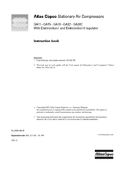
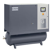
Instruction book
Atlas Copco Stationary Air Compressors
Instruction book
SF1 — SF2 — SF4 Skid -Tank-mounted
SF6 — SF8 Twin
SF6 — SF8 — SF11 — SF15 Multi
Copyright 2003, Atlas Copco Airpower n.v, Antwerp, Belgium.
Any unauthorized use or copying of the contents or any part thereof is prohibited. This applies in
particular to trademarks, model denominations, part numbers and drawings.
This instruction book meets the requirements for instructions specified by the machinery directive
98/37/EC and is valid for CE as well as non-CE labelled machines.
Note: The PED instructions for this machine are included at the end of the book.
No. 2920 1521 00
Registration code: APC SF / 38 / 980
2003-10
www.atlascopco.com
2920 1521 00
1
Summary of Contents for Atlas Copco Air Compressor
-
Page 1
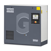
Atlas Copco Oil-injected rotary screw compressors GA 7 VSD+, GA 11 VSD+, GA 15 VSD+ Instruction book… -
Page 3
Atlas Copco Oil-injected rotary screw compressors GA 7 VSD+, GA 11 VSD+, GA 15 VSD+ From following serial No. onwards: API 250 000 Instruction book Original instructions Copyright notice Any unauthorized use or copying of the contents or any part thereof is prohibited. -
Page 4: Table Of Contents
Instruction book Table of contents Safety precautions………………….5 ……………………… 5 AFETY ICONS ………………….5 AFETY PRECAUTIONS GENERAL ………………. 6 AFETY PRECAUTIONS DURING INSTALLATION ………………..7 AFETY PRECAUTIONS DURING OPERATION …………….8 AFETY PRECAUTIONS DURING MAINTENANCE OR REPAIR General description…………………. 10 ……………………..10 NTRODUCTION ……………………..14 LOW DIAGRAM ……………………16…
-
Page 5
Instruction book 3.13 ………………….48 ODIFYING GENERAL SETTINGS 3.14 ……………………….50 NFO MENU 3.15 ………………………51 EEK TIMER MENU 3.16 ……………………….. 60 EST MENU 3.17 ……………………61 SER PASSWORD MENU 3.18 ……………………..62 EB SERVER 3.19 …………………….70 ROGRAMMABLE SETTINGS Installation……………………73 ……………………73 IMENSION DRAWINGS ……………………76 NSTALLATION PROPOSAL …………………….78 LECTRICAL CONNECTIONS… -
Page 6
Instruction book 7.11 ………………….112 TORAGE AFTER INSTALLATION 7.12 ………………….112 ISPOSAL OF USED MATERIAL Problem solving………………….113 Technical data………………….118 ……………………118 EADINGS ON DISPLAY ………………….119 LECTRIC CABLE SIZE AND FUSES ………………124 EFERENCE CONDITIONS AND LIMITATIONS ……………………125 OMPRESSOR DATA ® ………………127 ECHNICAL DATA LEKTRONIKON… -
Page 7: Safety Precautions
Instruction book Safety precautions Safety icons Explanation Danger for life Warning Important note Safety precautions, general General precautions 1. The operator must employ safe working practices and observe all related work safety requirements and regulations. 2. If any of the following statements does not comply with the applicable legislation, the stricter of the two shall apply.
-
Page 8: Safety Precautions During Installation
Instruction book Safety precautions during installation All responsibility for any damage or injury resulting from neglecting these precautions, or non observance of the normal caution and care required for installation, operation, maintenance and repair, even if not expressly stated, will be disclaimed by the manufacturer.
-
Page 9: Safety Precautions During Operation
Instruction book 16. Piping or other parts with a temperature in excess of 70˚C (158˚F) and which may be accidentally touched by personnel in normal operation must be guarded or insulated. Other high temperature piping must be clearly marked. 17. For water-cooled machines, the cooling water system installed outside the machine has to be protected by a safety device with set pressure according to the maximum cooling water inlet pressure.
-
Page 10: Safety Precautions During Maintenance Or Repair
Instruction book • Air cooling filters of the electrical cabinet are not clogged 9. If warm cooling air from compressors is used in air heating systems, e.g. to warm up a workroom, take precautions against air pollution and possible contamination of the breathing air. 10.
-
Page 11
Instruction book 12. Whenever there is an indication or any suspicion that an internal part of a machine is overheated, the machine shall be stopped but no inspection covers shall be opened before sufficient cooling time has elapsed; this to avoid the risk of spontaneous ignition of the oil vapor when air is admitted. 13. -
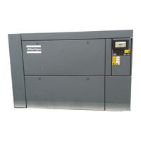
Page 12: General Description
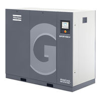
GA 7 VSD+ up to GA 15 VSD+ are single-stage, oil-injected screw compressors driven by an interior permanent magnet motor (iPM motor). The compressors are controlled by the Atlas Copco Elektronikon® Graphic regulator (ER). The regulator is fitted to the front panel. An electric cabinet (1) comprising fuses, transformers, relays, etc.
-
Page 13
Instruction book Open side view, GA VSD+ Workplace GA Workplace Full-Feature The Workplace Full Feature compressors have an air dryer which is integrated in the sound-insulated bodywork. The dryer removes condensate from the compressed air by cooling the air to near freezing point. 2920 7109 23… -
Page 14
Instruction book Front view, GA VSD+ Workplace Full-Feature Open side view, GA VSD+ Workplace Full-Feature Reference Name Air filter Air receiver 2920 7109 23… -
Page 15
Instruction book Reference Name Air outlet Air cooler Oil cooler Automatic condensate outlet Manual condensate outlet Refrigerant dryer Compressor element Electronic water drain Elektronikon® Graphic controller Cooling fan Drive motor Oil filter Oil separator Emergency stop button Electric cabinet 2920 7109 23… -
Page 16: Flow Diagram
Instruction book Flow diagram GA 7 VSD+ up to GA 15 VSD+ Workplace 2920 7109 23…
-
Page 17
Instruction book GA 7 VSD+ up to GA 15 VSD+ Workplace Full-Feature Reference Description Air inlet Air/oil mixture Wet compressed air Condensate 2920 7109 23… -
Page 18: Condensate System
Instruction book Reference Description Dry compressed air (Full-Feature) Air flow Air comes in through filter (AF) and inlet valve (IV) and is compressed in the compressor element (E). A mixture of compressed air and oil flows into the air receiver/oil separator (AR). The air flows through the minimum pressure valve (Vp), the air cooler (Ca) and the condensate trap (MT) to the outlet valve (AV).
-
Page 19
Instruction book Location of electronic water drain (Workplace) Location of electronic water drain (Workplace Full-Feature) On GA Workplace units, the water in the air condenses and collects in the collector of the air cooler. On a GA Workplace Full-Feature, the water in the air collects in the water separator of the heat exchanger/ evaporator. -
Page 20: Regulating System
Instruction book Electronic water drain (ED), typical example To test the electronic water drain, press the Test button (2) on top of the device. Regulating system Description When the compressor is started and the net pressure is below the setpoint, the motor speed increases until the net pressure reaches the setpoint or until the maximum motor speed is reached.
-
Page 21
Instruction book Electric cabinet, typical example Reference Designation Transformer Circuit breaker Circuit breaker Contactor EMC filter Frequency converter Electrical diagrams You find the complete electrical diagram inside the electric cabinet. 2920 7109 23… -
Page 22: Air Dryer
Instruction book Air dryer Flow diagram Air dryer Reference Name Air inlet Air outlet Air/air heat exchanger Air/refrigerant heat exchanger/evaporator Condensate separator Automatic drain / condensate outlet Refrigerant compressor Refrigerant condenser Liquid refrigerant dryer/filter Capillary Bypass valve Condenser cooling fan Pressure switch, fan control Liquid separator Compressed air circuit…
-
Page 23
Instruction book This causes the air to cool further close to the evaporating temperature of the refrigerant. More water in the air condenses. The cold air flows through the separator (3) where all the condensate gets out of the air. The condensate is automatically drained through the outlet (4). -
Page 24: Elektronikon® Graphic Controller
Instruction book Elektronikon® Graphic controller ® Elektronikon Graphic controller Control panel ® Display of the Elektronikon Graphic controller Introduction ® The Elektronikon controller has following functions: • Controlling the compressor • Protecting the compressor • Monitoring components subject to service •…
-
Page 25
For compressors leaving the factory, this function is made inactive. If desired, the function can be activated. Consult the Atlas Copco Customer Centre. If the function is activated and provided the regulator was in the automatic operation mode, the compressor will automatically restart if the supply voltage to the module is restored. -
Page 26: Control Panel
Instruction book Control panel Elektronikon regulator Control panel Parts and functions Reference Designation Function Display Shows the compressor operating condition and a number of icons to navigate through the menu. Pictograph Automatic operation Pictograph General alarm Alarm LED Flashes in case of a shut-down, is lit in case of a warning condition.
-
Page 27: Icons Used
Instruction book Icons used Status icons Name Icon Description Stopped / Running When the compressor is stopped, the icon stands still. When the compressor is running, the icon is rotating. Compressor status Motor stopped Running unloaded Running loaded Machine control mode Local start / stop Remote start / stop Network control…
-
Page 28
Instruction book Name Icon Description Active protection functions Emergency stop Shutdown Warning Service Service required Main screen display Value lines display icon Chart display icon General icons No communication / network problem Not valid Input icons Icon Description Pressure Temperature Digital input Special protection 2920 7109 23… -
Page 29
Instruction book System icons Icon Description Compressor element (LP, HP, …) Dryer Frequency converter Drain Filter Motor Failure expansion module Network problem General alarm Menu icons Icon Description Inputs Outputs Alarms (Warnings, shutdowns) Counters 2920 7109 23… -
Page 30
Instruction book Icon Description Test Settings Service Event history (saved data) Access key / User password Network Setpoint Info Navigation arrows Icon Description Down 2920 7109 23… -
Page 31: Main Screen
Instruction book Main screen Control panel Scroll keys Enter key Escape key Function The Main screen is the screen that is shown automatically when the voltage is switched on and one of the keys is pushed. It is switched off automatically after a few minutes when no keys are pushed. Typically, 5 different main screen views can be chosen: 1.
-
Page 32
Instruction book Text on figures Compressor Outlet Flow Load, shutdown, … (text varies upon the compressors actual condition) Menu Unload, ES,…(text varies upon the compressors actual condition) Typical Main screen (4 value lines) Text on figures Compressor Outlet Flow Off, Shutdown,… (text varies upon the compressors actual condition) Menu Running hours Element outlet… -
Page 33
Instruction book This bar shows the text that corresponds to the selected icon. • Section D shows the Action buttons. These buttons are used: • To call up or program settings • To reset a motor overload, service message or emergency stop •… -
Page 34
Instruction book When the Chart (Medium Resolution) is selected, the chart shows the variation of the selected input per hour. The screen shows the last 4 hours. When the Chart (Low Resolution) is selected, the chart shows the variation of the selected input per day. The screen shows the evolution over the last 10 days. -
Page 35: Calling Up Menus
Instruction book Calling up menus Control panel Control panel Scroll keys Enter key Escape key Description When the voltage is switched on, the main screen is shown automatically (see section Main screen): Typical Main screen (2 value lines) • To go to the Menu screen, select <Menu> (3), using the Scroll keys. •…
-
Page 36: Inputs Menu
Instruction book • The screen shows a number of icons. Each icon indicates a menu item. By default, the Pressure Settings (Regulation) icon is selected. The status bar shows the name of the menu that corresponds with the selected icon. •…
-
Page 37
Instruction book Text on image Inputs Compressor Outlet Element Outlet Ambient Air Emergency Stop • The screen shows a list of all inputs with their corresponding icons and readings. • If an input is in warning or shutdown, the original icon is replaced by the warning or shutdown icon respectively (i.c. -
Page 38: Outputs Menu
Instruction book Select Yes to remove or No to quit the current action. In a similar way, another input signal can be highlighted and selected as Main Chart signal: (1): Set as main chart signal Outputs menu Menu icon, Outputs Function To call up information regarding the actual status of some outputs such as the condition of the Fan overload contact (on air cooled compressors), the Emergency stop contact, etc.
-
Page 39
Instruction book Text on image Menu Regulation • Move the cursor to the Outputs icon (see above, section Menu icon, using the Scroll keys. • Press the Enter key. A screen similar to the one below appears: Outputs screen (typical) Text on image Outputs Fan motor… -
Page 40: Counters
Instruction book Counters Control panel Scroll keys Enter key Escape key Menu icon, Counters Function To call up: • The running hours • The loaded hours • The number of motor starts • The number of hours that the regulator has been powered •…
-
Page 41
Instruction book Text on figure Menu Regulation • Using the Scroll keys, move the cursor to the Counters icon (see above, section Menu icon) • Press the Enter key. Following screen appears: Text on figure Counters Running Hours Motor Starts Load Relay VSD 1-20 % rpm in % (the percentage of the time during which the motor speed was between 1 and 20 %) -
Page 42: Control Mode Selection
Instruction book Control mode selection Control panel Scroll keys Enter key Escape key Function To select the control mode, i.e. whether the compressor is in local control, remote control or controlled via a local area network (LAN). Procedure Starting from the main screen, make sure the button Menu (1) is selected: Next, use the scroll buttons to go to the regulation icon (2) and press the enter button: 2920 7109 23…
-
Page 43: Service Menu
Instruction book There are 3 possibilities: • Local control • Remote control • LAN (network) control After selecting the required regulation mode, press the enter button on the controller to confirm your selection. The new setting is now visible on the main screen. See section Icons used for the meaning of the icons.
-
Page 44
Instruction book • Using the Scroll keys, move the cursor to the Service icon (see above, section Menu icon). • Press the Enter key. Following screen appears: Text on image Service Overview Service Plan Next Service History • Scroll through the items to select the desired item and press the Enter key to see the details as explained below. -
Page 45
Instruction book warning when either 4000 running hours or 8760 real hours are reached, whichever comes first. Note that the real time hours counter keeps counting, also when the controller is not powered. The figures within the bars are the number of hours to go till the next service intervention. In the example above, the compressor was just started up, which means it still has 4000 running hours or 8280 hours to go before the next Service intervention. -
Page 46
Instruction book Modify the value as required using the ↑ or ↓ scroll key and press the Enter key to confirm. Note: Running hours and real time hours can be modified in steps of 100 hours. Next Service Text on image Next service Level Running Hours… -
Page 47: Modifying The Setpoint
Instruction book 3.11 Modifying the setpoint Control panel Scroll keys Enter key Escape key Menu icon, Setpoint Function On compressors with a frequency converter driven main motor, it is possible to program two different setpoints. This menu is also used to select the active setpoint. Procedure Starting from the Main screen, •…
-
Page 48
Instruction book Text on image Menu Regulation • Activate the menu by pressing the enter key. A screen similar to the one below appears: Text on image Regulation Setpoint 1 Indirect stop level 1 Direct stop level 1 Setpoint 2 Modify •… -
Page 49: Event History Menu
Instruction book The upper and lower limit of the setting is shown in grey, the actual setting is shown in black. Use the ↑ or ↓ key of the Scroll keys to modify the settings as required and press the Enter key to accept. If necessary, change the other settings as required in the same way as described above.
-
Page 50: Modifying General Settings
Instruction book Example of Event History screen • Scroll through the items to select the desired shutdown or emergency stop event. • Press the Enter key to find the date, time and other data reflecting the status of the compressor when that shutdown or emergency stop occurred.
-
Page 51
Instruction book This screen shows again a number of icons. By default, the User Password icon is selected. The status bar shows the description that corresponds with the selected icon. Each icon covers one or more items , such as •… -
Page 52: Info Menu
• Move the cursor to the action button Menu and press the Enter key. Following screen appears: Text on image Menu Regulation • Using the Scroll keys, move the cursor to the Info icon (see above, section Menu icon). • Press the Enter key. The Atlas Copco internet address appears on the screen. 2920 7109 23…
-
Page 53: Week Timer Menu
Instruction book 3.15 Week timer menu Control panel Scroll keys Enter key Escape key Menu icon, Week timer Function • To program time-based start/stop commands for the compressor • To program time-based change-over commands for the net pressure band • Four different week schemes can be programmed. •…
-
Page 54
Instruction book Text on figure Menu Week Timer • Press the Enter key on the controller. Following screen appears: Week Timer Week Action Schemes Week Cycle Status Week Timer Inactive Remaining Running Time The first item in this list is highlighted in red. Select the item requested and press the Enter key on the controller to modify. -
Page 55
Instruction book Week Action Schemes Week Action Scheme 1 Week Action Scheme 2 Week Action Scheme 3 Week Action Scheme 4 • A weekly list is shown. Monday is automatically selected and highlighted in red. Press the Enter key on the controller to set an action for this day. Week Action Scheme 1 Monday Tuesday… -
Page 56
Instruction book Monday Modify • A new pop-up window opens. Select an action from this list by using the Scroll keys on the controller. When ready press the Enter key to confirm. Monday Actions Remove Start Stop Pressure Setpoint 1 Modify •… -
Page 57
Instruction book Monday Start Save Modify • To adjust the time, use the Scroll keys on the controller and press the Enter key to confirm. Monday Start Save Modify • A pop-up window opens. Use the ↑ or ↓ key of Scroll keys to modify the values of the hours. Use the ←… -
Page 58
Instruction book Monday Start Save Modify • A new pop-up window opens. Use the Scroll keys on the controller to select the correct actions. Press the Enter key to confirm. Monday Are you sure? Save Modify Press the Escape key to leave this window. •… -
Page 59
Instruction book Monday — Start Tuesday Wednesday Thursday Friday Saturday Sunday Press the Escape key on the controller to leave this screen. Programming the week cycle A week cycle is a sequence of 10 weeks. For each week in the cycle, one of the four programmed week schemes can be chosen. -
Page 60
Instruction book Week 3 Week 4 Modify Press twice the Enter key on the controller to modify the first week. • A new window opens. Select the action, example: Week Action Scheme 1 Week Cycle Week 1 Week Action Scheme 1 Week Action Scheme 2 Week Action Scheme 3 Modify… -
Page 61
Instruction book Week Timer Week Week Timer Inactive Week 1 • Press the Escape key on the controller to leave this window. The status shows that week 1 is active. Week Timer Week Action Schemes Week Cycle Status Remaining Running Time •… -
Page 62: Test Menu
Instruction book Week Timer Week Action Schemes Week Cycle Status Remaining Running Time • This timer is used when the week timer is set and for certain reasons the compressor must continue working, for example, 1 hour, it can be set in this screen. This timer is prior to the Week Timer action.
-
Page 63: User Password Menu
Instruction book • Using the scroll keys (1), move the cursor to the test icon (see above, section Menu icon) • Press the enter key (2), following screen appears: Text on image Test Safety Valve Test Not allowed Audit Data •…
-
Page 64: Web Server
If both the web server functionality and SMARTBOX are required, please contact your local Atlas Copco Customer Center for support. Make sure you are logged in as administrator. • Use the internal network card from your computer or a USB to LAN adapter (see picture below).
-
Page 65
Instruction book USB to LAN adapter • Use a UTP cable (CAT 5e) to connect to the controller (see picture below). Configuration of the network card (in Windows XP) • Go to My Network places (1). • Click on View Network connections (1). 2920 7109 23… -
Page 66
Instruction book • Select the Local Area connection (1), which is connected to the controller. • Click with the right button and select properties (1). • Use the check box Internet Protocol (TCP/IP) (1) (see picture). To avoid conflicts, uncheck other properties if they are checked. -
Page 67
Instruction book • Use the following settings: • IP Address 192.168.100.200 • Subnetmask 255.255.255.0 Click OK and close network connections. Configuration of the web server Configure the web interface (for Internet Explorer) • Open Internet Explorer and click on Tools — Internet options (2). •… -
Page 68
Instruction book • In the Proxy server Group box, click on the Advanced button (1). • In the Exceptions Group box, enter the IP address of your controller. Multiple IP addresses can be given but they must be separated with semicolons (;). 2920 7109 23… -
Page 69
Instruction book Example: Suppose that you already added two IP addresses (192.168.100.1 and 192.168.100.2). Now you add 192.168.100.100 and separate the 3 IP addresses by putting semicolons between them (1) (see picture). Click OK (2) to close the window. Viewing the controller data All screen shots are indicative. -
Page 70
Instruction book Screen shot (example!) Navigation and options • The banner shows the compressor type and the language selector. In this example, three languages are available on the controller. Compressor settings All compressor settings can be displayed or hidden. Put a check mark in front of each point of interest and it will be displayed. -
Page 71
Instruction book Counters Lists all current counter values from controller and compressor. Info status Machine status is always shown on the web interface. Digital inputs Lists all Digital inputs and their status. Digital outputs Lists all Digital outputs and their status. 2920 7109 23… -
Page 72: Programmable Settings
Instruction book Special protections Lists all special protections of the compressor. Service plan Displays all levels of the service plan and their status. This screen shot underneath only shows the running hours. It is also possible to show the current status of the service interval. 3.19 Programmable settings Compressor/motor Minimum…
-
Page 73
The built-in service timers will give a Service warning message after their respective preprogrammed time interval has elapsed. For specific data, see section Preventive Maintenance. Consult Atlas Copco if a timer setting needs to be changed. The intervals must not exceed the nominal intervals and must coincide logically. See section Modifying general settings. -
Page 74
Proportional The settings for the Proportional band and integration time are determined by band and experiment. Altering these settings may damage the compressor. Consult Atlas Copco. integration time 2920 7109 23… -
Page 75: Installation
Instruction book Installation Dimension drawings Centre of gravity and weight Type Weight (mm) (mm) (mm) (kg) GA 7 VSD+ GA 11 VSD+ GA 15 VSD+ 2920 7109 23…
-
Page 76
Instruction book Centre of gravity and weight Type Weight (mm) (mm) (mm) (kg) GA 7 VSD+ 200-230V GA 7 VSD+ 500-575V GA 7 VSD+ FF 200-230V GA 7 VSD+ FF 380-460V GA 7 VSD+ FF 500-575V GA 11 VSD+ 200-230V GA 11 VSD+ 500-575V 2920 7109 23… -
Page 77
Instruction book Type Weight (mm) (mm) (mm) (kg) GA 11 VSD+ FF 200-230V GA 11 VSD+ FF 380-460V GA 11 VSD+ FF 500-575V GA 15 VSD+ 200-230V GA 15 VSD+ 500-575V GA 15 VSD+ FF 200-230V GA 15 VSD+ FF 380-460V GA 15 VSD+ FF 500-575V Dimensions +/- 10 mm Weights (oil included) +/- 10 kg… -
Page 78: Installation Proposal
Instruction book Installation proposal Compressor room example Text on image Ventilation proposals Minimum free area to be reserved for the compressor installation Description Compressor unit: Install the compressor unit on a solid, level floor suitable for taking the weight. Position of the compressed air outlet valve. 2920 7109 23…
-
Page 79
Atlas Copco has oil/water separators (type OSD or OSCi) to separate the major part of the oil from the condensate to ensure that the condensate meets the requirements of the environmental codes. -
Page 80: Electrical Connections
In this case, consult Atlas Copco. Also if operating above 1000 m (3300 ft), consult Atlas Copco. Moving/lifting The compressor can be moved by a lift truck using the slots in the frame. Take care not to damage the bodywork during lifting or transport.
-
Page 81
To use the machine in light industrial, commercial or residential environments with a shared supply network or in an IT network, extra measures can be required: contact Atlas Copco. Electrical connections for GA 7 VSD+ up to GA 15 VSD+… -
Page 82
Stop the compressor and switch off the voltage before connecting external equipment. Only potential free contacts are allowed. • LAN control: The compressor is controlled via a local network. Consult Atlas Copco. Compressor status indication The Elektronikon controller is provided with potential free auxiliary NO contacts (NO = normally open) (K05, K07 and K08) for remote indication of: •… -
Page 83: Pictographs
Instruction book Pictographs Pictographs Reference Designation Lock out/ tag out the compressor before starting maintenance or repairs Automatic condensate drain Manual condensate drain Lightly oil the gasket of the oil filter, screw it on and tighten by hand (approx. half a turn) Warning, hot surface Stop the compressor before cleaning the coolers Warning, voltage…
-
Page 84: Options
The Atlas Copco energy recovery (ER) systems are designed to recover most of the above-mentioned heat by transforming it into warm or hot water without any adverse influence on the compressor performance.
-
Page 85
Instruction book Energy recovery unit (ER-unit) Main components of the ER unit (typical installation) Reference Designation Water inlet pipe Water outlet pipe Temperature sensor, water inlet pipe Temperature sensor, water outlet pipe Oil drain valve Oil line from compressor oil separator vessel to ER unit Oil line from ER unit to oil filter housing Location of heat exchanger by-pass valve (BV2) Heat exchanger… -
Page 86
Instruction book Field installation The main components are assembled ex-factory as a compact unit which fits inside the bodywork of the compressor. Consult Atlas Copco for installing and connecting the energy recovery unit. 5.1.2 Energy recovery systems General The energy recovery systems can be applied as low temperature rise/high water flow systems or as high temperature rise/low water flow systems. -
Page 87
Instruction book 5.1.3 Operation Description The compressor oil flow is controlled by two thermostatic valves (BV1 and BV2), ensuring reliable compressor operation and optimum energy recovery. Bypass valve (BV1) is integrated in the oil filter housing of the compressor and controls the oil flow to the heat exchanger (HE) and the main oil cooler (Co) of the compressor. -
Page 88
Instruction book Flow diagram of compressor with energy recovery system 2920 7109 23… -
Page 89
Instruction book Reference Designation Reference Designation Thermostatic bypass valve of ER Oil filter unit Oil/water heat exchanger (ER Oil separator vessel unit) Compressor element Thermostatic bypass valve in oil filter housing Oil cooler (compressor) Aftercooler (compressor) Water inlet Water outlet BV1 starts closing the bypass line over the oil cooling circuit at the lower limit of its temperature range. -
Page 90
Instruction book Position of bypass ball valves ER label Attention: It is NOT allowed to use the ball valves at an in-between position! BV1 must have a higher opening temperature (set point) than BV2 in order to prevent the heat from being dissipated in the compressor oil cooler (Co) rather than in the oil/water heat exchanger (HE) when using the compression heat as source for energy recovery. -
Page 91
Instruction book Energy recovery system in use (see drawing) Bypass valves in position (A): the heat exchanger (HE) is integrated in the water side of the ER • Compressor start-up When the compressor is started up from cold, the oil temperature will be low. Bypass valve (BV1) shuts off the oil supply to the oil cooling system to prevent the compressor oil from being cooled. -
Page 92
To clean the oil side, soak the heat exchanger in a degreasing solution. To remove scale formation in the water compartment, a proper descaling process should be applied. Consult Atlas Copco. 5.1.5… -
Page 93
Instruction book Type of cooling system Materials Standard Energy recovery Recirculating (with tower) Containing copper 6.8 — 9.3 not applicable Stainless steel with carbon 6.8 — 9.3 steel and / or cast iron Stainless steel only 6 — 9.3 Closed loop Containing copper 7.5 — 9.3 7.5 — 9.3… -
Page 94
Instruction book • D : depends on the HCO concentration or M-alkalinity The values of A, B, C and D can be found in below table: Total Temperature Ca hardness dissolved (°C) (ppm CaCO Alkalinity solids (ppm (mg/l) CaCO < 30 0 — 1 9 — 11 10 — 11… -
Page 95
Instruction book RSI < 5.5 5.6 < RSI < 6.2 6.3 < RSI < 6.8 6.9 < RSI < 7.5 7.6 < RSI (ppm) For energy recovery systems, the limit is 100 ppm. 7. Sulphates (SO Sulphate (ppm) Type of cooling system Standard Energy recovery Single pass… -
Page 96
Instruction book If biology is present, it must be aerobic. Anaerobic biology (in closed systems) must be avoided. Biology (CFU/ml) Type of cooling system Standard Energy recovery Single pass < 10 / < 10 < 10 / < 10 Recirculating (with tower) not applicable <… -
Page 97: Main Switch
Instruction book Temperature input Minimum Nominal Maximum setting setting setting Water inlet temperature of energy recovery ˚C Water inlet temperature of energy recovery ˚F Energy recovery water outlet temperature ˚C Depends on application Energy recovery water outlet temperature ˚F Depends on application To modify a setting, consult the relevant section in the description of the Elektronikon controller.
-
Page 98
Instruction book Electrical connections Electric connection diagram (typical example) Reference Designation Main Switch Customer’s installation Note The complete electrical diagram can be found in the electrical cubicle 2920 7109 23… -
Page 99: Operating Instructions
Instruction book Operating instructions Initial start-up The operator must apply all relevant Safety precautions. Also consult section Problem solving. For the location of the air outlet valve and the drain connections, see sections Introduction Condensate system. Step Action Remove the canopy panel(s) in order to get access to the internal components. Remove the red transport spacers (1) and the related bolts under the motor.
-
Page 100
Instruction book Step Action Check the oil level. The oil level should reach the bottom of the oil filler neck (FC). Minimum level should reach the oil sight glass (GI) when the compressor is stopped. If needed, top up the oil. Take care that no dirt drops into the oil system. -
Page 101
Instruction book Step Action Open the air outlet valve. Start and run the compressor for a few minutes. Check that the compressor operates normally. Starting Control panel Elektronikon® Graphic Step Action Open the air outlet valve. Switch on the voltage. Check that voltage on LED (6) lights up. Press start button (1) on the control panel. -
Page 102
Instruction book A few minutes after stopping, the oil level should reach the bottom of the oil filler neck (FC). If the oil level is too low, wait until the compressor has depressurized. Push the emergency stop button (10) to avoid the compressor to start unexpectedly. Next, close the air outlet valve and open the manual drain valve (Dm) until the air system between oil separator/air receiver vessel and outlet valve is fully depressurized. -
Page 103
Instruction book been exceeded. Carry out the service actions of the indicated plans or replace the component and reset the relevant timer, see section Service menu. Stopping Step Action Press stop button (9). Automatic operation LED (8) goes out and the compressor stops. Close the air outlet valve. -
Page 104: Maintenance
For overhauling or carrying out preventive maintenance, service kits are available (see section Service kits). Service contracts Atlas Copco offers several types of service contracts, relieving you of all preventive maintenance work. Consult your Atlas Copco Customer Centre. General When servicing, replace all removed O-rings and washers.
-
Page 105
Instruction book Preventive maintenance schedule Daily and 3-monthly check list Period Operation Daily Check oil level. If needed, top up the oil (see section Operations instructions / During operation) Check readings on display. Check that condensate is discharged during operation. Drain condensate. -
Page 106
(see section Compressor data). Exposure of the compressor to external pollutants, operation at high humidity combined with low duty cycles or operation at higher temperatures may require a shorter oil exchange interval. Contact Atlas Copco if in doubt. Exchange interval for Roto-Inject Fluid… -
Page 107: Oil Specifications
Oil specifications It is strongly recommended to use genuine Atlas Copco Lubricants. They are the result of years of field experience and research. See section Preventive maintenance schedule for the advised replacement intervals and consult your Spare Parts list for part number information.
-
Page 108: Drive Motor
Roto-Foodgrade Fluid Special oil, delivered as an option. Atlas Copco’s Roto-Foodgrade Fluid is a unique high quality synthetic lubricant, specially created for oil injected screw compressors that provide air for the food industry. This lubricant keeps the compressor in excellent condition. Roto-Foodgrade Fluid can be used for compressors operating at ambient temperatures between 0 ˚C (32 ˚F) and 40 ˚C (104 ˚F).
-
Page 109: Oil, Oil Filter And Oil Separator Change
Instruction book Oil, oil filter and oil separator change Warning The operator must apply all relevant Safety precautions. Always drain the compressor oil at all drain points. Used oil left in the compressor can contaminate the oil system and can shorten the lifetime of the new oil. Never mix lubricants of different brands or types as they may not be compatible and the oil mix will have inferior properties.
-
Page 110
Instruction book Vent plug, oil cooler Workplace Full-Feature • Open the oil drain valve (Do). • Hold the oil drain hose (1) downward to drain the oil. • Disconnect the air hose (2) at the top on the vessel. • Move the hose downward to drain the oil from the element. •… -
Page 111: Coolers
Instruction book Take care that no dirt drops into the system. Refit and tighten filler plug (FC). 8. Run the compressor loaded for a few minutes. Stop the compressor. • Close the air outlet valve and switch off the voltage. •…
-
Page 112: Dryer Maintenance Instructions
Remove dirt from the fan with a fibre brush. • Clean with an air jet in the reverse direction to normal flow. • If it is necessary to wash the coolers with a cleaning agent, consult Atlas Copco. After maintenance on the fan and on the coolers: Remove the material that was used as cover.
-
Page 113: Safety Valves
Instruction book Be aware that certain components such as the refrigerant compressor and the discharge pipe can become quite hot (up to 110 °C — 230 °F). Therefore, wait until the dryer has cooled down before removing the panels. Before starting any maintenance or repair work, switch off the voltage and close the air inlet and outlet valves.
-
Page 114: Service Kits
Service kits For overhauling and for preventive maintenance, a wide range of service kits is available. Service kits comprise all parts required for servicing the component and offer the benefits of genuine Atlas Copco parts while keeping the maintenance budget low.
-
Page 115: Problem Solving
Instruction book Problem solving Warning Before carrying out any maintenance, repair work or adjustment, stop compressor, wait 3 minutes and close the air outlet valve. Press the test button on top of the electronic water drain until the air system between the air receiver and outlet valve is fully depressurized.
-
Page 116
If a problem is detected by the converter, a specific code (Main motor converter alarm) will appear on the Elektronikon display, together with a fault code. Below table lists the most important error codes. If another code appears, please contact Atlas Copco. 2920 7109 23… -
Page 117
Instruction book Typical display when the compressor is stopped by a shutdown Shutdown Navigate to the Stop icon or to the Protections icon and press Enter. Protections General The display shows the problem (Main Motor Converter Alarm) and a fault code (31 in this case). Main Motor Converter Alarm Fault 2920 7109 23… -
Page 118
Instruction book Fault code Cause Actions Overcurrent Contact Atlas Copco Ground fault Contact Atlas Copco Too high voltage. The voltage on the Check the supply voltage converter is above the specifications. Contact Atlas Copco. Too low voltage. The voltage on the Check the supply voltage converter is below the specifications. -
Page 119
Instruction book Condition Fault Remedy Shortage of refrigerant Have circuit checked for leaks and recharged Refrigerant compressor does See below not run Evaporator pressure too high See below Condenser pressure too high See below Condenser pressure too high Fan control switch out of Replace or too low order… -
Page 120: Technical Data
Instruction book Technical data Readings on display Elektronikon® Graphic controller Important The readings mentioned below are valid under the reference conditions (see section Reference conditions and limtations). Reference Reading Air outlet pressure Depends on the setpoint (desired net pressure). Compressor element Approx.
-
Page 121: Electric Cable Size And Fuses
Instruction book Electric cable size and fuses Important • The voltage on the compressor terminals must not deviate more than 10% of the nominal voltage. It is however highly recommended to keep the voltage drop over the supply cables at nominal current below 5% of the nominal voltage (IEC 60204-1). •…
-
Page 122
Instruction book Compressor type Max fuse fuse (1) GA 11 VSD+ 50 Hz 230 V 42.5 A 60 A 45.6 A 60 A GA 11 VSD+ 50 Hz 400 V + N 26.0 A 32 A GA 11 VSD+ 50 Hz 400 V 24.4 A 25 A… -
Page 123
Instruction book Fuse calculations for IEC are done according to 60364-4-43 electrical installations of buildings, part 4: protection for safety- section 43: protection against overcurrent. Fuse sizes are calculated in order to protect the cable against short circuit. Fuse calculations for cUL and UL: The indicated fuse size is the maximum fuse size in order to protect the motor against short circuit. -
Page 124
Instruction book Maximum allowed current in function of the ambient temperature for installation method C Ambient temperature Cable section 30 °C 40 °C 45 °C 50 °C 55 °C 4 mm² < 32 A < 28 A < 25 A <… -
Page 125
Instruction book • For supply cables larger than 35 mm²: half the size of the supply wires Always check the voltage drop over the cable (less than 5 % of the nominal voltage is recommended). Example: I = 89 A, maximum ambient temperature is 45 °C, recommended fuse = 100 A •… -
Page 126: Reference Conditions And Limitations
Instruction book • Size PE cable: • For supply cables up to AWG8: same size as the supply cables • For supply cables larger than AWG8: use maximum allowed ampacity of the selected supply cables and compare with value in table below (see CEC Part 1 table 17) <…
-
Page 127: Compressor Data
Instruction book Compressor data Reference conditions All data specified below apply under reference conditions, see section Reference conditions and limitations. Common compressor data Unit Number of compression stages Temperature of the air leaving the outlet valve (approx.), Workplace ˚C Temperature of the air leaving the outlet valve (approx.), Workplace ˚F Temperature of the air leaving the outlet valve (approx.), Workplace Full- ˚C…
-
Page 128
Instruction book GA 11 VSD+ Normal effective working pressure bar(e) 12.5 Normal effective working pressure psig Maximum effective working pressure, bar(e) Workplace Maximum effective working pressure, psig Workplace Maximum effective working pressure, bar(e) 12.75 12.75 12.75 12.75 Workplace Full-Feature Maximum effective working pressure, psig Workplace Full-Feature Maximum motor shaft speed… -
Page 129: Technical Data Elektronikon® Controller
Instruction book Oil capacity Oil capacity US gal 2.06 Oil capacity Imp. gal 1.72 Oil capacity cu. ft. 0.28 Sound pressure level (according to ISO 2151 (2004)) dB(A) Technical data Elektronikon® controller General Supply voltage 24 V AC /16 VA 50/60Hz (+40%/-30%) 24 V DC/0.7 A Type of protection IP54 (front)
-
Page 130
Instruction book Analog inputs Number of pressure inputs 2 (Elektronikon® Graphic controller — p.n. 1900 5200 10 …. 1900 5200 19) Number of temperature inputs 5 (Elektronikon® Graphic controller — p.n. 1900 5200 10 …. 1900 5200 19) 2920 7109 23… -
Page 131: Instructions For Use
Instruction book Instructions for use Air/oil separator vessel This vessel can contain pressurised air; this can be potentially dangerous if the equipment is misused. This vessel must only be used as a compressed air/oil separator and must be operated within the limits specified on the data plate. No alterations must be made to this vessel by welding, drilling or any other mechanical methods without the written permission of the manufacturer.
-
Page 132: Guidelines For Inspection
Instruction book Guidelines for inspection Guidelines On the Declaration of Conformity / Declaration by the Manufacturer, the harmonised and/or other standards that have been used for the design are shown and/or referred to. The Declaration of Conformity / Declaration by the Manufacturer is part of the documentation that is supplied with this compressor.
-
Page 133: Pressure Equipment Directives
Instruction book Pressure equipment directives Components subject to 97/23/EC Pressure Equipment Directive The following table contains the necessary information for the inspection of all pressure equipment of category II and higher according to the Pressure Equipment Directive 97/23/EC and all pressure equipment according to the Simple Pressure Vessel Directive 2009/105/EC.
-
Page 134: Declaration Of Conformity
Instruction book Declaration of conformity Typical example of a Declaration of Conformity document (1): Contact address: Atlas Copco Airpower n.v. P.O. Box 100 B-2610 Wilrijk (Antwerp) Belgium 2920 7109 23…
-
Page 135
Instruction book On the Declaration of Conformity / Declaration by the Manufacturer, the harmonized and/or other standards that have been used for the design are shown and/or referred to. The Declaration of Conformity / Declaration by the Manufacturer is part of the documentation that is supplied with this device. -
Page 138
Atlas Copco delivers the products and services that help to increase your business’ efficiency and profitability. Atlas Copco’s pursuit of innovation never ceases, driven by our need for reliability and efficiency. Always working with you, we are committed to providing you the customized quality air solution that is the driving force behind your business.