-
Contents
-
Table of Contents
-
Bookmarks
Quick Links
AT-GS950/8 Web Users Guide
AT-S107
[1.00.043]
613-001484 Rev A
AT-GS950/8
Gigabit Ethernet Smart Switch
Related Manuals for Allied Telesis AT-GS950/8
Summary of Contents for Allied Telesis AT-GS950/8
-
Page 1
AT-GS950/8 Gigabit Ethernet Smart Switch AT-GS950/8 Web Users Guide AT-S107 [1.00.043] 613-001484 Rev A… -
Page 2
Telesis, Inc. be liable for any incidental, special, indirect, or consequential damages whatsoever, including but not limited to lost profits, arising out of or related to this manual or the information contained herein, even if Allied Telesis, Inc. has been advised of, known, or should have known, the possibility of such damages. -
Page 3: Table Of Contents
Contents List of Figures …………………………9 List of Tables …………………………13 Preface …………………………..15 Where to Find Web-based Product Information………………16 Contacting Allied Telesis……………………..17 Online Support……………………….. 17 Email and Telephone Support ………………….17 Warranty ………………………… 17 Returning Products……………………..17 Sales or Corporate Information ………………….
-
Page 4
Contents SSL Settings…………………………. 56 Configuring SSL ……………………… 56 System Log Configuration …………………….. 58 Chapter 3 : Port Configuration ……………………61 Overview…………………………62 Display and Configure Ports……………………63 Chapter 4 : Port Mirroring ……………………..67 Overview…………………………68 Port Mirroring Configuration ……………………69 Disable Port Mirroring…………………….. -
Page 5
AT-GS950/8 Web Interface User Guide Chapter 9 : Multiple Spanning Tree Protocol ………………..131 Multiple Spanning Tree Configuration…………………. 132 Head2 …………………………132 VLAN Mapping ……………………….135 Open MSTP VLAN Mapping Page ………………..135 Create VLAN Mapping to MST Instance ………………. 135 Modify MST Instance……………………. -
Page 6
Contents Port List …………………………195 Create Port List ……………………..195 Modify Port List ……………………..196 Delete Port List………………………197 Policy …………………………..198 Create Policy……………………….198 Modify Policy ……………………….200 Delete Policy ……………………….201 Policy Sequence……………………….203 Chapter 14 : Storm Control ……………………..205 Overview…………………………206 Ingress Rate Limiting …………………….207 Egress Rate Limiting ……………………..207 Configuration ……………………….208 Ingress Rate Limiting……………………..210 Egress Rate Limiting ……………………..212… -
Page 7
AT-GS950/8 Web Interface User Guide Dial-in User — Local Authentication………………….252 Overview……………………….252 Dial-in User Configuration ……………………. 252 Destination MAC Filter ……………………..255 Overview……………………….255 Destination MAC Filter Configuration ………………..255 Delete Destination MAC Filter ………………….256 Chapter 19 : LLDP ……………………….257 Overview ………………………… -
Page 8
Contents Chapter 22 : RMON ………………………..287 Overview…………………………288 Enable and Disable RMON ……………………289 Port Statistics……………………….290 Histories…………………………291 Events………………………….293 Alarms …………………………295 Chapter 23 : Network Statistics ……………………299 Overview…………………………300 Traffic Comparison Statistics……………………301 Error Group Statistics ……………………..304 Historical Status Charts ……………………..306 Chapter 24 : Management Software Updates ………………..309 Overview…………………………310 Upgrade Firmware Image via HTTP………………….311 Upgrade Firmware Image via TFTP ………………….313… -
Page 9: List Of Figures
List of Figures Figure 1. Entering a Switch’s IP Address in the URL Field………………..20 Figure 2. Management Login Dialog Box …………………….. 20 Figure 3. AT-GS950/8 Switch Information Page…………………… 21 Figure 4. AT-GS950/8 Front Panel Page……………………… 22 Figure 5. IP Setup Page …………………………26 Figure 6.
-
Page 10
Figures Figure 51. LACP Group Status Page……………………..161 Figure 52. LACP Group Status Page with No Cables Connected ………………. 162 Figure 53. LACP Group Status Page with Three Cables Connected …………….163 Figure 54. AT-GS950/8 Port Priority Page……………………164 Figure 55. CoS Page …………………………. 171 Figure 56. -
Page 11
AT-GS950/8 Web Interface User Guide Figure 111. Firmware Upgrade via TFTP Page………………….. 313 Figure 112. Configuration Upload/Download via HTTP Page ………………315 Figure 113. File Download with HTTP ……………………..316 Figure 114. Result Page …………………………317 Figure 115. Configuration Upload/Download via TFTP Page………………318 Figure 116. -
Page 12
Figures… -
Page 13: List Of Tables
List of Tables Table 1. Bridge Priority Value Increments ………………113 Table 2. Valid Port Priority Values ………………..115 Table 3. Default Mappings Priority Levels to Priority Queues …………167 Table 4. Customized Mappings Priority Levels to Priority Queues ……….167 Table 5.
-
Page 14
List of Tables… -
Page 15: Preface
The AT-S107 Management software has a web browser interface that you can access from any management workstation on your network that has a web browser application. This preface contains the following sections: “Where to Find Web-based Product Information” on page 16 “Contacting Allied Telesis” on page 17 …
-
Page 16: Where To Find Web-Based Product Information
Preface Where to Find Web-based Product Information The product guides are available for all Allied Telesis products in portable document format (PDF) on our web site. Management software updates are also available. Go to www.alliedtelesis.com/support.
-
Page 17: Contacting Allied Telesis
Select your country from the list Support displayed on the website. then select the appropriate menu tab. Warranty For hardware warranty information, refer to the Allied Telesis web site at www.alliedtelesis.com/support/warranty. Returning Products for return or repair must first be assigned a return materials authorization (RMA) number.
-
Page 18
Preface… -
Page 19: Chapter 1 : Starting A Web Browser Session
Chapter 1 Starting a Web Browser Session This chapter contains the procedures for starting, using, and quitting a web browser management session on the AT-GS950/8 switch. This chapter includes the following sections: “Establishing a Remote Connection to the Web Browser Interface” on …
-
Page 20: Establishing A Remote Connection To The Web Browser Interface
The AT-GS950/8 switch is shipped with a pre-assigned IP address of 192.168.1.1. After your initial login, Allied Telesis suggests that you assign a new IP address to your switch. To manually assign an IP address to the switch, refer to “Configuration of IP Address, Subnet Mask and Gateway Address”…
-
Page 21: Figure 3. At-Gs950/8 Switch Information Page
AT-GS950/8 Web Interface User Guide 3. Enter the AT-S107 management login user name and password. The default user name is “manager” and the default password is “friend.” The login name and password are case-sensitive. 4. Press OK. The AT-GS950/8 Switch Information page is displayed. See Figure 3. Note To change the user name and password, refer to “User Name and Password Configuration”…
-
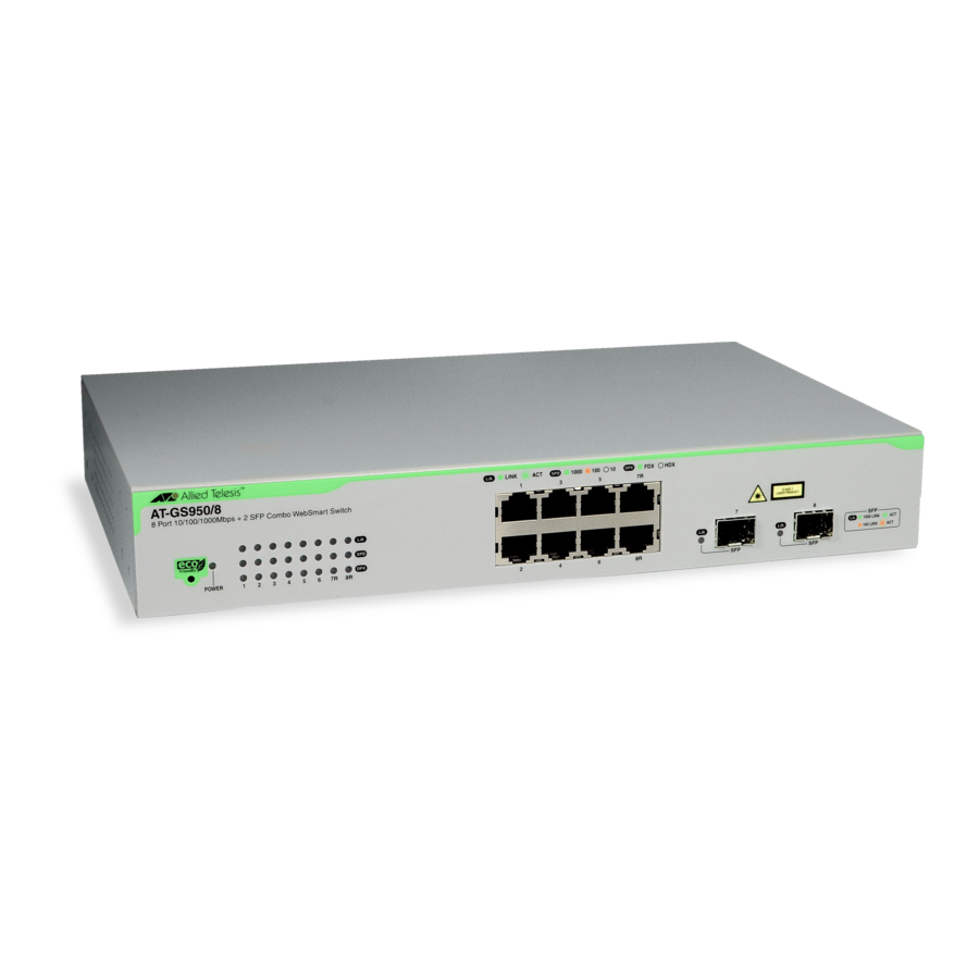
Page 22: Figure 4. At-Gs950/8 Front Panel Page
Chapter 1: Starting a Web Browser Session Security LLDP Statistics Chart Tools Save Configuration 5. To see the front panel of the switch, select Front Panel from the main menu on the left side of the page. The AT-S107 Management software displays the front of the switch.
-
Page 23: Web Browser Tools
AT-GS950/8 Web Interface User Guide Web Browser Tools You can use the web browser tools to move around the management pages. Selecting Back on your browser’s toolbar returns you to the previous display. You can also use the browser’s Bookmark feature to save the link to the switch.
-
Page 24: Quitting A Web Browser Management Session
Chapter 1: Starting a Web Browser Session Quitting a Web Browser Management Session To exit a web browser management session, close the web browser.
-
Page 25: Chapter 2 : Basic Switch Configuration
Chapter 2 Basic Switch Configuration This chapter provides procedures to configuring basic system parameters for the AT-GS950/8 switch and contains information for the following sections: “Configuration of IP Address, Subnet Mask and Gateway Address” on page 26 “IP Access List Configuration” on page 28 …
-
Page 26: Configuration Of Ip Address, Subnet Mask And Gateway Address
Chapter 2: Basic Switch Configuration Configuration of IP Address, Subnet Mask and Gateway Address This procedure explains how to change the IP address, subnet mask, and gateway address of the switch. Before performing the procedure, note the following: A gateway address is only required if you want to remotely …
-
Page 27
AT-GS950/8 Web Interface User Guide System Default Gateway — Displays the default gateway of the switch. To change the default gateway, enter a new gateway. When DHCP is enabled, you cannot change this parameter. DHCP Mode — For information about setting this parameter, refer to “DHCP Client Configuration”… -
Page 28: Ip Access List Configuration
Chapter 2: Basic Switch Configuration IP Access List Configuration When the IP Access List feature is enabled, remote access to the AT-S107 management software is restricted to the IP addresses entered into the IP Access List. The procedures in this section describe how to enable or disable the IP Access List feature and how to add or remove IP addresses from the list.
-
Page 29
AT-GS950/8 Web Interface User Guide Note You can add up to 10 IP address to the IP Access List table. -
Page 30: Delete An Ip Address List Entry
Chapter 2: Basic Switch Configuration 5. From the IP Restriction Status field, select one of the following choices from the pull-down menu: Enable — This selection restricts the access to the AT-S107 management software to the IP addresses in the table listed under Accessible IP.
-
Page 31: System Time
AT-GS950/8 Web Interface User Guide System Time The procedures in this section describe how to configure the system time by manually entering the time or through SNTP and how to configure the daylight savings time feature. See the following sections: “Manually Setting System Time”…
-
Page 32: Setting Sntp
Chapter 2: Basic Switch Configuration 3. Use the pull down menu to set the Clock Mode parameter to Local time. 4. In the Local Time Settings section, set the Date Setting (YYYY:MM:DD) to the current date in the YYYY:MM:DD format. 5.
-
Page 33: Setting Daylight Savings Parameters
AT-GS950/8 Web Interface User Guide Setting Daylight If you want to configure the switch for daylight savings time, perform the following procedure: Savings Parameters 1. From the main menu on the left side of the page, click the System folder. The System folder expands.
-
Page 34: Dhcp And Ati Web Discovery Tool
Chapter 2: Basic Switch Configuration DHCP and ATI Web Discovery Tool The AT-GS950/8 Gigabit Ethernet Smart switch is managed through a web browser interface only. The factory default IP address is 192.168.1.1. The switch does not have a local console connector, which means that you cannot learn what the switch’s management IP address is on a web browser without first knowing what the address is.
-
Page 35: Dhcp Client Configuration
AT-GS950/8 Web Interface User Guide DHCP Client Configuration This procedure explains how to activate and deactivate the DHCP client on the AT-GS950/8 switch. When the client is activated, the switch obtains its IP configuration including an IP address and subnet mask from a DHCP server on your network.
-
Page 36
Chapter 2: Basic Switch Configuration Note The ATI Web Discovery Tool is available for download on the AT- GS950/8 product page at alliedtelesis.com. 6. Follow the procedure to log on with the new IP address provided by the DHCP Server as described in “Establishing a Remote Connection to the Web Browser Interface”… -
Page 37: Dhcp Auto Configuration
AT-GS950/8 Web Interface User Guide DHCP Auto Configuration If you need to automatically update the switch’s configuration files via a remote server, the DHCP Auto Configuration feature is available for this purpose via the DHCP server. Note You must enable the DHCP client so that this feature can operate with the DHCP server.
-
Page 38: System Management Information
Entering this information is optional. Note Allied Telesis recommends that you assign a name to the switch. Naming each switch can help you identify the specific switch you want to manage among others. It can also help to avoid performing a configuration procedure on the wrong switch.
-
Page 39
AT-GS950/8 Web Interface User Guide System Name — Specifies a name for the switch, for example, Sales. The name is optional and may contain up to 15 characters. System Location — Specifies the location of the switch. The location is optional and may contain up to 30 characters. System Contact — Specifies the name of the network administrator responsible for managing the switch. -
Page 40: User Name And Password Configuration
Chapter 2: Basic Switch Configuration User Name and Password Configuration Password protection is always enabled for access to the AT-S107 Management software. This section explains how to create new users names and passwords and how to modify or delete existing users for the web interface.
-
Page 41: Modify User Name And Password
AT-GS950/8 Web Interface User Guide 4. To add a password that corresponds to the user name entered in step 3, enter a password of up to 12 alphanumeric characters in the box next to the Password field. The Password field is case sensitive. 5.
-
Page 42: Delete User Name And Password
Chapter 2: Basic Switch Configuration Delete User Name To delete a user name that you have previously added, perform the following procedure. and Password 1. From the main menu on the left side of the page, click the System folder. The System folder expands.
-
Page 43: User Interface Configuration
AT-GS950/8 Web Interface User Guide User Interface Configuration This procedure explains how to enable and disable the user interfaces on the switch. With this procedure you can enable or disable the AT-GS950/8 SNMP Agent. For more information about SNMP, go to Chapter 20, “Simple Network Management Protocol SNMPv1 and v2c”…
-
Page 44: User Interface Timeout
Chapter 2: Basic Switch Configuration Note See Chapter 20, “Simple Network Management Protocol SNMPv1 and v2c” on page 263 and Chapter 21, “Simple Network Management Protocol SNMPv3” on page 273 to configure the remaining SNMP parameters. 4. Click Apply located under the Web Server Status Enable/Disable field.
-
Page 45: System Information Display
AT-GS950/8 Web Interface User Guide System Information Display The Switch Information page is initially displayed when you first log into the AT-GS950/8 switch. It provides general information about the switch. To view this information, perform the following procedure: 1. From the main menu on the left side of the page, select Switch Info. The Switch Information Page is displayed.
-
Page 46
Chapter 2: Basic Switch Configuration Administration Information Section: Switch Name — This parameter displays the name assigned to the switch. To assign the switch a name, refer to “System Management Information” on page 38. Switch Location — This parameter displays the location of the switch. -
Page 47: Switch Reboot
AT-GS950/8 Web Interface User Guide Switch Reboot You can reboot the AT-GS950/8 switch by either pressing the front panel eco-friendly switch between 5 to 9 seconds or by using the Normal reboot function provided in the AT-S107 management software. In addition to rebooting the switch, you have the option to reset the AT-GS950/8 switch configuration parameters to the original factory default settings.
-
Page 48: Switch Reboot
Allied Telesis has no knowledge of it. You are responsible for keeping the password in a safe place. If it is lost, Allied Telesis does not have a way to help you recover it. See “Disabling Factory Default Reset Feature” on page 51 for information about how to disable the factory default reset feature.
-
Page 49: Configure Factory Default Values
AT-GS950/8 Web Interface User Guide Figure 14. Factory Default Reset/Reboot Page 3. Go to the lower part of the page to the Reboot section. 4. In the Reboot Type field, select Normal from the pull-down menu. When the switch is rebooted with this selection, all configuration parameters that are saved in flash memory are loaded into the switch’s active memory.
-
Page 50
Chapter 2: Basic Switch Configuration To return the AT-S107 Management software to the default settings, perform the following procedure: Note See “AT-GS950/8 Default Parameters” on page 347 for the specific factory default values. 1. From the main menu on the left side of the page, select the Tools folder. -
Page 51: Disabling Factory Default Reset Feature
5. In the New Password field, enter a password of up to 12 characters in length. It is case-sensitive. There is not a default password for this field. Caution Since you define this password as part of the process of disabling this function, Allied Telesis has no knowledge of it. You are…
-
Page 52: Enabling Factory Default Reset
Chapter 2: Basic Switch Configuration responsible for keeping the password in a safe place. If it is lost, Allied Telesis does not have a way to help you recover it. 6. Re-enter the same password in the Confirm Password field.
-
Page 53: Figure 17. Factory Default Reset/Reboot Page With Password Entry
AT-GS950/8 Web Interface User Guide Note If the Factory Default Reset field is already set to Enable, you do not need to continue with this procedure. 4. To enable the factory default reset feature, select Enable on the pull- down menu of the Factory Default Reset field. The Factory Default Reset/Reboot Page changes to include a Password field for entering a password.
-
Page 54: Pinging A Remote System
Chapter 2: Basic Switch Configuration Pinging a Remote System This procedure instructs the AT-GS950/8 switch to ping a node on your network. This procedure is useful in determining whether an active link exists between the switch and another network device. Note The device you are pinging must be a member of the Default VLAN and within the same local area network as your switch.
-
Page 55: Figure 19. Ping Test Results Page
AT-GS950/8 Web Interface User Guide 5. To view the ping results, click Show Ping Results. A sample Ping Test Results Page is displayed. See Figure 19. Figure 19. Ping Test Results Page The following information is displayed: Destination IP Address — Indicates the IP address of the unit that receives the ping.
-
Page 56: Ssl Settings
Chapter 2: Basic Switch Configuration SSL Settings The AT-GS950/8 switch has a web browser server for remote management of the unit with a web browser application from management workstations on your network. By default, the server operates in a non-secure HTTP mode and can be configured to communicate in a secure HTTPS mode with SSL protocol.
-
Page 57
AT-GS950/8 Web Interface User Guide 4. Click Apply. The SSL setting that you have selected is now active. 5. From the main menu on the left side of the page, select Save Configuration to Flash to permanently save your changes. -
Page 58: System Log Configuration
Chapter 2: Basic Switch Configuration System Log Configuration The System log is designed to monitor the operation the AT-GS950/8 switch by recording the event messages it generates during normal operation. These events may provide vital information about system activity that can help in the identification and solutions of system problems.
-
Page 59
AT-GS950/8 Web Interface User Guide 3. From the Syslog Status field, select one of the following choices from the pull-down menu: Enable — The System log is active. Disable — The System log is inactive. 4. From the Time Stamp field, select one of the following choices from the pull-down menu: Enable — Each event message recorded in the log will have a time stamp recorded with it. -
Page 60
Chapter 2: Basic Switch Configuration… -
Page 61: Chapter 3 : Port Configuration
Chapter 3 Port Configuration This chapter provides a description of the physical characteristics of the ports and a procedure that explains how to view and change the port settings. This chapter includes the following sections: “Overview” on page 62 “Display and Configure Ports”…
-
Page 62: Overview
Chapter 3: Port Configuration Overview This chapter describes how to display and modify the physical characteristics of an AT-GS950/8 switch. You can display and modify the settings of all the ports on one web page. The port characteristics that are displayed are: Trunk Group Number …
-
Page 63: Display And Configure Ports
AT-GS950/8 Web Interface User Guide Display and Configure Ports This procedure explains how to configure the ports on the AT-GS950/8 switch using the Port Configuration Page. This page allows you to view and configure the parameter settings of individual or all the switch ports at one time.
-
Page 64
Chapter 3: Port Configuration twisted-pair ports (1 through 6, 7R and 8R) and 100FX or 1000TX for the SFP ports (7 and for copper or fiber SFP type. Link Status — This parameter indicates the status of the link between the port and the end node connected to the port.
 -
Page 65
AT-GS950/8 Web Interface User Guide Mode -This parameter i Indicates the speed and duplex mode settings for the port. You can use this parameter to set the speed and duplex mode of a port. The possible settings are: Ignore -This parameter i Indicates that the All setting does not apply to the Mode field. -
Page 66
Chapter 3: Port Configuration Ignore — This parameter indicates that the All setting does not apply to the Flow Control field. In other words, each port is set individually. Enabled — This parameter indicates that the port is permitted to use flow control. -
Page 67: Chapter 4 : Port Mirroring
Chapter 4 Port Mirroring This chapter describes the Port Mirroring feature and the procedure for setting up port mirroring. Port mirroring allows you to unobtrusively monitor the ingress and egress traffic on a port by having the traffic copied to another port.
-
Page 68: Overview
Chapter 4: Port Mirroring Overview The port mirroring feature allows you to unobtrusively monitor the traffic received and transmitted on one or more ports by copying the traffic to another switch port. You can connect a data analyzer to the port where the traffic is copied and monitor the traffic on the other ports without impacting network performance or speed.
-
Page 69: Port Mirroring Configuration
AT-GS950/8 Web Interface User Guide Port Mirroring Configuration To configure Port Mirroring, perform the following procedure: 1. Select the Bridge folder. The Bridge folder expands. 2. From the Bridge folder, select Mirroring. The Mirroring Page is displayed. See Figure 23. Figure 23.
-
Page 70
Chapter 4: Port Mirroring 7. From the main menu on the left side of the page, select Save Configuration to Flash to permanently save your changes. -
Page 71: Disable Port Mirroring
AT-GS950/8 Web Interface User Guide Disable Port Mirroring To disable Port Mirroring, perform the following procedure: 1. Select the Bridge folder. The Bridge folder expands. 2. From the Bridge folder, select Mirroring. The Mirroring page is shown in Figure 23 on page 69. 3.
-
Page 72
Chapter 4: Port Mirroring… -
Page 73: Chapter 5 : Virtual Lans
Chapter 5 Virtual LANs This chapter contains a description of Virtual Local Area Networks (VLANs) and the procedures for creating, modifying, and deleting both port-based and tagged VLANs. This chapter contains the following sections: “VLAN Overview” on page 74 “Assign Ports to a VLAN Mode”…
-
Page 74: Vlan Overview
Chapter 5: Virtual LANs VLAN Overview A virtual LAN or VLAN is a group of ports on an Ethernet switch that form a logical Ethernet segment via the AT-S107 Management software. The ports of a VLAN form an independent traffic domain where the traffic generated by the nodes of a VLAN remains within the VLAN.
-
Page 75: Port-Based Vlan Overview
AT-GS950/8 Web Interface User Guide With VLANS, you can reconfigure the LAN segment assignment of an end node connected to the AT-GS950/8 switch’s management software. Also, you can change the VLAN memberships without moving the workstations physically or change group memberships without moving cables from one port to another.
-
Page 76: Tagged Vlan Overview
Chapter 5: Virtual LANs Each port of a port-based VLAN can belong to as many VLANs as needed. Therefore, traffic can be forwarded to the members of the groups to which the port is assigned. For example, port 1 and port 2 are members of group 1 and ports 1 and 3 are members of group 2.
-
Page 77
AT-GS950/8 Web Interface User Guide VLAN Name To create a tagged VLAN, you must give it a unique name. This name can reflect the function of the network devices that are VLAN members, such as Sales, Production, and Engineering. Tagged and Untagged Ports When you specify that a port is a member of a tagged VLAN, you need to specify that it is tagged or untagged. -
Page 78
Chapter 5: Virtual LANs General Rules for Creating a Tagged VLAN Here is a summary of the rules to observe when you create a tagged VLAN: Assign a unique name to each tagged VLAN. Each tagged VLAN must be assigned a unique VLAN ID. If a … -
Page 79: Assign Ports To A Vlan Mode
AT-GS950/8 Web Interface User Guide Assign Ports to a VLAN Mode The procedure described in this section allows you to assign ports to tagged or a port-based VLAN. In addition, it permits you to display the current VLAN assignment of ports. However, you can assign ports to a port-based VLAN only after you have created a port-based VLAN with the procedure described in “Port-Based VLAN Configuration”…
-
Page 80
Chapter 5: Virtual LANs 6. If you want to restore the port assignment before saving the configuration, click Restore. Note Once the VLAN assignment has been saved by clicking first on the Apply button and then saving the configuration, the Restore button will not be active for those port assignments. -
Page 81: Tagged Vlan Configuration
AT-GS950/8 Web Interface User Guide Tagged VLAN Configuration On a port, the tag information within a frame is examined when it is received to determine if the frame is qualified as a member of a specific tagged VLAN. If it is, it is eligible to be switched to other member ports of the same VLAN.
-
Page 82: Modify A Tagged Vlan
Chapter 5: Virtual LANs 4. To assign a VLAN ID, type a VLAN ID in the VLAN ID field. The range for this field is 2 to 4,000. You can create a maximum of 255 tagged VLANs. 5. To assign a name to the VLAN, type a unique name in the VLAN Name field.
-
Page 83: Figure 26. Example Of At-Gs950/8 Tagged Vlan Page
AT-GS950/8 Web Interface User Guide 2. From the Bridge folder, select VLAN. The VLAN folder expands. 3. From the VLAN folder, select Tagged VLAN. An example of a tagged VLAN (VLAN2) is shown in the table at the bottom of Figure 26 on page 83. Figure 26.
-
Page 84
Chapter 5: Virtual LANs 6. To change the VLAN Name, type a new VLAN Name in the VLAN Name field. For more information about this field, refer to “VLAN Name” on page 75. -
Page 85: Delete A Tagged Vlan
AT-GS950/8 Web Interface User Guide 7. To change the Management VLAN assignment, select one of the following choices from the pull-down menu: Enable — This parameter enables Management VLAN on this VLAN. The Management VLAN will be disabled on all other VLANs and only be operational on this VLAN.
-
Page 86
Chapter 5: Virtual LANs Note You cannot delete the Default VLAN which has a VID of 1. 6. From the main menu on the left side of the page, select Save Configuration to Flash to permanently save your changes. -
Page 87: Tagged Vlan Port Settings
AT-GS950/8 Web Interface User Guide Tagged VLAN Port Settings To configure a VLAN port that is a member of a Tagged VLAN, perform the following procedure: 1. From the main menu on the left side of the page, select Bridge. The Bridge folder expands.
-
Page 88
Chapter 5: Virtual LANs Disable — This disables Ingress Filtering at the selected port. 6. Click Apply. The port configuration becomes effective. 7. If you need to configure other ports of the switch for the VLAN Port Settings, repeat steps 4 through 7. 8. -
Page 89: Port-Based Vlan Configuration
AT-GS950/8 Web Interface User Guide Port-Based VLAN Configuration A port-based VLAN is a group of ports on the switch that form a logical Ethernet segment. This type of VLAN is independent of the header information including VLAN tags in a frame. You can create and delete Port-Based VLANs by following the procedures in the following sections: “Create a Port-Based VLAN”…
-
Page 90: Modify A Port-Based Vlan
Chapter 5: Virtual LANs 7. Click Apply. 8. From the main menu on the left side of the page, select Save Configuration to Flash to permanently save your changes. Modify a Port- To modify the name or port assignments of a port-based VLAN, perform the following procedure: Based VLAN 1.
-
Page 91
AT-GS950/8 Web Interface User Guide The Bridge folder expands. 2. From the Bridge folder, select VLAN. The VLAN folder expands. 3. From the VLAN folder, select Port-Based VLAN. The Port-Based VLAN Page is shown in Figure 29 on page 89. 4. -
Page 92
Chapter 5: Virtual LANs… -
Page 93: Chapter 6 : Gvrp
Chapter 6 GVRP This chapter contains the following sections: “Overview and Guidelines” on page 94 “General Configuration” on page 95 “Port Settings” on page 96 “Time Settings” on page 98 …
-
Page 94: Overview And Guidelines
The default port setting on the switch for GVRP is active, meaning that the ports participate in GVRP. Allied Telesis recommends disabling GVRP on those ports that are connected to GVRP- inactive devices, meaning devices that do not feature GVRP.
-
Page 95: General Configuration
AT-GS950/8 Web Interface User Guide General Configuration Perform the following procedure to enable or disable GVRP: 1. From the main menu on the left side of the page, select Bridge. The Bridge folder expands. 2. From the Bridge folder, select GVRP. The GVRP folder expands.
-
Page 96: Port Settings
Chapter 6: GVRP Port Settings Perform the following procedure to configure the GVRP port settings: 1. From the main menu on the left side of the page, select Bridge. The Bridge folder expands. 2. From the Bridge folder, select GVRP. The GVRP folder expands.
-
Page 97
AT-GS950/8 Web Interface User Guide Disable — The Restricted VLAN Registration is de-active for the port row selected. 5. Once you have configured the parameters, click Apply for the affected port. 6. If you want to configure GVRP for other ports, repeat steps 4 and 5. 7. -
Page 98: Time Settings
Chapter 6: GVRP Time Settings Perform the following procedure to configure the GVRP port settings: 1. From the main menu on the left side of the page, select Bridge. The Bridge folder expands. 2. From the Bridge folder, select GVRP. The GVRP folder expands.
-
Page 99
AT-GS950/8 Web Interface User Guide equation: GARPLeaveAllTimer > (GARPLeaveTimer + 10) Note To ensure compatibility between network devices, you need to configure the same values for the GARP Join Timer, GARP Leave Timer, and GARP Leave All Timer on all participating GVRP devices in your network. -
Page 100
Chapter 6: GVRP… -
Page 101: Chapter 7 : Voice Vlan
Chapter 7 Voice VLAN This chapter contains a description of the AT-GS950/8 switch’s Voice VLAN feature and the procedures to create, modify, and delete a voice VLAN configuration. This chapter contains the following sections: “Overview” on page 102 “General Guidelines” on page 105 …
-
Page 102: Overview
Chapter 7: Voice VLAN Overview The AT-GS950/8 Voice VLAN feature is specifically designed to maintain high quality, uninterrupted voice traffic through the switch. When talking on a voice over IP phone, a user expects to have no interruptions in the conversation and excellent voice quality.
-
Page 103: Dynamic Auto-Detection Vs Static Ports
AT-GS950/8 Web Interface User Guide When you are configuring the voice VLAN parameters, you must enter the complete MAC address of at least one of your IP phones. An “OUI Mask” is automatically generated and applied by the AT-S107 management software to yield the manufacturer’s OUI.
-
Page 104
Chapter 7: Voice VLAN One or more ports in your voice VLAN must be configured as Static tagged or untagged members. Static VLAN members are permanent member ports of the voice VLAN and there is no dependency on the configuration of the devices connected to the ports. These ports might be connected to other voice VLAN network nodes such as other Ethernet switches, a telephone switch, and/or a DHCP server. -
Page 105: General Guidelines
AT-GS950/8 Web Interface User Guide General Guidelines Here is a summary of the rules to observe when you create a voice VLAN: One voice VLAN can be configured on the switch at any time. A voice VLAN is based on a pre-defined tagged VLAN. …
-
Page 106: Configuration
Chapter 7: Voice VLAN Configuration Prior to configuring your voice VLAN, you must first configure a tagged VLAN. This VLAN will be used as a basis for your voice VLAN. Note See “Create a Tagged VLAN” on page 81 for more information about configuring a tagged VLAN with Not Member and Static tagged ports.
-
Page 107
AT-GS950/8 Web Interface User Guide 4. From the Voice VLAN field at the top of the page, select one of the following choices from the pull-down menu: Enable — The voice VLAN feature is active. The other parameter fields in the voice VLAN Global Settings section become active and are eligible for data to be entered. -
Page 108
Chapter 7: Voice VLAN Note The voice VLAN Auto-Detection feature can only be enabled on “Not Member” ports of the voice VLAN. Member ports cannot have the voice VLAN Auto-Detection feature enabled. The Status column displays Static for the member ports. See “Dynamic Auto-Detection vs Static Ports”… -
Page 109: Oui Setting
AT-GS950/8 Web Interface User Guide OUI Setting You can create and delete Voice VLAN OUI Settings by following the procedures in these sections: “Create OUI Setting” “Modify OUI Setting” on page 110 Create OUI To create a Voice OUI configuration, perform the following procedure: Setting 1.
-
Page 110: Modify Oui Setting
Chapter 7: Voice VLAN Modify OUI To modify or delete an OUI, it must be first be deleted and then re-entered by following the procedure in “Create OUI Setting” on page 109. Setting Delete OUI To delete an OUI, perform the following procedure: Setting 1.
-
Page 111: Chapter 8 : Stp And Rstp
Chapter 8 STP and RSTP This chapter provides background information about the Spanning Tree Protocol (STP) and the Rapid Spanning Tree Protocol (RSTP). In addition, there are procedures to configure STP and RSTP. The sections in the chapter include: “Overview” on page 112 …
-
Page 112: Overview
Chapter 8: STP and RSTP Overview The performance of a Ethernet network can be negatively impacted by the formation of a data loop in the network topology. A data loop exists when two or more nodes on a network can transmit data to each other over more than one data path.
-
Page 113: Bridge Priority And The Root Bridge
AlliedWare Plus Version 2.1.2 Management Software Web Browser User’s Guide Bridge Priority The first task that bridges perform when a spanning tree protocol is activated on a network is the selection of a root bridge. A root bridge and the Root distributes network topology information to the other network bridges and Bridge is used by the other bridges to determine if there are redundant paths in…
-
Page 114: Port Priority
Chapter 8: STP and RSTP Path Costs and Port Costs After the root bridge has been selected, the bridges determine if the network contains redundant paths and, if one is found, select a preferred path while placing the redundant paths in a backup or blocking state. Where there is only one path between a bridge and the root bridge, the bridge is referred to as the designated bridge and the port through which the bridge is communicating with the root bridge is referred to as the root…
-
Page 115: Forwarding Delay And Topology Changes
AlliedWare Plus Version 2.1.2 Management Software Web Browser User’s Guide Table 2. Valid Port Priority Values Port Step Priority Forwarding If there is a change in the network topology due to a failure, removal, or addition of any active components, the active topology also changes. This Delay and may trigger a change in the state of some blocked ports.
-
Page 116
Chapter 8: STP and RSTP The forwarding delay value is adjustable in the AT-S107 Management software. The appropriate value for this parameter depends on a number of variables; the size of your network is a primary factor. For large networks, you should specify a value large enough to allow the root bridge sufficient time to propagate a topology change throughout the entire network. -
Page 117: Figure 36. Point-To-Point Ports
AlliedWare Plus Version 2.1.2 Management Software Web Browser User’s Guide Figure 36. Point-to-Point Ports A port operates as an edge port when it is connected to a network terminal device such as a workstation or a server. An edge port on a bridge should not have any STP or RSTP devices connected to it either directly or through another device connected to that port.
-
Page 118: Mixed Stp And Rstp Networks
RSTP Networks network can operate together to create a single spanning tree domain. If you decide to activate spanning tree on the switch, Allied Telesis recommends RSTP instead of STP even when all of other switches in the network are running STP. The AT-GS950/8 switch can combine RSTP with the STP of the other switches.
-
Page 119: Figure 38. Stp And Vlan Fragmentation With Untagged Ports
AlliedWare Plus Version 2.1.2 Management Software Web Browser User’s Guide Figure 38. STP and VLAN Fragmentation with Untagged Ports You can avoid this problem by connecting the switches using tagged instead of untagged ports when you plan to have STP or RSTP enabled on your network.
-
Page 120: Figure 39. Stp And Vlan Compatibility With Tagged Ports
Chapter 8: STP and RSTP Figure 39. STP and VLAN Compatibility with Tagged Ports Note For information about tagged and untagged ports, refer to Chapter 5, “VLAN Overview” on page 74.
-
Page 121: Basic Stp And Rstp Configuration
AlliedWare Plus Version 2.1.2 Management Software Web Browser User’s Guide Basic STP and RSTP Configuration To configure the basic STP and RSTP settings, perform the following procedure: 1. From the main menu on the left side of the page, select Bridge. The Bridge folder expands.
-
Page 122
Chapter 8: STP and RSTP The RSTP Configuration page allows you to configure basic STP (STP-Compatible) or RSTP protocols as well as to view current settings of the feature. In the upper portion of the page, you can set the following … -
Page 123
AlliedWare Plus Version 2.1.2 Management Software Web Browser User’s Guide The following parameters refer to the designated root bridge. You cannot change these fields. Designated Root — This parameter includes two fields: the root bridge priority and the MAC address of the root bridge. For example, 1000 00C08F1211BB shows the root bridge priority as 1000, and 00C08F1211BB as the MAC address. -
Page 124: Configure Rstp Port Settings
Chapter 8: STP and RSTP Configure RSTP Port Settings This section contains the following topics: “Configure the Basic RSTP Port Settings” “Configure the Advanced RSTP Port Settings” on page 126 Configure the To configure the basic RSTP port settings, perform the following procedure: Basic RSTP Port Settings…
-
Page 125
AlliedWare Plus Version 2.1.2 Management Software Web Browser User’s Guide sent or received on a the port except for BPDU data. A port with a higher path cost to the root bridge than another on the switch will cause a switching loop and is placed in the blocking state by the Spanning Tree algorithm. -
Page 126: Configure The Advanced Rstp Port Settings
Chapter 8: STP and RSTP STP Status — Indicates if spanning tree protocol (either RSTP or STP-Compatible) is active or not on the port. Select one of the following choices from the pull-down menu: Enable — The spanning tree protocol (both RSTP or STP- Compatible) is enabled on the port.
-
Page 127: Figure 42. At-Gs950/8 Rstp Advanced Port Configuration Page
AlliedWare Plus Version 2.1.2 Management Software Web Browser User’s Guide Figure 42. AT-GS950/8 RSTP Advanced Port Configuration Page This page displays the following information about the ports: Port — Indicates ports 1 through 8 on the AT-GS950/8 switch. Use the All row to apply the same settings to the STP Status, Priority, and Path Cost fields to all the ports on your switch.
-
Page 128
Chapter 8: STP and RSTP Disabled — The Disabled Port role is assigned if the port is not operational or is excluded from the active topology by management or it is a network access port (IEEE Std 802.1X) and it is Unauthorized, or its Administrative Bridge Port state is Disabled. -
Page 129: Spanning Tree Topology
AlliedWare Plus Version 2.1.2 Management Software Web Browser User’s Guide Spanning Tree Topology To view the current spanning tree topology, perform the following procedure: 1. From the main menu on the left side of the page, select Bridge. This folder expands. 2.
-
Page 130
Chapter 8: STP and RSTP… -
Page 131: Chapter 9 : Multiple Spanning Tree Protocol
Chapter 9 Multiple Spanning Tree Protocol This chapter provides the procedures for configuring Multiple Spanning Tree Protocol (MSTP). You can find an overview and configuration guidelines for this feature in “MSTP Overview” on page 327. When you configure MSTP, the information should be entered in order on the following web pages: “Multiple Spanning Tree Configuration”…
-
Page 132: Multiple Spanning Tree Configuration
Chapter 9: Multiple Spanning Tree Protocol Multiple Spanning Tree Configuration Head2 Head3 To configure the MSTP settings, perform the following procedure: 1. From the main menu on the left side of the page, select Bridge. The Bridge folder expands. 2. From the Bridge folder, select the Spanning Tree folder. The Spanning Tree folder expands.
-
Page 133
AT-GS950/8 Web Interface User Guide Global MSTP Status — Set this field to Enable or Disable the MSTP feature on the switch. The Global MSTP Status must be set to Enable before the other MSTP configuration parameters can be set. Note Both RSTP and BPDU Passthrough must be disabled before you enable MSTP. -
Page 134
Chapter 9: Multiple Spanning Tree Protocol bridge spends in the listening and learning states. Its range is 4 — 30 seconds. Maximum Hop Count — The Maximum Hop Count is a parameter set in a BPDU packet when it originates. It is decremented by 1 each time it is retransmitted by the next bridge. -
Page 135: Vlan Mapping
AT-GS950/8 Web Interface User Guide VLAN Mapping You can create, modify and delete MSTP settings with the procedures in the following sections: ”Open MSTP VLAN Mapping Page” ”Create VLAN Mapping to MST Instance”. “Modify MST Instance” on page 136. …
-
Page 136: Modify Mst Instance
Chapter 9: Multiple Spanning Tree Protocol Modify MST If you wish to modify a MST Instance, you must first delete the instance and then redefine it. Refer to “Create VLAN Mapping to MST Instance” on Instance page 135 for more information. Delete MST 1.
-
Page 137: Port Configuration
AT-GS950/8 Web Interface User Guide Port Configuration To configure the MSTP parameters for each of the ports, perform the following procedure: 1. From the main menu on the left side of the page, select Bridge. The Bridge folder expands. 2. From the Bridge folder, select the Spanning Tree folder. The Spanning Tree folder expands.
-
Page 138
Chapter 9: Multiple Spanning Tree Protocol network topology. ForcedFalse — The port is not connected to a network device in the network topology. Auto — The switch will automatically determine the port type. Edge Port — Indicates if a port is connected to an edge device in the network topology or not. -
Page 139
AT-GS950/8 Web Interface User Guide True — The port cannot process receive/transmit TCN BPDUs. False — The port can process receive/transmit TCN BPDU packets. 5. Once you have configured the parameters, click Apply in the Action column. 6. If you choose to change the MSTP port configuration for other ports, repeat steps 4 and 5. -
Page 140: Port Settings
Chapter 9: Multiple Spanning Tree Protocol Port Settings To configure the MSTP port settings, perform the following procedure: 1. From the main menu on the left side of the page, select Bridge. The Bridge folder expands. 2. From the Bridge folder, select the Spanning Tree folder. The Spanning Tree folder expands.
-
Page 141
AT-GS950/8 Web Interface User Guide 6. If you choose to change the MSTP port settings for other ports, repeat steps 4 and 5. 7. From the main menu on the left side of the page, select Save Configuration to Flash to permanently save your changes. -
Page 142: Topology Information
Chapter 9: Multiple Spanning Tree Protocol Topology Information To configure the MSTP port settings, perform the following procedure: 1. From the main menu on the left side of the page, select Bridge. The Bridge folder expands. 2. From the Bridge folder, select the Spanning Tree folder. The Spanning Tree folder expands.
-
Page 143
AT-GS950/8 Web Interface User Guide Regional Root Priority — The priority of the regional root port. Regional Path Cost — The path cost from the regional root port to the regional root bridge. Type — This specifies the regional port type which can be either a point-to-point or an edge type port. -
Page 144
Chapter 9: Multiple Spanning Tree Protocol… -
Page 145: Chapter 10 : Static Port Trunking
Chapter 10 Static Port Trunking This chapter contains a description of port trunking and the procedures for creating, modifying, and deleting a static port trunk. The following topics are discussed: “Overview” on page 146 “Create a Port Trunk” on page 149 …
-
Page 146: Overview
Chapter 10: Static Port Trunking Overview A port trunk is an economical way for you to increase the bandwidth between the Ethernet switch and another networking device, such as a network server, router, workstation, or another Ethernet switch. A port trunk is a group of ports that have been grouped together to function as one logical path.
-
Page 147
General Guidelines Following are the guidelines for creating a static trunk: Allied Telesis recommends setting static port trunks between Allied Telesis networking devices to ensure compatibility. A static trunk can contain up to eight ports. -
Page 148
Chapter 10: Static Port Trunking more than one VLAN. The ports of a static trunk can be either untagged or untagged members of the same VLAN. The switch selects a port in the trunk to handle broadcast packets and packets of unknown destination. -
Page 149: Create A Port Trunk
AT-GS950/8 Web Interface User Guide Create a Port Trunk This procedure explains how to create a static port trunk. Caution Do not connect the cables of a port trunk to the ports on the switch until you have configured the ports on both the switch and the end nodes.
-
Page 150
Chapter 10: Static Port Trunking A check in a box indicates the port is a member of the trunk. No check means the port is not a member. A port trunk can contain up to eight ports. 5. Change the Trunk Status from Disable to another setting. The choice in the status field are the following: Active — The specific aggregator will broadcast and respond to LACPDU (LACP Data Unit) packets. -
Page 151: Modify A Port Trunk
AT-GS950/8 Web Interface User Guide Modify a Port Trunk This procedure explains how to change the status of a port trunk and add or remove ports from a port trunk. Caution Before you disable or modify a port trunk, disconnect all of the cables from the ports of the trunk.
-
Page 152
Chapter 10: Static Port Trunking 9. Configure the port trunk on the other switch with the same parameters. 10. Connect the Ethernet cables between trunk ports on the AT-GS950/8 switch and the trunk ports on the other switch. -
Page 153: Disable A Port Trunk
AT-GS950/8 Web Interface User Guide Disable a Port Trunk This procedure explains how to disable a port trunk. Caution Before you disable or modify a port trunk, disconnect all of the cables from the ports of the trunk. Leaving the cables connected during the reconfiguration of a trunk can create loops in your network topology.
-
Page 154
Chapter 10: Static Port Trunking… -
Page 155: Chapter 11 : Lacp Port Trunks
AT-GS950/8 Web Interface User Guide Chapter 11 LACP Port Trunks This chapter contains overview information about LACP port trunks and the procedures for setting this feature. This chapter contains the following sections: “System Priority” on page 157 “Port Priority Value” on page 157 …
-
Page 156: Overview
802.3ad standard, making it interoperable with equipment from other vendors that also comply with the standard. Therefore, you can create an LACP trunk between an Allied Telesis device and network devices from other manufacturers. Another advantage is that ports in an LACP trunk can function in a standby mode.
-
Page 157: System Priority
AT-GS950/8 Web Interface User Guide System Priority It is possible for two devices interconnected by an aggregate trunk to encounter a conflict when they form the trunk. For example, the two devices might not support the same number of active ports in an aggregate trunk or might not agree on which ports are active and which are in standby mode.
-
Page 158
Chapter 11: LACP Port Trunks Two conditions must be met for a port in an aggregate trunk to function in the standby mode. First, the number of ports in the trunk must exceed the highest allowed number of active ports and, second, the port must be receiving LACPDU packets from the other device. -
Page 159: General Guidelines
The port with the highest priority in an aggregate trunk carries broadcast packets and packets with an unknown destination. Prior to creating an aggregate trunk between an Allied Telesis device and another vendor’s device, refer to the vendor’s documentation to determine the maximum number of active ports the device can support in a trunk.
-
Page 160
Chapter 11: LACP Port Trunks the maximum number for the AT-GS950/8 switch, you should assign the other vendor’s device a higher system LACP priority than your AT-GS950/8 switch. This can help avoid a conflict between the devices if some ports are placed in the standby mode when the devices create the trunk. -
Page 161: Group Status
AT-GS950/8 Web Interface User Guide Group Status To display the LACP Group Status, perform the following procedure: 1. Select the Bridge folder. The Bridge folder expands. 2. From the Bridge folder, select the Trunk Config folder. The Trunk Config folder expands. 3.
-
Page 162: Configuration Example
Chapter 11: LACP Port Trunks The System Priority is a preassigned value that you cannot alter. This value applies to the switch. See “System Priority” on page 157. The System ID is a MAC address value assigned to the individual switch.
-
Page 163: Figure 53. Lacp Group Status Page With Three Cables Connected
AT-GS950/8 Web Interface User Guide Figure 53. LACP Group Status Page with Three Cables Connected You can now see that each port has been grouped under a single aggregator since the ports are now in a Link-Up status.
-
Page 164: Port Priority Configuration
Chapter 11: LACP Port Trunks Port Priority Configuration To select a priority for an LACP port, perform the following procedure: 1. Select the Bridge folder. The Bridge folder expands. 2. From the Bridge folder, select the Trunk Config folder. The Trunk Config folder expands. 3.
-
Page 165: Chapter 12 : Quality Of Service (Cos)
Chapter 12 Quality of Service (CoS) This chapter contains the following topics: “Overview” on page 166 “Associate Ports to CoS Priorities” on page 173 “Associate DSCP Classes to Egress Queues” on page 174 “Queue Scheduling Algorithm” on page 175 …
-
Page 166: Overview
Chapter 12: Quality of Service (CoS) Overview When a port on an Ethernet switch becomes oversubscribed, its egress queues contain more packets than the port can handle in a timely manner. In this situation, the port may be forced to delay the transmission of some packets, resulting in the delay of packets reaching their destinations.
-
Page 167: Egress Queue Vs Packet Priority Mapping
AT-GS950/8 Web Interface User Guide Egress Queue vs Each switch port has four egress queues, labeled Q0, Q1, Q2, and Q3. Q0 is the lowest priority queue and Q3 is the highest. A packet in a high Packet Priority priority egress queue is typically transmitted sooner than a packet in a low Mapping priority queue.Table 3 lists the default mappings between the eight CoS priority levels and the four egress queues of a switch port.
-
Page 168: Prioritizing Untagged Packets
Chapter 12: Quality of Service (CoS) The procedure for changing the default mappings is found in “Associate Ports to CoS Priorities” on page 173. Note that because all ports must use the same priority-to-egress queue mappings, these mappings are applied at the switch level.
-
Page 169
AT-GS950/8 Web Interface User Guide have time to process the packets waiting in the lower priority queues. -
Page 170: Table 5. Example Of Weighted Round Robin Priority
Chapter 12: Quality of Service (CoS) Weighted Round Robin Priority Scheduling The weighted round robin (WRR) scheduling method functions as its name implies. The port transmits a set number of packets from each queue, in a round robin fashion, so that each has a chance to transmit traffic.Normally, the higher the queue’s priority the more packets are transmitted in as the algorithm cycles through the queues in turn.
-
Page 171: Mapping Cos Priorities To Egress Queues
AT-GS950/8 Web Interface User Guide Mapping CoS Priorities to Egress Queues Before mapping the CoS priorities and the egress queues, you must disable the Jumbo frame parameter on each port. See the Jumbo parameter definition in “Display and Configure Ports” on page 63. Note When Jumbo frames are enabled, COS can not be enabled.
-
Page 172
Chapter 12: Quality of Service (CoS) 4. For each Traffic Class whose queue you want to change, click on the Queue (0, 1, 2, or 3) radio button that applies to your configuration. 5. After you have completed this mapping process, select Enable in the QoS Status field, 6. -
Page 173: Associate Ports To Cos Priorities
AT-GS950/8 Web Interface User Guide Associate Ports to CoS Priorities The Port Priority values is assigned to an untagged frame at ingress for internal processing in the switch. This procedure explains how to change the default mappings of port priorities to the User Priority. This is set at the switch level.
-
Page 174: Associate Dscp Classes To Egress Queues
Chapter 12: Quality of Service (CoS) Associate DSCP Classes to Egress Queues If you choose to use the DSCP tags in your Access Control policy configuration, each DSCP value (0-63) that is relevant to your configuration needs to be mapped to one of the four egress queues (0-3).
-
Page 175: Queue Scheduling Algorithm
AT-GS950/8 Web Interface User Guide Queue Scheduling Algorithm To change the scheduling algorithm for the egress queues, perform the following procedure. 1. From the main menu on the left side of the page, select Bridge. The Bridge folder expands. 2. From the Bridge folder, select QoS. The QoS folder expands.
-
Page 176
Chapter 12: Quality of Service (CoS) -
Page 177: Chapter 13 : Access Control Configuration
Chapter 13 Access Control Configuration Access Control configuration allows you to control different aspects of the Ethernet traffic as it enters the switch ports and is process through the switch. You can specify what traffic is permitted or denied to flow through the switch by setting up specific filter criteria at an ingress port.
-
Page 178: Classifier
Chapter 13: Access Control Configuration Classifier The Create Classifier page allows you to specify packet settings for filtering Ethernet traffic. You can create, modify or delete a Classifier by following the procedures in the following sections: “Create Classifier,” next “Modify Classifier”…
-
Page 179
AT-GS950/8 Web Interface User Guide 3. Enter a number in the Classifier Index field. The Classifier Index must be a unique number within the range of 1 — 65535. Note The Classifier Index is a required parameter when you create a Policy. -
Page 180: Modify Classifier
Chapter 13: Access Control Configuration 5. Click ADD. The classifier entry is displayed in the table at the bottom of the page. If you do not see you new entry, you may need to navigate to another page of the table with the First Page, Previous Page, Next Page, and Last Page buttons located below the table.
-
Page 181: Delete Classifier
AT-GS950/8 Web Interface User Guide 3. From the Create Classifier page, identify which classifier that want to modify and click the modify link in the Action column. The Modify Classifier page is displayed in Figure 61. Figure 61. Modify Classifier Page 4.
-
Page 182
Chapter 13: Access Control Configuration 3. From the Create Classifier page, identify which classifier table entry that want to delete and click the Delete button in the Action column. You will be prompted with a message saying, “Do you want to delete classifier xxxx?”… -
Page 183: Profile Action
AT-GS950/8 Web Interface User Guide Profile Action The Create Profile Action page defines the priority parameters for policing on DSCP (layer 3) and/or class of service (layer 2). Note You must enter a Profile Index on this page even if you do not define the Policed-DHCP and Policed-CoS parameters because the Profile Index is a required parameter for creating both the In-Profile and Out-Profile Actions.
-
Page 184: Modify Profile Action
Chapter 13: Access Control Configuration 3. Enter a number in the Profile Action Index field. The Index must be a unique number ranging from 1 to 72. 4. Enter a number in the Policed DSCP field within the range of 0 to 63. This field indicates the DSCP level of interest.
-
Page 185: Delete Profile Action
AT-GS950/8 Web Interface User Guide 2. From the Access Control Config folder, select Profile Action. An example of the Create Profile Action page with a Profile Action table entry is shown in Figure 64 on page 185. 3. Select the table entry that you want to modify and click the modify link in the Action column.
-
Page 186
Chapter 13: Access Control Configuration 4. Click on the OK button. The profile action entry is deleted from the profile action table. 5. From the main menu on the left side of the page, select Save Configuration to Flash to permanently save your changes. -
Page 187: In-Profile Action
AT-GS950/8 Web Interface User Guide In-Profile Action The Create In-Profile Action page allows you to specify a Profile Action’s Permit or Deny privilege for packets in the ingress queue. Note A Profile Action Index is required to create an In-Profile Action. See “Create Profile Action”…
-
Page 188: Figure 66. Example Of In-Profile Action Entry
Chapter 13: Access Control Configuration 4. Enter a number in the Profile Action ID field ranging from 0 to 72. This field is mandatory. Note This field must be pre-defined on the Create Profile page — see “Create Profile Action” on page 183 for more information. 5.
-
Page 189: Modify In-Profile Action
AT-GS950/8 Web Interface User Guide Modify In-Profile To modify a In-Profile action entry, perform the following procedure: Action Note You must first enter a In-Profile action before you can modify it. See “Create In-Profile Action” on page 187 for more information. 1.
-
Page 190: Delete In-Profile Action
Chapter 13: Access Control Configuration Delete In-Profile To delete a In-Profile action entry, perform the following procedure: Action 1. From the main menu on the left side of the page, select the Access Control Config folder. The Access Control Config folder expands. 2.
-
Page 191: Out-Profile Action
AT-GS950/8 Web Interface User Guide Out-Profile Action The Create Out-Profile Action page allows you to specify a Profile Action’s Permit or Deny privilege and bandwidth restrictions for packets in the egress queue. You can create, modify or delete an Out-Profile Action by following the procedures in the following sections: “Create Out-Profile Action,”…
-
Page 192: Figure 69. Example Of Out-Profile Action Entry
Chapter 13: Access Control Configuration 4. Enter a number in the Profile Action ID field ranging from 0 to 72. This field is mandatory. Note This field must be pre-defined on the Create Profile page — see “Create Profile Action” on page 183 for more information. 5.
-
Page 193: Modify Out-Profile Action
AT-GS950/8 Web Interface User Guide Modify Out- To modify a Out-Profile action entry, perform the following procedure: Profile Action Note Before you can modify an entry, you must first enter a Out-Profile action — see “Create In-Profile Action” on page 187. 1.
-
Page 194: Delete Out-Profile Action
Chapter 13: Access Control Configuration Delete Out- To delete a Out-Profile action entry, perform the following procedure: Profile Action 1. From the main menu on the left side of the page, select the Access Control Config folder. The Access Control Config folder expands. 2.
-
Page 195: Port List
AT-GS950/8 Web Interface User Guide Port List The Create Port List page allows you to specify a list of ports that will be used as part of the policy specification. You can create, modify or delete a Port List by following the procedures in the following sections: “Create Port List,”…
-
Page 196: Modify Port List
Chapter 13: Access Control Configuration 5. Click Add. The Out-Profile Action entry is added to the status table. If the Page field located below the table displays a page number and you do not see your new entry, then there are multiple pages of the table that you can navigate.
-
Page 197: Delete Port List
AT-GS950/8 Web Interface User Guide Figure 73. Modify Port List Page 4. Change the parameters as required. Note See “Create Port List” on page 195 for the definitions of each parameters. 5. Click Apply. The modified Port List entry is displayed in the table at the bottom of the page of the Create Port List page.
-
Page 198: Policy
Chapter 13: Access Control Configuration Policy The Create Policy page allows you to specify the filtering criteria for one policy. Before creating a policy, you must pre-define the following indexes: Classifier Index — See “Create Classifier” on page 178 for more information.
-
Page 199
AT-GS950/8 Web Interface User Guide 3. Enter a number in the Policy Index field. The Policy Index is a unique number within the range of 1 — 65535 which identifies the policy. This field is mandatory. 4. Enter data in the remaining parameters. All parameters listed below must be entered to form the policy: Classifier Index — The Classifier Index is a unique number within the range of 1 — 65535. -
Page 200: Modify Policy
Chapter 13: Access Control Configuration Figure 75. Example of Policy Entry 6. From the main menu on the left side of the page, select Save Configuration to Flash to permanently save your changes. Modify Policy To modify a Policy entry, perform the following procedure: Note Before you can modify an entry, you must first enter a Policy — see “Create Policy”…
-
Page 201: Delete Policy
AT-GS950/8 Web Interface User Guide Figure 76. Modify Policy Page 4. Change the parameters as required. Note See “Create Policy” on page 198 for the definitions of each parameters. 5. Click Apply. The modified Policy entry is displayed in the table at the bottom of the page of the Create Policy page.
-
Page 202
Chapter 13: Access Control Configuration 2. From the Access Control Config folder, select Policy. An example of the Create Policy page with a Policy table entry is shown in Figure 75 on page 200. 3. From the Create Policy page, identify which Policy table entry that want to delete and click the Delete button in the Action column. -
Page 203: Policy Sequence
AT-GS950/8 Web Interface User Guide Policy Sequence The Policy Sequence page displays the order that policies are applied to each port. You can order the display by Policy Index or by Policy Sequence number. To display the policy sequence, perform the following procedure: 1.
-
Page 204
Chapter 13: Access Control Configuration… -
Page 205: Chapter 14 : Storm Control
Chapter 14 Storm Control This chapter contains a description and configuration procedures for the Storm Control (bandwidth) feature. The following topics are discussed: “Overview” on page 206 “Configuration” on page 208 “Ingress Rate Limiting” on page 210 “Egress Rate Limiting”…
-
Page 206: Overview
Chapter 14: Storm Control Overview The features available in the AT-S107 Management software allow you to limit Ethernet traffic within your switch based on specific criteria. You can use Storm Control to limit the bandwidth of various types of Ethernet packets.
-
Page 207: Ingress Rate Limiting
AT-GS950/8 Web Interface User Guide Ingress Rate The Ingress Rate Limiting feature restricts the traffic to a pre-configured data rate that can flow into a port. This data rate limit can be configured in Limiting 64 Kbps increments within a range from 64 Kbps to 1000 Mbps. The formula for calculating the bandwidth limit is as follows: Bandwidth = 64Kbps x rate limit The rate limit parameter is an integer ranging from 1 to 15625.
-
Page 208: Configuration
Chapter 14: Storm Control Configuration This procedure explains how to set DLF, broadcast, multicast, and threshold levels for each port on the AT-GS950/8 switch. To change the settings of the storm control feature, perform the following procedure: 1. From the main menu on the left side of the page, select the Bridge folder.
-
Page 209
AT-GS950/8 Web Interface User Guide Note For more information, see the Broadcast setting definition in“Overview” on page 206. 7. Click Apply. 8. To enable or disable ingress and egress Multicast packets, select Enable or Disable from the Multicast pull-down menu next to the port that you want to change. -
Page 210: Ingress Rate Limiting
Chapter 14: Storm Control Ingress Rate Limiting This procedure explains how to set Bandwidth levels and Status for Ingress Rate Limiting on each port of the AT-GS950/8 switch. To change the settings of the ingress rate limiting feature, perform the following procedure: 1.
-
Page 211
AT-GS950/8 Web Interface User Guide 7. From the main menu on the left side of the page, select Save Configuration to Flash to permanently save your changes. -
Page 212: Egress Rate Limiting
Chapter 14: Storm Control Egress Rate Limiting This procedure explains how to set Bandwidth levels and Status for Egress Rate Limiting on each port of the AT-GS950/8 switch. To change the settings of the egress rate limiting feature, perform the following procedure: 1.
-
Page 213: Chapter 15 : Mac Address Table
Chapter 15 MAC Address Table This chapter contains a description of the static multicast MAC address feature and the procedure for configuring it. This chapter includes the following sections: “Overview” on page 214 “Static Unicast MAC Address Configuration” on page 216 …
-
Page 214: Overview
Chapter 15: MAC Address Table Overview The AT-GS950/8 switch has a MAC address table with a storage capacity of up to 8,000 entries. The table stores the MAC addresses of the network nodes connected to its ports and the port number where each address is learned.
-
Page 215
AT-GS950/8 Web Interface User Guide allows the multicast stream to be forwarded immediately to those predefined ports entered in the MAC table without any configuration delays or loss of data. -
Page 216: Static Unicast Mac Address Configuration
Chapter 15: MAC Address Table Static Unicast MAC Address Configuration This procedure explains how to set the static multicast feature for each port on the AT-GS950/8 switch. To add a static MAC address to the switch, perform the following procedure: 1.
-
Page 217
AT-GS950/8 Web Interface User Guide 4. In the Group MAC Address field, enter a unicast MAC address. 5. Assign the MAC address a Port Member (or members) by selecting the check box beside each port number. Note You can assign a maximum limit of 256 static unicast addresses on the switch. -
Page 218: Modify Static Unicast Address
Chapter 15: MAC Address Table Modify Static Unicast Address To modify the port assignment of a unicast MAC address in the MAC address table, perform the following procedure: 1. From the main menu on the left side of the page, select the Bridge folder.
-
Page 219: Delete Static Unicast Address
AT-GS950/8 Web Interface User Guide Delete Static Unicast Address To delete a unicast MAC address from the MAC address table, perform the following procedure: 1. From the main menu on the left side of the page, select the Bridge folder. 2.
-
Page 220: Static Multicast Address Configuration
Chapter 15: MAC Address Table Static Multicast Address Configuration This procedure explains how to set the static multicast feature for each port on the AT-GS950/8 switch. To add a static MAC address to the switch, perform the following procedure: 1. From the main menu on the left side of the page, select the Bridge folder.
-
Page 221
AT-GS950/8 Web Interface User Guide Note An error message is generated when you enter a VLAN ID or VLAN Index which is not been defined or when you enter a VLAN ID or VLAN Index without also clicking on the respective radio button. -
Page 222: Modify Static Multicast Address
Chapter 15: MAC Address Table Modify Static Multicast Address To modify the port assignment of a multicast MAC address in the MAC address table, perform the following procedure: 1. From the main menu on the left side of the page, select the Bridge folder.
-
Page 223: Delete Static Multicast Address
AT-GS950/8 Web Interface User Guide Delete Static Multicast Address To delete a multicast MAC address from the MAC address table, perform the following procedure: 1. From the main menu on the left side of the page, select the Bridge folder. 1.
-
Page 224
Chapter 15: MAC Address Table… -
Page 225: Chapter 16 : Dhcp Snooping
Chapter 16 DHCP Snooping This chapter contains a description of the AT-GS950/8 switch’s DHCP Snooping feature and the procedures for creating, modifying, and deleting the DHCP Snooping configuration. This chapter contains the following sections: “Overview” on page 226 “Trusted Ports” on page 226 …
-
Page 226: Overview
Chapter 16: DHCP Snooping Overview The DHCP Snooping feature provides security by inspecting ingress packets for the correct IP and MAC address information. The DHCP Snooping feature defines the AT-GS950/8 ports as either trusted or untrusted. With DHCP Snooping enabled, two network security issues are addressed: All ingress DHCP packets are examined on the untrusted ports …
-
Page 227: Dhcp With Option 82
AT-GS950/8 Web Interface User Guide first DHCPOFFER packet from the server that it receives. This packet contains the DHCP server’s IP address and mask. If the unauthorized DHCP server responds first, then the network device will use the information from the unintended DHCP server for the default gateway or DNS server.
-
Page 228: General Guidelines
Chapter 16: DHCP Snooping General Guidelines Here is a summary of the rules to observe when you configure DHCP Snooping: A trusted port is connect to one of the following: – Directly to the legitimate trusted DHCP Server. – A network device relaying DHCP messages to and from a trusted server.
-
Page 229: General Configuration
AT-GS950/8 Web Interface User Guide General Configuration The following procedure describes how to configure the DHCP Snooping feature on the AT-GS950/8 switch: 1. From the main menu on the left side of the page, select DHCP Snooping. The DHCP Snooping folder expands. 2.
-
Page 230
Chapter 16: DHCP Snooping through the switch without regard to the IP and MAC Address information in the packet header. 6. From the Backup Database field, select one of the following choices from the pull-down menu: Enable — The AT-S107 Management software saves a backup copy of the Binding Table to flash at a specified interval (Database Update Interval) of time. -
Page 231: Vlan Setting
AT-GS950/8 Web Interface User Guide VLAN Setting You can create and delete DHCP Snooping VLAN settings by following the procedures in these sections: «Create VLAN Setting» “Modify VLAN Setting” on page 232 “Delete VLAN Setting” on page 232 …
-
Page 232: Modify Vlan Setting
Chapter 16: DHCP Snooping Modify VLAN To modify or delete a VLAN ID, it must first be deleted and then re-entered by following the procedure outline in “Create VLAN Setting” on page 231. Setting Delete VLAN To delete a VLAN ID, perform the following procedure: Setting 1.
-
Page 233: Trusted And Untrusted Port Configuration
AT-GS950/8 Web Interface User Guide Trusted and Untrusted Port Configuration The following procedure describes how to configure the DHCP Snooping trusted interfaces on the AT-GS950/8 switch: 1. From the main menu on the left side of the page, select DHCP Snooping.
-
Page 234: Binding Database
Chapter 16: DHCP Snooping Binding Database The Binding Database displays learned and statically assigned MAC Address and IP Address information for each host on the local area network. Dynamically assigned IP addresses from the DHCP server will automatically populate the table on the Binding Database page as they are assigned by the server.
-
Page 235: Viewing
AT-GS950/8 Web Interface User Guide Type — Because the IP Address being entered is static, you must select Static. Lease Time — Enter the time that IP address assignment is valid. The range is 10 to 4294967295 seconds. 2. Click Add. The static address information is entered into the Binding Database.
-
Page 236
Chapter 16: DHCP Snooping… -
Page 237: Chapter 17 : Igmp Snooping
Chapter 17 IGMP Snooping This chapter contains a description of the IGMP Snooping procedure as well as procedures for working with IGMP Snooping in the web interface. The following topics are discussed: “Overview” on page 238 “IGMP Snooping Configuration” on page 240 …
-
Page 238: Overview
Chapter 17: IGMP Snooping Overview IGMP enables IPv4 routers to create lists of nodes that are members of multicast groups. (A group of end nodes that receive multicast packets from a multicast application is defined as a multicast group.) The router creates a multicast membership list by periodically sending out queries to the local area networks connected to its ports.
-
Page 239
AT-GS950/8 Web Interface User Guide Without IGMP snooping, a switch floods multicast packets from all of its ports, except the port on which it received the packet. Such flooding of packets can negatively impact network performance. The AT-GS950/8 switch maintains a list of multicast groups through an adjustable time out value, which controls how frequently it expects to see reports from end nodes that want to remain members of multicast groups, and by processing leave requests. -
Page 240: Igmp Snooping Configuration
Chapter 17: IGMP Snooping IGMP Snooping Configuration This procedure explains how to set IGMP snooping on the switch and set the IGMP Snooping (V1) age-out timer. To configure IGMP snooping, perform the following procedure: 1. From the main menu on the left side of the page, select the Bridge folder.
-
Page 241: Figure 88. Igmp Snooping Page With Mac Address
AT-GS950/8 Web Interface User Guide 6. The IGMP Snooping Page is updated with active Multicast Group address(s). See Figure 88. Note The Multicast Group Address table contains MAC addresses of nodes that are active members of multicast groups. To set a static Multicast Group Address, see “Static Multicast Address Configuration”…
-
Page 242
Chapter 17: IGMP Snooping… -
Page 243: Chapter 18 : Security
Chapter 18 Security This Chapter contains information about the Port-based security features and the procedures for setting this feature. This chapter includes the following sections: “Port Access Control” on page 244 “RADIUS Client” on page 249 “Dial-in User — Local Authentication” on page 252 …
-
Page 244: Port Access Control
Chapter 18: Security Port Access Control This section contains information and configuration procedures for the Port-based Access Control. This section includes the following sections: “Overview” on page 244 “Port Access Control Configuration” on page 245 Note After configuring the Port-based Network Access Control, you can choose to use either the local authentication server in the AT-S107 for 802.1x authentication or a remote RADIUS server for 802.1x authentication.
-
Page 245: Port Access Control Configuration
AT-GS950/8 Web Interface User Guide Port Access To configure port-based access control, perform the following procedure: Control 1. Select the Security folder from the main menu on the left side of the Configuration page. The Security folder expands. 2. From the Security folder, select Port Access Control. The Port Access Control Configuration Page is displayed.
-
Page 246
Chapter 18: Security Port — This parameter specifies the port being configured for authentication. Authentication Mode — This parameter specifies the port-based authentication mode. The pull-down menu choices are as follows: 802.1x — 802.1x is specified as the authentication mode. This setting applies to configuration for either RADIUS or Dial-In User authentication. -
Page 247
AT-GS950/8 Web Interface User Guide Supplicant Mode — This parameter specifies if one or more supplicants can be authenticated on a port. Single — The port is set to permit only one supplicant to log on and forwards only the traffic of that supplicant. After one supplicant has logged on, the port discards packets from any other supplicant. -
Page 248
Chapter 18: Security Maximum Request — Specifies the maximum number of times authenticator ports transmit EAP Request packets to clients before timing out authentication sessions. The range is 1 to 10. Re-authentication Period — Specifies the time interval for reauthentication of clients on an authenticator port. The range is 1 to 65535 seconds Server Timeout — Sets the length of time the switch waits for a response from the authentication server. -
Page 249: Radius Client
You must install RADIUS server software on a network server or management station. Authentication protocol server software is not available from Allied Telesis. The RADIUS server must communicate with the switch through a port that is an untagged member of the Default VLAN and is configured for Forced-Authorized (802.1x) port control.
-
Page 250: Radius Client Configuration
Chapter 18: Security You need to specify the user name and password combinations when configuring the RADIUS server software on the authentication server. Note This manual does not explain how to configure RADIUS server software. Refer to the documentation that comes with the RADIUS server software for instructions.
-
Page 251
AT-GS950/8 Web Interface User Guide 7. Click Apply to save your changes. 8. From the main menu on the left side of the page, select Save Configuration to Flash to permanently save your changes. -
Page 252: Dial-In User — Local Authentication
Chapter 18: Security Dial-in User — Local Authentication Dial-in User feature provides the local authentication server for port security when a remote (RADIUS) server is not available. This section includes the following: “Overview” on page 252 “Dial-in User Configuration” on page 252 …
-
Page 253: Figure 91. Dial-In User Page
AT-GS950/8 Web Interface User Guide Figure 91. Dial-In User Page 3. In the User Name field, type a name for the user. 4. In the Password field, type a password for the user. 5. In the Dynamic VLAN field, enter the VID of the VLAN which you will allow the user to access.
-
Page 254
Chapter 18: Security Delete a Dial-in User To delete a dial-in user, perform the following procedure: 1. From the main menu on the left side of the page, select the Security folder. The Security folder expands. 2. From the Security folder, Dial-in User. The Dial-in User page is displayed. -
Page 255: Destination Mac Filter
AT-GS950/8 Web Interface User Guide Destination MAC Filter This chapter contains an explanation of the Destination MAC Filter feature as well a procedure for configuring it. This chapter includes the following sections: “Overview” on page 255 “Destination MAC Filter Configuration” on page 255 …
-
Page 256: Delete Destination Mac Filter
Chapter 18: Security Figure 92. Destination MAC Filter Page 3. To enter the MAC address that you want filtered, enter the MAC address into the MAC Address field. 4. Click Add to save your entry. 5. After you have configured a destination MAC address, the Destination MAC Filter Page is updated with the MAC address.
-
Page 257: Chapter 19 : Lldp
Chapter 19 LLDP Link Layer Discovery Protocol (LLDP) allows Ethernet network devices such as switches and routers to receive and/or transmit device-related information to directly connected devices on the network that are also using the protocols, and to store the information that is learned about other devices.
-
Page 258: Overview
Chapter 19: LLDP Overview The data sent and received by LLDP are useful for many reasons. The switch can discover other devices directly connected to it. Neighboring devices can use LLDP to advertise some parts of their Layer 2 configuration to each other, which may highlight inconsistencies in the neighboring device’s configuration which can then be corrected.
-
Page 259: Global Configuration
AT-GS950/8 Web Interface User Guide Global Configuration Perform the following procedures to configure the Global parameters for LLDP: “Enable/Disable LLDP” “System Information” on page 260 “Port States” on page 261 Enable/Disable To enable or disable the LLDP feature, perform the following procedure: LLDP 1.
-
Page 260: System Information
Chapter 19: LLDP 3. From the LLDP parameter, select one of the following radio button choices: Enable — The LLDP feature is active. Note The LLDP feature is not dependent on the DHCP feature. Therefore the DHCP feature can be either Enabled or Disabled without affecting LLDP.
-
Page 261: Port States
AT-GS950/8 Web Interface User Guide For more information, see “System Management Information” on page 38 System Description — This parameter describes the switch’s title that is advertised. You cannot change this parameter. Port States Each port on the switch can be assigned a LLDP states as follows: 1.
-
Page 262: Neighbors Information
Chapter 19: LLDP Neighbors Information To view the information received from the neighboring network devices, perform the following procedure: 1. From the main menu on the left side of the page, click the LLDP folder. The LLDP folder expands. 2. From the LLDP folder, select LLDP Neighbors Information. The LLDP Neighbors Information Page is displayed.
-
Page 263: Chapter 20 : Simple Network Management Protocol Snmpv1 And V2C
Chapter 20 Simple Network Management Protocol SNMPv1 and v2c This chapter contains a description of SNMPv1 and SMNMPv2c and the procedures for configuring with these protocols. This chapter contains the following sections: “SNMPv1 and SNMPv2c Overview” on page 264 “Trap Receiver Attributes”…
-
Page 264: Snmpv1 And Snmpv2C Overview
Configure the SNMP interface parameters in the AT-S107 Management software. Note The MIB file is available from the Allied Telesis web site at www.alliedtelesis.com/support/software. Enter your hardware product model in the Search by Product Name field; for example, enter AT-GS950/8. Links for the latest product software and documentation are displayed.
-
Page 265: Trap Receiver Attributes
AT-GS950/8 Web Interface User Guide Attributes Trap Receiver A trap is a message sent by the agent to one or more managers to indicate the occurrence of a particular event on the device. There are numerous events that can trigger a trap. For instance, when the switch reboots or when the Spanning Tree Root Bridge changes.
-
Page 266: Activate Snmp Interface
Chapter 20: Simple Network Management Protocol SNMPv1 and v2c Activate SNMP Interface The SNMP interface is activated by default. If you want to de-activate it or re-activate it, go to “User Interface Configuration” on page 43.
-
Page 267: Snmpv1/V2 User And Group Names
AT-GS950/8 Web Interface User Guide SNMPv1/v2 User and Group Names A v1/v2 User Name and Group Name definition is the basis for creating SNMPv1/v2 communities. You can create and delete User and Group Names with the procedures in the following sections: “Create SNMP v1/v2 User and Group Names”…
-
Page 268: Modify Snmpv1/V2 User And Group Names
Chapter 20: Simple Network Management Protocol SNMPv1 and v2c Note If you choose to use the default User and Group Names (ReadOnly and ReadWrite) that are already displayed in the table, proceed to step 7 below. 3. Type a new User Name. Enter a name up to 31 characters in length.
-
Page 269: Snmpv1/V2 Community Strings
AT-GS950/8 Web Interface User Guide SNMPv1/v2 Community Strings A community string has attributes for controlling who can use the string and what the string will allow a network management station to do on the switch. The AT-S107 Management software does NOT provide any default community strings.
-
Page 270: Modify Snmpv1/V2 Community Strings
Chapter 20: Simple Network Management Protocol SNMPv1 and v2c 5. Click Add. The new Community Name and User Name are displayed. 6. From the main menu on the left side of the page, select Save Configuration to Flash to permanently save your changes. Modify SNMPv1/ If you need to modify a Community Table entry, you must first delete the entry by using the procedure below and then re-enter it with the…
-
Page 271: Snmp Traps
AT-GS950/8 Web Interface User Guide SNMP Traps A Host IP address is used to specify a management device that needs to receive SNMP traps sent by the switch. This IP address is associated with the SNMP Version and a valid Community Name in the Host table of the switch.
-
Page 272: Modify Trap Host Table Entry
Chapter 20: Simple Network Management Protocol SNMPv1 and v2c 6. Click Add. The new host is added to the table. 7. From the main menu on the left side of the page, select Save Configuration to Flash to permanently save your changes. Modify Trap If you need to modify an SNMP Trap entry, you must first delete the entry by using the procedure below and then re-enter it with the modification by…
-
Page 273: Chapter 21 : Simple Network Management Protocol Snmpv3
Chapter 21 Simple Network Management Protocol SNMPv3 This chapter contains a description of SNMPv3 and the procedures for configuring this protocol. This chapter contains the following sections: “SNMPv3 Overview” on page 274 “SNMPv3 Authentication Protocols” on page 274 “SNMPv3 Privacy Protocol”…
-
Page 274: Snmpv3 Overview
Chapter 21: Simple Network Management Protocol SNMPv3 SNMPv3 Overview The SNMPv3 protocol builds on the existing SNMPv1 and SNMPv2c protocol implementation which is described in Chapter 20 on page 263. In SNMPv3, User-based Security Model (USM) authentication is implemented along with encryption, allowing you to configure a secure SNMP environment.
-
Page 275: Snmpv3 Privacy Protocol
AT-GS950/8 Web Interface User Guide In addition, you have the option of assigning no user authentication. In this case, no authentication is performed for this user. You may want to make this configuration for someone with super-user capabilities. SNMPv3 Privacy After you have configured an authentication protocol, you have the option of assigning a privacy protocol if you have the encrypted version of the AT- Protocol…
-
Page 276: Snmpv3 Configuration Process
Chapter 21: Simple Network Management Protocol SNMPv3 The AT-S107 Management software supports the MIB tree, starting with the Internet MIBs, as defined by 1.3.6.1. There are two ways to specify a MIB view. You can enter the OID number of the MIB view or its equivalent text name.
-
Page 277: Figure 99. Snmp V3 Table Relationships
AT-GS950/8 Web Interface User Guide Note The Community Strings do not have a default value defined and are initially blank. 5. Finally, the traps can be defined on the Trap Management page based on the Community or User Name. See Figure 99 for an illustration of how the user configuration tables are linked.
-
Page 278: Snmpv3 User And Group Names
Chapter 21: Simple Network Management Protocol SNMPv3 SNMPv3 User and Group Names A v3 User Name and Group Name definition is the basis for all the other SNMPv3 tables. You can create and delete View Names by following the procedures in the following sections: “Create SNMPv3 User and Group Names”…
-
Page 279: Modify Snmpv3 User And Group Names
AT-GS950/8 Web Interface User Guide 9. Select one of the following choices for the Priv-Protocol field: DES — The DES encryption scrambles the SNMP data so that outside observers are prevented from seeing the data content. none — No encryption is selected for the SNMP data. Note If you specify a privacy password, the privacy protocol is set to DES and you must also specify an authentication protocol and password.
-
Page 280: Snmpv3 View Names
Chapter 21: Simple Network Management Protocol SNMPv3 SNMPv3 View Names The SNMPv3 View names are defined in the SNMP Group Access table and are based on the User and Group Names. You can create and delete View Names by following the procedures in the following sections: “Create SNMPv3 View Names”…
-
Page 281: Modify Snmpv3 View Names
AT-GS950/8 Web Interface User Guide 5. Enter the Write View Name. This name is an optional field. It can be up to 31 characters in length. 6. Enter the Notify View Name. This name is an optional field. It can be up to 31 characters in length. 7.
-
Page 282
Chapter 21: Simple Network Management Protocol SNMPv3 4. From the main menu on the left side of the page, select Save Configuration to Flash to permanently save your changes. -
Page 283: View Table
AT-GS950/8 Web Interface User Guide View Table The SNMP v3 View table specifies the MIB object access criteria for each View Name. If the View Name is not specified on this page, then it has access to all MIB objects. You can specify specific areas of the MIB that can be accessed or denied based on the entries in this table.
-
Page 284: Modify Snmpv3 View Table Entries
Chapter 21: Simple Network Management Protocol SNMPv3 5. Enter “1” for the OID Mask. 6. Enter the View Type. This can be one of two choices: Included — This selection allows the specified MIB object to be included in the view. Excluded — This selection blocks the view of the specified MIB object.
-
Page 285: Snmpv3 Traps
AT-GS950/8 Web Interface User Guide SNMPv3 Traps The creation, modification and deletion of traps for SNMPv3 is identical to the procedure for SNMPv1/v2. See “SNMP Traps” on page 271.
-
Page 286
Chapter 21: Simple Network Management Protocol SNMPv3… -
Page 287: Chapter 22 : Rmon
Chapter 22 RMON This chapter contains the following sections: “Overview” on page 288 “Enable and Disable RMON” on page 289 “Port Statistics” on page 290 “Histories” on page 291 “Events” on page 293 “Alarms” on page 295 …
-
Page 288: Overview
Chapter 22: RMON Overview The RMON (Remote MONitoring) MIB is used with SNMP applications to monitor the operations of network devices. The switch supports the four RMON MIB groups listed here: Statistic group. This group is used to view port statistics remotely …
-
Page 289: Enable And Disable Rmon
AT-GS950/8 Web Interface User Guide Enable and Disable RMON You can now use your SNMP Network Management System (NMS) software and the RMON section of the MIB tree to view the RMON statistics, history and alarms associated with specific ports. Since RMON uses the SNMP agent for communicating with your NMS software, the SNMP Agent must be enabled and the SNMP feature must be configured on your.
-
Page 290: Port Statistics
Chapter 22: RMON Port Statistics You can remotely view individual port statistics with RMON by using your SNMP NMS software and the RMON portion of the MIB tree. Perform the following procedure to configure RMON port statistics for a specific port: 1.
-
Page 291: Histories
AT-GS950/8 Web Interface User Guide Histories RMON histories are snapshots of port statistics. They are taken by the switch at predefined intervals and can be used to identify trends or patterns in the numbers or types of ingress packets on the ports on the switch.
-
Page 292
Chapter 22: RMON Interval — This parameter specifies how frequently the switch takes snapshots of the port’s statistics. The range is 1 to 3600 seconds (1 hour). For example, if you want the switch to take one snapshot every minute on a port, you specify an interval of sixty seconds. Owner — This parameter is used to identify the person who created an entry. -
Page 293: Events
AT-GS950/8 Web Interface User Guide Events An event specifies the action of the switch when the ingress packet activity on a port crosses a statistical threshold defined in an alarm. The choices are to log a message in the event log of the switch, send an SNMP trap to an SNMP workstation, or both.
-
Page 294
Chapter 22: RMON 4. Once you have configured the parameters, click Add. Your entry will appear in the table at the bottom of the page. 5. If you want to configure additional RMON events, repeat steps 3 and 4. 6. From the main menu on the left side of the page, select Save Configuration to Flash to permanently save your changes. -
Page 295: Alarms
AT-GS950/8 Web Interface User Guide Alarms RMON alarms are used to generate alert messages when packet activity on designated ports rises above or falls below specified threshold values. The alert messages can take the form of messages that are entered in the event log on the switch or traps that are send to your SNMP NMS software or both.
-
Page 296: Figure 106. Rmon Alarm Configuration Page
Chapter 22: RMON 2. From the RMON folder, select Alarm. The RMON Alarm Configuration Page is displayed. See Figure 106. Figure 106. RMON Alarm Configuration Page 3. The following fields are listed: Index — This parameter specifies the ID number of the new group. The range is 1 to 65535.
-
Page 297
AT-GS950/8 Web Interface User Guide Rising Event Index — This parameter specifies the event index for the rising threshold. Its range is 1 to 65535. This field is mandatory and must match an Event Index that you previously entered in “Events” on page 293. -
Page 298
Chapter 22: RMON… -
Page 299: Chapter 23 : Network Statistics
Chapter 23 Network Statistics The sections in this chapter explain how to display traffic, error, and history statistics about the network traffic on the AT-GS950/8 switch and its ports. This chapter includes the following sections: “Overview” on page 300 “Traffic Comparison Statistics”…
-
Page 300: Overview
Chapter 23: Network Statistics Overview Statistics provide important information for troubleshooting switch problems at the port level. The AT-S107 Management software provides a versatile set of statistics charts that you can customize for your needs, including (depending upon the chart) the ports whose statistics you want to view and the color used to draw the chart.
-
Page 301: Traffic Comparison Statistics
AT-GS950/8 Web Interface User Guide Traffic Comparison Statistics The Traffic Comparison statistics chart allows you to display a specified traffic statistic over all of the ports. You can select 12 statistic types and 12 colors for each port. To display traffic comparison statistics, perform the following procedure: 1.
-
Page 302: Table 6 Traffic Comparison Options
Chapter 23: Network Statistics 3. To view traffic statistics, click on the arrow next to “Statistics” and select one of the options in Table 6. Table 6 Traffic Comparison Options Option Definition Inbound Octets (Bytes/s) Measures the number of inbound octet bits in bytes per second.
-
Page 303
AT-GS950/8 Web Interface User Guide 5. To select the color of the traffic comparison graph, select Color. Choose one of the following colors: Green Blue Purple Yellow Orange Gray Light Red Light Blue Light Green Light Yellow Light Gray 6. To create the traffic comparison graph, select Draw. 7. -
Page 304: Error Group Statistics
Chapter 23: Network Statistics Error Group Statistics The Error Group chart displays the discard and error counts for a specified port. To display error group statistics for a port, perform the following procedure: 1. Select the Statistics Chart folder. The Statistics Chart folder expands. 2.
-
Page 305
AT-GS950/8 Web Interface User Guide 4. To select the amount of time before the screen is refreshed, click Auto Refresh. Choose from the following options: 5 seconds 10 seconds 15 seconds 30 seconds 5. To select the color of the traffic comparison graph, select Color. Choose one of the following colors: Green Blue… -
Page 306: Historical Status Charts
Chapter 23: Network Statistics Historical Status Charts The Historical Status chart allows you to select from 12 statistics to view for a selection of ports for however long this chart is running on the management workstation. To display historical status charts statistics for a port, perform the following procedure: 1.
-
Page 307: Table 7 Historical Status Options
AT-GS950/8 Web Interface User Guide Table 7 Historical Status Options Option Definition Inbound Octet Rate (Bytes) Measures the rate of inbound octet bits in bytes per second. Inbound Unicast Packet Rate (Pkts) Measures the rate of inbound unicast packets in packets per second.
-
Page 308
Chapter 23: Network Statistics 4. To select the amount of time before the screen is refreshed, click Auto Refresh. Choose from the following options: 5 seconds 10 seconds 15 seconds 30 seconds 5. To select the color of the traffic comparison graph, select Color. Choose one of the following colors: Green Blue… -
Page 309: Chapter 24 : Management Software Updates
Chapter 24 Management Software Updates This chapter explains the methods for upgrading the AT-S107 Management software on the switch and saving configuration files. This chapter contains the following sections: “Overview” on page 310 “Upgrade Firmware Image via HTTP” on page 311 …
-
Page 310: Overview
Chapter 24: Management Software Updates Overview You can use the Management Software Updates features to upgrade the AT-S107 Management software to a new version, save a configuration file or load a configuration file. in addition, you can: Upload a configuration file from the switch onto a PC …
-
Page 311: Upgrade Firmware Image Via Http
AT-GS950/8 Web Interface User Guide Upgrade Firmware Image via HTTP This section describes how to upgrade an firmware image of the AT-S107 Management software using HTTP on an Internet server. Before downloading a new version of the AT-S107 Management software onto the switch with HTTP, note the following: The current configuration of the switch is retained when a new …
-
Page 312: Figure 110. Firmware Upgrade Via Http Page
Chapter 24: Management Software Updates 2. From the Firmware Upgrade folder, select via HTTP. The Firmware Upgrade via HTTP Page is displayed. See Figure 110. Figure 110. Firmware Upgrade via HTTP Page 3. Change the following parameter as necessary: Firmware File — Enter the path and the firmware file name or click the Browse button and select the file name.
-
Page 313: Upgrade Firmware Image Via Tftp
AT-GS950/8 Web Interface User Guide Upgrade Firmware Image via TFTP This section describes how to upgrade an firmware image of the AT-S107 Management software using TFTP on an TFTP server. Before downloading a new version of the AT-S107 Management software onto the switch, note the following: The current configuration of a switch is retained when a new AT-S107 …
-
Page 314
Chapter 24: Management Software Updates The Image/Version Date shows the current version and date of software installed on the switch. 3. Change the following parameters as necessary: TFTP Server IP — The IP address of the TFTP server from which you are downloading the new software. -
Page 315: Download Or Upload A Configuration File Via Http
AT-GS950/8 Web Interface User Guide Download or Upload a Configuration File via HTTP This section describes how to download or upload a configuration file using HTTP on an Internet server. Before you upload or download a configuration file via HTTP, note the following: You must be able to access the new AT-S107 image file from your PC.
-
Page 316: Configuration File Upload
Chapter 24: Management Software Updates Configuration To upload an AT-S107 configuration file onto the switch, perform the following procedure: File Upload 1. Select the Upload button. Select this button to upload a configuration file from the switch to your PC. The following window shown in Figure 113 is displayed.
-
Page 317: Figure 114. Result Page
AT-GS950/8 Web Interface User Guide Note If the IP address contained in the new configuration file is different than the one you currently have in your browser URL, you will loose connectivity with the AT-S107 Management software on the AT-GS950/8 switch after the new configuration file is loaded. If this is the case, you can identify the new IP address by using the ATI Web Discovery Tool.
-
Page 318: Download Or Upload A Configuration File Via Tftp
Chapter 24: Management Software Updates Download or Upload a Configuration File via TFTP This section describes how to download or upload a configuration file using TFTP on an TFTP server. Before uploading or downloading a configuration file onto the switch using TFTP, note the following: Your network must have a TFTP server.
-
Page 319: Configuration File Download
AT-GS950/8 Web Interface User Guide Configuration To download an AT-S107 configuration file onto the switch, perform the following procedure: File Download 1. Enter the name of the configuration file in the field next to the Config File Name parameter. 2. Select the Download button to download a configuration file onto the switch.
-
Page 320
Chapter 24: Management Software Updates… -
Page 321: Chapter 25 : Loopback Protection
Chapter 25 Loopback Protection This chapter explains how to configure the Loopback Protection feature for specific ports on the AT-GS950/8 switch. If the Tx and Rx pairs on the same port are connected, then this feature detects this condition and disables the port for a pre-configured amount of time.
-
Page 322: Configuration
Chapter 25: Loopback Protection Configuration To configure the Loopback Detection feature, perform the following procedure: 1. From the main menu on the left side of the page, select Bridge. The Bridge folder expands. 2. From the Bridge folder, select Loopback Detection. The AT-GS950/8 Loopback Detection Page is displayed.
-
Page 323
AT-GS950/8 Web Interface User Guide 4. Under the Loopback Detection Global Settings, configure the following parameters: Interval — This parameter sets the interval of time that the ports are tested. The range is 1 to 32767 seconds. Recover Time — This parameter sets the amount of time that the port will take to recover once the loopback condition has been removed. -
Page 324: Status
Chapter 25: Loopback Protection Status The status of the Loopback Detection is given in the Loop Status column of the table at the bottom of the Loopback Detection page. See Figure 116 on page 322. The status is one of the following states: Normal — This status indicates that the port does not have the Tx to Rx pairs connected.
-
Page 325: Chapter 26 : Cable Diagnostics
Chapter 26 Cable Diagnostics This chapter provides procedures to run cable diagnostics on the cables connected to the switch ports. If a port is selected, a cable must be connected to it for meaningful test results to be displayed. Note To permanently save your new settings or any changes to the configuration file, select Save Configuration to Flash from the main menu on the left side of the page.
-
Page 326
Chapter 26: Cable Diagnostics Test Results — Displays the diagnostic results for each pair in the cable. One of the following cable status parameters is displayed: OK — There is not problem detected with the cable. Open in Cable — There is an open wire within the cable. Short in Cable — Two wires are shorted together within the cable. -
Page 327: Appendix A: Mstp Overview
Appendix A MSTP Overview This appendix provides background information about the Multiple Spanning Tree Protocol (MSTP) and includes the following sections: “Overview” on page 328 “Multiple Spanning Tree Instance (MSTI)” on page 330 “General Guidelines” on page 333 …
-
Page 328: Overview
Appendix A: MSTP Overview Overview In the AT-GS950/8, STP and RSTP are referred to as single-instance spanning trees that search for physical loops across all VLANs in a bridged network. When loops are detected, the active protocol stops the loops by placing one or more bridge ports in a blocking state.
-
Page 329
AT-GS950/8 Web Interface User Guide Note Do not activate MSTP on the AT-GS950/8 switch without first familiarizing yourself with the following concepts and guidelines. Like STP and RSTP, you must activate this MSTP protocol on a switch and then configure the protocol parameters. Note The implementation of MSTP in the management software complies fully with the new IEEE 802.1s standard and should be interoperable… -
Page 330: Multiple Spanning Tree Instance (Msti)
Appendix A: MSTP Overview Multiple Spanning Tree Instance (MSTI) The individual spanning trees in MSTP are referred to as Multiple Spanning Tree Instances (MSTIs). A MSTI can span any number of AT-GS950 switches. The switch can support up to 31 MSTIs at a time. Before creating a MSTI, you first enable MSTP.
-
Page 331: Multiple Vlans Assigned To An Msti
AT-GS950/8 Web Interface User Guide MSTP and the two VLANs have been assigned different spanning tree instances. Now that they reside in different MSTIs, both links remain active, enabling the VLANs to forward traffic over their respective direct link. Figure 119. MSTP Example of Two Spanning Tree Instances Multiple VLANS A MSTI can contain more than one VLAN.
-
Page 332: Figure 120. Multiple Vlans In A Msti
Appendix A: MSTP Overview Figure 120. Multiple VLANs in a MSTI In this example, because an MSTI contains more than one VLAN, the links between the VLAN parts is made with tagged (not untagged) ports so that they can carry traffic from more than one virtual LAN. Referring again to Figure 120, the tagged link in MSTI 1 is carrying traffic for both the Presales and Sales VLANs between the two switches while the tagged link in MSTI 2 is carrying traffic for the Design and Engineering VLANs.
-
Page 333: General Guidelines
AT-GS950/8 Web Interface User Guide General Guidelines Here are the guidelines for MSTIs: The AT-GS950/8 switch can support up to 31 spanning tree instances, including the CIST. A MSTI can contain any number of VLANs. A VLAN can belong to only one MSTI at a time. …
-
Page 334: Vlan And Msti Associations
Appendix A: MSTP Overview VLAN and MSTI Associations Part of the task to configuring MSTP involves assigning VLANs to spanning tree instances. The mapping of VLANs to MSTIs is called associations. A VLAN, either port-based or tagged, can belong to only one instance at a time, but an instance can contain any number of VLANs.
-
Page 335: Ports In Multiple Mstis
AT-GS950/8 Web Interface User Guide Ports in Multiple MSTIs A port can be a member of more than one MSTI at a time if it is a tagged member of one or more VLANs assigned to different MSTI’s. In this circumstance, a port might be have to operate in different spanning tree states simultaneously, depending on the requirements of the MSTIs.
-
Page 336: Multiple Spanning Tree Regions
Appendix A: MSTP Overview Multiple Spanning Tree Regions Another important concept of MSTP is regions. A MSTP region is defined as a group of bridges that share exactly the same MSTI characteristics. Those characteristics are: Region name Region revision …
-
Page 337: Figure 121. Multiple Spanning Tree Region
AT-GS950/8 Web Interface User Guide Figure 121. Multiple Spanning Tree Region The AT-GS950/8 switch determines regional boundaries by examining the MSTP BPDUs received on the ports. A port that receives a MSTP BPDU from another bridge with regional information different from its own is considered to be a boundary port and the bridge connected to the port as belonging to another region.
-
Page 338: Mst Region Guidelines
Appendix A: MSTP Overview Each MSTI functions as an independent spanning tree within a region. Consequently, each MSTI must have a root bridge to locate physical loops within the spanning tree instance. An MSTI’s root bridge is called a regional root.
-
Page 339
AT-GS950/8 Web Interface User Guide Each MSTI must have a regional root for locating loops in the instance. MSTIs can share the same regional root or have different roots. A regional root is determined by the MSTI Bridge Priority value and a bridge’s MAC address. -
Page 340: Common And Internal Spanning Tree (Cist)
Appendix A: MSTP Overview Common and MSTP has a default spanning tree instance called the Common and Internal Spanning Tree (CIST). This instance has an MSTI ID of 0. Internal Spanning Tree This instance has unique features and functions that make it different from the (CIST) MSTIs that you create yourself.
-
Page 341: Associating Vlans To Mstis
AT-GS950/8 Web Interface User Guide Associating VLANs to MSTIs When you are using Multiple Spanning Tree, Allied Telesis recommends that you assign each VLANs to one of the existing MSTIs on a switch. You should not leave any VLAN unassigned including the Default VLAN. This is to prevent the blocking of a port that should be in the forwarding state.
-
Page 342: Figure 123. Cist And Vlan Guideline — Example 2
Appendix A: MSTP Overview Figure 123. CIST and VLAN Guideline — Example 2 When port 3 on switch B receives a BPDU, the switch notes the port sending the packet belongs only to CIST 0. Therefore, switch B uses CIST 0 in determining whether a loop exists. The result would be that the switch detects a loop because the other port is also receiving BPDU packets from CIST 0.
-
Page 343: Vlans Across Different Regions
AT-GS950/8 Web Interface User Guide VLANs Across Different Regions Special consideration needs to be taken into account when you connect different MSTP regions or an MSTP region and a single-instance STP or RSTP region. Unless planned properly, VLAN fragmentation can occur between the VLANS of your network.
-
Page 344: Figure 125. Spanning Regions Without Blocking
Appendix A: MSTP Overview Another approach is to configure multiple regions in a subnet and group the VLANs that need to span two or more regions into the same MSTI. If other VLANs also exist that do not span multiple regions, they can be assigned to other MSTIs within their respective region.
-
Page 345: Summary Of Guidelines
AT-GS950/8 Web Interface User Guide Summary of Guidelines Careful planning is essential for the successful implementation of MSTP. This section reviews all the rules and guidelines mentioned in earlier sections, and contains a few new ones: The AT-GS950/8 switch can support up to 32 multiple spanning tree …
-
Page 346
Appendix A: MSTP Overview… -
Page 347: Appendix A: At-Gs950/8 Default Parameters
Appendix A AT-GS950/8 Default Parameters Table 9 lists the factory default settings for the AT-S107 Management software on the AT-GS950/8 switch. The Parameters reflect the fields found on each web page. Table 9. AT-S107 Management Software Default Settings AT-GS950/8 Parameter Specifications Default Setting System/Management…
-
Page 348: Specifications
Appendix A: AT-GS950/8 Default Parameters Table 9. AT-S107 Management Software Default Settings (Continued) AT-GS950/8 Parameter Specifications Default Setting IP address entries 10 entries 10 entries System/Administration User Name manager 1 — 12 characters Password friend 1 — 12 characters System/User Interface SNMP Agent Enabled Enabled/Disabled…
-
Page 349
AT-GS950/8 Web Interface User Guide Table 9. AT-S107 Management Software Default Settings (Continued) AT-GS950/8 Parameter Specifications Default Setting January:01:00:00 (Month:Day:HH:MM) DST Offset 1 hr System/SSL Settings SSL Settings Disabled Enabled/Disabled System/DHCP Auto Configuration Settings Auto Configuration Disabled Enabled/Disabled State System/System Log Configuration Syslog Status Disabled Enabled/Disabled… -
Page 350
Appendix A: AT-GS950/8 Default Parameters Table 9. AT-S107 Management Software Default Settings (Continued) AT-GS950/8 Parameter Specifications Default Setting Trunk Type 1000TX Down Up/Down Link Status Enabled Enabled/Disabled Admin Status Mode Auto Auto/10Half/10Full/100Half/100Full/1000Full Enabled Enabled/Disabled Jumbo Disabled Enabled/Disabled Flow Control EAP Pass Disabled Enabled/Disabled BPDU… -
Page 351: Default Setting
AT-GS950/8 Web Interface User Guide Table 9. AT-S107 Management Software Default Settings (Continued) AT-GS950/8 Parameter Specifications Default Setting Bridge Priority 32768 0 — 61440 Region Name MAC Address of AT-GS950/8 switch Region Revision 0 — 65535 Dynamic Path Cost True True/False Calculation Bridge Maximum Age…
-
Page 352
Appendix A: AT-GS950/8 Default Parameters Table 9. AT-S107 Management Software Default Settings (Continued) AT-GS950/8 Parameter Specifications Default Setting AutoEdge Status True True/False Restricted Role False True/False Restricted TCN False True/False Port State Ignore Enable/Disable/Ignore Bridge/Trunk Config/Trunking Trunk Status Disabled Active/Passive/Manual/Disabled Bridge/Trunk Config/LACP Group Status System Priority 32768… -
Page 353
AT-GS950/8 Web Interface User Guide Table 9. AT-S107 Management Software Default Settings (Continued) AT-GS950/8 Parameter Specifications Default Setting 802.1Q VLAN ID 1 — 4000 Port-Based VLAN ID 1 — 52 Index MAC Address none xx:xx:xx:xx:xx:xx hex format Port Member 1 — 8 ports Bridge/Static Multicast 802.1Q VLAN ID 1 — 4000… -
Page 354
Appendix A: AT-GS950/8 Default Parameters Table 9. AT-S107 Management Software Default Settings (Continued) AT-GS950/8 Parameter Specifications Default Setting Ingress Rate Limiting Disabled Enabled/Disabled Status Egress Rate Limiting 64Kbps X rate limit where rate limit (1 — 15625) Bandwidth Egress Rate Limiting Disabled Enabled/Disabled Status… -
Page 355
AT-GS950/8 Web Interface User Guide Table 9. AT-S107 Management Software Default Settings (Continued) AT-GS950/8 Parameter Specifications Default Setting Restricted VLAN Disabled Enabled/Disabled Registration GarpJoinTime 200 milli-seconds 10 — 1073741810 milli-seconds GarpLeaveTime 600 milli-seconds 30 — 2147483630 milli-seconds GarpLeaveAllTime 10000 milli-seconds 40 — 2147483640 milli-seconds Bridge/QoS QoS Status… -
Page 356
Appendix A: AT-GS950/8 Default Parameters Table 9. AT-S107 Management Software Default Settings (Continued) AT-GS950/8 Parameter Specifications Default Setting SNMP Version v1/v2c/v3 encrypted not checked not checked/checked Auth-Protocol MD5/SHA Password none Priv-Protocol DES/none Password none SNMP/Community Table Community Name none User Name (View none Policy) SNMP/Trap Management… -
Page 357
AT-GS950/8 Web Interface User Guide Table 9. AT-S107 Management Software Default Settings (Continued) AT-GS950/8 Parameter Specifications Default Setting Protocol none 1 — 255 Source IP Address IPv4 address in xxx.xxx.xxx.xxx hex format; none Source IP Mask none 1 — 32 Length Destination IP Address none IPv4 address in xxx.xxx.xxx.xxx hex format;… -
Page 358
Appendix A: AT-GS950/8 Default Parameters Table 9. AT-S107 Management Software Default Settings (Continued) AT-GS950/8 Parameter Specifications Default Setting Port Number port 1 port 1 — 8 Policy Index none 1 — 65535 Classifier Index none 1 — 65535 Policy Sequence none 1 — 64 RMON… -
Page 359
AT-GS950/8 Web Interface User Guide Table 9. AT-S107 Management Software Default Settings (Continued) AT-GS950/8 Parameter Specifications Default Setting Event Index Nas1 1 — 65535 Event Description none Event Type None None/Log/SNMP Trap/Log and Trap Event Community none Event Owner none Voice VLAN Voice VLAN Disabled… -
Page 360
Appendix A: AT-GS950/8 Default Parameters Table 9. AT-S107 Management Software Default Settings (Continued) AT-GS950/8 Parameter Specifications Default Setting RADIUS Accounting 1813 1 — 65535 Port RADIUS Shared none 1 — 20 characters Secret Destination MAC none Rule: 1. Not support Multicast Mac address Filter MAC Address (01:xx:xx:xx:xx:xx) 2. -
Page 361
AT-GS950/8 Web Interface User Guide Table 9. AT-S107 Management Software Default Settings (Continued) AT-GS950/8 Parameter Specifications Default Setting Binding Database none VLAN Binding Database port 1 1 — 8 ports Port Binding Database Dynamic/Static Dynamic Type Binding Database none 10 — 4,294,967,295 seconds Lease Time LLDP LLDP… -
Page 362
Appendix A: AT-GS950/8 Default Parameters Table 9. AT-S107 Management Software Default Settings (Continued) AT-GS950/8 Parameter Specifications Default Setting Historical Status 5 seconds 5/10/15/30 seconds Auto Refresh Historical Status port 1 — 8 Port Historical Status Green 12 colors Color Tools Firmware Upgrade via none HTTP… -
Page 363
AT-GS950/8 Web Interface User Guide Table 9. AT-S107 Management Software Default Settings (Continued) AT-GS950/8 Parameter Specifications Default Setting Reboot selection Normal Normal/Factory Default/Factory Default Except IP Ping — Destination IP 0.0.0.0 IPv4 address in xxx.xxx.xxx.xxx hex format Address Ping — Timeout Value 3 seconds 1 — 5 seconds Ping — Number of Ping… -
Page 364
Appendix A: AT-GS950/8 Default Parameters…
 for copper or fiber SFP type. Link Status — This parameter indicates the status of the link between the port and the end node connected to the port.
 Содержание
- Руководство по эксплуатации Allied Telesis AT-GS950/8
- Руководство по эксплуатации для устройства Allied Telesis AT-GS950/8
- Как пользоваться?
- Доступ к веб-интерфейсу на управляемом коммутаторе Allied Telesyn GS950/24
Руководство по эксплуатации Allied Telesis AT-GS950/8
Руководство по эксплуатации для устройства Allied Telesis AT-GS950/8
Устройство: Allied Telesis AT-GS950/8
Размер: 1,14 MB
Добавлено: 2013-03-12 15:37:20
Количество страниц: 76
Печатать инструкцию
Как пользоваться?
Наша цель — обеспечить Вам самый быстрый доступ к руководству по эксплуатации устройства Allied Telesis AT-GS950/8 . Пользуясь просмотром онлайн Вы можете быстро просмотреть содержание и перейти на страницу, на которой найдете решение своей проблемы с Allied Telesis AT-GS950/8 .
Для Вашего удобства
Если просмотр руководства Allied Telesis AT-GS950/8 непосредственно на этой странице для Вас неудобен, Вы можете воспользоваться двумя возможными решениями:
- Полноэкранный просмотр -, Чтобы удобно просматривать инструкцию (без скачивания на компьютер) Вы можете использовать режим полноэкранного просмотра. Чтобы запустить просмотр инструкции Allied Telesis AT-GS950/8 на полном экране, используйте кнопку Полный экран .
- Скачивание на компьютер — Вы можете также скачать инструкцию Allied Telesis AT-GS950/8 на свой компьютер и сохранить ее в своем архиве. Если ты все же не хотите занимать место на своем устройстве, Вы всегда можете скачать ее из ManualsBase.
Печатная версия
Многие предпочитают читать документы не на экране, а в печатной версии. Опция распечатки инструкции также предусмотрена и Вы можете воспользоваться ею нажав на ссылку, находящуюся выше — Печатать инструкцию . Вам не обязательно печатать всю инструкцию Allied Telesis AT-GS950/8 а только некоторые страницы. Берегите бумагу.
Резюме
Ниже Вы найдете заявки которые находятся на очередных страницах инструкции для Allied Telesis AT-GS950/8 . Если Вы хотите быстро просмотреть содержимое страниц, которые находятся на очередных страницах инструкции, Вы воспользоваться ими.
Источник
Доступ к веб-интерфейсу на управляемом коммутаторе Allied Telesyn GS950/24
Итак, я купил подержанный Allied Telesyn GS950/24 пару дней назад и с тех пор борюсь с ним. Продавец сказал, что устройство работает без нареканий. Теперь устройство фактически работает как коммутатор, поскольку оно действительно передает данные.
Тем не менее, я не могу получить доступ к веб-интерфейсу, с которым поставляется это устройство, и именно поэтому я приобрел его. Очевидно, 192.168.1.1/24 является настройкой сети по умолчанию, но устройство не отвечает ни на один браузер, ping или nmap. Я настроил свою подсеть на соответствие, но безуспешно. Продавец говорит, что он не изменил настройки по умолчанию. Я даже попробовал Windows и Linux и до сих пор ничего.
Я получил новый кабель RS232 и подключил его к компьютеру и коммутатору, но, похоже, нет связи. Экран не показывает выходной сигнал даже после выключения и включения устройства.
Я открыл это, и все, кажется, хорошо. Могут ли быть какие-либо переключатели сброса, которые я могу использовать для сброса устройства к заводским настройкам, на всякий случай?
Любые подсказки о том, что попробовать дальше? Я купил это устройство как есть, я, вероятно, должен был попросить продавца показать мне, как получить доступ к интерфейсу, но я просто не сделал.
Обновление: мое устройство — более старая модель, а не eco one и только два sfp вместо четырех.
Обновление 2: попробовал на компьютере моего друга и тоже не работал. У него такая же материнская плата, как и у меня.
Обновление 4: возможно, меня перепутали с более новой версией. Оказывается, что устройство либо получает IP-адрес через подключенный к нему DHCP-сервер, либо использует предварительно настроенный IP-адрес. Итак, вопрос сейчас: как я могу узнать, каков его IP-адрес?
Обновление 5: не удается получить его IP-адрес. Прежде всего, я понятия не имею, какой может быть ее подсеть. Пробовал пинговать широковещание и проверять таблицы ARP, но его там нет. Пробовал отслеживать трафик с помощью wireshark, но отправляется только один пакет, и это EAP — там нет IP-адреса. У меня есть MAC-адрес, но я не могу его использовать. Попробовал агента LLDP haneWIN, но не смог заставить его работать. Арпинг тоже не поможет.
Обновление 6: я боюсь, что мой вопрос превратился в этот: Найти неизвестный статический IP + маска подсети устройства?
Источник
 Loading…

AT-GS950/48
Gigabit Ethernet Switch
AT-GS950/48 Web Interface User Guide
AT-S116 Version 2.0.0 [1.00.016]
613-001806 Rev C
Copyright ♥ 2014 Allied Telesis, Inc.
All rights reserved. No part of this publication may be reproduced without prior written permission from Allied Telesis, Inc.
Allied Telesis and the Allied Telesis logo are trademarks of Allied Telesis, Incorporated. All other product names, company names, logos or other designations mentioned herein are trademarks or registered trademarks of their respective owners.
Allied Telesis, Inc. reserves the right to make changes in specifications and other information contained in this document without prior written notice. The information provided herein is subject to change without notice. In no event shall Allied Telesis, Inc. be liable for any incidental, special, indirect, or consequential damages whatsoever, including but not limited to lost profits, arising out of or related to this manual or the information contained herein, even if Allied Telesis, Inc. has been advised of, known, or should have known, the possibility of such damages.

Contents
|
List of Figures ……………………………………………………………………………………………………………………………… |
11 |
|
List of Tables ………………………………………………………………………………………………………………………………. |
15 |
|
Preface ………………………………………………………………………………………………………………………………………… |
17 |
|
Document Conventions……………………………………………………………………………………………………………… |
18 |
|
Allied Telesis Contact Information……………………………………………………………………………………………….. |
19 |
|
Section I: Getting Started ………………………………………………………………………………. |
21 |
|
Chapter 1: Starting a Web Browser Session …………………………………………………………………………………… |
23 |
|
Establishing a Remote Connection to the Web Browser Interface …………………………………………………… |
24 |
|
Web Browser Tools…………………………………………………………………………………………………………………… |
27 |
|
Quitting a Web Browser Management Session …………………………………………………………………………….. |
28 |
|
Chapter 2: System Configuration …………………………………………………………………………………………………… |
29 |
|
System Management Information ……………………………………………………………………………………………….. |
30 |
|
Configuration of IPv4 Address, Subnet Mask and Gateway Address ……………………………………………….. |
32 |
|
IPv6 System Configuration…………………………………………………………………………………………………………. |
34 |
|
IPv6 Neighbor Configuration………………………………………………………………………………………………………. |
36 |
|
Create an IPv6 Neighbor List ……………………………………………………………………………………………….. |
36 |
|
Delete an IPv6 Neighbor Entry ……………………………………………………………………………………………… |
37 |
|
Find an IPv6 Neighbor…………………………………………………………………………………………………………. |
37 |
|
IP Access List Configuration ………………………………………………………………………………………………………. |
40 |
|
Create an IP Access List ……………………………………………………………………………………………………… |
40 |
|
Delete an IP Address List Entry…………………………………………………………………………………………….. |
41 |
|
User Name and Password Configuration……………………………………………………………………………………… |
42 |
|
Add New User Name and Password ……………………………………………………………………………………… |
42 |
|
Modify User Name and Password …………………………………………………………………………………………. |
43 |
|
Delete User Name and Password …………………………………………………………………………………………. |
44 |
|
User Interface Configuration ………………………………………………………………………………………………………. |
45 |
|
SNMP Interface ………………………………………………………………………………………………………………….. |
45 |
|
User Interface Timeout ………………………………………………………………………………………………………… |
46 |
|
Group Interval…………………………………………………………………………………………………………………….. |
46 |
|
System Time ……………………………………………………………………………………………………………………………. |
47 |
|
Manually Setting System Time ……………………………………………………………………………………………… |
47 |
|
Setting SNTP……………………………………………………………………………………………………………………… |
48 |
|
Setting Daylight Savings Parameters …………………………………………………………………………………….. |
49 |
|
SSL Settings ……………………………………………………………………………………………………………………………. |
50 |
|
Configuring SSL …………………………………………………………………………………………………………………. |
50 |
|
DHCP and ATI Web Discovery Tool ……………………………………………………………………………………………. |
52 |
|
DHCP Client Configuration ………………………………………………………………………………………………………… |
53 |
|
Activate or Deactivate DCHP for IPv4 ……………………………………………………………………………………. |
53 |
|
Activate or Deactivate DCHP for IPv6 ……………………………………………………………………………………. |
54 |
|
DHCP Auto Configuration ………………………………………………………………………………………………………….. |
56 |
|
System Information Display ……………………………………………………………………………………………………….. |
57 |
3
|
Contents |
|
|
System Log Configuration ………………………………………………………………………………………………………….. |
60 |
|
Section II: Bridge Configuration …………………………………………………………………….. |
63 |
|
Chapter 3: Port Configuration ………………………………………………………………………………………………………… |
65 |
|
Overview………………………………………………………………………………………………………………………………….. |
66 |
|
Displaying and Configuring Ports ………………………………………………………………………………………………… |
67 |
|
Chapter 4: STP and RSTP ……………………………………………………………………………………………………………. |
71 |
|
Overview………………………………………………………………………………………………………………………………….. |
72 |
|
Bridge Priority and the Root Bridge………………………………………………………………………………………… |
73 |
|
Forwarding Delay and Topology Changes………………………………………………………………………………. |
75 |
|
Mixed STP and RSTP Networks ……………………………………………………………………………………………. |
78 |
|
Spanning Tree and VLANs …………………………………………………………………………………………………… |
78 |
|
STP and RSTP Global Settings…………………………………………………………………………………………………… |
81 |
|
STP and RSTP Port Settings ……………………………………………………………………………………………………… |
84 |
|
Chapter 5: Multiple Spanning Tree Protocol ……………………………………………………………………………………. |
87 |
|
MSTP Global Settings ……………………………………………………………………………………………………………….. |
88 |
|
Generic MSTP Port Settings ………………………………………………………………………………………………………. |
91 |
|
MST Settings ……………………………………………………………………………………………………………………………. |
94 |
|
Open MST Settings Page …………………………………………………………………………………………………….. |
94 |
|
Specify Region and Revision Level………………………………………………………………………………………… |
94 |
|
Create VLAN Mapping to MST Instance …………………………………………………………………………………. |
95 |
|
Modify MST Instance …………………………………………………………………………………………………………… |
95 |
|
Delete MST Instance……………………………………………………………………………………………………………. |
95 |
|
MST Port Settings …………………………………………………………………………………………………………………….. |
96 |
|
Instance Information ………………………………………………………………………………………………………………….. |
98 |
|
Chapter 6: Static Port Trunking ……………………………………………………………………………………………………… |
99 |
|
Overview………………………………………………………………………………………………………………………………… |
100 |
|
Create a Port Trunk …………………………………………………………………………………………………………………. |
103 |
|
Modify a Port Trunk …………………………………………………………………………………………………………………. |
105 |
|
Disable a Port Trunk………………………………………………………………………………………………………………… |
107 |
|
Chapter 7: LACP Port Trunks ………………………………………………………………………………………………………. |
109 |
|
Overview………………………………………………………………………………………………………………………………… |
110 |
|
System Priority ……………………………………………………………………………………………………………………….. |
111 |
|
Port Priority Value……………………………………………………………………………………………………………………. |
112 |
|
General Guidelines………………………………………………………………………………………………………………….. |
113 |
|
Group Status ………………………………………………………………………………………………………………………….. |
115 |
|
Configuration Example……………………………………………………………………………………………………….. |
116 |
|
Port Priority Configuration ………………………………………………………………………………………………………… |
118 |
|
Chapter 8: Port Mirroring …………………………………………………………………………………………………………….. |
119 |
|
Overview………………………………………………………………………………………………………………………………… |
120 |
|
Port Mirroring Configuration ……………………………………………………………………………………………………… |
121 |
|
Disable Port Mirroring………………………………………………………………………………………………………………. |
123 |
|
Chapter 9: Loopback Protection …………………………………………………………………………………………………… |
125 |
|
Configuration ………………………………………………………………………………………………………………………….. |
126 |
|
Status ……………………………………………………………………………………………………………………………………. |
128 |
|
Chapter 10: MAC Address Table …………………………………………………………………………………………………. |
129 |
|
Overview………………………………………………………………………………………………………………………………… |
130 |
|
Static Unicast MAC Address Configuration …………………………………………………………………………………. |
132 |
|
Modify Static Unicast Address…………………………………………………………………………………………………… |
134 |
|
Delete Static Unicast Address …………………………………………………………………………………………………… |
135 |
4
|
AT-GS950/48 Web Interface User Guide |
|
|
Static Multicast Address Configuration ………………………………………………………………………………………. |
136 |
|
Modify Static Multicast Address ………………………………………………………………………………………………… |
139 |
|
Delete Static Multicast Address ………………………………………………………………………………………………… |
140 |
|
Chapter 11: IGMP Snooping ……………………………………………………………………………………………………….. |
141 |
|
Overview ……………………………………………………………………………………………………………………………….. |
142 |
|
IGMP Snooping Configuration ………………………………………………………………………………………………….. |
144 |
|
IGMP Snooping Router Port Modification …………………………………………………………………………………… |
147 |
|
Chapter 12: Storm Control ………………………………………………………………………………………………………….. |
149 |
|
Overview ……………………………………………………………………………………………………………………………….. |
150 |
|
Ingress Rate Limiting…………………………………………………………………………………………………………. |
151 |
|
Egress Rate Limiting …………………………………………………………………………………………………………. |
151 |
|
Configuration………………………………………………………………………………………………………………………….. |
152 |
|
Ingress Rate Limiting ………………………………………………………………………………………………………………. |
154 |
|
Egress Rate Limiting……………………………………………………………………………………………………………….. |
156 |
|
Chapter 13: Virtual LANs ……………………………………………………………………………………………………………. |
157 |
|
VLAN Overview………………………………………………………………………………………………………………………. |
158 |
|
Port-based VLAN Overview………………………………………………………………………………………………… |
159 |
|
Tagged VLAN Overview …………………………………………………………………………………………………….. |
160 |
|
Private VLAN Overview ……………………………………………………………………………………………………… |
162 |
|
Assign Ports to a VLAN Mode…………………………………………………………………………………………………… |
164 |
|
Tagged VLAN Configuration …………………………………………………………………………………………………….. |
166 |
|
Create a Tagged VLAN ……………………………………………………………………………………………………… |
167 |
|
Modify a Tagged VLAN ……………………………………………………………………………………………………… |
168 |
|
Delete a Tagged VLAN………………………………………………………………………………………………………. |
171 |
|
Tagged VLAN Port Settings ……………………………………………………………………………………………………… |
172 |
|
Port-Based VLAN Configuration ……………………………………………………………………………………………….. |
174 |
|
Create a Port-Based VLAN ………………………………………………………………………………………………… |
174 |
|
Modify a Port-Based VLAN…………………………………………………………………………………………………. |
175 |
|
Delete a Port-Based VLAN…………………………………………………………………………………………………. |
176 |
|
Select MAC Address Forwarding Table Mode …………………………………………………………………………….. |
177 |
|
View Dynamic Forwarding Table ………………………………………………………………………………………………. |
178 |
|
Private VLAN Configuration ……………………………………………………………………………………………………… |
180 |
|
Enable or Disable Private VLAN………………………………………………………………………………………….. |
180 |
|
Create a Private VLAN ………………………………………………………………………………………………………. |
181 |
|
Modify a Private VLAN ………………………………………………………………………………………………………. |
182 |
|
Delete a Private VLAN……………………………………………………………………………………………………….. |
182 |
|
View Current VLAN Database…………………………………………………………………………………………………… |
184 |
|
Chapter 14: GVRP …………………………………………………………………………………………………………………….. |
187 |
|
Overview and Guidelines …………………………………………………………………………………………………………. |
188 |
|
General Configuration……………………………………………………………………………………………………………… |
189 |
|
Port Settings…………………………………………………………………………………………………………………………… |
190 |
|
Time Settings …………………………………………………………………………………………………………………………. |
192 |
|
Chapter 15: Quality of Service and Class of Service ………………………………………………………………………. |
195 |
|
Overview ……………………………………………………………………………………………………………………………….. |
196 |
|
Packet Priority ………………………………………………………………………………………………………………….. |
196 |
|
Egress Queue vs Packet Priority Mapping ……………………………………………………………………………. |
197 |
|
Prioritizing Untagged Packets …………………………………………………………………………………………….. |
198 |
|
Scheduling……………………………………………………………………………………………………………………….. |
198 |
|
Mapping CoS Priorities to Egress Queues………………………………………………………………………………….. |
200 |
|
Associate Ports to CoS Priorities ………………………………………………………………………………………………. |
202 |
|
Associate DSCP Classes to Egress Queues ………………………………………………………………………………. |
203 |
|
Queue Scheduling Algorithm ……………………………………………………………………………………………………. |
205 |
5
|
Contents |
|
|
IPv6 Traffic Class Mapping……………………………………………………………………………………………………….. |
206 |
|
Enable or Disable IPv6 Traffic Class Mapping……………………………………………………………………….. |
206 |
|
Create IPv6 Traffic Class Entries …………………………………………………………………………………………. |
207 |
|
Delete an IPv6 Traffic Class Entry ……………………………………………………………………………………….. |
208 |
|
Section III: Advanced Features …………………………………………………………………….. |
209 |
|
Chapter 16: SNMPv1 and v2c ……………………………………………………………………………………………………… |
211 |
|
SNMPv1 and SNMPv2c Overview …………………………………………………………………………………………….. |
212 |
|
Trap Receiver Attributes…………………………………………………………………………………………………………… |
213 |
|
Activate SNMP Interface ………………………………………………………………………………………………………….. |
214 |
|
SNMPv1 and SNMPv2c User and Group Names ………………………………………………………………………… |
215 |
|
Create User and Group Names …………………………………………………………………………………………… |
215 |
|
Modify User and Group Names……………………………………………………………………………………………. |
217 |
|
Delete User and Group Names……………………………………………………………………………………………. |
217 |
|
SNMP Community Strings………………………………………………………………………………………………………… |
218 |
|
Create SNMP Community Strings………………………………………………………………………………………… |
218 |
|
Modify SNMP Community Strings………………………………………………………………………………………… |
219 |
|
Delete SNMP Community Strings ………………………………………………………………………………………… |
219 |
|
SNMP Traps …………………………………………………………………………………………………………………………… |
221 |
|
Create Trap Host Table Entry ……………………………………………………………………………………………… |
221 |
|
Modify a Trap Host Table Entry …………………………………………………………………………………………… |
222 |
|
Delete a Trap Host Table Entry……………………………………………………………………………………………. |
223 |
|
Chapter 17: SNMPv3 …………………………………………………………………………………………………………………. |
225 |
|
Overview………………………………………………………………………………………………………………………………… |
226 |
|
SNMPv3 Authentication Protocols ……………………………………………………………………………………….. |
226 |
|
SNMPv3 Privacy Protocol …………………………………………………………………………………………………… |
227 |
|
SNMPv3 MIB Views …………………………………………………………………………………………………………… |
227 |
|
SNMPv3 Configuration Process…………………………………………………………………………………………… |
228 |
|
SNMPv3 User and Group Names ……………………………………………………………………………………………… |
230 |
|
Creating SNMPv3 User and Group Names …………………………………………………………………………… |
230 |
|
Modifying SNMPv3 User and Group Names………………………………………………………………………….. |
231 |
|
Deleting SNMPv3 User and Group Names……………………………………………………………………………. |
232 |
|
SNMPv3 View Names ……………………………………………………………………………………………………………… |
233 |
|
Creating SNMPv3 View Names …………………………………………………………………………………………… |
233 |
|
Modifying SNMPv3 View Names …………………………………………………………………………………………. |
235 |
|
Deleting SNMPv3 View Names……………………………………………………………………………………………. |
235 |
|
SNMPv3 View Table………………………………………………………………………………………………………………… |
236 |
|
Creating SNMPv3 View Table Entries ………………………………………………………………………………….. |
236 |
|
Modifying SNMPv3 View Table Entries…………………………………………………………………………………. |
237 |
|
Deleting SNMPv3 View Table Entries…………………………………………………………………………………… |
237 |
|
SNMPv3 Traps ……………………………………………………………………………………………………………………….. |
239 |
|
SNMP Engine ID …………………………………………………………………………………………………………………….. |
240 |
|
Modifying SNMP Engine ID…………………………………………………………………………………………………. |
240 |
|
Resetting SNMP Engine ID…………………………………………………………………………………………………. |
240 |
|
Chapter 18: Access Control Configuration …………………………………………………………………………………….. |
243 |
|
Overview………………………………………………………………………………………………………………………………… |
244 |
|
Policy Settings ………………………………………………………………………………………………………………………… |
245 |
|
Create a Policy………………………………………………………………………………………………………………….. |
245 |
|
Change a Policy Status………………………………………………………………………………………………………. |
249 |
|
Modify a Policy………………………………………………………………………………………………………………….. |
250 |
|
Delete a Policy ………………………………………………………………………………………………………………….. |
251 |
|
View Specific Classifier Details ……………………………………………………………………………………………. |
252 |
|
Rate Control Settings ………………………………………………………………………………………………………………. |
253 |
6
|
AT-GS950/48 Web Interface User Guide |
|
|
Create a Rate Control Entry ……………………………………………………………………………………………….. |
253 |
|
Modify the Committed Rate ………………………………………………………………………………………………… |
254 |
|
Delete a Rate Control Entry………………………………………………………………………………………………… |
255 |
|
Policy Database ……………………………………………………………………………………………………………………… |
256 |
|
Display Policy Sequence ……………………………………………………………………………………………………. |
256 |
|
Display Specific Policy Information………………………………………………………………………………………. |
257 |
|
Chapter 19: RMON ……………………………………………………………………………………………………………………. |
259 |
|
Overview ……………………………………………………………………………………………………………………………….. |
260 |
|
Enable and Disable RMON ………………………………………………………………………………………………………. |
261 |
|
Port Statistics …………………………………………………………………………………………………………………………. |
262 |
|
Histories ………………………………………………………………………………………………………………………………… |
264 |
|
Events …………………………………………………………………………………………………………………………………… |
266 |
|
Alarms…………………………………………………………………………………………………………………………………… |
268 |
|
Chapter 20: Voice VLAN …………………………………………………………………………………………………………….. |
273 |
|
Overview ……………………………………………………………………………………………………………………………….. |
274 |
|
CoS with Voice VLAN………………………………………………………………………………………………………… |
274 |
|
Organization Unique Identifier (OUI) ……………………………………………………………………………………. |
274 |
|
Dynamic Auto-Detection vs Static Ports……………………………………………………………………………….. |
275 |
|
General Guidelines …………………………………………………………………………………………………………………. |
277 |
|
Configuration………………………………………………………………………………………………………………………….. |
278 |
|
OUI Setting…………………………………………………………………………………………………………………………….. |
281 |
|
Create OUI Setting ……………………………………………………………………………………………………………. |
281 |
|
Modify OUI Setting ……………………………………………………………………………………………………………. |
282 |
|
Delete OUI Setting…………………………………………………………………………………………………………….. |
282 |
|
Chapter 21: Security ………………………………………………………………………………………………………………….. |
283 |
|
Port Access Control ………………………………………………………………………………………………………………… |
284 |
|
Port Access Control Overview…………………………………………………………………………………………….. |
284 |
|
Port Access Control Configuration ………………………………………………………………………………………. |
285 |
|
RADIUS Client ……………………………………………………………………………………………………………………….. |
290 |
|
RADIUS Overview …………………………………………………………………………………………………………….. |
290 |
|
General Guidelines……………………………………………………………………………………………………………. |
290 |
|
RADIUS Client Configuration ……………………………………………………………………………………………… |
291 |
|
RADIUS Accounting Status ………………………………………………………………………………………………… |
292 |
|
TACACS+ ……………………………………………………………………………………………………………………………… |
293 |
|
TACACS+ Overview ………………………………………………………………………………………………………….. |
293 |
|
General Guidelines……………………………………………………………………………………………………………. |
293 |
|
TACACS+ Configuration…………………………………………………………………………………………………….. |
294 |
|
Dial-in User— Local Authentication …………………………………………………………………………………………… |
296 |
|
Dial-In User Overview………………………………………………………………………………………………………… |
296 |
|
Dial-in User Configuration ………………………………………………………………………………………………….. |
296 |
|
Destination MAC Filter …………………………………………………………………………………………………………….. |
299 |
|
Destination MAC Filter Overview…………………………………………………………………………………………. |
299 |
|
Destination MAC Filter Configuration …………………………………………………………………………………… |
299 |
|
Delete Destination MAC Filter …………………………………………………………………………………………….. |
300 |
|
Chapter 22: DHCP Snooping ………………………………………………………………………………………………………. |
303 |
|
Overview ……………………………………………………………………………………………………………………………….. |
304 |
|
Trusted Ports ……………………………………………………………………………………………………………………. |
304 |
|
Untrusted Ports…………………………………………………………………………………………………………………. |
304 |
|
Unauthorized DHCP Servers………………………………………………………………………………………………. |
304 |
|
DHCP with Option 82 ………………………………………………………………………………………………………… |
305 |
|
General Guidelines …………………………………………………………………………………………………………………. |
306 |
|
General Configuration……………………………………………………………………………………………………………… |
307 |
|
Enabling DHCP Snooping ………………………………………………………………………………………………….. |
307 |
7
|
Contents |
|
|
Configuring DHCP Snooping General Settings………………………………………………………………………. |
308 |
|
VLAN Setting ………………………………………………………………………………………………………………………….. |
310 |
|
Creating a VLAN ……………………………………………………………………………………………………………….. |
310 |
|
Modifying a VLAN ……………………………………………………………………………………………………………… |
311 |
|
Deleting a VLAN………………………………………………………………………………………………………………… |
311 |
|
Trusted and Untrusted Port Configuration…………………………………………………………………………………… |
312 |
|
Binding Database ……………………………………………………………………………………………………………………. |
314 |
|
Static IP Addresses……………………………………………………………………………………………………………. |
314 |
|
Viewing…………………………………………………………………………………………………………………………….. |
315 |
|
Chapter 23: LLDP ……………………………………………………………………………………………………………………… |
317 |
|
Overview………………………………………………………………………………………………………………………………… |
318 |
|
Global Configuration………………………………………………………………………………………………………………… |
319 |
|
Enabling or Disabling LLDP ………………………………………………………………………………………………… |
320 |
|
Displaying System Information…………………………………………………………………………………………….. |
321 |
|
Setting Port States …………………………………………………………………………………………………………….. |
321 |
|
Neighbors Information ……………………………………………………………………………………………………………… |
323 |
|
Chapter 24: Network Statistics …………………………………………………………………………………………………….. |
325 |
|
Overview………………………………………………………………………………………………………………………………… |
326 |
|
Traffic Comparison Statistics…………………………………………………………………………………………………….. |
327 |
|
Error Group Statistics ………………………………………………………………………………………………………………. |
331 |
|
Historical Status Statistics ………………………………………………………………………………………………………… |
333 |
|
Section IV: Tools ………………………………………………………………………………………… |
337 |
|
Chapter 25: Software/Configuration Updates ………………………………………………………………………………… |
339 |
|
Overview………………………………………………………………………………………………………………………………… |
340 |
|
Upgrade Firmware Image via HTTP…………………………………………………………………………………………… |
341 |
|
Upgrade Firmware Image via TFTP …………………………………………………………………………………………… |
343 |
|
Download or Upload a Configuration File via HTTP……………………………………………………………………… |
345 |
|
Configuration File Download ……………………………………………………………………………………………….. |
346 |
|
Configuration File Upload……………………………………………………………………………………………………. |
347 |
|
Download or Upload a Configuration File via TFTP ……………………………………………………………………… |
349 |
|
Configuration File Download ……………………………………………………………………………………………….. |
349 |
|
Configuration File Upload……………………………………………………………………………………………………. |
350 |
|
Chapter 26: Cable Diagnostics ……………………………………………………………………………………………………. |
351 |
|
Chapter 27: LED ECO Mode ……………………………………………………………………………………………………….. |
353 |
|
Enable LED ECO Mode……………………………………………………………………………………………………………. |
354 |
|
Disable LED ECO Mode…………………………………………………………………………………………………………… |
355 |
|
Chapter 28: Energy-Efficient Ethernet ………………………………………………………………………………………….. |
357 |
|
Enable EEE ……………………………………………………………………………………………………………………………. |
358 |
|
Disable EEE …………………………………………………………………………………………………………………………… |
359 |
|
Chapter 29: Rebooting the AT-GS950/48 ……………………………………………………………………………………… |
361 |
|
Switch Reboot ………………………………………………………………………………………………………………………… |
362 |
|
Configure Factory Default Values………………………………………………………………………………………………. |
364 |
|
Password Protection of Factory Reset ……………………………………………………………………………………….. |
366 |
|
Disabling Factory Default Reset Feature ………………………………………………………………………………. |
366 |
|
Enabling Factory Default Reset …………………………………………………………………………………………… |
368 |
|
Chapter 30: Pinging a Remote System …………………………………………………………………………………………. |
371 |
|
Appendix A: MSTP Overview ……………………………………………………………………………………………………….. |
373 |
|
Overview………………………………………………………………………………………………………………………………… |
374 |
8
|
AT-GS950/48 Web Interface User Guide |
|
|
Multiple Spanning Tree Instance (MSTI)…………………………………………………………………………………….. |
376 |
|
Resolving VLAN Fragmentation ………………………………………………………………………………………….. |
376 |
|
Multiple VLANs Assigned to an MSTI…………………………………………………………………………………… |
377 |
|
General Guidelines …………………………………………………………………………………………………………………. |
379 |
|
VLAN and MSTI Associations …………………………………………………………………………………………………… |
380 |
|
Ports in Multiple MSTIs ……………………………………………………………………………………………………………. |
381 |
|
Multiple Spanning Tree Regions ……………………………………………………………………………………………….. |
382 |
|
MST Region Guidelines……………………………………………………………………………………………………… |
384 |
|
Common and Internal Spanning Tree (CIST)………………………………………………………………………… |
385 |
|
MSTP with STP and RSTP…………………………………………………………………………………………………. |
385 |
|
Associating VLANs to MSTIs ……………………………………………………………………………………………………. |
387 |
|
VLANs Across Different Regions ………………………………………………………………………………………………. |
389 |
|
Summary of Guidelines……………………………………………………………………………………………………………. |
391 |
|
Appendix B: AT-GS950/48 Default Parameters ……………………………………………………………………………… |
393 |
9
![]()
List of Figures
|
Figure 1. |
Entering a Switch’s IP Address in the URL Field…………………………………………………………………………………… |
24 |
|
Figure 2. Management Login Dialog Box ………………………………………………………………………………………………………….. |
24 |
|
|
Figure 3. AT-GS950/48 Switch Information Page……………………………………………………………………………………………….. |
25 |
|
|
Figure 4. |
Front Panel Page …………………………………………………………………………………………………………………………….. |
26 |
|
Figure 5. AT-GS950/48 Management Page ………………………………………………………………………………………………………. |
30 |
|
|
Figure 6. IPv4 Setup Page ……………………………………………………………………………………………………………………………… |
32 |
|
|
Figure 7. |
IPv6 System Settings Page……………………………………………………………………………………………………………….. |
34 |
|
Figure 8. |
IPv6 Neighbor Settings Page …………………………………………………………………………………………………………….. |
36 |
|
Figure 9. IPv6 Neighbor Settings Page with Addresses………………………………………………………………………………………. |
37 |
|
|
Figure 10. |
Example Search with Neighbor IPv6 Address…………………………………………………………………………………….. |
38 |
|
Figure 11. Example Search with Link Layer MAC Address………………………………………………………………………………….. |
38 |
|
|
Figure 12. Example Search with Both Addresses ………………………………………………………………………………………………. |
39 |
|
|
Figure 13. |
IP Access List Page ……………………………………………………………………………………………………………………….. |
40 |
|
Figure 14. |
Administration Page ……………………………………………………………………………………………………………………….. |
42 |
|
Figure 15. |
Administration Page Example ………………………………………………………………………………………………………….. |
43 |
|
Figure 16. |
Modify Administration Page……………………………………………………………………………………………………………… |
44 |
|
Figure 17. |
User Interface Page ……………………………………………………………………………………………………………………….. |
45 |
|
Figure 18. System Time Page …………………………………………………………………………………………………………………………. |
47 |
|
|
Figure 19. SSL Settings Page …………………………………………………………………………………………………………………………. |
50 |
|
|
Figure 20. |
DHCP Auto Configuration Settings Page …………………………………………………………………………………………… |
56 |
|
Figure 21. |
AT-GS950/48 Switch Information Page……………………………………………………………………………………………… |
57 |
|
Figure 22. |
System Log Configuration Page……………………………………………………………………………………………………….. |
60 |
|
Figure 23. |
AT-GS950/48 Physical Interface Page………………………………………………………………………………………………. |
67 |
|
Figure 24. |
Point-to-Point Ports ………………………………………………………………………………………………………………………… |
77 |
|
Figure 25. |
Edge Port ……………………………………………………………………………………………………………………………………… |
77 |
|
Figure 26. STP and VLAN Fragmentation with Untagged Ports……………………………………………………………………………. |
79 |
|
|
Figure 27. |
STP and VLAN Compatibility with Tagged Ports…………………………………………………………………………………. |
80 |
|
Figure 28. |
Spanning Tree Protocol Settings Page ……………………………………………………………………………………………… |
81 |
|
Figure 29. |
Port Settings Page …………………………………………………………………………………………………………………………. |
84 |
|
Figure 30. |
Spanning Tree Protocol Settings Page ……………………………………………………………………………………………… |
88 |
|
Figure 31. |
Port Settings Page …………………………………………………………………………………………………………………………. |
91 |
|
Figure 32. MST Settings Page ………………………………………………………………………………………………………………………… |
94 |
|
|
Figure 33. MST Port Settings Page………………………………………………………………………………………………………………….. |
96 |
|
|
Figure 34. |
Instance Information Page ………………………………………………………………………………………………………………. |
98 |
|
Figure 35. |
Static Port Trunk Example……………………………………………………………………………………………………………… |
100 |
|
Figure 36. Trunking Page ……………………………………………………………………………………………………………………………… |
103 |
|
|
Figure 37. LACP Group Status Page ……………………………………………………………………………………………………………… |
115 |
|
|
Figure 38. LACP Group Status Page with No Cables Connected……………………………………………………………………….. |
116 |
|
|
Figure 39. LACP Group Status Page with Three Cables Connected …………………………………………………………………… |
117 |
|
|
Figure 40. |
AT-GS950/48 Port Priority Page …………………………………………………………………………………………………….. |
118 |
|
Figure 41. AT-GS950/48 Mirroring Page…………………………………………………………………………………………………………. |
121 |
|
|
Figure 42. AT-GS950/48 Loopback Detection Page …………………………………………………………………………………………. |
126 |
|
|
Figure 43. AT-GS950/48 Static Unicast Address Table Page…………………………………………………………………………….. |
132 |
|
|
Figure 44. |
Static Unicast Address Table with Port-Based VLAN Example……………………………………………………………. |
133 |
|
Figure 45. |
Modify Static Unicast Address Page ……………………………………………………………………………………………….. |
134 |
|
Figure 46. |
Static Multicast Address Table Page……………………………………………………………………………………………….. |
136 |
|
Figure 47. |
Static Multicast Address Table Example ………………………………………………………………………………………….. |
137 |
|
Figure 48. |
Modify Static Multicast Address Page ……………………………………………………………………………………………… |
139 |
|
Figure 49. IGMP Snooping Settings Page……………………………………………………………………………………………………….. |
144 |
|
|
Figure 50. IGMP Snooping Page with MAC Address ………………………………………………………………………………………… |
146 |
11
|
Figures |
||
|
Figure 51. IGMP Snooping Router Port Page…………………………………………………………………………………………………… |
147 |
|
|
Figure 52. |
Modify IGS Static Router Port Page ………………………………………………………………………………………………… |
147 |
|
Figure 53. AT-GS950/48 Storm Control Page ………………………………………………………………………………………………….. |
152 |
|
|
Figure 54. AT-GS950/48 Ingress Rate Limiting Page………………………………………………………………………………………… |
154 |
|
|
Figure 55. AT-GS950/48 Egress Rate Limiting Page ………………………………………………………………………………………… |
156 |
|
|
Figure 56. AT-GS950/48 VLAN Mode Page…………………………………………………………………………………………………….. |
164 |
|
|
Figure 57. AT-GS950/48 Tagged VLAN Page………………………………………………………………………………………………….. |
167 |
|
|
Figure 58. Example of AT-GS950/48 Tagged VLAN Page…………………………………………………………………………………. |
169 |
|
|
Figure 59. AT-GS950/48 Modify VLAN Page …………………………………………………………………………………………………… |
170 |
|
|
Figure 60. AT-GS950/48 VLAN Port Settings Page ………………………………………………………………………………………….. |
172 |
|
|
Figure 61. Port-Based VLAN Page…………………………………………………………………………………………………………………. |
174 |
|
|
Figure 62. Example of AT-GS950/48 Port Based VLAN Page ……………………………………………………………………………. |
175 |
|
|
Figure 63. Modify Port-Based VLAN Page ………………………………………………………………………………………………………. |
176 |
|
|
Figure 64. Forwarding Table Mode Page ………………………………………………………………………………………………………… |
177 |
|
|
Figure 65. Dynamic Forwarding Table Page ……………………………………………………………………………………………………. |
178 |
|
|
Figure 66. Private VLAN Page……………………………………………………………………………………………………………………….. |
181 |
|
|
Figure 67. VLAN Current Database Page………………………………………………………………………………………………………… |
184 |
|
|
Figure 68. GVRP Global Settings Page…………………………………………………………………………………………………………… |
189 |
|
|
Figure 69. GVRP Port Settings Page………………………………………………………………………………………………………………. |
190 |
|
|
Figure 70. AT-GS950/48 GVRP Time Settings Page ………………………………………………………………………………………… |
192 |
|
|
Figure 71. CoS Page ……………………………………………………………………………………………………………………………………. |
200 |
|
|
Figure 72. |
AT-GS950/48 Port Priority Page……………………………………………………………………………………………………… |
202 |
|
Figure 73. DSCP Class Mapping Page……………………………………………………………………………………………………………. |
203 |
|
|
Figure 74. |
Scheduling Algorithm Page ……………………………………………………………………………………………………………. |
205 |
|
Figure 75. |
IPv6 Traffic Class Priority Settings Page ………………………………………………………………………………………….. |
206 |
|
Figure 76. |
IPv6 Traffic Class Priority Settings Page with Entries ………………………………………………………………………… |
207 |
|
Figure 77. SNMP User/Group Page ……………………………………………………………………………………………………………….. |
215 |
|
|
Figure 78. SNMP User/Group Page Example ………………………………………………………………………………………………….. |
216 |
|
|
Figure 79. Community Table Page …………………………………………………………………………………………………………………. |
218 |
|
|
Figure 80. SNMP Community Table Page Example………………………………………………………………………………………….. |
219 |
|
|
Figure 81. Trap Management Page………………………………………………………………………………………………………………… |
221 |
|
|
Figure 82. Trap Management Page Example…………………………………………………………………………………………………… |
222 |
|
|
Figure 83. MIB Tree……………………………………………………………………………………………………………………………………… |
227 |
|
|
Figure 84. SNMPv3 Table Relationships…………………………………………………………………………………………………………. |
229 |
|
|
Figure 85. SNMP User Group, SNMPv3 Example…………………………………………………………………………………………….. |
231 |
|
|
Figure 86. SNMP Group Access Table……………………………………………………………………………………………………………. |
233 |
|
|
Figure 87. SNMP Group Access Table Example for SNMPv3 ……………………………………………………………………………. |
235 |
|
|
Figure 88. SNMP View Table…………………………………………………………………………………………………………………………. |
236 |
|
|
Figure 89. SNMP View Table Page Example …………………………………………………………………………………………………… |
237 |
|
|
Figure 90. SNMP Engine ID Settings………………………………………………………………………………………………………………. |
240 |
|
|
Figure 91. |
Policy Settings Page……………………………………………………………………………………………………………………… |
245 |
|
Figure 92. |
IPv4 Policy Settings Page………………………………………………………………………………………………………………. |
246 |
|
Figure 93. |
IPv6 Policy Settings Page………………………………………………………………………………………………………………. |
246 |
|
Figure 94. |
Policy Settings Example ………………………………………………………………………………………………………………… |
249 |
|
Figure 95. |
Modify Policy Page ……………………………………………………………………………………………………………………….. |
251 |
|
Figure 96. |
Classifier Detail Page ……………………………………………………………………………………………………………………. |
252 |
|
Figure 97. |
Rate Control Settings Page ……………………………………………………………………………………………………………. |
253 |
|
Figure 98. |
Rate Control Settings Example……………………………………………………………………………………………………….. |
254 |
|
Figure 99. Policy Database Page …………………………………………………………………………………………………………………… |
256 |
|
|
Figure 100. |
Policy Detail Page……………………………………………………………………………………………………………………….. |
257 |
|
Figure 101. RMON Basic Settings Page………………………………………………………………………………………………………….. |
261 |
|
|
Figure 102. |
Ethernet Statistics Settings Page ………………………………………………………………………………………………….. |
262 |
|
Figure 103. |
Ethernet Statistics Configuration Example ……………………………………………………………………………………… |
263 |
|
Figure 104. |
History Control Settings Page……………………………………………………………………………………………………….. |
264 |
|
Figure 105. |
History Control Configuration Example…………………………………………………………………………………………… |
265 |
|
Figure 106. RMON Event Settings Page …………………………………………………………………………………………………………. |
266 |
|
|
Figure 107. RMON Event Configuration Example …………………………………………………………………………………………….. |
267 |
|
|
Figure 108. RMON Alarm Settings Page…………………………………………………………………………………………………………. |
269 |
|
|
Figure 109. RMON Alarm Configuration Example…………………………………………………………………………………………….. |
270 |
|
|
Figure 110. AT-GS950/48 Voice VLAN Settings Page………………………………………………………………………………………. |
278 |
12
|
AT-GS950/48 Web Interface User Guide |
||
|
Figure 111. Voice VLAN OUI Settings Page ……………………………………………………………………………………………………. |
281 |
|
|
Figure 112. |
Port Access Control Settings Page ……………………………………………………………………………………………….. |
285 |
|
Figure 113. |
Expanded Port Access Control Settings Page ………………………………………………………………………………… |
286 |
|
Figure 114. RADIUS Page ……………………………………………………………………………………………………………………………. |
291 |
|
|
Figure 115. RADIUS Accounting Global Settings Page …………………………………………………………………………………….. |
292 |
|
|
Figure 116. TACACS+ Page …………………………………………………………………………………………………………………………. |
294 |
|
|
Figure 117. |
Dial-In User Page ……………………………………………………………………………………………………………………….. |
297 |
|
Figure 118. Dial-In User Page Example ………………………………………………………………………………………………………….. |
297 |
|
|
Figure 119. |
Destination MAC Filter Page ………………………………………………………………………………………………………… |
300 |
|
Figure 120. |
Destination MAC Filter Page Example …………………………………………………………………………………………… |
300 |
|
Figure 121. |
General Settings Page ………………………………………………………………………………………………………………… |
307 |
|
Figure 122. DHCP Snooping VLAN Settings Page …………………………………………………………………………………………… |
310 |
|
|
Figure 123. |
AT-GS950/48 Trusted Interfaces Page ………………………………………………………………………………………….. |
312 |
|
Figure 124. |
Trusted Interfaces Page Example …………………………………………………………………………………………………. |
313 |
|
Figure 125. AT-GS950/48 Binding Database Page…………………………………………………………………………………………… |
314 |
|
|
Figure 126. Binding Database Page Example………………………………………………………………………………………………….. |
315 |
|
|
Figure 127. AT-GS950/48 LLDP Global Settings Page……………………………………………………………………………………… |
319 |
|
|
Figure 128. LLDP Neighbors Information Page………………………………………………………………………………………………… |
323 |
|
|
Figure 129. |
Traffic Comparison Chart Page…………………………………………………………………………………………………….. |
327 |
|
Figure 130. |
Traffic Comparison Page Example………………………………………………………………………………………………… |
330 |
|
Figure 131. Error Group Chart Page ………………………………………………………………………………………………………………. |
331 |
|
|
Figure 132. |
Historical Status Chart Page ………………………………………………………………………………………………………… |
333 |
|
Figure 133. |
Historical Statistics Page Example………………………………………………………………………………………………… |
336 |
|
Figure 134. Firmware Upgrade via HTTP Page ……………………………………………………………………………………………….. |
342 |
|
|
Figure 135. Firmware Upgrade via TFTP Page………………………………………………………………………………………………… |
344 |
|
|
Figure 136. |
Configuration File Backup/Restore via HTTP Page …………………………………………………………………………. |
345 |
|
Figure 137. |
Save Configuration File Message………………………………………………………………………………………………….. |
346 |
|
Figure 138. Download Complete Message………………………………………………………………………………………………………. |
346 |
|
|
Figure 139. |
Select File Field with Path Location……………………………………………………………………………………………….. |
347 |
|
Figure 140. |
Configuration File Restore Finished Message…………………………………………………………………………………. |
347 |
|
Figure 141. |
Configuration Backup/Restore via TFTP Page………………………………………………………………………………… |
349 |
|
Figure 142. |
Cable Diagnostics Page ………………………………………………………………………………………………………………. |
351 |
|
Figure 143. LED ECO Mode Page …………………………………………………………………………………………………………………. |
354 |
|
|
Figure 144. LED ECO Mode Enabled……………………………………………………………………………………………………………… |
354 |
|
|
Figure 145. LED ECO Mode in Enabled State …………………………………………………………………………………………………. |
355 |
|
|
Figure 146. LED ECO Mode Disabled…………………………………………………………………………………………………………….. |
355 |
|
|
Figure 147. IEEE 802.3az EEE Page……………………………………………………………………………………………………………… |
358 |
|
|
Figure 148. |
Factory Default Reset/Reboot Page………………………………………………………………………………………………. |
362 |
|
Figure 149. |
Factory Default Reset/Reboot Page with Password Entry ………………………………………………………………… |
367 |
|
Figure 150. |
Factory Default Reset Disabled Page ……………………………………………………………………………………………. |
368 |
|
Figure 151. |
Factory Default Reset/Reboot Page with Password Entry ………………………………………………………………… |
369 |
|
Figure 152. |
Ping Test Settings Page………………………………………………………………………………………………………………. |
371 |
|
Figure 153. |
Ping Test Results Page……………………………………………………………………………………………………………….. |
372 |
|
Figure 154. VLAN Fragmentation with STP or RSTP………………………………………………………………………………………… |
376 |
|
|
Figure 155. MSTP Example of Two Spanning Tree Instances……………………………………………………………………………. |
377 |
|
|
Figure 156. Multiple VLANs in an MSTI…………………………………………………………………………………………………………… |
378 |
|
|
Figure 157. CIST and VLAN Guideline — Example 1………………………………………………………………………………………….. |
387 |
|
|
Figure 158. CIST and VLAN Guideline — Example 2………………………………………………………………………………………….. |
388 |
|
|
Figure 159. Spanning Regions — Example 1…………………………………………………………………………………………………….. |
389 |
|
|
Figure 160. |
Spanning Regions without Blocking ………………………………………………………………………………………………. |
390 |
13

List of Tables
|
Table 1. |
Valid Port Priority Values …………………………………………………………………………………….. |
75 |
|
Table 2. |
Default Mappings Priority Levels to Priority Queues ………………………………………………. |
197 |
|
Table 3. |
Customized Mappings Priority Levels to Priority Queues ……………………………………….. |
197 |
|
Table 4. |
Example of Weighted Round Robin Priority ………………………………………………………….. |
199 |
|
Table 5. |
Traffic Comparison Options ……………………………………………………………………………….. |
328 |
|
Table 6. |
Historical Status Options ……………………………………………………………………………………. |
334 |
|
Table 7. MSTP Region …………………………………………………………………………………………………… |
383 |
|
|
Table 8. |
Regional Bridge Priority Value Increments …………………………………………………………… |
384 |
|
Table 9. Region VLAN Example ……………………………………………………………………………………… |
390 |
|
|
Table 10. AT-S116 Management Software Default Settings ………………………………………………. |
393 |
15

Preface
This guide contains instructions on how to use the AT-S116 Management Software to manage and monitor the AT-GS950/48 Gigabit Ethernet Switch.
The AT-S116 Management software has a web browser interface that you can access from any management workstation on your network that has a web browser application.
This preface contains the following sections:
“Document Conventions” on page 18
“Allied Telesis Contact Information” on page 19
17

Preface
Document Conventions
This document uses the following conventions:
Note
Notes provide additional information.
 Caution
Cautions inform you that performing or omitting a specific action may result in equipment damage or loss of data.
Warning
Warnings inform you that performing or omitting a specific action may result in bodily injury.
18

AT-GS950/48 Web Interface User Guide
Allied Telesis Contact Information
If you need assistance with this product, you may contact Allied Telesis technical support by going to the Support & Services section of the Allied Telesis web site at www.alliedtelesis.com/support. You can find links for the following services on this page:
24/7 Online Support — Enter our interactive support center to search for answers to your questions in our knowledge database, check support tickets, learn about RMAs, and contact Allied Telesis technical experts.
USA and EMEA phone support — Select the phone number that best fits your location and customer type.
Hardware warranty information — Learn about Allied Telesis warranties and register your product online.
Replacement Services — Submit a Return Merchandise Authorization (RMA) request via our interactive support center.
Documentation — View the most recent installation guides, user guides, software release notes, white papers and data sheets for your product.
Software Updates — Download the latest software releases for your product.
For sales or corporate contact information, go to
www.alliedtelesis.com/purchase and select your region.
19
![]()
Section I
Getting Started
This section contains the following chapters:
Chapter 1, “Starting a Web Browser Session” on page 23
Chapter 2, “System Configuration” on page 29
21
22

Chapter 1
Starting a Web Browser Session
This chapter contains the procedures for starting, using, and quitting a web browser management session on the AT-GS950/48 switch. This chapter includes the following sections:
“Establishing a Remote Connection to the Web Browser Interface” on page 24
“Web Browser Tools” on page 27
“Quitting a Web Browser Management Session” on page 28
23

Chapter 1: Starting a Web Browser Session
Establishing a Remote Connection to the Web Browser Interface
The AT-GS950/48 switch is shipped with a pre-assigned IP address of 192.168.1.1. After your initial login, Allied Telesis suggests that you assign a new IP address to your switch. To manually assign an IP address to the switch, refer to “Configuration of IPv4 Address, Subnet Mask and Gateway Address” on page 32. To configure the switch to obtain its IP configuration from a DHCP server, refer to “DHCP Client Configuration” on page 53.
Whether you use the pre-assigned IP address or assign a new one, you must set your local PC to the same subnet as the switch.
To start a web browser management session, perform the following procedure:
1.Start your web browser.
2.In the URL field of the browser, enter 192.168.1.1.
This is the default IP address of the switch. See Figure 1.
Switch’s IP Address
Figure 1. Entering a Switch’s IP Address in the URL Field
The AT-S116 Management Software displays the login dialog box.
See Figure 2.
Figure 2. Management Login Dialog Box
3.Enter the AT-S116 management login user name and password.
The default user name is “manager” and the default password is “friend.” The login name and password are case-sensitive.
24

AT-GS950/48 Web Interface User Guide
4.Press OK.
The AT-GS950/48 Switch Information page is displayed. See Figure 3.
Note
To change the user name and password, refer to “User Name and Password Configuration” on page 42.
Figure 3. AT-GS950/48 Switch Information Page
The main menu appears on the left side and is common for all of the management pages discussed in this guide. It consists of the following folders and web pages:
Switch Info
Front Panel
System
Physical Interface
Bridge
SNMP
Access Control
RMON
25

Chapter 1: Starting a Web Browser Session
Voice VLAN
Security
DHCP Snooping
LLDP
Statistics Chart
Tools
Save Settings to Flash
5.To see the front panel of the switch, select Front Panel from the main menu on the left side of the page.
The AT-S116 Management software displays the front of the switch. Ports are green that have a link to an end node. Ports without a link are grey. To view the status of the ports for an MSTP instance, select the instance from the MST Instance ID drop-down menu. The ATGS950/48 switch front panel page is shown in Figure 4.
Figure 4. Front Panel Page
A web browser management session remains active even if you link to other sites. You can return to the management web pages anytime as long as you do not quit your browser session or the management session does not time out. The default time-out is 10 minutes.
26

AT-GS950/48 Web Interface User Guide
Web Browser Tools
You can use the web browser tools to move around the management pages. Selecting Back on your browser’s toolbar returns you to the previous display. You can also use the browser’s Bookmark feature to save the link to the switch.
27

Chapter 1: Starting a Web Browser Session
Quitting a Web Browser Management Session
To exit a web browser management session, close the web browser.
28

Chapter 2
System Configuration
This chapter provides procedures to configure basic system parameters for the AT-GS950/48 switch and contains information for the following sections:
“System Management Information” on page 30
“Configuration of IPv4 Address, Subnet Mask and Gateway Address” on page 32
“IPv6 System Configuration” on page 34
“IPv6 Neighbor Configuration” on page 36
“IP Access List Configuration” on page 40
“User Name and Password Configuration” on page 42
“User Interface Configuration” on page 45
“System Time” on page 47
“SSL Settings” on page 50
“DHCP and ATI Web Discovery Tool” on page 52
“DHCP Client Configuration” on page 53
“DHCP Auto Configuration” on page 56
“System Information Display” on page 57
“System Log Configuration” on page 60
Note
To permanently save your new settings or any changes to the configuration file, select Save Settings to Flash from the main menu on the left side of the page.
29

Chapter 2: System Configuration
System Management Information
This section explains how to assign a name, location, and contact information for the AT-GS950/48 switch. This information helps in identifying each specific AT-GS950/48 switch among other switches in the same local area network. Entering this information is optional.
Note
Allied Telesis recommends that you assign a name to the switch. Naming each switch can help you identify the specific switch you want to manage among others. It can also help to avoid performing a configuration procedure on the wrong switch.
To set a switch’s administration information, perform the following procedure:
1.From the main menu on the left side of the page, click the System folder.
The System folder expands.
2.From the System folder, select Management.
The Management Page is displayed. See Figure 5 for the AT-GS950/48 Management Page.
Figure 5. AT-GS950/48 Management Page
3. Configure the following parameters as necessary:
System Description — Indicates the Allied Telesis switch model.
You cannot change this parameter.
System Object ID — Indicates the unique SNMP MIB object identifier that identifies the switch model. You cannot change this parameter.
30
AT-GS950/48 Web Interface User Guide
System Name — Specifies a name for the switch, for example, Sales. The name is optional and may contain up to 15 characters.
System Location — Specifies the location of the switch. The location is optional and may contain up to 30 characters.
System Contact — Specifies the name of the network administrator responsible for managing the switch. This contact name is optional and may contain up to 30 characters.
4.Click Apply.
5.From the main menu on the left side of the page, click on Switch Info. The Switch Information page is displayed. See “AT-GS950/48 Switch Information Page” on page 25 for more information.
6.From the main menu on the left side of the page, select Save Settings to Flash to permanently save your changes.
31

Chapter 2: System Configuration
Configuration of IPv4 Address, Subnet Mask and Gateway Address
This procedure explains how to change the IP address, subnet mask, and gateway address of the switch. Before performing the procedure, note the following:
A gateway address is only required if you want to remotely manage the device from a management station that is separated from the switch by a router.
To configure the switch to automatically obtain its IP configuration from a DHCP server on your network, go to “DHCP Client Configuration” on page 53.
To change the switch’s IPv4 configuration, perform the following procedure:
1.From the main menu on the left side of the page, click the System folder.
The System folder expands.
2.From the System folder, select IPv4 Setup. The IPv4 Setup Page is displayed. See Figure 6.
Figure 6. IPv4 Setup Page
3.Change the IPv4 configuration parameters by observing or entering new information in the following fields:
System MAC Address — This parameter displays the MAC address of the switch. You cannot change this parameter.
System IP Address — Displays the current IP address of the switch. To change the IP address, enter a new IP address. When DHCP is enabled, you cannot change this parameter.
32

AT-GS950/48 Web Interface User Guide
System Subnet Mask — Displays the current subnet mask of the switch. To change the subnet mask, enter a new subnet mask. When DHCP is enabled, you cannot change this parameter.
System Default Gateway — Displays the default gateway of the switch. To change the default gateway, enter a new gateway. When DHCP is enabled, you cannot change this parameter.
System IP Mode — Displays the current mode of the switch. To change the mode, select Static, DHCP, or BootP. If the DHCP or BootP mode is selected, you cannot change the System IP Address, System Subnet Mask, and System Default Gateway parameters because these parameters are automatically retrieved by the DHCP or BootP server. For information about setting the DHCP mode, refer to “DHCP Client Configuration” on page 53.
4. Click Apply.
Note
Changing the IP address ends your management session. To resume managing the device, enter the new IP address of the switch in the web browser’s URL field, as shown in Figure 1 on page 24.
5.After you log on to the switch with the new IP address, select Save Settings to Flash from the main menu on the left side of the page to save the new IP address to memory.
 Caution
If you do not select Save Settings to Flash, the IP address will revert to its original setting when you power cycle or reboot the switch.
33

Chapter 2: System Configuration
IPv6 System Configuration
This procedure explains how to enable IPv6 and configure IPv6 system settings.
To enable IPv6 and configure the switch’s IPv6 settings, perform the following procedure:
1.From the main menu on the left side of the page, click the System folder.
The System folder expands.
2.From the System folder, select IPv6 System Settings. The IPv6 System Settings Page is displayed. See Figure 7.
Figure 7. IPv6 System Settings Page
3.To enable or disable IPv6 on the switch, select Enabled or Disabled from the IPv6 State pull-down menu.
4.To enable or disable the DHCPv6 Client on the switch, select Enabled or Disabled from the DHCPv6 pull-down menu.
34

AT-GS950/48 Web Interface User Guide
5.Change the IPv6 system settings by observing or entering new information in the following fields:
IPv6 Unicast Address/Prefix Length — Displays the current IPv6 unicast address and prefix length of the switch. To change the address and prefix length, enter a new IPv6 unicast address and prefix length. When DHCP is enabled, you cannot change this parameter.
IPv6 Static Gateway — Displays the current IPv6 static gateway of the switch. To change the gateway, enter a new IPv6 static gateway. When DHCP is enabled, you cannot change this parameter.
IPv6 Dynamic Gateway — This parameter displays the IPv6 Dynamic Gateway of the switch. You cannot change this parameter.
6.Click Apply.
7.To change the Neighbor Solicitation (NS) retransmit time, enter the new time in the field next to NS Retransmit Time. The range is from 1 to 3600 seconds.
8.Change the link local address settings as follows:
Automatic Link Local Address — Select Enabled to automatically assign a link local address. Select Disabled to manually assign the link local address.
Link Local Address/Prefix length — To change the link local address and prefix length, enter a new address and prefix length. When Automatic Link Local Address is enabled, you cannot change this parameter.
9.Click Apply.
10.Select Save Settings to Flash from the main menu on the left side of the page to save the new IPv6 configuration to memory.
 Caution
If you do not select Save Settings to Flash, the IPv6 setting will revert to its original setting when you power cycle or reboot the switch.
35

Chapter 2: System Configuration
IPv6 Neighbor Configuration
Create an IPv6
Neighbor List
You can configure the switch’s IPv6 neighbors manually if a router is unavailable.
The procedures in this section describe how to add IPv6 neighbors or remove them from the list and how to find IPv6 neighbors in the list.
See the following sections:
«Create an IPv6 Neighbor List»
“Delete an IPv6 Neighbor Entry” on page 37
“Find an IPv6 Neighbor” on page 37
To create a list of IPv6 neighbors, perform the following procedure:
1.From the main menu on the left side of the page, click the System folder.
The System folder expands.
2.From the System folder, select IPv6 Neighbor Settings. The IPv6 Neighbor Settings Page is displayed. See Figure 8.
Figure 8. IPv6 Neighbor Settings Page
3.Enter an IPv6 address in the Neighbor IPv6 Address field using xxxx:xxxx:xxxx:xxxx:xxxx:xxxx:xxxx:xxxx format, where each x is a hexadecimal digit representing 4 bits.
4.Enter a link layer MAC address in the Link Layer MAC Address field.
5.Click Add.
The IPv6 address and link layer MAC address are added to the list. See Figure 9 on page 37.
36

AT-GS950/48 Web Interface User Guide
Delete an IPv6
Neighbor Entry
Find an IPv6
Neighbor
Figure 9. IPv6 Neighbor Settings Page with Addresses
6.From the main menu on the left side of the page, select Save Settings to Flash to permanently save your changes.
To delete an IPv6 neighbor entry or multiple entries, perform the following procedure:
1.From the main menu on the left side of the page, click the System folder.
The System folder expands.
2.From the System folder, select IPv6 Neighbor Settings.
The IPv6 System Settings Page is displayed. See Figure 9 on page 37.
3.Select Delete next to the IPv6 neighbor entry that you want to remove. The IP address is removed from the list.
You can also delete multiple entries by using the top row of the table:
To delete all entries, select All from the drop-down menu under State, then click the Delete button under Action.
To delete all static entries, select Static from the drop-down menu under State, then click the Delete button under Action.
To delete all dynamic entries, select Dynamic from the drop-down menu under State, then click the Delete button under Action.
4.From the main menu on the left side of the page, select Save Settings to Flash to permanently save your changes.
To find an IPv6 neighbor or multiple neighbors, perform the following procedure:
1.From the main menu on the left side of the page, click the System folder.
The System folder expands.
37

Chapter 2: System Configuration
2.From the System folder, select IPv6 Neighbor Settings.
The IPv6 System Settings Page is displayed. See Figure 9 on page 37.
3.Enter the search criteria using the top row of the table:
To find a specific IPv6 neighbor, do one of the following:
Type the IPv6 neighbor address in the Neighbor IPv6 Address field and type an asterisk in the Link Layer MAC Address field. The asterisk serves as a wildcard character. See Figure 10 for an example.
Figure 10. Example Search with Neighbor IPv6 Address
Or
Type an asterisk in the Neighbor IPv6 Address field and type the link layer MAC address in the Link Layer MAC Address field. See Figure 11 for an example.
Figure 11. Example Search with Link Layer MAC Address
Or
Type the IPv6 neighbor address in the Neighbor IPv6 Address field and type the link layer MAC address in the Link Layer MAC Address field. See Figure 12 on page 39 for an example.
38

AT-GS950/48 Web Interface User Guide
Figure 12. Example Search with Both Addresses
To find all static IPv6 neighbors, type asterisks in the
Neighbor IPv6 Address and Link Layer MAC Address fields, then select Static from the drop-down menu under State.
To find all dynamic IPv6 neighbors, type asterisks in the Neighbor IPv6 Address and Link Layer MAC Address fields, then select Dynamic from the dropdown menu under State.
4.Click the Find button under Action. The entry or entries are displayed in the table.
5.To view all of the IPv6 entries created in the list, refresh the page by selecting IPv6 Neighbor Settings from the System folder.
39

Chapter 2: System Configuration
IP Access List Configuration
When the IP Access List feature is enabled, remote access to the AT-S116 management software is restricted to the IP addresses entered into the IP Access List.
The procedures in this section describe how to enable or disable the IP Access List feature and how to add or remove IP addresses from the list. See the following sections:
«Create an IP Access List»
“Delete an IP Address List Entry” on page 41
Note
To modify an IP address that has already been created, it must first be deleted and then re-created using the following procedures.
To create a list of accessible IP addresses, perform the following procedure:
1.From the main menu on the left side of the page, click the System folder.
The System folder expands.
2.From the System folder, select IP Access List. The IP Access List
Page is displayed. See Figure 13.
.
Figure 13. IP Access List Page
40
![]()
Delete an IP
Address List
Entry
AT-GS950/48 Web Interface User Guide
3. Enter an IP address one of the IP Address fields:
For an IPv4 address, click IPv4, then enter the address using xxx.xxx.xxx.xxx format.
For an IPv6 address, click IPv6, then enter the address using xxxx:xxxx:xxxx:xxxx:xxxx:xxxx:xxxx:xxxx format, where each x is a hexadecimal digit representing 4 bits.
4.Click Add.
The IP address is added to the IP Access List table in the Accessible IP column.
Note
You can add up to 10 IP addresses to the IP Access List table.
5.From the IP Restriction Status field, select one of the following choices from the pull-down menu:
Enabled — This selection restricts the access to the AT-S116 management software to the IP addresses in the table listed under
Accessible IP.
Disabled — This selection allows unrestricted access to the ATS116 management software.
6.Click Apply.
Access to the management software is now restricted to those IP addresses listed in the IP Access List table.
7.From the main menu on the left side of the page, select Save Settings to Flash to permanently save your changes.
To delete an IP address from the IP Access List, perform the following procedure:
1.From the main menu on the left side of the page, click the System folder.
The System folder expands.
2.From the System folder, select IP Access List.
The IP Access List Page is displayed. See Figure 13 on page 40.
3.Select Delete next to the IP address that you want to remove. The IP address is removed from the IP Access List table. If you
remove the last IP address from the table, the IP Restriction Status field is set to Disabled.
4.From the main menu on the left side of the page, select Save Settings to Flash to permanently save your changes.
41

Chapter 2: System Configuration
User Name and Password Configuration
Add New User
Name and
Password
Password protection is always enabled for access to the AT-S116 Management software. This section explains how to create new user names and passwords and how to modify or delete existing users for the web interface. See the following sections:
«Add New User Name and Password»
“Modify User Name and Password” on page 43
“Delete User Name and Password” on page 44
The default User Name and Password is “manager” and “friend” — both without the quotes. To configure new User Name and Password information, perform the following procedure:
1.From the main menu on the left side of the page, click the System folder.
The System folder expands.
2.From the System folder, select Administration. The Administration Page is displayed. See Figure 14.
Figure 14. Administration Page
3.Select an authentication method from the User Authentication Method menu: Local, Local & RADIUS, or Local & TACACS+.
4.Click Apply.
5.To create a user name, enter a user name in the box next to the User Name field.
You can enter a value of up to 12 alphanumeric characters. The User Name field is case sensitive.
42

Modify User
Name and
Password
AT-GS950/48 Web Interface User Guide
6.To add a password that corresponds to the user name entered in Step 5, enter a password of up to 12 alphanumeric characters in the box next to the Password field. The Password field is case sensitive.
7.To confirm the password entry, retype the password in the box next to the Confirm Password field.
8.Click Add to activate your changes on the switch.
An example of the Administration Page is shown in Figure 15.
Figure 15. Administration Page Example
9.From the main menu on the left side of the page, select Save Settings to Flash to permanently save your changes.
To modify a user name password, perform the following procedure:
1.From the main menu on the left side of the page, click the System folder.
The System folder expands.
2.From the System folder, select Administration.
The Administration Page is shown in Figure 15 on page 43.
3.Identify the user name that you want to change and click Modify in the Action column.
The Modify Administration Page is displayed. See Figure 16 on page 44.
Note
The entry number and default user name cannot be modified or deleted in the Modify Administration page. The entry number is automatically assigned as an index number in the Administration page when the entry is originally created. The default password can be modified.
43

Chapter 2: System Configuration
Figure 16. Modify Administration Page
Delete User Name
and Password
4.To change a password, enter a password of up to 12 alphanumeric characters in the box next to the Password field.
5.To confirm the above password, retype the password in the box next to the Confirm Password field.
6.Click Apply to activate your changes on the switch.
7.From the main menu on the left side of the page, select Save Settings to Flash to permanently save your changes.
To delete a user name that you have previously added, perform the following procedure.
1.From the main menu on the left side of the page, click the System folder.
The System folder expands.
2.From the System folder, select Administration.
The Administration Page is shown in Figure 15 on page 43.
3.Identify the user name that you want to delete and click Delete. The user name is removed from the Administration table.
Note
The default user name cannot be modified or deleted. The default password can be modified.
4.From the main menu on the left side of the page, select Save Settings to Flash to permanently save your changes.
44

AT-GS950/48 Web Interface User Guide
User Interface Configuration
This procedure explains how to enable and disable the user interfaces on the switch. With this procedure, you can enable or disable the AT-GS950/ 48 SNMP Agent. For more information about SNMP, go to Chapter 16, “SNMPv1 and v2c” on page 211 and Chapter 17, “SNMPv3” on page 225.
Note
The Web Server Status is displayed as Enabled for your information only. The Web Server cannot be disabled.
SNMP Interface To enable or disable the AT-GS950/48 SNMP interface, perform the following procedure:
1.From the main menu on the left side of the page, click the System folder.
The System folder expands.
2.From the System folder, select User Interface.
The User Interface Page is displayed. See Figure 17.
Figure 17. User Interface Page
3.Choose Enabled or Disabled from the pull-down list for the SNMP Agent parameter.
Enabled — When you enable this parameter, the SNMP agent is active. You can manage the AT-GS950/48 switch with Network Management Software and the switch’s private MIB.
Disabled — When you enable this parameter, the SNMP agent is inactive.
45

Chapter 2: System Configuration
User Interface
Timeout
Group Interval
Note
See Chapter 16, “SNMPv1 and v2c” on page 211 and Chapter 17, “SNMPv3” on page 225 to configure the remaining SNMP parameters.
4.Click Apply under the Web Server Status field.
5.From the main menu on the left side of the page, select Save Settings to Flash to permanently save your changes.
To set the Web Idle Timeout, perform the following procedure:
1.From the main menu on the left side of the page, click the System folder.
The System folder expands.
2.From the System folder, select User Interface.
The User Interface Page is displayed. See Figure 17 on page 45.
3.Refer to the bottom portion of the web page. Enter the Web Idle Timeout parameter. The range is from 3 to 60 minutes.
4.From the main menu on the left side of the page, select Save Settings to Flash to permanently save your changes.
To set the SNMP Group Interval Timeout, perform the following procedure:
1.From the main menu on the left side of the page, click the System folder.
The System folder expands.
2.From the System folder, select User Interface.
The User Interface Page is displayed. See Figure 17 on page 45.
3.Refer to the bottom portion of the web page. Enter the Group Interval parameter. The range is from 0 or 120 to 1225 seconds. 0 disables the interval.
4.From the main menu on the left side of the page, select Save Settings to Flash to permanently save your changes.
46

AT-GS950/48 Web Interface User Guide
System Time
Manually Setting
System Time
The procedures in this section describe how to configure the system time by manually entering the time or through SNTP and how to configure the daylight savings time feature. See the following sections:
«Manually Setting System Time»
“Setting SNTP” on page 48
“Setting Daylight Savings Parameters” on page 49
To set the system time manually, perform the following procedure:
1.From the main menu on the left side of the page, click the System folder.
The System folder expands.
2.From the System folder, select System Time.
The System Time Page is displayed. See Figure 18.
Figure 18. System Time Page
47
Chapter 2: System Configuration
3.Use the pull-down menu to set the Clock Mode parameter to
Local time.
4.In the Local Time Settings section, set the Date Setting (YYYY:MM:DD) to the current date in the YYYY:MM:DD format.
5.In the Local Time Settings section, set the Time Settings (HH:MM:SS) to the current time in the HH:MM:SS format.
6.Click the Apply button at the bottom of the page. The time will take effect immediately.
7.Save your new settings or any changes to the configuration file by selecting Save Settings to Flash from the main menu on the left side of the page.
Setting SNTP To configure SNTP, perform the following procedure:
1.From the main menu on the left side of the page, click the System folder.
The System folder expands.
2.From the System folder, select System Time.
The System Time Page is displayed. See Figure 18 on page 47.
3.Use the pull-down menu to set the Clock Mode parameter to SNTP.
4.Enter the IPv4 or IPv6 address of the SNTP Primary Server: The format is xxx.xxx.xxx.xxx for IPv4 and xxxx:xxxx:xxxx:xxxx:xxxx:xxxx:xxxx:xxx in hexadecimal digits for IPv6.
5.Click IPv4 or IPv6.
6.Enter the IP address of the SNTP Secondary Server. The format is xxx.xxx.xxx.xxx for IPv4 and xxxx:xxxx:xxxx:xxxx:xxxx:xxxx:xxxx:xxx in hexadecimal for IPv6.
7.Click IPv4 or IPv6.
8.Enter the SNTP Poll Interval. The range is 1 — 60 minutes.
9.Select the local Time Zone from the pull-down menu.
10.Click the Apply button at the bottom of the page.
The switch will immediately start polling the SNTP primary server for time information.
11.Save your new settings or any changes to the configuration file by selecting Save Settings to Flash from the main menu on the left side of the page.
48
Setting Daylight
Savings
Parameters
AT-GS950/48 Web Interface User Guide
If you want to configure the switch for daylight savings time, perform the following procedure:
1.From the main menu on the left side of the page, click the System folder.
The System folder expands.
2.From the System folder, select System Time.
The System Time Page is displayed. See Figure 18 on page 47.
3.In the Daylight Savings Time Status field, select Enabled.
4.Specify the Month, Day, Hour and Minute when Daylight Savings will take effect in the From time fields.
5.Specify the Month, Day, Hour and Minute when Daylight Savings will end in the To time fields.
6.Using the pull-down menu, specify the Daylight Savings offset in the DST Offset field. You can select either 1 hr or 1/2 hr.
7.Save your new settings or any changes to the configuration file by selecting Save Settings to Flash from the main menu on the left side of the page.
49

Chapter 2: System Configuration
SSL Settings
The AT-GS950/48 switch has a web browser server for remote management of the unit with a web browser application from management workstations on your network. By default, the server operates in a non-secure HTTP mode and can be configured to communicate in a secure HTTPS mode with the SSL protocol.
In many situations, the communication with the switch will be in a controlled environment, and it is acceptable to communicate with the management software in the HTTP mode.
However, you may find that your management communications are subject to outside security risks and web sessions conducted in the nonsecure HTTP mode are vulnerable to security issues because the packets are sent in clear text. Web browser management sessions that use the secure HTTPS mode with SSL are protected against snooping because the packets exchanged between the switch and your management workstations are encrypted. When operating in this mode, only the ATGS950/48 switch and the web browser are able to decipher the packets sent and received between them.
Configuring SSL To enable or disable the SSL protocol feature, perform the following procedure:
1.From the main menu on the left side of the page, click the System folder.
The System folder expands.
2.From the System folder, select SSL Settings.
The SSL Settings Page is displayed. See Figure 19.
Figure 19. SSL Settings Page
50
Краткое содержание страницы № 1
AT-GS950/16
Gigabit Ethernet Smart Switch
How to Start a WEB
Management Session
613-001505 Rev B
Краткое содержание страницы № 2
Copyright © 2011 Allied Telesis, Inc. All rights reserved. No part of this publication may be reproduced without prior written permission from Allied Telesis, Inc. Allied Telesis and the Allied Telesis logo are trademarks of Allied Telesis, Incorporated. All other product names, company names, logos or other designations mentioned herein are trademarks or registered trademarks of their respective owners. Allied Telesis, Inc. reserves the right to make changes in specifications and other inf
Краткое содержание страницы № 3
How to Start an AT-GS950/16 WEB Management Session This document contains the procedures to start you Web management session on the AT-GS950/16 switch. The following topics are discussed: “Establishing a Remote Connection to the Web Browser Interface” on page 4 “Web Browser Tools” on page 8 “Configuration of IP Address, Subnet Mask and Gateway Address” on page 9 “IP Access List Configuration” on page 11 “DHCP Client Configuration” on page 18 “System Management Information” on pag
Краткое содержание страницы № 4
How to Start an AT-GS950/16 WEB Management Session Establishing a Remote Connection to the Web Browser Interface The AT-GS950/16 switch is shipped with a pre-assigned IP address of 192.168.1.1. After your initial login, you may want to assign a new IP address to your switch. To manually assign an IP address to the switch, refer to “Configuring an IP Address, Subnet Mask and Gateway Address” on page 10. To configure the switch to obtain its IP configuration from a DHCP server, refer to “Ena
Краткое содержание страницы № 5
How to Start an AT-GS950/16 WEB Management Session The AT-S108 Management Software displays the login dialog box, shown in Figure 2. Figure 2. Management Login Dialog Box 3. Enter the AT-S108 management login user name and password. The default user name is “manager” and the default password is “friend.” 4. Press OK. The login name and password are case-sensitive. The switch Home Page is displayed. See Figure 3 on page 6 for an example of the AT-S108 Home Page. To change the user name and
Краткое содержание страницы № 6
How to Start an AT-GS950/16 WEB Management Session Figure 3. AT-S108 Home Page The main menu appears on the left side and is common for all of the management pages discussed in this manual. It consists of the following folders and web pages: Switch Info. Front Panel System Physical Interface Bridge SNMP Access Control RMON Voice VLAN Security LLDP Statistics Chart Tools Save Configuration 6
Краткое содержание страницы № 7
How to Start an AT-GS950/16 WEB Management Session 5. To see the front panel of the switch, select Front Panel from the main menu on the left side of the page. The AT-S108 Management software displays the front of the switch. Ports that have a link to an end node are green. Ports without a link are grey. The AT-GS950/16 switch front panel page is shown in Figure 4. Figure 4. AT-GS950/16 Front Panel Page A web browser management session remains active even if you link to other sites. You can
Краткое содержание страницы № 8
How to Start an AT-GS950/16 WEB Management Session Web Browser Tools You can use the web browser tools to move around the management pages. Selecting Back on your browser’s toolbar returns you to the previous display. You can also use the browser’s bookmark feature to save the link to the switch. 8
Краткое содержание страницы № 9
How to Start an AT-GS950/16 WEB Management Session Configuration of IP Address, Subnet Mask and Gateway Address This procedure explains how to change the IP address, subnet mask, and gateway address of the switch. Before performing the procedure, note the following: A gateway address is only required if you want to remotely manage the device from a management station that is separated from the switch by a router. To configure the switch to automatically obtain its IP configuration from
Краткое содержание страницы № 10
How to Start an AT-GS950/16 WEB Management Session System Default Gateway — Displays the default gateway of the switch. To change the default gateway, enter a new gateway. When DHCP is enabled, you cannot change this parameter. DHCP Mode — For information about setting this parameter, refer to “DHCP Client Configuration” on page 18. 4. Click Apply. Note Changing the IP address ends your management session. To resume managing the device, enter the new IP address of the switch in the web brows
Краткое содержание страницы № 11
How to Start an AT-GS950/16 WEB Management Session IP Access List Configuration When the IP Access List feature is enabled, remote access to the AT-S108 management software is restricted to the IP addresses entered into the IP Access List. The procedures in this section describe how to enable or disable the IP Access List feature and how to add or remove IP addresses from the list. See the following sections: “Create an IP Access List” on page 11 “Delete an IP Address List Entry” on page
Краткое содержание страницы № 12
How to Start an AT-GS950/16 WEB Management Session Note You can add up to 10 IP address to the IP Access List table. 12
Краткое содержание страницы № 13
How to Start an AT-GS950/16 WEB Management Session 5. From the IP Restriction Status field, select one of the following choices from the pull-down menu: Enable — This selection restricts the access to the AT-S108 management software to the IP addresses in the table listed under Accessible IP. Disable — This selection allows unrestricted access to the AT-S108 management software. 6. Click Apply. Access to the management software is now restricted to those IP addresses listed in the IP Access
Краткое содержание страницы № 14
How to Start an AT-GS950/16 WEB Management Session System Time The procedures in this section describe how to configure the system time by manually entering the time or through SNTP and how to configure the daylight savings time feature. See the following sections: “Manually Setting System Time” on page 14 “Setting SNTP” on page 15 “Setting Daylight Savings Parameters” on page 16 Manually Setting To set the system time manually, perform the following procedure: System Time 1. From the ma
Краткое содержание страницы № 15
How to Start an AT-GS950/16 WEB Management Session 3. Use the pull down menu to set the Clock Mode parameter to Local time. 4. In the Local Time Settings section, set the Date Setting (YYYY:MM:DD) to the current date in the YYYY:MM:DD format. 5. In the Local Time Settings section, set the Time Settings (HH:MM:SS) to the current time in the HH:MM:SS format. 6. Click the Apply button at the bottom of the page. The time will take effect immediately. 7. Save your new settings or any changes to th
Краткое содержание страницы № 16
How to Start an AT-GS950/16 WEB Management Session Setting Daylight If you want to configure the switch for daylight savings time, perform the following procedure: Savings Parameters 1. From the main menu on the left side of the page, click the System folder. The System folder expands. 2. From the System folder, select System Time. The System Time Page is displayed. See Figure 7 on page 14. 3. In the Daylight Savings Time Status field, select Enabled. 4. Specify the Month, Day, Hour and Minute
Краткое содержание страницы № 17
How to Start an AT-GS950/16 WEB Management Session DHCP and ATI Web Discovery Tool The AT-GS950/16 Gigabit Ethernet Smart switch is managed through a web browser interface only. The factory default IP address is 192.168.1.1. The switch does not have a local console connector, which means that you cannot learn what the switch’s management IP address is on a web browser without first knowing what the address is. Once the IP address is known, you can enter it in the browser. When the DHCP feat
Краткое содержание страницы № 18
How to Start an AT-GS950/16 WEB Management Session DHCP Client Configuration This procedure explains how to activate and deactivate the DHCP client on the AT-GS950/16 switch. When the client is activated, the switch obtains its IP configuration including an IP address and subnet mask from a DHCP server on your network. Before performing the procedure, note the following: By default, the DHCP client is disabled on the switch. The DHCP client supports DHCP Auto Configuration Settings or
Краткое содержание страницы № 19
How to Start an AT-GS950/16 WEB Management Session Note The ATI Web Discovery Tool is available for download on the AT-GS950/16 product page at alliedtelesis.com. 6. Follow the procedure to log on with the new IP address provided by the DHCP Server as described in “Establishing a Remote Connection to the Web Browser Interface” on page 4. 7. Save your new settings or any changes to the configuration file by selecting Save Configuration to Flash from the main menu on the left side of the page
Краткое содержание страницы № 20
How to Start an AT-GS950/16 WEB Management Session DHCP Auto Configuration If you need to automatically update the switch’s configuration files via a remote server, the DHCP Auto Configuration feature is available for this purpose via the DHCP server. Note You must enable the DHCP client so that this feature can operate with the DHCP server. See “DHCP Client Configuration” on page 18 for more information. To configure this feature on the switch, perform the following procedure: 1. From the
Хорошее руководство по эксплуатации
Законодательство обязывает продавца передать покупателю, вместе с товаром, руководство по эксплуатации Allied Telesis AT-GS950/8. Отсутствие инструкции либо неправильная информация, переданная потребителю, составляют основание для рекламации в связи с несоответствием устройства с договором. В законодательстве допускается предоставлении руководства в другой, чем бумажная форме, что, в последнее время, часто используется, предоставляя графическую или электронную форму инструкции Allied Telesis AT-GS950/8 или обучающее видео для пользователей. Условием остается четкая и понятная форма.
Что такое руководство?
Слово происходит от латинского «instructio», тоесть привести в порядок. Следовательно в инструкции Allied Telesis AT-GS950/8 можно найти описание этапов поведения. Цель инструкции заключается в облегчении запуска, использования оборудования либо выполнения определенной деятельности. Инструкция является набором информации о предмете/услуге, подсказкой.
К сожалению немного пользователей находит время для чтения инструкций Allied Telesis AT-GS950/8, и хорошая инструкция позволяет не только узнать ряд дополнительных функций приобретенного устройства, но и позволяет избежать возникновения большинства поломок.
Из чего должно состоять идеальное руководство по эксплуатации?
Прежде всего в инструкции Allied Telesis AT-GS950/8 должна находится:
— информация относительно технических данных устройства Allied Telesis AT-GS950/8
— название производителя и год производства оборудования Allied Telesis AT-GS950/8
— правила обслуживания, настройки и ухода за оборудованием Allied Telesis AT-GS950/8
— знаки безопасности и сертификаты, подтверждающие соответствие стандартам
Почему мы не читаем инструкций?
Как правило из-за нехватки времени и уверенности в отдельных функциональностях приобретенных устройств. К сожалению само подсоединение и запуск Allied Telesis AT-GS950/8 это слишком мало. Инструкция заключает ряд отдельных указаний, касающихся функциональности, принципов безопасности, способов ухода (даже то, какие средства стоит использовать), возможных поломок Allied Telesis AT-GS950/8 и способов решения проблем, возникающих во время использования. И наконец то, в инструкции можно найти адресные данные сайта Allied Telesis, в случае отсутствия эффективности предлагаемых решений. Сейчас очень большой популярностью пользуются инструкции в форме интересных анимаций или видео материалов, которое лучше, чем брошюра воспринимаются пользователем. Такой вид инструкции позволяет пользователю просмотреть весь фильм, не пропуская спецификацию и сложные технические описания Allied Telesis AT-GS950/8, как это часто бывает в случае бумажной версии.
Почему стоит читать инструкции?
Прежде всего здесь мы найдем ответы касательно конструкции, возможностей устройства Allied Telesis AT-GS950/8, использования отдельных аксессуаров и ряд информации, позволяющей вполне использовать все функции и упрощения.
После удачной покупки оборудования/устройства стоит посвятить несколько минут для ознакомления с каждой частью инструкции Allied Telesis AT-GS950/8. Сейчас их старательно готовят или переводят, чтобы они были не только понятными для пользователя, но и чтобы выполняли свою основную информационно-поддерживающую функцию.

613-001489 Rev A
AT-GS950/16
Gigabit Ethernet Smart Switch
AT-GS950/16 Web Users Guide
AT-S108 Version V1.1.0
[1.00.043]